JP2019057383A - Manufacturing method of electrode sheet - Google Patents
Manufacturing method of electrode sheet Download PDFInfo
- Publication number
- JP2019057383A JP2019057383A JP2017180227A JP2017180227A JP2019057383A JP 2019057383 A JP2019057383 A JP 2019057383A JP 2017180227 A JP2017180227 A JP 2017180227A JP 2017180227 A JP2017180227 A JP 2017180227A JP 2019057383 A JP2019057383 A JP 2019057383A
- Authority
- JP
- Japan
- Prior art keywords
- film
- electrode mixture
- roll
- negative electrode
- current collector
- Prior art date
- Legal status (The legal status is an assumption and is not a legal conclusion. Google has not performed a legal analysis and makes no representation as to the accuracy of the status listed.)
- Granted
Links
Images


Classifications
-
- Y—GENERAL TAGGING OF NEW TECHNOLOGICAL DEVELOPMENTS; GENERAL TAGGING OF CROSS-SECTIONAL TECHNOLOGIES SPANNING OVER SEVERAL SECTIONS OF THE IPC; TECHNICAL SUBJECTS COVERED BY FORMER USPC CROSS-REFERENCE ART COLLECTIONS [XRACs] AND DIGESTS
- Y02—TECHNOLOGIES OR APPLICATIONS FOR MITIGATION OR ADAPTATION AGAINST CLIMATE CHANGE
- Y02E—REDUCTION OF GREENHOUSE GAS [GHG] EMISSIONS, RELATED TO ENERGY GENERATION, TRANSMISSION OR DISTRIBUTION
- Y02E60/00—Enabling technologies; Technologies with a potential or indirect contribution to GHG emissions mitigation
- Y02E60/10—Energy storage using batteries
Landscapes
- Application Of Or Painting With Fluid Materials (AREA)
- Battery Electrode And Active Subsutance (AREA)
Abstract
Description
本発明は、電池を構成する電極シートを製造する方法に関する。詳細には、集電箔の表面上に電極合材層を有する電極シートを製造する方法に関する。 The present invention relates to a method for producing an electrode sheet constituting a battery. In detail, it is related with the method of manufacturing the electrode sheet which has an electrode compound-material layer on the surface of current collection foil.
従来、電極シート(正極シートまたは負極シート)として、集電箔の表面上に電極合材層を有する電極シートが知られている。このような電極シートの製造方法としては、例えば、特許文献1,2に開示されているような方法が知られている。具体的には、まず、電極活物質と結着材と溶媒とを混合して造粒した複数の湿潤造粒体からなる電極合材を作製する。次いで、成膜工程において、対向して回転する第1ロールと第2ロールとの間隙に電極合材を通すことによって電極合材を圧縮しつつ膜状にして、膜状にした電極合材を第2ロールの表面に付着させる。さらに、第2ロールと対向して回転する第3ロールによって搬送される集電箔を、第2ロールと第3ロールとの間隙に通すことによって、第2ロールの表面に付着している膜状の電極合材を、集電箔の表面に対し加圧しつつ接触させて、集電箔の表面上に転写する。その後、乾燥工程において、転写した膜状の電極合材である膜状電極合材を乾燥させることで、集電箔の表面上に電極合材層が形成される。
Conventionally, an electrode sheet having an electrode mixture layer on the surface of a current collector foil is known as an electrode sheet (positive electrode sheet or negative electrode sheet). As a method for manufacturing such an electrode sheet, for example, methods disclosed in
ところで、前述のようにして、集電箔の表面上に転写した膜状電極合材では、当該膜状電極合材の幅方向の両端部において、幅方向の外側に突出する突出部が形成され、幅方向の両端部が凹凸形状となってしまうことがあった。しかも、この膜状電極合材の突出部は、集電箔の表面に密着していないことが多く、集電箔の表面から剥がれ易くなっていた。このため、成膜工程の後(集電箔の表面上に膜状電極合材を転写した後)、膜状電極合材の突出部の一部が集電箔の表面から剥がれ落ちてしまうことがあった。特に、乾燥工程を行うことで、膜状電極合材中から溶媒が除去されると、突出部が集電箔の表面から剥がれ落ち易くなる。このようなことから、成膜工程の後、乾燥工程の前に、膜状電極合材のうち突出部の少なくとも一部(集電箔の表面に対する結着力が弱く、特に集電箔の表面から剥がれ落ち易い部位)を除去することが求められていた。 By the way, in the film-like electrode mixture transferred onto the surface of the current collector foil as described above, protrusions that protrude outward in the width direction are formed at both ends in the width direction of the film-like electrode mixture. In some cases, both end portions in the width direction are uneven. In addition, the protrusions of the film electrode mixture are often not in close contact with the surface of the current collector foil, and are easily peeled off from the surface of the current collector foil. For this reason, after the film-forming process (after transferring the film electrode mixture onto the surface of the current collector foil), a part of the protruding portion of the film electrode mixture is peeled off from the surface of the current collector foil. was there. In particular, when the solvent is removed from the membranous electrode mixture by performing the drying step, the protruding portion is easily peeled off from the surface of the current collector foil. For this reason, after the film forming step and before the drying step, at least a part of the protruding portion of the film electrode mixture (the binding force to the surface of the current collector foil is weak, particularly from the surface of the current collector foil) It has been demanded to remove a portion that is easily peeled off.
本発明は、かかる現状に鑑みてなされたものであって、成膜工程の後、乾燥工程の前に、膜状電極合材のうち突出部の少なくとも一部を除去することができる電極シートの製造方法を提供することを目的とする。 The present invention has been made in view of the current situation, and is an electrode sheet that can remove at least a part of the protruding portion of the membrane electrode mixture after the film forming step and before the drying step. An object is to provide a manufacturing method.
本発明の一態様は、集電箔の表面上に電極合材層を有する電極シートを製造する電極シートの製造方法であって、電極活物質と結着材と溶媒とを混合して造粒した複数の湿潤造粒体からなる電極合材を、対向して回転する第1ロールと第2ロールとの間隙に通すことによって、前記電極合材を圧縮しつつ膜状にして、膜状にした前記電極合材を前記第2ロールの表面に付着させると共に、前記第2ロールと対向して回転する第3ロールによって搬送される前記集電箔を、前記第2ロールと前記第3ロールとの間隙に通すことによって、前記第2ロールの表面に付着している膜状の前記電極合材を、前記集電箔の前記表面に対し加圧しつつ接触させることで前記集電箔の前記表面上に転写して、前記集電箔の前記表面上に膜状の前記電極合材である膜状電極合材を有する膜状電極合材付き集電箔を作製する成膜工程と、前記膜状電極合材付き集電箔の前記膜状電極合材を乾燥させることで、前記集電箔の前記表面上に前記電極合材層を形成する乾燥工程と、を備える電極シートの製造方法において、前記成膜工程の後、前記乾燥工程の前に、前記膜状電極合材付き集電箔を搬送しつつ、前記膜状電極合材付き集電箔の前記膜状電極合材の表面を除去ロールの表面に接触させて、前記膜状電極合材付き集電箔の前記膜状電極合材のうち、当該膜状電極合材の幅方向の両端部に位置して前記幅方向の外側に突出する突出部の少なくとも一部を、前記除去ロールの前記表面に転写させることで、前記膜状電極合材のうち前記突出部の少なくとも一部を除去する除去工程を備える電極シートの製造方法である。 One aspect of the present invention is an electrode sheet manufacturing method for manufacturing an electrode sheet having an electrode mixture layer on the surface of a current collector foil, wherein an electrode active material, a binder, and a solvent are mixed and granulated. By passing the electrode mixture composed of a plurality of wet granulated materials through the gap between the first roll and the second roll rotating oppositely, the electrode mixture is compressed into a film, The electrode mixture is adhered to the surface of the second roll, and the current collector foil conveyed by the third roll rotating opposite the second roll is the second roll and the third roll. The surface of the current collector foil is brought into contact with the surface of the current collector foil while the film-like electrode mixture adhering to the surface of the second roll is pressed against the surface of the current collector foil. Transferred onto the surface of the current collector foil with the film-like electrode mixture A film forming step for producing a current collector foil with a film electrode mixture having a film electrode mixture, and drying the film electrode mixture of the current collector foil with a film electrode mixture; And a drying step of forming the electrode mixture layer on the surface of the electric foil. In the method for producing an electrode sheet, after the film formation step and before the drying step, the collection with the membrane electrode mixture While carrying the electric foil, the surface of the film-like electrode mixture of the current-collecting foil with the film-like electrode mixture is brought into contact with the surface of the removal roll, and the film-like shape of the current-collecting foil with the film-like electrode mixture By transferring at least a part of the protruding portion located at both ends in the width direction of the film-like electrode mixture of the electrode mixture to the outside in the width direction, to the surface of the removal roll, An electrode sheet comprising a removal step of removing at least a part of the protruding portion of the membrane electrode mixture It is a production method.
上述の電極シートの製造方法では、成膜工程において、電極活物質と結着材と溶媒とを混合して造粒した複数の湿潤造粒体からなる電極合材を、対向して回転する第1ロールと第2ロールとの間隙に通すことによって、電極合材を圧縮しつつ膜状にして、膜状にした電極合材を第2ロールの表面に付着させると共に、第2ロールと対向して回転する第3ロールによって搬送される集電箔を、第2ロールと第3ロールとの間隙に通すことによって、第2ロールの表面に付着している膜状の電極合材を、集電箔の表面に対し加圧しつつ接触させて、集電箔の表面上に転写する。これにより、集電箔の表面上に膜状の電極合材である膜状電極合材を有する膜状電極合材付き集電箔を作製する。 In the electrode sheet manufacturing method described above, in the film forming step, the electrode mixture composed of a plurality of wet granulation bodies obtained by mixing and granulating the electrode active material, the binder, and the solvent is rotated oppositely. By passing through the gap between one roll and the second roll, the electrode mixture is compressed into a film, and the electrode mixture formed in a film is attached to the surface of the second roll and is opposed to the second roll. The film-like electrode mixture adhering to the surface of the second roll is collected by passing the current collecting foil conveyed by the third roll rotating in the gap between the second roll and the third roll. The surface of the foil is brought into contact with pressure and transferred onto the surface of the current collector foil. Thus, a current collector foil with a film electrode mixture having a film electrode mixture which is a film electrode mixture on the surface of the current collector foil is produced.
このようにして集電箔の表面上に転写した膜状電極合材(膜状電極合材付き集電箔の膜状電極合材)では、当該膜状電極合材の幅方向の両端部において、幅方向の外側に突出する突出部が形成され、幅方向の両端部が凹凸形状となってしまうことがあった。しかも、この膜状電極合材の突出部は、集電箔の表面に密着していないことが多く、集電箔の表面から剥がれ易くなっていた。 In the film-shaped electrode mixture (film-shaped electrode mixture of the current-collecting foil with the film-shaped electrode mixture) thus transferred onto the surface of the current-collecting foil, at both ends in the width direction of the film-shaped electrode mixture In some cases, protrusions that protrude outward in the width direction are formed, and both end portions in the width direction become uneven. In addition, the protrusions of the film electrode mixture are often not in close contact with the surface of the current collector foil, and are easily peeled off from the surface of the current collector foil.
これに対し、上述の電極シートの製造方法では、成膜工程の後、乾燥工程の前に、膜状電極合材付き集電箔について、膜状電極合材のうち突出部の少なくとも一部(詳細には、膜状電極合材のうち幅方向について突出部よりも内側に位置する部位に比べて、集電箔の表面に対する結着力が弱くて集電箔の表面から剥がれ易い部位)を除去する除去工程を備えている。 On the other hand, in the above-described electrode sheet manufacturing method, after the film forming step and before the drying step, for the current collector foil with the film electrode mixture, at least a part of the protruding portion of the film electrode mixture ( Specifically, in the membrane electrode composite material, the portion that is weaker in binding force to the surface of the current collector foil and easier to peel off from the surface of the current collector foil) than the site located inside the protrusion in the width direction is removed. A removing step is provided.
具体的には、除去工程において、集電箔の表面上に膜状電極合材を有する膜状電極合材付き集電箔を搬送方向に搬送しつつ、この搬送されている膜状電極合材付き集電箔の膜状電極合材の表面を除去ロールの表面に接触させることで、膜状電極合材付き集電箔の膜状電極合材のうち、当該膜状電極合材の幅方向の両端部に位置して幅方向の外側に突出する突出部の少なくとも一部を、除去ロールの表面に転写させる。これにより、成膜工程の後、乾燥工程の前に、集電箔の表面上に位置する膜状電極合材のうち幅方向の外側に突出する突出部の少なくとも一部を、集電箔の表面から除去することができる。 Specifically, in the removing step, the film-shaped electrode mixture being conveyed while conveying the current-collecting foil with the film-shaped electrode mixture having the film-shaped electrode mixture on the surface of the current collecting foil in the conveying direction. The film electrode composite material of the current collector foil with the film electrode composite is brought into contact with the surface of the removal roll by bringing the surface of the film electrode composite with the current collector foil into contact with the surface of the removal roll. At least a part of the protrusions that are located at both ends of the protrusion and protrude outward in the width direction are transferred to the surface of the removal roll. Thereby, after the film forming step and before the drying step, at least a part of the protruding portion that protrudes outward in the width direction of the film electrode mixture located on the surface of the current collecting foil is removed from the current collecting foil. It can be removed from the surface.
なお、突出部においては、その先端側(膜状電極合材の幅方向について外側)に位置する部位ほど、集電箔の表面との密着性が低い(すなわち結着力が弱い)ため、除去工程では、特に、突出部のうち先端側(膜状電極合材の幅方向について外側)の部位を除去することができる。これにより、成膜工程の後、乾燥工程の前に、突出部の幅方向への突出寸法を小さくする(幅方向の凹凸を小さくする)ことができる。 In addition, in a protrusion part, since the site | part located in the front end side (outside about the width direction of a membranous electrode compound material) has low adhesiveness with the surface of current collection foil (namely, binding force is weak), a removal process Then, the site | part of the front end side (outside about the width direction of a membranous electrode compound material) among protrusions can be removed especially. Thereby, the protrusion dimension to the width direction of a protrusion part can be made small (the unevenness | corrugation of the width direction can be made small) after a film-forming process and before a drying process.
また、湿潤造粒体とは、溶媒が電極活物質の粒子と結着材に保持(吸収)された状態で、これらが集合(結合)した物質(粒状体)をいう。 The wet granulated body refers to a substance (granular body) in which the solvent is held (absorbed) by the electrode active material particles and the binder, and these are aggregated (bonded).
以下、本発明を具体化した実施形態について、図面を参照しつつ詳細に説明する。本実施形態は、リチウムイオン二次電池の負極シート(電極シート)の製造に、本発明を適用したものである。本実施形態では、負極シートの負極活物質層(電極合材層)を形成するための負極合材(電極合材)の材料として、負極活物質(電極活物質)と、結着材と、溶媒とを使用する。 DESCRIPTION OF EXEMPLARY EMBODIMENTS Hereinafter, embodiments of the invention will be described in detail with reference to the drawings. In the present embodiment, the present invention is applied to the manufacture of a negative electrode sheet (electrode sheet) of a lithium ion secondary battery. In this embodiment, as a material of the negative electrode mixture (electrode mixture) for forming the negative electrode active material layer (electrode mixture layer) of the negative electrode sheet, a negative electrode active material (electrode active material), a binder, Solvent is used.
なお、本実施形態では、負極活物質として、粉末状の炭素材料(例えば、黒鉛)を使用する。また、溶媒として、水を使用する。また、結着材として、CMC(カルボキシメチルセルロース)を使用する。 In this embodiment, a powdery carbon material (for example, graphite) is used as the negative electrode active material. Moreover, water is used as a solvent. Moreover, CMC (carboxymethylcellulose) is used as a binder.
本実施形態では、まず、電極合材作製工程において、上記の各材料を混練しつつ造粒して多数の湿潤造粒体16を作製すると共に、多数の湿潤造粒体16からなる負極合材6を作製する。次いで、成膜工程において、この負極合材6を、集電箔7の表面上に膜状に付着させる(塗布する)ことで、膜状負極合材8(膜状電極合材)を形成する。
In the present embodiment, first, in the electrode mixture preparation step, the above-mentioned materials are granulated while kneading to produce a large number of
その後、除去工程において、膜状負極合材8のうち、当該膜状負極合材8の幅方向WDの両端部(第1幅方向端部8bまたは第2幅方向端部8c)に位置して幅方向WDの外側(第1幅方向WD1または第2幅方向WD2)に突出する突出部8dの少なくとも一部を除去する。次に、乾燥工程において、集電箔7の表面上の膜状負極合材8(負極合材6の膜)を乾燥させて、集電箔7の表面上に負極合材層18を形成する。これにより、集電箔7の表面上に負極合材層18を有する負極シート19が製造される。
After that, in the removing step, the film-like
ここで、本実施形態にかかる電極シート(負極シート19)の製造方法について、詳細に説明する。図1は、実施形態にかかる電極シート製造装置10の側面視概略図である。図2は、電極シート製造装置10の斜視概略図である。図3は、膜状負極合材付き集電箔9(膜状電極合材付き集電箔)の平面図である。但し、図3には、成膜工程を行った後で、除去工程を行う前の膜状負極合材付き集電箔9の平面図を示している。図4は、図3のB部拡大図であり、膜状負極合材8の突出部8dの突出寸法Hを示している。図5は、実施形態にかかる電極シート(負極シート19)の製造方法の流れを示すフローチャートである。
Here, the manufacturing method of the electrode sheet (negative electrode sheet 19) concerning this embodiment is demonstrated in detail. FIG. 1 is a schematic side view of an electrode
本実施形態で使用する電極シート製造装置10は、ロール成膜装置20と、除去装置30と、図示しない乾燥装置と、図示しない巻き取り装置と、を備えている(図1及び図2参照)。なお、図1及び図2には、乾燥装置及び巻き取り装置の図示を省略しているが、乾燥装置は、膜状負極合材付き集電箔9の搬送方向CDについて、除去装置30よりも下流に配置されている。さらに、巻き取り装置は、膜状負極合材付き集電箔9(負極シート19)の搬送方向CDについて、最も下流に配置されており、製造された負極シート19を巻き取る装置である。
The electrode
図5に示すように、まず、ステップS1(電極合材作製工程)において、負極活物質(炭素材料)と結着材(CMC)と溶媒(水)とを混合しつつ造粒して多数の湿潤造粒体16を作製すると共に、多数の湿潤造粒体16からなる負極合材6を作製する。本実施形態では、公知の攪拌造粒機(図示なし)内に、負極活物質と結着材と溶媒を投入し、攪拌することで、負極活物質と結着材と溶媒を混合(分散)しつつ造粒して、多数の湿潤造粒体16にする。これにより、多数の湿潤造粒体16からなる負極合材6が得られる。
As shown in FIG. 5, first, in step S1 (electrode mixture preparation process), a negative electrode active material (carbon material), a binder (CMC), and a solvent (water) are mixed and granulated to obtain a large number of particles. While producing the wet
なお、湿潤造粒体16は、溶媒である水が、複数の負極活物質の粒子と結着材に保持(吸収)された状態で、これらが集合(結合)した物質(粒状体)である。負極合材6は、このような湿潤造粒体16の集合体である。また、本実施形態では、負極合材6(湿潤造粒体16)の固形分率が70wt%以上(例えば78wt%)となるように、負極活物質と結着材と溶媒とを混合している。
The wet
次に、ステップS2(成膜工程)に進み、ステップS1(電極合材作製工程)で作製した負極合材6を膜状にし、膜状にされた負極合材6を集電箔7の表面上に付着させる。なお、本実施形態では、図1及び図2に示すロール成膜装置20を用いて、ステップS2(成膜工程)を行う。
Next, it progresses to step S2 (film-forming process), the negative
ロール成膜装置20は、図1及び図2に示すように、第1ロール1と第2ロール2と第3ロール3の、3つのロールを有している。第1ロール1と第2ロール2とは水平方向(図1において左右方向)に並んで配置されている。一方、第2ロール2と第3ロール3とは、垂直方向(図1において上下方向)に並んで配置されている。また、第1ロール1と第2ロール2とは、わずかな間隔を挟んで対面(対向)している。同様に、第2ロール2と第3ロール3とも、わずかな間隔を挟んで対面(対向)している。さらに、第1ロール1と第2ロール2との対面箇所の上側には、仕切り板4と5が、ロールの幅方向(軸方向、図1において紙面に直交する方向)に離間して配置されている。
As shown in FIGS. 1 and 2, the roll
また、これら3つのロール1〜3の回転方向は、図1及び図2において矢印で示すように、隣り合う(対面する)2つのロールの回転方向が互いに逆方向となるように、すなわち、対面する2つのロールが互いに順方向回転となるように設定されている。そして、第1ロール1と第2ロール2との対面箇所では、これらのロールの表面が回転により下向きに移動するように設定されている。また、第2ロール2と第3ロール3との対面箇所では、これらのロールの表面が回転により右向きに移動するように設定されている。また、回転速度に関して、回転によるロールの表面の移動速度が、第1ロール1において最も遅く、第3ロール3において最も速く、第2ロール2ではそれらの中間となるように設定されている。
Further, the rotation directions of these three
このようなロール成膜装置20では、第1ロール1と第2ロール2との対面箇所の上に位置する仕切り板4と5の間の収容空間内に、ステップS1(電極合材作製工程)で作製した負極合材6が投入される。また、第3ロール3には、集電箔7が掛け渡されている。
In such a roll
集電箔7は、金属箔(銅箔)であり、その厚みは約10μmである。この集電箔7は、第3ロール3の回転と共に、第2ロール2と第3ロール3との対面箇所(間隙)を通って、第3ロール3の右下から右上へと搬送されるようになっている。また、第2ロール2と第3ロール3との対面箇所(間隙)には、集電箔7が通されている状態で、さらに第2ロール2と集電箔7との間に若干の隙間があるようにされている。すなわち、第2ロール2と第3ロール3との間の隙間(集電箔7が存在していない状態での隙間)は、集電箔7の厚さより少し広い。
The
このステップS2(成膜工程)では、対向して回転する第1ロール1と第2ロール2との間隙に負極合材6を通すことによって負極合材6を圧縮しつつ膜状にし、この膜状にした負極合材6を第2ロール2の表面に付着させる。これと共に、第2ロール2と対向して回転する第3ロール3によって搬送される集電箔7を、第2ロール2と第3ロール3との間隙に通すことによって、第2ロール2の表面に付着している膜状の負極合材6を、集電箔7の表面に対し加圧しつつ接触させて、集電箔7の表面上に転写する。
In this step S2 (film formation process), the
より具体的には、まず、ロール成膜装置20の仕切り板4と5の間の収容空間内に、ステップS1(電極合材作製工程)で作製した負極合材6を投入する。投入された負極合材6は、対向して回転する第1ロール1と第2ロール2との対面箇所の間隙内に供給され、第1ロール1及び第2ロール2の回転により、両ロール1,2の間の間隙を通過して膜状となる(図1、図2参照)。このとき、第1ロール1よりも第2ロール2のほうが回転速度が速いので、負極合材6(湿潤造粒体16)は、第2ロール2の表面に担持される(付着する)。
More specifically, first, the
そして、第2ロール2の表面に担持された(付着した)膜状の負極合材6(これを膜状負極合材8という)は、第2ロール2の回転と共に搬送されていく(図1、図2参照)。すると、第2ロール2と第3ロール3との対面箇所において、集電箔7の表面と膜状負極合材8とが出会い、第2ロール2と第3ロール3との間に集電箔7と膜状負極合材8とが挟まれる。なお、第2ロール2と第3ロール3と対面箇所における間隙寸法(最小間隙寸法)は、集電箔7の厚みと膜状負極合材8の厚みとの和よりも小さくされている。
Then, the film-like
このため、第2ロール2と第3ロール3との間に集電箔7と膜状負極合材8とが挟まれたとき、膜状負極合材8に対し第2ロール2の表面から集電箔7の表面に向けて押付荷重がかかる。これにより、第2ロール2の表面に付着している膜状負極合材8を、集電箔7の表面に対し加圧しつつ接触させることができるので、膜状負極合材8が、第2ロール2から、第3ロール3と共に回転している集電箔7の表面上に転写される(付着する)。これにより、集電箔7の表面上に膜状負極合材8が成膜された、膜状負極合材付き集電箔9が得られる。
Therefore, when the
なお、本実施形態では、集電箔7のうち幅方向WDの両端部(第1端部7b及び第2端部7c)の表面には、膜状負極合材8を形成しないようにしている(図2及び図3参照)。集電箔7の第1端部7b及び第2端部7cは、電池の電極端子部材(負極端子部材)と接続するための部位として使用する。
In the present embodiment, the film-like
ところで、上述のようにして作製された膜状負極合材付き集電箔9では、図3及び図4に示すように、膜状負極合材8のうち幅方向WDの両端部(第1幅方向端部8bまたは第2幅方向端部8c)において、幅方向WDの外側(第1幅方向WD1または第2幅方向WD2)に突出する突出部8dが存在し、膜状負極合材8の幅方向WDの両端部が凹凸形状となってしまうことがあった。しかも、この膜状負極合材8の突出部8dは、集電箔7の表面に密着していないことが多く、集電箔7の表面から剥がれ易くなっていた。
By the way, in the
詳細には、本実施形態では、湿潤造粒体16からなる負極合材6を用いているため、第1ロール1と第2ロール2との間隙に負極合材6を通すことによって負極合材6を圧縮しつつ膜状にして、膜状負極合材8を作製したとき、幅方向WDの両端部が凹凸形状となり易く、幅方向WDの外側(第1幅方向WD1または第2幅方向WD2)に突出する突出部8dが形成され易い。そして、膜状負極合材8の幅方向WDの両端部に位置する突出部8dが、これよりも幅方向WDの内側(中心側)に位置する部位に比べて、厚みが薄くなる傾向にあった。
Specifically, in this embodiment, since the
このため、第2ロール2と第3ロール3との間に集電箔7と膜状負極合材8を挟んで、第2ロール2の表面に付着している膜状負極合材8を、集電箔7の表面に対し加圧しつつ接触させることで、膜状負極合材8を集電箔7の表面上に転写したとき、幅方向WDの両端部に位置する突出部8dは、これよりも幅方向WDの内側(中心側)に位置する部位に比べて、集電箔7の表面への密着性が低くなる傾向にあった。このために、膜状負極合材8の突出部8dは、集電箔7の表面から剥がれ易くなっていた。
For this reason, sandwiching the
このため、成膜工程(ステップS2)において集電箔7の表面上に膜状負極合材8を転写した後、膜状負極合材8の突出部8dの少なくとも一部(詳細には、膜状負極合材8のうち幅方向WDについて突出部8dよりも内側に位置する内側部8gに比べて、集電箔7の表面に対する結着力が弱くて集電箔7の表面から剥がれ易い部位、以下同じ)が、集電箔7の表面から剥がれ落ちてしまうことがあった。特に、後述する乾燥工程(ステップS4)を行うことで、膜状負極合材8中から溶媒が除去されると、突出部8dの少なくとも一部が集電箔7の表面から剥がれ落ち易くなる。このようなことから、成膜工程(ステップS2)の後、乾燥工程(ステップS4)の前に、膜状負極合材8のうち突出部8dの少なくとも一部を除去することが求められていた。
For this reason, after transferring the film-like
これに対し、本実施形態では、図5に示すように、成膜工程(ステップS2)の後、乾燥工程(ステップS4)の前に、膜状負極合材8から突出部8dの少なくとも一部を除去する除去工程(ステップS3)を備えている。なお、本実施形態では、図1及び図2に示す除去装置30を用いて、ステップS3(除去工程)の処理を行う。
On the other hand, in this embodiment, as shown in FIG. 5, after the film forming step (step S2) and before the drying step (step S4), at least a part of the protruding
除去装置30は、除去ロール40と、掻き落とし装置50とを有する。このうち、除去ロール40は、金属からなり、膜状負極合材付き集電箔9(膜状負極合材8)の幅方向WDに延びる円柱形状をなしている。この除去ロール40の表面41(外周面)は、搬送方向CDに搬送される膜状負極合材8の表面に接触(圧接)した状態とされている。これにより、除去ロール40は、膜状負極合材8の搬送方向CDへの移動に伴って、その表面41のうち膜状負極合材8との接触部において、膜状負極合材8から搬送方向CD(図1において左から右に向かう方向)への力を受け、これにより、自身の中心軸の周りに(図1において反時計回りに)回転する。
The removing
また、掻き落とし装置50は、掻き落としブレード51と、収拾部55とを有する。このうち、掻き落としブレード51は、その先端部51bが、除去ロール40の表面41に接触する態様で、位置固定されている。また、収拾部55は、掻き落としブレード51の先端部51bよりも下方に配置されている。この収拾部55は、後述するように、膜状負極合材8の突出部8dのうち、除去ロール40の表面41に転写された後に掻き落としブレード51によって掻き落とされた部位(除去部8fという)を収拾する(受け止める)。なお、収拾部55の内部には、図示しない集塵機の集塵口が配置されている。これにより、収拾部55によって収拾された除去部8f(突出部8d)を、図示しない集塵機によって集めることができる。
Further, the
本実施形態のステップS3(除去工程)では、集電箔7の表面上に膜状負極合材8を有する膜状負極合材付き集電箔9を搬送方向CDに搬送しつつ、この搬送されている膜状負極合材付き集電箔9のうち膜状負極合材8の表面を、除去ロール40の表面41に接触させる。換言すれば、膜状負極合材付き集電箔9のうち膜状負極合材8の表面を、除去ロール40の表面41に接触させた状態で、この膜状負極合材付き集電箔9を搬送方向CDに搬送する(図1及び図2参照)。
In step S3 (removal process) of the present embodiment, the
これにより、膜状負極合材付き集電箔9の膜状負極合材8のうち、当該膜状負極合材8の幅方向WDの両端部(第1幅方向端部8bまたは第2幅方向端部8c)に位置して幅方向WDの外側(第1幅方向WD1または第2幅方向WD2)に突出する突出部8dの少なくとも一部(除去部8f)を、集電箔7の表面から除去ロール40の表面41に転写させることができる(図1参照)。
Thereby, among the film-like
前述したように、集電箔7の表面上に形成されている膜状負極合材8のうち、幅方向WDの両端部に位置する突出部8dは、これよりも幅方向WDの内側(中心側)に位置する内側部8gに比べて、集電箔7の表面から剥がれ易い傾向にある。さらに、突出部8dにおいては、その先端側(頂点側、膜状負極合材8の幅方向WDについて外側)に位置する部位ほど、集電箔7の表面との密着性が低くなり(すなわち結着力が弱くなり)、集電箔7の表面から剥がれ易くなる傾向にある。
As described above, of the film-like
このため、集電箔7の表面上に形成されている膜状負極合材8の表面を、除去ロール40の表面41に接触(圧接)させると、膜状負極合材8のうち幅方向WDの両端部に位置する突出部8dの少なくとも一部(特に、突出部8dのうち先端側に位置する部位)が、除去ロール40の表面41に転写される。これにより、膜状負極合材付き集電箔9から、膜状負極合材8のうち幅方向WDの両端部に位置する突出部8dの少なくとも一部(特に、突出部8dのうち先端側に位置する部位)が、除去部8fとして選択的に除去されると共に、突出部8dの幅方向WDへの突出寸法Hを小さくする(膜状負極合材8について幅方向WDの凹凸を小さくする)ことができる。
For this reason, when the surface of the film-like
さらに、膜状負極合材8のうち除去ロール40の表面41に転写された除去部8f(突出部8dを構成していた部位)は、除去ロール40の回転と共に、掻き落としブレード51の先端部51bが配置されている位置に移動する。すると、除去ロール40の表面41に付着している除去部8fは、掻き落としブレード51の先端部51bに衝突すると共に、掻き落としブレード51の先端部51bによって除去ロール40の表面41から下方に掻き落とされる。
Further, the
除去ロール40の表面41から掻き落とされた除去部8fは、掻き落としブレード51よりも下方に位置する収拾部55によって収拾される(受け止められる)。収拾部55によって収拾された除去部8fは、図示しない集塵機によって吸引除去される。これにより、成膜工程(ステップS2)の後、乾燥工程(ステップS4)の前に、膜状負極合材8のうち、幅方向WDの両端部(第1幅方向端部8bまたは第2幅方向端部8c)に位置して幅方向WDの外側(第1幅方向WD1または第2幅方向WD2)に突出する突出部8dの少なくとも一部(除去部8f)を、集電箔7の表面から適切に除去することができる。
The removing
従って、本実施形態では、成膜工程(ステップS2)の後、集電箔7の表面から剥がれ落ちる負極合材6(意図的に集電箔7の表面から剥がして除去されたものではなく、自然に剥がれ落ちる負極合材6)の量を低減することができる。特に、本実施形態では、成膜工程(ステップS2)の直後に、除去装置30を設けているため、集電箔7の表面上に膜状負極合材8を形成した直後に、膜状負極合材8の突出部8dの少なくとも一部(除去部8f)を、集電箔7の表面から除去することができる。このため、集電箔7の表面から剥がれ落ちる負極合材6の量をより一層低減することができる。
Therefore, in the present embodiment, after the film forming step (step S2), the
その後、図5に示すように、ステップS4(乾燥工程)に進み、膜状負極合材付き集電箔9を乾燥させる(膜状負極合材8を乾燥させる)。具体的には、膜状負極合材付き集電箔9を、図示しない乾燥装置(乾燥炉)の内部を通過させることにより、集電箔7の表面に転写した膜状負極合材8(膜状の負極合材6)を乾燥させる。これにより、膜状負極合材8(湿潤造粒体16)に吸収(保持)されている溶媒(水)が除去されて(蒸発して)、膜状負極合材8が負極合材層18(電極合材層)になる。これにより、集電箔7の表面上に負極合材層18が形成された負極シート19(図6参照)が作製される。
Then, as shown in FIG. 5, it progresses to step S4 (drying process), and the
なお、負極合材層18は、集電箔7の片面のみに形成する(すなわち、片面塗工負極シートを製造する)ようにしても良いし、両面に形成する(すなわち、両面塗工負極シートを製造する)ようにしても良い。集電箔7の両面に負極合材層18を形成する場合は、集電箔7の片面に負極合材層18を形成した片面塗工負極シートを製造した後、当該片面塗工負極シートの集電箔7のうち負極合材層18を形成していない面に対し、ステップS2,S3,S4の処理を順に行うようにすれば良い。
The negative
作製した負極シート19は、例えば、リチウムイオン二次電池の負極シートとして用いることができる。具体的には、例えば、負極シート19は、正極シート及びセパレータと組み合わされて、電極体を形成する。次いで、この電極体に端子部材を取り付けた後、電池ケース内に電極体及び電解液を収容する。これにより、リチウムイオン二次電池が完成する。
The produced
(実施例1)
実施例1では、除去ロール40として、その表面41(外周面)がPTFEの被膜で覆われた除去ロール40を使用した。すなわち、除去ロール40の表面41をPTFEの被膜で構成するようにした。このようにすることで、ステップS3(除去工程)において、除去ロール40の表面41に転写された除去部8f(膜状負極合材8の突出部8dを構成していた部位)を、掻き落としブレード51によって容易に掻き落とすことができるようになる。
Example 1
In Example 1, as the removing
これにより、長時間にわたり連続して負極シート19を製造する場合でも、除去ロール40の表面41に転写された除去部8fが除去ロール40の表面41上に残存して堆積することを防止することができる。従って、長時間にわたり連続して負極シート19を製造する場合でも、ステップS3(除去工程)において、適切に、膜状負極合材8の突出部8dの少なくとも一部を除去し続けることができる。
Thereby, even when the
(実施例2)
実施例2では、除去ロール40として、その表面41(外周面)が、凹凸形状を有し、且つ、PTFEの被膜で覆われた除去ロール40を使用した。ステップS3(除去工程)において、このような除去ロール40を用いることで、除去ロール40の表面41に転写された除去部8f(膜状負極合材8の突出部8dを構成していた部位)を、掻き落としブレード51によって容易に掻き落とすことができるようになる。なお、本実施例2では、除去ロール40の表面41(外周面)について、ディンプル加工を施すことによって多数の小さな窪みを有する凹凸形状としている。
(Example 2)
In Example 2, as the removing
(製造方法の評価試験)
実施例1及び実施例2の製造方法について評価をするための試験を行った。具体的には、各実施例の製造方法によって、200mの長さの負極シート19を連続して製造した。なお、実施例1と実施例2とは、前述したように、表面41の形態が異なる除去ロール40を用いてステップS3(除去工程)の処理を行っている点のみが異なり、その他は同様として負極シート19を製造している。
(Manufacturing method evaluation test)
Tests for evaluating the production methods of Example 1 and Example 2 were performed. Specifically, the
各実施例による負極シート19の製造期間中、公知の変位計によって、ステップS3(除去工程)の直後における、すなわち、膜状負極合材付き集電箔9(膜状負極合材8)が除去装置30を通過した直後における、膜状負極合材8の第1幅方向端部8bの幅方向WDにかかる位置を測定した。そして、この測定結果に基づいて、ステップS3(除去工程)の直後における膜状負極合材8の突出部8dの突出寸法Hの平均値(200mの長さの膜状負極合材8に含まれる突出部8dの突出寸法Hの平均値)を求めた。
During the production period of the
なお、突出部8dの突出寸法Hは、図4に示すように、各々の突出部8dを構成する山と谷の間の幅方向WDにかかる距離である。また、ステップS3(除去工程)の直後における膜状負極合材8の突出部8dの突出寸法Hの平均値は、成膜工程(ステップS2)の後で乾燥工程(ステップS4)の前における突出部8dの突出寸法Hの平均値である。
In addition, the protrusion dimension H of the
また、比較例1の製造方法によっても、200mの長さの負極シートを連続して製造した。なお、比較例1の製造方法は、実施例1,2の製造方法と比較して、ステップS3(除去工程)の処理を行わない点のみが異なり、その他は同様である。すなわち、比較例1では、実施例1,2で使用した電極シート製造装置10と比較して除去装置30を有していない点のみが異なる電極シート製造装置を用いて、200mの長さの負極シートを連続して製造した。
In addition, a negative electrode sheet having a length of 200 m was also continuously produced by the production method of Comparative Example 1. Note that the manufacturing method of Comparative Example 1 is different from the manufacturing methods of Examples 1 and 2 only in that the process of Step S3 (removal step) is not performed, and the others are the same. That is, in Comparative Example 1, a negative electrode having a length of 200 m was used by using an electrode sheet manufacturing apparatus that was different from the electrode
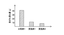
この比較例1の製造方法についても、実施例1,2と同様にして、膜状負極合材8の突出部8dの突出寸法Hの平均値を求めた。なお、比較例1でも、膜状負極合材8の第1幅方向端部8bの幅方向WDにかかる位置を測定する変位計を、電極シート製造装置内において実施例1,2と同等の位置に設けて、膜状負極合材8の第1幅方向端部8bの幅方向WDにかかる位置を測定している。但し、比較例1では、ステップS3(除去工程)の処理を行わないため、突出寸法Hの平均値は、ステップS2(成膜工程)の処理を行った直後における突出部8dについての値となるが、実施例1,2と同様に、成膜工程(ステップS2)の後で乾燥工程(ステップS4)の前における突出部8dの突出寸法Hの平均値となる。実施例1,2及び比較例1にかかる突出寸法Hの平均値を、図7に示す。
Also for the manufacturing method of Comparative Example 1, the average value of the protruding dimension H of the protruding
図7に示すように、比較例1の製造方法では、突出部8dの突出寸法Hの平均値が3.0mmとなった。これに対し、実施例1,2の製造方法では、突出部8dの突出寸法Hの平均値を1.0mm以下に低減することができた。詳細には、実施例1の製造方法では、突出部8dの突出寸法Hの平均値が1.0mmとなった。また、実施例2の製造方法では、突出部8dの突出寸法Hの平均値が0.8mmとなった。
As shown in FIG. 7, in the manufacturing method of Comparative Example 1, the average value of the protrusion dimension H of the
このように、実施例1,2において、成膜工程(ステップS2)の後で乾燥工程(ステップS4)の前に、突出部8dの突出寸法Hの平均値を小さくすることができた理由は、成膜工程(ステップS2)の後で乾燥工程(ステップS4)の前に、ステップS3(除去工程)の処理を行うことで、膜状負極合材8のうち突出部8dの少なくとも一部(先端部)を除去することができたからである。
As described above, in Examples 1 and 2, the reason why the average value of the protrusion dimension H of the
さらに、実施例1の製造方法によって200mの長さの負極シート19を連続して製造した後、電極シート製造装置10内のうち、集電箔7の搬送方向CDについてロール成膜装置20から巻き取り装置までの範囲内(すなわち、搬送方向CDについてロール成膜装置20よりも下流側の位置)において、集電箔7の表面から剥がれ落ちた負極合材6(膜状負極合材8の一部)を回収し、その総重量(剥がれ落ち量とする)を測定した。すなわち、実施例1の製造方法によって200mの長さの負極シート19を連続して製造したときに、集電箔7の表面から剥がれ落ちた負極合材6の総重量を求めた。また、実施例2及び比較例1についても、これと同様にして、剥がれ落ち量を測定した。これらの結果を図8に示す。
Furthermore, after the
なお、集電箔7の表面から剥がれ落ちた負極合材6には、ステップS3(除去工程)において集電箔7の表面から除去した負極合材6(除去部8f)は含まれない。集電箔7の表面から剥がれ落ちた負極合材6とは、製造中(搬送中)に、集電箔7の表面から自然に剥がれ落ちてしまった(脱落してしまった)負極合材6である。
Note that the
図8に示すように、比較例1の製造方法では、負極合材6の剥がれ落ち量が42gとなった。これに対し、実施例1,2の製造方法では、負極合材6の剥がれ落ち量を12g以下に低減することができた。詳細には、実施例1の製造方法では、負極合材6の剥がれ落ち量が12gとなった。また、実施例2の製造方法では、負極合材6の剥がれ落ち量が8gとなった。
As shown in FIG. 8, in the manufacturing method of Comparative Example 1, the amount of the
このように、実施例1,2において、集電箔7の表面から剥がれ落ちた負極合材6の量を少なくすることができた理由は、成膜工程(ステップS2)の後で乾燥工程(ステップS4)の前に、ステップS3(除去工程)の処理を行うことで、膜状負極合材8のうち、集電箔7の表面から剥がれ易い突出部8dの少なくとも一部(先端部)を、強制的に(集電箔7の表面から自然に剥がれ落ちる前に)除去したからである。
As described above, in Examples 1 and 2, the reason that the amount of the
本試験の結果より、成膜工程(ステップS2)の後で乾燥工程(ステップS4)の前に、ステップS3(除去工程)の処理を行うことで、膜状負極合材8のうち突出部8dの少なくとも一部を除去することによって、膜状負極合材8の突出部8dの突出寸法を低減することができると共に、集電箔7の表面から剥がれ落ちる負極合材6(膜状負極合材8を構成する材料)の量を低減することができるといえる。
From the result of this test, by performing the process of step S3 (removal process) after the film forming process (step S2) and before the drying process (step S4), the protruding
以上において、本発明を実施形態(実施例1,2)に即して説明したが、本発明は前記実施形態に限定されるものではなく、その要旨を逸脱しない範囲で、適宜変更して適用できることはいうまでもない。
例えば、実施形態では、本発明にかかる電極シートの製造方法として、負極シートを製造する方法を例示した。しかしながら、本発明を、正極シートの製造方法に適用するようにしても良い。
In the above, the present invention has been described with reference to the embodiments (Examples 1 and 2). However, the present invention is not limited to the above-described embodiments, and can be appropriately modified and applied without departing from the gist thereof. Needless to say, it can be done.
For example, in the embodiment, a method for producing a negative electrode sheet has been exemplified as a method for producing an electrode sheet according to the present invention. However, you may make it apply this invention to the manufacturing method of a positive electrode sheet.
1 第1ロール
2 第2ロール
3 第3ロール
6 負極合材(電極合材)
7 集電箔
8 膜状負極合材(膜状電極合材)
8d 突出部
8f 除去部
9 膜状負極合材付き集電箔(膜状電極合材付き集電箔)
10 電極シート製造装置
16 湿潤造粒体
18 負極合材層(電極合材層)
19 負極シート(電極シート)
20 ロール成膜装置
30 除去装置
40 除去ロール
41 表面
50 掻き落とし装置
51 掻き落としブレード
CD 搬送方向
WD 幅方向
S1 電極合材作製工程
S2 成膜工程
S3 除去工程
S4 乾燥工程
1
7
DESCRIPTION OF
19 Negative electrode sheet (electrode sheet)
20 roll
Claims (1)
電極活物質と結着材と溶媒とを混合して造粒した複数の湿潤造粒体からなる電極合材を、対向して回転する第1ロールと第2ロールとの間隙に通すことによって、前記電極合材を圧縮しつつ膜状にして、膜状にした前記電極合材を前記第2ロールの表面に付着させると共に、前記第2ロールと対向して回転する第3ロールによって搬送される前記集電箔を、前記第2ロールと前記第3ロールとの間隙に通すことによって、前記第2ロールの表面に付着している膜状の前記電極合材を、前記集電箔の前記表面に対し加圧しつつ接触させることで前記集電箔の前記表面上に転写して、前記集電箔の前記表面上に膜状の前記電極合材である膜状電極合材を有する膜状電極合材付き集電箔を作製する成膜工程と、
前記膜状電極合材付き集電箔の前記膜状電極合材を乾燥させることで、前記集電箔の前記表面上に前記電極合材層を形成する乾燥工程と、を備える
電極シートの製造方法において、
前記成膜工程の後、前記乾燥工程の前に、前記膜状電極合材付き集電箔を搬送しつつ、前記膜状電極合材付き集電箔の前記膜状電極合材の表面を除去ロールの表面に接触させて、前記膜状電極合材付き集電箔の前記膜状電極合材のうち、当該膜状電極合材の幅方向の両端部に位置して前記幅方向の外側に突出する突出部の少なくとも一部を、前記除去ロールの前記表面に転写させることで、前記膜状電極合材のうち前記突出部の少なくとも一部を除去する除去工程を備える
電極シートの製造方法。 An electrode sheet manufacturing method for manufacturing an electrode sheet having an electrode mixture layer on the surface of a current collector foil,
By passing an electrode mixture composed of a plurality of wet granulation bodies, which are granulated by mixing an electrode active material, a binder, and a solvent, through a gap between a first roll and a second roll that rotate oppositely, The electrode mixture is formed into a film while being compressed, and the film-formed electrode mixture is attached to the surface of the second roll, and is conveyed by a third roll that rotates opposite to the second roll. By passing the current collector foil through the gap between the second roll and the third roll, the film-like electrode mixture adhering to the surface of the second roll is used as the surface of the current collector foil. A film-like electrode having a film-like electrode mixture that is a film-like electrode mixture on the surface of the current-collecting foil. A film forming process for producing a current collector foil with a mixture;
A drying step of forming the electrode mixture layer on the surface of the current collector foil by drying the film electrode mixture of the current collector foil with the membrane electrode material. In the method
After the film forming step and before the drying step, the surface of the film electrode composite material of the current collector foil with film electrode material mixture is removed while conveying the current collector foil with film electrode material composite In contact with the surface of the roll, out of the film electrode mixture of the current collector foil with the film electrode mixture, located at both ends in the width direction of the film electrode mixture and on the outside in the width direction The manufacturing method of an electrode sheet provided with the removal process which removes at least one part of the said protrusion part among the said film-like electrode compound materials by transferring at least one part of the protrusion part which protrudes to the said surface of the said removal roll.
Priority Applications (1)
| Application Number | Priority Date | Filing Date | Title |
|---|---|---|---|
| JP2017180227A JP6791077B2 (en) | 2017-09-20 | 2017-09-20 | Electrode sheet manufacturing method |
Applications Claiming Priority (1)
| Application Number | Priority Date | Filing Date | Title |
|---|---|---|---|
| JP2017180227A JP6791077B2 (en) | 2017-09-20 | 2017-09-20 | Electrode sheet manufacturing method |
Publications (2)
| Publication Number | Publication Date |
|---|---|
| JP2019057383A true JP2019057383A (en) | 2019-04-11 |
| JP6791077B2 JP6791077B2 (en) | 2020-11-25 |
Family
ID=66107552
Family Applications (1)
| Application Number | Title | Priority Date | Filing Date |
|---|---|---|---|
| JP2017180227A Active JP6791077B2 (en) | 2017-09-20 | 2017-09-20 | Electrode sheet manufacturing method |
Country Status (1)
| Country | Link |
|---|---|
| JP (1) | JP6791077B2 (en) |
Cited By (6)
| Publication number | Priority date | Publication date | Assignee | Title |
|---|---|---|---|---|
| JP2021044096A (en) * | 2019-09-09 | 2021-03-18 | トヨタ自動車株式会社 | Manufacturing method of electrode sheet |
| CN114824156A (en) * | 2021-01-27 | 2022-07-29 | 泰星能源解决方案有限公司 | Electrode material and electrode comprising wet powder, method for producing the same, and secondary battery comprising the same |
| US20220271265A1 (en) * | 2021-02-22 | 2022-08-25 | Prime Planet Energy & Solutions, Inc. | Method for producing secondary battery electrodes |
| EP4057375A1 (en) * | 2021-03-11 | 2022-09-14 | Prime Planet Energy & Solutions, Inc. | Secondary battery electrode and method for producing the electrode |
| CN115084441A (en) * | 2021-03-12 | 2022-09-20 | 泰星能源解决方案有限公司 | Method for manufacturing electrode for secondary battery, electrode, and secondary battery provided with electrode |
| JP2022141439A (en) * | 2021-03-15 | 2022-09-29 | プライムプラネットエナジー&ソリューションズ株式会社 | Method for manufacturing electrode |
Citations (6)
| Publication number | Priority date | Publication date | Assignee | Title |
|---|---|---|---|---|
| JP2016051648A (en) * | 2014-09-01 | 2016-04-11 | 株式会社Gsユアサ | Polar plate manufacturing method and polar plate manufacturing device |
| JP2016207340A (en) * | 2015-04-17 | 2016-12-08 | トヨタ自動車株式会社 | Electrode manufacturing device |
| JP2017033848A (en) * | 2015-08-05 | 2017-02-09 | トヨタ自動車株式会社 | Manufacturing method of electrode plate |
| JP2017111917A (en) * | 2015-12-15 | 2017-06-22 | トヨタ自動車株式会社 | Method for manufacturing electrode sheet |
| JP2017147039A (en) * | 2016-02-15 | 2017-08-24 | トヨタ自動車株式会社 | Method for manufacturing electrode plate |
| JP2017157495A (en) * | 2016-03-04 | 2017-09-07 | トヨタ自動車株式会社 | Manufacturing method for electrode sheet |
-
2017
- 2017-09-20 JP JP2017180227A patent/JP6791077B2/en active Active
Patent Citations (6)
| Publication number | Priority date | Publication date | Assignee | Title |
|---|---|---|---|---|
| JP2016051648A (en) * | 2014-09-01 | 2016-04-11 | 株式会社Gsユアサ | Polar plate manufacturing method and polar plate manufacturing device |
| JP2016207340A (en) * | 2015-04-17 | 2016-12-08 | トヨタ自動車株式会社 | Electrode manufacturing device |
| JP2017033848A (en) * | 2015-08-05 | 2017-02-09 | トヨタ自動車株式会社 | Manufacturing method of electrode plate |
| JP2017111917A (en) * | 2015-12-15 | 2017-06-22 | トヨタ自動車株式会社 | Method for manufacturing electrode sheet |
| JP2017147039A (en) * | 2016-02-15 | 2017-08-24 | トヨタ自動車株式会社 | Method for manufacturing electrode plate |
| JP2017157495A (en) * | 2016-03-04 | 2017-09-07 | トヨタ自動車株式会社 | Manufacturing method for electrode sheet |
Cited By (15)
| Publication number | Priority date | Publication date | Assignee | Title |
|---|---|---|---|---|
| JP2021044096A (en) * | 2019-09-09 | 2021-03-18 | トヨタ自動車株式会社 | Manufacturing method of electrode sheet |
| EP4037006A3 (en) * | 2021-01-27 | 2022-12-07 | Prime Planet Energy & Solutions, Inc. | Electrode material comprising moisture powder, electrode, method for producing same, and secondary battery provided with said electrode |
| CN114824156A (en) * | 2021-01-27 | 2022-07-29 | 泰星能源解决方案有限公司 | Electrode material and electrode comprising wet powder, method for producing the same, and secondary battery comprising the same |
| EP4037006A2 (en) | 2021-01-27 | 2022-08-03 | Prime Planet Energy & Solutions, Inc. | Electrode material comprising moisture powder, electrode, method for producing same, and secondary battery provided with said electrode |
| KR20220108730A (en) | 2021-01-27 | 2022-08-03 | 프라임 플래닛 에너지 앤드 솔루션즈 가부시키가이샤 | Electrode material comprising moisture powder, electrode, method for producing same, and secondary battery provided with said electrode |
| US20220271265A1 (en) * | 2021-02-22 | 2022-08-25 | Prime Planet Energy & Solutions, Inc. | Method for producing secondary battery electrodes |
| US11594712B2 (en) * | 2021-02-22 | 2023-02-28 | Prime Planet Energy & Solutions, Inc. | Method for producing secondary battery electrodes |
| CN115084423A (en) * | 2021-03-11 | 2022-09-20 | 泰星能源解决方案有限公司 | Electrode for secondary battery and method for manufacturing the same |
| EP4057375A1 (en) * | 2021-03-11 | 2022-09-14 | Prime Planet Energy & Solutions, Inc. | Secondary battery electrode and method for producing the electrode |
| JP2022139879A (en) * | 2021-03-12 | 2022-09-26 | プライムプラネットエナジー&ソリューションズ株式会社 | Method of manufacturing secondary battery electrode, electrode, and secondary battery comprising the electrode |
| CN115084441A (en) * | 2021-03-12 | 2022-09-20 | 泰星能源解决方案有限公司 | Method for manufacturing electrode for secondary battery, electrode, and secondary battery provided with electrode |
| JP7320010B2 (en) | 2021-03-12 | 2023-08-02 | プライムプラネットエナジー&ソリューションズ株式会社 | METHOD FOR MANUFACTURING ELECTRODE FOR SECONDARY BATTERY, ELECTRODE AND SECONDARY BATTERY HAVING SAME |
| CN115084441B (en) * | 2021-03-12 | 2023-10-31 | 泰星能源解决方案有限公司 | Method for manufacturing electrode for secondary battery, electrode, and secondary battery provided with electrode |
| JP2022141439A (en) * | 2021-03-15 | 2022-09-29 | プライムプラネットエナジー&ソリューションズ株式会社 | Method for manufacturing electrode |
| JP7297005B2 (en) | 2021-03-15 | 2023-06-23 | プライムプラネットエナジー&ソリューションズ株式会社 | Electrode manufacturing method |
Also Published As
| Publication number | Publication date |
|---|---|
| JP6791077B2 (en) | 2020-11-25 |
Similar Documents
| Publication | Publication Date | Title |
|---|---|---|
| JP2019057383A (en) | Manufacturing method of electrode sheet | |
| JP6354698B2 (en) | Electrode plate manufacturing method | |
| JP6284020B2 (en) | Electrode sheet manufacturing method | |
| Wang et al. | The influence of polyvinylidene fluoride (PVDF) binder properties on LiNi0. 33Co0. 33Mn0. 33O2 (NMC) electrodes made by a dry-powder-coating process | |
| KR101942254B1 (en) | Method for manufacturing electrode for lithium ion secondary battery | |
| JP6443421B2 (en) | Electrode manufacturing method | |
| US9673455B2 (en) | Lithium-ion secondary battery | |
| EP3244470B1 (en) | Method for manufacturing electrode for lithium ion battery | |
| JP2017098029A (en) | Electrode plate manufacturing method | |
| JP2016081829A (en) | Method for manufacturing electrode for lithium ion secondary battery | |
| CN106537653A (en) | Method of manufacturing a lithium-ion secondary battery electrode sheet based on an active material dry powder | |
| JP6989265B2 (en) | Battery manufacturing method | |
| JP2016051648A (en) | Polar plate manufacturing method and polar plate manufacturing device | |
| JP2015176842A (en) | Production apparatus of sheet for lithium ion secondary battery, production method of sheet for lithium ion secondary battery, and manufacturing method for lithium ion secondary battery | |
| JP2017157495A (en) | Manufacturing method for electrode sheet | |
| JP7197267B2 (en) | Electrode sheet manufacturing method | |
| JP2001076712A (en) | Coating method of electrode paste for battery | |
| JP2021068510A (en) | Method for producing electrode sheet | |
| JP6583165B2 (en) | Electrode sheet manufacturing method | |
| JP7205426B2 (en) | Electrode sheet manufacturing method | |
| JP6919606B2 (en) | Manufacturing method of electrode sheet for sulfide all-solid-state battery | |
| JP6988625B2 (en) | Manufacturing method of positive electrode for lithium ion secondary battery | |
| JP6730201B2 (en) | Wet powder film formation method | |
| JP2024046380A (en) | Manufacturing method of electrode sheet | |
| JP2024030375A (en) | Manufacturing method of electrode sheet |
Legal Events
| Date | Code | Title | Description |
|---|---|---|---|
| A621 | Written request for application examination |
Free format text: JAPANESE INTERMEDIATE CODE: A621 Effective date: 20200128 |
|
| A977 | Report on retrieval |
Free format text: JAPANESE INTERMEDIATE CODE: A971007 Effective date: 20200923 |
|
| TRDD | Decision of grant or rejection written | ||
| A01 | Written decision to grant a patent or to grant a registration (utility model) |
Free format text: JAPANESE INTERMEDIATE CODE: A01 Effective date: 20201006 |
|
| A61 | First payment of annual fees (during grant procedure) |
Free format text: JAPANESE INTERMEDIATE CODE: A61 Effective date: 20201019 |
|
| R151 | Written notification of patent or utility model registration |
Ref document number: 6791077 Country of ref document: JP Free format text: JAPANESE INTERMEDIATE CODE: R151 |