JP2019056830A - Determination method, exposure method, program, exposure device, and method for producing article - Google Patents
Determination method, exposure method, program, exposure device, and method for producing article Download PDFInfo
- Publication number
- JP2019056830A JP2019056830A JP2017181472A JP2017181472A JP2019056830A JP 2019056830 A JP2019056830 A JP 2019056830A JP 2017181472 A JP2017181472 A JP 2017181472A JP 2017181472 A JP2017181472 A JP 2017181472A JP 2019056830 A JP2019056830 A JP 2019056830A
- Authority
- JP
- Japan
- Prior art keywords
- measurement
- optical system
- projection optical
- exposure
- image point
- Prior art date
- Legal status (The legal status is an assumption and is not a legal conclusion. Google has not performed a legal analysis and makes no representation as to the accuracy of the status listed.)
- Granted
Links
Images


Classifications
-
- G—PHYSICS
- G03—PHOTOGRAPHY; CINEMATOGRAPHY; ANALOGOUS TECHNIQUES USING WAVES OTHER THAN OPTICAL WAVES; ELECTROGRAPHY; HOLOGRAPHY
- G03F—PHOTOMECHANICAL PRODUCTION OF TEXTURED OR PATTERNED SURFACES, e.g. FOR PRINTING, FOR PROCESSING OF SEMICONDUCTOR DEVICES; MATERIALS THEREFOR; ORIGINALS THEREFOR; APPARATUS SPECIALLY ADAPTED THEREFOR
- G03F7/00—Photomechanical, e.g. photolithographic, production of textured or patterned surfaces, e.g. printing surfaces; Materials therefor, e.g. comprising photoresists; Apparatus specially adapted therefor
- G03F7/70—Microphotolithographic exposure; Apparatus therefor
- G03F7/70483—Information management; Active and passive control; Testing; Wafer monitoring, e.g. pattern monitoring
- G03F7/70591—Testing optical components
-
- G—PHYSICS
- G03—PHOTOGRAPHY; CINEMATOGRAPHY; ANALOGOUS TECHNIQUES USING WAVES OTHER THAN OPTICAL WAVES; ELECTROGRAPHY; HOLOGRAPHY
- G03F—PHOTOMECHANICAL PRODUCTION OF TEXTURED OR PATTERNED SURFACES, e.g. FOR PRINTING, FOR PROCESSING OF SEMICONDUCTOR DEVICES; MATERIALS THEREFOR; ORIGINALS THEREFOR; APPARATUS SPECIALLY ADAPTED THEREFOR
- G03F7/00—Photomechanical, e.g. photolithographic, production of textured or patterned surfaces, e.g. printing surfaces; Materials therefor, e.g. comprising photoresists; Apparatus specially adapted therefor
- G03F7/70—Microphotolithographic exposure; Apparatus therefor
- G03F7/708—Construction of apparatus, e.g. environment aspects, hygiene aspects or materials
- G03F7/70858—Environment aspects, e.g. pressure of beam-path gas, temperature
- G03F7/70883—Environment aspects, e.g. pressure of beam-path gas, temperature of optical system
- G03F7/70891—Temperature
-
- G—PHYSICS
- G03—PHOTOGRAPHY; CINEMATOGRAPHY; ANALOGOUS TECHNIQUES USING WAVES OTHER THAN OPTICAL WAVES; ELECTROGRAPHY; HOLOGRAPHY
- G03F—PHOTOMECHANICAL PRODUCTION OF TEXTURED OR PATTERNED SURFACES, e.g. FOR PRINTING, FOR PROCESSING OF SEMICONDUCTOR DEVICES; MATERIALS THEREFOR; ORIGINALS THEREFOR; APPARATUS SPECIALLY ADAPTED THEREFOR
- G03F7/00—Photomechanical, e.g. photolithographic, production of textured or patterned surfaces, e.g. printing surfaces; Materials therefor, e.g. comprising photoresists; Apparatus specially adapted therefor
- G03F7/70—Microphotolithographic exposure; Apparatus therefor
- G03F7/70483—Information management; Active and passive control; Testing; Wafer monitoring, e.g. pattern monitoring
- G03F7/70491—Information management, e.g. software; Active and passive control, e.g. details of controlling exposure processes or exposure tool monitoring processes
- G03F7/705—Modelling or simulating from physical phenomena up to complete wafer processes or whole workflow in wafer productions
-
- G—PHYSICS
- G01—MEASURING; TESTING
- G01B—MEASURING LENGTH, THICKNESS OR SIMILAR LINEAR DIMENSIONS; MEASURING ANGLES; MEASURING AREAS; MEASURING IRREGULARITIES OF SURFACES OR CONTOURS
- G01B11/00—Measuring arrangements characterised by the use of optical techniques
- G01B11/24—Measuring arrangements characterised by the use of optical techniques for measuring contours or curvatures
- G01B11/25—Measuring arrangements characterised by the use of optical techniques for measuring contours or curvatures by projecting a pattern, e.g. one or more lines, moiré fringes on the object
- G01B11/2518—Projection by scanning of the object
- G01B11/2522—Projection by scanning of the object the position of the object changing and being recorded
-
- G—PHYSICS
- G03—PHOTOGRAPHY; CINEMATOGRAPHY; ANALOGOUS TECHNIQUES USING WAVES OTHER THAN OPTICAL WAVES; ELECTROGRAPHY; HOLOGRAPHY
- G03F—PHOTOMECHANICAL PRODUCTION OF TEXTURED OR PATTERNED SURFACES, e.g. FOR PRINTING, FOR PROCESSING OF SEMICONDUCTOR DEVICES; MATERIALS THEREFOR; ORIGINALS THEREFOR; APPARATUS SPECIALLY ADAPTED THEREFOR
- G03F7/00—Photomechanical, e.g. photolithographic, production of textured or patterned surfaces, e.g. printing surfaces; Materials therefor, e.g. comprising photoresists; Apparatus specially adapted therefor
- G03F7/20—Exposure; Apparatus therefor
-
- G—PHYSICS
- G03—PHOTOGRAPHY; CINEMATOGRAPHY; ANALOGOUS TECHNIQUES USING WAVES OTHER THAN OPTICAL WAVES; ELECTROGRAPHY; HOLOGRAPHY
- G03F—PHOTOMECHANICAL PRODUCTION OF TEXTURED OR PATTERNED SURFACES, e.g. FOR PRINTING, FOR PROCESSING OF SEMICONDUCTOR DEVICES; MATERIALS THEREFOR; ORIGINALS THEREFOR; APPARATUS SPECIALLY ADAPTED THEREFOR
- G03F7/00—Photomechanical, e.g. photolithographic, production of textured or patterned surfaces, e.g. printing surfaces; Materials therefor, e.g. comprising photoresists; Apparatus specially adapted therefor
- G03F7/70—Microphotolithographic exposure; Apparatus therefor
- G03F7/70216—Mask projection systems
- G03F7/70241—Optical aspects of refractive lens systems, i.e. comprising only refractive elements
-
- G—PHYSICS
- G03—PHOTOGRAPHY; CINEMATOGRAPHY; ANALOGOUS TECHNIQUES USING WAVES OTHER THAN OPTICAL WAVES; ELECTROGRAPHY; HOLOGRAPHY
- G03F—PHOTOMECHANICAL PRODUCTION OF TEXTURED OR PATTERNED SURFACES, e.g. FOR PRINTING, FOR PROCESSING OF SEMICONDUCTOR DEVICES; MATERIALS THEREFOR; ORIGINALS THEREFOR; APPARATUS SPECIALLY ADAPTED THEREFOR
- G03F7/00—Photomechanical, e.g. photolithographic, production of textured or patterned surfaces, e.g. printing surfaces; Materials therefor, e.g. comprising photoresists; Apparatus specially adapted therefor
- G03F7/70—Microphotolithographic exposure; Apparatus therefor
- G03F7/70216—Mask projection systems
- G03F7/70258—Projection system adjustments, e.g. adjustments during exposure or alignment during assembly of projection system
-
- G—PHYSICS
- G03—PHOTOGRAPHY; CINEMATOGRAPHY; ANALOGOUS TECHNIQUES USING WAVES OTHER THAN OPTICAL WAVES; ELECTROGRAPHY; HOLOGRAPHY
- G03F—PHOTOMECHANICAL PRODUCTION OF TEXTURED OR PATTERNED SURFACES, e.g. FOR PRINTING, FOR PROCESSING OF SEMICONDUCTOR DEVICES; MATERIALS THEREFOR; ORIGINALS THEREFOR; APPARATUS SPECIALLY ADAPTED THEREFOR
- G03F7/00—Photomechanical, e.g. photolithographic, production of textured or patterned surfaces, e.g. printing surfaces; Materials therefor, e.g. comprising photoresists; Apparatus specially adapted therefor
- G03F7/70—Microphotolithographic exposure; Apparatus therefor
- G03F7/70483—Information management; Active and passive control; Testing; Wafer monitoring, e.g. pattern monitoring
- G03F7/7055—Exposure light control in all parts of the microlithographic apparatus, e.g. pulse length control or light interruption
-
- G—PHYSICS
- G03—PHOTOGRAPHY; CINEMATOGRAPHY; ANALOGOUS TECHNIQUES USING WAVES OTHER THAN OPTICAL WAVES; ELECTROGRAPHY; HOLOGRAPHY
- G03F—PHOTOMECHANICAL PRODUCTION OF TEXTURED OR PATTERNED SURFACES, e.g. FOR PRINTING, FOR PROCESSING OF SEMICONDUCTOR DEVICES; MATERIALS THEREFOR; ORIGINALS THEREFOR; APPARATUS SPECIALLY ADAPTED THEREFOR
- G03F7/00—Photomechanical, e.g. photolithographic, production of textured or patterned surfaces, e.g. printing surfaces; Materials therefor, e.g. comprising photoresists; Apparatus specially adapted therefor
- G03F7/70—Microphotolithographic exposure; Apparatus therefor
- G03F7/70483—Information management; Active and passive control; Testing; Wafer monitoring, e.g. pattern monitoring
- G03F7/70591—Testing optical components
- G03F7/706—Aberration measurement
-
- G—PHYSICS
- G03—PHOTOGRAPHY; CINEMATOGRAPHY; ANALOGOUS TECHNIQUES USING WAVES OTHER THAN OPTICAL WAVES; ELECTROGRAPHY; HOLOGRAPHY
- G03F—PHOTOMECHANICAL PRODUCTION OF TEXTURED OR PATTERNED SURFACES, e.g. FOR PRINTING, FOR PROCESSING OF SEMICONDUCTOR DEVICES; MATERIALS THEREFOR; ORIGINALS THEREFOR; APPARATUS SPECIALLY ADAPTED THEREFOR
- G03F7/00—Photomechanical, e.g. photolithographic, production of textured or patterned surfaces, e.g. printing surfaces; Materials therefor, e.g. comprising photoresists; Apparatus specially adapted therefor
- G03F7/70—Microphotolithographic exposure; Apparatus therefor
- G03F7/70691—Handling of masks or workpieces
- G03F7/70775—Position control, e.g. interferometers or encoders for determining the stage position
Abstract
Description
本発明は、投影光学系の光学特性を予測するための予測式を決定する決定方法、露光方法、プログラム、露光装置、および物品の製造方法に関する。 The present invention relates to a determination method, an exposure method, a program, an exposure apparatus, and an article manufacturing method for determining a prediction formula for predicting optical characteristics of a projection optical system.
半導体デバイスなどの製造工程(リソグラフィ工程)で用いられる装置の1つとして、投影光学系を介して基板を露光し、原版のパターンを基板上のショット領域に転写する露光装置がある。このような露光装置では、基板の露光中、投影光学系で露光光の一部が吸収されるため、それにより発生した熱の影響で投影光学系の光学特性が変化し、原版のパターンをショット領域に精度よく転写することが困難になりうる。 As one of apparatuses used in a manufacturing process (lithography process) of a semiconductor device or the like, there is an exposure apparatus that exposes a substrate through a projection optical system and transfers a pattern of an original to a shot area on the substrate. In such an exposure apparatus, part of the exposure light is absorbed by the projection optical system during exposure of the substrate, so that the optical characteristics of the projection optical system change due to the heat generated thereby, and the pattern of the original is shot. It can be difficult to accurately transfer to an area.
特許文献1には、露光量や露光時間などを変数とした予測式を用いて投影光学系の光学特性を予測し、その予測値に基づいて投影光学系の光学特性を制御する方法が提案されている。また、特許文献2には、予測値に生じる誤差が低減されるように、投影光学系の光学特性を実測した結果に基づいて予測式を最適化(補正)する方法が提案されている。 Patent Document 1 proposes a method of predicting the optical characteristics of a projection optical system using a prediction formula with variables such as exposure amount and exposure time, and controlling the optical characteristics of the projection optical system based on the predicted values. ing. Further, Patent Document 2 proposes a method for optimizing (correcting) the prediction formula based on the result of actual measurement of the optical characteristics of the projection optical system so that errors occurring in the predicted value are reduced.
予測式を最適化するための投影光学系の光学特性の実測は、例えば基板の露光の終了後、該光学特性が変化している期間に、投影光学系の物体面における複数の計測点(物点)の各々について像点の位置を順次計測することによって行われうる。しかしながら、この場合、各計測点での計測が、投影光学系の光学特性が互いに異なるタイミングで行われることとなる。そのため、各計測点での計測タイミングに応じて互いに異なる投影光学系の光学特性を考慮しないと、予測式の最適化が不十分になり、投影光学系の光学特性を精度よく予測することが困難になりうる。 The actual measurement of the optical characteristics of the projection optical system for optimizing the prediction formula is performed by, for example, a plurality of measurement points (objects) on the object plane of the projection optical system during the period when the optical characteristics change after the exposure of the substrate. This can be done by sequentially measuring the position of the image point for each of the points. However, in this case, the measurement at each measurement point is performed at a timing when the optical characteristics of the projection optical system are different from each other. Therefore, unless consideration is given to the optical characteristics of the projection optical systems that differ from each other according to the measurement timing at each measurement point, optimization of the prediction formula becomes insufficient, and it is difficult to accurately predict the optical characteristics of the projection optical system. Can be.
そこで、本発明は、投影光学系の光学性能を精度よく予測するために有利な技術を提供することを目的とする。 Therefore, an object of the present invention is to provide an advantageous technique for accurately predicting the optical performance of a projection optical system.
上記目的を達成するために、本発明の一側面としての決定方法は、基板の露光中に熱により変化する投影光学系の光学特性を予測するための予測式を決定する決定方法であって、前記投影光学系の物体面における複数の計測点の各々について、互いに異なる計測タイミングで像点の位置を計測する計測工程と、前記計測工程で計測された像点の位置と、各計測点での計測タイミングにおける前記光学特性の推定値とに基づいて、前記予測式を決定する決定工程と、を含むことを特徴とする。 In order to achieve the above object, a determination method according to one aspect of the present invention is a determination method for determining a prediction formula for predicting optical characteristics of a projection optical system that changes due to heat during exposure of a substrate, For each of a plurality of measurement points on the object plane of the projection optical system, a measurement process for measuring the position of the image point at different measurement timings, the position of the image point measured in the measurement process, and the measurement point at each measurement point And a determination step of determining the prediction formula based on the estimated value of the optical characteristic at the measurement timing.
本発明の更なる目的又はその他の側面は、以下、添付図面を参照して説明される好ましい実施形態によって明らかにされるであろう。 Further objects and other aspects of the present invention will become apparent from the preferred embodiments described below with reference to the accompanying drawings.
本発明によれば、例えば、投影光学系の光学性能を精度よく予測するために有利な技術を提供することができる。 According to the present invention, for example, it is possible to provide an advantageous technique for accurately predicting the optical performance of a projection optical system.
以下、添付図面を参照して、本発明の好適な実施の形態について説明する。なお、各図において、同一の部材ないし要素については同一の参照番号を付し、重複する説明は省略する。 DESCRIPTION OF EXEMPLARY EMBODIMENTS Hereinafter, preferred embodiments of the invention will be described with reference to the accompanying drawings. In addition, in each figure, the same reference number is attached | subjected about the same member thru | or element, and the overlapping description is abbreviate | omitted.
<第1実施形態>
本発明に係る第1実施形態の露光装置100について、図1を参照しながら説明する。図1は、第1実施形態の露光装置100を示す概略図である。露光装置100は、例えば、原版1(マスク)を保持する原版ステージ2と、投影光学系3と、基板4を保持して移動可能な基板ステージ5と、照明光学系6と、制御部7とを含みうる。制御部7は、例えばCPUやメモリなどを含み、原版1のパターンを基板4のショット領域に転写する露光処理を制御する(露光装置100の各部を制御する)。
<First Embodiment>
An
照明光学系6は、それに含まれるマスキングブレードなどの遮光部材により、光源(不図示)から射出された光を整形し、整形した光で原版1のパターン領域(回路パターンを含む領域)を照明する。原版1および基板4は、原版ステージ2および基板ステージ5によってそれぞれ保持されており、投影光学系3を介して光学的に共役な位置(投影光学系3の物体面および像面)にそれぞれ配置されうる。投影光学系3は、原版1のパターンを基板4(ショット領域)に投影する。
The illumination
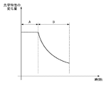
このように構成された露光装置100では、投影光学系3において露光光の一部が吸収されるため、それにより発生した熱の影響で投影光学系3の光学特性(例えばディストーションなどの光学収差)が露光時間とともに変化しうる。例えば、図2(b)に示すように一定の強度を有する露光光で露光処理を行うと、投影光学系3の光学特性は、図2(a)に示すように、露光時間に対して指数関数的に変化しうる。そのため、露光装置100では、このような投影光学系3の光学特性の変化量を考慮しないと、原版1のパターンをショット領域に精度よく転写することが困難になりうる。
In the
露光装置100では、基板4の露光中に熱により変化する投影光学系3の光学特性を予測し、その予測値に基づいて投影光学系3の光学特性を変更(補正)しながら露光処理が行われる。投影光学系3の光学特性の変更は、変更部(補正部)によって行われうる。変更部は、例えば、投影光学系3の光学素子3aを駆動する駆動部3b、および基板ステージ5の少なくとも一方を含みうる。本実施形態では、変更部として駆動部3bを用い、投影光学系3の光学特性の予測値に基づいて駆動部3bを制御部7によって制御する例について説明する。また、図1に示す駆動部は3b、1つの光学素子3aを駆動するように構成されているが、それに限られるものではなく、複数の光学素子を駆動するように構成されてもよい。
In the
以下に、本実施形態において投影光学系3の光学特性を予測する予測方法を、従来の予測方法と比較しながら説明する。以下では、投影光学系3の光学特性を予測する処理(予測式を決定する処理)を制御部7が行う例について説明するが、当該処理を行う処理部を制御部7と別体で設けてもよい。
Hereinafter, a prediction method for predicting the optical characteristics of the projection optical system 3 in the present embodiment will be described in comparison with a conventional prediction method. In the following, an example in which the
[従来の予測方法]
まず、従来における投影光学系3の光学特性の予測方法について説明する。従来では、投影光学系3の光学特性についての予測値Φkは、例えば式(1)で表される予測式によって求められうる。式(1)において、Ekは露光量(投影光学系を透過した光の光量)を、tkは露光時間を、Icは予測値を実測値に近づけるための係数(予測値の誤差を低減するための係数)を、Kは投影光学系3の熱伝導に関する時定数をそれぞれ表す。
[Conventional prediction method]
First, a conventional method for predicting the optical characteristics of the projection optical system 3 will be described. Conventionally, the predicted value Φ k for the optical characteristics of the projection optical system 3 can be obtained by a prediction formula represented by, for example, Expression (1). In Equation (1), E k is the exposure amount (the amount of light transmitted through the projection optical system), t k is the exposure time, and Ic is a coefficient for reducing the predicted value to the actual value (reducing the error in the predicted value). K represents a time constant related to the heat conduction of the projection optical system 3.
![]()
![]()
予測式により求められる予測値Φkには、実測値に対する誤差が生じることがある。このような誤差が予測値Φkに生じていると、当該予測値Φkに従って変更部(駆動部3b)を駆動しても、原版1のパターンを基板4のショット領域に精度よく転写することが困難になりうる。そのため、露光装置では、例えば、露光工程(図2の期間A)の後、露光工程で生じた投影光学系の光学特性の変化量が減少していく期間(図2の期間B)において、投影光学系3の光学特性を実測し、その実測結果に基づいて予測式の最適化が行われる。
An error with respect to an actual measurement value may occur in the predicted value Φ k obtained by the prediction formula. If such an error occurs in the predicted value Φ k , the pattern of the original 1 can be accurately transferred to the shot area of the
式(1)において、係数Icおよび時定数Kが、予測式を最適化するために決定されるパラメータ(以下、補正パラメータと呼ぶことがある)である。この補正パラメータは、投影光学系3の光学特性の種類(例えば、投影倍率、フォーカス、ディストーションなど)ごとに決定されうる。また、露光装置では、投影光学系3の光学特性の変動が、例えば照明NA、照明σ、露光画角、レチクル透過率、基板での光の反射率などの露光条件に依存して異なる。そのため、補正パラメータを露光条件ごとに決定(最適化)し、メモリ等に記憶しておくことが好ましい。 In Equation (1), the coefficient Ic and the time constant K are parameters (hereinafter, sometimes referred to as correction parameters) determined for optimizing the prediction equation. This correction parameter can be determined for each type of optical characteristics of the projection optical system 3 (for example, projection magnification, focus, distortion, etc.). In the exposure apparatus, the variation in the optical characteristics of the projection optical system 3 varies depending on the exposure conditions such as illumination NA, illumination σ, exposure angle of view, reticle transmittance, and light reflectance on the substrate. Therefore, it is preferable to determine (optimize) correction parameters for each exposure condition and store them in a memory or the like.
次に、予測式(補正パラメータ)を最適化する方法について説明する。予測式を最適化するためには、投影光学系3の光学特性の計測(実測)が行われうる。光学特性の計測方法としては、例えば、テストプリント(焼き付け)を用いる方法と、空中像を用いる方法とがある。前者のテストプリントを用いる方法は、原版1のパターンをテスト基板に転写し、テスト基板を現像した後に、テスト基板に転写されたパターンの位置や線幅を計測器で測定することにより、光学特性を求める方法である。一方、後者の空中像を用いる方法は、投影光学系3により形成された空中像を検出(観察)し、その検出結果から光学特性を計測する方法である。後者の空中像を用いる方法は、テストプリントを用いる方法と比べて、基板を現像する工程を含まないため、投影光学系3の光学特性を計測するために要する時間を大幅に削減することができる。以下に、空中像を用いて投影光学系3の光学特性(例えば、ディストーション)を計測する具体例について説明する。 Next, a method for optimizing the prediction formula (correction parameter) will be described. In order to optimize the prediction formula, measurement (actual measurement) of the optical characteristics of the projection optical system 3 can be performed. As a method for measuring optical characteristics, for example, there are a method using a test print (printing) and a method using an aerial image. The former method using a test print is to transfer the pattern of the original 1 to a test substrate, develop the test substrate, and then measure the position and line width of the pattern transferred to the test substrate with a measuring instrument. It is a method to ask for. On the other hand, the latter method using an aerial image is a method of detecting (observing) an aerial image formed by the projection optical system 3 and measuring optical characteristics from the detection result. Since the latter method using the aerial image does not include a step of developing the substrate, the time required to measure the optical characteristics of the projection optical system 3 can be greatly reduced as compared with the method using a test print. . Below, the specific example which measures the optical characteristic (for example, distortion) of the projection optical system 3 using an aerial image is demonstrated.
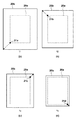
露光装置100には、図1(a)に示すように、投影光学系3の物体面側(原版側)および像面側(基板側)にそれぞれ計測用パターン10が設けられる。原版側の計測用パターン10aおよび基板側の計測用パターン10bは、同様の構成を有しており、図1(b)に示すように、Hパターン11とVパターン12とをそれぞれ含みうる。Hパターン11は、X方向に延びるライン要素としての光透過部13がY方向に複数並んだラインアンドスペースパターンを含み、Y方向における投影光学系3の像点位置を検出するために用いられうる。一方、Vパターン12は、Y方向に延びるライン要素としての光透過部13がX方向に複数並んだラインアンドスペースパターンを含み、X方向における投影光学系3の像点位置を検出するために用いられる。
As shown in FIG. 1A, the
原版側の計測用パターン10aおよび基板側の計測用パターン10bは、原版ステージ2および基板ステージ5にそれぞれ設けられ、投影光学系3の光軸方向(Z方向)、および該光軸に垂直な面内方向(X方向、Y方向)に移動可能である。また、基板ステージ5には、基板側の計測用パターン10bの下に、該計測用パターン10bの光透過部13を透過した光の光量(光強度)を検出し、原版側の計測用パターン10aの像点位置を計測する光量センサ14(計測部)が設けられうる。
The original-
露光装置100は、照明光学系6から射出された光が、原版側の計測用パターン10aの光透過部13と基板側の計測用パターン10bの光透過部13を透過し、光量センサ14で検出された光の光量が最大となるように、基板ステージ5を移動(走査)させる。例えば、Hパターン11については、ライン要素(光透過部13)の長手方向と直交する方向(Y方向)に基板ステージ5を移動させながら、光量センサ14に光量を検出させる。そして、光量センサ14で検出された光量が最大となる位置(座標)、即ち、原版側の計測用パターン10aの像と基板側の計測用パターン10bの像とがY方向に最もよく重なる位置を、Y方向における像点の位置(結像位置)として決定する。Vパターン12についても同様であり、X方向に基板ステージ5を移動させながら光量センサ14に光量を検出させ、検出された光量が最大となる位置をX方向における像点の位置(結像位置)として決定する。
In the
このような像点位置の計測は、投影光学系3の物体面(投影領域、画角)において予め設定された複数の計測点(物点)の各々に、原版ステージ2により原版側の計測用パターン10aを順次配置しながら行われる。これにより、各計測点について、光量センサ14により計測された原版側の計測用パターン10aの像点の位置と、原版側の計測用パターン10aの像点が計測されるべき目標位置(理想位置、設計位置)とのXY方向の差が求められる。当該差は、以下では「像点位置のずれ量」と呼ぶことがある。
Such image point position measurement is performed for measuring the original side by the original stage 2 at each of a plurality of measurement points (object points) set in advance on the object plane (projection area, angle of view) of the projection optical system 3. This is performed while sequentially arranging the
従来では、像点位置のずれ量dx、dyは以下の式(2)によって表わされ、最小二乗法などを用いて、像点位置のずれ量dx、dyがそれぞれ最小となるように係数IcMagを求めることにより、予測式(補正パラメータ)を最適化することができる。式(2)において、「xi」および「yi」はXY方向の目標位置の座標をそれぞれ示し、「i」は計測点の番号を示している。また、「IcMag」は、投影光学系のディストーションの空間変化成分(倍率成分)についての係数Icを示している。ここで、複数の計測点は、例えば、露光画角の四隅のそれぞれを含むように設定されてもよい。 Conventionally, the image point position shift amounts dx and dy are expressed by the following equation (2), and the coefficient Ic is used to minimize the image point position shift amounts dx and dy using the least square method or the like. By obtaining Mag , the prediction formula (correction parameter) can be optimized. In Expression (2), “x i ” and “y i ” indicate the coordinates of the target position in the XY directions, and “i” indicates the number of the measurement point. “Ic Mag ” indicates a coefficient Ic for a spatial change component (magnification component) of distortion of the projection optical system. Here, the plurality of measurement points may be set to include, for example, each of the four corners of the exposure field angle.
[本実施形態の予測方法]
各計測点での像点位置の計測は、露光処理の終了後、照明光学系6(遮光部材)により少なくとも原版側の計測用パターン10aを照明し、投影光学系3を透過する光の光量が基板の露光中より非常に小さい状態で行われる。即ち、像点位置の計測は、露光量Ekが「零」に近い状態で行われる。そのため、当該計測が行われている期間では、投影光学系3において熱の発生が殆ど生じず、露光処理によって生じた投影光学系の光学特性の変化量が指数関数的に減少することとなる。
[Prediction method of this embodiment]
The image point position at each measurement point is measured by illuminating at least the
投影光学系3の光学特性が変化する速度は、式(1)の時定数Kに依存する。この時定数Kが、複数の測定点の各々で像点位置を計測するために要する時間より十分に長い場合、各計測点での計測タイミングにおける投影光学系3の光学特性は一定であるとみなすことができる。この場合、上述した従来の方法を用いれば、予測式(補正パラメータ)を十分に最適化することができる。 The speed at which the optical characteristics of the projection optical system 3 change depends on the time constant K in Expression (1). When this time constant K is sufficiently longer than the time required to measure the image point position at each of a plurality of measurement points, the optical characteristics of the projection optical system 3 at the measurement timing at each measurement point are considered to be constant. be able to. In this case, if the conventional method described above is used, the prediction formula (correction parameter) can be sufficiently optimized.
しかしながら、時定数Kは、投影光学系3の構成などによって決定される固有の値であり、時定数Kによっては、複数の計測点の各々について像点位置を計測している間に、投影光学系3の光学特性が無視できない程度に変化することがある。例えば、1つの計測点での像点位置の計測に数秒〜十数秒の時間を要する場合、10箇所の計測点で像点位置を計測すると合計時間は数十秒程度になる。それに対し、投影光学系3の時定数Kは一般に数十秒〜数千秒の範囲にあり、時定数Kが数十秒程度である投影光学系3では、像点位置の計測に要する合計時間と同等となり、投影光学系3の光学特性の変化速度を無視することは好ましくない。つまり、各計測点での像点位置の計測タイミングにおける投影光学系3の光学特性を考慮しないと、予測式(補正パラメータ)の最適化が不十分になりうる。 However, the time constant K is a unique value determined by the configuration of the projection optical system 3 and the like. Depending on the time constant K, the projection optical system may be used while measuring the image point position for each of a plurality of measurement points. The optical characteristics of the system 3 may change to a degree that cannot be ignored. For example, when it takes several seconds to several tens of seconds to measure the image point position at one measurement point, if the image point positions are measured at 10 measurement points, the total time is about several tens of seconds. On the other hand, the time constant K of the projection optical system 3 is generally in the range of several tens of seconds to several thousand seconds. In the projection optical system 3 having the time constant K of about several tens of seconds, the total time required to measure the image point position. Therefore, it is not preferable to ignore the change speed of the optical characteristics of the projection optical system 3. That is, unless the optical characteristics of the projection optical system 3 at the measurement timing of the image point position at each measurement point are taken into consideration, the prediction formula (correction parameter) may not be optimized.
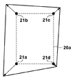
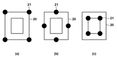
その具体的な例を、図3および図4を参照しながら説明する。ここでは、図3に示すように、露光工程の後、4つの計測点(画角の各頂点)において像点位置の計測を順次行う場合を想定し、1つの計測点での像点位置の計測に時間Δtを要するものとする。図3は、投影光学系3の光学特性(ディストーション)の変化を示す概念図であり、破線は、投影光学系3の光学特性が変化する前(図2の時刻t=0)の投影領域20aを示し、実線は、各計測点での計測タイミングにおける投影領域20bを示している。
A specific example will be described with reference to FIGS. Here, as shown in FIG. 3, it is assumed that the image point position is sequentially measured at the four measurement points (each vertex of the angle of view) after the exposure process, and the image point position at one measurement point is determined. It is assumed that time Δt is required for measurement. FIG. 3 is a conceptual diagram showing changes in the optical characteristics (distortion) of the projection optical system 3, and the broken line indicates the
1箇所目の計測点21aでの像点位置の計測を、図3(a)に示すように、投影領域20bが比較的大きい時刻t1に行ったとする。この場合、2箇所目の計測点21bでの像点位置の計測は、図3(b)に示すように、時刻t1より投影領域20bが小さくなる時刻t2(=t1+Δt)に行われる。また、3箇所目の計測点21cでの像点位置の計測は、図3(c)に示すように、時刻t2より投影領域20bが小さくなる時刻t3(=t1+2Δt)に行われる。同様に、4箇所目の計測点21dでの像点位置の計測は、図3(d)に示すように、時刻t3より投影領域20bが小さくなる時刻t4(=t1+3Δt)に行われる。このように各計測点での像点位置の計測を互いに異なる計測タイミングで行うと、図4に示すように、各計測タイミングでの投影領域の変化量(変化ベクトルの絶対値)が互いに異なりうる。そのため、従来のように、各計測タイミングでの投影光学系3の光学特性を考慮せずに、像点位置の計測結果をそのまま用いて予測式の最適化を行ってしまうと、当該最適化が不十分になりうる。
The measurement of the image point position in one place
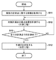
そこで、本実施形態の露光装置100は、複数の計測点の各々について計測された像点位置に基づいて予測式(補正パラメータ(係数Ic))を決定する際に、各計測点での計測タイミングにおける光学特性の変化量を考慮する。以下に、本実施形態に係る予測式の決定方法について、図5を参照しながら説明する。図5は、本実施形態に係る予測式の決定方法を示すフローチャートであり、当該フローチャートの各工程は、制御部7によって行われうる。本実施形態では、投影光学系3の光学特性として、投影光学系3のディストーションの一次成分である倍率成分を予測する予測式の決定方法について説明する。
Therefore, the
S11では、制御部7は、投影光学系3の物体面上に設定された複数の計測点に関する情報を取得する。本実施形態では、外部コンピュータなどにより予め設定された複数の計測点に関する情報を制御部7が取得する例を示すが、例えば、制御部7自体が複数の計測点を設定してもよい。
In S <b> 11, the
S12では、制御部7は、複数の計測点のうちの1つの計測点(以下、対象計測点)での像点位置を計測する(計測工程)。像点位置の計測は、上述したように、原版ステージ2により原版側の計測用パターン10aを対象計測点に配置し、基板ステージ5により光量センサ14を走査しながら、対象計測点での像点位置を探索することにより行われる。対象計測点で計測された像点位置は、対象計測点での計測タイミングとともにメモリ等に記憶される。S13では、制御部7は、複数の計測点の全てについて像点位置を計測したか否かを判定する。像点位置の計測が行われていない計測点が1つでもある場合にはS12に戻り、対象計測点を変更して像点位置の計測を行う。一方、複数の計測点の全てについて像点位置を計測した場合にはS14に進む。
In S12, the
S14では、制御部7は、S12の工程において各計測点で計測された像点位置と、各計測点での計測タイミングにおける投影光学系3の光学特性(変化量)の推定値とに基づいて、予測式(係数IcMag)を決定する(決定工程)。つまり、S14の計測工程では、各計測点で計測された像点位置に対し、各計測点での計測タイミングにおける投影光学系3の光学特性を考慮して、予測式を決定する。
In S14, the
ここで、S14の決定工程について詳細に説明する。例えば、制御部7は、S14において、対象計測点で計測された像点位置と目標位置とのXY方向の差(像点位置のずれ量)を求める。そして、時刻tiに計測された対象計測点のXY方向の目標位置が(xi,yi)であるとすると、像点位置のX方向のずれ量dx(xi,yi,ti)、Y方向のずれ量dy(xi,yi,ti)は、式(3)のようにそれぞれ表される。
Here, the determination step of S14 will be described in detail. For example, in S14, the
この式(3)は、上述した従来の式(2)と比較して、関数φMag(ti)が乗じられている。関数φMag(ti)は、式(4)によって表わされ、基板の露光量(投影光学系3を透過した光の光量)と時刻とに基づいて投影光学系の光学特性を推定(算出)するための関数であり、未知のパラメータである係数IcMagを含まずに規格化されている。つまり、式(3)は、各計測点での計測タイミングにおける投影光学系の光学特性の推定値と、像点の目標位置とをパラメータとして、像点位置のずれ量を算出する式である。 This expression (3) is multiplied by the function φ Mag (t i ) as compared with the conventional expression (2) described above. The function φ Mag (t i ) is expressed by Expression (4), and estimates (calculates) the optical characteristics of the projection optical system based on the exposure amount of the substrate (the amount of light transmitted through the projection optical system 3) and the time. ) And is normalized without including the coefficient Ic Mag that is an unknown parameter. That is, Expression (3) is an expression for calculating the deviation amount of the image point position using the estimated value of the optical characteristics of the projection optical system at the measurement timing at each measurement point and the target position of the image point as parameters.
制御部7は、最小二乗法などを用いて、式(3)で表わされる各計測点についての像点位置のずれ量dx(xi,yi,ti)、dy(xi,yi,ti)がそれぞれ最小となるように、係数IcMaxを求める。これにより、投影光学系3の光学特性の変化を予測するための予測式を精度よく決定することができる。例えば、投影光学系3の光学特性としての倍率成分(ディストーションの一次成分)の変化を予測するための予測式は、式(5)のように表わされうる。式(5)において、「Mag(t)」は、時刻tに対する投影光学系3の投影倍率を表している。
The
上述したように、本実施形態では、複数の計測点の各々について計測された像点位置と、計測タイミングにおける投影光学系3の光学特性の推定値とに基づいて、予測式を決定する。このように決定された予測式を用いることにより、基板の露光中における投影光学系3の光学特性を精度よく予測することができる。ここで、本実施形態では、露光装置100に設けられた制御部7によって予測式を決定する例について説明したが、それに限られず、露光装置100の外部に設けられた外部コンピュータなどの処理部によって予測式を決定してもよい。
As described above, in this embodiment, the prediction formula is determined based on the image point position measured for each of the plurality of measurement points and the estimated value of the optical characteristics of the projection optical system 3 at the measurement timing. By using the prediction formula thus determined, it is possible to accurately predict the optical characteristics of the projection optical system 3 during exposure of the substrate. Here, in this embodiment, the example in which the prediction formula is determined by the
<第2実施形態>
第1実施形態では、投影光学系3の光学特性として、ディストーションの1次成分(倍率成分)を予測する予測式の決定方法について説明した。第2実施形態では、第1実施形態より高次のディストーション成分を予測する予測式の決定方法について説明する。第2実施形態では、1次ディストーション対称成分、3次ディストーション対称成分、および1次ディストーションのXY差成分を予測する予測式の決定方法について、図5に示すフローチャートに基づいて説明する。
Second Embodiment
In the first embodiment, the prediction formula determination method for predicting the primary component (magnification component) of distortion as the optical characteristic of the projection optical system 3 has been described. In the second embodiment, a method for determining a prediction formula for predicting higher-order distortion components than in the first embodiment will be described. In the second embodiment, a method for determining a prediction equation for predicting the primary distortion symmetric component, the third distortion symmetric component, and the XY difference component of the primary distortion will be described with reference to the flowchart shown in FIG.
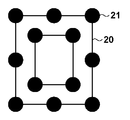
S11において、制御部7は、投影光学系3の物体面上に設定された複数の計測点(物点)に関する情報を取得する。本実施形態では、第1実施形態に比べて、より高次のディストーション成分まで計測するため、設定される計測点の数は、第1実施形態(例えば図3参照)より多くなる。図6は、本実施形態において物体面上に設定された複数の計測点の配置例を示す図である。図6に示す例では、投影光学系3の投影領域20(画角)上に12個の計測点21が設定されている。
In S <b> 11, the
S12〜S13において、制御部7は、複数の計測点の各々のついて像点位置を計測する。そして、S14において、制御部7は、各計測点で計測された像点位置に対し、各計測点での計測タイミングにおける投影光学系3の光学特性を考慮して、予測式を決定する。
In S12 to S13, the
本実施形態では、時刻tiに計測された対象計測点のXY方向の目標位置が(xi,yi)であるとすると、像点位置のX方向のずれ量dx(xi,yi,ti)、Y方向のずれ量dy(xi,yi,ti)は、式(6)のようにそれぞれ表される。 In the present embodiment, assuming that the target position in the XY direction of the target measurement point measured at time t i is (x i , y i ), the displacement amount dx (x i , y i ) in the X direction of the image point position. , t i), Y direction shift amount dy (x i, y i, t i) are respectively represented as in equation (6).
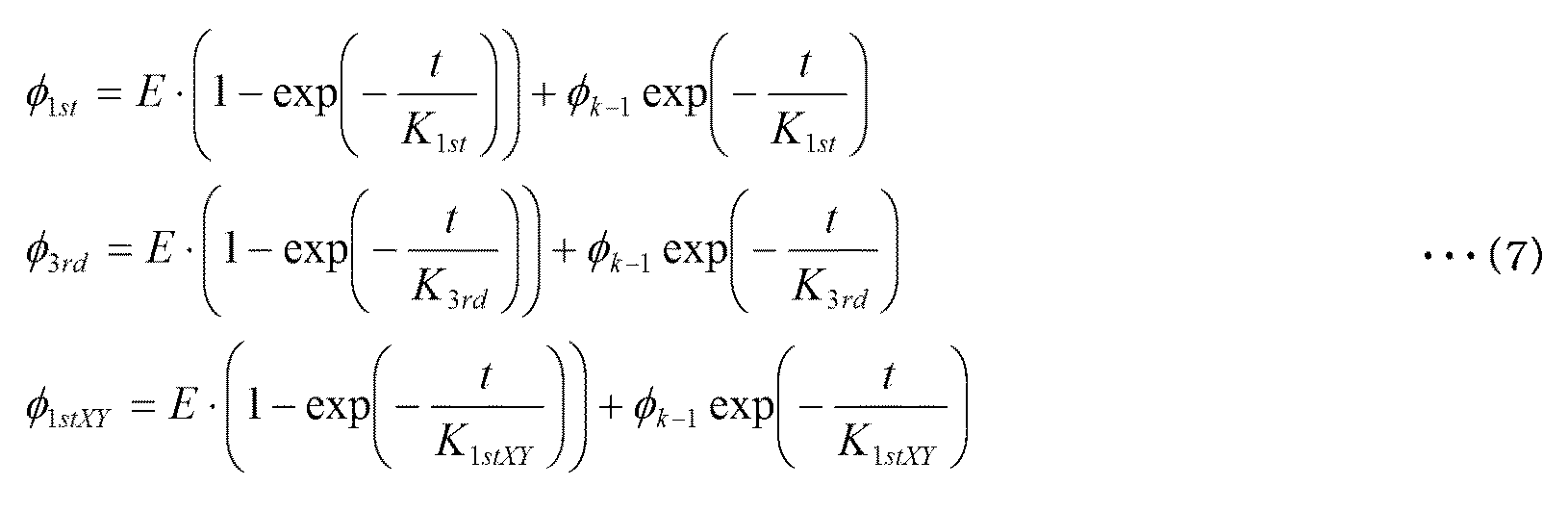
ここで、式(6)において、φ1st(ti)、φ3rd(ti)およびφ1stXY(ti)はそれぞれ、基板の露光量と時刻とに基づいて投影光学系の光学特性を推定(算出)するための関数である。つまり、φ1st(ti)は、時刻tiでの1次ディストーション対称成分の発生量の推定値を示し、φ3rd(ti)は、時刻tiでの3次ディストーション対称成分の発生量の推定値を示している。また、φ1stXY(ti)は、時刻tiでの1次ディストーションのXY差成分の発生量の推定値を示している。φ1st(ti)、φ3rd(ti)およびφ1stXY(ti)は、以下の式(7)のように表わされ、式(7)において、「t」は時刻を示し、「K1st」、「K3rd」、「K1stXY」は各ディストーション成分の時定数を示している。 Here, in Equation (6), φ 1st (t i ), φ 3rd (t i ), and φ 1stXY (t i ) estimate the optical characteristics of the projection optical system based on the exposure amount and time of the substrate, respectively. This is a function for (calculation). That is, φ 1st (t i ) represents an estimated value of the amount of occurrence of the first-order distortion symmetric component at time t i , and φ 3rd (t i ) represents the amount of occurrence of the third-order distortion symmetric component at time t i. The estimated value is shown. Further, φ 1stXY (t i ) indicates an estimated value of the generation amount of the XY difference component of the primary distortion at time t i . φ 1st (t i ), φ 3rd (t i ), and φ 1stXY (t i ) are expressed by the following equation (7), where “t” indicates time, “K 1st ”, “K 3rd ”, and “K 1stXY ” indicate time constants of each distortion component.
制御部7は、最小二乗法などを用いて、式(6)で表わされる像点位置のずれ量dx(xi,yi,ti)、dy(xi,yi,ti)がそれぞれ最小となるように、係数Ic1st、係数Ic3rd、係数Ic1stXYをそれぞれ求める。このように像点位置のずれ量を式(6)のように表すことで、任意の時刻および任意の計測座標で像点位置の計測を行うことが可能となるため、計測点を空間的・時間的に自由にサンプリングして像点位置の計測を行うことができる。
The
[計測点のグループ分け]
ところで、像点位置の計測は、露光工程の終了後、該露光工程で生じた投影光学系の光学特性の変化量が減少していく期間内に行われる。この場合、投影光学系3の光学特性の変化量は、図2に示すように、露光工程の終了直後で最も大きく、露光工程が終了してから時間が経過するにつれて減少していき、最終的には殆どなくなるといった傾向を示す。したがって、投影光学系3の光学特性を予測するための予測式を十分に最適化するためには、投影光学系の光学特性の変化量が可能な限り大きい状態で像点位置の計測が行われることが好ましい。例えば、像点位置の計測は、投影光学系の光学特性の変化量が、飽和状態での変化量に対して50%以上(より好ましくは70%以上)となる目標期間内に行われることが好ましい。
[Measuring point grouping]
By the way, the measurement of the image point position is performed within a period in which the change amount of the optical characteristics of the projection optical system generated in the exposure process decreases after the exposure process ends. In this case, as shown in FIG. 2, the amount of change in the optical characteristics of the projection optical system 3 is the largest immediately after the end of the exposure process, and decreases as time elapses from the end of the exposure process. Shows a tendency to almost disappear. Therefore, in order to sufficiently optimize the prediction formula for predicting the optical characteristics of the projection optical system 3, the image point position is measured in a state where the change amount of the optical characteristics of the projection optical system is as large as possible. It is preferable. For example, the measurement of the image point position may be performed within a target period in which the change amount of the optical characteristics of the projection optical system is 50% or more (more preferably 70% or more) with respect to the change amount in the saturated state. preferable.
しかしながら、例えば本実施形態のように高次のディストーション成分の予測式を決定する場合など、像点位置を計測すべき計測点の数が多いと、複数の計測点での像点位置の計測を当該目標期間内に行うことが困難になりうる。そのため、制御部7は、S11で取得した情報における複数の計測点を、少なくとも1つの計測点を含む複数のグループに振り分ける。そして、1つのグループにおける各計測点での像点位置の計測(計測工程)と露光工程とが交互に行われるように、複数回にわたる露光工程の合間に計測工程を行う。
However, when there are a large number of measurement points whose image point positions are to be measured, for example, when a prediction formula for higher-order distortion components is determined as in this embodiment, measurement of the image point positions at a plurality of measurement points is performed. It can be difficult to do within the target period. Therefore, the
図7は、図6に示す複数(12個)の計測点21を、3つのグループに振り分けた例を示す図である。図7(a)に示す第1グループには、投影領域20の各頂点に配置された4個の計測点21が振り分けられている。図7(b)に示す第2グループには、投影領域20の各辺に配置された4つの計測点21が振り分けられている。また、図7(c)に示す第3グループには、投影領域20の内側に配置された4個の計測点21が振り分けられている。複数のグループへの計測点21の振り分けは、投影光学系3の時定数K(即ち、光学特性の変化速度)や、1つの計測点での像点位置の計測に要する時間などに応じて、1つのグループにおける像点位置の計測が目標期間内に行われるように行われるとよい。
FIG. 7 is a diagram illustrating an example in which a plurality (12) of measurement points 21 illustrated in FIG. 6 are allocated to three groups. In the first group shown in FIG. 7A, four
図8は、露光工程と計測工程とを交互に行う場合(露光工程の合間における計測工程をグループごとに行う場合)における投影光学系3の光学特性の変化量(Ic・Ek)を示す図である。図7に示す例では、露光工程A1の終了後に第1グループの計測工程B1を行い、第1グループの計測工程B1の終了後に露光工程A2を行う。また、露光工程A2の終了後に第2グループの計測工程B2を行い、第2グループの計測工程B2の終了後に露光工程A3を行い、露光工程A3の終了後に第3グループの計測工程B3を行う。つまり、図8に示す例では、露光工程と計測工程とが交互に行われ、第1グループの計測工程B1と第2グループの計測工程B2との間、および、第2グループの計測工程B2と第3グループの計測工程B3との間では、それぞれ露光工程が行われうる。 FIG. 8 is a diagram showing a change amount (Ic · E k ) of the optical characteristics of the projection optical system 3 when the exposure process and the measurement process are alternately performed (when the measurement process between exposure processes is performed for each group). It is. In the example shown in FIG. 7, the first group measurement process B1 is performed after the exposure process A1 is completed, and the exposure process A2 is performed after the first group measurement process B1 is completed. Further, after the exposure process A2, the second group measurement process B2 is performed, the exposure process A3 is performed after the second group measurement process B2, and the third group measurement process B3 is performed after the exposure process A3. That is, in the example shown in FIG. 8, the exposure process and the measurement process are alternately performed, and between the first group measurement process B1 and the second group measurement process B2 and between the second group measurement process B2 and An exposure step can be performed between the third group of measurement steps B3.
このように複数の計測点を複数のグループに振り分け、1つのグループの計測工程と露光工程とを交互に行うことにより、投影光学系3の光学特性の変化量が比較的大きい状態で各計測点での像点位置の計測を行うことができる。一方、図9に示すように、露光工程の後の期間に、全て(12個)の計測点において像点位置の計測を連続して行うと、投影光学系3の光学特性の変化量が零に近い状態でも計測を行う必要が生じうるため、予測式を精度よく最適化することが困難になりうる。 In this way, by dividing a plurality of measurement points into a plurality of groups, and alternately performing the measurement process and the exposure process of one group, each measurement point can be obtained with a relatively large change in the optical characteristics of the projection optical system 3. The image point position can be measured at. On the other hand, as shown in FIG. 9, when the image point positions are continuously measured at all (12) measurement points in the period after the exposure step, the amount of change in the optical characteristics of the projection optical system 3 is zero. Since it may be necessary to perform measurement even in a state close to, it may be difficult to optimize the prediction formula with high accuracy.
[効果]
ここで、上述したように、複数の計測点をグループ分けして計測する効果について定量的に説明する。以下の説明では、1次ディストーション、3次ディストーション、および1次ディストーションのXY差成分のそれぞれについての投影光学系の時定数Kが80秒であると仮定し、1つの計測点での像点位置の計測に要する時間が10秒であると仮定する。
[effect]
Here, as described above, the effect of grouping and measuring a plurality of measurement points will be quantitatively described. In the following description, it is assumed that the time constant K of the projection optical system for each of the primary distortion, the third distortion, and the XY difference component of the primary distortion is 80 seconds, and the image point position at one measurement point It is assumed that the time required for the measurement is 10 seconds.
例えば、図9に示すように、露光工程Aの終了直後に、投影光学系3の光学特性が飽和した状態で計測工程Bを開始し、該計測工程Bで、12個全ての計測点について像点位置の計測を連続して行う場合を想定する。この場合、全ての計測点での計測に要する時間の合計は120秒である。上述したように、像点位置の計測中では、露光量Ekは「零」に近い状態であるため、投影光学系3の光学特性の変化量が時間の経過とともに指数関数的に減少していく。そのため、全ての計測点での計測が終了したときの光学特性は、計測開始時の光学特性に比べ、exp(−t/K)=exp(−120/80)≒22%まで減少していることとなる。また、計測工程の中間時点(60秒)における光学特性は、exp(−60/80)=47%まで減少していることとなる。 For example, as shown in FIG. 9, immediately after the exposure process A is completed, the measurement process B is started in a state where the optical characteristics of the projection optical system 3 are saturated, and all 12 measurement points are imaged in the measurement process B. Assume that point positions are continuously measured. In this case, the total time required for measurement at all measurement points is 120 seconds. As described above, during the measurement of the image point position, since the exposure amount E k is in a state close to “zero”, the amount of change in the optical characteristics of the projection optical system 3 decreases exponentially with time. Go. Therefore, the optical characteristics when measurement at all measurement points is completed are reduced to exp (−t / K) = exp (−120/80) ≈22% compared to the optical characteristics at the start of measurement. It will be. In addition, the optical characteristics at the intermediate point (60 seconds) in the measurement process are reduced to exp (−60/80) = 47%.
ここで、計測開始持(露光終了直後)における露光収差の発生量(投影光学系3の光学特性)、つまり飽和値Ic・Ekの計測精度について考える。投影光学系の光学特性が変化していない場合の計測精度を1.0ppmと仮定すると、光学特性が47%まで減少した計測工程の中間時点で計測を行った場合の計測精度は2.1ppmと見積もられる。 Here, (the optical characteristics of the projection optical system 3) generation amount of the exposure aberration at measurement start lifting (immediately after completion of exposure), that is considered the measurement accuracy of the saturation value Ic · E k. Assuming that the measurement accuracy when the optical characteristics of the projection optical system are not changed is 1.0 ppm, the measurement accuracy when the measurement is performed at an intermediate point in the measurement process in which the optical characteristics are reduced to 47% is 2.1 ppm. Estimated.
一方、図8に示すように、12個の計測点を3つのグループに振り分けて、計測工程と露光工程とを交互に行う場合、1つのグループの各計測点での計測に要する時間の合計は40秒である。つまり、1つのグループの各計測点での計測が終了したときの光学特性はexp(−40/80)=61%、中間時点(20秒)ではexp(−20/80)=78%しか減少しないこととなる。そして、計測工程の中間時点で計測を行った場合の計測精度は1.3ppmと見積もられ、図9に示すように全ての計測点で連続して計測を行う場合より、計測精度が向上することが分かる。 On the other hand, as shown in FIG. 8, when twelve measurement points are divided into three groups and the measurement process and the exposure process are performed alternately, the total time required for measurement at each measurement point in one group is 40 seconds. In other words, the optical characteristics when measurement at each measurement point of one group is completed are reduced to exp (−40/80) = 61%, and at the intermediate time point (20 seconds), only exp (−20/80) = 78%. Will not. And the measurement accuracy at the time of measuring at the intermediate point of the measurement process is estimated to be 1.3 ppm, and the measurement accuracy is improved as compared with the case where measurement is continuously performed at all measurement points as shown in FIG. I understand that.
このように、本実施形態では、複数の計測点を複数のグループに振り分け、各グループの計測工程を露光工程の合間に行う。これにより、各計測点での像点位置の計測を目標期間内に行うことができるため、この計測結果に基づいて決定された予測式を用いることにより、基板の露光中における投影光学系3の光学特性を精度よく予測することができる。 As described above, in this embodiment, a plurality of measurement points are assigned to a plurality of groups, and the measurement process of each group is performed between exposure processes. As a result, since the image point position at each measurement point can be measured within the target period, by using the prediction equation determined based on the measurement result, the projection optical system 3 during the exposure of the substrate can be used. Optical characteristics can be accurately predicted.
<物品の製造方法の実施形態>
本発明の実施形態に係る物品の製造方法は、例えば、半導体デバイス等のマイクロデバイスや微細構造を有する素子等の物品を製造するのに好適である。本実施形態の物品の製造方法は、基板に塗布された感光剤に上記の露光装置を用いて潜像パターンを形成する工程(基板を露光する工程)と、かかる工程で潜像パターンが形成された基板を現像する工程とを含み、現像された基板から物品が製造される。更に、かかる製造方法は、他の周知の工程(酸化、成膜、蒸着、ドーピング、平坦化、エッチング、レジスト剥離、ダイシング、ボンディング、パッケージング等)を含む。本実施形態の物品の製造方法は、従来の方法に比べて、物品の性能・品質・生産性・生産コストの少なくとも1つにおいて有利である。
<Embodiment of Method for Manufacturing Article>
The method for manufacturing an article according to an embodiment of the present invention is suitable for manufacturing an article such as a microdevice such as a semiconductor device or an element having a fine structure. In the method for manufacturing an article according to the present embodiment, a latent image pattern is formed on the photosensitive agent applied to the substrate using the above-described exposure apparatus (a step of exposing the substrate), and the latent image pattern is formed in this step. An article is produced from the developed substrate. Further, the manufacturing method includes other well-known steps (oxidation, film formation, vapor deposition, doping, planarization, etching, resist stripping, dicing, bonding, packaging, and the like). The method for manufacturing an article according to the present embodiment is advantageous in at least one of the performance, quality, productivity, and production cost of the article as compared with the conventional method.
<その他の実施形態>
本発明は、上述の実施形態の1以上の機能を実現するプログラムを、ネットワーク又は記憶媒体を介してシステム又は装置に供給し、そのシステム又は装置のコンピュータにおける1つ以上のプロセッサーがプログラムを読出し実行する処理でも実現可能である。また、1以上の機能を実現する回路(例えば、ASIC)によっても実現可能である。
<Other embodiments>
The present invention supplies a program that realizes one or more functions of the above-described embodiments to a system or apparatus via a network or a storage medium, and one or more processors in a computer of the system or apparatus read and execute the program This process can be realized. It can also be realized by a circuit (for example, ASIC) that realizes one or more functions.
以上、本発明の好ましい実施形態について説明したが、本発明はこれらの実施形態に限定されないことはいうまでもなく、その要旨の範囲内で種々の変形および変更が可能である。 As mentioned above, although preferred embodiment of this invention was described, it cannot be overemphasized that this invention is not limited to these embodiment, A various deformation | transformation and change are possible within the range of the summary.
1:原版、2:原版ステージ、3:投影光学系、4:基板、5:基板ステージ、6:照明光学系、7:制御部、10:計測用パターン、14:光量センサ、100:露光装置。 1: original plate, 2: original plate stage, 3: projection optical system, 4: substrate, 5: substrate stage, 6: illumination optical system, 7: control unit, 10: measurement pattern, 14: light quantity sensor, 100: exposure apparatus .
Claims (12)
前記投影光学系の物体面における複数の計測点の各々について、互いに異なる計測タイミングで像点の位置を計測する計測工程と、
前記計測工程で計測された像点の位置と、各計測点での計測タイミングにおける前記光学特性の推定値とに基づいて、前記予測式を決定する決定工程と、
を含むことを特徴とする決定方法。 A determination method for determining a prediction formula for predicting optical characteristics of a projection optical system that changes due to heat during exposure of a substrate,
For each of a plurality of measurement points on the object plane of the projection optical system, a measurement step of measuring the position of the image point at different measurement timings;
A determination step of determining the prediction formula based on the position of the image point measured in the measurement step and the estimated value of the optical characteristic at the measurement timing at each measurement point;
A determination method characterized by comprising:
第1グループに対する前記計測工程と前記第2グループに対する前記計測工程との間に前記露光工程が行われる、ことを特徴とする請求項5に記載の決定方法。 The plurality of measurement points are distributed to a plurality of groups including a first group and a second group,
The determination method according to claim 5, wherein the exposure step is performed between the measurement step for the first group and the measurement step for the second group.
前記決定工程では、前記計測工程で計測された像点の位置と前記推定値とに基づいて前記係数を決定する、ことを特徴とする請求項1乃至6のいずれか1項に記載の決定方法。 The prediction formula includes a coefficient for reducing an error of a predicted value,
7. The determination method according to claim 1, wherein in the determination step, the coefficient is determined based on a position of an image point measured in the measurement step and the estimated value. .
請求項1乃至8のいずれか1項に記載の決定方法を用いて決定された予測式に基づいて、投影光学系の光学特性を予測する予測工程と、
前記予測工程で得られた予測値に基づいて前記光学特性を変更しながら、前記投影光学系を介して前記基板を露光する露光工程と、
を含むことを特徴とする露光方法。 An exposure method for exposing a substrate,
A prediction step of predicting the optical characteristics of the projection optical system based on the prediction formula determined using the determination method according to any one of claims 1 to 8,
An exposure step of exposing the substrate through the projection optical system while changing the optical characteristics based on the predicted value obtained in the prediction step;
An exposure method comprising:
前記投影光学系の像点の位置を計測する計測部と、
前記投影光学系の光学特性を変更する変更部と、
基板の露光中に熱により変化する前記光学特性を予測式により予測し、それにより得られた予測値に基づいて前記変更部を制御する制御部と、
を含み、
前記制御部は、
前記投影光学系の物体面における複数の計測点の各々について、互いに異なる計測タイミングで像点の位置を前記計測部に計測させ、
前記計測部により計測された像点の位置と、各計測点での計測タイミングにおける前記光学特性の推定値とに基づいて、前記予測式を決定する、ことを特徴とする露光装置。 An exposure apparatus that exposes a substrate through a projection optical system,
A measurement unit for measuring the position of the image point of the projection optical system;
A changing unit for changing the optical characteristics of the projection optical system;
A control unit that predicts the optical characteristics that change due to heat during exposure of the substrate by a prediction formula, and controls the change unit based on a predicted value obtained thereby,
Including
The controller is
For each of a plurality of measurement points on the object plane of the projection optical system, the position of the image point is measured by the measurement unit at a different measurement timing,
An exposure apparatus that determines the prediction formula based on the position of the image point measured by the measurement unit and the estimated value of the optical characteristic at the measurement timing at each measurement point.
前記工程で露光された前記基板を現像する工程と、を有し、
現像された前記基板から物品を製造することを特徴とする物品の製造方法。 Exposing the substrate using the exposure apparatus according to claim 11;
Developing the substrate exposed in the step,
A method for producing an article, comprising producing the article from the developed substrate.
Priority Applications (5)
| Application Number | Priority Date | Filing Date | Title |
|---|---|---|---|
| JP2017181472A JP6944323B2 (en) | 2017-09-21 | 2017-09-21 | Calculation method, exposure method, program, exposure equipment, and manufacturing method of goods |
| TW107131502A TWI695233B (en) | 2017-09-21 | 2018-09-07 | Calculation method, exposure method, storage medium, exposure apparatus, and method of manufacturing article |
| US16/131,120 US10859927B2 (en) | 2017-09-21 | 2018-09-14 | Calculation method, exposure method, storage medium, exposure apparatus, and method of manufacturing article |
| KR1020180112582A KR102396135B1 (en) | 2017-09-21 | 2018-09-20 | Calculation method, exposure method, storage medium, exposure apparatus, and method of manufacturing article |
| CN201811103600.5A CN109541891B (en) | 2017-09-21 | 2018-09-21 | Calculation method, exposure method, storage medium, and exposure apparatus |
Applications Claiming Priority (1)
| Application Number | Priority Date | Filing Date | Title |
|---|---|---|---|
| JP2017181472A JP6944323B2 (en) | 2017-09-21 | 2017-09-21 | Calculation method, exposure method, program, exposure equipment, and manufacturing method of goods |
Publications (3)
| Publication Number | Publication Date |
|---|---|
| JP2019056830A true JP2019056830A (en) | 2019-04-11 |
| JP2019056830A5 JP2019056830A5 (en) | 2020-11-05 |
| JP6944323B2 JP6944323B2 (en) | 2021-10-06 |
Family
ID=65720202
Family Applications (1)
| Application Number | Title | Priority Date | Filing Date |
|---|---|---|---|
| JP2017181472A Active JP6944323B2 (en) | 2017-09-21 | 2017-09-21 | Calculation method, exposure method, program, exposure equipment, and manufacturing method of goods |
Country Status (5)
| Country | Link |
|---|---|
| US (1) | US10859927B2 (en) |
| JP (1) | JP6944323B2 (en) |
| KR (1) | KR102396135B1 (en) |
| CN (1) | CN109541891B (en) |
| TW (1) | TWI695233B (en) |
Cited By (1)
| Publication number | Priority date | Publication date | Assignee | Title |
|---|---|---|---|---|
| JP2020197609A (en) * | 2019-05-31 | 2020-12-10 | キヤノン株式会社 | Exposure device, and article manufacturing method |
Families Citing this family (2)
| Publication number | Priority date | Publication date | Assignee | Title |
|---|---|---|---|---|
| TWI628415B (en) * | 2017-09-13 | 2018-07-01 | 國立清華大學 | Positioning and measuring system based on image scale |
| WO2022156875A1 (en) * | 2021-01-19 | 2022-07-28 | Carl Zeiss Smt Gmbh | A method of setting up a projection exposure system, a projection exposure method and a projection exposure system for microlithography |
Citations (6)
| Publication number | Priority date | Publication date | Assignee | Title |
|---|---|---|---|---|
| JPS5994032A (en) * | 1982-11-22 | 1984-05-30 | Nippon Kogaku Kk <Nikon> | Apparatus for measuring characteristics of image forming optical system |
| JPS6358349A (en) * | 1986-08-29 | 1988-03-14 | Nikon Corp | Projection optical device |
| US20140204353A1 (en) * | 2013-01-24 | 2014-07-24 | Canon Kabushiki Kaisha | Exposure method, exposure apparatus, and device manufacturing method |
| JP2016032003A (en) * | 2014-07-28 | 2016-03-07 | キヤノン株式会社 | Lithography apparatus, irradiation method, and method of manufacturing device |
| JP2017037194A (en) * | 2015-08-10 | 2017-02-16 | キヤノン株式会社 | Exposure device control method, exposure device, program, and article manufacturing method |
| US20170052457A1 (en) * | 2015-08-20 | 2017-02-23 | Canon Kabushiki Kaisha | Determination method, exposure apparatus, storage medium, and method of manufacturing article |
Family Cites Families (18)
| Publication number | Priority date | Publication date | Assignee | Title |
|---|---|---|---|---|
| US5581324A (en) * | 1993-06-10 | 1996-12-03 | Nikon Corporation | Thermal distortion compensated projection exposure method and apparatus for manufacturing semiconductors |
| US5883704A (en) * | 1995-08-07 | 1999-03-16 | Nikon Corporation | Projection exposure apparatus wherein focusing of the apparatus is changed by controlling the temperature of a lens element of the projection optical system |
| KR100468067B1 (en) * | 1995-08-07 | 2005-07-07 | 가부시키가이샤 니콘 | Projection exposure equipment |
| US6333777B1 (en) * | 1997-07-18 | 2001-12-25 | Canon Kabushiki Kaisha | Exposure apparatus and device manufacturing method |
| US6522386B1 (en) * | 1997-07-24 | 2003-02-18 | Nikon Corporation | Exposure apparatus having projection optical system with aberration correction element |
| JP3937580B2 (en) * | 1998-04-30 | 2007-06-27 | キヤノン株式会社 | Projection exposure apparatus and device manufacturing method using the same |
| US6765647B1 (en) * | 1998-11-18 | 2004-07-20 | Nikon Corporation | Exposure method and device |
| JP2001160533A (en) | 1999-12-02 | 2001-06-12 | Canon Inc | Projection aligner and device producing method |
| JP2001244182A (en) * | 2000-02-29 | 2001-09-07 | Canon Inc | Method of measuring variations in image formation characteristics of projection optical system due to exposure heat and aligner |
| TW200301848A (en) * | 2002-01-09 | 2003-07-16 | Nikon Corp | Exposure apparatus and exposure method |
| JP4174356B2 (en) * | 2003-03-10 | 2008-10-29 | キヤノン株式会社 | Exposure method |
| JP4684563B2 (en) * | 2004-02-26 | 2011-05-18 | キヤノン株式会社 | Exposure apparatus and method |
| JP2007250947A (en) * | 2006-03-17 | 2007-09-27 | Canon Inc | Exposure apparatus and image surface detecting method |
| DE102010041528A1 (en) * | 2010-09-28 | 2012-03-29 | Carl Zeiss Smt Gmbh | Projection exposure system with optimized adjustment option |
| JP6039932B2 (en) * | 2012-06-22 | 2016-12-07 | キヤノン株式会社 | Exposure apparatus, exposure method, and article manufacturing method |
| JP6381188B2 (en) * | 2013-08-13 | 2018-08-29 | キヤノン株式会社 | Exposure apparatus and device manufacturing method |
| JP6422307B2 (en) * | 2014-11-05 | 2018-11-14 | キヤノン株式会社 | Exposure method, exposure apparatus, and article manufacturing method |
| CN107121893B (en) * | 2017-06-12 | 2018-05-25 | 中国科学院上海光学精密机械研究所 | Photoetching projection objective lens thermal aberration on-line prediction method |
-
2017
- 2017-09-21 JP JP2017181472A patent/JP6944323B2/en active Active
-
2018
- 2018-09-07 TW TW107131502A patent/TWI695233B/en active
- 2018-09-14 US US16/131,120 patent/US10859927B2/en active Active
- 2018-09-20 KR KR1020180112582A patent/KR102396135B1/en active IP Right Grant
- 2018-09-21 CN CN201811103600.5A patent/CN109541891B/en active Active
Patent Citations (6)
| Publication number | Priority date | Publication date | Assignee | Title |
|---|---|---|---|---|
| JPS5994032A (en) * | 1982-11-22 | 1984-05-30 | Nippon Kogaku Kk <Nikon> | Apparatus for measuring characteristics of image forming optical system |
| JPS6358349A (en) * | 1986-08-29 | 1988-03-14 | Nikon Corp | Projection optical device |
| US20140204353A1 (en) * | 2013-01-24 | 2014-07-24 | Canon Kabushiki Kaisha | Exposure method, exposure apparatus, and device manufacturing method |
| JP2016032003A (en) * | 2014-07-28 | 2016-03-07 | キヤノン株式会社 | Lithography apparatus, irradiation method, and method of manufacturing device |
| JP2017037194A (en) * | 2015-08-10 | 2017-02-16 | キヤノン株式会社 | Exposure device control method, exposure device, program, and article manufacturing method |
| US20170052457A1 (en) * | 2015-08-20 | 2017-02-23 | Canon Kabushiki Kaisha | Determination method, exposure apparatus, storage medium, and method of manufacturing article |
Cited By (2)
| Publication number | Priority date | Publication date | Assignee | Title |
|---|---|---|---|---|
| JP2020197609A (en) * | 2019-05-31 | 2020-12-10 | キヤノン株式会社 | Exposure device, and article manufacturing method |
| JP7213757B2 (en) | 2019-05-31 | 2023-01-27 | キヤノン株式会社 | Exposure apparatus and article manufacturing method |
Also Published As
| Publication number | Publication date |
|---|---|
| US20190086822A1 (en) | 2019-03-21 |
| TW201925920A (en) | 2019-07-01 |
| KR20190033452A (en) | 2019-03-29 |
| TWI695233B (en) | 2020-06-01 |
| KR102396135B1 (en) | 2022-05-10 |
| CN109541891B (en) | 2021-09-07 |
| US10859927B2 (en) | 2020-12-08 |
| JP6944323B2 (en) | 2021-10-06 |
| CN109541891A (en) | 2019-03-29 |
Similar Documents
| Publication | Publication Date | Title |
|---|---|---|
| JP4760705B2 (en) | Pre-measurement processing method, exposure system, and substrate processing apparatus | |
| JP6944323B2 (en) | Calculation method, exposure method, program, exposure equipment, and manufacturing method of goods | |
| US9996916B2 (en) | Evaluation method, storage medium, exposure apparatus, exposure method, and method of manufacturing article | |
| KR20230047981A (en) | Information processing apparatus, judgement method, non-transitory computer readable storage medium, lithography system, calculation method, and manufacturing method for manufacturing an article | |
| US10031429B2 (en) | Method of obtaining position, exposure method, and method of manufacturing article | |
| JP2009206458A (en) | Detecting apparatus, exposure apparatus, and device manufacturing method | |
| JP2006344739A (en) | Position measuring device and its method | |
| KR20100066381A (en) | Exposure apparatus and device manufacturing method | |
| JP7339826B2 (en) | Mark positioning method, lithographic method, article manufacturing method, program and lithographic apparatus | |
| TWI720439B (en) | Methods, computer program products and systems for accelerating calibration of a fabrication process model | |
| JP6440498B2 (en) | Lithographic system, lithographic method, and article manufacturing method | |
| JP6613074B2 (en) | Determination method, exposure apparatus, program, and article manufacturing method | |
| JP6271920B2 (en) | Measuring device, measuring method, lithography apparatus, and article manufacturing method | |
| KR102266119B1 (en) | Estimation method, article manufacturing method, and program | |
| JP2009170559A (en) | Exposure device, and device manufacturing method | |
| JP2019138957A (en) | Control method of exposure equipment, exposure equipment and article production method | |
| JP2010040553A (en) | Position detecting method, program, position detection device, and exposure device | |
| JP7383840B1 (en) | Information processing device, information processing method, program, exposure device, exposure method, and article manufacturing method | |
| US11886125B2 (en) | Method for inferring a local uniformity metric | |
| EP3879342A1 (en) | Method for inferring a local uniformity metric and associated appratuses | |
| JP7161322B2 (en) | Detection method, lithography method, article manufacturing method, optical device and exposure device | |
| JP2008294302A (en) | Aligning device and aligning method, exposing device, and method of manufacturing device | |
| JP4681803B2 (en) | Method for determining parameters of signal processing, exposure method, exposure apparatus and device manufacturing method | |
| TW202347042A (en) | Methods of metrology and associated devices | |
| JP2006080299A (en) | Method for measuring performance of image formation, and exposure method |
Legal Events
| Date | Code | Title | Description |
|---|---|---|---|
| A521 | Request for written amendment filed |
Free format text: JAPANESE INTERMEDIATE CODE: A523 Effective date: 20200917 |
|
| A621 | Written request for application examination |
Free format text: JAPANESE INTERMEDIATE CODE: A621 Effective date: 20200917 |
|
| RD01 | Notification of change of attorney |
Free format text: JAPANESE INTERMEDIATE CODE: A7421 Effective date: 20210103 |
|
| A521 | Request for written amendment filed |
Free format text: JAPANESE INTERMEDIATE CODE: A523 Effective date: 20210113 |
|
| A977 | Report on retrieval |
Free format text: JAPANESE INTERMEDIATE CODE: A971007 Effective date: 20210716 |
|
| TRDD | Decision of grant or rejection written | ||
| A01 | Written decision to grant a patent or to grant a registration (utility model) |
Free format text: JAPANESE INTERMEDIATE CODE: A01 Effective date: 20210813 |
|
| A61 | First payment of annual fees (during grant procedure) |
Free format text: JAPANESE INTERMEDIATE CODE: A61 Effective date: 20210910 |
|
| R151 | Written notification of patent or utility model registration |
Ref document number: 6944323 Country of ref document: JP Free format text: JAPANESE INTERMEDIATE CODE: R151 |