JP2019055532A - Printer, printing program, and printing method - Google Patents

Printer, printing program, and printing method Download PDF

Info

Publication number
JP2019055532A
JP2019055532A JP2017181434A JP2017181434A JP2019055532A JP 2019055532 A JP2019055532 A JP 2019055532A JP 2017181434 A JP2017181434 A JP 2017181434A JP 2017181434 A JP2017181434 A JP 2017181434A JP 2019055532 A JP2019055532 A JP 2019055532A
Authority
JP
Japan
Prior art keywords
printing
length
guide
ink ribbon
motor
Prior art date
Legal status (The legal status is an assumption and is not a legal conclusion. Google has not performed a legal analysis and makes no representation as to the accuracy of the status listed.)
Pending
Application number
JP2017181434A
Other languages
Japanese (ja)
Inventor
圭佑 藤田
Keisuke Fujita
圭佑 藤田
Current Assignee (The listed assignees may be inaccurate. Google has not performed a legal analysis and makes no representation or warranty as to the accuracy of the list.)
Brother Industries Ltd
Original Assignee
Brother Industries Ltd
Priority date (The priority date is an assumption and is not a legal conclusion. Google has not performed a legal analysis and makes no representation as to the accuracy of the date listed.)
Filing date
Publication date
Application filed by Brother Industries Ltd filed Critical Brother Industries Ltd
Priority to JP2017181434A priority Critical patent/JP2019055532A/en
Publication of JP2019055532A publication Critical patent/JP2019055532A/en
Pending legal-status Critical Current

Links

Images

Abstract

To provide a printer which can decrease an unused area of an ink ribbon and can support printing at higher speed than conventional speed, a printing program, and a printing method.SOLUTION: A control part of a printer prints an image according to printing data (S5), conveys an ink ribbon for a first length longer than length of a conveyance direction of the image in a conveyance direction of a printing medium (S5), and then conveys the ink ribbon during a non-printing period until next printing, in a return direction opposite to the conveyance direction for a second length longer than the first length and which decreases a distance between an area used for the next printing and one used area adjacent to the area and a downstream side in the conveyance direction to a length shorter than the first length (S11). While processing S11 is performed, the control part moves a guide that can change conveyance routes of the printing medium in a first direction (S10, S12).SELECTED DRAWING: Figure 5

Description

本発明は、印刷装置、印刷プログラム、及び印刷方法に関する。   The present invention relates to a printing apparatus, a printing program, and a printing method.

熱転写式の印刷装置において、インクリボンの未使用領域を減らして印刷することが可能な印刷方法が提案されている(特許文献1参照)。特許文献1に記載の印刷装置では、非印刷期間に手繰り機構を動作させて印刷媒体の搬送速度を遅くし、未使用のインクリボンが搬送された分を巻き戻すための時間を確保する。   In a thermal transfer type printing apparatus, a printing method has been proposed in which printing can be performed while reducing unused areas of the ink ribbon (see Patent Document 1). In the printing apparatus described in Patent Document 1, a hand mechanism is operated during a non-printing period to reduce the conveyance speed of the printing medium, and to secure time for rewinding the amount of unused ink ribbon being conveyed.

特許第5935042号Japanese Patent No. 5935042

従来の印刷装置において、非印刷期間が短い高速印刷に対応する技術が望まれる。   In a conventional printing apparatus, a technology that supports high-speed printing with a short non-printing period is desired.

本発明の目的は、インクリボンの未使用領域を減らし、且つ、従来よりも高速な印刷に対応可能な印刷装置、印刷プログラム、及び印刷方法を提供することである。   An object of the present invention is to provide a printing apparatus, a printing program, and a printing method that can reduce an unused area of an ink ribbon and can cope with printing at a higher speed than before.

本発明の第一態様に係る印刷装置は、インクリボンが巻回された第一ロールを装着するための第一装着部と、前記第一ロールから繰り出された前記インクリボンが巻き取られる第二ロールを装着するための第二装着部と、前記第一装着部から繰り出されてから、前記第二装着部で巻き取られるまでの前記インクリボンの搬送経路である第一経路に隣接し、複数の加熱素子が配列されたサーマルヘッドと、前記第一装着部及び前記第二装着部を回転させる第一モータと前記第一経路について、前記サーマルヘッドとは反対側に配置され、前記サーマルヘッドに対向するプラテンと、少なくとも一部が長尺状の印刷媒体と当接し、前記印刷媒体の搬送経路である第二経路を変更可能なガイドであって、第一方向に移動することで、前記印刷媒体が前記プラテンに接触し、且つ前記印刷媒体が前記プラテンと前記第一経路との間にある位置での前記印刷媒体の移動速度である第一速度を、前記ガイドに対して前記プラテンとは反対側の前記第二経路における位置での前記印刷媒体の移動速度である第二速度よりも小さくし、前記第一方向とは反対側の第二方向に移動することで、前記第一速度を前記第二速度よりも大きくするガイドと、前記ガイドを前記第一方向及び前記第二方向に移動可能な第二モータと、前記サーマルヘッド、前記第一モータ、及び前記第二モータの各々を制御可能な制御部とを備え、前記制御部は、印刷データに従って、前記サーマルヘッドの加熱と、前記第一モータとを制御して、画像を印刷する印刷制御手段と、前記印刷制御手段によって一の前記画像が印刷された後、次の前記画像が印刷されるまでの非印刷期間に、前記第一モータを制御して、前記インクリボンを、前記印刷媒体の搬送方向に、前記画像の前記搬送方向の長さよりも長い第一長さ搬送する第一搬送制御手段と、前記第一搬送制御手段によって前記インクリボンが前記第一長さ前記搬送方向に搬送された後、次に印刷するまでの前記非印刷期間に、前記第一モータを制御して、前記インクリボンを、前記搬送方向とは反対の戻し方向へ、前記第一長さよりも長く、且つ、次の印刷で使用される領域と、該領域と前記搬送方向下流側に隣接する一の使用済領域との距離を前記第一長さよりも小さくする、第二長さ搬送する第二搬送制御手段と、前記第二搬送制御手段による搬送が実行されている間に、前記第二モータを制御して、前記ガイドを前記第一方向に移動する第一移動制御手段として機能する。   The printing apparatus according to the first aspect of the present invention includes a first mounting portion for mounting a first roll on which an ink ribbon is wound, and a second on which the ink ribbon fed out from the first roll is wound. A second mounting portion for mounting a roll; and a second path adjacent to the first path that is a transport path of the ink ribbon from the time when the roll is fed out from the first mounting section until the second ribbon is wound up by the second mounting section. The thermal head in which the heating elements are arranged, the first motor that rotates the first mounting portion and the second mounting portion, and the first path are arranged on the opposite side of the thermal head, and the thermal head A guide that is capable of changing a second path, which is a conveying path of the print medium, at least partly in contact with an opposing platen and a long print medium, and moving in the first direction, thereby printing the print medium Medium A first speed, which is a moving speed of the print medium at a position where the print medium is in contact with the platen and the print medium is between the platen and the first path, is opposite to the platen with respect to the guide. The second speed of the print medium at a position in the second path is smaller than the second speed, and the second speed is moved in the second direction opposite to the first direction. A guide that is larger than two speeds, a second motor that can move the guide in the first direction and the second direction, and each of the thermal head, the first motor, and the second motor can be controlled. A control unit, and the control unit controls the heating of the thermal head and the first motor in accordance with print data to print an image, and the image is controlled by the print control unit. Print In the non-printing period until the next image is printed, the first motor is controlled so that the ink ribbon is moved in the transport direction of the print medium from the length of the image in the transport direction. A first conveyance control means for conveying the first length which is also long, and the non-printing period until the next printing after the ink ribbon is conveyed in the conveyance direction by the first conveyance control means And controlling the first motor to move the ink ribbon in a return direction opposite to the transport direction, which is longer than the first length and used in the next printing, The second conveyance control means for conveying the second length, which makes the distance from the one used region adjacent to the downstream side in the conveyance direction smaller than the first length, and the conveyance by the second conveyance control means are executed. While controlling the second motor, It functions as a first movement control means for moving the guide in the first direction.

本発明の第二態様に係る印刷プログラムは、長尺状の印刷媒体に印刷可能な印刷装置の制御部によって実行される印刷プログラムであって、印刷データに従って、サーマルヘッドの加熱と、インクリボンを搬送する第一モータとを制御して、画像を印刷する印刷制御ステップと、前記印刷制御ステップで、一の前記画像が印刷された後、次の前記画像が印刷されるまでの非印刷期間に、前記第一モータを制御して、前記インクリボンを、前記印刷媒体の搬送方向に、前記画像の前記搬送方向の長さよりも長い第一長さ搬送する第一搬送制御ステップと、前記第一搬送制御ステップで前記インクリボンが前記第一長さ前記搬送方向に搬送された後、次に印刷するまでの前記非印刷期間に、前記第一モータを制御して、前記インクリボンを、前記搬送方向とは反対の戻し方向へ、前記第一長さよりも長く、且つ、次の印刷で使用される領域と、該領域と前記搬送方向下流側に隣接する一の使用済領域との距離を前記第一長さよりも小さくする、第二長さ搬送する第二搬送制御ステップと、前記第一搬送制御ステップで前記インクリボンが前記第一長さ前記搬送方向に搬送された後、次に搬送するまでの間に第二モータを制御することで、前記印刷媒体と当接するガイドを第一方向に移動し、プラテンローラの位置における前記印刷媒体の速度を低下させる移動制御ステップとを実行するための指示を含む。   A printing program according to the second aspect of the present invention is a printing program executed by a control unit of a printing apparatus capable of printing on a long print medium, and heating a thermal head and an ink ribbon according to printing data. In the non-printing period after the one image is printed in the print control step by controlling the first motor to be conveyed and printing the image, and until the next image is printed A first transport control step of controlling the first motor to transport the ink ribbon in the transport direction of the print medium for a first length longer than the length of the image in the transport direction; After the ink ribbon is transported in the transport direction in the first length in the transport control step, the first motor is controlled during the non-printing period until the next printing, The distance between the area that is longer than the first length and used in the next printing in the return direction opposite to the feeding direction and one used area adjacent to the downstream side in the transport direction A second conveyance control step for conveying the second length, which is smaller than the first length, and the ink ribbon is conveyed in the conveyance direction in the first length in the first conveyance control step, and then conveyed In order to execute the movement control step of moving the guide in contact with the print medium in the first direction by reducing the speed of the print medium at the position of the platen roller by controlling the second motor until Including instructions.

本発明の第三態様に係る印刷方法は、長尺状の印刷媒体に印刷可能な印刷装置によって実行される印刷方法であって、印刷データに従って、サーマルヘッドの加熱と、インクリボンを搬送する第一モータとを制御して、画像を印刷する印刷制御ステップと、前記印刷制御ステップで、一の前記画像が印刷された後、次の前記画像が印刷されるまでの非印刷期間に、前記第一モータを制御して、前記インクリボンを、前記印刷媒体の搬送方向に、前記画像の前記搬送方向の長さよりも長い第一長さ搬送する第一搬送制御ステップと、前記第一搬送制御ステップで前記インクリボンが前記第一長さ前記搬送方向に搬送された後、次に印刷するまでの前記非印刷期間に、前記第一モータを制御して、前記インクリボンを、前記搬送方向とは反対の戻し方向へ、前記第一長さよりも長く、且つ、次の印刷で使用される領域と、該領域と前記搬送方向下流側に隣接する一の使用済領域との距離を前記第一長さよりも小さくする、第二長さ搬送する第二搬送制御ステップと、前記第一搬送制御ステップで前記インクリボンが前記第一長さ前記搬送方向に搬送された後、次に搬送するまでの間に第二モータを制御することで、前記印刷媒体と当接するガイドを第一方向に移動し、プラテンローラの位置における前記印刷媒体の速度を低下させる移動制御ステップと
を備える。
A printing method according to a third aspect of the present invention is a printing method executed by a printing apparatus capable of printing on a long print medium, wherein the thermal head is heated and an ink ribbon is conveyed according to print data. A printing control step for printing an image by controlling one motor, and the non-printing period after the one image is printed in the printing control step until the next image is printed. A first transport control step of controlling one motor to transport the ink ribbon in the transport direction of the print medium for a first length longer than the length of the image in the transport direction; and the first transport control step After the ink ribbon is transported in the transport direction in the first length, the first motor is controlled during the non-printing period until the next printing, and the ink ribbon is moved in the transport direction. Opposite return In the direction, the distance between the area longer than the first length and used in the next printing and one used area adjacent to the downstream side in the transport direction is smaller than the first length. A second transport control step for transporting a second length, and a second transport control after the ink ribbon is transported in the transport direction in the first length in the first transport control step. A movement control step of moving a guide in contact with the print medium in a first direction by controlling a motor to reduce the speed of the print medium at the position of the platen roller.

第一〜第三態様によれば、印刷装置は、印刷媒体の搬送方向において複数の画像を、画像間の距離がインクリボンの使用済領域間の長さが第一長さとなるように印刷した後、まとめて第二長さ巻き戻す。印刷装置は、画像を印刷する毎にインクリボンを巻き戻す場合に比べ、インクリボンの加速及び減速の期間に対する、一定速度期間を大きくできる。印刷装置は、インクリボンの未使用領域を減らし、且つ、従来の印刷装置に比べ非印刷期間の短い高速印刷に対応する。   According to the first to third aspects, the printing apparatus prints a plurality of images in the print medium conveyance direction so that the distance between the images is the first length between the used regions of the ink ribbon. Then, rewind the second length together. The printing apparatus can increase the constant speed period with respect to the acceleration and deceleration periods of the ink ribbon as compared with the case where the ink ribbon is rewound each time an image is printed. The printing apparatus reduces the unused area of the ink ribbon and supports high-speed printing with a shorter non-printing period than the conventional printing apparatus.

印刷機構11を備える印刷装置1の概要を示す図である。1 is a diagram illustrating an outline of a printing apparatus 1 including a printing mechanism 11. ガイド15により印刷位置速度Wpを変更する処理の説明図であるIt is explanatory drawing of the process which changes the printing position speed Wp by the guide 15. 印刷装置1の電気的構成を示すブロック図である。FIG. 2 is a block diagram illustrating an electrical configuration of the printing apparatus 1. インクリボン9の幅方向の未使用領域を使用して印刷を行う場合の、領域91〜103の使用順序を説明するための、状態(A)〜(G)との説明図である。FIG. 7 is an explanatory diagram of states (A) to (G) for explaining the order of use of regions 91 to 103 when printing is performed using an unused region in the width direction of the ink ribbon 9. 印刷制御処理のフローチャートである。It is a flowchart of a printing control process. 図5の印刷制御処理で実行される第一態様の印刷処理である。It is the printing process of the 1st aspect performed by the printing control process of FIG. 図5の印刷制御処理で実行される第二態様の印刷処理である。FIG. 6 is a second aspect of printing processing executed in the printing control processing of FIG. 5. 図5の印刷制御処理で実行される第三態様の印刷処理である。FIG. 6 is a third aspect of printing processing executed in the printing control processing of FIG. 5.

以下、本発明の第一〜第三実施形態について、図面を参照して順に説明する。以下、図の説明の理解を助けるため、印刷装置1の上側、下側、左側、右側、前側、及び後側を定義する。印刷装置1の上側、下側、左側、右側、前側、及び後ろ側は、図1の上側、下側、左側、右側、表側、及び裏側に各々対応する。図1に示す正面視の場合を基準に、各種部材の回転方向を説明する。   Hereinafter, first to third embodiments of the present invention will be described in order with reference to the drawings. Hereinafter, in order to facilitate understanding of the description of the drawings, the upper side, the lower side, the left side, the right side, the front side, and the rear side of the printing apparatus 1 are defined. The upper side, lower side, left side, right side, front side, and rear side of the printing apparatus 1 correspond to the upper side, lower side, left side, right side, front side, and back side of FIG. The rotation direction of various members will be described with reference to the front view shown in FIG.

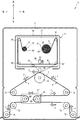
図1〜図3を参照して、第一〜第三実施形態の印刷装置1に共通する物理的構成を説明する。印刷装置1は、熱転写型の印刷装置である。印刷装置1は、非図示の印刷媒体搬送装置と同期して駆動される。印刷媒体搬送装置は、長尺状の印刷媒体8を所定の搬送速度で方向Z(本例では、全体として概して左方)に搬送する。印刷媒体8は、例えば、食品を収納する袋となるフィルム状の包装材であり、印刷装置1は、例えば、所定の間隔で賞味期限を表す文字列を印刷媒体8に印刷する。   A physical configuration common to the printing apparatuses 1 of the first to third embodiments will be described with reference to FIGS. The printing apparatus 1 is a thermal transfer type printing apparatus. The printing apparatus 1 is driven in synchronization with a print medium transport apparatus (not shown). The print medium transport device transports the long print medium 8 in the direction Z (in this example, generally leftward as a whole) at a predetermined transport speed. The print medium 8 is, for example, a film-like packaging material that serves as a bag for storing food, and the printing apparatus 1 prints a character string representing the expiration date on the print medium 8 at predetermined intervals, for example.

図1〜図3に示すように、印刷装置1は、印刷機構11、プラテンローラ14、ガイド15、ガイドモータ13、及び制御部7を備える。印刷装置1の各部材は、板状のフレーム5に支持される。印刷機構11は、長尺状の印刷媒体8(例えば、包装材)に画像を印刷可能である。印刷機構11は、第一装着部21、第二装着部22、サーマルヘッド23、供給モータ81、及び巻取モータ82を備える。第一装着部21及び第二装着部22は各々前後方向に延びる軸である。第一装着部21は、インクリボン9が巻回された第一ロール31を装着可能である。第二装着部22は、第一ロール31から繰り出されたインクリボン9が巻き取られる第二ロール32を装着可能である。サーマルヘッド23は、第一装着部21から繰り出されてから、第二装着部22で巻き取られるまでのインクリボン9の搬送経路である経路Rに隣接し、複数の加熱素子が前後方向に配列される。供給モータ81は、第一装着部21を回転させる。巻取モータ82は、第二装着部22を回転させる。   As illustrated in FIGS. 1 to 3, the printing apparatus 1 includes a printing mechanism 11, a platen roller 14, a guide 15, a guide motor 13, and a control unit 7. Each member of the printing apparatus 1 is supported by a plate-like frame 5. The printing mechanism 11 can print an image on a long print medium 8 (for example, a packaging material). The printing mechanism 11 includes a first mounting unit 21, a second mounting unit 22, a thermal head 23, a supply motor 81, and a winding motor 82. The first mounting part 21 and the second mounting part 22 are axes extending in the front-rear direction. The first mounting portion 21 can mount the first roll 31 around which the ink ribbon 9 is wound. The second mounting part 22 can mount a second roll 32 on which the ink ribbon 9 fed out from the first roll 31 is wound. The thermal head 23 is adjacent to a path R that is a transport path of the ink ribbon 9 from the time when the thermal head 23 is drawn out from the first mounting portion 21 until the thermal head 23 is wound up by the second mounting portion 22, and a plurality of heating elements are arranged in the front-rear direction. Is done. The supply motor 81 rotates the first mounting part 21. The winding motor 82 rotates the second mounting portion 22.

プラテンローラ14は、経路Rに対して、サーマルヘッド23とは反対側に配置され、サーマルヘッド23に対向する。ガイド15は、少なくとも一部が印刷媒体8と当接し、印刷媒体8の搬送経路である経路Pを変更可能である。ガイド15は、第一方向に移動することで、第一速度を第二速度よりも大きくする。第一速度は、印刷媒体8がプラテンローラ14に接触する位置での印刷媒体8の移動速度(以下、印刷位置速度Wpともいう。)である。第二速度は、ガイド15に対してプラテンローラ14とは反対側の経路Pにおける位置での印刷媒体8の移動速度(以下、搬送位置速度Wtともいう。)である。ガイド15は、第一方向とは反対側の第二方向に移動することで、第一速度を第二速度よりも小さくする。ガイドモータ13は、ステップモータであり、ガイドモータ13の回転方向に応じて、ガイド15を第一方向又は第二方向に移動する。制御部7は、サーマルヘッド23、巻取モータ82、ガイドモータ13の各々を制御可能である。以下、印刷装置1が備える各部材について詳述する。   The platen roller 14 is arranged on the opposite side of the path R from the thermal head 23 and faces the thermal head 23. The guide 15 is at least partially in contact with the print medium 8 and can change the path P that is the transport path of the print medium 8. The guide 15 moves in the first direction to make the first speed larger than the second speed. The first speed is a moving speed of the printing medium 8 at a position where the printing medium 8 contacts the platen roller 14 (hereinafter also referred to as a printing position speed Wp). The second speed is a moving speed of the printing medium 8 at a position in the path P opposite to the platen roller 14 with respect to the guide 15 (hereinafter also referred to as a transport position speed Wt). The guide 15 moves in the second direction opposite to the first direction, thereby making the first speed smaller than the second speed. The guide motor 13 is a step motor and moves the guide 15 in the first direction or the second direction according to the rotation direction of the guide motor 13. The control unit 7 can control each of the thermal head 23, the winding motor 82, and the guide motor 13. Hereinafter, each member with which the printing apparatus 1 is provided is explained in full detail.

<印刷機構11>
印刷機構11は、筐体10、ベースプレート17、ガイド軸61〜65、及び移動モータ83を更に備える。筐体10は箱状であり、内部にベースプレート17を設ける。ベースプレート17は、矩形状の金属板で構成される。ベースプレート17は、第一装着部21、第二装着部22、サーマルヘッド23、巻取モータ82、ガイド軸61〜65、供給モータ81、巻取モータ82、及び移動モータ83を支持する。
<Printing mechanism 11>
The printing mechanism 11 further includes a housing 10, a base plate 17, guide shafts 61 to 65, and a moving motor 83. The housing 10 has a box shape, and a base plate 17 is provided inside. The base plate 17 is composed of a rectangular metal plate. The base plate 17 supports the first mounting portion 21, the second mounting portion 22, the thermal head 23, the winding motor 82, the guide shafts 61 to 65, the supply motor 81, the winding motor 82, and the moving motor 83.

ベースプレート17は、第一装着部21及び第二装着部22をベースプレート17の前面に回動可能に支持する。第一ロール31は、円筒状の芯軸41の孔を第一装着部21に挿通させることにより、取り外し可能に第一装着部21に装着される。第二ロール32は、円筒状の芯軸42の孔を第二装着部22に挿通させることにより、取り外し可能に第一装着部21に装着される。即ち、第一装着部21及び第二装着部22は、回転可能にベースプレート17に保持されるスピンドルである。   The base plate 17 rotatably supports the first mounting portion 21 and the second mounting portion 22 on the front surface of the base plate 17. The first roll 31 is detachably mounted on the first mounting portion 21 by inserting a hole in the cylindrical core shaft 41 through the first mounting portion 21. The second roll 32 is detachably mounted on the first mounting portion 21 by inserting a hole in the cylindrical core shaft 42 through the second mounting portion 22. That is, the first mounting portion 21 and the second mounting portion 22 are spindles that are rotatably held by the base plate 17.

インクリボン9はインク層と基材とを含み、帯状である。基材は、例えばポリエチレンテレフタラート(PET)で形成される。インク層は、例えば、カーボンなどの色素成分と、ワックス及び/又はレジンなどのバインダー成分とを含む。インクリボン9は、インク層がサーマルヘッド23の位置において印刷媒体8側となる姿勢で搬送される。インク層は加熱により溶融し、印刷媒体8に転写される。インクリボン9は、必要に応じて、バックコート層、剥離層、及び接着層などの機能層を有してもよい。インクリボン9は、一端部が芯軸41の側面に接続され、他端部が芯軸42の側面に接続される。   The ink ribbon 9 includes an ink layer and a base material and has a strip shape. The substrate is made of, for example, polyethylene terephthalate (PET). The ink layer includes, for example, a pigment component such as carbon and a binder component such as wax and / or resin. The ink ribbon 9 is conveyed in such a posture that the ink layer is on the print medium 8 side at the position of the thermal head 23. The ink layer is melted by heating and transferred to the printing medium 8. The ink ribbon 9 may have functional layers such as a back coat layer, a release layer, and an adhesive layer as necessary. The ink ribbon 9 has one end connected to the side surface of the core shaft 41 and the other end connected to the side surface of the core shaft 42.

ガイド軸61〜65はインクリボン9の搬送経路である経路Rを規定する。ガイド軸61〜65は、各々円柱状であり、ベースプレート17の前面から前側に向けて延びる。ガイド軸61〜65は、例えば、前後方向に延びる回転軸を中心として回転可能なローラである。ガイド軸61〜65は各々自身の周面の一部にインクリボン9のインク層とは反対側の面が接触する。インクリボン9は、各ガイド軸61〜65に案内されて搬送される。ガイド軸61は、ベースプレート17の右上の隅近傍に設けられる。ガイド軸62は、ベースプレート17の右下の隅近傍に設けられる。ガイド軸63は、ベースプレート17の下方且つ左右方向の中心よりもやや左方に設けられる。ガイド軸64は、ベースプレート17の左下の隅近傍に設けられる。ガイド軸65は、ベースプレート17の左上の隅近傍に設けられる。経路Rについては後述する。   The guide shafts 61 to 65 define a path R that is a transport path of the ink ribbon 9. Each of the guide shafts 61 to 65 has a cylindrical shape and extends from the front surface of the base plate 17 toward the front side. For example, the guide shafts 61 to 65 are rollers that can rotate around a rotation shaft extending in the front-rear direction. Each of the guide shafts 61 to 65 comes into contact with a part of the peripheral surface of the guide shaft 61 to 65 on the side opposite to the ink layer of the ink ribbon 9. The ink ribbon 9 is guided by the guide shafts 61 to 65 and conveyed. The guide shaft 61 is provided near the upper right corner of the base plate 17. The guide shaft 62 is provided near the lower right corner of the base plate 17. The guide shaft 63 is provided below the base plate 17 and slightly to the left of the center in the left-right direction. The guide shaft 64 is provided near the lower left corner of the base plate 17. The guide shaft 65 is provided near the upper left corner of the base plate 17. The route R will be described later.

供給モータ81は、第一装着部21を回転させる。供給モータ81及び巻取モータ82は、例えば、ステップモータである。第一装着部21は供給モータ81の出力軸に直結する。即ち、第一装着部21の回転軸は、供給モータ81の出力軸と同一直線上に位置する。供給モータ81の回転量は、第一装着部21の回転量に等しい。第二装着部22の回転軸は巻取モータ82の出力軸に直結する。即ち、第二装着部22の回転軸は、巻取モータ82の出力軸と同一直線上に位置する。巻取モータ82の回転量は、第二装着部22の回転量に等しい。第一装着部21及び第二装着部22は、各々異なるモータによって回転されるので、各々異なる回転速度で回転可能である。制御部7は、供給モータ81と、巻取モータ82とを制御可能である。   The supply motor 81 rotates the first mounting part 21. The supply motor 81 and the winding motor 82 are step motors, for example. The first mounting portion 21 is directly connected to the output shaft of the supply motor 81. That is, the rotation shaft of the first mounting portion 21 is located on the same straight line as the output shaft of the supply motor 81. The rotation amount of the supply motor 81 is equal to the rotation amount of the first mounting portion 21. The rotating shaft of the second mounting portion 22 is directly connected to the output shaft of the winding motor 82. That is, the rotation shaft of the second mounting portion 22 is located on the same straight line as the output shaft of the winding motor 82. The rotation amount of the winding motor 82 is equal to the rotation amount of the second mounting portion 22. Since the first mounting part 21 and the second mounting part 22 are rotated by different motors, they can be rotated at different rotational speeds. The control unit 7 can control the supply motor 81 and the winding motor 82.

インクリボン9が第一ロール31から繰り出されて第二ロール32に巻き取られる場合の、芯軸41及び芯軸42の各々の回転方向を、「正転方向」という。正転方向と反対方向を「反転方向」という。芯軸41及び芯軸42の各々が反転方向に回転された場合、インクリボン9は、第二ロール32から繰り出されて第一ロール31に巻き取られる。本例の芯軸41、42の正転方向及び反転方向は各々、図1における反時計回り及び時計回りである。芯軸41、42の正転方向は、時計回り方向に限定されない。例えば、インクリボン9の巻回状態に応じて、第一ロール31及び第二ロール32の正転方向は、少なくとも一方が時計回り方向であってもよい。   The rotation direction of each of the core shaft 41 and the core shaft 42 when the ink ribbon 9 is unwound from the first roll 31 and wound around the second roll 32 is referred to as “forward rotation direction”. The direction opposite to the forward direction is referred to as the “reverse direction”. When each of the core shaft 41 and the core shaft 42 is rotated in the reverse direction, the ink ribbon 9 is unwound from the second roll 32 and wound around the first roll 31. The forward rotation direction and the reverse rotation direction of the core shafts 41 and 42 in this example are respectively counterclockwise and clockwise in FIG. The forward rotation direction of the core shafts 41 and 42 is not limited to the clockwise direction. For example, according to the winding state of the ink ribbon 9, at least one of the first roll 31 and the second roll 32 may be the clockwise direction.

サーマルヘッド23は、前後方向においてベースプレート17の前面よりも前側に設けられる。サーマルヘッド23は、ベースプレート17の左右方向略中央、且つ、第一装着部21及び第二装着部22よりも下側に設けられる。サーマルヘッド23は、前後方向に直線状に並んだ複数の発熱素子を有するラインサーマルヘッドである。サーマルヘッド23は、経路Rに隣接する。インクリボン9が経路Rに沿って搬送される場合、サーマルヘッド23は、インクリボン9に隣接する。印刷装置1を用いて印刷を行う場合、サーマルヘッド23は、移動モータ83を駆動力として、ラック・ピニオンなどを有する非図示のヘッド保持機構によって、印刷位置3Aと待機位置3Bとの間を上下方向に移動可能である。印刷位置3Aは、サーマルヘッド23とプラテンローラ14との間に印刷媒体8が配置されていない状態で、サーマルヘッド23の下端部がプラテンローラ14に接する位置である。サーマルヘッド23とプラテンローラ14との間に印刷媒体8が配置されている場合、印刷位置3Aに位置するサーマルヘッド23は、インクリボン9及び印刷媒体8を挟んでプラテンローラ14に接触する。待機位置3Bは、サーマルヘッド23の下端部がプラテンローラ14から離隔し、左右方向に延びるインクリボン9に接触又は近接する位置である。   The thermal head 23 is provided in front of the front surface of the base plate 17 in the front-rear direction. The thermal head 23 is provided approximately at the center in the left-right direction of the base plate 17 and below the first mounting portion 21 and the second mounting portion 22. The thermal head 23 is a line thermal head having a plurality of heating elements arranged linearly in the front-rear direction. The thermal head 23 is adjacent to the path R. When the ink ribbon 9 is transported along the path R, the thermal head 23 is adjacent to the ink ribbon 9. When printing using the printing apparatus 1, the thermal head 23 moves up and down between the printing position 3 </ b> A and the standby position 3 </ b> B by a head holding mechanism (not shown) having a rack and pinion using the moving motor 83 as a driving force. It can move in the direction. The printing position 3 </ b> A is a position where the lower end portion of the thermal head 23 is in contact with the platen roller 14 in a state where the printing medium 8 is not disposed between the thermal head 23 and the platen roller 14. When the print medium 8 is disposed between the thermal head 23 and the platen roller 14, the thermal head 23 positioned at the printing position 3 </ b> A contacts the platen roller 14 with the ink ribbon 9 and the print medium 8 interposed therebetween. The standby position 3B is a position where the lower end portion of the thermal head 23 is separated from the platen roller 14 and contacts or approaches the ink ribbon 9 extending in the left-right direction.

<プラテンローラ14>
プラテンローラ14は、フレーム5の上下方向及び左右方向のそれぞれの略中心に設けられる。プラテンローラ14は、前後方向に延びる回転軸を中心として回転可能である。プラテンローラ14は、印刷位置3Aに配置されたサーマルヘッド23の下側に対向する。プラテンローラ14は、サーマルヘッド23が印刷位置3Aに移動することに応じ、サーマルヘッド23に印刷媒体8を押し付ける。プラテンローラ14は、経路Rを間にしてサーマルヘッド23及び印刷機構11の下方に配置される。
<Platen roller 14>
The platen roller 14 is provided at approximately the center of each of the vertical and horizontal directions of the frame 5. The platen roller 14 can rotate around a rotation axis extending in the front-rear direction. The platen roller 14 faces the lower side of the thermal head 23 arranged at the printing position 3A. The platen roller 14 presses the print medium 8 against the thermal head 23 in response to the thermal head 23 moving to the printing position 3A. The platen roller 14 is disposed below the thermal head 23 and the printing mechanism 11 with the path R therebetween.

<インクリボン9の搬送経路R>
第一装着部21と第二装着部22の回転に応じ、第一ロール31と第二ロール32との間に張り渡されるインクリボン9は、筐体10内で搬送される。経路Rは、サーマルヘッド23、及びガイド軸61〜65に沿ってインクリボン9が搬送されるときに通過する経路である。
<Conveying path R of ink ribbon 9>
The ink ribbon 9 that is stretched between the first roll 31 and the second roll 32 in accordance with the rotation of the first mounting portion 21 and the second mounting portion 22 is conveyed in the housing 10. The path R is a path through which the ink ribbon 9 is transported along the thermal head 23 and the guide shafts 61 to 65.

図1中実線で示すように、サーマルヘッド23が待機位置3Bに配置された場合、インクリボン9の経路Rは、第一装着部21から右上に向けて延び、ガイド軸61に接触して方向を変え、ガイド軸62に向けて下方に延びる。経路Rは、ガイド軸62に接触して方向を変え、ガイド軸64に向けて左方に延びる。経路Rは、ガイド軸62と、ガイド軸64との間で、サーマルヘッド23の下端部に接触又は近接し、ガイド軸63の上端部に接触又は近接する。経路Rは、ガイド軸64に接触して方向を変え、ガイド軸65に向けて上方に延びる。経路Rは、ガイド軸65に接触して方向を変え、第二装着部22に向けて右下に向けて延びる。第一装着部21及び第二装着部22が回転することに応じ、インクリボン9は、ガイド軸62とガイド軸64との間を左右方向に移動する。   As indicated by the solid line in FIG. 1, when the thermal head 23 is disposed at the standby position 3 </ b> B, the path R of the ink ribbon 9 extends from the first mounting portion 21 toward the upper right and contacts the guide shaft 61. And extends downward toward the guide shaft 62. The path R contacts the guide shaft 62 and changes its direction, and extends to the left toward the guide shaft 64. The path R is in contact with or close to the lower end portion of the thermal head 23 and is in contact with or close to the upper end portion of the guide shaft 63 between the guide shaft 62 and the guide shaft 64. The path R changes its direction by contacting the guide shaft 64 and extends upward toward the guide shaft 65. The path R contacts the guide shaft 65 and changes its direction, and extends toward the lower right toward the second mounting portion 22. In response to the rotation of the first mounting portion 21 and the second mounting portion 22, the ink ribbon 9 moves between the guide shaft 62 and the guide shaft 64 in the left-right direction.

サーマルヘッド23が印刷位置3Aに配置された場合、インクリボン9の経路Rは、サーマルヘッド23が待機位置3Bに配置された場合に比べ、ガイド軸62とガイド軸64との間において変更される。図1中点線で示すように、サーマルヘッド23が印刷位置3Aに配置された場合のインクリボン9の経路Rは、ガイド軸62から左側に向けて延び、サーマルヘッド23の下端部に接触して方向を変え、ガイド軸63に向けて左斜め上側に延びる。経路Rは、ガイド軸63に接触して方向を変え、ガイド軸64に向けて左方に延びる。第一装着部21及び第二装着部22が回転することに応じ、インクリボン9は、ガイド軸62とサーマルヘッド23との間を左右方向に移動する。   When the thermal head 23 is disposed at the printing position 3A, the path R of the ink ribbon 9 is changed between the guide shaft 62 and the guide shaft 64 as compared with the case where the thermal head 23 is disposed at the standby position 3B. . As indicated by the dotted line in FIG. 1, the path R of the ink ribbon 9 when the thermal head 23 is disposed at the printing position 3A extends from the guide shaft 62 toward the left side and contacts the lower end of the thermal head 23. The direction is changed, and it extends obliquely upward to the left toward the guide shaft 63. The path R changes the direction in contact with the guide shaft 63 and extends to the left toward the guide shaft 64. In response to the rotation of the first mounting portion 21 and the second mounting portion 22, the ink ribbon 9 moves between the guide shaft 62 and the thermal head 23 in the left-right direction.

印刷位置3Aと待機位置3Bとの間を移動するサーマルヘッド23は、図1中点線で示す、サーマルヘッド23が待機位置3Bに配置された時のインクリボン9の経路Rと交差する。即ち、サーマルヘッド23が経路Rに隣接するとは、印刷位置3Aと待機位置3Bとの間を移動するサーマルヘッド23の移動経路と、経路Rとが交わることを意味する。サーマルヘッド23は、第一ロール31と第二ロール32との間に張り渡されるインクリボン9に隣接して配置される。第一ロール31及び第二ロール32を印刷装置1に着脱する場合、サーマルヘッド23は、待機位置3Bよりも上側の図示略の退避位置に移動される。以上のように、サーマルヘッド23は、第一ロール31と第二ロール32とが、第一装着部21及び第二装着部22に装着されているか否かに関わらず、常に経路Rに隣接しているといえる。   The thermal head 23 moving between the printing position 3A and the standby position 3B intersects the path R of the ink ribbon 9 when the thermal head 23 is disposed at the standby position 3B, which is indicated by a dotted line in FIG. That is, the fact that the thermal head 23 is adjacent to the path R means that the path R intersects the movement path of the thermal head 23 that moves between the printing position 3A and the standby position 3B. The thermal head 23 is disposed adjacent to the ink ribbon 9 that is stretched between the first roll 31 and the second roll 32. When the first roll 31 and the second roll 32 are attached to and detached from the printing apparatus 1, the thermal head 23 is moved to a retracted position (not shown) above the standby position 3B. As described above, the thermal head 23 is always adjacent to the path R regardless of whether the first roll 31 and the second roll 32 are mounted on the first mounting portion 21 and the second mounting portion 22. It can be said that.

<ガイド15及びガイドモータ13>
ガイド15は、プラテンローラ14よりも下側に配置される。ガイド15はプラテンローラ14に対して第一方向及び第二方向に移動可能である。本例の第一方向及び第二方向は各々、左方及び右方である。ガイド15は、支持板67、ガイドローラ68、及び69有する。支持板67は左右方向に長い矩形状の板である。支持板67は前面にガイドローラ68、69を回転可能に支持する。支持板67は非図示のガイドレールに第一方向及び第二方向の各々に移動可能に支持される。ガイドローラ68、69はそれぞれ、前後方向に延びる回転軸を中心として回転可能な円筒状のローラである。ガイドローラ68、69は、左右方向に並ぶ。ガイド15は、ガイドモータ13の一方への回転に応じて第一方向に移動し、他方への回転に応じて第二方向に移動する。ガイドモータ13の回転は、伝達機構(図示略)によって、ガイド15の第一方向、及び第二方向への並進運動に変換される。伝達機構としては、例えば、ボールネジ、ラック・ピニオン、タイミングベルト・プーリー等が適宜利用可能である。
<Guide 15 and guide motor 13>
The guide 15 is disposed below the platen roller 14. The guide 15 is movable in the first direction and the second direction with respect to the platen roller 14. The first direction and the second direction in this example are leftward and rightward, respectively. The guide 15 includes a support plate 67 and guide rollers 68 and 69. The support plate 67 is a rectangular plate that is long in the left-right direction. The support plate 67 rotatably supports the guide rollers 68 and 69 on the front surface. The support plate 67 is supported by a guide rail (not shown) so as to be movable in each of the first direction and the second direction. Each of the guide rollers 68 and 69 is a cylindrical roller that can rotate around a rotation axis extending in the front-rear direction. The guide rollers 68 and 69 are arranged in the left-right direction. The guide 15 moves in the first direction in response to rotation of the guide motor 13 in one direction, and moves in the second direction in response to rotation in the other direction. The rotation of the guide motor 13 is converted into a translational motion of the guide 15 in the first direction and the second direction by a transmission mechanism (not shown). As the transmission mechanism, for example, a ball screw, a rack and pinion, a timing belt and a pulley can be used as appropriate.

支持板67は、ガイドモータ13の駆動に応じて、ガイドレールに沿って第一方向又は第二方向に移動する。図2においてM(0)はガイド15の移動範囲の中心を示し、M(m)及びM(−m)は、ガイド15の移動範囲の左端及び右端を示す。ガイド15のガイドローラ68、69は、ガイドモータ13の回転に応じて一体的に、図2に示す位置M(m)から位置M(−m)の範囲で、第一方向及び第二方向に移動できる。   The support plate 67 moves in the first direction or the second direction along the guide rail in accordance with the drive of the guide motor 13. In FIG. 2, M (0) indicates the center of the moving range of the guide 15, and M (m) and M (−m) indicate the left end and the right end of the moving range of the guide 15. The guide rollers 68 and 69 of the guide 15 are integrated in the first direction and the second direction within the range from the position M (m) to the position M (−m) shown in FIG. 2 according to the rotation of the guide motor 13. Can move.

<ガイドローラ71〜76>
本例の印刷装置1は、更にガイドローラ71〜76備える。ガイドローラ71〜76は印刷媒体搬送装置に設けられてもよい。ガイドローラ71〜76は、印刷媒体8の搬送経路である経路P(後述)を規定する。図1に示すように、各ガイドローラ71〜76は、前後方向に延びる回転軸を中心として回転可能である。各ガイドローラ71〜76の径は、互いに同一又は略同一である。ガイドローラ71〜73は、左右方向においてプラテンローラ14よりも右側に配置される。ガイドローラ72、73のそれぞれの左右方向の位置は略同一である。ガイドローラ71は、左右方向においてガイドローラ72、73よりも右側に配置される。ガイドローラ74〜76は、左右方向においてプラテンローラ14よりも左側に配置される。ガイドローラ74、75のそれぞれの左右方向の位置は略同一である。ガイドローラ76は、左右方向においてガイドローラ74、75よりも左側に配置される。ガイドローラ73、74は、上下方向においてガイド15よりも上側に配置される。ガイドローラ73、74の上下方向の位置は略同一である。ガイドローラ71、72、75、76は、上下方向においてガイド15よりも下側に配置される。ガイドローラ71、76の上下方向の位置は略同一である。ガイドローラ72、75の上下方向の位置は略同一である。ガイドローラ71は、ガイドローラ72の右斜め下側に配置される。ガイドローラ76は、ガイドローラ75の左斜め下側に配置される。
<Guide rollers 71-76>
The printing apparatus 1 of this example further includes guide rollers 71 to 76. The guide rollers 71 to 76 may be provided in the print medium conveyance device. The guide rollers 71 to 76 define a path P (described later) that is a transport path of the print medium 8. As shown in FIG. 1, each guide roller 71 to 76 can rotate around a rotation axis extending in the front-rear direction. The diameters of the guide rollers 71 to 76 are the same or substantially the same. The guide rollers 71 to 73 are disposed on the right side of the platen roller 14 in the left-right direction. The left and right positions of the guide rollers 72 and 73 are substantially the same. The guide roller 71 is disposed on the right side of the guide rollers 72 and 73 in the left-right direction. The guide rollers 74 to 76 are disposed on the left side of the platen roller 14 in the left-right direction. The left and right positions of the guide rollers 74 and 75 are substantially the same. The guide roller 76 is disposed on the left side of the guide rollers 74 and 75 in the left-right direction. The guide rollers 73 and 74 are disposed above the guide 15 in the vertical direction. The vertical positions of the guide rollers 73 and 74 are substantially the same. The guide rollers 71, 72, 75, and 76 are disposed below the guide 15 in the vertical direction. The vertical positions of the guide rollers 71 and 76 are substantially the same. The vertical positions of the guide rollers 72 and 75 are substantially the same. The guide roller 71 is disposed on the lower right side of the guide roller 72. The guide roller 76 is disposed on the lower left side of the guide roller 75.

図3(B)に示すように、ガイド15がM(m)に配置された状態で、ガイドローラ68の中心は、左右方向においてガイドローラ74、75のそれぞれの中心よりも右側に配置される。図3(C)に示すように、ガイド15がM(−m)に配置された状態で、ガイドローラ69の中心は、左右方向においてガイドローラ72、73のそれぞれの中心よりも左側に配置される。   As shown in FIG. 3B, in the state where the guide 15 is disposed at M (m), the center of the guide roller 68 is disposed on the right side of the respective centers of the guide rollers 74 and 75 in the left-right direction. . As shown in FIG. 3C, the center of the guide roller 69 is arranged on the left side of the center of each of the guide rollers 72 and 73 in the left-right direction in the state where the guide 15 is arranged at M (−m). The

<印刷媒体8の搬送経路P>
図1に示すように、印刷媒体8は、プラテンローラ14、ガイド15のガイドローラ68、69、及びガイドローラ71〜76の間に張り渡され、搬送される。プラテンローラ14、ガイド15のガイドローラ68、69、及びガイドローラ71〜76に沿って印刷媒体8が搬送されるときに通過する経路を、「経路P」という。印刷媒体8の経路Pは、ガイドローラ71、72、69、73、プラテンローラ14、ガイドローラ74、68、75、76のそれぞれに順番に接触して方向を変えながら延びる。印刷媒体8は、非図示の印刷媒体搬送装置によって、経路Pに沿ってガイドローラ71からガイドローラ76に向けて移動する向き(方向Z)に搬送される。
<Conveyance path P of print medium 8>
As shown in FIG. 1, the print medium 8 is stretched between the platen roller 14, the guide rollers 68 and 69 of the guide 15, and the guide rollers 71 to 76 and is conveyed. A path through which the print medium 8 is conveyed along the platen roller 14, the guide rollers 68 and 69 of the guide 15, and the guide rollers 71 to 76 is referred to as “path P”. The path P of the print medium 8 extends while contacting the guide rollers 71, 72, 69, and 73, the platen roller 14, and the guide rollers 74, 68, 75, and 76 in order and changing the direction. The print medium 8 is conveyed in a direction (direction Z) in which the print medium 8 moves from the guide roller 71 toward the guide roller 76 along the path P by a print medium conveyance device (not shown).

ガイドローラ71〜73、及びガイド15のガイドローラ69は、経路Pに沿った方向においてプラテンローラ14よりも上流に配置される。ガイドローラ74〜76、及びガイド15のガイドローラ68は、経路Pに沿った方向においてプラテンローラ14よりも下流に配置される。ガイド15は、上下方向において、プラテンローラ14に対して印刷機構11側(つまり、上方)とは反対側(つまり、下方)に設けられる。   The guide rollers 71 to 73 and the guide roller 69 of the guide 15 are disposed upstream of the platen roller 14 in the direction along the path P. The guide rollers 74 to 76 and the guide roller 68 of the guide 15 are disposed downstream of the platen roller 14 in the direction along the path P. The guide 15 is provided on the opposite side (that is, the lower side) from the printing mechanism 11 side (that is, the upper side) with respect to the platen roller 14 in the vertical direction.

<ガイド15による印刷位置速度の調整>
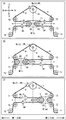
ガイド15は、印刷媒体搬送装置によって略等速で搬送されている印刷媒体8の印刷位置速度(第一速度)Wpを、ガイド15を第一方向又は第二方向に移動している期間、ガイド15の移動方向に応じて、変更することが可能である。ガイド15は、第一方向への移動に伴いプラテンローラ14よりも上流側の経路Pの長さを移動開始時の長さよりも長くし、第二方向への移動に伴いプラテンローラ14よりも上流側の経路Pの長さを移動開始時の長さよりも短くする。搬送位置速度(第二速度)Wtは、印刷媒体搬送装置による印刷媒体8の搬送速度に対応する。搬送位置速度Wtは、例えば、ガイドローラ71、72、75、76に接触する位置での移動速度に対応する。図2(A)に示すように、ガイド15が停止した状態における印刷位置速度Wp(n)は、搬送位置速度Wtと一致する。
<Adjustment of printing position speed with guide 15>
The guide 15 guides the printing position speed (first speed) Wp of the printing medium 8 being conveyed at a substantially constant speed by the printing medium conveying apparatus during the period in which the guide 15 is moved in the first direction or the second direction. It is possible to change according to the 15 moving directions. As the guide 15 moves in the first direction, the length of the path P on the upstream side of the platen roller 14 becomes longer than the length at the start of movement, and the guide 15 moves upstream of the platen roller 14 as the second direction moves. The length of the path P on the side is made shorter than the length at the start of movement. The transport position speed (second speed) Wt corresponds to the transport speed of the print medium 8 by the print medium transport apparatus. The conveyance position speed Wt corresponds to, for example, the movement speed at positions where the guide rollers 71, 72, 75, and 76 are in contact with each other. As shown in FIG. 2A, the printing position speed Wp (n) when the guide 15 is stopped coincides with the transport position speed Wt.

図2(B)に示すように、図2(A)に示すガイド15が移動可能範囲の中心M(0)からガイド15が第一方向(左方)に移動した場合、プラテンローラ14よりも下流側(左側)の経路Pは図2(A)に示す移動前に比べ短くなる。プラテンローラ14よりも上流側(右側)の経路Pは図2(A)に示す移動前に比べ長くなる。ガイド15が第一方向に移動している期間、ガイドローラ69、73、プラテンローラ14、ガイドローラ74、68の間の印刷媒体8は、ガイド15の移動量に応じて上流側に引っ張られる。故に、ガイド15が第一方向に移動している期間の印刷位置速度Wp(s)は、搬送位置速度Wtよりも遅くなる。プラテンローラ14よりも上流側の経路Pの長さは、移動開始時に比べ、ガイドローラ72と73との間で、ガイド15の移動量の2倍だけ長くなる。   As shown in FIG. 2 (B), when the guide 15 shown in FIG. 2 (A) moves in the first direction (leftward) from the center M (0) of the movable range, the guide 15 moves more than the platen roller 14. The downstream (left side) path P is shorter than before the movement shown in FIG. The path P on the upstream side (right side) of the platen roller 14 is longer than before the movement shown in FIG. While the guide 15 is moving in the first direction, the print medium 8 between the guide rollers 69 and 73, the platen roller 14, and the guide rollers 74 and 68 is pulled upstream according to the amount of movement of the guide 15. Therefore, the printing position speed Wp (s) during the period in which the guide 15 is moving in the first direction is slower than the transport position speed Wt. The length of the path P on the upstream side of the platen roller 14 is longer by twice the amount of movement of the guide 15 between the guide rollers 72 and 73 than at the start of movement.

図2(C)に示すように、図2(A)に示すガイド15が移動可能範囲の中心M(0)からガイド15が第二方向(右方)に移動した場合、プラテンローラ14よりも下流側(左側)の経路Pは図2(A)に示す移動前に比べ長くなる。プラテンローラ14よりも上流側(右側)の経路Pは図2(A)に示す移動前に比べ短くなる。ガイド15が第二方向に移動している期間、ガイドローラ69、73、プラテンローラ14、ガイドローラ74、68の間の印刷媒体8は、ガイド15の移動量に応じて下流側に引っ張られる。故に、ガイド15が第一方向に移動している期間の印刷位置速度Wp(f)は、搬送位置速度Wtよりも速くなる。プラテンローラ14よりも上流側の経路Pの長さは、移動開始時に比べ、ガイドローラ72と73との間で、ガイド15の移動量の2倍だけ短くなる。   As shown in FIG. 2 (C), when the guide 15 shown in FIG. 2 (A) moves in the second direction (rightward) from the center M (0) of the movable range, the guide 15 moves more than the platen roller 14. The downstream (left side) path P is longer than before the movement shown in FIG. The path P on the upstream side (right side) of the platen roller 14 is shorter than before the movement shown in FIG. While the guide 15 is moving in the second direction, the print medium 8 between the guide rollers 69 and 73, the platen roller 14, and the guide rollers 74 and 68 is pulled downstream according to the amount of movement of the guide 15. Therefore, the printing position speed Wp (f) during the period in which the guide 15 is moving in the first direction is faster than the transport position speed Wt. The length of the path P on the upstream side of the platen roller 14 is shorter by twice the amount of movement of the guide 15 between the guide rollers 72 and 73 than at the start of movement.

ガイド15が第一方向(左方)に移動している期間、印刷位置速度Wp(s)は搬送位置速度Wtよりも小さい。これに対し、ガイド15が第二方向(右方)に移動している期間、印刷位置速度Wp(f)は搬送位置速度Wtよりも大きい。搬送位置速度Wtが一定である場合には、ガイド15が第一方向(左方)に移動している期間、印刷位置速度Wp(s)はガイド15の停止時の印刷位置速度Wp(n)よりも小さく、ガイド15が第二方向(右方)に移動している期間、印刷位置速度Wp(f)はガイド15の停止時の印刷位置速度Wp(n)よりも大きい。   During the period in which the guide 15 is moving in the first direction (leftward), the printing position speed Wp (s) is smaller than the transport position speed Wt. In contrast, during the period in which the guide 15 is moving in the second direction (rightward), the printing position speed Wp (f) is greater than the transport position speed Wt. When the transport position speed Wt is constant, the printing position speed Wp (s) is the printing position speed Wp (n) when the guide 15 is stopped while the guide 15 is moving in the first direction (leftward). The printing position speed Wp (f) is larger than the printing position speed Wp (n) when the guide 15 is stopped during the period when the guide 15 is moving in the second direction (rightward).

<印刷装置1の電気的構成>
図3を参照し、第一〜第三実施形態に共通する印刷装置1の電気的構成について説明する。印刷装置1は制御部7、記憶部6、サーマルヘッド23、供給モータ81、巻取モータ82、ガイドモータ13、移動モータ83、センサ55、57、及び通信インターフェース(通信I/F)60を備える。制御部7は、印刷装置1を制御するハードウェアプロセッサ(例えば、CPU)と、ハードウェアプロセッサの指示に応じて動作する各種の駆動回路とを含む。各種の駆動回路は、例えば、供給モータ81、巻取モータ82、ガイドモータ13、移動モータ83に信号(例えば、駆動電流としてのパルス信号)を供給するための回路、サーマルヘッド23に信号(例えば、駆動電流)を供給するための回路、及びセンサ55、57を駆動すると共に受信した出力信号のA/D変換を行うための回路などを含む。制御部7は、記憶部6、サーマルヘッド23、供給モータ81、巻取モータ82、ガイドモータ13、移動モータ83、センサ55、57、及び通信I/F60と電気的に接続する。
<Electrical Configuration of Printing Apparatus 1>
With reference to FIG. 3, the electrical configuration of the printing apparatus 1 common to the first to third embodiments will be described. The printing apparatus 1 includes a control unit 7, a storage unit 6, a thermal head 23, a supply motor 81, a winding motor 82, a guide motor 13, a moving motor 83, sensors 55 and 57, and a communication interface (communication I / F) 60. . The control unit 7 includes a hardware processor (for example, CPU) that controls the printing apparatus 1 and various drive circuits that operate in accordance with instructions from the hardware processor. The various drive circuits include, for example, a circuit for supplying a signal (for example, a pulse signal as a drive current) to the supply motor 81, the take-up motor 82, the guide motor 13, and the moving motor 83, and a signal (for example, the thermal head 23). , A driving current) circuit, a circuit for driving the sensors 55 and 57 and A / D conversion of the received output signal. The control unit 7 is electrically connected to the storage unit 6, the thermal head 23, the supply motor 81, the winding motor 82, the guide motor 13, the moving motor 83, the sensors 55 and 57, and the communication I / F 60.

記憶部6は、ROM、RAM、フラッシュメモリ等の各種記憶媒体を含む。記憶部6には、制御部7が後述の印刷制御処理を実行するための指示を含む印刷プログラムが記憶される。記憶部6には更に、印刷装置1を駆動させるための各種設定値が記憶されている。各種設定値は、後述する印刷データ、印刷設定情報、インクリボン9の全長、インクリボン9の初期径、及びガイドモータ13の駆動量とガイド15の移動量との対応等を含む。各種設定値は、供給モータ81の駆動量と、巻取モータ82の駆動量と、インクリボン9の搬送速度との対応を記憶する。設定値は、印刷装置1の操作部(図示略)を介して受け付けたユーザ入力によって設定されてもよい。   The storage unit 6 includes various storage media such as a ROM, a RAM, and a flash memory. The storage unit 6 stores a print program including an instruction for the control unit 7 to execute a print control process described later. The storage unit 6 further stores various setting values for driving the printing apparatus 1. The various set values include print data, print setting information, the total length of the ink ribbon 9, the initial diameter of the ink ribbon 9, the correspondence between the driving amount of the guide motor 13 and the moving amount of the guide 15, and the like. The various set values store correspondences between the drive amount of the supply motor 81, the drive amount of the take-up motor 82, and the conveyance speed of the ink ribbon 9. The set value may be set by a user input received via an operation unit (not shown) of the printing apparatus 1.

サーマルヘッド23の複数の発熱素子の各々は、制御部7から出力される信号に応じて選択的に発熱する。供給モータ81は、制御部7から出力されるパルス信号に応じて、第一装着部21を回転させる。巻取モータ82は、制御部7から出力されるパルス信号に応じて、第二装着部22を回転させる。ガイドモータ13は、制御部7から出力されるパルス信号に応じて、ガイド15を第一方向又は第二方向に移動させる。移動モータ83は、制御部7から出力されるパルス信号に応じて回転し、サーマルヘッド23を、印刷位置3A(図1参照)、待機位置3B(図1参照)、及び図示略の退避位置の間で移動させる。   Each of the plurality of heating elements of the thermal head 23 selectively generates heat according to a signal output from the control unit 7. The supply motor 81 rotates the first mounting unit 21 in accordance with the pulse signal output from the control unit 7. The winding motor 82 rotates the second mounting unit 22 in accordance with the pulse signal output from the control unit 7. The guide motor 13 moves the guide 15 in the first direction or the second direction according to the pulse signal output from the control unit 7. The moving motor 83 rotates in accordance with the pulse signal output from the control unit 7, and moves the thermal head 23 at the printing position 3A (see FIG. 1), the standby position 3B (see FIG. 1), and a retracted position (not shown). Move between.

センサ55は、ガイド軸65とインクリボン9との間に働く摩擦力によって、インクリボン9の搬送に追随して回転可能に構成される。センサ55は、例えば、ガイド軸65と一体に回転する永久磁石と、ベースプレート17に設けられたホール素子などの磁気センサとで構成される。磁気センサが検出する永久磁石からの磁力に基づいて、ガイド軸65の回転量が検知される。回転量を時間で割ることで、回転速度が特定される。ガイド軸65の径は既知のため、ガイド軸65の回転量又は回転速度から、インクリボン9の搬送量又は搬送速度が特定される。センサ55から出力されるセンサ信号は、例えば、インクリボン9の搬送速度のフィードバック制御に利用可能である。センサ57は、ガイド15の位置を表す信号を制御部7に入力する。センサ57は、例えば、上下方向においてガイド15と同じ位置でフレーム5に設けられた、リニアエンコーダ及びリミットスイッチ等であってよい。通信I/F60は、印刷装置1に接続される外部機器150との間で通信を行なうための、所定の標準規格(例えば、USB(Universal Serial Bus),LVDS(Low Voltage Differential Signaling),Ethernet(登録商標),Wi−Fi)に準拠したインターフェース素子である。外部機器150は、ユーザが印刷装置1に対して様々な指示を行うために使用される端末機器及び、前記した印刷媒体搬送装置である。   The sensor 55 is configured to be able to rotate following the conveyance of the ink ribbon 9 by a frictional force acting between the guide shaft 65 and the ink ribbon 9. The sensor 55 includes, for example, a permanent magnet that rotates integrally with the guide shaft 65 and a magnetic sensor such as a Hall element provided on the base plate 17. Based on the magnetic force from the permanent magnet detected by the magnetic sensor, the rotation amount of the guide shaft 65 is detected. The rotation speed is specified by dividing the rotation amount by time. Since the diameter of the guide shaft 65 is known, the transport amount or transport speed of the ink ribbon 9 is specified from the rotation amount or rotation speed of the guide shaft 65. The sensor signal output from the sensor 55 can be used for feedback control of the conveyance speed of the ink ribbon 9, for example. The sensor 57 inputs a signal indicating the position of the guide 15 to the control unit 7. The sensor 57 may be, for example, a linear encoder and a limit switch provided on the frame 5 at the same position as the guide 15 in the vertical direction. The communication I / F 60 is a predetermined standard (for example, USB (Universal Serial Bus), LVDS (Low Voltage Differential Signaling), Ethernet (for example) for performing communication with the external device 150 connected to the printing apparatus 1. (Registered trademark) and Wi-Fi). The external device 150 is a terminal device used for a user to give various instructions to the printing apparatus 1 and the above-described print medium transport device.

制御部7によって実行されるプログラムは、例えば、外部機器150から通信I/F60を介してダウンロードされてもよい。制御部7は、通信I/F60を介して外部機器150から取得したプログラムを、記憶部6に記憶してもよい。記憶部6に記憶される各種情報は、外部機器150を介して変更可能としてもよい。   The program executed by the control unit 7 may be downloaded from the external device 150 via the communication I / F 60, for example. The control unit 7 may store the program acquired from the external device 150 via the communication I / F 60 in the storage unit 6. Various types of information stored in the storage unit 6 may be changeable via the external device 150.

<印刷制御処理>
印刷装置1は、インクリボン9の加速期間及び減速期間の和に対する、一定速度で搬送される期間を大きくすることで、インクリボン9の未使用領域を減らし、且つ、従来よりも高速な印刷に対応可能である。インクリボン9の加速期間は、インクリボン9の搬送が停止されている状態から、インクリボン9の搬送方向への搬送を開始し、印刷時の速度である一定速度に達するまでの期間である。インクリボン9が搬送方向に搬送される場合、第一装着部21及び第二装着部22は、正転方向に回転される。インクリボン9の減速期間は、インクリボン9を一定速度で搬送方向に搬送後にインクリボン9の搬送を停止するまでの期間である。一定速度は、厳密に一定の速度である必要はなく、一定とみなせる範囲の速度であればよい。印刷制御処理が実行されている間、印刷媒体8は、印刷媒体搬送装置によって所定速度で搬送方向に搬送される。
<Print control processing>
The printing apparatus 1 reduces the unused area of the ink ribbon 9 by increasing the period during which the ink ribbon 9 is transported at a constant speed with respect to the sum of the acceleration period and the deceleration period of the ink ribbon 9, and enables faster printing than before. It is possible. The acceleration period of the ink ribbon 9 is a period from when the conveyance of the ink ribbon 9 is stopped to when the ink ribbon 9 starts to be conveyed in the conveyance direction and reaches a constant speed that is the speed at the time of printing. When the ink ribbon 9 is transported in the transport direction, the first mounting portion 21 and the second mounting portion 22 are rotated in the forward rotation direction. The deceleration period of the ink ribbon 9 is a period from when the ink ribbon 9 is conveyed in the conveyance direction at a constant speed until the conveyance of the ink ribbon 9 is stopped. The constant speed does not need to be a strictly constant speed, and may be a speed within a range that can be regarded as constant. While the print control process is being executed, the print medium 8 is transported in the transport direction at a predetermined speed by the print medium transport device.

図4〜図6を参照して、印刷装置1が実行する第一実施形態の印刷制御処理を、図4に示す具体例を用いて説明する。図4の左右方向及び上下方向は各々、インクリボン9の長さ方向及び幅方向である。図4において、白で示す領域は、未使用領域を示し、斜線の網掛けで示す領域は、使用済領域を示す。具体例では、印刷装置1は、インクリボン9内の矩形状の領域91〜103を使用して印刷を実行する。インクリボン9の長さ方向における領域91〜103の長さは、印刷媒体8に印刷される画像の長さLと等しい。画像の大きさ及び形状等は適宜変更されてよい。インクリボン9の長さ方向における隣合う領域の間隔は各々Mである。印刷制御処理を実行するための指示を含む印刷プログラムは記憶部6に記憶されている。制御部7は、印刷装置1の起動後、印刷プログラムを記憶部6のRAM上で展開し、以下の処理を実行する。   With reference to FIGS. 4 to 6, the print control process of the first embodiment executed by the printing apparatus 1 will be described using a specific example shown in FIG. 4. 4 are the length direction and the width direction of the ink ribbon 9, respectively. In FIG. 4, a white area indicates an unused area, and a hatched area indicates a used area. In the specific example, the printing apparatus 1 executes printing using the rectangular areas 91 to 103 in the ink ribbon 9. The lengths of the regions 91 to 103 in the length direction of the ink ribbon 9 are equal to the length L of the image printed on the print medium 8. The size and shape of the image may be changed as appropriate. The interval between adjacent regions in the length direction of the ink ribbon 9 is M. A print program including an instruction for executing the print control process is stored in the storage unit 6. After starting the printing apparatus 1, the control unit 7 develops a print program on the RAM of the storage unit 6 and executes the following processing.

図5に示すように、制御部7は、各種設定を行う(S1)。制御部7は、例えば、印刷データを取得し、Y、Nを設定する。Yは、インクリボン9が搬送方向に連続して搬送される条件の下での、印刷順序が前後する使用済み領域間に、配置される領域の数である。Yは、以下の式(1)を満たす自然数であればよい。本例のYは2である。
Y≦Lf/(L+M) ・・・式(1)
式(1)において、Lfは、次の印刷までの非印刷時間を使って搬送できるインクリボン9の長さである。Lfは以下の式(2)で計算される。
Lf=(Ta−Tb―Tc/N)*Vr ・・・式(2)
式(2)において、Taはガイド15が移動されない条件での印刷処理が実行される時間間隔である。Tbは、ガイド15が移動されない条件での一の画像を印刷するのに要する時間である。Tcは、ガイド15を第二方向に移動させることにより印刷媒体8を所定量搬送するのに要する時間の短縮量である。Vrは、インクリボン9を搬送方向及び戻し方向に搬送する場合の最大速度である。戻し方向は、搬送方向の反対の方向である。
As shown in FIG. 5, the control unit 7 performs various settings (S1). For example, the control unit 7 acquires print data and sets Y and N. Y is the number of regions arranged between the used regions whose printing order is fluctuated under the condition that the ink ribbon 9 is continuously conveyed in the conveyance direction. Y should just be a natural number which satisfy | fills the following formula | equation (1). Y in this example is 2.
Y ≦ Lf / (L + M) (1)
In Expression (1), Lf is the length of the ink ribbon 9 that can be conveyed using the non-printing time until the next printing. Lf is calculated by the following equation (2).
Lf = (Ta−Tb−Tc / N) * Vr (2)
In Expression (2), Ta is a time interval at which the printing process is executed under the condition that the guide 15 is not moved. Tb is the time required to print one image under the condition that the guide 15 is not moved. Tc is a reduction amount of time required for transporting the print medium 8 by a predetermined amount by moving the guide 15 in the second direction. Vr is the maximum speed when the ink ribbon 9 is transported in the transport direction and the return direction. The return direction is the direction opposite to the transport direction.

Nは、一定速度で搬送中に、連続して印刷される画像の数である。Nは、以下の式(3)を満たす2以上の整数であればよい。Nが1である場合には、インクリボン9を戻し方向に搬送する処理が実行されないようにする処理を追加してもよい。本例のNは3である。
N≦Lb/((Y+1)*(L+M))+1 ・・・式(3)
式(3)のLbは、ガイド15を第一方向に最大量(M(−m)の位置からM(m)の位置までの長さ)移動させた期間に、インクリボン9を戻し方向に搬送できる長さである。Lbは以下の式(4)で計算される。
Lb=(Ta−Tb+Td)*Vr ・・・式(4)
式(4)において、Tdは、ガイド15を第一方向に移動させることにより印刷媒体8を所定量搬送するのに要する時間の延長量である。
N is the number of images printed continuously during conveyance at a constant speed. N should just be an integer greater than or equal to 2 which satisfy | fills the following formula | equation (3). When N is 1, a process for preventing the process of transporting the ink ribbon 9 in the return direction from being executed may be added. N in this example is 3.
N ≦ Lb / ((Y + 1) * (L + M)) + 1 Expression (3)
Lb in Expression (3) indicates that the ink ribbon 9 is moved in the return direction during the period in which the guide 15 is moved in the first direction by the maximum amount (the length from the position of M (−m) to the position of M (m)). It is the length that can be transported. Lb is calculated by the following formula (4).
Lb = (Ta−Tb + Td) * Vr (4)
In Expression (4), Td is an extension amount of time required to transport the print medium 8 by a predetermined amount by moving the guide 15 in the first direction.

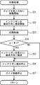
制御部7は、印刷準備を行う(S2)。制御部7は例えば、ガイド15を初期位置に移動する。ガイド15の初期位置は、例えば、ガイド15がM(m)にある位置である。S1で制御部7はインクリボン9の径を取得する。制御部7は、記憶部6が記憶するサーマルヘッド23、ガイド15の位置等の初期値を初期化する。   The control unit 7 prepares for printing (S2). For example, the control unit 7 moves the guide 15 to the initial position. The initial position of the guide 15 is, for example, a position where the guide 15 is at M (m). In S <b> 1, the control unit 7 acquires the diameter of the ink ribbon 9. The control unit 7 initializes initial values such as the positions of the thermal head 23 and the guide 15 stored in the storage unit 6.

制御部7は、変数iに0を設定する(S3)。変数iは、Yに関する変数である。図4の領域91〜103内に記載した、0〜2の数字は、変数iの値に対応する。制御部7は、変数jに0を設定する(S4)。変数jは、Nに関する変数である。制御部7は、印刷処理を実行する(S5)。図6に示すように、制御部7は、ガイドモータ13を制御して、ガイド15を第二方向への移動を開始する(S21)。ガイド15が第二方向に移動されると、印刷媒体8の搬送速度は速度Wp(f)になる。制御部7は、インクリボン9の搬送方向への搬送を開始する(S22)。インクリボン9は、加速後、一定速度で搬送される。制御部7は、移動モータ83を制御して、サーマルヘッド23を印刷位置3Aへ移動する。制御部7は、S1で取得した印刷データに従って、サーマルヘッド23の加熱と、供給モータ81と巻取モータ82とを制御して、画像を印刷する印刷制御を実行する(S23)。具体例では、図4(A)の領域91を用いて、画像が印刷される。制御部7は、変数jが(N−1)よりも小さいかを判断する(S24)。図4(A)に示す具体例では変数jは0であり、2よりも小さい(S24:YES)。この場合、制御部7は、印刷装置1は、非印刷期間に、供給モータ81及び巻取モータ82を制御して、インクリボン9を、印刷媒体8の搬送方向に、第一長さL1搬送する(S25)。非印刷期間は、一の画像が印刷された後、次の画像が印刷されるまでの期間である。第一長さL1は、画像の搬送方向の長さLよりも長い。本例の第一長さL1は、非印刷期間と、画像の搬送方向の長さとに基づいて決定される。第一長さL1は、予め設定されていてもよいし、印刷条件に応じて印刷制御処理が実行される毎に計算されてもよい。第一長さL1はユーザが設定してもよい。本例の第一長さL1は、下記の式(5)で表される。
第一長さL1=Y*(L+M)+M ・・・式(5)
Mはインクリボン9の長さ方向における、隣合う領域間の距離である。
The control unit 7 sets 0 to the variable i (S3). The variable i is a variable related to Y. The numbers 0 to 2 described in the areas 91 to 103 in FIG. 4 correspond to the value of the variable i. The control unit 7 sets 0 to the variable j (S4). The variable j is a variable related to N. The controller 7 executes a printing process (S5). As shown in FIG. 6, the control unit 7 controls the guide motor 13 to start moving the guide 15 in the second direction (S21). When the guide 15 is moved in the second direction, the conveyance speed of the print medium 8 becomes the speed Wp (f). The controller 7 starts transporting the ink ribbon 9 in the transport direction (S22). The ink ribbon 9 is conveyed at a constant speed after acceleration. The control unit 7 controls the moving motor 83 to move the thermal head 23 to the printing position 3A. The controller 7 controls the heating of the thermal head 23, the supply motor 81, and the take-up motor 82 in accordance with the print data acquired in S1, and executes print control for printing an image (S23). In a specific example, an image is printed using the area 91 in FIG. The control unit 7 determines whether the variable j is smaller than (N−1) (S24). In the specific example shown in FIG. 4A, the variable j is 0 and is smaller than 2 (S24: YES). In this case, the control unit 7 controls the supply motor 81 and the take-up motor 82 during the non-printing period so that the ink ribbon 9 is transported in the transport direction of the print medium 8 by the first length L1. (S25). The non-printing period is a period from when one image is printed until the next image is printed. The first length L1 is longer than the length L in the image conveyance direction. The first length L1 in this example is determined based on the non-printing period and the length in the image conveyance direction. The first length L1 may be set in advance or may be calculated every time the print control process is executed according to the printing conditions. The user may set the first length L1. The first length L1 of this example is represented by the following formula (5).
First length L1 = Y * (L + M) + M (5)
M is the distance between adjacent regions in the length direction of the ink ribbon 9.

変数jが(N−1)よりも小さくはない場合(S24:NO)、又はS25の処理の次に、制御部7は、供給モータ81及び巻取モータ82を制御して、インクリボン9の搬送を停止する(S26)。インクリボン9は、減速後、停止する。制御部7は、ガイド15の移動を停止する(S27)。ガイド15の移動停止によって、印刷媒体8の搬送速度は、印刷媒体搬送装置が搬送する速度Wtとなる。制御部7は以上で印刷処理を終了し、図5の印刷制御処理に戻る。S21の処理とS27の処理とは、ガイド15の初期位置が、ガイド15がM(−m)にある位置である条件で、変数iが0の場合は省略されてよい。   When the variable j is not smaller than (N−1) (S24: NO), or after the processing of S25, the control unit 7 controls the supply motor 81 and the take-up motor 82 to control the ink ribbon 9. The conveyance is stopped (S26). The ink ribbon 9 stops after decelerating. The control unit 7 stops the movement of the guide 15 (S27). As the guide 15 stops moving, the transport speed of the print medium 8 becomes the speed Wt transported by the print medium transport device. The control unit 7 ends the printing process as described above, and returns to the printing control process of FIG. The process of S21 and the process of S27 may be omitted when the initial position of the guide 15 is a position where the guide 15 is at M (−m) and the variable i is 0.

S5の処理の次に、制御部7は、変数jを1だけインクリメントする(S6)。制御部7は、変数jが、Nと等しいかを判断する(S7)。変数jが1の時、Nよりも小さい(S7:NO)。この場合制御部7は、処理をS5に戻す。変数jが1である時のS5の処理において、図4(B)に示すように領域94を使用した印刷制御が実行される(S23)。変数jが2である時のS5の処理において、図4(C)に示すように領域97を使用した印刷制御が実行され(S23)、変数jは(N−1)と等しいと判断され(S24:NO)、S25の処理が実行されない。この場合、S5の後のS7の処理において、変数jがNと等しい場合(S7:YES)、制御部7は、変数iを1だけインクリメントする(S8)。変数jがNと等しい場合は、インクリボン9の搬送方向への搬送を開始した後、連続してN回の印刷制御が終了した場合である。   Following the processing of S5, the control unit 7 increments the variable j by 1 (S6). The control unit 7 determines whether the variable j is equal to N (S7). When the variable j is 1, it is smaller than N (S7: NO). In this case, the control unit 7 returns the process to S5. In the process of S5 when the variable j is 1, print control using the area 94 is executed as shown in FIG. 4B (S23). In the process of S5 when the variable j is 2, the print control using the area 97 is executed as shown in FIG. 4C (S23), and it is determined that the variable j is equal to (N−1) ( S24: NO), the process of S25 is not executed. In this case, when the variable j is equal to N in the processing of S7 after S5 (S7: YES), the control unit 7 increments the variable i by 1 (S8). The case where the variable j is equal to N is a case where N times of printing control are continuously completed after the conveyance of the ink ribbon 9 in the conveyance direction is started.

制御部7は、変数iが(Y+1)と等しいかを判断する(S9)。S9の処理では、搬送方向においてインクリボン9の隣合う使用済領域の間隔の内、第一長さL1よりも大きくなる間隔があるかを判断する処理である。図4(C)に示す状態である場合、変数iが1であり、変数iは(Y+1)よりも小さい(S9:NO)。この場合制御部7は、移動モータ83を制御して、サーマルヘッド23を印刷位置3Aから待機位置3Bに移動させた後、ガイドモータ13を制御して、ガイド15を第一方向に移動させる処置を開始する(S10)。ガイド15が第一方向に移動されると、印刷媒体8の搬送速度が速度Wp(s)になる。制御部7は、次に印刷するまでの非印刷期間に、供給モータ81及び巻取モータ82を制御して、インクリボン9を、搬送方向とは反対の戻し方向へ、第一長さL1よりも長い第二長さL2搬送する(S11)。第二長さL2は、次の印刷で使用される領域と、該領域と搬送方向下流側(図4における左方)に隣接する一の使用済領域との距離を第一長さL1よりも小さくする長さである。第二長さL2は、予め設定されていてもよいし、印刷条件に応じて印刷制御処理が実行される毎に計算されてもよい。第二長さL2はユーザが設定してもよい。   The control unit 7 determines whether the variable i is equal to (Y + 1) (S9). The process of S9 is a process of determining whether there is an interval that is larger than the first length L1 among the intervals between the adjacent used regions of the ink ribbon 9 in the transport direction. In the state shown in FIG. 4C, the variable i is 1, and the variable i is smaller than (Y + 1) (S9: NO). In this case, the control unit 7 controls the moving motor 83 to move the thermal head 23 from the printing position 3A to the standby position 3B, and then controls the guide motor 13 to move the guide 15 in the first direction. Is started (S10). When the guide 15 is moved in the first direction, the conveyance speed of the print medium 8 becomes the speed Wp (s). The control unit 7 controls the supply motor 81 and the take-up motor 82 during the non-printing period until the next printing, and moves the ink ribbon 9 in the return direction opposite to the transport direction from the first length L1. Also, the second long length L2 is conveyed (S11). The second length L2 is a distance between an area used in the next printing and one used area adjacent to the area and the downstream side in the transport direction (left side in FIG. 4) than the first length L1. The length to be reduced. The second length L2 may be set in advance or may be calculated every time the print control process is executed according to the printing conditions. The user may set the second length L2.

具体例の第二長さL2は、以下の式(6)によって表される。
第二長さL2=(N−1)*(Y+1)*(L+M)−M+Q ・・・式(6)
式(6)において、Qは、インクリボン9を搬送方向に搬送する場合の加速期間及び減速期間に搬送される長さである。制御部7は、図4(C)に示すように、変数iが0であり、変数jが2の場合に、領域97を使用して印刷後、インクリボン9の搬送方向への搬送を停止し、図4(D)に示すように、第二長さL2だけ、インクリボン9を戻し方向へ搬送する。次の印刷で使用される領域92と、該領域92と搬送方向下流側に隣接する一の使用済領域91との距離はMであり第一長さL1よりも小さい。制御部7は、ガイドモータ13を制御して、ガイド15の移動を停止させる(S12)。S10、S12の処理によって制御部7は、S11の処理が実行されている間に、ガイド15を第一方向に移動する。制御部7は、S11の処理が開始された後、S11の処理が終了される前までに、ガイド15を第一方向に移動してもよい。制御部7は処理をS4に戻す。S12の後のS5では変数図4(D)に示すように、インクリボン9の領域92を使用した印刷制御が実行され(S23)、図4(E)に示すように、インクリボン9が搬送方向に第一長さL1搬送される、次のS5の処理で、インクリボン9の領域95を使用した印刷制御が実行される(S23)。
The second length L2 of the specific example is represented by the following formula (6).
Second length L2 = (N−1) * (Y + 1) * (L + M) −M + Q (6)
In Expression (6), Q is a length that is transported during the acceleration period and the deceleration period when the ink ribbon 9 is transported in the transport direction. As shown in FIG. 4C, when the variable i is 0 and the variable j is 2, the control unit 7 uses the region 97 to stop the conveyance of the ink ribbon 9 in the conveyance direction. Then, as shown in FIG. 4D, the ink ribbon 9 is conveyed in the return direction by the second length L2. The distance between the area 92 used in the next printing and the used area 91 adjacent to the area 92 on the downstream side in the transport direction is M, which is smaller than the first length L1. The control unit 7 controls the guide motor 13 to stop the movement of the guide 15 (S12). The control unit 7 moves the guide 15 in the first direction while the process of S11 is being executed by the processes of S10 and S12. The controller 7 may move the guide 15 in the first direction after the process of S11 is started and before the process of S11 is completed. The control unit 7 returns the process to S4. In S5 after S12, printing control using the region 92 of the ink ribbon 9 is executed as shown in the variable FIG. 4D (S23), and the ink ribbon 9 is conveyed as shown in FIG. 4E. Printing control using the region 95 of the ink ribbon 9 is executed in the next processing of S5, which is transported in the direction by the first length L1 (S23).

繰り返し実行されるS5において、図4(F)に示すように、領域99を使用して印刷が実行されると(S23)、その後のS9の処理では変数iが(Y+1)と等しいと判断される(S9:YES)。この場合制御部7は、処理をS3に戻し、第二長さL2戻し方向に搬送する処理(S10〜S12)は実行しない。変数iが(Y+1)と等しいと判断された後のS5の処理では、図4(G)のように、制御部7は、インクリボン9を搬送方向にMだけ搬送した後、領域100を使用して印刷する(S23)。以上の処理を、印刷制御処理を終了する指示が取得されるまで実行されることで、インクリボン9の搬送方向において、使用済領域が第一長さL1よりも短い間隔Mで配置されるように、印刷が実行される。   In S5 that is repeatedly executed, as shown in FIG. 4F, when printing is performed using the region 99 (S23), it is determined in the subsequent processing of S9 that the variable i is equal to (Y + 1). (S9: YES). In this case, the control unit 7 returns the process to S3 and does not execute the processes (S10 to S12) for conveying in the return direction of the second length L2. In the process of S5 after it is determined that the variable i is equal to (Y + 1), as shown in FIG. 4G, the control unit 7 uses the region 100 after conveying the ink ribbon 9 by M in the conveyance direction. And printing (S23). By executing the above process until an instruction to end the print control process is acquired, the used areas are arranged at intervals M shorter than the first length L1 in the transport direction of the ink ribbon 9. Then, printing is executed.

図7及び図8を参照して、印刷装置1が実行する第二、第三実施形態の印刷制御処理を順に説明する。第二、第三実施形態の印刷制御処理は各々、図5のS5の処理が第一実施形態の印刷制御処理と異なり、他の処理は同じである。第二実施形態の印刷制御処理では、図7の印刷処理が実行され、第三実施形態の印刷制御処理では、図8の印刷処理が実行される。第二、第三実施形態の印刷制御処理は、ガイド15の第二方向への移動を開始及び停止するタイミングにおいて、第一実施形態の印刷制御処理と相違する。図7及び図8において、第一実施形態の印刷処理と同様の処理には同じステップ番号を付与している。第二実施形態及び第三実施形態の印刷制御処理を実行するための指示を含む印刷プログラムは記憶部6に記憶されている。制御部7は、印刷装置1の起動後、印刷プログラムを記憶部6のRAM上で展開し、以下の処理を実行する。   With reference to FIGS. 7 and 8, the print control processing of the second and third embodiments executed by the printing apparatus 1 will be described in order. In the print control processes of the second and third embodiments, the process of S5 in FIG. 5 is different from the print control process of the first embodiment, and the other processes are the same. In the print control process of the second embodiment, the print process of FIG. 7 is executed, and in the print control process of the third embodiment, the print process of FIG. 8 is executed. The print control process of the second and third embodiments is different from the print control process of the first embodiment at the timing of starting and stopping the movement of the guide 15 in the second direction. 7 and 8, the same step number is assigned to the same process as the print process of the first embodiment. A print program including an instruction for executing the print control process of the second embodiment and the third embodiment is stored in the storage unit 6. After starting the printing apparatus 1, the control unit 7 develops a print program on the RAM of the storage unit 6 and executes the following processing.

図7に示すように、第二実施形態の印刷処理では、制御部7は、第一実施形態と同様のS22〜S24を実行する。変数jが(N−1)よりも小さい場合(S24:YES)、制御部7は、ガイドモータ13を制御してガイド15を第二方向への移動を開始する(S28)。制御部7は、非印刷期間に、供給モータ81及び巻取モータ82を制御して、インクリボン9を、印刷媒体8の搬送方向に、第一長さL1搬送する(S25)。制御部7は、ガイドモータ13を制御してガイド15を第二方向への移動を停止する(S29)。
変数jが(N−1)よりも小さくはない場合(S24:NO)、又はS29の処理の次に、制御部7は第一実施形態と同様のS26の処理を実行する(S26)。
As shown in FIG. 7, in the printing process of the second embodiment, the control unit 7 executes S22 to S24 similar to those of the first embodiment. When the variable j is smaller than (N-1) (S24: YES), the control unit 7 controls the guide motor 13 to start moving the guide 15 in the second direction (S28). The control unit 7 controls the supply motor 81 and the take-up motor 82 during the non-printing period to transport the ink ribbon 9 in the transport direction of the print medium 8 for the first length L1 (S25). The controller 7 controls the guide motor 13 to stop the movement of the guide 15 in the second direction (S29).
When the variable j is not smaller than (N−1) (S24: NO), or after the process of S29, the control unit 7 executes the process of S26 similar to the first embodiment (S26).

図8に示すように、第三実施形態の印刷処理では、制御部7は、第一実施形態と同様のS21〜S23を実行する。制御部7は、ガイドモータ13を制御してガイド15を第二方向への移動を停止する(S30)。制御部7は、第一実施形態と同様のS24〜S26を実行する。   As shown in FIG. 8, in the printing process of the third embodiment, the control unit 7 executes S21 to S23 similar to those of the first embodiment. The control unit 7 controls the guide motor 13 to stop the movement of the guide 15 in the second direction (S30). The control part 7 performs S24-S26 similar to 1st embodiment.

上記第一〜第三実施形態の印刷装置1において、第一装着部21、第二装着部22、サーマルヘッド23、プラテンローラ14、ガイド15、ガイドモータ13、及び制御部7は各々、本発明の第一装着部、第二装着部、サーマルヘッド、プラテン、ガイド、第二モータ及び制御部の一例である。供給モータ81及び巻取モータ82は、本発明の第一モータの一例である。S23の処理を実行する制御部7は、本発明の印刷制御手段の一例であり、S23の処理は、印刷制御ステップの一例である。S25の処理を実行する制御部7は、本発明の第一搬送制御手段の一例であり、S25の処理は、第一搬送制御ステップの一例である。S11の処理を実行する制御部7は、本発明の第二搬送制御手段の一例であり、S11の処理は、本発明の第二搬送ステップの一例である。S10、S12の処理を実行する制御部7は、本発明の第一移動制御手段の一例であり、S10、S12の処理は、本発明の移動制御ステップの一例である。S21、S27の処理、S28、S29の処理、S21、S30の処理を実行する制御部7は、本発明の第二移動制御手段の一例である。S24の処理を実行する制御部7は、判断手段の一例である。   In the printing apparatus 1 according to the first to third embodiments, the first mounting unit 21, the second mounting unit 22, the thermal head 23, the platen roller 14, the guide 15, the guide motor 13, and the control unit 7 are each included in the present invention. It is an example of a 1st mounting part, a 2nd mounting part, a thermal head, a platen, a guide, a 2nd motor, and a control part. The supply motor 81 and the take-up motor 82 are examples of the first motor of the present invention. The control unit 7 that executes the process of S23 is an example of a print control unit of the present invention, and the process of S23 is an example of a print control step. The control unit 7 that executes the process of S25 is an example of a first transport control unit of the present invention, and the process of S25 is an example of a first transport control step. The controller 7 that executes the process of S11 is an example of the second transport control means of the present invention, and the process of S11 is an example of the second transport step of the present invention. The control unit 7 that executes the processes of S10 and S12 is an example of the first movement control means of the present invention, and the processes of S10 and S12 are an example of the movement control step of the present invention. The control unit 7 that executes the processes of S21 and S27, the processes of S28 and S29, and the processes of S21 and S30 is an example of the second movement control means of the present invention. The control unit 7 that executes the process of S24 is an example of a determination unit.

上記印刷装置1は、印刷媒体8の搬送方向において複数の画像を、画像間の距離がインクリボン9の使用済領域間の長さが第一長さL1となるように印刷した後、まとめて第二長さL2巻き戻す。印刷装置1は、画像を印刷する毎にインクリボン9を巻き戻す場合に比べ、インクリボン9の加速及び減速の期間に対する、一定速度期間を大きくできる。印刷装置1は、インクリボン9の未使用領域を減らし、且つ、従来の印刷装置1に比べ非印刷期間の短い高速印刷に対応する。   The printing apparatus 1 collectively prints a plurality of images in the conveyance direction of the print medium 8 so that the distance between the images is the length between the used regions of the ink ribbon 9 is the first length L1. Rewind the second length L2. The printing apparatus 1 can increase the constant speed period with respect to the acceleration and deceleration periods of the ink ribbon 9 as compared with the case where the ink ribbon 9 is rewound each time an image is printed. The printing apparatus 1 reduces the unused area of the ink ribbon 9 and supports high-speed printing with a shorter non-printing period than the conventional printing apparatus 1.

制御部7は、インクリボン9が搬送方向に搬送されている期間に、ガイドモータ13を制御して、ガイド15を第二方向に移動させる。故に印刷装置1は、ガイドモータ13の動力でガイド15の位置を第二方向に移動できる。   The control unit 7 controls the guide motor 13 to move the guide 15 in the second direction while the ink ribbon 9 is being conveyed in the conveyance direction. Therefore, the printing apparatus 1 can move the position of the guide 15 in the second direction by the power of the guide motor 13.

第二実施形態の印刷装置1では、制御部7は、インクリボン9が搬送方向に搬送されている期間に、ガイドモータ13を制御して、ガイド15を第二方向に移動させ、印刷されている期間にはガイドモータ13を制御せず、ガイド15を移動させない。印刷装置は、印刷時に印刷媒体の速度を加速させた場合、印刷媒体が一定速度で搬送する場合に比べ、解像度を劣化させる可能性がある。印刷装置1は、印刷時にはガイド15を第二方向に移動させないので、印刷媒体が一定速度で搬送されないことに起因して解像度を劣化させる可能性を低減できる。   In the printing apparatus 1 according to the second embodiment, the control unit 7 controls the guide motor 13 to move the guide 15 in the second direction during the period in which the ink ribbon 9 is being conveyed in the conveyance direction. During this period, the guide motor 13 is not controlled and the guide 15 is not moved. In the printing apparatus, when the speed of the printing medium is accelerated at the time of printing, there is a possibility that the resolution is deteriorated as compared with the case where the printing medium is conveyed at a constant speed. Since the printing apparatus 1 does not move the guide 15 in the second direction during printing, it is possible to reduce the possibility that the resolution is deteriorated due to the printing medium not being conveyed at a constant speed.

第三実施形態の印刷装置1では、制御部7は、印刷が実行されている期間に、ガイドモータ13を制御して、ガイド15を第二方向に移動させ、インクリボン9が搬送されている期間にはガイドモータ13を制御せず、ガイド15を移動させない。印刷装置1は、インクリボン9が搬送されている時にガイド15を第二方向に移動した場合、ガイド15を第二方向に移動しない場合に比べ、インクリボン9が搬送されるのに要する時間が短くなる。印刷装置1は、非印刷期間にインクリボン9が搬送方向に搬送されている時には、ガイド15を移動させない。故に、印刷装置1は、非印刷期間のガイド15の駆動時間が短くならないので、非印刷期間に比較的長い距離インクリボン9を搬送できる。   In the printing apparatus 1 according to the third embodiment, the control unit 7 controls the guide motor 13 to move the guide 15 in the second direction and the ink ribbon 9 is transported during the printing period. During the period, the guide motor 13 is not controlled and the guide 15 is not moved. In the printing apparatus 1, when the guide 15 is moved in the second direction when the ink ribbon 9 is being conveyed, the time required for the ink ribbon 9 to be conveyed is longer than when the guide 15 is not moved in the second direction. Shorter. The printing apparatus 1 does not move the guide 15 when the ink ribbon 9 is being conveyed in the conveyance direction during the non-printing period. Therefore, since the driving time of the guide 15 during the non-printing period is not shortened, the printing apparatus 1 can transport the ink ribbon 9 for a relatively long distance during the non-printing period.

印刷装置1の制御部7は、搬送方向においてインクリボン9の隣合う使用済領域の間隔の内、第一長さL1よりも大きくなる間隔があるかを判断する(S24)。制御部7は、第一長さよりも大きくなる間隔があると判断された場合に(S24:NO)、第二長さL2戻し方向に搬送しない。故に印刷装置1は、第二長さL2戻し方向に搬送することが適切でない場合に、第二長さL2戻し方向に搬送する処理を自動で省略できる。   The control unit 7 of the printing apparatus 1 determines whether there is an interval that is larger than the first length L1 among the intervals between the adjacent used regions of the ink ribbon 9 in the transport direction (S24). When it is determined that there is an interval larger than the first length (S24: NO), the control unit 7 does not convey the second length L2 in the return direction. Therefore, the printing apparatus 1 can automatically omit the process of transporting in the second length L2 return direction when it is not appropriate to transport in the second length L2 return direction.

第一長さL1は、非印刷期間と、画像の搬送方向の長さとに基づいて決定される。故に、印刷装置1は、非印刷期間と、画像の搬送方向の長さとに基づき、第一長さL1を決定できる。   The first length L1 is determined based on the non-printing period and the length in the image conveyance direction. Therefore, the printing apparatus 1 can determine the first length L1 based on the non-printing period and the length in the image conveyance direction.

S11の処理でインクリボン9が戻し方向に搬送されてから、次にインクリボン9が戻し方向に搬送されるまでの期間に、複数回S25の処理を実行し、インクリボン9を搬送方向に第一長さL1搬送する。印刷装置1は、印刷媒体8の搬送方向において複数個の画像を、画像間の距離がインクリボン9の使用済領域間の長さが第一長さL1となるように印刷した後、まとめて第二長さL2巻き戻す。印刷装置は、画像を印刷する毎にインクリボン9を巻き戻す場合に比べ、インクリボン9の加速及び減速の期間に対する、一定速度期間を大きくできる。印刷装置は、従来の印刷装置に比べ非印刷期間の短い高速印刷に対応する。   In the period from when the ink ribbon 9 is transported in the return direction in the process of S11 until the next time the ink ribbon 9 is transported in the return direction, the process of S25 is executed a plurality of times, and the ink ribbon 9 is moved in the transport direction. Transport one length L1. The printing apparatus 1 collectively prints a plurality of images in the conveyance direction of the print medium 8 so that the distance between the images is the length between the used regions of the ink ribbon 9 is the first length L1. Rewind the second length L2. The printing apparatus can increase the constant speed period with respect to the acceleration and deceleration periods of the ink ribbon 9 as compared with the case where the ink ribbon 9 is rewound each time an image is printed. The printing apparatus supports high-speed printing with a shorter non-printing period than the conventional printing apparatus.

S11の処理でインクリボン9が戻し方向に搬送されてから、次にインクリボン9が戻し方向に搬送されるまでの期間の非印刷期間における搬送方向に第一長さL1搬送する回数Nは、第一長さL1と第二長さL2とに基づいて決定される。印刷装置1は、第一長さL1と第二長さL2とに基づき、Nを決定できる。   The number N of times the first length L1 is conveyed in the conveyance direction in the non-printing period after the ink ribbon 9 is conveyed in the return direction in the process of S11 until the next time the ink ribbon 9 is conveyed in the return direction is: It is determined based on the first length L1 and the second length L2. The printing apparatus 1 can determine N based on the first length L1 and the second length L2.

本発明の印刷装置、印刷プログラム及び印刷方法は、上記した実施形態に限定されるものではなく、本発明の要旨を逸脱しない範囲内において種々変更が加えられてもよい。例えば、以下の変形が適宜加えられてもよい。   The printing apparatus, printing program, and printing method of the present invention are not limited to the above-described embodiments, and various modifications may be made without departing from the scope of the present invention. For example, the following modifications may be added as appropriate.

印刷装置1の構成は適宜変更されてよい。例えば、印刷装置1は印刷媒体8を搬送する印刷媒体搬送装置を備えてもよい。印刷装置1の経路R及び経路Pは適宜変更されてよい。第一装着部及び第二装着部は各々、インクリボンが巻回された第一ロール及び第一ロールから繰り出されたインクリボンが巻き取られる第二ロールを装着可能であればよい。ガイドの構成は適宜変更されてよい。例えば、ガイド15は、2つのガイドローラ68、69が支持板67に回動可能に支持されていたが、ガイドローラ68、69は同期して印刷媒体8の経路Pの長さを変更可能であればよく、同じ支持板に支持されなくてもよい。印刷媒体8及びインクリボン9の構成は適宜変更されてよい。各部材を移動させる駆動源は適宜変更されてよい。ガイドは1つのガイドローラと、テンションアームとを備えてもよい。この場合、ガイドローラは経路Pにおいてプラテンローラ14に対して一方側に配置され、テンションアームは経路Pにおいてプラテンローラ14に対して他方側に配置される。ガイドは、ガイドローラが移動することにより生じる印刷媒体の弛み又は緊張を、テンションアームで吸収すればよい。ガイドは、駆動ローラと従動ローラとを備え、駆動ローラと従動ローラとで印刷媒体を挟み、駆動ローラと従動ローラとの移動(即ち、回転)に応じて、印刷媒体を搬送する構成であってもよい。この場合、必要に応じてテンションアームが、経路P上においてプラテンローラ14に対して駆動ローラと従動ローラと反対側に設けられてもよい。   The configuration of the printing apparatus 1 may be changed as appropriate. For example, the printing apparatus 1 may include a printing medium conveyance device that conveys the printing medium 8. The route R and the route P of the printing apparatus 1 may be changed as appropriate. Each of the first mounting portion and the second mounting portion only needs to be able to mount the first roll on which the ink ribbon is wound and the second roll on which the ink ribbon fed out from the first roll is wound. The configuration of the guide may be changed as appropriate. For example, in the guide 15, the two guide rollers 68 and 69 are rotatably supported by the support plate 67, but the guide rollers 68 and 69 can change the length of the path P of the print medium 8 in synchronization. It suffices that it is not necessary to be supported by the same support plate. The configurations of the print medium 8 and the ink ribbon 9 may be changed as appropriate. The drive source for moving each member may be changed as appropriate. The guide may include one guide roller and a tension arm. In this case, the guide roller is disposed on one side with respect to the platen roller 14 in the path P, and the tension arm is disposed on the other side with respect to the platen roller 14 in the path P. The guide may absorb the slack or tension of the print medium caused by the movement of the guide roller with the tension arm. The guide includes a driving roller and a driven roller, sandwiches the printing medium between the driving roller and the driven roller, and conveys the printing medium according to the movement (ie, rotation) of the driving roller and the driven roller. Also good. In this case, a tension arm may be provided on the opposite side of the driving roller and the driven roller with respect to the platen roller 14 on the path P as necessary.

制御部7は、CPUの代わりに、マイクロコンピュータ、ASIC (Application Specific Integrated Circuits)、FPGA (Field Programmable Gate Array)などを備えてもよい。印刷制御処理は、複数のプロセッサによって分散処理されてもよい。記憶部6は非一時的な記憶媒体であればよく、情報を記憶する期間に関わらず、情報を留めておくことが可能な記憶媒体であればよい。非一時的な記憶媒体は、一時的な記憶媒体(例えば、伝送される信号)を含まなくてもよい。印刷制御処理を実行するためのプログラムは、例えば、非図示のネットワークに接続されたサーバからダウンロードされて(即ち、伝送信号として送信され)、記憶部6に記憶されてもよい。この場合、該印刷プログラムは、サーバに備えられた記憶部などの非一時的な記憶媒体に保存されていればよい。上記実施形態の印刷制御処理の各ステップは、必要に応じて順序の変更、ステップの省略、及び追加が可能である。印刷装置1の制御部7からの指令に基づき、印刷装置1で稼動しているオペレーティングシステム(OS)等が実際の処理の一部又は全部を行い、その処理によって上記実施形態の機能が実現される場合も本開示の範囲に含まれる。   The control unit 7 may include a microcomputer, ASIC (Application Specific Integrated Circuits), FPGA (Field Programmable Gate Array), and the like instead of the CPU. The print control process may be distributed by a plurality of processors. The storage unit 6 may be a non-temporary storage medium, and may be any storage medium that can retain information regardless of the period in which the information is stored. The non-transitory storage medium may not include a temporary storage medium (for example, a signal to be transmitted). A program for executing the print control process may be downloaded from a server connected to a network (not shown) (that is, transmitted as a transmission signal) and stored in the storage unit 6. In this case, the print program only needs to be stored in a non-temporary storage medium such as a storage unit provided in the server. Each step of the print control process of the above embodiment can be changed in order, omitted, or added as necessary. Based on a command from the control unit 7 of the printing apparatus 1, an operating system (OS) or the like operating in the printing apparatus 1 performs part or all of the actual processing, and the functions of the above-described embodiments are realized by the processing. Are included in the scope of the present disclosure.

画像範囲は、印刷毎に異なっていてもよい。インクリボン9に対する画像範囲及び画像範囲間の幅方向の距離は適宜変更されてよい。第一長さ及び第二長さは適宜変更されてよい。第一長さ、第二長さ、回数N等の決定方法は、適宜変更されてよい。印刷処理においてガイド15を第二方向に移動する処理は、必要に応じて省略されてもよい。印刷処理においてガイド15を第二方向に移動する処理を実行されるタイミングは適宜変更されてよい。S24の処理は必要に応じて省略されてよい。S24の判断基準は適宜変更されてよく、例えば、ガイド15の位置が第二方向の端部にない場合に、インクリボン9を第一長さ搬送方向に搬送する処理(S25)が実行されてもよい。   The image range may be different for each printing. The image range with respect to the ink ribbon 9 and the distance in the width direction between the image ranges may be changed as appropriate. The first length and the second length may be changed as appropriate. The method for determining the first length, the second length, the number of times N, and the like may be changed as appropriate. The process of moving the guide 15 in the second direction in the printing process may be omitted as necessary. The timing for executing the process of moving the guide 15 in the second direction in the printing process may be changed as appropriate. The process of S24 may be omitted as necessary. The determination criterion of S24 may be changed as appropriate. For example, when the position of the guide 15 is not at the end portion in the second direction, a process (S25) for conveying the ink ribbon 9 in the first length conveyance direction is executed. Also good.

1:印刷装置、2:搬送装置、6:記憶部、7:制御部、13:ガイドモータ、14:プラテンローラ、15:ガイド、21:第一装着部、22:第二装着部、23:サーマルヘッド、81:供給モータ、82:巻取モータ   1: printing device, 2: transport device, 6: storage unit, 7: control unit, 13: guide motor, 14: platen roller, 15: guide, 21: first mounting unit, 22: second mounting unit, 23: Thermal head, 81: supply motor, 82: take-up motor

Claims (10)

インクリボンが巻回された第一ロールを装着するための第一装着部と、
前記第一ロールから繰り出された前記インクリボンが巻き取られる第二ロールを装着するための第二装着部と、
前記第一装着部から繰り出されてから、前記第二装着部で巻き取られるまでの前記インクリボンの搬送経路である第一経路に隣接し、複数の加熱素子が配列されたサーマルヘッドと、
前記第一装着部及び前記第二装着部を回転させる第一モータと
前記第一経路について、前記サーマルヘッドとは反対側に配置され、前記サーマルヘッドに対向するプラテンと、
少なくとも一部が長尺状の印刷媒体と当接し、前記印刷媒体の搬送経路である第二経路を変更可能なガイドであって、第一方向に移動することで、前記印刷媒体が前記プラテンに接触し、且つ前記印刷媒体が前記プラテンと前記第一経路との間にある位置での前記印刷媒体の移動速度である第一速度を、前記ガイドに対して前記プラテンとは反対側の前記第二経路における位置での前記印刷媒体の移動速度である第二速度よりも小さくし、前記第一方向とは反対側の第二方向に移動することで、前記第一速度を前記第二速度よりも大きくするガイドと、
前記ガイドを前記第一方向及び前記第二方向に移動可能な第二モータと、
前記サーマルヘッド、前記第一モータ、及び前記第二モータの各々を制御可能な制御部とを備え、
前記制御部は、
印刷データに従って、前記サーマルヘッドの加熱と、前記第一モータとを制御して、画像を印刷する印刷制御手段と、
前記印刷制御手段によって一の前記画像が印刷された後、次の前記画像が印刷されるまでの非印刷期間に、前記第一モータを制御して、前記インクリボンを、前記印刷媒体の搬送方向に、前記画像の前記搬送方向の長さよりも長い第一長さ搬送する第一搬送制御手段と、
前記第一搬送制御手段によって前記インクリボンが前記第一長さ前記搬送方向に搬送された後、次に印刷するまでの前記非印刷期間に、前記第一モータを制御して、前記インクリボンを、前記搬送方向とは反対の戻し方向へ、前記第一長さよりも長く、且つ、次の印刷で使用される領域と、該領域と前記搬送方向下流側に隣接する一の使用済領域との距離を前記第一長さよりも小さくする、第二長さ搬送する第二搬送制御手段と、
前記第二搬送制御手段による搬送が実行されている間に、前記第二モータを制御して、前記ガイドを前記第一方向に移動する第一移動制御手段と
して機能することを特徴とする印刷装置。
A first mounting portion for mounting a first roll around which an ink ribbon is wound;
A second mounting portion for mounting a second roll on which the ink ribbon fed from the first roll is wound;
A thermal head in which a plurality of heating elements are arranged adjacent to the first path, which is a transport path of the ink ribbon, from the first mounting part until it is taken up by the second mounting part.
A first motor that rotates the first mounting portion and the second mounting portion; and a platen that is disposed on the opposite side of the thermal head and faces the thermal head with respect to the first path;
A guide that is at least partially in contact with a long print medium and can change a second path, which is a conveyance path of the print medium, and moves in the first direction so that the print medium is placed on the platen. A first speed, which is a moving speed of the print medium at a position in contact with the print medium and between the platen and the first path, is set to the first speed on the opposite side of the platen from the guide. The first speed is made lower than the second speed by making it smaller than the second speed, which is the moving speed of the print medium at the position in the two paths, and moving in the second direction opposite to the first direction. With a bigger guide,
A second motor capable of moving the guide in the first direction and the second direction;
A controller capable of controlling each of the thermal head, the first motor, and the second motor;
The controller is
Print control means for printing the image by controlling the heating of the thermal head and the first motor according to the print data;
After the one image is printed by the print control means, during the non-printing period until the next image is printed, the first motor is controlled so that the ink ribbon is transported in the transport direction of the print medium. First transport control means for transporting a first length longer than the length of the image in the transport direction;
After the ink ribbon has been transported in the transport direction by the first length by the first transport control means, the first motor is controlled during the non-printing period until the next printing, , An area longer than the first length and used in the next printing in a return direction opposite to the conveyance direction, and one used area adjacent to the area and the downstream side in the conveyance direction A second transport control means for transporting a second length, the distance being smaller than the first length;
A printing apparatus that functions as first movement control means for controlling the second motor and moving the guide in the first direction while conveyance by the second conveyance control means is being executed. .
前記制御部は、前記印刷制御手段と前記第一搬送制御手段との少なくとも一方が駆動している期間に、前記第二モータを制御して、前記ガイドを前記第二方向に移動させる第二移動制御手段として機能することを特徴とする請求項1に記載の印刷装置。   The control unit controls the second motor to move the guide in the second direction while at least one of the print control unit and the first transport control unit is driven. The printing apparatus according to claim 1, wherein the printing apparatus functions as a control unit. 前記第二移動制御手段は、前記第一搬送制御手段により前記インクリボンが搬送されている期間に、前記第二モータを制御して、前記ガイドを前記第二方向に移動させ、前記印刷制御手段により印刷されている期間には前記ガイドを移動させないことを特徴とする請求項2に記載の印刷装置。   The second movement control unit controls the second motor to move the guide in the second direction during the period in which the ink ribbon is being conveyed by the first conveyance control unit, and the printing control unit The printing apparatus according to claim 2, wherein the guide is not moved during the printing period. 前記第二移動制御手段は、前記印刷制御手段により印刷されている期間に、前記第二モータを制御して、前記ガイドを前記第二方向に移動させ、前記第一搬送制御手段により前記インクリボンが搬送されている期間には前記ガイドを移動させないことを特徴とする請求項2に記載の印刷装置。   The second movement control unit controls the second motor to move the guide in the second direction during a period during which printing is performed by the print control unit, and the ink conveyance unit is configured to move the guide in the second direction. The printing apparatus according to claim 2, wherein the guide is not moved during a period in which the sheet is conveyed. 前記制御部は更に、
前記搬送方向において前記インクリボンの隣合う使用済領域の間隔の内、前記第一長さよりも大きくなる間隔があるかを判断する判断手段として機能し、
前記第二搬送制御手段は、前記判断手段によって前記第一長さよりも大きくなる前記間隔があると判断された場合に、前記第二長さ前記戻し方向に搬送しないことを特徴とする請求項1〜4の何れかに記載の印刷装置。
The control unit further includes:
In the transport direction, it functions as a determination unit that determines whether there is an interval that is larger than the first length among the intervals between the used regions adjacent to the ink ribbon,
The said 2nd conveyance control means does not convey in the said 2nd length said return direction, when the said determination means determines that there exists the said space | interval larger than said 1st length. The printing apparatus in any one of -4.
前記第一長さは、前記非印刷期間と、前記画像の前記搬送方向の長さとに基づいて決定される請求項1〜5の何れかに記載の印刷装置。   The printing apparatus according to claim 1, wherein the first length is determined based on the non-printing period and a length of the image in the transport direction. 前記第一搬送制御手段は、前記第二搬送制御手段により前記インクリボンが搬送されてから、次に前記第二搬送制御手段により前記インクリボンが搬送されるまでの期間に、複数回前記インクリボンを前記搬送方向に前記第一長さ搬送することを特徴とする請求項1〜6の何れかに記載の印刷装置。   The first transport control unit is configured to perform the ink ribbon a plurality of times during a period from when the second ribbon control unit transports the ink ribbon until the second transport control unit transports the ink ribbon. The printing apparatus according to claim 1, wherein the first length is conveyed in the conveyance direction. 前記期間の前記第一搬送制御手段の駆動回数は、前記第一長さと前記第二長さとに基づいて決定されることを特徴とする請求項7に記載の印刷装置。   The printing apparatus according to claim 7, wherein the number of driving times of the first conveyance control unit in the period is determined based on the first length and the second length. 長尺状の印刷媒体に印刷可能な印刷装置の制御部によって実行される印刷プログラムであって、
印刷データに従って、サーマルヘッドの加熱と、インクリボンを搬送する第一モータとを制御して、画像を印刷する印刷制御ステップと、
前記印刷制御ステップで、一の前記画像が印刷された後、次の前記画像が印刷されるまでの非印刷期間に、前記第一モータを制御して、前記インクリボンを、前記印刷媒体の搬送方向に、前記画像の前記搬送方向の長さよりも長い第一長さ搬送する第一搬送制御ステップと、
前記第一搬送制御ステップで前記インクリボンが前記第一長さ前記搬送方向に搬送された後、次に印刷するまでの前記非印刷期間に、前記第一モータを制御して、前記インクリボンを、前記搬送方向とは反対の戻し方向へ、前記第一長さよりも長く、且つ、次の印刷で使用される領域と、該領域と前記搬送方向下流側に隣接する一の使用済領域との距離を前記第一長さよりも小さくする、第二長さ搬送する第二搬送制御ステップと、
前記第一搬送制御ステップで前記インクリボンが前記第一長さ前記搬送方向に搬送された後、次に搬送するまでの間に第二モータを制御することで、前記印刷媒体と当接するガイドを第一方向に移動し、プラテンローラの位置における前記印刷媒体の速度を低下させる移動制御ステップと
を実行するための指示を含むことを特徴とする印刷プログラム。
A printing program executed by a control unit of a printing apparatus capable of printing on a long print medium,
A print control step for controlling the heating of the thermal head and the first motor for transporting the ink ribbon according to the print data to print an image;
In the printing control step, after the one image is printed, the first motor is controlled during the non-printing period until the next image is printed, and the ink ribbon is transported by the printing medium. A first transport control step for transporting in the direction a first length longer than the length of the image in the transport direction;
After the ink ribbon is transported in the transport direction in the first length in the first transport control step, the first motor is controlled during the non-printing period until the next printing. , An area longer than the first length and used in the next printing in a return direction opposite to the conveyance direction, and one used area adjacent to the area and the downstream side in the conveyance direction A second transport control step of transporting a second length to make the distance smaller than the first length;
After the ink ribbon is transported in the transport direction in the first length in the first transport control step, the guide that contacts the print medium is controlled by controlling the second motor until the next transport. A printing program comprising: an instruction for executing a movement control step of moving in a first direction and reducing the speed of the printing medium at the position of the platen roller.
長尺状の印刷媒体に印刷可能な印刷装置によって実行される印刷方法であって、
印刷データに従って、サーマルヘッドの加熱と、インクリボンを搬送する第一モータとを制御して、画像を印刷する印刷制御ステップと、
前記印刷制御ステップで、一の前記画像が印刷された後、次の前記画像が印刷されるまでの非印刷期間に、前記第一モータを制御して、前記インクリボンを、前記印刷媒体の搬送方向に、前記画像の前記搬送方向の長さよりも長い第一長さ搬送する第一搬送制御ステップと、
前記第一搬送制御ステップで前記インクリボンが前記第一長さ前記搬送方向に搬送された後、次に印刷するまでの前記非印刷期間に、前記第一モータを制御して、前記インクリボンを、前記搬送方向とは反対の戻し方向へ、前記第一長さよりも長く、且つ、次の印刷で使用される領域と、該領域と前記搬送方向下流側に隣接する一の使用済領域との距離を前記第一長さよりも小さくする、第二長さ搬送する第二搬送制御ステップと、
前記第一搬送制御ステップで前記インクリボンが前記第一長さ前記搬送方向に搬送された後、次に搬送するまでの間に第二モータを制御することで、前記印刷媒体と当接するガイドを第一方向に移動し、プラテンローラの位置における前記印刷媒体の速度を低下させる移動制御ステップと
を備えたことを特徴とする印刷方法。
A printing method executed by a printing apparatus capable of printing on a long print medium,
A print control step for controlling the heating of the thermal head and the first motor for transporting the ink ribbon according to the print data to print an image;
In the printing control step, after the one image is printed, the first motor is controlled during the non-printing period until the next image is printed, and the ink ribbon is transported by the printing medium. A first transport control step for transporting in the direction a first length longer than the length of the image in the transport direction;
After the ink ribbon is transported in the transport direction in the first length in the first transport control step, the first motor is controlled during the non-printing period until the next printing. , An area longer than the first length and used in the next printing in a return direction opposite to the conveyance direction, and one used area adjacent to the area and the downstream side in the conveyance direction A second transport control step of transporting a second length to make the distance smaller than the first length;
After the ink ribbon is transported in the transport direction in the first length in the first transport control step, the guide that contacts the print medium is controlled by controlling the second motor until the next transport. A printing method comprising: a movement control step of moving in a first direction to reduce the speed of the printing medium at the position of the platen roller.
JP2017181434A 2017-09-21 2017-09-21 Printer, printing program, and printing method Pending JP2019055532A (en)

Priority Applications (1)

Application Number Priority Date Filing Date Title
JP2017181434A JP2019055532A (en) 2017-09-21 2017-09-21 Printer, printing program, and printing method

Applications Claiming Priority (1)

Application Number Priority Date Filing Date Title
JP2017181434A JP2019055532A (en) 2017-09-21 2017-09-21 Printer, printing program, and printing method

Publications (1)

Publication Number Publication Date
JP2019055532A true JP2019055532A (en) 2019-04-11

Family

ID=66105935

Family Applications (1)

Application Number Title Priority Date Filing Date
JP2017181434A Pending JP2019055532A (en) 2017-09-21 2017-09-21 Printer, printing program, and printing method

Country Status (1)

Country Link
JP (1) JP2019055532A (en)

Similar Documents

Publication Publication Date Title
JP2018122504A (en) Printer, printing method and printing program
JP2018140591A (en) Printer and printing control program
US11052673B2 (en) Printing system
JP2019055532A (en) Printer, printing program, and printing method
JP2018167481A (en) Printing apparatus, printing program and printing method
JP2018167479A (en) Printing apparatus, printing program and printing method
JP7193023B2 (en) printing system
US11440333B2 (en) Printing system
JP2018165187A (en) Roll-shaped medium conveying device
JP4682019B2 (en) Thermal transfer printer and motor control method for thermal transfer printer
JP7197430B2 (en) printer
JP2022155801A (en) Printing system and printing method
JPH11246095A (en) Winding device for printer
US11052672B2 (en) Printing system
JP7031560B2 (en) Printing system
JP2018167480A (en) Printing device, printing program and printing method
JP7087922B2 (en) Printing system
JP5963492B2 (en) Conveying apparatus and recording apparatus
JP2022155805A (en) Printing system and printing method
JP4054911B2 (en) Print control device
JP2016023067A (en) Roll sheet transportation control method, roll sheet transportation unit and printer
JP6669619B2 (en) Printer
JP6264046B2 (en) Medium transport control method and printer
JP2018171721A (en) Printer
JPS63104876A (en) Printer