JP2019049350A - Brake disc for bicycle - Google Patents
Brake disc for bicycle Download PDFInfo
- Publication number
- JP2019049350A JP2019049350A JP2018148081A JP2018148081A JP2019049350A JP 2019049350 A JP2019049350 A JP 2019049350A JP 2018148081 A JP2018148081 A JP 2018148081A JP 2018148081 A JP2018148081 A JP 2018148081A JP 2019049350 A JP2019049350 A JP 2019049350A
- Authority
- JP
- Japan
- Prior art keywords
- brake disc
- coupling
- rotor
- carrier
- coupling seat
- Prior art date
- Legal status (The legal status is an assumption and is not a legal conclusion. Google has not performed a legal analysis and makes no representation as to the accuracy of the status listed.)
- Pending
Links
Images


Classifications
-
- F—MECHANICAL ENGINEERING; LIGHTING; HEATING; WEAPONS; BLASTING
- F16—ENGINEERING ELEMENTS AND UNITS; GENERAL MEASURES FOR PRODUCING AND MAINTAINING EFFECTIVE FUNCTIONING OF MACHINES OR INSTALLATIONS; THERMAL INSULATION IN GENERAL
- F16D—COUPLINGS FOR TRANSMITTING ROTATION; CLUTCHES; BRAKES
- F16D65/00—Parts or details
- F16D65/02—Braking members; Mounting thereof
- F16D65/12—Discs; Drums for disc brakes
- F16D65/123—Discs; Drums for disc brakes comprising an annular disc secured to a hub member; Discs characterised by means for mounting
-
- B—PERFORMING OPERATIONS; TRANSPORTING
- B62—LAND VEHICLES FOR TRAVELLING OTHERWISE THAN ON RAILS
- B62L—BRAKES SPECIALLY ADAPTED FOR CYCLES
- B62L1/00—Brakes; Arrangements thereof
-
- B—PERFORMING OPERATIONS; TRANSPORTING
- B62—LAND VEHICLES FOR TRAVELLING OTHERWISE THAN ON RAILS
- B62L—BRAKES SPECIALLY ADAPTED FOR CYCLES
- B62L1/00—Brakes; Arrangements thereof
- B62L1/005—Brakes; Arrangements thereof constructional features of brake elements, e.g. fastening of brake blocks in their holders
-
- F—MECHANICAL ENGINEERING; LIGHTING; HEATING; WEAPONS; BLASTING
- F16—ENGINEERING ELEMENTS AND UNITS; GENERAL MEASURES FOR PRODUCING AND MAINTAINING EFFECTIVE FUNCTIONING OF MACHINES OR INSTALLATIONS; THERMAL INSULATION IN GENERAL
- F16D—COUPLINGS FOR TRANSMITTING ROTATION; CLUTCHES; BRAKES
- F16D65/00—Parts or details
- F16D65/02—Braking members; Mounting thereof
- F16D65/12—Discs; Drums for disc brakes
-
- F—MECHANICAL ENGINEERING; LIGHTING; HEATING; WEAPONS; BLASTING
- F16—ENGINEERING ELEMENTS AND UNITS; GENERAL MEASURES FOR PRODUCING AND MAINTAINING EFFECTIVE FUNCTIONING OF MACHINES OR INSTALLATIONS; THERMAL INSULATION IN GENERAL
- F16D—COUPLINGS FOR TRANSMITTING ROTATION; CLUTCHES; BRAKES
- F16D65/00—Parts or details
- F16D65/02—Braking members; Mounting thereof
- F16D2065/13—Parts or details of discs or drums
- F16D2065/1304—Structure
- F16D2065/1316—Structure radially segmented
-
- F—MECHANICAL ENGINEERING; LIGHTING; HEATING; WEAPONS; BLASTING
- F16—ENGINEERING ELEMENTS AND UNITS; GENERAL MEASURES FOR PRODUCING AND MAINTAINING EFFECTIVE FUNCTIONING OF MACHINES OR INSTALLATIONS; THERMAL INSULATION IN GENERAL
- F16D—COUPLINGS FOR TRANSMITTING ROTATION; CLUTCHES; BRAKES
- F16D65/00—Parts or details
- F16D65/02—Braking members; Mounting thereof
- F16D2065/13—Parts or details of discs or drums
- F16D2065/1304—Structure
- F16D2065/1328—Structure internal cavities, e.g. cooling channels
-
- F—MECHANICAL ENGINEERING; LIGHTING; HEATING; WEAPONS; BLASTING
- F16—ENGINEERING ELEMENTS AND UNITS; GENERAL MEASURES FOR PRODUCING AND MAINTAINING EFFECTIVE FUNCTIONING OF MACHINES OR INSTALLATIONS; THERMAL INSULATION IN GENERAL
- F16D—COUPLINGS FOR TRANSMITTING ROTATION; CLUTCHES; BRAKES
- F16D65/00—Parts or details
- F16D65/02—Braking members; Mounting thereof
- F16D2065/13—Parts or details of discs or drums
- F16D2065/134—Connection
- F16D2065/1348—Connection resilient
-
- F—MECHANICAL ENGINEERING; LIGHTING; HEATING; WEAPONS; BLASTING
- F16—ENGINEERING ELEMENTS AND UNITS; GENERAL MEASURES FOR PRODUCING AND MAINTAINING EFFECTIVE FUNCTIONING OF MACHINES OR INSTALLATIONS; THERMAL INSULATION IN GENERAL
- F16D—COUPLINGS FOR TRANSMITTING ROTATION; CLUTCHES; BRAKES
- F16D65/00—Parts or details
- F16D65/02—Braking members; Mounting thereof
- F16D2065/13—Parts or details of discs or drums
- F16D2065/134—Connection
- F16D2065/1392—Connection elements
-
- F—MECHANICAL ENGINEERING; LIGHTING; HEATING; WEAPONS; BLASTING
- F16—ENGINEERING ELEMENTS AND UNITS; GENERAL MEASURES FOR PRODUCING AND MAINTAINING EFFECTIVE FUNCTIONING OF MACHINES OR INSTALLATIONS; THERMAL INSULATION IN GENERAL
- F16D—COUPLINGS FOR TRANSMITTING ROTATION; CLUTCHES; BRAKES
- F16D2200/00—Materials; Production methods therefor
- F16D2200/0004—Materials; Production methods therefor metallic
- F16D2200/0008—Ferro
- F16D2200/0021—Steel
-
- F—MECHANICAL ENGINEERING; LIGHTING; HEATING; WEAPONS; BLASTING
- F16—ENGINEERING ELEMENTS AND UNITS; GENERAL MEASURES FOR PRODUCING AND MAINTAINING EFFECTIVE FUNCTIONING OF MACHINES OR INSTALLATIONS; THERMAL INSULATION IN GENERAL
- F16D—COUPLINGS FOR TRANSMITTING ROTATION; CLUTCHES; BRAKES
- F16D2200/00—Materials; Production methods therefor
- F16D2200/0004—Materials; Production methods therefor metallic
- F16D2200/0026—Non-ferro
- F16D2200/003—Light metals, e.g. aluminium
-
- F—MECHANICAL ENGINEERING; LIGHTING; HEATING; WEAPONS; BLASTING
- F16—ENGINEERING ELEMENTS AND UNITS; GENERAL MEASURES FOR PRODUCING AND MAINTAINING EFFECTIVE FUNCTIONING OF MACHINES OR INSTALLATIONS; THERMAL INSULATION IN GENERAL
- F16D—COUPLINGS FOR TRANSMITTING ROTATION; CLUTCHES; BRAKES
- F16D65/00—Parts or details
- F16D65/02—Braking members; Mounting thereof
- F16D65/12—Discs; Drums for disc brakes
- F16D65/128—Discs; Drums for disc brakes characterised by means for cooling
-
- F—MECHANICAL ENGINEERING; LIGHTING; HEATING; WEAPONS; BLASTING
- F16—ENGINEERING ELEMENTS AND UNITS; GENERAL MEASURES FOR PRODUCING AND MAINTAINING EFFECTIVE FUNCTIONING OF MACHINES OR INSTALLATIONS; THERMAL INSULATION IN GENERAL
- F16D—COUPLINGS FOR TRANSMITTING ROTATION; CLUTCHES; BRAKES
- F16D65/00—Parts or details
- F16D65/78—Features relating to cooling
- F16D65/84—Features relating to cooling for disc brakes
- F16D65/847—Features relating to cooling for disc brakes with open cooling system, e.g. cooled by air
Abstract
Description
本発明は、自転車用のブレーキディスクに関する。
好ましくは、前記自転車は、競走用自転車である。
The present invention relates to a brake disc for a bicycle.
Preferably, the bicycle is a racing bicycle.
既知のとおり、今日の自転車では、ディスクブレーキを使用することが普及している。事実、このようなブレーキは、高い制動力や、顕著な制動感度を可能にする優れたモジュール性を確実にするだけでなく、泥や水により引き起こされる問題に曝され難いことから、異なる設計の従来からのブレーキよりもしばしば好まれる。 As is known, in today's bicycles it is widespread to use disc brakes. In fact, such a brake not only ensures high braking power, good modularity which allows outstanding braking sensitivity, but also is not easily exposed to problems caused by mud and water, so that it is of different design. Often preferred over conventional brakes.
典型的に、ディスクブレーキは、自転車のフレームに固定されるキャリパーと、車輪のハブに取り付けられるブレーキディスクとを備える。上記キャリパーの内部には、2つ又は4つのブレーキパッドが両側に存在している。上記ブレーキディスクは、これら両側のパッド間に形成された空間内を回転する。ブレーキレバーを作動させることにより上記パッドは、上記ブレーキディスクに近付けられて当該ブレーキディスク上で摩擦を引き起こす結果、車輪を制動する。 Typically, a disc brake comprises a caliper fixed to the frame of the bicycle and a brake disc attached to the hub of the wheel. Inside the caliper, two or four brake pads are present on both sides. The brake disc rotates in the space formed between the pads on both sides. By activating the brake lever, the pad is brought close to the brake disc and causes friction on the brake disc, thereby braking the wheel.
上記ブレーキディスクは、上記ブレーキパッドと協働するように構成された制動トラック、および上記ハブとの中央のカップリング部を有する。
上記ブレーキディスクは、単一物として形成されていることもあれば、2つの部品で形成されていることもある。
後者の場合には、上記制動トラックを含むロータが、上記ハブとの上記中央のカップリング部とは物理的に別体であり、かつ、当該中央のカップリング部と連結されることで、2つの部品が互いに固定連結されるようになっている。
The brake disc has a braking track configured to cooperate with the brake pad and a central coupling portion with the hub.
The brake disc may be formed as a single piece or in two parts.
In the latter case, the rotor including the braking track is physically separated from the central coupling portion with the hub, and is coupled with the central coupling portion. The two parts are intended to be fixedly connected to one another.
上記ロータは、例えば鋼等のような、良好な制動特性を確実にする材料からなり、上記ハブとの上記中央のカップリング部(「キャリア」とも称される)は典型的に、例えばアルミニウム、軽合金等のような、上記ブレーキディスクの総重量を抑えるためのより軽量の材料からなる。
上記ロータは、通常、上記制動トラックとの一体品であり且つ当該制動トラックの径方向内側に延在する、上記キャリアへの複数の連結アームを有している。
The rotor is made of a material which ensures good braking properties, eg steel etc., and the central coupling portion (also referred to as “carrier”) with the hub is typically eg aluminum, It consists of a lighter material, such as a light alloy, to reduce the overall weight of the brake disc.
The rotor usually has a plurality of connecting arms to the carrier which are integral with the braking track and extend radially inward of the braking track.
上記キャリアには、上記ロータの上記連結アームを受ける複数の連結座部が備え付けられている。
上記キャリアの上記連結座部と上記ロータの上記連結アームとの連結は、これらロータおよびキャリアが、実質的に同一平面上にありながら直接には接触しないように行われ得る。これらロータおよびキャリアは、リベットなどで互いに繋げられる。当該リベットなどは、これらロータおよびキャリアを径方向に繋げるだけでなく、これら2つの部品を同一平面上に維持する役割も果たす。
The carrier is provided with a plurality of connection seats for receiving the connection arms of the rotor.
The connection between the connection seat of the carrier and the connection arm of the rotor may be made such that the rotor and the carrier are not in direct contact while being substantially coplanar. The rotor and the carrier are connected to each other by rivets or the like. The rivets not only connect the rotor and the carrier in the radial direction, but also play the role of maintaining the two parts on the same plane.
「フローティング(floating)型」とも称されるこの種のカップリングは、制動時の上記制動トラックの昇温後に上記ロータを構成する材料と上記キャリアを構成する材料との2種類の材料の相異なる熱膨張係数が原因となって、これらキャリアとロータとの間に機械的張力が発生するのを防ぐ。
フローティング型カップリングのブレーキディスクには、上記ロータが上記キャリアに対して軸方向に動くということが(特に、当該ロータの厚さと当該キャリアの厚さとが互いに異なるときに)起こり得るという短所がある。このような短所を抑えるために、しばしば連結アーム及び連結座部が多数設けられることがあるが、これは上記ブレーキディスクの重量を増加させる。
Couplings of this type, also referred to as "floating type", differ from one another in the two materials of the material constituting the rotor and the material constituting the carrier after the braking track is heated during braking. The thermal expansion coefficient prevents mechanical tension from being generated between the carrier and the rotor.
The brake disc of a floating coupling has the disadvantage that the rotor can move axially relative to the carrier (especially when the thickness of the rotor and the thickness of the carrier are different) . In order to reduce such disadvantages, a large number of connection arms and connection seats are often provided, but this increases the weight of the brake disc.
上記ブレーキディスクの上記2つの部品は、これらロータの上記連結アームとキャリアの上記連結座部との間で重なり合い領域が生じるように互いに連結される場合もあり、いわゆる非フローティング型カップリングを形成する。
この場合には、リベットなどが、上記連結アームに及び上記連結座部に形成された互いに重なり合う孔へと、上記ロータ及び上記キャリアを軸方向に互いにロックするように且つ上記連結座部に対する上記連結アームの並進を阻止するように挿入される。さらに、ロータとキャリアとの上記重なり合い領域により、上記ブレーキディスク全体の構造的連続性及び軸方向安定性が確保される。
The two parts of the brake disc may be connected to one another in such a way that an overlapping area occurs between the connection arm of the rotor and the connection seat of the carrier, forming a so-called non-floating type coupling .
In this case, a rivet or the like locks the rotor and the carrier axially to each other into the mutually overlapping holes formed in the connection arm and in the connection seat and the connection to the connection seat. It is inserted to block translation of the arm. Furthermore, the overlap area between the rotor and the carrier ensures the structural continuity and axial stability of the entire brake disc.
非フローティング型のブレーキディスクはフローティング型の解決手段と比べて、同じ材料及びサイズであってもカップリングアーム及びカップリング座部の数が少なくて済むので、フローティング型のブレーキディスクよりも軽量となり、自転車の総重量を抑えるのに好まれる。 A non-floating brake disc is lighter than a floating brake disc because it requires fewer coupling arms and coupling seats, even with the same material and size, as compared to the floating solution. Preferred to reduce the total weight of the bicycle.
本出願人は、非フローティング型のブレーキディスクでは、上記制動トラックが制動時に変形に曝されることを見出した。
具体的に述べると、本出願人は、制動時にブレーキパッドと制動トラックとの間に発生する熱[当該熱は、600〜800ワットの加熱量(heat power)に到達し及び上回り得る]によって当該制動トラックが、当該制動トラックの延在平面外への弾性変形を生じることを見出した。
The applicant has found that, with non-floating brake discs, the braking track is subjected to deformation when braking.
In particular, the applicant claims that the heat generated between the brake pad and the braking track during braking can be reached by the heat reaching and exceeding 600 to 800 watts of heat power. It has been found that the braking track produces an elastic deformation out of the plane of extension of the braking track.
本出願人の経験によれば、このような弾性変形は2種類ある。第1の種類の変形は、上記制動トラック全体を変形させて、当該制動トラックを当該制動トラックの平面外へと軸方向に撓ませる傾向を示す変形であり、第2の種類の変形は、制動トラックのうちの2つの連結アーム間に延在する部分に関係し、制動トラックのうちのこれらの部分を正弦波形状(sinusoidal shape)にさせる傾向を示す変形である。
本出願人は、このような弾性変形が通常、上記制動トラックの温度が下がれば(典型的には、制動動作の終了時で自転車が数メートル走行した後に)消失し、これによって当該制動トラックが変形前の状態に戻ることを見出した。
According to the applicant's experience, there are two such elastic deformations. The first type of deformation is a deformation that deforms the entire braking track to tend to axially deflect the braking track out of the plane of the braking track, and the second type of deformation is braking A variant relating to the part of the track that extends between the two connecting arms, which tends to cause these parts of the braking track to have a sinusoidal shape.
Applicants have found that such elastic deformation usually disappears when the temperature of the braking track drops (typically after the bicycle has traveled a few meters at the end of the braking operation), which causes the braking track to I found that I could return to the state before deformation.
前述した第1の種類の弾性変形は、制動後まだ消失していないあいだ上記制動トラックを上記ブレーキパッドに対して軸方向にずらすことになり、結果として当該制動トラックがブレーキパッドで滑りを生じる。
前述した第2の種類の弾性変形は、制動後まだ消失していないあいだ上記制動トラックに、一方のブレーキパッドと他方のブレーキパッドとで交互に滑りを生じさせることになる。
いずれの場合も、上記制動トラックの上記弾性変形は、運転者のパフォーマンスを低下させるだけでなく、上記ブレーキパッドの異常な消費を引き起こしかねない。
The first type of elastic deformation mentioned above causes the braking track to be axially displaced relative to the brake pad while it has not yet dissipated after braking, resulting in the braking track slipping on the brake pad.
The elastic deformation of the second type mentioned above causes the braking track to slip alternately between one brake pad and the other while it has not dissipated after braking.
In any case, the elastic deformation of the braking track not only degrades the driver's performance but can also lead to anomalous consumption of the brake pad.
したがって、本発明は、回転軸心回りに回転可能である自転車の車輪のハブへの連結用に構成された連結部、および複数のカップリング座部を有するキャリアと、
径方向外側の制動トラック、および前記キャリアの前記カップリング座部と軸方向に少なくとも部分的に重なり合うことによって連結領域を形成する複数の径方向内側のカップリング座部を有するロータと、
を備える、自転車用のブレーキディスクであって、
前記ロータと前記キャリアとが、前記連結領域で動作(active)する機械的なジョイントによって互いに繋げられており、
前記ロータの少なくとも1つのカップリング座部と前記キャリアのカップリング座部との間の、それぞれの連結領域での拘束が、並進自由度を有する、ブレーキディスクに関する。
Thus, the present invention relates to a coupling configured for coupling a bicycle wheel to a hub that is rotatable about an axis of rotation, and a carrier having a plurality of coupling seats,
A radially outer braking track, and a rotor having a plurality of radially inner coupling seats that at least partially axially overlap with the coupling seats of the carrier to form a coupling region;
A brake disc for a bicycle comprising
The rotor and the carrier are connected to one another by a mechanical joint which is active in the connection area;
The invention relates to a brake disc, wherein the restraints in the respective connection area between the at least one coupling seat of the rotor and the coupling seat of the carrier have a translational freedom.
「並進自由度(degree of translational freedom)」という用語は、直線方向に沿った運動を妨げない運動学的拘束(kinematic constraint)のことを意味する。
「回転自由度」という用語は、ある軸心回りの回転を妨げない運動学的拘束のことを意味する。
「幾何学的中心」という用語は、周囲(perimeter)の内側にある点であって、このような周囲と同じ形状の底面を有する直角柱(right prism)の質量中心(重心)に相当する点のことを意味する。
「軸方向」という用語は、前記ブレーキディスクの回転軸心(自転車の前記車輪の回転軸心と略合致する)と略合致するか又は当該回転軸心と略平行な方向を指し、「径方向」などの用語は、前記ブレーキディスクの回転軸心と略直交し且つこのような回転軸心が通る平面上に延在する方向を指す。
「径方向内側(径方向内方)」及び「径方向外側(径方向外方)」という用語は、前記ブレーキディスクの回転軸心により近い位置、前記ブレーキディスクの回転軸心からより遠い位置のことをそれぞれ意味する。
「周方向」という用語は、前記ブレーキディスクの回転方向に沿った方向のことを意味する。
The term "degree of translational freedom" refers to kinematic constraints that do not prevent movement along a linear direction.
The term "rotational degrees of freedom" refers to kinematic constraints that do not prevent rotation about an axis.
The term "geometrical center" is a point that is inside the perimeter and corresponds to the center of mass (center of gravity) of a right prism with a base of the same shape as such a perimeter It means that.
The term "axial direction" refers to a direction substantially coincident with or substantially parallel to the axis of rotation of the brake disc (which substantially coincides with the axis of rotation of the wheel of the bicycle). The term "and the like" refers to a direction substantially orthogonal to the rotational axis of the brake disc and extending in a plane through which such rotational axis passes.
The terms "radially inward (radially inward)" and "radially outward (radially outward)" refer to a position closer to the axis of rotation of the brake disc, a position farther from the axis of rotation of the brake disc It means that respectively.
The term "circumferential" means in a direction along the direction of rotation of the brake disc.
前記ロータの少なくとも1つのカップリング座部と前記キャリアのうちの対応するカップリング座部との間の拘束にある程度の並進自由(a degree of translational freedom)を付与することにより、これら2つのカップリング座部が互いに並進することが可能となる。
本出願人は、これにより前記ロータの前記カップリング座部が前記キャリアの前記カップリング座部に対してこれら2つのカップリング座部間の拘束がある程度の並進自由を有している方向に沿って並進することにより、(前記制動トラックの昇温により発生した)前記ロータ内部のテンションを緩和できると考える。
本出願人は、これが、前記ロータを変形させる傾向を示す当該ロータの弾性(及び塑性)変形を防ぐか又は少なくとも制限すると考える。
これは、制動動作の終了時に前記制動トラックがブレーキパッドで不所望のスライドを生じることを防ぐか又は少なくとも減少させる。
本発明にかかる自転車用のブレーキディスクは、少なくとも1つの下記の好適な構成を単独で又は組合せとして備えるものとされてもよい。
These two couplings by providing a degree of translational freedom in the restraint between at least one coupling seat of the rotor and the corresponding coupling seat of the carrier It is possible for the seats to translate relative to one another.
Applicants hereby make it possible for the coupling seat of the rotor to move along the direction in which the restraint between the two coupling seats has some degree of translational freedom with respect to the coupling seat of the carrier. It is considered that the tension inside the rotor (which is generated by the temperature rise of the braking track) can be relaxed by translation.
Applicants believe that this prevents or at least limits elastic (and plastic) deformation of the rotor which tends to deform the rotor.
This prevents or at least reduces the braking track from causing an unwanted slide on the brake pads at the end of the braking operation.
The brake disc for a bicycle according to the invention may be provided with at least one of the following preferred configurations, alone or in combination.
好ましくは、連結領域の総数の1/2を四捨五入した(equal to half, rounded up or down, of the total number)数以上の連結領域の、前記ロータの前記カップリング座部と前記キャリアのうちの対応する前記カップリング座部との間の拘束が、並進自由度を有する。
これにより、制動時に前記ロータ内部に発生したテンション(又ストレス)が多くの領域で放出されて、ブレーキパッドに対する不所望のスライドを招く前記制動トラックの弾性変形をなおいっそう減少させることができる。
好ましくは、ある程度の並進自由度を有する拘束の前記連結領域が、並進自由度を有する拘束を持たない連結領域と交互に設けられている。
Preferably, of the coupling seat of the rotor and the carrier in a number of connection areas equal to or more than the number equal to half, rounded up or down, of the total number of the total number of connection areas. The constraint between the corresponding coupling seat has a translational freedom.
As a result, the tension (or stress) generated inside the rotor at the time of braking can be released in many areas, and the elastic deformation of the braking track that causes an undesired slide on the brake pad can be further reduced.
Preferably, said connection regions of a constraint having a degree of translational freedom are alternated with unconstrained connection regions having a translational degree of freedom.
変形例として、全ての前記連結領域が、前記ロータの前記カップリング座部と前記キャリアの前記カップリング座部との間で並進自由度を有する。
好ましくは、並進自由度の拘束を有する少なくとも2つの前記連結領域が周方向に連続している。
As a variant, all the connection areas have a translational freedom between the coupling seat of the rotor and the coupling seat of the carrier.
Preferably, at least two of the connection regions having a constraint of translational freedom are circumferentially continuous.
好ましくは、並進自由度を有する前記連結領域では、前記ロータの前記カップリング座部および/または前記キャリアの前記カップリング座部が、第1の寸法(dimension)および第2の寸法を有しており、前記第1の寸法および前記第2の寸法は、第1の基準平面上に延在する第1の基準軸心と第2の基準軸心でそれぞれ測定され、前記第2の基準軸心は前記第1の基準軸心と交点で交わり、前記第1の寸法は前記第2の寸法よりも大きい。 Preferably, in the connection region having a translational freedom, the coupling seat of the rotor and / or the coupling seat of the carrier have a first dimension and a second dimension. Said first dimension and said second dimension are respectively measured at a first reference axis and a second reference axis extending on a first reference plane, said second reference axis Intersects the first reference axis at a point of intersection, the first dimension being greater than the second dimension.
好ましくは、前記第1の基準軸心と前記第2の基準軸心との前記交点は、前記ロータの前記カップリング座部および/または前記キャリアの前記カップリング座部の幾何学的中心を規定する。
好ましくは、前記並進自由度は、前記第1の基準軸心に沿ったものである。
つまり、前記ロータの前記カップリング座部と前記キャリアの前記カップリング座部とが、前記第1の基準軸心に沿って相互に移動可能となる。
Preferably, the point of intersection of the first reference axis and the second reference axis defines the geometric center of the coupling seat of the rotor and / or the coupling seat of the carrier. Do.
Preferably, the translational freedom is along the first reference axis.
That is, the coupling seat of the rotor and the coupling seat of the carrier can move relative to each other along the first reference axis.
好ましくは、前記第1の寸法は、前記第2の寸法よりも少なくとも1.5%大きい。
このような量は、前記ロータの前記カップリング座部が前記キャリアの前記カップリング座部に対して前記第1の基準軸心に沿って移動可能な最小量(絶対値)を規定している。
Preferably, said first dimension is at least 1.5% greater than said second dimension.
Such amount defines the minimum amount (absolute value) that the coupling seat of the rotor can move along the first reference axis with respect to the coupling seat of the carrier .
好ましくは、前記第1の基準平面は、前記回転軸心と直交する。
つまり、前記ロータの前記カップリング座部と前記キャリアの前記カップリング座部とが、前記回転軸心と直交する方向に沿って相互に移動可能となる。
Preferably, the first reference plane is orthogonal to the rotation axis.
That is, the coupling seat of the rotor and the coupling seat of the carrier can move relative to each other along a direction orthogonal to the rotation axis.
好ましくは、前記第2の基準軸心は、前記第1の基準軸心と略直交する。
好ましくは、前記第1の基準軸心は、前記第1の基準平面と直交し且つ前記回転軸心を含む第2の基準平面に対して絶対値で0〜80°の角度を形成しており、当該角度は、前記交点を基準として径方向外方に測定される。
Preferably, the second reference axis is substantially orthogonal to the first reference axis.
Preferably, the first reference axis forms an angle of 0 to 80 ° in absolute value with respect to a second reference plane orthogonal to the first reference plane and including the rotation axis. The angle is measured radially outward with respect to the intersection point.
本出願人は、前記第1の基準軸心を適切に選択することにより、すなわち、前記ロータの前記カップリング座部が前記キャリアの前記カップリング座部に対して並進可能となる方向を適切に選択することにより、前記並進自由度によりもたらされる効果を最大限に高められることを見出した。 Applicants have properly selected the first reference axis, that is, the direction in which the coupling seat of the rotor is translatable relative to the coupling seat of the carrier. By choosing, it has been found that the effect provided by the translational freedom can be maximized.
具体的に述べると、本出願人は、このような方向を制動時の前記ロータと前記キャリアとの間での力伝達方向と出来る限り揃うように選択することにより、前記制動トラックの変形が最小限になることを見出した。
ロータとキャリアとの間での力伝達方向は、通常、前記第1の基準軸心と前記第2の基準平面との間に形成される前述した角度範囲内に含まれる。
好ましくは、どの2つの第1の基準軸心も、互いに直交しない。
Specifically, the applicant has selected such a direction as close as possible to the force transmission direction between the rotor and the carrier at the time of braking to minimize deformation of the braking track. I found it to be limited.
The direction of force transmission between the rotor and the carrier is usually included within the aforementioned angular range formed between the first reference axis and the second reference plane.
Preferably, no two first reference axes are orthogonal to one another.
この構成によれば、全ての前記連結領域にある程度の並進自由を有する拘束が付与されているとき、前記ロータの前記カップリング座部が前記キャリアのうちの対応する前記カップリング座部に対して前記制動トラックと共に剛体並進(translate rigidly)することができ、当該制動トラックが変形することなく(又は少し変形するだけで)内部のテンションを放出することが可能になる。 According to this configuration, when all the coupling regions are constrained with a certain degree of translational freedom, the coupling seat of the rotor is in relation to the corresponding coupling seat of the carrier. It can be translated rigidly with the braking track, allowing the internal tension to be released without deformation (or with only a slight deformation).
変形例では、少なくとも2つの第1の基準軸心が、互いに直交する。
この場合には、前記ロータの前記カップリング座部が前記キャリアのうちの対応する前記カップリング座部に対して前記制動トラックと共に剛体並進することができない。
本出願人は、これが、前記制動トラックの弾性変形を必ずしも引き起こさないことを見出した。というのも、(前記制動トラックの昇温により発生した)前記ロータ内部の応力によって当該ロータの前記カップリング座部が伸長することで、当該ロータの当該カップリング座部がいずれにせよ前記キャリアの前記カップリング座部に対して並進し、これによって前記ロータ内部の応力が、前記制動トラックを変形させることなく(又は少し変形させるだけで)放出されるからである。
In a variant, the at least two first reference axes are orthogonal to one another.
In this case, the coupling seat of the rotor can not rigidly translate with the braking track relative to the corresponding coupling seat of the carrier.
Applicants have found that this does not necessarily cause elastic deformation of the braking track. Because the coupling seat of the rotor is extended by the stress inside the rotor (generated by the temperature rise of the braking track), the coupling seat of the rotor is in any case the carrier This translates into translation with respect to the coupling seat, so that the stress inside the rotor is released without deformation (or with only a slight deformation) of the braking track.
好ましくは、前記ロータの前記カップリング座部および/または前記キャリアの前記カップリング座部は、前記第2の寸法以下の直径を持つ基準円周(reference circumference)内である。
これにより、例えば略円筒状の軸部を有するリベット等のような機械的なジョイントを使用することが可能になる。
Preferably, said coupling seat of said rotor and / or said coupling seat of said carrier is within a reference circle having a diameter less than or equal to said second dimension.
This makes it possible, for example, to use a mechanical joint such as a rivet with a substantially cylindrical shank.
好ましくは、前記ロータの前記カップリング座部および/または前記キャリアの前記カップリング座部は、第1のエッジ、第2のエッジ、および当該第1のエッジと当該第2のエッジとの間にそれぞれ延びる2つの接合エッジにより画定されており、前記第1のエッジは、前記第2の基準軸心を基準として前記第2のエッジと鏡像対称であり、前記2つの接合エッジは、前記第1の基準軸心を基準として互いに鏡像対称である。
これにより、前記ロータの前記カップリング座部および/または前記キャリアの前記カップリング座部は、軸対称な形状に従って形成されることができる。
Preferably, the coupling seat of the rotor and / or the coupling seat of the carrier has a first edge, a second edge, and between the first edge and the second edge. The first edge is defined mirror-symmetrical to the second edge with respect to the second reference axis, and the two junction edges are defined by the first edge. Are mirror images of each other with respect to the reference axis of.
Thereby, the coupling seat of the rotor and / or the coupling seat of the carrier can be formed according to an axially symmetrical shape.
好ましくは、前記2つの接合エッジの、前記第1の基準軸心への投影に沿って測定される長さが、前記第2の寸法の少なくとも1.5%である。
つまり、前記2つの接合エッジが、前記第1の距離の広がりを前記第2の距離よりも大きいものにしている。
好ましくは、前記第1のエッジは、半円形状を有している。
これにより、前記キャリアの前記カップリング座部および/または前記ロータの前記カップリング座部が、略楕円形状を呈する。
Preferably, the length measured along the projection to the first reference axis of the two bonding edges is at least 1.5% of the second dimension.
That is, the two bonding edges make the spread of the first distance larger than the second distance.
Preferably, the first edge has a semicircular shape.
Thereby, the coupling seat of the carrier and / or the coupling seat of the rotor exhibits a substantially elliptical shape.
好ましくは、前記ロータの前記カップリング座部および/または前記キャリアの前記カップリング座部は、前記機械的なジョイントを受け入れるように構成された貫通孔を有しているか又は当該貫通孔により形成されている。
好ましくは、前記貫通孔の前記第1の寸法が、前記第2の寸法よりも大きい。
上記のように前記第1の寸法が前記第2の寸法よりも大きい前記貫通孔と前記機械的なジョイントとの組合せが、前記ロータの前記カップリング座部と前記キャリアの前記カップリング座部との間の、並進自由度を有する拘束の一例をなす。
Preferably, the coupling seat of the rotor and / or the coupling seat of the carrier comprises or is formed by a through hole adapted to receive the mechanical joint. ing.
Preferably, the first dimension of the through hole is larger than the second dimension.
As described above, the combination of the through hole and the mechanical joint in which the first dimension is larger than the second dimension is the coupling seat of the rotor and the coupling seat of the carrier. An example of a constraint with translational freedom between
事実、前記貫通孔は、前記機械的なジョイントに対して前記第1の基準軸心に沿って(すなわち、当該貫通孔が前記第1の寸法を有する方向に)スライドすることができる。
好ましくは、並進自由度を有する各々の連結領域では、前記ロータの前記カップリング座部及び前記キャリアの前記カップリング座部のうちの前記貫通孔を有さないほうが、当該貫通孔と重なり合う連結用孔を有しており、当該連結用孔は前記貫通孔の前記第1の寸法未満の直径を有する基準円周を当該連結用孔内に有することができる。
すなわち、前記ロータの前記カップリング座部が前記貫通孔を有するときには、前記キャリアの前記カップリング座部が前記連結用孔を有する。変形例として、前記キャリアの前記カップリング座部が前記貫通孔を有するときには、前記ロータの前記カップリング座部が前記連結用孔を有する。
In fact, the through hole can slide relative to the mechanical joint along the first reference axis (i.e. in the direction in which the through hole has the first dimension).
Preferably, in each of the coupling regions having translational freedom, one of the coupling seat of the rotor and the coupling seat of the carrier which has no through hole is a connecting ring overlapping with the through hole. The connection hole may have a reference circumference in the connection hole having a diameter smaller than the first dimension of the through hole.
That is, when the coupling seat of the rotor has the through hole, the coupling seat of the carrier has the coupling hole. Alternatively, when the coupling seat of the carrier has the through hole, the coupling seat of the rotor has the connection hole.
好ましくは、前記連結用孔の前記基準円周の半径は、前記貫通孔内の基準円周の半径と同じである。
好ましくは、前記貫通孔は、前記ロータの前記カップリング座部に形成(formed)されているか又は当該カップリング座部により形成(defined)されている。
Preferably, the radius of the reference circumference of the connection hole is the same as the radius of the reference circumference in the through hole.
Preferably, the through hole is formed in or defined by the coupling seat of the rotor.
好ましくは、前記機械的なジョイントは、前記貫通孔と前記連結用孔とに挿入されたリベットである。当該リベットは、前記貫通孔を画定する縁部全体に接触しているのではない。これにより、リベットと貫通孔との組合せが、並進自由度を有する前記拘束を形成することができる。
好ましくは、前記ロータの少なくとも1つのカップリング座部と前記キャリアのカップリング座部との、それぞれの連結領域での前記拘束は、さらに、回転自由度も有する。
好ましくは、前記回転自由度は、基準平面(当該基準平面上での並進自由度を、前記拘束の延在方向が有する)と直交する軸心回りの回転自由度である。
Preferably, the mechanical joint is a rivet inserted into the through hole and the connecting hole. The rivet is not in contact with the entire edge defining the through hole. Thereby, the combination of the rivet and the through hole can form the restraint having the translational freedom.
Preferably, the restraints in the respective connection areas of the at least one coupling seat of the rotor and the coupling seat of the carrier also have a rotational degree of freedom.
Preferably, the rotational degree of freedom is a rotational degree of freedom around an axis orthogonal to a reference plane (translational freedom on the reference plane is included in the direction in which the constraint extends).
この構成によれば、このような軸心回りのトルクが、前記ロータの前記カップリング座部と前記キャリアの前記カップリング座部との間で伝わることができない。
好ましくは、前記ロータは、前記制動トラックから径方向内方に延びる少なくとも1つのカップリングアームを有し、前記ロータの少なくとも1つの前記カップリング座部が、当該カップリングアームの端部に配置されている。
According to this configuration, such torque around the axis can not be transmitted between the coupling seat of the rotor and the coupling seat of the carrier.
Preferably, the rotor comprises at least one coupling arm extending radially inward from the braking track, at least one coupling seat of the rotor being arranged at the end of the coupling arm ing.
好ましくは、各々のカップリングアームは前記制動トラックへと当該制動トラックのうちの、2つの周方向端点間に含まれる部位で接続されており、各々の第1の基準軸心が、それぞれの前記連結領域を通過し、かつ、前記2つの周方向端点を通る基準セグメントと交差している。 Preferably, each coupling arm is connected to the braking track at a point included between two circumferential end points of the braking track, each first reference axis being the respective said It passes through the connection area and intersects with a reference segment passing through the two circumferential end points.
本出願人は、少なくとも一部の実施形態におけるロータとキャリアとの間での力伝達方向が、前記基準セグメントと交差して且つ前記連結領域を通過することを見出した。
好ましくは、各々のカップリングアームは、第1の外縁部および第2の外縁部により周方向に画定されており、前記第1の基準軸心が少なくとも前記連結領域で、前記第1の外縁部と前記第2の外縁部との間に含まれる方向と揃っている。
Applicants have found that the direction of force transmission between the rotor and the carrier in at least some embodiments intersects the reference segment and passes through the connection region.
Preferably, each coupling arm is circumferentially defined by a first outer edge and a second outer edge, said first reference axis being at least in said connection area, said first outer edge And the direction included between the second outer edge.
本発明のさらなる特徴および利点は、添付の図面を参照しながら行う、本発明の好適な実施形態についての説明から明らかになる。 Further features and advantages of the present invention will become apparent from the description of the preferred embodiments of the present invention, made with reference to the accompanying drawings.
添付の図面を参照する。参照符号10は、本発明にかかる自転車用のブレーキディスクの全体を指す。
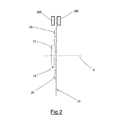
ブレーキディスク10は、自転車の車輪のハブ(図示せず)へと、ブレーキキャリパーのブレーキパッド100,100(図2に概略的に示す)間で取り付けられるように構成されている。
Please refer to the attached drawings. The
The
ブレーキディスク10は、両側のブレーキパッド100,100間に形成された空間内で回転軸心X回りに自由に回転し、ブレーキレバー(図示せず)を作動させることによってブレーキパッド100が、ブレーキディスク10に向かって動かされて当該ブレーキディスク10上で摩擦を引き起こす結果、車輪を制動する。
The
ブレーキディスク10は前記車輪の前記ハブへと、例えば(添付の図面に示す実施形態のように)当該ハブのうちの溝付き表面と合致する溝付き表面12を有する中央孔11、当該ブレーキディスク10を前記ハブへと軸方向に且つ回転固定で拘束するねじ又はボルト等の周知の様式によってカップリングされることが可能である。
The
ブレーキディスク10は、ロータ13およびキャリア14を備える。キャリア14は、ブレーキディスクのうちの、前記車輪の前記ハブに回転固定で拘束されるように意図された部位であり、ロータ13は、ブレーキディスクのうちの、ブレーキパッド100と接触するように意図された部位である。
キャリア14は好ましくはアルミニウム又はアルミニウム合金からなり、ロータ13は好ましくは鋼からなる。
ロータ13は、径方向外側の位置に配置されてブレーキパッド100,100間で回転するように構成された制動トラック15を有する。
The
The
制動トラック15は、略環状の広がりを有し、かつ、(添付の図面に示す例のように)円環形状を呈し得るか又はいわゆるデイジーホイール(daisy-wheel)形制動トラックを形成するように波形状もしくは多葉形状(undulating or multi-lobed shape)を呈し得る。いずれにせよ、制動トラック15の具体的な形状にかかわらず、当該制動トラック15内にはブレーキパッド100と触れるような直径を持つ制動円周16(図3に示す)が存在し得る。
The
制動トラック15には、制動時に当該制動トラック15で生じた熱の一部を放散する目的を持つ長手状の貫通スリット17が複数設けられ得る。
ロータ13は、制動トラック15の径方向内側に配置されて当該ロータ13をキャリア14へと連結する機能を持つ複数のカップリング座部18を有する。
好ましくは、カップリング座部18は、制動トラック15との一体品として形成されている。
The
The
Preferably, the
各々のカップリング座部18は、制動トラック15から径方向内方に延びるカップリングアーム18aの端部に形成されている。
カップリングアーム18aは、(添付の図面に示す実施形態のように)少なくとも1つの重量軽減のための貫通開口19を有し得る。
各々のカップリングアーム18aは第1の外縁部20および第2の外縁部21により周方向に画定されており、これら第1の外縁部20と第2の外縁部21との間に、前述した軽量化用の貫通開口19が少なくとも1つ設けられ得る。
Each
The
Each
第1の外縁部20および第2の外縁部21は、互いに平行であり得て(あるいは、より好ましくは平行でない)、かつ、直線状もしくは曲線状の広がりまたは直線状の部分と曲線状の部分とにより与えられる広がりを有し得る。
いずれにせよ、カップリングアーム18aは、制動トラック15へと接続する第1および第2の周方向端点22,23を有している。
The first
In any case, the
図3に示すように、第1および第2の周方向端点22,23は、カップリングアーム18aのうちの径方向外側の位置に配置されている。
これら2つの端点22,23は、カップリングアーム18aが制動トラック15へと接続する点のうちの、周方向に互いに最も離れた点によって形成されている。
カップリングアーム18aが制動トラック15へと(添付の図面の実施形態のように)連続しているときには、そのような端点22,23が、当該制動トラックの径方向内側縁部15aとカップリングアーム18aとの接点により特定される。
いずれにせよ、端点22,23は、制動トラック15の径方向内側縁部15aを通る理想的な円周とカップリングアーム18aとの交点により形成される。
制動トラック15の径方向内側縁部が円周と揃うものでない場合には、上記のような理想的な円周が、制動トラック15の当該径方向内側縁部15aのうちの径方向最外側の点を通る円周により与えられる。
As shown in FIG. 3, the first and second
These two
When the
In any case, the end points 22, 23 are formed by the intersection of the ideal circumference through the radially
If the radially inner edge of the
キャリア14は、ロータ13のカップリング座部18を受けて当該ロータ13と当該キャリア14との間の連結領域25を形成するための複数のカップリング座部24を有する。
連結領域25では、ロータ13のカップリング座部18が、キャリア14のカップリング座部24と軸方向に重なり合って当該カップリング座部24に直接接触することにより、非フローティング型の連結部を形成している。
各々のカップリングアーム18aは、当該カップリングアーム18aがキャリア14のうちの対応するカップリング座部24と連結される各々の連結領域25と、第1の外縁部20と、第2の外縁部21との間で特定される。
The
In the
Each
添付の図面に示す実施形態では、連結領域25、キャリア14のカップリング座部24およびロータ13のカップリング座部18が、周方向に等間隔で7つ設けられている。
ロータ13のカップリング座部18とキャリア14のカップリング座部24とを軸方向に互いに拘束するために、機械的なジョイント26(好ましくは、リベット)が設けられている。
In the embodiment shown in the attached drawings, seven
A mechanical joint 26 (preferably a rivet) is provided to axially restrain the
少なくとも1つの連結領域25でのロータ13のカップリング座部18とキャリア14のうちのそれぞれのカップリング座部24との間の拘束は、並進自由度を有する。
言い換えれば、ロータ13のカップリング座部18とキャリア14のカップリング座部24との相互の並進が妨げられない第1の基準軸心A1(図8)が存在する。
このような第1の基準軸心A1は、ブレーキディスク10の回転軸心Xと直交する第1の基準平面P1上に延在する(図8)。なお、第1の基準平面P1は、制動トラック15の延在平面と合致するか又は当該延在平面と平行である。
このような連結領域25では、ロータ13のカップリング座部18とキャリア14のカップリング座部24との間の拘束が、さらに、ブレーキディスク10の前記回転軸心と平行な回転軸心AR1回りの回転自由度を有する。
The restraint between the
In other words, there is a first reference axis A1 (FIG. 8) in which the mutual translation of the
Such a first reference axis A1 extends on a first reference plane P1 orthogonal to the rotation axis X of the brake disc 10 (FIG. 8). The first reference plane P1 coincides with or is parallel to the extension plane of the
In such a
キャリア14のカップリング座部24に対するロータ13のカップリング座部18のそれ以外の運動は、全て阻止されている。
具体的に述べると、回転軸心AR1に沿った並進が、ロータ13のカップリング座部18とキャリア14のカップリング座部24との相互の接触により、および、機械的なジョイント26により妨げられている。
All further movement of the
In particular, the translation along the axis of rotation AR1 is impeded by the mutual contact of the
第1の基準平面P1に含まれていて且つ第1の基準軸心A1と直交する第2の基準軸心A2に沿った並進は、機械的なジョイント26により妨げられている。
第1の基準軸心A1回りの回転は、機械的なジョイント26により妨げられている。
第2の基準軸心A2回りの回転は、機械的なジョイント26により妨げられている。
Translation along the second reference axis A2, which is included in the first reference plane P1 and is orthogonal to the first reference axis A1, is prevented by the mechanical joint 26.
The rotation about the first reference axis A1 is blocked by the mechanical joint 26.
The rotation about the second reference axis A2 is blocked by the mechanical joint 26.
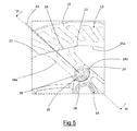
図8に示すように、第1の基準軸心A1は連結領域25を通過し、かつ、第1および第2の周方向端点22,23を通る基準セグメントSRと交差している。
図8に描かれているように、第1の基準軸心A1は、連結領域25でカップリングアーム18aのうちの第1の外縁部20と第2の外縁部21との間に含まれている。
第1の基準軸心A1は、第1の基準平面P1と直交し且つ回転軸心Xを含む第2の基準平面P2に対して絶対値で0〜80°の角度ANを形成している。図8に示すように、このような角度ANは径方向外方に測定される。
好ましくは、角度ANは、絶対値で0〜60°である。
As shown in FIG. 8, the first reference axis A1 passes through the
As depicted in FIG. 8, a first reference axis A1 is included in the
The first reference axis A1 forms an angle AN of 0 to 80 ° in absolute value with respect to a second reference plane P2 which is orthogonal to the first reference plane P1 and which includes the rotation axis X. As shown in FIG. 8, such an angle AN is measured radially outward.
Preferably, the angle AN is 0 to 60 degrees in absolute value.
添付の図面に示す実施形態のような一部の実施形態では、第1の基準軸A1がカップリングアーム18aの径方向広がり全体にわたって、第1の外縁部20と第2の外縁部21との間に含まれている。
本発明の好適な実施形態では、これまで1つの連結領域25に関して説明したことが、全ての連結領域25に当てはまる。
つまり、本発明の好適な実施形態では、全ての連結領域25でのロータ13のカップリング座部18とキャリア14のうちの対応するカップリング座部24との間の拘束が、各々の基準軸A1を基準にした並進自由度を有する。
In some embodiments, such as the embodiment shown in the attached drawings, the first reference axis A1 extends between the first
In the preferred embodiment of the present invention, what has been described in connection with one
That is, in the preferred embodiment of the present invention, the constraint between the
図8に示すように、全ての基準軸A1が同じ第1の基準平面P1上に延在し、少なくとも2つの基準軸A1が互いに平行でない。
各々の連結領域25での並進自由度により、それぞれの第1の基準軸A1に沿ってロータ13のカップリング座部18とキャリア14のうちの対応するカップリング座部24とが相互に変位可能となっている。
As shown in FIG. 8, all reference axes A1 extend on the same first reference plane P1 and at least two reference axes A1 are not parallel to one another.
By means of the translational freedom in the
カップリングアーム18aは、2つの第1の基準軸A1が互いに完全に直交しないように形作られ得る。
この構成では、ロータ13がキャリア14に対して第1の基準平面P1に沿って剛体移動(move rigidly)することができる。
The
In this configuration, the
変形例として、カップリングアーム18aは、少なくとも2つの第1の基準軸A1が互いに完全に直交するように形状決めされてもよい。
この構成では、ロータ13がキャリア14に対して剛体移動することができない。というのも、2つある第1の基準軸心のうちの一方の第1の基準軸に沿ったロータ13の剛体移動が、それら2つある第1の基準軸のうちの当該一方の第1の基準軸と直交する他方の第1の基準軸により与えられる並進拘束(constraint to translation)によって阻止されるからである。
Alternatively, the
In this configuration, the
本発明の好適な実施形態では、各々のカップリングアーム18aの、軸方向に測定される厚さが一定であり且つ好ましくは制動トラック15の厚さに等しい。
キャリア14の軸方向における厚さは、好ましくは前記中央孔部の前記溝12で最大となり、かつ、図2に示すようにカップリング座部24の箇所で減少する。
In a preferred embodiment of the invention, the axially measured thickness of each
The axial thickness of the
具体的に述べると、各々のカップリング座部24は、図4に分かり易く示すようにキャリア14のうちの径方向外側の部位27に形成されている。径方向外側の部位27の、軸方向における厚さは、好ましくはロータ13のカップリング座部18の厚さに等しい量ぶん減少している。
Specifically, each
ショルダー部28が、径方向外側の部位27を径方向内方で画定している。本発明の好適な実施形態では、ショルダー部28の形状がアーチ状である。
径方向外側の部位27は、ロータ13のカップリング座部18を、具体的にはロータ13のうちのカップリング座部18が形成されている端部部位18bを、軸方向の当接で受けるように構成されている。
なお、カップリング座部18(具体的には、端部部位18a)は、径方向外側の部位27のショルダー部28に接触しない。具体的に述べると、端部部位18bは、ショルダー部28から所定の量ぶん離間している。
A
The radially
The coupling seat 18 (specifically, the
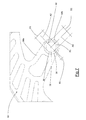
図4に示すように、前記キャリアのカップリング座部24は、貫通孔29を有しているか又は当該貫通孔29により形成されている。貫通孔29は、孔軸AFを有し、かつ、当該孔の幾何学的中心を通過している。孔軸AFは、ロータ13のカップリング座部18とキャリア14のカップリング座部24とが回転自由度を有する回転軸心AR1と(図8に示すように)合致する。
As shown in FIG. 4, the
以下では、貫通孔29の構成について定義するが、これらの構成は、キャリア14のカップリング座部24が当該貫通孔29により形成されている場合には、キャリア14のカップリング座部24の構成であるとして直接言及することができる。
貫通孔29は、リベット26を受け入れるように構成されている。
Hereinafter, although the configuration of the through
The through
貫通孔29は、第1の基準軸心A1に沿って測定される第1の寸法D1および第2の基準軸心A2に沿って測定される第2の寸法D2を有している。第2の基準軸心A2は、前記第1の基準平面に含まれていて、かつ、第1の基準軸心A1と直交し、かつ、孔軸AFと交わる。
第1の基準軸心A1も、孔軸AFと交わる。
なお、孔軸AFは、さらに、第1の基準軸心A1と第2の基準軸心A2との交点AF1とも合致する。
第2の寸法D2は、(既にコーキング済みの)リベット26の軸部26aの、第2の基準軸心A2に沿った寸法に略等しい。
The through
The first reference axis A1 also intersects the hole axis AF.
The hole axis AF also coincides with an intersection point AF1 between the first reference axis A1 and the second reference axis A2.
The second dimension D2 is approximately equal to the dimension along the second reference axis A2 of the
貫通孔29には、第2の寸法D2に等しい直径を有する基準円周が存在し得る。
第1の寸法D1は、第2の寸法D2よりも大きい。
具体的に述べると、第1の寸法D1は、第2の寸法D2よりも少なくとも1.5%(1.5%以上)大きい。
好ましくは、第1の寸法D1は、第2の寸法D2よりも少なくとも3%(3%以上)大きい。
好ましくは、第1の寸法D1は、第2の寸法D2の120%未満である。
より好ましくは、前記第1の寸法は、第2の寸法D2の約105%である。
一例として、直径が160ミリメートルのブレーキディスクは、第2の寸法D2が6.05ミリメートルで且つ第1の寸法D1が6.35ミリメートルの貫通孔を有する。
好ましくは、貫通孔29は、レギュラー形状を有する。
The through
The first dimension D1 is larger than the second dimension D2.
Specifically, the first dimension D1 is at least 1.5% (1.5% or more) larger than the second dimension D2.
Preferably, the first dimension D1 is at least 3% (3% or more) larger than the second dimension D2.
Preferably, the first dimension D1 is less than 120% of the second dimension D2.
More preferably, said first dimension is about 105% of second dimension D2.
As an example, a brake disc having a diameter of 160 mm has a through hole with a second dimension D2 of 6.05 mm and a first dimension D1 of 6.35 mm.
Preferably, the through
本発明の好適な実施形態では、貫通孔29が、第2の基準軸心A2を基準として互いに対称な、半円形状の第1のエッジ30及び第2のエッジ31を有している(図4を参照)。
第1のエッジ30と第2のエッジ31とは、第1の基準軸心A1を基準として互いに対称な、2つの接合エッジ(joining edge)32によって互いに繋がっている。
好ましくは、2つの接合エッジ32は、略楕円形状の貫通孔(elliptical through hole)29を形成するようにアーチ状の広がりを有している。
なお、2つの接合エッジ32の、第1の基準軸心A1に沿って測定される広がりB1が、第1の寸法D1と第2の寸法D2との差分を決める。
図4に示す実施形態では、第1の寸法D1が貫通孔29の楕円形状の長軸に合致し、第2の寸法D2が短軸に合致する。
In the preferred embodiment of the present invention, the through
The
Preferably, the two
The spread B1 of the two
In the embodiment shown in FIG. 4, the first dimension D1 coincides with the major axis of the elliptical shape of the through
リベット26が貫通孔29に挿入されてコーキングされたとき、当該リベット26の軸部26aは、貫通孔29の全てのエッジ30,31,32に接触しているわけではない。
具体的に述べると、リベット26は、第1のエッジ30の及び第2のエッジ31の広がり全体に接触しているわけではない。
ロータ13のカップリング座部18は、連結用孔(joining hole)32を有しているか又は当該連結用孔32により形成されている。連結用孔32は、好ましくは円状であるか、あるいは、いずれにせよ円周内である。連結用孔32(図6)の直径または当該連結用孔32内の前記円周の直径は、コーキング後のリベット26の軸部26aの直径に略等しい。
When the
Specifically, the
The
図6に示すように、リベット26は、連結用孔32と貫通孔29との両方に挿入されており、かつ、コーキング後は、ロータ13のカップリング座部18のための軸方向ショルダー部として及びキャリア14のカップリング座部24のための軸方向ショルダー部としてそれぞれ機能する両側の2つのヘッド部26bを有し、ロータ13とキャリア14とが軸方向に相互に並進(reciprocal translation)するのを防ぐ。
As shown in FIG. 6, the
図7に示す本発明の代替的な一実施形態では、ロータ13のカップリング座部18が、上記のような連結用孔32を有さずに、既述した貫通孔29と同じ構成の貫通孔29を有しているか又は当該貫通孔29により形成されている。
この実施形態(貫通孔29がロータ13のカップリング座部18を形成している場合には、当該貫通孔29の全ての構成が、ロータ13のカップリング座部18の構成であるとして直接言及することができる)では、さらに、キャリア14のカップリング座部24が、貫通孔29を有し得る(又は当該貫通孔29により形成され得る)か、あるいは、(前述した種類の)連結用孔32を有し得る(又は当該連結用孔32により形成され得る)。
どちらの場合であっても、第1の基準軸心A1に沿った並進可能拘束度がいずれにせよ確保される。
In an alternative embodiment of the invention shown in FIG. 7, the
In this embodiment (when the through
In either case, a translatable degree of restraint along the first reference axis A1 is ensured in any case.
試作試験時に、寸法、カップリング座部及び連結アームの数、材料ならびに厚さが同一である非フローティング型の2つのブレーキディスクを比較した。一方のブレーキディスクは、ロータのカップリング座部とキャリアのカップリング座部との間のどの拘束も並進自由度を有さない(以降、従来のブレーキディスクと称する)のに対し、他方のブレーキディスクは、ロータのうちの全てのカップリング座部とキャリアのうちの全てのカップリング座部との間の拘束が(前述の説明に従って)並進自由度を有する(以降、本発明にかかるブレーキディスクと称する)という点のみで相違する。 During trial manufacture, two non-floating brake discs of identical dimensions, number of coupling seats and connecting arms, material and thickness were compared. One brake disc has no translational freedom between the coupling seat of the rotor and the coupling seat of the carrier (hereinafter referred to as the conventional brake disc) while the other brake is not The disc has a translational freedom (in accordance with the above description) between all the coupling seats of the rotor and all the coupling seats of the carrier (hereinafter referred to as the brake disc according to the invention) It differs only in the point of).
試作試験時には、それぞれのブレーキディスクが、当該ブレーキディスクの回転軸心回りに回転されて、かつ、同じ制動力で急制動された(2つのブレーキディスクの回転速度及び停止時間は同一とした)。
各々の制動トラックには、当該制動トラックの、開始軸方向位置からの軸方向シフトを測定するための軸方向位置トランスデューサ(感知レバー)が配置された。
試作試験では、制動時における従来のブレーキディスクの制動トラックの、変形前の軸方向位置を中心とした発振量(約0.7ミリメートル)が、本発明にかかるブレーキディスクの発振量(約0.1ミリメートル)よりも大きくなった。発振の周波数は、双方のブレーキディスクで実質的に同一であった。
制動が完了すると、双方のブレーキディスクが変形前の位置を取り戻した。
従来のブレーキディスクは変形前の状態を取り戻すのに約45秒かかり、本発明にかかるブレーキディスクは変形前の状態を取り戻すのに約3秒かかった。
At the time of trial manufacture, each brake disc was rotated about the rotation axis of the brake disc, and suddenly braked with the same braking force (the rotational speeds and stop times of the two brake discs were the same).
On each braking track an axial position transducer (sensing lever) was arranged to measure the axial shift of the braking track from the starting axial position.
In the trial manufacture, the oscillation amount (about 0.7 mm) of the braking track of the conventional brake disc at the time of braking about the axial position before deformation is the oscillation amount of the brake disc according to the present invention (about 0. 0). It became bigger than 1 mm). The frequency of oscillation was substantially the same for both brake disks.
When braking was complete, both brake discs regained their pre-deformation position.
The conventional brake disc took about 45 seconds to recover the state before deformation, and the brake disc according to the present invention took about 3 seconds to recover the state before deformation.
試験条件を下り走行時の競走用自転車の実使用に関連付けると、従来のブレーキディスクを装備した自転車は、制動トラックの変形前の状態を取り戻すまでに約50メートル走行する(その間、当該制動トラックはブレーキパッドに対して不所望の滑りを生じる)のに対し、本発明にかかるブレーキディスクを装備した自転車は、約4メートルしか走行しない(制動トラックの、ブレーキパッドに対する不所望の滑り作用が明らかに減少する)と推定された。 If the test conditions are linked to the actual use of the race bike when traveling backward, the bicycle equipped with the conventional brake disc travels about 50 meters before recovering the state before the deformation of the braking track (while the braking track is The bicycle equipped with the brake disc according to the present invention travels only about 4 meters, whereas the brake disc according to the present invention travels only about 4 meters (the undesired slip action of the brake track against the brake pad is apparent). Decrease)).
当然ながら、当業者であれば、その時々の要件や偶発的な要件を満足するために、本発明にかかる自転車用のブレーキディスクに様々な変更や変形を施すことが可能であり、いずれにせよこれら変更や変形の全ては添付の特許請求の範囲により定まる保護範囲に含まれる。 Of course, those skilled in the art can make various changes and modifications to the brake disc for a bicycle according to the present invention in order to satisfy the occasional requirements and incidental requirements. All these changes and modifications are included in the scope of protection defined by the appended claims.
Claims (15)
径方向外側の制動トラック(15)、および前記キャリア(14)の前記カップリング座部(24)と軸方向に少なくとも部分的に重なり合うことによって連結領域(25)を形成する複数の径方向内側のカップリング座部(18)を有するロータ(13)と、
を備える、自転車用のブレーキディスク(10)であって、
前記ロータ(13)と前記キャリア(14)とが、前記連結領域(25)で動作する機械的なジョイント(26)によって互いに繋げられており、
前記ロータ(13)の少なくとも1つのカップリング座部(18)と前記キャリア(14)のカップリング座部(24)との間の、それぞれの連結領域(25)での拘束が、並進自由度を有する、ブレーキディスク(10)。 A connection (12) configured for connection to a hub of a bicycle wheel that is rotatable about an axis of rotation (X), and a carrier (14) having a plurality of coupling seats (24)
A radially outer braking track (15) and a plurality of radially inner which form a coupling region (25) by at least partially overlapping the coupling seat (24) of the carrier (14) in axial direction A rotor (13) having a coupling seat (18);
A brake disc (10) for a bicycle comprising
Said rotor (13) and said carrier (14) are connected to one another by means of a mechanical joint (26) operating in said connection area (25);
The restriction in the respective connection area (25) between the at least one coupling seat (18) of the rotor (13) and the coupling seat (24) of the carrier (14) has a translational freedom Have a brake disc (10).
Applications Claiming Priority (2)
| Application Number | Priority Date | Filing Date | Title |
|---|---|---|---|
| IT102017000092546 | 2017-08-09 | ||
| IT102017000092546A IT201700092546A1 (en) | 2017-08-09 | 2017-08-09 | Brake disc for bicycle |
Publications (2)
| Publication Number | Publication Date |
|---|---|
| JP2019049350A true JP2019049350A (en) | 2019-03-28 |
| JP2019049350A5 JP2019049350A5 (en) | 2021-07-26 |
Family
ID=60766062
Family Applications (1)
| Application Number | Title | Priority Date | Filing Date |
|---|---|---|---|
| JP2018148081A Pending JP2019049350A (en) | 2017-08-09 | 2018-08-07 | Brake disc for bicycle |
Country Status (6)
| Country | Link |
|---|---|
| US (1) | US20190048950A1 (en) |
| EP (1) | EP3441295B1 (en) |
| JP (1) | JP2019049350A (en) |
| CN (1) | CN109386560A (en) |
| IT (1) | IT201700092546A1 (en) |
| TW (1) | TWI763896B (en) |
Families Citing this family (2)
| Publication number | Priority date | Publication date | Assignee | Title |
|---|---|---|---|---|
| TWI722937B (en) * | 2020-07-02 | 2021-03-21 | 許再勝 | Rivet Set of Floating Disc |
| TWI722936B (en) * | 2020-07-02 | 2021-03-21 | 許再勝 | Inner dish |
Citations (6)
| Publication number | Priority date | Publication date | Assignee | Title |
|---|---|---|---|---|
| JPS61104842U (en) * | 1984-12-14 | 1986-07-03 | ||
| US20040200674A1 (en) * | 2003-03-28 | 2004-10-14 | Campbell Darren J. | Quick-mount disc brake rotor |
| JP2006029552A (en) * | 2004-07-21 | 2006-02-02 | Shimano Inc | Bicycle disc rotor |
| TWM462809U (en) * | 2013-04-11 | 2013-10-01 | Talonbrake Industry Co Ltd | Bicycle replaceable floating type disk tray |
| DE202013104350U1 (en) * | 2013-09-24 | 2013-10-09 | Kun-Liang Chieh | Construction of a floating disc brake |
| US20170198773A1 (en) * | 2016-01-07 | 2017-07-13 | Hb Performance Systems, Inc. | Brake rotor with tilted mounting slots |
Family Cites Families (17)
| Publication number | Priority date | Publication date | Assignee | Title |
|---|---|---|---|---|
| JPH0249394Y2 (en) * | 1987-05-21 | 1990-12-26 | ||
| US6135248A (en) * | 1995-11-08 | 2000-10-24 | Hayes Brake, Inc. | Brake disk |
| JP2916888B2 (en) * | 1995-12-14 | 1999-07-05 | 株式会社ユタカ技研 | Floating brake disc |
| US6357561B2 (en) * | 1999-10-15 | 2002-03-19 | Stop Technologies Llc | Thermal expansion bushing in a metal matrix composite rotor |
| TW484551U (en) * | 2000-10-02 | 2002-04-21 | Robert J Seymour | Disk brake device |
| CN100447441C (en) * | 2004-05-18 | 2008-12-31 | 株式会社丰技研 | Floating type disk brake |
| JP4855929B2 (en) * | 2004-05-18 | 2012-01-18 | 株式会社ユタカ技研 | Floating disc brake |
| CN2889875Y (en) * | 2005-12-07 | 2007-04-18 | 永祺车业股份有限公司 | Bicycle drum disc locking structure |
| TWM335443U (en) * | 2008-01-30 | 2008-07-01 | yi-zhen Zhang | Brake disc device |
| US8353391B2 (en) * | 2008-07-08 | 2013-01-15 | Yutaka Giken Co., Ltd. | Floating type brake disc |
| ES2366889T3 (en) * | 2008-08-29 | 2011-10-26 | Stanislav Spacek | FLOATING BRAKE DISK. |
| ES2465943B1 (en) * | 2012-12-07 | 2014-12-05 | Marcos PÉREZ FERRER | Disc brake assembly for a vehicle with an inner support and an outer ring divided into a plurality of sectors |
| JP5783994B2 (en) * | 2012-12-25 | 2015-09-24 | 本田技研工業株式会社 | Wheel speed sensor ring mounting structure |
| CN104976253A (en) * | 2014-04-11 | 2015-10-14 | 曾玉娟 | Floating disc combined device |
| CN104309753B (en) * | 2014-10-16 | 2017-02-08 | 宏展五金塑胶制品(苏州)有限公司 | Bicycle brake disc |
| TWM505425U (en) * | 2015-02-12 | 2015-07-21 | Min-Lang Zeng | Floating brake disc |
| ITUB20155214A1 (en) * | 2015-10-19 | 2017-04-19 | Grimeca S R L | DISC BRAKE. |
-
2017
- 2017-08-09 IT IT102017000092546A patent/IT201700092546A1/en unknown
-
2018
- 2018-07-31 EP EP18186720.1A patent/EP3441295B1/en active Active
- 2018-08-02 TW TW107126808A patent/TWI763896B/en active
- 2018-08-07 JP JP2018148081A patent/JP2019049350A/en active Pending
- 2018-08-08 US US16/058,208 patent/US20190048950A1/en not_active Abandoned
- 2018-08-09 CN CN201810901609.4A patent/CN109386560A/en active Pending
Patent Citations (6)
| Publication number | Priority date | Publication date | Assignee | Title |
|---|---|---|---|---|
| JPS61104842U (en) * | 1984-12-14 | 1986-07-03 | ||
| US20040200674A1 (en) * | 2003-03-28 | 2004-10-14 | Campbell Darren J. | Quick-mount disc brake rotor |
| JP2006029552A (en) * | 2004-07-21 | 2006-02-02 | Shimano Inc | Bicycle disc rotor |
| TWM462809U (en) * | 2013-04-11 | 2013-10-01 | Talonbrake Industry Co Ltd | Bicycle replaceable floating type disk tray |
| DE202013104350U1 (en) * | 2013-09-24 | 2013-10-09 | Kun-Liang Chieh | Construction of a floating disc brake |
| US20170198773A1 (en) * | 2016-01-07 | 2017-07-13 | Hb Performance Systems, Inc. | Brake rotor with tilted mounting slots |
Also Published As
| Publication number | Publication date |
|---|---|
| CN109386560A (en) | 2019-02-26 |
| IT201700092546A1 (en) | 2019-02-09 |
| US20190048950A1 (en) | 2019-02-14 |
| EP3441295B1 (en) | 2021-02-24 |
| TW201910656A (en) | 2019-03-16 |
| TWI763896B (en) | 2022-05-11 |
| EP3441295A1 (en) | 2019-02-13 |
Similar Documents
| Publication | Publication Date | Title |
|---|---|---|
| RU2549594C2 (en) | Disk for disk brakes | |
| CN111936759B (en) | Aerodynamic noise reduction member, brake disc unit for railway vehicle, disc brake for railway vehicle, wheel for railway vehicle, and railway vehicle | |
| TWI748054B (en) | Brake disc for a bicycle | |
| CN103185094B (en) | Bicycle disk brake rotor | |
| JP6173689B2 (en) | Ventilated brake disc | |
| JP5224207B2 (en) | Wheel brake with brake discs divided into fan-shaped pieces | |
| BR112018001051B1 (en) | SUPPORT PLATE FOR A DISC BRAKE COATING, DISC BRAKE COATING AND PARTLY COATED DISC BRAKE OF MOTOR VEHICLE | |
| RU2351815C1 (en) | Clasp brake and spreader bar | |
| EP0710778A1 (en) | Disc brake | |
| JP2001165211A (en) | Ventilated disk | |
| JP2019049350A (en) | Brake disc for bicycle | |
| EP2962009B1 (en) | Disc brake disc and phonic wheel | |
| US10428886B2 (en) | Bicycle disc brake rotor | |
| CN113494552A (en) | Brake disc | |
| JP2018028384A (en) | Brake disc for bicycle | |
| US6135248A (en) | Brake disk | |
| CN109790890B (en) | Wheel brake device | |
| JP4610340B2 (en) | Brake disc for vehicle | |
| JP2019049350A5 (en) | ||
| TWI597437B (en) | Disc brake rotor, hub assembly and brake assembly | |
| TW201807331A (en) | Brake disc for a bicycle | |
| JP2009216205A (en) | Brake disc, and vehicle | |
| JP7364211B2 (en) | brake rotor | |
| WO2017146032A1 (en) | Rotor for disc brake | |
| JP7031731B2 (en) | Rail vehicle brake discs and rail vehicle disc brakes |
Legal Events
| Date | Code | Title | Description |
|---|---|---|---|
| A521 | Request for written amendment filed |
Free format text: JAPANESE INTERMEDIATE CODE: A523 Effective date: 20210525 |
|
| A621 | Written request for application examination |
Free format text: JAPANESE INTERMEDIATE CODE: A621 Effective date: 20210525 |
|
| A977 | Report on retrieval |
Free format text: JAPANESE INTERMEDIATE CODE: A971007 Effective date: 20220415 |
|
| A131 | Notification of reasons for refusal |
Free format text: JAPANESE INTERMEDIATE CODE: A131 Effective date: 20220426 |
|
| A601 | Written request for extension of time |
Free format text: JAPANESE INTERMEDIATE CODE: A601 Effective date: 20220726 |
|
| A521 | Request for written amendment filed |
Free format text: JAPANESE INTERMEDIATE CODE: A523 Effective date: 20220922 |
|
| A02 | Decision of refusal |
Free format text: JAPANESE INTERMEDIATE CODE: A02 Effective date: 20230117 |