[1.パチンコ機の全体構造]
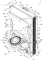
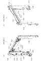
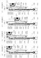
本発明の一実施形態であるパチンコ機1について、図面を参照して詳細に説明する。まず、図1乃至図12を参照して本実施形態のパチンコ機1の全体構成について説明する。図1は本発明の一実施形態であるパチンコ機の正面図である。図2はパチンコ機の右側面図であり、図3はパチンコ機の左側面図であり、図4はパチンコ機の背面図である。図5はパチンコ機を右前から見た斜視図であり、図6はパチンコ機を左前から見た斜視図であり、図7はパチンコ機を後ろから見た斜視図である。図8は演出操作ユニットの押圧操作部が上昇位置の時のパチンコ機の正面図であり、図9は演出操作ユニットの押圧操作部が上昇位置の時のパチンコ機を右前から見た斜視図である。また、図10は、本体枠から扉枠を開放させると共に、外枠から本体枠を開放させた状態で前から見たパチンコ機の斜視図である。図11はパチンコ機を扉枠、遊技盤、本体枠、及び外枠に分解して前から見た分解斜視図であり、図12はパチンコ機を扉枠、遊技盤、本体枠、及び外枠に分解して後ろから見た分解斜視図である。
[1. Overall structure of pachinko machine]
A pachinko machine 1 according to an embodiment of the present invention will be described in detail with reference to the drawings. First, an entire configuration of a pachinko machine 1 according to the present embodiment will be described with reference to FIGS. 1 to 12. FIG. 1 is a front view of a pachinko machine which is an embodiment of the present invention. FIG. 2 is a right side view of the pachinko machine, FIG. 3 is a left side view of the pachinko machine, and FIG. 4 is a rear view of the pachinko machine. FIG. 5 is a perspective view of the pachinko machine as viewed from the right front, FIG. 6 is a perspective view of the pachinko machine as viewed from the left front, and FIG. 7 is a perspective view of the pachinko machine as viewed from the rear. FIG. 8 is a front view of the pachinko machine when the pressing operation unit of the rendering operation unit is at the rising position, and FIG. 9 is a perspective view of the pachinko machine when the pressing operation unit of the rendering operation unit is at the rising position from the right front is there. Moreover, FIG. 10 is a perspective view of the pachinko machine seen from the front in a state in which the door frame is opened from the main body frame and the main body frame is opened from the outer frame. FIG. 11 is an exploded perspective view of the pachinko machine disassembled into a door frame, a game board, a main body frame, and an outer frame, and FIG. 12 is a pachinko machine as a door frame, game board, main body frame, and outer frame It is the disassembled perspective view which disassembled and was seen from back.
本実施形態のパチンコ機1は、遊技ホールの島設備(図示しない)に設置される枠状の外枠2と、外枠2の前面を開閉可能に閉鎖する扉枠3と、扉枠3を開閉可能に支持していると共に外枠2に開閉可能に取付けられている本体枠4と、本体枠4に前側から着脱可能に取付けられると共に扉枠3を通して遊技者側から視認可能とされ遊技者によって遊技球B(図90を参照)が打込まれる遊技領域5aを有した遊技盤5と、を備えている。
The pachinko machine 1 of this embodiment includes a frame-shaped outer frame 2 installed on an island facility (not shown) of a game hall, a door frame 3 for closing the front of the outer frame 2 so as to be openable and closable, A main unit frame 4 supported so as to be openable and closable, and removably attached to the main unit frame 4 from the front side, is made visible from the player side through the door frame 3. And a game board 5 having a game area 5a into which the game ball B (see FIG. 90) is inserted.
外枠2は、正面視の形状が上下に延びた四角形の枠に形成されている。外枠2は、左右に離間しており上下に延びている外枠左組立体10及び外枠右組立体20と、外枠左組立体10及び外枠右組立体20の上端同士を連結している外枠上部材30と、外枠左組立体10及び外枠右組立体20の下端同士を連結している外枠下組立体40と、外枠上部材30の上面左端に取付けられている外枠上ヒンジ組立体50と、外枠左組立体10の右側面下部と外枠下組立体40の上面左端に取付けられている外枠下ヒンジ部材60と、を備えている。
The outer frame 2 is formed in a rectangular frame in which the shape in a front view extends vertically. The outer frame 2 connects the upper ends of the outer frame left assembly 10 and the outer frame right assembly 20 which are separated left and right and extend vertically, and the outer frame left assembly 10 and the outer frame right assembly 20 Attached to the upper surface left end of the outer frame upper member 30, and the outer frame lower assembly 40 connecting lower ends of the outer frame upper member 30, the lower end of the outer frame left assembly 10 and the outer frame right assembly 20; An outer frame upper hinge assembly 50 and an outer frame lower hinge member 60 attached to the lower right side surface of the outer frame left assembly 10 and the upper end of the upper surface of the outer frame lower assembly 40 are provided.
外枠2は、パチンコ機1が設置される遊技ホールの島設備に取付けられ、外枠上ヒンジ組立体50と外枠下ヒンジ部材60とによって、本体枠4の本体枠上ヒンジ部材510と本体枠下ヒンジ組立体520とを同軸上で回転可能に支持して、本体枠4を正面視左側を中心にして前方へ開閉可能に取付けるためのものである。
The outer frame 2 is attached to the island facility of the game hall where the pachinko machine 1 is installed, and the outer frame upper hinge assembly 50 and the outer frame lower hinge member 60 make the main frame upper hinge member 510 of the main body frame 4 and the main body The frame lower hinge assembly 520 is rotatably supported coaxially, and the main body frame 4 is mounted so as to be able to open and close in a forward direction centering on the left side in a front view.
また、扉枠3は、本体枠4を閉じた時に、外枠下組立体40が、本体枠4における基板ユニット620のスピーカユニット620aと協働して、本体枠スピーカ622のエンクロージャ624の一部を形成し、本体枠スピーカ622の後方へ出力されたサウンドを、位相反転させて前方へ放射することで、より重低音のサウンドを遊技者に聴かせることができるものである。
In the door frame 3, when the main body frame 4 is closed, the outer frame lower assembly 40 cooperates with the speaker unit 620 a of the substrate unit 620 in the main body frame 4 to partially cover the enclosure 624 of the main body frame speaker 622. The sound outputted to the rear of the main body frame speaker 622 is phase-reversed and radiated forward to allow the player to hear a more deep bass sound.
扉枠3は、遊技球Bが打込まれる遊技盤5の遊技領域5aを前側から視認可能に閉鎖し、遊技領域5a内に打込むための遊技球Bを貯留すると共に、貯留している遊技球Bを遊技領域5a内へ打込むために遊技者が操作するハンドル182を備えているものである。また、扉枠3は、パチンコ機1の前面全体を装飾するものである。
The door frame 3 closes the gaming area 5a of the gaming board 5 in which the gaming ball B is struck so as to be visible from the front side, stores the gaming ball B for hitting into the gaming area 5a, and stores the gaming It has a handle 182 operated by the player in order to drive the ball B into the game area 5a. Moreover, the door frame 3 decorates the whole front of the pachinko machine 1.
また、扉枠3は、ハンドル182とは別に遊技者が操作可能な演出操作部301を備えており、遊技者参加型演出が実行された際に、遊技者が演出操作部301を操作することで遊技者が演出に参加できるようになり、遊技球Bによる遊技に加えて、演出操作部301の操作によっても遊技者を楽しませることができるようにしている。
Further, the door frame 3 is provided with the effect operation unit 301 which can be operated by the player separately from the handle 182, and the player operates the effect operation unit 301 when the player participation type effect is executed. Thus, the player can participate in the effect, and in addition to the game by the game ball B, the player can be entertained also by the operation of the effect operation unit 301.
本体枠4は、後部が外枠2の枠内に挿入可能とされると共に遊技盤5の外周を支持可能とされた枠状の本体枠ベースユニット500と、本体枠4を外枠2に対して開閉可能に取付けると共に扉枠3を開閉可能に取付けるための本体枠上ヒンジ部材510及び本体枠下ヒンジ組立体520と、本体枠ベースユニット500を補強している本体枠補強フレーム530と、遊技盤5の遊技領域5a内に遊技球Bを打込むための球発射装置540と、遊技ホールの島設備から供給される遊技球Bを受取る払出ベースユニット550と、払出ベースユニット550で受取った遊技球Bを遊技者側へ払出すための払出ユニット560と、電源基板630や払出制御基板633を有している基板ユニット620と、本体枠ベース501に取付けられた遊技盤5の後側を覆う裏カバー640と、外枠2と本体枠4、及び扉枠3と本体枠4の間を施錠する施錠ユニット650と、を備えている。
The main body frame 4 has a frame-like main body frame base unit 500 which can be inserted into the frame of the outer frame 2 at its rear portion and can support the outer periphery of the game board 5, and the main body frame 4 against the outer frame 2. The main frame upper hinge member 510 and the lower main frame hinge assembly 520 for mounting the door frame 3 in an openable and closable manner, the main frame reinforcing frame 530 reinforcing the main frame base unit 500, and the game The ball launch device 540 for hitting the game ball B into the game area 5a of the board 5, the payout base unit 550 which receives the game ball B supplied from the island facility of the game hall, and the game received by the payout base unit 550 A game unit attached to a main unit frame base 501, a payout unit 560 for paying out the ball B to the player side, a substrate unit 620 having a power supply substrate 630 and a payout control substrate 633, and A back cover 640 that covers the rear side of, and includes an outer frame 2 and the main frame 4, and the door frame 3 and the locking unit 650 for locking between the body frame 4, a.
本体枠4は、遊技球Bを打込むことで遊技が行われる遊技領域5aを有した遊技盤5を保持すると共に、遊技球Bを遊技者側へ払出したり、遊技に使用された遊技球Bをパチンコ機1の後方(遊技ホールの島設備側)へ排出したり、するためのものである。本体枠4は、前方が開放された箱状に形成されており、内部に前方から遊技盤5が着脱可能に収容される。また、本体枠4は、正面左辺側前端の上下において、遊技ホールの島設備に取付けられる枠状の外枠2に開閉可能に取付けられると共に、開放された前面側が閉鎖されるように扉枠3が開閉可能に取付けられる。
The main unit frame 4 holds the game board 5 having the game area 5a in which the game is performed by hitting the game ball B, and pays out the game ball B to the player side, or the game ball B used for the game. To the rear of the pachinko machine 1 (the island equipment side of the game hall). The main body frame 4 is formed in a box shape whose front is open, and the game board 5 is detachably accommodated in the inside from the front. In addition, the main body frame 4 is attached to the frame-like outer frame 2 attached to the island facility of the game hall so as to be openable and closable at the top and bottom of the front left side front end, and the door frame 3 is closed so as to close the opened front side. Is mounted so that it can be opened and closed.
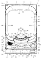
遊技盤5は、遊技者の操作によって遊技球Bが行われる遊技領域5aと、遊技領域5aの外周を区画し外形が正面視略四角形状とされた前構成部材1000と、前構成部材1000の後側に取付けられており遊技領域5aの後端を区画する板状の遊技パネル1100と、遊技パネル1100の後側下部に取付けられている基板ホルダ1200と、基板ホルダ1200の後面に取付けられており主制御基板1310を有している主制御ユニット1300と、主制御基板1310からの制御信号に基づいて遊技状況を表示する機能表示ユニット1400と、遊技パネル1100の後側に配置されている周辺制御ユニット1500(図12を参照)と、正面視において遊技領域5aの中央に配置されており所定の演出画像を表示可能な演出表示装置1600と、遊技パネル1100の前面に取付けられる表ユニット2000と、遊技パネル1100の後面に取付けられる裏ユニット3000と、を備えている。裏ユニット3000には、遊技状態に応じて可動演出や発光演出を行うことが可能な各種の演出ユニットを備えている。
The game board 5 has a game area 5a in which the game ball B is played by the operation of the player, a front component 1000 which divides the outer periphery of the game area 5a and whose outer shape is substantially square in a front view, It is attached to the plate-shaped game panel 1100 attached to the rear side and partitioning the rear end of the game area 5a, the substrate holder 1200 attached to the lower rear side of the game panel 1100, and the rear surface of the substrate holder 1200 A main control unit 1300 having a main control board 1310, a function display unit 1400 for displaying a game situation based on a control signal from the main control board 1310, and a periphery disposed on the rear side of the game panel 1100 A control unit 1500 (see FIG. 12) and an effect display device arranged at the center of the game area 5a in front view and capable of displaying a predetermined effect image 600, and a table unit 2000 attached to the front of the gaming panel 1100, a back unit 3000 attached to the rear surface of the gaming panel 1100, the. The back unit 3000 is provided with various effect units capable of performing movable effects and light emission effects according to the game state.
遊技盤5の遊技領域5a内には、遊技球Bと当接し所定のゲージ配列で植設されている複数の障害釘と、遊技球Bの受入れ又は通過により遊技者に対して所定の特典(例えば、所定数の遊技球Bの払出し)を付与する一般入賞口2001、第一始動口2002、ゲート部2003、第二始動口2004、第一大入賞口2005、及び第二大入賞口2006と、を備えている。障害釘Nは、遊技パネル1100の前面に植設されている。一般入賞口2001、第一始動口2002、ゲート部2003、第二始動口2004、第一大入賞口2005、及び第二大入賞口2006は、表ユニット2000に備えられている。
In the gaming area 5a of the gaming board 5, a plurality of obstacle nails which are in contact with the gaming ball B and are installed in a predetermined gauge array, and a predetermined benefit for the player by receiving or passing the gaming ball B ( For example, a general winning opening 2001 for giving a payout of a predetermined number of gaming balls B, a first starting opening 2002, a gate section 2003, a second starting opening 2004, a first large winning opening 2005, and a second large winning opening 2006 And. The obstacle nail N is implanted on the front of the game panel 1100. The general winning opening 2001, the first starting opening 2002, the gate unit 2003, the second starting opening 2004, the first large winning opening 2005, and the second large winning opening 2006 are provided in the front unit 2000.
遊技盤5の遊技領域5a内には、遊技者がハンドルユニット180のハンドル182を操作することで、遊技球Bを打込むことができる。これにより、遊技球Bが、遊技領域5a内の一般入賞口2001、第一始動口2002、ゲート部2003、第二始動口2004、第一大入賞口2005、及び第二大入賞口2006等に、受入れられたり通過したりするように、遊技者に対してハンドル182の打込操作を楽しませることができる。
The player can drive the game ball B into the game area 5 a of the game board 5 by operating the handle 182 of the handle unit 180. As a result, the game ball B is placed in the general winning opening 2001, the first starting opening 2002, the gate section 2003, the second starting opening 2004, the first large winning opening 2005, the second large winning opening 2006 etc. The player can enjoy the operation of hitting the handle 182 as accepted or passed.
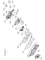
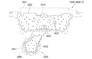
また、遊技盤5は、遊技領域5a内に遊技球Bを打込むことで変化する遊技状態に応じて、演出表示装置1600に所定の演出画像を表示させたり、裏後演出ユニット3100、裏下左演出ユニット3200、裏下右演出ユニット3250、裏下中演出ユニット3300、裏上演出ユニット3400、裏後左演出ユニット3500、裏後右演出ユニット3600、裏前左演出ユニット3700、裏前右演出ユニット3800、等により発光演出や可動演出等を行わせたりして、遊技者を楽しませることができる。
In addition, the game board 5 displays a predetermined effect image on the effect display device 1600 according to the game state which changes by hitting the game ball B in the game area 5a, and the back effect unit 3100, the back down Left production unit 3200, back down right production unit 3250, back down inside production unit 3300, back up production unit 3400, back back left production unit 3500, back back right production unit 3600, back front left production unit 3700, back front right production A player can be entertained by causing a light emission effect or a movable effect to be performed by the unit 3800 or the like.
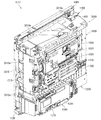
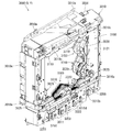
[2.外枠の全体構成]
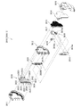
パチンコ機1の外枠2について、図13乃至図18を参照して説明する。図13はパチンコ機における外枠の正面図であり、図14は外枠の背面図であり、図15は外枠の右側面図である。また、図16は外枠を前から見た斜視図であり、図17は外枠を後ろから見た斜視図である。図18は、外枠を主な部材毎に分解して前から見た分解斜視図である。外枠2は、遊技ホール等のパチンコ機1が設置される島設備(図示は省略)に取付けられるものである。外枠2は、正面視の形状が上下に延びた四角形の枠に形成されている。
[2. Overall configuration of outer frame]
The outer frame 2 of the pachinko machine 1 will be described with reference to FIGS. 13 to 18. FIG. 13 is a front view of an outer frame of a pachinko machine, FIG. 14 is a rear view of the outer frame, and FIG. 15 is a right side view of the outer frame. 16 is a perspective view of the outer frame as viewed from the front, and FIG. 17 is a perspective view of the outer frame as viewed from the back. FIG. 18 is an exploded perspective view of the outer frame disassembled into main members and viewed from the front. The outer frame 2 is attached to an island facility (not shown) on which the pachinko machine 1 such as a game hall is installed. The outer frame 2 is formed in a rectangular frame in which the shape in a front view extends vertically.
外枠2は、図示するように、左右に離間しており上下に延びている外枠左組立体10及び外枠右組立体20と、外枠左組立体10及び外枠右組立体20の上端同士を連結している外枠上部材30と、外枠左組立体10及び外枠右組立体20の下端同士を連結している外枠下組立体40と、外枠上部材30の上面左端に取付けられている外枠上ヒンジ組立体50と、外枠左組立体10の右側面下部と外枠下組立体40の上面左端に取付けられている外枠下ヒンジ部材60と、を備えている。
The outer frame 2 is, as shown in the figure, separated from the left and right and extending vertically, the left outer frame assembly 10 and the right outer frame assembly 20, and the left outer frame assembly 10 and the right outer frame assembly 20. Outer frame upper member 30 connecting upper ends, outer frame lower assembly 40 connecting lower ends of outer frame left assembly 10 and outer frame right assembly 20, and upper surface of outer frame upper member 30 An outer frame upper hinge assembly 50 attached to the left end, and an outer frame lower hinge member 60 attached to the lower right side surface of the outer frame left assembly 10 and the upper surface left end of the outer frame lower assembly 40 ing.
外枠2は、本体枠4を閉じた時に、外枠下組立体40が、本体枠4における基板ユニット620のスピーカユニット620aと協働して、本体枠スピーカ622のエンクロージャ624の一部を形成していると共に、本体枠スピーカ622の後方へ出力されたサウンドを、位相反転させて前方へ放射することができるものである。
In the outer frame 2, when the main body frame 4 is closed, the lower outer frame assembly 40 cooperates with the speaker unit 620 a of the substrate unit 620 in the main body frame 4 to form a part of the enclosure 624 of the main body frame speaker 622 The sound outputted to the rear of the main body frame speaker 622 can be phase-reversed and emitted forward.
外枠2は、外枠上ヒンジ組立体50が、本体枠4の本体枠上ヒンジ部材510を着脱可能に支持することができる。外枠2は、外枠上ヒンジ組立体50と外枠下ヒンジ部材60とによって、本体枠4の本体枠上ヒンジ部材510と本体枠下ヒンジ組立体520とを同軸上で回転可能に支持することができ、本体枠4を正面視左側を中心にして前方へ開閉可能に取付けることができる。
The outer frame upper hinge assembly 50 can detachably support the main frame upper hinge member 510 of the main body frame 4 of the outer frame 2. The outer frame 2 coaxially rotatably supports the main frame upper hinge member 510 of the main frame 4 and the main frame lower hinge assembly 520 by the outer frame upper hinge assembly 50 and the outer frame lower hinge member 60. Thus, the main body frame 4 can be mounted so as to be openable and closable to the front centering on the left side in a front view.
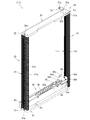
[2−1.外枠左組立体及び外枠右組立体]
外枠2の外枠左組立体10及び外枠右組立体20について、主に図19を参照して詳細に説明する。図19は、外枠の外枠左組立体及び外枠右組立体を夫々分解して前から見た分解斜視図である。外枠2の外枠左組立体10及び外枠右組立体20は、夫々が上下に延びており、互いに左右に離間して配置されている。外枠左組立体10及び外枠右組立体20は、本体枠4の本体枠上ヒンジ部材510及び本体枠下ヒンジ組立体520を同軸上で回転可能に支持して、外枠2に対して本体枠4を開閉可能に取付けるためのものである。
[2-1. Outer frame left assembly and outer frame right assembly]
The outer frame left assembly 10 and the outer frame right assembly 20 of the outer frame 2 will be described in detail with reference mainly to FIG. FIG. 19 is an exploded perspective view of the outer frame left assembly and the outer frame right assembly of the outer frame disassembled and viewed from the front. The outer frame left assembly 10 and the outer frame right assembly 20 of the outer frame 2 extend in the vertical direction, and are disposed apart from each other in the left and right direction. The left outer frame assembly 10 and the right outer frame assembly 20 coaxially rotatably support the main frame upper hinge member 510 and the lower main frame hinge assembly 520 of the main frame 4 with respect to the outer frame 2. It is for attaching the main body frame 4 so that opening and closing is possible.
まず、外枠左組立体10は、前後方向が一定の幅(奥行)で上下に延びている外枠左部材11と、外枠左部材11の右側面上端に取付けられている左上連結部材12と、外枠左部材11の右側面下端に取付けられている左下連結部材13と、を備えている。
First, the outer frame left assembly 10 has an outer frame left member 11 extending vertically with a constant width (depth) in the front-rear direction, and an upper left connecting member 12 attached to the upper right end of the outer frame left member 11. And the lower left connecting member 13 attached to the lower end of the right side surface of the outer frame left member 11.
外枠左部材11は、一定の断面形状で上下に延びており、アルミ合金の押出型材によって形成されている。外枠左部材11は、左側面における前後方向を三等分したうちの後側の部位において平坦状に右方へ窪んでいる凹部11aと、右側面における凹部11aとは反対側の部位から右方へ膨出している膨出部11bと、膨出部11bを上下に貫通している空洞部11cと、を備えている。外枠左部材11は、凹部11aや膨出部11bによって、強度・剛性が高められていると共に、空洞部11cによって、重量が軽減されている。
The outer frame left member 11 extends up and down with a constant cross-sectional shape, and is formed of an aluminum alloy extruded material. The outer frame left member 11 is a portion from the side opposite to the concave portion 11a which is recessed to the right in a flat shape in the rear side portion of the left side in the front-rear direction divided into three, and the right side from the side opposite to the concave portion 11a The bulging part 11b bulging toward the direction and the hollow part 11c which penetrates the bulging part 11b up and down are provided. The outer frame left member 11 is enhanced in strength and rigidity by the concave portion 11a and the bulging portion 11b, and reduced in weight by the hollow portion 11c.
また、外枠左部材11は、左右両側面において、上下に延びた複数の溝が形成されている。左側面の複数の溝は、V字状に形成されており、右側面の複数の溝は、半円形状に形成されている。外枠左部材11は、後述する外枠右組立体20の外枠右部材21と左右対称形状に形成されている。
Moreover, the outer frame left member 11 is formed with a plurality of grooves extending vertically in the left and right side surfaces. The plurality of grooves on the left side are formed in a V shape, and the plurality of grooves on the right side are formed in a semicircular shape. The outer frame left member 11 is formed to be symmetrical with the outer frame right member 21 of the outer frame right assembly 20 described later.
左上連結部材12は、外枠左部材11の上端と外枠上部材30の左端とを連結するためのものである。左上連結部材12は、水平に延びた平板状の水平固定部12aと、水平固定部12aの左辺における前後方向の中間から上方へ延出している平板状の上横固定部12bと、水平固定部12aの左辺における上横固定部12bの前後両側から下方へ延出している平板状の一対の下横固定部12cと、を備えている。左上連結部材12は、平板状の金属板を屈曲させて形成されている。
The upper left connecting member 12 is for connecting the upper end of the outer frame left member 11 and the left end of the outer frame upper member 30. The upper left connecting member 12 includes a horizontally extending flat horizontal fixing portion 12a, a flat upper horizontal fixing portion 12b extending upward from the middle of the left side of the horizontal fixing portion 12a in the front-rear direction, and a horizontal fixing portion A flat plate-like pair of lower horizontal fixing portions 12c extending downward from the front and rear sides of the upper horizontal fixing portion 12b at the left side of 12a is provided. The upper left connecting member 12 is formed by bending a flat metal plate.
左上連結部材12は、後側の下横固定部12cを外枠左部材11の空洞部11c内に挿入させると共に、水平固定部12aを外枠左部材11の上端に当接させ、更に、前側及び後側の下横固定部12cを外枠左部材11の右側面に当接させた状態で、外枠左部材11の左側面の外側から下横固定部12cにビスを捩じ込むことで、外枠左部材11に取付けられる。また、左上連結部材12は、水平固定部12aを外枠上部材30の左端側の下面に当接させると共に、上横固定部12bを外枠上部材30の左側面の切欠部30a内に挿入させた状態で、水平固定部12a及び上横固定部12bを通して外枠上部材30にビスを捩じ込むことで、外枠上部材30に取付けられる。
The upper left connecting member 12 inserts the lower horizontal fixing portion 12c on the rear side into the hollow portion 11c of the outer frame left member 11 and brings the horizontal fixing portion 12a into contact with the upper end of the outer frame left member 11 And in a state where the lower horizontal fixing portion 12c on the rear side is in contact with the right side surface of the outer frame left member 11, the screw is screwed into the lower horizontal fixing portion 12c from the outside of the left side surface of the outer frame left member 11 , Attached to the outer frame left member 11. The upper left connecting member 12 brings the horizontal fixing portion 12a into contact with the lower surface of the outer frame upper member 30 on the left end side, and inserts the upper horizontal fixing portion 12b into the notch 30a of the left side of the outer frame upper member 30. In this state, the screw is screwed into the outer frame upper member 30 through the horizontal fixing portion 12a and the upper horizontal fixing portion 12b, whereby the outer frame upper member 30 is attached.
左下連結部材13は、外枠左部材11の下端と外枠下組立体40(外枠下部材41)の左端とを連結するためのものである。左下連結部材13は、水平に延びた平板状の水平固定部13aと、水平固定部13aの左辺から上方へ延出していると共に水平固定部13aよりも後方へ延出している平板状の上横固定部13bと、上横固定部13bの下辺における水平固定部よりも後側の部位から下方へ延出している平板状の下横固定部13cと、上横固定部13bの後辺から右方へ短く延出している平板状の当接部13dと、を備えている。左下連結部材13は、平板状の金属板を屈曲させて形成されている。
The lower left connecting member 13 is for connecting the lower end of the outer frame left member 11 and the left end of the outer frame lower assembly 40 (outer frame lower member 41). The lower left connecting member 13 is a flat horizontal fixing portion 13a extending horizontally and a flat upper horizontal portion extending upward from the left side of the horizontal fixing portion 13a and further rearward than the horizontal fixing portion 13a. The fixing portion 13b, a flat lower horizontal fixing portion 13c extending downward from a portion behind the horizontal fixing portion at the lower side of the upper horizontal fixing portion 13b, and the right side from the rear side of the upper horizontal fixing portion 13b And a flat contact portion 13d which extends short. The lower left connecting member 13 is formed by bending a flat metal plate.
左下連結部材13は、当接部13dの後面を外枠左部材11の膨出部11bの前面に当接させると共に、上横固定部13bの左側面を外枠左部材11の右側面に当接させ、水平固定部13aの下面を外枠左部材11の下端と一致させた状態で、外枠左部材11の左側面の外側から上横固定部13bにビスを捩じ込むことで、外枠左部材11に取付けられる。また、左下連結部材13は、水平固定部13aを外枠下部材41の左端側の上面に当接させると共に、下横固定部13cを外枠下部材41の左側面の切欠部41aに挿入させた状態で、水平固定部13a及び下横固定部13cを通して外枠下部材にビスを捩じ込むことで、外枠下部材41に取付けられる。
The lower left connecting member 13 brings the rear surface of the contact portion 13d into contact with the front surface of the bulging portion 11b of the outer frame left member 11, and brings the left side of the upper horizontal fixing portion 13b into contact with the right surface of the outer frame left member 11. With the lower surface of the horizontal fixing portion 13a being in contact with the lower end of the outer frame left member 11, the screw is screwed into the upper horizontal fixing portion 13b from the outside of the left side surface of the outer frame left member 11 It is attached to the frame left member 11. The lower left connecting member 13 causes the horizontal fixing portion 13a to abut the upper surface of the outer frame lower member 41 on the left end side, and inserts the lower horizontal fixing portion 13c into the notch 41a on the left side of the outer frame lower member 41. In this state, the screw is attached to the outer frame lower member 41 by screwing a screw into the outer frame lower member through the horizontal fixing portion 13a and the lower horizontal fixing portion 13c.
次に、外枠右組立体20は、前後方向が一定の幅(奥行)で上下に延びている外枠右部材21と、外枠右部材21の左側面上端に取付けられている右上連結部材22と、外枠右部材21の左側面下端に取付けられている右下連結部材23と、外枠右部材21の左側面上部に取付けられている上鉤掛部材24と、外枠右部材21の左側面下部に取付けられている下鉤掛部材25と、を備えている。
Next, the outer frame right assembly 20 has an outer frame right member 21 extending vertically with a constant width (depth) in the front-rear direction, and an upper right connecting member attached to the upper left end of the outer frame right member 21 22, the lower right connecting member 23 attached to the lower end of the left side surface of the outer frame right member 21, the upper hooking member 24 attached to the upper left side surface of the outer frame right member 21, and the outer frame right member 21. And a lower hooking member 25 attached to a lower portion of the left side surface.
外枠右部材21は、一定の断面形状で上下に延びており、アルミ合金の押出型材によって形成されている。外枠右部材21は、右側面における前後方向を三等分したうちの後側の部位において平坦状に左方へ窪んでいる凹部21aと、左側面における凹部21aとは反対側の部位から左方へ膨出している膨出部21bと、膨出部21bを上下に貫通している空洞部21cと、を備えている。外枠右部材21は、凹部21aや膨出部21bによって、強度・剛性が高められていると共に、空洞部21cによって、重量が軽減されている。
The outer frame right member 21 extends up and down with a constant cross-sectional shape, and is formed of an aluminum alloy extruded material. The outer frame right member 21 is provided with a recess 21a recessed leftwardly in a flat shape at the rear side of the right and left sides of the right and left sides from the front and back, and a left side from the side opposite to the recess 21a in the left side A bulging portion 21 b bulging in the direction, and a hollow portion 21 c penetrating the bulging portion 21 b up and down are provided. The outer frame right member 21 is enhanced in strength and rigidity by the recessed portion 21a and the bulging portion 21b, and reduced in weight by the hollow portion 21c.
また、外枠右部材21は、左右両側面において、上下に延びた複数の溝が形成されている。右側面の複数の溝は、V字状に形成されており、左側面の複数の溝は、半円形状に形成されている。外枠右部材21は、外枠左組立体10の外枠左部材11と左右対称形状に形成されている。
Further, the outer frame right member 21 is formed with a plurality of grooves extending vertically in the left and right side surfaces. The plurality of grooves on the right side is formed in a V shape, and the plurality of grooves on the left side is formed in a semicircular shape. The outer frame right member 21 is formed symmetrically with the outer frame left member 11 of the outer frame left assembly 10.
右上連結部材22は、外枠右部材21の上端と外枠上部材30の右端とを連結するためのものである。右上連結部材22は、水平に延びた平板状の水平固定部22aと、水平固定部22aの右辺における前後方向の中間から上方へ延出している平板状の上横固定部22bと、水平固定部22aの右辺における上横固定部22bの前後両側から下方へ延出している平板状の一対の下横固定部22cと、を備えている。右上連結部材22は、平板状の金属板を屈曲させて形成されている。
The upper right connecting member 22 is for connecting the upper end of the outer frame right member 21 and the right end of the outer frame upper member 30. The upper right connecting member 22 includes a horizontally extending flat horizontal fixing portion 22a, a flat upper horizontal fixing portion 22b extending upward from the middle in the front-rear direction on the right side of the horizontal fixing portion 22a, and a horizontal fixing portion A flat plate-like pair of lower horizontal fixing portions 22c extending downward from the front and rear sides of the upper horizontal fixing portion 22b on the right side of the right side 22a are provided. The upper right connecting member 22 is formed by bending a flat metal plate.
右上連結部材22は、後側の下横固定部22cを外枠右部材21の空洞部21c内に挿入させると共に、水平固定部22aを外枠右部材21の上端に当接させ、更に、前側及び後側の下横固定部22cを外枠右部材21の左側面に当接させた状態で、外枠右部材21の右側面の外側から下横固定部22cにビスを捩じ込むことで、外枠右部材21に取付けられる。また、右上連結部材22は、水平固定部22aを外枠上部材30の右端側の下面に当接させると共に、上横固定部22bを外枠上部材30の右側面の切欠部30a内に挿入させた状態で、水平固定部22a及び上横固定部22bを通して外枠上部材30にビスを捩じ込むことで、外枠上部材30に取付けられる。
The upper right connecting member 22 inserts the rear lower horizontal fixing portion 22c into the hollow portion 21c of the outer frame right member 21 and brings the horizontal fixing portion 22a into contact with the upper end of the outer frame right member 21 and further front side And in a state where the lower horizontal fixing portion 22c on the rear side is in contact with the left side surface of the outer frame right member 21, the screw is screwed into the lower horizontal fixing portion 22c from the outside of the right side surface of the outer frame right member 21 , Attached to the outer frame right member 21. Further, the upper right connecting member 22 brings the horizontal fixing portion 22a into contact with the lower surface of the right end of the outer frame upper member 30, and inserts the upper horizontal fixing portion 22b into the cutout 30a of the right side of the outer frame upper member 30. In this state, the screw is screwed into the outer frame upper member 30 through the horizontal fixing portion 22a and the upper horizontal fixing portion 22b, whereby the outer frame upper member 30 is attached.
右下連結部材23は、外枠右部材21の下端と外枠下組立体40(外枠下部材41)の右端とを連結するためのものである。右下連結部材23は、水平に延びた平板状の水平固定部23aと、水平固定部23aの右辺から上方へ延出していると共に水平固定部23aよりも後方へ延出している平板状の上横固定部23bと、上横固定部23bの下辺における水平固定部よりも後側の部位から下方へ延出している平板状の下横固定部23cと、上横固定部23bの後辺から左方へ短く延出している平板状の当接部23dと、を備えている。右下連結部材23は、平板状の金属板を屈曲させて形成されている。
The lower right connecting member 23 is for connecting the lower end of the outer frame right member 21 and the right end of the outer frame lower assembly 40 (outer frame lower member 41). The lower right connecting member 23 is a flat plate-like horizontal fixing portion 23a extending horizontally, and a flat plate-like upper portion extending upward from the right side of the horizontal fixing portion 23a and further rearward than the horizontal fixing portion 23a. A horizontal fixing portion 23b, a flat lower horizontal fixing portion 23c extending downward from a portion behind the horizontal fixing portion at the lower side of the upper horizontal fixing portion 23b, and a left side from the rear side of the upper horizontal fixing portion 23b And a flat contact portion 23d extending short in the direction. The lower right connecting member 23 is formed by bending a flat metal plate.
右下連結部材23は、当接部23dの後面を外枠右部材21の膨出部21bの前面に当接させると共に、上横固定部23bの右側面を外枠右部材21の左側面に当接させ、水平固定部23aの下面を外枠右部材21の下端と一致させた状態で、外枠右部材21の右側面の外側から上横固定部23bにビスを捩じ込むことで、外枠右部材21に取付けられる。また、右下連結部材23は、水平固定部23aを外枠下部材41の右端側の上面に当接させると共に、下横固定部23cを外枠下部材41の右側面の切欠部41aに挿入させた状態で、水平固定部23a及び下横固定部23cを通して外枠下部材にビスを捩じ込むことで、外枠下部材41に取付けられる。
The lower right connecting member 23 causes the rear surface of the contact portion 23d to abut on the front surface of the bulging portion 21b of the outer frame right member 21 and the right side surface of the upper horizontal fixing portion 23b to the left surface of the outer frame right member 21 By screwing a screw into the upper horizontal fixing portion 23b from the outside of the right side surface of the outer frame right member 21 in a state in which the lower surface of the horizontal fixing portion 23a is in contact with the lower end of the outer frame right member 21 It is attached to the outer frame right member 21. The lower right connecting member 23 causes the horizontal fixing portion 23a to abut the upper surface of the right end of the outer frame lower member 41, and inserts the lower horizontal fixing portion 23c into the cutout 41a of the right side of the outer frame lower member 41. In this state, the screw is attached to the outer frame lower member 41 by screwing a screw into the outer frame lower member through the horizontal fixing portion 23a and the lower horizontal fixing portion 23c.
上鉤掛部材24及び下鉤掛部材25は、後述する本体枠4における施錠ユニット650の外枠用鉤653が掛止されるものである。上鉤掛部材24は、前後方向に一定の幅で上下に延びており外枠右部材21の左側面に取付けられる平板状の取付部24aと、取付部24aの前辺から左方へ延出しており上側の外枠用鉤653が掛止される平板状の掛止片部24bと、を備えている。
The upper hooking member 24 and the lower hooking member 25 are members to which an outer frame collar 653 of a locking unit 650 in the main body frame 4 described later is hooked. The upper hooking member 24 extends vertically from the front side of the mounting portion 24a to a flat mounting portion 24a that extends vertically with a constant width in the front-rear direction and is attached to the left side of the outer frame right member 21 And a flat plate-like locking piece portion 24b on which the outer frame collar 653 at the upper side is locked.
下鉤掛部材25は、前後方向に一定の幅で上下に延びており外枠右部材21の左側面に取付けられる平板状の取付部25aと、取付部25aの前辺から左方へ延出しており下側の外枠用鉤653が掛止される平板状の掛止片部25bと、掛止片部25bを前後に貫通しており下側の外枠用鉤653が挿通可能な挿通口25cと、を備えている。
The lower hooking member 25 extends up and down with a constant width in the front-rear direction, and extends from the front side of the mounting portion 25a to the left from a flat mounting portion 25a attached to the left side surface of the outer frame right member 21 The flat-plate shaped hooking piece 25b on which the lower outer frame collar 653 is locked and the insertion through which the lower outer frame collar 653 can be inserted through the hooking piece 25b. And a mouth 25c.
[2−2.外枠上部材]
外枠2の外枠上部材30について、主に図18を参照して詳細に説明する。外枠上部材30は、左右に離間している外枠左組立体10及び外枠右組立体20の上端同士を連結するためのものである。外枠上部材30は、前後方向の幅が、外枠左部材11及び外枠右部材21の前後方向と略同じ幅で、上下方向の厚さが一定で、左右方向に延びており、木材によって形成されている。外枠上部材30は、左右方向の長さが、後述する外枠下組立体40の外枠下部材41の左右方向の長さと同じに形成されている。
[2-2. Outer frame upper member]
The outer frame upper member 30 of the outer frame 2 will be described in detail with reference mainly to FIG. The outer frame upper member 30 is for connecting the upper ends of the outer frame left assembly 10 and the outer frame right assembly 20 which are separated to the left and right. The outer frame upper member 30 has a width in the longitudinal direction substantially the same as the longitudinal direction of the outer frame left member 11 and the outer frame right member 21 and has a constant thickness in the vertical direction and extends in the lateral direction It is formed by The outer frame upper member 30 is formed to have the same length in the left-right direction as the length in the left-right direction of the outer frame lower member 41 of the outer frame lower assembly 40 described later.
外枠上部材30は、左右両側面における前後方向の中央において、上下に貫通した状態で左右方向中央側へ夫々窪んでいる切欠部30aを備えている。これら左右両端の切欠部30aには、左上連結部材12の上横固定部12b及び右上連結部材22の上横固定部22bが夫々挿入された状態で取付けられる。
The outer frame upper member 30 is provided with a notch 30a which is recessed to the center in the left-right direction in a state of penetrating vertically at the center in the front-rear direction on both left and right side surfaces. The upper horizontal fixing portion 12b of the upper left connecting member 12 and the upper horizontal fixing portion 22b of the upper right connecting member 22 are attached to the notches 30a at the left and right ends, respectively.
また、外枠上部材30は、左側端部において、上面と前面が一般面よりも窪んだ取付段部30bを備えている。この取付段部30bには、後述する外枠上ヒンジ組立体50が取付けられる。
Moreover, the outer frame upper member 30 is provided with the attachment step part 30b in which the upper surface and front surface were recessed rather than the general surface in the left side edge part. An outer frame upper hinge assembly 50 described later is attached to the attachment step 30b.
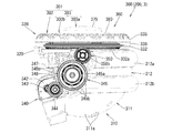
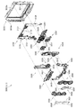
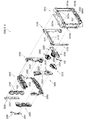
[2−3.外枠下組立体]
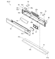
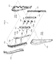
外枠2の外枠下組立体40について、主に図20を参照して詳細に説明する。図20は、外枠の外枠下組立体を分解して前から見た分解斜視図である。外枠下組立体40は、左右に離間している外枠左組立体10及び外枠右組立体20の下端同士を連結すると共に、パチンコ機1において扉枠3よりも下側を閉鎖して装飾するためのものである。
[2-3. Outer frame lower assembly]
The outer frame lower assembly 40 of the outer frame 2 will be described in detail with reference mainly to FIG. FIG. 20 is an exploded perspective view of the lower outer frame assembly of the outer frame as viewed from the front. The lower outer frame assembly 40 connects the lower ends of the left outer frame assembly 10 and the right outer frame assembly 20 spaced apart to the left and right, and closes the lower side of the door frame 3 in the pachinko machine 1. It is for decoration.
外枠下組立体40は、左右に離間している外枠左組立体10及び外枠右組立体20の下端同士を連結しており左右に延びている外枠下部材41と、外枠下部材41の前方に配置されており外枠下部材41に沿って左右に延びていると共に後方が開放されている箱状の幕板前部材42と、幕板前部材42の後側に取付けられていると共に外枠下部材41の上面に取付けられており前方が開放されている左右に延びた箱状の幕板後部材43と、幕板後部材43の上面における左端に形成されている球噛防止機構44と、を備えている。
The outer frame lower assembly 40 connects the lower ends of the outer frame left assembly 10 and the outer frame right assembly 20 which are separated left and right, and extends in the left and right direction; A box-shaped front curtain member 42 which is disposed forward of the member 41 and extends left and right along the outer frame lower member 41 and whose rear is open, and is attached to the rear side of the front curtain member 42 And a box-shaped rear curtain plate member 43 attached to the upper surface of the outer frame lower member 41 and extending forwardly open, and a ball biting prevention formed on the left end of the upper surface of the rear curtain plate member 43 And a mechanism 44.
外枠下部材41は、前後方向の幅が、外枠左部材11及び外枠右部材21の前後方向と略同じ幅で、上下方向の厚さが一定で、左右方向に延びており、木材によって形成されている。外枠下部材41は、左右方向の長さが、外枠上部材30の左右方向の長さと同じに形成されている。
The outer frame lower member 41 has a width in the longitudinal direction substantially the same as the longitudinal direction of the outer frame left member 11 and the outer frame right member 21 and has a constant thickness in the vertical direction and extends in the lateral direction. It is formed by The outer frame lower member 41 is formed to have the same length in the left-right direction as the length in the left-right direction of the outer frame upper member 30.
外枠下部材41は、左右両側面における前後方向の中央において、上下に貫通した状態で左右方向中央側へ夫々窪んでいる切欠部41aを備えている。これら左右両端の切欠部41aには、左下連結部材13の下横固定部13c及び右下連結部材23の下横固定部23cが夫々挿入された状態で取付けられる。これにより、外枠左部材11及び外枠右部材21の下端同士を連結することができる。
The outer frame lower member 41 is provided with a notch 41a which is recessed to the center in the left-right direction in a state of penetrating vertically in the center in the front-rear direction on both left and right side surfaces. The lower horizontal fixing portion 13c of the lower left connecting member 13 and the lower horizontal fixing portion 23c of the lower right connecting member 23 are attached to the notches 41a at the left and right ends, respectively. Thereby, the lower ends of the outer frame left member 11 and the outer frame right member 21 can be connected.
また、外枠下部材41は、上面から凹んでおり、幕板後部材43の下部が挿入される凹部41bを備えている。凹部41bは、左右に延びていると共に、前後方向中央の後ろ寄りの位置から前端側へ抜けている。この凹部41bにより、幕板前部材42及び幕板後部材43により形成される幕板内部空間40aの容積を可及的に広くしている。
Further, the outer frame lower member 41 is recessed from the upper surface, and is provided with a recess 41 b into which the lower portion of the rear curtain plate member 43 is inserted. The concave portion 41 b extends in the left and right direction, and extends from the rear position of the center in the front-rear direction to the front end side. The recessed portion 41 b widens the volume of the inner space 40 a of the curtain plate formed by the front plate member 42 and the rear plate member 43 as much as possible.
幕板前部材42は、左右方向の長さが外枠下部材41と同じ長さに延びており、高さに対して前後方向の奥行が短い横長の直方体状の箱状に形成されており、後側の全面が開放されている。幕板前部材42は、開放されている後側を、幕板後部材43によって閉鎖することで、幕板後部材43と協働して本体枠スピーカ622のエンクロージャ624の一部となる幕板内部空間40aを形成する。幕板前部材42は、右端付近の前面において、前後に貫通していると共に左右に延びている長孔状の開口部42aを備えている。
The front curtain plate member 42 is formed in a horizontally-long rectangular parallelepiped box shape whose length in the left-right direction extends to the same length as the outer frame lower member 41, and the depth in the front-rear direction is short with respect to the height The entire rear side is open. The front curtain member 42 closes the open rear side with the rear curtain plate member 43 so as to cooperate with the rear curtain plate member 43 to be part of the enclosure 624 of the main frame speaker 622 The space 40a is formed. The front curtain member 42 has an elongated opening 42a penetrating in the front and back direction and extending in the left and right direction on the front surface near the right end.
幕板後部材43は、左右方向の長さが外枠下部材41よりも若干短く延びており、前方が開放された箱状に形成されている。幕板後部材43は、前面に幕板前部材42を取付けることで、幕板前部材42と協働して本体枠スピーカ622のエンクロージャ624の一部となる幕板内部空間40aを形成する。幕板後部材43は、上面における左右方向中央部において、左右に延びていると共に上方へ突出しており幕板内部空間40aと連通している筒状の接続筒部43aを有している。接続筒部43aは、上端が、幕板後部材43の一般的な上面と一致している前端側から後方へ向かうほど上方へ位置するように傾斜している。本実施形態では、接続筒部43aの上端は、45度の角度で傾斜している。
The rear curtain plate member 43 has a length in the left-right direction extending slightly shorter than that of the outer frame lower member 41, and is formed in a box shape whose front is open. The rear curtain plate member 43 cooperates with the front curtain plate member 42 to form the inner curtain plate space 40 a which becomes a part of the enclosure 624 of the main frame speaker 622 by attaching the front curtain plate member 42 to the front. The rear curtain plate member 43 has a cylindrical connection cylindrical portion 43a which extends in the left and right direction and protrudes upward and communicates with the inner curtain plate space 40a at the center in the left-right direction on the upper surface. The connecting cylindrical portion 43 a is inclined such that the upper end thereof is positioned upward from the front end side, which coincides with the general upper surface of the rear curtain plate 43, toward the rear. In the present embodiment, the upper end of the connection cylindrical portion 43a is inclined at an angle of 45 degrees.
この接続筒部43aは、左右方向の長さが、幕板後部材43全体の約1/3の長さに形成されていると共に、前後方向の奥行が、幕板後部材43全体の奥行よりも若干短く形成されている。接続筒部43a内には、前端側と後端側とを結ぶ複数のリブ43bが備えられている。この接続筒部43aの上端には、外枠2に対して本体枠4を閉じた時に、本体枠4における基板ユニット620のスピーカユニット620aにおけるスピーカカバー621の接続部621cが接続されて、スピーカユニット620aの内部空間と連通した状態となり、エンクロージャ624を形成する。
The connecting cylindrical portion 43a has a length in the left-right direction which is about 1/3 the length of the entire rear curtain plate member 43, and a depth in the front-rear direction is greater than the depth of the entire rear curtain plate member 43. Is also formed slightly short. In the connection cylindrical portion 43a, a plurality of ribs 43b connecting the front end side and the rear end side are provided. The connection portion 621c of the speaker cover 621 of the speaker unit 620a of the board unit 620 in the main body frame 4 is connected to the upper end of the connection cylindrical portion 43a when the main body frame 4 is closed with respect to the outer frame 2. In communication with the internal space of 620 a, an enclosure 624 is formed.
球噛防止機構44は、幕板後部材43の上面における左端において、外枠下ヒンジ部材60の部位に遊技球Bが滞留することで、外枠2と本体枠4との間に遊技球Bが挟まれるのを防止するためのものである。
In the ball biting prevention mechanism 44, the gaming ball B is retained at the portion of the outer frame lower hinge member 60 at the left end of the upper surface of the curtain plate rear member 43, so that the gaming ball B is held between the outer frame 2 and the main body frame 4. It is for preventing that it is pinched.
球噛防止機構44は、幕板後部材43の上面における左端に形成されており、後述する外枠下ヒンジ部材60が際されるように平坦に形成された載置部44aと、載置部44aの左端において上方へ向かって開口している第一排出口44bと、載置部44aにおける第一排出口44bよりも右方で上方へ向かって開口している第二排出口44cと、載置部44aの後辺及び右辺から上方へ延出している立壁部44dと、立壁部44dの上端から前方へ突出していると共に上面が後方へ向かうに従って上方に位置するように傾斜している上端突出部44eと、を備えている。
The ball biting prevention mechanism 44 is formed at the left end of the upper surface of the curtain plate rear member 43, and is provided with a mounting portion 44a formed flat so that the outer frame lower hinge member 60 to be described later may be involved; A first discharge port 44b opened upward at the left end of the left end 44a, and a second discharge port 44c opened upward on the right side of the first discharge port 44b in the mounting portion 44a; An upright wall portion 44d extending upward from the rear side and the right side of the resting portion 44a, and an upper end projection projecting forward from the upper end of the upright wall portion 44d and inclined to be positioned upward as the upper surface goes rearward And a unit 44e.
第一排出口44bは、後述する外枠下ヒンジ部材60の排出孔60dと一致する位置に形成されている。第一排出口44b及び第二排出口44cは、遊技球Bが通過可能な大きさに形成されている。第一排出口44b及び第二排出口44cは、幕板内部空間40aとは連通しておらず、幕板後部材43の後面に開口している。従って、第一排出口44b及び第二排出口44cに進入した遊技球Bを、幕板後部材43の後方へ排出することができる。
The first discharge port 44 b is formed at a position that matches the discharge hole 60 d of the outer frame lower hinge member 60 described later. The first discharge port 44b and the second discharge port 44c are formed in a size that allows the game ball B to pass through. The first discharge port 44 b and the second discharge port 44 c do not communicate with the inner space 40 a of the curtain plate, and open at the rear surface of the curtain plate rear member 43. Therefore, the gaming ball B that has entered the first discharge port 44 b and the second discharge port 44 c can be discharged to the rear of the rear curtain plate member 43.
この球噛防止機構44は、球噛防止機構44は、外枠下ヒンジ部材60と後述する本体枠下ヒンジ組立体520との間の隙間を通して、ピアノ線等の不正な工具が挿入された場合、載置部44aの後端から立上っている立壁部44dにより、不正な工具の侵入を阻止することができる。仮に、不正な工具の先端が立壁部44dに当接することで、上方へ曲がったとしても、立壁部44dの上端に備えられている前方へ突出した上端突出部44eに当接し、これ以上の侵入を阻止することができる。従って、外枠下ヒンジ部材60の部位を介して、不正行為が行われるのを防止することができる。
In the ball biting prevention mechanism 44, when the ball biting preventing mechanism 44 is inserted into a gap between the outer frame lower hinge member 60 and the main frame lower hinge assembly 520 described later, an incorrect tool such as a piano wire is inserted. The rising wall portion 44d rising from the rear end of the mounting portion 44a can prevent unauthorized tool entry. Even if the tip of the incorrect tool abuts against the upright wall portion 44d, even if it is bent upward, it abuts on the forwardly projecting upper end projecting portion 44e provided on the upper end of the upright wall portion 44d, and further intrusion Can be blocked. Therefore, it is possible to prevent the fraudulent action from being performed through the portion of the outer frame lower hinge member 60.
ところで、載置部44aの後端に立壁部44dを備えた場合、外枠2に対して本体枠4を開けた時に、何らかの理由により載置部44a上に落下した遊技球Bが、立壁部44dによって外枠2の後方への移動が阻止されるため、載置部44a上に遊技球Bが滞留し易くなる。そして、載置部44a上に遊技球Bが滞留していると、外枠2に対して本体枠4を閉じる際に、外枠2と本体枠4との間に遊技球Bが挟み込まれてしまい、本体枠4を閉じることができなくなる問題が発生する。
By the way, when the standing wall portion 44d is provided at the rear end of the placing portion 44a, when the main body frame 4 is opened with respect to the outer frame 2, the gaming ball B dropped onto the placing portion 44a for some reason is the standing wall portion Since the movement of the outer frame 2 to the rear is blocked by 44d, the gaming ball B is easily retained on the placement portion 44a. Then, when the game ball B is staying on the placement portion 44a, when the main body frame 4 is closed to the outer frame 2, the game ball B is sandwiched between the outer frame 2 and the main body frame 4 As a result, there arises a problem that the body frame 4 can not be closed.
これに対して、本実施形態の球噛防止機構44では、外枠下ヒンジ部材60上や載置部44a上に落下した遊技球Bを、外枠下ヒンジ部材60の排出孔60dと第一排出口44bを通して、又は、第二排出口44cを通して、遊技球Bを幕板後部材43の後方(外枠2の後方)へ排出することができ、外枠2と本体枠4との間に遊技球Bが挟まれるのを防止することができる。
On the other hand, in the ball biting prevention mechanism 44 of the present embodiment, the game ball B dropped on the outer frame lower hinge member 60 or the placing portion 44a is firstly discharged from the discharge hole 60d of the outer frame lower hinge member 60. The game ball B can be discharged to the rear of the rear curtain plate member 43 (the rear of the outer frame 2) through the discharge port 44b or through the second discharge port 44c, and between the outer frame 2 and the main frame 4 It is possible to prevent the game ball B from being caught.
外枠下組立体40は、幕板前部材42及び幕板後部材43の上面に左右に離間して配置されている一対の案内部材45と、幕板前部材42の開口部42aを後側から閉鎖している平板状のグリル部材46と、グリル部材46を挟んで開口部42aを閉鎖するように幕板前部材42の内部に取付けられており前後に延びた二つの円筒を有したポート部材47と、幕板後部材43の接続筒部43aの上端に配置される枠状のシール部材48と、を備えている。
The lower outer frame assembly 40 closes a pair of guide members 45 disposed on the upper surfaces of the front and rear curtain plate members 42 and 43 at a distance to the left and right and the opening 42a of the front curtain plate member 42 from the rear side. A flat plate-like grill member 46, and a port member 47 having two cylinders extending in the front and rear direction and attached to the inside of the front curtain plate member 42 so as to close the opening 42a across the grill member 46; And a frame-like seal member 48 disposed at the upper end of the connection cylindrical portion 43 a of the rear curtain plate member 43.
一対の案内部材45は、外枠2に対して本体枠4を閉じた時に、扉枠3の下端が当接するものである。案内部材45は、摩擦抵抗の低い低摩擦材料によって形成されており、本体枠4の下端を滑り易くして、開閉を容易にしている。
When the main body frame 4 is closed with respect to the outer frame 2, the lower end of the door frame 3 abuts on the pair of guide members 45. The guide member 45 is formed of a low friction material having low friction resistance, and the lower end of the main body frame 4 is made slippery to facilitate opening and closing.
グリル部材46は、無数の小穴を有したパンチングメタルにより形成されている。ポート部材47は、二つの円筒により、グリル部材46を介して幕板内部空間40a(エンクロージャ624)と外枠2の前方とを連通させている。ポート部材47は、二つの円筒が、所定の内径で所定の長さに形成されており、ヘルムホルツ共鳴の原理により本体枠スピーカ622から後方(エンクロージャ624内)へ発せられた低音を共振・増幅させて、豊かな低音を外枠2の前方(遊技者側)へ放射することができる。つまり、本実施形態では、本体枠スピーカ622のエンクロージャ624がバスレフ型とされており、遊技者に対して重低音を聞かせることができる。
The grill member 46 is formed of punching metal having innumerable small holes. The port member 47 communicates the curtain inner space 40 a (the enclosure 624) with the front of the outer frame 2 through the grill member 46 by two cylinders. In the port member 47, two cylinders are formed with a predetermined inner diameter and a predetermined length, and resonate and amplify the bass emitted from the main body frame speaker 622 to the rear (in the enclosure 624) according to the principle of Helmholtz resonance. Thus, rich bass can be radiated to the front of the outer frame 2 (player's side). That is, in the present embodiment, the enclosure 624 of the main body frame speaker 622 is of a bass reflex type, so that the player can hear a deep bass.
シール部材48は、外枠2に対して本体枠4を閉じた時に、接続筒部43aの上端と本体枠4におけるスピーカカバー621の接続部621cの下端との間に挟まれて圧縮されるものであり、接続筒部43aと接続部621cとの間からスピーカのエンクロージャ内の音が漏れるのを防止するものである。
The seal member 48 is compressed between the upper end of the connection cylindrical portion 43a and the lower end of the connection portion 621c of the speaker cover 621 in the main body frame 4 when the main body frame 4 is closed with respect to the outer frame 2. Thus, it is possible to prevent the sound in the enclosure of the speaker from leaking between the connection cylindrical portion 43a and the connection portion 621c.
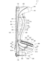
[2−4.外枠上ヒンジ組立体]
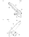
外枠2の外枠上ヒンジ組立体50について、主に図21を参照して詳細に説明する。図21(a)は外枠2の外枠上ヒンジ組立体を分解して前上から見た分解斜視図であり、(b)は(a)を前下から見た分解斜視図である。外枠上ヒンジ組立体50は、外枠左組立体10の上端と外枠上部材30の左端に取付けられるものであり、外枠2に対して本体枠4をヒンジ回転可能に取付けるためのものである。外枠上ヒンジ組立体50は、外枠左部材11の凹部11aの上端と外枠上部材30の取付段部30bとに取付けられる外枠上ヒンジ部材51と、外枠上ヒンジ部材51に取付けられているロック部材52と、ロック部材52を外枠上ヒンジ部材51に取付けている取付ビス53と、を備えている。
[2-4. Outer frame and upper hinge assembly]
The outer frame upper hinge assembly 50 of the outer frame 2 will be described in detail with reference mainly to FIG. Fig.21 (a) is a disassembled perspective view which disassembled the outer frame upper hinge assembly of the outer frame 2, and was seen from the front upper, and (b) is the disassembled perspective view which looked at (a) from the front lower. The outer frame upper hinge assembly 50 is attached to the upper end of the outer frame left assembly 10 and the left end of the outer frame upper member 30, and is for attaching the main frame 4 to the outer frame 2 so as to be hinge rotatable. It is. The outer frame upper hinge assembly 50 is attached to the outer frame upper hinge member 51 attached to the upper end of the recess 11 a of the outer frame left member 11 and the mounting step 30 b of the outer frame upper member 30 and the outer frame upper hinge member 51 And an attachment screw 53 for attaching the lock member 52 to the outer frame upper hinge member 51.
外枠上ヒンジ部材51は、水平に延びた平板状で外枠上部材30の取付段部30bの上面に取付けられる上固定部51aと、上固定部51aの前辺から前方へ延出している平板状の前方延出部51bと、前方延出部51bの右辺の途中から前方へ向かうに従って前方延出部51bの左右中央へ延びており上下に貫通している軸受溝51cと、上固定部51aの左辺から下方へ延びている平板状の横固定部51dと、前方延出部51bの左辺から前辺を周って軸受溝51cが開口している部位までの端縁から下方へ延びており横固定部51dと連続している平板状の端縁壁部51eと、を備えている。外枠上ヒンジ部材51は、金属板をプレス成型により打抜き・屈曲させて形成されている。外枠上ヒンジ部材51は、軸受溝51c内において、本体枠上ヒンジ部材510の後述する本体枠上ヒンジピン512を回転可能に支持することができる。
The outer frame upper hinge member 51 extends from the front side of the upper fixing portion 51a to the upper fixing portion 51a attached to the upper surface of the mounting step portion 30b of the outer frame upper member 30 and extends horizontally from the front side of the upper fixing portion 51a. A flat front extension 51b, a bearing groove 51c extending to the left and right center of the front extension 51b from the middle of the right side of the front extension 51b and penetrating vertically, and an upper fixing portion The plate-like horizontal fixing portion 51d extending downward from the left side of 51a, and extending downward from the end edge to the portion where the bearing groove 51c is open from the left side to the front side of the front extension 51b And a flat plate-like end edge wall 51e which is continuous with the cage horizontal fixing portion 51d. The outer frame upper hinge member 51 is formed by punching and bending a metal plate by press molding. The outer frame upper hinge member 51 can rotatably support a later-described main frame upper hinge pin 512 of the main frame upper hinge member 510 in the bearing groove 51c.
ロック部材52は、前後に延びている帯板状のロック本体52aと、ロック本体52aの後端から右方へ突出している操作片52bと、ロック本体52aの後端から左方へ延びた後に斜め左前方へ延びている弾性変形可能な棒状の弾性部52cと、ロック本体52aの後端付近で上下に貫通している取付孔52dと、を備えている。ロック部材52は、合成樹脂によって形成されている。ロック部材52は、取付ビス53によって、外枠上ヒンジ部材51における前方延出部51bの下面で、軸受溝51cよりも後側の部位に回動可能に取付けられる。
The lock member 52 has a strip-shaped lock main body 52a extending in the front and rear direction, an operation piece 52b projecting rightward from the rear end of the lock main body 52a, and a left side extending from the rear end of the lock main body 52a. An elastically deformable rod-like elastic portion 52c extending diagonally forward to the left and an attachment hole 52d penetrating vertically in the vicinity of the rear end of the lock main body 52a are provided. The lock member 52 is formed of a synthetic resin. The lock member 52 is rotatably attached to the rear side of the bearing groove 51c on the lower surface of the front extension 51b of the outer frame upper hinge member 51 by the mounting screw 53.
ロック部材52は、外枠上ヒンジ部材51に取付けた状態で、ロック本体52aが、平面視で軸受溝51cを遮ることができると共に、前端付近の右側面が、外枠上ヒンジ部材51の端縁壁部51eにおける軸受溝51cの開口まで延びている部位と当接可能となるように前方へ延びている。また、ロック本体52aの後端から左方へ延びている弾性部52cの先端は、外枠上ヒンジ部材51における端縁壁部51eの内周面に当接している。このロック部材52は、弾性部52cの付勢力によって取付孔52dを中心に、前端が左方へ回動する方向に付勢されている。従って、通常の状態では、ロック部材52のロック本体52aの前端付近の右側面が、端縁壁部51eに当接している。この状態では、軸受溝51cにおけるロック本体52aよりも前側の部位に、本体枠上ヒンジ部材510の本体枠上ヒンジピン512を収容可能な空間が形成される。
With the lock member 52 attached to the outer frame upper hinge member 51, the lock main body 52a can block the bearing groove 51c in plan view, and the right side near the front end is the end of the outer frame upper hinge member 51. It extends forward so as to be able to abut on a portion of the edge wall 51e which extends to the opening of the bearing groove 51c. Further, the tip end of the elastic portion 52 c extending leftward from the rear end of the lock main body 52 a is in contact with the inner peripheral surface of the end edge wall portion 51 e of the outer frame upper hinge member 51. The lock member 52 is biased in a direction such that the front end pivots to the left around the attachment hole 52d by the biasing force of the elastic portion 52c. Therefore, in the normal state, the right side surface in the vicinity of the front end of the lock main body 52a of the lock member 52 is in contact with the edge wall 51e. In this state, a space capable of accommodating the main frame upper hinge pin 512 of the main frame upper hinge member 510 is formed in a portion on the front side of the lock main body 52a in the bearing groove 51c.
このロック部材52は、操作片52bを操作することで、弾性部52cの付勢力に抗してロック本体52aを回動させることができる。そして、操作片52bの操作によって、ロック本体52aを、その前端が左方へ移動する方向へ回動させることで、平面視において軸受溝51cからロック本体52aを後退させることができ、軸受溝51cが全通している状態とすることができる。これにより、軸受溝51c内に本体枠上ヒンジピン512を挿入したり、軸受溝51c内から本体枠上ヒンジピン512を外したりすることができる。
The lock member 52 can rotate the lock main body 52a against the biasing force of the elastic portion 52c by operating the operation piece 52b. Then, the lock body 52a can be retracted from the bearing groove 51c in plan view by rotating the lock body 52a in the direction in which the front end moves leftward by the operation of the operation piece 52b, and the bearing groove 51c Can be completely through. Thereby, the main frame upper hinge pin 512 can be inserted into the bearing groove 51c, or the main frame upper hinge pin 512 can be removed from the inside of the bearing groove 51c.
[2−5.外枠下ヒンジ部材]
外枠2の外枠下ヒンジ部材60について、主に図18を参照して詳細に説明する。外枠下ヒンジ部材60は、水平に延びた平板状の水平部60aと、水平部60aの左辺において前後方向中央よりも後側の部位から上方へ立上っている平板状の立上部60bと、水平部60aの前端付近から上方へ突出している外枠下ヒンジピン60cと、水平部60aを上下に貫通しており遊技球Bが一つのみ通過可能な大きさの排出孔60dと、を備えている。この外枠下ヒンジ部材60は、金属板をプレス成型により打抜き・屈曲させて形成されている。
[2-5. Outer frame lower hinge member]
The outer frame lower hinge member 60 of the outer frame 2 will be described in detail with reference mainly to FIG. The outer frame lower hinge member 60 includes a horizontally extending flat plate-like horizontal portion 60a, and a flat plate-like rising portion 60b rising upward from a portion behind the center in the front-rear direction on the left side of the horizontal portion 60a. And an outer frame lower hinge pin 60c projecting upward from the vicinity of the front end of the horizontal portion 60a; and a discharge hole 60d which has a size that allows the game ball B to pass through vertically through the horizontal portion 60a. ing. The outer frame lower hinge member 60 is formed by punching and bending a metal plate by press molding.
外枠下ヒンジ部材60の水平部60aは、平面視において、左辺を底辺とした台形に形成されている。外枠下ヒンジピン60cは、円柱状で、上下方向中央よりも上部が、上端が窄まった円錐台状に形成されている。この外枠下ヒンジピン60cは、水平部60aの前端付近における左寄りの位置に取付けられている。排出孔60dは、水平部60aにおいて、立上部60bの前後方向中央の部位と接し、水平部60aの左辺から右方へ逆U字状に延びるように形成されている。この排出孔60dは、外枠下組立体40における球噛防止機構44の第一排出口44bと、略同じ大きさに形成されている。
The horizontal portion 60a of the outer frame lower hinge member 60 is formed in a trapezoidal shape with the left side as the base in a plan view. The outer frame lower hinge pin 60c has a cylindrical shape and is formed in a truncated cone shape whose upper end is narrowed at the upper end than the center in the vertical direction. The outer frame lower hinge pin 60c is attached at a left position near the front end of the horizontal portion 60a. The discharge hole 60d is formed in the horizontal portion 60a so as to be in contact with a central portion of the upright portion 60b in the front-rear direction, and extends in a reverse U shape from the left side of the horizontal portion 60a to the right. The discharge hole 60 d is formed to have substantially the same size as the first discharge port 44 b of the ball bite prevention mechanism 44 in the outer frame lower assembly 40.
外枠下ヒンジ部材60は、外枠2に組立てた状態で、水平部60aの後部が、外枠下組立体40における幕板後部材43の載置部44a上に載置され、図示しないビスによって幕板後部材43に固定されている。また、立上部60bが、外枠左部材11の右側面における膨出部11bよりも前側の部位に、図示しないビスによって取付けられている。この外枠下ヒンジ部材60は、外枠下ヒンジピン60cを、本体枠4の本体枠下ヒンジ組立体520における外枠用下ヒンジ孔521aに挿通させることで、外枠上ヒンジ部材51と協働して本体枠4を開閉可能に取付けることができる。
The lower portion of the outer frame lower hinge member 60 is mounted on the mounting portion 44a of the rear curtain plate member 43 in the outer frame lower assembly 40 in the state assembled to the outer frame 2, and a screw not shown Is fixed to the rear curtain member 43 by the Further, the rising portion 60 b is attached to a portion on the front side of the bulging portion 11 b in the right side surface of the outer frame left member 11 by a screw (not shown). The outer frame lower hinge member 60 cooperates with the outer frame upper hinge member 51 by inserting the outer frame lower hinge pin 60 c into the outer frame lower hinge hole 521 a in the main frame lower hinge assembly 520 of the main frame 4. Thus, the main body frame 4 can be attached so as to be openable and closable.
また、外枠2を組立てた状態では、排出孔60dが、外枠下組立体40における球噛防止機構44の第一排出口44bと一致している。これにより、水平部60a上の遊技球Bを、排出孔60d及び第一排出口44bを通して、外枠2の後方へ落下(排出)させることができる。詳述すると、外枠2に対して本体枠4を閉じる時に、外枠2と本体枠4との間に落下した遊技球Bが、本体枠4が閉じられるのに従って、外枠2と本体枠4との間が徐々に狭くなることから、間隔が広い後方側へ転動とすることとなり、排出孔60dから排出させることができる。この際に、排出孔60dが、パチンコ機1に組立てた状態で、外枠2に対して本体枠4を閉じた時に、本体枠4の後端と略同じとなる位置に形成されているため、外枠2と本体枠4との間に落下した遊技球Bを、排出孔60dから排出させることで本体枠4よりも後側へ転動するのを阻止し易くすることができ、外枠下ヒンジ部材60の部位に遊技球Bが留まり難くすることができる。
Further, in the assembled state of the outer frame 2, the discharge hole 60 d matches the first discharge port 44 b of the anti-ball bite mechanism 44 in the outer frame lower assembly 40. Thereby, the game ball B on the horizontal portion 60a can be dropped (discharged) to the rear of the outer frame 2 through the discharge hole 60d and the first discharge port 44b. More specifically, when closing the main frame 4 with respect to the outer frame 2, the game ball B dropped between the outer frame 2 and the main frame 4 is closed as the main frame 4 is closed. Since the gap between 4 and 4 gradually narrows, it rolls to the rear side where the distance is wide, and can be discharged from the discharge hole 60d. At this time, the discharge hole 60d is formed at a position substantially the same as the rear end of the main body frame 4 when the main body frame 4 is closed with respect to the outer frame 2 in a state assembled to the pachinko machine 1. The game balls B dropped between the outer frame 2 and the main frame 4 can be more easily prevented from rolling backward than the main frame 4 by discharging the game balls B from the discharge holes 60 d. It is possible to make it difficult for the gaming ball B to stay at the portion of the lower hinge member 60.
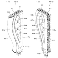
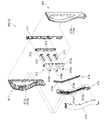
[3.扉枠の全体構成]
パチンコ機1の扉枠3について、主に図22乃至図30を参照して詳細に説明する。図22はパチンコ機における扉枠の表面図であり、図23は扉枠の背面図であり、図24は扉枠の左側面図であり、図25は扉枠の右側面図である。図26は扉枠を右前から見た斜視図であり、図27は扉枠を左前から見た斜視図であり、図28は扉枠を後ろから見た斜視図である。図29は扉枠を主な部材毎に分解して前から見た分解斜視図であり、図30は扉枠を主な部材毎に分解して後ろから見た分解斜視図である。
[3. Overall configuration of the door frame]
The door frame 3 of the pachinko machine 1 will be described in detail mainly with reference to FIG. 22 to FIG. 22 is a surface view of a door frame in a pachinko machine, FIG. 23 is a rear view of the door frame, FIG. 24 is a left side view of the door frame, and FIG. 25 is a right side view of the door frame. 26 is a perspective view of the door frame as viewed from the front right, FIG. 27 is a perspective view of the door frame as viewed from the left front, and FIG. 28 is a perspective view of the door frame as viewed from the rear. FIG. 29 is an exploded perspective view of the door frame disassembled into main members and viewed from the front, and FIG. 30 is an exploded perspective view of the door frame disassembled into main members and viewed from the rear.
扉枠3は、外枠2の枠内と略同じ大きさで正面視において上下に延びた四角形に形成されており、本体枠4を介して外枠2の枠内を前側から開閉可能に取付けられている。扉枠3は、遊技球Bが打込まれる遊技盤5の遊技領域5aを前側から視認可能に閉鎖し、遊技領域5a内に打込むための遊技球Bを貯留すると共に、貯留している遊技球Bを遊技領域5a内へ打込むために遊技者が操作するハンドル182を備えているものである。また、扉枠3は、パチンコ機1の前面全体を装飾するものである。
The door frame 3 has a substantially the same size as the inside of the frame of the outer frame 2 and is formed in a rectangular shape extending in the vertical direction in a front view, and the inside of the frame of the outer frame 2 can be attached openably from the front side It is done. The door frame 3 closes the gaming area 5a of the gaming board 5 in which the gaming ball B is struck so as to be visible from the front side, stores the gaming ball B for hitting into the gaming area 5a, and stores the gaming It has a handle 182 operated by the player in order to drive the ball B into the game area 5a. Moreover, the door frame 3 decorates the whole front of the pachinko machine 1.
扉枠3は、正面視の外形が上下に延びた四角形で枠状の扉枠ベースユニット100と、扉枠ベースユニット100に着脱可能に取付けられており本体枠4に取付けられた遊技盤5の遊技領域5aを前方から視認可能に閉鎖しているガラスユニット160と、ガラスユニット160の下部を後側から覆うように扉枠ベースユニット100に取付けられている防犯カバー170と、扉枠ベースユニット100の前面右下隅に取付けられているハンドルユニット180と、扉枠ベースユニット100の前面下部に取付けられている皿ユニット200と、皿ユニット200の上側で扉枠ベースユニット100の前面左部に取付けられている扉枠左サイドユニット400と、皿ユニットの上側で扉枠ベースユニット100の前面右部に取付けられている扉枠右サイドユニット410と、扉枠左サイドユニット400及び扉枠右サイドユニット410の上側で扉枠ベースユニット100の前面上部に取付けられている扉枠トップユニット450と、を備えている。
The door frame 3 is a rectangular frame-shaped door frame base unit 100 whose outer shape in the front view extends vertically, and the game board 5 which is removably attached to the door frame base unit 100 and attached to the main body frame 4 A glass unit 160 closing the gaming area 5a so as to be visible from the front, a crime prevention cover 170 attached to the door frame base unit 100 so as to cover the lower part of the glass unit 160 from the rear side, A handle unit 180 attached to the front lower right corner, a pan unit 200 mounted to the lower front of the door frame base unit 100, and a front upper portion of the door frame base unit 100 above the pan unit 200. The door frame left side unit 400 is attached to the front right side of the door frame base unit 100 above the plate unit A frame right side unit 410, and a door frame top unit 450 which is attached to the upper front portion of the door frame base unit 100 at the upper side of the door frame left side unit 400 and the door frame right side unit 410, a.
扉枠ベースユニット100は、正面視の外形が上下に延びた四角形(長方形)に形成されており前後に貫通している扉窓101aを有した扉枠ベース101と、扉枠ベース101の前面右下に取付けられているハンドル取付部材102と、扉枠ベース101の後側で背面視右下隅に取付けられているスピーカダクト103と、扉枠ベース101の後側の下部における背面視右端付近に取付けられている扉枠主中継基板104と、扉枠主中継基板104の背面視左方に取付けられている扉枠副中継基板105と、扉枠副中継基板105の背面視左方に取付けられているハンドル後中継基板106と、扉枠主中継基板104と扉枠副中継基板105の一部とを後側から被覆する扉枠中継基板カバー107と、ハンドル後中継基板106を後側から被覆するハンドル後中継基板カバー108と、配線ケーブルを被覆するケーブルカバー109と、を備えている。
The door frame base unit 100 has a door frame base 101 having a door window 101 a which is formed in a rectangular shape (rectangular shape) in which the outer shape of the front view extends vertically, and the front right of the door frame base 101 Handle attachment member 102 attached below, speaker duct 103 attached to the lower right corner in rear view on the rear side of the door frame base 101, and attached near the rear end right end in the lower part on the rear side of the door frame base 101 The door frame main relay board 104, the door frame sub relay board 105 mounted on the left side of the door frame main relay board 104, and the door frame sub relay board 105 on the left side A door frame relay board cover 107 that covers the rear handlebar relay board 106, the door frame main relay board 104, and part of the door frame sub relay board 105 from the rear side, and the handlebar relay board 106 from the rear side A handle after the relay board cover 108 for covering a cable cover 109 for covering the distribution cable, and a.
また、扉枠ベースユニット100は、扉枠ベース101の後側に取付けられている枠状の扉枠補強ユニット110と、扉枠補強ユニット110に取付けられている扉枠上ヒンジ組立体120及び扉枠下ヒンジ部材125と、扉枠補強ユニット110に取付けられている開閉用のシリンダ錠130と、扉枠ベース101の後側でハンドル後中継基板106の上方に取付けられている球送給ユニット140と、扉枠ベース101の後側の下部における背面視右側に取付けられているファールカバーユニット150と、を備えている。
In addition, the door frame base unit 100 includes a frame-shaped door frame reinforcing unit 110 attached to the rear side of the door frame base 101, and a door frame upper hinge assembly 120 attached to the door frame reinforcing unit 110 and a door A frame lower hinge member 125, a cylinder lock 130 for opening and closing attached to the door frame reinforcing unit 110, and a ball feeding unit 140 attached above the rear handle relay board 106 on the rear side of the door frame base 101. And a foul cover unit 150 mounted on the right of the rear lower portion of the door frame base 101 in a rear view.
扉枠補強ユニット110は、扉枠ベース101の後側に取付けられることで、扉枠ベース101を補強して剛性を付与するものである。扉枠上ヒンジ組立体120及び扉枠下ヒンジ部材125は、扉枠3を本体枠4に対して開閉可能に取付けるためのものである。シリンダ錠130は、本体枠4の施錠ユニット650と協働して、扉枠3と本体枠4との開閉、及び、外枠2と本体枠4との開閉施錠に使用されるものである。
The door frame reinforcing unit 110 is attached to the rear side of the door frame base 101 to reinforce the door frame base 101 and impart rigidity. The door frame upper hinge assembly 120 and the door frame lower hinge member 125 are for attaching the door frame 3 to the main body frame 4 so as to be able to open and close. The cylinder lock 130 is used for opening and closing the door frame 3 and the body frame 4 and for opening and closing the outer frame 2 and the body frame 4 in cooperation with the locking unit 650 of the body frame 4.
また、球送給ユニット140は、上皿201内の遊技球Bを一つずつ本体枠4の球発射装置540へ供給するためのものである。ファールカバーユニット150は、球発射装置540により発射されて遊技盤5の遊技領域5a内に到達しなかった遊技球B(ファール球)を、下皿202に誘導すると共に、払出装置580から払出された遊技球Bを、上皿201又は下皿202に誘導するためのものである。
Further, the ball feeding unit 140 is for supplying the gaming balls B in the upper tray 201 one by one to the ball launching device 540 of the main body frame 4. The foul cover unit 150 guides the game ball B (fall ball) that has been fired by the ball launcher 540 and has not reached the game area 5a of the game board 5 to the lower tray 202 and is paid out from the payout device 580 The game ball B is to be guided to the upper tray 201 or the lower tray 202.
ガラスユニット160は、透明なガラス板162を有しており扉枠ベース101の扉窓101aを閉鎖している。防犯カバー170は、ガラスユニット160の下部を後方から覆うように扉枠ベース101に取付けられている。ハンドルユニット180は、遊技者が回転操作可能なハンドル182を備えており、ハンドル182を操作することで、上皿201内の遊技球Bを、球発射装置540によって遊技盤5の遊技領域5a内に打込む遊技を行うためのものである。
The glass unit 160 has a transparent glass plate 162 and closes the door window 101 a of the door frame base 101. The crime prevention cover 170 is attached to the door frame base 101 so as to cover the lower part of the glass unit 160 from the rear. The handle unit 180 is provided with a handle 182 which can be operated by the player. By operating the handle 182, the game ball B in the upper tray 201 can be inserted into the game area 5a of the game board 5 by the ball launcher 540. It is for playing the game which is thrown into.
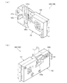
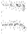
[3−1.扉枠ベースユニットの全体構成]
扉枠3の扉枠ベースユニット100について、主に図31乃至図33を参照して詳細に説明する。図31(a)は扉枠の扉枠ベースユニットを前から見た斜視図であり、(b)は扉枠ベースユニットを後ろから見た斜視図である。図32は扉枠ベースユニットを主な部材毎に分解して前から見た分解斜視図であり、図33は扉枠ベースユニットを主な部材毎に分解して後ろから見た分解斜視図である。
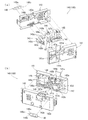
[3-1. Overall configuration of door frame base unit]
The door frame base unit 100 of the door frame 3 will be described in detail with reference mainly to FIGS. 31 to 33. 31 (a) is a perspective view of a door frame base unit of a door frame as viewed from the front, and FIG. 31 (b) is a perspective view of the door frame base unit as viewed from the rear. 32 is an exploded perspective view of the door frame base unit disassembled into main members and viewed from the front, and FIG. 33 is an exploded perspective view of the door frame base unit disassembled into main members and viewed from the rear is there.
扉枠ベースユニット100は、正面視左辺側が本体枠4に対してヒンジ回転可能に取付けられ、本体枠4の前面を開閉可能に閉鎖していると共に、本体枠4に取付けられている遊技盤の遊技領域を前方から視認可能としている。扉枠ベースユニット100は、外形が上下に延びた四角形で平板状の扉枠ベース101と、扉枠ベース101の前面右下に取付けられておりハンドルユニット180を取付けるためのハンドル取付部材102と、扉枠ベース101の後側で背面視右下隅に取付けられているスピーカダクト103と、を備えている。
The door frame base unit 100 is mounted on the left side in a front view in a hinge rotatable manner with respect to the main body frame 4 and closes the front of the main body frame 4 so as to be openable and closable. The game area is visible from the front. The door frame base unit 100 has a rectangular, flat door frame base 101 whose outer shape extends vertically, and a handle attachment member 102 attached to the front lower right of the door frame base 101 for attaching the handle unit 180. And a speaker duct 103 attached to the lower right corner in a rear view on the rear side of the door frame base 101.
また、扉枠ベースユニット100は、扉枠ベース101の後側の下部における背面視右端付近に取付けられている扉枠主中継基板104と、扉枠ベース101の後側の下部における扉枠主中継基板104の背面視左方に取付けられている扉枠副中継基板105と、扉枠ベース101の後側の下部における扉枠副中継基板105の背面視左方に取付けられているハンドル後中継基板106と、扉枠ベース101の後側に取付けられており扉枠主中継基板104と扉枠副中継基板105の一部とを後側から被覆する扉枠中継基板カバー107と、扉枠ベース101の後側に取付けられておりハンドル後中継基板106を後側から被覆するハンドル後中継基板カバー108と、扉枠ベース101の後側に取付けられており配線ケーブルを被覆するケーブルカバー109と、を備えている。
In addition, the door frame base unit 100 is a door frame main relay board 104 mounted near the right end in the rear view in the lower portion on the rear side of the door frame base 101 and a door frame main relay in the lower portion on the rear side of the door frame base 101 A door frame sub relay board 105 attached to the left side of the rear view of the substrate 104 and a handle back relay board attached to the left side of the door frame sub relay board 105 at the lower rear side of the door frame base 101 106, a door frame relay board cover 107 mounted on the rear side of the door frame base 101 and covering the door frame main relay board 104 and a part of the door frame sub relay board 105 from the rear side, the door frame base 101 The back handle handle relay board cover 108 is attached to the back of the handlebar and covers the handle back handle relay board 106 from the back side, and is attached to the back side of the door frame base 101 to cover the wiring cable. And Burukaba 109, and a.
更に、扉枠ベースユニット100は、扉枠ベース101の後側に取付けられている枠状の扉枠補強ユニット110と、扉枠補強ユニット110に取付けられている扉枠上ヒンジ組立体120及び扉枠下ヒンジ部材125と、扉枠補強ユニット110に取付けられている開閉用のシリンダ錠130と、扉枠ベース101の後側でハンドル後中継基板106の上方に取付けられている球送給ユニット140と、扉枠ベース101の後側の下部における背面視右側に取付けられているファールカバーユニット150と、を備えている。
Further, the door frame base unit 100 includes a frame-like door frame reinforcing unit 110 attached to the rear side of the door frame base 101, and a door frame upper hinge assembly 120 and a door attached to the door frame reinforcing unit 110. A frame lower hinge member 125, a cylinder lock 130 for opening and closing attached to the door frame reinforcing unit 110, and a ball feeding unit 140 attached above the rear handle relay board 106 on the rear side of the door frame base 101. And a foul cover unit 150 mounted on the right of the rear lower portion of the door frame base 101 in a rear view.
この扉枠ベースユニット100には、前面下隅にハンドルユニット180が、扉窓101aの下側前面に皿ユニット200が、扉窓101aの左外側前面に扉枠左サイドユニット400が、扉窓101aの右外側前面に扉枠右サイドユニット410が、扉窓101aの上外側前面に扉枠トップユニット450が、夫々取付けられるものである。
In the door frame base unit 100, the handle unit 180 is in the front lower corner, the dish unit 200 is in the lower front of the door window 101a, the door frame left side unit 400 is in the front left outside of the door window 101a, and A door frame right side unit 410 is attached to the right outer front, and a door frame top unit 450 is attached to the upper outer front of the door window 101a.
また、扉枠ベースユニット100には、扉窓101aを後方から閉鎖するようにガラスユニット160が取付けられると共に、ガラスユニット160の下部を後方から覆うように透明な防犯カバー170が取付けられるものである。
Further, the glass frame 160 is attached to the door frame base unit 100 so as to close the door window 101a from the rear, and the transparent crime prevention cover 170 is attached to cover the lower part of the glass unit 160 from the rear. .
[3−1a.扉枠ベース]
扉枠3における扉枠ベースユニット100の扉枠ベース101について、主に図31乃至図33を参照して詳細に説明する。扉枠ベース101は、正面視の外形が上下に延びた四角形(長方形)に形成されている。扉枠ベース101は、前後に貫通しており、正面視における内周形状が上下に延びた略四角形に形成された扉窓101aを備えている。扉窓101aは、内周を形成している上辺及び左右両辺が、扉枠ベース101の外周辺に夫々接近しており、内周を形成している下辺が、扉枠ベース101の下端から上下方向の約1/3の高さに位置している。このように、扉枠ベース101は、前後に貫通している扉窓101aにより全体が枠状に形成されている。この扉枠ベース101は、合成樹脂により一体成形されている。
3-1a. Door frame base]
The door frame base 101 of the door frame base unit 100 in the door frame 3 will be described in detail mainly with reference to FIG. 31 to FIG. The door frame base 101 is formed in a quadrangle (rectangle) in which the outer shape in a front view extends vertically. The door frame base 101 is penetrated back and forth, and is provided with the door window 101a formed in a substantially rectangular shape whose inner peripheral shape in a front view extends vertically. The upper side and the left and right sides forming the inner periphery of the door window 101a approach the outer periphery of the door frame base 101 respectively, and the lower side forming the inner periphery is from the lower end of the door frame base 101 up and down It is located at a height of about 1/3 of the direction. Thus, the door frame base 101 is formed in a frame shape as a whole by the door window 101 a penetrating in the front and back direction. The door frame base 101 is integrally molded of synthetic resin.
扉枠ベース101は、前面における正面視右下隅に形成されており左端側が右端側よりも前方へやや突出するように傾斜しているハンドル取付座面101bと、ハンドル取付座面101bと扉窓101aとの間で正面視右端付近に後面から前方へ向かって窪み、扉枠補強ユニット110のシリンダ取付フレーム115が挿入される挿入凹部101cと、挿入凹部101cにおいて前後に貫通しておりシリンダ錠130のシリンダ本体131が挿通されるシリンダ挿通孔101dと、シリンダ挿通孔101d及びハンドル取付座面101bの正面視左側で前後に貫通しており球送給ユニット140の進入口141a及び球抜口141bを前方に臨ませるための球送給開口101eと、を備えている。
The door frame base 101 is formed at the front right lower corner of the front view and is inclined such that the left end side protrudes slightly more forward than the right end side, the handle mounting surface 101b, and the door window 101a. Between the front end and the insertion recess 101c in which the cylinder mounting frame 115 of the door frame reinforcing unit 110 is inserted and the insertion recess 101c penetrates back and forth in the cylinder lock 130 The cylinder insertion hole 101d into which the cylinder main body 131 is inserted, and the cylinder insertion hole 101d and the handle mounting surface 101b are penetrated back and forth in front view left side, and the entrance 141a and the ball outlet 141b of the ball feeding unit 140 And a ball feed opening 101e for facing the
また、扉枠ベース101は、左右方向中央より左寄りで且つハンドル取付座面101bと略同じ高さで前後に貫通しておりファールカバーユニット150の球放出口150dを前方に臨ませる下皿用球通過口101fと、正面視左端付近で扉窓101aの下辺に隣接するように前後に貫通しておりファールカバーユニット150の貫通球通路150aを前方に臨ませる上皿用球通過口101gと、扉窓101aの内周に沿って後面から前方へ向かって窪み、ガラスユニット160のガラス枠161が挿入されるガラスユニット取付部101hと、を備えている。
The door frame base 101 penetrates back and forth at the same height as the handle mounting seat surface 101b to the left of the center in the left-right direction and penetrates the ball outlet 150d of the far cover unit 150 forward for the lower bowl ball A passing hole 101f, a ball passing hole 101g for the upper tray which penetrates forward and backward through the ball passage 150a of the far cover unit 150 so as to penetrate forward and backward adjacent to the lower side of the door window 101a near the left end in front view And a glass unit attachment portion 101h into which the glass frame 161 of the glass unit 160 is inserted, which is recessed forward from the rear surface along the inner periphery of the window 101a.
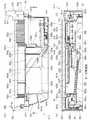
また、扉枠ベース101は、正面視左下隅(上皿用球通過口101gの下方)に形成されており前後に貫通した縦長の複数のスリット101iを、備えている。複数のスリット101iの後側にスピーカダクト103が取付けられる。また、複数のスリット101iは、パチンコ機1を組立てた状態で、前方に皿ユニット200における皿ユニットベース211のスピーカ口211bが位置していると共に、後方に本体枠4のスピーカユニット620aにおける本体枠スピーカ622が位置しており、本体枠スピーカ622からの音を前方へ放射することができる。
Further, the door frame base 101 is provided with a plurality of vertically elongated slits 101i which are formed at the lower left corner (below the ball passage opening 101g for the upper plate) in a front view and penetrate through the front and rear. The speaker duct 103 is attached to the rear side of the plurality of slits 101i. In the state where the pachinko machine 1 is assembled, the plurality of slits 101i has the speaker opening 211b of the plate unit base 211 of the plate unit 200 located forward and the main body frame of the speaker unit 620a of the main body frame 4 rearward. The speaker 622 is located, and the sound from the main body frame speaker 622 can be emitted forward.
更に、扉枠ベース101は、扉窓101aの下方でハンドル取付座面101bの上方において、前後に貫通している貫通孔101jを備えている。この貫通孔101jは、扉枠ベースユニット100側と皿ユニット200側とを接続する配線ケーブル(図示は省略)が挿通されるものであり、後述する扉枠補強ユニット110における中間補強フレーム114の貫通部114bと一致するように形成されている。
Furthermore, the door frame base 101 is provided with a through hole 101 j which passes through in the front and rear direction below the door window 101 a and above the handle mounting seat surface 101 b. A wiring cable (not shown) for connecting the door frame base unit 100 side and the plate unit 200 side is inserted through the through hole 101 j, and the intermediate reinforcing frame 114 in the door frame reinforcing unit 110 to be described later penetrates It is formed to coincide with the portion 114b.
[3−1b.ハンドル取付部材]
扉枠ベースユニット100のハンドル取付部材102について、主に図31乃至図33を参照して詳細に説明する。ハンドル取付部材102は、扉枠ベース101の前面にハンドルユニットを取付けるためのものであり、扉枠ベース101の前面のハンドル取付座面101bに取付けられる。
[3-1 b. Handle mounting member]
The handle attachment member 102 of the door frame base unit 100 will be described in detail mainly with reference to FIGS. 31 to 33. The handle attachment member 102 is for attaching a handle unit to the front surface of the door frame base 101, and is attached to the handle attachment seat surface 101 b on the front surface of the door frame base 101.
ハンドル取付部材102は、前後方向へ延びた円筒状の筒部102aと、筒部102aの後端から筒部102aの軸に対して直角方向外方へ延びた円環状のフランジ部102bと、筒部102a内に突出していると共に筒部102aの軸方向全長に亘って延びており筒部102aの周方向に対して不等間隔に配置された複数(本例では三つ)の突条102cと、筒部102aの外周面とフランジ部102bの前面とを繋ぎ、筒部102aの周方向に対して複数配置された補強リブ102dと、を備えている。
The handle mounting member 102 includes a cylindrical tubular portion 102a extending in the front-rear direction, an annular flange portion 102b extending outward in a direction perpendicular to the axis of the tubular portion 102a from the rear end of the cylindrical portion 102a, and a tubular A plurality of (three in this example) ridges 102c which project into the portion 102a and extend over the entire axial length of the cylindrical portion 102a and are arranged at irregular intervals with respect to the circumferential direction of the cylindrical portion 102a The outer peripheral surface of the cylindrical portion 102a and the front surface of the flange portion 102b are connected to each other, and a plurality of reinforcing ribs 102d arranged in the circumferential direction of the cylindrical portion 102a are provided.
ハンドル取付部材102は、フランジ部102bの後面を、扉枠ベース101におけるハンドル取付座面101bの前面に当接させた状態で、ビスによってハンドル取付座面101bに取付けられる。
The handle attachment member 102 is attached to the handle attachment seat surface 101 b with a screw in a state where the rear surface of the flange portion 102 b is in contact with the front surface of the handle attachment seat surface 101 b of the door frame base 101.
筒部102aは、内径がハンドルユニット180におけるハンドルベース181の基部181aの外径よりも若干大きく形成されている。三つの突条102cは、一つが筒部102aの上部に備えられており、残り二つが筒部102aの下部に備えられている。これら三つの突条102cは、ハンドルベース181における三つの溝部181cと対応する位置に形成されている。従って、ハンドル取付部材102は、三つの突条102cと、ハンドルベース181の三つの溝部181cとを一致させた状態でのみ、筒部102a内にハンドルベース181の基部181aを挿入させることができ、扉枠ベース101に対してハンドルベース181(ハンドルユニット180)の回転位置を規制することができる。
The cylindrical portion 102 a is formed to have an inner diameter slightly larger than the outer diameter of the base portion 181 a of the handle base 181 in the handle unit 180. One of the three ridges 102c is provided on the upper portion of the cylindrical portion 102a, and the remaining two are provided on the lower portion of the cylindrical portion 102a. The three ridges 102 c are formed at positions corresponding to the three grooves 181 c in the handle base 181. Therefore, the handle attachment member 102 can insert the base portion 181a of the handle base 181 into the cylindrical portion 102a only in a state in which the three ridges 102c and the three groove portions 181c of the handle base 181 coincide with each other. The rotational position of the handle base 181 (handle unit 180) can be regulated with respect to the door frame base 101.
なお、ハンドル取付部材102は、フランジ部102bの後面に対して、筒部102aの軸線が垂直に延びていることから、扉枠ベース101の傾斜しているハンドル取付座面101bに取付けることで、筒部102aの軸線が右前方へ延びるように傾いた状態となり、ハンドルユニット180を同様に傾いた状態で扉枠ベース101に取付けることができる。
The handle mounting member 102 is mounted on the inclined handle mounting surface 101b of the door frame base 101 because the axis of the cylindrical portion 102a extends perpendicularly to the rear surface of the flange 102b. The axis of the cylindrical portion 102a is inclined so as to extend to the right front, and the handle unit 180 can be attached to the door frame base 101 in a similar inclined state.
[3−1c.スピーカダクト]
扉枠ベースユニット100のスピーカダクト103について、主に図31乃至図33を参照して詳細に説明する。このスピーカダクト103は、筒状に形成されており、扉枠ベース101の後側において複数のスリット101iが形成されている部位に取付けられる。スピーカダクト103は、パチンコ機1を組立てた状態で、筒状の部位の後端が、本体枠4の本体枠スピーカ622の前方に位置している。これにより、本体枠4の本体枠スピーカ622から放射(出力)された音(サウンド)を、拡散させることなく前方へ誘導することができ、扉枠ベース101の複数のスリット101i及び皿ユニット200の皿ユニットベース211におけるスピーカ口211bを通して、パチンコ機1の前方(遊技者側)へ良好に誘導することができる。
[3-1 c. Speaker duct]
The speaker duct 103 of the door frame base unit 100 will be described in detail with reference mainly to FIGS. 31 to 33. The speaker duct 103 is formed in a tubular shape, and is attached to the rear side of the door frame base 101 at a portion where a plurality of slits 101i are formed. When the speaker duct 103 is in a state where the pachinko machine 1 is assembled, the rear end of the cylindrical portion is located in front of the main body frame speaker 622 of the main body frame 4. Thereby, the sound (sound) radiated (output) from the main body frame speaker 622 of the main body frame 4 can be guided forward without being diffused, and the plurality of slits 101i of the door frame base 101 and the plate unit 200 The player can be favorably guided to the front (player side) of the pachinko machine 1 through the speaker opening 211 b of the dish unit base 211.
また、スピーカダクト103は、筒状の部位の下方の後面に、接続ケーブル503を保持するケーブルホルダ103aを備えている。ケーブルホルダ103aは、扉枠中継基板カバー107よりも正面視左方に配置されており、扉枠主中継基板104及び扉枠副中継基板105に接続されている接続ケーブル503を、扉枠3の左端側へ延びるように保持している。
Moreover, the speaker duct 103 is equipped with the cable holder 103a which hold | maintains the connection cable 503 in the back surface of the downward direction of a cylindrical site | part. The cable holder 103 a is disposed to the left of the door frame relay board cover 107 in a front view, and the connection cable 503 connected to the door frame main relay board 104 and the door frame sub relay board 105 is the same as that of the door frame 3. It is held so as to extend to the left end side.
[3−1d.扉枠主中継基板・扉枠副中継基板・ハンドル後中継基板]
扉枠ベースユニット100の扉枠主中継基板104、扉枠副中継基板105、ハンドル後中継基板106について、主に図32及び図33等を参照して説明する。扉枠主中継基板104は、外形が上下に延びた四角形に形成されており、扉枠ベース101の後側の下部における背面視右下隅に取付けられる。扉枠主中継基板104は、ハンドル後中継基板106と本体枠4の基板ユニット620におけるインターフェイス基板635との接続を中継するためのものであり、本体枠4から延びている接続ケーブル503(図83及び図84を参照)の一部が接続される。
[3-1 d. Door frame main relay board / door frame sub relay board / handle back relay board]
The door frame main relay board 104, the door frame sub relay board 105, and the handle back relay board 106 of the door frame base unit 100 will be described mainly with reference to FIGS. The door frame main relay substrate 104 is formed in a rectangular shape whose outer shape extends in the vertical direction, and is attached to the lower right corner of the rear lower portion of the door frame base 101 in a rear view. The door frame main relay board 104 is for relaying the connection between the handle back relay board 106 and the interface board 635 in the board unit 620 of the main body frame 4, and the connection cable 503 extending from the main body frame 4 (FIG. And FIG. 84) are connected.
扉枠副中継基板105は、外形が、上下に延びた四角形の上部の正面視右側に左右に延びた四角形が組み合された逆L字状に形成されており、上下に延びているが扉枠主中継基板104の背面視左方に隣接するように、扉枠ベース101の後側に取付けられている。扉枠副中継基板105は、ハンドルユニット180のハンドル装飾基板184、皿ユニット200の皿ユニット中継基板214、扉枠左サイドユニット400の扉枠左サイド装飾基板402、扉枠右サイドユニット410のサイド窓内装飾部装飾基板413及び扉枠右サイド装飾基板418、扉枠トップユニット450の扉枠トップ中継基板467等と、本体枠4のインターフェイス基板635との接続を中継するためのものであり、本体枠4から延びている接続ケーブル503の残りが接続される。
The outer shape of the door frame sub relay board 105 is formed in an inverted L shape in which a quadrangle extending right and left on the front view right side of the upper part of the quadrangle extending vertically is combined and extends vertically. It is attached to the rear side of the door frame base 101 so as to be adjacent to the left of the frame main relay board 104 in a rear view. The door frame sub relay board 105 includes the handle decoration board 184 of the handle unit 180, the plate unit relay board 214 of the dish unit 200, the door frame left side decoration board 402 of the door frame left side unit 400, and the side of the door frame right side unit 410. It is for relaying the connection between the in-window decoration portion decoration substrate 413 and the door frame right side decoration substrate 418, the door frame top relay substrate 467 of the door frame top unit 450, etc. and the interface substrate 635 of the main body frame 4. The rest of the connection cable 503 extending from the body frame 4 is connected.
扉枠主中継基板104及び扉枠副中継基板105は、接続端子が後方へ向かって突出するように、扉枠ベース101に取付けられる。扉枠主中継基板104及び扉枠副中継基板105は、扉枠ベースユニット100を組立てた状態で、扉枠主中継基板104と扉枠副中継基板105の上下に延びている部位とが、扉枠中継基板カバー107によって後側が被覆された状態となり、扉枠副中継基板105の残りの部位が、ファールカバーユニット150によって後側が被覆された状態となる。
The door frame main relay substrate 104 and the door frame sub relay substrate 105 are attached to the door frame base 101 such that the connection terminals project rearward. In the door frame main relay board 104 and the door frame sub relay board 105, the door frame main relay board 104 and the parts extending above and below the door frame sub relay board 105 with the door frame base unit 100 assembled are The rear side is covered by the frame relay board cover 107, and the remaining part of the door frame sub relay board 105 is covered by the rear cover unit 150.
ハンドル後中継基板106は、外形が左右に延びた四角形に形成されており、扉枠ベース101の後側における球送給開口101eの下方でハンドル取付座面101bの後側に取付けられる。ハンドル後中継基板106は、扉枠主中継基板104とハンドルユニット180のハンドル回転検知センサ189、ハンドルタッチセンサ192、単発ボタン操作センサ194、及び球送給ユニット140の球送給ソレノイド145との接続を中継するためのものである。ハンドル後中継基板106は、扉枠ベースユニット100を組立てた状態で、ハンドル後中継基板カバー108によって後側が被覆された状態となる。
The handle back relay board 106 is formed in a rectangular shape whose outer shape extends to the left and right, and is attached to the rear side of the handle mounting surface 101 b below the ball feeding opening 101 e on the rear side of the door frame base 101. The handle back relay board 106 is connected to the door frame main relay board 104 and the handle rotation detection sensor 189 of the handle unit 180, the handle touch sensor 192, the single button operation sensor 194, and the ball feed solenoid 145 of the ball feed unit 140. To relay the When the door frame base unit 100 is assembled, the handle back relay board 106 is in a state in which the rear side is covered by the handle back relay board cover 108.
[3−1e.扉枠中継基板カバー・ハンドル後中継基板カバー・ケーブルカバー]
扉枠ベースユニット100の扉枠中継基板カバー107、ハンドル後中継基板カバー108、及びケーブルカバー109について、主に図31乃至図33を参照して説明する。扉枠中継基板カバー107は、扉枠ベース101の後側に取付けることで、扉枠主中継基板104と扉枠副中継基板の一部(逆L字状の上下に延びている部位)の後側を被覆するものである。扉枠中継基板カバー107は、前方及び正面視左方が開放された箱状に形成されている。扉枠ベースユニット100に組立てた状態では、後側を被覆している扉枠主中継基板104及び扉枠副中継基板105の接続端子が扉枠中継基板カバー107の内部に露出しており、開放されている左側から接続ケーブル503を内部に挿入して、それら端子に接続することができる。
[3-1 e. Door frame relay board cover · handle back relay board cover · cable cover]
The door frame relay board cover 107, the back handle handle relay board cover 108, and the cable cover 109 of the door frame base unit 100 will be described mainly with reference to FIG. 31 to FIG. By attaching the door frame relay board cover 107 to the rear side of the door frame base 101, the back of the door frame main relay board 104 and a part of the door frame sub relay board (a part extending in the reverse L shape up and down) It covers the side. The door frame relay board cover 107 is formed in a box shape whose front and left in front view are open. In the state assembled to the door frame base unit 100, the connection terminals of the door frame main relay board 104 covering the rear side and the door frame sub relay board 105 are exposed inside the door frame relay board cover 107 and are opened. The connection cable 503 can be inserted into the inside from the left side and connected to those terminals.
ハンドル後中継基板カバー108は、ハンドル後中継基板106の後側を被覆するように扉枠ベース101の後側に取付けられるものである。ケーブルカバー109は、扉枠補強ユニット110における中間補強フレーム114の後側に取付けられ、扉枠主中継基板104と皿ユニット200の球貸操作ユニット220とを接続する配線ケーブル(図示は省略)を被覆するためのものである。ケーブルカバー109は、左右に延びた箱状に形成されており、前面の左端付近と下面の左右方向中央に、配線ケーブルを通すための開口が形成されている。
The handle back relay board cover 108 is attached to the back side of the door frame base 101 so as to cover the back side of the handle back relay board 106. The cable cover 109 is attached to the rear side of the intermediate reinforcing frame 114 in the door frame reinforcing unit 110, and a wiring cable (not shown) for connecting the door frame main relay board 104 and the ball lending operation unit 220 of the plate unit 200 is used. It is for coating. The cable cover 109 is formed in a box shape extending in the left and right direction, and an opening for passing the wiring cable is formed in the vicinity of the left end of the front surface and in the center in the left and right direction of the lower surface.
[3−1f.扉枠補強ユニット]
扉枠ベースユニット100の扉枠補強ユニット110について、主に図31乃至図33を参照して詳細に説明する。扉枠補強ユニット110は、扉枠ベース101の後側に取付けられることで、平板状の扉枠ベース101を補強して、扉枠ベースユニット100に剛性を付与している。扉枠補強ユニット110は、左右に離間して配置されている上下に延びた左補強フレーム111及び右補強フレーム112と、左補強フレーム111及び右補強フレーム112の上端同士を連結している左右に延びた上補強フレーム113と、左補強フレーム111の下端から上寄りの位置に左端側が取付けられており右補強フレーム112付近まで右方へ延びた中間補強フレーム114と、中間補強フレーム114の右端と右補強フレーム112とを連結しているシリンダ取付フレーム115と、右補強フレーム112の後側に上下に離間して複数取付けられており本体枠4の施錠ユニット650の扉枠用鉤652が掛止される鉤掛部材116と、を備えている。
[3-1 f. Door frame reinforcement unit]
The door frame reinforcing unit 110 of the door frame base unit 100 will be described in detail mainly with reference to FIGS. 31 to 33. The door frame reinforcing unit 110 is attached to the rear side of the door frame base 101 to reinforce the flat door frame base 101 and impart rigidity to the door frame base unit 100. The door frame reinforcing unit 110 is connected to the left reinforcing frame 111 and the right reinforcing frame 112 extending up and down, which are disposed apart from each other on the left and right, and the left and the right connecting the upper ends of the left reinforcing frame 111 and the right reinforcing frame 112. An upper reinforcement frame 113 which has been extended, an intermediate reinforcement frame 114 which is attached at the upper end from the lower end of the left reinforcement frame 111 to the left and extends rightward to the vicinity of the right reinforcement frame 112, and the right end of the intermediate reinforcement frame 114 A plurality of cylinder mounting frames 115 connecting the right reinforcing frame 112, and a plurality of vertically spaced apart mountings on the rear side of the right reinforcing frame 112, door frame hooks 652 of the locking unit 650 of the main body frame 4 are hooked And the hooking member 116.
左補強フレーム111及び右補強フレーム112は、左右方向が一定の幅で、扉枠ベース101の上下の高さと略同じ長さで上下に延びている。右補強フレーム112には、上下方向に離間しており、前後方向に貫通している複数の挿通孔が形成されている。これら挿通孔は、本体枠4に対して扉枠3を閉めた時に、施錠ユニット650の扉枠用鉤652の先端が挿通される。上補強フレーム113は、上下方向が一定の幅で、扉枠ベース101の左右の幅と略同じ長さで左右に延びている。
The left reinforcing frame 111 and the right reinforcing frame 112 have a constant width in the left-right direction, and extend in the vertical direction at substantially the same height as the vertical height of the door frame base 101. The right reinforcing frame 112 is formed with a plurality of insertion holes which are vertically separated and penetrated in the front-rear direction. In these insertion holes, when the door frame 3 is closed with respect to the main body frame 4, the tip of the door frame wedge 652 of the locking unit 650 is inserted. The upper reinforcing frame 113 has a constant width in the vertical direction, and extends in the left and right direction with substantially the same length as the width of the door frame base 101.
中間補強フレーム114は、上下方向が上補強フレーム113の上下の幅よりも広い幅で左右に延びている。中間補強フレーム114は、左端付近において上端から下方へ四角く切欠かれた切欠部114aと、右端付近において前後に貫通している貫通部114bと、を有している。切欠部114aは、扉枠ベース101の上皿用球通過口101gと、貫通部114bは、扉枠ベース101の貫通孔101jと、夫々一致する位置に形成されている。
The intermediate reinforcing frame 114 extends in the left-right direction with a width greater than the width of the upper reinforcing frame 113 in the vertical direction. The intermediate reinforcing frame 114 has a notch 114a which is notched in a square shape from the upper end in the vicinity of the left end, and a penetrating portion 114b penetrating in the front-rear direction near the right end. The notch portion 114 a is formed at a position where the upper plate ball passage opening 101 g of the door frame base 101 and the through portion 114 b coincide with the through hole 101 j of the door frame base 101.
シリンダ取付フレーム115は、左右に離間して配置されており正面視において上下に延びた四角形の平板状に形成されている一対の後片部と、一対の後片部の対面している夫々の辺から前方へ平板状に延出している一対の側片部と、一対の前方延出部の前端の辺同士を連結している平板状の前片部と、を備えている。このシリンダ取付フレーム115は、平面視の形状が前方へ突出した凸形状に形成されている。シリンダ取付フレーム115は、左側の後片部が中間補強フレーム114の右端に取付けられ、右側の後片部が右補強フレーム112に取付けられる。このシリンダ取付フレーム115は、前片部にシリンダ錠130が取付けられる。
The cylinder mounting frame 115 is disposed to be separated left and right, and in a front view, has a pair of rear piece portions formed in a rectangular flat plate shape extending in the vertical direction, and a pair of rear piece portions facing each other. A pair of side piece portions extending flatly forward from the side and a flat plate-like front piece portion connecting the sides of the front ends of the pair of front extending portions are provided. The cylinder mounting frame 115 is formed in a convex shape in which the shape in plan view is projected forward. In the cylinder mounting frame 115, the left rear piece is attached to the right end of the intermediate reinforcing frame 114, and the right rear piece is attached to the right reinforcing frame 112. The cylinder lock 130 is attached to the front piece of the cylinder attachment frame 115.
鉤掛部材116は、右補強フレーム112の後側において、前後に貫通している挿通孔の部位に取付けられている。これら鉤掛部材116は、施錠ユニット650の扉枠用鉤652が掛止される。
The hooking member 116 is attached to the rear side of the right reinforcing frame 112 at the site of the insertion hole penetrating in the front and rear direction. A door frame hook 652 of the locking unit 650 is hooked to the hooking member 116.
扉枠補強ユニット110を構成している左補強フレーム111、右補強フレーム112、上補強フレーム113、中間補強フレーム114、シリンダ取付フレーム115、及び鉤掛部材116は、金属板をプレス成型によって打抜き・屈曲することで形成されている。これらは、リベットによって組立てられている。
The left reinforcing frame 111, the right reinforcing frame 112, the upper reinforcing frame 113, the intermediate reinforcing frame 114, the cylinder mounting frame 115, and the hooking member 116 constituting the door frame reinforcing unit 110 are stamped and formed of a metal plate by press molding. It is formed by bending. These are assembled by rivets.
扉枠補強ユニット110は、左補強フレーム111、右補強フレーム112、及び上補強フレーム113が、扉枠ベース101の左辺、右辺、及び上辺に沿うように組立てられていると共に、中間補強フレーム114が、扉枠ベース101の扉窓101aの下方に位置するように組立てられている。
In the door frame reinforcing unit 110, the left reinforcing frame 111, the right reinforcing frame 112, and the upper reinforcing frame 113 are assembled along the left side, the right side, and the upper side of the door frame base 101, and the intermediate reinforcing frame 114 is , And assembled so as to be located below the door window 101 a of the door frame base 101.
扉枠補強ユニット110は、図示しない複数のビスにより扉枠ベース101の後側に取付けられる。この扉枠補強ユニット110は、扉枠ベース101に取付けた状態で、中間補強フレーム114の切欠部114a及び貫通部114bが、扉枠ベース101の上皿用球通過口101g及び貫通孔101jと一致した状態となると共に、シリンダ取付フレーム115が、扉枠ベース101の挿入凹部101c内に挿入された状態となる。
The door frame reinforcing unit 110 is attached to the rear side of the door frame base 101 by a plurality of screws (not shown). When the door frame reinforcing unit 110 is attached to the door frame base 101, the notch portion 114a and the through portion 114b of the intermediate reinforcing frame 114 coincide with the upper plate ball passage opening 101g and the through hole 101j of the door frame base 101. The cylinder attachment frame 115 is inserted into the insertion recess 101 c of the door frame base 101.
[3−1g.扉枠上ヒンジ組立体]
扉枠ベースユニット100の扉枠上ヒンジ組立体120について、主に図31乃至図33を参照して説明する。扉枠上ヒンジ組立体120は、扉枠補強ユニット110の正面視左上隅に取付けられる。扉枠上ヒンジ組立体120は、扉枠3を、扉枠下ヒンジ部材125と協働して本体枠4に対してヒンジ回転可能に取付けるためのものである。扉枠上ヒンジ組立体120は、扉枠補強ユニット110に取付けられるヒンジブラケット121と、ヒンジブラケット121に上下方向へ移動可能に取付けられる扉枠上ヒンジピン122と、扉枠上ヒンジピン122に取付けられる鍔部材123と、扉枠上ヒンジピン122を上方へ移動するように付勢しているロックバネ124と、を備えている。
[3-1 g. Door frame and hinge assembly]
The door frame upper hinge assembly 120 of the door frame base unit 100 will be described mainly with reference to FIG. 31 to FIG. The door frame upper hinge assembly 120 is attached to the upper left corner of the door frame reinforcing unit 110 in a front view. The door frame upper hinge assembly 120 is for attaching the door frame 3 to the main body frame 4 so as to be hinge-rotatable in cooperation with the door frame lower hinge member 125. The door frame upper hinge assembly 120 includes a hinge bracket 121 attached to the door frame reinforcing unit 110, a door frame upper hinge pin 122 mounted movably in the vertical direction on the hinge bracket 121, and a hook attached to the door frame upper hinge pin 122. A member 123 and a lock spring 124 urging the door frame upper hinge pin 122 to move upward are provided.
ヒンジブラケット121は、正面視四角形の平板状の取付片121aと、取付片121aの上辺及び下辺から前方へ延出している平板状の突出片121bと、を備えている。ヒンジブラケット121は、取付片121aが扉枠補強ユニット110に取付けられる。ヒンジブラケット121は、金属板を屈曲させて形成されている。
The hinge bracket 121 includes a flat mounting piece 121a having a square shape in a front view, and a flat protruding piece 121b extending forward from the upper side and the lower side of the mounting piece 121a. In the hinge bracket 121, the attachment piece 121a is attached to the door frame reinforcing unit 110. The hinge bracket 121 is formed by bending a metal plate.
扉枠上ヒンジピン122は、円柱状の金属棒をL字状に屈曲させたものである。扉枠上ヒンジピン122は、扉枠上ヒンジ組立体120に組立てた状態で、上下に延びている部位が、ヒンジブラケット121における一対の突出片121bの前端付近において下方から貫通し、上端が上側の突出片121bよりも上方へ延び出していると共に、水平に延びている部位が下側の突出片121bの下面に当接している。扉枠上ヒンジピン122は、上端が本体枠4の本体枠上ヒンジ部材510における上ヒンジ本体511の扉枠用上ヒンジ孔511aに回転可能に挿通される。
The door frame upper hinge pin 122 is obtained by bending a cylindrical metal rod into an L shape. When the door frame upper hinge pin 122 is assembled to the door frame upper hinge assembly 120, the vertically extending portion penetrates from below near the front end of the pair of projecting pieces 121b of the hinge bracket 121, and the upper end is the upper side. A portion extending upward from the protruding piece 121b and extending horizontally is in contact with the lower surface of the lower protruding piece 121b. The upper end of the door frame upper hinge pin 122 is rotatably inserted into the door frame upper hinge hole 511 a of the upper hinge main body 511 of the main frame upper hinge member 510 of the main body frame 4.
鍔部材123は、Eリングとされており、扉枠上ヒンジピン122における一対の突出片121bの間となる部位に取付けられている。ロックバネ124は、コイル状に形成されており、鍔部材123とヒンジブラケット121における下側の突出片121bとの間において扉枠上ヒンジピン122の上下に延びている部位の周りに被せられている。このロックバネ124により、鍔部材123を介して扉枠上ヒンジピン122が上方へ付勢されている。
The wedge member 123 is an E-ring, and is attached to a portion between the pair of projecting pieces 121 b of the door frame upper hinge pin 122. The lock spring 124 is formed in a coil shape, and is placed around the vertically extending portion of the door frame upper hinge pin 122 between the wedge member 123 and the lower projecting piece 121 b of the hinge bracket 121. The door frame upper hinge pin 122 is biased upward by the lock spring 124 via the wedge member 123.
扉枠上ヒンジ組立体120は、扉枠上ヒンジピン122がロックバネ124により上方へ付勢された状態となっており、扉枠上ヒンジピン122における下端の水平に延びている部位が下側の突出片121bの下面に当接することで、これ以上の上方への移動が規制されている。この状態では、扉枠上ヒンジピン122の上端が、上側の突出片121bの上面よりも所定量上方に突出している。
The door frame upper hinge assembly 120 is in a state where the door frame upper hinge pin 122 is biased upward by the lock spring 124, and the horizontally extending portion of the lower end of the door frame upper hinge pin 122 is the lower projecting piece By coming into contact with the lower surface of 121 b, further upward movement is restricted. In this state, the upper end of the door frame upper hinge pin 122 protrudes upward by a predetermined amount than the upper surface of the upper protruding piece 121 b.
扉枠上ヒンジ組立体120は、扉枠上ヒンジピン122における下端の水平に延びている部位を、ロックバネ124の付勢力に抗してその部位を下方へ移動させると、扉枠上ヒンジピン122を全体的に下方へ移動させることができ、扉枠上ヒンジピン122の上端を、上側の突出片121bの上面よりも下方へ没入させることができる。従って、扉枠上ヒンジ組立体120は、扉枠上ヒンジピン122の上端を、本体枠上ヒンジ部材510の扉枠用上ヒンジ孔511aに対して下方から挿入させたり、下方へ抜いたりすることができる。これにより、扉枠上ヒンジピン122の上端を、本体枠上ヒンジ部材510の扉枠用上ヒンジ孔511aに挿入させることで、扉枠3の正面視上部左端を、本体枠4に対してヒンジ回転可能に支持させることができる。
When the horizontally extending portion of the lower end of the door frame upper hinge assembly 120 is moved downward against the biasing force of the lock spring 124, the entire door frame upper hinge pin 122 is entirely moved. The upper end of the door frame upper hinge pin 122 can be recessed below the upper surface of the upper projecting piece 121b. Therefore, the door frame upper hinge assembly 120 can insert the upper end of the door frame upper hinge pin 122 into the door frame upper hinge hole 511 a of the main frame upper hinge member 510 from below or pull it out downward. it can. Thus, the upper end of the door frame upper hinge pin 122 is inserted into the door frame upper hinge hole 511a of the main frame upper hinge member 510, so that the upper left end of the door frame 3 in a front view is rotated with respect to the main body frame 4. It can be supported as much as possible.
また、扉枠上ヒンジ組立体120は、扉枠上ヒンジピン122における上下に延びている部位が、後述する扉枠下ヒンジ部材125の扉枠下ヒンジピン126と同軸上に位置している。これにより、扉枠上ヒンジピン122と扉枠下ヒンジピン126とによって、扉枠3を本体枠4に対して良好な状態でヒンジ回転させることができる。
In the upper door frame hinge assembly 120, a portion of the upper door frame hinge pin 122 extending in the vertical direction is coaxial with the lower door frame hinge pin 126 of the lower door frame hinge member 125 described later. As a result, the door frame 3 can be hinge-rotated in a favorable state with respect to the main body frame 4 by the door frame upper hinge pin 122 and the door frame lower hinge pin 126.
[3−1h.扉枠下ヒンジ部材]
扉枠ベースユニット100の扉枠下ヒンジ部材125について、主に図31乃至図33を参照して説明する。扉枠下ヒンジ部材125は、扉枠補強ユニット110の正面視左下隅に取付けられる。扉枠下ヒンジ部材125は、扉枠3を、扉枠上ヒンジ組立体120と協働して本体枠4に対してヒンジ回転可能に取付けるためのものである。
[3-1 h. Door frame lower hinge member]
The door frame lower hinge member 125 of the door frame base unit 100 will be described mainly with reference to FIG. 31 to FIG. The door frame lower hinge member 125 is attached to the lower left corner of the door frame reinforcing unit 110 in a front view. The door frame lower hinge member 125 is for attaching the door frame 3 to the main body frame 4 so as to be hinge-rotatable in cooperation with the door frame upper hinge assembly 120.
扉枠下ヒンジ部材125は、扉枠補強ユニット110に取付けられ正面視四角形で平板状の取付片125aと、取付片125aの下辺から前方へ延出している平板状の突出片125bと、突出片125bの前端付近の下面から下方へ突出している扉枠下ヒンジピン126(図22等を参照)と、を備えている。
The lower door frame hinge member 125 is attached to the door frame reinforcing unit 110 and has a square-shaped flat plate-like mounting piece 125a, a flat plate-like protruding piece 125b extending forward from the lower side of the mounting piece 125a, and a projecting piece And a door frame lower hinge pin 126 (see FIG. 22 and the like) protruding downward from the lower surface near the front end of 125b.
扉枠下ヒンジ部材125の取付片125a及び突出片125bは、金属板を屈曲させて形成されている。扉枠下ヒンジピン126は、円柱状の金属棒で、下端部の外周にテーパ状の面取りが施されている。この扉枠下ヒンジピン126は、扉枠ベースユニット100に組立てた状態で、突出片125bにおける扉枠上ヒンジ組立体120の扉枠上ヒンジピン122の上下に延びている部位と同軸上となる部位に取付けられている。
The mounting piece 125 a and the protruding piece 125 b of the lower door frame hinge member 125 are formed by bending a metal plate. The door frame lower hinge pin 126 is a cylindrical metal rod, and the outer periphery of the lower end portion is tapered and chamfered. The lower door frame hinge pin 126 is coaxial with the vertically extending portion of the upper door frame hinge pin 122 of the upper door frame hinge assembly 120 in the projecting piece 125 b when assembled to the door frame base unit 100. It is attached.
この扉枠下ヒンジ部材125は、扉枠下ヒンジピン126を本体枠側下ヒンジ部材の扉枠用ヒンジ孔に挿入することで、扉枠3を本体枠4に対してヒンジ回転可能に支持することができる。
The door frame lower hinge member 125 supports the door frame 3 so that the door frame 3 can be hinged rotatably with respect to the body frame 4 by inserting the door frame lower hinge pin 126 into the door frame hinge hole of the body frame lower hinge member. Can.
[3−1i.シリンダ錠]
扉枠ベースユニット100のシリンダ錠130について、主に図31乃至図33を参照して詳細に説明する。シリンダ錠130は、扉枠補強ユニット110のシリンダ取付フレーム115に取付けられ、後述する施錠ユニット650と協働して、扉枠3と本体枠4との開閉、及び、外枠2と本体枠4との開閉施錠に使用されるものである。シリンダ錠130は、前後に延びた円柱状のシリンダ本体131と、シリンダ本体131の前端面に形成されている鍵穴132と、シリンダ本体131の後側に取付けられており鍵穴132に挿入され正規の鍵を回転させると一緒に回転する回転伝達部材133と、を備えている。
[3-1 i. Cylinder lock]
The cylinder lock 130 of the door frame base unit 100 will be described in detail with reference mainly to FIGS. 31 to 33. The cylinder lock 130 is attached to the cylinder mounting frame 115 of the door frame reinforcing unit 110 and cooperates with a locking unit 650 described later to open and close the door frame 3 and the body frame 4, and the outer frame 2 and the body frame 4. It is used for opening and closing locking with The cylinder lock 130 is attached to a cylindrical cylinder main body 131 extending in the front and rear direction, a key hole 132 formed on the front end face of the cylinder main body 131, and a rear side of the cylinder main body 131 and inserted into the key hole 132 And a rotation transmitting member 133 which rotates together with the rotation of the key.
シリンダ錠130のシリンダ本体131は、シリンダ取付フレーム115の前片部を後方から貫通して後端が前片部に取付けられている。回転伝達部材133は、後方が開放された円筒状(詳しくは、後方へ向かうに従って直径が大きくなる円錐筒状)に形成されており、中心軸を挟んで対向した位置に後端から前方へ向かって切欠かれた一対の切欠部を有している。回転伝達部材133は、本体枠4における施錠ユニット650の伝達シリンダ654が後方から挿入されるように形成されており、伝達シリンダ654の一対の突起が一対の切欠部内に挿入されることで、回転伝達部材133(鍵穴132に挿入された鍵)の回転を、伝達シリンダ654に伝達させて回転させることができる。
The cylinder body 131 of the cylinder lock 130 passes through the front piece of the cylinder mounting frame 115 from the rear and has its rear end attached to the front piece. The rotation transmission member 133 is formed in a cylindrical shape (specifically, a conical cylindrical shape whose diameter becomes larger toward the rear) opened at the rear, and is directed from the rear end to the front at a position opposite to sandwich the central axis. It has a pair of notched parts. The rotation transmission member 133 is formed such that the transmission cylinder 654 of the locking unit 650 in the main body frame 4 is inserted from the rear, and the pair of projections of the transmission cylinder 654 is inserted into the pair of cutouts to rotate. The rotation of the transmission member 133 (the key inserted into the keyhole 132) can be transmitted to the transmission cylinder 654 for rotation.
シリンダ錠130は、扉枠3に組立てた状態で、シリンダ本体131の前端が皿ユニット200における皿ユニット本体252のシリンダ挿通口252hの前端と略一致した状態となる(図22等を参照)。
The cylinder lock 130 is in a state where the front end of the cylinder main body 131 substantially matches the front end of the cylinder insertion port 252 h of the pan unit main body 252 in the pan unit 200 when assembled in the door frame 3 (see FIG. 22 etc.).
[3−1j.球送給ユニット]
扉枠ベースユニット100の球送給ユニット140について、主に図34及び図35を参照して詳細に説明する。図34(a)は扉枠ベースユニットの球送給ユニットを前から見た斜視図であり、(b)は球送給ユニットを後ろから見た斜視図である。図35(a)は球送給ユニットを分解して前から見た分解斜視図であり、(b)は球送給ユニットの後ケースと不正防止部材を外して後から見た分解斜視図である。球送給ユニット140は、皿ユニット200の上皿201から供給される遊技球Bを一つずつ本体枠4の球発射装置540へ供給することができると共に、上皿201内に貯留された遊技球Bを、上皿球抜ボタン222の操作によって下皿202へ抜くことができるものである。
[3-1 j. Ball feeding unit]
The ball feeding unit 140 of the door frame base unit 100 will be described in detail mainly with reference to FIGS. 34 and 35. FIG. 34 (a) is a perspective view of the ball feeding unit of the door frame base unit as viewed from the front, and FIG. 34 (b) is a perspective view of the ball feeding unit as viewed from the rear. FIG. 35 (a) is an exploded perspective view of the ball feeding unit disassembled and seen from the front, and FIG. 35 (b) is an exploded perspective view of the ball feeding unit with the back case removed and the tamperproof member removed. is there. The ball feeding unit 140 can supply the game balls B supplied from the upper plate 201 of the plate unit 200 to the ball emitting device 540 of the main body frame 4 one by one, and the game stored in the upper plate 201 The ball B can be pulled out to the lower plate 202 by the operation of the upper plate ball extraction button 222.
球送給ユニット140は、皿ユニット200の上皿201から遊技球Bが供給され前後方向に貫通している進入口141a、及び進入口141aの下側に開口する球抜口141bを有し後方が開放された箱状の前カバー141と、前カバー141の後端を閉鎖すると共に前方が開放された箱状で、前後方向に貫通している前カバー141の進入口141aから進入した遊技球Bを球発射装置540へ供給するための打球供給口142aを有した後カバー142と、後カバー142及び前カバー141の間で前後方向へ延びた軸周りに回動可能に軸支され前カバー141の後側で進入口141aと球抜口141bとの間を仕切る仕切部143aを有した球抜部材143と、球抜部材143の仕切部143a上の遊技球Bを一つずつ後カバー142の打球供給口142aへ送り、前カバー141と後カバー142との間で上下方向へ延びた軸周りに回動可能に支持された球送給部材144と、球送給部材144を回動させる球送給ソレノイド145と、を備えている。
The ball feeding unit 140 has an entrance 141a which is supplied with gaming balls B from the upper plate 201 of the dish unit 200 and penetrates in the front-rear direction, and a ball outlet 141b opened below the entrance 141a. And the rear end of the front cover 141 are closed and the front is opened in a box shape, and the game ball entered from the entrance 141a of the front cover 141 penetrating in the front and rear direction A front cover pivotally supported on a rear cover 142 having a striking ball supply port 142a for supplying B to the ball launcher 540, and an axis extending between the rear cover 142 and the front cover 141 in the front-rear direction. The ball extraction member 143 having a partition 143a that divides the entrance 141a from the ball outlet 141b on the rear side of the 141, and the game ball B on the partition 143a of the ball extraction 143 one back cover 14 The ball feeding member 144 and the ball feeding member 144 are rotatably supported around an axis extending in the vertical direction between the front cover 141 and the rear cover 142. And a ball feed solenoid 145.
この球送給ユニット140は、図示するように、正面視で、球送給部材144が進入口141aの右側に配置されており、球送給部材144の左側に球抜部材143が、球送給部材144の右側に球送給ソレノイド145が夫々配置されている。
As shown in the figure, the ball feeding unit 140 has the ball feeding member 144 disposed on the right side of the entrance 141a in a front view, and the ball pulling member 143 on the left side of the ball feeding member 144 A ball feed solenoid 145 is disposed on the right side of the feed member 144, respectively.
球送給ユニット140の前カバー141は、正面視で球抜口141bの左側に、球抜部材143の回転中心に対して同心円状に形成された円弧状のスリット141cを備えており、このスリット141cから後述する球抜部材143の作動棹143cが前方へ延びだすようになっている。また、前カバー141は、進入口141aの上縁から上側が上方へ延びだしており、扉枠3を組立てた際に、上皿球抜後ユニット240における後ベース241の球送給誘導路241b及び球抜誘導路241cの上流端側の後方へ開放されている部位を後側から閉鎖するように形成されている。
The front cover 141 of the ball feeding unit 140 has an arc-shaped slit 141c formed concentrically with respect to the rotation center of the ball extracting member 143 on the left side of the ball outlet 141b in a front view. From 141c, an operating rod 143c of a ball pullout member 143 described later extends forward. Also, the front cover 141 extends upward from the upper edge of the entrance 141a, and when the door frame 3 is assembled, the ball feed and guide passage 241b of the rear base 241 in the unit 240 after removing the upper ball. And it is formed so that the site | part currently open | released to the back of the upstream end side of the ball extraction guide path 241c may be closed from a back side.
球抜部材143は、進入口141aよりも下側で進入口141aと球抜口141bとの間を仕切り上面が球送給部材144の方向へ向かって低くなる仕切部143aと、仕切部143aの球送給部材144とは反対側の端部から下方へ延出すると共に上下方向の中間付近から球抜口141bの下側中央へ向かってく字状に屈曲し下端が前後方向へ延びた軸周りに回動可能に支持される回動棹部143bと、回動棹部143bの上端から前方へ向かって突出する棒状の作動棹143cと、作動棹143cよりも下側で回動棹部143bの側面から仕切部143aとは反対側へ突出した錘部143dと、を備えている。球抜部材143の作動棹143cは、前カバー141に形成された円弧状のスリット141cを通して前方へ突出するように形成されている(図34(a)を参照)。作動棹143cは、扉枠ベース101の球送給開口101eを介して皿ユニット200の上皿球抜ボタン222の押圧操作によって下方へ移動する上皿球抜スライダ242の作動伝達部242bの上端(上面)と当接する。
The ball extraction member 143 divides the space between the inlet 141a and the ball outlet 141b below the inlet 141a, and has a partition 143a whose upper surface is lowered in the direction of the ball feeding member 144; Around an axis extending downward from the end opposite to the ball feeding member 144 and being bent in a V shape toward the lower center of the ball outlet 141b from near the middle in the vertical direction and the lower end extends in the front and rear direction , A rod-like operating rod 143c projecting forward from the upper end of the rotating rod 143b, and a lower part of the rotating rod 143b below the operating rod 143c And a weight portion 143d protruding from the side surface to the opposite side to the partition portion 143a. The operating rod 143c of the ball removal member 143 is formed to project forward through an arc-shaped slit 141c formed in the front cover 141 (see FIG. 34 (a)). The actuating rod 143c moves downward by the pressing operation of the upper disc ball extraction button 222 of the disc unit 200 through the ball feeding opening 101e of the door frame base 101 (the upper end of the operation transmitting portion 242b of the upper disc ball extracting slider 242 Contact with the upper surface).
球送給部材144は、進入口141a及び球抜部材143の仕切部143aの方を向き上下方向へ延びた回転軸芯を中心とした平面視が扇状の遮断部144aと、遮断部144aの後端から回転軸芯側へ円弧状に窪んだ球保持部144bと、球保持部144bの後端から下方へ延出する棒状の棹部144cと、を備えている。球送給部材144における遮断部144aと球保持部144bは、夫々回転軸芯を中心とした約180゜の角度範囲内に隣接して形成されている。また、球送給部材144の球保持部144bは、一つの遊技球Bを保持可能な大きさとされている。球送給部材144は、球送給ソレノイド145の駆動によって回転軸芯と偏芯した位置に配置された棹部144cが左右方向へ移動させられることで、回転軸芯周りに回動する。
The ball feeding member 144 is directed to the entrance 141a and the partitioning portion 143a of the ball removing member 143, and the blocking portion 144a having a fan-like plan view centering on the rotation axis extending in the vertical direction, and the back of the blocking portion 144a. It has a ball holding portion 144b which is recessed in an arc shape from the end toward the rotation axis, and a rod-shaped collar portion 144c which extends downward from the rear end of the ball holding portion 144b. The blocking portion 144a and the ball holding portion 144b of the ball feeding member 144 are formed adjacent to each other within an angle range of about 180 ° around the rotation axis. Further, the ball holding portion 144b of the ball feeding member 144 has a size capable of holding one gaming ball B. The ball feeding member 144 rotates around the rotation axis by moving the collar portion 144c disposed at a position eccentric to the rotation axis by driving the ball feeding solenoid 145 in the left-right direction.
この球送給部材144は、遮断部144aが仕切部143aの方向を向くと同時に球保持部144bが打球供給口142aと連通した方向を向いた供給位置と、球保持部144bが仕切部143aの方向へ向いた保持位置との間で回動するようになっている。球送給部材144が供給位置の時には、球保持部144bに保持された遊技球Bが、打球供給口142aから球発射装置540へ供給されると共に、進入口141aから仕切部143a上に進入した遊技球Bが、遮断部144aによって球保持部144b(打球供給口142a)側への移動が遮断されて仕切部143a上に留まった状態となる。一方、球送給部材144が保持位置へ回動すると、球保持部144bが仕切部143aの方向を向くと共に、球保持部144bの棹部144c側の端部が打球供給口142aを閉鎖した状態となり、仕切部143a上の遊技球Bが一つだけ球保持部144b内に保持される。
The ball feed member 144 has a supply position in which the ball holding portion 144b is in communication with the ball hitting supply port 142a at the same time as the blocking portion 144a faces the partition portion 143a, and the ball holding portion 144b has a partition portion 143a. It is pivoted between the directionally oriented holding position. When the ball feed member 144 is at the supply position, the gaming ball B held by the ball holding portion 144b is supplied from the ball hitting supply port 142a to the ball firing device 540 and enters the partition 143a from the entrance 141a. The movement of the game ball B to the ball holding portion 144b (ball hitting supply port 142a) side is blocked by the blocking portion 144a, and the game ball B remains on the partition portion 143a. On the other hand, when the ball feeding member 144 is turned to the holding position, the ball holding portion 144b is directed to the partition portion 143a, and the ball holding portion 144b is closed at the ball feeding port 142a. Thus, only one game ball B on the partition portion 143a is held in the ball holding portion 144b.
また、球送給ユニット140は、球送給ソレノイド145の駆動(通電)によって先端が上下方向へ揺動する球送給作動桿146と、球送給作動桿146における上下方向へ揺動する先端の動きによって前後方向へ延びた軸周りに回動すると共に、球送給部材144を上下方向へ延びた軸周りに回動させる球送給クランク147と、を備えている。
In addition, the ball feeding unit 140 has a ball feeding operation rod 146 whose tip is swung in the vertical direction by driving (energization) of a ball feeding solenoid 145, and a tip of the ball feeding movement rod 146 which is swung in the vertical direction. And a ball feeding crank 147 for pivoting the ball feeding member 144 around the vertically extending axis.
球送給作動棹146は、球送給ソレノイド145の下方の部位に鉄板146aを備えている。球送給作動棹146は、左右に延びており、球送給クランク147とは反対側の端部(右端部)が前後に延びた軸周りに回転可能に前カバー141及び後カバー142に取付けられている。球送給作動棹146は、球送給ソレノイド145が駆動されると、発生する磁力によって鉄板146aが球送給ソレノイド145の方(上方)へ引寄せられ、右端部を中心にして球送給クランク147に近い左端部側が上方へ移動するように回動する。その後、球送給ソレノイド145の駆動が解除されると、磁力が消滅することによって鉄板146aの自重が作用して、右端部を中心にして球送給クランク147に近い左端部側が下方へ移動するように回動して初めの状態に復帰する。これにより、球送給作動棹146は、球送給ソレノイド145によって、球送給クランク147に近い左端部(先端)が上下方向に揺動することとなる。
The ball feed operating rod 146 is provided with an iron plate 146 a at a position below the ball feed solenoid 145. The ball feeding operation rod 146 extends left and right, and the end (right end) opposite to the ball feeding crank 147 is attached to the front cover 141 and the rear cover 142 so as to be rotatable about an axially extending axis. It is done. When the ball feed solenoid 145 is driven, the ball feed operation rod 146 pulls the iron plate 146a toward the ball feed solenoid 145 (upward) by the generated magnetic force, and the ball feed around the right end The left end side closer to the crank 147 is pivoted to move upward. After that, when the drive of the ball feed solenoid 145 is released, the magnetic force disappears and the weight of the iron plate 146a acts, and the left end side near the ball feed crank 147 moves downward around the right end. As it is pivoted back to its initial state. As a result, the ball feed operating rod 146 causes the left end portion (tip) near the ball feed crank 147 to swing in the vertical direction by the ball feed solenoid 145.
球送給クランク147は、球送給作動桿146の上下動する先端と係合可能とされ左右方向へ延びた係合部147aと、係合部147aの球送給作動桿146と係合する側とは反対側に配置され前カバー141と後カバー142との間で前後方向へ延びた軸周りに回動可能に軸支される軸部147bと、軸部147bから上方へ延出しており、球送給部材144における回動中心に対して偏芯した位置から下方へ突出する棒状の棹部144c(図35(b)を参照)と係合する伝達部147cと、を備えている。
The ball feeding crank 147 engages with an engaging portion 147a which is engageable with the vertically moving tip of the ball feeding operating rod 146 and extends in the left and right direction, and the ball feeding operating rod 146 of the engaging portion 147a. A shaft portion 147b disposed on the side opposite to the side and pivotally supported about an axis extending in the front-rear direction between the front cover 141 and the rear cover 142, and extending upward from the shaft portion 147b And a transmission portion 147c engaged with a rod-like collar portion 144c (see FIG. 35B) protruding downward from a position eccentric to the center of rotation of the ball feeding member 144.
この球送給ユニット140は、球送給ソレノイド145の駆動により球送給作動棹146の先端(左端)を上方へ移動させることで、球送給作動棹146を介して球送給クランク147を前後に延びた軸周りに回動させることができる。
The ball feeding unit 140 moves the tip (left end) of the ball feeding operation rod 146 upward by driving the ball feeding solenoid 145, whereby the ball feeding crank 147 is moved through the ball feeding operation rod 146. It can be pivoted about an axis extending back and forth.
球送給ユニット140は、球送給ソレノイド145の非駆動時(通常時)では、球送給作動桿146が球送給ソレノイド145の下端から離れて先端が下方へ位置した状態となり、この状態では球送給部材144が供給位置に位置した状態となる。また、球送給ソレノイド145の駆動時では、球送給作動桿146が球送給ソレノイド145の下端に吸引されて先端(左端)が上方へ位置した状態となり、球送給部材144が保持位置へ回動する。つまり、球送給ソレノイド145が駆動される(ONの状態)と、球送給部材144が遊技球Bを一つ受入れ、球送給ソレノイド145の駆動が解除される(OFFの状態)と、球送給部材144が受入れた遊技球Bを球発射装置540側へ送る(供給する)ことができる。この球送給ユニット140における球送給ソレノイド145の駆動は、払出制御基板633の発射制御部633b(図190を参照)により発射ソレノイド542の駆動制御と同期して制御される。
When the ball feed solenoid 140 is not driven (normal time), the ball feed unit 140 is in a state where the ball feed operation rod 146 is separated from the lower end of the ball feed solenoid 145 and the tip is positioned downward. Then, the ball feeding member 144 is in the state of being positioned at the feeding position. Further, when the ball feed solenoid 145 is driven, the ball feed operation rod 146 is attracted to the lower end of the ball feed solenoid 145 and the tip (left end) is positioned upward, and the ball feed member 144 is held Turn to That is, when the ball feed solenoid 145 is driven (ON state), the ball feed member 144 receives one game ball B, and the drive of the ball feed solenoid 145 is released (OFF state), The game ball B received by the ball feeding member 144 can be sent (supplied) to the ball launching device 540 side. The drive of the ball feed solenoid 145 in the ball feed unit 140 is controlled in synchronization with the drive control of the launch solenoid 542 by the launch control unit 633b (see FIG. 190) of the payout control board 633.
また、球送給ユニット140は、回動可能に軸支されている球抜部材143か、錘部143dによって正面視反時計周りの方向へ回転するようなモーメントがかかるようになっている。しかしながら、球抜部材143の前方へ突出している作動棹143cが、皿ユニット200の上皿球抜ボタン222の押圧操作によって動作する上皿球抜スライダ242の作動伝達部242bの上端と当接することで、その回動が規制されているため、通常の状態では、球抜部材143の仕切部143aが進入口141aと球抜口141bとの間に位置して仕切っており、球抜口141b側へ遊技球Bが侵入することはない。
Further, the ball feeding unit 140 is configured to apply a moment so as to rotate in a counterclockwise direction in a front view by the ball extracting member 143 pivotally supported pivotally or by the weight portion 143 d. However, the actuating rod 143c projecting forward of the ball extracting member 143 abuts on the upper end of the operation transmitting portion 242b of the upper disc ball extracting slider 242 operated by the pressing operation of the upper disc ball extracting button 222 of the disc unit 200. In the normal state, since the rotation is restricted, the partitioning portion 143a of the ball removal member 143 is located between the entrance 141a and the ball removal hole 141b, and is separated. The game ball B does not intrude.
そして、遊技者が、皿ユニットの上皿球抜ボタンを下方へ押圧操作すると、上皿球抜スライダが作動伝達部と共に下方へスライドし、作動伝達部の下方への移動に伴って作動棹143cも相対的に下方へ移動することとなる。作動伝達部と共に作動棹143cが下方へ移動すると、球抜部材143が正面視反時計周りの方向へ回動し、仕切部143aが進入口141aと球抜口141bとの間から移動して仕切りが解除される。これにより、進入口141aから進入した遊技球Bが、球抜口141b側へ落下し、球抜口141bから皿ユニット200における上皿球抜後ユニット240の球抜誘導路241cへと排出され、下皿球供給口211cを介して下皿202へ排出(供給)させることができる。
Then, when the player presses the upper disc ball extraction button of the dish unit downward, the upper disc ball extraction slider slides downward with the operation transmission unit, and the movement lever 143c is moved with the movement of the operation transmission section downward. Will move relatively downward. When the actuating rod 143c moves downward together with the actuating transmission portion, the ball extracting member 143 rotates in the counterclockwise direction in a front view, and the partitioning portion 143a moves from between the entrance 141a and the ball outlet 141b to partition Is released. As a result, the gaming ball B entering from the entrance 141a drops toward the ball outlet 141b, and is discharged from the ball outlet 141b to the ball withdrawal guiding path 241c of the unit 240 after pulling out the upper ball in the tray unit 200, It can be discharged (supplied) to the lower tray 202 via the lower tray ball supply port 211c.
なお、球抜部材143の作動棹143cが当接する作動伝達部242bが形成されている上皿球抜スライダ242は、バネ243によって上方へ付勢されているので、仕切部143a上に遊技球Bが勢い良く供給されても、その衝撃を、作動棹143cを介してバネ243によって吸収させることができ、球抜部材143等が破損するのを防止することができると共に、遊技球Bが仕切部143aで跳ね返るのを防止することができる。
In addition, since the upper disc ball removal slider 242 formed with the operation transmission part 242 b with which the operation rod 143 c of the ball removal member 143 abuts is biased upward by the spring 243, the game ball B on the partition part 143 a Can be absorbed by the spring 243 through the actuating rod 143c, so that breakage of the ball pullout member 143 etc. can be prevented, and the gaming ball B is a partition It is possible to prevent bouncing back at 143a.
また、球送給ユニット140は、後カバー142における打球供給口142aの背面視で右上に前方へ窪んだ矩形状の取付凹部142b(図35(b)等を参照)が形成されていると共に、その取付凹部142b内に不正防止部材148が取付けられている。球送給ユニット140の不正防止部材148は、工具鋼やステンレス等の硬質の金属板により形成されており、後カバー142の取付凹部142b内に対して後側から脱着可能に取付けられている。
Further, the ball feeding unit 140 is provided with a rectangular attachment recess 142b (see FIG. 35 (b) etc.) that is recessed forward on the upper right in the back view of the hitting supply port 142a of the rear cover 142. A tamperproof member 148 is mounted in the mounting recess 142b. The fraud prevention member 148 of the ball feeding unit 140 is formed of a hard metal plate such as tool steel or stainless steel, and is detachably attached to the inside of the mounting recess 142 b of the rear cover 142 from the rear side.
不正防止部材148は、正面視の外形が左右に延びた長方形状に形成されており、右辺から左方へ所定距離の間において、上下方向略中央で上下に分離している上片部148a及び下片部148bと、上片部148a及び下片部148bの互いに対向している辺の先端側(正面視右端側)でC面取り状に夫々形成されている傾斜部148cと、を備えている。不正防止部材148の上片部148aは、不正防止部材148の一般面に対して、正面視右端が後方へ突出するように屈曲させられている。下片部148bは、不正防止部材148の一般面と同一面上に延びている。これにより、平面視において、上片部148aと下片部148bとによって、右方に向かうに従って広がるV字状の溝を形成している。
The fraud prevention member 148 is formed in a rectangular shape in which the outer shape in a front view extends left and right, and is separated into upper and lower portions 148a at a substantially central position in the vertical direction. A lower piece portion 148b, and an inclined portion 148c formed in a C-chamfered manner on the tip end side (right end side in front view) of sides of the upper piece portion 148a and the lower piece portion 148b facing each other . The upper piece portion 148 a of the tamperproof member 148 is bent with respect to the general surface of the tamperproof member 148 so that the right end in the front view protrudes rearward. The lower piece portion 148 b extends in the same plane as the general surface of the tamperproof member 148. Thus, in the plan view, the upper piece portion 148a and the lower piece portion 148b form a V-shaped groove extending toward the right.
不正防止部材148は、後カバー142の取付凹部142bに取付けられることで、上片部148aと下片部148bとで形成されるV字状の溝が、打球供給口142a内と連通した状態となる。
The fraud prevention member 148 is attached to the attachment recess 142b of the rear cover 142, so that the V-shaped groove formed by the upper piece portion 148a and the lower piece portion 148b is in communication with the inside of the hit ball supply port 142a. Become.
この不正防止部材148によれば、紐を取付けた不正な遊技球Bを、上皿から球送給ユニット140を介して球発射装置540により遊技領域5a内に打込み、不正な遊技球Bに取付けられた紐を操作して、不正な遊技球Bを第一始動口等に出し入れさせるような不正行為が行われる際に、球発射装置540により発射(打球)された不正な遊技球Bの勢いによって、不正な遊技球Bに取付けられた紐を、上片部148aと下片部148bとの間に挿入させた上で、上片部148aと下片部148bとによって形成されたV字状の狭くなった部位により切断させることができ、紐を取付けた不正な遊技球Bを用いた不正行為が行われるのを防止することができる。
According to this fraud prevention member 148, the illegal gaming ball B attached with a string is driven into the game area 5a from the upper plate via the ball feeding unit 140 by the ball launching device 540 and attached to the illegal gaming ball B The momentum of the illegal game ball B fired (hit ball) by the ball launcher 540 when an illegal act is performed such that the illegal game ball B is moved into and out of the first starting opening by operating the strap The V-shape formed by the upper piece portion 148a and the lower piece portion 148b after the string attached to the illegal gaming ball B is inserted between the upper piece portion 148a and the lower piece portion 148b by It is possible to cut off by the narrowed portion, and it is possible to prevent a fraudulent act using an illegal gaming ball B attached with a string.
[3−1k.ファールカバーユニット]
扉枠ベースユニット100のファールカバーユニット150について、主に図36及び図37を参照して詳細に説明する。図36(a)は扉枠ベースユニットのファールカバーユニットを前から見た斜視図であり、(b)はファールカバーユニットを後ろから見た斜視図である。また、図37は、蓋部材を外した状態のファールカバーユニットの正面図である。ファールカバーユニット150は、扉枠ベース101の後側の下部における背面視右側に取付けられている。ファールカバーユニット150は、球発射装置540により発射されて遊技盤5の遊技領域5a内に到達しなかった遊技球B(ファール球)を、下皿202に誘導すると共に、払出装置580から払出された遊技球Bを、上皿201又は下皿202に誘導するためのものである。ファールカバーユニット150は、図示するように、扉枠ベース101の後側に取付けられ前側が開放された浅い箱状のユニット本体151と、ユニット本体151の前面に取付けられている平板状の蓋部材152と、を備えている。
[3-1 k. Foul cover unit]
The fowl cover unit 150 of the door frame base unit 100 will be described in detail mainly with reference to FIG. 36 and FIG. FIG. 36 (a) is a perspective view of a front cover unit of the door frame base unit as viewed from the front, and FIG. 36 (b) is a perspective view of the rear cover unit as viewed from the rear. FIG. 37 is a front view of the foul cover unit with the lid removed. The false cover unit 150 is attached to the lower portion on the rear side of the door frame base 101 on the right side in a rear view. The foul cover unit 150 guides the game ball B (fall ball) that has been fired by the ball launcher 540 and has not reached the game area 5a of the game board 5 to the lower tray 202 and is paid out from the payout device 580 The game ball B is to be guided to the upper tray 201 or the lower tray 202. As shown in the figure, the fool cover unit 150 is a shallow box-like unit main body 151 attached to the rear side of the door frame base 101 and opened on the front side, and a flat cover member attached to the front of the unit main body 151 And 152.
ファールカバーユニット150は、正面視左上隅において前後に貫通しており本体枠4の下部満タン球経路ユニットの通常誘導路と皿ユニットの上皿球供給口とを連通させる貫通球通路150aと、貫通球通路150aの正面視右下側で後方へ向かって開口しており本体枠4の下部満タン球経路ユニットの満タン誘導路と連通可能な満タン球受口150bと、を備えている。
The foul cover unit 150 penetrates back and forth at the upper left corner in a front view, and a through ball passage 150a which brings the normal guiding path of the lower full ball passage unit of the main body frame 4 into communication with the upper countersink supply port of the dish unit; The full ball receiving opening 150b is open toward the rear on the lower right side in the front view of the through ball passage 150a and can communicate with the full tank guiding path of the lower full ball passage unit of the main body frame 4 .
また、ファールカバーユニット150は、満タン球受口150bの正面視右側で上方へ向かって開口しており本体枠4の球発射装置により発射されにも関わらず遊技領域5a内へ到達しなかった遊技球B(ファール球)を受けるファール球受口150cと、正面視右下隅付近で前方へ向かって開口しており満タン球受口150b及びファール球受口150cに受入れられた遊技球Bを前方へ放出すると共に皿ユニットの下皿球供給口と連通する球放出口150dと、を備えている。
In addition, the foul cover unit 150 is opened upward at the right side in front view of the full tank receptacle 150b and does not reach the game area 5a despite being fired by the ball launching device of the main frame 4 The ball ball socket 150c for receiving the game ball B (far ball) and the game ball B which is opened forward in the vicinity of the lower right corner of the front view and received by the full tank ball socket 150b and the ball ball socket 150c. And a ball outlet 150d for discharging forward and communicating with the lower ball inlet of the tray unit.
更に、ファールカバーユニット150は、ユニット本体151及び蓋部材152によって、満タン球受口150b及びファール球受口150cと球放出口150dとの間に形成されており所定量の遊技球Bを貯留可能な広さを有している貯留通路150eを、備えている。
Further, the foul cover unit 150 is formed between the full ball receptacle 150b and the far ball receptacle 150c and the ball outlet 150d by the unit main body 151 and the lid member 152, and stores a predetermined amount of gaming balls B. A reservoir passage 150e having a possible size is provided.
貫通球通路150aは、ユニット本体151と蓋部材152の両方に跨って形成されている。満タン球受口150b及びファール球受口150cは、ユニット本体151に形成されている。球放出口150dは、蓋部材152に形成されている。貯留通路150eは、ユニット本体151と蓋部材152とで形成されている。
The through ball passage 150 a is formed across both the unit body 151 and the lid member 152. The full ball receptacle 150 b and the far ball receptacle 150 c are formed in the unit main body 151. The ball outlet 150 d is formed in the lid member 152. The storage passage 150 e is formed by the unit main body 151 and the lid member 152.
また、ファールカバーユニット150は、貯留通路150eの内壁の一部を構成しており下端が回動可能にユニット本体151及び蓋部材152に取付けられている平板状の可動片153と、可動片153の貯留通路150eから遠ざかる方向への回動を検知する満タン検知センサ154と、可動片153を貯留通路150e側へ付勢しているバネ155と、を備えている。
In addition, the flat cover unit 150 constitutes a part of the inner wall of the storage passage 150e, and the flat movable piece 153 whose lower end is rotatably attached to the unit main body 151 and the lid member 152; And a spring 155 for biasing the movable piece 153 toward the storage passage 150e. The full tank detection sensor 154 detects rotation in a direction away from the storage passage 150e.
このファールカバーユニット150は、皿ユニット200の下皿202内が遊技球Bで一杯になって、球放出口150dから遊技球Bが下皿202側へ放出されなくなると、貯留通路150e内にある程度の数の遊技球Bを貯留することができる。そして、貯留通路150e内にある程度の数の遊技球Bが貯留されると、遊技球Bの重さによって可動片153の上端がバネ155の付勢力に抗して貯留通路150eから遠ざかる方向へ移動するように可動片153が回動し、その回動が満タン検知センサ154によって検知される。これにより、下皿202が遊技球Bで満タンになっていると判断することができるため、満タン検知センサ154により満タンが検知されると、これ以上の遊技球Bの払出しを停止させると共に、その旨を遊技者や遊技ホールの係員等に報知して、下皿202の満タンを解消させるように促すことができる。
In the far cover unit 150, when the lower plate 202 of the plate unit 200 is filled with the gaming balls B and the gaming balls B are not released from the ball discharge port 150d to the lower plate 202 side, to some extent in the storage passage 150e. The number of game balls B can be stored. Then, when a certain number of gaming balls B are stored in the storage passage 150e, the weight of the gaming balls B moves the upper end of the movable piece 153 away from the storage passage 150e against the biasing force of the spring 155. As the movable piece 153 rotates, the rotation is detected by the full tank detection sensor 154. As a result, it can be determined that the lower plate 202 is full of gaming balls B, so if fullness is detected by the full detection sensor 154, the payout of more gaming balls B is stopped At the same time, it is possible to notify the player or a person in charge of the game hall of that effect, and to urge the player to eliminate the filling of the lower tray 202.
また、ファールカバーユニット150は、ユニット本体151の後側で貫通球通路150aの下側に取付けられており、本体枠4の後述する払出ユニット560における下部満タン球経路ユニット610の払出通路開閉扉613の作動突部613aが当接可能な扉開閉当接部150fを備えている(図91を参照)。扉開閉当接部150fは、後面が下方へ向かうに従って前方へ移動するように傾斜している。この扉開閉当接部150fに払出通路開閉扉613の作動突部613aが当接することで、払出通路開閉扉613を回動させて下部通常払出通路610a及び下部満タン払出通路610bの下流端(前側開口)を開放させることができる。
Further, the foul cover unit 150 is attached to the lower side of the through ball passage 150 a on the rear side of the unit main body 151, and the dispensing passage opening / closing door of the lower full ball passage unit 610 in the dispensing unit 560 described later of the body frame 4. A door opening / closing contact portion 150f is provided to which the actuating projection 613a of 613 can abut (see FIG. 91). The door opening and closing contact portion 150f is inclined so as to move forward as the rear surface goes downward. When the operation projection 613a of the dispensing passage opening / closing door 613 abuts on the door opening / closing abutment portion 150f, the dispensing passage opening / closing door 613 is rotated to lower end of the lower normal dispensing passage 610a and the lower full delivery passage 610b The front opening can be opened.
[3−2.ガラスユニット]
扉枠3におけるガラスユニット160について、主に図29及び図30等を参照して詳細に説明する。ガラスユニット160は、扉枠ベースユニット100における扉枠ベース101の扉窓101aを閉鎖するように、後方からガラスユニット取付部101h内に挿入されて着脱可能に取付けられている。このガラスユニット160は、扉枠3を本体枠4に対して閉めた時に、本体枠4に取付けられている遊技盤5の遊技領域5aを遊技者側(前方)から視認可能とすると共に、遊技領域5aの前方を閉鎖するものである。
[3-2. Glass unit]
The glass unit 160 in the door frame 3 will be described in detail mainly with reference to FIG. 29, FIG. 30, and the like. The glass unit 160 is removably inserted from the rear into the glass unit attachment portion 101 h so as to close the door window 101 a of the door frame base 101 of the door frame base unit 100. When the door frame 3 is closed with respect to the main body frame 4, the glass unit 160 enables the game area 5 a of the game board 5 attached to the main body frame 4 to be visible from the player side (forward) It closes the front of the area 5a.
ガラスユニット160は、扉枠ベース101の扉窓101aの内周形状よりも大きくガラスユニット取付部101hに取付可能な枠状のガラス枠161と、ガラス枠161の枠内を閉鎖し外周がガラス枠161に取付けられている透明な二つのガラス板162と、扉枠ベースユニット100における扉枠ベース101の後側に回転可能に取付けられガラス枠161を扉枠ベース101に取付けるための一対のガラスユニット取付部材163と、を備えている。
The glass unit 160 has a frame-like glass frame 161 attachable to the glass unit attachment portion 101h larger than the inner peripheral shape of the door window 101a of the door frame base 101, and the inside of the glass frame 161 closed. Two transparent glass plates 162 attached to 161 and a pair of glass units rotatably attached to the rear side of the door frame base 101 of the door frame base unit 100 for attaching the glass frame 161 to the door frame base 101 And a mounting member 163.
ガラス枠161は、正面視左右上隅よりも下側の位置から外方へ平板状に延出している一対の取付片161aと、下端から下方へ突出していると共に下辺に沿って延びている帯板状の係止片161bと、を有している。ガラス枠161の取付片161aは、ガラスユニット取付部材163の突出部163bと当接可能とされている。係止片161bは、扉枠ベース101と扉枠補強ユニット110の中間補強フレーム114との間の空間内に挿入可能とされている(図97を参照)。二つのガラス板162は、ガラス枠161の前端側と後端側とに夫々取付けられており、互いの間に空間が形成されるように前後に離間している(図97を参照)。
The glass frame 161 has a pair of mounting pieces 161a extending flatly outward from a position lower than the front left and right upper corners, and a band projecting downward from the lower end and extending along the lower side And a plate-like locking piece 161b. The mounting piece 161 a of the glass frame 161 can be in contact with the projection 163 b of the glass unit mounting member 163. The locking piece 161 b is insertable into the space between the door frame base 101 and the intermediate reinforcing frame 114 of the door frame reinforcing unit 110 (see FIG. 97). The two glass plates 162 are attached to the front end side and the rear end side of the glass frame 161, respectively, and are separated in the front and back direction so as to form a space between each other (see FIG. 97).
ガラスユニット取付部材163は、扉枠ベース101の後側で前後に延びた軸線周りに対して回転可能に取付けられる円盤状の基部163aと、基部163aから回転軸線に対して直角方向へ棒状に突出している突出部163bと、を有している。ガラスユニット取付部材163は、扉枠ベース101の後面における扉窓101aの四隅のうち上側の二つの隅の外側に、夫々回転可能に取付けられる。
The glass unit attachment member 163 has a disk-like base 163a rotatably mounted around an axis extending back and forth on the rear side of the door frame base 101, and a bar-like projection from the base 163a in a direction perpendicular to the rotation axis. And a protruding portion 163b. The glass unit attachment members 163 are rotatably attached to the outside of the upper two corners of the four corners of the door window 101a on the rear surface of the door frame base 101, respectively.
ガラスユニット160を扉枠ベース101に取付けるには、まず、扉枠ベース101に取付けられているガラスユニット取付部材163を、突出部163bが基部163aよりも上方に位置するように回転させた状態とする。そして、扉枠ベース101の後側から、ガラスユニット160のガラス枠161の係止片161bを、扉枠ベース101と扉枠補強ユニット110の中間補強フレーム114との間の隙間に上方から挿入した上で、ガラス枠161の前端を扉枠ベース101のガラスユニット取付部101hの後面に当接させる。その後、ガラスユニット取付部材163を、突出部163bが基部163aよりも下方に位置するように回転させて、突出部163bをガラス枠161の取付片161aの後面と当接させる。これにより、ガラスユニット160が扉枠ベース101に取付けられる。
In order to attach the glass unit 160 to the door frame base 101, first, the glass unit attachment member 163 attached to the door frame base 101 is rotated so that the protrusion 163b is positioned above the base 163a. Do. Then, from the rear side of the door frame base 101, the locking piece 161b of the glass frame 161 of the glass unit 160 is inserted from above into the gap between the door frame base 101 and the intermediate reinforcing frame 114 of the door frame reinforcing unit 110. Above, the front end of the glass frame 161 is brought into contact with the rear surface of the glass unit attachment portion 101 h of the door frame base 101. Thereafter, the glass unit attachment member 163 is rotated so that the protrusion 163b is located below the base 163a, and the protrusion 163b is brought into contact with the rear surface of the attachment piece 161a of the glass frame 161. Thereby, the glass unit 160 is attached to the door frame base 101.
ガラスユニット160を扉枠ベース101から取外す場合は、上記と逆の手順により、取外すことができる。これにより、ガラスユニット160は、扉枠ベース101(扉枠ベースユニット100)に対して着脱可能となっている。
When the glass unit 160 is removed from the door frame base 101, it can be removed by the reverse procedure to the above. Thereby, the glass unit 160 is detachable with respect to the door frame base 101 (door frame base unit 100).
なお、ガラスユニット160では、ガラスユニット取付部材163の突出部163bが、基部163aよりも下方に位置している回転位置の時に、突出部163bによりガラス枠161の後方への移動を規制しているため、ガラスユニット取付部材163に振動等が作用しても、突出部163bが基部163aよりも上方となるように位置へ回転することはない。従って、ガラス枠161の後方への移動の規制が自然に解除されることはなく、ガラスユニット160が扉枠ベース101から自然に外れることはない。
In the glass unit 160, the protrusion 163b restricts the rearward movement of the glass frame 161 by the protrusion 163b when the protrusion 163b of the glass unit attachment member 163 is located below the base 163a. Therefore, even if vibration or the like acts on the glass unit attachment member 163, the protrusion 163b does not rotate to a position above the base portion 163a. Therefore, the restriction of the backward movement of the glass frame 161 is not naturally released, and the glass unit 160 does not naturally come off the door frame base 101.
[3−3.防犯カバー]
扉枠3における防犯カバー170について、主に図29及び図30等を参照して詳細に説明する。防犯カバー170は、ガラスユニット160の後面下部を覆うように扉枠ベースユニット100の後側に取付けられ、透明な合成樹脂により形成されている。防犯カバー170は、外周が所定形状に形成された平板状の本体部171と、本体部171の外周縁に沿って後方へ短く突出した平板状の後方突片172と、左右に離間して配置され本体部171よりも前方に突出し、扉枠ベース101の後側に係止可能とされている一対の係止片173と、を備えている。
[3-3. Security cover]
The crime prevention cover 170 in the door frame 3 will be described in detail with reference mainly to FIG. 29, FIG. 30, and the like. The crime prevention cover 170 is attached to the rear side of the door frame base unit 100 so as to cover the lower part of the rear surface of the glass unit 160, and is formed of a transparent synthetic resin. Security cover 170 is disposed with a flat plate-like main body portion 171 whose outer periphery is formed in a predetermined shape, a flat plate-like rear projection 172 projecting short rearwardly along the outer peripheral edge of main body portion 171, and left and right And a pair of locking pieces 173 that project forward beyond the main body 171 and can be locked to the rear side of the door frame base 101.
防犯カバー170の本体部171は、扉枠ベースユニット100に取付けた状態で下端がガラスユニット160の下端よりも下方へ突出するように形成されている。また、本体部171は、上端が、パチンコ機1に組立てた状態で、遊技盤5における遊技領域5aの下端に沿った形状に形成されている。詳述すると、本体部171の上端は、後述する前構成部材1000の内レール1002の一部、アウト誘導部1003、右下レール1004の一部、及び右レール1005に沿った形状に形成されており、パチンコ機1に組立てた状態で遊技領域5a内に突出しないように形成されている。
The main body portion 171 of the crime prevention cover 170 is formed so that the lower end thereof protrudes below the lower end of the glass unit 160 in a state of being attached to the door frame base unit 100. Further, the main body portion 171 is formed in a shape along the lower end of the game area 5 a in the game board 5 in a state where the upper end is assembled to the pachinko machine 1. More specifically, the upper end of the main body 171 is formed along a portion of the inner rail 1002 of the front component 1000 described later, the out guiding portion 1003, a portion of the lower right rail 1004, and the right rail 1005 It is formed so as not to protrude into the game area 5 a in a state where it is assembled in the pachinko machine 1.
後方突片172は、本体部171の外周縁の略全周に亘って形成されている。従って、防犯カバー170は、本体部171と後方突片172とによって、後方へ開放された浅い箱状に形成されており、強度・剛性が高くなっている。また、後方突片172は、本体部171の外周縁とは異なる本体部171の後面の一部からも後方に突出している。この本体部171の後面の一部から後方に突出している後方突片172は、パチンコ機1に組立てた状態で遊技盤5の前構成部材1000における外レール1001の一部と沿うように形成されている。
The rear protrusion 172 is formed over substantially the entire outer peripheral edge of the main body 171. Therefore, the crime prevention cover 170 is formed in the shape of a shallow box opened rearward by the main body portion 171 and the rear projection 172, and the strength and the rigidity are high. Further, the rear protrusion 172 also protrudes rearward from a part of the rear surface of the main body 171 which is different from the outer peripheral edge of the main body 171. A rear projection 172 projecting rearward from a part of the rear surface of the main body 171 is formed along a part of the outer rail 1001 of the front component 1000 of the game board 5 in a state assembled to the pachinko machine 1 ing.
なお、後方突片172は、パチンコ機1に組立てた状態で、遊技盤5における外レール1001と内レール1002との間に位置する部位には形成されていない。これにより、外レール1001と内レール1002との間を通る遊技球B(球発射装置540により発射された遊技球B)が、防犯カバー170の後方突片172に当接することはなく、遊技領域5a内への遊技球Bの打込みを阻害することはない。
The rear projection 172 is not formed in a portion of the game board 5 located between the outer rail 1001 and the inner rail 1002 in the state of being assembled in the pachinko machine 1. As a result, the game ball B (the game ball B fired by the ball launcher 540) passing between the outer rail 1001 and the inner rail 1002 does not abut the rear projection 172 of the security cover 170, and the game area It does not prevent the game ball B from being driven into 5a.
一対の係止片173は、扉枠ベースユニット100(スピーカダクト103及びケーブルカバー109)の後側に弾性係止される。これにより、防犯カバー170は、扉枠ベースユニット100に対して容易に着脱することができる。
The pair of locking pieces 173 is resiliently locked to the rear side of the door frame base unit 100 (the speaker duct 103 and the cable cover 109). Thereby, the crime prevention cover 170 can be easily attached to and detached from the door frame base unit 100.
防犯カバー170は、パチンコ機1に組立てた状態で、本体部171の前面がガラスユニット160の後面(ガラス枠161の後端)と当接し、本体部171の下辺から後方へ突出している部位を除いた後方突片172が、前構成部材1000の防犯凹部1009内に挿入された状態となる。また、防犯カバー170は、本体部171の下辺から後方に突出している後方突片172が、前構成部材1000の下面と接するように前構成部材1000の前面よりも後方へ突出している状態となる。これにより、防犯カバー170と遊技盤5(前構成部材1000)との間が、防犯カバー170の後方突片172と前構成部材1000の防犯凹部1009とによって複雑に屈曲した状態となるため、遊技盤5の前面下方より防犯カバー170と前構成部材1000との間を通してピアノ線等の不正な工具を遊技領域5a内に侵入させようとしても、後方突片172や防犯凹部1009に阻まれることとなり、遊技領域5a内への不正な工具の侵入を阻止することができる。
In the state where the crime prevention cover 170 is assembled in the pachinko machine 1, the front surface of the main body 171 abuts on the rear surface of the glass unit 160 (the rear end of the glass frame 161), and the part projecting backward from the lower side of the main body 171 is The removed rear projection 172 is inserted into the security recess 1009 of the front component 1000. Further, the security cover 170 is in a state where the rear projection 172 projecting backward from the lower side of the main body 171 projects rearward than the front surface of the front component 1000 so as to contact the lower surface of the front component 1000. . Thus, the space between the crime prevention cover 170 and the game board 5 (the front component 1000) is intricately bent by the rear projection 172 of the crime prevention cover 170 and the crime prevention recess 1009 of the front component 1000. Even if an unauthorized tool such as a piano wire is made to enter the game area 5a from below the front of the board 5 between the crime prevention cover 170 and the front component 1000, it will be blocked by the rear projection 172 and the crime prevention recess 1009. , And can prevent unauthorized tools from entering the gaming area 5a.
[3−4.ハンドルユニット]
扉枠3におけるハンドルユニット180について、主に図38等を参照して詳細に説明する。図38(a)は扉枠におけるハンドルユニットを分解して前から見た分解斜視図であり、(b)はハンドルユニットを分解して後ろから見た分解斜視図である。ハンドルユニット180は、扉枠ベースユニット100のハンドル取付部材102に取付けられ、遊技者が操作することで、上皿201内の遊技球Bを遊技盤5の遊技領域5a内に打込むことができるものである。
[3-4. Handle unit]
The handle unit 180 in the door frame 3 will be described in detail mainly with reference to FIG. FIG. 38 (a) is an exploded perspective view of the handle unit in the door frame as viewed from the front, and FIG. 38 (b) is an exploded perspective view of the handle unit as viewed from the rear. The handle unit 180 is attached to the handle attachment member 102 of the door frame base unit 100, and can be driven into the game area 5a of the game board 5 by operating the player. It is a thing.
ハンドルユニット180は、扉枠ベースユニット100におけるハンドル取付部材102の筒部102aに取付けられるハンドルベース181と、ハンドルベース181の前端に回転可能に取付けられるハンドル182と、ハンドル182の前端側を覆うようにハンドルベース181に取付けられる円盤状のカバー台座183と、カバー台座183の前側に取付けられており前面に複数のLEDが実装されているハンドル装飾基板184と、ハンドル装飾基板184の前側を覆うようにカバー台座183に取付けられているハンドルカバー185と、を備えている。
The handle unit 180 covers the handle base 181 attached to the cylindrical portion 102 a of the handle attachment member 102 in the door frame base unit 100, the handle 182 rotatably attached to the front end of the handle base 181, and the front end side of the handle 182 A cover base 183 attached to the handle base 181, a handle decoration substrate 184 mounted on the front side of the cover base 183 and having a plurality of LEDs mounted on the front surface, and a front side of the handle decoration substrate 184 And a handle cover 185 attached to the cover pedestal 183.
また、ハンドルユニット180は、ハンドル182の後側でハンドルベース181の前面に取付けられるインナーベース186と、前端にハンドル182が取付けられると共にインナーベース186とハンドルベース181とによって回転可能に取付けられ外周に駆動ギア部187aを有している軸部材187と、軸部材187の駆動ギア部187aと噛合している伝達ギア188と、伝達ギア188と一体回転する検知軸189aを有しハンドルベース181とインナーベース186との間に挟持されているハンドル回転検知センサ189と、を備えている。
Further, the handle unit 180 is rotatably attached by an inner base 186 attached to the front of the handle base 181 on the rear side of the handle 182 and a handle 182 at the front end and rotatably attached by the inner base 186 and the handle base 181 It has a shaft member 187 having a drive gear portion 187a, a transmission gear 188 meshing with the drive gear portion 187a of the shaft member 187, and a detection shaft 189a integrally rotating with the transmission gear 188, and a handle base 181 and an inner And a handle rotation detection sensor 189 held between the base 186 and the base.
更に、ハンドルユニット180は、一端側がハンドルベース181に取付けられると共に他端側がハンドル182に取付けられハンドル182を初期回転位置(正面視で反時計周りの方向への回転端)へ復帰させるように付勢しているハンドル復帰バネ190と、一端側がインナーベース186に取付けられると共に他端側が伝達ギア188に取付けられ伝達ギア188を介してハンドル回転検知センサ189の検知軸189aを正面視で時計回りの方向へ付勢している補助バネ191と、を備えている。
Furthermore, the handle unit 180 has one end attached to the handle base 181 and the other end attached to the handle 182 to return the handle 182 to the initial rotational position (rotation end in the counterclockwise direction in front view). One end side is attached to the inner base 186 and the other end side is attached to the transmission gear 188, and the detection shaft 189a of the handle rotation detection sensor 189 is clockwise in a front view through the transmission gear 188. And an auxiliary spring 191 biased in a direction.
また、ハンドルユニット180は、インナーベース186の後方でハンドルベース181に取付けられているハンドルタッチセンサ192と、先端側がハンドルベース181の前端外周面の正面視おける左側から外方に突出していると共に基端側がインナーベース186の後方でハンドルベース181に前後に延びた軸周りに回転可能に取付けられている単発ボタン193と、単発ボタン193の押圧操作を検知しハンドルベース181に取付けられている単発ボタン操作センサ194と、を備えている。
Further, the handle unit 180 has a handle touch sensor 192 attached to the handle base 181 at the rear of the inner base 186 and a tip end projecting outward from the left side in a front view outer peripheral surface of the handle base 181 A single-shot button 193 attached to the handle base 181 and a single-shot button 193 rotatably mounted around an axis extending back and forth to the handle base 181 at the end side behind the inner base 186 and a single-shot button attached to the handle base 181 And an operation sensor 194.
ハンドルユニット180のハンドルベース181は、前後に延びた円筒状の基部181aと、基部181aの前端から半径方向へ突出している円盤状の前端部181bと、円筒状の基部181aの外周面から窪んでいると共に軸方向に延びており周方向へ不等間隔で三つ形成されている溝部181cと、を備えている。ハンドルベース181の基部181aは、外径がハンドル取付部材102の筒部102aの内径よりも若干小さく形成されている。また、三つの溝部181cは、ハンドル取付部材102における筒部102aの三つの突条102cと対応した位置に形成されている。従って、三つの溝部181cを三つの突条102cと一致させた状態で、基部181aをハンドル取付部材102の筒部102a内に挿入させることができると共に、三つの溝部181c内に夫々突条102cが挿入されることで、ハンドルベース181がハンドル取付部材102に対して相対回転不能な状態となる。
The handle base 181 of the handle unit 180 is recessed from the outer peripheral surface of a cylindrical base 181a extending in the front and rear direction, a disk-like front end 181b radially projecting from the front end of the base 181a, and a cylindrical base 181a. And three grooves 181c extending in the axial direction and formed at irregular intervals in the circumferential direction. The outer diameter of the base portion 181 a of the handle base 181 is formed to be slightly smaller than the inner diameter of the cylindrical portion 102 a of the handle attachment member 102. Further, the three grooves 181 c are formed at positions corresponding to the three ridges 102 c of the cylindrical portion 102 a of the handle attachment member 102. Therefore, the base 181a can be inserted into the cylindrical portion 102a of the handle mounting member 102 with the three grooves 181c aligned with the three ridges 102c, and the ridges 102c can be inserted in the three grooves 181c. By being inserted, the handle base 181 can not be rotated relative to the handle attachment member 102.
ハンドル182は、外周面から周方向に離れて外方へ突出している四つの第一突起182a、第二突起182b、第三突起182c、及び第四突起182dと、回転軸(軸部材187)を中心として円弧状に延びていると共に前後方向に貫通している二つのスリット182eと、スリット182eよりも回転中心に対して内側の位置から後方に突出しておりハンドル復帰バネ190の他端側が係止される係止突部182fと、を備えている。
The handle 182 includes four first protrusions 182a, second protrusions 182b, third protrusions 182c, and fourth protrusions 182d, which protrude outward in a circumferential direction away from the outer peripheral surface, and a rotation shaft (shaft member 187). Two slits 182e extending in a circular arc shape as a center and penetrating in the front-rear direction, and projecting backward from a position inside with respect to the rotation center with respect to the slit 182e, the other end side of the handle return spring 190 is locked And a locking projection 182f.
四つの第一突起182a、第二突起182b、第三突起182c、及び第四突起182dは、正面視において時計回りの方向に順番に備えられている。詳述すると、第一突起182aは、ハンドル182の一般外周面から最も突出した部位の正面視時計回りの方向の側面が、外側へ膨らむように膨出しており、反対側である反都決周りの方向の側面が、内側へ湾曲するように凹んでいる(抉れている)。第二突起182bは、ハンドル182の一般外周面から最も突出した部位が、第一突起182aの最も突出した部位から時計回りの方向へ約85度の回転角度で離れており、第一突起182aよりはやや低く突出している。この第二突起182bは、最も突出した部位の正面視時計回りの方向の側面が、外側へ膨らむように膨出しており、反対側である反時計周りの方向の側面が、内側へ湾曲するように凹んでおり、第一突起182aと相似した形状に形成されている。
The four first protrusions 182a, the second protrusions 182b, the third protrusions 182c, and the fourth protrusions 182d are sequentially provided in the clockwise direction in front view. More specifically, the first protrusion 182a is such that the side surface in the clockwise direction as viewed from the front of the portion of the handle 182 that protrudes most from the general outer peripheral surface bulges outward, and the opposite side is the opposite side The side in the direction of is concaved (curved) to curve inward. The portion of the second protrusion 182b that most protrudes from the general outer peripheral surface of the handle 182 is separated from the most protruding portion of the first protrusion 182a in the clockwise direction by a rotation angle of about 85 degrees. Is slightly lower. The second protrusion 182 b is configured such that the side surface in the clockwise direction in the front view clockwise bulges outward and the side surface in the counterclockwise direction on the opposite side curves inward. And is formed in a shape similar to the first protrusion 182a.
第三突起182cは、ハンドル182の一般外周面から最も突出した部位が、第二突起182bの最も突出した部位から時計回りの方向へ約70度の回転角度で離れており、第一突起182aの約半分の高さで突出している。この第三突起182cは、両側の側面が略直線状に傾斜しており、時計回りの方向の側面が反対側である反時計回りの方向の側面よりもなだらかに傾斜している。第四突起182dは、ハンドル182の一般外周面から最も突出した部位が、第三突起182cの最も突出した部位から時計回りの方向へ約55度の回転角度で離れており、第一突起182aよりもやや高く突出している。この第四突起182dは、両側の側面が略直線状に傾斜しており、略二等辺三角形に形成されている。
The third protrusion 182c has a portion most projecting from the general outer peripheral surface of the handle 182 away from the most protruding portion of the second protrusion 182b in the clockwise direction at a rotational angle of about 70 degrees. It protrudes at about half height. The side surfaces of both sides of the third protrusion 182c are inclined substantially linearly, and the side surface in the clockwise direction is inclined more gently than the side surface in the counterclockwise direction which is the opposite side. In the fourth protrusion 182d, the most protruding part from the general outer peripheral surface of the handle 182 is separated from the most protruding part of the third protrusion 182c in the clockwise direction at a rotation angle of about 55 degrees from the first protrusion 182a It also protrudes slightly high. The side surfaces of both sides of the fourth protrusion 182 d are inclined in a substantially linear shape, and are formed in a substantially isosceles triangle.
カバー台座183は、円盤状に形成されており、後面から後方へ突出している三つの取付ボス183aを備えている。三つの取付ボス183aは、ハンドル182のスリット182eを前方から貫通してハンドルベース181の前面に取付けられる。ハンドルカバー185の取付ボス183aが、ハンドル182のスリット182eを貫通していることから、取付ボス183aがスリット182eの周方向端部に当接することとなり、ハンドル182の回転角度を規制している。本例では、ハンドル182を、約120度の回転角度の範囲内で回転させることができる。
The cover pedestal 183 is formed in a disk shape, and includes three mounting bosses 183 a protruding rearward from the rear surface. The three mounting bosses 183 a are attached to the front surface of the handle base 181 by penetrating the slit 182 e of the handle 182 from the front. Since the attachment boss 183a of the handle cover 185 penetrates the slit 182e of the handle 182, the attachment boss 183a abuts on the circumferential end of the slit 182e, and the rotation angle of the handle 182 is restricted. In the present example, the handle 182 can be rotated within a range of approximately 120 degrees of rotation.
ハンドルカバー185は、前面が前方へ丸く膨出しており、透光性を有している。ハンドルカバー185は、内部に、透明な部材で立体的に形成されたレンズ部材が備えられている。このハンドルカバー185は、ハンドル装飾基板184の前面のLEDを適宜発光させることで、発光装飾させられる。
The front surface of the handle cover 185 bulges forward and has a light transmitting property. The handle cover 185 is internally provided with a three-dimensionally formed lens member of a transparent member. The handle cover 185 is made to emit light by appropriately emitting the LED on the front surface of the handle decoration substrate 184.
このハンドルユニット180は、扉枠ベース101のハンドル取付座面101bに対して、ハンドル取付部材102を介して取付けられる。この扉枠ベース101のハンドル取付座面101bは、平面視において、右端側が左端側よりも後方に位置するように傾斜しており、外側(開放側)を向いているため、ハンドル取付部材102を介して取付けられるハンドルユニット180も平面視で外側に傾斜(換言すると、パチンコ機1の前面に直交する線に対してその先端部がパチンコ機1の外側に向かうように傾斜している。)して扉枠3に取付固定される。これにより、遊技者がハンドルユニット180のハンドル182が握り易く、違和感がなく回動操作を行わせることができる。
The handle unit 180 is attached to the handle attachment seat surface 101 b of the door frame base 101 via the handle attachment member 102. The handle mounting seat surface 101b of the door frame base 101 is inclined so that the right end is positioned more rearward than the left end in plan view and faces the outside (the open side). The handle unit 180 to be attached via is also inclined outward in plan view (in other words, its tip is inclined to the outside of the pachinko machine 1 with respect to a line perpendicular to the front of the pachinko machine 1). It is attached and fixed to the door frame 3. As a result, the player can easily hold the handle 182 of the handle unit 180, and can make the user perform the turning operation without a sense of discomfort.
ハンドルユニット180のハンドル回転検知センサ189は、可変抵抗器とされており、ハンドル182を回転させると、軸部材187及び伝達ギア188を介してハンドル回転検知センサ189の検知軸189aが回転する。この検知軸189aの回転角度に応じてハンドル回転検知センサ189の内部抵抗が変化し、ハンドル回転検知センサ189の内部抵抗に応じて後述する球発射装置540における発射ソレノイド542の駆動力が変化して、ハンドル182の回転角度に応じた強さで遊技球Bが遊技領域5a内へ打込まれる。
The handle rotation detection sensor 189 of the handle unit 180 is a variable resistor, and when the handle 182 is rotated, the detection shaft 189 a of the handle rotation detection sensor 189 is rotated via the shaft member 187 and the transmission gear 188. The internal resistance of the handle rotation detection sensor 189 changes according to the rotation angle of the detection shaft 189a, and the driving force of the emission solenoid 542 in the ball emission device 540 described later changes according to the internal resistance of the handle rotation detection sensor 189. The game ball B is driven into the game area 5a with a strength corresponding to the rotation angle of the handle 182.
ハンドルタッチセンサ192は、ハンドルユニット180に作用する静電気を検知するものであり、遊技者がハンドル182等に接触することで、遊技者から作用する静電気を検知し、遊技者のハンドル182等への接触を検出する。そして、ハンドルタッチセンサ192が遊技者の接触を検出している時に、ハンドル182を回動させると、ハンドル回転検知センサ189の検知が受付けられ、ハンドル182の回転角度に応じた強さで発射ソレノイド542の駆動が制御されて、遊技球Bを打込むことができる。つまり、遊技者がハンドル182に触れずに、何らかの方法でハンドル182を回転させて遊技球Bを遊技領域5a内に打込もうとしても、ハンドルタッチセンサ192が遊技者の接触を検知していないことから、発射ソレノイド542は駆動されず、遊技球Bを打込むことができないようになっている。これにより、遊技者が本来とは異なる方法でハンドル182を回転させて遊技が行われるのを防止することができ、パチンコ機1を設置する遊技ホールに係る負荷(負担)を軽減させることができる。
The handle touch sensor 192 detects static electricity acting on the handle unit 180, and when the player contacts the handle 182 or the like, the static electricity acting from the player is detected, and the handle 182 or the like of the player is detected. Detect contact. Then, when the handle touch sensor 192 detects the player's touch, when the handle 182 is turned, the detection of the handle rotation detection sensor 189 is received, and the firing solenoid is applied with the strength according to the rotation angle of the handle 182. The drive of 542 is controlled, and the game ball B can be hit. That is, even if the player tries to hit the game ball B into the game area 5a by rotating the handle 182 in some way without touching the handle 182, the handle touch sensor 192 does not detect the player's contact. Thus, the firing solenoid 542 is not driven, and the game ball B can not be hit. Thereby, it is possible to prevent the player from playing the game by rotating the handle 182 in a method different from the original method, and it is possible to reduce the load (burden) associated with the gaming hall where the pachinko machine 1 is installed. .
また、ハンドルユニット180は、遊技者がハンドル182を回転操作中に、単発ボタン193を押圧すると、単発ボタン操作センサ194が単発ボタン193の操作を検知し、払出制御基板633の発射制御部633bによって発射ソレノイド542の駆動が停止させられる。これにより、ハンドル182の回転操作を戻さなくても、遊技球Bの発射を一時的に停止させることができると共に、単発ボタン193の押圧操作を解除することで、単発ボタン193を操作する前の打込強さで再び遊技球Bを遊技領域5a内に打込むことができる。
Also, when the player presses the one-shot button 193 while the player is rotating the handle 182, the one-shot button manipulation sensor 194 detects the operation of the one-shot button 193, and the firing control portion 633b of the payout control board 633 The drive of the firing solenoid 542 is stopped. Thus, the firing of the game ball B can be temporarily stopped without returning the rotation operation of the handle 182, and by releasing the pressing operation of the one-shot button 193, the operation before the one-shot button 193 is performed. The game ball B can be re-injected into the game area 5a with the hitting strength.
更に、ハンドルユニット180は、ハンドル182に、四つの第一突起182a、第二突起182b、第三突起182c、及び第四突起182dを備えており、ハンドル182を正面視時計回りの方向へ最も回転させて、遊技球Bを最も強く遊技領域5a内に打込むようにした(所謂、「右打ち」した)時に、第四突起182dが、ハンドル182を回転させていない時の第一突起182aの位置と、略同じ位置となるため、第四突起182dを第一突起182aとしてハンドル182を持ち替えることで、遊技者が楽な状態で「右打ち」の位置でハンドル182を維持させることができ、遊技者の疲労感を軽減させて遊技に対する興趣の低下を抑制させることができる。
Furthermore, the handle unit 180 includes, in the handle 182, four first protrusions 182a, second protrusions 182b, third protrusions 182c, and fourth protrusions 182d, and the handle 182 is rotated most in the clockwise direction as viewed from the front. Of the first protrusion 182 a when the fourth protrusion 182 d does not rotate the handle 182 when the game ball B is most strongly hit into the game area 5 a (so-called “right hit”). The position is substantially the same as the position, so that the player can maintain the handle 182 at the position of “right-handed” in a comfortable state by changing the fourth protrusion 182 d as the first protrusion 182 a and holding the handle 182. It is possible to reduce the player's feeling of fatigue and to suppress the decrease in interest for the game.
[3−5.皿ユニットの全体構成]
扉枠3における皿ユニット200について、主に図39乃至図42を参照して詳細に説明する。図39は扉枠の皿ユニットを見た斜視図であり、図40は皿ユニットを後ろから見た斜視図である。図41は皿ユニットを主な部材毎に分解して前から見た分解斜視図であり、図42は皿ユニットを主な部材毎に分解して後ろから見た分解斜視図である。皿ユニット200は、扉枠ベースユニット100の扉枠ベース101の前面における扉窓101aよりも下側の部位に取付けられる。皿ユニット200は、遊技領域5a内に打込むための遊技球Bを貯留する上皿201と、上皿201の下側に配置されており上皿201やファールカバーユニット150から供給される遊技球Bを貯留可能な下皿202と、を備えている。
[3-5. Overall configuration of dish unit]
The plate unit 200 in the door frame 3 will be described in detail with reference mainly to FIGS. 39 to 42. FIG. 39 is a perspective view of the plate unit of the door frame, and FIG. 40 is a perspective view of the plate unit from the back. FIG. 41 is an exploded perspective view of the plate unit disassembled into main members and viewed from the front, and FIG. 42 is an exploded perspective view of the plate units disassembled into main members and viewed from the rear. The plate unit 200 is attached to the front side of the door frame base 101 of the door frame base unit 100 at a position lower than the door window 101 a. The dish unit 200 is arranged on the lower side of the upper dish 201 and the upper dish 201 for storing the game balls B for hitting into the game area 5a, and the game balls supplied from the upper dish 201 and the far cover unit 150 And a lower plate 202 capable of storing B.
皿ユニット200は、上皿201を有しており扉枠ベースユニット100の扉枠ベース101の前面に取付けられている皿ベースユニット210と、皿ベースユニット210の前面に取付けられており下皿202を有している皿装飾ユニット250と、皿装飾ユニット250及び皿ベースユニット210の前面に取付けられており遊技者が操作可能な演出操作ユニット300と、を備えている。
The pan unit 200 has a pan 201 and is mounted on the front of the door frame base 101 of the door frame base unit 100. The pan unit 210 is mounted on the front of the pan base unit 210. And a rendering operation unit 300 attached to the front of the dish decoration unit 250 and the dish base unit 210 and operable by the player.
皿ベースユニット210は、左右に延びた平板状の皿ユニットベース211と、皿ユニットベース211の前面上部に取付けられ上皿201を有している上皿本体212と、上皿本体212の右方に取付けられており前方へ突出している取付ベース213と、取付ベース213の右方に取付けられている皿ユニット中継基板214と、取付ベース213の上面に取付けられている球貸操作ユニット220と、取付ベース213の下方に取付けられている上皿球抜前ユニット230と、上皿球抜前ユニット230の後方に取付けられている上皿球抜後ユニット240と、を備えている。
The plate base unit 210 includes a plate-like plate unit base 211 extending to the left and right, an upper plate body 212 attached to the front upper portion of the plate unit base 211 and having an upper plate 201, and the right side of the upper plate body 212. A mounting base 213 attached to the front and projecting forward, a plate unit relay board 214 mounted on the right of the mounting base 213, and a ball lending operation unit 220 mounted on the top surface of the mounting base 213; An upper counterball removal unit 230 mounted below the mounting base 213 and an upper counterball removal unit 240 mounted at the rear of the upper counterball removal unit 230 are provided.
皿装飾ユニット250は、皿ユニットベース211の前面下部に取付けられており下皿202を有している下皿本体251と、下皿本体251の外周を覆うように皿ユニットベース211の前面に取付けられる皿ユニット本体252と、下皿本体251の下面に取付けられている下皿球抜ユニット260と、皿ユニット本体252の前面上部に左右に離間して夫々取付けられている皿左上装飾ユニット270及び皿右上装飾ユニット275と、皿左上装飾ユニット270及び皿右上装飾ユニット275の夫々の下方に取付けられている皿左下装飾ユニット280及び皿右下装飾ユニット285と、を備えている。
The dish decoration unit 250 is attached to the lower front of the dish unit base 211 and attached to the front of the dish unit base 211 so as to cover the outer periphery of the lower dish body 251 having the lower dish 202 and the outer periphery of the lower dish body 251. Tray unit main body 252, a lower plate ball pulling out unit 260 attached to the lower surface of the lower plate main body 251, and a plate upper left decorative unit 270 separately attached to the upper front of the plate unit main body 252 A dish upper right decoration unit 275, and a dish lower left decoration unit 280 and a dish lower right decoration unit 285 mounted below the dish upper left decoration unit 270 and the dish upper right decoration unit 275, respectively.
演出操作ユニット300は、遊技者が操作可能な演出操作部301として、遊技者が回転操作可能な回転操作部302と、遊技者が押圧操作可能な押圧操作部303と、を備えている。演出操作ユニット300は、皿装飾ユニット250の前面に取付けられる演出操作部カバーユニット310と、演出操作部カバーユニット310に内に収容される操作部ベース320と、操作部ベース320の上面に取付けられており回転操作部302を有している円環状の演出操作リング330と、回転操作部302を回転させる回転駆動ユニット340と、回転駆動ユニット340の回転を回転操作部302に伝達させる操作リング用伝達ギア350と、操作リング用伝達ギア350を回転可能に取付けているギア取付部材351と、を備えている。
The effect operation unit 300 includes, as the effect operation unit 301 operable by the player, a rotation operation unit 302 capable of rotating operation by the player, and a pressing operation unit 303 operable by pressing operation by the player. The rendering operation unit 300 is mounted on the top surface of the rendering operation portion cover unit 310 attached to the front of the dish decoration unit 250, the operation portion base 320 housed inside the rendering operation portion cover unit 310, and the upper surface of the operation portion base 320. An annular effect operation ring 330 having a rotation operation unit 302, a rotation drive unit 340 for rotating the rotation operation unit 302, and an operation ring for transmitting the rotation of the rotation drive unit 340 to the rotation operation unit 302 A transmission gear 350 and a gear attachment member 351 rotatably attaching the operation ring transmission gear 350 are provided.
また、演出操作ユニット300は、演出操作リング330を発光装飾させる演出操作リング装飾基板352と、演出操作リング装飾基板352の上側を覆う装飾基板カバー353と、操作部ベース320の下面に取付けられている振動スピーカ354と、演出操作リング330の環内に臨むように操作部ベース320に取付けられている演出操作ボタンユニット360と、操作部ベース320の後面に取付けられている操作部中継基板ユニット390と、を備えている。
Further, the rendering operation unit 300 is attached to a rendering operation ring decoration substrate 352 for emitting and decorating the rendering operation ring 330, a decoration substrate cover 353 covering the upper side of the rendering operation ring decoration substrate 352, and the lower surface of the operation unit base 320 Vibration speaker 354, effect operation button unit 360 attached to the operation unit base 320 to face in the ring of the effect operation ring 330, and operation unit relay board unit 390 attached to the rear surface of the operation unit base 320 And have.
皿ユニット200は、全体が前方へ膨出しており、左右方向中央において演出操作部301の上面が斜め上前方を向くように演出操作ユニット300が配置されており、上面における演出操作ユニット300の左側に上皿201が演出操作ユニット300の右側に球貸操作ユニット220が配置されていると共に、上皿201の下側で演出操作ユニット300の左側に下皿202が配置されている。
The whole is bulging forward as a whole, and the rendering operation unit 300 is disposed so that the upper surface of the rendering operation unit 301 is obliquely upward forward at the center in the lateral direction, and the left side of the rendering operation unit 300 at the upper surface While the upper plate 201 is disposed on the right side of the effect operation unit 300, the ball lending operation unit 220 is disposed, and the lower plate 202 is disposed on the lower side of the upper plate 201 and to the left of the effect operation unit 300.
[3−5a.上皿]
皿ユニット200の上皿201について、主に図39乃至図42等を参照して詳細に説明する。上皿201は、皿ユニットベース211と上皿本体212とによって形成されており、正面視左右の中央より左側の方が大きく前方へ膨出し、上方へ開放された容器状に形成されている。上皿201(上皿本体212)は、扉枠3の左右方向の幅に対して左端から右方へ約1/3の部位が最も前方に膨出している。上皿201は、最も膨出した部位から正面視右方へ向かうに従って、前端が後方へ後退しており、前後方向の奥行が遊技球Bの外径よりも若干大きい誘導通路部201a(図46を参照)を有している。上皿201は、誘導通路部201aを含む底面の全体が、右端側が低くなるように傾斜しており、誘導通路部201aの正面視右端側が、球貸操作ユニット220の下方へ潜り込んでいる。
[3-5a. Upper plate]
The upper plate 201 of the plate unit 200 will be described in detail mainly with reference to FIGS. 39 to 42 and the like. The upper plate 201 is formed of the plate unit base 211 and the upper plate main body 212, and is formed in the shape of a container which is largely expanded forward on the left side than the center in the left and right in a front view. In the upper tray 201 (upper tray main body 212), a portion about 1/3 of the width from the left end to the right with respect to the width in the left-right direction of the door frame 3 bulges forward most. The upper plate 201 has a front end receding to the rear as it goes to the right in a front view from the most bulging part, and the depth in the front-rear direction is slightly larger than the outer diameter of the game ball B (see FIG. 46). See). In the upper tray 201, the entire bottom surface including the guiding passage portion 201a is inclined so that the right end is lower, and the right end side in a front view of the guiding passage portion 201a is below the ball lending operation unit 220.
上皿201は、皿ユニット200に組立てた状態で、その底面が、皿ユニットベース211の上皿球供給口211aよりも下側の位置から上皿球送給口211eの上端に対して遊技球Bの外径よりも若干下側の位置へ向かって低くなるように傾斜している。これにより、上皿球供給口211aから前方へ放出された遊技球Bが、上皿201内に受けられて貯留させることができると共に、受けられた遊技球Bを誘導通路部201aの右端側から上皿球送給口211eを通って球送給ユニット140側へ供給させることができる。
The upper plate 201 is assembled to the plate unit 200, and the bottom surface of the upper plate 201 is placed on the lower end of the plate unit base 211 with respect to the upper end of the upper ball supply port 211a. It inclines so as to be lower toward a position slightly lower than the outer diameter of B. Thus, the game ball B discharged forward from the upper ball supply port 211a can be received and stored in the upper plate 201, and the received game ball B can be received from the right end side of the guiding passage portion 201a. The ball can be supplied to the ball feeding unit 140 through the upper ball feeding port 211e.
なお、誘導通路部201aには、パチンコ機1において電気的に接地(アース)されている金属製のアース金具201bが備えられており、遊技球Bが接触(転動)することで、遊技球Bに帯電した静電気を除去させることができる。
The induction passage portion 201a is provided with a metal earth metal fitting 201b electrically grounded (earthed) in the pachinko machine 1, and the game ball B contacts (rolls) to make the game ball Static electricity charged to B can be removed.
[3−5b.下皿]
皿ユニット200の下皿202について、主に図39乃至図42等を参照して詳細に説明する。下皿202は、上皿201の下方で、正面視おいて皿ユニット200(扉枠3)の左右方向中央よりも左側に配置されている。下皿202は、下皿本体251と皿ユニットベース211とで形成されている。下皿202は、遊技球Bを貯留可能な容器状に形成されており、底壁に上下に貫通し遊技球Bを排出可能とされた下皿球抜孔202aを備えている。下皿202の下皿球抜孔202aは、下皿球抜ユニット260によって開閉可能に閉鎖されている。
[3-5b. Lower plate]
The lower tray 202 of the tray unit 200 will be described in detail with reference mainly to FIGS. 39 to 42 and the like. The lower plate 202 is disposed below the upper plate 201 and to the left of the center of the plate unit 200 (door frame 3) in the left-right direction in a front view. The lower plate 202 is formed of a lower plate main body 251 and a plate unit base 211. The lower tray 202 is formed in the shape of a container capable of storing the gaming balls B, and is provided at the bottom wall with a lower countersink extraction hole 202a which penetrates up and down and can discharge the gaming balls B. The lower bowl ball extraction hole 202 a of the lower tray 202 is closed so as to be opened and closed by a lower bowl ball extraction unit 260.
下皿202は、平面視の形状が左右に延びた略四角形に形成されており、左右方向中央より左側の前端が右側よりも前方へ突出している。下皿202は、上下に貫通している下皿球抜孔202aが、右端付近の前端付近に配置されている。この下皿202は、底面が下皿球抜孔202aへ向かって低くなるように傾斜している。下皿202の下皿球抜孔202aは、皿ユニット200に組立てた状態で、下皿球供給口211cの前方で演出操作ユニット300の下方に位置している。
The lower plate 202 is formed in a substantially rectangular shape whose shape in plan view extends leftward and rightward, and the front end on the left side from the center in the left-right direction protrudes more forward than the right side. In the lower tray 202, lower countersink holes 202a penetrating vertically are disposed near the front end near the right end. The lower plate 202 is inclined so that the bottom surface is lower toward the lower ball open hole 202a. The lower bowl ball extraction hole 202a of the lower tray 202 is located in front of the lower bowl ball supply port 211c and below the effect operation unit 300 in a state of being assembled in the tray unit 200.
下皿202は、下皿球抜孔202aを閉鎖している状態で、下皿球供給口211cから前方へ放出された遊技球Bを貯留することができると共に、下皿球抜孔202aを開放することで貯留されている遊技球Bを皿ユニット200の下方(例えば、ドル箱)へ排出させることができる。また、下皿202の下皿球抜孔202aが開放されている状態では、下皿球抜孔202aが下皿球供給口211cの前方に配置されていることから、下皿球供給口211cから前方へ放出された遊技球Bを、最短距離の移動で速やかに下皿球抜孔202aから下方へ排出させることができる。
The lower tray 202 can store the game balls B discharged forward from the lower flat ball supply port 211c in a state where the lower flat ball extraction hole 202a is closed, and open the lower flat ball extraction hole 202a. The game balls B stored in the above can be discharged to the lower side (e.g., dollar box) of the dish unit 200. Further, in the state where the lower flat ball extraction hole 202a of the lower plate 202 is opened, the lower flat ball extraction hole 202a is disposed in front of the lower flat ball supply port 211c, so It is possible to quickly discharge the released game ball B downward from the lower ball extraction hole 202a by the movement of the shortest distance.
[3−5c.皿ベースユニット]
皿ユニット200における皿ベースユニット210について、主に図43乃至図46を参照して詳細に説明する。図43は皿ユニットにおける皿ベースユニットを前から見た斜視図であり、図44は皿ユニットにおける皿ベースユニットを後ろから見た斜視図である。また、図45は皿ベースユニットを主な部材毎に分解して前から見た分解斜視図であり、図46は皿ベースユニットを主な部材毎に分解して後ろから見た分解斜視図である。皿ベースユニット210は、扉枠ベースユニット100の扉枠ベース101の前面における扉窓101aの下方に取付けられると共に、前面に、皿装飾ユニット250及び演出操作ユニット300が取付けられるものである。
[3-5 c. Dish base unit]
The dish base unit 210 in the dish unit 200 will be described in detail mainly with reference to FIGS. 43 to 46. FIG. 43 is a front perspective view of the pan base unit in the pan unit, and FIG. 44 is a rear perspective view of the pan base unit in the pan unit. FIG. 45 is an exploded perspective view of the plate base unit disassembled into main members and viewed from the front, and FIG. 46 is an exploded perspective view of the plate base unit disassembled into main members and viewed from the rear is there. The dish base unit 210 is attached to the front of the door frame base 101 of the door frame base unit 100 below the door window 101a, and the dish decoration unit 250 and the rendering operation unit 300 are attached to the front.
皿ベースユニット210は、扉枠ベースユニット100の前面下部に取付けられ左右に延びた平板状の皿ユニットベース211と、皿ユニットベース211の前面上部に取付けられ上皿201を有している上皿本体212と、皿ユニットベース211の前面上部における上皿本体212の右方に取付けられており前方へ突出している取付ベース213と、皿ユニットベース211の前面で取付ベース213の右方に取付けられている皿ユニット中継基板214と、を備えている。
The plate base unit 210 is a flat plate unit base 211 attached to the lower front of the door frame base unit 100 and extending left and right, and an upper plate attached to the upper front of the plate unit base 211 and having an upper plate 201. The mounting base 213 is attached to the right of the main body 212 and the upper pan body 212 at the upper front of the pan unit base 211 and protrudes forward, and is mounted to the right of the mounting base 213 at the front of the pan unit base 211 And the tray unit relay board 214.
また、皿ベースユニット210は、取付ベース213の上面に取付けられている球貸操作ユニット220と、取付ベース213の下方で皿ユニットベース211の前面に取付けられている上皿球抜前ユニット230と、上皿球抜前ユニット230の後方で皿ユニットベース211の後側に取付けられている上皿球抜後ユニット240と、を備えている。
Further, the bowl base unit 210 includes a ball lending operation unit 220 attached to the upper surface of the mounting base 213, and an upper bowling ball extraction unit 230 attached to the front of the bowl unit base 211 below the mounting base 213. , And an after-the-counter ball removal unit 240 mounted on the rear side of the plate unit base 211 at the rear of the table ball removal front unit 230.
[3−5c−1.皿ユニットベース]
皿ベースユニット210の皿ユニットベース211について、主に図45及び図46を参照して詳細に説明する。皿ユニットベース211は、扉枠ベースユニット100の扉枠ベース101の前面における扉窓101aの下方に取付けられ、扉枠ベース101の全幅に亘って左右に延びた平板状(後方が開放された浅い箱状)に形成されている。
[3-5c-1. Dish unit base]
The plate unit base 211 of the plate base unit 210 will be described in detail with reference mainly to FIGS. 45 and 46. The plate unit base 211 is attached below the door window 101a on the front face of the door frame base 101 of the door frame base unit 100, and extends flat across the entire width of the door frame base 101 Box-shaped).
皿ユニットベース211は、正面視左上隅付近で前後に貫通していると共に後方へ筒状に延びている上皿球供給口211aと、上皿球供給口211aの下方で前後に貫通しており前側にパンチングメタルが取付けられているスピーカ口211bと、正面視左右中央に対して左寄りの下部において前後に貫通していると共に後方へ筒状に延びている下皿球供給口211cと、下皿球供給口211cの後方へ筒状に延びている部位の右側壁において遊技球Bが通過可能な大きさに切欠かれている切欠部211dと、下皿球供給口211cの正面視右上側で前後に貫通していると共に上下に延びており上部が上皿本体212の右端に位置する上皿球送給口211eと、を備えている。
The pan unit base 211 penetrates back and forth in the vicinity of the upper left corner of the front view, and penetrates back and forth under the upper pan ball supply port 211a and the upper pan and ball supply port 211a extending cylindrically rearward. A speaker port 211b to which a punching metal is attached on the front side, a lower circular bulb supply port 211c which penetrates back and forth in the lower part on the left side with respect to the left and right center in front view and cylindrically extends backward; A notch 211d is notched in the right side wall of the portion extending cylindrically to the rear of the ball supply port 211c and has a size that allows the game ball B to pass through, and front and rear in the front right upper side of the lower flat ball supply port 211c And an upper flat ball feed port 211e which extends upward and downward and whose upper portion is located at the right end of the upper flat body 212.
また、皿ユニットベース211は、上皿球送給口211eの右方で前方へ突出しており取付ベースが載置される載置突部211fと、上皿球送給口211eの左方で上皿本体の下方において前後に貫通しており上皿球抜後ユニット240における上皿球抜スライダ242の作動伝達部242bが挿通されるスライダ挿通口211gと、正面視右下隅で前後に貫通しており扉枠ベースユニット100のハンドル取付部材102の筒部102aが挿通されるハンドル挿通口211hと、正面視右隅付近で前後に貫通しておりシリンダ錠130のシリンダ本体131が挿通されるシリンダ挿通口211iと、を備えている。
Further, the plate unit base 211 protrudes forward on the right side of the upper flat ball feed port 211e, and is raised on the left side of the upper flat ball feed port 211e, on which the mounting base is placed. A slider insertion port 211g which penetrates back and forth in the lower part of the pan body and into which the operation transmission portion 242b of the upper disc ball removal slider 242 of the upper disc ball removal unit 240 is inserted and penetrates back and forth at the lower right corner in front view Handle insertion opening 211h through which the cylindrical portion 102a of the handle mounting member 102 of the door frame base unit 100 is inserted, and cylinder insertion through which the cylinder body 131 of the cylinder lock 130 is inserted, which penetrates back and forth near the right corner in front view And a mouth 211i.
皿ユニットベース211の上皿球供給口211aは、扉枠3に組立てた状態で、前端が上皿201の後壁に開口し、筒状の後端が扉枠ベース101の上皿用球通過口101gを前側から貫通してファールカバーユニット150の貫通球通路150aの前端と接続している。これにより、払出ユニット560の払出装置580から払出された遊技球Bが、上皿球供給口211aを通って上皿201内に供給(払出)される。
The upper bowl ball supply port 211 a of the bowl unit base 211 is assembled to the door frame 3, and the front end is opened to the rear wall of the upper bowl 201, and the cylindrical rear end passes through the upper bowl ball for the door frame base 101. The mouth 101 g is penetrated from the front side to be connected to the front end of the through ball passage 150 a of the far cover unit 150. As a result, the gaming ball B dispensed from the dispensing device 580 of the dispensing unit 560 is supplied (dispensed) into the upper tray 201 through the upper ball dispensing port 211 a.
下皿球供給口211cは、扉枠3に組立てた状態で、前端が下皿202の後壁に開口し、筒状の後端が扉枠ベース101の下皿用球通過口101fを前側から貫通してファールカバーユニット150の球放出口150dの前端と接続している。これにより、ファールカバーユニット150の貯留通路150e内を流通する遊技球Bが、下皿球供給口211cを通って下皿202内に供給される。また、下皿球供給口211cの筒状に延びている部位に形成されている切欠部211dには、上皿球抜後ユニット240の後ベース241における球抜誘導路241cの下流端が接続されている。これにより、上皿201に貯留されている遊技球Bが、上皿球抜ボタン222の操作により、上皿球送給口211e、球送給ユニット140の進入口141a及び球抜口141b、上皿球抜後ユニット240の球送給誘導路241b及び球抜誘導路241c、及び切欠部211dを介して、下皿球供給口211cから下皿202内に排出される。
The lower disc ball supply port 211c is assembled to the door frame 3, and the front end is opened to the rear wall of the lower plate 202, and the cylindrical rear end is the lower disc ball passage port 101f of the door frame base 101 from the front side. It penetrates and is connected with the front end of ball emission mouth 150d of far cover unit 150. As a result, the gaming ball B circulating in the storage passage 150e of the far cover unit 150 is supplied into the lower tray 202 through the lower countersink supply port 211c. In addition, the downstream end of the ball extraction guiding path 241c in the rear base 241 of the unit 240 after the removal of the upper ball is connected to the notch portion 211d formed in the cylindrically extending portion of the lower ball supply port 211c. ing. Thus, the game ball B stored in the upper plate 201 is operated by the upper plate ball extraction button 222, the upper ball supply port 211e, the entrance 141a and the ball extraction port 141b of the ball supply unit 140, and the upper The lower ball and ball supply port 211c is discharged into the lower plate 202 through the ball feeding and introducing passage 241b and the ball removal and introducing passage 241c of the unit 240 and the notch 211d.
上皿球送給口211eは、皿ベースユニット210に組立てた状態で、上皿球抜後ユニット240における後ベース241の球受口241aの前方に位置しており、上皿201内の遊技球Bが、上皿球抜後ユニット240の球受口241aから球送給誘導路241bへ供給される。
The upper flat ball feeding port 211 e is located in front of the ball receiving port 241 a of the rear base 241 in the upper flat ball dropping unit 240 in a state assembled to the flat base unit 210. B is supplied from the ball socket 241a of the unit 240 after ball removal to the ball feeding and introducing passage 241b.
[3−5c−2.上皿本体]
皿ベースユニット210の上皿本体212について、主に図45及び図46等を参照して詳細に説明する。上皿本体212は、皿ユニットベース211の前面に取付けられ、皿ユニットベース211と協働して上皿201を形成するものである。上皿本体212は、上方及び後方が開放された容器状(皿状)に形成されている。上皿本体212は、左右に延びており、正面視左右の中央より左側の方が大きく前方へ膨出している。上皿本体212は、最も前方へ膨出した部位から正面視右方へ向かうに従って、前端が後方へ後退しており、前後方向の奥行が遊技球Bの外径よりも若干大きい幅に形成されている。上皿本体212の底面は、右端が最も低くなるように傾斜している。上皿本体212は、右端付近の上方が閉鎖されている。
[3-5c-2. Upper plate body]
The upper plate main body 212 of the plate base unit 210 will be described in detail with reference mainly to FIGS. 45 and 46 and the like. The upper dish main body 212 is attached to the front of the dish unit base 211 and cooperates with the dish unit base 211 to form the upper dish 201. The upper dish main body 212 is formed in a container shape (dish shape) in which the upper side and the rear side are opened. The upper plate main body 212 extends in the left and right direction, and the left side of the upper plate main body 212 bulges forward largely from the center in the left and right in a front view. The upper plate main body 212 is formed such that the front end recedes backward as going from the most bulging part to the right in the front view, and the depth in the front-rear direction is slightly larger than the outer diameter of the game ball B ing. The bottom surface of the upper tray main body 212 is inclined so that the right end is lowest. The upper tray main body 212 is closed at the top near the right end.
上皿本体212は、皿ユニット200に組立てた状態で、右端付近の上方が閉鎖されている部位が、球貸操作ユニット220の下方に潜り込むように取付けられている。また、上皿本体212は、上部における左右方向の中間部に、演出操作ユニット取付部212aが形成されており、この演出操作ユニット取付部212aに演出操作ユニット300の一部が取付けられる。
The upper tray main body 212 is attached to the lower end of the bowl unit 200 so that the portion closed at the upper side in the vicinity of the right end sinks below the ball lending operation unit 220 when assembled in the tray unit 200. Further, in the upper tray main body 212, a rendering operation unit mounting portion 212a is formed at an intermediate portion in the left-right direction in the upper portion, and a part of the rendering operation unit 300 is mounted on the rendering operation unit mounting portion 212a.
[3−5c−3.取付ベース]
皿ベースユニット210の取付ベース213について、主に図45及び図46を参照して詳細に説明する。取付ベース213は、皿ユニットベース211の載置突部211fの上面に載置された状態で皿ユニットベース211の前面に取付けられると共に、上側に球貸操作ユニット220が取付けられるものである。取付ベース213は、上方が開放された浅い箱状に形成されている。取付ベース213は、左端付近において上下に貫通している挿通口213aと、後端右隅において上下に貫通している貫通口213bと、を備えている。
[3-5c-3. Mounting base]
The mounting base 213 of the pan base unit 210 will be described in detail with reference mainly to FIGS. 45 and 46. The mounting base 213 is mounted on the front surface of the pan unit base 211 in a state of being mounted on the upper surface of the mounting protrusion 211 f of the pan unit base 211, and the ball lending operation unit 220 is mounted on the upper side. The mounting base 213 is formed in a shallow box shape whose upper side is open. The mounting base 213 is provided with an insertion port 213a penetrating vertically in the vicinity of the left end, and a penetration port 213b penetrating vertically in the rear right corner.
取付ベース213の挿通口213aは、上皿球抜前ユニット230の前スライダ232が挿通されるものである。また、貫通口213bは、球貸操作ユニット220と扉枠主中継基板104とを接続するための配線ケーブルが挿通されるものである。
The insertion hole 213a of the mounting base 213 is a hole through which the front slider 232 of the unit 230 is removed. Moreover, the wiring cable for connecting the ball lending operation unit 220 and the door frame main relay board 104 is inserted through the through hole 213 b.
[3−5c−4.皿ユニット中継基板]
皿ベースユニット210の皿ユニット中継基板214は、扉枠ベースユニット100における扉枠副中継基板105と、皿左上装飾基板273、皿右上装飾基板278、皿左下装飾基板283、皿右下装飾基板288、及び操作部中継基板392との接続を中継するためのものである。皿ユニット中継基板214は、皿ユニットベース211の前面における載置突部211fより右側に取付けられる。この皿ユニット中継基板214は、皿ユニットベース211に取付けた状態では、後面が皿ユニットベース211の後側に臨んでいる。
[3-5c-4. Plate unit relay board]
The plate unit relay substrate 214 of the plate base unit 210 includes the door frame sub relay substrate 105 in the door frame base unit 100, the plate upper left decorative substrate 273, the plate upper right decorative substrate 278, the plate lower left decorative substrate 283, and the plate lower right decorative substrate 288 , And relay the connection with the operation unit relay board 392. The tray unit relay substrate 214 is attached to the right of the mounting protrusion 211 f on the front surface of the tray unit base 211. When the plate unit relay board 214 is attached to the plate unit base 211, the rear surface faces the back side of the plate unit base 211.
[3−5c−5.球貸操作ユニット]
皿ベースユニット210の球貸操作ユニット220について、主に図39乃至図46等を参照して詳細に説明する。球貸操作ユニット220は、取付ベース213を介して皿ユニットベース211の前面に取付けられている。この球貸操作ユニット220は、上皿201に貯留されている遊技球Bを下皿202へ排出したり、パチンコ機1に隣接して設けられた球貸機(図示は省略)に対して現金やプリペイドカードを投入した上で、所定数の遊技球Bを皿ユニット200の上皿201内へ貸出したり、球貸機に投入された現金やプリペイドカードの残量を表示したり、球貸機に投入された現金やプリペイドカードを貸出された遊技球Bの分を差し引いて返却したり、するためのものである。
[3-5c-5. Ball lending operation unit]
The ball lending operation unit 220 of the dish base unit 210 will be described in detail with reference mainly to FIGS. 39 to 46 and the like. The ball lending operation unit 220 is attached to the front of the dish unit base 211 via the attachment base 213. The ball lending operation unit 220 discharges the gaming balls B stored in the upper tray 201 to the lower tray 202, and cashes the ball lending machine (not shown) provided adjacent to the pachinko machine 1 Or, after inserting a prepaid card, lend a predetermined number of gaming balls B into the upper plate 201 of the plate unit 200, display the remaining amount of cash or prepaid card inserted into the ball lending machine, or It is for deducting and returning the part of the game ball B from which the cash and prepaid card thrown in to were loaned out, or returning.
球貸操作ユニット220は、取付ベース213の上側に取付けられるベース部221と、ベース部221の上面の左端付近に配置されている上皿球抜ボタン222と、ベース部221の上面における上皿球抜ボタン222の右方に配置されており透光性を有した円盤状の球貸操作ベース223と、球貸操作ベース223の前部左側に配置されている球貸ボタン224と、球貸操作ベース223の前部右側に配置されている返却ボタン225と、球貸操作ベース223の後部下方に配置されている球貸表示部(図示は省略)と、を備えている。
The ball lending operation unit 220 has a base portion 221 attached to the upper side of the mounting base 213, an upper flat ball extraction button 222 disposed near the left end of the upper surface of the base portion 221, and an upper flat ball on the upper surface of the base portion 221 A light transmitting disc-like ball lending operation base 223 disposed to the right of the extraction button 222, a ball lending button 224 disposed on the front left side of the ball lending operation base 223, and a ball lending operation A return button 225 disposed on the front right side of the base 223 and a ball lending display unit (not shown) disposed below the rear of the ball lending operation base 223 are provided.
上皿球抜ボタン222は、ベース部221の上面から円柱状に上方へ突出しており、遊技者が押圧操作することで下方へ移動することができる。球貸ボタン224は、円形状に形成されている。返却ボタン225は、三角形状に形成されている。球貸表示部は、三つの7セグメントLEDにより構成されており、発光している状態で透明な球貸操作ベース223を通して視認することができる。
The upper ball ball extraction button 222 protrudes upward in a cylindrical shape from the upper surface of the base portion 221, and can be moved downward by the player performing a pressing operation. The ball lending button 224 is formed in a circular shape. The return button 225 is formed in a triangular shape. The ball lending display unit is configured of three 7-segment LEDs, and can be viewed through the transparent ball lending operation base 223 in a light emitting state.
球貸操作ユニット220は、上皿球抜ボタン222を押圧操作することで、上皿201に貯留されている遊技球Bを下皿へ排出することができる。また、球貸機に現金や残金のあるプリペイドカードを投入した上で、球貸ボタン224を押圧操作すると、所定数の遊技球Bが上皿201に供給される。返却ボタン225を押圧操作すると、球貸機に投入されている現金やプリペイドカードに対して、貸出された遊技球Bの分を差し引いて返却する。球貸表示部には、球貸機に投入されている現金やプリペイドカードの残量が表示される。また、球貸表示部には、球貸機が故障した時にエラーコードが表示される。
The ball lending operation unit 220 can discharge the gaming balls B stored in the upper tray 201 to the lower tray by pressing the upper tray ball extraction button 222. Further, after inserting a prepaid card with cash or balance into the ball lending machine and pressing the ball lending button 224, a predetermined number of gaming balls B are supplied to the upper tray 201. When the return button 225 is pressed, the game ball B is deducted from the cash or prepaid card inserted in the ball lending machine and returned. The ball lending display unit displays the remaining amount of cash or prepaid card inserted into the ball lending machine. Further, an error code is displayed on the ball rental display unit when the ball rental machine breaks down.
[3−5c−6.上皿球抜前ユニット及び上皿球抜後ユニット]
皿ベースユニット210における上皿球抜前ユニット230及び上皿球抜後ユニット240について、主に図45及び図46等を参照して詳細に説明する。上皿球抜前ユニット230及び上皿球抜後ユニット240は、球貸操作ユニット220の上皿球抜ボタン222が押圧操作された時に、球送給ユニット140と協働して、上皿201内に貯留されている遊技球Bを下皿202へ排出させるためのものである。
[3-5c-6. Upper flat ball removal unit and upper flat ball removal unit]
The unit 230 for removing the upper ball and the unit for removing the upper ball 240 in the plate base unit 210 will be described in detail with reference mainly to FIGS. 45 and 46 and the like. The upper flat ball extraction unit 230 and the upper flat ball extraction unit 240 cooperate with the ball feeding unit 140 when the upper flat ball extraction button 222 of the ball lending operation unit 220 is pressed to operate the upper tray 201. The game balls B stored inside are discharged to the lower tray 202.
上皿球抜前ユニット230は、皿ユニットベース211の前面における載置突部211fの左方で球貸操作ユニット220の下方に取付けられる。上皿球抜後ユニット240は、皿ユニットベース211の後面における上皿球抜前ユニット230の後方となる部位に取付けられる。
The upper bowl ball extraction front unit 230 is attached below the ball lending operation unit 220 on the left side of the placement projection 211 f on the front surface of the bowl unit base 211. The upper bowl ball removal unit 240 is attached to the rear surface of the bowl unit base 211 at a position behind the upper bowl ball removal unit 230.
上皿球抜前ユニット230は、皿ユニットベース211の前面に取付けられており上下に延びた筒状の前ベース231と、前ベース231の筒内に上下方向へ移動可能に挿入されている前スライダ232と、を備えている。前ベース231は、皿ユニットベース211の前面における上皿球送給口211e及びスライダ挿通口211gの前方付近に取付けられている。前スライダ232は、上下に延びており、上端が上皿球抜ボタン222の下端と当接していると共に、下端が上皿球抜後ユニット240の上皿球抜スライダ242の作動受部242aの上面と当接している。
The upper ball and ball removal front unit 230 is attached to the front surface of the disk unit base 211 and extends in the up and down direction, and is movably inserted in the cylinder of the front base 231. And a slider 232. The front base 231 is attached to the front of the pan unit base 211 near the front of the upper pan and ball feed port 211 e and the slider insertion port 211 g. The front slider 232 extends vertically and its upper end is in contact with the lower end of the upper flat ball extraction button 222 and its lower end is the operation receiving portion 242 a of the upper flat ball extraction slider 242 of the unit 240 after the upper flat ball extraction. It is in contact with the upper surface.
上皿球抜後ユニット240は、上皿球送給口211e及びスライダ挿通口211gを後方から閉鎖するように皿ユニットベース211の後面に取付けられる後ベース241と、後ベース241の前面に上下方向へスライド可能に取付けられている上皿球抜スライダ242と、上皿球抜スライダ242を上方へ付勢しているバネ243と、後ベース241の後側に取付けられている後カバー244と、を備えている。
The upper countersink ball removal unit 240 is attached to the rear surface of the disk unit base 211 so as to close the upper ball and ball supply port 211e and the slider insertion port 211g from the rear, and the front surface of the rear base 241 in the vertical direction An upper ball ball slide slider 242 slidably mounted, a spring 243 urging the upper ball ball slide slider 242 upward, and a rear cover 244 mounted on the rear side of the rear base 241; Is equipped.
後ベース241は、上皿球抜スライダ242をスライド可能に取付ける部位から上方へ突出していると共に前方へ向かって開口しており遊技球Bが通過可能な球受口241aと、球受口241aに受入れられた遊技球Bを後ベース241の後面において下方へ誘導した後に後方へ誘導する球送給誘導路241bと、後ベース241の後面において球送給誘導路241bよりも下側の位置から遊技球Bを下方へ誘導した後に背面視右方へ誘導する球抜誘導路241cと、を備えている。
The rear base 241 protrudes upward from a portion to which the upper ball ball slide slider 242 is slidably attached, and is opened forward and a ball socket 241a through which the game ball B can pass, and a ball socket 241a. The ball feeding guide path 241b that guides the received gaming ball B downward on the rear surface of the rear base 241 and then guides it backward, and the game on the rear surface of the rear base 241 from a position lower than the ball feeding guide path 241b And a ball extraction guide path 241c for guiding the ball B downward and guiding it to the right in a rear view.
球受口241aは、皿ベースユニット210に組立てた状態で、上皿201の誘導通路部201a下流端(正面視右端)において、皿ユニットベース211の上皿球送給口211eを通して前方へ向かって開口する位置に形成されている。球送給誘導路241bは、扉枠3に組立てた状態で、下部の後方に球送給ユニット140の進入口141aが位置するように形成されている。これにより、上皿201に供給された遊技球Bが、球受口241a及び球送給誘導路241bを通って球送給ユニット140の進入口141aに進入するようになっている。
The ball socket 241a is assembled in the plate base unit 210, and is directed forward through the upper plate feeding port 211e of the plate unit base 211 at the downstream end (right end in front view) of the guide passage portion 201a of the upper plate 201. It is formed at an opening position. The ball feed guide path 241b is formed so that the entrance 141a of the ball feed unit 140 is located at the rear of the lower part in the state assembled to the door frame 3. As a result, the gaming ball B supplied to the upper tray 201 is made to enter the entrance 141 a of the ball feeding unit 140 through the ball receiving port 241 a and the ball feeding guide path 241 b.
球抜誘導路241cの左右に延びている部位は、上皿球抜スライダ242をスライド可能に取付けている部位よりも背面視右方へ突出していると共に、背面視右端側が低くなるように傾斜しており、背面視右側面に開口している。球抜誘導路241cの左右に延びている部位は、後側が後カバー244によって閉鎖される。球抜誘導路241cは、扉枠3に組立てた状態で、球送給誘導路241bの下方で上下に延びている部位の上部が、球送給ユニット140の球抜口141bの前方に位置すると共に、左右に延びている部位の背面視右端が皿ユニットベース211における下皿球供給口211cの切欠部211dに接続されるように形成されている。これにより、球送給ユニット140の球抜口141bから排出された遊技球Bは、球抜誘導路241c及び切欠部211dを介して下皿球供給口211cから下皿202内へ放出される。
The portions of the ball extraction guide path 241c that extend to the left and right are projected to the right in the rear view and inclined so that the right end in the rear view is lower than the part to which the upper disc ball extraction slider 242 is slidably attached. And open on the right side in a rear view. The rear side of the ball extension guiding path 241 c is closed by the rear cover 244. The upper part of the part extending vertically up and down below the ball feeding and guiding passage 241b is located in front of the ball pulling out port 141b of the ball feeding unit 140 when the ball pulling and guiding passage 241c is assembled in the door frame 3. At the same time, the right end in the rear view of the portion extending leftward and rightward is formed so as to be connected to the notch portion 211 d of the lower circular bulb supply port 211 c in the dish unit base 211. As a result, the gaming ball B discharged from the ball outlet 141b of the ball feeding unit 140 is discharged into the lower tray 202 from the lower flat ball supply port 211c through the ball extraction guiding path 241c and the notch portion 211d.
上皿球抜スライダ242は、正面視の形状が四角形に形成されており、左上隅から前方へ突出している作動受部242aと、作動受部242aの後側となる後面から後方へ突出している作動伝達部242bと、を備えている。作動受部242aは、上面が平坦に形成されている。また、作動伝達部242bは、上面が後方へ向かうに従って下方へ位置するように傾斜しており、上面の後端と繋がるように下面が水平に延びている。
The upper flat ball slide slider 242 is formed in a square shape in a front view, and protrudes rearward from the rear surface which is the rear side of the operation receiving portion 242 a that protrudes forward from the upper left corner and the operation receiving portion 242 a And an operation transmission unit 242b. The upper surface of the operation receiving portion 242a is formed flat. In addition, the operation transmitting portion 242b is inclined so that the upper surface is positioned downward as it goes rearward, and the lower surface extends horizontally so as to be connected to the rear end of the upper surface.
上皿球抜スライダ242は、扉枠3に組立てた状態で、作動受部242aが、皿ユニットベース211のスライダ挿通口211gを後側から貫通して前方へ突出していると共に、作動受部242aの上面に上皿球抜前ユニット230の前スライダ232の下端が当接している。また、上皿球抜スライダ242は、扉枠3に組立てた状態で、作動伝達部242bが、後ベース241の後方に突出していると共に、上面に球送給ユニット140の球抜部材143における作動棹143cが当接している。
The upper ball ball removal slider 242 is assembled to the door frame 3, and the operation receiving portion 242a penetrates the slider insertion port 211g of the plate unit base 211 from the rear side and protrudes forward, and the operation receiving portion 242a The lower end of the front slider 232 of the unit 230 is in contact with the upper surface of the front flat ball. Further, the upper ball ball slide slider 242 is assembled to the door frame 3, and the operation transmission portion 242b protrudes to the rear of the rear base 241 and operates the ball extraction member 143 of the ball feeding unit 140 on the upper surface. A weir 143c is in contact.
バネ243は、上端が後ベース241に取付けられていると共に、下端が上皿球抜スライダ242に取付けられており、上皿球抜スライダ242を上方へ付勢している。従って、上皿球抜スライダ242は、バネ243の付勢力により上方への移動端に位置しており、バネ243の付勢力に抗することで下方へ移動することができる。
The upper end of the spring 243 is attached to the rear base 241, and the lower end is attached to the upper countersink slider 242, and the upper countersink slider 242 is biased upward. Therefore, the upper ball ball slide slider 242 is positioned at the upward moving end by the biasing force of the spring 243, and can move downward by resisting the biasing force of the spring 243.
上皿球抜前ユニット230及び上皿球抜後ユニット240は、バネ243の付勢力により、上皿球抜スライダ242が上方への移動端に位置させていると共に、上皿球抜スライダ242の作動受部242aの上面に当接している前スライダ232を介して上皿球抜ボタン222を上方へ移動端に位置させている。また、バネ243の付勢力により、上皿球抜スライダ242が上方への移動端に位置させていることから、作動伝達部242bの上面に当接している作動棹143cの下方への移動を阻止しており、球抜部材143の仕切部143aを進入口141aと球抜口141bとの間に位置させて、両者の間を仕切っている。
The upper counter ball removal unit 230 and the upper counter ball removal unit 240 have the upper counter ball removal slider 242 positioned at the upper moving end by the biasing force of the spring 243, and the upper counter ball removal slider 242 The upper flat screen extraction button 222 is positioned at the moving end upward through the front slider 232 that is in contact with the upper surface of the operation receiving portion 242a. Further, since the upper flat ball slide slider 242 is positioned at the upward moving end by the biasing force of the spring 243, the downward movement of the actuating rod 143c in contact with the upper surface of the actuating transmission portion 242b is blocked. The partition portion 143a of the ball removal member 143 is positioned between the entrance 141a and the ball removal hole 141b to separate the two.
従って、上皿球抜ボタン222を押圧していない状態では、球送給ユニット140において進入口141aと球抜口141bとの間が仕切られており、上皿201から球受口241aへ送られた遊技球Bを、進入口141a及び球送給部材144を介して打球供給口142aから球発射装置540側へ送ることができる。
Therefore, in a state in which the upper flat ball extraction button 222 is not pressed, the space between the inlet 141a and the ball outlet 141b is partitioned in the ball feeding unit 140, and is sent from the upper tray 201 to the ball socket 241a. The game ball B can be sent from the hitting supply port 142a to the ball emitting device 540 via the entrance 141a and the ball feeding member 144.
一方、上皿球抜ボタン222を、バネ243の付勢力に抗して下方へ押圧すると、前スライダ232を介して上皿球抜スライダ242が下方へ移動し、上皿球抜スライダ242の作動伝達部242bの上面に当接している球抜部材143の作動棹143cが下方へ移動できるようになり、球抜部材143の錘部143dの荷重により球抜部材143が回動して仕切部143aが進入口141aと球抜口141bとの間から後退する。これにより、上皿201から球受口241a及び球送給誘導路241bを通って進入口141aに進入した遊技球Bが、進入口141aの下方に開口している球抜口141bから前方へ排出されることとなる。そして、球抜口141bから前方へ排出された遊技球Bは、球抜誘導路241cを通って切欠部211dから下皿球供給口211c内へ誘導された後に、下皿球供給口211cから下皿202内へ放出され、上皿201内の遊技球Bが下皿202内へ排出されることとなる。
On the other hand, when the upper flat ball extraction button 222 is pressed downward against the biasing force of the spring 243, the upper flat ball extraction slider 242 moves downward via the front slider 232, and the operation of the upper flat ball extraction slider 242 The actuating rod 143c of the ball removal member 143 in contact with the upper surface of the transmission portion 242b can move downward, and the load of the weight portion 143d of the ball removal member 143 rotates the ball removal member 143 to divide the partition 143a. Is retracted from between the entrance 141a and the ball outlet 141b. As a result, the gaming ball B that has entered the entrance 141a from the upper plate 201 through the ball receptacle 241a and the ball feed guiding path 241b is discharged forward from the ball outlet 141b opened below the entrance 141a. It will be done. The gaming ball B discharged forward from the ball outlet 141b is guided from the notch portion 211d into the lower flat ball supply port 211c through the ball extraction guide path 241c, and then lower from the lower flat ball supply port 211c. The game balls B in the upper plate 201 are discharged into the lower plate 202 after being discharged into the plate 202.
上皿球抜ボタン222の下方への押圧を解除すると、バネ243の付勢力により上皿球抜スライダ242が上方へ移動し、作動受部242aと当接している前スライダ232を介して上皿球抜ボタン222が上昇すると共に、作動伝達部242bと当接している作動棹143cにより球抜部材143が回動して進入口141aと球抜口141bとの間に仕切部143aが位置して元の状態に復帰することとなる。
When the downward pressing of the upper flat ball extraction button 222 is released, the upper flat ball extraction slider 242 is moved upward by the biasing force of the spring 243, and the upper pan via the front slider 232 in contact with the operation receiving portion 242a. As the ball removal button 222 is lifted, the ball removal member 143 is rotated by the actuating rod 143c in contact with the actuating transmission portion 242b, and the partition portion 143a is positioned between the entrance 141a and the ball removal port 141b. It will return to the original state.
このように、上皿球抜前ユニット230及び上皿球抜後ユニット240によって、上皿201内の遊技球Bを、球送給ユニット140を介して球発射装置540側へ送給したり、下皿202側へ排出したりすることができる。
As described above, the gaming ball B in the upper tray 201 is fed to the ball launcher 540 via the ball feeding unit 140 by the unit 230 for removing the upper bowl and the unit 240 for removing the upper bowl. It can be discharged to the lower tray 202 side.
[3−5d.皿装飾ユニット]
皿ユニット200における皿装飾ユニット250について、主に図47乃至図50等を参照して詳細に説明する。図47は皿ユニットにおける皿装飾ユニットを前から見た斜視図であり、図48は皿装飾ユニットを後ろから見た斜視図である。また、図49は皿装飾ユニットを主な部材毎に分解して前から見た分解斜視図であり、図50は皿装飾ユニットを主な部材毎に分解して後ろから見た分解斜視図である。皿装飾ユニット250は、下皿202を有しており皿ベースユニット210の前面に取付けられると共に、左右方向中央に前方から演出操作ユニット300が取付けられるものである。皿装飾ユニット250は、皿ユニット200の略全体を装飾している。
[3-5 d. Dish decoration unit]
The dish decoration unit 250 in the dish unit 200 will be described in detail with reference mainly to FIGS. 47 to 50 and the like. FIG. 47 is a perspective view of the dish decoration unit in the dish unit as viewed from the front, and FIG. 48 is a perspective view of the dish decoration unit as viewed from the back. FIG. 49 is an exploded perspective view of the dish decoration unit disassembled into main members and viewed from the front, and FIG. 50 is an exploded perspective view of the dish decoration unit disassembled into main members and seen from the back is there. The dish decoration unit 250 has the lower dish 202 and is attached to the front of the dish base unit 210, and the rendering operation unit 300 is attached to the center in the left-right direction from the front. The dish decoration unit 250 is decorating almost the whole of the dish unit 200.
皿装飾ユニット250は、皿ユニットベース211の前面下部に取付けられ皿ユニットベース211と協働して下皿202を形成する下皿本体251と、下皿本体251の外周を覆うように皿ユニットベース211の前面に取付けられる皿ユニット本体252と、下皿本体251の下面に取付けられている下皿球抜ユニット260と、皿ユニット本体252の前面上部に左右に離間して夫々取付けられている皿左上装飾ユニット270及び皿右上装飾ユニット275と、皿ユニット本体252の全面で皿左上装飾ユニット270及び皿右上装飾ユニット275の夫々の下方に取付けられている皿左下装飾ユニット280及び皿右下装飾ユニット285と、を備えている。
The dish decoration unit 250 is attached to the lower front of the dish unit base 211 and cooperates with the dish unit base 211 to form the lower dish main body 251 and the dish unit base to cover the outer circumference of the lower dish main body 251. A bowl unit main body 252 attached to the front of the bowl 211, a lower bowl ball pulling out unit 260 attached to the lower surface of the lower bowl main body 251, and a bowl separately mounted on the upper front of the bowl unit main body 252 A lower left decoration unit 280 and a lower right decoration unit mounted below the upper left decoration unit 270 and the upper right decoration unit 275 and the upper left decoration unit 270 and the upper right decoration unit 275 on the entire surface of the main unit 252 And 285.
[3−5d−1.下皿本体]
皿装飾ユニット250における下皿本体251について、主に図47乃至図50等を参照して詳細に説明する。下皿本体251は、皿ベースユニット210の皿ユニットベース211と協働して下皿202を形成するものである。下皿本体251は、左右に延びていると共に、上方及び後方が開放された容器状(皿状)に形成されている。この下皿本体251は、皿ユニットベース211の前面下部における左右方向中央より左側の部位に、開放されている後方が閉鎖されるように取付けられる。
[3-5 d-1. Lower plate body]
The lower plate main body 251 in the plate decoration unit 250 will be described in detail with reference mainly to FIGS. 47 to 50 and the like. The lower tray body 251 cooperates with the plate unit base 211 of the plate base unit 210 to form the lower plate 202. The lower tray main body 251 is formed in a container shape (dish shape) which extends in the left and right direction and is open at the upper and the rear. The lower tray main body 251 is attached to a portion on the left side of the front lower portion of the tray unit base 211 from the center in the left-right direction so that the open rear is closed.
下皿本体251は、平面視の形状が左右に延びた略四角形に形成されており、左右方向中央より左側の前端が右側よりも前方へ突出している。下皿本体251には、平面視において、右端の前端付近において、上下に貫通している下皿球抜孔202aが形成されている。下皿本体251は、底面が、下皿球抜孔202aへ向かって低くなるように傾斜している。下皿球抜孔202aは、下皿球抜ユニット260の下皿球抜蓋265によって開閉可能に閉鎖される。
The lower tray main body 251 is formed in a substantially rectangular shape whose shape in plan view extends in the left and right direction, and the front end on the left side from the center in the left and right direction protrudes more forward than the right side. In the lower tray main body 251, in the vicinity of the front end of the right end in a plan view, a lower countersink hole 202a penetrating vertically is formed. The lower tray main body 251 is inclined so that the bottom surface thereof is lowered toward the lower spherical ball opening 202a. The lower ball ball extraction hole 202 a is closed by the lower ball ball extraction lid 265 so as to be opened and closed.
下皿本体251は、皿装飾ユニット250に組立てた状態で、外周と下面の一部とが皿ユニット本体252に覆われた状態となる。また、下皿本体は、皿ユニット200に組立てた状態で、底面が皿ユニットベース211の下皿球供給口211cよりも下方に位置していると共に、下皿球抜孔202aが下皿球供給口211cの前方に位置している。これにより、下皿球供給口211cから前方へ放出された遊技球Bを、貯留することができる。
The lower tray body 251 is in a state in which the outer periphery and a part of the lower surface are covered with the tray unit main body 252 in a state where the lower tray main body 251 is assembled in the tray decoration unit 250. Further, the lower tray main body is in a state assembled to the tray unit 200, the bottom surface is positioned lower than the lower tray ball supply port 211c of the plate unit base 211, and the lower plate ball extraction hole 202a is a lower plate ball supply port. It is located in front of 211c. Thereby, the game ball B discharged forward from the lower ball supply port 211c can be stored.
[3−5d−2.皿ユニット本体]
皿装飾ユニット250における皿ユニット本体252について、主に図47乃至図50等を参照して詳細に説明する。皿ユニット本体252は、皿ベースユニット210における皿ユニットベース211の前面に取付けられ、皿ユニット200の前面を装飾するものである。皿ユニット本体252は、上部側では左右方向の中央が前方へ突出するように膨出しており、下部側では左右方向の左側が前方へ突出するように膨出している。また、皿ユニット本体252は、上面が、左右方向の中央が最も低くなるように湾曲している。皿ユニット本体252は、後方へ開放された箱状に形成されている。
[3-5 d-2. Dish unit body]
The dish unit main body 252 in the dish decoration unit 250 will be described in detail mainly with reference to FIGS. 47 to 50 and the like. The dish unit main body 252 is attached to the front of the dish unit base 211 in the dish base unit 210, and decorates the front of the dish unit 200. The pan unit body 252 bulges so that the center in the left and right direction protrudes forward on the upper side, and the left side in the left and right direction bulges forward on the lower side. Further, the upper surface of the plate unit main body 252 is curved such that the center in the left-right direction is lowest. The plate unit main body 252 is formed in the shape of a box opened rearward.
皿ユニット本体252は、上部において左右両端から左右方向中央へ向かうに従って前方へ膨出していると共に下方へ延びており左右に離間している上部サイド膨出部252aと、下部において左右方向中央より左側が下皿本体251の外周を被覆するように前方へ膨出している下部前面装飾部252bと、下部前面装飾部252bの下端から後方へ平板状に延びている底板部252cと、を備えている。
The pan unit main body 252 bulges forward toward the center in the left and right direction from the left and right ends in the upper part and extends upward and separately from the upper side bulged part 252a spaced apart in the left and right And a bottom plate portion 252c extending in the form of a flat plate from the lower end of the lower front decorative portion 252b to the rear in such a manner as to cover the outer periphery of the lower tray main body 251. .
左右の上部サイド膨出部252aは、後方が開放された箱状に形成されており、夫々の前面に皿左上装飾ユニット270及び皿左下装飾ユニット280と皿右上装飾ユニット275及び皿右下装飾ユニット285が取付けられる。左側の上部サイド膨出部252aは、下面の右端が下部前面装飾部252bと接続されている。また、右側の上部サイド膨出部252aは、下端が下部前面装飾部252bと接続されている。
The left and right upper side bulging parts 252a are formed in a box shape with an open rear, and the front left plate top left decoration unit 270, the plate bottom left decoration unit 280, the plate top right decoration unit 275 and the plate bottom right decoration unit 285 is attached. The right end of the lower surface of the left upper side bulging portion 252a is connected to the lower front decorative portion 252b. Further, the lower end of the upper side bulging portion 252a on the right side is connected to the lower front decorative portion 252b.
皿ユニット本体252は、左側の上部サイド膨出部252aと下部前面装飾部252bとの間で前後に貫通している下皿開口部252dが形成されている。下皿開口部252dは、遊技者の手指が挿入可能な大きさで、左方へ向かうに従って上下が広くなるように形成されている。下皿開口部252dは、下皿本体251と左側の上部サイド膨出部252aの下面とによって、前後に延びた筒状に形成されている。
The pan unit main body 252 is formed with a lower pan opening 252d which penetrates back and forth between the upper side bulging portion 252a on the left side and the lower front decorative portion 252b. The lower plate opening 252d has a size such that the player's finger can be inserted, and the lower plate opening 252d is formed to be wider upward and downward as it goes to the left. The lower plate opening 252d is formed in a cylindrical shape extending in the front-rear direction by the lower plate main body 251 and the lower surface of the upper side bulging portion 252a on the left side.
また、皿ユニット本体252は、下部前面装飾部252bにおける下皿本体251の外周を被覆している部位の前面下端から上方へ切欠かれている前面切欠部252eと、底板部252cにおける下皿本体251の下方となる部位において切欠かれている底面切欠部252fと、を備えている。前面切欠部252e及び底面切欠部252fには、下皿球抜ユニット260が挿入される。
Further, the plate unit main body 252 is a front notch portion 252e which is notched upward from the front lower end of a portion covering the outer periphery of the lower plate main body 251 in the lower front decorative portion 252b, and the lower plate main body 251 in the bottom plate portion 252c. And a bottom notch 252f which is notched at a lower part of The lower countersunk ball extraction unit 260 is inserted into the front notch 252e and the bottom notch 252f.
更に、皿ユニット本体252は、下部前面装飾部252bの右下隅において前後に貫通しておりハンドル取付部材102の筒部102aが挿通されるハンドル挿通口252gと、ハンドル挿通口252gの上方で下部前面装飾部252bを前後に貫通しておりシリンダ錠130のシリンダ本体131が挿通されるシリンダ挿通口252hと、左右方向中央となる一対の上部サイド膨出部252aの間に形成されており演出操作ユニット300が取付けられる演出操作ユニット取付部252iと、を備えている。演出操作ユニット取付部252iは、皿ユニット本体252の左右方向の幅の約1/3の幅に形成されている。
Furthermore, the pan unit main body 252 penetrates back and forth at the lower right corner of the lower front decorative portion 252b, and the handle insertion port 252g through which the cylindrical portion 102a of the handle attachment member 102 is inserted; It is formed between the cylinder insertion port 252h which penetrates the decoration part 252b back and forth and into which the cylinder body 131 of the cylinder lock 130 is inserted, and a pair of upper side bulging parts 252a which becomes the center in the horizontal direction. And a rendering operation unit attachment portion 252i to which the 300 is attached. The effect operation unit attachment portion 252i is formed to have a width of about 1/3 of the width of the plate unit main body 252 in the left-right direction.
皿ユニット本体252は、皿ユニット200に組立てた状態で、皿ベースユニット210の前面を全体的に覆うように形成されており、下皿開口部252dを通してスピーカ口211bが前方へ臨んだ状態となる。また、皿装飾ユニット250に組立てた状態では、前面切欠部252eから下皿球抜ユニット260の下皿球抜ボタン263が前方へ臨むと共に、下皿球抜ユニット260の下皿球抜ベース261が底面切欠部252fを閉鎖して下面同士が同一面上の状態となる。
The plate unit main body 252 is formed to entirely cover the front surface of the plate base unit 210 in a state assembled to the plate unit 200, and the speaker opening 211b faces forward through the lower plate opening 252d. . Further, in a state where it is assembled in the dish decoration unit 250, the lower disc ball extraction button 263 of the lower disc ball extraction unit 260 faces forward from the front notch portion 252e, and the lower disc ball extraction base 261 of the lower disc ball extraction unit 260. The bottom notch 252f is closed so that the lower surfaces are in the same plane.
[3−5d−3.下皿球抜ユニット]
皿装飾ユニット250における下皿球抜ユニット260について、主に図47乃至図50等を参照して詳細に説明する。下皿球抜ユニット260は、下皿本体251の下面に取付けられ、下皿球抜孔202aを開閉させることで、下皿202に遊技球Bを貯留させたり、下皿202から遊技球Bを排出させたりするためのものである。
[3-5 d-3. Lower bowl ball removal unit]
The lower ball ball extraction unit 260 in the dish decoration unit 250 will be described in detail with reference mainly to FIGS. 47 to 50 and the like. The lower tray ball removal unit 260 is attached to the lower surface of the lower plate main body 251 and stores the game balls B in the lower plate 202 or discharges the game balls B from the lower plate 202 by opening and closing the lower plate ball extraction holes 202a. It is intended to
下皿球抜ユニット260は、下皿本体251の下面に取付けられており平面視右前隅に上下に貫通している貫通孔を有した平板状の下皿球抜ベース261と、下皿球抜ベース261の上面側において前後へスライド可能に取付けられているスライダ262と、スライダ262の前端に取付けられている下皿球抜ボタン263と、スライダ262を前方へ付勢しているバネ264と、スライダ262の前後方向への移動によって貫通孔を開閉する下皿球抜蓋265と、スライダ262を介して下皿球抜蓋265を開状態に保持する保持機構266と、を備えている。
The lower disc ball extraction unit 260 is attached to the lower surface of the lower disc body 251 and has a flat lower disc ball extraction base 261 having a through hole penetrating vertically in the front right corner in plan view; A slider 262 slidably mounted to the front and back on the upper surface side of the base 261, a lower countersunk ball release button 263 attached to the front end of the slider 262, and a spring 264 biasing the slider 262 forward; The lower disc ball lid 265 opens and closes the through hole by the movement of the slider 262 in the front-rear direction, and the holding mechanism 266 holds the lower disc ball lid 265 in the open state via the slider 262.
下皿球抜ベース261は、皿ユニット本体252の底面切欠部252fを閉鎖する大きさに形成されており、下皿202(下皿本体251)の下皿球抜孔202aと一致する位置に上下に貫通している貫通孔が形成されている。下皿球抜ベース261の貫通孔は、下皿球抜孔202aと同じ大きさに形成されている。スライダ262は、前後に延びた平板状に形成されており、下皿球抜ベース261における左右方向中央から左寄りの部位に、前後へスライド可能に取付けられている。スライダ262は、上方へ円柱状に突出している突ピンを備えている。
The lower ball ball extraction base 261 is formed to close the bottom notch 252f of the disk unit main body 252, and is vertically moved to a position corresponding to the lower ball ball extraction hole 202a of the lower disk 202 (lower disk main body 251). A penetrating through hole is formed. The through hole of the lower ball ball extraction base 261 is formed in the same size as the lower ball ball extraction hole 202a. The slider 262 is formed in the shape of a flat plate extending in the front and rear direction, and is slidably mounted on the lower disc ball removal base 261 in the front and rear direction at a position from the center in the left-right direction to the left. The slider 262 is provided with a projecting pin projecting cylindrically upward.
下皿球抜蓋265は、左端側が、スライダ262よりも左方の位置で、上下に延びた軸周りに対して回転可能に下皿球抜ベース261に取付けられており、右端側が、スライダ262を越えて右方へ延出しており右端側が貫通孔を閉鎖可能に形成されている。下皿球抜蓋265には、スライダ262の突ピンが摺動可能に挿入される左右に延びたスリットが形成されている。
The lower disc ball ejection lid 265 is attached to the lower disc ball ejection base 261 so as to be rotatable about an axis extending up and down at a position on the left side of the slider 262 at the left end side. The right end side is formed so as to be able to close the through hole. The lower flat ball lid 265 is formed with a slit extending in the left and right direction in which the protruding pin of the slider 262 is slidably inserted.
下皿球抜ユニット260は、皿装飾ユニット250に組立てた状態で、下皿球抜ベース261が皿ユニット本体252の底面切欠部252fを閉鎖していると共に、下皿球抜ベース261の下面が底板部252cの下面と同一面上に位置している。また、下皿球抜ボタン263が、皿ユニット本体252の前面切欠部252eから前方に臨んでいる。下皿球抜ユニット260は、通常の状態では、スライダ262がバネ264の付勢力により前方側の移動端に位置していると共に、下皿球抜蓋265の右端側が貫通孔の直上に位置しており、貫通孔(下皿球抜孔202a)を閉鎖している。
In the lower tray ball removal unit 260, the lower tray ball removal base 261 closes the bottom surface cutout portion 252f of the plate unit main body 252 in a state assembled to the plate decoration unit 250, and the lower surface of the lower plate ball removal base 261 It is located on the same plane as the lower surface of the bottom plate 252c. In addition, the lower countersunk ball extraction button 263 is facing forward from the front cutout 252e of the main dish unit main body 252. Under normal conditions, the slider 262 is positioned at the front moving end by the biasing force of the spring 264, and the right end side of the lower microcontroller ball lid 265 is positioned directly above the through hole in the normal state. And the through hole (the lower countersink hole 202a) is closed.
この通常の状態では、下皿球抜孔202aが下皿球抜蓋265によって閉鎖されており、下皿202に遊技球Bを貯留させることができる。また、通常の状態では、下皿球抜ボタン263の前面が、下部前面装飾部252bの前面における前面切欠部252eの周囲の前面と略一致している。
In this normal state, the lower ball extraction hole 202a is closed by the lower ball removal cover 265, and the gaming ball B can be stored in the lower plate 202. Further, in the normal state, the front surface of the lower ball ball extraction button 263 substantially coincides with the front surface around the front cutout portion 252e in the front surface of the lower front decorative portion 252b.
通常の状態において、下皿球抜ボタン263を後方へ押圧して、バネ264の付勢力に抗して後方へ移動させると、下皿球抜ボタン263と伴にスライダ262が後方へ移動することとなる。このスライダ262が後方へ移動することで、スライダ262の突ピンがスリットを介して下皿球抜蓋265を後方へ押圧し、下皿球抜蓋265が左端側を中心にして右端側が後方へ移動する方向へ回動することとなる。そして、貫通孔の直上に位置していた下皿球抜蓋265の右端側が、貫通孔の位置から後方へ移動することで、貫通孔が開放されて下皿球抜孔202aが開いた状態となり、下皿球抜孔202aを通して下皿202内の遊技球Bを皿ユニット200の下方へ排出させることができる。
Under normal conditions, when the lower ball extraction button 263 is pushed backward and moved backward against the biasing force of the spring 264, the slider 262 moves backward together with the lower ball extraction button 263. It becomes. When the slider 262 moves backward, the projecting pin of the slider 262 presses the lower flat ball lid 265 backward through the slit, and the lower flat ball lid 265 is centered on the left end side and the right end is backward It will turn in the direction of movement. Then, the right end side of the lower countersunk ball lid 265 located immediately above the through hole moves backward from the position of the through hole, so that the through hole is opened and the lower countersink hole 202a is opened, The gaming ball B in the lower tray 202 can be discharged to the lower side of the tray unit 200 through the lower tray ball extraction hole 202a.
なお、下皿球抜ボタン263の押圧によりスライダ262を後方へ移動させると、スライダ262の後端が保持機構266によって保持されるようになっており、下皿球抜ボタン263の押圧を解除しても、スライダ262がバネ264の付勢力によって前方へ移動することはない。これにより、下皿球抜蓋265の右端側が後方へ回動したままの状態となり、下皿球抜孔202aが開放されたままの状態で維持され、下皿202内の遊技球Bを連続して下方へ排出させることができる。
In addition, when the slider 262 is moved backward by the pressing of the lower ball lifting button 263, the rear end of the slider 262 is held by the holding mechanism 266, and the pressing of the lower ball lifting button 263 is released. However, the slider 262 is not moved forward by the biasing force of the spring 264. As a result, the right end side of the lower ball removal cover 265 is kept turned to the rear, and the lower ball removal hole 202a is maintained in the open state, and the gaming balls B in the lower plate 202 are continuously used. It can be discharged downward.
この状態から下皿球抜孔202aを閉鎖するには、下部前面装飾部252bの前面よりも後退している下皿球抜ボタン263を後方へ押圧すると、保持機構266によるスライダ262の保持が解除される。そして、下皿球抜ボタン263の押圧を放すと、スライダ262がバネ264の付勢力により前方へ移動し、下皿球抜ボタン263の前面が下部前面装飾部252bの前面と一致した状態に復帰すると共に、下皿球抜蓋265が回動して右端側が貫通孔の直上に位置し、下皿球抜孔202aが下皿球抜蓋265により閉鎖された状態となる。これにより、下皿202内に遊技球Bを貯留させることができる。
In order to close the lower ball extraction hole 202a from this state, when the lower ball extraction button 263 which is retracted from the front surface of the lower front decorative portion 252b is pushed backward, the holding of the slider 262 by the holding mechanism 266 is released. Ru. Then, when the pressing of the lower ball releasing button 263 is released, the slider 262 moves forward by the biasing force of the spring 264, and the front surface of the lower ball releasing button 263 returns to the state where it matches the front surface of the lower front decorative portion 252b. At the same time, the lower ball removal cover 265 is pivoted so that the right end side is located immediately above the through hole, and the lower ball removal hole 202 a is closed by the lower ball removal cover 265. Thus, the gaming balls B can be stored in the lower tray 202.
[3−5d−4.皿左上装飾ユニット及び皿右上装飾ユニット]
皿装飾ユニット250における皿左上装飾ユニット270及び皿右上装飾ユニット275について、主に図47乃至図50等を参照して詳細に説明する。皿左上装飾ユニット270及び皿右上装飾ユニット275は、皿ユニット本体252の上部サイド膨出部252aにおける前面の上部に取付けられる。皿左上装飾ユニット270及び皿右上装飾ユニット275は、皿ユニット200の上部で演出操作ユニット300の左右両側を装飾するものである。
[3-5 d-4. Upper left decoration unit and upper right decoration unit]
The dish upper left decoration unit 270 and the dish upper right decoration unit 275 in the dish decoration unit 250 will be described in detail mainly with reference to FIGS. 47 to 50 and the like. The upper left decoration unit 270 and the upper right decoration unit 275 are attached to the upper front of the upper side bulging portion 252 a of the main unit 252. The dish upper left decoration unit 270 and the dish upper right decoration unit 275 are for decorating the left and right sides of the rendering operation unit 300 at the upper part of the dish unit 200.
皿左上装飾ユニット270は、半円筒状で左右に延びており透光性を有している皿左上装飾体271と、皿左上装飾体271の後側に取付けられている皿左上リフレクタ272と、皿左上リフレクタ272の後側に取付けられており前面に複数のLEDが実装されている皿左上装飾基板273と、を備えている。
The dish upper left decorative unit 270 is a semicylindrical shape extending in the left and right direction and has a light transmitting property. The dish upper left decorative body 271 and the dish upper left reflector 272 attached to the rear side of the dish upper left decorative body 271 A dish upper left decorative substrate 273 mounted on the back side of the dish upper left reflector 272 and having a plurality of LEDs mounted on the front surface thereof.
皿左上装飾体271は、左端から右端へ向かうに従って、前方へ移動すると共に下方へ移動するように曲線状に延びており、左側の上部サイド膨出部252aの上部に取付けられる。皿左上装飾体271は、前方へ膨出した半円弧が、左端では中心軸が斜め左上に延びていると共に、右端では中心軸が左右に延びており、半円筒が捩れているような形状に形成されている。この皿左上装飾体271は、乳白色に形成されている。
The dish upper left decorative body 271 extends curvilinearly so as to move forward and move downward from the left end to the right end, and is attached to the upper part of the left upper side bulging portion 252a. The upper left decorative body 271 has a shape in which the semicircular arc bulging forward has a central axis extending obliquely to the upper left at the left end, and a central axis extending to the left and right at the right end, and the half cylinder is twisted. It is formed. The dish upper left decorative body 271 is formed in milky white.
皿左上リフレクタ272は、皿左上装飾体271の内部に後方から挿入されており、皿左上装飾基板273のLEDと対応している部位に貫通孔が形成されている。皿左上装飾基板273に実装されている複数のLEDは、フルカラーLEDとされており、発光させることで、皿左上装飾体271を発光装飾させることができる。
The dish upper left reflector 272 is inserted from the back into the dish upper left decoration 271, and a through hole is formed in a portion corresponding to the LED of the dish upper left decoration substrate 273. The plurality of LEDs mounted on the upper left decoration substrate 273 are full color LEDs, and by emitting light, the upper left decoration 271 can be made to emit light.
皿左上装飾ユニット270は、扉枠3に組立てた状態で、左端が扉枠左サイドユニット400の下端と連続し、右端が演出操作ユニット300におけるユニット前カバー312の皿中央上装飾体312aの左端と連続している。皿左上装飾ユニット270は、皿左上装飾体271において長手方向の途中にリブを有していないことから、皿左上装飾基板273の複数のLEDを発光させると、皿左上装飾体271の前面全体を略均一に発光装飾させることができ、蛍光灯が埋め込まれているように見せることができる。
The left upper part of the upper left decorative unit 270 is assembled to the door frame 3, and the left end is continuous with the lower end of the left left side unit 400, and the right end is the left end of the upper central decorative body 312a of the unit front cover 312 in the presentation operation unit 300. And continuous. Since the upper left decoration unit 270 does not have a rib in the middle in the longitudinal direction in the upper left decoration 271, when the plurality of LEDs of the upper left decoration substrate 273 emit light, the entire front of the upper left decoration 271 is The light emitting decoration can be made substantially uniform, and it can appear as if a fluorescent lamp is embedded.
皿右上装飾ユニット275は、半円筒状で左右に延びており透光性を有している皿右上装飾体276と、皿右上装飾体276の後側に取付けられている皿右上リフレクタ277と、皿右上リフレクタ277の後側に取付けられており前面に複数のLEDが実装されている皿右上装飾基板278と、を備えている。
The dish upper right decoration unit 275 has a semicylindrical shape extending laterally and has a light transmitting property, the dish upper right decoration 276 and the dish upper right reflector 277 mounted on the rear side of the dish upper right decoration 276, A dish upper right decoration substrate 278 is mounted on the back side of the dish upper right reflector 277 and has a plurality of LEDs mounted on the front side.
皿右上装飾体276は、右端から左端へ向かうに従って、前方へ移動すると共に下方へ移動するように曲線状に延びており、右側の上部サイド膨出部252aの上部に取付けられる。皿右上装飾体276は、前方へ膨出した半円弧が、右端では中心軸が斜め右上に延びていると共に、左端では中心軸が左右に延びており、半円筒が捩れているような形状に形成されている。この皿右上装飾体276は、乳白色に形成されている。
The dish upper right decoration 276 extends curvilinearly so as to move forward and move downward from the right end to the left end, and is attached to the upper part of the right upper side bulging portion 252a. The upper right decoration 276 has a shape in which the semicircular arc bulging forward has a central axis extending obliquely rightward at the right end, and a central axis extending left and right at the left end, and the half cylinder is twisted. It is formed. The dish upper right decoration 276 is formed in milky white.
皿右上リフレクタ277は、皿右上装飾体276の内部に後方から挿入されており、皿右上装飾基板278のLEDと対応している部位に貫通孔が形成されている。皿右上装飾基板278に実装されている複数のLEDは、フルカラーLEDとされており、発光させることで、皿右上装飾体276を発光装飾させることができる。
The dish upper right reflector 277 is inserted from behind into the dish upper right decoration 276, and a through hole is formed in a portion of the dish upper right decoration substrate 278 corresponding to the LED. The plurality of LEDs mounted on the dish upper right decoration substrate 278 are full color LEDs, and by emitting light, the dish upper right decoration 276 can be decorated to emit light.
皿右上装飾ユニット275は、扉枠3に組立てた状態で、右端が扉枠右サイドユニット410の下端と連続し、左端が演出操作ユニット300におけるユニット前カバー312の皿中央上装飾体312aの右端と連続している。皿右上装飾ユニット275は、皿右上装飾体276において長手方向の途中にリブを有していないことから、皿右上装飾基板278の複数のLEDを発光させると、皿右上装飾体276の前面全体を略均一に発光装飾させることができ、蛍光灯が埋め込まれているように見せることができる。
The right upper part of the upper right decoration unit 275 is continuous with the lower end of the right side unit 410, and the left end is the right end of the upper part decoration 312a of the unit front cover 312 in the presentation operation unit 300. And continuous. Since the dish upper right decoration unit 275 does not have a rib in the middle in the longitudinal direction in the dish upper right decoration 276, when the plurality of LEDs of the dish upper right decoration substrate 278 are illuminated, the entire front face of the dish upper right decoration 276 The light emitting decoration can be made substantially uniform, and it can appear as if a fluorescent lamp is embedded.
皿左上装飾ユニット270及び皿右上装飾ユニット275は、扉枠3に組立てた状態で、皿装飾ユニット250の皿ユニット本体252における上部サイド膨出部252aの前端よりも一部が上方へ突出しており、上部サイド膨出部252aとの間で皿左上装飾ユニット270及び皿右上装飾ユニット275側が高くなった段差を形成することができる。これにより、皿左上装飾ユニット270及び皿右上装飾ユニット275と上部サイド膨出部252aとの段差を利用して、遊技者が指を引掛けることができ、上皿201内の遊技球Bを均したり、後述する演出操作部301を操作したり、する際の指掛りとすることができる。また、皿左上装飾ユニット270及び皿右上装飾ユニット275と上部サイド膨出部252aとの段差により、上部サイド膨出部252a上の遊技球Bが、前方へ流出することを防止することができる。
The upper left decorative unit 270 and the upper right decorative unit 275 are partially assembled to the door frame 3. The upper left portion 252a of the plate unit main body 252 of the plate decorative unit 250 is partially protruded upward. The step in which the upper left decoration unit 270 and the upper right decoration unit 275 side become higher can be formed between the upper side bulging portion 252a. As a result, the player can hook a finger using the step between the upper left decoration unit 270 and upper right decoration unit 275 and the upper side bulging portion 252a, and the game ball B in the upper plate 201 is equalized. Alternatively, the finger can be used when operating the effect operation unit 301 to be described later. Further, the game ball B on the upper side bulging portion 252a can be prevented from flowing forward by the step between the dish upper left decoration unit 270 and the plate upper right decoration unit 275 and the upper side bulging portion 252a.
[3−5d−5.皿左下装飾ユニット及び皿右下装飾ユニット]
皿装飾ユニット250における皿左下装飾ユニット280及び皿右下装飾ユニット285について、主に図47乃至図50等を参照して詳細に説明する。皿左下装飾ユニット280及び皿右下装飾ユニット285は、皿左上装飾ユニット270及び皿右上装飾ユニット275に夫々沿って延びるように、皿ユニット本体252の上部サイド膨出部252aにおける前面の下部に取付けられる。皿左下装飾ユニット280及び皿右下装飾ユニット285は、皿左上装飾ユニット270及び皿右上装飾ユニット275と協働して、皿ユニット200の前面と演出操作ユニット300の左右両側を装飾するものである。
[3-5 d-5. Lower left decoration unit and lower right decoration unit]
The dish lower left decoration unit 280 and the dish lower right decoration unit 285 in the dish decoration unit 250 will be described in detail mainly with reference to FIGS. 47 to 50 and the like. The lower left decoration unit 280 and the lower right decoration unit 285 are attached to the lower portion of the front of the upper side bulging portion 252a of the main unit 252 so as to extend along the upper left decoration unit 270 and the upper right decoration unit 275 respectively. Be The dish lower left decoration unit 280 and the dish lower right decoration unit 285 cooperate with the dish upper left decoration unit 270 and the dish upper right decoration unit 275 to decorate the front of the dish unit 200 and the left and right sides of the rendering operation unit 300 .
皿左下装飾ユニット280は、半円筒状で左右に延びており透光性を有している皿左下装飾体281と、皿左下装飾体281の後側に取付けられている皿左下リフレクタ282と、皿左下リフレクタ282の後側に取付けられており前面に複数のLEDが実装されている皿左下装飾基板283と、を備えている。
The lower left decoration unit 280 has a semi-cylindrical shape extending in the left and right direction and has a light transmitting property. The lower left decoration 281 has a lower left reflector 282 mounted on the rear side of the lower left decoration 281. A dish lower left decorative substrate 283 mounted on the back side of the dish lower left reflector 282 and having a plurality of LEDs mounted on the front side.
皿左下装飾体281は、左端から右端へ向かうに従って、前方へ移動すると共に下方へ移動するように曲線状に延びていると共に、平面視において後方に中心を有した円弧状に延びており、左側の上部サイド膨出部252aの下部に取付けられる。皿左下装飾体281は、皿左上装飾体271及び皿右上装飾体276よりも小さい半径で前方へ膨出した半円弧が、左端では中心軸がやや斜め左上後方に延びていると共に、右端では中心軸が左右に延びており、半円筒が曲げられているような形状に形成されている。皿左下装飾体281は、左端が球面状に形成されている。皿左下装飾体281は、左端側へ向かうに従って細くなるように半円弧の曲率が変化している。この皿左下装飾体281は、乳白色に形成されている。
The lower left decorative body 281 extends curvilinearly to move forward and move downward from the left end to the right end, and extends in a circular arc having a center at the rear in plan view, Is attached to the lower portion of the upper side bulging portion 252a. The lower left decorative body 281 has a semicircular arc bulging forward at a smaller radius than the upper left decorative body 271 and the upper right decorative body 276. The shaft extends left and right, and is shaped so that the semi-cylinder is bent. The left lower end of the lower left decoration body 281 is formed in a spherical shape. The curvature of the semicircular arc changes so that the dish lower left decorative body 281 becomes thinner toward the left end. This dish lower left decoration 281 is formed milky white.
皿左下リフレクタ282は、皿左下装飾体281の内部に後方から挿入されており、皿左下装飾基板283のLEDと対応している部位に貫通孔が形成されている。皿左下装飾基板283に実装されている複数のLEDは、フルカラーLEDとされており、発光させることで、皿左下装飾体281を発光装飾させることができる。
The lower left reflector 282 is inserted into the lower left decorative body 281 from the rear, and a through hole is formed in a portion of the lower left decorative substrate 283 corresponding to the LED. The plurality of LEDs mounted on the lower left decoration board 283 is a full color LED, and by emitting light, the lower left decoration 281 can be made to emit light.
皿左下装飾ユニット280は、扉枠3に組立てた状態で、左端が皿左上装飾ユニット270の左端の下方に位置し、右端が演出操作ユニット300におけるユニット前カバー312の皿中央下装飾体312bの左端と連続している。皿左下装飾ユニット280は、皿左下装飾体281の左端が球面状に形成されていることから、左端が扉枠3内へ潜り込んでいるように見える。皿左下装飾ユニット280は、皿左下装飾体281において長手方向の途中にリブを有していないことから、皿左下装飾基板283の複数のLEDを発光させると、皿左下装飾体281の前面全体を略均一に発光装飾させることができ、蛍光灯が埋め込まれているように見せることができる。
With the lower left decoration unit 280 assembled to the door frame 3, the left end is located below the left end of the upper left decoration unit 270, and the right end is the lower center decoration 312b of the unit front cover 312 in the rendering operation unit 300. It is continuous with the left end. In the lower left decoration unit 280, since the left end of the lower left decoration 281 is formed in a spherical shape, it looks as if the left end is sunk into the door frame 3. The lower left decorative unit 280 does not have a rib in the middle of the lower left decorative body 281 in the longitudinal direction. Therefore, when the plurality of LEDs of the lower left decorative board 283 emit light, the entire front surface of the lower left decorative body 281 The light emitting decoration can be made substantially uniform, and it can appear as if a fluorescent lamp is embedded.
皿右下装飾ユニット285は、半円筒状で左右に延びており透光性を有している皿右下装飾体286と、皿右下装飾体286の後側に取付けられている皿右下リフレクタ287と、皿右下リフレクタ287の後側に取付けられており前面に複数のLEDが実装されている皿右下装飾基板288と、を備えている。
The dish lower right decoration unit 285 is a semi-cylindrical, horizontally extending, light transmitting dish lower right decoration 286 and a dish lower right decoration attached to the back of the dish lower right decoration 286. A reflector 287 and a dish lower right decoration substrate 288 mounted on the rear side of the dish lower right reflector 287 and having a plurality of LEDs mounted on the front surface are provided.
皿右下装飾体286は、右端から左端へ向かうに従って、前方へ移動すると共に下方へ移動するように曲線状に延びていると共に、平面視において後方に中心を有した円弧状に延びており、右側の上部サイド膨出部252aの下部に取付けられる。皿右下装飾体286は、皿左上装飾体271及び皿右上装飾体276よりも小さい半径で前方へ膨出した半円弧が、右端では中心軸がやや斜め右上後方に延びていると共に、左端では中心軸が左右に延びており、半円筒が曲げられているような形状に形成されている。皿右下装飾体286は、右端が球面状に形成されている。皿右下装飾体286は、右端側へ向かうに従って細くなるように半円弧の曲率が変化している。この皿右下装飾体286は、乳白色に形成されている。
The dish lower right decoration 286 extends curvilinearly to move forward and move downward from the right end to the left end, and extends in a circular arc having a center at the rear in plan view, It is attached to the lower part of the upper side bulging part 252a of the right side. The lower right decoration 286 is a semicircular arc bulging forward at a smaller radius than the upper left decoration 271 and the upper right decoration 276. The central axis extends to the left and right, and the half cylinder is formed to be bent. The right lower end of the lower right decoration 286 is formed in a spherical shape. The curvature of the semicircular arc changes so that the dish lower right decoration 286 becomes thinner toward the right end. This dish lower right decoration 286 is formed milky white.
皿右下リフレクタ287は、皿右下装飾体286の内部に後方から挿入されており、皿右下装飾基板288のLEDと対応している部位に貫通孔が形成されている。皿右下装飾基板288に実装されている複数のLEDは、フルカラーLEDとされており、発光させることで、皿右下装飾体286を発光装飾させることができる。
The dish lower right reflector 287 is inserted from the back into the inside of the dish lower right decoration 286, and a through hole is formed in a portion corresponding to the LED of the dish lower right decoration substrate 288. The plurality of LEDs mounted on the dish lower right decoration substrate 288 are full color LEDs, and by emitting light, the dish lower right decoration 286 can be decorated with light emission.
皿右下装飾ユニット285は、扉枠3に組立てた状態で、右端が皿右上装飾ユニット275の右端の下方に位置し、左端が演出操作ユニット300におけるユニット前カバー312の皿中央下装飾体312bの右端と連続している。皿右下装飾ユニット285は、皿右下装飾体286の右端が球面状に形成されていることから、右端が扉枠3内へ潜り込んでいるように見える。皿右下装飾ユニット285は、皿右下装飾体286において長手方向の途中にリブを有していないことから、皿右下装飾基板288の複数のLEDを発光させると、皿右下装飾体286の前面全体を略均一に発光装飾させることができ、蛍光灯が埋め込まれているように見せることができる。
The right lower end of the lower right decoration unit 285 is located below the right end of the upper right decoration unit 275, and the left end is the lower center decoration 312b of the unit front cover 312 in the rendering operation unit 300. It is continuous with the right end of. In the lower right decoration unit 285, the right end of the lower right decoration 286 of the lower right decoration of the lower right decoration of the lower right decoration of the lower right decoration of the lower right decoration appears to be embedded in the door frame 3. Since the dish lower right decoration unit 285 has no rib in the middle of the dish lower right decoration 286 in the longitudinal direction, when the plural LEDs of the dish lower right decoration substrate 288 emit light, the dish lower right decoration 286 The entire front surface of the light emitting device can be substantially uniformly emitted and decorated, and it can appear as if a fluorescent light is embedded.
[3−5e.演出操作ユニットの全体構成]
皿ユニット200における演出操作ユニット300の全体構成について、主に図51乃至図54等を参照して詳細に説明する。図51は、皿ユニットにおける演出操作ユニットを演出操作ボタンの進退方向から見た平面図である。図52(a)は演出操作ユニットを前から見た斜視図であり、(b)は演出操作ユニットを後ろから見た斜視図である。図53は演出操作ユニットを主な部材毎に分解して前から見た分解斜視図であり、図54は演出操作ユニットを主な部材毎に分解して後ろから見た分解斜視図である。演出操作ユニット300は、皿ユニット200における左右方向中央に備えられており、皿ユニット200を装飾していると共に、遊技者参加型演出が実行された際に遊技者が操作して演出に参加することができるものである。演出操作ユニット300は、皿ベースユニット210と皿装飾ユニット250とに取付けられている。
[3-5 e. Overall Configuration of Production Operation Unit]
The entire configuration of the effect operation unit 300 in the pan unit 200 will be described in detail mainly with reference to FIGS. 51 to 54 and the like. FIG. 51 is a plan view of the effect operation unit in the dish unit as viewed from the direction of movement of the effect operation button. FIG. 52 (a) is a perspective view of the effect operation unit as viewed from the front, and FIG. 52 (b) is a perspective view of the effect operation unit as viewed from the back. FIG. 53 is an exploded perspective view of the effect operation unit disassembled for each main member and viewed from the front, and FIG. 54 is an exploded perspective view of the effect operation unit disassembled for each main member and viewed from the rear. The rendering operation unit 300 is provided at the center in the left-right direction of the plate unit 200, and while decorating the plate unit 200, the player operates and participates in the rendering when the player participation type rendering is performed. It can be done. The rendering operation unit 300 is attached to the dish base unit 210 and the dish decoration unit 250.
演出操作ユニット300は、遊技者が操作可能な演出操作部301を備えている。演出操作部301は、遊技者が回転操作可能な回転操作部302と、遊技者が押圧操作可能な押圧操作部303と、から構成されている。演出操作部301は、回転操作部302が、外径に対して約3/5の大きさの内径を有した円環状に形成されており、その環内に押圧操作部303が配置されている。押圧操作部303は、回転操作部302の中心に配置され、回転操作部302の内径の半分よりも若干大きい直径の中央押圧操作部303aと、中央押圧操作部303aの外周と回転操作部302の内周との間に配置されている円環状の外周押圧操作部303bとで構成されている。
The effect operation unit 300 includes an effect operation unit 301 that can be operated by the player. The effect operation unit 301 is composed of a rotation operation unit 302 that can be rotated by the player and a pressing operation unit 303 that can be pressed by the player. In the effect operation unit 301, the rotation operation unit 302 is formed in an annular shape having an inner diameter of about 3/5 of the outer diameter, and the pressing operation unit 303 is disposed in the ring . The pressing operation unit 303 is disposed at the center of the rotation operation unit 302, and has a center pressing operation unit 303a having a diameter slightly larger than a half of the inner diameter of the rotation operation unit 302, an outer periphery of the center pressing operation unit 303a, and the rotation operation unit 302. It is comprised with the annular | circular shaped outer periphery press operation part 303b arrange | positioned between inner periphery.
演出操作ユニット300は、皿装飾ユニット250の前面に取付けられる演出操作部カバーユニット310と、演出操作部カバーユニット310に内に収容される操作部ベース320と、操作部ベース320の上面に取付けられており回転操作部302を有している円環状の演出操作リング330と、演出操作リング330の回転操作部302を回転させる回転駆動ユニット340と、回転駆動ユニット340と演出操作リング330の回転操作部302との間で回転を伝達させる操作リング用伝達ギア350と、操作リング用伝達ギア350を回転可能に操作部ベース320に取付けているギア取付部材351と、を備えている。
The rendering operation unit 300 is mounted on the top surface of the rendering operation portion cover unit 310 attached to the front of the dish decoration unit 250, the operation portion base 320 housed inside the rendering operation portion cover unit 310, and the upper surface of the operation portion base 320. The ring-shaped effect operation ring 330 having the rotation operation portion 302, the rotation drive unit 340 for rotating the rotation operation portion 302 of the effect operation ring 330, and the rotation operation of the rotation drive unit 340 and the effect operation ring 330 A transmission gear 350 for operation ring that transmits rotation between the unit 302 and the gear 302, and a gear attachment member 351 that rotatably attaches the transmission gear 350 for operation ring to the operation portion base 320.
また、演出操作ユニット300は、演出操作リング330の下方で操作部ベース320の上面に取付けられており上面に複数のLEDが実装されている演出操作リング装飾基板352と、演出操作リング装飾基板352の上側を覆うように操作部ベース320に取付けられている装飾基板カバー353と、操作部ベース320の下面に取付けられている振動スピーカ354と、演出操作リング330の環内に臨むように操作部ベース320に取付けられている演出操作ボタンユニット360と、操作部ベース320の後面に取付けられている操作部中継基板ユニット390と、を備えている。
In addition, the rendering operation unit 300 is attached to the upper surface of the operation unit base 320 below the rendering operation ring 330, and a plurality of LEDs are mounted on the upper surface, and the rendering operation ring decorative substrate 352 The decorative substrate cover 353 attached to the operation unit base 320 so as to cover the upper side of the above, the vibration speaker 354 attached to the lower surface of the operation unit base 320, and the operation unit so as to face inside the ring of the effect operation ring 330 The rendering operation button unit 360 attached to the base 320 and the operation unit relay board unit 390 attached to the rear surface of the operation unit base 320 are provided.
[3−5e−1.演出操作部カバーユニット]
演出操作ユニット300の演出操作部カバーユニット310について、主に図53及び図54等を参照して詳細に説明する。演出操作部カバーユニット310は、皿装飾ユニット250の皿ユニット本体252の演出操作ユニット取付部252iに取付けられ、皿ユニット200の左右方向中央で演出操作ユニット300の前面を装飾するものである。演出操作部カバーユニット310は、上方及び後方が開放された容器状に形成されている。
[3-5e-1. Effect operation unit cover unit]
The effect operation unit cover unit 310 of the effect operation unit 300 will be described in detail with reference mainly to FIGS. 53 and 54 and the like. The effect operation unit cover unit 310 is attached to the effect operation unit attachment portion 252i of the dish unit main body 252 of the dish decoration unit 250, and decorates the front surface of the effect operation unit 300 at the center in the left-right direction of the dish unit 200. The effect operation unit cover unit 310 is formed in the shape of a container whose upper and rear portions are open.
演出操作部カバーユニット310は、下方へ窪んだ半球状のユニット下カバー311と、ユニット下カバー311の前側上端に取付けられており前方へ膨出した半円環状のユニット前カバー312と、ユニット前カバー312の皿中央上装飾体312a内に後方から取付けられている皿中央上リフレクタ313と、皿中央上リフレクタ313に取付けられており前方へ向かって光を照射可能な複数のLEDが実装されている皿中央上装飾基板314と、ユニット前カバー312の皿中央下装飾体312b内に後方から取付けられている皿中央下リフレクタ315と、皿中央下リフレクタ315に取付けられており前方へ向かって光を照射可能な複数のLEDが実装されている皿中央下装飾基板316と、を備えている。
The effect operation unit cover unit 310 includes a hemispherical unit lower cover 311 recessed downward, a semicircular annular unit front cover 312 attached to the front upper end of the unit lower cover 311 and expanded forward, and a unit front The dish center upper reflector 313 is mounted from the rear in the dish center upper decoration body 312a of the cover 312, and a plurality of LEDs mounted on the dish center upper reflector 313 and capable of emitting light forward are mounted. The plate center upper decoration substrate 314, the plate center lower reflector 315 mounted from the rear in the plate center lower decoration body 312b of the unit front cover 312, and the plate center lower reflector 315 And a lower center decoration substrate 316 on which a plurality of LEDs capable of irradiating the light are mounted.
ユニット下カバー311は、ユニット下カバー311は、前後方向中央後寄りから前側が、下方へ膨出した半球面状に形成されており、これより後側が、皿ユニット本体252の演出操作ユニット取付部252iに、上方から載置されるように取付けられる。ユニット下カバー311は、前部の半円弧状に延びている上端縁に形成される仮想の平面に垂直な軸線が、上方へ向かうに従って前方へ位置するように、傾斜した状態で取付けられる。本実施形態では、鉛直線に対して約18度(18.65度)の角度で傾斜している。ユニット下カバー311は、皿ユニット200に組立てた時に、最も低くなる部位に複数の排水孔311aが形成されている。
The unit lower cover 311 is formed in a hemispherical shape in which the unit lower cover 311 bulges downward from the center rear side in the front-rear direction, and the rear side is the effect operation unit attachment portion of the plate unit main body 252 It is attached to 252i so as to be placed from above. The unit lower cover 311 is attached in an inclined state such that an axis perpendicular to a virtual plane formed on the front semicircular arc extending upper end edge is positioned forward as it goes upward. In this embodiment, it is inclined at an angle of about 18 degrees (18.65 degrees) with respect to the vertical line. The unit lower cover 311 has a plurality of drainage holes 311 a formed at the lowest position when assembled into the pan unit 200.
ユニット前カバー312は、ユニット前カバー312は、平面視の形状がユニット下カバー311の前端に沿うように前方へ膨出した半円弧状に形成されており、ユニット下カバー311の前部上端に取付けられている。ユニット前カバー312は、前方へ膨出した半円弧がユニット下カバー311の前端に沿うように半円弧状に延びている皿中央上装飾体312aと、皿中央上装飾体312aの下方で前方へ膨出した半円弧がユニット下カバー311の前端に沿うように半円弧状に延びている皿中央下装飾体312bと、を備えている。ユニット前カバー312は、皿中央下装飾体312bの下端がユニット下カバー311に取付けられている。
The unit front cover 312 is formed in a semicircular arc shape in which the shape of the unit front cover 312 bulges forward so that the shape in plan view follows the front end of the unit lower cover 311. It is attached. The unit front cover 312 is a plate central upper decoration 312a in which a semicircular arc bulging forward extends in a semicircular shape along the front end of the unit lower cover 311, and a front below the dish central upper decoration 312a. And a dish center lower decoration body 312 b extending in a semicircular arc shape so that the bulging semicircular arc follows the front end of the unit lower cover 311. The unit front cover 312 is attached to the unit lower cover 311 at the lower end of the dish center lower decoration 312 b.
ユニット前カバー312の皿中央上装飾体312aと皿中央下装飾体312bは、略同じ太さ(半径)の円筒を、半割にした上で割面を中心側へ向けて半円弧状に延びるように屈曲させた形状に形成されている。皿中央上装飾体312aに対して皿中央下装飾体312bは、大きい曲率で半円弧状に延びていると共に、皿中央上装飾体312aに対して皿中央下装飾体312bは、若干細い太さの半円筒状に形成されている。ユニット前カバー312は、皿ユニット200に組立てた状態で、皿中央上装飾体312aの前端が、皿中央下装飾体312bの前端よりも前方へ突出している。また、皿ユニット200に組立てた状態では、皿中央上装飾体312aの左右両端が、皿左上装飾ユニット270の右端及び皿右上装飾ユニット275の左端と夫々連続していると共に、皿中央下装飾体312bの左右両端が、皿左下装飾ユニット280の右端及び皿右下装飾ユニット285の左端と夫々連続している。ユニット前カバー312は、透光性を有し、乳白色に形成されている。
The plate center upper decoration body 312a of the unit front cover 312 and the plate center lower decoration body 312b are formed by dividing a cylinder of substantially the same thickness (radius) into halves and extending in a semicircular arc shape with the dividing surface facing the center side It is formed in a bent shape. The dish center lower decoration 312b extends with a large curvature in a semicircular arc shape with respect to the dish center upper decoration 312a, and the dish center lower decoration 312b has a slightly smaller thickness than the dish center upper decoration 312a. It has a semi-cylindrical shape. When the unit front cover 312 is assembled to the dish unit 200, the front end of the dish upper center decoration 312a protrudes forward than the front end of the dish center lower decoration 312b. Further, when assembled in the dish unit 200, the left and right ends of the dish upper center decoration body 312a are respectively continuous with the right end of the dish upper left decoration unit 270 and the left end of the dish upper right decoration unit 275 The left and right ends of 312 b are respectively continuous with the right end of the dish lower left decoration unit 280 and the left end of the dish lower right decoration unit 285. The unit front cover 312 has translucency and is formed milky white.
また、ユニット前カバー312は、扉枠3に組立てた状態で、その前端が扉枠3の前端となっており、扉枠ベース101の前面からユニット前カバー312の前端までの距離が、扉枠ベース101の左右方向の全幅の約1/2の距離となっている。
The front end of the unit front cover 312 is the front end of the door frame 3 when assembled to the door frame 3. The distance from the front surface of the door frame base 101 to the front end of the unit front cover 312 is the door frame The distance is about half the full width of the base 101 in the left-right direction.
皿中央上リフレクタ313は、前方へ膨出した半円弧状に形成されており、ユニット前カバー312の皿中央上装飾体312a内に後方から挿入されて取付けられる。皿中央上リフレクタ313は、皿中央上装飾基板314に実装されているLEDからの光が、後方(内側)へ漏れるのを遮断している。皿中央上装飾基板314は、皿中央上装飾体312aに沿うように半円弧状に形成されており、上面に前方(外側)へ向かって光を照射可能な複数のLEDが実装されている。皿中央上装飾基板314の複数のLEDは、フルカラーLEDとされており、発光させることで皿中央上装飾体312aを発光装飾させることができる。
The dish upper central reflector 313 is formed in a semicircular arc shape which bulges forward, and is inserted from the rear into the dish central upper decoration body 312 a of the unit front cover 312 and attached. The dish center upper reflector 313 blocks the light from the LED mounted on the dish center upper decoration substrate 314 from leaking backward (inward). The dish center upper decoration substrate 314 is formed in a semicircular arc shape along the dish center upper decoration body 312a, and a plurality of LEDs capable of emitting light forward (outside) are mounted on the upper surface. The plurality of LEDs of the dish upper center decoration substrate 314 are full color LEDs, and by emitting light, the dish upper center decoration body 312a can be illuminated and decorated.
皿中央下リフレクタ315は、前方へ膨出した半円弧状に形成されており、ユニット前カバー312の皿中央下装飾体312b内に後方から挿入されて取付けられる。皿中央下リフレクタ315は、皿中央下装飾基板316に実装されているLEDからの光が、後方(内側)へ漏れるのを遮断している。皿中央下装飾基板316は、皿中央下装飾体312bに沿うように半円弧状に形成されており、上面に前方(外側)へ向かって光を照射可能な複数のLEDが実装されている。皿中央下装飾基板316の複数のLEDは、フルカラーLEDとされており、発光させることで皿中央下装飾体312bを発光装飾させることができる。
The lower center dish reflector 315 is formed in the shape of a semicircular arc that bulges forward, and is inserted from the rear into the lower stage center decoration 312 b of the unit front cover 312 and attached. The lower center dish reflector 315 blocks the light from the LED mounted on the lower center dish decoration substrate 316 from leaking backward (inward). The lower dish center lower decoration substrate 316 is formed in a semicircular arc shape along the lower dish center lower decoration body 312b, and a plurality of LEDs capable of emitting light forward (outside) are mounted on the upper surface. The plurality of LEDs of the lower center dish decoration substrate 316 are full color LEDs, and by emitting light, the lower dish center lower decoration body 312b can be lighted and decorated.
演出操作部カバーユニット310は、ユニット前カバー312の皿中央上装飾体312a及び皿中央下装飾体312bにおいて、半円弧状に延びている途中に補強用のリブを有していないことから、皿中央上装飾基板314のLED及び皿中央下装飾基板316のLEDを発光させると、夫々の全体を略均一に発光装飾させることができ、蛍光灯が埋め込まれているように見せることができる。
The effect operation unit cover unit 310 does not have a reinforcing rib in the middle of extending in a semicircular arc shape in the upper plate center decoration 312a and the lower plate center decoration 312b of the unit front cover 312, so When the LEDs of the upper center decoration substrate 314 and the LEDs of the lower center lower decoration substrate 316 are made to emit light, the whole can be emitted and decorated substantially uniformly, and it can appear as if a fluorescent lamp is embedded.
演出操作部カバーユニット310は、皿ユニット200に組立てた状態で、前端が、上皿201や下皿202よりも前方へ大きく突出している。また、演出操作部カバーユニット310は、皿中央上装飾体312aが皿左上装飾体271及び皿右上装飾体276と連続していると共に、皿中央下装飾体312bが皿左下装飾体281及び皿右下装飾体286と連続している。これにより、演出操作ユニット300を目立たせていると共に、一体的な装飾により見栄えを良くしている。
The effect operation unit cover unit 310 has a front end projecting forward more than the upper plate 201 and the lower plate 202 in a state assembled to the plate unit 200. Further, in the effect operation unit cover unit 310, the dish upper center decoration body 312a is continuous with the dish upper left decoration body 271 and the dish upper right decoration body 276, and the dish center lower decoration body 312b is the dish lower left decoration body 281 and the dish right It is continuous with the lower decoration 286. Thus, the rendering operation unit 300 is made to stand out and the appearance is improved by the integrated decoration.
[3−5e−2.操作部ベース]
演出操作ユニット300の操作部ベース320について、主に図53及び図54等を参照して詳細に説明する。操作部ベース320は、演出操作部カバーユニット310内に上方から挿入され、下端が演出操作部カバーユニット310に取付けられると共に、上部後端が皿ベースユニット210における上皿本体212の演出操作ユニット取付部212aに取付けられる。操作部ベース320は、上方が開放された容器状に形成されている。
[3-5e-2. Controller base]
The operation unit base 320 of the effect operation unit 300 will be described in detail with reference mainly to FIGS. 53 and 54 and the like. The operation unit base 320 is inserted from above into the effect operation unit cover unit 310, the lower end is attached to the effect operation unit cover unit 310, and the upper rear end is attached to the effect operation unit of the upper tray main body 212 in the dish base unit 210. It is attached to the part 212a. The operation unit base 320 is formed in the shape of a container whose top is open.
操作部ベース320は、外形が略立方体の箱状に形成されており上方が開放されている本体部321と、本体部321の上端から外方へ延出しており外周が円形状に形成されているフランジ部322と、本体部321の底面から下方へ突出している複数(ここでは四つ)の脚部323と、フランジ部322の後端に形成されており皿ベースユニット210に取付けられる上部取付部324と、本体部321の左外側でフランジ部322を貫通して上方に開口しており操作リング用伝達ギア350を回転可能に支持するためのギア軸受部325と、を備えている。
The operation unit base 320 is formed in a box shape having a substantially cubic outer shape and extends outward from the upper end of the main body portion 321 whose upper portion is open, and the outer periphery is formed in a circular shape The upper attachment which is formed on the flange base 322, the plurality of (here four) legs 323 projecting downward from the bottom of the main body 321, and the rear end of the flange 322 and attached to the disc base unit 210 A portion 324, and a gear bearing portion 325 which is opened upward through the flange portion 322 on the left outside of the main body portion 321 and rotatably supports the transmission gear 350 for operation ring.
操作部ベース320は、本体部321が、内部に演出操作ボタンユニット360を収容可能な大きさに形成されている。本体部321は、底壁に下側から振動スピーカ354が取付けられると共に、下面における振動スピーカ354が取付けられる部位が平坦面に形成されている。本体部321の底壁は、振動スピーカ354からの振動に対して共振し易く形成されており、振動を増幅させることができると共に、振動を音声や音楽等のサウンドに変換して出力させることができる。
The operation unit base 320 is formed in such a size that the main body 321 can accommodate the effect operation button unit 360 inside. The main body portion 321 has a bottom surface to which the vibration speaker 354 is attached from the lower side, and a portion of the lower surface to which the vibration speaker 354 is attached is formed to be a flat surface. The bottom wall of the main body 321 is formed so as to easily resonate with the vibration from the vibration speaker 354 and can amplify the vibration and convert the vibration into a sound such as voice or music and output it. it can.
本体部321の底壁の上面には、演出操作ボタンユニット360におけるボタンユニットベース361の脚部361bが取付けられる。また、本体部321は、底壁の外周縁において、本体部321内に侵入した液体を排出させる貫通孔が形成されている。本体部321は、左側壁外側に回転駆動ユニット340が取付けられると共に、後側壁外側に操作部中継基板ユニット390が取付けられる。
The leg 361 b of the button unit base 361 of the effect operation button unit 360 is attached to the upper surface of the bottom wall of the main body 321. Further, the main body portion 321 is formed with a through hole for discharging the liquid that has entered the main body portion 321 at the outer peripheral edge of the bottom wall. In the main body portion 321, the rotary drive unit 340 is attached to the outer side of the left side wall, and the operation unit relay board unit 390 is attached to the outer side of the rear wall.
フランジ部322は、外周がユニット前カバー312の皿中央上装飾体312aの内周と略一致する直径に形成されている。フランジ部322の上面には、演出操作リング装飾基板352及び装飾基板カバー353が取付けられると共に、演出操作リング330のリング取付ベース331が取付けられる。複数の脚部323は、下端が演出操作部カバーユニット310におけるユニット下カバー311の上面に取付けられる。
The flange portion 322 is formed to have a diameter such that the outer periphery thereof substantially matches the inner periphery of the plate center upper decoration 312 a of the unit front cover 312. A rendering operation ring decorative substrate 352 and a decorative substrate cover 353 are attached to the upper surface of the flange portion 322, and a ring attachment base 331 of the rendering operation ring 330 is attached. The lower ends of the plurality of legs 323 are attached to the upper surface of the unit lower cover 311 in the effect operation unit cover unit 310.
ギア軸受部325は、ギア取付部材と協働して操作リング用伝達ギアを、左右に延びた軸周りに対して回転可能に取付けることができる。ギア軸受部325に操作リング用伝達ギア350を取付けた状態では、操作リング用伝達ギア350の上部が上方へ突出した状態となると共に、操作リング用伝達ギア350の駆動側ギア部350bがフランジ部322の下方において外側に露出した状態となる。
The gear bearing portion 325 can rotatably mount the transmission gear for operation ring around an axis extending in the left and right direction in cooperation with the gear mounting member. When the transmission gear 350 for operation ring is attached to the gear bearing 325, the upper portion of the transmission gear 350 for operation ring protrudes upward, and the drive gear portion 350b of the transmission gear 350 for operation ring is a flange portion. It is exposed to the outside below 322.
操作部ベース320は、演出操作ユニット300に組立てた状態で、フランジ部322の上面が、ユニット前カバー312の皿中央上装飾体312aの上面よりも若干下方に位置している。また、演出操作ユニット300に組立てた状態では、本体部321の下面に振動スピーカ354が接した状態で取付けられている。
The upper surface of the flange portion 322 is positioned slightly lower than the upper surface of the plate center upper decoration 312 a of the unit front cover 312 in a state where the operation unit base 320 is assembled in the rendering operation unit 300. Moreover, in the state assembled to the rendering operation unit 300, the vibration speaker 354 is attached to the lower surface of the main body 321 in a state of being in contact with it.
[3−5e−3.演出操作リング]
演出操作ユニット300の演出操作リング330について、主に図55及び図56等を参照して詳細に説明する。図55(a)は演出操作ユニットの演出操作リングを上前から見た斜視図であり、(b)は演出操作リングを下前から見た斜視図である。図56(a)は演出操作リングを分解して上前から見た分解斜視図であり、(b)は演出操作リングを分解して下前から見た分解斜視図である。演出操作リング330は、操作部ベース320におけるフランジ部322の上面に取付けられ、遊技者が回転操作可能な回転操作部302を有している。演出操作リング330(回転操作部302)は、直径(外径)が上皿201の前後方向の寸法の約2倍の大きさとされており、内径が外径の約3/5の大きさの円環状に形成されている。本実施形態では、演出操作リング330の外径が約13cmとされている。
[3-5e-3. Production operation ring]
The effect operation ring 330 of the effect operation unit 300 will be described in detail with reference mainly to FIG. 55, FIG. 56 and the like. FIG. 55 (a) is a perspective view of the effect operation ring of the effect operation unit as viewed from the top front, and FIG. 55 (b) is a perspective view of the effect operation ring as viewed from the bottom front. FIG. 56 (a) is an exploded perspective view of the effect operation ring disassembled and viewed from the top front, and (b) is an exploded perspective view of the effect operation ring disassembled and viewed from the bottom front. The effect operation ring 330 is attached to the upper surface of the flange portion 322 in the operation portion base 320, and has a rotation operation portion 302 which can be rotationally operated by the player. The effect operation ring 330 (rotation operation portion 302) has a diameter (outer diameter) about twice as large as the dimension in the front-rear direction of the upper plate 201, and the inner diameter is about 3/5 It is formed in an annular shape. In the present embodiment, the outer diameter of the effect operation ring 330 is approximately 13 cm.
演出操作リング330は、操作部ベース320のフランジ部322の上面に取付けられる円環状のリング取付ベース331と、リング取付ベース331に回転可能に載置される円環状の回転ベース332と、回転ベース332の外周面と当接しリング取付ベース331に上下に延びた軸周りに回転可能に取付けられている複数のブッシュ333と、リング取付ベース331に取付けられており回転ベース332の上方への移動を規制しているリング抜止部材334と、を備えている。
The rendering operation ring 330 includes an annular ring attachment base 331 attached to the upper surface of the flange portion 322 of the operation unit base 320, an annular rotation base 332 rotatably mounted on the ring attachment base 331, and a rotation base A plurality of bushes 333 that are in contact with the outer peripheral surface of 332 and rotatably mounted around a vertically extending shaft on the ring mounting base 331 and are attached to the ring mounting base 331 to move the rotating base 332 upward And a ring retaining member 334 which regulates the movement.
また、演出操作リング330は、回転ベース332の上面に取付けられており回転操作部302の一部を構成しているリング外上カバー335と、リング外上カバー335の下側に取付けられており回転操作部302の一部を構成しているリング外下カバー336と、リング外上カバー335の内周側で回転ベース332の上面に取付けられており回転操作部302の一部を構成しているリング内カバー337と、を備えている。リング外上カバー335、リング外下カバー336、及びリング内カバー337は、夫々透光性を有した円環状に形成されている。
Also, the rendering operation ring 330 is attached to the upper surface of the rotation base 332 and is attached to the lower side of the ring outer upper cover 335 that constitutes a part of the rotational operation portion 302 and the lower side of the ring outer upper cover 335. A ring outer lower cover 336 constituting a part of the rotation operation portion 302 and an inner peripheral side of the ring outer upper cover 335 are attached to the upper surface of the rotation base 332 to constitute a part of the rotation operation portion 302 And an in-ring cover 337. The ring outer upper cover 335, the ring outer lower cover 336, and the ring inner cover 337 are each formed in a light transmitting annular shape.
リング取付ベース331は、外径が操作部ベース320のフランジ部322の外径よりも若干大きく、内径がフランジ部322の内径と略同じ大きさに形成されている。リング取付ベース331は、内周縁に沿った上面側に回転ベース332が周方向へ摺動可能に載置される載置部331aと、上面における載置部331aよりも外側で周方向へ離間して複数(ここでは四つ)の部位から上方へ円筒状に突出しておりブッシュ333を回転可能に取付けるためのボス部331bと、上面における載置部331aよりも外側で周方向へ間隔をあけて複数の部位において上下に貫通している貫通口331cと、を備えている。複数の貫通口331cは、演出操作リング装飾基板352のLEDと対応する位置に形成されている。
The ring attachment base 331 has an outer diameter slightly larger than the outer diameter of the flange portion 322 of the operation portion base 320, and an inner diameter formed to be substantially the same as the inner diameter of the flange portion 322. The ring mounting base 331 is spaced apart in the circumferential direction outside the placement portion 331a on which the rotary base 332 is slidably disposed in the circumferential direction on the upper surface side along the inner peripheral edge and the placement portion 331a on the upper surface And a boss 331 b for projecting cylindrically upward from a plurality (four in this case) of parts and for mounting the bush 333 rotatably and spaced apart in the circumferential direction outside the mounting part 331 a on the upper surface And a through-hole 331c penetrating vertically at a plurality of sites. The plurality of through holes 331 c are formed at positions corresponding to the LEDs of the effect operation ring decoration substrate 352.
回転ベース332は、外径がリング取付ベース331の載置部331aの直径(外径)よりも若干小さく、内径がリング取付ベース331の内径よりも小さく形成されている。回転ベース332は、下面から下方へ突出していると共に周方向へ延びているリングギア332aを備えている。リングギア332aは、回転ベース332の中心側へ向かうに従って下方へ突出するように傘歯車に形成されている。リングギア332aは、リング取付ベース331の内径よりも外径が小さく形成されており、演出操作リング330に組立てた状態では、リング取付ベース331の内周側から下方へ臨んだ状態となる。このリングギア332aは、演出操作ユニット300に組立てた状態で、操作リング用伝達ギア350のリング側ギア部350aと噛合する。
The outer diameter of the rotation base 332 is slightly smaller than the diameter (outer diameter) of the mounting portion 331 a of the ring attachment base 331, and the inner diameter is smaller than the inner diameter of the ring attachment base 331. The rotation base 332 includes a ring gear 332 a that protrudes downward from the lower surface and extends in the circumferential direction. The ring gear 332 a is formed in a bevel gear so as to protrude downward as it goes to the center side of the rotation base 332. The ring gear 332 a is formed to have an outer diameter smaller than the inner diameter of the ring attachment base 331, and in a state of being assembled to the effect operation ring 330, the ring gear 332 a faces downward from the inner peripheral side of the ring attachment base 331. The ring gear 332 a meshes with the ring-side gear portion 350 a of the operation ring transmission gear 350 in a state assembled to the effect operation unit 300.
リング外上カバー335は、円形における外部且つ上部を構成している円弧が円環状に延びている外上表面部335aと、外上表面部335aに立体的に形成されており周方向へ複数配置されている装飾部335bと、外上表面部335aの内周端から下方へ延出した後に中心側へ延出しており周方向へ複数配置されている外上カバー取付部335cと、を備えている。リング外上カバー335の外上表面部335aは、円の1/4の範囲の円弧が円環状に延びた形状に形成されている。装飾部335bは、外形が六角形に形成されている。外上カバー取付部335cは、外上表面部335aの下端よりも若干下方へ延出しており、回転ベース332の上面に取付けられるものである。
The ring outer upper cover 335 is three-dimensionally formed on the outer upper surface portion 335a and the outer upper surface portion 335a in which circular arcs forming the outer and upper portions in a circular shape are arranged three-dimensionally And an outer upper cover attachment portion 335c extending in the circumferential direction after extending downward from the inner peripheral end of the outer upper surface portion 335a. There is. The outer upper surface portion 335 a of the ring outer upper cover 335 is formed in a shape in which a circular arc in the range of 1⁄4 of a circle extends in an annular shape. The decorative portion 335 b has a hexagonal outer shape. The outer upper cover attachment portion 335 c extends slightly lower than the lower end of the outer upper surface portion 335 a, and is attached to the upper surface of the rotation base 332.
リング外下カバー336は、円形における外部且つ下部を構成している円弧が円環状に延びている外下表面部336aと、外下表面部336aの内側から上方且つ中心側へ突出しており周方向へ複数配置されている外下カバー取付部336bと、を備えている。リング外下カバー336の外下表面部336aは、円の1/8の範囲の円弧が円環状に延びた形状に形成されている。外下カバー取付部336bは、リング外上カバー335に取付けられるものである。
The outer ring lower cover 336 has an outer lower surface portion 336a in which a circular arc forming an outer lower portion in a circular shape extends in an annular shape, and protrudes upward from the inner side of the outer lower surface portion 336a in the circumferential direction And a plurality of outer lower cover attachment portions 336b arranged in plural. The outer lower surface portion 336a of the ring outer lower cover 336 is formed in a shape in which an arc within a range of 1/8 of a circle extends in an annular shape. The outer lower cover attachment portion 336 b is attached to the ring outer upper cover 335.
リング内カバー337は、円形における内部且つ上部を構成している円弧が円環状に延びている内表面部337aと、内表面部337aの内側端部から中心軸に平行に下方へ延びている筒状の筒表面部337bと、筒表面部337bの外周に形成されており周方向へ複数配置されている内カバー取付部337cと、を備えている。リング内カバー337の内表面部337aは、円の1/8の範囲の円弧が円環状に延びた形状に形成されている。筒表面部337bは、円筒状の内径が回転ベース332の内径と同じ大きさである。内カバー取付部337cは、回転ベース332の上面に取付けられるものである。
The inner ring cover 337 has an inner surface portion 337a in which a circular arc constituting an inner upper portion in a circular shape extends in an annular shape, and a cylinder extending downward from the inner end portion of the inner surface portion 337a parallel to the central axis And an inner cover attachment portion 337c formed on the outer periphery of the cylinder surface portion 337b and arranged in the circumferential direction. The inner surface portion 337a of the inner ring cover 337 is formed in a shape in which an arc of 1⁄8 of a circle extends in an annular shape. The cylindrical surface portion 337 b has a cylindrical inner diameter that is the same as the inner diameter of the rotation base 332. The inner cover attachment portion 337 c is attached to the upper surface of the rotation base 332.
リング外上カバー335、リング外下カバー336、及びリング内カバー337は、演出操作リング330に組立てた状態で、外上表面部335a、外下表面部336a、及び内表面部337aが、連続するように形成されており、外上表面部335a、外下表面部336a、及び内表面部337aによって、円の1/2以上の範囲の部位を構成し、全体がドーナツ状となる。演出操作リング330は、演出操作リング装飾基板352によって発光装飾可能とされている。
When the ring outer upper cover 335, the ring outer lower cover 336, and the ring inner cover 337 are assembled to the effect operation ring 330, the outer upper surface portion 335a, the outer lower surface portion 336a, and the inner surface portion 337a are continuous. The outer upper upper surface portion 335a, the outer lower lower surface portion 336a, and the inner surface portion 337a constitute a portion in the range of 1/2 or more of a circle, and the whole is in a donut shape. The effect operation ring 330 is capable of emitting light by the effect operation ring decoration substrate 352.
[3−5e−4.回転駆動ユニット]
演出操作ユニット300における回転駆動ユニット340について、主に図57乃至図59等を参照して詳細に説明する。図57(a)は演出操作ユニットの回転駆動ユニットを前から見た斜視図であり、(b)は回転駆動ユニットを後ろから見た斜視図である。図58は回転駆動ユニットを分解して右前から見た分解斜視図であり、図59は回転駆動ユニットを分解して左前から見た分解斜視図である。回転駆動ユニット340は、演出操作リング330の回転操作部302を回転駆動させたり、回転操作部302の回転操作を検知したりするためのものである。回転駆動ユニット340は、操作部ベース320の本体部321における左側面の外側に取付けられる。
[3-5e-4. Rotary drive unit]
The rotary drive unit 340 in the effect operation unit 300 will be described in detail mainly with reference to FIGS. 57 to 59 and the like. FIG. 57 (a) is a perspective view of the rotary drive unit of the effect operation unit as viewed from the front, and FIG. 57 (b) is a perspective view of the rotary drive unit as viewed from the rear. 58 is an exploded perspective view of the rotary drive unit as viewed from the front right, and FIG. 59 is an exploded perspective view of the rotary drive unit as viewed from the left front. The rotation drive unit 340 is for rotating and driving the rotation operation unit 302 of the effect operation ring 330 and detecting the rotation operation of the rotation operation unit 302. The rotary drive unit 340 is attached to the outside of the left side surface of the main body 321 of the operation unit base 320.
回転駆動ユニット340は、操作部ベース320の本体部321に取付けられる回転駆動ベース341と、回転駆動ベース341の右側面後部に回転軸が左方へ突出するように取付けられる操作リング駆動モータ342と、操作リング駆動モータ342の回転軸に取付けられる駆動ギア343と、駆動ギア343により回転させられる変速ギア344と、変速ギア344により回転させられると共に操作リング用伝達ギア350を回転させる伝達検知ギア部材345と、変速ギア344及び伝達検知ギア部材345を回転駆動ベースを協働して回転可能に取付けていると共に駆動ギア343、変速ギア344及び伝達検知ギア部材345左方から被覆しているギアカバー346と、を備えている。
The rotation drive unit 340 includes a rotation drive base 341 attached to the main body 321 of the operation unit base 320, and an operation ring drive motor 342 attached to the rear right side of the rotation drive base 341 so that the rotation shaft protrudes leftward. A drive gear 343 attached to the rotation shaft of the operation ring drive motor 342, a transmission gear 344 rotated by the drive gear 343, and a transmission detection gear member rotated by the transmission gear 344 and rotating the transmission gear 350 for operation ring A gear cover rotatably mounting the transmission gear 344 and the transmission detection gear member 345 in cooperation with the rotary drive base and covering the drive gear 343, the transmission gear 344 and the transmission detection gear member 345 from the left side 346, and.
また、回転駆動ユニット340は、ギアカバー346に取付けられており伝達検知ギア部材345の回転位置を検知している第一回転検知センサ347及び第二回転検知センサ348と、第一回転検知センサ347及び第二回転検知センサ348を左方から覆うようにギアカバー346に取付けられているセンサカバー349と、を備えている。
The rotation drive unit 340 is attached to the gear cover 346, and detects a rotation position of the transmission detection gear member 345. The first rotation detection sensor 347 and the second rotation detection sensor 348, and the first rotation detection sensor 347 And a sensor cover 349 attached to the gear cover 346 so as to cover the second rotation detection sensor 348 from the left.
回転駆動ベース341は、左右方向が短く前後方向へ長く延びており左方へ開放されている浅い箱状に形成されている。操作リング駆動モータ342は、ステッピングモータとされている。駆動ギア343は、平歯車とされている。変速ギア344は、駆動ギアと噛合する平歯車状の第一ギア344aと、第一ギア344aと一体回転すると共に大径に形成されている平歯車状の第二ギア344bと、から構成されている。変速ギア344の第二ギア344bは、伝達検知ギア部材345のギア部345aと噛合する。
The rotary drive base 341 is formed in a shallow box shape which is short in the left-right direction and long in the front-rear direction and opened leftward. The operation ring drive motor 342 is a stepping motor. The drive gear 343 is a spur gear. The transmission gear 344 is constituted by a spur gear-like first gear 344a meshing with the drive gear, and a spur gear-like second gear 344b integrally rotating with the first gear 344a and having a large diameter. There is. The second gear 344 b of the transmission gear 344 meshes with the gear portion 345 a of the transmission detection gear member 345.
伝達検知ギア部材345は、変速ギア344よりも大径(第二ギア344bの直径の2倍の大きさ)のギア部345aと、ギア部345aの左側面から左方へ突出しており周方向に一定の間隔で列設されている複数の検知片345bと、を備えている。ギア部345aは、変速ギア344の第二ギア344bと噛合すると共に、操作リング用伝達ギア350の駆動側ギア部350bと噛合する。複数の検知片345bは、周方向の長さが周方向へ離間している間隔と同じ長さとされている。本実施形態では、検知片345bは、45度の回転角度の間隔で、周方向に八つ配置されている。これら検知片345bは、第一回転検知センサ347及び第二回転検知センサ348によって検知される。
The transmission detection gear member 345 protrudes leftward from the left side surface of the gear portion 345a having a diameter (a size twice the diameter of the second gear 344b) larger than the transmission gear 344 and extends in the circumferential direction. And a plurality of detection pieces 345b arranged at regular intervals. The gear portion 345a meshes with the second gear 344b of the transmission gear 344 and meshes with the drive gear portion 350b of the operation ring transmission gear 350. The plurality of detection pieces 345 b have a length in the circumferential direction equal to the interval at which they are separated in the circumferential direction. In the present embodiment, eight detection pieces 345 b are arranged circumferentially at intervals of a rotational angle of 45 degrees. The detection pieces 345 b are detected by the first rotation detection sensor 347 and the second rotation detection sensor 348.
第一回転検知センサ347及び第二回転検知センサ348は、伝達検知ギア部材345の検知片345bを検知するものである。第一回転検知センサ347及び第二回転検知センサ348は、周方向へ列設されている検知片345bの間隔に対して、整数倍とは異なる間隔で周方向へ離間して配置されている。本実施形態では、第一回転検知センサ347及び第二回転検知センサ348は、101.25度の回転角度で離間している。これにより、伝達検知ギア部材345が回転した時に、第一回転検知センサ347及び第二回転検知センサ348が同じタイミングで検知片345bを検知することはなく、一方が先に検知片345bを検知するようになっている。これにより、伝達検知ギア部材345を介して演出操作リング330における回転操作部302の回転方向や回転速度を検知することができる。
The first rotation detection sensor 347 and the second rotation detection sensor 348 detect the detection piece 345 b of the transmission detection gear member 345. The first rotation detection sensor 347 and the second rotation detection sensor 348 are spaced apart in the circumferential direction at an interval different from an integral multiple of the interval between the detection pieces 345 b arranged in the circumferential direction. In the present embodiment, the first rotation detection sensor 347 and the second rotation detection sensor 348 are separated at a rotation angle of 101.25 degrees. Thereby, when the transmission detection gear member 345 rotates, the first rotation detection sensor 347 and the second rotation detection sensor 348 do not detect the detection piece 345b at the same timing, and one detects the detection piece 345b first. It is supposed to be. Thereby, the rotation direction and the rotation speed of the rotation operation unit 302 in the effect operation ring 330 can be detected through the transmission detection gear member 345.
回転駆動ユニット340は、組立てた状態で、伝達検知ギア部材345のギア部345aの上部が上方へ露出しており、ギア部345aの露出した部位が操作リング用伝達ギア350の駆動側ギア部350bと噛合する。また、回転駆動ユニット340は、演出操作ユニット300に組立てた状態で、全体が演出操作部カバーユニット310内に位置している。
In the assembled state, the upper portion of the gear portion 345a of the transmission detection gear member 345 is exposed upward, and the exposed portion of the gear portion 345a is the drive gear portion 350b of the transmission gear 350 for operation ring. Engage with Further, the whole of the rotary drive unit 340 is located in the effect operation unit cover unit 310 in a state of being assembled to the effect operation unit 300.
回転駆動ユニット340は、操作リング駆動モータ342の駆動により、駆動ギア343、変速ギア344、伝達検知ギア部材345、及び操作リング用伝達ギアを介して、演出操作リング330の回転操作部302を任意の方向へ回転させることができる。また、回転駆動ユニット340は、操作リング駆動モータ342により駆動ギア343を、所定の回転角度の範囲で正転・逆転を繰返させることで、回転操作部302を往復回動させて振動させることができる。
The rotation drive unit 340 can freely set the rotation operation portion 302 of the effect operation ring 330 via the drive gear 343, the transmission gear 344, the transmission detection gear member 345, and the transmission gear for operation ring by driving the operation ring drive motor 342. Can be rotated in the direction of In addition, the rotary drive unit 340 may cause the rotary operation unit 302 to oscillate in a reciprocating manner by oscillating the drive gear 343 by means of the operation ring drive motor 342 by repeating normal rotation and reverse rotation within a predetermined rotation angle range. it can.
また、回転駆動ユニット340は、遊技者により演出操作リング330の回転操作部302が回転させられると、操作リング用伝達ギア350を介して伝達検知ギア部材345が回転し、伝達検知ギア部材345の検知片345bが第一回転検知センサ347及び第二回転検知センサ348によって検知され、回転操作部302の回転操作を検知することができる。従って、回転操作部302の回転方向に応じて遊技者参加型演出の内容を変化させることができる。
In the rotary drive unit 340, when the player rotates the rotary operation unit 302 of the effect operation ring 330, the transmission detection gear member 345 rotates via the operation ring transmission gear 350, and the transmission detection gear member 345 is rotated. The detection piece 345 b is detected by the first rotation detection sensor 347 and the second rotation detection sensor 348, and the rotation operation of the rotation operation unit 302 can be detected. Therefore, the content of the player participation type effect can be changed according to the rotation direction of the rotation operation unit 302.
また、回転駆動ユニット340では、第一回転検知センサ347及び第二回転検知センサ348によって回転操作部302の回転操作を検知することができるため、回転操作された回転方向と同じ方向へ操作リング駆動モータ342を駆動させることで、遊技者の回転操作をアシストすることができる。或いは、回転操作部302の回転方向とは反対の方向へ操作リング駆動モータ342を駆動させることで、遊技者の回転操作に負荷を与えることができる。従って、これらを適宜組合せることで、回転操作部302に、遊技者参加型演出の内容に応じた操作感を付与したり、クリック感を付与したりすることができる。
Further, in the rotation drive unit 340, since the rotation operation of the rotation operation unit 302 can be detected by the first rotation detection sensor 347 and the second rotation detection sensor 348, the operation ring is driven in the same direction as the rotation direction of the rotation operation. By driving the motor 342, the player's rotation operation can be assisted. Alternatively, by driving the operation ring drive motor 342 in the direction opposite to the rotation direction of the rotation operation unit 302, a load can be given to the rotation operation of the player. Therefore, by combining these as appropriate, it is possible to provide the rotation operation unit 302 with an operation feeling or click feeling according to the content of the player participation type effect.
[3−5e−5.操作リング用伝達ギア]
演出操作ユニット300の操作リング用伝達ギア350について、主に図53及び図54等を参照して詳細に説明する。操作リング用伝達ギア350は、回転駆動ユニット340の伝達検知ギア部材345と演出操作リング330の回転操作部302の回転ベース332との間で回転を伝達させるものであり、操作部ベース320のギア軸受部325に回転可能に取付けられるものである。
[3-5e-5. Transmission gear for operation ring]
The transmission gear 350 for operation ring of the effect operation unit 300 will be described in detail mainly with reference to FIG. 53, FIG. 54 and the like. The operation ring transmission gear 350 is for transmitting rotation between the transmission detection gear member 345 of the rotation drive unit 340 and the rotation base 332 of the rotation operation portion 302 of the effect operation ring 330, and the gear of the operation portion base 320 It is rotatably attached to the bearing 325.
操作リング用伝達ギア350は、演出操作リング330の回転ベース332におけるリングギア332aと噛合する傘歯車状のリング側ギア部350aと、リング側ギア部350aと一体回転し回転駆動ユニット340の伝達検知ギア部材345におけるギア部345aと噛合する平歯車状の駆動側ギア部350bと、を備えている。リング側ギア部350aと駆動側ギア部350bは、ピッチ円が同じ直径に形成されている。傘歯車状のリング側ギア部350aは、回転ベース332の回転軸の方向へ窄まっている。
The transmission gear 350 for operation ring rotates integrally with the ring gear portion 350a in the bevel gear shape, which meshes with the ring gear 332a in the rotation base 332 of the effect operation ring 330, and the transmission detection of the rotation drive unit 340 And a spur gear-like drive-side gear portion 350b engaged with the gear portion 345a of the gear member 345. The pitch circle of the ring gear portion 350a and the drive gear portion 350b are formed to have the same diameter. The bevel gear-like ring side gear portion 350 a is narrowed in the direction of the rotation axis of the rotation base 332.
操作リング用伝達ギア350は、回転軸が左右方向へ延びていると共に、演出操作リング330の回転ベース332の回転軸と交わるように、操作部ベース320に取付けられる。操作リング用伝達ギア350は、操作部ベース320のギア軸受部325に上方から挿入された上で、ギア取付部材351が操作部ベース320に取付けられることで、操作部ベース320に回転可能に取付けられる。
The operation ring transmission gear 350 is attached to the operation unit base 320 such that the rotation axis extends in the left-right direction and intersects with the rotation axis of the rotation base 332 of the effect operation ring 330. The transmission gear 350 for operation ring is inserted from above into the gear bearing portion 325 of the operation portion base 320, and then the gear attachment member 351 is attached to the operation portion base 320, so that it is rotatably attached to the operation portion base 320. Be
操作リング用伝達ギア350は、演出操作ユニット300に組立てられた状態で、リング側ギア部350aが演出操作リング330における回転ベース332のリングギア332aと噛合していると共に、駆動側ギア部350bが回転駆動ユニット340における伝達検知ギア部材345のギア部345aと噛合している。従って、操作リング用伝達ギア350は、演出操作リング330の回転操作部302の回転操作を回転駆動ユニット340側へ伝達させることができると共に、回転駆動ユニット340の操作リング駆動モータ342の回転駆動を演出操作リング330の回転操作部302に伝達させて回転させることができる。
In the operation ring transmission gear 350, the ring side gear portion 350a meshes with the ring gear 332a of the rotation base 332 in the effect operation ring 330 in a state assembled in the effect operation unit 300, and the drive side gear portion 350b It meshes with the gear portion 345 a of the transmission detection gear member 345 in the rotational drive unit 340. Therefore, the operation ring transmission gear 350 can transmit the rotation operation of the rotation operation unit 302 of the effect operation ring 330 to the rotation drive unit 340 side, and the rotation drive of the operation ring drive motor 342 of the rotation drive unit 340 The rotation operation unit 302 of the effect operation ring 330 can be transmitted and rotated.
[3−5e−6.演出操作リング装飾基板]
演出操作ユニット300における演出操作リング装飾基板352について、主に図53及び図54等を参照して説明する。演出操作リング装飾基板352は、操作部ベース320におけるフランジ部322の上面に取付けられ、上面に複数のLEDが実装されている。演出操作リング装飾基板352は、演出操作リング330の下方に取付けられており、複数のLEDを適宜発光させることで演出操作リング330(回転操作部302)を発光装飾させることができる。
[3-5e-6. Effect operation ring decoration board]
The effect operation ring decoration substrate 352 in the effect operation unit 300 will be described mainly with reference to FIG. 53, FIG. 54 and the like. The effect operation ring decoration substrate 352 is attached to the upper surface of the flange portion 322 in the operation unit base 320, and a plurality of LEDs are mounted on the upper surface. The effect operation ring decoration substrate 352 is attached below the effect operation ring 330, and can emit light and decorate the effect operation ring 330 (rotation operation unit 302) by appropriately emitting a plurality of LEDs.
演出操作リング装飾基板352は、円環を前後に分割したような形態に形成されており、前側の前装飾基板352aと、後側の後装飾基板352bとで構成されている。前装飾基板352a及び後装飾基板352bの上面の夫々に、複数のLEDが外周に沿って列設されている。演出操作リング装飾基板352の複数のLEDは、フルカラーLEDとされている。
The effect operation ring decoration substrate 352 is formed in a form in which an annular ring is divided back and forth, and is configured of a front decoration substrate 352a on the front side and a rear decoration substrate 352b on the rear side. A plurality of LEDs are arrayed along the outer circumference on each of the top surfaces of the front decoration substrate 352a and the rear decoration substrate 352b. The plurality of LEDs of the effect operation ring decoration substrate 352 are full color LEDs.
演出操作リング装飾基板352は、演出操作ユニット300に組立てた状態で、演出操作リング330のリング取付ベース331の下方に位置している。演出操作リング装飾基板352は、上側が透明な装飾基板カバー353によって被覆されている。装飾基板カバー353は、演出操作リング装飾基板352と同様に、前後に分割された形態に形成されており、前装飾基板352aを上側から覆い操作部ベース320のフランジ部322に取付けられる前基板カバー353aと、後装飾基板352bを上側から覆い操作部ベース320のフランジ部322に取付けられる後基板カバー353bと、で構成されている。
The effect operation ring decoration substrate 352 is located below the ring attachment base 331 of the effect operation ring 330 in a state of being assembled to the effect operation unit 300. The effect operation ring decoration substrate 352 is covered with a decoration substrate cover 353 whose upper side is transparent. Similar to the rendering operation ring decoration substrate 352, the decoration substrate cover 353 is formed in a form divided into front and rear, and is a front substrate cover that covers the front decoration substrate 352a from the upper side and is attached to the flange portion 322 of the operation portion base 320 A rear substrate cover 353 b and a rear substrate cover 353 b attached to the flange portion 322 of the operation unit base 320 from the upper side covering the rear decorative substrate 352 b are configured.
演出操作リング装飾基板352は、上面に実装されている複数のLEDを発光させることで、装飾基板カバー353及びリング取付ベース331の貫通口331cを通して、回転操作部302を構成しているリング外上カバー335、リング外下カバー336、及びリング内カバー337を、内部から発光装飾させることができる。従って、回転操作部302内にLEDが備えられているような発光装飾を遊技者に見せることができる。
The effect operation ring decoration substrate 352 emits a plurality of LEDs mounted on the upper surface, and thereby the rotation operation unit 302 is configured through the decoration substrate cover 353 and the through hole 331 c of the ring attachment base 331. The cover 335, the ring outer lower cover 336, and the ring inner cover 337 can be illuminated and decorated from the inside. Therefore, it is possible to show the player the light emission decoration that the LED is provided in the rotation operation unit 302.
[3−5e−7.振動スピーカ]
演出操作ユニット300における振動スピーカ354について、主に図53及び図54等を参照して詳細に説明する。振動スピーカ354は、操作部ベース320における本体部321の下面に出力方向を上方へ向けて取付けられており、音声や音楽等のサウンドに加えて、多彩な周波数の振動を出力することができるものである。
[3-5e-7. Vibration speaker]
The vibration speaker 354 in the effect operation unit 300 will be described in detail mainly with reference to FIG. 53, FIG. 54 and the like. The vibration speaker 354 is attached to the lower surface of the main body 321 of the operation unit base 320 with the output direction directed upward, and can output various frequency vibrations in addition to sounds such as voice and music. It is.
振動スピーカ354は、操作部ベース320の底壁を振動板として振動させることで、音声や音楽等のサウンド(音)を出力することができる。また、振動スピーカ354は、操作部ベース320を介して演出操作ユニット300全体を振動させることができる。この振動スピーカ354は、偏芯させた錘をモータで回転させる振動装置と比較して、様々な周波数の振動を発生させることができ、より多彩な演出を遊技者に提示することができる。
The vibration speaker 354 can output sound (sound) such as voice and music by vibrating the bottom wall of the operation unit base 320 as a diaphragm. In addition, the vibration speaker 354 can vibrate the entire effect operation unit 300 via the operation unit base 320. The vibration speaker 354 can generate vibrations of various frequencies as compared to a vibration device in which a decentered weight is rotated by a motor, and can present more colorful effects to the player.
[3−5e−8.演出操作ボタンユニット]
演出操作ユニット300における演出操作ボタンユニット360について、主に図60乃至図62等を参照して詳細に説明する。図60は演出操作ユニットの演出操作ボタンユニットを分解して前上から見た分解斜視図であり、図61は演出操作ボタンユニットを分解して前下から見た分解斜視図である。図62(a)は押圧操作部が下降位置の時の演出操作ボタンユニットの断面図であり、(b)押圧操作部が上昇位置の時の演出操作ボタンユニットの断面図である。演出操作ボタンユニット360は、演出操作リング330の環内に臨むように操作部ベース320に取付けられており、遊技者が押圧操作可能な押圧操作部303を有している。演出操作ボタンユニット360の押圧操作部303は、円柱状の中央押圧操作部303aと、中央押圧操作部303aの外周を覆うように形成されている円筒状の外周押圧操作部303bと、で構成されている。
[3-5e-8. Production operation button unit]
The rendering operation button unit 360 in the rendering operation unit 300 will be described in detail with reference mainly to FIGS. 60 to 62 and the like. 60 is an exploded perspective view of the effect operation button unit of the effect operation unit disassembled and viewed from the front upper side, and FIG. 61 is an exploded perspective view of the effect operation button unit disassembled and viewed from the front lower side. FIG. 62 (a) is a cross-sectional view of the effect operation button unit when the pressing operation unit is at the lowered position, and (b) is a cross-sectional view of the effect operation button unit when the pressing operation unit is at the raised position. The effect operation button unit 360 is attached to the operation unit base 320 so as to face in the ring of the effect operation ring 330, and has a pressing operation unit 303 which can be pressed by the player. The pressing operation unit 303 of the effect operation button unit 360 is configured of a cylindrical center pressing operation unit 303a and a cylindrical outer periphery pressing operation unit 303b formed to cover the outer periphery of the center pressing operation unit 303a. ing.
演出操作ボタンユニット360は、外周が略円形状に形成されており操作部ベース320の本体部321内に取付けられるボタンユニットベース361と、ボタンユニットベース361の中心軸を境にして対象に配置されており上方へ円柱状に延出している一対のガイドシャフト362と、一対のガイドシャフト362の上端同士を連結しており外周がボタンユニットベース361よりも小さい円形状に形成されている円盤状の上部ベース363と、上部ベース363とボタンユニットベース361との間において一対のガイドシャフト362によって上下方向へ移動可能に取付けられており外周がボタンユニットベース361と略同じ大きさの円形状に形成されている円盤状の昇降ベース364と、一対のガイドシャフト362が夫々挿通されており昇降ベース364を上方へ付勢している一対の昇降バネ365と、を備えている。
The effect operation button unit 360 has an outer periphery formed in a substantially circular shape, and is disposed at an object bordering on a central axis of the button unit base 361 attached within the main body 321 of the operation unit base 320 and the button unit base 361. A disc-like member having a pair of guide shafts 362 extending upward in a cylindrical shape and connecting the upper ends of the pair of guide shafts 362 and having a circular outer periphery smaller than the button unit base 361 Between the upper base 363 and the upper base 363 and the button unit base 361, the guide shaft 362 is movably attached in the vertical direction by a pair of guide shafts 362, and the outer periphery is formed in a circular shape substantially the same size as the button unit base 361. Disc-shaped lifting and lowering base 364 and a pair of guide shafts 362 are inserted respectively It includes a pair of lift springs 365, the a and elevating base 364 is being biased upward.
また、演出操作ボタンユニット360は、ボタンユニットベース361の中心から上方へ円柱状に延出しており上端が上部ベース363に取付けられている中央シャフト366と、ボタンユニットベース361の下面に回転軸が上方へ突出するように取付けられている操作ボタン昇降駆動モータ367と、操作ボタン昇降駆動モータ367の回転軸に取付けられている平歯車状の昇降駆動ギア368と、昇降駆動ギア368と噛合しておりボタンユニットベース361の上側に回転可能に取付けられている平歯車状の従動ギア369と、従動ギア369により回転させられ中央シャフト366が挿通されて回転可能に取付けられている昇降カム駆動ギア部材370と、昇降カム駆動ギア部材370と下端が連結されていると共に中央シャフト366が挿通されて回転可能に取付けられており回転することで昇降ベース364を昇降させる昇降カム部材371と、昇降駆動ギア368、従動ギア369、及び昇降カム駆動ギア部材370を上方から覆うようにボタンユニットベース361の上側に取付けられている円盤状のギアカバー372と、を備えている。
In addition, the presentation operation button unit 360 extends cylindrically upward from the center of the button unit base 361 and has a central shaft 366 whose upper end is attached to the upper base 363 and a rotation shaft on the lower surface of the button unit base 361 Engaging with the operation button elevating drive motor 367 mounted so as to project upward, the spur gear elevating drive gear 368 attached to the rotary shaft of the operation button elevating drive motor 367, and the elevating drive gear 368 A spur gear-like driven gear 369 rotatably mounted on the upper side of the cage button unit base 361 and an elevation cam drive gear member rotated by the driven gear 369 and rotatably inserted by the central shaft 366 being inserted therein. 370, the lifting cam drive gear member 370 and the lower end are connected and the central shaft A lift cam member 371 for vertically moving the lift base 364 by inserting and rotatably attaching and moving the lift base 364, the lift drive gear 368, the driven gear 369, and the lift cam drive gear member 370 is covered from above. And a disk-shaped gear cover 372 mounted on the upper side of the button unit base 361.
更に、演出操作ボタンユニット360は、内径が上部ベースよりも大径で上下に延びた有底筒状に形成されており昇降ベース364より上側で一対のガイドシャフト362によって上下方向へ移動可能に取付けられている中央ボタン本体373と、中央ボタン本体373と昇降ベース364との間に配置されており中央ボタン本体373を上方へ付勢している一対のボタンバネ374と、中央ボタン本体373と略同じ径で上端側が閉鎖された有底筒状に形成されており上部ベース363の上方を覆うように中央ボタン本体373の上端に取付けられている中央ボタンカバー375と、上部ベース363の上面に取付けられており上方へ光を照射可能な複数のLEDが実装されている中央ボタン装飾基板376と、を備えている。演出操作ボタンユニット360は、中央ボタン本体373と中央ボタンカバー375とで中央押圧操作部303aを構成している。
Further, the rendering operation button unit 360 is formed in a bottomed cylindrical shape whose inner diameter is larger than the upper base and extends vertically, and is mounted movably in the vertical direction by the pair of guide shafts 362 above the lift base 364 Substantially the same as the central button main body 373 and a pair of button springs 374 disposed between the central button main body 373 and the elevation base 364 and biasing the central button main body 373 upward; The central button cover 375 is formed in a cylindrical shape with a diameter and the upper end side is closed and is attached to the upper end of the central button body 373 so as to cover the upper side of the upper base 363. And a central button decoration substrate 376 on which a plurality of LEDs capable of emitting light upward are mounted. In the effect operation button unit 360, the center button body 373 and the center button cover 375 constitute a center pressing portion 303a.
また、演出操作ボタンユニット360は、昇降ベース364の上面における中央ボタン本体373よりも外側の部位に取付けられており上面に複数のLEDが実装されている円環状の外周ボタン装飾基板377と、外周ボタン装飾基板377の上側を覆うと共に中央ボタン本体373の外周を覆うように昇降ベース364に取付けられている外周基板カバー378と、外周基板カバー378における中央ボタン本体373の外周を覆っている部位の外周側で外周ボタン装飾基板377の上方に配置されており立体的な装飾が施された透光性を有する円筒状の外周装飾レンズ379と、外周装飾レンズ379の外周及び上面を覆うように昇降ベース364に取付けられており中央において中央ボタンカバー375が上方へ臨む透明な外周ボタンカバー380と、を備えている。演出操作ボタンユニット360は、外周基板カバー378と外周装飾レンズ379と外周ボタンカバー380とで、外周押圧操作部303bを構成している。
Further, the effect operation button unit 360 is attached to a portion outside the central button main body 373 on the upper surface of the elevation base 364 and has an annular outer peripheral button decoration substrate 377 on which a plurality of LEDs are mounted; An outer peripheral substrate cover 378 attached to the elevating base 364 so as to cover the upper side of the button decorative substrate 377 and cover the outer periphery of the central button main body 373 and a portion of the outer peripheral substrate cover 378 covering the outer periphery of the central button main body 373 The outer peripheral button decorative substrate 377 disposed on the outer peripheral side above the outer peripheral button decorative substrate 377 and raised and lowered so as to cover the outer peripheral surface and upper surface of the cylindrical outer peripheral decorative lens 379 having translucency with three-dimensional decoration A transparent perimeter button attached to the base 364 with the center button cover 375 facing upward at the center Is provided with a bar 380, a. In the effect operation button unit 360, an outer periphery pressing operation unit 303b is configured by the outer periphery substrate cover 378, the outer periphery decoration lens 379, and the outer periphery button cover 380.
また、演出操作ボタンユニット360は、ボタンユニットベース361に取付けられており押圧操作部303の押圧操作を検知する押圧検知センサ381と、ボタンユニットベース361に取付けられており昇降カム駆動ギア部材370の回転位置を検知することで昇降ベース364の昇降を検知する昇降検知センサ382と、を備えている。
Further, the rendering operation button unit 360 is attached to the button unit base 361 and detects the pressing operation of the pressing operation unit 303, and is attached to the button unit base 361 and the elevation cam driving gear member 370. An elevation detection sensor 382 for detecting elevation of the elevation base 364 by detecting a rotational position.
ボタンユニットベース361は、円盤状に形成されているベース本体361aと、ベース本体361aから下方へ突出している複数の脚部361bと、を備えている。ボタンユニットベース361のベース本体361aは、外径が、操作部ベース320における本体部321の内周径よりも若干小さい大きさに形成されている。このベース本体361aは、上面に、一対のガイドシャフト362、中央シャフト366、従動ギア369、昇降カム駆動ギア部材370、及びギアカバー372が取付けられ、下面に、押圧検知センサ381及び昇降検知センサ382が取付けられる。ボタンユニットベース361は、脚部361bの下端が操作部ベース320における本体部321の底壁に取付けられる。
The button unit base 361 includes a base main body 361 a formed in a disk shape, and a plurality of legs 361 b projecting downward from the base main body 361 a. The base main body 361 a of the button unit base 361 is formed in a size slightly smaller than the inner circumferential diameter of the main body portion 321 of the operation portion base 320. The base body 361a has a pair of guide shafts 362, a central shaft 366, a driven gear 369, an elevation cam drive gear member 370, and a gear cover 372 attached to the upper surface, and a pressure detection sensor 381 and an elevation detection sensor 382 on the lower surface. Is attached. The lower end of the leg 361 b of the button unit base 361 is attached to the bottom wall of the main body 321 of the operation unit base 320.
一対のガイドシャフト362は、ボタンユニットベース361のベース本体361aの上面において、中心から前方及び後方へ、ベース本体361aの直径の半分の距離の位置に夫々取付けられている。一対のガイドシャフト362及び中央シャフト366は、金属棒によって形成されている。一対のガイドシャフト362は、中央シャフト366よりも太く形成されている。
The pair of guide shafts 362 are attached on the top surface of the base main body 361 a of the button unit base 361 at a distance of half the diameter of the base main body 361 a from the center to the front and the rear. The pair of guide shafts 362 and the central shaft 366 are formed by metal rods. The pair of guide shafts 362 are formed thicker than the central shaft 366.
上部ベース363は、外径がボタンユニットベース361のベース本体361aの外径の約1/2の大きさに形成されている。一対の昇降バネ365は、コイルスプリングとされており、下端がボタンユニットベース361のベース本体361aに当接していると共に、上端が昇降ベース364に当接している。昇降バネ365は、ボタンバネ374よりも付勢力の強いバネとされている。
The upper base 363 is formed to have an outer diameter that is about one half of the outer diameter of the base main body 361 a of the button unit base 361. The pair of lift springs 365 are coil springs, and the lower ends thereof are in contact with the base main body 361 a of the button unit base 361, and the upper ends are in contact with the lift base 364. The elevating spring 365 is a spring having a stronger biasing force than the button spring 374.
昇降ベース364は、外径がボタンユニットベース361のベース本体361aの外径と略同じ大きさに形成されている。昇降ベース364は、一対のガイドシャフト362が夫々摺動可能に挿入される一対のガイド孔364aと、中央において昇降カム部材371が通過可能な大きさで上下に貫通している中央孔364bと、中央孔364bの周縁から上方へ円筒状に突出している立壁部364cと、立壁部364cの下端付近において中央孔364bの内へ互いに対向するように突出している一対の案内ピン364dと、を備えている。一対の案内ピン364dは、同一軸芯上で互いに対向していると共に、軸芯周りに回転可能に取付けられている。
The elevation base 364 is formed to have an outer diameter substantially the same as the outer diameter of the base main body 361 a of the button unit base 361. The lift base 364 has a pair of guide holes 364a in which a pair of guide shafts 362 are slidably inserted, and a central hole 364b vertically penetrated with a size that allows the lift cam member 371 to pass through at the center. An upright wall portion 364c cylindrically projecting upward from the periphery of the central hole 364b, and a pair of guide pins 364d projecting so as to face each other into the central hole 364b near the lower end of the upright wall portion 364c There is. The pair of guide pins 364d are opposed to each other on the same axial core and rotatably mounted around the axial core.
昇降ベース364は、一対のガイド孔364aに一対のガイドシャフト362が挿通されることで、上下方向へ昇降可能に案内される。昇降ベース364は、立壁部364cの上端が上部ベース363に当接することで、上方への移動が規制されると共に、上部ベース363との間に中央ボタン本体373の底部373bが移動可能な空間を形成している。また、昇降ベース364は、一対の案内ピン364dが、昇降カム部材371のカム部371aに案内されることで、上下方向へ移動させられる。
The elevating base 364 is guided to be vertically movable in the vertical direction by inserting the pair of guide shafts 362 into the pair of guide holes 364a. The upper end of the upright wall 364c abuts on the upper base 363 to restrict the upward movement of the elevating base 364 and a space in which the bottom 373b of the central button main body 373 can move between the upper base 363 and the elevating base 364c. It is formed. Further, the elevating base 364 is moved in the vertical direction by the pair of guide pins 364 d being guided by the cam portion 371 a of the elevating cam member 371.
昇降カム駆動ギア部材370は、従動ギア369と噛合する平歯車状のギア部370aと、ギア部370aから上方へ突出しており昇降カム部材371の下端が連結される連結部370bと、ギア部370aから下方へ筒状に突出していると共に対向している二箇所が切欠かれており昇降検知センサ382により検知される昇降検知片370cと、を備えている。昇降カム駆動ギア部材370は、ギア部370aの中心に中央シャフト366が挿入されることで、回転可能に取付けられる。
The lift cam drive gear member 370 has a spur gear-like gear portion 370a engaged with the driven gear 369, a connecting portion 370b projecting upward from the gear portion 370a and to which the lower end of the lift cam member 371 is connected, and a gear portion 370a. The elevating detection piece 370 c has two cylindrical portions projecting downward from the lower side and facing each other, which are notched and detected by the elevating detection sensor 382. The lift cam drive gear member 370 is rotatably mounted by inserting the central shaft 366 into the center of the gear portion 370a.
昇降カム部材371は、中心に中央シャフト366が挿通されることで、回転可能に取付けられる。昇降カム部材371は、円柱状の外周面において周方向へ180度離間しており、外方へ突出している一対のカム部371aを備えている。一対のカム部371aは、昇降ベース364の案内ピン364dを案内するものである。
The lift cam member 371 is rotatably mounted by the central shaft 366 being inserted at the center. The lift cam member 371 is spaced 180 degrees in the circumferential direction on the cylindrical outer peripheral surface, and includes a pair of cam portions 371a protruding outward. The pair of cam portions 371 a guides the guide pins 364 d of the elevation base 364.
カム部371aは、下端付近において軸芯に対して直角方向へ延びている第一カム371bと、第一カム371bの中間で上方へ窪んでいる係止部371cと、第一カム371bの一方の端部から軸芯と平行に上方へ延びている第二カム371dと、第一カム371bの第二カム371dとは反対側の端部から螺旋状に上方へ延びている第三カム371eと、を備えている(図62を参照)。第二カム371dと第三カム371eは、同じ高さまで上方へ延びており、隣接するカム部371a同士の間では、昇降ベース364の案内ピン364dの直径よりも小さい距離で離間している。
The cam portion 371a has a first cam 371b extending in a direction perpendicular to the axial center near the lower end, a locking portion 371c recessed upward in the middle of the first cam 371b, and one of the first cam 371b. A second cam 371d extending upward from the end parallel to the axial center, and a third cam 371e extending spirally upward from the end of the first cam 371b opposite to the second cam 371d; (See FIG. 62). The second cam 371 d and the third cam 371 e extend upward to the same height, and are separated by a distance smaller than the diameter of the guide pin 364 d of the lift base 364 between the adjacent cam portions 371 a.
また、昇降カム部材371は、下端に昇降カム駆動ギア部材370の連結部370bと連結する被連結部371fを備えている。
Further, the lift cam member 371 is provided at the lower end thereof with a connected portion 371 f connected to the connection portion 370 b of the lift cam drive gear member 370.
昇降カム部材371は、カム部371aにおいて、第二カム371dが、昇降カム部材371を平面視において反時計回りの方向へ回転させた時に、第一カム371bの後端側から上方へ延出するように形成されている。昇降カム部材371は、回転することで、カム部371aにより昇降ベース364の案内ピン364dを案内して昇降ベース364を昇降させることができる。
The lift cam member 371 extends upward from the rear end side of the first cam 371b when the second cam 371d rotates the lift cam member 371 in a counterclockwise direction in plan view in the cam portion 371a. It is formed as. The raising and lowering cam member 371 can rotate and thereby guide the guide pin 364d of the raising and lowering base 364 by the cam portion 371a to raise and lower the raising and lowering base 364.
中央ボタン本体373は、中央ボタン本体373は、上下に延びた円筒状の筒部373aと、筒部373aの下端側を閉鎖している底部373bと、底部373bを貫通しており一対のガイドシャフト362が摺動可能に挿入される一対のガイド孔373cと、底部373bの中央において昇降ベース364の立壁部364cの外径よりも大きい径で貫通している中央口373dと、底部373bから下方へ突出しており押圧検知センサ381により検知される押圧検知片373eと、底部373bから後方へ円柱状に突出しておりボタンバネ374に挿通される一対のガイドボス373fと、を備えている。
The central button body 373 penetrates the cylindrical portion 373a extending vertically, the bottom portion 373b closing the lower end side of the cylinder portion 373a, and the bottom portion 373b, and the pair of guide shafts A pair of guide holes 373c into which the guide 362 is slidably inserted, a central opening 373d penetrating at the center of the bottom 373b with a diameter larger than the outer diameter of the upright wall 364c of the elevation base 364 and downward from the bottom It includes a pressing detection piece 373 e which is projected and detected by the pressing detection sensor 381, and a pair of guide bosses 373 f which project in a cylindrical shape rearward from the bottom portion 373 b and are inserted into the button spring 374.
中央ボタン本体373は、筒部373aと底部373bとによって、有底筒状に形成されている。中央ボタン本体373は、底部373bが上部ベース363と昇降ベース364との間に配置されると共に、筒部373aの上端が上部ベース363よりも上方へ突出するように形成されている。中央口373dは、下方へ短く延びた円筒状に形成されており、下端が昇降ベース364の上面に当接することで、中央ボタン本体373の下方への移動が規制される。中央ボタン本体373の中央口373dを通って、昇降ベース364の立壁部364cの上端が上部ベース363に当接する。
The central button main body 373 is formed in a bottomed cylindrical shape by the cylindrical portion 373a and the bottom portion 373b. The central button body 373 is formed such that the bottom 373 b is disposed between the upper base 363 and the elevating base 364, and the upper end of the cylindrical portion 373 a protrudes above the upper base 363. The central opening 373 d is formed in a cylindrical shape which is extended short downward, and the lower end abuts on the upper surface of the lift base 364, whereby the downward movement of the central button main body 373 is restricted. Through the central opening 373 d of the central button body 373, the upper end of the upright wall portion 364 c of the elevating base 364 abuts on the upper base 363.
中央ボタン本体373は、一対のガイドボス373fが挿通されている一対のボタンバネ374によって上方へ付勢されている。一対のガイドボス373fは、下端が昇降ベース364を貫通して下方へ延出するように形成されており、下端にワッシャが挿通されたビスが取付けられる。ガイドボス373fの下端に取付けられたワッシャが昇降ベース364の下面に当接することで、中央ボタン本体373の上方への移動が規制される。
The central button body 373 is biased upward by a pair of button springs 374 into which a pair of guide bosses 373f is inserted. The pair of guide bosses 373f is formed such that the lower end extends downward through the lift base 364 and a screw having a washer inserted therein is attached to the lower end. The washer attached to the lower end of the guide boss 373f abuts the lower surface of the lift base 364 to restrict the upward movement of the central button body 373.
中央ボタン本体373の押圧検知片373eは、一対のボタンバネ374の付勢力に抗して中央ボタン本体373の底部373b(中央口373dの下端)が昇降ベース364の上面に当接した時に、昇降ベース364を貫通して下方へ突出するように形成されている。この中央ボタン本体373は、不透明に形成されている。一対のボタンバネ374は、昇降バネ365よりも付勢力の弱いコイルバネとされている。
When the bottom portion 373b (the lower end of the central opening 373d) of the central button body 373 abuts against the upper surface of the elevation base 364 against the biasing force of the pair of button springs 374, the pressing detection piece 373e of the central button body 373 It is formed to project downward through 364. The central button body 373 is formed to be opaque. The pair of button springs 374 are coil springs having a weaker biasing force than the elevation springs 365.
中央ボタンカバー375は、中央ボタン本体373の筒部373aと略同じ直径の円盤状の天板部375aと、天板部375aの外周から下方へ延出している筒状の周壁部375bと、を備えており、透光性を有するように形成されている。中央ボタンカバー375は、天板部375aと周壁部375bとによって有底筒状に形成されている。この中央ボタンカバー375は、周壁部375bの下端が中央ボタン本体373における筒部373aの上端に取付けられる。
The central button cover 375 includes a disk-shaped top plate portion 375a having substantially the same diameter as the cylindrical portion 373a of the central button body 373 and a cylindrical peripheral wall portion 375b extending downward from the outer periphery of the top plate portion 375a. It is provided so as to be translucent. The central button cover 375 is formed in a bottomed cylindrical shape by the top plate portion 375a and the peripheral wall portion 375b. The lower end of the peripheral wall portion 375b of the central button cover 375 is attached to the upper end of the cylindrical portion 373a of the central button main body 373.
中央ボタン装飾基板376は、上面に実装されている複数のLEDがフルカラーLEDとされている。中央ボタン装飾基板376は、複数のLEDを適宜発光させることで、中央ボタンカバー375を発光装飾させることができる。外周ボタン装飾基板377は、上面に実装されている複数のLEDがフルカラーLEDとされている。外周ボタン装飾基板377は、複数のLEDを適宜発光させることで、外周装飾レンズ379及び外周ボタンカバー380を発光装飾させることができる。
The central button decoration substrate 376 has a plurality of LEDs mounted on the upper surface as full color LEDs. The center button decoration substrate 376 can cause the center button cover 375 to emit light and decorate by appropriately emitting a plurality of LEDs. In the outer peripheral button decoration substrate 377, a plurality of LEDs mounted on the upper surface are full color LEDs. The outer circumference button decoration substrate 377 can cause the outer circumference decoration lens 379 and the outer circumference button cover 380 to emit light by appropriately emitting a plurality of LEDs.
外周基板カバー378は、外周ボタン装飾基板377の上側を覆い昇降ベース364に取付けられる円環状の基板部378aと、基板部378aの内周から上方へ筒状に延出しており中央ボタン本体373の外周を覆う円筒部378bと、を備えている。外周基板カバー378は、透明に形成されている。
The outer peripheral substrate cover 378 covers the upper side of the outer peripheral button decoration substrate 377 and has an annular base portion 378a attached to the elevating base 364 and cylindrically extending upward from the inner periphery of the base portion 378a. And a cylindrical portion 378 b covering the outer periphery. The outer peripheral substrate cover 378 is formed transparent.
外周装飾レンズ379は、上方へ向かうに従って周方向へ移動するように延びている捩れた部位が、周方向に一定の間隔で列設されている。外周装飾レンズ379は、外周基板カバー378における基板部378aの上側に取付けられている。外周ボタンカバー380は、外周装飾レンズ379の外周を覆う円筒状の筒状部380aと、筒状部380aの上端から中心側へ延出している円環状の環状部380bと、を備えている。外周ボタンカバー380は、筒状部380aの下端が昇降ベース364に取付けられる。環状部380bは、内径が外周基板カバー378の円筒部378bと略同じ大きさに形成されている。
In the outer peripheral decorative lens 379, twisted portions extending so as to move in the circumferential direction as going upward are arranged in a row at regular intervals in the circumferential direction. The outer peripheral decorative lens 379 is attached to the upper side of the substrate portion 378 a in the outer peripheral substrate cover 378. The outer peripheral button cover 380 includes a cylindrical tubular portion 380a covering the outer periphery of the outer peripheral decorative lens 379, and an annular annular portion 380b extending to the center side from the upper end of the cylindrical portion 380a. The lower end of the cylindrical portion 380 a of the outer peripheral button cover 380 is attached to the elevating base 364. The annular portion 380 b has an inner diameter that is substantially the same as that of the cylindrical portion 378 b of the outer peripheral substrate cover 378.
演出操作ボタンユニット360は、組立てた状態では、図62(a)に示すように、昇降ベース364が一対の昇降バネ365によって上方へ付勢された状態で、昇降ベース364の案内ピン364dが、昇降カム部材371のカム部371aにおける係止部371cに下方から挿入されている。この状態では、昇降ベース364が下方へ移動した下降位置の状態となっており、一対の昇降バネ365が圧縮されている。また、この状態では、中央ボタン本体373がボタンバネ374の付勢力により上方側への移動端に位置しており、中央ボタンカバー375の上面が、外周ボタンカバー380の上面よりも上方へ突出した状態となっている。
In the effect operation button unit 360, in the assembled state, as shown in FIG. 62 (a), the guide pin 364d of the elevation base 364 is in a state where the elevation base 364 is biased upward by the pair of elevation springs 365, The locking portion 371 c of the cam portion 371 a of the lift cam member 371 is inserted from below. In this state, the lift base 364 is in the lowered position where it has moved downward, and the pair of lift springs 365 are compressed. Further, in this state, the central button main body 373 is positioned at the upward moving end by the biasing force of the button spring 374, and the upper surface of the central button cover 375 protrudes above the upper surface of the outer peripheral button cover 380 It has become.
従って、演出操作ユニット300に組立てた状態では、外周ボタンカバー380の上面が演出操作リング330の上面よりも僅かに上方へ突出していると共に、中央ボタンカバー375の上面が外周ボタンカバー380の上面よりも上方へ突出している(図63等を参照)。
Therefore, when assembled in the rendering operation unit 300, the upper surface of the outer peripheral button cover 380 protrudes slightly above the upper surface of the rendering operation ring 330, and the upper surface of the center button cover 375 is from the upper surface of the outer peripheral button cover 380 Also project upward (see FIG. 63 etc.).
この状態(図62(a)の状態)で、中央ボタンカバー375(中央押圧操作部303a)を下方へ押圧して、ボタンバネ374の付勢力に抗して下方へ移動させると、中央ボタン本体373の押圧検知片373eが押圧検知センサ381により検知され、中央押圧操作部303aの押圧操作が検知される。中央押圧操作部303aを押圧操作した状態では、中央ボタンカバー375の上面が、外周ボタンカバー380の上面と略一致した高さとなっている(図65(c)を参照)。
In this state (the state of FIG. 62A), when the central button cover 375 (central pressing operation portion 303a) is pressed downward and moved downward against the biasing force of the button spring 374, the central button main body 373 The pressing detection piece 373 e is detected by the pressing detection sensor 381, and the pressing operation of the central pressing operation unit 303 a is detected. In a state in which the center pressing operation portion 303a is pressed, the upper surface of the center button cover 375 has a height substantially coincident with the upper surface of the outer peripheral button cover 380 (see FIG. 65C).
また、この状態で、外周ボタンカバー380(外周押圧操作部303b)を下方へ押圧操作しても、外周ボタンカバー380は下方へ移動することはなく、中央ボタン本体373の押圧検知片373eが押圧検知センサ381に検知されることもない。つまり、押圧操作部303の押圧操作が検知されない。
Further, in this state, even if the outer peripheral button cover 380 (the outer peripheral pressing operation portion 303b) is pressed downward, the outer peripheral button cover 380 does not move downward, and the pressing detection piece 373e of the central button main body 373 It is not detected by the detection sensor 381. That is, the pressing operation of the pressing operation unit 303 is not detected.
この下降位置の状態で、操作ボタン昇降駆動モータ367により昇降駆動ギア368を平面視において反時計回りの方向へ回転させると、昇降駆動ギア368と噛合している従動ギア369を介して昇降カム駆動ギア部材370が平面視反時計回りの方向へ回転し、昇降カム駆動ギア部材370と連結されている昇降カム部材371も同じ方向へ回転することとなる。この昇降カム部材371が反時計回りの方向へ回転すると、図62において正面に見えているカム部371aが右方へ移動することとなり、昇降ベース364の案内ピン364dが、係止部371cから第一カム371bにおける係止部371cの左方の部位へ転動すると共に、案内ピン364dを介して昇降ベース364が昇降バネ365の付勢力に抗して下方へ移動する。
In this lowered position, when the lift drive gear 368 is rotated in a counterclockwise direction in plan view by the operation button lift drive motor 367, the lift cam is driven through the driven gear 369 engaged with the lift drive gear 368. The gear member 370 rotates in the counterclockwise direction in plan view, and the lift cam member 371 connected to the lift cam drive gear member 370 also rotates in the same direction. When the lift cam member 371 rotates in the counterclockwise direction, the cam portion 371a seen from the front in FIG. 62 moves to the right, and the guide pin 364d of the lift base 364 is moved from the locking portion 371c to the first position. While rolling to the left portion of the locking portion 371c in one cam 371b, the elevating base 364 moves downward against the biasing force of the elevating spring 365 via the guide pin 364d.
そして、昇降カム部材371の回転に伴って、第一カム371bに沿って相対的に左方へ転動する案内ピン364dが、第一カム371bの左端から第二カム371d側へ位置すると、第二カム371dが第一カム371bに対して垂直に上方へ延びていることから、昇降バネ365の付勢力により案内ピン364dが第二カム371dに沿って上方へ移動することとなり、案内ピン364dと一緒に昇降ベース364が上昇して上昇位置の状態となる。
Then, when the guide pin 364d, which rolls relative to the left along the first cam 371b with the rotation of the lift cam member 371, is positioned from the left end of the first cam 371b to the second cam 371d side, Since the two cams 371d extend vertically upward with respect to the first cam 371b, the biasing force of the lift spring 365 causes the guide pin 364d to move upward along the second cam 371d. At the same time, the lifting base 364 is raised to be in the raised position.
上昇位置の状態では、図62(b)に示すように、昇降ベース364の案内ピン364dが、一方のカム部371aの第二カム371dと残りのカム部371aの第三カム371eとに接した状態となっている。この状態で、操作ボタン昇降駆動モータ367の駆動が一旦停止される。
In the raised position, as shown in FIG. 62 (b), the guide pin 364d of the lift base 364 is in contact with the second cam 371d of one cam portion 371a and the third cam 371e of the remaining cam portion 371a. It is in the state. In this state, the drive of the operation button elevation drive motor 367 is temporarily stopped.
上昇位置の状態では、昇降ベース364の立壁部364cの上端が上部ベース363の下面に当接しており、昇降ベース364のこれ以上の上方への移動が規制されている。また、上昇位置の状態では、下降位置の時の中央ボタンカバー375(中央押圧操作部303a)と外周ボタンカバー380(外周押圧操作部303b)との位置関係が保持されており、中央ボタンカバー375及び外周ボタンカバー380を含む押圧操作部303全体が上方へ移動していると共に、中央ボタンカバー375の上面が外周ボタンカバー380の上面よりも上方へ突出している。
In the raised position, the upper end of the vertical wall 364c of the lifting base 364 is in contact with the lower surface of the upper base 363, and the further upward movement of the lifting base 364 is restricted. In the state of the raised position, the positional relationship between the central button cover 375 (central pressing operation portion 303 a) and the outer peripheral button cover 380 (outer peripheral pressing operation portion 303 b) at the lowered position is maintained. The entire pressing operation portion 303 including the outer peripheral button cover 380 moves upward, and the upper surface of the central button cover 375 protrudes higher than the upper surface of the outer peripheral button cover 380.
演出操作ユニット300に組立てた状態で、上昇位置へ移動させると、中央ボタンカバー375及び外周ボタンカバー380が、演出操作リング330の上面よりも大きく突出した状態となる(図65(b)等を参照)。
When the central button cover 375 and the outer peripheral button cover 380 are projected to a position larger than the upper surface of the effect operation ring 330 when moved to the raised position in a state assembled in the effect operation unit 300 (see FIG. reference).
この上昇位置の状態で、中央ボタンカバー375(中央押圧操作部303a)を、ボタンバネ374の付勢力よりも強い力で下方へ押圧した場合、中央ボタンカバー375及び中央ボタン本体373がボタンバネ374の付勢力に抗して下方へ移動し、中央ボタン本体373が昇降ベース364に当接することとなる。中央ボタン本体373が昇降ベース364に当接している状態では、中央ボタン本体373の押圧検知片373eが昇降ベース364よりも下方へ突出した状態となっているが、昇降ベース364がボタンユニットベース361から離れているため、押圧検知片373eが押圧検知センサ381によって検知されることはない。
When the center button cover 375 (center pressing operation portion 303 a) is pressed downward with a force stronger than the biasing force of the button spring 374 in the raised position, the center button cover 375 and the center button main body 373 are attached with the button spring 374. It moves downward against the force, and the central button body 373 comes in contact with the lift base 364. In a state where the central button main body 373 is in contact with the elevation base 364, the pressing detection piece 373 e of the central button main body 373 protrudes downward relative to the elevation base 364, but the elevation base 364 is a button unit base 361. Because the pressure detection piece 373 e is not detected by the pressure detection sensor 381.
中央ボタンカバー375(中央押圧操作部303a)を、昇降バネ365の付勢力よりも強い力で下方へ押圧した場合、中央ボタンカバー375及び中央ボタン本体373がボタンバネ374の付勢力に抗して、中央ボタン本体373が昇降ベース364に当接した上で、昇降ベース364が、昇降バネ365の付勢力に抗して下方へ移動し、昇降ベース364の下端がボタンユニットベース361に当接することとなる。昇降ベース364がボタンユニットベース361に当接することで、昇降ベース364が下降位置の状態となり、昇降ベース364と共に外周ボタンカバー380(外周押圧操作部303b)も下降位置の状態となる。
When the center button cover 375 (center pressing operation portion 303 a) is pressed downward with a force stronger than the biasing force of the elevation spring 365, the center button cover 375 and the center button main body 373 resist the biasing force of the button spring 374, After the center button body 373 contacts the lift base 364, the lift base 364 moves downward against the biasing force of the lift spring 365, and the lower end of the lift base 364 contacts the button unit base 361. Become. When the elevating base 364 abuts on the button unit base 361, the elevating base 364 is in the lowered position, and along with the elevating base 364, the outer peripheral button cover 380 (the outer peripheral pressing portion 303b) is also in the lowered position.
このように、中央ボタン本体373が昇降ベース364に当接した状態で、昇降ベース364がボタンユニットベース361に当接すると、昇降ベース364から下方へ突出している中央ボタン本体373の押圧検知片373eが、押圧検知センサ381に検知された状態となり、中央ボタンカバー375(中央押圧操作部303a)の押圧が検知される。
As described above, when the lifting base 364 contacts the button unit base 361 in a state where the center button main body 373 contacts the lifting base 364, the pressing detection piece 373 e of the center button main body 373 protruding downward from the lifting base 364 However, the pressure is detected by the pressure detection sensor 381, and the pressure on the center button cover 375 (center pressure operation unit 303a) is detected.
一方、上昇位置の状態で、外周ボタンカバー380(外周押圧操作部303b)を、昇降バネ365の付勢力よりも力で下方へ押圧した場合、外周ボタンカバー380を介して昇降ベース364が昇降バネ365の付勢力に抗して下方へ移動し、昇降ベース364の下端がボタンユニットベース361に当接することとなる。この状態では、昇降ベース364と共に外周ボタンカバー380が下降位置の状態となるが、中央ボタンカバー375(中央押圧操作部303a)がボタンバネ374の付勢力により上方へ突出していることから、中央ボタン本体373の押圧検知片373eが昇降ベース364から下方へ突出しておらず、押圧検知片373eが押圧検知センサ381により検知されない。
On the other hand, when the outer peripheral button cover 380 (the outer peripheral pressing operation portion 303b) is pressed downward by a force more than the biasing force of the elevating spring 365 in the state of the raised position, the elevating base 364 lifts the elevating spring via the outer peripheral button cover 380 The lower end of the lifting base 364 abuts on the button unit base 361 by moving downward against the urging force of 365. In this state, the outer peripheral button cover 380 is in the lowered position together with the elevation base 364, but since the central button cover 375 (central pressing operation portion 303 a) protrudes upward by the biasing force of the button spring 374, the central button main body The pressing detection piece 373 e does not protrude downward from the elevation base 364, and the pressing detection piece 373 e is not detected by the pressing detection sensor 381.
中央ボタンカバー375及び外周ボタンカバー380を(押圧操作部303を)、上昇位置から下降位置へ戻すには、操作ボタン昇降駆動モータ367により、昇降カム部材371を平面視反時計回りの方向へ回転させると、図62(b)において、昇降ベース364の案内ピン364dの左上と当接している第三カム371eが、右方(案内ピン364dの方向)へ移動することとなるため、第三カム371eによって案内ピン364dが下方へ押圧され、案内ピン364dを介して昇降ベース364が昇降バネ365の付勢力に抗して下方へ移動することとなる。
In order to return the center button cover 375 and the outer periphery button cover 380 (the pressing operation unit 303) from the raised position to the lowered position, the raising and lowering cam member 371 is rotated counterclockwise in plan view by the operation button raising and lowering drive motor 367. Then, in FIG. 62 (b), the third cam 371e in contact with the upper left of the guide pin 364d of the lift base 364 moves to the right (in the direction of the guide pin 364d). The guide pin 364d is pressed downward by 371e, and the elevating base 364 is moved downward against the biasing force of the elevating spring 365 via the guide pin 364d.
そして、昇降カム部材371の回転に伴って案内ピン364dが第三カム371eの下端から第一カム371b側へ移動すると、昇降ベース364の下方への移動が停止し、案内ピン364dが第一カム371bに沿って転動する。その後、案内ピン364dが第一カム371bの途中の係止部371cの位置に到達すると、昇降バネ365の付勢力により案内ピン364dが上方へ窪んだ係止部371c内に挿入されると共に、操作ボタン昇降駆動モータ367による昇降カム部材371の回転を停止させることで、元の下降位置の状態となる。
When the guide pin 364d moves from the lower end of the third cam 371e to the first cam 371b side with the rotation of the lift cam member 371, the downward movement of the lift base 364 stops, and the guide pin 364d becomes the first cam Roll along 371b. Thereafter, when the guide pin 364d reaches the position of the locking portion 371c in the middle of the first cam 371b, the biasing force of the lifting spring 365 inserts the guide pin 364d into the locking portion 371c which is recessed upward, and the operation By stopping the rotation of the lift cam member 371 by the button lift drive motor 367, the original lowered position is obtained.
[3−5e−9.操作部中継基板ユニット]
演出操作ユニット300における操作部中継基板ユニット390について、主に図53及び図54等を参照して詳細に説明する。操作部中継基板ユニット390は、操作部ベース320の後面に取付けられている。操作部中継基板ユニット390は、操作部ベース320における本体部321の後面に取付けられる箱状の基板ボックス391と、基板ボックス391内に取付けられている操作部中継基板392と、を備えている。
[3-5e-9. Operation unit relay board unit]
The operation unit relay board unit 390 in the effect operation unit 300 will be described in detail with reference mainly to FIGS. 53 and 54 and the like. The operation unit relay board unit 390 is attached to the rear surface of the operation unit base 320. The operation unit relay substrate unit 390 includes a box-shaped substrate box 391 attached to the rear surface of the main body 321 of the operation unit base 320, and an operation unit relay substrate 392 attached inside the substrate box 391.
基板ボックス391は、演出操作ユニット300に組立てた時に、回転駆動ユニット340の操作リング駆動モータ342を後側から覆うモータカバー部391aを有している。操作部中継基板392は、皿中央上装飾基板314、皿中央下装飾基板316、操作リング駆動モータ342、第一回転検知センサ347、第二回転検知センサ348、演出操作リング装飾基板352、振動スピーカ354、操作ボタン昇降駆動モータ367、中央ボタン装飾基板376、外周ボタン装飾基板377、押圧検知センサ381、及び昇降検知センサ382と、皿ベースユニット210の皿ユニット中継基板214との接続を中継している。
The substrate box 391 has a motor cover portion 391a that covers the operation ring drive motor 342 of the rotary drive unit 340 from the rear side when assembled in the effect operation unit 300. The operation unit relay substrate 392 is a dish center upper decoration board 314, a dish center lower decoration board 316, an operation ring drive motor 342, a first rotation detection sensor 347, a second rotation detection sensor 348, a presentation operation ring decoration board 352, a vibration speaker Relay the connection between the operation button elevation drive motor 367, the central button decoration substrate 376, the outer circumference button decoration substrate 377, the pressure detection sensor 381, the elevation detection sensor 382, and the plate unit relay substrate 214 of the plate base unit 210 There is.
[3−5e−10.演出操作ユニットの作用]
次に、演出操作ユニット300の作用について、主に図63乃至図65等を参照して詳細に説明する。図63は、演出操作ユニットの左側面図において演出操作リングと回転駆動ユニットとの関係を示す説明図である。図64は、演出操作ユニットを押圧操作部の押圧方向から見た平面図において演出操作リングと演出操作リング装飾基板との関係を示す説明図である。図65(a)は通常の状態で示す皿ユニットの正面図であり、(b)は押圧操作部が上昇位置の時の皿ユニットの正面図であり、(c)は押圧操作部の中央押圧操作部を押圧した時の皿ユニットの正面図である。
[3-5e-10. Action of production operation unit]
Next, the operation of the effect operation unit 300 will be described in detail with reference mainly to FIGS. 63 to 65 and the like. FIG. 63 is an explanatory view showing the relationship between the effect operation ring and the rotary drive unit in the left side view of the effect operation unit. FIG. 64 is an explanatory view showing the relationship between the effect operation ring and the effect operation ring decoration substrate in the plan view of the effect operation unit as viewed from the pressing direction of the pressing operation unit. FIG. 65 (a) is a front view of the pan unit shown in a normal state, (b) is a front view of the pan unit when the pressing operation section is in the raised position, It is a front view of a saucer unit when an operation part is pressed.
演出操作ユニット300は、上面に遊技者が操作可能な演出操作部301を備えている。演出操作部301は、大きな円環状の回転操作部302と、回転操作部302の環内に配置されている押圧操作部303とで構成されている。押圧操作部303は、回転操作部302の中心に位置する円柱状の中央押圧操作部303aと、中央押圧操作部303aと回転操作部302との間に配置されている円環状の外周押圧操作部303bとで構成されている。
The effect operation unit 300 includes an effect operation unit 301 which can be operated by the player on the top surface. The effect operation unit 301 is configured of a large annular rotation operation unit 302 and a pressing operation unit 303 disposed in the ring of the rotation operation unit 302. The pressing operation unit 303 is a circular center pressing operation unit 303 a positioned at the center of the rotation operation unit 302, and an annular outer periphery pressing operation unit disposed between the center pressing operation unit 303 a and the rotation operation unit 302. And 303 b.
回転操作部302は、演出操作リング330のリング外上カバー335、リング外下カバー336、及びリング内カバー337によって形成されている。中央押圧操作部303aは、演出操作ボタンユニット360の中央ボタンカバー375及び中央ボタン本体373によって形成されており、外周押圧操作部303bは、外周ボタンカバー380及び外周基板カバー378によって形成されている。
The rotation operation unit 302 is formed by the ring outer upper cover 335, the ring outer lower cover 336, and the ring inner cover 337 of the effect operation ring 330. The center pressing operation unit 303 a is formed by the center button cover 375 and the center button main body 373 of the effect operation button unit 360, and the outer periphery pressing operation unit 303 b is formed by the outer periphery button cover 380 and the outer periphery substrate cover 378.
演出操作ユニット300は、円環状の回転操作部302(演出操作リング330)の上面によって形成される仮想の平面の前方側が低くなるように傾斜した状態で皿ユニット200に組立てられる。従って、回転操作部302の環内に配置されている押圧操作部303の押圧方向が、下方へ向かうに従って後方へ移動する(換言すると、上方へ向かうに従って前方へ移動する)ように傾斜している。
The rendering operation unit 300 is assembled to the dish unit 200 in a state of being inclined so that the front side of the virtual plane formed by the upper surface of the annular rotation operating unit 302 (the rendering operation ring 330) is lower. Therefore, the pressing direction of the pressing operation unit 303 disposed in the ring of the rotation operation unit 302 is inclined to move backward as it goes downward (in other words, it moves forward as it goes upward) .
演出操作ユニット300は、通常の状態では、回転操作部302の上面よりも押圧操作部303が僅かに上方へ突出した状態となっている。詳しくは、演出操作リング330の上面よりも外周ボタンカバー380の上面が僅かに上方へ突出していると共に、外周ボタンカバー380の上面よりも中央ボタンカバー375の上面が上方へ突出した状態となっている(図63等を参照)。
In the normal state, the effect operation unit 300 is in a state where the pressing operation unit 303 slightly protrudes upward from the upper surface of the rotation operation unit 302. Specifically, the upper surface of the outer peripheral button cover 380 protrudes slightly upward from the upper surface of the effect operation ring 330, and the upper surface of the central button cover 375 protrudes upward from the upper surface of the outer peripheral button cover 380. (See Figure 63 etc.)
この通常の状態で、回転駆動ユニット340の操作リング駆動モータ342により、伝達検知ギア部材345を左側面視で時計回りの方向へ回転させると、操作リング用伝達ギア350を介して演出操作リング330の回転操作部302が、平面視において時計周りの方向へ回転する。一方、操作リング駆動モータ342により、伝達検知ギア部材345を左側面視で反時計周りの方向へ回転させると、演出操作リング330の回転操作部302が平面視において反時計回りの方向へ回転する。
In this normal state, when the transmission detection gear member 345 is rotated clockwise in left side view by the operation ring drive motor 342 of the rotation drive unit 340, the effect operation ring 330 is transmitted via the operation ring transmission gear 350. The rotation operation unit 302 rotates clockwise in a plan view. On the other hand, when the transmission detection gear member 345 is rotated counterclockwise in left side view by the operation ring drive motor 342, the rotation operation portion 302 of the effect operation ring 330 is rotated counterclockwise in plan view. .
操作リング駆動モータ342は、ステッピングモータとされており、所定の回転角度の範囲で正転・逆転を繰返させることで、回転操作部302を往復回動させて振動させることができる。この振動は、振動スピーカ354による振動とは異なり、回転操作部302のみが振動する。
The operation ring drive motor 342 is a stepping motor, and can repeat the forward rotation and the reverse rotation in a range of a predetermined rotation angle to swing the rotation operation unit 302 back and forth to vibrate. This vibration is different from the vibration by the vibration speaker 354, and only the rotation operation unit 302 vibrates.
演出操作リング330の回転操作部302は、操作リング駆動モータ342により回転させられるだけでなく、遊技者によっても回転させることができる。回転操作部302を平面視において時計回りの方向へ回転させると、操作リング用伝達ギア350を介して回転駆動ユニット340の伝達検知ギア部材345が左側面視において時計回りの方向へ回転し、回転操作部302を平面視において反時計回りの方向へ回転させると、伝達検知ギア部材345が左側面視において反時計回りの方向へ回転する。この伝達検知ギア部材345は、第一回転検知センサ347と第二回転検知センサ348の二つのセンサによって回転を検知している。
The rotary operation unit 302 of the effect operation ring 330 can be rotated not only by the operation ring drive motor 342 but also by the player. When the rotation operation unit 302 is rotated clockwise in plan view, the transmission detection gear member 345 of the rotation drive unit 340 is rotated clockwise in left side view through the transmission gear 350 for operation ring, and the rotation is performed. When the operation unit 302 is rotated in the counterclockwise direction in plan view, the transmission detection gear member 345 is rotated in the counterclockwise direction in left side view. The transmission detection gear member 345 detects rotation by two sensors of a first rotation detection sensor 347 and a second rotation detection sensor 348.
伝達検知ギア部材345の回転は、複数の検知片345bを第一回転検知センサ347及び第二回転検知センサ348によって検知することで、回転を検知している。詳述すると、周方向に等間隔で列設されている複数の検知片345bの間隔に対して、周方向に離間している第一回転検知センサ347と第二回転検知センサ348との間隔が、整数倍とならない間隔とされている。これにより、第一回転検知センサ347と第二回転検知センサ348とが、同じタイミングで検知片345bを検知しないように構成されている。
The rotation of the transmission detection gear member 345 is detected by detecting the plurality of detection pieces 345 b by the first rotation detection sensor 347 and the second rotation detection sensor 348. More specifically, the distance between the first rotation detection sensor 347 and the second rotation detection sensor 348 spaced apart in the circumferential direction is equal to the distance between the plurality of detection pieces 345b arranged in a row at equal intervals in the circumferential direction. The intervals are not integer multiples. Thereby, the first rotation detection sensor 347 and the second rotation detection sensor 348 are configured not to detect the detection piece 345b at the same timing.
本実施形態では、伝達検知ギア部材345が左側面視において時計回りの方向へ回転すると、第二回転検知センサ348が検知片345bを検知してから第一回転検知センサ347が検知片345bを検知する。これに対して、伝達検知ギア部材345が左側面視において反時計回りの方向へ回転すると、第一回転検知センサ347が検知片345bを検知してから第二回転検知センサ348が検知片345bを検知する。従って、第一回転検知センサ347と第二回転検知センサ348とが、検知片345bを検知する順番によって、伝達検知ギア部材345(回転操作部302)の回転方向を検知することができる。また、第一回転検知センサ347及び第二回転検知センサ348における検知片345bの検知時間によって、伝達検知ギア部材345(回転操作部302)の回転速度を検知することができる。
In this embodiment, when the transmission detection gear member 345 rotates clockwise in left side view, the second rotation detection sensor 348 detects the detection piece 345b and then the first rotation detection sensor 347 detects the detection piece 345b. Do. On the other hand, when the transmission detection gear member 345 rotates in a counterclockwise direction in left side view, the first rotation detection sensor 347 detects the detection piece 345b and then the second rotation detection sensor 348 detects the detection piece 345b. Detect Therefore, the rotation direction of the transmission detection gear member 345 (rotation operation unit 302) can be detected by the order in which the first rotation detection sensor 347 and the second rotation detection sensor 348 detect the detection piece 345b. The rotational speed of the transmission detection gear member 345 (rotation operation unit 302) can be detected by the detection time of the detection piece 345b in the first rotation detection sensor 347 and the second rotation detection sensor 348.
このように、回転操作部302の回転操作を検知することができるため、回転操作部302の回転方向に応じて遊技者参加型演出の内容を変化させることができる。また、回転操作部302の回転操作を検知した時に、操作リング駆動モータ342により、回転操作部302を回転操作方向と同じ方向へ回転駆動させることで、回転操作を軽くしてアシストすることができる。或いは、操作リング駆動モータ342により、回転操作部302を回転操作方向と反対方向へ回転駆動させることで、回転操作を重くしたり、クリック感を付与したりすることができる。
As described above, since the rotation operation of the rotation operation unit 302 can be detected, the content of the player participation type effect can be changed according to the rotation direction of the rotation operation unit 302. Further, when the rotation operation of the rotation operation unit 302 is detected, the rotation operation can be lightened and assisted by rotationally driving the rotation operation unit 302 in the same direction as the rotation operation direction by the operation ring drive motor 342. . Alternatively, by rotationally driving the rotation operation unit 302 in the direction opposite to the rotation operation direction by the operation ring drive motor 342, it is possible to make the rotation operation heavier or to give a click feeling.
演出操作リング330の回転操作部302は、リング外上カバー335、リング外下カバー336、及びリング内カバー337によって形成されており、円の半分以上の円弧が環状に延びている形状に形成されている。換言すると、回転操作部302がドーナツ状に形成されている。そして、回転操作部302は、図示するように、外周面、上面、及び内周面の一部、が露出した状態で取付けられているため、遊技者の手で掴み易い形状に形成されている。
The rotation operation portion 302 of the effect operation ring 330 is formed by the ring outer upper cover 335, the ring outer lower cover 336, and the ring inner cover 337, and is formed in a shape in which a half or more circular arc extends annularly. ing. In other words, the rotation operation unit 302 is formed in a donut shape. And since the rotation operation part 302 is attached in the state which the outer peripheral surface, the upper surface, and a part of inner peripheral surface exposed, as shown in figure, it is formed in the shape which is easy to grasp with a player's hand .
これにより、回転操作部302に対して遊技者が様々な方向から触れることができるため、遊技者のやり易い思い思いの仕方で回転操作部302を回転操作させることができ、回転操作部302の操作性が高められている。また、回転操作部302は、押圧操作部303が下降位置又は上昇位置の何れの状態の時でも、回転操作することができる。なお、回転操作部302は、下面側が操作部ベース320に取付けられているため、自動車のハンドルのように握ることはできない。
As a result, since the player can touch the rotation operation unit 302 from various directions, it is possible to rotate the rotation operation unit 302 in a way that the player can easily do, and the operation of the rotation operation unit 302 Sex is enhanced. Further, the rotation operation unit 302 can perform rotation operation even when the pressing operation unit 303 is in either the lowered position or the raised position. In addition, since the rotation operation part 302 is attached to the operation part base 320 on the lower surface side, it can not be grasped like a steering wheel of a car.
演出操作ユニット300は、図64に示すように、演出操作リング330の下方に、複数のLEDが円環状に列設されている演出操作リング装飾基板352を備えている。これにより、演出操作リング装飾基板352のLEDを発光させることで、演出操作リング330の回転操作部302を発光装飾させることができる。また、演出操作リング装飾基板352では、複数のLEDを回転操作部302に沿って環状に列設しているため、回転操作部302の回転に合わせて、列設されている複数のLEDを順次発光させることで、回転している回転操作部302の特定の部位のみを発光装飾させることができる。これにより、回転する回転操作部302内に、LED(装飾基板)が備えられているように遊技者を錯覚させることができる。
As shown in FIG. 64, the rendering operation unit 300 is provided below the rendering operation ring 330 with a rendering operation ring decoration substrate 352 in which a plurality of LEDs are annularly arranged. Thus, the light emitting decoration of the rotation operation unit 302 of the effect operation ring 330 can be performed by causing the LED of the effect operation ring decoration substrate 352 to emit light. Further, in the effect operation ring decoration substrate 352, since the plurality of LEDs are arranged in a ring along the rotation operation unit 302, the plurality of LEDs arranged in a row are sequentially arranged according to the rotation of the rotation operation unit 302. By emitting light, it is possible to emit light and decorate only a specific part of the rotating rotation operation unit 302. Thereby, the player can be illusive as if the LED (decorative substrate) is provided in the rotating operation unit 302.
演出操作ユニット300は、通常の状態では、図65(a)に示すように、回転操作部302の環内に配置されている押圧操作部303が、その上面が回転操作部302の上面よりも僅かに上方に突出した下降位置の状態となっている。この状態では、回転操作部302を回転させることができると共に、押圧操作部303における中央押圧操作部303aを押圧操作することができる。中央押圧操作部303aを下方へ押圧操作すると、中央押圧操作部303a(中央ボタンカバー375)の上面が、外周押圧操作部303b(外周ボタンカバー380)の上面と略同じ高さまで下降し、押圧検知センサ381により押圧が検知される。
In the effect operation unit 300, in the normal state, as shown in FIG. 65A, the pressing operation unit 303 disposed in the ring of the rotation operation unit 302 has an upper surface that is higher than the upper surface of the rotation operation unit 302. It is in the state of the descent position which projected slightly upwards. In this state, the rotary operation unit 302 can be rotated, and the central pressing operation unit 303 a of the pressing operation unit 303 can be pressed. When the central pressing operation portion 303a is pressed downward, the upper surface of the central pressing operation portion 303a (central button cover 375) is lowered to substantially the same height as the upper surface of the outer peripheral pressing operation portion 303b (outer peripheral button cover 380). The sensor 381 detects a press.
この通常(下降位置)の状態では、押圧操作部303における外周押圧操作部303bを下方へ押圧しても、外周押圧操作部303b(外周ボタンカバー380)が下方へ移動することはなく、押圧検知センサ381により押圧が検知されることはない。
In this normal (downward position) state, even if the outer periphery pressing operation portion 303b of the pressing operation portion 303 is pressed downward, the outer periphery pressing operation portion 303b (outer periphery button cover 380) is not moved downward, and the pressing is detected The sensor 381 does not detect a press.
通常の状態で、操作ボタン昇降駆動モータ367により、昇降カム部材371を平面視において反時計回りの方向へ回転させると、昇降ベース364の案内ピン364dがカム部371a(第一カム371b)から外れて、一対の昇降バネ365の付勢力により、昇降ベース364と共に押圧操作部303が勢いよく上方へ突出して上昇位置の状態となる(図65(b)を参照)。この上昇位置の状態では、押圧操作部303の上面が回転操作部302の上面よりも大きく上方に位置している。換言すると、中央ボタンカバー375及び外周ボタンカバー380が、演出操作リング330の上面よりも大きく上方へ突出している。
In the normal state, when the lift cam member 371 is rotated in the counterclockwise direction in plan view by the operation button lift drive motor 367, the guide pin 364d of the lift base 364 is disengaged from the cam portion 371a (first cam 371b) The biasing force of the pair of lifting springs 365 causes the pressing base 303 along with the lifting base 364 to vigorously project upward to be in the state of the rising position (see FIG. 65B). In the state of the raised position, the upper surface of the pressing operation unit 303 is positioned above the upper surface of the rotation operating unit 302. In other words, the central button cover 375 and the outer peripheral button cover 380 protrude upward more than the upper surface of the effect operation ring 330.
押圧操作部303が上昇位置の状態で、中央押圧操作部303aを下方へ押圧すると、まず、ボタンバネ374の付勢力に抗して中央押圧操作部303aが下方へ移動し、中央押圧操作部303aの上面と外周押圧操作部303bの上面とが略同じ高さの状態となる。この状態では、押圧検知センサ381が押圧を検知しない。更に、昇降バネ365の付勢力に抗して中央押圧操作部303aが外周押圧操作部303bと一緒に下方へ移動し、中央押圧操作部303a及び外周押圧操作部303bの上面が回転操作部302の上面と略同じ高さの状態となる(図65(c)を参照)。この状態では、押圧検知センサ381が押圧を検知する。
When the center pressing unit 303a is pressed downward with the pressing unit 303 in the raised position, first, the center pressing unit 303a moves downward against the biasing force of the button spring 374 to move the center pressing unit 303a. The upper surface and the upper surface of the outer peripheral pressing portion 303b are in substantially the same height. In this state, the press detection sensor 381 does not detect a press. Furthermore, the central pressing unit 303a moves downward together with the outer peripheral pressing unit 303b against the urging force of the elevating spring 365, and the upper surfaces of the central pressing operating unit 303a and the outer peripheral pressing unit 303b are the rotation operating unit 302. The height is substantially the same as that of the upper surface (see FIG. 65C). In this state, the press detection sensor 381 detects a press.
また、押圧操作部303が上昇位置の状態で、外周押圧操作部303bを下方へ押圧すると、中央押圧操作部303aの上面が外周押圧操作部303bの上面よりも上方へ突出している状態のまま、外周押圧操作部303bと中央押圧操作部303aとが下方へ移動し、外周押圧操作部303bの上面が回転操作部302の上面と略同じ高さの状態となる(図65(a)を参照)。この状態では、押圧検知センサ381が押圧を検知しない。
In addition, when the pressing operation unit 303 presses the outer periphery pressing operation unit 303b downward with the pressing operation unit 303 in the raised position, the upper surface of the center pressing operation unit 303a is projected above the upper surface of the outer periphery pressing operation unit 303b. The outer periphery pressing unit 303b and the center pressing unit 303a move downward, and the upper surface of the outer periphery pressing unit 303b becomes substantially flush with the upper surface of the rotation operating unit 302 (see FIG. 65A). . In this state, the press detection sensor 381 does not detect a press.
このように、本実施形態の押圧操作部303は、下降位置或いは上昇位置に関わらず、中央押圧操作部303aを、下方への移動端まで押圧しないと、押圧検知センサ381により検知されないようになっている。従って、遊技者に対して、中央押圧操作部303aをしっかりと押圧操作させることを促すことが可能となるため、遊技者参加型演出において演出操作部301の操作に注意を引付けさせることができ、遊技者参加型演出をより楽しませることができる。
As described above, regardless of the lowered position or the raised position, the pressing operation unit 303 according to the present embodiment can not be detected by the pressing detection sensor 381 unless the central pressing operation unit 303a is pressed to the downward moving end. ing. Therefore, since it is possible to urge the player to firmly press the central pressing operation unit 303a, attention can be drawn to the operation of the effect operating unit 301 in the player participation type effect , The player participation type can be more enjoyable.
なお、押圧操作部303が上昇位置の状態でも、回転操作部302を回転させることができる。従って、押圧操作部303を上昇位置の状態とした時では、遊技者によっては、押圧操作部303を手がかりにして回転操作が楽になったり、押圧操作部303が邪魔になって回転操作がし難くなったりすることから、回転操作部302の操作性を変化させることができ、より多彩な操作を楽しませることができる。
In addition, even when the pressing operation unit 303 is in the raised position, the rotation operation unit 302 can be rotated. Therefore, when the pressing operation unit 303 is in the raised position, depending on the player, the rotating operation may be facilitated by the pressing operation unit 303, or the pressing operation unit 303 may be difficult to perform the rotating operation. The operability of the rotation operation unit 302 can be changed, and more versatile operations can be enjoyed.
[3−6.扉枠左サイドユニット]
扉枠3における扉枠左サイドユニット400について、主に図66乃至図68を参照して詳細に説明する。図66(a)は扉枠の扉枠左サイドユニットを前から見た斜視図であり、(b)は扉枠左サイドユニットを後ろから見た斜視図である。図67は扉枠左サイドユニットを分解して前から見た分解斜視図であり、図68は扉枠左サイドユニットを分解して後ろから見た分解斜視図である。扉枠左サイドユニット400は、皿ユニット200の上側で扉枠ベースユニット100の前面左部に取付けられており、正面視において遊技領域5aの左外側を装飾するものである。
[3-6. Door frame left side unit]
The door frame left side unit 400 in the door frame 3 will be described in detail mainly with reference to FIG. 66 to FIG. Fig.66 (a) is the perspective view which looked at the door frame left side unit of the door frame from the front, (b) is the perspective view which looked at the door frame left side unit from the back. FIG. 67 is an exploded perspective view of the door frame left side unit as viewed from the front, and FIG. 68 is an exploded perspective view of the door frame left side unit as viewed from the rear. The door frame left side unit 400 is attached to the front left side of the door frame base unit 100 above the plate unit 200, and decorates the left outside of the game area 5a in a front view.
扉枠左サイドユニット400は、扉枠ベースユニット100の扉枠ベース101の前面における扉窓101aの左外側に取付けられる扉枠左サイドベース401と、扉枠左サイドベース401の前面に取付けられており前面に複数のLEDが実装されている扉枠左サイド装飾基板402と、扉枠左サイド装飾基板402の前側を覆うように扉枠左サイドベース401に取付けられている左サイドリフレクタ403と、左サイドリフレクタ403の前側を覆うように扉枠左サイドベース401に取付けられている扉枠左サイド装飾体404と、を備えている。
The door frame left side unit 400 is attached to the front of the door frame left side base 401 attached to the left outside of the door window 101 a in the front of the door frame base 101 of the door frame base unit 100 and to the front of the door frame left side base 401 A door frame left side decorative substrate 402 having a plurality of LEDs mounted on the front of the cage, and a left side reflector 403 attached to the door frame left side base 401 so as to cover the front side of the door frame left side decorative substrate 402; A door frame left side decoration 404 is attached to the door frame left side base 401 so as to cover the front side of the left side reflector 403.
扉枠左サイドベース401は、上下に延びており前方へ開放された箱状に形成されている。扉枠左サイド装飾基板402は、上下に延びた帯板状に形成されており、左サイド上装飾基板402aと左サイド下装飾基板402bとで構成されている。扉枠左サイド装飾基板402は、前面に実装されている複数のLEDが、フルカラーLEDとされている。扉枠左サイド装飾基板402は、複数のLEDを適宜発光させることで、扉枠左サイド装飾体404を発光装飾させることができる。
The door frame left side base 401 is formed in a box shape which extends vertically and is opened forward. The door frame left side decorative substrate 402 is formed in a strip plate shape extending vertically, and is configured of a left side upper decorative substrate 402 a and a left side lower decorative substrate 402 b. In the door frame left side decorative substrate 402, a plurality of LEDs mounted on the front surface are full color LEDs. The door frame left-side decoration substrate 402 can cause the door frame left-side decoration 404 to emit light and decorate by causing the plurality of LEDs to emit light as appropriate.
左サイドリフレクタ403は、扉枠左サイド装飾基板402に実装されているLEDと対応する位置に前後に貫通している貫通孔403aが形成されている。扉枠左サイド装飾体404は、透光性を有した乳白色に形成されている。扉枠左サイド装飾体404は、前方へ膨出した半円弧が上下に延びた形態に形成されている。これにより、扉枠左サイド装飾体404は、後方へ開放された半チューブ状に形成されている。
The left side reflector 403 is formed with a through hole 403 a penetrating in the front and rear direction at a position corresponding to the LED mounted on the door frame left side decorative substrate 402. The door frame left side decoration body 404 is formed in translucent milky white. The door frame left side decoration body 404 is formed in the form which the half circular arc bulging forward extended up and down. Thus, the door frame left side decoration 404 is formed in a semi-tubular shape opened rearward.
扉枠左サイドユニット400は、下端が皿ユニット200における皿左上装飾ユニット270の皿左上装飾体271の左端と連続するように形成されており、上端が扉枠トップユニット450扉枠トップ装飾体453の左側下端と連続するように形成されている。
The door frame left side unit 400 is formed such that the lower end is continuous with the left end of the plate upper left decoration 271 of the plate upper left decoration unit 270 in the plate unit 200 and the upper end is the door frame top unit 450 door frame top decoration 453 It is formed to be continuous with the lower end on the left side of.
扉枠左サイドユニット400は、左右方向の幅と前後方向の奥行が、略同じ距離に形成されている。扉枠左サイドユニット400は、扉枠3に組立てた状態で、扉枠ベース101の扉窓101aの左外側を装飾しており、円柱状の蛍光灯が埋め込まれているように見せている。
In the door frame left side unit 400, the width in the left-right direction and the depth in the front-rear direction are formed at substantially the same distance. The door frame left side unit 400, when assembled to the door frame 3, decorates the left outside of the door window 101a of the door frame base 101, and appears as if a cylindrical fluorescent lamp is embedded.
[3−7.扉枠右サイドユニット]
扉枠3における扉枠右サイドユニット410について、主に図69乃至図71を参照して詳細に説明する。図69(a)は扉枠の扉枠右サイドユニットを前から見た斜視図であり、(b)は扉枠右サイドユニットを後ろから見た斜視図である。図70は扉枠右サイドユニットを分解して前から見た分解斜視図であり、図71は扉枠右サイドユニットを分解して後ろから見た分解斜視図である。扉枠右サイドユニット410は、皿ユニット200の上側で扉枠ベースユニット100の前面右部に取付けられており、正面視において遊技領域5aの右外側を装飾するものである。
[3-7. Door frame right side unit]
The door frame right side unit 410 in the door frame 3 will be described in detail mainly with reference to FIGS. 69 to 71. FIG. 69 (a) is a perspective view of the door frame right side unit of the door frame as viewed from the front, and FIG. 69 (b) is a perspective view of the door frame right side unit as viewed from the rear. FIG. 70 is an exploded perspective view of the door frame right side unit disassembled and viewed from the front, and FIG. 71 is an exploded perspective view of the door frame right side unit disassembled and viewed from the rear. The door frame right side unit 410 is attached to the front right portion of the door frame base unit 100 above the plate unit 200, and decorates the right outside of the game area 5a in a front view.
扉枠右サイドユニット410は、扉枠3の右辺から皿ユニット200の上皿201や下皿202と略同じ位置まで前方へ平板状に延出しており、左右方向へ貫通しているサイド窓410aと、サイド窓410a内に複数配置されている発光可能なサイド窓内装飾部410bと、を備えている。この扉枠右サイドユニット410は、パチンコ機1が設置された遊技ホール等において、右側に配置されているパチンコ機の遊技領域内を見え難くしたり、右側のパチンコ機で遊技している遊技者から本パチンコ機1の遊技領域5a内を見え難くしたりすることができ、遊技のプライバシーを保護するような遊技者のパーソナル空間を形成することができる。
The door frame right side unit 410 extends from the right side of the door frame 3 in the form of a flat plate to the front substantially to the same position as the upper plate 201 and the lower plate 202 of the plate unit 200, and penetrates in the left and right direction And a light emitting side window interior decoration 410b disposed in a plurality in the side window 410a. The door frame right side unit 410 is a player who makes it difficult to see inside the gaming area of the pachinko machine disposed on the right in the gaming hall or the like in which the pachinko machine 1 is installed, or a player playing a game with the pachinko machine on the right. Thus, it is possible to make the inside of the game area 5a of the pachinko machine 1 inconspicuous, and to form a player's personal space that protects the privacy of the game.
扉枠右サイドユニット410は、扉枠ベースユニット100の扉枠ベース101の前面における扉窓101aの右外側に取付けられ上下に延びている扉枠右サイドベース411と、扉枠右サイドベース411の前面に取付けられており前方へ円筒状に延出し上下に列設されている複数のサイド窓内装飾部410bを有するサイド窓内装飾部材412と、前面におけるサイド窓内装飾部材412の複数のサイド窓内装飾部410bと対応する部位に複数のLEDが実装されており扉枠右サイドベース411の前側に取付けられているサイド窓内装飾部装飾基板413と、サイド窓内装飾部材412の複数のサイド窓内装飾部410bの内部に夫々挿入されている内部リフレクタ414と、を備えている。
The door frame right side unit 410 includes a door frame right side base 411 attached to the right outside of the door window 101 a on the front surface of the door frame base 101 of the door frame base unit 100 and extending vertically. A side window interior decoration member 412 having a plurality of side window interior decoration portions 410b attached to the front surface and extending forward cylindrically and arranged in a row vertically, and a plurality of sides of the side window interior decoration member 412 on the front surface A plurality of LEDs are mounted on a portion corresponding to the in-window decorative portion 410b, and the in-window decorative portion decoration substrate 413 attached to the front side of the door frame right side base 411 and the plurality of side window in-window decorative members 412 And an internal reflector 414 which is inserted into the interior of the side window interior decoration 410b.
また、扉枠右サイドユニット410は、サイド窓内装飾部材412の前端よりも前方に配置されており上下に延びている右サイドリフレクタ415と、扉枠右サイドベース411に取付けられており扉枠右サイドベース411と右サイドリフレクタ415の右側面を被覆するように上下方向及び前後方向へ平板状に延びていると共に左右方向へ貫通しサイド窓410aを構成する貫通口416aが形成されている扉枠右サイド外パネル416と、扉枠右サイドベース411及び右サイドリフレクタ415に取付けられており扉枠右サイドベース411と右サイドリフレクタ415の左側面を被覆するように上下方向及び前後方向へ平板状に延びていると共に左右方向へ貫通しサイド窓410aを構成する貫通口417aが形成されている扉枠右サイド内パネルと417と、を備えている。
In addition, the door frame right side unit 410 is disposed to the front of the front end of the side window inner decoration member 412 and extends vertically, and is attached to the door frame right side base 411 and the door frame A door extending in a plate shape in the vertical and longitudinal directions so as to cover the right side surface of the right side base 411 and the right side reflector 415 and having a through hole 416a penetrating in the left and right direction to constitute a side window 410a It is attached to the frame right side outer panel 416, the door frame right side base 411 and the right side reflector 415, and is flat in the vertical and longitudinal directions so as to cover the left side of the door frame right side base 411 and the right side reflector 415 Door frame having a through-hole 417a which extends in the shape of a circle and which penetrates in the left-right direction to form a side window 410a The side panel and 417, and a.
更に、扉枠右サイドユニット410は、右サイドリフレクタ415の後面に取付けられており前面に複数のLEDが実装されている扉枠右サイド装飾基板418と、右サイドリフレクタ415の前側を覆うように右サイドリフレクタ415に取付けられている扉枠右サイド装飾体419と、を備えている。
Furthermore, the door frame right side unit 410 is attached to the rear surface of the right side reflector 415 and covers the front side of the door frame right side decoration substrate 418 on which a plurality of LEDs are mounted and the right side reflector 415 And a door frame right side decoration 419 attached to the right side reflector 415.
扉枠右サイドベース411は、上下に延びており後方へ開放された箱状に形成されている。サイド窓内装飾部材412は、上下方向に列設されている複数(ここでは三つ)のサイド窓内装飾部410bの下端同士を連結している平板状の連結ベース412aを有している。サイド窓内装飾部材412のサイド窓内装飾部410bは、前端側が後端側よりも外径がやや小さくなった円錐台状の円筒に形成されていると共に、円筒の前端が半球状に形成されている。サイド窓内装飾部材412は、サイド窓内装飾部410bの前端が扉枠右サイド外パネル416に取付けられる。サイド窓内装飾部材412は、扉枠右サイドベース411の前面において、上下方向中央に対して下寄りの位置から上側の部位に取付けられる。サイド窓内装飾部材412は、透光性を有した乳白色に形成されている。
The door frame right side base 411 is formed in a box shape extending vertically and being opened rearward. The in-side window decorative member 412 has a flat connection base 412a connecting the lower ends of a plurality of (here, three) in-side window decorative portions 410b arranged in the vertical direction. The side window inner decoration portion 410b of the side window inner decoration member 412 is formed in a truncated cone-like cylinder whose front end side has a slightly smaller outer diameter than the rear end side, and the front end of the cylinder is formed hemispherical ing. In the side window inner decoration member 412, the front end of the side window inner decoration portion 410b is attached to the door frame right side outer panel 416. The side window interior decoration member 412 is attached to the front side of the door frame right side base 411 from the lower side position to the upper side with respect to the vertical center. The side window interior decoration member 412 is formed to have a translucent white light.
サイド窓内装飾部装飾基板413は、扉枠右サイドベース411の前面において、サイド窓内装飾部材412の連結ベース412aの後方となる部位に取付けられる。サイド窓内装飾部装飾基板413に備えられている複数のLEDは、フルカラーLEDとされている。サイド窓内装飾部装飾基板413は、複数のサイド窓内装飾部410bの夫々の後方となる部位に、四つのLEDがサイド窓内装飾部410bの軸芯を中心として上下左右の十字状に配置されている。
The side window interior decoration portion decorative substrate 413 is attached to the front of the door frame right side base 411 at a position behind the connection base 412 a of the side window interior decoration member 412. The plurality of LEDs provided on the in-side window decoration portion decoration substrate 413 are full color LEDs. In the side window interior decoration portion decorative substrate 413, four LEDs are arranged in a cross shape of upper, lower, left, and right around the axis of the side window interior decoration portion 410b at the rear of each of the plurality of side window interior decoration portions 410b. It is done.
内部リフレクタ414は、正面視の形状がX状に形成されており、挿入されるサイド窓内装飾部410bの内面に沿うように前後方向に延びている。内部リフレクタ414は、サイド窓内装飾部410bの内部を、上下左右の四つに仕切っている。
The inner reflector 414 is formed in an X shape in a front view, and extends in the front-rear direction along the inner surface of the side window inner decorative portion 410b to be inserted. The inner reflector 414 divides the interior of the side window inner decoration portion 410b into four in the upper, lower, left, and right.
右サイドリフレクタ415は、扉枠右サイドベース411と同じ高さで上下に延びており、前後方向の形状が、上端から下端へ向かうに従って、前方へ移動した後に後方へ移動するような波状に形成されている。右サイドリフレクタ415は、前後に貫通し、扉枠右サイド装飾基板418のLEDが前方へ臨む複数の貫通孔415aが形成されている。
The right side reflector 415 extends up and down at the same height as the door frame right side base 411, and is formed in a wave shape such that it moves forward and then moves backward as it goes from the upper end to the lower end. It is done. The right side reflector 415 penetrates in the front and rear direction, and a plurality of through holes 415 a are formed in which the LEDs of the door frame right side decorative substrate 418 face forward.
扉枠右サイド外パネル416は、平板状で上下及び前後に延びており、後辺が鉛直に直線状に延びていると共に、前辺が右サイドリフレクタ415に沿って波状に延びている。扉枠右サイド外パネル416は、左右方向へ貫通している貫通口416aが、上下に延びた変楕円形状に形成されていると共に、サイド窓内装飾部材412の連結ベース412aの前側と扉枠右サイド装飾基板418(右サイドリフレクタ415)の後側とを被覆可能に形成されている。扉枠右サイド外パネル416は、不透光性に形成されている。
The door frame right side outer panel 416 has a flat plate shape and extends vertically and longitudinally, and the rear side extends vertically and linearly, and the front side extends along the right side reflector 415 in a wavelike manner. In the door frame right side outer panel 416, a through hole 416a penetrating in the left and right direction is formed in a variable elliptical shape extending vertically, and a door frame of the front side of the connection base 412a of the in-window decorative member 412 and the door frame The rear side of the right side decorative substrate 418 (right side reflector 415) can be covered. The door frame right side outer panel 416 is formed to be opaque.
扉枠右サイド内パネル417は、平板状で上下及び前後に延びており、後辺が鉛直に直線状に延びていると共に、前辺が右サイドリフレクタ415に沿って波状に延びている。扉枠右サイド内パネル417は、左右方向へ貫通している貫通口417aが、上下に延びた変楕円形状に形成されていると共に、サイド窓内装飾部材412の連結ベース412aの前側と扉枠右サイド装飾基板418(右サイドリフレクタ415)の後側とを被覆可能に形成されている。扉枠右サイド内パネル417は、不透光性に形成されている。
The door frame right side inner panel 417 is flat and extends vertically and longitudinally, and the rear side extends vertically and linearly, and the front side extends along the right side reflector 415 in a wavelike manner. In the door frame right side inner panel 417, a through hole 417a penetrating in the left and right direction is formed in a variable elliptical shape extending vertically, and a door frame of the front side of the connection base 412a of the in-window decorative member 412 and the door frame The rear side of the right side decorative substrate 418 (right side reflector 415) can be covered. The door frame right side inner panel 417 is formed to be opaque.
扉枠右サイド装飾基板418は、上下に延びた帯板状に形成されており、右サイド上装飾基板418aと、右サイド下装飾基板418bとで構成されている。扉枠右サイド装飾基板418は、前面に実装されている複数のLEDが、フルカラーLEDとされている。扉枠右サイド装飾基板418は、複数のLEDを適宜発光させることで、扉枠右サイド装飾体419を発光装飾させることができる。
The door frame right side decorative substrate 418 is formed in a vertically extending strip-like plate shape, and is configured of a right side upper decorative substrate 418a and a right side lower decorative substrate 418b. The door frame right side decorative substrate 418 has a plurality of LEDs mounted on the front surface as full color LEDs. The door frame right side decoration substrate 418 can cause the door frame right side decoration 419 to emit light and decorate by emitting light from a plurality of LEDs as appropriate.
扉枠右サイド装飾体419は、透光性を有した乳白色に形成されている。扉枠右サイド装飾体419は、前方へ膨出した半円弧が、右サイドリフレクタ415に沿うように波状に上下に延びた形態に形成されている。これにより、扉枠右サイド装飾体419は、後方へ開放された半チューブ状に形成されている。
The door frame right side decoration 419 is formed to have a translucent white light. The door frame right side decoration 419 is formed in a form in which a semicircular arc bulging forward extends vertically in a wavelike manner along the right side reflector 415. Thereby, the door frame right side decoration 419 is formed in the shape of a half tube opened to the rear.
扉枠右サイドユニット410は、下端が皿ユニット200における皿右上装飾ユニット275の皿右上装飾体276の右端と連続するように形成されていると共に、上端が扉枠トップユニット450の扉枠トップ装飾体453の右側下端と連続するように形成されている。
The door frame right side unit 410 is formed such that the lower end is continuous with the right end of the plate upper right decoration 276 of the plate upper right decoration unit 275 in the plate unit 200 and the upper end is the door frame top decoration of the door frame top unit 450 It is formed to be continuous with the right lower end of the body 453.
扉枠右サイドユニット410は、扉枠3に組立てた状態で、扉枠ベース101の扉窓101aの右外側を装飾しており、扉枠右サイド装飾体419の部位が円柱状の蛍光灯が埋め込まれているように見える。扉枠右サイドユニット410は、上から1/4の部位が最も前方へ突出するように前端(前辺)が波状に前方へ延びており、衝立状に形成されている。扉枠右サイドユニット410は、左右方向へ貫通しているサイド窓410aを有しており、サイド窓410aを通して反対側を視認することができる。
The door frame right side unit 410, when assembled to the door frame 3, decorates the right outside of the door window 101a of the door frame base 101, and the portion of the door frame right side decoration 419 has a cylindrical fluorescent light Looks like it's embedded. The front end (front side) of the door frame right side unit 410 extends in a wavelike manner forward so that a quarter of the portion from the top protrudes forward, and is formed in a screen shape. The door frame right side unit 410 has a side window 410a penetrating in the left-right direction, and can visually recognize the opposite side through the side window 410a.
扉枠右サイドユニット410は、サイド窓410a内に、前後に延びた円筒状(円柱状)のサイド窓内装飾部410bを備えており、サイド窓内装飾部装飾基板413のLEDを発光させることで、サイド窓内装飾部410bを発光装飾させることができる。そして、サイド窓内装飾部410bを発光装飾させることで、サイド窓410a内を眩しくすることができ、サイド窓410aを通して反対側を見え難くすることができる。
The door frame right side unit 410 includes a cylindrical (cylindrical) side window inner decoration portion 410b extending in the front and rear direction in the side window 410a, and causes the LEDs of the side window inner decoration portion decoration substrate 413 to emit light. Thus, the side window interior decoration 410b can be illuminated and decorated. Then, the light emission decoration is performed on the side window inner decoration portion 410b, so that the inside of the side window 410a can be made bright and the opposite side can be made less visible through the side window 410a.
本実施形態の扉枠右サイドユニット410によれば、通常の状態では、複数のサイド窓内装飾部410bを発光装飾させるサイド窓内装飾部装飾基板413のLEDが消灯しているため、サイド窓410aにおける三つのサイド窓内装飾部410bの間を通して、本パチンコ機1の横(島設備の端)から遊技領域5a内を視認することができる。従って、遊技をするパチンコ機として本パチンコ機1(本遊技盤5)を探している遊技者が、島設備に沿って本パチンコ機1の前方まで移動しなくても、本パチンコ機1を簡単に見つけることができ、本パチンコ機1での遊技に対する期待感を高めさせて興趣の低下を抑制させることができる。
According to the door frame right side unit 410 of the present embodiment, since the LED of the in-window decorative portion decoration substrate 413 for emitting and decorating the plurality of in-window decorative portions 410b is turned off in the normal state, the side window It is possible to visually recognize the inside of the game area 5a from the side of the pachinko machine 1 (the end of the island facility) through the three side window interior decorations 410b in 410a. Therefore, even if the player who is searching for the pachinko machine 1 (the game board 5) as a pachinko machine to play a game does not move to the front of the pachinko machine 1 along the island facilities, the pachinko machine 1 is simplified. In the pachinko machine 1 according to the present invention, it is possible to enhance the sense of expectation for the game in the pachinko machine 1 and to suppress the decrease in interest.
また、扉枠右サイドユニット410にサイド窓410aが貫通していてもサイド窓内装飾部410bを含むその他の部位によって、近隣に位置している遊技者の視線を遮ることができるため、他の遊技者から遊技領域5aの全体を見え辛くすることができ、他の遊技者から見られているような感じを受け難くすることで他の遊技者に気兼ねすることなく遊技を行わせることができる。
In addition, even if the side window 410a penetrates the door frame right side unit 410, the line of sight of the player located in the vicinity can be blocked by the other part including the in-side window decorative part 410b. It is possible to make the whole game area 5a hard to see from the player, and by making it hard to receive the feeling as seen from other players, it is possible to cause the other players to play the game without hesitation .
更に、サイド窓内装飾部装飾基板413のLEDにより三つのサイド窓内装飾部410bを発光させると、その光によりサイド窓410a内を眩しくすることができ、サイド窓410aを通した視認性を変化させる。この際に、三つのサイド窓内装飾部410bを、円柱状としていることから、光が帯状且つ放射状に放射されることとなるため、サイド窓内装飾部410bを眩しくさせて間から反対側を視認し難くすることができ、隣等の他の遊技者から遊技領域5a内を覗かれ難くすることができる。このように、遊技領域5a内を覗かれ難くすることができることから、他の遊技者が本パチンコ機1に注目するのを回避させることができるため、注目されることで他の遊技者が気になって遊技に専念できないことから不快感を覚えたり、ミスが誘発されることで損した気分になったりするのを防止することができ、遊技者を遊技に専念させることで遊技をより楽しませて興趣の低下を抑制させることができる。
Furthermore, when the three side window interior decoration portions 410b are caused to emit light by the LED of the side window interior decoration portion decoration substrate 413, the light can make the inside of the side window 410a glare, and the visibility through the side window 410a changes Let At this time, since the three side window inner decoration portions 410b are cylindrical, light is radiated in a band shape and in a radial manner, so the side window inner decoration portions 410b are made to be dazzling and the opposite side is made between them It is possible to make it difficult to visually recognize, and it is possible to make it difficult to look into the game area 5a from another player such as the next player. As described above, since it is possible to make it difficult to look into the game area 5a, it is possible to avoid that another player pays attention to the pachinko machine 1, and therefore, the other player is distracted by being noticed. Can prevent you from feeling uncomfortable because you can not concentrate on playing games, or you can feel you are lost due to the induction of mistakes, and you can make the game more fun by letting the player concentrate on playing games It is possible to suppress the decline in interest.
[3−8.扉枠トップユニット]
扉枠3における扉枠トップユニット450について、主に図72乃至図74等を参照して詳細に説明する。図72(a)は扉枠における扉枠トップユニットを前から見た斜視図であり、(b)は扉枠トップユニットを後ろから見た斜視図であり、(c)はトップ下カバーを外した状態で示す扉枠トップユニットの底面図である。図73は扉枠トップユニットを分解して前上から見た分解斜視図であり、図74は扉枠トップユニットを分解して前下から見た分解斜視図である。扉枠トップユニット450は、扉枠左サイドユニット400及び扉枠右サイドユニット410の上側で扉枠ベースユニット100の前面上部に取付けられるものである。
[3-8. Door frame top unit]
The door frame top unit 450 in the door frame 3 will be described in detail mainly with reference to FIGS. 72 to 74 and the like. FIG. 72 (a) is a perspective view of the door frame top unit in the door frame as viewed from the front, (b) is a perspective view of the door frame top unit as viewed from the rear, and (c) is an outside of the top lower cover It is a bottom view of the door frame top unit shown in a closed state. FIG. 73 is an exploded perspective view of the door frame top unit as viewed from the front upper side, and FIG. 74 is an exploded perspective view of the door frame top unit as viewed from the lower front side. The door frame top unit 450 is attached to the upper front of the door frame base unit 100 above the door frame left side unit 400 and the door frame right side unit 410.
扉枠トップユニット450は、扉枠ベースユニット100の扉枠ベース101の前面における扉窓101aよりも上側に取付けられる扉枠トップベース451と、扉枠トップベース451の左右両側と前面上部を覆うように扉枠トップベース451に取付けられているトップ上カバー452と、トップ上カバー452の前端に取付けられている扉枠トップ装飾体453と、扉枠トップ装飾体453の下端と扉枠トップベース451の下端とを連結している扉枠トップ底板454と、を添えている。
The door frame top unit 450 covers the left and right sides and the front upper portion of the door frame top base 451 attached on the front side of the door frame base 101 of the door frame base unit 100 above the door window 101a. The top upper cover 452 attached to the door frame top base 451, the door frame top decorative body 453 attached to the front end of the top upper cover 452, the lower end of the door frame top decorative body 453 and the door frame top base 451 And a door frame top bottom plate 454 connecting the lower end of the frame.
また、扉枠トップユニット450は、扉枠トップ装飾体453の後方でトップ上カバー452の前面中央に取付けられており前面に複数のLEDが実装されている扉枠トップ中央装飾基板455と、扉枠トップ装飾体453の後方でトップ上カバー452の前面における扉枠トップ中央装飾基板455の左方に取付けられており前面に複数のLEDが実装されている扉枠トップ左装飾基板456と、扉枠トップ装飾体453の後方でトップ上カバー452の前面における扉枠トップ中央装飾基板455の右方に取付けられており前面に複数のLEDが実装されている扉枠トップ右装飾基板457と、を備えている。
In addition, the door frame top unit 450 is attached to the front center of the top upper cover 452 behind the door frame top decorative body 453 and has a door frame top central decorative substrate 455 on which a plurality of LEDs are mounted. A door frame top left decorative substrate 456 attached to the left of the door frame top central decorative substrate 455 on the front of the top upper cover 452 behind the frame top decorative body 453 and on which the plurality of LEDs are mounted A door frame top right decoration substrate 457 attached to the right of the door frame top central decoration substrate 455 on the front of the top top cover 452 behind the frame top decoration 453 and on which the plurality of LEDs are mounted on the front Have.
また、扉枠トップユニット450は、扉枠トップ装飾体453と扉枠トップ中央装飾基板455との間に配置されトップ上カバー452の前面に取付けられているトップ中央リフレクタ458と、扉枠トップ装飾体453と扉枠トップ左装飾基板456との間に配置されトップ上カバー452の前面に取付けられているトップ左リフレクタ459と、扉枠トップ装飾体453と扉枠トップ右装飾基板457との間に配置されトップ上カバー452の前面に取付けられているトップ右リフレクタ460と、を備えている。
In addition, the door frame top unit 450 is disposed between the door frame top decorative body 453 and the door frame top central decorative substrate 455 and is attached to the front of the top upper cover 452, and the door frame top decoration Between the door frame top decoration 453 and the door frame top right decoration substrate 457, the top left reflector 459 disposed between the body 453 and the door frame top left decoration substrate 456 and attached to the front of the top upper cover 452 And a top right reflector 460 mounted on the front of the top top cover 452.
更に、扉枠トップユニット450は、扉枠トップ底板454の上面中央に取付けられている中央スピーカボックス461と、中央スピーカボックス461に下方へ向けて取付けられている一対のトップ中央スピーカ462と、扉枠トップベース451の前面左右両端付近に取付けられている一対のスピーカブラケット463と、一対のスピーカブラケット463に夫々取付けられている一対のトップサイドスピーカ464と、扉枠トップ底板454を下方から覆うように扉枠トップ底板454に取付けられているトップ下カバー465と、トップ下カバー465の外周縁を下方から押圧するように扉枠トップ底板454に取付けられている下カバー枠466と、扉枠トップベース451の上部右端付近に取付けられている扉枠トップ中継基板467と、扉枠トップベース451の上方を覆うようにトップ上カバー452に取付けられている扉枠トップ天板468と、を備えている。
Furthermore, the door frame top unit 450 includes a central speaker box 461 attached to the center of the upper surface of the door frame top bottom plate 454, a pair of top central speakers 462 attached downward to the central speaker box 461, and a door A pair of speaker brackets 463 attached near the front left and right ends of the frame top base 451, a pair of top side speakers 464 attached respectively to the pair of speaker brackets 463, and a door frame top bottom plate 454 from below And a lower cover frame 466 attached to the door frame top bottom plate 454 so as to press the outer peripheral edge of the top lower cover 465 from the lower side, and a door frame top Door frame top relay board mounted near upper right end of base 451 67, includes a door frame top top plate 468 is attached to the top on the cover 452 so as to cover the upper part of the door frame top base 451, a.
扉枠トップベース451は、扉枠ベースユニット100の扉枠ベース101の左右方向の幅と同じ長さで左右に延びている平板状の本体部451aと、本体部451aの前面における左右両端付近から前方へ突出している前方突出部451bと、を備えている。本体部451aは、下辺が、扉枠ベース101における扉窓101aの上縁と沿うように、左右方向の中央が上方へ位置するような湾曲状に形成されている。左右の前方突出部451bは、前端が下方へ向かうに従って後方へ移動するように傾斜しており、後方へ開放された箱状に形成されている。正面視右側の前方突出部451bは、上方にも開放されている。
The door frame top base 451 is a flat plate-like main body portion 451a extending in the right and left in the same length as the width of the door frame base 101 of the door frame base unit 100 in the left and right direction; And a forward projecting portion 451b projecting forward. The main body 451 a is formed in a curved shape such that the center in the left-right direction is positioned upward so that the lower side is along the upper edge of the door window 101 a of the door frame base 101. The left and right front protrusions 451b are inclined in such a way as to move rearward as the front end moves downward, and are formed in the shape of a box opened rearward. The front protrusion 451b on the right side in the front view is also opened upward.
トップ上カバー452は、正面視の形状が、扉枠トップベース451と略同じ形状に形成されている。トップ上カバー452は、扉枠トップベース451の左右の前方突出部451bの夫々の外側を覆うと共に、左右の前方突出部451bの前端上部の間を結ぶような形状に形成されている。トップ上カバー452の前端は、左右方向中央が前方へ最も突出しており、左右方向中央から左右方向両端へ向かうに従って、下方及び後方へ移動するように湾曲状に延びている。また、トップ上カバー452は、上面に後端から前方へ向かって大きく切欠かれた開口部452aを有している。この開口部452aは、扉枠トップ天板468によって閉鎖される。
The top upper cover 452 is formed in substantially the same shape as the door frame top base 451 in a front view. The top upper cover 452 is formed in such a shape as to cover the outside of each of the left and right front protrusions 451 b of the door frame top base 451 and to connect between the front end upper portions of the left and right front protrusions 451 b. The front end of the top upper cover 452 has the center in the left-right direction most projecting forward, and extends in a curved shape so as to move downward and backward as going from the center in the left-right direction to both ends in the left-right direction. Further, the top upper cover 452 has an opening 452a which is largely cut out from the rear end to the front on the upper surface. The opening 452 a is closed by a door frame top plate 468.
扉枠トップ装飾体453は、透光性を有した乳白色に形成されている。扉枠トップ装飾体453は、前方へ膨出した半円弧が、左右両端から左右方向中央へ向かうに従って曲率が小さくなると共に、トップ上カバー452の前端に沿うように、左右方向へ延びた形態に形成されている。これにより、扉枠トップ装飾体453は、後方へ開放された半チューブ状に形成されている。扉枠トップ装飾体453は、左右方向の両端が下方へ延びるように向いており、扉枠左サイド装飾体404及び扉枠右サイド装飾体419の上端と夫々連続するように形成されている。
The door frame top decorative body 453 is formed to have a translucent white light. The door frame top decorative body 453 has a form in which the semicircular arc bulging forward has a curvature which becomes smaller as going from the left and right ends toward the center in the left and right direction and extends in the left and right direction along the front end of the top upper cover 452 It is formed. Thereby, the door frame top decorative body 453 is formed in the shape of a half tube opened to the rear. The door frame top decorative body 453 is oriented so that both ends in the left-right direction extend downward, and is formed to be continuous with the upper ends of the door frame left side decorative body 404 and the door frame right side decorative body 419, respectively.
扉枠トップ底板454は、扉枠トップ装飾体453の下端と扉枠トップベース451の本体部451aの下端同士を連結するように前後方向へ延びていると共に、左右方向中央が上方へ膨出するように左右方向へ延びている。扉枠トップ底板454は、前後方向の中央が下方へ突出するように折れ曲がった形態に形成されている。扉枠トップ底板454は、左右方向へ離間しており前端と後端とを結ぶと共に上方へ平板状に延びている一対の補強リブ454aと、一対の補強リブ454aの間において上下に貫通しておりトップ中央スピーカ462が臨む一対の中央スピーカ口454bと、一対の補強リブ454aの夫々の左右方向外側において上下に貫通しておりトップサイドスピーカ464が臨む一対のサイドスピーカ口454cと、を有している。扉枠トップ底板454の上面における一対の補強リブ454aの間に中央スピーカボックス461が取付けられる。
The door frame top bottom plate 454 extends in the front-rear direction so as to connect the lower end of the door frame top decorative body 453 and the lower end of the main body 451a of the door frame top base 451 and the center in the lateral direction bulges upward Extends in the left-right direction. The door frame top bottom plate 454 is formed in a bent shape such that the center in the front-rear direction protrudes downward. The door frame top bottom plate 454 is vertically separated between a pair of reinforcing ribs 454a and a pair of reinforcing ribs 454a which are spaced apart in the left-right direction and connect the front end and the rear end and extend upward in a flat plate shape. A pair of central speaker openings 454b facing the top central speaker 462 and a pair of side speaker openings 454c penetrating vertically in the lateral direction outer side of each of the pair of reinforcing ribs 454a and facing the top side speaker 464 ing. A central speaker box 461 is attached between the pair of reinforcing ribs 454 a on the top surface of the door frame top bottom plate 454.
扉枠トップ中央装飾基板455は、左右に延びた帯板状に形成されている。扉枠トップ中央装飾基板455は、前面に実装されている複数のLEDが、フルカラーLEDとされている。この扉枠トップ中央装飾基板455は、複数のLEDを適宜発光させることで、扉枠トップ装飾体453の中央部分を発光装飾させることができる。
The door frame top central decorative substrate 455 is formed in the shape of a strip extending to the left and right. The door frame top central decorative substrate 455 has a plurality of LEDs mounted on the front as full color LEDs. The door frame top central decorative substrate 455 can cause the central portion of the door frame top decorative body 453 to emit light and decorate by appropriately emitting a plurality of LEDs.
扉枠トップ左装飾基板456は、左右に延びた帯板状に形成されている。扉枠トップ左装飾基板456は、前面に実装されている複数のLEDが、フルカラーLEDとされている。この扉枠トップ左装飾基板456は、複数のLEDを適宜発光させることで、扉枠トップ装飾体453の左部分を発光装飾させることができる。
The door frame top left decorative substrate 456 is formed in the shape of a strip extending to the left and right. In the door frame top left decorative substrate 456, a plurality of LEDs mounted on the front surface are full color LEDs. The door frame top left decorative substrate 456 can emit light and decorate the left portion of the door frame top decorative body 453 by appropriately emitting light from a plurality of LEDs.
扉枠トップ右装飾基板457は、左右に延びた帯板状に形成されている。扉枠トップ右装飾基板457は、前面に実装されている複数のLEDが、フルカラーLEDとされている。この扉枠トップ右装飾基板457は、複数のLEDを適宜発光させることで、扉枠トップ装飾体453の右部分を発光装飾させることができる。
The door frame top right decorative substrate 457 is formed in the shape of a strip extending to the left and right. In the door frame top right decoration substrate 457, a plurality of LEDs mounted on the front surface are full color LEDs. The door frame top right decoration substrate 457 can cause the right portion of the door frame top decoration 453 to emit light and decorate by emitting a plurality of LEDs appropriately.
トップ中央リフレクタ458、トップ左リフレクタ459、及びトップ右リフレクタ460は、夫々左右方向に延びており、扉枠トップ中央装飾基板455、扉枠トップ左装飾基板456、及び扉枠トップ右装飾基板457に夫々実装されているLEDと対応する位置に前後に貫通している貫通孔が形成されている。
The top central reflector 458, the top left reflector 459, and the top right reflector 460 extend in the left-right direction, respectively, to the door frame top central decorative substrate 455, the door frame top left decorative substrate 456, and the door frame top right decorative substrate 457. Through holes are formed at the positions corresponding to the mounted LEDs.
中央スピーカボックス461は、左右に延びた箱状に形成され、一対のトップ中央スピーカ462が下前を向くように取付けられる。この中央スピーカボックス461は、扉枠トップ底板454の上面における一対の補強リブ454aの間に取付けられる。トップ中央スピーカ462は、フルレンジスピーカとされており、広い周波数帯域で音声や音楽等のサウンドを出力するものである。
The central speaker box 461 is formed in a box shape extending leftward and rightward, and is mounted such that the pair of top central speakers 462 face downward and frontward. The central speaker box 461 is attached between the pair of reinforcing ribs 454 a on the top surface of the door frame top bottom plate 454. The top center speaker 462 is a full range speaker and outputs sounds such as voice and music in a wide frequency band.
スピーカブラケット463は、扉枠トップベース451における左右の前方突出部451bの下面に取付けられる。トップサイドスピーカ464は、ツイータとされており、音声や音楽等のサウンドの高音域を出力するものである。
The speaker bracket 463 is attached to the lower surface of the left and right front protrusions 451 b of the door frame top base 451. The top side speaker 464 is a tweeter and outputs the high range of sounds such as voice and music.
トップ下カバー465は、無数の貫通孔を有した金属板からなるパンチングメタルによって形成されている。トップ下カバー465を通して、トップ中央スピーカ462やトップサイドスピーカ464から出力されたサウンドが、前方且つ下方へ向けて放射される。
The top lower cover 465 is formed of a punching metal made of a metal plate having innumerable through holes. The sound output from the top center speaker 462 and the top side speaker 464 is emitted forward and downward through the top lower cover 465.
扉枠トップ中継基板467は、扉枠トップ中央装飾基板455、扉枠トップ左装飾基板456、扉枠トップ右装飾基板457、トップ中央スピーカ462、及びトップサイドスピーカ464と、扉枠ベースユニット100の扉枠副中継基板105との接続を中継するためのものである。
The door frame top relay substrate 467 includes the door frame top central decorative substrate 455, the door frame top left decorative substrate 456, the door frame top right decorative substrate 457, the top central speaker 462, the top side speaker 464, and the door frame base unit 100. It is for relaying the connection with the door frame sub relay board 105.
扉枠トップ天板468は、トップ上カバー452の開口部452aを閉鎖するものであり、前端がトップ上カバー452に係止されると共に、後端が扉枠ベースユニット100に取付けられる。
The door frame top plate 468 closes the opening 452 a of the top upper cover 452, and the front end thereof is locked to the top upper cover 452 and the rear end is attached to the door frame base unit 100.
扉枠トップユニット450は、扉枠3に組立てた状態で、扉枠ベース101の扉窓101aの上外側を装飾している。扉枠トップユニット450は、扉枠トップ装飾体453の左右両端が、扉枠左サイド装飾体404及び扉枠右サイド装飾体419の上端と夫々連続しており、一体的な装飾を形成している。また、扉枠トップユニット450は、一対のトップ中央スピーカ462及び一対のトップサイドスピーカ464によって、音声や音楽等のサウンドを遊技者側へ出力することができる。
The door frame top unit 450 decorates the upper and the outer sides of the door window 101 a of the door frame base 101 in a state of being assembled to the door frame 3. In the door frame top unit 450, the left and right ends of the door frame top decorative body 453 are respectively continuous with the upper ends of the door frame left side decorative body 404 and the door frame right side decorative body 419 to form an integral decoration. There is. Further, the door frame top unit 450 can output sounds such as voice and music to the player by the pair of top center speakers 462 and the pair of top side speakers 464.
[3−9.扉枠の装飾]
扉枠3における装飾について、主に図75等を参照して詳細に説明する。図75は、各装飾基板と共に示す扉枠の正面図である。扉枠3は、図示するように、正面視中央に、ガラスユニット160の透明なガラス板162によって閉鎖されている上下に延びた略四角形の扉窓101aを有している。扉枠3は、皿ユニット200の皿左上装飾体271、皿右上装飾体276、演出操作ユニット300の皿中央上装飾体312a、扉枠左サイドユニット400の扉枠左サイド装飾体404、扉枠右サイドユニット410の扉枠右サイド装飾体419、及び扉枠トップユニット450の扉枠トップ装飾体453によって、扉窓101aの外周が全周に亘って囲まれている。
[3-9. Door frame decoration]
The decoration in the door frame 3 will be described in detail mainly with reference to FIG. FIG. 75 is a front view of a door frame shown together with each decorative substrate. As illustrated, the door frame 3 has, at the center in a front view, a substantially rectangular door window 101a extending vertically and closed by a transparent glass plate 162 of the glass unit 160. The door frame 3 is the dish upper left decoration 271 of the dish unit 200, the dish upper right decoration 276, the dish upper center decoration 312a of the rendering operation unit 300, the door frame left side decoration 404 of the door frame left side unit 400, the door frame The outer periphery of the door window 101 a is surrounded by the door frame 101 a by the door frame right side decoration 419 of the right side unit 410 and the door frame top decoration 453 of the door frame top unit 450.
扉窓101aの外周を囲っている皿左上装飾体271、皿右上装飾体276、皿中央上装飾体312a、扉枠左サイド装飾体404、扉枠右サイド装飾体419、及び扉枠トップ装飾体453は、半チューブ状に形成されているため、扉窓101aの全周が蛍光灯で囲まれているような装飾を遊技者に見せることができる。
Top left decorative body 271 surrounding the outer periphery of the door window 101a, top right decorative body 276, top center decorative body 312a, door frame left side decorative body 404, door frame right side decorative body 419, and door frame top decorative body Since the reference numeral 453 is formed in a semi-tubular shape, it is possible to show the player a decoration in which the entire circumference of the door window 101a is surrounded by fluorescent lights.
扉枠3では、扉窓101aの外周を囲っている皿左上装飾体271、皿右上装飾体276、皿中央上装飾体312a、扉枠左サイド装飾体404、扉枠右サイド装飾体419、及び扉枠トップ装飾体453の後方に、皿左上装飾基板273、皿右上装飾基板278、皿中央上装飾基板314、扉枠左サイド装飾基板402、扉枠右サイド装飾基板418、扉枠トップ中央装飾基板455、扉枠トップ左装飾基板456、及び扉枠トップ右装飾基板457が配置されているため、それら装飾基板のLEDを適宜発光させることで、扉窓101aの外周全体を発光装飾させたり、扉窓101aの外周に沿って光が移動するように発光演出を遊技者に見せたり、することができる。
In the door frame 3, the dish upper left decorative body 271, the dish upper right decorative body 276, the dish upper center decorative body 312a, the door frame left side decorative body 404, the door frame right side decorative body 419, and the door frame 101 Behind the door frame top decoration 453, the dish upper left decoration board 273, dish upper right decoration board 278, dish upper center decoration board 314, door frame left side decoration board 402, door frame right side decoration board 418, door frame top central decoration Since the substrate 455, the door frame top left decorative substrate 456, and the door frame top right decorative substrate 457 are disposed, the entire outer periphery of the door window 101a can be made to emit light by emitting the LEDs of the decorative substrate appropriately. It is possible to show the player a light emission effect so that the light moves along the outer periphery of the door window 101a.
扉枠3の皿ユニット200では、上面に、上皿201の前後方向の距離よりも直径が大きい円環状でドーナツ形状の回転操作部302と、回転操作部302の環内に同軸状に配置された円筒状の外周押圧操作部303bと円柱状の中央押圧操作部303aとからなる押圧操作部303とが取付けられていると共に、回転操作部302の下方に回転操作部302と同じような半円弧のドーナツ形状(半円筒状、若しくは、半チューブ状)で直径の大きな二つの皿中央上装飾体312a及び皿中央下装飾体312bが上下に二つ離間して取付けられていると共に、皿中央上装飾体312a及び皿中央下装飾体312bの両端と連続するように同じような形状の扉枠左サイドユニット400の扉枠左サイド装飾体404、扉枠右サイドユニット410の扉枠右サイド装飾体419、及び扉枠トップユニット450の扉枠トップ装飾体453が遊技領域5aの外周を囲むように扉枠ベース101の扉窓101aの外側に取付けられている。
The plate unit 200 of the door frame 3 is coaxially disposed on the upper surface in an annular annular donut-shaped rotation operating unit 302 whose diameter is larger than the distance in the front-rear direction of the upper tray 201 and the rotation operating unit 302. A pressing operation unit 303 including a cylindrical outer periphery pressing operation unit 303b and a cylindrical center pressing operation unit 303a is attached, and a semicircular arc similar to the rotation operation unit 302 below the rotation operation unit 302. Of the upper and lower two-centered upper decoration 322a and the lower center decoration 312b of a large diameter donut shape (semi-cylindrical shape or semi-tubular shape), The door frame left side decoration 404 of the door frame left side unit 400 having the same shape so as to be continuous with both ends of the decoration 312a and the lower center decoration of the plate 312b, the door frame right side unit 41 Door frame right side decorative body 419, and the door frame top decorative body 453 of the door frame top unit 450 is attached to the outside of Tobiramado 101a of the door frame base 101 so as to surround the outer periphery of the gaming region 5a.
これにより、皿ユニット200において、回転操作部302と二つの皿中央上装飾体312a及び皿中央下装飾体312bとで三つのドーナツ形状の部材が上下に並んでいると共に、回転操作部302、外周押圧操作部303b、及び中央押圧操作部303aが同心円状に並んでいるため、見た目のインパクトを高めることができ、回転操作部302や押圧操作部303を目立たせることができる。
Thus, in the plate unit 200, three doughnut-shaped members are vertically aligned with the rotation operation unit 302 and the two upper and lower center decoration 3a and 312b, and the rotation operation unit 302 and the outer periphery Since the pressing operation unit 303 b and the center pressing operation unit 303 a are arranged concentrically, the visual impact can be enhanced, and the rotation operation unit 302 and the pressing operation unit 303 can be made to stand out.
また、皿左上装飾体271、皿右上装飾体276、及び皿中央上装飾体312aの下方に配置されている皿左下装飾体281、皿右下装飾体286及び皿中央下装飾体312bを、半チューブ状のチューブの太さを若干細くしていると共に、皿中央下装飾体312bの下方に半球面状のユニット下カバー311を備えている。これにより、演出操作ユニット300では下端から上方へ向かうほど大きくなっているため、上下方向に対する遠近感を強調することが可能となり、上側に配置されている遊技者が操作可能な回転操作部302や押圧操作部303を大きく見せることができ、遊技者の関心を皿ユニット200の上面の演出操作ユニット300における回転操作部302や押圧操作部303へ強く引付けさせて興趣の低下を抑制させることができる。
In addition, the dish upper left decoration 271, the dish upper right decoration 276, and the dish lower left decoration 281 disposed below the dish upper center decoration 312a, the dish lower right decoration 286 and the dish lower center decoration 312b, The tube-like tube has a slightly smaller thickness, and a hemispherical unit lower cover 311 is provided below the lower center dish decoration 312b. As a result, since the effect operation unit 300 is larger from the lower end toward the upper side, it is possible to emphasize the sense of perspective in the vertical direction, and the rotation operation portion 302 or the like operable by the player disposed on the upper side. The pressing operation unit 303 can be made to look large, and the player's interest is strongly attracted to the rotating operation unit 302 and the pressing operation unit 303 in the effect operation unit 300 on the upper surface of the plate unit 200 to suppress a decrease in interest. it can.
更に、皿ユニット200の上面に、ドーナツ形状の回転操作部302を上方へ向かうに従って前方へ位置するように延びている軸周りに回転可能に取付けており、回転操作部302の上面が、前端側が低くなるように傾斜した状態となるため、回転操作部302や押圧操作部303の上面が本パチンコ機1の前方に着座した遊技者の頭(顔)の方向を向くこととなり、遊技者から回転操作部302や押圧操作部303の全容を見え易くすることができ、回転操作部302や押圧操作部303を大きく見せることができる。また、上述したように、回転操作部302や押圧操作部303の全容が判り易くなるため、遊技者に対して回転操作部302がドーナツ形状であることを認識させ易くすることができる。従って、遊技者に対して、ドーナツ形状の回転操作部302が回転操作するものであることを即座に認識させることができるため、遊技者参加型演出が実行された時に、即座に遊技者が回転操作部302を回転操作することができ、回転操作部302の操作により遊技者参加型演出を楽しませて興趣の低下を抑制させることができる。
Furthermore, on the upper surface of the tray unit 200, the doughnut-shaped rotational operation portion 302 is rotatably mounted about an axis extending forward as it goes upward, and the upper surface of the rotational operation portion 302 has the front end side Since the upper surface of the rotation operation unit 302 and the pressing operation unit 303 faces the direction of the head (face) of the player seated in front of the pachinko machine 1, the upper surface of the rotation operation unit 302 and the pressing operation unit 303 turns. The entire volume of the operation unit 302 and the pressing operation unit 303 can be easily viewed, and the rotation operation unit 302 and the pressing operation unit 303 can be made to look large. Further, as described above, since the entire contents of the rotation operation unit 302 and the pressing operation unit 303 can be easily understood, the player can easily recognize that the rotation operation unit 302 has a donut shape. Therefore, it is possible to cause the player to immediately recognize that the donut-shaped rotation operation unit 302 performs the rotation operation, so that the player rotates immediately when the player participation type effect is performed. The operation unit 302 can be rotated, and the player participation type effect can be enjoyed by the operation of the rotation operation unit 302 to suppress a decrease in interest.
また、回転操作部302の直径を上皿201の前後方向の距離よりも大きくしていると共に、皿中央上装飾体312a及び皿中央下装飾体312bの直径を回転操作部302よりも大きくしており、パチンコ機1の皿ユニット200において、回転操作部302や皿中央上装飾体312a及び皿中央下装飾体312bの前端側が上皿201よりも前方へ大きく突出した状態となると共に、皿中央上装飾体312a及び皿中央下装飾体312bが回転操作部302の外周を装飾している状態となるため、回転操作部302や皿中央上装飾体312a及び皿中央下装飾体312bを大きく目立たせることができると同時に、皿中央上装飾体312a及び皿中央下装飾体312bによって回転操作部302周りの見栄えを良くすることができる。従って、遊技者に対して、一見して他のパチンコ機とは異なるパチンコ機1であることを認識させることができ、遊技者の関心を強く引付けさせることができると共に、遊技者に対する訴求力を高めることができ、遊技するパチンコ機として本パチンコ機1を選択させ易くすることができる。
In addition, the diameter of the rotation operation portion 302 is made larger than the distance in the front-rear direction of the upper tray 201, and the diameters of the upper center dish decoration 312a and the lower center dish decoration 312b are larger than the rotation operation portion 302. In the plate unit 200 of the pachinko machine 1, the front end sides of the rotary operation unit 302, the plate center upper decoration body 312a and the plate lower center decoration body 312b project more forward than the upper plate 201, and Since the decoration body 312a and the lower center dish decoration 312b decorate the outer periphery of the rotary operation unit 302, the rotary operation section 302, the upper center dish decoration 312a and the lower center dish decoration 312b are made to stand out At the same time, the dish center upper decoration body 312a and the dish center lower decoration body 312b can improve the appearance around the rotation operation unit 302. Therefore, it is possible to make the player recognize that it is the pachinko machine 1 different from other pachinko machines at first glance, and it is possible to attract the player's interest strongly, and to appeal the player. The pachinko machine 1 can be easily selected as a pachinko machine to be played.
[4.本体枠の全体構成]
パチンコ機1における本体枠4の全体構成について、主に図76乃至図82を参照して詳細に説明する。図76はパチンコ機における本体枠の正面図であり、図77はパチンコ機における本体枠の背面図である。図78は本体枠を右前から見た斜視図であり、図79は本体枠を左前から見た斜視図であり、図80は本体枠を後ろから見た斜視図である。図81は本体枠を主な部材毎に分解して前から見た分解斜視図であり、図82は本体枠を主な部材毎に分解して後ろから見た分解斜視図である。
[4. Overall configuration of body frame]
The entire configuration of the main body frame 4 in the pachinko machine 1 will be described in detail mainly with reference to FIGS. 76 to 82. FIG. 76 is a front view of the main body frame of the pachinko machine, and FIG. 77 is a rear view of the main body frame of the pachinko machine. FIG. 78 is a perspective view of the main body frame viewed from the right front, FIG. 79 is a perspective view of the main body frame viewed from the left front, and FIG. 80 is a perspective view of the main body frame viewed from the back. FIG. 81 is an exploded perspective view of the main body frame disassembled into main members and viewed from the front, and FIG. 82 is an exploded perspective view of the main body frame disassembled into main members and viewed from the rear.
本体枠4は、遊技球Bを打込むことで遊技が行われる遊技領域5aを有した遊技盤5を保持すると共に、遊技球Bを遊技者側へ払出したり、遊技に使用された遊技球Bをパチンコ機1の後方(遊技ホールの島設備側)へ排出したり、するためのものである。本体枠4は、図示するように、前方が開放された箱状に形成されており、内部に前方から遊技盤5が着脱可能に収容される。本体枠4は、正面左辺側前端の上下において、遊技ホールの島設備に取付けられる枠状の外枠2に開閉可能に取付けられると共に、開放された前面側が閉鎖されるように扉枠3が開閉可能に取付けられる。
The main unit frame 4 holds the game board 5 having the game area 5a in which the game is performed by hitting the game ball B, and pays out the game ball B to the player side, or the game ball B used for the game. To the rear of the pachinko machine 1 (the island equipment side of the game hall). The main body frame 4 is formed in the shape of a box whose front is open as shown in the figure, and the game board 5 is detachably accommodated in the inside from the front. The main body frame 4 is mounted so as to be openable and closable to the frame-like outer frame 2 attached to the island facility of the game hall at the upper and lower ends of the front left side, and the door frame 3 is opened and closed so that the open front side is closed. Can be mounted.
本体枠4は、後部が外枠2の枠内に挿入可能とされると共に遊技盤5の外周を支持可能とされた枠状の本体枠ベースユニット500と、本体枠ベースユニット500の正面視左側の上端に取付けられ外枠2の外枠上ヒンジ組立体50に回転可能に取付けられると共に扉枠3の扉枠上ヒンジ組立体120が回転可能に取付けられる本体枠上ヒンジ部材510と、本体枠ベースユニット500の正面視左側の下端に取付けられ外枠2の外枠下ヒンジ部材60に回転可能に取付けられると共に扉枠3の扉枠下ヒンジ部材125が回転可能に取付けられる本体枠下ヒンジ組立体520と、を備えている。
The main body frame 4 has a frame-like main body frame base unit 500 whose rear portion is insertable into the frame of the outer frame 2 and is capable of supporting the outer periphery of the game board 5, and the left side of the main body frame base unit 500 in front view Body frame upper hinge member 510 to which the door frame upper hinge assembly 120 of the door frame 3 is rotatably mounted and the body frame mounted on the upper end of the outer frame 2 and rotatably attached to the outer frame upper hinge assembly 50 of the outer frame 2; Body frame lower hinge set attached to the lower end of the left side of the base unit 500 in a front view and rotatably attached to the outer frame lower hinge member 60 of the outer frame 2 and the door frame lower hinge member 125 of the door frame 3 rotatably attached And a solid 520.
また、本体枠4は、本体枠ベースユニット500の正面視左側面に取付けられる本体枠補強フレーム530と、本体枠ベースユニット500の前面下部に取付けられており遊技盤5の遊技領域5a内に遊技球Bを打込むための球発射装置540と、本体枠ベースユニット500の後側における正面視上辺及び左辺に沿って取付けられている逆L字状の払出ベースユニット550と、払出ベースユニット550の後側に取付けられており遊技者側へ遊技球Bを払出すための払出ユニット560と、本体枠ベースユニット500の後面下部に取付けられている基板ユニット620と、本体枠ベースユニット500の後側に開閉可能に取付けられ本体枠ベース501に取付けられた遊技盤5の後側を覆う裏カバー640と、本体枠ベースユニット500の正面視右側面に取付けられており外枠2と本体枠4、及び扉枠3と本体枠4の間を施錠する施錠ユニット650と、を備えている。
Further, the main body frame 4 is attached to the main body frame reinforcing frame 530 attached to the left side surface of the main body frame base unit 500 in front view, and to the lower front of the main body frame base unit 500 A ball launcher 540 for driving the ball B, an inverted L-shaped dispensing base unit 550 mounted along the front side upper side and the left side on the rear side of the main body frame base unit 500, and a dispensing base unit 550. A payout unit 560 mounted on the rear side for dispensing the gaming ball B to the player, a substrate unit 620 mounted on the lower rear surface of the main body frame base unit 500, and a rear side of the main body frame base unit 500 Back cover 640 which is attached to the main frame base 501 so as to be openable and closable, and which covers the rear side of the game board 5 attached to the main frame base 501; 0 viewed from the front right side with an installed and the outer frame 2 and the main frame 4, and the door frame 3 and the locking unit 650 for locking between the body frame 4, and a.
本体枠ベースユニット500は、正面視の形状が上下に延びた長方形の枠状に形成されている本体枠ベース501と、扉枠3側と接続するための接続ケーブル503を案内する接続ケーブル案内部材502と、遊技盤5を着脱可能に保持するための遊技盤ロック部材505と、を備えている。
The main body frame base unit 500 is a connecting cable guide member for guiding a connecting frame 503 for connecting the main body frame base 501 which is formed in a rectangular frame shape whose shape in front view extends vertically and a door frame 3 side. And 502 a game board lock member 505 for detachably holding the game board 5.
払出ベースユニット550は、本体枠ベースユニット500の本体枠ベース501の後側に取付けられる払出ベース551と、払出ベース551に取付けられており左右に延びた箱状で上方へ開放されている球タンク552と、球タンク552の左側に取付けられており上方へ開放された溝状に左方へ延びているタンクレール553と、タンクレール553の上端に取付けられている第一レールカバー554と、第一レールカバー554から正面視左方に離間してタンクレール553の上端に取付けられている第二レールカバー555と、第一レールカバー554と第二レールカバー555の間の位置でタンクレール553の上端に取付けられている球整流部材556と、タンクレール553の下流側端に取付けられている球止部材557と、を備えている。
The dispensing base unit 550 is a dispensing base 551 attached to the rear side of the main body frame base 501 of the main body frame base unit 500, and a box-like ball tank attached to the dispensing base 551 and extending left and right. 552, a tank rail 553 attached to the left of the ball tank 552 and extending leftward in the form of a groove opened upward, a first rail cover 554 attached to the upper end of the tank rail 553, A second rail cover 555 attached to the upper end of the tank rail 553 at a distance from the first rail cover 554 to the left in a front view, and the tank rail 553 at a position between the first rail cover 554 and the second rail cover 555 A ball straightening member 556 attached to the upper end, and a ball stopper 557 attached to the downstream end of the tank rail 553; It is equipped with a.
払出ユニット560は、タンクレール553からの遊技球Bを蛇行状に下方へ誘導する球誘導ユニット570と、球誘導ユニット570により誘導された遊技球Bを払出制御基板633からの指示に基づいて一つずつ払出す払出装置580と、払出装置580を通った遊技球Bを下方へ誘導する上部満タン球経路ユニット600と、上部満タン球経路ユニット600を通った遊技球Bを扉枠3側又は基板ユニット620側へ誘導する下部満タン球経路ユニット610と、を備えている。
Payout unit 560 is a ball guidance unit 570 for guiding gaming balls B from tank rail 553 downward in a serpentine manner, and one for gaming balls B induced by ball guidance unit 570 based on instructions from payout control board 633. Dispensing device 580 each, the upper full ball path unit 600 for guiding the gaming ball B passed through the dispensing device 580 downward, the gaming ball B through the upper full ball path unit 600 on the door frame 3 side Or a lower full tank path unit 610 for guiding to the substrate unit 620 side.
基板ユニット620は、本体枠ベースユニット500の本体枠ベース501に取付けられるスピーカユニット620aと、本体枠ベース501の後面に取付けられるベースユニット620bと、ベースユニット620bの後側に取付けられている電源ユニット620cと、電源ユニット620cの後側に取付けられている払出制御ユニット620dと、スピーカユニット620aの後面に取付けられているインターフェイスユニット620eと、を備えている。
The board unit 620 includes a speaker unit 620a attached to the body frame base 501 of the body frame base unit 500, a base unit 620b attached to the back surface of the body frame base 501, and a power supply unit attached to the back side of the base unit 620b. 620 c, a payout control unit 620 d attached to the rear side of the power supply unit 620 c, and an interface unit 620 e attached to the rear surface of the speaker unit 620 a.
施錠ユニット650は、本体枠ベース501に取付けられるユニットベース651と、ユニットベース651から前方へ突出しており扉枠3と係止可能な複数の扉枠用鉤652と、ユニットベース651から後方へ突出しており外枠2と係止可能な複数の外枠用鉤653と、扉枠用鉤652又は外枠用鉤653を上下方向へ移動させる伝達シリンダ654と、扉枠用鉤652を下方へ付勢していると共に外枠用鉤653を上方へ付勢している錠バネ655と、外枠用鉤653を下方へ移動させる外枠用開錠レバー656と、を備えている。
The locking unit 650 includes a unit base 651 attached to the main frame base 501, a plurality of door frame wedges 652 projecting forward from the unit base 651 and capable of locking with the door frame 3, and projecting rearward from the unit base 651. And a transmission cylinder 654 for moving the door frame ridge 652 or the outer frame ridge 653 in the vertical direction, and the door frame ridge 652 downward. A lock spring 655 which biases and presses the outer frame collar 653 upward, and an outer frame unlocking lever 656 which moves the outer frame collar 653 downward.
[4−1.本体枠ベースユニット]
本体枠4における本体枠ベースユニット500について、主に図76乃至図84等を参照して詳細に説明する。図83(a)は本体枠における正面左下隅を示す拡大斜視図であり、(b)は本体枠に対して扉枠を開いた時の本体枠の正面左下隅を示す拡大斜視図である。図84は、本体枠に対する扉枠の開閉時における本体枠の接続ケーブル案内部材の動作を示す説明図である。本体枠ベースユニット500は、前方から後部が外枠2の枠内に挿入されると共に、前方から挿入された遊技盤5の外周を保持するものである。
[4-1. Main unit frame base unit]
The main body frame base unit 500 in the main body frame 4 will be described in detail mainly with reference to FIGS. 76 to 84 and the like. FIG. 83 (a) is an enlarged perspective view showing a front lower left corner of the body frame, and FIG. 83 (b) is an enlarged perspective view showing a front lower left corner of the body frame when the door frame is opened with respect to the body frame. FIG. 84 is an explanatory view showing the operation of the connection cable guiding member of the main body frame when the door frame is opened and closed with respect to the main body frame. The main body frame base unit 500 is inserted into the frame of the outer frame 2 from the front to the rear, and holds the outer periphery of the game board 5 inserted from the front.
本体枠ベースユニット500は、正面視の形状が上下に延びた長方形の枠状に形成されている本体枠ベース501と、本体枠ベース501の前面における左下隅に取付けられており接続ケーブル503を案内する接続ケーブル案内部材502と、本体枠ベース501の前面下部に前後に延びた軸周りに回転可能に取付けられており遊技盤5を着脱可能に保持するための遊技盤ロック部材505と、を備えている。
The main body frame base unit 500 is attached to a main body frame base 501 formed in a rectangular frame shape extending in the vertical direction in a front view, and a lower left corner of the front surface of the main body frame base 501 to guide the connecting cable 503 And a game board lock member 505 rotatably mounted on a lower portion of the front surface of the body frame base 501 so as to be rotatable about an axis extending back and forth and for holding the game board 5 in an attachable and detachable manner. ing.
本体枠ベースユニット500の本体枠ベース501は、正面視の形状が上下に延びた長方形に形成されているベース本体501aと、ベース本体501aの上端よりやや下側の位置から全高の約3/4の高さの範囲で前後に貫通しており遊技盤5が前側から挿入される遊技盤挿入口501bと、遊技盤挿入口501bの下辺を形成しており遊技盤5が載置される遊技盤載置部501cと、遊技盤載置部501cの左右方向中央から上方へ突出しており遊技盤5の下端の左右及び後方への移動を規制する遊技盤規制部501dと、を備えている。
The main body frame base 501 of the main body frame base unit 500 has a base main body 501a formed in a rectangular shape with a front view shape extending vertically and about 3/4 of the total height from a position slightly below the upper end of the base main body 501a. The game board insertion slot 501b which penetrates back and forth in the height range of the game board 5 is inserted from the front side, and the lower side of the game board insertion slot 501b is formed, and the game board on which the game board 5 is placed A placement board 501c, and a game board regulation part 501d that protrudes upward from the center in the left-right direction of the game board placement part 501c and regulates movement of the lower end of the game board 5 in the left and right and backward.
また、本体枠ベース501は、ベース本体501aの前面における遊技盤載置部501cの正面視右下側で後方へ窪んでおり球発射装置540を取付けるための発射装置取付部501eと、発射装置取付部501eの正面視右側で前後に貫通しており施錠ユニット650の伝達シリンダ654が挿通されるシリンダ挿通口501fと、遊技盤載置部501cの正面視左下側で前後に貫通しており基板ユニット620におけるスピーカユニット620aの本体枠スピーカ622を前方へ臨ませる円形状のスピーカ用開口部501gと、本体枠ベース501は、スピーカ用開口部501gの下方で後方へ窪んでいると共に左右に延びており接続ケーブル案内部材502が取付けられるケーブル取付凹部501hと、ケーブル取付凹部501hの正面視右端上部において前後に貫通しているケーブル挿通口501iと、を備えている。
Further, the main frame base 501 is recessed rearward on the lower right side of the gaming board placement portion 501c on the front of the base main body 501a in the front view, and the launcher attachment portion 501e for attaching the ball launcher 540; It penetrates back and forth in the cylinder insertion port 501f which penetrates back and forth in the front view right side of the part 501e and the transmission cylinder 654 of the locking unit 650 is inserted, and penetrates back and forth in the front view lower left side of the game board placement part 501c. A circular speaker opening 501g for facing the main body frame speaker 622 of the speaker unit 620a at 620 and the main body frame base 501 are recessed rearward under the speaker opening 501g and extend left and right. The cable attachment recess 501 h to which the connection cable guide member 502 is attached and the positive of the cable attachment recess 501 h And a, a cable insertion hole 501i extending through the front and rear at the right end upper viewing.
更に、本体枠ベース501は、ベース本体501aにおける遊技盤挿入口501bの正面視右辺から後方へ板状に延出しており、右側面に施錠ユニット650が取付けられると共に、後端に裏カバー640が回動可能に取付けられる後方延出部501jと、ベース本体501aの後面における正面視左端の上下両端部付近に形成されており、本体枠上ヒンジ部材510及び本体枠下ヒンジ組立体520を取付けるための上ヒンジ取付部501k及び下ヒンジ取付部501lと、を備えている。
Furthermore, the main frame base 501 extends in a plate shape from the front right side of the gaming board insertion slot 501b in the base main body 501a to the rear in a plate shape, the locking unit 650 is attached to the right side, and the back cover 640 is at the rear end. It is formed in the vicinity of the upper and lower end portions of the rear extension portion 501j rotatably mounted and the left end in the front view on the rear surface of the base main body 501a, and for mounting the main frame upper hinge member 510 and the main frame lower hinge assembly 520 An upper hinge attachment portion 501k and a lower hinge attachment portion 501l.
本体枠ベース501には、前面における遊技盤載置部501cの下方でスピーカ用開口部501gの右方の位置に、遊技盤ロック部材505が前後に延びた軸周りに回転可能に取付けられる。遊技盤ロック部材505は、遊技盤挿入口501bに挿通された遊技盤5の前方への移動を規制可能とすることで、遊技盤挿入口501bに挿入された遊技盤5を着脱可能としている。
A game board lock member 505 is rotatably mounted on the main body frame base 501 at a position below the gaming board placement portion 501c on the front and to the right of the speaker opening 501g. The game board lock member 505 can restrict the forward movement of the game board 5 inserted into the game board insertion slot 501b, thereby making the game board 5 inserted into the game board insertion slot 501b removable.
本体枠ベース501のケーブル取付凹部501hは、下ヒンジ取付部501lの右端側からスピーカ用開口部501gよりも右方で遊技盤ロック部材505が取付けられ部位の下方の位置まで左右方向に延びている。ケーブル取付凹部501hは、接続ケーブル案内部材502を収容可能な大きさに形成されており、接続ケーブル案内部材502の右端側を上下に延びた軸周りに回転可能に取付けることができる。
The cable attachment recess 501h of the main frame base 501 extends from the right end side of the lower hinge attachment portion 501l to the position below the portion where the game board lock member 505 is attached to the right of the speaker opening 501g. . The cable attachment recess 501 h is formed to have a size capable of accommodating the connection cable guide member 502, and can be rotatably mounted on the right end side of the connection cable guide member 502 around an axis extending vertically.
本体枠ベースユニット500の接続ケーブル案内部材502は、左右に延びた平板状の案内本体502aと、案内本体502aの上下両辺において夫々前方へ突出していると共に案内本体502aの右端よりも右方へ延出している帯板状の一対の枠片502bと、一対の枠片502bの右端同士を連結している円柱状の取付軸502cと、案内本体502aの上下両端において前後に貫通していると共に左右方向へ列設されている複数の貫通孔502dと、を備えている。
The connection cable guide member 502 of the main frame base unit 500 protrudes forward in the upper and lower sides of a flat guide body 502a extending in the left and right direction, and both upper and lower sides of the guide body 502a and extends rightward from the right end of the guide body 502a. A pair of strip-shaped frame pieces 502b that are extended, a cylindrical attachment shaft 502c connecting the right ends of the pair of frame pieces 502b, and the left and right ends of the guide main body 502a And a plurality of through holes 502d aligned in the direction.
接続ケーブル案内部材502は、左右方向の長さが、本体枠ベース501のケーブル取付凹部501hの左右方向の長さよりも若干短い長さとされており、ケーブル取付凹部501h内に収容可能な大きさに形成されている。接続ケーブル案内部材502は、取付軸502cが、ケーブル取付凹部501h内における右端付近において上下に延びた軸周りに回転可能に取付けられる。これにより、接続ケーブル案内部材502は、左端側が前方へ突出するように回動(ヒンジ回転)することができる。
The connection cable guide member 502 has a length in the left-right direction slightly shorter than the length in the left-right direction of the cable attachment recess 501h of the main frame base 501, and has a size that can be accommodated in the cable attachment recess 501h. It is formed. The connecting cable guiding member 502 is rotatably mounted around an axis extending up and down near the right end in the cable mounting recess 501 h. Thereby, the connection cable guide member 502 can be rotated (hinge rotation) so that the left end side protrudes forward.
この接続ケーブル案内部材502は、接続ケーブル503を案内するためのものである。接続ケーブル503は、複数の配線コードからなり、一方の端部が基板ユニット620のインターフェイス基板635に接続されると共に、反対側の端部が扉枠3の扉枠主中継基板104及び扉枠副中継基板105に接続される。
The connection cable guide member 502 is for guiding the connection cable 503. The connection cable 503 includes a plurality of wiring cords, one end of which is connected to the interface board 635 of the board unit 620, and the other end of which is the door frame main relay board 104 of the door frame 3 and the door frame sub It is connected to the relay board 105.
続いて、接続ケーブル案内部材502による作用効果について説明する。接続ケーブル案内部材502は、図84等に示すように、本体枠ベース501に対して、左右方向における扉枠3をヒンジ回転可能に取付ける側(左側)とは反対側の端部(右側端部)が、扉枠3のヒンジ軸と平行に延びた軸周りに回転可能に取付けられる。
Then, the effect by the connection cable guide member 502 is demonstrated. As shown in FIG. 84 etc., the connection cable guiding member 502 is an end (right end) opposite to the side (left side) to which the door frame 3 in the left-right direction is hinge-rotatably attached to the body frame base 501. ) Is rotatably mounted about an axis extending parallel to the hinge axis of the door frame 3.
そして、本体枠4のインターフェイス基板635と扉枠3の扉枠主中継基板104及び扉枠副中継基板105とを接続する接続ケーブル503は、インターフェイス基板635に接続されている側が、接続ケーブル案内部材502の案内本体502aの右方から左方へ延びるように案内本体502aの前面に当接させた状態で、案内本体502aの上下両端側に形成されている複数の貫通孔502dのうち左右方向が同じ位置の一組の貫通孔502dに挿通した結束バンド504により、案内本体502aと一緒に締付けられることで、案内本体502aに取付けられる。
The connection cable 503 connecting the interface board 635 of the main frame 4 to the door frame main relay board 104 and the door frame sub relay board 105 of the door frame 3 is connected to the interface board 635 by the connection cable guide member. In a state of being in contact with the front surface of the guide main body 502a so as to extend leftward from the right side of the guide main body 502a of 502, the lateral direction is the plurality of through holes 502d formed on the upper and lower ends of the guide main body 502a. It is attached to the guide main body 502a by being clamped together with the guide main body 502a by the binding band 504 which penetrated to the pair of through-holes 502d of the same position.
本体枠4の接続ケーブル案内部材502は、パチンコ機1に組立て扉枠3を本体枠4に対して閉じた状態で、扉枠3の扉枠主中継基板104及び扉枠副中継基板105の後方に位置している(図84(a)を参照)。この状態では、接続ケーブル503が、接続ケーブル案内部材502から左方へ延び出した後、下ヒンジ取付部501lの前方で曲げ返されて扉枠3のケーブルホルダ103aを通って扉枠中継基板カバー107内へ延出している。扉枠3のケーブルホルダ103aは、接続ケーブル案内部材502の左端よりも左方に配置されている。
The connection cable guide member 502 of the main frame 4 is the back of the door frame main relay board 104 and the door frame sub relay board 105 of the door frame 3 in a state where the assembly door frame 3 is closed to the main frame 4 in the pachinko machine 1 (See FIG. 84 (a)). In this state, after the connection cable 503 extends leftward from the connection cable guide member 502, it is bent back in front of the lower hinge attachment portion 501l, passes through the cable holder 103a of the door frame 3, and the door frame relay board cover It extends into 107. The cable holder 103 a of the door frame 3 is disposed to the left of the left end of the connection cable guiding member 502.
この状態で、扉枠3を本体枠4に対して開くようにヒンジ回転させると、接続ケーブル案内部材502の左端側が、接続ケーブル503における扉枠3に取付けられている側によって前方へ引っ張られ、接続ケーブル案内部材502が右端の取付軸502cを中心にして回動することとなる。この際に、本実施形態では、扉枠3の開角度αと、接続ケーブル案内部材502の開角度βとの関係が、 α/2≧β (望ましくは、α/3≧β) を満たすように形成されている(図84(b)を参照)。
In this state, when the door frame 3 is hinged to open with respect to the main body frame 4, the left end side of the connection cable guiding member 502 is pulled forward by the side of the connection cable 503 attached to the door frame 3, The connection cable guiding member 502 is pivoted about the mounting shaft 502c at the right end. At this time, in the present embodiment, the relationship between the open angle α of the door frame 3 and the open angle β of the connection cable guide member 502 satisfies: α / 2 ≧ β (desirably, α / 3 ≧ β) (See FIG. 84 (b)).
接続ケーブル案内部材502の開角度βは、扉枠3が閉じている状態(扉枠3の開角度αが0度の状態)では、0度となっている。接続ケーブル案内部材502の開角度βは、扉枠3を開いて開角度αが大きくなるに従って、大きくなるが、開角度αがある程度(例えば、約90度)よりも大きくなると、増加が停止するように推移する。本実施形態では、開角度βの最大角度が、45度未満とされている。
The open angle β of the connection cable guide member 502 is 0 degree when the door frame 3 is closed (the open angle α of the door frame 3 is 0 degree). The opening angle β of the connection cable guiding member 502 increases as the door frame 3 is opened and the opening angle α becomes larger, but the increase stops when the opening angle α becomes larger than a certain degree (for example, about 90 degrees) Transition as follows. In the present embodiment, the maximum angle of the open angle β is less than 45 degrees.
このように、扉枠3を開けた時に、接続ケーブル案内部材502の左端側が、本体枠ベース501よりも前方へ移動するように接続ケーブル案内部材502が回動するため、接続ケーブル案内部材502に接続ケーブル503が案内されることで、扉枠3と本体枠4との間で接続ケーブル503が垂れ下がってしまうのを防止することができる。
Thus, when the door frame 3 is opened, the connection cable guide member 502 rotates so that the left end side of the connection cable guide member 502 moves forward relative to the main body frame base 501. The guiding of the connection cable 503 can prevent the connection cable 503 from hanging down between the door frame 3 and the main body frame 4.
開いた扉枠3を閉める時には、接続ケーブル503における扉枠3に取付けられている部位が相対的に後方へ移動することとなるため、接続ケーブル503によって接続ケーブル案内部材502の左端側が後方へ押圧され、接続ケーブル案内部材502が取付軸502cを中心にして左端側が後方へ移動するように回動することとなる。この際に、接続ケーブル案内部材502が、45度未満の開角度βで開いているため、接続ケーブル案内部材502が扉枠3の閉じる方向への移動を阻害することはなく、扉枠3をスムーズに閉めることができる。また、接続ケーブル503が接続ケーブル案内部材502に案内されているため、扉枠3を閉める際に、接続ケーブル503が扉枠3と本体枠4との間に挟まれることはなく、接続ケーブル503に不具合が生じるのを防止することができる。
When the open door frame 3 is closed, the portion of the connection cable 503 attached to the door frame 3 is relatively moved backward, so the left end side of the connection cable guide member 502 is pressed backward by the connection cable 503. As a result, the connection cable guiding member 502 is pivoted about the mounting shaft 502c so that the left end side moves rearward. At this time, since the connecting cable guiding member 502 is opened at an opening angle β of less than 45 degrees, the connecting cable guiding member 502 does not obstruct the movement of the door frame 3 in the closing direction, and the door frame 3 It can be closed smoothly. Further, since the connection cable 503 is guided by the connection cable guide member 502, the connection cable 503 is not pinched between the door frame 3 and the main body frame 4 when the door frame 3 is closed. Can be prevented from occurring.
また、本体枠4に対して扉枠3を閉じた時に、接続ケーブル案内部材502に案内されている接続ケーブル503を、180度折返していることから、接続ケーブル503の折返している部位に、折り癖を付けることができる。これにより、扉枠3を開くことで、接続ケーブル503の180度折返されている部位が開くように変化した時に、折り癖により接続ケーブル503に対して閉じようとする力が作用することとなるため、扉枠3を閉じる際に、その折り癖により接続ケーブル503(接続ケーブル案内部材502)が開く方向へ移動するのを阻止することができると共に、接続ケーブル503(接続ケーブル案内部材502)を閉じる方向へ誘導させることができ、扉枠3を円滑に閉じさせることができる。
Further, since the connecting cable 503 guided by the connecting cable guiding member 502 is folded 180 degrees when the door frame 3 is closed with respect to the main body frame 4, the connecting cable 503 is folded at the folded part. You can put on a bribe. Thus, when the door frame 3 is opened, the force for closing the connection cable 503 is acted upon by the fold when the 180-folded portion of the connection cable 503 is changed to open. Therefore, when the door frame 3 is closed, it is possible to prevent the connecting cable 503 (connection cable guiding member 502) from moving in the opening direction by its fold, and the connecting cable 503 (connection cable guiding member 502) It can be guided in the closing direction, and the door frame 3 can be smoothly closed.
更に、扉枠3側において、折返されている接続ケーブル503を接続ケーブル案内部材502の先端よりも扉枠上ヒンジピン122及び扉枠下ヒンジピン126の中心軸(軸芯)に近い位置でケーブルホルダ103aによって保持していることから、本体枠4に対して扉枠3を閉じる際に、ケーブルホルダ103aによって保持されている接続ケーブル503により、接続ケーブル案内部材502の先端側を扉枠上ヒンジピン122及び扉枠下ヒンジピン126の中心軸(軸芯)側へ引寄せることができる。
Furthermore, on the side of the door frame 3, the cable holder 103a is located closer to the central axis (axial center) of the door frame upper hinge pin 122 and the door frame lower hinge pin 126 than the tip of the connection cable guide member 502. When the door frame 3 is closed with respect to the main frame 4, the distal end side of the connection cable guiding member 502 is the hinge pin 122 on the door frame by the connection cable 503 held by the cable holder 103a. The door frame lower hinge pin 126 can be pulled toward the central axis (axial core) side.
また、本実施形態では、接続ケーブル案内部材502の回転中心を通り、扉枠上ヒンジピン122及び扉枠下ヒンジピン126の中心軸(軸芯)を中心として、スピーカダクト103におけるケーブルホルダ103aよりも扉枠上ヒンジピン122及び扉枠下ヒンジピン126の中心軸(軸芯)側で後方へ突出している部位(押圧部)を通る円に接する接線と、本体枠4の前面と交差する角度が、45度以下となるように構成している。これにより、これにより、本体枠4に対して扉枠3を閉じる時に、押圧部が接続ケーブル503に当接することにより、接続ケーブル503を介して開いている接続ケーブル案内部材502の先端側を閉じる方向へ押圧することができるため、扉枠3の閉方向への移動に伴って接続ケーブル案内部材502をスムーズに閉じさせることができ、扉枠3を確実に閉じることができる。また、扉枠3の開閉に伴って回転(開閉)する接続ケーブル案内部材502の最大開角度βを、45度以下とすることができるため、扉枠3を閉じる際に、接続ケーブル案内部材502を閉じる方向へ確実に回転させることができ、上述と同様の作用効果を奏することができる。
Further, in the present embodiment, the door passes through the rotation center of the connection cable guiding member 502, and the door rather than the cable holder 103a in the speaker duct 103 centering on the central axes (axial centers) of the door frame upper hinge pin 122 and the door frame lower hinge pin 126. A tangent line contacting a circle passing through a portion (pressing portion) projecting backward on the central axis (axial center) side of the frame upper hinge pin 122 and the door frame lower hinge pin 126, and an angle of 45 degrees crossing the front surface of the main body frame 4. It is configured to be as follows. Thereby, when closing the door frame 3 with respect to the main body frame 4, the pressing portion abuts on the connection cable 503 to close the tip end side of the connection cable guiding member 502 opened through the connection cable 503. Since it is possible to press in the direction, the connection cable guide member 502 can be smoothly closed with the movement of the door frame 3 in the closing direction, and the door frame 3 can be closed reliably. Further, since the maximum opening angle β of the connection cable guide member 502 which rotates (opens and closes) with the opening and closing of the door frame 3 can be 45 degrees or less, the connection cable guide member 502 can be closed when the door frame 3 is closed. Can be reliably rotated in the closing direction, and the same effects as those described above can be obtained.
[4−2.本体枠上ヒンジ部材]
本体枠4における本体枠上ヒンジ部材510について、主に図81及び図82等を参照して詳細に説明する。本体枠上ヒンジ部材510は、本体枠ベースユニット500の本体枠ベース501における上ヒンジ取付部501kに取付けられ、外枠2の外枠上ヒンジ組立体50に回転可能に取付けられると共に、扉枠3の扉枠上ヒンジ組立体120を回転可能に取付けるものである。
[4-2. Main frame upper hinge member]
The main frame upper hinge member 510 in the main frame 4 will be described in detail with reference mainly to FIGS. 81 and 82 and the like. The main frame upper hinge member 510 is attached to the upper hinge attachment portion 501k of the main frame base 501 of the main frame base unit 500, and is rotatably attached to the outer upper hinge assembly 50 of the outer frame 2. The door frame upper hinge assembly 120 is rotatably mounted.
本体枠上ヒンジ部材510は、水平に延びた平板状の板材の後部が下方へL字状に折り曲げられている上ヒンジ本体511と、上ヒンジ本体511の前端から上方へ円柱状に突出しており外枠上ヒンジ組立体50に軸支される本体枠上ヒンジピン512と、を備えている。上ヒンジ本体511は、水平に延びた部位における本体枠上ヒンジピン512の正面視左側で上下方向に貫通しており扉枠上ヒンジ組立体120を軸支するための扉枠用上ヒンジ孔511aを備えている。
An upper hinge main body 511 in which a rear portion of a horizontally extending flat plate member is bent in an L shape downward, and a cylindrical shape protruding upward from the front end of the upper hinge main body 511 And a main frame upper hinge pin 512 pivotally supported by the outer frame upper hinge assembly 50. The upper hinge main body 511 penetrates vertically in the front view left side of the main frame upper hinge pin 512 at a horizontally extending portion, and the door frame upper hinge hole 511 a for pivotally supporting the upper door frame hinge assembly 120 Have.
本体枠上ヒンジ部材510は、上ヒンジ本体511における下方へ折り曲げられて上下に延びている部位が、本体枠ベースユニット500の本体枠ベース501における上ヒンジ取付部501kに取付けられる。本体枠上ヒンジ部材510は、本体枠上ヒンジピン512が、外枠上ヒンジ組立体50における外枠上ヒンジ部材51の軸受溝51c内に挿入されて軸支される。上ヒンジ本体511の扉枠用上ヒンジ孔511aには、扉枠3の扉枠上ヒンジ組立体120における扉枠上ヒンジピン122が下方から回転可能に挿入される。
A portion of the upper hinge main body 511 which is bent downward and extends vertically is attached to the upper hinge attachment portion 501 k of the main frame base 501 of the main frame base unit 500. The main frame upper hinge member 510 is pivotally supported with the main frame upper hinge pin 512 inserted in the bearing groove 51 c of the outer frame upper hinge member 51 in the outer frame upper hinge assembly 50. A door frame upper hinge pin 122 in the door frame upper hinge assembly 120 of the door frame 3 is rotatably inserted from below into the door frame upper hinge hole 511 a of the upper hinge main body 511.
この本体枠上ヒンジ部材510は、本体枠下ヒンジ組立体520と協働して、本体枠4を外枠2に対してヒンジ回転可能に取付けることができると共に、本体枠4に対して扉枠3をヒンジ回転可能に取付けることができる。
The main frame upper hinge member 510 can be mounted so that the main frame 4 can be hinged rotatably relative to the outer frame 2 in cooperation with the lower main frame hinge assembly 520, and the door frame relative to the main frame 4 3 can be hingedly mounted.
[4−3.本体枠下ヒンジ組立体]
本体枠4における本体枠下ヒンジ組立体520について、主に図81及び図82等を参照して詳細に説明する。本体枠下ヒンジ組立体520は、本体枠ベースユニット500の本体枠ベース501における下ヒンジ取付部501lに取付けられ、外枠2の外枠下ヒンジ部材60に回転可能に取付けられると共に、扉枠3の扉枠下ヒンジ部材125が回転可能に取付けられる。
[4-3. Body frame lower hinge assembly]
The lower main frame hinge assembly 520 of the main body frame 4 will be described in detail with reference mainly to FIGS. 81 and 82. The main frame lower hinge assembly 520 is attached to the lower hinge attachment portion 501l of the main frame base 501 of the main frame base unit 500, and is rotatably attached to the outer lower hinge member 60 of the outer frame 2. The lower door frame hinge member 125 is rotatably mounted.
本体枠下ヒンジ組立体520は、水平に延びた平板状の板材の後部が上方へL字状に折り曲げられている下ヒンジ第一本体521と、下ヒンジ第一本体521の上側に配置されており水平に延びた平板状の板材の後部が上方へL字状に折り曲げられている下ヒンジ第二本体522と、を備えている。本体枠下ヒンジ組立体520は、下ヒンジ第一本体521の水平に延びている部位から上方へ間隔をあけて下ヒンジ第二本体522の水平に延びている部位が配置されていると共に、下ヒンジ第一本体521の垂直に延びている部位の前面に、下ヒンジ第二本体522の垂直に延びている部位が当接している。
The lower main frame hinge assembly 520 is disposed above the lower hinge first main body 521 and the lower hinge first main body 521 in which the rear portion of the horizontally extending flat plate member is bent in an L shape upward And a lower hinge second body 522 in which a rear portion of a flat plate material extending horizontally is bent in an L shape upward. The lower horizontal hinge assembly 520 is provided with a horizontally extending portion of the lower hinge second main body 522 at a distance from the horizontally extending portion of the lower hinge first main body 521 and a lower portion thereof. The vertically extending portion of the lower hinge second body 522 is in contact with the front surface of the vertically extending portion of the hinge first body 521.
下ヒンジ第一本体521は、水平に延びている部位の前端付近で上下に貫通しており外枠2の外枠下ヒンジ部材60における外枠下ヒンジピン60cが下方から挿入される外枠用下ヒンジ孔521aを有している。外枠用下ヒンジ孔521aは、本体枠上ヒンジ部材510の本体枠上ヒンジピン512と同軸上に形成されている。
The lower hinge first main body 521 penetrates up and down near the front end of the horizontally extending portion, and the lower lower hinge pin 60c of the outer frame lower hinge member 60 of the outer frame 2 is inserted from below for the outer frame It has a hinge hole 521a. The outer frame lower hinge hole 521 a is formed coaxially with the main frame upper hinge pin 512 of the main frame upper hinge member 510.
下ヒンジ第二本体522は、水平に延びている部位の前端付近で上下に貫通しており扉枠3の扉枠下ヒンジ部材125の扉枠下ヒンジピン126が上方から挿入される扉枠用下ヒンジ孔522aと、水平に延びている部位の左辺における扉枠用下ヒンジ孔522aよりも後側の位置から上方へ延出しており扉枠3の回動範囲を規制するための規制片522bと、を備えている。扉枠用下ヒンジ孔522aは、本体枠上ヒンジ部材510の上ヒンジ本体511における扉枠用上ヒンジ孔511aと同軸上に形成されている。
The lower hinge second main body 522 penetrates up and down in the vicinity of the front end of the horizontally extending portion, and the lower door frame lower hinge pin 126 of the lower door frame hinge member 125 of the door frame 3 is inserted from above A hinge hole 522a, and a restriction piece 522b extending upward from a position behind the lower hinge hole 522a at the left side of the horizontally extending portion, for restricting the pivoting range of the door frame 3; And. The door frame lower hinge hole 522 a is formed coaxially with the door frame upper hinge hole 511 a in the upper hinge main body 511 of the main frame upper hinge member 510.
本体枠下ヒンジ組立体520は、下ヒンジ第一本体521と下ヒンジ第二本体522とにおける垂直に延びている部位が、本体枠ベースユニット500の本体枠ベース501における下ヒンジ取付部501lに取付けられる。本体枠下ヒンジ組立体520は、本体枠上ヒンジ部材510と協働して、本体枠4を外枠2に対してヒンジ回転可能に取付けることができると共に、本体枠4に対して扉枠3をヒンジ回転可能に取付けることができる。
The vertically extending portion of the lower hinge first main body 521 and the lower hinge second main body 522 is attached to the lower hinge attachment portion 5011 of the main frame base 501 of the main frame base unit 500. Be The main frame lower hinge assembly 520 can attach the main frame 4 to the outer frame 2 so as to be hinge-rotatable in cooperation with the main frame upper hinge member 510, and the door frame 3 to the main frame 4. The hinge can be mounted rotatably.
[4−4.本体枠補強フレーム]
本体枠4における本体枠補強フレーム530について、主に図81及び図82等を参照して詳細に説明する。本体枠補強フレーム530は、本体枠ベースユニット500における本体枠ベース501の左側面に取付けられる。本体枠補強フレーム530は、平面視の断面形状が、右側が開放されたコ字状に形成されており、一定の断面形状で上下に延びている。本実施形態では、本体枠補強フレーム530が、金属の押出型材によって形成されている。
[4-4. Body frame reinforcement frame]
The main body frame reinforcing frame 530 in the main body frame 4 will be described in detail mainly with reference to FIG. 81, FIG. 82 and the like. The main body frame reinforcing frame 530 is attached to the left side surface of the main body frame base 501 in the main body frame base unit 500. The cross-sectional shape in plan view of the main body frame reinforcing frame 530 is formed in a U shape whose right side is opened, and extends vertically with a constant cross-sectional shape. In the present embodiment, the main body frame reinforcing frame 530 is formed of a metal extrusion material.
本体枠補強フレーム530には、前端から右方へ延びている部位の後側に、本体枠ベース501の遊技盤挿入口501bに挿入された遊技盤5が前方及び上下に移動するのを規制する左位置規制部材531が、上下に離間して二つ取付けられている。
In the main body frame reinforcing frame 530, the movement of the game board 5 inserted in the game board insertion slot 501b of the main body frame base 501 is restricted forward and upward to the rear side of the portion extending rightward from the front end. Two left position control members 531 are vertically spaced apart and attached.
本体枠補強フレーム530は、平面視において右側が開放されたコ字状に形成されている前側に、右方へ開放されていると共に上下に延びている溝部530aを有している。この溝部530aは、本体枠4に対して扉枠3を閉じた時に、扉枠3における扉枠補強ユニット110の左補強フレーム111の後部左端が挿入されるものである。溝部530a内に左補強フレーム111が挿入されることで、平面視において、本体枠補強フレーム530と左補強フレール111との間の隙間が蛇行した状態となり、パチンコ機1の左側面から不正な工具が内部に挿入されることを防止することができる。本体枠補強フレーム530は、本体枠ベースユニット500の本体枠ベース501の左側(ヒンジ側)を補強していると共に、外枠2と本体枠4の間を通した左側からの本体枠4内(遊技盤5)への不正な工具の差し込みを防止している。
The main body frame reinforcing frame 530 has a groove 530a which is open to the right and extends vertically, on the front side formed in a U shape in which the right side is opened in a plan view. When the door frame 3 is closed with respect to the main body frame 4, the groove 530 a is such that the rear left end of the left reinforcing frame 111 of the door frame reinforcing unit 110 in the door frame 3 is inserted. By inserting the left reinforcing frame 111 into the groove 530a, the gap between the main frame reinforcing frame 530 and the left reinforcing flail 111 meanders in a plan view, and an incorrect tool from the left side of the pachinko machine 1 Can be prevented from being inserted inside. The main body frame reinforcing frame 530 reinforces the left side (hinge side) of the main body frame base 501 of the main body frame base unit 500, and the inside of the main body frame 4 from the left passing between the outer frame 2 and the main body frame 4 ( It prevents the insertion of unauthorized tools into the game board 5).
[4−5.球発射装置]
本体枠4における球発射装置540について、主に図85等を参照して詳細に説明する。図85(a)は本体枠における球発射装置を前から見た斜視図であり、(b)は球発射装置を後ろから見た斜視図である。球発射装置540は、本体枠ベースユニット500の前面下部に取付けられており、扉枠3における皿ユニット200の上皿201に貯留されている遊技球Bを、本体枠4に取付けられた遊技盤5の遊技領域5a内に打込むためのものである。球発射装置540は、扉枠3の前面右下隅のハンドルユニット180のハンドル182の回動角度に応じた強さで遊技球Bを打込むことができる。
[4-5. Ball launcher]
The ball launcher 540 in the main body frame 4 will be described in detail with reference mainly to FIG. FIG. 85 (a) is a perspective view of the ball launcher in the main body frame as viewed from the front, and FIG. 85 (b) is a perspective view of the ball launcher as viewed from the rear. The ball launcher 540 is attached to the lower front of the main unit frame base unit 500, and the game ball B stored in the upper plate 201 of the plate unit 200 in the door unit 3 is attached to the main unit 4 It is for driving into the five game areas 5a. The ball launcher 540 can strike the gaming ball B with a strength according to the turning angle of the handle 182 of the handle unit 180 at the front lower right corner of the door frame 3.
球発射装置540は、本体枠ベースユニット500における本体枠ベース501の発射装置取付部501eに取付けられる平板状の発射ベース541と、発射ベース541の正面視右部の後面に取付けられており回動軸が発射ベース541を貫通して前方へ延出しているロータリーソレノイドからなる発射ソレノイド542と、発射ソレノイド542の回転軸に基端が取付けられている打球槌543と、打球槌543の先端付近から左斜め上方へ延出するように発射ベース541の前面に取付けられており遊技球Bが転動可能な発射レール544と、を備えている。
The ball launcher 540 is attached to a flat launch base 541 attached to the launcher attachment portion 501e of the main body frame base 501 of the main body frame base unit 500 and to the rear surface of the right side of the launch base 541 in a front view From around the tip of the hitting ball 543, a shooting solenoid 542 consisting of a rotary solenoid whose axis extends forward through the shooting base 541, a hitting ball 543 whose base end is attached to the rotating shaft of the shooting solenoid 542, and The game ball B is mounted on the front surface of the firing base 541 so as to extend obliquely upward and to the left, and the game ball B is rollable.
球発射装置540は、扉枠3の球送給ユニット140から遊技球Bが発射レール544の上面右端に供給されるようになっており、発射レール544の上面右端に遊技球Bが供給されている状態で、ハンドル182を回動操作すると、その回動操作角度に応じた強さで発射ソレノイド542が駆動して、打球槌543により遊技球Bを打球する。そして、打球槌543により打たれた遊技球Bは、発射レール544を通って遊技盤5の外レール1001及び内レール1002に案内されて遊技領域5a内に打込まれる。
In the ball launcher 540, the game ball B is supplied from the ball feed unit 140 of the door frame 3 to the upper right end of the launch rail 544, and the game ball B is supplied to the upper right end of the launch rail 544 When the handle 182 is turned in the state where it is in motion, the firing solenoid 542 is driven with a strength according to the turning operation angle, and the game ball B is hit by the hit ball 543. The game ball B hit by the hitting ball 543 is guided to the outer rail 1001 and the inner rail 1002 of the game board 5 through the firing rail 544 and is driven into the game area 5a.
なお、遊技球Bの打込強さ等の関係で、打球した遊技球Bが遊技領域5a内に到達しなかった場合は、発射レール544と遊技盤5(外レール1001及び内レール1002)との間から、下方のファールカバーユニット150のファール球受口150cへ落下し、ファールカバーユニット150内を通って下皿202に排出される。
If the hit game ball B does not reach the game area 5a due to the impact strength of the game ball B, etc., the launch rails 544 and the game board 5 (the outer rails 1001 and the inner rails 1002) Between the two, it falls to the ball socket 150 c of the lower far cover unit 150, passes through the inside of the far cover unit 150, and is discharged to the lower tray 202.
[4−6.払出ベースユニット]
本体枠4における払出ベースユニット550について、主に図86等を参照して詳細に説明する。図86(a)は本体枠の払出ベースユニットを前から見た斜視図であり、(b)は払出ベースユニットを後ろから見た斜視図である。払出ベースユニット550は、逆L字状に形成されており、本体枠ベースユニット500の後側に取付けられる。
[4-6. Disbursement base unit]
The dispensing base unit 550 in the main body frame 4 will be described in detail mainly with reference to FIG. 86 and the like. Fig. 86 (a) is a perspective view of the dispensing base unit of the main body frame as viewed from the front, and (b) is a perspective view of the dispensing base unit as viewed from the rear. Dispensing base unit 550 is formed in an inverted L shape, and is attached to the rear side of main body frame base unit 500.
払出ベースユニット550は、本体枠ベースユニット500における本体枠ベース501の後側に取付けられる払出ベース551を備えている。払出ベース551は、前後方向が略一定の幅で左右に延びている天板部551aと、天板部551aの正面視左辺から前後方向の幅が天板部と略同じ幅で下方へ長く延びている左側板部551bと、天板部551aの正面視右辺から前後方向の幅が天板部551aと略同じ幅で下方へ短く延びている右側板部551cと、天板部551aの後辺から右側板部551cの下辺と同じ位置まで下方へ延びている背板上部551dと、左側板部551bの後辺よりも前方寄りの位置から右方へ略一定の幅で下端付近まで延びている背板左部551eと、背板左部551eの右辺から後方へ左側板部551bの後辺と同じ位置まで延びている内側板部551fと、左側板部551bの下辺の前部から右方へ背板左部551eの右辺と略同じ位置まで延びている底板部551gと、底板部551gの右辺と内側板部551fの下辺とを連結している連結板部551hと、を備えている。払出ベース551は、正面視において逆L字状に形成されており、前方とL字の内方へ開放された箱状に形成されている。
The dispensing base unit 550 includes a dispensing base 551 attached to the rear side of the main body frame base 501 in the main body frame base unit 500. The dispensing base 551 has a top plate portion 551a extending in the left-right direction with a substantially constant width in the front-rear direction, and a width in the front-rear direction from the left side of the top plate portion 551a is substantially the same width as the top plate portion. The left side plate portion 551b, the right side plate portion 551c whose width in the front-rear direction from the right side in front view of the top plate portion 551a is substantially the same width as that of the top plate portion 551a and is shortened short, and the rear side of the top plate portion 551a And a back plate upper portion 551d extending downward to the same position as the lower side of the right side plate portion 551c, and extending from the position closer to the front than the rear side of the left side plate portion 551b Back plate left portion 551e and inner plate portion 551f extending backward from the right side of back plate left portion 551e to the same position as the rear side of left side plate portion 551b, and from the front of the lower side of left side plate portion 551b to the right Extend to approximately the same position as the right side of the back plate left part 551e It includes a bottom plate portion 551g and a connecting plate portion 551h, which connects the lower side of the right inner plate portion 551f of the bottom plate portion 551g, a. The dispensing base 551 is formed in an inverted L shape in a front view, and is formed in a box shape opened forward and in an L shape.
払出ベース551は、天板部551aが本体枠ベース501の遊技盤挿入口501bの左右方向の幅と略同じ長さで左右に延びていると共に、左側板部551bが遊技盤挿入口501bの上下方向の高さと略同じ長さで上下に延びている。払出ベース551は、天板部551a、左側板部551b、及び右側板部551cの前端が本体枠ベース501の後側に取付けられる。
The payout base 551 has a top plate portion 551a extending in the lateral direction substantially the same as the width in the left-right direction of the game board slot 501b of the main frame base 501, and the left side plate portion 551b is the upper and lower sides of the game board slot 501b. It extends up and down with approximately the same length as the direction height. The front end of the top plate portion 551a, the left side plate portion 551b, and the right side plate portion 551c of the dispensing base 551 is attached to the rear side of the main body frame base 501.
また、払出ベース551は、左側板部551b、背板左部551e、及び内側板部551fによって、後方へ開放されており上下に延びている浅い凹部状の部位を備えており、その部位に払出ユニット560が取付けられる。また、払出ベース551は、内側板部551fの正面視右側面の上部において右方へ突出しており、裏カバー640が取付けられる裏カバー取付部551iを有している。
Further, the dispensing base 551 is provided with a shallow concave portion which is opened rearward and extends vertically by the left side plate portion 551b, the back plate left portion 551e, and the inner side plate portion 551f, and the portion is dispensed Unit 560 is attached. Further, the dispensing base 551 protrudes rightward in the upper part of the right side surface of the inner side plate portion 551 f in a front view, and has a back cover attaching portion 551 i to which the back cover 640 is attached.
払出ベースユニット550は、払出ベース551の天板部551aの上面に取付けられており左右に延びた箱状で上方へ開放されている球タンク552と、払出ベース551の左右に延びている部位の上側における球タンク552の左側に取付けられており上方へ開放された溝状に左方へ延びているタンクレール553と、を備えている。
Dispensing base unit 550 is attached to the upper surface of top plate portion 551a of dispensing base 551 and extends in the left and right box-like ball tank 552 opened upward, and the portion of dispensing base 551 extending in the left and right And a tank rail 553 attached to the left side of the ball tank 552 at the upper side and extending in the form of a groove opened upward to the left.
また、払出ベースユニット550は、タンクレール553の上端における左右方向の途中に取付けられている第一レールカバー554と、第一レールカバー554から正面視左方に離間してタンクレール553の上端に取付けられておりタンクレール553の左端まで延びている第二レールカバー555と、第一レールカバー554と第二レールカバー555の間の位置でタンクレール553の上端に取付けられている球整流部材556と、タンクレール553の下端における正面視左端付近に取付けられている球止部材557と、を備えている。
Further, the dispensing base unit 550 is separated from the first rail cover 554 on the left side of the first rail cover 554 attached to the upper end of the tank rail 553 in the left and right direction, A second rail cover 555 attached and extending to the left end of the tank rail 553 and a ball straightening member 556 attached to the upper end of the tank rail 553 at a position between the first rail cover 554 and the second rail cover 555 And a ball stopper 557 attached near the left end in the front view at the lower end of the tank rail 553.
球タンク552は、左右方向が払出ベース551の天板部551aの左右方向の幅の約半分の長さに形成されていると共に、前後方向が天板部551aの前後方向の奥行よりも短い長さに形成されている。球タンク552は、天板部551aの上面において、左右方向の右寄りの位置に取付けられている。球タンク552の底面は、左端側が低くなるように傾斜している。球タンク552は、左端側がタンクレール553と連通している。
The ball tank 552 is formed so that the left and right direction is about half the width of the top plate portion 551a of the dispensing base 551 in the left and right direction, and the front and rear direction is shorter than the depth of the top plate portion 551a in the front and rear direction Is formed. The ball tank 552 is attached on the upper surface of the top plate 551 a at a position to the right in the left-right direction. The bottom surface of the ball tank 552 is inclined so that the left end side is lower. The ball tank 552 communicates with the tank rail 553 at the left end side.
タンクレール553は、払出ベース551の天板部551aの上面における左右方向中央より左側の後端付近に取付けられている。タンクレール553は、平面視の形状が、球タンク552と連通している右端から左方且つ後方へ斜めで前後方向の奥行が遊技球Bの外径の数倍の奥行から略一つ分の奥行になるように延びた後に、前後方向の奥行が遊技球Bの外径よりも若干大きい奥行で左方へ真直ぐに延びた形状に形成されている。タンクレール553は、左端側が低くなるように底面が傾斜しており、底面の左端が遊技球Bの外径よりも若干大きい大きさで下方へ向かって開口している。タンクレール553の底面の左端の開口が、払出ユニット560の球誘導ユニット570における誘導通路570aの上端開口と連通している。
The tank rail 553 is attached near the rear end on the left side of the top surface of the top plate 551 a of the dispensing base 551 with respect to the center in the left-right direction. The shape of the tank rail 553 in plan view is approximately one minute from the depth at which the depth in the front-rear direction is diagonal to the left and back from the right end communicating with the ball tank 552 and several times the outer diameter of the gaming ball B After extending so as to be depth, the depth in the front-rear direction is formed in a shape extending straight to the left at a depth slightly larger than the outer diameter of the game ball B. The bottom surface of the tank rail 553 is inclined so that the left end side is lower, and the left end of the bottom surface opens downward with a size slightly larger than the outer diameter of the game ball B. The opening at the left end of the bottom surface of the tank rail 553 communicates with the upper end opening of the guiding passage 570 a in the ball guiding unit 570 of the dispensing unit 560.
また、タンクレール553は、左方へ真直ぐに延びている部位の上端が、左端側の高さが遊技球Bの外径よりも若干大きい高さとなるように、底面よりも水平に対して急な角度で左端側が低くなるように傾斜している。タンクレール553は、左方へ真直ぐに延びている部位の後端が、天板部551aの後辺と略一致するように天板部551aの上面に取付けられる。また、タンクレール553は、左方へ真直ぐ延びている部位の上端に、第一レールカバー554、第二レールカバー555、球整流部材556、及び球止部材557が取付けられる。
In addition, the tank rail 553 is steeper than the bottom surface so that the upper end of the portion extending straight to the left has a height slightly larger than the outer diameter of the game ball B at the left end. It inclines so that the left end side becomes low at a certain angle. The tank rail 553 is attached to the upper surface of the top plate 551a such that the rear end of the portion extending straight to the left substantially coincides with the rear side of the top plate 551a. In addition, the first rail cover 554, the second rail cover 555, the ball straightening member 556, and the ball stopper 557 are attached to the tank rail 553 at the upper end of the portion extending straight to the left.
第一レールカバー554及び第二レールカバー555は、タンクレール553における左方へ真直ぐに延びている部位の上端に取付けられる。第一レールカバー554及び第二レールカバー555は、タンクレール553の上端の前後方向の奥行が、タンクレール553内の遊技球Bの圧力によって、広がったり、狭くなったりするのを防止するためのものである。
The first rail cover 554 and the second rail cover 555 are attached to the upper end of the portion of the tank rail 553 that extends straight to the left. The first rail cover 554 and the second rail cover 555 prevent the depth in the front-rear direction of the upper end of the tank rail 553 from spreading or narrowing due to the pressure of the game ball B in the tank rail 553. It is a thing.
球整流部材556は、タンクレール553の上端における第一レールカバー554と第二レールカバー555との間に部位において、第一レールカバー554側の端部が前後方向に延びた軸周りに対して回転可能に取付けられている。球整流部材556は、タンクレール553内へ突出し左右方向に延びている整流片556aを備えている(図92を参照)。この整流片556aによって上下二段になって流通している遊技球Bの上段側の遊技球Bの流れを遅らせて、下流側では一段となって流れるように整流することで、タンクレール553内の高さが低くなっても球詰りしないようにしている。
The ball rectifying member 556 is located at a position between the first rail cover 554 and the second rail cover 555 at the upper end of the tank rail 553 with respect to the axis about which the end on the first rail cover 554 side extends in the front-rear direction It is rotatably mounted. The ball straightening member 556 includes a straightening piece 556a that protrudes into the tank rail 553 and extends in the left-right direction (see FIG. 92). The flow of the game balls B on the upper side of the game balls B circulating in two stages in the upper and lower directions is delayed by the rectifying pieces 556a, and the flow is rectified in the downstream side to flow in the tank rail 553 Even if the height is lowered, it does not clog the ball.
球止部材557は、タンクレール553の下面における正面視左端付近において、左右方向へスライド可能に取付けられており、左方へスライドさせることで、タンクレール553の底面左端の開口を閉鎖して、タンクレール553から下流の払出ユニット側へ遊技球Bが流通しないようにすることができる。
The ball stopper 557 is mounted slidably in the lateral direction in the vicinity of the left end of the bottom surface of the tank rail 553 in the front view, and by sliding left, the bottom end opening of the tank rail 553 is closed. It is possible to prevent the game ball B from circulating from the tank rail 553 to the payout unit side downstream.
更に、払出ベースユニット550は、払出ベース551の左右に延びている部位の上面における球タンク552の正面視左方に取付けられている外部端子板558を、更に備えている。外部端子板558は、パチンコ機1とパチンコ機1が設置される遊技ホールの島設備との間で電気的な接続を行うためのものである。外部端子板558は、図示は省略するが、本体枠ベース501の遊技盤挿入口501b側へ臨んだアース接続部を備えている。アース接続部には、遊技盤5側から延びたアース線が接続される。
Furthermore, the dispensing base unit 550 further includes an external terminal plate 558 attached to the left of the ball tank 552 in a front view on the top surface of the portion extending to the left and right of the dispensing base 551. The external terminal board 558 is for electrically connecting between the pachinko machine 1 and the island facility of the game hall where the pachinko machine 1 is installed. Although not shown, the external terminal board 558 is provided with a ground connection portion facing the game board insertion slot 501b side of the main body frame base 501. A ground wire extending from the game board 5 is connected to the ground connection portion.
[4−7.払出ユニットの全体構成]
本体枠4における払出ユニット560の全体構成について、主に図87及び図88等を参照して詳細に説明する。図87(a)は本体枠における払出ユニットを前から見た斜視図であり、(b)は払出ユニットを後ろから見た斜視図である。図88(a)は払出ユニットを主な構成毎に分解して前から見た分解斜視図であり、(b)は払出ユニットを主な構成毎に分解して後ろから見た分解斜視図である。払出ユニット560は、払出ベースユニット550の払出ベース551の背板左部551eの後面に取付けられるものである。
[4-7. Overall configuration of the payout unit]
The entire configuration of the dispensing unit 560 in the main body frame 4 will be described in detail mainly with reference to FIGS. 87 and 88 and the like. FIG. 87 (a) is a perspective view of the dispensing unit in the main body frame as viewed from the front, and (b) is a perspective view of the dispensing unit as viewed from the rear. FIG. 88 (a) is an exploded perspective view of the dispensing unit disassembled into main components and viewed from the front, and FIG. 88 (b) is an exploded perspective view of the dispensing unit disassembled into main components and viewed from the rear is there. The dispensing unit 560 is attached to the rear surface of the back plate left portion 551 e of the dispensing base 551 of the dispensing base unit 550.
払出ユニット560は、タンクレール553からの遊技球Bを蛇行状に下方へ誘導する球誘導ユニット570と、球誘導ユニット570の下側に配置されており球誘導ユニット570により誘導された遊技球Bを払出制御基板633からの指示に基づいて一つずつ払出す払出装置580と、払出装置580を通った遊技球Bを下方へ誘導する上部満タン球経路ユニット600と、上部満タン球経路ユニット600を通った遊技球Bを扉枠3側又は基板ユニット620側へ誘導する下部満タン球経路ユニット610と、を備えている。
The payout unit 560 is a ball guiding unit 570 for guiding the gaming ball B from the tank rail 553 downward in a meandering manner, and the gaming ball B disposed under the ball guiding unit 570 and guided by the ball guiding unit 570 A payout device 580 for paying out one at a time based on an instruction from the payout control board 633, an upper full ball path unit 600 for guiding the gaming ball B having passed through the payout device 580 downward, and an upper full ball path unit And a lower full ball path unit 610 for guiding the game ball B having passed through 600 to the door frame 3 side or the board unit 620 side.
球誘導ユニット570は、タンクレール553により一列に整列された遊技球Bを、払出装置580へ供給する。払出装置580は、球誘導ユニット570から供給された遊技球Bが流通可能な払出通路580aと、払出通路580aの途中から分岐している球抜通路580bとを有しており、通常の状態では、払出制御基板633からの指示に基づいて払出通路580aから上部満タン球経路ユニット600側へ遊技球Bを放出し、球抜レバー593が操作される球抜通路580bから上部満タン球経路ユニット600側へ遊技球Bを放出するものである。
The ball guiding unit 570 supplies the game balls B aligned by the tank rails 553 to the payout device 580. The payout device 580 has a payout passage 580a through which the game ball B supplied from the ball guiding unit 570 can flow and a ball extraction passage 580b branched from the middle of the payout passage 580a, and in a normal state The game ball B is discharged from the payout passage 580a to the upper full ball passage unit 600 side based on an instruction from the payout control board 633, and the ball pullout passage 580b is operated from the ball pulling lever 593 to the upper full ball passage unit The game ball B is released to the 600 side.
上部満タン球経路ユニット600は、払出装置580の払出通路580aから放出された遊技球Bと、球抜通路580bから放出された遊技球Bとを、分けて下方へ誘導するものである。下部満タン球経路ユニット610は、上部満タン球経路ユニット600を介して、払出装置580の払出通路580aから放出された遊技球Bを扉枠3側へ誘導し、球抜通路580bから放出された遊技球Bを基板ユニット620側へ誘導するものである。
The upper full tank path unit 600 separately guides the gaming ball B discharged from the payout passage 580a of the payout device 580 and the gaming ball B discharged from the ball extraction passage 580b downward. The lower full tank path unit 610 guides the game ball B discharged from the payout passage 580a of the payout device 580 to the door frame 3 side through the upper full tank path unit 600, and is released from the ball extraction passage 580b. The game ball B is guided to the substrate unit 620 side.
[4−7a.球誘導ユニット]
払出ユニット560における球誘導ユニット570について、主に図87及び図88等を参照して詳細に説明する。球誘導ユニット570は、払出ベースユニット550における払出ベース551の背板左部551eの後面上部に後方から取付けられ、タンクレール553からの遊技球Bを受取って払出装置580側へ遊技球Bを誘導するためのものである。
[4-7a. Ball guidance unit]
The ball guiding unit 570 in the dispensing unit 560 will be described in detail with reference mainly to FIGS. 87 and 88. The ball guiding unit 570 is attached from the rear to the upper rear of the back plate left portion 551e of the payout base 551 of the payout base unit 550, receives the gaming ball B from the tank rail 553 and guides the gaming ball B to the payout device 580 side. It is to do.
球誘導ユニット570は、遊技球Bが流通可能な蛇行状に延びた誘導通路570aを有しており前方へ開放されている箱状の誘導ユニットベース571と、誘導ユニットベース571の前側を閉鎖している平板状の誘導通路前蓋572と、誘導通路570a内を流通する遊技球Bにより可動する可動片部材573と、可動片部材573の可動を検知することで誘導通路570a内の遊技球Bの有無を検知する球切検知センサ574と、を備えている(図92を参照)。
The ball guiding unit 570 has a box-like guiding unit base 571 having a meanderingly extending guiding passage 570a through which the game ball B can flow and is opened forward, and a front side of the guiding unit base 571 closed. The game ball B in the guide passage 570a is detected by detecting the movement of the flat guide channel front lid 572 and the movable piece member 573 movable by the game ball B circulating in the guide passage 570a. And a ball-off detection sensor 574 for detecting the presence or absence of (see FIG. 92).
球誘導ユニット570は、誘導ユニットベース571及び誘導通路前蓋572の正面視の形状が、上下に延びた四角形に形成されている。誘導通路570aは、誘導ユニットベース571の上面の左端付近において上方へ開口しており、上端から誘導ユニットベース571の高さ方向中央付近まで垂直に下方へ延びた後に、右方へ屈曲し、誘導ユニットベース571の左右方向の幅の間で折返しを繰返しながら蛇行状に下方へ延びて、誘導ユニットベース571の下面の左端付近において下方へ開口している。
In the ball guiding unit 570, the shape of the guiding unit base 571 and the guiding path front cover 572 in a front view is formed in a rectangular shape extending in the vertical direction. The induction passage 570a opens upward near the left end of the upper surface of the induction unit base 571 and extends vertically downward from the upper end to near the center in the height direction of the induction unit base 571 and then bends to the right It extends downward in a meandering manner while repeatedly turning back and forth between the width of the unit base 571 and opens downward near the left end of the lower surface of the induction unit base 571.
誘導通路570aは、遊技球Bが流通する流通方向に対して、前後右方の奥行と、左右方向の幅とが、遊技球Bの外径よりも若干大きく形成されており、遊技球Bを一列で誘導することができる。
The guiding passage 570a is formed such that the depth in the front and rear right and the width in the right and left direction are slightly larger than the outer diameter of the gaming ball B with respect to the distribution direction in which the gaming ball B is distributed. It can be guided in one row.
球誘導ユニット570は、上部付近において、可動片部材573が誘導通路570a内へ進退可能に取付けられている。詳しくは、可動片部材573は、上部が誘導通路570aの正面視右外側の部位で前後に延びた軸周りに回転可能に取付けられており、自重により下端の一部が誘導通路570a内へ突出するように形成されている。この可動片部材573は、誘導通路570a内へ突出している部位に遊技球Bが当接することで、突出している部位が遊技球Bに押されて誘導通路570a内から後退して突出していない状態となる。
In the ball guiding unit 570, the movable piece member 573 is mounted to be able to move back and forth into the guiding passage 570a near the top. Specifically, the movable piece member 573 is rotatably mounted around an axis whose upper portion extends forward and backward at a portion on the right outer side in a front view of the guide passage 570a, and a portion of the lower end protrudes into the guide passage 570a by its own weight It is formed to be. In this movable piece member 573, when the gaming ball B is in contact with the portion projecting into the guiding passage 570a, the projecting portion is pushed by the gaming ball B and does not protrude backward from the inside of the guiding passage 570a. It becomes.
球切検知センサ574は、可動片部材573の一部が誘導通路570a内へ突出している時には、可動片部材573を検知せず、可動片部材573の一部が誘導通路570a内から後退して突出していない時には、可動片部材573を検知する。従って、球切検知センサ574は、誘導通路570a内に遊技球Bが存在している時には検知の状態となり、誘導通路570a内に遊技球Bが存在していない時には非検知の状態となる。
When a part of the movable piece member 573 protrudes into the guiding passage 570a, the ball breakage detection sensor 574 does not detect the movable piece member 573, and a part of the movable piece member 573 retracts from inside the guiding passage 570a. When not protruding, the movable piece member 573 is detected. Therefore, the ball breakage detection sensor 574 is in the detection state when the gaming ball B is present in the guidance passage 570a, and is in the non detection state when the gaming ball B is not present in the guidance passage 570a.
球誘導ユニット570は、本体枠4に組立てた状態で、誘導通路570aの上流端が、タンクレール553の下流端と連通していると共に、誘導通路570aの下流端が、払出装置580の払出通路580aの上流端と連通している。球誘導ユニット570は、遊技球Bを誘導する誘導通路570aが蛇行状に延びていることから、球誘導ユニット570の全高によりも誘導通路570aが長く延びており、誘導通路570a内に多くの遊技球Bを貯留することができる。また、球誘導ユニット570は、球切検知センサ574によって誘導通路570a内の遊技球Bの有無を検知することができるため、誘導通路570aを介して球タンク552内の遊技球Bの有無を検知することができる。
When the ball guiding unit 570 is assembled to the main frame 4, the upstream end of the guiding passage 570 a communicates with the downstream end of the tank rail 553, and the downstream end of the guiding passage 570 a is a dispensing passage of the dispensing device 580. It is in communication with the upstream end of 580a. In the ball guiding unit 570, since the guiding passage 570a for guiding the gaming ball B extends in a serpentine manner, the guiding passage 570a extends longer than the entire height of the ball guiding unit 570, and many gaming can be performed in the guiding passage 570a. The ball B can be stored. Further, since the ball guidance unit 570 can detect the presence or absence of the gaming ball B in the guidance passage 570a by the ball breakage detection sensor 574, the presence or absence of the gaming ball B in the ball tank 552 is detected via the guidance passage 570a. can do.
[4−7b.払出装置]
払出ユニット560における払出装置580について、主に図87乃至図90等を参照して詳細に説明する。図89は、払出ユニットの払出装置を払出羽根の前後方向中央で切断した背面断面図である。図90(a)は球抜可動片が開状態の時に払出装置を払出羽根の前後方向中央で切断した背面断面図であり、(b)は(a)におけるA−A線で切断した断面図である。払出装置580は、払出ベースユニット550の払出ベース551における背板左部551eの後面の球誘導ユニット570の下側に後方から着脱可能に取付けられる。
[4-7 b. Dispensing device]
The dispensing device 580 in the dispensing unit 560 will be described in detail mainly with reference to FIGS. 87 to 90 and the like. FIG. 89 is a rear cross-sectional view of the dispensing device of the dispensing unit taken along the center of the dispensing blade in the front-rear direction. FIG. 90 (a) is a back cross-sectional view of the dispensing device cut at the center in the front-rear direction of the dispensing blade when the ball-extracting movable piece is open, and FIG. 90 (b) is a cross-sectional view of It is. Dispensing device 580 is removably attached to the underside of ball guiding unit 570 on the rear surface of back plate left portion 551e of dispensing base 551 of dispensing base unit 550 from the rear.
払出装置580は、後方へ開放された箱状で遊技球Bが流通可能な払出通路580a及び払出通路580aの途中から分岐している球抜通路580bを有している払出装置本体581と、払出装置本体581を後側から閉鎖している平板状の払出装置後蓋582と、払出装置本体581の前側に取付けられており後方へ開放された浅い箱状の払出装置前蓋583と、を備えている。
The payout device 580 has a box-like opening in the rear and has a payout passage 580a through which game balls B can be distributed and a payout device main body 581 having a ball extraction passage 580b branched from the middle of the payout passage 580a It has a flat-plate-like dispensing device rear lid 582 closing the device body 581 from the rear side, and a shallow box-like dispensing device front lid 583 attached to the front side of the dispensing device body 581 and opened rearward. ing.
また、払出装置580は、払出装置本体581の後面に取付けられており回転軸が払出装置本体581と払出装置前蓋583との間に突出している払出モータ584と、払出モータ584の回転軸に取付けられている平歯車状の駆動ギア585と、駆動ギア585と噛合しており払出装置本体581と払出装置前蓋583とによって回転可能に取付けられている平歯車状の第一伝達ギア586と、第一伝達ギア586と噛合しており払出装置本体581と払出装置前蓋583とによって回転可能に取付けられている平歯車状の第二伝達ギア587と、第二伝達ギア587と噛合している平歯車状の払出ギア588a及び払出ギア588aよりも外方へ延出している複数の検知片588bを有し払出装置本体581と払出装置前蓋583との間で回転可能に取付けられている払出ギア部材588と、払出装置本体581と払出装置後蓋582との間で払出ギア部材588と一体回転し払出通路580a内に突出している複数の羽根片589aを有した払出羽根589と、払出装置本体581の後側に取付けられており払出ギア部材588の検知片588bを検知する羽根回転検知センサ590と、を備えている。
Further, the dispensing device 580 is attached to the rear surface of the dispensing device main body 581, and the rotating shaft is disposed between the dispensing device main body 581 and the dispensing device front cover 583. A spur gear-like drive gear 585 attached, and a spur gear-like first transmission gear 586 meshed with the drive gear 585 and rotatably mounted by the dispenser main body 581 and the dispenser front lid 583; The second transmission gear 587 in the form of a spur gear meshed with the first transmission gear 586 and rotatably mounted by the dispensing device main body 581 and the dispensing device front lid 583 and the second transmission gear 587 Between the dispensing device main body 581 and the dispensing device front lid 583 having a plurality of detection pieces 588 b extending outward from the spur gear-like dispensing gear 588 a and the dispensing gear 588 a A plurality of blade pieces 589a that rotate integrally with the discharge gear member 588 between the discharge device main body 581 and the discharge device back cover 582 are provided. And a blade rotation detection sensor 590 attached to the rear side of the discharge device main body 581 and detecting a detection piece 588b of the discharge gear member 588.
更に、払出装置580は、払出通路580aの下流端において払出装置本体581と払出装置後蓋582とによって取付けられており遊技球Bを検知する払出検知センサ591と、払出装置本体581と払出装置後蓋582とによって払出通路580aから分岐する部位で球抜通路580bを開閉可能に取付けられている球抜可動片592と、球抜可動片592が球抜通路580bを閉鎖している位置で保持可能とされており払出装置本体581と払出装置後蓋582とによって上下方向へスライド可能に取付けられている球抜レバー593と、を備えている。
Furthermore, the payout device 580 is attached at the downstream end of the payout passage 580a by the payout device main body 581 and the payout device rear cover 582, and detects the gaming ball B, and after the payout device main body 581 and the payout device The ball extraction movable piece 592 mounted so as to be able to open and close the ball extraction passage 580b at a site branched from the ejection passage 580a by the lid 582 and the ball extraction movable piece 592 can be held at the position where the ball extraction passage 580b is closed. And a ball extraction lever 593 which is attached slidably in the vertical direction by the dispenser main body 581 and the dispenser rear lid 582.
払出装置580は、平面視の形状が上下に延びた四角形に形成されている。払出装置580は、左右方向の幅が、球誘導ユニット570の左右方向の幅よりも正面視右方へ大きく形成されている。
The dispensing device 580 is formed in a rectangular shape extending in the vertical direction in a plan view. The dispensing device 580 is formed such that the width in the left-right direction is larger in the front view right than the width in the left-right direction of the ball guiding unit 570.
払出装置580の払出通路580aは、図89に示すように、背面視において、上流端が左右方向の中央から左寄りの位置で上方へ開口しており、下流端が左右方向の右端付近の位置で下方へ開口している。払出通路580aは、上流端から下方へ向かうに従って少しずつ左方へ移動するように上から全高の約1/3の高さほど下方へ斜めに延び、そこから右方やや斜め下へ折れ曲がった後に、左右の幅の約1/3のところで折れ曲がって払出羽根589の中心(回転軸)へ向かうように下方へ略垂直に延びている。そして、払出羽根589の中心よりも上側において、遊技球Bの外径よりも若干大きい幅で背面視右方へ折れ曲がった後に、払出羽根589の外周との間に遊技球Bよりも若干大きい隙間が形成されるように払出羽根589と同心円の円弧状に下方へ延びた上で、払出羽根589の中心よりも背面視右方の位置で下流端まで下方へ垂直に延びている。
As shown in FIG. 89, the upstream end of the dispensing passage 580a of the dispensing device 580 opens upward at a position near the left from the center in the lateral direction, and the downstream end is at a position near the right end in the lateral direction. It opens downward. Dispensing passage 580a extends obliquely downward from the upper end by about 1/3 of the total height from the upper end so as to move little by little leftward, and after bending slightly diagonally downward from the upper side, It bends at about 1/3 of the left and right width and extends downward substantially vertically to the center (rotation axis) of the discharge blade 589. Then, after bending to the right in the rear view with a width slightly larger than the outer diameter of the gaming ball B above the center of the dispensing blade 589, a gap slightly larger than the gaming ball B with the outer periphery of the dispensing blade 589 It extends downward in a circular arc concentric with the discharge blade 589 so as to be formed, and extends vertically downward to the downstream end at a position on the right of the rear view from the center of the discharge blade 589.
払出通路580a内において、払出羽根589よりも下方で下流端の直上に払出検知センサ591が配置されている。
In the dispensing passage 580a, a dispensing detection sensor 591 is disposed below the dispensing blade 589 and immediately above the downstream end.
球抜通路580bは、払出通路580a内における上流端から斜め下方へ延びて右方へ折れ曲がっている部位で分岐して、背面視左辺に沿って下端まで垂直に延びており、底面の背面視における左端付近で下方へ開口している。
The ball removal passage 580b extends obliquely downward from the upstream end in the dispensing passage 580a and branches off at a portion bent rightward, and extends vertically along the left side in a rear view to the lower end in the rear view of the bottom surface It opens downward near the left end.
払出装置本体581及び払出装置後蓋582は、払出通路580aと球抜通路580bとが分岐している部位における球抜可動片592が取付けられている側において、互いに対向し遊技球Bの外径よりも狭い隙間を形成するように夫々から後方及び前方へ突出していると共に、夫々が払出通路580aと球抜通路580bの背面視における左側壁と連続するように形成されている本体側ガイド壁581a及び後蓋側ガイド壁582aを備えている。本体側ガイド壁581a及び後蓋側ガイド壁582aは、払出通路580aにおける球抜通路580bと分岐して上から約1/3の高さの位置で背面視右方へ延びている部位の背面視左方の位置に形成されている。本体側ガイド壁581a及び後蓋側ガイド壁582aは、背面視において左斜め上へ窪むように湾曲しており、主に球抜通路580bの側壁を構成するように形成されている。本体側ガイド壁581aと後蓋側ガイド壁582aとの間を通って球抜可動片592が回動する。
The payout device main body 581 and the payout device rear cover 582 face each other on the side where the ball pulling movable piece 592 is attached at the portion where the payout passage 580a and the ball pulling passage 580b are branched, and the outer diameter of the gaming ball B A main body side guide wall 581a which protrudes backward and forward from each other so as to form a narrower gap than the other, and is formed so as to be continuous with the left side wall in back view of the dispensing passage 580a and the ball removing passage 580b And a rear lid side guide wall 582a. The main body side guide wall 581a and the rear lid side guide wall 582a are branched from the ball removal passage 580b in the dispensing passage 580a and are a back view of a portion extending to the right in a rear view at a height of about 1/3 from the top It is formed at the left position. The main-body-side guide wall 581a and the rear lid-side guide wall 582a are curved so as to be recessed obliquely upward to the left in a rear view, and are formed mainly to constitute the side wall of the ball removal passage 580b. The ball pulling movable piece 592 rotates through the space between the main body side guide wall 581a and the rear lid side guide wall 582a.
払出モータ584は、払出装置本体581における払出通路580aが上流端から斜め下方へ延びている部位の背面視右方に取付けられている。駆動ギア585、第一伝達ギア586、第二伝達ギア587、及び払出ギア部材588は、払出装置本体581の前方に配置されており、前側が払出装置前蓋583によって被覆されている。払出ギア部材588は、外方へ延出している平板状の検知片588bが、周方向へ120度の角度の間隔で三つ備えられている。
The dispensing motor 584 is attached to the right of the portion of the dispensing device body 581 where the dispensing passage 580a extends obliquely downward from the upstream end in a rear view. The drive gear 585, the first transmission gear 586, the second transmission gear 587, and the dispensing gear member 588 are disposed in front of the dispensing device body 581, and the front side is covered by the dispensing device front lid 583. The delivery gear member 588 is provided with three flat plate-like detection pieces 588 b extending outward at intervals of an angle of 120 degrees in the circumferential direction.
払出羽根589は、払出装置本体581と払出装置後蓋582との間に配置されている。払出羽根589は、外方へ平板状に延出している複数の羽根片589aが、周方向へ120度の角度の間隔で三つ備えられている。羽根片589aは、払出通路580a内における上方から回転軸に向かって延びた後に背面視右方へ延びている部位において、払出通路の側壁との間が遊技球Bの外径よりも狭くなるように、払出通路580a内へ突出している。払出羽根589は、三つの羽根片589aの間に、中心側へ遊技球Bの半径よりも若大きい半径の円弧で窪んだ球収容部589bを備えている。この球収容部589bには、遊技球Bを一つのみ収容可能とされている。これにより、払出羽根589は、羽根片589aによって払出通路580a内の遊技球Bが、払出羽根589よりも下流側へ移動するのを規制することができると共に、背面視時計回りの方向へ回転することで球収容部589bに収容された遊技球Bを下流側へ移動させることができる。
The dispensing blade 589 is disposed between the dispensing device main body 581 and the dispensing device back cover 582. The discharge blade 589 is provided with a plurality of blade pieces 589a extending outward in a flat plate shape at an angular interval of 120 degrees in the circumferential direction. The blade piece 589a is narrower than the outer diameter of the game ball B at the portion extending in the dispensing passage 580a from the upper side to the rotational axis and then extending to the right in the rear view. And protrudes into the dispensing passage 580a. The discharge blade 589 is provided with a ball housing portion 589b recessed in an arc having a radius larger than the radius of the gaming ball B to the center side, between the three blade pieces 589a. Only one game ball B can be accommodated in the ball accommodation portion 589b. Thus, the payout blade 589 can restrict movement of the gaming ball B in the payout passage 580a to the downstream side of the payout blade 589 by the blade piece 589a, and rotates in a clockwise direction as viewed from the rear. Thus, the gaming ball B housed in the ball housing portion 589b can be moved to the downstream side.
払出ギア部材588と払出羽根589は、払出装置後蓋582と払出装置前蓋583とによって同軸上で一体回転可能に取付けられている。羽根回転検知センサ590は、背面視において、払出ギア部材588の回転軸の背面視左方に配置されている。羽根回転検知センサ590は、払出羽根589と一体回転する払出ギア部材588の検知片588bを検知することで、払出羽根589の回転を検知するためのものである。
The dispensing gear member 588 and the dispensing blade 589 are coaxially integrally rotatably mounted by the dispensing device rear lid 582 and the dispensing device front lid 583. The blade rotation detection sensor 590 is disposed on the left in the rear view of the rotation shaft of the delivery gear member 588 in the rear view. The blade rotation detection sensor 590 is for detecting the rotation of the discharge blade 589 by detecting the detection piece 588 b of the discharge gear member 588 that rotates integrally with the discharge blade 589.
球抜可動片592は、上端が、本体側ガイド壁581a及び後蓋側ガイド壁582aの上端において前後に延びた軸周りに回転可能に取付けられている。球抜可動片592は、く字状に屈曲しており、窪んでいる側が払出通路580a内を向くように取付けられている。球抜可動片592は、前後方向の奥行が、本体側ガイド壁581aと後蓋側ガイド壁582aとの間の隙間よりも小さく形成されており、本体側ガイド壁581a及び後蓋側ガイド壁582aの間の隙間を通って、球抜通路580b内へ突出したり球抜通路580b外へ後退したりすることができる。
The upper end of the ball removal movable piece 592 is rotatably mounted around an axis extending in the back and forth direction at the upper ends of the main body side guide wall 581a and the rear lid side guide wall 582a. The ball removal movable piece 592 is bent in a V-shape, and is attached so that the recessed side faces in the dispensing passage 580a. The depth of the ball removal movable piece 592 is smaller than the gap between the main body side guide wall 581a and the rear lid side guide wall 582a, and the main body side guide wall 581a and the rear lid side guide wall 582a Through the gap between the two, and may be projected into the ball removal passage 580b or retracted out of the ball removal passage 580b.
球抜レバー593は、球抜可動片592の上端付近の背面視左方において上下方向へスライド可能に、払出装置本体581及び払出装置後蓋582に取付けられている。球抜レバー593は、一部が払出装置後蓋582を貫通して後方へ突出しており、その突出している部位を操作することで、スライドさせることができる。球抜レバー593は、下降端に位置させることで、下部が球抜可動片592と当接可能となり、球抜可動片592の背面視時計回りの方向への回動を規制することができ、球抜可動片592によって球抜通路580bを閉鎖させることができる。また、球抜レバー593は、上昇端に位置させることで、球抜可動片592を球抜通路580bの外側へ回動できるようにすることができ、球抜通路580bを開くことができる(図90を参照)。
The ball extracting lever 593 is attached to the dispensing device main body 581 and the dispensing device rear cover 582 so as to be slidable in the vertical direction in the rear view left in the vicinity of the upper end of the ball extracting movable piece 592. A part of the ball extraction lever 593 penetrates the dispensing device rear lid 582 and protrudes rearward, and can be slid by operating the protruding portion. By positioning the ball extraction lever 593 at the lowering end, the lower portion can be in contact with the ball extraction movable piece 592, and it is possible to regulate the rotation of the ball extraction movable piece 592 in a clockwise direction as viewed from the rear. The ball removal movable piece 592 can close the ball removal passage 580 b. Further, by positioning the ball extraction lever 593 at the rising end, the ball extraction movable piece 592 can be turned to the outside of the ball extraction passage 580b, and the ball extraction passage 580b can be opened (see FIG. See 90).
球抜レバー593を上昇させて球抜可動片592を回動可能な状態とすると、球抜可動片592の上流側で数珠繋ぎのような状態となっていた遊技球Bが、球抜可動片592を越えて球抜通路580b側へ流下することとなる。この際に、球抜通路580bが払出通路580aの上流側から真直ぐに直線状に延びているため、払出通路580aの上流から流下してきた遊技球Bが、真直ぐに球抜通路580b側へ流下すると共に、球抜通路580bの下流側が島設備側に連通していることから、払出羽根589のように遊技球Bの流れを抑制するようなものがないため、遊技球Bが払出通路580a側よりも早く流下することとなる。
When the ball pulling lever 593 is raised to make the ball pulling movable piece 592 rotatable, the gaming ball B, which is in a state like beading on the upstream side of the ball pulling movable piece 592 is Flow to the ball removal passage 580b side. At this time, since the ball removal passage 580b extends straight from the upstream side of the discharge passage 580a, the gaming ball B that has flowed down from the upstream of the discharge passage 580a flows straight down to the ball removal passage 580b. At the same time, since the downstream side of the ball removal passage 580b communicates with the island equipment side, there is nothing like the payout wing 589 for suppressing the flow of the gaming ball B, so the gaming ball B is from the payout passage 580a side. It will flow down too early.
このように、球抜可動片592を回動可能としている状態では、球抜通路580b内を遊技球Bが早い速度で流下することから、球抜通路580b内に突出している球抜可動片592の下端側に遊技球Bが勢い良く当接することとなるが、球抜可動片592が払出装置本体581の本体側ガイド壁581aと払出装置後蓋582の後蓋側ガイド壁582aとの間を通して球抜通路580bの内面よりも外側へ移動することができることから、その当接の力によって球抜可動片592が球抜通路580bの外側へ移動することとなるため、球抜可動片592が球抜通路580bの壁面と遊技球Bとの間に挟まれることはなく、遊技球Bにより球抜可動片592に強い力が作用しないようにすることができ、遊技球Bの衝突による球抜可動片592の耐久性の低下や破損を抑制させることができる。
As described above, in the state where the ball extraction movable piece 592 is rotatable, the gaming ball B flows down at a high speed in the ball extraction passage 580b, so the ball extraction movable piece 592 protruding into the ball extraction passage 580b. The game ball B comes into contact with the lower end side of the ball vigorously, but the ball extraction movable piece 592 passes between the main body side guide wall 581a of the dispenser main body 581 and the rear lid side guide wall 582a of the dispenser rear lid 582 Since the ball pullout movable piece 592 is moved to the outside of the ball pullout passage 580b by the contact force since it can move to the outer side than the inner surface of the ball pullout passage 580b, the ball pullout movable piece 592 is The game ball B is not pinched between the wall surface of the removal passage 580b and the game ball B, and a strong force can be prevented from acting on the ball extraction movable piece 592. Piece 59 Deterioration and breakage of the durability can be suppressed.
このようなことから、球抜可動片592を破損し難くすることができることから、球抜通路580bの下流側の島設備側へより多くの遊技球Bをより早く排出させることができるため、パチンコ機1の交換やメンテナンス等にかかる時間の増加を抑制させることができ、遊技ホール側の負担を軽減させることができる。
From such a thing, since it is possible to make the ball removal movable piece 592 hard to break, more gaming balls B can be discharged faster to the island equipment side on the downstream side of the ball removal passage 580b. It is possible to suppress an increase in time required for replacement or maintenance of the machine 1, and to reduce the burden on the game hall side.
また、球抜可動片592が回動可能な状態の時に、球抜可動片592が遊技球Bよりも狭い間隔の本体側ガイド壁581aと後蓋側ガイド壁582aとの間を通して球抜通路580bの外側へ移動するため、球抜通路580b内に突出している球抜可動片592に遊技球Bが当接することで球抜可動片592が本体側ガイド壁581aと後蓋側ガイド壁582aとの間を通して外側へ移動する際に、球抜可動片592と一緒に遊技球Bが本体側ガイド壁581aと後蓋側ガイド壁582aとの間側へ移動しても、遊技球Bよりも間隔の狭い本体側ガイド壁581aと後蓋側ガイド壁582aとの間により、遊技球Bのみが外側への移動を阻止することができる。
In addition, when the ball extraction movable piece 592 is rotatable, the ball extraction passage 580b passes between the main-body-side guide wall 581a and the rear lid-side guide wall 582a at intervals where the ball extraction movable piece 592 is narrower than the gaming ball B. In order to move to the outside of the ball removal passage 580b, the game ball B is in contact with the ball removal movable piece 592 projecting into the ball removal passage 580b so that the ball removal movable piece 592 has a main body side guide wall 581a and a rear lid side guide wall 582a. Even when the game ball B is moved to the side between the main body side guide wall 581a and the rear lid side guide wall 582a together with the ball extraction movable piece 592 when moving outward through the space, Only the game ball B can prevent outward movement by the space between the narrow main body side guide wall 581a and the rear lid side guide wall 582a.
そして、本体側ガイド壁581aと後蓋側ガイド壁582aとの間によって遊技球Bの外側への移動が阻止されることで、球抜可動片592から遊技球Bが離れることとなり、その後の球抜可動片592の移動が慣性力によることとなるため、球抜可動片592に対して強い力が作用することはなく、球抜可動片592を破損し難くすることができると共に、本体側ガイド壁581aと後蓋側ガイド壁582aとの間から遊技球Bが球抜通路580bの外側へ飛び出すことはなく、遊技球Bを球抜通路580bの下流側へ確実に流通させることができる。
Then, the movement of the gaming ball B to the outside is blocked between the main body side guide wall 581a and the rear lid side guide wall 582a, so that the gaming ball B is separated from the ball pulling movable piece 592, and the ball thereafter Since the movement of the pullout movable piece 592 is due to an inertial force, a strong force does not act on the ball pullout movable piece 592, and the ball pullout movable piece 592 can be made hard to break and the main body side guide The gaming ball B does not protrude to the outside of the ball removal passage 580b from between the wall 581a and the rear lid side guide wall 582a, and the gaming ball B can be reliably circulated to the downstream side of the ball removal passage 580b.
[4−7c.上部満タン球経路ユニット]
払出ユニット560における上部満タン球経路ユニット600について、主に図87及び図88等を参照して詳細に説明する。上部満タン球経路ユニット600は、払出ベースユニット550における払出ベース551の背板左部551eの後面下部で払出装置580の下側に後方から取付けられる。上部満タン球経路ユニット600は、払出装置580から下方へ放出され遊技球Bを、下部満タン球経路ユニット610へ誘導するためのものである。上部満タン球経路ユニット600は、正面視の形状が上下に延びた四角形に形成されている。
[4-7 c. Upper full tank path unit]
The upper full tank path unit 600 in the dispensing unit 560 will be described in detail with reference mainly to FIGS. 87 and 88 and the like. The upper full tank path unit 600 is attached from below to the lower side of the dispensing device 580 at the lower rear surface of the back plate left portion 551 e of the dispensing base 551 of the dispensing base unit 550. The upper full tank path unit 600 is to be emitted downward from the payout device 580 and guide the gaming ball B to the lower full tank path unit 610. The upper full tank path unit 600 is formed in a square shape extending in the vertical direction in a front view.
上部満タン球経路ユニット600は、払出ベース551に取付けられ後側が開放された箱状の上部満タンベース601と、上部満タンベース601の後側に取付けられており前側が開放された箱状の上部満タンカバー602と、上部満タンカバー602の上端付近に回転可能に取付けられており払出装置580を上方へ押圧可能な払出装置押圧部材603と、を備えている。上部満タンベース601は、正面視右辺から右方へ突出しており、裏カバーを取付けるための裏カバー取付部601aを備えている。
The upper full tank path unit 600 is a box-like upper full tank base 601 attached to the dispensing base 551 and opened at the rear side, and a box shape attached to the rear side of the upper full tank base 601 and the front side open. And a dispenser pressing member 603 rotatably mounted near the upper end of the top full-tank cover 602 and capable of pressing the dispenser 580 upward. The upper full tank base 601 protrudes rightward from the right side in a front view, and includes a back cover attachment portion 601 a for attaching a back cover.
また、上部満タン球経路ユニット600は、上面における正面視左端付近において上方へ開口しており下から全高の約2/3の高さの位置まで左辺に沿って下方へ延出している上部払出球受通路600aと、上部払出球受通路600aと連通しており正面視右方へ全幅の約3/4ほど延びていると共に下から全高の約1/6の高さまで下方へ延出している上部球貯留通路600bと、上部球貯留通路600bの左右方向中央より正面視左側から下方へ延びており下面において下方へ開口している上部通常払出通路600cと、上部通常払出通路600cと隣接し上部球貯留通路600bの左右方向中央より正面視右側から下方へ延びており下面において下方へ開口している上部満タン払出通路600dと、上面における正面視右端付近において上方へ開口して下方へ略垂直に延びた後に下面の右端付近において下方へ開口している上部球抜通路600eと、を備えている(図92を参照)。
In addition, the upper full tank path unit 600 is an upper discharge that opens upward near the left end in the front view on the upper surface and extends downward along the left side to a position about 2/3 the height from the lower side. It is in communication with the ball receiving passage 600a and the upper discharging ball receiving passage 600a and extends about 3/4 of the full width to the right in front view and extends downward from the bottom to about 1/6 of the full height An upper ball storage passage 600b, an upper normal discharge passage 600c extending downward from the left side in front view from the center in the left-right direction of the upper ball storage passage 600b and opening downward at the lower surface, and an upper normal discharge passage 600c An upper full tank delivery passage 600d extending downward from the front right side from the center in the left-right direction of the ball storage passage 600b and opening downward at the lower surface, and the vicinity of the right end in the front view on the upper surface And a, and upper ball 抜通 passage 600e that opens downward in the lower surface near the right end after extending substantially vertically downwards and opens upwardly (see Figure 92).
上部満タン球経路ユニット600は、下面において、正面視左側から、上部通常払出通路600c、上部満タン払出通路600d、及び上部球抜通路600eが、順に並んで下方へ開口している。上部満タン球経路ユニット600は、払出ユニット560に組立てた状態で、上部払出球受通路600aの上流端が、払出装置580における払出通路580aの下流端の直下で開口しており、上部球抜通路600eの上流端が、払出装置580における球抜通路580bの下流端の直下で開口している。これにより、払出装置580の払出通路580aから放出(払出)された遊技球Bは、上部払出球受通路600a及び上部球貯留通路600bを通って、上部通常払出通路600c又は上部満タン払出通路600dの何れかから下方へ放出される。また、払出装置580の球抜通路580bから下方へ放出された遊技球Bは、上部球抜通路600eを通って下方へ放出される。
On the lower surface of the upper full tank passage unit 600, the upper normal discharge passage 600c, the upper full discharge passage 600d, and the upper ball extraction passage 600e are sequentially opened downward from the left in front view. The upper full ball passage unit 600 is assembled to the dispensing unit 560, and the upstream end of the upper dispensing ball receiving passage 600a is opened immediately below the downstream end of the dispensing passage 580a in the dispensing device 580. The upstream end of the passage 600e is opened immediately below the downstream end of the ball removal passage 580b in the dispensing device 580. As a result, the gaming ball B released (disbursed) from the dispensing passage 580a of the dispensing device 580 passes through the upper dispensing ball receiving passage 600a and the upper ball storage passage 600b to form the upper normal dispensing passage 600c or the upper full dispensing passage 600d. It is discharged downward from any of the The gaming ball B discharged downward from the ball removal passage 580b of the dispensing device 580 is discharged downward through the upper ball removal passage 600e.
[4−7d.下部満タン球経路ユニット]
払出ユニット560における下部満タン球経路ユニット610について、主に図87及び図88等を参照して詳細に説明する。下部満タン球経路ユニット610は、払出ベースユニット550における払出ベース551の底板部551gに載置されると共に、上部満タン球経路ユニット600の下部に取付けられる。下部満タン球経路ユニット610は、上部満タン球経路ユニット600から下方へ放出された遊技球Bを、扉枠3側へ誘導したり、基板ユニット620側へ誘導したりするものである。下部満タン球経路ユニット610は、前端側が低くなるように前後方向に延びていると共に、後端が上方へ延びている。
[4-7 d. Lower full tank path unit]
The lower full tank path unit 610 in the dispensing unit 560 will be described in detail with reference mainly to FIGS. 87 and 88. The lower full tank path unit 610 is mounted on the bottom plate 551g of the dispensing base 551 of the dispensing base unit 550, and is attached to the lower part of the upper full ball channel unit 600. The lower full tank path unit 610 is for guiding the game ball B discharged downward from the upper full tank path unit 600 to the door frame 3 side or to the substrate unit 620 side. The lower full-tan ball passage unit 610 extends in the front-rear direction so that the front end side is lower, and the rear end extends upward.
下部満タン球経路ユニット610は、下部通常払出通路610a、下部満タン払出通路610b、及び下部球抜通路610cを有しており前後方向に延びていると共に上方へ開放されている下部満タンベース611と、下部満タンベース611の上側に取付けられている下部満タンカバー612と、下部満タンベース611の前端に前後に延びた軸周りに回動可能に取付けられており下部通常払出通路610a及び下部満タン払出通路610bの下流端開口を開閉可能としている払出通路開閉扉613と、下部通常払出通路610a及び下部満タン払出通路610bの下流端開口を閉鎖する方向へ払出通路開閉扉613を付勢している閉鎖バネ614と、を備えている。
The lower full tank passage unit 610 includes a lower normal discharge passage 610a, a lower full discharge passage 610b, and a lower ball extraction passage 610c, and extends in the front-rear direction and is open upward. And a lower full tank cover 612 attached to the upper side of the lower full tank base 611, and rotatably mounted around an axis extending forward and backward at the front end of the lower full tank base 611, the lower normal discharge passage 610a and A discharge passage opening / closing door 613 which can open and close the downstream end opening of the lower full tank discharge passage 610b, and a discharge passage opening / closing door 613 in a direction to close the downstream end opening of the lower normal discharge passage 610a and the lower full tank discharge passage 610b And a closing spring 614 which is biased.
下部満タン球経路ユニット610は、後端の上方へ延びている部位の上面に、正面視左から順に、下部通常払出通路610a、下部満タン払出通路610b、及び下部球抜通路610cが並んだ状態で、夫々の上流端が上方へ向かって開口している。下部通常払出通路610a及び下部満タン払出通路610bは、左右に並んだ状態で前方へ延びた上で、下部満タン球経路ユニット610の前端において前方へ向かって開口している。下部満タン払出通路610bは、下部通常払出通路610aよりも若干低い状態で前方へ延びている。下部球抜通路610cは、下部満タン払出通路610bの正面視右側面に沿って前方へ延びており、前後方向の途中において右方へ向かって開口している。
In the lower full tank passage unit 610, the lower normal discharge passage 610a, the lower full tank discharge passage 610b, and the lower ball extraction passage 610c are arranged in order from the left in front view on the upper surface of the portion extending upward at the rear end. In the state, each upstream end opens upward. The lower normal discharge passage 610 a and the lower full discharge passage 610 b extend forward in a side-by-side manner, and open forward at the front end of the lower full ball passage unit 610. The lower full tank delivery passage 610b extends forward slightly lower than the lower normal delivery passage 610a. The lower ball removal passage 610c extends forward along the right side surface of the lower full discharge passage 610b in a front view, and opens rightward in the longitudinal direction.
払出通路開閉扉613は、下部通常払出通路610aと下部満タン払出通路610bとの夫々の前端開口の間の位置で回動可能に取付けられている。この払出通路開閉扉613は、閉鎖バネ614によって正面視時計回りの方向へ付勢されており、通常の状態では、下部通常払出通路610a及び下部満タン払出通路610bの夫々の前端開口(下流端開口)を閉鎖している。払出通路開閉扉613は、前方へ突出している作動突部613aを備えている。作動突部613aは、正面視の形状が、払出通路開閉扉613の回動中心を中心とした短い円弧状に形成されており、前端面が、反時計回りの方向の端部側へ近付くに従って前方へ突出するように傾斜している。この作動突部613aは、本体枠4に対して扉枠3を閉めた時に、扉枠3におけるファールカバーユニット150の扉開閉当接部150fと当接するように形成されている。
The discharge passage opening / closing door 613 is rotatably mounted at a position between the front end openings of the lower normal discharge passage 610a and the lower full discharge passage 610b. The discharge passage opening / closing door 613 is biased in a clockwise direction as viewed from the front by a closing spring 614, and in a normal state, the front end openings (downstream end) of the lower normal discharge passage 610a and the lower full discharge passage 610b. Opening is closed. The dispensing passage opening / closing door 613 is provided with an operating protrusion 613 a protruding forward. The actuating projection 613a is formed in a short arc shape centering on the rotation center of the dispensing passage opening / closing door 613 in a front view, and as the front end face approaches the end in the counterclockwise direction It is inclined to project forward. When the door frame 3 is closed with respect to the main body frame 4, the actuating projection 613 a is formed to abut on the door opening / closing contact portion 150 f of the wafer cover unit 150 in the door frame 3.
下部満タン球経路ユニット610は、払出ユニット560に組立てた状態で、後部上端において上方へ開口している下部通常払出通路610a、下部満タン払出通路610b、下部球抜通路610cが、夫々上部満タン球経路ユニット600の上部通常払出通路600c、上部満タン払出通路600d、及び上部球抜通路600eの下流端の直下に位置している。これにより、上部通常払出通路600cから下方へ放出された遊技球Bは、下部通常払出通路610aを流通し、上部満タン払出通路600dから下方へ放出された遊技球Bは下部満タン払出通路610bを流通し、上部球抜通路600eから下方へ放出された遊技球Bは下部球抜通路610cを流通することとなる。
In the lower full tank unit 610, the lower normal discharge passage 610a, the lower full discharge passage 610b, and the lower ball extraction passage 610c, which are opened upward at the rear upper end, are assembled into the upper full at the upper end of the lower unit. It is located immediately below the downstream end of the upper normal discharge passage 600c, the upper full discharge passage 600d, and the upper ball removal passage 600e of the tongue passage unit 600. Thereby, the gaming ball B discharged downward from the upper normal payout passage 600c flows through the lower normal payout passage 610a, and the gaming ball B discharged downward from the upper full payout passage 600d is the lower full payout passage 610b. , And the game balls B discharged downward from the upper ball-opening passage 600e flow in the lower ball-opening passage 610c.
また、下部満タン球経路ユニット610は、パチンコ機1に組立てた状態で、下部通常払出通路610a及び下部満タン払出通路610bの前端(下流端)が、扉枠3におけるファールカバーユニット150の貫通球通路150a及び満タン球受口150bの直後で開口している。また、下部球抜通路610cの下流端は、基板ユニット620のベースユニット620bにおける左方へ開口した球抜誘導部627と対向するように開口している。
Further, when the lower full-tank passage unit 610 is assembled in the pachinko machine 1, the front ends (downstream ends) of the lower normal delivery passage 610 a and the lower full delivery passage 610 b pass through the fal cover unit 150 in the door frame 3. It is opened immediately after the ball passage 150a and the full tank receptacle 150b. Further, the downstream end of the lower ball extraction passage 610 c is opened to face the ball extraction guide 627 opened to the left in the base unit 620 b of the substrate unit 620.
下部満タン球経路ユニット610は、通常の状態(本体枠4に対して扉枠3を閉じている状態)では、払出通路開閉扉613の作動突部613aがファールカバーユニット150の扉開閉当接部150fと当接することで、閉鎖バネ614の付勢力に抗して正面視反時計回りの方向へ回動している。これにより、下部通常払出通路610a及び下部満タン払出通路610bの夫々の下流端の開口が開いた状態となっており、ファールカバーユニット150の貫通球通路150a及び満タン球受口150bと連通した状態となっている。
In the lower full tank path unit 610, in the normal state (the state where the door frame 3 is closed with respect to the main body frame 4), the actuating projection 613a of the dispensing passage opening / closing door 613 abuts on the door opening / closing of the fal cover unit 150. By being in contact with the portion 150f, the plate is pivoted in the counterclockwise direction in front view against the biasing force of the closing spring 614. Thus, the openings at the downstream ends of the lower normal discharge passage 610a and the lower full discharge passage 610b are opened, and are communicated with the through ball passage 150a and the full ball receiving hole 150b of the far cover unit 150. It is in the state.
一方、本体枠4に対して扉枠3を開いた状態とすると、払出通路開閉扉613の作動突部613aがファールカバーユニット150の扉開閉当接部150fから離れることとなり、払出通路開閉扉613が閉鎖バネ614の付勢力によって正面視時計回りの方向へ回動し、下部通常払出通路610a及び下部満タン払出通路610bの夫々の下流端の開口が閉じられた状態となる。この状態では、下部通常払出通路610a及び下部満タン払出通路610b内の遊技球Bが、夫々の前端開口から前方へ移動することができなくなる。これにより、本体枠4に対して扉枠3を開けても、下部通常払出通路610a及び下部満タン払出通路610bから遊技球Bがこぼれることはない。
On the other hand, when the door frame 3 is opened with respect to the main body frame 4, the actuating projection 613 a of the dispensing passage opening / closing door 613 is separated from the door opening / closing contact portion 150 f of the fall cover unit 150. Is pivoted in a clockwise direction as viewed from the front by the biasing force of the closing spring 614, and the openings at the downstream ends of the lower normal discharge passage 610a and the lower full discharge passage 610b are closed. In this state, the gaming balls B in the lower normal payout path 610a and the lower full payout path 610b can not move forward from the respective front end openings. Thereby, even if the door frame 3 is opened with respect to the main body frame 4, the game ball B does not spill from the lower normal payout passage 610a and the lower full payout passage 610b.
[4−7e.払出ユニットにおける遊技球の流れ]
続いて、払出ユニット560における遊技球Bの流れについて、主に図92を参照して詳細に説明する。払出ユニット560は、本体枠4に組立てた状態では、払出ベース551の後面に取付けられている。通常の状態では、払出装置580の球抜レバー593が下降端に位置しており、払出通路580aから分岐している球抜通路580bを分岐部分において閉鎖している。また、下部満タン球経路ユニット610では、払出通路開閉扉613が開状態となっている。
[4-7 e. Flow of gaming balls in the payout unit]
Subsequently, the flow of the gaming balls B in the payout unit 560 will be described in detail mainly with reference to FIG. The dispensing unit 560 is attached to the rear surface of the dispensing base 551 in a state of being assembled to the main body frame 4. In a normal state, the ball pulling lever 593 of the dispensing device 580 is located at the lowering end, and the ball pulling passage 580 b branched from the discharging passage 580 a is closed at the branch portion. Further, in the lower full tank path unit 610, the dispensing passage opening / closing door 613 is in the open state.
上方へ開放されている球タンク552には、パチンコ機1を設置している遊技ホール島設備から、例えば、球誘導ユニット570の球切検知センサ574による球切れの検知に基づいて、所定数の遊技球Bが供給される。球タンク552に供給・貯留された遊技球Bは、タンクレール553によって一列に整列された状態で、球誘導ユニット570の誘導通路570aを通って払出装置580の払出通路580a内へと送られる。払出モータ584が回転していない状態では、遊技球Bが払出羽根589よりも下流側へ移動(流下)することができず、払出羽根589よりも上流側に複数の遊技球Bが滞留した状態となる。
A predetermined number of ball tanks 552, which are open upwards, are detected from the game hall island facility in which the pachinko machine 1 is installed, based on detection of ball breakage by the ball breakage detection sensor 574 of the ball guidance unit 570, for example. A game ball B is supplied. The gaming balls B supplied and stored in the ball tank 552 are sent into the dispensing passage 580a of the dispensing device 580 through the guiding passage 570a of the ball guiding unit 570 in a state of being aligned by the tank rail 553. In a state in which the payout motor 584 is not rotating, the gaming ball B can not move (flow downward) downstream of the payout blade 589, and a plurality of gaming balls B stagnate upstream of the payout blade 589 It becomes.
そして、球誘導ユニット570の誘導通路570a内の遊技球Bが可動片部材573を押圧し、球切検知センサ574が可動片部材573を検知することなる。これにより、少なくとも可動片部材573から払出羽根589までの間の通路内に遊技球Bが貯留されていることが判る。
Then, the gaming ball B in the guiding passage 570a of the ball guiding unit 570 presses the movable piece member 573, and the ball breakage detection sensor 574 detects the movable piece member 573. Thus, it can be seen that the gaming ball B is stored in the passage from at least the movable piece member 573 to the payout blade 589.
この状態で、払出モータ584により払出羽根589が背面視時計周りの方向へ回転すると、球収容部589bに収容された遊技球Bが背面視時計回りの方向へ移動し、払出通路580aにおける払出羽根589よりも下流側へ放出される。そして、払出羽根589(球収容部589b)から放出された遊技球Bは、払出検知センサ591に検知された後に、上部満タン球経路ユニット600の上部払出球受通路600aへと送られる。
In this state, when the dispensing blade 589 is rotated in the clockwise direction by the dispensing motor 584, the gaming ball B accommodated in the ball accommodating portion 589b moves in the clockwise direction as viewed from the rear, and the dispensing blade in the dispensing passage 580a It is released downstream of 589. Then, the gaming balls B discharged from the dispensing blade 589 (the ball accommodating portion 589 b) are sent to the upper dispensing ball receiving passage 600 a of the upper full ball passage unit 600 after being detected by the dispensing detection sensor 591.
上部満タン球経路ユニット600の上部払出球受通路600aへ送られた遊技球Bは、通常の状態では、上部球貯留通路600bを通って、上部払出球受通路600aの直下に配置されている上部通常払出通路600cへと流下する。そして、上部通常払出通路600cへと流下した遊技球Bは、下部満タン球経路ユニット610の下部通常払出通路610a、扉枠3のファールカバーユニット150の貫通球通路150aを通って、皿ユニット200における皿ユニットベース211の上皿球供給口211aから上皿201内へ放出される。
The gaming ball B sent to the upper payout ball receiving passage 600a of the upper full ball passing unit 600 is disposed immediately below the upper payout ball receiving passage 600a through the upper ball storage passage 600b in a normal state. It flows down to the upper normal discharge passage 600c. Then, the gaming ball B which has flowed down to the upper normal payout passage 600 c passes through the lower normal payout passage 610 a of the lower full ball passage unit 610 and the through ball passage 150 a of the far cover unit 150 of the door frame 3. It is discharged into the upper plate 201 from the upper plate-ball supply port 211 a of the plate unit base 211 in the case of FIG.
払出装置580から多くの遊技球Bが払出されて、上皿201内が遊技球Bで一杯になると、上皿球供給口211aから前方へ遊技球Bを放出することができなくなるため、払出装置580から払出された遊技球Bが、下部満タン球経路ユニット610の下部通常払出通路610a内に滞留するようになり、更に遊技球Bが払出されると、下部通常払出通路610aと上流側で連通している上部満タン球経路ユニット600の上部通常払出通路600c内にも滞留することとなる。そして、上部通常払出通路600c内が遊技球Bで一杯になった状態で、更に遊技球Bが払出されると、上部通常払出通路600cの上流側で連通している上部球貯留通路600b内に遊技球Bが滞留し始める共に、遊技球Bが上部通常払出通路600cと隣接している上部満タン払出通路600d側へ流下し初める。
When many game balls B are paid out from the payout device 580 and the inside of the upper plate 201 becomes full with the game balls B, the game balls B can not be released forward from the upper ball feed opening 211a, so the payout device When the game ball B paid out from 580 comes to stay in the lower normal discharge passage 610a of the lower full tank passage unit 610 and the game ball B is further discharged, the lower normal discharge passage 610a and the upstream side It will also stay in the upper normal discharge passage 600c of the communicating upper full ball passage unit 600. Then, when the gaming ball B is further dispensed in a state where the inside of the upper normal payout passage 600c is full of the gaming balls B, the upper normal ball storage passage 600b communicated on the upstream side of the upper normal payout passage 600c is stored. The gaming ball B starts to stagnate, and the gaming ball B starts to flow to the upper full payout path 600d side adjacent to the upper regular payout path 600c.
そして、上部満タン払出通路600d側へ流下した遊技球Bは、下部満タン球経路ユニット610の下部満タン払出通路610bを通って、扉枠3のファールカバーユニット150における満タン球受口150bに受けられる。その後、満タン球受口150bに受けられた遊技球Bは、貯留通路150e、球放出口150d、及び皿ユニットベース211の下皿球供給口211cを通って下皿202内へ放出される。これにより、上皿201が遊技球Bで満タンになった状態で、更に遊技球Bが払出された場合、遊技球Bを自動的に下皿202へ払出させることができる。
Then, the gaming ball B that has flowed down to the upper full discharge passage 600 d passes through the lower full discharge passage 610 b of the lower full ball passage unit 610 and fills the full ball receptacle 150 b in the far cover unit 150 of the door frame 3. Received by Thereafter, the gaming balls B received in the full tank receptacle 150b are discharged into the lower tray 202 through the storage passage 150e, the ball outlet 150d, and the lower tray supply port 211c of the tray unit base 211. As a result, when the game balls B are further paid out in a state where the upper plate 201 is full of the game balls B, the game balls B can be automatically paid out to the lower plate 202.
なお、下皿202が遊技球Bで一杯になって、下皿球供給口211cから前方へ遊技球Bを放出することができなくなった状態で、更に遊技球Bが払出されると、下皿球供給口211cの上流側のファールカバーユニット150の貯留通路150e内に遊技球Bが滞留して貯留されることとなる。そして、貯留通路150e内にある程度の数の遊技球Bが貯留されると、可動片153が可動して満タン検知センサ154に検知され、上皿201及び下皿202が遊技球Bで満杯(満タン)になっていることを遊技者に案内すると共に、払出装置580の払出モータ584を、満タン検知センサ154が非検知の状態となるまで一時的に停止させる。
In addition, when the lower plate 202 is full of the game balls B and it becomes impossible to release the game balls B forward from the lower plate ball supply port 211c, when the game balls B are further paid out, the lower plate The gaming ball B is retained and stored in the storage passage 150e of the far cover unit 150 on the upstream side of the ball supply port 211c. Then, when a certain number of gaming balls B are stored in the storage passage 150e, the movable piece 153 is moved and detected by the full tank detection sensor 154, and the upper tray 201 and the lower tray 202 are full with gaming balls B (( The player is informed that the container is full, and the payout motor 584 of the payout device 580 is temporarily stopped until the full tank detection sensor 154 is not detected.
パチンコ機1のメンテナンスや交換等の際に、球タンク552内に貯留されている遊技球Bをパチンコ機1から排出する場合は、払出装置580の球抜レバー593を下降端の位置から上方へスライドさせて上昇端の位置の状態とする。その後、球抜可動片592の下端側が遊技球Bに押されて、背面視時計回りの方向へ回動することとなり、球抜可動片592が本体側ガイド壁581aと後蓋側ガイド壁582aとの間を通って、球抜通路580bの外側へ押し出された状態となる。これにより、払出通路580aから分岐している球抜通路580bへ遊技球Bが進入可能となり、上流側の遊技球Bが球抜通路580bを通って下方へ放出される。
When discharging the gaming ball B stored in the ball tank 552 from the pachinko machine 1 at the time of maintenance or replacement of the pachinko machine 1, the ball pulling lever 593 of the payout device 580 is moved upward from the position of the descent end Slide it to the position of the rising end. Thereafter, the lower end side of the ball removal movable piece 592 is pushed by the game ball B, and is rotated in the clockwise direction as viewed from the rear, and the ball removal movable piece 592 is the main body side guide wall 581a and the rear lid side guide wall 582a , And is pushed out of the ball removal passage 580b. As a result, the game ball B can enter the ball removal passage 580b branched from the payout passage 580a, and the upstream game ball B is discharged downward through the ball removal passage 580b.
この際に、球抜可動片592の部位では、流下する遊技球Bが、球抜可動片592よりも本体側ガイド壁581a及び後蓋側ガイド壁582aに強く当接するため、球抜可動片592が破損し難くなっている。
At this time, in the region of the ball extraction movable piece 592, the game ball B flowing down contacts the main body side guide wall 581 a and the rear lid side guide wall 582 a more strongly than the ball extraction movable piece 592. Is less likely to break.
そして、払出装置580の球抜通路580bから下方へ放出された遊技球Bは、上部満タン球経路ユニット600の上部球抜通路600e、及び下部満タン球経路ユニット610の下部球抜通路610cを通って、下部球抜通路610cの下流端開口から基板ユニット620の球抜誘導部627へ放出された後に、排出球受部628及び球排出口629を通ってパチンコ機1の後方外部(遊技ホールの島設備側)に排出される。
The gaming ball B discharged downward from the ball removal passage 580b of the dispensing device 580 passes through the upper ball removal passage 600e of the upper full ball passage unit 600 and the lower ball removal passage 610c of the lower full ball passage unit 610. After being discharged from the downstream end opening of the lower ball removal passage 610c to the ball removal guiding portion 627 of the substrate unit 620, the ball ball receiving portion 628 and the ball discharge port 629 pass through the rear outside of the pachinko machine 1 Discharged to the island facilities side of
[4−8.基板ユニット]
本体枠4における基板ユニット620について、主に図93乃至図97等を参照して詳細に説明する。図93(a)は本体枠の基板ユニットを前から見た斜視図であり、(b)は基板ユニットを後ろから見た斜視図である。図94は、基板ユニットを後ろ下から見た斜視図である。図95は基板ユニットを主な構成毎に分解して前から見た分解斜視図であり、図96は基板ユニットを主な構成毎に分解して後ろから見た分解斜視図である。図97は、左右方向中央で切断したパチンコ機の下部を示す拡大側面断面図である。基板ユニット620は、本体枠ベースユニット500の後面下部に取付けられている。
[4-8. Substrate unit]
The substrate unit 620 in the main body frame 4 will be described in detail with reference mainly to FIGS. 93 to 97 and the like. FIG. 93 (a) is a perspective view of the substrate unit of the main body frame as viewed from the front, and FIG. 93 (b) is a perspective view of the substrate unit as viewed from the rear. FIG. 94 is a perspective view of the substrate unit as viewed from the bottom rear. FIG. 95 is an exploded perspective view of the substrate unit disassembled into main components and viewed from the front, and FIG. 96 is an exploded perspective view of the substrate unit disassembled into main components and viewed from the rear. FIG. 97 is an enlarged side cross-sectional view showing the lower part of the pachinko machine cut at the center in the left-right direction. The substrate unit 620 is attached to the lower portion of the rear surface of the main body frame base unit 500.
基板ユニット620は、本体枠ベースユニット500における本体枠ベース501の後面における遊技盤載置部501cよりも下側に取付けられるスピーカユニット620aと、スピーカユニット620aの一部を後方から覆うように本体枠ベース501の後面に取付けられるベースユニット620bと、ベースユニット620bの後側に取付けられている電源ユニット620cと、電源ユニット620cの後側に取付けられている払出制御ユニット620dと、払出制御ユニット620dの一部を後方から覆うようにスピーカユニット620aの後面に取付けられているインターフェイスユニット620eと、を備えている。
The base unit 620 is a main unit frame so as to cover a part of the speaker unit 620a and the speaker unit 620a attached to the lower side than the game board placement portion 501c on the rear surface of the main unit frame base 501 in the main unit frame base unit 500. A base unit 620b attached to the rear surface of the base 501, a power supply unit 620c attached to the rear side of the base unit 620b, a payout control unit 620d attached to the rear side of the power unit 620c, and a payout control unit 620d. And an interface unit 620e attached to the rear surface of the speaker unit 620a so as to cover a part from the rear.
スピーカユニット620aは、本体枠ベースユニット500における本体枠ベース501の後面における遊技盤載置部501cよりも下側に取付けられるスピーカカバー621と、スピーカカバー621の後面における正面視左端付近において前方へ向けて取付けられている本体枠スピーカ622と、本体枠スピーカ622の後側を覆うようにスピーカカバー621の後側に取付けられており前方へ開放された容器状のスピーカボックス623と、を備えている。
The speaker unit 620a is directed forward in the vicinity of the front end of the speaker cover 621 mounted on the rear surface of the main body frame base unit 500 below the gaming board placement portion 501c on the rear surface of the main body frame base 501. And a container-like speaker box 623 mounted on the rear side of the speaker cover 621 so as to cover the rear side of the body frame speaker 622 and opened forward. .
スピーカカバー621は、左右方向へ延びており、正面視左端付近において前後に貫通しており上下に延びた複数のスリットにより構成されている円形状のスピーカ取付部621aと、スピーカ取付部621aの正面視右方側で後方から前方へ膨出するように窪んでいる空間用前凹部621bと、空間用前凹部621bの下面から下方へ突出していると共に左右方向へ延びており斜め下後へ向けて開口している接続部621cと、を備えている。
The speaker cover 621 extends in the left-right direction, and has a circular speaker attachment portion 621a formed of a plurality of slits extending in the front-rear direction near the left end in front view and extending in the vertical direction, and a front surface of the speaker attachment portion 621a A space front recess 621b recessed so as to bulge forward from the rear on the right side and a space protruding downward from the lower surface of the space front recess 621b and extending in the lateral direction and directed diagonally backward And an open connection portion 621c.
スピーカカバー621のスピーカ取付部621aに、後側から本体枠スピーカ622が前方へ向けて取付けられる。また、スピーカカバー621の接続部621cは、下端が外枠2の外枠下組立体40における幕板後部材43の接続筒部43aの上端と一致するように45度の角度で傾斜している。本体枠スピーカ622は、主に低音を出力するコーン型スピーカとされている
The main body frame speaker 622 is attached to the speaker attachment portion 621a of the speaker cover 621 from the rear side toward the front. The connection portion 621 c of the speaker cover 621 is inclined at an angle of 45 degrees so that the lower end coincides with the upper end of the connection cylindrical portion 43 a of the rear curtain plate member 43 in the outer frame lower assembly 40 of the outer frame 2 . The main frame speaker 622 is a cone-shaped speaker that mainly outputs bass.
スピーカボックス623は、前方へ開放された容器状に形成されており、本体枠スピーカ622の後側となる部位が後方へ最も大きく突出しており、正面視右方へ向かうに従って、階段状に後方への突出が小さくなるように形成されている。これにより、スピーカボックス623の正面視中央より右側の後方の空間を十分に確保することができ、ベースユニット620bや電源ユニット620c等が配置できるようにしている。スピーカボックス623は、スピーカカバー621の接続部621cを除いた後面の全体を被覆する(閉じる)ように形成されている。
The speaker box 623 is formed in the shape of a container opened forward, and the rear side of the main body frame speaker 622 protrudes the most greatly, and is stepped backward in a step-wise manner as it goes right It is formed so that the protrusion of. As a result, a space on the rear side to the right of the center in the front view of the speaker box 623 can be sufficiently secured, and the base unit 620 b, the power supply unit 620 c, and the like can be disposed. The speaker box 623 is formed to cover (close) the entire rear surface of the speaker cover 621 excluding the connection portion 621 c.
スピーカユニット620aは、スピーカカバー621とスピーカボックス623とで本体枠スピーカ622から後方へ出力されるサウンドを封じ込めるエンクロージャ624の一部を形成している。このエンクロージャ624は、スピーカカバー621においてスピーカ取付部621aの正面視右方に前方へ膨出した空間用前凹部621bが形成されていることから、スピーカボックス623が右方へ向かうに従って後方への突出量が小さくなるように階段状に形成されていても、本体枠スピーカ622よりも右方の空間を充分に広く確保されている。
The speaker unit 620 a forms a part of an enclosure 624 that encloses a sound output rearward from the main body frame speaker 622 by the speaker cover 621 and the speaker box 623. The enclosure 624 has the space front concave portion 621b which bulges forward in the front view right of the speaker mounting portion 621a in the speaker cover 621. Therefore, the enclosure 624 protrudes rearward as the speaker box 623 goes to the right The space on the right side of the main body frame speaker 622 is secured sufficiently wide even if it is formed in a step shape so as to reduce the amount.
スピーカユニット620aは、外枠2に対して本体枠4を閉じた状態とすると、スピーカカバー621の接続部621cがシール部材48を挟むように接続筒部43aに接続され、本体枠スピーカ622の後方の空間と、外枠2の幕板内部空間40aとが連通した状態となる。従って、本体枠スピーカ622の後側に、スピーカカバー621、スピーカボックス623、幕板前部材42、及び幕板後部材43によって、広い空間のエンクロージャ624を形成することができ、本体枠スピーカ622の後方へ出力されたサウンドを幕板前部材42の開口部42aから前方へ出力(放射)させることができる。
In the speaker unit 620 a, when the main body frame 4 is closed with respect to the outer frame 2, the connection portion 621 c of the speaker cover 621 is connected to the connection cylindrical portion 43 a so as to sandwich the seal member 48. And the inner space 40a of the outer plate 2 communicate with each other. Accordingly, a large space enclosure 624 can be formed by the speaker cover 621, the speaker box 623, the front plate member 42 and the rear plate member 43 on the rear side of the main frame speaker 622, and the rear of the main frame speaker 622 The sound that has been output can be output (radiated) forward from the opening 42 a of the curtain front member 42.
詳述すると、上述したように、スピーカユニット620aでは、本体枠スピーカ622の後方の空間(エンクロージャ624の一部)を、比較的広い奥行で正面視右方まで延出させて、接続部621c及び接続筒部43aを介して外枠下組立体40側へ連通させていることから、本体枠スピーカ622から後方へ出力されたサウンドにおいて、特に低音域を減衰させることなく、外枠下組立体40側へ伝達させることができると共に、伝達された低音域を二つのポート部材47を通すことで共振・増幅させて幕板前部材42の開口部42aから前方へ放射することができる。
More specifically, as described above, in the speaker unit 620a, the space (a part of the enclosure 624) behind the main body frame speaker 622 is extended to the right in front view with a relatively large depth, and the connection portion 621c and Since the communication is made with the outer frame lower assembly 40 through the connection tube portion 43a, the outer frame lower assembly 40 is not particularly attenuated in the sound outputted from the main frame speaker 622 to the rear. The sound can be transmitted to the side, and the transmitted low frequency band can be resonated and amplified by passing the two port members 47 and can be emitted forward from the opening 42 a of the curtain front member 42.
この際に、幕板前部材42の開口部42aから前方へ放射されるサウンドは、位相が反転された状態で、放射されるようにしているため、本体枠スピーカ622の前面から出力されて皿ユニット200のスピーカ口211bから放射されたサウンドに対して、増幅させるように共振することとなり、本体枠スピーカ622の口径が小さくても重低音が響く大きなサウンドを出力することができる。
At this time, the sound radiated forward from the opening 42a of the curtain plate front member 42 is radiated in a phase-reversed state, and therefore, it is outputted from the front of the main frame speaker 622 to be a dish unit The sound radiated from the speaker port 211b of 200 is resonated so as to be amplified, and even if the aperture of the main body frame speaker 622 is small, it is possible to output a large sound in which heavy bass sounds.
つまり、本実施形態では、本体枠スピーカ622のエンクロージャ624がバスレフ型とされており、遊技者に対して重低音を聞かせることができる。これにより、本体枠スピーカ622の前面から出力されて皿ユニット200のスピーカ口211bから放射されるサウンドと、本体枠スピーカ622の後面から出力されて外枠2のグリル部材46から放射されるサウンドとによって、豊かな低音を有したサウンドを遊技者に聴かせることができる。
That is, in the present embodiment, the enclosure 624 of the main body frame speaker 622 is of a bass reflex type, so that the player can hear a deep bass. Thus, a sound emitted from the front surface of the main body frame speaker 622 and radiated from the speaker port 211 b of the dish unit 200 and a sound emitted from the rear surface of the main body frame speaker 622 and radiated from the grill member 46 of the outer frame 2 Allows the player to hear a sound with rich bass.
また、スピーカユニット620aは、スピーカカバー621に、スピーカ取付部621aの下部と空間用前凹部621bとの間の位置で前後方向に貫通している貫通口621dが形成されていると共に、スピーカボックス623に、貫通口621dと連通して筒状に延びており前後に貫通している貫通筒623aが形成されている。スピーカユニット620aに組立てた状態では、貫通口621dと貫通筒623aが互いに連通し、エンクロージャ624とは独立した状態となる。これら貫通口621d及び貫通筒623aには、接続ケーブル503が挿通される。
In the speaker unit 620a, a through hole 621d penetrating in the front-rear direction is formed in the speaker cover 621 at a position between the lower portion of the speaker mounting portion 621a and the space front recess 621b. A through cylinder 623a which extends in a cylindrical shape and communicates with the through hole 621d is formed. In the assembled state of the speaker unit 620 a, the through hole 621 d and the through cylinder 623 a communicate with each other, and become independent of the enclosure 624. The connection cable 503 is inserted into the through hole 621d and the through cylinder 623a.
基板ユニット620のベースユニット620bは、スピーカボックス623の一部を後方から覆うように本体枠ベース501の後面に取付けられる前ベース625と、前ベース625の後側に取付けられており後面に電源ユニット620cが取付けられる後ベース626と、を備えている。
The base unit 620 b of the board unit 620 is attached to the front base 625 attached to the rear surface of the main frame base 501 so as to cover a part of the speaker box 623 from the rear, and to the rear side of the front base 625. And a rear base 626 to which the 620 c is attached.
また、ベースユニット620bは、前ベース625と後ベース626とで協働して形成しており、下部満タン球経路ユニット610の下部球抜通路610cから放出された遊技球Bを受取って正面視右方へ誘導する球抜誘導部627と、球抜誘導部627の下流側で正面視右方において上方へ開口しており遊技盤5から下方に排出された遊技球Bを受ける排出球受部628と、球抜誘導部627及び排出球受部628を通った遊技球Bを下方へ排出する球排出口629と、を備えている。
Further, the base unit 620b is formed in cooperation with the front base 625 and the rear base 626, and receives the game ball B released from the lower ball extraction passage 610c of the lower full-tank passage unit 610 and is viewed from the front. A ball withdrawal guiding portion 627 guiding rightward and a discharge ball receiving portion receiving the gaming ball B which is opened upward on the right side in a front view on the downstream side of the ball withdrawal guiding portion 627 and which is discharged downward from the game board 5 628, and a ball outlet 629 for discharging the gaming ball B which has passed through the ball extraction guiding portion 627 and the discharging ball receiver 628 downward.
球抜誘導部627は、上流端が正面視において左側面の上部に左方へ向けて開口しており、下流端が排出球受部628の左端側に開口している。球抜誘導部627は、本体枠4に組立てた状態で、上流端の開口が、下部満タン球経路ユニット610の下部球抜通路610cの下流端開口と一致するように対向しており、下部球抜通路610cから放出された遊技球Bを受取って、排出球受部628へ誘導することができる。
The upstream end of the ball extraction guiding portion 627 is opened leftward in the upper part of the left side surface in a front view, and the downstream end is opened on the left end side of the discharge ball receiving portion 628. The ball extraction guiding portion 627 faces the lower end of the lower full ball passage unit 610 so that the opening at the upstream end matches the downstream end opening of the lower ball extraction passage 610c of the lower full ball passage unit 610 The game ball B released from the ball removal passage 610c can be received and guided to the discharge ball receiving portion 628.
排出球受部628は、上方へ開放されていると共に、左右に長く延びている。排出球受部628の底面は、正面視左端が球抜誘導部627の底面と連続しており、右方へ向かうに従って低くなるように傾斜している。
The discharge ball receiving portion 628 is opened upward and extends in the left and right direction. The bottom surface of the discharge ball receiving portion 628 is continuous with the bottom surface of the ball extraction guiding portion 627 at the left end in a front view, and is inclined so as to be lower toward the right side.
ベースユニット620bは、球タンク552から抜かれた遊技球Bや、遊技盤5から排出された遊技球Bを、球抜誘導部627や排出球受部628によって正面視右方へ誘導した後に、球排出口629から下方へ排出するようにしているため、正面視において左右方向中央より左側の空間を広く確保し易くすることができる。これにより、スピーカユニット620aのエンクロージャ624の空間を広くすることができ、従来のパチンコ機よりも豊かな低音を有したサウンドを遊技者に聴かせることができる。
The base unit 620b guides the game balls B removed from the ball tank 552 and the game balls B discharged from the game board 5 to the right in a front view by the ball withdrawal guiding portion 627 and the discharge ball receiving portion 628, Since the sheet is discharged downward from the discharge port 629, the space on the left side of the center in the left-right direction can be easily secured widely in front view. As a result, the space of the enclosure 624 of the speaker unit 620a can be enlarged, and the player can hear sounds with richer bass than conventional pachinko machines.
基板ユニット620の電源ユニット620cは、ベースユニット620bの後ベース626の後側に取付けられている電源基板630と、電源基板630の後側を覆うように後ベース626に取付けられている電源基板カバー631と、を備えている。
The power supply unit 620 c of the substrate unit 620 includes a power supply substrate 630 attached to the rear side of the rear base 626 of the base unit 620 b and a power supply substrate cover attached to the rear base 626 to cover the rear side of the power supply substrate 630 And 631.
払出制御ユニット620dは、電源ユニット620cにおける電源基板カバー631の後側に着脱可能に取付けられる箱状の払出制御基板ボックス632と、払出制御基板ボックス632内に収容されている払出制御基板633(図97を参照)と、を備えている。払出制御基板633は、皿ユニット200における球貸操作ユニット220の球貸ボタン224の押圧操作や、遊技盤5の主制御基板等からの払出コマンドに応じて、払出装置580の払出モータ584を制御して、指示された数の遊技球Bを遊技者側(上皿201又は下皿202)に払出すためのものである。払出制御基板ボックス632は、開閉の痕跡が残るように形成されている。これにより、払出制御基板633に対する不正な改造を察知することができ、不正行為に対する抑止力を高めている。
The dispensing control unit 620d includes a box-like dispensing control substrate box 632 detachably mounted on the rear side of the power supply substrate cover 631 in the power supply unit 620c, and a dispensing control substrate 633 housed in the dispensing control substrate box 632 (see FIG. 97) and. The payout control board 633 controls the payout motor 584 of the payout device 580 according to the pressing operation of the ball lending button 224 of the ball lending operation unit 220 in the plate unit 200 or the payout command from the main control board of the gaming board 5 or the like. Then, the game balls B of the instructed number are to be paid out to the player side (upper tray 201 or lower tray 202). The dispensing control board box 632 is formed to leave a trace of opening and closing. This makes it possible to detect an unauthorized modification of the payout control board 633, and enhances the deterrence against fraud.
インターフェイスユニット620eは、スピーカユニット620aにおけるスピーカボックス623の後側に取付けられている基板ベース634と、基板ベース634の後面に取付けられているインターフェイス基板635と、インターフェイス基板635の後側を覆うように基板ベース634に取付けられているインターフェイス基板カバー636と、を備えている。
The interface unit 620 e covers the substrate base 634 attached to the rear side of the speaker box 623 in the speaker unit 620 a, the interface substrate 635 attached to the rear surface of the substrate base 634, and the rear side of the interface substrate 635. And an interface substrate cover 636 attached to the substrate base 634.
基板ベース634は、スピーカボックス623の後面における本体枠スピーカ622の後方となる後方へ最も突出している部位に取付けられている。インターフェイス基板635は、接続ケーブル503の一方(本体枠4側)の端部が接続されている。インターフェイス基板635は、電源基板630、払出制御基板633、主制御基板、周辺制御基板、等が接続されると共に、パチンコ機1の外部に設置されているCRユニットと接続される。インターフェイス基板カバー636は、払出制御ユニット620dの一部を覆うように基板ベース634(インターフェイス基板635)よりも正面視右方へ延出している。
The substrate base 634 is attached to the rearmost portion of the rear of the main body frame speaker 622 on the rear surface of the speaker box 623. The interface board 635 is connected to an end of one (the body frame 4 side) of the connection cable 503. The interface substrate 635 is connected to a power supply substrate 630, a payout control substrate 633, a main control substrate, a peripheral control substrate, and the like, and is connected to a CR unit installed outside the pachinko machine 1. The interface substrate cover 636 extends to the right in a front view more than the substrate base 634 (interface substrate 635) so as to cover a part of the dispensing control unit 620d.
[4−9.裏カバー]
本体枠4における裏カバー640について、主に図76乃至図82を参照して詳細に説明する。裏カバー640は、本体枠ベースユニット500の本体枠ベース501の遊技盤挿入口501b内に前方から挿入されて取付けられた遊技盤5の後側を覆うものである。裏カバー640は、正面視における右辺が、本体枠ベース501の後方延出部501jの上下に延びている後端に、上下に延びた軸周りに回転可能に取付けられ、左辺が、払出ベース551の裏カバー取付部551iと上部満タン球経路ユニット600の裏カバー取付部601aとに取付けられる。
[4-9. Back cover]
The back cover 640 in the main body frame 4 will be described in detail mainly with reference to FIGS. 76 to 82. The back cover 640 covers the rear side of the game board 5 inserted and attached from the front into the game board insertion slot 501 b of the main body frame base 501 of the main body frame base unit 500. The back cover 640 is rotatably attached to the rear end of the rear extension of the rear extension 501 j of the main body frame base 501 on the right side in a front view, and the left side is a payout base 551. And the back cover mounting portion 601 a of the upper full ball passage unit 600.
裏カバー640は、上下左右に延びた平板の正面視右辺側が前方へ折り曲げられたような形状に形成されており、本体枠4に組立てた状態で、後面が払出ベース551の背板上部551dの後面と略同一面上に位置するように形成されている。裏カバー640は、前後に貫通し上下に延びている複数のスリット641が形成されている。本実施形態では、裏カバー640は、透明な合成樹脂によって形成されており、パチンコ機1の後側から本体枠4内を視認することができる。
The back cover 640 is formed in such a shape that the right side in a front view right side of the flat plate extending vertically and horizontally is bent forward, and the rear surface is the back plate upper portion 551 d of the back plate upper portion 551 d in the assembled state. It is formed to be located on substantially the same plane as the rear surface. The back cover 640 is formed with a plurality of slits 641 penetrating vertically and longitudinally. In the present embodiment, the back cover 640 is formed of a transparent synthetic resin, and can visually recognize the inside of the main body frame 4 from the rear side of the pachinko machine 1.
[4−10.施錠ユニット]
本体枠4における施錠ユニット650について、主に図98を参照して詳細に説明する。図98(a)は本体枠の施錠ユニットを前から見た斜視図であり、(b)は施錠ユニットを後ろから見た斜視図である。施錠ユニット650は、本体枠4の本体枠ベース501に取付けられ、本体枠4と扉枠3、本体枠4と外枠2、との間を施錠するものである。
[4-10. Locking unit]
The locking unit 650 in the main body frame 4 will be described in detail with reference mainly to FIG. FIG. 98 (a) is a perspective view of the locking unit of the main body frame as viewed from the front, and FIG. 98 (b) is a perspective view of the locking unit as viewed from the rear. The locking unit 650 is attached to the main body frame base 501 of the main body frame 4 and locks between the main body frame 4 and the door frame 3 and between the main body frame 4 and the outer frame 2.
施錠ユニット650は、本体枠ベース501の後方延出部501jの右側面に取付けられ上下に延びているユニットベース651と、ユニットベース651から前方へ突出しており扉枠3と係止可能な複数の扉枠用鉤652と、ユニットベース651から後方へ突出しており外枠2と係止可能な複数の外枠用鉤653と、ユニットベース651の前端下部から前方へ突出しており回転方向によって扉枠用鉤652又は外枠用鉤653を上下方向へ移動させる伝達シリンダ654と、を備えている。
The locking unit 650 is attached to the right side surface of the rear extension portion 501j of the main body frame base 501 and extends vertically, and a plurality of lockable units with the door frame 3 projecting forward from the unit base 651. A door frame wedge 652, a plurality of outer frame wedges 653 projecting backward from the unit base 651 and capable of engaging with the outer frame 2, and forward projecting from the lower end of the front end of the unit base 651 And a transmission cylinder 654 for moving the hook 652 or the outer frame hook 653 in the vertical direction.
また、施錠ユニット650は、扉枠用鉤652を下方へ付勢していると共に外枠用鉤653を上方へ付勢している錠バネ655と、ユニットベース651の前端における伝達シリンダ654よりも上方の位置から前方へ突出しており下方へスライドさせることで、外枠用鉤653を下方へ移動させる外枠用開錠レバー656と、を備えている。
In addition, the locking unit 650 biases the door frame collar 652 downward and the outer frame collar 653 upward as compared to the lock spring 655 and the transmission cylinder 654 at the front end of the unit base 651. And an outer frame unlocking lever 656 for moving the outer frame collar 653 downward by protruding forward from the upper position and sliding it downward.
施錠ユニット650は、本体枠4に組立てた状態で、複数(三つ)の扉枠用鉤652、伝達シリンダ654、及び外枠用開錠レバー656が、本体枠ベース501の前面よりも前方へ突出している。伝達シリンダ654は、本体枠ベース501のシリンダ挿通口501fを通って前方へ突出し、本体枠4に対して扉枠3を閉じた状態とすることで、前端が扉枠3のシリンダ錠130の回転伝達部材133と係合し、鍵穴132に挿入された鍵の回転が伝達されて回転する。
When the locking unit 650 is assembled to the main body frame 4, the plurality (three) of door frame ridges 652, the transmission cylinder 654, and the outer frame unlocking lever 656 move forward of the front surface of the main frame base 501. It protrudes. The transmission cylinder 654 protrudes forward through the cylinder insertion opening 501f of the main body frame base 501, and closes the door frame 3 with respect to the main body frame 4, whereby the front end rotates the cylinder lock 130 of the door frame 3. The transmission member 133 is engaged, and rotation of the key inserted into the keyhole 132 is transmitted and rotated.
施錠ユニット650は、複数(三つ)の扉枠用鉤652が、扉枠3の扉枠ベースユニット100における扉枠補強ユニット110の鉤掛部材116に係止され、複数(二つ)の外枠用鉤653が、外枠2における外枠右組立体20の上鉤掛部材24と下鉤掛部材25とに係止される。
In the locking unit 650, a plurality of (three) door frame wedges 652 are locked to the hook members 116 of the door frame reinforcing unit 110 in the door frame base unit 100 of the door frame 3, and a plurality of (two) The frame collar 653 is locked to the upper hooking member 24 and the lower hooking member 25 of the outer frame right assembly 20 in the outer frame 2.
施錠ユニット650は、パチンコ機1に組立てた状態で、シリンダ錠130の鍵穴132に対応している鍵を差し込んで、正面視反時計回りの方向へ回転させると、伝達シリンダ654を介して複数の扉枠用鉤652が上方へ移動し、本体枠4に対して扉枠3が開錠される。一方、鍵を正面視時計回りの方向へ回転させると、伝達シリンダ654を介して複数の外枠用鉤653が下方へ移動し、外枠2に対して本体枠4が開錠される。本体枠4に対して扉枠3を開いた状態では、外枠用開錠レバー656を下方へスライドさせると、複数の外枠用鉤653が下方へ移動し、外枠2に対して本体枠4が開錠される。このようにして、本体枠4と扉枠3との間や、本体枠4と外枠2との間の施錠を、開錠することができる。
The locking unit 650, when assembled in the pachinko machine 1, inserts a key corresponding to the key hole 132 of the cylinder lock 130, and when rotated in a counterclockwise direction in a front view, a plurality of transmission cylinders 654 The door frame wedge 652 moves upward, and the door frame 3 is unlocked with respect to the main body frame 4. On the other hand, when the key is rotated clockwise as viewed from the front, the plurality of outer frame collars 653 move downward via the transmission cylinder 654, and the main body frame 4 is unlocked with respect to the outer frame 2. In the state where the door frame 3 is opened with respect to the main body frame 4, when the outer frame unlocking lever 656 is slid downward, the plurality of outer frame wedges 653 move downward, and the main body frame relative to the outer frame 2 4 is unlocked. Thus, locking between the main body frame 4 and the door frame 3 and between the main body frame 4 and the outer frame 2 can be unlocked.
本体枠4と扉枠3との間や、本体枠4と外枠2との間を施錠する場合は、扉枠用鉤652及び外枠用鉤653の先端側が細くなるように傾斜しているため、本体枠4に対して扉枠3を閉じたり、外枠2に対して本体枠4を閉じたりすると、扉枠用鉤652や外枠用鉤653が、鉤掛部材116や上鉤掛部材24及び下鉤掛部材25を乗り越えるように下方や上方へ移動した後に、錠バネ655の付勢力によって施錠状態となる。
When locking between the main body frame 4 and the door frame 3 or between the main body frame 4 and the outer frame 2, the tip end sides of the door frame ridge 652 and the outer frame ridge 653 are inclined so as to be thin. Therefore, when the door frame 3 is closed with respect to the main body frame 4 or the main body frame 4 is closed with respect to the outer frame 2, the door frame ridge 652 and the outer frame ridge 653 are the hooking member 116 and the upper hooking member After moving downward and upward so as to get over the lower hooking member 24 and the lower hooking member 25, the locking state is achieved by the biasing force of the lock spring 655.
[4−11.本体枠上部の詳細な構成]
続いて、本体枠4の上部の詳細な構成について、主に図99乃至図106を参照して詳細に説明する。図99(a)は本体枠の平面図であり、(b)は(a)におけるB−B線で切断した断面図である。図100は、本体枠を後ろから見た斜視図において上部を拡大して示す拡大図である。図101(a)は球タンクにタンクレール等を組立てた状態で前上から見た斜視図であり、(b)は(a)を前下から見た斜視図である。図102は、図101(a)を分解して前から見た分解斜視図である。図103は、本体枠上部における球タンクから溢れた遊技球が流通する領域を示す説明図である。図104は、本体枠上部における球タンクから溢れた遊技球の流れを示す説明図である。図105は、本体枠上部における迂回通路への遊技球の流れを示す説明図である。図106は、本体枠をヒンジ側の後ろから見た斜視図においてタンクレール付近を拡大して示す拡大図である。
[4-11. Detailed configuration at the top of the main frame]
Subsequently, the detailed configuration of the upper portion of the main body frame 4 will be described in detail mainly with reference to FIGS. FIG. 99 (a) is a plan view of the main body frame, and FIG. 99 (b) is a cross-sectional view taken along the line B-B in FIG. FIG. 100 is an enlarged view showing the upper portion of the main body frame in a rear perspective view. FIG. 101 (a) is a perspective view seen from the front upper side in a state in which a tank rail and the like are assembled in a ball tank, and FIG. 101 (b) is a perspective view seen from the front lower side. FIG. 102 is an exploded perspective view of FIG. 101 (a) disassembled and viewed from the front. FIG. 103 is an explanatory view showing a region where game balls overflowing from the ball tank in the upper portion of the main body frame are circulated. FIG. 104 is an explanatory view showing the flow of gaming balls overflowing from the ball tank in the upper portion of the main body frame. FIG. 105 is an explanatory view showing the flow of the gaming ball to the bypass passage in the upper part of the main body frame. FIG. 106 is an enlarged view showing the vicinity of the tank rail in a perspective view of the main body frame as viewed from behind the hinge side.
本体枠4は、上述したように、後部が外枠2の枠内に挿入可能とされると共に本体枠上ヒンジ部材510及び本体枠下ヒンジ組立体520により外枠2に対して着脱可能且つヒンジ回転可能に取付けられ遊技盤5の外周を支持可能とされた枠状の本体枠ベース501と、本体枠ベース501の後側における正面視上辺及び左辺に沿って取付けられている逆L字状の払出ベース551と、払出ベース551に取付けられており左右に延びた箱状(容器状)で上方へ開放されている球タンク552と、球タンク552の左側に取付けられており上方へ開放された溝状に左方へ延びているタンクレール553と、タンクレール553の上端の一部に取付けられている第一レールカバー554と、第一レールカバー554から正面視左方に離間してタンクレール553の上端に取付けられている第二レールカバー555と、第一レールカバー554と第二レールカバー555の間の位置でタンクレール553の上端に取付けられている球整流部材556と、タンクレール553の下流側端に取付けられている球止部材557と、払出ベース551の後側でタンクレール553の下流側に取付けられており遊技者側へ遊技球Bを払出すための払出装置580と、を備えている。
As described above, the main body frame 4 is insertable into the outer frame 2 by the main frame upper hinge member 510 and the main frame lower hinge assembly 520, and the rear portion can be inserted into the outer frame 2 frame. A frame-shaped main frame base 501 rotatably mounted and capable of supporting the outer periphery of the game board 5, and an inverted L-shaped attached along the front view upper side and the left side on the rear side of the main frame base 501 A dispensing base 551 and a ball tank 552 attached to the dispensing base 551 and opened upward in a box shape (container form) extending to the left and right, attached to the left side of the ball tank 552 and opened upward The tank rail 553 extending to the left in the form of a groove, the first rail cover 554 attached to a part of the upper end of the tank rail 553, and the first rail cover 554 A second rail cover 555 attached to the upper end of the rail 553; a ball straightening member 556 attached to the upper end of the tank rail 553 at a position between the first rail cover 554 and the second rail cover 555; A ball stopper 557 attached to the downstream end of the lens 553 and a payout device 580 mounted on the downstream side of the tank rail 553 on the rear side of the payout base 551 and for dispensing the gaming ball B to the player And.
球タンク552は、平面視の形状が左右方向へ延びた四角形に形成されており正面視において左側が低くなるように傾斜している底壁552aと、底壁552aの前辺及び後辺から夫々上方へ延びている前壁552b及び後壁552cと、底壁552aの左右両辺から夫々上方へ延びている左側壁552d及び右側壁552eと、を有し、上側が開放されている容器状に形成されている。球タンク552には、パチンコ機1が設置される遊技ホール等の島設備から供給される遊技球Bが貯留される。
The ball tank 552 is formed in a rectangular shape whose plan view shape extends in the left and right direction, and is inclined from the front side and the rear side of the bottom wall 552a which is inclined so that the left side is low in front view. It has a front wall 552b and a rear wall 552c extending upward, and a left wall 552d and a right wall 552e extending upward from the left and right sides of the bottom wall 552a, respectively, and is formed like a container whose upper side is open. It is done. In the ball tank 552, game balls B supplied from island facilities such as a game hall where the pachinko machine 1 is installed are stored.
また、球タンク552は、前壁552bにおいて上方から切欠いて残りの外周上端縁よりも低く形成されている越流部552fを有している。この越流部552fは、前壁552bにおける左側壁552dの端部側から反対側(右側壁552e側)の端部へ向かって、前壁552bの左右方向の長さの約3/4の長さに亘って形成されている。
Further, the ball tank 552 has an overflow portion 552f which is notched from above in the front wall 552b and is formed lower than the remaining outer peripheral upper end edge. The overflow portion 552 f is about 3⁄4 the length of the front wall 552 b in the left-right direction from the end side of the left wall 552 d to the end of the opposite side (right wall 552 e side) in the front wall 552 b. It is formed over the ridge.
タンクレール553は、正面視において右端側(上流側)が球タンク552の内部と連通していると共に、球タンク552から遠ざかるように下流側が左右方向の一方側(左方側)へ延びている。タンクレール553は、底部において上流付近から下流端まで延びており遊技球Bの流通方向に直交する幅方向が遊技球Bを一つのみ流通可能に形成されている樋状の主誘導部553aを有している。主誘導部553aは、正面視左方へ向かうほど低くなるように傾斜している。また、主誘導部553aは、平面視において、右端側から左方へ左右方向に延びた軸線に対して平行に右端から左右方向の全長の約1/10の位置まで延びた後に、左方へ向かうに従って後方へ移動するように右端から左右方向の全長の約4/10の位置まで斜めに延び、そこから左右方向に延びた軸線に対して平行に左端まで延びたクランク状に形成されている。タンクレール553は、主誘導部553aにおいて、左端から右方へ左右方向に延びた軸線に対して平行に延びている部位が、同じ幅で上端まで延びており、この部位の上端に第一レールカバー554、第二レールカバー555、及び球整流部材556が取付けられることで上側が閉鎖される。また、タンクレール553は、上側が閉鎖される部位において、遊技球Bが流通する流路の高さが下流端(左端)へ向かうに従って低くなるように形成されており、下流端では遊技球Bが一つのみ流通可能な高さ(遊技球Bの外径よりも若干高い高さ)に形成されている。
The tank rail 553 communicates with the inside of the ball tank 552 at the right end side (upstream side) in front view, and the downstream side extends to one side (left side) in the left-right direction so as to be away from the ball tank 552 . The tank rail 553 extends from near the upstream to the downstream end at the bottom portion, and has a bowl-shaped main guiding portion 553a in which only one game ball B can be distributed in the width direction orthogonal to the flow direction of the game ball B Have. The main guiding portion 553a is inclined to be lower toward the left in front view. Further, the main guiding portion 553a extends leftward from the right end to a position approximately 1/10 of the total length in the left-right direction in parallel to an axis extending in the left-right direction from the right end to the left in plan view It has a crank shape that extends diagonally from the right end to about 4/10 of the total length in the left-right direction and moves parallel to the axis extending from the right end to the left end so as to move backward toward the end . In the main guiding portion 553a, the tank rail 553 has a portion extending parallel to an axis extending in the left-right direction from the left end to the right, extending to the upper end with the same width, and the first rail at the upper end of this portion With the cover 554, the second rail cover 555, and the ball straightening member 556 attached, the upper side is closed. In addition, the tank rail 553 is formed so that the height of the flow path through which the gaming ball B circulates becomes lower toward the downstream end (left end) at the portion where the upper side is closed, and the gaming ball B at the downstream end Is formed at a height allowing only one flow (a height slightly higher than the outer diameter of the game ball B).
また、タンクレール553は、主誘導部553aよりも上方で上流端から上側が閉鎖される部位まで延びており、遊技球Bの流通方向に直交する幅方向へ遊技球Bが複数並ぶように主誘導部553aの幅よりも広く膨出していると共に上流端から下流側へ向かって幅方向が狭くなって主誘導部553aの幅と一致するように変化している膨出部553bを有している。この膨出部553bによって、上流側では幅方向に広がっていた複数の遊技球Bを、下流側へ向かうに従って、幅方向を遊技球B一つ分の幅となるように整列させることができる。また、膨出部553bは、上端側から下方の主誘導部553aへ向かうに従って幅方向が狭くなるように形成されている。このようなことから、タンクレール553は、膨出部553bを流通している複数の遊技球Bを、下流側及び下方側へ向かうに従って、幅方向が一列となるように整列させることができる。
In addition, the tank rail 553 extends from the upstream end to the part where the upper side is closed above the main guiding portion 553a, and the plurality of gaming balls B are arranged in the width direction orthogonal to the distribution direction of the gaming balls B A bulging portion 553b which is bulging wider than the width of the guiding portion 553a and narrows in the width direction from the upstream end toward the downstream side so as to match the width of the main guiding portion 553a There is. The plurality of gaming balls B spread in the width direction on the upstream side can be aligned by the bulging portion 553b such that the width direction becomes the width of one game ball B as it goes to the downstream side. Further, the bulging portion 553b is formed so that the width direction becomes narrower as it goes from the upper end side to the main guiding portion 553a below. Because of this, the tank rail 553 can align the plurality of gaming balls B circulating in the bulging portion 553b such that the width direction becomes one line as it goes downstream and downward.
タンクレール553の膨出部553bは、曲率の中心が内部側に配置されており、三次元的に湾曲した形状に形成されている。膨出部553bは、湾曲している曲率の中心が、主誘導部553aよりも上方に配置されているため、タンクレール553では、主誘導部553aと膨出部553bとの境に、わずかに面取りされた角が形成されている。また、膨出部553bは、上流側よりも下流側の方が、湾曲している曲率が大きく形成されている。このようなことから、三次元的に湾曲している膨出部553bを流通する遊技球Bでは、当接する膨出部553bの位置によって、膨出部553b側からの反力が作用する向きが様々に方向へ変化することとなり、膨出部553b内において球ガミの発生を抑制させることができる。詳述すると、膨出部553bを一定に延びている形状に形成した場合、膨出部553b内を流通する遊技球Bには、膨出部553bの内面から常に一定の方向へ反力が作用することとなり、反力が分散し難くなるため、内部の遊技球Bが常に一定の方向へ押されることで、遊技球Bが逃げ難くなり、球詰り(球ガミ)が発生し易くなる。これに対して、膨出部553bを三次元的な湾曲面としていることから、遊技球Bの位置によって膨出部553bの内面から作用する反力の向きが区々となるため、内部を流通する複数の遊技球Bの押される方向が分散されることで、押された遊技球Bを逃げ易くすることができ、球詰り(球ガミ)を発生し難くすることができる。
The bulging portion 553b of the tank rail 553 has a center of curvature disposed on the inner side, and is formed in a three-dimensionally curved shape. In the bulging portion 553b, the center of the curved curvature is disposed above the main guiding portion 553a, so in the tank rail 553, the boundary between the main guiding portion 553a and the bulging portion 553b is slightly Chamfered corners are formed. Further, the bulging portion 553b is formed such that the curvature thereof is larger on the downstream side than on the upstream side. Because of this, in the gaming ball B that circulates the three-dimensionally curved bulging portion 553b, the direction in which the reaction force from the bulging portion 553b side acts is in accordance with the position of the bulging portion 553b that contacts. It will change in various directions, and can suppress generation | occurrence | production of a ball | bowl on the inside of the bulging part 553b. More specifically, when the bulging portion 553b is formed to have a constant extending shape, a reaction force always acts on the gaming ball B circulating in the bulging portion 553b from the inner surface of the bulging portion 553b in a constant direction. Because it becomes difficult to disperse the reaction force, it is difficult for the game ball B to escape by always pressing the internal game ball B in a fixed direction, and it becomes easy to generate a ball clog (ball seam). On the other hand, since the bulging portion 553b has a three-dimensional curved surface, the direction of the reaction force acting from the inner surface of the bulging portion 553b becomes different depending on the position of the game ball B, so the inside is circulated By dispersing the pressed directions of the plurality of game balls B, the pressed game balls B can be easily escaped, and it is possible to make it difficult to generate a ball clog (ball game).
また、タンクレール553は、透明な素材により形成されており、外側から内部を視認することができるように構成されている。これにより、仮に、タンクレール553内において球詰り(球ガミ)が発生しても、外側からタンクレール553内の遊技球Bの状態を見ることができるため、球詰りしている場所を素早く特定することができる。従って、タンクレール553内での球詰りを、素早く解消させることができるため、球詰りの発生による遊技の中断を可及的に短くすることができ、遊技の中断による遊技者の遊技に対する興趣の低下を抑制させることができる。また、タンクレール553を透明にしていることから、後方からタンクレール553を通して本体枠4に取付けられている遊技盤5の後側(裏ユニット3000)を視認することができるため、遊技盤5の可動演出ユニット等において可動の不具合が発生した時に、遊技盤5を本体枠4に取付けたままの状態で、駆動モータやギアやベルト等の伝達機構の状況を確認することができ、上記と同様の作用効果を奏することができる。
The tank rail 553 is formed of a transparent material, and is configured to be able to visually recognize the inside from the outside. As a result, even if a ball clog (ball seam) occurs in the tank rail 553, the state of the game ball B in the tank rail 553 can be viewed from the outside, so a ball clogged location can be identified quickly. can do. Therefore, since clogging in the tank rail 553 can be quickly eliminated, interruption of the game due to the occurrence of clogging can be shortened as much as possible, and the player's interest in the game due to interruption of the game The decrease can be suppressed. In addition, since the tank rail 553 is transparent, it is possible to visually recognize the rear side (back unit 3000) of the game board 5 attached to the main frame 4 through the tank rail 553 from behind. When a movable malfunction occurs in the movable effect unit etc., with the game board 5 attached to the main body frame 4, the status of the drive motor, transmission mechanism such as gear or belt can be checked, as above The effects and effects of
本体枠4は、球タンク552の前側に備えられ、前後方向へ延びていると共に左右方向におけるタンクレール553の下流側と同じ側(正面視において左側)が球タンク552の左側壁552dよりも外方(左方)へ延びており、球タンク552から前方へ溢れた遊技球Bを球タンク552へ戻すために後端側が越流部552fと同じ高さで前端側が高くなるように傾斜している越流面部501mと、越流面部501mの後端における球タンク552の左側壁552dの外側からタンクレール553における上側が開放されている膨出部553bの上方まで後方へ延び、後端側が低くなるように傾斜していると共に、左右方向において球タンク552から遠ざかっている側(左側)が低くなるように傾斜しており、球タンク552から越流面部501mに溢れた遊技球Bの一部を誘導する迂回通路552gと、を備えている。
The body frame 4 is provided on the front side of the ball tank 552, extends in the front-rear direction, and the same side (left side in front view) as the downstream side of the tank rail 553 in the left and right direction is outside the left wall 552d of the ball tank 552. In order to return to the ball tank 552 the gaming ball B which extends to the left (left) and overflows from the ball tank 552, the rear end side is inclined so that the front end side is at the same height as the overflow portion 552f It extends rearward from the outside of the left side wall 552d of the ball tank 552 at the rear end of the overflow surface portion 501m and the rear end of the overflow surface portion 501m to the upper side of the bulging portion 553b of the tank rail 553 which is open at the upper side. And the side (left side) away from the ball tank 552 in the left-right direction is low, and the overflow surface from the ball tank 552 is A bypass passage 552g to induce some of the game balls B full of 501m, and a.
また、本体枠4は、迂回通路552gの左右方向両外側のうち球タンク552の左側壁552dとは反対側に備えられており、左右方向の間隔が遊技球の外径よりも広く、底面の高さがタンクレール553における上側が開放されている部位よりも低い排出部551jと、排出部551jを間にして迂回通路552gとは反対側で、越流面部501mよりも低い位置に備えられており、後方から電気配線を接続可能とされている複数の電線接続端子558aを有した外部端子板558と、複数の電線接続端子558a(外部端子板558)の上側を覆い、上面が越流面部501mよりも高い位置で水平に延びている端子カバー551kと、を備えている。
Further, the main body frame 4 is provided on the opposite side to the left side wall 552d of the ball tank 552 out of both the left and right sides of the bypass passage 552g, and the space in the left and right direction is wider than the outer diameter of the gaming ball Provided at a position lower than the overflow surface portion 501m on the side opposite to the detour passage 552g with the discharge portion 551j whose height is lower than the portion of the tank rail 553 opened at the upper side than the upper portion is open Covers the upper side of an external terminal board 558 having a plurality of wire connection terminals 558a which can be connected with electric wiring from the rear, and a plurality of the wire connection terminals 558a (external terminal board 558) And a terminal cover 551k extending horizontally at a position higher than 501 m.
越流面部501mは、本体枠ベース501に形成されている。越流面部501mは、正面視の形状が上下に延びた長方形に形成されているベース本体501aの後面における上辺から遊技球Bの外径の2倍〜4倍の距離低い位置から後方へ平板状に延出している。越流面部501mは、左右方向の長さが、本体枠ベース501の左右方向の長さの約1/3の長さに形成されており、正面視における左端が、本体枠ベース501の左端から左右方向の全長の1/3よりも右方に位置している。越流面部501mは、前端から後端までの高さが、遊技球Bの外径の約1/2の高さに形成されている。この越流面部501mは、本体枠4を外枠2に対して閉じた状態で、外枠上部材30との間に、遊技球Bの外径の約2倍の距離の隙間が形成される。
The overflow surface portion 501m is formed on the main body frame base 501. The overflowing surface portion 501m is a flat plate from the upper side of the rear surface of the base main body 501a formed in a rectangular shape with a front view shape extending vertically to the rear from a position low by 2 to 4 times the outer diameter of the gaming ball B It is extended to The overflow surface portion 501m has a length in the left-right direction that is about 1/3 of the length in the left-right direction of the main body frame base 501, and the left end in front view is from the left end of the main body frame base 501 It is located to the right of 1/3 of the total length in the left-right direction. The overflow surface portion 501m is formed such that the height from the front end to the rear end is about 1/2 the height of the outer diameter of the gaming ball B. In this overflow surface portion 501m, in a state in which the main body frame 4 is closed to the outer frame 2, a gap having a distance of about twice the outer diameter of the game ball B is formed between it and the outer frame upper member 30. .
本体枠ベース501は、越流面部501mの左右両側に配置されており、越流面部501mの前端と同じ高さで略水平に延びている平板状の左段部501n及び右段部501oと、左段部501n及び右段部501oの夫々の左右方向両外側において左段部501n及び右段部501oよりも上端が高く前後方向へ帯板状に延びており、左右方向へ遊技球Bの外径よりも狭い間隔で列設されている複数のリブ501pと、を有している。左段部501nは、前後方向の長さに対して、左右方向の長さが短く形成されている。また、左段部501nは、水平面に対して、正面視において後端右隅が僅かに低くなるように傾斜している。右段部501oは、前後方向の長さに対して、左右方向の長さが長く形成されている。また、右段部501oは、水平面に対して、正面視において後端左隅が僅かに低くなるように傾斜している。
The main body frame base 501 is disposed on the left and right sides of the overflow surface portion 501m, and has flat left and right step portions 501n and 501o that extend substantially horizontally at the same height as the front end of the overflow surface portion 501m; The upper end of the left step 501n and the right step 501o is higher than the left step 501n and the right step 501o in the left and right direction, and the upper end extends in the front and back direction in a band plate shape. And a plurality of ribs 501p arranged at intervals smaller than the diameter. The left step portion 501 n is formed to be shorter in the left-right direction than the length in the front-rear direction. Further, the left step portion 501 n is inclined with respect to the horizontal surface so that the rear end right corner is slightly lower in front view. The right step portion 501o is formed to be longer in the left-right direction than the length in the front-rear direction. Further, the right step portion 501o is inclined with respect to the horizontal surface so that the rear end left corner is slightly lower in a front view.
本体枠ベース501の複数のリブ501pは、端子カバー551kの上面よりも高く形成されており、本体枠4を外枠2に対して閉じた状態では、外枠2の外枠上部材30の下面との間の隙間が、遊技球Bの外径よりも狭くなる高さに形成されている。
The plurality of ribs 501p of the main frame base 501 are formed higher than the upper surface of the terminal cover 551k, and the lower surface of the outer frame upper member 30 of the outer frame 2 when the main frame 4 is closed to the outer frame 2. A gap between the two is formed at a height that is narrower than the outer diameter of the game ball B.
本体枠ベース501は、本体枠4に組立てた状態で、正面視において、越流面部501mの右端が球タンク552における越流部552fの右端と左右方向が一致していると共に、越流面部501mの左端が迂回通路552gの左端と左右方向が度一致しており、右段部501oの右端が球タンク552の右側壁552eと左右方向が一致している。
When the main body frame base 501 is assembled to the main body frame 4, the right end of the overflow surface portion 501m coincides with the right end of the overflow portion 552f of the ball tank 552 in a front view, and the overflow surface portion 501m The left end of the left step coincides with the left end of the bypass passage 552g in the left-right direction, and the right end of the right step 501o coincides with the right wall 552e of the ball tank 552 in the left-right direction.
迂回通路552gは、球タンク552と一体に形成されている。なお、以下では、底壁552a、前壁552b、後壁552c、左側壁552d、及び右側壁552eで囲まれた容器状の領域を、単に球タンク552とも称する。迂回通路552gは、球タンク552の左側壁552dの外側から左方へ平板状に延出しており前端が越流部552fと同じ高さで後端が低くなるように傾斜している通路面552hと、通路面552hにおける左側壁552dとは反対側の端辺から上方へ左側壁552dと同じ高さまで延出している堰部と、を有している。迂回通路552gの通路面552hの後端辺は、正面視において後端辺の左端側(堰部552i側)が、球タンク552の後壁552cと同じ位置まで後方に延びており、その左端側から右端側へ向かうに従って前方へ移動するように斜めに延びている。なお、迂回通路552gの通路面552hは、左右方向の傾斜を水平にしても良い。
The bypass passage 552 g is integrally formed with the ball tank 552. In the following, the container-like region surrounded by the bottom wall 552a, the front wall 552b, the rear wall 552c, the left wall 552d, and the right wall 552e is also simply referred to as a ball tank 552. The bypass passage 552g extends in a flat plate shape from the outside of the left side wall 552d of the ball tank 552 to the left from the outside, and is a passage surface 552h inclined such that the front end is the same height as the overflow portion 552f and the rear end is lower And a ridge portion extending upward from the end opposite to the left side wall 552 d in the passage surface 552 h to the same height as the left side wall 552 d. The rear end side of the passage surface 552h of the bypass passage 552g extends rearward to the same position as the rear wall 552c of the ball tank 552 in the front view, and the left end side (the collar 552i side) of the rear end side It extends diagonally to move forward as it goes from the to the right end side. The passage surface 552h of the bypass passage 552g may have a horizontal inclination.
迂回通路552gは、本体枠4に組立てた状態で、後端が、左右方向へクランク状に延びているタンクレール553において、左右方向に対して斜めに延びている部位の前端側と沿うように延びている。つまり、迂回通路552gの後端は、左右方向に対して斜めに延びている。これにより、迂回通路552gにより後方へ誘導された遊技球Bは、斜めになっている後端より、その流通方向が斜めの後端に対して垂直方向となるように変化することとなる。迂回通路552gの斜めに延びている後端は、タンクレール553の斜めに延びている部位と、略平行(タンクレール553内における遊技球Bの流通方向)に延びている。従って、迂回通路552gの後端からは、タンクレール553の流通方向(幅方向)に対して略垂直な方向へ遊技球Bが放出されるため、タンクレール553で幅の広い部位で迂回通路552gからの遊技球Bを受けることができる。また、迂回通路552gからタンクレール553内へは、遊技球Bの流通方向に対して略垂直方向(直角方向)に遊技球Bが供給されるため、迂回通路552gからの遊技球Bによるタンクレール553内での球詰りを発生し難くすることができる。
The detour passage 552g is assembled in the main body frame 4 so that the rear end is along the front end side of the portion extending obliquely with respect to the left and right direction in the tank rail 553 extending in a crank shape in the left and right direction. It extends. That is, the rear end of the bypass passage 552g extends obliquely with respect to the left-right direction. As a result, the gaming ball B guided to the rear by the bypass passage 552 g changes from the rear end, which is oblique, so that the flow direction is perpendicular to the oblique rear end. The obliquely extending rear end of the bypass passage 552 g extends substantially parallel to the obliquely extending portion of the tank rail 553 (the flow direction of the game ball B in the tank rail 553). Therefore, the game ball B is released from the rear end of the bypass passage 552g in a direction substantially perpendicular to the flow direction (width direction) of the tank rail 553. The game ball B from can be received. In addition, since game balls B are supplied from the bypass passage 552 g into the tank rail 553 in a direction (perpendicular direction) substantially perpendicular to the distribution direction of the game balls B, the tank rail by the game balls B from the bypass passage 552 g It is possible to make it difficult to cause ball clogging in 553.
迂回通路552gは、後端が、タンクレール553の下流側へ向かうに従って後方へ移動するように、左右方向に対して斜めに延びているため、迂回通路552gからタンクレール553側へ遊技球Bが放出される際に、斜めに延びている後端により、遊技球Bを、タンクレール553の幅が狭くなっている下流側よりも幅の広くなっている上流側へ放出することができ、幅の広い部位に放出することでタンクレール553内での球ガミの発生を抑制することができる。
The detour passage 552 g extends obliquely with respect to the left and right direction so that the rear end moves rearward as the downstream side of the tank rail 553 is reached, so the game ball B moves from the detour passage 552 g to the tank rail 553 side. At the time of discharge, the obliquely extending rear end allows the gaming ball B to be discharged to the upstream side which is wider than the downstream side where the width of the tank rail 553 is narrowed, and the width It is possible to suppress the generation of the ball seam in the tank rail 553 by releasing it to the wide area of
また、迂回通路552gにより遊技球Bを誘導する部位は、タンクレール553において、球タンク552の左側壁552dの後部と後壁552cの正面視左部の外側に該当している。この部位には、球タンク552内から、球タンク552の案内面部552jの下側(開口部552kの天井側)を潜った遊技球Bが流通する。このようなことから、タンクレール553における迂回通路552gの後方となる部位では、上下方向に積み重なった複数の遊技球Bの高さが、開口部552kの天井の高さ(タンクレール553の壁の高さ)を越えることはない。従って、タンクレール553における球タンク552の下流側、つまり、迂回通路552gの後端側において、上側へ遊技球Bを積み重ねることが可能なスペース(空き)を確保することができるため、迂回通路552gにより後方へ誘導された遊技球Bを、タンクレール553において確実に受取ることができ、タンクレール553から遊技球Bが後方へこぼれることはない。
Further, in the tank rail 553, a portion for guiding the gaming ball B by the bypass passage 552g corresponds to the rear of the left side wall 552d of the ball tank 552 and the outside of the rear side 552c in a front view. In this part, the gaming ball B which has descended from the inside of the ball tank 552 below the guide surface 552 j of the ball tank 552 (the ceiling side of the opening 552 k) is distributed. Because of this, the height of the plurality of gaming balls B stacked in the vertical direction is the height of the ceiling of the opening 552 k (the wall of the tank rail 553 in the portion behind the detour passage 552 g in the tank rail 553 Never exceed height). Therefore, on the downstream side of the ball tank 552 in the tank rail 553, that is, on the rear end side of the bypass passage 552g, a space (vacant) where game balls B can be stacked upward can be secured. Thus, the game balls B induced to the rear side can be reliably received by the tank rails 553, and the game balls B will not spill backward from the tank rails 553.
球タンク552は、前壁552b、後壁552c、及び左側壁552dに囲まれた内側において、左側壁552dにおける越流部552fよりも若干低い位置から右方へ低くなるように延びている平板状の案内面部552jを有している。案内面部552jは、前後方向が前壁552bから後壁552cまで延びている。また、案内面部552jは、正面視において右端辺が、前壁552bにおける左端から前壁552bの左右方向の全長の約1/3の位置から、前壁552bにおける左端から前壁552bの左右方向の全長の約1/9で前壁552bから左側壁552dの前後方向の全長の約1/2付近の位置まで後方へ斜めに延びた後に、左側壁552dと平行に後壁552cの近傍まで延び、そこから後壁552cに平行に前後方向が一定の幅で後壁552cの左端から後壁552cの左右方向の全長の約1/3の位置まで延びた形状に形成されている。
The ball tank 552 is a flat plate extending in the inner side surrounded by the front wall 552b, the rear wall 552c, and the left side wall 552d so as to be lower from a position slightly lower than the overflow portion 552f in the left side wall 552d. The guide surface portion 552 j of The guide surface portion 552 j extends from the front wall 552 b to the rear wall 552 c in the front-rear direction. Further, the guide surface portion 552 j has a right end side from the left end of the front wall 552 b to about 1/3 of the total length of the front wall 552 b in the left and right direction in front view After being obliquely extended to about 1/9 of the total length from the front wall 552b to about one half of the total length in the front-rear direction of the left wall 552d, it extends parallel to the left wall 552d to the vicinity of the rear wall 552c, From there, it is formed in parallel to the rear wall 552c, extending from the left end of the rear wall 552c to about 1/3 of the total length in the left-right direction of the rear wall 552c with a constant width in the front-rear direction.
球タンク552には、平面視において、上記のような形状に形成されている案内面部552jの右端辺と、当該右端辺の前壁552b側の端と後壁552c側の端とを結んだ直線とで囲まれた領域が、上下方向に貫通するように形成された開口部552kを有している。また、球タンク552は、右側壁552eの前端側と迂回通路552gの堰部552iの前端側に、夫々前壁552bと同一面上で左右方向外方及び上下方向に延びている平板状のフランジ部552lを有している。球タンク552は、前壁552bにおける越流部552fを除いた部位の上端縁と、二つのフランジ部552lの上端縁の高さが、左側壁552dや後壁552cの上端縁(本体枠ベース501の左段部501n及び右段部501oの上面)よりも高く形成されている。
The ball tank 552 is a straight line connecting the right end of the guide surface 552j formed in the above shape in plan view, the end on the front wall 552b side of the right end and the end on the rear wall 552c The region surrounded by and has an opening 552k formed to penetrate vertically. The ball tank 552 is a flat flange extending in the lateral direction outward and in the vertical direction on the front end side of the right side wall 552e and the front end side of the flange 552i of the bypass passage 552g. It has a portion 551l. The ball tank 552 has the upper end edge of the front wall 552b excluding the overflow portion 552f and the upper end edges of the two flange portions 552l have the height of the left end wall 552d or the upper end edge of the rear wall 552c (body frame base 501 Of the left step portion 501 n and the right step portion 501 o).
球タンク552とタンクレール553は、互いに組立てた状態では、球タンク552の開口部552kに、タンクレール553の上流端(正面視において右端)が接続されている。また、平面視においてクランク状に左右方向へ延びているタンクレール553の斜めに延びている部位とその左側の左右方向へ真直ぐに延びている部位とは、球タンク552よりも後方に位置(突出)している。そして、球タンク552の左側壁552dの左側の迂回通路552gの後端辺は、クランク状に左右方向へ延びているタンクレール553の斜めに延びている部位の前端に位置している。
When the ball tank 552 and the tank rail 553 are assembled to each other, the upstream end (right end in front view) of the tank rail 553 is connected to the opening 552 k of the ball tank 552. Further, the obliquely extending portion of the tank rail 553 extending in the left-right direction in a crank shape in plan view and the portion extending straight in the left-right direction on the left side are positioned behind the ball tank 552 )doing. The rear end side of the bypass passage 552g on the left side of the left side wall 552d of the ball tank 552 is located at the front end of the obliquely extending portion of the tank rail 553 extending in the left-right direction in a crank shape.
排出部551jは、払出ベース551の上面に形成されている。排出部551jは、本体枠4に組立てた状態で、迂回通路552gよりも低い高さから球タンク552の底壁552aと同じ高さまで後方へ向かって階段状に低くなるように、球タンク552における正面視左側のフランジ部552lの後側からタンクレール553まで後方へ延びた後に、タンクレール553に沿って左方へタンクレール553の上端よりも高くなる位置(第二レールカバー555の左右方向中央付近の位置)まで延びた上で、後方へ向かって延びている。
The discharge unit 551 j is formed on the top surface of the payout base 551. The discharge portion 551 j is in the ball tank 552 so as to be lowered stepwise backward from the height lower than the bypass passage 552 g to the same height as the bottom wall 552 a of the ball tank 552 when assembled in the main body frame 4. A position where the top of the tank rail 553 is higher leftward along the tank rail 553 than the upper end of the tank rail 553 (the center of the second rail cover 555 in the left-right direction) It extends to the rear and then extends to a nearby position).
外部端子板558は、後面に複数の電線接続端子558aが左右方向へ並んだ状態で取付けられている。この電線接続端子558aは、レバーの操作により把持部が開いて電気配線の先端を把持することができワンタッチターミナルである。外部端子板558は、本体枠4に組立てた状態で、タンクレール553における上側が第一レールカバー554、第二レールカバー555、及び球整流部材556により閉鎖される部位の前方に配置されている。外部端子板558(複数の電線接続端子558a)の上側を覆う端子カバー551kは、払出ベース551の上面に形成されている。端子カバー551kの上面は、球タンク552におけるフランジ部552lの上端と略同じ高さに形成されている。
The external terminal board 558 is attached to the rear surface with the plurality of wire connection terminals 558a aligned in the left-right direction. The electric wire connection terminal 558a is a one-touch terminal which can hold the tip of the electric wiring by opening the holding portion by the operation of the lever. The external terminal plate 558 is disposed in front of a portion where the upper side of the tank rail 553 is closed by the first rail cover 554, the second rail cover 555, and the ball rectifying member 556 in an assembled state in the main body frame 4. . A terminal cover 551k that covers the upper side of the external terminal plate 558 (a plurality of wire connection terminals 558a) is formed on the top surface of the dispensing base 551. The upper surface of the terminal cover 551k is formed at substantially the same height as the upper end of the flange portion 552l of the ball tank 552.
次に、パチンコ機1における本体枠4の上部の作用効果について説明する。まず、越流面部501m、左段部501n、右段部501o、及び迂回通路552gは、図103において白抜きの矢印で示すように、越流面部501mと迂回通路552gは後端側が低くなるように傾斜しており、左段部501nは後端右隅が、右段部501oは後端左隅が、夫々低くなるように傾斜している。また、球タンク552の底壁552a及びタンクレール553(主誘導部553a)は、正面視において、夫々左端側が低くなるように傾斜している。また、球タンク552の案内面部552jは、底壁552aとは逆方向の右端側が低くなるように傾斜している。
Next, the operation and effect of the upper portion of the main body frame 4 in the pachinko machine 1 will be described. First, in the overflow surface portion 501m, the left step portion 501n, the right step portion 501o, and the bypass passage 552g, as shown by the white arrows in FIG. 103, the overflow surface portion 501m and the bypass passage 552g are lower at the rear end side. The left step 501 n is inclined so that the rear right corner is lower, and the right step 501 o is lower so that the rear left corner is lower. Further, the bottom wall 552a of the ball tank 552 and the tank rail 553 (main guiding portion 553a) are inclined such that the left end side is lower in front view. Further, the guide surface portion 552 j of the ball tank 552 is inclined so that the right end side in the opposite direction to the bottom wall 552 a is lower.
そして、島設備から供給されることで球タンク552内に貯留されている遊技球Bの量が増えてくると、まず初めに、外周上端縁のうち最も高さの低い越流部552fを越えて球タンク552の外側(前方)へ流出させることができ、球タンク552から溢れた遊技球Bを越流面部501mに逃すことができると共に、球タンク552から前方の越流面部501mへ流出させた遊技球Bを、越流面部501mの傾斜により球タンク552内へ戻すことができる(図104を参照)。従って、球タンク552内でのこれ以上の遊技球Bの増加を防止することができるため、球タンク552内において遊技球B同士が強く押し合うこと(球圧の増加)を抑制させることができ、球タンク552内において遊技球B同士の噛み合いによる詰り(所謂、球ガミ)の発生を防止することができる。
Then, when the amount of gaming balls B stored in the ball tank 552 is increased by being supplied from the island facility, first, the overflowing portion 552 f having the lowest height among the outer peripheral upper end edges is exceeded It can be made to flow out to the outside (forward) of the ball tank 552, and the game ball B overflowing from the ball tank 552 can be released to the overflow surface portion 501m and made to flow out from the ball tank 552 to the forward overflow surface portion 501m. The game ball B can be returned into the ball tank 552 by the inclination of the overflow surface portion 501m (see FIG. 104). Therefore, since it is possible to prevent an increase in the number of game balls B in the ball tank 552, it is possible to suppress that the game balls B strongly push each other in the ball tank 552 (increase in ball pressure). It is possible to prevent the occurrence of clogging (so-called, ball seam) due to the engagement between the game balls B in the ball tank 552.
また、迂回通路552gを備えていることから、図105に示すように、球タンク552から越流面部501mに溢れた遊技球Bを、迂回通路552gを介してタンクレール553へ送ることができる。これにより、越流面部501mに溜った遊技球Bにより球タンク552内の遊技球Bに後方への押圧力が強く作用することを回避させることができ、球タンク552内における遊技球Bの詰りを防止することができる。また、迂回通路552gを介して遊技球Bをタンクレール553へ送ることができるため、球タンク552や越流面部501mから溢れた遊技球Bが本体枠4の外側(後側)にこぼれるのを防止することができる。従って、本体枠4の外側にこぼれた遊技球Bが、外枠2と本体枠4との間に挟まれて本体枠4が開閉できなくなるような不具合の発生を回避させることができる。
Further, since the bypass passage 552g is provided, as shown in FIG. 105, the game ball B overflowing from the ball tank 552 to the overflow surface portion 501m can be sent to the tank rail 553 via the bypass passage 552g. As a result, it is possible to prevent the back pressure from acting strongly on the game ball B in the ball tank 552 by the game ball B accumulated in the overflow surface portion 501m, and clogging of the game ball B in the ball tank 552 Can be prevented. In addition, since the game ball B can be sent to the tank rail 553 through the bypass passage 552g, the game ball B overflowing from the ball tank 552 or the overflow surface portion 501m may spill out on the outside (rear side) of the main body frame 4. It can be prevented. Therefore, it is possible to avoid the occurrence of such a problem that the game ball B spilled to the outside of the main body frame 4 is caught between the outer frame 2 and the main body frame 4 and the main body frame 4 can not be opened or closed.
更に、球タンク552から越流面部501mに溢れた遊技球Bの一部を、迂回通路552gによりタンクレール553の下流側へ誘導することができると共に、球タンク552から遠ざかっている左側に沿った一定の位置から遊技球Bをタンクレール553へ送ることができるため、迂回通路552gによってタンクレール553へ送られた遊技球Bによる流れ(圧力)をタンクレール553の下流側へ向けさせることができ、タンクレール553内において遊技球B同士が強く押し合うのを抑制して遊技球Bが詰まるのを防止することができる。
Further, a part of the game ball B overflowing from the ball tank 552 to the overflow surface portion 501m can be guided to the downstream side of the tank rail 553 by the detour passage 552g and along the left side away from the ball tank 552 Since the game ball B can be sent to the tank rail 553 from a certain position, the flow (pressure) by the game ball B sent to the tank rail 553 by the bypass passage 552 g can be directed to the downstream side of the tank rail 553 It is possible to prevent the game balls B from being clogged by suppressing the game balls B from strongly pushing each other in the tank rail 553.
また、球タンク552の外周上端縁において、越流部552f以外の残りの上端縁の高さを越流部552fよりも高くしていることから、球タンク552と迂回通路552gとの間の球タンク552における左右方向の一方側の左側壁552dの上端縁が、越流部552f、つまり、越流面部501mの後端よりも高くなっている。これにより、球タンク552から越流部552fを越えて越流面部501mに溢れた上で、越流面部501mから迂回通路552gへ流通している遊技球Bが、球タンク552の一方側の左側壁552dにより遮られることで、迂回通路552gから球タンク552側へ戻ってしまうことを防止することができ、迂回通路552g側の遊技球Bが球タンク552内の遊技球Bを押圧して球タンク552内において遊技球Bの詰りが発生することを防止することができる。
Further, at the outer peripheral upper end edge of the ball tank 552, since the height of the upper end edge other than the overflow portion 552f is made higher than the overflow portion 552f, the ball between the ball tank 552 and the bypass passage 552g The upper end edge of the left side wall 552d on one side in the left-right direction of the tank 552 is higher than the overflow portion 552f, that is, the rear end of the overflow surface portion 501m. Thus, the game ball B flowing from the overflow surface portion 501m to the bypass passage 552g after overflowing from the ball tank 552 over the overflow portion 552f to the overflow surface portion 501m is the left side of one side of the ball tank 552 By being blocked by the wall 552d, it is possible to prevent the return from the bypass passage 552g to the ball tank 552 side, and the gaming ball B on the bypass passage 552g side presses the gaming ball B in the ball tank 552 to hold the ball It is possible to prevent clogging of the game balls B in the tank 552.
更に、上述したように、球タンク552と迂回通路552gとの間の左側壁552dの上端縁が、越流面部501mの後端(迂回通路552gにおける遊技球Bが転動する通路面552h)よりも高くなっているため、越流面部501mを介することなく遊技球Bが球タンク552から迂回通路552gへ溢れてしまうことを防止することができる。これにより、迂回通路552gに対して横(球タンク552)からの遊技球Bの流入を防止することができるため、迂回通路552gにおける遊技球Bの流れを、前端側の越流面部501mから後端側のタンクレール553へ向かう一定の方向の流れとすることができ、迂回通路552gからタンクレール553へ誘導される遊技球Bの圧力を一定方向とすることができる。従って、タンクレール553内において、遊技球Bにかかる圧力の向きがばらばらとなることで遊技球B同士が押し合って噛み込んでしまうことを防止することができ、遊技球Bの詰りの発生を防止することができる。
Furthermore, as described above, the upper end edge of the left side wall 552d between the ball tank 552 and the bypass passage 552g is from the rear end of the overflow surface portion 501m (the passage surface 552h on which the gaming ball B rolls on the bypass passage 552g) Since the height is also high, it is possible to prevent the game ball B from overflowing from the ball tank 552 to the bypass passage 552g without passing through the overflow surface portion 501m. Thereby, since it is possible to prevent the inflow of gaming balls B from the side (ball tank 552) to the bypass passage 552g, the flow of the gaming balls B in the bypass passage 552g is behind the overflow surface portion 501m on the front end side The flow in a fixed direction toward the tank rail 553 on the end side can be made, and the pressure of the gaming ball B guided from the bypass passage 552 g to the tank rail 553 can be made in a fixed direction. Therefore, in the tank rail 553, the directions of the pressure applied to the gaming balls B become different, so that it is possible to prevent the gaming balls B from pushing each other and biting each other, and the clogging of the gaming balls B is generated. It can be prevented.
また、タンクレール553の底部に、下流端まで延びている主誘導部553aを備えていることから、タンクレール553内の遊技球Bが主誘導部553aに到達することで、左右方向へ一列に並んだ状態となるため、タンクレール553内の遊技球Bを整列させることができ、遊技球Bを下流側の払出装置580へ確実に誘導することができる。また、タンクレール553における上側が開放されている部位において、複数の遊技球Bが並ぶことが可能な幅の広い膨出部553bを備えているため、迂回通路552gの後端から放出された遊技球Bを確実に受けることができ、上述した作用効果を確実に奏することができる。
Further, since the bottom of the tank rail 553 is provided with the main guiding portion 553a extending to the downstream end, the gaming balls B in the tank rail 553 reach the main guiding portion 553a, so that they are aligned in the left-right direction. Since the game balls B in the tank rail 553 can be aligned since they are lined up, the game balls B can be reliably guided to the payout device 580 on the downstream side. In addition, since a wide bulging portion 553b in which a plurality of game balls B can be arranged is provided at a portion of the tank rail 553 which is open at the upper side, the game released from the rear end of the bypass passage 552g The ball B can be reliably received, and the above-described effects can be reliably achieved.
また、タンクレール553の膨出部553bを、上流端から上側が閉鎖されている部位まで延びるようにすると共に、上流端から下流側へ向かって幅方向が狭くなって主誘導部553aの幅と一致するように変化させるようにしているため、複数の遊技球Bが膨出部553b内において下流側へ向かうに従って、それらが幅方向に対して一列となるように整列させられることができる。また、タンクレール553における上側が閉鎖されている部位を、遊技球Bが流通する流路の高さが下流端へ向かうに従って低くなるように形成しているため、上流側(球タンク552側)において高さ方向へ複数段に積み重なっていた複数の遊技球Bを、タンクレール553における上側が閉鎖されている部位を通って下流側へ流通させることで、高さ方向の段数を少なくして一列に整列させることができる。従って、タンクレール553により、複数の遊技球Bを、一列に整列させた状態で下流側(払出装置580側)へ誘導することができる。
Further, the bulging portion 553b of the tank rail 553 is extended from the upstream end to a portion where the upper side is closed, and the width direction is narrowed from the upstream end toward the downstream side, and the width of the main guiding portion 553a Since the change is made to coincide with each other, the plurality of gaming balls B can be aligned in a row in the width direction as they go downstream in the bulging portion 553b. Further, the upper part of the tank rail 553 is closed so that the height of the channel through which the gaming ball B circulates becomes lower toward the downstream end, so the upstream side (ball tank 552 side) The number of steps in the height direction is reduced by circulating the plurality of gaming balls B stacked in multiple steps in the height direction in the lower direction through the portion of the tank rail 553 which is closed on the upper side, thereby reducing the number of steps in the height direction Can be aligned to Therefore, the plurality of gaming balls B can be guided to the downstream side (the payout device 580 side) in a state of being aligned in one row by the tank rail 553.
更に、越流面部501m及び迂回通路552gを備えていることから、それらにおいて或る程度の数の遊技球Bを貯留することが可能となると共に、タンクレール553に膨出部553bを備えていることから、タンクレール553内の容積を大きくすることができるため、球タンク552と合わせてより多くの遊技球Bを貯留することができる。
Furthermore, since the overflow surface portion 501m and the detour passage 552g are provided, it is possible to store a certain number of gaming balls B in them, and the tank rail 553 is provided with the bulging portion 553b. Thus, since the volume in the tank rail 553 can be increased, more gaming balls B can be stored together with the ball tank 552.
また、迂回通路552g及び排出部551jを間にして球タンク552とは反対側に、電気配線が接続される複数の電線接続端子558aを備えた外部端子板558と、複数の電線接続端子558a(外部端子板558)の上側を覆う端子カバー551kとを備えているため、島設備から遊技球Bが供給される球タンク552に対して、電線接続端子558a及び端子カバー551kを遠くすることができるため、島設備から供給された遊技球Bが、球タンク552や越流面部501mにおいて跳ねたり勢いよく供給されたりしても、電線接続端子558a等に到達(当接)し難くすることができ、遊技球Bの当接によりショートしたり電気配線が外れたりするような不具合が発生することはない。
Further, an external terminal plate 558 provided with a plurality of wire connection terminals 558a to which electric wiring is connected on the opposite side to the ball tank 552 with the bypass passage 552g and the discharge portion 551j interposed therebetween, and a plurality of wire connection terminals 558a ( Since the terminal cover 551k covering the upper side of the external terminal board 558) is provided, the wire connection terminal 558a and the terminal cover 551k can be separated from the ball tank 552 to which the game ball B is supplied from the island facility Therefore, even if the game ball B supplied from the island facility bounces or vigorously supplies in the ball tank 552 or the overflow surface portion 501m, it can be made difficult to reach (abut) the wire connection terminal 558a etc. There is no occurrence of a short circuit or an electrical wiring disconnection due to the contact of the game ball B.
また、複数の電線接続端子558aを後方へ向けると共に、端子カバー551kの上面を、越流面部501mよりも高くしているため、島設備から球タンク552に供給された遊技球Bが球タンク552や越流面部501mで跳ねても、端子カバー551kの上面に乗り難くすることができると共に、端子カバー551kの上面に遊技球Bが乗っても、後側から落下し難くすることができ上述したような不具合の発生を回避させ易くすることができる。
The game ball B supplied from the island facility to the ball tank 552 is the ball tank 552 since the plurality of wire connection terminals 558a are directed backward and the upper surface of the terminal cover 551k is made higher than the overflow surface portion 501m. Also, it is difficult to get on the upper surface of the terminal cover 551k even if it bounces on the overflow surface portion 501m, and it is difficult to drop from the rear side even if the game ball B gets on the upper surface of the terminal cover 551k It is possible to easily avoid the occurrence of such problems.
更に、越流面部501mから球タンク552の案内面部552jに戻された遊技球Bは、案内面部552jの傾斜により球タンク552の上流側(図104において右方向)へ送られる。これにより、案内面部552j上の遊技球Bが、球タンク552内の遊技球Bに対して下流方向へ押圧することを防止することができ、球タンク552内において遊技球Bの詰りが発生することを防止することができる。
Further, the gaming ball B returned from the overflow surface portion 501m to the guiding surface portion 552j of the ball tank 552 is sent to the upstream side (rightward in FIG. 104) of the ball tank 552 by the inclination of the guiding surface portion 552j. As a result, the game ball B on the guide surface 552 j can be prevented from pressing in the downstream direction against the game ball B in the ball tank 552, and clogging of the game ball B occurs in the ball tank 552 Can be prevented.
また、島設備から球タンク552に供給された遊技球Bが、球タンク552や越流面部501mで跳ねて、越流面部501mの左右両側にある左段部501nや右段部501oに乗っても、図104に示すように、それらの傾斜により遊技球Bを越流面部501mや迂回通路552gへ誘導することができ、本体枠4の外側に遊技球Bがこぼれることで不具合が発生するのを防止することができる。
In addition, the game ball B supplied to the ball tank 552 from the island facility bounces on the ball tank 552 and the overflow surface portion 501m, and rides on the left step portion 501n and the right step portion 501o on the left and right sides of the overflow surface portion 501m. Also, as shown in FIG. 104, due to their inclination, the game ball B can be guided to the overflow surface portion 501m and the bypass passage 552g, and a problem occurs because the game ball B spills on the outside of the main body frame 4. Can be prevented.
また、球タンク552からタンクレール553側へ遊技球Bが流通する際に、遊技球Bが案内面部552jの下側を通る構成としているため、案内面部552jによりタンクレール553において上側に積み重なる遊技球Bの量(高さ)を、案内面部552jの下面よりも高くならないように規制することができる。従って、タンクレール553における球タンク552(案内面部552j)の下流側、つまり、迂回通路552gの後端側において、上側へ遊技球Bを積み重ねることが可能なスペース(空き)を確保することができ、迂回通路552gにより誘導された遊技球Bを確実に受取ることができる。
In addition, when the game ball B circulates from the ball tank 552 to the tank rail 553 side, the game ball B is configured to pass below the guide surface portion 552j. The amount (height) of B can be regulated so as not to be higher than the lower surface of the guide surface 552 j. Therefore, on the downstream side of the ball tank 552 (guide surface portion 552j) in the tank rail 553, that is, on the rear end side of the bypass passage 552g, a space (vacant) where the gaming ball B can be stacked upward can be secured. The gaming ball B induced by the bypass passage 552 g can be reliably received.
更に、複数の電線接続端子558a及び端子カバー551kを、タンクレール553における上側が閉鎖されている部位の前方に配置しているため、端子カバー551kから後方へ遊技球Bが落下しても、その遊技球Bがタンクレール553に受入られることはなく、当該遊技球Bがタンクレール553内の遊技球Bに影響を与えて不具合が発生することを防止することができる。
Furthermore, since the plurality of wire connection terminals 558a and the terminal cover 551k are disposed in front of the portion of the tank rail 553 closed on the upper side, even if the game ball B falls backward from the terminal cover 551k, The game ball B is not received by the tank rail 553, and the game ball B can be prevented from affecting the game ball B in the tank rail 553 to cause a problem.
[5.遊技盤の全体構成]
パチンコ機1における遊技盤5の全体構成について、主に図107乃至図115を参照して詳細に説明する。図107は、パチンコ機において前構成部材、遊技パネル、及び表ユニット等を不透明にした遊技盤の正面図である。図108は図107の遊技盤を右前から見た斜視図であり、図109は図107の遊技盤を左前から見た斜視図であり、図110は遊技盤を後ろから見た斜視図である。図111は、前構成部材、遊技パネル、及び表ユニット等を透明にした状態の遊技盤の正面図である。図112は遊技盤を主な部材毎に分解して前から見た分解斜視図であり、図113は遊技盤を主な部材毎に分解して後ろから見た分解斜視図である。図114は図107におけるC−C線で切断した断面図である。図115は、遊技パネルの面と平行に表ユニットを切断して遊技球が流通する遊技領域内と障害釘とを現した状態で示す遊技盤の正面図である。
[5. Overall configuration of the game board]
The entire configuration of the game board 5 in the pachinko machine 1 will be described in detail mainly with reference to FIGS. 107 to 115. FIG. 107 is a front view of the game board in which the front component, the game panel, the front unit, and the like are opaque in the pachinko machine. FIG. 108 is a perspective view of the game board of FIG. 107 as viewed from the right front, FIG. 109 is a perspective view of the game board of FIG. 107 as viewed from the left front, and FIG. 110 is a perspective view of the game board as viewed from behind . FIG. 111 is a front view of the game board in a state in which the front component, the game panel, the front unit, and the like are transparent. FIG. 112 is an exploded perspective view of the game board disassembled into main members and viewed from the front, and FIG. 113 is an exploded perspective view of the game board disassembled into main members and viewed from the rear. FIG. 114 is a cross-sectional view of FIG. 107 taken along the line C-C. FIG. 115 is a front view of the gaming board shown in a state in which the front unit is cut in parallel with the face of the gaming panel to show the inside of the gaming area where the gaming balls circulate and the obstacle nail.
なお、以下では、装飾基板の面に対して垂直方向から見た時に、装飾基板に実装されたLEDの形状が正方形の時には、当該LEDが装飾基板の面に対して垂直方向へ光を照射するもの(トップビューLED)であり、装飾基板に実装されたLEDの形状が長方形の時には、当該LEDが装飾基板の面に平行な方向へ光を照射するもの(サイドビューLED)であることを表しており、詳細な説明は省略する。
In the following, when viewed in a direction perpendicular to the surface of the decorative substrate, when the shape of the LED mounted on the decorative substrate is square, the LED emits light in the direction perpendicular to the surface of the decorative substrate When the shape of the LED mounted on the decorative substrate is rectangular, it indicates that the LED emits light in a direction parallel to the surface of the decorative substrate (side view LED) The detailed description is omitted.
パチンコ機1の遊技盤5は、遊技者がハンドルユニット180のハンドル182を操作することで遊技球Bが打込まれる遊技領域5aを有している。遊技領域5aには、遊技球Bの受入れ又は通過により遊技者に対して所定の特典(例えば、所定数の遊技球Bの払出し)を付与する一般入賞口2001、第一始動口2002、ゲート部2003、第二始動口2004、第一大入賞口2005、及び第二大入賞口2006が備えられている。この遊技盤5は、遊技球Bが、遊技領域5a内の一般入賞口2001、第一始動口2002、ゲート部2003、第二始動口2004、第一大入賞口2005、及び第二大入賞口2006等に、受入れられる又は通過するように、ハンドル182の打込操作と遊技領域5a内での遊技球Bの流通とを楽しませる遊技を行うためのものである。
The game board 5 of the pachinko machine 1 has a game area 5a in which the game ball B is hit when the player operates the handle 182 of the handle unit 180. General winning opening 2001 for giving a predetermined benefit (for example, payout of a predetermined number of gaming balls B) to the player by accepting or passing the gaming balls B in the game area 5a, first start opening 2002, gate section 2003, a second start opening 2004, a first winning opening 2005, and a second opening win 2006 are provided. In this game board 5, the game ball B is in the general winning opening 2001, the first starting opening 2002, the gate section 2003, the second starting opening 2004, the first large winning opening 2005, and the second large winning opening in the gaming area 5a. In order to be accepted or passed in 2006 etc., the game is performed to enjoy the operation of hitting the handle 182 and the circulation of the game ball B in the game area 5a.
遊技盤5は、遊技領域5aの外周を区画し外形が正面視略四角形状とされた前構成部材1000と、前構成部材1000の後側に取付けられており遊技領域5aの後端を区画する板状の遊技パネル1100と、を備えている。遊技パネル1100の前面における遊技領域5a内となる部位には、遊技球Bと当接する複数の障害釘N(図115等を参照)が所定のゲージ配列で植設されている。また、遊技盤5は、遊技パネル1100の後側下部に取付けられている基板ホルダ1200と、基板ホルダ1200の後面に取付けられており遊技球Bを遊技領域5a内へ打込むことで行われる遊技内容を制御する主制御基板1310(図114及び図190等を参照)を有している主制御ユニット1300と、を備えている。
The game board 5 is attached to the front component 1000 that divides the outer periphery of the game area 5a and has an outer shape in a substantially square shape in a front view, and the back of the front component 1000 and divides the rear end of the game area 5a. And a plate-shaped game panel 1100. A plurality of obstacle nails N (see FIG. 115 etc.) in contact with the game balls B are implanted in a predetermined gauge arrangement in a part of the front surface of the game panel 1100 which is to be in the game area 5a. In addition, the game board 5 is attached to the substrate holder 1200 attached to the lower rear side of the game panel 1100 and to the rear face of the substrate holder 1200, and the game is performed by hitting the game ball B into the game area 5a. And a main control unit 1300 having a main control board 1310 (see FIGS. 114 and 190 etc.) for controlling the content.
また、遊技盤5は、主制御基板1310からの制御信号に基づいて遊技状況を表示し前構成部材1000の左上隅に遊技者側へ視認可能に取付けられている機能表示ユニット1400と、遊技パネル1100の後側に配置されている周辺制御ユニット1500と、正面視において遊技領域5aの中央に配置されており所定の演出画像を表示可能な演出表示装置1600と、遊技パネル1100の後側に配置されている駆動基板ユニット1700と、遊技パネル1100の前面に取付けられる表ユニット2000と、遊技パネル1100の後面に取付けられる裏ユニット3000と、を更に備えている。
In addition, the game board 5 displays the game situation based on the control signal from the main control board 1310, and the function display unit 1400 attached to the player's side so as to be visible to the player in the upper left corner of the front component 1000; A peripheral control unit 1500 disposed on the rear side of the 1100, an effect display device 1600 disposed on the center of the game area 5a in front view and capable of displaying a predetermined effect image, and a rear side of the gaming panel 1100 And a back unit 3000 attached to the front surface of the game panel 1100, and a back unit 3000 attached to the back surface of the game panel 1100.
裏ユニット3000の後面に演出表示装置1600が取付けられていると共に、演出表示装置1600の後面に周辺制御ユニット1500が取付けられている。また、演出表示装置1600の後方で裏ユニット3000の後面に、駆動基板ユニット1700が取付けられている。
The effect display device 1600 is attached to the rear surface of the back unit 3000, and the peripheral control unit 1500 is attached to the rear surface of the effect display device 1600. In addition, a drive substrate unit 1700 is attached to the rear of the rear unit 3000 behind the effect display device 1600.
前構成部材1000は、全体が透明に形成されている。前構成部材1000は、正面視の外形が略正方形とされ、内形が略円形状に前後方向へ貫通しており、内形の内周によって遊技領域5aの外周を区画している。
The front component 1000 is formed to be entirely transparent. The front component 1000 has a substantially square outer shape in a front view, an inner shape penetrating in a substantially circular shape in the front-rear direction, and the outer periphery of the game area 5a is divided by the inner shape of the inner shape.
遊技パネル1100は、外周が枠状の前構成部材1000の内周よりもやや大きく形成されていると共に透明な平板状のパネル板1110と、パネル板1110の外周を保持しており前構成部材1000の後側に取付けられると共に後面に裏ユニット3000が取付けられる枠状のパネルホルダ1120(図116等を参照)と、を備えている。
The outer periphery of the game panel 1100 is formed slightly larger than the inner periphery of the frame-shaped front component member 1000, and the outer periphery of the transparent flat panel plate 1110 and the panel plate 1110 is held. And a frame-like panel holder 1120 (see FIG. 116 etc.) to which the back unit 3000 is attached on the rear surface.
駆動基板ユニット1700は、主制御基板1310と周辺制御基板1510との接続を中継しているパネル中継基板1710と、周辺制御基板1510からのコマンドに応じて表ユニット2000や裏ユニット3000に備えられている装飾基板、駆動モータ及び駆動ソレノイド等を駆動させる演出駆動基板1720と、パネル中継基板1710と演出駆動基板1720とを収容している駆動基板ボックス1730と、を備えている。駆動基板ボックス1730は、背面視左辺側が裏ユニット3000における裏箱3010の後面にヒンジ回転可能に取付けられていると共に、背面視右辺側が演出表示装置1600の後面に着脱可能に取付けられている。
Drive board unit 1700 is provided in front unit 2000 and back unit 3000 according to a command from panel control board 1510 relaying the connection between main control board 1310 and peripheral control board 1510 and peripheral control board 1510. The display substrate includes an effect drive substrate 1720 for driving a decorative substrate, a drive motor, a drive solenoid and the like, and a drive substrate box 1730 accommodating the panel relay substrate 1710 and the effect drive substrate 1720. The drive substrate box 1730 is hinge-rotatably attached to the rear surface of the back box 3010 in the rear unit 3000 in the rear side on the left side, and is removably attached to the rear surface of the effect display device 1600 on the right side in the rear surface.
表ユニット2000は、遊技領域5a内に打込まれた遊技球Bを受入可能に常時開口している複数(ここでは四つ)の一般入賞口2001と、複数の一般入賞口2001とは遊技領域5a内の異なる位置で遊技球Bを受入可能に常時開口している第一始動口2002と、遊技領域5a内の所定位置に取付けられており遊技球Bの通過を検知するゲート部2003と、遊技球Bがゲート部2003を通過することにより抽選される普通抽選結果に応じて遊技球Bの受入れが可能となる第二始動口2004と、第一始動口2002又は第二始動口2004への遊技球Bの受入れにより抽選される第一特別抽選結果又は第二特別抽選結果に応じて遊技球Bの受入れが可能となる第一大入賞口2005と、第一始動口2002又は第二始動口2004への遊技球Bの受入れにより抽選される第一特別抽選結果又は第二特別抽選結果に応じて遊技球Bの受入れが可能となる第二大入賞口2006と、を備えている。
The front unit 2000 has a plurality of (here four) general winning openings 2001 which are always open to accept the game ball B inserted into the gaming area 5a and a plurality of general winning openings 2001 A first starting opening 2002 which is always open to accept the game ball B at different positions in 5a, and a gate unit 2003 attached to a predetermined position in the game area 5a for detecting passage of the game ball B; The second start opening 2004 and the first start opening 2002 or the second start opening 2004 can receive the game ball B according to the result of the normal lottery that the game ball B passes through the gate portion 2003. The first special winning opening 2005 and the first starting opening 2002 or the second starting opening that can receive the game ball B according to the first special lottery result or the second special lottery result drawn by receiving the game ball B. 2004 Includes the second special winning opening 2006 which is possible to accept the game ball B according to the first special lottery result or the second special lottery result is the lottery by accepting game balls B, and.
また、表ユニット2000は、遊技領域5aの下端に設けられており遊技球Bを遊技領域5a内から排出するアウト口2010と、遊技領域5a内の上下方向の途中に設けられており遊技球Bを遊技領域5a内から排出する第一サブアウト口2011及び第二サブアウト口2012と、を備えている。
Further, the front unit 2000 is provided at the lower end of the game area 5a and is provided at an out port 2010 for discharging the game ball B from the inside of the game area 5a and in the middle of the game area 5a in the vertical direction. And the first sub-out port 2011 and the second sub-out port 2012 for discharging the game area 5a from the inside of the game area 5a.
また、表ユニット2000は、遊技領域5a内の左右方向中央で遊技領域5aの下端の直上に取付けられており第一始動口2002を有している始動口ユニット2100と、始動口ユニット2100の正面視左方で内レール1002に沿うように設けられており三つの一般入賞口2001を有しているサイドユニット2200と、サイドユニット2200の正面視左方のやや上側に設けられているサイド左上ユニット2300と、遊技領域5a内の正面視右下隅となる始動口ユニット2100の正面視右方に設けられており第二始動口2004、第一大入賞口2005、及び第一サブアウト口2011を有している第一アタッカユニット2400と、始動口ユニット2100及びサイドユニット2200よりも上方で、遊技領域5a内の正面視略中央やや上寄りに設けられている枠状のセンター役物2500と、センター役物2500の右方で第一アタッカユニット2400の上方に設けられており第二大入賞口2006を有している第二アタッカユニット2600と、第二アタッカユニット2600の上方に設けられており一つの一般入賞口2001及び第二サブアウト口2012を有しているサイド右中ユニット2700と、サイド右中ユニット2700の上方に設けられておりゲート部2003を有しているゲート部材2800と、を備えている。
The front unit 2000 is mounted right above the lower end of the game area 5a at the center in the left-right direction in the game area 5a, and has a start opening unit 2100 having a first start opening 2002 and a front surface of the start opening unit 2100 A side unit 2200 provided along the inner rail 1002 at the left of the view and having three general winning openings 2001, and a side upper left unit provided slightly above the left side of the front view of the side unit 2200 2300 and provided on the right of the front view opening unit 2100 in the game area 5a as the front view lower right corner and having a second start opening 2004, a first big winning opening 2005, and a first sub-out opening 2011 The front of the game area 5a above the first attacking unit 2400 and the starting opening unit 2100 and the side unit 2200. A frame-shaped center character 2500 provided approximately at the center slightly above and a second large winning opening 2006 provided on the right of the center character 2500 above the first attachment unit 2400. A side right middle unit 2700 and a side right middle unit 2700 provided above the second attacking unit 2600 and the second attacking unit 2600 and having one general winning opening 2001 and the second sub-out port 2012 And a gate member 2800 provided with the gate portion 2003.
裏ユニット3000は、遊技パネル1100のパネルホルダ1120の後面に取付けられ前方が開放されている箱状で後壁に四角い開口部3010aを有している裏箱3010と、裏箱3010の後面に取付けられており演出表示装置1600を着脱可能に取付けるためのロック機構3020と、を備えている。
The back unit 3000 is attached to the back surface of the panel holder 1120 of the game panel 1100 and is attached to the back surface of the back box 3010 and a back box 3010 having a square opening 3010 a in the back wall. And a lock mechanism 3020 for detachably attaching the effect display device 1600.
また、裏ユニット3000は、裏箱3010の前端の左右両端付近に夫々設けられている平板状の裏前左装飾体3030及び裏前右装飾体3040と、裏箱3010内の前端の下部に設けられている裏誘導ユニット3050と、裏箱3010内の後端に設けられている裏後演出ユニット3100と、裏箱3010内の下部における裏誘導ユニット3050の後方で左右に離隔して設けられている裏下左演出ユニット3200及び裏下右演出ユニット3250と、裏箱3010内における裏下左演出ユニット3200及び裏下右演出ユニット3250の後方に設けられている裏下中演出ユニット3300と、を備えている。
In addition, the back unit 3000 is provided in the lower portion of the front end in the back box 3010 and the flat back left front decoration 3030 and the back front right decoration 3040 provided respectively near the left and right ends of the front end of the back box 3010. The back induction unit 3050, the back-rear rendering unit 3100 provided at the rear end in the back box 3010, and the back induction unit 3050 at the lower part in the back box 3010 are provided separately left and right A back down left rendering unit 3200 and a back down right rendering unit 3250, and a back down inside rendering unit 3300 provided behind the back down left rendering unit 3200 and the back down right rendering unit 3250 in the back box 3010; Have.
更に、裏ユニット3000は、裏箱3010内の上部における裏後演出ユニット3100の前方に設けられている裏上演出ユニット3400と、裏箱3010内における裏前左装飾体3030の後方に設けられている裏後左演出ユニット3500と、裏箱3010内における裏前右装飾体3040の後方に設けられている裏後右演出ユニット3600と、裏箱3010内における裏前左装飾体3030と裏後左演出ユニット3500との間に設けられている裏前左演出ユニット3700と、裏箱3010内における裏前右装飾体3040と裏後右演出ユニット3600との間に設けられている裏前右演出ユニット3800と、を備えている。
Furthermore, the back unit 3000 is provided behind the back front left decoration 3030 in the back box 3010 and the back up rendering unit 3400 provided in front of the back back rendering unit 3100 in the upper part in the back box 3010 The back rear left rendering unit 3500, the back rear right rendering unit 3600 provided behind the back front right decoration 3040 in the back box 3010, the back front left decoration 3030 in the back box 3010, and the back left A back front left rendering unit 3700 provided between the rendering unit 3500 and a back front right rendering unit provided between the back front right decorative body 3040 and the back rear right rendering unit 3600 in the back box 3010 And 3800.
[5−1.前構成部材]
遊技盤5における前構成部材1000について、主に図116を参照して詳細に説明する。図116(a)は遊技盤における前構成部材及び遊技パネルを前から見た斜視図であり、(b)は前構成部材及び遊技パネルを後ろから見た斜視図である。
[5-1. Front component]
The front component 1000 in the game board 5 will be described in detail mainly with reference to FIG. FIG. 116 (a) is a perspective view of the front component and the game panel in the game board as viewed from the front, and FIG. 116 (b) is a perspective view of the front component and the game panel as viewed from the back.
前構成部材1000は、全体が透明に形成されている。前構成部材1000は、正面視の外形が略正方形とされ、内形が略円形状に前後方向へ貫通しており、内形の内周によって遊技領域5aの外周を区画している。この前構成部材1000は、正面視で左右方向中央から左寄りの下端から時計回りの周方向へ沿って円弧状に延び正面視左右方向中央上端を通り過ぎて右斜め上部まで延びた外レール1001と、外レール1001に略沿って前構成部材1000の内側に配置され正面視左右方向中央下部から正面視左斜め上部まで円弧状に延びた内レール1002と、内レール1002の下端の正面視右側で遊技領域5aの最も低くなった位置に形成されており後方(アウト口2010)へ向かって低くなるように傾斜しているアウト誘導部1003と、を備えている。
The front component 1000 is formed to be entirely transparent. The front component 1000 has a substantially square outer shape in a front view, an inner shape penetrating in a substantially circular shape in the front-rear direction, and the outer periphery of the game area 5a is divided by the inner shape of the inner shape. The front component 1000 is an outer rail 1001 which extends in an arc shape along the circumferential direction clockwise from the lower end on the left side to the left side in front view and extends to the upper right oblique side passing through the upper end in the left and right direction in front view; The inner rail 1002 disposed inside the front component 1000 substantially along the outer rail 1001 and extending in an arc shape from the center lower portion in the front view left-right direction to the upper left diagonal upper part And an out guiding portion 1003 which is formed at the lowest position of the region 5a and is inclined so as to be lower toward the rear (outlet 2010).
また、前構成部材1000は、アウト誘導部1003の正面視右端から前構成部材1000の右辺付近まで右端側が僅かに高くなるように直線状に傾斜している右下レール1004と、右下レール1004の右端から前構成部材1000の右辺に沿って外レール1001の上端の下側まで延びており上部が前構成部材1000の内側へ湾曲している右レール1005と、右レール1005の上端と外レール1001の上端とを繋いでおり外レール1001に沿って転動して来た遊技球Bが当接する衝止部1006と、を備えている。
Further, the front component 1000 includes a lower right rail 1004 and a lower right rail 1004 which are linearly inclined such that the right end is slightly higher from the right end in front view of the out guiding portion 1003 to the vicinity of the right side of the front component 1000. The right rail 1005 extends from the right end of the front component 1000 along the right side of the front component 1000 to the lower side of the upper end of the outer rail 1001, and the upper portion is curved inward of the front component 1000; A stop portion 1006 is connected to the upper end of 1001 and abuts against the game ball B rolled along the outer rail 1001.
また、前構成部材1000は、内レール1002の上端に回動可能に軸支され、外レール1001との間を閉鎖するように内レール1002の上端から上方へ延出した閉鎖位置と正面視時計回りの方向へ回動して外レール1001との間を開放した開放位置との間でのみ回動可能とされると共に閉鎖位置側へ復帰するように図示しないバネによって付勢された逆流防止部材1007を、備えている。
Also, the front component 1000 is pivotally supported at the upper end of the inner rail 1002 and has a closed position and a front view clock extending upward from the upper end of the inner rail 1002 so as to close the space with the outer rail 1001. A backflow preventing member (not shown) which is pivotable in the direction of rotation to be pivotable only between the open position where it and the outer rail 1001 are open and to return to the closed position side. It has 1007.
更に、前構成部材1000は、枠内における正面視左右方向中央下部で、アウト誘導部1003の後端において前後に貫通しているアウト口2010を備えている。アウト口2010は、二つの遊技球Bが左右方向へ十分に並ぶ幅で貫通している。アウト誘導部1003によって後方へ誘導された遊技球Bは、アウト口2010及び後述する裏ユニット3000のアウト球検知部材3080を通って前構成部材1000(遊技パネル1100)の後方へ排出される。
Furthermore, the front component member 1000 includes an out port 2010 which penetrates back and forth at the rear end of the out guiding portion 1003 at the center lower portion in the front view left and right direction in the frame. In the out slot 2010, two game balls B penetrate with a sufficient width in the left-right direction. The game ball B induced to the rear by the out guiding portion 1003 is discharged to the rear of the front component 1000 (game panel 1100) through the out port 2010 and the out ball detecting member 3080 of the back unit 3000 described later.
また、前構成部材1000は、外レール1001及び内レール1002における下端から略垂直に延びた付近の部位の外側、アウト誘導部1003及び右下レール1004の下側、及び右レール1005の外側、の夫々の部位において、前端から後方へ窪んだ防犯凹部1009を備えている。この防犯凹部1009は、遊技盤5を本体枠4に取付けて、本体枠4に対して扉枠3を閉じた状態とすると、扉枠3における防犯カバー170の後方へ突出した後方突片172が挿入された状態となる。これにより、防犯カバー170と遊技盤5(前構成部材1000)との間が、防犯カバー170の後方突片172と前構成部材1000の防犯凹部1009とによって複雑に屈曲した状態となるため、遊技盤5の前面下方より防犯カバー170と前構成部材1000との間を通してピアノ線等の不正な工具を遊技領域5a内に侵入させようとしても、後方突片172や防犯凹部1009に阻まれることとなり、遊技領域5a内への不正な工具の侵入を阻止することができる。
In addition, the front component 1000 includes an outer portion of the outer rail 1001 and an inner portion of the inner rail 1002 which extends substantially perpendicularly from the lower end, a lower portion of the out guiding portion 1003 and the lower right rail 1004, and an outer portion In each part, it has a crime prevention recess 1009 that is recessed backward from the front end. When the game board 5 is attached to the main body frame 4 and the door frame 3 is closed with respect to the main body frame 4, the crime prevention recess 1009 has a rear projection 172 protruding rearward of the crime prevention cover 170 in the door frame 3. It will be in the inserted state. Thus, the space between the crime prevention cover 170 and the game board 5 (the front component 1000) is intricately bent by the rear projection 172 of the crime prevention cover 170 and the crime prevention recess 1009 of the front component 1000. Even if an unauthorized tool such as a piano wire is made to enter the game area 5a from below the front of the board 5 between the crime prevention cover 170 and the front component 1000, it will be blocked by the rear projection 172 and the crime prevention recess 1009. , And can prevent unauthorized tools from entering the gaming area 5a.
また、前構成部材1000は、正面視左下隅において下端から上方へ切欠かれている切欠部1010を備えている。この切欠部1010は、遊技パネル1100におけるパネルホルダ1120の切欠部1122と一致しており、遊技盤5を本体枠4に取付けた時に、切欠部1010及び切欠部を貫通して下部満タン球経路ユニット610の下部通常払出通路610a及び下部満タン払出通路610bの前端開口が前方へ臨むようになっている。
Further, the front component 1000 includes a notch 1010 which is cut upward from the lower end at the lower left corner in a front view. This notch 1010 matches the notch 1122 of the panel holder 1120 in the game panel 1100, and when the game board 5 is attached to the main frame 4, it penetrates the notch 1010 and the notch and the lower full ball path The front end openings of the lower normal dispensing passage 610a and the lower full dispensing passage 610b of the unit 610 are adapted to face forward.
更に、前構成部材1000は、正面視において左上隅に形成されており、機能表示ユニット1400が取付けられる機能表示ユニット取付部1011と、左下隅に形成されている証紙貼付部1012と、を備えている。
Furthermore, the front component member 1000 is formed in the upper left corner in a front view, and includes a function display unit attaching portion 1011 to which the function display unit 1400 is attached, and a certificate stamp attaching portion 1012 formed in the lower left corner. There is.
また、前構成部材1000は、略全体が透明に形成されており、後側に配置されている遊技パネル1100や裏ユニット3000等を前方から視認することができる。この前構成部材1000は、後側に取付けられる遊技パネル1100と伴に透明に形成されているため、遊技盤5に組立てた時に、遊技領域5aの境界が明瞭に見えることを低減させることができ、遊技者に対して開放感を与えることができると共に、実際の遊技領域5aの大きさが変わらないものの、遊技者に対して遊技領域5aを大きく(広く)見せることができる。
Further, the front component member 1000 is formed substantially transparent in its entirety, and the game panel 1100, the back unit 3000, and the like disposed on the rear side can be viewed from the front. Since this front component 1000 is formed transparent with the game panel 1100 attached to the rear side, it is possible to reduce clear visibility of the boundaries of the game area 5a when assembled on the game board 5. While being able to give the player a sense of openness, the size of the actual playing area 5a does not change, but the playing area 5a can be made large (wide) for the player.
また、前構成部材1000を、遊技パネル1100と伴に透明としているため、演出表示装置1600、表ユニット2000や裏ユニット3000、等からの光を、前方(遊技者側)へ反射させたり屈折させたりすることで発光しているように見せることができ、遊技盤5の全体の装飾性をより高めることができる。
In addition, since the front component 1000 is made transparent with the game panel 1100, the light from the effect display device 1600, the front unit 2000, the back unit 3000, etc. is reflected or refracted forward (to the player). It can be made to appear to emit light by doing so, and the overall decorativeness of the game board 5 can be further enhanced.
[5−2.遊技パネル]
遊技盤5における遊技パネル1100について、主に図116等を参照して詳細に説明する。遊技パネル1100は、前構成部材1000の後面に取付けられており、表ユニット2000及び裏ユニット3000が取付けられるものである。遊技パネル1100は、外周が枠状の前構成部材1000の内周よりもやや大きく形成されていると共に透明な合成樹脂で形成されている平板状のパネル板1110と、パネル板1110の外周を保持しており前構成部材1000の後側に取付けられると共に後面に裏ユニット3000が取付けられる枠状のパネルホルダ1120と、を備えている。遊技パネル1100におけるパネル板1110の前面には、所定のゲージ配列で複数の障害釘Nが植設されている(図115等を参照)。
5-2. Game panel]
The game panel 1100 in the game board 5 will be described in detail mainly with reference to FIG. 116 and the like. The game panel 1100 is attached to the rear surface of the front component 1000, and the front unit 2000 and the rear unit 3000 are attached. The game panel 1100 holds the outer periphery of a flat panel panel 1110 formed of a transparent synthetic resin and the outer periphery of which is formed slightly larger than the inner periphery of the frame-shaped front component 1000. And a frame-like panel holder 1120 attached to the rear side of the front component 1000 and to which the back unit 3000 is attached on the rear surface. On the front surface of the panel board 1110 in the game panel 1100, a plurality of obstacle nails N are implanted in a predetermined gauge arrangement (see FIG. 115 and the like).
遊技パネル1100のパネル板1110は、アクリル樹脂、ポリカーボネイト樹脂、ポリアリレート樹脂、メタクリル樹脂等の合成樹脂板や、ガラスや金属等の無機質板により形成されている。このパネル板1110の板厚は、パネルホルダよりも薄く、障害釘Nを前面に植設したり表ユニット2000を取付けたりしても十分に保持可能な必要最低限の厚さ(8〜10mm)とされている。なお、本実施形態では、透明な合成樹脂板によってパネル板1110が形成されている。
The panel plate 1110 of the game panel 1100 is formed of a synthetic resin plate such as acrylic resin, polycarbonate resin, polyarylate resin, and methacrylic resin, or an inorganic plate such as glass or metal. The thickness of this panel board 1110 is thinner than the panel holder, and the minimum necessary thickness (8 to 10 mm) which can be sufficiently held even if the obstacle nail N is planted on the front or the front unit 2000 is attached. It is assumed. In the present embodiment, the panel board 1110 is formed of a transparent synthetic resin board.
パネル板1110は、遊技領域5a内において最も低い位置となり前構成部材1000のアウト口2010と対応した位置が、下端から上方へ窪んでいる。また、パネル板1110には、前後に貫通しており表ユニット2000を取付けるための開口部1112が複数形成されている。
The panel board 1110 is at the lowest position in the game area 5a, and the position corresponding to the out port 2010 of the front component 1000 is recessed upward from the lower end. In addition, a plurality of openings 1112 are formed in the panel plate 1110 so as to penetrate front and back and to attach the front unit 2000.
また、図示は省略するが、パネル板1110は、前後に貫通した丸孔及び短い長孔に形成されている複数の位置決孔と、上縁と下縁とにおいて夫々左右方向へ離隔しており板厚が薄く形成されている複数の係合段部と、を備えている。位置決孔は、パネルホルダ1120の突出ピン(図示は省略)が挿入されることで、パネルホルダ1120との位置決めをするためのものである。係合段部は、パネルホルダ1120の係合爪(図示は省略)や係合片(図示は省略)に係合されることで、パネルホルダ1120に対して着脱可能に取付けられるためのものである。
Further, although not shown, the panel plate 1110 is separated in the left and right direction at the upper edge and the lower edge, respectively, in the plurality of positioning holes formed in the round hole and the short long hole penetrating in the front and rear direction. And a plurality of engagement steps whose thickness is thin. The positioning holes are for positioning with the panel holder 1120 by inserting a protruding pin (not shown) of the panel holder 1120. The engagement step is to be detachably attached to the panel holder 1120 by being engaged with an engagement claw (not shown) or an engagement piece (not shown) of the panel holder 1120. is there.
パネル板1110は、図116に示すように、センター役物2500を取付けるための大きな開口部1112が、正面視において中央よりも右上にオフセットしている。これにより、パネル板1110が枠状となっており、正面視において、遊技球Bの流通方向(枠状の周方向)に対して直交している幅が、中央より左側と下側が複数の遊技球Bが並ぶことが可能な広い幅となっており、上側が複数の遊技球Bが並ぶことが不能な狭い幅となっている。
In the panel plate 1110, as shown in FIG. 116, the large opening 1112 for attaching the center character 2500 is offset to the upper right from the center in a front view. Thereby, the panel board 1110 has a frame shape, and the width orthogonal to the distribution direction (circumferential direction of the frame shape) of the gaming ball B in the front view is a plurality of games on the left side and the lower side It has a wide width in which the balls B can be arranged, and the upper side has a narrow width in which a plurality of game balls B can not be arranged.
遊技パネル1100のパネルホルダ1120は、パネル板1110を包含する大きさで外形が略四角形状とされ、パネル板1110よりも厚く(本例では、約20mm)形成されている。パネルホルダ1120は、透明な合成樹脂(例えば、熱可塑性合成樹脂)により形成されている。このパネルホルダ1120は、パネル板1110と略同じ大きさで前面側から後方側に向かって凹んでいる保持段部(図示は省略)と、保持段部を略遊技領域5aと同等の大きさで前後方向に貫通している貫通口1121を備えている。
The panel holder 1120 of the game panel 1100 has a size including the panel plate 1110 and a substantially square outer shape, and is formed thicker (about 20 mm in this example) than the panel plate 1110. The panel holder 1120 is formed of a transparent synthetic resin (for example, a thermoplastic synthetic resin). The panel holder 1120 has substantially the same size as the panel plate 1110 and has a holding step (not shown) recessed from the front side to the rear side, and a holding step having a size substantially equal to the game area 5a. A through hole 1121 penetrating in the front-rear direction is provided.
また、パネルホルダ1120は、正面視左下隅において下端から上方へ切欠かれている切欠部1122を備えている。この切欠部1122は、前構成部材1000の切欠部1010と一致するように形成されており、遊技盤5を本体枠4に取付けた時に、切欠部1010及び切欠部を貫通して貫通して下部満タン球経路ユニット610の下部通常払出通路610a及び下部満タン払出通路610bの前端開口が前方へ臨むようになっている。
Further, the panel holder 1120 is provided with a notch portion 1122 which is cut upward from the lower end at the lower left corner in a front view. This notch portion 1122 is formed to coincide with the notch portion 1010 of the front component 1000, and when the game board 5 is attached to the main body frame 4, it penetrates through the notch portion 1010 and the notch portion to lower The front end openings of the lower normal discharge passage 610a and the lower full discharge passage 610b of the full tank passage unit 610 are arranged to face forward.
更に、パネルホルダ1120には、下端からアウト口2010に対応した位置まで上方へ延びており、後面から前方へ向かって窪んでいるアウト凹部1123が形成されている。アウト凹部1123は、上部がアウト口2010と連通している。このアウト凹部1123には、後述する裏ユニット3000の裏誘導ユニット3050におけるアウト球検知部材3080の筒部3081が挿入される。
Furthermore, the panel holder 1120 is formed with an out recess 1123 which extends upward from the lower end to a position corresponding to the out port 2010 and is recessed forward from the rear surface. The upper portion of the out recess 1123 is in communication with the out port 2010. The cylindrical portion 3081 of the out-ball detecting member 3080 in the back guiding unit 3050 of the back unit 3000 described later is inserted into the out recess 1123.
また、パネルホルダ1120は、図示は省略するが、保持段部から前方へ突出しておりパネル板1110の複数の位置決孔に夫々が挿入される複数の突出ピンと、保持段部よりも外側に配置されておりパネル板1110の上側と左下の傾斜している部位の係合段部に対して弾性係合する三つの係合爪と、保持段部の下外側から上方へ突出しておりパネル板1110の下辺の二つの係合段部と夫々係合する一対の係合片と、を備えている。パネルホルダ1120は、前方斜め上からパネル板1110の下辺の係合段部を、係合片に係合させた上で、パネル板1110の上部を後方へ移動させて、上側と左下の傾斜している部位の係合段部を係合爪に弾性係合させることで、パネル板1110を保持段部に収容した状態で着脱可能に取付けることができる。この際に、パネル板1110の位置決孔に、パネルホルダ1120の突出ピンが挿入され、パネル板1110がパネルホルダ1120に対して所定の位置に位置決めされる。
Further, although not shown, the panel holder 1120 is disposed outside the holding step and a plurality of protruding pins protruding forward from the holding step and inserted into the plurality of positioning holes of the panel plate 1110 respectively. And the three engaging claws resiliently engaged with the engagement steps on the upper and lower left inclined portions of the panel plate 1110 and the panel plate 1110 projecting upward from the lower outside of the holding step And a pair of engagement pieces respectively engaged with the two engagement steps on the lower side of the housing. The panel holder 1120 engages the engagement step on the lower side of the panel plate 1110 with the engagement piece from the front upper side, moves the upper portion of the panel plate 1110 backward, and inclines the upper side and the lower left By elastically engaging the engagement step portion of the portion where the panel plate 1110 is located with the engagement claw, the panel plate 1110 can be detachably attached while being accommodated in the holding step portion. At this time, the protruding pins of the panel holder 1120 are inserted into the positioning holes of the panel plate 1110, and the panel plate 1110 is positioned at a predetermined position with respect to the panel holder 1120.
この遊技パネル1100は、前側に取付けられる前構成部材1000と伴に透明に形成されているため、遊技盤5に組立てた時に、遊技領域5aの境界が明瞭に見えることを低減させることができ、遊技者に対して開放感を与えることができると共に、実際の遊技領域5aの大きさが変わらないものの、遊技者に対して遊技領域5aを大きく(広く)見せることができる。
Since the game panel 1100 is formed transparent with the front component 1000 attached to the front side, it is possible to reduce clear visibility of the boundaries of the game area 5a when assembled on the game board 5, While the player can be given an open feeling and the size of the actual game area 5a does not change, the game area 5a can be made large (wide) to the player.
また、遊技パネル1100を、前構成部材1000と伴に透明としているため、演出表示装置1600、表ユニット2000や裏ユニット3000、等からの光を、前方(遊技者側)へ反射させたり屈折させたりすることで発光しているように見せることができ、遊技盤5の全体の装飾性をより高めることができる。
Further, since the game panel 1100 is made transparent with the front component 1000, the light from the effect display device 1600, the front unit 2000, the back unit 3000, etc. is reflected or refracted forward (to the player). It can be made to appear to emit light by doing so, and the overall decorativeness of the game board 5 can be further enhanced.
[5−3.基板ホルダ]
遊技盤5における基板ホルダ1200について、主に図112及び図113等を参照して詳細に説明する。基板ホルダ1200は、上方及び前方が開放された横長の箱状に形成されており、底面が左右方向中央へ向かって低くなるように傾斜している。基板ホルダ1200は、底面における左右方向中央において、前端から後方へ向かって切欠かれている排出部1201を有している。この基板ホルダ1200は、遊技盤5に組立てた状態で、遊技パネル1100の後側に取付けられている裏ユニット3000の下部を下側及び後側から覆っていると共に、後面に主制御ユニット1300の主制御基板ボックス1320が取付けられている。
[5-3. Substrate holder]
The substrate holder 1200 in the game board 5 will be described in detail mainly with reference to FIGS. The substrate holder 1200 is formed in a horizontally long box shape whose upper and front sides are open, and the bottom surface is inclined so as to be lower toward the center in the left-right direction. The substrate holder 1200 has a discharge portion 1201 which is notched rearward from the front end at the center in the left-right direction on the bottom surface. The substrate holder 1200 covers the lower part of the back unit 3000 attached to the rear side of the game panel 1100 from the lower side and the rear side in the assembled state to the game board 5 and A main control board box 1320 is attached.
基板ホルダ1200は、パチンコ機1に組立てた状態で、排出部1201が、本体枠4の基板ユニット620におけるベースユニット620bの排出球受部628の直上に位置していると共に、裏ユニット3000のアウト球検知部材3080の直下に位置している。この基板ホルダ1200は、表ユニット2000及び裏ユニット3000から下方へ排出された遊技球B、を全て受けることができ、底面に形成された排出部1201から下方の排出球受部628へ排出させることができる。
With the substrate holder 1200 assembled in the pachinko machine 1, the discharge portion 1201 is positioned directly above the discharge ball receiving portion 628 of the base unit 620 b in the substrate unit 620 of the main body frame 4, and the back unit 3000 is out. It is located directly below the ball detection member 3080. The substrate holder 1200 can receive all the game balls B discharged downward from the front unit 2000 and the back unit 3000, and discharges the discharge ball 1201 formed on the bottom to the discharge ball receiver 628 below. Can.
[5−4.主制御基板ユニット]
遊技盤5における主制御ユニット1300について、主に図112乃至図114等を参照して詳細に説明する。主制御ユニット1300は、基板ホルダ1200の後面に着脱可能に取付けられている。主制御ユニット1300は、遊技内容及び遊技球Bの払出し等を制御する主制御基板1310(図190を参照)と、主制御基板1310を収容しており基板ホルダ1200に取付けられる主制御基板ボックス1320と、を備えている。
5-4. Main control board unit]
The main control unit 1300 in the game board 5 will be described in detail with reference mainly to FIG. 112 to FIG. Main control unit 1300 is removably attached to the rear surface of substrate holder 1200. The main control unit 1300 contains a main control board 1310 (see FIG. 190) for controlling the game contents and payout of the game ball B, and the main control board box 1320 which accommodates the main control board 1310 and is attached to the substrate holder 1200. And have.
主制御基板ボックス1320は、複数の封印機構を備えており、一つの封印機構を用いて主制御基板ボックス1320を閉じると、次に、主制御基板ボックス1320を開けるためにはその封印機構を破壊する必要があり、主制御基板ボックス1320の開閉の痕跡を残すことができる。従って、開閉の痕跡を見ることで、主制御基板ボックス1320の不正な開閉を発見することができ、主制御基板1310への不正行為に対する抑止力が高められている。
The main control board box 1320 is provided with a plurality of sealing mechanisms, and when the main control board box 1320 is closed using one sealing mechanism, the sealing mechanism is broken next to open the main control board box 1320. It is necessary to leave a trace of the opening and closing of the main control board box 1320. Therefore, by looking at the trace of the opening and closing, it is possible to detect the improper opening and closing of the main control board box 1320, and the deterrence against the tampering with the main control board 1310 is enhanced.
主制御ユニット1300の主制御基板1310は、インターフェイス基板635、及び周辺制御基板1510と、接続されている。また、主制御基板1310は、機能表示ユニット1400、第一始動口センサ3052、ゲートセンサ2801、第二始動口センサ2401、一般入賞口センサ3051、第一大入賞口センサ2402、第二大入賞口センサ2601、アウト口センサ3053、第一サブアウト口センサ2403、第二サブアウト口センサ3054、及び磁気センサ2404,2602,3055、等と接続されている。
The main control board 1310 of the main control unit 1300 is connected to the interface board 635 and the peripheral control board 1510. Further, the main control board 1310 includes a function display unit 1400, a first starting opening sensor 3052, a gate sensor 2801, a second starting opening sensor 2401, a general winning opening sensor 3051, a first large winning opening sensor 2402, a second large winning opening The sensor 2601, the out-port sensor 3053, the first sub-out sensor 2403, the second sub-out sensor 3054, and the magnetic sensors 2404, 2602, and 35055 are connected.
[5−5.機能表示ユニット]
遊技盤5における機能表示ユニット1400について、主に図107等を参照して詳細に説明する。機能表示ユニット1400は、遊技領域5aの外側で前構成部材1000の左上隅に取付けられている。機能表示ユニット1400は、パチンコ機1に組立てた状態で、扉枠3の扉窓101aを通して前方(遊技者側)から視認することができる。この機能表示ユニット1400は、主制御基板1310からの制御信号に基づき複数のLEDを用いて、遊技状態(遊技状況)や、普通抽選結果や特別抽選結果等を表示するものである。
[5-5. Function Display Unit]
The function display unit 1400 in the game board 5 will be described in detail mainly with reference to FIG. 107 and the like. The function display unit 1400 is attached to the upper left corner of the front component 1000 outside the gaming area 5a. The function display unit 1400 can be viewed from the front (the player side) through the door window 101 a of the door frame 3 in a state of being assembled in the pachinko machine 1. The function display unit 1400 uses a plurality of LEDs based on a control signal from the main control board 1310 to display a gaming state (playing status), an ordinary lottery result, a special lottery result and the like.
機能表示ユニット1400は、詳細な図示は省略脛が、遊技状態を表示する三つのLEDからなる状態表示器と、ゲート部2003での遊技球Bの通過により抽選される普通抽選結果を表示する二つのLEDからなる普通図柄表示器と、ゲート部2003での遊技球Bの通過に係る保留数を表示する二つのLEDからなる普通保留表示器と、を備えている。
The function display unit 1400 displays a normal lottery result in which the detailed illustration is omitted, and the shin is a state indicator consisting of three LEDs for displaying the gaming state and the game ball B is passed by the gate unit 2003. A normal symbol display consisting of two LEDs and a normal hold display consisting of two LEDs for displaying the number of holdings related to the passage of the game ball B at the gate section 2003 are provided.
また、機能表示ユニット1400は、第一始動口2002への遊技球Bの受入れにより抽選された第一特別抽選結果を表示する八つのLEDからなる第一特別図柄表示器と、第一始動口2002への遊技球Bの受入れに係る保留数を表示する二つのLEDからなる第一特別保留数表示器と、第二始動口2004への遊技球Bの受入れにより抽選された第二特別抽選結果を表示する八つのLEDからなる第二特別図柄表示器と、第二始動口2004への遊技球Bの受入れに係る保留数を表示する二つのLEDからなる第二特別保留数表示器と、を備えている。
In addition, the function display unit 1400 has a first special symbol indicator consisting of eight LEDs for displaying the first special lottery result drawn by receiving the game ball B in the first starting port 2002, and the first starting port 2002 The first special hold number indicator consisting of two LEDs to display the number of reservations pertaining to the acceptance of the game ball B, and the second special lottery result drawn by the acceptance of the game ball B to the second start port 2004 A second special symbol display consisting of eight LEDs to be displayed, and a second special hold number display consisting of two LEDs for displaying the number of reservations relating to the acceptance of the game ball B to the second starting opening 2004 ing.
更に、機能表示ユニット1400は、第一特別抽選結果又は第二特別抽選結果が「当り」等の時に、第一大入賞口2005又は第二大入賞口2006の開閉パターンの繰返し回数(ラウンド数)を表示する五つのLEDからなるラウンド表示器、を備えている。
Furthermore, the function display unit 1400 indicates the number of repetitions (the number of rounds) of the opening and closing pattern of the first large winning opening 2005 or the second large winning opening 2006 when the first special lottery result or the second special lottery result is "hit" or the like. It has a round indicator, which consists of five LEDs to display.
この機能表示ユニット1400では、備えられているLEDを、適宜、点灯、消灯、及び、点滅、等させることにより、保留数や図柄等を表示することができる。
The function display unit 1400 can display the number of holdings, a symbol, and the like by appropriately turning on, off, and blinking the provided LEDs.
[5−6.周辺制御ユニット]
遊技盤5における周辺制御ユニット1500について、主に図110、図113、及び図114等を参照して説明する。周辺制御ユニット1500は、裏ユニット3000の裏箱3010の後面に取付けられている演出表示装置1600の後側に取付けられている。周辺制御ユニット1500は、主制御基板1310からの制御信号に基づいて遊技者に提示する演出を制御する周辺制御基板1510(図190を参照)と、周辺制御基板1510を収容している周辺制御基板ボックス1520と、を備えている。周辺制御基板1510は、発光演出、サウンド演出、及び可動演出、等を制御するための周辺制御部1511と、演出画像を制御するための演出表示制御部1512と、を備えている。
[5-6. Peripheral control unit]
The peripheral control unit 1500 in the game board 5 will be described mainly with reference to FIG. 110, FIG. 113, and FIG. The peripheral control unit 1500 is mounted on the rear side of the effect display device 1600 mounted on the rear surface of the back box 3010 of the rear unit 3000. The peripheral control unit 1500 has a peripheral control board 1510 (see FIG. 190) for controlling effects to be presented to the player based on a control signal from the main control board 1310 and a peripheral control board accommodating the peripheral control board 1510. And a box 1520. The peripheral control board 1510 includes a peripheral control unit 1511 for controlling a light emission effect, a sound effect, a movable effect, and the like, and an effect display control unit 1512 for controlling an effect image.
周辺制御ユニット1500の周辺制御基板1510は、主制御基板1310、演出操作ユニット300、扉枠3側の各種装飾基板、演出表示装置1600、等と接続されている。
The peripheral control substrate 1510 of the peripheral control unit 1500 is connected to the main control substrate 1310, the rendering operation unit 300, various decorative substrates on the door frame 3 side, the rendering display device 1600, and the like.
[5−7.演出表示装置]
遊技盤5における演出表示装置1600について、主に図112及び図113等を参照して説明する。演出表示装置1600は、正面視において遊技領域5aの中央に配置されており、遊技パネル1100の後側に、裏ユニット3000の裏箱3010を介して取付けられている。演出表示装置1600は、裏箱3010の後壁の略中央の後面に対して、着脱可能に取付けられている。演出表示装置1600は、遊技盤5を組立てた状態で、枠状のセンター役物2500の枠内を通して、前側(遊技者側)から視認することができる。
[5-7. Effect display device]
The effect display device 1600 in the game board 5 will be described mainly with reference to FIGS. 112 and 113 and the like. The effect display device 1600 is disposed at the center of the game area 5a in a front view, and is attached to the rear side of the game panel 1100 via the back box 3010 of the back unit 3000. The effect display device 1600 is detachably attached to the rear surface substantially at the center of the rear wall of the back box 3010. The effect display device 1600 can visually recognize from the front side (the player side) through the frame of the center character 2500 in the assembled state of the game board 5.
演出表示装置1600は、白色LEDをバックライトとした19inchのフルカラーの液晶表示装置であり、裏箱3010における後壁の左右方向の幅と略同じ幅である。演出表示装置は、周辺制御基板1510に接続されており、所定の静止画像や動画を表示することができる。
The effect display device 1600 is a 19-inch full-color liquid crystal display device with a white LED as a backlight, and has a width substantially the same as the width of the back wall in the back box 3010 in the left-right direction. The effect display device is connected to the peripheral control board 1510, and can display a predetermined still image or a moving image.
演出表示装置1600は、上端面から上方へ突出している二つの上固定片1601と、下端面から下方へ突出している一つの下固定片1602と、を備えている。この演出表示装置1600は、液晶画面を前方へ向けた状態で、後述する裏箱3010の枠状の液晶取付部3010b内の上内周面に開口している二つの固定溝3010cに、裏箱3010の斜め後方から二つの上固定片1601を挿入した上で、下固定片1602側を前方へ移動させて、下固定片1602をロック機構3020の開口部内に挿入し、ロック機構3020を背面視において右方へスライドさせることにより、裏箱3010に取付けられる。
The effect display device 1600 includes two upper fixing pieces 1601 projecting upward from the upper end surface, and one lower fixing piece 1602 projecting downward from the lower end surface. In the effect display device 1600, with the liquid crystal screen directed forward, the two fixed grooves 3010c opened in the upper inner circumferential surface in the frame-shaped liquid crystal mounting portion 3010b of the back box 3010 described later After inserting the two upper fixed pieces 1601 obliquely from the rear of 3010, the lower fixed piece 1602 side is moved forward to insert the lower fixed piece 1602 into the opening of the lock mechanism 3020, and the lock mechanism 3020 is viewed from the rear Is attached to the back box 3010 by sliding it to the right.
[5−8.表ユニットの全体構成]
遊技盤5における表ユニット2000について、主に図117を参照して詳細に説明する。図117(a)は遊技盤における表ユニットを前から見た斜視図であり、(b)は遊技盤における表ユニットを後ろから見た斜視図である。表ユニット2000は、遊技パネル1100のパネル板1110に、前方から取付けられており、前端がパネル板1110の前面よりも前方へ突出していると共に、後端の一部がパネル板1110の開口部1112を貫通してパネル板1110の後面よりも後方へ突出している。
[5-8. Overall configuration of table unit]
The front unit 2000 in the game board 5 will be described in detail with reference mainly to FIG. FIG. 117 (a) is a perspective view of the front unit of the game board viewed from the front, and FIG. 117 (b) is a perspective view of the front unit of the game board viewed from the back. The front unit 2000 is attached to the panel plate 1110 of the game panel 1100 from the front, and the front end protrudes forward more than the front surface of the panel plate 1110 and a part of the rear end is an opening 1112 of the panel plate 1110. And project rearward beyond the rear surface of the panel plate 1110.
表ユニット2000は、遊技領域5a内に打込まれた遊技球Bを受入可能としており常時開口している複数(ここでは四つ)の一般入賞口2001と、複数の一般入賞口2001とは遊技領域5a内の異なる位置で遊技球Bを受入可能に常時開口している第一始動口2002と、遊技領域5a内の所定位置に設けられており遊技球Bの通過を検知するゲート部2003と、遊技球Bがゲート部2003を通過することにより抽選される普通抽選結果に応じて遊技球Bの受入れが可能となる第二始動口2004と、第一始動口2002又は第二始動口2004への遊技球Bの受入れにより抽選される第一特別抽選結果又は第二特別抽選結果に応じて遊技球Bの受入れが可能となる第一大入賞口2005と、第一大入賞口2005とは異なる位置に設けられており第一始動口2002又は第二始動口2004への遊技球Bの受入れにより抽選される第一特別抽選結果又は第二特別抽選結果に応じて遊技球Bの受入れが可能となる第二大入賞口2006と、を備えている。
The front unit 2000 is capable of receiving the game ball B driven into the game area 5a and has a plurality of (here four) general winning openings 2001 always open and a plurality of general winning openings 2001 A first start port 2002 which is always open to accept the game ball B at different positions in the area 5a, and a gate portion 2003 provided at a predetermined position in the game area 5a for detecting passage of the game ball B The second start-up port 2004 where the game ball B can be received according to the result of the normal lottery that the game ball B passes through the gate portion 2003, and the first start-up port 2002 or the second start-up port 2004 The first special winning opening 2005 and the first special winning opening 2005 are different from the first special winning opening 2005 which allows the receiving of the gaming ball B according to the first special drawing result or the second special drawing result drawn by the acceptance of the game ball B position It is provided, and the reception of game ball B becomes possible according to the 1st special lottery result or the 2nd special lottery result which is drawn by reception of game ball B to 1st starting opening 2002 or 2nd starting opening 2004 It has two major winning openings 2006.
複数(ここでは四つ)の一般入賞口2001は、三つが遊技領域5a内の下部における左右方向中央に対して左側に配置されており、残りの一つが遊技領域5a内の右部における上下方向中央より上側に配置されている。第一始動口2002は、遊技領域5a内の左右方向中央で最下端にあるアウト口2010の直上に配置されている。ゲート部2003は、遊技領域5a内における正面視右端付近で上下方向の下から約3/4の高さに配置されている。第二始動口2004は、遊技領域5aの右下隅で左端の一般入賞口2001よりも若干高い高さに配置されている。第一大入賞口2005は、第一始動口2002と第二始動口2004との間に配置されている。第二大入賞口2006は、第二始動口2004の上方で右側の一般入賞口2001の直下に配置されている。
Three (four in this case) general winning openings 2001 are arranged on the left side with respect to the horizontal center in the lower part in the game area 5a, and the remaining one is the vertical direction in the right part in the game area 5a It is arranged above the center. The first start port 2002 is disposed right above the out port 2010 at the lowermost end at the center in the left-right direction in the game area 5a. The gate portion 2003 is disposed at a height of about 3⁄4 from the bottom in the vertical direction near the right end in the front view in the game area 5a. The second start port 2004 is disposed at a height slightly higher than the general winning a prize port 2001 at the lower right corner of the game area 5a. The first large winning opening 2005 is disposed between the first starting opening 2002 and the second starting opening 2004. The second large winning opening 2006 is disposed above the second starting opening 2004 and directly below the general winning opening 2001 on the right.
第一サブアウト口2011は、第二始動口2004の下方に配置されており、第二サブアウト口2012は、右側の一般入賞口2001の右側に配置されている。
The first sub-out port 2011 is disposed below the second start port 2004, and the second sub-out port 2012 is disposed on the right of the general winning port 2001 on the right.
また、表ユニット2000は、遊技領域5a内の左右方向中央で遊技領域5aの下端の直上に取付けられており第一始動口2002を有している始動口ユニット2100と、始動口ユニット2100の正面視左方で内レール1002に沿うように設けられており三つの一般入賞口2001を有しているサイドユニット2200と、サイドユニット2200の正面視左方のやや上側に設けられているサイド左上ユニット2300と、遊技領域5a内の正面視右下隅となる始動口ユニット2100の正面視右方に設けられており第二始動口2004、第一大入賞口2005、及び第一サブアウト口2011を有している第一アタッカユニット2400と、始動口ユニット2100及びサイドユニット2200よりも上方で、遊技領域5a内の正面視略中央やや上寄りに設けられている枠状のセンター役物2500と、を備えている。
The front unit 2000 is mounted right above the lower end of the game area 5a at the center in the left-right direction in the game area 5a, and has a start opening unit 2100 having a first start opening 2002 and a front surface of the start opening unit 2100 A side unit 2200 provided along the inner rail 1002 at the left of the view and having three general winning openings 2001, and a side upper left unit provided slightly above the left side of the front view of the side unit 2200 2300 and provided on the right of the front view opening unit 2100 in the game area 5a as the front view lower right corner and having a second start opening 2004, a first big winning opening 2005, and a first sub-out opening 2011 The front of the game area 5a above the first attacking unit 2400 and the starting opening unit 2100 and the side unit 2200. A frame-shaped center won game 2500 provided substantially at the center slightly above closer, and a.
更に、表ユニット2000は、センター役物2500の右方で第一アタッカユニット2400の上方に設けられており第二大入賞口2006を有している第二アタッカユニット2600と、第二アタッカユニット2600の上方に設けられており一つの一般入賞口2001及び第二サブアウト口2012を有しているサイド右中ユニット2700と、サイド右中ユニット2700の上方に設けられておりゲート部2003を有しているゲート部材2800と、を備えている。
Furthermore, the front unit 2000 is provided on the right of the center character 2500 above the first attachment unit 2400 and has a second large winning opening 2006, and a second attachment unit 2600 and a second attachment unit 2600. And a gate portion 2003 provided above the side right middle unit 2700 and the side right middle unit 2700 provided above the side and having one general winning opening 2001 and second sub-out port 2012. And a gate member 2800.
[5−8a.始動口ユニット]
表ユニット2000の始動口ユニット2100について、主に図118乃至図120等を参照して詳細に説明する。図118(a)は表ユニットにおける始動口ユニットとサイドユニットを前から見た斜視図であり、(b)は表ユニットにおける始動口ユニットとサイドユニットを後ろから見た斜視図であり、(c)は始動口ユニットの左側面図であり、(d)はサイドユニットの左側面図である。図119は、一般入賞口の前面の傾斜と、開状態の時の可変入賞口の扉部材の傾斜とを比較した説明図である。図120は、遊技盤における始動口ユニット及びサイドユニットの部位を示す拡大正面図である。表ユニット2000の始動口ユニット2100は、遊技領域5a内において、左右方向中央の下端部付近でアウト口2010の直上に配置されており、遊技パネル1100に前方から取付けられている。始動口ユニット2100は、遊技球Bが一つのみ受入可能な幅で上方へ向かって常時開口している第一始動口2002を有している。
[5-8a. Starting port unit]
The starting opening unit 2100 of the front unit 2000 will be described in detail mainly with reference to FIGS. 118 to 120 and the like. Fig. 118 (a) is a front perspective view of the starting opening unit and the side unit in the front unit, and Fig. 118 (b) is a perspective view of the starting opening unit and the side unit in the front unit from the rear. ) Is a left side view of the starting opening unit, and (d) is a left side view of the side unit. FIG. 119 is an explanatory view in which the inclination of the front of the general winning opening is compared with the inclination of the door member of the variable winning opening in the open state. FIG. 120 is an enlarged front view showing a part of the starting opening unit and the side unit in the game board. The starting opening unit 2100 of the front unit 2000 is disposed immediately above the out port 2010 near the lower end in the middle in the left-right direction in the gaming area 5a, and is attached to the gaming panel 1100 from the front. The starting opening unit 2100 has a first starting opening 2002 which is always open upward with a width which allows only one gaming ball B to be received.
始動口ユニット2100は、遊技領域5a(遊技パネル1100)の面と平行に延びている前壁部2101と、前壁部2101の周縁から後方へ延出している周壁部2102と、周壁部2102の前後方向の途中から左右方向外方へ延出している平板状のフランジ部2103と、を備えており、全体が透明な部材により形成されている。前壁部2101は、正面視の形状が、左右に長い長方形の部位と、その長方形の部位の下辺を弦とした半円形の部位と、を組合せたような形状に形成されている。周壁部2102は、前壁部2101の上辺を除いた周縁から後方へ延出しており、上方が開放された樋状に形成されている。この周壁部2102の底面は、後端側が低くなるように傾斜しており、遊技球Bを後方へ誘導することができる。
The starting opening unit 2100 includes a front wall 2101 extending parallel to the surface of the game area 5a (the game panel 1100), a peripheral wall 2102 extending backward from the peripheral edge of the front wall 2101, and a peripheral wall 2102 A flat plate-like flange portion 2103 extending outward in the left-right direction from the middle in the front-rear direction is provided, and the whole is formed of a transparent member. The front wall portion 2101 is formed in a shape as viewed from the front, which is a combination of a rectangular portion long in left and right and a semicircular portion having the lower side of the rectangular portion as a chord. The peripheral wall portion 2102 extends rearward from the peripheral edge excluding the upper side of the front wall portion 2101, and is formed in a bowl shape whose upper portion is opened. The bottom surface of the peripheral wall portion 2102 is inclined so that the rear end side is lower, and the gaming ball B can be guided to the rear.
始動口ユニット2100は、周壁部2102の途中から左右方向へ延出したフランジ部2103が遊技パネル1100のパネル板1110の前面に当接させられた状態で、パネル板1110に取付けられる。始動口ユニット2100は、パネル板1110に取り付けられた状態で、パネル板1110よりも前方へ突出している前壁部2101と周壁部2102とにより、遊技球Bを受入可能な第一始動口2002を形成している。
The starting opening unit 2100 is attached to the panel plate 1110 in a state where the flange portion 2103 extending in the lateral direction from the middle of the peripheral wall portion 2102 is in contact with the front surface of the panel plate 1110 of the game panel 1100. The start opening unit 2100 is attached to the panel plate 1110, and the first start opening 2002 capable of receiving the game ball B by the front wall portion 2101 and the peripheral wall portion 2102 protruding forward than the panel plate 1110 is displayed. It is formed.
始動口ユニット2100は、遊技パネル1100に取付けることで、第一始動口2002が、遊技パネル1100の前面よりも前方に突出した上で、上方へ開放された状態となり、センター役物2500のステージ2513の中央の直下に位置する。従って、ステージ2513の中央放出部2513aから下方へ遊技球Bが放出されると、極めて高い確率で第一始動口2002に受入れられる。
When the starting opening unit 2100 is attached to the game panel 1100, the first starting opening 2002 protrudes forward beyond the front surface of the game panel 1100 and then is opened upward, and the stage 2513 of the center character 2500 Located just below the center of the Therefore, when the gaming ball B is discharged downward from the central discharge portion 2513a of the stage 2513, it is accepted by the first starting opening 2002 with a very high probability.
始動口ユニット2100は、遊技パネル1100に取付けた状態で、第一始動口2002に受入れられた遊技球Bを、樋状の周壁部2102の傾斜により遊技パネル1100の後方へ誘導し、裏ユニット3000における裏誘導ユニット3050の第一受渡口3061に受け渡すことができる。裏誘導ユニット3050の第一受渡口3061に受け渡された遊技球Bは、第一始動口センサ3052により検知された上で、下方の基板ホルダ1200上に排出される。
Starting port unit 2100 guides gaming ball B received in first starting port 2002 to the rear of game panel 1100 by the inclination of bowl-shaped peripheral wall portion 2102 in a state of being attached to game panel 1100, and back unit 3000 Can be delivered to the first delivery port 3061 of the back induction unit 3050. The game ball B delivered to the first delivery port 3061 of the back induction unit 3050 is detected by the first start port sensor 3052 and then discharged onto the lower substrate holder 1200.
なお、図示は省略するが、前壁部2101の前面には、装飾用のシールが貼り付けられており、サイドユニット2200の一般入賞口2001よりも目立つようになっている。これにより、遊技者の関心を一般入賞口2001よりも第一始動口2002へ向けさせることができ、遊技者に対して第一始動口2002を狙った遊技球Bの打込操作を促すことができると共に、第一始動口2002に遊技球Bを受入れさせることにより、「大当り」遊技等の遊技者が有利となる有利遊技状態が発生する特別抽選結果(第一特別抽選結果)の抽選が行われるため、第一始動口2002への遊技球Bの受入れにより抽選される特別抽選結果に対する期待感を高めさせることができ、遊技者の興趣の低下を抑制させることができる。
Although illustration is omitted, a decorative seal is attached to the front surface of the front wall portion 2101 so as to be more prominent than the general winning opening 2001 of the side unit 2200. As a result, the player's interest can be directed to the first starting opening 2002 rather than the general winning opening 2001, and the player can be urged to perform the hitting operation of the game ball B aiming at the first starting opening 2002. In addition to being able to receive the game ball B in the first starting opening 2002, a lottery of special lottery results (first special lottery results) in which an advantageous gaming state in which a player such as a "big hit" game is advantageous occurs. Since the user is given the expectation of the special lottery result selected by the reception of the game ball B into the first starting opening 2002, the player's interest can be suppressed from being lowered.
この始動口ユニット2100は、遊技球Bを後方へ誘導する周壁部2102の底面が、サイドユニット2200の第一前壁部2203の傾斜している部位よりも緩い角度(水平に近い角度)で傾斜しているため、相対的に後方への遊技球Bの移動速度(転動速度)が遅くなっている。従って、第一始動口2002に遊技球Bが受入れられると、一般入賞口2001に受入れられた遊技球Bよりも長い時間、受入れられた遊技球Bが見えることとなるため、遊技者に対して遊技球Bが第一始動口2002に受入れられたことを確実に認識させることができると共に、第一始動口2002に遊技球Bが受入れられたことに対する喜び(優越感)を、一般入賞口2001に受入れられた時よりも長い時間味わわせることができる。
In this starting opening unit 2100, the bottom surface of the peripheral wall portion 2102 for guiding the gaming ball B backward is inclined at a loose angle (closer to the horizontal angle) than the inclined portion of the first front wall portion 2203 of the side unit 2200. Because of this, the moving speed (rolling speed) of the game ball B to the rear is relatively slow. Therefore, when the game ball B is received in the first start opening 2002, the received game ball B can be viewed for a longer time than the game ball B received in the general winning hole 2001, so While being able to make it recognize certainly that game ball B was received by the 1st starting opening 2002, pleasure (a sense of superiority) for the game ball B being received by the 1st starting opening 2002, general winning a prize opening 2001 Can be tasted for a longer time than was accepted by
また、始動口ユニット2100は、遊技盤5に組立てた状態では、図120に示すように、後方に裏ユニット3000の裏下中演出ユニット3300が位置し、裏下中演出ユニット3300に設けられている裏下中装飾体ユニット3320の裏下中第一装飾基板3322や裏下中第二装飾基板3329等のLEDからの光により、発光装飾されるようになっている。
In addition, in a state where the starting opening unit 2100 is assembled on the game board 5, as shown in FIG. 120, the back-to-back effect unit 3300 of the back unit 3000 is positioned at the back, and is provided to the back-to-back effect unit 3300 The light is decorated by light from LEDs such as the first decoration substrate 3322 and the second decoration substrate 3329 in the back of the back decoration unit 3320.
更に、詳細な図示は省略するが、始動口ユニット2100において、第一始動口2002における前壁部2201と周壁部2102の底部とに跨るリブを設けるようにしても良い。このリブは、側面視において三角形(一部分が丸みを帯びていてもよい)に形成されており、上面が、サイドユニット2200における右側から二つの一般入賞口2001の第一前壁部2203における傾斜している部分と、略同じ角度で傾斜させると共に、第一前壁部2203の上端までの距離を、サイドユニット2200の第一前壁部2203において上端から傾斜している部位までの距離よりも長くしている(リブの位置を第一前壁部2203における傾斜している部位よりも下方にしている)。これにより、第一始動口2002に受入れられた遊技球Bが、リブに当接して後方へ誘導されるタイミングを、一般入賞口2001に受入れられた遊技球Bが、第一前壁部2203における傾斜している部位に当接して後方へ誘導されるタイミングよりも遅くすることができ、上述と同様の作用効果を奏することができる。
Furthermore, although detailed illustration is omitted, in the starting opening unit 2100, a rib may be provided to straddle the front wall 2201 of the first starting opening 2002 and the bottom of the peripheral wall 2102. This rib is formed in a triangle (a part of which may be rounded) in a side view, and the upper surface is inclined at the first front wall 2203 of the two general winning openings 2001 from the right side in the side unit 2200. And incline at approximately the same angle, and the distance to the upper end of the first front wall 2203 is longer than the distance from the upper end to the inclined portion of the first front wall 2203 of the side unit 2200. (The position of the rib is below the inclined portion of the first front wall 2203). Thus, the game ball B received by the general winning hole 2001 in the first front wall portion 2203 is a timing at which the game ball B received by the first start opening 2002 abuts against the rib and is guided backward. It is possible to make it later than the timing when it abuts on the inclined portion and is guided backward, and the same function and effect as described above can be obtained.
[5−8b.サイドユニット]
表ユニット2000におけるサイドユニット2200について、主に図118乃至図120等を参照して詳細に説明する。表ユニット2000のサイドユニット2200は、遊技領域5a内において、始動口ユニット2100の左方で内レール1002に沿うように延びており、遊技パネル1100に前方から取付けられている。サイドユニット2200は、遊技球Bを常時受入可能に開口している三つの一般入賞口2001を備えている。サイドユニット2200の三つの一般入賞口2001は、内レール1002に沿うように円弧状に列設されている。右側の二つの一般入賞口2001は上方へ向けて開口しており、左側の一般入賞口2001は左上へ向けて開口している。
[5-8b. Side unit]
The side unit 2200 in the front unit 2000 will be described in detail with reference mainly to FIGS. 118 to 120 and the like. The side unit 2200 of the front unit 2000 extends along the inner rail 1002 on the left side of the starting opening unit 2100 in the game area 5a, and is attached to the game panel 1100 from the front. The side unit 2200 is provided with three general winning openings 2001 in which the game ball B is always open. The three general winning openings 2001 of the side unit 2200 are arranged in an arc along the inner rail 1002. The two general winning openings 2001 on the right side are opened upward, and the general winning openings 2001 on the left side are opened toward the upper left.
サイドユニット2200は、平板状の台板と、台板から前後に樋状に延出していると共に前端が下方へ向かうに従って後方へ移動するように傾斜しており左右に離隔している二つ第一誘導樋と、二つの第一誘導樋の夫々の前端側を閉鎖している第一前壁部と、二つの第一誘導樋よりも左方において台板から前後に樋状に延出している第二誘導樋と、第二誘導樋の前端側を閉鎖している第二前壁部と、を備えている。サイドユニット2200は、全体が透明な部材により形成されている。
The side unit 2200 includes a flat base plate, and a pair of second base members extending in the form of a bowl from the base plate in the form of a bowl and inclined so as to move rearward as the front end goes downward. The first front wall which closes the front end side of each of the first induction rods and the first front wall which closes the front end sides of the first induction rods, and extends like a weir in the left and right of the two first induction rods. And a second front wall closing the front end side of the second guiding rod. The side unit 2200 is formed of a transparent member as a whole.
第一誘導樋2202及び第二誘導樋2204は、断面がU字状に形成されている。第一誘導樋2202は、U字の開放されている部位が上方へ向けられており、第二誘導樋2204は、U字の開放されている部位が左上へ向けられている。第一誘導樋2202の前端は、下から約3/4の高さの部位を境にして、上側が垂直に延びていると共に、下側が下方へ向かうに従って後方へ移動するように台板2201付近まで斜めに延びている。従って、第一誘導樋2202の前端側を閉鎖している第一前壁部2203は、下から約3/4の高さの位置で、下側が後方へ折れ曲がった形状となっている。
The first induction rod 2202 and the second induction rod 2204 have a U-shaped cross section. The first induction weir 2202 has the U-shaped open portion directed upward, and the second induction weir 2204 has the U-shaped open portion directed to the upper left. The front end of the first induction rod 2202 extends vertically at the upper side bordering on a part at a height of about 3⁄4 from the lower side, and near the base plate 2201 so as to move rearward as the lower side goes downward. It extends diagonally. Therefore, the first front wall 2203 closing the front end side of the first induction rod 2202 has a shape in which the lower side is bent rearward at a height of about 3⁄4 from the lower side.
第二誘導樋2204は、前端側が垂直となっている。従って、第二誘導樋2204の前端側を閉鎖している第二前壁部2205は、台板2201と平行に垂直に延びている。
The front end side of the second induction rod 2204 is vertical. Therefore, the second front wall 2205 closing the front end side of the second guiding rod 2204 extends vertically in parallel with the base plate 2201.
このサイドユニット2200は、台板2201が遊技パネル1100のパネル板1110の前面に当接させられた状態で、パネル板1110に取付けられる。そして、第一誘導樋2202及び第二誘導樋2204におけるパネル板1110よりも前方に突出している部位と、第一前壁部2203及び第二前壁部2205とで、遊技球Bを受入可能な一般入賞口2001を形成している。また、サイドユニット2200は、パネル板1110に取付けた状態では、第一誘導樋2202及び第二誘導樋2204における台板2201よりも後方に突出している部位が、パネル板1110の開口部1112を貫通してパネル板1110の後面よりも後方に突出している。これら第一誘導樋2202及び第二誘導樋2204は、底面が後方へ向かって低くなるように傾斜しており、一般入賞口2001に受入れられた遊技球Bを後方へ誘導することができる。
The side unit 2200 is attached to the panel plate 1110 with the base plate 2201 in contact with the front surface of the panel plate 1110 of the game panel 1100. The game ball B can be received by the first front wall 2203 and the second front wall 2205 of a portion of the first induction rod 2202 and the second induction rod 2204 that protrudes forward beyond the panel plate 1110. The general winning combination 2001 is formed. Further, in a state where side unit 2200 is attached to panel plate 1110, a portion of first induction wedge 2202 and second induction wedge 2204 that protrudes rearward with respect to base plate 2201 penetrates opening 1112 of panel plate 1110. It projects rearward than the rear surface of the panel plate 1110. The first induction rods 2202 and the second induction rods 2204 are inclined so that the bottoms thereof are lower toward the rear, and can guide the gaming balls B received by the general winning opening 2001 to the rear.
サイドユニット2200は、遊技盤5に組立てた状態で、三つの一般入賞口2001が遊技パネル1100の前面よりも前方に突出している。このサイドユニット2200は、一般入賞口2001に受入れられた遊技球Bを、遊技パネル1100の後方に誘導し、裏ユニット3000における裏誘導ユニット3050の第二受渡口3062、第三受渡口3063、及び第四受渡口3064の何れかに受け渡すことができる。裏誘導ユニット3050の第二受渡口3062、第三受渡口3063、及び第四受渡口3064の何れかに受け渡された遊技球Bは、一般入賞口センサ3051により検知された上で、下方の基板ホルダ1200上に排出される。
With the side unit 2200 assembled in the game board 5, three general winning openings 2001 project forward from the front of the game panel 1100. The side unit 2200 guides the game ball B received in the general winning opening 2001 to the rear of the game panel 1100, and the second delivery port 3062, the third delivery port 3063, and the back delivery unit 3050 in the back unit 3000. It can be delivered to any of the fourth delivery openings 3064. The game ball B delivered to any of the second delivery port 3062, the third delivery port 3063 and the fourth delivery port 3064 of the back induction unit 3050 is detected by the general winning port sensor 3051, and Ejected onto substrate holder 1200.
サイドユニット2200は、始動口ユニット2100とは異なり、一般入賞口2001の前面を形成している第一前壁部2203や第二前壁部2205に装飾用のシールが貼り付けられておらず、第一始動口2002よりは目立たないようになっている。なお、サイドユニット2200における二つの一般入賞口2001では、前端を傾斜させているため、それら一般入賞口2001の立体感を強調することができ、前面に装飾用のシールを貼り付けていなくても、見栄えが悪くなることはない。
Unlike the starting opening unit 2100, the side unit 2200 does not have a decorative seal attached to the first front wall 2203 and the second front wall 2205 that form the front of the general winning opening 2001. It is less noticeable than the first start opening 2002. In the two general winning openings 2001 of the side unit 2200, since the front end is inclined, the three-dimensional effect of the general winning openings 2001 can be emphasized, and the decorative seal is not attached to the front. The appearance does not get worse.
サイドユニット2200は、遊技盤5に組立てた状態では、図120に示すように、後方に裏ユニット3000の裏下左演出ユニット3200が位置しており、裏下左演出ユニット3200における裏下左装飾基板3203のLEDからの光により発光装飾することができると共に、裏下左回転装飾体3201を良好な状態で視認させることができる。また、サイドユニット2200は、二つの一般入賞口2001の前端を夫々形成している第一前壁部2203に傾斜している部位を有しているため、当該部位により裏ユニット3000における裏下左演出ユニット3200の裏下左装飾基板3203から前方へ照射された光を、パチンコ機1の前方に着座している遊技者の頭部付近へ反射(又は屈折)させることができ、パチンコ機1の見栄えを良くすることができる。
When the side unit 2200 is assembled on the game board 5, as shown in FIG. 120, the back lower left rendering unit 3200 of the back unit 3000 is located at the rear, and the back lower left decoration in the back lower left rendering unit 3200 The light emitting decoration can be performed by the light from the LED of the substrate 3203, and the back bottom left rotating decorative body 3201 can be visually recognized in a good state. Further, side unit 2200 has a portion inclined to first front wall portion 2203 respectively forming the front ends of two general winning openings 2001, so that the lower back portion of back unit 3000 is left by the portion. The light emitted forward from the back lower left decorative substrate 3203 of the rendering unit 3200 can be reflected (or refracted) to the vicinity of the head of the player sitting in front of the pachinko machine 1. You can make it look better.
このサイドユニット2200は、第一前壁部2203における折れ曲がって斜めに延びている部位が、始動口ユニット2100における周壁部2102の底面よりも急な角度で傾斜しているため、相対的に後方への遊技球Bの移動速度(転動速度)が速くなっている。なお、第一誘導樋2202及び第二誘導樋2204の底面は、始動口ユニット2100における周壁部2102の底面と、略同じ角度で傾斜している。従って、一般入賞口2001に遊技球Bが受入れられると、第一始動口2002に受入れられた遊技球Bよりも短い時間で、受入れられた遊技球Bが見えなくなる。これにより、遊技者に対して一般入賞口2001への遊技球Bの受入れを確実に認識させつつ、遊技者の関心が一般入賞口2001に対して無用に長く引き付けられることを抑制することが可能となるため、遊技者の関心を次の遊技球Bや第一始動口2002、第一大入賞口2005及び第二大入賞口2006等の他の入賞口へ向けさせ易くすることができ、引き続き遊技領域5a内での遊技を楽しませて興趣の低下を抑制させることができる。
In the side unit 2200, the bent and obliquely extending portion of the first front wall 2203 is inclined at a steeper angle than the bottom surface of the peripheral wall 2102 of the starting opening unit 2100. The moving speed (rolling speed) of the game ball B is increased. The bottom surfaces of the first induction rod 2202 and the second induction rod 2204 are inclined at substantially the same angle as the bottom surface of the peripheral wall portion 2102 of the starting opening unit 2100. Therefore, when the game ball B is received in the general winning opening 2001, the received game ball B disappears in a shorter time than the game ball B received in the first start hole 2002. Thus, it is possible to prevent the player's interest from being drawn unnecessarily to the general winning opening 2001 while making the player surely recognize the acceptance of the game ball B to the general winning opening 2001. Therefore, the player's interest can be easily directed to other winning openings such as the next game ball B, the first starting opening 2002, the first large winning opening 2005, the second large winning opening 2006, etc. It is possible to enjoy the game in the game area 5a and to suppress the decrease in interest.
換言すると、サイドユニット2200の第一前壁部2203における折れ曲がって斜めに延びている部位を、始動口ユニット2100における周壁部2102の底面よりも急な角度で傾斜させているため、一般入賞口2001に受入れられた遊技球Bの転動速度よりも、第一始動口2002に受入れられた遊技球Bの転動速度を遅くすることができる。従って、第一始動口2002に遊技球Bが受入れられると、一般入賞口2001に受入れられた遊技球Bよりも長い時間、受入れられた遊技球Bが見えることとなるため、遊技者に対して遊技球Bが第一始動口2002に受入れられたことを確実に認識させることができると共に、第一始動口2002に遊技球Bが受入れられたことに対する喜び(優越感)を、一般入賞口2001に受入れられた時よりも長い時間味わわせることができる。
In other words, the bent and obliquely extending portion of the first front wall 2203 of the side unit 2200 is inclined at a steeper angle than the bottom surface of the peripheral wall 2102 of the starting opening unit 2100. The rolling speed of the gaming ball B received in the first starting opening 2002 can be made slower than the rolling speed of the gaming ball B received in. Therefore, when the game ball B is received in the first start opening 2002, the received game ball B can be viewed for a longer time than the game ball B received in the general winning hole 2001, so While being able to make it recognize certainly that game ball B was received by the 1st starting opening 2002, pleasure (a sense of superiority) for the game ball B being received by the 1st starting opening 2002, general winning a prize opening 2001 Can be tasted for a longer time than was accepted by
ところで、サイドユニット2200では、二つの一般入賞口2001の前端を夫々形成している第一前壁部2203を傾斜させているため、第一誘導樋2202の側方から、第一前壁部2203の傾斜している部位の前方を遊技球Bが通過することが可能となる。遊技球Bが第一前壁部2203の前方を通過した場合、正面から見ると遊技球Bが一般入賞口2001と重なって見えるため、遊技者によっては遊技球Bが一般入賞口2001に受入れられたと錯覚してしまい、遊技球Bの払出しが行われないことでパチンコ機1や遊技ホール側への不信感を覚えてしまい、遊技に対する興趣を低下させてしまう恐れがある。これに対して、本実施形態のサイドユニット2200では、上述したように、第一前壁部2203の傾斜している部位と第一誘導樋2202とで、一般入賞口2001に受入れられて後方へ誘導される遊技球Bを、短時間ながら遊技者に視認させることができるため、遊技球Bが一般入賞口2001に受入れられたことを認識させることができる。従って、第一前壁部2203の前方を通過した遊技球Bが一般入賞口2001に受入れられたと錯覚しても、直ちに錯覚であると認識させることができる。
By the way, in the side unit 2200, since the first front wall 2203 forming the front ends of the two general winning openings 2001 is inclined, the first front wall 2203 is viewed from the side of the first induction rod 2202. It becomes possible for game ball B to pass ahead of the part which is inclined. When the game ball B passes the front of the first front wall 2203, the game ball B appears to overlap with the general winning opening 2001 when viewed from the front, so some gaming balls B may be accepted by the general winning opening 2001. An illusion is made that the payout of the game ball B is not made, and a sense of distrust to the pachinko machine 1 or the game hall side is remembered, which may lower the interest in the game. On the other hand, in the side unit 2200 of the present embodiment, as described above, the inclined portion of the first front wall portion 2203 and the first induction rod 2202 are received by the general winning opening 2001 and moved backward. Since the player can visually recognize the induced game ball B for a short time, it can be recognized that the game ball B has been accepted by the general winning opening 2001. Therefore, even if the gaming ball B which has passed the front of the first front wall 2203 is illusion that it is accepted by the general winning opening 2001, it can be immediately recognized as an illusion.
また、このサイドユニット2200では、第一前壁部2203の前方を遊技球Bの一部が通過可能とするようにしているため、一般入賞口2001の第一前壁部2203の前方を遊技球Bが通過した時に、正面視において、遊技球Bの大部分(少なくとも遊技球Bの半分以上)が一般入賞口2001と重なっていると、遊技者によっては、当該遊技球Bが一般入賞口2001に受れられたかのように錯覚させることができ、遊技者を楽しませることができる。この際に、遊技球Bの一部が一般入賞口2001と重なっていないことから、遊技球Bが一般入賞口2001に受入れられたと強く認識することはなく、錯覚であったとも思わせることができるため、その後に特典(遊技球Bの払出しや第一特別抽選結果の抽選)が付与されなくても、パチンコ機1や遊技ホール側に対して不信感を抱いてしまうことを回避させることができ、遊技者に対して引続き遊技を楽しませて興趣の低下を抑制させることができる。
Further, in this side unit 2200, a portion of the game ball B is allowed to pass through the front of the first front wall portion 2203, so the game ball in front of the first front wall portion 2203 of the general winning hole 2001 is When B passes, most of the gaming balls B (at least half of the gaming balls B) overlap with the general winning opening 2001 in a front view. It is possible to make an illusion as if it were received by the player, and to entertain the player. At this time, since a part of the gaming ball B does not overlap with the general winning opening 2001, it is not strongly recognized that the gaming ball B is accepted in the general winning opening 2001, and it may be thought as an illusion. Since it is possible, it is possible to avoid having a sense of mistrust in the pachinko machine 1 or the game hall side even if a benefit (a payout of the game ball B or a lottery of the first special lottery result) is not given thereafter. It is possible to make the player continue to enjoy the game and suppress the decrease in interest.
また、サイドユニット2200は、三つの一般入賞口2001のうち、最も左側(左端)の一般入賞口2001の前端を、第二前壁部2205により遊技パネル1100(パネル板1110)と平行に延びており、始動口ユニット2100の第一始動口2002と同じような形状としている。これにより、左端の一般入賞口2001に遊技球Bが受入れられると、遊技者によっては始動口に受入れられたと錯覚させることができる。そして、始動口であると錯覚した一般入賞口2001に遊技球Bが受入れられても、特別抽選結果の抽選が行われないため、パチンコ機1や遊技ホール側へに対して不信感を覚えてしまう恐れがあるが、当該一般入賞口2001を、左右方向中央の第一始動口2002から左方へ離れたサイドユニット2200の左端(「右打ち」では受入れさせることができない位置)に設けていると共に、第二前壁部2205の前面に始動口を示すような装飾用のシールが貼り付けられていないことから、始動口ではないと再確認させることができ、遊技者が不信感を覚えることで遊技に対する興趣を低下させてしまうことを回避させることができる。
Further, the side unit 2200 extends the front end of the leftmost (left end) general winning opening 2001 among the three general winning openings 2001 in parallel to the game panel 1100 (panel board 1110) by the second front wall 2205. It has a shape similar to that of the first starting opening 2002 of the starting opening unit 2100. As a result, when the game ball B is received in the leftmost general winning opening 2001, some players can be perceived as being accepted in the starting opening. Then, even if the game ball B is received in the general winning opening 2001, which is illusion to be the starting opening, the lottery of the special lottery result is not performed, so remember the distrust of the pachinko machine 1 and the gaming hall side However, there is a risk that the general winnings port 2001 is provided at the left end of the side unit 2200 (a position which can not be accepted by the “right-handed”) away from the first starting port 2002 at the center in the lateral direction. At the same time, since the decorative seal for indicating the starting opening is not attached to the front of the second front wall 2205, it can be reconfirmed that it is not the starting opening and the player feels distrust Can reduce the interest in the game.
また、サイドユニット2200は、二つの一般入賞口2001の前端を傾斜させているため、それらの前端を遊技パネル1100の面と平行にした場合と比較して、サイドユニット2200に必要な素材の量を低減させることができると共に、一般入賞口2001の前面に装飾用のシールを貼り付けないようにしているため、パチンコ機1にかかるコストを低減させることができる。
In addition, since the side unit 2200 inclines the front ends of the two general winning openings 2001, the amount of material required for the side unit 2200 compared to the case where the front ends thereof are parallel to the surface of the game panel 1100. Since the decorative seal is not attached to the front of the general winning opening 2001, the cost for the pachinko machine 1 can be reduced.
なお、サイドユニット2200(一般入賞口2001)の第一前壁部2203における水平からの傾斜角度は、図示は省略するが、大入賞口や役物入賞口等の可変入賞口を開閉可能に閉鎖する入賞口扉が、遊技球Bを入賞口側へ誘導するように、上辺が前方へ移動するように下辺を中心に回動して開状態となった時の水平からの傾斜角度よりも大きい角度としている。詳述すると、遊技者によっては、可変入賞口への遊技球Bの受入れにより払出される遊技球Bの数を一般入賞口2001よりも多くした場合、当該可変入賞口への遊技球Bの多くの入賞を願うようになる。或いは、規定入賞数が定められている可変入賞口(大入賞口)であっても、規定数以上の入賞を願うようになる。従って、当該可変入賞口の入賞口扉の傾斜を、一般入賞口2001(第一前壁部2203)よりも緩くしていることで、入賞口扉上を転動する遊技球Bの速度が遅くなり、上述したように、可変入賞口に遊技球Bが受入れられると、一般入賞口2001に受入れられた遊技球Bよりも長い時間、受入れられた遊技球Bが見えることとなるため、遊技者に対して遊技球Bが可変入賞口に受入れられたことを確実に認識させることができると共に、可変入賞口に遊技球Bが受入れられたことに対する喜び(優越感)を、一般入賞口2001に受入れられた時よりも長い時間味わわせることができる。また、開状態の時の入賞口扉の角度が緩いことから、開状態の入賞口扉が閉状態となるまでの時間が長くなるため、遊技者に対して規定数以上に遊技球Bが入賞するように思わせることができる。
In addition, although the inclination angle from the horizontal in the 1st front wall part 2203 of the side unit 2200 (general winning a prize opening 2001), illustration is omitted, variable winning a prize opening such as a big winning a prize opening or a prize winning a prize opening is closed so that opening and closing is possible. Is larger than the angle of inclination from the horizontal when the upper side is turned to the open side so that the upper side moves forward so that the game ball B is guided to the winning side. It is an angle. More specifically, when the number of gaming balls B paid out by the reception of gaming balls B to the variable winning opening is made larger than that of the general winning opening 2001 depending on the player, many of the gaming balls B to the variable winning opening Would like to win a prize. Alternatively, even if it is a variable winning opening (large winning opening) in which the specified number of winnings is determined, the player wishes to win more than the specified number. Therefore, the speed of the game ball B rolling on the winning opening door is slow by making the inclination of the winning opening door of the variable winning opening slower than that of the general winning opening 2001 (first front wall portion 2203). Therefore, as described above, when the game ball B is received in the variable winning hole, the received game ball B can be viewed for a longer time than the game ball B received in the general winning hole 2001. On the other hand, it is possible to reliably recognize that the game ball B has been accepted to the variable winning opening, and to the general winning hole 2001, the pleasure (a feeling of superiority) for the game ball B being received to the variable winning opening. Can taste for a longer time than accepted. In addition, since the angle of the winning opening door in the open state is loose, the time until the winning opening door in the open state is closed is long, so the number of gaming balls B is more than the prescribed number for the player. Can make you think.
また、サイドユニット2200における右側の二つの一般入賞口2001では、第一前壁部2203における上端から下方へ垂直に延びている部位の距離よりも、当該部位の下端から斜め下方へ延びている部位の距離の方が長く形成されている。これにより、当該入賞口が一般入賞口2001であることから、遊技球Bの払出しは行われるものの普通抽選や特別抽選等の抽選は行われないので、一般入賞口2001に受入れられた遊技球Bを早期に遊技者の視界から見えなくすることができる。
Further, in the two general winning openings 2001 on the right side of the side unit 2200, a portion extending obliquely downward from the lower end of the first front wall portion 2203 than the distance of the portion extending vertically downward from the upper end The distance is longer. As a result, since the corresponding winning opening is the general winning opening 2001, although the game balls B are paid out, the drawing such as the normal lottery or the special drawing is not performed, so the gaming ball B received in the general winning opening 2001 is Can be made invisible early from the player's view.
更に、上記の実施形態では、サイドユニット2200において、複数ある一般入賞口2001のうち特定の一般入賞口2001の前面を傾斜させたものを示したが、これに限定するものではなく、全ての一般入賞口2001の前面を傾斜させるようにしても良い。また、本実施形態では、前面を傾斜させていない一般入賞口2001を、通常の遊技状態の時の発射位置(所謂、「左打ち」)に発射された遊技球Bが入球可能とされる位置に設けたものを示したが、これに限定するものではなく、前面を傾斜させていない一般入賞口2001を、有利遊技状態(「時短」や「確変」や「大当り」中)のときの発射位置(所謂、「右打ち」)に発射された遊技球Bが入球可能とされる位置に設けるようにしても良いし、両方に設けるようにしても良い。
Furthermore, in the above embodiment, in the side unit 2200, one of the plurality of general winning openings 2001 is shown in which the front surface of a specific general winning opening 2001 is inclined, but this is not a limitation. The front of the winning opening 2001 may be inclined. Further, in the present embodiment, the game ball B fired at the launch position (so-called "left-handed") in the normal gaming state is allowed to enter the general winning opening 2001 whose front is not inclined. Although what was provided in the position was shown, it is not limited to this, and the general winning a prize port 2001 which does not incline the front is in the advantageous gaming state ("time reduction" or "certain change" or "big hit") The game ball B fired at the launch position (so-called "right-handed") may be provided at a position where it can enter the ball, or may be provided at both.
また、図119に示すように、前面に傾斜を設けた一般入賞口2001の傾斜角度は、可変入賞口(例えば、大入賞口)が閉鎖しているときから開放させたときの開放角度よりも狭い角度としている。大入賞口への入賞したときの遊技球Bの払出し個数を一般入賞口2001よりも多くした場合、規定入賞数が定められている大入賞口であっても規定数以上の入賞を遊技者は願う。そのため、大入賞口へ入賞した遊技球Bが奥側に転がるときの速度は、前面を傾斜させた一般入賞口2001に入賞した遊技球Bが奥側に転がるときの速度よりも遅いとされている。言い換えると、大入賞口へ入賞したときの払出し数よりも少ない一般入賞口2001へ入賞した場合には、大入賞口へ入賞した遊技球Bが奥側に転がるときの速度に比べて速いとされている。つまり、払出しが多い入賞口ほど、遊技者の視界から消える時間が遅い、ということが言える。これにより、払出しが多い入賞口ほど、入賞したときの喜びの時間を長く提供することができる。
In addition, as shown in FIG. 119, the inclination angle of the general winning opening 2001 provided with a slope on the front is more than the opening angle when the variable winning opening (for example, the special winning opening) is opened from when it is closed. It is a narrow angle. When the number of payouts of the game ball B when winning to the special winning opening is larger than that of the regular winning opening 2001, the player receives more than the prescribed number of winnings even if the special winning number is determined. I hope. Therefore, the speed at which the game ball B that has won the large winning opening rolls to the back side is considered to be slower than the speed at which the game ball B that has won the general winning port 2001 that tilts the front is to the back side. There is. In other words, in the case of winning to the general winning a prize port 2001 which is smaller than the number of payouts when winning to the big winning a prize port, it is considered faster than the speed at which the game ball B winning to the big prize winning port rolls to the back side. ing. In other words, it can be said that the winning opening with more payouts has a slower time of disappearing from the player's view. As a result, a winning opening with more payouts can be provided with a longer time of joy when winning.
[5−8c.サイド左上ユニット]
表ユニット2000におけるサイド左上ユニット2300について、主に図117等を参照して詳細に説明する。表ユニット2000のサイド左上ユニット2300は、遊技領域5a内において、サイドユニット2200の左方で内レール1002に接するように、遊技パネル1100に前方から取付けられている。サイド左上ユニット2300は、右方へ低くなるように傾斜した棚部2301を有している。このサイド左上ユニット2300は、全体が透明に形成されている。
5-8 c. Side upper left unit]
The side upper left unit 2300 in the table unit 2000 will be described in detail mainly with reference to FIG. 117 and the like. The upper left side unit 2300 of the front unit 2000 is attached to the game panel 1100 from the front so as to contact the inner rail 1002 on the left side of the side unit 2200 in the game area 5a. The upper left side unit 2300 has a shelf 2301 inclined so as to be lower to the right. The side upper left unit 2300 is entirely transparent.
サイド左上ユニット2300は、遊技盤5に組立てた状態で、棚部2301が遊技パネル1100の前面よりも前方へ突出している。サイド左上ユニット2300は、センター役物2500の左側を流下してきた遊技球Bを、棚部2301により、センター役物2500の下方となる右方側へ誘導することができる。
In the side upper left unit 2300, the shelf 2301 projects forward of the front of the game panel 1100 in a state where it is assembled on the game board 5. The side upper left unit 2300 can guide the game ball B flowing down the left side of the center character 2500 to the right side below the center character 2500 by the shelf 2301.
[5−8d.第一アタッカユニット]
表ユニット2000における第一アタッカユニット2400について、主に図121乃至図125等を参照して詳細に説明する。図121(a)は表ユニットにおける第一アタッカユニットを前から見た斜視図であり、(b)は表ユニットにおける第一アタッカユニットを後ろから見た斜視図である。図122は第一アタッカユニットを分解して前から見た分解斜視図であり、図123は第一アタッカユニットを分解して後ろから見た分解斜視図である。図124は、第一アタッカユニットにおける第一大入賞口扉の動きを左側面から示す説明図である。図125は、第一アタッカユニットにおける遊技球の通路を断面で示す説明図である。
[5-8 d. 1st Attacker Unit]
The first attacker unit 2400 in the front unit 2000 will be described in detail with reference mainly to FIGS. 121 to 125 and the like. FIG. 121 (a) is a perspective view of the first attachment unit in the front unit as viewed from the front, and FIG. 121 (b) is a perspective view of the first attachment unit in the front unit as viewed from the back. FIG. 122 is an exploded perspective view of the first attachment unit as viewed from the front, and FIG. 123 is an exploded perspective view of the first attachment unit as viewed from the rear. FIG. 124 is an explanatory view showing, from the left side, the movement of the first special winning opening door in the first attacker unit. FIG. 125 is an explanatory view showing the passage of the gaming ball in the first attacking unit in cross section.
表ユニット2000の第一アタッカユニット2400は、遊技領域5a内において、正面視右下隅となる始動口ユニット2100の正面視右方に配置されており、遊技パネル1100のパネル板1110の前面に前方から取付けられている。この第一アタッカユニット2400は、第二始動口2004、第一大入賞口2005、及び第一サブアウト口2011を備えている(図130等を参照)。第一アタッカユニット2400では、正面視において、第二始動口2004が左右方向中央から右寄りの上部に設けられており、第一大入賞口2005が左右方向中央より左側で第二始動口2004よりも低い位置に設けられており、第一サブアウト口2011が第二始動口2004の下方で第一大入賞口2005よりも低い位置に設けられている。
The first attacker unit 2400 of the front unit 2000 is disposed on the right side of the starting opening unit 2100 in the game area 5a, which is the lower right corner of the front view, from the front to the front of the panel plate 1110 of the gaming panel 1100. It is attached. This first attacker unit 2400 is provided with a second start port 2004, a first big winning port 2005, and a first sub-out port 2011 (see FIG. 130 and the like). In the first attacker unit 2400, the second start port 2004 is provided on the upper right side from the center in the left-right direction in front view, and the first large winning opening 2005 is on the left side from the center in the left-right direction It is provided at a low position, and the first sub-out port 2011 is provided below the second start port 2004 at a position lower than the first big winning opening 2005.
また、第一アタッカユニット2400は、第二始動口2004に受入れられた遊技球Bを検知する第二始動口センサ2401と、第一大入賞口2005に受入れられた遊技球Bを検知する第一大入賞口センサ2402と、第一サブアウト口2011に受入れられた遊技球Bを検知する第一サブアウト口センサ2403と、不正な磁気を検知する磁気センサ2404と、を備えている。第一大入賞口センサ2402と磁気センサ2404は、夫々二つずつ設けられている。
In addition, the first attacker unit 2400 detects the game ball B received by the second start hole 2004, and the first attack sensor 2401 detects the game ball B received by the first big winning hole 2005. A large winning opening sensor 2402, a first sub-out sensor 2403 for detecting the game ball B received by the first sub-out port 2011, and a magnetic sensor 2404 for detecting an incorrect magnetism are provided. Two first big winning opening sensors 2402 and two magnetic sensors 2404 are provided.
第一アタッカユニット2400は、パネル板1110に取付けられるユニットベース2411と、ユニットベース2411の前側に取付けられ遊技球Bの流路を形成している前カバー2412と、ユニットベース2411の後側に取付けられている後カバー2413と、ユニットベース2411に取付けられており第二始動口2004を閉鎖可能な第二始動口扉2414と、第二始動口扉2414を可動させて第二始動口2004を開閉させるための始動口ソレノイド2415と、始動口ソレノイド2415を覆っているソレノイドカバー2416と、ユニットベース2411に取付けられており第一大入賞口2005を閉鎖可能な第一大入賞口扉2417と、第一大入賞口扉2417を可動させて第一大入賞口2005を開閉させるための第一アタッカソレノイド2418と、第一アタッカソレノイド2418の進退を伝達して第一大入賞口扉2417を可動させる伝達部材2419と、を備えている。
The first attachment unit 2400 is attached to the unit base 2411 attached to the panel plate 1110, the front cover 2412 attached to the front of the unit base 2411 and forming the flow path of the game ball B, and attached to the back of the unit base 2411. The second start port door 2414 attached to the rear cover 2413 and the unit base 2411 that can close the second start port 2004 and the second start port door 2414 are moved to open and close the second start port 2004 First opening hole solenoid 2415 for making it possible, a solenoid cover 2416 covering the opening opening solenoid 2415, a first large winning opening door 2417 attached to the unit base 2411 and capable of closing the first large winning opening 2005; For making one big winning opening door 2417 move and opening and closing the first big winning opening 2005 Includes as one attacker solenoid 2418, the transmission member 2419 to the movable first winning opening the door 2417 by transmitting the advance and retreat of the first attacker solenoid 2418, the.
また、第一アタッカユニット2400は、後カバー2413に取付けられており第一大入賞口2005を発光装飾させるための第一大入賞口装飾基板2420と、後カバー2413の後面に取付けられており、第二始動口センサ2401、第一大入賞口センサ2402、第一サブアウト口センサ2403、磁気センサ2404、始動口ソレノイド2415、第一アタッカソレノイド2418、及び第一大入賞口装飾基板2420とパネル中継基板1710との接続を中継するための第一アタッカ中継基板2421と、を備えている。
Also, the first attacker unit 2400 is attached to the back cover 2413 and attached to the first large winning opening decoration substrate 2420 for emitting and decorating the first large winning opening 2005, and to the back surface of the rear cover 2413, Second starting opening sensor 2401, first big winning opening sensor 2402, first sub out opening sensor 2403, magnetic sensor 2404, starting opening solenoid 2415, first attachment solenoid 2418, and first big winning opening decoration board 2420 and panel relay board And a first relay relay substrate 2421 for relaying connection with the 1710.
ユニットベース2411は、透明な部材により形成されている。ユニットベース2411は、左右方向中央から右寄りの上端付近において前後に貫通している第一開口部2411aと、第一開口部2411aの下方で前後に貫通している第一誘導孔2411bと、左右方向中央より左側の上部において左右に長く前後に貫通している第二開口部2411cと、第二開口部2411cの下方で左右に並んで前後に貫通している二つの第二誘導孔2411dと、第一誘導孔2411bの下方で前後に貫通している第一サブアウト口2011と、を有している。
The unit base 2411 is formed of a transparent member. The unit base 2411 has a first opening 2411 a penetrating in the front-rear direction near the upper end toward the right from the center in the left-right direction, a first guide hole 2411 b penetrating in the front-rear direction below the first opening 2411 a, and a horizontal direction A second opening 2411c which passes through in the left and right direction in the upper left part from the center, two second guide holes 2411d which pass through in the left and right below the second opening 2411c, and And a first sub-out port 2011 which penetrates back and forth below the one induction hole 2411 b.
ユニットベース2411の第一開口部2411aは、左右の幅が遊技球Bの直径よりも若干長く形成されており、第二始動口扉2414の扉部2414aが挿通される。第一誘導孔2411bは、上下方向中央より下側の位置に設けられている。第一誘導孔2411bは、筒状に後方へ突出しており、後端側が低くなるように傾斜している。第二開口部2411cは、遊技球Bの直径の4倍〜6倍の長さで左右に延びており、第一大入賞口扉2417の扉部2417aが挿通される。第二誘導孔2411dは、夫々が筒状に後方へ突出しており、後端側が低くなるように傾斜している。
The first opening 2411a of the unit base 2411 is formed such that the width on the left and right is slightly longer than the diameter of the game ball B, and the door 2414a of the second start opening door 2414 is inserted. The first guiding hole 2411 b is provided at a position lower than the center in the vertical direction. The first guide hole 2411 b protrudes rearward in a cylindrical shape, and is inclined so that the rear end side is lower. The second opening 2411 c extends left and right by four to six times the diameter of the gaming ball B, and the door 2417 a of the first large winning opening door 2417 is inserted. Each of the second guide holes 2411 d protrudes cylindrically rearward, and is inclined so that the rear end side is lower.
また、ユニットベース2411は、第二開口部2411cの上辺に沿って左右に並んでおり、三角形状に前方へ突出した二つの当接部2411eを有している。これら当接部2411eは、第一大入賞口2005が閉状態の時に、第一大入賞口扉2417の扉部2417a上を転動している遊技球Bを、前カバー2412の当接部と協働して、前後方向へ大きくジグザグ状に流通させるものである。
The unit base 2411 is also laterally aligned along the upper side of the second opening 2411c, and has two contact portions 2411e projecting forward in a triangular shape. The contact portions 2411 e are the game balls B rolling on the door portion 2417 a of the first large winning opening door 2417 when the first large winning opening 2005 is in the closed state, and the contact portion of the front cover 2412. It cooperates and distributes it in the shape of a large zigzag in the front-back direction.
ユニットベース2411には、第一誘導孔2411bの直上において、ユニットベース2411の前面から検知孔を前方へ突出させた状態で第二始動口センサ2401が取付けられている。また、二つの第二誘導孔2411dの夫々の直上において、ユニットベース2411の前面から検知孔を前方へ突出させた状態で第一大入賞口センサ2402が取付けられている。更に、第一サブアウト口2011の後端において、検知孔が一致するように第一サブアウト口センサ2403がユニットベース2411に取付けられている。また、ユニットベース2411の後面における第一誘導孔2411bよりも左側の部位と、二つの第二誘導孔2411dよりも右側の部位とに、夫々磁気センサ2404が取付けられている。
A second start port sensor 2401 is attached to the unit base 2411 in a state in which the detection hole is projected forward from the front surface of the unit base 2411 immediately above the first guide hole 2411 b. Further, immediately above each of the two second guide holes 2411 d, the first large winning opening sensor 2402 is attached in a state in which the detection hole is projected forward from the front surface of the unit base 2411. Furthermore, at the rear end of the first sub-out port 2011, a first sub-out port sensor 2403 is attached to the unit base 2411 so that the detection holes coincide. In addition, magnetic sensors 2404 are attached to a portion on the left side of the first guide hole 2411 b and a portion on the right side of the two second guide holes 2411 d on the rear surface of the unit base 2411.
前カバー2412は、後方へ開放された箱状に形成されており、透明に部材に形成されている。前カバー2412は、ユニットベース2411の前面に、遊技球Bの通路を形成するためのものである。前カバー2412は、図125に示すように、正面視において、右上隅付近から左方へ低くなるように延びている第一棚部2412aと、第一棚部2412aの左端から左方へ遊技球Bの直径よりも若干長く間隔をあけると共に第一棚部2412aの左端よりも低い位置から左方へ低くなるように第一棚部2412aよりも短く延びており、第一棚部2412aとの間で第二始動口2004を形成している第二棚部2412bと、第二棚部2412bの左端よりも左方で遊技球Bの直径よりも低い位置から左方へ低くなるように第二棚部2412bよりも短く延びている第三棚部2412cと、第三棚部2412cの左端から左方へ遊技球Bの直径の4倍〜6倍の長さの間隔をあけると共に第三棚部2412cよりも低い位置から左方へ低くなるように延びており、第三棚部2412cとの間で第一大入賞口2005を形成している第四棚部2412dと、を有している。
The front cover 2412 is formed in the shape of a box opened rearward, and is formed in a transparent member. The front cover 2412 is for forming a passage of the game balls B on the front of the unit base 2411. As shown in FIG. 125, the front cover 2412 has a first shelf 2412a extending from the vicinity of the upper right corner to the left and a left end from the left end of the first shelf 2412a in front view. It extends shorter than the first shelf 2412 a so as to be slightly longer than the diameter of B and lower from the lower position than the left end of the first shelf 2412 a to the left, and between the first shelf 2412 a And the second shelf 2412 b forming the second starting opening 2004 and the second shelf so as to be lower left from a position lower than the diameter of the gaming ball B on the left than the left end of the second shelf 2412 b A third shelf 2412c, which extends shorter than the portion 2412b, and a distance 4 to 6 times the diameter of the game ball B from the left end of the third shelf 2412c to the left, and a third shelf 2412c. Lower from lower position to lower left It extends so that has a fourth ledge 2412d forming the first special winning opening 2005 between the third ledge 2412c, a.
第一棚部2412aの右端は、前カバー2412の右辺から、遊技球Bの直径よりも若干長く左方へ離れている。第一棚部2412a、第二棚部2412b、第三棚部2412cは、夫々が同じ角度で傾斜しており、第四棚部2412dは、第一棚部2412a等よりも急な角度で傾斜している。
The right end of the first shelf 2412 a is separated from the right side of the front cover 2412 slightly longer than the diameter of the gaming ball B to the left. The first shelf 2412a, the second shelf 2412b, and the third shelf 2412c are inclined at the same angle, and the fourth shelf 2412d is inclined at a steeper angle than the first shelf 2412a and the like. ing.
また、前カバー2412は、第一棚部2412aの右端から下方へ垂直に延びている第一立壁部2412eと、第一棚部2412aの左端から下方へ垂直に第一立壁部2412eの下端と同じ高さまで延びている第二立壁部2412fと、第二棚部2412bの右端から下方へ垂直に第一立壁部2412eの下端と同じ高さまで延びている第三立壁部2412gと、第三棚部2412cの右端から下方へ垂直に前カバー2412の下辺まで延びている第四立壁部2412hと、第三棚部2412cの左端から下方へ延びている第五立壁部2412iと、第四棚部2412dの右端から下方へ延びている第六立壁部2412jと、第四棚部2412dの左端から下方へ延びている第七立壁部2412kと、を有している。
Further, the front cover 2412 is the same as the lower end of the first upright wall 2412e, and the first upright wall 2412e vertically extending downward from the right end of the first shelf 2412a, and vertically downward from the left end of the first shelf 2412a. A second upright wall 2412f extending to a height, a third upright wall 2412g vertically extending downward from the right end of the second shelf 2412b to the same height as the lower end of the first upright wall 2412e, and a third shelf 2412c A fourth upright wall 2412h extending vertically downward from the right end of the front cover 2412, a fifth upright wall 2412i extending downward from the left end of the third shelf 2412c, and a right end of the fourth shelf 2412d And a seventh upright wall 2412k extending downward from the left end of the fourth shelf 2412d.
第五立壁部2412iは、第三棚部2412cの左端から下方へ第四棚部2412dよりも低い位置まで延びた後に左方へ低くなるように遊技球Bの直径よりも若干長く延びた上で、更に下方へ前カバー2412の下辺まで延びている。また、第六立壁部2412jは、第四棚部2412dの右端から下方へ第四棚部2412dよりも低い位置まで延びた後に右方へ低くなるように遊技球Bの直径よりも若干長く延びた上で、更に下方へ前カバー2412の下辺まで延びている。第五立壁部2412iと第六立壁部2412jとの下部同士の左右方向の間隔は、遊技球Bの直径の2倍よりも長い間隔である。
The fifth vertical wall portion 2412i extends slightly downward from the left end of the third shelf portion 2412c to a position lower than the fourth shelf portion 2412d and then extends slightly longer than the diameter of the game ball B so as to become lower leftward. , Further downward to the lower side of the front cover 2412. Further, the sixth upright wall portion 2412 j extends slightly downward from the right end of the fourth shelf portion 2412 d to a position lower than the fourth shelf portion 2412 d and then extends slightly longer than the diameter of the gaming ball B so as to be lower rightward. The upper side further extends downward to the lower side of the front cover 2412. The distance between the lower portions of the fifth upright wall 2412i and the sixth upright wall 2412j in the left-right direction is an interval longer than twice the diameter of the gaming ball B.
更に、前カバー2412は、第一立壁部2412e、第二立壁部2412f、及び第三立壁部2412gの下端同士を連結している第一横壁部2412lと、前カバー2412の右辺における第一立壁部2412eの下端よりも低い位置から、第一横壁部2412lとの間で遊技球Bが流通可能な間隔をあけて左方へ低くなるように傾斜した後に左方の第四立壁部2412hの途中へ向かって高くなるように傾斜している第二横壁部2412mと、を有している。第一横壁部2412lは、ユニットベース2411における第一誘導孔2411bの下端と同じ高さに設けられている。第二横壁部2412mは、第二始動口2004の下方の第一サブアウト口2011の部位が最も低くなるように形成されている。
Furthermore, the front cover 2412 includes a first lateral wall 2412l connecting the lower ends of the first vertical wall 2412e, the second vertical wall 2412f, and the third vertical wall 2412g, and a first vertical wall on the right side of the front cover 2412. From the position lower than the lower end of 2412e, the game ball B is inclined to the left from the lower position with the first horizontal wall portion 2412l at a flowable distance and then to the middle of the fourth standing wall portion 2412h on the left side And a second lateral wall portion 2412 m which is inclined to be higher. The first lateral wall portion 2412 l is provided at the same height as the lower end of the first guiding hole 2411 b in the unit base 2411. The second lateral wall portion 2412 m is formed such that the portion of the first sub-out port 2011 below the second start port 2004 is the lowest.
また、前カバー2412は、第五立壁部2412i及び第六立壁部2412jの夫々の下部付近から、互いに接近する方向へ、夫々第五立壁部2412iと第六立壁部2412jとの間の中央付近まで延びている第三横壁部2412nと、二つの第三横壁部2412nの対向している夫々の端部同士を連結していると共に上方へ延出している仕切部2412oと、を有している。第三横壁部2412nは、ユニットベース2411における第二誘導孔2411dの下端と同じ高さに設けられている。
Further, the front cover 2412 extends from near the lower part of each of the fifth vertical wall 2412i and the sixth vertical wall 2412j to the vicinity of the center between the fifth vertical wall 2412i and the sixth vertical wall 2412j, in the direction approaching each other. An extending third lateral wall portion 2412 n and a partition portion 2412 o connecting the respective opposite ends of the two third lateral wall portions 2412 n and extending upward are provided. The third lateral wall portion 2412 n is provided at the same height as the lower end of the second guide hole 2411 d in the unit base 2411.
更に、前カバー2412は、前カバーの上辺に沿って左方へ低くなるように階段状に延びており、第二棚部2412b及び第三棚部2412cの間で遊技球Bが流通可能な間隔をあけて設けられている。上棚部2412pを、有している。上棚部2412pは、右端が第一棚部2412aの左端の直上に位置しており、左端が第四棚部2412dの右端よりも若干右方に位置している。また、上棚部2412pは、右端付近が右方へ低くなるように傾斜している。
Further, the front cover 2412 extends stepwise along the upper side of the front cover so as to be lowered to the left, and a space in which the game ball B can flow between the second shelf 2412 b and the third shelf 2412 c. Are provided. It has an upper shelf portion 2412p. The upper shelf portion 2412 p has a right end located immediately above the left end of the first shelf portion 2412 a and a left end located slightly to the right of the right end of the fourth shelf portion 2412 d. Further, the upper shelf portion 2412 p is inclined so that the vicinity of the right end is lowered to the right.
また、前カバー2412は、図示は省略するが、ユニットベース2411の当接部2411eの前方となると共に、ユニットベース2411の二つの当接部2411eに対して左右方向へ互い違いとなる部位に、三角形状に後方へ突出している二つの当接部を、有している。これら当接部は、第一大入賞口2005が閉状態の時に、第一大入賞口扉2417の扉部2417a上を転動している遊技球Bを、ユニットベース2411の当接部2411eと協働して、前後方向へ大きくジグザグ状に流通させるものである。
The front cover 2412 is not shown in the figure, but is a front portion of the contact portion 2411 e of the unit base 2411 and is a triangular portion at a position where the two contact portions 2411 e of the unit base 2411 are laterally staggered. It has two abutments projecting backwards in shape. These contact parts are the game balls B rolling on the door part 2417a of the first big winning opening door 2417 when the first big winning opening 2005 is in the closed state, and the contacting parts 2411e of the unit base 2411 It cooperates and distributes it in the shape of a large zigzag in the front-back direction.
後カバー2413は、前方へ開放された箱状に形成されている。後カバー2413は、ユニットベース2411と協働して、第二始動口扉2414、ソレノイドカバー2416、第一大入賞口扉2417、第一アタッカソレノイド2418、等を保持している。また、後カバー2413は、前カバー2412と協働して、第二始動口センサ2401、第一大入賞口センサ2402、及び第一サブアウト口センサ2403を、挟持するように保持している。
The rear cover 2413 is formed in a box shape opened forward. The rear cover 2413 cooperates with the unit base 2411 to hold a second start opening door 2414, a solenoid cover 2416, a first big winning opening door 2417, a first attachment solenoid 2418, and the like. Further, the rear cover 2413 holds the second start opening sensor 2401, the first large winning opening sensor 2402, and the first sub-out sensor 2403 in cooperation with the front cover 2412.
第二始動口扉2414は、平板状の扉部2414aと、扉部2414aから下方へ延出しているアーム部2414bと、アーム部2414bの下端から左右方向へ延出しており、ユニットベース2411に対して回転可能に取付けられる回転軸2414cと、アーム部2414bの下部における回転軸2414cから離れた部位に設けられており始動口ソレノイド2415のプランジャの先端と接続させる接続部2414dと、を有している。
The second start opening door 2414 extends horizontally from the lower end of a flat door 2414 a, an arm 2414 b extending downward from the door 2414 a, and a lower end of the arm 2414 b relative to the unit base 2411. And a connecting portion 2414d provided at a lower part of the arm 2414b away from the rotating shaft 2414c and connected to the tip of the plunger of the start port solenoid 2415. .
第二始動口扉2414の扉部2414aは、左端側が低くなるように傾斜している。第二始動口扉2414のアーム部2414bは、扉部2414aの後端から下方へ延びた後に、扉部2414aの前端と略同じ位置まで前方へ屈曲している。接続部2414dは、アーム部2414bにおける回転軸2414cよりも扉部2414aに近い側に設けられている。
The door portion 2414a of the second start opening door 2414 is inclined so that the left end side is lower. The arm portion 2414b of the second start opening door 2414 extends downward from the rear end of the door portion 2414a, and then bends forward to substantially the same position as the front end of the door portion 2414a. The connection portion 2414d is provided closer to the door portion 2414a than the rotation shaft 2414c in the arm portion 2414b.
この第二始動口扉2414は、扉部2414aにより第二始動口2004を閉鎖することができる。第二始動口扉2414は、始動口ソレノイド2415のプランジャの前後方向への進退により、回転軸2414cを中心として回転(回動)することで、扉部2414aが前後方向へ移動して、第二始動口2004を開閉することができる。
The second start opening door 2414 can close the second start opening 2004 by the door portion 2414 a. The second start opening door 2414 rotates (rotates) about the rotation shaft 2414 c by advancing and retracting the plunger of the start opening solenoid 2415 in the front-rear direction, whereby the door portion 2414 a moves in the front-rear direction. The start port 2004 can be opened and closed.
始動口ソレノイド2415は、プランジャが突出している向きを前方へ向けて取付けられている。この始動口ソレノイド2415は、通電していない状態では図示しないバネの付勢力によってプランジャが前方へ突出しており、通電することによりプランジャが後退する。
The start port solenoid 2415 is mounted with the plunger projecting forward. In the start-up port solenoid 2415, in a non-energized state, the plunger projects forward due to the biasing force of a spring (not shown), and the plunger retracts by being energized.
第一大入賞口扉2417は、左右に長い平板状の扉部2417aと、扉部2417aの左右方向両端から夫々下方へ延出している一対のアーム部2417bと、一対のアーム部2417bの夫々の下端から互いに同軸上で左右方向へ夫々が延出している回転軸2417cと、右側のアーム部2417bの下部から右方へ突出している円柱状のリンクピン2417dと、を有している。
The first large winning opening door 2417 has a flat plate-like door portion 2417a long in the left and right direction, a pair of arm portions 2417b extending downward from both lateral direction ends of the door portion 2417a, and a pair of arm portions 2417b, respectively. The rotary shaft 2417c coaxially extends from the lower end in the left-right direction, and a cylindrical link pin 2417d projecting rightward from the lower portion of the right arm 2417b.
第一大入賞口扉2417の扉部2417aは、左端側が低くなように傾斜している。一対のアーム部2417bは、扉部2417aの後端から下方へ延びた後に、扉部2417aの前端と略同じ位置まで前方へ屈曲している。リンクピン2417dは、アーム部2417bの下部における回転軸2417cよりも扉部2417aに近い側に設けられている。このリンクピン2417dは、後述する伝達部材2419の上下に延びているスリット2419c内に、摺動可能に挿入される。
The door part 2417a of the first big winning opening door 2417 is inclined so that the left end side is low. The pair of arm portions 2417 b extends downward from the rear end of the door portion 2417 a and then bends forward to substantially the same position as the front end of the door portion 2417 a. The link pin 2417 d is provided on the lower side of the arm portion 2417 b closer to the door portion 2417 a than the rotary shaft 2417 c. The link pin 2417d is slidably inserted in a slit 2419c extending in the vertical direction of a transmission member 2419 described later.
この第一大入賞口扉2417は、扉部2417aにより第一大入賞口2005を閉鎖することができる。第一大入賞口扉2417は、第一アタッカソレノイド2418のプランジャの前後方向への進退により、回転軸2417cを中心として回転(回動)することで、扉部2417aが前後方向へ移動して、第一大入賞口2005を開閉することができる。
The first big winning opening door 2417 can close the first big winning opening 2005 by the door portion 2417a. As the first large winning opening door 2417 rotates (rotates) about the rotation shaft 2417c by moving the plunger of the first attachment solenoid 2418 back and forth, the door 2417a moves in the front-back direction, The first big winning opening 2005 can be opened and closed.
第一アタッカソレノイド2418は、プランジャが突出している向きを前方へ向けて取付けられている。この第一アタッカソレノイド2418は、通電していない状態では図示しないバネの付勢力によってプランジャが前方へ突出しており、通電することによりプランジャが後退する。
The first attachment solenoid 2418 is mounted with the direction in which the plunger protrudes facing forward. When the first attachment solenoid 2418 is not energized, the plunger projects forward due to the biasing force of a spring (not shown), and the plunger is retracted by energization.
伝達部材2419は、第一アタッカソレノイド2418のプランジャの先端に取付けられる基部2419aと、基部2419aから前方へ延出している延出部2419bと、延出部2419bの前端付近で左右方向へ貫通していると共に上下に延びているスリット2419cと、を有している。伝達部材2419のスリット2419c内には、第一大入賞口扉2417のリンクピン2417dが摺動可能に挿入される。
The transmission member 2419 penetrates in the left-right direction in the vicinity of the front end of the extension 2419b and a base 2419a attached to the tip of the plunger of the first attachment solenoid 2418, an extension 2419b extending forward from the base 2419a And a slit 2419c extending vertically. The link pin 2417 d of the first large winning opening door 2417 is slidably inserted into the slit 2419 c of the transmission member 2419.
第一大入賞口装飾基板2420は、前方へ光を照射可能な複数のLEDが前面に実装されている。第一大入賞口装飾基板2420の複数のLEDは、フルカラーLEDである。第一大入賞口装飾基板2420は、複数のLEDを発光させることで、第一大入賞口2005を発光装飾させることができる。
A plurality of LEDs capable of emitting light forward are mounted on the front of the first big winning opening decorative substrate 2420. The plurality of LEDs of the first big winning opening decoration substrate 2420 are full color LEDs. The first large winning opening decoration substrate 2420 can cause the first large winning opening 2005 to be lighted and decorated by causing the plurality of LEDs to emit light.
第一アタッカユニット2400は、通常の状態では、始動口ソレノイド2415及び第一アタッカソレノイド2418が、夫々非通電(OFF)の状態となっている。この通常の状態では、始動口ソレノイド2415のプランジャが、図示しないバネの付勢力により前方へ突出していると共に、第二始動口扉2414の扉部2414aがユニットベース2411の第一開口部2411aを通って前方へ突出している。この状態では、第二始動口扉2414の扉部2414aが、第二始動口2004の上方に位置しており、扉部2414aにより第二始動口2004への遊技球Bの受入れが不能な状態となっている。つまり、第二始動口2004が第二始動口扉2414(扉部2414a)により閉鎖されている(図125を参照)。
In the first attachment unit 2400, in the normal state, the start port solenoid 2415 and the first attachment solenoid 2418 are in the non-energized state (OFF). In this normal state, the plunger of the start port solenoid 2415 protrudes forward by the biasing force of a spring (not shown), and the door portion 2414a of the second start port door 2414 passes through the first opening 2411a of the unit base 2411. Protruding forward. In this state, the door 2414a of the second start opening door 2414 is located above the second start opening 2004, and the door 2414a can not receive the game ball B into the second start opening 2004. It has become. That is, the second start port 2004 is closed by the second start port door 2414 (the door portion 2414a) (see FIG. 125).
また、通常の状態では、第一アタッカソレノイド2418のプランジャが、図示しないバネの付勢力により前方へ突出していると共に、第一大入賞口扉2417の扉部2417aがユニットベース2411の第二開口部2411cを通って前方へ突出している。この状態では、第一大入賞口扉2417の扉部2417aが、第一大入賞口2005の上方に位置しており、扉部2417aにより第一大入賞口2005への遊技球Bの受入れが不能な状態となっている。つまり、第一大入賞口2005が第一大入賞口扉2417(扉部2417a)により閉鎖されている(図124及び図125を参照)。
Also, in a normal state, the plunger of the first attacher solenoid 2418 protrudes forward by the biasing force of a spring (not shown), and the door 2417a of the first large winning opening door 2417 is the second opening of the unit base 2411 It projects forward through 2411c. In this state, the door 2417a of the first big winning opening door 2417 is located above the first big winning opening 2005, and the door 2417a can not accept the game ball B to the first big winning opening 2005. It is in a state of That is, the first large winning opening 2005 is closed by the first large winning opening door 2417 (the door portion 2417a) (see FIGS. 124 and 125).
この通常の状態で、第一棚部2412a上に遊技球Bが流下すると、第一棚部2412aの傾斜により遊技球Bが左方へ転動し、第二始動口扉2414の扉部2414aの上面、及び第二棚部2412bを転動した上で、第二棚部2412bの左端から左方へ放出される。第二棚部2412bから左方へ放出された遊技球Bは、その勢いに応じて、第三棚部2412c又は第一大入賞口扉2417の扉部2417a上に落下し、それらの傾斜により左方へ転動する。なお、第二棚部2412bから左方へ放出された遊技球Bが、上棚部2412pの下面に当接して右方へ跳ね返ると、第二棚部2412bと第三棚部2412cとの間の隙間に進入することがある。
In this normal state, when the game ball B flows down onto the first shelf 2412 a, the game ball B rolls to the left due to the inclination of the first shelf 2412 a, and the door 2414 a of the second start opening door 2414 After rolling the upper surface and the second shelf 2412b, the left shelf 2412b is discharged leftward from the left end of the second shelf 2412b. The game balls B discharged to the left from the second shelf 2412 b fall onto the third shelf 2412 c or the door 2417 a of the first big winning opening door 2417 according to the momentum, and are inclined to the left by their inclination. Roll towards. In addition, when the game ball B discharged to the left from the second shelf 2412 b abuts on the lower surface of the upper shelf 2412 p and rebounds to the right, the gap between the second shelf 2412 b and the third shelf 2412 c May enter the
この際に、第一大入賞口2005を閉鎖している扉部2417a上を転動している遊技球Bは、ユニットベース2411の当接部2411eと前カバー2412の当接部に対して、交互に当接することとなり、前後方向へジグザグしながら左方へ転動することとなる。扉部2417a上を左方へ転動した遊技球Bは、第四棚部2412dを転動した後に、その左端から第一アタッカユニット2400外へ放出される。
At this time, the game ball B rolling on the door portion 2417a closing the first big winning hole 2005 is against the contact portion of the unit base 2411 and the contact portion of the front cover 2412, It will contact alternately and will roll to the left while zigzag in the front and back direction. The game ball B rolled to the left on the door portion 2417a rolls the fourth shelf portion 2412d, and then is released from the left end of the gaming machine B to the outside of the first attacker unit 2400.
この第一アタッカユニット2400では、第一棚部2412aよりも右方に遊技球Bが流下すると、第一立壁部2412eの右側を通り、第二横壁部2412mの右端付近に落下し、第二横壁部2412mの傾斜により左方へ転動して第一サブアウト口2011に進入する。また、遊技球Bが、第二棚部2412bと第三棚部2412cとの間の隙間に進入すると、第三立壁部2412gと第四立壁部2412hとの間を通って第二横壁部2412mの左端付近に落下し、第二横壁部2412mの傾斜により右方へ転動して第一サブアウト口2011に進入する。
In this first attacking unit 2400, when the game ball B flows down to the right from the first shelf 2412a, it passes through the right side of the first upright wall 2412e and falls near the right end of the second lateral wall 2412m, and the second lateral wall Due to the inclination of the portion 2412 m, it rolls to the left and enters the first sub out port 2011. In addition, when the game ball B enters the gap between the second shelf 2412b and the third shelf 2412c, it passes between the third vertical wall 2412g and the fourth vertical wall 2412h to reach the second horizontal wall 2412m. It falls near the left end and rolls to the right due to the inclination of the second lateral wall portion 2412 m to enter the first sub-out port 2011.
第一サブアウト口2011に進入した遊技球Bは、第一サブアウト口センサ2403により検知された上で、遊技領域5a内に戻されることなく裏ユニット3000における裏誘導ユニット3050の第五受渡口3065に受け渡され、裏誘導ユニット3050から下方の基板ホルダ1200上に排出される。この第一アタッカユニット2400では、第一棚部2412aの右側を流通した遊技球Bと、第二棚部2412bと第三棚部2412cの間の隙間を通った遊技球Bとが、何れも第一サブアウト口2011に進入するように形成されており、実質的に第一サブアウト口2011が二つ設けられている。
The game ball B entering the first sub-out port 2011 is detected by the first sub-out port sensor 2403 and is then returned to the fifth delivery port 3065 of the back guidance unit 3050 in the back unit 3000 without being returned into the game area 5a. It is delivered and discharged from the back induction unit 3050 onto the lower substrate holder 1200. In the first attacker unit 2400, the gaming ball B distributed on the right side of the first shelf 2412a and the gaming ball B passing through the gap between the second shelf 2412b and the third shelf 2412c are all One sub-out port 2011 is formed, and substantially two first sub-out ports 2011 are provided.
この通常の状態において、ゲート部2003を遊技球Bが通過することで抽選された普通抽選結果に応じて、始動口ソレノイド2415に通電(ON)されると、バネの付勢力に抗してプランジャが後退し、第二始動口扉2414のアーム部2414bにおける回転軸2414cよりも上側(扉部2414a側)の接続部2414dが、プランジャの先端により後方へ引っ張られる。これにより、第二始動口扉2414が、回転軸2414cを中心として、扉部2414aが後方に移動する方向へ回動することとなる。そして、扉部2414aがユニットベース2411の前面から後退するように回動することにより、第二始動口2004の上方が開放された状態となり、第二始動口2004への遊技球Bの受入れが可能となる。つまり、第二始動口2004が開状態となる。
In this normal state, when the starting opening solenoid 2415 is energized (ON) according to the normal lottery result drawn by the game ball B passing through the gate portion 2003, the plunger resists the biasing force of the spring. Is retracted, and the connecting portion 2414d on the upper side (door side 2414a side) of the rotation axis 2414c of the arm 2414b of the second start opening door 2414 is pulled rearward by the tip of the plunger. As a result, the second start opening door 2414 pivots in the direction in which the door portion 2414a moves rearward, with the rotation shaft 2414c as the center. Then, by rotating the door portion 2414a so as to retract from the front surface of the unit base 2411, the upper side of the second start port 2004 is opened, and the game ball B can be received in the second start port 2004. It becomes. That is, the second start port 2004 is in the open state.
第二始動口2004が開状態の時に、遊技球Bが第二始動口2004に受入れられると、第二立壁部2412fと第三立壁部2412gとの間を流下し、第二始動口センサ2401に検知された後に、第一横壁部2412l上に落下する。この第一横壁部2412lにおける第二立壁部2412fと第三立壁部2412gとの間の部位は、後方へ低くなるように傾斜しており、その傾斜により遊技球Bが後方へ転動し、ユニットベース2411の第一誘導孔2411bに進入し、その後端から後方へ放出される。第一誘導孔2411bの後端から後方へ放出された遊技球Bは、裏ユニット3000における裏誘導ユニット3050の第五受渡口3065に受け渡され、裏誘導ユニット3050から下方の基板ホルダ1200上に排出される。
When the game ball B is received by the second start port 2004 when the second start port 2004 is in the open state, it flows down between the second upright wall portion 2412 f and the third upright wall portion 2412 g to the second start aperture sensor 2401. After being detected, it falls onto the first lateral wall portion 2412l. The portion of the first lateral wall portion 2412l between the second upright wall portion 2412f and the third upright wall portion 2412g is inclined to be lower rearward, and the game ball B is rolled backward by the inclination, and the unit It enters the first guide hole 2411 b of the base 2411 and is discharged rearward from the rear end. The gaming ball B discharged rearward from the rear end of the first guiding hole 2411 b is delivered to the fifth delivery port 3065 of the back guiding unit 3050 in the back unit 3000, and from the back guiding unit 3050 onto the lower substrate holder 1200. Exhausted.
一方、通常の状態において、第一始動口2002や第二始動口2004に遊技球Bが受入れられることで抽選された特別抽選結果(第一特別抽選結果や第二特別抽選結果)に応じて、第一アタッカソレノイド2418に通電(ON)されると、バネの付勢力に抗してプランジャが、その先端に取付けられている伝達部材2419と一緒に後退する。この伝達部材2419が後退すると、伝達部材2419のスリット2419cに挿入されている第一大入賞口扉2417のリンクピン2417dが、スリット2419c内を摺動しながらスリット2419cの内壁により後方へ押圧されることとなる。
On the other hand, in a normal state, according to the special lottery result (the first special lottery result or the second special lottery result) drawn by the game ball B being received in the first starting opening 2002 or the second starting opening 2004, When the first attachment solenoid 2418 is energized (ON), the plunger retracts together with the transmission member 2419 attached to the tip thereof against the biasing force of the spring. When the transmission member 2419 is retracted, the link pin 2417d of the first large winning opening door 2417 inserted in the slit 2419c of the transmission member 2419 is pushed backward by the inner wall of the slit 2419c while sliding in the slit 2419c. It will be.
これにより、第一大入賞口扉2417が、回転軸2417cを中心にして扉部2417aが後方へ移動するように回動することとなり、扉部2417aの前端がユニットベース2411の前面よりも後方へ移動することとなる。この第一大入賞口扉2417の扉部2417aがユニットベース2411の前面よりも後方へ移動するとにより、第一大入賞口2005が上方へ開放された状態となり、第一大入賞口2005への遊技球Bの受入れが可能な状態となる(図124を参照)。つまり、第一大入賞口2005が開状態となる。
As a result, the first special winning opening door 2417 is pivoted so that the door portion 2417a moves rearward about the rotation shaft 2417c, and the front end of the door portion 2417a moves rearward relative to the front surface of the unit base 2411 It will move. When the door portion 2417a of the first big winning opening door 2417 moves to the rear of the front of the unit base 2411, the first big winning opening 2005 is opened upward, and the game to the first big winning opening 2005 The ball B can be received (see FIG. 124). That is, the first large winning opening 2005 is in the open state.
第一大入賞口2005が開状態の時に、遊技球Bが第一大入賞口2005に受入れられると、第五立壁部2412iと第六立壁部2412jとの間を通った上で、第五立壁部2412iと仕切部2412oとの間、又は、第六立壁部2412jと仕切部2412oとの間を通って、二つの第一大入賞口センサ2402のうちの一つに検知された上で、第三横壁部2412n上に落下する。この第三横壁部2412nは、上面から後方へ向かって低くなるように傾斜しており、第三横壁部2412n上に落下した遊技球Bは、その傾斜により後方へ転動し、ユニットベース2411の第二誘導孔2411dを通って後方へ放出される。第二誘導孔2411dから後方へ放出された遊技球Bは、裏ユニット3000における裏誘導ユニット3050の第六受渡口3066に受け渡され、裏誘導ユニット3050から下方の基板ホルダ1200上に排出される。
When the game ball B is received by the first large winning opening 2005 when the first large winning opening 2005 is in the open state, the fifth standing wall passes between the fifth standing wall portion 2412i and the sixth standing wall portion 2412j. After being detected by one of the two first big winning opening sensors 2402 passing between the section 2412i and the partition section 2412o or between the sixth standing wall section 2412j and the partition section 2412o, It falls onto the three lateral wall portions 2412 n. The third lateral wall portion 2412 n is inclined so as to be lower from the upper surface to the rear, and the gaming ball B dropped onto the third lateral wall portion 2412 n rolls backward due to the inclination, and the unit base 2411 is It is discharged rearward through the second guiding hole 2411 d. The gaming ball B discharged rearward from the second guiding hole 2411 d is delivered to the sixth delivery port 3066 of the back guiding unit 3050 in the back unit 3000 and discharged from the back guiding unit 3050 onto the lower substrate holder 1200. .
このように、本実施形態の第一アタッカユニット2400によれば、第一大入賞口2005を開閉する第一大入賞口扉2417において、第一大入賞口2005を閉鎖する扉部2417aの前端付近と前後方向が同じ位置で左右に延びた回転軸2417cを中心として扉部2417aを回転させることにより、第一大入賞口2005を開閉させるようにしているため、第一大入賞口2005(第一アタッカユニット2400)にかかる前後方向の奥行を可及的に短くすることができる。この効果は、第二始動口扉2414により開閉される第二始動口2004においても同じである。これにより、第一アタッカユニット2400の後方のスペースを相対的に広くすることができる。
Thus, according to the first attacker unit 2400 of the present embodiment, the vicinity of the front end of the door 2417a closing the first winning opening 2005 in the first winning opening door 2417 opening and closing the first winning opening 2005. The first big winning opening 2005 is opened and closed by rotating the door 2417a around the rotation shaft 2417c which extends to the left and right at the same position in the front and rear direction. The depth in the front-rear direction of the attacker unit 2400) can be made as short as possible. This effect is the same for the second start port 2004 opened and closed by the second start port door 2414. As a result, the space behind the first attachment unit 2400 can be made relatively wide.
また、第一アタッカユニット2400では、第一大入賞口2005ら受入れられた遊技球Bを仕切部2412oにより二つに分けて、夫々を異なる第一大入賞口センサ2402により検知してユニットベース2411の後方へ放出するようにしているため、第一大入賞口2005と第一大入賞口センサ2402との間で遊技球Bが滞ることを抑制させることができると共に、短時間で多くの遊技球Bを受入れることができる。
Further, in the first attacker unit 2400, the gaming ball B received in the first big winning opening 2005 and the like is divided into two by the dividing portion 2412o, and each is detected by the different first big winning opening sensor 2402 and unit base 2411 The game ball B can be prevented from being stuck between the first large winning opening 2005 and the first large winning opening sensor 2402, and many gaming balls can be produced in a short time. B can be accepted.
[5−8e.センター役物]
次に、表ユニット2000のセンター役物2500について、主に図126及び図127等を参照して詳細に説明する。図126(a)は表ユニットのセンター役物を前から見た斜視図であり、(b)は表ユニットのセンター役物を後ろから見た斜視図である。図127は、センター役物の正面図である。表ユニット2000のセンター役物2500は、遊技領域5a内において、始動口ユニット2100よりも上方で、正面視略中央やや上寄りに配置されており、遊技パネル1100におけるパネル板1110の前面に取付けられている。センター役物2500は、透明な枠状に形成されており、遊技パネル1100の後方に設けられた演出表示装置1600や裏ユニット3000に備えられている各種演出ユニット等を前方から視認することができる。
5-8 e. Center feature]
Next, the center product 2500 of the table unit 2000 will be described in detail with reference mainly to FIGS. 126 and 127 and the like. FIG. 126 (a) is a front perspective view of the center part of the front unit, and FIG. 126 (b) is a rear perspective view of the center part of the front unit. FIG. 127 is a front view of a center character. The center character 2500 of the front unit 2000 is disposed above the starting opening unit 2100 and slightly above the center of the front view in the game area 5a, and attached to the front of the panel plate 1110 in the game panel 1100. ing. The center character 2500 is formed in a transparent frame, and can visually recognize from the front the effect display device 1600 provided behind the game panel 1100 and various effect units provided in the back unit 3000. .
枠状のセンター役物2500は、全周に亘って遊技パネル1100の前面よりも前方へ突出している部位を有しており、遊技領域5a内に打込まれた遊技球Bが、枠内に侵入できないようになっている。
The frame-shaped center character 2500 has a portion projecting forward beyond the front surface of the game panel 1100 over the entire circumference, and the game ball B driven into the game area 5a is in the frame. It can not be invaded.
センター役物2500は、前後方向に延びている枠状の周壁部2501(センターフレームとも称する)と、周壁部2501の外周から突出しており遊技パネル1100のパネル板1110の前面に当接する平板状のフランジ部2502と、周壁部2501の内周から突出している平板状のサポート部2503と、を有している。周壁部2501は、遊技盤5に組立てた状態で、後端が遊技パネル1100のパネル板1110の後面と一致する位置まで後方に延びている。また、周壁部2501は、パネル板1110におけるセンター役物2500が挿入される開口部1112の内周に沿うような形状に形成されている。この周壁部2501は、遊技機5に組立てた状態で、センター役物2500の外側から枠内の内側への遊技球Bの侵入を防止することができる。
The center character 2500 has a frame-like peripheral wall 2501 (also referred to as a center frame) extending in the front-rear direction, and a flat plate projecting from the outer periphery of the peripheral wall 2501 and contacting the front surface of the panel plate 1110 of the game panel 1100. A flange portion 2502 and a flat support portion 2503 protruding from the inner periphery of the peripheral wall portion 2501 are provided. The peripheral wall portion 2501 extends rearward to a position where the rear end coincides with the rear surface of the panel board 1110 of the game panel 1100 in a state of being assembled to the game board 5. Further, the peripheral wall portion 2501 is formed in a shape along the inner periphery of the opening 1112 into which the center part 2500 in the panel plate 1110 is inserted. The peripheral wall portion 2501 can prevent the game ball B from entering the inside of the frame from the outside of the center character 2500 when assembled in the gaming machine 5.
フランジ部2502とサポート部2503の厚さは、パネル板1110の厚さよりも薄く(パネル板1110の厚さの1/4〜1/5の厚さ)形成されている。フランジ部2502とサポート部2503は、前後方向の同じ位置で周壁部2501から突出している。従って、サポート部2503(フランジ部2502)の後面から周壁部2501の後端までの距離が、パネル板1110の厚さと同じである。
The thickness of the flange portion 2502 and the support portion 2503 is thinner than the thickness of the panel plate 1110 (1⁄4 to 1⁄5 of the thickness of the panel plate 1110). The flange 2502 and the support 2503 protrude from the peripheral wall 2501 at the same position in the front-rear direction. Therefore, the distance from the rear surface of the support portion 2503 (flange portion 2502) to the rear end of the peripheral wall portion 2501 is the same as the thickness of the panel plate 1110.
サポート部2503は、周壁部2501の内周において、部分的に複数設けられている。また、サポート部2503は、周壁部2501におけるフランジ部2502の突出していない部位に設けられており、周壁部2501を補強している。また、サポート部2503は、周壁部2501から突出した端辺が、周壁部2501の正面形状に倣った形状、若しくは、直線状に形成されており、サポート部2503が目立たないようにしている。このサポート部2503は、周壁部2501からの突出量を、サポート部2503の厚さ〜パネル板1110の厚さ(1mm〜10mm)、の範囲内としており、補強としての効果を発揮させつつ遊技者から目立ち難いようにしている。
A plurality of support portions 2503 are partially provided on the inner periphery of the peripheral wall portion 2501. Further, the support portion 2503 is provided at a portion where the flange portion 2502 does not protrude in the peripheral wall portion 2501, and reinforces the peripheral wall portion 2501. Further, the support 2503 has an end side protruding from the peripheral wall 2501 formed in a shape conforming to the front shape of the peripheral wall 2501 or in a linear shape, so that the support 2503 is not noticeable. The support 2503 has a protrusion amount from the peripheral wall 2501 in a range from the thickness of the support 2503 to the thickness of the panel plate 1110 (1 mm to 10 mm), and the player can achieve an effect as reinforcement. It is difficult to see from the
更に詳述すると、センター役物2500のサポート部2503は、複数設けられている。例えば、後述するワープ入口2511よりも上方で、周壁部2501が最も左方に突出した部位に設けられているサポート部2503では、当該部位における周壁部2501の形状が、上下に延びた部位の中間が左方へ膨出したような形状となっている。そして、サポート部2503の先端辺は、周壁部2501の左方へ膨出した部位の上下両側では、周壁部2501に沿った形状に形成され、周壁部2501の左方へ膨出した部位では、周壁部2501とは異なる形状で、上下両側の部位を繋ぐように直線状に形成されている(図135を参照)。この部位のサポート部2503は、遊技盤5に組立てた状態で、サポート部2503の先端辺における上下に直線状に延びている部位が、後方に設けられている裏ユニット3000における裏前左装飾体3030の右辺の一部に略沿っている。従って、サポート部2503の先端辺が、裏前左装飾体3030の辺縁と一致していることで、サポート部2503が判別し辛くなり、相対的に、後方に設けられている裏前左装飾体3030の装飾を目立たせることができる。
More specifically, a plurality of support portions 2503 of the center character 2500 are provided. For example, in the support 2503 provided above the warp inlet 2511 to be described later and at the part where the peripheral wall 2501 is most protruded leftward, the shape of the peripheral wall 2501 at the part is the middle of the part extending vertically Is shaped like a bulging to the left. The tip end side of the support portion 2503 is formed along the peripheral wall 2501 on both the upper and lower sides of the portion of the peripheral wall 2501 bulging left, and the portion on the peripheral wall 2501 bulging out is: It has a shape different from that of the peripheral wall portion 2501 and is formed in a straight line so as to connect the upper and lower portions (see FIG. 135). The support portion 2503 of this portion is assembled to the game board 5, and a portion extending linearly in the upper and lower portions on the tip side of the support portion 2503 is the back front left decorative body in the back unit 3000 provided behind It is approximately along a part of the right side of 3030. Therefore, the front end side of the support portion 2503 coincides with the edge of the back front left decorative body 3030, which makes the support portion 2503 difficult to distinguish, and the back front left decoration provided relatively backward. The decoration of the body 3030 can be highlighted.
また、複数のサポート部2503のうち、ワープ入口2511の下側のサポート部2503は、周壁部2501が斜めに延びているのに対して、四角形に右方へ延出している。この部位のサポート部2503は、遊技盤5に組立てた状態で、裏ユニット3000の裏前左演出ユニット3700における第三裏前左装飾体ユニット3710Cの前方に位置している(図107等を参照)。このサポート部2503の左右に延びている先端辺は、第三裏前左装飾体ユニット3710Cにおけるシャッターユニット3730の複数のシャッター3732と平行に延びていることから、シャッター3732の形状に一部のように見え、サポート部2503が判別し辛くなっている(図111を参照)。
Further, among the plurality of support portions 2503, the support portion 2503 on the lower side of the warp inlet 2511 extends rightward in a rectangular shape, while the peripheral wall portion 2501 extends obliquely. The support portion 2503 of this portion is located in front of the third back front left decoration unit 3710 C in the back front left rendering unit 3700 of the back unit 3000 in a state assembled on the game board 5 (see FIG. 107 etc.) ). Since the tip sides of the support portion 2503 extend in the left and right direction extend in parallel with the plurality of shutters 3732 of the shutter unit 3730 in the third back front left decoration unit 3710 C, the shape of the shutter 3732 is partially And the support portion 2503 is difficult to determine (see FIG. 111).
センター役物2500は、周壁部2501における正面視左側で遊技パネル1100(パネル板1110)の前面よりも前画の部位において、遊技領域5a内の遊技球Bが進入可能に開口しているワープ入口2511と、ワープ入口2511に進入した遊技球Bを放出可能とされ遊技パネル1100の前面よりも後側で枠内に開口しているワープ出口2512と、ワープ出口2512から放出された遊技球Bを左右方向に転動させた後に遊技領域5a内へ放出可能なステージ2513と、ステージ2513の上方を覆うように設けられているステージカバー2515と、を備えている(図127等を参照)。ステージカバー2515は、ステージ2513上で跳ねた遊技球Bをステージ2513側へ跳ね返すことで、センター役物2500の枠外から枠内への遊技球Bの侵入を防止するためのものである。
The center character 2500 is a warp entrance in which the game ball B in the game area 5a is open so that the game ball B in the game area 5a can enter in the front area on the left side of the peripheral wall 2501 in front view than the front side of the game panel 1100 (panel board 1110). 2511, a warp outlet 2512 capable of releasing game balls B entering the warp inlet 2511 and opening in a frame on the rear side of the front of the game panel 1100, and the game balls B discharged from the warp outlet 2512 It has a stage 2513 which can be released into the game area 5a after being rolled in the lateral direction, and a stage cover 2515 provided to cover the upper side of the stage 2513 (see FIG. 127 and the like). The stage cover 2515 is for preventing the game ball B from entering the frame from the outside of the center character 2500 by jumping the game ball B bounced on the stage 2513 toward the stage 2513 side.
センター役物2500のステージ2513は、左右方向の中央側が窪んだ湾曲状で、始動口ユニット2100の第一始動口2002の直上と対応した位置、つまり、センター役物2500を遊技パネル1100のパネル板1110に取付けた状態で左右方向の略中央の位置が、その左右両側よりも若干高くなるような波状(W字状)に形成されている。このステージ2513は、左右方向中央の左右両側よりも若干高くなっている部位(中央放出部2513a)と、その左右両側の最も低くなっている部位(サイド放出部2513b)とが、前方へ向かって低くなるように傾斜しており、それらの部位から遊技球Bを遊技領域5a内へ放出させることができる。
The stage 2513 of the center character 2500 has a curved shape in which the center side in the left-right direction is recessed and corresponds to a position directly above the first start opening 2002 of the start opening unit 2100, that is, the center character 2500 is a panel plate of the game panel 1100. In the state of being attached to 1110, a substantially central position in the lateral direction is formed in a wave shape (W-shape) that is slightly higher than the left and right sides. In this stage 2513, a portion (center emission portion 2513a) slightly higher than the left and right sides in the center in the left-right direction and the lowest portions (side emission portions 2513b) on the left and right sides thereof are directed forward. It inclines so that it may become low, and can release game ball B in the game area 5a from those sites.
センター役物2500は、遊技盤5に組立てた状態で、ステージ2513の左右方向中央の高くなっている部位(中央放出部2513a)が、始動口ユニット2100の第一始動口2002の直上に位置している。これにより、ステージ2513の中央の中央放出部2513aから遊技球Bが放出されると、極めて高い確率で第一始動口2002に受入れられる。
When the center role 2500 is assembled on the game board 5, the raised portion (center release portion 2513 a) at the center in the left-right direction of the stage 2513 is positioned directly above the first start port 2002 of the start port unit 2100. ing. As a result, when the gaming ball B is released from the central release portion 2513a at the center of the stage 2513, it is accepted by the first starting opening 2002 with extremely high probability.
また、センター役物2500は、右上隅に設けられており遊技球Bが流通可能な二つの通路からなる案内通路群2520を備えている。このセンター役物2500は、遊技盤5に組立てた状態で、案内通路群2520の右端(センター役物2500の右上隅の端部)が、遊技領域5aの内周縁(前構成部材1000の衝止部1006付近の右レール1005)に略接しており、センター役物2500の上方の右側に打込まれた遊技球Bが、必ず案内通路群2520を通るように形成されている。
Further, the center product 2500 is provided with a guide passage group 2520 which is provided at the upper right corner and is capable of circulating the game ball B. The right end (the end of the upper right corner of the center combination 2500) of the guide passage group 2520 is an inner peripheral edge of the game area 5a (a stop of the front component 1000) when the center combination 2500 is assembled on the game board 5. The game ball B, which is substantially in contact with the right rail 1005) in the vicinity of the portion 1006 and is driven to the right above the center character 2500, is formed so as to pass the guide passage group 2520 without fail.
案内通路群2520は、上下方向の長さが、遊技領域5aの全高に対して、約1/7の長さである。この案内通路群2520は、何れも前方へ開放された溝状に形成されており、内部を流通する遊技球Bを、前方から良好な状態で視認することができる。
The guide passage group 2520 has a length in the vertical direction of about 1/7 of the total height of the game area 5a. Each of the guide passage groups 2520 is formed in the shape of a groove opened forward, and it is possible to visually recognize the gaming balls B flowing in the inside in a good state from the front.
案内通路群2520は、センター役物2500における周壁部2501の外側に設けられており、周壁部2501から離れている第一案内通路2521と、第一案内通路2521の右方で周壁部2501に沿って延びている第二案内通路2522と、から構成されている。第一案内通路2521の入口と第二案内通路2522の入口は、左右に離隔している。また、第一案内通路2521の出口と第二案内通路2522の出口は、左右に隣接しており、右レール1005上部の円弧に沿うように斜め右下へ向かって開口している。
The guide passage group 2520 is provided on the outer side of the peripheral wall 2501 of the center character 2500, and is along the peripheral wall 2501 on the right side of the first guide passage 2521 separated from the peripheral wall 2501 and the first guide passage 2521. And a second guide passage 2522 extending therefrom. The inlet of the first guide passage 2521 and the inlet of the second guide passage 2522 are separated left and right. Further, the outlet of the first guide passage 2521 and the outlet of the second guide passage 2522 are adjacent to each other on the left and right, and open obliquely toward the lower right along the arc of the upper portion of the right rail 1005.
案内通路群2520は、センター役物2500を遊技盤5に組立てた状態で、ゲート部2003の上方に位置している。また、第一案内通路2521は、その入口の右端がが前構成部材1000の衝止部1006の下端の直下に位置しており、衝止部1006に当接した遊技球Bの殆どが第一案内通路2521へ進入するように形成されている。
The guide passage group 2520 is located above the gate portion 2003 in a state where the center character 2500 is assembled to the game board 5. Further, the right end of the entrance of the first guide passage 2521 is located directly below the lower end of the stopper 1006 of the front component 1000, and most of the gaming balls B in contact with the stopper 1006 are first The guide passage 2521 is formed to enter.
また、センター役物2500は、周壁部2501の右下隅から右方へ突出しており、上方からの遊技球Bを右方へ誘導した後に下方へ放出する右下案内通路2530を、備えている。この右下案内通路2530は、入口が左右方向の前幅に亘って上方へ開口しており、出口が遊技球B一つ分の幅で斜め左下へ向かって開口している。
The center character 2500 projects rightward from the lower right corner of the peripheral wall 2501 and includes a lower right guiding passage 2530 for guiding the gaming ball B from the upper side to the right and releasing the game ball B downward. In the lower right guiding passage 2530, the inlet is opened upward over the front width in the left-right direction, and the outlet is opened obliquely toward the lower left with a width corresponding to one game ball B.
この右下案内通路2530は、遊技盤5に組立てた状態で、右端が右レール1005に略接しており、第一アタッカユニット2400と第二アタッカユニット2600との間に位置している。従って、案内通路群2520と右下案内通路2530との間には、第二アタッカユニット2600、サイド右中ユニット2700、及びゲート部材2800が、配置されている。
The right end of the lower right guiding passage 2530 is substantially in contact with the right rail 1005 in a state of being assembled on the game board 5 and is located between the first and second attacker units 2400 and 2600. Therefore, between the guide passage group 2520 and the lower right guide passage 2530, the second attacker unit 2600, the side right middle unit 2700, and the gate member 2800 are disposed.
本実施形態のセンター役物2500によれば、周壁部2501から内側へ突出したサポート部2503を設けるようにしていることから、サポート部2503を設けた部位では、周壁部2501がセンター役物2500の外縁となるため、周壁部2501の内側(センター役物2500の枠内)を相対的に広くすることができ、センター役物2500の枠内を通して後方の演出表示装置1600の演出画像や、裏ユニット3000の装飾等をより見え易くすることができる。
According to the center product 2500 of the present embodiment, since the support 2503 protruding inward from the peripheral wall 2501 is provided, the peripheral wall 2501 corresponds to the center product 2500 at the portion where the support 2503 is provided. Because it becomes the outer edge, the inside of the peripheral wall 2501 (within the frame of the center character 2500) can be relatively widened, and the effect image of the effect display device 1600 on the rear through the frame of the center character 2500 and the back unit 3000 decorations etc can be made more visible.
また、周壁部2501におけるフランジ部2502が設けられていない部位に内側へ突出したサポート部2503を設けているため、周壁部2501の強度を補強することができる。これにより、周壁部2501におけるサポート部2503が設けられている部位の外側に遊技球Bが当接しても、周壁部2501が変形したり破損したりすることを防止することができる。また、サポート部2503によりセンター役物2500の強度を高めることができるため、センター役物2500を変形させることなく射出成形型から脱型することができる。
Further, since the support portion 2503 projecting inward is provided at a portion of the peripheral wall 2501 where the flange 2502 is not provided, the strength of the peripheral wall 2501 can be reinforced. Thereby, even if the game ball B abuts on the outer side of the portion of the peripheral wall 2501 where the support 2503 is provided, the peripheral wall 2501 can be prevented from being deformed or damaged. Further, since the strength of the center part 2500 can be increased by the support portion 2503, the center part 2500 can be removed from the injection mold without being deformed.
また、透明なサポート部2503を周壁部2501の内周から短く突出させていると共に、周壁部2501の全周に対して部分的に設けているため、サポート部2503が後方に設けられている裏ユニット3000の装飾体や演出表示装置1600の演出画像等の視認性を妨げることを低減させることができる。また、サポート部2503等のセンター役物2500を透明としていると共に、センター役物2500の後面に対して可及的に近い位置に裏ユニット3000の裏前左装飾体3030や裏前左演出ユニット3700を配置しているため、透明なセンター役物2500によるレンズ効果により後側の裏前左装飾体3030や裏前左演出ユニット3700の装飾がぼやけてしまうことを抑制することができる。このようなことから、本実施形態のセンター役物2500によれば、後方に設けられている装飾体等の視認性を向上させることができ、それらによる装飾効果を確実に発揮させることができる。
In addition, the transparent support portion 2503 protrudes short from the inner periphery of the peripheral wall portion 2501 and is partially provided over the entire periphery of the peripheral wall portion 2501, so the back of the support portion 2503 is provided at the rear. It is possible to reduce the hindrance to the visibility of the decorative body of the unit 3000, the effect image of the effect display device 1600, and the like. In addition, the center character 2500 such as the support portion 2503 is transparent, and the back front decoration 3030 and the back front left rendering unit 3700 of the back unit 3000 are as close as possible to the rear surface of the center land 2500. Are arranged, it is possible to suppress blurring of the decoration of the back front left decoration 3030 and the back front left rendering unit 3700 by the lens effect of the transparent center character 2500. From such a thing, according to the center product 2500 of the present embodiment, the visibility of the decorative body or the like provided behind can be improved, and the decorative effect by them can be reliably exhibited.
更に、サポート部2503等を透明としていると共に、サポート部2503を発光装飾可能な装飾体や演出表示装置1600の前方に設けているため、それらからの光によって発光装飾することができ、見栄えを良くすることができる。詳述すると、図135等に示すように、サポート部2503(図135においてクロスハッチング部分)の後方には、裏ユニット3000における裏前左演出ユニット3700や演出表示装置1600等が設けられているため、裏前左演出ユニット3700における裏前左装飾基板3714のLEDや演出表示装置1600等から前方へ照射された光を、透過させたり反射させたり屈折させたり拡散させたりして煌びやかな発光装飾を遊技者に見せることができる。なお、サポート部2503に段差や切欠き等を設けるようにしても良く、段差などにより後方からの光を拡散させることができ、より煌びやかに見せることができる。
Furthermore, since the support portion 2503 and the like are made transparent, and the support portion 2503 is provided in front of the decorative body capable of emitting light and decoration and the effect display device 1600, the light can be decorated by light from them and the appearance is good. can do. Describing in detail, as shown in FIG. 135 etc., the back front left rendering unit 3700 and the effect display device 1600 etc. in the back unit 3000 are provided behind the support portion 2503 (cross hatched portion in FIG. 135) , The light emitted forward from the LED on the back front left decoration substrate 3714 in the back front left rendering unit 3700, light from the effect display device 1600, etc. is transmitted, reflected, refracted or diffused to create a brilliant luminous decoration It can be shown to the player. Note that a step, a notch, or the like may be provided in the support portion 2503, and light from the rear can be diffused by the step or the like, which can make it look more refreshing.
また、サポート部2503を設けることにより、周壁部2501から外方へ突出しているフランジ部2502が設けられていない部位を有するようにしているため、遊技パネル1100(パネル板1110)におけるサポート部2503に近い部位では、周壁部2501に対して可及的に接近した位置に障害釘Nを植設することができる。これにより、遊技領域5a内において複数の障害釘Nによる遊技の領域を可及的に広くすることができ、本来の遊技を楽しませられるパチンコ機1とすることができる。
In addition, the support portion 2503 is provided so that the portion where the flange portion 2502 protruding outward from the peripheral wall portion 2501 is not provided is provided to the support portion 2503 in the game panel 1100 (panel plate 1110). In the near part, the obstacle nail N can be implanted at a position as close as possible to the peripheral wall 2501. As a result, the game area of the plurality of obstacle nails N can be made as wide as possible in the game area 5a, and the pachinko machine 1 can be made to enjoy the original game.
また、周壁部2501をパネル板1110の開口部1112の内周形状と同じような形状とした上で、周壁部2501の後端をパネル板1110の後面と同一面上としていると共に、サポート部2503をパネル板1110の前面と略同一面上に設けているため、遊技者に対してサポート部2503を目立ち難くすることができると共に、センター役物2500がパネル板1110と一体化しているように見せることができる。
In addition, the peripheral wall 2501 has a shape similar to the inner peripheral shape of the opening 1112 of the panel plate 1110, and the rear end of the peripheral wall 2501 is flush with the rear surface of the panel plate 1110 and the support 2503 Is made substantially flush with the front face of the panel board 1110, so that it is possible for the player to make the support part 2503 less noticeable and to make the center character 2500 appear to be integrated with the panel board 1110. be able to.
更に、センター役物2500の全周の一部にサポート部2503を設けているため、全周に亘ってサポート部2503を設けるようにした場合と比較して、センター役物2500の枠内をより広くすることができ、後方に設けられている演出表示装置1600の表示画面をより見え易くすることができる。換言すると、センター役物2500の周壁部2501(センターフレーム)により区画される非流通領域(枠の内側)を大きく見せたい場合、サポート部2503を、周壁部2501の全周の一部に設けるようにしても良い。或いは、サポート部2503を、正面視において、後方に設けられている演出表示装置1600の表示画面とは重ならない程度の延出量とすることが好ましい。
Furthermore, since the support portion 2503 is provided on a part of the entire circumference of the center part 2500, the inside of the center part 2500 is further compared to the case where the support part 2503 is provided on the entire circumference. The display screen of the effect display device 1600 provided behind can be made more visible. In other words, when it is desired to make the non-circulation area (the inner side of the frame) partitioned by the peripheral wall 2501 (center frame) of the center character 2500 large, the support 2503 is provided on a part of the entire circumference of the peripheral wall 2501. You may Alternatively, it is preferable to set the support portion 2503 to an extension amount that does not overlap with the display screen of the effect display device 1600 provided in the rear in the front view.
なお、サポート部2503の辺縁を、後方に設けられている裏前左演出ユニット3700の前カバー3711の形状(装飾体の形状)と同じような形状としても良い。これにより、サポート部2503が後方の装飾と異なることで、サポート部2503が目立って後方の装飾体の装飾性を低下させてしまうことを抑制することができると同時に、サポート部2503によっても装飾性を高めることができる。
The edge of the support portion 2503 may be shaped the same as the shape (shape of the decoration) of the front cover 3711 of the back front left rendering unit 3700 provided at the rear. Thereby, the support portion 2503 can be different from the decoration on the rear side, so that the support portion 2503 can be suppressed from lowering the decorativeness of the decoration on the rear side at the same time. Can be enhanced.
また、上記の実施形態では、サポート部2503を、後方に設けられている裏ユニット3000の裏前左装飾体3030や裏前左演出ユニット3700に近い位置に設けて、レンズ効果によりそれらの装飾がぼやけて見えてしまうことを抑制するようにしたものを示したが、これに限定するものではなく、サポート部2503を、後方の裏ユニット3000から遠ざかった周壁部2501の前端付近に設けるようにして、意図的に、後方に設けられている裏ユニット3000の裏前左装飾体3030や裏前左演出ユニット3700がぼやけて見えるようにしても良い。
Further, in the above embodiment, the support portion 2503 is provided at a position close to the back front left decoration 3030 or the back front left rendering unit 3700 of the back unit 3000 provided at the back, and those decorations are made by the lens effect. Although what showed that it was made to suppress becoming blurred was shown, it is not limited to this, and it is made to provide the support part 2503 near the front end of the surrounding wall part 2501 away from the back unit 3000 behind. Intentionally, the back front left decoration 3030 and the back front left rendering unit 3700 of the back unit 3000 provided behind may be made to look blurry.
また、上記の実施形態では、遊技パネル1100のパネル板1110に貫通した開口部1112を有し、センター役物2500の周壁部2501の後側を開口部1112に挿入したものを示したが、これに限定するものではなく、周壁部2501における開口部1112に挿入される後側の部位が無いものとしても良く、この場合、開口部1112を有していない遊技パネル1100に取付けるようにしても良い。また、センター役物2500を、開口部1112を有していない遊技パネル1100に取付ける場合、サポート部2503を遊技パネル1100に取付けても良く、この場合、センター役物2500にフランジ部2502を設けないようにしても良い。
In the above embodiment, the panel plate 1110 of the game panel 1100 has the opening 1112 penetrating therethrough, and the rear side of the peripheral wall 2501 of the center character 2500 is inserted into the opening 1112. It is also possible that the rear wall portion 2501 is not inserted into the opening 1112 and there is no part on the rear side, and in this case, it may be attached to the game panel 1100 not having the opening 1112 . When the center character 2500 is attached to the game panel 1100 not having the opening 1112, the support 2503 may be attached to the game panel 1100. In this case, the center character 2500 is not provided with the flange 2502. You may do so.
[5−8f.第二アタッカユニット]
続いて、表ユニット2000の第二アタッカユニット2600について、主に図128及び図129等を参照して詳細に説明する。図128(a)は表ユニットにおける第二アタッカユニット、サイド右中ユニット、及びゲート部材を前から見た斜視図であり、(b)は表ユニットにおける第二アタッカユニット、サイド右中ユニット、及びゲート部材を後ろから見た斜視図である。図129は、第二アタッカユニット及びサイド右中ユニットにおける遊技球の通路を断面で示す説明図である。
[5-8 f. Second Attack Unit]
Subsequently, the second attacker unit 2600 of the front unit 2000 will be described in detail with reference mainly to FIGS. 128 and 129 and the like. FIG. 128 (a) is a front perspective view of the second attachment unit, the side right middle unit, and the gate member in the front unit, and FIG. 128 (b) is the second attachment unit in the front unit, the side right middle unit, and It is the perspective view which looked at the gate member from the back. FIG. 129 is an explanatory view showing a section of the passage of the game ball in the second attacker unit and the unit in the side right middle.
表ユニット2000の第二アタッカユニット2600は、センター役物2500の周壁部2501における右辺よりも右側で、右下案内通路2530と遊技領域5aの上下方向の中央との間に配置されており、遊技パネル1100におけるパネル板1110の前面に取付けられている。第二アタッカユニット2600は、左方へ向けて開閉可能に開口している第二大入賞口2006を備えている(図129を参照)。
The second attack unit 2600 of the front unit 2000 is disposed on the right side of the right side of the peripheral wall 2501 of the center character 2500, between the lower right guiding passage 2530 and the vertical center of the game area 5a. It is attached to the front of the panel board 1110 in the panel 1100. The second attacker unit 2600 is provided with a second large winning opening 2006 openable toward the left (see FIG. 129).
第二アタッカユニット2600は、第二大入賞口2006に受入れられた遊技球Bを検知する第二大入賞口センサ2601と、第二大入賞口2006付近に作用する不正な時期を検知する磁気センサ2602と、を備えている。また、第二アタッカユニット2600は、第二大入賞口2006を開閉可能に閉鎖するための第二大入賞口扉2611と、第二大入賞口扉2611を可動させて第二大入賞口2006を開閉するための第二アタッカソレノイド2612と、第二アタッカソレノイド2612のプランジャの進退を伝達させて第二大入賞口扉2611を可動させる伝達部材(図示は省略)と、第二大入賞口2006に受入れられた遊技球Bを誘導して後方へ放出する誘導通路2613と、を有している。
The second attack unit 2600 is a second large winning opening sensor 2601 that detects the game ball B received in the second large winning opening 2006, and a magnetic sensor that detects an incorrect time acting in the vicinity of the second large winning opening 2006. And 2602. In addition, the second attack unit 2600 moves the second large winning opening door 2611 for closing the second large winning opening 2006 so as to be able to open and close, and the second large winning opening door 2611 to move the second large winning opening 2006. A second attachment solenoid 2612 for opening and closing, a transmission member (not shown) for moving the second large winning opening door 2611 by transmitting and receiving the plunger of the second attachment solenoid 2612 and the second large winning opening 2006 And a guiding passage 2613 for guiding the received gaming ball B and releasing it backward.
第二アタッカユニット2600は、第二大入賞口2006が左右方向中央から右寄りの位置で左方へ向かって開口しており、その第二大入賞口2006を左方から閉鎖するように第二大入賞口扉2611が設けられている。
In the second attack unit 2600, the second large winning opening 2006 opens leftward at a position from the center in the left-right direction to the right, and the second large winning opening 2006 is closed from the left. A winning opening door 2611 is provided.
第二大入賞口扉2611は、下方へ膨出した半円形状の下辺と、下辺の右端に接して上方へ直線状に延びている右辺と、右辺の上端から左方へ膨出するように下辺の左側に接している円弧状の左辺と、で構成された、所謂羽根状に形成されている。第二大入賞口扉2611は、半円形状の下辺の中心を軸芯として前後方向に延びた円柱状の回転軸2611aと、回転軸よりも離れた位置から後方へ円柱状に突出しているリンクピン(図示は省略)と、を有している。第二大入賞口扉2611は、上端が左方へ移動するように、下部の回転軸が回転可能に取付けられている。
The second large winning opening door 2611 bulges leftward from the lower end of the semicircular shape bulging downward, the right side extending linearly upward in contact with the right end of the lower side, and the upper end of the right side The left side of the lower side is in contact with the left side of the arc, and is formed in a so-called blade shape. The second large winning opening door 2611 is a cylindrical rotary shaft 2611 a extending in the front-rear direction with the center of the lower side of the semicircular shape as an axis, and a link projecting rearward in a cylindrical shape from a position farther than the rotary shaft And a pin (not shown). The second large winning opening door 2611 has a lower rotation shaft rotatably mounted so that the upper end moves to the left.
第二アタッカソレノイド2612は、詳細な図示は省略するが、プランジャが下方へ突出する向きで取付けられている。図示しない伝達部材は、第二アタッカソレノイド2612のプランジャの先端に取付けられる基部と、前後方向に貫通していると共に左右方向に延びており第二大入賞口扉2611のリンクピンが摺動可能に挿入されるスリットと、を有しており、上下方向へスライド可能に取付けられている。
Although the second attachment solenoid 2612 is not shown in detail, the second attachment solenoid 2612 is attached with the plunger projecting downward. The transmission member (not shown) penetrates the base attached to the tip of the plunger of the second attachment solenoid 2612 in the front-rear direction and extends in the left-right direction so that the link pin of the second large winning opening door 2611 can slide And a slit to be inserted, and is slidably mounted in the vertical direction.
第二アタッカユニット2600は、遊技盤5に組立てた状態で、右辺が前構成部材1000の右レール1005に略接するように位置しており、第二大入賞口2006とセンター役物2500の周壁部2501における右辺側との間に、遊技球Bが流通可能な空間を形成している。また、第二アタッカユニット2600は、遊技盤5に組立てた状態で、誘導通路2613の後端を含む後面が、遊技パネル1100におけるパネル板1110の後面よりも後方へ突出している。
The second attacking unit 2600 is positioned on the right side of the right side of the front component 1000 so that the right side thereof substantially contacts the right rail 1005 of the front component 1000 when assembled on the game board 5. A space in which the gaming ball B can circulate is formed between the right side and the right side in 2501. Further, in the second attachment unit 2600 assembled in the game board 5, the rear surface including the rear end of the guide passage 2613 protrudes rearward with respect to the rear surface of the panel board 1110 in the game panel 1100.
この第二アタッカユニット2600は、通常の状態では、第二アタッカソレノイド2612が非通電(OFF)の状態となっており、プランジャが自身の自重と伝達部材の自重とにより下方へ突出している。この状態では、第二大入賞口扉2611が直立しており、第二大入賞口2006が第二大入賞口扉2611により閉鎖されている。つまり、通常の状態では、第二大入賞口2006に対して遊技球Bが受入不能となっている。
In the second attachment unit 2600, in the normal state, the second attachment solenoid 2612 is in the non-energized state (OFF), and the plunger protrudes downward due to its own weight and the own weight of the transmission member. In this state, the second large winning opening door 2611 is upright, and the second large winning opening 2006 is closed by the second large winning opening door 2611. That is, in the normal state, the game ball B can not be received with respect to the second large winning opening 2006.
この通常の状態において、第一始動口2002や第二始動口2004に遊技球Bが受入れられることで抽選された特別抽選結果(第一特別抽選結果や第二特別抽選結果)に応じて、第二アタッカソレノイド2612に通電(ON)されると、プランジャと一緒に伝達部材が上方へ移動し、伝達部材のスリット内に挿入されている第二大入賞口扉2611のリンクピンが、上方へ引き上げられると共に、スリット内を摺動することで、第二大入賞口扉2611が回転軸2611aを中心として反時計回りの方向へ回動することとなる。
In this normal state, according to the special lottery result (the first special lottery result or the second special lottery result) drawn by the game ball B being received in the first starting opening 2002 or the second starting opening 2004, When the second attacher solenoid 2612 is energized (ON), the transmission member moves upward with the plunger, and the link pin of the second large winning opening door 2611 inserted in the slit of the transmission member pulls upward. By sliding in the slit, the second large winning opening door 2611 is pivoted in the counterclockwise direction about the rotation shaft 2611 a.
これにより、第二大入賞口扉2611の上端が左方へ移動して、第二大入賞口2006が左方へ開放された状態となると共に、第二大入賞口扉2611の右端側が低くなるように傾斜した状態となる。つまり、第二大入賞口2006が開状態となる。この状態で、流下してきた遊技球Bが第二大入賞口扉2611に当接すると、その傾斜により右方へ転動して、第二大入賞口2006に受入れられることとなる。第二大入賞口2006に受入れられた遊技球Bは、第二大入賞口センサ2601により検知された後に、誘導通路2613により誘導されて後方へ放出される。誘導通路2613から後方へ放出された遊技球Bは、裏ユニット3000における裏誘導ユニット3050の第七受渡口3067に受け渡され、裏誘導ユニット3050から下方の基板ホルダ1200上に排出される。
Thus, the upper end of the second large winning opening door 2611 moves leftward, and the second large winning opening 2006 is opened leftward, and the right end side of the second large winning opening door 2611 is lowered. It will be in the inclined state. That is, the second big winning opening 2006 is in the open state. In this state, when the game ball B flowing down contacts the second large winning opening door 2611, it rolls to the right due to its inclination, and is accepted by the second large winning opening 2006. The game balls B received in the second large winning opening 2006 are detected by the second large winning opening sensor 2601 and then guided by the guiding passage 2613 and discharged rearward. The gaming ball B discharged rearward from the guiding passage 2613 is delivered to the seventh delivery port 3067 of the back guiding unit 3050 in the back unit 3000 and discharged from the back guiding unit 3050 onto the lower substrate holder 1200.
[5−8g.サイド右中ユニット]
次に、表ユニット2000におけるサイド右中ユニット2700について、主に図128及び図129等を参照して詳細に説明する。表ユニット2000のサイド右中ユニット2700は、遊技領域5a内において、第二アタッカユニット2600の直上に配置されており、遊技パネル1100におけるパネル板1110の前面に取付けられている。このサイド右中ユニット2700は、一つの一般入賞口2001と、第二サブアウト口2012と、を備えている。
[5-8 g. Side Right Middle Unit]
Next, the side right middle unit 2700 in the table unit 2000 will be described in detail with reference mainly to FIGS. 128 and 129 and the like. The side right middle unit 2700 of the front unit 2000 is disposed immediately above the second attachment unit 2600 in the gaming area 5a, and is attached to the front of the panel board 1110 of the gaming panel 1100. The side right middle unit 2700 has one general winning hole 2001 and a second sub-out port 2012.
サイド右中ユニット2700は、左右方向が遊技球B一つの分の幅で上方へ向かって一般入賞口2001が常時開口していると共に、一般入賞口2001の右側に隣接して、左右方向が遊技球B二つの分の幅で上方へ向かって第二サブアウト口2012が常時開口している。
In the side right middle unit 2700, the right and left direction is the width of one game ball B upward and the general winning opening 2001 is always open, and adjacent to the right of the general winning opening 2001, the left and right direction is gaming The second sub-out port 2012 is always open upward at a width of two balls B.
また、サイド右中ユニット2700は、一般入賞口2001に受入れられた遊技球Bを後方へ誘導する第一誘導通路2701と、第二サブアウト口2012に受入れられた遊技球Bを後方へ誘導する第二誘導通路2702と、を有している。第一誘導通路2701は、一般入賞口2001から後方へ延出した後に、右方へ屈曲した上で更に後方へ屈曲した、クランク状に形成されている。第二誘導通路2702は、第二サブアウト口2012から第一誘導通路2701よりも下方へ延出した後に、後方へ屈曲している。第一誘導通路2701の出口と第二誘導通路2702の出口は、上下に並んでいる。
Also, the side right middle unit 2700 guides the gaming ball B received in the second sub-out port 2012 backward, with the first guiding passage 2701 guiding the gaming ball B received in the general winning opening 2001 backward. And a second induction passage 2702. The first guide passage 2701 is formed in a crank shape which is bent to the right and then further bent backward after extending rearward from the general winning hole 2001. The second guiding passage 2702 bends rearward after extending from the second sub-out port 2012 below the first guiding passage 2701. The outlet of the first induction passage 2701 and the outlet of the second induction passage 2702 are vertically aligned.
このサイド右中ユニット2700は、遊技盤5に組立てた状態で、第一誘導通路2701及び第二誘導通路2702の夫々の後端が、遊技パネル1100におけるパネル板1110の後面よりも後方へ突出している。
When the side right middle unit 2700 is assembled on the game board 5, the rear ends of the first induction passage 2701 and the second induction passage 2702 project rearward of the rear surface of the panel board 1110 in the game panel 1100. There is.
また、サイド右中ユニット2700は、遊技盤5に組立てた状態で、右端が前構成部材1000の右レール1005と略接していると共に、下端が第二アタッカユニット2600の上端と略接しており、左端とセンター役物2500における周壁部2501の右辺との間に遊技球Bが流通可能な空間を形成している。このサイド右中ユニット2700は、一般入賞口2001が第二大入賞口2006よりも若干左方の位置で上方に開口しており、第二サブアウト口2012が一般入賞口2001と右レール1005との間の略全体に亘って上方に開口している(図130等を参照)。
In the side right middle unit 2700, the right end is substantially in contact with the right rail 1005 of the front component 1000 and the lower end is substantially in contact with the upper end of the second attacker unit 2600 when assembled on the game board 5. Between the left end and the right side of the peripheral wall 2501 of the center character 2500, a space in which the game balls B can flow is formed. In the side right middle unit 2700, the general winning opening 2001 opens upward slightly to the left of the second large winning opening 2006, and the second sub-out opening 2012 corresponds to the general winning opening 2001 and the right rail 1005. It opens upward substantially throughout the entire space (see FIG. 130 and the like).
サイド右中ユニット2700は、一般入賞口2001に受入れられた遊技球Bを、第一誘導通路2701により遊技パネル1100のパネル板1110よりも後側へ誘導した上で、後方に設けられている裏ユニット3000における裏誘導ユニット3050の第八受渡口3068に受け渡すことができる。第八受渡口3068に受け渡された遊技球Bは、一般入賞口センサ3051により検知された上で、下方の基板ホルダ1200上に排出される。また、サイド右中ユニット2700は、第二サブアウト口2012に受入れられた遊技球Bを、第二誘導通路2702によりパネル板1110よりも後側へ誘導した上で、後方に設けられている裏ユニット3000における裏誘導ユニット3050の第九受渡口3069に受け渡すことができる。第九受渡口3069に受け渡された遊技球Bは、第二サブアウト口センサ3054により検知された上で、下方の基板ホルダ1200上に排出される。
The side right middle unit 2700 guides the game ball B received in the general winning opening 2001 to the rear side of the panel board 1110 of the game panel 1100 by the first induction passage 2701 and is provided behind the back. It can be delivered to the eighth delivery port 3068 of the back induction unit 3050 in the unit 3000. The game ball B delivered to the eighth delivery opening 3068 is detected by the general winning opening sensor 3051 and discharged onto the lower substrate holder 1200. Further, the side right middle unit 2700 guides the gaming ball B received in the second sub-out port 2012 to the rear side of the panel plate 1110 by the second induction passage 2702 and is provided behind it. It can be delivered to the ninth delivery port 3069 of the back induction unit 3050 at 3000. The gaming ball B delivered to the ninth delivery port 3069 is detected by the second sub out sensor 3054 and then discharged onto the lower substrate holder 1200.
[5−8h.ゲート部材]
次に、表ユニット2000におけるゲート部材2800について、主に図117及び図128等を参照して詳細に説明する。表ユニット2000のゲート部材2800は、遊技領域5a内において、センター役物2500の案内通路群2520とサイド右中ユニット2700との間に配置されており、遊技パネル1100におけるパネル板1110の前面に取付けられている。ゲート部材2800は、遊技球Bの通過により第二始動口2004を開閉させる普通抽選結果の抽選が行われるゲート部2003と、ゲート部2003を遊技牛Bが通過したことを検知するためのゲートセンサ2801と、を有している。ゲートセンサ2801における遊技球Bを検知するための検知孔を、ゲート部2003としている。
[5-8 h. Gate member]
Next, the gate member 2800 in the front unit 2000 will be described in detail with reference mainly to FIGS. 117 and 128. The gate member 2800 of the front unit 2000 is disposed between the guide passage group 2520 of the center character 2500 and the side right middle unit 2700 in the game area 5a, and is attached to the front of the panel plate 1110 in the game panel 1100. It is done. The gate member 2800 is a gate unit 2003 in which a lottery of a normal lottery result is performed to open and close the second starting opening 2004 by passage of the game ball B, and a gate sensor for detecting that the game cow B has passed through the gate unit 2003. And 2801. A detection hole for detecting the game ball B in the gate sensor 2801 is a gate unit 2003.
ゲート部材2800は、下面の右端付近から斜め左下へ向かって突出している誘導片2802を有している。誘導片2802は、ゲート部2003を通過した遊技球Bを左下へ誘導するためのものである。この誘導片2802は、遊技盤5に組立てた状態で、その延長線が、サイド右中ユニット2700における一般入賞口2001の左端付近を通るように傾斜している。
The gate member 2800 has a guide piece 2802 which protrudes obliquely from the vicinity of the right end of the lower surface toward the lower left. The guiding piece 2802 is for guiding the gaming ball B which has passed through the gate portion 2003 to the lower left. The guide piece 2802 is inclined so that its extension line passes near the left end of the general winning opening 2001 of the side right middle unit 2700 in the assembled state to the game board 5.
ゲート部材2800は、遊技盤5に組立てた状態で、前構成部材1000の右レール1005とセンター役物2500の周壁部2501の右辺との間の略中央に位置しており、左右両外側に遊技球Bが流通可能な隙間を形成している。このゲート部材2800は、センター役物2500の案内通路群2520における第一案内通路2521の直下よりもやや左寄りに位置していると共に、サイド右中ユニット2700の一般入賞口2001の直上よりも右寄りに位置している。
The gate member 2800 is located approximately at the center between the right rail 1005 of the front component 1000 and the right side of the peripheral wall 2501 of the center role 2500 in the assembled state on the game board 5 The ball B forms a clearance through which it can flow. The gate member 2800 is positioned slightly leftward from immediately below the first guide passage 2521 in the guide passage group 2520 of the center character 2500, and also rightwardly from directly above the general winning opening 2001 of the side right middle unit 2700. positioned.
[5−8i.遊技領域内での遊技球の流れ]
次に、遊技領域5a内での遊技球Bの流れについて、主に図115及び図130等を参照して詳細に説明する。図130は、図115において遊技領域内の右部を拡大した説明図である。遊技盤5に組立てた状態では、センター役物2500が遊技領域5aの略中央に設けられている。遊技領域5a内において、センター役物2500の左右両外側の部位と下側の部位に、複数の障害釘Nが所定のゲージ配列で植設されている。また、センター役物2500の左側でサイド左上ユニット2300の上方に、遊技球Bの当接により回転する風車Wが設けられている。
[5-8 i. Flow of game balls in the game area]
Next, the flow of the game balls B in the game area 5a will be described in detail with reference mainly to FIG. 115 and FIG. FIG. 130 is an explanatory view in which the right portion in the game area in FIG. 115 is enlarged. When assembled on the game board 5, a center character 2500 is provided substantially at the center of the game area 5a. In the game area 5a, a plurality of obstacle nails N are implanted in a predetermined gauge arrangement at the left and right outer parts and the lower part of the center character 2500. In addition, on the left side of the center character 2500 and above the side upper left unit 2300, a windmill W which is rotated by the contact of the game ball B is provided.
センター役物2500の左側に植設されている複数の障害釘Nは、センター役物2500の左側に打込まれた遊技球Bを、風車Wの中心よりも右側の部位、へ主に進入するように調整されていると共に、それらより低い確率で、風車Wの中心よりも左側の部位へ進入するように調整されている。これにより、遊技球Bが、センター役物2500の左側を流下するように打込むことにより、ある程度の確率で、センター役物2500のワープ入口2511に進入させることができる。
A plurality of obstacle nails N implanted on the left side of the center character 2500 mainly enter the game ball B struck on the left side of the center character 2500 to a site on the right side of the center of the windmill W It adjusts so that it may approach to the site | part on the left side rather than the center of the windmill W at the same time while being adjusted. As a result, the game balls B can be made to enter the warp entrance 2511 of the center character 2500 with a certain probability by being driven to flow down the left side of the center character 2500.
センター役物2500の案内通路群2520とゲート部材2800との間に植設されている複数の障害釘Nは、案内通路群2520の右側の第一案内通路2521を流通した遊技球Bよりも、案内通路群2520の左側の第二案内通路2522を流通した遊技球Bの方が、高い確率でゲート部2003を通過するように調整されている。また、案内通路群2520とゲート部材2800との間に植設されている複数の障害釘Nは、主に、ゲート部材2800の右側の部位よりも左側を遊技球Bが流通するように調整されている。
The plurality of obstacle nails N embedded between the guide passage group 2520 of the center character 2500 and the gate member 2800 is more than the gaming ball B which has flowed through the first guide passage 2521 on the right side of the guide passage group 2520. The game balls B distributed in the second guide passage 2522 on the left side of the guide passage group 2520 are adjusted so as to pass through the gate portion 2003 with high probability. Further, the plurality of obstacle nails N implanted between the guide passage group 2520 and the gate member 2800 are mainly adjusted such that the game ball B flows on the left side of the right side portion of the gate member 2800. ing.
ゲート部材2800とサイド右中ユニット2700との間に植設されている複数の障害釘Nは、主に、サイド右中ユニット2700よりも左側を遊技球Bが流通するように調整されている。
The plurality of obstacle nails N implanted between the gate member 2800 and the side right middle unit 2700 are mainly adjusted such that the game ball B flows on the left side of the side right middle unit 2700.
遊技領域5a内には、遊技球Bが、外レール1001と内レール1002とに案内されて左側から遊技領域5aの周縁に沿って上部に打込まれる。遊技領域5a内に対してセンター役物2500の左側を流通するように遊技球Bを打込んだ場合、図115に示すように、センター役物2500の左側に植設されている複数の障害釘Nにより、センター役物2500のワープ入口2511、又は、風車Wの中心よりも右側の部位、の何れかに進入するように誘導され、それらよりも低い確率で風車Wの中心よりも左側の部位に進入するように誘導される。
In the game area 5a, the game ball B is guided by the outer rail 1001 and the inner rail 1002 and is struck from the left along the periphery of the game area 5a at the top. When the game ball B is hit to circulate the left side of the center character 2500 into the game area 5a, as shown in FIG. 115, a plurality of obstacle nails implanted on the left side of the center character 2500. N is induced to enter either the warp inlet 2511 of the center work 2500 or the site on the right side of the center of the windmill W, and the site to the left of the center of the windmill W with a lower probability than them. Induced to enter the
風車Wの中心よりも左側の部位に誘導された遊技球Bは、サイド左上ユニット2300の棚部2301により、右方へ誘導されてサイドユニット2200へ流下する。そして、サイドユニット2200に設けられている三つの一般入賞口2001に受入れられる可能性がある。一般入賞口2001に受入れられた遊技球Bは、遊技パネル1100の後方へ誘導された後に、裏ユニット3000における裏誘導ユニット3050の第二受渡口3062、第三受渡口3063、及び第四受渡口3064の何れかに受け渡されて、一般入賞口センサ3051により検知された上で基板ホルダ1200上に排出される。一般入賞口センサ3051により遊技球Bが検知されると、所定数の遊技球Bが払出される特典が付与される。風車Wの中心よりも左側の部位へ誘導された遊技球Bは、第一始動口2002に受入れられることは殆んどない。そして、一般入賞口2001に受入れられなかった遊技球Bは、アウト口2010から遊技領域5a外へ排出される。
The gaming ball B guided to the left side of the center of the windmill W is guided to the right by the shelf 2301 of the upper left unit 2300 and flows down to the side unit 2200. Then, there is a possibility of being accepted by the three general winning openings 2001 provided in the side unit 2200. After being guided to the rear of the game panel 1100, the game ball B accepted in the general winning opening 2001 is subjected to the second delivery port 3062, the third delivery port 3063 and the fourth delivery port of the back induction unit 3050 in the back unit 3000. It is delivered to any of 3064 and detected by the general winning opening sensor 3051 and discharged onto the substrate holder 1200. When the game ball B is detected by the general winning opening sensor 3051, a bonus is given that a predetermined number of game balls B are paid out. The gaming ball B guided to the left side of the center of the windmill W is hardly accepted by the first starting opening 2002. Then, the gaming balls B that have not been accepted by the general winning opening 2001 are discharged from the out opening 2010 out of the gaming area 5a.
風車Wの中心よりも右側に誘導された遊技球Bは、センター役物2500の下辺に沿って斜めに列設されている複数の障害釘Nにより、左右方向の中央(第一始動口2002)側へ誘導され、第一始動口2002に受入れられる可能性がある。また、風車Wの中心よりも右側に誘導された遊技球Bは、斜めに列設されている複数の障害釘Nの間を通って、サイドユニット2200上へ流下することがあり、サイドユニット2200の一般入賞口2001に受入れられる可能性がある。
The gaming ball B guided to the right side of the center of the windmill W is laterally centered by a plurality of obstacle nails N diagonally arranged along the lower side of the center work 2500 (first start port 2002) It can be guided to the side and accepted by the first starting port 2002. In addition, the gaming ball B guided to the right side of the center of the windmill W may flow down onto the side unit 2200 through between the plurality of obstacle nails N arranged diagonally, and the side unit 2200 There is a possibility that it will be accepted in the general winning a prize mouth 2001 of.
センター役物2500のワープ入口2511に進入した(受入れられた)遊技球Bは、ワープ出口2512からステージ2513に供給される。ステージ2513に供給された遊技球Bは、ステージ2513上を転動して左右に行ったり来たりして、左右方向中央部分から前方へ放出される。ステージ2513の中央の中央放出部2513aから遊技球Bが遊技領域5a内に放出されると、その中央放出部2513aが第一始動口2002の直上に位置していることから、高い確率で第一始動口2002に受入れられる。中央放出部2513aの左右両側のサイド放出部2513bから遊技球Bが放出されると、或る程度の確率で第一始動口2002に受入れられる。
The game ball B that has entered (received) the warp inlet 2511 of the center character 2500 is supplied from the warp outlet 2512 to the stage 2513. The game balls B supplied to the stage 2513 roll on the stage 2513 and move back and forth, and are discharged forward from the central portion in the left-right direction. When the game ball B is released into the game area 5a from the central central release portion 2513a at the center of the stage 2513, the central discharge portion 2513a is located immediately above the first starting opening 2002, so the first probability is high with a high probability. Acceptable at the starting port 2002. When the gaming balls B are released from the side release portions 2513b on the left and right sides of the central release portion 2513a, they are received by the first starting opening 2002 with a certain degree of probability.
第一始動口2002に受入れられた遊技球Bは、遊技パネル1100の後方へ誘導された後に、裏ユニット3000における裏誘導ユニット3050の第一受渡口3061に受け渡されて、第一始動口センサ3052により検知された上で基板ホルダ1200上に排出される。第一始動口センサ3052により遊技球Bが検知されると、第一特別抽選結果の抽選が行われると共に所定数の遊技球Bが払出される等の特典が付与される。ステージ2513から放出されて第一始動口2002に受入れられなかった遊技球Bは、アウト口2010から遊技領域5a外へ排出される。
The game ball B received in the first start opening 2002 is guided to the rear of the game panel 1100 and is then delivered to the first delivery port 3061 of the back induction unit 3050 in the back unit 3000, and the first start opening sensor After being detected by the sensor 3052, the sheet is discharged onto the substrate holder 1200. When the game ball B is detected by the first starting opening sensor 3052, a lottery of the first special lottery result is performed, and a benefit such as payout of a predetermined number of game balls B is provided. The game balls B that have been released from the stage 2513 and not accepted by the first starting opening 2002 are discharged from the out opening 2010 out of the game area 5a.
なお、遊技領域5a内におけるセンター役物2500の左側を流通した遊技球Bは、ゲート部2003を通過したり、第二始動口2004、第一大入賞口2005及び第二大入賞口2006に受入れられたりする可能性はない。
It should be noted that the game ball B distributed on the left side of the center role 2500 in the game area 5a passes through the gate portion 2003 or is accepted by the second start opening 2004, the first big winning opening 2005 and the second big winning opening 2006. There is no possibility of being
本実施形態の遊技盤5では、センター役物2500の右側へ打込んだ遊技球Bが第二始動口2004に受入れられる確率に対して、センター役物2500の左側へ打込んだ遊技球Bが第一始動口2002に受入れられる確率の方が、高く設定されている。これにより、第一大入賞口2005や第二大入賞口2006が開状態でない時には、センター役物2500の左側への遊技球Bの打込操作(「左打ち」)を促すことができる。
In the game board 5 of the present embodiment, the game ball B hit to the left of the center character 2500 has a probability that the game ball B hit to the right of the center character 2500 is accepted by the second start port 2004. The probability of being accepted by the first starting port 2002 is set higher. As a result, when the first large winning opening 2005 and the second large winning opening 2006 are not in the open state, it is possible to promote the operation of hitting the game ball B to the left side of the center character 2500 ("left hit").
本実施形態の遊技盤5では、センター役物2500の周壁部2501の上辺における左右方向中央付近から右方へ向かって低くなる部位の上方に、遊技球Bが進入する強さで遊技球Bを打込むと、案内通路群2520の第一案内通路2521又は第二案内通路2522の何れかを遊技球Bが流通する。
In the game board 5 of the present embodiment, the game ball B is entered with a strength such that the game ball B enters above the portion which decreases from the vicinity of the center in the left-right direction on the upper side of the peripheral wall 2501 of the center character 2500 to the right. When the game ball B is hit, the gaming ball B circulates in either the first guide passage 2521 or the second guide passage 2522 of the guide passage group 2520.
具体的に詳述すると、遊技球Bを、遊技領域5aの周縁の一部を構成する外レール1001から内方へ突出している衝止部1006に当接する強さで打込む(所謂、右打ちする)と、衝止部1006に当接した遊技球Bが第一案内通路2521に進入する。この第一案内通路2521に進入した遊技球Bは、ゲート部2003の直上よりもやや右寄りの位置で下方へ放出される。
Specifically speaking, the game ball B is driven with strength to abut against the stopper portion 1006 protruding inward from the outer rail 1001 which constitutes a part of the periphery of the game area 5a (so-called, right And the gaming ball B in contact with the stopper 1006 enters the first guide passage 2521. The game ball B entering the first guide passage 2521 is discharged downward at a position slightly to the right of the position directly above the gate portion 2003.
第一案内通路2521の出口から下方へ放出された遊技球Bは、案内通路群2520とゲート部材2800との間に植設されている複数の障害釘Nにより、ゲート部材2800の左側、ゲート部2003、ゲート部材2800の右側、の順に確率が低くなるように誘導されて、サイド右中ユニット2700側へ流下する。
The game ball B discharged downward from the outlet of the first guide passage 2521 is the left side of the gate member 2800, the gate portion by a plurality of obstacle nails N embedded between the guide passage group 2520 and the gate member 2800. In 2003, the right side of the gate member 2800 is induced so that the probability becomes lower in the order, and flows downward to the side right middle unit 2700 side.
一方、センター役物2500の上部の右側に打込まれた遊技球Bが第二案内通路2522の入口に進入して、第二案内通路2522を流通すると、第一案内通路2521の出口よりも左側から下方へ放出される。第二案内通路2522の出口から下方へ放出された遊技球Bは、ゲート部2003とゲート部材2800の左側とが略同じ確率で、ゲート部材2800の右側がそれらよりも低い確率となるように誘導されて、サイド右中ユニット2700側へ流下する。
On the other hand, when the game ball B driven to the right of the upper part of the center product 2500 enters the entrance of the second guide passage 2522 and circulates through the second guide passage 2522, the left side of the outlet of the first guide passage 2521 It is discharged downward from the The game ball B discharged downward from the exit of the second guiding passage 2522 is guided such that the right side of the gate member 2800 has a lower probability than those of the gate portion 2003 and the left side of the gate member 2800 with substantially the same probability. It flows down to the side right middle unit 2700 side.
ゲート部材2800の右側を通った遊技球Bは、第二サブアウト口2012に受入れられる。第二サブアウト口2012に受入れられた遊技球Bは、遊技パネル1100の後方へ誘導されて、裏ユニット3000における裏誘導ユニット3050の第九受渡口3069に受け渡された後に、第二サブアウト口センサ3054により検知された上で遊技領域5a外へ排出される。また、ゲート部2003を通過した遊技球Bは、ゲートセンサ2801により検知された後に、サイド右中ユニット2700側へ放出される。このゲートセンサ2801による遊技球Bの検知により、第二始動口2004が開閉する普通抽選結果の抽選が行われる。
The game ball B passing the right side of the gate member 2800 is received by the second sub-out port 2012. After the gaming ball B received in the second sub-out port 2012 is guided to the rear of the game panel 1100 and delivered to the ninth delivery port 3069 of the back induction unit 3050 in the back unit 3000, the second sub-out port sensor After being detected by 3054, it is discharged to the outside of the game area 5a. In addition, the gaming ball B that has passed through the gate unit 2003 is detected by the gate sensor 2801 and then released to the side right middle unit 2700 side. By the detection of the game ball B by the gate sensor 2801, a lottery of the result of the ordinary lottery that the second starting opening 2004 opens and closes is performed.
ゲート部2003及びゲート部材2800の左側を通った遊技球Bは、ゲート部材2800とサイド右中ユニット2700との間に植設されている複数の障害釘Nにより、高い確率でサイド右中ユニット2700の左側を流下し、たまにサイド右中ユニット2700の一般入賞口2001に受入れられたり、まれに第二サブアウト口2012に受入れられたりする。サイド右中ユニット2700の一般入賞口2001に受入れられた遊技球Bは、遊技パネル1100の後方へ誘導された後に、裏ユニット3000における裏誘導ユニット3050の第八受渡口3068に受け渡されて、一般入賞口センサ3051により検知された上で基板ホルダ1200上に排出される。この際に、所定数の遊技球Bが払出される特典が付与される。
The game ball B passing the left side of the gate unit 2003 and the gate member 2800 has a high probability that the side right middle unit 2700 has a plurality of obstacle nails N implanted between the gate member 2800 and the side right middle unit 2700. Of the left side of the rear right side, and sometimes received in the general winning opening 2001 of the side right middle unit 2700, or rarely received in the second sub-out port 2012. After being guided to the rear of the game panel 1100, the game ball B accepted in the general winning opening 2001 of the side right middle unit 2700 is delivered to the eighth delivery port 3068 of the back induction unit 3050 in the back unit 3000, After being detected by the general winning opening sensor 3051, it is discharged onto the substrate holder 1200. At this time, a benefit is awarded that a predetermined number of gaming balls B are paid out.
サイド右中ユニット2700の左側を流下する遊技球Bは、サイド右中ユニット2700の左側に植設されている複数の障害釘Nに誘導されて、第二アタッカユニット2600における第二大入賞口2006の左方を流下する。
The game ball B flowing down the left side of the side right middle unit 2700 is guided by the plurality of obstacle nails N implanted on the left side of the side right middle unit 2700 and the second winning opening 2006 in the second attack unit 2600 Flow down the left side of the
この際に、第一始動口2002や第二始動口2004に遊技球Bが受入れられて第一特別抽選結果や第二特別抽選結果として「小当り」が抽選されている場合、第二大入賞口2006が所定のパターンで開閉するため、サイド右中ユニット2700の左側を流下した遊技球Bが、高い確率で第二大入賞口2006に受入れられる。
At this time, when the game ball B is received in the first starting opening 2002 or the second starting opening 2004 and the "small hit" is drawn as the first special drawing result or the second special drawing result, the second large winning combination Since the mouth 2006 opens and closes in a predetermined pattern, the gaming ball B which has flowed down the left side of the side right middle unit 2700 is accepted with high probability in the second big winning opening 2006.
第二大入賞口2006に受入れられた遊技球Bは、第二大入賞口センサ2601に検知された上で、遊技領域5a外となる遊技パネル1100の後方へ誘導された後に、裏ユニット3000における裏誘導ユニット3050の第七受渡口3067に受け渡されて基板ホルダ1200上に排出される。この第二大入賞口センサ2601による遊技球Bの検知により、所定数の遊技球Bが払出される特典が付与される。
The game ball B received in the second large winning opening 2006 is detected by the second large winning opening sensor 2601 and, after being guided to the rear of the gaming panel 1100 which is out of the game area 5a, in the back unit 3000 It is delivered to the seventh delivery port 3067 of the back induction unit 3050 and discharged onto the substrate holder 1200. As a result of the detection of the game ball B by the second big winning opening sensor 2601, a benefit is awarded that a predetermined number of game balls B are paid out.
第二大入賞口2006に受入れられずに、第二大入賞口2006の左方を流下した遊技球Bは、センター役物2500の右下案内通路2530に進入し、右下案内通路2530の出口から第一アタッカユニット2400側へ放出される。
The gaming ball B which has flown down the left of the second large winning opening 2006 without being accepted by the second large winning opening 2006 enters the lower right guiding passage 2530 of the center character 2500 and the exit of the lower right guiding passage 2530 Is discharged to the side of the first attacker unit 2400.
センター役物2500の右下案内通路2530から下方(斜め左下)へ放出された遊技球Bは、第一アタッカユニット2400の第一棚部2412a上に流下する。なお、右下案内通路2530と第一アタッカユニット2400との間には、複数の障害釘Nが植設されているため、遊技球Bが、右下案内通路2530から直接第一アタッカユニット2400における第一立壁部2412eの右側へ流下することはない。
The game balls B discharged downward (obliquely lower left) from the lower right guiding passage 2530 of the center character 2500 flow down onto the first shelf 2412 a of the first attacker unit 2400. In addition, since a plurality of obstacle nails N are implanted between the lower right guiding passage 2530 and the first attachment unit 2400, the game ball B is directly connected to the first attachment unit 2400 from the lower right guiding passage 2530. It does not flow down to the right of the first upright wall portion 2412e.
第一アタッカユニット2400の第一棚部2412aに流下した遊技球Bは、その傾斜により左方へ転動して、第二始動口扉2414の扉部2414aの上面、及び第二棚部2412bを転動した上で、第二棚部2412bの左端から左方へ放出される。そして、第二棚部2412bから左方へ放出された遊技球Bは、その勢いに応じて、第三棚部2412c又は第一大入賞口扉2417の扉部2417a上に落下し、それらの傾斜により左方へ転動し、扉部2417aから第四棚部2412dを転動した後に、第四棚部2412dから第一アタッカユニット2400外となる左方へ放出される。
The game ball B that has flowed down to the first shelf 2412 a of the first attachment unit 2400 rolls to the left due to its inclination, and the upper surface of the door 2414 a of the second start opening door 2414 and the second shelf 2412 b After rolling, it is discharged leftward from the left end of the second shelf 2412b. Then, the game balls B discharged to the left from the second shelf 2412 b fall onto the third shelf 2412 c or the door 2417 a of the first big winning opening door 2417 according to the momentum, and their inclinations As a result, after rolling to the left and rolling the fourth shelf 2412d from the door 2417a, it is discharged to the left from the fourth shelf 2412d so as to be outside the first attacker unit 2400.
なお、センター役物2500の右下案内通路2530から放出された遊技球Bの勢いによっては、複数の障害釘Nに当接することで、第一棚部2412aに流下せずに、上棚部2412pに流下することがある。そして、上棚部2412pに流下した遊技球Bは、その傾斜により左方へ転動して上棚部2412pの左端から左方へ放出された上で、左方に植設されている障害釘Nに当接して下方へ向きを変えて、第一大入賞口扉2417における扉部2417aの上面の左端付近に流下した後に、扉部2417a及び第四棚部2412dを左方へ転動して第一アタッカユニット2400外へ放出される。従って、遊技球Bが上棚部2412p上を転動した場合でも、上棚部2412pから遊技球Bが放出されるタイミングと、第一大入賞口2005が開状態となるタイミングとによっては、第一大入賞口2005に受入れられることがある。
It should be noted that depending on the momentum of the game ball B released from the lower right guiding passage 2530 of the center product 2500, the upper shelf 2412p may not flow down to the first shelf 2412a by contacting a plurality of obstacle nails N. It may flow down. The gaming ball B that has flowed down to the upper shelf 2412p rolls to the left due to its inclination and is discharged from the left end of the upper shelf 2412p to the left, and then to the obstacle nail N implanted on the left. After it abuts and turns downward and flows down near the left end of the upper surface of the door 2417a in the first big winning opening door 2417, it rolls the door 2417a and the fourth shelf 2412d to the left to It is discharged out of the attacker unit 2400. Therefore, even when the gaming ball B rolls on the upper shelf portion 2412p, depending on the timing at which the gaming ball B is released from the upper shelf portion 2412p and the timing at which the first large winning opening 2005 is opened, It may be accepted by the winning opening 2005.
また、センター役物2500の右下案内通路2530から放出された遊技球Bの勢いによっては、障害釘Nや上棚部2412pの右端への当接等により、右方へ跳ね返って第一棚部2412a上に流下することで、第一棚部2412aをその傾斜に抗して右方へ転動して、第一棚部2412aの右端から右方(下方)へ放出されることがある。第一棚部2412aの右端から右方へ放出された遊技球Bは、第一立壁部2412eと前構成部材1000の右レール1005との間を通って、第二横壁部2412mの右端付近に流下し、第二横壁部2412mの傾斜により左方へ転動して第一サブアウト口2011に受入れられる。第一サブアウト口2011に受入れられた遊技球Bは、第一サブアウト口センサ2403により検知された上で、遊技領域5a内に戻されることなく裏ユニット3000における裏誘導ユニット3050の第五受渡口3065に受け渡され、裏誘導ユニット3050から下方の基板ホルダ1200上に排出される。
In addition, depending on the momentum of the game ball B released from the lower right guiding passage 2530 of the center character 2500, the first shelf 2412a bounces to the right due to contact with the right end of the obstacle nail N or the upper shelf 2412p. By flowing upward, the first shelf 2412a may be rolled rightward against the inclination thereof, and may be discharged rightward (downward) from the right end of the first shelf 2412a. The game ball B discharged to the right from the right end of the first shelf 2412 a flows between the first upright wall 2412 e and the right rail 1005 of the front component 1000 and flows down near the right end of the second lateral wall 2412 m. Because of the inclination of the second lateral wall portion 2412m, it rolls to the left and is received by the first sub-out port 2011. The game ball B received in the first sub-out port 2011 is detected by the first sub-out port sensor 2403 and is not returned to the inside of the game area 5 a. The fifth delivery port 3065 of the back guidance unit 3050 in the back unit 3000 And is discharged onto the lower substrate holder 1200 from the back induction unit 3050.
センター役物2500の右下案内通路2530から遊技球Bが放出された際に、ゲート部2003での遊技球Bの通過により普通抽選結果として「普通当り」が抽選されている場合、第二始動口扉2414が可動して第二始動口2004が所定のパターンで開状態となるため、第一棚部2412aを左方へ転動している遊技球Bが、第二始動口2004に受入れられる可能性がある。そして、遊技球Bが第二始動口2004に受入れられると、第二始動口センサ2401に検知された後に、遊技領域5a外となる基板ホルダ1200上に排出される。第二始動口センサ2401により遊技球Bが検知されると、第二特別抽選結果の抽選が行われると共に所定数の遊技球Bが払出される等の特典が付与される。
When the game ball B is released from the lower right guide passage 2530 of the center character 2500, if the “normal hit” is randomly drawn as a result of the passage of the game ball B at the gate section 2003, the second start Since the mouth door 2414 is movable and the second start opening 2004 is opened in a predetermined pattern, the game ball B rolling the first shelf 2412 a to the left is received by the second start opening 2004 there is a possibility. Then, when the game ball B is received by the second start port 2004, after being detected by the second start port sensor 2401, the game ball B is discharged onto the substrate holder 1200 which is outside the game area 5a. When the game ball B is detected by the second starting opening sensor 2401, a lottery of the second special lottery result is performed and a benefit such as payout of a predetermined number of game balls B is awarded.
また、第二棚部2412bから左方へ遊技球Bが放出された際に、第一始動口2002や第二始動口2004に遊技球Bが受入れられて第一特別抽選結果や第二特別抽選結果として「大当り」が抽選されている場合、第一大入賞口扉2417が可動して第一大入賞口2005が所定のパターンで開閉するため、第二棚部2412bから左方へ放出された遊技球Bが、高い確率で第一大入賞口2005に受入れられることとなる。第一大入賞口2005に受入れられた遊技球Bは、第一大入賞口センサ2402により検知された上で、遊技領域5a外の基板ホルダ1200上に排出される。この第一大入賞口センサ2402による遊技球Bの検知により、所定数の遊技球Bが払出される特典が付与される。
In addition, when the game ball B is released leftward from the second shelf 2412b, the game ball B is received in the first start port 2002 or the second start port 2004, and the first special lottery result or the second special lottery As a result, when the "big hit" is drawn, the first large winning opening door 2417 is movable and the first large winning opening 2005 is opened and closed in a predetermined pattern, so it is released leftward from the second shelf 2412b. The game ball B will be accepted by the first big winning opening 2005 with high probability. The game ball B accepted by the first large winning opening 2005 is detected by the first large winning opening sensor 2402 and then discharged onto the substrate holder 1200 outside the gaming area 5a. As a result of the detection of the game ball B by the first big winning opening sensor 2402, a benefit is awarded that a predetermined number of game balls B are paid out.
なお、第二棚部2412bから左方へ放出された遊技球Bの勢いによっては、上棚部2412pの下面の段差に当接することで、斜め右下へ流下して第二棚部2412bと第三棚部2412cとの間の隙間に遊技球Bが進入することがある。第二棚部2412bと第三棚部2412cとの間の隙間に進入した遊技球Bは、第三立壁部2412gと第四立壁部2412hとの間を通って第二横壁部2412mの左端付近に落下し、第二横壁部2412mの傾斜により右方へ転動して第一サブアウト口2011に受入れられる。
In addition, depending on the momentum of the game ball B discharged to the left from the second shelf 2412b, the second shelf 2412b and the third shelf 2412b flow downward by coming into contact with the step on the lower surface of the upper shelf 2412p. The game ball B may enter the gap between the shelf 2412 c and the shelf 2412 c. The game ball B which has entered the gap between the second shelf 2412 b and the third shelf 2412 c passes between the third vertical wall 2412 g and the fourth vertical wall 2412 h and is near the left end of the second horizontal wall 2412 m. It falls and is rolled to the right due to the inclination of the second lateral wall portion 2412 m to be received in the first sub-out port 2011.
センター役物2500の右下案内通路2530から第一アタッカユニット2400側へ放出された遊技球Bが、第二始動口2004、第一大入賞口2005、及び第一サブアウト口2011の何れにも受け入れられなかった場合は、遊技領域5aの下端のアウト口2010ら、遊技領域5a外となる遊技パネル1100の後方の下方へ排出される。
The game ball B released from the lower right guide passage 2530 of the center character 2500 to the first attachment unit 2400 side is received by any of the second start opening 2004, the first big winning opening 2005, and the first sub-out opening 2011 If not, it is discharged to the lower part of the lower end of the game area 5a and the like, the lower part behind the game panel 1100 which is outside the game area 5a.
このようなことから、第一大入賞口2005や第二大入賞口2006を開閉させるためには、第一始動口2002又は第二始動口2004に遊技球Bを受入れさせて、「小当り」や「大当り」等の第一特別抽選結果又は第二特別抽選結果の抽選を行わせる必要がある。第一始動口2002は常時開口しているのに対して、第二始動口2004はゲート部2003に遊技球Bを通過させて普通抽選結果としての「普通当り」を抽選させる(引き当てる)必要があるため、第二始動口2004へ遊技球Bを受入れさせる機会は、第一始動口2002よりも低くなっている。
From such a thing, in order to open and close the first large winning opening 2005 and the second large winning opening 2006, let the first starting opening 2002 or the second starting opening 2004 receive the game ball B, and "small hit" And it is necessary to make the lottery of the first special lottery result such as “big hit” or the second special lottery result. While the first starting opening 2002 is always open, it is necessary for the second starting opening 2004 to cause the gate section 2003 to pass the game ball B and to draw a "normal hit" as a normal drawing result. Because of this, the opportunity for the game ball B to be received by the second starting opening 2004 is lower than that of the first starting opening 2002.
従って、通常の状態では、遊技者に対して、第一始動口2002に遊技球Bが受入れられるように、センター役物2500の左側を遊技球Bが流下するように、遊技球Bの打込操作を行わせることができ、複数の障害釘Nにより案内される遊技球Bの動きを見せてパチンコ機1による本来の遊技を楽しませることができると共に、第一始動口2002への遊技球Bの受入れに対する期待感を高めさせることができる。
Therefore, in the normal state, the game ball B is hit so that the game ball B flows down the left side of the center role 2500 so that the game ball B can be received in the first starting opening 2002 for the player. The operation can be performed, and the movement of the game ball B guided by the plurality of obstacle nails N can be shown to entertain the original game by the pachinko machine 1 and the game ball B to the first starting opening 2002 Expectations for the acceptance of
そして、第一始動口2002へ遊技球Bが受入れられることで、第一特別抽選結果として「小当り」や「大当り」が抽選されると、第一大入賞口2005又は第二大入賞口2006が開閉するため、第一大入賞口2005又は第二大入賞口2006に遊技球Bが受入れられるように、遊技球Bの打込操作を「右打ち」に変更させて、第一大入賞口2005又は第二大入賞口2006への遊技球Bの受入れに対する期待感を高めさせることができる。
Then, when "small hit" or "big hit" is drawn as a result of the first special drawing by the game ball B being accepted to the first starting opening 2002, the first large winning opening 2005 or the second large winning opening 2006 In order for the game ball B to be accepted in the first large winning opening 2005 or the second large winning opening 2006 in order to open and close, the hitting operation of the gaming ball B is changed to “right strike”, and the first large winning opening It is possible to increase the expectation for the acceptance of the game ball B to the 2005 or the second winning opening 2006.
この際に、センター役物2500の右上隅に第一案内通路2521と第二案内通路2522とからなる案内通路群2520が設けられており、流通させる案内通路によって、ゲート部2003を通過させ易かったり、第二サブアウト口2012に受入れられ易かったりするため、所望の案内通路を遊技球Bが流通するように、遊技球Bの打込強さを調整させることができ、遊技者に対して遊技球Bの打込操作を楽しませることができる。
At this time, a guide passage group 2520 including the first guide passage 2521 and the second guide passage 2522 is provided in the upper right corner of the center product 2500, and it is easy to pass the gate portion 2003 by the guide passage to be circulated. , And the second sub-out port 2012 can be easily received, so that the game ball B can adjust the hitting strength of the game ball B so that the game ball B circulates in the desired guide passage. It is possible to entertain the B's driving operation.
また、「右打ち」を行うことで、ゲート部2003に遊技球Bを通過させることで、第二始動口2004が開状態となる「普通当り」が抽選される可能性があり、開状態の第二始動口2004に遊技球Bを受入れさせて、「小当り」や「大当り」が抽選される可能性があるため、遊技に対する期待感を高めさせることができ、興趣の低下を抑制させることができる。
In addition, by making the gate portion 2003 pass the game ball B by performing "right strike", there is a possibility that the "normal hit" in which the second start port 2004 is opened may be drawn, The game ball B is allowed to be accepted in the second start port 2004, and there is a possibility that "small hits" and "big hits" may be drawn, so it is possible to increase the sense of expectation for the game and suppress the decrease in interest. Can.
[5−9.裏ユニットの全体構成]
遊技盤5における裏ユニット3000の全体構成について、主に図131乃至図134等を参照して詳細に説明する。図131は遊技盤における裏ユニットを前から見た斜視図であり、図132は遊技盤における裏ユニットを後ろから見た斜視図である。図133は裏ユニットを主な構成毎に分解して前から見た分解斜視図であり、図134は裏ユニットを主な構成毎に分解して後ろから見た分解斜視図である。遊技盤5における裏ユニット3000は、遊技パネル1100の後面に取付けられており、後側に演出表示装置1600及び駆動基板ユニット1700が取付けられている。
[5-9. Overall configuration of back unit]
The entire configuration of the back unit 3000 in the game board 5 will be described in detail mainly with reference to FIGS. 131 to 134 and the like. FIG. 131 is a perspective view of the back unit in the game board as viewed from the front, and FIG. 132 is a perspective view of the back unit in the game board as viewed from the back. FIG. 133 is an exploded perspective view of the rear unit disassembled into main components and viewed from the front, and FIG. 134 is an exploded perspective view of the rear unit disassembled into main components and viewed from the rear. The back unit 3000 in the game board 5 is attached to the rear surface of the game panel 1100, and the effect display device 1600 and the drive board unit 1700 are attached to the rear side.
裏ユニット3000は、遊技パネル1100におけるパネルホルダ1120の後面に取付けられ前方が開放されている箱状で後壁に四角い開口部3010aを有している裏箱3010と、裏箱3010の後面に取付けられており演出表示装置1600を着脱可能に取付けるためのロック機構3020と、を備えている。
The back unit 3000 is attached to the back surface of the panel holder 1120 in the game panel 1100, and is attached to the back surface of the back box 3010 and a back box 3010 having a square opening 3010a in the back wall. And a lock mechanism 3020 for detachably attaching the effect display device 1600.
また、裏ユニット3000は、裏箱3010の前端の左右両端付近に夫々設けられている平板状の裏前左装飾体3030及び裏前右装飾体3040と、裏箱3010内の前端の下部に設けられている裏誘導ユニット3050と、裏箱3010内の後端に設けられている裏後演出ユニット3100と、裏箱3010内の下部における裏誘導ユニット3050の後方で左右に離隔して設けられている裏下左演出ユニット3200及び裏下右演出ユニット3250と、裏箱3010内における裏下左演出ユニット3200及び裏下右演出ユニット3250の後方に設けられている裏下中演出ユニット3300と、を備えている。
In addition, the back unit 3000 is provided in the lower portion of the front end in the back box 3010 and the flat back left front decoration 3030 and the back front right decoration 3040 provided respectively near the left and right ends of the front end of the back box 3010. The back induction unit 3050, the back-rear rendering unit 3100 provided at the rear end in the back box 3010, and the back induction unit 3050 at the lower part in the back box 3010 are provided separately left and right A back down left rendering unit 3200 and a back down right rendering unit 3250, and a back down inside rendering unit 3300 provided behind the back down left rendering unit 3200 and the back down right rendering unit 3250 in the back box 3010; Have.
更に、裏ユニット3000は、裏箱3010内の上部における裏後演出ユニット3100の前方に設けられている裏上演出ユニット3400と、裏箱3010内における裏前左装飾体3030の後方に設けられている裏後左演出ユニット3500と、裏箱3010内における裏前右装飾体3040の後方に設けられている裏後右演出ユニット3600と、裏箱3010内における裏前左装飾体3030と裏後左演出ユニット3500との間に設けられている裏前左演出ユニット3700と、裏箱3010内における裏前右装飾体3040と裏後右演出ユニット3600との間に設けられている裏前右演出ユニット3800と、を備えている。
Furthermore, the back unit 3000 is provided behind the back front left decoration 3030 in the back box 3010 and the back up rendering unit 3400 provided in front of the back back rendering unit 3100 in the upper part in the back box 3010 The back rear left rendering unit 3500, the back rear right rendering unit 3600 provided behind the back front right decoration 3040 in the back box 3010, the back front left decoration 3030 in the back box 3010, and the back left A back front left rendering unit 3700 provided between the rendering unit 3500 and a back front right rendering unit provided between the back front right decorative body 3040 and the back rear right rendering unit 3600 in the back box 3010 And 3800.
[5−9a.裏箱]
裏ユニット3000の裏箱3010について、主に図131乃至図134等を参照して説明する。裏箱3010は、遊技パネル1100におけるパネルホルダ1120の後面に取付けられるものである。この裏箱3010内には、裏前左装飾体3030及び裏前右装飾体3040や、各種演出ユニットが取付けられると共に、後側に演出表示装置1600及び駆動基板ユニット1700が取付けられる。この裏箱3010は、透明に合成樹脂により形成されている。
[5-9a. Back box]
The back box 3010 of the back unit 3000 will be described mainly with reference to FIGS. 131 to 134 and the like. The back box 3010 is attached to the rear surface of the panel holder 1120 in the game panel 1100. In the back box 3010, the back front left decoration 3030, the back front right decoration 3040, and various effect units are attached, and the effect display device 1600 and the drive substrate unit 1700 are attached to the back side. The back box 3010 is transparently formed of a synthetic resin.
裏ユニット3000の裏箱3010は、前方が開放されている箱状で後壁に四角く貫通している開口部3010aと、開口部3010aの周縁から間隔を開けて後方へ突出している平板枠状の液晶取付部3010bと、液晶取付部3010bにおける上辺において枠内の内側から上方へ向かって窪んでおり演出表示装置1600の上固定片1601が挿入される二つの固定溝3010cと、液晶取付部3010bの下辺の左右方向中央付近において後端から裏箱3010の後壁まで切欠かれロック機構3020が取付けられる切欠部3010dと、を備えている。
The back box 3010 of the back unit 3000 has a box shape open at the front, an opening 3010 a which is squarely penetrated to the back wall, and a flat frame which protrudes backward from the periphery of the opening 3010 a. The liquid crystal mounting portion 3010b, the two fixing grooves 3010c which are recessed upward from the inside of the frame on the upper side of the liquid crystal mounting portion 3010b and into which the upper fixed piece 1601 of the effect display device 1600 is inserted A notch 3010d to which a lock mechanism 3020 is attached from the rear end to the rear wall of the back box 3010 is provided near the center in the left-right direction of the lower side.
裏箱3010の開口部3010aは、演出表示装置1600の表示画面と略同じ大きさに形成されている。また、液晶取付部3010bは、枠内に演出表示装置1600を嵌め込むことが可能な大きさに形成されている。裏箱3010は、後面における切欠部3010dの背面視左側にロック機構3020が左右にスライド可能に取付けられる。
The opening 3010 a of the back box 3010 is formed to have substantially the same size as the display screen of the effect display device 1600. In addition, the liquid crystal mounting portion 3010 b is formed in a size in which the effect display device 1600 can be fitted into the frame. In the back box 3010, the lock mechanism 3020 is slidably mounted to the left and right on the left side in a back view of the cutout 3010d in the rear surface.
また、裏箱3010は、前端から外方へ延出している平板状の固定片部3010eを備えている。この固定片部3010eは、前面が遊技パネル1100の後面に当接した状態で、遊技パネル1100に取付けられる。裏箱3010は、装飾体や演出ユニット等を取付けるためのボスや取付孔等が適宜位置に形成されている。
In addition, the back box 3010 includes a flat fixing piece 3010 e extending outward from the front end. The fixed piece portion 3010 e is attached to the gaming panel 1100 with the front surface in contact with the rear surface of the gaming panel 1100. In the back box 3010, bosses, mounting holes and the like for attaching a decorative body, a rendering unit and the like are formed at appropriate positions.
また、裏箱3010は、開口部3010aの下辺と左右両辺とに沿って取付けられている金属板からなる帯板状の補強板3011を有している。この補強板3011により、液晶取付部3010bが補強されている。
In addition, the back box 3010 has a band plate-like reinforcing plate 3011 made of a metal plate mounted along the lower side and the left and right sides of the opening 3010 a. The liquid crystal mounting portion 3010 b is reinforced by the reinforcing plate 3011.
[5−9b.裏前左装飾体及び裏前右装飾体]
続いて、裏ユニット3000における裏前左装飾体3030及び裏前右装飾体3040について、主に図131乃至図135等を参照して詳細に説明する。図135は、扉枠を透明にした状態で遊技盤の左上隅を拡大して示すパチンコ機の正面図である。裏ユニット3000の裏前左装飾体3030及び裏前右装飾体3040は、裏箱3010の前端に、左右に離隔して取付けられているものである。
[5-9b. Back front left decoration and back front right decoration]
Subsequently, the back front left decorative body 3030 and the back front right decorative body 3040 in the back unit 3000 will be described in detail mainly with reference to FIGS. 131 to 135 and the like. FIG. 135 is a front view of a pachinko machine in which the upper left corner of the game board is enlarged with the door frame being transparent. The back front left decoration 3030 and the back front right decoration 3040 of the back unit 3000 are attached to the front end of the back box 3010 so as to be separated left and right.
裏前左装飾体3030は、上下に延びている平板状のベース3031と、ベース3031の前面に貼り付けられている装飾シール3032と、を備えている。ベース3031は、裏箱3010の開口部3010aと同じ高さで上下に延びており、左端側が裏箱3010の前端に取付けられている。装飾シール3032は、図示は省略するが、パチンコ機1(遊技盤5)のコンセプトに沿った装飾が施されている。この裏前左装飾体3030は、不透明に形成されており、後方の部材を前方から視認不能とすることができる。
The back front left decorative body 3030 includes a flat base 3031 extending vertically and a decorative seal 3032 attached to the front of the base 3031. The base 3031 extends up and down at the same height as the opening 3010 a of the back box 3010, and the left end side is attached to the front end of the back box 3010. Although illustration is abbreviate | omitted, the decoration seal | sticker 3032 is decorated according to the concept of the pachinko machine 1 (game board 5). The back front left decoration 3030 is formed to be opaque, and can make the rear member invisible from the front.
裏前右装飾体3040は、上下に延びている平板状のベース3041と、ベース3041の前面に貼り付けられている装飾シール3042と、を備えている。ベース3041は、裏箱3010の上端から上下方向の中央付近まで延びており、右端側が裏箱3010の前端に取付けられている。装飾シール3042は、図示は省略するが、パチンコ機1(遊技盤5)のコンセプトに沿った装飾が施されている。この裏前右装飾体3040は、不透明に形成されており、後方の部材を前方から視認不能とすることができる。
The back right front decoration 3040 includes a flat base 3041 extending vertically and a decorative seal 3042 attached to the front of the base 3041. The base 3041 extends from the upper end of the back box 3010 to near the center in the vertical direction, and the right end side is attached to the front end of the back box 3010. Although illustration is abbreviate | omitted, the decoration seal 3042 is decorated according to the concept of the pachinko machine 1 (game board 5). The back front right decoration 3040 is formed to be opaque, and the rear member can be made invisible from the front.
裏前左装飾体3030及び裏前右装飾体3040は、遊技盤5に組立てた状態で、外側となる外周縁が、正面視において遊技領域5aよりも外側に位置するように、平板状に延出している(図111及び図135等を参照)。更に、裏前左装飾体3030及び裏前右装飾体3040は、パチンコ機1に組立てた時に、外側となる外周縁が、扉枠3における扉窓101aよりも外側に位置するように、平板状に延出している。
When the back front left decoration 3030 and the back front right decoration 3040 are assembled on the game board 5, the outer peripheral edge that is the outside extends flat in a flat shape so that the front outer view is positioned outside the game area 5a. (See FIG. 111 and FIG. 135 etc.). Furthermore, when the back front left decorative body 3030 and the back front right decorative body 3040 are assembled in the pachinko machine 1, the outer peripheral edge to be the outer side is a flat plate shape so as to be located outside the door window 101a in the door frame 3. It is extended to
詳述すると、例えば、図135に示すように、正面視において、裏前左装飾体3030を、裏後左演出ユニット3500の左上隅に設けられている裏後左昇降駆動モータ3554の下から半分の位置まで延出させている。換言すると、裏前左装飾体3030を、正面視において、前構成部材1000の左上隅に取付けられている機能表示ユニット1400よりも外側へ延出させている。更に、換言すると、裏前左装飾体3030を、扉枠3における扉窓101aよりも外側へ延出させている。
More specifically, for example, as shown in FIG. 135, in front view, the back front left decorative body 3030 is provided in the upper left corner of the back rear left rendering unit 3500 and the half from the bottom of the back rear left lifting drive motor 3554 is provided. It is extended to the position of In other words, the front left decorative body 3030 extends outward from the function display unit 1400 attached to the upper left corner of the front component 1000 in a front view. Furthermore, in other words, the back front left decorative body 3030 is extended outside the door window 101 a of the door frame 3.
これにより、遊技盤5に組立てた状態では、裏後左昇降駆動モータ3554の下半分を裏前左装飾体3030(図135において網掛け部分)により覆うことができ、遊技者側から裏後左昇降駆動モータ3554を見え難くすることができる。また、パチンコ機1に組立てた状態では、裏後左昇降駆動モータ3554の下半分を覆っている裏前左装飾体3030が、扉枠3(図135においてハッチング部分)の扉窓101aよりも外側へ延出しているため、裏前左装飾体3030と扉枠3とで裏後左昇降駆動モータ3554を遊技者側から視認不能とする(見えなくする)ことができる。従って、裏前左装飾体3030の後方に設けられている駆動モータや駆動ソレノイド等の機能部品を、遊技者側から視認不能とすることができ、遊技盤5(パチンコ機1)の見栄えを良くすることができる。
Thereby, in the state assembled to the game board 5, the lower half of the back rear left lift drive motor 3554 can be covered with the back front left decoration 3030 (shaded portion in FIG. 135), and the back rear left from the player side The elevation drive motor 3554 can be made less visible. Also, in the state of being assembled in the pachinko machine 1, the back front left decoration 3030 covering the lower half of the back rear left lifting drive motor 3554 is outside the door window 101a of the door frame 3 (hatched portion in FIG. 135) Since it is extended to the back front left decoration body 3030 and the door frame 3, it is possible to make the back rear left lifting drive motor 3554 invisible (invisible) from the player side. Therefore, functional components such as a drive motor and a drive solenoid provided behind the back front left decorative body 3030 can be made invisible from the player side, and the appearance of the game board 5 (pachinko machine 1) is good. can do.
また、裏前左装飾体3030では、裏後左昇降駆動モータ3554の一部(下半分)を覆うように延出させており、遊技盤5に組立てた状態では裏後左昇降駆動モータ3554の一部(上半分)が前方から見えることとなるが、パチンコ機1に組立てることで、裏後左昇降駆動モータ3554の上半分を扉枠3により覆って隠すことができる。従って、裏前左装飾体3030を、裏後左昇降駆動モータ3554の全体を覆うように延出させる必要が無く、裏前左装飾体3030が無用に大きくなることを抑制することができ、パチンコ機1にかかるコストを低減させることができる。
Further, in the back front left decoration 3030, it is extended to cover a part (lower half) of the back rear left lift drive motor 3554, and in the state assembled to the game board 5, the back rear left lift drive motor 3554 Although a part (upper half) will be seen from the front, by assembling the pachinko machine 1, the upper half of the back and rear lifting motor 3554 can be covered and hidden by the door frame 3. Therefore, there is no need to extend the back front left decorative body 3030 so as to cover the entire back rear left lifting drive motor 3554, and it is possible to prevent the back front left decorative body 3030 from becoming unnecessarily large, pachinko The cost of the machine 1 can be reduced.
更に、裏前左装飾体3030を、機能表示ユニット1400よりも外側へ延出させているため、前構成部材1000において正面視左上隅に機能表示ユニット1400が取付けられていなくても、機能表示ユニット1400の替りに裏前左装飾体3030によって、後方に設けられている裏後左昇降駆動モータ3554(機能部品)等を隠すことができる。
Furthermore, since the back front left decorative body 3030 extends outside the function display unit 1400, even if the function display unit 1400 is not attached to the front upper left corner of the front component 1000, the function display unit In place of 1400, the back rear left raising / lowering drive motor 3554 (functional parts) provided behind can be hidden by the back front left decoration 3030.
一方、裏前右装飾体3040では、正面視において、裏後右演出ユニット3600における裏後右昇降駆動モータ3654の全体を覆うように、裏箱3010の右上隅まで延出しており、透明な前構成部材1000及び透明な遊技パネル1100を通しても、裏後右昇降駆動モータ3654を前方(遊技者側)から視認不能としている。従って、裏前右装飾体3040の後方に設けられている駆動モータや駆動ソレノイド等の機能部品を、遊技者側から視認不能とすることで、遊技盤5(パチンコ機1)の見栄えを良くすることができ、裏前左装飾体3030と同様の作用効果を発揮することができる。
On the other hand, in the front right back decoration 3040, it extends to the upper right corner of the back box 3010 so as to cover the entire back rear right lifting drive motor 3554 in the back rear right rendering unit 3600 in front view, transparent front Also through the component member 1000 and the transparent game panel 1100, the back rear right elevation drive motor 3554 is not visible from the front (player side). Therefore, the appearance of the game board 5 (pachinko machine 1) is improved by making the functional parts such as the drive motor and drive solenoid provided behind the back right front decoration 3040 invisible from the player side. The same effect as that of the back left front decoration 3030 can be exhibited.
このように、本実施形態の裏前左装飾体3030及び裏前右装飾体3040によれば、後方に設けられている駆動モータや駆動ソレノイド等の機能部品の少なくとも一部を覆うようにしているため、遊技者側から機能部品を見え辛くすることができ、遊技盤5(パチンコ機1)の見栄えを良くすることができる。
As described above, according to the back front left decorative body 3030 and the back front right decorative body 3040 of the present embodiment, at least a part of functional components such as a drive motor and a drive solenoid provided at the back is covered. Therefore, it is possible to make the functional parts visible and difficult from the player side, and the appearance of the game board 5 (pachinko machine 1) can be improved.
また、上述したように、裏前左装飾体3030及び裏前右装飾体3040により後方に設けられている機能部品の前方を覆うことができるため、前構成部材1000及び遊技パネル1100を透明にしても、機能部品を遊技者側から視認不能とすることができる。つまり、前構成部材1000及び遊技パネル1100を透明にすることができる。従って、透明な前構成部材1000及び遊技パネル1100により、遊技領域5aの境界が明瞭に見えることを低減させることができ、遊技者に対して開放感を与えることができると共に、実際の遊技領域5aの大きさが変わらないものの、遊技者に対して遊技領域5aを大きく(広く)見せることができる。この際に、所定の装飾が施されている裏前左装飾体3030の装飾シール3032及び裏前右装飾体3040の装飾シール3042における遊技領域5a外の部位が、前構成部材1000及び遊技パネル1100を通して前方から視認することができるため、それらによって遊技領域5a外も装飾することができると共に、遊技領域5aを実際よりも大きく見せることができ、遊技者の関心を強く引付けることが可能な遊技盤5(パチンコ機1)とすることができる。
Further, as described above, since the front of the functional components provided behind can be covered by the back front left decoration 3030 and the back front right decoration 3040, the front component 1000 and the game panel 1100 are made transparent. Also, the functional parts can be made invisible from the player side. That is, the front component 1000 and the game panel 1100 can be made transparent. Therefore, the clear front component 1000 and the game panel 1100 can reduce clear visibility of the boundaries of the game area 5a, and can give the player a sense of openness, as well as the actual game area 5a. Although the size of the game area 5a does not change, the game area 5a can be made large (wide) for the player. At this time, portions outside the game area 5a in the decorative seal 3032 of the front left decorative body 3030 and the decorative seal 3042 of the rear right front decorative body 3040 to which the predetermined decoration is applied are the front component 1000 and the game panel 1100. Since they can be viewed from the front through them, they can also decorate the outside of the game area 5a, and can make the game area 5a appear larger than it actually is, a game that can strongly attract the player's attention The board 5 (pachinko machine 1) can be used.
また、上述したように、裏前左装飾体3030及び裏前右装飾体3040により、前構成部材1000及び遊技パネル1100を透明とすることができるため、演出表示装置1600、表ユニット2000や裏ユニット3000、等からの光を、前構成部材1000及び遊技パネル1100によって前方(遊技者側)へ反射させたり屈折させたりすることができ、前構成部材1000や遊技パネル1100が発光しているように見せることができ、遊技盤5の全体の装飾性をより高めることができる。
Further, as described above, the front component 1000 and the game panel 1100 can be made transparent by the back front left decoration 3030 and the back front right decoration 3040, so the effect display device 1600, the front unit 2000, and the back unit Light from 3000, etc. can be reflected or refracted to the front (player side) by the front component 1000 and the game panel 1100 so that the front component 1000 and the game panel 1100 emit light. It can be shown and the overall decorativeness of the game board 5 can be further enhanced.
なお、裏前左装飾体3030及び裏前右装飾体3040における遊技領域5aよりも外側へ延出させた部位により、後方に設けられている駆動モータや駆動ソレノイド等の機能部品を遊技者側から視認不能とすることができることから、全ての機能部品を正面視において遊技領域5a外へ設けるようにしても良い。この際に、遊技盤5の大きさには限りがあることから、全ての機能部品を遊技領域5a外に設けるためのスペースを確保しようとすると、相対的に遊技領域5aの大きさを小さくしなければならない課題が発生する恐れがあるため、本実施形態のように、遊技盤5の大きさに対して遊技領域5aを大きく採れるようなバランスで、機能部品の一部を遊技領域5a外に設けることが望ましい。
It should be noted that functional parts such as a drive motor and a drive solenoid provided at the back from the player side by the portions of the back front left decorative body 3030 and the back front right decorative body 3040 extending outward beyond the game area 5a. All functional components may be provided outside the game area 5a in a front view because they can be made invisible. At this time, since the size of the game board 5 is limited, if it is attempted to secure a space for providing all the functional parts outside the game area 5a, the size of the game area 5a is relatively reduced. Because there is a risk that problems that must be done will occur, as in the present embodiment, some of the functional components are out of the game area 5a with a balance that allows the game area 5a to be taken large relative to the size of the game board 5 It is desirable to provide.
また、裏前左装飾体3030及び裏前右装飾体3040の装飾を、正面視において、遊技領域5a内の装飾(デザイン)と関連した装飾とすることが望ましい。これにより、遊技領域5a内から遊技領域5a外まで延びる裏前左装飾体3030及び裏前右装飾体3040により、遊技領域5a内のデザインを遊技領域5a外まで延長させることができるため、遊技領域5aを実際よりも大きく見せることができ、遊技者の関心を強く引付けることが可能なパチンコ機1とすることができる。
Further, it is desirable that the decoration of the back front left decoration body 3030 and the back front right decoration body 3040 be a decoration associated with the decoration (design) in the game area 5a in a front view. Thus, the design in the game area 5a can be extended to the outside of the game area 5a by the back front left decoration 3030 and the back front right decoration 3040 extending from the inside of the game area 5a to the outside of the game area 5a. The pachinko machine 1 can show 5a larger than the actual size and can attract the player's attention strongly.
[5−9c.裏誘導ユニット]
次に、裏ユニット3000における裏誘導ユニット3050について、主に図136等を参照して詳細に説明する。図136(a)は裏ユニットにおける裏誘導ユニットを前から見た斜視図であり、(b)は裏ユニットにおける裏誘導ユニットを後ろから見た斜視図である。裏ユニット3000の裏誘導ユニット3050は、裏箱3010内における前端の下部に取付けられており、左右に延びた両端が上方へ屈曲されたような形状に形成されている。裏誘導ユニット3050は、略全体が透明に形成されている。
[5-9c. Back induction unit]
Next, back induction unit 3050 in back unit 3000 will be described in detail with reference mainly to FIG. 136 and the like. FIG. 136 (a) is a perspective view of the back guiding unit in the back unit as viewed from the front, and FIG. 136 (b) is a perspective view of the back guiding unit in the back unit as viewed from the back. The back induction unit 3050 of the back unit 3000 is attached to the lower portion of the front end in the back box 3010, and is shaped such that both left and right extending ends are bent upward. The back induction unit 3050 is substantially transparent.
裏誘導ユニット3050は、一般入賞口2001に受入れられた遊技球Bを検知する一般入賞口センサ3051と、第一始動口2002に受入れられた遊技球Bを検知する第一始動口センサ3052と、アウト口2010に受入れられた遊技球Bを検知するアウト口センサ3053と、第二サブアウト口2012に受入れられた遊技球Bを検知する第二サブアウト口センサ3054と、センター役物2500のワープ入口2511の後方となる部位に設けられており不正な磁気を検知する磁気センサ3055と、を備えている。
The back induction unit 3050 includes a general winning opening sensor 3051 for detecting the gaming ball B received at the general winning opening 2001, and a first starting opening sensor 3052 for detecting the gaming ball B received at the first starting opening 2002. An out-port sensor 3053 for detecting the game ball B received in the out-port 2010, a second sub-out sensor 3054 for detecting the game ball B received in the second sub-out port 2012, and a warp entrance 2511 of the center character 2500 And a magnetic sensor 3055 provided at the rear of the sensor for detecting an incorrect magnetism.
また、裏誘導ユニット3050は、始動口ユニット2100の第一始動口2002に受入れられた遊技球Bが受け渡される第一受渡口3061と、サイドユニット2200の右側の一般入賞口2001に受入れられた遊技球Bが受け渡される第二受渡口3062と、サイドユニット2200の中側の一般入賞口2001に受入れられた遊技球Bが受け渡される第三受渡口3063と、サイドユニット2200の左側の一般入賞口2001に受入れられた遊技球Bが受け渡される第四受渡口3064と、第一アタッカユニット2400の第二始動口2004及び第一サブアウト口2011に受入れられた遊技球Bが受け渡される第五受渡口3065と、第一アタッカユニット2400の第一大入賞口2005に受入れられた遊技球Bが受け渡される第六受渡口3066と、第二アタッカユニット2600の第二大入賞口2006に受入れられた遊技球Bが受け渡される第七受渡口3067と、サイド右中ユニット2700の一般入賞口2001に受入れられた遊技球Bが受け渡される第八受渡口3068と、サイド右中ユニット2700の第二サブアウト口2012に受入れられた遊技球Bが受け渡される第九受渡口3069と、を備えている。
In addition, the back induction unit 3050 is received by the first delivery port 3061 to which the game ball B received by the first start port 2002 of the start port unit 2100 is delivered, and by the general winning port 2001 on the right side of the side unit 2200. The second delivery port 3062 to which the game ball B is delivered, the third delivery port 3063 to which the gaming ball B received by the general winning a prize port 2001 on the inner side of the side unit 2200 is delivered, and the left side of the side unit 2200 The fourth delivery port 3064 to which the gaming ball B accepted in the winning opening 2001 is delivered, and the gaming ball B accepted to the second starting port 2004 and the first sub-out port 2011 of the first attachment unit 2400 are delivered first The game ball B accepted in the five delivery openings 3065 and the first large winning opening 2005 of the first attachment unit 2400 is delivered Accepted at the sixth delivery opening 3066, the seventh delivery opening 3067 to which the game ball B received at the second large winning opening 2006 of the second attack unit 2600 is delivered, and the general winning opening 2001 of the side right middle unit 2700 An eighth delivery port 3068 to which the game ball B is delivered and a ninth delivery port 3069 to which the game ball B received to the second sub-out port 2012 of the side right middle unit 2700 is delivered.
更に、裏誘導ユニット3050は、詳細な図示は省略するが、第一受渡口3061に受け渡された遊技球Bを右方へ誘導した上で下方へ排出する第一排出路と、第二受渡口3061に受け渡された遊技球Bと第三受渡口3602に受け渡された遊技球Bとを、合流させた上で下方へ排出する第二排出路と、第四受渡口3063に受け渡され遊技球Bを、下方へ誘導した上で斜め右下へ排出する第三排出路と、第八受渡口3068に受け渡された遊技球Bを第六受渡口3066よりも下側となる位置まで下方へ誘導した上で、第六受渡口3066よりも左側となる位置まで左方へ誘導した後に、斜め左下へ放出する第四排出路と、を備えている。この第四排出路には、第五受渡口3065、第六受渡口3066、第七受渡口3067、及び第九受渡口3069が、連通している。
Furthermore, although the detailed illustration is omitted, the back induction unit 3050 guides the gaming ball B delivered to the first delivery port 3061 to the right and discharges the game ball B downward, and the second receiving path. The second discharge path for discharging the game ball B transferred to the transfer port 3061 and the game ball B transferred to the third delivery port 3602 after being merged and delivered to the fourth transfer port 3063 And the third discharge path for guiding the gaming ball B downward and discharging it obliquely to the lower right, and the position where the gaming ball B delivered to the eighth delivery port 3068 is lower than the sixth delivery port 3066 The vehicle is guided downward to the left, and then guided leftward to a position on the left side of the sixth delivery port 3066, and then the fourth discharge path discharged diagonally to the lower left. A fifth delivery port 3065, a sixth delivery port 3066, a seventh delivery port 3067, and a ninth delivery port 3069 are in communication with the fourth discharge path.
始動口ユニット2100の第一始動口2002に受入れられて第一受渡口3061に受け渡された遊技球Bは、第一排出路の途中で第一始動口センサ3052により検知された後に下方へ排出される。サイドユニット2200の右側の一般入賞口2001に受入れられて第二受渡口3062に受け渡された遊技球Bと、中側の一般入賞口2001に受入れられて第三受渡口3063に受け渡され遊技球Bとは、第二排出路において合流した上で、一般入賞口2001に検知された後に下方へ排出される。サイドユニット2200の左側の一般入賞口2001に受入れられて第四受渡口3064に受け渡された遊技球Bは、第三排出路の途中で一般入賞口2001に検知された後に下方へ排出される。
The gaming ball B received by the first starting opening 2002 of the starting opening unit 2100 and delivered to the first delivery opening 3061 is discharged downward after being detected by the first starting opening sensor 3052 in the middle of the first discharging path. Be done. The game ball B received by the right general winning opening 2001 on the right side of the side unit 2200 and transferred to the second delivery opening 3062 and received by the middle general winning opening 2001 is transferred to the third delivery opening 3063 and played After being merged with the ball B in the second discharge path, the ball B is discharged downward after being detected by the general winning hole 2001. The gaming ball B accepted by the left general winning opening 2001 on the left side of the side unit 2200 and delivered to the fourth delivery opening 3064 is discharged downward after being detected by the general winning opening 2001 in the middle of the third discharge path. .
第一アタッカユニット2400の第二始動口2004又は第一サブアウト口2011に受入れられて第五受渡口3065に受け渡され遊技球Bと、第一アタッカユニット2400の第一大入賞口2005に受入れられて第六受渡口3066に受け渡された遊技球Bと、第二アタッカユニット2600の第二大入賞口2006に受入れられて第七受渡口3067に受け渡された遊技球Bとは、第四排出路を通って排出される。
Accepted by the second start port 2004 or the first sub out port 2011 of the first attacher unit 2400 and delivered to the fifth delivery port 3065 and accepted by the game ball B and the first large winning opening 2005 of the first attacher unit 2400 The game ball B delivered to the sixth delivery port 3066 and the game ball B accepted to the seventh delivery port 3067 received by the second large winning opening 2006 of the second attack unit 2600 are the fourth It is discharged through the discharge channel.
サイド右中ユニット2700の一般入賞口2001に受入れられて第八受渡口3068に受け渡された遊技球Bは、第四排出路における第九受渡口3069と連通している部位よりも上流側で一般入賞口センサ3051に検知され、第四排出路を通って排出される。サイド右中ユニット2700の第二サブアウト口2012に受入れられて第九受渡口3069に受け渡された遊技球Bは、第二サブアウト口センサ3054により検知された後に第四排出路と合流し、第四排出路を通って排出される。
The gaming ball B received by the general winning opening 2001 of the side right middle unit 2700 and delivered to the eighth delivery port 3068 is on the upstream side of the portion communicating with the ninth delivery port 3069 in the fourth discharge path. It is detected by the general winning opening sensor 3051 and discharged through the fourth discharge path. The game ball B received by the second sub-out port 2012 of the side right middle unit 2700 and delivered to the ninth delivery port 3069 merges with the fourth discharge path after being detected by the second sub-out port sensor 3054 and It is discharged through 4 discharge channels.
この裏誘導ユニット3050は、アウト口2010に受入れられた遊技球Bを検知するアウト球検知部材3080を備えている。アウト球検知部材3080は、遊技領域5a内に打込まれ、一般入賞口2001、第一始動口2002、第二始動口2004、第一大入賞口2005、及び第二大入賞口2006に受入れられなかった遊技球B(特典が付与されなかった遊技球B、「アウト球」とも称する)のうち、遊技領域5aの下端に開口しているアウト口2010に受入れられた遊技球Bを検知するためのものである。
The back induction unit 3050 includes an out ball detection member 3080 that detects the game ball B received in the out port 2010. The out ball detection member 3080 is driven into the game area 5a and accepted by the general winning opening 2001, the first starting opening 2002, the second starting opening 2004, the first large winning opening 2005, and the second large winning opening 2006. In order to detect the game ball B received by the out port 2010 opened at the lower end of the game area 5 a among the game balls B (also referred to as the game ball B to which the benefit was not given). belongs to.
アウト球検知部材3080は、遊技パネル1100におけるパネルホルダ1120のアウト凹部1123内に後方から挿入され、遊技球Bが流通可能に前後方向へ筒状に延びている筒部3081と、筒部3081の内部を左右に分割している仕切部3082と、筒部3081の後端の外周から左右方向へ平板状に突出しているフランジ部3083と、筒部3081の後端と連続し遊技球Bを下方へ誘導して排出可能な後カバー3084と、を備えている(図114を参照)。アウト球検知部材3080は、筒部3081と後カバー3084との間にアウト口センサ3053が設けられている。
The out ball detection member 3080 is inserted from the back into the out recess 1123 of the panel holder 1120 in the game panel 1100, and the cylinder portion 3081 and the cylinder portion 3081 extend in the longitudinal direction so that the game ball B can flow. The gaming ball B is continuous with a partition portion 3082 that divides the inside left and right, a flange portion 3083 that protrudes in a flat plate shape in the horizontal direction from the outer periphery of the rear end of the cylindrical portion 3081, and the rear end of the cylindrical portion 3081 And a rear cover 3084 which can be guided and discharged (see FIG. 114). The out ball detection member 3080 is provided with an out port sensor 3053 between the cylindrical portion 3081 and the rear cover 3084.
筒部3081は、アウト口2010と略同じ大きさであり、左右方向の幅が二つの遊技球Bが十分に並ぶ幅(遊技球Bが三つは並ばない幅)で、下側の内面が後方側へ向かって低くなるように傾斜している。仕切部3082は、筒部3081の後端付近に設けられており、左右両側において遊技球Bが一つ通過可能な大きさに仕切っている。仕切部3082は、前端側が、下方へ向かうに従って前方へ突出するように湾曲しており、遊技球Bの直径よりも短く前方へ突出している。
The cylindrical portion 3081 has substantially the same size as the out port 2010, and the width in the left-right direction is wide enough for two game balls B to line up (width where three game balls B do not line up) and the lower inner surface is It inclines to become lower toward the rear side. The partitioning portion 3082 is provided near the rear end of the cylindrical portion 3081 and is partitioned into sizes that allow one game ball B to pass through on the left and right sides. The front end side of the partition portion 3082 is curved so as to protrude forward as it goes downward, and protrudes forward shorter than the diameter of the gaming ball B.
アウト球検知部材3080では、アウト口センサ3053が左右に並んで二つ設けられている。左側のアウト口センサ3053は、筒部3081内における仕切部3082の左側を流通した遊技球Bを検知するものであり、右側のアウト口センサ3053は、筒部3081内における仕切部3082の右側を流通した遊技球Bを検知するものである。アウト口センサ3053は、非接触タイプの電磁式の近接スイッチである。
In the out ball detection member 3080, two out port sensors 3053 are provided side by side in the left and right direction. The left out-port sensor 3053 detects the game ball B that has flowed through the left side of the partition section 3082 in the cylindrical section 3081, and the right-side out port sensor 3053 detects the right side of the partition section 3082 in the cylindrical section 3081. The game ball B which has been distributed is detected. The out port sensor 3053 is a noncontact electromagnetic proximity switch.
二つのアウト口センサ3053は、遊技球Bの検知方向(遊技球Bが通過する検知孔の軸方向)が、筒部3081の下側の内面と平行になるように設けられている。これにより、筒部3081内を流通する遊技球Bの流通方向がアウト口センサ3053の部位でも変わらないため、アウト口センサ3053に対して遊技球Bをスムーズに検知させることができ、遊技球Bを速やかに排出してアウト口センサ3053の前側で滞ることを抑制させることができる。
The two out-port sensors 3053 are provided such that the detection direction of the gaming ball B (the axial direction of the detection hole through which the gaming ball B passes) is parallel to the lower inner surface of the cylindrical portion 3081. Thus, the distribution direction of the gaming ball B circulating in the cylinder portion 3081 does not change even in the part of the out port sensor 3053. Therefore, the gaming ball B can be detected smoothly to the out port sensor 3053. Can be promptly discharged to prevent the stagnation at the front side of the out port sensor 3053.
このアウト球検知部材3080は、遊技盤5に組立てた状態で、筒部3081が遊技パネル1100におけるパネルホルダ1120のアウト凹部1123内に挿入されている(図114を参照)。
The cylinder portion 3081 is inserted into the out concave portion 1123 of the panel holder 1120 in the game panel 1100 in a state where the out ball detection member 3080 is assembled to the game board 5 (see FIG. 114).
アウト球検知部材3080は、遊技盤5に組立てた状態で、筒部3081の前端上部が、前構成部材1000のアウト誘導部1003の後端よりも前方に突出している(図114を参照)。つまり、筒部3081内に、アウト誘導部1003の後端が挿入されている。また、後カバー3084の下端は、基板ホルダ1200の排出部1201を通って基板ホルダ1200の下面よりも下方に突出している。
With the out ball detection member 3080 assembled in the game board 5, the upper end of the front end of the cylindrical portion 3081 protrudes more forward than the rear end of the out guiding portion 1003 of the front component member 1000 (see FIG. 114). That is, the rear end of the out guiding portion 1003 is inserted into the cylindrical portion 3081. Further, the lower end of the rear cover 3084 protrudes below the lower surface of the substrate holder 1200 through the discharge part 1201 of the substrate holder 1200.
このアウト球検知部材3080は、遊技領域5a内において、前構成部材1000の内レール1002又は右下レール1004の下流端まで流下した後に、アウト誘導部1003により後方へ誘導されてアウト口2010に受入れられた遊技球Bを、筒部3081内を通して、二つのアウト口センサ3053の何れかで検知した上で、後カバー3084により下方へ誘導して排出する。アウト球検知部材3080は、遊技球Bを、基板ホルダ1200上に当接させることなく、本体枠4の排出球受部628へ排出する。
After falling out to the downstream end of the inner rail 1002 or the lower right rail 1004 of the front component 1000 in the game area 5a, the out ball detection member 3080 is guided rearward by the out guiding portion 1003 and received in the out port 2010 The detected game ball B is detected by one of the two out-port sensors 3053 through the inside of the cylinder portion 3081, and is guided downward by the rear cover 3084 and discharged. The out ball detection member 3080 discharges the game ball B to the discharge ball receiving portion 628 of the main body frame 4 without bringing the game ball B into contact with the substrate holder 1200.
本実施形態のアウト球検知部材3080によれば、左右に備えられている二つのアウト口センサ3053の間を仕切部3082で仕切っているため、センター役物2500の左側を流下した遊技球Bを左側のアウト口センサ3053側へ誘導することができると共に、センター役物2500の右側を流下してきた遊技球Bを右側のアウト口センサ3053側へ誘導することができる。従って、左右のアウト口センサ3053の夫々において、時間当りに検知される遊技球Bの数により、遊技者が「左打ち」の傾向にあるのか「右打ち」の傾向にあるのかを判別することができ、その判別に基づいて、遊技状況に最適な打込操作を促して、意図した遊技を楽しませることができる。
According to the out ball detection member 3080 of this embodiment, since the two out port sensors 3053 provided on the left and right are partitioned by the dividing portion 3082, the gaming ball B which has flowed down the left side of the center prize 2500 is The game ball B that has flowed down on the right side of the center character 2500 can be guided to the out-port sensor 3053 on the right side as well as can be guided to the out-port sensor 3053 on the left side. Therefore, in each of the left and right out-port sensors 3053, it is determined whether the player is in the "left-handed" or the "right-handed" tendency by the number of gaming balls B detected per time. And, based on the determination, it is possible to promote the most suitable typing operation for the game situation and enjoy the intended game.
また、アウト球検知部材3080では、仕切部3082の前方への突出を短くして遊技球Bが乗り越え易いものとしているため、時間当りに多くの遊技球Bがアウト口2010に進入した時に、仕切部3082の比較的遊技球Bの流通量が少ない左側又は右側へ遊技球Bを逃がすことができ、アウト口2010において遊技球Bが滞ることなく排出することができる。
In addition, in the out ball detection member 3080, since the game ball B is easy to get over by shortening the forward protrusion of the partition portion 3082, when many game balls B enter the out port 2010 per hour, the partition The game ball B can be released to the left side or the right side where the circulation amount of the game ball B is relatively small in the part 3082, and the game ball B can be discharged without any delay at the out port 2010.
また、後カバー3084の下端を、基板ホルダ1200の排出部1201よりも下方へ突出させているため、一般入賞口2001、第一始動口2002、第二始動口2004、第一大入賞口2005、第二大入賞口2006、第一サブアウト口2011、及び第二サブアウト口2012に受入れられて基板ホルダ1200上に排出された遊技球Bが、アウト球検知部材3080で逆流してアウト口センサ3053で検知されてしまうことを防止することができ、アウト口2010に受入れられた「アウト球」のみを正確に検知することができる。
In addition, since the lower end of the rear cover 3084 is protruded lower than the discharge portion 1201 of the substrate holder 1200, the general winning opening 2001, the first starting opening 2002, the second starting opening 2004, the first large winning opening 2005, The game ball B received by the second large winning opening 2006, the first sub-out port 2011, and the second sub-out port 2012 and discharged onto the substrate holder 1200 is backflowed by the out ball detection member 3080 and the out port sensor 3053 It can be prevented from being detected, and only the "out ball" received by the out port 2010 can be accurately detected.
なお、本実施形態では、アウト球検知部材3080を、裏ユニット3000に設けたものを示したが、これに限定するものではなく、アウト球検知部材3080を遊技パネル1100に取付けるものとしても良い。この際に、遊技パネル1100として、アウト凹部1123を有しているものであれば、アウト球検知部材3080を取付けることができるため、アウト凹部1123を有した既存の遊技パネル1100に対応することができると共に、既存の遊技盤5に対して後付けすることができる。
In the present embodiment, although the out ball detection member 3080 is provided in the back unit 3000, the present invention is not limited to this, and the out ball detection member 3080 may be attached to the game panel 1100. At this time, if the game panel 1100 has the out concave portion 1123, the out ball detection member 3080 can be attached, so that it can correspond to the existing game panel 1100 having the out concave portion 1123. While being able to do, it is possible to retrofit to the existing game board 5.
また、本実施形態によれば、遊技領域5a内に打込まれ、一般入賞口2001、第一始動口2002、第二始動口2004、第一大入賞口2005、及び第二大入賞口2006の何れにも受入れられなかった遊技球B(「アウト球」)を、アウト口センサ3053、第一サブアウト口センサ2403、及び第二サブアウト口センサ3054により検知することができるため、例えば、特定の入賞口への遊技球Bの受入れが継続的に検知されているのにも関わらず、「アウト球」が検知されないような場合、特定の入賞口に対して不正行為が行われていることとなり、不正行為が行われている旨を報知することができる。
Further, according to the present embodiment, the game area 5a is driven into the general winning opening 2001, the first starting opening 2002, the second starting opening 2004, the first large winning opening 2005, and the second large winning opening 2006. The game ball B (“out ball”) which has not been accepted by any of them can be detected by the out port sensor 3053, the first sub out port sensor 2403, and the second sub out port sensor 3054. If the "out ball" is not detected despite the fact that the acceptance of the game ball B to the mouth is continuously detected, it means that a fraudulent action has been made to a specific winning opening, It can be informed that fraudulent activity is being conducted.
また、「アウト球」の検知により、その数をカウントすることができるため、一般入賞口2001、第一始動口2002、第二始動口2004、第一大入賞口2005、及び第二大入賞口2006に受入れられた遊技球Bの検知によりカウントされた「入賞球」の数と、「アウト球」の数と、一般入賞口2001、第一始動口2002、第二始動口2004、第一大入賞口2005、及び第二大入賞口2006への遊技球Bの受入れにより払出された「セーフ球」の数とから、パチンコ機1における「出玉率」を知ることができる。なお、図示は省略するが、遊技盤5の後側には、「出玉率」を表示する表示部が設けられている。
Also, since the number can be counted by detecting the "out ball", the general winning opening 2001, the first starting opening 2002, the second starting opening 2004, the first large winning opening 2005, and the second large winning opening Number of "winning balls" counted by detection of gaming ball B accepted in 2006, number of "out balls", general winning hole 2001, first starting opening 2002, second starting opening 2004, first large The payout rate in the pachinko machine 1 can be known from the number of “safe balls” paid out by the reception of the game ball B in the winning opening 2005 and the second large winning opening 2006. Although illustration is omitted, on the rear side of the game board 5, a display unit for displaying a "payout rate" is provided.
また、遊技盤5において、遊技領域5a内に打込まれた全ての遊技球B(「全球」)を検知するようにしたり、遊技領域5a内から排出された全ての遊技球B(「全球」)を検知するようにしたりした場合、アウト口センサ3053、第一サブアウト口センサ2403、及び第二サブアウト口センサ3054により「アウト球」のみを検知しているため、「アウト球」、「入賞球」、及び「全球」、の夫々の数を比較することで、遊技盤5内における球詰りの発生を検知することができる。
In addition, in the game board 5, all the game balls B ("global") driven into the game area 5a are detected, or all the game spheres B ("global") discharged from the inside of the game area 5a Because the out-port sensor 3053, the first sub-out sensor 2403, and the second sub-out sensor 3054 detect only the “out ball”, the “out ball”, the “winning ball” are detected. By comparing the numbers of “all balls” and “all balls”, it is possible to detect the occurrence of clogging in the game board 5.
[5−9d.裏後演出ユニット]
次に、裏ユニット3000における裏後演出ユニット3100について、主に図137乃至図141等を参照して詳細に説明する。図137(a)は裏ユニットにおける裏後演出ユニットを前から見た斜視図であり、(b)は裏ユニットにおける裏後演出ユニットを後ろから見た斜視図である。図138は裏後演出ユニットを分解して前から見た分解斜視図であり、図139は裏後演出ユニットを分解して後ろから見た分解斜視図である。図140は、裏後演出ユニットの可動構成を正面から示す説明図である。図141は、裏後演出ユニットの動きを示す説明図である。
[5-9 d. Back and forth production unit]
Next, the back-to-back effect unit 3100 in the back unit 3000 will be described in detail with reference mainly to FIGS. 137 to 141 and the like. FIG. 137 (a) is a perspective view of the back-rear effect unit in the back unit as viewed from the front, and FIG. 137 (b) is a perspective view of the back-back effect unit in the back unit as viewed from the back. FIG. 138 is an exploded perspective view of the back-rear rendering unit disassembled and viewed from the front, and FIG. 139 is an exploded perspective view of the back-rear rendering unit disassembled and the rear viewing. FIG. 140 is an explanatory view showing the movable configuration of the back-rear effect unit from the front. FIG. 141 is an explanatory view showing the movement of the back-rear effect unit.
裏ユニット3000の裏後演出ユニット3100は、裏箱3010内の最も後方(後壁の前面)に取付けられている。裏後演出ユニット3100は、正面視の形状が下方へ開放されているコ字状で、裏箱3010の内形と略同じ大きさに形成されている。裏後演出ユニット3100は、左右方向へ延びている裏後可動装飾体3110と、裏後可動装飾体3110を上下方向へ移動させる裏後可動機構3120と、を備えている。
The rear-rear effect unit 3100 of the rear unit 3000 is attached to the rearmost side (the front surface of the rear wall) in the rear box 3010. The back-rear effect unit 3100 has a U-shape that is open downward as viewed from the front, and is formed to have substantially the same size as the inner shape of the back box 3010. The back-to-back effect unit 3100 includes a back-to-back movable decorative body 3110 extending in the left-right direction, and a back-to-back movable mechanism 3120 for moving the back-to-back movable decorative body 3110 in the vertical direction.
裏後可動装飾体3110は、左右方向へ延びており前面にレリーフ状の装飾が施されている透光性を有した装飾体3111と、装飾体3111の後方に設けられており前面に複数のLEDが実装されている裏後装飾基板3112と、裏後装飾基板3112の後側を覆うように装飾体3111に取付けられている装飾体ベース3113と、を備えている。裏後装飾基板3112に実装されている複数のLEDは、フルカラーLEDである。裏後装飾基板3112の複数のLEDにより、装飾体3111(裏後可動装飾体3110)を発光装飾させることができる。
The back movable movable decorative body 3110 is a translucent decorative body 3111 which extends in the left-right direction and has a relief-like decoration on the front surface, and is provided behind the decorative body 3111 and has a plurality of on the front surface. A back-to-back decorative substrate 3112 on which the LED is mounted, and a decorative body base 3113 attached to the decorative body 3111 so as to cover the back side of the back-to-back decorative substrate 3112 are provided. The plurality of LEDs mounted on the back and forth decorative substrate 3112 are full color LEDs. The decorative body 3111 (the back movable movable decoration 3110) can be made to emit light by a plurality of LEDs of the back rear decoration substrate 3112.
また、裏後可動装飾体3110は、装飾体ベース3113における装飾体3111よりも左側に設けられており上下延びている左スライダ3114と、左スライダ3114の下端付近から左方へ突出している可動用突起3115と、左スライダ3114の上端付近から左方へ三角形状に突出しているロック用突起3116と、左スライダ3114の上端に設けられている検知片3117と、装飾体ベース3113における装飾体3111よりも右側に設けられており上下に延びている右スライダ3118と、を備えている。
In addition, the back rear movable decorative body 3110 is provided on the left side of the decorative body 3111 in the decorative body base 3113 and extends leftward and rightward from the lower end vicinity of the left slider 3114 and the left slider 3114 From the protrusion 3115, the locking protrusion 3116 protruding in a triangular shape from the vicinity of the upper end of the left slider 3114, the detection piece 3117 provided on the upper end of the left slider 3114, and the decoration 3111 in the decoration base 3113 And a right slider 3118 provided on the right side and extending vertically.
裏後可動機構3120は、正面視の形状が下方へ開放されたコ字状に形成されており裏箱3010内に取付けられるユニットベース3121と、ユニットベース3121の左辺において円柱状に上下方向へ延びており裏後可動装飾体3110の左スライダ3114を上下方向へ移動可能に支持しているスライドシャフト3122と、スライドシャフト3122よりも左側でスライドシャフト3122と平行に上下に延びており、外周にスパイラル状の溝が形成されているスパイラルシャフト3123と、を備えている。
The back movable mechanism 3120 is formed in a U shape whose front view shape is opened downward, and extends vertically in a cylindrical shape on the left side of the unit base 3121 mounted in the back box 3010 and on the left side of the unit base 3121 The slide shaft 3122, which supports the left slider 3114 of the movable decorative body 3110 movably in the vertical direction, extends up and down parallel to the slide shaft 3122 on the left side of the slide shaft 3122 and spirals on the outer periphery And a spiral shaft 3123 in which the groove is formed.
また、裏後可動機構3120は、スパイラルシャフト3123の下端に取付けられている平歯車状の伝達ギア3124と、伝達ギア3124と噛合している平歯車状のモータギア3125と、モータギア3125が回転軸に取付けられている裏後駆動モータ3126と、裏後駆動モータ3126をユニットベース3121の左辺の下端に取付けているモータベース3127と、スパイラルシャフト3123の上端を回転可能にユニットベース3121に取付けている上軸受部材3128と、スパイラルシャフト3123の下端付近を回転可能にユニットベース3121に取付けている下軸受部材3129と、を備えている。
In the back-to-back movable mechanism 3120, a spur gear transmission gear 3124 attached to the lower end of the spiral shaft 3123, a spur gear motor gear 3125 meshing with the transmission gear 3124, and a motor gear 3125 are used as rotation shafts. A motor drive 3126 attached to the back, a motor base 3127 mounting the back drive motor 3126 to the lower end of the left side of the unit base 3121 and an upper end rotatably mounting the upper end of the spiral shaft 3123 to the unit base 3121 A bearing member 3128 and a lower bearing member 3129 rotatably mounted near the lower end of the spiral shaft 3123 to the unit base 3121 are provided.
また、裏後可動機構3120は、スパイラルシャフト3123に螺合されており裏後可動装飾体3110の可動用突起3115に対して下方から当接可能なスライドガイド3130と、スパイラルシャフト3123よりも左側で上下に延びていると共に昇降可能とされており下端側が上方からスライドガイド3130に当接可能とされている伝達スライダ3131と、伝達スライダ3131を上方へ付勢しているバネ3132と、伝達スライダ3131の昇降により前後方向の軸周りに回動するリンク部材3133と、リンク部材3133の回動により左右方向へスライドし裏後可動装飾体3110のロック用突起3116と当接可能なロック部材3134と、を備えている。
In addition, the back-to-back movable mechanism 3120 is screwed to the spiral shaft 3123 and is able to abut from below with respect to the movable projection 3115 of the back-to-back movable decorative body 3110, and on the left side of the spiral shaft 3123 The transmission slider 3131 extends vertically and can be moved up and down, and the lower end side can contact the slide guide 3130 from above, a spring 3132 biasing the transmission slider 3131 upward, and the transmission slider 3131 A link member 3133 that rotates about an axis in the front-rear direction by lifting and lowering, and a lock member 3134 that slides in the left-right direction by rotation of the link member 3133 and that can contact back with the locking projection 3116 of the movable decorative body 3110 Is equipped.
更に、裏後可動機構3120は、裏後可動装飾体3110の検知片3117を検知する裏後上検知センサ3135と、スライドガイド3130の検知片3130aを検知する裏後下検知センサ3136と、裏後可動装飾体3110の左端側を前方から覆うようにユニットベース3121の左辺に取付けられている前左カバー3137と、裏後可動装飾体3110の右端側を前方から覆うようにユニットベース3121の右辺に取付けられている前右カバー3138と、前左カバー3137の前面下部に取付けられており裏後駆動モータ3126、裏後上検知センサ3135、及び裏後下検知センサ3136と演出駆動基板1720との接続を中継している裏後左中継基板3139と、ユニットベース3121と前右カバー3138との間に取付けられており裏後可動装飾体3110の裏後装飾基板3112と演出駆動基板1720との接続を中継している裏後右中継基板3140と、を備えている。
Furthermore, the back-to-back movable mechanism 3120 is a back-to-back upper detection sensor 3135 that detects the detection piece 3117 of the back-to-back movable decorative body 3110, and a back-to-back lower detection sensor 3136 that detects the detection piece 3130 a of the slide guide 3130, The front left cover 3137 is attached to the left side of the unit base 3121 so as to cover the left end side of the movable decorative body 3110 from the front, and the back side of the back of the movable decorative body 3110 is covered on the right side of the unit base 3121 so as to cover it from the front. The connection between the attached front right cover 3138 and the front left cover 3137 attached to the lower front of the front left cover 3137, back drive motor 3126, back back upper detection sensor 3135, and back rear lower detection sensor 3136 and effect drive board 1720 Between the unit base 3121 and the front right cover 3138. A back right rear relay board 3140 relaying the connection between the back after the decorative substrate 3112 and effect driving substrate 1720 has vignetting in the back after the movable decorative body 3110, and a.
ユニットベース3121は、下方へ移動した裏後可動装飾体3110の左スライダ3114の下面、及び右スライダ3118の下面、と当接して衝撃を吸収する衝撃吸収部材3121aを有している。スライドシャフト3122は、上端と下端とがユニットベース3121と前左カバー3137とで挟持されている。
The unit base 3121 has a shock absorbing member 3121 a which abuts against the lower surface of the left slider 3114 of the rear movable movable body 3110 and the lower surface of the right slider 3118 which has moved downward and absorbs an impact. The upper and lower ends of the slide shaft 3122 are sandwiched between the unit base 3121 and the front left cover 3137.
スライドガイド3130は、下端付近から右方へ突出しており、裏後下検知センサ3136により検知される検知片3130aを有している。スライドガイド3130は、ユニットベース3121と前左カバー3137との間で上下方向へ摺動可能に設けられており、それらに接することでスパイラルシャフト3123の軸周りに対して回転不能とされている。スライドガイド3130は、上端面に裏後可動装飾体3110の可動用突起3115の下面が当接可能とされている。また、スライドガイド3130は、下面に伝達スライダ3131の下突部3131aの上端面が当接可能とされている。
The slide guide 3130 protrudes rightward from the vicinity of the lower end, and has a detection piece 3130 a detected by the back-rear lower detection sensor 3136. The slide guide 3130 is provided slidably in the vertical direction between the unit base 3121 and the front left cover 3137, and can not rotate around the axis of the spiral shaft 3123 by contacting them. The lower surface of the movable projection 3115 of the rear back movable decorative body 3110 can be in contact with the upper surface of the slide guide 3130. Further, the upper surface of the lower protrusion 3131 a of the transmission slider 3131 can be in contact with the lower surface of the slide guide 3130.
伝達スライダ3131は、ユニットベース3121と前左カバー3137との間で上下方向へ移動可能に取付けられている。伝達スライダ3131は、前左カバー3137により、所定範囲内でのみ上下方向へ移動可能とされている。伝達スライダ3131は、下端側において右方へ突出している下突部3131aと、上端側において右方へ突出している上突部3131bと、上突部3131bの上端付近から後方へ円柱状に突出している突起ピン3131cと、を備えている。伝達スライダ3131は、下突部3131aの上面に、スライドガイド3130の下面が当接可能とされている。また、伝達スライダ3131は、突起ピン3131cが、リンク部材3133の第一スリット3133a内に摺動可能に挿入される。
The transmission slider 3131 is vertically movably attached between the unit base 3121 and the front left cover 3137. The transmission slider 3131 is vertically movable only within a predetermined range by the front left cover 3137. The transmission slider 3131 has a cylindrical shape protruding backward from the vicinity of the upper end of the lower projection 3131a which protrudes rightward on the lower end side, the upper projection 3131b which protrudes rightward on the upper end side, and the upper projection 3131b. And a protruding pin 3131c. The lower surface of the slide guide 3130 can be in contact with the upper surface of the lower projection 3131 a of the transmission slider 3131. Also, in the transmission slider 3131, the projection pin 3131 c is slidably inserted into the first slit 3133 a of the link member 3133.
バネ3132は、上端側がユニットベース3121に取付けられていると共に、下端側が伝達スライダ3131の上突部3131bに取付けられており、伝達スライダ3131を上方へ付勢している。
The upper end side of the spring 3132 is attached to the unit base 3121 and the lower end side is attached to the upper projection 3131 b of the transmission slider 3131 to bias the transmission slider 3131 upward.
リンク部材3133は、正面視の形状が、各頂点がR面取りされた三角形に形成されている。リンク部材3133は、一つの頂点付近でユニットベース3121に前後方向の軸周りに対して回転可能に取付けられている。リンク部材3133は、回転軸から左方の頂点付近において回転軸の方向へ延びた長孔状の第一スリット3133aと、回転軸から上方の頂点付近において回転軸の方向へ延びた長孔状の第二スリット3133bと、を有している。リンク部材3133は、第一スリット3133aに伝達スライダ3131の突起ピン3131cが摺動可能に挿入されると共に、第二スリット3133bにロック部材3134の伝達ピン3134aが摺動可能に挿入される。
The link member 3133 is formed in the shape of a front view in the triangle in which each vertex was R-chamfered. The link member 3133 is attached to the unit base 3121 rotatably around an axis in the front-rear direction near one vertex. The link member 3133 has an elongated hole-shaped first slit 3133 a extending in the direction of the rotating shaft near the vertex on the left side from the rotating shaft, and a elongated hole shaped in the direction of the rotating shaft near the vertex above the rotating shaft. And a second slit 3133 b. In the link member 3133, the projection pin 3131c of the transmission slider 3131 is slidably inserted into the first slit 3133a, and the transmission pin 3134a of the lock member 3134 is slidably inserted into the second slit 3133b.
ロック部材3134は、ユニットベース3121と前左カバー3137との間で、前左カバー3137により左右方向へスライド可能に取付けられている。
ロック部材3134は、後方へ円柱状に突出しており、リンク部材3133の第二スリット3133b内に摺動可能に挿入される伝達ピン3134aと、平坦状の上端面を形成していると共に左右方向へ延びており裏後可動装飾体3110のロック用突起3116の下面が当接可能な当接面3134bと、当接面3134bの右端から下方へ向かうに従って左方へ移動するように傾斜しており、ロック用突起3116が当接可能な案内面3134cと、を有している。
The lock member 3134 is slidably attached in the left-right direction by the front left cover 3137 between the unit base 3121 and the front left cover 3137.
The lock member 3134 has a cylindrical shape protruding rearward, a transmission pin 3134a slidably inserted in the second slit 3133b of the link member 3133, and a flat upper end face and in the lateral direction. The contact surface 3134b is extended so that the lower surface of the lock projection 3116 of the rear movable back decoration 3110 can be abutted, and is inclined to move leftward from the right end of the contact surface 3134b. And a guide surface 3134c against which the locking projection 3116 can abut.
前右カバー3138は、ユニットベース3121と協働して裏後可動装飾体3110の右スライダ3118を上下方向へ摺動可能に支持している。
The front right cover 3138 cooperates with the unit base 3121 to slidably support the right slider 3118 of the back rear movable decorative body 3110 in the vertical direction.
続いて、裏後演出ユニット3100の動作について説明する。裏後演出ユニット3100は、通常の状態では、図140(図141(a))に示すように、裏後可動装飾体3110が、上方へ移動した退避位置の状態となっており、スライドガイド3130がスパイラルシャフト3123の上端付近に位置していると共に、ロック部材3134が右方へ移動してロック位置に位置している。この状態では、スライドガイド3130の上端面に裏後可動装飾体3110の左スライダ3114の可動用突起3115の下面が当接していると共に、ロック部材3134の当接面3134bに、裏後可動装飾体3110のロック用突起3116の下面が当接している。
Subsequently, the operation of the back-rear effect unit 3100 will be described. In the normal condition, as shown in FIG. 140 (FIG. 141 (a)), the back-to-back effect unit 3100 is in the retracted position where the back-to-back movable decorative body 3110 has moved upward, and the slide guide 3130 Is located near the upper end of the spiral shaft 3123, and the lock member 3134 is moved to the right and is located at the lock position. In this state, the lower surface of the movable projection 3115 of the left slider 3114 of the back movable back 3110 is in contact with the upper end surface of the slide guide 3130, and the back movable back decoration on the contact surface 3134 b of the lock member 3134. The lower surface of the locking projection 3116 of 3110 abuts.
通常の状態では、伝達スライダ3131がバネ3132の付勢力により上方への移動端に位置している。そして、伝達スライダ3131の突起ピン3131cがリンク部材3133の第一スリット3133aに挿入されていると共に、リンク部材3133の第二スリット3133bにロック部材3134の伝達ピン3134aが挿入されていることから、バネ3132の付勢力が、リンク部材3133が回転軸を中心として時計回りの方向へ作用していると共に、ロック部材3134が右方へスライドする方向へ付勢されている。従って、ロック部材3134が、バネ3132の付勢力により、ロック位置の状態に維持されている。
In the normal state, the transmission slider 3131 is positioned at the upward moving end by the biasing force of the spring 3132. The projection pin 3131c of the transmission slider 3131 is inserted into the first slit 3133a of the link member 3133, and the transmission pin 3134a of the lock member 3134 is inserted into the second slit 3133b of the link member 3133. The biasing force of 3132 acts on the link member 3133 in the clockwise direction about the rotation axis, and the locking member 3134 is biased in the direction of sliding to the right. Therefore, the lock member 3134 is maintained in the locked position by the biasing force of the spring 3132.
この状態では、裏後可動装飾体3110が、スライドガイド3130とロック部材3134の二つにより、下方への移動が規制されている。従って、何らかの理由(不具合)により、スライドガイド3130及びロック部材3134の何れかが、当該位置から移動しても、残りにより裏後可動装飾体3110の下方への移動(落下)を阻止することができる。
In this state, the downward movement of the back-to-back movable decorative body 3110 is restricted by the slide guide 3130 and the lock member 3134. Therefore, even if any of the slide guide 3130 and the locking member 3134 moves from the position for any reason (failure), the rest prevents the back movement of the movable decorative body 3110 from falling (dropping) by the rest. it can.
また、通常の状態では、リンク部材3133の第一スリット3113aがリンク部材3133の回転軸よりも上方に位置していると共に、ロック部材3134の伝達ピン3134aが挿入されている第二スリット3133bが回転軸よりも右方に位置している。また、裏後上検知センサ3135が裏後可動装飾体3110の検知片3117を検知していると共に、裏後下検知センサ3136がスライドガイド3130の検知片3130aを非検知としている。
In a normal state, the first slit 3113a of the link member 3133 is located above the rotation axis of the link member 3133, and the second slit 3133b in which the transmission pin 3134a of the lock member 3134 is inserted is rotated. It is located to the right of the axis. Also, the back-rear upper detection sensor 3135 detects the detection piece 3117 of the back-rear movable decoration 3110, and the back-rear lower detection sensor 3136 does not detect the detection piece 3130a of the slide guide 3130.
裏後演出ユニット3100は、退避位置の通常の状態では、裏上演出ユニット3400の後方に位置しており、前方(遊技者側)から視認不能となっている。
In the normal state of the retracted position, the back-rear effect unit 3100 is located behind the back-up effect unit 3400 and can not be viewed from the front (the player side).
この通常の状態で、裏後駆動モータ3126によりスパイラルシャフト3123を所定方向(ここでは、平面視において反時計回りの方向)へ回転させると、スパイラルシャフト3123に螺合されているスライドガイド3130が下方へ移動する。このスライドガイド3130が下方へ移動しても、裏後可動装飾体3110のロック用突起3116がロック部材3134と当接しているため、裏後可動装飾体3110は退避位置から下方へ移動することはなく、スライドガイド3130のみが裏後可動装飾体3110の可動用突起3115から離れて下方へ移動することとなる。
In this normal state, when the spiral shaft 3123 is rotated in a predetermined direction (here, a counterclockwise direction in plan view) by the back-rear drive motor 3126, the slide guide 3130 screwed to the spiral shaft 3123 is downward. Move to Even if the slide guide 3130 moves downward, since the locking projection 3116 of the rear back movable decorative body 3110 is in contact with the lock member 3134, the back rear movable decorative body 3110 can be moved downward from the retracted position Instead, only the slide guide 3130 is moved backward away from the movable projection 3115 of the movable decorative body 3110 from behind.
そして、スパイラルシャフト3123の回転によりスライドガイド3130が下方へ移動して、その検知片3130aが裏後下検知センサ3136により検知されると、スライドガイド3130の下面が伝達スライダ3131の下突部3131aの上端面に当接する(図141(b)を参照)。裏後下検知センサ3136がスライドガイド3130の検知片3130aを検知としている状態で、更にスライドガイド3130が下方へ移動すると、スライドガイド3130が、伝達スライダ3131の下突部3131aを下方へ押圧し、伝達スライダ3131がバネ3132の付勢力に抗してスライドガイド3130と一緒に下方へ移動することとなる。
Then, when the slide guide 3130 is moved downward by the rotation of the spiral shaft 3123 and the detection piece 3130 a is detected by the back rear lower detection sensor 3136, the lower surface of the slide guide 3130 is the lower protrusion 3131 a of the transmission slider 3131. Contact the upper end surface (see FIG. 141 (b)). When the slide guide 3130 is further moved downward while the back-back lower detection sensor 3136 detects the detection piece 3130a of the slide guide 3130, the slide guide 3130 presses the lower projection 3131a of the transmission slider 3131 downward, The transmission slider 3131 moves downward together with the slide guide 3130 against the biasing force of the spring 3132.
この伝達スライダ3131が下方へ移動することで、伝達スライダ3131の突起ピン3131cが挿入されているリンク部材3133の第一スリット3133aが下方へ押圧され、リンク部材3133がその回転軸を中心として反時計回りの方向へ回動することとなる。そして、リンク部材3133が反時計周りの方向へ回動することにより、リンク部材3133の第二スリット3133bが左方へ移動することとなり、第二スリット3133bに挿入されている伝達ピン3134aを介してロック部材3134が左方へ移動することとなる(図141(c)を参照)。
As the transmission slider 3131 moves downward, the first slit 3133a of the link member 3133 in which the projection pin 3131c of the transmission slider 3131 is inserted is pressed downward, and the link member 3133 is anticlockwise as its center of rotation. It will turn around. Then, when the link member 3133 rotates in the counterclockwise direction, the second slit 3133 b of the link member 3133 moves to the left, and via the transmission pin 3134 a inserted in the second slit 3133 b. The lock member 3134 moves to the left (see FIG. 141 (c)).
ロック部材3134が裏後可動装飾体3110のロック用突起3116よりも左方へ移動すると、ロック部材3134によるロック(下方への規制)が解除され、裏後可動装飾体3110が落下する。この際に、下方へ移動しているスライドガイド3130の検知片3130aが、裏後下検知センサ3136に対して非検知の状態となり、裏後駆動モータ3126の回転が停止する。
When the lock member 3134 moves to the left from the back protrusion 3116 of the back of the movable decorative body 3110, the lock (downward restriction) by the lock member 3134 is released, and the back movable decoration 3110 falls. At this time, the detection piece 3130a of the slide guide 3130 moving downward is not detected with respect to the back-rear lower detection sensor 3136, and the rotation of the back-rear drive motor 3126 is stopped.
そして、落下した裏後可動装飾体3110は、ユニットベース3121の衝撃吸収部材3121aに当接することにより、落下が停止して出現位置の状態となる(図141(c)を参照)。この出現位置の状態では、スライドガイド3130が、裏後可動装飾体3110の左スライダ3114の下端よりも下方に位置しており、裏後可動装飾体3110が当接することはない。
Then, the back movable backrest 3110 comes into contact with the shock absorbing member 3121a of the unit base 3121 so that the falling back is stopped and the appearance position state is obtained (see FIG. 141 (c)). In the state of this appearance position, the slide guide 3130 is located below the lower end of the left slider 3114 of the back movable movable decoration 3110, and the back movable movable decoration 3110 does not abut.
裏後演出ユニット3100は、裏後可動装飾体3110が落下した出現位置の状態では、裏後可動装飾体3110が前方(遊技者側)から視認可能となる。この状態で、裏後装飾基板3112に実装されている複数のLEDを適宜発光させることで、裏後可動装飾体3110(装飾体3111)を発光装飾させることができ、裏後可動装飾体3110の発光装飾により遊技者を楽しませることができる。
In the back-to-back effect unit 3100, the back-to-back movable decorative body 3110 can be viewed from the front (the player side) in the state of the appearance position where the back-to-back movable decorative body 3110 is dropped. In this state, by appropriately emitting a plurality of LEDs mounted on the back rear decoration substrate 3112, it is possible to make the back light movable decoration 3110 (the decoration 3111) emit light and decoration, and the back rear movable decoration 3110 The luminous decoration can entertain the player.
裏後可動装飾体3110を下方の移動端の出現位置から、通常の状態の退避位置へ復帰させる場合は、裏後駆動モータ3126によりスパイラルシャフト3123を逆方向(ここでは、平面視において時計回りの方向)へ回転させて、スライドガイド3130を上方へ移動させる。このスライドガイド3130が上方へ移動すると、スライドガイド3130と一緒に、伝達スライダ3131がバネ3132の付勢力により上方へスライドする。そして、伝達スライダ3131が上方へ移動することで、上記とは逆に、リンク部材3133が時計回りの方向へ回動すると共に、ロック部材3134が右方へ移動し、ロック位置で停止することとなる。
When the back rear movable decorative body 3110 is returned from the appearance position of the lower moving end to the retracted position in the normal state, the back rotation drive motor 3126 reverses the spiral shaft 3123 (here, clockwise in plan view) Direction) to move the slide guide 3130 upward. When the slide guide 3130 moves upward, the transmission slider 3131 slides upward by the biasing force of the spring 3132 together with the slide guide 3130. Then, as the transmission slider 3131 moves upward, the link member 3133 pivots in the clockwise direction and the lock member 3134 moves to the right and stops at the lock position, contrary to the above. Become.
また、スライドガイド3130が上方へ移動することで、下突部3131aの上端面が裏後可動装飾体3110の可動用突起3115の下面に当接することとなり、スライドガイド3130が可動用突起3115を上方へ押圧することで、裏後可動装飾体3110が上方へ移動することとなる(図141(d)を参照)。
In addition, when the slide guide 3130 moves upward, the upper end surface of the lower protrusion 3131 a comes back and comes in contact with the lower surface of the movable projection 3115 of the movable decorative body 3110, and the slide guide 3130 moves the movable projection 3115 upward. By pressing the back, the back movable movable decorative body 3110 is moved upward (see FIG. 141 (d)).
そして、スライドガイド3130により裏後可動装飾体3110が退避位置付近まで上方へ移動すると、ロック用突起3116がロック部材3134の案内面3134cに下方から当接することとなる。ロック用突起3116が案内面3134cに下方から当接して、ロック用突起3116が案内面3134cを上方へ押圧すると、案内面3134cの傾斜により、ロック部材3134に左方へ移動させようとする力が作用することとなり、伝達スライダ3131及びリンク部材3133を介して右方へ移動させようとするバネ3132の付勢力に抗して、ロック部材3134が右方へスライドする。
Then, when the back rear movable decorative body 3110 is moved upward to near the retracted position by the slide guide 3130, the locking projection 3116 abuts on the guide surface 3134c of the locking member 3134 from below. When the lock projection 3116 abuts on the guide surface 3134c from below and the lock projection 3116 presses the guide surface 3134c upward, the inclination of the guide surface 3134c causes the lock member 3134 to move leftward. As a result, the lock member 3134 slides to the right against the biasing force of the spring 3132 which is to move to the right through the transmission slider 3131 and the link member 3133.
裏後可動装飾体3110の上方への移動により、ロック用突起3116がロック部材3134の案内面3134cの上端よりも上方に位置すると、案内面3134cに対するロック用突起3116による上方への押圧が無くなり、ロック部材3134がバネ3132の付勢力により右方へスライドしてロック位置の状態となる。これにより、裏後可動装飾体3110のロック用突起3116の下方に、ロック部材3134の当接面3134bの右端側が位置した状態となり、ロック部材3134により裏後可動装飾体3110の下方への移動を規制することができる。
When the lock projection 3116 is positioned above the upper end of the guide surface 3134c of the lock member 3134 by the upward movement of the movable decorative body 3110 from the back, the upward pressing of the guide surface 3134c by the lock projection 3116 is eliminated. The lock member 3134 slides to the right by the biasing force of the spring 3132 to be in the lock position. As a result, the right end side of the contact surface 3134 b of the lock member 3134 is positioned below the locking projection 3116 of the back rear movable decorative body 3110, and the back movement movable decorative body 3110 is moved downward by the lock member 3134. It can be regulated.
この際に、裏後可動装飾体3110の検知片3117が裏後上検知センサ3135により検知され、裏後駆動モータ3126の回転が停止する。このようにして、裏後可動装飾体3110が、出現位置から、通常の状態である退避位置の状態に復帰することができる。
At this time, the detection piece 3117 of the back rear movable decorative body 3110 is detected by the back rear upper detection sensor 3135, and the rotation of the back rear drive motor 3126 is stopped. In this manner, the back rear movable decorative body 3110 can return from the appearance position to the state of the retracted position, which is a normal state.
本実施形態の裏後演出ユニット3100によれば、左右に延びた裏後可動装飾体3110を、遊技者側から視認不能な退避位置の状態から、視認可能となる出現位置の状態へ落下させることができるため、遊技者に対して強いインパクトを与えることができ、遊技者の関心を強く引付けさせることができる。
According to the back / rear effect unit 3100 of the present embodiment, the back rear movable decorative body 3110 extending left and right is dropped from the state of the retracted position which can not be visually recognized from the player side to the state of the appearance position which can be visually recognized. As a result, the player can have a strong impact on the player, and the player's interest can be strongly attracted.
また、裏後可動装飾体3110を退避位置の状態でロック(規制)しているロック部材3134を、左方へ移動させることでロックを解除するようにしているため、前後方向の軸周りに回動させてロックを解除するようにした場合と比較して、ロックの解除の際に裏後可動装飾体3110が上方へ移動することなく落下させることができる。
In addition, since the lock is released by moving the lock member 3134 that locks (regulates) the movable decorative body 3110 in the retracted position back to the left, the lock is released around the axis in the front-rear direction. As compared with the case where the lock is released by moving, the back movable decoration 3110 can be dropped without being moved upward when the lock is released.
[5−9e.裏下左演出ユニット及び裏下右演出ユニット]
次に、裏ユニット3000における裏下左演出ユニット3200及び裏下右演出ユニット3250について、主に図142乃至図145等を参照して詳細に説明する。図142(a)は裏ユニットにおける裏下左演出ユニット及び裏下右演出ユニットを前から見た斜視図であり、(b)は裏ユニットにおける裏下左演出ユニット及び裏下右演出ユニットを後ろから見た斜視図である。図143は裏下左演出ユニット及び裏下右演出ユニットを分解して前から見た分解斜視図であり、図144は裏下左演出ユニット及び裏下右演出ユニットを分解して後ろから見た分解斜視図である。図145は、裏下左演出ユニット及び裏下右演出ユニットの可動構成を正面から示す説明図である。
5-9 e. Back down left production unit and back down right production unit]
Next, the back lower left rendering unit 3200 and the back lower right rendering unit 3250 in the back unit 3000 will be described in detail with reference mainly to FIGS. 142 to 145 and the like. FIG. 142 (a) is a perspective view of the lower back left rendering unit and the lower back right rendering unit in the back unit as viewed from the front, and FIG. 142 (b) is the back lower left rendering unit and the lower back right rendering unit It is the perspective view seen from. FIG. 143 is an exploded perspective view of the lower back left rendering unit and the lower back right rendering unit disassembled and viewed from the front, and FIG. 144 is the lower back left rendering unit and the lower back right rendering unit disassembled and viewed from the back It is a disassembled perspective view. FIG. 145 is an explanatory view showing the movable configuration of the back lower left rendering unit and the back lower right rendering unit from the front.
裏ユニット3000の裏下左演出ユニット3200及び裏下右演出ユニット3250は、裏箱3010内における開口部3010aよりも下側で、裏後演出ユニット3100の下端に取付けられている。裏下左演出ユニット3200及び裏下右演出ユニット3250は、遊技盤5に組立てた状態で、裏下中演出ユニット3300の裏下中装飾体ユニット3320の左右両側に位置しており、正面からは透明な遊技パネル1100や表ユニット2000等を通して視認可能とされている。
The back lower left rendering unit 3200 and the back lower right rendering unit 3250 of the back unit 3000 are attached to the lower end of the back rear rendering unit 3100 below the opening 3010 a in the back box 3010. The back down left rendering unit 3200 and the back down right rendering unit 3250 are located on the left and right sides of the back down bottom decoration unit 3320 of the back down bottom rendering unit 3300 in the state assembled on the game board 5, and from the front It is made visible through the transparent game panel 1100, the front unit 2000, and the like.
まず、裏下左演出ユニット3200について説明する。裏下左演出ユニット3200は、後方へ突出した軸シャフト3201aを有した透光性を有する裏下左回転装飾体3201と、裏下左回転装飾体3201の後方に設けられており、透光性を有する裏下左装飾体3202と、裏下左装飾体3202の後方に設けられており、前面に複数のLEDが実装されている裏下左装飾基板3203と、裏下左装飾基板3203の後方に設けられており、裏下左回転装飾体3201が回転可能に取付けられていると共に裏下左装飾体3202が取付けられており、裏後演出ユニット3100の左辺の下端に取付けられるユニットベース3204と、を備えている。
First, the back lower left rendering unit 3200 will be described. The back bottom left rendering unit 3200 is provided behind the back bottom left rotation decorative body 3201 having a light transmitting property and having a shaft shaft 3201 a protruding backward, and the back bottom left rotating decoration body 3201, and has a light transmitting property. A back-down left decoration substrate 3203 provided on the back of the back-down left decoration body 3202 and the back-down left decoration body 3202 having a plurality of LEDs mounted on the front surface, a back of the back-down left decoration substrate 3203 And a back-and-left rotating decorative body 3201 is rotatably attached and a back-and-bottom left decorative body 3202 is attached, and a unit base 3204 attached to the lower end of the left side of the back-rear rendering unit 3100 And.
また、裏下左演出ユニット3200は、ユニットベース3204の前面に回転軸が後方へ突出するように取付けられている裏下左駆動モータ3205と、裏下左駆動モータ3205の回転軸に取付けられている平歯車状の駆動ギア3206と、駆動ギア3206と噛合しておりユニットベース3204に回転可能に取付けられている平歯車状の第一伝達ギア3207と、第一伝達ギア3207と噛合しておりユニットベース3204に回転可能に取付けられている平歯車状の第二伝達ギア3208と、第二伝達ギア3208と噛合しており裏下左回転装飾体3201の軸シャフト3201aの後端に取付けられている平歯車状の第三伝達ギア3209と、裏下左装飾体3202よりも下側でユニットベース3204の前面に取付けられている前カバー3210と、を備えている。
In addition, the back lower left rendering unit 3200 is attached to the back lower left drive motor 3205 mounted on the front of the unit base 3204 so that the rotation axis protrudes rearward, and to the rotation axis of the back lower left drive motor 3205 The first transmission gear 3207 in the form of a spur gear meshed with the drive gear 3206 and the drive gear 3206 and rotatably mounted to the unit base 3204 and the first transmission gear 3207 The spur gear second transmission gear 3208 rotatably mounted on the unit base 3204 and the second transmission gear 3208 are engaged with the second transmission gear 3208 and attached to the rear end of the shaft shaft 3201 a of the back left rotating decorative body 3201 It is attached to the front of the unit base 3204 below the lower spur gear type third transmission gear 3209 and the back bottom left decoration 3202 Is provided with a cover 3210, a.
裏下左回転装飾体3201は、桜の花を模した形状に形成されている。裏下左回転装飾体3201の後面の中央から後方へ突出している軸シャフト3201aは、裏下左装飾体3202、裏下左装飾基板3203、及びユニットベース3204を貫通する長さに形成されている。裏下左装飾体3202は、裏下左回転装飾体3201と同じ大きさの二つの桜の花を、前後に重ねた上で後側の花弁が、前側の花弁同士の間に位置するように回転させたような形状に形成されている。
The back bottom left rotating decorative body 3201 is formed in a shape imitating a cherry blossom. An axial shaft 3201a protruding rearward from the center of the rear surface of the back left rotating decorative body 3201 is formed to have a length penetrating through the back left left decorative body 3202, the back left decorative substrate 3203, and the unit base 3204. . The lower back left decoration 3202 rotates so that the petal on the back side is positioned between the front petals, after the two cherry blossoms of the same size as the back back left rotating decoration 3201 are stacked back and forth It is formed in the shape as it is.
裏下左装飾基板3203は、前面に実装されている複数のLEDが、フルカラーLEDである。裏下左装飾基板3203は、後面に第三伝達ギア3209の検知片3209aを検知する裏下左検知センサ3203aが設けられている。裏下左検知センサ3203aは、ユニットベース3204を貫通して後方へ突出している。第三伝達ギア3209は、前方へ突出し裏下左装飾基板3203の裏下左検知センサ3203aに検知される検知片3209aを有している。第三伝達ギア3209の検知片3209aが裏下左検知センサ3203aにより検知されている状態では、裏下左回転装飾体3201が一つの花弁を上方へ向けた状態となっている(図145を参照)。
In the lower back left decorative substrate 3203, the plurality of LEDs mounted on the front surface are full color LEDs. A back lower left detection substrate 3203 is provided with a back lower left detection sensor 3203 a that detects a detection piece 3209 a of the third transmission gear 3209 on the rear surface. The lower back left detection sensor 3203 a protrudes through the unit base 3204 rearward. The third transmission gear 3209 has a detection piece 3209 a that protrudes forward and is detected by the back lower left detection sensor 3203 a of the back lower left decorative substrate 3203. In the state where the detection piece 3209a of the third transmission gear 3209 is detected by the back lower left detection sensor 3203a, the back lower left rotary decorative body 3201 is in a state where one petal is directed upward (see FIG. 145). ).
本実施形態の裏下左演出ユニット3200は、裏下左駆動モータ3205により駆動ギア3206を回転されると、第一伝達ギア3207、第二伝達ギア3208、及び第三伝達ギア3209を介して裏下左回転装飾体3201を前後方向の軸周りに回転させることができる。また、裏下左演出ユニット3200は、裏下左装飾基板3203の複数のLEDを発光させることで、裏下左回転装飾体3201及び裏下左装飾体3202を発光装飾させることができる。
When the drive gear 3206 is rotated by the lower back left drive motor 3205, the lower back left rendering unit 3200 of the present embodiment is reversed via the first transmission gear 3207, the second transmission gear 3208, and the third transmission gear 3209. The lower left rotating ornament 3201 can be rotated about an axis in the front-rear direction. In addition, the back bottom left rendering unit 3200 can emit light and decorate the back bottom left rotating decorative body 3201 and the back bottom left decorative body 3202 by causing the plurality of LEDs of the back bottom left decorative substrate 3203 to emit light.
次に、裏下右演出ユニット3250について説明する。裏下右演出ユニット3250は、後方へ突出した軸シャフト3251aを有した透光性を有する裏下右回転装飾体3251と、裏下右回転装飾体3251の後方に設けられており、透光性を有する裏下右装飾体3252と、裏下右装飾体3252の後方に設けられており、前面に複数のLEDが実装されている裏下右装飾基板3253と、裏下右装飾基板3253の後方に設けられており、裏下右回転装飾体3251が回転可能に取付けられていると共に裏下右装飾体3252が取付けられており、裏後演出ユニット3100の右辺の下端に取付けられるユニットベース3254と、を備えている。
Next, the back bottom right rendering unit 3250 will be described. The back bottom right rendering unit 3250 is provided behind the back bottom right rotation decoration body 3251 having a light transmitting property and having a shaft shaft 3251 a protruding backward, and the back bottom right rotation decoration body 3251. A back-to-back right decoration substrate 3253 which is provided behind the back-to-back right decoration 3252 and the back-to-back right decoration 3252 and has a plurality of LEDs mounted on the front, and a back of the back-to-back right decoration substrate 3253 And a back-to-right rotation decoration 3251 is rotatably attached and a back-to-back right decoration 3252 is attached, and a unit base 3254 is attached to the lower end of the back side of the back-up rendering unit 3100 And.
また、裏下右演出ユニット3250は、ユニットベース3254の前面に回転軸が後方へ突出するように取付けられている裏下右駆動モータ3255と、裏下右駆動モータ3255の回転軸に取付けられている平歯車状の駆動ギア3256と、駆動ギア3256と噛合しておりユニットベース3254に回転可能に取付けられている平歯車状の第一伝達ギア3257と、第一伝達ギア3257と噛合しておりユニットベース3254に回転可能に取付けられている平歯車状の第二伝達ギア3258と、第二伝達ギア3258と噛合しており裏下右回転装飾体3251の軸シャフト3251aの後端に取付けられている平歯車状の第三伝達ギア3259と、裏下右装飾体3252よりも下側でユニットベース3254の前面に取付けられている前カバー3260と、を備えている。
In addition, the back lower right rendering unit 3250 is attached to the back lower right drive motor 3255 mounted on the front of the unit base 3254 so that the rotation axis projects rearward, and to the rotation axis of the back lower right drive motor 3255 The first transmission gear 3257 in the form of a spur gear meshed with the drive gear 3256 and the drive gear 3256 and rotatably mounted on the unit base 3254 and the first transmission gear 3257 The spur gear second transmission gear 3258 rotatably mounted on the unit base 3254 and the second transmission gear 3258 are engaged with the second transmission gear 3258 and attached to the rear end of the shaft shaft 3251a of the back right rotation decorative body 3251 It is attached to the front of the unit base 3254 below the rear gear 3259 and the lower back decoration 3252. Is provided with a cover 3260, a.
裏下右回転装飾体3251は、桜の花を模した形状に形成されている。裏下右回転装飾体3251の後面の中央から後方へ突出している軸シャフト3251aは、裏下右装飾体3252、裏下右装飾基板3253、及びユニットベース3254を貫通する長さに形成されている。裏下右装飾体3252は、裏下右回転装飾体3251と同じ大きさの二つの桜の花を、前後に重ねた上で後側の花弁が、前側の花弁同士の間に位置するように回転させたような形状に形成されている。
The back bottom right rotation decorative body 3251 is formed in a shape imitating a cherry blossom. An axial shaft 3251a projecting rearward from the center of the rear surface of the back-right rotating decorative body 3251 is formed to a length passing through the back-right decorative body 3252, the back-right decorative substrate 3253 and the unit base 3254 . The lower back right decoration 3252 rotates so that the petal on the back side is located between the front petals, after the two cherry blossoms of the same size as the back back right rotating decoration 3251 are stacked back and forth It is formed in the shape as it is.
裏下右装飾基板3253は、前面に実装されている複数のLEDが、フルカラーLEDである。裏下右装飾基板3253は、後面に第三伝達ギア3259の検知片3259aを検知する裏下右検知センサ3253aが設けられている。裏下右検知センサ3253aは、ユニットベース3254を貫通して後方へ突出している。第三伝達ギア3259は、前方へ突出し裏下右装飾基板3253の裏下右検知センサ3253aに検知される検知片3259aを有している。第三伝達ギア3259の検知片3259aが裏下右検知センサ3253aにより検知されている状態では、裏下右回転装飾体3251が一つの花弁を上方へ向けた状態となっている(図145を参照)。
In the back and bottom right decoration substrate 3253, the plurality of LEDs mounted on the front surface are full color LEDs. A lower back right detection substrate 3253 is provided with a lower back detection sensor 3253 a for detecting a detection piece 3259 a of the third transmission gear 3259 on the rear surface. The lower back right detection sensor 3253 a protrudes rearward through the unit base 3254. The third transmission gear 3259 has a detection piece 3259a that protrudes forward and is detected by the back lower right detection sensor 3253a of the back lower right decorative substrate 3253. In the state where the detection piece 3259a of the third transmission gear 3259 is detected by the back lower right detection sensor 3253a, the back lower right rotation decorative body 3251 is in a state where one petal is directed upward (see FIG. 145). ).
本実施形態の裏下右演出ユニット3250は、裏下右駆動モータ3255により駆動ギア3256を回転されると、第一伝達ギア3257、第二伝達ギア3258、及び第三伝達ギア3259を介して裏下右回転装飾体3251を前後方向の軸周りに回転させることができる。また、裏下右演出ユニット3250は、裏下右装飾基板3253の複数のLEDを発光させることで、裏下右回転装飾体3251及び裏下右装飾体3252を発光装飾させることができる。
When the drive gear 3256 is rotated by the lower back right drive motor 3255, the lower back right rendering unit 3250 of the present embodiment is reversed via the first transmission gear 3257, the second transmission gear 3258, and the third transmission gear 3259. The lower-right rotation decorative body 3251 can be rotated about an axis in the front-rear direction. In addition, the back bottom right rendering unit 3250 can emit light and decorate the back bottom right rotation decorative body 3251 and the back bottom right decoration 3252 by causing the plurality of LEDs of the back bottom right decorative substrate 3253 to emit light.
[5−9f.裏下中演出ユニット]
続いて、裏ユニット3000における裏下中演出ユニット3300について、主に図146乃至図153等を参照して詳細に説明する。図146(a)は裏ユニットにおける裏下中演出ユニットを前から見た斜視図であり、(b)は裏ユニットにおける裏下中演出ユニットを後ろから見た斜視図である。図147は裏下中演出ユニットの裏下中昇降機構を分解して前から見た分解斜視図であり、図148は裏下中演出ユニットの裏下中昇降機構を分解して前から見た分解斜視図である。図149は裏下中演出ユニットの裏下中装飾体ユニットを分解して前から見た分解斜視図であり、図150は裏下中演出ユニットの裏下中装飾体ユニットを分解して後ろから見た分解斜視図である。図151は、裏下中演出ユニットにおける裏下中昇降機構による裏下中装飾体ユニットの昇降を示す説明図である。図152(a)は裏下中演出ユニットにおける裏下中装飾体ユニットの裏下中回転装飾体の回転にかかる構成を正面から示す説明図であり、(b)は裏下中回転装飾体の停止位置と各検知センサとの関係を表で示す説明図である。図153は、裏下中演出ユニットにおける裏下中装飾体ユニットのLEDの配置を正面から示す説明図である。
[5-9 f. Back and forth production unit]
Next, the back and bottom effect unit 3300 in the back unit 3000 will be described in detail with reference mainly to FIGS. 146 to 153 and the like. FIG. 146 (a) is a perspective view of a back unit in the back unit viewed from the front, and FIG. 146 (b) is a perspective view of the back unit in the back unit viewed from the back. FIG. 147 is an exploded perspective view of the back-down middle lifting mechanism of the back-down middle effect unit as viewed from the front, and FIG. 148 is a disassembled back-back middle lifting mechanism of the back-back middle effect unit It is a disassembled perspective view. FIG. 149 is an exploded perspective view of the back bottom decoration unit of the back effect rendering unit disassembled and viewed from the front, and FIG. 150 is the back view disassembling the back bottom decoration unit of the rendering unit from the back It is the disassembled perspective view seen. FIG. 151 is an explanatory view showing raising and lowering of the back and forth middle decoration unit by the back and forth middle raising and lowering mechanism in the back and forth middle effect unit. FIG. 152 (a) is an explanatory view showing from the front a configuration involved in rotation of the rotating decoration in the back of the decoration unit in the case of the unit in the back, in the effect unit for back; FIG. It is explanatory drawing which shows the relationship between a stop position and each detection sensor by a table. FIG. 153 is an explanatory front view showing the arrangement of LEDs of the back-to-back interior decoration unit in the back-to-back interior rendering unit.
裏ユニット3000の裏下中演出ユニット3300は、裏箱3010内における開口部3010aよりも下側に配置されている。裏下中演出ユニット3300は、裏下左演出ユニット3200及び裏下右演出ユニット3250の後側に取付けられている。裏下中演出ユニット3300は、前後方向の軸周りに回転可能な裏下中回転装飾体3310を有する裏下中装飾体ユニット3320と、裏下中装飾体ユニット3320を昇降させる裏下中昇降機構3350と、を備えている。
The back and bottom effect unit 3300 of the back unit 3000 is disposed below the opening 3010 a in the back box 3010. The back bottom middle rendering unit 3300 is attached to the back side of the back bottom left rendering unit 3200 and the back bottom right rendering unit 3250. The back and bottom effect unit 3300 has a back and bottom inside decoration unit 3320 having a back and bottom inside rotation decoration 3310 that can rotate around an axis in the back and forth direction, and a back and bottom movement mechanism that raises and lowers the back and bottom inside decoration unit 3320 And 3350.
裏下中演出ユニット3300の裏下中回転装飾体3310は、正面視の形状が、正六角形に形成されている。この裏下中回転装飾体3310は、全面に「1」〜「6」までのレリーフ状に形成された六つの数字装飾が、中央を中心にして時計回りの方向へ60度の角度毎に円周上に配置されている。この裏下中回転装飾体3310は、透光性を有している。裏下中回転装飾体3310は、後面に後述する裏下中装飾体ユニット3320における拡散レンズ3321、裏下中第一装飾基板3322、及び基板固定部材3323の前端側、を収容可能な凹部3311を有している。
The shape of the front view is formed in the shape of a regular hexagon in the back and in the inside of the back and in the inside of the rendering unit 3300. In this back-to-back rotating decorative body 3310, six numeral decorations formed in a relief shape of “1” to “6” on the entire surface are circular at an angle of 60 degrees clockwise around the center. It is arranged on the lap. The back-to-back rotating ornament 3310 has a light transmitting property. The back-to-back rotating decorative body 3310 has a recess 3311 capable of accommodating the diffusion lens 3321 in the back-to-back inside decoration unit 3320, the back-to-back first decoration substrate 3322 and the front end side of the substrate fixing member 3323 on the back surface. Have.
裏下中装飾体ユニット3320は、図149及び図150等に示すように、裏下中回転装飾体3310の後方に設けられている拡散レンズ3321と、拡散レンズ3321の後方に設けられており、前面に複数のLEDが実装されている裏下中第一装飾基板3322と、裏下中第一装飾基板3322を後側から挟むように拡散レンズ3321に取付けられており後方へ円柱状に突出している軸部3323aを有する基板固定部材3323と、基板固定部材3323の軸部3323aが相対回転可能に挿入される軸孔3324aを有しており裏下中回転装飾体3310の後側に取付けられる回転ベース3324と、を備えている。
As shown in FIG. 149 and FIG. 150 etc., the back-to-back decoration unit 3320 is provided on the back of the diffusion lens 3321 provided behind the back-to-back rotation decoration 3310 and the diffusion lens 3321, It is attached to the diffusion lens 3321 so as to sandwich the back side first decoration substrate 3322 on which the plurality of LEDs are mounted on the front side and the back side bottom first decoration substrate 3322 from the back side The substrate fixing member 3323 having the shaft portion 3323a and the shaft hole 3324a into which the shaft portion 3323a of the substrate fixing member 3323 is inserted so as to be relatively rotatable, and is mounted on the back side of the rotating decorative body 3310 And a base 3324.
また、裏下中装飾体ユニット3320は、回転ベース3324の後面から後方へ突出しており軸孔3324aと同軸上の半円弧に延びている領域検知片3325と、領域検知片3325と同軸の円周上で回転ベース3324から複数突出している位置検知片3326と、回転ベース3324の後面に設けられている平歯車状の回転ギア3327と、を備えている。
In addition, the rear underside decoration unit 3320 projects rearward from the rear surface of the rotary base 3324 and has a region detection piece 3325 extending in a semicircular arc coaxial with the axial hole 3324a, and a circumference coaxial with the region detection piece 3325 A plurality of position detection pieces 3326 protruding above the rotary base 3324 and a spur gear-like rotary gear 3327 provided on the rear surface of the rotary base 3324 are provided.
更に、裏下中装飾体ユニット3320は、回転ベース3324の後方に設けられていると共に領域検知片3325及び位置検知片3326が通過可能な貫通した開口部3328aを有しており、透光性を有する裏下中装飾体3328と、裏下中装飾体3328の後方に設けられており前面に複数のLEDが実装されている裏下中第二装飾基板3329と、裏下中第二装飾基板3329の前面に取付けられており、領域検知片3325を検知可能な複数の領域特定センサ3330と、裏下中第二装飾基板3329の前面に取付けられており、位置検知片3326を検知可能な位置特定センサ3331と、を備えている。
Furthermore, the under-the-back decoration unit 3320 is provided at the rear of the rotary base 3324 and has a through opening 3328a through which the area detection piece 3325 and the position detection piece 3326 can pass, and the light transmission The second back decoration substrate 3329 provided on the back of the back back decoration 3328 and having a plurality of LEDs mounted on the front, and the back decoration second decoration substrate 3329 And a plurality of area specifying sensors 3330 capable of detecting the area detecting piece 3325 and a front side of the second decorative substrate 3329 in the lower back, and position specifying capable of detecting the position detecting piece 3326 And a sensor 3331.
また、裏下中装飾体ユニット3320は、裏下中第二装飾基板3329の後方に設けられており、基板固定部材3323の軸部3323aの後端が取付けられると共に裏下中装飾体3328が取付けられる可動ベース3332と、可動ベース3332の後面に回転軸が前方へ突出するように取付けられている裏下中回転駆動モータ3333と、裏下中回転駆動モータ3333の回転軸に取付けられていると共に回転ギア3327と噛合している平歯車状の駆動ギア3334と、可動ベース3332の後側に取付けられている後カバー3335と、可動ベース3332の後側に取付けられており裏下中昇降機構3350のスライドレール3360により上下方向へスライド可能に案内される昇降スライダ3336と、を備えている。
In addition, the lower back inner decoration unit 3320 is provided at the back of the lower inner back second decoration substrate 3329, and the rear end of the shaft portion 3323a of the substrate fixing member 3323 is attached and the lower back inner decoration 3328 is attached. And a rotary drive motor 3333 mounted on the rear surface of the movable base 3332 so that the rotary shaft projects forward from the rear surface of the movable base 3332; A spur gear-like drive gear 3334 meshing with the rotary gear 3327, a rear cover 3335 mounted on the rear side of the movable base 3332, and a rear side of the movable base 3332 are mounted on the rear side of the back lower middle lifting mechanism 3350 And a lifting slider 3336 slidably guided in the vertical direction by the slide rail 3360 of
拡散レンズ3321、裏下中第一装飾基板3322、及び基板固定部材3323の前端側は、組立てた状態で、裏下中回転装飾体3310と回転ベース3324との間に位置して、裏下中回転装飾体3310の凹部3311内に収容された状態となっており、裏下中回転装飾体3310及び回転ベース3324の何れにも接触していない。裏下中第一装飾基板3322の複数のLEDを適宜発光させることで、裏下中回転装飾体3310における数字の装飾(レリーフ)の部位を発光装飾させることができる。裏下中第一装飾基板3322のLEDは、フルカラーLEDである。また、裏下中第二装飾基板3329のLEDは、フルカラーLEDである。
The front end sides of the diffusion lens 3321, the back bottom first decoration substrate 3322, and the substrate fixing member 3323 are located between the back bottom turning decorative body 3310 and the rotation base 3324 in the assembled state, and the back bottom middle It is in a state of being accommodated in the recess 3311 of the rotary decorative body 3310, and is not in contact with any of the rotary decorative body 3310 and the rotary base 3324 in the lower back. By appropriately emitting the plurality of LEDs of the first decorative substrate 3322 in the back side, it is possible to make the light decoration of the portion of the decoration (relief) of the numeral in the back side rotating decorative body 3310. The LEDs of the first decorative substrate 3322 in the back and bottom are full color LEDs. Further, the LEDs of the second decorative substrate 3329 in the back and bottom are full color LEDs.
領域検知片3325は、回転ギア3327よりも大きい直径で回転ベース3324の後面から後方へ突出している。領域検知片3325は、図152(a)に示すように、裏下中回転装飾体3310における「2」と「3」の数字装飾の間から、「3」、「4」、「5」の数字装飾を通って、「5」と「6」の数字装飾の間まで、回転軸を中心として180度の範囲で円弧状に形成されている。
The area detection piece 3325 protrudes rearward from the rear surface of the rotary base 3324 with a diameter larger than that of the rotary gear 3327. As shown in FIG. 152 (a), the area detection piece 3325 is one of “3”, “4”, and “5” from among the numeral decorations of “2” and “3” in the back underside rotating decorative body 3310. Through the number decoration, it is formed in an arc shape in the range of 180 degrees around the rotation axis until the number decoration of "5" and "6".
複数(ここでは、六個)の位置検知片3326は、夫々が、領域検知片3325よりも大きい直径の円周上で回転ベース3324の後面から後方へ突出している。各位置検知片3326は、夫々が裏下中回転装飾体3310の数字の装飾の中央に位置するように、周方向へθ度(ここでは、60度)の角度で等間隔に設けられている。本実施形態では、一つの位置検知片3326は、回転軸を中心として所定角度α度(20度〜25度、ここでは、23.34度)の範囲で円弧状に形成されており、隣の位置検知片3326との間は、回転軸を中心として、2×β度(θ度−α度(ここでは、36.66度))の間隔があいている(図152(a)を参照)。
The plurality (six in this case) of position detection pieces 3326 project rearward from the rear surface of the rotary base 3324 on the circumference of a diameter larger than that of the area detection piece 3325. The respective position detection pieces 3326 are provided at equal intervals at an angle of θ degrees (here, 60 degrees) in the circumferential direction so that the respective position detection pieces 3326 are positioned at the center of the decoration of the numerals of the rotary decoration 3310 respectively. . In the present embodiment, one position detection piece 3326 is formed in an arc shape within a range of a predetermined angle α degrees (20 degrees to 25 degrees, here, 23.34 degrees) around the rotation axis, There is an interval of 2 × β degrees (θ degree−α degree (here, 36.66 degrees)) between the position detection piece 3326 and the rotation axis (see FIG. 152A). .
複数(ここでは、三個)の領域特定センサ3330は、裏下中回転装飾体3310の回転軸を中心にして、θ度(60度)の角度の間隔で並ぶように設けられている。三つの領域特定センサ3330は、時計回りの順に、第一領域特定センサ3330a、第二領域特定センサ3330b、及び第三領域特定センサ3330c、の順番に設けられている。本実施形態では、3つの領域特定センサ3330が、裏下中回転装飾体3310の「1」の装飾を回転中心の直上に位置させた状態で、「3」、「4」、「5」の数字装飾と対応する位置に設けられている(図152(a)を参照)。
A plurality of (in this case, three) area specifying sensors 3330 are provided at intervals of an angle of θ degrees (60 degrees) centered on the rotation axis of the back bottom middle rotating decoration 3310. The three area specifying sensors 3330 are provided in the order of the first area specifying sensor 3330 a, the second area specifying sensor 3330 b, and the third area specifying sensor 3330 c in the clockwise order. In the present embodiment, in the state where the three area specifying sensors 3330 locate the decoration of "1" of the rotating decoration 3310 in the back bottom right above the rotation center, "3", "4", "5" It is provided at a position corresponding to the number decoration (see FIG. 152 (a)).
位置検知センサ3331は、第一領域特定センサ3330aから裏下中回転装飾体3310の回転軸を中心にして反時計回りの方向へ、γ度(ここでは、30度)の角度の位置に設けられている。
The position detection sensor 3331 is provided at a position at an angle of γ degrees (here, 30 degrees) in a counterclockwise direction about the rotation axis of the rotary decoration 3310 from the first area specifying sensor 3330a to the back bottom. ing.
可動ベース3332は、後面の下部から後方へ円柱状に突出している昇降ピン3332aを有している。この昇降ピン3332aは、裏下中昇降機構3350における昇降アーム3357の第二スリット3357b内に摺動可能に挿入されるものである。裏下中回転駆動モータ3333は、回転位置を検知可能なステッピングモータである。
The movable base 3332 has a lift pin 3332a cylindrically protruding rearward from the lower part of the rear surface. The raising and lowering pins 3332a are slidably inserted into the second slits 3357b of the raising and lowering arms 3357 in the lower back middle raising and lowering mechanism 3350. The back down middle rotational drive motor 3333 is a stepping motor capable of detecting the rotational position.
この裏下中装飾体ユニット3320は、裏下中回転駆動モータ3333により駆動ギア3334を回転させることで、回転ギア3327を介して裏下中回転装飾体3310を前後方向の軸周りに回転させることができる。また、裏下中装飾体ユニット3320は、裏下中第一装飾基板3322及び裏下中第二装飾基板3329に夫々実装されている複数のLEDを発光させることで、裏下中回転装飾体3310及び裏下中装飾体3328を発光装飾させることができる。
The back-to-back decoration unit 3320 rotates the back-to-back rotation decoration 3310 through the rotation gear 3327 by rotating the drive gear 3334 by the back-to-back rotation drive motor 3333. Can. In addition, the back-to-back rotating ornament 3330 emits a plurality of LEDs mounted on the back-to-back first decoration substrate 3322 and the back-to-back second decoration substrate 3329 respectively, thereby causing the back-to-back rotating decoration 3310. And, the back decoration can be decorated with light emission.
裏下中昇降機構3350は、図147及び図148等に示すように、左右に延びており両端側が裏下左演出ユニット3200及び裏下右演出ユニット3250に取付けられるユニットベース3351と、ユニットベース3351の前面に回転軸が後方へ突出するように取付けられる裏下中昇降駆動モータ3352と、裏下中昇降駆動モータ3352の回転軸に取付けられ一部がユニットベース3351の前面側に臨んでいる平歯車状の駆動ギア3353と、駆動ギア3353と噛合しておりユニットベース3351の前面に回転可能に取付けられている平歯車状の第一伝達ギア3354と、第一伝達ギア3354と噛合しておりユニットベース3351の前面に回転可能に取付けられている平歯車状の第二伝達ギア3355と、第二伝達ギア3355と噛合している平歯車状のギア部3356a、及びギア部3356aの前面の外周付近から円柱状に前方へ突出している駆動ピン3356bを有しており、ユニットベース3351の前面における左右方向の中央上部で回転可能に取付けられている昇降カムギア3356と、を備えている。
As shown in FIG. 147 and FIG. 148 etc., the unit base 3351 which is attached to the back lower left rendering unit 3200 and the back lower right rendering unit 3250, and the unit base 3351 extend to the left and right. Is mounted on the front of the unit base 3351 with a back-to-back middle lift drive motor 3352 mounted so that the rotary shaft projects backward on the front of the A spur gear-shaped first transmission gear 3354 meshed with the gear-shaped drive gear 3353 and the drive gear 3353 and rotatably mounted on the front surface of the unit base 3351 and meshed with the first transmission gear 3354 A spur gear second transmission gear 3355 rotatably mounted on the front of the unit base 3351 and a second transmission gear A spur gear gear 3356a meshing with 355, and a drive pin 3356b projecting forward cylindrically from the vicinity of the outer periphery of the front face of the gear 3356a. And a lift cam gear 3356 rotatably mounted at an upper central portion.
また、裏下中昇降機構3350は、左右方向へ延びている基端側がユニットベース3351の前面に回転可能に取付けられており、昇降カムギア3356の駆動ピン3356bが摺動可能に挿入される長手方向へ延びた第一スリット3357a、第一スリット3357aよりも先端側で長手方向へ延びており裏下中装飾体ユニット3320における可動ベース3332の昇降ピン3332aが摺動可能に挿入される第二スリット3357b、及び先端に設けられている検知片3357c、を有している昇降アーム3357と、昇降アーム3357の検知片3357cを検知可能な裏下中昇降検知センサ3358aが設けられており、ユニットベース3351の前面に取付けられている裏下中中継基板3358と、を備えている。
Further, the base end side extending in the left-right direction is rotatably attached to the front face of the unit base 3351 and the longitudinal direction in which the drive pin 3356b of the raising and lowering cam gear 3356 is slidably inserted To the first slit 3357a, the second slit 3357b extending in the longitudinal direction on the tip side of the first slit 3357a and into which the elevating pins 3332a of the movable base 3332 of the decorative unit 3320 are slidably inserted And a lift arm 3357 having a detection piece 3357c provided at the tip, and a back-bottom middle lifting detection sensor 3358a capable of detecting the detection piece 3357c of the lift arm 3357; And a relay substrate 3358 attached to the front surface.
更に、裏下中昇降機構3350は、第一伝達ギア3354、第二伝達ギア3355、昇降カムギア3356、及び昇降アーム3357を前側から覆うようにユニットベース3351の前面に取付けられており、裏下中装飾体ユニット3320における可動ベース3332の昇降ピン3332aが挿通される上下に延びた昇降スリット3359aを有する前カバー3359と、前カバー3359の前面に取付けられており、裏下中装飾体ユニット3320における昇降スライダ3336を上下方向へ案内するスライドレール3360と、駆動ギア3353を後方から覆うようにユニットベース3351の後側に取付けられているギアカバー3361と、昇降アーム3357の先端側が上方に移動方向(正面視に対して時計回りの方向)へ昇降アーム3357が回動するように付勢しているバネ3362と、を備えている。
Furthermore, the lower back middle lift mechanism 3350 is attached to the front of the unit base 3351 so as to cover the first transmission gear 3354, the second transmission gear 3355, the lift cam gear 3356, and the lift arm 3357 from the front side. It is attached to the front of the front cover 3359 having a lift slit 3359a extending up and down through which the lift pin 3332a of the movable base 3332 in the decoration unit 3320 is inserted, and is raised and lowered in the back cover decoration unit 3320 A slide rail 3360 for guiding the slider 3336 in the vertical direction, a gear cover 3361 attached to the rear side of the unit base 3351 so as to cover the drive gear 3353 from the rear, and a tip of the lift arm 3357 move upward (front Clockwise to the eye) Arm 3357 is provided with a spring 3362 that is urged to rotate.
裏下中昇降駆動モータ3352は、ユニットベース3351の左右方向中央よりも左側の下部に取付けられている。昇降アーム3357は、基端側が昇降カムギア3356の右方で昇降カムギア3356の中心と同じ高さで回転可能に取付けられている。昇降アーム3357は、先端側が昇降カムギア3356よりも左方へ延びている。
The back bottom middle lifting drive motor 3352 is attached to the lower portion on the left side of the center of the unit base 3351 in the left-right direction. The lift arm 3357 is rotatably mounted at the same height as the center of the lift cam gear 3356 on the right side of the lift cam gear 3356 at the base end side. The tip end side of the lift arm 3357 extends further to the left than the lift cam gear 3356.
裏下中中継基板3358は、裏下中第一装飾基板3322、裏下中第二装飾基板3329、領域特定センサ3330、位置特定センサ3331、裏下中回転駆動モータ3333、裏下中昇降駆動モータ3352、裏下中昇降検知センサ3358aと、演出駆動基板1720との接続を中継している。
The back bottom middle relay board 3358 is a back bottom middle first decoration board 3322, a back bottom middle second decoration board 3329, an area specifying sensor 3330, a position specifying sensor 3331, a back bottom turning driving motor 3333, a back bottom turning up and down driving motor At 3352, the connection between the back and forth middle rise and fall detection sensor 3358a and the effect drive board 1720 is relayed.
前カバー3359は、ユニットベース3351の左右方向の中央に取付けられており、昇降スリット3359aがユニットベース3351の左右方向中央よりも左側に設けられている。前カバー3359の昇降スリット3359aには、裏下中装飾体ユニット3320における可動ベース3332の昇降ピン3332aが摺動可能に挿入される。スライドレール3360は、前カバー3359におけるユニットベース3351の左右方向中央よりも右側に設けられている。この昇降スリット3359aとスライドレール3360とにより、裏下中装飾体ユニット3320を、上下方向へ真直ぐにスライドするように支持することができる。
The front cover 3359 is attached to the center of the unit base 3351 in the left-right direction, and the elevating slit 3359 a is provided on the left side of the center of the unit base 3351 in the left-right direction. The lift pins 3332a of the movable base 3332 in the back bottom middle decoration unit 3320 are slidably inserted in the lift slits 3359a of the front cover 3359. The slide rail 3360 is provided to the right of the center of the unit base 3351 in the front cover 3359 in the left-right direction. The back and bottom interior decoration unit 3320 can be supported to slide vertically in the vertical direction by the elevation slit 3359a and the slide rail 3360.
この裏下中昇降機構3350は、裏下中昇降駆動モータ3352により駆動ギア3353を回転させると、第一伝達ギア3354、第二伝達ギア3355、及び昇降カムギア3356のギア部3356aを介して昇降カムギア3356を回転させることができる。そして、昇降カムギア3356の回転により公転する駆動ピン3356bにより、駆動ピン3356bが摺動可能に挿入されている第一スリット3357aを介して昇降アーム3357を回動させることができ、昇降アーム3357の第二スリット3357bに摺動可能に挿入されている可動ベース3332の昇降ピン3332aを介して裏下中装飾体ユニット3320を裏下中回転装飾体3310と伴に昇降させることができる。
When the drive gear 3353 is rotated by the drive mechanism 3352, the elevating mechanism 3350 moves up and down the cam gear via the first transmission gear 3354, the second transmission gear 3355, and the gear portion 3356a of the elevating cam gear 3356. The 3356 can be rotated. The lift arm 3357 can be rotated via the first slit 3357a in which the drive pin 3356b is slidably inserted by the drive pin 3356b that revolves by the rotation of the lift cam gear 3356. The back decoration unit 3320 can be raised and lowered together with the rotation decoration body 3310 via the raising and lowering pins 3332a of the movable base 3332 slidably inserted into the two slits 3357b.
次に、裏下中演出ユニット3300における裏下中回転装飾体3310や裏下中装飾体ユニット3320の動きについて、詳細に説明する。裏下中演出ユニット3300は、通常の状態では、裏下中装飾体ユニット3320が最も下方へ移動した下降位置の状態となっている。この通常の状態では、裏下中昇降機構3350における昇降アーム3357が、先端側が基端側よりも下方に位置しており、先端の検知片3357cが、裏下中中継基板3358の裏下中昇降検知センサ3358aに検知されている(図151(a)を参照)。
Next, the movement of the back-to-back rotating decorative body 3310 and the back-to-back inside decoration unit 3320 in the back-to-back effect unit 3300 will be described in detail. In the normal state, the back bottom middle effect unit 3300 is in the lowered position where the back bottom middle decoration unit 3320 has moved to the lowermost position. In this normal state, the raising and lowering arm 3357 in the back lower middle lifting mechanism 3350 is positioned lower than the base end at the tip end side, and the detection piece 3357 c at the tip is raised and lowered in the back bottom middle relay substrate 3358 It is detected by the detection sensor 3358a (see FIG. 151 (a)).
この通常の状態では、昇降カムギア3356の駆動ピン3356bが、その公転中心よりも下方に位置していると共に、昇降アーム3357の第一スリット3357a内における基端側の端部付近に位置している。詳述すると、駆動ピン3356bにおける第一スリット3357aとの接点を通る法線が、昇降カムギア3356の回転中心を通るように延びている。これにより、バネ3362により昇降アーム3357を時計回りの方向へ回動させようとする付勢力が作用していても、その付勢力の力線が、第一スリット3357aに当接している駆動ピン3356bを介して、昇降カムギア3356の回転中心を通るため、昇降カムギア3356は回転することはない。従って、昇降カムギア3356の駆動ピン3356bも公転しないため、昇降アーム3357が回動することはなく、裏下中装飾体ユニット3320が下降位置からバネ3362の付勢力により移動することはないと共に、バネ3362の付勢力が昇降アーム3367等を介して裏下中昇降駆動モータ3352に作用することはない。
In this normal state, the drive pin 3356b of the lift cam gear 3356 is located below the center of revolution of the lift cam gear 3356 and near the proximal end of the lift arm 3357 in the first slit 3357a. . More specifically, the normal passing through the contact point of the drive pin 3356b with the first slit 3357a extends through the rotation center of the lift cam gear 3356. As a result, even if an urging force is applied to turn the lift arm 3357 in the clockwise direction by the spring 3362, the line of force of the urging force is in contact with the first slit 3357a. The lift cam gear 3356 does not rotate because it passes through the rotation center of the lift cam gear 3356 via the. Accordingly, since the drive pin 3356b of the lift cam gear 3356 does not revolve either, the lift arm 3357 does not rotate, and the decoration unit 3320 does not move from the lowered position by the biasing force of the spring 3362 and the spring The biasing force 3362 does not act on the back and forth middle lifting drive motor 3352 via the lifting arm 3367 and the like.
なお、通常の状態において、昇降カムギア3356の駆動ピン3356bを、第一スリット3357aの基端側の端部に当接させるようにしても良い。これにより、バネ3362の付勢力により昇降アーム3367が時計回りの方向へ回動しようとすると、第一スリット3357aから駆動ピン3356bを介して作用する力により、昇降カムギア3356が反時計回りの方向へ回転しようとする。この際に、駆動ピン3356bが昇降アーム3367の基端側へ移動するように公転しようとすることとなるが、駆動ピン3356bが第一スリット3357aの基端側の端部に当接しているため、駆動ピン3356bが公転することができず、昇降アーム3357の回動がロックされて、裏下中装飾体ユニット3320の上方への移動を阻止することができる。
In the normal state, the drive pin 3356b of the lift cam gear 3356 may be in contact with the end of the first slit 3357a on the proximal end side. Thus, when the lift arm 3367 tries to rotate in the clockwise direction by the biasing force of the spring 3362, the lift cam gear 3356 moves in the counterclockwise direction by the force acting from the first slit 3357a through the drive pin 3356b. Try to rotate. At this time, the drive pin 3356b tries to revolve so as to move to the base end side of the lift arm 3367, but since the drive pin 3356b is in contact with the end portion of the first slit 3357a on the base end side. The driving pin 3356b can not revolve and the rotation of the lifting arm 3357 can be locked to block the upward movement of the decoration unit 3320 in the back and bottom.
裏下中演出ユニット3300は、通常の状態では、裏下中回転装飾体3310における複数の数字装飾のうち、最も上側に位置している数字装飾が、センター役物2500の枠内よりも内側に位置しており、前方(遊技者側)から良好に視認することができる(図111等を参照)。また、通常の状態では、最も下側に位置している数字装飾が、始動口ユニット2100の第一始動口2002の後方に位置しており、裏下中第一装飾基板3322や裏下中第二装飾基板3329のLEDを発光させることで、裏下中回転装飾体の発光装飾に加えて、透明部材で形成された第一始動口2002をも発光装飾させることができる(図120等を参照)。
In the back bottom middle effect unit 3300, in the normal state, among the plurality of number decorations in the back bottom middle rotary decoration 3310, the topmost number decoration is located inside the frame of the center character 2500. It is located and can be visually recognized well from the front (the player side) (see FIG. 111 and the like). Also, in the normal state, the lowermost number decoration is located behind the first starting opening 2002 of the starting opening unit 2100, and the first decorative substrate 3322 in the back bottom and the second inside the back bottom By emitting the LED of the second decoration substrate 3329, in addition to the light emission decoration of the rotating decoration under the lower back, the first start port 2002 formed of a transparent member can also be light emission decoration (see FIG. 120 etc.) ).
この通常の状態で、裏下中昇降駆動モータ3352により、駆動ギア3353を正面視において反時計回りの方向へ回転させると、第一伝達ギア3354、第二伝達ギア3355、及びギア部3356aを介して、昇降カムギア3356が時計回りの方向へ回転することとなり、昇降カムギア3356の駆動ピン3356bが時計回りの方向へ公転することとなる。この駆動ピン3356bが公転することで、駆動ピン3356bと当接している第一スリット3357aの内面が上方へ押圧され、駆動ピン3356bが第一スリット3357a内を先端側へ摺動すると共に、昇降アーム3357の先端側が上方へ移動するように、基端側を中心として時計回りの方向へ回動することとなる。
In this normal state, when the drive gear 3353 is rotated in a counterclockwise direction in a front view by the up and down elevating drive motor 3352, the first transmission gear 3354, the second transmission gear 3355, and the gear portion 3356a are interposed. As a result, the lift cam gear 3356 rotates in the clockwise direction, and the drive pin 3356b of the lift cam gear 3356 revolves in the clockwise direction. As the drive pin 3356b revolves, the inner surface of the first slit 3357a in contact with the drive pin 3356b is pressed upward, and the drive pin 3356b slides in the first slit 3357a toward the tip end, and the elevating arm As the distal end side of 3357 moves upward, it rotates in the clockwise direction centering on the proximal end side.
この昇降アーム3357が時計回りの方向へ回動することにより、昇降アーム3357の先端側の第二スリット3357b内に挿入されている可動ベース3332の昇降ピン3332aが、第二スリット3357bの内面により上方へ押圧され、昇降ピン3332aを介して裏下中装飾体ユニット3320が上方へ移動することとなる。そして、駆動ピン3356bが、公転中心よりも上方へ移動すると、駆動ピン3356bが第一スリット3357a内を基端側へ向かって摺動するようになる。この際に、昇降アーム3357では、バネ3362により時計回りの方向への付勢力が作用しているため、その付勢力により裏下中装飾体ユニット3320の上方への移動がアシストされ、裏下中昇降駆動モータ3352にかかる負荷を軽減させている。
As the lift arm 3357 rotates in the clockwise direction, the lift pin 3332a of the movable base 3332 inserted in the second slit 3357b on the tip end side of the lift arm 3357 is moved upward by the inner surface of the second slit 3357b. The decoration unit 3320 is moved upward through the up and down pins 3332a. Then, when the drive pin 3356 b moves upward beyond the center of revolution, the drive pin 3356 b slides in the first slit 3357 a toward the proximal end. At this time, in the raising and lowering arm 3357, since the biasing force in the clockwise direction is applied by the spring 3362, the upward movement of the back / rear middle decoration unit 3320 is assisted by the biasing force, and the back / under middle The load on the lift drive motor 3352 is reduced.
この駆動ピン3356bが更に時計回りの方向へ公転して、第一スリット3357aの基端側の端部付近に到達すると、裏下中昇降駆動モータ3352による駆動ギア3353の回転が停止すると同時に、駆動ピン3356bの公転が停止する。これにより、昇降アーム3357による裏下中装飾体ユニット3320の移動が停止し、裏下中装飾体ユニット3320が最も上方へ移動した上昇位置の状態となる。
When the drive pin 3356b further revolves in the clockwise direction and reaches near the end of the base end side of the first slit 3357a, the drive gear 3353 is stopped to rotate at the same time as the drive motor 3352 stops driving. The revolution of pin 3356b is stopped. As a result, the movement of the back decoration unit 3320 by the lift arm 3357 is stopped, and the back decoration unit 3320 is in the state of the raised position at which the decoration unit 3320 is moved most upward.
裏下中装飾体ユニット3320が上昇位置の状態では、駆動ピン3356bにおける第一スリット3357aとの接点を通る法線が、昇降カムギア3356の回転中心を通るように延びている。これにより、裏下中装飾体ユニット3320の自重により昇降アーム3357を反時計回りの方向へ回動させようとする力が作用していても、その力の力線が、第一スリット3357aに当接している駆動ピン3356bを介して、昇降カムギア3356の回転中心を通るため、昇降カムギア3356は回転することはない。従って、昇降カムギア3356の駆動ピン3356bも公転しないため、昇降アーム3357が回動することはなく、裏下中装飾体ユニット3320が上昇位置から下方へ移動することはないと共に、裏下中装飾体ユニット3320の自重が昇降アーム3367等を介して裏下中昇降駆動モータ3352に作用することはない。
When the back bottom decoration unit 3320 is in the raised position, the normal passing through the contact point of the drive pin 3356 b with the first slit 3357 a extends through the rotation center of the lift cam gear 3356. As a result, even if a force is applied to turn the lift arm 3357 in the counterclockwise direction by the weight of the lower back middle decoration unit 3320, the force's force line is in contact with the first slit 3357a. The lift cam gear 3356 does not rotate because it passes through the center of rotation of the lift cam gear 3356 via the drive pin 3356b in contact. Accordingly, since the drive pin 3356b of the lift cam gear 3356 does not revolve either, the lift arm 3357 does not rotate, and the decoration unit 3320 does not move downward from the raised position during the back and bottom movement, and The weight of the unit 3320 does not act on the back and forth middle lifting drive motor 3352 via the lifting arm 3367 and the like.
なお、裏下中装飾体ユニット3320が上昇位置の状態において、昇降カムギア3356を更に公転させて、駆動ピン3356bを第一スリット3357aの基端側の端部に当接させるようにしても良い。これにより、裏下中装飾体ユニット3320の自重により昇降アーム3367が反時計回りの方向へ回動しようとすると、第一スリット3357aから駆動ピン3356bを介して作用する力により、昇降カムギア3356が時計回りの方向へ回転しようとする。この際に、駆動ピン3356bが昇降アーム3367の基端側へ移動するように公転しようとすることとなるが、駆動ピン3356bが第一スリット3357aの基端側の端部に当接しているため、駆動ピン3356bが公転することができず、昇降アーム3357の回動がロックされて、裏下中装飾体ユニット3320の下方への移動を阻止することができる。
In addition, in the state in which the decoration unit 3320 is in the raised position, the raising and lowering cam gear 3356 may be further revolved to abut the drive pin 3356b on the proximal end side of the first slit 3357a. As a result, when the lift arm 3367 tries to rotate in the counterclockwise direction by the weight of the lower back decoration unit 3320, the lift cam gear 3356 is watched by the force acting from the first slit 3357a through the drive pin 3356b. Try to rotate around. At this time, the drive pin 3356b tries to revolve so as to move to the base end side of the lift arm 3367, but since the drive pin 3356b is in contact with the end portion of the first slit 3357a on the base end side. The drive pin 3356b can not revolve, and the rotation of the lift arm 3357 can be locked to block the downward movement of the decoration unit 3320 in the back and bottom.
裏下中装飾体ユニット3320を上昇位置へ移動させた状態では、裏下中回転装飾体3310の殆どが、センター役物2500の枠内に位置(さらには、遊技領域5aを転動する遊技球Bがセンターフレーム(周壁部2501)の外側から内側へと跳ね返ることを防止するセンター役物2500に設けられた跳ね返り防止部材(ステージカバー2515)よりも上側に位置)しており、前方(遊技者側)から良好に、全ての数字装飾を視認することができる(図185を参照)。
In the state in which the back bottom middle decoration unit 3320 is moved to the raised position, most of the back bottom middle rotation decoration 3310 is positioned within the frame of the center character 2500 (further, the game ball rolling on the game area 5a B is positioned above the bounce preventing member (stage cover 2515) provided on the center combination 2500 that prevents the B from bouncing inward from the outside of the center frame (peripheral wall portion 2501), and is forward (player From the side) you can see all the number decorations well (see Figure 185).
裏下中装飾体ユニット3320を上昇位置へ移動させた状態から、下降位置へ復帰させる場合は、裏下中昇降駆動モータ3352により駆動ギア3353を上記とは逆方向に回転させると、昇降アーム3357が反時計回りの方向へ回動して裏下中装飾体ユニット3320が上昇位置から下方へ移動する。そして、昇降アーム3357の先端の検知片3357cが、裏下中中継基板3358の裏下中昇降検知センサ3358aにより検知されたら、裏下中昇降駆動モータ3352により駆動ギア3353の回転を停止させることにより、裏下中装飾体ユニット3320を通常の状態である下降位置(さらには、遊技領域5aを転動する遊技球Bがセンターフレーム(周壁部2501)の外側から内側へと跳ね返ることを防止するセンター役物2500に設けられた跳ね返り防止部材(ステージカバー2515)をパチンコ機1において正面視した場合に重なる位置)に復帰させることができる。
When returning from the state where the back decoration unit 3320 has been moved to the raising position to the lowering position, the driving gear 3353 is rotated in the opposite direction to the above by the raising and lowering drive motor 3352 in the back holding position. Rotates in the counterclockwise direction to move the decoration unit 3320 downward from the raised position. Then, when the detection piece 3357c at the tip end of the lifting arm 3357 is detected by the lifting sensor 3358a of the lower back of the relay substrate 3358, the rotation of the driving gear 3353 is stopped by the lifting motor 3352 of the lower back. , Lower down the decoration unit 3320 in the normal state down position (Furthermore, the game ball B rolling the game area 5a prevents the center ball (peripheral wall portion 2501) from bouncing back to the inside) The bounce preventing member (stage cover 2515) provided on the accessory 2500 can be returned to the overlapping position when the pachinko machine 1 is viewed from the front.
本実施形態の裏下中演出ユニット3300は、裏下中装飾体ユニット3320における裏下中回転駆動モータ3333により駆動ギア3334を回転させることで、回転ギア3327を介して裏下中回転装飾体3310を前後方向の軸周りに回転させることができる。この裏下中回転装飾体3310を回転させることで、前面に設けられている六つの数字装飾がルーレットのように回転する。裏下中回転装飾体3310は、裏下中装飾体ユニット3320が下降位置や上昇位置等の何れの位置においても、裏下中回転駆動モータ3333により回転させることができる。
The back-back middle effect unit 3300 of the present embodiment rotates the drive gear 3334 by the back-back middle rotation drive motor 3333 in the back-back middle decoration unit 3320 to make the back-back middle rotation decoration 3310 via the rotation gear 3327. Can be rotated about the longitudinal axis. By rotating the rotating decoration 3310 in the lower back, the six number decorations provided on the front are rotated like a roulette. The back bottom middle rotation decoration 3310 can be rotated by the back bottom middle rotation drive motor 3333 at any position of the back bottom middle decoration unit 3320 such as the lowered position and the raised position.
本実施形態の裏下中演出ユニット3300は、通常の状態では、裏下中回転装飾体3310における複数(ここでは、6個)の数字装飾の一つが、回転中心の直上(停止位置)に位置している。例えば、図152(a)に示すように、裏下中回転装飾体3310における「1」の数字装飾が上に位置している状態では、回転ベース3324の領域検知片3325を、第一領域特定センサ3330a、第二領域特定センサ3330b、及び第三領域特定センサ3330cの三つの領域特定センサ3330により検知していると共に、複数(ここでは、6個)の位置検知片3326を、位置特定センサ3331が検知していない。
In the back bottom middle effect unit 3300 of the present embodiment, in the normal state, one of a plurality (here, six) of the number decorations in the back bottom middle rotation decorative body 3310 is positioned directly above the rotation center (stop position) doing. For example, as shown in FIG. 152 (a), in the state in which the numeral decoration of “1” in the back-to-back rotating decorative body 3310 is positioned on the upper side, the area detecting piece 3325 of the rotating base 3324 While detecting with three area specifying sensors 3330 of the sensor 3330a, the second area specifying sensor 3330b, and the third area specifying sensor 3330c, a plurality of (in this case, six) position detection pieces 3326 can be detected by the position specifying sensor 3331 Has not detected.
ここで、まず、三つの領域特定センサ3330と、裏下中回転装飾体3310の六つの停止位置との関係について説明する。「1」の数字装飾を停止位置とした状態では、上記のように、第一領域特定センサ3330a、第二領域特定センサ3330b、及び第三領域特定センサ3330cが、回転ベース3324の領域検知片3325を検知している。つまり、図152(b)に示すように、第一領域特定センサ3330a、第二領域特定センサ3330b、及び第三領域特定センサ3330cが検知の時には、「1」の数字装飾が、停止位置を中心とした±30度の領域の範囲内に位置している。
Here, first, the relationship between the three area specifying sensors 3330 and the six stop positions of the back-to-back middle rotary ornament 3310 will be described. In the state where the numeral decoration of “1” is at the stop position, as described above, the first area specifying sensor 3330 a, the second area specifying sensor 3330 b, and the third area specifying sensor 3330 c are the area detecting pieces 3325 of the rotation base 3324. Is detected. That is, as shown in FIG. 152 (b), when the first area specifying sensor 3330a, the second area specifying sensor 3330b, and the third area specifying sensor 3330c are detected, the numeral decoration of "1" centers on the stop position. And within the range of ± 30 degrees.
また、第一領域特定センサ3330a及び第二領域特定センサ3330bが検知、第三領域特定センサ3330cが非検知の時には、「2」の数字装飾が、停止位置を中心とした±30度の領域の範囲内に位置している。
Further, when the first area specifying sensor 3330a and the second area specifying sensor 3330b detect it and the third area specifying sensor 3330c does not detect it, the numeral decoration of "2" is an area of ± 30 degrees around the stop position. It is located within the range.
また、第一領域特定センサ3330aが検知、第二領域特定センサ3330b及び第三領域特定センサ3330cが非検知の時には、「3」の数字装飾が、停止位置を中心とした±30度の領域の範囲内に位置している。
Further, when the first area specifying sensor 3330a detects and the second area specifying sensor 3330b and the third area specifying sensor 3330c do not detect, the numeral decoration of "3" is an area of ± 30 degrees around the stop position. It is located within the range.
更に、第一領域特定センサ3330a、第二領域特定センサ3330b、及び第三領域特定センサ3330cが非検知の時には、「4」の数字装飾が、停止位置を中心とした±30度の領域の範囲内に位置している。
Furthermore, when the first area specifying sensor 3330a, the second area specifying sensor 3330b, and the third area specifying sensor 3330c are not detected, the numeral decoration of "4" is an area of ± 30 degrees around the stop position. It is located inside.
また、第一領域特定センサ3330a及び第二領域特定センサ3330bが非検知、第三領域特定センサ3330cが検知の時には、「5」の数字装飾が、停止位置を中心とした±30度の領域の範囲内に位置している。
When the first area specifying sensor 3330a and the second area specifying sensor 3330b are not detected and the third area specifying sensor 3330c is detected, the numeral decoration of "5" is an area of ± 30 degrees around the stop position. It is located within the range.
また、第一領域特定センサ3330aが非検知、第二領域特定センサ3330b及び第三領域特定センサ3330cが検知の時には、「6」の数字装飾が、停止位置を中心とした±30度の領域の範囲内に位置している。
When the first area specifying sensor 3330a is not detected and the second area specifying sensor 3330b and the third area specifying sensor 3330c are detected, the numeral decoration of "6" is an area of ± 30 degrees around the stop position. It is located within the range.
このように、第一領域特定センサ3330a、第二領域特定センサ3330b、及び第三領域特定センサ3330cの三つの領域特定センサ3330の検知・非検知の組合せにより、何れの数字装飾が、停止位置を含む停止領域内に位置しているのかを、知る(検知する)ことができる。
As described above, the combination of detection and non-detection of the three area specifying sensors 3330 of the first area specifying sensor 3330 a, the second area specifying sensor 3330 b, and the third area specifying sensor 3330 c makes any numeral decoration stop position It can be known (detected) whether it is located within the included stop area.
そして、本実施形態の裏下中回転駆動モータ3333は、ステッピングモータとされていることから、領域特定センサ3330が領域検知片3325を検知してから、30度回転した時に、裏下中回転駆動モータ3333の回転を停止させることにより、裏下中回転装飾体3310の所望の数字装飾を、停止位置で停止させることが可能となる。しかしながら、そのような制御を行う場合、三つの領域特定センサ3330により停止位置の領域を特定させつつ、停止位置で停止させるための原点の認識を行わせなければならず、裏下中回転装飾体3310の回転停止にかかる制御が複雑になり、負荷が高くなる問題がある。そこで、本実施形態では、停止位置を特定するための複数の位置検知片3326と、位置検知片3326を検知する位置特定センサ3331と、を設けており、位置特定センサ3331により原点を認識させることで、裏下中回転装飾体3310の回転停止にかかる制御の複雑化を抑制して、負荷を軽減させている。
And since the back down middle rotation drive motor 3333 of this embodiment is a stepping motor, when the area specifying sensor 3330 rotates 30 degrees after detecting the area detection piece 3325, the back down middle rotation drive is performed. By stopping the rotation of the motor 3333, it is possible to stop the desired numeral decoration of the rotating decoration 3310 in the back down at the stop position. However, in the case of performing such control, while the area of the stop position is specified by the three area specifying sensors 3330, recognition of the origin for stopping at the stop position has to be performed. There is a problem that the control for stopping the rotation of 3310 becomes complicated and the load becomes high. Therefore, in the present embodiment, a plurality of position detection pieces 3326 for specifying the stop position and a position specification sensor 3331 for detecting the position detection piece 3326 are provided, and the origin is recognized by the position specification sensor 3331. Thus, the load is reduced by suppressing the complication of control for stopping the rotation of the rotating decorative body 3310 in the lower back.
具体的に詳述すると、裏下中回転装飾体3310を、所望の数字装飾を停止位置で停止させたい場合、裏下中回転装飾体3310が回転して、三つの領域特定センサ3330が所望の停止位置を充足する組合せとなると、位置特定センサ3331が、第一領域特定センサ3330aに対して30度の角度で回転方向へズレているため、位置特定センサ3331は、位置検知片3326の中央を検知している。この状態では、所望の数字が、停止位置から30度の回転角度で離れている。
More specifically, when it is desired to stop the back decoration middle rotation decoration 3310 at the stop position for the desired number decoration, the back rotation middle rotation decoration 3310 is rotated and the three area specifying sensors 3330 are desired. Since the position specifying sensor 3331 is shifted in the rotational direction at an angle of 30 degrees with respect to the first area specifying sensor 3330 a when the combination satisfies the stop position, the position specifying sensor 3331 sets the center of the position detection piece 3326 It is detected. In this state, the desired number is separated from the stop position by a rotation angle of 30 degrees.
この状態で、裏下中回転装飾体3310が、位置検知片3326の長さとなるα/2度(ここでは、11.67度)、更に回転すると、位置検知片3326が位置特定センサ3331から離れて、位置特定センサ3331が非検知となる。この位置特定センサ3331が非検知となった角度を原点とする。そして、そこから(原点から)、β度(ここでは、18.33度)回転した時に、裏下中回転駆動モータ3333による裏下中回転装飾体3310の回転を停止させることで、所望の数字装飾を停止位置に正確に停止させることができる。
In this state, when the back decoration middle rotation decoration 3310 is further rotated by α / 2 degrees (here, 11.67 degrees) which is the length of the position detection piece 3326, the position detection piece 3326 separates from the position specifying sensor 3331 Thus, the position specifying sensor 3331 is not detected. An angle at which the position specifying sensor 3331 is not detected is set as an origin. Then, when it is rotated by β degrees (here, 18.33 degrees) from there (from the origin), the desired number is obtained by stopping the rotation of the back decoration 3033 by the rotation driving motor 3333 during the back rotation. The decoration can be stopped exactly at the stopping position.
なお、上記では、裏下中回転装飾体3310の回転停止を、角度により説明したが、ステッピングモータからなる裏下中回転駆動モータ3333の回転stepにより回転停止させるようにしても良い。例えば、1回転を396stepとした場合、三つの領域特定センサ3330が所望の停止位置を充足する組合せとなった状態で、裏下中回転装飾体3310が、13step更に回転すると、位置検知片3326が位置特定センサ3331から離れて、位置特定センサ3331が非検知となる。この位置特定センサ3331が非検知となった角度を原点として、20step回転した時に、裏下中回転駆動モータ3333による裏下中回転装飾体3310の回転を停止させることで、所望の数字装飾を停止位置に正確に停止させることができる。
In the above, the rotation stop of the rotating decorative member 3310 in the back down is described by the angle, but the rotation may be stopped by the rotation step of the rotation driving motor 3333 in the back down consisting of a stepping motor. For example, in the case where one rotation is set to 396 steps, when the back bottom middle rotating decorative body 3310 further rotates by 13 steps in a combination where three area specifying sensors 3330 satisfy the desired stop position, the position detection piece 3326 Away from the position specifying sensor 3331, the position specifying sensor 3331 is not detected. The desired number decoration is stopped by stopping the rotation of the back decoration middle rotation decoration body 3310 by the back rotation middle rotation drive motor 3333 when the position specifying sensor 3331 rotates by 20 steps with the angle at which the position detection sensor 3331 is not detected as the origin. The position can be accurately stopped.
次に、裏下中演出ユニット3300における発光装飾について説明する。裏下中演出ユニット3300は、図153に示すように、裏下中装飾体ユニット3320に、裏下中回転装飾体3310を発光装飾させるための複数のLEDが実装された、裏下中第一装飾基板3322と裏下中第二装飾基板3329とを備えている。裏下中第一装飾基板3322の複数のLEDは、裏下中回転装飾体3310における六つの数字装飾の後方に位置しており、夫々の数字装飾を、独立して発光装飾させることができる。
Next, the light emission decoration in the back and bottom effect unit 3300 will be described. As shown in FIG. 153, the back-to-back interior decoration unit 3300 has a plurality of LEDs mounted on the back-to-back interior decoration unit 3310 to emit light and decorate the back-to-back interior decoration unit 3320. A decorative substrate 3322 and a second decorative substrate 3329 in the back and bottom are provided. The plurality of LEDs of the first decorative substrate 3322 in the back side are located behind the six numeral decorations in the back side rotating decorative body 3310, and each number decoration can be made to emit light independently.
一方、裏下中第二装飾基板3329の複数のLEDは、裏下中回転装飾体3310における複数の数字装飾よりも外側の部位の後方に位置しており、裏下中回転装飾体3310の外周縁を発光装飾させることができる。
On the other hand, the plurality of LEDs of the second decoration substrate 3329 in the lower back is positioned behind the portion outside the plurality of numeral decorations in the lower back rotation decoration 3310, and is outside the lower back rotation decoration 3310. The rim can be decorated with light emission.
この裏下中演出ユニット3300は、上述したように、三つの領域特定センサ3330により裏下中回転装飾体3310の回転位置をある程度、検知することができるため、領域特定センサ3330の検知に基づいて、裏下中第一装飾基板3322の複数のLEDを適宜発光させることにより、特定の数字装飾のみを発光装飾させた状態や、夫々の数字装飾を異なる色で発光装飾させた状態で、回転させることができ、遊技者の関心を強く引付けられる演出を遊技者に見せることができる。
As described above, since the back-to-back inside effect unit 3300 can detect the rotational position of the back-to-back inside-turn decorative body 3310 to a certain extent, as described above, based on the detection of the back-to-back inside rotation sensor 3310. Backside down, by turning on the plurality of LEDs of the first decoration substrate 3322 appropriately, it is rotated in a state in which only a specific number decoration is made to emit light or in a state in which each number decoration is made to emit light in different colors. It is possible to show the player an effect that strongly attracts the player's interest.
また、裏下中装飾体ユニット3320が下降位置の状態では、裏下中回転装飾体3310の下側の数字装飾が、始動口ユニット2100の第一始動口2002の後方に位置しているため、裏下中第一装飾基板3322における当該部位のLEDを発光させることにより、第一始動口2002を発光装飾させることができる。これにより、遊技者の関心を第一始動口2002へ向けさせることができる。また、第一始動口2002へ遊技球Bが入賞したことを契機に、裏下中第一装飾基板3322のLEDを発光(または、複数の発光態様の中から一の発光態様を決定して発光)させるようにしても良い。
Further, when the back bottom inner decoration unit 3320 is in the lowered position, the numeral decoration on the lower side of the back bottom middle rotation decoration 3310 is located behind the first starting opening 2002 of the starting opening unit 2100, The first start port 2002 can be decorated to emit light by causing the LED of the corresponding portion of the first decorative substrate 3322 to emit light. Thereby, the player's interest can be directed to the first starting opening 2002. In addition, upon the game ball B winning in the first starting opening 2002, the LED of the first decorative substrate 3322 is turned on and off (or one of the plural light emission modes is determined to emit light). ) May be allowed.
このように、本実施形態の裏下中演出ユニット3300によれば、これにより、6つの停止位置を有した回転する裏下中回転装飾体3310に、三つの停止位置に亘る長さの領域検知片3325と、各停止位置に対応している六つの位置検知片3326と、を設けると共に、領域検知片3325を検知する三つ領域特定センサ3330と、位置検知片3326を検知する一つの位置特定センサ3331と、を設けるようにしているため、裏下中回転装飾体3310が回転すると、領域検知片3325を検知する三つの領域特定センサ3330が、回転方向の一方側から順番に増加した後に減少することを繰り返すこととなり、裏下中回転装飾体3310が次の停止位置へ回転するまでの間でも、一旦全ての領域特定センサ3330が非検知となることはなく、領域検知片3325を検知している領域特定センサ3330の組合せにより、裏下中回転装飾体3310の現在の回転位置を大まかに把握することができる。
As described above, according to the back-and-back inside rendering unit 3300 of the present embodiment, this makes it possible to detect areas of lengths extending across the three stopping positions in the rotating back-to-back inside rotating decorative body 3310 having six stop positions. A three-area identification sensor 3330 for detecting the area detection piece 3325 and one position specification for detecting the position detection piece 3326 while providing the pieces 3325 and six position detection pieces 3326 corresponding to each stop position Since the sensor 3331 is provided, the three area specifying sensors 3330 for detecting the area detecting piece 3325 increase in order from one side in the rotating direction and decrease after rotation of the rotating decoration body 3310 in the lower back. If all the area specifying sensors 3330 do not detect, even during the back-to-back rotation decoration 3310 is rotated to the next stop position. Not Rukoto, by a combination of area identification sensor 3330 that detects the area detection piece 3325 can roughly grasp the current rotational position of the subplantar rotating decorative body 3310.
そして、裏下中回転装飾体3310に、夫々の停止位置に対応している六つの位置検知片3326を備えているため、三つの領域特定センサ3330による領域検知片3325の検知により裏下中回転装飾体3310の任意の停止位置への回転を大まかに検知した上で、一つの位置特定センサ3331による位置検知片3326の検知により、停止位置を正確に検知することができ、停止位置のズレを可及的に少なくして複数の停止位置を有する裏下中回転装飾体3310の停止位置を正確に把握することができる。
Then, since the back-to-back rotating decorative body 3310 is provided with six position detection pieces 3326 corresponding to the respective stop positions, the back-to-back rotating is detected by the detection of the area detection pieces 3325 by the three area specifying sensors 3330. After roughly detecting the rotation of the decorative body 3310 to an arbitrary stop position, the stop position can be accurately detected by the detection of the position detection piece 3326 by one position specifying sensor 3331. It is possible to accurately grasp the stop position of the back-to-back inside-turn decorative body 3310 having a plurality of stop positions as little as possible.
また、裏下中回転装飾体3310の停止位置を正確に把握することができるため、裏下中回転装飾体3310を任意の停止位置に正確に停止させることができ、停止位置がズレることで遊技者に対して違和感を与えてしまうことを防止することが可能となり、裏下中回転装飾体3310による演出(可動演出)を楽しませて興趣の低下を抑制させることができる。
In addition, since it is possible to accurately grasp the stop position of the back-to-back rotating ornament 3310, the back-to-back under-turn decorative member 3310 can be accurately stopped at any stop position. It is possible to prevent giving a sense of discomfort to the person, and it is possible to enjoy the effect (the movable effect) by the rotating decorative body 3310 in the back down and to suppress the decrease in interest.
更に、裏下中回転装飾体3310の停止位置を正確に把握することができるため、裏下中回転装飾体3310の回転速度を速くしても停止位置のズレを抑制することができると共に、裏下中回転装飾体3310を回転するものとすることで、裏下中回転装飾体3310を往復するものとした場合と比較して、裏下中回転装飾体3310の移動速度(回転速度)をより速くすることができる。従って、速く回転する裏下中回転装飾体3310により遊技者に対して強いインパクトを与えることができ、遊技者の関心を強く引付けさせることができると共に、裏下中回転装飾体3310の回転を楽しませることができ、遊技者の遊技に対する興趣の低下を抑制させることができる。
Furthermore, since it is possible to accurately grasp the stop position of the back-to-back rotating decorative body 3310, it is possible to suppress the shift of the stop position even if the rotational speed of the back-to-back rotating decorative body 3310 is increased. By rotating the lower and middle rotary decorative body 3310, the moving speed (rotational speed) of the lower back and middle rotary decorative body 3310 is made greater than in the case where the lower back and middle lower rotary decorative body 3310 is reciprocated. You can be fast. Therefore, a strong impact can be given to the player by the rapidly rotating back and forth inside rotating ornament 3310, and the player's interest can be strongly attracted, and the rotation of the back downward rotating ornament 3310 can be performed. It can be entertained, and a drop in interest for the player's game can be suppressed.
また、裏下中回転装飾体3310を前後方向の軸周りに回転するものとしていると共に、前面に複数の数字装飾を設けていることから、グルグル回転した後に任意の停止位置で回転停止するルーレットのような演出を遊技者に見せることができるため、所望の数字装飾が停止位置で回転停止するか否かによって遊技者をドキドキ・ワクワクさせることができ、裏下中回転装飾体3310による可動演出を楽しませて興趣の低下を抑制させることができる。
In addition, since the rotating decorative body 3310 is supposed to be rotated about an axis in the back and forth direction, and a plurality of numeral decorations are provided on the front surface, the roulette rotating at the arbitrary stop position is stopped after rotating. Such effects can be shown to the player, so the player can be thrilled and excited depending on whether or not the desired number decoration is stopped rotating at the stopping position, and the movable effect by the rotating decoration 3310 in the back down is made It can be entertained to suppress the decline in interest.
また、裏下中回転装飾体3310の停止位置の数を偶数としているため、任意の停止位置への移動の検知に必要な最小限の領域特定センサ3330の数により対応可能な停止位置の数と、裏下中回転装飾体3310の停止位置との数とが同じとなり、複数の領域特定センサ3330による能力(停止位置の把握)を最大限に引き出すことができ、より多くの停止位置を有した裏下中回転装飾体3310により遊技者を楽しませて興趣の低下を抑制させることができる。
In addition, since the number of stop positions of the back-to-back rotating decorative body 3310 is an even number, the number of stop positions that can be handled by the minimum number of area specifying sensors 3330 required to detect movement to any stop position , And the number of stop positions of the rotating decorative body 3310 in the back and back is the same, the ability (the grasp of the stop position) by the plurality of area specifying sensors 3330 can be maximized, and there are more stop positions. The player can be entertained by the back and bottom turning ornament 3310 to suppress the decrease in interest.
更に、領域検知片3325や位置検知片3326を、裏下中回転装飾体3310と一緒に回転する回転ベース3324に設けているため、領域検知片3325や位置検知片3326の半径(直径)を可及的に大きくすることができ、停止位置の位置決め精度をより高くすることができる。
Furthermore, since the area detection piece 3325 and the position detection piece 3326 are provided on the rotation base 3324 that rotates together with the back-to-back rotary ornament 3310, the radius (diameter) of the area detection piece 3325 and the position detection piece 3326 can be changed. And the positioning accuracy of the stop position can be further enhanced.
なお、上記の実施形態では、裏下中回転装飾体3310と一体的に(一緒に)回転する回転ベース3324に、領域検知片3325や位置検知片3326を設けたものを示したが、これに限定するものではなく、駆動ギア3334のように裏下中回転装飾体3310の回転に伴って回転する部材に領域検知片3325や位置検知片3326を設けるようにしても良い。
In the above embodiment, the area detection piece 3325 and the position detection piece 3326 are provided on the rotation base 3324 that rotates integrally (with) the back decoration during the rotation decoration 3310. The area detection piece 3325 and the position detection piece 3326 may be provided on a member that rotates with the rotation of the back-to-back rotating decorative body 3310 like the drive gear 3334 without limiting the area.
[5−9g.裏上演出ユニット]
続いて、裏ユニット3000における裏上演出ユニット3400について、主に図154乃至図161等を参照して詳細に説明する。図154(a)は裏ユニットにおける裏上演出ユニットを前から見た斜視図であり、(b)は裏ユニットにおける裏上演出ユニットを後ろから見た斜視図である。図155は裏上演出ユニットを主な部材毎に分解して前から見た分解斜視図であり、図156は裏上演出ユニットを主な部材毎に分解して後ろから見た分解斜視図である。図157は裏上演出ユニットにおける裏上昇降装飾体ユニットを分解して前から見た分解斜視図であり、図158は裏ユニットにおける裏上昇降装飾体ユニットを分解して後ろから見た分解斜視図である。
[5-9 g. Back-up production unit]
Subsequently, the back-up effect unit 3400 in the back unit 3000 will be described in detail mainly with reference to FIGS. 154 to 161 and the like. Fig. 154 (a) is a perspective view of the back-up effect unit in the back unit as viewed from the front, and (b) is a perspective view of the back-up effect unit in the back unit as viewed from the back. FIG. 155 is an exploded perspective view of the back-up effect unit disassembled into main members and viewed from the front, and FIG. 156 is an exploded perspective view of the back-up effect unit disassembled into main members and viewed from the back is there. FIG. 157 is an exploded perspective view of the back-up raising and lowering decoration unit in the back-up effect unit, and FIG. 158 is an exploded perspective view of the back-raising raising and lowering decoration unit in the back unit. FIG.
図159は、裏上演出ユニットにおける裏上前回転装飾体の回転機構を正面から示す説明図である。図160(a)は裏上演出ユニットにおける裏上昇降装飾体ユニットの昇降機構を正面から示す説明図であり、(b)は裏上昇降装飾体ユニットを出現位置へ移動させた状態で裏上昇降装飾体ユニットの昇降機構と裏上後回転装飾体の回転機構とを正面から示す説明図である。図161は、裏上演出ユニットにおいて裏上昇降装飾体ユニットを出現位置へ移動させた状態で装飾基板を正面から示す説明図である。
FIG. 159 is an explanatory view showing the rotating mechanism of the back up front rotating decoration in the back up rendering unit from the front. FIG. 160 (a) is an explanatory view showing the lifting mechanism of the back lifting mechanism in the back rendering unit from the front, and FIG. 160 (b) is the back lifting with the back lifting symbol unit moved to the appearance position. It is explanatory drawing which shows the raising / lowering mechanism of a raising / lowering decoration unit and the rotation mechanism of back up back rotation ornament from a front. FIG. 161 is an explanatory view showing the decorative substrate from the front in a state in which the back-up lifting and lowering decoration unit is moved to the appearance position in the back-up effect unit.
裏ユニット3000の裏上演出ユニット3400は、裏箱3010内における開口部3010aよりも上方で、裏後演出ユニット3100の前側に取付けられるものである。裏上演出ユニット3400は、図155及び図156に示すように、後面の中央から後方へ突出した軸シャフト3410aを有している裏上前回転装飾体3410と、裏上前回転装飾体3410の軸シャフト3410aが左右方向の中央で貫通している左右に延びた裏上前装飾体3421と、裏上前装飾体3421の後方に設けられており前面に複数のLEDが実装されている裏上前装飾基板3422と、裏上前装飾基板3422の後方に設けられていると共に前面に裏上前装飾体3421が取付けられており裏上前回転装飾体3410の軸シャフト3410aを回転可能に支持しているユニットベース3423と、を備えている。
The back-up effect unit 3400 of the back unit 3000 is attached to the front side of the back-back effect unit 3100 above the opening 3010 a in the back box 3010. As shown in FIGS. 155 and 156, the back-up effect unit 3400 has a back-up front rotation decoration 3410 having an axis shaft 3410 a protruding rearward from the center of the back surface, and a back-up front rotation decoration 3410. A shaft shaft 3410a is provided on the back of the back upper front decoration 3421 which extends in the left-right direction at the center in the left and right direction, and the back upper front decoration 3421, and a plurality of LEDs are mounted on the front The front decoration substrate 3422 and the back top front decoration substrate 3422 are provided at the back and the back top front decoration 3421 is attached to the front, and the shaft shaft 3410a of the back top front rotation decoration 3410 is rotatably supported. And a unit base 3423.
また、裏上演出ユニット3400は、ユニットベース3423の後面との間に空間を形成するように取付けられている後カバー3424と、後カバー3424の後面に回転軸が前方のユニットベース3423との間の空間内に突出するように取付けられている裏上前回転駆動モータ3425と、裏上前回転駆動モータ3425の回転軸に取付けられている平歯車状の駆動ギア3426と、駆動ギア3426と噛合している平歯車状で裏上前回転装飾体3410の軸シャフト3410aの後端に取付けられていると共に前方へ突出した検知片3427aを有している回転ギア3427と、裏上前装飾基板3422の後面に取付けられており回転ギア3427の検知片3427aを検知可能な裏上回転検知センサ3428と、を備えている。
In addition, the back-up effect unit 3400 is mounted between the rear cover 3424 attached so as to form a space between the rear surface of the unit base 3423 and the unit base 3423 whose rotation axis is the front of the rear cover 3424 And a spur gear-like drive gear 3426 attached to the rotation shaft of the back-up front rotation drive motor 3425, and a drive gear 3426 meshing with the drive gear 3426. Rotating gear 3427 attached to the rear end of the shaft shaft 3410a of the spur gear-like back side back front rotation decoration 3410 and having a forwardly projecting detection piece 3427a, and back top front decoration substrate 3422 And a back-up rotation detection sensor 3428 attached to the rear surface of the rear gear and capable of detecting the detection piece 3427a of the rotation gear 3427.
また、裏上演出ユニット3400は、後カバー3424の後面に回転軸が前方のユニットベース3423との間の空間内に突出するように取付けられている裏上昇降駆動モータ3429と、裏上昇降駆動モータ3429の回転軸に取付けられている平歯車状のモータギア3430と、モータギア3430と噛合しているギア部3431a、ギア部3431aの円周よりも外方へ突出した部位から後カバー3424を貫通して後方へ円柱状に突出している駆動ピン3431b、及びギア部3431aの外周付近から前方へ突出している検知片3431c、を有しており後カバー3424に回転可能に取付けられている昇降カムギア3431と、裏上前装飾基板3422の後面に取付けられており昇降カムギア3431の検知片3431cを検知可能な裏上昇降検知センサ3432と、裏上後回転装飾体3440が設けられている先端側が昇降カムギア3431の駆動ピン3431bの公転により昇降するように、基端側が後カバー3424の後面に前後方向の軸周りに回動可能に取付けられている裏上昇降装飾体ユニット3450と、裏上昇降装飾体ユニット3450を先端側が上方へ移動する方向へ回動するように付勢しているバネ3433と、後カバー3424の後側に取付けられており、裏上昇降装飾体ユニット3450の上方への移動を規制している棒状の規制部材3434と、を備えている。
Also, the back-up effect unit 3400 has a back-up lift drive motor 3429 mounted on the back surface of the back cover 3424 so that the rotation axis protrudes into the space between the unit base 3423 and the front, The rear cover 3424 is penetrated from a portion of the motor gear 3430 attached to the rotation shaft of the motor 3429 and a gear portion 3431a meshing with the motor gear 3430 and a gear portion 3431a that protrudes outward beyond the circumference of the gear portion. And an elevation cam gear 3431 rotatably mounted on a rear cover 3424. The drive pin 3431b has a cylindrical shape projecting rearward and a detection piece 3431c projecting forward from near the outer periphery of the gear portion 3431a. , It is attached to the rear surface of the back top front decoration substrate 3422 and detects the detection piece 3431 c of the lift cam gear 3431 The base end side of the rear cover 3424 in the front-rear direction so that the front end side provided with the back-up back elevation detection sensor 3432 and the back-back back rotation decoration body 3440 is raised and lowered by revolution of the drive pin 3431 b of the lift cam gear 3431 A rear up-and-down decoration unit 3450 rotatably mounted around the axis of the above, and a spring 3433 biasing the back-up raising / lowering decoration unit 3450 so that the tip side moves upward. And a rod-shaped regulating member 3434 attached to the rear side of the rear cover 3424 and regulating the upward movement of the back-up lift decorative unit 3450.
裏上昇降装飾体ユニット3450は、図157及び図158に示すように、裏上後回転装飾体3440の後面の中央から後方へ突出している軸シャフト3440aが中央で貫通している裏上後装飾体3451と、裏上後装飾体3451の後方に設けられており前面に複数のLEDが実装されている裏上後装飾基板3452と、裏上後装飾基板3452の後方から裏上後装飾体3451が前面に取付けられていると共に、ユニットベース3423に回転可能に取付けられ、裏上後回転装飾体3440の軸シャフト3440aを回転可能に支持している昇降ユニットベース3453と、を備えている。
As shown in FIG. 157 and FIG. 158, the back-and-front raising / lowering decoration unit 3450 is a back-on-back decoration in which an axial shaft 3440a projecting rearward from the center of the rear surface of the back-to-back rotating decorative body 3440 Back-to-back decoration substrate 3452 provided behind body 3451 and back-to-back rear decoration 3451 and having a plurality of LEDs mounted on the front, and back-to-back back-to-back decoration 3451 And a lift unit base 3453 rotatably mounted on the unit base 3423 and rotatably supporting an axial shaft 3440a of the back-to-back rotary decorative body 3440.
また、裏上昇降装飾体ユニット3450は、昇降ユニットベース3453の前面に回転軸が後方へ突出するように取付けられている裏上後回転駆動モータ3454と、裏上後回転駆動モータ3454の回転軸に取付けられている平歯車状の駆動ギア3455と、駆動ギア3455と噛合しており昇降ユニットベース3453に回転可能に取付けられている平歯車状の第一伝達ギア3456と、第一伝達ギア3456と噛合しており昇降ユニットベース3453に回転可能に取付けられている平歯車状の第二伝達ギア3457と、第二伝達ギア3457と噛合しており裏上後回転装飾体3440の軸シャフト3440aの後端に取付けられている平歯車状の回転ギア3458と、を備えている。
In addition, the back up and down decoration unit 3450 has a back up rear rotation drive motor 3454 mounted on the front side of the up and down unit base 3453 so that the rotation axis protrudes backward, and a rotation axis of the back up back rotation drive motor 3454 A spur gear-like drive gear 3455 attached to the first gear, a spur gear-like first transmission gear 3456 meshed with the drive gear 3455 and rotatably mounted to the lift unit base 3453, and a first transmission gear 3456 The second transmission gear 3457 in the form of a spur gear meshed with the second gear 3457 and rotatably mounted on the lifting unit base 3453; and the second transmission gear 3457 meshed with the second transmission gear 3457; And a spur gear-like rotating gear 3458 attached to the rear end.
更に、裏上昇降装飾体ユニット3450は、駆動ギア3455、第一伝達ギア3456、第二伝達ギア3457、及び回転ギア3458を後方から覆うように昇降ユニットベース3453の後面に取付けられているギアカバー3459と、裏上後回転駆動モータ3454を前方から覆うように昇降ユニットベース3453の前面に取付けられているモータカバー3460と、を備えている。
Furthermore, the back-up raising / lowering decoration unit 3450 is a gear cover attached to the rear surface of the raising / lowering unit base 3453 so as to cover the drive gear 3455, the first transmission gear 3456, the second transmission gear 3457, and the rotary gear 3458 from the rear. A motor cover 3460 is attached to the front of the lifting unit base 3453 so as to cover the back up rear rotation drive motor 3454 from the front.
裏上演出ユニット3400の裏上前回転装飾体3410は、桜の花を模した形状に形成されており、透光性を有している。裏上前回転装飾体3410の後面の中央から後方へ突出している軸シャフト3410aは、裏上前装飾体3421、裏上前装飾基板3422、及びユニットベース3423を貫通して、ユニットベース3423と後カバー3424との間の空間まで延びている。裏上前装飾体3421は、左右方向の中央に、裏上前回転装飾体3410と同じ大きさの二つの桜の花を、前後に重ねた上で後側の花弁が、前側の花弁同士の間に位置するように回転させたような形状の装飾を有している。裏上前装飾体3421は、全体が透光性を有している。
The back-up pre-rotation decoration 3410 of the back-up effect unit 3400 is formed in a shape imitating a cherry blossom, and has translucency. An axial shaft 3410a projecting rearward from the center of the rear surface of the back front front rotation decoration 3410 penetrates the back front front decoration 3421, the back front front decoration substrate 3422, and the unit base 3423, and the unit base 3423 and the rear. It extends to the space between the cover 3424. The back surface front decoration 3421 has two cherry blossoms of the same size as the back surface front rotation decoration 3410 in the center in the left-right direction, and the back petals are placed between the front petals. It has a decoration that looks like it has been turned to be located at. The entire back upper front decoration body 3421 is translucent.
裏上前装飾基板3422は、裏上前装飾体3421の左右方向の略全長に亘って左右に延びている。裏上前装飾基板3422のLEDを発光させることで、裏上前回転装飾体3410ゆ裏上前装飾体3421を発光装飾させることができる。裏上前装飾基板3422に実装されている複数のLEDは、フルカラーLEDである。
The back upper front decoration substrate 3422 extends leftward and right over substantially the entire length of the back top front decoration 3421 in the left-right direction. By making the LEDs of the back upper front decoration substrate 3422 emit light, it is possible to cause the back upper front rotation decoration 3410 and the back upper front decoration 3421 to emit light. The plurality of LEDs mounted on the back upper front decoration substrate 3422 are full color LEDs.
ユニットベース3423は、裏上前装飾基板3422の後面に取付けられている裏上回転検知センサ3428及び裏上昇降検知センサ3432が夫々挿通される貫通孔3423aを有している。後カバー3424は、裏上前回転装飾体3410の軸シャフト3410aと同軸上で、後面から後方へ突出している円柱状の支持軸3424aと、昇降カムギア3431の駆動ピン3431bが挿通される円弧状に延びたスリット3424bと、を有している。後カバー3424の支持軸3424aは、裏上昇降装飾体ユニット3450を回動可能に支持するためのものであり、昇降ユニットベース3453の軸孔3453a内に挿入される。
The unit base 3423 has a through hole 3423a through which the back up rotation detection sensor 3428 and the back up and down movement detection sensor 3432 attached to the back surface of the back up front decoration substrate 3422 are respectively inserted. The rear cover 3424 has a cylindrical support shaft 3424a which protrudes rearward from the rear surface coaxially with the shaft shaft 3410a of the back top front rotary decoration 3410, and an arc shape through which the drive pin 3431b of the elevating cam gear 3431 is inserted. And an elongated slit 3424b. The support shaft 3424a of the rear cover 3424 is for rotatably supporting the back-up lifting and lowering decoration unit 3450, and is inserted into the shaft hole 3453a of the lifting and lowering unit base 3453.
回転ギア3427の検知片3427aは、ユニットベース3423の貫通孔3423aを貫通して後方へ突出した裏上回転検知センサ3428に検知される。昇降カムギア3431は、ギア部3431aが半円弧状に形成されており、ギア部3431aの反対側から外方へ膨出した部位に後方へ突出した駆動ピン3431bが設けられている。昇降カムギア3431の駆動ピン3431bは、後カバー3424のスリット3424bを貫通して裏上昇降装飾体ユニット3450における昇降ユニットベース3453のスリット3453b内に摺動可能に挿入される。また、昇降カムギア3431の検知片3431cは、ユニットベース3423の貫通孔3423aを貫通して後方へ突出した裏上昇降検知センサ3432に検知される。
The detection piece 3427a of the rotary gear 3427 is detected by an upper back rotation detection sensor 3428 which protrudes through the through hole 3423a of the unit base 3423 and protrudes rearward. The raising and lowering cam gear 3431 has a gear portion 3431a formed in a semicircular arc shape, and is provided with a drive pin 3431b protruding rearward at a portion bulging outward from the opposite side of the gear portion 3431a. The drive pin 3431b of the lift cam gear 3431 is inserted slidably into the slit 3453b of the lift unit base 3453 in the back-up lift decoration unit 3450 through the slit 3424b of the rear cover 3424. Further, the detection piece 3431 c of the elevation cam gear 3431 is detected by the back up and down elevation detection sensor 3432 which protrudes through the through hole 3423 a of the unit base 3423 and protrudes rearward.
裏上後回転装飾体3440は、桜の花を模した形状に形成されており、透光性を有している。裏上後回転装飾体3440の後面の中央から後方へ突出している軸シャフト3440aは、裏上後装飾体3451、裏上後装飾基板3452、及び昇降ユニットベース3453を貫通して、昇降ユニットベース3453の後側まで延びている。裏上後装飾体3451は、裏上後回転装飾体3440と同じ大きさの二つの桜の花を、前後に重ねた上で後側の花弁が、前側の花弁同士の間に位置するように回転させたような形状の装飾を有している。裏上後装飾体3451は、全体が透光性を有している。
The back-up and back-turn decorative body 3440 is formed in a shape imitating a cherry blossom and has translucency. An axial shaft 3440a protruding rearward from the center of the rear surface of the back decoration 3440 penetrates the back decoration 3451, the back decoration substrate 3452, and the lifting unit base 3453, and the lifting unit base 3453 Extends to the back of the Back-up and back decoration 3451 rotates so that the petal on the back side is located between the petals on the front side after overlapping two cherry blossoms of the same size as the back-up and back rotation decoration 3440 on the front and back It has a decoration of the shape of The entire back-rear back decoration 3451 is translucent.
裏上後装飾基板3452は、前面に実装されている複数のLEDを発光させることで、裏上後回転装飾体3440及び裏上後装飾体3451を発光装飾させることができる。裏上後装飾基板3452のLEDは、フルカラーLEDである。
The back-up and back decoration substrate 3452 can emit light and decorate the back-up and back rotation decorative body 3440 and the back-up and back decoration 3451 by emitting a plurality of LEDs mounted on the front side. The LEDs on the back top and back decoration substrate 3452 are full color LEDs.
昇降ユニットベース3453は、基端側(正面視において右端側)に前後に貫通し後カバー3424の支持軸3424aが相対回転可能に挿入される軸孔3453aと、軸孔3453aの右方に設けられており軸孔3453aの中心を通る線上に沿って延びている長孔状のスリット3453bと、を有している。昇降ユニットベース3453のスリット3453b内には、昇降カムギア3431の駆動ピン3431bが摺動可能に挿入される。モータカバー3460は、前面に桜の花を模した装飾が形成されている。
The lifting unit base 3453 is provided on the right side of the shaft hole 3453a, into which the support shaft 3424a of the rear cover 3424 is inserted so as to be relatively rotatable, penetrating back and forth on the base end side (right end side in front view) And an elongated slit 3453b extending along a line passing through the center of the axial hole 3453a. The drive pin 3431b of the lift cam gear 3431 is slidably inserted into the slit 3453b of the lift unit base 3453. The motor cover 3460 has a decoration on the front that imitates a cherry blossom.
次に、裏上演出ユニット3400における裏上前回転装飾体3410、裏上後回転装飾体3440、及び裏上昇降装飾体ユニット3450の動きについて説明する。裏上演出ユニット3400は、通常の状態では、裏上前回転装飾体3410の軸シャフト3410aに取付けられている回転ギア3427の検知片3427aが、裏上回転検知センサ3428により検知されており、裏上前回転装飾体3410が、一つの花弁を上方へ向けた状態となっている(図159を参照)。この状態で、裏上前回転駆動モータ3425により駆動ギア3426を回転させると、回転ギア3427を介して裏上前回転装飾体3410を前後方向の軸周りに回転させることができる。
Next, the movement of the back up front rotating decoration 3410, the back up back rotating back decoration 3440, and the back up raising and lowering decoration body unit 3450 in the back up rendering unit 3400 will be described. In the back-up effect unit 3400, in the normal state, the detection piece 3427a of the rotation gear 3427 attached to the shaft shaft 3410a of the back-up front rotation decoration 3410 is detected by the back-up rotation detection sensor 3428. The upper front rotation decoration 3410 is in a state where one petal is directed upward (see FIG. 159). In this state, when the drive gear 3426 is rotated by the back-up front rotation drive motor 3425, the back-up front rotation decoration 3410 can be rotated about an axis in the front-rear direction via the rotation gear 3427.
また、通常の状態では、先端側に裏上後回転装飾体3440が設けられている裏上昇降装飾体ユニット3450が、左右方向へ延びた状態となっており、先端側を除いた全体が、裏上前装飾体3421の後方に位置して前方から視認不能な退避位置の状態となっている(図160(a)を参照)。なお、裏上昇降装飾体ユニット3450の裏上前装飾体3421よりも左方へ突出している部位は、遊技盤5に組立てた状態で、裏前左演出ユニット3700の後方に位置しており、前方から視認不能となっている。
Also, in the normal state, the back-up raising and lowering decoration unit 3450 provided with the back-up and back rotation decoration 3440 on the front end side is in a state of extending in the left and right direction, and the whole except the front end side is It is located at the rear of the back upper front decoration body 3421 and is in a state of a retracted position which is not visible from the front (see FIG. 160 (a)). In addition, the site | part protruded to the left rather than the back upper front decoration body 3421 of the back up raising / lowering decoration unit 3450 is the state assembled in the game board 5, and is located back of the back front left production unit 3700, It is not visible from the front.
この通常の状態では、昇降カムギア3431の検知片3431cが、裏上昇降検知センサ3432により検知されている。また、昇降カムギア3431の駆動ピン3431bが、その公転中心よりも下方に位置していると共に、裏上昇降装飾体ユニット3450の昇降ユニットベース3453のスリット3453b内における軸孔34453aから遠い端部付近に位置している。
In this normal state, the detection piece 3431 c of the elevation cam gear 3431 is detected by the back up and down elevation detection sensor 3432. In addition, the drive pin 3431b of the lift cam gear 3431 is located below the rotation center thereof and near the end far from the shaft hole 34453a in the slit 3453b of the lift unit base 3453 of the back up lift decoration unit 3450 positioned.
詳述すると、昇降カムギア3431の駆動ピン3431bにおけるスリット3453bとの接点を通る法線が、昇降カムギア3431の回転中心を通るように延びている。これにより、裏上昇降装飾体ユニット3450の自重により昇降ユニットベース3453を、先端側が下方へ移動するように反時計回りの方向へ回動させようとする力が作用していても、その力の力線が、スリット3453bに当接している駆動ピン3431bを介して、昇降カムギア3431の回転中心を通るため、昇降カムギア3431は回転することはない。従って、昇降カムギア3431の駆動ピン3431bも公転しないため、昇降ユニットベース3453が回動することはなく、裏上昇降装飾体ユニット3450が退避位置から、先端側が下方へ移動するように回動することはない。そのため、裏上昇降装飾体ユニット3450の自重が、昇降ユニットベース3453及び昇降カムギア3431を介して裏上昇降駆動モータ3429に作用することはない。
More specifically, the normal line passing through the contact point of the drive pin 3431b of the lift cam gear 3431 with the slit 3453b extends through the rotation center of the lift cam gear 3431. As a result, even if a force is applied to rotate the lifting unit base 3453 in the counterclockwise direction so that the tip end side moves downward by the weight of the back-up lifting decoration unit 3450, Since the force lines pass through the rotation center of the lift cam gear 3431 via the drive pin 3431 b in contact with the slit 3453 b, the lift cam gear 3431 never rotates. Accordingly, since the drive pin 3431b of the lift cam gear 3431 does not revolve, the lift unit base 3453 does not rotate, and the back up lift decoration unit 3450 rotates so that the tip end side moves downward from the retracted position. There is no. Therefore, the own weight of the back-up lift decorative unit 3450 does not act on the back-up lift drive motor 3429 via the lift unit base 3453 and the lift cam gear 3431.
なお、通常の状態において、昇降カムギア3431の駆動ピン3431bを、スリット3453bの軸孔3453aから遠い端部に当接させるようにしても良い。これにより、裏上昇降装飾体ユニット3450の自重により昇降ユニットベース3453が反時計回りの方向へ回動しようとすると、スリット34453bから駆動ピン3431bを介して作用する力により、昇降カムギア3431が反時計回りの方向へ回転しようとする。この際に、駆動ピン3431bが昇降ユニットベース3453の軸孔3453aから遠ざかる方向へ移動するように公転しようとすることとなるが、駆動ピン3431bがスリット3453bの軸孔3453aから遠い端部に当接しているため、駆動ピン3431bが公転することができず、昇降ユニットベース3453の回動がロックされて、裏上昇降装飾体ユニット3450の反時計回りの方向への回動を阻止することができる。
In the normal state, the drive pin 3431b of the lift cam gear 3431 may be in contact with the end of the slit 3453b far from the shaft hole 3453a. Thereby, when the lifting unit base 3453 tries to rotate in the counterclockwise direction by the weight of the back-up lifting decoration unit 3450, the lifting cam gear 3431 is anti-clockwise by the force acting from the slit 34453b through the drive pin 3431b. Try to rotate around. At this time, the drive pin 3431b tries to revolve so as to move in a direction away from the shaft hole 3453a of the elevation unit base 3453. However, the drive pin 3431b abuts the end of the slit 3453b far from the shaft hole 3453a. Therefore, the drive pin 3431b can not revolve, and the rotation of the lifting unit base 3453 is locked, so that the rotation of the back-up lifting decoration unit 3450 in the counterclockwise direction can be blocked. .
この通常の状態で、裏上昇降駆動モータ3429によりモータギア3430を反時計回りの方向へ回転させると、モータギア3430に噛合しているギア部3431aにより、昇降カムギア3431が時計回りの方向へ回転することとなり、昇降カムギア3431の駆動ピン3431bが時計回りの方向へ公転することとなる。この駆動ピン3431bが時計回りの方向へ公転することで、駆動ピン3431bが左方且つ上方へ移動することとなり、駆動ピン3431bがスリット3453b内を軸孔3453aの方向へ向かって摺動すると共に、裏上昇降装飾体ユニット3450の自重により昇降ユニットベース3453が、その先端側が下方へ移動するように軸孔3453aを中心として反時計回りの方向へ回動することとなる。
In this normal state, when the motor gear 3430 is rotated in the counterclockwise direction by the back-up lift drive motor 3429, the lift cam gear 3431 is rotated clockwise by the gear portion 3431a meshing with the motor gear 3430. As a result, the drive pin 3431 b of the lift cam gear 3431 revolves in the clockwise direction. As the drive pin 3431b revolves in the clockwise direction, the drive pin 3431b moves leftward and upward, and the drive pin 3431b slides in the slit 3453b in the direction of the shaft hole 3453a, Due to the weight of the back-up lifting and lowering decoration unit 3450, the lifting and lowering unit base 3453 is pivoted counterclockwise around the shaft hole 3453a so that the tip end side moves downward.
昇降カムギア3431の駆動ピン3431bが時計回りの方向へ公転して、昇降カムギア3431の回転中心と昇降ユニットベース3453の軸孔3453aの中心とを結んだ直線よりも上方へ移動すると、駆動ピン3431bがスリット3453b内を、軸孔3453aから遠ざかる方向へ摺動するようになる。そして、駆動ピン3431bが更に時計回りの方向へ公転して、スリット3453bにおける軸孔3453aから遠い端部付近に到達すると、裏上昇降駆動モータ3429によりるモータギア3430の回転が停止すると同時に、駆動ピン3431bの公転が停止する。
When the drive pin 3431b of the lift cam gear 3431 revolves in the clockwise direction and moves upward from a straight line connecting the rotation center of the lift cam gear 3431 and the center of the axial hole 3453a of the lift unit base 3453, the drive pin 3431b The slit 3453b slides in the direction away from the shaft hole 3453a. Then, when the drive pin 3431b further revolves in the clockwise direction and reaches near the end of the slit 3453b far from the shaft hole 3453a, the rotation of the motor gear 3430 by the back-up lift drive motor 3429 stops simultaneously with the drive pin. The revolution of 3431b stops.
これにより、昇降ユニットベース3453を介した裏上昇降装飾体ユニット3450の反時計回りの方向への回動が停止し、裏上後回転装飾体3440を含む裏上昇降装飾体ユニット3450の先端側が、裏上前装飾体3421よりも下方へ移動した出現位置の状態となる(図160(b)を参照)。この出現位置の状態では、裏上昇降装飾体ユニット3450の中央付近よりも先端側が、裏上前装飾体3421よりも下方に位置しているため、裏上後回転装飾体3440等が前方から視認可能な状態となる。
As a result, the counterclockwise rotation of the back raising / lowering decoration unit 3450 via the raising / lowering unit base 3453 is stopped, and the tip end side of the back raising / lowering decoration unit 3450 including the back turning back rotation decoration 3440 is In this case, the appearance position is lower than the back upper front decoration 3421 (see FIG. 160 (b)). In the state of this appearance position, the tip side is positioned lower than the back upper front decoration body 3421 than near the center of the back up raising / lowering decoration unit 3450, so the back up back rotation decoration 3440 etc. are visible from the front It will be possible.
裏上昇降装飾体ユニット3450が出現位置の状態では、駆動ピン3431bにおけるスリット3453bとの接点を通る法線が、昇降カムギア3431の回転中心を通るように延びている。これにより、裏上昇降装飾体ユニット3450の自重により昇降ユニットベース3453を更に反時計回りの方向へ回動させようとする力が作用していても、その力の力線が、スリット3453bに当接している駆動ピン3431bを介して、昇降カムギア3431の回転中心を通るため、昇降カムギア3431は回転することはない。従って、昇降カムギア3431の駆動ピン3431bも公転しないため、昇降ユニットベース3453が回動することはなく、裏上昇降装飾体ユニット3450が出現位置から更に、先端側が下方へ移動するように反時計回りの方向へ回動することはないと共に、裏上昇降装飾体ユニット3450の自重が昇降カムギア3431を介して裏上昇降駆動モータ3429に作用することはない。
In the state where the back and up and down decoration unit 3450 is at the appearance position, the normal line passing through the contact point of the drive pin 3431b with the slit 3453b extends so as to pass through the rotation center of the up and down cam gear 3431. As a result, even if a force is applied to further rotate the lifting unit base 3453 in the counterclockwise direction by the weight of the back-up lifting decoration unit 3450, the force's force line is in contact with the slit 3453b. Since the cam passes through the center of rotation of the lift cam gear 3431 via the drive pin 3431 b in contact, the lift cam gear 3431 never rotates. Therefore, the drive pin 3431b of the lift cam gear 3431 does not revolve either, so that the lift unit base 3453 does not rotate, and the back up lift decoration unit 3450 counterclockwise moves so that the tip side further moves downward from the appearance position. The self-weight of the back-up raising / lowering decoration unit 3450 does not act on the back-up raising / lowering drive motor 3429 via the raising / lowering cam gear 3431.
なお、裏上昇降装飾体ユニット3450が出現位置の状態において、昇降カムギア3431を更に公転させて、駆動ピン3431bをスリット3453bの軸孔3453aから遠い端部に当接させるようにしても良い。これにより、裏上昇降装飾体ユニット3450の自重により昇降ユニットベース3453が更に反時計回りの方向へ回動しようとすると、スリット3453bから駆動ピン3431bを介して作用する力により、昇降カムギア3431が時計回りの方向へ回転しようとする。この際に、駆動ピン3431bが昇降ユニットベース3453の軸孔3453aから遠ざかる方向へ移動するように公転しようとすることとなるが、駆動ピン3431bがスリット3453bの軸孔3453aから遠い端部に当接しているため、駆動ピン3431bは公転することができず、昇降ユニットベース3453の回動がロックされて、裏上昇降装飾体ユニット3450の反時計回りの方向への回動を阻止することができる。
In the state where the back and up and down decoration unit 3450 is at the appearance position, the raising and lowering cam gear 3431 may be further revolved to abut the drive pin 3431b to the end remote from the shaft hole 3453a of the slit 3453b. As a result, when the lifting unit base 3453 tries to further rotate in the counterclockwise direction by the weight of the back-up lifting decoration unit 3450, the lifting cam gear 3431 is watched by the force acting from the slit 3453b via the drive pin 3431b. Try to rotate around. At this time, the drive pin 3431b tries to revolve so as to move in a direction away from the shaft hole 3453a of the elevation unit base 3453. However, the drive pin 3431b abuts the end of the slit 3453b far from the shaft hole 3453a. Therefore, the drive pin 3431b can not revolve, and the pivoting of the lifting unit base 3453 is locked, so that the pivoting of the back-up lifting decorative unit 3450 in the counterclockwise direction can be blocked. .
裏上昇降装飾体ユニット3450を退避位置から出現位置側へ移動させた状態では、先端側に設けられている裏上後回転装飾体3440が前方から視認可能となる。裏上昇降装飾体ユニット3450では、裏上後回転駆動モータ3454により駆動ギア3455を回転させると、第一伝達ギア3456、第二伝達ギア3457、及び回転ギア3458を介して、裏上後回転装飾体3440を前後方向の軸周りに回転させることができる(図160(b)を参照)。従って、裏上後回転装飾体3440が前方から視認可能な時に、裏上後回転駆動モータ3454により駆動ギア3455を回転させると、回転している裏上後回転装飾体3440を視認させることができる。
In a state where the back-up lifting and lowering decoration unit 3450 is moved from the retracted position to the emergence position side, the back-up and back rotation decoration 3440 provided on the tip end side can be visually recognized from the front. In the back-up raising / lowering decoration unit 3450, when the drive gear 3455 is rotated by the back-up back rotation drive motor 3454, the back-up back rotation decoration is performed via the first transmission gear 3456, the second transmission gear 3457, and the rotation gear 3458. The body 3440 can be rotated about a longitudinal axis (see FIG. 160 (b)). Therefore, when the drive gear 3455 is rotated by the back-up back rotation drive motor 3454 when the back-up back rotation decorative body 3440 is visible from the front, the rotating back-up back rotation decoration body 3440 can be viewed visually .
裏上昇降装飾体ユニット3450を出現位置から退避位置へ復帰させる場合は、裏上昇降駆動モータ3429によりモータギア3430を上記とは逆方向へ回転させることで、昇降カムギア3431の駆動ピン3431bが、昇降ユニットベース3453のスリット3453bの内面を下方へ押圧し、昇降ユニットベース3453が時計回りの方向へ回動して、裏上昇降装飾体ユニット3450の先端側が上方へ移動する。そして、昇降カムギア3431の検知片3431cが、裏上昇降検知センサ3432により検知されたら、裏上昇降駆動モータ3429によるモータギア3430の回転を停止させることにより、裏上昇降装飾体ユニット3450を退避位置に復帰させることができる。
When the back-up lift decoration unit 3450 is returned from the appearance position to the retracted position, the drive pin 3431b of the lift cam gear 3431 is raised or lowered by rotating the motor gear 3430 in the opposite direction to the above by the back-up lift drive motor 3429. The inner surface of the slit 3453b of the unit base 3453 is pressed downward, and the lifting unit base 3453 is rotated in the clockwise direction, and the tip end side of the back-up lifting decoration unit 3450 is moved upward. Then, when the detection piece 3431 c of the lift cam gear 3431 is detected by the lift sensor 3432, the rotation of the motor gear 3430 by the lift motor 3429 is stopped to set the lift unit 3450 to the retracted position. It can be returned.
この際に、バネ3433が、裏上昇降装飾体ユニット3450を時計回りの方向へ付勢しており、裏上昇降装飾体ユニット3450の退避位置側への回動をアシストして、裏上昇降駆動モータ3429にかかる負荷を軽減させている。
At this time, the spring 3433 urges the back-up raising / lowering decoration unit 3450 in the clockwise direction, assists the pivoting of the back-up raising / lowering decoration unit 3450 to the retracted position side, and raises / lowers back up. The load on the drive motor 3429 is reduced.
本実施形態の裏上演出ユニット3400は、図161に示すように、裏上前回転装飾体3410及び裏上前装飾体3421の後方に、裏上前装飾基板3422が設けられているため、裏上前装飾基板3422に実装されている複数のLEDを適宜発光させることで、裏上前回転装飾体3410及び裏上前装飾体3421を発光装飾させることができる。また、裏上後回転装飾体3440及び裏上後装飾体3451の後方に、裏上後装飾基板3452が設けられているため、裏上後装飾基板3452に実装されている複数のLEDを適宜発光させることで、裏上後回転装飾体3440及び裏上後装飾体3451を発光装飾させることができる。
In the back-up effect unit 3400 of this embodiment, as shown in FIG. 161, the back-up front decoration substrate 3422 is provided behind the back-up front rotation decoration 3410 and the back-up front decoration 3421. By appropriately emitting the plurality of LEDs mounted on the upper front decoration substrate 3422, the back upper front rotating decoration 3410 and the back upper front decoration 3421 can be made to emit light. In addition, since the back-up back decoration substrate 3452 is provided behind the back-up back rotation decorative body 3440 and the back-up back decoration body 3451, the plurality of LEDs mounted on the back-up back decoration board 3452 appropriately emit light By doing this, it is possible to make the back-and-back back rotation decoration 3440 and the back-to-back back decoration 3451 emit light.
この際に、裏上昇降装飾体ユニット3450を退避位置から出現位置側へ回動させた状態で、裏上後装飾基板3452のLEDを発光させることで、発光装飾されている裏上後回転装飾体3440及び裏上後装飾体3451を遊技者に見せることができる。
At this time, with the back-up raising / lowering decoration unit 3450 being turned from the retracted position to the appearance position side, the LED of the back-up / back decoration substrate 3452 emits light, so that the back-up back rotation decoration decorated with light emission The body 3440 and back side back decoration 3451 can be shown to the player.
[5−9h.裏後左演出ユニット]
続いて、裏ユニット3000における裏後左演出ユニット3500について、主の図162乃至図168等を参照して、詳細に説明する。図162(a)は裏ユニットにおける裏後左演出ユニットを前から見た斜視図であり、(b)は裏ユニットにおける裏後左演出ユニットを後ろから見た斜視図である。図163は裏後左演出ユニットを主な部材毎に分解して前から見た分解斜視図であり、図164は裏後左演出ユニットを主な部材毎に分解して後ろから見た分解斜視図である。図165は裏後左演出ユニットの裏後左装飾体ユニットを分解して前から見た分解斜視図であり、図166は裏後左演出ユニットの裏後左装飾体ユニットを分解して後ろから見た分解斜視図である。図167は、裏後左演出ユニットの可動機構を正面から示す説明図である。図168は、裏後左演出ユニットにおける裏後左装飾体ユニットの動きを示す説明図である。
[5-9 h. Back left left production unit]
Subsequently, the back-rear left rendering unit 3500 in the back unit 3000 will be described in detail with reference to FIGS. 162 to 168 and the like. FIG. 162 (a) is a perspective view of the back and rear left rendering unit in the back unit as viewed from the front, and FIG. 162 (b) is a perspective view of the back and back left rendering unit in the back unit. FIG. 163 is an exploded perspective view of the back-rear left rendering unit disassembled into main members and viewed from the front, and FIG. 164 is an exploded perspective view of the back-rear left rendering unit disassembled into main members and viewed from the rear FIG. Fig. 165 is an exploded perspective view of the back decoration left decoration unit disassembled and seen from the front, and Fig. 166 is a view from the back of the back decoration left decoration unit disassembled and the back decoration left decoration unit. It is the disassembled perspective view seen. FIG. 167 is an explanatory view showing the movable mechanism of the back rear left rendering unit from the front. FIG. 168 is an explanatory view showing the movement of the back rear left decoration unit in the back rear left rendering unit.
裏ユニット3000の裏後左演出ユニット3500は、裏箱3010内の左端付近で、裏後演出ユニット3100の左辺の前方に設けられている。裏後左演出ユニット3500は、前後方向の軸周りに回転可能な透光性を有する裏後左回転装飾体3510と、下端側において裏後左回転装飾体3510を回転可能に支持している裏後左装飾体ユニット3520と、裏後左装飾体ユニット3520の上端側を前後方向の軸周りに回動させ、裏箱3010内に取付けられている裏後左駆動ユニット3550と、を備えている。
The back-rear left rendering unit 3500 of the back unit 3000 is provided near the left end in the back box 3010, in front of the left side of the back-back rendering unit 3100. The back left left rendering unit 3500 has a light transmitting back rotatable left back decorative member 3510 having a light transmitting property that can rotate around an axis in the front and rear direction, and a back back left rotating decorative member 3510 rotatably on the lower end side. The rear left decoration unit 3520 and the back rear left drive unit 3550 mounted in the back box 3010 by rotating the upper end side of the back rear left decoration unit 3520 around the longitudinal axis. .
裏後左演出ユニット3500の裏後左回転装飾体3510は、桜の花を模した形状に形成されており、透光性を有している。裏後左回転装飾体3510は、後面の中央から後方へ円柱状に突出している軸シャフト3510aを有している(図166を参照)。
The back and left rotation decorative body 3510 of the back and left effect unit 3500 is formed in a shape imitating a cherry blossom and has translucency. The back left rotation decorative body 3510 has an axial shaft 3510 a cylindrically protruding rearward from the center of the rear surface (see FIG. 166).
裏後左装飾体ユニット3520は、図165及び図166に示すように、裏後左回転装飾体3510の軸シャフト3510aが中央で貫通している裏後左装飾体3521と、裏後左装飾体3521の後方に設けられており前面に複数のLEDが実装されている裏後左装飾基板3522と、裏後装飾基板3522の後方から裏後左装飾体3521の後側に取付けられていると共に、裏後左回転装飾体3510の軸シャフト3510aを回転可能に支持している前カバー3523と、前カバー3523の後側に取付けられていると共に、上端側が裏後左駆動ユニット3550に回転可能に取付けられる可動ベース3524と、を備えている。
As shown in FIGS. 165 and 166, the back rear left decoration unit 3520 has a back rear left decoration 3521 and a back rear left decoration, in which an axial shaft 3510 a of the back rear left rotation decoration 3510 penetrates at the center. A back-rear left decoration substrate 3522 provided behind the 3521 and having a plurality of LEDs mounted on the front, and mounted from the back of the back-rear decoration substrate 3522 to the back side of the back-rear decoration 3521 The back cover is attached to the front cover 3523 rotatably supporting the shaft shaft 3510a of the left rotation decorative body 3510 and the back side of the front cover 3523, and the upper end side is rotatably attached to the back drive left drive unit 3550 And a movable base 3524.
また、裏後左装飾体ユニット3520は、可動ベース3524の後面に回転軸が可動ベース3524と前カバー3523との間へ突出するように取付けられている裏後左回転駆動モータ3525と、裏後左回転駆動モータ3525の回転軸に取付けられている平歯車状の駆動ギア3526と、駆動ギア3526と噛合しており裏後左回転装飾体3510の軸シャフト3510aの後端に取付けられている平歯車状の回転ギア3527と、を備えている。
Also, the back rear left decoration unit 3520 is mounted on the back surface of the movable base 3524 so that the rotation axis protrudes between the movable base 3524 and the front cover 3523. A spur gear-like drive gear 3526 attached to the rotation shaft of the left rotation drive motor 3525 and a flat gear meshed with the drive gear 3526 and attached to the rear end of the shaft shaft 3510 a of the back left rotation decoration body 3510 And a gear-shaped rotating gear 3527.
裏後左装飾体ユニット3520の裏後左装飾体3521は、透光性を有しており、裏後左回転装飾体3510と同じ大きさの二つの桜の花を、前後に重ねた上で後側の花弁が、前側の花弁同士の間に位置するように回転させたような形状に形成されている。裏後左装飾基板3522の複数のLEDは、フルカラーLEDである。
The back decoration left decoration body 3521 of the back decoration left decoration body unit 3520 has translucency, and two cherry blossoms of the same size as the back rotation left rotation decoration body 3510 are stacked back and forth. The petals on the side are shaped as if they were rotated to lie between the petals on the front side. The plurality of LEDs on the back rear left decorative substrate 3522 are full color LEDs.
前カバー3523は、正面視の形状が、裏後左装飾体3521の外形と同じ形状の部位と、当該部位の左上から上方へ四角形に延びている部位とを、組み合わせた形状に形成されている。前カバー3523は、上方へ四角形に延びている部位の前面に複数の桜の花の装飾が形成されている。前カバー3523は、後方へ開放された浅い容器状に形成されている。
The front cover 3523 is formed in a shape combining a part having the same shape as the outer shape of the back rear left decorative body 3521 and a part extending in a rectangular shape from the upper left of the part to the top in a front view . In the front cover 3523, decorations of a plurality of cherry blossoms are formed on the front surface of a portion extending in a rectangular shape upward. The front cover 3523 is formed in the shape of a shallow container opened rearward.
可動ベース3524は、前カバー3523の開放されている後側を閉鎖するように形成されており、上端側が前カバー3523の上端よりも上方へ延出している。可動ベース3524は、上端側において前後に貫通している軸孔3524aと、軸孔3524aから離れた位置で前方へ円柱状に突出している作動ピン3524bと、を有している。可動ベース3524の軸孔3524aは、裏後左駆動ユニット3550の補強板3551の支持軸3551aが相対回転可能に挿入される。また、作動ピン3524bは、軸孔3524aの下方且つ右方の位置で、前方へ突出している。
The movable base 3524 is formed so as to close the open rear side of the front cover 3523, and the upper end side extends upward than the upper end of the front cover 3523. The movable base 3524 has an axial hole 3524a penetrating in the front and rear direction on the upper end side, and an operation pin 3524b cylindrically projecting forward at a position away from the axial hole 3524a. In the shaft hole 3524a of the movable base 3524, the support shaft 3551a of the reinforcing plate 3551 of the back rear left drive unit 3550 is inserted so as to be relatively rotatable. Also, the actuating pin 3524b protrudes forward at a position below and to the right of the shaft hole 3524a.
この裏後左装飾体ユニット3520は、裏後左回転駆動モータ3525により駆動ギア3526を回転させると、駆動ギア3526と噛合している回転ギア3527を介して裏後左回転装飾体3510を、前後方向の軸周りに回転させることができる。
When the back decoration left rotation unit 3520 rotates the drive gear 3526 by the back rotation left rotation drive motor 3525, the back decoration left rotation decoration 3510 is engaged with the drive gear 3526. It can be rotated around the axis of orientation.
裏後左駆動ユニット3550は、図163及び図164に示すように、裏後左装飾体ユニット3520を回転可能に支持する支持軸3551aを有している上下に延びた平板状の補強板3551と、補強板3551の前面に取付けられており裏箱3010内に取付けられる上下に延びたユニットベース3552と、ユニットベース3552の前面に取付けられているユニットカバー3553と、ユニットカバー3553の前面上部に回転軸がユニットベース3552とユニットカバー3553との間へ突出するように取付けられている裏後左昇降駆動モータ3554と、裏後左昇降駆動モータ3554の回転軸に取付けられている平歯車状のモータギア3555と、を備えている。
The back-rear left drive unit 3550, as shown in FIGS. 163 and 164, includes a vertically extending flat reinforcing plate 3551 having a support shaft 3551a rotatably supporting the back-rear left decoration unit 3520. The vertically extending unit base 3552 attached to the front of the reinforcing plate 3551 and mounted in the back box 3010, the unit cover 3553 attached to the front of the unit base 3552, and the upper front of the unit cover 3553 rotate Back-and-rear left elevating drive motor 3554 mounted so that the shaft protrudes between the unit base 3552 and the unit cover 3553 and spur gear motor gear mounted on the rotation shaft of the back-left elevating drive motor 3554 And 3555.
また、裏後左駆動ユニット3550は、モータギア3555と噛合しておりユニットカバー3553に回転可能に取付けられている平歯車状の伝達ギア3556と、伝達ギア3556と噛合する平歯車状のギア部3557a、ギア部3557aの外周付近から後方へ円柱状に突出している駆動ピン3557b、及びギア部3557aの前面外周付近から前方へ突出している検知片3557c、を有している昇降カムギア3557と、昇降カムギア3557の駆動ピン3557bが摺動可能に挿入される左右に延びた第一スリット3558a、及び第一スリット3558aの下方で左右に延びており裏後左装飾体ユニット3520における可動ベース3524の作動ピン3524bが摺動可能に挿入される第二スリット3558b、を有しており、ユニットベース3552とユニットカバー3553との間で上下方向へスライド可能に取付けられているリンク部材3558と、を備えている。
In addition, the rear back left drive unit 3550 is in mesh with the motor gear 3555 and has a spur gear transmission gear 3556 rotatably mounted on the unit cover 3553 and a spur gear gear portion 3557a meshing with the transmission gear 3556. An elevation cam gear 3557 having a drive pin 3557b cylindrically projecting backward from the vicinity of the outer periphery of the gear portion 3557a and a detection piece 3557c projecting forward from the vicinity of the front outer periphery of the gear portion 3557a; The first slit 3558a extending in the left and right direction into which the drive pin 3557b of 3557 is slidably inserted, and the actuating pin 3524b of the movable base 3524 in the back rear left decoration unit 3520 extending left and right under the first slit 3558a. Has a second slit 3558b slidably inserted therein , A, a link member 3558 are slidably mounted in the vertical direction between the unit base 3552 and the unit cover 3553.
更に、裏後左駆動ユニット3550は、リンク部材3558を上方へ付勢しているバネ3559と、リンク部材3558と昇降カムギア3557との間に設けられている平板状の仕切板3560と、ユニットカバー3553の前面に取付けられている裏後左中継基板3561と、裏後左中継基板3561の後面に取付けられており、昇降カムギア3557の検知片3557cを検知可能な裏後左昇降検知センサ3562と、を備えている。
Furthermore, the back-rear left drive unit 3550 includes a spring 3559 biasing the link member 3558 upward, a flat partition plate 3560 provided between the link member 3558 and the lift cam gear 3557, and a unit cover A back rear left lift detection sensor 3562 mounted on the front of the 3553 and a back rear left relay substrate 3561 and a back rear left relay substrate 3561 that can detect the detection piece 3557c of the lift cam gear 3557; Is equipped.
裏後左駆動ユニット3550の補強板3551は、上下に延びた金属板であり、上部において支持軸3551aが前方へ突出している。補強板3551の支持軸3551aは、裏後左装飾体ユニット3520における可動ベース3524の軸孔3524aに、相対回転可能に挿入される。
The reinforcing plate 3551 of the back left drive unit 3550 is a metal plate extending vertically, and a support shaft 3551 a protrudes forward at the upper portion. The support shaft 3551 a of the reinforcing plate 3551 is relatively rotatably inserted into the shaft hole 3524 a of the movable base 3524 in the back rear left decoration unit 3520.
ユニットベース3552は、上下方向の中央付近に補強板3551の支持軸3551aが位置するように、補強板3551よりも上下方向へ長く延びている。ユニットカバー3553は、ユニットベース3552と略同じ長さで上下に延びており、後方へ開放された浅い容器状に形成されている。
The unit base 3552 extends in the vertical direction longer than the reinforcing plate 3551 so that the support shaft 3551 a of the reinforcing plate 3551 is positioned near the center in the vertical direction. The unit cover 3553 extends in the vertical direction substantially the same length as the unit base 3552 and is formed in the shape of a shallow container opened rearward.
昇降カムギア3557は、駆動ピン3557bが仕切板3560のスリット3560aを貫通してリンク部材3558の第一スリット3558aに摺動可能に挿入される。検知片3557cは、ユニットカバー3553を貫通して後方へ突出した裏後左昇降検知センサ3562により検知される。リンク部材3558は、上下に延びており、上端付近に第一スリット3558aが設けられていると共に、下端に第二スリット3558bが設けられている。バネ3559は、下端がリンク部材3558に取付けられており、上端が仕切板3560に取付けられている。
In the lift cam gear 3557, the drive pin 3557b penetrates the slit 3560a of the partition plate 3560 and is slidably inserted into the first slit 3558a of the link member 3558. The detection piece 3557 c penetrates the unit cover 3553 and protrudes backward, and is detected by a back-rear left elevation detection sensor 3562. The link member 3558 extends vertically and is provided with a first slit 3558a near the upper end and a second slit 3558b at the lower end. The lower end of the spring 3559 is attached to the link member 3558, and the upper end is attached to the partition plate 3560.
仕切板3560は、昇降カムギア3557の駆動ピン3557bが挿通される半円弧状に延びたスリット3560aを有している。裏後左中継基板3561は、裏後左装飾基板3522、裏後左回転駆動モータ3525、裏後左昇降駆動モータ3554、及び裏後左昇降検知センサ3562と、演出駆動基板1720との接続を中継するためのものである。
The partition plate 3560 has a slit 3560a extending in a semicircular arc shape through which the drive pin 3557b of the lift cam gear 3557 is inserted. The back relay left relay board 3561 relays the connection between the back drive left decoration board 3522, the back back left rotation drive motor 3525, the back back left lift drive motor 3554, and the back back left lift detection sensor 3562, and the effect drive board 1720 It is to do.
続いて、裏後左演出ユニット3500の動作について説明する。裏後左演出ユニット3500は、通常の状態では、図167及び図168(a)に示すように、下端側(先端側)に裏後左回転装飾体3510が設けられている裏後左装飾体ユニット3520が垂下した退避位置の状態となっている。この通常の状態では、裏後左装飾体ユニット3520(裏後左回転装飾体3510)が、裏前左演出ユニット3700の後方に位置しており、前方(遊技者側)から視認不能な状態となっている。
Next, the operation of the back-rear left rendering unit 3500 will be described. In the normal state, as shown in FIG. 167 and FIG. 168 (a), the back rendering left rendering unit 3500 is provided with the back rear left rotating ornament 3510 on the lower end side (tip end side). The unit 3520 is in the retracted position where it is suspended. In this normal state, the back rear left decoration unit 3520 (the back rear left rotation decoration 3510) is located behind the back front left rendering unit 3700 and can not be viewed from the front (the player side). It has become.
また、遊技盤5に組立てた通常の状態では、裏後左演出ユニット3500の殆どが、裏前左装飾体3030及び裏前左演出ユニット3700の後方に位置しており、裏後左昇降駆動モータ3554の一部のみが前方へ臨んでいる(図131等を参照)。なお、裏後左駆動モータ3554の前方へ臨んでいる部位は、パチンコ機1に組立てた状態では、扉枠3の扉窓101aよりも外側の部位により前方が覆われた状態となり、遊技者側から視認不能となる(図135を参照)。
Also, in the normal state assembled on the game board 5, most of the back-rear left rendering unit 3500 is located behind the back-front left decoration 3030 and the back-front left rendering unit 3700, and the back-rear left lift drive motor Only part of 3554 is facing forward (see FIG. 131 etc.). When the back drive drive motor 3554 is assembled in the pachinko machine 1, the part facing forward of the left drive motor 3554 is covered by the part outside the door window 101a of the door frame 3 on the player side. From the point of view (see FIG. 135).
この通常の状態では、昇降カムギア3557の検知片3557cが、裏後左昇降検知センサ3562により検知されている。また、通常の状態では、昇降カムギア3557の駆動ピン3557bが、昇降カムギア3557の回転中心の直下に位置していると共に、リンク部材3558における第一スリット3558a内の左端付近に位置している。また、通常の状態では、リンク部材3558が下方の移動端に位置しており、裏後左装飾体ユニット3520における可動ベース3524の軸孔3524aよりも右方に位置している作動ピン3524bが、リンク部材3558の第二スリット3558b内の左端付近に位置している。
In this normal state, the detection piece 3557 c of the raising and lowering cam gear 3557 is detected by the back-rear left elevation detection sensor 3562. Further, in a normal state, the drive pin 3557 b of the lift cam gear 3557 is positioned directly below the rotation center of the lift cam gear 3557 and is positioned near the left end in the first slit 3558 a of the link member 3558. In the normal state, the link member 3558 is located at the lower moving end, and the actuating pin 3524b located to the right of the shaft hole 3524a of the movable base 3524 in the back rear left decoration unit 3520 is The link member 3558 is located near the left end in the second slit 3558b.
この通常の状態では、バネ3559により、リンク部材3558が上方へ移動する方向へ付勢されているが、昇降カムギア3557の駆動ピン3557bにおける第一スリット3558aと接している接点を通る法線が、昇降カムギア3557の回転中心(駆動ピン3557bの公転中心)を通っているため、バネ3559の付勢力により第一スリット3558aを介して駆動ピン3557bに上方への力が作用しても、駆動ピン3557bは何れの方向へも公転することはなく、リンク部材3558が上方へ移動することはない。従って、リンク部材3558が上方へ移動しないため、裏後左装飾体ユニット3520(裏後左回転装飾体3510)が、退避位置の状態から可動ベース3524の軸孔3524a(支持軸3551a)を中心として回動することはないと共に、バネ3559の付勢力が、リンク部材3558及び昇降カムギア3557等を介して裏後左昇降駆動モータ3554に作用することはない。
In this normal state, the spring 3559 urges the link member 3558 to move upward, but the normal passing through the contact point in contact with the first slit 3558a in the drive pin 3557b of the lift cam gear 3557 is Since it passes through the rotation center of the lift cam gear 3557 (the center of revolution of the drive pin 3557b), even if an upward force is applied to the drive pin 3557b via the first slit 3558a by the biasing force of the spring 3559, the drive pin 3557b Does not revolve in either direction, and the link member 3558 does not move upward. Therefore, since the link member 3558 does not move upward, the back rear left decoration unit 3520 (back rear left rotation decoration 3510) is centered on the shaft hole 3524a (support shaft 3551 a) of the movable base 325 from the retracted position. There is no rotation, and the biasing force of the spring 3559 does not act on the back and rear left elevation drive motor 3554 via the link member 3558 and the elevation cam gear 3557 and the like.
なお、通常の状態において、昇降カムギア3557の駆動ピン3557bを、第一スリット3558aの左端に当接させるようにしても良い。これにより、バネ3559の付勢力によりリンク部材3558が上方へ移動しようとすると、第一スリット3558aから駆動ピン3557bを介して作用する力により、昇降カムギア3557が時計回りの方向へ回転しようとする。この際に、昇降カムギア3557の駆動ピン3557bが、左方へ移動する方向へ公転しようとすることとなるが、駆動ピン3557bが第一スリット3558aの左端に当接していることで、駆動ピン3557bが公転することができず、昇降カムギア3557を介してリンク部材3558の上方への移動がロックされて、裏後左装飾体ユニット3520の退避位置からの回動を阻止することができる。
In the normal state, the drive pin 3557b of the lift cam gear 3557 may be in contact with the left end of the first slit 3558a. Thus, when the link member 3558 tries to move upward by the biasing force of the spring 3559, the lifting cam gear 3557 tends to rotate clockwise by the force acting from the first slit 3558a through the drive pin 3557b. At this time, the drive pin 3557b of the lift cam gear 3557 tries to revolve in the direction of moving to the left, but the drive pin 3557b is in contact with the left end of the first slit 3558a. However, the upward movement of the link member 3558 is locked via the raising and lowering cam gear 3557 so that the back rear left decoration unit 3520 can be prevented from pivoting from the retracted position.
この通常の状態で、裏後左昇降駆動モータ3554によりモータギア3555を反時計回りの方向へ回転させると、伝達ギア3556及びギア部3557aを介して昇降カムギア3557が反時計回りの方向へ回転することとなり、昇降カムギア3557の駆動ピン3557bが反時計回りの方向へ公転することとなる。この駆動ピン3557bが反時計回りの方向へ公転すると、第一スリット3558aの内面を上方へ押圧しながら、第一スリット3558a内を右方へ摺動することとなり、リンク部材3558が上方へ移動することとなる。
In this normal state, when the motor gear 3555 is rotated in the counterclockwise direction by the back-rear left lift drive motor 3554, the lift cam gear 3557 is rotated in the counterclockwise direction via the transmission gear 3556 and the gear portion 3557a. As a result, the drive pin 3557b of the lift cam gear 3557 revolves in the counterclockwise direction. When the drive pin 3557b revolves counterclockwise, it slides inside the first slit 3558a to the right while pressing the inner surface of the first slit 3558a upward, and the link member 3558 moves upward. It will be.
リンク部材3558が上方へ移動すると、支持軸3551aの下方且つ右方で突出している裏後左装飾体ユニット3520の可動ベース3524の作動ピン3524bが、リンク部材3558の第二スリット3558bの内面により上方へ押圧され、作動ピン3524bが第二スリット3558b内を右方へ摺動しながら、可動ベース3524が支持軸3551aを中心として反時計回りの方向へ回動し、裏後左装飾体ユニット3520が退避位置から反時計回りの方向へ回動することとなる(図168(a)及び(b)を参照)。この際に、バネ3559の付勢力によりリンク部材3558の上方への移動をアシストしており、裏後左昇降駆動モータ3554にかかる負荷を軽減させている。
When the link member 3558 moves upward, the actuating pin 3524b of the movable base 3524 of the back rear left decoration unit 3520 protruding downward and to the right of the support shaft 3551a is moved upward by the inner surface of the second slit 3558b of the link member 3558. The movable base 3524 is pivoted counterclockwise around the support shaft 3551a while the actuating pin 3524b is slid rightward in the second slit 3558b, and the back decoration unit 3520 is It will rotate in the counterclockwise direction from the retracted position (see FIGS. 168 (a) and (b)). At this time, the upward movement of the link member 3558 is assisted by the biasing force of the spring 3559, and the load applied to the rear lifting motor 3554 is reduced.
このようにして裏後左装飾体ユニット3520が支持軸3551aを中心として反時計回りの方向へ回動することで、下端側に設けられている裏後左回転装飾体3510が右方へ移動しつつ上方へ移動することとなり、裏後左回転装飾体3510が裏前左演出ユニット3700よりも右方へ移動して、前方(遊技者側)から視認可能な状態となる。
Thus, by rotating the back decoration left decoration unit 3520 in the counterclockwise direction about the support shaft 3551a, the back rotation decoration 3510 provided on the lower end side moves to the right. While moving back upward, the back rear left rotating decorative body 3510 moves to the right with respect to the back front left rendering unit 3700 and becomes visible from the front (player side).
本実施形態の裏後左演出ユニット3500では、昇降カムギア3557が、通常の状態(退避位置の状態)から反時計回りの方向へ約90度回転した時の裏後左装飾体ユニット3520の回動位置を、第一出現位置としている(図168(b)を参照)。この第一出現位置の状態では、裏後左装飾体ユニット3520が、退避位置の状態から反時計回りの方向へ約44度回動している。
In the back-rear left rendering unit 3500 of the present embodiment, the raising / lowering cam gear 3557 rotates about 90 degrees in the counterclockwise direction from the normal state (state of the retracted position) in the counterclockwise direction. The position is taken as the first appearance position (see FIG. 168 (b)). In the state of the first appearance position, the back and rear left decoration unit 3520 is rotated about 44 degrees in the counterclockwise direction from the state of the retracted position.
そして、第一出現位置の状態から、昇降カムギア3557が更に反時計回りの方向へ回転すると、駆動ピン3557bが、第一スリット3558a内を左方へ摺動するようになる。そして、駆動ピン3557bが、公転中心の直上まで移動すると(通常の状態から180度公転すると)、裏後左昇降駆動モータ3554によるモータギア3555の回転が停止すると同時に、駆動ピン3557bの公転が停止する。
Then, when the lift cam gear 3557 further rotates in the counterclockwise direction from the state of the first appearance position, the drive pin 3557b slides leftward in the first slit 3558a. Then, when the drive pin 3557b moves to a position just above the revolution center (when it revolves 180 degrees from the normal state), the rotation of the motor gear 3555 by the rear lifting motor 3554 stops and the revolution of the drive pin 3557b stops. .
これにより、リンク部材3558の上方への移動が停止し、裏後左装飾体ユニット3520の反時計回りの方向への回動が停止して、第二出現位置の状態となる(図168(c)を参照)。この第二出現位置の状態では、裏後左装飾体ユニット3520が、退避位置の状態から反時計回りの方向へ約74度回動している。
As a result, the upward movement of the link member 3558 is stopped, and the counterclockwise rotation of the back decoration left decorative unit 3520 is stopped, resulting in the second appearance position (FIG. 168 (c See)). In the state of the second appearance position, the back rear left decoration unit 3520 is rotated approximately 74 degrees in the counterclockwise direction from the state of the retracted position.
裏後左装飾体ユニット3520が第二出現位置の状態では、駆動ピン3557bが、昇降カムギア3557の回転中心の直上に位置している。この状態では、裏後左装飾体ユニット3520の自重により、裏後左装飾体ユニット3520が支持軸3551aを中心にして時計回りの方向へ回動しようとする力が作用し、その力により可動ベース3524の作動ピン3524b及び第二スリット3558bを介してリンク部材3558が下方へ移動しようとすることとなるが、第一スリット3558aに挿入されている駆動ピン3557bが公転中心の直上に位置しているため、駆動ピン3557bが何れの方向へも公転することはない。
When the back decoration left decoration unit 3520 is in the second appearance position, the drive pin 3557 b is located directly above the rotation center of the lift cam gear 3557. In this state, the weight of the back rear left decoration unit 3520 exerts a force to turn the back rear left decoration unit 3520 clockwise about the support shaft 3551 a, and the force causes the movable base to move. The link member 3558 tries to move downward through the 3524 actuating pin 3524b and the second slit 3558b, but the drive pin 3557b inserted in the first slit 3558a is located directly above the center of revolution Therefore, the drive pin 3557b does not revolve in any direction.
従って、駆動ピン3557bが公転しないことから昇降カムギア3557も回転することはないため、リンク部材3558が下方へ移動することはなく、裏後左装飾体ユニット3520が第二出現位置の状態から回動することはないと共に、裏後左装飾体ユニット3520の自重による力が、リンク部材3558及び昇降カムギア3557等を介して裏後左昇降駆動モータ3554に作用することはない。
Therefore, since the lift cam gear 3557 does not rotate because the drive pin 3557b does not revolve, the link member 3558 does not move downward, and the back rear left decoration unit 3520 rotates from the state of the second appearance position In addition, the force by the weight of the back rear left decoration unit 3520 does not act on the back rear left elevation drive motor 3554 via the link member 3558 and the elevation cam gear 3557 and the like.
なお、裏後左装飾体ユニット3520が第二出現位置の状態において、昇降カムギア3557を更に反時計回りの方向へ回転させて、駆動ピン3557bを第一スリット3558aの左端に当接させるようにしても良い。これにより、裏後左装飾体ユニット3520が自重により支持軸3551aを中心として時計回りの方向へ回動しようとすることで、作動ピン3524bを介してリンク部材3558が下方へ移動しようとすると、第一スリット3558aから駆動ピン3557bを介して作用する力により、昇降カムギア3557が反時計回りの方向へ回転しようとする。この際に、駆動ピン3557bが左方へ移動するように公転しようとすることとなるが、駆動ピン3557bが第一スリット3558aの左端に当接しているため、駆動ピン3557bは公転することができず、リンク部材3558の下方への移動が阻止され、裏後左装飾体ユニット3520が第二出現位置の状態で回動不能にロックすることができる。
When the rear decoration unit 3520 is in the second appearance position, the lift cam gear 3557 is further rotated in the counterclockwise direction so that the drive pin 3557b is in contact with the left end of the first slit 3558a. Also good. As a result, when the link member 3558 tries to move downward via the operation pin 3524b by the back rear left decoration unit 3520 trying to turn clockwise around the support shaft 3551a by its own weight. The lift cam gear 3557 tries to rotate in the counterclockwise direction by the force acting from the one slit 3558a through the drive pin 3557b. At this time, the drive pin 3557b tries to revolve so as to move leftward, but since the drive pin 3557b is in contact with the left end of the first slit 3558a, the drive pin 3557b can revolve. Also, the downward movement of the link member 3558 is blocked, and the back rear left decoration unit 3520 can be locked in a non-rotatable manner in the state of the second appearance position.
裏後左装飾体ユニット3520を、退避位置から第一出現位置及び第二出現位置へ回動させた状態では、下端側に設けられている裏後左回転装飾体3510が前方(遊技者側)から視認可能となる。
In the state where the back decoration left decoration unit 3520 is rotated from the retracted position to the first appearance position and the second appearance position, the back rear left rotation decoration 3510 provided on the lower end side is forward (player's side) It becomes visible from
この裏後左装飾体ユニット3520では、裏後左回転駆動モータ3525により駆動ギア3526を回転させることで、駆動ギア3526と噛合している回転ギア3527を介して裏後左回転装飾体3510を、前後方向の軸周りに回転させることができる(図167を参照)。従って、裏後左回転装飾体3510が前方(遊技者側)から視認可能な時に、裏後左回転駆動モータ3525により駆動ギア3526を回転させると、回転している裏後左回転装飾体3510を遊技者に視認させることができる。
In the back rear left decoration unit 3520, by rotating the drive gear 3526 by the back rear left rotation drive motor 3525, the back rear left rotation decoration 3510 is engaged via the rotation gear 3527 meshed with the drive gear 3526, It can be rotated about a longitudinal axis (see FIG. 167). Therefore, when the drive gear 3526 is rotated by the back left rotation drive motor 3525 when the back rear left rotation decoration 3510 is visible from the front (player's side), the rotating back back left rotation decoration 3510 is It can be made visible to the player.
裏後左装飾体ユニット3520を第一出現位置や第二出現位置の状態から、通常の状態である退避位置へ復帰させる場合は、裏後左昇降駆動モータ3554によりモータギア3555を、上記とは逆の方向へ回転させることで、昇降カムギア3557の駆動ピン3557bの公転によりリンク部材3558を下方へ移動させることができ、リンク部材3558の下方への移動に伴って、裏後左装飾体ユニット3520が退避位置の方向(時計回りの方向)へ回動することとなる。そして、昇降カムギア3557の検知片3557cが、裏後左昇降検知センサ3562により検知されたら、裏後左昇降駆動モータ3554によるモータギア3555の回転を停止させることにより、裏後左装飾体ユニット3520を退避位置の状態に復帰させることができる。
When the back decoration left decoration unit 3520 is returned from the state of the first appearance position or the second appearance position to the retracted position which is a normal state, the motor gear 3555 is reversed by the back raising left and right drive motor 3554. The link member 3558 can be moved downward by the rotation of the drive pin 3557b of the lift cam gear 3557 by rotating in the direction of d. With the movement of the link member 3558 downward, the back rear left decoration unit 3520 It will turn in the direction of the retraction position (clockwise direction). Then, when the detection piece 3557c of the lift cam gear 3557 is detected by the back rear left lift detection sensor 3562, the back rear left lift unit 3520 is stopped by stopping the rotation of the motor gear 3555 by the back lift left lift drive motor 3554 It can be returned to the position state.
本実施形態の裏後左演出ユニット3500は、図167に示すように、裏後左回転装飾体3510及び裏後左装飾体3521の後方に、裏後左装飾基板3522が設けられているため、裏後左装飾基板3522に実装されている複数のLEDを適宜発光させることで、裏後左回転装飾体3510及び裏後左装飾体3521を発光装飾させることができる。この際に、裏後左装飾体ユニット3520を、退避位置から第一出現位置及び第二出現位置側へ回動させた状態で、裏後左装飾基板3522のLEDを発光させることで、発光装飾されている裏後左回転装飾体3510及び裏後左装飾体3521を遊技者に見せることができる。
In the back-rear left rendering unit 3500 of the present embodiment, as shown in FIG. 167, since the back-rear left decoration substrate 3522 is provided behind the back-rear left rotating decorative body 3510 and the back-rear left decorative body 3521, By appropriately emitting the plurality of LEDs mounted on the back rear left decorative substrate 3522, the back rear left rotary decorative body 3510 and the back rear left decorative body 3521 can be made to emit light. At this time, the light emitting decoration is made by causing the LEDs of the back rear left decorative substrate 3522 to emit light in a state where the back rear left decoration unit 3520 is rotated from the retracted position to the first appearance position and the second appearance position side. The back and left rotation ornament 3510 and the back and left decoration 3521 can be shown to the player.
[5−9i.裏後右演出ユニット]
続いて、裏ユニット3000における裏後右演出ユニット3600について、主の図169乃至図175等を参照して、詳細に説明する。図169(a)は裏ユニットにおける裏後右演出ユニットを前から見た斜視図であり、(b)は裏ユニットにおける裏後右演出ユニットを後ろから見た斜視図である。図170は裏後右演出ユニットを主な部材毎に分解して前から見た分解斜視図であり、図171は裏後右演出ユニットを主な部材毎に分解して後ろから見た分解斜視図である。図172は裏後右演出ユニットの裏後右装飾体ユニットを分解して前から見た分解斜視図であり、図173は裏後右演出ユニットの裏後右装飾体ユニットを分解して後ろから見た分解斜視図である。図174は、裏後右演出ユニットの可動機構を正面から示す説明図である。図175は、裏後右演出ユニットにおける裏後右装飾体ユニットの動きを示す説明図である。
[5-9i. Right behind the back production unit]
Subsequently, the back and rear right rendering unit 3600 in the back unit 3000 will be described in detail with reference to FIGS. 169 to 175 and the like. Fig. 169 (a) is a perspective view of a back unit in the back unit, viewed from the front, and Fig. 169 (b) is a perspective view of the back unit in the back unit, viewed from the back. FIG. 170 is an exploded perspective view of the back production right rendering unit disassembled into main members and seen from the front, and FIG. 171 is an exploded perspective view of the back rear right rendering unit disassembled into main members and viewed from the back FIG. Fig. 172 is an exploded perspective view of the back decoration right decoration unit disassembled and seen from the front, and Fig. 173 is a view from the back of the back decoration right decoration unit disassembly It is the disassembled perspective view seen. FIG. 174 is an explanatory view showing the movable mechanism of the back rear right rendering unit from the front. FIG. 175 is an explanatory view showing the movement of the back rear right decoration unit in the back rear right rendering unit.
裏ユニット3000の裏後右演出ユニット3600は、裏箱3010内の右端付近で、裏後演出ユニット3100の右辺の前方に設けられている。裏後右演出ユニット3600は、前後方向の軸周りに回転可能な透光性を有する裏後右回転装飾体3610と、下端側において裏後右回転装飾体3610を回転可能に支持している裏後右装飾体ユニット3620と、裏後右装飾体ユニット3620の上端側を前後方向の軸周りに回動させ、裏箱3010内に取付けられている裏後右駆動ユニット3650と、を備えている。
The back-to-back right rendering unit 3600 of the back unit 3000 is provided in front of the right side of the back-to-back rendering unit 3100 near the right end in the back box 3010. The back right rendering unit 3600 is a back supporting the back right rotation decoration 3610 having a light transmitting property that can be rotated about an axis in the front-rear direction and the back right rotation decoration 3610 at the lower end side. A rear right decoration unit 3620 and a back rear right drive unit 3650 mounted in a back box 3010 by rotating the upper end side of the back rear right decoration unit 3620 about an axis in the front-rear direction are provided. .
裏後右演出ユニット3600の裏後右回転装飾体3610は、桜の花を模した形状に形成されており、透光性を有している。裏後右回転装飾体3610は、後面の中央から後方へ円柱状に突出している軸シャフト3610aを有している(図172を参照)。
The back-to-back right-turn decorative body 3610 of the back-to-back right rendering unit 3600 is formed in a shape imitating a cherry blossom and has translucency. The back right rotation decorative body 3610 has an axial shaft 3610 a cylindrically projecting rearward from the center of the rear surface (see FIG. 172).
裏後右装飾体ユニット3620は、図172及び図173に示すように、裏後右回転装飾体3610の軸シャフト3610aが中央で貫通している裏後右装飾体3621と、裏後右装飾体3621の後方に設けられており前面に複数のLEDが実装されている裏後右装飾基板3622と、裏後装飾基板3622の後方から裏後右装飾体3621の後側に取付けられていると共に、裏後右回転装飾体3610の軸シャフト3610aを回転可能に支持している前カバー3623と、前カバー3623の後側に取付けられていると共に、上端側が裏後右駆動ユニット3650に回転可能に取付けられる可動ベース3624と、を備えている。
As shown in FIGS. 172 and 173, the back rear right decoration unit 3620 has a back rear right decoration 3621 in which an axial shaft 3610a of the back rear right rotation decoration 3610 penetrates at the center, and a back rear right decoration A back-to-right decorative substrate 3622 provided behind the 3621 and mounted with a plurality of LEDs on the front, and mounted from the back of the back-to-back decorative substrate 3622 to the back side of the back-to-right decorative body 3621 The back cover is attached to the front cover 3623 rotatably supporting the shaft shaft 3610a of the right rotation decorative body 3610, and to the rear side of the front cover 3623, and the upper end side is rotatably attached to the back drive right drive unit 3650 And a movable base 3624.
また、裏後右装飾体ユニット3620は、可動ベース3624の後面に回転軸が可動ベース3624と前カバー3623との間へ突出するように取付けられている裏後右回転駆動モータ3625と、裏後右回転駆動モータ3625の回転軸に取付けられている平歯車状の駆動ギア3626と、駆動ギア3626と噛合しており裏後右回転装飾体3610の軸シャフト3610aの後端に取付けられている平歯車状の回転ギア3627と、を備えている。
Also, the back rear right decoration unit 3620 is mounted on the rear surface of the movable base 3624 so that the rotation axis protrudes between the movable base 3624 and the front cover 3623. A spur gear-like drive gear 3626 attached to the rotation shaft of the right rotation drive motor 3625 and a flat gear engaged with the drive gear 3626 and attached to the rear end of the shaft shaft 3610 a of the back right rotation decoration body 3610 And a gear-like rotation gear 3627.
裏後右装飾体ユニット3620の裏後右装飾体3621は、透光性を有しており、裏後右回転装飾体3610と同じ大きさの二つの桜の花を、前後に重ねた上で後側の花弁が、前側の花弁同士の間に位置するように回転させたような形状に形成されている。裏後右装飾基板3622の複数のLEDは、フルカラーLEDである。
Back to back Right back decoration 3621 has a light transmitting property and two back cherry blossoms of the same size as the back turn right rotation decoration 3610 are stacked back and forth. The petals on the side are shaped as if they were rotated to lie between the petals on the front side. The plurality of LEDs of the back decoration right decoration substrate 3622 are full color LEDs.
前カバー3623は、正面視の形状が、裏後右装飾体3621の外形と同じ形状の部位と、当該部位の右上から上方へ四角形に延びている部位とを、組み合わせた形状に形成されている。前カバー3623は、上方へ四角形に延びている部位の前面に複数の桜の花の装飾が形成されている。前カバー3623は、後方へ開放された浅い容器状に形成されている。
The front cover 3623 is formed as a combination of a part having the same shape as the outer shape of the back rear right decoration 3621 and a part extending in a rectangular shape from the upper right of the part in the front view. . In the front cover 3623, decorations of a plurality of cherry blossoms are formed on the front surface of a portion extending in a rectangular shape upward. The front cover 3623 is formed in the shape of a shallow container opened rearward.
可動ベース3624は、前カバー3623の開放されている後側を閉鎖するように形成されており、上端側が前カバー3623の上端よりも上方へ延出している。可動ベース3624は、上端側において前後に貫通している軸孔3624aと、軸孔3624aから離れた位置で前方へ円柱状に突出している作動ピン3624bと、を有している。可動ベース3624の軸孔3624aは、裏後右駆動ユニット3650の補強板3651の支持軸3651aが相対回転可能に挿入される。また、作動ピン3624bは、軸孔3624aの下方且つ左方の位置で、前方へ突出している。
The movable base 3624 is formed to close the open rear side of the front cover 3623, and the upper end side extends upward than the upper end of the front cover 3623. The movable base 3624 has an axial hole 3624a penetrating in the front and rear direction on the upper end side, and an operation pin 3624b cylindrically projecting forward at a position away from the axial hole 3624a. In the shaft hole 3624a of the movable base 3624, the support shaft 3651a of the reinforcing plate 3651 of the back right drive unit 3650 is inserted so as to be relatively rotatable. Further, the actuating pin 3624 b protrudes forward at a position below and to the left of the shaft hole 3624 a.
この裏後右装飾体ユニット3620は、裏後右回転駆動モータ3625により駆動ギア3626を回転させると、駆動ギア3626と噛合している回転ギア3627を介して裏後右回転装飾体3610を、前後方向の軸周りに回転させることができる。
When the back decoration right rotation unit 3620 rotates the drive gear 3626 by the back rotation right rotation drive motor 3625, the back decoration right rotation decoration body 3610 is back and forth through the rotation gear 3627 meshing with the drive gear 3626. It can be rotated around the axis of orientation.
裏後右駆動ユニット3650は、図170及び図171に示すように、裏後右装飾体ユニット3620を回転可能に支持する支持軸3651aを有している上下に延びた平板状の補強板3651と、補強板3651の前面に取付けられており裏箱3010内に取付けられる上下に延びたユニットベース3652と、上部がユニットベース3652の前面に取付けられている上下に延びたユニットカバー3653と、ユニットカバー3653の前面上部に回転軸がユニットベース3652とユニットカバー3653との間へ突出するように取付けられている裏後右昇降駆動モータ3654と、裏後右昇降駆動モータ3654の回転軸に取付けられている平歯車状のモータギア3655と、を備えている。
As shown in FIGS. 170 and 171, the back right drive unit 3650 includes a vertically extending flat reinforcing plate 3651 having a support shaft 3651 rotatably supporting the back right decoration unit 3620. , A vertically extending unit base 3652 mounted on the front of the reinforcing plate 3651 and mounted in the back box 3010; a vertically extending unit cover 3653 mounted on the front of the unit base 3652; and a unit cover It is mounted on the rotary shaft of the back-right drive motor 3654 and the back-right drive motor 3554 so that the rotary shaft projects between the unit base 3652 and the unit cover 3653 at the top of the front of the 3653. And a spur gear-like motor gear 3655.
また、裏後右駆動ユニット3650は、モータギア3655と噛合している平歯車状のギア部3657a、ギア部3657aの外周付近から後方へ円柱状に突出している駆動ピン3657b、及びギア部3657aの前面外周付近から前方へ突出している検知片3657c、を有している昇降カムギア3657と、昇降カムギア3657の駆動ピン3657bが摺動可能に挿入される左右に延びた第一スリット3658a、及び第一スリット3658aの下方で左右に延びており裏後右装飾体ユニット3620における可動ベース3624の作動ピン3624bが摺動可能に挿入される第二スリット3658b、を有しており、ユニットベース3652とユニットカバー3653との間で上下方向へスライド可能に取付けられているリンク部材3658と、を備えている。
In addition, the back right drive unit 3650 has a spur gear-shaped gear portion 3657a meshing with the motor gear 3655, a drive pin 3657b projecting cylindrically from the vicinity of the outer periphery of the gear portion 3657a, and a front surface of the gear portion 3657a. A lift cam gear 3657 having a detection piece 3657c projecting forward from near the outer periphery, a first slit 3658a extending in the left and right direction in which a drive pin 3657b of the lift cam gear 3657 is slidably inserted, and a first slit The unit base 3652 and the unit cover 3653 have a second slit 3658b which extends left and right below the 3658a and into which the actuating pin 3624b of the movable base 3624 in the back rear right decoration unit 3620 is slidably inserted. And a link portion slidably mounted in the vertical direction between It is provided with a 3658, a.
更に、裏後右駆動ユニット3650は、リンク部材3658を上方へ付勢しているバネ3659と、リンク部材3658と昇降カムギア3657との間に設けられている平板状の仕切板3660と、ユニットカバー3653の前面に取付けられている裏後右中継基板3661と、裏後右中継基板3661の後面に取付けられており、昇降カムギア3657の検知片3657cを検知可能な裏後右昇降検知センサ3662と、ユニットベース3652の下方で補強板3651の前面に取付けられていると共に、前面にユニットカバー3653の下部が取付けられている下部ベース3663と、を備えている。
Furthermore, the back-right drive unit 3650 includes a spring 3659 biasing the link member 3658 upward, a flat partition 3660 provided between the link member 3658 and the lift cam gear 3657, and a unit cover A back rear right elevation detection sensor 3662 which is attached to the front of the back 653 and is attached to the rear surface of the back rear right relay substrate 3661 and can detect the detection piece 3657c of the elevation cam gear 3657; A lower base 3663 is attached to the front surface of the reinforcing plate 3651 below the unit base 3652, and on the front surface, the lower part of the unit cover 3653 is attached.
裏後右駆動ユニット3650の補強板3651は、上下に延びた金属板であり、上部において支持軸3651aが前方へ突出している。補強板3651の支持軸3651aは、裏後右装飾体ユニット3620における可動ベース3624の軸孔3624aに、相対回転可能に挿入される。
The reinforcing plate 3651 of the rear right drive unit 3650 is a metal plate extending in the vertical direction, and a support shaft 3651 a protrudes forward at the upper part. The support shaft 3651 a of the reinforcing plate 3651 is relatively rotatably inserted into the shaft hole 3624 a of the movable base 3624 in the back rear right decoration unit 3620.
ユニットベース3652は、下端付近に補強板3651の支持軸3651aが位置するように、補強板3651よりも上方へ延びている。ユニットカバー3653は、ユニットベース3652の上端から補強板3651(下部ベース3663)の下端までと略同じ長さで上下に延びており、後方へ開放された浅い容器状に形成されている。
The unit base 3652 extends above the reinforcing plate 3651 so that the support shaft 3651 a of the reinforcing plate 3651 is located near the lower end. The unit cover 3653 extends in the vertical direction substantially the same length as the upper end of the unit base 3652 to the lower end of the reinforcing plate 3651 (lower base 3663), and is formed in the shape of a shallow container opened rearward.
昇降カムギア3657は、駆動ピン3657bが仕切板3660のスリット3660aを貫通してリンク部材3658の第一スリット3658aに摺動可能に挿入される。検知片3657cは、ユニットカバー3653を貫通して後方へ突出した裏後右昇降検知センサ3662により検知される。リンク部材3658は、上下に延びており、上端付近に第一スリット3658aが設けられていると共に、下端に第二スリット3658bが設けられている。バネ3659は、下端がリンク部材3658に取付けられており、上端が仕切板3660に取付けられている。
In the lift cam gear 3657, the drive pin 3657b penetrates the slit 3660a of the partition plate 3660 and is slidably inserted into the first slit 3658a of the link member 3658. The detection piece 3657 c is detected by a back and up and down movement detection sensor 3662 which protrudes backward by penetrating the unit cover 3653. The link member 3658 extends vertically and is provided with a first slit 3658a near the upper end and a second slit 3658b at the lower end. The lower end of the spring 3659 is attached to the link member 3658, and the upper end is attached to the partition plate 3660.
仕切板3660は、昇降カムギア3657の駆動ピン3657bが挿通される半円弧状に延びたスリット3660aを有している。裏後右中継基板3661は、裏後右装飾基板3622、裏後右回転駆動モータ3625、裏後右昇降駆動モータ3654、及び裏後右昇降検知センサ3662と、演出駆動基板1720との接続を中継するためのものである。
The partition plate 3660 has a semicircular arc-shaped slit 3660 a through which the drive pin 3657 b of the lift cam gear 3657 is inserted. The back relay right relay board 3661 relays the connection between the back drive right decoration board 3622, the back back right rotation drive motor 3625, the back back right lift drive motor 3654, and the back back right lift detection sensor 3662, and the effect drive board 1720 It is to do.
続いて、裏後右演出ユニット3600の動作について説明する。裏後右演出ユニット3600は、通常の状態では、図174及び図175(a)に示すように、下端側(先端側)に裏後右回転装飾体3610が設けられている裏後右装飾体ユニット3620が垂下した退避位置の状態となっている。この通常の状態では、裏後右装飾体ユニット3620(裏後右回転装飾体3610)が、裏前右演出ユニット3800の後方に位置しており、前方(遊技者側)から視認不能な状態となっている。
Subsequently, the operation of the back-rear right rendering unit 3600 will be described. In the normal condition, as shown in FIG. 174 and FIG. 175 (a), the back right rendering unit 3600 is provided with the back right rotation decoration 3610 at the lower end side (tip end side). The unit 3620 is in the retracted position where it is suspended. In this normal state, the back rear right decoration unit 3620 (the back rear right rotation decoration 3610) is located behind the back front right rendering unit 3800 and can not be viewed from the front (the player side). It has become.
また、遊技盤5に組立てた通常の状態では、裏後右演出ユニット3600が、裏前右装飾体3040及び裏前右演出ユニット3800の後方に位置しており、全体が前方(遊技者側)から視認不能となっている。
Also, in a normal state assembled on the game board 5, the back-rear right rendering unit 3600 is located behind the back front right decoration 3040 and the back front right rendering unit 3800, and the whole is forward (player's side) It is not visible from
この通常の状態では、昇降カムギア3657の検知片3657cが、裏後右昇降検知センサ3662により検知されている。また、通常の状態では、昇降カムギア3657の駆動ピン3657bが、昇降カムギア3657の回転中心の直下に位置していると共に、リンク部材3658における第一スリット3658a内の右端付近に位置している。また、通常の状態では、リンク部材3658が下方の移動端に位置しており、裏後右装飾体ユニット3620における可動ベース3624の軸孔3624aよりも左方に位置している作動ピン3624bが、リンク部材3658の第二スリット3658b内の右端付近に位置している。
In this normal state, the detection piece 3657c of the raising and lowering cam gear 3657 is detected by the back rear right raising and lowering detection sensor 3662. In the normal state, the drive pin 3657 b of the lift cam gear 3657 is located immediately below the rotation center of the lift cam gear 3657 and is located near the right end in the first slit 3658 a of the link member 3658. In the normal state, the link member 3658 is located at the lower moving end, and the actuating pin 3624 b located on the left side of the shaft hole 3624 a of the movable base 3624 in the back rear right decoration unit 3620 is The link member 3658 is located near the right end in the second slit 3658 b.
この通常の状態では、バネ3659により、リンク部材3658が上方へ移動する方向へ付勢されているが、昇降カムギア3657の駆動ピン3657bにおける第一スリット3658aと接している接点を通る法線が、昇降カムギア3657の回転中心(駆動ピン3657bの公転中心)を通っているため、バネ3659の付勢力により第一スリット3658aを介して駆動ピン3657bに上方への力が作用しても、駆動ピン3657bは何れの方向へも公転することはなく、リンク部材3658が上方へ移動することはない。従って、リンク部材3658が上方へ移動しないため、裏後右装飾体ユニット3620(裏後右回転装飾体3610)が、退避位置の状態から可動ベース3624の軸孔3624a(支持軸3651a)を中心として回動することはないと共に、バネ3659の付勢力が、リンク部材3658及び昇降カムギア3657等を介して裏後右昇降駆動モータ3654に作用することはない。
In this normal state, the spring 3659 urges the link member 3658 to move upward, but the normal passing through the contact point in contact with the first slit 3658a in the drive pin 3657b of the elevation cam gear 3657 is Since it passes through the rotation center of the lift cam gear 3657 (the center of revolution of the drive pin 3657b), even if an upward force is applied to the drive pin 3657b via the first slit 3658a by the biasing force of the spring 3659, the drive pin 3657b Does not revolve in either direction, and the link member 3658 does not move upward. Therefore, since the link member 3658 does not move upward, the back rear right decoration unit 3620 (back rear right rotation decoration 3610) is centered on the shaft hole 3624a (support shaft 3651 a) of the movable base 3624 from the retracted position. There is no rotation, and the biasing force of the spring 3659 does not act on the back rear right elevation drive motor 3554 via the link member 3658, the elevation cam gear 3657 and the like.
なお、通常の状態において、昇降カムギア3657の駆動ピン3657bを、第一スリット3658aの右端に当接させるようにしても良い。これにより、バネ3659の付勢力によりリンク部材3658が上方へ移動しようとすると、第一スリット3658aから駆動ピン3657bを介して作用する力により、昇降カムギア3657が反時計回りの方向へ回転しようとする。この際に、昇降カムギア3657の駆動ピン3657bが、右方へ移動する方向へ公転しようとすることとなるが、駆動ピン3657bが第一スリット3658aの右端に当接していることで、駆動ピン3657bが公転することができず、昇降カムギア3657を介してリンク部材3658の上方への移動がロックされて、裏後右装飾体ユニット3620の退避位置からの回動を阻止することができる。
In the normal state, the drive pin 3657b of the lift cam gear 3657 may be in contact with the right end of the first slit 3658a. Thus, when the link member 3658 tries to move upward by the biasing force of the spring 3659, the lift cam gear 3657 tries to rotate in the counterclockwise direction by the force acting from the first slit 3658a through the drive pin 3657b. . At this time, the drive pin 3657b of the lift cam gear 3657 tries to revolve in the direction of moving to the right, but the drive pin 3657b is in contact with the right end of the first slit 3658a. However, the upward movement of the link member 3658 is locked via the raising and lowering cam gear 3657, so that the back rear right decoration unit 3620 can be prevented from pivoting from the retracted position.
この通常の状態で、裏後右昇降駆動モータ3654によりモータギア3655を反時計回りの方向へ回転させると、ギア部3657aを介して昇降カムギア3657が時計回りの方向へ回転することとなり、昇降カムギア3657の駆動ピン3657bが時計回りの方向へ公転することとなる。この駆動ピン3657bが時計回りの方向へ公転すると、第一スリット3658aの内面を上方へ押圧しながら、第一スリット3658a内を左方へ摺動することとなり、リンク部材3658が上方へ移動することとなる。
In this normal state, when the motor gear 3655 is rotated in the counterclockwise direction by the rear-rear right elevation drive motor 3554, the elevation cam gear 3657 is rotated in the clockwise direction via the gear portion 3657a, and the elevation cam gear 3657 The drive pin 3657b is rotated in the clockwise direction. When the drive pin 3657b revolves in the clockwise direction, it slides inside the first slit 3658a left while pressing the inner surface of the first slit 3658a upward, and the link member 3658 moves upward. It becomes.
リンク部材3658が上方へ移動すると、支持軸3651aの下方且つ左方で突出している裏後右装飾体ユニット3620の可動ベース3624の作動ピン3624bが、リンク部材3658の第二スリット3658bの内面により上方へ押圧され、作動ピン3624bが第二スリット3658b内を左方へ摺動しながら、可動ベース3624が支持軸3651aを中心として時計回りの方向へ回動し、裏後右装飾体ユニット3620が退避位置から時計回りの方向へ回動することとなる(図175(a)及び(b)を参照)。この際に、バネ3659の付勢力によりリンク部材3658の上方への移動をアシストしており、裏後右昇降駆動モータ3654にかかる負荷を軽減させている。
When the link member 3658 moves upward, the actuating pin 3624b of the movable base 3624 of the back rear right decoration unit 3620 protruding below and to the left of the support shaft 3651a is moved upward by the inner surface of the second slit 3658b of the link member 3658. The movable base 3624 is rotated clockwise about the support shaft 3651a while being pushed to the left while the actuating pin 3624b slides in the second slit 3658b, and the back decoration right decoration unit 3620 is retracted. It will rotate from the position in the clockwise direction (see FIGS. 175 (a) and (b)). At this time, the upward movement of the link member 3658 is assisted by the biasing force of the spring 3659, and the load applied to the back raising / lowering drive motor 3564 is reduced.
このようにして裏後右装飾体ユニット3620が支持軸3651aを中心として時計回りの方向へ回動することで、下端側に設けられている裏後右回転装飾体3610が左方へ移動しつつ上方へ移動することとなり、裏後右回転装飾体3610が裏前右演出ユニット3800よりも左方へ移動して、前方(遊技者側)から視認可能な状態となる。
In this manner, by rotating the back decoration right decoration unit 3620 clockwise around the support shaft 3651 a, the back rotation right rotation decoration 3610 provided on the lower end side moves leftward while moving to the left. The back rotating right turn decorative body 3610 moves to the left relative to the back front right rendering unit 3800 and becomes visible from the front (the player side).
本実施形態の裏後右演出ユニット3600では、昇降カムギア3657が、通常の状態(退避位置の状態)から時計回りの方向へ約90度回転した時の裏後右装飾体ユニット3620の回動位置を、第一出現位置としている(図175(b)を参照)。この第一出現位置の状態では、裏後右装飾体ユニット3620が、退避位置の状態から時計回りの方向へ約44度回動している。
In the back-to-back right rendering unit 3600 of the present embodiment, the pivoting position of the back-to-back right decoration unit 3620 when the lift cam gear 3657 rotates approximately 90 degrees clockwise from the normal state (state of retracted position) Is a first appearance position (see FIG. 175 (b)). In the state of the first appearance position, the back rear right decoration unit 3620 is rotated approximately 44 degrees in the clockwise direction from the state of the retracted position.
そして、第一出現位置の状態から、昇降カムギア3657が更に時計回りの方向へ回転すると、駆動ピン3657bが、第一スリット3658a内を右方へ摺動するようになる。そして、駆動ピン3657bが、公転中心の直上まで移動すると(通常の状態から180度公転すると)、裏後右昇降駆動モータ3654によるモータギア3655の回転が停止すると同時に、駆動ピン3657bの公転が停止する。
Then, when the lift cam gear 3657 is further rotated in the clockwise direction from the state of the first appearance position, the drive pin 3657b slides rightward in the first slit 3658a. Then, when the drive pin 3657b moves to a position just above the center of revolution (when it revolves 180 degrees from the normal state), the rotation of the motor gear 3655 by the back lift drive motor 3554 is stopped and the revolution of the drive pin 3657b is stopped. .
これにより、リンク部材3658の上方への移動が停止し、裏後右装飾体ユニット3620の時計回りの方向への回動が停止して、第二出現位置の状態となる(図175(c)を参照)。この第二出現位置の状態では、裏後右装飾体ユニット3620が、退避位置の状態から時計回りの方向へ約74度回動している。
As a result, the upward movement of the link member 3658 is stopped, and the back rotation of the right decoration unit 3620 in the clockwise direction is stopped, resulting in the second appearance position (FIG. 175 (c)). See). In the state of the second appearance position, the back rear right decoration unit 3620 is rotated approximately 74 degrees in the clockwise direction from the state of the retracted position.
裏後右装飾体ユニット3620が第二出現位置の状態では、駆動ピン3657bが、昇降カムギア3657の回転中心の直上に位置している。この状態では、裏後右装飾体ユニット3620の自重により、裏後右装飾体ユニット3620が支持軸3651aを中心にして反時計回りの方向へ回動しようとする力が作用し、その力により可動ベース3624の作動ピン3624b及び第二スリット3658bを介してリンク部材3658が下方へ移動しようとすることとなるが、第一スリット3658aに挿入されている駆動ピン3657bが公転中心の直上に位置しているため、駆動ピン3657bが何れの方向へも公転することはない。
When the back decoration right decoration unit 3620 is in the second appearance position, the drive pin 3657b is located directly above the rotation center of the lift cam gear 3657. In this state, the back weight of the back decoration right decoration unit 3620 exerts a force to turn the back decoration right decoration unit 3620 in the counterclockwise direction about the support shaft 3651 a, and the force causes the back decoration to move. The link member 3658 tries to move downward via the operation pin 3624b and the second slit 3658b of the base 3624, but the drive pin 3657b inserted in the first slit 3658a is located immediately above the center of revolution. Therefore, the drive pin 3657b does not revolve in any direction.
従って、駆動ピン3657bが公転しないことから昇降カムギア3657も回転することはないため、リンク部材3658が下方へ移動することはなく、裏後右装飾体ユニット3620が第二出現位置の状態から回動することはないと共に、裏後右装飾体ユニット3620の自重による力が、リンク部材3658及び昇降カムギア3657等を介して裏後右昇降駆動モータ3654に作用することはない。
Therefore, since the lift cam gear 3657 does not rotate because the drive pin 3657b does not revolve, the link member 3658 does not move downward, and the back rear right decoration unit 3620 rotates from the state of the second appearance position There is no possibility that the back weight of the back decoration unit 3620 is due to its own weight acting on the back height raising / lowering drive motor 3654 via the link member 3658 and the elevation cam gear 3657.
なお、裏後右装飾体ユニット3620が第二出現位置の状態において、昇降カムギア3657を更に時計回りの方向へ回転させて、駆動ピン3657bを第一スリット3658aの右端に当接させるようにしても良い。これにより、裏後右装飾体ユニット3620が自重により支持軸3651aを中心として反時計回りの方向へ回動しようとすることで、作動ピン3624bを介してリンク部材3658が下方へ移動しようとすると、第一スリット3658aから駆動ピン3657bを介して作用する力により、昇降カムギア3657が時計回りの方向へ回転しようとする。この際に、駆動ピン3657bが右方へ移動するように公転しようとすることとなるが、駆動ピン3657bが第一スリット3658aの右端に当接しているため、駆動ピン3657bは公転することができず、リンク部材3658の下方への移動が阻止され、裏後右装飾体ユニット3620が第二出現位置の状態で回動不能にロックすることができる。
When the back decoration right decoration unit 3620 is in the second appearance position, the lift cam gear 3657 is further rotated clockwise so that the drive pin 3657b abuts on the right end of the first slit 3658a. good. As a result, when the link member 3658 tries to move downward via the actuating pin 3624 b by the back rear right decoration unit 3620 trying to rotate counterclockwise about the support shaft 3651 a by its own weight. The lift cam gear 3657 tries to rotate in the clockwise direction by the force acting from the first slit 3658a through the drive pin 3657b. At this time, the drive pin 3657b tries to revolve so as to move to the right, but since the drive pin 3657b is in contact with the right end of the first slit 3658a, the drive pin 3657b can revolve. Also, the downward movement of the link member 3658 is blocked, and the back rear right decoration unit 3620 can be locked so as not to rotate in the state of the second appearance position.
裏後右装飾体ユニット3620を、退避位置から第一出現位置及び第二出現位置へ回動させた状態では、下端側に設けられている裏後右回転装飾体3610が前方(遊技者側)から視認可能となる。
In the state where the back decoration right decoration unit 3620 is rotated from the retracted position to the first appearance position and the second appearance position, the back right rotation decoration 366 provided on the lower end side is forward (player's side) It becomes visible from
この裏後右装飾体ユニット3620では、裏後右回転駆動モータ3625により駆動ギア3626を回転させることで、駆動ギア3626と噛合している回転ギア3627を介して裏後右回転装飾体3610を、前後方向の軸周りに回転させることができる(図174を参照)。従って、裏後右回転装飾体3610が前方(遊技者側)から視認可能な時に、裏後右回転駆動モータ3625により駆動ギア3626を回転させると、回転している裏後右回転装飾体3610を遊技者に視認させることができる。
In the back rear right decoration unit 3620, the back rear right rotation decoration 3610 is rotated via the rotation gear 3627 meshing with the drive gear 3626 by rotating the drive gear 3626 by the back rear right rotation drive motor 3625. It can be rotated about a longitudinal axis (see FIG. 174). Therefore, when the drive gear 3626 is rotated by the back right rotation drive motor 3625 when the back rear right rotation decoration 3610 is visible from the front (player's side), the rotating back back right rotation decoration 3610 is It can be made visible to the player.
裏後右装飾体ユニット3620を第一出現位置や第二出現位置の状態から、通常の状態である退避位置へ復帰させる場合は、裏後右昇降駆動モータ3654によりモータギア3655を、上記とは逆の方向へ回転させることで、昇降カムギア3657の駆動ピン3657bの公転によりリンク部材3658を下方へ移動させることができ、リンク部材3658の下方への移動に伴って、裏後右装飾体ユニット3620が退避位置の方向(反時計回りの方向)へ回動することとなる。そして、昇降カムギア3657の検知片3657cが、裏後右昇降検知センサ3662により検知されたら、裏後右昇降駆動モータ3654によるモータギア3655の回転を停止させることにより、裏後右装飾体ユニット3620を退避位置の状態に復帰させることができる。
When the back decoration right decoration unit 3620 is returned from the state of the first appearance position or the second appearance position to the retracted position which is a normal state, the motor gear 3655 is reversed by the back raising right elevating drive motor 365 The link member 3658 can be moved downward by revolving the drive pin 3657b of the raising / lowering cam gear 3657 by rotating in the direction of (1). With the downward movement of the link member 3658, the back rear right decoration unit 3620 It will turn in the direction of the retraction position (counterclockwise direction). Then, when the detection piece 3657c of the lift cam gear 3657 is detected by the back rear right lift detection sensor 3662, the back rear right lift drive motor 3554 stops the rotation of the motor gear 3655 to retract the back rear right decoration unit 3620 It can be returned to the position state.
本実施形態の裏後右演出ユニット3600は、図174に示すように、裏後右回転装飾体3610及び裏後右装飾体3621の後方に、裏後右装飾基板3622が設けられているため、裏後右装飾基板3622に実装されている複数のLEDを適宜発光させることで、裏後右回転装飾体3610及び裏後右装飾体3621を発光装飾させることができる。この際に、裏後右装飾体ユニット3620を、退避位置から第一出現位置及び第二出現位置側へ回動させた状態で、裏後右装飾基板3622のLEDを発光させることで、発光装飾されている裏後右回転装飾体3610及び裏後右装飾体3621を遊技者に見せることができる。
In the back-to-back right rendering unit 3600 of the present embodiment, as shown in FIG. 174, the back-to-back right decoration substrate 3622 is provided behind the back-to-right rotating decorative body 3610 and the back-to-back right decorative body 3621. By appropriately emitting the plurality of LEDs mounted on the back rear right decoration substrate 3622, the back rear right rotation decoration 3610 and the back rear right decoration 3621 can be made to emit light. At this time, the light emission decoration is performed by causing the LEDs of the back decoration right decoration substrate 3622 to emit light in a state where the back decoration right decoration unit 3620 is rotated from the retracted position to the first appearance position and the second appearance position side. It is possible to show the player the back-and-right rotation decoration 3610 and the back-right decoration 3621 that are being played.
[5−9j.裏前左演出ユニット]
続いて、裏ユニット3000における裏前左演出ユニット3700について、主に図176乃至図179等を参照して詳細に説明する。図176(a)は裏ユニットにおける裏前左演出ユニットを前から見た斜視図であり、(b)は裏ユニットにおける裏前左演出ユニットを後ろから見た斜視図である。図177は裏前左演出ユニットにおける一つの裏前左装飾体ユニットを分解して前から見た分解斜視図であり、図178は裏前左演出ユニットにおける一つの裏前左装飾体ユニットを分解して後ろから見た分解斜視図である。図179(a)は裏前左演出ユニットにおいてシャッター群を閉状態で示す正面図であり、(b)は裏前左演出ユニットにおいてシャッター群を開状態で示す正面図である。
[5-9 j. Back front left production unit]
Subsequently, the back front left rendering unit 3700 in the back unit 3000 will be described in detail with reference mainly to FIGS. 176 to 179 and the like. FIG. 176 (a) is a perspective view of the back front left rendering unit in the back unit as viewed from the front, and FIG. 176 (b) is a perspective view of the back front left rendering unit in the back unit as viewed from the back. FIG. 177 is an exploded perspective view of one back front left decoration unit in the back front left rendering unit, and FIG. 178 is an exploded perspective view of one back front left decoration unit in the back front left rendering unit. And is an exploded perspective view seen from behind. FIG. 179 (a) is a front view showing the shutter group in a closed state in the back front left rendering unit, and FIG. 179 (b) is a front view showing the shutter group in an open state in the back front left rendering unit.
裏ユニット3000における裏前左演出ユニット3700は、裏箱3010内において、左端付近が裏前左装飾体3030の後方に位置するように、裏後左演出ユニット3500の前側に取付けられている。裏前左演出ユニット3700は、上から順に、第一裏前左装飾体ユニット3710A、第二裏前左装飾体ユニット3710B、及び第三裏前左装飾体ユニット3710C、の三つの裏前左装飾体ユニット3710により構成されている。
The back front left rendering unit 3700 in the back unit 3000 is attached to the front side of the back rear left rendering unit 3500 so that the vicinity of the left end is positioned behind the back front left decorative body 3030 in the back box 3010. The back front left rendering unit 3700 includes, in order from the top, a first back front left decoration unit 3710A, a second back front left decoration unit 3710B, and a third back front left decoration unit 3710C. The body unit 3710 is configured.
裏前左演出ユニット3700では、図179に示すように、第一裏前左装飾体ユニット3710Aは、第二裏前左装飾体ユニット3710B及び第三裏前左装飾体ユニット3710Cと比較して、上端側が右方へ移動するように、斜めに傾斜させられている。また、第一裏前左装飾体ユニット3710Aは、後カバー3715の形状が、第二裏前左装飾体ユニット3710B及び第三裏前左装飾体ユニット3710Cのものとは若干異なっている。
In the back front left rendering unit 3700, as shown in FIG. 179, the first back front left decoration unit 3710A is compared to the second back front left decoration unit 3710B and the third back front left decoration unit 3710C, It is inclined obliquely so that the upper end side moves to the right. Further, the shape of the back cover 3715 of the first back front left decoration unit 3710A is slightly different from those of the second back front left decoration unit 3710 B and the third back front left decoration unit 3710 C.
裏前左演出ユニット3700の裏前左装飾体ユニット3710は、図177及び図178に示すように、前後に貫通した枠状の前カバー3711と、前カバー3711の後側に取付けられている枠状のシャッター支持部材3712と、シャッター支持部材3712の前面において上下方向へ列設されていると共に夫々が左右方向の軸周りに回動可能に支持されて前カバー3711の枠内を開閉可能としているシャッターユニット3730と、を備えている。
As shown in FIGS. 177 and 178, the back front left decoration unit 3710 of the back front left rendering unit 3700 has a frame-shaped front cover 3711 penetrating back and forth and a frame attached to the rear side of the front cover 3711 The shutter support member 3712 and the front surface of the shutter support member 3712 are vertically aligned and supported rotatably around an axis in the left-right direction, so that the inside of the frame of the front cover 3711 can be opened and closed. And a shutter unit 3730.
また、裏前左装飾体ユニット3710は、シャッター支持部材3712の枠内を後方から閉鎖しており、透光性を有した平板状の裏前左装飾体3713と、裏前左装飾体3713の後方に設けられており、前面に複数のLEDが実装されている裏前左装飾基板3714と、裏前左装飾基板3714を後方から覆うように前カバー3711に取付けられており裏後左演出ユニット3500の前面に取付けられる後カバー3715と、を備えている。
In addition, the back front left decoration unit 3710 closes the inside of the frame of the shutter support member 3712 from the rear, and has a light transmitting flat plate back front left decoration 3713 and a back front left decoration 3713. It is attached to the front cover 3711 so as to cover the back front left decoration substrate 3714 on the front side and on which the plurality of LEDs are mounted and the back front left decoration substrate 3714 from the back, and back back left rendering unit And a rear cover 3715 attached to the front of the 3500.
更に、裏前左装飾体ユニット3710は、シャッター支持部材3712の左辺側に取付けられている金属板からなる支持板3716と、支持板3716に取付けられている裏前左駆動ソレノイド3717と、裏前左駆動ソレノイド3717におけるプランジャの先端に取付けられている伝達部材3718と、支持板3716に左右方向の軸周りに回動可能に取付けられており、裏前左駆動ソレノイド3717による伝達部材3718の進退により回動するリンク部材3719と、リンク部材3719の回動により上下方向へスライドしてシャッターユニット3730を開閉させる開閉スライダ3720と、を備えている。
Furthermore, the back front left decoration unit 3710 includes a support plate 3716 made of a metal plate attached to the left side of the shutter support member 3712, a back front left drive solenoid 3717 attached to the support plate 3716, and a back front. The transmission member 3718 attached to the tip of the plunger in the left drive solenoid 3717 and the support plate 3716 are rotatably attached around the axis in the left-right direction, by advancing and retracting the transmission member 3718 by the back front left drive solenoid 3717 A link member 3719 which rotates and an open / close slider 3720 which slides in the vertical direction by the rotation of the link member 3719 to open and close the shutter unit 3730 are provided.
裏前左装飾体ユニット3710の前カバー3711は、外形が、「凸」字を右に倒して角を丸めたような形状(「松」を図案化した形状)に形成されている。シャッター支持部材3712は、前面にシャッターユニット3730における各シャッター部材3731の軸部3733を回転可能に支持する軸受部3712aが複数設けられている。また、シャッター支持部材3712は、前面の左端付近から円筒状に前方へ突出しているボス部3712bを有している。このボス部3712bは、開閉スライダ3720のスリット3720b内に摺動可能に挿入されると共に、先端に支持板3716が取付けられる。
The front cover 3711 of the back front left decoration unit 3710 is formed in an outer shape with a “convex” character turned to the right and a rounded corner (a shape obtained by stylizing “pine”). The shutter support member 3712 has a plurality of bearing portions 3712 a rotatably supporting the shaft portions 3733 of the shutter members 3731 in the shutter unit 3730 on the front surface. Further, the shutter support member 3712 has a boss portion 3712 b cylindrically projecting forward from near the left end of the front surface. The boss 3712 b is slidably inserted into the slit 3720 b of the open / close slider 3720, and the support plate 3716 is attached to the tip.
シャッターユニット3730は、複数(ここでは、8個)のシャッター部材3731により構成されている。シャッター部材3731は、左右に延びた平板状のシャッター3732と、シャッター3732の左右方向両端から円柱状に延びている軸部3733と、左側の軸部3733の先端から軸直角方向へ突出した後に左方へ円柱状に延びているクランク軸3734と、を有している。
The shutter unit 3730 is composed of a plurality of (here, eight) shutter members 3731. The shutter member 3731 has a flat plate-like shutter 3732 extending left and right, a shaft portion 3733 extending cylindrically from both ends in the left and right direction of the shutter 3732, and a left end after protruding in a direction perpendicular to the axis from the tip of the left shaft portion 3733 And a crankshaft 3734 extending cylindrically in the direction of the arrow.
シャッター3732は、前カバー3711の枠内の形状に対して、シャッター部材3731が配置されている高さに応じた長さ及び形状に、形成されている。軸部3733は、シャッター3732の面を前方へ向けた状態でシャッター3732の上端付近から突出している。クランク軸3734は、軸部3733よりも後方に位置している。
The shutter 3732 is formed to have a length and a shape corresponding to the height at which the shutter member 3731 is disposed with respect to the shape in the frame of the front cover 3711. The shaft portion 3733 protrudes from near the upper end of the shutter 3732 in a state where the surface of the shutter 3732 is directed forward. The crankshaft 3734 is located rearward of the shaft portion 3733.
シャッター部材3731は、軸部3733が、シャッター支持部材3712の軸受部3712aにより回転可能に支持されることで、軸部3733を中心として左右方向の軸周りに回動することができる。クランク軸3734は、開閉スライダ3720の伝達溝3720a内に摺動可能に挿入される。
The shutter member 3731 can be pivoted about a shaft in the left-right direction about the shaft portion 3733 by the shaft portion 3733 being rotatably supported by the bearing portion 3712 a of the shutter support member 3712. The crankshaft 3734 is slidably inserted into the transmission groove 3720 a of the opening / closing slider 3720.
裏前左装飾体3713は、図示は省略するが、パチンコ機1のコンセプトに沿ったキャラクタ、アイテム、ロゴ、等の絵柄が施されている。裏前左装飾体3713は、裏前左装飾基板3714のLEDからの光を拡散させることができる。裏前左装飾基板3714の複数のLEDは、フルカラーLEDである。
The back front left decorative body 3713 is not shown, but has a pattern such as a character, an item, a logo or the like in accordance with the concept of the pachinko machine 1. The back front left decoration 3713 can diffuse the light from the LEDs of the back front left decoration substrate 3714. The plurality of LEDs of the back front left decorative substrate 3714 are full color LEDs.
支持板3716は、左右方向へ板面を向けた状態で上下に延びていると共に、前端側が右方へ屈曲された形状に形成されている。支持板3716は、前端側の右方へ屈曲された部位が、シャッター支持部材3712のボス部3712bの前面に取付けられ、残りの部位が、シャッター支持部材3712の左方を通って後方へ突出している。また、支持板3716は、下端付近から右方へ円柱状に突出している支持ピン3716aを有している。この支持ピン3716aは、リンク部材3719を回動可能に支持するためのものである。
The support plate 3716 extends vertically with the plate surface facing in the left-right direction, and is formed in a shape in which the front end side is bent rightward. The support plate 3716 has a portion bent rightward on the front end side attached to the front surface of the boss 3712 b of the shutter support member 3712, and the remaining portion protrudes rearward through the left side of the shutter support member 3712. There is. In addition, the support plate 3716 has a support pin 3716a which is cylindrically projecting rightwardly from near the lower end. The support pin 3716a is for rotatably supporting the link member 3719.
裏前左駆動ソレノイド3717は、プランジャが下方へ進退する向きで支持板3716に取付けられている。裏前左駆動ソレノイド3717は、バネによりプランジャが下方へ突出する方向へ付勢されている。リンク部材3719は、支持板3716の支持ピン3716aが挿入されることで、支持ピン3716aを中心として左右方向の軸周りに回動することができる。このリンク部材3719は、支持ピン3716aが挿入される部位を間にして、伝達部材3718に接続される第一接続部3719aが後側に設けられていると共に、開閉スライダ3720に接続される第二接続部3719bが前側に設けられている。
The back front left drive solenoid 3717 is attached to the support plate 3716 in a direction in which the plunger advances and retracts downward. The back front left drive solenoid 3717 is biased by a spring in a direction in which the plunger projects downward. The link member 3719 can be pivoted about an axis in the left-right direction about the support pin 3716a by inserting the support pin 3716a of the support plate 3716. The link member 3719 has a first connection portion 3719a connected to the transmission member 3718 at the rear side and a second connected to the opening / closing slider 3720 with the portion where the support pin 3716a is inserted. The connection portion 3719 b is provided on the front side.
開閉スライダ3720は、複数のシャッター部材3731からなるシャッターユニット3730の高さと略同じ長さで上下に延びており、シャッターユニット3730の各クランク軸3734が前後方向へ摺動可能に挿入される伝達溝3720aと、シャッター支持部材3712のボス部3712bが上下方向へ摺動可能に挿入されるスリット3720bと、を有している。
The opening / closing slider 3720 extends vertically at substantially the same length as the height of the shutter unit 3730 including the plurality of shutter members 3731 and is a transmission groove in which each crankshaft 3734 of the shutter unit 3730 is slidably slidable in the front-rear direction. 3720a and a slit 3720b into which the boss 3712b of the shutter support member 3712 is slidably inserted in the vertical direction.
次に、裏前左演出ユニット3700の動作について説明する。裏前左演出ユニット3700は、通常の状態では、図179(a)に示すように、シャッターユニット3730のシャッター部材3731のシャッター3732が、その板面を前方へ向けた状態となっており、複数のシャッター3732により前カバー3711の枠内が閉鎖された閉状態となっている。この通常の状態では、シャッターユニット3730の後方に設けられている裏前左装飾体3713が前方(遊技者側)から視認不能となっている。なお、図示は省略するが、シャッターユニット3730が閉状態の時に、シャッターユニット3730(複数のシャッター3732)の前面に、後方の裏前左装飾体3713に施されている絵柄とは異なる絵柄が施されている。
Next, the operation of the back front left rendering unit 3700 will be described. In the normal condition, as shown in FIG. 179 (a), the back front left rendering unit 3700 has a plurality of shutters 3732 of the shutter member 3731 of the shutter unit 3730 with the surface thereof facing forward. The inside of the frame of the front cover 3711 is closed by the shutter 3732 of FIG. In this normal state, the back front left decorative body 3713 provided behind the shutter unit 3730 is not visible from the front (player side). In addition, although illustration is omitted, when the shutter unit 3730 is in a closed state, the front of the shutter unit 3730 (plural shutters 3732) has a pattern different from the pattern on the back front left decoration 3713 It is done.
通常の状態では、裏前左駆動ソレノイド3717が非通電(OFF)の状態となっており、バネの付勢力によりプランジャが下方へ突出している。また、通常の状態では、開閉スライダ3720が上方の移動端に位置していると共に、各シャッター部材3731のクランク軸3724が軸部3733よりも上方に位置している。
In the normal state, the back front left drive solenoid 3717 is in a non-energized (OFF) state, and the plunger projects downward due to the biasing force of the spring. In the normal state, the opening / closing slider 3720 is located at the upper moving end, and the crankshaft 3724 of each shutter member 3731 is located above the shaft portion 3733.
この通常の状態で、裏前左駆動ソレノイド3717が通電(ON)されると、バネの付勢力に抗してプランジャが上方へ移動すると同時に、プランジャの先端に取付けられている伝達部材3718が上方へ移動する。この伝達部材3718が上方へ移動することで、伝達部材3718に接続されているリンク部材3719の第一接続部3719aが上方へ移動することとなり、リンク部材3719が支持ピン3716aを中心として回動することで、第一接続部3719aとは反対側の第二接続部3719bが下方へ移動することとなる。そして、リンク部材3719の第二接続部3719bの下方への移動により、第二接続部3719bに接続されている開閉スライダ3720が下方へ移動することとなる。
In this normal state, when the back front left drive solenoid 3717 is energized (ON), the plunger moves upward against the biasing force of the spring and at the same time, the transmission member 3718 attached to the tip of the plunger is upward. Move to When the transmission member 3718 moves upward, the first connection portion 3719a of the link member 3719 connected to the transmission member 3718 moves upward, and the link member 3719 rotates around the support pin 3716a. As a result, the second connection portion 3719b opposite to the first connection portion 3719a moves downward. Then, the downward movement of the second connection portion 3719b of the link member 3719 causes the open / close slider 3720 connected to the second connection portion 3719b to move downward.
この開閉スライダ3720が下方へ移動することにより、伝達溝3720aに挿入されているシャッター部材3731のクランク軸3734が下方へ押圧され、クランク軸3734が軸部3733よりも下方へ位置するように、シャッター部材3731が軸部3733を中心として回動することとなる。これにより、シャッター3732の板面が上下方向を向いた状態となるため、複数のシャッター3732により前カバー3711の枠内が開放された開状態となり、シャッターユニット3730の後方に設けられている裏前左装飾体3713が前方から視認可能な状態となる(図179(b)を参照)。
By moving the opening / closing slider 3720 downward, the crankshaft 3734 of the shutter member 3731 inserted in the transmission groove 3720a is pressed downward, and the shutter 3734 is positioned below the shaft portion 3733. The member 3731 rotates around the shaft portion 3733. As a result, the plate surface of the shutter 3732 is in the vertical direction, so that the inside of the frame of the front cover 3711 is opened by the plurality of shutters 3732, and the back front provided behind the shutter unit 3730 The left decorative body 3713 is visible from the front (see FIG. 179 (b)).
その後、裏前左駆動ソレノイド3717を非通電(OFF)とすることで、上方へ移動していたプランジャがバネの付勢力により下方へ移動することとなり、上記とは逆の動きをすることで、開状態のシャッターユニット3730が通常の状態である閉状態に復帰することができる。
Thereafter, the back front left drive solenoid 3717 is de-energized (OFF), the plunger which has been moved upward is moved downward by the biasing force of the spring, and the movement opposite to the above is performed, The open shutter unit 3730 can return to the normal closed state.
このように、本実施形態の裏前左演出ユニット3700によれば、裏前左駆動ソレノイド3717によりシャッターユニット3730を開閉させることで、シャッターユニット3730の装飾(絵柄)から、裏前左装飾体3713の装飾(絵柄)に切換えることができ、遊技者に対して装飾の変化を楽しませることができる。
As described above, according to the back front left rendering unit 3700 of the present embodiment, the shutter unit 3730 is opened and closed by the back front left driving solenoid 3717 so that the decoration (pattern) of the shutter unit 3730 can be obtained. It is possible to switch to the decoration (pattern) of to make the player enjoy the change of the decoration.
また、シャッターユニット3730及び裏前左装飾体3713の後方に裏前左装飾基板3714を設けているため、シャッターユニット3730が閉状態の時に、裏前左装飾基板3714の複数のLEDを発光させることで、発光装飾されたシャッターユニット3730を遊技者に見せることができ、シャッターユニット3730が開状態の時に、裏前左装飾基板3714の複数のLEDを発光させることで、発光装飾された裏前左装飾体3713を遊技者に見せることができる。
In addition, since the back front left decoration substrate 3714 is provided behind the shutter unit 3730 and the back front left decoration 3713, the plurality of LEDs of the back front left decoration substrate 3714 emit light when the shutter unit 3730 is closed. Then, the shutter unit 3730 lighted and decorated can be shown to the player, and when the shutter unit 3730 is in the open state, the plurality of LEDs of the back front left decorative substrate 3714 are lighted to make the light emission decorated back front left The decorative body 3713 can be shown to the player.
更に、裏前左演出ユニット3700では、第一裏前左装飾体ユニット3710A、第二裏前左装飾体ユニット3710B、及び第三裏前左装飾体ユニット3710C、の三つの裏前左装飾体ユニット3710を、夫々独立してシャッターユニット3730を開閉させたり、発光装飾させたりすることができるため、三つの裏前左装飾体ユニット3710による演出を適宜組合せることで、多彩な演出を遊技者に見せることができる。
Furthermore, in the back front left rendering unit 3700, the three back front left decoration units of the first back front left decoration unit 3710A, the second back front left decoration unit 3710B, and the third back front left decoration unit 3710C. Since the 3710 can independently open and close the shutter unit 3730 and emit light and decorate, various effects can be provided to the player by appropriately combining the effects by the three back left decoration units 3710. I can show it.
[5−9k.裏前右演出ユニット]
続いて、裏ユニット3000における裏前右演出ユニット3800について、主に図180乃至図183等を参照して詳細に説明する。図180(a)は裏ユニットにおける裏前右演出ユニットを前から見た斜視図であり、(b)は裏ユニットにおける裏前右演出ユニットを後ろから見た斜視図である。図181は裏前右演出ユニットにおける一つの裏前右装飾体ユニットを分解して前から見た分解斜視図であり、図182は裏前右演出ユニットにおける一つの裏前右装飾体ユニットを分解して後ろから見た分解斜視図である。図183(a)は裏前右演出ユニットにおいてシャッター群を閉状態で示す正面図であり、(b)は裏前右演出ユニットにおいてシャッター群を開状態で示す正面図である。
[5-9 k. Right behind the back production unit]
Subsequently, the back front right rendering unit 3800 in the back unit 3000 will be described in detail mainly with reference to FIGS. 180 to 183 and the like. FIG. 180 (a) is a perspective view of the back front right rendering unit in the back unit as viewed from the front, and FIG. 180 (b) is a perspective view of the back front right rendering unit in the back unit as viewed from the back. FIG. 181 is an exploded perspective view of one back front decoration unit in the back front right rendering unit, and FIG. 182 is an exploded perspective view of one back front right decoration unit in the back front right rendering unit And is an exploded perspective view seen from behind. FIG. 183 (a) is a front view showing the shutter group in the closed state in the back front right rendering unit, and FIG. 183 (b) is a front view showing the shutter group in the open front state in the back front right rendering unit.
裏ユニット3000における裏前右演出ユニット3800は、裏箱3010内において、右端付近の上部が裏前右装飾体3040の後方に位置するように、裏後右演出ユニット3600の前側に取付けられている。裏前右演出ユニット3800は、上から順に、第一裏前右装飾体ユニット3810A、第二裏前右装飾体ユニット3810B、及び第三裏前右装飾体ユニット3810C、の三つの裏前右装飾体ユニット3810により構成されている。
The back front right rendering unit 3800 in the back unit 3000 is attached to the front side of the back rear right rendering unit 3600 so that the upper portion near the right end is positioned behind the back front right decorative body 3040 in the back box 3010 . The back front right rendering unit 3800 includes, from top to bottom, a first back front right decoration unit 3810 A, a second back front right decoration unit 3810 B, and a third back front right decoration unit 3810 C, three back front right decorations The body unit 3810 is configured.
裏前右演出ユニット3800では、図183に示すように、第一裏前右装飾体ユニット3810Aは、第二裏前右装飾体ユニット3810B及び第三裏前右装飾体ユニット3810Cと比較して、上端側が左方へ移動するように、斜めに傾斜させられている。また、第一裏前右装飾体ユニット3810Aは、後カバー3815の形状が、第二裏前右装飾体ユニット3810B及び第三裏前右装飾体ユニット3810Cのものとは若干異なっている。
In the back front right rendering unit 3800, as shown in FIG. 183, the first back front right decoration unit 3810A is compared with the second back front right decoration unit 3810B and the third back front right decoration unit 3810C, It is inclined obliquely so that the upper end side moves to the left. Also, the shape of the back cover 3815 of the first back front right decoration unit 3810A is slightly different from that of the second back front right decoration unit 3810 B and the third back front right decoration unit 3810 C.
裏前右演出ユニット3800の裏前右装飾体ユニット3810は、図181及び図182に示すように、前後に貫通した枠状の前カバー3811と、前カバー3811の後側に取付けられている枠状のシャッター支持部材3812と、シャッター支持部材3812の前面において上下方向へ列設されていると共に夫々が左右方向の軸周りに回動可能に支持されて前カバー3811の枠内を開閉可能としているシャッターユニット3830と、を備えている。
The back front right decoration unit 3810 of the back front right rendering unit 3800 is, as shown in FIGS. 181 and 182, a frame-shaped front cover 3811 penetrating back and forth, and a frame attached to the rear side of the front cover 3811 The shutter support member 3812 and the front surface of the shutter support member 3812 are vertically aligned and supported rotatably around an axis in the left-right direction, so that the inside of the frame of the front cover 3811 can be opened and closed. And a shutter unit 3830.
また、裏前右装飾体ユニット3810は、シャッター支持部材3812の枠内を後方から閉鎖しており、透光性を有した平板状の裏前右装飾体3813と、裏前右装飾体3813の後方に設けられており、前面に複数のLEDが実装されている裏前右装飾基板3814と、裏前右装飾基板3814を後方から覆うように前カバー3811に取付けられており裏後右演出ユニット3600の前面に取付けられる後カバー3815と、を備えている。
In addition, the back front right decoration unit 3810 closes the inside of the frame of the shutter support member 3812 from the rear, and has a light transmitting flat plate back front right decoration 3813 and the back front right decoration 3813. It is attached to the front cover 3811 so as to cover the back right decoration substrate 3814 provided on the back and multiple LEDs mounted on the front and the back front right decoration substrate 3814 from the back, and the back rear right rendering unit And a rear cover 3815 attached to the front of the 3600.
更に、裏前右装飾体ユニット3810は、シャッター支持部材3812の右辺側に取付けられている金属板からなる支持板3816と、支持板3816に取付けられている裏前右駆動ソレノイド3817と、裏前右駆動ソレノイド3817におけるプランジャの先端に取付けられている伝達部材3818と、支持板3816に左右方向の軸周りに回動可能に取付けられており、裏前右駆動ソレノイド3817による伝達部材3818の進退により回動するリンク部材3819と、リンク部材3819の回動により上下方向へスライドしてシャッターユニット3830を開閉させる開閉スライダ3820と、を備えている。
Furthermore, the back front right decoration unit 3810 includes a support plate 3816 made of a metal plate attached to the right side of the shutter support member 3812, a back front right drive solenoid 3817 attached to the support plate 3816, and a back front. The transmission member 3818 attached to the tip of the plunger in the right drive solenoid 3817 and the support plate 3816 are rotatably attached around the axis in the left-right direction, and are advanced and retracted by the transmission member 3818 by the back right drive solenoid 3817 A link member 3819 which rotates and an opening / closing slider 3820 which slides in the vertical direction by the rotation of the link member 3819 to open and close the shutter unit 3830 are provided.
裏前右装飾体ユニット3810の前カバー3811は、外形が、「凸」字を左に倒して角を丸めたような形状(「松」を図案化した形状)に形成されている。シャッター支持部材3812は、前面にシャッターユニット3830における各シャッター部材3831の軸部3833を回転可能に支持する軸受部3812aが複数設けられている。また、シャッター支持部材3812は、前面の右端付近から円筒状に前方へ突出しているボス部3812bを有している。このボス部3812bは、開閉スライダ3820のスリット3820b内に摺動可能に挿入されると共に、先端に支持板3816が取付けられる。
The front cover 3811 of the back right front decoration unit 3810 is formed in an outer shape with a “convex” character turned to the left and rounded corners (a shape obtained by stylizing “pine”). The shutter support member 3812 is provided with a plurality of bearing portions 3812 a rotatably supporting the shaft portions 3833 of the shutter members 3831 in the shutter unit 3830 on the front surface. In addition, the shutter support member 3812 has a boss 3812 b cylindrically projecting forward from the vicinity of the right end of the front surface. The boss 3812 b is slidably inserted into the slit 3820 b of the open / close slider 3820, and the support plate 3816 is attached to the tip.
シャッターユニット3830は、複数(ここでは、8個)のシャッター部材3831により構成されている。シャッター部材3831は、左右に延びた平板状のシャッター3832と、シャッター3832の左右方向両端から円柱状に延びている軸部3833と、右側の軸部3833の先端から軸直角方向へ突出した後に右方へ円柱状に延びているクランク軸3834と、を有している。
The shutter unit 3830 is composed of a plurality of (here, eight) shutter members 3831. The shutter member 3831 has a flat plate-like shutter 3832 extending to the left and right, a shaft portion 3833 extending cylindrically from both ends in the left-right direction of the shutter 3832, and a right-handed shaft portion 3833 And Crankshaft 3834 extending in a cylindrical shape.
シャッター3832は、前カバー3811の枠内の形状に対して、シャッター部材3831が配置されている高さに応じた長さ及び形状に、形成されている。軸部3833は、シャッター3832の面を前方へ向けた状態でシャッター3832の上端付近から突出している。クランク軸3834は、軸部3833よりも後方に位置している。
The shutter 3832 is formed to have a length and a shape corresponding to the height at which the shutter member 3831 is disposed with respect to the shape in the frame of the front cover 3811. The shaft portion 3833 protrudes from the vicinity of the upper end of the shutter 3832 in a state where the surface of the shutter 3832 is directed forward. The crankshaft 3834 is located rearward of the shaft 3833.
シャッター部材3831は、軸部3833が、シャッター支持部材3812の軸受部3812aにより回転可能に支持されることで、軸部3833を中心として左右方向の軸周りに回動することができる。クランク軸3834は、開閉スライダ3820の伝達溝3820a内に摺動可能に挿入される。
The shutter member 3831 can be pivoted about an axis in the left-right direction about the shaft portion 3833 by the shaft portion 3833 being rotatably supported by the bearing portion 3812 a of the shutter support member 3812. The crankshaft 3834 is slidably inserted into the transmission groove 3820 a of the open / close slider 3820.
裏前右装飾体3813は、図示は省略するが、パチンコ機1のコンセプトに沿ったキャラクタ、アイテム、ロゴ、等の絵柄が施されている。裏前右装飾体3813は、裏前右装飾基板3814のLEDからの光を拡散させることができる。裏前右装飾基板3814の複数のLEDは、フルカラーLEDである。
Although the illustration of the back right front decoration 3813 is omitted, a pattern such as a character, an item, a logo or the like in accordance with the concept of the pachinko machine 1 is provided. The back front right decoration 3813 can diffuse light from the LEDs of the back front right decoration substrate 3814. The plurality of LEDs on the back front right decoration substrate 3814 are full color LEDs.
支持板3816は、左右方向へ板面を向けた状態で上下に延びていると共に、前端側が左方へ屈曲された形状に形成されている。支持板3816は、前端側の左方へ屈曲された部位が、シャッター支持部材3812のボス部3812bの前面に取付けられ、残りの部位が、シャッター支持部材3812の右方を通って後方へ突出している。また、支持板3816は、下端付近から左方へ円柱状に突出している支持ピン3816aを有している。この支持ピン3816aは、リンク部材3819を回動可能に支持するためのものである。
The support plate 3816 extends vertically with the plate surface facing in the left-right direction, and is formed in a shape in which the front end side is bent leftward. The left side of the support plate 3816 is bent at the front end side to be attached to the front surface of the boss 3812 b of the shutter support member 3812, and the remaining portion protrudes rearward through the right side of the shutter support member 3812. There is. The support plate 3816 also has a support pin 3816 a cylindrically projecting leftward from near the lower end. The support pin 3816 a is for rotatably supporting the link member 3819.
裏前右駆動ソレノイド3817は、プランジャが下方へ進退する向きで支持板3816に取付けられている。裏前右駆動ソレノイド3817は、バネによりプランジャが下方へ突出する方向へ付勢されている。リンク部材3819は、支持板3816の支持ピン3816aが挿入されることで、支持ピン3816aを中心として左右方向の軸周りに回動することができる。このリンク部材3819は、支持ピン3816aが挿入される部位を間にして、伝達部材3818に接続される第一接続部3819aが後側に設けられていると共に、開閉スライダ3820に接続される第二接続部3819bが前側に設けられている。
The back front right drive solenoid 3817 is attached to the support plate 3816 in a direction in which the plunger advances and retracts downward. The back front right drive solenoid 3817 is biased by a spring in a direction in which the plunger projects downward. The link member 3819 can be pivoted about an axis in the left-right direction about the support pin 3816 a by inserting the support pin 3816 a of the support plate 3816. The link member 3819 has a first connection portion 3819a connected to the transmission member 3818 on the rear side and a second connected to the opening / closing slider 3820 with the portion where the support pin 3816a is inserted. The connection portion 3819 b is provided on the front side.
開閉スライダ3820は、複数のシャッター部材3831からなるシャッターユニット3830の高さと略同じ長さで上下に延びており、シャッターユニット3830の各クランク軸3834が前後方向へ摺動可能に挿入される伝達溝3820aと、シャッター支持部材3812のボス部3812bが上下方向へ摺動可能に挿入されるスリット3820bと、を有している。
The opening / closing slider 3820 extends vertically at substantially the same length as the height of the shutter unit 3830 including the plurality of shutter members 3831, and is a transmission groove in which each crankshaft 3834 of the shutter unit 3830 is slidably slidable in the front-rear direction. It has 3820a and a slit 3820b in which the boss 3812b of the shutter support member 3812 is slidably inserted in the vertical direction.
次に、裏前右演出ユニット3800の動作について説明する。裏前右演出ユニット3800は、通常の状態では、図183(a)に示すように、シャッターユニット3830のシャッター部材3831のシャッター3832が、その板面を前方へ向けた状態となっており、複数のシャッター3832により前カバー3811の枠内が閉鎖された閉状態となっている。この通常の状態では、シャッターユニット3830の後方に設けられている裏前右装飾体3813が前方(遊技者側)から視認不能となっている。なお、図示は省略するが、シャッターユニット3830が閉状態の時に、シャッターユニット3830(複数のシャッター3832)の前面に、後方の裏前右装飾体3813に施されている絵柄とは異なる絵柄が施されている。
Next, the operation of the back front right rendering unit 3800 will be described. In the normal state, the back front right rendering unit 3800 has a plurality of shutters 3832 of the shutter member 3831 of the shutter unit 3830 facing forward as shown in FIG. The inside of the frame of the front cover 3811 is closed by the shutter 3832 of FIG. In this normal state, the back front right decoration 3813 provided behind the shutter unit 3830 is not visible from the front (player side). Although illustration is omitted, when the shutter unit 3830 is in a closed state, a pattern different from the pattern applied to the rear right front decoration 3813 is applied to the front of the shutter unit 3830 (plural shutters 3832). It is done.
通常の状態では、裏前右駆動ソレノイド3817が非通電(OFF)の状態となっており、バネの付勢力によりプランジャが下方へ突出している。また、通常の状態では、開閉スライダ3820が上方の移動端に位置していると共に、各シャッター部材3831のクランク軸3824が軸部3833よりも上方に位置している。
In the normal state, the back front right drive solenoid 3817 is in the non-energized (OFF) state, and the plunger projects downward due to the biasing force of the spring. In the normal state, the open / close slider 3820 is located at the upper moving end, and the crankshaft 3824 of each shutter member 3831 is located above the shaft portion 3833.
この通常の状態で、裏前右駆動ソレノイド3817が通電(ON)されると、バネの付勢力に抗してプランジャが上方へ移動すると同時に、プランジャの先端に取付けられている伝達部材3818が上方へ移動する。この伝達部材3818が上方へ移動することで、伝達部材3818に接続されているリンク部材3819の第一接続部3819aが上方へ移動することとなり、リンク部材3819が支持ピン3816aを中心として回動することで、第一接続部3819aとは反対側の第二接続部3819bが下方へ移動することとなる。そして、リンク部材3819の第二接続部3819bの下方への移動により、第二接続部3819bに接続されている開閉スライダ3820が下方へ移動することとなる。
In this normal state, when the back front right drive solenoid 3817 is energized (ON), the plunger moves upward against the biasing force of the spring and at the same time, the transmission member 3818 attached to the tip of the plunger is upward Move to When the transmission member 3818 moves upward, the first connection portion 3819a of the link member 3819 connected to the transmission member 3818 moves upward, and the link member 3819 rotates around the support pin 3816a. Thus, the second connection portion 3819b opposite to the first connection portion 3819a moves downward. Then, the downward movement of the second connection portion 3819b of the link member 3819 causes the open / close slider 3820 connected to the second connection portion 3819b to move downward.
この開閉スライダ3820が下方へ移動することにより、伝達溝3820aに挿入されているシャッター部材3831のクランク軸3834が下方へ押圧され、クランク軸3834が軸部3833よりも下方へ位置するように、シャッター部材3831が軸部3833を中心として回動することとなる。これにより、シャッター3832の板面が上下方向を向いた状態となるため、複数のシャッター3832により前カバー3811の枠内が開放された開状態となり、シャッターユニット3830の後方に設けられている裏前右装飾体3813が前方から視認可能な状態となる(図183(b)を参照)。
When the opening / closing slider 3820 moves downward, the crankshaft 3834 of the shutter member 3831 inserted in the transmission groove 3820 a is pressed downward, so that the crankshaft 3834 is positioned below the shaft part 3833. The member 3831 rotates around the shaft 3833. As a result, the plate surface of the shutter 3832 is in the vertical direction, so that the inside of the frame of the front cover 3811 is opened by the plurality of shutters 3832, and the back front provided behind the shutter unit 3830 The right decorative body 3813 is visible from the front (see FIG. 183 (b)).
その後、裏前右駆動ソレノイド3817を非通電(OFF)とすることで、上方へ移動していたプランジャがバネの付勢力により下方へ移動することとなり、上記とは逆の動きをすることで、開状態のシャッターユニット3830が通常の状態である閉状態に復帰することができる。
After that, the back front right drive solenoid 3817 is de-energized (OFF), the plunger which has been moved upward is moved downward by the biasing force of the spring, and by moving in the opposite direction to the above, The open shutter unit 3830 can return to the normal closed state.
このように、本実施形態の裏前右演出ユニット3800によれば、裏前右駆動ソレノイド3817によりシャッターユニット3830を開閉させることで、シャッターユニット3830の装飾(絵柄)から、裏前右装飾体3813の装飾(絵柄)に切換えることができ、遊技者に対して装飾の変化を楽しませることができる。
As described above, according to the back front right rendering unit 3800 of the present embodiment, the shutter unit 3830 is opened and closed by the back front right solenoid 3817 so that the decoration (pattern) of the shutter unit 3830 can be used. It is possible to switch to the decoration (pattern) of to make the player enjoy the change of the decoration.
また、シャッターユニット3830及び裏前右装飾体3813の後方に裏前右装飾基板3814を設けているため、シャッターユニット3830が閉状態の時に、裏前右装飾基板3814の複数のLEDを発光させることで、発光装飾されたシャッターユニット3830を遊技者に見せることができ、シャッターユニット3830が開状態の時に、裏前右装飾基板3814の複数のLEDを発光させることで、発光装飾された裏前右装飾体3813を遊技者に見せることができる。
In addition, since the back front right decoration substrate 3814 is provided behind the shutter unit 3830 and the back front right decoration 3813, the plurality of LEDs of the back front right decoration substrate 3814 emit light when the shutter unit 3830 is closed. The shutter unit 3830 illuminated and decorated can be shown to the player, and when the shutter unit 3830 is in the open state, the plurality of LEDs of the back right front decoration substrate 3814 are illuminated to illuminate the rear right and back illuminated right The decorative body 3813 can be shown to the player.
更に、裏前右演出ユニット3800では、第一裏前右装飾体ユニット3810A、第二裏前右装飾体ユニット3810B、及び第三裏前右装飾体ユニット3810C、の三つの裏前右装飾体ユニット3810を、夫々独立してシャッターユニット3830を開閉させたり、発光装飾させたりすることができるため、三つの裏前右装飾体ユニット3810による演出を適宜組合せることで、多彩な演出を遊技者に見せることができる。
Furthermore, in the back front right rendering unit 3800, the three back front right decoration units of the first back front right decoration unit 3810A, the second back front right decoration unit 3810B, and the third back front right decoration unit 3810C. Since the 3810 can independently open and close the shutter unit 3830 and emit light and decorate, various effects can be provided to the player by appropriately combining the effects of the three back right decoration units 3810. I can show it.
[5−10.遊技盤における演出]
次に、遊技盤5における主な演出(可動演出)について、主に図184乃至図189等を参照して詳細に説明する。図184は、裏後演出ユニットの裏後可動装飾体を退避位置から出現位置へ移動させた状態で示す遊技盤の正面図である。図185は、裏下中演出ユニットの裏下中回転装飾体を下降位置から上昇位置へ移動させた状態で示す遊技盤の正面図である。図186は、裏上後演出ユニットの裏上後回転装飾体を退避位置から出現位置へ、裏後左演出ユニットの裏後左回転装飾体を退避位置から第一出現位置へ、及び裏後右演出ユニットの裏後右回転装飾体を退避位置から第一出現位置へ、夫々移動された状態で示す遊技盤の正面図である。図187は、裏後左演出ユニットの裏後左回転装飾体を退避位置から第二出現位置へ、及び裏後右演出ユニットの裏後右回転装飾体を退避位置から第二出現位置へ、夫々移動された状態で示す遊技盤の正面図である。図188は、裏前左演出ユニットのシャッターユニットと、裏前右演出ユニットのシャッターユニットと、を夫々閉状態から開状態にして示す遊技盤の正面図である。
[5-10. Effects on the game board]
Next, main effects (movable effects) on the game board 5 will be described in detail mainly with reference to FIGS. 184 to 189 and the like. FIG. 184 is a front view of the game board showing the back rear movable decorative body of the back rear effect unit moved from the retracted position to the appearance position. FIG. 185 is a front view of the gaming board shown in the state in which the back-to-back inside rotation decorative body of the back-to-back inside effect unit is moved from the lowered position to the raised position. FIG. 186 shows the back-to-back rotation decorative body from the back position to the appearance position, and the back-to-back left rotation unit from the back position to the first appearance position, and back to the right It is a front view of the game board which shows the back right rotation decorative body of the effect unit from the retracted position to the first appearance position in a state of being moved respectively. FIG. 187 shows the back rear left rotating unit from the retracted position to the second appearance position, and the back right rotating unit from the back position to the second appearance position. It is a front view of the game board shown in the moved state. FIG. 188 is a front view of the gaming board, showing the shutter unit of the back front left rendering unit and the shutter unit of the back front right rendering unit from the closed state to the open state.
図189は、裏後演出ユニットの裏後可動装飾体を退避位置から出現位置へ、裏上後演出ユニットの裏上後回転装飾体を退避位置から出現位置へ、裏後左演出ユニットの裏後左回転装飾体を退避位置から第一出現位置へ、裏後右演出ユニットの裏後右回転装飾体を退避位置から第一出現位置へ、及び裏下中演出ユニットの裏下中回転装飾体を下降位置から上昇位置へ、夫々移動された状態で示す遊技盤の正面図である。
In FIG. 189, the back rear movable decorative body from the back position to the emergence position from the back rear effect unit, the back up back to the back effect of the back effect unit from the retracted position to the appearance position, the back back left effect unit The left-turn decoration from the retracted position to the first appearance position, the back-right rotation unit from the back to the right-turn decoration from the withdrawal position to the first appearance position, and the back-rear middle-turn decoration It is a front view of the game board shown in a state of being moved from the lowered position to the raised position.
本実施形態の遊技盤5は、遊技領域5aの外周を区画している前構成部材1000、遊技領域5aの後端側を区画している遊技パネル1100、始動口ユニット2100、サイドユニット2200、サイド左上ユニット2300、第一アタッカユニット2400、センター役物2500、第二アタッカユニット2600、サイド右中ユニット2700、及びゲート部材2800が、略全体的に透明に形成されていることから、通常の状態では、図111に示すように、それらを通して、遊技パネル1100の後方に配置されている裏ユニット3000における裏前左装飾体3030、裏前右装飾体3040、裏下左演出ユニット3200の裏下左回転装飾体3201、裏下右演出ユニット3250の裏下右回転装飾体3251、裏下中演出ユニット3300の裏下中回転装飾体3310、裏上演出ユニット3400の裏上前回転装飾体3410及び裏上前装飾体3421、裏前左演出ユニット3700の前カバー3711及びシャッターユニット3730、裏前右演出ユニット3800の前カバー3811及びシャッターユニット3830、等を良好に視認することができると共に、センター役物2500の枠内を通して、演出表示装置1600に表示されている演出画像を、良好に視認することができる。
The game board 5 of the present embodiment includes a front component 1000 that divides the outer periphery of the game area 5a, a game panel 1100 that divides the rear end side of the game area 5a, a starting opening unit 2100, a side unit 2200, and a side. In the normal state, since the upper left unit 2300, the first attachment unit 2400, the center character 2500, the second attachment unit 2600, the side right middle unit 2700, and the gate member 2800 are substantially entirely transparent. As shown in FIG. 111, through them, the back front left decoration 3030, the back front right decoration 3040, and the back bottom left presentation unit 3200 in the back unit 3000 disposed behind the game panel 1100, and the back left rotation of the presentation unit 3200. Decoration body 3201, back and bottom right rotation decoration body 3251, back and bottom inside production unit 3250 The back decoration of the cover 3300, the back decoration of the back effect unit 3400, the back decoration of the back effect unit 3410 and the back decoration, the front cover 3711 of the left effect unit 3700, the shutter unit 3730, the back front The front cover 3811 and the shutter unit 3830 of the right rendering unit 3800 can be viewed well, and the effect image displayed on the effect display device 1600 can be viewed well through the frame of the center character 2500. be able to.
更に、詳述すると、裏前左装飾体3030は、センター役物2500よりも左側に位置していると共に、裏前右装飾体3040は、前構成部材1000の衝止部1006から右レール1005に沿ってサイド右中ユニット2700付近までの間に位置している。また、裏後演出ユニット3100の裏後可動装飾体3110は、裏上演出ユニット3400の後方に位置しており、遊技者側から視認不能となっている。
Further, in detail, the back front left decoration 3030 is located on the left side of the center character 2500 and the back front right decoration 3040 is attached to the right rail 1005 from the stopper 1006 of the front component 1000. Along the side right middle unit 2700 is located near. In addition, the back rear movable decorative body 3110 of the back rear effect unit 3100 is located behind the back upper effect unit 3400 and can not be viewed from the player side.
また、裏下左回転装飾体3201は、センター役物2500の枠内よりも下方でサイドユニット2200の中央と左側の一般入賞口2001の後方に位置していると共に、裏下右回転装飾体3251は、センター役物2500の枠内よりも下方で第一アタッカユニット2400の第一大入賞口2005の後方に位置している。裏下左回転装飾体3201及び裏下右回転装飾体3251は、透明な遊技パネル1100及び表ユニット2000を通して、遊技者側から視認可能となっている。
In addition, the back bottom left rotation decorative body 3201 is located below the frame of the center character 2500 and at the center of the side unit 2200 and behind the general winning opening 2001 on the left side, and the back bottom right rotation decoration body 3251 Is located at the rear of the first winning opening 2005 of the first attacker unit 2400 below the frame of the center character 2500. The back bottom left rotation decorative body 3201 and the back bottom right rotation decoration body 3251 are visible from the player side through the transparent game panel 1100 and the front unit 2000.
また、裏下中回転装飾体3310は、下降位置の状態となっており、上部がセンター役物2500の枠内に突出するように、始動口ユニット2100の第一始動口2002の後方に位置している。この裏下中回転装飾体3310は、パチンコ機1の前方に着座した遊技者からは、斜め上方からの視点となるため、センター役物2500の枠内を通して、回転中心よりも上側の数字装飾を良好に視認することができる。
In addition, the back-to-back rotating decorative body 3310 is in the lowered position, and is positioned behind the first starting opening 2002 of the starting opening unit 2100 so that the upper part protrudes into the frame of the center character 2500. ing. Since the player sitting on the front of the pachinko machine 1 has a perspective from above obliquely from the player sitting on the front of the pachinko machine 1, the numeral decoration above the center of rotation is passed through the frame of the center character 2500. It can be viewed well.
更に、裏上演出ユニット3400の裏上前装飾体3421は、正面視において、遊技領域5aの上部で左右に延びており、左右方向中央より左側の上部が、透明な遊技パネル1100及びセンター役物2500を通して視認することができると共に、残りがセンター役物2500の枠内を通して良好に視認することができる。裏上前回転装飾体3410は、裏上前装飾体3421の前方における左右方向中央で、一つの花弁を上方へ向けた状態となっており、センター役物2500の枠内を通して遊技者側から良好に視認することができる。裏上演出ユニット3400の裏上後回転装飾体3440を有する裏上昇降装飾体ユニット3450は、通常の状態では、裏上前装飾体3421の後方となる退避位置の状態となっており、遊技者側から視認不能となっている。
Furthermore, the back upper front decoration body 3421 of the back upper effect unit 3400 extends leftward and rightward in the upper part of the game area 5a in a front view, and the upper left part from the center in the left and right direction is a transparent game panel 1100 and center character As well as being visible through 2500, the rest can be well viewed through the frame of center character 2500. The back surface front rotation decoration 3410 is in a state in which one petal is directed upward at the center in the left-right direction in front of the back surface front decoration 3421, and it is good from the player side through the frame of the center character 2500. It can be viewed on the The back-up raising / lowering decoration unit 3450 having the back-up / back-turn decoration 3440 of the back-up effect unit 3400 is in the state of the retracted position behind the back-up front decoration 3421 in the normal state. It is not visible from the side.
また、裏後左演出ユニット3500の裏後左回転装飾体3510を有する裏後左装飾体ユニット3520は、通常の状態では、裏前左演出ユニット3700の後方となる退避位置の状態となっており、遊技者側から視認不能となっている。また、裏後右演出ユニット3600の裏後右回転装飾体3610を有する裏後右装飾体ユニット3620は、通常の状態では、裏前右演出ユニット3800の後方となる退避位置の状態となっており、遊技者側から視認不能となっている。
Also, the back rear left decoration unit 3520 having the back rear left rotation decoration 3510 in the back rear left rendering unit 3500 is in the state of a retracted position behind the back front left rendering unit 3700 in the normal state. , It is not visible from the player side. In addition, the back rear right decoration unit 3620 having the back rear right rotation decoration 3610 in the back rear right rendering unit 3600 is in the state of a retracted position behind the back front right rendering unit 3800 in a normal state. , It is not visible from the player side.
また、裏前左演出ユニット3700の三つの裏前左装飾体ユニット3710は、遊技パネル1100の左辺に沿うように上下に並んでおり、正面視において、遊技領域5a内に位置し、透明な遊技パネル1100及びセンター役物2500、センター役物2500の枠内、を通して遊技者側から視認可能となっている。三つの裏前左装飾体ユニット3710のうちの上側の第一裏前左装飾体ユニット3710Aは、正面視において、殆どが、透明な遊技パネル1100及びセンター役物2500の後方に位置しており、下部がセンター役物2500の枠内に位置している。中側の第二裏前左装飾体ユニット3710Bは、正面視において、センター役物2500の枠内に位置している。下側の第三裏前左装飾体ユニット3710Cは、正面視において、殆どが、透明な遊技パネル1100及びセンター役物2500の後方に位置しており、右部がセンター役物2500の枠内に位置している。
Further, the three back front left decoration units 3710 of the back front left rendering unit 3700 are vertically aligned along the left side of the game panel 1100 and are transparently located in the game area 5a in a front view. It is visible from the player side through the panel 1100, the center character 2500, and the frame of the center character 2500. Of the three back front left decoration units 3710, the upper first back front left decoration unit 3710A is mostly located behind the transparent game panel 1100 and the center character 2500 in front view, The lower part is located within the center character 2500 frame. The second back front left decoration unit 3710 B on the inner side is located in the frame of the center character 2500 in a front view. Most of the lower third back front left decorative unit 3710 C is located behind the transparent game panel 1100 and the center part 2500 in front view, and the right part is in the frame of the center part 2500. positioned.
裏前左演出ユニット3700は、通常の状態では、三つの裏前左装飾体ユニット3710の夫々において、シャッターユニット3730が閉状態となっており、裏前左装飾体3713が視認不能となっていると共に、シャッターユニット3730の装飾が視認可能となっている。
In the back front left rendering unit 3700, in the normal state, the shutter unit 3730 is closed in each of the three back front left decoration units 3710, and the back front left decoration 371 is not visible. At the same time, the decoration of the shutter unit 3730 is visible.
更に、裏前右演出ユニット3800の三つの裏前右装飾体ユニット3810は、遊技パネル1100の右辺に沿うように上下に並んでおり、正面視において、遊技領域5a内に位置し、透明な遊技パネル1100及びセンター役物2500、センター役物2500の枠内、を通して遊技者側から視認可能となっている。三つの裏前右装飾体ユニット3810のうちの上側の第一裏前右装飾体ユニット3810Aは、正面視において、右側が、透明な遊技パネル1100及びセンター役物2500の後方に位置しており、左側がセンター役物2500の枠内に位置している。中側の第二裏前右装飾体ユニット3810B及び下側の第三裏前右装飾体ユニット3810Cは、正面視において、左右方向中央よりも左寄りの部位から右側が、透明な遊技パネル1100及びセンター役物2500の後方に位置しており、残りの左側がセンター役物2500の枠内に位置している。
Furthermore, the three back front decoration units 3810 of the back front right rendering unit 3800 are vertically aligned along the right side of the game panel 1100 and are transparently located in the game area 5a in a front view. It is visible from the player side through the panel 1100, the center character 2500, and the frame of the center character 2500. Of the three back front right decoration units 3810, the upper first back front right decoration unit 3810A is located to the rear of the transparent game panel 1100 and the center character 2500 on the right side in front view, The left side is located within the center character 2500 frame. The second back front right decoration unit 3810B on the inner side and the third back front right decoration unit 3810C on the lower side are transparent game panel 1100 and the center on the right side from the left side of the center in the horizontal direction in front view It is located behind the character 2500, and the remaining left side is located within the frame of the center character 2500.
裏前右演出ユニット3800は、通常の状態では、三つの裏前右装飾体ユニット3810の夫々において、シャッターユニット3830が閉状態となっており、裏前右装飾体3813が視認不能となっていると共に、シャッターユニット3830の装飾が視認可能となっている。
In the back front right rendering unit 3800, the shutter unit 3830 is closed in each of the three back front right decoration units 3810 in a normal state, and the back front right decoration 3813 is not visible. At the same time, the decoration of the shutter unit 3830 is visible.
遊技盤5は、第一始動口2002や第二始動口2004に遊技球Bが受入れられることで抽選される第一特別抽選結果や第二特別抽選結果に応じて、裏ユニット3000の裏後演出ユニット3100、裏下左演出ユニット3200、裏下右演出ユニット3250、裏下中演出ユニット3300、裏上演出ユニット3400、裏後左演出ユニット3500、裏後右演出ユニット3600、裏前左演出ユニット3700、及び裏前右演出ユニット3800が、所定の演出(可動演出や発光演出)を行う。
According to the first special lottery result and the second special lottery result drawn by the game ball B being received in the first start opening 2002 and the second start opening 2004, the game board 5 is set to perform the back of the back unit 3000. Unit 3100, back left bottom production unit 3200, back bottom right production unit 3250, back bottom inside production unit 3300, back top production unit 3400, back back left production unit 3500, back back right production unit 3600, back front left production unit 3700 And, the back front right effect unit 3800 performs a predetermined effect (a movable effect or a light emission effect).
具体的には、裏ユニット3000の裏後演出ユニット3100を用いた演出としては、例えば、図184に示すように、裏後駆動モータ3126によりスライドガイド3130を下方へ移動させることで、ロック部材3134によるロックを解除して、裏後可動装飾体3110を退避位置から出現位置へ落下させる。これにより、演出表示装置1600の表示画面を左右方向へ跨ぐ大きな裏後可動装飾体3110が、演出表示装置1600の表示画面を遮りながら自由落下する演出(可動演出)を遊技者に見せることができるため、遊技者に対して強いインパクトを与えることができ、遊技者を楽しませることができると共に、遊技者に対して遊技者が有利となる有利遊技状態(例えば、「大当り」遊技)が発生するのではないかと思わせることができ、遊技に対する期待感を高めさせることができる。
Specifically, as an effect using the back-to-back effect unit 3100 of the back unit 3000, for example, as shown in FIG. 184, the lock member 3134 is moved downward by moving the slide guide 3130 by the back-to-back drive motor 3126. Is released, and the back movable movable decorative body 3110 is dropped from the retracted position to the emerging position. This makes it possible to show the player an effect (a movable effect) in which the large back rear movable decorative body 3110 straddling the display screen of the effect display device 1600 in the left-right direction intercepts the display screen of the effect display device 1600 As a result, a strong impact can be given to the player, and the player can be entertained, and an advantageous gaming state (for example, a "big hit" game) occurs in which the player has an advantage over the player. It can make you think that it is not, and you can make the expectation for the game increase.
この裏後演出ユニット3100では、図示は省略するが、裏後可動装飾体3110を出現位置へ落下させた後に、裏後駆動モータ3126によりスライドガイド3130を上方へ移動させて、裏後可動装飾体3110を退避位置へ復帰させる際に、裏後駆動モータ3126の正転・逆転を適宜変化させることで、スライドガイド3130を介して裏後可動装飾体3110を、演出表示装置1600の表示画面の上下方向中央付近において、上下に往復移動させるようにしても良い。これにより、演出表示装置1600の表示画面の上下方向中央を遮りながら、裏後可動装飾体3110が上下に移動するため、遊技者の関心を裏後可動装飾体3110に強く引付けさせて裏後可動装飾体3110に注目させることができ、裏後可動装飾体3110の動きを楽しませることができる。
Although this illustration is omitted in the back-to-back effect unit 3100, after the back-to-back movable decorative body 3110 is dropped to the appearance position, the back-to-back drive motor 3126 is caused to move the slide guide 3130 upward, and the back-to-back movable decorative body At the time of returning 3110 to the retracted position, the back and rear movable decorative body 3110 is properly changed via the slide guide 3130 by changing the forward and reverse rotation of the back and rear drive motor 3126 appropriately. It may be made to move up and down in the vicinity of the center of the direction. As a result, the back rear movable decorative body 3110 moves up and down while blocking the center of the display screen of the effect display device 1600 in the vertical direction, so the player's interest is strongly attracted to the back rear movable decoration 3110 and the back back The movable decorative body 3110 can be noticed, and the back and forth movement of the movable decorative body 3110 can be enjoyed.
裏ユニット3000における裏下中演出ユニット3300を用いた演出としては、例えば、図185に示すように、裏下中昇降駆動モータ3352により昇降アーム3357を回動させて、裏下中装飾体ユニット3320を下降位置から上昇位置へ移動させると共に、裏下中回転駆動モータ3333により裏下中回転装飾体3310を前後方向の軸周りに回転させる。これにより、裏下中回転装飾体3310が、演出表示装置1600の演出画像の一部を遮るように、上方へ移動してセンター役物2500の枠内に位置することとなり、遊技者側から良好に視認できると共に、グルグルと回転するため、遊技者に対して強いインパクトを与えることができ、遊技者を楽しませることができる。
As an effect using the back and bottom inside rendering unit 3300 in the back unit 3000, for example, as shown in FIG. 185, the lifting and lowering arm 3357 is rotated by the back and bottom inside lifting and lowering drive motor 3352 to turn the back and bottom inside decoration unit 3320. Is moved from the lowered position to the raised position, and the back-to-back middle rotation drive motor 3333 rotates the back-to-back middle rotation decoration 3310 about the axis in the front-rear direction. As a result, the back-to-back rotating decorative body 3310 moves upward and is positioned within the frame of the center character 2500 so as to block part of the effect image of the effect display device 1600, which is good from the player side In addition, the player can have a strong impact on the player and can entertain the player because the player rotates in a circle.
この裏下中回転装飾体3310には、六つの数字装飾が設けられているため、裏下中回転装飾体3310を回転させることで、遊技者に対して恰もルーレットが回転しているような印象を与えることができる。従って、裏下中回転装飾体3310を回転させる際に、演出表示装置1600に、「双六」のような演出画像を表示させると共に、回転停止した裏下中回転装飾体3310の数字装飾の数字に応じて、「駒」が進むようにしても良い。これにより、「駒」が所望の「升」へ進むように、回転している裏下中回転装飾体3310が、所望の数字装飾の位置で回転停止するか否かによって、遊技者をハラハラ・ドキドキさせることができ、遊技者を楽しませることができる。また、遊技者に対して、「駒」が進むことで、期待値が高まりつつあるような気分にさせることができ、遊技に対する期待感を高めさせることができる。
Since the back decoration in the back rotation decoration 3310 is provided with six number decorations, by rotating the back rotation inside rotation decoration 3310, the impression that the roulette is also rotating to the player Can be given. Therefore, when rotating the back decoration member 3310 during rotation, the effect display device 1600 displays a rendering image such as “Tsing Roku” and the numeral of the numeral decoration of the back decoration member 3310 is stopped. The "piece" may be advanced according to As a result, the player is harassed or not depending on whether or not the rotating back-and-back rotating ornament 3310 stops rotating at the position of the desired number decoration so that the "piece" proceeds to the desired "twill". It can be exciting and can entertain the player. In addition, the player can feel as if the expectation value is increasing by advancing the “piece”, and the sense of expectation for the game can be enhanced.
裏ユニット3000における裏下左演出ユニット3200、裏下右演出ユニット3250、裏上演出ユニット3400、裏後左演出ユニット3500、及び裏後右演出ユニット3600を用いた演出としては、例えば、図186に示すように、裏下左演出ユニット3200において裏下左駆動モータ3205により裏下左回転装飾体3201を回転させると共に、裏下右演出ユニット3250において裏下右駆動モータ3255により裏下右回転装飾体3251を回転させる。また、裏上演出ユニット3400においては、裏上前回転駆動モータ3425により裏上前回転装飾体3410を回転させると共に、裏上昇降駆動モータ3429により裏上昇降装飾体ユニット3450を退避位置から下方の出現位置へ回動させると同時に、裏上後回転駆動モータ3454により裏上後回転装飾体3440回転させる。更に、裏後左演出ユニット3500において裏後左昇降駆動モータ3554により裏後左装飾体ユニット3520を退避位置からやや右上の第一出現位置へ移動させると共に、裏後左回転駆動モータ3525により裏後左回転装飾体3510を回転させる。また、裏後右演出ユニット3600において裏後右昇降駆動モータ3654により裏後右装飾体ユニット3620を退避位置からやや左上の第一出現位置へ移動させると共に、裏後右回転駆動モータ3625により裏後右回転装飾体3610を回転させる。
As effects using the back-down left rendering unit 3200, the back-down right rendering unit 3250, the back-up rendering unit 3400, the back-back left rendering unit 3500, and the back-right rendering unit 3600 in the back unit 3000, for example, FIG. As shown, the back bottom left rotation decoration body 3201 is rotated by the back bottom left drive motor 3205 in the back bottom left rendering unit 3200, and the back bottom right rotation decoration body is reversed by the back bottom right driving motor 3255 in the back bottom right rendering unit 3250. Rotate 3251. In the back-up effect unit 3400, the back-up front rotation drive motor 3425 rotates the back-up front rotation decoration 3410, and the back-up lifting drive motor 3429 lowers the back-up lifting decoration unit 3450 from the retracted position. At the same time as rotating to the appearance position, the back-up back rotation drive motor 3454 rotates the back-up back rotation decoration body 3440. Furthermore, the back rear left raising / lowering drive motor 3554 in the back rear left rendering unit 3500 moves the back rear left decoration unit 3520 from the retracted position to the first appearance position slightly upper right, and the back rear left rotation drive motor 3525 The left rotating decorative body 3510 is rotated. In addition, the back rear right raising / lowering drive motor 3554 is used to move the back rear right decoration unit 3620 from the retracted position to the first appearance position slightly upper left in the back rear right rendering unit 3600, and the back back right rotation drive motor 3625 The right rotation decoration 3610 is rotated.
これにより、裏上後回転装飾体3440、裏後左回転装飾体3510、及び裏後右回転装飾体3610が、演出表示装置1600の前方へ移動して視認可能となると共に、裏下左回転装飾体3201、裏下右回転装飾体3251、裏上前回転装飾体3410、裏上後回転装飾体3440、裏後左回転装飾体3510、及び裏後右回転装飾体3610、が夫々回転するため、六つの装飾体がグルグル回転することで、遊技者に対して強いインパクトを与えることができ、何か良いことが起こるのではないかと思わせて遊技に対する期待感を高めさせることができる。
Thereby, the back-up back rotation decoration 3440, the back-back left rotation decoration 3510, and the back-back right rotation decoration 3610 move forward to the effect display device 1600 and become visible while the back-down left rotation decoration The body 3201, back right turn decoration 3251, back front rotation decoration 3410, back up back rotation decoration 3440, back back left rotation decoration 3510, and back back right rotation decoration 3610, respectively, By rotating the six decoration bodies, it is possible to give a strong impact to the player, and it is possible to make the expectation of the game to be heightened by thinking that something good will happen.
この際に、裏上昇降駆動モータ3429、裏後左昇降駆動モータ3554、及び裏後右昇降駆動モータ3654を、正転・逆転を適宜繰り返して、裏上昇降装飾体ユニット3450、裏後左装飾体ユニット3520、及び裏後右装飾体ユニット3620を、夫々揺動させるようにしても良い。これにより、裏上後回転装飾体3440、裏後左回転装飾体3510、及び裏後右回転装飾体3610が、フラフラと揺れながら回転するため、遊技者の関心を強く引付けさせることができ、遊技者を楽しませることができる。
At this time, the back-up lift drive motor 3429, the back-back left lift drive motor 3554, and the back-back right lift drive motor 3554 are repeated as needed, forward and reverse reverse, and the back up lift decoration unit 3450, back back left decoration The body unit 3520 and the back rear right decoration unit 3620 may be respectively rocked. This allows the player's interest to be drawn strongly, as the back and back rotating decorative body 3440, the back and back left rotating decorative body 3510, and the back and right rotating decorative body 3610 rotate while fluttering, The player can be entertained.
また、この際に、裏下中回転装飾体3310を回転させるようにしても良い。これにより、七つの装飾体がグルグルと回転するため、遊技者に対して遊技者が有利となる有利遊技状態(例えば、「大当り」遊技)が発生するのではないかと強く思わせることができ、遊技に対する期待感を高めさせることができる。
In addition, at this time, the rotating decoration 3310 may be rotated during the back down. This makes it possible for the player to strongly think that an advantageous gaming state (for example, a "big hit" game) may occur to the player since the seven decorative bodies rotate in a circle. It is possible to increase the sense of expectation for the game.
裏ユニット3000における裏後左演出ユニット3500及び裏後右演出ユニット3600を用いた演出としては、例えば、図187に示すように、裏後左演出ユニット3500において裏後左昇降駆動モータ3554により裏後左装飾体ユニット3520を退避位置から右上の第二出現位置へ移動させると共に、裏後左回転駆動モータ3525により裏後左回転装飾体3510を回転させる。また、裏後右演出ユニット3600において裏後右昇降駆動モータ3654により裏後右装飾体ユニット3620を退避位置から左上の第二出現位置へ移動させると共に、裏後右回転駆動モータ3625により裏後右回転装飾体3610を回転させる。これにより、パチンコ機1の前方に着座した遊技者の目と、略の高さの位置で二つの装飾体がグルグルと回転することとなるため、遊技者を驚かせて何か良いことがあるのではないかと思わせることができ、遊技に対する期待感を高めさせることができる。
As effects using the back-to-back left rendering unit 3500 and back-to-back right rendering unit 3600 in the back unit 3000, for example, as shown in FIG. 187, back-to-back left raising / lowering drive motor 3554 in back-to-back left rendering unit 3500 The left decoration unit 3520 is moved from the retracted position to the second appearance position on the upper right, and the back rotation rotation motor 3525 is used to rotate the back rotation left rotation decoration body 3510. In addition, the back rear right raising / lowering drive motor 3554 in the back rear right rendering unit 3600 moves the back rear right decoration unit 3620 from the retracted position to the second appearance position on the upper left, and the back rear right driving motor 3625 backs back right The rotating decoration 3610 is rotated. As a result, the player's eyes seated in front of the pachinko machine 1 and the two decorative bodies rotate at an approximate height, so there is something good to surprise the player. It can be made to think whether or not, and it can be made to raise expectation for a game.
この際に、演出表示装置1600において、第二出現位置の裏後左回転装飾体3510及び裏後右回転装飾体3610の位置が、パチンコ機1のコンセプトに沿った所定のキャラクタの顔の目の位置となるような演出画像を表示させるようにしても良い。これにより、キャラクタの目がグルグル回っているような演出を遊技者に見せることができ、遊技者を楽しませることができる。
At this time, in the effect display device 1600, the positions of the back and left rotating decorative body 3510 and the back and right rotating decorative body 3610 of the second appearance position are the eyes of the face of the predetermined character along the concept of the pachinko machine 1. You may make it display an effect image which becomes a position. As a result, it is possible to show the player the effect that the eyes of the character are turning round and round, and the player can be entertained.
裏ユニット3000における裏前左演出ユニット3700及び裏前右演出ユニット3800を用いた演出として、例えば、図188に示すように、裏前左演出ユニット3700において裏前左駆動ソレノイド3717によりシャッターユニット3730を閉状態から開状態とすると共に、裏前右演出ユニット3800において裏前右駆動ソレノイド3817によりシャッターユニット3830を閉状態から開状態とする。これにより、シャッターユニット3730の後方の裏前左装飾体3713及びシャッターユニット3830の後方の裏前右装飾体3813が、遊技者側から視認可能となるため、裏前左装飾体3713及び裏前右装飾体3813の装飾を遊技者に見せることができ、遊技者に対して装飾の変化を楽しませることができる。
As effects using the back front left rendering unit 3700 and the back front right rendering unit 3800 in the back unit 3000, for example, as shown in FIG. 188, the back front left driving solenoid 3717 in the back front left rendering unit 3700 At the same time, the shutter unit 3830 is switched from the closed state to the open state by the back front right drive solenoid 3817 in the back front right effect unit 3800. As a result, since the back front left decoration body 3713 behind the shutter unit 3730 and the back front right decoration body 3813 behind the shutter unit 3830 become visible from the player side, the back front left decoration body 3713 and the back front right The decoration of the decorative body 3813 can be shown to the player, and the player can enjoy the change of the decoration.
なお、裏前左演出ユニット3700及び裏前右演出ユニット3800を用いた演出としては、夫々において三つの裏前左装飾体ユニット3710及び三つの裏前右装飾体ユニット3810を有していることから、裏前左装飾体ユニット3710のシャッターユニット3730や、裏前右装飾体ユニット3810のシャッターユニット3830を、夫々において個々に開閉させるようにしても良く、開閉させるシャッターユニット3730及びシャッターユニット3830の組合せにより、多彩な演出を遊技者に見せることができ、遊技者を飽きさせ難くすることができる。
In addition, as an effect using the back front left rendering unit 3700 and the back front right rendering unit 3800, each has three back front left decoration units 3710 and three back front right decoration units 3810. The shutter unit 3730 of the back front left decoration unit 3710 and the shutter unit 3830 of the back front right decoration unit 3810 may be individually opened and closed in combination. A combination of the shutter unit 3730 and the shutter unit 3830 opening and closing Thus, various effects can be shown to the player, making it difficult for the player to get bored.
裏ユニット3000における裏後演出ユニット3100、裏下左演出ユニット3200、裏下右演出ユニット3250、裏下中演出ユニット3300、裏上演出ユニット3400、裏後左演出ユニット3500、裏後右演出ユニット3600、裏前左演出ユニット3700、及び裏前右演出ユニット3800を用いた演出として、例えば、図189に示すように、全ての装飾体等を可動させるようにしても良い。これにより、
全ての装飾体が可動することで、遊技者に対して有利遊技状態(例えば、「大当り」遊技状態)が発生すると確信させることができ、有利遊技状態に対する期待感を高めさせることができる。なお、この場合、裏後左演出ユニット3500及び裏後右演出ユニット3600では、裏後左装飾体ユニット3520及び裏後右装飾体ユニット3620を、退避位置から第一出現位置まで移動させた状態とすることで、裏後可動装飾体3110との接触を回避させる。
Back unit 3000 in the back unit 3000, back left down production unit 3200, back down right production unit 3250, back down in the middle production unit 3300, back up production unit 3400, back left production unit 3500, back back right production unit 3600 As an effect using the back front left effect unit 3700 and the back front right effect unit 3800, for example, as shown in FIG. 189, all the decorative bodies and the like may be moved. By this,
By moving all the decorative bodies, it is possible to convince the player that an advantageous gaming state (for example, a "big hit" gaming state) will occur, and it is possible to increase an expectation for the advantageous gaming state. In this case, in the back-rear left rendering unit 3500 and the back-back right rendering unit 3600, the back-back left decoration unit 3520 and the back-back right decoration unit 3620 are moved from the retracted position to the first appearance position. By doing this, the back contact with the movable decoration 3110 is avoided.
なお、上記では、各装飾体の可動について説明したが、各装飾体を可動させる際に、後方に設けられている装飾基板のLEDを適宜発光させることで、装飾体の発光演出を遊技者に見せることができ、遊技者の関心をより一層引付けることができる。
In the above, although the movable of each decorative body has been described, when moving each decorative body, the player is provided with a light-emitting effect of the decorative body by appropriately emitting the LED of the decorative substrate provided behind It can be shown and attract more attention of the player.
また、本実施形態の遊技盤5では、上記したような可動演出と発光演出とを適宜組合せることができる共に、演出表示装置1600の表示画面に表示される演出画像(表示演出)とも組合せることができる。これにより、発光演出、可動演出、表示演出、等を適宜組合せることで多彩なパターンの演出を遊技者に提示することができ、遊技者を飽きさせ難くすることができると共に、各種の演出によって遊技者を楽しませることができ、遊技者の遊技に対する興趣が低下するのを抑制することができる。
Further, in the game board 5 of the present embodiment, the above-described movable effect and the light emission effect can be appropriately combined, and are also combined with the effect image (display effect) displayed on the display screen of the effect display device 1600 be able to. As a result, by appropriately combining the light emission effect, the movable effect, the display effect, etc., effects of various patterns can be presented to the player, making it difficult for the player to get bored, and by various effects. The player can be entertained, and a decrease in the player's interest in the game can be suppressed.
[6.制御構成]
次に、パチンコ機1の各種制御を行う制御構成について、図190を参照して説明する。図190は、パチンコ機の制御構成を概略で示すブロック図である。パチンコ機1の主な制御構成は、図示するように、遊技盤5に取付けられる主制御基板1310及び周辺制御基板1510と、本体枠4に取付けられる払出制御基板633と、から構成されており、夫々の制御が分担されている。主制御基板1310は、遊技動作(遊技の進行)を制御する。周辺制御基板1510は、主制御基板1310からのコマンドに基づいて遊技中の各種演出を制御する周辺制御部1511と、周辺制御部1511からのコマンドに基づいて演出表示装置1600での演出画像の表示を制御する演出表示制御部1512と、を備えている。払出制御基板633は、遊技球Bの払出し等を制御する払出制御部633aと、ハンドル182の回転操作による遊技球Bの発射を制御する発射制御部633bと、を備えている。
[6. Control configuration]
Next, a control configuration for performing various controls of the pachinko machine 1 will be described with reference to FIG. FIG. 190 is a block diagram schematically showing a control configuration of the pachinko machine. The main control configuration of the pachinko machine 1 is composed of a main control board 1310 and a peripheral control board 1510 attached to the game board 5 and a payout control board 633 attached to the main frame 4, as shown in FIG. Each control is shared. The main control board 1310 controls the game operation (progress of the game). The peripheral control board 1510 controls the various effects in the game based on commands from the main control board 1310, and displays effect images on the effect display device 1600 based on commands from the peripheral control unit 1511. And an effect display control unit 1512 for controlling the display. The payout control board 633 includes a payout control unit 633a for controlling the payout and the like of the gaming ball B, and a firing control unit 633b for controlling the firing of the gaming ball B by the rotation operation of the handle 182.
[6−1.主制御基板]
遊技の進行を制御する主制御基板1310は、詳細な図示は省略するが、各種処理プログラムや各種コマンドを記憶するROMや一時的にデータを記憶するRAM等が内蔵されるマイクロプロセッサである主制御MPUと、入出力デバイス(I/Oデバイス)としての主制御I/Oポートと、各種検出スイッチからの検出信号が入力される主制御入力回路と、各種ソレノイドを駆動するための主制御ソレノイド駆動回路と、主制御MPUに内蔵されているRAMに記憶された情報を完全に消去するためのRAMクリアスイッチと、を備えている。主制御MPUは、その内蔵されたROMやRAMのほかに、その動作(システム)を監視するウォッチドックタイマや不正を防止するための機能等も内蔵されている。
[6-1. Main control board]
The main control board 1310 for controlling the progress of the game is a microprocessor that incorporates a ROM for storing various processing programs and various commands, a RAM for temporarily storing data, etc., although detailed illustration is omitted. An MPU, a main control I / O port as an input / output device (I / O device), a main control input circuit to which detection signals from various detection switches are input, and a main control solenoid drive for driving various solenoids A circuit and a RAM clear switch for completely erasing information stored in a RAM built in the main control MPU are provided. In addition to the built-in ROM and RAM, the main control MPU has a built-in watchdog timer for monitoring the operation (system) and a function for preventing fraud.
主制御基板1310の主制御MPUは、第一始動口2002に受入れられた遊技球Bを検出する第一始動口センサ3052、ゲート部2003を通過した遊技球Bを検知するゲートセンサ2801、第二始動口2004に受入れられた遊技球Bを検出する第二始動口センサ2401、一般入賞口2001に受入れられた遊技球Bを検出する一般入賞口センサ3051、第一大入賞口2005に受入れられた遊技球Bを検知する第一大入賞口センサ2402、第二大入賞口2006に受入れられた遊技球Bを検知する第二大入賞口センサ2601、アウト口2010に受入れられた遊技球Bを検知するアウト口センサ3053、第一サブアウト口2011に受入れられた遊技球Bを検知する第一サブアウト口センサ2403、第二サブアウト口2012に受入れられた遊技球Bを検知する第二サブアウト口センサ3054、及び遊技領域5a内における不正な磁気を検知する磁気センサ2404,2602,3055、等からの検出信号が夫々主制御I/Oポートを介して入力される。
The main control MPU of the main control board 1310 is a first start opening sensor 3052 that detects the game ball B received by the first start opening 2002, and a gate sensor 2801 that detects the game ball B that has passed the gate unit 2003, the second The second start opening sensor 2401 for detecting the game ball B received in the start opening 2004, the general winning opening sensor 3051 for detecting the game ball B received in the general winning opening 2001, and the first winning opening 2005 The first large winning opening sensor 2402 for detecting the gaming ball B, the second large winning opening sensor 2601 for detecting the gaming ball B accepted for the second large winning opening 2006, and the gaming ball B accepted for the out opening 2010 Out port sensor 3053; first sub out port sensor 2403 for detecting the game ball B received in the first sub out port 2011; second sub out port Detection signals from the second sub out port sensor 3054 for detecting the game ball B received at 012 and the magnetic sensors 2404, 2602, 3555, etc. for detecting illegal magnetism in the game area 5a are main control I / O, respectively. Input via port.
主制御MPUは、これらの検出信号に基づいて、主制御I/Oポートから主制御ソレノイド駆動回路に制御信号を出力することにより、始動口ソレノイド2415、第一アタッカソレノイド2418、及び第二アタッカソレノイド2612、等に駆動信号を出力したり、主制御I/Oポートから機能表示ユニット1400の状態表示器、普通図柄表示器、普通保留表示器、第一特別図柄表示器、第一特別保留数表示器、第二特別図柄表示器、第二特別保留数表示器、ラウンド表示器、等に駆動信号を出力したりする。
The main control MPU outputs a control signal from the main control I / O port to the main control solenoid drive circuit based on these detection signals, whereby the start port solenoid 2415, the first attacker solenoid 2418, and the second attacker solenoid Output a drive signal to 2612, etc., or from the main control I / O port the status indicator of the function display unit 1400, the normal symbol indicator, the normal hold indicator, the first special symbol indicator, the first special hold number indicator The drive signal is output to the device, the second special symbol display, the second special hold number display, the round display, etc.
なお、本実施形態おいて、第一始動口センサ3052、第二始動口センサ2401、ゲートセンサ2801、第一大入賞口センサ2402、第二大入賞口センサ2601、アウト口センサ3053には、非接触タイプの電磁式の近接スイッチを用いているのに対して、一般入賞口センサ3051、第一サブアウト口センサ2403、及び第二サブアウト口センサ3054には、接触タイプのON/OFF動作式のメカニカルスイッチを用いている。これは、遊技球Bが、第一始動口2002や第二始動口2004、ゲート部2003、には頻繁に入球又は通過するため、第一始動口センサ3052、第二始動口センサ2401、及びゲートセンサ2801による遊技球Bの検出も頻繁に発生する。このため、第一始動口センサ3052、第二始動口センサ2401、及びゲートセンサ2801には、耐久性が高く寿命の長い近接スイッチを用いている。
In the present embodiment, the first starting opening sensor 3052, the second starting opening sensor 2401, the gate sensor 2801, the first large winning opening sensor 2402, the second large winning opening sensor 2601, and the out opening sensor 3053 While the contact type electromagnetic proximity switch is used, the general winning opening sensor 3051, the first sub out sensor 2403, and the second sub out sensor 3054 are contact type ON / OFF mechanical mechanical It uses a switch. This is because the game ball B frequently enters or passes through the first starting opening 2002, the second starting opening 2004, and the gate unit 2003, so the first starting opening sensor 3052, the second starting opening sensor 2401, and The detection of the game ball B by the gate sensor 2801 also frequently occurs. Therefore, as the first start opening sensor 3052, the second start opening sensor 2401, and the gate sensor 2801, proximity switches with high durability and long life are used.
また、遊技者にとって有利となる有利遊技状態(「大当り」遊技、等)が発生すると、第一大入賞口2005や第二大入賞口2006が開放されて遊技球Bが頻繁に入球するため、第一大入賞口センサ2402や第二大入賞口センサ2601による遊技球Bの検出も頻繁に発生する。このため、第一大入賞口センサ2402や第二大入賞口センサ2601にも、耐久性が高く寿命の長い近接スイッチを用いている。これに対して、遊技球Bが頻繁に入球しない一般入賞口2001には、一般入賞口センサ3051による検出も頻繁に発生しない。このため、一般入賞口センサ3051には、近接スイッチより寿命が短いメカニカルスイッチを用いている。
In addition, when an advantageous gaming state ("big hit" game, etc.) that is advantageous to the player occurs, the first large winning opening 2005 and the second large winning opening 2006 are opened, and the gaming ball B enters frequently. The detection of the game ball B by the first large winning opening sensor 2402 or the second large winning opening sensor 2601 also frequently occurs. Therefore, a proximity switch with high durability and a long life is also used for the first large winning opening sensor 2402 and the second large winning opening sensor 2601. On the other hand, in the general winning opening 2001 where the gaming ball B does not enter frequently, the detection by the general winning opening sensor 3051 does not occur frequently. Therefore, a mechanical switch whose life is shorter than that of the proximity switch is used as the general winning hole sensor 3051.
更に、アウト口2010には遊技球Bが頻繁に入球するため、アウト口センサ3053には耐久性が高く寿命の長い近接スイッチを用いている。一方、第一サブアウト口2011及び第二サブアウト口2012には、遊技球Bが頻繁に入球しないため、第一サブアウト口センサ2403及び第二サブアウト口センサ3054には近接スイッチより寿命が短いメカニカルスイッチを用いている。
Further, since the game ball B frequently enters the out slot 2010, a proximity switch with high durability and long life is used as the out port sensor 3053. On the other hand, since the game ball B does not frequently enter the first sub-out port 2011 and the second sub-out port 2012, the first sub-out port sensor 2403 and the second sub-out port sensor 3054 are mechanical switches whose lifetime is shorter than the proximity switch. Is used.
また、主制御MPUは、遊技に関する各種情報(遊技情報)及び払出しに関する各種コマンド等を払出制御基板633に送信したり、この払出制御基板633からのパチンコ機1の状態に関する各種コマンド等を受信したりする。更に、主制御MPUは、遊技演出の制御に関する各種コマンド及びパチンコ機1の状態に関する各種コマンドを、主制御I/Oポートを介して周辺制御基板1510の周辺制御部1511に送信したりする。なお、主制御MPUは、その詳細な説明は後述するが、払出制御基板633からパチンコ機1の状態に関する各種コマンドを受信すると、これらの各種コマンドを整形して周辺制御部1511に送信する。
In addition, the main control MPU transmits various information (gaming information) on gaming and various commands on payout to the payout control board 633, and receives various commands on the state of the pachinko machine 1 from the payout control board 633, etc. To Furthermore, the main control MPU transmits various commands related to control of game effects and various commands related to the state of the pachinko machine 1 to the peripheral control unit 1511 of the peripheral control board 1510 via the main control I / O port. Although the main control MPU will be described later in detail, when receiving various commands related to the state of the pachinko machine 1 from the payout control board 633, the main control MPU shapes these various commands and transmits them to the peripheral control unit 1511.
主制御基板1310には、詳細な説明は後述するが、基板ユニット620の電源基板630から各種電圧が供給されている。この主制御基板1310に各種電圧を供給する電源基板630は、電源遮断時にでも所定時間、主制御基板1310に電力を供給するためのバックアップ電源としての電気二重層キャパシタ(以下、単に「キャパシタ」と記載する。)を備えている。このキャパシタにより主制御MPUは、電源遮断時にでも電源断時処理において各種情報をRAMに記憶することができる。この記憶した各種情報は、電源投入時に主制御基板1310のRAMクリアスイッチが操作されると、RAMから完全に消去(クリア)される。このRAMクリアスイッチの操作信号(検出信号)は、払出制御基板633にも出力される。
Various voltages are supplied to the main control substrate 1310 from the power supply substrate 630 of the substrate unit 620, as described in detail later. The power supply substrate 630 for supplying various voltages to the main control substrate 1310 is an electric double layer capacitor (hereinafter simply referred to as a “capacitor”) as a backup power supply for supplying power to the main control substrate 1310 for a predetermined time even when power is shut off. (To describe)). With this capacitor, the main control MPU can store various information in the RAM in the power-off process even when the power is shut off. The stored various information is completely erased (cleared) from the RAM when the RAM clear switch of the main control board 1310 is operated when the power is turned on. The operation signal (detection signal) of the RAM clear switch is also output to the payout control board 633.
また、主制御基板1310には、停電監視回路が設けられている。この停電監視回路は、電源基板630から供給される各種電圧の低下を監視しており、それらの電圧が停電予告電圧以下となると、停電予告として停電予告信号を出力する。この停電予告信号は、主制御I/Oポートを介して主制御MPUに入力される他に、払出制御基板633等にも出力されている。
In addition, the main control board 1310 is provided with a power failure monitoring circuit. The blackout monitoring circuit monitors the drops of various voltages supplied from the power supply substrate 630, and outputs a blackout notice signal as a blackout notice when the voltages become lower than the blackout notice voltage. The power failure notice signal is input not only to the main control MPU via the main control I / O port, but also to a payout control board 633 or the like.
[6−2.払出制御基板]
遊技球Bの払出し等を制御する払出制御基板633は、払出しに関する各種制御を行う払出制御部633aと、発射ソレノイド542による発射制御を行うとともに、球送給ソレノイド145による球送給制御を行う発射制御部633bと、パチンコ機1の状態を表示するエラーLED表示器と、エラーLED表示器に表示されているエラーを解除するためのエラー解除スイッチと、メンテナンスの際に、球タンク552、タンクレール553、球誘導ユニット570、及び払出装置580内の遊技球Bを、パチンコ機1の外部(上皿201)に排出して、球抜き動作を開始するための球抜スイッチと、を備えている。
6-2. Disbursement control board]
The payout control board 633 for controlling the payout and the like of the gaming ball B is a payout control unit 633a for performing various control relating to payout and a launch control by the launch solenoid 542 and a launch by which the ball feed control by the ball feed solenoid 145 is performed. Control unit 633b, an error LED display for displaying the state of the pachinko machine 1, an error release switch for releasing an error displayed on the error LED display, and the ball tank 552, tank rail at the time of maintenance 553, the ball guidance unit 570, and the ball extraction switch for discharging the gaming ball B in the payout device 580 to the outside (upper tray 201) of the pachinko machine 1 and starting the ball extraction operation .
[6−2a.払出制御部]
払出制御基板633における払出しに関する各種制御を行う払出制御部633aは、詳細な図示は省略するが、各種処理プログラムや各種コマンドを記憶するROMや一時的にデータを記憶するRAM等が内蔵されるマイクロプロセッサである払出制御MPUと、I/Oデバイスとしての払出制御I/Oポートと、払出制御MPUが正常に動作しているか否かを監視するための外部WDT(外部ウォッチドックタイマ)と、払出装置580の払出モータ584に駆動信号を出力するための払出モータ駆動回路と、払出しに関する各種検出スイッチからの検出信号が入力される払出制御入力回路と、を備えている。払出制御MPUには、その内蔵されたROMやRAMのほかに、不正を防止するため機能等も内蔵されている。
6-2a. Payout control section]
The payout control unit 633a for performing various controls on the payout in the payout control board 633 is a micro not shown in detail but incorporating a ROM for storing various processing programs and various commands, a RAM for temporarily storing data, etc. A payout control MPU that is a processor, a payout control I / O port as an I / O device, an external WDT (external watchdog timer) for monitoring whether the payout control MPU is operating normally, and a payout The apparatus includes a payout motor drive circuit for outputting a drive signal to the payout motor 584 of the device 580, and a payout control input circuit to which detection signals from various detection switches related to payout are input. In addition to the built-in ROM and RAM, the payout control MPU has a function and the like for preventing fraud.
払出制御部633aの払出制御MPUは、主制御基板1310からの遊技に関する各種情報(遊技情報)及び払い出しに関する各種コマンドを払出制御I/Oポートを介してシリアル方式で受信したり、主制御基板1310からのRAMクリアスイッチの操作信号(検出信号)が払出制御I/Oポートを介して入力されたりする他に、満タン検知センサ154からの検出信号が入力されたり、球切検知センサ574、払出検知センサ591、及び羽根回転検知センサ590からの検出信号が入力される。
The payout control MPU of the payout control unit 633a receives various information (gaming information) on gaming from the main control board 1310 and various commands on payout via the payout control I / O port in a serial manner, or the main control board 1310 In addition to the operation signal (detection signal) of the RAM clear switch from the input via the payout control I / O port, the detection signal from the full tank detection sensor 154 is input, the ball-off detection sensor 574, the payout Detection signals from the detection sensor 591 and the blade rotation detection sensor 590 are input.
球誘導ユニット570の球切検知センサ574、払出装置580の払出検知センサ591及び羽根回転検知センサ590からの検出信号は、払出制御入力回路に入力され、払出制御I/Oポートを介して払出制御MPUに入力される。
Detection signals from the ball breakage detection sensor 574 of the ball guidance unit 570, the payout detection sensor 591 of the payout device 580, and the blade rotation detection sensor 590 are input to the payout control input circuit, and payout control via the payout control I / O port. It is input to the MPU.
また、本体枠4に対する扉枠3の開放を検出する扉枠開放スイッチ、及び外枠2に対する本体枠4の開放を検出する本体枠開放スイッチからの検出信号は、払出制御入力回路に入力され、払出制御I/Oポートを介して払出制御MPUに入力される。
Further, a detection signal from a door frame opening switch for detecting the opening of the door frame 3 to the body frame 4 and a body frame opening switch for detecting the opening of the body frame 4 to the outer frame 2 is input to the payout control input circuit. It is input to the payout control MPU via the payout control I / O port.
また、ファールカバーユニット150の満タン検知センサ154からの検出信号は、払出制御入力回路に入力され、払出制御I/Oポートを介して払出制御MPUに入力される。
Further, a detection signal from the full tank detection sensor 154 of the foul cover unit 150 is input to the payout control input circuit, and is input to the payout control MPU via the payout control I / O port.
払出制御MPUは、払出モータ584を駆動するための駆動信号を、払出制御I/Oを介して払出モータ584に出力したり、パチンコ機1の状態をエラーLED表示器に表示するための信号を、払出制御I/Oポートを介してエラーLED表示器に出力したり、パチンコ機1の状態を示すためのコマンドを、払出制御I/Oポートを介して主制御基板1310にシリアル方式で送信したり、実際に払出した遊技球Bの球数を払出制御I/Oポートを介して外部端子板558に出力したりする。この外部端子板558は、遊技ホール側に設置されたホールコンピュータに接続されている。このホールコンピュータは、パチンコ機1が払出した遊技球Bの球数やパチンコ機1の遊技情報等を把握することにより遊技者の遊技を監視している。
The payout control MPU outputs a drive signal for driving the payout motor 584 to the payout motor 584 via the payout control I / O, or displays a signal for displaying the state of the pachinko machine 1 on the error LED indicator. Output to the error LED display via the payout control I / O port, or send a command for indicating the state of the pachinko machine 1 to the main control board 1310 in serial mode via the payout control I / O port. Or, the number of balls of the gaming ball B actually paid out is output to the external terminal board 558 through the payout control I / O port. The external terminal board 558 is connected to a hall computer installed on the game hall side. The hall computer monitors the game of the player by grasping the number of balls of the game ball B paid out by the pachinko machine 1, the game information of the pachinko machine 1, and the like.
エラーLED表示器(図示は省略)は、セグメント表示器であり、英数字や図形等を表示してパチンコ機1の状態を表示している。エラーLED表示器が表示して報知する内容としては、次のようなものがある。例えば、図形「−」が表示されているときには「正常」である旨を報知し、数字「0」が表示されているときには「接続異常」である旨(具体的には、主制御基板1310と払出制御基板633との基板間の電気的な接続に異常が生じている旨)を報知し、数字「1」が表示されているときには「球切れ」である旨(具体的には、球切検知センサ574からの検出信号に基づいて払出装置580内に遊技球Bがない旨)を報知し、数字「2」が表示されているときには「球がみ」である旨(具体的には、羽根回転検知センサ590からの検出信号に基づいて払出装置580の払出通路580aと払出羽根589との間に遊技球Bがかみ込んで払出羽根589が回転困難となっている旨)を報知し、数字「3」が表示されているときには「計数スイッチエラー」である旨(具体的には、払出検知センサ591からの検出信号に基づいて払出検知センサ591に不具合が生じている旨)を報知し、数字「5」が表示されているときには「リトライエラー」である旨(具体的には、払出し動作のリトライ回数が予め設定された上限値に達した旨)を報知し、数字「6」が表示されているときには「満タン」である旨(具体的には、満タン検知センサ154からの検出信号に基づいてファールカバーユニット150内に貯留された遊技球Bで満タンである旨)を報知し、数字「7」が表示されているときには「CR未接続」である旨(払出制御基板633からCRユニットまでに亘るいずれかにおいて電気的な接続が切断されている旨)を報知し、数字「9」が表示されているときには「ストック中」である旨(具体的には、まだ払出していない遊技球Bの球数が予め定めた球数に達している旨)を報知している。
The error LED display (not shown) is a segment display, and displays the state of the pachinko machine 1 by displaying alphanumeric characters, figures, and the like. The contents displayed and notified by the error LED display include the following. For example, when the figure "-" is displayed, it indicates that "normal" is displayed, and when the number "0" is displayed, it indicates that "connection abnormal" (specifically, the main control board 1310 and Informing that there is an abnormality in the electrical connection between the board and the dispensing control board 633), and when the number “1” is displayed, it indicates “ball out” (specifically, the ball is cut off) Informing that there is no gaming ball B in the payout device 580 based on the detection signal from the detection sensor 574, and when the number "2" is displayed, it indicates that "the ball is seen" (specifically, Based on the detection signal from the blade rotation detection sensor 590, the game ball B gets caught between the payout passage 580a of the payout device 580 and the payout blade 589 and notifies that the payout blade 589 is difficult to rotate). When the number "3" is displayed, "Count "It is a switch error" (specifically, it is informed that a malfunction has occurred in the payout detection sensor 591 based on a detection signal from the payout detection sensor 591), and when the number "5" is displayed "Retry error" (specifically, notification that the number of payout retries has reached a preset upper limit) is notified, and when the number "6" is displayed, it is "full" (Specifically, the game ball B stored in the far cover unit 150 indicates that the game ball is full based on the detection signal from the full tank detection sensor 154), and the number "7" is displayed. At the same time, it informs that it is "CR not connected" (in other words, it indicates that the electrical connection is disconnected anywhere from the dispensing control board 633 to the CR unit), and when the number "9" is displayed Tsu that is being click "(specifically, yet that the ball number of payout non game ball B has reached a predetermined number spheres) are informed.
球貸ボタン224からの遊技球Bの球貸要求信号、及び返却ボタン225からのプリペイドカードの返却要求信号は、CRユニットに入力される。CRユニットは、球貸要求信号に従って貸し出す遊技球Bの球数を指定した信号を、払出制御基板633にシリアル方式で送信し、この信号が払出制御I/Oポートで受信されて払出制御MPUに入力される。またCRユニットは、貸出した遊技球Bの球数に応じて挿入されたプリペイドカードの残度を更新するとともに、その残度の表示信号を球貸操作ユニット220へ出力し、この信号が球貸操作ユニット220の球貸表示部に入力されて表示される。
The ball lending request signal of the gaming ball B from the ball lending button 224 and the return request signal of the prepaid card from the return button 225 are input to the CR unit. The CR unit transmits a signal designating the number of balls of the gaming ball B to be lent according to the ball lending request signal to the payout control board 633 in a serial method, and this signal is received by the payout control I / O port and sent to the payout control MPU. It is input. The CR unit also updates the remaining degree of the prepaid card inserted according to the number of balls of the lent gaming ball B, and outputs a display signal of the remaining degree to the ball lending operation unit 220, and this signal is the ball lending unit It is input and displayed on the ball rental display unit of the operation unit 220.
[6−2b.発射制御部]
発射制御部633bは、発射ソレノイド542による発射制御と、球送給ソレノイド145による球送給制御と、を行う。発射制御部633bは、詳細に図示は省略するが、発射に関する各種検出スイッチからの検出信号が入力される発射制御入力回路と、定時間毎にクロック信号を出力する発振回路と、このクロック信号に基づいて遊技球Bを遊技領域5aに向かって打ち出すための発射基準パルスを出力する発射タイミング制御回路と、この発射基準パルスに基づいて発射ソレノイド542に駆動信号を出力する発射ソレノイド駆動回路と、発射基準パルスに基づいて球送給ソレノイド145に駆動信号を出力する球送給ソレノイド駆動回路と、を備えている。発射タイミング制御回路は、発振回路からのクロック信号に基づいて、1分当たり100個の遊技球Bが遊技領域5aに向かって打ち出されるよう発射基準パルスを生成して発射ソレノイド駆動回路に出力するとともに、発射基準パルスを所定数倍した球送基準パルスを生成して球送給ソレノイド駆動回路に出力する。
6-2 b. Launch control unit]
The launch control unit 633 b performs launch control by the launch solenoid 542 and ball feed control by the ball feed solenoid 145. Although not illustrated in detail, the emission control unit 633 b is provided with an emission control input circuit to which detection signals from various detection switches related to emission are input, an oscillation circuit that outputs a clock signal at fixed time intervals, and the clock signal. A firing timing control circuit for outputting a firing reference pulse for firing the gaming ball B toward the gaming area 5a based on the above, a firing solenoid drive circuit for outputting a drive signal to the firing solenoid 542 based on the firing reference pulse, and firing And a ball feeding solenoid drive circuit for outputting a drive signal to the ball feeding solenoid 145 based on the reference pulse. The firing timing control circuit generates a firing reference pulse based on the clock signal from the oscillation circuit so that 100 gaming balls B per minute are shot toward the gaming area 5a and outputs the firing reference pulse to the firing solenoid drive circuit. And generating a ball-sending reference pulse by multiplying the firing reference pulse by a predetermined number and outputting the generated pulse to the ball-feeding solenoid drive circuit.
ハンドルユニット180の関係では、ハンドル182に手のひらや指が触れているか否かを検出するハンドルタッチセンサ192、及び遊技者の意志によって遊技球Bの打ち出しを強制的に停止するか否かを検出する単発ボタン操作センサ194からの検出信号は、発射制御入力回路に入力された後に、発射タイミング制御回路に入力される。またCRユニットとCRユニット接続端子板とが電気的に接続されると、CR接続信号として発射制御入力回路に入力され、発射タイミング制御回路に入力される。ハンドル182の回転位置に応じて遊技球Bを遊技領域5aに向かって打ち出す強度を電気的に調節するハンドル回転検知センサ189からの信号は、発射ソレノイド駆動回路に入力され。
In relation to the handle unit 180, the handle touch sensor 192 detects whether or not the palm or finger touches the handle 182, and whether to forcibly stop the launch of the game ball B according to the intention of the player A detection signal from the one-shot button operation sensor 194 is input to the emission control circuit after being input to the emission control input circuit. Further, when the CR unit and the CR unit connection terminal plate are electrically connected, the CR connection signal is input to the emission control input circuit and input to the emission timing control circuit. A signal from a handle rotation detection sensor 189 that electrically adjusts the strength of striking the gaming ball B toward the gaming area 5a in accordance with the rotational position of the handle 182 is input to the firing solenoid drive circuit.
この発射ソレノイド駆動回路は、ハンドル回転検知センサ189からの信号に基づいて、ハンドル182の回転位置に見合う打ち出し強度で遊技球Bを遊技領域5aに向かって打ち出すための駆動電流を、発射基準パルスが入力されたことを契機として、発射ソレノイド542に出力する。一方、球送給ソレノイド駆動回路は、球送基準パルスが入力されたことを契機として、球送給ソレノイド145に一定電流を出力することにより、皿ユニット200の上皿201に貯留された遊技球Bを球送給ユニット140内に1球受入れ、その球送基準パルスの入力が終了したことを契機として、その一定電流の出力を停止することにより受入れた遊技球Bを球発射装置540側へ送る。このように、発射ソレノイド駆動回路から発射ソレノイド542に出力される駆動電流は可変に制御されるのに対して、球送給ソレノイド駆動回路から球送給ソレノイド145に出力される駆動電流は一定に制御されている。
In this firing solenoid drive circuit, based on the signal from the handle rotation detection sensor 189, the drive current for shooting the game ball B toward the game area 5a with the launch strength corresponding to the rotation position of the handle 182, the firing reference pulse In response to the input, it outputs to the firing solenoid 542. On the other hand, the ball feeding solenoid drive circuit is a game ball stored in the upper tray 201 of the tray unit 200 by outputting a constant current to the ball feeding solenoid 145 in response to the input of the ball feeding reference pulse. When one ball is received in the ball feeding unit 140 and the input of the ball sending reference pulse is finished, the game ball B received by stopping the output of the constant current to the ball launching device 540 side send. Thus, while the drive current output from the launch solenoid drive circuit to the launch solenoid 542 is variably controlled, the drive current output from the ball feed solenoid drive circuit to the ball feed solenoid 145 is constant. It is controlled.
なお、払出制御基板633に各種電圧を供給する電源基板630は、電源遮断時にでも所定時間、主制御基板1310に電力を供給するためのバックアップ電源としてのキャパシタを備えている。このキャパシタにより払出制御MPUは、電源遮断時にでも電源断時処理において各種情報を払出制御基板633のRAMに記憶することができる。この記憶した各種情報は、電源投入時に主制御基板1310のRAMクリアスイッチが操作されると、払出制御基板633のRAMから完全に消去(クリア)される。
The power supply substrate 630 for supplying various voltages to the payout control substrate 633 includes a capacitor as a backup power supply for supplying power to the main control substrate 1310 for a predetermined time even when the power is shut off. With this capacitor, the payout control MPU can store various types of information in the RAM of the payout control board 633 in the power-off process even when the power is shut off. The stored various information is completely erased (cleared) from the RAM of the payout control board 633 when the RAM clear switch of the main control board 1310 is operated when the power is turned on.
[6−3.周辺制御基板]
周辺制御基板1510は、図190に示すように、主制御基板1310からのコマンドに基づいて演出制御を行う周辺制御部1511と、この周辺制御部1511からの制御データに基づいて、演出表示装置1600の描画制御を行う演出表示制御部1512と、を備えている。
6-3. Peripheral control board]
As shown in FIG. 190, peripheral control board 1510 performs peripheral control unit 1511 that performs effect control based on a command from main control board 1310, and effect display device 1600 based on control data from this peripheral control unit 1511. And an effect display control unit 1512 for performing drawing control of
[6−3a.周辺制御部]
周辺制御基板1510における演出制御を行う周辺制御部1511は、詳細な図示は省略するが、マイクロプロセッサとしての周辺制御MPUと、各種処理プログラムや各種コマンドを記憶する周辺制御ROMと、高音質の演奏を行う音源ICと、この音源ICが参照する音楽、音声、及び効果音等の音情報が記憶されている音ROMと、を備えている。
6-3a. Peripheral control unit]
Although the peripheral control unit 1511 for effect control in the peripheral control board 1510 is not shown in detail, a peripheral control MPU as a microprocessor, a peripheral control ROM for storing various processing programs and various commands, and a high-quality music performance And a sound ROM in which sound information such as music, sound, and sound effects to which the sound source IC refers are stored.
周辺制御MPUは、パラレルI/Oポート、シリアルI/Oポート等を複数内蔵しており、主制御基板1310から各種コマンドを受信すると、この各種コマンドに基づいて、遊技盤5の各装飾基板に設けられたカラーLED等への点灯信号、点滅信号又は階調点灯信号を出力するための遊技盤側発光データをランプ駆動基板用シリアルI/Oポートから遊技盤5の各装飾基板に送信したり、遊技盤5に設けられた各種演出ユニットを作動させる駆動モータへの駆動信号を出力するための遊技盤側駆動データを遊技盤装飾駆動基板用シリアルI/Oポートから遊技盤5の駆動モータ或いは駆動ソレノイドに送信したり、扉枠3に設けられた操作リング駆動モータ342、及び操作ボタン昇降駆動モータ367等への駆動信号を出力するための扉側駆動データと、扉枠3の各装飾基板に設けられたカラーLED等への点灯信号、点滅信号又は階調点灯信号を出力するための扉側発光データと、から構成される扉側駆動発光データを枠装飾駆動基板用シリアルI/Oポートから扉枠3側に送信したり、演出表示装置1600に表示させる画面を示す制御データ(表示コマンド)を表示制御部用シリアルI/Oポートから演出表示制御部1512に送信したり、するほかに、音ROMから音情報を抽出するための制御信号(音コマンド)を音源ICに出力したりする。
The peripheral control MPU incorporates a plurality of parallel I / O ports, serial I / O ports, etc. When various commands are received from the main control board 1310, each decoration board of the game board 5 is selected based on the various commands. The game board side light emission data for outputting the lighting signal to the provided color LED or the like, the blinking signal or the gradation lighting signal is transmitted from the lamp drive board serial I / O port to each decoration board of the game board 5 The game board side drive data for outputting a drive signal to the drive motor for operating various effect units provided in the game board 5 or the drive motor of the game board 5 from the serial I / O port for game board decoration drive board or For transmitting to the drive solenoid or outputting a drive signal to the operation ring drive motor 342 provided on the door frame 3 and the operation button up / down drive motor 367 etc. Door-side drive light emission composed of the side drive data and the lighting signal to the color LED etc. provided on each decoration substrate of the door frame 3, the door side light emission data for outputting the blinking signal or the gradation lighting signal Control data (display command) indicating a screen to be transmitted from the frame decoration drive substrate serial I / O port to the door frame 3 side from the frame decoration drive substrate serial I / O port or displayed on the effect display device 1600 is produced from the display control unit serial I / O port In addition to transmission to the display control unit 1512, a control signal (sound command) for extracting sound information from the sound ROM is output to the sound source IC.
また、扉枠3に設けられた演出操作ユニット300の押圧検知センサ381、第一回転検知センサ347及び第二回転検知センサ348からの検知信号は、周辺制御MPUに入力されている。
Further, detection signals from the pressure detection sensor 381, the first rotation detection sensor 347 and the second rotation detection sensor 348 of the effect operation unit 300 provided in the door frame 3 are input to the peripheral control MPU.
また周辺制御MPUは、演出表示制御部1512が正常に動作している旨を伝える信号(動作信号)が演出表示制御部1512から入力されており、この動作信号に基づいて演出表示制御部1512の動作を監視している。
In addition, the peripheral control MPU receives, from the effect display control unit 1512, a signal (operation signal) indicating that the effect display control unit 1512 is operating normally, and based on this operation signal, the peripheral display MPU of the effect display control unit 1512 I am monitoring the operation.
音源ICは、周辺制御MPUからの制御データ(音コマンド)に基づいて音ROMから音情報を抽出し、扉枠3や本体枠4等に設けられた振動スピーカ354、トップ中央スピーカ462、トップサイドスピーカ464や、本体枠4の本体枠スピーカ622等から各種演出に合せた音楽及び効果音等のサウンドが流れるように制御を行う。なお、周辺制御基板1510が収容された周辺制御基板ボックスから後方へ突出しているボリュームを回転操作することで、音量を調整することができるようになっている。本実施形態では、扉枠3側のトップ中央スピーカ462、トップサイドスピーカ464と、本体枠4の低音用の本体枠スピーカ622とに、音情報としての音響信号(例えば、2chステレオ信号、4chステレオ信号、2.1chサラウンド信号、或いは、4.1chサラウンド信号、等)を送ることで、従来よりも臨場感のある音響効果(音響演出)を提示することができる。
The sound source IC extracts sound information from the sound ROM based on control data (sound command) from the peripheral control MPU, and the vibration speaker 354, the top center speaker 462, and the top side provided on the door frame 3 and the body frame 4 or the like. Control is performed so that sounds, such as music and sound effects, matched to various effects flow from the speaker 464 and the main body frame speaker 622 of the main body frame 4 or the like. The volume can be adjusted by rotating the volume projecting rearward from the peripheral control board box in which the peripheral control board 1510 is accommodated. In the present embodiment, the top center speaker 462 and the top side speaker 464 on the door frame 3 side and the body frame speaker 622 for the bass of the body frame 4 are acoustic signals as sound information (for example, 2ch stereo signal, 4ch stereo) By sending a signal, a 2.1ch surround signal, a 4.1ch surround signal, etc.), it is possible to present a more realistic sound effect (sound effect) than ever before.
なお、周辺制御部1511は、周辺制御MPUに内蔵された内蔵WDT(ウォッチドックタイマ)のほかに、図示しない、外部WDT(ウォッチドックタイマ)も備えており、周辺制御MPUは、内蔵WDTと外部WDTとを併用して自身のシステムが暴走しているか否かを診断している。
The peripheral control unit 1511 also includes an external WDT (watch dock timer) (not shown) in addition to the built-in WDT (watch dock timer) built in the peripheral control MPU, and the peripheral control MPU is a built-in WDT and an external In conjunction with the WDT, it diagnoses whether or not its own system is out of control.
この周辺制御MPUから演出表示制御部1512に出力される表示コマンドはシリアル入出力ポートにより行われ、本実施形態では、ビットレート(単位時間あたりに送信できるデータの大きさ)として19.2キロ(k)ビーピーエス(bits per second、以下、「bps」と記載する)が設定されている。一方、周辺制御MPUから遊技盤5側に出力される、初期データ、扉枠側点灯点滅コマンド、遊技盤側点灯点滅コマンド、可動体駆動コマンド等は、表示コマンドと異なる複数のシリアル入出力ポートにより行われ、本実施形態では、ビットレートとして250kbpsが設定されている。
The display command output from the peripheral control MPU to the effect display control unit 1512 is issued by the serial input / output port, and in the present embodiment, 19.2 km (the size of data that can be transmitted per unit time) is used. k) BPPS (bits per second, hereinafter referred to as "bps") is set. On the other hand, the initial data, door frame side lighting blink command, gaming board side lighting blink command, movable body drive command, etc., which are output from the peripheral control MPU to the game board 5, are different from the display command by a plurality of serial input / output ports. In the present embodiment, 250 kbps is set as the bit rate.
[6−3b.演出表示制御部]
演出表示制御部1512は、演出表示装置1600の描画制御を行うものである。演出表示制御部1512は、詳細な図示は省略するが、マイクロプロセッサとしての表示制御MPUと、各種処理プログラム、各種コマンド及び各種データを記憶する表示制御ROMと、演出表示装置1600を表示制御するVDP(Video Display Processorの略)と、演出表示装置1600に表示される画面の各種データを記憶する画像ROMと、この画像ROMに記憶されている各種データが転送されてコピーされる画像RAMと、を備えている。
6-3 b. Effect display control section]
The effect display control unit 1512 performs drawing control of the effect display device 1600. Although not shown in detail, the effect display control unit 1512 performs display control of the effect display device 1600 as well as a display control MPU as a microprocessor, a display control ROM for storing various processing programs, various commands, and various data. (An abbreviation for Video Display Processor), an image ROM storing various data of the screen displayed on the effect display device 1600, and an image RAM to which various data stored in the image ROM are transferred and copied Have.
この表示制御MPUは、パラレルI/Oポート、シリアルI/Oポート等を内蔵しており、周辺制御部1511からの制御データ(表示コマンド)に基づいてVDPを制御して演出表示装置1600の描画制御を行っている。なお、表示制御MPUは、正常に動作していると、その旨を伝える動作信号を周辺制御部1511に出力する。また表示制御MPUは、VDPから実行中信号が入力されており、この実行中信号の出力が16msごとに停止されたことを契機として、割り込み処理を行っている。
The display control MPU incorporates a parallel I / O port, a serial I / O port, etc., and controls VDP based on control data (display command) from the peripheral control unit 1511 to draw the effect display device 1600. I have control. When the display control MPU is operating normally, the display control MPU outputs an operation signal to that effect to the peripheral control unit 1511. Further, the display control MPU receives an in-execution signal from the VDP, and performs interrupt processing when the output of the in-execution signal is stopped every 16 ms.
表示制御ROMは、演出表示装置1600に描画する画面を生成するための各種プログラムのほかに、周辺制御部1511からの制御データ(表示コマンド)と対応するスケジュールデータ、その制御データ(表示コマンド)と対応する非常駐領域転送スケジュールデータ等を複数記憶している。スケジュールデータは、画面の構成を規定する画面データが時系列に配列されて構成されており、演出表示装置1600に描画する画面の順序が規定されている。非常駐領域転送スケジュールデータは、画像ROMに記憶されている各種データを画像RAMの非常駐領域に転送する際に、その順序を規定する非常駐領域転送データが時系列に配列されて構成されている。この非常駐領域転送データは、スケジュールデータの進行に従って演出表示装置1600に描画される画面データを、前もって、画像ROMから画像RAMの非常駐領域に各種データを転送する順序が規定されている。
The display control ROM includes various programs for generating a screen to be drawn on the effect display device 1600, as well as control data (display command) from the peripheral control unit 1511, corresponding schedule data, and the control data (display command). A plurality of corresponding nonresident area transfer schedule data and the like are stored. The schedule data is configured by arranging screen data defining the configuration of the screen in time series, and the order of the screen to be drawn on the effect display device 1600 is defined. The non-resident area transfer schedule data is configured by arranging non-resident area transfer data defining the order of various data stored in the image ROM in time series when transferring the various data to the non-resident area of the image RAM. In the non-resident area transfer data, the order of transferring various data from the image ROM to the non-resident area of the image RAM is defined in advance in the screen data drawn on the effect display device 1600 as the schedule data progresses.
表示制御MPUは、周辺制御部1511からの制御データ(表示コマンド)と対応するスケジュールデータの先頭の画面データを表示制御ROMから抽出してVDPに出力した後に、先頭の画面データに続く画面データを表示制御ROMから抽出してVDPに出力する。このように、表示制御MPUは、スケジュールデータに時系列に配列された画面データを、先頭の画面データから1つずつ表示制御ROMから抽出してVDPに出力する。
The display control MPU extracts the screen data at the top of the schedule data corresponding to the control data (display command) from the peripheral control unit 1511 from the display control ROM and outputs it to the VDP, and then the screen data following the screen data at the top It is extracted from the display control ROM and output to VDP. As described above, the display control MPU extracts the screen data arranged in time series in the schedule data from the top screen data one by one from the display control ROM and outputs the extracted data to the VDP.
VDPは、表示制御MPUから出力された画面データが入力されると、この入力された画面データに基づいて画像RAMからスプライトデータを抽出して演出表示装置1600に表示する描画データを生成し、この生成した描画データを、演出表示装置1600に出力する。またVDPは、演出表示装置1600が、表示制御MPUからの画面データを受入れないときに、その旨を伝える実行中信号を表示制御MPUに出力する。なお、VDPは、ラインバッファ方式が採用されている。この「ラインバッファ方式」とは、演出表示装置1600の左右方向を描画する1ライン分の描画データをラインバッファに保持し、このラインバッファに保持した1ライン分の描画データを、演出表示装置1600に出力する方式である。
When the screen data output from the display control MPU is input, the VDP extracts drawing data from the image RAM based on the input screen data, and generates drawing data to be displayed on the effect display device 1600. The generated drawing data is output to the effect display device 1600. Further, when the effect display device 1600 does not receive screen data from the display control MPU, the VDP outputs an in-execution signal to that effect to the display control MPU. A line buffer method is adopted as VDP. In this “line buffer method”, drawing data for one line for drawing the left and right direction of the effect display device 1600 is held in a line buffer, and drawing data for one line held in the line buffer is stored in the effect display device 1600. Is a method of outputting to
画像ROMには、極めて多くのスプライトデータが記憶されており、その容量が大きくなっている。画像ROMの容量が大きくなると、つまり、演出表示装置1600に描画するスプライトの数が多くなると、画像ROMのアクセス速度が無視できなくなり、演出表示装置1600に描画する速度に影響することとなる。そこで、本実施形態では、アクセス速度の速い画像RAMに、画像ROMに記憶されているスプライトデータを転送してコピーし、この画像RAMからスプライトデータを抽出している。なお、スプライトデータは、スプライトをビットマップ形式に展開する前のデータである基データであり、圧縮された状態で画像ROMに記憶されている。
An extremely large amount of sprite data is stored in the image ROM, and the capacity thereof is large. As the capacity of the image ROM increases, that is, as the number of sprites drawn on the effect display device 1600 increases, the access speed of the image ROM can not be ignored, which affects the speed of drawing on the effect display device 1600. Therefore, in the present embodiment, the sprite data stored in the image ROM is transferred and copied to the image RAM having a high access speed, and the sprite data is extracted from the image RAM. Sprite data is basic data which is data before expanding a sprite into a bitmap format, and is stored in the image ROM in a compressed state.
ここで、「スプライト」について説明すると、「スプライト」とは、演出表示装置1600に、纏まった単位として表示されるイメージである。例えば、演出表示装置1600に、種々の人物(キャラクタ)を表示させる場合には、夫々の人物を描くためのデータを「スプライト」と呼ぶ。これにより、演出表示装置1600に複数人の人物を表示させる場合には、複数のスプライトを用いることとなる。また人物のほかに、背景を構成する家、山、道路等もスプライトであり、背景全体を1つのスプライトとすることもできる。これらのスプライトは、画面に配置される位置やスプライト同士が重なる場合の上下関係(以下、「スプライトの重ね合わせの順序」と記載する。)が設定されて演出表示装置1600に描画される。
Here, to describe “sprite”, “sprite” is an image displayed on the effect display device 1600 as an integrated unit. For example, in the case of displaying various persons (characters) on the effect display device 1600, data for drawing each person is called "sprite". Thereby, when displaying a plurality of persons on the effect display device 1600, a plurality of sprites will be used. Besides the person, a house, a mountain, a road, etc. constituting the background are also sprites, and the entire background can be one sprite. The sprites are drawn on the effect display device 1600 with the position to be arranged on the screen and the upper / lower relation (hereinafter referred to as “order of superposition of sprites”) when the sprites overlap with each other.
なお、スプライトは縦横それぞれ64画素の矩形領域を複数張り合わせて構成されている。この矩形領域を描くためのデータを「スプライトキャラクタ」と呼ぶ。小さなスプライトの場合には1つのスプライトキャラクタを用いて表現することができるし、人物など比較的大きいスプライトの場合には、例えば横2×縦3などで配置した合計6個のスプライトキャラクタを用いて表現することができる。背景のように更に大きいスプライトの場合には更に多数のスプライトキャラクタを用いて表現することができる。このように、スプライトキャラクタの数及び配置は、スプライトごとに任意に指定することができるようになっている。
The sprite is formed by bonding a plurality of rectangular areas each having 64 pixels in the vertical and horizontal directions. Data for drawing this rectangular area is called a "sprite character". In the case of a small sprite, it can be expressed using one sprite character, and in the case of a relatively large sprite such as a person, a total of six sprite characters arranged, for example, 2 × 3 Can be expressed. In the case of a larger sprite such as the background, it can be expressed using a larger number of sprite characters. Thus, the number and arrangement of sprite characters can be arbitrarily designated for each sprite.
演出表示装置1600は、その正面から見て左から右に向かって順次、画素に沿った一方向に画素ごとの表示状態を設定する主走査と、その一方向と交差する方向に主走査を繰り返し行う副走査と、によって駆動される。演出表示装置1600は、演出表示制御部1512から出力された1ライン分の描画データが入力されると、主走査として演出表示装置1600の正面から見て左から右に向かって順次、1ライン分の画素にそれぞれ出力する。そして1ライン分の出力が完了すると、演出表示装置1600は、副走査として直下のラインに移行し、同様に次ライン分の描画データが入力されると、この次ライン分の描画データに基づいて主走査として演出表示装置1600の正面から見て左から右に向かって順次、1ライン分の画素にそれぞれ出力する。
The effect display device 1600 repeats main scanning to set the display state for each pixel in one direction along the pixels sequentially from left to right as viewed from the front, and main scanning in the direction intersecting the one direction It is driven by the sub-scan to be performed. The effect display device 1600 receives one line of drawing data output from the effect display control unit 1512, sequentially from left to right as viewed from the front of the effect display device 1600 as main scanning. Output to each pixel. When the output for one line is completed, the effect display device 1600 shifts to the line immediately below as a sub-scan, and similarly, when drawing data for the next line is input, based on the drawing data for the next line As main scanning, when viewed from the front of the effect display device 1600, the image data is sequentially output to pixels for one line from left to right.
[7.遊技内容]
本実施形態のパチンコ機1による遊技内容について、図115及び図130等を参照して説明する。本実施形態のパチンコ機1は、扉枠3の前面右下隅に配置されたハンドルユニット180のハンドル182を遊技者が回転操作することで、皿ユニット200の上皿201に貯留された遊技球Bが、遊技盤5における外レール1001と内レール1002との間を通って遊技領域5a内の上部へと打ち込まれて、遊技球Bによる遊技が開始される。遊技領域5a内の上部へ打ち込まれた遊技球Bは、その打込強さによってセンター役物2500の左側、或いは、右側の何れかを流下する。なお、遊技球Bの打込強さは、ハンドル182の回転量によって調整することができ、時計回りの方向へ回転させるほど強く打込むことができ、連続で一分間に最大100個の遊技球B、つまり、0.6秒間隔で遊技球Bを打込むことができる。
[7. Game content]
The game contents by the pachinko machine 1 of the present embodiment will be described with reference to FIGS. 115 and 130 and the like. In the pachinko machine 1 of the present embodiment, the game ball B stored in the upper plate 201 of the plate unit 200 by the player rotating the handle 182 of the handle unit 180 disposed at the front lower right corner of the door frame 3. Is driven into the upper part of the game area 5a through the space between the outer rail 1001 and the inner rail 1002 in the game board 5, and the game by the game ball B is started. The game ball B driven into the upper part in the game area 5a flows either the left side or the right side of the center character 2500 depending on the hit strength. In addition, the hitting strength of the game ball B can be adjusted by the amount of rotation of the handle 182, and can be hit more strongly as it is rotated in the clockwise direction, and a maximum of 100 game balls can be continuously played in one minute. B, that is, the game ball B can be hit at intervals of 0.6 seconds.
また、遊技領域5a内には、適宜位置に所定のゲージ配列で複数の障害釘Nが遊技パネル1100の前面に植設されており、遊技球Bが障害釘Nに当接することで、遊技球Bの流下速度が抑制されると共に、遊技球Bに様々な動きが付与されて、その動きを楽しませられるようになっている。また、遊技領域5a内には、障害釘Nの他に、遊技球Bの当接により回転する風車Wがサイド左上ユニット2300の上方でセンター役物2500の左方に設けられている。
Further, in the game area 5a, a plurality of obstacle nails N are implanted in the front of the game panel 1100 with a predetermined gauge arrangement at an appropriate position, and the game ball B contacts the obstacle nails N While the flow-down speed of B is suppressed, various movements are given to the game ball B, and the movement can be enjoyed. Further, in the game area 5a, in addition to the obstacle nail N, a windmill W rotated by the contact of the game ball B is provided above the side upper left unit 2300 to the left of the center role 2500.
センター役物2500の上部へ打込まれた遊技球Bは、センター役物2500の外周面のうち、最も高くなった部位よりも正面視左側へ進入すると、複数の障害釘Nに当接しながら、センター役物2500よりも左側の領域を流下することとなる。そして、センター役物2500の左側の領域を流下する遊技球Bが、センター役物2500の周壁部2501に開口しているワープ入口2511に進入すると、ワープ出口2512からステージ2513に供給される。
When the game ball B driven into the upper part of the center character 2500 enters the left side in the front view than the highest part of the outer peripheral surface of the center character 2500, it abuts on a plurality of obstacle nails N, The region to the left of the center character 2500 will flow down. Then, when the gaming ball B flowing down the area on the left side of the center character 2500 enters the warp inlet 2511 opened in the peripheral wall 2501 of the center character 2500, it is supplied from the warp outlet 2512 to the stage 2513.
ステージ2513に供給された遊技球Bは、ステージ2513上を転動して左右に行ったり来たりして、左右方向中央部分から前方へ放出される。ステージ2513の中央の中央放出部2513aから遊技球Bが遊技領域5a内に放出されると、その中央放出部2513aが第一始動口2002の直上に位置していることから、高い確率で第一始動口2002に受入れられる。この第一始動口2002に遊技球Bが受入れられると、主制御基板1310及び払出制御基板633を介して払出装置580から所定数(例えば、3個)の遊技球Bが、上皿201に払出されると共に、主制御基板1310において、遊技者に有利な有利遊技状態(例えば、「大当り」、「中当り」、「小当り」、「確率変動(確変)当り」、「時間短縮(時短)当り」、を発生させる特別抽選結果(第一特別抽選結果)の抽選が行われる。
The game balls B supplied to the stage 2513 roll on the stage 2513 and move back and forth, and are discharged forward from the central portion in the left-right direction. When the game ball B is released into the game area 5a from the central central release portion 2513a at the center of the stage 2513, the central discharge portion 2513a is located immediately above the first starting opening 2002, so the first probability is high with a high probability. Acceptable at the starting port 2002. When the game ball B is received in the first start opening 2002, a predetermined number (for example, three) of game balls B are paid out to the upper tray 201 from the payout device 580 through the main control substrate 1310 and the payout control substrate 633. On the main control board 1310, advantageous game states advantageous to the player (eg, "big hit", "medium hit", "small hit", "per probability change (certain variation)", "shortened time") A lottery of a special lottery result (first special lottery result) for generating a hit is performed.
センター役物2500のステージ2513から遊技領域5a内に放出された遊技球Bは、始動口ユニット2100の第一始動口2002に受入れられる可能性がある。
The game ball B released from the stage 2513 of the center product 2500 into the game area 5a may be received by the first start opening 2002 of the start opening unit 2100.
ところで、センター役物2500の左側へ流下した遊技球Bが、ワープ入口2511に進入しなかった場合、サイド左上ユニット2300の棚部2301や障害釘Nにより左右方向中央側へ寄せられ、サイドユニット2200の一般入賞口2001、或いは、始動口ユニット2100の第一始動口2002等、に受入れられる可能性がある。そして、一般入賞口2001に遊技球Bが受入れられると、主制御基板1310及び払出制御基板633を介して払出装置580から所定数(例えば、10個)の遊技球Bが、上皿201に払出される。
By the way, when the gaming ball B which has flowed down to the left side of the center character 2500 does not enter the warp inlet 2511, it is brought closer to the center in the lateral direction by the shelf 2301 of the side upper left unit 2300 and the obstacle nail N. There is a possibility of being accepted by the general winning opening 2001 or the first starting opening 2002 of the starting opening unit 2100 or the like. Then, when the game ball B is received in the general winning opening 2001, a predetermined number (for example, 10) of game balls B are paid out to the upper tray 201 from the payout device 580 through the main control board 1310 and the payout control board 633. Be done.
一方、遊技領域5a内においてセンター役物2500の上部に打込まれた遊技球Bが、センター役物2500の周壁部2501の最も高くなった部位よりも右側に進入すると、センター役物2500の案内通路群2520の第一案内通路2521又は第二案内通路2522の何れかを通って、ゲート部2003の上方に放出され、案内通路群2520とゲート部2003との間に植設されている複数の障害釘Nに当接した上で、ある程度の確率でゲート部2003を通過する。
On the other hand, when the game ball B inserted into the upper part of the center character 2500 in the game area 5a enters the right side of the highest part of the peripheral wall 2501 of the center character 2500, the guidance of the center character 2500 is given. A plurality of gate paths released through the first guide passage 2521 or the second guide passage 2522 of the passage group 2520 above the gate portion 2003 and implanted between the guide passage group 2520 and the gate portion 2003. After coming into contact with the obstacle nail N, it passes through the gate portion 2003 with a certain probability.
センター役物2500の案内通路群2520は、衝止部1006の近傍に入口が開口している第一案内通路2521と、第一案内通路2521の入口から左方へ間隔をあけて入口が開口している第二案内通路2522と、から構成されている。これにより、衝止部1006に当接する強さで遊技球Bを打込む(所謂、右打ちする)と、第一案内通路2521に進入し、衝止部1006に当接しない強さ(右打ちよりもある程度弱い強さ)で遊技球Bを打込むと、高い確率で第二案内通路2522に進入する。つまり、センター役物2500の上部の右側に打込まれた遊技球Bは、その打込強さに応じて、第一案内通路2521又は第二案内通路2522の何れかを流通する。
The guide passage group 2520 of the center work 2500 includes a first guide passage 2521 whose inlet is open near the stopper 1006 and an opening whose left is spaced from the inlet of the first guide passage 2521. And a second guide passage 2522. As a result, when the game ball B is hit with the strength to abut against the stopper 1006 (so-called right-handed), it enters the first guide passage 2521 and does not abut against the stopper 1006 (right-handed) When the game ball B is hit with a certain level of strength (weaker than that to some extent), it enters the second guide passage 2522 with high probability. That is, the game ball B driven to the right of the upper part of the center product 2500 circulates either the first guide passage 2521 or the second guide passage 2522 depending on the driving strength.
本実施形態では、第一案内通路2521よりも第二案内通路2522を流通させた方が、高い確率でゲート部2003を遊技球Bが通過するように構成されている。また、第一案内通路2521よりも第二案内通路2522を流通させた方が、高い確率でゲート部2003及びゲート部2003の左側を通過するように構成されている。
In the present embodiment, the game ball B is configured to pass through the gate portion 2003 with high probability when the second guide passage 2522 is circulated than the first guide passage 2521. Further, when the second guide passage 2522 is made to flow more than the first guide passage 2521, the gate portion 2003 and the left side of the gate portion 2003 pass with high probability.
このゲート部2003を遊技球Bが通過してゲートセンサ2801により検知されると、主制御基板1310において普通抽選が行われ、抽選された普通抽選結果が「普通当り」の場合、第一アタッカユニット2400における閉鎖されている第二始動口2004が所定時間(例えば、0.3〜10秒)の間、開状態となり、第二始動口2004への遊技球Bの受入れが可能となる。
When game ball B passes through this gate portion 2003 and is detected by the gate sensor 2801, a normal lottery is performed on the main control board 1310, and if the lottery result of the ordinary lottery is "normal hit", the first attacker unit The closed second starting port 2004 in 2400 is opened for a predetermined time (for example, 0.3 to 10 seconds), and the game ball B can be received in the second starting port 2004.
本実施形態では、ゲート部2003を遊技球Bが通過することで行われる普通抽選において、普通抽選を開始してから普通抽選結果を示唆するまでにある程度の時間を設定している(例えば、0.01〜60秒、普通変動時間とも称す)。この普通抽選結果の示唆は、遊技盤5の機能表示ユニット1400に表示される。第二始動口2004では、普通変動時間の経過後に開状態となる。
In this embodiment, in the normal lottery performed by the game ball B passing through the gate portion 2003, a certain amount of time is set from the start of the normal lottery until the normal lottery result is suggested (for example, 0) .01 to 60 seconds, commonly referred to as fluctuating time). The suggestion of the normal lottery result is displayed on the function display unit 1400 of the game board 5. The second start port 2004 normally opens after the fluctuation time has elapsed.
なお、遊技球Bがゲート部2003を通過してから普通抽選結果が示唆されるまでの間に、遊技球Bがゲート部2003を通過すると、普通抽選結果の示唆を開始することができないため、普通抽選結果の示唆の開始を、先の普通抽選結果の示唆が終了するまで保留するようにしている。また、普通抽選結果の保留数は、4つまでを上限とし、それ以上については、ゲート部2003に遊技球Bが通過しても、保留せずに破棄している。これにより、保留が貯まることで遊技ホール側の負担の増加を抑制している。
If the game ball B passes through the gate unit 2003 during the period after the game ball B passes through the gate unit 2003 and the normal lottery result is suggested, the suggestion of the normal lottery result can not be started, The start of the suggestion of the normal lottery result is held until the suggestion of the previous ordinary lottery result is finished. Also, the number of pending normal lottery results has an upper limit of up to four, and more than that, even if the game ball B passes through the gate unit 2003, it is discarded without being suspended. Thereby, the increase in the burden on the game hall side is suppressed by the accumulation of the suspension.
ゲート部2003及びゲート部2003の左側を通った遊技球Bは、ゲート部2003とサイド右中ユニット2700との間に植設されている複数の障害釘Nにより、高い確率でサイド右中ユニット2700の左側を流下し、たまにサイド右中ユニット2700の一般入賞口2001に受入れられたり、まれに第二サブアウト口2012に受入れられたりする。遊技球Bがサイド右中ユニット2700の一般入賞口2001に受入れられると、サイドユニット2200の一般入賞口2001と同様に、所定数の遊技球Bが払出される。一方、遊技球Bが第二サブアウト口2012に受入れられると、第二大入賞口2006、第二始動口2004や第一大入賞口2005に受入れられる機会もなく、遊技領域5a外へ排出される。
The game ball B passing the left side of the gate unit 2003 and the gate unit 2003 has a high probability that the side right middle unit 2700 with a plurality of obstacle nails N implanted between the gate unit 2003 and the side right middle unit 2700. Of the left side of the rear right side, and sometimes received in the general winning opening 2001 of the side right middle unit 2700, or rarely received in the second sub-out port 2012. When the game ball B is received by the general winning opening 2001 of the side right middle unit 2700, a predetermined number of game balls B are paid out, similarly to the general winning opening 2001 of the side unit 2200. On the other hand, when game ball B is received in second sub-out port 2012, it is discharged out of game area 5a without a chance to be accepted in second large winning opening 2006, second starting opening 2004 or first large winning opening 2005 .
また、ゲート部2003の右側を通った遊技球Bは、サイド右中ユニット2700の第二サブアウト口2012に受入れられ、サイド右中ユニット2700の一般入賞口2001、第二大入賞口2006、第二始動口2004や第一大入賞口2005に受入れられる機会もなく、遊技領域5a外へ排出される。
The game ball B passing through the right side of the gate unit 2003 is received by the second sub-out port 2012 of the side right middle unit 2700, and the general winning port 2001 of the side right middle unit 2700, the second big winning port 2006, the second The game is discharged out of the game area 5a without an opportunity to be accepted by the starting opening 2004 or the first large winning opening 2005.
このように、案内通路群2520の下流側の第二サブアウト口2012に遊技球Bが受入れられると、当該遊技球Bが遊技領域5a外へ排出されてしまうため、遊技者に対して第二サブアウト口2012に遊技球Bが受けられないような、打込操作を促すことができる。本実施形態では、センター役物2500の案内通路群2520において、第一案内通路2521よりも第二案内通路2522の方が、第二サブアウト口2012の遊技球Bの受入確率が低くなっているため、第二案内通路2522を狙った遊技球Bの打込操作を促すことができる。つまり、遊技球Bが衝止部1006に当接するような「右打ち」よりも、ハンドル182の回転操作に微妙な調整が必要な打込操作を促すことができ、遊技球Bの打込操作をメインとしたパチンコ機1本来の遊技を楽しませることができる。
As described above, when the gaming ball B is received at the second sub-out port 2012 on the downstream side of the guide passage group 2520, the gaming ball B is discharged to the outside of the gaming area 5a. It is possible to urge the hitting operation so that the game ball B can not be received in the mouth 2012. In this embodiment, in the guide passage group 2520 of the center product 2500, the second guide passage 2522 has a lower probability of receiving the game ball B in the second sub-out port 2012 than the first guide passage 2521. The user can urge the game ball B to hit the second guide passage 2522. In other words, it is possible to urge the striking operation requiring a delicate adjustment for the turning operation of the handle 182 rather than the “right hitting” where the gaming ball B abuts the abutment portion 1006, and the striking operation of the gaming ball B The pachinko machine 1 with its main function can enjoy the original game.
サイド右中ユニット2700の左側を通った遊技球Bは、サイド右中ユニット2700の左側に植設されている複数の障害釘Nに誘導されて、第二アタッカユニット2600における第二大入賞口2006の左方を通った後に、センター役物2500の右下案内通路2530を介して第一アタッカユニット2400側へ放出される。
The game ball B passing through the left side of the side right middle unit 2700 is guided by the plurality of obstacle nails N implanted on the left side of the side right middle unit 2700, and the second big winning opening 2006 in the second attacker unit 2600 After passing through the left side of the center attachment 2500, it is discharged to the first attacker unit 2400 side via the lower right guiding passage 2530 of the center article 2500.
この際に、第一始動口2002や第二始動口2004に遊技球Bが受入れられて第一特別抽選結果や第二特別抽選結果として「小当り」が抽選されている場合、第二大入賞口2006が所定のパターンで開閉するため、サイド右中ユニット2700の左側を流下した遊技球Bが、高い確率で第二大入賞口2006に受入れられる。第二大入賞口2006が開状態の時に、第二大入賞口2006に遊技球Bが受入れられると、主制御基板1310及び払出制御基板633によって払出装置580から所定数(例えば、10個、又は、13個)の遊技球Bが、上皿201に払出される。
At this time, when the game ball B is received in the first starting opening 2002 or the second starting opening 2004 and the "small hit" is drawn as the first special drawing result or the second special drawing result, the second large winning combination Since the mouth 2006 opens and closes in a predetermined pattern, the gaming ball B which has flowed down the left side of the side right middle unit 2700 is accepted with high probability in the second big winning opening 2006. When gaming ball B is received at second large winning opening 2006 when second large winning opening 2006 is open, a predetermined number (for example, ten or more) from payout device 580 by main control substrate 1310 and payout control substrate 633 , 13 game balls B are paid out to the upper tray 201.
第二大入賞口2006の左方を通って第一アタッカユニット2400側へ放出された遊技球Bは、第一棚部2412a、第二始動口扉2414、及び第二棚部2412b、上を左方へ転動した後に、左方へ放出され、更に、第三棚部2412c、第一大入賞口扉2417、及び第四棚部2412d、上を左方へ転動して遊技領域5a内へ放出される。
The game ball B released to the first attacker unit 2400 side through the left of the second large winning opening 2006 left the first shelf 2412a, the second start opening door 2414, and the second shelf 2412b, the top After rolling to the left, it is discharged to the left, and further, the third shelf 2412 c, the first large winning opening door 2417, and the fourth shelf 2412 d, and the top roll to the left to enter the game area 5a. Released.
そして、遊技球Bが第二始動口扉2414上を転動している時に、ゲート部2003での遊技球Bの通過により抽選された普通抽選結果が「普通当り」で、第二始動口扉2414が後退していると、当該遊技球Bが第二始動口2004に遊技球Bが受入れられる。この第二始動口2004に遊技球Bが受入れられると、主制御基板1310及び払出制御基板633を介して払出装置580から所定数(例えば、4個)の遊技球Bが、上皿201に払出されると共に、主制御基板1310において、遊技者に有利な有利遊技状態(例えば、「大当り」、「中当り」、「小当り」、「確率変動(確変)当り」、「時間短縮(時短)当り」、を発生させる特別抽選結果(第一特別抽選結果)の抽選が行われる。
Then, when the game ball B is rolling on the second start opening door 2414, the normal lottery result selected by the passage of the game ball B at the gate section 2003 is "normal hit", and the second start opening door When 2414 is retreated, the game ball B is received in the second start port 2004. When the game ball B is received in the second start port 2004, a predetermined number (for example, four) of game balls B are paid out to the upper tray 201 from the payout device 580 through the main control board 1310 and the payout control board 633. On the main control board 1310, advantageous game states advantageous to the player (eg, "big hit", "medium hit", "small hit", "per probability change (certain variation)", "shortened time") A lottery of a special lottery result (first special lottery result) for generating a hit is performed.
また、遊技球Bが第一大入賞口扉2417上を転動している際に、第一始動口2002及び第二始動口2004への遊技球Bの受入れにより抽選された特別抽選結果(第一特別抽選結果及び第二特別抽選結果)が、有利遊技状態を発生させる特別抽選結果(例えば、「大当り」)の場合、特別変動時間の経過後に、第一大入賞口2005が所定の開閉パターンで遊技球Bの受入れが可能な状態となる。第一大入賞口2005が開状態の時に、第一大入賞口2005に遊技球Bが受入れられると、主制御基板1310及び払出制御基板633によって払出装置580から所定数(例えば、10個、又は、13個)の遊技球Bが、上皿201に払出される。従って、第一大入賞口2005が遊技球Bを受入可能としている時に、第一大入賞口2005に遊技球Bを受入れさせることで、多くの遊技球Bを払出させることができ、遊技者を楽しませることができる。
In addition, when game ball B is rolling on first big winning a prize opening door 2417, the special drawing result which is drawn by the acceptance of game ball B to 1st starting opening 2002 and 2nd starting opening 2004 When the first special lottery result and the second special lottery result) are special lottery results (for example, "big hit") that cause the advantageous gaming state, the first big winning opening 2005 has a predetermined opening / closing pattern after the elapse of the special variation time The game ball B can be received. When the game ball B is received in the first large winning opening 2005 when the first large winning opening 2005 is in the open state, a predetermined number (for example, 10 or more) from the payout device 580 by the main control substrate 1310 and the payout control substrate 633 , 13 game balls B are paid out to the upper tray 201. Therefore, when the first large winning opening 2005 can receive the gaming ball B, many gaming balls B can be paid out by making the first large winning opening 2005 receive the gaming ball B, and the player can be It can be entertaining.
本実施形態のパチンコ機1は、第一始動口2002及び第二始動口2004に遊技球Bが受入れられると、主制御基板1310において、遊技者に有利な有利遊技状態(例えば、「大当り」、「中当り」、「小当り」、「確率変動(確変)当り」、「時間短縮(時短)当り」、を発生させる特別抽選結果の抽選が行われる。そして、抽選された特別抽選結果を、所定時間(例えば、0.1〜360秒、特別変動時間とも称す)かけて遊技者に示唆する。なお、第一始動口2002及び第二始動口2004に遊技球Bが受入れられることで抽選される特別抽選結果には、「ハズレ」、「小当り」、「2R大当り」、「5R大当り」、「15R大当り」、「確変(確率変更)当り」、「時短(時間短縮)当り」、「確変時短当り」、「確変時短無し当り」、「第二大当り」、等がある。
In the pachinko machine 1 of the present embodiment, when the gaming ball B is received in the first starting opening 2002 and the second starting opening 2004, an advantageous gaming state (for example, “big hit”) advantageous to the player on the main control board 1310 A lottery of special lottery results is generated to generate "medium hit", "small hit", "probability fluctuation (certain variation)", and "time reduction (short time)", and the special lottery result drawn is Suggests to the player over a predetermined time (for example, 0.1 to 360 seconds, also referred to as a special fluctuation time) Note that the game ball B is received in the first start port 2002 and the second start port 2004 In the special lottery results, there are "lost", "small hit", "2R big hit", "5R big hit", "15 R big hit", "per probability change (probability change)", "time reduction (time reduction) per", " "Successive time short hit", "Successive time short nona" Per "," the second big hit ", and the like.
特別抽選結果が「小当り」の場合、第二大入賞口2006が、所定短時間(例えば、0.2秒〜0.6秒の間)の間、遊技球Bを受入可能な開状態となってから閉鎖する開閉パターンを複数回(例えば、2回)繰返す。一方、特別抽選結果が「大当り」の場合、第一大入賞口2005が、遊技球Bを受入可能な開状態となった後に、所定時間(例えば、約30秒)経過、或いは、第一大入賞口2005への所定個数(例えば、10個)の遊技球Bの受入れ、の何れかの条件が充足すると、遊技球Bを受入不能な閉状態とする開閉パターン(一回の開閉パターンを1ラウンドと称す)を、所定回数(所定ラウンド数)繰返す。例えば、「2R大当り」であれば2ラウンド、「5R大当り」であれば5ラウンド、「15R大当り」であれば15ラウンド、夫々繰返して、遊技者に有利な有利遊技状態を発生させる。
When the special lottery result is "small hit", the second large winning opening 2006 is in an open state where it can receive the game ball B for a predetermined short time (for example, between 0.2 seconds and 0.6 seconds). The opening and closing pattern to be closed after that is repeated several times (for example, twice). On the other hand, when the special lottery result is "big hit", a predetermined time (for example, about 30 seconds) has elapsed or the first large after the first large winning opening 2005 becomes open to accept the game ball B. When any of the conditions for receiving a predetermined number (for example, 10) of game balls B to the winning opening 2005 is satisfied, the open / close pattern (one open / close pattern which makes the game ball B in an unacceptable closed state) The round is called a predetermined number of times (predetermined number of rounds). For example, "2R big hit" is repeated for two rounds, "5R big hit" for 5 rounds, and "15R big hit" for 15 rounds to generate an advantageous gaming state advantageous to the player.
なお、「大当り」では、大当り遊技の終了後に、「大当り」等の特別抽選結果が抽選される確率を変更(「確変当り」)したり、特別抽選結果を示唆する演出画像の表示時間を変更(「時短当り」)したりする「当り」がある。
In the "big hit", after the end of the big hit game, change the probability that "special hit" such as "big hit" will be drawn ("perhaps") or change the display time of the effect image that suggests the special lottery result There is a hit that you do ("time hit").
特別抽選結果(例えば、第二特別抽選結果)が「第二大当り」の場合、第一大入賞口2005が、所定のパターンで遊技球Bを受入可能とした後に、有利遊技状態としてST(スペシャル・タイム)を発生させる。このSTとは、予め決められた特定の変動回数の間、確変や時短の状態を維持するものである。
When the special lottery result (for example, the second special lottery result) is "second big hit", after the first large winning opening 2005 has made it possible to receive the game ball B in a predetermined pattern, ST (special (special) state is made as ST (special・ Generate time). This ST is to maintain a definite change or a short time during a predetermined number of predetermined changes.
本実施形態では、第一始動口2002及び第二始動口2004への遊技球Bの受入れにより特別抽選の開始から抽選された特別抽選結果が示唆されるまでの間に、第一始動口2002及び第二始動口2004に遊技球Bが受入れられると、特別抽選結果の示唆を開始することができないため、先に抽選された特別抽選結果の示唆が完了するまで、特別抽選結果の示唆の開始が保留される。この保留される特別抽選結果の保留数は、第一始動口2002及び第二始動口2004に対して、夫々4つまでを上限とし、それ以上については、第一始動口2002及び第二始動口2004に遊技球Bが受入れられても特別抽選結果を保留せずに、破棄している。これにより、保留が貯まることで遊技ホール側の負担の増加を抑制している。
In the present embodiment, the first start opening 2002 and the second start opening 2004 indicate the reception of the game ball B from the start of the special drawing until the special lottery result drawn is suggested. When the game ball B is accepted in the second start port 2004, the suggestion of the special lottery result can not be started, so the suggestion of the special lottery result is started until the suggestion of the special lottery result drawn earlier is completed. Be put on hold. The number of pending special lottery results is limited to four for each of the first starting opening 2002 and the second starting opening 2004, and for more than that, the first starting opening 2002 and the second starting opening Even if the game ball B is accepted in 2004, the special lottery result is discarded without being suspended. Thereby, the increase in the burden on the game hall side is suppressed by the accumulation of the suspension.
この特別抽選結果の示唆は、機能表示ユニット1400と演出表示装置1600とで行われる。機能表示ユニット1400では、主制御基板1310によって直接制御されて特別抽選結果の示唆が行われる。機能表示ユニット1400での特別抽選結果の示唆は、複数のLEDを、点灯・消灯を繰返して所定時間点滅させ、その後に、点灯しているLEDの組合せによって特別抽選結果を示唆する。
The suggestion of the special lottery result is performed by the function display unit 1400 and the effect display device 1600. The function display unit 1400 is directly controlled by the main control board 1310 to suggest a special lottery result. The suggestion of the special lottery result in the function display unit 1400 causes the plurality of LEDs to blink for a predetermined time by repeatedly turning on and off, and thereafter suggests the special lottery result by the combination of the lit LEDs.
一方、演出表示装置1600では、主制御基板1310からの制御信号に基づいて、周辺制御基板1510によって間接的に制御され演出画像として特別抽選結果の示唆が行われる。演出表示装置1600での特別抽選結果を示唆する演出画像は、複数の絵柄からなる絵柄列を、左右方向へ三つ並べて表示した状態で、各絵柄列を変動させ、変動表示されている絵柄列を順次停止表示させ、停止表示される三つの絵柄列の絵柄が、特別抽選結果と対応した組合せとなるように夫々の絵柄列が停止表示される。特別抽選結果が「ハズレ」以外の場合は、三つの絵柄列が停止して各絵柄が停止表示された後に、特別抽選結果を示唆する確定画像が演出表示装置1600に表示されて、抽選された特別抽選結果に応じた有利遊技状態(例えば、「小当り」遊技、「大当り」遊技、等)が発生する。
On the other hand, in the effect display device 1600, based on the control signal from the main control board 1310, it is indirectly controlled by the peripheral control board 1510, and the special lottery result is suggested as an effect image. The effect image that suggests the special lottery result in the effect display device 1600 is a pattern row in which each pattern row is fluctuated and variably displayed in a state where three pattern rows consisting of a plurality of patterns are displayed side by side in the horizontal direction. Is sequentially displayed, and each pattern row is stopped and displayed so that the patterns of the three pattern rows displayed in the stop pattern become a combination corresponding to the special lottery result. If the special lottery result is other than "losing", after the three pattern rows are stopped and the respective symbols are stopped and displayed, a finalized image indicating the special lottery result is displayed on the effect display device 1600, and the lottery is made. An advantageous gaming state (for example, "small hit" game, "big hit" game, etc.) corresponding to the special lottery result is generated.
なお、機能表示ユニット1400での特別抽選結果を示唆する時間(LEDの点滅時間(変動時間))と、演出表示装置1600での特別抽選結果を示唆する時間(絵柄列が変動して確定画像が表示されるまでの時間)とは、異なっており、機能表示ユニット1400の方が長い時間に設定されている。
In addition, the time which suggests the special lottery result in the function display unit 1400 (flashing time of LED (variation time)) and the time which suggests the special lottery result in the effect display device 1600 (the pattern row fluctuates and the finalized image is The time until it is displayed is different, and the function display unit 1400 is set to a longer time.
また、周辺制御基板1510では、演出表示装置1600による特別抽選結果を示唆するための演出画像の表示の他に、抽選された特別抽選結果に応じて、扉枠3における演出操作ユニット300における演出操作部301の回転操作部302や押圧操作部303を操作させる遊技者参加型演出を行うことができる。遊技者参加型演出では、操作リング駆動モータ342により回転操作部302を回転させたり、振動させたり、回転操作をアシストしたり、回転操作を阻害したりすることができると共に、操作ボタン昇降駆動モータ367により押圧操作部303を上昇させて目立たせることができ、演出操作部301の操作により遊技者参加型演出を楽しませることができる。
In addition to the display of the effect image for suggesting the special lottery result by the effect display device 1600, the effect operation in the effect operation unit 300 in the door frame 3 in the periphery control board 1510 according to the drawn special lottery result. It is possible to perform a player participation type effect for operating the rotation operation unit 302 and the pressing operation unit 303 of the unit 301. In the player participation type effect, the rotation operation unit 302 can be rotated or vibrated by the operation ring drive motor 342, the rotation operation can be assisted, or the rotation operation can be inhibited. The pressing operation unit 303 can be raised and made conspicuous by 367, and the player participation type effect can be enjoyed by the operation of the effect operation unit 301.
また、周辺制御基板1510では、扉枠3に備えられている各装飾基板や、遊技盤5に備えられている各装飾基板、演出表示装置1600、及び裏ユニット3000の裏後演出ユニット3100、裏下左演出ユニット3200、裏下右演出ユニット3250、裏下中演出ユニット3300、裏上演出ユニット3400、裏後左演出ユニット3500、裏後右演出ユニット3600、裏前左演出ユニット3700、及び裏前右演出ユニット3800、等を適宜用いて、発光演出や表示演出等を行うことが可能であり、各種の演出によっても遊技者を楽しませることができ、遊技者の遊技に対する興趣が低下するのを抑制することができる。
In addition, in the peripheral control board 1510, each decoration board provided in the door frame 3, each decoration board provided in the game board 5, the effect display device 1600, and the back unit 3000 for the back unit 3000, back unit Lower left production unit 3200, lower back right production unit 3250, lower back middle production unit 3300, upper back production unit 3400, back rear left production unit 3500, back rear right production unit 3600, back front left production unit 3700, and back front It is possible to perform a light emission effect, a display effect, etc. by appropriately using the right effect unit 3800, etc., and the player can be entertained by various effects, and the interest for the player's game decreases. It can be suppressed.
更に、周辺制御基板1510では、回転操作部302や押圧操作部303を操作する遊技者参加型演出において、遊技者が操作すべき操作を間違えたり、行わなかったりした時に、正しい操作を行わせるように遊技者にその旨を告知する。具体的には、例えば、中央押圧操作部303aの押圧操作が要求されている時に、外周押圧操作部303bを押圧操作したり、回転操作部302を回転操作した場合、振動スピーカ354により振動させたり演出表示装置1600にその旨を表示させたりする。
Furthermore, in the player control type player operating the rotation operation unit 302 and the pressing operation unit 303 on the peripheral control substrate 1510, when the operation to be operated by the player is mistaken or not performed, the correct operation is performed. Inform the player of that. Specifically, for example, when the pressing operation on the center pressing operation unit 303a is requested, the outer periphery pressing operation unit 303b is pressed or the rotation operation unit 302 is rotated, the vibration speaker 354 vibrates or the like. The effect display device 1600 displays that effect.
[8.自立補助部材]
続いて、本パチンコ機1における自立補助部材7について、主に図191を参照して説明する。図191は、自立補助部材と共に示すパチンコ機の右側面図である。パチンコ機1の自立補助部材7は、扉枠3における皿ユニット200の下面と、パチンコ機1が設置される遊技ホールにおける島設備の膳板8との間に装着され、パチンコ機1を島設備に設置する(取付ける)際に、パチンコ機1の自立を補助して転倒することを防止するものである。この自立補助部材7は、ブロック状に形成されている。また、自立補助部材7は、硬質の発泡樹脂、プラスチック、段ボール紙、木材、パルプモウルド、等の少なくとも一つを用いて形成されている。
[8. Standing support member]
Subsequently, the self-supporting auxiliary member 7 in the pachinko machine 1 will be described mainly with reference to FIG. FIG. 191 is a right side view of the pachinko machine shown together with the self-supporting auxiliary member. The self supporting auxiliary member 7 of the pachinko machine 1 is mounted between the lower surface of the plate unit 200 in the door frame 3 and the roof plate 8 of the island facility in the game hall where the pachinko machine 1 is installed. When installing (attaching) to the vehicle, the pachinko machine 1 assists the independence of the machine to prevent it from tipping over. The self-supporting auxiliary member 7 is formed in a block shape. Further, the self-supporting auxiliary member 7 is formed using at least one of hard foam resin, plastic, corrugated paper, wood, pulp mold, and the like.
本実施形態のパチンコ機1は、詳細な図示は省略するが、扉枠3における皿ユニット200の下面に、自立補助部材7を取付けるための装着部が設けられている。一方、自立補助部材7には、皿ユニット200の装着部に装着される被装着部が設けられている。本実施形態では、皿ユニット200に装着部として、前後に延びた溝が設けられていると共に、自立補助部材7に被装着部として、皿ユニット200の溝内に挿入される突条が設けられている。これにより、皿ユニット200に対して自立補助部材7を前後方向へスライドさせて、皿ユニット200の装着部に、自立補助部材7の被装着部を挿入することで、皿ユニット200に自立補助部材7を取付ける(装着する)ことができる。これにより、扉枠3の皿ユニット200に自立補助部材7を取付けた状態で、パチンコ機1を島設備に取付けた時に、自立補助部材7を前方へスライドさせることで、簡単に取外すことができる。また、島設備に取り付けられたパチンコ機1を取外す時に、自立補助部材7を取外した時とは逆方向へスライドさせることで、簡単に取付けることができる。
In the pachinko machine 1 of the present embodiment, although not shown in detail, a mounting portion for mounting the self-supporting auxiliary member 7 is provided on the lower surface of the plate unit 200 in the door frame 3. On the other hand, the self-supporting auxiliary member 7 is provided with a mounting portion to be mounted to the mounting portion of the pan unit 200. In the present embodiment, the plate unit 200 is provided with a groove extending in the front and back direction as a mounting portion, and a protrusion to be inserted into the groove of the plate unit 200 as a mounting portion is provided in the self-supporting auxiliary member 7. ing. Thus, the self-supporting auxiliary member 7 is slid in the front-rear direction with respect to the dish unit 200, and the mounting portion of the self-supporting auxiliary member 7 is inserted into the mounting portion of the dish unit 200. 7 can be attached (mounted). Thereby, when the pachinko machine 1 is attached to the island facility in a state in which the self supporting auxiliary member 7 is attached to the plate unit 200 of the door frame 3, the self supporting auxiliary member 7 can be easily removed by sliding it forward. . Moreover, when removing the pachinko machine 1 attached to the island installation, it can be easily attached by making it slide in the reverse direction to the time of removing the self-supporting auxiliary member 7.
なお、皿ユニット200の装着部と自立補助部材7の被装着部との取付け(装着)としては、上記のものに限定するものではなく、「孔への突起の挿入によるもの」、「爪の係止によるもの」、「磁石による磁着によるもの」、「面ファスナーによるもの」、「吸着盤によるもの」、「剥離可能な粘着材によるもの」、等としても良い。また、皿ユニット200における装着部を設ける位置としては、上記のような皿ユニット200の下面に限定するものではなく、「内部」、「少なくとも左右一方の側面」、「前面」、等としても良い。
The mounting (mounting) of the mounting portion of the tray unit 200 and the mounting portion of the self-supporting auxiliary member 7 is not limited to the above, but is performed by "insertion of the projection into the hole", "nail It is also possible to use "locking", "magnetic bonding by magnet", "track fastener", "suction board", "removable adhesive material", or the like. Moreover, as a position which provides the mounting part in the plate unit 200, it does not limit to the lower surface of the above-mentioned plate unit 200, It is good also as "inside", "at least one side", "front" etc. .
この自立補助部材7は、パチンコ機1を島設備に設置した後には、皿ユニット200の装着部から取外して、遊技ホール側において保管し、本パチンコ機1を島設備から取外す際に、再び皿ユニット200に装着して使用する。なお、自立補助部材7は、メーカー側から遊技ホール側へパチンコ機1を出荷する際に、予め皿ユニット200に取付けておいても良いし、設置作業の時に取付けても良い。
After installing the pachinko machine 1 in the island facility, the self-supporting auxiliary member 7 is removed from the mounting portion of the plate unit 200 and stored in the game hall side, and when removing the pachinko machine 1 from the island facility Attached to the unit 200 and used. The self-supporting auxiliary member 7 may be attached to the plate unit 200 in advance when shipping the pachinko machine 1 from the manufacturer to the gaming hall side, or may be attached at the time of installation work.
本実施形態のパチンコ機1によれば、扉枠3には、前方へ大きく突出している皿ユニット200、扉枠右サイドユニット410、及び扉枠トップユニット450を有していることから、前方へ倒れ易くなっているが、皿ユニット200の下側の装着部に自立補助部材7を装着することで、パチンコ機1の自立を補助して、前方へ倒れることを防止することができる。これにより、パチンコ機1を遊技ホールの島設備に設置する際に、皿ユニット200の装着部に自立補助部材7を装着しておくことで、皿ユニット200と島設備の膳板8との間に位置している自立補助部材7により、パチンコ機1が前方へ転倒することを防止することができるため、パチンコ機1の島設備への設置する時に、パチンコ機1が転倒しないように抑えておく必要が無く、設置作業にかかる手間が容易なパチンコ機1となっている。
According to the pachinko machine 1 of the present embodiment, the door frame 3 has the plate unit 200, the door frame right side unit 410, and the door frame top unit 450 projecting largely to the front. Although it is easy to fall down, by attaching the self-supporting auxiliary member 7 to the lower mounting part of the plate unit 200, it is possible to assist the self-supporting of the pachinko machine 1 and prevent it from falling forward. Thus, when the pachinko machine 1 is installed on the island facility of the game hall, by attaching the self-supporting auxiliary member 7 to the mounting portion of the plate unit 200, between the plate unit 200 and the roof plate 8 of the island facility. Because the pachinko machine 1 can be prevented from tipping forward by the self-supporting auxiliary member 7 located in the case, when installing the pachinko machine 1 on an island facility, the pachinko machine 1 is suppressed so as not to fall. The pachinko machine 1 is an easy-to-use pachinko machine that does not need to be stored and is easy to install.
また、皿ユニット200の装着部に自立補助部材7を装着することで、パチンコ機1の転倒を防止することができるため、転倒によるパチンコ機1の破損を回避させることができ、遊技ホールやメーカー側の負担を軽減させることが可能なパチンコ機1となっている。
Further, by attaching the self-supporting auxiliary member 7 to the mounting portion of the plate unit 200, it is possible to prevent the pachinko machine 1 from falling over, so it is possible to avoid damage to the pachinko machine 1 due to falling over, and the game hall or manufacturer It has become a pachinko machine 1 that can reduce the burden on the side.
更に、扉枠2の皿ユニット200に自立補助部材7を取付けるための装着部を設けていることから、皿ユニット200の装着部に自立補助部材7を取付けることで、パチンコ機1の自立を補助して前方へ転倒することを防止することができるため、扉枠3に設けられる演出装置や装飾部材等を、より大きくしたり、より前方へ突出させたりすることがて可能となり、これまでのパチンコ機とは外観が大きく異なるパチンコ機を構成し易くすることができ、遊技者に対する訴求力の高いパチンコ機1を提供することができる。従って、本パチンコ機1では、扉枠2において、皿ユニット200等を大きく前方へ突出させており、訴求力の高いパチンコ機1となっている。
Furthermore, since the mounting unit for mounting the self-supporting auxiliary member 7 is provided on the plate unit 200 of the door frame 2, the self-supporting auxiliary member 7 is mounted on the mounting portion of the pan unit 200 to assist the self-standing of the pachinko machine 1 And it is possible to make the rendering device, the decoration member, etc. provided on the door frame 3 larger or to make it project more forward, because A pachinko machine having a large appearance different from that of the pachinko machine can be easily configured, and the pachinko machine 1 having high appeal to the player can be provided. Therefore, in the pachinko machine 1, the plate unit 200 and the like are largely protruded forward in the door frame 2, and the pachinko machine 1 has a high appeal.
なお、上記の実施形態では、自立補助部材7を前後方向へスライドさせることで、皿ユニット200の装着部から着脱できるものを示したが、これに限定するものではなく、自立補助部材7を扉枠3の皿ユニット200に対して、左右方向へスライドさせることで、着脱できるようにしても良い。
In the above embodiment, the self-supporting auxiliary member 7 is slid in the front-rear direction to be detachable from the mounting portion of the pan unit 200. However, the invention is not limited to this. It may be made removable by sliding it in the left and right direction with respect to the plate unit 200 of the frame 3.
また、自立補助部材7を、扉枠3(皿ユニット200)の装着部に対して着脱可能とした上で、扉枠3に着脱可能に設けた機能部材(例えば、上皿201又は下皿202、扉枠左サイドユニット400、扉枠右サイドユニット410、扉枠トップユニット450、等)と兼用するようしても良い。これにより、パチンコ機1を島設備に取付けたり島設備から取外したりする時には、扉枠3から取外された機能部材を、自立補助部材7として扉枠3の皿ユニット200に取付けて、パチンコ機1が安定した状態で自立できるようにする。一方、パチンコ機1が島設備に取付けられている状態では、扉枠3の皿ユニット200から取外した自立補助部材7を、機能部材として扉枠3に取付けることで、パチンコ機1の一部を構成する機能部材として機能させることができる。具体的には、例えば、自立補助部材7と兼用する機能部材として扉枠3における扉窓101aの左側から前方へ膨出している扉枠左サイドユニット400とした場合、扉枠3から取外した扉枠左サイドユニット400を皿ユニット200の下側に取付けることで自立補助部材7として機能させることができ、皿ユニット200の下側から取外して扉窓101aの左側に取付けることで機能部材として機能させることができる。このようなことから、自立補助部材7を着脱可能とした時に、取外した自立補助部材7を別途に保管しておく必要が無く、取外された自立補助部材7が紛失しないように管理する手間をなくすことができ、遊技ホール側の負担を軽減させることができる。
In addition, a functional member (for example, the upper plate 201 or the lower plate 202) provided detachably on the door frame 3 after the self-supporting auxiliary member 7 is made attachable to and detachable from the mounting portion of the door frame 3 (dish unit 200). The door frame left side unit 400, the door frame right side unit 410, the door frame top unit 450, and the like may be used in combination. Thereby, when attaching the pachinko machine 1 to an island installation or removing it from an island installation, the functional member removed from the door frame 3 is attached to the plate unit 200 of the door frame 3 as a self supporting auxiliary member 7 Let 1 be able to stand on its own in a stable condition On the other hand, in a state where the pachinko machine 1 is attached to the island facility, a part of the pachinko machine 1 is attached by attaching the self-supporting auxiliary member 7 removed from the plate unit 200 of the door frame 3 to the door frame 3 as a functional member. It can function as a functional member to constitute. Specifically, for example, in the case of the door frame left side unit 400 that protrudes forward from the left side of the door window 101 a in the door frame 3 as a functional member that doubles as the self-supporting auxiliary member 7, the door removed from the door frame 3 By attaching the frame left side unit 400 to the lower side of the pan unit 200, it can function as the self-supporting auxiliary member 7, and by detaching from the lower side of the pan unit 200 and attaching it to the left side of the door window 101a, it functions as a functional member be able to. For this reason, when the self-supporting auxiliary member 7 is made detachable, there is no need to separately store the detached self-supporting auxiliary member 7, and it is time-consuming to manage so that the detached self-supporting auxiliary member 7 is not lost The burden on the game hall side can be reduced.
或いは、自立補助部材7を、扉枠3(皿ユニット200)に対して着脱可能とした上で、本体枠4に着脱可能に設けた機能部材(例えば、「基板を覆う基板カバー」、「配線を保持する配線保持部材」、「演出表示装置や可動装飾体等の後方を保護する保護カバー」、「遊技媒体が貯留される貯留タンク」、「遊技媒体が流通する誘導部材」、等)と兼用するようにしても良い。これにより、パチンコ機1を島設備に取付けたり島設備から取外したりする時には、本体枠4から取外された自立補助部材7を扉枠3(皿ユニット200)に取付けて、パチンコ機1が安定した状態で自立できるようにする。一方、パチンコ機1が島設備に取付けられている状態では、扉枠3から取外した自立補助部材7を、本体枠4の所定の部位に取付けることで、パチンコ機1の一部を構成する機能部材として機能させることができる。このようなことから、自立補助部材7を着脱可能とした時に、取外した自立補助部材7を別途に保管しておく必要が無く、取外された自立補助部材7が紛失しないように管理する手間をなくすことができ、遊技ホール側の負担を軽減させることができる。なお、自立補助部材7を、本体枠4に設けられている機能部材と兼用するようにした場合、機能部材が本体枠4に取付けられている状態では、着脱可能な機能部材を遊技者が触れることはできないため、遊技者が起因となって機能部材が外れしまうことを回避させることができ、遊技者に不快感を与えることのないパチンコ機1とすることができる。
Alternatively, after making the self-supporting auxiliary member 7 detachable with respect to the door frame 3 (dish unit 200), a functional member detachably provided to the main body frame 4 (for example, "substrate cover for covering substrate", "wiring" A wire holding member for holding the game, a protective cover for protecting the rear of the effect display device, the movable decoration, etc., a storage tank for storing game media, a guiding member for circulating game media, etc. It may be used in combination. Thereby, when attaching the pachinko machine 1 to an island installation or removing it from an island installation, the self-supporting auxiliary member 7 removed from the main body frame 4 is attached to the door frame 3 (dish unit 200), and the pachinko machine 1 is stable. To be able to stand on its own. On the other hand, in a state where the pachinko machine 1 is attached to the island facility, the function of configuring a part of the pachinko machine 1 by attaching the self-supporting auxiliary member 7 removed from the door frame 3 to a predetermined portion of the main body frame 4 It can function as a member. For this reason, when the self-supporting auxiliary member 7 is made detachable, there is no need to separately store the detached self-supporting auxiliary member 7, and it is time-consuming to manage so that the detached self-supporting auxiliary member 7 is not lost The burden on the game hall side can be reduced. When the self-supporting auxiliary member 7 is also used as a functional member provided in the main body frame 4, the player touches the detachable functional member in the state where the functional member is attached to the main body frame 4. Since it can not be done, it is possible to prevent the player from disengaging the functional members as a result, and it is possible to provide the pachinko machine 1 which does not give the player a sense of discomfort.
また、自立補助部材7を、扉枠3や本体枠4に設けられている機能部材と兼用するようにした場合、自立補助部材7を、機能部材と兼用しない場合と比較して、パチンコ機1にかかる部品点数を少なくすることができ、コストの増加を抑制させることができる。
When the self-supporting auxiliary member 7 is also used as a functional member provided in the door frame 3 or the main body frame 4, the pachinko machine 1 is compared with the case where the self-supporting auxiliary member 7 is not used as a functional member. The number of parts can be reduced, and an increase in cost can be suppressed.
更に、自立補助部材7を、扉枠3の皿ユニット200内に収容可能に設けるようにしても良い。これにより、パチンコ機1を島設備に取付けて自立させる必要の無い時には、自立補助部材7を扉枠3の皿ユニット200内に収容することで、自立補助部材7の存在によりパチンコ機1の見栄えが悪くなったり、自立補助部材7が遊技の邪魔になったりすることを回避させることができる。一方、パチンコ機1を島設備に取付けたり島設備から取外したりする時には、扉枠3の皿ユニット200内に収容されている自立補助部材7を取出して、パチンコ機1が自立できるようにすることで、パチンコ機1の設置作業や取外作業を容易にすることができる。また、この場合、自立補助部材7を取外して別途に保管するようにした場合と比較して、自立補助部材7を保管しておく必要が無く、自立補助部材7が紛失しないように管理する手間をなくすことができ、遊技ホール側の負担を軽減させることができる。
Furthermore, the self-supporting auxiliary member 7 may be provided so as to be able to be accommodated in the dish unit 200 of the door frame 3. Thereby, when it is not necessary to attach the pachinko machine 1 to an island facility and make it stand by itself, the self-supporting auxiliary member 7 is accommodated in the plate unit 200 of the door frame 3, so that the pachinko machine 1 looks good And the independence supporting member 7 can be prevented from becoming an obstacle to the game. On the other hand, when attaching the pachinko machine 1 to an island installation or removing it from an island installation, take out the self-supporting auxiliary member 7 accommodated in the plate unit 200 of the door frame 3 so that the pachinko machine 1 can stand alone. Thus, installation and removal of the pachinko machine 1 can be facilitated. Also, in this case, there is no need to store the self-supporting auxiliary member 7 as compared with the case where the self-supporting auxiliary member 7 is removed and stored separately, and it takes time and effort to manage the self-supporting auxiliary member 7 not to be lost The burden on the game hall side can be reduced.
なお、上記の実施形態では、皿ユニット200の装着部に取付けられる被装着部を有した自立補助部材7を示したが、これに限定するものではなく、被装着部を有していないものとしても良い。
In the above embodiment, although the self-supporting auxiliary member 7 having the mounting portion to be attached to the mounting portion of the pan unit 200 is shown, the present invention is not limited to this and it is assumed that the mounting portion is not provided. Also good.
また、皿ユニット200の装着部に対して着脱可能な自立補助部材7を示したが、これに限定するものではなく、自立補助部材7が、皿ユニット200(扉枠3)に内蔵されていて、島設備に設置する際に、自立補助部材7を下方へ突出させて膳板8に当接させるようにしても良い。これにより、パチンコ機1を島設備に設置した後に、自立補助部材7を取外して別途に保管しておく必要が無く、遊技ホール側の管理にかかる手間を軽減させることができる。
Also, although the self-supporting auxiliary member 7 that can be attached to and detached from the mounting portion of the pan unit 200 is shown, the present invention is not limited to this. The self-supporting auxiliary member 7 is built in the pan unit 200 (door frame 3) When installing in an island facility, the self-supporting auxiliary member 7 may be made to project downward and be made to abut on the weir plate 8. As a result, after the pachinko machine 1 is installed in the island facility, there is no need to remove the self-supporting auxiliary member 7 and store it separately, and it is possible to reduce the time required for managing the gaming hall side.
[9.本実施形態と本発明の関係]
本実施形態における裏ユニット3000の裏前左装飾体3030及び裏前右装飾体3040は本発明の装飾体に、本実施形態の裏ユニット3000における裏後左演出ユニット3500の裏後左昇降駆動モータ3554及び裏後右演出ユニット3600の裏後右昇降駆動モータ3654は本発明の機能部品に、夫々相当している。
[9. Relationship between the present embodiment and the present invention]
The back front left decorative body 3030 and the back front right decorative body 3040 of the back unit 3000 according to the present embodiment are the same as those of the back body 3000 of the back unit 3000 according to the present invention. A back rear right raising / lowering drive motor 3554 of 3554 and the back rear right rendering unit 3600 respectively correspond to the functional components of the present invention.
[10.本実施形態の特徴的な作用効果]
このように、本実施形態のパチンコ機1によると、これにより、遊技領域5aの外周を区画している枠状の前構成部材1000と、前構成部材1000の枠内を後側から閉鎖している平板状の遊技パネル1100とを、夫々透明とすると共に、遊技パネル1100の後側の、裏ユニット3000における裏後左演出ユニット3500の機能部品としての裏後左昇降駆動モータ3554及び裏後右演出ユニット3600の裏後右昇降駆動モータ3654を、正面視において、少なくとも一部が遊技領域5a外となるように配置し、遊技パネル1100と裏後左昇降駆動モータ3554及び裏後右昇降駆動モータ3654との間に、裏後左昇降駆動モータ3554及び裏後右昇降駆動モータ3654における遊技領域5a内の部位を少なくとも覆うように、遊技領域5a内から遊技領域5a外まで延びた裏後左装飾体3030や裏後右装飾体3040を備えるようにしているため、裏後左装飾体3030及び裏後右装飾体3040によって裏後左昇降駆動モータ3554及び裏後右昇降駆動モータ3654の少なくとも一部を覆って隠すことが可能となり、透明な前構成部材1000及び遊技パネル1100や遊技領域5a内を通して、遊技者側から裏後左昇降駆動モータ3554及び裏後右昇降駆動モータ3654を見え難くすることができ、パチンコ機1全体の見栄えが悪くなるのを抑制することができると共に、裏後左昇降駆動モータ3554及び裏後右昇降駆動モータ3654の代わりに前側の裏後左装飾体3030及び裏後右装飾体3040が見えることで、パチンコ機1全体の見栄えを良くすることができ、遊技者に対する訴求力を高められるパチンコ機1とすることができる。
[10. Characteristic effects of the present embodiment]
Thus, according to the pachinko machine 1 of the present embodiment, the frame-shaped front component 1000 that divides the outer periphery of the game area 5a and the frame of the front component 1000 are closed from the rear side. The back-and-left elevating drive motor 3554 and back-back right as a functional part of the back-back left rendering unit 3500 in the back unit 3000 on the back side of the game panel 1100 while making the flat-shaped game panel 1100 transparent The rear back right elevating drive motor 3554 of the rendering unit 3600 is disposed so that at least a part is outside the game area 5a in front view, the game panel 1100 and the back rear left elevating drive motor 3554 and the back rear right elevating drive motor At least the portion in the game area 5a of the back and left lift drive motor 3554 and the back back and right lift drive motor 3554 is covered with the 3654. As described above, since the back rear left decoration 3030 and the back rear right decoration 3040 extending from inside the game area 5a to the outside of the game area 5 a are provided, the back rear left decoration 3030 and the back rear right decoration 3040 are used. It is possible to cover and hide at least a part of the back-rear left lift drive motor 3554 and the back rear right lift drive motor 3554, and pass through the transparent front component 1000, the game panel 1100 and the game area 5a from the player side. The back left lift drive motor 3554 and the back rear right lift drive motor 3554 can be made difficult to see, and the appearance of the pachinko machine 1 can be suppressed from deteriorating as well as the back rear lift drive motor 3554 and the back back The pachinko machine 1 all can be viewed by seeing the front back rear back left decoration 3030 and the back rear right decoration 3040 instead of the right lifting drive motor 365. The appearance can be made better, it is possible to pachinko machine 1 is enhanced appeal against the player.
また、前構成部材1000及び遊技パネル1100を透明としていることから、前構成部材1000及び遊技パネル1100により区画される遊技領域5aの境界が判り辛くなるため、遊技領域5aの外周が区画されていないように見えることで開放感を与えることができ、遊技領域5aが従来のパチンコ機と同じ大きさであっても、遊技領域5aをより大きく見せることができる。従って、従来のパチンコ機よりも遊技領域5aが大きく見えることで、遊技者に対して強いインパクトを与えることができ、本パチンコ機1での遊技に対する期待感を高めさせることができると共に、遊技するパチンコ機として本パチンコ機1を選択させ易くすることができ、遊技者に対する訴求力を高められるパチンコ機1とすることができる。
In addition, since the front component 1000 and the game panel 1100 are transparent, the boundary of the game area 5a divided by the front component 1000 and the game panel 1100 is hard to understand, so the outer periphery of the game area 5a is not partitioned. It looks like an open feeling, and even if the game area 5a has the same size as a conventional pachinko machine, the game area 5a can be made larger. Therefore, by making the game area 5a look larger than the conventional pachinko machine, it is possible to give a strong impact to the player, and it is possible to increase the sense of expectation for the game with the pachinko machine 1 and to play the game. The pachinko machine 1 can be easily selected as a pachinko machine, and the pachinko machine 1 can be made to be capable of enhancing the appeal to the player.
また、装飾体を、機能部品の前方の少なくとも遊技領域内の部位を覆うようにしていることから、装飾体によって、遊技領域内で機能部品が見えることを防止することができるため、遊技領域内の見栄えを良くすることができ、上述と同様の作用効果を奏することができる他に、遊技領域の中央側から斜めから見た時でも機能部品を見え難くすることができる。
Further, since the decorative body covers at least a portion in the game area in front of the functional parts, the decorative body can prevent the functional parts from being seen in the game area, so In addition to the above-mentioned effects, the functional parts can be made difficult to see even when viewed obliquely from the center side of the game area.
更に、裏後左装飾体3030及び裏後右装飾体3040に、全面に亘って連続した装飾を有するようにしており、正面視において、遊技領域5a内から遊技領域5a外まで延びている裏後左装飾体3030及び裏後右装飾体3040の装飾が、全面に亘って連続しているため、連続した装飾により遊技領域5aの外周の境界を判り辛くすることができ、開放感を与えて遊技領域5aの大きさを実際の大きさよりも大きく見せることができると共に、裏後左装飾体3030及び裏後右装飾体3040の装飾によりパチンコ機1の見栄えを良くすることができ、パチンコ機1を目立たせて遊技者に対する訴求力をより高めることができる。
Furthermore, the back rear left decorative body 3030 and the back rear right decorative body 3040 are made to have a continuous decoration over the entire surface, and in front view, the back rear extending from inside the game area 5a to outside the game area 5a Since the decorations of the left decoration 3030 and the back right decoration 3040 are continuous over the entire surface, the continuous decoration can make the boundary of the outer periphery of the game area 5a hard to recognize, giving an open feeling to the game The size of the area 5a can be made larger than the actual size, and the appearance of the pachinko machine 1 can be improved by the decoration of the back rear left decoration 3030 and the back rear right decoration 3040, and the pachinko machine 1 It can be made to stand out to make the player more appealing.
また、裏後左装飾体3030及び裏後右装飾体3040を不透明にしているため、裏後左装飾体3030及び裏後右装飾体3040を通して後側に設けられている裏後左演出ユニット3500及び裏後右演出ユニット3600等が見えることを防止することができ、前構成部材1000及び遊技パネル1100を通して当該裏後左演出ユニット3500及び裏後右演出ユニット3600等が遊技者側から見えることで見栄えが悪くなるのを防止して、パチンコ機1の見栄えを良くすることができる。
In addition, since the back rear left decoration 3030 and the back rear right decoration 3040 are opaque, the back rear left rendering unit 3500 and the back rear left rendering unit 3500 provided through the back rear left decoration 3030 and the back rear right decoration 3040 The back rear right rendering unit 3600 can be prevented from being viewed, and the back rear left rendering unit 3500 and the back rear right rendering unit 3600 can be seen from the player side through the front component member 1000 and the game panel 1100. Can be prevented, and the appearance of the pachinko machine 1 can be improved.
また、正面視において遊技領域5a外に、機能部品としての裏後左昇降駆動モータ3554及び裏後右昇降駆動モータ3654の少なくとも一部を配置するようにしている(裏後左昇降駆動モータ3554では完全に(全体を)遊技領域5a外に配置している)ため、裏後左昇降駆動モータ3554及び裏後右昇降駆動モータ3654を配置するために前構成部材1000と遊技領域5aの外周との間のスペースを大きくしなくても、裏後左昇降駆動モータ3554及び裏後右昇降駆動モータ3654を配置することができ、裏後左昇降駆動モータ3554及び裏後右昇降駆動モータ3654の配置のバランスを取ることで遊技領域5aのスペースが小さくなることを抑制することができる。換言すると、裏後右昇降駆動モータ3654の一部を、正面視において遊技領域5a内に配置するようにしているため、前構成部材1000と遊技領域5aの外周との間のスペースを小さくすることが可能となり、相対的に、遊技領域5aのスペースを大きくすることができ、上述した作用効果をより一層発揮させることが可能なパチンコ機1とすることができる。また、遊技領域5a内で可動する役物の駆動源(モータやソレノイド等)の一部を遊技領域5a外に設けることで、遊技領域5a内のスペースを大きくすることもでき、その場合には遊技領域5a内で行われる演出の幅が広がる。遊技領域5a内で可動する役物の全ての駆動源(モータやソレノイド等)を遊技領域5a外に配置するようにしても良い。
In addition, at least a part of the back rear left elevating drive motor 3554 and the back rear right elevating drive motor 3554 as functional components are arranged outside the game area 5a in front view (in the back rear left elevating drive motor 3554) In order to arrange the back rear left lift drive motor 3554 and the back rear right lift drive motor 3554 completely (outside the game area 5a), the front component 1000 and the outer periphery of the game area 5a It is possible to arrange the back rear left lift drive motor 3554 and the back rear right lift drive motor 3554 without increasing the space between the back mount left lift drive motor 3554 and the back rear right lift drive motor 3554 It is possible to prevent the space in the game area 5a from being reduced by balancing. In other words, since a part of the back and rear right elevation drive motor 3554 is disposed in the game area 5a in front view, the space between the front component 1000 and the outer periphery of the game area 5a is reduced. Thus, the pachinko machine 1 can be made relatively capable of enlarging the space of the game area 5a and further exhibiting the above-described effects. In addition, by providing a part of the driving source (motor, solenoid, etc.) of the movable property in the game area 5a outside the game area 5a, the space in the game area 5a can be enlarged, in which case The range of effects performed in the game area 5a is expanded. All the drive sources (motors, solenoids, etc.) of the movable items in the game area 5a may be arranged outside the game area 5a.
更に、前構成部材1000及び遊技パネル1100を透明としているため、本パチンコ機1が設置される遊技ホール内の照明の光や、パチンコ機1に設けられている各種のLEDや演出表示装置1600等からの光を、透過させたり反射させたり屈折させたり拡散させたりすることが可能となり、あたかも前構成部材1000や遊技パネル1100が発光しているかのように見せることができ、パチンコ機1の全体の見栄えを良くすることができる。また、裏前左装飾体3030及び裏前右装飾体3040には不透明な装飾シール3032及び装飾シール3042が施されるものの、裏前左装飾体3030及び裏前右装飾体3040の夫々のベース3031及びベース3041(装飾シール3032及び装飾シール3042を含めても良い)は透明部材で形成しているため、パチンコ機1に設けられている各種のLEDからの光が裏前左装飾体3030または裏前右装飾体3040に届いて裏前左装飾体3030及び裏前右装飾体3040が発光するような印象を与えることができる。パチンコ機1に設けられている各種のLEDからの光が届く位置に裏前左装飾体3030及び裏前右装飾体3040が配置されているとも言える。
Furthermore, since the front component 1000 and the game panel 1100 are transparent, the illumination light in the game hall where the pachinko machine 1 is installed, various LEDs provided in the pachinko machine 1, the effect display device 1600, etc. Can be transmitted, reflected, refracted or diffused, and it can appear as if the front component 1000 or the game panel 1100 is emitting light, and the entire pachinko machine 1 can Can improve the appearance of Moreover, although the opaque decorative seal 3032 and the decorative seal 3042 are applied to the back front left decoration 3030 and the back front right decoration 3040, the base 3031 of each of the back front left decoration 3030 and the back front right decoration 3040 And since the base 3041 (which may include the decorative seal 3032 and the decorative seal 3042) is made of a transparent member, the light from the various LEDs provided in the pachinko machine 1 can be the back front left decoration 3030 or the back It can reach the front right decoration 3040 and give the impression that the back front left decoration 3030 and the back front right decoration 3040 emit light. It can be said that the back front left decoration 3030 and the back front right decoration 3040 are disposed at positions where light from various LEDs provided in the pachinko machine 1 can reach.
また、裏後左装飾体3030により機能部品としての裏後左昇降駆動モータ3554の少なくとも一部を覆うようにしているため、全部を覆わなくてもある程度覆うことで、機能部品であることが判り辛くなり、装飾の一部のように見せることができる。従って、裏後左装飾体3030を、裏後左昇降駆動モータ3554の全体を覆うような大きさにしなくても、上述と同様の作用効果を奏することが可能となるため、裏後左装飾体3030にかかるコストを低減させつつ、遊技領域5aを大きく見せることができる。なお、裏後左装飾体3030及び裏後右装飾体3040によって裏後左昇降駆動モータ3554及び裏後右昇降駆動モータ3654の少なくとも一部を覆って隠しているが、当該一部は、パチンコ機1の中心から近い部分(遊技領域5a内と遊技領域5a外とを区画する境界線からより近い部分)としたほうが望ましい。また、遊技領域5a外に駆動源がない所定の箇所(図131における左下の箇所等、つまり、遊技盤5における左下隅の箇所等)に対しても遊技領域5a内から遊技領域5a外まで延びる装飾体を設けることで遊技領域5aを大きく見せることができる。
In addition, since at least a part of the back raising / lowering drive motor 3554 as a functional part is covered with the back decorative left 3030, it is found that the functional part is a functional part by covering to some extent without covering the whole. It can be painful and look like part of a decoration. Therefore, even if the back rear left decoration 3030 does not have the size to cover the entire back rear left lift drive motor 3554, the same function and effect as described above can be achieved. It is possible to make the game area 5a appear large while reducing the cost for 3030. Although at least a part of the back rear left lift drive motor 3554 and the back rear right lift drive motor 3554 is covered and concealed by the back rear left decoration 3030 and the back rear right decoration 3040, the part is a pachinko machine It is preferable to use a portion close to the center of 1 (a portion closer to the boundary between the inside of the game area 5a and the outside of the game area 5a). In addition, it also extends from inside of game area 5a to outside of game area 5a with respect to a predetermined place (the place at the lower left in FIG. 131, etc., that is, the place at the lower left corner in game board 5) where there is no drive source outside game area 5a. By providing the decorative body, it is possible to make the game area 5a appear large.
また、遊技領域5aの外周を区画している前構成部材1000の枠内を、透明な遊技パネル1100により後方から閉鎖するようにしており、遊技パネル1100の前側に遊技領域5aが位置することとなるため、裏後左装飾体3030及び裏後右装飾体3040が遊技領域5aよりも後側に設けられることとなる。従って、正面視において、遊技領域5a内から遊技領域5a外まで延びている裏後左装飾体3030及び裏後右装飾体3040により、遊技領域5aの内外を後方から装飾することができ、上述と同様の作用効果を奏することができると共に、遊技領域5a内において裏後左装飾体3030及び裏後右装飾体3040が遊技球Bの邪魔になることはなく、遊技領域5a内での遊技を円滑に楽しませて興趣の低下を抑制させることができる。
Further, the inside of the frame of the front component 1000 defining the outer periphery of the game area 5a is closed from behind by the transparent game panel 1100, and the game area 5a is located on the front side of the game panel 1100. Therefore, the back rear left decoration 3030 and the back rear right decoration 3040 are provided on the rear side of the game area 5a. Therefore, in front view, the inside and outside of the game area 5a can be decorated from the back by the back and left decoration 3030 and the back and right decoration 3040 extending from the inside of the game area 5a to the outside of the game area 5a. Similar effects can be achieved, and the back rear left decoration 3030 and the back rear right decoration 3040 do not interfere with the game ball B in the game area 5a, and the game in the game area 5a is smoothed. Can be entertained to control the decline in interest.
また、裏後左装飾体3030及び裏後右装飾体3040を、正面視において、扉枠3の扉窓101aよりも外側まで延ばすようにしているため、扉窓101a内において、裏後左装飾体3030及び裏後右装飾体3040の後方の裏後左演出ユニット3500及び裏後右演出ユニット3600等を見えなくすることができ、パチンコ機1の外観の見栄えを良くすることができる。また、裏前左装飾体3030を、機能部品としての裏後左昇降駆動モータ3354における扉窓101aの内側の部位が隠れる程度に延ばしていることから、裏前左装飾体3030により裏後左昇降駆動モータ3554の全体を覆わなくても、覆われていない部位を枠状の扉枠3により覆うことができるため、裏前左装飾体3030が必要以上に長くなることを回避させることができ、裏前左装飾体3030(パチンコ機1)にかかるコストを低減させることができる。
Further, since the back rear left decoration 3030 and the back rear right decoration 3040 are extended to the outside of the door window 101a of the door frame 3 in the front view, the back rear left decoration in the door window 101a The back rear left rendering unit 3500 and the rear back right rendering unit 3600 of the rear 3030 and the rear rear right decorative body 3040 can be made invisible and the appearance of the pachinko machine 1 can be improved. Further, since the back front left decorative body 3030 is extended to such an extent that the inner part of the door window 101a in the back rear left lifting drive motor 3354 as a functional part is hidden, the back front left raising body 3030 Even if the entire drive motor 3554 is not covered, the uncovered part can be covered by the frame-shaped door frame 3, so that the back front left decorative body 3030 can be prevented from being unnecessarily long. The cost applied to the back front left decorative body 3030 (pachinko machine 1) can be reduced.
更に、本実施形態のパチンコ機1によると、遊技盤5の表ユニット2000におけるサイドユニット2200の右から二つの一般入賞口2001では前面を形成している第一前壁部2203を遊技パネル1100へ向かって傾斜させているのに対して、始動口ユニット2100における第一始動口2002では前面を形成している前壁部2101を遊技パネル1100と平行にしていると共に、前面に透光性を有した装飾を施す(シールを貼り付ける)ようにしているため、第一始動口2002の前面が前方(遊技者側)へ向くこととなり、一般入賞口2001よりも第一始動口2002を目立たせることができる。従って、遊技者の意識を一般入賞口2001よりも第一始動口2002へ向けさせ易くすることができるため、第一始動口2002に受入れられる遊技球Bの数が減少する(若しくは、第一始動口2002よりも一般入賞口2001へと遊技者の意識が集中してしまう)ことを回避させることができ、第一始動口2002への遊技球Bの受入れにより行われる第一特別抽選結果の抽選に対する期待感を高めさせて興趣の低下を抑制させることができると共に、遊技者が狙うべき第一始動口2002の位置を確実に認識させることができ、遊技者に第一始動口2002を狙った遊技を楽しませることができる。
Furthermore, according to the pachinko machine 1 of the present embodiment, the first front wall portion 2203 forming the front surface of the two general winning openings 2001 from the right of the side unit 2200 in the front unit 2000 of the game board 5 While being inclined toward the front, in the first starting opening 2002 of the starting opening unit 2100, the front wall portion 2101 forming the front is parallel to the game panel 1100, and the front has transparency. Because the front decoration of the first starting opening 2002 faces forward (to the player) because the decoration is applied (the sticker is pasted), the first starting opening 2002 is made more visible than the general winning opening 2001. Can. Therefore, since the player's awareness can be more easily directed to the first starting opening 2002 than the general winning opening 2001, the number of gaming balls B accepted by the first starting opening 2002 decreases (or, the first starting opening 2002) The player's consciousness concentrates on the general winning opening 2001 rather than the opening 2002), and the drawing of the first special drawing result performed by the reception of the game ball B to the first starting opening 2002 The player's expectation for the game can be enhanced to suppress the decline in interest, and the position of the first starting opening 2002 to be aimed by the player can be surely recognized, and the player aims the first starting opening 2002. You can enjoy the game.
そして、遊技領域5a内の遊技球Bが、第一始動口2002に受入れられるか否かによって、遊技者をハラハラさせることができる上に、第一始動口2002に遊技球Bが受入れられると、第一特別抽選結果の抽選により有利遊技状態が発生する当選(例えば、「大当り」)が抽選されるか否かによって、遊技者をドキドキ・ワクワクさせることができ、遊技に対する期待感を高めさせて興趣の低下を抑制させることができる。その後、第一特別抽選結果の抽選により当選が抽選されると、第一大入賞口2005や第二大入賞口2006が所定のパターンで開閉する有利遊技状態が発生するため、遊技者を大いに楽しませることができ、遊技に対する興趣の低下を抑制させることができる。この際に、第一始動口2002を狙った遊技球Bが、一般入賞口2001に受入れられた場合、第一特別抽選結果の抽選は行われないものの特典として遊技球Bの払出しが行われるため、遊技者を落胆させることはなく、引続き遊技を楽しませて興趣の低下を抑制させることができる。
When the gaming ball B is received in the first starting opening 2002, the player can be harassed depending on whether the gaming ball B in the gaming area 5a is received in the first starting opening 2002 or not. The player can be thrilled and excited depending on whether or not the winning (for example, "big hit") that generates an advantageous gaming state is drawn by the drawing of the first special drawing result, and the expectation for the game is enhanced It is possible to suppress the decline in interest. After that, when the winning is drawn by the drawing of the first special drawing result, an advantageous gaming state in which the first large winning opening 2005 and the second large winning opening 2006 open and close in a predetermined pattern occurs, so the player is greatly enjoyed. It is possible to suppress the decrease in interest for the game. At this time, when the game ball B aiming at the first start opening 2002 is accepted by the general winning hole 2001, the lottery of the first special lottery result is not performed, but the game ball B is paid out as a bonus The player is not discouraged and can continue to enjoy the game to suppress the decline in interest.
また、一般入賞口2001の第一前壁部2203を遊技パネル1100の面に対して傾斜させていると共に、第一始動口2002の前壁部2101を遊技パネル1100の面に対して平行にしており、一般入賞口2001と第一始動口2002との形態(外観)が大きく異なることとなるため、第一始動口2002の前面にシールを貼り付け、一般入賞口2001の前面にはシールを貼り付けなくても、遊技者に対して違和感を与えることはなく、パチンコ機1の見栄えが悪くなることを防止することができ、遊技者に本パチンコ機1での遊技を楽しませて興趣の低下を抑制させることができる。
Further, the first front wall portion 2203 of the general winning opening 2001 is inclined to the surface of the game panel 1100, and the front wall portion 2101 of the first start opening 2002 is parallel to the surface of the game panel 1100. Because the form (appearance) of the general winning opening 2001 and the first starting opening 2002 is largely different, a seal is attached to the front of the first starting opening 2002, and a seal is attached to the front of the general winning opening 2001. Even if it is not attached, it does not give a sense of incongruity to the player, and it is possible to prevent the appearance of the pachinko machine 1 from being deteriorated, and the player enjoys the game with the pachinko machine 1 and the interest is reduced. Can be suppressed.
また、一般入賞口2001及び第一始動口2002を、透明な部材により形成していることから、一般入賞口2001や第一始動口2002に受入れられた遊技球Bを、透明な部材を通して視認することができるため、遊技者に対して、遊技球Bが一般入賞口2001や第一始動口2002に受入れられたことを確実に認識させることができ、受入れられたことによる喜びを十分に味わわせることで興趣の低下を抑制させることができる。また、一般入賞口2001及び第一始動口2002を透明な部材により形成していることから、本パチンコ機1が設置される遊技ホール内の照明の光や、パチンコ機1に設けられている発光手段(装飾基板のLED)からの光を、反射させたり屈折させたり拡散させたりすることが可能となるため、一般入賞口2001及び第一始動口2002を煌びやかに見せることができ、見栄えを良くして遊技者に対する訴求力を高めることができる。
Further, since the general winning opening 2001 and the first starting opening 2002 are formed of a transparent member, the game ball B received in the general winning opening 2001 or the first starting opening 2002 is visually recognized through the transparent member. As a result, the player can be made to recognize that the game ball B has been accepted to the general winning opening 2001 and the first start opening 2002 with certainty, and the user can fully enjoy the pleasure of being accepted. It is possible to suppress the decline in interest. In addition, since the general winning opening 2001 and the first start opening 2002 are formed of a transparent member, the light of the illumination in the game hall where the pachinko machine 1 is installed, and the light provided in the pachinko machine 1 Since it becomes possible to reflect, refract and diffuse the light from the means (the LED of the decorative substrate), the general winning hole 2001 and the first starting hole 2002 can be made to look refreshing, and the appearance is good. The appeal to the player can be enhanced.
更に、一般入賞口2001では、前面を形成している第一前壁部2203を遊技パネル1100へ向かって傾斜させていると共に、第一始動口2002では、受入れられた遊技球Bを一般入賞口2001に受入れられた遊技球Bよりも遅く後方へ誘導するようにしてことから、第一特別抽選結果の抽選が行われる第一始動口2002に受入れられた遊技球Bを、一般入賞口2001に受入れられた遊技球Bよりも、遅いタイミングで後方へ誘導することができるため、第一始動口2002に受入れられた遊技球Bを相対的に長い時間、遊技者に見せることができる。従って、第一特別抽選結果の抽選が行われる第一始動口2002に遊技球Bが受入れられると、第一始動口2002へ遊技球Bが受入れられたことによる喜び(優越感)を、一般入賞口2001へ遊技球Bが受入れられた時よりも長い時間、遊技者に味わわせることができ、遊技者を楽しませて興趣の低下を抑制させることができる。
Furthermore, in the general winning opening 2001, the first front wall portion 2203 forming the front is inclined toward the game panel 1100, and in the first starting opening 2002, the accepted gaming ball B is used as a general winning opening. Since the game ball B received in 2001 is later guided backward, the game ball B received in the first starting opening 2002 where the lottery of the first special lottery result is performed is The game ball B received in the first start opening 2002 can be shown to the player for a relatively long time because the game ball B can be guided backward at a later timing than the received game ball B. Therefore, when the game ball B is received in the first starting opening 2002 where the drawing of the first special lottery result is performed, the joy (a feeling of superiority) due to the game ball B being received in the first starting opening 2002 The player can be tasted for a longer time than when the game ball B is accepted to the mouth 2001, and the player can be entertained to suppress the decrease in interest.
また、一般入賞口2001の前面を形成している第一前壁部2203を、遊技パネル1100へ向かって傾斜させていることから、一般入賞口2001に受入れられた遊技球Bを、直ちに後方(遊技パネル1100側)へ誘導して、第一始動口2002に受入れられた遊技球Bよりも速く排出することができるため、遊技球Bが一般入賞口2001に受入れられたことに対して、無用に長い時間実感させることを抑制することが可能となり、遊技者の関心を次の遊技球Bへ向けさせることができ、遊技をサクサクと進めさせて興趣の低下を抑制させることができる。
Further, since the first front wall 2203 forming the front of the general winning opening 2001 is inclined toward the game panel 1100, the gaming ball B accepted by the general winning opening 2001 is immediately The game ball B can be discharged faster than the game ball B received in the first start port 2002 by being guided to the game panel 1100 side), so useless with respect to the game ball B being received in the general winning hole 2001 It is possible to prevent the player from feeling for a long time, to turn the player's attention to the next game ball B, to make the game proceed smoothly and to suppress the decrease in interest.
更に、一般入賞口2001では、前面を形成している第一前壁部2203を遊技パネル1100に対して傾斜させた上で、第一前壁部2203の前方を遊技球Bの一部が通過可能とするようにしているため、一般入賞口2001の第一前壁部2203の前方を遊技球Bが通過した時に、正面視において、遊技球Bの大部分が一般入賞口2001と重なっていると、遊技者によっては、当該遊技球Bが一般入賞口2001に受れられたかのように錯覚させることができ、遊技者を楽しませることができる。この際に、遊技球Bの一部が一般入賞口2001と重なっていないことから、遊技球Bが一般入賞口2001に受入れられたと強く認識することはなく、錯覚であったとも思わせることができるため、その後に特典(第一特別抽選結果の抽選)が付与されなくても、パチンコ機1や遊技ホール側に対して不信感を抱いてしまうことを回避させることができ、遊技者に対して引続き遊技を楽しませて興趣の低下を抑制させることができる。
Furthermore, in the general winning hole 2001, after the first front wall 2203 forming the front is inclined to the game panel 1100, a portion of the game ball B passes in front of the first front wall 2203. Since it is made possible, when the game ball B passes in front of the first front wall portion 2203 of the general winning opening 2001, most of the gaming ball B overlaps the general winning opening 2001 in front view Also, depending on the player, it can be illusive as if the gaming ball B was received by the general winning hole 2001, and the player can be entertained. At this time, since a part of the gaming ball B does not overlap with the general winning opening 2001, it is not strongly recognized that the gaming ball B is accepted in the general winning opening 2001, and it may be thought as an illusion. Since it is possible, it is possible to avoid having a sense of mistrust in the pachinko machine 1 or the gaming hall side even if a benefit (lottery of the first special lottery result) is not given thereafter, and the player can be prevented. It is possible to continue to enjoy the game and to control the decline in interest.
また、一般入賞口2001の第一前壁部2203を遊技パネル1100へ向かって傾斜させているため、一般入賞口2001(サイドユニット2200)にかかる素材の量を低減させることができると共に、一般入賞口2001の前面にシール等の装飾を省略することができる。従って、一般入賞口2001にかかるコストを低減させることができるため、その分を演出装置等に回すことで、より遊技者を楽しませられるパチンコ機1とすることができる。
In addition, since the first front wall 2203 of the general winning opening 2001 is inclined toward the game panel 1100, the amount of material applied to the general winning opening 2001 (side unit 2200) can be reduced and the general winning Decorations such as seals on the front of the mouth 2001 can be omitted. Therefore, since the cost for the general winning a prize opening 2001 can be reduced, the pachinko machine 1 can be made more enjoyable to the player by turning that amount to a rendering device or the like.
更に、本実施形態のパチンコ機1によると、裏ユニット3000における裏下中演出ユニット3300の裏下中装飾体ユニット3320において、偶数箇所の複数(ここでは6箇所)の停止位置を有した回転する裏下中回転装飾体3310に、停止位置の半数に亘る長さの領域検知片3325と、各停止位置に対応している複数(ここでは六つ)の位置検知片3326と、を設けると共に、領域検知片3325を検知する停止位置の半数からなる複数(ここでは三つ)の領域特定センサ3330と、位置検知片3326を検知する一つの位置特定センサ3331と、からなる複数(ここでは四つ)のセンサを設けるようにしているため、裏下中回転装飾体3310が回転すると、領域検知片3325を検知する複数の領域特定センサ3330が、回転方向の一方側から順番に増加した後に減少することを繰り返すこととなり、領域検知片3325を検知している領域特定センサ3330の組合せにより、裏下中回転装飾体3310の現在の回転位置を大まかに把握することができる。
Furthermore, according to the pachinko machine 1 of the present embodiment, in the back and bottom of the back and forth inside rendering unit 3300 of the back unit 3000, the decoration unit 3320 rotates with even number of stop positions (here, six places). While providing a region detection piece 3325 of a length covering half of the stop position and a plurality (six in this case) position detection pieces 3326 corresponding to each stop position in the back-to-back rotating decorative body 3310, A plurality (here four) of a plurality of (here, three) area specifying sensors 3330 consisting of half the stop position for detecting the area detecting piece 3325 and a single position specifying sensor 3331 for detecting the position detecting piece 3326 ), So that when the back decoration rotates the rotary ornament 3310, a plurality of area specifying sensors 3330 which detect the area detecting piece 3325. , And then increase and decrease sequentially from one side of the rotation direction, and the combination of the area specifying sensor 3330 detecting the area detection piece 3325 makes the current rotational position of the back decoration medium rotating decoration 3310 It is possible to grasp roughly.
詳述すると、回転方向へ第一停止位置から第六停止位置までの6箇所の停止位置を有した裏下中回転装飾体3310の場合、領域検知片3325が半数となる3つの並んだ停止位置に亘る長さとなると共に、任意の停止位置への移動の検知に必要な最小限の領域特定センサ3330の数が停止位置の数の半数の三つとなる。そして、三つの領域特定センサ3330を、回転方向へ第一領域特定センサ3330a、第二領域特定センサ3330b、及び第三領域特定センサ3330cとすると共に、裏下中回転装飾体3310が第一停止位置(「3」の装飾数字の位置)の時に第一領域特定センサ3330aのみが領域検知片3325を検知している状態とする。この状態から裏下中回転装飾体3310が第二停止位置(「2」の装飾数字の位置)へ回転すると、第一領域特定センサ3330aと第二領域特定センサ3330bとが領域検知片3325を検知する。更に、裏下中回転装飾体3310が第三停止位置(「1」の装飾数字の位置)へ回転すると、第一領域特定センサ3330aと第二領域特定センサ3330bと第三領域特定センサ3330cとが領域検知片3325を検知する。
More specifically, in the case of the back-to-back inside-turn decorative body 3310 having six stop positions from the first stop position to the sixth stop position in the rotational direction, three stop positions where the area detection pieces 3325 are half are arranged. The minimum number of area specifying sensors 3330 required to detect movement to any stop position is three in number of half of the number of stop positions. And while making three area specific sensors 3330 into the 1st area specific sensor 3330a, the 2nd area specific sensor 3330b, and the 3rd area specific sensor 3330c in a rotation direction, the back decoration middle rotation ornament 3310 is the first stop position It is assumed that only the first area specifying sensor 3330a is detecting the area detection piece 3325 at the time of (the position of the decoration number of "3"). From this state, when the rotating decoration body 3310 rotates to the second stop position (position of the decoration number of "2"), the first area specifying sensor 3330a and the second area specifying sensor 3330b detect the area detecting piece 3325. Do. Furthermore, when the rotating decorative body 3310 is rotated to the third stop position (the position of the decoration number “1”), the first area specifying sensor 3330 a, the second area specifying sensor 3330 b, and the third area specifying sensor 3330 c The area detection piece 3325 is detected.
更に、裏下中回転装飾体3310が第四停止位置(「6」の装飾数字の位置)へ回転すると、第一領域特定センサ3330aが非検知となり、第二領域特定センサ3330bと第三領域特定センサ3330cとが領域検知片3325を検知する。更に、裏下中回転装飾体3310が第五停止位置(「5」の装飾数字の位置)へ回転すると、第二領域特定センサ3330bが非検知となり、第三領域特定センサ3330cのみが領域検知片3325を検知する。そして、裏下中回転装飾体3310が第六停止位置(「4」の装飾数字の位置)へ回転すると、第三領域特定センサ3330cも非検知となり、全ての領域特定センサ3330が領域検知片3325を検知していない状態となる。その後、更に、裏下中回転装飾体3310が回転すると第一停止位置(「3」の装飾数字の位置)へと回転することとなり、第一領域特定センサ3330aのみが領域検知片3325を検知している最初の状態となり、裏下中回転装飾体3310の回転に伴って上記のような領域特定センサ3330の検知・非検知が繰り返されることとなる。
Furthermore, when the inner back rotation decoration 3310 is rotated to the fourth stop position (the position of the decoration number “6”), the first area specifying sensor 3330 a is not detected, and the second area specifying sensor 3330 b and the third area specifying The sensor 3330 c detects the area detection piece 3325. Furthermore, when the rotating decorative body 3310 is turned to the fifth stop position (position of the decoration number "5"), the second area specifying sensor 3330b is not detected, and only the third area specifying sensor 3330c is the area detecting piece. Detect 3325. Then, when the back-to-back rotating decorative body 3310 is rotated to the sixth stop position (the position of the decoration number “4”), the third area specifying sensor 3330 c is also undetected, and all the area specifying sensors 3330 are area detecting pieces 3325 Is not detected. Thereafter, when the back-to-back rotating decorative body 3310 is further rotated, it is rotated to the first stop position (the position of the decorative numeral "3"), and only the first area identification sensor 3330a detects the area detection piece 3325 In the first state, the detection of the area specifying sensor 3330 as described above is repeated with the rotation of the rotating decoration 3310 in the lower back.
このように、停止位置の数の半数の停止位置に亘る長さの領域検知片3325を備えているため、複数の領域特定センサ3330による領域検知片3325の検知の組合せにより、裏下中回転装飾体3310の回転を検知することができると共に、裏下中回転装飾体3310が次の停止位置へ回転するまでの間でも、全ての領域特定センサ3330が非検知となることはないため、裏下中回転装飾体3310の現在位置を大まかに把握することができる。
As described above, since the area detection pieces 3325 having a length extending to half the number of stop positions of the stop positions are provided, a combination of detection of the area detection pieces 3325 by the plurality of area specifying sensors 3330 enables the back decoration to rotate. Since the rotation of the body 3310 can be detected, and all the area specifying sensors 3330 will not be undetected until the back decoration rotates the decorative body 3310 to the next stop position, the back movement is detected. The current position of the middle-turn decorative body 3310 can be roughly grasped.
そして、裏下中回転装飾体3310に、夫々の停止位置に対応している複数(ここでは六つ)の位置検知片3326を備えているため、複数の領域特定センサ3330による領域検知片3325の検知により裏下中回転装飾体3310の任意の停止位置への回転を大まかに検知した上で、一つの位置特定センサ3331による位置検知片3326の検知により、停止位置を正確に検知することができ、停止位置のズレを可及的に少なくして複数の停止位置を有する裏下中回転装飾体3310の停止位置を正確に把握することができる。
And since a plurality of (six in this case) position detection pieces 3326 corresponding to the respective stop positions are provided on the back-to-back rotating decorative body 3310, the area detection pieces 3325 of the plurality of area specifying sensors 3330 are After roughly detecting the rotation of the back-to-back rotating decorative body 3310 to an arbitrary stop position by detection, the stop position can be accurately detected by the detection of the position detection piece 3326 by one position specifying sensor 3331. It is possible to accurately grasp the stop position of the back-and-back middle rotary ornament 3310 having a plurality of stop positions by minimizing the shift of the stop position as much as possible.
また、裏下中回転装飾体3310の停止位置を正確に把握することができるため、裏下中回転装飾体3310を任意の停止位置に正確に停止させることができ、停止位置がズレることで遊技者に対して違和感(不快感)を与えてしまうことを防止することが可能となり、裏下中回転装飾体3310による演出(可動演出)を楽しませて興趣の低下を抑制させることができると共に、遊技者に対して不快感を与えない可動体(裏下中回転装飾体3310)の動作を実現可能なパチンコ機1とすることができる。
In addition, since it is possible to accurately grasp the stop position of the back-to-back rotating ornament 3310, the back-to-back under-turn decorative member 3310 can be accurately stopped at any stop position. It is possible to prevent giving a sense of discomfort (discomfort) to the person, and it is possible to enjoy the effect (movable effect) by the rotating decorative body 3310 in the back down and to suppress the decrease in interest, The pachinko machine 1 can realize the operation of the movable body (back and bottom turning ornament 3310) which does not give the player a sense of discomfort.
更に、裏下中回転装飾体3310の停止位置を正確に把握することができるため、裏下中回転装飾体3310の回転速度を速くしても停止位置のズレを抑制することができると共に、裏下中回転装飾体3310を回転するものとすることで、裏下中回転装飾体3310を往復するものとした場合と比較して、裏下中回転装飾体3310の移動速度(回転速度)をより速くすることができる。従って、速く回転する裏下中回転装飾体3310により遊技者に対して強いインパクトを与えることができ、遊技者の関心を強く引付けさせることができると共に、裏下中回転装飾体3310の回転を楽しませることができ、遊技者の遊技に対する興趣の低下を抑制させることができる。
Furthermore, since it is possible to accurately grasp the stop position of the back-to-back rotating decorative body 3310, it is possible to suppress the shift of the stop position even if the rotational speed of the back-to-back rotating decorative body 3310 is increased. By rotating the lower and middle rotary decorative body 3310, the moving speed (rotational speed) of the lower back and middle rotary decorative body 3310 is made greater than in the case where the lower back and middle lower rotary decorative body 3310 is reciprocated. You can be fast. Therefore, a strong impact can be given to the player by the rapidly rotating back and forth inside rotating ornament 3310, and the player's interest can be strongly attracted, and the rotation of the back downward rotating ornament 3310 can be performed. It can be entertained, and a drop in interest for the player's game can be suppressed.
また、裏下中回転装飾体3310を前後方向の軸周りに回転するものとすることで、裏下中回転装飾体3310の回転面が前方の遊技者側を向くこととなり、グルグル回転した後に任意の停止位置で回転停止するルーレットのような演出を遊技者に見せることができるため、所望の停止位置で裏下中回転装飾体3310が回転停止するか否かによって遊技者をドキドキ・ワクワクさせることができ、裏下中回転装飾体3310による可動演出を楽しませて興趣の低下を抑制させることができる。
In addition, by rotating the back-to-back rotating decorative body 3310 about the axis in the front-rear direction, the rotating surface of the back-to-back rotating decorative body 3310 faces the player side in the forward direction, and it is optional after turning around. Since it is possible to show the player a roulette-like effect of stopping rotation at the stop position of the player, the player is thrilled and excited depending on whether or not the rotation decoration body 3310 stops rotating at the desired stop position. Thus, it is possible to enjoy the movable effect by the back and forth inside rotating decorative body 3310 and to suppress the decrease in interest.
また、裏下中回転装飾体3310の停止位置の数を偶数としているため、任意の停止位置への移動の検知に必要な最小限のセンサ(領域特定センサ3330)の数により対応可能な停止位置の数と、裏下中回転装飾体3310の停止位置との数とが同じとなり、複数のセンサ(領域特定センサ3330及び位置特定センサ3331)による能力(停止位置の把握)を最大限に引き出すことができ、より多くの停止位置を有した裏下中回転装飾体3310により遊技者を楽しませて興趣の低下を抑制させることができる。
In addition, since the number of stop positions of the back-to-back rotating decorative body 3310 is an even number, the stop positions that can be handled by the minimum number of sensors (area specifying sensors 3330) required to detect movement to any stop position. And the number of stop positions of the back-to-back rotating decorative body 3310 are the same, and the ability (the grasp of the stop position) by a plurality of sensors (the area specifying sensor 3330 and the position specifying sensor 3331) is maximized. The player can be entertained by the back-to-back rotating ornament 3310 having more stop positions, and the decrease in interest can be suppressed.
以上、本発明について好適な実施形態を挙げて説明したが、本発明はこれらの実施形態に限定されるものではなく、以下に示すように、本発明の要旨を逸脱しない範囲において、種々の改良及び設計の変更が可能である。
Although the present invention has been described above by way of preferred embodiments, the present invention is not limited to these embodiments, and as described below, various improvements can be made without departing from the scope of the present invention. And design changes are possible.
すなわち、上記の実施形態では、遊技機としてパチンコ機1に適用したものを示したが、これに限定するものではなく、パチンコ機とパチスロ機とを融合させてなる遊技機(パロット機)に、適用しても良く、この場合でも、上記と同様の作用効果を奏することができる。
That is, in the above-mentioned embodiment, although what was applied to the pachinko machine 1 as a game machine was shown, it is not limited to this, It is a gaming machine (parrot machine) formed by uniting a pachinko machine and a pachislot machine. It may be applied, and even in this case, the same operation and effect as described above can be exhibited.
また、上記の実施形態では、裏ユニット3000の裏下中演出ユニット3300における裏下中回転装飾体3310として、6箇所の停止位置を有したものを示したが、これに限定するものではなく、4箇所〜10箇所の停止位置を有するものとしても良い。
Moreover, in said embodiment, although the thing with six stop positions was shown as a back decoration in a back unit 3000 of the back unit 3000, and the rotation decoration body 3310 in the back generation middle, it does not limit to this, It may have four to ten stop positions.
また、上記の実施形態では、複数の停止位置を有する可動体(裏下中回転装飾体3310)として回転するものを示したが、これに限定するものではなく、複数の停止位置を有する可動体として、「周回するもの」、「直線状に移動するもの」、「円弧状に移動するもの」、「曲線状の移動するもの」、等としても良い。
Moreover, in said embodiment, although what was rotated as a movable body (back bottom middle rotation decoration body 3310) which has several stop positions was shown, it is not limited to this, The movable body which has several stop positions For example, it is also possible to set “around”, “move linearly”, “move circularly”, “move curved”, or the like.