JP2019044571A - Reinforcement method - Google Patents
Reinforcement method Download PDFInfo
- Publication number
- JP2019044571A JP2019044571A JP2018078853A JP2018078853A JP2019044571A JP 2019044571 A JP2019044571 A JP 2019044571A JP 2018078853 A JP2018078853 A JP 2018078853A JP 2018078853 A JP2018078853 A JP 2018078853A JP 2019044571 A JP2019044571 A JP 2019044571A
- Authority
- JP
- Japan
- Prior art keywords
- injection
- injection material
- core material
- hole
- ground
- Prior art date
- Legal status (The legal status is an assumption and is not a legal conclusion. Google has not performed a legal analysis and makes no representation as to the accuracy of the status listed.)
- Granted
Links
- 238000000034 method Methods 0.000 title claims abstract description 42
- 230000002787 reinforcement Effects 0.000 title abstract description 10
- 238000002347 injection Methods 0.000 claims abstract description 256
- 239000007924 injection Substances 0.000 claims abstract description 256
- 239000000463 material Substances 0.000 claims abstract description 193
- 239000011162 core material Substances 0.000 claims abstract description 108
- 238000005553 drilling Methods 0.000 claims abstract description 7
- 230000003014 reinforcing effect Effects 0.000 claims description 10
- 238000012856 packing Methods 0.000 claims 1
- 239000011440 grout Substances 0.000 abstract description 29
- 230000002093 peripheral effect Effects 0.000 abstract description 21
- 238000007599 discharging Methods 0.000 abstract description 8
- 229910000831 Steel Inorganic materials 0.000 abstract description 5
- 239000010959 steel Substances 0.000 abstract description 5
- 239000000243 solution Substances 0.000 abstract 1
- 238000010276 construction Methods 0.000 description 7
- 238000010586 diagram Methods 0.000 description 5
- 239000011435 rock Substances 0.000 description 4
- 239000003566 sealing material Substances 0.000 description 4
- 230000015572 biosynthetic process Effects 0.000 description 3
- 238000007796 conventional method Methods 0.000 description 2
- 239000012530 fluid Substances 0.000 description 2
- 102100025490 Slit homolog 1 protein Human genes 0.000 description 1
- 101710123186 Slit homolog 1 protein Proteins 0.000 description 1
- 230000000694 effects Effects 0.000 description 1
- 238000005516 engineering process Methods 0.000 description 1
- -1 for example Substances 0.000 description 1
- 239000011796 hollow space material Substances 0.000 description 1
- 239000012779 reinforcing material Substances 0.000 description 1
- 239000004576 sand Substances 0.000 description 1
- 239000002689 soil Substances 0.000 description 1
- 230000006641 stabilisation Effects 0.000 description 1
- 238000011105 stabilization Methods 0.000 description 1
Images


Landscapes
- Piles And Underground Anchors (AREA)
- Pit Excavations, Shoring, Fill Or Stabilisation Of Slopes (AREA)
Abstract
Description
本発明は、例えば法面をロックボルトで補強する補強工法に関する。 The present invention relates to a reinforcing method for reinforcing a slope with a lock bolt, for example.
例えば、盛土法面にロックボルト工を適用する場合に、ボルト長さを長く設定して、所定以上の周面摩擦抵抗を確保する場合がある。しかし、ボルト長さが長いと、その分だけ施工コストが嵩み、経済性に問題がある。
また、注入材(グラウト材)を注入する際に、いわゆる「ケーシング加圧注入」を行い、ロックボルトの地中側先端部に注入材が注入された領域を形成することがある。その様な工法を用いれば、ロックボルトに引き抜き力が作用した場合に、注入材が注入された領域が抵抗力を発揮して、前記引き抜き力に対抗することが出来る。
しかし、鋼製ロックボルトと注入材との摩擦が不十分となり、引き抜き力が作用すると鋼製ロックボルトのみが固化した注入材から剥離して、地上側に引き抜かれてしまう恐れが存在する。
For example, when rock bolting is applied to the embankment slope, the bolt length may be set long to ensure a circumferential friction resistance of a predetermined value or more. However, if the bolt length is long, the construction cost increases accordingly and there is a problem in economic efficiency.
In addition, when injecting the injection material (grouting material), so-called “casing pressure injection” may be performed to form a region where the injection material is injected at the tip of the underground side of the rock bolt. If such a construction method is used, when a pulling force is applied to the lock bolt, the region into which the injection material has been injected exhibits a resistance force and can counter the pulling force.
However, the friction between the steel rock bolt and the injection material becomes insufficient, and when a pulling force is applied, only the steel lock bolt may be peeled off from the solidified injection material and pulled out to the ground side.
その他の従来技術として、注入材を加圧注入する工程を有する補強材の造成方法が存在し(特許文献1参照)、鉛直方向の地盤改良のため締固め砂杭を造成する技術も存在し(特許文献2参照)、加圧注入型の棒状補強体により土構造物の耐震性、耐雨性を向上した斜面安定化技術が存在する(特許文献3)。
しかし、これ等の従来技術は、何れも、上述した様な周面摩擦抵抗の確保及び鋼製部材と固化した注入材との剥離防止を目的とするものではない。
As another conventional technique, there is a method of creating a reinforcing material having a step of injecting the injected material under pressure (see Patent Document 1), and there is also a technology of creating a compacted sand pile for improving the ground in the vertical direction ( Patent Document 2), there is a slope stabilization technique that improves the earthquake resistance and rain resistance of a soil structure by a pressure injection type rod-shaped reinforcement (Patent Document 3).
However, none of these conventional techniques is aimed at ensuring the peripheral frictional resistance as described above and preventing the steel member from being separated from the solidified injection material.
本発明は上述した従来技術の問題点に鑑みて提案されたものであり、ボルト長さを短くしても十分な周面摩擦抵抗を確保することが出来て、しかも、鋼製部材と固化した注入材との剥離を防止することが出来る補強工法の提供を目的としている。 The present invention has been proposed in view of the above-mentioned problems of the prior art, and even if the bolt length is shortened, sufficient peripheral frictional resistance can be secured, and solidified with a steel member. The object is to provide a reinforcing method capable of preventing peeling from the injection material.
本発明の補強工法は、ボーリング孔(H)を(例えばケーシング削孔により)削孔する工程と、
貫通口(1A:例えばスリットや孔)が形成された中空の芯材(1)をボーリング孔(H)に挿入する工程と、
芯材(1)の中空部に注入材(C:例えばグラウト材)を供給して前記貫通口(1A)から地盤中に注入(吐出)する工程を有することを特徴としている。
The reinforcing method of the present invention includes a step of drilling a bore hole (H) (for example, by casing drilling),
Inserting a hollow core material (1) in which a through-hole (1A: for example, a slit or a hole) is formed into a boring hole (H);
An injection material (C: for example, a grout material) is supplied to the hollow portion of the core material (1) and injected (discharged) into the ground from the through-hole (1A).
本発明において、前記貫通口(1A)が複数形成されており、
前記地盤中に注入(吐出)する工程では、全ての貫通口(1A)から注入材(C)が注入(吐出)されるのが好ましい。
或いは本発明において、前記芯材(1)の貫通口(1A)が複数形成されており、
芯材(1)はボーリング孔(H)に挿入されたケーシング(3)に収容されており、
前記地盤中に注入(吐出)する工程では、ケーシング(3)をボ―リング孔(H)の軸方向に段階的に移動させる(引き抜く)ことにより、ケーシング(3)で包囲されていない一部の貫通口(1A)のみから注入材(C)が注入(吐出)され、ケーシング(3)で包囲された貫通口(1A)からの注入(吐出)は当該貫通口を包囲するケーシング(3)により遮断される工程を有することも可能である。
In the present invention, a plurality of the through holes (1A) are formed,
In the step of injection (discharge) into the ground, the injection material (C) is preferably injected (discharge) from all the through-holes (1A).
Alternatively, in the present invention, a plurality of through-holes (1A) of the core material (1) are formed,
The core material (1) is accommodated in the casing (3) inserted into the boring hole (H),
In the step of injecting (discharging) into the ground, the casing (3) is moved (pulled out) stepwise in the axial direction of the boring hole (H), so that a part not surrounded by the casing (3) The injection material (C) is injected (discharged) from only the through-hole (1A) of the casing, and the injection (discharge) from the through-hole (1A) surrounded by the casing (3) is the casing (3) surrounding the through-hole. It is also possible to have a process that is blocked by.
また本発明において、前記貫通口(1A)が複数形成されており、
前記地盤中に注入(吐出)する工程は、パッカー(2A)と注入材吐出口(2B)を有する注入材吐出管(2:パッカー管)を芯材(1)内に挿入し、注入材吐出管(2)の注入材吐出口(2B)を芯材(1)の所定の貫通口(1AA:注入材Cを注入或いは吐出するべき貫通口)に位置決めし、パッカー(2A)を膨張し、注入材吐出管(2)の注入材吐出口(2B)と位置決めされた貫通口(1AA)のみから注入材(C)を注入(吐出)するのが好ましい。
In the present invention, a plurality of the through holes (1A) are formed,
Injecting (discharging) into the ground is performed by inserting an injection material discharge pipe (2: packer tube) having a packer (2A) and an injection material discharge port (2B) into the core material (1), and discharging the injection material. Position the injection material discharge port (2B) of the pipe (2) at a predetermined through port (1AA: a through port through which the injection material C should be injected or discharged) and expand the packer (2A), It is preferable to inject (discharge) the injection material (C) only from the injection material discharge port (2B) of the injection material discharge pipe (2) and the through-hole (1AA) positioned.
本発明において、芯材(1)の中空部に高粘性の注入材(2次注入で注入される注入材よりも粘性の高い注入材、例えば可塑性グラウト)を供給して貫通口(1A)からケーシング(3)内に充填する工程を含むことが可能である。 In the present invention, a highly viscous injection material (an injection material having a higher viscosity than an injection material injected by secondary injection, for example, plastic grout) is supplied to the hollow portion of the core material (1) from the through-hole (1A). It is possible to include filling the casing (3).
本発明において、芯材(1)は径寸法の異なる複数種類(例えば2種類)の回転体(1−1、1−2:例えば円筒形)を交互に連結した形状となっているのが好ましい。 In the present invention, the core material (1) preferably has a shape in which a plurality of types (for example, two types) of rotating bodies (1-1, 1-2: for example, cylindrical shapes) having different diameters are alternately connected. .
本発明の実施に際して、前記地盤中に注入(吐出)する工程では、ボーリング孔(H)の地上側端部がシール材(4:口元シール材、例えば口元パッカー)で密封するのが好ましい。
また本発明の実施に際して、貫通口(1A、1AA)の断面積(大きさ)を変更することにより、注入材(C)が地盤中に注入される範囲(注入範囲)をコントロールするのが好ましい。
In carrying out the present invention, in the step of injecting (discharging) into the ground, it is preferable that the ground-side end portion of the boring hole (H) is sealed with a sealing material (4: mouth seal material, for example, mouth packer).
In carrying out the present invention, it is preferable to control the range (injection range) in which the injection material (C) is injected into the ground by changing the cross-sectional area (size) of the through holes (1A, 1AA). .
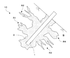
上述の構成を具備する本発明によれば、加圧注入により注入材を注入された領域(R1〜R4:図1参照)が存在するので、法面を崩壊しようとする力が生じてロックボルト(10)を引き抜く力が作用しても、注入材(C)が充填されて固化した領域(R1)〜(R4)が抵抗して、ロックボルト(10)が引き抜かれることを防止し、以て、法面の崩壊を防止することが出来る。
その際に、注入材(C)を注入された領域(R1)〜(R4)はロックボルト(10)の側方を長手方向と直角な方向へ不規則に延在しているので、ロックボルト(10)を地上側に引っ張る(引き抜く)力に対して大きな抵抗力を発生する。
その結果、ロックボルト(10)のボルト長さを長くすることなく、周面摩擦抵抗を向上することが出来る。
According to the present invention having the above-described configuration, since there are regions (R1 to R4: see FIG. 1) into which the injection material is injected by pressure injection, a force to collapse the slope is generated, and the lock bolt Even if a force for pulling out (10) is applied, the regions (R1) to (R4) filled with the injection material (C) and solidified are resisted and the lock bolt (10) is prevented from being pulled out. Thus, the slope can be prevented from collapsing.
At that time, the regions (R1) to (R4) into which the injection material (C) is injected extend irregularly on the side of the lock bolt (10) in the direction perpendicular to the longitudinal direction. A large resistance force is generated against the force pulling (pulling) (10) to the ground side.
As a result, the circumferential frictional resistance can be improved without increasing the bolt length of the lock bolt (10).
また、芯材(1)に貫通口(1A:例えばスリットや孔等)を形成し、当該貫通口(1A)から注入材(C)を吐出するので、固化した注入材(C)は当該貫通口(1A)を介して芯材(1)の外側の領域と芯材(1)内側の領域とを一体化するので、固化した注入材(C)と芯材(1)とが不可分一体となる。
そのため、芯材(1)を地上側に引き抜こうとする力が作用しても、前記貫通口(1A)を介して芯材(1)の外側の領域と芯材(1)内側の領域とを一体化している固化した注入材(C)により、芯材(1)のみが地上側に引き抜かれてしまうことが防止される。
Moreover, since a through-hole (1A: for example, a slit or a hole) is formed in the core material (1), and the injection material (C) is discharged from the through-hole (1A), the solidified injection material (C) passes through the through-hole. Since the region outside the core material (1) and the region inside the core material (1) are integrated through the mouth (1A), the solidified injection material (C) and the core material (1) are inseparably integrated. Become.
Therefore, even if the force which tries to pull out the core material (1) to the ground side acts, the region outside the core material (1) and the region inside the core material (1) are connected via the through-hole (1A). The integrated solidified injection material (C) prevents only the core material (1) from being pulled out to the ground side.
本発明において、地盤中に注入(吐出)する工程で、ケーシング(3)で包囲されていない一部の貫通口(1A)のみから注入材(C)が注入(吐出)され、ケーシング(3)で包囲された貫通口(1A)からの注入(吐出)は当該貫通口を包囲するケーシング(3)により遮断される工程を有すれば、例えば、地中側から段階的、且つ安定的に地盤補強を施工することが出来る。
更に、地盤中に注入(吐出)する工程で、注入材吐出管(2)の注入材吐出口(2B)を芯材(1)の所定の貫通口(1AA)に位置決めし、当該位置決めされた貫通口(1AA)のみから注入材(C)を注入(吐出)すれば、地盤状況等から必要性の高い領域を重点的に地盤補強することが出来る。
また、前記地盤中に注入(吐出)する工程において、パッカー(2A)と注入材吐出口(2B)を有する注入材吐出管(2:パッカー管)を芯材(1)内に挿入し、注入材吐出管(2)の注入材吐出口(2B)を芯材(1)の所定の貫通口(1AA:注入材Cを注入或いは吐出するべき貫通口)に位置決めし、パッカー(2A)を膨張し、注入材吐出管(2)の注入材吐出口(2B)と位置決めされた貫通口(1AA)のみから注入材(C)を注入(吐出)すれば、特定の貫通口(1AA)のみから注入材(C)を注入(吐出)されるので、必要性の高い領域に高精度で重点的に注入材(C)を注入して、より効率的な地盤補強を行うことが出来る。
In the present invention, in the step of injecting (discharging) into the ground, the injection material (C) is injected (discharged) only from a part of the through holes (1A) not surrounded by the casing (3), and the casing (3) Injecting (discharging) from the through-hole (1A) surrounded by the ground has a step of being blocked by the casing (3) surrounding the through-hole, for example, in a stepwise and stable manner from the ground side Reinforcement can be applied.
Further, in the step of injection (discharge) into the ground, the injection material discharge port (2B) of the injection material discharge pipe (2) is positioned at a predetermined through-hole (1AA) of the core material (1), and the positioning is performed. If the injection material (C) is injected (discharged) only from the through-hole (1AA), the ground area can be reinforced with emphasis on the area that is highly necessary from the ground conditions.
Further, in the step of injecting (discharging) into the ground, an injection material discharge pipe (2: packer tube) having a packer (2A) and an injection material discharge port (2B) is inserted into the core material (1) and injected. The injection material discharge port (2B) of the material discharge pipe (2) is positioned at a predetermined through port (1AA: through port through which the injection material C should be injected or discharged) and the packer (2A) is expanded. If the injection material (C) is injected (discharged) only from the injection material discharge port (2B) of the injection material discharge pipe (2) and the positioned through port (1AA), only from the specific through port (1AA). Since the injection material (C) is injected (discharged), it is possible to inject the injection material (C) in a highly accurate and focused manner in a highly necessary region, thereby performing more efficient ground reinforcement.
さらに、地盤中に注入材(C)を注入する工程(2次注入)に先立ち、1次注入で、芯材(1)の中空部に(2次注入で用いられる注入材よりも)高粘性の注入材(例えば可塑性グラウト)を供給して貫通口(1A)からケーシング(3)内に充填する工程を実施すれば、例えば可塑性グラウトは2次注入で用いられる注入材(C)に比較して高粘度の流体であるため、ケーシング3内(すなわち、ボーリング孔H内)に充填した後、長時間に亘ってボーリング孔(H)内に留まる。
そして、2次注入で用いられる注入材(C)に比較して高粘度の注入材(例えば可塑性グラウト材)をボーリング孔(H)内に充填した場合には、2次注入で用いられる注入材(C)と同じ注入材(C)を1次注入で充填した場合とは異なり、可塑性グラウト材が硬化するまで2次注入(地盤中へ注入材(C)の注入)を待つ必要がない。そのため、工期の短縮が可能である。
また、可塑性グラウトはボーリング孔(H)内に充填されるとボーリング孔(H)内に長く留まり、2次注入の際に限定的な注入を行う等により、注入範囲をコントロールすることが出来る。
Further, prior to the step of injecting the injection material (C) into the ground (secondary injection), the primary injection is performed in the hollow portion of the core material (1) (higher than the injection material used in the secondary injection). If an injection material (for example, plastic grout) is supplied and filled into the casing (3) from the through-hole (1A), the plastic grout is compared with the injection material (C) used for secondary injection, for example. Since it is a highly viscous fluid, after filling in the casing 3 (that is, in the bore hole H), it remains in the bore hole (H) for a long time.
When the boring hole (H) is filled with an injection material (for example, a plastic grout material) having a higher viscosity than the injection material (C) used in the secondary injection, the injection material used in the secondary injection. Unlike the case where the same injection material (C) as (C) is filled by primary injection, there is no need to wait for secondary injection (injection of injection material (C) into the ground) until the plastic grout material is cured. Therefore, the construction period can be shortened.
Further, when the plastic grout is filled in the borehole (H), the plastic grout remains in the borehole (H) for a long time, and the injection range can be controlled by performing limited injection at the time of secondary injection.
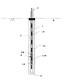
また、本発明において、芯材(1)を、径寸法の異なる複数種類(図2では2種類)の回転体(1−1、1−2、例えば円筒形)を交互に連結した形状とすれば、径寸法の大きい回転体(1−2)の外周側領域が半径方向外方に突出した形状となるため、芯材(1)の周辺が注入材(C)で充填され、固化した後、当該外周側領域が抵抗となり、芯材(1)が引き抜かれることを防止することが出来る。このことも、ロックボルト(10)における周面摩擦抵抗の向上につながる。
それに加えて、芯材外周面に沿って注入材(C:例えばグラウト材)が地上側に流出或いは逸走しようとしても、芯材(1)の外周縁部が断続的に半径方向外方に突出しているため、注入材(C)が地上側に逸走することが防止される。
In the present invention, the core material (1) has a shape in which a plurality of types (two types in FIG. 2) of rotating bodies (1-1, 1-2, for example, a cylindrical shape) having different diameters are alternately connected. For example, since the outer peripheral side region of the rotating body (1-2) having a large radial dimension has a shape protruding radially outward, the periphery of the core material (1) is filled with the injection material (C) and solidified. The outer peripheral side region becomes a resistance, and the core material (1) can be prevented from being pulled out. This also leads to an improvement in the peripheral frictional resistance of the lock bolt (10).
In addition, even if the injection material (C: for example, grout material) flows out or escapes to the ground side along the outer peripheral surface of the core material, the outer peripheral edge of the core material (1) intermittently protrudes radially outward. Therefore, the injection material (C) is prevented from running away to the ground side.
本発明において、貫通口(1A、1AA)の断面積(大きさ)を変更することにより、注入材(C)が地盤中に注入される範囲(注入範囲)をコントロールすることが出来る。そのため、芯材(1)に形成された貫通口(1A、11A:例えばスリットや孔等)の大きさ(断面積)を適宜設定することにより、注入材(C)が地盤中に注入される範囲(注入範囲)がコントロールすることが出来る。 In the present invention, the range (injection range) in which the injection material (C) is injected into the ground can be controlled by changing the cross-sectional area (size) of the through holes (1A, 1AA). Therefore, the injection material (C) is injected into the ground by appropriately setting the size (cross-sectional area) of the through holes (1A, 11A: for example, slits and holes) formed in the core material (1). The range (injection range) can be controlled.
以下、添付図面を参照して、本発明の実施形態について説明する。
最初に、図1〜図7を参照して、本発明の第1実施形態について説明する。
第1実施形態の補強工法により法面を補強した状態を示す図1において、ロックボルト10は、図3〜図7で説明する工程により芯材1から地盤中に注入された注入材Cにより造成されている。そしてロックボトル10は、その側方に形成された領域R1〜R4を有しており、領域R1〜R4はロックボトル10の側方を長手方向と直角に不規則に延在している。
Embodiments of the present invention will be described below with reference to the accompanying drawings.
First, a first embodiment of the present invention will be described with reference to FIGS.
In FIG. 1 showing a state in which the slope is reinforced by the reinforcing method of the first embodiment, a
図1において、ロックボルト10には領域R1〜R4に延在している部分が存在するので、ロックボルト10を引き抜こうとする力(ロックボルト10を引き抜く力)が作用しても、注入材C(例えばグラウト材)が充填されて固化した領域R1〜R4の抵抗により、ロックボルト10が引き抜かれることを防止し、以て、法面の崩壊を防止することが出来る。
そのため、ロックボルトの長さを長くしなくても、領域R1〜R4の存在がロックボルト10における周面摩擦抵抗が向上する。
In FIG. 1, the
Therefore, even if the length of the lock bolt is not increased, the presence of the regions R1 to R4 improves the peripheral frictional resistance of the
注入材Cを注入する際は、芯材1に形成された貫通口1A(スリット、図2)から地盤へ注入材を吐出するので、当該スリット1Aを介して、固化した注入材Cは芯材1の外側の領域と芯材内側の領域とで一体化している。ここで、貫通口1Aとしてはスリットのみならず、円形或いは長円形の孔や、その他の形状の孔としても良い。換言すれば、貫通口1Aの形状については、特に限定される訳ではない。
そのため、芯材1を地上側に引き抜こうとする力が作用しても、スリット1Aを介して芯材1の外側の領域と芯材1内側の領域とは一体化しているので、芯材1及びその内側の固化した注入材のみが地上側に引き抜かれてしまうことはない。
When injecting the injection material C, since the injection material is discharged to the ground from the through-
Therefore, even if a force to pull the
図1及び図3〜図11において、図示の簡略化のため、芯材1は単なる円筒形状で示されている。しかし、より詳細に図示すると、芯材1は、例えば図2で示す構造となっている。
図2において、芯材1は径寸法の異なる複数種類(図2では2種類)の円筒形1−1(径寸法の小さな方の円筒形)、1−2(径寸法の大きな方の円筒形)を交互に連結した形状となっている。径寸法の大きい円筒形状1−2の半径方向外方側(外周側)領域が半径方向外方に突出した形状となるため、芯材1の周辺(径寸法の大きい円筒形状1−2の間に挟まれた空間、径寸法の小さい円筒形状1−1の半径方向外方の空間を含む)が注入材(図示しない)で充填され、固化した後、円筒形状1−2の半径方向外方側領域(外周側領域)が抵抗となり、芯材1が引き抜かれることを防止する。そして、このことも、ロックボルト10における周面摩擦抵抗の向上に寄与する。
1 and 3 to 11, the
In FIG. 2, the
それに加えて、径寸法の小さい円筒形状1−1と径寸法の大きい円筒形状1−2を交互に連結した形状の芯材1によれば、径寸法の大きい円筒形状1−2の外周縁部が軸方向について断続的に半径方向外方に突出しているため、芯材外周面に沿って注入材(例えばグラウト材)が逸走しようとしても、円筒形状1−2の外周縁部が断続して逸走しようとする注入材の抵抗となるので、注入材が地上側に逸走することが防止される。
In addition, according to the
芯材1は全体が中空形状であり(図示せず)、芯材1の中空部と芯材1の外側面とを連通する複数の貫通口1A(スリット)が、芯材1の軸方向に亘って形成されている。図2の例では、複数のスリット1Aは、径寸法の小さい円筒形状1−1と径寸法の大きい円筒形状1−2に跨る軸方向位置に形成されている。
注入材を注入する際は、芯材1の地上側端部に配置した図示しない注入材供給源から、図示しない芯材注入アタッチメントを介して、芯材1に注入材を供給する。供給された注入材は芯材1の中空部を流過した上、複数のスリット1Aから地盤方向に向けて注入(吐出)される。
The
When injecting the injection material, the injection material is supplied to the
次に図3〜図7を参照して、第1実施形態の補強工法の施工手順を説明する。
第1実施形態では、ロックボルト側面の地盤中に、複数のスリット1Aから注入材Cを注入する(図6、図7)。
図3においては、例えば施工対象である法面に、所定の深度を有するボーリング孔Hを、例えば、いわゆる「ケーシング削孔」により削孔する。ケーシング削孔の際は、必要に応じてケーシング3を継ぎ足しながら行うが、図示の簡略化のため、図3ではケーシング3を1本のみ示している。図3において、ケーシング削孔以外の方法でボーリング孔Hを削孔することが出来る。
なお、図3〜図7、図8〜図11において、図示の簡略化のため、補強工法の施工対象である法面を水平に図示している。
Next, with reference to FIGS. 3-7, the construction procedure of the reinforcement construction method of 1st Embodiment is demonstrated.
In 1st Embodiment, the injection material C is inject | poured into the ground of a rock bolt side surface from
In FIG. 3, for example, a bore hole H having a predetermined depth is drilled on a slope to be constructed by, for example, so-called “casing drilling”. Casing drilling is performed while adding the
In addition, in FIG. 3 to FIG. 7 and FIG. 8 to FIG. 11, for the sake of simplification, the slope that is the object of the reinforcement construction method is shown horizontally.
図3に示す工程で法面の所定深度までボーリング孔Hを削孔したならば、図4において、芯材1をボーリング孔Hに挿入する。その際、ボーリング孔Hの崩落防止の為、ボーリング孔H内にはケーシング3が残存している。
芯材1はケーシング3の内側空間の地中側端部近傍まで(すなわち、ボーリング孔Hの地中側端部近傍まで)挿入される。そして図2に関連して説明した様に、芯材1は注入材Cの流路となる中空部(図示しない)を有しており、当該中空部と芯材外側面とを連通する複数のスリット1A(貫通口)が形成されている。
If the boring hole H is drilled to the predetermined depth of the slope in the process shown in FIG. 3, the
The
芯材1をボーリング孔H内のケーシング3の内側空間に挿入したならば(図4)、図5において、芯材1(の中空部)に地上側の図示しない供給源から注入材C(例えばグラウト材)を注入(供給)する(矢印A1:1次注入)。なお、図5における符号5は、注入材Cを芯材1(の中空部)に注入するための芯材注入アタッチメントを示している。
芯材1に注入材Cを注入すれば(1次注入を行うと)、注入材Cは芯材1の中空部から複数のスリット1Aを介して、ケーシング3の内側空間(すなわちケーシング3の内側面と芯材1の外側面の間の円環状の空間)に流入し、芯材1(の中空部)及びケーシング3の内側空間は注入材Cで満たされる。
図5では、(1次注入の後に)注入材Cが、芯材1(の中空部)及びケーシング3の内側空間に充填された状態が示されている。そして、図6で示す工程を実行する。
If the
If the injection material C is injected into the core material 1 (when primary injection is performed), the injection material C passes through a plurality of
FIG. 5 shows a state in which the injection material C is filled in the core material 1 (the hollow portion thereof) and the inner space of the casing 3 (after the primary injection). And the process shown in FIG. 6 is performed.
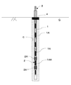
図6に示す工程では、芯材1の中空部及びケーシング3の内側空間が注入材Cで充填された状態(図5で示す状態)において、ケーシング3をボーリング孔Hの軸方向所定位置Pまで地上側に引き抜く(引き上げる)。そして、注入材Cを芯材1(の中空部)に加圧注入する(矢印A2:2次注入)。
図6において、注入材Cを加圧注入すると(2次注入を行うと)、注入材Cを加圧注入した圧力が、芯材1(の中空部)及びケーシング3の内側空間の注入材Cにも作用する。そして2次注入で加圧注入された注入材Cは、引き抜かれたケーシング3の下端位置Pよりも地中側における芯材1の貫通口1Aから、ボーリング孔Hの壁面を介して、施工するべき地盤中に加圧注入(吐出)される(矢印B2)。
In the process shown in FIG. 6, in a state where the hollow portion of the
In FIG. 6, when the injection material C is injected under pressure (secondary injection is performed), the pressure under which the injection material C is injected under pressure is the injection material C in the inner space of the core material 1 (hollow part thereof) and the
一方、注入材Cを加圧注入しても(2次注入を行っても)、引き抜かれたケーシング3の下端位置Pよりも地上側の領域では、芯材1の貫通口1Aの半径方向外方はケーシング3で遮蔽されている。そのため、ケーシング3の下端位置Pより地上側の領域における貫通口1Aから注入(吐出)され注入材Cは、地盤内に注入されることはない。すなわち、図6の工程では、注入材Cは、ケーシング3の下端位置Pよりも地中側の貫通口1A(一部の貫通口1A)のみから地盤中に加圧注入(吐出)され、ケーシング3の下端位置Pより地上側の領域における貫通口1Aから注入(吐出)された注入材Cは地盤中には直接は注入されない。
図6では明示されていないが、ケーシング3の地上側端部は図示しないシール部材でシールされているので、注入材Cがケーシング3の地上側端部から流出することが防止されている。
On the other hand, even if the injection material C is injected under pressure (secondary injection is performed), in the region on the ground side from the lower end position P of the drawn-out
Although not clearly shown in FIG. 6, the ground-side end portion of the
図示はされていないが、発明者の実験によれば、断面積が小さい貫通口1Aから注入材Cを注入した方が、断面積が大きい貫通口から注入材Cを注入する場合に比較して、地盤中に注入圧力が作用し易く、注入材Cが地盤中に注入され易いことが判明している。
そして、貫通口1Aの断面積(大きさ)を変更することにより、注入材Cが地盤中に注入される範囲(注入範囲)をコントロールすることが可能である。
すなわち、図6の工程(2次注入)では、芯材1に形成された貫通口1A(例えばスリット等)の大きさ(断面積)を適宜設定することにより、注入材Cが地盤中に注入される範囲(注入範囲)がコントロールされている。
Although not shown, according to the inventors' experiment, the injection material C is injected from the through-
And it is possible to control the range (injection range) where the injection material C is injected into the ground by changing the cross-sectional area (size) of the through-
That is, in the step of FIG. 6 (secondary injection), the injection material C is injected into the ground by appropriately setting the size (cross-sectional area) of the through-
図6の工程に続く図7の工程では、ケーシング3をボーリング孔Hから完全に引き抜き、ボーリング孔Hの地上側端部(いわゆる口元)に口元パッカー4(口元シール材)を配置し、密閉している。ボーリング孔Hの地上側端部に口元シール材4を配置するので、注入された注入材Cが(ボーリング孔Hの地上側端部から)地上側に流出してしまうことが防止され、注入材Cは地盤中に確実に注入される。
そして、更に注入材Cを加圧注入する(2次注入を行う:矢印A3)。
In the process of FIG. 7 following the process of FIG. 6, the
Further, the injection material C is injected under pressure (secondary injection: arrow A3).
図7において、注入材Cを加圧注入すると、加圧注入の圧力が芯材1(の中空部)及びボーリング孔Hの内側空間の注入材Cにも作用し、注入材Cは芯材1の全ての貫通口1Aから、ボーリング孔Hの壁面を介して、地盤中に加圧注入(吐出)される(矢印B3)。
図7の工程で注入材Cの地盤への加圧注入が完了した後(2次注入が完了した後)、芯材注入アタッチメント5を除去することにより、図1で示すロックボルト10が造成される。
ロックボルト10の造成が完了したら、芯材1の地上側端部を図示しないロックナットにより締め付け、芯材1に地上側方向の引張力を与えて補強工法は完了する。
In FIG. 7, when the injection material C is pressure-injected, the pressure of the pressure injection also acts on the core material 1 (hollow part) and the injection material C in the inner space of the borehole H, and the injection material C is the
After the pressure injection to the ground of the injection material C is completed in the process of FIG. 7 (after the secondary injection is completed), the
When the formation of the
図5の工程(1次注入)において、芯材1(の中空部)に、2次注入で用いられる注入材よりも高粘度の注入材(例えば可塑性グラウト)を注入することも出来る(図5の矢印A1)。2次注入で用いられる注入材Cよりも高粘度の注入材(例えば可塑性グラウト)は粘性が高いので、ボーリング孔H内(或いはケーシング3内)に充填した後、2次注入で用いられるのと同一の注入材を用いた場合に比較して、ボーリング孔H内に長時間留まる。そして、地盤中に注入材Cを注入する二次注入を、可塑性グラウトが硬化するまで待たずに実行することが出来る。そのため、工期を短縮することが出来る。また、2次注入で用いられる注入材よりも高粘度の注入材(例えば可塑性グラウト)を1次注入で充填した場合には、当該高粘度の注入材(例えば可塑性グラウト)はボーリング孔H内に長時間留まり、2次注入(加圧注入)において、限定的な注入を行う等により、注入範囲のコントロールを行うことが出来るというメリットが存在する。
1次注入において芯材1に2次注入で用いられる注入材よりも高粘度の注入材(例えば可塑性グラウト)を注入すれば、当該注入材(例えば可塑性グラウト)は芯材1の中空部から複数のスリット1Aを介して、ケーシング3の内側空間(すなわちケーシング3の内側面と芯材1の外側面の間の円環状の空間)に流入し、芯材1(の中空部)及びケーシング3の内側空間は、2次注入で用いられる注入材よりも高粘度の注入材(例えば可塑性グラウト)で充填される。
In the step of FIG. 5 (primary injection), an injection material (for example, plastic grout) having a higher viscosity than the injection material used in the secondary injection can be injected into the core material 1 (hollow portion thereof) (FIG. 5). Arrow A1). Since the injection material (for example, plastic grout) having a higher viscosity than the injection material C used in the secondary injection has a higher viscosity, it is used in the secondary injection after filling the bore hole H (or in the casing 3). Compared with the case where the same injection material is used, it stays in the borehole H for a long time. And the secondary injection | pouring which inject | pours the injection material C in the ground can be performed without waiting until a plastic grout hardens | cures. Therefore, the construction period can be shortened. In addition, when the injection material (for example, plastic grout) having a higher viscosity than the injection material used for the secondary injection is filled by the primary injection, the high-viscosity injection material (for example, plastic grout) is placed in the bore hole H. There is an advantage that the injection range can be controlled by, for example, performing a limited injection in the secondary injection (pressurization injection) for a long time.
If an injection material (for example, plastic grout) having a higher viscosity than the injection material used for the secondary injection is injected into the
1次注入で高粘度の注入材(例えば可塑性グラウト)をボーリング孔H内に充填したならば、図6で示す工程を実行する。図6において、ケーシング3をボーリング孔Hの軸方向所定位置Pまで地上側に引き上げた上、注入材Cを加圧注入すると(図6の矢印A2)、注入材Cは、引き抜かれたケーシング3の下端位置Pよりも地中側における芯材1の貫通口1Aから、ボーリング孔Hの壁面を介して、施工するべき地盤中に加圧注入(吐出)される(2次注入:図6の矢印B2)。
If the boring hole H is filled with a high-viscosity injection material (for example, plastic grout) by the primary injection, the process shown in FIG. 6 is performed. In FIG. 6, when the
1次注入において、2次注入で用いられる注入材よりも高粘度の注入材(例えば可塑性グラウト)をボーリング孔H内に充填注入する場合(図5の1次注入の工程で、例えば可塑性グラウトを注入する場合)においても、図7の2次注入の工程では、ケーシング3をボーリング孔Hから完全に引き抜き、注入材Cを加圧注入(図7の矢印A3)する。
注入材Cは、全ての貫通口1Aから、ボーリング孔Hの壁面を介して、施工するべき地盤中に加圧注入(吐出)される(図7の矢印B3)。
In the primary injection, when an injection material (for example, plastic grout) having a higher viscosity than the injection material used in the secondary injection is filled and injected into the borehole H (for example, in the primary injection step of FIG. Also in the case of injection), in the secondary injection step of FIG. 7, the
The injection material C is pressure-injected (discharged) from all the through-
次に図8〜図11を参照して、本発明の第2実施形態について説明する。
図3〜図7を参照して上述した第1実施形態では、ケーシングCの下端部Pより下方の領域における(芯材1の)全てのスリット1Aから(図6)、或いは、地中の全てのスリット1Aから(図7)注入材Cを注入している。それに対して図8〜図11の第2実施形態では、多数のスリットではなく、少数の所定のスリット(パッカー管のパッカーで挟まれた位置のスリット)のみから注入材Cを地盤中に注入する。
第2実施形態においても、図3〜図5で示す工程については第1実施形態と同様であり、重複説明は省略する。また、第2実施形態における芯材、ケーシングは、第1実施形態の芯材1、ケーシング3と同様な構成を有しており、それぞれ同一の符号で示している。
Next, a second embodiment of the present invention will be described with reference to FIGS.
In 1st Embodiment mentioned above with reference to FIGS. 3-7, from all the
Also in the second embodiment, the steps shown in FIGS. 3 to 5 are the same as those in the first embodiment, and redundant description is omitted. Moreover, the core material and casing in 2nd Embodiment have the structure similar to the
第2実施形態と第1実施形態は、図3〜図5の工程は共通している。図5の工程(1次注入)で、芯材1(の中空部)及びケーシング3の内側空間(地中側先端から地上側端部近傍まで)に注入材Cを充填させた後、ケーシング3をボーリング孔Hから引き抜く。ケーシング3をボーリング孔Hから引き抜いた後、ボーリング孔Hの地上側端部に口元パッカー4(口元シール材)を配置し、密閉した状態にする。
そして図8の工程では、注入材吐出管2(パッカー管)を芯材1(の中空空間)内に挿入する(矢印Q)。図8で示す様に、パッカー管2は、一対のパッカー2Aと一対のパッカー2A間に形成された円周方向に複数の注入材吐出口2Bを有している。
パッカー管2を挿入した後、図9で示す工程を行う。
The steps of FIGS. 3 to 5 are common to the second embodiment and the first embodiment. In the step (primary injection) of FIG. 5, after filling the core material 1 (hollow part thereof) and the inner space of the casing 3 (from the underground side end to the vicinity of the ground side end part) with the injection material C, the
In the step of FIG. 8, the injection material discharge pipe 2 (packer pipe) is inserted into the core material 1 (hollow space) (arrow Q). As shown in FIG. 8, the
After inserting the
図9で示す工程では、パッカー管2の注入材吐出口2B(図9では図示せず、図8参照)を芯材1における所定の貫通口1AA(例えばスリット)と整合する様に位置決めする。芯材1における所定のスリット1AAは、複数のスリット1Aにおいて、注入材Cを注入して重点的に地盤補強するべき領域に対応した位置に存在する。第2実施形態においても、貫通口1AAはスリットのみならず、円形或いは長円形の孔や、その他の形状の孔で構成することが出来て、特にスリットのみに限定される訳ではない。
なお、地盤補強するべき領域が(鉛直方向について)大きい場合には、一対のパッカー2A間の間隔を大きくして、芯材1の軸方向複数の所定のスリット1AAが当該パッカー2A間に位置する様にしても良い。或いは、図示はしないが、パッカー2Aを複数対設け、注入材吐出口2Bを複数形成することも出来る。
図9で示す状態では、注入材吐出口2Bが所定のスリット1AA(貫通口)に位置決め(整合する)様に、パッカー管2の一対のパッカー2Aが芯材1の所定のスリット1AAを挟む様に、パッカー管が配置されている。すなわち、図9で示す状態では、パッカー管2の注入材吐出口2Bは、所定のスリット1AAと対応する位置に存在する。
図9で示す様に注入材吐出口2Bをスリット1AAに対峙させたならば、図10で示す工程を実行する。
9, the injection
In addition, when the area | region which should be ground-reinforced is large (about a perpendicular direction), the space | interval between a pair of
In the state shown in FIG. 9, the pair of
If the injection
図10で示す工程では、図示しない圧縮流体供給手段によりパッカー管2の一対のパッカー2Aを膨張させる。膨張した一対のパッカー2Aは芯材1の内壁に圧接し、一対のパッカー2A、パッカー管2の外周面、芯材1の内周面により包囲された空間(所定空間)を形成し、当該空間(所定空間)は所定スリット1AAのみにより芯材1の外部に連通している。
膨張した一対のパッカー2Aにより、注入材吐出口2Bから吐出した注入材Cが芯材1の所定のスリット1AA以外のスリット1Aに流れる経路(流路)は閉鎖される。
したがって、地上側の注入材供給源からパッカー管2に注入材Cが加圧注入される(2次注入される)と(図11の工程)、加圧注入(2次注入)された注入材Cは、一対のパッカー2A間に形成された注入材吐出口2B(図8参照)から前記所定空間(一対のパッカー2A、パッカー管2の外周面、芯材1の内周面により包囲された空間)に流入し、所定のスリット1AAのみを介して地盤中に注入(吐出)される。
In the step shown in FIG. 10, the pair of
A path (flow path) through which the injected material C discharged from the injected
Therefore, when the injection material C is pressure-injected (secondary injection) into the
図11の工程では、注入材供給源から芯材注入アタッチメント6を介して、パッカー管2に注入材Cが加圧注入される(矢印A4)。上述した様に、加圧注入された注入材C(例えばグラウト材)はパッカー管2を地中側に向かって流れ、一対のパッカー2A間に形成された注入材吐出口2B(図11では図示せず:図8参照)のみから前記所定空間(一対のパッカー2A、パッカー管2の外周面、芯材1の内周面により包囲された空間)に注入する。そして、芯材1の所定スリット1AA、ボーリング孔Hの壁面を介して、地盤中に加圧注入(吐出)される(矢印B4)。
第1実施形態における図6の工程に関して上述した様に、発明者の実験により、断面積が小さい貫通口1Aから注入材Cを2次注入した方が、断面積が大きい貫通口から注入材Cを2次注入する場合に比較して、地盤中に注入圧力が作用し易く、注入材Cが地盤中に注入され易いことが確認されており、貫通口1Aの断面積(大きさ)を変更することにより、注入材Cが地盤中に注入される範囲(注入範囲)をコントロールすることが出来る。
そのため、図11の工程でも、芯材1に形成された貫通口11A(例えばスリット等)の大きさ(断面積)を適宜設定することにより、注入材Cが地盤中に注入される範囲(注入範囲)がコントロールすることが出来る。
In the process of FIG. 11, the injection material C is pressure-injected into the
As described above with reference to the process of FIG. 6 in the first embodiment, according to the inventor's experiment, when the injection material C is secondarily injected from the through
Therefore, also in the process of FIG. 11, by appropriately setting the size (cross-sectional area) of the through-hole 11A (for example, a slit) formed in the
図11の工程で注入材Cの地盤への加圧注入(2次注入)が完了した後、芯材注入アタッチメント6を取り外せば、ロックボルトの造成が完了する。
また、ロックボルトの造成が完了したら、第1実施形態と同様に、芯材1の地上側端部を図示しないロックナットにより締め付け、芯材1に地上側方向の引張力を与えて補強工法は完了する。
After the pressure injection (secondary injection) of the injection material C to the ground is completed in the step of FIG. 11, if the core material injection attachment 6 is removed, the formation of the lock bolt is completed.
When the formation of the lock bolt is completed, as in the first embodiment, the ground side end of the
ここで、第2実施形態においても、図8の工程の直前の図5に示す工程(1次注入の工程)で、地上側の供給源から芯材1(の中空部)に、2次注入で用いられる注入材よりも高粘度の注入材(例えば可塑性グラウト)を注入することが出来る(図5の矢印A1)。
上述した様に、2次注入で用いられる注入材よりも高粘度の注入材(例えば可塑性グラウト)を使用することにより、当該高粘度の注入材(例えば可塑性グラウト)をボーリング孔H内(ケーシング3内)に1次注入した後、限定的な注入を行う等により、2次注入における注入範囲をコントロールすることが出来る。
第2実施形態におけるその他の構成及び作用効果については、第1実施形態と同様である。
Here, also in the second embodiment, secondary injection is performed from the ground-side supply source to the core material 1 (hollow portion) in the step shown in FIG. 5 (primary injection step) immediately before the step of FIG. An injection material (for example, plastic grout) having a viscosity higher than that of the injection material used in the above can be injected (arrow A1 in FIG. 5).
As described above, by using an injection material (for example, plastic grout) having a viscosity higher than that of the injection material used in the secondary injection, the high-viscosity injection material (for example, plastic grout) is placed in the borehole H (casing 3). After the primary injection into the inner), the injection range in the secondary injection can be controlled by performing a limited injection or the like.
Other configurations and operational effects in the second embodiment are the same as those in the first embodiment.
図示の実施形態はあくまでも例示であり、本発明の技術的範囲を限定する趣旨の記述ではないことを付記する。
例えば、第1実施形態において、ケーシング3をボ―リング孔Hの軸方向に移動させるに際して、図6で示す状態と図7で示す状態の2段階で引き抜き、注入材Cを地盤中に2段階で加圧注入している。しかし、ケーシング3をボ―リング孔Hの軸方向により細かく移動して3段階以上の状態となる様に引き抜き、注入材Cを注させることも出来る。
さらに、図6で示す工程を省略し、ボ―リング孔Hを削孔後に直ちにケーシング3を完全にボ―リング孔Hから引き抜き(1段階で引抜)、注入材Cを芯材1の全スリット1Aから地盤中に1工程のみで加圧注入することも出来る。
また、第2実施形態において、パッカー管2にパッカー2Aを2対以上配置して、ボーリング孔Hの軸方向に隔離した複数の注入材吐出口2Bから注入材Cを注入する様に構成することも出来る。
これに加えて、図示の実施形態では貫通口1Aとしてはスリットが示されているが、貫通口1Aを円形或いは長円形の孔、その他の形状の孔で構成することが出来る。
It should be noted that the illustrated embodiment is merely an example, and is not a description to limit the technical scope of the present invention.
For example, in the first embodiment, when the
Further, the process shown in FIG. 6 is omitted, and immediately after the boring hole H is cut, the
In the second embodiment, two or more pairs of
In addition to this, in the illustrated embodiment, a slit is shown as the through-
1・・・芯材
1A・・・スリット(貫通口)
1AA・・・所定の貫通口(注入材を注入するべき貫通口)
1−1、1−2・・・回転体(例えば円筒形)
2・・・パッカー管(注入材吐出管)
2A・・・パッカー
2B・・・注入材吐出口
3・・・ケーシング
4・・・口元パッカー(口元シール材)
C・・・注入材(例えばグラウト材)
H・・・ボーリング孔
1 ...
1AA ... predetermined through-hole (through-hole through which injection material should be injected)
1-1, 1-2... Rotating body (for example, cylindrical)
2 ... Packer tube (injection material discharge tube)
2A:
C ... Injection material (eg grout material)
H ... Boring hole
Claims (5)
貫通口が形成された中空の芯材をボーリング孔に挿入する工程と、
芯材の中空部に注入材を供給して前記貫通口から地盤中に注入する工程を有することを特徴とする補強工法。 A step of drilling a boring hole;
Inserting a hollow core material having a through-hole into the borehole;
A reinforcing method comprising a step of supplying an injection material into a hollow portion of a core material and injecting the injection material into the ground from the through hole.
前記地盤中に注入する工程では、全ての貫通口から注入材が注入される請求項1の補強工法。 A plurality of the through holes are formed,
The reinforcing method according to claim 1, wherein in the step of injecting into the ground, the injection material is injected from all through holes.
前記地盤中に注入する工程は、パッカーと注入材吐出口を有する注入材吐出管を芯材内に挿入し、注入材吐出管の注入材吐出口を芯材の所定の貫通口に位置決めし、パッカーを膨張し、注入材吐出管の注入材吐出口と位置決めされた貫通口のみから注入材を注入する請求項1の補強工法。 A plurality of the through holes are formed,
The step of injecting into the ground includes inserting an injection material discharge pipe having a packer and an injection material discharge port into the core material, positioning the injection material discharge port of the injection material discharge pipe at a predetermined through-hole of the core material, The reinforcing method according to claim 1, wherein the packing material is expanded and the injection material is injected only from the through-hole positioned with the injection material discharge port of the injection material discharge pipe.
Applications Claiming Priority (2)
| Application Number | Priority Date | Filing Date | Title |
|---|---|---|---|
| JP2017166442 | 2017-08-31 | ||
| JP2017166442 | 2017-08-31 |
Publications (2)
| Publication Number | Publication Date |
|---|---|
| JP2019044571A true JP2019044571A (en) | 2019-03-22 |
| JP7075270B2 JP7075270B2 (en) | 2022-05-25 |
Family
ID=65812524
Family Applications (1)
| Application Number | Title | Priority Date | Filing Date |
|---|---|---|---|
| JP2018078853A Active JP7075270B2 (en) | 2017-08-31 | 2018-04-17 | Reinforcement method |
Country Status (1)
| Country | Link |
|---|---|
| JP (1) | JP7075270B2 (en) |
Cited By (2)
| Publication number | Priority date | Publication date | Assignee | Title |
|---|---|---|---|---|
| CN111287769A (en) * | 2020-02-28 | 2020-06-16 | 贵州建工集团第六建筑工程有限责任公司 | Tunnel surrounding rock advanced grouting reinforcement structure and construction method thereof |
| JP2021095719A (en) * | 2019-12-16 | 2021-06-24 | 株式会社カテックス | Natural ground reinforcement method |
Citations (9)
| Publication number | Priority date | Publication date | Assignee | Title |
|---|---|---|---|---|
| JP2000352046A (en) * | 1999-06-11 | 2000-12-19 | Raito Kogyo Co Ltd | Pile creating construction method |
| JP2002167746A (en) * | 2000-11-29 | 2002-06-11 | Kfc Ltd | Ground reinforcing construction method and hole wall holding casing pipe used therefor |
| KR20050030095A (en) * | 2003-09-24 | 2005-03-29 | 대원토질 주식회사 | Pressure-type grouting apparatus for reinforcing the ground and hybrid-type nailing method by pressurized using the apparatus |
| JP2007205079A (en) * | 2006-02-03 | 2007-08-16 | Shimizu Corp | Anchor member construction method in ground anchor construction method |
| JP2008248487A (en) * | 2007-03-29 | 2008-10-16 | Kfc Ltd | Construction method of rotary press-in pile and slope construction device |
| JP2008274553A (en) * | 2007-04-25 | 2008-11-13 | Toyo Constr Co Ltd | Slope stabilizing method |
| JP2014177746A (en) * | 2013-03-13 | 2014-09-25 | Osaka Bosui Constr Co Ltd | Chemical injection method and chemical injection structure in ground when injecting chemical |
| JP2015110892A (en) * | 2013-11-07 | 2015-06-18 | ライト工業株式会社 | Reinforcement material and method for establishing the same |
| JP2016053273A (en) * | 2014-09-04 | 2016-04-14 | 公益財団法人鉄道総合技術研究所 | Slope stabilizing method as countermeasure to earthquake and rain in soil structure with pressure insertion type bar reinforcement |
-
2018
- 2018-04-17 JP JP2018078853A patent/JP7075270B2/en active Active
Patent Citations (9)
| Publication number | Priority date | Publication date | Assignee | Title |
|---|---|---|---|---|
| JP2000352046A (en) * | 1999-06-11 | 2000-12-19 | Raito Kogyo Co Ltd | Pile creating construction method |
| JP2002167746A (en) * | 2000-11-29 | 2002-06-11 | Kfc Ltd | Ground reinforcing construction method and hole wall holding casing pipe used therefor |
| KR20050030095A (en) * | 2003-09-24 | 2005-03-29 | 대원토질 주식회사 | Pressure-type grouting apparatus for reinforcing the ground and hybrid-type nailing method by pressurized using the apparatus |
| JP2007205079A (en) * | 2006-02-03 | 2007-08-16 | Shimizu Corp | Anchor member construction method in ground anchor construction method |
| JP2008248487A (en) * | 2007-03-29 | 2008-10-16 | Kfc Ltd | Construction method of rotary press-in pile and slope construction device |
| JP2008274553A (en) * | 2007-04-25 | 2008-11-13 | Toyo Constr Co Ltd | Slope stabilizing method |
| JP2014177746A (en) * | 2013-03-13 | 2014-09-25 | Osaka Bosui Constr Co Ltd | Chemical injection method and chemical injection structure in ground when injecting chemical |
| JP2015110892A (en) * | 2013-11-07 | 2015-06-18 | ライト工業株式会社 | Reinforcement material and method for establishing the same |
| JP2016053273A (en) * | 2014-09-04 | 2016-04-14 | 公益財団法人鉄道総合技術研究所 | Slope stabilizing method as countermeasure to earthquake and rain in soil structure with pressure insertion type bar reinforcement |
Cited By (3)
| Publication number | Priority date | Publication date | Assignee | Title |
|---|---|---|---|---|
| JP2021095719A (en) * | 2019-12-16 | 2021-06-24 | 株式会社カテックス | Natural ground reinforcement method |
| JP7311894B2 (en) | 2019-12-16 | 2023-07-20 | 株式会社カテックス | Ground reinforcement method |
| CN111287769A (en) * | 2020-02-28 | 2020-06-16 | 贵州建工集团第六建筑工程有限责任公司 | Tunnel surrounding rock advanced grouting reinforcement structure and construction method thereof |
Also Published As
| Publication number | Publication date |
|---|---|
| JP7075270B2 (en) | 2022-05-25 |
Similar Documents
| Publication | Publication Date | Title |
|---|---|---|
| JP5990214B2 (en) | Reinforcement method of hole wall in construction method of cast-in-place concrete pile. | |
| JP5274145B2 (en) | Cast-in-place pile and its construction method | |
| JP6679757B2 (en) | Micropile corrugated grout bulb and method of forming the same | |
| JP2008274553A (en) | Slope stabilizing method | |
| JP2001040980A (en) | Multistage grouting device and method therefor | |
| JP2019044571A (en) | Reinforcement method | |
| KR101119829B1 (en) | Method for cast-in-place pile construction using punctured couplers | |
| JP6474994B2 (en) | Shear reinforcement method for concrete structures | |
| JP4609712B2 (en) | Filling means for filling cavities and filling method | |
| JP5948068B2 (en) | Pile construction method with anchors | |
| KR101395868B1 (en) | Rock bolt | |
| KR20060105721A (en) | Method for cast-in-place pile construction using casing pipe and steel pipe with hole) | |
| JP4341029B2 (en) | Pile foundation method | |
| JP4336169B2 (en) | How to install rock bolts | |
| JP5973931B2 (en) | Construction method of high bearing capacity pile | |
| KR100811289B1 (en) | Method for reinforcing ground and apparatus for the same | |
| KR100756524B1 (en) | Method for reinforcing ground and apparatus for the same | |
| JP5252732B2 (en) | Pipe with cylindrical elastic member and injection method using the same | |
| KR20020068981A (en) | steal pipe micro-pile and grouting installing method | |
| JP2006249773A (en) | Mouth caulking device of pipe | |
| KR100811291B1 (en) | Method for reinforcing ground and apparatus for the same | |
| KR100691727B1 (en) | Cement Paste Injection Apparatus And A Method Of Reinforcement For Soft Ground Using The Same | |
| KR100811287B1 (en) | Method for reinforcing ground and apparatus for the same | |
| JP3886704B2 (en) | Method for forming a space in a pile head into which a curable material flows and a space forming tool used therefor | |
| KR101015555B1 (en) | Wedge type seal apparatus |
Legal Events
| Date | Code | Title | Description |
|---|---|---|---|
| A621 | Written request for application examination |
Free format text: JAPANESE INTERMEDIATE CODE: A621 Effective date: 20201222 |
|
| A977 | Report on retrieval |
Free format text: JAPANESE INTERMEDIATE CODE: A971007 Effective date: 20211119 |
|
| A131 | Notification of reasons for refusal |
Free format text: JAPANESE INTERMEDIATE CODE: A131 Effective date: 20211202 |
|
| A521 | Request for written amendment filed |
Free format text: JAPANESE INTERMEDIATE CODE: A523 Effective date: 20220117 |
|
| TRDD | Decision of grant or rejection written | ||
| A01 | Written decision to grant a patent or to grant a registration (utility model) |
Free format text: JAPANESE INTERMEDIATE CODE: A01 Effective date: 20220511 |
|
| A61 | First payment of annual fees (during grant procedure) |
Free format text: JAPANESE INTERMEDIATE CODE: A61 Effective date: 20220513 |
|
| R150 | Certificate of patent or registration of utility model |
Ref document number: 7075270 Country of ref document: JP Free format text: JAPANESE INTERMEDIATE CODE: R150 |