JP2019026096A - Vehicular seat - Google Patents
Vehicular seat Download PDFInfo
- Publication number
- JP2019026096A JP2019026096A JP2017148029A JP2017148029A JP2019026096A JP 2019026096 A JP2019026096 A JP 2019026096A JP 2017148029 A JP2017148029 A JP 2017148029A JP 2017148029 A JP2017148029 A JP 2017148029A JP 2019026096 A JP2019026096 A JP 2019026096A
- Authority
- JP
- Japan
- Prior art keywords
- duct
- engagement portion
- seat
- duct member
- cover
- Prior art date
- Legal status (The legal status is an assumption and is not a legal conclusion. Google has not performed a legal analysis and makes no representation as to the accuracy of the status listed.)
- Granted
Links
Images


Landscapes
- Seats For Vehicles (AREA)
Abstract
Description
本発明は、シートクッションおよびシートバックを備える乗物用シートに関する。 The present invention relates to a vehicle seat including a seat cushion and a seat back.
従来、吹出口と通気路が形成されたシートクッションおよびシートバックと、シートクッションの底面に取り付けられた送風装置と、送風装置とシートバックの通気路とを接続するダクトとを備え、送風装置が、空調空気を通気路やダクトを介して吹出口へ送るように構成された車両シートが知られている(特許文献1)。 Conventionally, a seat cushion and a seat back formed with an air outlet and an air passage, a blower attached to the bottom surface of the seat cushion, and a duct connecting the air blower and the air passage of the seat back, A vehicle seat configured to send conditioned air to an outlet through an air passage or a duct is known (Patent Document 1).
ところで、ダクトを複数の部品を接続して構成する場合、ダクトの接続部に、例えば、後席の乗員の足が当たるなどして衝撃が加わると、接続部が外れてしまう可能性がある。 By the way, when the duct is configured by connecting a plurality of parts, if the impact is applied to the connecting portion of the duct, for example, when the foot of an occupant in the rear seat hits the connecting portion, the connecting portion may come off.
そこで、本発明は、複数の部品を接続してなるダクトの接続部を保護することができる乗物用シートを提供することを目的とする。
また、本発明は、カバー部材をコンパクト化することを目的とする。
また、本発明は、ダクトの接続部の係合箇所を保護することを目的とする。
また、本発明は、ダクトの接続部の係合箇所の係合状態を目視して確認することを目的とする。
また、本発明は、ダクトの複数の部品を簡単な構成で接続することを目的とする。
また、本発明は、ダクトの複数の部品を外れにくくすることを目的とする。
また、本発明は、シートクッションやシートバックの座面の広範囲において空気を吹き出したり、吸い込んだりする構成を実現することを目的とする。
Then, an object of this invention is to provide the vehicle seat which can protect the connection part of the duct formed by connecting several components.
Another object of the present invention is to make the cover member compact.
Moreover, an object of this invention is to protect the engaging location of the connection part of a duct.
Moreover, an object of this invention is to visually confirm the engagement state of the engagement location of the connection part of a duct.
Another object of the present invention is to connect a plurality of parts of a duct with a simple configuration.
Another object of the present invention is to make it difficult to remove a plurality of parts of a duct.
Another object of the present invention is to realize a configuration in which air is blown out or sucked in a wide range of seat cushions or seat back seat surfaces.
前記した目的を達成するための本発明は、シートクッションおよびシートバックを備える乗物用シートであって、前記シートクッションと前記シートバックとに跨がって配置され、前記シートクッションおよび前記シートバックの少なくとも一方に形成された通気路と送風装置を接続するダクトと、前記ダクトの一部を覆うカバー部材と、を備え、前記ダクトは、第1ダクト部材と、前記第1ダクト部材に接続される第2ダクト部材とを有し、前記カバー部材は、前記第1ダクト部材と前記第2ダクト部材との接続部である第1接続部の少なくとも一部を覆うことを特徴とする。 The present invention for achieving the above-described object is a vehicle seat including a seat cushion and a seat back, and is disposed across the seat cushion and the seat back. A duct connecting at least one of the air passage and the blower; and a cover member covering a part of the duct; and the duct is connected to the first duct member and the first duct member. It has a 2nd duct member, The said cover member covers at least one part of the 1st connection part which is a connection part of the said 1st duct member and the said 2nd duct member, It is characterized by the above-mentioned.
このような構成によれば、カバー部材によって複数の部品を接続してなるダクトの接続部を保護することができる。 According to such a structure, the connection part of the duct formed by connecting a plurality of components by the cover member can be protected.
前記した乗物用シートにおいて、前記第1ダクト部材は、前記第1接続部に設けられた第1係合部および第2係合部を有し、前記第2ダクト部材は、前記第1係合部に係合する第3係合部と、前記第2係合部に係合する第4係合部とを有し、前記カバー部材は、前記第1係合部および前記第3係合部を覆い、前記第2係合部および前記第4係合部を覆わない構成とすることができる。 In the vehicle seat described above, the first duct member has a first engagement portion and a second engagement portion provided in the first connection portion, and the second duct member is the first engagement. A third engagement portion that engages with the second engagement portion, and a fourth engagement portion that engages with the second engagement portion, wherein the cover member includes the first engagement portion and the third engagement portion. , And the second engagement portion and the fourth engagement portion may not be covered.
これによれば、カバー部材ですべての係合部を覆う場合と比較して、カバー部材をコンパクト化することができる。 According to this, compared with the case where all the engaging parts are covered with a cover member, the cover member can be made compact.
前記した乗物用シートは、前記シートクッションの左右のフレームを構成する左右のクッションサイドフレームと、前記左右のクッションサイドフレームの後部同士を連結する後部フレームと、を備え、前記ダクトは、前記後部フレームの後側を通って前記シートクッションから前記シートバックに向かうように延び、前記第2係合部および前記第4係合部は、前記第1接続部の右側面または左側面に設けられる構成とすることができる。 The vehicle seat described above includes left and right cushion side frames that constitute left and right frames of the seat cushion, and a rear frame that connects rear portions of the left and right cushion side frames, and the duct includes the rear frame. Extending from the seat cushion toward the seat back through the rear side, and the second engagement portion and the fourth engagement portion are provided on the right side surface or the left side surface of the first connection portion; can do.
これによれば、カバー部材で覆われていない第2係合部および第4係合部に後席の乗員の足が後から当たるのを抑制できるので、ダクトの接続部の係合箇所である第2係合部と第4係合部を保護することができる。また、第2係合部と第4係合部の係合状態を目視して確認することができる。 According to this, since it is possible to prevent the rear passenger's foot from hitting the second engaging portion and the fourth engaging portion that are not covered with the cover member from the rear, this is the engaging portion of the connecting portion of the duct. The second engaging portion and the fourth engaging portion can be protected. Moreover, the engagement state of the second engagement portion and the fourth engagement portion can be visually confirmed.
前記した乗物用シートにおいて、前記第1接続部は、前記左右方向において前記シートクッションの中央よりも右または左の前記クッションサイドフレームに寄った位置に位置し、前記第1係合部および前記第3係合部は、前記第1接続部の、左右方向において前記第2係合部および前記第4係合部よりも前記シートクッションの中央から遠い側面に設けられる構成とすることができる。 In the vehicle seat described above, the first connection portion is located at a position closer to the cushion side frame on the right or left than the center of the seat cushion in the left-right direction, and the first engagement portion and the first The three engaging portions may be provided on a side surface of the first connecting portion that is farther from the center of the seat cushion than the second engaging portion and the fourth engaging portion in the left-right direction.
これによれば、第1接続部がシートクッションの左右方向中央に寄った位置に位置する場合と比較して、第1接続部付近に後席の乗員の足が後から当たること自体を抑制できるので、カバー部材で覆われていない第2係合部と第4係合部をより保護することができる。 According to this, compared with the case where the 1st connection part is located in the position near the center of the left-right direction of a seat cushion, it can control that the foot of a crew member of a backseat hits back near the 1st connection part itself. Therefore, the 2nd engaging part and the 4th engaging part which are not covered with the cover member can be protected more.
前記した乗物用シートにおいて、前記第1係合部および前記第3係合部は、左右方向において前記第2係合部および前記第4係合部よりも前記乗物用シートの後側に乗降するためのドアの近くに設けられる構成とすることができる。 In the vehicle seat described above, the first engagement portion and the third engagement portion get on and off the rear side of the vehicle seat with respect to the second engagement portion and the fourth engagement portion in the left-right direction. It can be set as the structure provided near the door for.
これによれば、乗員が乗物用シートの後側に乗り込む際に、第1接続部の、第1係合部および第3係合部が設けられた側面付近に乗員の足などが当たる可能性があるが、第1係合部と第3係合部はカバー部材で覆われているので、カバー部材によって第1係合部と第3係合部を効果的に保護することができる。 According to this, when the occupant gets into the rear side of the vehicle seat, the occupant's feet or the like may hit near the side surface of the first connection portion where the first engagement portion and the third engagement portion are provided. However, since the first engaging portion and the third engaging portion are covered with the cover member, the first engaging portion and the third engaging portion can be effectively protected by the cover member.
前記した乗物用シートにおいて、前記第1係合部および前記第2係合部は、外側に突出した形状の凸部であり、前記第3係合部および前記第4係合部は、前記凸部が係合する貫通した穴である構成とすることができる。 In the vehicle seat described above, the first engaging portion and the second engaging portion are convex portions protruding outward, and the third engaging portion and the fourth engaging portion are the convex portions. It can be set as the structure which is the through-hole which a part engages.
これによれば、第1ダクト部材と第2ダクト部材を簡単な構成で接続することができる。 According to this, the first duct member and the second duct member can be connected with a simple configuration.
前記した乗物用シートにおいて、前記凸部は、前記第1ダクト部材が前記第2ダクト部材に接続する方向と反対に延びる返し部を有する構成とすることができる。 In the vehicle seat described above, the convex portion may include a return portion that extends opposite to a direction in which the first duct member is connected to the second duct member.
これによれば、第1ダクト部材と第2ダクト部材を外れにくくすることができる。 According to this, the first duct member and the second duct member can be made difficult to come off.
前記した乗物用シートにおいて、前記第2ダクト部材は、前記第1ダクト部材の後端に接続されて上方に延び、前記ダクトは、前記シートバックに配置され、前記第2ダクト部材の上端に接続される第3ダクト部材を有し、前記カバー部材は、前記第2ダクト部材と前記第3ダクト部材との接続部である第2接続部の少なくとも一部を覆う構成とすることができる。 In the vehicle seat described above, the second duct member is connected to a rear end of the first duct member and extends upward, and the duct is disposed on the seat back and connected to an upper end of the second duct member. The cover member may be configured to cover at least a part of a second connection portion that is a connection portion between the second duct member and the third duct member.
これによれば、カバー部材によって、第1ダクト部材と第2ダクト部材との接続部だけでなく、第2ダクト部材と第3ダクト部材との接続部も保護することができる。 According to this, not only the connection part of a 1st duct member and a 2nd duct member but the connection part of a 2nd duct member and a 3rd duct member can be protected by a cover member.
前記した乗物用シートは、前記シートバックの左右のフレームを構成する左右のバックサイドフレームを備え、前記カバー部材は、前記左右のバックサイドフレームに架け渡すように取り付けられた板状のリアカバーを含み、前記リアカバーが前記第2接続部を後から覆う構成とすることができる。 The vehicle seat described above includes left and right back side frames constituting left and right frames of the seat back, and the cover member includes a plate-like rear cover that is attached so as to span the left and right back side frames. The rear cover may cover the second connection portion later.
これによれば、板状のリアカバーによって第2ダクト部材と第3ダクト部材との接続部を効果的に保護することができる。 According to this, the connection part of a 2nd duct member and a 3rd duct member can be effectively protected by a plate-shaped rear cover.
前記した乗物用シートにおいて、前記シートクッションおよび前記シートバックの一方は、第1通気路と第2通気路を有し、前記ダクトは、前記第1通気路に接続する第1ダクト部と、前記第1ダクト部から分岐して延び、前記第2通気路に接続する第2ダクト部とを有する構成とすることができる。 In the vehicle seat described above, one of the seat cushion and the seat back has a first air passage and a second air passage, and the duct has a first duct portion connected to the first air passage, The second duct portion may be extended from the first duct portion and connected to the second air passage.
これによれば、ダクトによって送風装置と複数の通気路とを接続できるので、シートクッションやシートバックの座面の広範囲において空気を吹き出す構成、または、空気を吸い込む構成を実現することができる。 According to this, since the air blower and the plurality of ventilation paths can be connected by the duct, it is possible to realize a configuration for blowing out air or a configuration for sucking air over a wide range of seat cushions and seat backs.
本発明によれば、カバー部材によって複数の部品を接続してなるダクトの接続部を保護することができる。 ADVANTAGE OF THE INVENTION According to this invention, the connection part of the duct formed by connecting several components with a cover member can be protected.
また、本発明によれば、カバー部材が、第1係合部と第3係合部を覆い、第2係合部と第4係合部を覆わない構成とすることで、カバー部材をコンパクト化することができる。 According to the present invention, the cover member covers the first engagement portion and the third engagement portion and does not cover the second engagement portion and the fourth engagement portion, so that the cover member is compact. Can be
また、本発明によれば、第2係合部と第4係合部を第1接続部の右側面または左側面に設けることで、第2係合部と第4係合部を保護することができる。また、第2係合部と第4係合部の係合状態を目視して確認することができる。 According to the present invention, the second engagement portion and the fourth engagement portion are protected by providing the second engagement portion and the fourth engagement portion on the right side surface or the left side surface of the first connection portion. Can do. Moreover, the engagement state of the second engagement portion and the fourth engagement portion can be visually confirmed.
また、本発明によれば、第1接続部が左右方向においてシートクッションの中央よりも右または左のクッションサイドフレームに寄った位置に位置することで、第2係合部と第4係合部をより保護することができる。 Further, according to the present invention, the second engagement portion and the fourth engagement portion are located at a position closer to the right or left cushion side frame than the center of the seat cushion in the left-right direction. Can be more protected.
また、本発明によれば、第1係合部と第3係合部を乗物用シートの後側に乗降するためのドアの近くに設けることで、カバー部材によって第1係合部と第3係合部を効果的に保護することができる。 Further, according to the present invention, the first engaging portion and the third engaging portion are provided near the door for getting on and off the rear side of the vehicle seat, so that the first engaging portion and the third engaging portion are provided by the cover member. The engaging portion can be effectively protected.
また、本発明によれば、第1係合部と第2係合部を凸部とし、第3係合部と第4係合部を凸部が係合する貫通した穴とすることで、第1ダクト部材と第2ダクト部材を簡単な構成で接続することができる。 Further, according to the present invention, the first engaging portion and the second engaging portion are convex portions, and the third engaging portion and the fourth engaging portion are through holes through which the convex portions are engaged. The first duct member and the second duct member can be connected with a simple configuration.
また、本発明によれば、凸部が返し部を有する構成とすることで、第1ダクト部材と第2ダクト部材を外れにくくすることができる。 Moreover, according to this invention, it can be made hard to remove | deviate from a 1st duct member and a 2nd duct member by setting it as the structure which a convex part has a return part.
また、本発明によれば、カバー部材が第2接続部を覆う構成とすることで、カバー部材によって第2ダクト部材と第3ダクト部材との接続部も保護することができる。 According to the present invention, since the cover member covers the second connection portion, the connection portion between the second duct member and the third duct member can be protected by the cover member.
また、本発明によれば、カバー部材を構成するリアカバーが第2接続部を後から覆う構成とすることで、リアカバーによって第2ダクト部材と第3ダクト部材との接続部を効果的に保護することができる。 Moreover, according to this invention, the rear cover which comprises a cover member is set as the structure which covers a 2nd connection part later, and the connection part of a 2nd duct member and a 3rd duct member is effectively protected by a rear cover. be able to.
また、本発明によれば、シートクッションおよびシートバックの一方が第1通気路と第2通気路を有し、ダクトが第1ダクト部と第2ダクト部を有する構成とすることで、シートクッションやシートバックの座面の広範囲において空気を吹き出したり、吸い込んだりする構成を実現することができる。 According to the invention, the seat cushion is configured such that one of the seat cushion and the seat back has the first air passage and the second air passage, and the duct has the first duct portion and the second duct portion. In addition, it is possible to realize a configuration in which air is blown out or sucked in a wide range of seating surfaces of the seat back.
以下、添付の図面を参照しながら、発明の一実施形態について説明する。なお、本明細書において、前後、左右、上下は、シートに座った者から見た、前後、左右、上下を基準とする。
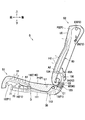
図1に示すように、本実施形態の乗物用シートは、自動車に搭載される車両用シートSとして構成されており、シートクッションS1およびシートバックS2を備えている。
Hereinafter, an embodiment of the invention will be described with reference to the accompanying drawings. In this specification, front and rear, left and right, and top and bottom are based on front and rear, left and right, and top and bottom as viewed from the person sitting on the seat.
As shown in FIG. 1, the vehicle seat of the present embodiment is configured as a vehicle seat S mounted on an automobile, and includes a seat cushion S1 and a seat back S2.
図2に示すように、車両用シートSは、シートフレームF(図3参照)に、ウレタンフォームなどからなるパッドPと、布地や皮革などからなる表皮U1,U2を被せることで構成されている。 As shown in FIG. 2, the vehicle seat S is configured by covering a seat frame F (see FIG. 3) with a pad P made of urethane foam or the like and skins U1 and U2 made of fabric or leather. .
パッドPは、シートクッションS1のパッドを構成するクッションパッドP1と、シートバックS2のパッドを構成するバックパッドP2を含む。クッションパッドP1は、内部に形成された通気路A1と、上側の面から通気路A1に連通する複数の通気穴H1とを有している。また、バックパッドP2は、内部に形成された通気路A2と、前側の面から通気路A2に連通する複数の通気穴H2とを有している。 The pad P includes a cushion pad P1 constituting the pad of the seat cushion S1 and a back pad P2 constituting the pad of the seat back S2. The cushion pad P1 has a ventilation path A1 formed therein and a plurality of ventilation holes H1 communicating with the ventilation path A1 from the upper surface. Further, the back pad P2 has a ventilation path A2 formed therein and a plurality of ventilation holes H2 communicating with the ventilation path A2 from the front surface.
通気路A1,A2は、後述するダクトDにより送風装置70と接続されている。送風装置70は、シロッコファンであり、後述するパンフレーム12の下側に配置されている。送風装置70は、パンフレーム12にブラケット71を介して取り付けられている。車両用シートSは、送風装置70から送風された空気を、ダクトDと通気路A1,A2を通して通気穴H1,H2からシートに座った乗員に向けて吹き出すように構成されている。
The ventilation paths A1 and A2 are connected to the
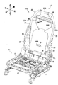
図3に示すように、シートフレームFは、シートクッションS1のフレームを構成するクッションフレームF1と、シートバックS2のフレームを構成するバックフレームF2とを含む。シートクッションS1は、クッションフレームF1をクッションパッドP1と表皮U1で覆うことで構成されており、シートバックS2は、バックフレームF2をバックパッドP2と表皮U2で覆うことで構成されている(図1参照)。 As shown in FIG. 3, the seat frame F includes a cushion frame F1 constituting a frame of the seat cushion S1 and a back frame F2 constituting a frame of the seat back S2. The seat cushion S1 is configured by covering the cushion frame F1 with the cushion pad P1 and the skin U1, and the seat back S2 is configured by covering the back frame F2 with the back pad P2 and the skin U2 (FIG. 1). reference).
クッションフレームF1は、左右のクッションサイドフレーム11と、パンフレーム12と、後部フレームとしてのリアパイプ13と、フロントパイプ14(図6参照)とを備えている。左右のクッションサイドフレーム11は、シートクッションS1の左右のフレームを構成する部材であり、左右方向に対向した状態で離間して配置されている。クッションサイドフレーム11は、板金からなり、前後に長い長尺状に形成されている。
The cushion frame F1 includes left and right cushion side frames 11, a
パンフレーム12は、板金からなり、左右のクッションサイドフレーム11の前部同士を連結している。図6に示すように、リアパイプ13とフロントパイプ14は、金属製のパイプ材からなり、前後に離間して配置され、左右のクッションサイドフレーム11を連結している。詳しくは、リアパイプ13が左右のクッションサイドフレーム11の後部同士を連結しており、フロントパイプ14が左右のクッションサイドフレーム11の前部同士を連結している。フロントパイプ14は、パンフレーム12の下側に配置されている。
The
左右のクッションサイドフレーム11の間には、支持部材30が配置されている。支持部材30は、シートに座った乗員からの荷重を受ける部材であり、複数のワイヤ部材31と、ワイヤ部材31をつなぐ複数の樹脂部材32とを有している。ワイヤ部材31は、金属製の線材からなり、左右に交互に屈曲しながら前後に延びている。ワイヤ部材31は、左右に並んだ状態で配置され、パンフレーム12とリアパイプ13に架け渡された状態で設けられている。樹脂部材32は、樹脂からなり、インサート成形によりワイヤ部材31の一部の全周を覆った状態でワイヤ部材31と一体に形成されている。
A
図3に示すように、バックフレームF2は、左右の板金フレーム22と、パイプフレーム23と、ロアフレーム24と、架橋フレーム25とを備えている。左右の板金フレーム22は、左右方向に対向した状態で離間して配置されている。板金フレーム22は、板金からなり、上下に長い長尺状に形成されている。
As shown in FIG. 3, the back frame F <b> 2 includes left and right sheet metal frames 22, a
パイプフレーム23は、金属製のパイプ材からなり、略上下に延びる左右のアッパーサイドフレーム23Aと、アッパーサイドフレーム23Aの上端同士を連結するアッパーフレーム23Bとを有している。左右のアッパーサイドフレーム23Aは、下部が板金フレーム22の上部に接続されていることで、左右の板金フレーム22とともに、シートバックS2の左右のフレームを構成する左右のバックサイドフレーム21を形成している。ロアフレーム24は、板金からなり、左右のバックサイドフレーム21の下部同士を連結している。架橋フレーム25は、板金からなり、左右のバックサイドフレーム21の上部同士を連結している。架橋フレーム25は、下端に前に向けて延出した下側延出部25Aを有し、下側延出部25Aの左右の端部には、上下に貫通した支持孔25Bが形成されている。
The
左右のバックサイドフレーム21の間には、受圧部材50と、ワイヤ部材60が配置されている。受圧部材50は、シートに座った乗員からの荷重を受ける板状の部材であり、樹脂などからなる。受圧部材50は、乗員の背中と対向するように配置されている。受圧部材50は、ダクトDを通すための開口50Aを有している。ワイヤ部材60は、受圧部材50をバックフレームF2に連結する部材である。ワイヤ部材60は、下端部がロアフレーム24に固定され、上端が架橋フレーム25の支持孔25Bに挿入されることで、バックフレームF2に連結されている。受圧部材50は、図示しない結束バンドなどによりワイヤ部材60に留められることで、ワイヤ部材60を介してバックフレームF2に連結されている。
A
クッションサイドフレーム11の後部とバックサイドフレーム21の下部とは、リクライニング機構RLを介して回動可能に連結されている。これにより、車両用シートSは、シートバックS2がシートクッションS1に対して前後に回動可能となっている。
The rear part of the
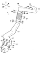
図2に示すように、ダクトDは、シートクッションS1およびシートバックS2のパッドP(P1,P2)に形成された通気路A1,A2と送風装置70を接続する部材である。ダクトDは、複数の部品を接続してなる。具体的には、図4に示すように、ダクトDは、第1ダクト部材110と、第2ダクト部材120と、第3ダクト部材130と、第4ダクト部材140とを有している。
As shown in FIG. 2, the duct D is a member that connects the air passages A1 and A2 formed in the pads P (P1 and P2) of the seat cushion S1 and the seat back S2 and the
第1ダクト部材110は、略前後に延びる第1管部111と、第1管部111の後端から後斜め上方に延びる第2管部112と、第2管部112の上端から略上方に延びる第1接続管部113とを有している。第1管部111は、前端部が送風装置70に接続されている(図2参照)。
The
第2ダクト部材120は、第1ダクト部材110の後端に接続されており、第1ダクト部材110の後端から略上方に延びるように設けられている。第2ダクト部材120は、第2接続管部121と、第2接続管部121の上に設けられた第1蛇腹部122と、第1蛇腹部122の上に設けられた第3接続管部123とを有している。第2接続管部121は、第1ダクト部材110の第1接続管部113が内側に嵌るようなサイズに形成されている。第1蛇腹部122は、可撓性を有するとともに伸縮自在となっている。
The
第3ダクト部材130は、第2ダクト部材120の上端に接続されている。第3ダクト部材130は、略上下に延びる第4接続管部131と、第4接続管部131の上端から左斜め上方(左右方向における車両用シートSの中央に向けて斜め上方)に延びる第3管部132と、第3管部132の上端から略上方に延びる第4管部133と、第4管部133の上端から略前方に延びるバック接続管部134とを有している。第4接続管部131は、第2ダクト部材120の第3接続管部123の内側に嵌るようなサイズに形成されている。バック接続管部134は、前端部がバックパッドP2に形成された通気路A2に接続されている(図2参照)。
The
第4ダクト部材140は、第1ダクト部材110の前部に接続されており、略上下に延びるように設けられている。第4ダクト部材140は、第2蛇腹部141と、第2蛇腹部141の上に設けられたクッション接続管部142と、第2蛇腹部141の下に設けられた左右の接続壁部143とを有している。第2蛇腹部141は、可撓性を有するとともに伸縮自在となっている。クッション接続管部142は、クッションパッドP1に形成された通気路A1に接続されている(図2参照)。接続壁部143は、第2蛇腹部141の下端から下方に向けて延び、第1ダクト部材110の第1管部111を左右から挟むように設けられている。
The
図5(a)に示すように、第1ダクト部材110は、第1接続部C1に設けられた第1係合部151および第2係合部152を有しており、第2ダクト部材120は、第1接続部C1に設けられた第3係合部153および第4係合部154を有している。第1接続部C1は、第1ダクト部材110と第2ダクト部材120との接続部である。具体的には、第1接続部C1は、第1ダクト部材110の第1接続管部113と第2ダクト部材120の第2接続管部121とが接続されて重なった部分である。
As shown in FIG. 5A, the
第1係合部151および第2係合部152は、第1接続管部113の左右の側面から左右方向外側に突出した形状の凸部である。第3係合部153および第4係合部154は、凸部としての係合部151,152が係合する左右に貫通した略矩形の穴であり、第2接続管部121の左右の側壁に設けられている。第3係合部153は、第1係合部151に係合し、第4係合部154は、第2係合部152に係合する。
The first
また、第3ダクト部材130は、第2接続部C2に設けられた第5係合部161および第6係合部162を有しており、第2ダクト部材120は、第2接続部C2に設けられた第7係合部163および第8係合部164を有している。第2接続部C2は、第2ダクト部材120と第3ダクト部材130との接続部である。具体的には、第2接続部C2は、第2ダクト部材120の第3接続管部123と第3ダクト部材130の第4接続管部131とが接続されて重なった部分である。
The
第5係合部161および第6係合部162は、第4接続管部131の左右の側面から左右方向外側に突出した形状の凸部である。第7係合部163および第8係合部164は、係合部161,162が係合する左右に貫通した略矩形の穴であり、第3接続管部123の左右の側壁に設けられている。第7係合部163は、第5係合部161に係合し、第8係合部164は、第6係合部162に係合する。
The
また、図5(b)に示すように、第1ダクト部材110は、第1管部111に設けられた第9係合部171および第10係合部172を有しており、第4ダクト部材140は、接続壁部143に設けられた第11係合部173および第12係合部174を有している。第9係合部171および第10係合部172は、第1管部111の左右の側面から左右方向外側に突出した形状の凸部である。第11係合部173および第12係合部174は、係合部171,172が係合する左右に貫通した略矩形の穴である。第11係合部173は、第9係合部171に係合し、第12係合部174は、第10係合部172に係合する。なお、第1ダクト部材110には、第1管部111から分岐して略上方に延び、第4ダクト部材140の内側に嵌る第5接続管部114が設けられている。
As shown in FIG. 5B, the
係合部151,152,161,162,171,172は、図5に示す断面視において略三角形状をなしている。具体的に、係合部151,152,161,162,171,172は、当接面151A,152A,161A,162A,171A,172Aと、傾斜面151B,152B,161B,162B,171B,172Bとを有している。当接面151A,152A,161A,162A,171A,172Aは、第2ダクト部材120または第4ダクト部材140が延びる方向(図5の上下方向)に対して略直交する平面となっている。また、傾斜面151B,152B,161B,162B,171B,172Bは、当接面151A,152A,161A,162A,171A,172Aの左右方向外側の端から、対応する接続管部113,131,114の先端に向かうにつれてダクトDの左右方向中央に近づくように傾斜した面となっている。
The engaging
図2に示すように、ダクトDは、シートクッションS1とシートバックS2とに跨がって配置されている。具体的には、ダクトDは、シートクッションS1の下側からリアパイプ13の後側を通って上方のシートバックS2に向かうように延びた状態で配置されている。ダクトDは、主に、第1ダクト部材110と第4ダクト部材140がシートクッションS1に配置され、第3ダクト部材130がシートバックS2に配置され、第2ダクト部材120がシートクッションS1とシートバックS2を跨ぐように配置されている。第1接続部C1は、リアパイプ13の後方に位置しており、第2接続部C2は、ロアフレーム24の後方に位置している。
As shown in FIG. 2, the duct D is disposed across the seat cushion S1 and the seat back S2. Specifically, the duct D is disposed in a state extending from the lower side of the seat cushion S1 to the upper seat back S2 through the rear side of the
図6に示すように、ダクトDは、第1ダクト部材110が、支持部材30の下側で、左右方向におけるシートクッションS1の中央(中央面CP)よりも右に配置されている。第1ダクト部材110は、前端部がパンフレーム12の下側に配置された送風装置70に接続され、第1管部111が略後方に向けて延び、第2管部112がリアパイプ13の下側を通って、第1接続管部113がリアパイプ13の後側に位置するように延びている。
As shown in FIG. 6, in the duct D, the
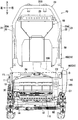
また、図7に示すように、ダクトDは、第2ダクト部材120が略上方に向けて延び、クッションフレームF1とバックフレームF2を跨ぐように配置されている。第2ダクト部材120、言い換えると、第1接続部C1および第2接続部C2は、左右方向において中央面CPよりも右のクッションサイドフレーム11に寄った位置に位置している。
As shown in FIG. 7, the duct D is arranged so that the
また、ダクトDは、第3ダクト部材130の第3管部132がロアフレーム24の後方を通りながら、中央面CPに向けて斜め上方に延び、第4管部133が中央面CP上を略上方に向けて延びている。そして、ダクトDは、第3ダクト部材130のバック接続管部134が略前方に向けて延び、受圧部材50の開口50Aを通ってバックパッドP2に形成された通気路A2に接続されている(図2参照)。
Further, the duct D extends obliquely upward toward the center plane CP while the
図5(a)に示すように、第2係合部152および第4係合部154は、第1接続部C1の左側面に設けられており、第6係合部162および第8係合部164は、第2接続部C2の左側面に設けられている。また、第10係合部172は、第1管部111の左側面に設けられており、第12係合部174は、左の接続壁部143に設けられている。一方、第1係合部151および第3係合部153は、第1接続部C1の右側面に設けられており、第5係合部161および第7係合部163は、第2接続部C2の右側面に設けられている。また、第9係合部171は、第1管部111の右側面に設けられており、第11係合部173は、右の接続壁部143に設けられている。
As shown in FIG. 5A, the
ここで、第1接続部C1は、右のクッションサイドフレーム11に寄った位置に位置しているので、第1係合部151および第3係合部153は、第1接続部C1の、左右方向において第2係合部152および第4係合部154よりも中央面CP(図7参照)から遠い側面に設けられている。同様に、第5係合部161および第7係合部163は、第2接続部C2の、左右方向において第6係合部162および第8係合部164よりも中央面CPから遠い側面に設けられている。
Here, since the 1st connection part C1 is located in the position near the right
また、図1に示すように、車両用シートSは、右側に、当該車両用シートS、および、車両用シートSのシートバックS2を前に倒して車両用シートSの後側に乗降するための乗降口を開閉するドアDRが配置されている。そのため、図1および図5(a)に示すように、第1接続部C1の右側面に設けられた第1係合部151および第3係合部153は、左右方向において、第1接続部C1の左側面に設けられた第2係合部152および第4係合部154よりもドアDRの近くに設けられている。
Further, as shown in FIG. 1, the vehicle seat S is moved to the rear side of the vehicle seat S with the vehicle seat S and the seat back S2 of the vehicle seat S tilted forward on the right side. The door DR which opens and closes the entrance / exit of is arranged. Therefore, as shown in FIG. 1 and FIG. 5A, the first engaging
図7に示すように、車両用シートSは、カバー部材CVを備えている。カバー部材CVは、リアカバー80と、サイドフレームカバー90を含む。
リアカバー80は、樹脂などから左右に長い板状に形成され、第3ダクト部材130の第4管部133およびバック接続管部134の後方に配置されている。リアカバー80は、左右の端部が、左右のバックサイドフレーム21の後端の左右内側に延出した部分にボルト締結などにより固定されている。これにより、リアカバー80は、左右のバックサイドフレーム21に架け渡すように取り付けられている。このようなリアカバー80を備えることで、リアカバー80によってダクトDとバックパッドP2が接続する部分を保護することができる。
As shown in FIG. 7, the vehicle seat S includes a cover member CV. Cover member CV includes a
The
サイドフレームカバー90は、右のクッションサイドフレーム11の後端部を覆う部材である。サイドフレームカバー90は、樹脂からなり、サイドフレームカバー部91(図8参照)と、ダクトカバー部92と、リクライニング機構カバー部93とを有している。図8に示すように、サイドフレームカバー部91は、右のクッションサイドフレーム11の後端部の左右方向内側を覆う部分である。
The
ダクトカバー部92は、クッションフレームF1の後方において、ダクトDの一部を覆う部分である。詳しくは、ダクトカバー部92は、リアパイプ13の後方に配置され、第2管部112、第1接続部C1および第1蛇腹部122の一部を覆っている。より詳しくは、図9に示すように、ダクトカバー部92は、サイドフレームカバー部91の後端から後方に向けて延びる第1サイドカバー部92Aと、第1サイドカバー部92Aの後端から左右方向内側に向けて延びるリアカバー部92Bとを有している。第1サイドカバー部92Aは、第2管部112、第1接続部C1および第1蛇腹部122を右から覆っている。また、リアカバー部92Bは、後斜め下方に凸となる弓状の断面形状を有し、下に向かうにつれて前に位置するように延びており、第2管部112、第1接続部C1および第1蛇腹部122を後から覆っている。
The
ダクトカバー部92は、第1サイドカバー部92Aが第1接続部C1の右側面を覆い、リアカバー部92Bが第1接続部C1の後側面を覆っている。一方、ダクトカバー部92は、第1接続部C1の左側面は覆わない。これにより、ダクトカバー部92は、第1接続部C1の右側面に設けられた第1係合部151および第3係合部153を覆い、図8に示すように、第1接続部C1の左側面に設けられた第2係合部152および第4係合部154を覆わない構成となっている。
In the
図9に示すように、リクライニング機構カバー部93は、リクライニング機構RLを覆う部分であり、左右方向内側および下側が開放された略カップ状に形成されている。リクライニング機構カバー部93は、サイドフレームカバー部91からリクライニング機構RLの周面に沿って延びるように形成されて、リクライニング機構RLの後側、上側および前側を覆う周面カバー部93Aと、リクライニング機構RLの左右方向外側を覆う第2サイドカバー部93Bとを有している。
As shown in FIG. 9, the reclining
以上説明した本実施形態によれば、カバー部材CVを構成するサイドフレームカバー90が第1ダクト部材110と第2ダクト部材120との接続部である第1接続部C1を覆うので、サイドフレームカバー90によって複数の部品を接続してなるダクトDの接続部(第1接続部C1)を保護することができる。
According to the embodiment described above, the side frame cover 90 that constitutes the cover member CV covers the first connection portion C1 that is the connection portion between the
また、サイドフレームカバー90が、第1係合部151と第3係合部153を覆い、第2係合部152と第4係合部154を覆わない構成なので、カバー部材ですべての係合部を覆う場合と比較して、サイドフレームカバー90をコンパクト化することができる。
Further, since the side frame cover 90 covers the
また、第2係合部152と第4係合部154が第1接続部C1の左側面に設けられているので、サイドフレームカバー90で覆われていない第2係合部152と第4係合部154に後席の乗員の足が後から当たるのを抑制することができる。これにより、ダクトDの接続部の係合箇所である第2係合部152と第4係合部154を保護することができる。また、第2係合部152と第4係合部154が、第1接続部C1の、前側面や、サイドフレームカバー90で覆われる後側面ではなく、サイドフレームカバー90で覆われない左側面に設けられていることで、第2係合部152と第4係合部154の係合状態を目視して確認することができる。
Further, since the
また、第1接続部C1が中央面CPよりも右のクッションサイドフレーム11に寄った位置に位置しているので、第1接続部C1が中央面CPに寄った位置に位置する場合と比較して、第1接続部C1付近に後席の乗員の足が後から当たること自体を抑制することができる。これにより、サイドフレームカバー90で覆われていない第2係合部152と第4係合部154をより保護することができる。また、第1接続部C1付近、言い換えると、第2ダクト部材120に後席の乗員の足が後から当たること自体を抑制できることで、サイドフレームカバー90で覆われていない係合部161〜164も良好に保護することができる。
In addition, since the first connection portion C1 is located at the position closer to the
また、第1係合部151と第3係合部153が、第2係合部152と第4係合部154よりも車両用シートSの後側に乗降するためのドアDRの近くに設けられているので、乗員が車両用シートSの後側に乗り込む際に、第1接続部C1の、第1係合部151と第3係合部153が設けられた側面付近に乗員の足などが当たる可能性があるが、第1係合部151と第3係合部153はサイドフレームカバー90で覆われているため、サイドフレームカバー90によって第1係合部151と第3係合部153を効果的に保護することができる。
Further, the first engaging
また、第1係合部151と第2係合部152が凸部であり、第3係合部153と第4係合部154が当該凸部が係合する穴であるので、第1ダクト部材110と第2ダクト部材120を簡単な構成で接続することができる。第2ダクト部材120と第3ダクト部材130との接続、および、第1ダクト部材110と第4ダクト部材140との接続についても同様のことが言える。
In addition, since the first engaging
また、シートクッションS1に乗員が座って、その重みでクッションパッドP1や支持部材30が下に撓んだとき、第1ダクト部材110の位置が下に下がり、第1ダクト部材110に第2ダクト部材120から抜けようとする力が作用することがあるが、この場合には、係合部151,153の当接面151A,153Aが係合部152,154の縁に引っ掛かるので、第1ダクト部材110が第2ダクト部材120から外れるのを抑制することができる。
When the occupant sits on the seat cushion S1 and the cushion pad P1 and the
また、シートバックS2をシートクッションS1に対して前に回動させたとき、第3ダクト部材130がシートバックS2とともに回動することで、第3ダクト部材130に第2ダクト部材120から抜けようとする力が作用することがあるが、この場合には、係合部161,163の当接面161A,163Aが、係合部162,164の縁に引っ掛かるので、第3ダクト部材130が第2ダクト部材120から外れるのを抑制することができる。
Further, when the seat back S2 is rotated forward with respect to the seat cushion S1, the
以上、発明の一実施形態について説明したが、本発明は前記実施形態に限定されるものではない。具体的な構成については、下記のように発明の趣旨を逸脱しない範囲で適宜変更が可能である。なお、以下では、前記実施形態と同様の構成については同一符号を付して適宜説明を省略し、前記実施形態と異なる点について詳細に説明する。 As mentioned above, although one Embodiment of invention was described, this invention is not limited to the said embodiment. About a concrete structure, it can change suitably in the range which does not deviate from the meaning of invention as follows. In the following description, the same components as those in the above-described embodiment are denoted by the same reference numerals, description thereof is omitted as appropriate, and differences from the above-described embodiment will be described in detail.
例えば、図10に示す変形例では、凸部としての係合部151,152は、第1ダクト部材110が第2ダクト部材120に接続する方向、具体的には、下から上に向かう方向と反対に延びる返し部151C,152Cを有している。詳しくは、返し部151C,152Cは、第1ダクト部材110が第2ダクト部材120に接続する方向とは反対の方向(上から下に向かう方向)に向かうにつれて、第1接続管部113の左右の側面から遠ざかるように左右方向外側の斜め下方に延びている。このような構成によれば、返し部151C,152Cが係合部153,154の縁に引っ掛かることで、第1ダクト部材110と第2ダクト部材120を外れにくくすることができる。なお、係合部161,162,171,172についても同様の構成を採用することができる。
For example, in the modification shown in FIG. 10, the engaging
また、図11に示す変形例では、カバー部材CVを構成するサイドフレームカバー90のダクトカバー部92は、前記実施形態のダクトカバー部92よりも上下の長さが長くなっており、第2接続部C2を覆っている。詳しくは、図11に示すダクトカバー部92は、第2接続部C2の右側面と後側面を覆っている。このような構成によれば、カバー部材CVによって、第1接続部C1だけでなく、第2接続部C2も保護することができる。
Further, in the modification shown in FIG. 11, the
なお、以上では、ダクトカバー部92が第1接続部C1や第2接続部C2の一部だけ(右側面と後側面)を覆う構成であったが、これに限定されない。例えば、ダクトカバー部(カバー部材)は、第1接続部C1や第2接続部C2の全体を覆う構成であってもよい。別の言い方をすれば、カバー部材は、第1係合部151、第2係合部152、第3係合部153および第4係合部154のすべて覆う構成であってもよい。
In the above, the
また、図12に示す変形例では、第2接続部C2を、サイドフレームカバー90ではなく、リアカバー80が覆っている。詳しくは、カバー部材CVを構成するリアカバー80は、下部が前記実施形態のリアカバー80よりも下まで長く延びており、第2接続部C2を後から覆っている。このような構成によれば、板状のリアカバー80によって第2接続部C2を効果的に保護することができる。なお、図示は省略するが、リアカバーは、第2接続部C2だけでなく、第1接続部C1も覆うように設けられていてもよい。
In the modification shown in FIG. 12, the second cover C <b> 2 is covered not by the side frame cover 90 but by the
また、図13に示す変形例では、シートバックS2(バックパッドP2)は、下部に形成された第1通気路A21と、第1通気路A21の上方で第1通気路A21とは独立して形成された(第1通気路A21とつながっていない)第2通気路A22とを有している。また、ダクトDは、第1通気路A21に接続する第1ダクト部としての第3ダクト部材130と、第3ダクト部材130から分岐して延び、第2通気路A22に接続する第2ダクト部としての第5ダクト部材180とを有している。
Further, in the modification shown in FIG. 13, the seat back S2 (back pad P2) includes a first air passage A21 formed in a lower portion, and the first air passage A21 above the first air passage A21 and independent of the first air passage A21. And a second air passage A22 that is formed (not connected to the first air passage A21). The duct D includes a
第3ダクト部材130は、第4接続管部131の上端から略上方に延びる分岐管部135をさらに有している。第1のバック接続管部134は、前端部がバックパッドP2の下部に形成された第1通気路A21に接続されている。
The
第5ダクト部材180は、略上下に延びる第5管部181と、第5管部181の上端から左斜め上方に延びる第6管部182と、第6管部182の上端から略上方に延びる第7管部183と、第7管部183の上端から略前方に延びる第2のバック接続管部184とを有している。第5管部181は、第3ダクト部材130の分岐管部135が内側に嵌るようなサイズに形成されており、下端が第3ダクト部材130の分岐管部135に接続されている。第2のバック接続管部184は、前端部がバックパッドP2の、第1通気路A21の上に形成された第2通気路A22に接続されている。
The
このような構成によれば、ダクトDによって送風装置70と複数の通気路A21,A22とを接続できるので、シートバックS2の座面の広範囲において空気を吹き出す構成を実現することができる。
According to such a configuration, the
なお、図13に示したような構成は、シートバックS2とともに、または、シートバックS2の代わりに、シートクッションS1に適用してもよい。すなわち、シートクッションS1が、第1通気路と第2通気路を有し、例えば、ダクトDをシートクッションS1の下側で分岐させて、第1通気路と第2通気路に個別に接続するようにしてもよい。これによれば、シートクッションS1の座面の広範囲において空気を吹き出す構成を実現することができる。 The configuration as shown in FIG. 13 may be applied to the seat cushion S1 together with the seat back S2 or instead of the seat back S2. That is, the seat cushion S1 has a first ventilation path and a second ventilation path. For example, the duct D is branched at the lower side of the seat cushion S1, and is individually connected to the first ventilation path and the second ventilation path. You may do it. According to this, the structure which blows off air in the wide range of the seat surface of seat cushion S1 is realizable.
また、ダクトDは、前記実施形態で説明した構成に対し、左右対称の形状を有する構成であってもよい。この場合、第1接続部C1や第2接続部C2は、左右方向においてシートクッションS1の中央(中央面CP)よりも左のクッションサイドフレーム11に寄った位置に位置する構成とすることができ、また、係合部151,153,161,163などは、第1接続部C1の左側面に設けられ、係合部152,154,162,164などは、第1接続部C1の右側面に設けられる構成とすることができる。
Further, the duct D may have a configuration having a symmetrical shape with respect to the configuration described in the embodiment. In this case, the first connection portion C1 and the second connection portion C2 can be configured to be located at a position closer to the
また、前記実施形態では、ダクトDの接続部C1,C2が左右方向においてクッションサイドフレーム11に寄った位置に位置していたが、これに限定されない。例えば、図14および図15に示すように、ダクトDの接続部C3,C4は、左右方向においてシートクッションS1の中央、または、左右方向においてクッションサイドフレーム11よりもシートクッションS1の中央に寄った位置(中央面CP上)に位置していてもよい。なお、接続部C3,C4が中央面CP上に位置する構成において、接続部C3,C4は、例えば、リアカバー80によって覆うことができる。また、図14に示すように、ダクトDは、接続部C3が中央面CP上に位置する場合も、第1通気路A21に接続する第1ダクト部191と、第1ダクト部191から分岐して延び、第2通気路A22に接続する第2ダクト部192とを有する構成とすることができる。
Moreover, in the said embodiment, although the connection parts C1 and C2 of the duct D were located in the position close | similar to the
また、前記実施形態では、第1通気路A21と第2通気路A22が上下に並ぶように形成されていたが、これに限定されない。例えば、図15に示すように、第1通気路A23と第2通気路A24は、左右に並ぶように形成されていてもよい。この場合、ダクトDは、例えば、図示しないバックパッドの後に位置する部分が、後から見て、第1通気路A23に接続する第1ダクト部193と、第1ダクト部193から分岐して延び、第2通気路A24に接続する第2ダクト部194とを有する略Y字状に形成することができる。
Moreover, in the said embodiment, although 1st ventilation path A21 and 2nd ventilation path A22 were formed so that it might rank up and down, it is not limited to this. For example, as shown in FIG. 15, the first air passage A23 and the second air passage A24 may be formed so as to be lined up on the left and right. In this case, for example, a portion of the duct D located behind the back pad (not shown) extends from the
また、前記実施形態では、第1係合部151と第2係合部152が外側に突出した形状の凸部であり、第3係合部153と第4係合部154が凸部が係合する穴であったが、これに限定されない。例えば、第1係合部および第2係合部は内側に突出した形状の凸部であってもよい。また、第3係合部と第4係合部が凸部であり、第1係合部と第2係合部が穴であってもよい。また、穴は、貫通した穴ではなく、有底の穴(凹部)であってもよい。また、第1係合部と第2係合部は互いに異なる構成、例えば、一方が凸部、他方が穴であってもよい。第3係合部と第4係合部についても同様である。また、以上は、他の係合部(161〜164,171〜174)についても同様のことが言える。また、ダクトは接続部に係合部が設けられていない構成であってもよい。
Moreover, in the said embodiment, the
また、前記実施形態では、送風装置70としてシロッコファンを例示したが、これに限定されず、例えば、プロペラファンやターボファンなどであってもよい。また、前記実施形態では、車両用シートSが通気穴H1,H2から空気を吹き出すように構成されていたが、これに限定されず、例えば、通気穴から空気を吸い込むように構成されていてもよい。通気穴から空気を吸い込む構成を、例えば、図13に示した形態で適用すると、シートバックやシートクッションの座面の広範囲において空気を吸い込む構成を実現することができる。
Moreover, although the sirocco fan was illustrated as the
また、送風装置は、例えば、羽根車の回転方向を切り替えることで、送風と吸引を切り替えることができるものであってもよい。また、前記実施形態では、車両用シートSが送風装置70を備えていたが、車両用シート自体は送風装置を備えない構成であってもよい。言い換えると、送風装置は、車両用シートが搭載される自動車の車体に設けられていてもよい。この場合、車両用シートは、ダクトが、例えば、車体に設けられた空気の吹出口または吸引口に接続される構成とすることができる。
Further, the blower device may be capable of switching between blowing and suction by switching the rotation direction of the impeller, for example. Moreover, in the said embodiment, although the vehicle seat S was provided with the
また、前記実施形態では、ダクトDにより送風装置と接続される通気路が、シートクッションおよびシートバックの両方に形成されていたが、これに限定されず、シートクッションおよびシートバックのいずれか一方だけに形成された構成であってもよい。 Moreover, in the said embodiment, although the ventilation path connected with an air blower by the duct D was formed in both a seat cushion and a seat back, it is not limited to this, Only one of a seat cushion and a seat back The structure formed in this may be sufficient.
また、前記実施形態では、乗物用シートとして自動車に搭載される車両用シートSを例示したが、これに限定されず、自動車以外の乗物、例えば、鉄道車両や船舶、航空機などに搭載されるシートであってもよい。 Moreover, in the said embodiment, although vehicle seat S mounted in a motor vehicle was illustrated as a vehicle seat, it is not limited to this, The seat mounted in vehicles other than a motor vehicle, for example, a rail vehicle, a ship, an aircraft, etc. It may be.
また、前記した実施形態および変形例で説明した各要素を、任意に組み合わせて実施してもよい。 Moreover, you may implement combining each element demonstrated by above-described embodiment and modification arbitrarily.
11 クッションサイドフレーム
13 リアパイプ
21 バックサイドフレーム
70 送風装置
80 リアカバー
90 サイドフレームカバー
110 第1ダクト部材
120 第2ダクト部材
130 第3ダクト部材
151 第1係合部
152 第2係合部
153 第3係合部
154 第4係合部
A1 通気路
A2 通気路
C1 第1接続部
C2 第2接続部
CV カバー部材
D ダクト
DR ドア
S 車両用シート
S1 シートクッション
S2 シートバック
DESCRIPTION OF
Claims (10)
前記シートクッションと前記シートバックとに跨がって配置され、前記シートクッションおよび前記シートバックの少なくとも一方に形成された通気路と送風装置を接続するダクトと、
前記ダクトの一部を覆うカバー部材と、を備え、
前記ダクトは、第1ダクト部材と、前記第1ダクト部材に接続される第2ダクト部材とを有し、
前記カバー部材は、前記第1ダクト部材と前記第2ダクト部材との接続部である第1接続部の少なくとも一部を覆うことを特徴とする乗物用シート。 A vehicle seat comprising a seat cushion and a seat back,
A duct that is disposed across the seat cushion and the seat back, and connects the air passage and the blower formed in at least one of the seat cushion and the seat back;
A cover member covering a part of the duct,
The duct has a first duct member and a second duct member connected to the first duct member,
The vehicle seat according to claim 1, wherein the cover member covers at least a part of a first connection portion that is a connection portion between the first duct member and the second duct member.
前記第2ダクト部材は、前記第1係合部に係合する第3係合部と、前記第2係合部に係合する第4係合部とを有し、
前記カバー部材は、前記第1係合部および前記第3係合部を覆い、前記第2係合部および前記第4係合部を覆わないことを特徴とする請求項1に記載の乗物用シート。 The first duct member has a first engagement portion and a second engagement portion provided in the first connection portion,
The second duct member has a third engagement portion that engages with the first engagement portion, and a fourth engagement portion that engages with the second engagement portion,
2. The vehicle according to claim 1, wherein the cover member covers the first engagement portion and the third engagement portion and does not cover the second engagement portion and the fourth engagement portion. Sheet.
前記左右のクッションサイドフレームの後部同士を連結する後部フレームと、を備え、
前記ダクトは、前記後部フレームの後側を通って前記シートクッションから前記シートバックに向かうように延び、
前記第2係合部および前記第4係合部は、前記第1接続部の右側面または左側面に設けられることを特徴とする請求項2に記載の乗物用シート。 Left and right cushion side frames constituting left and right frames of the seat cushion; and
A rear frame that connects the rear portions of the left and right cushion side frames, and
The duct extends from the seat cushion toward the seat back through the rear side of the rear frame,
The vehicle seat according to claim 2, wherein the second engagement portion and the fourth engagement portion are provided on a right side surface or a left side surface of the first connection portion.
前記第1係合部および前記第3係合部は、前記第1接続部の、左右方向において前記第2係合部および前記第4係合部よりも前記シートクッションの中央から遠い側面に設けられることを特徴とする請求項3に記載の乗物用シート。 The first connection portion is located at a position closer to the cushion side frame on the right or left than the center of the seat cushion in the left-right direction,
The first engagement portion and the third engagement portion are provided on a side surface of the first connection portion that is farther from the center of the seat cushion than the second engagement portion and the fourth engagement portion in the left-right direction. The vehicle seat according to claim 3, wherein the vehicle seat is provided.
前記ダクトは、前記シートバックに配置され、前記第2ダクト部材の上端に接続される第3ダクト部材を有し、
前記カバー部材は、前記第2ダクト部材と前記第3ダクト部材との接続部である第2接続部の少なくとも一部を覆うことを特徴とする請求項1から請求項7のいずれか1項に記載の乗物用シート。 The second duct member is connected to a rear end of the first duct member and extends upward;
The duct has a third duct member disposed on the seat back and connected to an upper end of the second duct member;
The said cover member covers at least one part of the 2nd connection part which is a connection part of a said 2nd duct member and a said 3rd duct member, The any one of Claims 1-7 characterized by the above-mentioned. The vehicle seat described.
前記カバー部材は、前記左右のバックサイドフレームに架け渡すように取り付けられた板状のリアカバーを含み、前記リアカバーが前記第2接続部を後から覆うことを特徴とする請求項8に記載の乗物用シート。 Comprising left and right backside frames constituting left and right frames of the seat back;
The vehicle according to claim 8, wherein the cover member includes a plate-like rear cover attached so as to span the left and right back side frames, and the rear cover covers the second connection portion from the rear. Sheet.
前記ダクトは、前記第1通気路に接続する第1ダクト部と、前記第1ダクト部から分岐して延び、前記第2通気路に接続する第2ダクト部とを有することを特徴とする請求項1から請求項9のいずれか1項に記載の乗物用シート。 One of the seat cushion and the seat back has a first air passage and a second air passage,
The duct has a first duct portion connected to the first air passage, and a second duct portion extending from the first duct portion and connected to the second air passage. The vehicle seat according to any one of claims 1 to 9.
Priority Applications (3)
| Application Number | Priority Date | Filing Date | Title |
|---|---|---|---|
| JP2017148029A JP7317459B2 (en) | 2017-07-31 | 2017-07-31 | vehicle seat |
| PCT/JP2018/027341 WO2019026650A1 (en) | 2017-07-31 | 2018-07-20 | Vehicle seat |
| US16/635,449 US11167672B2 (en) | 2017-07-31 | 2018-07-20 | Vehicle seat |
Applications Claiming Priority (1)
| Application Number | Priority Date | Filing Date | Title |
|---|---|---|---|
| JP2017148029A JP7317459B2 (en) | 2017-07-31 | 2017-07-31 | vehicle seat |
Publications (2)
| Publication Number | Publication Date |
|---|---|
| JP2019026096A true JP2019026096A (en) | 2019-02-21 |
| JP7317459B2 JP7317459B2 (en) | 2023-07-31 |
Family
ID=65475439
Family Applications (1)
| Application Number | Title | Priority Date | Filing Date |
|---|---|---|---|
| JP2017148029A Active JP7317459B2 (en) | 2017-07-31 | 2017-07-31 | vehicle seat |
Country Status (1)
| Country | Link |
|---|---|
| JP (1) | JP7317459B2 (en) |
Cited By (1)
| Publication number | Priority date | Publication date | Assignee | Title |
|---|---|---|---|---|
| US11203277B1 (en) | 2020-06-17 | 2021-12-21 | Hyundai Motor Company | Ventilation apparatus for vehicle seat |
Citations (8)
| Publication number | Priority date | Publication date | Assignee | Title |
|---|---|---|---|---|
| JPS4827771Y1 (en) * | 1970-05-02 | 1973-08-17 | ||
| JPS6127915U (en) * | 1984-07-25 | 1986-02-19 | マツダ株式会社 | Engine exhaust passage structure |
| JPH0414894U (en) * | 1990-05-30 | 1992-02-06 | ||
| JPH07317982A (en) * | 1994-05-25 | 1995-12-08 | Kurashiki Kako Co Ltd | Quick connector |
| JP2001047848A (en) * | 1999-08-03 | 2001-02-20 | Denso Corp | Air conditioner for vehicular seat |
| JP2002267090A (en) * | 2001-03-08 | 2002-09-18 | Fusoo Kasei Kk | Connecting and fixing device for flexible pipe cover |
| JP2004082961A (en) * | 2002-08-28 | 2004-03-18 | Johnson Controls Automotive Systems Corp | Seat for vehicle |
| JP2007333108A (en) * | 2006-06-15 | 2007-12-27 | Denso Corp | Pipe joint and pipe joint device |
Family Cites Families (2)
| Publication number | Priority date | Publication date | Assignee | Title |
|---|---|---|---|---|
| JP4827771B2 (en) | 2007-03-08 | 2011-11-30 | キヤノン株式会社 | Organic light emitting device and display device using oligofluorene compound |
| JP6127915B2 (en) | 2013-10-30 | 2017-05-17 | 富士通株式会社 | Connector misinsertion prevention mechanism and connector |
-
2017
- 2017-07-31 JP JP2017148029A patent/JP7317459B2/en active Active
Patent Citations (8)
| Publication number | Priority date | Publication date | Assignee | Title |
|---|---|---|---|---|
| JPS4827771Y1 (en) * | 1970-05-02 | 1973-08-17 | ||
| JPS6127915U (en) * | 1984-07-25 | 1986-02-19 | マツダ株式会社 | Engine exhaust passage structure |
| JPH0414894U (en) * | 1990-05-30 | 1992-02-06 | ||
| JPH07317982A (en) * | 1994-05-25 | 1995-12-08 | Kurashiki Kako Co Ltd | Quick connector |
| JP2001047848A (en) * | 1999-08-03 | 2001-02-20 | Denso Corp | Air conditioner for vehicular seat |
| JP2002267090A (en) * | 2001-03-08 | 2002-09-18 | Fusoo Kasei Kk | Connecting and fixing device for flexible pipe cover |
| JP2004082961A (en) * | 2002-08-28 | 2004-03-18 | Johnson Controls Automotive Systems Corp | Seat for vehicle |
| JP2007333108A (en) * | 2006-06-15 | 2007-12-27 | Denso Corp | Pipe joint and pipe joint device |
Cited By (1)
| Publication number | Priority date | Publication date | Assignee | Title |
|---|---|---|---|---|
| US11203277B1 (en) | 2020-06-17 | 2021-12-21 | Hyundai Motor Company | Ventilation apparatus for vehicle seat |
Also Published As
| Publication number | Publication date |
|---|---|
| JP7317459B2 (en) | 2023-07-31 |
Similar Documents
| Publication | Publication Date | Title |
|---|---|---|
| WO2018158987A1 (en) | Vehicle seat | |
| JP2019026255A (en) | Vehicular seat | |
| JP7267674B2 (en) | vehicle seat | |
| JP6375965B2 (en) | Air conditioning seat for vehicles | |
| JP2019026096A (en) | Vehicular seat | |
| JP7157300B2 (en) | vehicle seat | |
| JP2018167631A (en) | Vehicle seat | |
| JP2024045674A (en) | vehicle seat | |
| JP6836066B2 (en) | Vehicle seat | |
| JP5928821B2 (en) | Exhaust structure for vehicles | |
| JP6583314B2 (en) | Vehicle seat | |
| JP6643726B2 (en) | Vehicle seat | |
| WO2019026650A1 (en) | Vehicle seat | |
| JP6652713B2 (en) | Vehicle seat | |
| JP2018095144A (en) | Vehicle seat | |
| JP6643727B2 (en) | Vehicle seat | |
| JP2021066434A (en) | Vehicle seat | |
| JP2016124414A (en) | Vehicle air-conditioning seat | |
| JP2021061875A (en) | Vehicle seat | |
| JP7428885B2 (en) | vehicle seat | |
| JP6982258B2 (en) | Vehicle seat | |
| JP7317460B2 (en) | vehicle seat | |
| JP2020121602A (en) | Pocket structure of interior material for vehicle | |
| JP2019043293A (en) | Vehicle seat | |
| JP7448768B2 (en) | vehicle seat |
Legal Events
| Date | Code | Title | Description |
|---|---|---|---|
| A621 | Written request for application examination |
Free format text: JAPANESE INTERMEDIATE CODE: A621 Effective date: 20200729 |
|
| A131 | Notification of reasons for refusal |
Free format text: JAPANESE INTERMEDIATE CODE: A131 Effective date: 20210706 |
|
| A601 | Written request for extension of time |
Free format text: JAPANESE INTERMEDIATE CODE: A601 Effective date: 20210830 |
|
| A521 | Request for written amendment filed |
Free format text: JAPANESE INTERMEDIATE CODE: A523 Effective date: 20211029 |
|
| A02 | Decision of refusal |
Free format text: JAPANESE INTERMEDIATE CODE: A02 Effective date: 20220322 |
|
| A521 | Request for written amendment filed |
Free format text: JAPANESE INTERMEDIATE CODE: A523 Effective date: 20220622 |
|
| C60 | Trial request (containing other claim documents, opposition documents) |
Free format text: JAPANESE INTERMEDIATE CODE: C60 Effective date: 20220622 |
|
| A911 | Transfer to examiner for re-examination before appeal (zenchi) |
Free format text: JAPANESE INTERMEDIATE CODE: A911 Effective date: 20220629 |
|
| C21 | Notice of transfer of a case for reconsideration by examiners before appeal proceedings |
Free format text: JAPANESE INTERMEDIATE CODE: C21 Effective date: 20220705 |
|
| A912 | Re-examination (zenchi) completed and case transferred to appeal board |
Free format text: JAPANESE INTERMEDIATE CODE: A912 Effective date: 20220902 |
|
| C211 | Notice of termination of reconsideration by examiners before appeal proceedings |
Free format text: JAPANESE INTERMEDIATE CODE: C211 Effective date: 20220906 |
|
| C22 | Notice of designation (change) of administrative judge |
Free format text: JAPANESE INTERMEDIATE CODE: C22 Effective date: 20230207 |
|
| C22 | Notice of designation (change) of administrative judge |
Free format text: JAPANESE INTERMEDIATE CODE: C22 Effective date: 20230418 |
|
| A61 | First payment of annual fees (during grant procedure) |
Free format text: JAPANESE INTERMEDIATE CODE: A61 Effective date: 20230719 |
|
| R150 | Certificate of patent or registration of utility model |
Ref document number: 7317459 Country of ref document: JP Free format text: JAPANESE INTERMEDIATE CODE: R150 |