JP2019022431A - Motor and brushless wiper motor - Google Patents
Motor and brushless wiper motor Download PDFInfo
- Publication number
- JP2019022431A JP2019022431A JP2018113645A JP2018113645A JP2019022431A JP 2019022431 A JP2019022431 A JP 2019022431A JP 2018113645 A JP2018113645 A JP 2018113645A JP 2018113645 A JP2018113645 A JP 2018113645A JP 2019022431 A JP2019022431 A JP 2019022431A
- Authority
- JP
- Japan
- Prior art keywords
- magnet
- peripheral surface
- outer peripheral
- motor
- circumferential
- Prior art date
- Legal status (The legal status is an assumption and is not a legal conclusion. Google has not performed a legal analysis and makes no representation as to the accuracy of the status listed.)
- Granted
Links
Images


Abstract
Description
本発明は、モータ及びブラシレスワイパーモータに関するものである。 The present invention relates to a motor and a brushless wiper motor.
ブラシレスモータ(以下、単にモータと称することがある)は、コイルが巻回されたティースを有するステータと、ステータの径方向内側に回転自在に設けられたロータと、を備えている。ステータには、コイルに給電を行うことにより鎖交磁束が形成される。ロータは、回転軸と、この回転軸に外嵌固定される略円柱状のロータコアと、ロータコアに設けられた永久磁石と、を有している。そして、ステータに形成された鎖交磁束とロータコアに設けられた永久磁石との間に磁気的な吸引力や反発力が生じ、ロータが継続的に回転する。 A brushless motor (hereinafter sometimes simply referred to as a motor) includes a stator having teeth around which a coil is wound, and a rotor that is rotatably provided on the radial inner side of the stator. An interlinkage magnetic flux is formed in the stator by supplying power to the coil. The rotor includes a rotating shaft, a substantially cylindrical rotor core that is fitted and fixed to the rotating shaft, and a permanent magnet provided on the rotor core. Then, a magnetic attractive force or a repulsive force is generated between the interlinkage magnetic flux formed in the stator and the permanent magnet provided in the rotor core, and the rotor continuously rotates.
ここで、ロータに永久磁石を配置する方式としては、大きく2つに大別される。1つは、ロータコアにスリットを複数形成し、スリット内に永久磁石を配置する永久磁石埋込方式(IPM:Interior Permanent Magnet)がある。
また、ロータに永久磁石を配置するもう1つの方式として、ロータコアの外周面に永久磁石を配置する方式(SPM:Surface Permanent Magnet)がある(例えば、特許文献1参照)。
Here, the method of arranging the permanent magnet on the rotor is roughly divided into two. One is a permanent magnet embedded system (IPM) in which a plurality of slits are formed in a rotor core and permanent magnets are arranged in the slits.
Further, as another method of arranging permanent magnets on the rotor, there is a method of arranging permanent magnets on the outer peripheral surface of the rotor core (SPM: Surface Permanent Magnet) (see, for example, Patent Document 1).
ところで、上記したようなモータを、例えば、自動車用のワイパーモータに用いる場合などに、高回転化と高トルク化との双方が要求されることがある。
SPM方式のモータにおいては、電流供給の進角化と広角化を図れば、高回転化を図ることができる。電流供給の広角化とは、交互に供給する3相の各相の電流の供給タイミングを互いにラップさせ、120°以上に広角化させることである。このようにして、進角通電及び広角通電による弱め界磁を用いることで、モータの高回転化を図ることができる。
このようなSPM方式のモータにおいて、磁石の使用量を増やすことで、高トルク化を図ることができる。
By the way, when the motor as described above is used for a wiper motor for an automobile, for example, both high rotation and high torque may be required.
In the SPM motor, if the current supply is advanced and widened, the rotation speed can be increased. The widening of the current supply is to wrap the supply timings of the currents of the three phases alternately supplied to each other to widen the angle to 120 ° or more. In this way, by using the field weakening by the advance angle energization and the wide angle energization, it is possible to increase the rotation speed of the motor.
In such an SPM motor, the torque can be increased by increasing the amount of magnet used.
しかしながら、SPM方式のモータの高回転化と高トルク化とを図ると、モータの回転にともなって、トルクが周期的に上下するリップルが大きく生じる場合がある。
このようなリップルを打ち消すには、コイルに印加する相電流に、5次、7次、11次といった高次の高調波成分を重畳させる必要がある。しかし、高い次数の高調波を、コイルに電流を供給する駆動回路のマイコンで演算して生成するのは、処理負荷が高く、マイコンのコスト上昇に繋がってしまう。
However, when the rotation and torque of the SPM motor are increased, ripples that cause the torque to periodically increase and decrease may occur with the rotation of the motor.
In order to cancel such a ripple, it is necessary to superimpose higher-order harmonic components such as the fifth, seventh, and eleventh orders on the phase current applied to the coil. However, generating high-order harmonics by calculating with a microcomputer of the drive circuit that supplies current to the coil has a high processing load and leads to an increase in the cost of the microcomputer.
そこで、本発明は、上述した事情に鑑みてなされたものであって、低コストでリップルを効果的に低減することのできるモータ及びブラシレスワイパーモータを提供することである。 Therefore, the present invention has been made in view of the above-described circumstances, and provides a motor and a brushless wiper motor that can effectively reduce ripples at low cost.
本発明は、上記課題を解決するため、以下の手段を採用する。
すなわち、本発明のモータは、環状のステータコア、及び前記ステータコアの内周面から径方向内側に向かって突出する複数のティースを有するステータと、前記ティースに巻回されるコイルと、前記ステータコアの径方向内側で回転軸線回りに回転するシャフトと、前記シャフトに固定され、前記回転軸線を径方向中心とするロータコアと、前記ロータコアの外周面に配置され、前記回転軸線回りの周方向両側の端部における前記径方向の厚さが、前記周方向の中間部における前記径方向の厚さよりも小さい磁石と、前記ロータコアの前記外周面の周方向で隣り合う前記磁石の間に、前記磁石の周方向の端部よりも径方向外側に向かって突出形成された突極と、を備え、前記磁石の磁極数と前記ティースの数との比は2n:3n(ただし、nは自然数)に設定されており、前記磁石は、外周面の曲率半径が、前記磁石の前記外周面で最も径方向外側に位置する部位における、前記回転軸線からの距離に対し、0.8倍以下に設定されていることを特徴とする。
The present invention employs the following means in order to solve the above problems.
That is, the motor of the present invention includes an annular stator core, a stator having a plurality of teeth protruding radially inward from an inner peripheral surface of the stator core, a coil wound around the teeth, and a diameter of the stator core. A shaft that rotates around the rotation axis on the inner side in the direction, a rotor core that is fixed to the shaft and that has the rotation axis as the center in the radial direction, and that is disposed on the outer peripheral surface of the rotor core, and ends on both sides in the circumferential direction around the rotation axis In the circumferential direction of the magnet, the magnet has a radial thickness smaller than the radial thickness in the circumferential intermediate portion and the magnet adjacent in the circumferential direction of the outer circumferential surface of the rotor core. And a salient pole projecting outward in the radial direction from the end of the magnet, and the ratio of the number of magnetic poles of the magnet to the number of teeth is 2n: 3n (however, Is a natural number), and the radius of curvature of the outer periphery of the magnet is 0.8 times the distance from the axis of rotation at the portion of the outermost surface of the magnet that is located radially outward. It is set as follows.
このように、突極を磁石の周方向の端部よりも径方向外側に向かって突出させるとともに、磁石の外周面の曲率半径を、磁石の外周面で最も径方向外側に位置する部位における回転軸線からの距離よりも小さくした。これにより、磁石の周方向両側の端部は、突極よりも径方向内側に配置されることとなる。そして、磁束は突極に集中し、減磁界が磁石の端部に作用しにくくなる。すると、コイルに電流を供給したときの誘起電圧に含有される高次の高調波成分を抑えることが可能となり、モータにおけるトルクリップルを抑制することができる。このように、磁石の外周面の曲率半径を小さくすればトルクリップルの抑制効果が得られるので、高い次数の高調波を、コイルに電流を供給する駆動回路のマイコンで演算して生成する必要が抑えられる。したがって、駆動回路部に、処理負荷が高いマイコンを備える必要性が低くなり、コスト上昇を抑えることができる。 In this way, the salient poles are protruded radially outward from the circumferential end of the magnet, and the radius of curvature of the outer peripheral surface of the magnet is rotated at a portion located on the outermost radial direction of the magnet. It was smaller than the distance from the axis. Thereby, the edge part of the circumferential direction both sides of a magnet will be arrange | positioned radially inside rather than a salient pole. And magnetic flux concentrates on a salient pole and it becomes difficult for a demagnetizing field to act on the end of a magnet. Then, it is possible to suppress higher-order harmonic components contained in the induced voltage when a current is supplied to the coil, and torque ripple in the motor can be suppressed. As described above, if the radius of curvature of the outer peripheral surface of the magnet is reduced, the effect of suppressing torque ripple can be obtained. Therefore, it is necessary to generate high-order harmonics by calculating with a microcomputer of a drive circuit that supplies current to the coil. It can be suppressed. Therefore, the necessity for providing a microcomputer with a high processing load in the drive circuit unit is reduced, and an increase in cost can be suppressed.
また、本発明のモータは、環状のステータコア、及び前記ステータコアの内周面から径方向内側に向かって突出する複数のティースを有するステータと、前記ティースに巻回されるコイルと、前記ステータコアの径方向内側で回転軸線回りに回転するシャフトと、前記シャフトに固定され、前記回転軸線を径方向中心とするロータコアと、前記ロータコアの外周面に配置され、前記回転軸線回りの周方向両側の端部における前記径方向の厚さが、前記周方向の中間部における前記径方向の厚さよりも小さい磁石と、前記ロータコアの前記外周面の周方向で隣り合う前記磁石の間に、前記磁石の周方向の端部よりも径方向外側に向かって突出形成された突極と、を備え、前記磁石の磁極数と前記ティースの数との比は2n:3n(ただし、nは自然数)に設定されており、前記磁石は、外周面の曲率半径が、前記磁石の前記外周面で最も径方向外側に位置する部位における、前記回転軸線からの距離に対し、0.8倍よりも大きく、且つ0.9倍以下であるとともに、前記外周面の周方向両側の端部に、電気角10°以上18°以下の範囲に前記磁石の前記外周面が平坦な平面部を有することを特徴とする。 The motor of the present invention includes an annular stator core, a stator having a plurality of teeth protruding radially inward from an inner peripheral surface of the stator core, a coil wound around the teeth, and a diameter of the stator core. A shaft that rotates around the rotation axis on the inner side in the direction, a rotor core that is fixed to the shaft and that has the rotation axis as the center in the radial direction, and that is disposed on the outer peripheral surface of the rotor core, and ends on both sides in the circumferential direction around the rotation axis In the circumferential direction of the magnet, the magnet has a radial thickness smaller than the radial thickness in the circumferential intermediate portion and the magnet adjacent in the circumferential direction of the outer circumferential surface of the rotor core. And a ratio of the number of magnetic poles of the magnet to the number of teeth is 2n: 3n (where n is The radius of curvature of the outer peripheral surface of the magnet is 0.8 times the distance from the rotation axis at the portion located on the outermost radial direction of the outer peripheral surface of the magnet. Larger than and 0.9 times or less, and the outer peripheral surface of the magnet has a flat surface portion in a range of electrical angle of 10 ° or more and 18 ° or less at both ends of the outer peripheral surface in the circumferential direction. It is characterized by that.
このように、突極を磁石の周方向の端部よりも径方向外側に向かって突出させる。また、磁石の外周面の曲率半径を、磁石の外周面で最も径方向外側に位置する部位における回転軸線からの距離よりも小さくし、磁石の外周面の周方向両側の端部に平面部を形成する。このようにして、磁石の周方向両側の端部は、突極よりも径方向内側に配置されることとなる。これにより、磁束は突極に集中し、減磁界が磁石の端部に作用しにくくなる。すると、コイルに電流を供給したときの誘起電圧に含有される高次の高調波成分を抑えることが可能となり、モータにおけるトルクリップルを抑制することができる。このように、磁石の外周面の曲率半径を小さくして、突極を磁石の周方向の端部よりも径方向外側に向かって突出させれば、トルクリップルの抑制効果が得られるので、高い次数の高調波を、コイルに電流を供給する駆動回路のマイコンで演算して生成する必要が抑えられる。したがって、駆動回路部に、処理負荷が高いマイコンを備える必要性が低くなり、コスト上昇を抑えることができる。 In this way, the salient poles are protruded radially outward from the circumferential end of the magnet. In addition, the radius of curvature of the outer peripheral surface of the magnet is made smaller than the distance from the rotation axis at the portion located on the outermost radial direction on the outer peripheral surface of the magnet, and flat portions are provided at both ends in the circumferential direction of the outer peripheral surface of the magnet. Form. In this way, the end portions on both sides in the circumferential direction of the magnet are arranged radially inward from the salient poles. Thereby, magnetic flux concentrates on a salient pole and it becomes difficult for a demagnetizing field to act on the edge part of a magnet. Then, it is possible to suppress higher-order harmonic components contained in the induced voltage when a current is supplied to the coil, and torque ripple in the motor can be suppressed. Thus, if the radius of curvature of the outer peripheral surface of the magnet is reduced and the salient pole protrudes radially outward from the circumferential end of the magnet, a torque ripple suppressing effect can be obtained, which is high. It is possible to suppress the generation of harmonics of the order by calculating with a microcomputer of a drive circuit that supplies current to the coil. Therefore, the necessity for providing a microcomputer with a high processing load in the drive circuit unit is reduced, and an increase in cost can be suppressed.
また、本発明のモータは、前記突極の前記径方向外側の端部における周方向の幅寸法は、電気角で40°以下に設定されているのが好ましい。 In the motor of the present invention, it is preferable that a circumferential width dimension at the radially outer end of the salient pole is set to 40 ° or less in electrical angle.
このような構成によれば、突極の電気角を40°以下として、周方向における突極の幅寸法を小さくすることで、q軸方向におけるインダクタンス値を小さくすることができる。このため、減磁界を抑えることができる。 According to such a configuration, the inductance value in the q-axis direction can be reduced by setting the electrical angle of the salient pole to 40 ° or less and reducing the width dimension of the salient pole in the circumferential direction. For this reason, a demagnetizing field can be suppressed.
また、本発明のモータは、前記突極の前記径方向外側の端部における周方向の幅寸法は、電気角20°以上に設定されていてもよい。 In the motor of the present invention, the circumferential width dimension at the radially outer end of the salient pole may be set to an electrical angle of 20 ° or more.
このような構成によれば、突極の電気角を20°以上として、径方向における幅寸法を確保することができる。これにより、磁束が突極に集中することで、減磁界がフェライト磁石の端部に作用しにくくなるという効果を、確実に得ることができる。 According to such a configuration, the electrical angle of the salient pole can be set to 20 ° or more, and the width dimension in the radial direction can be ensured. Thereby, the effect that the demagnetizing field hardly acts on the end portion of the ferrite magnet can be surely obtained by concentrating the magnetic flux on the salient pole.
また、本発明のモータは、前記磁石はフェライト磁石であるとともに、着磁の配向がパラレル配向であるようにしてもよい。 In the motor of the present invention, the magnet may be a ferrite magnet, and the magnetization orientation may be a parallel orientation.
このような構成によれば、モータのコギングを抑えるとともに、高い磁束密度を得ることができる。また、磁石に希土類磁石ではなくフェライト磁石を用いることで、高トルクを得るために磁石の径方向寸法を大きくしても、磁石使用量増加にともなうコスト上昇を抑えることができる。 According to such a configuration, the cogging of the motor can be suppressed and a high magnetic flux density can be obtained. Further, by using a ferrite magnet instead of a rare earth magnet as the magnet, even if the radial dimension of the magnet is increased in order to obtain a high torque, an increase in cost due to an increase in the amount of magnet used can be suppressed.
また、本発明のモータは、前記コイルに、5次高調波を重畳した駆動電流を印加する駆動回路部をさらに備えるようにしてもよい。 The motor of the present invention may further include a drive circuit unit that applies a drive current in which a fifth harmonic is superimposed on the coil.
このような構成によれば、5次高調波を重畳した駆動電流をコイルに印加するのみで、さらに高次の高調波を駆動回路のマイコンで演算して生成する必要が抑えられる。 According to such a configuration, it is only necessary to apply a driving current superimposed with the fifth harmonic to the coil, and it is possible to suppress the necessity of calculating and generating a higher harmonic by the microcomputer of the driving circuit.
また、本発明のブラシレスワイパーモータは、上記したようなモータを備えたことを特徴とする。 The brushless wiper motor according to the present invention includes the motor as described above.
このような構成によれば、磁石の外周面の曲率半径を小さくして、突極を磁石の周方向の端部よりも径方向外側に向かって突出させ、トルクリップルの抑制効果が得られる。これにより、高い次数の高調波を、コイルに電流を供給する駆動回路のマイコンで演算して生成する必要が抑えられる。したがって、駆動回路部に、処理負荷が高いマイコンを備える必要性が低くなり、コスト上昇を抑えることができる。 According to such a configuration, the radius of curvature of the outer circumferential surface of the magnet is reduced, and the salient poles are projected outward in the radial direction from the circumferential end portion of the magnet, thereby obtaining a torque ripple suppressing effect. As a result, it is possible to suppress the need to generate and generate higher-order harmonics by the microcomputer of the drive circuit that supplies current to the coil. Therefore, the necessity for providing a microcomputer with a high processing load in the drive circuit unit is reduced, and an increase in cost can be suppressed.
本発明によれば、低コストでリップルを効果的に低減することが可能となる。 According to the present invention, it is possible to effectively reduce ripples at low cost.
次に、本発明の実施形態に係るモータ及びブラシレスワイパーモータについて、図面を参照して説明をする。 Next, a motor and a brushless wiper motor according to an embodiment of the present invention will be described with reference to the drawings.
(ワイパーモータ)
図1は、ワイパーモータ1の斜視図である。図2は、図1のA−A線に沿う断面図である。
図1、図2に示すように、ワイパーモータ(ブラシレスワイパーモータ)1は、例えば車両に搭載されるワイパの駆動源となる。ワイパーモータ1は、モータ部(モータ)2と、モータ部2の回転を減速して出力する減速部3と、モータ部2の駆動制御を行うコントローラ部4と、を備えている。
なお、以下の説明において、単に軸方向という場合は、モータ部2のシャフト31の回転軸線方向をいい、単に周方向という場合は、シャフト31の周方向をいい、単に径方向という場合は、シャフト31の径方向をいうものとする。
(Wiper motor)
FIG. 1 is a perspective view of the wiper motor 1. 2 is a cross-sectional view taken along line AA in FIG.
As shown in FIGS. 1 and 2, a wiper motor (brushless wiper motor) 1 serves as a drive source for a wiper mounted on a vehicle, for example. The wiper motor 1 includes a motor unit (motor) 2, a
In the following description, the axial direction simply refers to the rotational axis direction of the
(モータ部)
モータ部2は、モータケース5と、モータケース5内に収納されている略円筒状のステータ8と、ステータ8の径方向内側に設けられ、ステータ8に対して回転可能に設けられたロータ9と、を備えている。モータ部2は、ステータ8に電力を供給する際にブラシを必要としない、いわゆるブラシレスモータである。
(Motor part)
The
(モータケース)
モータケース5は、例えばアルミダイキャスト等の放熱性の優れた材料に形成されている。モータケース5は、軸方向に分割可能に構成された第1モータケース6と、第2モータケース7と、からなる。第1モータケース6及び第2モータケース7は、それぞれ有底筒状に形成されている。
第1モータケース6は、底部10が減速部3のギヤケース40と接合されるように、このギヤケース40と一体成形されている。底部10の径方向略中央には、ロータ9のシャフト31を挿通可能な貫通孔10aが形成されている。
(Motor case)
The
The
また、第1モータケース6の開口部6aに、径方向外側に向かって張り出す外フランジ部16が形成されているとともに、第2モータケース7の開口部7aに、径方向外側に向かって張り出す外フランジ部17が形成されている。これら外フランジ部16,17同士を突き合わせて内部空間を有するモータケース5を形成している。そして、モータケース5の内部空間に、第1モータケース6及び第2モータケース7に内嵌されるようにステータ8が配置されている。
In addition, an
(ステータ)
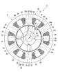
図3は、ステータ8及びロータ9を軸方向からみた平面図である。
図2、図3に示すように、ステータ8は、径方向に沿う断面形状が略円形となる筒状のコア部21と、コア部21から径方向内側に向かって突出する複数(例えば、本第1実施形態では6つ)のティース22と、が一体成形されたステータコア20を有している。
ステータコア20は、複数の金属板を軸方向に積層することにより形成されている。なお、ステータコア20は、複数の金属板を軸方向に積層して形成する場合に限られるものではなく、例えば、軟磁性粉を加圧成形することにより形成してもよい。
(Stator)
FIG. 3 is a plan view of the
As shown in FIGS. 2 and 3, the
The
ティース22は、コア部21の内周面から径方向に沿って突出するティース本体101と、ティース本体101の径方向内側端から周方向に沿って延びる鍔部102と、が一体成形されたものである。鍔部102は、ティース本体101から周方向両側に延びるように形成されている。そして、周方向で隣り合う鍔部102の間に、スロット19が形成される。
The
また、コア部21の内周面、及びティース22は、樹脂製のインシュレータ23によって覆われている。このインシュレータ23の上から各ティース22にコイル24が巻回されている。各コイル24は、コントローラ部4からの給電により、ロータ9を回転させるための磁界を生成する。
The inner peripheral surface of the
(ロータ)
ロータ9は、ステータ8の径方向内側に微小隙間を介して回転自在に設けられている。ロータ9は、減速部3を構成するウォーム軸44(図2参照)と一体成形されたシャフト31と、シャフト31に外嵌固定されこのシャフト31を軸心(回転軸線)C1とする略円柱状のロータコア32と、ロータコア32の外周面に設けられた4つの磁石33と、を備えている。このように、モータ部2において、磁石33の磁極数とスロット19(ティース22)の数との比は、4:6である。
(Rotor)
The
ロータコア32は、複数の金属板を軸方向に積層することにより形成されている。なお、ロータコア32は、複数の金属板を軸方向に積層して形成する場合に限られるものではなく、例えば、軟磁性粉を加圧成形することにより形成してもよい。
また、ロータコア32の径方向略中央には、軸方向に貫通する貫通孔32aが形成されている。この貫通孔32aに、シャフト31が圧入されている。なお、貫通孔32aに対してシャフト31を挿入とし、接着剤等を用いてシャフト31にロータコア32を外嵌固定してもよい。
The
In addition, a through
さらに、ロータコア32の外周面32bには、4つの突極35が周方向に等間隔で設けられている。突極35は、径方向外側に突出され、且つロータコア32の軸方向全体に延びるように形成されている。また、突極35の径方向外側で、且つ周方向両側の角部には、丸面取り部35aが形成されている。
このように形成されたロータコア32の外周面32bは、周方向で隣り合う2つの突極35の間が、それぞれ磁石収納部36として構成されている。これら磁石収納部36に、それぞれ磁石33が配置され、例えば接着剤等によりロータコア32に固定される。
Furthermore, four
The outer
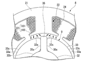
図4は、図3のロータ9を拡大した図である。
同図に示すように、磁石33は、シャフト31の軸心C1回りの周方向両側の端部33sにおける径方向の厚さが、周方向中間部33cにおける径方向の厚さよりも小さくなるように形成される。ここで、磁石33は、フェライト磁石である。
このため、磁石33の径方向外側の外周面33aとティース22の内周面との間の微小隙間は、磁石33の周方向中央が最も小さく、この周方向中央から周方向に離間するに従って徐々に大きくなる。
FIG. 4 is an enlarged view of the
As shown in the figure, the
For this reason, the minute gap between the outer
また、図3に示すように、磁石33は、外周面33aの中心C2が、シャフト31の軸心C1に対して径方向外側にオフセットしている。さらに、磁石33は、外周面33aの曲率半径R1が、磁石33の外周面33aにおいて最も径方向外側に位置する周方向中間部33cにおける、シャフト31の軸心C1からの半径(距離)R2よりも小さく設定されている。
より具体的には、図5に示すように、シャフト31の軸心C1を中心として、磁石33の外周面33aにおいて最も径方向外側に位置する周方向中間部33cを通る円弧面Wは、外周面33aの周方向中間部33cにおける、シャフト31の軸心C1からの距離を半径R2としている。そして、磁石33の外周面33aの曲率半径R1は、円弧面Wの半径R2に対し、0.8倍以下(R1≦0.8×R2)に設定されている。これにより、図4に示すように、磁石33の周方向両側の端部33sは、突極35よりも径方向内側に配置されている。
As shown in FIG. 3, the
More specifically, as shown in FIG. 5, the circular arc surface W passing through the circumferential
また、磁石33は、磁界の配向が厚み方向に沿ってパラレル配向となるように着磁されている。そして、周方向に磁極が互い違いになるように、磁石33が配置されている。さらに、ロータコア32の突極35は、周方向で隣り合う磁石33の間、つまり、磁極の境界(極境界)に位置している。
The
突極35は、径方向外側の端部における周方向の幅寸法が、電気角θで20°以上40°以下に設定されている。
なお、突極35の径方向外側の端部における周方向の幅寸法とは、突極35に丸面取り部35aが形成されていないとした場合の周方向の両角部35b間の幅寸法をいう。以下の説明では、突極35における径方向外側の端部における周方向の幅寸法を、単に突極35の径方向における幅寸法と称して説明する。
The
The circumferential width dimension at the radially outer end of the
さらに、突極35は、周方向両側において磁石33の周方向の端部33sに対向する対向面35sが、互いに平行に形成されているのが好ましい。
また、磁石33を上記のように形成することにより、この磁石33の最大外径と突極35の最大外径とが同一寸法でありながら、突極35が磁石33の周方向の端部33sよりも径方向外側に突出されている。
Furthermore, it is preferable that the
In addition, by forming the
(減速部)
図1、図2に戻り、減速部3は、モータケース5が取り付けられているギヤケース40と、ギヤケース40内に収納されるウォーム減速機構41と、を備えている。ギヤケース40は、例えばアルミダイキャスト等の放熱性の優れた材料により形成されている。ギヤケース40は、一面に開口部40aを有する箱状に形成されており、内部にウォーム減速機構41を収容するギヤ収容部42を有する。また、ギヤケース40の側壁40bには、第1モータケース6が一体成形されている箇所に、この第1モータケース6の貫通孔10aとギヤ収容部42とを連通する開口部43が形成されている。
(Decelerator)
Returning to FIGS. 1 and 2, the
さらに、ギヤケース40の側壁40bには、3つの固定ブラケット54a,54b,54cが一体成形されている。これら固定ブラケット54a,54b,54cは、不図示の車体等に、ワイパーモータ1を固定するためのものである。3つの固定ブラケット54a,54b,54cは、モータ部2を避けるように、周方向にほぼ等間隔に配置されている。各固定ブラケット54a,54b,54cには、それぞれ防振ゴム55が装着されている。防振ゴム55は、ワイパーモータ1を駆動する際の振動が、不図示の車体に伝達されてしまうのを防止するためのものである。
Further, three fixing brackets 54a, 54b, 54c are integrally formed on the
また、ギヤケース40の底壁40cには、略円筒状の軸受ボス49が突設されている。軸受ボス49は、ウォーム減速機構41の出力軸48を回転自在に支持するためのものであって、内周面に不図示の滑り軸受が設けられている。さらに、軸受ボス49の先端内周縁には、不図示のOリングが装着されている。これにより、軸受ボス49を介して外部から内部に塵埃や水が侵入してしまうことが防止される。また、軸受ボス49の外周面には、複数のリブ52が設けられている。これにより、軸受ボス49の剛性が確保されている。
Further, a substantially
ギヤ収容部42に収容されたウォーム減速機構41は、ウォーム軸44と、ウォーム軸44に噛合されるウォームホイール45と、により構成されている。ウォーム軸44は、モータ部2のシャフト31と同軸上に配置されている。そして、ウォーム軸44は、両端がギヤケース40に設けられた軸受46,47によって回転自在に支持されている。ウォーム軸44のモータ部2側の端部は、軸受46を介してギヤケース40の開口部43に至るまで突出している。この突出したウォーム軸44の端部とモータ部2のシャフト31との端部が接合され、ウォーム軸44とシャフト31とが一体化されている。なお、ウォーム軸44とシャフト31は、1つの母材からウォーム軸部分と回転軸部分とを成形することにより一体として形成してもよい。
The worm
ウォーム軸44に噛合されるウォームホイール45には、このウォームホイール45の径方向中央に出力軸48が設けられている。出力軸48は、ウォームホイール45の回転軸方向と同軸上に配置されており、ギヤケース40の軸受ボス49を介してギヤケース40の外部に突出している。出力軸48の突出した先端には、不図示の電装品と接続可能なスプライン48aが形成されている。
The
また、ウォームホイール45の径方向中央には、出力軸48が突出されている側とは反対側に、不図示のセンサマグネットが設けられている。このセンサマグネットは、ウォームホイール45の回転位置を検出する回転位置検出部60の一方を構成している。この回転位置検出部60の他方を構成する磁気検出素子61は、ウォームホイール45のセンサマグネット側(ギヤケース40の開口部40a側)でウォームホイール45と対向配置されているコントローラ部4に設けられている。
Further, a sensor magnet (not shown) is provided at the radial center of the
(コントローラ部)
モータ部2の駆動制御を行うコントローラ部4は、磁気検出素子61が実装されたコントローラ基板(駆動回路部)62と、ギヤケース40の開口部40aを閉塞するように設けられたカバー63と、を有している。そして、コントローラ基板62が、ウォームホイール45のセンサマグネット側(ギヤケース40の開口部40a側)に対向配置されている。
(Controller part)
The controller unit 4 that performs drive control of the
コントローラ基板62は、いわゆるエポキシ基板に複数の導電性のパターン(不図示)が形成されたものである。コントローラ基板62には、モータ部2のステータコア20から引き出されたコイル24の端末部が接続されていると共に、カバー63に設けられたコネクタの端子(何れも不図示)が電気的に接続されている。また、コントローラ基板62には、磁気検出素子61の他に、コイル24に供給する電流を制御するFET(Field Effect Transistor:電界効果トランジスタ)等のスイッチング素子からなるパワーモジュール(不図示)が実装されている。さらに、コントローラ基板62には、このコントローラ基板62に印加される電圧の平滑化を行うコンデンサ(不図示)等が実装されている。
The
このように構成されたコントローラ基板62を覆うカバー63は、樹脂により形成されている。また、カバー63は、若干外側に膨出するように形成されている。そして、カバー63の内面側は、コントローラ基板62等を収容するコントローラ収容部56とされている。
また、カバー63の外周部に、不図示のコネクタが一体成形されている。このコネクタは、不図示の外部電源から延びるコネクタと嵌着可能に形成されている。そして、不図示のコネクタの端子に、コントローラ基板62が電気的に接続されている。これにより、外部電源の電力がコントローラ基板62に供給される。
The
A connector (not shown) is integrally formed on the outer periphery of the
ここで、コントローラ基板62は、コイル24に対し、進角通電と、電気角θが121°から180°の広角通電とを行う。また、コントローラ基板62は、コイル24に対し、5次高調波を重畳した駆動電流を印加する。
Here, the
さらに、カバー63の開口縁には、ギヤケース40の側壁40bの端部と嵌め合わされる嵌合部81が突出形成されている。嵌合部81は、カバー63の開口縁に沿う2つの壁81a,81bにより構成されている。そして、これら2つの壁81a,81bの間に、ギヤケース40の側壁40bの端部が挿入(嵌め合い)される。これにより、ギヤケース40とカバー63との間にラビリンス部83が形成される。このラビリンス部83によって、ギヤケース40とカバー63との間から塵埃や水が浸入してしまうことが防止される。なお、ギヤケース40とカバー63との固定は、不図示のボルトを締結することにより行われる。
Further, a
(ワイパーモータの動作)
次に、ワイパーモータ1の動作について説明する。
ワイパーモータ1は、不図示のコネクタを介してコントローラ基板62に供給された電力が、不図示のパワーモジュールを介してモータ部2の各コイル24に選択的に供給される。
すると、ステータ8(ティース22)に所定の鎖交磁束が形成され、この鎖交磁束とロータ9の磁石33により形成される有効磁束との間で磁気的な吸引力や反発力が生じる。これにより、ロータ9が継続的に回転する。
ロータ9が回転すると、シャフト31と一体化されているウォーム軸44が回転し、さらにウォーム軸44に噛合されているウォームホイール45が回転する。そして、ウォームホイール45に連結されている出力軸48が回転し、所望の電装品が駆動する。
(Wiper motor operation)
Next, the operation of the wiper motor 1 will be described.
In the wiper motor 1, the power supplied to the
Then, a predetermined interlinkage magnetic flux is formed in the stator 8 (tooth 22), and a magnetic attractive force and a repulsive force are generated between the interlinkage magnetic flux and an effective magnetic flux formed by the
When the
また、コントローラ基板62に実装されている磁気検出素子61によって検出されたウォームホイール45の回転位置検出結果は、信号として不図示の外部機器に出力される。不図示の外部機器は、ウォームホイール45の回転位置検出信号に基づいて、不図示のパワーモジュールのスイッチング素子等の切替えタイミングが制御され、モータ部2の駆動制御が行われる。なお、パワーモジュールの駆動信号の出力やモータ部2の駆動制御は、コントローラ部4で行われていても良い。
The rotation position detection result of the
(ロータの作用、効果)
次に、図6〜図17に基づいて、ロータ9の作用、効果について説明する。
モータ部2は、ロータコア32の外周面32bに、磁石33を配置した、いわゆるSPM(Surface Permanent Magnet)モータである。このため、d軸方向のインダクタンス値を小さくすることができる。ここで、ロータ9において、d軸方向のインダクタンス値を、さらに小さくするには、磁石33の径方向の寸法を大きくする必要がある。この実施形態において、磁石33は、フェライト磁石からなるので、磁石33の径方向の寸法を大きくして磁石使用量を増加させても、希土類磁石に比較し、コスト上昇を大幅に抑えることができる。
(Operation and effect of rotor)
Next, the operation and effect of the
The
ここで、ロータコア32の外周面32bに設けられた4つの突極35は、周方向の幅寸法を電気角θで20°以上40°以下に設定されている。このように、周方向における突極35の幅寸法を電気角θで40°以下に設定することで、q軸方向におけるインダクタンス値を小さくすることができる。これにより、減磁界を抑えるとともに、高いリラクタンストルクを得ることができる。以下、より具体的に説明する。
Here, the four
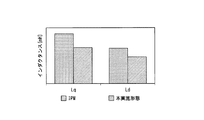
図6は、ロータ9のq軸、d軸のインダクタンスLq、Ld[mH]を示すグラフであって、本実施形態のロータ9と、従来構造のロータとを比較している。なお、ここでいう従来構造とは、ロータコアに複数径したスリット内に永久磁石を配置した、いわゆるIPM(Interior Permanent Magnet)モータのロータの構造である。
同図に示すように、従来構造と比較して、本実施形態のロータ9は、q軸、d軸とも、インダクタンス値が小さくなっていることが確認できる。
FIG. 6 is a graph showing the inductances Lq and Ld [mH] of the q-axis and d-axis of the
As shown in the figure, it can be confirmed that the
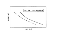
図7は、縦軸をロータ9の回転数[rpm]とし、横軸をロータ9のトルク[N・m]とした場合のロータ9の回転数の変化を示すグラフである。より具体的には、図6は、ロータ9に進角通電と広角通電とを行った場合の、トルク[N・m]と回転数[rpm]との関係を示すグラフであって、本実施形態のロータ9と、従来のIPM構造のロータとを比較している。
同図に示すように、従来構造と比較して、本実施形態のロータ9は、より高いトルク、回転数を発生していることが確認できる。
FIG. 7 is a graph showing changes in the number of revolutions of the
As shown in the figure, it can be confirmed that the
図8は、縦軸をロータ9のトルク[N・m]とし、横軸をロータコア32に設けられた突極35の突極幅[mm]とした場合のロータ9のトルクの変化を示すグラフである。より具体的には、図7は、突極35の周方向における幅寸法(電気角θ)を異ならせた場合に、本実施形態のロータ9で発生するトルクを示すグラフである。
図9は、縦軸をロータ9のリップル率[%]とし、横軸をロータコア32の突極35の突極幅[mm]とした場合のロータ9のリップル率の変化を示すグラフである。より具体的には、図8は、突極35の幅寸法を異ならせた場合に、本実施形態のロータ9で発生するリップル率を示すグラフである。
図10は、縦軸をロータ9のコギング[mN・m]とし、横軸をロータコア32の突極35の突極幅[mm]とした場合のロータ9のコギングの変化を示すグラフである。より具体的には、図9は、突極35の幅寸法を異ならせた場合に、本実施形態のロータ9で発生するコギングを示すグラフである。
FIG. 8 is a graph showing a change in torque of the
FIG. 9 is a graph showing changes in the ripple rate of the
FIG. 10 is a graph showing the cogging change of the
図8〜図10に示すように、本実施形態のロータ9は、突極35の周方向の幅寸法が3mm(電気角θ=20°)〜5mm(電気角θ=40°)であるときに、高いリラクタンストルクを得るとともに、リップル率及びコギングを抑制できていることが確認できる。
As shown in FIGS. 8 to 10, in the
また、突極35を磁石33の周方向の端部33sよりも径方向外側に突出させることで、磁束が突極35に集中する。このようにして、減磁界が磁石33の端部33sに作用しにくくなる。
Further, the magnetic flux is concentrated on the
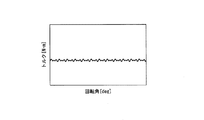
図11は、縦軸をロータ9の磁石33の周方向の端部33sにおける磁束密度[T]とし、横軸をロータ9の回転角度[deg]とした場合の磁石33の周方向の端部33sにおける磁束密度の変化を示すグラフである。より具体的には、図10は、ロータ9の磁石33の周方向の端部33sにおける磁束密度[T]を示すグラフであって、突極35を磁石33の周方向の端部33sよりも径方向外側に突出させた場合(図11中、符号E)と、突極35を磁石33の周方向の端部33sよりも径方向外側に突出させない場合(図11中、符号C)とを比較している。
同図に示すように、突極35を磁石33の周方向の端部33sよりも径方向外側に突出させない場合に比較し、突極35を磁石33の周方向の端部33sよりも径方向外側に突出させた場合は、磁束密度が高く、減磁しにくいことが確認できる。
11, the vertical axis represents the magnetic flux density [T] at the
As shown in the figure, compared to the case where the
図12、図13は、突極35の周囲における磁束の向きを示す図であって、突極35を磁石33の周方向の端部33sよりも径方向外側に突出させた場合(図12)と、突極35を磁石33の周方向の端部33sよりも径方向外側に突出させない場合(図13)とを比較している。
これらの図13に示すように、突極35を磁石33の周方向の端部33sよりも径方向外側に突出させない場合に比較し、図12に示すように、突極35を磁石33の周方向の端部33sよりも径方向外側に突出させた場合は、磁石33の端部33sに磁束が集中するのを抑え、突極35に磁束が集中することが確認できる。
12 and 13 are diagrams showing the direction of the magnetic flux around the
Compared to the case where the
また、突極35は、周方向両側において磁石33の周方向の端部33sに対向する対向面35sを、互いに平行に形成した。ここで、突極35の径方向内側の根元部の幅寸法が大きく、径方向外側の先端部の幅寸法が小さい台形状であると、周方向で隣り合う突極35どうしの間に配置される磁石33の周方向両側の端部33sが薄くなり、減磁が生じやすくなる。また、突極35の根元部の幅寸法が小さく、先端部の幅寸法が大きい台形状であると、突極35で磁束密度が飽和しやすい。これに対し、突極35を、周方向両側の対向面35sを互いに平行に形成することで、減磁も生じにくく、磁束密度の飽和も抑えることができる。
In addition, the
また、磁石33の着磁の配向はパラレル配向であるようにした。これにより、コギングを抑えるとともに、高い磁束密度を得ることができる。
In addition, the magnetization orientation of the
図14は、磁石33の配向をパラレル配向、ラジアル配向としたときの、本実施形態のロータ9で発生するコギング[mN・m]を示すグラフである。図15は、磁石33の配向をパラレル配向、ラジアル配向としたときの、本実施形態のロータ9で発生する有効磁束[μWb]を示すグラフである。
図14、図15に示すように、磁石33の着磁の配向をパラレル配向とすることで、コギングを抑制するとともに、有効磁束が高まることが確認できる。
FIG. 14 is a graph showing cogging [mN · m] generated in the
As shown in FIGS. 14 and 15, it can be confirmed that the cogging is suppressed and the effective magnetic flux is increased by setting the magnetization orientation of the
さらに、図16は、縦軸をロータ9の磁石33の周方向の端部33sにおける磁束密度[T]とし、横軸をロータ9の回転角度[deg]とした場合の磁石33の周方向の端部33sにおける磁束密度の変化を示すグラフである。より具体的には、図15は、ロータ9の磁石33の周方向の端部33sにおける磁束密度[T]を示すグラフであって、突極35を磁石33の周方向の端部33sよりも径方向外側に突出させた場合(図16中、符号E)と、突極35を磁石33の周方向の端部33sよりも径方向外側に突出させない場合(図16中、符号C)と、のそれぞれで、磁石33の着磁の配向をパラレル配向とした場合とラジアル配向とした場合とを比較している。
図17は、突極35を磁石33の周方向の端部33sよりも径方向外側に突出させた場合(図17中、符号E)と、突極35を磁石33の周方向の端部33sよりも径方向外側に突出させない場合(図17中、符号C)と、のそれぞれで、磁石33の着磁の配向をパラレル配向とした場合とラジアル配向とした場合の、磁束密度の最小値(MIN)を比較している。
Further, in FIG. 16, the vertical axis represents the magnetic flux density [T] at the
FIG. 17 shows a case where the
図16、図17に示すように、突極35を磁石33の周方向の端部33sよりも径方向外側に突出させるとともに、磁石33の着磁の配向をパラレル配向とすることで、減磁界を有効に抑制することができる。
As shown in FIGS. 16 and 17, the
また、磁石33は、外周面33aの曲率半径R1が、磁石33の外周面33aで最も径方向外側に位置する周方向中間部33cにおける、シャフト31の軸心C1からの半径R2に対し、0.8倍以下であるように設定した。これにより、磁石33の周方向両側の端部33sは、突極35よりも径方向内側に配置されることとなる。これにより、磁束は突極35に集中し、減磁界が磁石33の端部33sに作用しにくくなる。すると、コイル24に電流を供給したときの誘起電圧に含有される高次の高調波成分を抑えることが可能となり、モータ部2におけるトルクリップルを抑制することができる。
Further, the
図18は、磁石33の外周面33aの曲率半径R1を変化させて、半径R2に対する比率を異ならせた場合の、誘起電圧に含まれる高調波の含有率を示すグラフである。
同図に示すように、磁石33の外周面33aの曲率半径R1を、周方向中間部33cの半径R2に対して0.8以下とすることで、11次の高調波成分が1%未満に低減されることが確認できる。
さらに、図19は、磁石33の配向をパラレル配向、ラジアル配向としたときの、誘起電圧に含まれる高調波の含有率を示すグラフである。
同図に示すように、磁石33をパラレル配向とした方が、11次の高調波成分が低減されることが確認できる。
FIG. 18 is a graph showing the content of harmonics included in the induced voltage when the radius of curvature R1 of the outer
As shown in the figure, the eleventh-order harmonic component is less than 1% by setting the curvature radius R1 of the outer
Further, FIG. 19 is a graph showing the content of harmonics included in the induced voltage when the orientation of the
As shown in the figure, it can be confirmed that the 11th-order harmonic component is reduced when the
また、コントローラ基板62は、コイル24に、5次高調波を重畳した駆動電流を印加するようにした。これにより、モータ部2におけるトルクリップルを抑制することができる。
In addition, the
図20は、縦軸を駆動電流[A]とし、横軸を角度[θ]としたときの5次高調波を重畳していない三相の駆動電流の波形を示す図である。図21は、縦軸をロータ9のトルク[N・m]とし、横軸をロータ9の回転角[deg]としたときにおける5次高調波を重畳していない三相の駆動電流を印加した場合のトルク波形を示す図である。図22は、縦軸を駆動電流[A]とし、横軸を角度[θ]としたときの5次高調波を重畳した三相の駆動電流の波形を示す図である。図23は、縦軸をロータ9のトルク[N・m]とし、横軸をロータ9の回転角[deg]としたときにおける5次高調波を重畳した三相の駆動電流を印加した場合のトルク波形を示す図である。図24は、図21及び図23のトルク波形をFFT解析し、各次における発生トルクを比較するグラフである。
FIG. 20 is a diagram showing three-phase drive current waveforms in which the fifth harmonic is not superimposed when the vertical axis is the drive current [A] and the horizontal axis is the angle [θ]. In FIG. 21, a three-phase drive current without superimposing fifth-order harmonics is applied when the vertical axis is the torque [N · m] of the
図20に示すような5次高調波を重畳していない三相の駆動電流を印加した場合、モータ部2においては、図21に示すように、周期的なトルク変動を有するトルクリップルが発生する。これに対し、図22に示すような5次高調波を重畳した三相の駆動電流を印加した場合、モータ部2においては、図23に示すように、トルクリップルが大幅に低減されることが確認できる。
そして、図24に示すように、駆動電流に5次高調波を重畳することで、電気角で6次のトルクリップルが大幅に低減されることが確認できる。
When a three-phase drive current without superimposing fifth-order harmonics as shown in FIG. 20 is applied, a torque ripple having periodic torque fluctuation is generated in the
And as shown in FIG. 24, it can confirm that a 6th-order torque ripple is significantly reduced by an electrical angle by superimposing a 5th-order harmonic on a drive current.
このように、上述のモータ部2及びワイパーモータ1は、環状のステータコア20、及びステータコア20の内周面から径方向内側に向かって突出する複数のティース22を有するステータ8と、ティース22に巻回されるコイル24と、ステータコア20の径方向内側で軸心C1回りに回転するシャフト31と、シャフト31に固定され、軸心C1を径方向中心とするロータコア32と、ロータコア32の外周面32bに配置され、軸心C1回りの周方向両側の端部33sにおける径方向の厚さが、周方向中間部における径方向の厚さよりも小さい磁石33と、ロータコア32の外周面32bの周方向で隣り合う磁石33の間に、磁石33の周方向の端部33sよりも径方向外側に向かって突出形成された突極35と、を備え、磁石33の磁極数とティース22の数との比は2n:3n(ただし、nは自然数)であり、磁石33は、外周面33aの曲率半径R1が、磁石33の外周面33aで最も径方向外側に位置する周方向中間部33cにおける、シャフト31の軸心C1からの半径R2に対し、0.8倍以下に設定されている。
As described above, the
このように、突極35を磁石33の周方向の端部33sよりも径方向外側に向かって突出させるとともに、磁石33の外周面33aの曲率半径R1を、磁石33の外周面33aの周方向中間部33cにおける半径R2よりも小さくするようにした。これにより、磁石33の周方向両側の端部33sは、突極35よりも径方向内側に配置されることとなる。したがって、磁束は突極35に集中し、減磁界が磁石33の端部33sに作用しにくくなる。すると、コイル24に電流を供給したときの誘起電圧に含有される高次の高調波成分を抑えることが可能となり、モータ部2におけるトルクリップルを抑制することができる。このように、磁石33の外周面33aの曲率半径を小さくすればトルクリップルの抑制効果が得られるので、高い次数の高調波を、コイル24に電流を供給するコントローラ基板62のマイコンで演算して生成する必要が抑えられる。したがって、コントローラ基板62に、処理負荷が高いマイコンを備える必要性が低くなり、コスト上昇を抑えることができる。その結果、低コストでリップルを効果的に低減することが可能となる。
As described above, the
また、上記のような構成により、モータ部2の高トルク化、コギングの抑制を図ることができる。さらに、このようなモータ部2においては、進角通電と広角通電とを行うことで、高回転化を図ることができる。したがって、コスト上昇を抑えつつ、高回転化及び高トルク化を図ることが可能となる。
Further, with the configuration as described above, it is possible to increase the torque of the
また、突極35の径方向における幅寸法は、電気角40°以下であるように設定した。このような構成によれば、突極35の電気角を40°以下に設定して、周方向における突極35の幅寸法を小さくすることで、q軸方向におけるインダクタンス値を小さくすることができる。このため、減磁界を抑えることができる。
Moreover, the width dimension in the radial direction of the
さらに、突極35の径方向における幅寸法は、電気角20°以上であるように設定した。このような構成によれば、突極35の電気角を20°以上として、径方向における幅寸法を確保することができる。したがって、磁束が突極35に集中することで、減磁界が磁石33の端部33sに作用しにくくなるという効果を、確実に得ることができる。また、突極35の電気角θを20°以上40°以下に設定することで、高いリラクタンストルクを得ることができる。
Further, the width dimension of the
また、磁石33はフェライト磁石であるとともに、着磁の配向がパラレル配向であるようにした。このような構成によれば、モータ部2のコギングを抑えるとともに、高い磁束密度を得ることができる。また、磁石33に希土類磁石ではなくフェライト磁石を用いることで、磁石33の径方向寸法を大きくしても、磁石33使用量増加にともなうコスト上昇を抑えることができる。
The
また、コントローラ基板62は、コイル24に、5次高調波を重畳した駆動電流を印加するようにした。このような構成によれば、モータ部2におけるトルクリップルを抑制することができる。
In addition, the
(実施形態の変形例)
上記実施形態に示した磁石33は、外周面33aが一定の曲率半径R1を有した形状を有しているが、これに限らない。
図25は、本発明の実施形態の変形例における磁石の形状を示す図である。
同図に示すように、磁石33Bは、外周面33aの周方向両側の端部33sにおいて、電気角θ2が10°以上18°以下の範囲に平面部37を有している。平面部37は、磁石33Bの外周面33aを平坦に形成してなる。
(Modification of the embodiment)
The
FIG. 25 is a diagram showing the shape of a magnet in a modification of the embodiment of the present invention.
As shown in the figure, the
さらに、磁石33Bの外周面33aは、周方向両側の平面部37の間(図25において、矢印の範囲)が、一定の曲率半径R3を有した湾曲面38とされている。
湾曲面38の曲率半径R3は、磁石33Bの外周面33aにおいて最も径方向外側に位置する周方向中間部33cにおける、シャフト31の軸心C1からの半径R2(図5参照)に対し、0.8倍よりも大きく、且つ0.9倍以下(0.8×R2<R3≦0.9×R2)とされている。
Furthermore, the outer
The curvature radius R3 of the
このような磁石33Bを有したモータ部2及びワイパーモータ1においても、コイル24に電流を供給したときの誘起電圧に含有される高次の高調波成分を抑えることが可能となる。その結果、モータ部2におけるトルクリップルを抑制することができる。
このように、磁石33Bの外周面33aの曲率半径を小さくするとともに、周方向両側の端部33sに平面部37を形成することによって、突極35を磁石33Bの周方向の端部33sよりも径方向外側に向かって突出させれば、トルクリップルの抑制効果が得られる。したがって、高い次数の高調波を、コイル24に電流を供給するコントローラ基板62のマイコンで演算して生成する必要が抑えられる。このため、コントローラ基板62に、処理負荷が高いマイコンを備える必要性が低くなり、コスト上昇を抑えることができる。よって、低コストでリップルを効果的に低減することが可能となる。
Also in the
In this way, by reducing the radius of curvature of the outer
図26は、磁石33Bの平面部37を形成する範囲(電気角θ2)を変化させた場合の、誘起電圧に含まれる高調波の含有率を示すグラフである。
同図に示すように、磁石33の外周面33a(湾曲面38)の曲率半径R3を、周方向中間部33cの半径R2に対して0.8倍よりも大きく、且つ0.9倍以下に設定し、平面部37を電気角θ2で10°以上18°以下とすることで、11次の高調波成分が1%未満に低減されることが確認できる。
FIG. 26 is a graph showing the content rate of harmonics included in the induced voltage when the range (electrical angle θ2) for forming the
As shown in the figure, the radius of curvature R3 of the outer
(その他の実施形態)
なお、本発明は上述の実施形態に限られるものではなく、本発明の趣旨を逸脱しない範囲において、上述の実施形態に種々の変更を加えたものを含む。
(Other embodiments)
The present invention is not limited to the above-described embodiment, and includes various modifications made to the above-described embodiment without departing from the spirit of the present invention.
例えば、上述の実施形態では、モータとして、ワイパーモータ1を例に挙げたが、本発明に係るモータは、ワイパーモータ1以外にも、車両に搭載される電装品(例えば、パワーウインドウ、サンルーフ、電動シート等)の駆動源となるものや、その他のさまざまな用途に使用することができる。
これ以外にも、本発明の主旨を逸脱しない限り、上記実施の形態で挙げた構成を取捨選択したり、他の構成に適宜変更したりすることが可能である。
For example, in the above-described embodiment, the wiper motor 1 is taken as an example of the motor. However, the motor according to the present invention is not limited to the wiper motor 1, and other electrical components (for example, a power window, a sunroof, It can be used as a driving source for an electric seat or the like, and for various other purposes.
In addition to this, the configuration described in the above embodiment can be selected or changed to another configuration as appropriate without departing from the gist of the present invention.
1…ワイパーモータ(ブラシレスワイパーモータ)
2…モータ部(モータ)
8…ステータ
9…ロータ
20…ステータコア
22…ティース
24…コイル
31…シャフト
32…ロータコア
33、33B…磁石
33a…外周面
33c…周方向中間部(周方向の中間部)
33s…端部
35…突極
37…平面部
38…湾曲面
62…コントローラ基板(駆動回路部)
C1…軸心(回転軸線)
C2…中心
R1、R3…曲率半径
R2…半径(距離)
1. Wiper motor (brushless wiper motor)
2 ... Motor part (motor)
DESCRIPTION OF
33 s ... end 35 ...
C1 axis (rotation axis)
C2 ... Center R1, R3 ... Radius of curvature R2 ... Radius (distance)
Claims (7)
前記ティースに巻回されるコイルと、
前記ステータコアの径方向内側で回転軸線回りに回転するシャフトと、
前記シャフトに固定され、前記回転軸線を径方向中心とするロータコアと、
前記ロータコアの外周面に配置され、前記回転軸線回りの周方向両側の端部における前記径方向の厚さが、前記周方向の中間部における前記径方向の厚さよりも小さい磁石と、
前記ロータコアの前記外周面の周方向で隣り合う前記磁石の間に、前記磁石の周方向の端部よりも径方向外側に向かって突出形成された突極と、
を備え、
前記磁石の磁極数と前記ティースの数との比は2n:3n(ただし、nは自然数)に設定されており、
前記磁石は、外周面の曲率半径が、前記磁石の前記外周面で最も径方向外側に位置する部位における、前記回転軸線からの距離に対し、0.8倍以下に設定されている
ことを特徴とするモータ。 An annular stator core, and a stator having a plurality of teeth projecting radially inward from the inner peripheral surface of the stator core;
A coil wound around the teeth;
A shaft that rotates about the rotation axis on the radially inner side of the stator core;
A rotor core fixed to the shaft and having the rotational axis as a radial center;
A magnet disposed on an outer peripheral surface of the rotor core, wherein the radial thickness at both ends in the circumferential direction around the rotation axis is smaller than the radial thickness at the intermediate portion in the circumferential direction;
Between the magnets adjacent in the circumferential direction of the outer peripheral surface of the rotor core, salient poles formed to protrude radially outward from the circumferential end of the magnet;
With
The ratio between the number of magnetic poles of the magnet and the number of teeth is set to 2n: 3n (where n is a natural number),
In the magnet, the radius of curvature of the outer peripheral surface is set to be 0.8 times or less with respect to the distance from the rotation axis at the portion located radially outermost on the outer peripheral surface of the magnet. Motor.
前記ティースに巻回されるコイルと、
前記ステータコアの径方向内側で回転軸線回りに回転するシャフトと、
前記シャフトに固定され、前記回転軸線を径方向中心とするロータコアと、
前記ロータコアの外周面に配置され、前記回転軸線回りの周方向両側の端部における前記径方向の厚さが、前記周方向の中間部における前記径方向の厚さよりも小さい磁石と、
前記ロータコアの前記外周面の周方向で隣り合う前記磁石の間に、前記磁石の周方向の端部よりも径方向外側に向かって突出形成された突極と、
を備え、
前記磁石の磁極数と前記ティースの数との比は2n:3n(ただし、nは自然数)に設定されており、
前記磁石は、外周面の曲率半径が、前記磁石の前記外周面で最も径方向外側に位置する部位における、前記回転軸線からの距離に対し、0.8倍よりも大きく、且つ0.9倍以下であるとともに、前記外周面の周方向両側の端部に、電気角10°以上18°以下の範囲に前記磁石の前記外周面が平坦な平面部を有する
ことを特徴とするモータ。 An annular stator core, and a stator having a plurality of teeth projecting radially inward from the inner peripheral surface of the stator core;
A coil wound around the teeth;
A shaft that rotates about the rotation axis on the radially inner side of the stator core;
A rotor core fixed to the shaft and having the rotational axis as a radial center;
A magnet disposed on an outer peripheral surface of the rotor core, wherein the radial thickness at both ends in the circumferential direction around the rotation axis is smaller than the radial thickness at the intermediate portion in the circumferential direction;
Between the magnets adjacent in the circumferential direction of the outer peripheral surface of the rotor core, salient poles formed to protrude radially outward from the circumferential end of the magnet;
With
The ratio between the number of magnetic poles of the magnet and the number of teeth is set to 2n: 3n (where n is a natural number),
In the magnet, the radius of curvature of the outer peripheral surface is greater than 0.8 times and 0.9 times the distance from the rotation axis at the portion located radially outermost on the outer peripheral surface of the magnet. The motor is characterized in that the outer peripheral surface of the magnet has a flat surface portion in an electric angle range of 10 ° to 18 ° at both ends in the circumferential direction of the outer peripheral surface.
ことを特徴とする請求項1または2に記載のモータ。 3. The motor according to claim 1, wherein a circumferential width dimension at the radially outer end of the salient pole is set to 40 ° or less in electrical angle.
ことを特徴とする請求項3に記載のモータ。 The motor according to claim 3, wherein a circumferential width dimension at the radially outer end of the salient pole is set to an electrical angle of 20 ° or more.
ことを特徴とする請求項1〜請求項4の何れか1項に記載のモータ。 The motor according to any one of claims 1 to 4, wherein the magnet is a ferrite magnet, and the orientation of magnetization is parallel orientation.
ことを特徴とする請求項1〜請求項5の何れか1項に記載のモータ。 The motor according to claim 1, further comprising a drive circuit unit that applies a drive current in which a fifth harmonic is superimposed on the coil.
ことを特徴とするブラシレスワイパーモータ。 A brushless wiper motor comprising the motor according to any one of claims 1 to 6.
Priority Applications (4)
| Application Number | Priority Date | Filing Date | Title |
|---|---|---|---|
| US16/632,370 US11289960B2 (en) | 2017-07-20 | 2018-06-26 | Motor and brushless wiper motor |
| EP18835497.1A EP3657637B1 (en) | 2017-07-20 | 2018-06-26 | Motor and brushless wiper motor |
| CN201880047701.7A CN110915106B (en) | 2017-07-20 | 2018-06-26 | Motor and brushless wiper motor |
| PCT/JP2018/024195 WO2019017161A1 (en) | 2017-07-20 | 2018-06-26 | Motor and brushless wiper motor |
Applications Claiming Priority (2)
| Application Number | Priority Date | Filing Date | Title |
|---|---|---|---|
| JP2017141168 | 2017-07-20 | ||
| JP2017141168 | 2017-07-20 |
Publications (3)
| Publication Number | Publication Date |
|---|---|
| JP2019022431A true JP2019022431A (en) | 2019-02-07 |
| JP2019022431A5 JP2019022431A5 (en) | 2021-01-21 |
| JP7105624B2 JP7105624B2 (en) | 2022-07-25 |
Family
ID=65355160
Family Applications (1)
| Application Number | Title | Priority Date | Filing Date |
|---|---|---|---|
| JP2018113645A Active JP7105624B2 (en) | 2017-07-20 | 2018-06-14 | Motors and brushless wiper motors |
Country Status (1)
| Country | Link |
|---|---|
| JP (1) | JP7105624B2 (en) |
Cited By (3)
| Publication number | Priority date | Publication date | Assignee | Title |
|---|---|---|---|---|
| JP2021027713A (en) * | 2019-08-06 | 2021-02-22 | 株式会社ミツバ | Rotor, motor, and brushless wiper motor |
| JP2021027717A (en) * | 2019-08-06 | 2021-02-22 | 株式会社ミツバ | Rotor, motor, and brushless wiper motor |
| JP7440675B2 (en) | 2019-08-26 | 2024-02-28 | 株式会社ミツバ | Motor and motor manufacturing method |
Citations (9)
| Publication number | Priority date | Publication date | Assignee | Title |
|---|---|---|---|---|
| JP2002101629A (en) * | 2000-09-19 | 2002-04-05 | Hitachi Ltd | Permanent magnet rotating electric machine |
| JP2012235671A (en) * | 2011-04-20 | 2012-11-29 | Asmo Co Ltd | Motor |
| WO2013108726A1 (en) * | 2012-01-17 | 2013-07-25 | 三菱電機株式会社 | Brushless motor, method for driving brushless motor, and electric power steering device |
| WO2013150652A1 (en) * | 2012-04-06 | 2013-10-10 | 三菱電機株式会社 | Rotor and electric motor having embedded permanent magnet |
| JP2013236455A (en) * | 2012-05-08 | 2013-11-21 | Asmo Co Ltd | Stator and motor |
| JP2014155372A (en) * | 2013-02-12 | 2014-08-25 | Mitsubishi Electric Corp | Surface magnet rotor and manufacturing method therefor and permanent magnet dynamo-electric machine with surface magnet rotor and electric power steering device using permanent magnet dynamo-electric machine |
| WO2014167645A1 (en) * | 2013-04-09 | 2014-10-16 | 三菱電機株式会社 | Permanent magnet-type motor and electric power steering apparatus |
| JP2015122842A (en) * | 2013-12-20 | 2015-07-02 | ファナック株式会社 | Rotor for motor with magnet, motor, and manufacturing method of rotor |
| JP2016134931A (en) * | 2015-01-15 | 2016-07-25 | 東芝産業機器システム株式会社 | Rotary electric machine and rotor |
-
2018
- 2018-06-14 JP JP2018113645A patent/JP7105624B2/en active Active
Patent Citations (9)
| Publication number | Priority date | Publication date | Assignee | Title |
|---|---|---|---|---|
| JP2002101629A (en) * | 2000-09-19 | 2002-04-05 | Hitachi Ltd | Permanent magnet rotating electric machine |
| JP2012235671A (en) * | 2011-04-20 | 2012-11-29 | Asmo Co Ltd | Motor |
| WO2013108726A1 (en) * | 2012-01-17 | 2013-07-25 | 三菱電機株式会社 | Brushless motor, method for driving brushless motor, and electric power steering device |
| WO2013150652A1 (en) * | 2012-04-06 | 2013-10-10 | 三菱電機株式会社 | Rotor and electric motor having embedded permanent magnet |
| JP2013236455A (en) * | 2012-05-08 | 2013-11-21 | Asmo Co Ltd | Stator and motor |
| JP2014155372A (en) * | 2013-02-12 | 2014-08-25 | Mitsubishi Electric Corp | Surface magnet rotor and manufacturing method therefor and permanent magnet dynamo-electric machine with surface magnet rotor and electric power steering device using permanent magnet dynamo-electric machine |
| WO2014167645A1 (en) * | 2013-04-09 | 2014-10-16 | 三菱電機株式会社 | Permanent magnet-type motor and electric power steering apparatus |
| JP2015122842A (en) * | 2013-12-20 | 2015-07-02 | ファナック株式会社 | Rotor for motor with magnet, motor, and manufacturing method of rotor |
| JP2016134931A (en) * | 2015-01-15 | 2016-07-25 | 東芝産業機器システム株式会社 | Rotary electric machine and rotor |
Cited By (5)
| Publication number | Priority date | Publication date | Assignee | Title |
|---|---|---|---|---|
| JP2021027713A (en) * | 2019-08-06 | 2021-02-22 | 株式会社ミツバ | Rotor, motor, and brushless wiper motor |
| JP2021027717A (en) * | 2019-08-06 | 2021-02-22 | 株式会社ミツバ | Rotor, motor, and brushless wiper motor |
| JP7330011B2 (en) | 2019-08-06 | 2023-08-21 | 株式会社ミツバ | Rotors, motors and brushless wiper motors |
| JP7330010B2 (en) | 2019-08-06 | 2023-08-21 | 株式会社ミツバ | Rotors, motors and brushless wiper motors |
| JP7440675B2 (en) | 2019-08-26 | 2024-02-28 | 株式会社ミツバ | Motor and motor manufacturing method |
Also Published As
| Publication number | Publication date |
|---|---|
| JP7105624B2 (en) | 2022-07-25 |
Similar Documents
| Publication | Publication Date | Title |
|---|---|---|
| US20170288517A1 (en) | Brushless motor | |
| JP5058849B2 (en) | Brushless motor | |
| JP5527488B2 (en) | Motor driving method and motor driving apparatus | |
| JP2010183781A (en) | Motor generator | |
| US11289960B2 (en) | Motor and brushless wiper motor | |
| JP7105624B2 (en) | Motors and brushless wiper motors | |
| JP2008141803A (en) | Brushless motor | |
| WO2019202915A1 (en) | Motor, brushless wiper motor, and method for driving motor | |
| WO2019198464A1 (en) | Motor and brushless wiper motor | |
| US11901779B2 (en) | Motor and brushless wiper motor | |
| JP7077153B2 (en) | Motors and brushless wiper motors | |
| JP6768259B2 (en) | Rotor and electric motor | |
| WO2020100457A1 (en) | Motor and brushless wiper motor | |
| JP2018183011A (en) | Electric motor and brushless motor | |
| JP5199704B2 (en) | Brushless motor | |
| JP6914150B2 (en) | Brushless motor | |
| JP6655500B2 (en) | Electric motor | |
| JP7287825B2 (en) | motor and wiper motor | |
| JP2020115733A (en) | Motor and brushless wiper motor | |
| JP2018183013A (en) | Synchronous motor and brushless motor | |
| EP3657637B1 (en) | Motor and brushless wiper motor | |
| JP4611242B2 (en) | Brushless motor | |
| JP2020078148A (en) | Rotor, motor and brushless wiper motor | |
| JP2012227989A (en) | Brushless motor | |
| JP2020171136A (en) | Stator, motor and wiper motor |
Legal Events
| Date | Code | Title | Description |
|---|---|---|---|
| A521 | Request for written amendment filed |
Free format text: JAPANESE INTERMEDIATE CODE: A523 Effective date: 20201204 |
|
| A621 | Written request for application examination |
Free format text: JAPANESE INTERMEDIATE CODE: A621 Effective date: 20201204 |
|
| A131 | Notification of reasons for refusal |
Free format text: JAPANESE INTERMEDIATE CODE: A131 Effective date: 20220118 |
|
| A521 | Request for written amendment filed |
Free format text: JAPANESE INTERMEDIATE CODE: A523 Effective date: 20220317 |
|
| TRDD | Decision of grant or rejection written | ||
| A01 | Written decision to grant a patent or to grant a registration (utility model) |
Free format text: JAPANESE INTERMEDIATE CODE: A01 Effective date: 20220705 |
|
| A61 | First payment of annual fees (during grant procedure) |
Free format text: JAPANESE INTERMEDIATE CODE: A61 Effective date: 20220712 |
|
| R150 | Certificate of patent or registration of utility model |
Ref document number: 7105624 Country of ref document: JP Free format text: JAPANESE INTERMEDIATE CODE: R150 |