JP2019021143A - Human flow simulation device, human flow simulation method and human flow simulation program - Google Patents
Human flow simulation device, human flow simulation method and human flow simulation program Download PDFInfo
- Publication number
- JP2019021143A JP2019021143A JP2017140341A JP2017140341A JP2019021143A JP 2019021143 A JP2019021143 A JP 2019021143A JP 2017140341 A JP2017140341 A JP 2017140341A JP 2017140341 A JP2017140341 A JP 2017140341A JP 2019021143 A JP2019021143 A JP 2019021143A
- Authority
- JP
- Japan
- Prior art keywords
- facility
- visitor
- agent
- information
- visitors
- Prior art date
- Legal status (The legal status is an assumption and is not a legal conclusion. Google has not performed a legal analysis and makes no representation as to the accuracy of the status listed.)
- Ceased
Links
Images


Classifications
-
- G—PHYSICS
- G06—COMPUTING; CALCULATING OR COUNTING
- G06F—ELECTRIC DIGITAL DATA PROCESSING
- G06F30/00—Computer-aided design [CAD]
- G06F30/20—Design optimisation, verification or simulation
-
- G—PHYSICS
- G06—COMPUTING; CALCULATING OR COUNTING
- G06N—COMPUTING ARRANGEMENTS BASED ON SPECIFIC COMPUTATIONAL MODELS
- G06N3/00—Computing arrangements based on biological models
- G06N3/004—Artificial life, i.e. computing arrangements simulating life
- G06N3/006—Artificial life, i.e. computing arrangements simulating life based on simulated virtual individual or collective life forms, e.g. social simulations or particle swarm optimisation [PSO]
-
- G—PHYSICS
- G06—COMPUTING; CALCULATING OR COUNTING
- G06N—COMPUTING ARRANGEMENTS BASED ON SPECIFIC COMPUTATIONAL MODELS
- G06N7/00—Computing arrangements based on specific mathematical models
- G06N7/01—Probabilistic graphical models, e.g. probabilistic networks
-
- G—PHYSICS
- G06—COMPUTING; CALCULATING OR COUNTING
- G06Q—INFORMATION AND COMMUNICATION TECHNOLOGY [ICT] SPECIALLY ADAPTED FOR ADMINISTRATIVE, COMMERCIAL, FINANCIAL, MANAGERIAL OR SUPERVISORY PURPOSES; SYSTEMS OR METHODS SPECIALLY ADAPTED FOR ADMINISTRATIVE, COMMERCIAL, FINANCIAL, MANAGERIAL OR SUPERVISORY PURPOSES, NOT OTHERWISE PROVIDED FOR
- G06Q10/00—Administration; Management
- G06Q10/06—Resources, workflows, human or project management; Enterprise or organisation planning; Enterprise or organisation modelling
- G06Q10/063—Operations research, analysis or management
-
- G—PHYSICS
- G06—COMPUTING; CALCULATING OR COUNTING
- G06F—ELECTRIC DIGITAL DATA PROCESSING
- G06F2111/00—Details relating to CAD techniques
- G06F2111/10—Numerical modelling
Abstract
Description
本件は、人流シミュレーション装置、人流シミュレーション方法、及び人流シミュレーションプログラムに関する。 The present invention relates to a human flow simulation apparatus, a human flow simulation method, and a human flow simulation program.
複数の施設を備えたテーマパークを設計する際に、来場者の移動及び滞留の状況(以下、人流という)をシミュレーションし、施設の配置等の設計に反映する技術が知られている(例えば、特許文献1参照)。一方で、施設の配置を見直さずに、来場者が集中する施設に対する優先入場券を来場者に発券して、その施設で生じる混雑を緩和する技術も知られている(例えば、特許文献2参照)。 When designing a theme park with a plurality of facilities, a technology for simulating the situation of movement and staying of visitors (hereinafter referred to as human flow) and reflecting the design in the layout of facilities is known (for example, Patent Document 1). On the other hand, a technique is also known in which a priority admission ticket for a facility where visitors are concentrated is issued to a visitor without reexamining the arrangement of the facility, and the congestion generated in the facility is alleviated (see, for example, Patent Document 2). ).
優先入場券を取得した来場者は先にその施設とは異なる別の施設に移動し、その別の施設を利用した後に優先入場券が対象とする施設を後から利用するため、待ち時間を抑えることができる。このように、優先入場券は来場者の行動を誘発する契機となる場合がある。また、このような優先入場券に限らず、例えばテーマパーク内の飲食店で利用できる割引券やサービス券、クーポン券などの各種媒体も来場者の行動を誘発する契機となる場合がある。 Visitors who have obtained a priority admission ticket will move to another facility different from the facility first, and after using the other facility, the facility targeted by the priority admission ticket will be used later, so the waiting time will be reduced. be able to. Thus, the priority admission ticket may be an opportunity to induce the visitor's behavior. Moreover, not only such a priority admission ticket but various media, such as a discount ticket, a service ticket, a coupon ticket, etc. which can be used in the restaurant in a theme park, for example, may become an opportunity to induce a visitor's action.
ところで、来場者の中には、上述した各種媒体に影響を受け易い来場者もいれば、影響を受けにくい来場者もいる。このように、各種媒体に影響を受ける来場者の特性(以下、影響特性という)により来場者は様々な行動をとる可能性がある。 By the way, among visitors, there are visitors who are easily influenced by the above-mentioned various media, and there are visitors who are not easily affected. As described above, the visitors may take various actions depending on the characteristics of the visitors affected by various media (hereinafter referred to as influence characteristics).
しかしながら、上述した技術は来場者の影響特性を考慮せずに人流をシミュレーションしており、来場者の影響特性を考慮した場合、来場者の人流を正確にシミュレーションすることができない可能性ある。 However, the above-described technique simulates the flow of people without considering the influence characteristics of the visitors, and if the influence characteristics of the visitors are taken into account, there is a possibility that the flow of visitors cannot be accurately simulated.
そこで、1つの側面では、来場者の影響特性を考慮した人流をシミュレーションできる人流シミュレーション装置、人流シミュレーション方法、及び人流シミュレーションプログラムを提供することを目的とする。 Therefore, an object of one aspect is to provide a human flow simulation device, a human flow simulation method, and a human flow simulation program that can simulate a human flow in consideration of the influence characteristics of visitors.
1つの実施態様では、人流シミュレーション装置は、複数の施設が設置された場所における複数の来場者の人流をシミュレーションする人流シミュレーション装置であって、前記複数の来場者の状況をそれぞれ表す来場者情報と、前記複数の来場者の行動を誘発する誘発情報に対して前記複数の来場者が影響を受ける特性をそれぞれ表す複数の影響特性モデル情報とに基づき、前記複数の影響特性モデル情報とそれぞれ関連付けられた複数の来場者エージェントをシミュレーション環境上に生成し、前記複数の施設の中から目的の施設を選択する確率を算出する算出式と前記複数の影響特性モデル情報とに基づいて、前記シミュレーション環境上に生成された複数の施設エージェントの中から前記複数の来場者エージェントが向かう目的の施設エージェントを選択する、処理を実行する処理部を含む。 In one embodiment, the human flow simulation device is a human flow simulation device for simulating the human flow of a plurality of visitors in a place where a plurality of facilities are installed, and includes visitor information that represents the situation of each of the plurality of visitors. And a plurality of influence characteristic model information respectively representing characteristics affected by the plurality of visitors with respect to the trigger information for inducing the behavior of the plurality of visitors, and associated with the plurality of influence characteristic model information, respectively. Generating a plurality of visitor agents on the simulation environment, and calculating the probability of selecting a target facility from the plurality of facilities and the plurality of influence characteristic model information on the simulation environment. A plurality of facility agents generated at a time to which the plurality of visitor agents go. Selecting an agent includes a processor for executing processing.
来場者の影響特性を考慮した人流をシミュレーションすることができる。 It is possible to simulate the human flow considering the influence characteristics of visitors.
以下、本件を実施するための形態について図面を参照して説明する。 Hereinafter, an embodiment for carrying out this case will be described with reference to the drawings.
図1は人流シミュレーションシステムSの一例を説明するための図である。人流シミュレーションシステムSはいわゆるマルチエージェントシステムである。人流シミュレーションシステムSは人流シミュレーション装置としての端末装置100とサーバ装置200とを備えている。図1では、端末装置100の一例としてPersonal Computer(PC)が示されているが、例えばスマートフォンやタブレット端末といったスマートデバイスであってもよい。端末装置100はユーザによって操作される。ユーザとしては、例えばテーマパークにおける来場者の人流をシミュレーションする者が該当する。尚、テーマパークは人流をシミュレーションする場所の一例であって、テーマパークに代えて例えば観光地や行楽地などが利用されてもよい。以下、テーマパークを一例として説明する。
FIG. 1 is a diagram for explaining an example of a human flow simulation system S. The human flow simulation system S is a so-called multi-agent system. The human flow simulation system S includes a
サーバ装置200は例えばテーマパーク内の管理事務室10などに配備される。サーバ装置200は複数のセンサ11〜14と接続されている。センサ11は入退場ゲートと接続されており、テーマパークに入場した来場者の数を計数したり、テーマパークから退場した来場者の数を計数したりする。一方、センサ12〜14は優先利用券を発券する発券機器を備え、ジェットコースター、巨大迷路、観覧車といった各種アトラクション施設(以下、単に施設という)の利用人数及び待ち人数を計数するとともに、優先利用券を発券する。特に、センサ12〜14は優先利用券を持つ優先来場者が並ぶ優先レーンと優先利用券を持たない一般来場者が並ぶ一般レーンを分けて待ち人数を計数する。したがって、サーバ装置200はセンサ11〜14からテーマパークの来場者数や各施設の利用人数及び待ち人数を取得することができる。このように、サーバ装置200はテーマパークや各施設の混雑状況を管理する。尚、センサ11〜14の代わりに、サーバ装置200がシミュレーションしたテーマパークや各施設の混雑状況を利用してもよい。また、サーバ装置200は混雑状況に応じて定期的又は非定期的に優先利用券の情報を生成する。サーバ装置200は生成した情報を上記発券機器に出力したり、端末装置100(具体的には、後述する来場者エージェント)からの要求に応じて当該情報を端末装置100に出力したりする。尚、サーバ装置200は当該情報の出力と併せて、施設への移動を提案する情報やクーポン券といった各種媒体に関する情報を出力してもよい。
The
端末装置100とサーバ装置200は互いに接続されている。より詳しくは、端末装置100とサーバ装置200は通信ネットワークNWを介して接続されている。通信ネットワークNWとしては例えばインターネットなどがある。したがって、端末装置100は有線通信を利用してサーバ装置200に接続することができる。
The
端末装置100は入力装置110、表示装置120、及び制御装置130を含んでいる。制御装置130は入力装置110から入力された情報や指示に基づいて、表示装置120の表示内容を制御する。また、制御装置130は入力装置110から入力された情報や指示に基づいて、サーバ装置200から送信された情報を受信したりする。制御装置130は受信した情報に基づいて、表示装置120の表示内容を制御する。
The
以下、上述した制御装置130の構成及び動作の詳細を説明する。
Hereinafter, the configuration and operation details of the
図2は制御装置130のハードウェア構成の一例である。尚、上述したサーバ装置200については基本的に制御装置130と同様のハードウェア構成であるため、説明を省略する。図2に示すように、制御装置130は、少なくともプロセッサとしてのCentral Processing Unit(CPU)130A、Random Access Memory(RAM)130B、Read Only Memory(ROM)130C及びネットワークI/F(インタフェース)130Dを含んでいる。制御装置130は、必要に応じて、Hard Disk Drive(HDD)130E、入力I/F130F、出力I/F130G、入出力I/F130H、ドライブ装置130Iの少なくとも1つを含んでいてもよい。CPU130Aからドライブ装置130Iまでは、内部バス130Jによって互いに接続されている。少なくともCPU130AとRAM130Bとが協働することによってコンピュータが実現される。尚、CPU130Aに代えてMicro Processing Unit(MPU)をプロセッサとして利用してもよい。
FIG. 2 is an example of a hardware configuration of the
入力I/F130Fには、入力装置110が接続される。入力装置110としては、例えばキーボードやマウスなどがある。出力I/F130Gには、表示装置120が接続される。表示装置120としては、例えば液晶ディスプレイがある。入出力I/F130Hには、半導体メモリ730が接続される。半導体メモリ730としては、例えばUniversal Serial Bus(USB)メモリやフラッシュメモリなどがある。入出力I/F130Hは、半導体メモリ730に記憶されたプログラムやデータを読み取る。入力I/F130F及び入出力I/F130Hは、例えばUSBポートを備えている。出力I/F130Gは、例えばディスプレイポートを備えている。
The
ドライブ装置130Iには、可搬型記録媒体740が挿入される。可搬型記録媒体740としては、例えばCompact Disc(CD)−ROM、Digital Versatile Disc(DVD)といったリムーバブルディスクがある。ドライブ装置130Iは、可搬型記録媒体740に記録されたプログラムやデータを読み込む。ネットワークI/F130Dは、例えばLANポートを備えている。ネットワークI/F130Dは上述した通信ネットワークNWと接続される。
A portable recording medium 740 is inserted into the drive device 130I. Examples of the portable recording medium 740 include a removable disk such as a Compact Disc (CD) -ROM and a Digital Versatile Disc (DVD). The drive device 130I reads a program and data recorded on the portable recording medium 740. The network I /
上述したRAM130Bには、ROM130CやHDD130Eに記憶されたプログラムがCPU130Aによって格納される。RAM130Bには、可搬型記録媒体740に記録されたプログラムがCPU130Aによって格納される。格納されたプログラムをCPU130Aが実行することにより、後述する各種の機能が実現され、また、後述する各種の処理が実行される。尚、プログラムは後述するフローチャートに応じたものとすればよい。
The
次に、図3から図15までを参照して、制御装置130の機能について説明する。
Next, functions of the
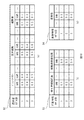
図3は制御装置130のブロック図の一例である。図3では、制御装置130の機能構成を表している。図4は場所データ21の一例である。図5は施設データ22の一例である。図6は施設プログラムデータ23の一例である。図7は経路データ31の一例である。図8は来場者データ41の一例である。図9は来場者モデルデータ51の一例である。
FIG. 3 is an example of a block diagram of the
図10(a)は選好度モデルデータ52の一例である。図10(b)は行動特性モデルデータ53の一例である。図10(c)は影響特性モデルデータ54の一例である。図11は場所テーブルT1の一例である。図12は施設テーブルT2の一例である。図13は施設プログラムテーブルT3の一例である。図14は経路テーブルT4の一例である。図15は来場者テーブルT5の一例である。
FIG. 10A is an example of the
制御装置130は、図3に示すように、施設情報受付部131、経路情報受付部132、来場者情報受付部133、及び来場者モデル受付部134を備えている。制御装置130は、処理部としての施設エージェント生成部135、経路生成部136、及び来場者エージェント生成部137を備えている。制御装置130は、施設記憶部140、経路記憶部141、及び来場者記憶部142を備えている。制御装置130は、処理部としての来場者エージェント更新部143、誘発情報受信部144、施設選択部145、及び施設エージェント更新部146を備えている。
As shown in FIG. 3, the
尚、施設情報受付部131、経路情報受付部132、来場者情報受付部133、来場者モデル受付部134は、例えば上述した入力I/F130Fによって実現される。施設記憶部140、経路記憶部141、及び来場者記憶部142は、例えば上述したRAM130B又はHDD130Eによって実現される。施設エージェント生成部135、経路生成部136、及び来場者エージェント生成部137、来場者エージェント更新部143、施設選択部145、及び施設エージェント更新部146は、例えば上述したCPU130Aによって実現される。誘発情報受信部144は、例えば上述したネットワークI/F130Dによって実現される。
The facility
施設情報受付部131は入力装置110から入力された施設情報を受け付ける。施設情報受付部131は受け付けた施設情報を施設エージェント生成部135に出力する。施設情報は、図4から図6に示すように、特定の記述言語で記載された場所データ21、施設データ22、及び施設プログラムデータ23を含んでいる。場所データ21は人流をシミュレーションする場所のデータである。場所データ21は場所の名称、その場所の営業時間及び位置(具体的には経路及び緯度)を含んでいる。施設データ22は場所データ21によって特定される場所に設置された複数の施設に関するデータである。施設データ22は複数の施設の名称、その施設の位置、及び収容人数などを含んでいる。施設プログラムデータ23は施設データ22によって特定される施設が提供するプログラムに関するデータである。施設プログラムデータ23は施設が提供するプログラムの開始時刻及び終了時刻を含んでいる。施設情報受付部131は、このような場所データ21、施設データ22、及び施設プログラムデータ23を含む施設情報を受け付けて、施設エージェント生成部135に出力する。
The facility
経路情報受付部132は入力装置110から入力された経路情報を受け付ける。経路情報受付部132は受け付けた経路情報を経路生成部136に出力する。経路情報は、図7に示すように、特定の記述言語で記載された経路データ31を含んでいる。経路データ31は複数の施設の間を移動できる経路を表すデータである。経路データ31は経路を識別する経路ID、経路の始点を識別する始点ノードID、経路の終点を識別する終点ノードID、及び経路の始点及び終点を特定するそれぞれの位置(具体的には緯度及び経度)を含んでいる。経路情報受付部132は、このような経路データ31を含む経路情報を受け付けて、経路生成部136に出力する。
The route
来場者情報受付部133は入力装置110から入力された来場者情報を受け付ける。来場者情報受付部133は受け付けた来場者情報を来場者エージェント生成部137に出力する。来場者情報は、図8に示すように、来場者データ41を含んでいる。来場者データ41は上述した場所データ21によって特定される場所の時間帯毎の来場者数、その時間帯における来場者の滞在時間の平均及び分散を含んでいる。来場者データ41は例えば表計算用アプリなどによって定義される。来場者情報受付部133は、このような来場者データ41を含む来場者情報を受け付けて、来場者エージェント生成部137に出力する。
The visitor
来場者モデル受付部134は入力装置110から入力された来場者モデル情報を受け付ける。来場者モデル受付部134は受け付けた来場者モデル情報を来場者エージェント生成部137に出力する。来場者モデル情報は、図9及び図10(a)〜(c)に示すように、来場者モデルデータ51、選好度モデルデータ52、行動特性モデルデータ53、及び影響特性モデルデータ54を含んでいる。来場者モデルデータ51、選好度モデルデータ52、行動特性モデルデータ53、及び影響特性モデルデータ54はいずれも例えば表計算用アプリなどによって定義されている。
The visitor
来場者モデルデータ51は来場者の種々の特性をモデル化したデータである。来場者モデルデータ51は、図9に示すように、来場者モデルID、選好度モデルID、行動特性モデルID、影響特性モデルID、及び重みを構成要素として含んでいる。来場者モデルIDは来場者モデルデータ51を識別する識別情報である。選好度モデルIDは選好度モデルデータ52を識別する識別情報である。行動特性モデルIDは行動特性モデルデータ53を識別する識別情報である。影響特性モデルIDは影響特性モデルデータ54を識別する識別情報である。重みは後述する来場者エージェントに来場者モデルIDを割り当てる際の基準である。
ここで、上述した選好度モデルデータ52は来場者の施設に対する選好度をモデル化したデータである。選好度モデルデータ52は、図10(a)に示すように、選好度モデルID毎に複数の施設について各施設の時間帯毎の来場者の施設に対する選好度を表すパラメータを含んでいる。例えば、選好度モデルID「1」により特定される選好度モデルデータ52では、9時台にはジェットコースターに対する選好度がパラメータ「0.9」であるが、10時台にはその選好度がパラメータ「0.8」に下がっている。すなわち、10時台では9時台よりジェットコースターを好んで選ぶ度合が下がっていることを表している。ジェットコースター以外の施設についてもジェットコースターと同様である。このように、選好度モデルデータ52は複数の施設に対する時間帯毎の選好度を時系列に管理している。
Here, the above-described
また、上述した行動特性モデルデータ53は来場者の行動の特性をモデル化したデータである。行動特性モデルデータ53は、図10(b)に示すように、行動特性モデルID毎に待ち時間抵抗度及び移動距離抵抗度のそれぞれについて時間帯毎の来場者の行動の特性を表すパラメータを含んでいる。待ち時間抵抗度は、来場者が許容できない待ち時間の度合を表しており、移動距離抵抗度は、来場者が許容できない移動距離の度合を表している。例えば、行動特性モデルID「1」により特定される行動特性モデルデータ53では、9時台には待ち時間抵抗度がパラメータ「0.1」であり、移動距離抵抗度がパラメータ「0.5」である。すなわち、9時台では来場者は待ち時間についてはある程度許容できるが、移動距離についてはあまり許容できないことを表している。このように、行動特性モデルデータ53は時間帯毎に待ち時間抵抗度及び移動距離抵抗度を時系列に管理している。
The behavior
さらに、上述した影響特性モデルデータ54は来場者の誘発情報に対する影響の特性をモデル化したデータである。誘発情報は来場者の行動を誘発する情報である。誘発情報としては、例えば施設の移動を提案する情報や、優先利用券に関する情報、サービス券、割引券、クーポン券に関する情報といった移動の動機付け(インセンティブ)を与える情報などがある。当該情報に動機付けの強度(例えば高い割引率や価値の高いサービスなど)を関連付けてもよい。影響特性モデルデータ54は、図10(c)に示すように、時間帯毎に来場者の誘発情報に対する感受性に関する特性を表すパラメータを含んでいる。例えば、影響特性モデルID「1」により特定される影響特性モデルデータ54では、9時台には感受性がパラメータ「0.3」である。すなわち、9時台では来場者は誘発情報に対しあまり影響を受けないことを表している。逆に、感受性がパラメータ「0.9」である場合、来場者は誘発情報に対し強く影響を受けることを表している。このように、影響特性モデルデータ54は時間帯毎に感受性を時系列に管理している。
Further, the above-described influence
施設エージェント生成部135は施設情報受付部131から出力された施設情報に基づいて、施設エージェントを生成する。施設エージェントはシミュレーション環境上で施設の代理として動作する情報である。より詳しくは、施設エージェント生成部135は、施設情報に含まれる場所データ21に基づいて、図11に示すように、場所データ21を含む場所テーブルT1を生成する。施設エージェント生成部135は生成した場所テーブルT1を施設記憶部140に登録する。また、施設エージェント生成部135は、施設情報に含まれる施設データ22に基づいて、図12に示すように、施設データ22を含む施設テーブルT2を生成する。施設エージェント生成部135は生成した施設テーブルT2を施設エージェントとして施設記憶部140に登録する。さらに、施設エージェント生成部135は、施設情報に含まれる施設プログラムデータ23に基づいて、図13に示すように、施設プログラムデータ23を含む施設プログラムテーブルT3を生成する。施設エージェント生成部135は生成した施設プログラムテーブルT3を施設記憶部140に登録する。
The facility
経路生成部136は経路情報受付部132から出力された経路情報に基づいて、来場者エージェントの移動経路を生成する。より詳しくは、経路生成部136は、経路情報に含まれる経路データ31に基づいて、図14に示すように、経路データ31を含む経路テーブルT4を生成する。経路生成部136は生成した経路テーブルT4を移動経路として経路記憶部141に登録する。
The
来場者エージェント生成部137は来場者情報受付部133から出力された来場者情報と来場者モデル受付部134から出力された来場者モデル情報とに基づいて、来場者エージェントを生成する。来場者エージェントはシミュレーション環境上で来場者の代理として動作する情報である。より詳しくは、来場者エージェント生成部137は、まず、来場者情報に含まれる時間帯別来場者数と滞在時間の分散に基づいて、図15に示すように、来場者テーブルT5を生成する。次に、来場者エージェント生成部137は、来場者モデルデータ51に含まれる重み(図9参照)の比率に基づいて、来場者テーブルT5の来場者モデルIDの欄に、来場者モデルデータ51の来場者モデルIDを割り当てる。これにより、来場者モデルデータ51(図9参照)を介して、来場者テーブルT5と選好度モデルデータ52(図10(a)参照)、行動特性モデルデータ53(図10(b)参照)、及び影響特性モデルデータ54(図10(c)参照)とが互いに関連付けられる。例えば、図15に示す来場者ID「101」の選好度、行動特性及び影響特性は来場者モデルID「3」によって特定され、来場者モデルデータ51(図9参照)に基づけば、来場者モデルID「3」は選好度モデルID「3」、行動特性モデルID「4」及び影響特性モデルID「1」によって特定される。来場者エージェント生成部137は来場者テーブルT5を生成すると、生成したテーブルT5を来場者エージェントとして来場者記憶部142に登録する。
The visitor
来場者エージェント更新部143は、シミュレーション環境上の時間軸に従って、来場者記憶部142が記憶する来場者エージェントの状態を更新する。より詳しくは、来場者エージェント更新部143は、シミュレーション環境上のテーマパーク内に滞在する全ての来場者エージェントの状態を更新する。来場者エージェントの状態としては、例えば施設への移動を表す状態や施設の利用を待っている状態、施設を利用している状態などがある。尚、来場者エージェントの状態の詳細については後述する。来場者エージェント更新部143は、来場者エージェントの状態を更新し終えると、更新後の来場者エージェントの状態をシミュレーション結果として来場者記憶部142に登録する。また、来場者エージェント更新部143は各来場者エージェントの来場者モデルデータ51に基づいて、選好度モデルデータ52、行動特性モデルデータ53、及び影響特性モデルデータ54を取得し、取得した選好度モデルデータ52、行動特性モデルデータ53、及び影響特性モデルデータ54を施設選択部145に出力する。
The visitor
誘発情報受信部144は誘発情報をサーバ装置200から来場者エージェントの要求に基づいて又は来場者エージェントの要求に基づかずに受信する。誘発情報受信部144は誘発情報を受信すると、受信した誘発情報を施設選択部145に出力する。
The trigger
施設選択部145は来場者エージェントの行先施設を選択する。より詳しくは、施設選択部145は施設記憶部140から施設エージェントを取得するとともに、経路記憶部141から移動経路を取得する。施設選択部145は施設エージェント及び移動経路を取得すると、取得した施設エージェント及び移動経路、来場者エージェント更新部143から出力された選好度モデルデータ52、行動特性モデルデータ53、及び影響特性モデルデータ54、並びに誘発情報受信部144から出力された誘発情報に基づいて、来場者エージェントの行先施設を選択する。施設選択部145は来場者エージェントの行先施設を選択すると、選択した行先施設を、来場者エージェント更新部143を通して来場者記憶部142に登録する。
The
施設エージェント更新部146は施設記憶部140が記憶する施設エージェントを更新する。より詳しくは、そのシミュレーション時刻における来場者エージェントの状態(例えば、当該施設を利用中、または、利用待ち中など)に基づいて、施設エージェントを更新する。例えば、1ステップ前のシミュレーション時刻と比べてジェットコースターの待ち人数や利用者数が増えていた場合、施設エージェント更新部146はジェットコースターの待ち人数を増やしたり、利用者数を増やしたりする。また、施設エージェント更新部146は施設エージェントの更新結果をシミュレーション結果として施設記憶部140に登録する。
The facility
続いて、制御装置130の動作について説明する。
Next, the operation of the
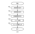
図16は制御装置130の動作の一例を示すフローチャートである。図17は来場者エージェントのシミュレーション結果の一例である。図18は来場者エージェントのシミュレーション結果の他の一例である。図19は施設エージェントのシミュレーション結果の一例である。図20は施設エージェントのシミュレーション結果の他の一例である。図21(a)及び(b)は施設エージェントのシミュレーション結果の他の一例である。
FIG. 16 is a flowchart illustrating an example of the operation of the
まず、施設情報受付部131は入力装置110から入力された施設情報を受け付ける(ステップS101)。次いで、経路情報受付部132は入力装置110から入力された経路情報を受け付ける(ステップS102)。次いで、来場者情報受付部133は入力装置110から入力された来場者情報を受け付ける(ステップS103)。より詳しくは、来場者情報受付部133は入力装置110から入力された来場者情報を受け付け、来場者モデル受付部134は入力装置110から入力された来場者モデル情報を受け付ける。
First, the facility
ステップS103の処理が完了すると、次いで、施設エージェント生成部135等はシミュレーション処理を実行する(ステップS104)。シミュレーション処理は、施設エージェント、移動経路、及び来場者エージェントを生成し、生成した施設エージェント、移動経路、来場者エージェント、及び受信した誘発情報に基づいて、施設エージェント及び来場者エージェントの状態を更新し、来場者エージェントの人流をシミュレーションする処理である。尚、シミュレーション処理の詳細については後述する。
When the process in step S103 is completed, the facility
ステップS104の処理が完了すると、次いで、来場者エージェント更新部143等はシミュレーション結果を出力する(ステップS105)。例えば、来場者エージェントに関するシミュレーション結果であれば、来場者エージェント更新部143はそのシミュレーション結果を来場者記憶部142に出力する。例えば、施設エージェントに関するシミュレーション結果であれば、施設エージェント更新部146はそのシミュレーション結果を施設記憶部140に出力する。
When the process of step S104 is completed, the visitor
来場者記憶部142に出力されるシミュレーション結果としては、例えば、図17に示すように、来場者エージェントの来場者ID毎の行動履歴や、図18に示すように、来場者エージェントの来場者ID毎の待ち時間などがある。一方、施設記憶部140に出力されるシミュレーション結果としては、例えば、図19に示すように、各施設エージェントのシミュレーション時刻毎の利用者数や待ち人数、混雑率、待ち時間、図20に示すように、施設エージェントの施設ID毎の待ち時間などがある。また、施設記憶部140に出力されるシミュレーション結果としては、図21(a)に示すように、テーマパーク内の時間帯別の滞在者数や、図21(b)に示すように、各施設の時間帯別平均待ち時間などもある。来場者エージェント更新部143及び施設エージェント更新部146はこれらのシミュレーション結果を表示装置120に出力してもよい。尚、待ち人数は一般レーンの待ち人数、または、優先レーンの待ち人数であり、図19ではそれぞれについて出力された一般レーンの待ち人数と優先レーンの待ち人数の一方が示されている。混雑率は利用人数と待ち人数の和を収容人数で割った値である。待ち時間は待ち人数を回転数で割って所要時間を掛けた値である。待ち人数、混雑率、及び待ち時間はいずれも施設エージェント更新部146によって算出される。
The simulation result output to the
続いて、図22を参照して、上述したシミュレーション処理の詳細について説明する。 Next, details of the above-described simulation process will be described with reference to FIG.
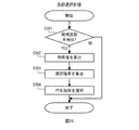
図22はシミュレーション処理のフローチャートの一例である。上述したステップS103の処理が完了すると、まず、施設エージェント生成部135は施設エージェントを生成する(ステップS201)。ステップS201の処理が完了すると、次いで、経路生成部136は移動経路を生成する(ステップS202)。ステップS202の処理が完了すると、次いで、来場者エージェント生成部137は来場者エージェントを生成する(ステップS203)。
FIG. 22 is an example of a flowchart of simulation processing. When the process of step S103 described above is completed, the facility
ステップS203の処理が完了すると、次いで、来場者エージェント更新部143はシミュレーション時刻を1ステップ(例えば1分)進行させる(ステップS204)。ステップS204の処理が完了すると、来場者エージェント更新部143は状態遷移処理を実行する(ステップS205)。状態遷移処理は来場者エージェントの状態遷移を実行したり、来場者エージェントの行先施設を選択したりする処理である。尚、状態遷移処理の詳細については後述する。
When the process of step S203 is completed, the visitor
ステップS205の処理が完了すると、次いで、施設エージェント更新部146は施設エージェントを更新する(ステップS206)。ステップS206の処理が完了すると、次いで、来場者エージェント更新部143は指定時間が終了したか否かを判断する(ステップS207)。指定時間が終了していない場合(ステップS207:NO)、来場者エージェント更新部143はステップS204の処理を実行する。これにより、シミュレーション時刻が進行する度に、来場者エージェントの状態が更新され、施設エージェントの状態が更新される。一方、指定時間が終了した場合(ステップS207:YES)、シミュレーション処理が終了する。
When the process of step S205 is completed, the facility
図23は状態遷移処理の処理手順の一例を示す図である。図23では、テーマパーク内の状態遷移を表している。まず、来場者エージェント生成部137が来場者エージェントを生成すると、生成した来場者エージェントはテーマパーク内に入場し、idle状態に遷移する(W1)。idle状態では確率p1で行先施設を選択し、予め定めた一定の確率p2でサーバ装置200に対して例えば行先施設の提案を要求し(W2)、確率1−p1−p2でidle状態を維持する(W3)。尚、行先施設を選択する処理については後述する。
FIG. 23 is a diagram illustrating an example of a process procedure of the state transition process. FIG. 23 shows the state transition in the theme park. First, when the visitor
idle状態で行先施設を選択すると、来場者エージェントの状態はidle状態からroam状態に遷移する(W4)。すなわち、来場者エージェントは選択した行先施設に向けた散策を開始する。一方、idle状態で行先施設の提案を要求すると、来場者エージェントは行先施設の提案と併せて有効時限が設定された優先利用券を取得する。このとき、行先施設は複数提案されるものとし、その中から来場者エージェントは行先を選択する。idle状態で優先利用券を取得すると、取得した優先利用券が有効時限内であれば(もしくは、移動を開始してその行先施設到着時に有効時限内に入るのであれば)、来場者エージェントの状態はidle状態からmove状態に遷移する(W5)。すなわち、提案された行先施設に向けて来場者エージェントは移動する。 When the destination facility is selected in the idle state, the state of the visitor agent transitions from the idle state to the roam state (W4). That is, the visitor agent starts a walk toward the selected destination facility. On the other hand, when a request for a destination facility is requested in the idle state, the visitor agent acquires a priority use ticket in which a valid time period is set together with the proposal for the destination facility. At this time, it is assumed that a plurality of destination facilities are proposed, and the visitor agent selects a destination from among them. If a priority use ticket is acquired in the idle state, if the acquired priority use ticket is within the valid time period (or if it enters the valid time period when the destination facility arrives and arrives at the destination facility), the state of the visitor agent Transitions from the idle state to the move state (W5). That is, the visitor agent moves toward the proposed destination facility.
roam状態では、来場者エージェントは自ら選択した行先施設に向かい移動する。行先施設に到着した場合には、来場者エージェント更新部143は待ち判定を行う。来場者エージェント更新部143は待ち時間が長くなるほど、来場者エージェントがその施設を諦めると判断する。例えば待ち時間が所定の設定時間より長くなると、来場者エージェントの状態はroam状態からidle状態に遷移する(W6)。一方、待ち時間が所定の設定時間より短い場合、来場者エージェントの状態はroam状態からwait状態に遷移する(W7)。この場合、来場者エージェントは優先利用券を所持していないため、一般レーンでの待機となる。
In the room state, the visitor agent moves toward the destination facility selected by himself / herself. When arriving at the destination facility, the visitor
また、roam状態において、来場者エージェントが優先利用券を所持しており、移動中にその有効時限に間に合わなくなると判断した場合には、来場者エージェントの状態はroam状態からmove状態に遷移する(W8)。移動中にその有効時限に間に合わなくなるか否かは、例えば来場者エージェント更新部143が取得した移動経路に基づいて判断する。
Also, if the visitor agent has a priority use ticket in the roam state and it is determined that the valid time limit will not be met during the move, the state of the visitor agent transitions from the roam state to the move state ( W8). Whether or not the effective time limit is missed during the movement is determined based on the movement route acquired by the visitor
move状態では、来場者エージェントは優先利用券が対象とする施設に向かい移動し、当該施設に到着すると、来場者エージェントの状態はmove状態からwait状態に遷移する(W9)。来場者エージェントは優先利用券を所持しているため、優先搭乗レーンでの待機となる。 In the move state, the visitor agent moves toward the facility targeted by the priority use ticket. When the visitor agent arrives at the facility, the state of the visitor agent transitions from the move state to the wait state (W9). Since the visitor agent has a priority use ticket, he / she is on standby in the priority boarding lane.
wait状態では、一般レーンでの待機であっても優先搭乗レーンでの待機であっても、施設を利用できる時間になるまで待機する。施設を利用できる時間になると、来場者エージェントの状態はwait状態からfacility状態に遷移する(W10,W11)。尚、一般レーンでの待機の場合には、来場者エージェント更新部143はroam状態の際の待ち判定より緩和された条件で待ち判定を行う。例えば待ち時間が所定の設定時間より長かった場合、来場者エージェントは一定の確率で行列から離脱し、来場者エージェントの状態はwait状態からidle状態に遷移する(W12)。一方、wait状態において、来場者エージェントが優先利用券を所持しており、待機中にその有効時限に間に合わなくなると判断した場合には、来場者エージェントの状態はwait状態からmove状態に遷移する(W13)。
In the wait state, the system waits until it is possible to use the facility regardless of whether it is standby in a general lane or standby in a priority boarding lane. When it is time to use the facility, the state of the visitor agent transitions from the wait state to the facility state (W10, W11). In the case of waiting in a general lane, the visitor
facility状態では、来場者エージェントは施設を利用する。施設の利用が終了すると、来場者エージェントの状態はfacility状態からidle状態に遷移する(W14)。設定された滞在時間に到達した場合には、来場者エージェントはテーマパークから退場し、来場者エージェントのシミュレーションは終了する。 In the facility state, the visitor agent uses the facility. When the use of the facility ends, the state of the visitor agent transitions from the facility state to the idle state (W14). When the set stay time is reached, the visitor agent leaves the theme park, and the visitor agent simulation ends.
図24は施設選択処理の一例を示すフローチャートである。施設選択処理は来場者エージェントが行先施設を選択する処理である。提案された行先施設から施設を選択するときにも実行される。まず、施設選択部145は、行先施設の候補を抽出できるか否かを判断する(ステップS301)。より詳しくは、来場者エージェントが上述したidle状態に遷移すると、施設選択部145は来場者エージェントがまだ利用していない施設エージェントを抽出できるか否かを判断する。テーマパーク内に設置された全ての施設の施設エージェントを来場者エージェントが利用した場合、施設選択部145は来場者エージェントが利用していない施設を抽出できないと判断し(ステップS301:NO)、処理を終了する。
FIG. 24 is a flowchart illustrating an example of the facility selection process. Facility selection processing is processing in which a visitor agent selects a destination facility. It is also executed when selecting a facility from the proposed destination facilities. First, the
一方、全ての施設の施設エージェントを来場者エージェントがまだ利用し終えていない場合、施設選択部145は来場者エージェントがまだ利用していない施設エージェントを抽出できると判断し(ステップS301:YES)、抽出できた各施設エージェントの効用値を算出する(ステップS302)。ここで、施設選択部145は以下の算出式(1)と各係数とに基づいて、時刻tにおける施設エージェントiの効用値Vi(t)を算出する。提案された行先施設から施設を選択するときには、上記効用値が一定以上のものだけを対象とする。
<算出式(1)>

Pi:施設エージェントiに対する選好度
WTi:施設エージェントiの待ち時間
Di:施設エージェントiまでの距離
Ii:施設エージェントiに対する情報又はインセンティブ強度
β1:待ち時間に対する抵抗度
β2:移動距離に対する抵抗度
β3:情報またはインセンティブに対する感受性
On the other hand, if the visitor agent has not yet used the facility agents of all the facilities, the
<Calculation formula (1)>
P i : Preference for facility agent i WT i : Waiting time for facility agent i D i : Distance to facility agent i I i : Information or incentive strength for facility agent i β 1 : Resistance to waiting time β 2 : Movement Resistance to distance β 3 : Sensitivity to information or incentives
ステップS302の処理が完了すると、次いで、施設選択部145は抽出できた各施設エージェントの選択確率を算出する(ステップS303)。ここで、施設選択部145は算出した各施設エージェントの効用値と以下の算出式(2)とに基づいて、時刻tにおける施設エージェントiの選択確率Probi(t)を算出する。
<算出式(2)>
<Calculation formula (2)>
ステップS303の処理が完了すると、次いで、施設選択部145は行先施設を選択する(ステップS304)。より詳しくは、施設選択部145は算出した各施設エージェントの選択確率Probi(t)に基づいて行先施設を選択する。例えば、施設選択部145は算出した各施設エージェントの選択確率Probi(t)の中から最大の選択確率Probi(t)を算出した施設エージェントを行先施設として選択する。すなわち、施設選択部145は最大の選択確率Probi(t)を上述した確率P1とし、確率P1を算出した施設を行先施設として選択する。ステップS304の処理が終了すると、施設選択部145は処理を終了する。このように、施設選択部145は来場者エージェントの影響特性を考慮した効用値を算出し、算出した効用値に基づいて施設の選択確率を算出し、算出した選択確率に基づいて行先施設を選択する。
When the process of step S303 is completed, the
以上、本実施形態によれば、制御装置130は来場者エージェント生成部137と施設選択部145を備えている。来場者エージェント生成部137は、来場者情報と複数の影響特性モデル情報とに基づき、複数の影響特性モデル情報とそれぞれ関連付けられた複数の来場者エージェントをシミュレーション環境上に生成する。施設選択部145は上述した算出式(2)と影響特性モデル情報とに基づいて、シミュレーション環境上に生成された複数の施設エージェントの中から複数の来場者エージェントが向かう目的の施設エージェントを選択する。これにより、来場者の影響特性を考慮した人流をシミュレーションすることができる。
As described above, according to the present embodiment, the
以上、本発明の好ましい実施形態について詳述したが、本発明に係る特定の実施形態に限定されるものではなく、特許請求の範囲に記載された本発明の要旨の範囲内において、種々の変形・変更が可能である。例えば、上述した実施形態では、複数の来場者が時間及び距離に関して許容できない抵抗度合を表す行動特性モデル情報を利用して説明したが、時間及び距離に限定されず、例えば天候や環境(例えば気温や湿度など)、テーマパーク内の人口密度などを抵抗度合として利用してもよい。 The preferred embodiments of the present invention have been described in detail above, but the present invention is not limited to the specific embodiments according to the present invention, and various modifications are possible within the scope of the gist of the present invention described in the claims.・ Change is possible. For example, in the above-described embodiment, a description has been given using behavior characteristic model information indicating a degree of resistance that a plurality of visitors cannot accept with respect to time and distance. However, the present invention is not limited to time and distance. Or the population density in the theme park may be used as the degree of resistance.
なお、以上の説明に関して更に以下の付記を開示する。
(付記1)複数の施設が設置された場所における複数の来場者の人流をシミュレーションする人流シミュレーション装置であって、前記複数の来場者の状況をそれぞれ表す来場者情報と、前記複数の来場者の行動を誘発する誘発情報に対して前記複数の来場者が影響を受ける特性をそれぞれ表す複数の影響特性モデル情報とに基づき、前記複数の影響特性モデル情報とそれぞれ関連付けられた複数の来場者エージェントをシミュレーション環境上に生成し、前記複数の施設の中から目的の施設を選択する確率を算出する算出式と前記複数の影響特性モデル情報とに基づいて、前記シミュレーション環境上に生成された複数の施設エージェントの中から前記複数の来場者エージェントが向かう目的の施設エージェントを選択する、処理を実行する処理部を含む人流シミュレーション装置。
(付記2)前記処理部は、前記複数の来場者が少なくとも時間及び距離に関して許容できない抵抗度合をそれぞれ表す複数の行動特性モデル情報ともそれぞれ関連付けられた前記複数の来場者エージェントを生成し、前記複数の行動特性モデル情報にも基づいて、前記施設エージェントを選択する、ことを特徴とする付記1に記載の人流シミュレーション装置。
(付記3)前記処理部は、前記複数の施設のいずれかを選ぶ際の選好度をそれぞれ表す複数の選好度モデル情報ともそれぞれ関連付けられた前記複数の来場者エージェントを生成し、前記複数の選好度モデル情報にも基づいて、前記施設エージェントを選択する、ことを特徴とする付記1又は2に記載の人流シミュレーション装置。
(付記4)前記複数の影響特性モデル情報、前記複数の行動特性モデル情報、及び前記複数の選好度モデル情報はいずれも時系列に管理されている、ことを特徴とする付記3に記載の人流シミュレーション装置。
(付記5)前記処理部は、前記誘発情報を前記人流シミュレーション装置以外の装置から要求に基づいて又は前記要求に基づかずに受信する、ことを特徴とする付記1から4のいずれか1項に記載の人流シミュレーション装置。
(付記6)複数の施設が設置された場所における複数の来場者の人流をシミュレーションする処理をコンピュータが実行する人流シミュレーション方法であって、前記複数の来場者の状況をそれぞれ表す来場者情報と、前記複数の来場者の行動を誘発する誘発情報に対して前記複数の来場者が影響を受ける特性をそれぞれ表す複数の影響特性モデル情報とに基づき、シミュレーション環境上に前記複数の影響特性モデル情報とそれぞれ関連付けられた複数の来場者エージェントを生成し、前記複数の施設の中から目的の施設を選択する確率を算出する算出式と前記複数の影響特性モデル情報とに基づいて、前記シミュレーション環境上に生成された複数の施設エージェントの中から前記複数の来場者エージェントが向かう目的の施設エージェントを選択する、処理を含む人流シミュレーション方法。
(付記7)前記処理は、前記複数の来場者が時間及び距離に関して許容できない抵抗度合をそれぞれ表す複数の行動特性モデル情報ともそれぞれ関連付けられた前記複数の来場者エージェントを生成し、前記複数の行動特性モデル情報にも基づいて、前記施設エージェントを選択する、ことを特徴とする付記6に記載の人流シミュレーション方法。
(付記8)前記処理は、前記複数の施設のいずれかを選ぶ際の選好度をそれぞれ表す複数の選好度モデル情報ともそれぞれ関連付けられた前記複数の来場者エージェントを生成し、前記複数の選好度モデル情報にも基づいて、前記施設エージェントを選択する、ことを特徴とする付記6又は7に記載の人流シミュレーション方法。
(付記9)前記複数の影響特性モデル情報、前記複数の行動特性モデル情報、及び前記複数の選好度モデル情報はいずれも時系列に管理されている、ことを特徴とする付記8に記載の人流シミュレーション方法。
(付記10)前記処理は、前記誘発情報を前記人流をシミュレーションする装置以外の装置から要求に基づいて又は前記要求に基づかずに受信する、ことを特徴とする付記6から9のいずれか1項に記載の人流シミュレーション方法。
(付記11)複数の施設が設置された場所における複数の来場者の人流をシミュレーションする処理をコンピュータに実行させる人流シミュレーションプログラムであって、前記複数の来場者の状況をそれぞれ表す来場者情報と、前記複数の来場者の行動を誘発する誘発情報に対して前記複数の来場者が影響を受ける特性をそれぞれ表す複数の影響特性モデル情報とに基づき、シミュレーション環境上に前記複数の影響特性モデル情報とそれぞれ関連付けられた複数の来場者エージェントを生成し、前記複数の施設の中から目的の施設を選択する確率を算出する算出式と前記複数の影響特性モデル情報とに基づいて、前記シミュレーション環境上に生成された複数の施設エージェントの中から前記複数の来場者エージェントが向かう目的の施設エージェントを選択する、処理を含む人流シミュレーションプログラム。
In addition, the following additional notes are disclosed regarding the above description.
(Supplementary note 1) A human flow simulation apparatus for simulating the flow of a plurality of visitors in a place where a plurality of facilities are installed, the visitor information representing the situation of each of the plurality of visitors, and the plurality of visitors A plurality of visitor agents respectively associated with the plurality of influence characteristic model information based on a plurality of influence characteristic model information respectively representing characteristics affected by the plurality of visitors with respect to the trigger information for inducing behavior A plurality of facilities generated on the simulation environment based on a calculation formula for calculating a probability of selecting a target facility from the plurality of facilities and the plurality of influence characteristic model information The target facility agent to which the plurality of visitor agents go is selected from the agents, and the process is executed. Pedestrian flow simulation apparatus including a processing unit.
(Supplementary Note 2) The processing unit generates the plurality of visitor agents respectively associated with a plurality of behavior characteristic model information each representing a degree of resistance that the plurality of visitors cannot allow at least with respect to time and distance. The human flow simulation device according to
(Supplementary Note 3) The processing unit generates the plurality of visitor agents respectively associated with a plurality of preference model information each representing a preference when selecting any of the plurality of facilities, and the plurality of
(Supplementary note 4) The human flow according to
(Additional remark 5) The said process part receives the said induction | guidance | derivation information based on a request | requirement from apparatuses other than the said human flow simulation apparatus, or not based on the said request | requirement to any one of the
(Supplementary note 6) A human flow simulation method in which a computer executes a process of simulating a human flow of a plurality of visitors in a place where a plurality of facilities are installed, wherein the visitor information represents the situation of each of the plurality of visitors, Based on a plurality of influence characteristic model information respectively representing characteristics affected by the plurality of visitors with respect to the induction information that induces the behavior of the plurality of visitors, the plurality of influence characteristic model information on the simulation environment and A plurality of visitor agents associated with each other are generated, and the simulation environment is created on the simulation environment based on a calculation formula for calculating a probability of selecting a target facility from the plurality of facilities and the plurality of influence characteristic model information. The target facility agent to which the plurality of visitor agents go from among the plurality of generated facility agents To select the door, people flow simulation methods, including processing.
(Supplementary Note 7) The processing generates the plurality of visitor agents respectively associated with a plurality of behavior characteristic model information each representing a degree of resistance that the plurality of visitors cannot accept with respect to time and distance, and The human flow simulation method according to appendix 6, wherein the facility agent is selected based on characteristic model information.
(Supplementary note 8) The processing generates the plurality of visitor agents respectively associated with a plurality of preference model information each representing a preference when selecting any of the plurality of facilities, and the plurality of preference levels The human flow simulation method according to
(Supplementary note 9) The human flow according to
(Additional remark 10) The said process receives the said induction | guidance | derivation information based on a request | requirement from apparatuses other than the apparatus which simulates the said human flow based on a request | requirement, or any one of the additional remark 6-9 characterized by the above-mentioned. The human flow simulation method described in 1.
(Supplementary Note 11) A human flow simulation program for causing a computer to execute a process of simulating a human flow of a plurality of visitors in a place where a plurality of facilities are installed, and each of the visitor information representing a situation of each of the plurality of visitors, Based on a plurality of influence characteristic model information respectively representing characteristics affected by the plurality of visitors with respect to the induction information that induces the behavior of the plurality of visitors, the plurality of influence characteristic model information on the simulation environment and A plurality of visitor agents associated with each other are generated, and the simulation environment is created on the simulation environment based on a calculation formula for calculating a probability of selecting a target facility from the plurality of facilities and the plurality of influence characteristic model information. Among the plurality of generated facility agents, the plurality of visitor agents are directed to the purpose. To select an agent, people flow simulation program, including processing.
S 人流シミュレーションシステム
100 端末装置
130 制御装置
135 施設エージェント生成部
136 経路生成部
137 来場者エージェント生成部
143 来場者エージェント更新部
144 誘発情報受信部
145 施設選択部
146 施設エージェント更新部
200 サーバ装置
S human
Claims (7)
前記複数の来場者の状況をそれぞれ表す来場者情報と、前記複数の来場者の行動を誘発する誘発情報に対して前記複数の来場者が影響を受ける特性をそれぞれ表す複数の影響特性モデル情報とに基づき、前記複数の影響特性モデル情報とそれぞれ関連付けられた複数の来場者エージェントをシミュレーション環境上に生成し、
前記複数の施設の中から目的の施設を選択する確率を算出する算出式と前記複数の影響特性モデル情報とに基づいて、前記シミュレーション環境上に生成された複数の施設エージェントの中から前記複数の来場者エージェントが向かう目的の施設エージェントを選択する、
処理を実行する処理部を含む人流シミュレーション装置。 A human flow simulation apparatus for simulating the flow of a plurality of visitors in a place where a plurality of facilities are installed,
Visitor information that represents the status of each of the plurality of visitors, and a plurality of influence characteristic model information that represents characteristics that the plurality of visitors are affected with respect to trigger information that induces the behavior of the plurality of visitors, and And generating a plurality of visitor agents respectively associated with the plurality of influence characteristic model information on the simulation environment,
Based on a calculation formula for calculating a probability of selecting a target facility from the plurality of facilities and the plurality of influence characteristic model information, the plurality of facility agents generated on the simulation environment are selected from the plurality of facility agents. Select the facility agent that the visitor agent is going to go to,
A human flow simulation apparatus including a processing unit for executing processing.
ことを特徴とする請求項1に記載の人流シミュレーション装置。 The processing unit generates the plurality of visitor agents respectively associated with a plurality of behavior characteristic model information respectively representing a degree of resistance that the plurality of visitors cannot accept at least with respect to time and distance, and the plurality of behavior characteristic models Selecting the facility agent based on the information;
The human flow simulation apparatus according to claim 1.
ことを特徴とする請求項1又は2に記載の人流シミュレーション装置。 The processing unit generates the plurality of visitor agents respectively associated with a plurality of preference model information each representing a preference level when selecting any of the plurality of facilities, and includes the plurality of preference model information. Also based on selecting the facility agent,
The human flow simulation apparatus according to claim 1 or 2, wherein
ことを特徴とする請求項3に記載の人流シミュレーション装置。 The plurality of influence characteristic model information, the plurality of behavior characteristic model information, and the plurality of preference model information are all managed in time series.
The human flow simulation apparatus according to claim 3.
ことを特徴とする請求項1から4のいずれか1項に記載の人流シミュレーション装置。 The processing unit receives the trigger information from a device other than the human flow simulation device based on a request or not based on the request.
The human flow simulation device according to claim 1, wherein the human flow simulation device is a human flow simulation device.
前記複数の来場者の状況をそれぞれ表す来場者情報と、前記複数の来場者の行動を誘発する誘発情報に対して前記複数の来場者が影響を受ける特性をそれぞれ表す複数の影響特性モデル情報とに基づき、シミュレーション環境上に前記複数の影響特性モデル情報とそれぞれ関連付けられた複数の来場者エージェントを生成し、
前記複数の施設の中から目的の施設を選択する確率を算出する算出式と前記複数の影響特性モデル情報とに基づいて、前記シミュレーション環境上に生成された複数の施設エージェントの中から前記複数の来場者エージェントが向かう目的の施設エージェントを選択する、
処理を含む人流シミュレーション方法。 A human flow simulation method in which a computer executes a process of simulating a human flow of a plurality of visitors in a place where a plurality of facilities are installed,
Visitor information that represents the status of each of the plurality of visitors, and a plurality of influence characteristic model information that represents characteristics that the plurality of visitors are affected with respect to trigger information that induces the behavior of the plurality of visitors, and And generating a plurality of visitor agents respectively associated with the plurality of influence characteristic model information on the simulation environment,
Based on a calculation formula for calculating a probability of selecting a target facility from the plurality of facilities and the plurality of influence characteristic model information, the plurality of facility agents generated on the simulation environment are selected from the plurality of facility agents. Select the facility agent that the visitor agent is going to go to,
Human flow simulation method including processing.
前記複数の来場者の状況をそれぞれ表す来場者情報と、前記複数の来場者の行動を誘発する誘発情報に対して前記複数の来場者が影響を受ける特性をそれぞれ表す複数の影響特性モデル情報とに基づき、シミュレーション環境上に前記複数の影響特性モデル情報とそれぞれ関連付けられた複数の来場者エージェントを生成し、
前記複数の施設の中から目的の施設を選択する確率を算出する算出式と前記複数の影響特性モデル情報とに基づいて、前記シミュレーション環境上に生成された複数の施設エージェントの中から前記複数の来場者エージェントが向かう目的の施設エージェントを選択する、
処理を含む人流シミュレーションプログラム。 A human flow simulation program for causing a computer to execute a process of simulating a human flow of a plurality of visitors in a place where a plurality of facilities are installed,
Visitor information that represents the status of each of the plurality of visitors, and a plurality of influence characteristic model information that represents characteristics that the plurality of visitors are affected with respect to trigger information that induces the behavior of the plurality of visitors, and And generating a plurality of visitor agents respectively associated with the plurality of influence characteristic model information on the simulation environment,
Based on a calculation formula for calculating a probability of selecting a target facility from the plurality of facilities and the plurality of influence characteristic model information, the plurality of facility agents generated on the simulation environment are selected from the plurality of facility agents. Select the facility agent that the visitor agent is going to go to,
Human flow simulation program including processing.
Priority Applications (2)
| Application Number | Priority Date | Filing Date | Title |
|---|---|---|---|
| JP2017140341A JP2019021143A (en) | 2017-07-19 | 2017-07-19 | Human flow simulation device, human flow simulation method and human flow simulation program |
| US16/033,853 US20190026408A1 (en) | 2017-07-19 | 2018-07-12 | People flow simulation apparatus and method |
Applications Claiming Priority (1)
| Application Number | Priority Date | Filing Date | Title |
|---|---|---|---|
| JP2017140341A JP2019021143A (en) | 2017-07-19 | 2017-07-19 | Human flow simulation device, human flow simulation method and human flow simulation program |
Publications (1)
| Publication Number | Publication Date |
|---|---|
| JP2019021143A true JP2019021143A (en) | 2019-02-07 |
Family
ID=65019034
Family Applications (1)
| Application Number | Title | Priority Date | Filing Date |
|---|---|---|---|
| JP2017140341A Ceased JP2019021143A (en) | 2017-07-19 | 2017-07-19 | Human flow simulation device, human flow simulation method and human flow simulation program |
Country Status (2)
| Country | Link |
|---|---|
| US (1) | US20190026408A1 (en) |
| JP (1) | JP2019021143A (en) |
Cited By (2)
| Publication number | Priority date | Publication date | Assignee | Title |
|---|---|---|---|---|
| JP2021002294A (en) * | 2019-06-24 | 2021-01-07 | 富士通株式会社 | Waiting time calculation program, waiting time calculation method, and waiting time calculation system |
| US11757699B2 (en) | 2021-06-08 | 2023-09-12 | Toyota Jidosha Kabushiki Kaisha | Multi-agent simulation system and method |
Families Citing this family (1)
| Publication number | Priority date | Publication date | Assignee | Title |
|---|---|---|---|---|
| CN114241755B (en) * | 2021-12-06 | 2023-08-25 | 安徽长泰科技有限公司 | Real-time optimal dispatching system for park vehicles |
Citations (4)
| Publication number | Priority date | Publication date | Assignee | Title |
|---|---|---|---|---|
| JPH06176004A (en) * | 1992-07-27 | 1994-06-24 | Takenaka Komuten Co Ltd | Simulation device for traffic line of visitor |
| JP2007509393A (en) * | 2003-10-15 | 2007-04-12 | ディズニー エンタープライゼス インコーポレイテッド | Managing the flow of people related to crowd centers with priority control |
| WO2017029698A1 (en) * | 2015-08-14 | 2017-02-23 | 富士通株式会社 | Simulation program, simulation method, and simulation device |
| US20170270565A1 (en) * | 2014-02-21 | 2017-09-21 | Alexey Filatoff | Facility mapping and interactive tracking |
Family Cites Families (3)
| Publication number | Priority date | Publication date | Assignee | Title |
|---|---|---|---|---|
| US8620675B2 (en) * | 2010-01-29 | 2013-12-31 | International Business Machines Corporation | Method and apparatus for optimal service channel reconfiguration based on multi-agent simulation |
| US20110246304A1 (en) * | 2010-03-31 | 2011-10-06 | Terry Hicks | Method and system for providing targeted advertisements based on positional tracking of mobile devices and financial data |
| US20180039949A1 (en) * | 2016-08-02 | 2018-02-08 | Sap Portals Israel Ltd. | Optimizing and synchronizing people flows |
-
2017
- 2017-07-19 JP JP2017140341A patent/JP2019021143A/en not_active Ceased
-
2018
- 2018-07-12 US US16/033,853 patent/US20190026408A1/en not_active Abandoned
Patent Citations (4)
| Publication number | Priority date | Publication date | Assignee | Title |
|---|---|---|---|---|
| JPH06176004A (en) * | 1992-07-27 | 1994-06-24 | Takenaka Komuten Co Ltd | Simulation device for traffic line of visitor |
| JP2007509393A (en) * | 2003-10-15 | 2007-04-12 | ディズニー エンタープライゼス インコーポレイテッド | Managing the flow of people related to crowd centers with priority control |
| US20170270565A1 (en) * | 2014-02-21 | 2017-09-21 | Alexey Filatoff | Facility mapping and interactive tracking |
| WO2017029698A1 (en) * | 2015-08-14 | 2017-02-23 | 富士通株式会社 | Simulation program, simulation method, and simulation device |
Cited By (3)
| Publication number | Priority date | Publication date | Assignee | Title |
|---|---|---|---|---|
| JP2021002294A (en) * | 2019-06-24 | 2021-01-07 | 富士通株式会社 | Waiting time calculation program, waiting time calculation method, and waiting time calculation system |
| JP7326916B2 (en) | 2019-06-24 | 2023-08-16 | 富士通株式会社 | Waiting Time Calculation Program, Waiting Time Calculating Method, and Waiting Time Calculating System |
| US11757699B2 (en) | 2021-06-08 | 2023-09-12 | Toyota Jidosha Kabushiki Kaisha | Multi-agent simulation system and method |
Also Published As
| Publication number | Publication date |
|---|---|
| US20190026408A1 (en) | 2019-01-24 |
Similar Documents
| Publication | Publication Date | Title |
|---|---|---|
| Prieto Curiel et al. | Gravity and scaling laws of city to city migration | |
| US9533229B2 (en) | Custom reward for viral help in game | |
| Mason | Simulation and real-time optimised relocation for improving ambulance operations | |
| JP5372421B2 (en) | Evacuation simulation system, evacuation simulation method, evacuation simulation program, and recording medium | |
| JP2017153078A (en) | Artificial intelligence learning method, artificial intelligence learning system, and answer relay method | |
| JP2019021143A (en) | Human flow simulation device, human flow simulation method and human flow simulation program | |
| JP5785973B2 (en) | New store candidate site analysis apparatus, method and program | |
| CN104737565A (en) | Method relating to predicting the future state of a mobile device user | |
| WO2020034851A1 (en) | Method, apparatus and device for pushing information | |
| Ridler et al. | A simulation and optimisation package for emergency medical services | |
| Liang et al. | Traffic signal control optimization in a connected vehicle environment considering pedestrians | |
| Pięta et al. | Multi-domain model for simulating smart IoT-based theme parks | |
| US20130303282A1 (en) | Interactive modeling and guided design method and system | |
| JPWO2016075933A1 (en) | Evacuation prediction system, model generation device, prediction device, evacuation prediction method, and computer-readable recording medium | |
| US11120386B2 (en) | Computer-readable recording medium, simulation method, and simulation apparatus | |
| JP2019095895A (en) | Human flow predicting device, method, and program | |
| CN111291868A (en) | Network model training method, device, equipment and computer readable storage medium | |
| JP6649229B2 (en) | Latency prediction device, latency prediction method, and latency prediction program | |
| Serok et al. | A simulation model for intra-urban movements | |
| Tofighi et al. | Estimating social contacts in mass gatherings for disease outbreak prevention and management: case of Hajj pilgrimage | |
| US20200302460A1 (en) | Information providing method, information providing program, and information providing apparatus | |
| Drigo et al. | Modeling intimate partner violence and support systems | |
| KR102095622B1 (en) | System and Method for Extracting Location-based Activity from Online Social Network Service Data | |
| Wood et al. | Relating quanta conservation and compartmental epidemiological models of airborne disease outbreaks in buildings | |
| KR102350131B1 (en) | Method, device and system for deriving exhibition planning strategy based on analysis movement analysis of visitor in exhibit hall |
Legal Events
| Date | Code | Title | Description |
|---|---|---|---|
| A621 | Written request for application examination |
Free format text: JAPANESE INTERMEDIATE CODE: A621 Effective date: 20200409 |
|
| A977 | Report on retrieval |
Free format text: JAPANESE INTERMEDIATE CODE: A971007 Effective date: 20210218 |
|
| A131 | Notification of reasons for refusal |
Free format text: JAPANESE INTERMEDIATE CODE: A131 Effective date: 20210309 |
|
| A521 | Request for written amendment filed |
Free format text: JAPANESE INTERMEDIATE CODE: A523 Effective date: 20210506 |
|
| A01 | Written decision to grant a patent or to grant a registration (utility model) |
Free format text: JAPANESE INTERMEDIATE CODE: A01 Effective date: 20211012 |
|
| A045 | Written measure of dismissal of application [lapsed due to lack of payment] |
Free format text: JAPANESE INTERMEDIATE CODE: A045 Effective date: 20220222 |