JP2019010903A - Vehicle seat - Google Patents
Vehicle seat Download PDFInfo
- Publication number
- JP2019010903A JP2019010903A JP2017127078A JP2017127078A JP2019010903A JP 2019010903 A JP2019010903 A JP 2019010903A JP 2017127078 A JP2017127078 A JP 2017127078A JP 2017127078 A JP2017127078 A JP 2017127078A JP 2019010903 A JP2019010903 A JP 2019010903A
- Authority
- JP
- Japan
- Prior art keywords
- side frame
- seat
- vehicle seat
- frame
- reinforcing wire
- Prior art date
- Legal status (The legal status is an assumption and is not a legal conclusion. Google has not performed a legal analysis and makes no representation as to the accuracy of the status listed.)
- Granted
Links
- 229910000831 Steel Inorganic materials 0.000 claims abstract description 12
- 239000010959 steel Substances 0.000 claims abstract description 12
- 229920005989 resin Polymers 0.000 claims abstract description 8
- 239000011347 resin Substances 0.000 claims abstract description 8
- 230000005540 biological transmission Effects 0.000 claims abstract description 6
- 230000003014 reinforcing effect Effects 0.000 claims description 35
- 239000000463 material Substances 0.000 claims 1
- 230000002787 reinforcement Effects 0.000 abstract description 10
- 230000000052 comparative effect Effects 0.000 description 6
- 229920003002 synthetic resin Polymers 0.000 description 2
- 239000000057 synthetic resin Substances 0.000 description 2
- 238000003466 welding Methods 0.000 description 2
- 238000005452 bending Methods 0.000 description 1
- 230000000694 effects Effects 0.000 description 1
- 239000002184 metal Substances 0.000 description 1
- 238000000034 method Methods 0.000 description 1
- 238000012986 modification Methods 0.000 description 1
- 230000004048 modification Effects 0.000 description 1
- 210000001364 upper extremity Anatomy 0.000 description 1
Images


Classifications
-
- B—PERFORMING OPERATIONS; TRANSPORTING
- B60—VEHICLES IN GENERAL
- B60N—SEATS SPECIALLY ADAPTED FOR VEHICLES; VEHICLE PASSENGER ACCOMMODATION NOT OTHERWISE PROVIDED FOR
- B60N2/00—Seats specially adapted for vehicles; Arrangement or mounting of seats in vehicles
- B60N2/24—Seats specially adapted for vehicles; Arrangement or mounting of seats in vehicles for particular purposes or particular vehicles
- B60N2/42—Seats specially adapted for vehicles; Arrangement or mounting of seats in vehicles for particular purposes or particular vehicles the seat constructed to protect the occupant from the effect of abnormal g-forces, e.g. crash or safety seats
- B60N2/4207—Seats specially adapted for vehicles; Arrangement or mounting of seats in vehicles for particular purposes or particular vehicles the seat constructed to protect the occupant from the effect of abnormal g-forces, e.g. crash or safety seats characterised by the direction of the g-forces
- B60N2/4214—Seats specially adapted for vehicles; Arrangement or mounting of seats in vehicles for particular purposes or particular vehicles the seat constructed to protect the occupant from the effect of abnormal g-forces, e.g. crash or safety seats characterised by the direction of the g-forces longitudinal
- B60N2/4221—Seats specially adapted for vehicles; Arrangement or mounting of seats in vehicles for particular purposes or particular vehicles the seat constructed to protect the occupant from the effect of abnormal g-forces, e.g. crash or safety seats characterised by the direction of the g-forces longitudinal due to impact coming from the front
-
- B—PERFORMING OPERATIONS; TRANSPORTING
- B60—VEHICLES IN GENERAL
- B60N—SEATS SPECIALLY ADAPTED FOR VEHICLES; VEHICLE PASSENGER ACCOMMODATION NOT OTHERWISE PROVIDED FOR
- B60N2/00—Seats specially adapted for vehicles; Arrangement or mounting of seats in vehicles
- B60N2/24—Seats specially adapted for vehicles; Arrangement or mounting of seats in vehicles for particular purposes or particular vehicles
- B60N2/42—Seats specially adapted for vehicles; Arrangement or mounting of seats in vehicles for particular purposes or particular vehicles the seat constructed to protect the occupant from the effect of abnormal g-forces, e.g. crash or safety seats
- B60N2/427—Seats or parts thereof displaced during a crash
-
- B—PERFORMING OPERATIONS; TRANSPORTING
- B60—VEHICLES IN GENERAL
- B60N—SEATS SPECIALLY ADAPTED FOR VEHICLES; VEHICLE PASSENGER ACCOMMODATION NOT OTHERWISE PROVIDED FOR
- B60N2/00—Seats specially adapted for vehicles; Arrangement or mounting of seats in vehicles
- B60N2/58—Seat coverings
- B60N2/60—Removable protective coverings
- B60N2/6009—Removable protective coverings covering more than only the seat
-
- B—PERFORMING OPERATIONS; TRANSPORTING
- B60—VEHICLES IN GENERAL
- B60N—SEATS SPECIALLY ADAPTED FOR VEHICLES; VEHICLE PASSENGER ACCOMMODATION NOT OTHERWISE PROVIDED FOR
- B60N2/00—Seats specially adapted for vehicles; Arrangement or mounting of seats in vehicles
- B60N2/68—Seat frames
Abstract
Description
本開示は車両用シートに関し、合成樹脂製のサイドカバーを備える車両用シートに適用可能である。 The present disclosure relates to a vehicle seat and can be applied to a vehicle seat including a synthetic resin side cover.
車両用シートのシートクッションの側部には、シートクッションの一部およびこのシートクッションを取り付けるサイドフレームの側部付近を被うサイドフィニッシャが取り付けられている。かかるサイドフィニッシャは、例えば車両の走行中に衝突事故にあった場合に、シートベルトの緊張力を受けて瞬時に変形または破損することがある。 A side finisher that covers a part of the seat cushion and the vicinity of the side portion of the side frame to which the seat cushion is attached is attached to the side portion of the seat cushion of the vehicle seat. Such a side finisher may be deformed or damaged instantaneously due to the tension of the seat belt when, for example, a collision accident occurs while the vehicle is running.
一方、かかるサイドフィニッシャの破損や損傷を回避するために、サイドフレームにサイドフィニッシャをこれの内面側から支承するステー(サイドフレームに両端が固定された針金)が取り付けられているものが、例えば特開2010−120490号公報(特許文献1)に開示されている。 On the other hand, in order to avoid breakage or damage of the side finisher, for example, there is a case in which a stay (wire with both ends fixed to the side frame) that supports the side finisher on the side frame is attached to the side frame. This is disclosed in Japanese Unexamined Patent Publication No. 2010-120490 (Patent Document 1).
しかしながら、特許文献1のような技術ではサイドフレームの剛性が低いとサイドフィニッシャ(樹脂カバー)の変形量を抑制することができない。
However, in the technique such as
本開示の目的は、樹脂カバーの変形量を低減する車両用シートを提供することである。 An object of the present disclosure is to provide a vehicle seat that reduces a deformation amount of a resin cover.
本開示の概要を簡単に説明すると下記の通りである。
本開示の車両用シートは、補強ワイヤが接合されるサイドフレームを有するシートクッションと、前記シートクッションに接続されるシートバックと、前記サイドフレームを覆う樹脂製のサイドカバーと、を備える。前記補強ワイヤは、前記サイドカバーのうちシートベルト装置のウェビングが当接する領域に位置し、一本の鋼線材である。前記補強ワイヤは、前記鋼線材の一端から前記サイドフレームに沿って延出し前記サイドフレームに接合される第一部分と、前記第一部分より前記サイドカバー側に位置し前記サイドフレームと対向する部分を有し前後方向に延伸する第二部分と、前記第一部分よりも前記サイドフレームの下端側に位置し前記第二部分より前方に位置し前記鋼線材の他端から前記サイドフレームに沿って延出し前記サイドフレームに接合される第三部分と、前記第一部分と前記第二部分を接続する第四部分と、前記第二部分と前記第三部分を接続する第五部分と、を備える。
The outline of the present disclosure will be briefly described as follows.
The vehicle seat of the present disclosure includes a seat cushion having a side frame to which a reinforcing wire is joined, a seat back connected to the seat cushion, and a resin side cover that covers the side frame. The reinforcing wire is located in a region of the side cover where the webbing of the seat belt device contacts, and is a single steel wire. The reinforcing wire has a first portion that extends from one end of the steel wire along the side frame and is joined to the side frame, and a portion that is located on the side cover side from the first portion and faces the side frame. A second portion extending in the front-rear direction, and positioned on the lower end side of the side frame with respect to the first portion and positioned in front of the second portion and extending along the side frame from the other end of the steel wire rod. A third portion joined to the side frame; a fourth portion connecting the first portion and the second portion; and a fifth portion connecting the second portion and the third portion.
上記の車両用シートによれば、樹脂カバーの変形量を低減することができる。 According to the vehicle seat described above, the deformation amount of the resin cover can be reduced.
以下、実施例について、図面を用いて説明する。ただし、以下の説明において、同一構成要素には同一符号を付し繰り返しの説明を省略することがある。なお、図面は説明をより明確にするため、実際の態様に比べ、各部の幅、厚さ、形状等について模式的に表される場合があるが、あくまで一例であって、本発明の解釈を限定するものではない。 Examples will be described below with reference to the drawings. However, in the following description, the same components may be denoted by the same reference numerals and repeated description may be omitted. In order to clarify the description, the drawings may be schematically represented with respect to the width, thickness, shape, etc. of each part as compared to the actual embodiment, but are merely examples, and the interpretation of the present invention is not limited to them. It is not limited.
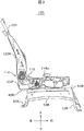
図1は車両用シートの右前方側からの斜視図である。車両用シート1の構造の理解を容易にするため、図中には、「前」、「後」、「左」、「右」、「上」および「下」の方向を示し、これらの方向は、以下の説明において相対的な位置関係を表現するのにも用いられる。また、これらの方向は、車両用シート1を車両に搭載したときの車両の方向に対応し、例えば、車両用シート1の前方向と車両の前方向とは同方向を示す。以下では、右前の席(例えば、運転席)に好適な車両用シート1の構造について述べるが、車両用シート1は、他の座席にも適用可能である。なお、車両の左側に搭載される車両用シートは車両用シート1の左右を入れ替えた構成になる。
FIG. 1 is a perspective view of a vehicle seat from the right front side. In order to facilitate understanding of the structure of the
本開示の車両用シート1は、シートクッション10と、シートバック20と、ヘッドレスト30と、サイドカバー40と、操作レバー41と、ライザ50と、シートスライド調整装置60と、を有する。シートクッション10は座面を形成する。シートバック20は背もたれを形成する。ヘッドレスト30は、シートバック20の上方に配され、乗員の頭部を支持する枕部を形成する。シートスライド調整装置60はライザ50を介して車両に対して固定され、シートクッション10の前後方向のスライド(位置調整)を可能にする。また、車両用シート1は、シートクッション10とシートバック20との角度調整を可能にするリクライニング装置(リクライナ)と、シートクッション10の高さ調整を可能にするリフト装置(リフタ)を有する。
The
操作レバー41は、リクライニング操作用の操作部であり、車両用シート1のリクライニング操作を受け付ける。
The
車両に搭載された車両用シート1の右側上方には、シートベルト装置のリトラクタ(不図示)が固定設置されている。リトラクタから引き出されたウェビングは、車両用シート1の右側下方のアンカー部(不図示)に連結されている。リトラクタから引き出されたウェビングの中途部にはタングプレート(不図示)が挿通されている。タングプレートは、左側の側部フレーム部にアンカー部(不図示)を介して連結されたバックル71に対して脱着可能とされている。
A retractor (not shown) of a seat belt device is fixedly installed on the upper right side of the
(シートフレーム)
図2は図1の車両用シートのシートフレームの右前方側からの斜視図である。図3は図2の車両用シートのシートフレームの右側方側からの側面図である。図4は図2の車両用シートのシートフレームの上方側からの上面図である。
(Seat frame)
2 is a perspective view from the right front side of the seat frame of the vehicle seat of FIG. 3 is a side view from the right side of the seat frame of the vehicle seat of FIG. FIG. 4 is a top view from the upper side of the seat frame of the vehicle seat of FIG.
シートフレーム100は、シートクッションフレーム110、リクライニング装置114でシートクッションフレーム110に前倒しおよび角度調整可能にヒンジ結合されるシートバックフレーム120、左右のシートスライド調整装置60および左右のライザ50で組み立てられる。シートクッション10がシートクッションフレーム110、シートクッションパッド(不図示)および表皮(不図示)で組み立てられ、また、シートバック20がシートバックフレーム120、シートバックパッド(不図示)および表皮(不図示)で組み立てられる。
The
ライザ50は右の支持部50Rと左の支持部50Lと連結部材51とを備える。右の支持部50Rは車両のフロアに据え付けられる前脚52Rおよび後脚53Rと、側板54Rを備える。左の支持部50Lも同様である。
The
シートスライド調整装置60は、左のガイドレール61L、右のガイドレール61R、左のガイドレール61Lおよび右のガイドレール61Rのそれぞれに摺動可能にはめ込まれて支持される左のスライドレール62L、右のスライドレール62R、ロック機構(不図示)、および操作機構64などで通常に組み立てられる。
The seat
シートスライド調整装置60の左のガイドレール61L、右のガイドレール61Rは、それぞれ左の支持部50L、右の支持部50Rの上に固定的に取り付けられ、シートクッションフレーム110を載せ、そして、シートクッションフレーム110を固定的に取り付けてそのシートクッション10を支持する。
The
シートクッションフレーム110は、シートクッション10の骨格となる略矩形状の枠体からなり、図2に示すように、左右側方にそれぞれ配置された左のサイドフレーム111Lおよび右のサイドフレーム111Rと、左のサイドフレーム111Lおよび右のサイドフレーム111Rの前方側の上面に架設された板状フレーム112と、左のサイドフレーム111Lおよび右のサイドフレーム111Rのそれぞれの後方側の内側面を連結する連結パイプ113と、前方側の内側面を連結する連結パイプ(不図示)と、を備えている。
The
左のサイドフレーム111Lおよび右のサイドフレーム111Rは、それぞれ前後方向に延在する板金部材からなり、左のサイドフレーム111Lと、右のサイドフレーム111Rとは、互いに略平行な状態で左右方向に離間している。
The
右のサイドフレーム111Rとシートバックフレーム120を連結した部分には、図2に示すように、シートクッション10に対してシートバック20を回動可能に連結するリクライニング装置114が設けられている。リクライニング装置114は、例えば、シートバックフレーム120を起立状態に付勢する渦巻きバネ(不図示)と、渦巻きバネの延出端部を係止するバネ係止部材(不図示)と、を備えている。なお、右のサイドフレーム111Rおよびリクライニング装置114はサイドカバー40で覆われている。
As shown in FIG. 2, a reclining
シートバックフレーム120は、バックフレーム本体121と、左のサイドフレーム122Lと、右のサイドフレーム122Rと、から構成されている。
The seat back
バックフレーム本体121は、シートバックフレーム120の骨格を成すフレーム部材であり、円筒状に形成されている丸パイプを折り曲げて形成されている。
The back frame
そして、右のサイドフレーム122Rの外面は、右のサイドフレーム111Rの内面に枢着されている。このとき、これら両面の間には、リクライニング装置114が組み付けられている。これにより、シートクッションフレーム110に対してシートバックフレーム120を所望する傾き位置でロックできるため、リクライニング機能を備えた車両用シート1にすることができる。
The outer surface of the
バックフレーム本体121の上方部のフレーム121bに、ヘッドレスト30の不図示のピラーを挿設するための一対のピラーガイド128が取り付けられている。
A pair of pillar guides 128 for inserting pillars (not shown) of the
シートクッション10、右のサイドフレーム111R、右のスライドレール62Rおよびガイドレール61Rの側部を被うように(隠すように)、サイドカバー40が右のサイドフレーム111Rに取り付けられている。この取り付けは、例えばサイドカバー40の内面側の複数箇所に設けられた突起(不図示)を、右のサイドフレーム111Rに形成された係止孔(不図示)に圧入すること等により、着脱可能に行える。
The side cover 40 is attached to the
サイドカバー40は合成樹脂の成形品であり、図示しない取付穴や凹部が形成されるとともに、この貫通孔や凹部を貫通するように設けられた貫通孔を通して、表面側にリクライニング装置114の操作レバー41などが手動操作可能に突設されている。
The side cover 40 is a synthetic resin molded product, and has an attachment hole and a concave portion (not shown), and an operation lever of the
(補強ワイヤ)
補強ワイヤについて図2〜5を用いて説明する。図5は右サイドフレームおよびサイドカバーの断面図である。
(Reinforcing wire)
The reinforcing wire will be described with reference to FIGS. FIG. 5 is a cross-sectional view of the right side frame and the side cover.
図2に示すように、右のサイドフレーム111Rの外側面(右側面)側には、鋼線材からなる補強ワイヤ115の両端部がそれぞれ固定されている。鋼線材の径は例えば7mmである。そして、この補強ワイヤ115の両端部を除く部位が右のサイドフレーム111Rに取り付けられたサイドカバー40の内面に当接可能にされている。補強ワイヤ115は、前方衝撃時、シートベルト(ウェビング)からサイドカバー40に荷重入力がある個所に配置される。補強ワイヤ115は、リクライニング装置114とリクライニング装置114の操作レバー114aの先端部との間に位置し、リクライニング装置114側の右のサイドフレーム111Rに固定される第一部分115aと、サイドカバー40の内面に当節可能な第二部分115bと、操作レバー114a側の右のサイドフレーム111Rに固定される第三部分115cと、第一部分115aと第二部分115bを連結する第四部分115dと、第二部分115bと第三部分115cを連結する第五部分115eとを有する。
As shown in FIG. 2, both ends of a reinforcing
第一部分115aは補強ワイヤ115の後方側の端部から右のサイドフレーム111Rの上端に沿って後方に延出して第四部分115dに接続する。第四部分115dは右のサイドフレーム111Rからサイドカバー40側に延出して第二部分115bに接続する。第二部分115bは右のサイドフレーム111Rの上端に沿って前方に延出して第五部分115eに接続する。第五部分115eはサイドカバー40側から右のサイドフレーム111R側に延出して第三部分115cに接続する。第三部分115cは右のサイドフレーム111Rの上部から下部の方向に延出して補強ワイヤ115の前方側の端部に至る。
The
補強ワイヤ115の第一部分115aおよび第三部分115cは右のサイドフレーム111Rに直接溶接によって固着される。
The
図5に示すように、補強ワイヤ115の第二部分115bはサイドカバー40に近接して配置される。サイドカバー40に荷重Fが矢印の方向にかけられると、サイドカバー40は補強ワイヤ115に当接する。
As shown in FIG. 5, the
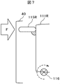
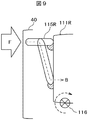
次に、補強ワイヤ115の作用効果について図6〜9を用いて説明する。図6は比較例に係る補強ワイヤの構造を説明するための模式的な断面図である。図7は比較例に係る補強ワイヤの荷重を説明するための模式的な断面図である。図8は実施例に係る補強ワイヤにかけられた荷重の伝達経路を説明するための右前からの斜視図である。図9は実施例に係る補強ワイヤの荷重を説明するための模式的な断面図である。
Next, the effect of the reinforcing
図6に示すように、比較例に係る補強ワイヤ115Rは、右のサイドフレーム111Rに固定される第一部分115Raと、サイドカバー40の内面に当節可能な第二部分115Rbと、右のサイドフレーム111Rに固定される第三部分115Rcと、第一部分115Raと第二部分115Rbを連結する第四部分115Rdと、第二部分115Rbと第三部分115Rcを連結する第五部分115Reとを有する。
As shown in FIG. 6, the reinforcing
第一部分115Raは補強ワイヤ115Rの後方側の端部から右のサイドフレーム111Rの上端に沿って後方に延出して第四部分115Rdに接続する。第四部分115Rdは右のサイドフレーム111Rからサイドカバー40側に延出して第二部分115Rbに接続する。第二部分115Rbは右のサイドフレーム111Rに沿って前方に延出して第五部分115Reに接続する。第五部分115eはサイドカバー40側から右のサイドフレーム111R側に延出して第三部分115Rcに接続する。第三部分115cは右のサイドフレーム111Rの前方側から後方側の方向に延出して補強ワイヤ115Rの前方側の端部に至る。
The first portion 115Ra extends rearward from the rear end of the reinforcing
図7に示すように、比較例は荷重Fを右のサイドフレーム111Rに溶接された補強ワイヤ115Rで保持する構造である。右のサイドフレーム111Rの締結部(支持部)116の周りの発生モーメントが大きく、右のサイドフレーム111Rの変形が大きくなり、サイドカバー40の変形も大きくなる。その結果、右のサイドフレーム111Rの剛性が低いとサイドカバー40の変形量が抑制できない。
As shown in FIG. 7, the comparative example has a structure in which the load F is held by a reinforcing
図8に示すように、実施例は荷重Fに対し右のサイドフレーム111Rの一部分に溶接された補強ワイヤ115で荷重を保持すると共に右のサイドフレーム111Rの他部分へ荷重を伝達する構造である。矢印Bは荷重伝達経路を示ししている。
As shown in FIG. 8, the embodiment has a structure in which the load is held by the reinforcing
図9に示すように、実施例では、荷重Fの一部が矢印Bの経路で右のサイドフレーム111Rに伝達されるので、右のサイドフレーム111Rの締結部(支持部)116周りの発生モーメントが小さく、右のサイドフレーム111Rの変形が小さくなり、サイドカバー40の変形も小さくなる。
As shown in FIG. 9, in the embodiment, a part of the load F is transmitted to the
実施例はウェビングからの入力に対し、溶接された補強ワイヤにより荷重の保持及び伝達することで樹脂カバーの変形を低減させる。前方衝撃時、ウェビングからの入力荷重でサイドカバーが破損することを低減することができ、破損したサイドカバーのエッジがウェビングを切断し、乗員拘束性能を損なう恐れを低減することができる。 In the embodiment, the deformation of the resin cover is reduced by holding and transmitting the load by the welded reinforcing wire in response to the input from the webbing. It is possible to reduce the damage of the side cover due to the input load from the webbing at the time of a forward impact, and it is possible to reduce the possibility that the damaged edge of the side cover cuts the webbing and impairs the occupant restraint performance.
荷重入力範囲に補強ワイヤを配置し、荷重伝達したい範囲に補強ワイヤを溶接する。これにより、荷重伝達構造を簡素化(小スペース、軽量)することが可能である。また、チューニング(補強ワイヤの径、形状、溶接位置の変更)が容易であり、投資損失を少なくすることができる。 Place the reinforcement wire in the load input range and weld the reinforcement wire to the range where you want to transmit the load. As a result, the load transmission structure can be simplified (small space and light weight). Further, tuning (change of the diameter, shape, and welding position of the reinforcing wire) is easy, and investment loss can be reduced.
以上、本発明者によってなされた発明を実施例に基づき具体的に説明したが、本発明は、上記実施例に限定されるものではなく、種々変更可能であることはいうまでもない。 As mentioned above, the invention made by the present inventor has been specifically described based on the embodiments. However, the present invention is not limited to the above-described embodiments, and needless to say, various modifications can be made.
1:車両用シート
10:シートクッション
110:シートクッションフレーム
111R:右のサイドフレーム
115:補強ワイヤ
20:シートバック
120:シートバックフレーム
40:サイドカバー
50:ライザ
60:シートスライド装置
1: Vehicle seat 10: Seat cushion 110:
Claims (6)
補強ワイヤが接合されるサイドフレームを有するシートクッションと、
前記シートクッションに接続されるシートバックと、
前記サイドフレームを覆う樹脂製のサイドカバーと、
を備え、
前記補強ワイヤは、前記サイドカバーのうちシートベルト装置のウェビングが当接する領域に位置し、一本の鋼線材であり、
前記補強ワイヤは、
前記鋼線材の一端から前記サイドフレームに沿って延出し前記サイドフレームに接合される第一部分と、
前記第一部分より前記サイドカバー側に位置し前記サイドフレームと対向する部分を有し前後方向に延伸する第二部分と、
前記第一部分よりも前記サイドフレームの下端側に位置し前記第二部分より前方に位置し前記鋼線材の他端から前記サイドフレームに沿って延出し前記サイドフレームに接合される第三部分と、
前記第一部分と前記第二部分を接続する第四部分と、
前記第二部分と前記第三部分を接続する第五部分と、
を備える。 The vehicle seat
A seat cushion having a side frame to which a reinforcing wire is joined;
A seat back connected to the seat cushion;
A resin side cover that covers the side frame;
With
The reinforcing wire is located in a region where the webbing of the seat belt device contacts the side cover, and is a single steel wire,
The reinforcing wire is
A first portion extending from the one end of the steel wire along the side frame and joined to the side frame;
A second portion extending in the front-rear direction having a portion facing the side frame located on the side cover side from the first portion;
A third part positioned on the lower end side of the side frame relative to the first part and positioned in front of the second part, extending from the other end of the steel wire material along the side frame, and joined to the side frame;
A fourth part connecting the first part and the second part;
A fifth part connecting the second part and the third part;
Is provided.
前記サイドカバーは、前記ウェビングによって荷重がかけられたときに前記補強ワイヤに当接し、
前記補強ワイヤは、前記荷重を保持する保持部分と、前記荷重を前記保持部分から遠ざかる方向の経路を経由して前記サイドフレームに伝達する伝達部分と、を備え、
前記荷重は前記第二部分、前記第五部分および前記第三部分を介して前記サイドフレームに伝達される。 The vehicle seat according to claim 1,
The side cover contacts the reinforcing wire when a load is applied by the webbing,
The reinforcing wire includes a holding portion that holds the load, and a transmission portion that transmits the load to the side frame via a path in a direction away from the holding portion.
The load is transmitted to the side frame via the second part, the fifth part, and the third part.
前記第二部分は前記サイドカバーの上辺に沿って配置され、
前記第三部分は前記第五部分から前記鋼線材の他端の下方に向かって延伸し、
前記第五部分は前記第二部分から前記サイドカバーに向かって延伸している。 The vehicle seat according to claim 2,
The second part is disposed along an upper side of the side cover;
The third part extends from the fifth part toward the bottom of the other end of the steel wire,
The fifth portion extends from the second portion toward the side cover.
さらに、前記シートクッションと前記シートバックとの角度調整を可能にするリクライニング装置を備え、
前記リクライニング装置は、前記シートバックの回転中心に位置するリクライニング装置本体とリクライニング装置本体を操作する操作レバーとを、前記サイドフレームと前記サイドカバーの間に備え、
前記補強ワイヤは前記リクライニング装置本体と前記操作レバーの先端との間に位置する。 In the vehicle seat according to claim 3,
And a reclining device that enables angle adjustment between the seat cushion and the seat back,
The reclining device includes a reclining device main body located at the rotation center of the seat back and an operation lever for operating the reclining device main body between the side frame and the side cover,
The reinforcing wire is located between the reclining device main body and the tip of the operation lever.
前記補強ワイヤの前記第一部分は、前記鋼線材の一端から後方に延出する。 The vehicle seat according to claim 1,
The first portion of the reinforcing wire extends backward from one end of the steel wire.
前記補強ワイヤの前記第三部分は、前記鋼線材の一端から上方に延出する。 The vehicle seat according to claim 5, wherein
The third portion of the reinforcing wire extends upward from one end of the steel wire.
Priority Applications (1)
| Application Number | Priority Date | Filing Date | Title |
|---|---|---|---|
| JP2017127078A JP6869827B2 (en) | 2017-06-29 | 2017-06-29 | Vehicle seat |
Applications Claiming Priority (1)
| Application Number | Priority Date | Filing Date | Title |
|---|---|---|---|
| JP2017127078A JP6869827B2 (en) | 2017-06-29 | 2017-06-29 | Vehicle seat |
Publications (2)
| Publication Number | Publication Date |
|---|---|
| JP2019010903A true JP2019010903A (en) | 2019-01-24 |
| JP6869827B2 JP6869827B2 (en) | 2021-05-12 |
Family
ID=65227226
Family Applications (1)
| Application Number | Title | Priority Date | Filing Date |
|---|---|---|---|
| JP2017127078A Active JP6869827B2 (en) | 2017-06-29 | 2017-06-29 | Vehicle seat |
Country Status (1)
| Country | Link |
|---|---|
| JP (1) | JP6869827B2 (en) |
Cited By (1)
| Publication number | Priority date | Publication date | Assignee | Title |
|---|---|---|---|---|
| EP4046864A1 (en) * | 2021-02-23 | 2022-08-24 | Volkswagen Ag | Vehicle seat with a crash-modified aperture holder with a main frame and an auxiliary frame |
-
2017
- 2017-06-29 JP JP2017127078A patent/JP6869827B2/en active Active
Cited By (1)
| Publication number | Priority date | Publication date | Assignee | Title |
|---|---|---|---|---|
| EP4046864A1 (en) * | 2021-02-23 | 2022-08-24 | Volkswagen Ag | Vehicle seat with a crash-modified aperture holder with a main frame and an auxiliary frame |
Also Published As
| Publication number | Publication date |
|---|---|
| JP6869827B2 (en) | 2021-05-12 |
Similar Documents
| Publication | Publication Date | Title |
|---|---|---|
| US8708411B2 (en) | Vehicle seat | |
| JP6004909B2 (en) | Vehicle seat | |
| JP5308010B2 (en) | Vehicle seat | |
| US7234769B2 (en) | Vehicle seat | |
| JP5576111B2 (en) | Vehicle seat | |
| WO2012077764A1 (en) | Vehicle seat | |
| WO2017056337A1 (en) | Seat frame | |
| MX2015002728A (en) | Vehicle seat. | |
| US11660987B2 (en) | Vehicle seat | |
| JP6869827B2 (en) | Vehicle seat | |
| JP4222235B2 (en) | Sheet | |
| JP6867262B2 (en) | Vehicle seat | |
| US10434910B2 (en) | Seat cushion member | |
| JP6527556B2 (en) | Vehicle seat | |
| JP6054713B2 (en) | Vehicle seat | |
| JP6053465B2 (en) | Vehicle seat | |
| JP2019010905A (en) | Vehicle seat | |
| JP7290775B2 (en) | vehicle seat | |
| JP4492863B2 (en) | Vehicle seat | |
| JP7323814B2 (en) | vehicle seat | |
| JP2019010902A (en) | Vehicle seat | |
| JP5099662B2 (en) | Vehicle seat | |
| JP7332920B2 (en) | vehicle seat | |
| WO2019203012A1 (en) | Vehicle seat | |
| JP6366672B2 (en) | Vehicle seat |
Legal Events
| Date | Code | Title | Description |
|---|---|---|---|
| A621 | Written request for application examination |
Free format text: JAPANESE INTERMEDIATE CODE: A621 Effective date: 20191209 |
|
| A977 | Report on retrieval |
Free format text: JAPANESE INTERMEDIATE CODE: A971007 Effective date: 20200923 |
|
| A131 | Notification of reasons for refusal |
Free format text: JAPANESE INTERMEDIATE CODE: A131 Effective date: 20201006 |
|
| A521 | Request for written amendment filed |
Free format text: JAPANESE INTERMEDIATE CODE: A523 Effective date: 20201104 |
|
| TRDD | Decision of grant or rejection written | ||
| A01 | Written decision to grant a patent or to grant a registration (utility model) |
Free format text: JAPANESE INTERMEDIATE CODE: A01 Effective date: 20210413 |
|
| A61 | First payment of annual fees (during grant procedure) |
Free format text: JAPANESE INTERMEDIATE CODE: A61 Effective date: 20210414 |
|
| R150 | Certificate of patent or registration of utility model |
Ref document number: 6869827 Country of ref document: JP Free format text: JAPANESE INTERMEDIATE CODE: R150 |
|
| S531 | Written request for registration of change of domicile |
Free format text: JAPANESE INTERMEDIATE CODE: R313531 |
|
| R350 | Written notification of registration of transfer |
Free format text: JAPANESE INTERMEDIATE CODE: R350 |
|
| R250 | Receipt of annual fees |
Free format text: JAPANESE INTERMEDIATE CODE: R250 |