JP2018536963A - Modular storage system - Google Patents
Modular storage system Download PDFInfo
- Publication number
- JP2018536963A JP2018536963A JP2018512854A JP2018512854A JP2018536963A JP 2018536963 A JP2018536963 A JP 2018536963A JP 2018512854 A JP2018512854 A JP 2018512854A JP 2018512854 A JP2018512854 A JP 2018512854A JP 2018536963 A JP2018536963 A JP 2018536963A
- Authority
- JP
- Japan
- Prior art keywords
- power storage
- storage system
- distribution member
- air distribution
- door
- Prior art date
- Legal status (The legal status is an assumption and is not a legal conclusion. Google has not performed a legal analysis and makes no representation as to the accuracy of the status listed.)
- Pending
Links
Images


Classifications
-
- H—ELECTRICITY
- H01—ELECTRIC ELEMENTS
- H01M—PROCESSES OR MEANS, e.g. BATTERIES, FOR THE DIRECT CONVERSION OF CHEMICAL ENERGY INTO ELECTRICAL ENERGY
- H01M10/00—Secondary cells; Manufacture thereof
- H01M10/60—Heating or cooling; Temperature control
- H01M10/61—Types of temperature control
- H01M10/613—Cooling or keeping cold
-
- H—ELECTRICITY
- H01—ELECTRIC ELEMENTS
- H01M—PROCESSES OR MEANS, e.g. BATTERIES, FOR THE DIRECT CONVERSION OF CHEMICAL ENERGY INTO ELECTRICAL ENERGY
- H01M10/00—Secondary cells; Manufacture thereof
- H01M10/60—Heating or cooling; Temperature control
- H01M10/65—Means for temperature control structurally associated with the cells
- H01M10/656—Means for temperature control structurally associated with the cells characterised by the type of heat-exchange fluid
- H01M10/6561—Gases
- H01M10/6563—Gases with forced flow, e.g. by blowers
- H01M10/6565—Gases with forced flow, e.g. by blowers with recirculation or U-turn in the flow path, i.e. back and forth
-
- A—HUMAN NECESSITIES
- A62—LIFE-SAVING; FIRE-FIGHTING
- A62C—FIRE-FIGHTING
- A62C31/00—Delivery of fire-extinguishing material
-
- H—ELECTRICITY
- H01—ELECTRIC ELEMENTS
- H01M—PROCESSES OR MEANS, e.g. BATTERIES, FOR THE DIRECT CONVERSION OF CHEMICAL ENERGY INTO ELECTRICAL ENERGY
- H01M10/00—Secondary cells; Manufacture thereof
- H01M10/60—Heating or cooling; Temperature control
- H01M10/62—Heating or cooling; Temperature control specially adapted for specific applications
- H01M10/627—Stationary installations, e.g. power plant buffering or backup power supplies
-
- H—ELECTRICITY
- H01—ELECTRIC ELEMENTS
- H01M—PROCESSES OR MEANS, e.g. BATTERIES, FOR THE DIRECT CONVERSION OF CHEMICAL ENERGY INTO ELECTRICAL ENERGY
- H01M10/00—Secondary cells; Manufacture thereof
- H01M10/60—Heating or cooling; Temperature control
- H01M10/63—Control systems
-
- H—ELECTRICITY
- H01—ELECTRIC ELEMENTS
- H01M—PROCESSES OR MEANS, e.g. BATTERIES, FOR THE DIRECT CONVERSION OF CHEMICAL ENERGY INTO ELECTRICAL ENERGY
- H01M10/00—Secondary cells; Manufacture thereof
- H01M10/60—Heating or cooling; Temperature control
- H01M10/63—Control systems
- H01M10/633—Control systems characterised by algorithms, flow charts, software details or the like
-
- H—ELECTRICITY
- H01—ELECTRIC ELEMENTS
- H01M—PROCESSES OR MEANS, e.g. BATTERIES, FOR THE DIRECT CONVERSION OF CHEMICAL ENERGY INTO ELECTRICAL ENERGY
- H01M10/00—Secondary cells; Manufacture thereof
- H01M10/60—Heating or cooling; Temperature control
- H01M10/63—Control systems
- H01M10/635—Control systems based on ambient temperature
-
- H—ELECTRICITY
- H01—ELECTRIC ELEMENTS
- H01M—PROCESSES OR MEANS, e.g. BATTERIES, FOR THE DIRECT CONVERSION OF CHEMICAL ENERGY INTO ELECTRICAL ENERGY
- H01M10/00—Secondary cells; Manufacture thereof
- H01M10/60—Heating or cooling; Temperature control
- H01M10/64—Heating or cooling; Temperature control characterised by the shape of the cells
- H01M10/647—Prismatic or flat cells, e.g. pouch cells
-
- H—ELECTRICITY
- H01—ELECTRIC ELEMENTS
- H01M—PROCESSES OR MEANS, e.g. BATTERIES, FOR THE DIRECT CONVERSION OF CHEMICAL ENERGY INTO ELECTRICAL ENERGY
- H01M10/00—Secondary cells; Manufacture thereof
- H01M10/60—Heating or cooling; Temperature control
- H01M10/65—Means for temperature control structurally associated with the cells
- H01M10/656—Means for temperature control structurally associated with the cells characterised by the type of heat-exchange fluid
- H01M10/6561—Gases
- H01M10/6563—Gases with forced flow, e.g. by blowers
-
- H—ELECTRICITY
- H01—ELECTRIC ELEMENTS
- H01M—PROCESSES OR MEANS, e.g. BATTERIES, FOR THE DIRECT CONVERSION OF CHEMICAL ENERGY INTO ELECTRICAL ENERGY
- H01M10/00—Secondary cells; Manufacture thereof
- H01M10/60—Heating or cooling; Temperature control
- H01M10/66—Heat-exchange relationships between the cells and other systems, e.g. central heating systems or fuel cells
- H01M10/663—Heat-exchange relationships between the cells and other systems, e.g. central heating systems or fuel cells the system being an air-conditioner or an engine
-
- H—ELECTRICITY
- H01—ELECTRIC ELEMENTS
- H01M—PROCESSES OR MEANS, e.g. BATTERIES, FOR THE DIRECT CONVERSION OF CHEMICAL ENERGY INTO ELECTRICAL ENERGY
- H01M50/00—Constructional details or processes of manufacture of the non-active parts of electrochemical cells other than fuel cells, e.g. hybrid cells
- H01M50/20—Mountings; Secondary casings or frames; Racks, modules or packs; Suspension devices; Shock absorbers; Transport or carrying devices; Holders
- H01M50/204—Racks, modules or packs for multiple batteries or multiple cells
-
- H—ELECTRICITY
- H01—ELECTRIC ELEMENTS
- H01M—PROCESSES OR MEANS, e.g. BATTERIES, FOR THE DIRECT CONVERSION OF CHEMICAL ENERGY INTO ELECTRICAL ENERGY
- H01M50/00—Constructional details or processes of manufacture of the non-active parts of electrochemical cells other than fuel cells, e.g. hybrid cells
- H01M50/20—Mountings; Secondary casings or frames; Racks, modules or packs; Suspension devices; Shock absorbers; Transport or carrying devices; Holders
- H01M50/271—Lids or covers for the racks or secondary casings
-
- H—ELECTRICITY
- H01—ELECTRIC ELEMENTS
- H01M—PROCESSES OR MEANS, e.g. BATTERIES, FOR THE DIRECT CONVERSION OF CHEMICAL ENERGY INTO ELECTRICAL ENERGY
- H01M8/00—Fuel cells; Manufacture thereof
- H01M8/04—Auxiliary arrangements, e.g. for control of pressure or for circulation of fluids
- H01M8/04007—Auxiliary arrangements, e.g. for control of pressure or for circulation of fluids related to heat exchange
- H01M8/04067—Heat exchange or temperature measuring elements, thermal insulation, e.g. heat pipes, heat pumps, fins
- H01M8/04074—Heat exchange unit structures specially adapted for fuel cell
-
- H—ELECTRICITY
- H01—ELECTRIC ELEMENTS
- H01M—PROCESSES OR MEANS, e.g. BATTERIES, FOR THE DIRECT CONVERSION OF CHEMICAL ENERGY INTO ELECTRICAL ENERGY
- H01M2220/00—Batteries for particular applications
- H01M2220/10—Batteries in stationary systems, e.g. emergency power source in plant
-
- H—ELECTRICITY
- H01—ELECTRIC ELEMENTS
- H01M—PROCESSES OR MEANS, e.g. BATTERIES, FOR THE DIRECT CONVERSION OF CHEMICAL ENERGY INTO ELECTRICAL ENERGY
- H01M2250/00—Fuel cells for particular applications; Specific features of fuel cell system
- H01M2250/10—Fuel cells in stationary systems, e.g. emergency power source in plant
-
- Y—GENERAL TAGGING OF NEW TECHNOLOGICAL DEVELOPMENTS; GENERAL TAGGING OF CROSS-SECTIONAL TECHNOLOGIES SPANNING OVER SEVERAL SECTIONS OF THE IPC; TECHNICAL SUBJECTS COVERED BY FORMER USPC CROSS-REFERENCE ART COLLECTIONS [XRACs] AND DIGESTS
- Y02—TECHNOLOGIES OR APPLICATIONS FOR MITIGATION OR ADAPTATION AGAINST CLIMATE CHANGE
- Y02B—CLIMATE CHANGE MITIGATION TECHNOLOGIES RELATED TO BUILDINGS, e.g. HOUSING, HOUSE APPLIANCES OR RELATED END-USER APPLICATIONS
- Y02B90/00—Enabling technologies or technologies with a potential or indirect contribution to GHG emissions mitigation
- Y02B90/10—Applications of fuel cells in buildings
-
- Y—GENERAL TAGGING OF NEW TECHNOLOGICAL DEVELOPMENTS; GENERAL TAGGING OF CROSS-SECTIONAL TECHNOLOGIES SPANNING OVER SEVERAL SECTIONS OF THE IPC; TECHNICAL SUBJECTS COVERED BY FORMER USPC CROSS-REFERENCE ART COLLECTIONS [XRACs] AND DIGESTS
- Y02—TECHNOLOGIES OR APPLICATIONS FOR MITIGATION OR ADAPTATION AGAINST CLIMATE CHANGE
- Y02E—REDUCTION OF GREENHOUSE GAS [GHG] EMISSIONS, RELATED TO ENERGY GENERATION, TRANSMISSION OR DISTRIBUTION
- Y02E60/00—Enabling technologies; Technologies with a potential or indirect contribution to GHG emissions mitigation
- Y02E60/10—Energy storage using batteries
-
- Y—GENERAL TAGGING OF NEW TECHNOLOGICAL DEVELOPMENTS; GENERAL TAGGING OF CROSS-SECTIONAL TECHNOLOGIES SPANNING OVER SEVERAL SECTIONS OF THE IPC; TECHNICAL SUBJECTS COVERED BY FORMER USPC CROSS-REFERENCE ART COLLECTIONS [XRACs] AND DIGESTS
- Y02—TECHNOLOGIES OR APPLICATIONS FOR MITIGATION OR ADAPTATION AGAINST CLIMATE CHANGE
- Y02E—REDUCTION OF GREENHOUSE GAS [GHG] EMISSIONS, RELATED TO ENERGY GENERATION, TRANSMISSION OR DISTRIBUTION
- Y02E60/00—Enabling technologies; Technologies with a potential or indirect contribution to GHG emissions mitigation
- Y02E60/30—Hydrogen technology
- Y02E60/50—Fuel cells
Abstract
【課題】空間利用が最適化されていて且つ熱管理能力が向上した、モジュール型の蓄電システムの改良品を提供する。【解決手段】モジュール型の蓄電システムは、第1の端部及び第2の端部を有するハウジングと、ハウジング内で連結された複数の蓄電装置と、ハウジングの第1の端部に枢結された第1のドアアセンブリと、第1のドアアセンブリと隣り合って、ハウジングの第1の端部に枢結された第2のドアアセンブリとを備える。第1及び第2のドアアセンブリはそれぞれ、複数の蓄電装置から熱エネルギを吸収するように冷却空気流を当該複数の蓄電装置に向かって分配及び方向付けるように構成された空気分配部材を含む。【選択図】図1The present invention provides an improved module type power storage system in which space utilization is optimized and heat management capability is improved. A module-type power storage system is pivotally connected to a housing having a first end and a second end, a plurality of power storage devices connected within the housing, and a first end of the housing. A first door assembly and a second door assembly adjacent to the first door assembly and pivotally connected to the first end of the housing. Each of the first and second door assemblies includes an air distribution member configured to distribute and direct a cooling air flow toward the plurality of power storage devices so as to absorb thermal energy from the plurality of power storage devices. [Selection] Figure 1
Description
本願は、2015年9月11日付出願の米国仮特許出願第62/217,717号の利益及び優先権を主張する。この米国仮特許出願の全開示内容は、参照をもって本明細書に取り入れたものとする。 This application claims the benefit and priority of US Provisional Patent Application No. 62 / 217,717, filed September 11, 2015. The entire disclosure of this US provisional patent application is incorporated herein by reference.
本願は、概して蓄電システム(エネルギ貯蔵システム)に関する。本発明は、詳細にはモジュール型(モジュール式)の蓄電システムに関する。 The present application generally relates to power storage systems (energy storage systems). More particularly, the present invention relates to a modular (module type) power storage system.
一般的に言って、風力タービンや太陽電池などの再生可能エネルギ電源は、電力グリッドに対して電力を間欠的(断続的)に供給する可能性がある。モジュール型の蓄電システムは、電力を供給したり吸収したりするように再生可能エネルギ電源と連携して使用されることにより、当該再生可能電源から上記グリッドへの電力出力を平滑化することが可能である。モジュール型の蓄電システムは、さらに、遠隔の地理的場所や自然災害地域において例えば上記グリッドに補充電力を供給等するために使用可能である。典型的に、モジュール型の蓄電システムの多くは、蓄電装置(例えば、バッテリ等)、電力変換機器などを収納することが可能な大型の筐体(例えば、ISO輸送用コンテナ等)を利用して、需要に応じて電力を貯蔵および/または供給する。このようなモジュール型のシステムは、例えば、電力平滑化または補充電力等が必要とされている地理的場所に配備され得る。 Generally speaking, renewable energy power sources such as wind turbines and solar cells may supply power intermittently (intermittently) to the power grid. A modular power storage system can be used in conjunction with a renewable energy power supply to supply and absorb power, thereby smoothing the power output from the renewable power supply to the grid. It is. Further, the modular power storage system can be used to supply supplementary power to the grid, for example, in a remote geographical location or a natural disaster area. Typically, many modular power storage systems use a large housing (for example, an ISO shipping container) that can store a power storage device (for example, a battery), a power conversion device, or the like. Store and / or supply power according to demand. Such a modular system can be deployed, for example, in geographical locations where power smoothing or supplemental power is required.
しかし、このようなモジュール型のシステムの多くは、未開発地域や自然災害地域などの遠隔での用途には最適化されていない。その理由の一部として、当該システムを支援するために必要なインフラストラクチャや、広いスペース要件が求められることが挙げられる。しかも、このようなシステムの多くは、空間利用が最適化されておらず且つ熱管理も厳密でなく、これは機器不良や動作性能の低下を招き得る。例えば、従来からの一部の蓄電システムは、ファンを使用して且つ/或いは例えば筐体等に開口部を設けることで外気からの空気流が当該筐体へと進入するのを可能にすることにより、当該蓄電システムに収納された電力用電子部品を冷却する。一般的に言って、上記筐体へと進入した後の上記空気流は、制御や案内(方向付け)がされておらず、当該筐体に収納された各種電子機器に対しての分配も行われない。最終的に、これは、上記電力用電子部品(例えば、バッテリ、電力変換機器等)の不均等で且つ満足のいかない冷却に繋がり得る。 However, many such modular systems are not optimized for remote applications such as undeveloped areas and natural disaster areas. Part of that is the need for infrastructure and wide space requirements to support the system. Moreover, many such systems are not optimized for space utilization and strict thermal management, which can lead to equipment failure and reduced operating performance. For example, some conventional power storage systems use a fan and / or provide an opening in, for example, a housing to allow an air flow from outside air to enter the housing. Thus, the power electronic component housed in the power storage system is cooled. Generally speaking, the air flow after entering the housing is not controlled or guided (directed), and is distributed to various electronic devices housed in the housing. I will not. Ultimately, this can lead to unequal and unsatisfactory cooling of the power electronics (eg, battery, power conversion equipment, etc.).
一部のモジュール型の蓄電システムは、さらに、上記蓄電装置を再生可能エネルギ電源および/またはグリッドと連携して動作させる場合に電力の交流から直流への変換又は直流から交流への変換を可能にする電力変換機器を備える。大半の電力変換機器は、モジュール型の筐体内部に設置された別個のハウジング内に取り付けられるか又は収納される。一般的に言って、このような別個のハウジングは、当該別個のハウジングに収納された電力変換用電子部品の十分な冷却を可能しない。しかも、このような別個のハウジングは扱い難く、搬送や操作が困難である。 Some module-type power storage systems can further convert power from AC to DC or from DC to AC when the power storage device is operated in cooperation with a renewable energy power source and / or grid. Power conversion equipment. Most power conversion devices are mounted or housed in a separate housing installed inside a modular housing. Generally speaking, such a separate housing does not allow sufficient cooling of the power conversion electronics housed in the separate housing. Moreover, such a separate housing is difficult to handle and difficult to transport and operate.
よって、空間利用が最適化されていて且つ熱管理能力が向上した、モジュール型の蓄電システムの改良品が所望される。さらに、(幾つかある利点の中でも特に)モジュール型の蓄電システム内において向上した温度制御/冷却を実現することが可能な、電力変換機器の取付配置構成が所望される。本願の開示内容を参酌すれば、これらの有利な構成及びその他の有利な構成が明らかになるであろう。 Therefore, an improved product of a modular power storage system is desired in which space utilization is optimized and heat management capability is improved. Furthermore, a power converter mounting arrangement that can achieve improved temperature control / cooling in a modular storage system (among other advantages) is desirable. These and other advantageous configurations will become apparent upon consideration of the disclosure of the present application.
一実施形態は、ハウジングと、複数の蓄電装置と、第1のドアアセンブリと、第2のドアアセンブリとを備えるモジュール型の蓄電システムに関する。前記ハウジングは、第1の端部及び第2の端部を有する。前記複数の蓄電装置は、前記ハウジング内で連結されている。前記第1のドアアセンブリは、前記ハウジングの前記第1の端部に枢結されている。前記第2のドアアセンブリは、前記第1のドアアセンブリと隣り合って、前記ハウジングの前記第1の端部に枢結されている。前記第1及び第2のドアアセンブリがそれぞれ、前記複数の蓄電装置から熱エネルギを吸収するように冷却空気流を当該複数の蓄電装置に向かって分配及び方向付けるように構成された空気分配部材を含む。 One embodiment relates to a modular power storage system including a housing, a plurality of power storage devices, a first door assembly, and a second door assembly. The housing has a first end and a second end. The plurality of power storage devices are coupled within the housing. The first door assembly is pivotally connected to the first end of the housing. The second door assembly is pivotally connected to the first end of the housing adjacent to the first door assembly. An air distribution member configured to distribute and direct a cooling air flow toward the plurality of power storage devices such that each of the first and second door assemblies absorbs thermal energy from the plurality of power storage devices; Including.
他の実施形態は、ハウジングと、複数の蓄電装置と、ドアアセンブリとを備えるモジュール型の蓄電システムに関する。前記ドアアセンブリは、ドアパネル、空気分配部材および冷却装置を含む。前記複数の蓄電装置は、前記ハウジング内で連結されている。前記ドアアセンブリは、前記ハウジングに枢結されている。前記空気分配部材は、前記ドアパネルの第1の表面に着脱自在に連結されている。前記冷却装置は、前記ドアパネルの前記第1の表面とは反対側の第2の表面に連結されている。前記冷却装置は、冷却空気流を前記ドアパネルを通って前記空気分配部材に供給するように構成された空調ユニットである。前記空気分配部材は、前記複数の蓄電装置から熱エネルギを吸収するように前記冷却空気流を当該複数の蓄電装置に向かって分配及び方向付けるように構成されている。 Another embodiment relates to a modular power storage system including a housing, a plurality of power storage devices, and a door assembly. The door assembly includes a door panel, an air distribution member, and a cooling device. The plurality of power storage devices are coupled within the housing. The door assembly is pivoted to the housing. The air distribution member is detachably connected to the first surface of the door panel. The cooling device is coupled to a second surface opposite to the first surface of the door panel. The cooling device is an air conditioning unit configured to supply a cooling air flow to the air distribution member through the door panel. The air distribution member is configured to distribute and direct the cooling air flow toward the plurality of power storage devices so as to absorb thermal energy from the plurality of power storage devices.
さらに他の実施形態は、ハウジングと、複数の蓄電装置と、ドアアセンブリとを備えるモジュール型の蓄電システムに関する。前記ドアアセンブリは、ドアパネル、空気分配部材および冷却装置を含む。前記複数の蓄電装置は、前記ハウジング内で連結されている。前記ドアアセンブリは、前記ハウジングに枢結されている。前記空気分配部材は、前記ドアパネルの第1の表面に着脱自在に連結されている。前記空気分配部材は、略扁平なパネルを含み、当該略扁平なパネルは、当該略扁平なパネルの縁部に沿って設けられた複数の開口部を有する。前記略扁平なパネルは、前記ドアパネルからオフセットして(偏位して、ずらして)配置されている。前記冷却装置は、前記ドアパネルの前記第1の表面とは反対側の第2の表面に連結されている。前記冷却装置は、冷却空気流を前記ドアパネルを通って前記空気分配部材に供給するように構成された空調ユニットである。前記空気分配部材は、前記複数の蓄電装置から熱エネルギを吸収するように前記冷却空気流を前記複数の開口部を介して当該複数の蓄電装置に向かって分配及び方向付けるように構成されている。 Yet another embodiment relates to a modular power storage system including a housing, a plurality of power storage devices, and a door assembly. The door assembly includes a door panel, an air distribution member, and a cooling device. The plurality of power storage devices are coupled within the housing. The door assembly is pivoted to the housing. The air distribution member is detachably connected to the first surface of the door panel. The air distribution member includes a substantially flat panel, and the substantially flat panel has a plurality of openings provided along edges of the substantially flat panel. The substantially flat panel is arranged offset (displaced and shifted) from the door panel. The cooling device is coupled to a second surface opposite to the first surface of the door panel. The cooling device is an air conditioning unit configured to supply a cooling air flow to the air distribution member through the door panel. The air distribution member is configured to distribute and direct the cooling air flow toward the plurality of power storage devices through the plurality of openings so as to absorb thermal energy from the plurality of power storage devices. .
一部の実施形態では、前記空気分配部材が、囲い(外囲空間)を画定するように、略扁平なパネル、および当該略扁平なパネルに対して直交配置された複数のサイドパネルを有する。 In some embodiments, the air distribution member includes a substantially flat panel and a plurality of side panels arranged orthogonal to the substantially flat panel so as to define an enclosure (enclosure space).
一部の実施形態では、前記空気分配部材が、略扁平なパネルであって、当該略扁平なパネルの縁部に沿って配置された複数の開口部を有する略扁平なパネルを有する。当該複数の開口部は、前記冷却空気流を前記複数の蓄電装置に向かって方向付けるように構成されている。 In some embodiments, the air distribution member includes a substantially flat panel having a plurality of openings disposed along an edge of the substantially flat panel. The plurality of openings are configured to direct the cooling air flow toward the plurality of power storage devices.
一部の実施形態では、前記ドアアセンブリが、前記空気分配部材の外周に沿って、前記ハウジングの内部空間に向けて前記空気分配部材の外側に延設されたシュラウドを含む。当該シュラウドは、前記複数の蓄電装置と前記空気分配部材との間に延在するコールドアイル冷却領域を部分的に画定する。 In some embodiments, the door assembly includes a shroud that extends outwardly of the air distribution member along an outer periphery of the air distribution member toward an interior space of the housing. The shroud partially defines a cold aisle cooling region extending between the plurality of power storage devices and the air distribution member.
一部の実施形態では、前記ドアアセンブリが、前記シュラウドの少なくとも一部に沿って延在するシールであって、前記複数の蓄電装置と前記空気分配部材との間の前記コールドアイル冷却領域を密閉するように構成されているシールを含む。 In some embodiments, the door assembly is a seal that extends along at least a portion of the shroud, and seals the cold aisle cooling region between the plurality of power storage devices and the air distribution member. Including a seal configured to.
一部の実施形態では、前記ドアアセンブリが、ドアパネルであって、当該ドアパネルに設けられた第1の開口部及び第2の開口部を有するドアパネルを含む。 In some embodiments, the door assembly includes a door panel having a first opening and a second opening provided in the door panel.
一部の実施形態では、前記ドアアセンブリが、前記ドアパネルに連結された冷却装置を含む。当該冷却装置は、前記冷却空気流を前記ドアパネルの前記第1の開口部を介して前記空気分配部材に供給するように構成された空調ユニットである。 In some embodiments, the door assembly includes a cooling device coupled to the door panel. The cooling device is an air conditioning unit configured to supply the cooling air flow to the air distribution member through the first opening of the door panel.
一部の実施形態では、前記ドアアセンブリが、前記ドアパネルに連結された空気帰還ダクトを含む。当該空気帰還ダクトは、前記ハウジング内からの帰還空気流を受け取り、且つ、当該帰還空気流を前記ドアパネルの前記第2の開口部を介して前記ハウジングの内部空間の外に(内部空間から離れるように)方向付けるように構成されている。 In some embodiments, the door assembly includes an air return duct coupled to the door panel. The air return duct receives a return air flow from the inside of the housing, and the return air flow is out of the interior space of the housing through the second opening of the door panel (so as to be separated from the interior space). To be oriented).
本明細書には、図面を概略的に参照しながら、空間利用が最適化されて且つ熱管理能力が向上した、モジュール型の蓄電システムが開示されている。例示的な一実施形態では、前記モジュール型の蓄電システムが少なくとも1つの蓄電装置(例えば、バッテリ等)、少なくとも1つの電力変換アセンブリ、および冷却システムを備えている。これらは、小型で且つ容易に搬送可能なハウジング内に収納されている。前記冷却システムは、前記蓄電システム内に収納された例えばバッテリ、電力変換用電子部品、システム制御部等の各種構成品を冷却するように空気流を案内(方向付け)及び分配する空気分配部材(例えば、エアバッフル等)を含む。このようにして、前記蓄電システムは熱管理が向上している。そのため、機器不良の可能性が減り、1つ以上の蓄電装置の寿命が延び、当該蓄電システムからの付随する電力消費が抑えられ、当該蓄電システムの動作性能が向上している。 The present specification discloses a modular power storage system in which space utilization is optimized and heat management capability is improved with reference to the drawings schematically. In an exemplary embodiment, the modular power storage system includes at least one power storage device (eg, a battery), at least one power conversion assembly, and a cooling system. These are housed in a small and easily transportable housing. The cooling system includes an air distribution member that guides (directs) and distributes an air flow so as to cool various components such as a battery, an electronic component for power conversion, and a system control unit housed in the power storage system. For example, an air baffle etc.). In this way, the power storage system has improved thermal management. Therefore, the possibility of device failure is reduced, the life of one or more power storage devices is extended, the accompanying power consumption from the power storage system is suppressed, and the operation performance of the power storage system is improved.
本願の開示内容は、さらに、電力変換アセンブリであって、当該アセンブリに接続されて例えばモジュール型の蓄電システム内に収納されている各種電子部品の温度制御・冷却を向上させることが可能な開口枠構造を有している電力変換アセンブリを提供する。当該アセンブリは、さらに、当該アセンブリの搬送性及び取付に関して向上をもたらすことが可能な構成を有している。 The disclosure of the present application further relates to a power conversion assembly that is connected to the assembly and can improve temperature control and cooling of various electronic components housed in, for example, a modular power storage system. A power conversion assembly having a structure is provided. The assembly further has a configuration that can provide improvements in terms of transportability and attachment of the assembly.
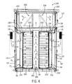
図1に、例示的な一実施形態に係るモジュール型の蓄電システム100を示す。図1の実施形態では、システム100が、下側ハウジング110(例えば、下側の筐体、下側のコンテナ、下側の部位等)および上側ハウジング120(例えば、上側の筐体、上側のコンテナ、上側の部位等)を有している。図示の例示的な実施形態では、下側ハウジング110と上側ハウジング120とが、上側及び下側の部位を有する単一のハウジングを画定するように一体的に形成されている。例示的な他の実施形態では、上側ハウジング120が、下側ハウジング110に取外し可能に連結又は取り付けられている。例示的な他の実施形態では、上側ハウジング120が、下側ハウジング110へと(例えば、溶着等によって)恒久的に連結又は取り付けられている。例示的な一実施形態では、下側ハウジング110が、モジュール型の蓄電システムとして使用されるように構成された10ft(フィート)ISO規格輸送用コンテナである。例示的な他の実施形態では、下側ハウジング110が、モジュール型の蓄電用に構成された他の種類の規格コンテナ又は筐体である。下側ハウジング110は、フォークリフト又は他の昇降装置又は搬送装置による前記システムの昇降又は搬送を可能にする構成を有してもよい。これにより、下側ハウジング110と上側ハウジング120とが一体となって他の場所に移送又は搬送されて蓄電ソリューションを提供可能である。
FIG. 1 shows a modular
下側ハウジング110は、(幾つかある構成品の中でも特に)少なくとも1つのラック201(例えば、機器ラック、バッテリラック、取付フレーム等)を収容又は収納してもよい。ラック201は、複数の蓄電装置200(例えば、バッテリ等)を保持してもよい。同様に、上側ハウジング120は、(幾つかある構成品の中でも特に)少なくとも1つの電力変換アセンブリ300を収容又は収納してもよい。例示的な他の実施形態では、下側ハウジング110が、少なくとも1つの蓄電装置200と共に電力変換アセンブリ300を収容してもよい。例示的な一実施形態では、電力変換アセンブリ300が、蓄電装置200に電気的に接続されてもよい。有利なことに、モジュール型の蓄電システム100は、遠隔の場所において例えば電気グリッドに補充電力を供給したり電力を平滑化したり等するために配備されることが可能である。モジュール型の蓄電システム100は、さらに、複数のモジュール型の蓄電システム100が「プラグアンドプレイ」配置構成で互いに通信可能に接続されることで大規模な蓄電システムを構築可能であるように構成されている。このようにしてモジュール型の蓄電システム100は、各種用途の要件を満たすように拡張可能である。
The
図1を依然として参照する。下側ハウジング110は、2つの側壁110a、基部110b、上側支持部位を画定する少なくとも1つの長手部材110c、および二対のドアアセンブリ130を有している。側壁110aと長手部材110cと基部110bとは、内部空間を有する部分的な筐体を協働で画定するように互いに連結されているか又は一体的に形成されている。ドアアセンブリ130は、前記内部空間へのアクセスを提供するように下側ハウジング110に回動可能(枢動可能)に連結されている。すなわち、ドアアセンブリ130は、前記内部空間へのアクセスを提供するように下側ハウジング110に枢結されている。それぞれの対のドアアセンブリ130が、下側ハウジング110の互いに反対側の端部に配置されている。これにより、人間(例えば、オペレータ、サービス提供者等)が、下側ハウジング110の片側の端部又は両側の端部から当該下側ハウジング110の内部空間にアクセスすることができる。また、各ドアアセンブリ130は、下側ハウジング110のそれぞれの端部から冷却空気流を供給することが可能な冷却装置を含み、これによってホットアイルおよびコールドアイルの冷却配置構成を実現する(詳細については、後述する)。例示的な他の実施形態では、ドアアセンブリ130が一つだけ、下側ハウジング110の片側の端部又は両側の端部に回動可能に連結されている。
Still referring to FIG. The
例示的な一実施形態では、各長手部材110cが、下側ハウジング110の前側部分と後側部分との間に連結されている。長手部材110cは、下側ハウジング110の内部空間を上側ハウジング120の内部空間から部分的に隔てている。例示的な他の実施形態では、長手部材110cが、2つの側壁110a間に連結されている。長手部材110cは、当該長手部材110c間及び側壁110a間に開口空間(開放空間)を画定するように略水平方向の平面に沿って互いに側方に離間している。長手部材110cにより画定されるこれらの開口空間は、下側ハウジング110の内部空間と上側ハウジング120の内部空間との間での流体連通(例えば、空気流等)を可能にする。長手部材110c同士が、下側ハウジング110の上側支持部位を協働で画定している。図1の例示的な実施形態では、長手部材110cが、上側ハウジング120内に着脱自在に連結された少なくとも1つの電力変換アセンブリ300を構造的に支持する。例示的な各種実施形態では、長手部材110cが、下側ハウジング110に連結された金属押出材、桁材または梁材であってもよい。例示的な他の実施形態では、長手部材110cが、当該長手部材110c上において各種機器を支持するのに十分な他の種類の高剛性部材(例えば、開口部を有する、金属プレート又は金属シート等)である。
In one exemplary embodiment, each
例示的な各種実施形態では、下側ハウジング110が、当該下側ハウジング110c内に例えばラック201、蓄電装置200、冷却システム構成品、火災抑制機器、システム制御部等の様々な構成品又は機器を収容してもよい。図1の例示的な実施形態では、下側ハウジング110cが複数のラック201を収納し、複数のラック201が下側ハウジング110に連結された複数の蓄電装置200を具備している。例示的な一実施形態では、下側ハウジング110が、当該下側ハウジング110c内に約200kWh〜約500kWhの蓄電量をサポートする容量を有している。例示的な一実施形態では、蓄電装置200が例えば鉛、リチウムイオン、ニッケル水素(NiMH)、燃料電池、キャパシタ等のバッテリ、または任意の他の種類のバッテリもしくは蓄電装置である。ラック201は、図1の実施形態に示されているように、互いに離間した平行な二列の蓄電装置200を画定することによって当該二列の蓄電装置200間に隙間又は空間を画定するように配置される。例示的な他の実施形態では、ラック201が、下側ハウジング110内において二列以外(一列又は三列以上)の蓄電装置200を画定するように配置される。各列の蓄電装置200が、2つの側壁110a間に延在して且つ略直方体の形状を有している。例示的な一実施形態では、各々のラック201が、空気流を当該ラック201内で蓄電装置200に通して循環させる例えばファン、他の同様の装置等の少なくとも1つの空気循環装置203(例えば図4等を参照)を具備している。
In various exemplary embodiments, the
図1の例示的な実施形態では、上側ハウジング120が、4つの側壁120aおよび上壁120bを有している。側壁120aと上壁120bとが、筐体を画定するように互いに連結されているか又は一体的に形成されている。上側ハウジング120は、図1に示すように(幾つかある機器の中でも特に)複数の電力変換アセンブリ300を収容してもよい。例示的な他の実施形態では、上側ハウジング120が、電力変換アセンブリ300を一つだけ収納する。例示的な一実施形態では、少なくとも1つの側壁120aが、上側ハウジング120の内部空間へのアクセスを提供するように少なくとも1つの回動可能アクセスパネル又はドアを具備している。上側ハウジング120は、図1に示すように、下側ハウジング110と一体的に形成されている。例示的な他の実施形態では、上側ハウジング120が、例示的な一実施形態に従って少なくとも1つの締結具(例えば、ボルト、ねじ等)で下側ハウジング110に取外し可能に連結されてもよい。例示的な他の実施形態では、上側ハウジング120が、下側ハウジング110に(例えば、溶接等によって)恒久的に取り付けられている。
In the exemplary embodiment of FIG. 1, the
図2には、図1のドアアセンブリ130が、例示的な一実施形態に従って示されている。図2には右側のサイドドアアセンブリが示されているが、下記の説明は左側のサイドドアアセンブリにも同様に当てはまることを理解されたい。というのも、これらのドアアセンブリは互いに鏡像であり、かつ、それぞれ内側での空気分配が可能であるように同様の設計を有しているからである。ドアアセンブリ130は、図2に示すように、(幾つかある構成品の中でも特に)冷却装置131、ドアパネル132、空気分配部材133(例えば、エアバッフル、分配プレート等)、およびシュラウド134(例えば、フランジ、スカート、側壁等)を含む。冷却装置131は、冷却空気流をドアパネル132を通って空気分配部材133に供給してもよい。有利なことに、空気分配部材133は、下側ハウジング110及び上側ハウジング120内に収納された電力用電子部品(例えば、蓄電装置200、電力変換アセンブリ300等)を冷却するように前記冷却空気流を当該空気分配部材133に設けられた複数の開口部を介して分配及び案内してもよい。空気分配部材133は、空気速度を最大化しながら当該空気分配部材133と蓄電装置200との間の温度成層化(temperature stratification)を最小限に抑えるように構成されている。このようにして、空気分配部材133は前記冷却空気流を分配及び案内して下側ハウジング110の内部空間のうちの蓄電装置200の近傍又は蓄電装置200の箇所での温度差抑制を支援することができ、かつ、蓄電装置200の効率的で且つ対象とする温度制御を維持することができる。
In FIG. 2, the
例示的な一実施形態では、冷却装置131が、ドアパネル132の外側部分又は外側表面に着脱自在に連結されている。図2の例示的な実施形態では、冷却装置131が空調ユニットとして図示されている。例示的な他の実施形態では、冷却装置131が、冷却空気流を供給するファン又は任意の他の供給源であってもよい。冷却装置131は、図2に示すように、当該冷却装置131が空気入口131aを介して外気から空気流を受け入れることが可能であるように外気に曝されている。当該空気流が冷却装置131の凝縮器を通過することで副生成物として暖められた空気流を生成する可能性があり、当該暖められた空気流は開口部131bを通って再び外気に戻る可能性がある。冷却装置131は冷却空気流を、空気出口131dを介してドアパネル132における開口部(例えば、第1の開口部等)及び空気分配部材133に供給してもよい。当該冷却空気流は、下側ハウジング111内及び上側ハウジング120内に収納された電力用電子部品(例えば、蓄電装置200、電力変換アセンブリ300等)から熱エネルギを吸収できる。冷却装置131は、ドアアセンブリ130から空気帰還口131cを介して帰還空気流を受け取ってもよい。例示的な一実施形態では、上側ハウジング120および/または下側ハウジング110から空気帰還ダクト136を介して当該帰還空気流が受け入れられる。
In one exemplary embodiment, the
図2を依然として参照する。ドアパネル132は、冷却装置131の空気帰還口131cに対応する開口部(例えば、図3の開口部132b等)、冷却装置131の空気出口131dに対応する開口部(例えば、図3の開口部132a等)をそれぞれ有している。例示的な一実施形態では、空気分配部材133が、ドアパネル132の内側表面に着脱自在に連結されている。空気分配部材133は、当該空気分配部材133の外周に沿って配置された少なくとも1つの締結具138(例えば、ボルト、ねじ等)によりドアパネル132に着脱自在に連結されている。空気分配部材133とドアパネル132とが、冷却装置131から冷却空気流を受け取る外囲空間(囲い)を協働で画定している。
Still referring to FIG. The
例示的な一実施形態では、空気分配部材133が取り外されて例えば異なる全体寸法、異なる冷却特性(例えば、異なる孔径、異なる孔位置等)等の異なる特性を有する異なる空気分配部材に置き換えられてもよい。空気分配部材133がこのように着脱自在であることにより、モジュール型の蓄電システム100のカスタマイズや構成変更が可能となり得る。例えば、蓄電装置200が異なる冷却要件を有する異なる蓄電装置に置き換えられた場合には、空気分配部材133が、置換え後の蓄電装置の対象の冷却を促す異なる特性を有する異なる空気分配部材に置き換えられてもよい。同様に、前記蓄電システムから1つ以上の蓄電装置200が取り外された場合には、残りの蓄電装置200を対象とするように異なる孔数および/または異なる孔位置を有する異なる空気分配部材133が採用されてもよい。空気分配部材133がこのように着脱自在であることにより、前記蓄電システムの設計(例えば、蓄電容量等)に融通を利かせられると同時に、当該蓄電システムに収納された蓄電装置200の効率的で且つ対象とする温度制御を提供することが可能である。空気分配部材133は、現場でオペレータやサービス提供者が簡単に取り外して別のものに置き換えることが可能である。
In an exemplary embodiment, the
例示的な一実施形態では、空気分配部材133が、略扁平なパネル133b、および部分的な外囲空間(囲い)(例えば、開口箱(開放箱)、凹状空間(キャビティ)等)を画定するように当該略扁平なパネル133bに対して直交に配置された少なくとも1つのサイドパネル133cを有している。空気分配部材133により画定される当該部分的な外囲空間つまり凹状空間は、冷却装置131から受け取った前記冷却空気流の、空気分配部材133によって分配される前の速度を最大化させることができる。
In an exemplary embodiment, the
例示的な一実施形態では、ドアパネル132の内側表面と略扁平なパネル133bの内側表面との間の距離又は間隔が、5’’(インチ)(12.7cm)である(例えば図4等を参照)。例示的な他の実施形態では、当該距離又は間隔が、5’’(インチ)(12.7cm)〜7’’(インチ)(17.78cm)の範囲内である。有利なことに、略扁平なパネル133bとドアパネル132との間のこのような間隔は、冷却装置131から受け取った前記冷却空気流の速度を最大化し、これによって例えば蓄電装置200等の効率的な冷却を提供する。図2では略扁平なパネル133bは長方形状を有しているが、例示的な他の実施形態では当該パネル133bが例えば円形状、五角形状、八角形状等の他の形状を有していてもよい。例示的な一実施形態では、略扁平なパネル133b及びサイドパネル133cを有する空気分配部材133が、板金、アルミニウム、またはモジュール型の蓄電システム100内という特定の用途に適した任意の他の高剛性材料(例えば、ガラス繊維、複合材料、プラスチック等)からそれぞれ作製(例えば、形成、溶接等)されている。
In an exemplary embodiment, the distance or spacing between the inner surface of the
空気分配部材133は、さらに、略扁平なパネル133bに設けられた複数の開口部133aを有している。これらの開口部133aは、略扁平なパネル133b縁部に沿って(例えば、当該略扁平なパネル133bの側縁部および/または上縁部および/または下縁部に沿って)設けられている。これらの開口部133aは、略扁平なパネル133bの中央(空気分配部材133がドアパネル132に連結されたときに冷却装置131の空気出口131dが略揃えられる箇所)から離れて略位置している。これにより、冷却装置131から受け取った前記冷却空気流を、空気分配部材133及びドアパネル132により画定される前記外囲空間又は凹状空間中に行きわたらせることができる。例示的な一実施形態では、開口部133aの形状が略円形とされるが、例示的な他の実施形態では例えば長円形状、正方形状、五角形状、八角形状等の他の形状も考えられる。例示的な一実施形態では、開口部133aのそれぞれの直径が2’’(インチ)(5.08cm)〜3’’(インチ)(7.62cm)の範囲内である。
The
図2に示す例示的な実施形態では、前記ドアアセンブリが、冷却装置131の空気帰還口131cに連通するように構成された空気帰還ダクト136を含む。空気帰還ダクト136は、ドアパネル132と空気分配部材133との間に形成されて冷却装置131から前記冷却空気流を受け取る前記外囲空間から、分離しているか又は隔絶されている。空気帰還ダクト136は下側ハウジング110および/または上側ハウジング120から帰還空気流を受け取り、当該帰還空気流をドアパネル132を通って冷却装置131に(例えば、冷却装置131の空気帰還部131c等に)案内してもよい。図2の例示的な実施形態では、エアフィルタ135が空気帰還ダクト136の入口に着脱自在に連結されている。エアフィルタ135は、下側ハウジング110および/または上側ハウジング120から空気帰還ダクト136に進入する帰還空気流中に存在し得る粒子類を濾過してもよい。
In the exemplary embodiment shown in FIG. 2, the door assembly includes an
図2を依然として参照する。ドアアセンブリ130は、さらに、空気分配部材133のためのシュラウド134(例えば、スカート、フランジ等)を協働で画定する上部部材134a及び側部部材134bを含む。例示的な一実施形態では、シュラウド134が、空気分配部材133及びドアパネル132により画定される前記部分的な外囲空間又は凹状空間を封鎖してもよい。シュラウド134は、さらに、蓄電装置200と空気分配部材133との間のコールドアイル冷却領域を部分的に画定している。例えば、一対のドアアセンブリ130が下側ハウジング110のそれぞれの端部で互いに隣り合って回動可能に連結されているとき、一対の隣り合うドアアセンブリ130の対応するシュラウド134同士が協働で、コールドアイル冷却領域を各々の空気分配部材133と一列の蓄電装置200との間に画定している。つまり、下側ハウジング110のそれぞれの端部における各対の隣り合うドアアセンブリ130は、2つの個別のコールドアイル冷却領域を協働で画定してもよい(例えば図4等を参照)。
Still referring to FIG. The
図2に示すように、上部部材134aは空気分配部材133の上縁に連結されており、側部部材134bは空気分配部材133の側縁に連結されている。上部部材134a及び側部部材134bは、下側ハウジング110の内部空間に向かってドアパネル132から内方に延設されている(例えば図1、図4等を参照)。上部部材134a及び側部部材134bはそれぞれ、ドアアセンブリ130が閉じた位置にあるときに少なくとも1つのラック201および/または蓄電装置200のうちの少なくとも一部と係合するか又は接続するのに十分な距離だけ、略扁平なパネル133bを越えて延びている。例示的な一実施形態では、上部部材134a及び側部部材134bが、5’’(インチ)(12.7cm)の距離だけ略扁平なパネル133bを越えて延びている。
As shown in FIG. 2, the
図4に示す例示的な一実施形態において、シュラウド134は、ドアアセンブリ130が閉じた位置にあるときにラック201および/または蓄電装置200に対してシールを形成してもよい。このようにしてシュラウド134は、蓄電装置200とドアアセンブリ130との間の前記コールドアイル冷却領域の隔絶又は密閉を支援することができる。例えば、図2の例示的な実施形態では、上部部材134aが上部のシール137aを具備し、側部部材134bが側部のシール137b及び下部のシール137cを具備する。上部のシール137aと側部のシール137bと下部のシール137cとは、ドアアセンブリ130が閉じた位置にあるときに少なくとも1つのラック201および/または蓄電装置200と接続するか又は係合するように構成された縁部シールを協働で画定する。これにより、空気分配部材133で分配された冷却空気流を、シュラウド134によって前記コールドアイル冷却領域内で蓄電装置200に向かうように閉じ込めるか又は案内することができる。例示的な一実施形態では、上部のシール137aおよび/または側部のシール137bおよび/または下部のシール137cがバルブシール(bulb seal)である。例示的な他の実施形態では、上部のシール137aおよび/または側部のシール137bおよび/または下部のシール137cは、シュラウド134と前記ラックおよび/または蓄電装置200との間にシールをつくるのに適した任意の他の部材(例えば、ブラシ等)であってもよい。
In the exemplary embodiment shown in FIG. 4, the
図2の例示的な実施形態では、上部部材134aが複数の穴(開口)134cを有している。これらの穴134cは、冷却空気流が空気分配部材133によって蓄電装置200に分配されるときの前記コールドアイル冷却領域の空気圧逃しを提供することができる。このようにして前記穴134cは、前記コールドアイル冷却領域内の空気流および/または空気分配の向上を支援することができる。図2に示すように、これらの穴134cは上部部材134aの外周に沿って設けられている。これらの穴134cは円形状を有しているが、例示的な他の実施形態では当該穴134cが例えば長円形状、正方形状、五角形状、八角形状等の他の形状を有していてもよい。例示的な一実施形態では、前記穴134cの各直径が、前記コールドアイル冷却領域内の最適な空気流を達成するように1’’(インチ)(2.54cm)とされる。
In the exemplary embodiment of FIG. 2, the
図3に、図2のドアアセンブリ130を、ドアパネル132の構造を示すために空気分配部材133を仮想線で示す。図3に示すように、ドアパネル132は第1の開口部132a(例えば、供給用開口部、入口等)および第2の開口部132b(例えば、帰還用開口部、出口等)を有している。第1の開口部132aは、冷却装置131に連通して当該冷却装置131から空気分配部材133への矢印「A」で表す冷却空気流を供給することができる。例示的な一実施形態において、第1の開口部132aは、形状が略長方形であり、かつ、寸法が10’’(インチ)(25.4cm)×15’’(インチ)(38.1cm)である。当業者であれば理解できるように、例示的な他の実施形態では第1の開口部132aが異なる形状及び寸法を有していてもよい。第2の開口部132bは、空気帰還ダクト136が冷却装置131の前記空気帰還部に連通するのを可能にすることで、上側ハウジング120および/または下側ハウジング110の内部空間から冷却装置131に矢印「B」で表す帰還空気流を供給することができる。例示的な一実施形態では第2の開口部132bが略正方形の形状及び8’’(インチ)(20.32cm)×8’’(インチ)(20.32cm)の寸法を有するものとされるが、例示的な他の実施形態では当該第2の開口部132bが異なる形状及び寸法を有していてもよい。
FIG. 3 shows the
図4に、例示的な一実施形態に係るモジュール型の蓄電システム100の熱モデルを示す。同図は、この実施形態に係るシステム100が、当該システム100内を循環する冷却空気流と共に当該システム100の内部空間を示すように破断側面図である。図4に示すように、ドアアセンブリ130の空気分配部材133及びシュラウド134が協働で、下側ハウジング110のそれぞれの端部において蓄電装置200に接してコールドアイル冷却領域5Aを形成している。さらに、二列の蓄電装置200/ラック201が、当該二列間における下側ハウジング110の真ん中部分付近に位置したホットアイル領域5Bを画定している。
FIG. 4 shows a thermal model of the modular
図4に示すように、冷却装置131は、矢印「A」で表す冷却空気流をドアパネル132における開口部(例えば、図3に示す開口部132a等)を介して供給する。この空気流「A」は、各対のドアアセンブリ130のうちの空気分配部材133、ドアパネル132及びシュラウド134により形成される前記外囲空間に進入する。例示的な一実施形態では、空気分配部材133がドアパネル132から5’’(インチ)(12.7cm)〜7’’(インチ)(17.78cm)の範囲内の距離D1だけオフセットしており、これにより有利なことに、前記空気流を当該空気分配部材133によって分配及び案内される前に前記外囲空間中に行きわたらせるのを支援することができる。このような距離又は深さは、さらに、空気速度を最大化しながらコールドアイル冷却領域5A内の温度成層化を最小限に抑えるのを支援することができる。例示的な一実施形態では、空気分配部材133が、蓄電装置200の動作時(例えば、電力を供給又は吸収するとき等に)にコールドアイル冷却領域5A内の温度差(温度変化)を約3℃未満に維持し得る。そして、前記空気流が空気分配部材133のそれぞれの開口部133aを介してコールドアイル冷却領域5Aへと、対応付けられた蓄電装置200に向かって分配及び案内されることができる。この領域での前記空気流の温度T1は、15℃〜25℃の範囲内である。例示的な一実施形態では、空気分配部材133の外側表面が、5’’(インチ)(12.7cm)の距離D2だけ蓄電装置200から離れて配置されている。
As shown in FIG. 4, the
分配後の前記空気流は、その後、支持ラック201内を蓄電装置200を通って通過することにより、当該蓄電装置200から熱エネルギの少なくとも一部を吸収して、これによって当該蓄電装置200を冷却することができる。例示的な一実施形態では、前記空気流が、ラック201に連結された少なくとも1つの空気循環装置203(例えば、ファン等)によってラック201内を蓄電装置200を通って循環される。そして、前記空気流は、二列の蓄電装置200及びラック201間に位置したホットアイル領域5Bに進入することができる。この領域での前記空気流の温度T2は、蓄電装置200から熱エネルギを吸収したことによってコールドアイル冷却領域5Aの温度T1よりも高い。例示的な一実施形態では、温度T2が、25℃〜35℃の範囲内であり得る。前記空気流はその後、ホットアイル5B内を略上方に、長手部材110c間の開口領域を通って電力変換アセンブリ300に向かって流れ得る。この空気流は、電力変換アセンブリ300が生成する熱エネルギを吸収するように当該電力変換アセンブリ300を通って流れて、これによって当該電力変換アセンブリ300の効率的な熱管理/冷却を提供することができる(この詳細については、後で説明する)。電力変換アセンブリ300から熱エネルギを吸収した後のこの領域での前記空気流の温度T3は、30℃〜40℃の範囲内である。その後、矢印「B」で表す帰還空気流が、エアフィルタ135に流れて、そして空気帰還ダクト136を介して冷却装置131に再循環のために流れることができる。
The distributed air flow then passes through the
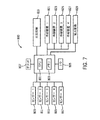
図7に示す例示的な一実施形態では、前記モジュール型の蓄電システムが、当該システムの各種機能(例えば、冷却装置131、蓄電装置200、空気循環装置203、温度/湿度センサ205(図4を参照)、電力変換アセンブリ300、火災抑制機器750(図6に示す)等)を制御する制御システム800を備える。図7に示すように、制御システム800は、中央演算処理装置(CPU)801、メモリ803および入出力ポート805を含む。CPU801及びメモリ803は、電力グリッド807に通信可能に接続されている。CPU801には、少なくとも1つのセンサ809〜817(例えば、温度・湿度センサ205等)が通信可能に接続されてもよい。センサ809〜817は、CPU801に温度データおよび/または湿度データを送信してもよい。当該温度データおよび/または湿度データは、下側ハウジング110内、上側ハウジング120内、支持ラック201の箇所での又は蓄電装置200内部の周辺温度/湿度を表すことができる。CPU801は、図7において冷却装置入力821〜827として概略的に示されている各冷却装置131に通信可能に接続されている。CPU801は、センサ809〜817から得られた前記温度/湿度データに応じて各ドアアセンブリ130の前記冷却装置の動作を制御することができる。
In an exemplary embodiment shown in FIG. 7, the modular power storage system includes various functions of the system (for example, a
例えば、制御システム800は、動作時に下側ハウジング110内、上側ハウジング120内、支持ラック201の箇所での又は蓄電装置200内部の特定の温度を維持するように構成されてもよい。このようにしてモジュール型の蓄電システム100は、下側ハウジング110及び上側ハウジング120内に収納された各種電子部品の効率的な熱管理を提供することができ且つ冷却装置131の動作時間を最適化することができ、これによってシステム効率を最大化させることができる。センサ809〜817は、コールドアイル冷却領域5A内及びホットアイル領域5B内のそれぞれにおいて周辺空気温度を監視するように設けられてもよい(例えば、図4のセンサ205等を参照)。センサ809〜817は、さらに、蓄電装置200のセル内部に例えば蓄電装置200の動作時のセル温度を監視するように設けられてもよい。
For example, the
次に、図5に、例示的な一実施形態に係る電力変換アセンブリ600を示す。電力変換アセンブリ600は、図1及び図4に示す電力変換アセンブリ300と同一のものである。電力変換アセンブリ600は、フレームアセンブリ610、および複数の電子部品を有するパネル620を含む。例示的な一実施形態では、パネル620および/またはフレームアセンブリ610に、例えば電力変換用電子部品(例えば、電力変換器等)、コントローラ(例えば、図7の制御システム800等)、バッテリ管理システム制御部、周波数応答制御部、グリッド監視/応答制御部等の様々な電子部品が連結されている(又は一体化されている)。
Next, FIG. 5 illustrates a
例示的な一実施形態では、少なくとも1つの電力変換アセンブリ600が、例えばモジュール型の蓄電システム100の上側ハウジング120内において例えば少なくとも1つの長手部材110cに着脱自在に連結されてもよい。例えば図1、図4等を参照すると、同図には一対の電力変換アセンブリ300が、上側ハウジング120内に背中合わせ配置構成で連結されてホットアイル領域5Bの略上方に配置されている。例示的な他の実施形態では、電力変換アセンブリ600が、下側ハウジング110内において蓄電装置200に隣接して連結されてもよい。なお、例示的な他の実施形態では電力変換アセンブリ600が、異なる構成を有する他の種類の筐体又はモジュール型の蓄電システム内に連結されてもよい。
In an exemplary embodiment, at least one
例示的な一実施形態では、電力変換アセンブリ600が、制御システム(例えば、図7に示す制御システム800等)を介してモジュール型の蓄電システム100の蓄電装置200に及び少なくとも1つの冷却装置131に電気的に接続されてもよい。例示的な一実施形態では、電力変換アセンブリ600が、例えば蓄電装置200と負荷(例えば、電力グリッド807、再生可能エネルギ電源等)との間で電力を交流から直流へと及び直流から交流へと変換してもよい。また、電力変換アセンブリ600は、冷却装置131および/または蓄電装置200および/または前記モジュール型の蓄電システムの他の装置/システム(例えば、図6に示す火災抑制システム750等)の電子制御を提供するように前記制御システム800(例えば、組込みコントローラ等)を含むものとされてもよい。
In an exemplary embodiment,
図5に示すように、フレームアセンブリ610は、一対の細長部材612に連結されているか又は固定的に取り付けられている一対の端部部材611を含み、これによって略扁平なフレーム部位を画定している。端部部材611と細長部材612とは、長方形状の外側フレームを画定するように配置されていて且つ当該外側フレーム上にパネル620を受け止めるように構成されている。フレームアセンブリ610は、さらに、前記外側フレームに連結されて且つ端部部材611に対して直角に向けられた2つ以上の基部部材613を含む。基部部材613は、端部部材611と共に「L」字を形成するように当該端部部材611から遠ざかる略外方に延設されている。少なくとも1つのガセット材(ブラケット材)614が、フレームアセンブリ610の構造的な支持を提供するように端部部材611と基部部材613との間にそれぞれ連結されている。基部部材613間には第3の細長部材612が、それぞれの基部部材の遠位端部で連結されている。一対の管状部材615が、2つの基部部材613間において連結されている。一対の管状部材615が、基部部材613と当該一対の管状部材615との間に開口領域をそれぞれ画定するように互いに側方に離間している。基部部材613と管状部材615と第3の細長部材612とが、フレームアセンブリ610の基部を協働で画定している。例示的な一実施形態では、電力変換アセンブリ600が、例えば下側ハウジング110の少なくとも1つの長手部材110cに、基部部材613および/または管状部材615を介して(例えば、ボルト、ねじなどの締結具を用いる等して)着脱自在に連結され得る。
As shown in FIG. 5, the
例示的な一実施形態では、各管状部材615が、電力変換アセンブリ600を移送/搬送するのにフォークリフトのフォークを受け入れるように寸法決め及び形成されている。これにより、電力変換アセンブリ600は、別の場所に容易に移送又は搬送されることが可能である。例示的な各種実施形態では、フレームアセンブリ610を構成する各部材が、鋼、アルミニウムまたは例えばモジュール型の蓄電システム100内の各種電子部品を支持するのに適した任意の他の高剛性部材もしくは複数種の高剛性部材の組合せからなる、正方形状又は円形状の管体(tubing)であってもよい。例示的な一実施形態では、フレームアセンブリ610を構成する各種部材が、溶接、リベットなどによって互いに固定的に連結されている。例示的な他の実施形態では、これら各種部材が、取外し可能な例えばボルト、ねじ等の締結具を用いて互いに着脱自在に連結されている。
In one exemplary embodiment, each
図5を依然として参照する。パネル620がフレームアセンブリ610に、2つの端部部材611及び一対の細長部材612により形成される前記略扁平なフレーム部位上で着脱自在に連結されている。例示的な一実施形態では、パネル620が、例えばモジュール型の蓄電システム100内において冷却空気流を受けるように外気に略曝された電子部品を有している。前記アセンブリ600が例えば上側ハウジング120内に連結されると、パネル620は略直立方向に向く。有利なことに、この向きは、パネル620(および/またはフレームアセンブリ610)に連結されているか又は一体化されている電子部品の冷却を促す。というのも、冷却空気流がフレームアセンブリ610の各種開口を介して(例えば、基部部材613と管状部材615との間および/またはガセット材614と基部部材613との間に形成された開口空間等を介して)上方に、それらの部品を対流によって冷却するように通過することができるからである。
Still referring to FIG. A
冷却空気流は例えば、(電力変換アセンブリ600と同一のものであり且つ本願の開示内容をとおして相互に置き換え可能に使用される)電力変換アセンブリ300を備えるモジュール型の蓄電システム100が示されている図4を参照すると、蓄電装置200から熱エネルギを吸収してからホットアイル領域5Bに進入することができる。この空気流がホットアイル領域5B内を上方に、例えば電力変換アセンブリ600に向かって進むことができる。例示的な一実施形態では、この空気流が、各電力変換アセンブリの基部部材613及び管状部材615により画定される開口空間を上方に通過することができる。空気流は同様に、フレームアセンブリ610における他の開口領域(例えば、ガセット材614と基部部材613との間等)をパネル620に向かって通過することができる。このようにして冷却空気流が、パネル620および/またはフレームアセンブリ610に連結されているか又は一体化されている電子部品を通って当該電子部品が生成する熱エネルギを吸収するように流れることができる。例示的な一実施形態において、ホットアイル5Bから受け取る前記空気流は、電力変換アセンブリ600の各種電子部品から熱エネルギを十分に吸収できる温度であり、これによって当該電力変換アセンブリ600の効率的な冷却および熱管理を提供する。
The cooling airflow is shown, for example, in a
次に図6を参照する。同図には、例示的な一実施形態に係る、火災抑制システム750を備えるモジュール型の蓄電システム700が示されている。火災抑制システム750は、モジュール型の蓄電システム700の制御システム(例えば、図7に示す制御システム800等)に電気的に接続されている(例えば、火災抑制システム入力819等を参照)。火災抑制システム750は、人間の介入なしでモジュール型の蓄電システム700内の火災を自動的に制御又は鎮静することができる。例えば、例示的な一実施形態に係る前記モジュール型の蓄電システムは、当該システム700の下側ハウジング710内に且つ/或いはコールドアイル冷却領域5A及びホットアイル領域5B内に収納されている(例えば図4等を参照)例えば蓄電装置200等に動作可能に接続された、少なくとも1つの温度監視装置(例えば、センサ等)を備えている。当該温度監視装置は、蓄電装置200の動作温度を表すデータを供給するように前記制御システム(例えば、制御システム800等)に電気的に接続されてもよい。前記制御システムは、そのような温度データが蓄電装置200の過熱状態(例えば、火災等)を示す閾値を上回った場合に火災抑制システム750に制御信号を供給するように構成されてもよい。火災抑制システム750は前記制御信号を受け取ると、火災または蓄電装置200の過熱状態に関係する他の事象を解消/制御するように前記制御システムによって作動されてもよい。例示的な各種実施形態では、火災抑制システム750が、散水システム、ガス式火災抑制システムまたは凝縮エアロゾル式火災抑制システムであってもよい。
Reference is now made to FIG. In the figure, a modular power storage system 700 including a
本明細書で説明する例示的な各種実施形態では、CPU801が、汎用プロセッサ、特定用途向け集積回路(ASIC)、少なくとも1つのフィールドプログラマブルゲートアレイ(FGPA)、デジタルシグナルプロセッサ(DSP)、処理部品の集まり、または他の適切な電子処理部品として実現されてもよい。メモリ803は、データ、および/または、本明細書で説明する各種処理を促進するコンピュータコードを記憶する少なくとも1つの装置(例えば、RAM、ROM、フラッシュメモリ、ハードディスクストレージ等)である。メモリ803は、非過渡的な揮発性メモリもしくは不揮発性メモリであっても、又は非過渡的な揮発性メモリもしくは不揮発性メモリを含んでもよい。メモリ803は、データベースコンポーネント、オブジェクトコードコンポーネント、スクリプトコンポーネント、または本明細書で説明する各種活動及び情報構造をサポートするための任意の他の種類の情報構造を有してもよい。メモリ803は、中央演算処理装置801に通信可能に接続されてもよく、本明細書で説明する処理を実行するために当該中央演算処理装置801にコンピュータコードまたは命令を供給してもよい。
In various exemplary embodiments described herein, the
本明細書で使用される「おおよそ」、「約」、「略」などの用語は、本願の開示内容の主題に関係する当業者にとって一般的で受け入れられている使い方に即した広義の意味を有するように意図されている。なお、本願の開示内容を参酌した当業者であれば、記載されたり請求されたりしている特定の構成を説明するにあたってそれらの用語が用いられることにより当該構成の範囲は、明記された数値範囲に必ずしも限定されないということを理解するであろう。つまり、それらの用語は、記載されたり請求されたりしている主題の些細な又は取るに足らない変更や変形も、添付の特許請求の範囲に記載されている本発明の範囲に含まれることを表していると解釈されるべきである。 As used herein, terms such as “approximately”, “about”, “abbreviation” and the like have broad meanings in accordance with their accepted and accepted usage for those skilled in the art related to the subject matter of this disclosure. Is intended to have. It should be noted that those skilled in the art who have taken into account the disclosure of the present application will use the terms used to describe the specific configuration described or claimed, and the scope of the configuration will be expressed as a specified numerical range. It will be understood that this is not necessarily the case. That is, the terms are intended to cover minor or insignificant modifications and variations of the subject matter described or claimed within the scope of the invention as set forth in the appended claims. Should be interpreted as representing.
なお、本明細書で各種実施形態について言及するうえで使用される「例示的」という用語はそのような実施形態が、想定可能な実施形態についての考えられ得る例および/または代表例および/または例示であること(そして、そのような用語は、このような実施形態が絶対的に特別な例や最良の例であると示唆するものではないこと)を表すように意図されている。 It should be noted that the term “exemplary” as used herein with reference to various embodiments refers to such examples and / or representative examples of possible embodiments of such embodiments. It is intended to be exemplary (and such terms are not meant to imply that such embodiments are absolutely specific or best examples).
本明細書で使用される「連結」、「接続」などの用語は、2つの部材が互いに直接的に又は間接的に繋がっていることを意味している。このような繋がりは、固定(例えば、恒久的なもの等)であっても可動(例えば、取外し可能、解除可能等)であってもよい。このような繋がりは、それら2つの部材が又はそれら2つの部材と任意の追加の介在部材とが単一物として互いに一体的に形成されていることで、あるいは、それら2つの部材が又はそれら2つの部材と任意の追加の介在部材とが互いに取り付けられていることで実現されてもよい。 As used herein, the terms “coupled”, “connected” and the like mean that two members are directly or indirectly connected to each other. Such a connection may be fixed (for example, permanent) or movable (for example, removable or releasable). Such a connection may be due to the two members or the two members and any additional intervening members being integrally formed as a single piece, or the two members or the two members. One member and any additional intervening members may be attached to each other.
構成/構成要素の位置についての本明細書での記載(例えば、「上」、「下」、「上方」、「下方」等)は単に、図中の各種構成/構成要素の向きを説明するために使用されている。なお、各種構成/構成要素の向きは例示的な他の実施形態では異なるものとされてもよく、このような変形例も本願の開示内容に含まれるものとして意図されている。 Descriptions herein regarding the location of components / components (eg, “up”, “down”, “up”, “down”, etc.) simply describe the orientation of the various components / components in the figure. Has been used for. Note that the orientations of the various configurations / components may be different in other exemplary embodiments, and such modifications are also intended to be included in the disclosure of the present application.
強調すべきは、例示的な各種実施形態として図示されている構造及び配置構成が例示に過ぎないことである。本願の開示内容では幾つかの実施形態しか詳細に説明していないが、本願の開示内容を参酌した当業者であれば、本明細書で説明する主題の新規的な教示や利点を大幅に逸脱することなく、数多くの変更(例えば、各種構成/構成要素の大きさ、寸法、構造、形状及び比率、パラメータの数値、取付配置構成、使用材料、色、向き等)が可能であることを容易に理解できるであろう。例えば、一体的に形成されていると図示された構成/構成要素が複数の部分又は構成要素によって構築されてもよく、構成/構成要素の位置が入れ替え又は変更されてもよく、個々の構成要素又は位置の性質又は数が変化又は変更されてもよい。代替的な実施形態では、任意の処理又は方法工程の順番又は順序が変更又は並べ替えされてもよい。例示的な各種実施形態の設計、動作条件及び配置構成においてその他の置換、変更、変化及び省略がさらに、本願の範囲を逸脱しない範疇で行われてもよい。 It should be emphasized that the structures and arrangements shown as exemplary embodiments are only exemplary. Although only a few embodiments have been described in detail in the present disclosure, those skilled in the art in view of the present disclosure will significantly depart from the novel teachings and advantages of the subject matter described herein. It is easy to make many changes (for example, the size, dimensions, structure, shape and ratio of various components / components, numerical values of parameters, mounting arrangement, materials used, colors, orientations, etc.) Will understand. For example, the components / components illustrated as being integrally formed may be constructed by a plurality of parts or components, the positions of the components / components may be interchanged or changed, and individual components Or the nature or number of locations may be changed or changed. In alternative embodiments, the order or order of any processes or method steps may be changed or rearranged. Other substitutions, changes, changes and omissions in the design, operating conditions and arrangement of the various exemplary embodiments may be made without departing from the scope of the present application.
Claims (20)
前記ハウジング内で連結された複数の蓄電装置と、
前記ハウジングの前記第1の端部に枢結された第1のドアアセンブリと、
前記第1のドアアセンブリと隣り合って、前記ハウジングの前記第1の端部に枢結された第2のドアアセンブリとを備えるモジュール型の蓄電システムであって、
前記第1及び第2のドアアセンブリがそれぞれ、前記複数の蓄電装置からの熱エネルギを吸収するように冷却空気流を当該複数の蓄電装置に向かって分配及び方向付けるように構成された空気分配部材を含む、モジュール型の蓄電システム。 A housing having a first end and a second end;
A plurality of power storage devices connected in the housing;
A first door assembly pivotally coupled to the first end of the housing;
A modular power storage system comprising a second door assembly adjacent to the first door assembly and pivotally connected to the first end of the housing;
An air distribution member configured to distribute and direct a cooling air flow toward the plurality of power storage devices so that each of the first and second door assemblies absorbs thermal energy from the plurality of power storage devices. A modular power storage system.
前記ハウジング内からの帰還空気流を受け取り、且つ、
当該帰還空気流を前記ドアパネルの前記第2の開口部を介して前記ハウジングの内部空間の外に方向付けるように構成されている、モジュール型の蓄電システム。 The modular power storage system according to claim 6, wherein each of the first and second door assemblies further includes an air return duct connected to the door panel,
Receiving a return air flow from within the housing; and
A modular power storage system configured to direct the return air flow to the outside of the internal space of the housing through the second opening of the door panel.
前記ハウジング内で連結された複数の蓄電装置と、
前記ハウジングに枢結されたドアアセンブリであって、
ドアパネル、
前記ドアパネルの第1の表面に着脱自在に連結された空気分配部材、および
前記ドアパネルの前記第1の表面とは反対側の第2の表面に連結された冷却装置を含む、ドアアセンブリとを備えるモジュール型の蓄電システムであって、
前記冷却装置が、冷却空気流を前記ドアパネルを通って前記空気分配部材に供給するように構成された空調ユニットであり、
前記空気分配部材が、前記複数の蓄電装置から熱エネルギを吸収するように前記冷却空気流を前記複数の蓄電装置に向かって分配及び方向付けるように構成されている、モジュール型の蓄電システム。 A housing;
A plurality of power storage devices connected in the housing;
A door assembly pivotally coupled to the housing,
Door panels,
An air distribution member removably coupled to a first surface of the door panel, and a door assembly including a cooling device coupled to a second surface opposite to the first surface of the door panel. A modular power storage system,
The cooling device is an air conditioning unit configured to supply a cooling air flow through the door panel to the air distribution member;
A module-type power storage system, wherein the air distribution member is configured to distribute and direct the cooling air flow toward the plurality of power storage devices so as to absorb thermal energy from the plurality of power storage devices.
前記ハウジング内からの帰還空気流を受け取り、且つ、
当該帰還空気流を前記ドアパネルの前記第2の開口部を介して前記ハウジングの内部空間の外に方向付けるように構成されている、モジュール型の蓄電システム。 The modular electricity storage system according to claim 14, wherein the door assembly further includes an air return duct connected to the door panel,
Receiving a return air flow from within the housing; and
A modular power storage system configured to direct the return air flow to the outside of the internal space of the housing through the second opening of the door panel.
前記ハウジング内で連結された複数の蓄電装置と、
前記ハウジングに枢結されたドアアセンブリであって、
ドアパネル、
前記ドアパネルの第1の表面に着脱自在に連結された空気分配部材であって、前記ドアパネルからオフセットして配置された略扁平なパネルであって、当該略扁平なパネルの縁部に沿って設けられた複数の開口部を有する略扁平なパネルを含む空気分配部材、ならびに、
前記ドアパネルの前記第1の表面とは反対側の第2の表面に連結された冷却装置を含む、ドアアセンブリとを備えるモジュール型の蓄電システムであって、
前記冷却装置が、冷却空気流を前記ドアパネルを通って前記空気分配部材に供給するように構成された空調ユニットであり、
前記空気分配部材が、前記複数の蓄電装置から熱エネルギを吸収するように前記冷却空気流を前記複数の開口部を介して当該複数の蓄電装置に向かって分配及び方向付けるように構成されている、モジュール型の蓄電システム。 A housing;
A plurality of power storage devices connected in the housing;
A door assembly pivotally coupled to the housing,
Door panels,
An air distribution member that is detachably connected to the first surface of the door panel, and is a substantially flat panel that is arranged offset from the door panel, and is provided along an edge of the substantially flat panel. An air distribution member including a substantially flat panel having a plurality of defined openings, and
A modular storage system comprising a door assembly including a cooling device coupled to a second surface opposite to the first surface of the door panel;
The cooling device is an air conditioning unit configured to supply a cooling air flow through the door panel to the air distribution member;
The air distribution member is configured to distribute and direct the cooling air flow toward the plurality of power storage devices through the plurality of openings so as to absorb thermal energy from the plurality of power storage devices. , Modular storage system.
前記ハウジング内からの帰還空気流を受け取り、且つ、
当該帰還空気流を前記ドアパネルの前記第2の開口部を介して前記ハウジングの内部空間の外に方向付けるように構成されている、モジュール型の蓄電システム。 The modular power storage system according to claim 17, wherein the door assembly further includes an air return duct connected to the door panel,
Receiving a return air flow from within the housing; and
A modular power storage system configured to direct the return air flow to the outside of the internal space of the housing through the second opening of the door panel.
Applications Claiming Priority (3)
| Application Number | Priority Date | Filing Date | Title |
|---|---|---|---|
| US201562217717P | 2015-09-11 | 2015-09-11 | |
| US62/217,717 | 2015-09-11 | ||
| PCT/US2016/051078 WO2017044830A1 (en) | 2015-09-11 | 2016-09-09 | Modular energy storage system |
Publications (2)
| Publication Number | Publication Date |
|---|---|
| JP2018536963A true JP2018536963A (en) | 2018-12-13 |
| JP2018536963A5 JP2018536963A5 (en) | 2019-09-26 |
Family
ID=57138110
Family Applications (1)
| Application Number | Title | Priority Date | Filing Date |
|---|---|---|---|
| JP2018512854A Pending JP2018536963A (en) | 2015-09-11 | 2016-09-09 | Modular storage system |
Country Status (5)
| Country | Link |
|---|---|
| US (1) | US10522801B2 (en) |
| JP (1) | JP2018536963A (en) |
| DE (1) | DE112016004116T5 (en) |
| GB (1) | GB2556604B (en) |
| WO (1) | WO2017044830A1 (en) |
Cited By (3)
| Publication number | Priority date | Publication date | Assignee | Title |
|---|---|---|---|---|
| CN112531232A (en) * | 2020-12-01 | 2021-03-19 | 阳光电源股份有限公司 | Energy storage system and thermal management method thereof |
| JP2022086178A (en) * | 2020-11-30 | 2022-06-09 | トヨタ自動車株式会社 | Fuel cell module and manufacturing method thereof |
| JP7304350B2 (en) | 2017-12-15 | 2023-07-06 | ブルーム エネルギー コーポレイション | Stackable fuel cell generator configuration with common inlet plenum and common outlet plenum |
Families Citing this family (23)
| Publication number | Priority date | Publication date | Assignee | Title |
|---|---|---|---|---|
| US20180287233A1 (en) * | 2017-03-28 | 2018-10-04 | Renewable Energy Systems Americas Inc. | Silenced Utility Scale Electrical Storage Device |
| FR3069710B1 (en) * | 2017-07-28 | 2022-06-24 | Blue Solutions | TRANSPORTABLE STATIONARY SHELTER, FOR THE STORAGE OF ELECTRIC ENERGY STORAGE MODULES |
| US10830541B2 (en) * | 2017-08-28 | 2020-11-10 | Commscope Technologies Llc | Outdoor electronics enclosure with dual heat exchangers |
| EP3787438A4 (en) * | 2018-04-30 | 2022-02-23 | Hewlett-Packard Development Company, L.P. | Storage receptacles with fire suppression |
| US10978884B2 (en) | 2018-08-10 | 2021-04-13 | Powin Energy Corporation | Enhanced switched balancing network for battery pack |
| CA3110857A1 (en) * | 2018-09-11 | 2020-03-19 | Powin Energy Corporation | Modular battery stack and support system |
| KR101970236B1 (en) * | 2018-09-21 | 2019-04-18 | 주식회사 디아이티이엔지 | Enclosure for energy storage system |
| US10935005B2 (en) * | 2018-10-05 | 2021-03-02 | Ayesha Bhargava | Gravitational potential energy storage system |
| US11224772B2 (en) | 2018-11-13 | 2022-01-18 | E-Cell Secure, L.L.C. | Containment system for hazardous products |
| USD947778S1 (en) * | 2018-12-19 | 2022-04-05 | Dongguan Poweramp Technology Limited | Energy storage system |
| CN109768349B (en) * | 2018-12-21 | 2021-02-12 | 北京双登慧峰聚能科技有限公司 | Battery energy storage container environmental control system |
| CN109768348B (en) * | 2018-12-21 | 2021-02-12 | 北京双登慧峰聚能科技有限公司 | Thermal management system for energy storage container in alpine region |
| CN109713399A (en) * | 2019-02-12 | 2019-05-03 | 国网浙江省电力有限公司电力科学研究院 | A kind of energy storage container temperature and humidity adjustment system and its method is used in combination |
| JP1644514S (en) * | 2019-04-04 | 2019-10-28 | ||
| DE102019210080A1 (en) * | 2019-07-09 | 2021-01-14 | Mahle International Gmbh | Battery housing for temperature control of a battery and fluid temperature controlled battery with such a battery housing |
| JP7136040B2 (en) * | 2019-08-06 | 2022-09-13 | トヨタ自動車株式会社 | fuel cell unit |
| CN110676406B (en) * | 2019-09-29 | 2022-02-08 | 盐城工学院 | Lithium battery capable of reducing electric loss |
| US11365675B2 (en) * | 2019-10-14 | 2022-06-21 | MTU Onsite Energy Corporation | Guiding mechanisms for modular generator set system |
| WO2021231200A1 (en) | 2020-05-11 | 2021-11-18 | Renewell Energy | Well-based potential energy conversion systems and methods |
| CN115692912A (en) * | 2021-07-30 | 2023-02-03 | 华为数字能源技术有限公司 | Energy storage device |
| CN216698514U (en) * | 2021-09-26 | 2022-06-07 | 华为数字能源技术有限公司 | Energy storage system |
| WO2023129735A2 (en) * | 2021-12-31 | 2023-07-06 | Powin, Llc | Energy storage systems and associated methods |
| CN218241988U (en) * | 2022-09-01 | 2023-01-06 | 阳光电源股份有限公司 | Energy storage device |
Citations (4)
| Publication number | Priority date | Publication date | Assignee | Title |
|---|---|---|---|---|
| JPS58180691U (en) * | 1982-05-26 | 1983-12-02 | 東芝エンジニアリング株式会社 | housing |
| JP2005243580A (en) * | 2004-02-27 | 2005-09-08 | Mitsubishi Heavy Ind Ltd | Electric power storage system |
| WO2012015000A1 (en) * | 2010-07-30 | 2012-02-02 | 三洋電機株式会社 | Secondary battery storage system rack |
| JP2014090782A (en) * | 2012-11-01 | 2014-05-19 | Hochiki Corp | Electric power storage system |
Family Cites Families (43)
| Publication number | Priority date | Publication date | Assignee | Title |
|---|---|---|---|---|
| DE2430424A1 (en) | 1974-06-25 | 1976-01-15 | Maier & Stadlinger Hoch Tief U | Movable partitioned prefabricated transformer station building - with continuous ledges for selective anchorage of beams and concrete slab floors |
| FR2341972A1 (en) | 1976-02-17 | 1977-09-16 | Merlin Gerin | Prefabricated transformer substation - has sheet metal enclosure with overlapping corrugated grill and removable maintenance panels |
| DE8519621U1 (en) | 1985-07-06 | 1985-10-03 | Betonbau GmbH, 6833 Waghäusel | Transportable substation |
| DE8804820U1 (en) | 1988-04-13 | 1988-09-01 | Betonbau Gmbh, 6833 Waghaeusel, De | |
| DE3841279A1 (en) | 1988-12-08 | 1990-06-13 | Betonbau Gmbh | TRANSPORTABLE TRANSFORMER STAND FOR OUTDOOR AIR TRANSFORMERS |
| US4992669A (en) | 1989-02-16 | 1991-02-12 | Parmley Daniel W | Modular energy system |
| ATE203856T1 (en) | 1995-10-13 | 2001-08-15 | Betonbau Gmbh | TRANSPORTABLE SPACE CELL AS A SUBSTATION |
| DE19609699C2 (en) | 1996-03-13 | 2001-11-22 | Loh Kg Rittal Werk | Control cabinet with a modular housing structure |
| DE19637047A1 (en) | 1996-09-12 | 1998-03-19 | Abb Patent Gmbh | HV voltage transformer sub-station with HV switchgear |
| FR2762153B1 (en) | 1997-04-10 | 1999-05-14 | Gec Alsthom T & D Serem Transp | MODULAR ASSEMBLY FOR MEDIUM AND LOW VOLTAGE ELECTRICAL EQUIPMENT |
| US6164369A (en) * | 1999-07-13 | 2000-12-26 | Lucent Technologies Inc. | Door mounted heat exchanger for outdoor equipment enclosure |
| GB0207382D0 (en) | 2002-03-28 | 2002-05-08 | Holland Heating Uk Ltd | Computer cabinet |
| US7793467B1 (en) | 2003-01-31 | 2010-09-14 | Melton David S | Passively cooled and heated electrical components and power building |
| US7142410B2 (en) | 2004-07-19 | 2006-11-28 | Carte International Inc. | Transformer with housing and switch gear |
| JP4455428B2 (en) | 2005-06-29 | 2010-04-21 | 株式会社日立製作所 | Power supply apparatus and assembly method thereof |
| US20070230094A1 (en) | 2006-04-04 | 2007-10-04 | Carlson Curt S | Integrated, self-contained power distribution system |
| CN101501599B (en) | 2006-06-01 | 2011-12-21 | 谷歌公司 | Modular computing environments |
| US7856838B2 (en) | 2006-09-13 | 2010-12-28 | Oracle America, Inc. | Cooling air flow loop for a data center in a shipping container |
| US20080196758A1 (en) | 2006-12-27 | 2008-08-21 | Mcguire Dennis | Portable, self-sustaining power station |
| EP2118974B1 (en) | 2007-02-13 | 2015-07-15 | Siemens Aktiengesellschaft | Electrical installation with a container |
| EP1970502A1 (en) | 2007-03-16 | 2008-09-17 | ABB Technology AG | Modular compact secondary substation |
| US8320125B1 (en) | 2007-06-29 | 2012-11-27 | Exaflop Llc | Modular data center cooling |
| FR2915030A1 (en) | 2007-11-08 | 2008-10-17 | Areva T & D Sa | Adjustable aeration gate for electric transformation base station, has three longitudinal girders, where two of girders are consecutive in stack direction and respectively includes lower and upper edges to define air passage traversing gate |
| DE102008019964B4 (en) | 2008-04-21 | 2013-02-28 | Deutsche Post Ag | Mobile cargo container with inductive power supply; Handling and / or transporting device for freight containers; Container logistics system and method for powering a cargo container |
| US8294286B2 (en) | 2008-07-15 | 2012-10-23 | F3 & I2, Llc | Network of energy generating modules for transfer of energy outputs |
| GB2463098A (en) | 2008-09-03 | 2010-03-10 | Oliver Claridge | Shipping container with photovoltaic panel |
| US7898804B2 (en) | 2008-10-28 | 2011-03-01 | Oracle America, Inc. | Air flow snorkel for computer system |
| US7817405B2 (en) | 2008-10-29 | 2010-10-19 | Barry Neumann | Portable electrical distribution enclosure |
| DE102009009860B4 (en) | 2009-02-20 | 2010-11-25 | Enwi-Etec Gmbh | Especially pre-assembled photovoltaic system connection cabinet |
| SE533820C2 (en) * | 2009-05-05 | 2011-01-25 | Sitetel Sweden Ab | Cabinet for cooling electronic equipment located in the cabinet |
| US8084686B2 (en) | 2009-05-29 | 2011-12-27 | Cooper Technologies Company | Stackable power distribution box |
| US8415829B2 (en) | 2009-06-02 | 2013-04-09 | Vdc Manufacturing Inc. | Transportable modular multi-appliance device |
| CN201877477U (en) | 2010-09-30 | 2011-06-22 | 深圳日海通讯技术股份有限公司 | Integral type thermostatic cabinet for storage battery |
| JP5601960B2 (en) * | 2010-10-14 | 2014-10-08 | 株式会社東芝 | Power storage system |
| KR101338258B1 (en) | 2010-11-17 | 2013-12-06 | 주식회사 엘지화학 | Battery Pack Providing Improved Distribution Uniformity of Coolant |
| FR2972598B1 (en) | 2011-03-11 | 2013-11-08 | Schneider Electric Ind Sas | METHOD OF THERMALLY MANAGING AN ELECTRIC ENERGY CONVERSION INSTALLATION AND INSTALLATION FOR IMPLEMENTING THE METHOD |
| GB2500196A (en) | 2012-03-12 | 2013-09-18 | Barratt Energy Ltd | Solar power plant comprising inverter modules housed in a shipping container |
| EP2685798B1 (en) | 2012-07-11 | 2019-02-13 | ABB Schweiz AG | An electrical room of an industrial equipment such as a container crane, the electrical room comprising a cooling device |
| CN203218761U (en) | 2013-05-07 | 2013-09-25 | 上海华声电气研究所 | Box-type transformer substation |
| EP2822178B2 (en) | 2013-06-18 | 2023-02-22 | Sarl Ecosun Innovations | Mobile solar island installation |
| PL2882052T3 (en) | 2013-11-18 | 2020-06-01 | Schneider Electric Industries Sas | Heat regulation of a compartment in a port electrical power supply substation |
| DE102015202602A1 (en) * | 2015-02-12 | 2016-08-18 | Heliocentris Industry GmbH | Battery cabinet with baffle arrangement, baffle arrangement for a battery cabinet and method for operating a battery cabinet |
| CN204651716U (en) * | 2015-02-28 | 2015-09-16 | 中兴通讯股份有限公司 | A kind of outdoor power cabinet and outdoor power system system |
-
2016
- 2016-09-09 GB GB1803395.1A patent/GB2556604B/en active Active
- 2016-09-09 JP JP2018512854A patent/JP2018536963A/en active Pending
- 2016-09-09 WO PCT/US2016/051078 patent/WO2017044830A1/en active Application Filing
- 2016-09-09 US US15/261,576 patent/US10522801B2/en not_active Expired - Fee Related
- 2016-09-09 DE DE112016004116.0T patent/DE112016004116T5/en not_active Withdrawn
Patent Citations (4)
| Publication number | Priority date | Publication date | Assignee | Title |
|---|---|---|---|---|
| JPS58180691U (en) * | 1982-05-26 | 1983-12-02 | 東芝エンジニアリング株式会社 | housing |
| JP2005243580A (en) * | 2004-02-27 | 2005-09-08 | Mitsubishi Heavy Ind Ltd | Electric power storage system |
| WO2012015000A1 (en) * | 2010-07-30 | 2012-02-02 | 三洋電機株式会社 | Secondary battery storage system rack |
| JP2014090782A (en) * | 2012-11-01 | 2014-05-19 | Hochiki Corp | Electric power storage system |
Cited By (6)
| Publication number | Priority date | Publication date | Assignee | Title |
|---|---|---|---|---|
| JP7304350B2 (en) | 2017-12-15 | 2023-07-06 | ブルーム エネルギー コーポレイション | Stackable fuel cell generator configuration with common inlet plenum and common outlet plenum |
| JP2022086178A (en) * | 2020-11-30 | 2022-06-09 | トヨタ自動車株式会社 | Fuel cell module and manufacturing method thereof |
| JP7413986B2 (en) | 2020-11-30 | 2024-01-16 | トヨタ自動車株式会社 | Fuel cell module and its manufacturing method |
| CN112531232A (en) * | 2020-12-01 | 2021-03-19 | 阳光电源股份有限公司 | Energy storage system and thermal management method thereof |
| CN112531232B (en) * | 2020-12-01 | 2023-03-31 | 阳光电源股份有限公司 | Energy storage system and thermal management method thereof |
| US11784368B2 (en) | 2020-12-01 | 2023-10-10 | Sungrow Power Supply Co., Ltd. | Energy storage system and thermal management method for the same |
Also Published As
| Publication number | Publication date |
|---|---|
| US20170077467A1 (en) | 2017-03-16 |
| WO2017044830A1 (en) | 2017-03-16 |
| GB201803395D0 (en) | 2018-04-18 |
| GB2556604A (en) | 2018-05-30 |
| US10522801B2 (en) | 2019-12-31 |
| DE112016004116T5 (en) | 2018-05-30 |
| GB2556604B (en) | 2022-04-27 |
Similar Documents
| Publication | Publication Date | Title |
|---|---|---|
| JP2018536963A (en) | Modular storage system | |
| US8867204B1 (en) | Datacenter with angled hot aisle venting | |
| KR101778666B1 (en) | Energy Storage Apparatus of Combined Cooling Manner | |
| CN207250613U (en) | Battery case | |
| WO2014041819A1 (en) | Air conditioning system | |
| WO2016018996A1 (en) | Adaptable container mounted cooling solution | |
| CN111697287A (en) | Container type energy storage system | |
| CN103238381B (en) | There is temperature controlled self-tolerant ups system | |
| CN115133157A (en) | Energy storage container | |
| KR20200065295A (en) | Battery pack equipped with cooling tool in multi-tandem battery module | |
| CN210183237U (en) | Energy storage converter | |
| JP5525934B2 (en) | Self-cooling power converter | |
| CN211745468U (en) | Low temperature control system suitable for multiple storehouse type granary | |
| WO2021058832A2 (en) | Containerized electric power supply | |
| CN111834697A (en) | Air-cooled energy storage module based on square lithium iron battery | |
| CN113161659B (en) | Portable movable energy storage box | |
| JP6455282B2 (en) | Container type power storage unit | |
| WO2021058833A1 (en) | Temperature control system for containerized power supply | |
| CN102255254A (en) | Double-screen distribution cabinet | |
| CN220106656U (en) | Energy storage container and energy storage equipment | |
| CN216354414U (en) | Battery cluster | |
| CN217822969U (en) | Energy storage container | |
| CN220774520U (en) | Liquid cooling energy storage all-in-one | |
| CN212392301U (en) | Air-cooled energy storage module based on square lithium iron battery | |
| CN213755530U (en) | Cooling structure of mobile lithium battery charging device |
Legal Events
| Date | Code | Title | Description |
|---|---|---|---|
| A521 | Request for written amendment filed |
Free format text: JAPANESE INTERMEDIATE CODE: A523 Effective date: 20190813 |
|
| A621 | Written request for application examination |
Free format text: JAPANESE INTERMEDIATE CODE: A621 Effective date: 20190813 |
|
| A977 | Report on retrieval |
Free format text: JAPANESE INTERMEDIATE CODE: A971007 Effective date: 20200902 |
|
| A131 | Notification of reasons for refusal |
Free format text: JAPANESE INTERMEDIATE CODE: A131 Effective date: 20201013 |
|
| A02 | Decision of refusal |
Free format text: JAPANESE INTERMEDIATE CODE: A02 Effective date: 20210511 |