JP2018536816A - Linear actuator with joint - Google Patents
Linear actuator with joint Download PDFInfo
- Publication number
- JP2018536816A JP2018536816A JP2018529281A JP2018529281A JP2018536816A JP 2018536816 A JP2018536816 A JP 2018536816A JP 2018529281 A JP2018529281 A JP 2018529281A JP 2018529281 A JP2018529281 A JP 2018529281A JP 2018536816 A JP2018536816 A JP 2018536816A
- Authority
- JP
- Japan
- Prior art keywords
- linear actuator
- motor
- actuated
- recess
- valve element
- Prior art date
- Legal status (The legal status is an assumption and is not a legal conclusion. Google has not performed a legal analysis and makes no representation as to the accuracy of the status listed.)
- Pending
Links
- 230000033001 locomotion Effects 0.000 claims description 23
- 239000012530 fluid Substances 0.000 claims description 9
- 230000005540 biological transmission Effects 0.000 abstract description 16
- 230000013011 mating Effects 0.000 description 7
- 230000008878 coupling Effects 0.000 description 5
- 238000010168 coupling process Methods 0.000 description 5
- 238000005859 coupling reaction Methods 0.000 description 5
- 230000001052 transient effect Effects 0.000 description 2
- XDHFUDFPYZAOOH-OCPPCWRMSA-O [n'-[3-[1-[(2s)-1-[4-[4-[4-[(2s)-2-[4-[3-[[amino(azaniumyl)methylidene]amino]propyl]triazol-1-yl]propanoyl]piperazin-1-yl]-6-[2-[2-(2-prop-2-ynoxyethoxy)ethoxy]ethylamino]-1,3,5-triazin-2-yl]piperazin-1-yl]-1-oxopropan-2-yl]triazol-4-yl]propyl]carbamimido Chemical compound [Cl-].N1([C@@H](C)C(=O)N2CCN(CC2)C=2N=C(NCCOCCOCCOCC#C)N=C(N=2)N2CCN(CC2)C(=O)[C@H](C)N2N=NC(CCCN=C(N)[NH3+])=C2)C=C(CCCN=C(N)[NH3+])N=N1 XDHFUDFPYZAOOH-OCPPCWRMSA-O 0.000 description 1
- 238000004519 manufacturing process Methods 0.000 description 1
Images


Classifications
-
- F—MECHANICAL ENGINEERING; LIGHTING; HEATING; WEAPONS; BLASTING
- F16—ENGINEERING ELEMENTS AND UNITS; GENERAL MEASURES FOR PRODUCING AND MAINTAINING EFFECTIVE FUNCTIONING OF MACHINES OR INSTALLATIONS; THERMAL INSULATION IN GENERAL
- F16K—VALVES; TAPS; COCKS; ACTUATING-FLOATS; DEVICES FOR VENTING OR AERATING
- F16K31/00—Actuating devices; Operating means; Releasing devices
- F16K31/02—Actuating devices; Operating means; Releasing devices electric; magnetic
- F16K31/04—Actuating devices; Operating means; Releasing devices electric; magnetic using a motor
- F16K31/047—Actuating devices; Operating means; Releasing devices electric; magnetic using a motor characterised by mechanical means between the motor and the valve, e.g. lost motion means reducing backlash, clutches, brakes or return means
Abstract
第1部(3)と第2部(5)とを含む線形アクチュエータ(1)が開示される。第1部(3)は、モータ(2)の回転部(4)と共に回転するように配置され、および第2部(5)は、被作動部(18、22)を駆動するように配置される。継手(6)は、第2部(5)が第1部(3)と同じ角速度で第1部(3)と共に回転することを可能にするために第1部(3)と第2部(5)とを相互接続する。継手(6)は、第1部(3)が、第2部(5)に係合しかつ第2部(5)を第1部(3)と共に回転させる前に所定の距離だけ回転することを可能にする、第1部(3)と第2部(5)との間の嵌合い公差を定める。嵌合い公差は、第1部(3)が特定の角速度に到達することと、それにより、第1部(3)から第2部(5)への結果としてのトルク伝達が、例えば被作動部(18、22)を予備張力がかけられた状態から解放するのに十分であることとを確実にする。 A linear actuator (1) including a first part (3) and a second part (5) is disclosed. The first part (3) is arranged to rotate with the rotating part (4) of the motor (2), and the second part (5) is arranged to drive the actuated parts (18, 22). The The joint (6) includes a first part (3) and a second part (5) to allow the second part (5) to rotate with the first part (3) at the same angular velocity as the first part (3). 5) are interconnected. The joint (6) is such that the first part (3) rotates a predetermined distance before the second part (5) is engaged with the second part (5) and the second part (5) is rotated together with the first part (3). The fitting tolerance between the first part (3) and the second part (5) is determined. The fitting tolerance is that when the first part (3) reaches a certain angular velocity, the resulting torque transmission from the first part (3) to the second part (5) is, for example, an actuated part. Ensure that (18, 22) is sufficient to release from the pre-tensioned state.
Description
本発明は、特にバルブの可動バルブ要素を動かすための線形アクチュエータに関する。本発明の線形アクチュエータは、過度に高いモータ始動トルクを必要とすることなく、非常に信頼性のある動作を確実にすることができる。 The invention relates in particular to a linear actuator for moving the movable valve element of a valve. The linear actuator of the present invention can ensure very reliable operation without requiring excessively high motor starting torque.
線形アクチュエータを使用するとき、被作動部が特定の位置で詰まるかまたは予備張力をかけられるようになり得る。例えば、被作動部がバルブの可動バルブ要素である場合、この可動バルブ要素は、バルブが閉位置にあるときに予備張力をかけられ得、それによりバルブにおける漏出を防ぐ。バルブが開けられることになるとき、したがって可動バルブ要素が移動する必要があるとき、この予備張力は、可動バルブ要素を作動させる線形アクチュエータにより克服されなければならない。これは、例えば、予備張力を克服するのに十分に高いモータトルクを提供することができるモータを提供することにより達成され得る。しかしながら、これは、モータが線形アクチュエータの正常な動作にとって大きすぎる寸法になり、それにより線形アクチュエータのコストが増加することをもたらすことが多い。 When using linear actuators, the actuated part can become clogged or pre-tensioned at a particular position. For example, if the actuated part is a movable valve element of a valve, this movable valve element can be pretensioned when the valve is in the closed position, thereby preventing leakage at the valve. This pretension must be overcome by a linear actuator that actuates the movable valve element when the valve is to be opened, and therefore when the movable valve element needs to move. This can be accomplished, for example, by providing a motor that can provide a motor torque that is high enough to overcome the pretension. However, this often results in the motor being too large for the normal operation of the linear actuator, thereby increasing the cost of the linear actuator.
米国特許第6,460,567B1号明細書は、入口と、出口と、それらの間のバルブシートとを備えたバルブ本体を含むモータ作動式バルブを開示する。モータのアーマチュアと共に回転するシャフト上のねじと協働するバルブコアのねじにより、バルブコアが開位置と閉位置との間で往復する。 US Pat. No. 6,460,567 B1 discloses a motor operated valve that includes a valve body with an inlet, an outlet, and a valve seat therebetween. The valve core screw reciprocates between an open position and a closed position by a screw on the valve core cooperating with a screw on the shaft that rotates with the armature of the motor.
過度に高いモータ始動トルクを必要とすることなく、信頼性のある動作を提供することができる線形アクチュエータを提供することが本発明の実施形態の目的である。 It is an object of an embodiment of the present invention to provide a linear actuator that can provide reliable operation without requiring excessively high motor starting torque.
過度なモータトルクを必要とすることなく、被作動部の信頼性のある動作を確実にする線形アクチュエータを提供することが本発明の実施形態のさらなる目的である。 It is a further object of embodiments of the present invention to provide a linear actuator that ensures reliable operation of the actuated part without requiring excessive motor torque.
第1態様によると、本発明は、線形アクチュエータであって、
− モータの回転部と共に回転するように配置された第1部と、
− 被作動部を駆動するように配置された第2部と、
− 第2部が第1部と同じ角速度で第1部と共に回転することを可能にするために第1部と第2部とを相互接続する継手であって、第1部が、第2部に係合しかつ第2部を第1部と共に回転させる前に所定の距離だけ回転することを可能にする、第1部と第2部との間の嵌合い公差を定める、継手と
を含む、線形アクチュエータを提供する。
According to a first aspect, the present invention is a linear actuator comprising:
-A first part arranged to rotate with the rotating part of the motor;
-A second part arranged to drive the actuated part;
-A joint interconnecting the first part and the second part to allow the second part to rotate with the first part at the same angular velocity as the first part, wherein the first part is the second part And a coupling defining a fitting tolerance between the first part and the second part, allowing the second part to rotate a predetermined distance before rotating with the first part. Provide a linear actuator.
したがって、第1態様によると、本発明は、線形アクチュエータを提供する。本発明との関連において、「線形アクチュエータ」という用語は、被作動部の線形運動を引き起こすことができるアクチュエータを意味すると解釈されなければならない。 Thus, according to a first aspect, the present invention provides a linear actuator. In the context of the present invention, the term “linear actuator” should be taken to mean an actuator capable of causing a linear movement of the actuated part.
線形アクチュエータは、第1部と第2部とを含む。第1部は、モータの回転部と共に回転するように配置される。第1部は、モータの回転部であり得、またはそれは、モータの回転部に動かないように接続された部品であり得る。いずれの場合も、第1部は、モータの回転部と同じ角速度でモータの回転部と共に回転する。 The linear actuator includes a first part and a second part. The first part is arranged to rotate together with the rotating part of the motor. The first part may be the rotating part of the motor, or it may be a component that is connected so as not to move to the rotating part of the motor. In any case, the first part rotates together with the rotating part of the motor at the same angular velocity as the rotating part of the motor.
第2部は、被作動部を駆動するように配置される。したがって、第2部は、被作動部の一部、すなわち線形アクチュエータにより駆動される部品に接触するか、被作動部の一部を形成する。例えば、第2部は、場合により被作動部と協働して被作動部を直線的に作動させるために、回転運動を線形運動へ変換するように配置され得る。 The second part is arranged to drive the actuated part. Thus, the second part contacts or forms part of the actuated part, i.e. a part driven by a linear actuator. For example, the second part may be arranged to convert rotational motion into linear motion, optionally in order to actuate the actuated portion linearly in cooperation with the actuated portion.
線形アクチュエータは、第1部と第2部とを相互接続する継手をさらに含む。継手は、第2部が第1部と同じ角速度で第1部と共に回転することを可能にする。したがって、継手は、第1部と第2部との間に伝動装置を提供しない。 The linear actuator further includes a coupling interconnecting the first part and the second part. The joint allows the second part to rotate with the first part at the same angular velocity as the first part. Therefore, the joint does not provide a transmission between the first part and the second part.
さらに、継手は、第1部が、第2部に係合しかつ第2部を第1部と共に回転させる前に所定の距離だけ回転することを可能にする、第1部と第2部との間の嵌合い公差を定める。嵌合い公差は、作動を開始するためにモータが始動されると、第1部が、第2部に係合する前に所定の距離だけ動くことを可能にされることを確実にする。それにより、第1部は、所定の距離を移動する間に加速することを可能にされる。したがって、第1部が第2部に係合するとき、それは既に特定の角速度に到達している。それにより、継手を介して、第1部と第2部との間の衝突時に第1部から第2部へ伝達されるトルクは、嵌合い公差がない場合よりも高く、したがって第2部が第1部と共に加速される必要があるであろう。これは、線形アクチュエータが、過度なモータ始動トルクを必要とすることなく高い始動トルクを提供することを可能にする。 In addition, the coupling allows the first part to engage the second part and rotate a predetermined distance before rotating the second part with the first part; Define fitting tolerances between The mating tolerance ensures that when the motor is started to begin operation, the first part is allowed to move a predetermined distance before engaging the second part. Thereby, the first part is allowed to accelerate while moving a predetermined distance. Thus, when the first part engages the second part, it has already reached a certain angular velocity. Thereby, the torque transmitted from the first part to the second part at the time of the collision between the first part and the second part via the joint is higher than when there is no fitting tolerance, so the second part is It will need to be accelerated with the first part. This allows the linear actuator to provide a high starting torque without requiring excessive motor starting torque.
さらに、上述のとおり、被作動部が予備張力をかけられる場合、本発明の線形アクチュエータは、継手の嵌合い公差を原因として、過度なモータ始動トルクを必要とすることなく、この予備張力を克服することができる。 Further, as described above, when the actuated part is pre-tensioned, the linear actuator of the present invention overcomes this pre-tension without requiring excessive motor starting torque due to joint fitting tolerances. can do.
第1部は、モータのモータシャフトまたは回転子であり得る。第1部がモータのモータシャフトである場合、継手は、モータシャフトと、例えば別のシャフトまたはスピンドルの形態の別の部品との間に配置される。第1部がモータの回転子である場合、継手は、例えば回転子とモータシャフトとの間に配置され得る。 The first part can be the motor shaft or rotor of the motor. If the first part is the motor shaft of the motor, the coupling is arranged between the motor shaft and another part, for example in the form of another shaft or spindle. When the first part is a rotor of a motor, the joint can be arranged, for example, between the rotor and the motor shaft.
第2部は、ねじ部分を含み得、被作動部は、第2部のねじ部分に係合するように配置されたねじ部分を有する線形可動要素を含み得る。この実施形態によると、第2部は、スピンドルの形態である。第2部のねじ部分および線形可動要素のねじ部分が相互作用して、第2部の回転運動を線形可動要素の線形運動に変換する。 The second part may include a threaded portion, and the actuated part may include a linear movable element having a threaded portion arranged to engage the threaded portion of the second part. According to this embodiment, the second part is in the form of a spindle. The threaded portion of the second part and the threaded part of the linear movable element interact to convert the rotational motion of the second part into the linear motion of the linear movable element.
第2部と被作動部との間のねじ接続部は、自動ロック式であり得る。それにより、力が被作動部に作用する場合でも、一定のモータトルクを必要とすることなく、第2部の回転が停止すると、すなわち被作動部が押し戻されないとき、被作動部は、第2部と被作動部との間の所定の相対的位置に自動的に維持される。これは線形アクチュエータの電力消費を低下させる。 The screw connection between the second part and the actuated part may be self-locking. Thereby, even when a force acts on the operated part, when the rotation of the second part stops without requiring a constant motor torque, that is, when the operated part is not pushed back, It is automatically maintained at a predetermined relative position between the two parts and the actuated part. This reduces the power consumption of the linear actuator.
例えば、被作動部が、バルブシートに対して閉鎖する可動バルブ要素である場合、予備張力は、バルブが閉鎖状態にあるときに導入される。ねじ接続部の自動ロック性能は、この予備張力が経時的に維持されることを確実にし、それにより、バルブを開くためにアクチュエータが再度作動されるまでバルブが固く閉じられたままであることを確実にする。 For example, if the actuated part is a movable valve element that closes against the valve seat, the pretension is introduced when the valve is in the closed state. The automatic locking performance of the screw connection ensures that this pre-tension is maintained over time, thereby ensuring that the valve remains tightly closed until the actuator is actuated again to open the valve. To.
他方で、自動ロック式設計は、被作動部の予備張力の原因となり得る。しかしながら、上述のとおり、本発明の線形アクチュエータは、過度なモータ始動トルクを必要とすることなく、このような予備張力を克服することができる。 On the other hand, self-locking designs can cause pretensioning of the actuated parts. However, as described above, the linear actuator of the present invention can overcome such pretension without requiring excessive motor starting torque.
被作動部は、可動バルブ要素であり得る。この実施形態によると、被作動部の作動は、線形アクチュエータにより、可動バルブ要素の動きをもたらし、それにより可動バルブ要素がその中に配置されたバルブを開くまたは閉じる。 The actuated part can be a movable valve element. According to this embodiment, the actuation of the actuated part causes movement of the movable valve element by means of a linear actuator, whereby the movable valve element opens or closes a valve disposed therein.
継手は、第1部および第2部の一方に形成された少なくとも1つの突出部と、第1部および第2部の他方に形成された少なくとも1つの凹部とを含み得、各凹部は、突出部を受けるように配置され、凹部は、突出部が凹部の壁に係合する前に、所定の距離に対応する第1部および第2部の相対的移動を可能にするような大きさおよび形状にされ得る。 The joint may include at least one protrusion formed on one of the first part and the second part, and at least one recess formed on the other of the first part and the second part, each recess protruding The recess is sized to allow relative movement of the first and second parts corresponding to a predetermined distance before the protrusion engages the wall of the recess. Can be shaped.
この実施形態によると、1つまたは複数の突出部および1つまたは複数の凹部の形態の嵌合部分がそれぞれ第1および第2部に形成される。例えば、第1/第2部には、第1/第2部の回転シャフトから半径方向に離れるように延在する、すなわち第1/第2部の回転軸に実質的に垂直な方向に延在する突出部が設けられ得る。第2/第1部には、したがって、第1/第2部に対して円周方向に配置された部品が設けられ得、円周方向部品には、凹部であって、その中に第1/第2部の突出部が配置される凹部が設けられ得る。第2/第1部の円周方向部品に設けられた凹部は、第1/第2部の突出部の大きさを超える角度の付いた延在部を有し得、それにより突出部と円周方向部品との間のいくらかの相対的回転運動を可能にする。相対的回転運動は所定の距離に対応する。 According to this embodiment, fitting portions in the form of one or more protrusions and one or more recesses are formed in the first and second parts, respectively. For example, the first / second part extends radially away from the rotation shaft of the first / second part, that is, extends in a direction substantially perpendicular to the rotation axis of the first / second part. Existing protrusions may be provided. The second / first part can thus be provided with a part arranged circumferentially relative to the first / second part, the circumferential part being a recess, in which the first / A recess in which the protrusion of the second part is arranged may be provided. The recess provided in the circumferential part of the second / first part may have an extension with an angle that exceeds the size of the projection of the first / second part, whereby the protrusion and the circle Allows some relative rotational movement between the circumferential parts. The relative rotational movement corresponds to a predetermined distance.
代替として、突出部および凹部が第1および第2部の端部に形成され得る。例えば、突出部および凹部の設計は、ねじの頭および対応するねじ回しと同様であり得る。 Alternatively, protrusions and recesses can be formed at the ends of the first and second parts. For example, the protrusion and recess design may be similar to the screw head and corresponding screwdriver.
第1部は、第1部と第2部との間の摺動インターフェイスを形成するように配置された摺動軸受を含み得る。この場合、摺動軸受は、例えばモータの回転部に動かないように接続され得る。摺動軸受により提供された第2部に向かう摺動インターフェイスは、第1部が、第2部に係合する前に第2部に対して所定の距離だけ容易に回転し得ることを確実にする。それにより、第1部が、第2部が係合される前に、必要とされるトルク伝達を提供するのに十分な角速度まで加速されることが確実にされる。 The first part may include a sliding bearing arranged to form a sliding interface between the first part and the second part. In this case, the sliding bearing can be connected so as not to move, for example, to the rotating part of the motor. The sliding interface towards the second part provided by the sliding bearing ensures that the first part can easily rotate a predetermined distance relative to the second part before engaging the second part. To do. This ensures that the first part is accelerated to an angular velocity sufficient to provide the required torque transmission before the second part is engaged.
継手が、さらに、第1および第2部に形成された突出部および凹部の形態の嵌合部分を含む種類である場合、少なくとも1つの凹部が摺動軸受に形成され得る。この場合、少なくとも1つの嵌合突出部が第2部に形成される。摺動軸受に凹部を形成し、続いて摺動軸受をモータの回転部に固定することは、凹部をモータの回転部に直接形成するよりも容易であることから、これは製造の観点から利点である。 If the joint is of a type further comprising a fitting part in the form of a protrusion and a recess formed in the first and second parts, at least one recess can be formed in the sliding bearing. In this case, at least one fitting protrusion is formed in the second part. This is an advantage from a manufacturing standpoint because it is easier to form a recess in the sliding bearing and then fix the sliding bearing to the rotating part of the motor than to form the recessed part directly in the rotating part of the motor. It is.
線形アクチュエータは、第2部を支持する軸受配置構成であって、第1部の回転軸に垂直な少なくとも1つの軸を中心とした第2部の角度の付いた動きを可能にする軸受配置構成をさらに含み得る。この実施形態によると、第2部は、第1部の回転軸に垂直な少なくとも1つの軸を中心とした小さい傾動を行うことを可能にされる。そのような小さい傾動は、実際には、第2部の回転軸を例えば第1部の回転軸に対して傾動させる。 The linear actuator is a bearing arrangement that supports the second part and that allows an angled movement of the second part about at least one axis perpendicular to the rotation axis of the first part. May further be included. According to this embodiment, the second part is allowed to perform a small tilt about at least one axis perpendicular to the rotation axis of the first part. Such a small tilt actually causes the rotation axis of the second part to tilt with respect to the rotation axis of the first part, for example.
第1部の回転軸に垂直な第2部の回転の自由は、モータの回転部と共に回転する第1部と、第2部に接続された被作動部との間のあり得る組立の不整合にかかわらず、線形アクチュエータが堅牢に機能することを可能にする。不整合に対する堅牢性は、第2部に提供された回転の自由より小さい全ての不整合に対して提供される。 The freedom of rotation of the second part perpendicular to the axis of rotation of the first part is a possible assembly mismatch between the first part rotating with the rotating part of the motor and the actuated part connected to the second part. Regardless, it allows the linear actuator to function robustly. Robustness against misalignment is provided for all misalignments less than the rotational freedom provided in the second part.
軸受配置構成は、例えばモータと被作動部との間に配置され得る。代替として、モータは、軸受配置構成と被作動部との間に配置され得る。別の代替として、軸受配置構成は、モータ内部に配置され得る。なお別の代替として、軸受配置構成は、継手の一部を形成し得る。 The bearing arrangement can be arranged, for example, between the motor and the actuated part. Alternatively, the motor can be placed between the bearing arrangement and the actuated part. As another alternative, the bearing arrangement may be located inside the motor. As yet another alternative, the bearing arrangement may form part of the joint.
モータは、ステッパモータであり得る。この実施形態によると、モータは、滑らかでありかつ連続的に回転するよりむしろ、徐々にまたは次第に移動する種類のモータである。ステッパモータは、本発明による線形アクチュエータに特に好適である。例えば、場合により、例えば被作動部の端止め具位置に依存して、継手は、第1部が、第2部に係合する前に十分な角速度に到達することを可能にされない位置にあるときがある。この場合、モータは、第1部と第2部との間の衝突時の不十分な過渡トルクを原因として、特定された整流シーケンスをたどることができない。結果として、モータは、例えば1つのステップにより自動的に逆回転し、それにより、継手を、モータが再度順方向へ作動されているときに、第1部が、第2部に係合する前に十分な角速度に到達することを可能にする位置へもたらす。それにより、継手の初期位置にかかわらず、モータから電子駆動回路への制御フィードバックを必要とすることなく、第1部と第2部との間の十分なトルク伝達が得られることが確実になる。別の種類のモータが使用される場合、同様の動作パターンを得るために、モータからの制御フィードバックを含む比較的複雑なモータ制御が必要とされ得る。さらに、第1部と第2部との間の単回の衝突が、予備張力をかけられた被作動部を解放するのに不十分である場合、ステッパモータは、上述の方法で逆回転し、第1部と第2部との間に追加的な衝突を引き起こす。これは、被作動部が予備張力をかけられた状態から解放されるまで繰り返され得る。この場合も同様に、これは、モータフィードバックもモータの複雑な制御も必要とすることなしに自動的に得られる。 The motor can be a stepper motor. According to this embodiment, the motor is a kind of motor that moves gradually or gradually rather than being smooth and rotating continuously. A stepper motor is particularly suitable for the linear actuator according to the invention. For example, in some cases, depending on the end stop position of the actuated part, for example, the joint is in a position where the first part is not allowed to reach a sufficient angular velocity before engaging the second part. There is a time. In this case, the motor cannot follow the identified commutation sequence due to insufficient transient torque during a collision between the first part and the second part. As a result, the motor reverses automatically, for example in one step, so that the coupling is connected before the first part engages the second part when the motor is again operated in the forward direction. To a position that makes it possible to reach a sufficient angular velocity. This ensures that sufficient torque transmission between the first part and the second part can be obtained without requiring control feedback from the motor to the electronic drive circuit regardless of the initial position of the joint. . If another type of motor is used, relatively complex motor control, including control feedback from the motor, may be required to obtain a similar operating pattern. Furthermore, if a single collision between the first part and the second part is insufficient to release the pretensioned actuated part, the stepper motor rotates in the reverse direction as described above. , Causing an additional collision between the first part and the second part. This can be repeated until the actuated part is released from the pretensioned state. Again, this is obtained automatically without the need for motor feedback or complex motor control.
所定の距離は、ステッパモータの少なくとも0.15フルステップ、例えばステッパモータの少なくとも0.25フルステップ、例えばステッパモータの少なくとも0.50フルステップ、例えばステッパモータの少なくとも0.75フルステップ、例えばステッパモータの少なくとも1.00フルステップに対応し得る。 The predetermined distance is at least 0.15 full step of the stepper motor, eg, at least 0.25 full step of the stepper motor, eg, at least 0.50 full step of the stepper motor, eg, at least 0.75 full step of the stepper motor, eg, stepper. It may correspond to at least 1.00 full step of the motor.
所定の距離は、モータが、第1部が第2部に係合すると第1部から第2部への望ましいトルク伝達を提供する角速度まで第1部を加速することを可能にするのに十分であることが確実にされなければならない。モータがステッパモータである場合、モータの最大角速度は、通常、単一のフルステップ内において、多くの場合にフルステップより著しく短いうちに得られる。したがって、十分な角速度が、モータの作動が開始されてから第1フルステップ内において、例えば第1フルステップの0.15以内に到達され得ることが想定され得る。したがって、所定の距離がステッパモータのフルステップの少なくとも0.15に対応するとき、第1部が第2部に対して所定の距離だけ移動する間、すなわち第1部が第2部に係合する前にモータが最大角速度まで加速することを可能にされることが確実になり、それにより、例えば被作動部の予備張力を克服するための、衝突時の第1部から第2部へのトルク伝達が十分であることが確実になる。被作動部が可動バルブ要素である場合、これは、バルブの開口性能を向上させる。 The predetermined distance is sufficient to allow the motor to accelerate the first part to an angular velocity that provides the desired torque transmission from the first part to the second part when the first part engages the second part. It must be ensured that If the motor is a stepper motor, the maximum angular velocity of the motor is usually obtained within a single full step, often much shorter than the full step. Thus, it can be assumed that a sufficient angular velocity can be reached within the first full step, for example within 0.15 of the first full step, after the start of motor operation. Thus, when the predetermined distance corresponds to at least 0.15 of the full stepper motor step, the first part engages the second part while the first part moves by a predetermined distance relative to the second part. It is ensured that the motor is allowed to accelerate up to the maximum angular velocity before doing so, for example to overcome the pretension of the actuated part, from the first part to the second part at the time of collision. It is ensured that the torque transmission is sufficient. If the actuated part is a movable valve element, this improves the opening performance of the valve.
代替的にまたは追加的に、所定の距離は、ステッパモータの最大で2フルステップ、例えばステッパモータの最大で1.75フルステップ、例えばステッパモータの最大で1.50フルステップ、例えばステッパモータの最大で1.00フルステップに対応し得る。 Alternatively or additionally, the predetermined distance may be up to 2 full steps for the stepper motor, for example 1.75 full steps for the stepper motor, for example 1.50 full steps for the stepper motor, for example for the stepper motor. A maximum of 1.00 full steps can be accommodated.
所定の距離が、モータ、したがって第1部が最大角速度に到達することを可能にする距離より長い場合、第1部から第2部へのトルク伝達は、所定の距離がさらに増加しないと増加しない。他方で、比較的長い所定の距離は、被作動部の予備張力を引き起こすトルクを増加させ得る。この構成において被作動部の予備張力を増加させることは、被作動部の端止め具位置を越えてステッパモータを連続的に駆動し、それにより端止め具位置を越えた各ステップのための高い過渡トルクピークの伝達を導入することにより実施される。実際には、予備張力を克服するために必要とされるトルクも増加する。したがって、一方では、第1部から第2部への十分なトルク伝達を確実にし、他方では、被作動部の予備張力を制限するレベルまで所定の距離を制限することは利点である。これは、ステッパモータの最大で2フルステップに対応する所定の距離を選択することにより得られる。 If the predetermined distance is longer than the distance that allows the motor, and thus the first part, to reach the maximum angular velocity, the torque transmission from the first part to the second part will not increase unless the predetermined distance further increases. . On the other hand, a relatively long predetermined distance can increase the torque that causes the pretension of the actuated part. In this configuration, increasing the pre-tension of the actuated part continuously drives the stepper motor beyond the end stop position of the actuated part, thereby increasing the high for each step beyond the end stop position. This is done by introducing transient torque peak transmission. In practice, the torque required to overcome the pretension also increases. Thus, on the one hand, it is advantageous to ensure sufficient torque transmission from the first part to the second part and on the other hand to limit the predetermined distance to a level that limits the pretension of the actuated part. This is obtained by selecting a predetermined distance corresponding to a maximum of 2 full steps of the stepper motor.
例えば、被作動部が可動バルブ部材である場合、可動バルブ要素がバルブの閉位置へ移動したときに予備張力が導入され得、導入された予備張力は、バルブが再度開かれたときに克服されなければならない。 For example, if the actuated part is a movable valve member, a pretension can be introduced when the movable valve element is moved to the closed position of the valve, and the introduced pretension is overcome when the valve is reopened. There must be.
継手の嵌合い公差は、所定の閾値出力トルクを超える、第2部に係合するときの第1部の出力トルクを提供するように選択され得る。上述のとおり、嵌合い公差は、第1部が、第2部に係合する前に特定の角速度まで加速されることを可能にする。この角速度は、第1部の特定の出力トルク、およびそれによる衝撃時の第1部から第2部への特定のトルク伝達を提供する。 The fitting tolerance of the joint may be selected to provide an output torque of the first part when engaging the second part that exceeds a predetermined threshold output torque. As mentioned above, the fit tolerance allows the first part to be accelerated to a specific angular velocity before engaging the second part. This angular velocity provides a specific output torque of the first part and thereby a specific torque transmission from the first part to the second part upon impact.
閾値出力トルクは、被作動部を予備張力がかけられた状態から解放するために必要とされるトルクに対応し得る。この実施形態によると、継手の嵌合い公差は、第1部が第2部に係合すると、衝撃が、被作動部を予備張力がかけられた状態から解放するのに十分となることが確実にされるような方法で選択される。それにより、線形アクチュエータが確実に作動することが確実にされる。例えば、被作動部が可動バルブ部品である場合、バルブの信頼性のある開口性能が確実にされる。 The threshold output torque may correspond to the torque required to release the actuated part from the pre-tensioned state. According to this embodiment, the fitting tolerance of the joint ensures that when the first part engages the second part, the impact will be sufficient to release the actuated part from the pre-tensioned state. Selected in such a way. This ensures that the linear actuator operates reliably. For example, when the actuated part is a movable valve part, reliable opening performance of the valve is ensured.
所定の距離は、少なくとも1°、例えば少なくとも1.5°、例えば少なくとも2°の角距離に対応し得る。 The predetermined distance may correspond to an angular distance of at least 1 °, such as at least 1.5 °, such as at least 2 °.
上述のとおり、所定の距離は、モータが、第1部が第2部に係合すると第1部から第2部への望ましいトルク伝達を提供する角速度まで第1部を加速することを可能にするのに十分であることが確実にされなければならない。したがって、所定の距離は、特定のモータがこのような角速度に到達するように適用されることを可能にする角距離でなければならない。様々な好適なモータについて、これは、数度の角距離内またはさらには1度の角距離内で可能である。 As described above, the predetermined distance allows the motor to accelerate the first part to an angular velocity that provides the desired torque transmission from the first part to the second part when the first part engages the second part. It must be ensured that it is sufficient to do. Thus, the predetermined distance must be an angular distance that allows a particular motor to be applied to reach such an angular velocity. For various suitable motors, this is possible within an angular distance of a few degrees or even within an angular distance of 1 degree.
第2態様によると、本発明は、バルブであって、流体入口と、流体出口と、流体入口と流体出口との間の流路に配置された静止バルブ要素と、可動バルブ要素であって、バルブの開口度を定めるために静止バルブ要素と協働するように配置された可動バルブ要素とを含み、本発明の第1態様による線形アクチュエータをさらに含み、線形アクチュエータが可動バルブ要素を作動させるように配置される、バルブを提供する。 According to a second aspect, the present invention is a valve comprising a fluid inlet, a fluid outlet, a stationary valve element disposed in a flow path between the fluid inlet and the fluid outlet, and a movable valve element, A movable valve element arranged to cooperate with the stationary valve element to define the opening degree of the valve, further comprising a linear actuator according to the first aspect of the invention, wherein the linear actuator operates the movable valve element A valve is provided.
当業者であれば、本発明の第1態様との組合せで説明されたいずれの特徴も同様に本発明の第2態様と組み合わせることができ、逆も同様であることを容易に認識することに留意されたい。したがって、上述の説明は、ここでも等しく当てはまる。静止バルブ要素は、例えば、バルブシートであることもバルブシートを含むこともできる。 One skilled in the art will readily recognize that any feature described in combination with the first aspect of the invention can be combined with the second aspect of the invention as well, and vice versa. Please keep in mind. Therefore, the above description applies equally here. The stationary valve element can be, for example, a valve seat or include a valve seat.
特に、本発明の第2態様によるバルブは、本発明の第1態様による線形アクチュエータを含むため、バルブの開口性能に信頼性がある。 In particular, since the valve according to the second aspect of the present invention includes the linear actuator according to the first aspect of the present invention, the opening performance of the valve is reliable.
本発明は、添付の図面を参照してさらに詳細に説明される。 The invention will be described in more detail with reference to the accompanying drawings.
図1a〜1dは、本発明の第1実施形態による線形アクチュエータ1を示す。図1aは、線形アクチュエータ1の斜視図であり、図1bは、線形アクチュエータ1の断面図である。
1a to 1d show a
線形アクチュエータ1は、ステッパモータ2と、ステッパモータ2の回転部4と共に回転するように配置された第1部3と、ステッパモータ2から離れるように延在するシャフトの形態の第2部5とを含む。図1aおよび1bに示された第1部3は、ステッパモータ2の回転部4に動かないように接続された回転子シャフトの形態である。
The
継手6が第1部3と第2部5とを相互接続する。それにより、第2部5は、第1部3と同じ角速度で第1部3と共に回転することができる。継手6は、図1cおよび1dにおいてさらに詳細に示される。
A joint 6 interconnects the
図1cは、図1bに示された線H−Hに沿った線形アクチュエータ1の断面図であり、図1dは、図1bに示された線F−Fに沿った線形アクチュエータ1の断面図である。
1c is a cross-sectional view of the
第2部5に突出部7が設けられ、第1部3には、第2部5の突出部7が受け入れられる凹部8が設けられる。ロッド9は、第1部3および第2部5と交差し、それにより第2部5が第1部3と共に回転することを可能にする。
The
小さい嵌合い公差がロッド9と第1部3と第2部5の突出部7との間に定められる。嵌合い公差は、ロッド9が第2部5の壁に係合するわずかに前に第1部3が回転することを可能にし、それにより第2部5を第1部3と共に回転させる。したがって、線形アクチュエータ1を作動させるためにステッパモータ2の動作が開始されると、第1部3は、第2部5に係合する前に特定の角速度まで加速することを可能にされる。それにより、衝突時の第1部3から第2部5へのトルク伝達は、第2部5が単純に最初から第1部3と共に回転された場合よりも高い。この増加したトルク伝達は、例えば閉位置において配置されたバルブ要素の「付着(sticking)」の形態の被作動部の予備張力を克服するのに十分である。嵌合い公差は、上述のとおり、例えばステッパモータ2のフルステップの少なくとも0.15もしくは0.25、および/またはステッパモータ2の最大で2フルステップに対応し得る。
A small fitting tolerance is defined between the
ボール10が第1部3の凹部8にさらに配置される。ボール10は、第2部5が第1部3に対して小さい傾動を行うことを可能にする。さらに、凹部8は、凹部8に受け入れられた突出部7よりわずかに大きく、それにより第1部3に対する第2部5のこれらの傾動を可能にする。
A
図2a〜2cは、本発明の第2実施形態による線形アクチュエータ1を示す。図2aは、線形アクチュエータ1の斜視図であり、図2bは、線形アクチュエータ1の断面図である。
2a-2c show a
線形アクチュエータ1は、ステッパモータ2と、ステッパモータ2の回転部4と共に回転するように配置された第1部3と、ステッパモータ2から離れるように延在するシャフトの形態の第2部5とを含む。図2aおよび2bに示される第1部3は、ステッパモータ2の回転部4に動かないように接続された回転子シャフトの形態である。第2部5には、第2部5の回転運動を被作動部の線形運動へ変換するために、被作動部に形成されたねじ部分に係合するように配置されたねじ部分11が設けられる。
The
継手6が第1部3と第2部5とを相互接続する。それにより、第2部5は、第1部3と同じ角速度で第1部3と共に回転することができる。継手6は、図2cにおいてさらに詳細に示される。
A joint 6 interconnects the
図2cは、図2bに示された線L−Lに沿った線形アクチュエータ1の断面図である。
FIG. 2c is a cross-sectional view of the
第1部3に突出部12が設けられ、第2部5には、第1部3の突出部12が受け入れられる凹部13が設けられる。突出部12と凹部13との間の協働は、第2部5が第1部3と共に回転することを可能にする。
The
小さい嵌合い公差が突出部12と凹部13との間に定められる。嵌合い公差は、突出部12が凹部13の壁に係合するわずかに前に第1部3が回転することを可能にし、それにより第2部5を第1部3と共に回転させる。したがって、図1a〜1dを参照して上で説明された状況と同様に、第1部3から第2部5への増加したトルク伝達が得られる。嵌合い公差は、上述のとおり、例えばステッパモータ2のフルステップの少なくとも0.15もしくは0.25、および/またはステッパモータ2の最大で2フルステップに対応し得る。
A small fitting tolerance is defined between the
軸受配置構成14は、第2部5が、第1部3に対するわずかな傾動を行うことを可能にされるような方法で第2部5を支持する。
The bearing
図3a〜3dは、本発明の第3実施形態による線形アクチュエータ1を示す。図3aは、線形アクチュエータ1の斜視図であり、図3bは、線形アクチュエータ1の断面図である。
Figures 3a to 3d show a
線形アクチュエータ1は、ステッパモータ2と、ステッパモータ2の回転部の形態の第1部3と、ステッパモータ2から離れるように延在する部分を含むモータシャフトの形態の第2部5とを含む。第2部5には、第2部5の回転運動を被作動部の線形運動へ変換するために、被作動部に形成されたねじ部分に係合するように配置されたねじ部分11が設けられる。
The
継手6が第1部3と第2部5とを相互接続する。それにより、第2部5は、第1部3と同じ角速度で第1部3と共に回転することができる。継手6は、図3cおよび3dにおいてより詳細に示されている。
A joint 6 interconnects the
図3cは、図3bに示された線T−Tに沿った線形アクチュエータ1の断面図であり、図3dは、図3bに示された線P−Pに沿った線形アクチュエータ1の断面図である。
3c is a cross-sectional view of the
第2部5には、2つの突出部15であって、第2部5の両側に、第2部5から離れるように延在する2つの突出部15を提供するロッドが設けられる。第1部3には、2つの凹部16であって、第2部5の突出部15が受け入れられる2つの凹部16が設けられる。突出部15と凹部16との協働は、第2部5が第1部3と共に回転することを可能にする。
The
嵌合い公差が突出部15と凹部16との間に定められる。嵌合い公差は、突出部15が各々凹部16の壁に係合するわずかに前に第1部3が回転することを可能にし、それにより第2部5を第1部3と共に回転させる。したがって、図1a〜1dを参照して上述された状況と同様に、第1部3から第2部5への増加したトルク伝達が得られる。嵌合い公差は、上述のとおり、例えばステッパモータ2のフルステップの少なくとも0.15もしくは0.25、および/またはステッパモータ2の最大で2フルステップに対応し得る。
A fitting tolerance is defined between the
軸受配置構成14は、第2部5がわずかな傾動を行うことを可能にされるような方法で第2部5を支持する。
The bearing
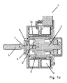
図4a〜4dは、本発明の第4実施形態による線形アクチュエータ1を示す。図4aは、線形アクチュエータ1の斜視図であり、図4bは、線形アクチュエータ1の断面図である。
4a-4d show a
線形アクチュエータ1は、ステッパモータ2と、ステッパモータ2の回転部4と共に回転するように配置された第1部3と、ステッパモータ2から離れるように延在するシャフトの形態の第2部5とを含む。図4aおよび4bに示された第1部3は、ステッパモータ2の回転部4に動かないように接続された回転子シャフトの形態である。第2部5には、第2部5の回転運動を被作動部の線形運動へ変換するために、被作動部に形成されたねじ部分に係合するように配置されたねじ部分11が設けられる。
The
継手6が第1部3と第2部5とを相互接続する。それにより、第2部5は、第1部3と同じ角速度で第1部3と共に回転することができる。継手6は、図4cおよび4dにおいてさらに詳細に示される。
A joint 6 interconnects the
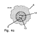
図4cは、図4bに示された線AN−ANに沿った線形アクチュエータ1の断面図であり、図4dは、図4bに示された線AL−ALに沿った線形アクチュエータ1の断面図である。
4c is a cross-sectional view of the
第2部5に突出部12が設けられ、第1部3には、第2部5の突出部12が受け入れられる凹部13が設けられる。突出部12と凹部13との間の協働は、第2部5が第1部3と共に回転することを可能にする。これは、図2a〜2cに示された実施形態と同様である。
The
小さい嵌合い公差が突出部12と凹部13との間に定められる。嵌合い公差は、凹部13の壁が突出部12に係合するわずかに前に第1部3が回転することを可能にし、それにより第2部5を第1部3と共に回転させる。したがって、図1a〜1dを参照して上述された状況と同様に、第1部3から第2部5への増加したトルク伝達が得られる。嵌合い公差は、上述のとおり、例えばステッパモータ2のフルステップの少なくとも0.15もしくは0.25、および/またはステッパモータ2の最大で2フルステップに対応し得る。
A small fitting tolerance is defined between the
軸受配置構成14は、第2部5がわずかな傾動を行うことを可能にされるような方法で第2部5を支持する。
The bearing
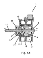
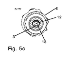
図5a〜5dは、本発明の第5実施形態による線形アクチュエータを示す。図5aは、線形アクチュエータ1の斜視図であり、図5bは、線形アクチュエータ1の断面図である。図5cは、図5bに示された線AU−AUに沿った線形アクチュエータ1の断面図であり、図5dは、図5bに示された線AR−ARに沿った線形アクチュエータ1の断面図である。
Figures 5a to 5d show a linear actuator according to a fifth embodiment of the present invention. FIG. 5 a is a perspective view of the
図5a〜5dの線形アクチュエータ1は、図4a〜4bの線形アクチュエータ1と極めて類似しており、したがって、これはここで詳細に説明されない。しかしながら、図5a〜5dの線形アクチュエータ1において、継手6は、図4a〜4dの線形アクチュエータ1の場合よりもステッパモータ2のさらに内部に配置される。これは、第2部5がステッパモータ2内部に配置された追加的な軸受17および軸受配置構成14により支持されるという結果を有する。
The
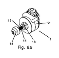
図6a〜6dは、本発明の第6実施形態による線形アクチュエータ1を示す。図6aは、線形アクチュエータ1の斜視図であり、図6bは、線形アクチュエータ1の断面図である。図6cは、図6bに示された線AJ−AJに沿った線形アクチュエータ1の断面図であり、図6dは、図6bに示された線AG−AGに沿った線形アクチュエータ1の断面図である。
6a to 6d show a
図6a〜6dの線形アクチュエータ1の継手6が図4a〜4dの線形アクチュエータ1の継手6と同様であるという意味で、図6a〜6dの線形アクチュエータ1は、図4a〜4bの線形アクチュエータ1と極めて類似している。したがって、図6a〜6dの線形アクチュエータ1、特に継手6はここで詳細に説明されない。
In the sense that the
図6a〜6dの線形アクチュエータ1には、2つの軸受配置構成14が設けられ、1つはステッパモータ2の後ろに配置されかつ第1部3を支持し、1つは第2部5の端部に配置されかつ第2部5を支持する。
The
雌ねじを有するナット18が、ナット18の雌ねじが第2部5に形成されたねじと係合するような方法で、第2部5のねじ部分11に配置される。ロッド19は、ナット18が回転するのを防ぐ。したがって、第2部5が回転すると、ナット18が第2部5の長さに沿って線形運動を行い、すなわち、ねじ接続部により第2部5の回転運動がナット18の線形運動に変換される。ナット18は、同様に、被作動部、例えば可動バルブ要素に接続され得る。それにより、被作動部は、ナット18に沿って直線的に移動する。
A
図7a〜7dは、本発明の第7実施形態による線形アクチュエータ1を示す。図7aは、線形アクチュエータ1の回転部の斜視断面図であり、図7bは、線形アクチュエータ1の断面図である。図7cは、図7bにおいて「B」と記された円に対応する拡大図であり、図7dは、図7bに示された線C−Cに沿った線形アクチュエータ1の断面図である。
7a-7d show a
図7a〜7dの線形アクチュエータ1の継手6が図3a〜3dの線形アクチュエータ1の継手6と同様であるという意味で、図7a〜7dの線形アクチュエータ1は、図3a〜3dの線形アクチュエータ1と極めて類似している。したがって、図7a〜7dの線形アクチュエータ1はここでより詳細に説明されない。しかしながら、図7a〜7dの線形アクチュエータ1において、継手6は、図3a〜3dの線形アクチュエータ1の場合よりもステッパモータ2のさらに内部に配置される。
7a-7d is similar to the
図7a〜7dの線形アクチュエータ1は、第1部3と第2部5との間の摺動インターフェイスを形成する摺動軸受25を含む。摺動軸受25は、ステッパモータ2の回転部の形態の第1部3に動かないように取り付けられる。しかしながら、摺動軸受25は、第2部5に対して容易に移動することができる。それにより、突出部15が凹部16の壁に係合し、それにより第2部5を第1部3と共に回転させる前に第1部3が十分な角速度まで加速することを可能にされることが確実にされる。
The
図7a〜7dの線形アクチュエータ1において、凹部16は、ステッパモータ2の回転部に直接形成される代わりに摺動軸受25に形成される。これは、摺動軸受25に凹部16を形成し、続いて摺動軸受25をステッパモータ2の回転部に取り付けることの方が、凹部16をステッパモータ2の回転部に直接形成するよりも容易であることために利点である。
In the
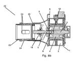
図8aおよび8bは、本発明の一実施形態によるバルブ20を示す。図8aは、バルブ20の斜視図であり、図8bは、バルブ20の断面図である。バルブ20は、バルブハウジング21内部に配置された図1a〜1dに示された種類の線形アクチュエータ1を含む。しかしながら、バルブ20は、代替的に、図2a〜7dに示された線形アクチュエータ1の1つを含み得ることに留意されたい。
Figures 8a and 8b show a
雌ねじが設けられたナット18が第2部5のねじ部分11に配置される。それにより、図6a〜6dを参照して上で説明された状況と同様に、第2部5の回転運動がナット18の線形運動に変換される。
A
ナット18は、可動バルブ要素22に接続される。したがって、ナット18が直線的に移動するとき、可動バルブ要素22も直線的に移動される。それにより、可動バルブ要素22と静止バルブ要素23との間の相対的位置が変えられる。静止バルブ要素23は、バルブハウジング21内部に配置されたスリーブの形態であり、バルブハウジング21に対して静止している。スリーブにはいくつかの開口24が設けられている。可動バルブ要素22が静止バルブ要素23に対して移動すると、バルブ要素22により覆われる開口24の部分が変わる。それにより、可動バルブ要素22により覆われていない、開口24の一部により定められた流体通路の大きさも変わる。したがって、バルブ20の開口度が変わる。
The
Claims (16)
− モータ(2)の回転部(4)と共に回転するように配置された第1部(3)と、
− 被作動部(18、22)を駆動するように配置された第2部(5)と、
− 前記第2部(5)が前記第1部(3)と同じ角速度で前記第1部(3)と共に回転することを可能にするために前記第1部(3)と前記第2部(5)とを相互接続する継手(6)であって、前記第1部(3)が、前記第2部(5)に係合しかつ前記第2部(5)を前記第1部(3)と共に回転させる前に所定の距離だけ回転することを可能にする、前記第1部(3)と前記第2部(5)との間の嵌合い公差を定める、継手(6)と
を含む、線形アクチュエータ(1)。 A linear actuator (1),
A first part (3) arranged to rotate with the rotating part (4) of the motor (2);
A second part (5) arranged to drive the actuated parts (18, 22);
The first part (3) and the second part (in order to allow the second part (5) to rotate with the first part (3) at the same angular velocity as the first part (3); 5), the first part (3) is engaged with the second part (5) and the second part (5) is connected to the first part (3). A joint (6) that defines a fitting tolerance between the first part (3) and the second part (5), which allows a predetermined distance to be rotated before rotating with A linear actuator (1).
Applications Claiming Priority (5)
| Application Number | Priority Date | Filing Date | Title |
|---|---|---|---|
| EP15198334.3 | 2015-12-08 | ||
| EP15198334.3A EP3179144A1 (en) | 2015-12-08 | 2015-12-08 | A linear actuator with a coupling |
| DKPA201600169 | 2016-03-21 | ||
| DKPA201600169 | 2016-03-21 | ||
| PCT/EP2016/079904 WO2017097770A1 (en) | 2015-12-08 | 2016-12-06 | A linear actuator with a coupling |
Publications (2)
| Publication Number | Publication Date |
|---|---|
| JP2018536816A true JP2018536816A (en) | 2018-12-13 |
| JP2018536816A5 JP2018536816A5 (en) | 2019-09-19 |
Family
ID=59013718
Family Applications (1)
| Application Number | Title | Priority Date | Filing Date |
|---|---|---|---|
| JP2018529281A Pending JP2018536816A (en) | 2015-12-08 | 2016-12-06 | Linear actuator with joint |
Country Status (6)
| Country | Link |
|---|---|
| US (1) | US11680658B2 (en) |
| EP (1) | EP3387304B1 (en) |
| JP (1) | JP2018536816A (en) |
| CN (1) | CN108368948B (en) |
| ES (1) | ES2827956T3 (en) |
| WO (1) | WO2017097770A1 (en) |
Families Citing this family (2)
| Publication number | Priority date | Publication date | Assignee | Title |
|---|---|---|---|---|
| EP3671072A1 (en) * | 2018-12-20 | 2020-06-24 | Danfoss A/S | Valve, in particular expansion valve |
| CN113557369A (en) * | 2019-03-13 | 2021-10-26 | 利纳克有限公司 | Linear actuator |
Citations (5)
| Publication number | Priority date | Publication date | Assignee | Title |
|---|---|---|---|---|
| US4215714A (en) * | 1978-06-01 | 1980-08-05 | Laue Charles E | Valve and method of making |
| JP2005291223A (en) * | 2004-03-31 | 2005-10-20 | Saginomiya Seisakusho Inc | Electric control valve |
| JPWO2004003414A1 (en) * | 2002-06-26 | 2005-10-27 | 千代田空調機器株式会社 | Motorized valve |
| JPWO2012023342A1 (en) * | 2010-08-20 | 2013-10-28 | Ckd株式会社 | Fluid control device |
| JP2014121264A (en) * | 2012-12-13 | 2014-06-30 | Johnson Electric Sa | Linear actuator |
Family Cites Families (12)
| Publication number | Priority date | Publication date | Assignee | Title |
|---|---|---|---|---|
| GB355231A (en) | 1930-05-12 | 1931-08-12 | Cutler Hammer Mfg Co | Improvements in or relating to driving mechanisms for valves and other devices |
| DE3507091A1 (en) | 1985-02-28 | 1986-08-28 | Kraftwerk Union AG, 4330 Mülheim | ARMATURE TO BLOCK A FLOW |
| JPH0849782A (en) * | 1994-08-06 | 1996-02-20 | Toyota Autom Loom Works Ltd | Screw shaft turning-stop mechanism for linear-motion converter motor |
| EP0784174A3 (en) | 1996-01-12 | 1998-03-11 | Siemens Aktiengesellschaft | Armature with and electromotor actuator |
| US6460567B1 (en) | 1999-11-24 | 2002-10-08 | Hansen Technologies Corpporation | Sealed motor driven valve |
| CA2822299C (en) | 2003-11-10 | 2015-01-06 | Sloan Valve Company | Automatically operated handle-type flush valve |
| JP2006112522A (en) | 2004-10-14 | 2006-04-27 | Saginomiya Seisakusho Inc | Motor-operated valve |
| CN102410392B (en) | 2010-09-19 | 2014-07-23 | 浙江三花股份有限公司 | Electrically operated valve |
| US8402833B2 (en) * | 2011-03-21 | 2013-03-26 | Irwin Industrial Tool Company | Stepper motor gauge |
| CN202513736U (en) | 2012-04-05 | 2012-10-31 | 浙江宏远数控机床有限公司 | Torque motor direct-driven device |
| JP6119466B2 (en) * | 2013-07-03 | 2017-04-26 | 株式会社デンソー | Electric expansion valve |
| JP6567336B2 (en) * | 2015-06-22 | 2019-08-28 | 株式会社不二工機 | Motorized valve |
-
2016
- 2016-12-06 WO PCT/EP2016/079904 patent/WO2017097770A1/en active Application Filing
- 2016-12-06 US US15/781,754 patent/US11680658B2/en active Active
- 2016-12-06 CN CN201680071710.0A patent/CN108368948B/en active Active
- 2016-12-06 ES ES16809724T patent/ES2827956T3/en active Active
- 2016-12-06 JP JP2018529281A patent/JP2018536816A/en active Pending
- 2016-12-06 EP EP16809724.4A patent/EP3387304B1/en active Active
Patent Citations (5)
| Publication number | Priority date | Publication date | Assignee | Title |
|---|---|---|---|---|
| US4215714A (en) * | 1978-06-01 | 1980-08-05 | Laue Charles E | Valve and method of making |
| JPWO2004003414A1 (en) * | 2002-06-26 | 2005-10-27 | 千代田空調機器株式会社 | Motorized valve |
| JP2005291223A (en) * | 2004-03-31 | 2005-10-20 | Saginomiya Seisakusho Inc | Electric control valve |
| JPWO2012023342A1 (en) * | 2010-08-20 | 2013-10-28 | Ckd株式会社 | Fluid control device |
| JP2014121264A (en) * | 2012-12-13 | 2014-06-30 | Johnson Electric Sa | Linear actuator |
Also Published As
| Publication number | Publication date |
|---|---|
| WO2017097770A1 (en) | 2017-06-15 |
| CN108368948B (en) | 2019-10-08 |
| EP3387304B1 (en) | 2020-08-26 |
| ES2827956T3 (en) | 2021-05-25 |
| US11680658B2 (en) | 2023-06-20 |
| US20180363797A1 (en) | 2018-12-20 |
| EP3387304A1 (en) | 2018-10-17 |
| CN108368948A (en) | 2018-08-03 |
Similar Documents
| Publication | Publication Date | Title |
|---|---|---|
| JP4440189B2 (en) | Biaxial hinge device | |
| JP4713934B2 (en) | Motorized valve | |
| JP2010043727A (en) | Motor valve | |
| CN112689723B (en) | Electric parking lock actuator limited rotational disconnect | |
| KR20120000491A (en) | Internal thread member, motor-operated valve using internal thread member, and manufacturing method of internal thread member for motor-operated valve | |
| JP2018536816A (en) | Linear actuator with joint | |
| JP2006194180A (en) | Starting motor with intermediate gear | |
| CN110985679B (en) | Valve device, electric valve, and refrigeration cycle system | |
| JP2007024274A (en) | Valve device | |
| EP3376083B1 (en) | Valve actuator | |
| JP2006316835A (en) | Electric control valve | |
| KR102273275B1 (en) | Valve drive device | |
| DE102006000546A1 (en) | Two-way clutch | |
| JP6791508B2 (en) | Solenoid valve | |
| JP2023528185A (en) | electronic expansion valve | |
| EP3179144A1 (en) | A linear actuator with a coupling | |
| JP2003329157A (en) | Motor-driven valve | |
| WO2016017417A1 (en) | Shift range switching device | |
| KR102273279B1 (en) | Valve drive device | |
| CN211261369U (en) | Electronic expansion valve | |
| US7073772B2 (en) | Motor brake structure and manufacturing method thereof | |
| KR100503015B1 (en) | A motor having clutch mounted thereon | |
| KR20150145197A (en) | Starter assembly | |
| JP4753560B2 (en) | Camera aperture device | |
| JPH11190451A (en) | Operation range setting device for rotary body |
Legal Events
| Date | Code | Title | Description |
|---|---|---|---|
| A521 | Request for written amendment filed |
Free format text: JAPANESE INTERMEDIATE CODE: A523 Effective date: 20190806 |
|
| A621 | Written request for application examination |
Free format text: JAPANESE INTERMEDIATE CODE: A621 Effective date: 20190806 |
|
| A977 | Report on retrieval |
Free format text: JAPANESE INTERMEDIATE CODE: A971007 Effective date: 20200730 |
|
| A131 | Notification of reasons for refusal |
Free format text: JAPANESE INTERMEDIATE CODE: A131 Effective date: 20200825 |
|
| A521 | Request for written amendment filed |
Free format text: JAPANESE INTERMEDIATE CODE: A523 Effective date: 20201102 |
|
| A02 | Decision of refusal |
Free format text: JAPANESE INTERMEDIATE CODE: A02 Effective date: 20210427 |