JP2005291223A - Electric control valve - Google Patents
Electric control valve Download PDFInfo
- Publication number
- JP2005291223A JP2005291223A JP2004102536A JP2004102536A JP2005291223A JP 2005291223 A JP2005291223 A JP 2005291223A JP 2004102536 A JP2004102536 A JP 2004102536A JP 2004102536 A JP2004102536 A JP 2004102536A JP 2005291223 A JP2005291223 A JP 2005291223A
- Authority
- JP
- Japan
- Prior art keywords
- rotor
- torque transmission
- control valve
- screw member
- electric control
- Prior art date
- Legal status (The legal status is an assumption and is not a legal conclusion. Google has not performed a legal analysis and makes no representation as to the accuracy of the status listed.)
- Pending
Links
Images
Landscapes
- Electrically Driven Valve-Operating Means (AREA)
- Transmission Devices (AREA)
Abstract
Description
この発明は、電動式コントロールバルブに関し、特に、ステッピングモータ等の電動機によって駆動される電動式コントロールバルブの騒音低減に関するものである。 The present invention relates to an electric control valve, and more particularly to noise reduction of an electric control valve driven by an electric motor such as a stepping motor.
流量制御等を行う弁装置として、ステッピングモータ等の電動機のロータの回転を雄ねじ部材と雌ねじ部材とのねじ係合による送りねじ機構によって弁リフト方向の直線運動に変換し、当該直線運動によって弁体を弁リフト方向に移動させる電動式コントロールバルブが知られている(例えば、特許文献1〜4)。
As a valve device for performing flow rate control and the like, the rotation of the rotor of an electric motor such as a stepping motor is converted into a linear motion in the valve lift direction by a feed screw mechanism by screw engagement between a male screw member and a female screw member, and the valve element is converted by the linear motion. There is known an electric control valve that moves the valve in the valve lift direction (for example,
上述のような電動式コントロールバルブでは、ステッピングモータの各励磁相(例えば、A相、AB相、B相)への通電により、ステッピングモータのロータがオーバシュートを伴う間欠回転運動を行い、この間欠回転運動(回転振動)が送りねじ機構に直接伝達されるため、ねじ係合部の摺動音を音源とする騒音(動作音)が生じ、静粛性が損なわれる。ステッピングモータのロータの間欠回転運動を状態を図11に模式的に示している。図11において、励磁相の変遷時に、区間Mで、オーバシュートを収束するロータの回転振動Nが生じる。 In the electric control valve as described above, the energization of each excitation phase (for example, A phase, AB phase, B phase) of the stepping motor causes the rotor of the stepping motor to perform intermittent rotational motion with overshoot. Since the rotational motion (rotational vibration) is directly transmitted to the feed screw mechanism, noise (operation sound) using the sliding sound of the screw engaging portion as a sound source is generated, and the silence is impaired. FIG. 11 schematically shows the intermittent rotational motion of the rotor of the stepping motor. In FIG. 11, at the transition of the excitation phase, in the section M, the rotational vibration N of the rotor that converges the overshoot occurs.
この問題を解決するために、ロータを合成樹脂製の軸受パッキンによって回転可能に支持し、軸受パッキンのダンピング効果によってロータの回転振動を抑制するもの(例えば、特許文献5)、ロータをブッシュ軸受とシャフト軸受とによる両端軸受構造によって回転および位置移動可能に支持してロータの回転振動を抑制するもの(例えば、特許文献6)、ロータに圧縮コイルばねによる負荷を与えてロータ回転に摺動抵抗を与え、ロータの回転振動を抑制するもの(例えば、特許文献7)がある。 In order to solve this problem, the rotor is rotatably supported by a bearing packing made of synthetic resin, and the rotor vibration is suppressed by a damping effect of the bearing packing (for example, Patent Document 5). A shaft bearing and a both-end bearing structure that supports the rotation and position of the rotor so as to suppress rotational vibration of the rotor (for example, Patent Document 6). There is one that suppresses rotational vibration of the rotor (for example, Patent Document 7).
しかし、軸受パッキンによるもの(例えば、特許文献5)は、軸受パッキンによってロータ回転の摺動抵抗を増やしてロータの回転振動を低減するものであるため、ロータの回転抵抗が増え、安定した動作を得ることが難しくなる。また、合成樹脂製の軸受パッキンを用いているため、経年変化によって軸受パッキンによる回転振動の低減効果が低下し、耐久性に問題がある。 However, since the bearing packing (for example, Patent Document 5) increases the sliding resistance of the rotor rotation by the bearing packing and reduces the rotational vibration of the rotor, the rotational resistance of the rotor is increased and stable operation is achieved. It becomes difficult to obtain. In addition, since the synthetic resin bearing packing is used, the effect of reducing rotational vibration by the bearing packing is lowered due to aging, and there is a problem in durability.
両端軸受構造によるもの(例えば、特許文献6)は、軸受部の同心管理、クリアランス管理が難しく、ロータの回転振動を軸受部で抑制するため、摺動抵抗が発生し、作動が不安定になる。このことに対して軸受部の摺動抵抗を少なくすると、ロータの回転振動がねじ係合部に伝達することを抑制する効果が低減し、騒音低減効果を期待できなくなる。 In the case of a double-end bearing structure (for example, Patent Document 6), concentric management and clearance management of the bearing portion is difficult, and rotational vibration of the rotor is suppressed by the bearing portion, so that sliding resistance is generated and operation becomes unstable. . On the other hand, if the sliding resistance of the bearing portion is reduced, the effect of suppressing the rotational vibration of the rotor from being transmitted to the screw engaging portion is reduced, and the noise reduction effect cannot be expected.
ロータに圧縮コイルばねによる負荷を与えてロータの回転振動を抑制するもの(例えば、特許文献7)は、ロータの回転抵抗が増加するばかりでなく、圧縮コイルばねによる負荷がねじ係合部にも作用するために、ねじ部の回転抵抗も増加し、耐久性が低下する。 A rotor that suppresses rotational vibration of the rotor by applying a load by a compression coil spring to the rotor (for example, Patent Document 7) not only increases the rotational resistance of the rotor, but also the load by the compression coil spring is applied to the screw engaging portion. In order to act, rotation resistance of a thread part also increases and durability falls.
従来のものは、何れも、ロータやロータ軸受部、ねじ係合部の回転抵抗が増加するため、ロータの回転に必要なトルクが増大し、コイル部の大型化、消費電力の増加を招く。
この発明が解決しようとする課題は、ロータやロータ軸受部、ねじ係合部の回転抵抗を増加することなく、ロータの回転振動がねじ係合部に伝わることを回避して騒音を低減し、併せて優れた動作安定性、耐久性を得ることである。 The problem to be solved by the present invention is to reduce the noise by avoiding the rotation vibration of the rotor being transmitted to the screw engaging portion without increasing the rotational resistance of the rotor, the rotor bearing portion, and the screw engaging portion, At the same time, it is to obtain excellent operational stability and durability.
この発明による電動式コントロールバルブは、雄ねじ部材と雌ねじ部材の何れか一方を電動機のロータによって回転駆動され、前記ロータの回転を前記雄ねじ部材と前記雌ねじ部材とのねじ係合による送りねじ機構によって弁リフト方向の直線運動に変換し、当該直線運動によって弁体を弁リフト方向に移動させる電動式コントロールバルブにおいて、前記ロータと前記送りねじ機構のうちロータによって回転駆動される側のねじ部材との間にロータ回転方向のクリアランスが設けられている。 In the electric control valve according to the present invention, either a male screw member or a female screw member is rotationally driven by a rotor of an electric motor, and the rotation of the rotor is controlled by a feed screw mechanism by screw engagement between the male screw member and the female screw member. In the electric control valve that converts the linear motion in the lift direction and moves the valve body in the valve lift direction by the linear motion, between the rotor and the screw member on the side of the feed screw mechanism that is rotationally driven by the rotor. Is provided with a clearance in the rotor rotation direction.
この発明による電動式コントロールバルブの電動機はステッピングモータである。 The electric motor of the electric control valve according to the present invention is a stepping motor.
この発明による電動式コントロールバルブは、前記ロータと前記送りねじ機構のうちロータによって回転駆動される側のねじ部材との接続部に前記クリアランスが設定されている、或いは前記ロータをロータケースより回転可能に支持し前記ロータによって回転駆動される側のねじ部材とトルク伝達関係で連結されるロータ軸を有し、当該ロータ軸と前記ロータとの間に前記クリアランスが設定されている、或いは前記ロータをロータケースより回転可能に支持し前記ロータによって回転駆動される側のねじ部材とトルク伝達関係で連結されるロータ軸を有し、当該ロータ軸と前記ねじ部材との間に前記クリアランスが設定されている。 In the electric control valve according to the present invention, the clearance is set at a connection portion between the rotor and the screw member on the side rotated by the rotor in the feed screw mechanism, or the rotor can be rotated from the rotor case. A rotor shaft that is connected to a screw member that is rotationally driven by the rotor in a torque transmission relationship, and the clearance is set between the rotor shaft and the rotor, or the rotor is A rotor shaft that is rotatably supported by the rotor case and is connected to a screw member that is driven to rotate by the rotor in a torque transmission relationship, and the clearance is set between the rotor shaft and the screw member. Yes.
この発明による電動式コントロールバルブは、更に、前記クリアランスにゴム状弾性部材が配置されている。 In the electric control valve according to the present invention, a rubber-like elastic member is further disposed in the clearance.
この発明による電動式コントロールバルブは、ロータとねじ部材との間にロータ回転方向のクリアランスが設けられていることにより、ロータの振動、つまり、ロータの微少角による往復回転がクリアランスによるロータの空転により吸収され、ロータ振動が送りねじ機構のねじ係合部に伝わることが回避される。 In the electric control valve according to the present invention, a clearance in the rotor rotation direction is provided between the rotor and the screw member, so that the vibration of the rotor, that is, the reciprocating rotation by a small angle of the rotor is caused by the idling of the rotor due to the clearance. It is absorbed and it is avoided that the rotor vibration is transmitted to the screw engaging portion of the feed screw mechanism.
これにより、ロータ(多極着磁マグネット)の種類、大きさ、重さ、相励磁速度の如何に拘わらず、ねじ係合部の摺動音を音源とする騒音(動作音)が低減する。また、単純にクリアランスによって振動伝達を絶縁(遮断)するから、ロータやロータ軸受部、ねじ係合部の回転抵抗を増加することがなく、優れた動作安定性、耐久性を得ることができ、コイル部の大型化、消費電力の増加を招くこともない。 Thereby, regardless of the type, size, weight, and phase excitation speed of the rotor (multipolar magnetized magnet), noise (operating sound) using the sliding sound of the screw engaging portion as a sound source is reduced. In addition, since vibration transmission is simply insulated (blocked) by clearance, the rotational resistance of the rotor, rotor bearing portion, and screw engagement portion is not increased, and excellent operational stability and durability can be obtained. There is no increase in coil size and power consumption.
この発明による電動式コントロールバルブの一つの実施形態を、図1〜図3を参照して説明する。 One embodiment of an electric control valve according to the present invention will be described with reference to FIGS.
この実施形態による電動式コントロールバルブは、図1に示されているように、弁ハウジング11を有し、弁ハウジング11は、弁室12、弁座部13、弁ポート14を形成している。弁ハウジング11には、弁室12に直接連通する管継手15と、弁ポート14に直接連通する管継手16とが接続されている。
As shown in FIG. 1, the electric control valve according to this embodiment includes a
弁ハウジング11には溶接等によって弁体支持部材17が固定装着されている。弁体支持部材17は、支持孔18によって弁体20の軸状のステム部20Bを上下方向(軸線方向)、つまり弁リフト方向に移動可能に支持している。
A valve
弁体20は、ステム部20Bの下端側にニードル弁部20Aを有し、ニードル弁部20Aによって弁ポート14の開閉、開度調整を行う。
The
ステム部20Bの上端には送りねじ機構の雄ねじ部材29が同心に一体に設けられている。雄ねじ部材29は、弁体支持部材17の上側に支持孔18と同心に形成された雌ねじ孔19にねじ係合し、回転により、ねじピッチによって弁体20を軸線方向、つまり、弁リフト方向に駆動する。
A
すなわち、弁体支持部材17が送りねじ機構の雌ねじ部材を兼ねており、雌ねじ孔19と雄ねじ部材29とのねじ係合による送りねじ機構によって後述のステッピングモータ30のロータ31の回転を弁リフト方向の直線運動に変換し、当該直線運動によって弁体20を弁リフト方向に移動させる。
That is, the valve
弁ハウジング11には、弁体支持部材17を内蔵する形態で、溶接等によってステッピングモータ30のキャン状のロータケース32が固定されている。ロータケース32内には天井部より頭部(フランジ33C)付きのロータ軸33が吊り下げ固定されている。ロータ31は、ロータケース32内にあってその中心孔31Aにロータ軸33を通され、ロータ軸33によってロータケース32より吊り下げ式に回転可能に支持されている。ロータ31の上面には滑り座金35が配置され、滑り座金35とロータケース32の天井部との間に、ロータ31の軸線方向のがた付き移動を抑制する圧縮コイルばね36が設けられている。
A can-
ロータケース32の外側にはステッピングモータ30のステータコイル装置34が取り付けられている。ステータコイル装置34は、図示されてないが、ステッピングモータ用の多磁極歯構造の一般的構造のもので、A相、AB相、B相等の励磁相を有するものであり、ロータ31が多極着磁されたマグネットであることにより、パルス通電によってロータ31を所定の分解能をもって分割回転駆動する。
A
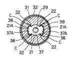
ロータ31の下側には、中心孔31Aと同心に円柱状のトルク伝達孔37が形成されている。このトルク伝達孔37の周面には、図1のA−A線断面図である図2及び図3に示されているように、ロータ31の回転方向に180度位相をずらして一対の扇形状部37Aが膨出形成されている。
A cylindrical
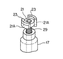
雄ねじ部材29の上端には、図3に示されているように、トルク伝達駒21が固定(固着)されている。トルク伝達駒21は、トルク伝達孔37と同じく円柱状を呈しており、トルク伝達駒21の周面には、ロータ31の回転方向に180度位相をずらして一対の扇形状部21Aが膨出形成されている。このトルク伝達駒21は、図2に示されているように、ロータ31のトルク伝達孔37に、軸線方向に変位可能に、滑りキー式にトルク伝達関係で係合している。
As shown in FIG. 3, the
ここで重要なことは、トルク伝達孔37の扇形状部37Aの両端に形成されたトルク伝達面38とトルク伝達駒21の扇形状部21Aの両端に形成されたトルク授与面22との間に、即ち、ロータ回転方向に相対向するトルク伝達面38とトルク授与面22との間に、各々、ロータ回転方向のクリアランス(間隙)Cが設けられていることである。クリアランスCは、一方の扇形状部37A、21Aの2つのトルク伝達面38及びトルク授与面22間にできる2つのクリアランスCの合計で、通常動作下で生じるロータ31の回転振動の振幅より少し大きい値に設定されている。
What is important here is that between the
これにより、ステッピングモータ30の励磁相の変遷時に、ロータ31が回転方向に振動しても、つまり、ロータ31が微少角による往復回転を繰り返しても、クリアランスCの範囲で、ロータ31だけが回転(空転)することにより、このロータ31の微少角による往復回転が、トルク伝達駒21、雄ねじ部材29に伝わることがない。
As a result, even if the
これにより、ロータ31の多極着磁の種類、大きさ、重さ、相励磁速度の如何に拘わらず、雄ねじ部材29と雌ねじ孔20とのねじ係合部の摺動音を音源とする騒音(動作音)が低減する。
As a result, regardless of the type, size, weight, and phase excitation speed of the multipolar magnetization of the
また、単純に、クリアランスCによってロータ31の回転振動が雄ねじ部材29の側に伝わることを絶縁(遮断)するから、ロータ31やロータ軸受部、ねじ係合部の回転抵抗を増加することがなく、優れた動作安定性、耐久性を得ることができ、ステータコイル装置34の大型化、消費電力の増加を招くこともないと云う効果が得られる。
Further, since the rotation C of the
なお、図4に示されているように、トルク伝達駒21の扇形状部21Aに、適度の硬度、弾性を有する合成樹脂、ゴム等によるゴム状弾性部材23を貼り付け、ゴム状弾性部材23をクリアランスC、つまり、トルク伝達孔37のトルク伝達面38とトルク伝達駒21のトルク授与面22との間に配置してもよい。
As shown in FIG. 4, a rubber-like
この場合には、ロータ31の回転振動によってゴム状弾性部材23が弾性変形することにより、防振ゴムの作用が得られ、ロータ31の回転振動を減衰する効果も得られる。また、トルク伝達孔37のトルク伝達面38とトルク伝達駒21のトルク授与面22とが直接衝突することが避けられ、衝突音の発生も避けられる。
In this case, the rubber-like
また、予めトルク伝達孔37のトルク伝達面38とトルク伝達駒21のトルク授与面22との、ロータ回転方向の間隙を余裕をもって設定することにより、ゴム状弾性部材23を配置してもなお、クリアランスCを、一方の扇形状部37A、21Aの2つのトルク伝達面38及びトルク授与面22間にできる2つのクリアランスCの合計で、通常動作下で生じるロータ31の回転振動の振幅より大きい値に設定することもできる。
In addition, even if the rubber-like
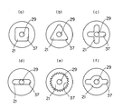
トルク伝達駒21、トルク伝達孔37のトルク伝達形状(横断面形状)は、図2、3に示す形状に限られることはなく、図5(a)〜(f)に示されているような四角形、三角形、十文字形一文字形、セレーション形、変形一文字形等、真円形以外の各種形状に設定することが可能である。
The torque transmission shapes (transverse cross-sectional shapes) of the
つぎに、この発明による電動式コントロールバルブの他の実施形態を、図6〜図8を参照して説明する。なお、図6〜図8において、図1〜図3に対応する部分は、図1〜図3に付した符号と同一の符号を付けて、その説明を省略する。 Next, another embodiment of the electric control valve according to the present invention will be described with reference to FIGS. 6 to 8, parts corresponding to those in FIGS. 1 to 3 are denoted by the same reference numerals as those in FIGS. 1 to 3, and description thereof is omitted.
この実施形態では、図6に示されているように、円筒状のロータ31の中心孔31Aをロータ軸33が軸線方向に貫通し、ロータ軸33は、上端部33Aをロータケース32の天井部に形成された軸受部32Aにより回転可能に支持され、下端部33Bをロータケース32に固定装着された支持板38の軸受孔38Aにより回転可能に支持されている。
In this embodiment, as shown in FIG. 6, the
支持板38の軸受孔38Aを貫通したロータ軸33の下端部33B部分にはトルク伝達凹部44が形成され、トルク伝達凹部44には、雄ねじ部材29の上端に固定装着されたトルク伝達頭部28が係合し、ロータ軸33と雄ねじ部材29とをトルク伝達関係でリジットに連結している。
A
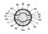
ロータ31の下端部には、図6のB−B線断面図である図7及び図8に示されているように、ロータ31の回転方向に180度位相をずらした中心孔31A箇所からロータ31の径方向に中心孔31Aを拡大してなる、キー溝状の一対のトルク伝達凹溝39が形成されている。
As shown in FIGS. 7 and 8, which are cross-sectional views taken along the line BB in FIG. 6, the
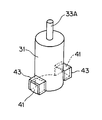
ロータ軸33の下端部寄りの周面部分には、図8に示されているように、ロータ31の回転方向に180度位相をずらして一対のトルク伝達凸部41がキー状に膨出形成されており、ロータ31の中心孔31Aを貫通したロータ軸33の各トルク伝達凸部41は、対応する各トルク伝達凹溝39にトルク伝達関係で係合している。
As shown in FIG. 8, a pair of torque transmission
トルク伝達凹溝39のトルク伝達面40とトルク伝達凸部41のトルク授与面42とは、ロータ回転方向に相対向しており、このトルク伝達凹溝39のトルク伝達面40とトルク伝達凸部41のトルク授与面42との間には、ロータ回転方向のクリアランスCが設けられている。クリアランスCは、一方のトルク伝達凹溝39、トルク伝達凸部41の2つのトルク伝達面40及びトルク授与面42間にできる2つのクリアランスCの合計で、通常動作下で生じるロータ31の回転振動の振幅より少し大きい値に設定されている。
The
これにより、ステッピングモータ30の励磁相の変遷時に、ロータ31が回転方向に振動しても、つまり、ロータ31が微少角による往復回転を繰り返しても、クリアランスCの範囲で、ロータ31だけが回転(空転)することにより、このロータ31の微少角による往復回転が、ロータ軸33、雄ねじ部材29に伝わることがない。
As a result, even if the
これにより、ロータ31の多極着磁の種類、大きさ、重さ、相励磁速度の如何に拘わらず、雄ねじ部材29と雌ねじ孔20とのねじ係合部の摺動音を音源とする騒音(動作音)が低減する。
As a result, regardless of the type, size, weight, and phase excitation speed of the multipolar magnetization of the
また、この実施形態でも、単純に、クリアランスCによってロータ31の回転振動が雄ねじ部材29の側に伝わることを絶縁(遮断)するから、ロータ31やロータ軸受部、ねじ係合部の回転抵抗を増加することがなく、優れた動作安定性、耐久性を得ることができ、ステータコイル装置34の大型化、消費電力の増加を招くこともないと云う効果が得られる。
In this embodiment as well, since the rotational vibration of the
なお、図9に示されているように、トルク伝達凸部41に、適度の硬度、弾性を有する合成樹脂、ゴム等によるゴム状弾性部材43を貼り付け、ゴム状弾性部材43をクリアランスC、つまり、トルク伝達凹溝39のトルク伝達面40とトルク伝達凸部41のトルク授与面42との間に配置してもよい。
As shown in FIG. 9, a rubber-like
この場合には、ロータ31の回転振動によってゴム状弾性部材43が弾性変形することにより、防振ゴムの作用が得られ、ロータ31の回転振動を減衰する効果も得られる。また、トルク伝達凹溝39のトルク伝達面40とトルク伝達凸部41のトルク授与面42とが直接衝突することが避けられ、衝突音の発生も避けられる。
In this case, the rubber-like
また、予めトルク伝達凹溝39のトルク伝達面40とトルク伝達凸部41のトルク授与面42との、ロータ回転方向の間隙を余裕をもって設定することにより、ゴム状弾性部材43を配置してもなお、クリアランスCを、一方のトルク伝達凹溝39、トルク伝達凸部41の2つのトルク伝達面40及びトルク授与面42間にできる2つのクリアランスCの合計で、通常動作下で生じるロータ31の回転振動の振幅より大きい値に設定することもできる。
Further, even if the rubber-like
トルク伝達凹溝39のトルク伝達面40とトルク伝達凸部41のトルク授与面42との回転方向のクリアランスCの設定は、上述の如きロータ31とロータ軸33とのトルク伝達部に限られることはなく、図6に示されている、ロータ軸33と雄ねじ部材29とをトルク伝達関係でリジットに連結しているトルク伝達凹部44とトルク伝達頭部28との間に、同様に設定することもできる。
The setting of the clearance C in the rotational direction between the
つぎに、この発明による電動式コントロールバルブのもう一つの実施形態を、図10を参照して説明する。なお、図10において、図1〜図8に対応する部分は、図1〜図8に付した符号と同一の符号を付けて、その説明を省略する。 Next, another embodiment of the electric control valve according to the present invention will be described with reference to FIG. 10, parts corresponding to those in FIGS. 1 to 8 are denoted by the same reference numerals as those in FIGS. 1 to 8, and description thereof is omitted.
この実施形態では、図6〜図8に示されている実施形態と同様に、図7に示されているようなロータ31の回転方向のクリアランスCが、ロータ31のトルク伝達凹溝39とロータ軸33のトルク伝達凸部41との間に設定されている。
In this embodiment, as in the embodiment shown in FIGS. 6 to 8, the rotational direction clearance C of the
そして、図10に示されているように、ロータ軸33の下端側には雄ねじ部材46が一体形成されている。また、弁体20のステム部20Bに、上端側に開放された中空部20Cが形成されており、この中空部20Cの上端寄り部分に雌ねじ部24が形成されている。弁体20は弁ハウジング11に固定された支持部材25によって軸線方向(上下方向)に移動可能に回り止めされている。雄ねじ部材46は、回り止めされている弁体20の雌ねじ部24にねじ係合し、ロータ31乃至ロータ軸33の回転により、ねじピッチによって弁体20を軸線方向、つまり、弁リフト方向に駆動する。
As shown in FIG. 10, a
すなわち、弁体20が送りねじ機構の雌ねじ部材を兼ねており、雌ねじ部24と雄ねじ部材46とのねじ係合による送りねじ機構によってステッピングモータ30のロータ31の回転を弁リフト方向の直線運動に変換し、当該直線運動によって弁体20を弁リフト方向に移動させる。
That is, the
なお、支持部材25による雄ねじ部材46の下端部の回転可能な軸受け支持部分の詳細な説明が必要ならば、特開2000−346225号公報を参照されたい。
In addition, if detailed description of the rotatable bearing support part of the lower end part of the
この実施形態でも、ステッピングモータ30の励磁相の変遷時に、ロータ31が回転方向に振動しても、つまり、ロータ31が微少角による往復回転を繰り返しても、クリアランスCの範囲で、ロータ31だけが回転(空転)することにより、このロータ31の微少角による往復回転が、ロータ軸33、雄ねじ部材29に伝わることがない。
Even in this embodiment, even when the
これにより、ロータ31の多極着磁の種類、大きさ、重さ、相励磁速度の如何に拘わらず、雄ねじ部材29と雌ねじ孔20とのねじ係合部の摺動音を音源とする騒音(動作音)が低減する。また、ロータ31やロータ軸受部、ねじ係合部の回転抵抗を増加することがないから、優れた動作安定性、耐久性を得ることができ、ステータコイル装置34の大型化、消費電力の増加を招くこともないと云う効果も同様に得られる。
As a result, regardless of the type, size, weight, and phase excitation speed of the multipolar magnetization of the
なお、上述した何れの実施形態でも、雄ねじ部材29がロータ31側で、送りねじ機構の回転部材になっているが、送りねじ機構の雌ねじ部材がロータ31側に設けられている型式の電動式コントロールバルブでも、上述の実施形態と同様に、ロータと送りねじ機構のうちロータ31によって回転駆動される側のねじ部材(雌ねじ部材)との間に、ロータ回転方向のクリアランスを設定することができ、上述の実施形態と同様の効果を得ることができる。
In any of the above-described embodiments, the
11 弁ハウジング
14 弁ポート
17 弁体支持部材
19 雌ねじ孔
20 弁体
21 トルク伝達駒
23 ゴム状弾性部材
24 雌ねじ孔
28 トルク伝達頭部
29 雄ねじ部材
30 ステッピングモータ
31 ロータ
32 ロータケース
33 ロータ軸
34 ステータコイル装置
36 圧縮コイルばね
37 トルク伝達孔
39 トルク伝達凹溝
41 トルク伝達凸部
43 ゴム状弾性部材
44 トルク伝達凹部
46 雄ねじ部材
C クリアランス
DESCRIPTION OF
Claims (6)
前記ロータと前記送りねじ機構のうちロータによって回転駆動される側のねじ部材との間にロータ回転方向のクリアランスが設けられている電動式コントロールバルブ。 Either one of the male screw member and the female screw member is driven to rotate by a rotor of an electric motor, and the rotation of the rotor is converted into a linear motion in the valve lift direction by a feed screw mechanism by screw engagement between the male screw member and the female screw member, In the electric control valve that moves the valve body in the valve lift direction by the linear motion,
An electric control valve in which a clearance in the rotor rotation direction is provided between the rotor and a screw member on the side of the feed screw mechanism that is rotationally driven by the rotor.
Priority Applications (1)
| Application Number | Priority Date | Filing Date | Title |
|---|---|---|---|
| JP2004102536A JP2005291223A (en) | 2004-03-31 | 2004-03-31 | Electric control valve |
Applications Claiming Priority (1)
| Application Number | Priority Date | Filing Date | Title |
|---|---|---|---|
| JP2004102536A JP2005291223A (en) | 2004-03-31 | 2004-03-31 | Electric control valve |
Publications (1)
| Publication Number | Publication Date |
|---|---|
| JP2005291223A true JP2005291223A (en) | 2005-10-20 |
Family
ID=35324402
Family Applications (1)
| Application Number | Title | Priority Date | Filing Date |
|---|---|---|---|
| JP2004102536A Pending JP2005291223A (en) | 2004-03-31 | 2004-03-31 | Electric control valve |
Country Status (1)
| Country | Link |
|---|---|
| JP (1) | JP2005291223A (en) |
Cited By (8)
| Publication number | Priority date | Publication date | Assignee | Title |
|---|---|---|---|---|
| JP2007154968A (en) * | 2005-12-02 | 2007-06-21 | Ogura Clutch Co Ltd | Inflator |
| JP2008032094A (en) * | 2006-07-27 | 2008-02-14 | Saginomiya Seisakusho Inc | Electric control valve |
| JP2011021749A (en) * | 2009-07-17 | 2011-02-03 | Zhejiang Sanhua Co Ltd | Electric expansion valve |
| JP2015014306A (en) * | 2013-07-03 | 2015-01-22 | 株式会社デンソー | Electric expansion valve |
| CN108071701A (en) * | 2016-11-10 | 2018-05-25 | 株式会社鹭宫制作所 | Motor-driven valve and refrigerating circulation system |
| JP2018536816A (en) * | 2015-12-08 | 2018-12-13 | ダンフォス アクチ−セルスカブ | Linear actuator with joint |
| JP2021504648A (en) * | 2017-12-01 | 2021-02-15 | 浙江三花智能控制股▲ふん▼有限公司 | Electronic expansion valve and refrigeration system equipped with it |
| WO2022209653A1 (en) * | 2021-04-01 | 2022-10-06 | 株式会社デンソー | Electric expansion valve |
Citations (7)
| Publication number | Priority date | Publication date | Assignee | Title |
|---|---|---|---|---|
| JPS62179576U (en) * | 1986-05-02 | 1987-11-14 | ||
| JPH07127757A (en) * | 1993-11-03 | 1995-05-16 | Ckd Corp | 'proportional control valve |
| JPH0849782A (en) * | 1994-08-06 | 1996-02-20 | Toyota Autom Loom Works Ltd | Screw shaft turning-stop mechanism for linear-motion converter motor |
| JP2000229578A (en) * | 1998-12-07 | 2000-08-22 | Koyo Seiko Co Ltd | Positioning mechanism |
| JP2002089730A (en) * | 2000-09-18 | 2002-03-27 | Fuji Koki Corp | Motor-operated selector wave |
| JP2003021252A (en) * | 2001-07-05 | 2003-01-24 | Smc Corp | Flow rate control valve |
| WO2004003414A1 (en) * | 2002-06-26 | 2004-01-08 | Chiyoda Kuchokiki Co., Ltd. | Motor-operated valve |
-
2004
- 2004-03-31 JP JP2004102536A patent/JP2005291223A/en active Pending
Patent Citations (7)
| Publication number | Priority date | Publication date | Assignee | Title |
|---|---|---|---|---|
| JPS62179576U (en) * | 1986-05-02 | 1987-11-14 | ||
| JPH07127757A (en) * | 1993-11-03 | 1995-05-16 | Ckd Corp | 'proportional control valve |
| JPH0849782A (en) * | 1994-08-06 | 1996-02-20 | Toyota Autom Loom Works Ltd | Screw shaft turning-stop mechanism for linear-motion converter motor |
| JP2000229578A (en) * | 1998-12-07 | 2000-08-22 | Koyo Seiko Co Ltd | Positioning mechanism |
| JP2002089730A (en) * | 2000-09-18 | 2002-03-27 | Fuji Koki Corp | Motor-operated selector wave |
| JP2003021252A (en) * | 2001-07-05 | 2003-01-24 | Smc Corp | Flow rate control valve |
| WO2004003414A1 (en) * | 2002-06-26 | 2004-01-08 | Chiyoda Kuchokiki Co., Ltd. | Motor-operated valve |
Cited By (14)
| Publication number | Priority date | Publication date | Assignee | Title |
|---|---|---|---|---|
| JP2007154968A (en) * | 2005-12-02 | 2007-06-21 | Ogura Clutch Co Ltd | Inflator |
| JP2008032094A (en) * | 2006-07-27 | 2008-02-14 | Saginomiya Seisakusho Inc | Electric control valve |
| JP2011021749A (en) * | 2009-07-17 | 2011-02-03 | Zhejiang Sanhua Co Ltd | Electric expansion valve |
| US8556229B2 (en) | 2009-07-17 | 2013-10-15 | Zhejiang Sanhua Co., Ltd. | Electronic expansion valve |
| EP3018391A4 (en) * | 2013-07-03 | 2016-11-30 | Denso Corp | Electric expansion valve |
| CN105308376A (en) * | 2013-07-03 | 2016-02-03 | 株式会社电装 | Electric expansion valve |
| JP2015014306A (en) * | 2013-07-03 | 2015-01-22 | 株式会社デンソー | Electric expansion valve |
| JP2018536816A (en) * | 2015-12-08 | 2018-12-13 | ダンフォス アクチ−セルスカブ | Linear actuator with joint |
| US11680658B2 (en) | 2015-12-08 | 2023-06-20 | Danfoss A/S | Linear actuator with a coupling |
| CN108071701A (en) * | 2016-11-10 | 2018-05-25 | 株式会社鹭宫制作所 | Motor-driven valve and refrigerating circulation system |
| JP2021504648A (en) * | 2017-12-01 | 2021-02-15 | 浙江三花智能控制股▲ふん▼有限公司 | Electronic expansion valve and refrigeration system equipped with it |
| US11168804B2 (en) | 2017-12-01 | 2021-11-09 | Zhejiang Sanhua Intelligent Controls Co., Ltd. | Electronic expansion valve and cooling system having same |
| JP7053830B2 (en) | 2017-12-01 | 2022-04-12 | 浙江三花智能控制股▲ふん▼有限公司 | Electronic expansion valve and freezing system equipped with it |
| WO2022209653A1 (en) * | 2021-04-01 | 2022-10-06 | 株式会社デンソー | Electric expansion valve |
Similar Documents
| Publication | Publication Date | Title |
|---|---|---|
| JP4685642B2 (en) | motor | |
| JP2005083575A (en) | Flywheel device | |
| WO1999043072A1 (en) | Control valve apparatus | |
| JP2005291223A (en) | Electric control valve | |
| JPH0928067A (en) | Spacing gap variable motor | |
| JP2003284311A (en) | Stepping motor | |
| JP2006307761A (en) | Actuator of valve lift controller | |
| JP4305895B2 (en) | Electromagnetic shock absorber | |
| US20050052087A1 (en) | Motor holding arrangement and motor actuator having the same | |
| KR101694541B1 (en) | Linear Stepping motor | |
| JP2019213280A (en) | Motor and valve drive device | |
| JP2006300273A (en) | Hypocycloid reduction gear with built-in motor | |
| JP2018038232A (en) | motor | |
| JP2000145482A (en) | Throttle control device | |
| JP3709074B2 (en) | Stepping motor | |
| CN212386357U (en) | Electric seat and electric driver thereof | |
| JP3620816B2 (en) | Motor with friction mechanism and fluid flow control device using this motor | |
| JP2020079562A (en) | Connecting unit, electric motor and valve timing change device | |
| US11533004B2 (en) | Rotary motor having a rotation unit configured to make an elastic deformation | |
| CN218294184U (en) | Novel one-way adjustable damping pivot mechanism and one-way damping hinge | |
| JP4314209B2 (en) | Actuator of valve lift control device | |
| CN220168716U (en) | Solenoid valve, thermal management system and vehicle | |
| JPS63297880A (en) | Flow control device | |
| JP4201786B2 (en) | Motor drive device | |
| JP4296106B2 (en) | Shock absorber |
Legal Events
| Date | Code | Title | Description |
|---|---|---|---|
| A621 | Written request for application examination |
Free format text: JAPANESE INTERMEDIATE CODE: A621 Effective date: 20061211 |
|
| A131 | Notification of reasons for refusal |
Effective date: 20090901 Free format text: JAPANESE INTERMEDIATE CODE: A131 |
|
| A521 | Written amendment |
Free format text: JAPANESE INTERMEDIATE CODE: A523 Effective date: 20091029 |
|
| A131 | Notification of reasons for refusal |
Free format text: JAPANESE INTERMEDIATE CODE: A131 Effective date: 20100209 |
|
| A02 | Decision of refusal |
Effective date: 20100608 Free format text: JAPANESE INTERMEDIATE CODE: A02 |

