JP2018532513A - Needle and related assemblies and methods - Google Patents
Needle and related assemblies and methods Download PDFInfo
- Publication number
- JP2018532513A JP2018532513A JP2018522973A JP2018522973A JP2018532513A JP 2018532513 A JP2018532513 A JP 2018532513A JP 2018522973 A JP2018522973 A JP 2018522973A JP 2018522973 A JP2018522973 A JP 2018522973A JP 2018532513 A JP2018532513 A JP 2018532513A
- Authority
- JP
- Japan
- Prior art keywords
- needle
- opening
- protrusion
- cannula
- hole
- Prior art date
- Legal status (The legal status is an assumption and is not a legal conclusion. Google has not performed a legal analysis and makes no representation as to the accuracy of the status listed.)
- Pending
Links
- 238000000034 method Methods 0.000 title claims abstract description 33
- 230000000712 assembly Effects 0.000 title description 3
- 238000000429 assembly Methods 0.000 title description 3
- 238000003466 welding Methods 0.000 claims description 22
- 239000011324 bead Substances 0.000 claims description 16
- 230000008569 process Effects 0.000 claims description 12
- 230000002093 peripheral effect Effects 0.000 claims description 6
- 206010033675 panniculitis Diseases 0.000 claims description 2
- 210000004304 subcutaneous tissue Anatomy 0.000 claims description 2
- 230000006698 induction Effects 0.000 claims 3
- 239000000463 material Substances 0.000 description 14
- 238000005520 cutting process Methods 0.000 description 11
- 210000001519 tissue Anatomy 0.000 description 11
- 238000011282 treatment Methods 0.000 description 8
- 230000000694 effects Effects 0.000 description 7
- 239000012530 fluid Substances 0.000 description 7
- 230000000149 penetrating effect Effects 0.000 description 7
- 238000004519 manufacturing process Methods 0.000 description 6
- 230000006378 damage Effects 0.000 description 5
- 229920000642 polymer Polymers 0.000 description 4
- 230000008021 deposition Effects 0.000 description 3
- 239000007789 gas Substances 0.000 description 3
- 238000010438 heat treatment Methods 0.000 description 3
- 210000000653 nervous system Anatomy 0.000 description 3
- 238000010008 shearing Methods 0.000 description 3
- 230000001225 therapeutic effect Effects 0.000 description 3
- WFKWXMTUELFFGS-UHFFFAOYSA-N tungsten Chemical compound [W] WFKWXMTUELFFGS-UHFFFAOYSA-N 0.000 description 3
- 229910052721 tungsten Inorganic materials 0.000 description 3
- 239000010937 tungsten Substances 0.000 description 3
- 241001631457 Cannula Species 0.000 description 2
- 229940035676 analgesics Drugs 0.000 description 2
- 229940035674 anesthetics Drugs 0.000 description 2
- 239000000730 antalgic agent Substances 0.000 description 2
- 238000005137 deposition process Methods 0.000 description 2
- 238000010586 diagram Methods 0.000 description 2
- 239000003193 general anesthetic agent Substances 0.000 description 2
- 208000014674 injury Diseases 0.000 description 2
- 238000003780 insertion Methods 0.000 description 2
- 230000037431 insertion Effects 0.000 description 2
- 229910052751 metal Inorganic materials 0.000 description 2
- 239000002184 metal Substances 0.000 description 2
- 210000001428 peripheral nervous system Anatomy 0.000 description 2
- 208000027418 Wounds and injury Diseases 0.000 description 1
- LNSPFAOULBTYBI-UHFFFAOYSA-N [O].C#C Chemical group [O].C#C LNSPFAOULBTYBI-UHFFFAOYSA-N 0.000 description 1
- 230000003444 anaesthetic effect Effects 0.000 description 1
- 230000000202 analgesic effect Effects 0.000 description 1
- 230000008901 benefit Effects 0.000 description 1
- 210000000133 brain stem Anatomy 0.000 description 1
- 210000003169 central nervous system Anatomy 0.000 description 1
- 230000008859 change Effects 0.000 description 1
- 238000013461 design Methods 0.000 description 1
- 238000010894 electron beam technology Methods 0.000 description 1
- 230000004907 flux Effects 0.000 description 1
- 239000011261 inert gas Substances 0.000 description 1
- 230000014759 maintenance of location Effects 0.000 description 1
- 238000012806 monitoring device Methods 0.000 description 1
- 238000005498 polishing Methods 0.000 description 1
- 238000012545 processing Methods 0.000 description 1
- 230000000717 retained effect Effects 0.000 description 1
- 210000000278 spinal cord Anatomy 0.000 description 1
- 229910001220 stainless steel Inorganic materials 0.000 description 1
- 239000010935 stainless steel Substances 0.000 description 1
- 208000024891 symptom Diseases 0.000 description 1
- 230000000451 tissue damage Effects 0.000 description 1
- 231100000827 tissue damage Toxicity 0.000 description 1
- 230000008733 trauma Effects 0.000 description 1
Images


Classifications
-
- A—HUMAN NECESSITIES
- A61—MEDICAL OR VETERINARY SCIENCE; HYGIENE
- A61M—DEVICES FOR INTRODUCING MEDIA INTO, OR ONTO, THE BODY; DEVICES FOR TRANSDUCING BODY MEDIA OR FOR TAKING MEDIA FROM THE BODY; DEVICES FOR PRODUCING OR ENDING SLEEP OR STUPOR
- A61M5/00—Devices for bringing media into the body in a subcutaneous, intra-vascular or intramuscular way; Accessories therefor, e.g. filling or cleaning devices, arm-rests
- A61M5/178—Syringes
- A61M5/31—Details
- A61M5/32—Needles; Details of needles pertaining to their connection with syringe or hub; Accessories for bringing the needle into, or holding the needle on, the body; Devices for protection of needles
-
- A—HUMAN NECESSITIES
- A61—MEDICAL OR VETERINARY SCIENCE; HYGIENE
- A61B—DIAGNOSIS; SURGERY; IDENTIFICATION
- A61B17/00—Surgical instruments, devices or methods, e.g. tourniquets
- A61B17/34—Trocars; Puncturing needles
- A61B17/3401—Puncturing needles for the peridural or subarachnoid space or the plexus, e.g. for anaesthesia
-
- A—HUMAN NECESSITIES
- A61—MEDICAL OR VETERINARY SCIENCE; HYGIENE
- A61B—DIAGNOSIS; SURGERY; IDENTIFICATION
- A61B17/00—Surgical instruments, devices or methods, e.g. tourniquets
- A61B17/34—Trocars; Puncturing needles
- A61B17/3417—Details of tips or shafts, e.g. grooves, expandable, bendable; Multiple coaxial sliding cannulas, e.g. for dilating
- A61B17/3421—Cannulas
-
- A—HUMAN NECESSITIES
- A61—MEDICAL OR VETERINARY SCIENCE; HYGIENE
- A61M—DEVICES FOR INTRODUCING MEDIA INTO, OR ONTO, THE BODY; DEVICES FOR TRANSDUCING BODY MEDIA OR FOR TAKING MEDIA FROM THE BODY; DEVICES FOR PRODUCING OR ENDING SLEEP OR STUPOR
- A61M25/00—Catheters; Hollow probes
- A61M25/01—Introducing, guiding, advancing, emplacing or holding catheters
- A61M25/06—Body-piercing guide needles or the like
- A61M25/065—Guide needles
-
- A—HUMAN NECESSITIES
- A61—MEDICAL OR VETERINARY SCIENCE; HYGIENE
- A61B—DIAGNOSIS; SURGERY; IDENTIFICATION
- A61B17/00—Surgical instruments, devices or methods, e.g. tourniquets
- A61B17/34—Trocars; Puncturing needles
- A61B17/3417—Details of tips or shafts, e.g. grooves, expandable, bendable; Multiple coaxial sliding cannulas, e.g. for dilating
- A61B2017/3454—Details of tips
-
- A—HUMAN NECESSITIES
- A61—MEDICAL OR VETERINARY SCIENCE; HYGIENE
- A61B—DIAGNOSIS; SURGERY; IDENTIFICATION
- A61B90/00—Instruments, implements or accessories specially adapted for surgery or diagnosis and not covered by any of the groups A61B1/00 - A61B50/00, e.g. for luxation treatment or for protecting wound edges
- A61B90/08—Accessories or related features not otherwise provided for
- A61B2090/0801—Prevention of accidental cutting or pricking
- A61B2090/08021—Prevention of accidental cutting or pricking of the patient or his organs
-
- A—HUMAN NECESSITIES
- A61—MEDICAL OR VETERINARY SCIENCE; HYGIENE
- A61M—DEVICES FOR INTRODUCING MEDIA INTO, OR ONTO, THE BODY; DEVICES FOR TRANSDUCING BODY MEDIA OR FOR TAKING MEDIA FROM THE BODY; DEVICES FOR PRODUCING OR ENDING SLEEP OR STUPOR
- A61M2207/00—Methods of manufacture, assembly or production
- A61M2207/10—Device therefor
-
- A—HUMAN NECESSITIES
- A61—MEDICAL OR VETERINARY SCIENCE; HYGIENE
- A61M—DEVICES FOR INTRODUCING MEDIA INTO, OR ONTO, THE BODY; DEVICES FOR TRANSDUCING BODY MEDIA OR FOR TAKING MEDIA FROM THE BODY; DEVICES FOR PRODUCING OR ENDING SLEEP OR STUPOR
- A61M5/00—Devices for bringing media into the body in a subcutaneous, intra-vascular or intramuscular way; Accessories therefor, e.g. filling or cleaning devices, arm-rests
- A61M5/178—Syringes
- A61M5/31—Details
- A61M5/32—Needles; Details of needles pertaining to their connection with syringe or hub; Accessories for bringing the needle into, or holding the needle on, the body; Devices for protection of needles
- A61M5/3286—Needle tip design, e.g. for improved penetration
Abstract
針は、その内部に穴を規定するカニューレと、カニューレの穴の末端開口と、末端開口に近接する針の基端面上の1つ以上の少なくとも1つの突起または拡大した丸みのある面と、カニューレの先端に近接して配置される少なくとも1つの面取り面と、を含む。方法には、針の末端開口に接する針の末端部に少なくとも1つの突起を形成するステップが含まれる。 The needle includes a cannula defining a hole therein, a distal opening of the hole in the cannula, one or more protrusions or an enlarged rounded surface on the proximal surface of the needle proximate the distal opening, and a cannula At least one chamfered surface disposed proximate to the tip of the. The method includes forming at least one protrusion at the distal end of the needle that contacts the distal opening of the needle.
Description
優先権主張
本出願は、2015年11月4日に出願された米国仮特許出願第62/250,866号の利益を主張するものであり、その内容は参照することによりその全体が本明細書に組み込まれるものとする。
This application claims the benefit of US Provisional Patent Application No. 62 / 250,866, filed Nov. 4, 2015, the contents of which are hereby incorporated by reference in their entirety. It shall be incorporated in
本開示は、一般に、医療機器およびそれに関連する方法の分野に関する。具体的には、本開示は、麻酔薬および鎮痛薬を投与するために、かつ/または、カテーテル、リード、またはその他の装置などの別の装置を被検体の神経系に近接して配置するために使用可能な針(例えば、誘導針)、およびそれに関連する組立体、および方法に関する。 The present disclosure relates generally to the field of medical devices and related methods. Specifically, the present disclosure provides for administering anesthetics and analgesics and / or placing another device, such as a catheter, lead, or other device, in proximity to the subject's nervous system. And a related assembly and method.
カテーテルやリードのような移植可能な医療デバイス(例えば、医療治療送達デバイス)は、様々な治療目的および診断目的で使用可能である。そのような治療送達要素を正確に配置し保持することにより、治療有効性が改善され、かつ/または、副作用が抑えられるため、被検体の体内でのこれらの要素の配置および保持を制御することが極めて必要である。しかし、誘導針は、一般に、鋭い先端すなわち尖頭状の鋭い先端を有し、組織を切って被検体の体内に挿入されるよう設計されているため、カテーテルまたはリードが誘導針の管腔を通って被検体の体内に配置される際、この針により傷つく恐れがある。例えば、誘導針の末端開口を囲む誘導針の鋭利な端部および表面により、カテーテルまたはリードが被検体内に配置される際、針の管腔から出るときに、傷つくことがある(例えば、せん断、切断、および/または削れ)。そのような損傷により、カテーテルやリードの機能が低下し、あるいは損なわれ、これらのデバイスの部分的または全体的な故障を引き起こし得る。さらに、針を通って挿入されたカテーテルやリードが、針の端部の鋭い先端すなわち尖頭状の鋭い先端の鋭いエッジによって切られ、すなわち切断され、これにより、カテーテルを針から外すことが困難になる、あるいは部分的に切断されたカテーテルにより周囲の組織を傷つけられる。
さらに、従来の誘導針の多くは、カテーテルおよびリードを導入するために必要な誘導針により形成されるオリフィスすなわち穴の大きな開口のために、比較的広い針先を有する。
Implantable medical devices such as catheters and leads (eg, medical treatment delivery devices) can be used for a variety of therapeutic and diagnostic purposes. Controlling the placement and retention of these elements within the subject's body, as such therapeutic delivery elements are accurately placed and retained to improve therapeutic efficacy and / or reduce side effects Is extremely necessary. However, guide needles generally have a sharp tip or pointed sharp tip and are designed to cut tissue and be inserted into the subject's body, so that the catheter or lead can penetrate the lumen of the guide needle. When passing through and placed in the body of the subject, the needle may be damaged. For example, the sharp end and surface of the introducer needle surrounding the distal opening of the introducer needle can cause injury when the catheter or lead exits the needle lumen when placed in the subject (eg, shearing). Cutting, cutting and / or shaving). Such damage can reduce or impair the function of the catheter or lead and cause partial or total failure of these devices. In addition, a catheter or lead inserted through the needle is cut or cut by the sharp tip of the end of the needle, i.e., the sharp tip of the pointed tip, making it difficult to remove the catheter from the needle The surrounding tissue is injured by the catheter being cut or partially cut.
Furthermore, many of the conventional introducer needles have a relatively wide needle tip due to the large opening of the orifice or hole formed by the introducer needle required to introduce the catheter and lead.
しかしながら、このような比較的広い針先は、誘導針が被検体に挿入される際、被検体の組織にしばしば外傷を与える。特に、このような比較的幅の広い針先は、広い切断面を有するメスの刃のように作用し、挿入中に被検体の組織を切断し、かつ/または損傷する可能性がある。 However, such a relatively wide needle tip often causes trauma to the tissue of the subject when the guide needle is inserted into the subject. In particular, such a relatively wide needle tip acts like a scalpel blade with a wide cutting surface and can cut and / or damage the tissue of the subject during insertion.
誘導針、誘導針組立体、被検体の体内に医療デバイスを挿入する方法、および関連するその他の組立体、装置および方法が開示される。そのような誘導針は、1種類以上の治療(例えば、麻酔薬、鎮痛薬)を被検体の体内へ投与し、かつ/または被検体内に1種類以上の関連するデバイス(例えば、カテーテルおよび/またはリード)を挿入し、かつ/または、配置するために使用され、誘導針の少なくとも一部が、被検者の体内に配置される(例えば、駐在する)。 A guide needle, a guide needle assembly, a method of inserting a medical device into the body of a subject, and other related assemblies, apparatus and methods are disclosed. Such introducer needles administer one or more treatments (eg, anesthetics, analgesics) into the body of the subject and / or one or more associated devices (eg, catheters and / or in the subject). Or lead) is used to insert and / or position, and at least a portion of the introducer needle is placed (eg, resides) in the subject's body.
誘導針が開示される。この誘導針は、その内部に穴を画定するカニューレであって、少なくとも1つの関連する医療デバイスがその穴を通って被検体の体内に通されるようその穴が構成される、カニューレと、カニューレの穴の末端開口を画定する斜面端と、末端開口に近接する斜面端の基端面上に配置される少なくとも1つの突起と、を含む。 A guide needle is disclosed. The introducer needle is a cannula defining a hole therein, the cannula configured to allow at least one associated medical device to pass through the hole and into the body of the subject; A sloped end defining a distal opening of the bore and at least one protrusion disposed on a proximal face of the sloped end proximate the distal opening.
その内部に穴を画定するカニューレと、そのカニューレの穴の末端開口を画定し、鋭利な先端部を有する斜面端と、末端開口に近接する斜面端の基端面上に配置される少なくとも1つの突起と、を含む針も開示される。 A cannula defining a hole therein, a beveled end defining a distal opening of the cannula hole and having a sharp tip; and at least one protrusion disposed on a proximal end surface of the beveled end proximate the distal opening Are also disclosed.
その内部に穴を画定するカニューレと、そのカニューレの穴の末端開口を画定し、尖った先端を有する斜面端と、斜面端を画定する表面とカニューレの外周面との間を延在し、鋭い先端に近接して配置される少なくとも1つの面取り面と、を含む針もさらに開示される。いくつかの実施形態では、少なくとも1つの面取り面は、誘導針の斜面端の鋭利な先端の両側に配置される2つの面取り面を含む。いくつかの実施形態では、針は、末端開口に近接する斜面端の基端面上に少なくとも1つの突起をさらに含む。 A cannula defining a hole therein, defining a distal opening of the hole of the cannula, a beveled end having a pointed tip, and extending between the surface defining the beveled end and the outer periphery of the cannula; Further disclosed is a needle that includes at least one chamfered surface disposed proximate the tip. In some embodiments, the at least one chamfered surface includes two chamfered surfaces disposed on opposite sides of the sharp tip of the beveled end of the guide needle. In some embodiments, the needle further includes at least one protrusion on the proximal face of the beveled end proximate to the distal opening.
その内部の穴を画定するカニューレを含む針がさらに開示される。この穴は、少なくとも1つの関連する医療デバイスが通って被検体の体内に通されるよう構成される。この針は、カニューレの穴の末端開口を画定する末端部と、この末端開口に近接する末端部上の少なくとも1つの拡大された丸みのある表面と、をさらに含む。いくつかの実施形態では、末端開口は、カニューレの長手方向軸線に対して斜めの角度で配置された平面内に配置される。いくつかの実施形態では、少なくとも1つの拡大された丸みのある表面には、末端開口の後方部分を画定する針の末端部の基端部に配置される少なくとも1つの丸みのある突起が含まれる。 Further disclosed is a needle that includes a cannula that defines a hole therein. The hole is configured to pass at least one associated medical device through the body of the subject. The needle further includes a distal end defining a distal opening of the cannula hole and at least one enlarged rounded surface on the distal end proximate the distal opening. In some embodiments, the distal opening is disposed in a plane disposed at an oblique angle with respect to the longitudinal axis of the cannula. In some embodiments, the at least one enlarged rounded surface includes at least one rounded protrusion disposed at the proximal end of the distal end of the needle that defines the posterior portion of the distal opening. .
本開示の一実施形態に従うと、医療デバイスの少なくとも一部を被検体の体内に挿入するための少なくともその一部が被検体の皮下組織内に配置されるよう構成される医療デバイスを含む医療デバイス組立体が開示される。 In accordance with an embodiment of the present disclosure, a medical device comprising a medical device configured to be placed in at least a portion of a medical device into a subject's subcutaneous tissue for insertion into the subject's body An assembly is disclosed.
また、本開示による誘導針および誘導針組立体を形成し利用する方法も開示される。 Also disclosed is a method of forming and utilizing a guide needle and guide needle assembly according to the present disclosure.
例えば、針を形成する方法には、その内部に穴を有するカニューレを提供するステップと、少なくとも1つの関連する医療デバイスがその穴を通って被検体の体内に入るよう穴を構成するステップと、針の末端にカニューレの穴の末端開口を画定するステップと、カニューレの末端開口に隣接するカニューレの末端の表面上に少なくとも1つの突起を形成するステップと、が含まれる。 For example, a method of forming a needle includes providing a cannula having a hole therein, and configuring the hole so that at least one associated medical device passes through the hole and into the body of the subject; Defining a distal opening of the cannula hole at the distal end of the needle and forming at least one protrusion on the surface of the distal end of the cannula adjacent to the distal opening of the cannula.
本明細書に示されている図は、必ずしも、いずれか特定のデバイス、組立体、システム、方法、またはそれらの構成要素の実際の図を意味するものではなく、単に本発明の実施形態を説明するために用いられる理想化された表現である。さらに、図面の間で共通の要素は、同じ数値表記を保持し得る。 The illustrations presented herein do not necessarily imply actual views of any particular device, assembly, system, method, or component thereof, and are merely illustrative of embodiments of the invention. It is an idealized expression used to Furthermore, elements common between the drawings may retain the same numerical notation.
本明細書で使用される場合、所与のパラメータ、特性、または状態に関し、「実質的に」という用語は、所与のパラメータ、特性、または状態が許容可能な製造公差の範囲内などの差異の範囲内にあることを意味する、あるいは、その意味を含むことは当業者なら理解されよう。例を挙げると、実質的に満たされる特定のパラメータ、特性、または状態によると、パラメータ、特性、または状態は、少なくとも90.0%、少なくとも95.0%、少なくとも99.0%、あるいは、さらには少なくとも99.9%が満たされる。 As used herein, for a given parameter, characteristic, or condition, the term “substantially” means a difference such that the given parameter, characteristic, or condition is within acceptable manufacturing tolerances. It will be understood by those skilled in the art to mean or include within the scope of By way of example, according to a particular parameter, characteristic, or state substantially satisfied, the parameter, characteristic, or state is at least 90.0%, at least 95.0%, at least 99.0%, or even Is at least 99.9% satisfied.
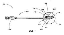
図1には、誘導針100(例えば、Tuohy針)が示される。図1に示されているように、この誘導針100は、明瞭にするために拡大されて示された誘導針100の先端または末端部102が示されている。この誘導針100は、その内部に穴108を画定するカニューレを含む。このカニューレは、縦軸(例えば、中心線)を有し得、この縦軸が全長方向に沿って(例えば、穴108に沿っておよび穴108内に)延在する。
FIG. 1 shows a guide needle 100 (for example, a Tuohy needle). As shown in FIG. 1, the
図示されているように、誘導針100は、中間レベルのHuberポイントを有し得る。いくつかの実施形態では、このHuberポイントにより、医療デバイスおよび/または治療デバイスが誘導針100を通って所望の方向に誘導され配置され易くなり、かつ、様々な内部構造(例えば、くも膜下構造)への影響が防止され、医療デバイスおよび/または治療デバイスの所望の方向への移動が容易になる。
As shown, the
図1はTuohy針を示しているが、他の実施形態では、誘導針は、例えば、修正Tuohy針(例えば、Tuohy−Flowers針)および対象の神経系(例えば、末梢神経系および/または中枢神経系)の部分に使用される他の針などの任意の適切な針として形成することができる。例えば、誘導針には、クロフォード針、ハステッド針、ワイス針、スプロット針、バーカー針などの硬膜外針が含まれ得る。 Although FIG. 1 shows a Tuohy needle, in other embodiments, the guide needle is, for example, a modified Tuohy needle (eg, a Tuohy-Flowers needle) and a subject's nervous system (eg, the peripheral nervous system and / or the central nervous system). It can be formed as any suitable needle, such as other needles used in the system) part. For example, guide needles may include epidural needles such as Crawford needles, Hasted needles, Weiss needles, Splat needles, Barker needles and the like.
いくつかの実施形態では、この誘導針100は、(例えば、麻酔薬および/または鎮痛薬を被検体の体内の選択位置に直接送達することによって)被検体に1つ以上の治療を投与するために使用され得る。いくつかの実施形態では、誘導針の少なくとも一部が、被検体の体内に存在する間(例えば、駐在する間)、この誘導針100は、1つ以上の関連するデバイス(例えば、カテーテル、リード、および/またはリード延長部)を被検体の体内に挿入し、かつ/または配置するために使用される。例えば、誘導針100は、例えば、診断デバイス、監視デバイス、治療デバイス、またはそれらの組み合わせを含む医療デバイスを挿入し、かつ/または配置するために使用され得る。いくつかの実施形態では、このような医療デバイスには、医療治療送達デバイス、被検体のパラメータを感知するよう構成される医療デバイス、症状を診断するよう構成される医療デバイス、被検体からの1つ以上の組織、および/または流体を採取するよう構成される医療デバイス、またはそれらの組み合わせが含まれ得る。いくつかの実施形態では、医療デバイスの少なくとも一部(例えば、カテーテル、リード、またはリード延長部)は、被検体の神経系(例えば、脊髄または管、脳および/末梢神経系)の非常に近くに配置される。
In some embodiments, the
誘導針100の基端104は、針ハブ106に接続され得る。この針ハブ106は、通常、処置中に被検体の体外に留まるように構成される。この針ハブ106は、例えば、グリップを収容するための湾曲した部分を備えたり、誘導針100の操作を容易にするためのリブまたは他の把持部材を備えたりすることにより、医師が取り扱えるように構成され得る。また、この針ハブ106は、例えば、ルアーロック(登録商標)接続部、ルアースリップ接続部、またはネジ接続部などを備えることにより、別の構造体またはデバイスに接続するよう構成され得る。その他の構造体、デバイス、または物質が針ハブ106を通って誘導針100の穴108に入ることができるよう、この針ハブ106は構成され得る。
The
末端部102は、末端部114および基端部116を有する誘導針100の穴108の末端部に開口112を画定するように形成される、あるいは形状を有する斜面110を含み得る。誘導針100の末端部102は、流体がこの末端部から吐出され得るよう、あるいは、医療デバイスがこの末端部を通って予定通りの方向に出ることできるよう上方に湾曲する。通常、例えば、針ハブ106内のスロットまたは他の表示器により斜面110の方向が示される。
The
図示されているように、この誘導針100は、誘導針100の末端部102に位置する穴108の開口112(例えば、末端開口)の近くに形成される1つ以上の特徴(例えば、拡大面、拡大した丸みのある面、拡大した鈍い面、突起118)を含む。例えば、突起118は、開口112に近接する、あるいは開口112の周りを延在する誘導針100の斜面110の後端面または基端面または部分116に配置され得る。すなわち、突起118は、開口112(例えば、斜面110)を画定する誘導針100の一部の後端面または基端面すなわち端部120に配置され得る。この突起118は、誘導針100の外面(例えば、斜面110の外面)から外向き、かつ/または上向き(例えば、少なくとも部分的に半径方向外向きに)に延在し得る。
As shown, the
一般に、斜面110の鋭い内エッジ部、特に、開口112を画定する誘導針100の一部の後端部または基端120により、誘導針100と共に使用する医療デバイス(例えば、ポリマー管)の一部のせん断、切断およびスカイビングの危険性を増す(例えば、図8および図9に示される誘導針700の鋭い後端または基端720を参照)。この危険性は、最初に誘導針100を取り外さずに医療器具を引き抜こうとすると増加する可能性がある。いくつかの実施形態では、斜面の鋭い内エッジ部分は、製造中に鈍くされているが(例えば、ヤスリかけ、電気研磨、ビードブラスト、マイクロコニカル研削点による研削、および/または残りの斜面の鋭い内エッジにより)、問題は残っている。
Generally, a portion of a medical device (e.g., a polymer tube) for use with the
斜面110の鋭い内エッジにより関連する医療デバイスが傷つけられる可能性を少なくするために、開口112に近接する、誘導針100から(例えば、誘導針100の内面から)材料を除去する、上記の従来の方法とは反対に、本開示の実施形態では、開口112に近接する誘導針100に材料を追加して(例えば、拡大された表面、および/または、突起を画定して)、斜面110の鋭い内エッジにより関連する医療デバイスが傷つけられる可能性を少なくする。例えば、開口112の少なくとも一部を取り囲む(例えば、開口112の4分の1を取り囲む、開口112の3分の1を取り囲む、開口112の半分を取り囲む、開口112の4分の3を取り囲む開口112の全体を取り囲む)よう形成され得る突起118により、処置中(例えば、誘導針100から配置されている間、かつ/または、回収されている間)この突起に接触する、かつ/または、この突起に沿って移動する、すなわち、平行移動(例えば、摺動)する医療デバイスに対して、比較的より滑らかな表面を提供するよう機能し得る(例えば、そのような特徴を欠いている斜面の鋭い内エッジと比較して)。
In order to reduce the likelihood that the associated medical device will be damaged by the sharp inner edge of the
誘導針100の斜面110の拡大した、あるいは丸みのあるヒールにより、医療デバイスを伴う斜面110の表面に加えられる圧力が、医療デバイス(例えば、ポリマーチューブ)の接触部分および誘導針100の一部(例えば、斜面110)にわたってより均一に分布され得る。このような効果により、医療デバイスの配置、調整、および/または、除去中に医療デバイスが突起118に沿って摺動可能となり、医療デバイスを著しく傷つけることがなくなる。
Due to the enlarged or rounded heel of the
突起118が針先端の内側の非切断面(例えば、斜面110のヒールまたは基端)に主に配置される実施形態では、この突起118は、誘導針100の貫通力に最小の影響を及ぼす、あるいは、全く影響を及ぼさず、任意の誘導針のフォーマット(例えば、製造中に形成されるか、または既存の針に後付けされる)で実施され得る。
In embodiments in which the
上述したように、従来の誘導針では、誘導針を通して配置される関連する医療デバイスにより引き起こされる損傷を少なくするために、開口を画定する斜面の後部ヒールまたは基端が丸められる。この後部ヒールまたは斜面の基端の丸み付けを可能にするために、より鋭いエッジを形成することなく丸めるのに十分な材料が存在するよう、より厚い壁を有するカニューレが必要となる。したがって、比較的薄い壁のカニューレは、誘導針の設計には実装されない。しかし、本開示の実施形態では、そのような針では、後部ヒールの丸み付けまたは斜面の基端が必要とされないので、より薄い壁の付いたカニューレの使用が可能となる。そのようなより薄い壁の付いたカニューレにより、針の全体的なゲージまたは外径を増加させることなく、誘導針はより大きな内径を有することを可能にする。 As noted above, in conventional introducer needles, the rear heel or proximal end of the bevel defining the opening is rounded to reduce damage caused by the associated medical device placed through the introducer needle. To enable rounding of the rear heel or the proximal end of the bevel, a cannula with a thicker wall is required so that there is enough material to roll without forming a sharper edge. Thus, a relatively thin wall cannula is not implemented in the guide needle design. However, embodiments of the present disclosure allow the use of thinner walled cannulas because such needles do not require rear heel rounding or beveled proximal ends. Such thinner walled cannulas allow the introducer needle to have a larger inner diameter without increasing the overall gauge or outer diameter of the needle.
図1にさらに示されるように、突起118は、開口112の第1の側面122から、開口112の基端120に沿って、開口112の第2の側面124(例えば、第1の側面122に対向する)に延在する連続構造体を含み得る。例えば、この連続構造体により、実質的にC字形、実質的にV字形、実質的に丸みのあるくさび形、およびその他の適切なタイプのくさび形などの、概してくさび形を有する(例えば、第1の比較的狭い端部と反対側の比較的幅広の端部を有する)連続する丸みのある表面を画定することができる。
As further shown in FIG. 1, the
いくつかの実施形態では、突起118は、誘導針100に塗布される1つ以上の材料(例えば、溶接プロセスまたは他の堆積または熱プロセスによって)、および誘導針100の材料によって形成される。例えば、溶接プロセスまたはマイクロ溶接プロセス(例えば、電子ビーム溶接プロセス、ガスタングステンアーク溶接(TIG溶接またはGTAW溶接)およびマイクロガスタングステンアーク溶接(マイクロGTAW)(マイクロタングステン不活性ガス(マイクロTIG)溶接としても知られている)などのパルスアーク溶接プロセス、ガス金属アーク溶接(MIG溶接)、フラックスシールドアーク溶接、酸素アセチレントーチ溶接、パルスレーザ溶接または堆積などのレーザビーム溶接、抵抗放電溶接プロセス、容量性放電溶接プロセスなど)を使用して、誘導針100上に材料を蓄積して突起118を形成することができる。いくつかの実施形態では、突起118は、誘導針100(例えば、医療グレードのステンレス鋼)の材料と同様の材料を含む、かつ/または異種材料(例えば、異なる金属、ポリマーなど)を含むことができる。
In some embodiments, the
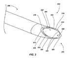
図2には、誘導針200の末端部202の拡大図が示される。この誘導針200は、図1を参照して上述した誘導針100と同様であり、1つ以上の同様の特徴および機能を含み、同様の方法によって形成される。図2に示すように、この誘導針200の末端部202は、誘導針200の穴208の末端に開口212を含むよう形成される、あるいは形付けられる斜面210を含み得る。この末端部202は、この末端部から流体が放出されるよう、あるいは、この末端部を貫通している医療器具が予定の方向に出られるよう上方に湾曲する。
FIG. 2 shows an enlarged view of the
図示されているように、この誘導針200は、誘導針200の末端部202に配置される穴208の開口212に近接して形成される(例えば、開口216の境界に位置し、開口216の境界を形成する)1つ以上の特徴(例えば、突起218)を含む。例えば、この突起218は、開口212(例えば、斜面210)を画定する誘導針200の部分の基端面または端部220(例えば、斜面210のヒールまたは後端)に直接配置され得る。いくつかの実施形態では、突起218はまた、開口212を少なくとも部分的に画定する。
As shown, the
いくつかの実施形態では、突起218は開口216内に延在し、開口216の周囲の少なくとも一部を画定する。いくつかの実施形態では、突起218は、穴208を画定する誘導針200の開口216内に、かつ内面226上に部分的に延在する。
In some embodiments, the
上記のように、この誘導針200は、誘導針200の突起218を開口212に近接して形成するための材料を追加して、関連する医療機器が斜面210の鋭い内エッジにより傷つけられる可能性を低くする。図示されているように、従来の誘導針と比較して、開口212の約半分以上を取り囲むことができる突起218は、処理中(例えば、誘導針200から配置されている間、かつ/または回収されている間)、医療デバイスがこの突起に接触し、かつ/または移動する、すなわち平行移動する(例えば、摺動)するための比較的滑らかな表面を提供するよう機能する。
As described above, the
図2にさらに示されるように、この突起218は、穴208を画定する誘導針200の斜面210(例えば、斜面210を画定する面)と内面226との間の接合部で開口212の第1の側面222から、開口212の基端220に沿って、開口212の第2の側面224(例えば、第1の側面222と対向する)に延在する連続構造体(例えば、実質的にくさび形を有する連続的な丸みのある面)を含み得る。いくつかの実施形態では、突起218の端部228は、誘導針200の表面(例えば、斜面210を画定する表面)内に滑らかに先細になっていてよい。
As further shown in FIG. 2, this
図3には、誘導針300の末端部302の拡大図が示される。この誘導針300は、図1および図2を参照して上述した誘導針100および200と同様であり、1つ以上の同様の特徴および機能を含み、同様の方法によって形成される。図3に示すように、この誘導針300の末端部302は、誘導針300の穴308の末端に開口312を含むよう形成される、あるいは形付けられる斜面310を含み得る。この末端部302は、この末端部から流体が放出されるよう、あるいは、この末端部を貫通している医療器具が予定の方向に出られるよう上方に湾曲する。
FIG. 3 shows an enlarged view of the
図示されているように、この誘導針300は、誘導針300の末端部302に配置される穴308の開口312に近接して形成される(例えば、開口316の境界に位置し、開口316の境界を形成する)1つ以上の特徴(例えば、滑らかな表面または突起318)を含む。例えば、この突起318は、開口312(例えば、斜面310)を画定する誘導針300の部分の基端面または端部320(例えば、斜面310のヒールまたは後端)に直接配置され得る。いくつかの実施形態では、突起318はまた、開口312を少なくとも部分的に画定する
As shown, the
さらに図示するように、突起318は、斜面310の基端320上に少なくとも部分的に丸みを帯びたまたは波状の表面を一緒になって提供する複数の重複部分(例えば、ビーズ)を含み得る。このような突起318は、例えば、溶接または他の熱処理や堆積処理などの製造処理によって形成され得る。上述したものに加えて、複数の丸みを帯びた表面またはビーズは、例えば、医療デバイスが突起318に接触し、突起318に沿って移動するときに、ボールベアリング効果を提供するために、突起318の丸みのある面に荷重を分配することができる。
As further illustrated, the
いくつかの実施形態では、突起318は開口316内に延在し、開口316の周囲の少なくとも一部を画定する。いくつかの実施形態では、突起318は、開口316内に延在し、穴308を画定する誘導針300の内面326上に部分的に延在する。
In some embodiments, the
上記のように、誘導針300は、開口312に近接して誘導針300の突起318を形成するための材料を追加して、関連する医療デバイスを斜面310の鋭い内エッジに傷つけられる可能性を低くする。図示されているように、開口312の約4分の1から3分の1、あるいはそれ以上を取り囲むことができる突起310は、処理中(例えば、誘導針300から配置されている間、かつ/または回収されている間)に医療デバイスが接触し、かつ/または移動する、すなわち平行移動する(例えば、摺動)ための比較的滑らかな表面を提供するように機能する。
As described above, the
図3にさらに示すように、この突起318は、斜面310(例えば、斜面310を画定する面)と穴308を画定する誘導針300の内面326との間の接合部で、開口312の第1の側面322から開口312の基端320に沿って開口312の第2の側面324(例えば、第1の側面322に対向する)に延在する、丸みのある、あるいは波状の表面(例えば、実質的にくさび形を有する)を集合的に含む。いくつかの実施形態では、突起318は、斜面310と誘導針300の内面326との間の接合部から誘導針300の外面328(例えば、誘導針300の外周面)と斜面310との間の別の接合部に延在し得る(例えば、別の接合部で止まるか、あるいは通過する)。
As further shown in FIG. 3, the
図4には、誘導針400の末端部402の拡大図が示される。この誘導針400は、図1〜図3を参照して上述した誘導針100、200、300と同様であり、1つ以上の同様の特徴および機能を含み、同様の方法によって形成される。図4に示すように、この誘導針400の末端部402は、誘導針400の穴408の末端に開口412を含むよう形成される、あるいは形付けられる斜面410を含み得る。この末端部402は、この末端部から流体が放出されるよう、あるいは、この末端部を貫通している医療器具が予定の方向に出られるよう上方に湾曲する。
FIG. 4 shows an enlarged view of the
図示されているように、この誘導針400は、誘導針400の末端部402に配置される穴408の開口412に近接して形成される(例えば、開口416の境界に位置し、開口416の境界を形成する)1つ以上の特徴(例えば、滑らかな表面または突起418)を含む。例えば、突起418は、開口412(例えば、斜面410)を画定する誘導針400の部分の基端面または端部420(例えば、斜面410のヒールまたは後端)に直接配置され得る。いくつかの実施形態では、突起418はまた、開口412を少なくとも部分的に画定する。
As shown, the
さらに図示するように、突起418は、斜面410の基端420上に少なくとも部分的に丸みを帯びた表面を一緒になって提供する複数の丸みを帯びた表面特徴(例えば、ビーズ)を含み得る。このような突起418は、例えば、溶接または他の熱処理や堆積処理などの製造処理によって形成され得る。上述したものに加えて、複数の丸みを帯びた表面特徴またはビーズは、例えば、医療デバイスが突起418に接触し、突起418に沿って移動するときに、ボールベアリング効果を提供するために、突起418の丸みのある面に荷重を分配することができる。
As further illustrated, the
いくつかの実施形態では、突起418は開口416内に延在し、開口416の周囲の少なくとも一部を画定する。いくつかの実施形態では、突起418は、開口416内に延在し、穴408を画定する誘導針400の内面426上に部分的に延在する。
In some embodiments, the
上記のように、誘導針400は、開口412に近接して誘導針400の突起418を形成するための材料を追加して、関連する医療デバイスを斜面410の鋭い内エッジに傷つけられる可能性を低くする。図示されているように、開口412の約3分の1から2分の1、あるいはそれ以上を取り囲むことができる突起418は、従来の誘導針と比較して、処理中(例えば、誘導針400から配置されている間、かつ/または回収されている間)に医療デバイスが接触し、かつ/または移動する、すなわち平行移動する(例えば、摺動)ための比較的滑らかな表面を提供するように機能する。
As described above, the
図4にさらに示すように、この突起418は、穴408を画定する誘導針400の斜面410(例えば、斜面410を画定する面)と内面426との間の接合部で、開口412の第1の側面部422から開口412の基端420に沿って開口412の第2の側面部424(例えば、第1の側面部422に対向する)に延在する、丸みのある表面(例えば、実質的にくさび形を有する)を集合的に含む。いくつかの実施形態では、突起418は、斜面410と誘導針400の内面426との間の接合部から誘導針400の外面428(例えば、誘導針400の外周面)と斜面410との間の別の接合部に延在し得る(例えば、別の接合部で止まるか、あるいは通過する)。
As further shown in FIG. 4, the
図5には、誘導針500の末端部502の拡大図が示される。この誘導針500は、図1〜図4を参照して上述した誘導針100、200、300、400と同様であり、1つ以上の同様の特徴および機能を含み、同様の方法によって形成される。図5に示すように、この誘導針500の末端部502は、誘導針500の穴508の末端に開口512を含むよう形成される、あるいは形付けられる斜面510を含み得る。この末端部502は、この末端部から流体が放出されるよう、あるいは、この末端部を貫通している医療器具が予定の方向に出られるよう上方に湾曲する。
FIG. 5 shows an enlarged view of the
図示されているように、この誘導針500は、誘導針500の末端部502に配置される穴508の開口512に近接して形成される(例えば、開口516の境界に位置し、開口516の境界を形成する)1つ以上の特徴(例えば、滑らかな表面または突起518)を含む。例えば、少なくともいくつかの突起518は、開口512(例えば、斜面510)を画定する誘導針500の部分の基端面または端部520(例えば、斜面510のヒールまたは後端)に直接配置され得る。いくつかの実施形態では、突起518の少なくともいくつかはまた、開口512を少なくとも部分的に画定する。
As shown, the
さらに図示するように、突起518は、斜面510の基端520上に少なくとも部分的に丸みを帯びた表面を一緒になって提供する複数の丸みを帯びた表面特徴(例えば、ビーズ)を含み得る。開口516からの突起518の距離は、突起518に沿って変化し得る。例えば、交互に並んだ突起518は、1つ以上の隣接する突起518と比較して、開口516から比較的離れて配置され得る。このような突起518は、例えば溶接または他の熱処理または堆積処理などの製造プロセスによって形成され得る。上述したものに加えて、複数の丸みを帯びた表面特徴またはビーズは、例えば、医療デバイスが突起518に接触し、突起518に沿って移動するときに、ボールベアリング効果を提供するために、突起518の丸みのある面に荷重を分配することができる。
As further illustrated, the
いくつかの実施形態では、突起518のうちの少なくともいくつかは開口516内に延在し、これにより、開口516の周囲の少なくとも一部を画定する。いくつかの実施形態では、突起518の少なくともいくつかが開口516内に延在し、穴508を画定する誘導針500の内面526上に部分的に延在する。
In some embodiments, at least some of the
上記のように、誘導針500は、開口512に近接して誘導針500の突起518を形成するための材料を追加して、関連する医療デバイスを斜面510の鋭い内エッジに傷つけられる可能性を低くする。図示されているように、開口512の約3分の1から2分の1、あるいはそれ以上を取り囲むことができる突起518は、従来の誘導針と比較して、処理中(例えば、誘導針500から配置されている間、かつ/または回収されている間)に医療デバイスが接触し、かつ/または移動する、すなわち平行移動する(例えば、摺動)ための比較的滑らかな表面を提供するように機能する。
As described above, the
図5にさらに示すように、この突起518は、穴508を画定する誘導針500の斜面510(例えば、斜面510を画定する面)と内面526との間の接合部で、あるいは、その接合部に近接して、開口512の第1の側面部522から開口512の基端520に沿って開口512の第2の側面部524(例えば、第1の側面部522に対向する)に延在する、丸みのある表面(例えば、実質的にくさび形を有する)を集合的に含む。いくつかの実施形態では、突起518のうちの少なくともいくつかは、斜面510と誘導針500の内面526との間の接合部から誘導針500の外面528(例えば、誘導針500の外周面)と斜面510との間の別の接合部に延在し得る(例えば、別の接合部で止まるか、あるいは通過する)。
As further shown in FIG. 5, this
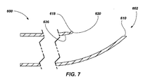
図6には、誘導針600の末端部602の拡大図が示される。この誘導針600は、図1〜図5を参照して上述した誘導針100、200、300、400、500と同様であり、1つ以上の同様の特徴および機能を含み、同様の方法によって形成される。図6に示すように、この誘導針600の末端部602は、誘導針600の穴608の末端に開口612を含むよう形成される、あるいは形付けられる斜面610を含み得る。この末端部602は、この末端部から流体が放出されるよう、あるいは、この末端部を貫通している医療器具が予定の方向に出られるよう上方に湾曲する。
FIG. 6 shows an enlarged view of the
図示されているように、この誘導針600は、誘導針600の末端部602に配置される穴608の開口612に近接して形成される(例えば、開口616の境界に位置し、開口616の境界を形成する)1つ以上の特徴(例えば、滑らかな表面または突起618)を含む。例えば、突起618は、開口612(例えば、斜面610)を画定する誘導針600の部分の基端面または端部620(例えば、斜面610のヒールまたは後端)に直接配置され得る。いくつかの実施形態では、突起618はまた、開口612を少なくとも部分的に画定する。
As shown, the
図7には、図6の誘導針600の末端部602の断面図が示される。図7に示すように、突起618は、斜面610の基端620の少なくとも部分的に丸みのある表面として形成され得る。上記のように、誘導針600は、開口612に近接して誘導針600の突起618を形成するための材料を追加して、関連する医療デバイスを斜面610の鋭い内エッジに傷つけられる可能性を低くする。図6に示されているように、開口612の約3分の1から2分の1、あるいはそれ以上を取り囲むことができる突起618は、従来の誘導針と比較して、処理中(例えば、誘導針600から配置されている間、かつ/または回収されている間)に医療デバイスが接触し、かつ/または移動する、すなわち平行移動する(例えば、摺動)ための比較的滑らかな表面を提供するように機能する。
FIG. 7 shows a cross-sectional view of the
図6および図7にさらに示すように、突起618により、斜面610(例えば、斜面610を画定する面)と、穴608を画定する誘導針600の内面626との間の接合部で、あるいはその接合部に近接して延在する、丸みのある面(例えば、実質的にくさび形を有する)が画定される。
As further shown in FIGS. 6 and 7, the
図8には、従来の誘導針700の末端部702の断面図が示される。図8に示すように、誘導針700の末端部702は、上述したように、斜面710の基端720の鋭利な切断面を含む
FIG. 8 shows a cross-sectional view of the
図9には、図6の誘導針600の末端部602の一部の拡大断面拡大図が示され、例示の誘導針の実施形態と従来の誘導針の実施形態との間の相違点を示すために、図8の誘導針700の末端部702の一部の拡大断面拡大図に重ねられている。図9に示すように、従来の誘導針700の基端720の鋭利な切断面は、斜面610の基端620の突起618の少なくとも部分的に丸みのある面に置き換えられる(例えば、そうなるように変更される)。
FIG. 9 shows an enlarged cross-sectional enlarged view of a portion of the
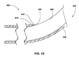
上述し、図10(針600の末端部602から配置される医療デバイス800を示す)に示すように、例えば、斜面610の基端620のそのような表面(例えば、突起618の少なくとも部分的に丸みのある面)は、従来の誘導針(例えば、誘導針700(図8および図9))と比較して、処理中(例えば、誘導針600から配置されている間、かつ/または回収されている間)に医療デバイス800が接触し、かつ/または移動する、すなわち平行移動する(例えば、摺動)ための比較的滑らかな表面を提供するように機能し得る。
As described above and shown in FIG. 10 (showing the
再び図2を参照すると、誘導針200の末端部は、1つ以上の丸みある面、斜角を付けた面、あるいは、面取り面を含み得る。例えば、誘導針200の最末端部230(例えば、終端部)は、誘導針200の斜面210と外面234と(例えば、丸みのある外面、すなわち外周面)の間に延在する面取り面232を含み得る。
Referring again to FIG. 2, the distal end of the
面取り面232は、例えば、丸みのある面、平滑面、直線状の面取り面、すなわち斜角を付けた面、および/または実質的に90度未満(例えば、20度〜70度)の外角を示すように修正された面を含み得る。図示されているように、面取り面232は、突起218に対向する斜面210の側面(例えば、斜面210の先端部分、誘導針200の先端エッジまたは前方の丸みのあるエッジ上に)に配置され得る。例えば、誘導針200が被検体の体内に挿入されるときに組織を貫通するように構成される誘導針200の先端236(例えば、鋭い先端)のどちらかの側にこの面取り面232が配置され得る。このような実施形態では、面取り面232は、誘導針200の鋭利な切断先端部236のサイズ(例えば、幅)を小さくするよう機能し得る。面取り面232は、実質的に切断することなく、被検体の組織を貫通し、穿刺孔を形成するのを助ける穿刺点(例えば、実質的に非切断面)として機能し得る。
The chamfered
いくつかの実施形態では、面取り面232は、比較的小さな切断点のみが誘導針200の先端236に残るように配置される。
In some embodiments, the chamfered
いくつかの実施形態では、図示されているように、誘導針200は、面取り面232と、突起(例えば、図2〜図5を参照して上述した突起(複数可)218、318、418、518)の両方を含む。他の実施形態では、誘導針200は、面取り面232の1つと、突起または複数の突起とを含む。
In some embodiments, as shown, guide
いくつかの実施形態では、面取り面232は、誘導針200を研削し、かつ/または研磨することによって形成される。
In some embodiments, the chamfered
この面取り面232は、誘導針200の斜面210と外面234との間に延在する、様々な角度で、実質的に線形の形状、および/または丸みのある形状を示し得る。いくつかの実施形態では、面取り面232のそれぞれの構成および角度は、臨床状態および/または医師の好みに応じて、誘導針200の貫通力を所望のレベルに変更するよう選択される。
The chamfered
1つ以上の面取り面を含む誘導針の実施形態により、進入時に組織面を貫通するように尖った先端を有する誘導針が提供され得る。しかし、多くの従来の誘導針は、カテーテルおよびリードを挿入するのに必要な誘導針内に形成されるオリフィスまたは穴の大きな開口のために比較的広い針先を有し、この比較的広い針先により、組織が傷つけられる。このような比較的広い針先は、広い切削面を有する外科用メスのように機能し得る。面取り面を含む誘導針の実施形態は、そのような面取り面を欠く従来の誘導針と比較して、組織損傷を最小限に抑えるよう機能し得る。そのような針の実施形態は、針が被検体の体内に挿入されたとき、組織を切断するのではなく、被検体の組織を広げる傾向があり得る。 An embodiment of a introducer needle that includes one or more chamfered surfaces may provide an introducer needle having a pointed tip that penetrates the tissue surface upon entry. However, many conventional introducer needles have a relatively wide needle tip due to the large opening of the orifice or hole formed in the introducer needle required to insert the catheter and lead, and this relatively wide needle The tissue is damaged by the tip. Such a relatively wide needle tip can function like a scalpel with a wide cutting surface. Embodiments of introducer needles that include a chamfered surface may function to minimize tissue damage compared to conventional introducer needles that lack such a chamfered surface. Such needle embodiments may tend to expand the tissue of the subject rather than cutting the tissue when the needle is inserted into the body of the subject.
1つ以上の面取り面を含む誘導針の実施形態により、誘導針に関連して使用する医療デバイス(例えば、誘導針を通って配置される)をせん断、切断、かつ/またはスカイビングの機会を少なくする(あるいは、上述の突起(複数可)と組み合わせて使用するとさらに少なくする)、より小さな針先を有する誘導針が提供され得る。例えば、誘導針を通って配置される医療デバイス(例えば、ポリマーカテーテルまたはリード)は、誘導針の斜面によって指示される、鋭い先端から離れる方向ではなく、針の先端に対して意図しない方向(例えば、針の鋭い先端の周りに、かつ先端に向かって延在する方向)に曲がる場合であっても、カテーテルまたはリードは面取り面のうち1つに移動し、鋭い先端から離れる傾向にあるので、カテーテルまたはリードは、面取り面に沿って滑動する。例えば、図10に示すように、医療デバイス800は、針600の先端636と接触し得る。面取り面により、比較的滑らかな境界面が提供されるので、この面取り面によってカテーテルまたはリードが損傷される可能性はかなり低くなる。
An embodiment of a guide needle that includes one or more chamfered surfaces provides an opportunity for shearing, cutting, and / or skiving a medical device (eg, disposed through the guide needle) used in connection with the guide needle. With less (or even less when used in combination with the above-described protrusion (s)), a guide needle having a smaller needle tip may be provided. For example, a medical device (eg, a polymer catheter or lead) placed through the introducer needle is not directed away from the sharp tip, as indicated by the bevel of the introducer needle, but in an unintended direction (eg, The catheter or lead moves to one of the chamfered surfaces and tends to move away from the sharp tip, even if bent around the sharp tip of the needle and in the direction extending toward the tip) The catheter or lead slides along the chamfered surface. For example, as shown in FIG. 10, the
本開示が通知されれば、本明細書に開示される装置および組立体を製造し使用することは、当業者なら可能であろう。 Given the present disclosure, one of ordinary skill in the art will be able to make and use the devices and assemblies disclosed herein.
Claims (20)
その内部に穴を画定するカニューレであって、少なくとも1つの関連する医療デバイスが前記穴を通って被検体の体内に通るよう前記穴が構成される、カニューレと、
前記カニューレの前記穴の末端開口を画定する斜面端と、
前記末端開口に近接する前記斜面端の基端面上に配置される少なくとも1つの突起と、
を含む、誘導針。 An induction needle,
A cannula defining a hole therein, wherein the hole is configured such that at least one associated medical device passes through the hole and into the body of the subject;
A beveled end defining a distal opening of the hole of the cannula;
At least one protrusion disposed on a proximal end surface of the sloped end proximate to the distal opening;
Including an induction needle.
その内部に穴を画定するカニューレであって、少なくとも1つの関連する医療デバイスが前記穴を通って被検体の体内に通るよう前記穴が構成される、カニューレと、
前記カニューレの前記穴の末端開口を画定する末端部と、
前記末端開口に近接する前記末端部上の少なくとも1つの拡大した丸みのある面と、
を含む針。 A needle,
A cannula defining a hole therein, wherein the hole is configured such that at least one associated medical device passes through the hole and into the body of the subject;
A distal end defining a distal opening of the hole of the cannula;
At least one enlarged rounded surface on the end proximate to the end opening;
Including needles.
少なくともその一部が被検体の皮下組織内に配置されるように構成される医療デバイスと、
前記医療デバイスの少なくとも一部を前記被検体内に挿入するための、請求項1から16のいずれか1つに記載の前記誘導針と、
を含む医療デバイス組立体。 A medical device assembly comprising:
A medical device configured to be at least partially disposed within the subcutaneous tissue of the subject;
The guide needle according to any one of claims 1 to 16, for inserting at least a part of the medical device into the subject;
A medical device assembly comprising:
その内部に穴を有するカニューレを提供するステップと、
少なくとも1つの関連する医療機器を穴を通して被検体に通すよう穴を構成するステップと、
前記針の末端部にカニューレの穴の末端開口を画定するステップと、
前記カニューレの前記末端開口に接する前記カニューレの末端部に少なくとも1つの突起を形成するステップと、
を含む、方法。 A method of forming a needle,
Providing a cannula having a hole therein;
Configuring the hole to pass at least one associated medical device through the hole to the subject;
Defining a distal opening of a cannula hole at the distal end of the needle;
Forming at least one protrusion at the distal end of the cannula that contacts the distal opening of the cannula;
Including a method.
Applications Claiming Priority (3)
| Application Number | Priority Date | Filing Date | Title |
|---|---|---|---|
| US201562250866P | 2015-11-04 | 2015-11-04 | |
| US62/250,866 | 2015-11-04 | ||
| PCT/US2016/048855 WO2017078831A1 (en) | 2015-11-04 | 2016-08-26 | Needles and related assemblies and methods |
Publications (2)
| Publication Number | Publication Date |
|---|---|
| JP2018532513A true JP2018532513A (en) | 2018-11-08 |
| JP2018532513A5 JP2018532513A5 (en) | 2019-09-19 |
Family
ID=58638143
Family Applications (1)
| Application Number | Title | Priority Date | Filing Date |
|---|---|---|---|
| JP2018522973A Pending JP2018532513A (en) | 2015-11-04 | 2016-08-26 | Needle and related assemblies and methods |
Country Status (11)
| Country | Link |
|---|---|
| US (1) | US20170119974A1 (en) |
| EP (1) | EP3370631A4 (en) |
| JP (1) | JP2018532513A (en) |
| KR (1) | KR20180082484A (en) |
| CN (1) | CN108430355A (en) |
| AU (1) | AU2016348361A1 (en) |
| BR (1) | BR112018009035A8 (en) |
| CA (1) | CA3003714A1 (en) |
| CO (1) | CO2018005711A2 (en) |
| HK (1) | HK1252200A1 (en) |
| WO (1) | WO2017078831A1 (en) |
Cited By (1)
| Publication number | Priority date | Publication date | Assignee | Title |
|---|---|---|---|---|
| JP2022549879A (en) * | 2019-12-06 | 2022-11-29 | ボストン サイエンティフィック サイムド,インコーポレイテッド | Ultrasound endoscopic guided access needle |
Families Citing this family (15)
| Publication number | Priority date | Publication date | Assignee | Title |
|---|---|---|---|---|
| US9237925B2 (en) | 2011-04-22 | 2016-01-19 | Ablative Solutions, Inc. | Expandable catheter system for peri-ostial injection and muscle and nerve fiber ablation |
| US8663190B2 (en) | 2011-04-22 | 2014-03-04 | Ablative Solutions, Inc. | Expandable catheter system for peri-ostial injection and muscle and nerve fiber ablation |
| US20130053792A1 (en) | 2011-08-24 | 2013-02-28 | Ablative Solutions, Inc. | Expandable catheter system for vessel wall injection and muscle and nerve fiber ablation |
| US9056185B2 (en) | 2011-08-24 | 2015-06-16 | Ablative Solutions, Inc. | Expandable catheter system for fluid injection into and deep to the wall of a blood vessel |
| US10881458B2 (en) | 2012-10-29 | 2021-01-05 | Ablative Solutions, Inc. | Peri-vascular tissue ablation catheters |
| US10945787B2 (en) * | 2012-10-29 | 2021-03-16 | Ablative Solutions, Inc. | Peri-vascular tissue ablation catheters |
| US10736656B2 (en) | 2012-10-29 | 2020-08-11 | Ablative Solutions | Method for painless renal denervation using a peri-vascular tissue ablation catheter with support structures |
| US9526827B2 (en) | 2012-10-29 | 2016-12-27 | Ablative Solutions, Inc. | Peri-vascular tissue ablation catheter with support structures |
| US9931046B2 (en) | 2013-10-25 | 2018-04-03 | Ablative Solutions, Inc. | Intravascular catheter with peri-vascular nerve activity sensors |
| US9949652B2 (en) | 2013-10-25 | 2018-04-24 | Ablative Solutions, Inc. | Apparatus for effective ablation and nerve sensing associated with denervation |
| US10517666B2 (en) | 2013-10-25 | 2019-12-31 | Ablative Solutions, Inc. | Apparatus for effective ablation and nerve sensing associated with denervation |
| WO2018207119A1 (en) * | 2017-05-10 | 2018-11-15 | Nestle Skin Health Sa | Conical needle and methods of use and manufacturing |
| US10888693B2 (en) * | 2017-08-22 | 2021-01-12 | Warsaw Orthopedic, Inc. | Drug pellet injector needle and method |
| US10849685B2 (en) | 2018-07-18 | 2020-12-01 | Ablative Solutions, Inc. | Peri-vascular tissue access catheter with locking handle |
| US20230233818A1 (en) * | 2022-01-27 | 2023-07-27 | Contego Medical, Inc. | Thrombectomy and aspiration system and methods of use |
Citations (6)
| Publication number | Priority date | Publication date | Assignee | Title |
|---|---|---|---|---|
| JP2000262629A (en) * | 1999-03-19 | 2000-09-26 | Terumo Corp | Medical appliance for intra-vascular insertion |
| WO2002002161A1 (en) * | 2000-07-03 | 2002-01-10 | Dr. Japan Co., Ltd. | Medical bevel needle |
| JP2008529594A (en) * | 2005-02-04 | 2008-08-07 | ボストン サイエンティフィック リミティド | Non-coring needle and manufacturing method thereof |
| JP2008194112A (en) * | 2007-02-09 | 2008-08-28 | Tasuku:Kk | Medical puncture needle |
| JP2011125898A (en) * | 2009-12-17 | 2011-06-30 | Technocoat Co Ltd | Method for forming tactile projection part |
| US20140242259A1 (en) * | 2013-02-22 | 2014-08-28 | Christopher S. Young | Method for Smoothing Cannula Bevel Heel |
Family Cites Families (42)
| Publication number | Priority date | Publication date | Assignee | Title |
|---|---|---|---|---|
| US2479645A (en) * | 1948-04-14 | 1949-08-23 | Rubin D Silverstein | Dental instrument |
| US2717599A (en) * | 1952-02-18 | 1955-09-13 | Huber Jennie | Needle structure |
| US3064651A (en) * | 1959-05-26 | 1962-11-20 | Henderson Edward | Hypodermic needle |
| US3071135A (en) * | 1960-01-27 | 1963-01-01 | Mfg Process Lab Inc | Hollow needle |
| US3090384A (en) * | 1960-04-15 | 1963-05-21 | Mfg Process Lab Inc | Needle |
| US4068660A (en) * | 1976-07-12 | 1978-01-17 | Deseret Pharmaceutical Co., Inc. | Catheter placement assembly improvement |
| US4529399A (en) * | 1983-05-03 | 1985-07-16 | Catheter Technology Corporation | Method and apparatus for placing a catheter |
| US4702260A (en) * | 1985-04-16 | 1987-10-27 | Ko Pen Wang | Flexible bronchoscopic needle assembly |
| US5515871A (en) * | 1990-09-28 | 1996-05-14 | Sulzer Brothers Ltd. | Hollow needle for medical use and a laser method for manufacturing |
| US5100390A (en) * | 1990-10-22 | 1992-03-31 | Norma A. Lubeck | Lubeck spinal catheter needle |
| US5213569A (en) * | 1992-03-31 | 1993-05-25 | Davis Peter L | Tip for a tissue phacoemulsification device |
| US5968022A (en) * | 1995-04-28 | 1999-10-19 | Saito; Yoshikuni | Medical hollow needle and method of production |
| US6629963B2 (en) * | 1996-06-20 | 2003-10-07 | Becton, Dickinson And Company | Syringe and needle shield assembly and method of sterilizing such assembly |
| US7468055B2 (en) * | 1996-06-20 | 2008-12-23 | Becton Dickinson And Company | Multi-beveled point needle and syringe having a multi-beveled point needle |
| US5752942A (en) * | 1996-06-20 | 1998-05-19 | Becton Dickinson And Company | Five beveled point geometry for a hypodermic needle |
| DE19646881C1 (en) * | 1996-11-13 | 1998-08-20 | Volker Geuder | Hollow needle for surgical ophthalmic instrument |
| US6702791B1 (en) * | 1999-02-04 | 2004-03-09 | Integ, Inc. | Needle for body fluid tester |
| JP3310270B1 (en) * | 2001-03-28 | 2002-08-05 | 宮子 鎌田 | Medical injection needle and method of manufacturing the same |
| US6666848B2 (en) * | 2001-06-14 | 2003-12-23 | Artes Medical Usa, Inc. | Medical injection apparatus |
| US6702790B1 (en) * | 2002-10-31 | 2004-03-09 | Chauncey F. Ross | Hypodermic needle |
| EP1590024B1 (en) * | 2003-01-21 | 2016-04-27 | Carmel Pharma AB | A needle for penetrating a membrane |
| FR2887153B1 (en) * | 2005-06-20 | 2008-04-04 | Alain Villette | INJECTION NEEDLE |
| US20070123935A1 (en) * | 2005-11-30 | 2007-05-31 | Myers Gene E | Method and apparatus for contemporaneous formation of a body structure opening and homologous pedicle |
| US8187203B2 (en) * | 2006-02-24 | 2012-05-29 | Mcclellan W Thomas | Biopsy needle system, biopsy needle and method for obtaining a tissue biopsy specimen |
| US8287484B2 (en) * | 2006-05-02 | 2012-10-16 | Abbott Medical Optics Inc. | Multi-purpose phacoemulsification needle |
| US20090099536A1 (en) * | 2006-11-06 | 2009-04-16 | Takayuki Akahoshi Akahoshi | Bidirectional Phacoemulsification Needle Tips for Torsional and Longitudinal Motion |
| JP2010524623A (en) | 2007-04-25 | 2010-07-22 | コーニンクレッカ フィリップス エレクトロニクス エヌ ヴィ | Needle for mechanically assisted insertion |
| CA2720452A1 (en) * | 2008-04-02 | 2009-10-08 | Laurimed, Llc | Methods and devices for delivering injections |
| WO2010022460A1 (en) * | 2008-09-01 | 2010-03-04 | Nigel Morlet | Cutting needle tip for surgical instrument |
| EP2159136A1 (en) * | 2008-09-01 | 2010-03-03 | Sika Technology AG | Bonding with adhesive beads or plots |
| WO2012044952A2 (en) * | 2010-09-30 | 2012-04-05 | Surmodics, Inc. | Drug delivery blade and methods for delivering a drug depot to a target site |
| JP2014526914A (en) * | 2011-06-28 | 2014-10-09 | クック メディカル テクノロジーズ エルエルシー | System for deploying fiducials |
| CN103796621B (en) * | 2011-08-03 | 2016-08-17 | 奈杰尔·莫雷特 | Trough of belt needle point for operating theater instruments |
| US20140100426A1 (en) * | 2012-08-03 | 2014-04-10 | Ipsyrng Capital Development, Llc | Blunt tip cannula for injection of a material into a patient |
| WO2014133777A1 (en) * | 2013-02-26 | 2014-09-04 | Cook Medical Technologies Llc | Ratchet-slide handle and system for fiducial deployment |
| WO2014144681A1 (en) * | 2013-03-15 | 2014-09-18 | C.R. Bard, Inc. | Short-bevel non-coring needle |
| ES2902693T3 (en) * | 2014-04-16 | 2022-03-29 | Erre Quadro S R L | vitrectomy probe |
| CN104075414B (en) * | 2014-07-02 | 2018-06-01 | 珠海格力电器股份有限公司 | Guard method and device for air conditioner air deflector |
| CN203988274U (en) * | 2014-08-14 | 2014-12-10 | 何荣 | Deep vein puncture syringe needle |
| US11793942B2 (en) * | 2014-12-11 | 2023-10-24 | Facet Technologies, Llc | Needle with multi-bevel tip geometry |
| EP4046572B1 (en) * | 2015-05-22 | 2024-04-24 | Dexcom, Inc. | Needle for transcutaneous analyte sensor delivery |
| EP3362137B1 (en) * | 2015-10-15 | 2021-01-20 | SPR Therapeutics, LLC | System for positioning, testing and deploying a stimulation lead |
-
2016
- 2016-08-26 CA CA3003714A patent/CA3003714A1/en not_active Abandoned
- 2016-08-26 US US15/249,092 patent/US20170119974A1/en not_active Abandoned
- 2016-08-26 CN CN201680077766.7A patent/CN108430355A/en active Pending
- 2016-08-26 BR BR112018009035A patent/BR112018009035A8/en not_active Application Discontinuation
- 2016-08-26 AU AU2016348361A patent/AU2016348361A1/en not_active Abandoned
- 2016-08-26 KR KR1020187015518A patent/KR20180082484A/en unknown
- 2016-08-26 JP JP2018522973A patent/JP2018532513A/en active Pending
- 2016-08-26 EP EP16862641.4A patent/EP3370631A4/en not_active Withdrawn
- 2016-08-26 WO PCT/US2016/048855 patent/WO2017078831A1/en active Application Filing
-
2018
- 2018-05-30 CO CONC2018/0005711A patent/CO2018005711A2/en unknown
- 2018-09-06 HK HK18111437.8A patent/HK1252200A1/en unknown
Patent Citations (6)
| Publication number | Priority date | Publication date | Assignee | Title |
|---|---|---|---|---|
| JP2000262629A (en) * | 1999-03-19 | 2000-09-26 | Terumo Corp | Medical appliance for intra-vascular insertion |
| WO2002002161A1 (en) * | 2000-07-03 | 2002-01-10 | Dr. Japan Co., Ltd. | Medical bevel needle |
| JP2008529594A (en) * | 2005-02-04 | 2008-08-07 | ボストン サイエンティフィック リミティド | Non-coring needle and manufacturing method thereof |
| JP2008194112A (en) * | 2007-02-09 | 2008-08-28 | Tasuku:Kk | Medical puncture needle |
| JP2011125898A (en) * | 2009-12-17 | 2011-06-30 | Technocoat Co Ltd | Method for forming tactile projection part |
| US20140242259A1 (en) * | 2013-02-22 | 2014-08-28 | Christopher S. Young | Method for Smoothing Cannula Bevel Heel |
Cited By (1)
| Publication number | Priority date | Publication date | Assignee | Title |
|---|---|---|---|---|
| JP2022549879A (en) * | 2019-12-06 | 2022-11-29 | ボストン サイエンティフィック サイムド,インコーポレイテッド | Ultrasound endoscopic guided access needle |
Also Published As
| Publication number | Publication date |
|---|---|
| CA3003714A1 (en) | 2017-05-11 |
| BR112018009035A2 (en) | 2018-10-30 |
| CO2018005711A2 (en) | 2018-08-21 |
| KR20180082484A (en) | 2018-07-18 |
| US20170119974A1 (en) | 2017-05-04 |
| CN108430355A (en) | 2018-08-21 |
| EP3370631A4 (en) | 2019-05-15 |
| AU2016348361A1 (en) | 2018-05-17 |
| WO2017078831A1 (en) | 2017-05-11 |
| BR112018009035A8 (en) | 2019-02-26 |
| EP3370631A1 (en) | 2018-09-12 |
| HK1252200A1 (en) | 2019-05-24 |
Similar Documents
| Publication | Publication Date | Title |
|---|---|---|
| JP2018532513A (en) | Needle and related assemblies and methods | |
| EP1958576A2 (en) | Double cut shaver | |
| US20070106219A1 (en) | Cleveland round tip (CRT) needle | |
| AU2018311081B2 (en) | Needle and catheter insertion device | |
| EP3099256B1 (en) | Side-port catheter | |
| US20020177864A1 (en) | Vascular needle | |
| US8512363B2 (en) | Channeled wire guide for a scalpel | |
| JP7335439B2 (en) | RF electrode cannula | |
| JP2023129552A (en) | needle and catheter assembly | |
| US20190030290A1 (en) | Vascular Access Needle for Guidewire Insertion | |
| US20170252520A1 (en) | Puncture needle | |
| JP2023504325A (en) | Intravenous catheter device | |
| JP6504446B2 (en) | Puncture needle for subcutaneous tunnel | |
| US20200324086A1 (en) | Introducer needle and related systems and methods | |
| US20230132481A1 (en) | Hypodermic needle for intra-arterial/intravenous line placement | |
| GB2377889A (en) | Subcutaneous tunnelling | |
| EP3731920A1 (en) | Over the needle catheter with an openable and closable distal tip |
Legal Events
| Date | Code | Title | Description |
|---|---|---|---|
| A521 | Request for written amendment filed |
Free format text: JAPANESE INTERMEDIATE CODE: A523 Effective date: 20180704 |
|
| A521 | Request for written amendment filed |
Free format text: JAPANESE INTERMEDIATE CODE: A523 Effective date: 20190808 |
|
| A621 | Written request for application examination |
Free format text: JAPANESE INTERMEDIATE CODE: A621 Effective date: 20190808 |
|
| A977 | Report on retrieval |
Free format text: JAPANESE INTERMEDIATE CODE: A971007 Effective date: 20200722 |
|
| A131 | Notification of reasons for refusal |
Free format text: JAPANESE INTERMEDIATE CODE: A131 Effective date: 20200804 |
|
| A02 | Decision of refusal |
Free format text: JAPANESE INTERMEDIATE CODE: A02 Effective date: 20210316 |