JP2018527246A - Operating system for Earth-orbiting satellite with electric thruster - Google Patents
Operating system for Earth-orbiting satellite with electric thruster Download PDFInfo
- Publication number
- JP2018527246A JP2018527246A JP2018514270A JP2018514270A JP2018527246A JP 2018527246 A JP2018527246 A JP 2018527246A JP 2018514270 A JP2018514270 A JP 2018514270A JP 2018514270 A JP2018514270 A JP 2018514270A JP 2018527246 A JP2018527246 A JP 2018527246A
- Authority
- JP
- Japan
- Prior art keywords
- thruster
- vehicle
- axis
- rotary joint
- boom
- Prior art date
- Legal status (The legal status is an assumption and is not a legal conclusion. Google has not performed a legal analysis and makes no representation as to the accuracy of the status listed.)
- Pending
Links
- 239000013598 vector Substances 0.000 claims description 26
- 230000005484 gravity Effects 0.000 claims description 16
- 238000000034 method Methods 0.000 abstract description 7
- 238000004891 communication Methods 0.000 description 13
- 230000008859 change Effects 0.000 description 9
- 239000003380 propellant Substances 0.000 description 6
- 238000002485 combustion reaction Methods 0.000 description 5
- 239000000126 substance Substances 0.000 description 5
- 238000010586 diagram Methods 0.000 description 4
- 239000000853 adhesive Substances 0.000 description 3
- 230000001070 adhesive effect Effects 0.000 description 3
- 239000002131 composite material Substances 0.000 description 3
- 230000007704 transition Effects 0.000 description 3
- 229920000049 Carbon (fiber) Polymers 0.000 description 2
- PEDCQBHIVMGVHV-UHFFFAOYSA-N Glycerine Chemical compound OCC(O)CO PEDCQBHIVMGVHV-UHFFFAOYSA-N 0.000 description 2
- 230000001174 ascending effect Effects 0.000 description 2
- 239000004917 carbon fiber Substances 0.000 description 2
- 230000007774 longterm Effects 0.000 description 2
- 239000000463 material Substances 0.000 description 2
- 239000002184 metal Substances 0.000 description 2
- VNWKTOKETHGBQD-UHFFFAOYSA-N methane Chemical compound C VNWKTOKETHGBQD-UHFFFAOYSA-N 0.000 description 2
- 238000012986 modification Methods 0.000 description 2
- 230000004048 modification Effects 0.000 description 2
- 230000004044 response Effects 0.000 description 2
- 230000001133 acceleration Effects 0.000 description 1
- 238000007792 addition Methods 0.000 description 1
- 230000014759 maintenance of location Effects 0.000 description 1
- 238000013507 mapping Methods 0.000 description 1
- 230000007246 mechanism Effects 0.000 description 1
- 238000005457 optimization Methods 0.000 description 1
- 239000002245 particle Substances 0.000 description 1
- 230000005855 radiation Effects 0.000 description 1
- 230000009467 reduction Effects 0.000 description 1
- 238000006467 substitution reaction Methods 0.000 description 1
Images


Classifications
-
- B—PERFORMING OPERATIONS; TRANSPORTING
- B64—AIRCRAFT; AVIATION; COSMONAUTICS
- B64G—COSMONAUTICS; VEHICLES OR EQUIPMENT THEREFOR
- B64G1/00—Cosmonautic vehicles
- B64G1/22—Parts of, or equipment specially adapted for fitting in or to, cosmonautic vehicles
- B64G1/24—Guiding or controlling apparatus, e.g. for attitude control
- B64G1/26—Guiding or controlling apparatus, e.g. for attitude control using jets
- B64G1/262—Guiding or controlling apparatus, e.g. for attitude control using jets having adjustable angles, e.g. gimbaled thrusters
- B64G1/264—Guiding or controlling apparatus, e.g. for attitude control using jets having adjustable angles, e.g. gimbaled thrusters mounted on adjustable booms or the like
-
- B—PERFORMING OPERATIONS; TRANSPORTING
- B64—AIRCRAFT; AVIATION; COSMONAUTICS
- B64G—COSMONAUTICS; VEHICLES OR EQUIPMENT THEREFOR
- B64G1/00—Cosmonautic vehicles
- B64G1/22—Parts of, or equipment specially adapted for fitting in or to, cosmonautic vehicles
- B64G1/24—Guiding or controlling apparatus, e.g. for attitude control
- B64G1/26—Guiding or controlling apparatus, e.g. for attitude control using jets
-
- B—PERFORMING OPERATIONS; TRANSPORTING
- B64—AIRCRAFT; AVIATION; COSMONAUTICS
- B64G—COSMONAUTICS; VEHICLES OR EQUIPMENT THEREFOR
- B64G1/00—Cosmonautic vehicles
- B64G1/22—Parts of, or equipment specially adapted for fitting in or to, cosmonautic vehicles
- B64G1/40—Arrangements or adaptations of propulsion systems
- B64G1/405—Ion or plasma engines
-
- B—PERFORMING OPERATIONS; TRANSPORTING
- B64—AIRCRAFT; AVIATION; COSMONAUTICS
- B64G—COSMONAUTICS; VEHICLES OR EQUIPMENT THEREFOR
- B64G1/00—Cosmonautic vehicles
- B64G1/22—Parts of, or equipment specially adapted for fitting in or to, cosmonautic vehicles
- B64G1/40—Arrangements or adaptations of propulsion systems
- B64G1/411—Electric propulsion
- B64G1/415—Arcjets or resistojets
Landscapes
- Engineering & Computer Science (AREA)
- Remote Sensing (AREA)
- Chemical & Material Sciences (AREA)
- Combustion & Propulsion (AREA)
- Aviation & Aerospace Engineering (AREA)
- Radar, Positioning & Navigation (AREA)
- Control Of Position, Course, Altitude, Or Attitude Of Moving Bodies (AREA)
- Pivots And Pivotal Connections (AREA)
Abstract
ビークルの上のスラスタを装着するためのシステム及び方法が本明細書で説明される。スラスタ装着構造体は、第1、第2、及び第3の回転ジョイント、ブーム、及びスラスタ・パレット、ならびに、スラスタ・パレットに取り付けられているスラスタを含むことが可能である。第1の回転ジョイントは、ビークルに取り付けられ得、また、第1の軸線において回転するように構成され得る。第1の回転ジョイントは、ブームに接続され得、第1の軸線の周りにブームを枢動させるように構成され得る。ブームは、第2の回転ジョイントに接続され得、第2の回転ジョイントは、第3の回転ジョイントに接続されており、第1の軸線において第3の回転ジョイントを回転させるように構成されている。第3の回転ジョイントは、スラスタ・パレットに接続され得、また、第1の軸線に対して垂直の第2の軸線においてスラスタ・パレットを枢動させるように構成され得る。Systems and methods for mounting a thruster on a vehicle are described herein. The thruster mounting structure may include first, second, and third revolute joints, a boom, and a thruster pallet, and a thruster attached to the thruster pallet. The first rotational joint can be attached to the vehicle and can be configured to rotate about the first axis. The first rotation joint may be connected to the boom and may be configured to pivot the boom about the first axis. The boom may be connected to a second rotary joint, the second rotary joint is connected to the third rotary joint and is configured to rotate the third rotary joint about the first axis. . The third rotation joint may be connected to the thruster palette and may be configured to pivot the thruster palette in a second axis that is perpendicular to the first axis.
Description
本発明は電気スラスタを備えた地球周回衛星のための操作システムに関する。 The present invention relates to an operating system for an Earth-orbiting satellite with an electric thruster.
衛星及び他の宇宙船は、典型的には、化学的なロケット推進システムを利用し、それらを軌道の中へ推進させ、ミッション動作を実施する。そのような推進システムは、比較的大量のスラストを提供するが、ロケット推進システムは、一般的に、推進剤効率が悪く、比推力が低い。その結果、ロケット推進システムによって推進される衛星及び宇宙船は、典型的には、それらの質量の大部分を推進剤として運搬し、ミッション・ペイロードに利用可能なのは比較的小さい割合の質量になる。電気推進システムは、長距離のミッション又は長期間のミッションのためのロケット推進システムに対する実行可能な代替例を提供し、それは、大量の推進剤を必要とする。電気推進システムは、電気エネルギーを使用することによって、推進剤、典型的にはイオン化されたガスの粒子を、高速で吐き出すように動作する。 Satellites and other spacecraft typically utilize chemical rocket propulsion systems to propel them into orbit and perform mission operations. While such propulsion systems provide a relatively large amount of thrust, rocket propulsion systems generally have poor propellant efficiency and low specific thrust. As a result, satellites and spacecraft propelled by rocket propulsion systems typically carry most of their mass as propellant, with a relatively small percentage of mass available for the mission payload. Electric propulsion systems provide a viable alternative to rocket propulsion systems for long-distance or long-term missions, which require large amounts of propellant. Electric propulsion systems operate to expel propellants, typically ionized gas particles, at high speeds by using electrical energy.
このようにして、それらは、ロケット推進システムと比較して、比較的高い比推力及び推進剤効率を実現するが、比較的小さい量のスラストを作り出す。これらの特性は、電気推進システムを長距離のミッション又は長期間のミッションに適切なものにし、衛星及び/又は宇宙船は、長期間にわたって加速され得る。 In this way, they achieve a relatively high specific thrust and propellant efficiency compared to rocket propulsion systems, but produce a relatively small amount of thrust. These characteristics make the electric propulsion system suitable for long-distance or long-term missions, and satellites and / or spacecraft can be accelerated over long periods.
スラスタをビークルの上に装着するためのシステム及び方法が、本明細書で説明されている。システムは、スラスタ装着構造体を含むことが可能であり、スラスタ装着構造体は、第1の回転ジョイントを含み、第1の回転ジョイントは、ビークルに取り付けられており、第1の軸線において回転するように構成されている。スラスタ装着構造体は、ブームをさらに含むことが可能であり、ブームは、第1の回転ジョイントに接続されており、第1の回転ジョイントは、第1の軸線の周りにブームを枢動させるように構成されている。スラスタ装着構造体は、第2の回転ジョイントをさらに含むことが可能であり、第2の回転ジョイントは、ブームに取り付けられており、第1の軸線において回転するように構成されている。スラスタ装着構造体は、第3の回転ジョイントをさらに含むことが可能であり、第3の回転ジョイントは、第2の回転ジョイントに取り付けられており、また、第1の軸線に対して垂直の第2の軸線において回転するように構成されている。第2の回転ジョイントは、第1の軸線の周りに第3の回転ジョイントを枢動させるように構成され得る。スラスタ装着構造体は、第3の回転ジョイントに取り付けられているスラスタ・パレットをさらに含むことが可能であり、第3の回転ジョイントは、第2の軸線の周りにスラスタ・パレットを枢動させるように構成されており、また、スラスタ装着構造体は、スラスタ・パレットに固定して取り付けられているスラスタを含むことが可能である。いくつかの実施形態では、スラスタ・パレットは、矩形の面を含み、第3の回転ジョイントは、矩形の面の長い縁部に沿ってスラスタ・パレットに取り付けるように構成され得る。 Systems and methods for mounting a thruster on a vehicle are described herein. The system can include a thruster mounting structure, the thruster mounting structure including a first rotational joint, wherein the first rotational joint is attached to the vehicle and rotates in a first axis. It is configured as follows. The thruster mounting structure can further include a boom, wherein the boom is connected to a first rotational joint such that the first rotational joint pivots the boom about the first axis. It is configured. The thruster mounting structure may further include a second rotational joint, the second rotational joint being attached to the boom and configured to rotate about the first axis. The thruster mounting structure may further include a third rotational joint, the third rotational joint being attached to the second rotational joint, and a second perpendicular to the first axis. It is comprised so that it may rotate in 2 axes. The second rotational joint may be configured to pivot the third rotational joint about the first axis. The thruster mounting structure can further include a thruster pallet attached to a third revolute joint, the third revolute joint pivoting the thruster pallet about the second axis. And the thruster mounting structure may include a thruster fixedly attached to the thruster pallet. In some embodiments, the thruster pallet includes a rectangular face, and the third rotational joint may be configured to attach to the thruster pallet along the long edge of the rectangular face.
ビークルは、衛星又は他の宇宙船を含む、任意の適切なビークルであってよく、また、任意の適切な形状を含むことが可能である。本明細書で説明されているシステム及び方法は、立方体又は矩形角柱のように形状決めされている衛星に関連して考察されているが、当業者によって理解されるように他の衛星及び宇宙船形状も企図され得る。また、スラスタ装着構造体は、立方体/矩形角柱の平坦な表面を含む、ビークルの任意の適切な表面の上に装着され得ることを理解されたい。当業者によって理解されるように他の装着表面も企図され得る。そのうえ、本明細書で説明されているシステム及び方法は、電気スラスタの観点から説明されているが、任意の適切なスラスタが、本明細書で説明されている装着構造体とともに利用され得ることを理解されたい。 The vehicle can be any suitable vehicle, including a satellite or other spacecraft, and can include any suitable shape. Although the systems and methods described herein are discussed in connection with satellites that are shaped like cubes or rectangular prisms, other satellites and spacecraft as will be appreciated by those skilled in the art. Shapes can also be contemplated. It should also be understood that the thruster mounting structure may be mounted on any suitable surface of the vehicle, including a cube / rectangular prismatic flat surface. Other mounting surfaces may be contemplated as will be appreciated by those skilled in the art. Moreover, while the systems and methods described herein are described in terms of electrical thrusters, it is understood that any suitable thruster can be utilized with the mounting structure described herein. I want you to understand.
いくつかの実施形態では、第1の軸線は、ビークルのロール軸であってよく、第2の軸線は、ビークルのヨー軸、ピッチ軸、又は、ピッチ軸及びヨー軸の組み合わせであってよい。いくつかの実施形態では、第1の軸線は、ビークルのヨー軸であってよく、第2の軸線は、ビークルのロール軸、ピッチ軸、又は、ロール軸及びピッチ軸の組み合わせであってよい。いくつかの実施形態では、第1の回転ジョイント及び第2の回転ジョイントは、電動回転ジョイントであってよい。たとえば、回転ジョイントは、モータ、サーボ、又は、回転移動を変化及び維持するための任意の他の適切なメカニズムを用いることが可能である。いくつかの実施形態では、回転ジョイントは、回転角度を変化及び維持するために、制御入力を受け取ることが可能である。いくつかの実施形態では、回転ジョイントは、回転角度を変化させるための制御が受け取られるまでに、回転角度を強固に維持するように構成され得る。いくつかの実施形態では、第2のスラスタは、スラスタ・パレットに接続され得る。第2のスラスタは、第1のスラスタと実質的に同一であってよく、又は、それは、実質的に異なっていてもよい。たとえば、第2のスラスタは、冗長なスラスタとして作用するために、第1のスラスタと実質的に同じスラストを提供するように構成され得る。 In some embodiments, the first axis may be a vehicle roll axis and the second axis may be a vehicle yaw axis, pitch axis, or a combination of pitch and yaw axes. In some embodiments, the first axis may be the vehicle's yaw axis and the second axis may be the vehicle's roll axis, pitch axis, or a combination of roll and pitch axes. In some embodiments, the first rotation joint and the second rotation joint may be electric rotation joints. For example, a rotary joint can use a motor, servo, or any other suitable mechanism for changing and maintaining rotational movement. In some embodiments, the rotary joint can receive a control input to change and maintain the rotation angle. In some embodiments, the rotational joint may be configured to maintain the rotational angle firmly until control is received to change the rotational angle. In some embodiments, the second thruster may be connected to a thruster palette. The second thruster may be substantially the same as the first thruster, or it may be substantially different. For example, the second thruster can be configured to provide substantially the same thrust as the first thruster to act as a redundant thruster.
回転ジョイントの組み合わせを通して、スラスタ装着構造体は、格納位置、ステーション・キーピング位置、及び軌道上昇位置を含む、さまざまな位置に、スラスタ・パレットを向けることが可能であり得る。格納位置では、ブームは、ビークルに対して実質的に平行に及び/又は同一平面上に位置決めされ得、スラスタ・パレットは、ビークルに接続され得る。いくつかの実施形態では、スラスタ・パレットは、保持受容部に嵌合され得、保持受容部は、スラスタ・パレットが展開されていない状態でスラスタ・パレットを固定することが可能である。たとえば、スラスタ・パレットは、打ち上げの間にビークル本体部に固定され、スペースを最小化することが可能であり、また、スラスタ装着構造体の上の振動及び他の力を最小化することが可能である。いくつかの実施形態では、スラスタ・パレットは、格納位置において、ビークルに対して同一平面上にある状態で維持され得る。いくつかの実施形態では、スラスタは、ビークルに対して、又は、スラスタ装着構造体が装着されているビークルの面に対して、実質的に垂直の方向に面していることが可能である。たとえば、スラスタは、実質的に外側に、又は、実質的にビークルに向けて、ビークルの面に対して垂直の方向に指向され得る。 Through a combination of revolute joints, the thruster mounting structure may be able to direct the thruster pallet to various positions, including a retracted position, a station keeping position, and a trajectory raised position. In the retracted position, the boom can be positioned substantially parallel and / or flush with the vehicle, and the thruster pallet can be connected to the vehicle. In some embodiments, the thruster pallet can be fitted into a retention receptacle that can secure the thruster pallet without the thruster pallet being deployed. For example, the thruster pallet is secured to the vehicle body during launch to minimize space and to minimize vibrations and other forces on the thruster mounting structure It is. In some embodiments, the thruster palette may be maintained in the same plane relative to the vehicle in the retracted position. In some embodiments, the thruster can face in a direction substantially perpendicular to the vehicle or to the surface of the vehicle on which the thruster mounting structure is mounted. For example, the thruster can be oriented in a direction perpendicular to the plane of the vehicle, substantially outward or toward the vehicle.
いくつかの実施形態では、スラスタ装着構造体は、ステーション・キーピング位置に配置され得る。ステーション・キーピング位置は、さらに詳細に下記に考察されているように、衛星/宇宙船の軌道が維持され得るようにスラスト・ベクトルを位置決めすることが意図された、多種多様な向きを含むことが可能である。ステーション・キーピング位置において、スラスタは、ビークル本体部から解放され、第1、第2、及び第3の回転ジョイントを使用して操縦されることになる。いくつかの実施形態では、ブームは、ステーション・キーピング位置において、ビークルに対して平行ではないことになる。いくつかの実施形態では、ブームは、ビークルに対して又はビークルの面に対して垂直な状態を維持されることになる。いくつかの実施形態では、ステーション・キーピング位置にあるスラスタは、ビークルの重心を通る方を向くスラスト・ベクトルを発生させることが可能である。 In some embodiments, the thruster mounting structure may be placed in a station keeping position. The station-keeping position may include a wide variety of orientations intended to position the thrust vector so that the satellite / spacecraft trajectory can be maintained, as discussed in more detail below. Is possible. In the station keeping position, the thruster is released from the vehicle body and will be steered using the first, second and third revolute joints. In some embodiments, the boom will not be parallel to the vehicle in the station keeping position. In some embodiments, the boom will be maintained perpendicular to the vehicle or to the plane of the vehicle. In some embodiments, a thruster in the station keeping position can generate a thrust vector that points towards the vehicle's center of gravity.
いくつかの実施形態では、スラスタ装着構造体は、軌道上昇位置に配置され得る。軌道上昇位置では、ブームは、ビークルに対して、又は、ビークルの面に対して、実質的に垂直に位置決めされ得る。スラスタ・パレットは、ビークル本体部の上の任意の拘束受容部から解放され得る。軌道上昇位置において、スラスタ及び/又はスラスタ・パレットは、ビークルに対して実質的に平行の方向に向けられ得る。スラスタは、たとえば、ブームによって、ビークルから間隔を離して配置された距離にあってよい。このようにして、スラスタは、ビークルの軌道を上昇又は転移させるために使用され得るスラスト・ベクトルを発生させるように位置決めされ得る。 In some embodiments, the thruster mounting structure may be placed in a trajectory raised position. In the orbit raised position, the boom may be positioned substantially perpendicular to the vehicle or to the surface of the vehicle. The thruster pallet can be released from any restraint receptacle on the vehicle body. In the orbit lift position, the thruster and / or thruster pallet may be oriented in a direction substantially parallel to the vehicle. The thruster may be at a distance spaced from the vehicle, for example by a boom. In this way, the thruster can be positioned to generate a thrust vector that can be used to raise or shift the trajectory of the vehicle.
いくつかの実施形態では、システムは、第2のスラスタ装着構造体を含むことが可能である。第2のスラスタ装着構造体は、第1のスラスタ装着構造体と実質的に同様であってよい。いくつかの実施形態では、ビークルは、矩形角柱形状を含むことが可能であり、第1のスラスタ装着構造体及び第2のスラスタ装着構造体は、矩形角柱の両面に装着され得る。このように、第1のスラスタ装着構造体及び第2のスラスタ装着構造体は、軌道高度、軌道傾斜角、離心率、及び/又はドリフトなどのような、ビークルの運動を変化させるために、独立して制御され得る。第2のスラスタ装着構造体は、ビークルに取り付けられている第4の回転ジョイントを含むことが可能であり、第4の回転ジョイントは、第1の軸線において回転するように構成されている。第4の回転ジョイントは、第1のスラスタ装着構造体の第1の回転ジョイントの軸線と実質的に同じ軸線において回転するように構成され得る。第2のスラスタ装着構造体は、第2のブームをさらに含むことが可能であり、第2のブームは、第4の回転ジョイントに接続され得、第4の回転ジョイントは、第1の軸線の周りにブームを枢動させるように構成されている。第2のスラスタ装着構造体は、第5の回転ジョイントを含むことが可能であり、第5の回転ジョイントは、第2のブームに取り付けられ得、また、第1の軸線において回転するように構成され得る。第2のスラスタ装着構造体は、第5の回転ジョイントに取り付けられている第6の回転ジョイントをさらに含むことが可能であり、第6の回転ジョイントは、第2の軸線において回転するように構成されており、第5の回転ジョイントは、第1の軸線の周りに第6の回転ジョイントを枢動させるように構成されている。第2のスラスタ装着構造体は、第6の回転ジョイントに取り付けられている第2のスラスタ・パレットをさらに含むことが可能であり、第6の回転ジョイントは、第2の軸線の周りに第2のスラスタ・パレットを枢動させるように構成されており、第2のスラスタは、第2のスラスタ・パレットに固定して取り付けられ得る。 In some embodiments, the system can include a second thruster mounting structure. The second thruster mounting structure may be substantially similar to the first thruster mounting structure. In some embodiments, the vehicle can include a rectangular prism shape, and the first thruster mounting structure and the second thruster mounting structure can be mounted on both sides of the rectangular prism. Thus, the first thruster mounting structure and the second thruster mounting structure are independent to change vehicle motion, such as orbit altitude, orbit tilt angle, eccentricity, and / or drift. Can be controlled. The second thruster mounting structure may include a fourth rotational joint attached to the vehicle, the fourth rotational joint being configured to rotate about the first axis. The fourth rotary joint may be configured to rotate in an axis that is substantially the same as the axis of the first rotary joint of the first thruster mounting structure. The second thruster mounting structure may further include a second boom, the second boom may be connected to a fourth rotation joint, and the fourth rotation joint is connected to the first axis. It is configured to pivot the boom around. The second thruster mounting structure can include a fifth rotation joint, which can be attached to the second boom and is configured to rotate about the first axis. Can be done. The second thruster mounting structure may further include a sixth rotational joint attached to the fifth rotational joint, the sixth rotational joint configured to rotate about the second axis. And the fifth rotary joint is configured to pivot the sixth rotary joint about the first axis. The second thruster mounting structure may further include a second thruster pallet attached to the sixth revolute joint, the sixth revolute joint being second around the second axis. The second thruster pallet can be fixedly attached to the second thruster pallet.
本明細書で説明されているシステム及び方法の全体的な理解を提供するために、ここで、特定の例示的な実施形態が説明されることになる。しかし、本明細書で説明されているシステム及び方法は、他の適切な用途のために適合及び修正され得ること、ならびに、そのような他の追加及び修正は、その範囲から逸脱しないことになることが当業者によって理解される。 In order to provide an overall understanding of the systems and methods described herein, specific exemplary embodiments will now be described. However, the systems and methods described herein may be adapted and modified for other suitable applications, and such other additions and modifications will not depart from its scope. It will be understood by those skilled in the art.
電気スラスタ及び電気スラスタ装着スキームは、以下の米国特許文献により詳細に説明されており、それらは、その全体が本願明細書に援用されている:1998年2月23日に出願された米国特許第6,032,904号;2003年2月21日に出願された米国特許第7,059,571号;1999年1月27日に出願された米国特許第6,296,207号;1992年4月28日に出願された米国特許第5,349,532号;2001年12月21日に出願された米国特許第6,565,043号;及び、2002年4月3日に出願された米国特許第6,637,701号。 Electrical thrusters and electrical thruster mounting schemes are described in more detail in the following US patent documents, which are hereby incorporated by reference in their entirety: US patent application filed February 23,1998. U.S. Pat. No. 7,059,571 filed Feb. 21, 2003; U.S. Pat. No. 6,296,207 filed Jan. 27, 1999; US Patent No. 5,349,532 filed on May 28; US Patent No. 6,565,043 filed December 21, 2001; and US filed April 3, 2002 Patent No. 6,637,701.
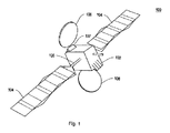
図1は、衛星100の例示的な実施形態を示している。衛星100は、衛星本体部102、ソーラ・パネル104、ソーラ・パネル装着システム105、通信アンテナ106、及び通信アンテナ装着システム107を含むことが可能である。衛星100は、例示的なためだけに提供されており、本明細書で説明されているスラスタ装着構造体は、任意の適切な衛星の中に一体化され得ることを理解されたい。
FIG. 1 shows an exemplary embodiment of a
衛星本体部102は、それに限定されないが、立方体又は矩形角柱を含む、任意の適切な形状であってよい。ソーラ・パネル104は、入射太陽光から電力を発生させるように構成され得、また、ソーラ・パネル装着システム105を通して、衛星本体部102の任意の適切な面の上に装着され得る。ソーラ・パネル装着システム105は、アクチュエータを含むことが可能であり、アクチュエータは、ソーラ・パネル104を回転させるように、及び/又は、ソーラ・パネル104に角度を付けるように構成されている。たとえば、ソーラ・パネル装着システム105は、ソーラ・パネル104を回転させるか又はソーラ・パネル104に角度を付け、太陽を追跡することが可能であり、これによって衛星のためのほとんどの電力を発生させるようになっている。また、ソーラ・パネル装着システム105は、ソーラ・パネル104をしまい込む及び/又は展開するための手段を含むことが可能である。たとえば、ソーラ・パネル104は、貯蔵のために折り畳めるように、及び、展開のために広がるように設計され得る。ソーラ・パネル装着システム105は、アクチュエータ及び/又はラッチを含み、ソーラ・パネル104を展開するように制御信号が受け取られるまで、格納位置にソーラ・パネルを維持することが可能である。通信アンテナ106は、衛星からのデータを通信するための任意の適切な機器であってよい。たとえば、通信アンテナ106は、ミッション・コントロールと通信するために、地球の上の地上ステーションに向けて方向付けられた電磁波を発生させることが可能である。通信アンテナ106は、通信アンテナ装着システム107を通して、衛星本体部102に接続され得る。ソーラ・パネル装着システム106と同様に、通信アンテナ装着システム107は、通信アンテナ106を展開するように制御信号が受け取られるまで、格納状態(たとえば、衛星本体部102に対して折り畳まれている)に通信アンテナ106を維持するために、アクチュエータ及び/又はラッチを含むことが可能である。
The
また、衛星100は、さらに詳細に下記に説明されているスラスタ装着構造体のうちの1つ又は複数を含むことが可能である。スラスタ装着構造体は、衛星本体部102の任意の適切な表面の上に装着又は一体化され得る。たとえば、2つのスラスタ装着構造体は、ソーラ・パネル104と同じ面の上に装着され得、それぞれの面に対して1つずつ装着され得る。このようにして、1対のスラスタ装着構造体は、連絡し合って働き、2つ以上のスラスタを位置決めし、ステーション・キーピング操作又は軌道上昇/転移操作のためのスラスタ・ベクタリングを提供することが可能である。スラスタ装着構造体は、任意の適切なタイプの推進システムを含むことが可能である。たとえば、いくつかの実施形態では、スラスタ装着構造体は、電気スラスタを含むことが可能である。それに限定されないが、イオン・スラスタ、プラズマ・ベースのスラスタ、静電スラスタ、電熱スラスタ、及び電磁スラスタを含む、任意の適切なタイプの電気スラスタが利用され得る。いくつかの実施形態では、衛星100は、宇宙船本体部102の任意の適切な表面の上に装着された従来のロケット・ベースのスラスタをさらに含むことが可能であり、衛星100は、化学ベースのロケット推進システム及び電気推進システムの組み合わせによって推進されるようになっている。これらの実施形態では、化学ベースのロケット推進システムは、本明細書で説明されているスラスタ装着構造体を使用して、又は、任意の他の適切な方法によって、衛星本体部102に装着され得る。いくつかの実施形態では、衛星100は、電気推進システムだけを含むことが可能である。そのような実施形態では、衛星100は、他の手段を通して衛星本体部102に装着されている電気スラスタに加えて、下記にさらに説明されているようなスラスタ装着構造体を通して衛星本体部102に装着された電気スラスタを含むことが可能である。このようにして、スラスタ装着構造体は、1次的な推進システムに加えて、冗長な又は追加的な推進能力を提供することが可能である。
The
図2は、衛星軌道200の例示的な図を示している。衛星204は、図1に関連して説明されている衛星100と実質的に同様であってよく、また、天体202の周りの軌道に乗ることが可能である。天体202は、それに限定されないが、地球、月、太陽、惑星、星、又は、任意の他の天体を含む、任意の適切な天体であってよい。衛星204は、天体202の周りの軌道206を確立することが可能である。軌道206は、以下の軌道特性、すなわち、高度、長半径、離心率、傾斜角、及び近点引数、昇交点黄経、近点通過時刻、近点の半径、及び、遠点の半径のうちの1つ又は複数を含むことが可能である。例示的な例として、通信衛星は、地球の赤道の上方の35,786kmの高度において静止(GEO)軌道を確立することが可能であり、これによって地球の表面の上方の一定の位置を維持するようになっている。別の例示的な例として、地球マッピング衛星は、比較的高い傾斜角(たとえば、赤道に対して90度に近い)で極軌道を確立することが可能であり、それが、それぞれの軌道の上の異なる経度において赤道を通過するようになっている。軌道206は、円形軌道、楕円形軌道、又は8の字形の形状を含む、任意の適切な形状を含むことが可能である。
FIG. 2 shows an exemplary view of
その軌道を維持するために、衛星204は、ステーション・キーピング操作208及び210を実施することが可能である。本明細書で使用される場合、「ステーション・キーピング」は、所望の軌道を維持するために必要とされる軌道操作を表している。ステーション・キーピングは、空気抗力、太陽輻射圧、及び、太陽/月からの重力などのような、衛星204の軌道を悪化させる複数の外力に起因して、衛星204に必要である可能性がある。いくつかの実施形態では、そのような外力は、衛星204の軌道速度を減少又は増加させ、それに応じて軌道206の高度(又は、長半径)を減少又は増加させ得る。そのような実施形態では、衛星204は、衛星204の軌道速度を増加又は減少させるために、及び、外力に対抗するように、軌道の方向に、又は、衛星204の移動の方向に、ステーション・キーピング操作208を実施することが可能である。いくつかの実施形態では、衛星204は、フィードバック・ループにしたがってステーション・キーピング操作208を実施することが可能であり、衛星204の軌道速度及び/又は高度が検知されるようになっており、また、衛星204の軌道速度及び/又は高度が所望の軌道速度又は高度と同じではないことを検出したことに応答して、ステーション・キーピング操作208を実施する。いくつかの実施形態では、フィードバック・ループは、衛星204の軌道パラメータを決定するために、天体202の上の地上ステーションとの通信、又は、別の軌道衛星もしくは宇宙船との通信を含むことが可能である。上記に考察されているようなフィードバック・ループは、例示的なためだけに提供されており、また、任意の適切な制御スキームが、ステーション・キーピング操作208によって利用され得ることを理解されたい。
To maintain its orbit, the
いくつかの実施形態では、外力は、衛星204の移動の方向以外の方向に、衛星204の速度の増加又は減少を提供する可能性がある。そのうえ、外力は、正味のトルク又は回転を衛星204に付与することが可能である。そのような場合では、ステーション・キーピング操作210は、そのような速度変化又は回転変化を補正するために使用され得る。たとえば、外力は、軌道206の以下の軌道パラメータ、すなわち、離心率、傾斜角、及び近点引数のうちの1つ又は複数に影響を与えることが可能である。ステーション・キーピング操作208に関連して上記に考察されているように、フィードバック・ループは、軌道パラメータの変化を補正するために使用され得る。いくつかの実施形態では、軌道パラメータのうちの1つ又は複数は、衛星204によって直接、又は、地上ステーションもしくは別の衛星によって、検知され得、検知された軌道パラメータが所望の軌道パラメータとは異なっていると決定したことに応答して、ステーション・キーピング操作210を実施する。いくつかの実施形態では、ステーション・キーピング操作208及び210の組み合わせが、軌道パラメータの変化を補正するために利用され得る。ステーション・キーピング操作208及び210は、直交するものとして図2に示されているが、ステーション・キーピング操作208及び210は、軌道パラメータに対する変化を補正するために任意の適切な方向を向くことが可能であることを理解されたい。また、ステーション・キーピング操作208及び210は、化学的なロケット・ベースのスラスタ及び電気的なスラスタ、ならびに、任意の数のスラスタ又はスラスタの組み合わせを含む、任意の適切なスラスタによって作り出され得ることを理解されたい。たとえば、いくつかのスラスタは、衛星204の重心を通る方を向くように構成され得、また、衛星204に正味の速度を付与するように設計され得るが、いくつかのスラスタは、衛星204の重心を通る方を向いていないスラスト・ベクトルを提供するように構成され得、また、衛星204に正味の回転を付与するように設計され得る。いくつかのスラスタは、正味の速度及び正味の回転の両方を衛星204に付与するように構成され得る。いくつかのスラスタは、適切な位置又は回転に固定され得るが、他のスラスタは、6つの自由度(3つの並進自由度、3つの回転自由度)のうちの少なくとも1つにおいてスラスタが移動することを可能にするように、装着され又はジンバルに支持され得る。たとえば、衛星204の上に装着されているスラスタのうちの1つ又は複数は、本明細書で説明されているスラスタ装着構造体を使用して装着され得る。
In some embodiments, the external force may provide an increase or decrease in the speed of the
図3は、軌道上昇操作300の例示的な図を示している。本明細書で使用されているように、「軌道上昇」又は「軌道転移」は、第1の軌道303から第2の軌道306へ衛星304の軌道を変化させる任意の軌道操作を表している。軌道上昇操作300は、ホーマン転移として図3に示されているが、軌道上昇操作300は、それが円形であろうが楕円形であろうが任意の初期軌道において始まることが可能であり、また、以下の軌道パラメータ、すなわち、高度、長半径、離心率、傾斜角、及び近点引数、昇交点黄経、近点通過時刻、近点の半径、及び、遠点の半径のうちの少なくとも1つを変化させる任意の適切な軌道操作であってよいことを理解されたい。
FIG. 3 shows an exemplary diagram of a
図3に示されているように、衛星304は、初期軌道303において、天体302の周りの軌道に乗ることが可能である。衛星304は、図1に示されている衛星100と実質的に同様であってよい。天体302は、図2に示されている天体202と実質的に同様であってよい。初期軌道303は、他の軌道パラメータに加えて、最終的な軌道306の半径よりも下の半径305を有することが可能である。初期軌道は、他の軌道パラメータに加えて、楕円形の軌道であってよく、近地点は、最終的な軌道306の下にあり、遠地点は、最終的な軌道306の下方にあるか、最終的な軌道306にあるか、又は、最終的な軌道306の上方にあってよい。衛星304は、1つ又は複数の軌道公転にわたって連続的に、又は、それらの任意の組み合わせにわたって、軌道の中の離散的なポイントにおける有限な持続期間の多数のスラスタ燃焼310を実施することが可能であり、これによって所望の速度の変化を付与し、最終的な軌道306に到達するようになっている。スラスタ燃焼ベクトル310は、衛星304の移動の方向になっているか、衛星304の移動の方向の反対側になっているか、又は、それらの間の任意の方向になっていることが可能である。スラスタ燃焼ベクトル310は、軌道の中で、及び、軌道平面に対して、任意の角度になっていることが可能である。
As shown in FIG. 3, the
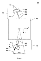
図4は、スラスタ装着スキーム400の例示的な図を示しており、衛星本体部402は、第1及び第2のスラスタ装着構造体404を含む。衛星本体部402は、図1に示されて上記に考察されている衛星本体部102と実質的に同様であってよい。第1のスラスタ装着構造体404は、スラスタ・パレット406、第1の方位角(azimuth)アクチュエータ408、第2の方位角アクチュエータ410、仰角アクチュエータ412、スラスタ414、及びブーム418を含む。第2のスラスタ装着構造体419は、第1のスラスタ装着構造体404と実質的に同じコンポーネントを含むことが可能である。図4に示されているように、第1及び第2のスラスタ装着構造体404及び419は、衛星本体部402の両面に装着され得る。
FIG. 4 shows an exemplary view of a
第1の方位角アクチュエータ408は、第1の方向424に回転するように構成され得る。いくつかの実施形態では、方向424は、図4に示されているように、z軸の周りの回転であってよい。いくつかの実施形態では、第1の方位角アクチュエータ408は、第1の方向424だけに回転するように構成されている。すなわち、第1の方位角アクチュエータ408は、他の2つの回転方向に対しては、回転方向に硬い。同様に、第2の方位角アクチュエータ410は、第2の方向426に回転するように構成され得、仰角アクチュエータ412は、方向428に回転するように構成され得る。第1の方位角アクチュエータ408と同様に、第2の方位角アクチュエータ410及び仰角アクチュエータ412は、いくつかの実施形態では、それぞれの方向だけに回転するように構成され、他の回転自由度において固定であるように構成され得る。いくつかの実施形態では、第1の方位角アクチュエータ408、第2の方位角アクチュエータ410、及び仰角アクチュエータ412は、回転位置、回転速度、及び/又は回転加速度に関する制御信号及び/又はセットポイントを受け取るように構成された電動アクチュエータであってよい。
The
スラスタ・パレット406は、金属、炭素繊維、又は複合材料などのような、任意の適切な材料から作製され得る。スラスタ・パレット406は、図4に示されているように、矩形角柱を含む、任意の適切な形状に構成され得る。スラスタ414は、それに限定されないが、ねじ、リベット、ボルト、溶接、接着剤、又は、それらの任意の組み合わせを含む、任意の適切な手段を使用して、スラスタ・パレット406の上に直接装着され得る。2つのスラスタ414が図4に示されているが、任意の数のスラスタが、スラスタ・パレット406の上に装着され得ることを理解されたい。そのうえ、スラスタ414は、電気スラスタ及び/又は化学的なロケット・スラスタを含む、任意の適切なタイプのスラスタであってよい。
The
ブーム418は、金属、炭素繊維、又は複合材料などのような、任意の適切な材料から作製され得る。ブーム418は、任意の適切な形状及び長さであってよい。たとえば、ブーム418は、方形断面を有する中空の部材であってよい。ブーム418は、それに限定されないが、ねじ、リベット、ボルト、溶接、接着剤、又は、それらの任意の組み合わせを含む、任意の適切な手段を使用して、第1の方位角アクチュエータ408、第2の方位角アクチュエータ410、及び/又は仰角アクチュエータ412のうちの1つ又は複数に取り付けられ得る。たとえば、ブーム418は、第1の方位角アクチュエータ408に取り付けられ得、第1の方位角アクチュエータ408がブームを方向424に枢動させることができるようになっている。第2の方位角アクチュエータ410は、それに限定されないが、ねじ、リベット、ボルト、溶接、接着剤、又は、それらの任意の組み合わせを含む、任意の適切な手段によって、スラスタ・パレット406に取り付けられ得る。第2の方位角アクチュエータ410は、スラスタ・パレット406を方向426に枢動させるように構成され得る。いくつかの実施形態では、方向424及び方向426は、同じであってもよい。仰角アクチュエータ412は、スラスタ・パレット及び/又は第2の方位角アクチュエータ410に接続され得る。仰角アクチュエータ412は、スラスタ・パレット406を方向428に枢動させるように構成され得る。
The
第1の方位角アクチュエータ408は、それに限定されないが、ねじ、リベット、ボルト、溶接、接着剤、又は、それらの任意の組み合わせを含む、任意の適切な手段を使用して、衛星本体部402に直接取り付けられ得る。第1の方位角アクチュエータ408は、スラスタ・パレット406を方向424に回転させ、スリュー角(slew angle)422を提供することが可能である。スリュー角422は、スラスタ414がスラスト・ベクトルを移動の方向又は軌道方向の接線方向に作り出すことを可能にすることができる。これは、衛星の経度ドリフト・レート及び離心率ベクトルの制御を可能にすることができる。いくつかの実施形態では、第2の方位角アクチュエータ410は、スラスタ・パレット406を回転させ、スラスタ方向420を提供することが可能であり、スラスタ方向420は、衛星の重心を通る方を向いている。衛星の重心は方形断面の中心として示されているが、重心は、衛星本体部402の中の任意のポイントに位置付けされ得る。いくつかの実施形態では、重心は、衛星本体部402の外側にあってよい。
The
図5は、ステーション・キーピング位置に位置決めされている第1及び第2のスラスタ装着構造体504及び519を含む、スラスタ装着スキーム500の例示的な図を示している。第1及び第2のスラスタ装着構造体504及び519は、図4に関連して説明されている第1及び第2のスラスタ装着構造体404及び419と実質的に同様であってよい。衛星本体部502は、図4に関連して説明されている衛星本体部402と実質的に同様であってよい。図5に示されているように、第1及び第2のスラスタ装着構造体504及び519は、衛星本体部502の1つの縁部に沿って装着され得る。図5に示されている例示的な例では、第1及び第2のスラスタ装着構造体504及び519は、衛星本体部502のy面の上に装着されている。ステーション・キーピング位置では、第1及び第2のスラスタ装着構造体504及び519は、図4に示されている仰角アクチュエータ412などのような、仰角アクチュエータを使用し、スラスタを枢動させ、スラスタ・ベクトル520を作り出すことが可能であり、スラスタ・ベクトル520は、衛星の重心を通る方を向いている。これは、カント角530を作り出すことが可能であり、カント角530は、スラスト・ベクトル520と宇宙船本体部502のxy平面との間の角度として測定される。カント角530は、移動の方向又は衛星の軌道方向に対して垂直及び/又は半径方向のスラスト・ベクトルをスラスタ514が作り出すことを可能にすることができる。これは、軌道傾斜角及び離心率ベクトルの制御を可能にすることができる。いくつかの実施形態では、カント角530は、軌道傾斜角及び離心率ベクトルの同時制御を可能にすることができる。いくつかの実施形態では、衛星の速度は、衛星の角運動量と同時に又は別々に制御され得る。たとえば、カント角530、及び、第1の方位角アクチュエータ424又は第2の方位角アクチュエータ426のいずれかの使用を通して、スラスタ414によって作り出されるスラスト・ベクトルは、重心を通る方を向くように構成され得、それによって、トルクのない速度変化を作り出し、又は、重心からわずかにオフセットされるように構成され得、それによって、正味のトルクを作り出す。ステーション・キーピング操作に関して、第1のスラスタ装着構造体504もしくは第2のスラスタ装着構造体519のいずれか又は両方に関連するスラスタが燃焼され得る。図2に関連して上記に考察されているように、スラスタ燃焼は、特定の軌道又は軌道特性を維持するために実施され得る。図4に示されているカント角530及びスリュー角422の使用を通して、幅広い範囲の制御オプションが、衛星本体部502を制御するために有効にされ得、それによって、ミッション最適化及び推進剤消費の低減を可能にする。いくつかの実施形態では、完全なステーション・キーピング動作は、2つのスラスタの使用によって、及び、1日又は軌道周期あたり2つの操作によって、完了され得る。いくつかの実施形態では、第1及び第2のスラスタ装着構造体504及び519は、衛星本体部502の6つの自由度(3つの並進自由度、3つの回転自由度)を制御するように構成され得る。したがって、完全な軌道及びステーション・キーピング制御が、2つのスラスタの使用だけで実現され得る。
FIG. 5 shows an exemplary view of a
図6は、軌道上昇位置に位置決めされている第1及び第2のスラスタ装着構造体604,619を含む、スラスタ装着スキーム600の例示的な図を示している。第1及び第2のスラスタ装着構造体604,619は、図4に関連して説明されている第1及び第2のスラスタ装着構造体404,419と実質的に同様であってよい。衛星本体部602は、図4に関連して説明されている衛星本体部402と実質的に同様であってよい。図6に示されているように、第1及び第2のスラスタ装着構造体604,619は、衛星本体部602の1つの縁部に沿って装着され得る。図6に示されている例示的な例では、第1及び第2のスラスタ装着構造体604,619は、衛星本体部602のy面の上に装着されている。軌道上昇位置では、第1及び第2のスラスタ装着構造体604,619は、図4に示されている仰角アクチュエータ412などのような、仰角アクチュエータを使用し、スラスタを枢動させることが可能であり、スラスタが、図6に示されているように実質的にビークル602のz方向にスラスト・ベクトル620を作り出すようになっている。いくつかの実施形態では、z方向は、移動の方向、移動の方向の反対側、又は、それらの間のどこかであってよい。スラスト・ベクトル620と衛星本体部602のxy平面との間に生成されるカント角630は、実質的に90度であってよい。いくつかの実施形態では、カント角は、図5に示されているようにビークル520の重心を通る方向を含むそれ以下の他の方向を向くことが可能である。軌道上昇操作に関して、第1及び第2のスラスタ装着構造体604,619に関連するスラスタのいずれか一方又は両方が燃焼され得る。図3に関連して上記に考察されているように、スラスタ燃焼は、初期軌道から最終的な軌道へ衛星の軌道を変化させるために、及び/又は、特定の軌道特性を変化させるために実施され得る。
FIG. 6 shows an exemplary view of a
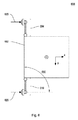
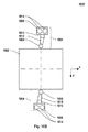
図7は、格納位置に位置決めされているスラスタ装着構造体704の例示的な図を示している。スラスタ装着スキーム700は、宇宙船本体部702、スラスタ装着構造体704、第1の方位角アクチュエータ708、ブーム718、スラスタ・パレット706、及びスラスタ714を含み、図4に関連して上記に考察されている対応するコンポーネントと実質的に同様であってよい。第1の方位角アクチュエータ708は、ブラケット720を介して宇宙船本体部702に直接接続されている。コンポーネント同士を共に直接接続すること、又は、1つのコンポーネントを別のコンポーネントに取り付けることは、それぞれのコンポーネントがそれぞれのコンポーネント間に延在する長尺状部材によって接続されてはいないことを意味しており、そのような長尺状部材は、ブームであり得る。したがって、共に直接接続されているか又は互いに取り付けられているコンポーネント同士は、ごく接近して置かれることになり、ブラケットなどによって共に固定され得る。第1の方位角アクチュエータ708は、静止部分722及び可動取り付け部分724を含む。いくつかの実施形態では、静止部分722は、アクチュエータ708を宇宙船本体部702に装着するために、ブラケット720に直接接続されている。いくつかの実施形態では、可動取り付け部分724は、接続されているコンポーネントを移動又は回転させるために回転可能なアクチュエータ708の一部分である。図7に示されている格納位置では、ブームは、衛星本体部702に実質的に平行になっていることが可能である。いくつかの実施形態では、ブーム718は、衛星本体部702に接触していることが可能である。いくつかの実施形態では、ブーム718は、衛星本体部702から間隔を離して配置された距離にあってよい。いくつかの実施形態では、ブーム718は、アクチュエータ708の幅726に等しい距離だけ、衛星本体部702から間隔を置いて配置されている。いくつかの実施形態では、スラスタ・パレット706は、スラスタ714が衛星本体部702に対して実質的に平行となるように位置合わせされ得、衛星本体部702に対して実質的に垂直な方を向くスラスト・ベクトルを有する。いくつかの実施形態では、スラスタ・パレット706は、装着構造体を使用して、衛星本体部702に取り付けられ得る。たとえば、装着構造体は、アクチュエータを含むことが可能であり、アクチュエータは、打ち上げの間に適切な場所にスラスタ・パレット706を維持することが意図されており、また、衛星のミッションの間の適当な時間にスラスタ・パレット706を展開することが意図されている。
FIG. 7 shows an exemplary view of the
図8は、ステーション・キーピング位置に位置決めされているスラスタ装着構造体804の例示的な図を示している。スラスタ装着スキーム800は、宇宙船本体部802、スラスタ装着構造体804、第1の方位角アクチュエータ808、ブーム818、ブラケット820、静止部分822、可動取り付け部分824、第2の方位角アクチュエータ810、スラスタ・パレット806、及びスラスタ814を含み、図4に関連して上記に考察されている対応するコンポーネントと実質的に同様であってよい。方位角アクチュエータ808は、可動取り付け部分824を含み、可動取り付け部分824は、接続されているコンポーネントを移動又は回転させるために、アクチュエータ808によって回転可能である。たとえば、図8に示されているステーション・キーピング位置では、ブーム818は、可動取り付け部分824に直接接続されている。したがって、第1の方位角アクチュエータ808は、衛星本体部802から内又は外にブーム818を回転させることが可能である。図8のブーム818は、衛星本体部802に対して実質的に垂直であるとして説明されているが、ブーム818は、ステーション・キーピング位置の中の他の角度へ回転され得ることを理解されたい。いくつかの実施形態では、第2の方位角アクチュエータ810、及び、図4に示されている仰角アクチュエータ412などのような仰角アクチュエータが、スラスタ・パレット806を回転させるために使用され得、スラスト・ベクトルが衛星本体部802に対して垂直にならないようになっている。第1の方位角アクチュエータ808、第2の方位角アクチュエータ810、及び仰角アクチュエータは、図2に関連して上記に考察されているように、1つ又は複数の軌道パラメータの中の偏差を補正するために、スラスタ・パレットをさまざまな位置へ回転させるために利用され得ることを理解されたい。
FIG. 8 shows an exemplary view of the
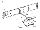
図9は、軌道上昇位置に位置決めされているスラスタ装着構造体904の例示的な図を示している。スラスタ装着スキーム900は、宇宙船本体部902、スラスタ装着構造体904、第1の方位角アクチュエータ908、ブーム918、第2の方位角アクチュエータ910、仰角アクチュエータ912、スラスタ・パレット806、及びスラスタ914を含み、図4に関連して上記に考察されている対応するコンポーネントと実質的に同様であってよい。図8に示されている軌道上昇位置では、第1の方位角アクチュエータ908は、衛星本体部902から外にブーム918を回転させることが可能である。図9のブーム918は、衛星本体部902に対して実質的に垂直であるとして説明されているが、ブーム918は、軌道上昇位置の中の他の角度へ回転され得ることを理解されたい。いくつかの実施形態では、第2の方位角アクチュエータ910及び仰角アクチュエータ912が、スラスタ・パレット906を回転させるために使用され得、スラスト・ベクトルが衛星本体部902に対して実質的に平行になるようになっている。いくつかの実施形態では、第2の方位角アクチュエータ910は、可動取り付け部分930及び静止部分931を含む。いくつかの実施形態では、静止部分931は、ブーム918に直接接続されている。いくつかの実施形態では、可動取り付け部分930は、仰角アクチュエータ912の可動取り付け部分932に直接接続されている。いくつかの実施形態では、第2の方位角アクチュエータ910及び仰角アクチュエータ912は、スラスタ・パレット906の上の装着ブラケット934を介して直接接続されている。したがって、いくつかの実施形態では、第2の方位角アクチュエータ910及び仰角アクチュエータ912は、少なくとも2つの軸線においてスラスタ・パレット906を回転させるように協働することが可能である。図9に示されているように、ブーム918は、衛星本体部902から間隔を置いて配置された距離に、スラスタ・パレット906及びスラスタ914を位置決めすることが可能である。いくつかの実施形態では、スラスタ914は、ビークルのz方向と実質的に一致する合成スラスト・ベクトルを作り出す。いくつかの実施形態では、個々のスラスタは、個々のスラスト・ベクトルがz方向とビークルの重心を通る方向との間のどこかの方を向くように回転され得る。図3に関連して上記に考察されているように、この向きのスラストは、初期軌道から最終的な軌道へ衛星の軌道を変化させるために使用され得る。
FIG. 9 shows an exemplary view of the
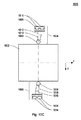
図10A〜Eは、さまざまな位置にある第1及び第2のスラスタ装着構造体1004の例示的な図1000を示している。宇宙船本体部1002、スラスタ装着構造体1004、第1の方位角アクチュエータ1008、ブーム1018、第2の方位角アクチュエータ1010、スラスタ・パレット1006、及びスラスタ1014は、図4に関連して上記に考察されている対応するコンポーネントと実質的に同様であってよい。図10Aは、格納位置にある第1及び第2のスラスタ装着構造体1004を示している。図7に関連して上記に考察されているように、格納位置では、ブーム1018は、衛星本体部1002に実質的に平行であり、及び/又は、同一平面状にあってよい。スラスタ・パレット1006は、その最も長い縁部に沿って平行となるように回転されることができ、スラスタが衛星本体部1002から外側を指向するようになっている。図7に関連して考察されているように、スラスタ・パレット1006は、装着スキームを使用して衛星本体部1002に固定され得、装着スキームは、衛星のミッションの間の適当な時間にスラスタ・パレット1006を解放又は展開するように構成されている。このようにして、格納位置は、必要とされる貯蔵スペースを最小化し、また、たとえば、打ち上げの間に、スラスタ・パレット1006に付与される任意の逆向きの力を最小化することが可能である。
10A-E show an exemplary diagram 1000 of first and second
図10Bは、軌道上昇位置にある第1及び第2のスラスタ装着構造体1004を示している。図6及び図9に関連して上記に考察されているように、軌道上昇位置では、スラスタ1014は、合成スラスタ・ベクトルが実質的にz方向を向くように回転され得る。いくつかの実施形態では、スラスタは、個々のスラスト・ベクトルがz方向とビークルの重心を通る方向との間のどこかの方を向くように回転され得る。図3に関連して上記に考察されているように、z方向のスラストは、衛星の速度を増加させ、軌道の変化をもたらすことが可能である。図10Bに示されているように、ブーム1018は、衛星本体部1002のxz面に対して垂直でなくてもよい。いくつかの実施形態では、軌道上昇操作に関して、第1及び第2のスラスタ装着構造体に関連するスラスタの両方は、衛星本体部1002の上の任意の望ましくない回転を低減させるために燃焼され得る。
FIG. 10B shows the first and second
図10Cは、ステーション・キーピング位置にある第1及び第2のスラスタ装着構造体1004を示している。図5及び図8に関連して上記に考察されているように、ステーション・キーピング位置では、スラスタ1014は、さまざまな位置へ回転され、特定の軌道パラメータの偏差を補正することが可能である。図10Cに示されている位置では、第1及び第2のスラスタ装着構造体1004は、傾斜角及び離心率の両方の偏差を補正することが可能である。たとえば、スラスタ1014の向きは、z方向及びy方向の両方の力を作り出すことが可能であり、それは、それらの方向の外力を補償することが可能である。図10Cに示されているように、ブーム1018は、衛星本体部1002のxz面に対して垂直でなくてもよい。いくつかの実施形態では、ステーション・キーピング操作に関して、第1及び第2のスラスタ装着構造体に関するスラスタのうちの一方又は両方は、必要に応じて、軌道偏差を補正するために燃焼され得る。
FIG. 10C shows the first and second
図10D及び図10Eは、他のステーション・キーピング位置にある第1及び第2のスラスタ装着構造体1004を示している。図5及び図8に関連して上記に考察されているように、ステーション・キーピング位置では、スラスタ1014は、さまざまな位置へ回転され、特定の軌道パラメータの偏差を補正することが可能である。図10D及び図10Eに示されている位置では、第1及び第2のスラスタ装着構造体1004は、傾斜角、離心率、及びドリフトの偏差を補正することが可能である。たとえば、スラスタ1014の向きは、x方向、y方向、及びz方向のすべてに力を作り出すことが可能であり、それは、それらの方向の外力を補償することが可能である。スラスト・ベクトルの角度は、第1の方位角アクチュエータ1008、第2の方位角アクチュエータ1010、及び、図4に示されているような仰角アクチュエータ412などのような仰角アクチュエータを使用して制御され得る。図10D及び図10Eに示されているように、ブーム1018は、衛星本体部1002のxz面に対して垂直でなくてもよい。いくつかの実施形態では、ステーション・キーピング操作に関して、第1及び第2のスラスタ装着構造体に関するスラスタのうちの一方又は両方は、必要に応じて、軌道偏差を補正するために燃焼され得る。
10D and 10E show the first and second
いくつかの実施形態では、衛星の重心の場所に応じて、図10B、図10C、図10D、及び図10Eに示されている向きは、また、衛星本体部1002に正味のトルク及び/又は回転を付与することが可能である。
In some embodiments, depending on the location of the center of gravity of the satellite, the orientation shown in FIGS. 10B, 10C, 10D, and 10E can also cause the
本明細書で説明されている実施形態は単なる例として提供されていることが当業者に明らかであろう。多数の変形例、代替例、変化例、及び置換例が、本発明を実践する際に当業者によって用いられ得ることを理解されたい。したがって、本発明は、本明細書で開示されている実施形態に限定されるべきではなく、以下の特許請求の範囲から理解されるべきであり、特許請求の範囲は、法律で許容される限り広く解釈されるべきであることを理解されたい。 It will be apparent to those skilled in the art that the embodiments described herein are provided by way of example only. It should be understood that numerous variations, alternatives, modifications, and substitutions can be used by those skilled in the art in practicing the present invention. Accordingly, the present invention should not be limited to the embodiments disclosed herein, but should be understood from the following claims, which are as permitted by law. It should be understood that this should be interpreted broadly.
Claims (23)
前記第1のスラスタ装着構造体は、
ビークルに取り付けられている第1の回転ジョイントであって、第1のブラケットを介して前記ビークルに接続されている第1の静止部分を備え、及び、第1の軸線において回転する第1の可動取り付け部分を備える、第1の回転ジョイントと、
前記第1の可動取り付け部分において前記第1の回転ジョイントに直接接続されているブームであって、前記第1の回転ジョイントは、前記第1の軸線の周りに前記ブームを枢動させる、ブームと、
前記ブームに直接接続されている第2の静止部分を備え、及び、前記第1の軸線において回転する第2の可動取り付け部分を備える、第2の回転ジョイントと、
前記第2の回転ジョイントに直接接続されており、また、前記第1の軸線に対して垂直な第2の軸線において回転する第3の可動取り付け部分を含む第3の回転ジョイントであって、前記第2の回転ジョイントは、前記第1の軸線の周りに前記第3の回転ジョイントを枢動させる、第3の回転ジョイントと、
前記第3の回転ジョイントの前記第3の可動取り付け部分に直接接続されているスラスタ・パレットであって、前記第3の回転ジョイントは、前記第2の軸線の周りに前記スラスタ・パレットを枢動させる、スラスタ・パレットと、
前記スラスタ・パレットに固定して取り付けられているスラスタと
を備える、システム。 A system for mounting a thruster on a vehicle, comprising a first thruster mounting structure,
The first thruster mounting structure includes:
A first rotary joint attached to the vehicle, comprising a first stationary portion connected to the vehicle via a first bracket and rotating in a first axis A first rotational joint comprising an attachment portion;
A boom directly connected to the first rotary joint at the first movable attachment portion, wherein the first rotary joint pivots the boom about the first axis; ,
A second rotary joint comprising a second stationary part connected directly to the boom and comprising a second movable attachment part rotating in the first axis;
A third rotary joint connected directly to the second rotary joint and including a third movable mounting portion rotating in a second axis perpendicular to the first axis, A second rotary joint pivoting the third rotary joint about the first axis; and
A thruster pallet directly connected to the third movable mounting portion of the third rotary joint, wherein the third rotary joint pivots the thruster pallet about the second axis; Let the thruster palette,
And a thruster fixedly attached to the thruster pallet.
前記第4の可動取り付け部分において前記第4の回転ジョイントに直接接続されている第2のブームであって、前記第4の回転ジョイントは、前記第1の軸線の周りに前記第2のブームを枢動させる、第2のブームと、
前記第2のブームに直接接続されている第5の静止部分を備え、及び、前記第1の軸線において回転する第5の可動取り付け部分を備える、第5の回転ジョイントと、
前記第5の回転ジョイントに直接接続されており、また、前記第2の軸線において回転する第6の可動取り付け部分を含む第6の回転ジョイントであって、前記第5の回転ジョイントは、前記第1の軸線の周りに前記第6の回転ジョイントを枢動させる、第6の回転ジョイントと、
前記第6の回転ジョイントの前記第6の可動取り付け部分に直接接続されている第2のスラスタ・パレットであって、前記第6の回転ジョイントは、前記第2の軸線の周りに前記第2のスラスタ・パレットを枢動させる、第2のスラスタ・パレットと、
前記第2のスラスタ・パレットに固定して取り付けられている第2のスラスタと
を備える、第2のスラスタ装着構造体
をさらに備える、請求項1に記載のシステム。 A fourth rotary joint attached to the vehicle, comprising a fourth stationary portion connected directly to the vehicle via a third bracket, and rotating about the first axis; A fourth rotary joint comprising four movable attachment parts;
A second boom connected directly to the fourth rotary joint at the fourth movable attachment portion, wherein the fourth rotary joint pivots the second boom about the first axis. A second boom to pivot,
A fifth rotary joint comprising a fifth stationary part directly connected to the second boom and comprising a fifth movable attachment part rotating in the first axis;
A sixth rotary joint connected directly to the fifth rotary joint and including a sixth movable attachment portion rotating in the second axis, wherein the fifth rotary joint is A sixth revolute joint pivoting the sixth revolute joint about one axis;
A second thruster pallet connected directly to the sixth movable mounting portion of the sixth rotational joint, wherein the sixth rotational joint is arranged around the second axis; A second thruster palette that pivots the thruster palette;
The system of claim 1, further comprising a second thruster mounting structure comprising: a second thruster fixedly attached to the second thruster pallet.
Priority Applications (1)
| Application Number | Priority Date | Filing Date | Title |
|---|---|---|---|
| JP2021113414A JP7383666B2 (en) | 2015-09-18 | 2021-07-08 | Operation system for earth-orbiting satellites with electric thrusters |
Applications Claiming Priority (3)
| Application Number | Priority Date | Filing Date | Title |
|---|---|---|---|
| US14/858,240 US10046867B2 (en) | 2015-09-18 | 2015-09-18 | Maneuvering system for earth orbiting satellites with electric thrusters |
| US14/858,240 | 2015-09-18 | ||
| PCT/US2016/052500 WO2017049297A1 (en) | 2015-09-18 | 2016-09-19 | Maneuvering system for earth orbiting satellites with electric thrusters |
Related Child Applications (1)
| Application Number | Title | Priority Date | Filing Date |
|---|---|---|---|
| JP2021113414A Division JP7383666B2 (en) | 2015-09-18 | 2021-07-08 | Operation system for earth-orbiting satellites with electric thrusters |
Publications (2)
| Publication Number | Publication Date |
|---|---|
| JP2018527246A true JP2018527246A (en) | 2018-09-20 |
| JP2018527246A5 JP2018527246A5 (en) | 2019-09-12 |
Family
ID=58276663
Family Applications (2)
| Application Number | Title | Priority Date | Filing Date |
|---|---|---|---|
| JP2018514270A Pending JP2018527246A (en) | 2015-09-18 | 2016-09-19 | Operating system for Earth-orbiting satellite with electric thruster |
| JP2021113414A Active JP7383666B2 (en) | 2015-09-18 | 2021-07-08 | Operation system for earth-orbiting satellites with electric thrusters |
Family Applications After (1)
| Application Number | Title | Priority Date | Filing Date |
|---|---|---|---|
| JP2021113414A Active JP7383666B2 (en) | 2015-09-18 | 2021-07-08 | Operation system for earth-orbiting satellites with electric thrusters |
Country Status (6)
| Country | Link |
|---|---|
| US (3) | US10046867B2 (en) |
| EP (1) | EP3350079B1 (en) |
| JP (2) | JP2018527246A (en) |
| CA (2) | CA2999148C (en) |
| IL (2) | IL258110B (en) |
| WO (1) | WO2017049297A1 (en) |
Families Citing this family (8)
| Publication number | Priority date | Publication date | Assignee | Title |
|---|---|---|---|---|
| CN107108047A (en) | 2014-08-26 | 2017-08-29 | 有效空间解决方案有限公司 | Docking system and method for satellite |
| US10046867B2 (en) * | 2015-09-18 | 2018-08-14 | Orbital Atk, Inc. | Maneuvering system for earth orbiting satellites with electric thrusters |
| US10005568B2 (en) | 2015-11-13 | 2018-06-26 | The Boeing Company | Energy efficient satellite maneuvering |
| US10569909B2 (en) * | 2016-03-30 | 2020-02-25 | The Boeing Company | Systems and methods for satellite orbit and momentum control |
| EP3521179B1 (en) * | 2016-09-29 | 2021-05-26 | Mitsubishi Electric Corporation | Pointing mechanism |
| US10625882B2 (en) * | 2017-03-06 | 2020-04-21 | Effective Space Solutions Ltd. | Service satellite for providing in-orbit services using variable thruster control |
| RU2676844C1 (en) * | 2017-11-27 | 2019-01-11 | Акционерное общество "Военно-промышленная корпорация "Научно-производственное объединение машиностроения" | System of return of course orientation of space vehicle using orbital gyrocompass |
| CN111409821A (en) * | 2020-04-26 | 2020-07-14 | 北京航空航天大学合肥创新研究院 | Solar unmanned aerial vehicle with tilting wings |
Citations (4)
| Publication number | Priority date | Publication date | Assignee | Title |
|---|---|---|---|---|
| JPH11291998A (en) * | 1998-02-23 | 1999-10-26 | Space Syst Loral Inc | Loading arrangement of combined use thruster |
| EP2660154A2 (en) * | 2012-05-03 | 2013-11-06 | Thales | Propulsion system for satellite orbit control and attitude control |
| EP2666723A1 (en) * | 2012-05-25 | 2013-11-27 | Thales | Propulsion system for satellite attitude control and orbit control |
| WO2015138592A2 (en) * | 2014-03-12 | 2015-09-17 | Lockheed Martin Corporation | Thruster arrangement for geosynchronous orbit spacecraft |
Family Cites Families (23)
| Publication number | Priority date | Publication date | Assignee | Title |
|---|---|---|---|---|
| US4955559A (en) | 1988-01-26 | 1990-09-11 | Trw Inc. | Thrust vector control system for aerospace vehicles |
| US5349532A (en) * | 1992-04-28 | 1994-09-20 | Space Systems/Loral | Spacecraft attitude control and momentum unloading using gimballed and throttled thrusters |
| US6102337A (en) * | 1995-12-22 | 2000-08-15 | Hughes Electronics Corporation | Spacecraft attitude control with gimbaled thrusters |
| US6173565B1 (en) * | 1998-04-09 | 2001-01-16 | Primex Technologies, Inc. | Three axis pulsed plasma thruster with angled cathode and anode strip lines |
| US6076773A (en) * | 1998-04-10 | 2000-06-20 | Hughes Electronics Corporation | Spin-stabilized spacecraft and methods |
| US6296207B1 (en) | 1999-01-27 | 2001-10-02 | Space Systems/Loral, Inc. | Combined stationkeeping and momentum management |
| FR2814216B1 (en) * | 2000-09-18 | 2002-12-20 | Snecma Moteurs | ORIENTATION DEVICE AND ON-BOARD ORIENTATION SYSTEM |
| US6565043B1 (en) * | 2001-12-21 | 2003-05-20 | The Boeing Company | Redundant system for satellite inclination control with electric thrusters |
| US6637701B1 (en) | 2002-04-03 | 2003-10-28 | Lockheed Martin Corporation | Gimbaled ion thruster arrangement for high efficiency stationkeeping |
| US7059571B2 (en) | 2003-02-21 | 2006-06-13 | The Boeing Company | Deployable spacecraft mount for electric propulsion |
| US6945500B2 (en) * | 2003-08-15 | 2005-09-20 | Skycorp, Inc. | Apparatus for a geosynchronous life extension spacecraft |
| US20050077425A1 (en) | 2003-10-10 | 2005-04-14 | Raymond Payette | Thruster for propelling and directing a vehicle without interacting with environment and method for making the same |
| EP1735213B1 (en) * | 2004-04-08 | 2015-03-11 | Astrium Limited | Deployable boom |
| NL1032158C2 (en) | 2006-07-13 | 2008-01-15 | Dutch Space B V | Satellite comprises body and two adjustable forward thrust units, each of which is mounted on its own arm, each arm composed of at least three parts rotatable in relation to each other |
| US8448902B2 (en) * | 2011-02-11 | 2013-05-28 | Space Systems/Loral LLC | Satellite having multiple aspect ratios |
| FR3006670B1 (en) | 2013-06-07 | 2015-05-29 | Thales Sa | TWO-MODULE PROPULSION SYSTEM FOR ORBIT CONTROL AND SATELLITE ATTITUDE CONTROL |
| FR3006671B1 (en) * | 2013-06-07 | 2015-05-29 | Thales Sa | FOUR-MODULE PROPULSION SYSTEM FOR ORBIT CONTROL AND SATELLITE ATTITUDE CONTROL |
| FR3022530B1 (en) | 2014-06-19 | 2018-03-02 | Airbus Defence And Space Sas | METHOD FOR CONTROLLING THE ORBIT OF A SATELLITE IN TERRESTRIAL ORBIT, SATELLITE AND SYSTEM FOR CONTROLLING THE ORBIT OF SUCH A SATELLITE |
| EP3034412B1 (en) * | 2014-12-16 | 2017-10-11 | Ruag Space GmbH | Regulating mechanism for adjusting at least one engine of a spacecraft |
| US9663251B2 (en) * | 2014-12-22 | 2017-05-30 | Space Systems/Loral, Llc | Thruster support mechanism for satellite propulsion |
| FR3032427B1 (en) * | 2015-02-10 | 2017-03-10 | Airbus Defence & Space Sas | SATELLITE HAVING ELECTRICAL PROPULSION MEANS, METHOD OF POSTING SUCH A SATELLITE AND METHOD FOR MAINTAINING SATELLITE |
| FR3036102B1 (en) | 2015-05-12 | 2017-05-26 | Airbus Defence & Space Sas | METHOD AND SYSTEM FOR DETECTING FAILURE OF A PROPULSION ARM OF A SPATIAL VEHICLE, SUCH AS A SATELLITE |
| US10046867B2 (en) | 2015-09-18 | 2018-08-14 | Orbital Atk, Inc. | Maneuvering system for earth orbiting satellites with electric thrusters |
-
2015
- 2015-09-18 US US14/858,240 patent/US10046867B2/en active Active
-
2016
- 2016-09-19 CA CA2999148A patent/CA2999148C/en active Active
- 2016-09-19 CA CA3115644A patent/CA3115644A1/en active Pending
- 2016-09-19 JP JP2018514270A patent/JP2018527246A/en active Pending
- 2016-09-19 EP EP16847550.7A patent/EP3350079B1/en active Active
- 2016-09-19 WO PCT/US2016/052500 patent/WO2017049297A1/en active Application Filing
-
2018
- 2018-03-14 IL IL258110A patent/IL258110B/en active IP Right Grant
- 2018-08-14 US US16/103,337 patent/US10745151B2/en active Active
-
2020
- 2020-08-17 US US16/995,033 patent/US11661213B2/en active Active
-
2021
- 2021-05-26 IL IL283462A patent/IL283462B/en unknown
- 2021-07-08 JP JP2021113414A patent/JP7383666B2/en active Active
Patent Citations (4)
| Publication number | Priority date | Publication date | Assignee | Title |
|---|---|---|---|---|
| JPH11291998A (en) * | 1998-02-23 | 1999-10-26 | Space Syst Loral Inc | Loading arrangement of combined use thruster |
| EP2660154A2 (en) * | 2012-05-03 | 2013-11-06 | Thales | Propulsion system for satellite orbit control and attitude control |
| EP2666723A1 (en) * | 2012-05-25 | 2013-11-27 | Thales | Propulsion system for satellite attitude control and orbit control |
| WO2015138592A2 (en) * | 2014-03-12 | 2015-09-17 | Lockheed Martin Corporation | Thruster arrangement for geosynchronous orbit spacecraft |
Also Published As
| Publication number | Publication date |
|---|---|
| CA2999148A1 (en) | 2017-03-23 |
| EP3350079A4 (en) | 2019-05-22 |
| US10745151B2 (en) | 2020-08-18 |
| WO2017049297A1 (en) | 2017-03-23 |
| JP2021165136A (en) | 2021-10-14 |
| US11661213B2 (en) | 2023-05-30 |
| IL283462B (en) | 2022-01-01 |
| US20170081048A1 (en) | 2017-03-23 |
| CA3115644A1 (en) | 2017-03-23 |
| IL258110A (en) | 2018-05-31 |
| IL283462A (en) | 2021-06-30 |
| IL258110B (en) | 2021-06-30 |
| US20190092497A1 (en) | 2019-03-28 |
| EP3350079B1 (en) | 2022-05-04 |
| EP3350079A1 (en) | 2018-07-25 |
| CA2999148C (en) | 2021-06-15 |
| US20210024230A1 (en) | 2021-01-28 |
| US10046867B2 (en) | 2018-08-14 |
| JP7383666B2 (en) | 2023-11-20 |
Similar Documents
| Publication | Publication Date | Title |
|---|---|---|
| JP7383666B2 (en) | Operation system for earth-orbiting satellites with electric thrusters | |
| JP7100780B2 (en) | Service satellites for providing orbital services with variable thruster control | |
| JP3220142B2 (en) | Method of controlling pitch attitude of satellite by pressure of solar radiation, and satellite for performing the method | |
| US5716029A (en) | Constant sun angle transfer orbit sequence and method using electric propulsion | |
| US9527607B2 (en) | Propulsion system for satellite orbit control and attitude control | |
| JPH1029599A (en) | Method and device for placing spacecraft in intended orbit | |
| US11827381B2 (en) | Spacecraft and control method | |
| Wie et al. | Solar-sail attitude control design for a flight validation mission | |
| US6637701B1 (en) | Gimbaled ion thruster arrangement for high efficiency stationkeeping | |
| US8763957B1 (en) | Spacecraft transfer orbit techniques | |
| JPH11291998A (en) | Loading arrangement of combined use thruster | |
| JP2000211598A (en) | Station keeping and momentum control system and method thereof | |
| KR102528036B1 (en) | Efficient stationkeeping design for mixed fuel systems in response to a failure of an electric thruster | |
| KR102528033B1 (en) | Efficient stationkeeping design for mixed fuel systems | |
| WO2018061226A1 (en) | Pointing mechanism | |
| CN108657469B (en) | Electric propulsion expansion and thrust direction adjusting mechanism | |
| US11174046B2 (en) | System and method for rotating mass attitude control | |
| Modi | On the semi-passive attitude control and propulsion of space vehicles using solar radiation pressure | |
| JPH0215440B2 (en) | ||
| Circi | Three-axis attitude control using combined gravity-gradient and solar pressure | |
| Brophy et al. | 30-kW SEP spacecraft as secondary payloads for low-cost deep space science missions | |
| Tekinalp et al. | Attitude control of satellites with de-orbiting solar sails | |
| Meissinger | A small, primary solar-electric propulsion demonstration satellite | |
| Prodger | A solar sail technology application mission for analyzing the earth's geomagnetic tail |
Legal Events
| Date | Code | Title | Description |
|---|---|---|---|
| A711 | Notification of change in applicant |
Free format text: JAPANESE INTERMEDIATE CODE: A711 Effective date: 20190626 |
|
| A521 | Request for written amendment filed |
Free format text: JAPANESE INTERMEDIATE CODE: A821 Effective date: 20190626 |
|
| A521 | Request for written amendment filed |
Free format text: JAPANESE INTERMEDIATE CODE: A523 Effective date: 20190802 |
|
| A621 | Written request for application examination |
Free format text: JAPANESE INTERMEDIATE CODE: A621 Effective date: 20190802 |
|
| A977 | Report on retrieval |
Free format text: JAPANESE INTERMEDIATE CODE: A971007 Effective date: 20200720 |
|
| A131 | Notification of reasons for refusal |
Free format text: JAPANESE INTERMEDIATE CODE: A131 Effective date: 20200818 |
|
| A521 | Request for written amendment filed |
Free format text: JAPANESE INTERMEDIATE CODE: A523 Effective date: 20201117 |
|
| A02 | Decision of refusal |
Free format text: JAPANESE INTERMEDIATE CODE: A02 Effective date: 20210309 |