EP3350079B1 - Maneuvering system for earth orbiting satellites with electric thrusters - Google Patents
Maneuvering system for earth orbiting satellites with electric thrusters Download PDFInfo
- Publication number
- EP3350079B1 EP3350079B1 EP16847550.7A EP16847550A EP3350079B1 EP 3350079 B1 EP3350079 B1 EP 3350079B1 EP 16847550 A EP16847550 A EP 16847550A EP 3350079 B1 EP3350079 B1 EP 3350079B1
- Authority
- EP
- European Patent Office
- Prior art keywords
- thruster
- vehicle
- rotational joint
- axis
- thrusters
- Prior art date
- Legal status (The legal status is an assumption and is not a legal conclusion. Google has not performed a legal analysis and makes no representation as to the accuracy of the status listed.)
- Active
Links
- 239000013598 vector Substances 0.000 description 24
- 238000010586 diagram Methods 0.000 description 18
- 230000005484 gravity Effects 0.000 description 14
- 238000004891 communication Methods 0.000 description 11
- 239000003380 propellant Substances 0.000 description 6
- 238000010304 firing Methods 0.000 description 5
- 239000000126 substance Substances 0.000 description 5
- 239000000853 adhesive Substances 0.000 description 4
- 230000001070 adhesive effect Effects 0.000 description 4
- 238000012546 transfer Methods 0.000 description 4
- 229920000049 Carbon (fiber) Polymers 0.000 description 2
- PEDCQBHIVMGVHV-UHFFFAOYSA-N Glycerine Chemical compound OCC(O)CO PEDCQBHIVMGVHV-UHFFFAOYSA-N 0.000 description 2
- 230000001174 ascending effect Effects 0.000 description 2
- 239000004917 carbon fiber Substances 0.000 description 2
- 239000002131 composite material Substances 0.000 description 2
- 239000000463 material Substances 0.000 description 2
- 239000002184 metal Substances 0.000 description 2
- VNWKTOKETHGBQD-UHFFFAOYSA-N methane Chemical compound C VNWKTOKETHGBQD-UHFFFAOYSA-N 0.000 description 2
- 230000001133 acceleration Effects 0.000 description 1
- 238000007792 addition Methods 0.000 description 1
- 230000002411 adverse Effects 0.000 description 1
- 238000013507 mapping Methods 0.000 description 1
- 238000000034 method Methods 0.000 description 1
- 238000012986 modification Methods 0.000 description 1
- 230000004048 modification Effects 0.000 description 1
- 238000005457 optimization Methods 0.000 description 1
- 239000002245 particle Substances 0.000 description 1
- 230000005855 radiation Effects 0.000 description 1
- 230000000452 restraining effect Effects 0.000 description 1
Images


Classifications
-
- B—PERFORMING OPERATIONS; TRANSPORTING
- B64—AIRCRAFT; AVIATION; COSMONAUTICS
- B64G—COSMONAUTICS; VEHICLES OR EQUIPMENT THEREFOR
- B64G1/00—Cosmonautic vehicles
- B64G1/22—Parts of, or equipment specially adapted for fitting in or to, cosmonautic vehicles
- B64G1/24—Guiding or controlling apparatus, e.g. for attitude control
- B64G1/26—Guiding or controlling apparatus, e.g. for attitude control using jets
- B64G1/262—Guiding or controlling apparatus, e.g. for attitude control using jets having adjustable angles, e.g. gimbaled thrusters
- B64G1/264—Guiding or controlling apparatus, e.g. for attitude control using jets having adjustable angles, e.g. gimbaled thrusters mounted on adjustable booms or the like
-
- B—PERFORMING OPERATIONS; TRANSPORTING
- B64—AIRCRAFT; AVIATION; COSMONAUTICS
- B64G—COSMONAUTICS; VEHICLES OR EQUIPMENT THEREFOR
- B64G1/00—Cosmonautic vehicles
- B64G1/22—Parts of, or equipment specially adapted for fitting in or to, cosmonautic vehicles
- B64G1/24—Guiding or controlling apparatus, e.g. for attitude control
- B64G1/26—Guiding or controlling apparatus, e.g. for attitude control using jets
-
- B—PERFORMING OPERATIONS; TRANSPORTING
- B64—AIRCRAFT; AVIATION; COSMONAUTICS
- B64G—COSMONAUTICS; VEHICLES OR EQUIPMENT THEREFOR
- B64G1/00—Cosmonautic vehicles
- B64G1/22—Parts of, or equipment specially adapted for fitting in or to, cosmonautic vehicles
- B64G1/40—Arrangements or adaptations of propulsion systems
- B64G1/405—Ion or plasma engines
-
- B—PERFORMING OPERATIONS; TRANSPORTING
- B64—AIRCRAFT; AVIATION; COSMONAUTICS
- B64G—COSMONAUTICS; VEHICLES OR EQUIPMENT THEREFOR
- B64G1/00—Cosmonautic vehicles
- B64G1/22—Parts of, or equipment specially adapted for fitting in or to, cosmonautic vehicles
- B64G1/40—Arrangements or adaptations of propulsion systems
- B64G1/411—Electric propulsion
- B64G1/415—Arcjets or resistojets
Definitions
- Satellites and other spacecraft typically utilize chemical rocket propulsion systems to propel themselves into orbit and to perform mission operations. Although such propulsion systems provide relatively large amounts of thrust, rocket propulsion systems are generally propellant inefficient and have a low specific impulse. As a result, satellites and spacecraft propelled by rocket propulsion systems typically carry a large proportion of their mass as propellant, leaving a relatively small proportion of the mass available for mission payloads. Electric propulsion systems provide a viable alternative to rocket propulsion systems for long-range or long-duration missions, which require large amounts of propellant. Electric propulsion systems operate by using electric energy to expel propellant, typically particles of ionized gas, at high speeds.
- WO2015/138592 describes a spacecraft comprising first and second pluralities of thrusters.
- the thrusters are attached to a spacecraft body configured to move the thrusters between stowed and deployed positions.
- Each thruster is attached to a boom by a two-axis gimbal, wherein the boom is attached to the spacecraft by a hinge.
- the vehicle may be any suitable vehicle, including a satellite or other spacecraft, and may comprise any suitable shape.
- the vehicles described herein are discussed in relation to a satellite that is shaped like a cube or a rectangular prism, other satellite and spacecraft shapes may be contemplated, as will be understood by one of skill in the art.
- the thruster mounting structure may be mounted on any suitable surface of the vehicle, including a flat surface of a cube/rectangular prism. Other mounting surfaces may be contemplated as will be understood by those of skill in the art.
- the vehicles described herein are described in terms of an electric thruster, it will be understood that any suitable thruster may be utilized with the mounting structure described herein.
- the first axis may be a roll axis of the vehicle, and the second axis may be a yaw axis, pitch axis or a combination of pitch axis and yaw axis of the vehicle.
- the first axis may be a yaw axis of the vehicle, and the second axis may be a roll axis, pitch axis or a combination of roll axis and pitch axis of the vehicle.
- the first rotational joint and the second rotational joint may be motorized rotational joints.
- the rotational joints may employ motors, servos, or any other suitable mechanism for changing and maintaining a rotational movement.
- the rotational joints may receive control inputs to change and maintain a rotational angle. In some embodiments, the rotational joints may be configured to stiffly maintain a rotational angle until a control is received to change the rotational angle.
- a second thruster may be connected to the thruster pallet. The second thruster may be substantially identical to the first thruster, or it may be substantially different. For instance, the second thruster may be configured to provide substantially the same thrust as the first thruster in order to act as a redundant thruster.
- the thruster mounting structure may be able to orient the thruster pallet in a variety of positions, including a stowed position, a station keeping position, and an orbit raising position.
- the boom In the stowed position, the boom may be positioned substantially parallel and/or flush to the vehicle and the thruster pallet may be connected to the vehicle.
- the thruster pallet may be mated to a retaining receptacle which may secure the thruster pallet while the thruster pallet is not deployed.
- the thruster pallet may be secured to the vehicle body during launch to minimize space and to minimize vibration and other forces on the thruster mounting structure.
- the thruster pallet may be kept flush to the vehicle in the stowed position.
- the thruster may be facing a direction substantially perpendicular to the vehicle or vehicle face that the thruster mounting structure is mounted to.
- the thruster may be faced substantially outward or substantially toward the vehicle, in a direction perpendicular to the vehicle face.
- the thruster mounting structure may be arranged into a station keeping position.
- the station keeping position as discussed in further detail below, may encompass a wide variety of orientations intended to position the thrust vector such that an orbit of the satellite/spacecraft may be maintained.
- the thruster will be released from the vehicle body and manipulated using the first, second, and third rotational joints.
- the boom may not be parallel to the vehicle in the station keeping position. In some embodiments, the boom will be kept perpendicular to the vehicle or a face of the vehicle.
- the thrusters in the station keeping position may generate a thrust vector that points through a center of gravity of the vehicle.
- the thruster mounting structure may be arranged into an orbit raising position.
- the boom In the orbit raising position, the boom may be positioned substantially perpendicular to the vehicle or a face of the vehicle.
- the thruster pallet may be released from any restraining receptacle on the vehicle body.
- the thruster and/or thruster pallet In the orbit raising position, the thruster and/or thruster pallet may be pointed in a direction substantially parallel to the vehicle.
- the thruster may be spaced a distance away from the vehicle, for example, by the boom. In this manner, the thruster may be positioned to generate a thrust vector that may be used to raise or transfer an orbit of the vehicle.
- the vehicle may comprise a second thruster mounting structure.
- the second thruster mounting structure may be substantially similar to the first thruster mounting structure.
- the vehicle may comprise a rectangular prism shape, and the first thruster mounting structure and the second thruster mounting structure may be mounted on opposing faces of the rectangular prism. In this manner, the first thruster mounting structure and the second thruster mounting structure may be controlled independently in order to change the vehicles motion, such as orbit altitude, orbit inclination, eccentricity, and/or drift.
- the second thruster mounting structure may comprise a fourth rotational joint attached to a vehicle, the fourth rotational joint configured to rotate in the first axis.
- the fourth rotational joint may be configured to rotate in substantially the same axis as the axis of the first rotational joint of the first thruster mounting structure.
- the second thruster mounting structure may further comprise a second boom that may be connected to the fourth rotational joint, wherein the fourth rotational joint is configured to pivot the boom about the first axis.
- the second thruster mounting structure may comprise a fifth rotational joint, which may be attached to the second boom and configured to rotate in the first axis.
- the second thruster mounting structure may further comprise a sixth rotational joint attached to the fifth rotational joint, the sixth rotational joint configured to rotate in the second axis, and wherein the fifth rotational joint is configured to pivot the sixth rotational joint about the first axis.
- the second thruster mounting structure may further comprise a second thruster pallet attached to the sixth rotational joint, wherein the sixth rotational joint is configured to pivot the second thruster pallet about the second axis, and a second thruster may be fixedly attached to the second thruster pallet.
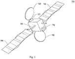
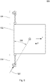
- FIG. 1 shows an exemplary embodiment of a satellite 100.
- the satellite 100 may comprise satellite body 102, solar panels 104, solar panel mounting system 105, communications antenna 106, and communications antenna mounting system 107.
- the satellite 100 is provided for illustrative purposes only, and it will be understood that the thruster mounting structure described herein may be integrated into any suitable satellite.
- the satellite body 102 may be any suitable shape, including, but not limited to, a cube or a rectangular prism.
- the solar panels 104 may be configured to generate electric power from incident sunlight and may be mounted on any suitable face(s) of the satellite body 102 through solar panel mounting system 105.
- the solar panel mounting system 105 may comprise actuators configured to rotate and/or angle the solar panels 104.
- the solar panel mounting system 105 may rotate or angle the solar panels 104 to track the sun in order to generate the most electric power for the satellite.
- the solar panel mounting system 105 may also include means for stowing and/or deploying the solar panels 104.
- the solar panels 104 may be designed to fold for storage and unfold for deployment.
- the solar panel mounting system 105 may comprise actuators and/or latches to maintain the solar panels in a stowed position until a control signal is received to deploy the solar panels 104.
- the communications antenna 106 may be any suitable equipment for communicating data from the satellite. For instance, the communications antenna 106 may generate electromagnetic waves directed toward a ground station on Earth in order to communicate with mission control.
- the communications antenna 106 may be connected to the satellite body 102 through communications antenna mounting system 107.
- the communications antenna mounting system 107 may comprise actuators and/or latches for maintaining the communications antenna 106 in a stowed state (e.g., folded against the satellite body 102) until a control signal is received to deploy the communications antenna 106.
- the satellite 100 may also comprise one or more of the thruster mounting structures described in further detail below.
- the thruster mounting structure(s) may be mounted or integrated on any suitable surface of satellite body 102.
- two thruster mounting structures may be mounted on the same faces as the solar panels 104, one for each face. In this manner, the pair of thruster mounting structures may work in tandem to position two or more thrusters to provide thruster vectoring for station keeping or orbit raising/transfer maneuvers.
- the thruster mounting structures may comprise any suitable type of propulsion system.
- the thruster mounting structures may comprise electric thrusters. Any suitable type of electric thruster may be utilized, including, but not limited to, ion thrusters, plasma-based thrusters, electrostatic thrusters, electrothermal thrusters, and electromagnetic thrusters.
- the satellite 100 may further comprise traditional rocket-based thrusters mounted on any suitable surface of the spacecraft body 102, such that the satellite 100 is propelled by a combination of a chemical-based rocket propulsion system and an electric propulsion system.
- the chemical-based rocket propulsion system may be mounted to the satellite body 102 using the thruster mounting structure described herein, or by any other suitable method.
- the satellite 100 may comprise only an electric propulsion system.
- the satellite 100 may comprise electric thrusters mounted to the satellite body 102 through a thruster mounting structure as described further below, in addition to electric thrusters which are mounted to the satellite body 102 through other means. In this manner, the thruster mounting structures may provide redundant or additional propulsion capacity in addition to a primary propulsion system.
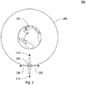
- FIG. 2 shows an illustrative diagram of a satellite orbit 200.
- the satellite 204 may be substantially similar to the satellite 100 described in relation to FIG. 1 and may orbit around celestial body 202.
- Celestial body 202 may be any suitable celestial body, including, but not limited to, the Earth, the moon, the sun, a planet, a star, or any other celestial body.
- the satellite 204 may establish an orbit 206 around the celestial body 202.
- the orbit 206 may comprise one or more of the following orbital characteristics: an altitude, a semi-major axis, an eccentricity, an inclination, and argument of periapsis, a longitude of the ascending node, a time of periapsis passage, a radius of periapsis, and a radius of apoapsis.
- a communications satellite may establish a geostationary (GEO) orbit at an altitude of 35,786km above the Earth's equator in order to maintain a fixed position above the Earth's surface.
- GEO geostationary
- an earth-mapping satellite may establish a polar orbit with a relatively high inclination (e.g., close to 90 degrees to the equator) so that it passes the equator at a different longitude on each orbit.
- the orbit 206 may comprise any suitable shape, including a circular orbit, elliptical orbit, or a figure-eight shape.
- the satellite 204 may perform station keeping maneuvers 208 and 210.
- station keeping refers to orbital maneuvers that are required to maintain a desired orbit. Station keeping may be necessary for satellite 204 due to a number of external forces that degrade the orbit of satellite 204, such as air drag, solar radiation pressure, and gravitational forces from the Sun/Moon. In some embodiments, such external forces may decrease or increase the orbit velocity of the satellite 204, causing the altitude (or semi-major axis) of the orbit 206 to decrease or increase accordingly.
- the satellite 204 may perform station keeping maneuver 208 in the direction of the orbit or the direction of travel of the satellite 204 in order to increase or decrease the orbit velocity of the satellite 204 and to counteract the external forces.
- the satellite 204 may perform station keeping maneuver 208 according to a feedback loop, such that the orbital velocity and/or the altitude of the satellite 204 is sensed, and in response to detecting the that orbital velocity and/or the altitude of the satellite 204 is not the same as the desired orbital velocity or altitude, performing the station keeping maneuver 208.
- the feedback loop may comprise communication with a ground station on the celestial body 202 or with another orbiting satellite or spacecraft in order to determine orbital parameters of the satellite 204.
- the feedback loop as discussed above is provided for illustrative purposes only, and it will be understood that any suitable control scheme may be utilized with station keeping maneuver 208.
- external forces may provide an increase or decrease in the velocity of the satellite 204 in directions other than the direction of travel of the satellite 204. Furthermore, the external forces may impart a net torque or rotation on the satellite 204. In such instances, station keeping maneuver 210 may be used to correct for such velocity or rotation changes.
- the external forces may affect one or more of the following orbital parameters of orbit 206: an eccentricity, an inclination, and argument of periapsis.
- a feedback loop may be used to correct for the changes in the orbital parameters.
- one or more of the orbital parameters may be sensed, either directly by the satellite 204 or by a ground station or another satellite, and in response to determining that the sensed orbital parameter(s) is different than a desired orbital parameter(s), performing station keeping maneuver 210.
- a combination of station keeping maneuver 208 and 210 may be utilized to correct for changes in orbital parameter(s).
- station keeping maneuvers 208 and 210 are depicted in Fig. 2 as orthogonal, it will be understood that station keeping maneuvers 208 and 210 may point in any suitable direction for correcting for changes to orbital parameter(s).
- station keeping maneuvers 208 and 210 may be produced by any suitable thruster(s), including chemical rocket-based thrusters and electrical thrusters, and any number or combination of thrusters.
- some thruster(s) may be configured to point through the center of gravity of the satellite 204 and designed to impart a net velocity on the satellite 204, while some thruster(s) may be configured to provide a thrust vector that does not point through the center of gravity of the satellite 204 and designed to impart a net rotation on the satellite 204.
- Some thruster(s) may be configured to impart both a net velocity and a net rotation on the satellite 204.
- thruster(s) may be fixed in position or rotation, while other thruster(s) may be mounted or gimbaled in a fashion that allows them to move in at least one of six degrees of freedom (three translational, three rotational).
- thrusters mounted onto satellite 204 may be mounted using the thruster mounting structure described herein.
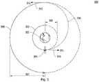
- FIG. 3 shows an illustrative diagram of an orbit raising maneuver 300.
- orbit raising or “orbit transfer” refers to any orbital maneuver that changes the orbit of the satellite 304 from a first orbit 303 to a second orbit 306. Although the orbit raising maneuver 300 is depicted in Fig.
- the orbit raising maneuver 300 may begin at any initial orbit, be it circular or elliptical, and be any suitable orbital maneuver that changes at least one of the following orbital parameters: an altitude, a semi-major axis, an eccentricity, an inclination, and argument of periapsis, a longitude of the ascending node, a time of periapsis passage, a radius of periapsis, and a radius of apoapsis.
- satellite 304 may orbit around celestial body 302 in an initial orbit 303.
- the satellite 304 may be substantially similar to the satellite 100 depicted in Fig. 1 .
- the celestial body 302 may be substantially similar to celestial body 202 depicted in Fig. 2 .
- the initial orbit 303 may have a radius 305, in addition to other orbital parameters, below that of the final orbit 306.
- the initial orbit may be an elliptical orbit, in addition to other orbital parameters, with a perigee below the final orbit 306 and an apogee that can be below, at, or above the final orbit 306.
- the satellite 304 may perform a multitude of thruster firings 310of finite duration at discrete points in the orbit, continuously over one or more orbital revolutions, or any combination thereof in order to impart the desired change in velocity and reach the final orbit 306.
- the thruster firing vector 310 may be in the direction of travel of the satellite 304, opposite of the direction of travel of the satellite 304, or any direction in between.
- the thruster firing vector 310 may be at any angle within the orbit and relative to the orbital plane.
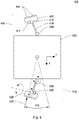
- FIG. 4 shows an illustrative diagram of a thruster mounting scheme 400 satellite body 402 comprising a first and a second thruster mounting structure 404.
- the satellite body 402 may be substantially similar to the satellite body 102 depicted in Fig. 1 and discussed above.
- the first thruster mounting structure 404 comprises a thruster pallet 406, a first azimuth actuator 408, a second azimuth actuator 410, an elevation actuator 412, thrusters 414, and boom 418.
- the second thruster mounting structure 419 may comprise substantially the same components as the first thruster mounting structure 404.
- the first and second thruster mounting structures 404 and 419 may be mounted on opposite faces of the satellite body 402.
- the first azimuth actuator 408 may be configured to rotate in a first direction 424.
- the direction 424 may be a rotation about the z axis, as depicted in FIG. 4 .
- the first azimuth actuator 408 is configured to rotate only in the first direction 424. That is, the first azimuth actuator 408 is stiff in rotation to the other two rotational directions.
- the second azimuth actuator 410 may be configured to rotate in a second direction 426, and the elevation actuator 412 may be configured to rotate in direction 428.
- the second azimuth actuator 410 and the elevation actuator 412 may be configured, in some embodiments, to rotate only in the respective directions and to be rigid in the other rotational degrees of freedom.
- the first azimuth actuator 408, the second azimuth actuator 410, and the elevation actuator 412 may be motorized actuators configured to receive control signals and/or setpoints for rotational position, rotational speed, and/or rotational acceleration.
- the thruster pallet 406 may be made of any suitable material, such as metal, carbon fiber, or composite material.
- the thruster pallet 406 may be configured into any suitable shape, including a rectangular prism, as depicted in Fig. 4 .
- the thrusters 414 may be mounted directly onto the thruster pallet 406 using any suitable means, including, but not limited to, screws, rivets, bolts, welds, adhesives, or any combination thereof. Although two thrusters 414 are depicted in Fig. 4 , it will be understood that a larger number of thrusters may be mounted onto thruster pallet 406.
- the thrusters 414 may be any suitable type of thruster, including electric thrusters and/or chemical rocket thrusters.
- the boom 418 may be made of any suitable material, such as metal, carbon fiber, or composite material.
- the boom 418 may be any suitable shape and length.
- the boom 418 may be a hollow member with a square cross section.
- the boom 418 may be attached to one or more of the first azimuth actuator 408, the second azimuth actuator 410, and/or the elevation actuator 412 using any suitable means, including, but not limited to, screws, rivets, bolts, welds, adhesives, or any combination thereof.
- the boom 418 may be attached to first azimuth actuator 408 such that the first azimuth actuator 408 may pivot the boom in direction 424.
- the second azimuth actuator 410 may be attached to the thruster pallet 406 by any suitable means, including, but not limited to, screws, rivets, bolts, welds, adhesives, or any combination thereof.
- the second azimuth actuator 410 may be configured to pivot the thruster pallet 406 in direction 426.
- the direction 424 and the direction 426 may be the same.
- the elevation actuator 412 may be connected to the thruster pallet and/or the second azimuth actuator 410.
- the elevation actuator 412 may be configured to pivot the thruster pallet 406 in direction 428.
- the first azimuth actuator 408 may be attached directly to the satellite body 402 using any suitable means, including, but not limited to, screws, rivets, bolts, welds, adhesives, or any combination thereof.
- the first azimuth actuator 408 may rotate the thruster pallet 406 in the direction 424 to provide a slew angle 422.
- the slew angle 422 may allow the thrusters 414 to produce a thrust vector in a direction tangential to the direction of travel or orbital direction. This may enable control of the longitude drift rate and eccentricity vector of the satellite.
- the second azimuth actuator 410 may rotate the thruster pallet 406 to provide a thruster direction 420 that points through the center of gravity of the satellite.
- the center of gravity of the satellite is depicted as the center of the square cross-section, the center of gravity may be located at any point within the satellite body 402. In some embodiments, the center of gravity may be outside of the satellite body 402.
- FIG. 5 shows an illustrative diagram of a thruster mounting scheme 500 including a first and a second thruster mounting structures 504 and 519 positioned in a station keeping position.
- the first and second thruster mounting structures 504 and 519 may be substantially similar to first and second thruster mounting structures 404 and 419 described in relation to FIG. 4 .
- Satellite body 502 may be substantially similar to satellite body 402 described in relation to FIG. 4 .
- the first and the second thruster mounting structures 504 and 519 may be mounted along one edge of the satellite body 502.
- the first and second thruster mounting structures 504 and 519 are mounted on the y faces of the satellite body 502.
- first and second thruster mounting structures 504 and 519 may use an elevation actuator, such as elevation actuator 412 depicted in FIG. 4 , to pivot the thrusters and produce a thruster vector 520 that points through the center of gravity of the satellite.
- This may produce cant angle 530, measured as the angle between the thrust vector 520 and an x-y plane of the spacecraft body 502.
- the cant angle 530 may allow the thrusters 514 to produce a thrust vector that is normal and/or radial to the direction of travel or the orbital direction of the satellite. This may enable control of the orbit inclination and eccentricity vector.
- the cant angle 530 may enable simultaneous control of the orbit inclination and eccentricity vector.
- the velocity of the satellite may be controlled simultaneously or separately from the angular momentum of the satellite.
- the thrust vector produced by thrusters 414 may be configured to point through the center of gravity, thereby producing a velocity change but no torque, or slightly offset from the center of gravity, thereby producing a net torque.
- the thruster associated with either the first thruster mounting structure 504 or the second thruster mounting structure 519, or both, may be fired. As discussed above in relation to FIG. 2 , the thruster firings may be performed in order to maintain a certain orbit or orbit characteristics.
- cant angle 530 and slew angle 422 depicted in FIG. 4 a wide range of control options may be enabled for controlling the satellite body 502, thereby allowing for mission optimization and reduced propellant consumption.
- full station keeping operations may be completed by the use of two thrusters and two maneuvers per day or orbital period.
- the first and a second thruster mounting structures 504 and 519 may be configured to control six degrees of freedom (three translational, three rotational) of the satellite body 502. Thus, full orbital and station keeping control may be achieved using only two thrusters.
- FIG. 6 shows an illustrative diagram of a thruster mounting scheme 600 including a first and a second thruster mounting structure 604 and 619 positioned in an orbit raising position.
- the first and second thruster mounting structures 604 and 619 may be substantially similar to first and second thruster mounting structures 404 and 419 described in relation to FIG. 4 .
- Satellite body 602 may be substantially similar to satellite body 402 described in relation to FIG. 4 .
- the first and the second thruster mounting structures 604 and 619 may be mounted along one edge of the satellite body 602.
- the first and second thruster mounting structures 604 and 619 are mounted on the y faces of the satellite body 602.
- first and second thruster mounting structures 604 and 619 may use an elevation actuator, such as elevation actuator 412 depicted in FIG. 4 , to pivot the thrusters so that they produce a thrust vector 620 substantially in the z direction of the vehicle 602 as depicted in Fig. 6 .
- the z-direction may be the direction of travel, opposite the direction of travel, or anywhere in between.
- the cant angle 630 created between the thrust vector 620 and the x-y plane of satellite body 602 may be substantially 90 degrees.
- the cant angle may point in other directions up to and including the direction through the center of gravity of the vehicle 520 as shown in Figure 5 .
- either one, or both, of the thrusters associated with the first and the second thruster mounting structures 604 and 619 may be fired.
- the thruster firings may be performed in order to change the orbit of the satellite from an initial orbit to a final orbit, and/or to change certain orbit characteristics.
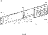
- FIG. 7 shows an illustrative diagram of a thruster mounting structure 704 positioned in a stowed position.
- the thruster mounting scheme 700 including the spacecraft body 702, the thruster mounting structure 704, the first azimuth actuator 708, the boom 718, the thruster pallet 706, and the thrusters 714, may be substantially similar to the corresponding components discussed above in relation to FIG. 4 .
- the first azimuth actuator 708 is directly connected to the spacecraft body 702 via a bracket 720. Directly connecting components together or attaching one component to another component means that the respective components are not connected by an elongate member extending between the respective components; such an elongate member may be a boom.
- the first azimuth actuator 708 includes a stationary portion 722 and a movable attachment portion 724.
- the stationary portion 722 is directly connected to the bracket 720 for mounting the actuator 708 to the spacecraft body 702.
- the movable attachment portion 724 is a portion of the actuator 708 that is rotatable for moving or rotating connected components.
- the boom In the stowed position depicted in FIG. 7 , the boom may be substantially parallel to the satellite body 702. In some embodiments, the boom 718 may be in contact with the satellite body 702.
- the boom 718 may be a spaced distance apart from satellite body 702. In some embodiments, the boom 718 is spaced from the satellite body 702 by distance equal to a width 726 of actuator 708.
- the thruster pallet 706 may be aligned such that the thrusters 714 are substantially parallel to the satellite body 702, with thrust vectors that point substantially perpendicular to the satellite body 702.
- the thruster pallet 706 may be attached to the satellite body 702 using a mounting structure.
- the mounting structure may include actuators intended to keep the thruster pallet 706 in place during launch, and to deploy the thruster pallet 706 at the appropriate time(s) during the satellite's mission.
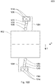
- FIG. 8 shows an illustrative diagram of a thruster mounting structure 804 positioned in a station keeping position.
- the thruster mounting scheme 800 including the spacecraft body 802, the thruster mounting structure 804, the first azimuth actuator 808, the boom 818, the bracket 820, the stationary portion 822, the movable attachment portion 824, the second azimuth actuator 810, the thruster pallet 806, and the thrusters 814, may be substantially similar to the corresponding components discussed above in relation to FIG. 4 .
- the azimuth actuator 808 includes a movable attachment portion 824 that is rotatable by the actuator 808 for moving or rotating connected components. For example, in the station keeping position depicted in FIG.
- the boom 818 is directly connected to the movable attachment portion 824.
- the first azimuth actuator 808 may rotate the boom 818 in or out from the satellite body 802.
- the boom 818 in FIG. 8 is depicted as substantially perpendicular to satellite body 802, it will be understood that the boom 818 may be rotated to other angles in the station keeping position.
- the second azimuth actuator 810, and an elevation actuator, such as elevation actuator 412 depicted in FIG. 4 may be used to rotate the thruster pallet 806 so that the thrust vector is not perpendicular to the satellite body 802.
- first azimuth actuator 808, the second azimuth actuator 810, and the elevation actuator may be utilized to rotate the thruster pallet into a variety of positions in order to correct for deviations in one or more orbital parameters, as discussed above in relation to FIG. 2 .
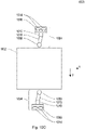
- FIG. 9 shows an illustrative diagram of a thruster mounting structure 904 positioned in an orbit raising position.
- the thruster mounting scheme 900 including the spacecraft body 902, the thruster mounting structure 904, the first azimuth actuator 908, the boom 918, the second azimuth actuator 910, the elevation actuator 912, the thruster pallet 806, and the thrusters 914, may be substantially similar to the corresponding components discussed above in relation to FIG. 4 .
- the first azimuth actuator 908 may rotate the boom 918 out from the satellite body 902.
- the boom 918 in FIG. 9 is depicted as substantially perpendicular to satellite body 902, it will be understood that the boom 918 may be rotated to other angles in the orbit raising position.
- the second azimuth actuator 910 and the elevation actuator 912 may be used to rotate the thruster pallet 906 so that the thrust vector is substantially parallel to the satellite body 902.
- the second azimuth actuator 910 includes a movable attachment portion 930 and a stationary portion 931.
- the stationary portion 931 is directly connected to boom 918.
- the movable attachment portion 930 is directly connected to a movable attachment portion 932 of the elevation actuator 912.
- the second azimuth actuator 910 and elevation actuator 912 are directly connected via a mounting bracket 934 on the thruster pallet 906.
- the second azimuth actuator 910 and elevation actuator 912 may cooperate to rotate the thruster pallet 906 in at least two axes.
- the boom 918 may position the thruster pallet 906 and the thrusters 914 a spaced distance from the satellite body 902.
- the thrusters 914 produce a combined thrust vector that is substantially in line with the z-direction of the vehicle.
- the individual thruster may be rotated such that the individual thrust vector points anywhere between the z-direction and the direction through the center of gravity of the vehicle. As discussed above in relation to FIG. 3 , the thrust in this orientation may be used to change the orbit of the satellite from an initial orbit to a final orbit.
- FIGs. 10A-E show illustrative diagrams 1000 of a first and a second thruster mounting structures 1004 in various positions.
- the spacecraft body 1002, the thruster mounting structure 1004, the first azimuth actuator 1008, the boom 1018, the second azimuth actuator 1010, the thruster pallet 1006, and the thrusters 1014 may be substantially similar to the corresponding components discussed above in relation to FIG. 4 .
- Fig. 10A depicts the first and second thruster mounting structures 1004 in a stowed position.
- the boom 1018 may be substantially parallel and/or flush with the satellite body 1002.
- the thruster pallet 1006 may be rotated to be parallel along its longest edge and such that the thrusters point outwards from the satellite body 1002. As discussed in relation to FIG. 7 , the thruster pallet 1006 may be secured to the satellite body 1002 using a mounting scheme, wherein the mounting scheme is configured to release or deploy the thruster pallet 1006 at an appropriate time(s) during the satellite's mission. In this manner, the stowed position may minimize the storage space required and minimize any adverse forces imparted on the thruster pallet 1006, for example, during launch.
- Fig. 10B depicts the first and second thruster mounting structures 1004 in an orbit raising position.
- the thrusters 1014 may be rotated such that the combined thruster vector points substantially in the zdirection.
- the thrusters may be rotated such that the individual thrust vector points anywhere between the z-direction and the direction through the center of gravity of the vehicle..
- the thrust in the z-direction may increase the velocity of the satellite and result in a change of orbit.
- the boom 1018 may not be perpendicular to the x-z fact of the satellite body 1002.
- both of the thrusters associated with the first and the second thruster mounting structure may be fired in order to reduce any unwanted rotation on the satellite body 1002.
- Fig. 10C depicts the first and second thruster mounting structures 1004 in a station keeping position.
- the thrusters 1014 may be rotated into a variety of positions to correct for deviations in certain orbit parameters.
- the first and second thruster mounting structures 1004 may correct for deviations in both inclination and eccentricity.
- the orientation of the thrusters 1014 may produce forces in both the z direction and the y direction, which may compensate for external forces in those directions.
- the boom 1018 may not be perpendicular to the x-z fact of the satellite body 1002.
- one or both the of the thrusters associated with the first and the second thruster mounting structure may be fired as needed to correct for orbital deviations.
- Figs. 10D and E depict the first and second thruster mounting structures 1004 in other station keeping positions.
- the thrusters 1014 may be rotated into a variety of positions to correct for deviations in certain orbit parameters.
- the first and second thruster mounting structures 1004 may correct for deviations in inclination, eccentricity, and drift.
- the orientation of the thrusters 1014 may produce forces in all of the x, y, and z directions, which may compensate for external forces in those directions.
- the angle of the thrust vector may be controlled using the first azimuth actuator 1008, the second azimuth actuator 1010, and an elevation actuator such as elevation actuator 412 depicted in FIG. 4 .
- the boom 1018 may not be perpendicular to the x-z fact of the satellite body 1002.
- one or both the of the thrusters associated with the first and the second thruster mounting structure may be fired as needed to correct for orbital deviations.
- the orientations depicted in FIGs. 10B , C, D and E may also impart a net torque and/or rotation on the satellite body 1002.
Landscapes
- Engineering & Computer Science (AREA)
- Remote Sensing (AREA)
- Chemical & Material Sciences (AREA)
- Combustion & Propulsion (AREA)
- Aviation & Aerospace Engineering (AREA)
- Radar, Positioning & Navigation (AREA)
- Control Of Position, Course, Altitude, Or Attitude Of Moving Bodies (AREA)
- Pivots And Pivotal Connections (AREA)
Description
- Satellites and other spacecraft typically utilize chemical rocket propulsion systems to propel themselves into orbit and to perform mission operations. Although such propulsion systems provide relatively large amounts of thrust, rocket propulsion systems are generally propellant inefficient and have a low specific impulse. As a result, satellites and spacecraft propelled by rocket propulsion systems typically carry a large proportion of their mass as propellant, leaving a relatively small proportion of the mass available for mission payloads. Electric propulsion systems provide a viable alternative to rocket propulsion systems for long-range or long-duration missions, which require large amounts of propellant. Electric propulsion systems operate by using electric energy to expel propellant, typically particles of ionized gas, at high speeds. In this manner, they achieve a relatively high specific impulse and propellant efficiency compared to rocket propulsion systems, but produce a relatively small amount of thrust. These characteristics make electric propulsion systems suitable for long-range or long-duration missions, where the satellite and/or spacecraft may be accelerated over a long period of time.
WO2015/138592 describes a spacecraft comprising first and second pluralities of thrusters. The thrusters are attached to a spacecraft body configured to move the thrusters between stowed and deployed positions. Each thruster is attached to a boom by a two-axis gimbal, wherein the boom is attached to the spacecraft by a hinge. - In accordance with the present invention, there is provided a vehicle in accordance with claim 1. Optional features of the vehicle are described in
claims 2 to 13. - The vehicle may be any suitable vehicle, including a satellite or other spacecraft, and may comprise any suitable shape. Although the vehicles described herein are discussed in relation to a satellite that is shaped like a cube or a rectangular prism, other satellite and spacecraft shapes may be contemplated, as will be understood by one of skill in the art. It will also be understood that the thruster mounting structure may be mounted on any suitable surface of the vehicle, including a flat surface of a cube/rectangular prism. Other mounting surfaces may be contemplated as will be understood by those of skill in the art. Furthermore, although the vehicles described herein are described in terms of an electric thruster, it will be understood that any suitable thruster may be utilized with the mounting structure described herein.
- In some embodiments, the first axis may be a roll axis of the vehicle, and the second axis may be a yaw axis, pitch axis or a combination of pitch axis and yaw axis of the vehicle. In some embodiments, the first axis may be a yaw axis of the vehicle, and the second axis may be a roll axis, pitch axis or a combination of roll axis and pitch axis of the vehicle. In some embodiments, the first rotational joint and the second rotational joint may be motorized rotational joints. For example, the rotational joints may employ motors, servos, or any other suitable mechanism for changing and maintaining a rotational movement. In some embodiments, the rotational joints may receive control inputs to change and maintain a rotational angle. In some embodiments, the rotational joints may be configured to stiffly maintain a rotational angle until a control is received to change the rotational angle. In some embodiments, a second thruster may be connected to the thruster pallet. The second thruster may be substantially identical to the first thruster, or it may be substantially different. For instance, the second thruster may be configured to provide substantially the same thrust as the first thruster in order to act as a redundant thruster.
- Through the combination of rotational joints, the thruster mounting structure may be able to orient the thruster pallet in a variety of positions, including a stowed position, a station keeping position, and an orbit raising position. In the stowed position, the boom may be positioned substantially parallel and/or flush to the vehicle and the thruster pallet may be connected to the vehicle. In some embodiments, the thruster pallet may be mated to a retaining receptacle which may secure the thruster pallet while the thruster pallet is not deployed. For example, the thruster pallet may be secured to the vehicle body during launch to minimize space and to minimize vibration and other forces on the thruster mounting structure. In some embodiments, the thruster pallet may be kept flush to the vehicle in the stowed position. In some embodiments, the thruster may be facing a direction substantially perpendicular to the vehicle or vehicle face that the thruster mounting structure is mounted to. For instance, the thruster may be faced substantially outward or substantially toward the vehicle, in a direction perpendicular to the vehicle face.
- The thruster mounting structure may be arranged into a station keeping position. The station keeping position, as discussed in further detail below, may encompass a wide variety of orientations intended to position the thrust vector such that an orbit of the satellite/spacecraft may be maintained. In the station keeping position, the thruster will be released from the vehicle body and manipulated using the first, second, and third rotational joints. The boom may not be parallel to the vehicle in the station keeping position. In some embodiments, the boom will be kept perpendicular to the vehicle or a face of the vehicle. The thrusters in the station keeping position may generate a thrust vector that points through a center of gravity of the vehicle.
- The thruster mounting structure may be arranged into an orbit raising position. In the orbit raising position, the boom may be positioned substantially perpendicular to the vehicle or a face of the vehicle. The thruster pallet may be released from any restraining receptacle on the vehicle body. In the orbit raising position, the thruster and/or thruster pallet may be pointed in a direction substantially parallel to the vehicle. The thruster may be spaced a distance away from the vehicle, for example, by the boom. In this manner, the thruster may be positioned to generate a thrust vector that may be used to raise or transfer an orbit of the vehicle.
- In some embodiments, the vehicle may comprise a second thruster mounting structure. The second thruster mounting structure may be substantially similar to the first thruster mounting structure. In some embodiments, the vehicle may comprise a rectangular prism shape, and the first thruster mounting structure and the second thruster mounting structure may be mounted on opposing faces of the rectangular prism. In this manner, the first thruster mounting structure and the second thruster mounting structure may be controlled independently in order to change the vehicles motion, such as orbit altitude, orbit inclination, eccentricity, and/or drift. The second thruster mounting structure may comprise a fourth rotational joint attached to a vehicle, the fourth rotational joint configured to rotate in the first axis. The fourth rotational joint may be configured to rotate in substantially the same axis as the axis of the first rotational joint of the first thruster mounting structure. The second thruster mounting structure may further comprise a second boom that may be connected to the fourth rotational joint, wherein the fourth rotational joint is configured to pivot the boom about the first axis. The second thruster mounting structure may comprise a fifth rotational joint, which may be attached to the second boom and configured to rotate in the first axis. The second thruster mounting structure may further comprise a sixth rotational joint attached to the fifth rotational joint, the sixth rotational joint configured to rotate in the second axis, and wherein the fifth rotational joint is configured to pivot the sixth rotational joint about the first axis. The second thruster mounting structure may further comprise a second thruster pallet attached to the sixth rotational joint, wherein the sixth rotational joint is configured to pivot the second thruster pallet about the second axis, and a second thruster may be fixedly attached to the second thruster pallet.
-
-
FIG. 1 shows an exemplary embodiment of a satellite; -
FIG. 2 shows an illustrative diagram of a satellite orbit; -
FIG. 3 shows an illustrative diagram of an orbit raising maneuver; -
FIG. 4 shows an illustrative diagram of a first and a second thruster mounting structure; -
FIG. 5 shows an illustrative diagram of a first and a second thruster mounting structure positioned in a station keeping position; -
FIG. 6 shows an illustrative diagram of a first and a second thruster mounting structure positioned in an orbit raising position; -
FIG. 7 shows an illustrative diagram of a thruster mounting structure positioned in a stowed position; -
FIG. 8 shows an illustrative diagram of a thruster mounting structure positioned in a station keeping position; -
FIG. 9 shows an illustrative diagram of a thruster mounting structure positioned in an orbit raising position; and -
FIGs. 10A-E show illustrative diagrams of a first and a second thruster mounting structure in various positions. - To provide an overall understanding of the vehicles described herein, certain illustrative embodiments will now be described. However, it will be understood by one of ordinary skill in the art that the vehicles described herein can be adapted and modified for other suitable applications and that such other additions and modifications will not depart from the scope of the claims.
- Electric thrusters and electric thruster mounting schemes are described in greater detail in the following U.S. patent documents:
U.S. Patent No. 6,032,904, filed February 23,1998 ;U.S. Patent No. 7,059,571, filed February 21,2003 ;U.S. Patent No. 6,296,207, filed January 27,1999 ;U.S. Patent No. 5,349,532, filed April 28, 1992 ;U.S. Patent No. 6,565,043, filed December 21,2001 ; andU.S. Patent No. 6,637,701 filed April 3,2002 . -
FIG. 1 shows an exemplary embodiment of asatellite 100. Thesatellite 100 may comprisesatellite body 102,solar panels 104, solarpanel mounting system 105,communications antenna 106, and communicationsantenna mounting system 107. Thesatellite 100 is provided for illustrative purposes only, and it will be understood that the thruster mounting structure described herein may be integrated into any suitable satellite. - The
satellite body 102 may be any suitable shape, including, but not limited to, a cube or a rectangular prism. Thesolar panels 104 may be configured to generate electric power from incident sunlight and may be mounted on any suitable face(s) of thesatellite body 102 through solarpanel mounting system 105. The solarpanel mounting system 105 may comprise actuators configured to rotate and/or angle thesolar panels 104. For example, the solarpanel mounting system 105 may rotate or angle thesolar panels 104 to track the sun in order to generate the most electric power for the satellite. The solarpanel mounting system 105 may also include means for stowing and/or deploying thesolar panels 104. For example, thesolar panels 104 may be designed to fold for storage and unfold for deployment. The solarpanel mounting system 105 may comprise actuators and/or latches to maintain the solar panels in a stowed position until a control signal is received to deploy thesolar panels 104. Thecommunications antenna 106 may be any suitable equipment for communicating data from the satellite. For instance, thecommunications antenna 106 may generate electromagnetic waves directed toward a ground station on Earth in order to communicate with mission control. Thecommunications antenna 106 may be connected to thesatellite body 102 through communicationsantenna mounting system 107. As with the solarpanel mounting system 106, the communicationsantenna mounting system 107 may comprise actuators and/or latches for maintaining thecommunications antenna 106 in a stowed state (e.g., folded against the satellite body 102) until a control signal is received to deploy thecommunications antenna 106. - The
satellite 100 may also comprise one or more of the thruster mounting structures described in further detail below. The thruster mounting structure(s) may be mounted or integrated on any suitable surface ofsatellite body 102. For example, two thruster mounting structures may be mounted on the same faces as thesolar panels 104, one for each face. In this manner, the pair of thruster mounting structures may work in tandem to position two or more thrusters to provide thruster vectoring for station keeping or orbit raising/transfer maneuvers. The thruster mounting structures may comprise any suitable type of propulsion system. For example, in some embodiments, the thruster mounting structures may comprise electric thrusters. Any suitable type of electric thruster may be utilized, including, but not limited to, ion thrusters, plasma-based thrusters, electrostatic thrusters, electrothermal thrusters, and electromagnetic thrusters. In some embodiments, thesatellite 100 may further comprise traditional rocket-based thrusters mounted on any suitable surface of thespacecraft body 102, such that thesatellite 100 is propelled by a combination of a chemical-based rocket propulsion system and an electric propulsion system. In these embodiments, the chemical-based rocket propulsion system may be mounted to thesatellite body 102 using the thruster mounting structure described herein, or by any other suitable method. In some embodiments, thesatellite 100 may comprise only an electric propulsion system. In such embodiments, thesatellite 100 may comprise electric thrusters mounted to thesatellite body 102 through a thruster mounting structure as described further below, in addition to electric thrusters which are mounted to thesatellite body 102 through other means. In this manner, the thruster mounting structures may provide redundant or additional propulsion capacity in addition to a primary propulsion system. -
FIG. 2 shows an illustrative diagram of asatellite orbit 200. Thesatellite 204 may be substantially similar to thesatellite 100 described in relation toFIG. 1 and may orbit aroundcelestial body 202.Celestial body 202 may be any suitable celestial body, including, but not limited to, the Earth, the moon, the sun, a planet, a star, or any other celestial body. Thesatellite 204 may establish anorbit 206 around thecelestial body 202. Theorbit 206 may comprise one or more of the following orbital characteristics: an altitude, a semi-major axis, an eccentricity, an inclination, and argument of periapsis, a longitude of the ascending node, a time of periapsis passage, a radius of periapsis, and a radius of apoapsis. As an illustrative example, a communications satellite may establish a geostationary (GEO) orbit at an altitude of 35,786km above the Earth's equator in order to maintain a fixed position above the Earth's surface. As another illustrative example, an earth-mapping satellite may establish a polar orbit with a relatively high inclination (e.g., close to 90 degrees to the equator) so that it passes the equator at a different longitude on each orbit. Theorbit 206 may comprise any suitable shape, including a circular orbit, elliptical orbit, or a figure-eight shape. - In order to maintain its orbit, the
satellite 204 may performstation keeping maneuvers satellite 204 due to a number of external forces that degrade the orbit ofsatellite 204, such as air drag, solar radiation pressure, and gravitational forces from the Sun/Moon. In some embodiments, such external forces may decrease or increase the orbit velocity of thesatellite 204, causing the altitude (or semi-major axis) of theorbit 206 to decrease or increase accordingly. In such embodiments, thesatellite 204 may performstation keeping maneuver 208 in the direction of the orbit or the direction of travel of thesatellite 204 in order to increase or decrease the orbit velocity of thesatellite 204 and to counteract the external forces. In some embodiments, thesatellite 204 may performstation keeping maneuver 208 according to a feedback loop, such that the orbital velocity and/or the altitude of thesatellite 204 is sensed, and in response to detecting the that orbital velocity and/or the altitude of thesatellite 204 is not the same as the desired orbital velocity or altitude, performing thestation keeping maneuver 208. In some embodiments, the feedback loop may comprise communication with a ground station on thecelestial body 202 or with another orbiting satellite or spacecraft in order to determine orbital parameters of thesatellite 204. The feedback loop as discussed above is provided for illustrative purposes only, and it will be understood that any suitable control scheme may be utilized withstation keeping maneuver 208. - In some embodiments, external forces may provide an increase or decrease in the velocity of the
satellite 204 in directions other than the direction of travel of thesatellite 204. Furthermore, the external forces may impart a net torque or rotation on thesatellite 204. In such instances,station keeping maneuver 210 may be used to correct for such velocity or rotation changes. For example, the external forces may affect one or more of the following orbital parameters of orbit 206: an eccentricity, an inclination, and argument of periapsis. As discussed above in relation tostation keeping maneuver 208, a feedback loop may be used to correct for the changes in the orbital parameters. In some embodiments, one or more of the orbital parameters may be sensed, either directly by thesatellite 204 or by a ground station or another satellite, and in response to determining that the sensed orbital parameter(s) is different than a desired orbital parameter(s), performingstation keeping maneuver 210. In some embodiments, a combination ofstation keeping maneuver station keeping maneuvers Fig. 2 as orthogonal, it will be understood thatstation keeping maneuvers station keeping maneuvers satellite 204 and designed to impart a net velocity on thesatellite 204, while some thruster(s) may be configured to provide a thrust vector that does not point through the center of gravity of thesatellite 204 and designed to impart a net rotation on thesatellite 204. Some thruster(s) may be configured to impart both a net velocity and a net rotation on thesatellite 204. Some thruster(s) may be fixed in position or rotation, while other thruster(s) may be mounted or gimbaled in a fashion that allows them to move in at least one of six degrees of freedom (three translational, three rotational). For example, one or more of the thrusters mounted ontosatellite 204 may be mounted using the thruster mounting structure described herein. -
FIG. 3 shows an illustrative diagram of anorbit raising maneuver 300. As used herein, "orbit raising" or "orbit transfer" refers to any orbital maneuver that changes the orbit of thesatellite 304 from afirst orbit 303 to asecond orbit 306. Although theorbit raising maneuver 300 is depicted inFig. 3 as a Hohmann transfer, it will be understood that theorbit raising maneuver 300 may begin at any initial orbit, be it circular or elliptical, and be any suitable orbital maneuver that changes at least one of the following orbital parameters: an altitude, a semi-major axis, an eccentricity, an inclination, and argument of periapsis, a longitude of the ascending node, a time of periapsis passage, a radius of periapsis, and a radius of apoapsis. - As depicted in
Fig. 3 ,satellite 304 may orbit aroundcelestial body 302 in aninitial orbit 303. Thesatellite 304 may be substantially similar to thesatellite 100 depicted inFig. 1 . Thecelestial body 302 may be substantially similar tocelestial body 202 depicted inFig. 2 . Theinitial orbit 303 may have aradius 305, in addition to other orbital parameters, below that of thefinal orbit 306. The initial orbit may be an elliptical orbit, in addition to other orbital parameters, with a perigee below thefinal orbit 306 and an apogee that can be below, at, or above thefinal orbit 306. Thesatellite 304 may perform a multitude of thruster firings 310of finite duration at discrete points in the orbit, continuously over one or more orbital revolutions, or any combination thereof in order to impart the desired change in velocity and reach thefinal orbit 306. Thethruster firing vector 310 may be in the direction of travel of thesatellite 304, opposite of the direction of travel of thesatellite 304, or any direction in between. Thethruster firing vector 310 may be at any angle within the orbit and relative to the orbital plane. -
FIG. 4 shows an illustrative diagram of athruster mounting scheme 400satellite body 402 comprising a first and a secondthruster mounting structure 404. Thesatellite body 402 may be substantially similar to thesatellite body 102 depicted inFig. 1 and discussed above. The firstthruster mounting structure 404 comprises athruster pallet 406, afirst azimuth actuator 408, asecond azimuth actuator 410, anelevation actuator 412,thrusters 414, andboom 418. The secondthruster mounting structure 419 may comprise substantially the same components as the firstthruster mounting structure 404. As depicted inFig. 4 , the first and secondthruster mounting structures satellite body 402. - The
first azimuth actuator 408 may be configured to rotate in afirst direction 424. In some embodiments, thedirection 424 may be a rotation about the z axis, as depicted inFIG. 4 . In some embodiments, thefirst azimuth actuator 408 is configured to rotate only in thefirst direction 424. That is, thefirst azimuth actuator 408 is stiff in rotation to the other two rotational directions. Similarly, thesecond azimuth actuator 410 may be configured to rotate in asecond direction 426, and theelevation actuator 412 may be configured to rotate indirection 428. As with thefirst azimuth actuator 408, thesecond azimuth actuator 410 and theelevation actuator 412 may be configured, in some embodiments, to rotate only in the respective directions and to be rigid in the other rotational degrees of freedom. In some embodiments, thefirst azimuth actuator 408, thesecond azimuth actuator 410, and theelevation actuator 412 may be motorized actuators configured to receive control signals and/or setpoints for rotational position, rotational speed, and/or rotational acceleration. - The
thruster pallet 406 may be made of any suitable material, such as metal, carbon fiber, or composite material. Thethruster pallet 406 may be configured into any suitable shape, including a rectangular prism, as depicted inFig. 4 . Thethrusters 414 may be mounted directly onto thethruster pallet 406 using any suitable means, including, but not limited to, screws, rivets, bolts, welds, adhesives, or any combination thereof. Although twothrusters 414 are depicted inFig. 4 , it will be understood that a larger number of thrusters may be mounted ontothruster pallet 406. Furthermore, thethrusters 414 may be any suitable type of thruster, including electric thrusters and/or chemical rocket thrusters. - The
boom 418 may be made of any suitable material, such as metal, carbon fiber, or composite material. Theboom 418 may be any suitable shape and length. For example, theboom 418 may be a hollow member with a square cross section. Theboom 418 may be attached to one or more of thefirst azimuth actuator 408, thesecond azimuth actuator 410, and/or theelevation actuator 412 using any suitable means, including, but not limited to, screws, rivets, bolts, welds, adhesives, or any combination thereof. For instance, theboom 418 may be attached tofirst azimuth actuator 408 such that thefirst azimuth actuator 408 may pivot the boom indirection 424. Thesecond azimuth actuator 410 may be attached to thethruster pallet 406 by any suitable means, including, but not limited to, screws, rivets, bolts, welds, adhesives, or any combination thereof. Thesecond azimuth actuator 410 may be configured to pivot thethruster pallet 406 indirection 426. In some embodiments, thedirection 424 and thedirection 426 may be the same. Theelevation actuator 412 may be connected to the thruster pallet and/or thesecond azimuth actuator 410. Theelevation actuator 412 may be configured to pivot thethruster pallet 406 indirection 428. - The
first azimuth actuator 408 may be attached directly to thesatellite body 402 using any suitable means, including, but not limited to, screws, rivets, bolts, welds, adhesives, or any combination thereof. Thefirst azimuth actuator 408 may rotate thethruster pallet 406 in thedirection 424 to provide aslew angle 422. Theslew angle 422 may allow thethrusters 414 to produce a thrust vector in a direction tangential to the direction of travel or orbital direction. This may enable control of the longitude drift rate and eccentricity vector of the satellite. In some embodiments, thesecond azimuth actuator 410 may rotate thethruster pallet 406 to provide athruster direction 420 that points through the center of gravity of the satellite. Although the center of gravity of the satellite is depicted as the center of the square cross-section, the center of gravity may be located at any point within thesatellite body 402. In some embodiments, the center of gravity may be outside of thesatellite body 402. -
FIG. 5 shows an illustrative diagram of athruster mounting scheme 500 including a first and a secondthruster mounting structures thruster mounting structures thruster mounting structures FIG. 4 .Satellite body 502 may be substantially similar tosatellite body 402 described in relation toFIG. 4 . As depicted inFig. 5 , the first and the secondthruster mounting structures satellite body 502. In the illustrative example depicted inFig. 5 , the first and secondthruster mounting structures satellite body 502. In the station keeping position, first and secondthruster mounting structures elevation actuator 412 depicted inFIG. 4 , to pivot the thrusters and produce athruster vector 520 that points through the center of gravity of the satellite. This may producecant angle 530, measured as the angle between thethrust vector 520 and an x-y plane of thespacecraft body 502. Thecant angle 530 may allow the thrusters 514 to produce a thrust vector that is normal and/or radial to the direction of travel or the orbital direction of the satellite. This may enable control of the orbit inclination and eccentricity vector. In some embodiments, thecant angle 530 may enable simultaneous control of the orbit inclination and eccentricity vector. In some embodiments, the velocity of the satellite may be controlled simultaneously or separately from the angular momentum of the satellite. For example, through the use ofcant angle 530 and either thefirst azimuth actuator 424 or thesecond azimuth actuator 426, the thrust vector produced bythrusters 414 may be configured to point through the center of gravity, thereby producing a velocity change but no torque, or slightly offset from the center of gravity, thereby producing a net torque. For station keeping maneuvers, the thruster associated with either the firstthruster mounting structure 504 or the secondthruster mounting structure 519, or both, may be fired. As discussed above in relation toFIG. 2 , the thruster firings may be performed in order to maintain a certain orbit or orbit characteristics. Through the use ofcant angle 530 and slewangle 422 depicted inFIG. 4 , a wide range of control options may be enabled for controlling thesatellite body 502, thereby allowing for mission optimization and reduced propellant consumption. In some embodiments, full station keeping operations may be completed by the use of two thrusters and two maneuvers per day or orbital period. In some embodiments, the first and a secondthruster mounting structures satellite body 502. Thus, full orbital and station keeping control may be achieved using only two thrusters. -
FIG. 6 shows an illustrative diagram of athruster mounting scheme 600 including a first and a secondthruster mounting structure thruster mounting structures thruster mounting structures FIG. 4 .Satellite body 602 may be substantially similar tosatellite body 402 described in relation toFIG. 4 . As depicted inFig. 6 , the first and the secondthruster mounting structures satellite body 602. In the illustrative example depicted inFig. 6 , the first and secondthruster mounting structures satellite body 602. In the orbit raising position, first and secondthruster mounting structures elevation actuator 412 depicted inFIG. 4 , to pivot the thrusters so that they produce athrust vector 620 substantially in the z direction of thevehicle 602 as depicted inFig. 6 . In some embodiments, the z-direction may be the direction of travel, opposite the direction of travel, or anywhere in between.. Thecant angle 630 created between thethrust vector 620 and the x-y plane ofsatellite body 602 may be substantially 90 degrees. In some embodiments, the cant angle may point in other directions up to and including the direction through the center of gravity of thevehicle 520 as shown inFigure 5 . For orbit raising maneuvers, either one, or both, of the thrusters associated with the first and the secondthruster mounting structures FIG. 3 , the thruster firings may be performed in order to change the orbit of the satellite from an initial orbit to a final orbit, and/or to change certain orbit characteristics. -
FIG. 7 shows an illustrative diagram of athruster mounting structure 704 positioned in a stowed position. Thethruster mounting scheme 700, including thespacecraft body 702, thethruster mounting structure 704, thefirst azimuth actuator 708, theboom 718, thethruster pallet 706, and thethrusters 714, may be substantially similar to the corresponding components discussed above in relation toFIG. 4 . Thefirst azimuth actuator 708 is directly connected to thespacecraft body 702 via abracket 720. Directly connecting components together or attaching one component to another component means that the respective components are not connected by an elongate member extending between the respective components; such an elongate member may be a boom. As such, components that are directly connected together or attached to one another will lie in close proximity and may be secured together by a bracket or the like. Thefirst azimuth actuator 708 includes astationary portion 722 and amovable attachment portion 724. In some embodiments, thestationary portion 722 is directly connected to thebracket 720 for mounting theactuator 708 to thespacecraft body 702. In some embodiments, themovable attachment portion 724 is a portion of theactuator 708 that is rotatable for moving or rotating connected components. In the stowed position depicted inFIG. 7 , the boom may be substantially parallel to thesatellite body 702. In some embodiments, theboom 718 may be in contact with thesatellite body 702. In some embodiments, theboom 718 may be a spaced distance apart fromsatellite body 702. In some embodiments, theboom 718 is spaced from thesatellite body 702 by distance equal to awidth 726 ofactuator 708. In some embodiments, thethruster pallet 706 may be aligned such that thethrusters 714 are substantially parallel to thesatellite body 702, with thrust vectors that point substantially perpendicular to thesatellite body 702. In some embodiments, thethruster pallet 706 may be attached to thesatellite body 702 using a mounting structure. For instance, the mounting structure may include actuators intended to keep thethruster pallet 706 in place during launch, and to deploy thethruster pallet 706 at the appropriate time(s) during the satellite's mission. -
FIG. 8 shows an illustrative diagram of athruster mounting structure 804 positioned in a station keeping position. Thethruster mounting scheme 800, including thespacecraft body 802, thethruster mounting structure 804, thefirst azimuth actuator 808, theboom 818, thebracket 820, thestationary portion 822, themovable attachment portion 824, thesecond azimuth actuator 810, thethruster pallet 806, and thethrusters 814, may be substantially similar to the corresponding components discussed above in relation toFIG. 4 . Theazimuth actuator 808 includes amovable attachment portion 824 that is rotatable by theactuator 808 for moving or rotating connected components. For example, in the station keeping position depicted inFIG. 8 , theboom 818 is directly connected to themovable attachment portion 824. As such, thefirst azimuth actuator 808 may rotate theboom 818 in or out from thesatellite body 802. Although theboom 818 inFIG. 8 is depicted as substantially perpendicular tosatellite body 802, it will be understood that theboom 818 may be rotated to other angles in the station keeping position. In some embodiments, thesecond azimuth actuator 810, and an elevation actuator, such aselevation actuator 412 depicted inFIG. 4 , may be used to rotate thethruster pallet 806 so that the thrust vector is not perpendicular to thesatellite body 802. It will be understood that thefirst azimuth actuator 808, thesecond azimuth actuator 810, and the elevation actuator may be utilized to rotate the thruster pallet into a variety of positions in order to correct for deviations in one or more orbital parameters, as discussed above in relation toFIG. 2 . -
FIG. 9 shows an illustrative diagram of athruster mounting structure 904 positioned in an orbit raising position. Thethruster mounting scheme 900, including thespacecraft body 902, thethruster mounting structure 904, thefirst azimuth actuator 908, theboom 918, thesecond azimuth actuator 910, theelevation actuator 912, thethruster pallet 806, and thethrusters 914, may be substantially similar to the corresponding components discussed above in relation toFIG. 4 . In the orbit raising position depicted inFIG. 8 , thefirst azimuth actuator 908 may rotate theboom 918 out from thesatellite body 902. Although theboom 918 inFIG. 9 is depicted as substantially perpendicular tosatellite body 902, it will be understood that theboom 918 may be rotated to other angles in the orbit raising position. In some embodiments, thesecond azimuth actuator 910 and theelevation actuator 912 may be used to rotate thethruster pallet 906 so that the thrust vector is substantially parallel to thesatellite body 902. In some embodiments, thesecond azimuth actuator 910 includes amovable attachment portion 930 and astationary portion 931. In some embodiments, thestationary portion 931 is directly connected toboom 918. In some embodiments, themovable attachment portion 930 is directly connected to amovable attachment portion 932 of theelevation actuator 912. In some embodiments, thesecond azimuth actuator 910 andelevation actuator 912 are directly connected via a mountingbracket 934 on thethruster pallet 906. As such, in some embodiments, thesecond azimuth actuator 910 andelevation actuator 912 may cooperate to rotate thethruster pallet 906 in at least two axes. As depicted inFIG. 9 , theboom 918 may position thethruster pallet 906 and the thrusters 914 a spaced distance from thesatellite body 902. In some embodiments, thethrusters 914 produce a combined thrust vector that is substantially in line with the z-direction of the vehicle. In some embodiments, the individual thruster may be rotated such that the individual thrust vector points anywhere between the z-direction and the direction through the center of gravity of the vehicle. As discussed above in relation toFIG. 3 , the thrust in this orientation may be used to change the orbit of the satellite from an initial orbit to a final orbit. -
FIGs. 10A-E show illustrative diagrams 1000 of a first and a secondthruster mounting structures 1004 in various positions. Thespacecraft body 1002, thethruster mounting structure 1004, thefirst azimuth actuator 1008, theboom 1018, thesecond azimuth actuator 1010, thethruster pallet 1006, and thethrusters 1014, may be substantially similar to the corresponding components discussed above in relation toFIG. 4 .Fig. 10A depicts the first and secondthruster mounting structures 1004 in a stowed position. As discussed above in relation toFIG. 7 , in the stowed position, theboom 1018 may be substantially parallel and/or flush with thesatellite body 1002. Thethruster pallet 1006 may be rotated to be parallel along its longest edge and such that the thrusters point outwards from thesatellite body 1002. As discussed in relation toFIG. 7 , thethruster pallet 1006 may be secured to thesatellite body 1002 using a mounting scheme, wherein the mounting scheme is configured to release or deploy thethruster pallet 1006 at an appropriate time(s) during the satellite's mission. In this manner, the stowed position may minimize the storage space required and minimize any adverse forces imparted on thethruster pallet 1006, for example, during launch. -
Fig. 10B depicts the first and secondthruster mounting structures 1004 in an orbit raising position. As discussed above in relation toFIGs. 6 and9 , in the orbit raising position, thethrusters 1014 may be rotated such that the combined thruster vector points substantially in the zdirection. In some embodiments, the thrusters may be rotated such that the individual thrust vector points anywhere between the z-direction and the direction through the center of gravity of the vehicle.. As discussed above in relation toFIG. 3 , the thrust in the z-direction may increase the velocity of the satellite and result in a change of orbit. As depicted inFIG. 10B , theboom 1018 may not be perpendicular to the x-z fact of thesatellite body 1002. In some embodiments, for orbit raising maneuvers, both of the thrusters associated with the first and the second thruster mounting structure may be fired in order to reduce any unwanted rotation on thesatellite body 1002. -
Fig. 10C depicts the first and secondthruster mounting structures 1004 in a station keeping position. As discussed above in relation toFIGs. 5 and8 , in the station keeping position, thethrusters 1014 may be rotated into a variety of positions to correct for deviations in certain orbit parameters. In the position depicted inFIG. 10C , the first and secondthruster mounting structures 1004 may correct for deviations in both inclination and eccentricity. For instance, the orientation of thethrusters 1014 may produce forces in both the z direction and the y direction, which may compensate for external forces in those directions. As depicted inFIG. 10C , theboom 1018 may not be perpendicular to the x-z fact of thesatellite body 1002. In some embodiments, for station keeping maneuvers, one or both the of the thrusters associated with the first and the second thruster mounting structure may be fired as needed to correct for orbital deviations. -
Figs. 10D andE depict the first and secondthruster mounting structures 1004 in other station keeping positions. As discussed above in relation toFIGs. 5 and8 , in the station keeping position, thethrusters 1014 may be rotated into a variety of positions to correct for deviations in certain orbit parameters. In the positions depicted inFIGs. 10D andE , the first and secondthruster mounting structures 1004 may correct for deviations in inclination, eccentricity, and drift. For instance, the orientation of thethrusters 1014 may produce forces in all of the x, y, and z directions, which may compensate for external forces in those directions. The angle of the thrust vector may be controlled using thefirst azimuth actuator 1008, thesecond azimuth actuator 1010, and an elevation actuator such aselevation actuator 412 depicted inFIG. 4 . As depicted inFIGs. 10D andE , theboom 1018 may not be perpendicular to the x-z fact of thesatellite body 1002. In some embodiments, for station keeping maneuvers, one or both the of the thrusters associated with the first and the second thruster mounting structure may be fired as needed to correct for orbital deviations. - In some embodiments, depending on the location of the center of gravity of the satellite, the orientations depicted in
FIGs. 10B , C, D and E may also impart a net torque and/or rotation on thesatellite body 1002. - It will be apparent to those skilled in the art that the embodiments described herein are provided by way of example only. Accordingly, it will be understood that the invention is not to be limited to the embodiments disclosed herein, but is to be understood from the following claims, which are to be interpreted as broadly as allowed under the law.
Claims (13)
- A vehicle (702, 802, 902) comprising:a system for mounting a thruster onto the vehicle, the system comprising:a first thruster mounting structure (704, 804, 904), the first thruster mounting structure comprising:a first rotational joint (708, 808, 908) attached to the vehicle, the first rotational joint including a first stationary portion (722, 822, 922) connected to the vehicle via a first bracket (720) and including a first movable attachment portion (724, 824, 924) configured to rotate in a first axis;a boom (718, 818, 918) directly connected to the first rotational joint at the first movable attachment portion, wherein the first rotational joint is configured to pivot the boom about the first axis;a second rotational joint (810, 910), the second rotational joint including a second stationary portion (931) directly connected to the boom and including a second movable attachment portion (930) configured to rotate in an axis parallel to the first axis;a third rotational joint (912), the third rotational joint directly connected to the second rotational joint and including a third movable attachment portion (932) configured to rotate in a second axis that is perpendicular to the first axis, wherein the second rotational joint is configured to pivot the third rotational joint about the axis parallel to the first axis;a thruster pallet (706, 806, 906) comprising a rectangular face, directly connected to the third movable attachment portion of the third rotational joint via a mounting bracket (934) along a long edge of the rectangular face, wherein the third rotational joint is configured to pivot the thruster pallet about the second axis; anda plurality of thrusters (714, 814, 914) fixedly attached to the thruster pallet.
- The vehicle of claim 1, wherein the first thruster mounting structure is arranged in a stowed position such that the boom is positioned substantially parallel and flush to the vehicle and the thruster pallet is connected to the vehicle.
- The vehicle of claim 2, wherein the thruster pallet is configured to be rotated to be parallel with the satellite body along the long edge of the rectangular face, the thrusters pointing outwards from the satellite body, and the thruster pallet being flush to the vehicle.
- The vehicle of claim 2, wherein the thrusters are facing a direction substantially perpendicular to the vehicle.
- The vehicle of any preceding claim, wherein the first axis is one of: a roll axis of the vehicle or a yaw axis of the vehicle.
- The vehicle of claim 1, wherein the second axis is perpendicular to the first axis anywhere within the pitch-yaw plane or pitch-roll plane of the vehicle.
- The vehicle of any preceding claim, wherein the first rotational joint and the second rotational joint are motorized rotational joints.
- The vehicle of any preceding claim, wherein the thrusters are electric thrusters.
- The vehicle of any preceding claim, further comprising a second thruster mounting structure (704, 804, 904), the second thruster mounting structure comprising:a fourth rotational joint (708, 808, 908) attached to the vehicle, the fourth rotational joint including a fourth stationary portion (722, 822, 922) directly connected to the vehicle via a third bracket (720) and including a fourth movable attachment portion (724, 824, 924) configured to rotate in a third axis;a second boom (718, 818, 918) directly connected to the fourth rotational joint at the fourth movable attachment portion, wherein the fourth rotational joint is configured to pivot the second boom about the third axis;a fifth rotational joint (810, 910), the fifth rotational joint including a fifth stationary portion (931) directly connected to the second boom and including a fifth movable attachment portion (930) configured to rotate in an axis parallel to the third axis;a sixth rotational joint (912), the sixth rotational joint directly connected to the fifth rotational joint and including a sixth movable attachment portion (932) configured to rotate in a fourth axis, wherein the fifth rotational joint is configured to pivot the sixth rotational joint about the fourth axis;a second thruster pallet (706, 806, 906) comprising a rectangular face, directly connected to the sixth movable attachment portion of the sixth rotational joint via a mounting bracket (934) along a long edge of the rectangular face, wherein the sixth rotational joint is configured to pivot the second thruster pallet about the fourth axis; anda plurality of thrusters (714, 814, 914) fixedly attached to the second thruster pallet.
- The vehicle of claim 9, wherein the vehicle comprises a rectangular prism, and wherein the first thruster mounting structure and the second thruster mounting structure are mounted on opposing faces of the rectangular prism.
- The vehicle of claim 10, wherein the plurality of thrusters attached to the first thruster pallet and the plurality of thrusters attached to the second thruster pallet are configured to control six degrees of freedom of the vehicle.
- The vehicle of claim 1, wherein the third rotational joint is directly attached to the second movable attachment portion of the second rotational joint.
- The vehicle of claim 1, wherein the second rotational joint and the third rotational joint are directly connected together via the mounting bracket.
Applications Claiming Priority (2)
| Application Number | Priority Date | Filing Date | Title |
|---|---|---|---|
| US14/858,240 US10046867B2 (en) | 2015-09-18 | 2015-09-18 | Maneuvering system for earth orbiting satellites with electric thrusters |
| PCT/US2016/052500 WO2017049297A1 (en) | 2015-09-18 | 2016-09-19 | Maneuvering system for earth orbiting satellites with electric thrusters |
Publications (3)
| Publication Number | Publication Date |
|---|---|
| EP3350079A1 EP3350079A1 (en) | 2018-07-25 |
| EP3350079A4 EP3350079A4 (en) | 2019-05-22 |
| EP3350079B1 true EP3350079B1 (en) | 2022-05-04 |
Family
ID=58276663
Family Applications (1)
| Application Number | Title | Priority Date | Filing Date |
|---|---|---|---|
| EP16847550.7A Active EP3350079B1 (en) | 2015-09-18 | 2016-09-19 | Maneuvering system for earth orbiting satellites with electric thrusters |
Country Status (6)
| Country | Link |
|---|---|
| US (3) | US10046867B2 (en) |
| EP (1) | EP3350079B1 (en) |
| JP (2) | JP2018527246A (en) |
| CA (2) | CA2999148C (en) |
| IL (2) | IL258110B (en) |
| WO (1) | WO2017049297A1 (en) |
Families Citing this family (9)
| Publication number | Priority date | Publication date | Assignee | Title |
|---|---|---|---|---|
| CN107108047A (en) | 2014-08-26 | 2017-08-29 | 有效空间解决方案有限公司 | Docking system and method for satellite |
| US10046867B2 (en) * | 2015-09-18 | 2018-08-14 | Orbital Atk, Inc. | Maneuvering system for earth orbiting satellites with electric thrusters |
| US10005568B2 (en) | 2015-11-13 | 2018-06-26 | The Boeing Company | Energy efficient satellite maneuvering |
| US10569909B2 (en) * | 2016-03-30 | 2020-02-25 | The Boeing Company | Systems and methods for satellite orbit and momentum control |
| JP6490314B2 (en) * | 2016-09-29 | 2019-03-27 | 三菱電機株式会社 | Pointing mechanism |
| US10625882B2 (en) | 2017-03-06 | 2020-04-21 | Effective Space Solutions Ltd. | Service satellite for providing in-orbit services using variable thruster control |
| IL283640B2 (en) | 2017-07-21 | 2024-08-01 | Northrop Grumman Innovation Systems Llc | Spacecraft servicing devices and related assemblies, systems, and methods |
| RU2676844C1 (en) * | 2017-11-27 | 2019-01-11 | Акционерное общество "Военно-промышленная корпорация "Научно-производственное объединение машиностроения" | System of return of course orientation of space vehicle using orbital gyrocompass |
| CN111409821A (en) * | 2020-04-26 | 2020-07-14 | 北京航空航天大学合肥创新研究院 | Solar unmanned aerial vehicle with tilting wings |
Citations (1)
| Publication number | Priority date | Publication date | Assignee | Title |
|---|---|---|---|---|
| NL1032158C2 (en) * | 2006-07-13 | 2008-01-15 | Dutch Space B V | Satellite comprises body and two adjustable forward thrust units, each of which is mounted on its own arm, each arm composed of at least three parts rotatable in relation to each other |
Family Cites Families (26)
| Publication number | Priority date | Publication date | Assignee | Title |
|---|---|---|---|---|
| US4955559A (en) | 1988-01-26 | 1990-09-11 | Trw Inc. | Thrust vector control system for aerospace vehicles |
| US5349532A (en) * | 1992-04-28 | 1994-09-20 | Space Systems/Loral | Spacecraft attitude control and momentum unloading using gimballed and throttled thrusters |
| US6102337A (en) * | 1995-12-22 | 2000-08-15 | Hughes Electronics Corporation | Spacecraft attitude control with gimbaled thrusters |
| US6032904A (en) * | 1998-02-23 | 2000-03-07 | Space Systems/Loral, Inc. | Multiple usage thruster mounting configuration |
| US6173565B1 (en) * | 1998-04-09 | 2001-01-16 | Primex Technologies, Inc. | Three axis pulsed plasma thruster with angled cathode and anode strip lines |
| US6076773A (en) * | 1998-04-10 | 2000-06-20 | Hughes Electronics Corporation | Spin-stabilized spacecraft and methods |
| US6296207B1 (en) | 1999-01-27 | 2001-10-02 | Space Systems/Loral, Inc. | Combined stationkeeping and momentum management |
| FR2814216B1 (en) * | 2000-09-18 | 2002-12-20 | Snecma Moteurs | ORIENTATION DEVICE AND ON-BOARD ORIENTATION SYSTEM |
| US6565043B1 (en) * | 2001-12-21 | 2003-05-20 | The Boeing Company | Redundant system for satellite inclination control with electric thrusters |
| US6637701B1 (en) | 2002-04-03 | 2003-10-28 | Lockheed Martin Corporation | Gimbaled ion thruster arrangement for high efficiency stationkeeping |
| US7059571B2 (en) | 2003-02-21 | 2006-06-13 | The Boeing Company | Deployable spacecraft mount for electric propulsion |
| US6945500B2 (en) * | 2003-08-15 | 2005-09-20 | Skycorp, Inc. | Apparatus for a geosynchronous life extension spacecraft |
| US20050077425A1 (en) | 2003-10-10 | 2005-04-14 | Raymond Payette | Thruster for propelling and directing a vehicle without interacting with environment and method for making the same |
| ES2539205T3 (en) * | 2004-04-08 | 2015-06-26 | Astrium Limited | Folding mast |
| US8448902B2 (en) * | 2011-02-11 | 2013-05-28 | Space Systems/Loral LLC | Satellite having multiple aspect ratios |
| FR2990193B1 (en) | 2012-05-03 | 2015-01-09 | Thales Sa | PROPULSION SYSTEM FOR ORBIT CONTROL AND SATELLITE ATTITUDE CONTROL |
| FR2990930B1 (en) * | 2012-05-25 | 2014-06-27 | Thales Sa | PROPULSION SYSTEM FOR ORBIT CONTROL AND SATELLITE ATTITUDE CONTROL |
| FR3006671B1 (en) * | 2013-06-07 | 2015-05-29 | Thales Sa | FOUR-MODULE PROPULSION SYSTEM FOR ORBIT CONTROL AND SATELLITE ATTITUDE CONTROL |
| FR3006670B1 (en) * | 2013-06-07 | 2015-05-29 | Thales Sa | TWO-MODULE PROPULSION SYSTEM FOR ORBIT CONTROL AND SATELLITE ATTITUDE CONTROL |
| US10183765B2 (en) * | 2014-03-12 | 2019-01-22 | Lockheed Martin Corporation | Thruster arrangement for geosynchronous orbit spacecraft |
| FR3022530B1 (en) * | 2014-06-19 | 2018-03-02 | Airbus Defence And Space Sas | METHOD FOR CONTROLLING THE ORBIT OF A SATELLITE IN TERRESTRIAL ORBIT, SATELLITE AND SYSTEM FOR CONTROLLING THE ORBIT OF SUCH A SATELLITE |
| EP3034412B1 (en) | 2014-12-16 | 2017-10-11 | Ruag Space GmbH | Regulating mechanism for adjusting at least one engine of a spacecraft |
| US9663251B2 (en) * | 2014-12-22 | 2017-05-30 | Space Systems/Loral, Llc | Thruster support mechanism for satellite propulsion |
| FR3032427B1 (en) * | 2015-02-10 | 2017-03-10 | Airbus Defence & Space Sas | SATELLITE HAVING ELECTRICAL PROPULSION MEANS, METHOD OF POSTING SUCH A SATELLITE AND METHOD FOR MAINTAINING SATELLITE |
| FR3036102B1 (en) | 2015-05-12 | 2017-05-26 | Airbus Defence & Space Sas | METHOD AND SYSTEM FOR DETECTING FAILURE OF A PROPULSION ARM OF A SPATIAL VEHICLE, SUCH AS A SATELLITE |
| US10046867B2 (en) * | 2015-09-18 | 2018-08-14 | Orbital Atk, Inc. | Maneuvering system for earth orbiting satellites with electric thrusters |
-
2015
- 2015-09-18 US US14/858,240 patent/US10046867B2/en active Active
-
2016
- 2016-09-19 JP JP2018514270A patent/JP2018527246A/en active Pending
- 2016-09-19 CA CA2999148A patent/CA2999148C/en active Active
- 2016-09-19 CA CA3115644A patent/CA3115644A1/en active Pending
- 2016-09-19 EP EP16847550.7A patent/EP3350079B1/en active Active
- 2016-09-19 WO PCT/US2016/052500 patent/WO2017049297A1/en active Application Filing
-
2018
- 2018-03-14 IL IL258110A patent/IL258110B/en active IP Right Grant
- 2018-08-14 US US16/103,337 patent/US10745151B2/en active Active
-
2020
- 2020-08-17 US US16/995,033 patent/US11661213B2/en active Active
-
2021
- 2021-05-26 IL IL283462A patent/IL283462B/en unknown
- 2021-07-08 JP JP2021113414A patent/JP7383666B2/en active Active
Patent Citations (1)
| Publication number | Priority date | Publication date | Assignee | Title |
|---|---|---|---|---|
| NL1032158C2 (en) * | 2006-07-13 | 2008-01-15 | Dutch Space B V | Satellite comprises body and two adjustable forward thrust units, each of which is mounted on its own arm, each arm composed of at least three parts rotatable in relation to each other |
Also Published As
| Publication number | Publication date |
|---|---|
| US10745151B2 (en) | 2020-08-18 |
| CA3115644A1 (en) | 2017-03-23 |
| US10046867B2 (en) | 2018-08-14 |
| US11661213B2 (en) | 2023-05-30 |
| JP2018527246A (en) | 2018-09-20 |
| JP2021165136A (en) | 2021-10-14 |
| IL283462A (en) | 2021-06-30 |
| IL258110A (en) | 2018-05-31 |
| JP7383666B2 (en) | 2023-11-20 |
| IL258110B (en) | 2021-06-30 |
| US20190092497A1 (en) | 2019-03-28 |
| EP3350079A4 (en) | 2019-05-22 |
| US20170081048A1 (en) | 2017-03-23 |
| US20210024230A1 (en) | 2021-01-28 |
| WO2017049297A1 (en) | 2017-03-23 |
| CA2999148C (en) | 2021-06-15 |
| CA2999148A1 (en) | 2017-03-23 |
| EP3350079A1 (en) | 2018-07-25 |
| IL283462B (en) | 2022-01-01 |
Similar Documents
| Publication | Publication Date | Title |
|---|---|---|
| US11661213B2 (en) | Maneuvering system for earth orbiting satellites with electric thrusters | |
| JP7100780B2 (en) | Service satellites for providing orbital services with variable thruster control | |
| US9573703B2 (en) | Propulsion system for controlling the orbit and controlling the attitude of a satellite | |
| Wie et al. | Solar-sail attitude control design for a flight validation mission | |
| JP6817341B2 (en) | Spacecraft and control method | |
| US8763957B1 (en) | Spacecraft transfer orbit techniques | |
| US9663251B2 (en) | Thruster support mechanism for satellite propulsion | |
| EP2740668B1 (en) | Methods and apparatus for performing propulsion operations using electric propulsion systems | |
| JPH11291998A (en) | Loading arrangement of combined use thruster | |
| US10464694B1 (en) | Asymmetric thruster gimbal configuration | |
| JPH1029599A (en) | Method and device for placing spacecraft in intended orbit | |
| US9428285B2 (en) | System and method for managing momentum accumulation | |
| JP2000168697A (en) | Practical method and device to stationarily hold satellite | |
| EP3202670B1 (en) | Spin stabilization of a spacecraft for an orbit maneuver | |
| KR102528036B1 (en) | Efficient stationkeeping design for mixed fuel systems in response to a failure of an electric thruster | |
| US10435183B1 (en) | Deployable propulsion module for spacecraft | |
| Wie et al. | Robust attitude control systems design for solar sails (Part 1): propellantless primary ACS | |
| Circi | Three-axis attitude control using combined gravity-gradient and solar pressure | |
| US12097979B1 (en) | Satellite for rendezvous and docking using electric propulsion thrusters | |
| Gill et al. | Station Relocation and Deorbit Using Electric Propulsion | |
| Gorbunova et al. | The finite-element behaviour simulation of the rotary-type and frame-type solar sails on the geocentric orbits | |
| Meissinger | A small, primary solar-electric propulsion demonstration satellite | |
| Duffy et al. | Comparison of Advanced Propulsion Concepts for Interplanetary Exploration: Solar Sails, Rocks and Electric Propulsion |
Legal Events
| Date | Code | Title | Description |
|---|---|---|---|
| STAA | Information on the status of an ep patent application or granted ep patent |
Free format text: STATUS: THE INTERNATIONAL PUBLICATION HAS BEEN MADE |
|
| PUAI | Public reference made under article 153(3) epc to a published international application that has entered the european phase |
Free format text: ORIGINAL CODE: 0009012 |
|
| STAA | Information on the status of an ep patent application or granted ep patent |
Free format text: STATUS: REQUEST FOR EXAMINATION WAS MADE |
|
| 17P | Request for examination filed |
Effective date: 20180411 |
|
| AK | Designated contracting states |
Kind code of ref document: A1 Designated state(s): AL AT BE BG CH CY CZ DE DK EE ES FI FR GB GR HR HU IE IS IT LI LT LU LV MC MK MT NL NO PL PT RO RS SE SI SK SM TR |
|
| AX | Request for extension of the european patent |
Extension state: BA ME |
|
| DAV | Request for validation of the european patent (deleted) | ||
| DAX | Request for extension of the european patent (deleted) | ||
| A4 | Supplementary search report drawn up and despatched |
Effective date: 20190423 |
|
| RIC1 | Information provided on ipc code assigned before grant |
Ipc: B64G 1/26 20060101AFI20190415BHEP Ipc: B64G 1/40 20060101ALN20190415BHEP |
|
| RAP1 | Party data changed (applicant data changed or rights of an application transferred) |
Owner name: NORTHROP GRUMMAN INNOVATION SYSTEMS, INC. |
|
| STAA | Information on the status of an ep patent application or granted ep patent |
Free format text: STATUS: EXAMINATION IS IN PROGRESS |
|
| STAA | Information on the status of an ep patent application or granted ep patent |
Free format text: STATUS: EXAMINATION IS IN PROGRESS |
|
| 17Q | First examination report despatched |
Effective date: 20201123 |
|
| RAP1 | Party data changed (applicant data changed or rights of an application transferred) |
Owner name: NORTHROP GRUMMAN SYSTEMS CORPORATION |
|
| REG | Reference to a national code |
Ref country code: DE Ref legal event code: R079 Ref document number: 602016071875 Country of ref document: DE Free format text: PREVIOUS MAIN CLASS: B64G0001000000 Ipc: B64G0001260000 |
|
| GRAP | Despatch of communication of intention to grant a patent |
Free format text: ORIGINAL CODE: EPIDOSNIGR1 |
|
| RIC1 | Information provided on ipc code assigned before grant |
Ipc: B64G 1/40 20060101ALN20211012BHEP Ipc: B64G 1/26 20060101AFI20211012BHEP |
|
| STAA | Information on the status of an ep patent application or granted ep patent |
Free format text: STATUS: GRANT OF PATENT IS INTENDED |
|
| RIC1 | Information provided on ipc code assigned before grant |
Ipc: B64G 1/40 20060101ALN20211025BHEP Ipc: B64G 1/26 20060101AFI20211025BHEP |
|
| INTG | Intention to grant announced |
Effective date: 20211118 |
|
| GRAS | Grant fee paid |
Free format text: ORIGINAL CODE: EPIDOSNIGR3 |
|
| GRAA | (expected) grant |
Free format text: ORIGINAL CODE: 0009210 |
|
| STAA | Information on the status of an ep patent application or granted ep patent |
Free format text: STATUS: THE PATENT HAS BEEN GRANTED |
|
| AK | Designated contracting states |
Kind code of ref document: B1 Designated state(s): AL AT BE BG CH CY CZ DE DK EE ES FI FR GB GR HR HU IE IS IT LI LT LU LV MC MK MT NL NO PL PT RO RS SE SI SK SM TR |
|
| REG | Reference to a national code |
Ref country code: GB Ref legal event code: FG4D |
|
| REG | Reference to a national code |
Ref country code: CH Ref legal event code: EP |
|
| REG | Reference to a national code |
Ref country code: AT Ref legal event code: REF Ref document number: 1488835 Country of ref document: AT Kind code of ref document: T Effective date: 20220515 |
|
| REG | Reference to a national code |
Ref country code: DE Ref legal event code: R096 Ref document number: 602016071875 Country of ref document: DE |
|
| REG | Reference to a national code |
Ref country code: IE Ref legal event code: FG4D |
|
| REG | Reference to a national code |
Ref country code: LT Ref legal event code: MG9D |
|
| REG | Reference to a national code |
Ref country code: NL Ref legal event code: MP Effective date: 20220504 |
|
| PG25 | Lapsed in a contracting state [announced via postgrant information from national office to epo] |
Ref country code: SE Free format text: LAPSE BECAUSE OF FAILURE TO SUBMIT A TRANSLATION OF THE DESCRIPTION OR TO PAY THE FEE WITHIN THE PRESCRIBED TIME-LIMIT Effective date: 20220504 Ref country code: PT Free format text: LAPSE BECAUSE OF FAILURE TO SUBMIT A TRANSLATION OF THE DESCRIPTION OR TO PAY THE FEE WITHIN THE PRESCRIBED TIME-LIMIT Effective date: 20220905 Ref country code: NO Free format text: LAPSE BECAUSE OF FAILURE TO SUBMIT A TRANSLATION OF THE DESCRIPTION OR TO PAY THE FEE WITHIN THE PRESCRIBED TIME-LIMIT Effective date: 20220804 Ref country code: NL Free format text: LAPSE BECAUSE OF FAILURE TO SUBMIT A TRANSLATION OF THE DESCRIPTION OR TO PAY THE FEE WITHIN THE PRESCRIBED TIME-LIMIT Effective date: 20220504 Ref country code: LT Free format text: LAPSE BECAUSE OF FAILURE TO SUBMIT A TRANSLATION OF THE DESCRIPTION OR TO PAY THE FEE WITHIN THE PRESCRIBED TIME-LIMIT Effective date: 20220504 Ref country code: HR Free format text: LAPSE BECAUSE OF FAILURE TO SUBMIT A TRANSLATION OF THE DESCRIPTION OR TO PAY THE FEE WITHIN THE PRESCRIBED TIME-LIMIT Effective date: 20220504 Ref country code: GR Free format text: LAPSE BECAUSE OF FAILURE TO SUBMIT A TRANSLATION OF THE DESCRIPTION OR TO PAY THE FEE WITHIN THE PRESCRIBED TIME-LIMIT Effective date: 20220805 Ref country code: FI Free format text: LAPSE BECAUSE OF FAILURE TO SUBMIT A TRANSLATION OF THE DESCRIPTION OR TO PAY THE FEE WITHIN THE PRESCRIBED TIME-LIMIT Effective date: 20220504 Ref country code: ES Free format text: LAPSE BECAUSE OF FAILURE TO SUBMIT A TRANSLATION OF THE DESCRIPTION OR TO PAY THE FEE WITHIN THE PRESCRIBED TIME-LIMIT Effective date: 20220504 Ref country code: BG Free format text: LAPSE BECAUSE OF FAILURE TO SUBMIT A TRANSLATION OF THE DESCRIPTION OR TO PAY THE FEE WITHIN THE PRESCRIBED TIME-LIMIT Effective date: 20220804 |
|
| PG25 | Lapsed in a contracting state [announced via postgrant information from national office to epo] |
Ref country code: RS Free format text: LAPSE BECAUSE OF FAILURE TO SUBMIT A TRANSLATION OF THE DESCRIPTION OR TO PAY THE FEE WITHIN THE PRESCRIBED TIME-LIMIT Effective date: 20220504 Ref country code: PL Free format text: LAPSE BECAUSE OF FAILURE TO SUBMIT A TRANSLATION OF THE DESCRIPTION OR TO PAY THE FEE WITHIN THE PRESCRIBED TIME-LIMIT Effective date: 20220504 Ref country code: LV Free format text: LAPSE BECAUSE OF FAILURE TO SUBMIT A TRANSLATION OF THE DESCRIPTION OR TO PAY THE FEE WITHIN THE PRESCRIBED TIME-LIMIT Effective date: 20220504 Ref country code: IS Free format text: LAPSE BECAUSE OF FAILURE TO SUBMIT A TRANSLATION OF THE DESCRIPTION OR TO PAY THE FEE WITHIN THE PRESCRIBED TIME-LIMIT Effective date: 20220904 |
|
| PG25 | Lapsed in a contracting state [announced via postgrant information from national office to epo] |
Ref country code: SM Free format text: LAPSE BECAUSE OF FAILURE TO SUBMIT A TRANSLATION OF THE DESCRIPTION OR TO PAY THE FEE WITHIN THE PRESCRIBED TIME-LIMIT Effective date: 20220504 Ref country code: SK Free format text: LAPSE BECAUSE OF FAILURE TO SUBMIT A TRANSLATION OF THE DESCRIPTION OR TO PAY THE FEE WITHIN THE PRESCRIBED TIME-LIMIT Effective date: 20220504 Ref country code: RO Free format text: LAPSE BECAUSE OF FAILURE TO SUBMIT A TRANSLATION OF THE DESCRIPTION OR TO PAY THE FEE WITHIN THE PRESCRIBED TIME-LIMIT Effective date: 20220504 Ref country code: EE Free format text: LAPSE BECAUSE OF FAILURE TO SUBMIT A TRANSLATION OF THE DESCRIPTION OR TO PAY THE FEE WITHIN THE PRESCRIBED TIME-LIMIT Effective date: 20220504 Ref country code: DK Free format text: LAPSE BECAUSE OF FAILURE TO SUBMIT A TRANSLATION OF THE DESCRIPTION OR TO PAY THE FEE WITHIN THE PRESCRIBED TIME-LIMIT Effective date: 20220504 Ref country code: CZ Free format text: LAPSE BECAUSE OF FAILURE TO SUBMIT A TRANSLATION OF THE DESCRIPTION OR TO PAY THE FEE WITHIN THE PRESCRIBED TIME-LIMIT Effective date: 20220504 |
|
| REG | Reference to a national code |
Ref country code: DE Ref legal event code: R097 Ref document number: 602016071875 Country of ref document: DE |
|
| PLBE | No opposition filed within time limit |
Free format text: ORIGINAL CODE: 0009261 |
|
| STAA | Information on the status of an ep patent application or granted ep patent |
Free format text: STATUS: NO OPPOSITION FILED WITHIN TIME LIMIT |
|
| PG25 | Lapsed in a contracting state [announced via postgrant information from national office to epo] |
Ref country code: AL Free format text: LAPSE BECAUSE OF FAILURE TO SUBMIT A TRANSLATION OF THE DESCRIPTION OR TO PAY THE FEE WITHIN THE PRESCRIBED TIME-LIMIT Effective date: 20220504 |
|
| 26N | No opposition filed |
Effective date: 20230207 |
|
| PG25 | Lapsed in a contracting state [announced via postgrant information from national office to epo] |
Ref country code: MC Free format text: LAPSE BECAUSE OF FAILURE TO SUBMIT A TRANSLATION OF THE DESCRIPTION OR TO PAY THE FEE WITHIN THE PRESCRIBED TIME-LIMIT Effective date: 20220504 |
|
| REG | Reference to a national code |
Ref country code: CH Ref legal event code: PL |
|
| REG | Reference to a national code |
Ref country code: BE Ref legal event code: MM Effective date: 20220930 |
|
| PG25 | Lapsed in a contracting state [announced via postgrant information from national office to epo] |
Ref country code: SI Free format text: LAPSE BECAUSE OF FAILURE TO SUBMIT A TRANSLATION OF THE DESCRIPTION OR TO PAY THE FEE WITHIN THE PRESCRIBED TIME-LIMIT Effective date: 20220504 |
|
| PG25 | Lapsed in a contracting state [announced via postgrant information from national office to epo] |
Ref country code: LU Free format text: LAPSE BECAUSE OF NON-PAYMENT OF DUE FEES Effective date: 20220919 |
|
| P01 | Opt-out of the competence of the unified patent court (upc) registered |
Effective date: 20230607 |
|
| PG25 | Lapsed in a contracting state [announced via postgrant information from national office to epo] |
Ref country code: LI Free format text: LAPSE BECAUSE OF NON-PAYMENT OF DUE FEES Effective date: 20220930 Ref country code: IE Free format text: LAPSE BECAUSE OF NON-PAYMENT OF DUE FEES Effective date: 20220919 Ref country code: CH Free format text: LAPSE BECAUSE OF NON-PAYMENT OF DUE FEES Effective date: 20220930 |
|
| REG | Reference to a national code |
Ref country code: AT Ref legal event code: UEP Ref document number: 1488835 Country of ref document: AT Kind code of ref document: T Effective date: 20220504 |
|
| PG25 | Lapsed in a contracting state [announced via postgrant information from national office to epo] |
Ref country code: BE Free format text: LAPSE BECAUSE OF NON-PAYMENT OF DUE FEES Effective date: 20220930 |
|
| PGFP | Annual fee paid to national office [announced via postgrant information from national office to epo] |
Ref country code: GB Payment date: 20230920 Year of fee payment: 8 Ref country code: AT Payment date: 20230921 Year of fee payment: 8 |
|
| PGFP | Annual fee paid to national office [announced via postgrant information from national office to epo] |
Ref country code: FR Payment date: 20230928 Year of fee payment: 8 Ref country code: DE Payment date: 20230920 Year of fee payment: 8 |
|
| PGFP | Annual fee paid to national office [announced via postgrant information from national office to epo] |
Ref country code: IT Payment date: 20230927 Year of fee payment: 8 |
|
| PG25 | Lapsed in a contracting state [announced via postgrant information from national office to epo] |
Ref country code: HU Free format text: LAPSE BECAUSE OF FAILURE TO SUBMIT A TRANSLATION OF THE DESCRIPTION OR TO PAY THE FEE WITHIN THE PRESCRIBED TIME-LIMIT; INVALID AB INITIO Effective date: 20160919 |
|
| PG25 | Lapsed in a contracting state [announced via postgrant information from national office to epo] |
Ref country code: CY Free format text: LAPSE BECAUSE OF FAILURE TO SUBMIT A TRANSLATION OF THE DESCRIPTION OR TO PAY THE FEE WITHIN THE PRESCRIBED TIME-LIMIT Effective date: 20220504 |
|
| PG25 | Lapsed in a contracting state [announced via postgrant information from national office to epo] |
Ref country code: MK Free format text: LAPSE BECAUSE OF FAILURE TO SUBMIT A TRANSLATION OF THE DESCRIPTION OR TO PAY THE FEE WITHIN THE PRESCRIBED TIME-LIMIT Effective date: 20220504 |
|
| PG25 | Lapsed in a contracting state [announced via postgrant information from national office to epo] |
Ref country code: MT Free format text: LAPSE BECAUSE OF FAILURE TO SUBMIT A TRANSLATION OF THE DESCRIPTION OR TO PAY THE FEE WITHIN THE PRESCRIBED TIME-LIMIT Effective date: 20220504 |