JP2018524881A - Orthogonal training field sequence - Google Patents
Orthogonal training field sequence Download PDFInfo
- Publication number
- JP2018524881A JP2018524881A JP2017564616A JP2017564616A JP2018524881A JP 2018524881 A JP2018524881 A JP 2018524881A JP 2017564616 A JP2017564616 A JP 2017564616A JP 2017564616 A JP2017564616 A JP 2017564616A JP 2018524881 A JP2018524881 A JP 2018524881A
- Authority
- JP
- Japan
- Prior art keywords
- training field
- transmission
- orthogonal training
- orthogonal
- frame
- Prior art date
- Legal status (The legal status is an assumption and is not a legal conclusion. Google has not performed a legal analysis and makes no representation as to the accuracy of the status listed.)
- Pending
Links
Images


Classifications
-
- H—ELECTRICITY
- H04—ELECTRIC COMMUNICATION TECHNIQUE
- H04B—TRANSMISSION
- H04B7/00—Radio transmission systems, i.e. using radiation field
- H04B7/02—Diversity systems; Multi-antenna system, i.e. transmission or reception using multiple antennas
- H04B7/04—Diversity systems; Multi-antenna system, i.e. transmission or reception using multiple antennas using two or more spaced independent antennas
- H04B7/0413—MIMO systems
- H04B7/0452—Multi-user MIMO systems
-
- H—ELECTRICITY
- H04—ELECTRIC COMMUNICATION TECHNIQUE
- H04B—TRANSMISSION
- H04B7/00—Radio transmission systems, i.e. using radiation field
- H04B7/02—Diversity systems; Multi-antenna system, i.e. transmission or reception using multiple antennas
- H04B7/04—Diversity systems; Multi-antenna system, i.e. transmission or reception using multiple antennas using two or more spaced independent antennas
- H04B7/0413—MIMO systems
- H04B7/0456—Selection of precoding matrices or codebooks, e.g. using matrices antenna weighting
-
- H—ELECTRICITY
- H04—ELECTRIC COMMUNICATION TECHNIQUE
- H04L—TRANSMISSION OF DIGITAL INFORMATION, e.g. TELEGRAPHIC COMMUNICATION
- H04L25/00—Baseband systems
- H04L25/02—Details ; arrangements for supplying electrical power along data transmission lines
- H04L25/0202—Channel estimation
- H04L25/0204—Channel estimation of multiple channels
-
- H—ELECTRICITY
- H04—ELECTRIC COMMUNICATION TECHNIQUE
- H04L—TRANSMISSION OF DIGITAL INFORMATION, e.g. TELEGRAPHIC COMMUNICATION
- H04L25/00—Baseband systems
- H04L25/02—Details ; arrangements for supplying electrical power along data transmission lines
- H04L25/0202—Channel estimation
- H04L25/0224—Channel estimation using sounding signals
-
- H—ELECTRICITY
- H04—ELECTRIC COMMUNICATION TECHNIQUE
- H04L—TRANSMISSION OF DIGITAL INFORMATION, e.g. TELEGRAPHIC COMMUNICATION
- H04L27/00—Modulated-carrier systems
- H04L27/26—Systems using multi-frequency codes
- H04L27/2601—Multicarrier modulation systems
- H04L27/2602—Signal structure
-
- H—ELECTRICITY
- H04—ELECTRIC COMMUNICATION TECHNIQUE
- H04L—TRANSMISSION OF DIGITAL INFORMATION, e.g. TELEGRAPHIC COMMUNICATION
- H04L27/00—Modulated-carrier systems
- H04L27/26—Systems using multi-frequency codes
- H04L27/2601—Multicarrier modulation systems
- H04L27/2602—Signal structure
- H04L27/26025—Numerology, i.e. varying one or more of symbol duration, subcarrier spacing, Fourier transform size, sampling rate or down-clocking
-
- H—ELECTRICITY
- H04—ELECTRIC COMMUNICATION TECHNIQUE
- H04L—TRANSMISSION OF DIGITAL INFORMATION, e.g. TELEGRAPHIC COMMUNICATION
- H04L27/00—Modulated-carrier systems
- H04L27/26—Systems using multi-frequency codes
- H04L27/2601—Multicarrier modulation systems
- H04L27/2602—Signal structure
- H04L27/261—Details of reference signals
- H04L27/2613—Structure of the reference signals
-
- H—ELECTRICITY
- H04—ELECTRIC COMMUNICATION TECHNIQUE
- H04L—TRANSMISSION OF DIGITAL INFORMATION, e.g. TELEGRAPHIC COMMUNICATION
- H04L5/00—Arrangements affording multiple use of the transmission path
- H04L5/0001—Arrangements for dividing the transmission path
- H04L5/0014—Three-dimensional division
- H04L5/0023—Time-frequency-space
-
- H—ELECTRICITY
- H04—ELECTRIC COMMUNICATION TECHNIQUE
- H04L—TRANSMISSION OF DIGITAL INFORMATION, e.g. TELEGRAPHIC COMMUNICATION
- H04L5/00—Arrangements affording multiple use of the transmission path
- H04L5/003—Arrangements for allocating sub-channels of the transmission path
- H04L5/0048—Allocation of pilot signals, i.e. of signals known to the receiver
-
- H—ELECTRICITY
- H04—ELECTRIC COMMUNICATION TECHNIQUE
- H04W—WIRELESS COMMUNICATION NETWORKS
- H04W56/00—Synchronisation arrangements
- H04W56/0035—Synchronisation arrangements detecting errors in frequency or phase
-
- H—ELECTRICITY
- H04—ELECTRIC COMMUNICATION TECHNIQUE
- H04W—WIRELESS COMMUNICATION NETWORKS
- H04W72/00—Local resource management
- H04W72/04—Wireless resource allocation
-
- H—ELECTRICITY
- H04—ELECTRIC COMMUNICATION TECHNIQUE
- H04L—TRANSMISSION OF DIGITAL INFORMATION, e.g. TELEGRAPHIC COMMUNICATION
- H04L27/00—Modulated-carrier systems
- H04L27/26—Systems using multi-frequency codes
- H04L27/2601—Multicarrier modulation systems
- H04L27/2602—Signal structure
- H04L27/26035—Maintenance of orthogonality, e.g. for signals exchanged between cells or users, or by using covering codes or sequences
Landscapes
- Engineering & Computer Science (AREA)
- Signal Processing (AREA)
- Computer Networks & Wireless Communication (AREA)
- Physics & Mathematics (AREA)
- Mathematical Physics (AREA)
- Power Engineering (AREA)
- Mobile Radio Communication Systems (AREA)
- Synchronisation In Digital Transmission Systems (AREA)
Abstract
本開示の態様は、比較的長いシンボル持続時間を使用するいくつかの部分を含むフレームを使用したワイヤレス通信における位相追跡のための技法を提供する。 Aspects of the present disclosure provide techniques for phase tracking in wireless communications using frames that include several portions that use relatively long symbol durations.
Description
米国特許法第119条に基づく優先権の主張
本出願は、2015年6月15日に出願された米国仮特許出願第62/180,030号(代理人整理番号154012USL)、2015年7月2日に出願された米国仮特許出願第62/188,331号(代理人整理番号154012USL02)、および2015年7月8日に出願された米国仮特許出願第62/190,245号(代理人整理番号154012USL03)の利益を主張する、2016年6月14日に出願された米国特許出願第15/182,554号の優先権を主張し、米国仮特許出願第62/180,030号、米国仮特許出願第62/188,331号、および米国仮特許出願第62/190,245号の各々が、本出願の譲受人に譲渡され、参照により明白に本明細書に組み込まれる。
This application is based on US Provisional Patent Application No. 62 / 180,030 (Attorney Docket No. 154012USL) filed on June 15, 2015, on July 2, 2015. The benefits of U.S. Provisional Patent Application No. 62 / 188,331 (Attorney Docket No. 154012USL02) and U.S. Provisional Patent Application No. 62 / 190,245 (Attorney Docket No. 154012USL03) filed on July 8, 2015 Claiming priority from U.S. Patent Application No. 15 / 182,554 filed on June 14, 2016, U.S. Provisional Patent Application No. 62 / 180,030, U.S. Provisional Patent Application No. 62 / 188,331, and U.S. Each provisional patent application No. 62 / 190,245 is assigned to the assignee of the present application and is expressly incorporated herein by reference.
本開示のいくつかの態様は概して、ワイヤレス通信に関し、より詳細には、トレーニングフィールドがシンボル持続時間において増加するときの位相追跡に関する。 Some aspects of this disclosure relate generally to wireless communications, and more particularly to phase tracking when a training field increases in symbol duration.
ワイヤレス通信ネットワークは、音声、ビデオ、パケットデータ、メッセージング、ブロードキャストなどの、様々な通信サービスを提供するために広く展開されている。これらのワイヤレスネットワークは、利用可能なネットワークリソースを共有することによって複数のユーザをサポートすることが可能な多元接続ネットワークであってもよい。そのような多元接続ネットワークの例には、符号分割多元接続(CDMA)ネットワーク、時分割多元接続(TDMA)ネットワーク、周波数分割多元接続(FDMA)ネットワーク、直交FDMA(OFDMA)ネットワーク、およびシングルキャリアFDMA(SC-FDMA)ネットワークがある。 Wireless communication networks are widely deployed to provide various communication services such as voice, video, packet data, messaging, broadcast, and so on. These wireless networks may be multiple access networks that can support multiple users by sharing available network resources. Examples of such multiple access networks include code division multiple access (CDMA) networks, time division multiple access (TDMA) networks, frequency division multiple access (FDMA) networks, orthogonal FDMA (OFDMA) networks, and single carrier FDMA ( SC-FDMA) network.
より大きいカバー範囲および通信範囲の増大を求める要望に対処するために、様々な方式が開発されている。そのような1つの方式は、米国電気電子技術者協会(IEEE)802.11ahタスクフォースによって開発されているsub-1-GHz周波数範囲(たとえば、米国において902〜928MHzの範囲で運用されている)である。この開発は、他のIEEE802.11技術の周波数範囲に関連するワイヤレス範囲よりも大きいワイヤレス範囲を有し、障害物による経路損失に関連する問題がより少ない可能性がある周波数範囲を利用したいという望みによって促進される。 Various schemes have been developed to address the desire for greater coverage and increased coverage. One such scheme is the sub-1-GHz frequency range developed by the Institute of Electrical and Electronics Engineers (IEEE) 802.11ah Task Force (for example, operating in the 902-928 MHz range in the United States). is there. This development has a wireless range that is greater than the wireless range associated with other IEEE 802.11 technology frequency ranges, and the desire to take advantage of the frequency range where there may be less problems associated with path loss due to obstacles. Promoted by.
本開示のシステム、方法、およびデバイスは、いくつかの態様をそれぞれ有し、それらのうちの単一の態様だけが、その望ましい属性を担うわけではない。以下の特許請求の範囲によって表される本開示の範囲を限定することなく、いくつかの特徴についてここで簡単に説明する。この説明を考慮した後で、また特に「発明を実施するための形態」と題するセクションを読んだ後で、本開示の特徴によって、ワイヤレスネットワークにおける改善された通信を含む利点がどのようにもたらされるのかが理解されよう。 The systems, methods, and devices of the present disclosure each have several aspects, not only a single aspect of which bears the desired attributes. Without limiting the scope of the present disclosure as expressed by the following claims, some features will now be described briefly. After considering this description and in particular after reading the section entitled "Mode for Carrying Out the Invention", how the features of the present disclosure provide benefits including improved communication in wireless networks It will be understood.
本開示の態様は、ワイヤレス通信のための装置を提供する。この装置は概して、1つまたは複数のトーンを介して送信すべきパイロットシンボルを含む1つまたは複数のトレーニングフィールドを有するフレームを生成するように構成された処理システムと、送信のためにフレームを出力するためのインターフェースとを含む。 Aspects of the present disclosure provide an apparatus for wireless communication. The apparatus generally includes a processing system configured to generate a frame having one or more training fields that include pilot symbols to be transmitted over one or more tones, and outputs the frame for transmission And an interface for
本開示の態様は、ワイヤレス通信のための装置を提供する。この装置は概して、フレーム自体において1つまたは複数のトーン上で送信されるパイロットシンボルを含む1つまたは複数のトレーニングフィールドを有するフレームを取得するためのインターフェースと、トレーニングフィールドに基づいてフレームに関するチャネル推定を実行し、パイロットシンボルに基づいて位相追跡を実行するように構成された処理システムとを含む。 Aspects of the present disclosure provide an apparatus for wireless communication. The apparatus generally includes an interface for obtaining a frame having one or more training fields that include pilot symbols transmitted on one or more tones in the frame itself, and channel estimation for the frame based on the training field And a processing system configured to perform phase tracking based on the pilot symbols.
本開示の態様は、ワイヤレス通信のための装置を提供する。この装置は概して、各々が異なる空間ストリームに割り当てられる複数の直交トレーニングフィールドシーケンスを有するフレームを生成するように構成された処理システムと、シングルユーザ(SU)送信、ダウンリンクマルチユーザ(MU)多入力多出力(MIMO)送信、または直交周波数分割多元接続(OFDMA)送信としての送信のためにフレームを出力するためのインターフェースとを含む。 Aspects of the present disclosure provide an apparatus for wireless communication. The apparatus generally includes a processing system configured to generate a frame having a plurality of orthogonal training field sequences each assigned to a different spatial stream and a single user (SU) transmission, downlink multiuser (MU) multiple input And an interface for outputting frames for transmission as multiple output (MIMO) transmission or orthogonal frequency division multiple access (OFDMA) transmission.
本開示の態様は、ワイヤレス通信のための装置を提供する。この装置は概して、各々が異なる空間ストリームに割り当てられる複数の直交トレーニングフィールドシーケンスを有するフレームを取得するためのインターフェースであって、フレームが、シングルユーザ(SU)送信、ダウンリンクマルチユーザ(MU)多入力多出力(MIMO)送信、または直交周波数分割多元接続(OFDMA)送信として取得されるインターフェースと、トレーニングフィールドシーケンスに基づいてフレームに関するチャネル推定を実行し、パイロットシンボルに基づいて位相追跡を実行するように構成された処理システムとを含む。 Aspects of the present disclosure provide an apparatus for wireless communication. The apparatus is generally an interface for obtaining a frame having a plurality of orthogonal training field sequences, each assigned to a different spatial stream, wherein the frame is a single user (SU) transmission, a downlink multi-user (MU) multiple Perform channel estimation on frames based on interfaces acquired as input multiple output (MIMO) or orthogonal frequency division multiple access (OFDMA) transmissions and training field sequences, and phase tracking based on pilot symbols And a processing system configured in the above.
本開示の態様は、上記で説明しかつ本明細書で説明する動作を実行することのできる様々な方法、他の装置、およびコンピュータ可読媒体も提供する。 Aspects of the present disclosure also provide various methods, other devices, and computer readable media that can perform the operations described above and described herein.
上記の目的および関連する目的を達成するために、1つまたは複数の態様は、以下で十分に説明し、特に特許請求の範囲において指摘する特徴を含む。以下の説明および添付の図面には、1つまたは複数の態様のいくつかの例示的な特徴が詳細に記載されている。しかしながら、これらの特徴は、様々な態様の原理が利用される場合がある種々の方法のうちのいくつかを示すにすぎず、この説明は、そのようなすべての態様およびそれらの均等物を含むことを意図している。 To the accomplishment of the above and related ends, one or more aspects include the features fully described below and particularly pointed out in the claims. The following description and the annexed drawings set forth in detail certain illustrative features of the one or more aspects. However, these features are merely illustrative of some of the various ways in which the principles of the various aspects may be utilized, and this description includes all such aspects and their equivalents. Is intended.
理解を促すために、可能な場合、図面に共通する同一要素を指すために、同一の参照番号が使用されている。特定の具陳なしに、一実施形態において開示する要素が他の実施形態に関して有利に利用される場合があると考えられる。 To facilitate understanding, identical reference numerals have been used, where possible, to designate identical elements that are common to the figures. It is contemplated that the elements disclosed in one embodiment may be advantageously utilized with respect to other embodiments, without specific details.
本開示の態様は概して、ワイヤレス通信に関し、より詳細には、延長されたシンボル持続時間(たとえば、2xシンボル持続時間および/または4xシンボル持続時間)を利用するワイヤレスパケットに関する位相および/またはキャリア周波数オフセット(CFO)を追跡するのに使用することができる技法に関する。この技法は、2x高効率(HE)LTFおよび4x高効率(HE)LTFなど、延長されたシンボル持続時間を使用するLTFにおいてパイロット信号を送信する場合にどのようなトーンを割り振るかを決定するのを助けることができる。この割振りは、通常、パイロット信号を送信するのに使用すべきトーンの数および位置を示す「トーンマップ」と呼ばれるものによって定義されてもよい。 Aspects of the present disclosure relate generally to wireless communications, and more particularly to phase and / or carrier frequency offset for wireless packets that utilize extended symbol duration (eg, 2x symbol duration and / or 4x symbol duration). Relates to techniques that can be used to track (CFO). This technique determines what tones are allocated when transmitting pilot signals in LTFs that use extended symbol duration, such as 2x high efficiency (HE) LTF and 4x high efficiency (HE) LTF. Can help. This allocation may be defined by what is commonly referred to as a “tone map” that indicates the number and location of tones that should be used to transmit a pilot signal.
以下に、本開示の種々の態様について、添付の図面を参照しながらさらに十分に説明する。しかしながら、本開示は、多くの異なる形態で具現化されてもよいので、本開示全体にわたって提示される任意の特定の構造または機能に限定されるものと解釈されるべきではない。むしろ、これらの態様は、本開示が周到で完全になり、本開示の範囲を当業者に十分に伝えるように与えられる。本明細書の教示に基づいて、本開示の範囲が、本開示の任意の他の態様とは独立して実施されるにしても、本開示の任意の他の態様と組み合わせて実施されるにしても、本明細書において開示される本開示のあらゆる態様を包含することを意図しているものとして、当業者は理解されたい。たとえば、本明細書において記載される任意の数の態様を用いて、装置を実現してもよく、あるいは方法を実施してもよい。加えて、本開示の範囲は、本明細書に記載される本開示の種々の態様に加えてまたはそれらの態様以外に、他の構造、機能、または構造および機能を用いて実施されるそのような装置またはそのような方法を包含することを意図している。本明細書において開示される本開示のいずれの態様も、請求項の1つまたは複数の要素によって具現化されてもよいことを理解されたい。 Various aspects of the disclosure are described more fully hereinafter with reference to the accompanying drawings. However, the present disclosure may be embodied in many different forms and should not be construed as limited to any particular structure or function presented throughout this disclosure. Rather, these aspects are provided so that this disclosure will be thorough and complete, and will fully convey the scope of the disclosure to those skilled in the art. Based on the teachings herein, the scope of the present disclosure may be implemented independently of any other aspect of the present disclosure, but in combination with any other aspect of the present disclosure. Nevertheless, those skilled in the art should understand that they are intended to encompass any aspect of the present disclosure disclosed herein. For example, any number of aspects described herein may be used to implement an apparatus or perform a method. In addition, the scope of the present disclosure may be implemented using other structures, functions, or structures and functions in addition to or in addition to the various aspects of the present disclosure described herein. Intended to encompass such devices or such methods. It should be understood that any aspect of the disclosure disclosed herein may be embodied by one or more elements of a claim.
「例示的」という単語は、本明細書において、例、事例、または例示として機能することを意味するために使用される。「例示的」として本明細書において記載されるいずれの態様も、必ずしも他の態様よりも好ましいか、または有利であると解釈されるべきでない。 The word “exemplary” is used herein to mean serving as an example, instance, or illustration. Any aspect described herein as "exemplary" is not necessarily to be construed as preferred or advantageous over other aspects.
特定の態様について本明細書において説明するが、これらの態様の多くの変形および置換が本開示の範囲内に入る。好ましい態様のいくつかの利益および利点について述べるが、本開示の範囲は、特定の利益、用途、または目的に限定されるものではない。そればかりではなく、本開示の態様は、異なるワイヤレス技法、システム構成、ネットワーク、および送信プロトコルに広く適用可能であるものであり、それらのうちのいくつかが例として図および好ましい態様の以下の説明において示される。詳細な説明および図面は、限定的ではなく本開示の例示にすぎず、本開示の範囲は、添付の特許請求の範囲およびその均等物によって規定される。 Although particular aspects are described herein, many variations and permutations of these aspects fall within the scope of the disclosure. Although some benefits and advantages of the preferred aspects are mentioned, the scope of the disclosure is not limited to particular benefits, uses, or objectives. Moreover, aspects of the present disclosure are broadly applicable to different wireless techniques, system configurations, networks, and transmission protocols, some of which are illustrated by way of example and the following description of preferred aspects Shown in The detailed description and drawings are merely illustrative of the disclosure rather than limiting, the scope of the disclosure being defined by the appended claims and equivalents thereof.
本明細書において説明する技法は、直交多重化方式に基づく通信システムを含む様々なブロードバンドワイヤレス通信システムに使用されてもよい。そのような通信システムの例には、空間分割多元接続(SDMA)システム、時分割多元接続(TDMA)システム、直交周波数分割多元接続(OFDMA)システム、およびシングルキャリア周波数分割多元接続(SC-FDMA)システムがある。SDMAシステムは、十分に異なる方向を利用して、複数のユーザ端末に属するデータを同時に送信してもよい。TDMAシステムは、複数のユーザ端末が、送信信号を異なるタイムスロットに分割することによって、同じ周波数チャネルを共有することを可能にする場合があり、各タイムスロットは、異なるユーザ端末に割り当てられる。OFDMAシステムは、システム帯域幅全体を複数の直交するサブキャリアに分割する変調技法である直交周波数分割多重化(OFDM)を利用する。これらのサブキャリアは、トーン、ビンなどと呼ばれることもある。OFDMでは、各サブキャリアは、データによって独立して変調されてもよい。SC-FDMAシステムは、システム帯域幅全体にわたって分散するサブキャリア上で送信するためのインターリーブされたFDMA(IFDMA)、隣接するサブキャリアのブロック上で送信するための局所化FDMA(LFDMA)、または隣接するサブキャリアの複数のブロック上で送信するための拡張FDMA(EFDMA)を利用してもよい。一般に、変調シンボルは、OFDMでは周波数領域において送られ、SC-FDMAでは時間領域において送られる。 The techniques described herein may be used for various broadband wireless communication systems, including communication systems that are based on an orthogonal multiplexing scheme. Examples of such communication systems include space division multiple access (SDMA) systems, time division multiple access (TDMA) systems, orthogonal frequency division multiple access (OFDMA) systems, and single carrier frequency division multiple access (SC-FDMA). There is a system. The SDMA system may transmit data belonging to a plurality of user terminals simultaneously using sufficiently different directions. A TDMA system may allow multiple user terminals to share the same frequency channel by dividing the transmitted signal into different time slots, where each time slot is assigned to a different user terminal. An OFDMA system utilizes orthogonal frequency division multiplexing (OFDM), which is a modulation technique that divides the entire system bandwidth into multiple orthogonal subcarriers. These subcarriers are sometimes called tones, bins, etc. In OFDM, each subcarrier may be independently modulated with data. SC-FDMA systems are interleaved FDMA (IFDMA) for transmitting on subcarriers distributed over the entire system bandwidth, localized FDMA (LFDMA) for transmitting on adjacent subcarrier blocks, or contiguous Enhanced FDMA (EFDMA) may be used for transmission on multiple blocks of subcarriers. In general, modulation symbols are sent in the frequency domain with OFDM and in the time domain with SC-FDMA.
本明細書の教示は、様々な有線装置またはワイヤレス装置(たとえば、ノード)に組み込まれてもよい(たとえば、その装置内に実装されるか、またはその装置によって実行されてもよい)。いくつかの態様では、本明細書の教示に従って実装されるワイヤレスノードは、アクセスポイントまたはアクセス端末を含んでもよい。 The teachings herein may be incorporated into (eg, implemented within or performed by) a variety of wired or wireless devices (eg, nodes). In some aspects, a wireless node implemented in accordance with the teachings herein may include an access point or access terminal.
アクセスポイント(「AP」)は、ノードB、無線ネットワークコントローラ(「RNC」)、進化型ノードB(eNB)、基地局コントローラ(「BSC」)、送受信基地局(「BTS」)、基地局(「BS」)、トランシーバ機能(「TF」)、無線ルータ、無線トランシーバ、基本サービスセット(「BSS」)、拡張サービスセット(「ESS」)、無線基地局(「RBS」)、もしくは何らかの他の用語を含むか、それらのいずれかとして実装されるか、またはそれらのいずれかとして知られている場合がある。 Access point (`` AP '') is Node B, Radio Network Controller (`` RNC ''), Evolved Node B (eNB), Base Station Controller (`` BSC ''), Transceiving Base Station (`` BTS ''), Base Station ( "BS"), transceiver function ("TF"), wireless router, wireless transceiver, basic service set ("BSS"), extended service set ("ESS"), radio base station ("RBS"), or some other May include terms, be implemented as any of them, or may be known as any of them.
アクセス端末(「AT」)は、加入者局、加入者ユニット、移動局(MS)、リモート局、リモート端末、ユーザ端末(UT)、ユーザエージェント、ユーザデバイス、ユーザ機器(UE)、ユーザ局、もしくは何らかの他の用語を含むか、それらのいずれかとして実装されるか、あるいはそれらのいずれかとして知られている場合がある。いくつかの実装形態では、アクセス端末は、セルラー電話、コードレス電話、セッション開始プロトコル(「SIP」)電話、ワイヤレスローカルループ(「WLL」)局、携帯情報端末(「PDA」)、ワイヤレス接続機能を有するハンドヘルドデバイス、局(APとして働く「AP STA」などの「STA」もしくは「非AP STA」)、またはワイヤレスモデムに接続された何らかの他の適切な処理デバイスを備えてもよい。したがって、本明細書で教示される1つまたは複数の態様は、電話(たとえば、セルラー電話またはスマートフォン)、コンピュータ(たとえば、ラップトップ)、タブレット、ポータブル通信デバイス、ポータブルコンピューティングデバイス(たとえば、携帯情報端末)、エンターテインメントデバイス(たとえば、音楽デバイスまたはビデオデバイス、あるいは衛星ラジオ)、全地球測位システム(GPS)デバイス、あるいはワイヤレス媒体または有線媒体を介して通信するように構成された任意の他の適切なデバイスに組み込まれることがある。いくつかの態様では、ATは、ワイヤレスノードであってもよい。たとえば、そのようなワイヤレスノードは、有線通信リンクまたはワイヤレス通信リンクを介して、ネットワーク(たとえば、インターネットもしくはセルラーネットワークなどのワイドエリアネットワーク)のための、またはネットワークへの接続を確立してもよい。 Access terminal (`` AT '') is a subscriber station, subscriber unit, mobile station (MS), remote station, remote terminal, user terminal (UT), user agent, user device, user equipment (UE), user station, Or it may include some other term, be implemented as any of them, or be known as any of them. In some implementations, the access terminal has a cellular phone, cordless phone, session initiation protocol (“SIP”) phone, wireless local loop (“WLL”) station, personal digital assistant (“PDA”), wireless connectivity capability. It may comprise a handheld device having, a station (“STA” or “non-AP STA” such as “AP STA” acting as an AP), or any other suitable processing device connected to the wireless modem. Accordingly, one or more aspects taught herein include a telephone (eg, a cellular phone or a smartphone), a computer (eg, a laptop), a tablet, a portable communication device, a portable computing device (eg, portable information Terminal), entertainment device (e.g., music or video device, or satellite radio), global positioning system (GPS) device, or any other suitable configured to communicate via wireless or wired media May be built into the device. In some aspects, the AT may be a wireless node. For example, such a wireless node may establish a connection for or to a network (eg, a wide area network such as the Internet or a cellular network) via a wired or wireless communication link.
例示的なワイヤレス通信システム
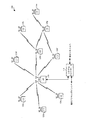
図1は、本開示の態様が実行される場合があるシステム100を示す。たとえば、アクセスポイント110および/またはユーザ端末120を含むワイヤレス局のいずれかが、近隣認識ネットワーク(NAN)内に位置する場合がある。ワイヤレス局は、ワイヤレス局がウェイクアップするようにすでにスケジュールされている期間(たとえば、ページングウィンドウまたはデータウィンドウ)の間の測距に関するファインタイミング測定(FTM)情報を交換してもよく、既存のフレーム(たとえば、関連付けフレーム、トリガ/ポーリングフレーム、プローブ要求/プローブ応答フレーム)を使用してFTM情報を交換してもよい。態様では、ワイヤレスデバイスのうちの1つが測距プロキシとして働いてもよい。
Exemplary Wireless Communication System FIG. 1 illustrates a
システム100は、たとえば、アクセスポイントおよびユーザ端末を有する多元接続多入力多出力(MIMO)システム100であってもよい。説明を簡単にするために、図1にはただ1つのアクセスポイント110が示されている。アクセスポイントは、一般に、ユーザ端末と通信する固定局であり、基地局または何らかの他の用語で呼ばれることもある。ユーザ端末は、固定であってもモバイルであってもよく、移動局、ワイヤレスデバイス、または何らかの他の用語で呼ばれる場合もある。アクセスポイント110は、ダウンリンクおよびアップリンク上で任意の所与の瞬間において1つまたは複数のユーザ端末120と通信してもよい。ダウンリンク(すなわち、順方向リンク)はアクセスポイントからユーザ端末への通信リンクであり、アップリンク(すなわち、逆方向リンク)はユーザ端末からアクセスポイントへの通信リンクである。ユーザ端末は、別のユーザ端末とピアツーピアで通信する場合もある。
システムコントローラ130は、これらのAPおよび/または他のシステムに対する協調および制御を実行してもよい。APは、たとえば、無線周波数電力、チャネル、認証、およびセキュリティに対する調整に対処する場合があるシステムコントローラ130によって管理されてもよい。システムコントローラ130は、バックホールを介してAPと通信してもよい。APは、たとえば、ワイヤレスバックホールまたは有線バックホールを介して直接または間接的に互いに通信する場合もある。
The
以下の開示の部分では、空間分割多元接続(SDMA)によって通信することが可能なユーザ端末120について説明するが、いくつかの態様では、ユーザ端末120は、SDMAをサポートしないいくつかのユーザ端末を含むこともある。したがって、そのような態様では、AP110は、SDMAユーザ端末と非SDMAユーザ端末の両方と通信するように構成されてもよい。この手法は、好都合なことに、より古いバージョンのユーザ端末(「レガシー」局)を企業に配備されたままにするのを可能にして、それらのユーザ端末の有効寿命を延長し、同時に、適宜より新しいSDMAユーザ端末が導入されるのを可能にしてもよい。
In the following disclosure, a user terminal 120 capable of communicating via space division multiple access (SDMA) is described, but in some aspects, user terminal 120 may include several user terminals that do not support SDMA. May be included. Thus, in such an aspect, the
システム100は、ダウンリンクおよびアップリンク上でのデータ送信のために複数の送信アンテナおよび複数の受信アンテナを使用する。アクセスポイント110は、Nap個のアンテナを備え、ダウンリンク送信では多入力(MI)を表し、アップリンク送信では多出力(MO)を表す。K個の選択されたユーザ端末120のセットは、ダウンリンク送信では多出力を集合的に表し、アップリンク送信では多入力を集合的に表す。純粋なSDMAの場合、K個のユーザ端末のためのデータシンボルストリームが、何らかの手段によって、コード、周波数、または時間において多重化されない場合、Nap≧K≧1であることが望まれる。TDMA技法、CDMAを用いた様々なコードチャネル、OFDMを用いたサブバンドの独立セットなどを使用してデータシンボルストリームを多重化することができる場合、KはNapより大きくてもよい。選択された各ユーザ端末は、ユーザ固有のデータをアクセスポイントに送信し、ならびに/あるいはユーザ固有のデータをアクセスポイントから受信する。一般に、選択された各ユーザ端末は、1つまたは複数のアンテナ(すなわち、Nut≧1)を備えてもよい。K個の選択されたユーザ端末は、同じ数または異なる数のアンテナを有することができる。
システム100は、時分割複信(TDD)システムまたは周波数分割複信(FDD)システムであってもよい。TDDシステムの場合、ダウンリンクとアップリンクは、同じ周波数帯域を共有する。FDDシステムの場合、ダウンリンクとアップリンクは異なる周波数帯域を使用する。MIMOシステム100は、送信に単一のキャリアを利用する場合もあるいは複数のキャリアを利用する場合もある。各ユーザ端末は、(たとえば、コストを抑えるために)単一のアンテナを備えるか、または(たとえば、追加コストをサポートすることができる場合に)複数のアンテナを備える場合がある。ユーザ端末120が、送信/受信を異なるタイムスロットに分割することによって、同じ周波数チャネルを共有する場合、システム100は、TDMAシステムであってもよく、各タイムスロットは、異なるユーザ端末120に割り当てられる。
図2は、本開示の態様を実装するために使用される場合がある、図1に示すAP110およびUT120の例示的な構成要素を示す。AP110およびUT120の1つまたは複数の構成要素は、本開示の態様を実施するのに使用されてもよい。たとえば、AP110のアンテナ224、Tx/Rx222、および/またはプロセッサ210、220、240、242、および/またはコントローラ230、あるいはUT120のアンテナ252、Tx/Rx254、プロセッサ260、270、288、290、および/またはコントローラ280は、それぞれ本明細書において説明し、図7および図7Aを参照しながら例示する動作700および700A、ならびにそれぞれ本明細書において説明し、図9および図9Aを参照しながら例示する動作900および900Aを実行するのに使用される場合がある。
FIG. 2 illustrates exemplary components of the
図2は、MIMOシステム100におけるアクセスポイント110ならびに2つのユーザ端末120mおよび120xのブロック図を示す。アクセスポイント110は、Nt個のアンテナ224a〜224apを備える。ユーザ端末120mは、Nut,m個のアンテナ252maから252muを備え、ユーザ端末120xは、Nut,x個のアンテナ252xa〜252xuを備える。アクセスポイント110は、ダウンリンクでは送信エンティティであり、アップリンクでは受信エンティティである。各ユーザ端末120は、アップリンクでは送信エンティティであり、ダウンリンクでは受信エンティティである。本明細書では、「送信エンティティ」は、ワイヤレスチャネルを介してデータを送信することが可能な独立動作型の装置またはデバイスであり、「受信エンティティ」は、ワイヤレスチャネルを介してデータを受信することが可能な独立動作型の装置またはデバイスである。以下の説明では、下付き文字「dn」は、ダウンリンクを表し、下付き文字「up」は、アップリンクを表し、Nup個のユーザ端末は、アップリンク上の同時送信のために選択され、Ndn個のユーザ端末は、ダウンリンク上の同時送信のために選択され、Nupは、Ndnと等しくてもよく、または等しくなくてもよく、NupおよびNdnは、静的な値であってもよく、または、スケジューリング間隔ごとに変化させることが可能である。アクセスポイントおよびユーザ端末において、ビームステアリングまたは何らかの他の空間処理技法が使用されてもよい。
FIG. 2 shows a block diagram of an
アップリンク上では、アップリンク送信のために選択された各ユーザ端末120において、送信(TX)データプロセッサ288は、データソース286からトラフィックデータを受信し、コントローラ280から制御データを受信する。コントローラ280は、メモリ282に結合されてもよい。TXデータプロセッサ288は、ユーザ端末のための選択されたレートに関連するコーディングおよび変調方式に基づいて、ユーザ端末のためのトラフィックデータを処理(たとえば、符号化、インターリーブ、および変調)し、データシンボルストリームを生成する。TX空間プロセッサ290は、データシンボルストリームに対して空間処理を実行し、Nut,m個のアンテナに関するNut,m個の送信シンボルストリームを生成する。各トランスミッタユニット(TMTR)254は、アップリンク信号を生成するために、それぞれの送信シンボルストリームを受信し、処理(たとえば、アナログ変換、増幅、フィルタリング、および周波数アップコンバート)する。Nut,m個のトランスミッタユニット254は、Nut,m個のアンテナ252からアクセスポイントへの送信のためにNut,m個のアップリンク信号を生成する。
On the uplink, at each user terminal 120 selected for uplink transmission, a transmit (TX) data processor 288 receives traffic data from the data source 286 and receives control data from the
Nup個のユーザ端末をアップリンク上で同時送信を行えるようにスケジュールすることができる。これらのユーザ端末の各々は、そのデータシンボルストリームに対して空間処理を実行し、アップリンク上でユーザ端末の送信シンボルストリームのセットをアクセスポイントに送信する。 N up user terminals can be scheduled for simultaneous transmission on the uplink. Each of these user terminals performs spatial processing on its data symbol stream and transmits a set of user terminal transmission symbol streams to the access point on the uplink.
アクセスポイント110において、Nap個のアンテナ224aから224apは、アップリンク上で送信を行うすべてのNup個のユーザ端末からのアップリンク信号を受信する。各アンテナ224は、受信した信号をそれぞれのレシーバユニット(RCVR)222に与える。各レシーバユニット222は、トランスミッタユニット254によって実行された処理と相補的な処理を実行し、受信シンボルストリームを生成する。RX空間プロセッサ240は、Nap個のレシーバユニット222からのNap個の受信シンボルストリームに対してレシーバ空間処理を実行し、Nup個の復元されたアップリンクデータシンボルストリームを生成する。レシーバ空間処理は、チャネル相関行列反転(CCMI)、最小平均2乗誤差(MMSE)、ソフト干渉消去(SIC)、または何らかの他の技法に従って実行される。復元された各アップリンクデータシンボルストリームは、それぞれのユーザ端末によって送信されたデータシンボルストリームの推定値である。RXデータプロセッサ242は、そのストリームのために使用されたレートに従って、復元された各アップリンクデータシンボルストリームを処理(たとえば、復調、デインターリーブ、および復号)して、復号されたデータを取得する。ユーザ端末ごとの復号されたデータは、記憶できるようにデータシンク244に与えられ、ならびに/あるいはさらに処理できるようにコントローラ230に与えられる場合がある。コントローラ230は、メモリ232に結合されてもよい。
At
ダウンリンク上で、アクセスポイント110において、TXデータプロセッサ210が、ダウンリンク送信に関してスケジュールされたNdn個のユーザ端末用のデータソース208からトラフィックデータを受信し、コントローラ230から制御データを受信し、場合によってはスケジューラ234から他のデータを受信する。様々なタイプのデータは、それぞれに異なるトランスポートチャネル上で送られる場合がある。TXデータプロセッサ210は、各ユーザ端末向けに選択されたレートに基づいて、そのユーザ端末のトラフィックデータを処理(たとえば、符号化、インターリーブ、変調)する。TXデータプロセッサ210は、Ndn個のユーザ端末に関するNdn個のダウンリンクデータシンボルストリームを生成する。TX空間プロセッサ220は、Ndn個のダウンリンクデータシンボルストリームに対して空間処理(本開示で説明するプリコーディングまたはビームフォーミングなど)を実行し、Nap個のアンテナに関するNap個の送信シンボルストリームを生成する。各トランスミッタユニット222は、それぞれの送信シンボルストリームを受信し処理して、ダウンリンク信号を生成する。Nap個のトランスミッタユニット222は、Nap個のアンテナ224からユーザ端末への送信のためにNap個のダウンリンク信号を生成する。各ユーザ端末の復号されたデータは、記憶できるようにデータシンク272に与えられ、ならびに/あるいはさらに処理できるようにコントローラ280に与えられる場合がある。
On the downlink, at
各ユーザ端末120において、Nut,m個のアンテナ252は、アクセスポイント110からNap個のダウンリンク信号を受信する。各レシーバユニット254は、関連するアンテナ252からの受信された信号を処理し、受信シンボルストリームを生成する。RX空間プロセッサ260は、Nut,m個のレシーバユニット254からのNut,m個の受信シンボルストリームに対してレシーバ空間処理を実行し、ユーザ端末に関する復元されたダウンリンクデータシンボルストリームを生成する。レシーバ空間処理は、CCMI、MMSE、または何らかの他の技法に従って実行される。RXデータプロセッサ270は、復元されたダウンリンクデータシンボルストリームを処理(たとえば、復調、デインターリーブ、および復号)して、ユーザ端末に関する復号されたデータを取得する。
In each user terminal 120, N ut, m antennas 252 receive N ap downlink signals from the
各ユーザ端末120において、チャネル推定器278は、ダウンリンクチャネル応答を推定し、チャネル利得推定値、SNR推定値、ノイズ分散などを含んでもよいダウンリンクチャネル推定値を生成する。同様に、アクセスポイント110において、チャネル推定器228は、アップリンクチャネル応答を推定し、アップリンクチャネル推定値を生成する。各ユーザ端末用のコントローラ280は、典型的には、ユーザ端末に関する空間フィルタ行列を、そのユーザ端末に関するダウンリンクチャネル応答行列Hdn,mに基づいて導出する。コントローラ230は、アクセスポイントに関する空間フィルタ行列を、実効アップリンクチャネル応答行列Hup,effに基づいて導出する。各ユーザ端末用のコントローラ280は、フィードバック情報(たとえば、ダウンリンクおよび/またはアップリンク固有ベクトル、固有値、SNR推定値など)をアクセスポイントに送ってもよい。コントローラ230および280は、それぞれ、アクセスポイント110およびユーザ端末120における様々な処理ユニットの動作も制御する。
At each user terminal 120,
図3は、MIMOシステム100内で使用される場合があるワイヤレスデバイス302において利用されることがある様々な構成要素を示す。ワイヤレスデバイス302は、本明細書において説明する様々な方法を実施するように構成されてもよいデバイスの一例である。たとえば、ワイヤレスデバイスは、それぞれ図7および図9に示す動作700および900を実施してもよい。ワイヤレスデバイス302は、アクセスポイント110またはユーザ端末120であってもよい。
FIG. 3 illustrates various components that may be utilized in a wireless device 302 that may be used within the
ワイヤレスデバイス302は、ワイヤレスデバイス302の動作を制御するプロセッサ304を含んでもよい。プロセッサ304は中央処理装置(CPU)と呼ばれることもある。メモリ306は、読取り専用メモリ(ROM)とランダムアクセスメモリ(RAM)の両方を含んでもよく、命令およびデータをプロセッサ304に与える。メモリ306の一部分は、不揮発性ランダムアクセスメモリ(NVRAM)を含む場合もある。プロセッサ304は、典型的には、メモリ306内に記憶されたプログラム命令に基づいて論理演算および算術演算を実行する。メモリ306内の命令は、本明細書で説明される方法を実施するように実行可能であってもよい。
The wireless device 302 may include a
ワイヤレスデバイス302は、ワイヤレスデバイス302とリモートノードとの間のデータの送信および受信を可能にするためのトランスミッタ310およびレシーバ312を含む場合があるハウジング308を含んでもよい。トランスミッタ310およびレシーバ312は、トランシーバ314として組み合わされてもよい。単一の送信アンテナまたは複数の送信アンテナ316が、ハウジング308に取り付けられ、トランシーバ314に電気的に結合されてもよい。ワイヤレスデバイス302は、複数のトランスミッタ、複数のレシーバ、および複数のトランシーバを含んでもよい(図示せず)。
The wireless device 302 may include a
ワイヤレスデバイス302は、トランシーバ314によって受信された信号のレベルを検出し、定量化するために使用される場合がある信号検出器318を含んでもよい。信号検出器318は、総エネルギー、シンボルごとのサブキャリア当りのエネルギー、電力スペクトル密度、および他の信号などの信号を検出してもよい。ワイヤレスデバイス302は、信号を処理する際に使用できるデジタルシグナルプロセッサ(DSP)320を含んでもよい。
The wireless device 302 may include a
ワイヤレスデバイス302の種々の構成要素は、バスシステム322によって互いに結合される場合があり、バスシステムは、データバスに加えて、電力バス、制御信号バス、およびステータス信号バスを含む場合がある。
Various components of the wireless device 302 may be coupled together by a
例示的なトーン割振り
上述のように、固定期間の間に固定周波数を介して変調された波形を使用してワイヤレス媒体を介してパケット(フレームとも呼ばれる)が伝達されてもよい。周波数帯域は、1つまたは複数の「トーン」に分割されてもよく、期間は、1つまたは複数の「シンボル」に分割されてもよい。説明に役立つ非限定的な例として、20MHz周波数帯域が4つの5MHzトーンに分割されてもよく、80マイクロ秒期間が20個の4マイクロ秒シンボルに分割されてもよい。したがって、「トーン」は、波形に含まれる周波数サブバンドを表す場合がある。トーンは、代替的にサブキャリアと呼ばれることがある。したがって、「トーン」は周波数領域単位である場合がある。「シンボル」は、波形に含まれる持続時間を表す時間領域単位である場合がある。したがって、ワイヤレスパケットに関する波形は、(しばしば周波数単位の垂直軸上の)複数のトーンと(時間単位の水平軸上の)複数のシンボルとを含む2次元構造として視覚化されてもよい。
Exemplary Tone Allocation As described above, packets (also referred to as frames) may be communicated over the wireless medium using a waveform that is modulated over a fixed frequency during a fixed period. A frequency band may be divided into one or more “tones” and a period may be divided into one or more “symbols”. As a non-limiting example to illustrate, a 20 MHz frequency band may be divided into four 5 MHz tones and an 80 microsecond period may be divided into 20 four microsecond symbols. Thus, a “tone” may represent a frequency subband included in the waveform. A tone may alternatively be referred to as a subcarrier. Thus, a “tone” may be a frequency domain unit. A “symbol” may be a time domain unit that represents a duration included in a waveform. Thus, the waveform for a wireless packet may be visualized as a two-dimensional structure that includes multiple tones (often on the vertical axis in frequency units) and multiple symbols (on the horizontal axis of time units).
一例として、ワイヤレスデバイスは、20メガヘルツ(MHz)ワイヤレスチャネル(たとえば、20MHz帯域幅を有するチャネル)を介してパケットを受信する場合がある。ワイヤレスデバイスは、64点高速フーリエ変換(FFT)を実行してパケットの波形における64個のトーンを決定してもよい。トーンのサブセットが「使用可能」と見なされる場合があり、残りのトーンが「使用不可能」と見なされる場合がある(たとえば、ガードトーン、直流(DC)トーンなどである場合がある)。一例として、52個のデータトーンと4つのパイロットトーンとを含む、64個のトーンのうちの56個が使用可能である場合がある。別の例として、48個のデータトーンと4つのパイロットトーンがある場合がある。上記のチャネル帯域幅、変換、およびトーンプランが例示的なものであることに留意されたい。代替実施形態によれば、様々なチャネル帯域幅(たとえば、5MHz、6MHz、6.5MHz、40MHz、80MHzなど)、様々な変換(たとえば、256点FFT、1024点FFTなど)、および/または様々なトーンプランが使用されてもよい。 As an example, a wireless device may receive packets via a 20 megahertz (MHz) wireless channel (eg, a channel having a 20 MHz bandwidth). The wireless device may perform a 64-point fast Fourier transform (FFT) to determine 64 tones in the packet waveform. A subset of tones may be considered “available” and the remaining tones may be considered “not available” (eg, may be guard tones, direct current (DC) tones, etc.). As an example, 56 of 64 tones may be available, including 52 data tones and 4 pilot tones. As another example, there may be 48 data tones and 4 pilot tones. Note that the above channel bandwidth, transform, and tone plan are exemplary. According to alternative embodiments, various channel bandwidths (e.g., 5 MHz, 6 MHz, 6.5 MHz, 40 MHz, 80 MHz, etc.), various conversions (e.g., 256 point FFT, 1024 point FFT, etc.), and / or various tones Plans may be used.
LTFにおける例示的な位相追跡
本開示の態様は概して、延長されたシンボル持続時間(たとえば、2xシンボル持続時間および/または4xシンボル持続時間)を利用するワイヤレスパケットに関する位相および/またはキャリア周波数オフセット(CFO)を追跡するのに使用することができる技法を提供する。この技法は、2x高効率(HE)LTFおよび4x高効率(HE)LTFなど、延長されたシンボル持続時間を使用するLTFにおいてパイロット信号を送信する場合にどのようなトーンを割り振るかを決定するのを助けることができる。
Exemplary Phase Tracking in LTF Aspects of this disclosure generally provide phase and / or carrier frequency offset (CFO) for wireless packets that utilize extended symbol duration (e.g., 2x symbol duration and / or 4x symbol duration). Provides a technique that can be used to track This technique determines what tones are allocated when transmitting pilot signals in LTFs that use extended symbol duration, such as 2x high efficiency (HE) LTF and 4x high efficiency (HE) LTF. Can help.
いくつかの適用例では、フレームの様々な部分により長いシンボル持続時間が使用される。たとえば、図4は、HE-LTFならびにそれに続くデータペイロードにより長いシンボル持続時間(たとえば、2xまたは4x)が使用される例示的なパケット400を示す。このシンボル持続時間は、基準持続時間(たとえば、レガシープリアンブル部分および/またはHE-SIGフィールドに使用される1xシンボル持続時間)と比較して長い。
In some applications, longer symbol durations are used for different parts of the frame. For example, FIG. 4 shows an
様々な適用例においてより長いシンボル持続時間が使用されると、送信デバイスにおける発振器と受信デバイスにおける発振器との違いに起因して位相追跡およびキャリア周波数オフセット(CFO)調整が必要になる場合がある。HE-LTFなどのロングトレーニングフィールドに関するシンボル持続時間を延長する場合、HE-LTFが他のシンボル持続時間(たとえば、802.11acによって規定されたLTF)よりも長い(たとえば、2xまたは4x長い)と仮定すると、チャネル推定の間に位相追跡および/またはCFO調整を実行することが望ましい場合がある。 As longer symbol durations are used in various applications, phase tracking and carrier frequency offset (CFO) adjustment may be required due to the difference between the oscillator at the transmitting device and the oscillator at the receiving device. When extending the symbol duration for a long training field such as HE-LTF, it is assumed that HE-LTF is longer (eg 2x or 4x longer) than other symbol durations (eg LTF specified by 802.11ac) It may then be desirable to perform phase tracking and / or CFO adjustments during channel estimation.
既存のヌメロロジー(ヌメロロジーという用語は一般に、データ/パイロット信号を送信するのに使用されるトーンの数および位置を指定する「トーンマップ」を指すかまたは定義する)を適用することを試みるときにいくつかの問題が生じることがある。たとえば、既存のヌメロロジーによれば、2xLTF(標準/基準シンボル長の2倍)は一般に、4xOFDMシンボル(標準/基準シンボル長の4倍)におけるトーンを1つおきにのみ存在させる。このため、たとえば、シングルユーザ(SU)送信などの、追跡すべきソースが1つである送信、DL MU MIMO、ならびに(たとえば、トランスミッタに別個の周波数が割り当てられる)アップリンクおよびダウンリンクOFDMA送信に関して、位相追跡をどのように行うかを決定する場合に様々なオプションが存在する。 When you try to apply existing numerology (the term numerology generally refers to or defines a `` tone map '' that specifies the number and location of tones used to transmit data / pilot signals) Some problems may arise. For example, according to existing numerology, 2xLTF (twice the standard / reference symbol length) generally has only every other tone in a 4xOFDM symbol (four times the standard / reference symbol length). For this reason, for example, transmission with one source to be tracked, such as single user (SU) transmission, DL MU MIMO, and uplink and downlink OFDMA transmission (e.g., the transmitter is assigned a separate frequency) There are various options when deciding how to perform phase tracking.
本開示の態様は、LTFを使用するチャネル推定時に位相追跡を実行するための様々な技法を提供する。場合によっては、LTFにおける様々なトーン上で送信されるパイロットを使用することによって位相追跡が実行されてもよい。他の場合には、パイロットを使用せずに、直交LTFシーケンスを使用することによって、位相追跡が実行されてもよい。 Aspects of this disclosure provide various techniques for performing phase tracking during channel estimation using LTF. In some cases, phase tracking may be performed by using pilots transmitted on various tones in the LTF. In other cases, phase tracking may be performed by using orthogonal LTF sequences without using pilots.
図5は、本開示のいくつかの態様による、LTFを使用する(受信装置による)パイロットベースの位相追跡を可能にする、送信装置によるワイヤレス通信のための例示的な動作500のブロック図である。
FIG. 5 is a block diagram of an
動作500は、502において、1つまたは複数のトーンを介して送信すべきパイロットシンボルを含む1つまたは複数のフィールド(LTF)を有するフレームを生成することによって開始する。504において、送信装置は、送信のためにフレームを出力する。
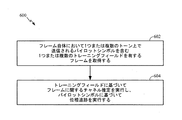
図6は、本開示のいくつかの態様によるパイロットベースの位相追跡を実行するための、受信装置によるワイヤレス通信のための例示的な動作600のブロック図を示す。たとえば、動作600は、図5に示す動作に従って送信されるフレームを処理するのに使用される補完的な「レシーバ側」動作と見なされてもよい。
FIG. 6 illustrates a block diagram of an
動作600は、602において、フレーム自体において1つまたは複数のトーン上で送信されるパイロットシンボルを含む1つまたは複数のフィールド(LTF)を有するフレームを取得することによって開始する。604において、受信装置は、LTFに基づいてフレームに関するチャネル推定を実行し、パイロットシンボルに基づいて位相追跡を実行する。
いくつかの態様によれば、LTFにおけるパイロットベースの追跡では、パイロットを送信するのに使用すべきトーンの位置ならびに/あるいはトーンの数を決定するのに既存のトーンプランが使用されてもよい。たとえば、4xLTFの場合、パケットのデータ部分において単一ストリームパイロット(SSPまたはSSPパイロットシンボル)を送信するための同じトーンプランが使用されてもよい。この場合、データにおいて使用されるのと同じ数のパイロットおよび同じパイロットトーン位置がLTFにおいて使用されてもよい。 According to some aspects, pilot-based tracking in LTF may use an existing tone plan to determine the location of tones and / or the number of tones to be used for transmitting pilots. For example, for 4xLTF, the same tone plan for transmitting a single stream pilot (SSP or SSP pilot symbol) in the data portion of the packet may be used. In this case, the same number of pilots and the same pilot tone positions used in the data may be used in the LTF.
しかし、上述のように、たとえば、4xOFDMシンボルのトーンを1つおきにのみ存在させることによって2xLTFが生成される場合がある(かつ既存の4xデータシンボルにおいて、パイロットトーンがすべて奇数のインデックスを有する場合がある)ので、2xLTFに様々な要件が生じることがある。しかし、本開示の態様は、許容される追跡性能を実現する(たとえば、単一ストリーム)パイロットの数および位置を利用する2xLTFにおけるパイロット設計を可能にする。 However, as mentioned above, for example, 2xLTF may be generated by having only every other tone of a 4xOFDM symbol (and in existing 4x data symbols, all pilot tones have odd indices) As a result, various requirements may arise for 2xLTF. However, aspects of the present disclosure allow pilot design in 2xLTF that utilizes the number and location of pilots that achieve acceptable tracking performance (eg, a single stream).
パケットのデータ部分およびLTFの間パイロット位置を整合させない、2xLTFに対処する様々な手法が提示される。たとえば、一手法によれば、パイロット用のLTFにおいて2xヌメロロジーが使用されてもよい。別の手法では、4xLTFヌメロロジーと同じ数のパイロットが使用されてもよい。 Various approaches to deal with 2xLTF are presented that do not align the pilot position between the data portion of the packet and the LTF. For example, according to one approach, 2x numerology may be used in the pilot LTF. In another approach, the same number of pilots as 4xLTF numerology may be used.
パイロット用の2xLTFにおいて2xヌメロロジーを使用すると、パイロットトーンの数が4xにおけるパイロットトーンの数の2分の1よりも多くなる場合があり、このことは、4xヌメロロジーと比較してパイロット密度が高くなったことを表す。その結果、そのような手法は、4xLTF以上の位相追跡性能を有することが予期される。この場合、パイロットの数をさらに減らす必要がない場合もあり、したがって、新しいパイロットトーンプランが不要になることがある。場合によっては、2xLTFにおけるパイロットトーンの数およびパイロット位置は、以下の2xヌメロロジーのうちの1つに従うことがある。
- 80MHz:512FFT(HE40)と同様な16個のパイロットおよびその位置
- 40MHz:256FFT(HE20)と同様な8つのパイロットおよびその位置
- 20MHz:128FFT(VHT40)と同様な6つのパイロットおよびその位置
- 106トーンRU(リソースユニット):52トーンRUと同様な4つのパイロットおよびその位置
- 52トーンRU:26トーンRUと同様な2つのパイロットおよびその位置
- 26トーンRU:13トーンブロックに関する新しいトーンプラン
新しい(13トーン)トーンブロックでは、場合によっては、チャネルがこのブロックにわたって比較的フラットであることを考慮して、(13トーンブロックの)中央に単一(1つ)のパイロットトーンが使用されることがある(26トーンRUにおける2つのパイロットと同じパイロット電力が使用される場合もある)。他の場合には、より良好なダイバーシティ利得および電力利得を得るために、中央に単一のトーンではなく、複数のパイロットトーンが使用されることがある(たとえば、その13トーンブロックにおける5番目および9番目のトーンとして2つのパイロットトーンが使用されることがある)。
Using 2x numerology in a pilot 2xLTF may result in more pilot tones than half the number of pilot tones in 4x, which increases pilot density compared to 4x numerology. It represents that. As a result, such an approach is expected to have a phase tracking performance of 4xLTF or better. In this case, it may not be necessary to further reduce the number of pilots, and therefore a new pilot tone plan may not be required. In some cases, the number of pilot tones and pilot positions in 2xLTF may follow one of the following 2x numerologies.
-80MHz: 16 pilots similar to 512FFT (HE40) and their positions
-40MHz: 8 pilots similar to 256FFT (HE20) and their positions
-20MHz: 6 pilots similar to 128FFT (VHT40) and their position
-106 tone RU (resource unit): 4 pilots similar to 52 tone RU and their positions
-52 tone RU: 2 pilots and their positions similar to 26 tone RU
-26 tone RU: New tone plan for 13 tone block In the new (13 tone) tone block, in some cases, the channel is relatively flat across this block, allowing for a single center (of the 13 tone block). One (one) pilot tone may be used (the same pilot power may be used as two pilots at 26 tone RU). In other cases, multiple pilot tones may be used instead of a single tone in the middle (e.g., the fifth and fifth in that 13-tone block) to obtain better diversity gain and power gain. Two pilot tones may be used as the ninth tone).
場合によっては、パイロット用の2xLTFにおいて2xヌメロロジーを使用する際、4xデータに関するチャネル推定における外挿損失を最小限に抑えるために、存在する(使用可能な)2xLTFトーンの数が縁部(の近く)または両縁部において増やされてもよい。この例示的なヌメロロジーは、「拡張」2xヌメロロジーと呼ばれることがある。 In some cases, when using 2x numerology in pilot 2xLTF, the number of 2xLTF tones present (near the edge) is near (to the edge) to minimize extrapolation loss in channel estimation for 4x data. ) Or at both edges. This exemplary numerology may be referred to as an “extended” 2x numerology.
場合によっては、26トーンRUの場合の2xLTFに関する新しい13トーンブロックを除いて、すべての他のRUが、すでに定義されている既存のヌメロロジー(たとえば、802.11ac/11ahに関するヌメロロジー)を使用する場合がある。そのような適用例では、パイロットは、2xLTFと4xLTFとの間のではなく2xLTF間の位相追跡に使用され、したがって、位相追跡の複雑さが増すことがなくなる場合がある。データおよびLTFの間パイロット位置を整合させることはないが、推定されたチャネルに関して、LTFにおけるパイロットの代わりにデータシンボルにおける位相オフセットが推定される場合があるので、そのような整合が不要になることがあり、2xLTFを送信する際には一般にチャネル補間が必要である。 In some cases, with the exception of the new 13-tone block for 2xLTF in the case of 26-tone RUs, all other RUs may use existing numerologies that are already defined (for example, numerology for 802.11ac / 11ah). is there. In such applications, the pilot may be used for phase tracking between 2xLTFs rather than between 2xLTF and 4xLTF, and thus phase tracking complexity may not increase. It does not align pilot positions between data and LTF, but for the estimated channel, phase offsets in data symbols may be estimated instead of pilots in LTF, so that such alignment is not necessary In general, channel interpolation is required to transmit 2xLTF.
上述のように、場合によっては、4xLTFと同じ数のパイロットが2xLTFにおいて使用されてもよい。現在の4xヌメロロジーでは、パイロットトーンはすべて奇数のインデックスを有する。したがって、4xと同じ数のパイロットを2xLTFにおいて有するには、4xLTFにおいてパイロット位置を偶数トーンインデックスにシフトさせればよく、それによってすべてのパイロット位置が2xLTFに存在することができる。上述のように、データの間にパイロット位置をさらにシフトさせてLTFおよびデータにおいてすべてのパイロットインデックスを整合させることが不要になる場合があるが、このように整合させることによって、LTFとデータの両方に関してパイロットの整合性を維持するのを助けることができる。4xLTFと同じ数のパイロットを2xLTFにおいて使用すると、2xおよび4xヌメロロジーに関する新しいパイロットトーンプランが得られる場合がある。LTFにおけるパイロットが増えると、パイロットトーン位置の周りのデータトーンに必要なチャネル補間が増大する場合がある。 As mentioned above, in some cases, the same number of pilots as 4xLTF may be used in 2xLTF. In current 4x numerology, all pilot tones have an odd index. Thus, to have the same number of pilots in 4xLTF as in 2xLTF, the pilot positions need only be shifted to an even tone index in 4xLTF, so that all pilot positions can be present in 2xLTF. As mentioned above, it may not be necessary to further shift the pilot position between data to align all pilot indexes in the LTF and data, but this alignment allows both LTF and data to be aligned. Can help maintain pilot integrity. Using the same number of pilots in 4xLTF in 2xLTF may result in a new pilot tone plan for 2x and 4x numerology. As the pilot in the LTF increases, the channel interpolation required for data tones around the pilot tone position may increase.
場合によっては、2xLTFにおけるパイロットトーンの数が4xヌメロロジーの場合と同じであってもよい。そのような場合、2xLTFおよび4xデータにおけるパイロット位置は(必要に応じて)、(既存の4xパイロットトーンインデックス+1)または(既存の4xパイロットトーンインデックス-1)に従ってもよく、2xLTFにおける厳密なパイロット位置は、以下のように、修正された4xパイロットインデックスを2で割った値に等しくなる。
- 80MHzに関する2xLTF:16個のパイロットおよびその位置は、(1024FFTにおけるパイロットトーンインデックス±1)/2である。
- 40MHzに関する2xLTF:16個のパイロットおよびその位置は、(512FFTにおけるパイロットトーンインデックス±1)/2である。
- 20MHzに関する2xLTF:8個のパイロットおよびその位置は、(256FFTにおけるパイロットトーンインデックス±1)/2である。
- 106トーンRUに関する2xLTF:4個のパイロットおよびその位置は、(106トーンRUにおけるパイロットトーンインデックス±1)/2である。
- 52トーンRUに関する2xLTF:4個のパイロットおよびその位置は、(52トーンRUにおけるパイロットトーンインデックス±1)/2である。
- 26トーンRUに関する2xLTF:2個のパイロットおよびその位置は、(26トーンRUにおけるパイロットトーンインデックス±1)/2である。
In some cases, the number of pilot tones in 2xLTF may be the same as in 4x numerology. In such a case, the pilot positions in 2xLTF and 4x data (if necessary) may follow (existing 4x pilot tone index + 1) or (existing 4x pilot tone index-1), and the exact pilot in 2xLTF The position is equal to the modified 4x pilot index divided by 2 as follows:
-2xLTF for 80MHz: 16 pilots and their positions are (pilot tone index ± 1 in 1024FFT) / 2.
-2xLTF for 40 MHz: 16 pilots and their positions are (pilot tone index ± 1 in 512 FFT) / 2.
-2xLTF for 20MHz: 8 pilots and their positions are (pilot tone index ± 1) / 2 in 256FFT.
-2xLTF for 106 tone RUs: 4 pilots and their position is (pilot tone index ± 1 in 106 tone RU) / 2.
-2xLTF for 52 tone RUs: 4 pilots and their positions are (pilot tone index ± 1 in 52 tone RU) / 2.
-2xLTF for 26 tone RU: 2 pilots and their position is (pilot tone index ± 1 in 26 tone RU) / 2.
図7は、本開示のいくつかの態様による、LTFを使用する非パイロットベースの位相追跡を可能にする、送信装置によるワイヤレス通信のための例示的な動作700のブロック図を示す。
FIG. 7 shows a block diagram of an
動作700は、702において、各々が異なる空間ストリームに割り当てられる複数の直交ロングトレーニングフィールド(LTF)を有するフレームを生成して、LTFに基づくチャネル推定の間位相追跡を可能にすることによって開始する。704において、送信装置は、シングルユーザ(SU)送信、ダウンリンクマルチユーザ(MU)多入力多出力(MIMO)送信、または直交周波数分割多元接続(OFDMA)送信としての送信のためにフレームを出力する。
図8は、本開示のいくつかの態様による非パイロットベースの位相追跡を実行するための、受信装置によるワイヤレス通信のための例示的な動作800のブロック図を示す。たとえば、動作800は、図7に示す動作に従って送信されるフレームを処理するのに使用される補完的な「レシーバ側」動作と見なされてもよい。
FIG. 8 illustrates a block diagram of an
動作800は、802において、各々が異なる空間ストリームに割り当てられる複数の直交ロングトレーニングフィールド(LTF)シーケンスを有するフレームを取得することによって開始し、このフレームは、シングルユーザ(SU)送信、ダウンリンクマルチユーザ(MU)多入力多出力(MIMO)送信、または直交周波数分割多元接続(OFDMA)送信として取得される。804において、受信装置は、フレームに関するチャネル推定またはLTFに基づく位相追跡のうちの少なくとも一方を実行する。
ストリーム全体にわたって直交LTFシーケンスを使用すると、様々なLTFシーケンスがそれぞれに異なるストリームに割り当てられる場合がある。この場合、すべてのデータトーンおよび少なくとも「第1の+最後の」LTFシンボルが、キャリア周波数オフセット(CFO)を推定するのに使用される場合がある。この手法は、LTFにおいてパイロットが不要になるという点で有利である場合があり、LTFにおけるパイロットトーンと比較してLTFトーンの数が増えることによって累積利得が増大することがある。直交LTFシーケンスは、2xLTFと4xLTFの両方に適用可能であってもよい。 If orthogonal LTF sequences are used across the entire stream, different LTF sequences may be assigned to different streams. In this case, all data tones and at least the “first + last” LTF symbol may be used to estimate the carrier frequency offset (CFO). This approach may be advantageous in that pilots are not required in the LTF, and the cumulative gain may be increased by increasing the number of LTF tones compared to pilot tones in the LTF. The orthogonal LTF sequence may be applicable to both 2xLTF and 4xLTF.
場合によっては、Nss個の直交LTFシーケンスがNss個のストリームに使用されてもよい(1対1マッピング)。この手法は、十分な合成利得が得られる場合があるが、少なくともNss個の隣接トーンが同じチャネルを有することが必要になる場合もある。他の場合には、Nss個よりも少ない数の直交LTFシーケンスが使用されてもよい。たとえば、2つの直交LTFシーケンスのみ、すなわち、第1のストリームに関する直交LTFシーケンスと残りのストリーム(たとえば、残りのNss-1)に関する直交LTFシーケンスが使用される場合がある。この手法は、フラットチャネルを隣接する2つのトーンのみに減らす場合があるが、(たとえば、1人のユーザに関するストリームが2つよりも多いときに)複数のストリームにわたる推定される位相ドリフトの平均化が行われないこともあり、場合によっては、1つのストリームのみにおいて追跡が続けられることに起因して電力損失が生じる場合もある。 In some cases, Nss orthogonal LTF sequences may be used for Nss streams (one-to-one mapping). This approach may provide sufficient composite gain, but may require that at least Nss adjacent tones have the same channel. In other cases, fewer than Nss orthogonal LTF sequences may be used. For example, only two orthogonal LTF sequences may be used: an orthogonal LTF sequence for the first stream and an orthogonal LTF sequence for the remaining stream (eg, the remaining Nss-1). This technique may reduce the flat channel to only two adjacent tones, but average estimated phase drift across multiple streams (for example, when there are more than two streams for a single user) May not be performed, and in some cases, power loss may occur due to tracking being continued in only one stream.
いくつかのシナリオでは、位相追跡に関して、たとえば、中程度のSNRから高SNRまでの範囲での周波数選択チャネルにおけるMIMO送信の場合に、単一ストリームパイロットが直交LTFよりも優れた性能を実現することがある。そのような場合、チャネル補間の観点から、パイロットの周りのチャネル損失は他のトーンよりも大きいことがあるが、パイロット密度が限定されているのでそれほど影響を与えない場合がある。 In some scenarios, for phase tracking, for example, MIMO transmission on frequency selective channels ranging from moderate SNR to high SNR, a single stream pilot will provide better performance than orthogonal LTF There is. In such cases, from a channel interpolation perspective, the channel loss around the pilot may be greater than other tones, but may not be significantly affected because the pilot density is limited.
しかし、そのような場合、ビームフォーミング時に、パイロットにおけるチャネル補間にいくつかの技法が使用されてもよい。そのような技法は、パイロットを受信するデバイスからのフィードバックに基づいて(ビームフォーミングされた送信に使用される)プリコーディング行列を生成する際に使用されてもよい。場合によっては、プリコーディングされたチャネルを平滑化するために、他のトーン上で送信されるチャネルに関するフィードバックに基づいて、特定のパイロットトーンに対応するプリコーディング行列エントリが生成されてもよい。たとえば、トーンインデックスnを有するパイロットトーンに関するプリコーディング行列が、(トーンインデックスn-1およびn+1を有する)2つの隣接するトーン上の補間されたチャネルフィードバックに基づいて生成されてもよい。
W(H(n))=f(H(n-1), H(n+1))
However, in such cases, some techniques may be used for channel interpolation in the pilot during beamforming. Such techniques may be used in generating a precoding matrix (used for beamformed transmission) based on feedback from the device receiving the pilot. In some cases, precoding matrix entries corresponding to particular pilot tones may be generated based on feedback on channels transmitted on other tones to smooth the precoded channels. For example, a precoding matrix for pilot tones with tone index n may be generated based on interpolated channel feedback on two adjacent tones (with tone indexes n−1 and n + 1).
W (H (n)) = f (H (n-1), H (n + 1))
場合によっては、所与のリソースユニット(RU)におけるパイロットトーンをどのように配置するかが検討されてもよく、それによって、パイロットトーンを2xLTFに使用することができる。1つの手法では、すべてのRUにおけるパイロットを偶数のトーンに配置する。このことは実際には、2つのパイロット構造を鏡面対称的に使用することを意味する場合があり、設計が一貫したものにならないことがあり、パイロット構造を決定するうえで依然としてRU位置の知識が必要になる場合がある。一般に、1つのパイロット構造がすべてのパイロットについて偶数のトーンインデックスを有する目標を実現することは困難であるかあるいは不可能である場合がある。場合によっては、スペクトル線とRU位置の両方が鏡面対称性を有することがある。 In some cases, it may be considered how to place pilot tones in a given resource unit (RU), so that pilot tones can be used for 2xLTF. One approach places the pilots in all RUs on an even number of tones. This may actually mean that the two pilot structures are used mirror-symmetrically, the design may not be consistent, and there is still knowledge of the RU location in determining the pilot structure. It may be necessary. In general, it may be difficult or impossible to achieve a goal in which one pilot structure has an even number of tone indexes for all pilots. In some cases, both the spectral line and the RU position may have mirror symmetry.
場合によっては、上述のように、パイロットトーン位置は、各RU内の相対的なパイロット構造に基づいてもよい。この場合、(たとえば、2xおよび4xに従来のヌメロロジーを再利用することによって)、2xLTFが2xパイロットを使用し、一方、4xLTFおよびデータが4xパイロットを使用するように、LTFとデータに別個のパイロット構造が使用されてもよい。 In some cases, as described above, the pilot tone position may be based on the relative pilot structure within each RU. In this case (for example, by reusing traditional numerology for 2x and 4x), 2xLTF uses 2x pilots, while 4xLTF and data use 4x pilots, while separate pilots for LTF and data A structure may be used.
別のオプションでは、固定された絶対パイロット構造をPPDU全体に使用する。この場合、任意のリソース割振り方式に使用すべき所与のPPDU帯域幅(たとえば、20/40/80MHz)における(たとえば、すべてのパイロットが偶数トーンインデックスに位置する)固定されたトーン位置にあるパイロットの定義されたセットに基づいてパイロットトーン位置が選択されてもよい(たとえば、デバイスが選択してもよい)。割振りごとに、割り振られたRU内のパイロットトーンは、RUサイズに適合するように適切にパンクチャしながら、定義されたセットに従って選択されてもよい。 Another option is to use a fixed absolute pilot structure for the entire PPDU. In this case, pilots at fixed tone positions (eg, all pilots are located at even tone indexes) in a given PPDU bandwidth (eg, 20/40/80 MHz) to be used for any resource allocation scheme A pilot tone position may be selected based on the defined set of (eg, the device may select). For each allocation, the pilot tones within the allocated RUs may be selected according to a defined set while appropriately puncturing to fit the RU size.
特定の例であるが限定的ではない例として、固定位置にある18個のパイロットが、20MHz PPDUにおいて、各ユーザが26-RUにおける2つのパイロットを有する最大で9人のユーザの割振りに対処するように定義されてもよい。1つのSTAに106RUが割り当てられると仮定すると、この106RU内に8つのパイロットが存在する。106RUに関して8つのパイロットから4つのパイロットを取得する場合、(たとえば、任意の適切なパンクチャリングルールに従って/適用することによって)パイロットを1つおきにパンクチャしてもよい。 As a specific but non-limiting example, 18 pilots at fixed locations address allocation of up to 9 users in a 20 MHz PPDU, each user having 2 pilots at 26-RU May be defined as follows. Assuming that 106RU is assigned to one STA, there are 8 pilots in this 106RU. When obtaining 4 pilots out of 8 pilots for 106RU, every other pilot may be punctured (eg, according to / applying any suitable puncturing rules).
PPDU全体に対する固定された絶対パイロット構造の1つの利点は、任意のRUおよび任意の割振りにおいてパイロット位置を整合させてもよいことであり、それによってハードウェア設計が容易になることがある。さらに、RU設計およびリソース割振りとは無関係のパイロット位置を有すると、OFDMA処理がより簡単になる場合がある。一例として、定義されたすべてのパイロットが偶数のトーンに位置する場合、2x送信と4x送信がLTF用のパイロットの同じセットを使用することになり、LTF処理がより簡単になる。固定された絶対パイロット構造を有することは、ダウンリンク共通パイロットの使用に関して有利である場合がある。 One advantage of a fixed absolute pilot structure for the entire PPDU is that pilot positions may be aligned at any RU and at any allocation, which may facilitate hardware design. In addition, having OFDM positions that are independent of RU design and resource allocation may make OFDMA processing easier. As an example, if all defined pilots are located on an even number of tones, 2x and 4x transmissions will use the same set of pilots for LTF, making LTF processing easier. Having a fixed absolute pilot structure may be advantageous with respect to the use of the downlink common pilot.
図9は、固定された絶対パイロット構造の一例を示す。図示の例では、20MHzにおける18個のパイロット、40MHzにおける36個のパイロット、および80MHzにおける74個のパイロットが提案されている。図示の例では、すべてのパイロットが偶数のトーンに配置され、PPDUのスペクトル線全体にわたって均等に拡散される。 FIG. 9 shows an example of a fixed absolute pilot structure. In the example shown, 18 pilots at 20 MHz, 36 pilots at 40 MHz, and 74 pilots at 80 MHz are proposed. In the example shown, all pilots are placed on an even number of tones and spread evenly across the spectral lines of the PPDU.
図示の例では、20MHzに関する提案されたパイロットトーンインデックスは、±10、±22、±36、±48、±62、±76、±90、±102、±116である。40MHzの場合、提案されたトーンインデックスは、±10、±24、±36、±50、±64、±78、±90、±104、±116、±130、±144、±158、±170、±184、±198、±212、±224、±238である。80MHzの場合、提案されたトーンインデックスは、±10、±24、±38、±50、±64、±78、±92、±104、±118、±130、±144、±158、±172、±184、±198、±212、±226、±238、±252、±266、±280、±292、±306、±320、±334、±346、±360、±372、±386、±400、±414、±426、±440、±454、±468、±480、±494である。 In the illustrated example, the proposed pilot tone index for 20 MHz is ± 10, ± 22, ± 36, ± 48, ± 62, ± 76, ± 90, ± 102, ± 116. For 40 MHz, the proposed tone index is ± 10, ± 24, ± 36, ± 50, ± 64, ± 78, ± 90, ± 104, ± 116, ± 130, ± 144, ± 158, ± 170, ± 184, ± 198, ± 212, ± 224, and ± 238. For 80 MHz, the proposed tone index is ± 10, ± 24, ± 38, ± 50, ± 64, ± 78, ± 92, ± 104, ± 118, ± 130, ± 144, ± 158, ± 172, ± 184, ± 198, ± 212, ± 226, ± 238, ± 252, ± 266, ± 280, ± 292, ± 306, ± 320, ± 334, ± 346, ± 360, ± 372, ± 386, ± 400 , ± 414, ± 426, ± 440, ± 454, ± 468, ± 480, and ± 494.
図10〜図12は、本開示の態様による、図9の絶対トーン構造の例示的なプロットを示す。図10は、20MHzにおける18個のパイロットの例示的なトーンマップを示し、図11は、40MHzにおける36個のパイロットの例示的なトーンマップを示し、一方、図12は、80MHzにおける74個のパイロットの例示的なトーンマップを示す。 10-12 illustrate exemplary plots of the absolute tone structure of FIG. 9, in accordance with aspects of the present disclosure. FIG. 10 shows an exemplary tone map of 18 pilots at 20 MHz, and FIG. 11 shows an exemplary tone map of 36 pilots at 40 MHz, while FIG. 12 shows 74 pilots at 80 MHz. An exemplary tone map of is shown.
図14は、本開示の態様による、別の例示的な絶対トーン構造(図9に示す構造の代替形態)を示す。図示の例では、20MHzに関する提案されたパイロットトーンインデックスは、図9に示すパイロットトーンインデックスと同じである。40MHzの場合、提案されたトーンインデックスは、±8、±22、±34、±48、±62、±76、±88、±102、±116、±130、±144、±158、±170、±184、±198、±212、±224、±238である。80MHzの場合、提案されたトーンインデックスは、±10、±22、±36、±48、±62、±76、±90、±102、±116、±130、±144、±158、±172、±184、±198、±212、±226、±238、±252、±264、±278、±290、±304、±318、±332、±344、±358、±372、±386、±400、±414、±426、±440、±454、±468、±480、±494である。 FIG. 14 illustrates another exemplary absolute tone structure (an alternative to the structure shown in FIG. 9) in accordance with aspects of the present disclosure. In the example shown, the proposed pilot tone index for 20 MHz is the same as the pilot tone index shown in FIG. For 40 MHz, the proposed tone index is ± 8, ± 22, ± 34, ± 48, ± 62, ± 76, ± 88, ± 102, ± 116, ± 130, ± 144, ± 158, ± 170, ± 184, ± 198, ± 212, ± 224, and ± 238. For 80 MHz, the proposed tone index is ± 10, ± 22, ± 36, ± 48, ± 62, ± 76, ± 90, ± 102, ± 116, ± 130, ± 144, ± 158, ± 172, ± 184, ± 198, ± 212, ± 226, ± 238, ± 252, ± 264, ± 278, ± 290, ± 304, ± 318, ± 332, ± 344, ± 358, ± 372, ± 386, ± 400 , ± 414, ± 426, ± 440, ± 454, ± 468, ± 480, and ± 494.
図10〜図12と同様に、図15〜図17は、本開示の態様による、図14の絶対トーン構造の例示的なプロットを示す。図10〜図12および図15〜図17に示すプロットは、特定の残余トーン(黄色いブロック)およびRU位置が与えられた場合に、例示的なRUの各々において定義されたパイロットをどのように使用しパンクチャするかを示す。残余トーンは、これらのトーンがエネルギーを有しないことがあるので「ヌルトーン」と呼ばれることもある。 Similar to FIGS. 10-12, FIGS. 15-17 illustrate exemplary plots of the absolute tone structure of FIG. 14 in accordance with aspects of the present disclosure. The plots shown in FIGS. 10-12 and 15-17 show how the pilot defined in each of the exemplary RUs is used given a specific residual tone (yellow block) and RU position. Indicates whether to puncture. The residual tones are sometimes called “null tones” because these tones may have no energy.
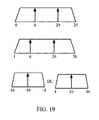
一般に、26トーンRUおよび52トーンRUの場合、各RUにおけるすべての利用可能なパイロットが使用されてもよい。106(すなわち、102+4)トーンRUおよび242トーンRUの場合、利用可能なパイロットトーンの2分の1がパンクチャされてもよい。図18に示すように、場合によっては、相対パイロット位置が、(1つの偶数パイロットインデックスと1つの奇数パイロットインデックスの対称パイロット構造を有する)11ahにおいて定義されているものの比較的近くに維持されてもよい。残余トーン割振りプランにかかわらず、図19に示すように、26トーンRU内にパイロットトーン位置の3つの変形形態があってもよい。第1の変形形態では、26トーンRUが、偶数インデックスから始まる左端トーンを有してもよく、[6P13P5]の構造を有してもよい。第2の変形形態では、左端トーンが奇数インデックスから始まってもよく、[5P13P6]の構造を必要とする場合がある。第3の変形形態では、中央26トーンRUパイロット構造が[6P66P6]であってもよい。 In general, for 26 tone RUs and 52 tone RUs, all available pilots in each RU may be used. For 106 (ie, 102 + 4) tone RUs and 242 tone RUs, one half of the available pilot tones may be punctured. As shown in FIG. 18, in some cases, the relative pilot position may be kept relatively close to that defined in 11ah (having a symmetric pilot structure with one even pilot index and one odd pilot index). Good. Regardless of the residual tone allocation plan, there may be three variations of pilot tone positions within 26 tone RUs as shown in FIG. In the first variation, the 26 tone RU may have a leftmost tone starting from an even index, and may have a [6P13P5] structure. In the second variant, the leftmost tone may start with an odd index and may require a [5P13P6] structure. In a third variation, the central 26 tone RU pilot structure may be [6P66P6].
偶数トーンインデックスを有するすべてのパイロットを確保するには、26トーンRU内の相対パイロット位置をそれぞれに異なる26トーンRUに対して異ならせる必要がある。 To ensure all pilots with an even tone index, the relative pilot positions within the 26 tone RUs need to be different for different 26 tone RUs.
たとえば、図10を参照すると、20MHzの場合、26トーンRUごとに(矢印によって示されている)パイロットトーンインデックスの対が選択されてもよい(左から右に、-116/-102、-90/-76、-62/-48、-36/-22、-10/10、22/36、48/62、76/90、および102/116)。同様に、これらの同じパイロットトーンインデックスのうちの4つのパイロットトーンインデックスのセットが52トーンRUに使用されてもよい(-116/-102/-90/-76、-62/-48/-36/-22、22/36/48/62、および76/90/102/116)。一方、これらのトーンインデックスのうちの2分の1のみが106トーンRU用に選択され(-116/-90/-48/-22および22/48/90/116)かつ242トーンRU用に選択されてもよく(-116/-90/-48/-22/22/48/90/116)用に選択されてもよく、一方、他のパイロットトーンインデックスはパンクチャされる(左から右に、-102、-76、-62、-36、-10、10、36、62、76、および102)。 For example, referring to FIG. 10, for 20 MHz, a pair of pilot tone indices (indicated by arrows) may be selected every 26 tone RUs (from left to right, −116 / −102, −90 / -76, -62 / -48, -36 / -22, -10/10, 22/36, 48/62, 76/90, and 102/116). Similarly, a set of four pilot tone indexes of these same pilot tone indexes may be used for 52 tone RUs (-116 / -102 / -90 / -76, -62 / -48 / -36 / -22, 22/36/48/62, and 76/90/102/116). On the other hand, only one-half of these tone indexes are selected for 106 tone RUs (-116 / -90 / -48 / -22 and 22/48/90/116) and selected for 242 tone RUs May be selected for (-116 / -90 / -48 / -22 / 22/48/90/116), while other pilot tone indexes are punctured (from left to right, -102, -76, -62, -36, -10, 10, 36, 62, 76, and 102).
同様に、図11を参照すると、40MHzの場合、26トーンRUごとに(矢印によって示されている)パイロットトーンインデックスの対が選択されてもよい(左から右に、-238/-224、-212/-198、-184/-170、-158/-144、-130/-116、-104/-90、-78/-64、-50/-36、-24/-10、10/24、36/50、64/78、90/104、116/130、144/158、170/184、198/212、および224/238)。同様に、これらの同じパイロットトーンインデックスのうちの4つのパイロットトーンインデックスのセットが52トーンRUに使用されてもよい(-238/-224/-212/-198、-184/-170/-158/-144、-104/-90/-78/-64、-50/-36/-24/-10、10/24/36/50、64/78/90/104、144/158/170/184、および198/212/224/238)。一方、これらのトーンインデックスのうちの2分の1よりも少ない数のトーンインデックスが106トーンRU用に選択され(-238/-212/-170/-144、-104/-78/-36/-10、10/36/78/104、および144/170/212/238)かつ242トーンRU用に選択されてもよく(-238/-212/-170/-144/-104/-78/-36/-10および10/36/78/104/144/170/212/238)、一方、他のパイロットトーンインデックスはパンクチャされる。 Similarly, referring to FIG. 11, for 40 MHz, a pair of pilot tone indices (indicated by arrows) may be selected every 26 tone RUs (from left to right, -238 / -224,- 212 / -198, -184 / -170, -158 / -144, -130 / -116, -104 / -90, -78 / -64, -50 / -36, -24 / -10, 10/24 36/50, 64/78, 90/104, 116/130, 144/158, 170/184, 198/212, and 224/238). Similarly, a set of four pilot tone indexes of these same pilot tone indexes may be used for 52 tone RUs (-238 / -224 / -212 / -198, -184 / -170 / -158 / -144, -104 / -90 / -78 / -64, -50 / -36 / -24 / -10, 10/24/36/50, 64/78/90/104, 144/158/170 / 184, and 198/212/224/238). On the other hand, fewer than half of these tone indexes are selected for 106 tone RUs (-238 / -212 / -170 / -144, -104 / -78 / -36 / -10, 10/36/78/104, and 144/170/212/238) and may be selected for 242 tone RU (-238 / -212 / -170 / -144 / -104 / -78 / -36 / -10 and 10/36/78/104/144/170/212/238), while the other pilot tone indexes are punctured.
同様に、図12を参照すると、80MHzの場合、26トーンRUごとに(矢印によって示されている)パイロットトーンインデックスの対が選択されてもよい(左から右に、-494/-480、-468/-454、-440/-426、-414/-400、-386/-372、-360/-346、-334/-320、-306/-292、-280/-266、-252/-238、-226/-212、-198/-184、-172/-158、-144/-130、-118/-104、-92/-78、-64/-50、-38/-24、-10/10、24/38、50/64、78/92、104/118、130/144、158/172、184/198、212/226、238/252、266/280、292/306、320/334、346/360、372/386、400/414、426/440、454/468、および480/494)。同様に、これらの同じパイロットトーンインデックスのうちの4つのパイロットトーンインデックスのセットが52トーンRUに使用されてもよい(左から右に、-494/-480/-468/-454、-440/-426/-414/-400、-360/-346/-334/-320、-306/-292/-280/-266、-252/-238/-226/-212、-198/-184/-172/-158、-118/-104/-92/-78、-64/-50/-38/-24、24/38/50/64、78/92/104/118、158/172/184/198、212/226/238/252、266/280/292/306、320/334/346/360、400/414/426/440、および454/468/480/494)。一方、これらのトーンインデックスのうちの2分の1以下の数のトーンインデックスが106トーンRU用に選択され(-494/-468/-426/-400、-360/-334/-292/-266、-252/-226/-184/-158、-118/-92/-50/-24、24/50/92/118、158/184/226/252、266/292/334/360、および400/426/468/494)かつ242トーンRU用に選択されてもよく(-494/-468/-426/-400/-360/-334/-292/-266、-252/-226/-184/-158/-118/-92/-50/-24、24/50/92/118/158/184/226/252、および266/292/334/360/400/426/468/494)、一方、他のパイロットトーンインデックスはパンクチャされる。一方、これらのトーンインデックスのうちの4分の1以下の数のトーンインデックスが996トーンRU用に選択されてもよく(-468/-400/-334/-266/-226/-158/-92/-24、24/92/158/226/266/334/400/468)、一方、他のパイロットトーンインデックスはパンクチャされる。 Similarly, referring to FIG. 12, for 80 MHz, a pair of pilot tone indexes (indicated by arrows) may be selected every 26 tone RUs (from left to right, -494 / -480,- 468 / -454, -440 / -426, -414 / -400, -386 / -372, -360 / -346, -334 / -320, -306 / -292, -280 / -266, -252 / -238, -226 / -212, -198 / -184, -172 / -158, -144 / -130, -118 / -104, -92 / -78, -64 / -50, -38 / -24 , -10/10, 24/38, 50/64, 78/92, 104/118, 130/144, 158/172, 184/198, 212/226, 238/252, 266/280, 292/306, 320/334, 346/360, 372/386, 400/414, 426/440, 454/468, and 480/494). Similarly, a set of four pilot tone indexes of these same pilot tone indexes may be used for 52 tone RUs (from left to right, -494 / -480 / -468 / -454, -440 / -426 / -414 / -400, -360 / -346 / -334 / -320, -306 / -292 / -280 / -266, -252 / -238 / -226 / -212, -198 / -184 / -172 / -158, -118 / -104 / -92 / -78, -64 / -50 / -38 / -24, 24/38/50/64, 78/92/104/118, 158/172 / 184/198, 212/226/238/252, 266/280/292/306, 320/334/346/360, 400/414/426/440, and 454/468/480/494). On the other hand, less than half of these tone indexes are selected for 106 tone RUs (-494 / -468 / -426 / -400, -360 / -334 / -292 /- 266, -252 / -226 / -184 / -158, -118 / -92 / -50 / -24, 24/50/92/118, 158/184/226/252, 266/292/334/360, And 400/426/468/494) and may be selected for 242 tone RU (-494 / -468 / -426 / -400 / -360 / -334 / -292 / -266, -252 / -226 / -184 / -158 / -118 / -92 / -50 / -24, 24/50/92/118/158/184/226/252, and 266/292/334/360/400/426/468 / 494) while other pilot tone indexes are punctured. On the other hand, less than a quarter of these tone indexes may be selected for 996 tone RUs (-468 / -400 / -334 / -266 / -226 / -158 /- 92 / -24, 24/92/158/226/266/334/400/468), while the other pilot tone indexes are punctured.
図13に示されている表は、図10〜図12に示すチャネル幅とRUサイズの様々な組合せに関するパイロットトーンインデックスについて要約したものである。言い換えれば、チャネル幅およびRUサイズに応じて、表に示す値から適切な数のパイロットトーンインデックスが選択されてもよい(たとえば、26トーンRU用の示されたトーンインデックスのうちの一対のトーンインデックスまたは52トーンRU用の示されたトーンインデックスのうちの4つのトーンインデックス)。 The table shown in FIG. 13 summarizes the pilot tone index for various combinations of channel width and RU size shown in FIGS. In other words, depending on the channel width and RU size, an appropriate number of pilot tone indexes may be selected from the values shown in the table (e.g., a pair of tone indexes out of the indicated tone indexes for 26 tone RUs). Or 4 tone indexes of the indicated tone index for 52 tone RU).
図15を参照すると、図14に示す20MHzトーンマッピングに関して、それぞれに異なるRU用に選択されるパイロットトーンインデックスは、図10に示すパイロットトーンインデックスと同じであってもよい。 Referring to FIG. 15, for the 20 MHz tone mapping shown in FIG. 14, the pilot tone index selected for each different RU may be the same as the pilot tone index shown in FIG.
同様に、図16を参照すると、図14に示す40MHzトーンマッピングに関して、26トーンRUごとに(矢印によって示されている)パイロットトーンインデックスの対が選択されてもよい(左から右に、-238/-224、-212/-198、-184/-170、-158/-144、-130/-116、-102/-88、-76/-62、-48/-34、-22/-8、8/22、34/48、62/76、88/102、116/130、144/158、170/184、198/212、および224/238)。同様に、これらの同じパイロットトーンインデックスのうちの4つのパイロットトーンインデックスのセットが52トーンRUに使用されてもよい(-238/-224/-212/-198、-184/-170/-158/-144、-102/-88/-76/-62、-48/-34/-22/-8、8/22/34/48、62/76/88/102、144/158/170/184、および198/212/224/238)。一方、これらのトーンインデックスのうちの2分の1よりも少ない数のトーンインデックスが106トーンRU用に選択され(-238/-212/-170/-144、-102/-76/-34/-8、8/34/76/102、および144/170/212/238)かつ242トーンRU用に選択されてもよく(-238/-212/-170/-144/-102/-76/-34/-8および8/34/76/102/144/170/212/238)、一方、他のパイロットトーンインデックスはパンクチャされる。 Similarly, referring to FIG. 16, for the 40 MHz tone mapping shown in FIG. 14, a pair of pilot tone indices (indicated by arrows) may be selected every 26 tone RUs (from left to right, -238 / -224, -212 / -198, -184 / -170, -158 / -144, -130 / -116, -102 / -88, -76 / -62, -48 / -34, -22 /- 8, 8/22, 34/48, 62/76, 88/102, 116/130, 144/158, 170/184, 198/212, and 224/238). Similarly, a set of four pilot tone indexes of these same pilot tone indexes may be used for 52 tone RUs (-238 / -224 / -212 / -198, -184 / -170 / -158 / -144, -102 / -88 / -76 / -62, -48 / -34 / -22 / -8, 8/22/34/48, 62/76/88/102, 144/158/170 / 184, and 198/212/224/238). On the other hand, fewer than half of these tone indexes are selected for 106 tone RUs (-238 / -212 / -170 / -144, -102 / -76 / -34 / -8, 8/34/76/102, and 144/170/212/238) and may be selected for 242 tone RU (-238 / -212 / -170 / -144 / -102 / -76 / -34 / -8 and 8/34/76/102/144/170/212/238), while the other pilot tone indices are punctured.
同様に、図17を参照すると、80MHzの場合、26トーンRUごとに(矢印によって示されている)パイロットトーンインデックスの対が選択されてもよい(左から右に、-494/-480、-468/-454、-440/-426、-414/-400、-386/-372、-358/-344、-332/-318、-304/-290、-278/-264、-252/-238、-226/-212、-198/-184、-172/-158、-144/-130、-116/-102、-90/-76、-62/-48、-36/-22、-10/10、22/36、48/62、76/90、102/116、130/144、158/172、184/198、212/226、238/252、264/278、290/304、318/332、344/358、372/386、400/414、426/440、454/468、および480/494)。同様に、これらの同じパイロットトーンインデックスのうちの4つのパイロットトーンインデックスのセットが52トーンRUに使用されてもよい(左から右に、-494/-480/-468/-454、-440/-426/-414/-400、-358/-344/-332/-318、-304/-290/-278/-264、-252/-238/-226/-212、-198/-184/-172/-158、-116/-102/-90/-76、-62/-48/-36/-22、22/36/48/62、76/90/102/116、158/172/184/198、212/226/238/252、264/278/290/304、318/332/344/358、400/414/426/440、および454/468/480/494)。一方、これらのトーンインデックスのうちの2分の1以下の数のトーンインデックスが、106トーンRU用に選択され(-494/-468/-426/-400、-358/-332/-290/-264、-252/-226/-184/-158、-116/-90/-48/-22、22/48/90/116、158/184/226/252、264/290/332/358、および400/426/468/494)かつ242トーンRU用に選択されてもよく(-494/-468/-426/-400/-358/-332/-290/-264、-252/-226/-184/-158/-116/-90/-48/-22、22/48/90/116/158/184/226/252、および264/290/332/358/400/426/468/494)、一方、他のパイロットトーンインデックスはパンクチャされる。一方、これらのトーンインデックスのうちの4分の1以下の数のトーンインデックスが996トーンRU用に選択されてもよく(-468/-400/-332/-264/-226/-158/-90/-22、22/90/158/226/264/332/400/468)、一方、他のパイロットトーンインデックスはパンクチャされる。 Similarly, referring to FIG. 17, for 80 MHz, a pair of pilot tone indices (indicated by arrows) may be selected every 26 tone RUs (from left to right, −494 / −480, − 468 / -454, -440 / -426, -414 / -400, -386 / -372, -358 / -344, -332 / -318, -304 / -290, -278 / -264, -252 / -238, -226 / -212, -198 / -184, -172 / -158, -144 / -130, -116 / -102, -90 / -76, -62 / -48, -36 / -22 , -10/10, 22/36, 48/62, 76/90, 102/116, 130/144, 158/172, 184/198, 212/226, 238/252, 264/278, 290/304, 318/332, 344/358, 372/386, 400/414, 426/440, 454/468, and 480/494). Similarly, a set of four pilot tone indexes of these same pilot tone indexes may be used for 52 tone RUs (from left to right, -494 / -480 / -468 / -454, -440 / -426 / -414 / -400, -358 / -344 / -332 / -318, -304 / -290 / -278 / -264, -252 / -238 / -226 / -212, -198 / -184 / -172 / -158, -116 / -102 / -90 / -76, -62 / -48 / -36 / -22, 22/36/48/62, 76/90/102/116, 158/172 / 184/198, 212/226/238/252, 264/278/290/304, 318/332/344/358, 400/414/426/440, and 454/468/480/494). On the other hand, less than half of these tone indexes are selected for 106 tone RUs (-494 / -468 / -426 / -400, -358 / -332 / -290 / -264, -252 / -226 / -184 / -158, -116 / -90 / -48 / -22, 22/48/90/116, 158/184/226/252, 264/290/332/358 , And 400/426/468/494) and may be selected for 242 tone RU (-494 / -468 / -426 / -400 / -358 / -332 / -290 / -264, -252 /- 226 / -184 / -158 / -116 / -90 / -48 / -22, 22/48/90/116/158/184/226/252, and 264/290/332/358/400/426/468 On the other hand, other pilot tone indexes are punctured. On the other hand, less than a quarter of these tone indexes may be selected for 996 tone RUs (-468 / -400 / -332 / -264 / -226 / -158 /- 90 / -22, 22/90/158/226/264/332/400/468), while the other pilot tone indexes are punctured.
これらの例に示すように、多くの場合、52トーンRUのパイロットを対応する2x26トーンRUにおけるパイロットと整合させてもよい。また、これらの例に示すように、より大きいRUのインデックスが、図20に示すように、より小さいRUのパイロットインデックスから選択されてもよい(たとえば、106トーンRUパイロットが対応する2x52トーンRUのパイロットインデックスから選択されてもよい)。 As shown in these examples, in many cases, a 52 tone RU pilot may be aligned with a corresponding 2x26 tone RU pilot. Also, as shown in these examples, the index of the larger RU may be selected from the pilot index of the smaller RU, as shown in FIG. 20 (e.g., the 2x52 tone RU of the corresponding 106 tone RU pilot May be selected from a pilot index).
図示の例では、パンクチャリングが、たとえば、80MHzにおける996トーンRU内でより均等に拡散するように242個のトーン内で鏡面対称的に実行される。996トーンRUの場合、RU間が良好に整合するように242個のRUからパイロットが1つおきに継承されてもよい。図示の例では、20/40/80MHzに関して同じパンクチャルールが適用される。もちろん、これは例にすぎず、各RUにおけるパイロット選択において様々な異なるパンクチャルールが適用されてもよい。 In the illustrated example, puncturing is performed mirror-symmetrically in 242 tones, for example, to spread more evenly within 996 tone RU at 80 MHz. In the case of 996 tone RUs, every other pilot may be inherited from 242 RUs so that the RUs are well matched. In the example shown, the same puncture rules are applied for 20/40/80 MHz. Of course, this is only an example, and various different puncture rules may be applied in pilot selection at each RU.
厳密にいくつのパイロットが必要になるかは様々な因子に基づく。たとえば、周波数誤差精度Aを実現するために11ac20における4つのパイロットが与えられたとすると、2xLTFにはA/2の精度で十分であるはずであり、一方、4つのパイロットを有する11ax 2xLTFでは、2xシンボル持続時間に起因してB=A/2を得ることができ、8つのパイロットを有する11ax 2xLTFでは、2倍の数のパイロットに起因してC=B/sqrt(2)を得ることができる。 The exact number of pilots required is based on various factors. For example, given 4 pilots at 11ac20 to achieve frequency error accuracy A, the accuracy of A / 2 should be sufficient for 2xLTF, while for 11ax 2xLTF with 4 pilots, 2x B = A / 2 can be obtained due to symbol duration, and 11ax 2xLTF with 8 pilots can yield C = B / sqrt (2) due to twice the number of pilots .
本明細書において開示する方法は、説明した方法を達成するための1つまたは複数のステップまたはアクションを含む。方法ステップおよび/または方法アクションは、特許請求の範囲から逸脱することなく互いに交換されてもよい。言い換えれば、ステップまたは活動の特定の順序が指定されない限り、特定のステップおよび/または活動の順序および/または使用は、特許請求の範囲から逸脱することなく変更されてもよい。 The methods disclosed herein include one or more steps or actions for achieving the described method. The method steps and / or method actions may be interchanged with one another without departing from the scope of the claims. In other words, unless a specific order of steps or activities is specified, the order and / or use of specific steps and / or activities may be changed without departing from the scope of the claims.
本明細書内で使用されるときに、項目のリスト「のうちの少なくとも1つ」に言及する句は、単一の要素を含むこれらの項目の任意の組合せを指す。一例として、「a、b、またはcのうちの少なくとも1つ」は、a、b、c、a-b、a-c、b-c、およびa-b-c、ならびに同じ要素の重複の任意の組合せ(たとえば、a-a、a-a-a、a-a-b、a-a-c、a-b-b、a-c-c、b-b、b-b-b、b-b-c、c-c、およびc-c-cまたはa、b、およびcの任意の他の順序)を包含するものとする。 As used herein, a phrase referring to “at least one of a list of items” refers to any combination of these items including a single element. As an example, “at least one of a, b, or c” means a, b, c, ab, ac, bc, and abc, and any combination of duplicates of the same element (eg, aa, aaa, aab, aac, abb, acc, bb, bbb, bbc, cc, and ccc or any other order of a, b, and c).
本明細書で使用されるときに、「判定する(determining)」という用語は、多種多様な動作を包含する。たとえば、「判定する」ことは、計算すること、算出すること、処理すること、導出すること、調査すること、ルックアップすること(たとえば、テーブル、データベースまたは別のデータ構造内でルックアップすること)、確認することなどを含んでもよい。また、「判定する」ことは、受信すること(たとえば、情報を受信すること)、アクセスすること(たとえば、メモリ内のデータにアクセスすること)などを含み得る。また、「判定する」ことは、解決すること、選択すること、選ぶこと、確立することなどを含み得る。 As used herein, the term “determining” encompasses a wide variety of actions. For example, `` determining '' is calculating, calculating, processing, deriving, examining, looking up (e.g., looking up in a table, database or another data structure ), Confirmation, etc. Also, “determining” can include receiving (eg, receiving information), accessing (eg, accessing data in a memory) and the like. Also, “determining” can include resolving, selecting, choosing, establishing and the like.
いくつかの場合には、デバイスは、フレームを実際に送信するのではなく、フレームを送信するように出力するインターフェースを有してもよい。たとえば、プロセッサは、バスインターフェースを介して、フレームを送信用のRFフロントエンドに出力してもよい。同様に、デバイスは、フレームを実際に受信するのではなく、別のデバイスから受信したフレームを取得するためのインターフェースを有してもよい。たとえば、プロセッサは、バスインターフェースを介して、フレームを送信用のRFフロントエンドから取得(または受信)してもよい。 In some cases, the device may have an interface that outputs to transmit the frame, rather than actually transmitting the frame. For example, the processor may output the frame to the RF front end for transmission via the bus interface. Similarly, a device may have an interface for obtaining a frame received from another device rather than actually receiving the frame. For example, the processor may obtain (or receive) a frame from the RF front end for transmission via the bus interface.
上述の方法の種々の動作は、対応する機能を実行することが可能な任意の適切な手段によって実行されてもよい。手段は、限定はしないが、回路、特定用途向け集積回路(ASIC)、またはプロセッサを含む、種々のハードウェアおよび/またはソフトウェア構成要素および/またはモジュールを含んでもよい。一般に、図に示される動作がある場合、それらの動作は、同様の番号を付された対応する同等のミーンズプラスファンクション構成要素を有してもよい。たとえば、図5、図6、図7、および図8に示す動作500、600、700、および800は、それぞれ図5A、図6A、図7A、および図8Aに示す手段500A、600A、700A、および800Aに対応する。
The various operations of the methods described above may be performed by any suitable means capable of performing the corresponding function. The means may include various hardware and / or software components and / or modules, including but not limited to circuits, application specific integrated circuits (ASICs), or processors. In general, where there are operations shown in the figures, they may have corresponding equivalent means-plus-function components numbered similarly. For example, the
たとえば、受信するための手段および取得するための手段は、図2に示すユーザ端末120のレシーバ(たとえば、トランシーバ254のレシーバユニット)および/またはユーザ端末120のアンテナ252、あるいは図2に示すアクセスポイント110のレシーバ(たとえば、トランシーバ222のレシーバユニット)および/またはアクセスポイント110のアンテナ224であってもよい。送信するための手段および出力するための手段は、図2に示すユーザ端末120のトランスミッタ(たとえば、トランシーバ254のトランスミッタユニット)および/またはユーザ端末120のアンテナ252、あるいは図2に示すアクセスポイント110のトランスミッタ(たとえば、トランシーバ222のトランスミッタユニット)および/またはアクセスポイント110のアンテナ224であってもよい。
For example, the means for receiving and the means for obtaining include the receiver of user terminal 120 shown in FIG. 2 (eg, the receiver unit of transceiver 254) and / or
生成するための手段、決定するための手段、選択するための手段、チャネル推定を実行するための手段、および/または位相追跡を実行するための手段は、図2に示すユーザ端末120のRXデータプロセッサ270、TXデータプロセッサ288、および/またはコントローラ280、あるいは図2に示すアクセスポイント110のTXデータプロセッサ210、RXデータプロセッサ242、および/またはコントローラ230などの、1つまたは複数のプロセッサを含む場合がある、処理システムを備えてもよい。
Means for generating, means for determining, means for selecting, means for performing channel estimation, and / or means for performing phase tracking are the RX data of user terminal 120 shown in FIG. Including one or more processors, such as processor 270, TX data processor 288, and / or
本開示に関して説明した様々な例示的な論理ブロック、モジュール、および回路は、汎用プロセッサ、デジタルシグナルプロセッサ(DSP)、特定用途向け集積回路(ASIC)、フィールドプログラマブルゲートアレイ(FPGA)もしくは他のプログラマブル論理デバイス(PLD)、ディスクリートゲートもしくはトランジスタロジック、ディスクリートハードウェア構成要素、または、本明細書に記載の機能を実行するように設計されたそれらの任意の組合せを用いて実装または実行されてよい。汎用プロセッサは、マイクロプロセッサであってもよいが、代替として、プロセッサは、任意の市販のプロセッサ、コントローラ、マイクロコントローラ、またはステートマシンであってもよい。プロセッサはまた、コンピューティングデバイスの組合せ(たとえば、DSPとマイクロプロセッサの組合せ、複数のマイクロプロセッサ、DSPコアと連携した1つもしくは複数のマイクロプロセッサ、または任意の他のそのような構成)として実装される場合もある。 Various exemplary logic blocks, modules, and circuits described in connection with this disclosure may be general purpose processors, digital signal processors (DSPs), application specific integrated circuits (ASICs), field programmable gate arrays (FPGAs), or other programmable logic. It may be implemented or implemented using a device (PLD), discrete gate or transistor logic, discrete hardware components, or any combination thereof designed to perform the functions described herein. A general purpose processor may be a microprocessor, but in the alternative, the processor may be any commercially available processor, controller, microcontroller or state machine. A processor is also implemented as a combination of computing devices (e.g., a DSP and microprocessor combination, multiple microprocessors, one or more microprocessors in conjunction with a DSP core, or any other such configuration). There is also a case.
ハードウェアとして実装される場合、例示的なハードウェア構成は、ワイヤレスノード内の処理システムを含んでもよい。処理システムは、バスアーキテクチャを用いて実装されてもよい。バスは、処理システムの特定の適用例および全体的な設計制約に応じて、任意の数の相互接続バスおよびブリッジを含んでもよい。バスは、プロセッサ、機械可読媒体、およびバスインターフェースを含む種々の回路を互いにリンクしてもよい。バスインターフェースは、バスを介して、とりわけ、処理システムにネットワークアダプタを接続するために使用されてもよい。ネットワークアダプタは、PHY層の信号処理機能を実装するために使用されてもよい。ユーザ端末120(図1参照)の場合において、ユーザインターフェース(たとえば、キーパッド、ディスプレイ、マウス、ジョイスティック、など)も、バスに接続されてもよい。バスは、当該技術分野において周知であり、したがって、これ以上説明することはない、タイミング源、周辺装置、電圧調整器、電力管理回路などの、様々な他の回路をリンクさせる場合もある。プロセッサは、1つまたは複数の汎用プロセッサおよび/または専用プロセッサを用いて実装されてもよい。例には、マイクロプロセッサ、マイクロコントローラ、DSPプロセッサ、およびソフトウェアを実行できる他の回路が含まれる。当業者は、特定の用途とシステム全体に課せられた全体的な設計制約とに応じて処理システムに関する上述の機能を最も適切に実装するにはどうすべきかを認識するであろう。 When implemented as hardware, an exemplary hardware configuration may include a processing system within a wireless node. The processing system may be implemented using a bus architecture. The bus may include any number of interconnecting buses and bridges depending on the particular application of the processing system and the overall design constraints. A bus may link various circuits including a processor, a machine-readable medium, and a bus interface together. The bus interface may be used to connect a network adapter to the processing system via the bus, among other things. The network adapter may be used to implement the signal processing function of the PHY layer. In the case of user terminal 120 (see FIG. 1), a user interface (eg, keypad, display, mouse, joystick, etc.) may also be connected to the bus. Buses are well known in the art and thus may link various other circuits, such as timing sources, peripherals, voltage regulators, power management circuits, etc., which will not be described further. The processor may be implemented using one or more general purpose processors and / or dedicated processors. Examples include microprocessors, microcontrollers, DSP processors, and other circuits that can execute software. Those skilled in the art will recognize how to best implement the above described functionality for a processing system, depending on the particular application and the overall design constraints imposed on the overall system.
ソフトウェアとして実装される場合、各機能は、1つまたは複数の命令またはコードとしてコンピュータ可読媒体上に記憶されるか、またはコンピュータ可読媒体を介して送信されてもよい。ソフトウェアは、ソフトウェア、ファームウェア、ミドルウェア、マイクロコード、ハードウェア記述言語、またはその他の名称で呼ばれるかどうかにかかわらず、命令、データ、またはそれらの任意の組合せを意味するように広く解釈されるものである。コンピュータ可読媒体は、ある場所から別の場所へのコンピュータプログラムの転送を容易にする任意の媒体を含む、コンピュータ記憶媒体とコンピュータ通信媒体との両方を含む。プロセッサは、機械可読記憶媒体に記憶されたソフトウェアモジュールの実行を含む、バスおよび一般的な処理を管理することを担い得る。コンピュータ可読記憶媒体は、プロセッサがその記憶媒体から情報を読み取ることができ、かつその記憶媒体に情報を書き込むことができるようにプロセッサに結合され得る。代替として、記憶媒体は、プロセッサに一体化されてもよい。例として、機械可読媒体は、すべてバスインターフェースを介してプロセッサによってアクセスされる場合がある送信線路、データによって変調された搬送波、および/またはワイヤレスノードとは別個の命令が記憶されたコンピュータ可読記憶媒体を含んでもよい。代替的または追加的に、機械可読媒体またはその任意の部分は、キャッシュおよび/または汎用レジスタファイルと同様にプロセッサに統合されてよい。機械可読記憶媒体の例としては、RAM(ランダムアクセスメモリ)、フラッシュメモリ、ROM(読取り専用メモリ)、PROM(プログラマブル読取り専用メモリ)、EPROM(消去可能プログラマブル読取り専用メモリ)、EEPROM(電気的消去可能プログラマブル読取り専用メモリ)、レジスタ、磁気ディスク、光ディスク、ハードドライブ、もしくは他の任意の適切な記憶媒体、またはそれらの任意の組合せを含めてもよい。機械可読媒体はコンピュータプログラム製品内で具現化されてもよい。 When implemented as software, each function may be stored on or transmitted over as one or more instructions or code on a computer-readable medium. Software is to be interpreted broadly to mean instructions, data, or any combination thereof, whether referred to by software, firmware, middleware, microcode, hardware description language, or other names. is there. Computer-readable media includes both computer storage media and computer communication media including any medium that facilitates transfer of a computer program from one place to another. The processor may be responsible for managing the bus and general processing, including execution of software modules stored on machine-readable storage media. A computer readable storage medium may be coupled to the processor such that the processor can read information from, and write information to, the storage medium. In the alternative, the storage medium may be integral to the processor. By way of example, a machine-readable medium is a computer-readable storage medium that stores transmission lines that may be accessed by a processor via a bus interface, carrier waves modulated by data, and / or instructions separate from a wireless node. May be included. Alternatively or additionally, the machine-readable medium or any portion thereof may be integrated into the processor as well as the cache and / or general purpose register file. Examples of machine-readable storage media include RAM (random access memory), flash memory, ROM (read-only memory), PROM (programmable read-only memory), EPROM (erasable programmable read-only memory), EEPROM (electrically erasable) Programmable read-only memory), registers, magnetic disks, optical disks, hard drives, or any other suitable storage medium, or any combination thereof. A machine-readable medium may be embodied in a computer program product.
ソフトウェアモジュールは、単一の命令、または多数の命令を含んでもよく、いくつかの異なるコードセグメントに分散され、異なるプログラム間で分散され、かつ複数の記憶媒体にわたって分散されてもよい。コンピュータ可読媒体は、いくつかのソフトウェアモジュールを含んでもよい。ソフトウェアモジュールは、プロセッサなどの装置によって実行されたときに、処理システムに様々な機能を実行させる命令を含む。ソフトウェアモジュールは、送信モジュールと受信モジュールとを含んでもよい。各ソフトウェアモジュールは、単一の記憶デバイス内に存在しても、または複数の記憶デバイスにわたって分散されてもよい。例として、トリガイベントが発生したときに、ソフトウェアモジュールは、ハードドライブからRAMにロードされてもよい。ソフトウェアモジュールの実行中、プロセッサは、アクセス速度を高めるために、命令のうちのいくつかをキャッシュにロードしてもよい。次いで、1つまたは複数のキャッシュラインは、プロセッサによって実行できるように汎用レジスタファイルにロードされてもよい。以下でソフトウェアモジュールの機能に言及する場合、そのような機能は、そのソフトウェアモジュールからの命令を実行するときにプロセッサによって実装されることが理解されよう。 A software module may include a single instruction or multiple instructions, and may be distributed across several different code segments, distributed among different programs, and distributed across multiple storage media. The computer readable medium may include a number of software modules. A software module includes instructions that, when executed by a device such as a processor, cause the processing system to perform various functions. The software module may include a transmission module and a reception module. Each software module may reside within a single storage device or may be distributed across multiple storage devices. As an example, a software module may be loaded from a hard drive into RAM when a trigger event occurs. During execution of the software module, the processor may load some of the instructions into the cache to increase access speed. The one or more cache lines may then be loaded into a general purpose register file for execution by the processor. When referring to the functionality of a software module below, it will be understood that such functionality is implemented by the processor when executing instructions from that software module.
さらに、任意の接続をコンピュータ可読媒体と呼ぶことも適切である。たとえば、ソフトウェアが、同軸ケーブル、光ファイバケーブル、ツイストペア、デジタル加入者回線(DSL)、または赤外線(IR)、無線、およびマイクロ波などのワイヤレス技術を使用して、ウェブサイト、サーバ、または他のリモートソースから送信される場合、同軸ケーブル、光ファイバケーブル、ツイストペア、DSL、または赤外線、無線、およびマイクロ波などのワイヤレス技術は、媒体の定義に含まれる。本明細書で使用されるディスク(disk)およびディスク(disc)は、コンパクトディスク(disc)(CD)、レーザーディスク(登録商標)(disc)、光ディスク(disc)、デジタル多用途ディスク(disc)(DVD)、フロッピーディスク(disk)、およびBlu-ray(登録商標)ディスク(disc)を含み、ここで、ディスク(disk)は、通常、データを磁気的に再生し、ディスク(disc)は、レーザを用いて光学的にデータを再生する。したがって、いくつかの態様では、コンピュータ可読媒体は、非一時的コンピュータ可読媒体(たとえば、有形媒体)を含んでもよい。さらに、他の態様では、コンピュータ可読媒体は、一時的なコンピュータ可読媒体(たとえば、信号)を含んでもよい。上記の組合せも、コンピュータ可読媒体の範囲に含まれるべきである。 In addition, it is also appropriate to refer to any connection as a computer-readable medium. For example, software may use websites, servers, or other devices using wireless technology such as coaxial cable, fiber optic cable, twisted pair, digital subscriber line (DSL), or infrared (IR), radio, and microwave. When transmitted from a remote source, coaxial technology, fiber optic cable, twisted pair, DSL, or wireless technologies such as infrared, radio, and microwave are included in the definition of the medium. As used herein, a disk and a disc are a compact disc (CD), a laser disc (registered trademark) (disc), an optical disc (disc), a digital versatile disc (disc) ( DVD), floppy disk, and Blu-ray® disc, where the disk normally plays data magnetically and the disc is a laser Is used to optically reproduce data. Thus, in some aspects computer readable media may include non-transitory computer readable media (eg, tangible media). Moreover, in other aspects computer readable media may include transitory computer readable media (eg, signals). Combinations of the above should also be included within the scope of computer-readable media.
したがって、いくつかの態様は、本明細書において提示される動作を実行するためのコンピュータプログラム製品を含んでもよい。たとえば、そのようなコンピュータプログラム製品は、命令が記憶(および/または符号化)されているコンピュータ可読媒体を含む場合があり、命令は、本明細書において説明する動作を実行するために1つまたは複数のプロセッサによって実行可能である。少なくとも1つの第2の装置がアウェイクするようにスケジュールされる期間を決定するための命令と、この期間中の第2の装置への送信のために第1のフレームを生成するための命令と、送信のために第1のフレームを出力するための命令と、第1のフレームに応答して第2のフレームを取得するための命令と、第1のフレームの送信と第2のフレームの受信との間の時間差に基づいて測距情報を決定するための命令と、測距情報を含む第3の情報を生成するための命令と、送信のために第3のフレームを出力するための命令。別の例では、低電力状態からアウェイクする期間を判定するための命令と、この期間中に第2の装置から第1のフレームを取得するための命令と、第1のフレームに応答して第2の装置への送信のために第2のフレームを生成するための命令と、第2の装置への送信のために第2のフレームを出力するための命令と、第1のフレームの送信と第2のフレームの受信との間の時間差に基づいて、第2の装置によって判定された測距情報を含む第3のフレームを取得するための命令と、第3のフレームに基づいて第1の装置に対する第2の装置の相対位置を判定するための命令。 Accordingly, some aspects may include a computer program product for performing the operations presented herein. For example, such a computer program product may include a computer-readable medium on which instructions are stored (and / or encoded), where the instructions are one or more for performing the operations described herein. It can be executed by multiple processors. Instructions for determining a period during which at least one second device is scheduled to awake, instructions for generating a first frame for transmission to the second device during this period; Instructions for outputting a first frame for transmission, instructions for obtaining a second frame in response to the first frame, transmission of the first frame and reception of the second frame; A command for determining ranging information based on a time difference between the commands, a command for generating third information including ranging information, and a command for outputting a third frame for transmission. In another example, an instruction to determine a period to awake from a low power state, an instruction to obtain a first frame from a second device during this period, and a first response in response to the first frame Instructions for generating a second frame for transmission to the second device, instructions for outputting the second frame for transmission to the second device, and transmission of the first frame A command for obtaining a third frame including ranging information determined by the second device based on a time difference from reception of the second frame; and a first based on the third frame Instruction for determining the relative position of the second device with respect to the device.
さらに、本明細書において説明する方法および技法を実行するためのモジュールおよび/または他の適切な手段が、必要に応じて、ユーザ端末および/または基地局によってダウンロードおよび/または別の方法で取得することができることを諒解されたい。たとえば、本明細書において説明する方法を実行するための手段の転送を容易にするために、そのようなデバイスはサーバに結合されてもよい。代替的には、本明細書において説明する様々な方法は、デバイスに記憶手段を結合するか、またはデバイスに記憶手段を設けたときに、ユーザ端末および/または基地局が様々な方法を取得することができるように、記憶手段(たとえば、RAM、ROM、コンパクトディスク(CD)またはフロッピーディスクなどの物理記憶媒体など)を介して実現することができる。その上、本明細書において説明される方法および技法をデバイスに実装するための任意の他の適切な技法を利用することができる。 Further, modules and / or other suitable means for performing the methods and techniques described herein may be downloaded and / or otherwise obtained by user terminals and / or base stations, as appropriate. I want you to understand that I can do it. For example, such a device may be coupled to a server to facilitate the transfer of means for performing the methods described herein. Alternatively, the various methods described herein may include various methods for a user terminal and / or base station to obtain storage means when coupled to a device or provided with storage means in a device. It can be realized via storage means (for example, physical storage media such as RAM, ROM, compact disk (CD) or floppy disk). Moreover, any other suitable technique for implementing the methods and techniques described herein in a device can be utilized.
特許請求の範囲は、上述の厳密な構成および構成要素に限定されないことを理解されたい。上で説明された方法および装置の配置、動作および細部に関して、特許請求の範囲から逸脱することなく、種々の変更、改変および変形を加えてもよい。 It is to be understood that the claims are not limited to the precise configuration and components illustrated above. Various changes, modifications and variations may be made in the arrangement, operation and details of the methods and apparatus described above without departing from the scope of the claims.
100 システム
110 アクセスポイント
120 ユーザ端末
130 システムコントローラ
208 データソース
210 TXデータプロセッサ
220 TX空間プロセッサ
222 レシーバユニット
228 チャネル推定器
230 コントローラ
232 メモリ
234 スケジューラ
240 RX空間プロセッサ
242 RXデータプロセッサ
244 データシンク
252 関連するアンテナ
260 RX空間プロセッサ
270 RXデータプロセッサ
272 データシンク
279 チャネル推定器
280 コントローラ
282 メモリ
286 データソース
288 TXデータプロセッサ
290 TX空間プロセッサ
302 ワイヤレスデバイス
304 プロセッサ
306 メモリ
308 ハウジング
310 トランスミッタ
312 レシーバ
314 トランシーバ
316 送信アンテナ
318 信号検出器
320 デジタルシグナルプロセッサ
322 バスシステム
400 例示的なパケット
500 動作
600 動作
700 動作
800 動作
100 system
110 access point
120 user terminals
130 System controller
208 data sources
210 TX data processor
220 TX spatial processor
222 Receiver unit
228 channel estimator
230 Controller
232 memory
234 Scheduler
240 RX spatial processor
242 RX data processor
244 Data Sync
252 Related Antenna
260 RX spatial processor
270 RX data processor
272 Data Sync
279 channel estimator
280 controller
282 memory
286 Data Source
288 TX data processor
290 TX spatial processor
302 wireless devices
304 processor
306 memory
308 housing
310 transmitter
312 receiver
314 transceiver
316 Transmitting antenna
318 Signal detector
320 digital signal processor
322 Bus system
400 exemplary packets
500 operation
600 operation
700 operation
800 operation
Claims (28)
各々が異なる空間ストリームに割り当てられる複数の直交トレーニングフィールドシーケンスを有するフレームを生成するように構成された処理システムと、
シングルユーザ(SU)送信、マルチユーザ(MU)多入力多出力(MIMO)送信、または直交周波数分割多元接続(OFDMA)送信としての送信のために前記フレームを出力するように構成されたインターフェースとを備える装置。 A device for wireless communication,
A processing system configured to generate frames having a plurality of orthogonal training field sequences, each assigned to a different spatial stream;
An interface configured to output the frame for transmission as a single user (SU) transmission, a multi-user (MU) multiple-input multiple-output (MIMO) transmission, or an orthogonal frequency division multiple access (OFDMA) transmission; Equipment provided.
前記直交トレーニングフィールドシーケンスは、Nss個の直交トレーニングフィールドシーケンスを含む、請求項1に記載の装置。 The frame is output for transmission via Nss spatial streams;
The apparatus of claim 1, wherein the orthogonal training field sequence comprises Nss orthogonal training field sequences.
前記直交トレーニングフィールドシーケンスは、Nss個よりも少ない数の直交トレーニングフィールドシーケンスを含む、請求項1に記載の装置。 The frame includes Nss spatial streams;
The apparatus of claim 1, wherein the orthogonal training field sequence includes fewer than Nss orthogonal training field sequences.
前記Nss個の空間ストリームのうちの第1のストリームに関する第1の直交トレーニングフィールドシーケンスと、
前記Nss個の空間ストリームのうちの残りのストリームに関する第2の直交トレーニングフィールドシーケンスとを含む、請求項3に記載の装置。 The orthogonal training field sequence is:
A first orthogonal training field sequence for a first stream of the Nss spatial streams;
4. The apparatus of claim 3, comprising a second orthogonal training field sequence for a remaining stream of the Nss spatial streams.
各々が異なる空間ストリームに割り当てられる複数の直交トレーニングフィールドシーケンスを有するフレームを取得するように構成されたインターフェースであって、前記フレームが、シングルユーザ(SU)送信、マルチユーザ(MU)多入力多出力(MIMO)送信、または直交周波数分割多元接続(OFDMA)送信を介して取得されるインターフェースと、
前記トレーニングフィールドシーケンスに基づいてチャネル推定または位相追跡の少なくとも一方を実行するように構成された処理システムとを備える装置。 A device for wireless communication,
An interface configured to acquire a frame having a plurality of orthogonal training field sequences each assigned to a different spatial stream, wherein the frame is a single user (SU) transmission, a multi-user (MU) multiple-input multiple-output An interface obtained via (MIMO) transmission, or Orthogonal Frequency Division Multiple Access (OFDMA) transmission;
And a processing system configured to perform at least one of channel estimation or phase tracking based on the training field sequence.
前記直交トレーニングフィールドシーケンスは、Nss個の直交トレーニングフィールドシーケンスを含む、請求項5に記載の装置。 The frame is obtained via Nss spatial streams,
6. The apparatus of claim 5, wherein the orthogonal training field sequence includes Nss orthogonal training field sequences.
前記直交トレーニングフィールドシーケンスは、Nss個よりも少ない数の直交トレーニングフィールドシーケンスを含む、請求項5に記載の装置。 The frame includes Nss spatial streams;
6. The apparatus of claim 5, wherein the orthogonal training field sequence includes fewer than Nss orthogonal training field sequences.
前記Nss個の空間ストリームのうちの第1のストリームに関する第1の直交トレーニングフィールドシーケンスと、
前記Nss個の空間ストリームのうちの残りのストリームに関する第2の直交トレーニングフィールドシーケンスとを含む、請求項7に記載の装置。 The orthogonal training field sequence is:
A first orthogonal training field sequence for a first stream of the Nss spatial streams;
8. The apparatus of claim 7, comprising a second orthogonal training field sequence for a remaining stream of the Nss spatial streams.
各々が異なる空間ストリームに割り当てられる複数の直交トレーニングフィールドシーケンスを有するフレームを生成するステップと、
シングルユーザ(SU)送信、マルチユーザ(MU)多入力多出力(MIMO)送信、または直交周波数分割多元接続(OFDMA)送信としての送信のために前記フレームを出力するステップとを含む方法。 A method for wireless communication,
Generating a frame having a plurality of orthogonal training field sequences, each assigned to a different spatial stream;
Outputting the frame for transmission as a single user (SU) transmission, a multi-user (MU) multiple-input multiple-output (MIMO) transmission, or an orthogonal frequency division multiple access (OFDMA) transmission.
前記直交トレーニングフィールドシーケンスは、Nss個の直交トレーニングフィールドシーケンスを含む、請求項9に記載の方法。 The frame is output for transmission via Nss spatial streams;
10. The method of claim 9, wherein the orthogonal training field sequence includes Nss orthogonal training field sequences.
前記直交トレーニングフィールドシーケンスは、Nss個よりも少ない数の直交トレーニングフィールドシーケンスを含む、請求項9に記載の方法。 The frame includes Nss spatial streams;
10. The method of claim 9, wherein the orthogonal training field sequence includes fewer than Nss orthogonal training field sequences.
前記Nss個の空間ストリームのうちの第1のストリームに関する第1の直交トレーニングフィールドシーケンスと、
前記Nss個の空間ストリームのうちの残りのストリームに関する第2の直交トレーニングフィールドシーケンスとを含む、請求項11に記載の方法。 The orthogonal training field sequence is:
A first orthogonal training field sequence for a first stream of the Nss spatial streams;
12. The method of claim 11, comprising a second orthogonal training field sequence for the remaining streams of the Nss spatial streams.
各々が異なる空間ストリームに割り当てられる複数の直交トレーニングフィールドシーケンスを有するフレームを取得するステップであって、前記フレームが、シングルユーザ(SU)送信、マルチユーザ(MU)多入力多出力(MIMO)送信、または直交周波数分割多元接続(OFDMA)送信を介して取得される、ステップと、
前記トレーニングフィールドシーケンスに基づいてチャネル推定または位相追跡の少なくとも一方を実行するステップとを含む方法。 A method for wireless communication,
Obtaining a frame having a plurality of orthogonal training field sequences each assigned to a different spatial stream, wherein the frame is a single user (SU) transmission, a multi-user (MU) multiple-input multiple-output (MIMO) transmission, Or obtained via orthogonal frequency division multiple access (OFDMA) transmission, and
Performing at least one of channel estimation or phase tracking based on the training field sequence.
前記直交トレーニングフィールドシーケンスは、Nss個の直交トレーニングフィールドシーケンスを含む、請求項13に記載の方法。 The frame is obtained via Nss spatial streams,
14. The method of claim 13, wherein the orthogonal training field sequence includes Nss orthogonal training field sequences.
前記直交トレーニングフィールドシーケンスは、Nss個よりも少ない数の直交トレーニングフィールドシーケンスを含む、請求項13に記載の方法。 The frame includes Nss spatial streams;
14. The method of claim 13, wherein the orthogonal training field sequence includes fewer than Nss orthogonal training field sequences.
前記Nss個の空間ストリームのうちの第1のストリームに関する第1の直交トレーニングフィールドシーケンスと、
前記Nss個の空間ストリームのうちの残りのストリームに関する第2の直交トレーニングフィールドシーケンスとを含む、請求項15に記載の方法。 The orthogonal training field sequence is:
A first orthogonal training field sequence for a first stream of the Nss spatial streams;
16. The method of claim 15, comprising a second orthogonal training field sequence for the remaining streams of the Nss spatial streams.
各々が異なる空間ストリームに割り当てられる複数の直交トレーニングフィールドシーケンスを有するフレームを生成するための手段と、
シングルユーザ(SU)送信、マルチユーザ(MU)多入力多出力(MIMO)送信、または直交周波数分割多元接続(OFDMA)送信としての送信のために前記フレームを出力するための手段とを備える装置。 A device for wireless communication,
Means for generating a frame having a plurality of orthogonal training field sequences, each assigned to a different spatial stream;
Means for outputting the frame for transmission as a single user (SU) transmission, a multi-user (MU) multiple-input multiple-output (MIMO) transmission, or an orthogonal frequency division multiple access (OFDMA) transmission.
前記直交トレーニングフィールドシーケンスは、Nss個の直交トレーニングフィールドシーケンスを含む、請求項17に記載の装置。 The frame is output for transmission via Nss spatial streams;
18. The apparatus of claim 17, wherein the orthogonal training field sequence includes Nss orthogonal training field sequences.
前記直交トレーニングフィールドシーケンスは、Nss個よりも少ない数の直交トレーニングフィールドシーケンスを含む、請求項17に記載の装置。 The frame includes Nss spatial streams;
18. The apparatus of claim 17, wherein the orthogonal training field sequence includes fewer than Nss orthogonal training field sequences.
前記Nss個の空間ストリームのうちの第1のストリームに関する第1の直交トレーニングフィールドシーケンスと、
前記Nss個の空間ストリームのうちの残りのストリームに関する第2の直交トレーニングフィールドシーケンスとを含む、請求項19に記載の装置。 The orthogonal training field sequence is:
A first orthogonal training field sequence for a first stream of the Nss spatial streams;
20. The apparatus of claim 19, comprising a second orthogonal training field sequence for a remaining stream of the Nss spatial streams.
各々が異なる空間ストリームに割り当てられる複数の直交トレーニングフィールドシーケンスを有するフレームを取得するための手段であって、前記フレームが、シングルユーザ(SU)送信、マルチユーザ(MU)多入力多出力(MIMO)送信、または直交周波数分割多元接続(OFDMA)送信を介して取得される手段と、
前記トレーニングフィールドシーケンスに基づいてチャネル推定または位相追跡の少なくとも一方を実行するための手段とを備える装置。 A device for wireless communication,
Means for obtaining a frame having a plurality of orthogonal training field sequences each assigned to a different spatial stream, wherein the frame is a single user (SU) transmission, a multi-user (MU) multiple-input multiple-output (MIMO) Means obtained via transmission or orthogonal frequency division multiple access (OFDMA) transmission;
Means for performing at least one of channel estimation or phase tracking based on the training field sequence.
前記直交トレーニングフィールドシーケンスは、Nss個の直交トレーニングフィールドシーケンスを含む、請求項21に記載の装置。 The frame is obtained via Nss spatial streams,
24. The apparatus of claim 21, wherein the orthogonal training field sequence includes Nss orthogonal training field sequences.
前記直交トレーニングフィールドシーケンスは、Nss個よりも少ない数の直交トレーニングフィールドシーケンスを含む、請求項21に記載の装置。 The frame includes Nss spatial streams;
23. The apparatus of claim 21, wherein the orthogonal training field sequence includes fewer than Nss orthogonal training field sequences.
前記Nss個の空間ストリームのうちの第1のストリームに関する第1の直交トレーニングフィールドシーケンスと、
前記Nss個の空間ストリームのうちの残りのストリームに関する第2の直交トレーニングフィールドシーケンスとを含む、請求項23に記載の装置。 The orthogonal training field sequence is:
A first orthogonal training field sequence for a first stream of the Nss spatial streams;
24. The apparatus of claim 23, comprising a second orthogonal training field sequence for a remaining stream of the Nss spatial streams.
少なくとも1つのアンテナと、
各々が異なる空間ストリームに割り当てられる複数の直交トレーニングフィールドシーケンスを有するフレームを生成するように構成された処理システムと、
前記フレームを前記少なくとも1つのアンテナを介して、シングルユーザ(SU)送信、マルチユーザ(MU)多入力多出力(MIMO)送信、または直交周波数分割多元接続(OFDMA)送信として送信するように構成されたトランスミッタとを備えるワイヤレスノード。 A wireless node,
At least one antenna,
A processing system configured to generate frames having a plurality of orthogonal training field sequences, each assigned to a different spatial stream;
Configured to transmit the frame as a single user (SU) transmission, a multi-user (MU) multiple-input multiple-output (MIMO) transmission, or an orthogonal frequency division multiple access (OFDMA) transmission via the at least one antenna. Wireless node with a transmitter.
少なくとも1つのアンテナと、
各々が異なる空間ストリームに割り当てられる複数の直交トレーニングフィールドシーケンスを有するフレームを前記少なくとも1つのアンテナを介して受信するように構成されたレシーバであって、前記フレームが、シングルユーザ(SU)送信、マルチユーザ(MU)多入力多出力(MIMO)送信、または直交周波数分割多元接続(OFDMA)送信を介して取得されるレシーバと、
前記トレーニングフィールドシーケンスに基づいてチャネル推定または位相追跡の少なくとも一方を実行するように構成された処理システムとを備えるワイヤレスノード。 A wireless node,
At least one antenna,
A receiver configured to receive, via the at least one antenna, a frame having a plurality of orthogonal training field sequences each assigned to a different spatial stream, wherein the frame is a single user (SU) transmission, A receiver acquired via user (MU) multiple-input multiple-output (MIMO) transmission, or orthogonal frequency division multiple access (OFDMA) transmission;
A wireless node comprising: a processing system configured to perform at least one of channel estimation or phase tracking based on the training field sequence.
各々が異なる空間ストリームに割り当てられる複数の直交トレーニングフィールドシーケンスを有するフレームを生成するための命令と、
シングルユーザ(SU)送信、マルチユーザ(MU)多入力多出力(MIMO)送信、または直交周波数分割多元接続(OFDMA)送信としての送信のために前記フレームを出力するための命令とを含むコンピュータ可読記憶媒体。 A computer-readable storage medium storing instructions, wherein the instructions are
Instructions for generating frames having a plurality of orthogonal training field sequences, each assigned to a different spatial stream;
Computer-readable comprising instructions for outputting the frame for transmission as a single user (SU) transmission, a multi-user (MU) multiple-input multiple-output (MIMO) transmission, or an orthogonal frequency division multiple access (OFDMA) transmission Storage medium.
各々が異なる空間ストリームに割り当てられる複数の直交トレーニングフィールドシーケンスを有するフレームを取得するための命令であって、前記フレームが、シングルユーザ(SU)送信、マルチユーザ(MU)多入力多出力(MIMO)送信、または直交周波数分割多元接続(OFDMA)送信を介して取得される命令と、
前記トレーニングフィールドシーケンスに基づいてチャネル推定または位相追跡の少なくとも一方を実行するための命令とを含むコンピュータ可読記憶媒体。 A computer-readable storage medium storing instructions, wherein the instructions are
Instructions for obtaining a frame having a plurality of orthogonal training field sequences each assigned to a different spatial stream, wherein the frame is a single user (SU) transmission, a multi-user (MU) multiple-input multiple-output (MIMO) Instructions obtained via transmission, or orthogonal frequency division multiple access (OFDMA) transmission, and
A computer-readable storage medium comprising instructions for performing at least one of channel estimation and phase tracking based on the training field sequence.
Applications Claiming Priority (9)
| Application Number | Priority Date | Filing Date | Title |
|---|---|---|---|
| US201562180030P | 2015-06-15 | 2015-06-15 | |
| US62/180,030 | 2015-06-15 | ||
| US201562188331P | 2015-07-02 | 2015-07-02 | |
| US62/188,331 | 2015-07-02 | ||
| US201562190245P | 2015-07-08 | 2015-07-08 | |
| US62/190,245 | 2015-07-08 | ||
| US15/182,554 | 2016-06-14 | ||
| US15/182,554 US10285149B2 (en) | 2015-06-15 | 2016-06-14 | Orthogonal training field sequences for phase tracking |
| PCT/US2016/037578 WO2016205333A1 (en) | 2015-06-15 | 2016-06-15 | Orthogonal training field sequences |
Publications (2)
| Publication Number | Publication Date |
|---|---|
| JP2018524881A true JP2018524881A (en) | 2018-08-30 |
| JP2018524881A5 JP2018524881A5 (en) | 2019-06-27 |
Family
ID=57516374
Family Applications (2)
| Application Number | Title | Priority Date | Filing Date |
|---|---|---|---|
| JP2017564446A Ceased JP2018524879A (en) | 2015-06-15 | 2016-06-15 | Phase tracking in the training field |
| JP2017564616A Pending JP2018524881A (en) | 2015-06-15 | 2016-06-15 | Orthogonal training field sequence |
Family Applications Before (1)
| Application Number | Title | Priority Date | Filing Date |
|---|---|---|---|
| JP2017564446A Ceased JP2018524879A (en) | 2015-06-15 | 2016-06-15 | Phase tracking in the training field |
Country Status (9)
| Country | Link |
|---|---|
| US (3) | US10237839B2 (en) |
| EP (3) | EP3308513B1 (en) |
| JP (2) | JP2018524879A (en) |
| KR (2) | KR102011914B1 (en) |
| CN (2) | CN107743690A (en) |
| BR (1) | BR112017026910A2 (en) |
| CA (2) | CA2983879A1 (en) |
| ES (1) | ES2808858T3 (en) |
| WO (2) | WO2016205333A1 (en) |
Cited By (1)
| Publication number | Priority date | Publication date | Assignee | Title |
|---|---|---|---|---|
| JP2018507398A (en) * | 2015-01-12 | 2018-03-15 | クアルコム,インコーポレイテッド | Location report on ultra high frequency (EHF) devices |
Families Citing this family (6)
| Publication number | Priority date | Publication date | Assignee | Title |
|---|---|---|---|---|
| EP3694136B1 (en) * | 2014-10-06 | 2021-12-01 | LG Electronics Inc. | Method and apparatus for transmitting data on resource unit including pilot tone in wlan |
| US10237839B2 (en) | 2015-06-15 | 2019-03-19 | Qualcomm Incorporated | Phase tracking in training fields |
| US20170111858A1 (en) * | 2015-10-19 | 2017-04-20 | Shahrnaz Azizi | Wake up packet design for low-power wake-up receiver in a wireless network |
| CN107547094B (en) * | 2016-06-29 | 2023-08-22 | 华为技术有限公司 | Signal transmission method and device |
| US10979191B2 (en) * | 2016-08-05 | 2021-04-13 | Samsung Electronics Co., Ltd. | Method and apparatus for reference signal signaling for advanced wireless communications |
| CN111669783B (en) * | 2019-03-06 | 2024-04-23 | 华为技术有限公司 | Information sending and receiving method and device |
Citations (3)
| Publication number | Priority date | Publication date | Assignee | Title |
|---|---|---|---|---|
| JP2012506661A (en) * | 2008-11-02 | 2012-03-15 | エルジー エレクトロニクス インコーポレイティド | Spatial multiplexing pre-coating method in a multiple input / output system |
| JP2013513340A (en) * | 2009-12-07 | 2013-04-18 | クゥアルコム・インコーポレイテッド | Enabling phase tracking for communication devices |
| JP2013520083A (en) * | 2010-02-10 | 2013-05-30 | クゥアルコム・インコーポレイテッド | Method and apparatus for performing residual frequency offset estimation and correction in IEEE 802.11 waveforms |
Family Cites Families (41)
| Publication number | Priority date | Publication date | Assignee | Title |
|---|---|---|---|---|
| CN1773989B (en) * | 2004-05-07 | 2012-03-21 | 美国博通公司 | Mimo wireless communication greenfield preamble formats |
| US8619907B2 (en) * | 2004-06-10 | 2013-12-31 | Agere Systems, LLC | Method and apparatus for preamble training in a multiple antenna communication system |
| US8737189B2 (en) | 2005-02-16 | 2014-05-27 | Broadcom Corporation | Method and system for compromise greenfield preambles for 802.11n |
| KR100784176B1 (en) * | 2006-01-17 | 2007-12-13 | 포스데이타 주식회사 | Channel estimation method of mobile terminal in radio communication system and channel estimator of enabling the method |
| US8027300B2 (en) * | 2006-10-17 | 2011-09-27 | Qualcomm Incorporated | VCO ringing correction in packet switched wireless networks |
| KR20090093800A (en) | 2008-02-29 | 2009-09-02 | 엘지전자 주식회사 | Method of transmitting ACK/NACK signal in wireless communication system |
| US20100046656A1 (en) * | 2008-08-20 | 2010-02-25 | Qualcomm Incorporated | Preamble extensions |
| US20100290449A1 (en) * | 2008-08-20 | 2010-11-18 | Qualcomm Incorporated | Preamble extensions |
| AT508582B1 (en) * | 2009-07-01 | 2011-09-15 | Leica Mikrosysteme Gmbh | METHOD FOR PRODUCING A WATER-RESISTANT SAMPLE INCLUDED IN A SAMPLE CONTAINER AND A SAMPLE CONTAINER FOR IMPLEMENTING THE PROCESS |
| US8717865B2 (en) | 2009-07-17 | 2014-05-06 | Qualcomm Incorporated | Method and apparatus for constructing very high throughput short training field sequences |
| US8432785B2 (en) | 2009-09-02 | 2013-04-30 | Qualcomm Incorporated | Flexible SDMA and interference suppression |
| US9089002B2 (en) * | 2010-05-16 | 2015-07-21 | Qualcomm Incorporated | Efficient group ID management for wireless local area networks (WLANs) |
| CN101848063B (en) * | 2010-05-21 | 2016-06-08 | 北京新岸线移动多媒体技术有限公司 | Support data transmission method and the wireless local area network (WLAN) system of sub-channel modulation coding |
| US9001908B2 (en) * | 2010-07-01 | 2015-04-07 | Marvell World Trade Ltd. | Orthogonal frequency division multiplexing (OFDM) symbol formats for a wireless local area network (WLAN) |
| KR101783928B1 (en) * | 2010-07-01 | 2017-10-10 | 마벨 월드 트레이드 리미티드 | Modulation of signal field in a wlan frame header |
| US8402295B2 (en) * | 2010-07-09 | 2013-03-19 | Qualcomm Incorporated | Techniques employing flits for clock gating |
| JP2012027543A (en) * | 2010-07-20 | 2012-02-09 | Toshiba Corp | Drawing device, drawing method and drawing program |
| WO2012021622A1 (en) | 2010-08-10 | 2012-02-16 | Marvell World Trade Ltd. | Channel description feedback in a communication system |
| US8494075B2 (en) * | 2010-08-26 | 2013-07-23 | Qualcomm Incorporated | Single stream phase tracking during channel estimation in a very high throughput wireless MIMO communication system |
| US8787338B2 (en) | 2010-10-04 | 2014-07-22 | Marvell World Trade Ltd. | Determining a communication channel from a plurality of possible channel bandwidths |
| HUE029443T2 (en) * | 2010-10-08 | 2017-02-28 | Lg Electronics Inc | Method for power saving in wireless local area network and apparatus for the same |
| US8687727B2 (en) | 2010-11-05 | 2014-04-01 | Intel Corporation | Coordinated multi-point transmission using interference feedback |
| EP2668736B1 (en) * | 2011-01-28 | 2018-04-25 | Marvell World Trade Ltd. | Physical layer frame format for long range wlan |
| US20120269142A1 (en) * | 2011-04-24 | 2012-10-25 | Broadcom Corporation | Doppler adaptation using pilot patterns within single user, multiple user, multiple access, and/or MIMO wireless communications |
| WO2012162309A2 (en) * | 2011-05-26 | 2012-11-29 | Marvell World Trade Ltd. | Sounding packet format for long range wlan |
| EP2721758B1 (en) | 2011-06-15 | 2020-01-01 | Marvell World Trade Ltd. | Low bandwidth phy for wlan |
| CN103999392B (en) * | 2011-11-02 | 2018-02-23 | 马维尔国际贸易有限公司 | Method and apparatus for physical layer (PHY) pattern of automatic data-detection unit in WLAN (WLAN) |
| US9078237B2 (en) * | 2012-04-13 | 2015-07-07 | Intel Corporation | Methods and arrangements for orthogonal training sequences in wireless networks |
| CN104521172B (en) * | 2012-05-24 | 2017-09-22 | 马维尔国际贸易有限公司 | Frequency domain in long distance wireless local area network is repeated |
| CN103326966B (en) * | 2013-05-16 | 2016-08-03 | 东莞中山大学研究院 | It is applicable to the channel estimation methods of WLAN ofdm system |
| US9565497B2 (en) * | 2013-08-01 | 2017-02-07 | Caavo Inc. | Enhancing audio using a mobile device |
| US10194006B2 (en) * | 2013-10-25 | 2019-01-29 | Marvell World Trade Ltd. | Physical layer frame format for WLAN |
| EP3700155A1 (en) * | 2013-10-25 | 2020-08-26 | Marvell World Trade Ltd. | Range extension mode for wifi |
| US9693261B1 (en) * | 2013-12-26 | 2017-06-27 | Marvell International Ltd. | Method and apparatus for transmitting and receiving a packet with a traveling pilot in sub-1 GHz band via one or more space time streams based on capabilities information |
| US9680621B2 (en) | 2014-01-31 | 2017-06-13 | Avago Technologies General Ip (Singapore) Pte. Ltd. | MU-MIMO acknowledgement protocol efficiency |
| EP3104568B1 (en) | 2014-02-04 | 2019-03-20 | LG Electronics Inc. | Method and apparatus for receiving data unit |
| KR20170013905A (en) | 2014-06-02 | 2017-02-07 | 마벨 월드 트레이드 리미티드 | High efficiency orthogonal frequency division multiplexing (ofdm) physical layer (phy) |
| KR20170018396A (en) * | 2014-06-11 | 2017-02-17 | 마벨 월드 트레이드 리미티드 | Compressed preamble for a wireless communication system |
| US9712217B2 (en) | 2014-09-08 | 2017-07-18 | Intel Corporation | Parallel channel training in multi-user multiple-input and multiple-output system |
| US9654308B2 (en) * | 2014-11-19 | 2017-05-16 | Intel Corporation | Systems and methods for carrier frequency offset estimation for long training fields |
| US10237839B2 (en) | 2015-06-15 | 2019-03-19 | Qualcomm Incorporated | Phase tracking in training fields |
-
2016
- 2016-06-14 US US15/182,551 patent/US10237839B2/en active Active
- 2016-06-14 US US15/182,554 patent/US10285149B2/en active Active
- 2016-06-15 BR BR112017026910A patent/BR112017026910A2/en not_active Application Discontinuation
- 2016-06-15 CA CA2983879A patent/CA2983879A1/en not_active Abandoned
- 2016-06-15 WO PCT/US2016/037578 patent/WO2016205333A1/en active Search and Examination
- 2016-06-15 ES ES16732853T patent/ES2808858T3/en active Active
- 2016-06-15 CN CN201680034507.6A patent/CN107743690A/en active Pending
- 2016-06-15 JP JP2017564446A patent/JP2018524879A/en not_active Ceased
- 2016-06-15 WO PCT/US2016/037569 patent/WO2016205327A1/en active Application Filing
- 2016-06-15 KR KR1020177035840A patent/KR102011914B1/en active IP Right Grant
- 2016-06-15 EP EP16732853.3A patent/EP3308513B1/en active Active
- 2016-06-15 CN CN201680034528.8A patent/CN107750447A/en active Pending
- 2016-06-15 EP EP16742047.0A patent/EP3308514A1/en not_active Withdrawn
- 2016-06-15 JP JP2017564616A patent/JP2018524881A/en active Pending
- 2016-06-15 KR KR1020177035843A patent/KR20180018557A/en unknown
- 2016-06-15 CA CA2983876A patent/CA2983876A1/en not_active Abandoned
- 2016-06-15 EP EP20165987.7A patent/EP3691213B1/en active Active
-
2019
- 2019-03-04 US US16/291,411 patent/US10820291B2/en active Active
Patent Citations (3)
| Publication number | Priority date | Publication date | Assignee | Title |
|---|---|---|---|---|
| JP2012506661A (en) * | 2008-11-02 | 2012-03-15 | エルジー エレクトロニクス インコーポレイティド | Spatial multiplexing pre-coating method in a multiple input / output system |
| JP2013513340A (en) * | 2009-12-07 | 2013-04-18 | クゥアルコム・インコーポレイテッド | Enabling phase tracking for communication devices |
| JP2013520083A (en) * | 2010-02-10 | 2013-05-30 | クゥアルコム・インコーポレイテッド | Method and apparatus for performing residual frequency offset estimation and correction in IEEE 802.11 waveforms |
Cited By (1)
| Publication number | Priority date | Publication date | Assignee | Title |
|---|---|---|---|---|
| JP2018507398A (en) * | 2015-01-12 | 2018-03-15 | クアルコム,インコーポレイテッド | Location report on ultra high frequency (EHF) devices |
Also Published As
| Publication number | Publication date |
|---|---|
| CN107743690A (en) | 2018-02-27 |
| KR20180018557A (en) | 2018-02-21 |
| EP3308513A1 (en) | 2018-04-18 |
| EP3691213A1 (en) | 2020-08-05 |
| WO2016205327A1 (en) | 2016-12-22 |
| US20160365955A1 (en) | 2016-12-15 |
| EP3308513B1 (en) | 2020-04-29 |
| US20190200314A1 (en) | 2019-06-27 |
| CA2983879A1 (en) | 2016-12-22 |
| US10285149B2 (en) | 2019-05-07 |
| KR20180018556A (en) | 2018-02-21 |
| WO2016205333A1 (en) | 2016-12-22 |
| US20160366659A1 (en) | 2016-12-15 |
| EP3691213B1 (en) | 2022-05-18 |
| CA2983876A1 (en) | 2016-12-22 |
| JP2018524879A (en) | 2018-08-30 |
| KR102011914B1 (en) | 2019-08-19 |
| BR112017026910A2 (en) | 2018-08-14 |
| US10237839B2 (en) | 2019-03-19 |
| US10820291B2 (en) | 2020-10-27 |
| EP3308514A1 (en) | 2018-04-18 |
| CN107750447A (en) | 2018-03-02 |
| ES2808858T3 (en) | 2021-03-02 |
Similar Documents
| Publication | Publication Date | Title |
|---|---|---|
| US11751063B2 (en) | Generalized distributed multi-user (MU) transmissions | |
| KR102011914B1 (en) | Phase Tracking in Training Fields | |
| EP3349390B1 (en) | Frame formats for channel bonding and mimo transmissions | |
| JP6466430B2 (en) | High efficiency WLAN preamble structure | |
| JP6625743B2 (en) | Beamforming reporting structure | |
| JP6749977B2 (en) | Response time mitigation for highly efficient WLAN | |
| US20160261319A1 (en) | Channel estimation for bonded channels | |
| US10211958B2 (en) | Method for transmitting uplink information in multi-user multiple-input multiple-output system, and apparatus | |
| KR101805746B1 (en) | Bandwidth indication in a frame | |
| US20180205519A1 (en) | Short multi-user null data packet (ndp) feedback | |
| TW201703452A (en) | Orthogonal training field sequences |
Legal Events
| Date | Code | Title | Description |
|---|---|---|---|
| A521 | Request for written amendment filed |
Free format text: JAPANESE INTERMEDIATE CODE: A523 Effective date: 20171218 |
|
| A521 | Request for written amendment filed |
Free format text: JAPANESE INTERMEDIATE CODE: A523 Effective date: 20190524 |
|
| A621 | Written request for application examination |
Free format text: JAPANESE INTERMEDIATE CODE: A621 Effective date: 20190524 |
|
| A977 | Report on retrieval |
Free format text: JAPANESE INTERMEDIATE CODE: A971007 Effective date: 20200624 |
|
| A131 | Notification of reasons for refusal |
Free format text: JAPANESE INTERMEDIATE CODE: A131 Effective date: 20200803 |
|
| A02 | Decision of refusal |
Free format text: JAPANESE INTERMEDIATE CODE: A02 Effective date: 20210308 |