JP2018517618A - Ship hull mounted electronic device - Google Patents
Ship hull mounted electronic device Download PDFInfo
- Publication number
- JP2018517618A JP2018517618A JP2018513905A JP2018513905A JP2018517618A JP 2018517618 A JP2018517618 A JP 2018517618A JP 2018513905 A JP2018513905 A JP 2018513905A JP 2018513905 A JP2018513905 A JP 2018513905A JP 2018517618 A JP2018517618 A JP 2018517618A
- Authority
- JP
- Japan
- Prior art keywords
- hull
- seat
- hole
- electronic device
- housing
- Prior art date
- Legal status (The legal status is an assumption and is not a legal conclusion. Google has not performed a legal analysis and makes no representation as to the accuracy of the status listed.)
- Granted
Links
Images
Classifications
-
- G—PHYSICS
- G10—MUSICAL INSTRUMENTS; ACOUSTICS
- G10K—SOUND-PRODUCING DEVICES; METHODS OR DEVICES FOR PROTECTING AGAINST, OR FOR DAMPING, NOISE OR OTHER ACOUSTIC WAVES IN GENERAL; ACOUSTICS NOT OTHERWISE PROVIDED FOR
- G10K11/00—Methods or devices for transmitting, conducting or directing sound in general; Methods or devices for protecting against, or for damping, noise or other acoustic waves in general
- G10K11/004—Mounting transducers, e.g. provided with mechanical moving or orienting device
- G10K11/006—Transducer mounting in underwater equipment, e.g. sonobuoys
-
- G—PHYSICS
- G01—MEASURING; TESTING
- G01S—RADIO DIRECTION-FINDING; RADIO NAVIGATION; DETERMINING DISTANCE OR VELOCITY BY USE OF RADIO WAVES; LOCATING OR PRESENCE-DETECTING BY USE OF THE REFLECTION OR RERADIATION OF RADIO WAVES; ANALOGOUS ARRANGEMENTS USING OTHER WAVES
- G01S7/00—Details of systems according to groups G01S13/00, G01S15/00, G01S17/00
- G01S7/52—Details of systems according to groups G01S13/00, G01S15/00, G01S17/00 of systems according to group G01S15/00
- G01S7/521—Constructional features
Landscapes
- Engineering & Computer Science (AREA)
- Physics & Mathematics (AREA)
- Acoustics & Sound (AREA)
- Multimedia (AREA)
- Computer Networks & Wireless Communication (AREA)
- General Physics & Mathematics (AREA)
- Radar, Positioning & Navigation (AREA)
- Remote Sensing (AREA)
- Casings For Electric Apparatus (AREA)
- Measurement Of Velocity Or Position Using Acoustic Or Ultrasonic Waves (AREA)
- Helmets And Other Head Coverings (AREA)
Abstract
船舶用の船殻装着電子装置(2)が提供されている。船殻装着電子装置は、貫通孔(11)を有している座部(10)に対し取り付けられるよう適用されており、座部は、座部の貫通孔が船殻の貫通孔(12)と整列するよう船舶の船殻(20)に対し取り付け可能である。船殻装着電子装置は、船殻の外側の水の中へと伝達される信号を発生するよう適用されているトランスデューサー(16)と、そして、トランスデューサーを封入し、そして下方部分(3)及びフランジ部分(4)を有しているハウジング(14)と備えている。下方部分及び下方部分に対し最も接近して配置されているフランジ部分の少なくとも部分が、水密であるとともにトランスデューサーにより発生された信号を透過させる材料(17)の表面(5)により覆われている。前記表面の一部分が、トランスデューサーの信号を伝達するよう配置されているハウジングの窓(13)を形成している。A hull mounted electronic device (2) for a ship is provided. The hull mounting electronic device is applied to be attached to a seat (10) having a through hole (11), and the seat has a through hole in the hull (12). Can be attached to the hull (20) of the ship to align with the hull. The hull mounted electronics includes a transducer (16) that is adapted to generate a signal that is transmitted into water outside the hull, and encloses the transducer and a lower portion (3). And a housing (14) having a flange portion (4). The lower part and at least part of the flange part which is arranged closest to the lower part are covered with a surface (5) of material (17) which is watertight and transmits signals generated by the transducer. . A portion of the surface forms a housing window (13) arranged to transmit transducer signals.
Description
この発明は大略的に、船舶用の船殻装着電子装置(hull-fitted electronic devices)の分野に関する。 The present invention relates generally to the field of hull-fitted electronic devices for ships.
海洋船舶には通常、例えばナビゲーションのために使用される船殻装着電子装置が設けられている。このような船殻装着電子装置の例は、船速測定装置(speed logs)及び音響測深機(echo sounders)である。船殻装着電子装置は、船殻の外側の水中へと伝達される信号を発生させるよう適用されたトランスデューサーを備えることができる。トランスデューサーは典型的にはハウジング中に封入されてよく、ハウジングは、ハウジングの一端部分が船殻の外側の水に対し露出されているように船殻の貫通孔中に設けられている。このような船殻装着電子装置が船舶−水の界面に設けられる時、ハウジング中へと同様に船舶中への水漏れを避けるための水密シールへの要求が高い。 Marine vessels are usually provided with hull-mounted electronic devices used, for example, for navigation. Examples of such hull-mounted electronic devices are ship speed measuring devices (speed logs) and acoustic sounders (echo sounders). The hull mounted electronics can include a transducer adapted to generate a signal that is transmitted into the water outside the hull. The transducer may typically be enclosed in a housing, which is provided in a through hole in the hull so that one end of the housing is exposed to water outside the hull. When such a hull-mounted electronic device is provided at the ship-water interface, there is a high demand for a watertight seal to avoid water leakage into the ship as well as into the housing.
通常、ハウジングと周辺設置構造との間の密封は、周辺設置構造の貫通孔中に適合されるよう適用されたハウジングの円筒部分の周囲に延出しているO−リングにより達成される。このような配置による欠点は、十分な密封を提供するためにO−リングをハウジングの円筒部分へと緊密に適合させなければならないことであり、これによりハウジングの回りに適合されているO−リングの寸法許容誤差は非常に精密であることが必要であり、ひいては船殻装着電子装置の製造及び取り付けを困難にしている。さらに、設置の際、装着構造の貫通孔中へハウジングの円筒部分の挿入時にO−リングが外れるかもしれないという危険性があり、水漏れの危険性を増加させている。 Typically, the seal between the housing and the peripheral mounting structure is achieved by an O-ring extending around the cylindrical portion of the housing that is adapted to fit into a through hole in the peripheral mounting structure. The disadvantage of such an arrangement is that the O-ring must be closely fitted to the cylindrical part of the housing in order to provide a sufficient seal, thereby being adapted around the housing. The dimensional tolerances of these must be very precise, which makes it difficult to manufacture and install hull-mounted electronic devices. Furthermore, there is a risk that the O-ring may come off when the cylindrical portion of the housing is inserted into the through-hole of the mounting structure during installation, increasing the risk of water leakage.
上述されたような欠点を克服する、又は少なくとも軽減する、船殻装着電子装置を達成することは有利である。特に、製造及び設置をより容易にするとともに水漏れの危険性を減少させる船殻装着電子装置を可能にすることが望まれている。 It would be advantageous to achieve a hull mounted electronic device that overcomes or at least mitigates the disadvantages as described above. In particular, it would be desirable to enable a hull-mounted electronic device that is easier to manufacture and install and that reduces the risk of water leakage.
これらに関する1つ又はそれ以上をより良く取り扱うために、独立請求項中に規定されている特徴を有している船殻装着電子装置が提供される。好適な実施形態が従属請求項中に規定されている。 In order to better handle one or more of these, a hull mounted electronic device is provided that has the features defined in the independent claims. Preferred embodiments are defined in the dependent claims.
したがって、1つの概念に従えば、船舶のための船殻装着電子装置が提供される。この船殻装着電子装置は、貫通孔を有している座部に対し取り付けられるよう適用されており、座部は座部の貫通孔が船殻の貫通孔と整列するよう船舶の船殻に対し取り付け可能である。船殻装着電子装置は、船殻の外側の水の中へと伝達される信号を発生させるために適用されているトランスデューサーと、そして、トランスデューサーを封入しており、そして座部の貫通孔中に挿入されるよう適用されている下方部分及び座部の貫通孔中に下方部分を支持するよう座部に対し取り付けられるよう適用されているフランジ部分を有しているハウジングと、を備えている。下方部分及び下方部分に対し最も接近して配置されているフランジ部分の少なくとも部分が、水密であるとともにトランスデューサーにより発生された信号を透過させる材料の表面を有している。さらに、前記表面の一部分が、船殻の外側の水に対しトランスデューサーにより発生された信号を伝達するよう配置されているハウジングの窓を形成している。 Thus, according to one concept, a hull mounted electronic device for a ship is provided. The hull-mounted electronic device is adapted to be attached to a seat having a through-hole, and the seat is attached to the ship's hull so that the through-hole of the seat is aligned with the through-hole of the hull. It can be attached to. The hull-mounted electronic device includes a transducer that is applied to generate a signal that is transmitted into water outside the hull, and encloses the transducer, and a through-hole in the seat A housing having a lower portion adapted to be inserted therein and a flange portion adapted to be attached to the seat to support the lower portion in the through-hole of the seat. Yes. At least a portion of the lower portion and the flange portion that is disposed closest to the lower portion has a surface of material that is watertight and that transmits the signal generated by the transducer. In addition, a portion of the surface forms a housing window that is arranged to transmit a signal generated by the transducer to water outside the hull.
水密表面が下方部分を横切って延出しており、さらには、フランジ部分上に至るまで延びているので、ハウジングと座部との間の密封のためのガスケットが、下方部分と座部との間よりもむしろフランジ部分と座部との間に位置されることができる。さらにガスケットは、下方部分の回りに必然的に緊密でなくともよく、下方部分の直径(又は幅)よりも大きな内直径を有することを許容されている。それにより、下方部分を取り囲んでいるO−リングが避けられてよい。平坦なプラスチック又はゴムのガスケットのような、より頑丈な型のガスケットが、代わりに使用されてよい。船殻装着電子装置はこれにより製造及び取り付けがより容易であり、そしてハウジングと座部との間の水漏れの危険性が減少される。 Since the watertight surface extends across the lower part and even extends over the flange part, a gasket for sealing between the housing and the seat is provided between the lower part and the seat. Rather, it can be located between the flange portion and the seat. Furthermore, the gasket does not necessarily have to be tight around the lower part, but is allowed to have an inner diameter that is larger than the diameter (or width) of the lower part. Thereby, an O-ring surrounding the lower part may be avoided. A more robust type of gasket, such as a flat plastic or rubber gasket, may be used instead. The hull-mounted electronic device is thereby easier to manufacture and install, and the risk of water leakage between the housing and the seat is reduced.
船殻装着電子装置が座部に対し設けられた時にガスケットにより範囲が定められているハウジングの部分は、ハウジングの濡れた部分として表されてよく、すなわち、船殻装着電子装置が使用された時に周囲の水に対し露出されたハウジングの部分である。ハウジングの残りの部分は、ハウジングの乾燥した部分として表されてよく、すなわち、周囲の水から密封されたハウジングの部分である。この概念によれば、濡れた部分はフランジ部分上までの完全に到達することができ、そして水密であるとともにトランスデューサー信号伝達材料の表面により完全に覆われることができる。したがって、この表面は、ハウジングの濡れた部分全体を覆っている水密バリアーを提供することができる。 The portion of the housing that is delimited by the gasket when the hull-mounted electronic device is provided to the seat may be represented as a wetted portion of the housing, i.e., when the hull-mounted electronic device is used. The part of the housing that is exposed to the surrounding water. The remaining part of the housing may be represented as a dry part of the housing, i.e. the part of the housing sealed from the surrounding water. According to this concept, the wetted part can reach completely up to the flange part and can be watertight and completely covered by the surface of the transducer signaling material. This surface can thus provide a water tight barrier covering the entire wetted part of the housing.
さらには、水密材料はトランスデューサーの信号に対し伝達可能であるので、同一の材料が下方部分全体を覆い、そして別の窓部分の必要が無く、それによりハウジング中への水漏れの危険性を減少させている。 Furthermore, since the watertight material can be transmitted to the transducer signal, the same material covers the entire lower part and there is no need for a separate window part, thereby reducing the risk of water leakage into the housing. It is decreasing.
この明細書においては、船殻の貫通孔と整列した座部の貫通孔が、共通の貫通孔が提供されるよう少なくとも部分的に重複又は少なくとも部分的に一致する2つの貫通孔を含むことができる。したがって、この2つの貫通孔の中心は、下方部分の端部分が周囲の水に対し露出されることができるよう共通の貫通孔が設けられる限り必ずしも一致しなくでもよい。 In this specification, the through hole in the seat aligned with the through hole in the hull includes two through holes that at least partially overlap or at least partially coincide so that a common through hole is provided. it can. Therefore, the centers of the two through holes may not necessarily coincide as long as a common through hole is provided so that the end portion of the lower part can be exposed to the surrounding water.
一実施形態に従えば、水密であるとともにトランスデューサー信号伝達材料の表面は、接合されていなくてもよい。したがって、この表面は、材料の単一片の表面であってよく、そして、下方部分及び下方部部に最も接近して配置されているフランジ部分の少なくとも部分を継ぎ目なしで覆ってよく、これにより水漏れの危険性がさらに減少される。 According to one embodiment, the surface of the transducer signal transmitting material may be watertight and unbonded. Thus, this surface may be the surface of a single piece of material and may seamlessly cover the lower portion and at least a portion of the flange portion located closest to the lower portion, thereby providing water The risk of leakage is further reduced.
1つの実施形態に従えば、その材料は、エポキシ又はポリウレタンのようなプラスチックを含む。プラスチックは通常、耐水性であると共にEM(電磁:electromagnetic)及び超音波信号の両方に対し伝達可能である。 According to one embodiment, the material comprises a plastic such as epoxy or polyurethane. Plastics are typically water resistant and capable of transmitting both EM (electromagnetic) and ultrasonic signals.
1つの実施形態に従えば、座部に対面しているフランジ部分の表面が、少なくとも部分的に前記材料により覆われていてよい。座部に対面しているフランジ部分の表面は、座部上に(ガスケットを介して)着座しているハウジングの部分である。フランジ部分のこの表面は、フランジ部分の下側として表されてよい。したがって、水密であるとともにトランスデューサー信号伝達材料の表面は、フランジ部分の下側上に至るまで延びてもよい。 According to one embodiment, the surface of the flange portion facing the seat may be at least partially covered by the material. The surface of the flange portion that faces the seat is the portion of the housing that sits on the seat (via the gasket). This surface of the flange portion may be represented as the underside of the flange portion. Thus, the surface of the transducer signal transmitting material that is watertight may extend to the lower side of the flange portion.
1つの実施形態に従えば、下方部分は円筒形であってよい。座部の貫通孔はまた任意に円筒形状であってよい。しかしながら、ガスケットはフランジ部分と座部との間に位置され、下方部分と座部との間に位置されないので、下方部分の横断面はO−リング中に適合するために円形である必要はなく、他の断面幾何学形状を有してもよい。 According to one embodiment, the lower part may be cylindrical. The through hole in the seat can also optionally be cylindrical. However, since the gasket is located between the flange portion and the seat and not between the lower portion and the seat, the cross section of the lower portion need not be circular to fit in the O-ring. , May have other cross-sectional geometries.
1つの実施形態に従えば、船殻装着電子装置は、船速測定装置又は音響測深機のようなナビゲーション装置であってよい。 According to one embodiment, the hull-mounted electronic device may be a navigation device such as a ship speed measuring device or an acoustic sounding device.
1つの実施形態に従えば、船舶のための構造(arrengement)が提供される。この構造は、貫通孔を備えているとともに船舶の船殻に対し取り付けられるよう適用されている座部を備えていてよく、前記取り付けにより座部の貫通孔が船殻の貫通孔と整列する。この構造はさらに、前述の複数の実施形態の何れか1つにおいて規定されているような船殻装着電子装置を備えていてよい。 According to one embodiment, an arrangement for a ship is provided. This structure may comprise a through-hole and a seat adapted to be attached to the hull of the ship, the attachment aligning the through-hole of the seat with the through-hole of the hull. The structure may further comprise a hull-mounted electronic device as defined in any one of the previous embodiments.
1つの実施形態に従えば、この構造は、ハウジングと座部との間の水漏れを阻止するためにフランジ部分と座部との間に適合されるよう適用されているガスケットをさらに備えてよい。ガスケットはハウジングの下方部分の回りに緊密に適合しなければならないことは無いので、O−リングよりも頑丈な型のガスケットが使用されてよく、ガスケットの損傷の危険性を減少させる。 According to one embodiment, the structure may further comprise a gasket adapted to be fitted between the flange portion and the seat to prevent water leakage between the housing and the seat. . Since the gasket does not have to fit tightly around the lower portion of the housing, a stronger type of gasket than the O-ring may be used, reducing the risk of gasket damage.
1つの実施形態に従えば、ハウジングが座部に対し設置された時にガスケットにより範囲が定められているフランジ部分の少なくとも一部分が、水密であるとともにトランスデューサー信号伝達材料の表面を有してよい。これにより、ハウジングの少なくとも濡れ部分が、ハウジング中への水漏れの危険性を減少させるような表面を有してよい。 According to one embodiment, at least a portion of the flange portion that is delimited by the gasket when the housing is installed against the seat may be watertight and have a surface of the transducer signaling material. Thereby, at least the wetted part of the housing may have a surface that reduces the risk of water leakage into the housing.
1つの実施形態に従えば、座部からの船殻装着電子装置の取り外しを容易にするために、座部の貫通孔が船殻の外側の水に向かう方向において先細にされて(tapered)いてよい。先細にされていない貫通孔であると、下方部分は貫通孔を形成している座部の壁に対し貼りつく傾向にある。例えば、座部の貫通孔は船殻の外側の水に向かう方向において連続して先細にされていてよい。あるいは又は補完として、座部は船殻の外側の水に向かう方向において階段状に先細にされていてよい。したがって、貫通孔の上方部分は貫通孔の下方部分の直径よりも大きな直径を有することができる。下方部分は座部の貫通孔に合致するよう適用されている対応した形状を任意に有してよい。あるいは、下方部分は真っ直ぐな(先細にされていない)形状を有してよい。 According to one embodiment, in order to facilitate the removal of the hull mounted electronics from the seat, the through hole in the seat is tapered in the direction towards the water outside the hull. Good. When the through hole is not tapered, the lower portion tends to stick to the wall of the seat portion forming the through hole. For example, the through hole of the seat portion may be continuously tapered in the direction toward the water outside the hull. Alternatively or as a complement, the seat may be tapered stepwise in the direction towards the water outside the hull. Therefore, the upper part of the through hole can have a larger diameter than the diameter of the lower part of the through hole. The lower part may optionally have a corresponding shape that is adapted to match the through hole in the seat. Alternatively, the lower part may have a straight (not tapered) shape.
この発明の複数の実施形態は特許請求の範囲中に引用されている特徴の全ての可能な組み合わせに関係していることに注意されたい。 Note that embodiments of the invention relate to all possible combinations of the features recited in the claims.
これらの態様及び他の複数の態様が、添付の図面を参照して、実施形態の以下の例示的及び非限定的な詳細な記載において、より詳細に記載される。
全ての図は概略的であり、必ずしも一定の縮尺ではなく、そして大略的には実施形態の説明するために必要な部位のみを示し、他の部位は省略されている。同様な参照数字は記載を通して同様な要素を参照している。 All the drawings are schematic, are not necessarily to scale, and generally only the parts necessary for the description of the embodiments are shown, and other parts are omitted. Like reference numerals refer to like elements throughout the description.
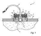
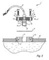
1つの実施形態に従っている、船舶のための構造1が、図1及び2を参照して説明する。 A structure 1 for a ship according to one embodiment will be described with reference to FIGS.
構造1は、座部10及び座部10に対し設置されるよう適用された船殻装着電子装置2を備えている。座部10は、座部10を通って延出している貫通孔11を備えている。座部10は次に、座部10の貫通孔11が船殻20の貫通孔12と整列するよう船舶の船殻20に対し固定されている。この例においては、座部10は船殻20の貫通孔12中に設置されている。あるいは、座部は座部の貫通孔が船殻の貫通孔に重複する(示されていない)ように船殻の内側上に設置されてよい。座部10は、船殻20と座部10との間の水漏れを阻止するために、例えば溶接により、船殻20に固定される。
The structure 1 comprises a
船殻装着電子装置2は、ハウジング14により封入されているトランスデューサー16を備える。ケーブル8が船殻装着電子装置2を制御システム又は同様なものへと連結することができる。トランスデューサー16は、例えば、EM信号又は超音波信号を夫々伝達するよう適用されているEM(電磁:electromagnetic)トランスデューサー又は超音波トランスデューサーであってよい。ハウジング14は、下方部分3及びフランジ部分4を備えることができる。下方部分3は、座部10の貫通孔11中に適合するよう形作られていてよい。任意に、下方部分3は実質的に円筒状であってもよい。フランジ部分4は、座部10の上方表面上に着座するよう形作られていてよく、それにより下方部分3を座部10の貫通孔11中に支持している。フランジ部分4は、例えば、下方部分3よりも大きな直径(又は幅)を有してよく、そして任意にはまた円筒状であってよい。フランジ部分4は、例えばボルト6により座部10に対し固定することができる。ボルト6は、フランジ部分4を通り、そして座部10中へと延出することができる。ボルト6と船殻装着電子装置2との間の密封を提供するためにガスケット7が配置されてもよい。
The hull mounting electronic device 2 includes a
下方部分3及び下方部分3に対し最も接近して配置されているフランジ部分4の少なくとも部分は、水密であると共にトランスデューサー16により生じさせられた信号を伝達可能である材料17の表面5により覆われてよい。この例においては、座部10に対面しているフランジ部分4の表面15の部分は、水密であると共にトランスデューサー16により生じさせられた信号を伝達可能である材料17の表面5により覆われている。材料17は、例えばエポキシ又はポリウレタンのようなプラスチックを含む。表面5の一部分は、トランスデューサー16により生じさせられた信号のための窓13を形成することができる。例えば、窓13は、船殻20の外側の水に対面している下方部分3の側のような下方部分3の端部分(底端)に配置されてよい。水密であると共にトランスデューサー信号伝達可能材料17の表面5は、例えばボルト6のための凹所18に至るまで実質的に延びている。
The lower part 3 and at least the part of the flange part 4 which is arranged closest to the lower part 3 are covered with a surface 5 of a material 17 which is watertight and capable of transmitting the signal produced by the
この例においては、トランスデューサー16は、水密であると共にトランスデューサー信号伝達可能材料17(中にモールドされるように)により封入されている。ハウジング14の下方部分3は、例えば水密であると共にトランスデューサー信号伝達可能材料17により実質的に全体的に形成されてよい。あるいは、水密であると共にトランスデューサー信号伝達可能材料の別の層が、(金属のようなもう1つの材料により形成されてよい)下方部分及び下方部分に対し最も接近して配置されているフランジ部分の少なくとも部分(示されていない)を覆ってもよい。
In this example, the
構造1はさらに、ハウジング14と座部10との間に密封を提供するために、フランジ部分14と座部10との間に配置されたガスケット9を備えている。ガスケット9は、例えば平坦であって弾性材料で形成されている。船殻装着電子装置2の取り付け時にガスケット9を通した下方部分3の挿入を容易にするよう、ガスケット9の内直径は、下方部分3の直径よりも1又は数センチメートル大きいように、下方部分3の直径よりも大きくてもよい。水密表面5がフランジ部分4上に至るまで到達し、そして、フランジ部分4の下側の少なくとも部位を覆うので、ガスケット9の直径の許容差は、フランジ部分4と座部10との間のガスケット9の正確な位置もまた同様に、より厳しくなくなる。
The structure 1 further includes a gasket 9 disposed between the
船殻装着電子装置2が座部10に取り付けられて、そして使用された時、下方部分3及びガスケット9により範囲が定められているフランジ部分4の前記部分は水に対し露出され、そして従ってハウジング14の濡れた部分として表される。ハウジング14の残りの部分は水から密封され、そして従ってハウジング14の乾いた部分として表される。表面5がハウジング14の少なくとも濡れた部分を覆い、そしてまた任意にハウジング14の乾いた部分の少なくとも一部を覆うので、いかなる接合又は継ぎ目を伴わない水密バリアーがハウジング14の少なくとも濡れた部分全体を覆う。
When the hull-mounted electronic device 2 is attached to the
座部10の貫通孔11は任意に、船殻の外側の水に向かう方向において先細にされていてよい。この例においては、貫通孔11の上方(及び主要)部分が連続して先細に(すなわち、僅かに円錐状に)されており、そして貫通孔11の下方部分は階段状に先細にされている。すなわち、貫通孔の直径は貫通孔11の下方部分で断崖状に減少されている。
The through
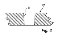
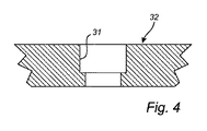
図3中に図示されているように、座部22の貫通孔21が代わりに、船殻の外側の水に向かう方向において完全に連続して先細にされていてよい。さらなる代替例に従えば、座部32の貫通孔31は、図4中に図示されているように、船殻の外側の水に向かう方向において単に階段状に先細にされている。座部の貫通孔の形とは無関係に、下方部分の形は座部の貫通孔の形と合致するよう適用されているか、あるいは、真っ直ぐ、先細でない、のように僅かに異なった形を有するか、のいずれであってもよい。
As shown in FIG. 3, the through
当該技術分野の当業者は、この発明が上に記載された複数の実施形態に決して限定されないことを十分に理解する。それどころか、多くの変形例及び変更が、添付の特許請求の範囲の範囲内で可能である。 Those skilled in the art will appreciate that the present invention by no means is limited to the embodiments described above. On the contrary, many variations and modifications are possible within the scope of the appended claims.
さらには、記載されている複数の実施形態に対する変更は、図面,説明,そして添付の特許請求の範囲の検討から、特許請求された発明の具体化において当業者により理解され、そして実行されることができる。特許請求の範囲においては、用語「備える(comprising)」は他の構成要素又は他の工程を除外せず、そして不定冠詞「a」又は「an」は複数を除外しない。ある手段が相互に異なっている独立請求項において引用されているという単なる事実は、これらの手段の組み合わせが有利に使用できないということを示すものではない。 Moreover, changes to the described embodiments will be understood and implemented by those skilled in the art in the implementation of the claimed invention from a study of the drawings, the description, and the appended claims. Can do. In the claims, the term “comprising” does not exclude other elements or steps, and the indefinite article “a” or “an” does not exclude a plurality. The mere fact that certain measures are recited in mutually different independent claims does not indicate that a combination of these measured cannot be used to advantage.
Claims (11)
船殻の外側の水の中へと伝達される信号を発生させるために適用されているトランスデューサー(16)と、そして、
トランスデューサーを封入し、そして座部の貫通孔中に挿入されるよう適用されている下方部分(3)及び座部の貫通孔中に下方部分を支持するよう座部に対し取り付けられるよう適用されているフランジ部分(4)を有しているハウジング(14)と、
を備えていて、
ここにおいては、下方部分及び下方部分に対し最も接近して配置されているフランジ部分の少なくとも部分が、水密であるとともにトランスデューサーにより発生された信号を透過させる材料(17)の表面(5)を有しており、そして、
ここにおいては、前記表面の一部分が、船殻の外側の水に対しトランスデューサーにより発生された信号を伝達するよう配置されているハウジングの窓(13)を形成している、
船殻装着電子装置。 A ship hull mounting electronic device (2) adapted to be attached to a seat (10) having a through hole (11), wherein the seat has a through hole in the seat. Attachable to the ship's hull (20) to align with the shell's through-hole (12);
A transducer (16) applied to generate a signal that is transmitted into the water outside the hull; and
Applied to the lower part (3) adapted to enclose the transducer and to be inserted into the through hole of the seat and to be attached to the seat to support the lower part in the through hole of the seat A housing (14) having a flange portion (4) having
With
Here, the lower part and at least part of the flange part, which is arranged closest to the lower part, is the surface (5) of the material (17) which is watertight and transmits the signal generated by the transducer. Have and
Here, a portion of the surface forms a housing window (13) arranged to transmit the signal generated by the transducer to the water outside the hull.
Hull mounted electronic device.
貫通孔(11)を備えているとともに船舶の船殻(20)に対し取り付けられるよう適用されている座部(10)を備え、前記取り付けにより座部の貫通孔が前記船殻の貫通孔(12)と整列し、
そして、
請求項1乃至6の何れか1項に記載の船殻装着電子装置(2)を備えている、
構造。 A structure (1) for a ship, wherein the structure is
A through-hole (11) and a seat portion (10) adapted to be attached to the ship hull (20) are provided, and the attachment allows the through-hole in the seat portion to pass through the through-hole in the hull ( 12)
And
A hull mounting electronic device (2) according to any one of claims 1 to 6, comprising:
Construction.
Applications Claiming Priority (3)
| Application Number | Priority Date | Filing Date | Title |
|---|---|---|---|
| EP15169770.3A EP3098622B1 (en) | 2015-05-29 | 2015-05-29 | Hull-fitted electronic device for a vessel |
| EP15169770.3 | 2015-05-29 | ||
| PCT/EP2016/061927 WO2016193120A1 (en) | 2015-05-29 | 2016-05-26 | Hull-fitted electronic device for a vessel |
Publications (2)
| Publication Number | Publication Date |
|---|---|
| JP2018517618A true JP2018517618A (en) | 2018-07-05 |
| JP6968782B2 JP6968782B2 (en) | 2021-11-17 |
Family
ID=53284058
Family Applications (1)
| Application Number | Title | Priority Date | Filing Date |
|---|---|---|---|
| JP2018513905A Active JP6968782B2 (en) | 2015-05-29 | 2016-05-26 | Hull-mounted electronics for ships |
Country Status (9)
| Country | Link |
|---|---|
| US (1) | US10991354B2 (en) |
| EP (1) | EP3098622B1 (en) |
| JP (1) | JP6968782B2 (en) |
| KR (1) | KR102603714B1 (en) |
| CN (1) | CN107660302B (en) |
| DK (1) | DK3098622T3 (en) |
| ES (1) | ES2778225T3 (en) |
| TW (1) | TWI693181B (en) |
| WO (1) | WO2016193120A1 (en) |
Families Citing this family (6)
| Publication number | Priority date | Publication date | Assignee | Title |
|---|---|---|---|---|
| CN109204736A (en) * | 2018-11-12 | 2019-01-15 | 江龙船艇科技股份有限公司 | Simple depth finder |
| CN109541253B (en) * | 2018-11-29 | 2021-08-20 | 中国船舶重工集团公司第七0七研究所九江分部 | A Two-Dimensional Electromagnetic and Acoustic Integrated Velocity Sensor for Vessel Velocity Measurement |
| CN111055964A (en) * | 2019-12-09 | 2020-04-24 | 中船西江造船有限公司 | Marine depth finder installation device |
| CN111473195A (en) * | 2020-04-02 | 2020-07-31 | 澳龙船艇科技有限公司 | Detachable detection instrument mount pad |
| CN115140238A (en) * | 2022-07-07 | 2022-10-04 | 大连船舶重工集团有限公司 | Ship bottom outward-exploring type streamline defoaming attachment and design method thereof |
| CN116381695B (en) * | 2023-05-30 | 2024-07-23 | 海底鹰深海科技股份有限公司 | Split sonar and sonar assembly and manufacturing method thereof |
Citations (13)
| Publication number | Priority date | Publication date | Assignee | Title |
|---|---|---|---|---|
| US1401024A (en) * | 1917-11-12 | 1921-12-20 | Submarine Signal Co | Diaphragm-mounting |
| US1582105A (en) * | 1921-05-11 | 1926-04-27 | Walker Signal And Equipment Co | Submarine signaling apparatus |
| US1906446A (en) * | 1929-10-31 | 1933-05-02 | Submarine Signal Co | Sound receiving apparatus |
| US2560066A (en) * | 1948-11-27 | 1951-07-10 | Raytheon Mfg Co | Hydrophone mounting |
| JPS50117865U (en) * | 1974-03-07 | 1975-09-26 | ||
| JPS5679543A (en) * | 1979-08-14 | 1981-06-30 | Blanchut & Bertrand Sa | Electroacoustic device for generating and identifying underwater signal in ship |
| JPS5851276U (en) * | 1981-10-02 | 1983-04-07 | 石川島播磨重工業株式会社 | Transducer mounting device for underwater ultrasound equipment |
| US5177891A (en) * | 1990-07-17 | 1993-01-12 | Holt Steven P | Game fish attracting device |
| JPH1143094A (en) * | 1997-07-25 | 1999-02-16 | Tech Res & Dev Inst Of Japan Def Agency | Sensor-exchange type measurement device for ships |
| US20080083360A1 (en) * | 2006-10-10 | 2008-04-10 | Steven Robert Rowley | Window housing for use with thru-hull fittings |
| JP2009214610A (en) * | 2008-03-07 | 2009-09-24 | Denso Corp | Mounting structure of ultrasonic sensor |
| KR20130081568A (en) * | 2012-01-09 | 2013-07-17 | 삼성중공업 주식회사 | A ship |
| CN203544341U (en) * | 2013-11-13 | 2014-04-16 | 中船重工(昆明)灵湖科技发展有限公司 | Underwater acoustic transducer convenient to locate and mount |
Family Cites Families (39)
| Publication number | Priority date | Publication date | Assignee | Title |
|---|---|---|---|---|
| US3123176A (en) * | 1964-03-03 | greenberg | ||
| BE562102A (en) | 1956-11-05 | |||
| US3495211A (en) * | 1968-04-09 | 1970-02-10 | Us Navy | Stainless steel diaphragm sonar transducer apparatus |
| US3734179A (en) * | 1969-07-24 | 1973-05-22 | W Smedley | Well packer & pump apparatus |
| US3647230A (en) * | 1969-07-24 | 1972-03-07 | William L Smedley | Well pipe seal |
| US3748637A (en) * | 1971-10-22 | 1973-07-24 | C W S Ind Inc | Sonar transducer assembly |
| JPS5318893B2 (en) | 1971-12-03 | 1978-06-17 | ||
| US3780220A (en) * | 1972-08-14 | 1973-12-18 | Us Navy | Remote control underwater observation vehicle |
| JPS5832559B2 (en) | 1979-07-04 | 1983-07-13 | 株式会社 モリタ製作所 | Transmission method of aerial ultrasonic pulses and ultrasonic transceiver equipment used therefor |
| DE3012038C2 (en) | 1980-03-28 | 1982-08-19 | Honeywell-Elac-Nautik Gmbh, 2300 Kiel | Electroacoustic water-borne sound converter |
| US4388709A (en) * | 1981-01-19 | 1983-06-14 | The Bendix Corporation | Funnel construction for a dipping sonar |
| DE8805953U1 (en) * | 1988-05-05 | 1988-07-07 | Höntzsch GmbH, 71334 Waiblingen | Electroacoustic transducer |
| US5088068A (en) * | 1990-12-04 | 1992-02-11 | Littoral, Inc. | Hand-held underwater distance measurement device |
| US5186428A (en) * | 1990-12-19 | 1993-02-16 | Canyon Enterprises, Inc. | Depth gauge transducer retractor device |
| US5297109A (en) * | 1992-07-27 | 1994-03-22 | American Oilfield Divers, Inc. | Piling and pier inspection apparatus and method |
| US5838635A (en) * | 1994-11-14 | 1998-11-17 | Masreliez; Karl | Thin speed transducer sensor |
| US5661466A (en) * | 1995-02-07 | 1997-08-26 | Robertshaw Controls Company | Angular displacement signalling device |
| US5697319A (en) * | 1996-06-12 | 1997-12-16 | Lowrance Electronics, Inc. | Boat hull having the capability of installing an optional transducer |
| US6247364B1 (en) * | 1997-10-27 | 2001-06-19 | Thomas P. Kicher & Co. | Acceleration transducer and method |
| US6269763B1 (en) * | 1998-02-20 | 2001-08-07 | Richard Lawrence Ken Woodland | Autonomous marine vehicle |
| US6053683A (en) * | 1999-02-04 | 2000-04-25 | Cabiran; Michel Lewis | Threaded seal cap for a connector |
| KR100329284B1 (en) * | 1999-08-05 | 2002-03-18 | 황해웅 | Wing type ultrasonic transducer |
| US6276503B1 (en) * | 1999-12-08 | 2001-08-21 | Donald J. Laughlin, Jr. | Portable reel apparatus and method |
| US20040129078A1 (en) * | 2001-06-18 | 2004-07-08 | Kicher Thomas P. | Acceleration transducer and method |
| US6791902B1 (en) * | 2002-05-30 | 2004-09-14 | Techsonic Industries, Inc. | Portable fish finder |
| US7044623B2 (en) * | 2003-11-21 | 2006-05-16 | Deepsea Power & Light | Thru-hull light |
| US20060108022A1 (en) * | 2004-11-22 | 2006-05-25 | Justrite Manufacturing Company Llc | Funnel with pivotable mounting bracket |
| WO2007089246A2 (en) * | 2005-02-09 | 2007-08-09 | Giraffe Liquid Management Systems, Inc. | Adjustable height inlet/outlet liquid level management tools and systems |
| JP2006345312A (en) * | 2005-06-09 | 2006-12-21 | Denso Corp | Ultrasonic sensor and ultrasonic transducer |
| CN101072452A (en) * | 2005-12-27 | 2007-11-14 | 中国科学院声学研究所 | Deep-sea piezoelectric underwater-acoustic transducer and its manufacturing method |
| WO2008134762A1 (en) * | 2007-04-30 | 2008-11-06 | Electro-Yak Llc | Improved electrically powered watercraft |
| US8677920B1 (en) * | 2007-08-30 | 2014-03-25 | Ocom Technology LLC | Underwater vehicle |
| US8456957B2 (en) * | 2008-01-29 | 2013-06-04 | Schneider Electric USA, Inc. | Ultrasonic transducer for a proximity sensor |
| WO2012145479A1 (en) * | 2011-04-21 | 2012-10-26 | Rensselaer Polytechnic Institute | Ultrasonic high temperature and pressure housing for piezoelectric-acoustic channels |
| US9142206B2 (en) * | 2011-07-14 | 2015-09-22 | Navico Holding As | System for interchangeable mounting options for a sonar transducer |
| US8712233B2 (en) * | 2012-02-24 | 2014-04-29 | Apple Inc. | Electronic device assemblies |
| US9851024B2 (en) * | 2016-05-25 | 2017-12-26 | Loren Piotrowski | Pass through fitting for cables and the like |
| US9914519B2 (en) * | 2016-06-30 | 2018-03-13 | Confluence Outdoor, Llc | Propulsion system for a watercraft |
| US10325582B2 (en) * | 2016-07-28 | 2019-06-18 | Navico Holding As | Transducer mounting assembly |
-
2015
- 2015-05-29 EP EP15169770.3A patent/EP3098622B1/en active Active
- 2015-05-29 ES ES15169770T patent/ES2778225T3/en active Active
- 2015-05-29 DK DK15169770.3T patent/DK3098622T3/en active
-
2016
- 2016-05-26 WO PCT/EP2016/061927 patent/WO2016193120A1/en not_active Ceased
- 2016-05-26 US US15/576,546 patent/US10991354B2/en active Active
- 2016-05-26 KR KR1020177036845A patent/KR102603714B1/en active Active
- 2016-05-26 JP JP2018513905A patent/JP6968782B2/en active Active
- 2016-05-26 CN CN201680029609.9A patent/CN107660302B/en active Active
- 2016-05-27 TW TW105116721A patent/TWI693181B/en active
Patent Citations (13)
| Publication number | Priority date | Publication date | Assignee | Title |
|---|---|---|---|---|
| US1401024A (en) * | 1917-11-12 | 1921-12-20 | Submarine Signal Co | Diaphragm-mounting |
| US1582105A (en) * | 1921-05-11 | 1926-04-27 | Walker Signal And Equipment Co | Submarine signaling apparatus |
| US1906446A (en) * | 1929-10-31 | 1933-05-02 | Submarine Signal Co | Sound receiving apparatus |
| US2560066A (en) * | 1948-11-27 | 1951-07-10 | Raytheon Mfg Co | Hydrophone mounting |
| JPS50117865U (en) * | 1974-03-07 | 1975-09-26 | ||
| JPS5679543A (en) * | 1979-08-14 | 1981-06-30 | Blanchut & Bertrand Sa | Electroacoustic device for generating and identifying underwater signal in ship |
| JPS5851276U (en) * | 1981-10-02 | 1983-04-07 | 石川島播磨重工業株式会社 | Transducer mounting device for underwater ultrasound equipment |
| US5177891A (en) * | 1990-07-17 | 1993-01-12 | Holt Steven P | Game fish attracting device |
| JPH1143094A (en) * | 1997-07-25 | 1999-02-16 | Tech Res & Dev Inst Of Japan Def Agency | Sensor-exchange type measurement device for ships |
| US20080083360A1 (en) * | 2006-10-10 | 2008-04-10 | Steven Robert Rowley | Window housing for use with thru-hull fittings |
| JP2009214610A (en) * | 2008-03-07 | 2009-09-24 | Denso Corp | Mounting structure of ultrasonic sensor |
| KR20130081568A (en) * | 2012-01-09 | 2013-07-17 | 삼성중공업 주식회사 | A ship |
| CN203544341U (en) * | 2013-11-13 | 2014-04-16 | 中船重工(昆明)灵湖科技发展有限公司 | Underwater acoustic transducer convenient to locate and mount |
Also Published As
| Publication number | Publication date |
|---|---|
| KR102603714B1 (en) | 2023-11-17 |
| EP3098622B1 (en) | 2020-01-01 |
| CN107660302B (en) | 2021-09-14 |
| JP6968782B2 (en) | 2021-11-17 |
| WO2016193120A1 (en) | 2016-12-08 |
| KR20180030788A (en) | 2018-03-26 |
| US20180151165A1 (en) | 2018-05-31 |
| DK3098622T3 (en) | 2020-03-09 |
| US10991354B2 (en) | 2021-04-27 |
| EP3098622A1 (en) | 2016-11-30 |
| CN107660302A (en) | 2018-02-02 |
| TW201706177A (en) | 2017-02-16 |
| TWI693181B (en) | 2020-05-11 |
| ES2778225T3 (en) | 2020-08-10 |
Similar Documents
| Publication | Publication Date | Title |
|---|---|---|
| JP2018517618A (en) | Ship hull mounted electronic device | |
| US11367425B2 (en) | Sonar transducer with multiple mounting options | |
| US9086473B2 (en) | Arrangement on a component of a motor vehicle | |
| JP7576611B2 (en) | Sonar transducer module with integrated protection | |
| MX2022007507A (en) | Water heater with an integrated leak detection system. | |
| CN103733250B (en) | Ultrasonic sensor device for vehicles and devices with such an ultrasonic sensor device | |
| KR101128010B1 (en) | Sonar of hull sticking type and ship having the same | |
| JP5691431B2 (en) | Transducer protection device | |
| KR20160139778A (en) | The ECHO SOUNDER which transfers and receives ultra sonic wave signal by RS422 protocol between main unit and transducer | |
| US1632331A (en) | Submarine sound receiver | |
| KR20230080595A (en) | Sence device for detecting water leakage | |
| CN224137447U (en) | A waterproof and dustproof underwater operation sensor | |
| WO2016209119A1 (en) | Hydroacoustic device | |
| JPS6044836A (en) | Method and apparatus for detecting underwater noise of ship | |
| CN107924673B (en) | Acoustic sensor with housing and diaphragm element arranged on the housing | |
| JPS5846711B2 (en) | Dopra sonar | |
| KR960016396B1 (en) | Sonar device | |
| JPH11331986A (en) | Underwater sensor device | |
| CN110678779A (en) | electronic building block | |
| KR20260017265A (en) | Echo sounder with reduced load on cable | |
| JPH05340932A (en) | Water immersion type ultrasonic probe waterproof structure | |
| KR20260029820A (en) | Hull-mount type underwater acoustic measurement device | |
| US2360923A (en) | Submarine signaling | |
| JPH07119800B2 (en) | Underwater measuring instrument | |
| JP2009300282A (en) | Ultrasonic wave transmitting and receiving apparatus |
Legal Events
| Date | Code | Title | Description |
|---|---|---|---|
| A621 | Written request for application examination |
Free format text: JAPANESE INTERMEDIATE CODE: A621 Effective date: 20190320 |
|
| A977 | Report on retrieval |
Free format text: JAPANESE INTERMEDIATE CODE: A971007 Effective date: 20200323 |
|
| A131 | Notification of reasons for refusal |
Free format text: JAPANESE INTERMEDIATE CODE: A131 Effective date: 20200414 |
|
| A711 | Notification of change in applicant |
Free format text: JAPANESE INTERMEDIATE CODE: A711 Effective date: 20200520 |
|
| A521 | Request for written amendment filed |
Free format text: JAPANESE INTERMEDIATE CODE: A821 Effective date: 20200521 |
|
| A521 | Request for written amendment filed |
Free format text: JAPANESE INTERMEDIATE CODE: A523 Effective date: 20200623 |
|
| A02 | Decision of refusal |
Free format text: JAPANESE INTERMEDIATE CODE: A02 Effective date: 20200923 |
|
| A521 | Request for written amendment filed |
Free format text: JAPANESE INTERMEDIATE CODE: A523 Effective date: 20201118 |
|
| C60 | Trial request (containing other claim documents, opposition documents) |
Free format text: JAPANESE INTERMEDIATE CODE: C60 Effective date: 20201118 |
|
| A911 | Transfer to examiner for re-examination before appeal (zenchi) |
Free format text: JAPANESE INTERMEDIATE CODE: A911 Effective date: 20201126 |
|
| C21 | Notice of transfer of a case for reconsideration by examiners before appeal proceedings |
Free format text: JAPANESE INTERMEDIATE CODE: C21 Effective date: 20201201 |
|
| A912 | Re-examination (zenchi) completed and case transferred to appeal board |
Free format text: JAPANESE INTERMEDIATE CODE: A912 Effective date: 20210108 |
|
| C211 | Notice of termination of reconsideration by examiners before appeal proceedings |
Free format text: JAPANESE INTERMEDIATE CODE: C211 Effective date: 20210119 |
|
| C22 | Notice of designation (change) of administrative judge |
Free format text: JAPANESE INTERMEDIATE CODE: C22 Effective date: 20210209 |
|
| C22 | Notice of designation (change) of administrative judge |
Free format text: JAPANESE INTERMEDIATE CODE: C22 Effective date: 20210413 |
|
| C13 | Notice of reasons for refusal |
Free format text: JAPANESE INTERMEDIATE CODE: C13 Effective date: 20210420 |
|
| A521 | Request for written amendment filed |
Free format text: JAPANESE INTERMEDIATE CODE: A523 Effective date: 20210608 |
|
| C23 | Notice of termination of proceedings |
Free format text: JAPANESE INTERMEDIATE CODE: C23 Effective date: 20210824 |
|
| C03 | Trial/appeal decision taken |
Free format text: JAPANESE INTERMEDIATE CODE: C03 Effective date: 20210928 |
|
| C30A | Notification sent |
Free format text: JAPANESE INTERMEDIATE CODE: C3012 Effective date: 20210928 |
|
| A61 | First payment of annual fees (during grant procedure) |
Free format text: JAPANESE INTERMEDIATE CODE: A61 Effective date: 20211027 |
|
| R150 | Certificate of patent or registration of utility model |
Ref document number: 6968782 Country of ref document: JP Free format text: JAPANESE INTERMEDIATE CODE: R150 |
|
| R250 | Receipt of annual fees |
Free format text: JAPANESE INTERMEDIATE CODE: R250 |
|
| R250 | Receipt of annual fees |
Free format text: JAPANESE INTERMEDIATE CODE: R250 |