JP2018513402A - Apparatus and method for encoding or decoding multi-channel signals - Google Patents
Apparatus and method for encoding or decoding multi-channel signals Download PDFInfo
- Publication number
- JP2018513402A JP2018513402A JP2017548015A JP2017548015A JP2018513402A JP 2018513402 A JP2018513402 A JP 2018513402A JP 2017548015 A JP2017548015 A JP 2017548015A JP 2017548015 A JP2017548015 A JP 2017548015A JP 2018513402 A JP2018513402 A JP 2018513402A
- Authority
- JP
- Japan
- Prior art keywords
- channel
- processing
- channels
- mch
- parameter
- Prior art date
- Legal status (The legal status is an assumption and is not a legal conclusion. Google has not performed a legal analysis and makes no representation as to the accuracy of the status listed.)
- Granted
Links
Images

Classifications
-
- G—PHYSICS
- G10—MUSICAL INSTRUMENTS; ACOUSTICS
- G10L—SPEECH ANALYSIS TECHNIQUES OR SPEECH SYNTHESIS; SPEECH RECOGNITION; SPEECH OR VOICE PROCESSING TECHNIQUES; SPEECH OR AUDIO CODING OR DECODING
- G10L19/00—Speech or audio signals analysis-synthesis techniques for redundancy reduction, e.g. in vocoders; Coding or decoding of speech or audio signals, using source filter models or psychoacoustic analysis
- G10L19/008—Multichannel audio signal coding or decoding using interchannel correlation to reduce redundancy, e.g. joint-stereo, intensity-coding or matrixing
-
- G—PHYSICS
- G10—MUSICAL INSTRUMENTS; ACOUSTICS
- G10L—SPEECH ANALYSIS TECHNIQUES OR SPEECH SYNTHESIS; SPEECH RECOGNITION; SPEECH OR VOICE PROCESSING TECHNIQUES; SPEECH OR AUDIO CODING OR DECODING
- G10L19/00—Speech or audio signals analysis-synthesis techniques for redundancy reduction, e.g. in vocoders; Coding or decoding of speech or audio signals, using source filter models or psychoacoustic analysis
- G10L19/02—Speech or audio signals analysis-synthesis techniques for redundancy reduction, e.g. in vocoders; Coding or decoding of speech or audio signals, using source filter models or psychoacoustic analysis using spectral analysis, e.g. transform vocoders or subband vocoders
-
- H—ELECTRICITY
- H04—ELECTRIC COMMUNICATION TECHNIQUE
- H04S—STEREOPHONIC SYSTEMS
- H04S3/00—Systems employing more than two channels, e.g. quadraphonic
- H04S3/008—Systems employing more than two channels, e.g. quadraphonic in which the audio signals are in digital form, i.e. employing more than two discrete digital channels
-
- H—ELECTRICITY
- H04—ELECTRIC COMMUNICATION TECHNIQUE
- H04S—STEREOPHONIC SYSTEMS
- H04S2400/00—Details of stereophonic systems covered by H04S but not provided for in its groups
- H04S2400/01—Multi-channel, i.e. more than two input channels, sound reproduction with two speakers wherein the multi-channel information is substantially preserved
Landscapes
- Engineering & Computer Science (AREA)
- Physics & Mathematics (AREA)
- Acoustics & Sound (AREA)
- Multimedia (AREA)
- Signal Processing (AREA)
- Computational Linguistics (AREA)
- Audiology, Speech & Language Pathology (AREA)
- Human Computer Interaction (AREA)
- Health & Medical Sciences (AREA)
- Mathematical Physics (AREA)
- Spectroscopy & Molecular Physics (AREA)
- Compression, Expansion, Code Conversion, And Decoders (AREA)
- Stereophonic System (AREA)
- Error Detection And Correction (AREA)
- Compression Or Coding Systems Of Tv Signals (AREA)
Abstract
実施の形態は、少なくとも3つのチャンネルを有するマルチチャンネル信号を符号化するための装置であって、第1反復ステップにおいて、前記少なくとも3つのチャンネルのそれぞれの組の間のチャンネル間相関値を計算し、前記第1反復ステップにおいて、最高値を有する、又は閾値より上の値を有する一組を選択し、マルチチャンネル処理操作を使用して前記選択された組を処理して、前記選択された組についての第1マルチチャンネルパラメータを導出する、及び第1の処理されたチャンネルを導出するための反復プロセッサーであって、前記反復プロセッサーは、第2反復ステップにおいて、少なくとも1つの前記処理されたチャンネルを使用して、前記計算、前記選択、前記処理を実行して、第2マルチチャンネルパラメータ及び第2の処理されたチャンネルを導出するように構成される反復プロセッサーと、前記反復プロセッサーが実行する反復処理から生じたチャンネルを符号化して符号化されたチャンネルを得るためのチャンネルエンコーダーと、前記符号化されたチャンネルと、前記第1及び前記第2マルチチャンネルパラメータと、を有する符号化されたマルチチャンネル信号を生成するための出力インターフェースと、を備える。【選択図】図1An embodiment is an apparatus for encoding a multi-channel signal having at least three channels, wherein in a first iteration step, an inter-channel correlation value between each set of the at least three channels is calculated. Selecting a set having the highest value or having a value above a threshold in the first iteration step, and processing the selected set using a multi-channel processing operation to select the selected set An iterative processor for deriving a first multi-channel parameter for and deriving a first processed channel, wherein the iterative processor determines at least one said processed channel in a second iteration step. Use the calculation, the selection, the processing to perform a second multi-channel parameter and An iterative processor configured to derive a second processed channel, a channel encoder for encoding a channel resulting from the iterative processing performed by the iterative processor to obtain an encoded channel, and the code And an output interface for generating an encoded multi-channel signal having the encoded channel and the first and second multi-channel parameters. [Selection] Figure 1
Description
本発明は、オーディオコーディング/復号化に関し、特にチャンネル間信号の依存性を利用するオーディオコーディングに関する。 The present invention relates to audio coding / decoding, and more particularly to audio coding that utilizes inter-channel signal dependency.
オーディオコーディングは、オーディオ信号において、余剰のもの及び不要なものの利用を解決する圧縮領域である。MPEG USAC[ISO/IEC 23003:2012 情報技術 MPEGオーディオ技術 パート3:統合した音声符号化とオーディオコーディング]において、2つのチャンネルのジョイントステレオ符号化は、MPS 2−1−2、又は帯域制限若しくは全帯域残差信号を伴う統合ステレオのような複雑な予測を使用して行われる。MPEG環境[ISO/IEC 23003−1:2007 情報技術 MPEGオーディオ技術 パート1:MPEG環境]は、残差信号の送信を有する/有しないマルチチャンネルオーディオのジョイントコーディングのために、OTTとTTTボックスとを段階的に結合する。MPEG−Hクワッドチャンネル要素は、固定された4×4リミックスツリーを構築する複雑な予測/MSステレオボックスによって、後に続くMPS 2−1−2ステレオボックスを段階的に適用する。AC4[ETSI TS 103 190 V1.1.1(2014−04)デジタルオーディオ圧縮(AC−4)標準]は、送信された混合行列や後のジョイントステレオ符号化情報を介して送信されたチャンネルをリミックスすることを許容する新しい3、4、5のチャンネル要素を取り入れる。さらに、以前の発表は、強化されたマルチチャンネルオーディオコーディングのために、カルーネン・レーベ変換(KLT)のような直交変換を使用することを提案する。[Yang, Dai and Ai, Hongmei and Kyriakakis, Chris and Kuo, C.-C. Jay, 2001: Adaptive Karhunen-Loeve Transform for Enhanced Multichannel Audio Coding, http://ict.usc.edu/pubs/Adaptive%20Karhunen-Loeve%20Transform%20for%20Enhanced %20Multichannel%20Audio%20Coding.pdf] Audio coding is a compression region that solves the use of redundant and unnecessary audio signals. In MPEG USAC [ISO / IEC 23003: 2012 Information Technology MPEG Audio Technology Part 3: Integrated Speech Coding and Audio Coding], joint stereo coding of two channels can be MPS 2-1-2, or band limited or full This is done using complex predictions such as integrated stereo with band residual signals. MPEG environment [ISO / IEC 2303-1: 2007 Information technology MPEG audio technology Part 1: MPEG environment] uses OTT and TTT box for joint coding of multi-channel audio with / without transmission of residual signals. Join in stages. The MPEG-H quad channel element applies the following MPS 2-1-2 stereo box step by step with a complex prediction / MS stereo box that builds a fixed 4x4 remix tree. AC4 [ETSI TS 103 190 V1.1.1 (2014-04) Digital Audio Compression (AC-4) Standard] remixes the transmitted channel through the transmitted mixing matrix and later joint stereo coding information Incorporates new 3, 4, 5 channel elements that are allowed to Furthermore, previous presentations propose to use orthogonal transforms such as the Karhunen-Leve transform (KLT) for enhanced multi-channel audio coding. [Yang, Dai and Ai, Hongmei and Kyriakakis, Chris and Kuo, C.-C. Jay, 2001: Adaptive Karhunen-Loeve Transform for Enhanced Multichannel Audio Coding, http://ict.usc.edu/pubs/Adaptive%20Karhunen -Loeve% 20Transform% 20for% 20Enhanced% 20Multichannel% 20Audio% 20Coding.pdf]
3Dオーディオの環境で、ラウドスピーカーチャンネルは、水平及び垂直のチャンネル対の結果となるいくつかの高い層によって分配される。USACにおいて定義づけられるように、2つのチャンネルだけのジョイントコーディングは、チャンネル間の空間的及び知覚的な関係を考慮するのに十分ではない。MPEG環境は、追加の前/後処理ステップで適用され、残りの信号は、例えば、右と左の間の垂直の残りの信号との間の依存性を利用するために、ジョイントステレオ符号化の可能性なしに個々に送信される。AC−4において、専用のNチャンネル要素は、ジョイントコーディングパラメータの効果的な符号化を許容するが、新しい没入型再生シナリオ(7.1+4、22.2)で提案されているように、より多くのチャンネルを持つ一般的なスピーカーの設定は失敗するように導入されている。MPEG−Hクワッドチャンネル要素は、4チャンネルのみに制限され、任意のチャンネルに動的に適用することはできず、チャンネル数をあらかじめ構成し、固定される。 In a 3D audio environment, loudspeaker channels are distributed by several high layers resulting in horizontal and vertical channel pairs. As defined in the USAC, joint coding of only two channels is not sufficient to take into account the spatial and perceptual relationships between the channels. The MPEG environment is applied with additional pre / post processing steps, and the remaining signal is used for joint stereo coding, for example to take advantage of the dependency between the vertical remaining signal between right and left. Sent individually without possibility. In AC-4, the dedicated N-channel element allows effective coding of joint coding parameters, but more as proposed in the new immersive playback scenario (7.1 + 4, 22.2). Common speaker settings with multiple channels have been introduced to fail. The MPEG-H quad channel element is limited to only four channels and cannot be dynamically applied to any channel, and the number of channels is preconfigured and fixed.
本発明の目的は、改良された符号化/復号化の概念を提供することである。 An object of the present invention is to provide an improved encoding / decoding concept.
この目的は、請求項1による少なくとも3つのチャンネル有するマルチチャンネル信号を符号化するための装置、請求項12による符号化されたチャンネルと、少なくとも第1及び第2マルチチャンネルパラメータとを有する符号化されたマルチチャンネルを復号化するための装置、請求項21による少なくとも3つのチャンネルを有するマルチチャンネル信号を符号化するための方法、請求項22によって符号化されたチャンネルと、少なくとも第1及び第2マルチチャンネルパラメータとを有する符号化されたマルチチャンネル信号を復号化するための方法、又は請求項23によるコンピュータプログラムによって達成される。
This object is achieved by an apparatus for encoding a multi-channel signal having at least three channels according to
実施の形態は、少なくとも3つのチャンネルを有するマルチチャンネル信号を符号化するための装置を備える。その装置は、反復プロセッサーと、チャンネルエンコーダーと、出力インターフェースとを備える。反復プロセッサーは、第1反復ステップにおいて、最高値又は閾値より上の値を有する組を選択するため、及び、マルチチャンネル処理操作を使用して選択された組を処理して、選択された組のための第1マルチチャンネルパラメータ(MCH_PAR1)を導出する、及び第1の処理されたチャンネルを導出するために、第1反復ステップにおいて、少なくとも3つのチャンネルのそれぞれの組の間のチャンネル間相関値を計算するよう構成される。さらに、反復プロセッサーは、第2反復ステップにおいて、処理されたチャンネルの少なくとも1つを使用して、計算、選択、処理を実行して、第2マルチチャンネルパラメータと第2の処理されたチャンネルとを導出するよう構成される。チャンネルエンコーダーは、反復プロセッサーによって実行される反復処理から生じたチャンネルを符号化して符号化されたチャンネルを得るよう構成される。出力インターフェースは、符号化されたチャンネルと、第1及び第2マルチチャンネルパラメータとを有する符号化されたマルチチャンネル信号を生成するよう構成される。 Embodiments include an apparatus for encoding a multi-channel signal having at least three channels. The apparatus includes an iterative processor, a channel encoder, and an output interface. The iterative processor processes the selected set in the first iteration step to select the set having the highest value or a value above the threshold and to process the selected set using a multi-channel processing operation. In order to derive a first multi-channel parameter (MCH_PAR1) for and a first processed channel, in a first iteration step, an inter-channel correlation value between each set of at least three channels is obtained. Configured to calculate. Further, the iterative processor performs calculations, selections and processing using at least one of the processed channels in a second iterative step to obtain a second multi-channel parameter and a second processed channel. Configured to derive. The channel encoder is configured to encode the channel resulting from the iterative process performed by the iterative processor to obtain an encoded channel. The output interface is configured to generate an encoded multi-channel signal having an encoded channel and first and second multi-channel parameters.
別の実施の形態は、符号化されたマルチチャンネル信号を復号化するための装置を備え、符号化されたマルチチャンネル信号は、符号化されたチャンネルと、第1及び第2マルチチャンネルパラメータとを有する。装置は、チャンネルデコーダーとマルチチャンネルプロセッサーとを備える。チャンネルデコーダーは、符号化されたチャンネルを復号化して、復号化されたチャンネルを得るよう構成される。マルチチャンネルプロセッサーは、第2マルチチャンネルパラメータによって識別された復号化されたチャンネルの第2の組を使用して、及び第2マルチチャンネルパラメータを使用してマルチチャンネル処理を実行して、処理されたチャンネルを得るように構成され、第1マルチチャンネルパラメータによって識別されたチャンネルの第1の組を使用して、及び第1マルチチャンネルパラメータを使用して、別のマルチチャンネル処理を実行するよう構成され、チャンネルの第1の組は、少なくとも1つの処理されたチャンネルを備える。 Another embodiment comprises an apparatus for decoding an encoded multi-channel signal, wherein the encoded multi-channel signal includes an encoded channel and first and second multi-channel parameters. Have. The apparatus comprises a channel decoder and a multichannel processor. The channel decoder is configured to decode the encoded channel to obtain a decoded channel. The multi-channel processor is processed using the second set of decoded channels identified by the second multi-channel parameter and performing multi-channel processing using the second multi-channel parameter. Configured to obtain a channel and configured to perform another multi-channel process using the first set of channels identified by the first multi-channel parameter and using the first multi-channel parameter. The first set of channels comprises at least one processed channel.
固定された信号経路(例えば、ステレオコーディングツリー)を使用する一般的なマルチチャンネル符号化概念とは対照的に、本発明の実施の形態は、マルチチャンネル入力信号の少なくとも3つの入力チャンネルの特徴に適合する動的信号経路を使用する。詳細には、反復プロセッサー102は、第1反復ステップにおいて、最高値又は閾値より上の値を有する組を選択するために、少なくとも3つのチャンネルCH1からCH3のそれぞれの組の間のチャンネル間相関値に基づいて、及び、第2反復ステップにおいて、最高値又は閾値より上の値を有する組を選択するために、少なくとも3つのチャンネルのそれぞれの組と、対応する以前に処理されたチャンネルの間のチャンネル間相関値に基づいて、信号経路(例えば、ステレオツリー)を構築するように適合しうる。
In contrast to the general multi-channel coding concept that uses a fixed signal path (eg, stereo coding tree), embodiments of the present invention are characterized by at least three input channels of the multi-channel input signal. Use a suitable dynamic signal path. Specifically, the
別の実施の形態は、少なくとも3つのチャンネルを有するマルチチャンネル信号を符号化するための方法を備える。その方法は、以下を備える。
−第1反復ステップにおいて、少なくとも3つのチャンネルのそれぞれの組の間のチャンネル間相関値を計算するステップと、第1反復ステップにおいて、最高値を有する又は閾値より上の値を有する組を選択するステップと、選択された組のための第1マルチチャンネルパラメータを導出するため、及び、第1の処理されたチャンネルを導出するためにマルチチャンネル処理操作を使用して選択された組を処理するステップ。
−第2マルチチャンネルパラメータと第2の処理されたチャンネルとを得るために、処理されたチャンネルの少なくとも1つを使用して、第2反復ステップにおいて、計算するステップと、選択するステップと、処理するステップとを実行するステップ。
−符号化されたチャンネルを得るために、反復プロセッサーによって実行された反復処理から生じたチャンネルを符号化するステップ。
−符号化されたチャンネルと、第1及び第2マルチチャンネルパラメータとを有する符号化されたマルチチャンネル信号を生成するステップ。
Another embodiment comprises a method for encoding a multi-channel signal having at least three channels. The method comprises:
-Calculating the inter-channel correlation value between each set of at least three channels in a first iteration step; and selecting the set having the highest value or above a threshold value in the first iteration step. Processing a selected set using a multi-channel processing operation to derive a first multi-channel parameter for the selected set and to derive a first processed channel .
Calculating, selecting and processing in a second iteration step using at least one of the processed channels to obtain a second multi-channel parameter and a second processed channel; And performing the step.
Encoding the channel resulting from the iterative process performed by the iterative processor to obtain an encoded channel;
Generating an encoded multi-channel signal having an encoded channel and first and second multi-channel parameters;
別の実施の形態は、符号化されたチャンネルと、第1及び第2マルチチャンネルパラメータとを有する符号化されたマルチチャンネル信号を復号化するための方法を備える。その方法は、以下を備える。
−復号化されたチャンネルを得るために、符号化されたチャンネルを復号化するステップ
−処理されたチャンネルを得るために、第2マルチチャンネルパラメータによって識別された復号化されたチャンネルの第2の組を使用して、及び第2マルチチャンネルパラメータを使用してマルチチャンネル処理を実行するステップと、第1マルチチャンネルパラメータによって識別されたチャンネルの第1の組を使用して、及び第1マルチチャンネルパラメータを使用して、別のマルチチャンネル処理を実行するステップを含み、チャンネルの第1の組は少なくとも1つの処理されたチャンネルを備える。
Another embodiment comprises a method for decoding an encoded multi-channel signal having an encoded channel and first and second multi-channel parameters. The method comprises:
Decoding a coded channel to obtain a decoded channel; a second set of decoded channels identified by a second multi-channel parameter to obtain a processed channel; And using the second multi-channel parameter to perform multi-channel processing, using the first set of channels identified by the first multi-channel parameter, and the first multi-channel parameter To perform another multi-channel process, wherein the first set of channels comprises at least one processed channel.
本発明の実施の形態は、添付している図を参照して、本願明細書に記載される。 Embodiments of the present invention are described herein with reference to the accompanying figures.
等しい若しくは等価である要素、又は等しい若しくは等価である機能を有する要素は、等しい若しくは等価の参照番号によって、後に説明される。 Elements that are equal or equivalent or have a function that is equal or equivalent will be described later by means of an equal or equivalent reference number.
後の説明において、複数の詳細は、本発明の実施の形態の説明を通してより詳細に述べられている。しかしながら、当業者にとって、本発明の実施の形態は、これらの特定の詳細なしで実行しうることは明らかであろう。他の例では、本発明の実施の形態を不明瞭となることを避けるため、周知の構造や機器は、詳細よりもむしろブロック図で示す。加えて、以下に説明する異なる実施の形態の特徴は、特記しない限り、互いに組み合しうる。 In the following description, several details are set forth in more detail throughout the description of embodiments of the invention. However, it will be apparent to one skilled in the art that embodiments of the present invention may be practiced without these specific details. In other instances, well-known structures and devices are shown in block diagram form, rather than in detail, in order to avoid obscuring embodiments of the present invention. In addition, the features of the different embodiments described below can be combined with each other unless otherwise specified.
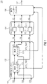
図1は、少なくとも3つのチャンネルCH1からCH3を有するマルチチャンネル信号101を符号化するための装置(エンコーダー)の概略的なブロック図を示す。装置100は、反復プロセッサー102と、チャンネルエンコーダー104と、出力インターフェース106とを備える。
FIG. 1 shows a schematic block diagram of an apparatus (encoder) for encoding a
反復プロセッサー102は、第1反復ステップにおいて、最高値を有する又は閾値より上の値を有する組を選択するため、及びマルチチャンネル処理操作を使用して選択された組を処理して、選択された組のための第1マルチチャンネルパラメータMCH_PAR1を導出するために、及び第1の処理されたチャンネルP1とP2とを導出するために、第1反復ステップにおいて、少なくとも3つのチャンネルCH1からCH3のそれぞれの組の間のチャンネル間相関値を計算するよう構成される。さらに、反復プロセッサー102は、第2反復ステップにおいて、第2マルチチャンネルパラメータMCH_PAR2、及び第2の処理されたチャンネルP3とP4を得るために、少なくとも1つの処理されたチャンネルP1又はP2を使用して計算、選択、処理を実行するよう構成される。
The
例えば、図1に示すように、反復プロセッサー102は、第1反復ステップにおいて、
少なくとも3つのチャンネルCH1からCH3の第1の組の間のチャンネル間相関値を計算しうり、第1の組は第1チャンネルCH1と第2チャンネルCH2からなり、少なくとも3つのチャンネルCH1からCH3の第2の組の間のチャンネル間相関値を計算しうり、第2の組は第2チャンネルCH2と第3チャンネルCH3からなり、そして、少なくとも3つのチャンネルCH1からCH3の第3の組の間のチャンネル間相関値を計算しうり、第3の組は第1チャンネルCH1と第3チャンネルCH3からなる。
For example, as shown in FIG. 1, the
An inter-channel correlation value between the first set of at least three channels CH1 to CH3 can be calculated, and the first set includes a first channel CH1 and a second channel CH2, and the first set of at least three channels CH1 to CH3. Calculating the inter-channel correlation value between the two sets, the second set comprising the second channel CH2 and the third channel CH3, and the channels between the third set of at least three channels CH1 to CH3 The third set consists of the first channel CH1 and the third channel CH3.
図1で、反復プロセッサー102は、第1反復ステップにおいて、最も高いチャンネル間相関値を有する第3の組を選択し、選択された組のための第1マルチチャンネルパラメータMCH_PAR1を導出するために、及び第1の処理されたチャンネルP1とP2を導出するために、マルチチャンネル処理操作を使用して、選択された組、すなわち、第3の組を処理するように、第1反復ステップにおいて、第1チャンネルCH1と第3チャンネルCH3とから成る第3の組は、最も高いチャンネル間相関値を備えると推測される。
In FIG. 1, the
さらに、第2反復ステップにおいて、最も高いチャンネル間相関値を有する又は閾値より上の値を有する組を選択するために、反復プロセッサー102は、第2反復ステップにおいて、少なくとも3つのチャンネルCH1からCH3と、処理されたチャンネルP1とP2とのそれぞれの組の間のチャンネル間相関値を計算するよう構成しうる。したがって、反復プロセッサー102は、第2反復ステップ(又は、任意の別の反復ステップ)において、第1反復ステップの選択された組を選択しないように構成しうる。
Furthermore, in the second iteration step, the
図1において示される例を参照すると、反復プロセッサー102は、第1チャンネルCH1と第1の処理されたチャンネルP1とから成る第4の組の間のチャンネル間相関値と、第1チャンネルCH1と第2の処理されたチャンネルP2とから成る第5の組の間のチャンネル間相関値と、第2チャンネルCH2と第1の処理されたチャンネルP1とから成る第6の組の間のチャンネル間相関値と、第2チャンネルCH2と第2の処理されたチャンネルP2とから成る第7の組の間のチャンネル間相関値と、第3チャンネルCH3と第1の処理されたチャンネルP1とから成る第8の組の間のチャンネル間相関値と、第3チャンネルCH3と第2の処理されたチャンネルP2とから成る第9の組の間のチャンネル間相関値と、第1の処理されたチャンネルP1と第2の処理されたチャンネルP2とから成る第10の組の間のチャンネル間相関値とを更に計算しうる。
Referring to the example shown in FIG. 1, the
図1で、反復プロセッサー102は、第2反復ステップにおいて、第6の組を選択し、選択された組のための第2マルチチャンネルパラメータMCH_PAR2を導出するために、及び第2の処理されたチャンネルP3とP4を導出するために、マルチチャンネル処理操作を使用して、選択された組、例えば、第6の組を処理するように、第2反復ステップにおいて、第2チャンネルCH2と第1の処理されたチャンネルP1とから成る第6の組は、最も高いチャンネル間相関値を備えると推測される。
In FIG. 1, the
反復プロセッサー102は、組のレベルの違いが閾値よりも小さいとき、一組だけを選択するよう構成しうり、閾値は、40dB、25dB、12dBよりも小さい、又は6dBよりも小さい。したがって、25又は40dBの閾値は、3又は0.5度の回転角度に対応する。
The
反復プロセッサー102は、正規化された整数相関値を計算するよう構成されうり、正規化された整数相関値が例えば0.2より大きい又は好ましくは0.3のとき、反復プロセッサー102は、一組を選択するよう構成しうる。
The
さらに、反復プロセッサー102は、マルチチャンネル処理から生じたチャンネルを、チャンネルエンコーダー104へ提供しうる。例えば、図1を参照すると、反復プロセッサー102は、第3の処理されたチャンネルP3と、第2反復ステップにおいて実行されたマルチチャンネル処理から生じた第4の処理されたチャンネルP4と、第1反復ステップにおいて実行されたマルチチャンネル処理から生じた第2の処理されたチャンネルP2を、チャンネルエンコーダー104へ提供しうる。したがって、反復プロセッサー102は、それらの処理されたチャンネルを、チャンネルエンコーダー104へ提供しうるだけであり、後の反復ステップにおいて(さらに)処理されない。図1で示すように、第1の処理されたチャンネルP1は、第2反復ステップにおいて、さらに処理されるので、チャンネルエンコーダー104へ提供されない。
Further, the
チャンネルエンコーダー104は、符号化されたチャンネルE1からE3を得るために、反復プロセッサー102によって実行された反復処理(又はマルチチャンネル処理)から生じたチャンネルP2からP4を符号化するよう構成しうる。
例えば、チャンネルエンコーダー104は、反復処理(又はマルチチャンネル処理)から生じたチャンネルP2からP4を符号化するために、モノラルエンコーダー(又はモノラルボックス、又はモノラルツール)120_1から120_3を使用するよう構成しうる。モノラルボックスは、より少ないビットが、より大きいエネルギー(又はより大きい振幅)を有するチャンネルを符号化するためよりも、より小さいエネルギー(又はより小さい振幅)を有するチャンネルを符号化するために要求されるように、チャンネルを符号化するよう構成しうる。モノラルボックス120_1から120_3は、例えば、変換ベースのオーディオエンコーダーとすることもできる。さらに、チャンネルエンコーダー104は、反復処理(又はマルチチャンネル処理)から生じるチャンネルP2からP4を符号化するために、ステレオエンコーダー(例えば、パラメトリックステレオエンコーダー、又はロッシーステレオエンコーダー)を使用するよう構成しうる。
For example,
出力インターフェース106は、符号化されたチャンネルE1からE3と、第1及び第2マルチチャンネルパラメータMCH_PAR1とMCH_PAR2とを有するマルチチャンネル信号107を生成し、符号化するよう構成しうる。
The
例えば、出力インターフェース106は、シリアル信号又はシリアルビットストリームのように符号化されたマルチチャンネル信号107を生成するように構成しうり、そのため、第2マルチチャンネルパラメータMCH_PAR2は、第1マルチチャンネルパラメータMCH_PAR1の前に符号化された信号107に含まれるようにする。したがって、図4に関して後に説明する実施の形態のデコーダーは、第1マルチチャンネルパラメータMCH_PAR1の前に第2マルチチャンネルパラメータMCH_PAR2を受信するだろう。
For example, the
図1において、反復プロセッサー102は、第1反復ステップにおけるマルチチャンネル処理操作と、第2反復ステップにおけるマルチチャンネル処理操作との、2つのマルチチャンネル処理操作を例示的に実行する。当然ながら、反復プロセッサー102も、後の反復処理において、別のマルチチャンネル処理操作を実行しうる。したがって、反復プロセッサー102は、反復終了基準に達するまで、反復ステップを実行するよう構成しうる。反復終了基準は、反復ステップの最大数が等しい、若しくはマルチチャンネル信号101のすべてのチャンネル数が2倍より大きい、又はチャンネル間相関値が、閾値よりも大きい値を有しないとき、閾値は好ましくは0.2よりも大きい、若しくは閾値は好ましくは0.3であるときである。別の実施の形態において、反復終了基準は、反復ステップの最大数が等しい、若しくはマルチチャンネル信号101のすべてのチャンネル総数がより多い、チャンネル間相関値が、閾値よりも大きい値を有しないとき、閾値は好ましくは0.2よりも大きいとき、若しくは閾値は好ましくは0.3である。
In FIG. 1, the
図示するために、第1反復ステップ及び第2反復ステップにおいて、反復プロセッサー102によって実行されるマルチチャンネル処理操作は、処理ボックス110及び112によって、図1において例示的に図示される。処理ボックス110及び112は、ハードウェア又はソフトウェアで実行されうる。処理ボックス110及び112は、例えば、ステレオボックスである。
For illustration purposes, the multi-channel processing operations performed by the
したがって、チャンネル間信号依存性は、既知のジョイントステレオコーディングツールを階層的に適用することによって利用しうる。以前のMPEGの方法とは対照的に、処理される信号組は、固定信号経路(例えば、ステレオコーディングツリー)によって予め決定されるのではなく、入力信号特性に適応するように動的に変更しうる。実際のステレオボックスの入力は、(1)チャンネルCH1からCH3のような未処理のチャンネル、又は(2)処理された信号P1からP4のような前述のステレオボックスの出力、又は(3)未処理のチャンネル及び前述のステレオボックスの出力の結合が可能である。 Thus, inter-channel signal dependence can be exploited by applying known joint stereo coding tools hierarchically. In contrast to previous MPEG methods, the signal set to be processed is not predetermined by a fixed signal path (eg, stereo coding tree), but dynamically changes to adapt to the input signal characteristics. sell. The actual stereo box input can be (1) an unprocessed channel such as channels CH1 to CH3, or (2) an output of the aforementioned stereo box such as processed signals P1 to P4, or (3) unprocessed. Can be combined with the output of the stereo box described above.
ステレオボックス110及び112の内部の処理は、(USACの複合予測ボックスのような)予測ベース、又はKLT/PCAベース(入力チャンネルは、エネルギー圧縮を最大化するために、すなわち、信号エネルギーを1つのチャンネルに集中させるために、エンコーダーにおいて(例えば、2×2回転行列を介して)回転させられ、デコーダーにおいて、回転させられた信号が、元の入力信号方向に再変換されるだろう)のどちらかであるだろう。
The processing inside the
エンコーダー100の可能な実装において、(1)エンコーダーは、すべてのチャンネルの組の間でもチャンネル間相関を計算し、入力信号から1つの適切な信号組を選択し、選択されたチャンネルにステレオツールを適用する。(2)エンコーダーは、すべてのチャンネル(処理された中間出力チャンネルと同様に未処理のチャンネルも含む)間のチャンネル間相関を再計算し、入力信号から1つの適切な信号組を選択し、選択されたチャンネルにステレオツールを適用する。そして、(3)エンコーダーは、すべてのチャンネル間相関が閾値以下になるまで、又は、もし変換の最大数が適用される場合は、ステップ(2)を繰り返す。
In a possible implementation of
すでに述べたように、エンコーダー100によって処理された信号組、又はより正確な反復プロセッサー102は、固定信号経路(例えば、ステレオコーディングツリー)によって予め決定されるのではなく、入力信号特性に適応するように動的に変更しうる。したがって、エンコーダー100(又は、反復プロセッサー102)は、マルチチャンネル(入力)信号101の少なくとも3つのチャンネルCH1からCH3に応じて、ステレオツリーを構築するよう構成しうる。言い換えれば、エンコーダー100(又は、反復プロセッサー102)は、チャンネル間相関(例えば、第1反復ステップにおいて、最高値又は閾値より上の値を有する組を選択するために、第1反復ステップにおいて、少なくとも3つのチャンネルCH1からCH3のそれぞれの組の間のチャンネル間相関値を計算することによって、及び、第2反復ステップにおいて、最高値又は閾値より上の値を有する組を選択するために、第2反復ステップにおいて、少なくとも3つのチャンネルと、前に処理されたチャンネルとのそれぞれの組の間のチャンネル間相関値を計算することによって)に基づいてステレオツリーを構築するよう構成しうる。1つのステップアプローチにしたがって、おそらく処理された以前の反復において、すべてのチャンネルの相関を含むおそらく各反復について、相関行列を計算しうる。
As already mentioned, the signal set processed by the
上記で示すように、反復プロセッサー102は、第1反復ステップにおいて、選択された組のための第1マルチチャンネルパラメータMCH_PAR1を導出して、第2反復ステップにおいて、選択された組のための第2マルチチャンネルパラメータMCH_PAR2を導出するよう構成しうる。第1マルチチャンネルパラメータMCH_PAR1は、第1反復ステップにおいて選択されたチャンネルの組を識別する(又は伝える)第1チャンネル組識別(又はインデックス)を備えうり、第2マルチチャンネルパラメータMCH_PAR2は、第2反復ステップにおいて選択されたチャンネルの組を識別する(又は伝える)第2チャンネル組識別(又はインデックス)を備えうる。
As indicated above, the
以下では、入力信号の効果的なインデックス付けが規定されている。例えば、チャンネル組は、チャンネルの総数に応じて、それぞれの組に対する特有のインデックスを使用して効果的に伝えうる。例えば、6つのチャンネルに対する組のインデックス付けは以下の表において示されうる。

例えば、上表において、インデックス5は、第1チャンネルと第2チャンネルとからなる組を伝えうる。同様に、インデックス6は、第1チャンネルと第3チャンネルとからなる組を伝えうる。 For example, in the above table, index 5 can convey a set of a first channel and a second channel. Similarly, the index 6 can convey a set of a first channel and a third channel.
n個のチャンネルに対する可能なチャンネル組のインデックスの総数は、以下によって計算されうる。
numPairs = numChannels*(numChannels-1)/2
The total number of possible channel set indices for n channels may be calculated by:
numPairs = numChannels * (numChannels-1) / 2
それゆえに、1つのチャンネル組を伝えるために必要なビット数は、以下となる。
numBits = floor(log2(numPairs-1))+1
Therefore, the number of bits necessary to convey one channel set is as follows.
numBits = floor (log 2 (numPairs-1)) + 1
さらに、エンコーダー100は、チャンネルマスクを使用しうる。マルチチャンネルツールの構造は、ツールがアクティブなチャンネルを示すチャンネルマスクを含みうる。したがって、LFE(LFE=低音増強/増大チャンネル)は、インデックス付けし、より効果的な符号化を許容するチャンネルから取り除きうる。例えば、11.1に設定するために、これは、12*11/2=66から11*10/2=55へインデックス付けするチャンネル組の数を減らし、7ビットの代わりに6ビットで伝えることを許容する。このメカニズムは、モノオブジェクト(例えば、多言語トラック)であることが意図されたチャンネルを除外するためにも使用できる。チャンネルマスク(チャンネルマスク)の復号化において、チャンネルマップ(チャンネルマップ)は、チャンネルの組のインデックスの再マッピングをデコーダーチャンネルへ許容するよう、生成されうる。
Further, the
さらに、反復プロセッサー102は、第1のフレームについて、複数の選択された組の指示を導出するように構成され、出力インターフェース106は、マルチチャンネル信号107に、第1のフレームの後に続く第2のフレームのために、第2のフレームが、第1のフレームと同じ複数の選択された組の指示を有することを示すキープインジケーターを含むよう構成しうる。
Further, the
キープインジケーター、又はキープツリーフラグは、新しいツリーには送信されないが、最後のステレオツリーが使用されることを伝えるために使用しうる。もし、チャンネル相関特性がより長い時間静止しているなら、これは、同じステレオツリー構成の複数の送信を避けるために使用しうる。 The keep indicator, or keep tree flag, is not sent to the new tree, but can be used to signal that the last stereo tree is used. If the channel correlation characteristic is stationary for a longer time, this can be used to avoid multiple transmissions of the same stereo tree configuration.
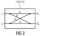
図2は、ステレオボックス110、112の概略的なブロック図を示す。ステレオボックス110、112は、第1の入力信号I1と第2の入力信号I2とに対する入力、及び第1の出力信号O1と第2の入力信号O2とに対する出力を備える。図2において示すように、入力信号I1及びI2からの出力信号O1及びO2の依存性は、s−パラメータS1からS4によって示される。
FIG. 2 shows a schematic block diagram of the
反復プロセッサー102は、(別の)処理されたチャンネルを導出するため、入力チャンネル及び/又は処理されたチャンネル上でマルチチャンネル処理操作を実行するために、ステレオボックス110、112を使用できる(又は、備えることができる)。例えば、反復プロセッサー102は、市販の予想ベース又はKLT(カルーネン・レーベ変換)ベースの回転ステレオボックス110、112を使用するよう構成しうる。
The
市販のエンコーダー(又は、エンコーダー側のステレオボックス)は、以下の式に基づいて出力信号O1とO2とを得るために、入力信号I1とI2とを符号化するよう構成しうる。
![]()
![]()
市販のデコーダー(又は、デコーダー側のステレオボックス)は、以下の式に基づいて出力信号O1とO2とを得るために、入力信号I1とI2とを復号化するよう構成しうる。
![]()
![]()
予測ベースのエンコーダー(又は、エンコーダー側のステレオボックス)は、以下の式に基づいて出力信号O1とO2とを得るために、入力信号I1とI2とを符号化するよう構成しうる。
![]()
![]()
予測ベースのデコーダー(又は、デコーダー側のステレオボックス)は、以下の式に基づいて出力信号O1とO2とを得るために、入力信号I1とI2とを復号化するよう構成しうる。
![]()
![]()
KLTベースの回転エンコーダー(又は、エンコーダー側のステレオボックス)は、以下の式に基づいて出力信号O1とO2とを得るために、入力信号I1とI2とを符号化するよう構成しうる。
![]()
![]()
KLTベースの回転デコーダー(又は、デコーダー側のステレオボックス)は、以下の式(逆回転)に基づいて出力信号O1とO2とを得るために、入力信号I1とI2とを復号化するよう構成しうる。
![]()
![]()
以下において、KLTベースの回転のための回転角度αの計算は示される。 In the following, the calculation of the rotation angle α for KLT-based rotation is shown.
KLTベースの回転のための回転角度αは、以下のように定義されうる。
![]()
![]()
これは、分数の分子内の負の相関と、分数の分母内の負のエネルギーの差異との間を区別できるようにatan2関数を使用して実行しうる。
alpha = 0.5*atan2(2*correlation[ch1][ch2],
(correlation[ch1][ch1] - correlation[ch2][ch2]))
This can be done using the atan2 function to be able to distinguish between negative correlations in the fractional numerator and negative energy differences in the fractional denominator.
alpha = 0.5 * atan2 (2 * correlation [ch1] [ch2],
(correlation [ch1] [ch1]-correlation [ch2] [ch2])))
さらに、反復プロセッサー102は、複数のバンドの対するチャンネル間相関値を得るために、複数のバンドを備えるそれぞれのチャンネルのフレームを使用して、チャンネル間相関を計算するよう構成しうる。反復プロセッサー102は、第1又は第2マルチチャンネルパラメータが複数のバンドのそれぞれから得られるので、複数のバンドのそれぞれに対して、マルチチャンネル処理を実行するよう構成しうる。
Further, the
したがって、反復プロセッサー102は、マルチチャンネル処理においてステレオパラメータを計算するよう構成され、反復プロセッサー102は、バンド内において、ステレオ処理のみを実行するよう構成され、ステレオパラメータは、ステレオ量子化器(例えば、KLTベース回転エンコーダ)によって定義されるゼロに量子化された閾値より高い。ステレオパラメータは、例えばMS On/Off、又は回転角度、又は予測係数であるだろう。
Accordingly, the
例えば、反復プロセッサー102は、マルチチャンネル処理において回転角度を計算するよう構成され、反復プロセッサー102は、バンド内において、回転処理のみを実行するよう構成しうり、回転角度は、回転角度量子化器(例えば、KLTベース回転エンコーダ)によって定義されるゼロに量子化された閾値より高い。
For example, the
したがって、エンコーダー100(又は、出力インターフェース106)は、完全なスペクトル(フルバンドボックス)に対する1つのパラメータ、又はスペクトルの一部に対する複数の周波数依存パラメータのどちらかのように、変換/回転情報を送信するよう構成しうる。 Thus, the encoder 100 (or output interface 106) transmits the transform / rotation information, either as a single parameter for the complete spectrum (full band box), or multiple frequency dependent parameters for a portion of the spectrum. Can be configured to.
エンコーダー100は、次の表に基づくビットストリーム107を生成するよう構成しうる。
The
表1‐mpegh3daExtElementConfig()のシンタックス
表21‐MCCConfig()のシンタックス
表32‐MultichannelCodingBoxBandWise()のシンタックス
表4‐MultichannelCodingBoxFullband()のシンタックス
表5‐MultichannelCodingFrame()のシンタックス
表6‐usacExtElementTypeの値
表7‐拡張ペイロード符号化のためのデータブロックの解釈
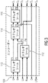
図3は、1つの実施の形態による、反復プロセッサー102の概略的なブロック図である。図3に示される実施の形態において、マルチチャンネル信号101は、6つのチャンネル、すなわち、左チャンネルL、右チャンネルR、左サラウンドチャンネルLs、右サラウンドチャンネルRs、正面チャンネルC、低音増幅チャンネルLFEを有する5.1チャンネル信号である。
FIG. 3 is a schematic block diagram of the
図3において示すように、LFEチャンネルは、反復プロセッサー102によって処理されない。これは、LFEチャンネルと他の5つのチャンネルL、R、Ls、Rs、Cのそれぞれとの間のチャンネル間相関値が小さい、又は、チャンネルマスクがLFEチャンネルを処理しないことを示すので、以下のように仮定する。
As shown in FIG. 3, the LFE channel is not processed by the
第1反復ステップにおいて、最高値を有する又は閾値より上の値を有する組を選択するために、反復プロセッサー102は、第1反復ステップにおいて、5つのチャンネルL、R、Ls、Rs、Cのそれぞれの組の間のチャンネル間相関値を計算する。図3において、反復プロセッサー102が、第1及び第2の処理されたチャンネルP1とP2とを導出するために、マルチチャンネル操作を処理する操作を実行するステレオボックス(又はステレオツール)110を使用して、左チャンネルLと右チャンネルRとを処理するように、左チャンネルLと右チャンネルRとが、最高値を有すると仮定される。
In the first iteration step, the
第2反復ステップにおいて、最高値を有する又は閾値より上の値を有する組を選択するために、反復プロセッサー102は、第2反復ステップにおいて、5つのチャンネルL、R、Ls、Rs、Cと、処理されたチャンネルP1とP2とのそれぞれの組の間のチャンネル間相関値を計算する。図3において、反復プロセッサー102が、第3及び第4の処理されたチャンネルP3とP4とを導出するために、ステレオボックス(又はステレオツール)112を使用して、左サラウンドチャンネルLsと右サラウンドチャンネルRsとを処理するように、左サラウンドチャンネルLsと右サラウンドチャンネルRsとが、最高値を有すると仮定される。
In order to select the set having the highest value or having a value above the threshold in the second iteration step, the
第3反復ステップにおいて、最高値を有する又は閾値より上の値を有する組を選択するために、反復プロセッサー102は、第3反復ステップにおいて、5つのチャンネルL、R、Ls、Rs、Cと、処理されたチャンネルP1からP4とのそれぞれの組の間のチャンネル間相関値を計算する。図3において、反復プロセッサー102が、第5及び第6の処理されたチャンネルP5とP6とを導出するために、ステレオボックス(又はステレオツール)114を使用して、第1の処理されたチャンネルP1と第3の処理されたチャンネルP3とを処理するように、第1の処理されたチャンネルP1と第3の処理されたチャンネルP3とが最高値を有すると仮定される。
In order to select the set having the highest value or having a value above the threshold in the third iteration step, the
第4反復ステップにおいて、最高値を有する又は閾値より上の値を有する組を選択するために、反復プロセッサー102は、第4反復ステップにおいて、5つのチャンネルL、R、Ls、Rs、Cと、処理されたチャンネルP1からP6とのそれぞれの組の間のチャンネル間相関値を計算する。図3において、反復プロセッサー102が、第7及び第8の処理されたチャンネルP7とP8とを導出するために、ステレオボックス(又はステレオツール)115を使用して、第5の処理されたチャンネルP5と正面チャンネルCとを処理するように、第5の処理されたチャンネルP5と正面チャンネルCとが最高値を有すると仮定される。
To select the set having the highest value or having a value above the threshold in the fourth iteration step, the
ステレオボックス110から116は、MSステレオボックスとすることができる。すなわち、中間/側面のステレオ音響効果ボックスが、中間チャンネルと側面チャンネルとに提供するよう構成される。中間チャンネルは、ステレオボックスの入力チャンネル間の合計であり、側面チャンネルは、ステレオボックスの入力チャンネル間の差である。さらに、ステレオボックス110から116は、回転ボックス又はステレオ予測ボックスとすることができる。
Stereo boxes 110-116 may be MS stereo boxes. That is, an intermediate / side stereo sound effect box is configured to provide the intermediate channel and the side channel. The middle channel is the sum between the input channels of the stereo box, and the side channel is the difference between the input channels of the stereo box. Furthermore, the
図3において、第1の処理されたチャンネルP1、及び第3の処理されたチャンネルP3、及び第5の処理されたチャンネルP5は中間チャンネルとすることができ、第2の処理されたチャンネルP2、及び第4の処理されたチャンネルP4、及び第6の処理されたチャンネルP6は中間チャンネルとすることができる。 In FIG. 3, the first processed channel P1, the third processed channel P3, and the fifth processed channel P5 can be intermediate channels, and the second processed channel P2, And the fourth processed channel P4 and the sixth processed channel P6 may be intermediate channels.
さらに、図3において示すように、反復プロセッサー102は、第2反復ステップにおいて、及び、該当する場合には以後のどの反復ステップにおいて、入力チャンネルL、R、Ls、Rs、C、及び、処理されたチャンネルの中間チャンネルP1、P3、P5(だけ)、を使用して、計算、選択、処理を実行するよう構成されうる。言い換えれば、反復プロセッサー102は、第2反復ステップ、及び、該当する場合には以後のどの反復ステップにおいて計算、選択、処理するときに、処理されたチャンネルの側面のチャンネルP1、P3、P5を使用しないように構成しうる。
Further, as shown in FIG. 3, the
図4は、符号化されたチャンネルE1からE3と、少なくとも第1及び第2マルチチャンネルパラメータMCH_PAR1とMCH_PAR2とを有する符号化されたマルチチャンネル信号107を復号化するために装置(デコーダー)200の概略的なブロック図を示す。装置200は、チャンネルデコーダー202とマルチチャンネルプロセッサー204とを備える。
FIG. 4 schematically shows an apparatus (decoder) 200 for decoding an encoded
チャンネルデコーダー202は、D1からD3の復号化されたチャンネルを得るために、符号化されたチャンネルE1からE3を復号化するよう構成される。
The
例えば、チャンネルデコーダー202は、少なくとも3つのモノラルデコーダー(又はモノラルボックス又はモノラルツール)206_1から206_3を備えることができ、それぞれのモノラルデコーダー206_1から206_3は、それぞれの復号化されたチャンネルE1からE3を得るために、少なくとも3つの符号化されたチャンネルE1からE3の1つを復号化するよう構成しうる。モノラルデコーダー206_1から206_3は、例えば、変換ベースのオーディオデコーダーとすることができる。
For example, the
マルチチャンネルプロセッサー204は、処理されたチャンネルを得るために、第2マルチチャンネルパラメータMCH_PAR2によって識別される復号化されたチャンネルの第2の組を使用して、及び第2マルチチャンネルパラメータMCH_PAR2を使用して、マルチチャンネル処理を実行し、第1マルチチャンネルパラメータMCH_PAR1によって識別されるチャンネルの第1の組を使用して、及び第1マルチチャンネルパラメータMCH_PAR1を使用して、別のマルチチャンネル処理を実行するように構成され、チャンネルの第1の組が、少なくとも1つの処理されたチャンネルを備える。
The
例示の方法によって図4において示すように、復号化されたチャンネルの第2の組は、第1の復号化されたチャンネルD1と第2の復号化されたチャンネルD2とから成ることを、第2マルチチャンネルパラメータMCH_PAR2は、示しうる(又は信号が送られうる)。したがって、マルチチャンネルプロセッサー204は、処理されたチャンネルP1*とP2*とを得るために、第1の復号化されたチャンネルD1と第2の復号化されたチャンネルD2(第2マルチチャンネルパラメータMCH_PAR2によって識別される)からなる復号化されたチャンネルの第2の組を使用して、及び、第2マルチチャンネルパラメータMCH_PAR2を使用して、マルチチャンネル処理を実行する。第1マルチチャンネルパラメータMCH_PAR1は、復号化されたチャンネルの第1の組は、第1の処理されたチャンネルP1*と第3の復号化されたチャンネルD3とからなることを示しうる。したがって、マルチチャンネルプロセッサー204は、処理されたチャンネルP3*とP4*を得るために、第1の処理されたチャンネルP1*と第3の復号化されたチャンネルD3(第1マルチチャンネルパラメータMCH_PAR1によって識別される)からなる復号化されたチャンネルの第1の組を使用して、及び、第1マルチチャンネルパラメータMCH_PAR1を使用して、別のマルチチャンネル処理を実行する。
As shown in FIG. 4 by way of example method, the second set of decoded channels comprises a first decoded channel D1 and a second decoded channel D2. The multi-channel parameter MCH_PAR2 may be indicated (or signaled). Therefore, the
さらに、マルチチャンネルプロセッサー204は、第3の処理されたチャンネルP3*を第1チャンネルCH1として、第4の処理されたチャンネルP4*を第3チャンネルCH3として、第2の処理されたチャンネルP2*を第2チャンネルCH2として提供しうる。
Furthermore, the
図4において示されるデコーダー200が、図1において示されるエンコーダー100から符号化されたマルチチャンネル信号107を受信すると仮定すると、デコーダー200の第1の復号化されたチャンネルD1は、エンコーダー100の第3の処理されたチャンネルP3と等価であり、デコーダー200の第2の復号化されたチャンネルD2は、エンコーダー100の第4の処理されたチャンネルP4と等価であり、デコーダー200の第3の復号化されたチャンネルD3は、エンコーダー100の第2の処理されたチャンネルP2と等価である。さらに、デコーダー200の第1の処理されたチャンネルP1*は、エンコーダー100の第1の処理されたチャンネルP1と等価である
Assuming that the
さらに、符号化されたマルチチャンネル信号107は、直列信号とすることができ、第2マルチチャンネルパラメータMCH_PAR2は、第1マルチチャンネルパラメータMCH_PAR1の前に、デコーダー200で受信される。その場合において、マルチチャンネルプロセッサー204は、マルチチャンネルパラメータMCH_PAR1及びMCH_PAR2が、デコーダーによって受信される順序で、復号化されたチャンネルを実行するよう構成しうる。図4において示す例において、デコーダーは、第1マルチチャンネルパラメータMCH_PAR1の前に、第2マルチチャンネルパラメータMCH_PAR2を受信し、したがって、第1マルチチャンネルパラメータMCH_PAR1によって識別される復号化されたチャンネルの第1の組(第1の処理されたチャンネルP1*と第3の復号化されたチャンネルD3とからなる)を使用してマルチチャンネル処理を実行する前に、第2マルチチャンネルパラメータMCH_PAR2によって識別される復号化されたチャンネルの第2の組(第1及び第2の復号化されたチャンネルD1とD2とからなる)を使用してマルチチャンネル処理を実行する。
Furthermore, the encoded
図4において、マルチチャンネルプロセッサー204は、2つのマルチチャンネル処理操作を見本として実行する。図示するために、マルチチャンネルプロセッサー204によって実行されるマルチチャンネル処理操作は、図4において処理ボックス208と210によって示される。処理ボックス208と210は、ハードウェア又はソフトウェアにおいて、実装しうる。処理ボックス208と210は、例えば、市販のデコーダー(又は、デコーダー側のステレオボックス)、又は予測ベースのデコーダー(又は、デコーダー側のステレオボックス)、又はKLTベースの回転デコーダー(又は、デコーダー側のステレオボックス)のように、エンコーダー100を参照して上述したように、ステレオボックスとすることができる。
In FIG. 4, the
例えば、エンコーダー100は、KLTベースの回転エンコーダー(又はエンコーダー側のステレオボックス)を使用することができる。その場合において、エンコーダー100は、第1及び第2マルチチャンネルパラメータMCH_PAR1とMCH_PAR2とを導出することができ、その結果、第1及び第2マルチチャンネルMCH_PAR1とMCH_PAR2とは、回転角度を備える。回転角度は、差動的に符号化しうる。それゆえに、デコーダー200のマルチチャンネルプロセッサー204は、差動的に符号化された回転角度を差動的に復号化するために差動的なデコーダーを備えうる。
For example, the
装置200は、符号化されたマルチチャンネル信号107を受信及び処理し、符号化されたチャンネルE1からE3を、チャンネルデコーダー202へ提供し、第1及び第2マルチチャンネルパラメータMCH_PAR1とMCH_PAR2とをマルチチャンネルプロセッサー204へ提供するよう構成されるインプットインターフェース212をさらに備える。
The
すでに述べたように、キープインジケータ(又はキープツリーフラグ)は、新しいツリーが送信されないことを伝えるために使用しうるが、最後のステレオツリーが、使用される必要がある。もし、チャンネル相関特性が長い時間静止している場合、これは、同じステレオツリー構成の複数の送信を避けるために使用しうる。 As already mentioned, the keep indicator (or keep tree flag) can be used to signal that no new tree is transmitted, but the last stereo tree needs to be used. If the channel correlation characteristic is stationary for a long time, this can be used to avoid multiple transmissions of the same stereo tree configuration.
それゆえに、符号化されたマルチチャンネル信号107が、第1のフレームに対して、第1又は第2マルチチャンネルパラメータMCH_PAR1とMCH_PAR2、及び、第1のフレームに続く、第2のフレームに対して、キープインジケーターを備えるとき、マルチチャンネルプロセッサー204は、第2のフレームにおいて、第1のフレームについて使用されるように、同じ第2の組又は同じ第1の組のチャンネルにマルチチャンネル処理又は別のマルチチャンネル処理を実行するよう構成しうる。
Therefore, the encoded
マルチチャンネル処理及び別のマルチチャンネル処理は、ステレオパラメータを使用するステレオ処理を含みうる。個々のスケールファクタバンド又は復号化されたチャンネルD1からD3のスケールファクタバンドのグループについて、第1ステレオパラメータは、第1マルチチャンネルパラメータMCH_PAR1が含まれ、第2ステレオパラメータは、第2マルチチャンネルパラメータMCH_PAR2が含まれる。それゆえに、第1ステレオパラメータ及び第2ステレオパラメータは、回転角度や予測係数のような、同じ型にすることができる。もちろん、第1ステレオパラメータ及び第2ステレオパラメータは、異なる型にすることができる。例えば、第1ステレオパラメータは、回転角度とすることができ、第2ステレオパラメータは、予測係数とすることができる。また、その逆もできる。 Multi-channel processing and other multi-channel processing can include stereo processing using stereo parameters. For individual scale factor bands or groups of scale factor bands of decoded channels D1 to D3, the first stereo parameter includes a first multichannel parameter MCH_PAR1, and the second stereo parameter is a second multichannel parameter MCH_PAR2. Is included. Therefore, the first stereo parameter and the second stereo parameter can be of the same type, such as a rotation angle and a prediction coefficient. Of course, the first stereo parameter and the second stereo parameter can be of different types. For example, the first stereo parameter can be a rotation angle, and the second stereo parameter can be a prediction coefficient. The reverse is also possible.
さらに、第1又は第2マルチチャンネルパラメータMCH_PAR1とMCH_PAR2とは、どのスケールファクタバンドがマルチチャンネル処理されていて、どのスケールファクタバンドがマルチチャンネル処理されていないかを示すマルチチャンネル処理マスクを備えうる。したがって、マルチチャンネルプロセッサー204は、マルチチャンネル処理マスクによって示されるスケールファクタバンドにおいて、マルチチャンネル処理が実行されないように構成しうる。
Further, the first or second multi-channel parameters MCH_PAR1 and MCH_PAR2 may include a multi-channel processing mask indicating which scale factor bands are multi-channel processed and which scale factor bands are not multi-channel processed. Accordingly, the
第1及び第2マルチチャンネルパラメータMCH_PAR1とMCH_PAR2とは、チャンネル組識別(又はインデックス)をそれぞれ含みうる。マルチチャンネルプロセッサー204は、予測された復号化ルール又は符号化されたマルチチャンネル信号で示される復号化ルールを使用してチャンネル組識別(又はインデックス)を復号化するよう構成しうる。
The first and second multi-channel parameters MCH_PAR1 and MCH_PAR2 may each include a channel set identification (or index).
例えば、チャンネル組は、エンコーダー100を参照して上述したように、チャンネルの総数に応じて、それぞれの組に対して、固有のインデックスを使用して、効果的に信号を送られうる。
For example, channel sets can be effectively signaled using a unique index for each set depending on the total number of channels, as described above with reference to
さらに、復号化ルールは、ハフマン復号化ルールとすることができ、マルチチャンネルプロセッサー204は、チャンネル組識別のハフマン復号化を実行するよう構成しうる。
Further, the decoding rule may be a Huffman decoding rule, and the
符号化されたマルチチャンネル信号107は、マルチチャンネル処理が許可された復号化された復号化されたチャンネルのサブグループだけを示し、且つ、マルチチャンネル処理が許可されていない少なくとも1つの復号化されたチャンネルを示す、マルチチャンネル処理許容インジケータを更に備える。したがって、マルチチャンネルプロセッサー204は、マルチチャンネル処理許容インジケータによって示されるように、マルチチャンネル処理が許容されない、少なくとも1つの復号化されたチャンネルについて、いかなるマルチチャンネル処理も実行しないように構成される。
The encoded
例えば、マルチチャンネル信号が、5.1チャンネル信号であるとき、マルチチャンネル処理許容インジケータは、マルチチャンネル処理が5つのチャンネル、すなわち、右R、左L、右サラウンドRs、左サラウンドLS、正面Cを許容するだけであることを示しうり、マルチチャンネル処理は、LFEチャンネルを許容しない。 For example, when the multi-channel signal is a 5.1 channel signal, the multi-channel processing allowance indicator indicates that the multi-channel processing has five channels: right R, left L, right surround Rs, left surround LS, front C. Multi-channel processing does not allow LFE channels, indicating that it only allows.
復号化処理(チャンネル組インデックスの復号化)のために、以下のCコードは使用されうる。したがって、すべてのチャンネル組に対して、アクティブなKLT処理を有するチャンネル数(nChannels)と現在のフレームのチャンネル組の数(numPairs)とが、必要とされる。
非バンド角度に対する予測係数を復号化するために、以下のCコードは使用されうる。
非バンドKLT角度に対する予測係数を復号化するために、以下のCコードは使用されうる。
異なるプラットフォームでの三角関数の浮動小数点の違いを避けるために、角度インデックスを直接sin/cosに変換するための以下のルックアップテーブルは使用しうる。
マルチチャンネルコーディングの復号化のために、以下のCコードはKLT回転に基づく手法に使用しうる。
バンド処理のために、以下のCコードを使用しうる。
KLT回転の適用のために、以下のCコードを使用しうる。
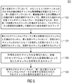
図5は、少なくとも3つのチャンネルを有するマルチチャンネル信号を符号化するための方法300のフローチャートである。方法300は、第1反復ステップにおいて、少なくとも3つのチャンネルそれぞれの組の間のチャンネル間相関値を計算し、第1反復ステップにおいて、最高値を有する又は閾値より上の値を有する組を選択し、選択された組のための第1マルチチャンネルパラメータを導出するため、及び、第1の処理されたチャンネルを導出するために、マルチチャンネル処理操作を使用して選択された組を処理するステップ302と、第2マルチチャンネルパラメータと第2の処理されたチャンネルとを導出するために、処理されたチャンネルの少なくとも1つを使用して、第2反復ステップにおいて、計算、選択、処理を実行するステップ304と、符号化されたチャンネルを得るために、反復プロセッサーによって実行された反復処理から生じたチャンネルを符号化するステップ306と、符号化されたチャンネルと、第1及び第2マルチチャンネルパラメータとを有する符号化されたマルチチャンネル信号を生成するステップ308とを備える。
FIG. 5 is a flowchart of a
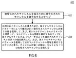
図6は、符号化されたチャンネルと、少なくとも第1及び第2マルチチャンネルパラメータとを有する符号化されたマルチチャンネル信号を復号化するための方法400のフローチャートを示す。方法400は、復号化されたチャンネルを得るために、符号化されたチャンネルを復号化するステップ402と、処理されたチャンネルを得るために、第2マルチチャンネルパラメータによって識別された復号化されたチャンネルの第2の組を使用して、及び第2マルチチャンネルパラメータを使用して、マルチチャンネル処理を実行し、第1マルチチャンネルパラメータによって識別されたチャンネルの第1の組を使用して、及び第1マルチチャンネルパラメータを使用して、マルチチャンネル処理を実行するステップ404と、を備え、チャンネルの第1の組は、少なくとも1つの処理されたチャンネルを備える。
FIG. 6 shows a flowchart of a
本発明は、ブロックが実際の又は論理的なハードウェア要素を示すブロック図との関係において述べられているけれども、本発明は、コンピュータ実装方法によって実装もすることができる。後者の場合、ブロックは、これらのステップが、対応する論理的又は物理的なハードウェアブロックによって実行される機能性を示す対応する方法ステップを示す。 Although the present invention has been described in the context of block diagrams in which blocks represent actual or logical hardware elements, the present invention can also be implemented by computer-implemented methods. In the latter case, the blocks indicate the corresponding method steps where these steps indicate the functionality performed by the corresponding logical or physical hardware block.
いくつかの側面が、装置との関係において述べられているけれども、これらの側面が、対応する方法の説明も示すことは明らかであり、ブロック又は装置が、方法ステップ又は方法ステップの特徴に相当する。同様に、方法ステップとの関係において述べられる側面は、対応するブロック又はアイテムの説明、又は対応する装置の特徴も示す。方法ステップのいくつか又はすべては、例えば、マイクロプロセッサー、又はプログラム可能なコンピュータ、又は電子回路のような、ハードウェア装置によって(又は使用して)実行されうる。いくつかの実施の形態において、最も重要な方法ステップのうち1つ以上は、このような装置によって実行されうる。 Although several aspects are described in relation to the apparatus, it is clear that these aspects also provide a description of the corresponding method, where the block or apparatus corresponds to a method step or method step feature. . Similarly, aspects described in relation to method steps also provide corresponding block or item descriptions or corresponding device features. Some or all of the method steps may be performed by (or using) a hardware device, such as, for example, a microprocessor, or a programmable computer, or an electronic circuit. In some embodiments, one or more of the most important method steps may be performed by such an apparatus.
本発明の送信又は符号化された信号は、デジタル記録媒体に保存されうり、又は無線送信媒体若しくはインターネットのような有線送信媒体のような送信媒体で送信されうる。 The transmitted or encoded signals of the present invention can be stored on a digital recording medium or transmitted on a transmission medium such as a wireless transmission medium or a wired transmission medium such as the Internet.
特定の実装要求に応じて、本発明の実施の形態は、ハードウェアにおいて、または、ソフトウェアにおいて実装しうる。実装は、それぞれの方法を実行されるように、プログラム可能なコンピュータシステムと協働するか、(又は協働することができる)保存された電気的に読み込み可能な制御信号を有する、デジタル記録媒体、例えば、フロッピー(登録商標)ディスク、DVD、ブルーレイディスク(登録商標)、CD、ROM、PROM、EPROM、EEPROM(登録商標)またはFLASHメモリを使用して実行しうる。このように、デジタル記憶媒体は、コンピュータに読み込み可能である。 Depending on certain implementation requirements, embodiments of the invention can be implemented in hardware or in software. An implementation is a digital recording medium that has a stored electrically readable control signal that cooperates (or can cooperate) with a programmable computer system to perform the respective methods. For example, using a floppy disk, DVD, Blu-ray disk, CD, ROM, PROM, EPROM, EEPROM, or FLASH memory. Thus, the digital storage medium can be read by a computer.
本発明によるいくつかの実施の形態は、本願明細書において記載された方法の1つが実行されるように、プログラム可能なコンピュータシステムと協働することができる電気的に読み込み可能な制御信号を有するデータ記録媒体を備える。 Some embodiments according to the invention have an electrically readable control signal that can cooperate with a programmable computer system so that one of the methods described herein is performed. A data recording medium is provided.
一般的に、本発明の実施の形態は、プログラムコードを有するコンピュータプログラム製品として実装しうる。そして、コンピュータプログラム製品がコンピュータ上で動くときに、プログラムコードは、方法の1つを実行するために動作される。プログラムコードは、例えば、機械読み取り可能な媒体に保存されうる。 In general, embodiments of the present invention may be implemented as a computer program product having program code. Then, when the computer program product runs on the computer, the program code is operated to perform one of the methods. The program code can be stored, for example, on a machine-readable medium.
他の実施の形態は、本願明細書において記載されている方法の1つを実行するためのコンピュータプログラムを備え、機械読み取り可能な媒体に保存される。 Another embodiment comprises a computer program for performing one of the methods described herein and is stored on a machine readable medium.
言い換えれば、本発明の方法の実施の形態は、したがって、コンピュータプログラムがコンピュータ上で実行するときに、本願明細書において記載されている方法の1つを実行するためのプログラムコードを有するコンピュータプログラムである。 In other words, an embodiment of the method of the present invention is therefore a computer program having program code for performing one of the methods described herein when the computer program runs on a computer. is there.
本発明の方法の別の実施形態は、したがって、本願明細書において記載されている方法の1つを実行するためのコンピュータプログラムを備え、そこに記録されるデータ記録媒体(又はデジタル記憶媒体のような非一過性の記録媒体、又はコンピュータ可読媒体)である。データ記録媒体、デジタル記憶媒体、又は記録媒体は、たいていは明白及び/又は非一時的である。 Another embodiment of the method of the present invention thus comprises a computer program for performing one of the methods described herein, such as a data recording medium (or digital storage medium) recorded thereon. Non-transitory recording medium or computer readable medium). Data recording media, digital storage media, or recording media are often explicit and / or non-transitory.
本発明の方法の別の実施形態は、したがって、本願明細書において記載されている方法の1つを実行するためのコンピュータプログラムを示すデータストリーム又は一連の信号である。例えば、データストリーム又は一連の信号は、データ通信接続を経て、例えばインターネットを経て、送信されるよう構成しうる。 Another embodiment of the method of the present invention is therefore a data stream or a series of signals indicative of a computer program for performing one of the methods described herein. For example, a data stream or series of signals may be configured to be transmitted over a data communication connection, eg, over the Internet.
別の実施の形態は、本願明細書において記載されている方法の1つを行うように構成、又は、適合された、例えばコンピュータのような処理手段又はプログラム可能な論理装置を備える。 Another embodiment comprises a processing means or programmable logic device, such as a computer, configured or adapted to perform one of the methods described herein.
別の実施の形態は、本願明細書において記載されている方法の1つを実行するためのコンピュータプログラムがインストールされるコンピュータを備える。 Another embodiment comprises a computer on which a computer program for performing one of the methods described herein is installed.
本発明による別の実施の形態は、本願明細書において記載される方法の1つを実行するためのコンピュータプログラムを受信装置に(例えば、電子的もしくは、光学的に)送信するよう構成される装置またはシステムを備える。受信装置は、例えば、コンピュータ、モバイル機器、メモリ装置または類似の装置でもよい。装置またはシステムは、例えば、コンピュータプログラムを受信装置に送信するためのファイルサーバを備えていてもよい。 Another embodiment according to the present invention is an apparatus configured to transmit (e.g., electronically or optically) a computer program for performing one of the methods described herein to a receiving apparatus. Or a system is provided. The receiving device may be, for example, a computer, mobile device, memory device or similar device. The device or system may comprise, for example, a file server for transmitting a computer program to the receiving device.
いくつかの実施の形態では、プログラム可能な論理装置(例えば、現場でプログラム可能なゲートアレイ)が、本願明細書において記載される方法の機能のいくつか又は全てを実行するために使用しうる。いくつかの実施の形態では、現場でプログラム可能なゲートアレイは、本願明細書において記載される方法の1つを実行するために、マイクロプロセッサーと協働できる。一般に、方法は、いかなるハードウェア装置によって、好ましくは、実行しうる。 In some embodiments, a programmable logic device (eg, a field programmable gate array) may be used to perform some or all of the functions of the methods described herein. In some embodiments, a field programmable gate array can work with a microprocessor to perform one of the methods described herein. In general, the method may preferably be performed by any hardware device.
上述した実施の形態は、本発明の原理を表すだけである。本願明細書に記載された構成及び詳細の修正及び変形は、当業者には明らかであることが理解される。したがって、本発明は、添付の特許請求の範囲によってのみ限定され、本願明細書の実施の形態の記述及び説明のための特定の詳細によっては限定されないことが意図される。 The above-described embodiments only represent the principles of the invention. It will be understood that modifications and variations of the configurations and details described herein will be apparent to those skilled in the art. Accordingly, it is intended that the invention be limited only by the scope of the appended claims and not by the specific details for describing and describing the embodiments herein.
Claims (27)
第1反復ステップにおいて、前記少なくとも3つのチャンネル(CH:CH3)のそれぞれの組の間のチャンネル間相関値を計算し、前記第1反復ステップにおいて、最高値を有する、又は閾値より上の値を有する一組を選択し、マルチチャンネル処理操作(110、112)を使用して前記選択された組を処理して、前記選択された組についての第1マルチチャンネルパラメータ(MCH_PAR1)を導出する、及び第1の処理されたチャンネル(P1、P2)を導出するための反復プロセッサー(102)であって、
前記反復プロセッサー(102)は、第2反復ステップにおいて、少なくとも1つの前記処理されたチャンネル(P1)を使用して、前記計算、前記選択、前記処理を実行して、第2マルチチャンネルパラメータ(MCH_PAR2)及び第2の処理されたチャンネル(P3、P4)を導出するように構成される反復プロセッサー(102)と、
前記反復プロセッサー(104)が実行する反復処理から生じたチャンネル(P2:P4)を符号化して符号化されたチャンネル(E1:E3)を得るためのチャンネルエンコーダーと、
前記符号化されたチャンネル(E1:E3)と、前記第1及び前記第2マルチチャンネルパラメータ(MCH_PAR1、MCH_PAR2)とを有する符号化されたマルチチャンネル信号(107)を生成するための出力インターフェース(106)とを備える装置(100)。 An apparatus (100) for encoding a multi-channel signal (101) having at least three channels (CH1: CH3) comprising:
In a first iteration step, an inter-channel correlation value between each set of the at least three channels (CH: CH3) is calculated, and in the first iteration step, a value having the highest value or above a threshold value is calculated. Selecting a set having and processing the selected set using multi-channel processing operations (110, 112) to derive a first multi-channel parameter (MCH_PAR1) for the selected set; and An iterative processor (102) for deriving a first processed channel (P1, P2) comprising:
The iterative processor (102) performs, in a second iteration step, using at least one of the processed channels (P1) to perform the calculation, the selection, and the processing, and a second multi-channel parameter (MCH_PAR2). ) And a second processed channel (P3, P4), an iterative processor (102),
A channel encoder for encoding the channels (P2: P4) resulting from the iterative processing performed by the iterative processor (104) to obtain encoded channels (E1: E3);
An output interface (106) for generating an encoded multichannel signal (107) having the encoded channel (E1: E3) and the first and second multichannel parameters (MCH_PAR1, MCH_PAR2). ).
前記反復プロセッサー(104)は、前記複数のバンドのそれぞれについて、前記第1又は前記第2マルチチャンネルパラメータ(MCH_PAR1、MCH_PAR2)が得られるように、前記複数のバンドのそれぞれに対して、前記マルチチャンネル処理を実行するよう構成される、請求項1ないし請求項4の1つに記載する装置(100)。 The iterative processor (102) is configured to calculate an inter-channel correlation using a frame of each channel comprising the plurality of bands so that a correlation value between one channel is obtained for the plurality of bands;
The iterative processor (104) may determine the multichannel for each of the plurality of bands so that the first or second multichannel parameter (MCH_PAR1, MCH_PAR2) is obtained for each of the plurality of bands. The apparatus (100) according to one of claims 1 to 4, configured to perform processing.
前記反復プロセッサー(102)は、前記第2反復ステップにおいて、前記第2マルチチャンネルパラメータ(MCH_PAR2)及び第2の処理されたチャンネル(P3、P4)を導出するために、前記処理されたチャンネル(P1、P2)の前記少なくとも1つとして、前記処理されたチャンネル(P1、P2)の前記中間チャンネル(P1)だけを使用して、前記計算、前記選択、前記処理を実行するよう構成される、請求項1ないし請求項12の1つに記載する装置(100)。 The iterative processor (102) processes the selected set using the multi-channel processing in the first iteration step, and the processed channels (P1, P2) become intermediate channels (P1). It is configured to be a side channel (P2),
The iteration processor (102), in the second iteration step, derives the processed channel (P1) to derive the second multi-channel parameter (MCH_PAR2) and a second processed channel (P3, P4). , P2) is configured to perform the calculation, the selection, and the processing using only the intermediate channel (P1) of the processed channels (P1, P2) as the at least one of P2). Device (100) according to one of claims 1 to 12.
前記符号化されたチャンネル(E1:E3)を復号化して復号化されたチャンネル(D1:D3)を得るためのチャンネルデコーダー(202)と、
前記第2マルチチャンネルパラメータ(MCH_PAR2)によって識別された、前記復号化されたチャンネル(D1:D3)の第2の組を使用して、及び前記第2マルチチャンネルパラメータ(MCH_PAR2)を使用してマルチチャンネル処理を実行して、処理されたチャンネル(P1*、P2*)を得るための、並びに、前記第1マルチチャンネルパラメータ(MCH_PAR1)によって識別されたチャンネル(D1:D3、P1*、P2*)の第1の組を使用して、及び前記第1マルチチャンネルパラメータ(MCH_PAR1)を使用して別のマルチチャンネル処理を実行するためのマルチチャンネルプロセッサー(204)であって、チャンネルの前記第1の組は、少なくとも1つの処理されたチャンネル(P1*、P2*)を構成される、装置(200)。 In an apparatus (200) for decoding an encoded multichannel signal (107) having an encoded channel (E1: E3) and at least first and second multichannel parameters (MCH_PAR1, MCH_PAR2) There,
A channel decoder (202) for decoding the encoded channel (E1: E3) to obtain a decoded channel (D1: D3);
Multiple using the second set of decoded channels (D1: D3) identified by the second multi-channel parameter (MCH_PAR2) and using the second multi-channel parameter (MCH_PAR2) Perform channel processing to obtain processed channels (P1 *, P2 *) and channels identified by the first multi-channel parameter (MCH_PAR1) (D1: D3, P1 *, P2 *) A multi-channel processor (204) for performing another multi-channel processing using the first set of channels and using the first multi-channel parameter (MCH_PAR1), The set consists of at least one processed channel (P1 *, P2 * Configured to, apparatus (200).
前記マルチチャンネルプロセッサー(204)は、前記第2のフレームにおいて、前記同じ第2の組と、前記第1のフレームにおいて使用されるのと同じ前記第1の組に対し、前記マルチチャンネル処理及び前記別のマルチチャンネル処理を実行するよう構成される、請求項15に記載する装置(200)。 The encoded multi-channel signal (107) includes the first and second multi-channel parameters (MCH_PAR1, MCH_PAR2) for a first frame, and a second frame following the first frame. And a keep indicator for
The multi-channel processor (204) performs the multi-channel processing and the multi-channel processing on the same second set and the same first set used in the first frame in the second frame. The apparatus (200) of claim 15, configured to perform another multi-channel process.
前記マルチチャンネルプロセッサー(204)は、前記マルチチャンネル処理マスクによって示される前記スケールファクタバンドにおいて、前記マルチチャンネル処理をしないように構成される、請求項15ないし請求項17の1つに記載する装置(200)。 The first or second multi-channel parameter (MCH_PAR1, MCH_PAR2) includes a multi-channel processing mask indicating which scale factor bands are multi-channel processed and which scale factor bands are not multi-channel processed.
The apparatus (1) according to one of claims 15 to 17, wherein the multi-channel processor (204) is configured not to perform the multi-channel processing in the scale factor band indicated by the multi-channel processing mask. 200).
前記マルチチャンネルプロセッサー(204)は、事前に定義された復号化ルール又は前記符号化されたマルチチャンネル信号において示された復号化ルールを使用して前記チャンネル組の識別を復号化するよう構成される、請求項15ないし請求項18の1つに記載する装置(200)。 The first or second multi-channel parameters (MCH_PAR1, MCH_PAR2) each include an identification of a channel set;
The multi-channel processor (204) is configured to decode the identification of the channel set using a predefined decoding rule or a decoding rule indicated in the encoded multi-channel signal. A device (200) according to one of claims 15 to 18.
前記マルチチャンネルプロセッサー(204)は、前記マルチチャンネル処理許容インジケータによって示されるように、前記マルチチャンネル処理が許容されない、前記少なくとも1つの復号化されたチャンネルについて、いかなるマルチチャンネル処理も実行しないように構成される、請求項15ないし請求項20の1つに記載する装置(200)。 The encoded multi-channel signal (107) indicates only a subgroup of the decoded channels that are allowed for the multi-channel processing, and at least one decoding that is not allowed for the multi-channel processing. A multi-channel processing allowance indicator that indicates the selected channel,
The multi-channel processor (204) is configured to not perform any multi-channel processing on the at least one decoded channel that is not allowed for multi-channel processing, as indicated by the multi-channel processing allowance indicator. 21. Apparatus (200) according to one of claims 15 to 20, wherein:
前記マルチチャンネルプロセッサー(204)は、前記マルチチャンネルパラメータ(MCH_PAR1、MCH_PAR2)が前記デコーダー(200)によって受け取られた順番で、前記復号化されたチャンネル(D1:D3)を処理するよう構成される、請求項15ないし請求項22の1つに記載する装置。 The encoded multi-channel signal (107) is a serial signal in which a second multi-channel parameter (MCH_PAR2) is received by the decoder (200) before the first multi-channel parameter (MCH_PAR1),
The multi-channel processor (204) is configured to process the decoded channels (D1: D3) in the order in which the multi-channel parameters (MCH_PAR1, MCH_PAR2) are received by the decoder (200). 23. Apparatus according to one of claims 15 to 22.
第1反復ステップにおいて、前記少なくとも3つのチャンネルのそれぞれの組の間のチャンネル間相関値を計算するステップ(302)と、第1反復ステップにおいて、最高値を有する又は閾値より上の値を有する組を選択するステップと、前記選択された組のための第1マルチチャンネルパラメータを導出するため、及び、第1の処理されたチャンネルを導出するために、マルチチャンネル処理操作を使用して前記選択された組を処理するステップと、
第2マルチチャンネルパラメータと第2の処理されたチャンネルとを導出するために、前記第2反復ステップにおいて、少なくとも1つの前記処理されたチャンネルとを使用して前記計算するステップと、前記選択するステップと、前記処理するステップとを実行するステップ(304)と、
符号化されたチャンネルを得るために、前記反復プロセッサーによって実行された反復処理によって生じたチャンネルを符号化するステップ(306)と、
前記符号化されたチャンネルと前記第1及び前記第2マルチチャンネルパラメータとを有する符号化されたマルチチャンネル信号を生成するステップ(308)とを備える、方法(300)。 A method (300) for encoding a multi-channel signal having at least three channels, the method comprising:
Calculating (302) an inter-channel correlation value between each set of the at least three channels in a first iteration step; and a set having a highest value or a value above a threshold in the first iteration step. Selecting a first multi-channel parameter for the selected set and deriving a first processed channel using the multi-channel processing operation. A step of processing the set;
Calculating and selecting in at least one of the processed channels in the second iteration step to derive a second multi-channel parameter and a second processed channel; And (304) executing the processing step;
Encoding a channel resulting from an iterative process performed by the iterative processor to obtain an encoded channel (306);
Generating (308) an encoded multi-channel signal having the encoded channel and the first and second multi-channel parameters.
復号化されたチャンネルを得るために前記符号化されたチャンネルを復号化するステップ(402)と、
処理されたチャンネルを得るために、前記第2マルチチャンネルパラメータによって識別された前記復号化されたチャンネルの第2の組を使用して、及び前記第2マルチチャンネルパラメータを使用して、マルチチャンネル処理を実行するステップ(404)と、前記第1マルチチャンネルパラメータによって識別されたチャンネルの第1の組を使用して、及び前記第1マルチチャンネルパラメータを使用して別のマルチチャンネル処理を実行するステップを含み、チャンネルの前記第1の組は、少なくとも1つの処理されたチャンネルを備える、方法(400)。 A method (400) for decoding an encoded channel and an encoded multi-channel signal having at least first and second multi-channel parameters, the method comprising:
Decoding (402) the encoded channel to obtain a decoded channel;
Multi-channel processing using the second set of decoded channels identified by the second multi-channel parameter and using the second multi-channel parameter to obtain a processed channel And performing another multi-channel process using the first set of channels identified by the first multi-channel parameter and using the first multi-channel parameter. And the first set of channels comprises at least one processed channel (400).
Applications Claiming Priority (5)
| Application Number | Priority Date | Filing Date | Title |
|---|---|---|---|
| EP15158234 | 2015-03-09 | ||
| EP15158234.3 | 2015-03-09 | ||
| EP15172492.9 | 2015-06-17 | ||
| EP15172492.9A EP3067885A1 (en) | 2015-03-09 | 2015-06-17 | Apparatus and method for encoding or decoding a multi-channel signal |
| PCT/EP2016/054900 WO2016142375A1 (en) | 2015-03-09 | 2016-03-08 | Apparatus and method for encoding or decoding a multi-channel signal |
Related Child Applications (1)
| Application Number | Title | Priority Date | Filing Date |
|---|---|---|---|
| JP2019182675A Division JP7208126B2 (en) | 2015-03-09 | 2019-10-03 | Apparatus and method for encoding or decoding multi-channel signals |
Publications (3)
| Publication Number | Publication Date |
|---|---|
| JP2018513402A true JP2018513402A (en) | 2018-05-24 |
| JP2018513402A5 JP2018513402A5 (en) | 2019-06-06 |
| JP6600004B2 JP6600004B2 (en) | 2019-10-30 |
Family
ID=52692421
Family Applications (4)
| Application Number | Title | Priority Date | Filing Date |
|---|---|---|---|
| JP2017548015A Active JP6600004B2 (en) | 2015-03-09 | 2016-03-08 | Apparatus and method for encoding or decoding multi-channel signals |
| JP2019182675A Active JP7208126B2 (en) | 2015-03-09 | 2019-10-03 | Apparatus and method for encoding or decoding multi-channel signals |
| JP2023000472A Active JP7617154B2 (en) | 2015-03-09 | 2023-01-05 | Apparatus and method for encoding or decoding a multi-channel signal - Patents.com |
| JP2025001698A Pending JP2025066734A (en) | 2015-03-09 | 2025-01-06 | Apparatus and method for encoding or decoding a multi-channel signal - Patents.com |
Family Applications After (3)
| Application Number | Title | Priority Date | Filing Date |
|---|---|---|---|
| JP2019182675A Active JP7208126B2 (en) | 2015-03-09 | 2019-10-03 | Apparatus and method for encoding or decoding multi-channel signals |
| JP2023000472A Active JP7617154B2 (en) | 2015-03-09 | 2023-01-05 | Apparatus and method for encoding or decoding a multi-channel signal - Patents.com |
| JP2025001698A Pending JP2025066734A (en) | 2015-03-09 | 2025-01-06 | Apparatus and method for encoding or decoding a multi-channel signal - Patents.com |
Country Status (16)
| Country | Link |
|---|---|
| US (5) | US10388289B2 (en) |
| EP (4) | EP3067885A1 (en) |
| JP (4) | JP6600004B2 (en) |
| KR (1) | KR102109159B1 (en) |
| CN (2) | CN112233684B (en) |
| AR (1) | AR103873A1 (en) |
| AU (1) | AU2016231238B2 (en) |
| CA (1) | CA2978818C (en) |
| ES (1) | ES2769032T3 (en) |
| MX (1) | MX364419B (en) |
| PL (1) | PL3268959T3 (en) |
| PT (1) | PT3268959T (en) |
| RU (1) | RU2711055C2 (en) |
| SG (1) | SG11201707180SA (en) |
| TW (1) | TWI584271B (en) |
| WO (1) | WO2016142375A1 (en) |
Cited By (2)
| Publication number | Priority date | Publication date | Assignee | Title |
|---|---|---|---|---|
| JP2023533366A (en) * | 2020-07-17 | 2023-08-02 | 華為技術有限公司 | Multi-channel audio signal encoding and decoding method and apparatus |
| JP2023534049A (en) * | 2020-07-17 | 2023-08-07 | 華為技術有限公司 | Multi-channel audio signal coding method and apparatus |
Families Citing this family (20)
| Publication number | Priority date | Publication date | Assignee | Title |
|---|---|---|---|---|
| EP3067885A1 (en) | 2015-03-09 | 2016-09-14 | Fraunhofer-Gesellschaft zur Förderung der angewandten Forschung e.V. | Apparatus and method for encoding or decoding a multi-channel signal |
| CN106710600B (en) * | 2016-12-16 | 2020-02-04 | 广州广晟数码技术有限公司 | Decorrelation coding method and apparatus for a multi-channel audio signal |
| US10650834B2 (en) | 2018-01-10 | 2020-05-12 | Savitech Corp. | Audio processing method and non-transitory computer readable medium |
| CN111630593B (en) | 2018-01-18 | 2021-12-28 | 杜比实验室特许公司 | Method and apparatus for decoding sound field representation signals |
| EP3818520B1 (en) * | 2018-07-04 | 2024-01-24 | Fraunhofer-Gesellschaft zur Förderung der angewandten Forschung e.V. | Multisignal audio coding using signal whitening as preprocessing |
| US10547927B1 (en) * | 2018-07-27 | 2020-01-28 | Mimi Hearing Technologies GmbH | Systems and methods for processing an audio signal for replay on stereo and multi-channel audio devices |
| JP7553355B2 (en) | 2018-11-13 | 2024-09-18 | ドルビー ラボラトリーズ ライセンシング コーポレイション | Representation of spatial audio from audio signals and associated metadata |
| CN112970270B (en) | 2018-11-13 | 2023-10-13 | 杜比实验室特许公司 | Audio processing in immersive audio services |
| US12308034B2 (en) | 2019-06-24 | 2025-05-20 | Qualcomm Incorporated | Performing psychoacoustic audio coding based on operating conditions |
| US11361776B2 (en) | 2019-06-24 | 2022-06-14 | Qualcomm Incorporated | Coding scaled spatial components |
| US12142285B2 (en) | 2019-06-24 | 2024-11-12 | Qualcomm Incorporated | Quantizing spatial components based on bit allocations determined for psychoacoustic audio coding |
| US11538489B2 (en) * | 2019-06-24 | 2022-12-27 | Qualcomm Incorporated | Correlating scene-based audio data for psychoacoustic audio coding |
| CN112151045B (en) * | 2019-06-29 | 2024-06-04 | 华为技术有限公司 | Stereo encoding method, stereo decoding method and device |
| CN112233682B (en) * | 2019-06-29 | 2024-07-16 | 华为技术有限公司 | A stereo encoding method, a stereo decoding method and a device |
| CN112216290B (en) * | 2019-07-09 | 2025-08-15 | 海信视像科技股份有限公司 | Audio data transmission method and device and playing equipment |
| CN113782040B (en) * | 2020-05-22 | 2024-07-30 | 华为技术有限公司 | Audio coding method and device based on psychoacoustics |
| EP4243015A4 (en) | 2021-01-27 | 2024-04-17 | Samsung Electronics Co., Ltd. | Audio processing device and method |
| CN115410584A (en) * | 2021-05-28 | 2022-11-29 | 华为技术有限公司 | Method and apparatus for encoding multi-channel audio signal |
| US12225370B2 (en) * | 2022-01-13 | 2025-02-11 | Electronics And Telecommunications Research Institute | Apparatus for immersive spatial audio modeling and rendering |
| WO2025091293A1 (en) * | 2023-10-31 | 2025-05-08 | 北京小米移动软件有限公司 | Grouping method, encoder, decoder, and storage medium |
Citations (7)
| Publication number | Priority date | Publication date | Assignee | Title |
|---|---|---|---|---|
| JPH07160292A (en) * | 1993-12-07 | 1995-06-23 | Sony Corp | Multilayer encoder |
| JP2004246224A (en) * | 2003-02-17 | 2004-09-02 | Matsushita Electric Ind Co Ltd | Audio efficient coding apparatus, audio efficient coding method, audio efficient coding program, and recording medium therefor |
| JP2008503767A (en) * | 2004-06-21 | 2008-02-07 | コーニンクレッカ フィリップス エレクトロニクス エヌ ヴィ | Method and apparatus for encoding and decoding multi-channel audio signals |
| JP2008129250A (en) * | 2006-11-20 | 2008-06-05 | National Chiao Tung Univ | Window switching method for AAC and band determination method for M / S encoding |
| JP2008535014A (en) * | 2005-03-30 | 2008-08-28 | コーニンクレッカ フィリップス エレクトロニクス エヌ ヴィ | Scalable multi-channel speech coding method |
| US20130077793A1 (en) * | 2010-03-29 | 2013-03-28 | Samsung Electronics Co., Ltd. | Method and apparatus for down-mixing multi-channel audio |
| JP2015011076A (en) * | 2013-06-26 | 2015-01-19 | 日本放送協会 | Acoustic signal encoder, acoustic signal encoding method, and acoustic signal decoder |
Family Cites Families (48)
| Publication number | Priority date | Publication date | Assignee | Title |
|---|---|---|---|---|
| US5956674A (en) * | 1995-12-01 | 1999-09-21 | Digital Theater Systems, Inc. | Multi-channel predictive subband audio coder using psychoacoustic adaptive bit allocation in frequency, time and over the multiple channels |
| JP4521939B2 (en) | 2000-07-06 | 2010-08-11 | キヤノン株式会社 | Image forming apparatus |
| JP2002073086A (en) | 2000-08-24 | 2002-03-12 | Sony Corp | Speech coding apparatus and method |
| SE519981C2 (en) * | 2000-09-15 | 2003-05-06 | Ericsson Telefon Ab L M | Coding and decoding of signals from multiple channels |
| US7502743B2 (en) * | 2002-09-04 | 2009-03-10 | Microsoft Corporation | Multi-channel audio encoding and decoding with multi-channel transform selection |
| US7447317B2 (en) * | 2003-10-02 | 2008-11-04 | Fraunhofer-Gesellschaft Zur Foerderung Der Angewandten Forschung E.V | Compatible multi-channel coding/decoding by weighting the downmix channel |
| DE102004009628A1 (en) * | 2004-02-27 | 2005-10-06 | Fraunhofer-Gesellschaft zur Förderung der angewandten Forschung e.V. | Apparatus and method for writing an audio CD and an audio CD |
| DE102004042819A1 (en) | 2004-09-03 | 2006-03-23 | Fraunhofer-Gesellschaft zur Förderung der angewandten Forschung e.V. | Apparatus and method for generating a coded multi-channel signal and apparatus and method for decoding a coded multi-channel signal |
| DE102004043521A1 (en) * | 2004-09-08 | 2006-03-23 | Fraunhofer-Gesellschaft zur Förderung der angewandten Forschung e.V. | Device and method for generating a multi-channel signal or a parameter data set |
| KR100682904B1 (en) * | 2004-12-01 | 2007-02-15 | 삼성전자주식회사 | Apparatus and method for processing multi-channel audio signal using spatial information |
| US7573912B2 (en) * | 2005-02-22 | 2009-08-11 | Fraunhofer-Gesellschaft Zur Foerderung Der Angewandten Forschunng E.V. | Near-transparent or transparent multi-channel encoder/decoder scheme |
| CN101124740B (en) * | 2005-02-23 | 2012-05-30 | 艾利森电话股份有限公司 | Multi-channel audio encoding and decoding method and device, audio transmission system |
| DE102005010057A1 (en) * | 2005-03-04 | 2006-09-07 | Fraunhofer-Gesellschaft zur Förderung der angewandten Forschung e.V. | Apparatus and method for generating a coded stereo signal of an audio piece or audio data stream |
| US7983922B2 (en) * | 2005-04-15 | 2011-07-19 | Fraunhofer-Gesellschaft Zur Foerderung Der Angewandten Forschung E.V. | Apparatus and method for generating multi-channel synthesizer control signal and apparatus and method for multi-channel synthesizing |
| US7961890B2 (en) * | 2005-04-15 | 2011-06-14 | Fraunhofer-Gesellschaft Zur Foerderung Der Angewandten Forschung, E.V. | Multi-channel hierarchical audio coding with compact side information |
| JP2006323314A (en) * | 2005-05-20 | 2006-11-30 | Matsushita Electric Ind Co Ltd | Device for binaural cue coding of multi-channel audio signals |
| WO2007004831A1 (en) * | 2005-06-30 | 2007-01-11 | Lg Electronics Inc. | Method and apparatus for encoding and decoding an audio signal |
| CN101248483B (en) * | 2005-07-19 | 2011-11-23 | 皇家飞利浦电子股份有限公司 | Generation of multi-channel audio signals |
| US7822616B2 (en) * | 2005-08-30 | 2010-10-26 | Lg Electronics Inc. | Time slot position coding of multiple frame types |
| KR100891688B1 (en) * | 2005-10-26 | 2009-04-03 | 엘지전자 주식회사 | Method for encoding and decoding multi-channel audio signal and apparatus thereof |
| KR100888474B1 (en) * | 2005-11-21 | 2009-03-12 | 삼성전자주식회사 | Apparatus and method for encoding/decoding multichannel audio signal |
| KR101218776B1 (en) * | 2006-01-11 | 2013-01-18 | 삼성전자주식회사 | Method of generating multi-channel signal from down-mixed signal and computer-readable medium |
| FR2898725A1 (en) | 2006-03-15 | 2007-09-21 | France Telecom | DEVICE AND METHOD FOR GRADUALLY ENCODING A MULTI-CHANNEL AUDIO SIGNAL ACCORDING TO MAIN COMPONENT ANALYSIS |
| US8027479B2 (en) * | 2006-06-02 | 2011-09-27 | Coding Technologies Ab | Binaural multi-channel decoder in the context of non-energy conserving upmix rules |
| WO2008006108A2 (en) * | 2006-07-07 | 2008-01-10 | Srs Labs, Inc. | Systems and methods for multi-dialog surround audio |
| UA94117C2 (en) * | 2006-10-16 | 2011-04-11 | Долби Свиден Ав | Improved coding and parameter dysplaying of mixed object multichannel coding |
| US8295494B2 (en) * | 2007-08-13 | 2012-10-23 | Lg Electronics Inc. | Enhancing audio with remixing capability |
| CN101802907B (en) * | 2007-09-19 | 2013-11-13 | 爱立信电话股份有限公司 | Joint enhancement of multi-channel audio |
| KR101290394B1 (en) * | 2007-10-17 | 2013-07-26 | 프라운호퍼 게젤샤프트 쭈르 푀르데룽 데어 안겐반텐 포르슝 에. 베. | Audio coding using downmix |
| US8249883B2 (en) * | 2007-10-26 | 2012-08-21 | Microsoft Corporation | Channel extension coding for multi-channel source |
| WO2009146734A1 (en) * | 2008-06-03 | 2009-12-10 | Nokia Corporation | Multi-channel audio coding |
| KR101137361B1 (en) * | 2009-01-28 | 2012-04-26 | 엘지전자 주식회사 | A method and an apparatus for processing an audio signal |
| WO2011013381A1 (en) * | 2009-07-31 | 2011-02-03 | パナソニック株式会社 | Coding device and decoding device |
| WO2011021239A1 (en) * | 2009-08-20 | 2011-02-24 | トムソン ライセンシング | Audio stream combining apparatus, method and program |
| WO2011045548A1 (en) * | 2009-10-15 | 2011-04-21 | France Telecom | Optimized low-throughput parametric coding/decoding |
| WO2011080916A1 (en) | 2009-12-28 | 2011-07-07 | パナソニック株式会社 | Audio encoding device and audio encoding method |
| EP2375409A1 (en) * | 2010-04-09 | 2011-10-12 | Fraunhofer-Gesellschaft zur Förderung der angewandten Forschung e.V. | Audio encoder, audio decoder and related methods for processing multi-channel audio signals using complex prediction |
| US8908874B2 (en) * | 2010-09-08 | 2014-12-09 | Dts, Inc. | Spatial audio encoding and reproduction |
| JP5681290B2 (en) | 2010-09-28 | 2015-03-04 | ホアウェイ・テクノロジーズ・カンパニー・リミテッド | Device for post-processing a decoded multi-channel audio signal or a decoded stereo signal |
| EP2656640A2 (en) * | 2010-12-22 | 2013-10-30 | Genaudio, Inc. | Audio spatialization and environment simulation |
| EP2839460A4 (en) * | 2012-04-18 | 2015-12-30 | Nokia Technologies Oy | Stereo audio signal encoder |
| EP2717265A1 (en) * | 2012-10-05 | 2014-04-09 | Fraunhofer-Gesellschaft zur Förderung der angewandten Forschung e.V. | Encoder, decoder and methods for backward compatible dynamic adaption of time/frequency resolution in spatial-audio-object-coding |
| BR112015021520B1 (en) | 2013-03-05 | 2021-07-13 | Fraunhofer-Gesellschaft zur Förderung der angewandten Forschung e.V | APPARATUS AND METHOD FOR CREATING ONE OR MORE AUDIO OUTPUT CHANNEL SIGNALS DEPENDING ON TWO OR MORE AUDIO INPUT CHANNEL SIGNALS |
| EP2989631A4 (en) * | 2013-04-26 | 2016-12-21 | Nokia Technologies Oy | Audio signal encoder |
| EP2830333A1 (en) * | 2013-07-22 | 2015-01-28 | Fraunhofer-Gesellschaft zur Förderung der angewandten Forschung e.V. | Multi-channel decorrelator, multi-channel audio decoder, multi-channel audio encoder, methods and computer program using a premix of decorrelator input signals |
| TWI713018B (en) | 2013-09-12 | 2020-12-11 | 瑞典商杜比國際公司 | Decoding method, and decoding device in multichannel audio system, computer program product comprising a non-transitory computer-readable medium with instructions for performing decoding method, audio system comprising decoding device |
| KR102144332B1 (en) * | 2014-07-01 | 2020-08-13 | 한국전자통신연구원 | Method and apparatus for processing multi-channel audio signal |
| EP3067885A1 (en) | 2015-03-09 | 2016-09-14 | Fraunhofer-Gesellschaft zur Förderung der angewandten Forschung e.V. | Apparatus and method for encoding or decoding a multi-channel signal |
-
2015
- 2015-06-17 EP EP15172492.9A patent/EP3067885A1/en not_active Withdrawn
-
2016
- 2016-02-24 TW TW105105526A patent/TWI584271B/en active
- 2016-03-07 AR ARP160100598A patent/AR103873A1/en active IP Right Grant
- 2016-03-08 EP EP19157636.2A patent/EP3506259A1/en not_active Withdrawn
- 2016-03-08 CA CA2978818A patent/CA2978818C/en active Active
- 2016-03-08 EP EP16709344.2A patent/EP3268959B1/en active Active
- 2016-03-08 PL PL16709344T patent/PL3268959T3/en unknown
- 2016-03-08 MX MX2017011495A patent/MX364419B/en active IP Right Grant
- 2016-03-08 JP JP2017548015A patent/JP6600004B2/en active Active
- 2016-03-08 KR KR1020177028549A patent/KR102109159B1/en active Active
- 2016-03-08 WO PCT/EP2016/054900 patent/WO2016142375A1/en not_active Ceased
- 2016-03-08 RU RU2017134964A patent/RU2711055C2/en active
- 2016-03-08 PT PT167093442T patent/PT3268959T/en unknown
- 2016-03-08 CN CN202011242898.5A patent/CN112233684B/en active Active
- 2016-03-08 EP EP25211436.8A patent/EP4675616A3/en active Pending
- 2016-03-08 AU AU2016231238A patent/AU2016231238B2/en active Active
- 2016-03-08 SG SG11201707180SA patent/SG11201707180SA/en unknown
- 2016-03-08 CN CN201680026823.9A patent/CN107592937B/en active Active
- 2016-03-08 ES ES16709344T patent/ES2769032T3/en active Active
-
2017
- 2017-09-06 US US15/696,861 patent/US10388289B2/en active Active
-
2019
- 2019-05-15 US US16/413,299 patent/US10762909B2/en active Active
- 2019-10-03 JP JP2019182675A patent/JP7208126B2/en active Active
-
2020
- 2020-08-17 US US16/995,537 patent/US11508384B2/en active Active
-
2022
- 2022-10-18 US US17/968,583 patent/US11955131B2/en active Active
-
2023
- 2023-01-05 JP JP2023000472A patent/JP7617154B2/en active Active
-
2024
- 2024-03-29 US US18/622,507 patent/US12462819B2/en active Active
-
2025
- 2025-01-06 JP JP2025001698A patent/JP2025066734A/en active Pending
Patent Citations (7)
| Publication number | Priority date | Publication date | Assignee | Title |
|---|---|---|---|---|
| JPH07160292A (en) * | 1993-12-07 | 1995-06-23 | Sony Corp | Multilayer encoder |
| JP2004246224A (en) * | 2003-02-17 | 2004-09-02 | Matsushita Electric Ind Co Ltd | Audio efficient coding apparatus, audio efficient coding method, audio efficient coding program, and recording medium therefor |
| JP2008503767A (en) * | 2004-06-21 | 2008-02-07 | コーニンクレッカ フィリップス エレクトロニクス エヌ ヴィ | Method and apparatus for encoding and decoding multi-channel audio signals |
| JP2008535014A (en) * | 2005-03-30 | 2008-08-28 | コーニンクレッカ フィリップス エレクトロニクス エヌ ヴィ | Scalable multi-channel speech coding method |
| JP2008129250A (en) * | 2006-11-20 | 2008-06-05 | National Chiao Tung Univ | Window switching method for AAC and band determination method for M / S encoding |
| US20130077793A1 (en) * | 2010-03-29 | 2013-03-28 | Samsung Electronics Co., Ltd. | Method and apparatus for down-mixing multi-channel audio |
| JP2015011076A (en) * | 2013-06-26 | 2015-01-19 | 日本放送協会 | Acoustic signal encoder, acoustic signal encoding method, and acoustic signal decoder |
Cited By (6)
| Publication number | Priority date | Publication date | Assignee | Title |
|---|---|---|---|---|
| JP2023533366A (en) * | 2020-07-17 | 2023-08-02 | 華為技術有限公司 | Multi-channel audio signal encoding and decoding method and apparatus |
| JP2023534049A (en) * | 2020-07-17 | 2023-08-07 | 華為技術有限公司 | Multi-channel audio signal coding method and apparatus |
| JP7519531B2 (en) | 2020-07-17 | 2024-07-19 | 華為技術有限公司 | Multi-channel audio signal encoding and decoding method and apparatus - Patents.com |
| JP7522295B2 (en) | 2020-07-17 | 2024-07-24 | 華為技術有限公司 | Method and apparatus for coding multi-channel audio signals |
| US12165660B2 (en) | 2020-07-17 | 2024-12-10 | Huawei Technologies Co., Ltd. | Multi-channel audio signal coding method and apparatus |
| US12437767B2 (en) | 2020-07-17 | 2025-10-07 | Huawei Technologies Co., Ltd. | Multi-channel audio signal encoding and decoding method and apparatus |
Also Published As
Similar Documents
| Publication | Publication Date | Title |
|---|---|---|
| JP6600004B2 (en) | Apparatus and method for encoding or decoding multi-channel signals | |
| HK40010211A (en) | Apparatus and method for encoding or decoding a multi-channel signal | |
| HK1241552A1 (en) | Apparatus and method for encoding or decoding a multi-channel signal | |
| HK1241552B (en) | Apparatus and method for encoding or decoding a multi-channel signal | |
| BR112017019187B1 (en) | APPARATUS AND METHOD FOR ENCODING AND DECODING A MULTI-CHANNEL SIGNAL | |
| BR122023021854B1 (en) | APPARATUS AND METHOD FOR ENCODING AND DECODING A MULTI-CHANNEL SIGNAL | |
| BR122023021817B1 (en) | APPARATUS AND METHOD FOR ENCODING AND DECODING A MULTI-CHANNEL SIGNAL | |
| BR122023021787B1 (en) | APPARATUS AND METHOD FOR ENCODING AND DECODING A MULTI-CHANNEL SIGNAL | |
| BR122023021855B1 (en) | APPARATUS AND METHOD FOR ENCODING AND DECODING A MULTI-CHANNEL SIGNAL | |
| BR122023021774B1 (en) | APPARATUS AND METHOD FOR ENCODING AND DECODING A MULTI-CHANNEL SIGNAL |
Legal Events
| Date | Code | Title | Description |
|---|---|---|---|
| A529 | Written submission of copy of amendment under article 34 pct |
Free format text: JAPANESE INTERMEDIATE CODE: A529 Effective date: 20171113 |
|
| A621 | Written request for application examination |
Free format text: JAPANESE INTERMEDIATE CODE: A621 Effective date: 20171113 |
|
| A977 | Report on retrieval |
Free format text: JAPANESE INTERMEDIATE CODE: A971007 Effective date: 20181024 |
|
| A131 | Notification of reasons for refusal |
Free format text: JAPANESE INTERMEDIATE CODE: A131 Effective date: 20181106 |
|
| A601 | Written request for extension of time |
Free format text: JAPANESE INTERMEDIATE CODE: A601 Effective date: 20190205 |
|
| A601 | Written request for extension of time |
Free format text: JAPANESE INTERMEDIATE CODE: A601 Effective date: 20190405 |
|
| A524 | Written submission of copy of amendment under article 19 pct |
Free format text: JAPANESE INTERMEDIATE CODE: A524 Effective date: 20190425 |
|
| TRDD | Decision of grant or rejection written | ||
| A01 | Written decision to grant a patent or to grant a registration (utility model) |
Free format text: JAPANESE INTERMEDIATE CODE: A01 Effective date: 20190903 |
|
| A61 | First payment of annual fees (during grant procedure) |
Free format text: JAPANESE INTERMEDIATE CODE: A61 Effective date: 20191003 |
|
| R150 | Certificate of patent or registration of utility model |
Ref document number: 6600004 Country of ref document: JP Free format text: JAPANESE INTERMEDIATE CODE: R150 |
|
| R250 | Receipt of annual fees |
Free format text: JAPANESE INTERMEDIATE CODE: R250 |
|
| R250 | Receipt of annual fees |
Free format text: JAPANESE INTERMEDIATE CODE: R250 |
|
| R250 | Receipt of annual fees |
Free format text: JAPANESE INTERMEDIATE CODE: R250 |
|
| R250 | Receipt of annual fees |
Free format text: JAPANESE INTERMEDIATE CODE: R250 |