JP2008129250A - Window changing method for advanced audio coding and band determination method for m/s encoding - Google Patents
Window changing method for advanced audio coding and band determination method for m/s encoding Download PDFInfo
- Publication number
- JP2008129250A JP2008129250A JP2006312942A JP2006312942A JP2008129250A JP 2008129250 A JP2008129250 A JP 2008129250A JP 2006312942 A JP2006312942 A JP 2006312942A JP 2006312942 A JP2006312942 A JP 2006312942A JP 2008129250 A JP2008129250 A JP 2008129250A
- Authority
- JP
- Japan
- Prior art keywords
- window
- short
- band
- signal
- long
- Prior art date
- Legal status (The legal status is an assumption and is not a legal conclusion. Google has not performed a legal analysis and makes no representation as to the accuracy of the status listed.)
- Pending
Links
- 238000000034 method Methods 0.000 title claims abstract description 83
- 230000005236 sound signal Effects 0.000 claims abstract description 48
- 230000000873 masking effect Effects 0.000 claims description 48
- 230000001052 transient effect Effects 0.000 claims description 42
- 230000007704 transition Effects 0.000 claims description 25
- 230000014509 gene expression Effects 0.000 claims description 14
- 230000001186 cumulative effect Effects 0.000 claims description 3
- 238000013139 quantization Methods 0.000 abstract description 29
- 230000006835 compression Effects 0.000 abstract description 8
- 238000007906 compression Methods 0.000 abstract description 8
- 238000010586 diagram Methods 0.000 description 17
- 238000010168 coupling process Methods 0.000 description 13
- 238000006243 chemical reaction Methods 0.000 description 12
- 230000008878 coupling Effects 0.000 description 11
- 238000005859 coupling reaction Methods 0.000 description 11
- 230000000694 effects Effects 0.000 description 9
- 238000004458 analytical method Methods 0.000 description 6
- 230000009466 transformation Effects 0.000 description 6
- 238000004364 calculation method Methods 0.000 description 5
- 238000001514 detection method Methods 0.000 description 5
- 238000011156 evaluation Methods 0.000 description 5
- 230000008859 change Effects 0.000 description 4
- 238000009792 diffusion process Methods 0.000 description 4
- 230000003595 spectral effect Effects 0.000 description 4
- 238000000844 transformation Methods 0.000 description 4
- 238000007493 shaping process Methods 0.000 description 3
- 230000002123 temporal effect Effects 0.000 description 3
- 230000008901 benefit Effects 0.000 description 2
- 238000013507 mapping Methods 0.000 description 2
- 238000005192 partition Methods 0.000 description 2
- 230000008569 process Effects 0.000 description 2
- 241000282412 Homo Species 0.000 description 1
- 238000007796 conventional method Methods 0.000 description 1
- 230000007812 deficiency Effects 0.000 description 1
- 238000013461 design Methods 0.000 description 1
- 238000005516 engineering process Methods 0.000 description 1
- 230000006872 improvement Effects 0.000 description 1
- 239000011159 matrix material Substances 0.000 description 1
- 238000005259 measurement Methods 0.000 description 1
- 230000007246 mechanism Effects 0.000 description 1
- 238000012986 modification Methods 0.000 description 1
- 230000004048 modification Effects 0.000 description 1
- 238000012856 packing Methods 0.000 description 1
- 238000011160 research Methods 0.000 description 1
- 238000001228 spectrum Methods 0.000 description 1
- 230000001629 suppression Effects 0.000 description 1
Images

Landscapes
- Compression, Expansion, Code Conversion, And Decoders (AREA)
Abstract
Description
本発明はオーディオ信号に関し、特に、圧縮エラーの低減およびデジタルオーディオ符号化のための帯域毎のM/S符号化の帯域状態の決定方法の改良に関する。 The present invention relates to an audio signal, and more particularly, to an improvement in a method for determining a band state of M / S coding for each band for reducing compression error and digital audio coding.
多くのデジタルオーディオシステムは、オーディオファイルサイズを少なくするために信号圧縮の技術に依存している。そのようなオーディオシステムでは一般的に未加工のオーディオ信号をサンプルウィンドウを使用してサンプリングする。
例えば、三分間の楽曲はそれぞれの長さが0.18秒のサンプルウィンドウを1000使用してサンプリングされる。通常ビット内で特定の長さを有するサンプルウィンドウのビット分解能は、符号化されたオーディオ信号の品質に大きな影響を及ぼす。例えば、0.18秒のサンプルウィンドウが128ビットを有する場合、それぞれのビットは0.0014秒の音楽に対応する。これらの数は実アプリケーションと一致しないかもしれない。明らかに、ウィンドウ毎のビット数が高ければ高いほどより品質の高い音楽が記憶されるが、ビットが大すぎる場合、圧縮という目的に反してしまう。圧縮およびサンプルウィンドウを使用する一般的なデジタルオーディオシステムはMP3(Motion Picture Expert Group Audio Layer-3)である。
Many digital audio systems rely on signal compression techniques to reduce audio file size. Such audio systems typically sample the raw audio signal using a sample window.
For example, a three minute piece of music is sampled using 1000 sample windows each having a length of 0.18 seconds. The bit resolution of a sample window having a specific length within a normal bit has a significant effect on the quality of the encoded audio signal. For example, if a 0.18 second sample window has 128 bits, each bit corresponds to 0.0013 second of music. These numbers may not match the actual application. Obviously, the higher the number of bits per window, the more quality music is stored, but if there are too many bits, it goes against the purpose of compression. A common digital audio system that uses compression and sample windows is MP3 (Motion Picture Expert Group Audio Layer-3).
ウィンドウ切り替えの原理は時間ベースの音声信号を周波数データに符号化する装置であるフィルタバンクのウィンドウサイズの変更であり、好適な時間周波数分解能を達成する。一般的に、ウィンドウ切り替えは二つの所定のウィンドウサイズであるラージとスモールとの間の選択に関係する。プリエコーと呼ばれる圧縮による人工的または不快なノイズが過渡信号(例えば非常に短時間の音声)が符号化されているとき発生する。過渡信号は信号変換を時間内に正確に表現する高い符号化分解能が必要であるので、全てのビット不足は量子化誤差がウィンドウ期間全体に拡散することを許してしまう。 The principle of window switching is to change the window size of a filter bank, which is a device for encoding a time-based audio signal into frequency data, and achieves a suitable time-frequency resolution. In general, window switching involves a choice between two predetermined window sizes, large and small. Artificial or unpleasant noise due to compression called pre-echo occurs when a transient signal (eg very short speech) is being encoded. Since transient signals require high coding resolution to accurately represent signal transformations in time, all bit deficiencies allow the quantization error to spread throughout the window period.
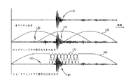
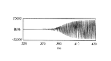
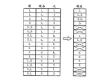
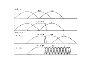
この問題を明らかに図示するために、図1は過渡音声を有する信号が符号化される例を示す。
図1において、符号化されるオリジナル信号100は小さい振幅範囲の後に続く高い振幅範囲の後に突然続く非常に小さな振幅範囲を有することが示されている。これは過渡信号ということがわかる。ロングウィンドウ120によってオリジナル信号100は符号化された後、符号化された信号110が得られる。量子化誤差の拡散は過渡高振幅の前の範囲130の符号化された信号110で見られる。オリジナル信号100のこの範囲には実質的に信号がないので、量子化誤差はより多くのドミナント信号によってマスクされない。一般的に、量子化誤差は一ウィンドウが実質的に異なる振幅を含む一エリアにかかる周波数領域符号化を使用するとき現われ、拡散する。周波数領域圧縮の結果として、ウィンドウ内のデータは特徴をシェアする傾向がある。符号化されたオーディオにおける量子化誤差はリスナーには不快である。
To clearly illustrate this problem, FIG. 1 shows an example in which a signal with transient speech is encoded.
In FIG. 1, the
量子化誤差を低減させる一方法は、異なる長さのウィンドウを使用することである。図1に示すように、量子化誤差の拡散はロングウィンドウ160がショートウィンドウ170との接続で使用されたとき、量子化された信号140の範囲150で低減される。ロングウィンドウの符号化された信号110と比較し、量子化誤差の拡散はショートウィンドウの量子化された信号のショートウィンドウ期間によって阻止される。
One way to reduce the quantization error is to use windows of different lengths. As shown in FIG. 1, the diffusion of quantization error is reduced in the
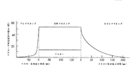
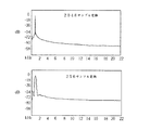
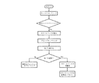
プレエコー現象の説明を行う。テンポラルマスキングは同時マスキング、プレマスキングおよびポストマスキングを含む。各マスキングのタイプの効果を図2に示す。プレマスキングおよびポストマスキングの効果的なマスカーの持続期間はそれぞれおよそ20msおよび100msである。過渡信号またはオーディオアタックが周波数領域へと符号化されたとき、量子化誤差は時間領域の信号ブロック全体へと拡散する。アタック前の信号部分は相対的に小さいので、アタックはそのエネルギーの大部分が信号ブロックへ最も寄与し、このようにマスキング閾値の生成を制御する。そのとき閾値はブロックの静寂範囲では高すぎる。一般のロングウィンドウサイズは2048サンプルであり、サンプルレートが44.1kHzのとき約46msを表現し、プレマスキングが20ms未満続くので、この過渡信号を符号化するのにロングウィンドウを使用したとき、量子化誤差の拡散はリスナーに容易に聞かれる。これはプレエコー現象と呼ばれる。 The pre-echo phenomenon will be explained. Temporal masking includes simultaneous masking, premasking and postmasking. The effect of each masking type is shown in FIG. The effective masker duration for pre-masking and post-masking is approximately 20 ms and 100 ms, respectively. When a transient signal or audio attack is encoded into the frequency domain, the quantization error is spread over the entire signal block in the time domain. Since the signal portion before the attack is relatively small, the attack contributes most to the signal block, thus controlling the generation of the masking threshold. The threshold is then too high in the block silence range. A typical long window size is 2048 samples, representing approximately 46 ms when the sample rate is 44.1 kHz, and premasking lasts less than 20 ms, so when using a long window to encode this transient signal, quantum Listener error diffusion is easily heard by listeners. This is called a pre-echo phenomenon.
さらに、現在のオーディオ符号化にとって、M/S(ミドル信号/サイド信号)符号化はステレオチャンネルにおける不適切で冗長な情報を効果的に低減させる中心技術である。二つ以上のチャンネル数に対し、現在のMPEG2 AACおよびMPEG4 AAC標準で使用される方法はチャンネルをペアに分割し、それからM/S符号化をそれぞれのペアに用いる方法である。符号化利得がAACに存在するとき、M/S符号化の使用は選択的なスペクトル領域範囲に適用することができる。MPEG4 AAC符号化標準において、帯域毎のM/S符号化はチャンネルの不適切性および冗長性を低減させるのに更なる融通性を提供する。しかし、その融通性はエンコーダの設計寸法および複雑度を増加させる。 Furthermore, for current audio coding, M / S (middle signal / side signal) coding is a central technology that effectively reduces inappropriate and redundant information in the stereo channel. For more than two channels, the method used in the current MPEG2 AAC and MPEG4 AAC standards is to divide channels into pairs and then use M / S coding for each pair. When coding gain is present in AAC, the use of M / S coding can be applied to selective spectral domain ranges. In the MPEG4 AAC coding standard, per-band M / S coding provides further flexibility to reduce channel inadequacy and redundancy. However, its flexibility increases encoder design dimensions and complexity.
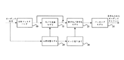
M/S符号化はL/R(左/右)信号をM/S信号へと変換するM/S変換モデルを含む拡大された聴覚オーディオ符号化である。図3は従来技術によるM/S変換での聴覚符号化を示すブロック図である。L/Rオーディオ信号は分析フィルタバンク10によって重複ブロックに分割され、周波数領域に変換される。仮に心理音響モデル20によって計算される符号化利得がある場合、M/S変換モデル15は周波数領域およびM/S信号への変換機のL/R信号を受信する。量子化/符号化モデル25はビット割り当て30によって決定されたいくつかのパラメータと共にこれらの信号の量子化および符号化をする信号を受信する。
M / S coding is an expanded auditory audio coding that includes an M / S conversion model that converts L / R (left / right) signals to M / S signals. FIG. 3 is a block diagram showing auditory coding by M / S conversion according to the prior art. The L / R audio signal is divided into overlapping blocks by the
心理音響モデル20はL/R信号内容を分析し、関連する人間の聴覚システムの聴覚分解能を計算する。聴覚分解能および使用可能なビットに基づいて、ビット割り当て30はビットレートに符合する好適な量子化方法を決定する。パッキングモデル35は規格により特定されたフォーマットで符号化された情報のすべてをパッキングする。帯域毎のM/S符号化に関する文献が存在する。
The
第1の文献はM/S信号のための心理音響モデル20に関するものである。心理音響モデル20は人間の聴覚システムをシミュレートし、量子化のための正しいマスキング閾値を与えようとする。LおよびRチャンネルに対する心理音響モデル20のマスキングモデルは標準においてすでに構築されている。しかし、MおよびSチャンネルに同じ手順を置くことは合理的ではない。その上、心理音響モデル20の複雑度はL/R符号化の15%以上のファクタに寄与している。心理音響モデル20からの追加的な複雑度はM/S符号化の費用の増加をもたらす。
The first document relates to a
第2の文献はそれぞれの帯域に基づいた信号の符号化の決定に関するものである。この決定はM/S符号化からL/R符号化への符号化利得の測定に関係する。帯域状態の切り替えは心理音響モデル20によって最大符号化利得を探し出すことを目的とする。全ての可能なケースを評価することによって最適の決定が探し出され、再構築信号を計算し、全てのケースから最小の歪を探し出す。オーディオ信号ファームは49の帯域を含むので、全ての可能なケースに対して命令O(2^49)の複雑度算定数値を有する。
The second document relates to the determination of signal encoding based on each band. This determination relates to the measurement of coding gain from M / S coding to L / R coding. The purpose of switching the band state is to find the maximum coding gain by the
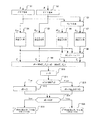
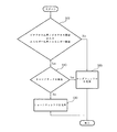
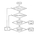
M/S符号化は自由に使用され、もっとも代表的なAACエンコーダであるFAACは緻密なパラメータ調整がされたジョンストンの調査に基づいて改良された。図4は従来技術によるFAACにおけるM/S符号化の帯域状態を決定する過程を示すフローチャート図である。心理音響モデル20はM/S符号化のそれぞれの帯域状態を決定するL/R信号を受信し、下記のステップを含む。
M / S coding is freely used, and FAAC, the most representative AAC encoder, has been improved based on Johnston's research with fine parameter adjustments. FIG. 4 is a flowchart showing a process for determining the band state of M / S encoding in FAAC according to the prior art. The
ステップ1〜ステップ2:左信号および右信号を高速フーリエ変換(FFT:Fast Fourier Transform)によって左FFT(LFFT)信号および右FFT(RFFT)信号に変換する。
ステップ3:左FFT信号および右FFT信号をミドルFFT(MFFT)信号およびサイドFFT(SFFT)信号に変換する。 Step 3: The left FFT signal and the right FFT signal are converted into a middle FFT (M FFT ) signal and a side FFT (S FFT ) signal.
ステップ4〜ステップ5:心理音響モデル20のマスキングモデルによって左信号および右信号のマスキング閾値(TL、TR)をそれぞれ計算する。
ステップ6〜ステップ8:ミドル信号およびサイド信号のマスキング閾値(TM、TS)を計算し、M/S信号はL/R符号化の中で同じモデルであるマスキングモデルに入れられ、マスキング閾値を取得する。その後、最後のマスキング閾値がバイノーラルMLD(masking level difference)効果を利用することによって決定される。
ステップ9〜ステップ14:db<0.25のときステップ15を実行するために計算および比較を行い、そうでなければステップ16を実行する。
ステップ15:ith帯域状態はM/S状態であると決定し、それからM/S変換モデル15はM/S信号へのNth帯域変換機のL/R信号を受信し、これらのM/S信号は量子化/符号化モデル25によって量子化および符号化される。
Step 15: It is determined that the i th band state is the M / S state, and then the M /
ステップ16:Nth帯域状態はL/R状態であると決定し、量子化/符号化モデル25はNthのL/R信号を受信して量子化および符号化を行う。
Step 16: It is determined that the N th band state is the L / R state, and the quantization /
FAACの帯域状態の決定に関する問題が存在する。第1の問題は、FAACはM/S帯域使用を決定するマスキング閾値の相違度のみを使用し、M/S信号はL/R閾値の中で同じモデルであるマスキングモデルに入れられ、マスキング閾値を取得する。M/S信号を置くことは合理的ではない。閾値の設定および基準の比較によって帯域状態使用を容易に決定することができるが、連続した帯域情報は使用できず、一つのフレーム内の不安定な状態の切り替えは効果的にそれぞれの帯域にビットを割り当てることができず、サイド情報が増加してしまう。さらに、全ての可能なケースを評価し、再構築された信号を計算し、各ケースから最低歪を見つけることによって最適な帯域状態の決定が見つけ出される。しかし、命令O(2^49)の複雑度計算は導入するには高価すぎる。 There are problems with determining the bandwidth state of FAAC. The first problem is that FAAC uses only the masking threshold dissimilarity that determines M / S band usage, and the M / S signal is put into a masking model that is the same model among the L / R thresholds. To get. Placing the M / S signal is not reasonable. Bandwidth usage can be easily determined by setting the threshold and comparing the criteria, but continuous bandwidth information is not available, and switching of unstable states within one frame is effectively a bit in each bandwidth. Cannot be assigned, and the side information increases. In addition, an optimal bandwidth state determination is found by evaluating all possible cases, calculating the reconstructed signal, and finding the lowest distortion from each case. However, the complexity calculation of the instruction O (2 ^ 49) is too expensive to introduce.
従って、本発明は、プレエコー、時間複雑度およびその他欠点などの量子化誤差を低減させるオーディオ圧縮方法およびAACのためのM/S符号化の帯域状態の決定方法に関する。
本発明の第1の目的は、量子化誤差を低減させる方法およびそれに関連する装置を提供することにある。
本発明の第2の目的は、各PE(聴覚エントロピー)を考慮し、隣の帯域の符号化状態を変更するための帯域の状態を決定し、時間複雑度を低減させるAACのためのM/S符号化の帯域状態の決定方法を提供することにある。
本発明の第3の目的は、どんな補助機能を使用するよりも簡単で、安価な計算で最適の帯域状態決定を見つけ出す方法を提供することにある。
本発明の第4の目的は、M/Sマスキング閾値を取得する心理音響モデルのM/S符号化モデルを修正する方法を提供することにあり、M/S信号を置くことは合理的である。
本発明の第5の目的は、AACのためのM/S符号化の帯域状態の決定方法を提供することにあり、大多数の帯域を含む少なくとも一つのオーディオストリームを受信するステップと、左信号、右信号、ミドル信号およびサイド信号を含む各帯域の、右信号および左信号のPE(聴覚エントロピー)値の合計である第1のノード、およびミドル信号およびサイド信号のPE値の合計である第2のノードを計算するステップと、Nth帯域の第1のノードから(N+1)th帯域の第1または第2のノード、或いはNth帯域の第2のノードから(N+1)th帯域の第1または第2のノードまでである各隣の帯域の最小コストパス値を計算するステップと、状態がL/R状態またはM/S状態であろう最小コストパス値に基づいて各帯域の状態を決定するステップとを含み、その方法は安価な計算およびM/Sマスキング閾値を提供し、時間複雑度を低減させる。
本発明のその他の目的は、発明を実施するための最良の形態での記述を読むことによって明らかになる。
It is a first object of the present invention to provide a method and related apparatus for reducing quantization error.
The second object of the present invention is to consider each PE (auditory entropy), determine the state of a band for changing the coding state of the adjacent band, and reduce M / for AAC to reduce time complexity. An object of the present invention is to provide a method for determining the band state of S encoding.
A third object of the present invention is to provide a method that finds the optimal bandwidth state determination with simpler and cheaper computation than using any auxiliary function.
The fourth object of the present invention is to provide a method for modifying the M / S coding model of the psychoacoustic model for obtaining the M / S masking threshold, and it is reasonable to put the M / S signal. .
A fifth object of the present invention is to provide a method for determining a band state of M / S coding for AAC, receiving at least one audio stream including a majority band, and a left signal. A first node that is the sum of the PE (auditory entropy) values of the right signal and the left signal, and the sum of the PE values of the middle signal and the side signal in each band including the right signal, the middle signal, and the side signal. calculating a second node, the first node N th band (N + 1) the first or second node of th band, or from the second node of the N th band (N + 1) th first band Or calculating the minimum cost path value of each adjacent band up to the second node and determining the state of each band based on the minimum cost path value that would be in the L / R state or M / S state That comprises the steps, the method provides an inexpensive computing and M / S masking threshold, reduce the time complexity.
Other objects of the invention will become apparent upon reading the description of the best mode for carrying out the invention.
上述の課題を解決するために、本発明は、オーディオ信号の第1の範囲のグローバルエネルギー比率を決定し、グローバルエネルギー比率を第1の閾値と比較する方法を提供し、オーディオ信号のブロックを受信するステップと、オーディオ信号の第1の範囲のグローバルエネルギー比率を決定し、グローバルエネルギー比率と第1の閾値とを比較するステップと、オーディオ信号の第2の範囲のゼロクロス比率を決定し、ゼロクロス比率と第2の閾値とを比較するステップと、グローバルエネルギー比率またはゼロクロス比率が第1または第2の閾値を超え、オーディオ信号の第3の範囲のトーンアタックが検出されないときショート符号化ウィンドウを選択するステップと、グローバルエネルギー比率およびゼロクロス比率が第1および第2の閾値を超えないとき、或いはオーディオ信号の第3の範囲のトーンアタックが検出されたときロング符号化ウィンドウを選択するステップと、選択された符号化ウィンドウで、第1、第2および第3の範囲と共通であるオーディオ信号の第4の範囲を符号化するステップとを含む。
本発明はさらにACCのためのM/S符号化の帯域状態の決定方法を提供し、帯域の大部分を含む少なくとも1つのオーディオストリームを受信するステップと、左信号、右信号、ミドル信号、およびサイド信号を含む各帯域の第1のノードおよび第2のノードを計算するステップと、各隣の帯域の最小コストパス値を計算するステップと、状態がL/R状態またはM/S状態であろう最小コストパス値に基づいて各帯域の状態を決定するステップとを含む。
To solve the above problems, the present invention provides a method for determining a global energy ratio of a first range of an audio signal, comparing the global energy ratio with a first threshold, and receiving a block of the audio signal. Determining a global energy ratio of the first range of the audio signal, comparing the global energy ratio with a first threshold, determining a zero cross ratio of the second range of the audio signal, and zero cross ratio Comparing the second and second thresholds, and selecting a short coding window when the global energy ratio or zero crossing ratio exceeds the first or second threshold and no third range tone attack of the audio signal is detected. Steps, the global energy ratio and the zero-cross ratio are the first and Selecting a long encoding window when a threshold of 2 is not exceeded, or when a tone attack of the third range of the audio signal is detected, and the first, second and third in the selected encoding window Encoding a fourth range of the audio signal that is common to the range of.
The present invention further provides a method for determining a band state of M / S coding for ACC, receiving at least one audio stream including a majority of the band, a left signal, a right signal, a middle signal, and Calculating a first node and a second node of each band including a side signal; calculating a minimum cost path value of each adjacent band; and the state is an L / R state or an M / S state Determining a state of each band based on a wax minimum cost path value.
本発明は、グローバルエネルギーへの考慮から、ゼロクロスおよびオーディオ信号のトーンアタックはショートウィンドウおよびロングウィンドウの選択を許し、このことによって量子化誤差をかなり低減することができる。 The present invention, from a global energy consideration, allows zero-cross and audio signal tone attacks to select between short and long windows, which can significantly reduce quantization errors.
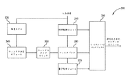
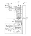
図5は、本発明の実施例のAAC(advanced audio coding)エンコーダ300を示すブロック図である。
AACエンコーダ300は利得制御ユニット310、聴覚モデル320、フィルタバンク330、ウィンドウ決定モジュール340およびビットストリームマルチプレクサ350から構成される。入力信号が利得制御ユニット310および聴覚モデル320からAACエンコーダ300に入力される。聴覚モデル320はウィンドウ決定方法(後ほど説明を行う)と関連がある情報をウィンドウ決定モジュール340に送る。ウィンドウ決定モジュール340はウィンドウサイズを選択し、適切な情報の入力信号を符号化するために、選択されたウィンドウサイズを使用するフィルタバンク330に通過させ、利得制御ユニット310の出力と協調して符号化されたオーディオストリームが生成される。AACエンコーダ300はさらにウィンドウ決定モジュール340とフィルタバンク330との間に接続されるウィンドウタイプスイッチ360およびフィルタバンク330とビットストリームマルチプレクサ350との間に接続される量子化モジュール370を備える。
上述の具体的な実施例によって本発明が制限されることはなく、AACエンコーダ300はISO/IEC MPEG‐2/4規格に合わせて設計することもできる。
FIG. 5 is a block diagram illustrating an AAC (advanced audio coding)
The
The present invention is not limited by the specific embodiments described above, and the
フィルタバンク330はロングウィンドウまたはショートウィンドウを選択することによる2048サンプルまたは256サンプルの入力期間を有する変換間での移行によって入力信号に対して時間周波数変換を行う。
The
2048サンプルおよび256サンプルの二つのウィンドウサイズはただの模範であり、二つウィンドウサイズより大きなものや異なるサイズのウィンドウでもよい。256サンプル期間は過渡信号符号化のためのものであり、周波数選択度とプレエコー抑制との間での良好な折衷点である。 The two window sizes of 2048 samples and 256 samples are merely exemplary, and may be larger than the two window sizes or different size windows. The 256 sample period is for transient signal coding and is a good compromise between frequency selectivity and pre-echo suppression.
図1に示すように、ロング変換とショート変換との間の遷移の間、スタートとストップとのブリッジされた変換(即ち、スタートウィンドウおよびストップウィンドウ)はMDCT(Modified Discrete Cosine Transformation)およびIMDCT(逆MDCT)の時間領域エイリアシング打消し特性の維持に使用され、ウィンドウアライメントが維持される。一般に、2048サンプルロング変換はロングシーケンスと呼ばれ、グループ内で発生する256サンプルショート変換はショートシーケンスと呼ばれる。ショートシーケンスは約50%が相互に重複するように配置され、スタートウィンドウおよびストップウィンドウに重複する境界の変換の半分を有する八つのショートウィンドウ変換を有することができる。
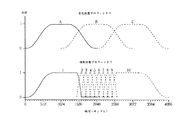
図6に示すように、これらの重複するシーケンスグループはウィンドウをスタートシーケンス、ストップシーケンス、ロングシーケンスおよびショートシーケンスに変換する。図6の下のカーブはストップウィンドウに続く八つのショートウィンドウに続くスタートウィンドウを示し、上のカーブは過渡信号不在でのロングウィンドウ符号化を示す。
As shown in FIG. 1, during the transition between long and short transformations, the bridged transformation between start and stop (ie, start window and stop window) is MDCT (Modified Discrete Cosine Transformation) and IMDCT (inverse). MDCT) is used to maintain time domain aliasing cancellation characteristics and window alignment is maintained. In general, a 2048 sample long transform is called a long sequence, and a 256 sample short transform occurring within a group is called a short sequence. The short sequence is arranged so that about 50% overlaps each other and can have eight short window transformations with half of the boundary transformations overlapping the start and stop windows.
As shown in FIG. 6, these overlapping sequence groups transform windows into start sequences, stop sequences, long sequences and short sequences. The lower curve in FIG. 6 shows the start window following the eight short windows following the stop window, and the upper curve shows the long window encoding in the absence of transient signals.
ショートウィンドウは高い時間分解能を有し、ロングウィンドウは高い周波数分解能を有するので、過渡信号はショートウィンドウから恩恵を受けてプレエコー効果を制御し、非過渡信号(即ち、変動がない)信号はロングウィンドウから恩恵を受けて余剰を取り出すために信号スペクトルの線路を分析する。仮に非過渡信号がショートウィンドウで発生した場合、低周波数分解能が周波数領域の符号化された信号の精密度を低減させる。第1の実施例では、AACエンコーダ300のウィンドウ決定モジュール340は、グローバルエネルギー比率、ゼロクロス比率およびトーンアタックを参照して次のウィンドウサイズを選択する。
Since the short window has a high time resolution and the long window has a high frequency resolution, the transient signal benefits from the short window to control the pre-echo effect, and the non-transient signal (ie, no variation) signal is a long window. Analyze signal spectrum lines to get the surplus to benefit from. If a non-transient signal occurs in a short window, the low frequency resolution reduces the accuracy of the frequency domain encoded signal. In the first embodiment, the
グローバルエネルギー比率:時間領域エネルギーが急激に変化するとき過渡信号は通常発生する。ゆえに過渡信号を検出するのにエネルギー比率が使用される。従来のエネルギー比率の検出方法は二つのスライドするショートウィンドウ間のエネルギー比率だけが考慮されたが、このエネルギー比率は徐々に増加する信号の検出には不適当である。一般にプリエコー効果は最も高いエネルギーを有する信号部分によって生成される。 Global energy ratio: Transient signals usually occur when time domain energy changes rapidly. Therefore, energy ratio is used to detect transient signals. Conventional energy ratio detection methods only consider the energy ratio between two sliding short windows, but this energy ratio is unsuitable for detecting signals that increase gradually. In general, the pre-echo effect is generated by the signal portion having the highest energy.
図7はスピーチ信号の例を示す図である。図7の三つの信号は上から、徐々に増加する過渡信号、エネルギー比率の従来値および本発明によるグローバルエネルギー比率である。従来のエネルギー比率の最高値は約2.1であるが、過渡検出閾値が2.0にセットされた場合、誤判断が容易に発生する。グローバルエネルギー比率方法はこの問題を解決するエネルギー比率の検出可能値をさらに容易に提供する。 FIG. 7 is a diagram illustrating an example of a speech signal. The three signals in FIG. 7 are, from above, a gradually increasing transient signal, the conventional value of the energy ratio and the global energy ratio according to the present invention. The maximum value of the conventional energy ratio is about 2.1. However, when the transient detection threshold is set to 2.0, erroneous determination easily occurs. The global energy ratio method more easily provides a detectable value of the energy ratio that solves this problem.
256サンプルウィンドウWiのエネルギー機能En(i)を決定するために、本発明では数式1に示すような入力信号Xkの二乗和を使用する。
In order to determine the energy function En (i) of the 256 sample window Wi, the present invention uses the square sum of the input signal Xk as shown in
(数1)

それから、ショートウィンドウのエネルギーEn(i)のセット内の最高エネルギーMax_Enおよび最低エネルギーMin_Enが見つけ出される。このようにグローバルエネルギー比率は数式2のように定義される。
Then, the highest energy Max_En and the lowest energy Min_En in the set of short window energies En (i) are found. Thus, the global energy ratio is defined as
(数2)
従って、グローバルエネルギー比率Global_En_Ratioが所定のエネルギー閾値よりも大きい場合、信号は過渡信号であるとみなされる。図7の下部の二つのグラフの比較から分かるように、数式1および数式2は改善された過渡信号検出を提供する。
Thus, if the global energy ratio Global_En_Ratio is greater than a predetermined energy threshold, the signal is considered a transient signal. As can be seen from the comparison of the two graphs at the bottom of FIG. 7,
ゼロクロス比率:グローバルエネルギー比率単独ではスペクトル内容の迅速な変更のあるセグメントを有する信号の検出を行うことはできないので、信号のメインの周波数内容を表現するためにゼロクロスレートが使用される。 Zero cross ratio: The zero cross rate is used to represent the main frequency content of the signal because the global energy ratio alone cannot detect signals with segments with rapid changes in spectral content.
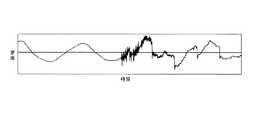
一例として、図8は安定したグローバルエネルギー比率での過渡信号を示す図であるが、この信号はスペクトル内容での急激な変化を有する。各256サンプルショートウィンドウのゼロクロスレートZe(i)が数式3のように定義されるときゼロクロス比率はこの種の過渡信号を検出できる。
As an example, FIG. 8 shows a transient signal with a stable global energy ratio, but this signal has an abrupt change in spectral content. When the zero cross rate Ze (i) of each 256 sample short window is defined as
(数3)
それから、ショートウィンドウのゼロクロスレートのセット内の最高ゼロクロスレートMax_Zeおよび最低ゼロクロスレートMin_Zeが見つけ出される。このようにゼロクロス比率は数式4のように定義される。
Then, the highest zero cross rate Max_Ze and the lowest zero cross rate Min_Ze within the set of short window zero cross rates are found. Thus, the zero cross ratio is defined as in
(数4)
ゼロクロス比率Ze_Ratioがゼロクロス閾値よりも大きいとき、信号は過渡信号であると見なされる。この方法は従来の方法よりも複雑度が低く、例えばバイオリンおよびスピーチ内の信号の過渡を正確に検出することができる。 When the zero cross ratio Ze_Ratio is greater than the zero cross threshold, the signal is considered to be a transient signal. This method is less complex than conventional methods and can accurately detect signal transients in, for example, violins and speech.
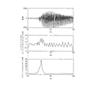
トーンアタック:一般にショートウィンドウはロングウィンドウよりも低い周波数分解能を有する。図9は本発明のグローバルエネルギー比率によって恐らく過渡信号であると見なされる純音声の信号の例を示す図である。
図10は2048サンプル変換(上)および256サンプル変換(下)によって変換された周波数を示す。図10において、短い方の変換によるトーン信号変換はサイド帯域エネルギーの増加をもたらすことが見られる。トーンアタック効果は信号がロングウィンドウ心理音響モデル(後ほど述べる)によって分析されたトーン帯域を有するときと定義される。
Tone attack: In general, a short window has a lower frequency resolution than a long window. FIG. 9 is a diagram illustrating an example of a pure speech signal that is considered to be a transient signal by the global energy ratio of the present invention.
FIG. 10 shows the frequency converted by the 2048 sample conversion (top) and 256 sample conversion (bottom). In FIG. 10, it can be seen that tone signal conversion by the shorter conversion results in an increase in sideband energy. A tone attack effect is defined when the signal has a tone band analyzed by a long window psychoacoustic model (discussed later).
ウィンドウ決定方法:ウィンドウ決定方法は上述のグローバルエネルギー比率、ゼロクロス比率およびトーンアタックが考慮される。図11は過渡信号の検出にグローバルエネルギー比率およびゼロクロス比率を使用し、トーンアタック分析による誤検出を避けることを表すフローチャート図である。ステップ900でエネルギー比率またはゼロクロス比率のどちらかがそれぞれの閾値を超えているか測定される。これらの比率のどちらかが閾値を超える場合、トーンアタックがステップ910でテストされる。両方の比率が閾値を超えない場合またはトーンアタックが検出された場合、ロングウィンドウがステップ920で選択される。しかし、比率のどちらかが閾値を越え、ステップ910でトーンアタックが検出されない場合、ステップ930でショートウィンドウが選択される。第1の実施例では図11のフローチャート図で達成される手順は図5に示すAACエンコーダ300のウィンドウ決定モジュール340によって実行される。
Window determination method: The above-described global energy ratio, zero cross ratio and tone attack are considered in the window determination method. FIG. 11 is a flowchart showing the use of the global energy ratio and the zero-cross ratio for detection of transient signals and avoiding false detection by tone attack analysis. In
上述の手順はオーディオ信号全体の符号化が完成するように繰り返される。 The above procedure is repeated to complete the encoding of the entire audio signal.
図12は、本発明のもう1つの実施例によるAACエンコーダ1000を示すブロック図である。AACエンコーダ300と同様に、AACエンコーダ1000は聴覚モデル320、フィルタバンク330、ウィンドウ決定モジュール340およびビットストリームマルチプレクサ350を備える。AACエンコーダ1000はさらにウィンドウタイプスイッチ1010、TNS(temporal noise shaping)ユニット1020、ショートウィンドウスケールファクタ評価ユニット1030、グルーピングユニット1040およびM/S符号化ユニット1050を備える。AACエンコーダ1000はさらに利得制御を提供する反復ループ1060を備える。
FIG. 12 is a block diagram illustrating an
図13は、本発明のさらにもう1つの実施例によるAACエンコーダ1100を示すブロック図である。AACエンコーダ300と同様に、AACエンコーダ1100は聴覚モデル320、フィルタバンク330、ウィンドウ決定モジュール340およびビットストリームマルチプレクサ350を備える。
FIG. 13 is a block diagram illustrating an
AACエンコーダ1000と同様に、AACエンコーダ1100はさらにウィンドウタイプスイッチ1010、TNS(temporal noise shaping)ユニット1020、ショートウィンドウスケールファクタ評価ユニット1030、グルーピングユニット1040およびM/S符号化ユニット1050を備える。AACエンコーダ1100はさらにウィンドウカップリングユニット1105、グループカップリングユニット1110、ショートウィンドウスケールファクタ再評価ユニット1120および利得制御を提供する反復ループ1130を備える。
Similar to the
さらに、手順を表すいくつかの構成要素が併合されるが、説明を明確にするためにここでは分割して説明を行う。例えばショートウィンドウスケールファクタ評価ユニット1030とショートウィンドウスケールファクタ再評価ユニット1120は同一の物理的装置とすることができる。
Furthermore, although some components representing the procedure are merged, the explanation is divided here for the sake of clarity. For example, the short window scale
ウィンドウタイプスイッチ360、1010:ウィンドウ決定モジュール340が次のフレームのウィンドウタイプを決定した後、現在のウィンドウタイプはウィンドウタイプスイッチ1010を使用して次のウィンドウタイプと前のウィンドウタイプとを比較することによって切り替えられる。
スタートタイプウィンドウはロングウィンドウとショートウィンドウとをブリッジするのに使用される。そのために、ウィンドウ決定モジュール340は予め次のフレームのウィンドウタイプを決定しなければならず、次のフレームが前のフレームと異なる場合、現在のフレームはスタートウィンドウタイプまたはストップウィンドウタイプに切り替えられる。
The start type window is used to bridge a long window and a short window. For this, the
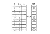
図14は、ウィンドウタイプスイッチの全ての可能な状況の分析を示す図である。ロングウィンドウ、ショートウィンドウ、スタートウィンドウおよびストップウィンドウがそれぞれL、S、L_SおよびS_Lで表される。いくつかの不可能な状況を無視することによって簡単なスイッチング演算式を得ることができる。 FIG. 14 shows an analysis of all possible situations of the window type switch. A long window, a short window, a start window, and a stop window are represented by L, S, L_S, and S_L, respectively. A simple switching equation can be obtained by ignoring some impossible situations.
if (Current == S) {
if (Previous == S || Previous == L_S)
Current = S;
} else {
if (Previous == L || Previous == S_L) {
if (Next == L)
Current = L;
else Current = L_S;
} else if (Previous == S) {
if (Next == L)
Current = S_L;
else
Current = S;
}
}
Previous [] = Current[]; Current [] = Next[]
if (Current == S) {
if (Previous == S || Previous == L_S)
Current = S;
} else {
if (Previous == L || Previous == S_L) {
if (Next == L)
Current = L;
else Current = L_S;
} else if (Previous == S) {
if (Next == L)
Current = S_L;
else
Current = S;
}
}
Previous [] = Current []; Current [] = Next []
この演算式はウィンドウタイプスイッチ360および/または1010によって実行され、そのような変更が隣接するウィンドウタイプによって必要とされる場合、現在のウィンドウは変更される。
This formula is executed by
心理音響モデル:心理音響モデルはどの特定の音声信号が人間に聞き取られ、どれが聞き取られないかを決定し、どの音声を無視してよいかを制御する。異なるウィンドウサイズは心理音響モデルの異なる解釈および標準化を要求する。仮にウィンドウシーケンスが八つのショートウィンドウから構成される場合、AACエンコーダ300、1000、1100はショートウィンドウ心理音響モデルを八回実行する必要がある。
Psychoacoustic model: The psychoacoustic model determines which specific speech signals are heard by humans, which are not heard, and controls which speech can be ignored. Different window sizes require different interpretations and standardizations of the psychoacoustic model. If the window sequence is composed of eight short windows, the
心理音響モデルはフィルタバンク330のそれぞれの帯域のために顕著なノイズレベルを決定するのに必要である最低マスキング閾値を計算する。
The psychoacoustic model calculates the minimum masking threshold required to determine a significant noise level for each band of
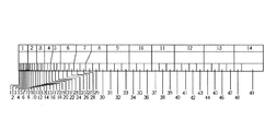
図15は、サンプルレートが44.1kHzのときのショートウィンドウの14の帯域に対応するロングウィンドウの49の帯域のマッピング結果の例を示す図である。仮にフレームがショートウィンドウを使用する場合、SMRsはロングウィンドウから取得される。 FIG. 15 is a diagram illustrating an example of a mapping result of 49 bands of the long window corresponding to 14 bands of the short window when the sample rate is 44.1 kHz. If the frame uses a short window, SMRs are obtained from the long window.
この改良はAACエンコーダ300、1000および1100の聴覚モデル320またはウィンドウ決定モジュール340によって実行される。
This refinement is performed by the
グルーピングユニット1040およびスケールファクタ評価ユニット1030/1120:仮にウィンドウシーケンスが八つのショートウィンドウから構成される場合、1024係数のセットは実際は八つのショートウィンドウの持続期間上の信号の時間周波数分解能を表す8×128周波数係数のマトリクスである。具体的に述べると、1024係数のセットcはインターリーブ前に次のように索引付けされる。
c[g][w][b][k] c [g] [w] [b] [k]
gはグループ索引であり、wはグループ内でのウィンドウの索引であり、bはウィンドウ内でのスケールファクタ帯域の索引であり、kはスケールファクタ帯域内での係数の索引であり、最左側の索引は最も迅速に変わる。 g is the group index, w is the index of the window within the group, b is the index of the scale factor band within the window, k is the index of the coefficient within the scale factor band, and the leftmost The index changes most quickly.
インターリーブ後、係数は次のように索引付けされる。 After interleaving, the coefficients are indexed as follows:
c[g][b][w][k] c [g] [b] [w] [k]
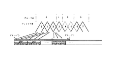
図16はショートウィンドウグルーピングおよびインターリーブの例を示す図である。図16において、グループ0は0、1および2と索引付けされたショートウィンドウを含む。インターリーブ後、これらの三つのショートウィンドウの第1の帯域は大きなスケールファクタ帯域(sfb 0)を形成する。グルーピング方法は異なる符号化の考慮のためにスケールファクタ帯域の数に柔軟性を提供する。
FIG. 16 is a diagram illustrating an example of short window grouping and interleaving. In FIG. 16,
ショートウィンドウはショートウィンドウ内にある量子化のノイズの拡散を制御することによって過渡信号を好適に取り扱うことができる。しかし、AACエンコーダ1000、1100がショートウィンドウを使用する場合、スケールファクタ帯域の総数は1つのロングウィンドウを使用する場合の二倍となる。
The short window can preferably handle the transient signal by controlling the diffusion of quantization noise within the short window. However, when the
本発明では、グルーピングユニット1040で実行されるグルーピング方法はスケールファクタ推定ユニット1030または1120で決定された八つのショートウィンドウの推定スケールファクタを使用する。従って、スケールファクタはAACエンコーダ1000内で相対的に初期にあるショートウィンドウスケールファクタ評価ユニット1030で推定されるので、グルーピング方法は他のコーデックモジュール(例えばM/S符号化ユニット1050)でより柔軟に適用される。
In the present invention, the grouping method performed by the
スケールファクタを推定するために、次の方程式が使用され、非一様量子化器の量子化誤差の予想eiは、数式5のようになる。 The following equation is used to estimate the scale factor, and the expected ei of the quantization error of the non-uniform quantizer is
(数5)
Δqは量子化ステップサイズであって、数式6のように定義される。
Delta q is a quantization step size is defined as
(数6)
gはスケールファクタ帯域qの独立したグローバル利得である。cqは各スケールファクタ帯域のスケールファクタである。 g is an independent global gain of the scale factor band q. cq is a scale factor of each scale factor band.
ビット割り当てのスケールファクタ推定は、帯域幅比例ノイズシェーピング基準に基づく。スケールファクタ帯域に対するノイズレベルは有効帯域幅B(q)に比例する。 The bit factor scale factor estimate is based on a bandwidth proportional noise shaping criterion. The noise level for the scale factor band is proportional to the effective bandwidth B (q).
(数7)
σ2 N(q)およびσ2 M(q)はスケールファクタバンドqに関連するノイズエネルギーおよびマスキングエネルギーである。 σ 2 N (q) and σ 2 M (q) are noise energy and masking energy associated with the scale factor band q.
数式5でスケールファクタをノイズパワーと関係させ、簡単に数式5と数式6とを結びつける。E[ei 2]=σ2 N(q) をさせ、T2 q=σ2 M(q)・B(q) を定義する。ビット割り当てのための量子化誤差の予想は数式8で表される。
In
(数8)
量子化ステップサイズの二乗Δq 2は数式9で表される。
The square Δ q 2 of the quantization step size is expressed by
(数9)
グローバル利得gとスケールファクタとの違いは数式10によって評価される。
The difference between the global gain g and the scale factor is evaluated by
(数10)
数式10から、グローバル利得gは数式11から評価される。
From
(数11)
そして全てのサブ帯域に対するスケールファクタが得られる。 And scale factors for all sub-bands are obtained.
グルーピング方法に関して、同じグループのショートウィンドウはグループ内の全てのスケールファクタ帯域間でスケールファクタをシェアするので、同じグループのショートウィンドウのシェアされたスケールファクタ(sharesfbg,b)および推定スケールファクタ(sfb,w)の違いは制限される。スケールファクタの違いに加え、この違いの影響は帯域幅(bandwidthb)に比例する。従って、グループgのスケールファクタエラーは数式12によって推定される。
With respect to grouping methods, the same group of short windows share the scale factor across all scale factor bands in the group, so the shared group's short window shared scale factor (sharesfb g, b ) and estimated scale factor (sf b, w ) differences are limited. In addition to the difference in scale factor, the effect of this difference is proportional to bandwidth ( b ). Therefore, the scale factor error of group g is estimated by
(数12)
グルーピング方法の基準はグルーピング数を最小化し、各グループのスケールファクタエラーEgは閾値Mよりも小さくなる。この基準によって、図17のフローチャート図に示す演算式が実行される。先ずスケールファクタ推定が実行される。その後、第1のショートウィンドウでグルーピング方法がスタートする。1つのグループのショートウィンドウは連続的であるので、演算式は各ショートウィンドウを前のショートウィンドウが属するグループに置こうとする。新しいグループのスケールファクタエラーが閾値Mよりも小さい場合、与えられたショートウィンドウはグループに入れられる。そうでなければ、ショートウィンドウのために新しいグループが作られる。 The standard of the grouping method minimizes the number of groupings, and the scale factor error Eg of each group becomes smaller than the threshold value M. Based on this criterion, the arithmetic expression shown in the flowchart of FIG. 17 is executed. First, scale factor estimation is performed. Thereafter, the grouping method starts in the first short window. Since a group of short windows is continuous, the arithmetic expression attempts to place each short window in the group to which the previous short window belongs. If the new group's scale factor error is less than the threshold M, the given short window is put into the group. Otherwise, a new group is created for the short window.
TNSユニット1020:TNSはプレエコー現象を避けるための技術である。この技術は本発明のTNSユニット1020で適用される。図18はエリアジングを緩和する試みにTNSが適用されたときのウィンドウタイプスイッチ構成を示す図である。図19は下記の対応する演算式を有するウィンドウタイプスイッチ1010のために修正されたウィンドウタイプスイッチテーブルを示す。
TNS unit 1020: TNS is a technique for avoiding the pre-echo phenomenon. This technique is applied in the
if (Current == S) {
if (Previous == S || Previous == L_S)
Current = S;
} else {
if (Previous == L || Previous == S_L) {
if (Next == L)
Current = L;
else
Current = L_S;
}else if (Previous == S || Previous = L_S) {
if (Next == L)
Current = S_L;
else Current = S;
}
}
Previous [] = Current[]; Current [] = Next[]
if (Current == S) {
if (Previous == S || Previous == L_S)
Current = S;
} else {
if (Previous == L || Previous == S_L) {
if (Next == L)
Current = L;
else
Current = L_S;
} else if (Previous == S || Previous = L_S) {
if (Next == L)
Current = S_L;
else Current = S;
}
}
Previous [] = Current []; Current [] = Next []
図19に示すように、現在のウィンドウタイプがロングである場合、TNSが適用されたときスタートウィンドウタイプに切り替えられる。次の時間(n+1)において、新しい状況(前のウィンドウタイプがスタート、現在のウィンドウタイプがロング、次のウィンドウタイプもロングのとき)が考慮される。 As shown in FIG. 19, when the current window type is long, when the TNS is applied, it is switched to the start window type. At the next time (n + 1), the new situation (when the previous window type is started, the current window type is long, and the next window type is also long) is considered.
M/S符号化ユニット1050およびウィンドウカップリングユニット1105:ステレオ符号化で、二つのステレオチャンネルのウィンドウタイプおよびグルーピング方法が同じときM/Sメカニズムは適用可能である。
M /
MPEG基準で定義されるように、聴覚エントロピー(PE)は数式13で示すように、類似性を判断するのを補助ことができる。
As defined by the MPEG standard, auditory entropy (PE) can assist in determining similarity, as shown in
(数13)
bは閾値計算区画の索引であり、Ebは区画bのエネルギー合計であり、BWbは区画bの周波数ラインの数であり、Maskingbは区画bのマスキングである。 b is the index of the threshold calculation section, E b is the total energy of section b, BW b is the number of frequency lines in section b, and Masking b is the masking of section b.
プレエコー制御を行うために、期間Maskingbは数式14のように修正される。
In order to perform the pre-echo control, the period Masking b is modified as shown in
(数14)
![]()
![]()
qthrbは静寂での閾値であり、nbb およびnb_lbは現在および前のブロックのための区画の閾値であり、repelevは不変である。 qthr b is the quiet threshold, nb b and nb_l b are the partition thresholds for the current and previous blocks, and repelev is unchanged.
信号が高いエネルギーにバーストしたとき、信号エネルギーの増加の結果、nb_lb からnbbまでの閾値は高くなる。それからMaskingbは小さく、PEの値は大きくなる。フレームPEが所定の閾値PE_SWITCHよりも高くなったとき、エンコーダは時間分解能を増加させ、プレエコー効果を低減させるためにウィンドウタイプをショートに変更する。 When the signal bursts to high energy, the threshold from nb_l b to nb b increases as a result of the increase in signal energy. Then Masking b is small and PE value is large. When the frame PE becomes higher than a predetermined threshold value PE_SWITCH, the encoder increases the time resolution and changes the window type to short in order to reduce the pre-echo effect.
図20は、ウィンドウカップリングを示すフローチャート図である。左チャンネルPEと右チャンネルPEの違いは類似性を判断するために、閾値T1と比較される。その他のPE閾値T2はウィンドウタイプを決定するために使用される。一般に上述の手順はM/S符号化ユニット1050およびウィンドウカップリングユニット1105によって実行される。
FIG. 20 is a flowchart showing window coupling. The difference between the left channel PE and the right channel PE is compared with a threshold T1 to determine the similarity. The other PE threshold T2 is used to determine the window type. In general, the above procedure is performed by the M /
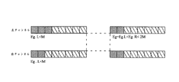
グループカップリングユニット1110:グループカップリングユニット1110に関して、スケールファクタエラーの合計がチャンネルおよびグループの二つのチャンネルで同時に計算される。図21の左部分で、グルーピング方法が二つのチャンネルで個々に使用されている。グループカップリングの目的は、図21の右部分に示すように、両方のチャンネルで同じグルーピング構成を維持させることにある。
Group coupling unit 1110: For
本発明のグルーピングはグループの数を最小にし、両チャンネルの各グループのトータルのスケールファクタエラーEgを制限し、新しい閾値2Mより小さくする。 The grouping of the present invention minimizes the number of groups and limits the total scale factor error E g for each group of both channels, making it smaller than the new threshold 2M.
図22は、ウィンドウカップリングおよびグループカップリングを示すフローチャート図であり、さらにM/Sコーディングとの関連を示す。M/Sがオンになったとき、二つのチャンネルのエネルギーは修正され、各スケールファクタ帯域と関連したスケールファクタは再推定される。M/Sが使用されないとき、グルーピングは二つのステレオチャンネルに個別に適用される。 FIG. 22 is a flowchart showing window coupling and group coupling, and further shows the relationship with M / S coding. When M / S is turned on, the energy of the two channels is modified and the scale factor associated with each scale factor band is re-estimated. When M / S is not used, the grouping is applied to the two stereo channels separately.
図5、12、13の実施例の装置で示されるエレメントの特徴は記述を明らかにするためだけのものである。 The features of the elements shown in the apparatus of the embodiment of FIGS. 5, 12, and 13 are for clarity of description only.
さらに、本発明は心理音響モデルによって計算される聴覚エントロピー(PE)にも関係し、それは左帯域、右帯域およびサイド帯域のために評価されるトランスペアレント品質を持つことが要求される最低ビットに反映される。PE値は帯域の左信号、右信号、ミドル信号およびサイド信号のためにビットを評価するのに最も簡単な方法となる。それから心理音響モデルは、L/R帯域およびM/S帯域からのPEの値を比較することによって各隣の帯域の最低コストパス値を計算し、帯域状態をL/R状態またはM/S状態に決定する。 Furthermore, the present invention also relates to auditory entropy (PE) calculated by the psychoacoustic model, which reflects on the lowest bit required to have a transparent quality evaluated for the left, right and side bands. Is done. The PE value is the simplest way to evaluate bits for the left, right, middle and side signals of the band. The psychoacoustic model then calculates the lowest cost path value for each adjacent band by comparing the PE values from the L / R and M / S bands, and the band state is either the L / R state or the M / S state. To decide.
PEは数式15のように定義される。
PE is defined as
(数15)
![]()
![]()
Wi、EiおよびTiはith帯域の帯域幅、エネルギーおよびマスキング閾値である。 W i , E i and T i are the bandwidth, energy and masking threshold of the i th band.
M/Sチャンネルのマスキング閾値を引き出すために、数式16、17のように再構築された左チャンネルおよび右チャンネルを考慮する。
To derive the masking threshold for the M / S channel, consider the left and right channels reconstructed as in
(数16)
(数17)
数式16、17から数式18、19が導き出される。
(数18)
![]()
![]()
(数19)
![]()
![]()
L'i[k],R'i[k],M'i[k] およびS'i[k]はデコーダからの再量子化された周波数ラインである。量子化誤差のために再構築された信号は数式20、21のように書き換えられる。
L ′ i [k], R ′ i [k], M ′ i [k] and S ′ i [k] are requantized frequency lines from the decoder. The signal reconstructed due to the quantization error is rewritten as
(数20)
![]()
![]()
(数21)
![]()
![]()
NLi[k],NRi[k],NMi[k]およびNsi[k]は各チャンネルに対する関連したノイズである。トランスペアレントオーディオ符号化のために、NLi[k]とNRi[k]との違いはL帯域信号およびR帯域信号のマスキング閾値未満でなければならない。区画帯域に関する違いは数式22、23によって強制される。
N Li [k], N Ri [k], N Mi [k] and N si [k] are the associated noise for each channel. For transparent audio coding, the difference between N Li [k] and N Ri [k] must be less than the masking threshold for L-band and R-band signals. The difference regarding the partition band is enforced by
(数22)
![]()
![]()
(数23)
![]()
![]()
不等式である数式22、23を満たす十分条件は数式24、25、26である。
The sufficient conditions that satisfy the
(数24)
![]()
![]()
(数25)
![]()
![]()
(数26)
![]()
![]()
ゆえに、数式27に示すように、閾値はM/S信号から直接出ている閾値に取って代わるために使用される。
Therefore, as shown in
(数27)
![]()
![]()
都合がよいように、PEはしばしば心理モデルのFFTから伝達された結果を使用する。しかし、実際の符号化信号はMDCT(modified discrete cosine transform)分析フィルタバンクの結果から来る。従って、マスキング閾値を調整し直し、エネルギーをFFTフォーマットからMDCTフォーマットに変更する必要がある。修正されたマスキング閾値は数式28、29、30のように表される。
For convenience, PEs often use the results communicated from the psychological model FFT. However, the actual encoded signal comes from the result of a modified discrete cosine transform (MDCT) analysis filter bank. Therefore, it is necessary to readjust the masking threshold and change the energy from the FFT format to the MDCT format. The corrected masking threshold is expressed as
(数28)
(数29)
(数30)
数式15によって各状態の各帯域のPEは数式31、32、33、34のように引き出される。
According to
(数31)
(数32)
(数33)
(数34)
LおよびR、MおよびSのすべての帯域PEは利用可能であるので、好適な代替法はそのPEの比較後に選ばれる。 Since all bands PE of L and R, M and S are available, the preferred alternative is chosen after comparing the PEs.
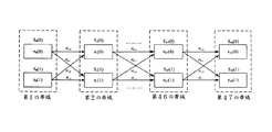
心理音響モデルは修正されたビタビ演算式によって各隣の帯域の最小コストパス値を計算し、帯域状態をL/R状態またはM/S状態に決定する。図23はM/S符号化コストを最小化するための修正されたビタビ演算式を示すブロック図である。状態iおよびL/R状態が0を表し、M/S状態が1を表すkth帯域の終わりのためのコストSk(i)を最小化するためにトレリスが構築される。各エッジは符号化状態を変更するための過渡コストファクタを表し、各ノードは比較のためにその帯域PEを有する。修正されたビタビ演算式は第1のスケールファクタ帯域から最後まで最小コストパスを探す。 The psychoacoustic model calculates the minimum cost path value of each adjacent band by using the modified Viterbi arithmetic expression, and determines the band state as the L / R state or the M / S state. FIG. 23 is a block diagram showing a modified Viterbi arithmetic expression for minimizing the M / S encoding cost. A trellis is constructed to minimize the cost S k (i) for the end of the k th band where state i and L / R state represent 0 and M / S state represents 1. Each edge represents a transient cost factor for changing the coding state, and each node has its band PE for comparison. The modified Viterbi equation searches for the minimum cost path from the first scale factor band to the end.
Sk(i)に第1の帯域からkth帯域までの状態iの最小累積コストを記録させ、nk(i)はkth帯域のith状態ノードコストを表し、メインビタビ演算式プロセスは数式35のように実行される。
Let S k (i) record the minimum accumulated cost of state i from the first band to the k th band, n k (i) represents the i th state node cost of the k th band, and the main Viterbi equation process is This is executed as shown in
(数35)
Qは全ての状態セットを意味し、αi,jは過渡コストファクタを表す。最小コストパスは追跡パスをリバースすることによって見つけ出される。言い換えると、この修正されたビタビ演算式によって最適な帯域モード使用法を見つけることができる。 Q means all state sets, and α i , j represents a transient cost factor. The minimum cost path is found by reversing the tracking path. In other words, the optimal band mode usage can be found by this modified Viterbi arithmetic expression.
時間複雑度を分析するために、第1の帯域ノード以外のすべてのノードが各ステージにおいて一回だけ比較を行うことを観察する。 To analyze the time complexity, observe that all nodes except the first band node make a comparison only once in each stage.
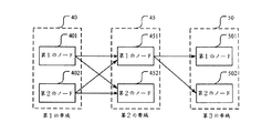
図24は、本発明の修正されたビタビ演算法の使用実施例を示すブロック図であり、第1の帯域40、第2の帯域45および第3の帯域50を備え、各帯域は第1のノードおよび第2のノードを備える。第1の帯域40の第1のノード401は10にセットされ、第1の帯域40の第2のノード402は20にセットされ、第2の帯域45の第1のノード451は30にセットされ、第2の帯域45の第2のノード452は40にセットされ、第3の帯域50の第1のノード501は50にセットされ、第3の帯域50の第2のノード502は60にセットされる。
FIG. 24 is a block diagram showing an embodiment of using the modified Viterbi algorithm of the present invention, comprising a
第1の帯域40の第1のノード401から第2の帯域45の第1のノード451までの過渡コストは1にセットされ、第1の帯域40の第1のノード401から第2の帯域45の第2のノード452までの過渡コストは2にセットされ、第1の帯域40の第2のノード402から第2の帯域45の第1のノード451までの過渡コストは3にセットされ、第1の帯域40の第2のノード402から第2の帯域45の第2のノード452までの過渡コストは4にセットされ、第2の帯域45の第1のノード451から第3の帯域50の第1のノード501までの過渡コストは5にセットされ、第2の帯域45の第1のノード451から第3の帯域50の第2のノード502は6にセットされる。第1の帯域40と第2の帯域45との間に四つのコストパス値が存在し、第2の帯域45と第3の帯域50との間に二つのコストパス値が存在する。
The transient cost from the
第1の帯域40の第1のノード401、過渡コストおよび第2の帯域45の第1のノード451の合計は第1のコストパス値であり、第1のコストパス値は41である。第1の帯域40の第1のノード401、過渡コストおよび第2の帯域45の第2のノード452の合計は第2のコストパス値であり、第2のコストパス値は52である。第1の帯域40の第2のノード402、過渡コストおよび第2の帯域45の第1のノード451の合計は第3のコストパス値であり、第3のコストパス値は53である。第1の帯域40の第2のノード402、過渡コストおよび第2の帯域45の第2のノード452の合計は第4のコストパス値であり、第4のコストパス値は64である。
The sum of the
四つのコストパス値は最小コストパスを得るために比較される。最小コストパス値は41であり、最小コストパス値を有する第2の帯域45の第1のノード451は41にセットされた累積値を含む。第2の帯域45の第2のノード452から第3の帯域50のノードまでのコストパス値を計算するよりむしろ、第2の帯域45の第1のノード451から第3の帯域50のノードまでのコストパス値を計算する。
The four cost path values are compared to obtain the minimum cost path. The minimum cost path value is 41, and the first node 451 of the
累積値、過渡コストおよび第3の帯域50の第1のノード501の合計は第1のコストパス値であり、第1のコストパス値は96であり、累積値は第2の帯域45の第1のノード451に属する。累積値、過渡コストおよび第3の帯域50の第2のノード502の合計は第2のコストパス値であり、第2のコストパス値は107であり、累積値は第2の帯域45の第1のノード451に属する。二つのコストパス値は最小コストパスを得るために比較される。最小コストパス値は96であり、最小コストパス値を有する第3の帯域50の第1のノード501は累積値を含む。最後に最小コストパスは第1の帯域40から第3の帯域50まで見つけられる。
The sum of the accumulated value, the transient cost, and the first node 501 of the
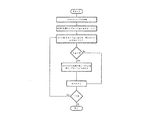
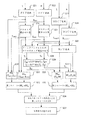
図25は、本発明のM/S符号化の帯域状態の決定方法を示すフローチャート図である。 FIG. 25 is a flowchart showing a method for determining the band state of M / S encoding according to the present invention.
ステップ21:心理音響モデルによって各帯域が左信号を含む帯域の大多数を受信し、FFT(fast fourier transform)によって左信号を左FFT信号(LFFT)に変換する。 Step 21: The majority of the bands including the left signal are received by the psychoacoustic model, and the left signal is converted into a left FFT signal (L FFT ) by FFT (fast fourier transform).
ステップ22:心理音響モデルによって各帯域が右信号を含む帯域の大多数を受信し、FFT(fast fourier transform)によって右信号を右FFT信号(RFFT)に変換する。 Step 22: The majority of the bands including the right signal are received by the psychoacoustic model, and the right signal is converted into a right FFT signal (R FFT ) by FFT (fast fourier transform).
ステップ23:分析フィルタバンクのMDCT(modified discrete cosine transform)によって左信号を左MDCT信号(LMDCT)に変換する。 Step 23: The left signal is converted into a left MDCT signal (L MDCT ) by MDCT (modified discrete cosine transform) of the analysis filter bank.
ステップ24:分析フィルタバンクのMDCT(modified discrete cosine transform)によって右信号を右MDCT信号(RMDCT)に変換する。 Step 24: The right signal is converted into the right MDCT signal (R MDCT ) by MDCT (modified discrete cosine transform) of the analysis filter bank.
ステップ25:同じ帯域の左信号および右信号を使用することによってミドル信号およびサイド信号を計算する。 Step 25: Calculate middle signal and side signal by using left signal and right signal of the same band.
ステップ26:左FFT信号のマスキング閾値(TLFFT)を計算するために、LFFT信号を受信する。 Step 26: Receive the L FFT signal to calculate the masking threshold (T LFFT ) of the left FFT signal.
ステップ27:右FFT信号のマスキング閾値(TRFFT)を計算するために、RFFT信号を受信する。 Step 27: Receive the R FFT signal to calculate the masking threshold (T RFFT ) of the right FFT signal.
ステップ28:左信号および右信号のマスキング閾値(TL、TR)をそれぞれ計算するために、TLFFT信号、TRFFT信号、LFFT信号、RFFT信号、LMDCT信号およびRMDCT信号を受信する。 Step 28: Receive the T LFFT signal, T RFFT signal, LFFT signal, RFFT signal, L MDCT signal and R MDCT signal to calculate the masking thresholds (T L , T R ) of the left signal and the right signal, respectively.
ステップ29:ミドル信号および右信号のマスキング閾値(TM、TS)をそれぞれ計算するために、TL信号およびTR信号を受信する。 Step 29: Receive the TL signal and the TR signal to calculate the masking thresholds (T M , T S ) of the middle signal and the right signal, respectively.
ステップ30:左信号のPE値(PEL)を計算するために、TLFFT信号およびLFFT信号を受信する。 Step 30: Receive the T LFFT signal and the L FFT signal to calculate the PE value (PE L ) of the left signal.
ステップ31:右信号のPE値(PER)を計算するために、TRFFT信号およびRFFT信号を受信する。 Step 31: Receive the T RFFT signal and the R FFT signal to calculate the PE value (PER) of the right signal.
ステップ32:第1のノードを計算する。PELおよび右PERの合計が第1のノードである。 Step 32: Calculate the first node. The sum of PEL and right PER is the first node.
ステップ33:ミドル信号のPE値(PEM)を計算するためにTM信号およびミドル信号を受信する。 Step 33: Receive the TM signal and the middle signal to calculate the PE value (PE M ) of the middle signal.
ステップ34:サイド信号のPE値(PEs)を計算するためにTs信号およびサイド信号を受信する。 Step 34: Receive the Ts signal and the side signal to calculate the PE value (PEs) of the side signal.
ステップ35:第2のノードを計算する。PEMおよび右PESの合計が第2のノードである。 Step 35: Calculate the second node. The sum of the PEM and the right PES is the second node.
ステップ36:修正されたビタビ演算法によって各隣の帯域の最小コストパスを計算する。 Step 36: Calculate the minimum cost path of each adjacent band by the modified Viterbi algorithm.
ステップ37:最小コストパス値に基づいて各帯域の状態を決定する。状態はL/R状態またはM/S状態である。 Step 37: Determine the state of each band based on the minimum cost path value. The state is an L / R state or an M / S state.
心理音響モデルによって帯域状態がM/S状態に決定されたとき、M/S変換モデルはNth帯域のL/R信号を受信し、M/S信号に変換し、量子化/符号化モデルによってNth帯域のM/S信号の量子化および符号化を行い、そうでなければ量子化/符号化モデルが量子化および符号化を行うためにNth帯域のL/R信号を受信する。 When the band state is determined to be the M / S state by the psychoacoustic model, the M / S conversion model receives the L / R signal of the N th band, converts it to the M / S signal, and uses the quantization / coding model The N th band M / S signal is quantized and encoded, otherwise the quantization / coding model receives the N th band L / R signal for quantization and encoding.
本発明は帯域、PEおよび修正されたビタビ演算式を通じて効果的な計算方法で帯域状態を決定する方法を提供する。修正されたビタビ演算法はAACのための命令O(2^49)からO(49*2)まで複雑度を低減させることができる。さらにM/Sマスキング閾値はM/S符号化閾値を得るためにL/R心理音響モデルから引き出すように修正され、M/S信号を置くことは合理的である。 The present invention provides a method for determining a band state with an effective calculation method through a band, a PE, and a modified Viterbi equation. The modified Viterbi algorithm can reduce the complexity from O (2 ^ 49) to O (49 * 2) instructions for AAC. Furthermore, the M / S masking threshold is modified to be derived from the L / R psychoacoustic model to obtain the M / S encoding threshold, and it is reasonable to put the M / S signal.
本発明の説明過程でこれらの装置および方法は多くの修正や変更がなされることが容易に分かる。よって、上述の説明は特許請求の範囲によってのみ制限されると解釈されるべきである。 It will be readily apparent that many modifications and variations of these devices and methods may be made during the course of describing the present invention. Accordingly, the above description should be construed as limited only by the following claims.
Claims (37)
オーディオ信号の第1の範囲のグローバルエネルギー比率を決定し、前記グローバルエネルギー比率を第1の閾値と比較するステップと、
オーディオ信号の第2の範囲のゼロクロス比率を決定し、前記ゼロクロス比率を第2の閾値と比較するステップと、
グローバルエネルギー比率またはゼロクロス比率のどちらかが第1または第2の閾値を超え、オーディオ信号の第3の範囲のトーンアタックが検出されないとき、ショート符号化ウィンドウを選択するステップと、
グローバルエネルギー比率およびゼロクロス比率がどちらも第1および第2の閾値を超えないか、或いはオーディオ信号の第3の範囲のトーンアタックが検出されたとき、ロング符号化ウィンドウを選択するステップと、
選択された符号化ウィンドウで第1、第2および第3の範囲と実質的に共通であるオーディオ信号の第4の範囲を符号化するステップと
を含むことを特徴とするオーディオ信号の符号化方法。 Receiving a block of audio signals;
Determining a global energy ratio of a first range of the audio signal and comparing the global energy ratio to a first threshold;
Determining a zero cross ratio of a second range of the audio signal and comparing the zero cross ratio to a second threshold;
Selecting a short coding window when either the global energy ratio or the zero crossing ratio exceeds the first or second threshold and no third range tone attack of the audio signal is detected;
Selecting a long encoding window when neither the global energy ratio nor the zero crossing ratio exceeds the first and second thresholds or when a tone attack of the third range of the audio signal is detected;
Encoding a fourth range of the audio signal that is substantially common to the first, second, and third ranges in the selected encoding window. .
前のウィンドウがロングウィンドウであり、現在のウィンドウがロングウィンドウであり、次のウィンドウがショートウィンドウであるとき、現在のウィンドウをロングからショートへの遷移ウィンドウに変更するステップと、
前のウィンドウがショートウィンドウであり、現在のウィンドウがロングウィンドウであり、次のウィンドウがロングウィンドウであるとき、現在のウィンドウをショートからロングへの遷移ウィンドウに変更するステップと、
前のウィンドウがショートウィンドウであり、現在のウィンドウがロングウィンドウであり、次のウィンドウがショートウィンドウであるとき、現在のウィンドウをショートウィンドウに変更するステップと、
前のウィンドウがショートからロングへの遷移ウィンドウであり、現在のウィンドウがロングウィンドウであり、次のウィンドウがショートウィンドウであるとき、現在のウィンドウをロングからショートへの遷移ウィンドウに変更するステップと
を含むことを特徴とする請求項1記載のオーディオ信号の符号化方法。 The selected window is the next window, the two preselected windows are the current window and the previous window;
Changing the current window to a long to short transition window when the previous window is a long window, the current window is a long window, and the next window is a short window;
Changing the current window from a short to long transition window when the previous window is a short window, the current window is a long window, and the next window is a long window;
Changing the current window to a short window when the previous window is a short window, the current window is a long window, and the next window is a short window;
When the previous window is a short to long transition window, the current window is a long window, and the next window is a short window, changing the current window to a long to short transition window and The audio signal encoding method according to claim 1, further comprising:
所定のエラーに類似するスケールファクタを有するショートウィンドウをグルーピングするステップと
を含むことを特徴とする請求項1記載のオーディオ信号の符号化方法。 And estimating a scale factor for the short window;
The method of claim 1, further comprising: grouping short windows having a scale factor similar to a predetermined error.
その後ショートウィンドウに対してスケールファクタの再評価を行うステップと
を含むことを特徴とする請求項8記載のオーディオ信号の符号化方法。 And performing M / S encoding on the audio signal;
9. The audio signal encoding method according to claim 8, further comprising the step of re-evaluating the scale factor for the short window.
オーディオ信号の第4の範囲にTNSを適用するステップと、
前のウィンドウがロングウィンドウであり、現在のウィンドウがロングウィンドウであり、次のウィンドウがショートウィンドウであるとき、現在のウィンドウをロングからショートへの遷移ウィンドウに変更するステップと、
前のウィンドウがショートウィンドウであり、現在のウィンドウがロングウィンドウであり、次のウィンドウがロングウィンドウであるとき、現在のウィンドウをショートからロングへの遷移ウィンドウに変更するステップと、
前のウィンドウがショートウィンドウであり、現在のウィンドウがロングウィンドウであり、次のウィンドウがショートウィンドウであるとき、現在のウィンドウをショートウィンドウに変更するステップと、
前のウィンドウがロングからショートへの遷移ウィンドウであり、現在のウィンドウがロングウィンドウであり、次のウィンドウがロングウィンドウであるとき、現在のウィンドウをショートからロングへの遷移ウィンドウに変更するステップと、
前のウィンドウがロングからショートへの遷移ウィンドウであり、現在のウィンドウがロングウィンドウであり、次のウィンドウがショートウィンドウであるとき、現在のウィンドウをショートウィンドウに変更するステップと、
前のウィンドウがショートからロングへの遷移ウィンドウであり、現在のウィンドウがロングウィンドウであり、次のウィンドウがショートウィンドウであるとき、現在のウィンドウをロングからショートへの遷移ウィンドウに変更するステップと
を含むことを特徴とする請求項1記載のオーディオ信号の符号化方法。 The selected window is the next window, the two preselected windows are the current window and the previous window;
Applying TNS to a fourth range of the audio signal;
Changing the current window to a long to short transition window when the previous window is a long window, the current window is a long window, and the next window is a short window;
Changing the current window from a short to long transition window when the previous window is a short window, the current window is a long window, and the next window is a long window;
Changing the current window to a short window when the previous window is a short window, the current window is a long window, and the next window is a short window;
Changing the current window from a short to long transition window when the previous window is a long to short transition window, the current window is a long window, and the next window is a long window;
Changing the current window to a short window when the previous window is a long to short transition window, the current window is a long window, and the next window is a short window;
When the previous window is a short to long transition window, the current window is a long window, and the next window is a short window, changing the current window to a long to short transition window and The audio signal encoding method according to claim 1, further comprising:
各チャンネルに対してロングまたはショート符号化を選択するステップと、
オーディオ信号の各チャンネルの符号化ウィンドウサイズが一致しないとき、二つのチャンネルのPEにおける違いを検出するステップと、
PEにおける違いが検出され、両方のチャンネルのPEが聴覚閾値より高いとき、両方のチャンネルでショート符号化ウィンドウを使用し、両方のチャンネルのPEが聴覚閾値よりも低いとき、両方のチャンネルでロング符号化ウィンドウを使用するステップと
を含むことを特徴とする請求項1記載のオーディオ信号の符号化方法。 The audio signal is a two-channel stereo signal, and
Selecting long or short coding for each channel;
Detecting the difference in the PEs of the two channels when the encoding window size of each channel of the audio signal does not match;
When a difference in PE is detected and the PE for both channels is above the hearing threshold, the short coding window is used for both channels, and when both PEs are below the hearing threshold, the long code is used for both channels. The method according to claim 1, further comprising: using an encoding window.
オーディオ信号の第1の範囲のグローバルエネルギー比率を決定し、前記グローバルエネルギー比率を第1の閾値と比較し、前記グローバルエネルギー比率は第1の範囲の最大エネルギーと第1の範囲の最小エネルギーとの比率であるステップと、
オーディオ信号の第2の範囲のゼロクロス比率を決定し、前記ゼロクロス比率を第2の閾値と比較し、前記ゼロクロス比率は第2の範囲の第1のサブ範囲のゼロクロスレートと第2の範囲の第2のサブ範囲のゼロクロスレートとの比率であり、前記第1のサブ範囲のゼロクロスレートは第2の範囲の最大値であり、第2のサブ範囲のゼロクロスレートは第2の範囲の最小値であるステップと、
グローバルエネルギー比率またはゼロクロス比率のどちらかが第1または第2の閾値を超え、オーディオ信号の第3の範囲のトーンアタックが検出されないとき、ショート符号化ウィンドウを選択し、前記前記トーンアタックはトーン閾値よりも高い調性を有するときショート符号化ウィンドウを選択するステップと、
グローバルエネルギー比率およびゼロクロス比率がどちらも第1および第2の閾値を超えないか、或いはオーディオ信号の第3の範囲のトーンアタックが検出されたとき、ロング符号化ウィンドウを選択するステップと、
選択された符号化ウィンドウで第1、第2および第3の範囲と実質的に共通であるオーディオ信号の第4の範囲を符号化するステップと
を含むことを特徴とするオーディオ信号の符号化方法。 Receiving a block of audio signals;
Determining a global energy ratio of a first range of the audio signal and comparing the global energy ratio to a first threshold, wherein the global energy ratio is a maximum energy of the first range and a minimum energy of the first range; A step that is a ratio;
Determining a zero cross ratio of a second range of the audio signal and comparing the zero cross ratio with a second threshold, the zero cross ratio being a zero cross rate of a first sub-range of the second range and a second cross-range of the second range; The zero cross rate of the second sub-range, the zero cross rate of the first sub-range is the maximum value of the second range, and the zero cross rate of the second sub-range is the minimum value of the second range. A step and
When either the global energy ratio or the zero crossing ratio exceeds the first or second threshold and no third range tone attack of the audio signal is detected, a short coding window is selected, the tone attack being a tone threshold Selecting a short coding window when having a higher tonality;
Selecting a long encoding window when neither the global energy ratio nor the zero crossing ratio exceeds the first and second thresholds or when a tone attack of the third range of the audio signal is detected;
Encoding a fourth range of the audio signal that is substantially common to the first, second, and third ranges in the selected encoding window. .
前のウィンドウがロングウィンドウであり、現在のウィンドウがロングウィンドウであり、次のウィンドウがショートウィンドウであるとき、現在のウィンドウをロングからショートへの遷移ウィンドウに変更するステップと、
前のウィンドウがショートウィンドウであり、現在のウィンドウがロングウィンドウであり、次のウィンドウがロングウィンドウであるとき、現在のウィンドウをショートからロングへの遷移ウィンドウに変更するステップと、
前のウィンドウがショートウィンドウであり、現在のウィンドウがロングウィンドウであり、次のウィンドウがショートウィンドウであるとき、現在のウィンドウをショートウィンドウに変更するステップと、
前のウィンドウがショートからロングへの遷移ウィンドウであり、現在のウィンドウがロングウィンドウであり、次のウィンドウがショートウィンドウであるとき、現在のウィンドウをロングからショートへの遷移ウィンドウに変更するステップと
を含むことを特徴とする請求項13記載のオーディオ信号の符号化方法。 The selected window is the next window, the two preselected windows are the current window and the previous window;
Changing the current window to a long to short transition window when the previous window is a long window, the current window is a long window, and the next window is a short window;
Changing the current window from a short to long transition window when the previous window is a short window, the current window is a long window, and the next window is a long window;
Changing the current window to a short window when the previous window is a short window, the current window is a long window, and the next window is a short window;
When the previous window is a short to long transition window, the current window is a long window, and the next window is a short window, changing the current window to a long to short transition window and The audio signal encoding method according to claim 13, further comprising:
所定のエラーに類似するスケールファクタを有するショートウィンドウをグルーピングするステップと
を含むことを特徴とする請求項13記載のオーディオ信号の符号化方法。 And estimating a scale factor for the short window;
The method of claim 13, further comprising: grouping short windows having a scale factor similar to a predetermined error.
その後ショートウィンドウに対してスケールファクタの再評価を行うステップと
を含むことを特徴とする請求項16記載のオーディオ信号の符号化方法。 And performing M / S encoding on the audio signal;
17. The audio signal encoding method according to claim 16, further comprising the step of re-evaluating the scale factor for the short window.
オーディオ信号の第4の範囲にTNSを適用するステップと、
前のウィンドウがロングウィンドウであり、現在のウィンドウがロングウィンドウであり、次のウィンドウがショートウィンドウであるとき、現在のウィンドウをロングからショートへの遷移ウィンドウに変更するステップと、
前のウィンドウがショートウィンドウであり、現在のウィンドウがロングウィンドウであり、次のウィンドウがロングウィンドウであるとき、現在のウィンドウをショートからロングへの遷移ウィンドウに変更するステップと、
前のウィンドウがショートウィンドウであり、現在のウィンドウがロングウィンドウであり、次のウィンドウがショートウィンドウであるとき、現在のウィンドウをショートウィンドウに変更するステップと、
前のウィンドウがロングからショートへの遷移ウィンドウであり、現在のウィンドウがロングウィンドウであり、次のウィンドウがロングウィンドウであるとき、現在のウィンドウをショートからロングへの遷移ウィンドウに変更するステップと、
前のウィンドウがロングからショートへの遷移ウィンドウであり、現在のウィンドウがロングウィンドウであり、次のウィンドウがショートウィンドウであるとき、現在のウィンドウをショートウィンドウに変更するステップと、
前のウィンドウがショートからロングへの遷移ウィンドウであり、現在のウィンドウがロングウィンドウであり、次のウィンドウがショートウィンドウであるとき、現在のウィンドウをロングからショートへの遷移ウィンドウに変更するステップと
を含むことを特徴とする請求項13記載のオーディオ信号の符号化方法。 The selected window is the next window, the two preselected windows are the current window and the previous window;
Applying TNS to a fourth range of the audio signal;
Changing the current window to a long-to-short transition window when the previous window is a long window, the current window is a long window, and the next window is a short window;
Changing the current window from a short to long transition window when the previous window is a short window, the current window is a long window, and the next window is a long window;
Changing the current window to a short window when the previous window is a short window, the current window is a long window, and the next window is a short window;
Changing the current window from a short to long transition window when the previous window is a long to short transition window, the current window is a long window, and the next window is a long window;
Changing the current window to a short window when the previous window is a long to short transition window, the current window is a long window, and the next window is a short window;
When the previous window is a short to long transition window, the current window is a long window, and the next window is a short window, the step of changing the current window to a long to short transition window and 14. The audio signal encoding method according to claim 13, further comprising:
各チャンネルに対してロングまたはショート符号化を選択するステップと、
オーディオ信号の各チャンネルの符号化ウィンドウサイズが一致しないとき、二つのチャンネルのPEにおける違いを検出するステップと、
PEにおける違いが検出され、両方のチャンネルのPEが聴覚閾値より高いとき、両方のチャンネルでショート符号化ウィンドウを使用し、両方のチャンネルのPEが聴覚閾値よりも低いとき、両方のチャンネルでロング符号化ウィンドウを使用するステップと
を含むことを特徴とする請求項13記載のオーディオ信号の符号化方法。 The audio signal is a two-channel stereo signal, and
Selecting long or short coding for each channel;
Detecting the difference in the PEs of the two channels when the encoding window size of each channel of the audio signal does not match;
When a difference in PE is detected and the PE for both channels is above the hearing threshold, the short coding window is used for both channels, and when both PEs are below the hearing threshold, the long code is used for both channels. The method of claim 13, further comprising the step of using an encoding window.
同じ帯域の左信号および右信号を使用することによってミドル信号およびサイド信号を計算するステップと、
各帯域の、左信号と右信号のPE値の合計である第1のノードと、ミドル信号とサイド信号のPE値の合計である第2のノードとを計算するステップと、
Nth帯域の第1のノードから(N+1)th帯域の第1または第2のノード、或いはNth帯域の第2のノードから(N+1)th帯域の第1または第2のノードまでである各隣の帯域の最小コストパス値を計算するステップと、
状態がL/R状態またはM/S状態であろう最小コストパス値に基づいて各帯域の状態を決定するステップと
を含むことを特徴とするAACのためのM/S符号化の帯域状態の決定方法。 Receiving at least one audio stream having a majority of bands, each band having a left signal and a right signal;
Calculating a middle signal and a side signal by using a left signal and a right signal in the same band; and
Calculating a first node that is the sum of the PE values of the left signal and the right signal and a second node that is the sum of the PE values of the middle signal and the side signal for each band;
Each is from a first node N th band until (N + 1) the first or second node of th band, or from the second node of the N th band (N + 1) th first or second node of the band Calculating the minimum cost path value of the adjacent band;
Determining a state of each band based on a minimum cost path value where the state may be an L / R state or an M / S state, and a band state of M / S encoding for AAC, comprising: Decision method.
各コストパス値が第1の帯域のノードから第2の帯域のノードまでであるコストパス値の大部分を計算するステップと、
コストパス値を比較して最小コストパス値を取得するステップと
を含むことを特徴とする請求項21記載のAACのためのM/S符号化の帯域状態の決定方法。 And calculating a minimum cost path value, said step comprising:
Calculating a majority of cost path values where each cost path value is from a first band node to a second band node;
22. The method for determining a band state of M / S encoding for AAC according to claim 21, further comprising: obtaining a minimum cost path value by comparing cost path values.
第1の帯域のノード、過渡コストおよび第2の帯域のノードの合計を使用することによって各コストパス値を計算するステップと、
コストパス値を比較して最小コストパス値を取得するステップと
を含むことを特徴とする請求項23記載のAACのためのM/S符号化の帯域状態の決定方法。 And calculating a minimum cost path value between the first band and the second band, said step comprising:
Calculating each cost path value by using the sum of the first band node, the transient cost and the second band node;
24. The method for determining a band state of M / S encoding for AAC according to claim 23, further comprising: obtaining a minimum cost path value by comparing cost path values.
累積値、過渡コストおよび(N+1)th帯域のノードの合計を使用することによって各コストパス値を計算するステップと、
コストパス値を比較して最小コストパス値を取得するステップと
を含むことを特徴とする請求項23記載のAACのためのM/S符号化の帯域状態の決定方法。 And calculating a minimum cost path value between the N th band of the remaining adjacent bands and the (N + 1) th band, said step comprising:
Calculating each cost path value by using the cumulative value, the transient cost and the sum of the nodes in the (N + 1) th band;
24. The method for determining a band state of M / S encoding for AAC according to claim 23, further comprising: obtaining a minimum cost path value by comparing cost path values.
修正されたビタビ演算式によってオーディオストリームの各隣の帯域の最小コストパス値を計算するステップを含むことを特徴とする請求項21記載のAACのためのM/S符号化の帯域状態の決定方法。 Further, the method includes calculating a minimum cost path value, the step comprising:
The method for determining a band state of M / S coding for AAC according to claim 21, further comprising: calculating a minimum cost path value of each adjacent band of the audio stream by a modified Viterbi arithmetic expression. .
各コストパス値が第1の帯域のノードから第2の帯域のノードまでであるコストパス値の大部分を計算するステップと、
コストパス値を比較して最小コストパス値を取得するステップと
を含むことを特徴とする請求項27記載のAACのためのM/S符号化の帯域状態の決定方法。 And calculating a minimum cost path value, said step comprising:
Calculating a majority of cost path values where each cost path value is from a first band node to a second band node;
The method for determining the band state of M / S encoding for AAC according to claim 27, comprising: comparing a cost path value to obtain a minimum cost path value.
第1の帯域のノード、過渡コストおよび第2の帯域のノードの合計を使用することによって各コストパス値を計算するステップと、
コストパス値を比較して最小コストパス値を取得するステップと
を含むことを特徴とする請求項29記載のAACのためのM/S符号化の帯域状態の決定方法。 And calculating a minimum cost path value between the first band and the second band, said step comprising:
Calculating each cost path value by using the sum of the first band node, the transient cost and the second band node;
30. The method for determining a band state of M / S encoding for AAC according to claim 29, comprising: comparing a cost path value to obtain a minimum cost path value.
累積値、過渡コストおよび(N+1)th帯域のノードの合計を使用することによって各コストパス値を計算するステップと、
コストパス値を比較して最小コストパス値を取得するステップと
を含むことを特徴とする請求項29記載のAACのためのM/S符号化の帯域状態の決定方法。 And calculating a minimum cost path value between the N th band of the remaining adjacent bands and the (N + 1) th band, said step comprising:
Calculating each cost path value by using the cumulative value, the transient cost and the sum of the nodes in the (N + 1) th band;
30. The method for determining a band state of M / S encoding for AAC according to claim 29, comprising: comparing a cost path value to obtain a minimum cost path value.
FFTによって左信号および右信号を左FFT信号および右FFT信号に変換するステップと、
左FFT信号および右FFT信号のマスキング閾値を計算するために、左FFT信号および右FFT信号を受信するステップと、
左信号および右信号のPE値をそれぞれ計算するためにマスキング閾値、左FFT信号および右FFT信号を受信するステップと
を含むことを特徴とする請求項21記載のAACのためのM/S符号化の帯域状態の決定方法。 And calculating the PE value of the left signal and the right signal, said step comprising:
Converting left and right signals into left and right FFT signals by FFT;
Receiving a left FFT signal and a right FFT signal to calculate a masking threshold for the left FFT signal and the right FFT signal;
22. The M / S encoding for AAC according to claim 21, comprising receiving a masking threshold, a left FFT signal and a right FFT signal to calculate PE values of the left signal and the right signal, respectively. How to determine the bandwidth status of
MDCTによって左信号および右信号を左MDCT信号および右MDCT信号に変換し、ミドル信号およびサイド信号を計算するステップを含むことを特徴とする請求項21記載のAACのためのM/S符号化の帯域状態の決定方法。 In addition, before calculating the middle and side signals,
The method of claim 21, further comprising: converting left and right signals into left and right MDCT signals by MDCT and calculating middle and side signals. Bandwidth determination method.
ミドル信号およびサイド信号のマスキング閾値を計算するステップと、
ミドル信号およびサイド信号のPE値をそれぞれ計算するために、マスキング閾値、ミドル信号およびサイド信号を受信するステップと
を含むことを特徴とする請求項34記載のAACのためのM/S符号化の帯域状態の決定方法。 The method further includes the step of calculating the PE value of the middle signal and the side signal,
Calculating a middle signal and a side signal masking threshold;
35. The method of M / S encoding for AAC according to claim 34, further comprising: receiving a masking threshold, a middle signal and a side signal to calculate a PE value of the middle signal and the side signal, respectively. Bandwidth determination method.
MDCTによって左信号および右信号を左MDCT信号および右MDCT信号に変換するステップ
FFTによって左信号および右信号を左FFT信号および右FFT信号に変換するステップと、
左FFT信号および右FFT信号のマスキング閾値を計算するために、左FFT信号および右FFT信号を受信するステップと
左信号および右信号のマスキング閾値を計算するために、左FFT信号および右FFT信号のマスキング閾値、左FFT信号、右FFT信号、左MDCT信号および右MDCT信号を受信するステップと、
ミドル信号および右信号のマスキング閾値をそれぞれ計算するために、左信号および右信号のマスキング閾値を受信するステップと
を含むことを特徴とする請求項35記載のAACのためのM/S符号化の帯域状態の決定方法。 Calculating a middle signal and side signal masking thresholds, said steps comprising:
Converting left and right signals into left and right MDCT signals by MDCT; converting left and right signals into left and right FFT signals by FFT; and
Receiving left and right FFT signals to calculate left and right FFT signal masking thresholds; and calculating left and right FFT signal masking thresholds to calculate left and right FFT masking thresholds. Receiving a masking threshold, a left FFT signal, a right FFT signal, a left MDCT signal and a right MDCT signal;
36. The M / S coding for AAC according to claim 35, comprising: receiving a masking threshold for the left signal and the right signal to calculate a masking threshold for the middle signal and the right signal, respectively. Bandwidth determination method.
Priority Applications (1)
| Application Number | Priority Date | Filing Date | Title |
|---|---|---|---|
| JP2006312942A JP2008129250A (en) | 2006-11-20 | 2006-11-20 | Window changing method for advanced audio coding and band determination method for m/s encoding |
Applications Claiming Priority (1)
| Application Number | Priority Date | Filing Date | Title |
|---|---|---|---|
| JP2006312942A JP2008129250A (en) | 2006-11-20 | 2006-11-20 | Window changing method for advanced audio coding and band determination method for m/s encoding |
Publications (1)
| Publication Number | Publication Date |
|---|---|
| JP2008129250A true JP2008129250A (en) | 2008-06-05 |
Family
ID=39555132
Family Applications (1)
| Application Number | Title | Priority Date | Filing Date |
|---|---|---|---|
| JP2006312942A Pending JP2008129250A (en) | 2006-11-20 | 2006-11-20 | Window changing method for advanced audio coding and band determination method for m/s encoding |
Country Status (1)
| Country | Link |
|---|---|
| JP (1) | JP2008129250A (en) |
Cited By (4)
| Publication number | Priority date | Publication date | Assignee | Title |
|---|---|---|---|---|
| CN104538041A (en) * | 2014-12-11 | 2015-04-22 | 深圳市智美达科技有限公司 | Method and system for detecting abnormal sounds |
| JP2018513402A (en) * | 2015-03-09 | 2018-05-24 | フラウンホッファー−ゲゼルシャフト ツァ フェルダールング デァ アンゲヴァンテン フォアシュンク エー.ファオ | Apparatus and method for encoding or decoding multi-channel signals |
| CN110097889A (en) * | 2013-02-20 | 2019-08-06 | 弗劳恩霍夫应用研究促进协会 | Generate encoded signal or to the decoded device and method of encoded signal |
| JP2019207419A (en) * | 2013-07-22 | 2019-12-05 | フラウンホーファー−ゲゼルシャフト・ツール・フェルデルング・デル・アンゲヴァンテン・フォルシュング・アインゲトラーゲネル・フェライン | Frequency-domain audio coding supporting transform length switching |
Citations (3)
| Publication number | Priority date | Publication date | Assignee | Title |
|---|---|---|---|---|
| JPH02259699A (en) * | 1989-03-30 | 1990-10-22 | Sharp Corp | Sound recording and reproducing device |
| JPH08179794A (en) * | 1994-12-21 | 1996-07-12 | Sony Corp | Sub-band coding method and device |
| JP2000004163A (en) * | 1998-06-16 | 2000-01-07 | Matsushita Electric Ind Co Ltd | Method and device for allocating dynamic bit for audio coding |
-
2006
- 2006-11-20 JP JP2006312942A patent/JP2008129250A/en active Pending
Patent Citations (3)
| Publication number | Priority date | Publication date | Assignee | Title |
|---|---|---|---|---|
| JPH02259699A (en) * | 1989-03-30 | 1990-10-22 | Sharp Corp | Sound recording and reproducing device |
| JPH08179794A (en) * | 1994-12-21 | 1996-07-12 | Sony Corp | Sub-band coding method and device |
| JP2000004163A (en) * | 1998-06-16 | 2000-01-07 | Matsushita Electric Ind Co Ltd | Method and device for allocating dynamic bit for audio coding |
Cited By (13)
| Publication number | Priority date | Publication date | Assignee | Title |
|---|---|---|---|---|
| US11621008B2 (en) | 2013-02-20 | 2023-04-04 | Fraunhofer-Gesellschaft Zur Foerderung Der Angewandten Forschung E.V. | Apparatus and method for encoding or decoding an audio signal using a transient-location dependent overlap |
| CN110097889B (en) * | 2013-02-20 | 2023-09-01 | 弗劳恩霍夫应用研究促进协会 | Apparatus and method for generating or decoding encoded signals |
| CN110097889A (en) * | 2013-02-20 | 2019-08-06 | 弗劳恩霍夫应用研究促进协会 | Generate encoded signal or to the decoded device and method of encoded signal |
| US11682408B2 (en) | 2013-02-20 | 2023-06-20 | Fraunhofer-Gesellschaft Zur Foerderung Der Angewandten Forschung E.V. | Apparatus and method for generating an encoded signal or for decoding an encoded audio signal using a multi overlap portion |
| US10984809B2 (en) | 2013-07-22 | 2021-04-20 | Fraunhofer-Gesellschaft Zur Foerderung Der Angewandten Forschung E.V. | Frequency-domain audio coding supporting transform length switching |
| JP2019207419A (en) * | 2013-07-22 | 2019-12-05 | フラウンホーファー−ゲゼルシャフト・ツール・フェルデルング・デル・アンゲヴァンテン・フォルシュング・アインゲトラーゲネル・フェライン | Frequency-domain audio coding supporting transform length switching |
| US11862182B2 (en) | 2013-07-22 | 2024-01-02 | Fraunhofer-Gesellschaft Zur Foerderung Der Angewandten Forschung E.V. | Frequency-domain audio coding supporting transform length switching |
| CN104538041A (en) * | 2014-12-11 | 2015-04-22 | 深圳市智美达科技有限公司 | Method and system for detecting abnormal sounds |
| US10762909B2 (en) | 2015-03-09 | 2020-09-01 | Fraunhofer-Gesellschaft Zur Foerderung Der Angewandten Forschung E.V. | Apparatus and method for encoding or decoding a multi-channel signal |
| US11508384B2 (en) | 2015-03-09 | 2022-11-22 | Fraunhofer-Gesellschaft Zur Foerderung Der Angewandten Forschung E.V. | Apparatus and method for encoding or decoding a multi-channel signal |
| US10388289B2 (en) | 2015-03-09 | 2019-08-20 | Fraunhofer-Gesellschaft Zur Foerderung Der Angewandten Forschung E.V. | Apparatus and method for encoding or decoding a multi-channel signal |
| JP2018513402A (en) * | 2015-03-09 | 2018-05-24 | フラウンホッファー−ゲゼルシャフト ツァ フェルダールング デァ アンゲヴァンテン フォアシュンク エー.ファオ | Apparatus and method for encoding or decoding multi-channel signals |
| US11955131B2 (en) | 2015-03-09 | 2024-04-09 | Fraunhofer-Gesellschaft Zur Foerderung Der Angewandten Forschung E.V. | Apparatus and method for encoding or decoding a multi-channel signal |
Similar Documents
| Publication | Publication Date | Title |
|---|---|---|
| JP5539203B2 (en) | Improved transform coding of speech and audio signals | |
| JP3623449B2 (en) | Method and apparatus for concealing errors in an encoded audio signal and method and apparatus for decoding an encoded audio signal | |
| KR102205596B1 (en) | Multi-channel signal encoding method and encoder | |
| US7613603B2 (en) | Audio coding device with fast algorithm for determining quantization step sizes based on psycho-acoustic model | |
| KR101395257B1 (en) | An apparatus and a method for calculating a number of spectral envelopes | |
| JP5485909B2 (en) | Audio signal processing method and apparatus | |
| JP3762579B2 (en) | Digital audio signal encoding apparatus, digital audio signal encoding method, and medium on which digital audio signal encoding program is recorded | |
| JP2019502966A (en) | Apparatus and method for estimating time difference between channels | |
| US20070016405A1 (en) | Coding with improved time resolution for selected segments via adaptive block transformation of a group of samples from a subband decomposition | |
| US9293146B2 (en) | Intensity stereo coding in advanced audio coding | |
| BR112019020515A2 (en) | apparatus for post-processing an audio signal using transient location detection | |
| KR20080039462A (en) | Stereo encoding device, stereo decoding device, and stereo encoding method | |
| WO2010037427A1 (en) | Apparatus for binaural audio coding | |
| US20210035591A1 (en) | Method for estimating noise in an audio signal, noise estimator, audio encoder, audio decoder, and system for transmitting audio signals | |
| MXPA06006497A (en) | Improved frequency-domain error concealment. | |
| KR100477701B1 (en) | An MPEG audio encoding method and an MPEG audio encoding device | |
| JP2008129250A (en) | Window changing method for advanced audio coding and band determination method for m/s encoding | |
| JP2006003580A (en) | Device and method for coding audio signal | |
| WO2009129822A1 (en) | Efficient encoding and decoding for multi-channel signals | |
| JP2012519309A (en) | Quantization for audio coding | |
| JP4055122B2 (en) | Acoustic signal encoding method and acoustic signal encoding apparatus | |
| JP2007004050A (en) | Device and program for encoding stereophonic signal | |
| KR100640833B1 (en) | Method for encording digital audio | |
| KR20080008897A (en) | Method for audio signal coding | |
| KR20070037771A (en) | Audio coding system |
Legal Events
| Date | Code | Title | Description |
|---|---|---|---|
| RD02 | Notification of acceptance of power of attorney |
Free format text: JAPANESE INTERMEDIATE CODE: A7422 Effective date: 20090828 |
|
| A131 | Notification of reasons for refusal |
Free format text: JAPANESE INTERMEDIATE CODE: A131 Effective date: 20100315 |
|
| A02 | Decision of refusal |
Free format text: JAPANESE INTERMEDIATE CODE: A02 Effective date: 20101201 |