JP2018500719A - Panel with integrated lighting - Google Patents
Panel with integrated lighting Download PDFInfo
- Publication number
- JP2018500719A JP2018500719A JP2017522409A JP2017522409A JP2018500719A JP 2018500719 A JP2018500719 A JP 2018500719A JP 2017522409 A JP2017522409 A JP 2017522409A JP 2017522409 A JP2017522409 A JP 2017522409A JP 2018500719 A JP2018500719 A JP 2018500719A
- Authority
- JP
- Japan
- Prior art keywords
- light
- optical fiber
- lighting
- illuminated
- lighting panel
- Prior art date
- Legal status (The legal status is an assumption and is not a legal conclusion. Google has not performed a legal analysis and makes no representation as to the accuracy of the status listed.)
- Pending
Links
Images
Classifications
-
- G—PHYSICS
- G02—OPTICS
- G02B—OPTICAL ELEMENTS, SYSTEMS OR APPARATUS
- G02B6/00—Light guides; Structural details of arrangements comprising light guides and other optical elements, e.g. couplings
- G02B6/0001—Light guides; Structural details of arrangements comprising light guides and other optical elements, e.g. couplings specially adapted for lighting devices or systems
- G02B6/0005—Light guides; Structural details of arrangements comprising light guides and other optical elements, e.g. couplings specially adapted for lighting devices or systems the light guides being of the fibre type
- G02B6/001—Light guides; Structural details of arrangements comprising light guides and other optical elements, e.g. couplings specially adapted for lighting devices or systems the light guides being of the fibre type the light being emitted along at least a portion of the lateral surface of the fibre
-
- F—MECHANICAL ENGINEERING; LIGHTING; HEATING; WEAPONS; BLASTING
- F21—LIGHTING
- F21V—FUNCTIONAL FEATURES OR DETAILS OF LIGHTING DEVICES OR SYSTEMS THEREOF; STRUCTURAL COMBINATIONS OF LIGHTING DEVICES WITH OTHER ARTICLES, NOT OTHERWISE PROVIDED FOR
- F21V33/00—Structural combinations of lighting devices with other articles, not otherwise provided for
- F21V33/0004—Personal or domestic articles
- F21V33/0012—Furniture
-
- G—PHYSICS
- G10—MUSICAL INSTRUMENTS; ACOUSTICS
- G10K—SOUND-PRODUCING DEVICES; METHODS OR DEVICES FOR PROTECTING AGAINST, OR FOR DAMPING, NOISE OR OTHER ACOUSTIC WAVES IN GENERAL; ACOUSTICS NOT OTHERWISE PROVIDED FOR
- G10K11/00—Methods or devices for transmitting, conducting or directing sound in general; Methods or devices for protecting against, or for damping, noise or other acoustic waves in general
- G10K11/16—Methods or devices for protecting against, or for damping, noise or other acoustic waves in general
- G10K11/162—Selection of materials
- G10K11/168—Plural layers of different materials, e.g. sandwiches
-
- A—HUMAN NECESSITIES
- A47—FURNITURE; DOMESTIC ARTICLES OR APPLIANCES; COFFEE MILLS; SPICE MILLS; SUCTION CLEANERS IN GENERAL
- A47B—TABLES; DESKS; OFFICE FURNITURE; CABINETS; DRAWERS; GENERAL DETAILS OF FURNITURE
- A47B2220/00—General furniture construction, e.g. fittings
- A47B2220/0075—Lighting
- A47B2220/0077—Lighting for furniture, e.g. cupboards and racks
-
- F—MECHANICAL ENGINEERING; LIGHTING; HEATING; WEAPONS; BLASTING
- F21—LIGHTING
- F21W—INDEXING SCHEME ASSOCIATED WITH SUBCLASSES F21K, F21L, F21S and F21V, RELATING TO USES OR APPLICATIONS OF LIGHTING DEVICES OR SYSTEMS
- F21W2131/00—Use or application of lighting devices or systems not provided for in codes F21W2102/00-F21W2121/00
- F21W2131/30—Lighting for domestic or personal use
- F21W2131/301—Lighting for domestic or personal use for furniture
-
- F—MECHANICAL ENGINEERING; LIGHTING; HEATING; WEAPONS; BLASTING
- F21—LIGHTING
- F21W—INDEXING SCHEME ASSOCIATED WITH SUBCLASSES F21K, F21L, F21S and F21V, RELATING TO USES OR APPLICATIONS OF LIGHTING DEVICES OR SYSTEMS
- F21W2131/00—Use or application of lighting devices or systems not provided for in codes F21W2102/00-F21W2121/00
- F21W2131/40—Lighting for industrial, commercial, recreational or military use
- F21W2131/402—Lighting for industrial, commercial, recreational or military use for working places
-
- F—MECHANICAL ENGINEERING; LIGHTING; HEATING; WEAPONS; BLASTING
- F21—LIGHTING
- F21Y—INDEXING SCHEME ASSOCIATED WITH SUBCLASSES F21K, F21L, F21S and F21V, RELATING TO THE FORM OR THE KIND OF THE LIGHT SOURCES OR OF THE COLOUR OF THE LIGHT EMITTED
- F21Y2101/00—Point-like light sources
-
- F—MECHANICAL ENGINEERING; LIGHTING; HEATING; WEAPONS; BLASTING
- F21—LIGHTING
- F21Y—INDEXING SCHEME ASSOCIATED WITH SUBCLASSES F21K, F21L, F21S and F21V, RELATING TO THE FORM OR THE KIND OF THE LIGHT SOURCES OR OF THE COLOUR OF THE LIGHT EMITTED
- F21Y2113/00—Combination of light sources
- F21Y2113/10—Combination of light sources of different colours
- F21Y2113/13—Combination of light sources of different colours comprising an assembly of point-like light sources
-
- F—MECHANICAL ENGINEERING; LIGHTING; HEATING; WEAPONS; BLASTING
- F21—LIGHTING
- F21Y—INDEXING SCHEME ASSOCIATED WITH SUBCLASSES F21K, F21L, F21S and F21V, RELATING TO THE FORM OR THE KIND OF THE LIGHT SOURCES OR OF THE COLOUR OF THE LIGHT EMITTED
- F21Y2115/00—Light-generating elements of semiconductor light sources
- F21Y2115/10—Light-emitting diodes [LED]
-
- G—PHYSICS
- G02—OPTICS
- G02B—OPTICAL ELEMENTS, SYSTEMS OR APPARATUS
- G02B6/00—Light guides; Structural details of arrangements comprising light guides and other optical elements, e.g. couplings
- G02B6/0001—Light guides; Structural details of arrangements comprising light guides and other optical elements, e.g. couplings specially adapted for lighting devices or systems
- G02B6/0011—Light guides; Structural details of arrangements comprising light guides and other optical elements, e.g. couplings specially adapted for lighting devices or systems the light guides being planar or of plate-like form
- G02B6/0081—Mechanical or electrical aspects of the light guide and light source in the lighting device peculiar to the adaptation to planar light guides, e.g. concerning packaging
- G02B6/0095—Light guides as housings, housing portions, shelves, doors, tiles, windows, or the like
Abstract
本発明は、統合型照明を保持する支持体を含む照明パネルであって、該統合型照明が光源に連結された製織された光ファイバーを含む照明用織物であり、該光ファイバーが照明パネルの平面に実質的に垂直である隣接表面を照らすのに適切な角度で光を放出することを特徴とする照明パネルを対象としている。The present invention is an illumination panel including a support for holding integrated illumination, wherein the integrated illumination includes a woven optical fiber coupled to a light source, and the optical fiber is in the plane of the illumination panel. It is directed to a lighting panel that emits light at an appropriate angle to illuminate adjacent surfaces that are substantially vertical.
Description
本発明は、照明パネルの平面に実質的に垂直な隣接表面、例えばワークトップ又はデスクなどを照らすための統合型照明を保持する支持構造体を含む照明パネルに関する。 The present invention relates to a lighting panel that includes a support structure that holds integrated lighting for illuminating an adjacent surface substantially perpendicular to the plane of the lighting panel, such as a worktop or desk.
オープンスペースのオフィス又は職場では、パーティションパネルがしばしば使用される。これらのパーティションパネルは、幾分の視覚的プライバシーを提供し、また、デスク間又はワークトップ間の吸音材として機能することもできる。 Partition panels are often used in open space offices or workplaces. These partition panels provide some visual privacy and can also act as sound absorbers between desks or worktops.
個々のデスク又はワークトップを照らすためには、通常、単独型ランプが設置され、又はデスクパーティションの上部にランプの取り付け部品が装備される。 To illuminate an individual desk or worktop, a stand-alone lamp is usually installed, or a lamp mounting part is provided on the top of the desk partition.
単独型ランプの場合には、光は通常点状源であり、そしてワークトップパーティションの上部に幅を広げたランプの場合でも、光はワークトップの全面に均一に広がらないことが一般的な問題である。 In the case of a stand-alone lamp, the light is usually a point source, and even in the case of a lamp with a wider width at the top of the worktop partition, the general problem is that the light does not spread evenly across the worktop It is.
別の問題は、単独型ランプはデスク又はワークトップの上でスペースを取ることである。 Another problem is that the stand-alone lamp takes up space on the desk or worktop.
上記の問題を解決するために、国際公開第2013/050908号は、光導波材料を含む統合型照明ユニットを備えた穿孔穴付きの金属シートを含むデスクパーティションパネルを提供している。光導波路は、実施例ではPMMAのシートを含むが、ポリカーボネート(PC)、シクロオレフィンコポリマー(COC)又は二層プリズムホイルなどの他の光導波材料を使用してもよい。この統合型ユニットはまた、光導波材料のシートの1つ以上の縁に光をカップリングさせるための一連のLEDも含む。光導波材料のシートは、低強度光源のアレイを形成する光出力開口のアレイを含む。これらの開口は特定の形状を有しており、その結果光をデスク領域にとどめることになる。 In order to solve the above problems, WO 2013/050908 provides a desk partition panel comprising a metal sheet with perforated holes with an integrated lighting unit comprising an optical waveguide material. The optical waveguide includes a sheet of PMMA in the examples, but other optical waveguide materials such as polycarbonate (PC), cycloolefin copolymer (COC), or bilayer prism foil may be used. The integrated unit also includes a series of LEDs for coupling light to one or more edges of the sheet of light guide material. The sheet of optical waveguide material includes an array of light output apertures that form an array of low intensity light sources. These openings have a specific shape, so that the light stays in the desk area.
しかしながら、光導波路を使用することの欠点は、より高い光強度が求められる場合には、より多くの低強度光源を用意し、それゆえより多くの開口をシートに設けなければならず、そのことで明らかに制限が課されることになる、ということである。 However, the disadvantage of using an optical waveguide is that if a higher light intensity is required, more low-intensity light sources must be prepared and therefore more openings must be provided in the sheet, which It will obviously impose restrictions.
さらに、光導波は単独型ランプと比較して、ワークトップ上により均一な光を提供するとは言うものの、開口の位置に応じてより低い光強度のパターンとより高い光強度のパターンがなおも残り、そして更なる光均一性が目標とされる場合には、開口の数を増加させなければならない。 Furthermore, although optical waveguides provide more uniform light on the worktop than single lamps, lower and higher light intensity patterns still remain depending on the position of the aperture. And if further light uniformity is targeted, the number of apertures must be increased.
別の欠点は、音響特性の点でこのような光導波路は余分の構造体であって、その後ろにある音響吸収層の音響吸収率を低下させる。理由は、光導波路が、光を反射して光導波路に戻すか又は見る人に向け孔を通して反射するための、光導波路の後ろに配置された反射体を含むからである。この反射体は、国際公開第2013/050908号に記載されるようにミクロ穿孔されて、それに記載の光導波路の音響吸収性を従来の光導波路と対比して改善するとは言うものの、パネル中の音響吸収層の能力は減じられる。 Another disadvantage is that in terms of acoustic properties, such an optical waveguide is an extra structure that reduces the acoustic absorptance of the acoustical absorption layer behind it. The reason is that the light guide includes a reflector disposed behind the light guide for reflecting light back into the light guide or reflecting through the aperture towards the viewer. Although this reflector is micro-perforated as described in WO 2013/050908, the acoustic absorption of the optical waveguide described therein is improved as compared with the conventional optical waveguide, but in the panel. The capacity of the sound absorbing layer is reduced.
上記のことを考慮して、本発明の目的は、開口の数に関する制限に悩まされることなく向上した均一性をもたらす、ワークトップ又はデスクを照明するための照明パネルを提供することである。 In view of the above, it is an object of the present invention to provide a lighting panel for illuminating a worktop or desk that provides improved uniformity without suffering from limitations on the number of openings.
国際公開第2004/068203号には、コーティング中に埋め込まれたたて糸及びよこ糸光ファイバーを含む光ファイバーシートを含む背面投射タイプのスクリーンが開示されている。埋め込まれた光ファイバーシートは、たて糸及びよこ糸光ファイバーの交点で光ファイバーの突出上部を露出させるために、両面を研磨されている。その結果として、光ファイバーを通過する光は研磨された部分から出ていくことができる。このデバイスが背面投射タイプのスクリーンである限り、光線はディスプレイスクリーンの裏面のプロジェクタから投射される。ディスプレイスクリーンの裏面に存在する光ファイバーの研磨部分に入射したこれらの光線は光ファイバー内で伝播し、そしてディスプレイスクリーンの前面の光ファイバーの研磨部分に到達することができる。それゆえ、光はディスプレイスクリーンの前面から出てゆくことができる。 WO 2004/068203 discloses a rear projection type screen comprising an optical fiber sheet comprising warp and weft optical fibers embedded in a coating. The embedded optical fiber sheet is polished on both sides in order to expose the protruding upper portion of the optical fiber at the intersection of the warp and weft optical fibers. As a result, light passing through the optical fiber can exit the polished portion. As long as the device is a rear projection type screen, light rays are projected from the projector on the back of the display screen. These rays incident on the polished portion of the optical fiber present on the back surface of the display screen can propagate in the optical fiber and reach the polished portion of the optical fiber on the front surface of the display screen. Therefore, light can emerge from the front of the display screen.
国際公開第2004/068203号によると、8メートルの距離で測定されるスクリーンの視野角は60°と63°の間である(該出願の表3参照)。視野角は、光ファイバーシートの中央と明度が中央の明度の半分である位置との間の角度であると定義される。 According to WO 2004/068203, the viewing angle of the screen measured at a distance of 8 meters is between 60 ° and 63 ° (see Table 3 of the application). The viewing angle is defined as the angle between the center of the optical fiber sheet and the position where the brightness is half the brightness of the center.
しかしながら、ワークトップ又はデスクのための照明パネルの場合には、パネルがすべての方向に発光するとしても、強度の最大値が、照明される表面の方向においてパネルの平面に対して特に20°と40°の間にピークがある特定の角度に対応することが有利である。 However, in the case of lighting panels for worktops or desks, even if the panel emits light in all directions, the maximum intensity is particularly 20 ° with respect to the plane of the panel in the direction of the illuminated surface. It is advantageous to correspond to a certain angle with a peak between 40 °.
それゆえ、国際公開第2004/068203号に開示されたディスプレイスクリーンはワークトップ又はデスクを照明するのに適しない。実際、そのデバイスはスクリーンの直近の表面を照明することができず、且つさらに、照明しようとする表面の方向においてパネルの平面に対して20°と40°の間の角度では、最大強度で照明することができない。 Therefore, the display screen disclosed in WO 2004/068203 is not suitable for illuminating a worktop or desk. In fact, the device is not able to illuminate the immediate surface of the screen, and furthermore illuminates at maximum intensity at an angle between 20 ° and 40 ° to the plane of the panel in the direction of the surface to be illuminated. Can not do it.
本発明の目的は、ワークトップ又はデスクを照明するのに特に適する照明パネルを提供することである。 An object of the present invention is to provide a lighting panel that is particularly suitable for illuminating a worktop or desk.
本発明の目的はまた、デスクを照明し且つ同時にコンピュータスクリーンに対する優れたバックライトを提供する、ワークトップ又はデスクを照明するための照明パネルを提供することである。 It is also an object of the present invention to provide a lighting panel for illuminating a worktop or desk that illuminates the desk and at the same time provides an excellent backlight to the computer screen.
本発明の別の目的は、向上した音響吸収特性を有するワークトップ又はデスクを照明するための照明パネルを提供することである。 Another object of the present invention is to provide a lighting panel for illuminating a worktop or desk having improved sound absorption properties.
さらに、本発明の別の目的は、見る人に対してリラックス効果又はさらには癒し効果を有することを目的としたワークトップ又はデスクを照明するための照明パネルを提供することである。 Furthermore, it is another object of the present invention to provide a lighting panel for illuminating a worktop or desk intended to have a relaxing or even healing effect on the viewer.
本発明は、複数の光源に連結されている製織光ファイバーを含む照明用織物を保持している支持構造体を含む照明パネルであって、光ファイバーが照明パネルの平面に対して実質的に垂直である隣接表面を照らすのに適した角度で光を拡散する照明パネルを対象とするものである。 The present invention is an illumination panel that includes a support structure that holds an illumination fabric that includes a woven optical fiber coupled to a plurality of light sources, the optical fiber being substantially perpendicular to a plane of the illumination panel. It is intended for lighting panels that diffuse light at an angle suitable for illuminating adjacent surfaces.
具体的に言えば、本発明は、複数の光源に連結されている製織光ファイバーでありそれらの長手方向の軸線に沿って側方に光を拡散することができる製織光ファイバーを含む照明用織物を保持している支持構造体を含む照明パネルであって、
・照明用織物の平面が被照明対象の隣接表面に対して実質的に垂直に配置され、
・光ファイバーの少なくとも一部が光源に接続され、そしてそれらの長手方向の軸線が被照明対象の隣接表面に対して実質的に垂直になるよう配置される、
ように、前記照明用織物が照明パネルに取り付けられており、
光が、これらの光ファイバーの長手方向の軸線に沿った光の伝播が被照明対象の平面の方に向けられ及び/又は該平面の反対側に向けられるようにこれらの光ファイバーの自由末端に入射する、照明パネルに関する。
Specifically, the present invention is a woven optical fiber that is connected to a plurality of light sources and holds a illuminating fabric that includes a woven optical fiber that can diffuse light laterally along their longitudinal axis. A lighting panel including a supporting structure,
The plane of the illuminating fabric is arranged substantially perpendicular to the adjacent surface of the object to be illuminated;
At least a portion of the optical fiber is connected to the light source and arranged such that their longitudinal axis is substantially perpendicular to the adjacent surface of the object to be illuminated;
The lighting fabric is attached to the lighting panel,
Light is incident on the free ends of these optical fibers so that the propagation of the light along the longitudinal axis of these optical fibers is directed toward and / or opposite the plane of the object to be illuminated. , Regarding lighting panels.
照明パネルは、2つの主要面を含む。照明用織物は、照明パネルの少なくとも1つの面の一部を形成する。 The lighting panel includes two main surfaces. The lighting fabric forms part of at least one surface of the lighting panel.
光源は、好ましくは発光ダイオード(LED)光源である。 The light source is preferably a light emitting diode (LED) light source.
本発明による第一の実施形態では、複数の光源に連結されている製織光ファイバーを含む照明用織物を保持している支持構造体を含む照明パネルであって、光ファイバーが照明パネルの平面に対して実質的に垂直である隣接表面を照らすのに適した角度で光を拡散する照明パネルが提供される。 In a first embodiment according to the present invention, an illumination panel comprising a support structure holding an illumination fabric comprising a woven optical fiber coupled to a plurality of light sources, wherein the optical fiber is relative to the plane of the illumination panel A lighting panel is provided that diffuses light at an angle suitable for illuminating adjacent surfaces that are substantially vertical.
本発明によると、照明用布帛としても知られている「照明用織物」は、光ファイバーを含み指向分配された糸及び最終的に結合する糸の製織により得られるシートである。製織は、たて糸方向に配置された糸(以下、たて糸と呼ぶ)とたて糸に垂直によこ糸方向に配置された糸(以下、よこ糸と呼ぶ)とを同一平面内で織り交ぜてなされる。製織されたたて糸及び/又はよこ糸の光ファイバーを含むこのような照明用織物は、例えば米国特許出願公開第2009/291606号明細書及び米国特許出願公開第2006/144460号明細書に記載されており、これらは参照によりここに組み入れられる。 According to the present invention, a “lighting fabric”, also known as a lighting fabric, is a sheet obtained by weaving directionally distributed yarns that contain optical fibers and finally bonded yarns. Weaving is performed by weaving yarns arranged in the warp direction (hereinafter referred to as warp yarns) and yarns arranged in the weft direction perpendicular to the warp yarns (hereinafter referred to as weft yarns) in the same plane. Such lighting fabrics comprising woven warp and / or weft optical fibers are described, for example, in US 2009/291606 and US 2006/144460, These are incorporated herein by reference.
ひとたび光源に接続されると、光ファイバーはその表面に沿った侵襲的改変部の存在のために側方に光を放出することができる。それゆえ、光ファイバーはその長手方向の軸線に沿って側方に光を拡散する。 Once connected to the light source, the optical fiber can emit light laterally due to the presence of invasive modifications along its surface. Therefore, the optical fiber diffuses light laterally along its longitudinal axis.
結合用の糸は、照明用織物の全体の良好な結合を確保し、そしてその特質に応じて、その寸法及び/又は機械特性に特定の特性を付与することを可能にする。 The bonding yarn ensures a good overall bonding of the lighting fabric and, depending on its nature, makes it possible to impart specific properties to its dimensions and / or mechanical properties.
光ファイバーは、照明用織物の縁に対応して照明用織物により規定される表面の外側に延在する。外側に延在している光ファイバーの部分は、個別光ファイバー、光ファイバーの末端、又は光ファイバーの自由末端と呼ばれる。 The optical fiber extends outside the surface defined by the lighting fabric corresponding to the edge of the lighting fabric. The portion of the optical fiber that extends outward is called the individual optical fiber, the end of the optical fiber, or the free end of the optical fiber.
本発明によると、「光源に連結された又は接続された光ファイバー」という構成は、光ファイバーの自由末端が光源に接続されていることを意味する。 According to the present invention, the configuration “optical fiber coupled or connected to a light source” means that the free end of the optical fiber is connected to the light source.
照明用織物は、
・照明用織物の平面が被照明対象の隣接表面に対して実質的に垂直に配置され、
・自由末端を含む光ファイバーの少なくとも一部が光源に接続され、そしてその長手方向の軸線が被照明対象の隣接表面に対して実質的に垂直となるように配置される、
ように、照明パネルに取り付けられる。
The lighting fabric is
The plane of the illuminating fabric is arranged substantially perpendicular to the adjacent surface of the object to be illuminated;
At least a portion of the optical fiber including the free end is connected to the light source and arranged such that its longitudinal axis is substantially perpendicular to the adjacent surface of the object to be illuminated;
Is attached to the lighting panel.
光ファイバーは、その長手方向の軸線に沿ってその構造の内部で光を伝播するだけでなく、光を側方に放出することも可能にする。結果的に、光ファイバーは照明用織物内部において分配様式で光を導波し、そして照明用織物の主要表面を拡散様式で照明することを可能にする。光ファイバーの自由末端で入射した光の一部はずっとファイバーに沿って伝播され、そして一部は侵襲的改変部により側方に散乱される。 An optical fiber not only propagates light within its structure along its longitudinal axis, but also allows light to be emitted laterally. As a result, the optical fiber guides light in a distributed manner within the illuminating fabric and allows the major surface of the illuminating fabric to be illuminated in a diffuse manner. Part of the light incident at the free end of the optical fiber is propagated along the fiber and part is scattered laterally by the invasive modification.
本発明との関連で言えば、照明用織物は側方に、好ましくはある角度で、光を拡散することができ、この角度は照明パネルの平面に実質的に垂直な、例えばワークトップ又はデスクなどの、隣接表面を照らすのに適している。 In the context of the present invention, the lighting fabric can diffuse light laterally, preferably at an angle, which is substantially perpendicular to the plane of the lighting panel, for example a worktop or desk. Suitable for illuminating adjacent surfaces.
出願人は、光ファイバーの長手方向の軸線に沿った光の伝播方向が被照明平面の方に向かうように光が入射するならば、すなわち光が照明パネルに取り付けられた照明用織物の上端側に入るならば、光はワークトップ又はデスクなどの水平表面を照らすために特に適合した角度で侵襲的改変部により拡散されることを見いだした。実際のところ、照明用織物はすべての方向に光を放出するが、強度が最大なのは特定の角度に対応する。光は、取り出しプロファイルを有する光ファイバーから取り出され、該プロファイルは照明パネルの平面(及び照明用織物の平面)に対応する光伝播方向に対して20°と40°の間、好ましくは25°と35°の間にピークを示す。照明パネルの平面に対して約30°の角度は、ワークトップ又はデスクなどの直近の水平表面を照らすのに適することが知られており、そのためその前に腰掛けて作業する人はワークトップ又はデスク上の自身の影に悩まされない。 Applicant will note that if the light is incident such that the propagation direction of the light along the longitudinal axis of the optical fiber is toward the illuminated plane, i.e. the light is on the upper end of the illuminating fabric attached to the lighting panel. When entering, it has been found that the light is diffused by the invasive modification at an angle specifically adapted to illuminate a horizontal surface such as a worktop or desk. In fact, lighting fabrics emit light in all directions, but the greatest intensity corresponds to a specific angle. Light is extracted from an optical fiber having an extraction profile, which is between 20 ° and 40 °, preferably 25 ° and 35 °, with respect to the direction of light propagation corresponding to the plane of the lighting panel (and the plane of the lighting fabric). Peaks are shown between °. An angle of about 30 ° with respect to the plane of the lighting panel is known to be suitable for illuminating the nearest horizontal surface, such as a worktop or desk, so that a person sitting in front of it will work. Don't be bothered by your own shadow above.
光ファイバーは、照明パネルの平面に対して15°と45°の間又は20°と40°の間、好ましくは25°と35°の間、さらにより良好には25°と30°の間の角度で光を拡散するのが好ましい。それは、照明用織物の平面又は照明パネルの平面に対応する光伝播方向に対して20°と40°の間、好ましくは25°と35°の間、さらにより良好には25°と30°の間の角度にピークを示す取り出しプロファイルを有する光ファイバーから光が取り出されることを意味する。 The optical fiber is at an angle between 15 ° and 45 ° or between 20 ° and 40 °, preferably between 25 ° and 35 °, and even better between 25 ° and 30 ° with respect to the plane of the lighting panel. It is preferable to diffuse the light. It is between 20 ° and 40 °, preferably between 25 ° and 35 °, and even better 25 ° and 30 ° relative to the direction of light propagation corresponding to the plane of the lighting fabric or the plane of the lighting panel. It means that light is extracted from an optical fiber having an extraction profile that peaks at an angle between.
照明用織物は、照明パネルの平面に対して15°と45°の間又は20°と40°の間、好ましくは25°と35°の間、さらに良好には25°と30°の間の角度で優先的に光を放出することができる。 The lighting fabric is between 15 ° and 45 ° or between 20 ° and 40 °, preferably between 25 ° and 35 °, and even better between 25 ° and 30 ° with respect to the plane of the lighting panel. Light can be preferentially emitted at an angle.
この実施形態によると、長手方向の軸線が被照明対象の隣接表面に対して実質的に垂直となるように配置されている光ファイバーの少なくとも一部に接続される光源は、これらの光ファイバーの長手方向の軸線に沿った光の伝播が被照明平面の方に向かうように照明パネルに取り付けられる。光源は白色LED光源から選ばれる。 According to this embodiment, the light source connected to at least a part of the optical fibers arranged such that the longitudinal axis is substantially perpendicular to the adjacent surface of the object to be illuminated is the longitudinal direction of these optical fibers. Is attached to the lighting panel so that the propagation of light along the axis of the heading is directed toward the illuminated plane. The light source is selected from white LED light sources.
このようにして、被照明平面の表面、例えばデスク又はワークトップなどは、照明パネルの平面に対して好ましくは約30°の角度で、白色光により有利に照らされる。 In this way, the surface of the illuminated plane, such as a desk or worktop, is advantageously illuminated by white light, preferably at an angle of about 30 ° to the plane of the lighting panel.
出願人はまた、光ファイバーの長手方向の軸線に沿った光の伝播方向が被照明平面の反対側に向かうように光が入射するならば、すなわち光が照明パネルに取り付けられた照明用織物の下端側に入るならば、光はワークトップ又はデスクなどの水平表面で作業している人の顔を照らすのに特に適切な角度で侵襲的改変部により拡散されることを見いだした。 Applicant will also note that if the light is incident so that the propagation direction of the light along the longitudinal axis of the optical fiber is opposite to the illuminated plane, that is, the lower end of the lighting fabric attached to the lighting panel. Upon entering the side, it has been found that the light is diffused by the invasive modification at an angle that is particularly appropriate to illuminate the face of a person working on a horizontal surface such as a worktop or desk.
この実施形態によると、長手方向の軸線が被照明対象の隣接表面に対して実質的に垂直となるように配置された光ファイバーの少なくとも一部に接続された光源が、これらの光ファイバーの長手方向の軸線に沿った光の伝播が被照明平面の反対側に向かうように照明パネルに取り付けられる。光源は青色LED光源から選ばれる。 According to this embodiment, a light source connected to at least a part of the optical fibers arranged such that the longitudinal axis is substantially perpendicular to the adjacent surface of the object to be illuminated is provided in the longitudinal direction of these optical fibers. It is attached to the illumination panel so that the propagation of light along the axis is directed to the opposite side of the illuminated plane. The light source is selected from blue LED light sources.
このようにして、照明パネルに向かって腰掛けている人の顔は、リラックス効果又はさらには癒し効果を有することが知られている青色光により有利に照らされる。 In this way, the face of a person sitting on the lighting panel is advantageously illuminated by blue light, which is known to have a relaxing effect or even a healing effect.
それゆえ、出願人は、光ファイバーの長手方向の軸線に沿った光の伝播方向が被照明平面の方を向き及び/又はその平面の反対側に向くように行われる光の入射が有利な効果をもたらすことを見いだした。 Therefore, Applicants have the advantage that the incidence of light performed in such a way that the propagation direction of the light along the longitudinal axis of the optical fiber is directed towards the illuminated plane and / or towards the opposite side of the plane. I found it to bring.
一実施形態によると、照明パネルは異なる色を有するLEDから選ばれる少なくとも2つのタイプの光源を含み、各タイプの光源は光ファイバーの長手方向の軸線が被照明対象の隣接表面に対して実質的に垂直となるように配置された光ファイバーの自由末端に接続される。1つのタイプの光源は、これらの光ファイバーの長手方向の軸線に沿った光の伝播が被照明平面の方に向かうように光ファイバーの自由末端で光を入射し、そして別のタイプの光源は、これらの光ファイバーの長手方向の軸線に沿った光の伝播が被照明平面の反対側に向かうように光ファイバーの自由末端で光を入射する。 According to one embodiment, the lighting panel includes at least two types of light sources selected from LEDs having different colors, each type of light source having a longitudinal axis of the optical fiber substantially relative to an adjacent surface of the object to be illuminated. Connected to the free end of an optical fiber arranged vertically. One type of light source impinges light at the free end of the optical fiber so that the propagation of light along the longitudinal axis of these optical fibers is towards the illuminated plane, and another type of light source The light is incident at the free end of the optical fiber so that the propagation of the light along the longitudinal axis of the optical fiber is directed to the opposite side of the illuminated plane.
LEDから放出される光は特定の波長を有し、このため特定の色を有する。主波長を決定し、そしてこのため出射光の色を決定するのは、LED半導体材料である。本発明によると、異なる色を有するLEDとは、LEDが特定の波長スペクトル分布に対応する異なる光を放出することができることを意味する。 The light emitted from the LED has a specific wavelength and thus a specific color. It is the LED semiconductor material that determines the dominant wavelength and thus the color of the emitted light. According to the present invention, LEDs having different colors mean that the LEDs can emit different light corresponding to a particular wavelength spectral distribution.
光ファイバーは、光を伝達しそして改変部で側方に光を放出するために光源に接続することができる自由末端を含む。光ファイバーの自由末端は、同一の光源の反対側の様々な自由末端を、好ましくは照明用織物の端部で、一体化するように、編むか又は集合させて束状にすることができる。 The optical fiber includes a free end that can be connected to a light source to transmit light and emit light laterally at the modification. The free ends of the optical fibers can be knitted or assembled into a bundle so that the various free ends on the opposite side of the same light source are integrated, preferably at the end of the illuminating fabric.
照明用織物は、好ましくは照明用織物の縁で、光ファイバーの少なくとも1つの自由末端に向かい合って配置された1つ以上の点光源を含む。あるいは、照明用織物は、光ファイバーの複数の自由末端に向かい合って配置された、幅を広げた光源を含んでもよい。この又はこれらの光源は、光ファイバーに接続される。任意選択的に切断され又は編まれている、光ファイバー、好ましくは光ファイバーの自由末端が、光源に接続される。 The illuminating fabric includes one or more point light sources, preferably at the edges of the illuminating fabric, facing the at least one free end of the optical fiber. Alternatively, the illuminating fabric may include a widened light source disposed opposite the plurality of free ends of the optical fiber. This or these light sources are connected to an optical fiber. An optical fiber, preferably the free end of the optical fiber, optionally cut or knitted, is connected to the light source.
光ファイバーの自由末端を照らすことを意図する光源は様々な種類のものでよく、具体的に言えば、発光ダイオードの形態、又は例えば白熱電球、蛍光管又はネオン等のガスを取り入れた放電管などの幅を広げた光源の形態であることができる。光源は発光ダイオードであるのが有利である。 The light source intended to illuminate the free end of the optical fiber may be of various types, specifically in the form of a light emitting diode or a discharge tube incorporating a gas such as an incandescent bulb, fluorescent tube or neon. It can be in the form of an expanded light source. The light source is advantageously a light emitting diode.
有利には、前記末端に光を集中させそして光透過の損失を制限するために、光源と光ファイバーの末端との間に光学レンズが挿入される。本発明による実施形態において使用される光源は、光ファイバーに(場合によりレンズを介して)連結するのに適する任意の光源であってよいが、好ましくはLED光源である。光ファイバーの少なくとも一部をLEDに連結させてもよい。 Advantageously, an optical lens is inserted between the light source and the end of the optical fiber in order to concentrate the light at the end and limit the loss of light transmission. The light source used in embodiments according to the present invention may be any light source suitable for coupling to an optical fiber (possibly via a lens), but is preferably an LED light source. At least a part of the optical fiber may be connected to the LED.
本発明による照明パネルに使用されるLED光源は、達成しようとする効果に応じて、入手可能なすべての適切なタイプでよく、例えば白色LED、青色LED又はRGB(赤−緑−青)LEDでよい。白色LED光源を用いる照明用織物を、被照明表面を照らすために明らかに使用することができる一方で、青色LED光源を用いる照明用織物を、環境に青色光を広げるために、又はさらには、リラックス効果及び/又は癒し効果を提供するため照明パネルの前で腰掛け又は作業している人の目に青色光を広げるために使用することもできる。それらの組み合わせも可能である。 The LED light source used in the lighting panel according to the invention may be of any suitable type available, depending on the effect to be achieved, for example white LED, blue LED or RGB (red-green-blue) LED. Good. Lighting fabrics using white LED light sources can obviously be used to illuminate the illuminated surface, while lighting fabrics using blue LED light sources are used to spread blue light into the environment, or even It can also be used to spread blue light in the eyes of a person sitting or working in front of a lighting panel to provide a relaxing and / or healing effect. Combinations thereof are also possible.
LED光源には、光を光ファイバーにカップリングさせるための専用レンズを付随させてもよく、通常はかかるレンズが付随している。 The LED light source may be accompanied by a dedicated lens for coupling light to the optical fiber, and is usually accompanied by such a lens.
光ファイバーは、ノッチ又は小さいスリットに相当する侵襲的改変部を含み、そしてそれらが、ファイバー内部の光線の反射角度及びファイバー外側の光の側方透過率を変更するので、ファイバーにおける光の取り出しを可能にする。様々な処理を用いることにより、光を光ファイバーから側方にデカップリングさせることができる。側方発光を可能にするのは、サンドブラスティング又はレーザーアブレーションなどの機械的又は化学的な損傷により、すなわち光ファイバーの側面に溝を切り込むことにより、コア−クラッディング境界層を意図的に乱すことである。 Optical fibers contain invasive modifications that correspond to notches or small slits, and they change the reflection angle of the rays inside the fiber and the lateral transmittance of the light outside the fiber, allowing light extraction in the fiber To. By using various treatments, light can be decoupled laterally from the optical fiber. Side emission is possible by intentionally disturbing the core-cladding boundary layer by mechanical or chemical damage such as sandblasting or laser ablation, ie by cutting grooves in the side of the optical fiber. It is.
光ファイバーのクラッディングが長手方向の軸線に沿って十分に損傷されるように光ファイバーを処理して組み合わせることが、そのように処理されてLEDなどの光源に接続された光ファイバーに長手方向の軸線に対して側方に光を放出させる。 Processing and combining optical fibers so that the optical fiber cladding is sufficiently damaged along the longitudinal axis, so that the processed optical fiber connected to a light source such as an LED is connected to the longitudinal axis. To emit light to the side.
照明用織物中の製織された光ファイバーの表面は、その少なくとも特定の部分において、ファイバーの長手方向の軸線に対して側方に光を拡散するように処理される。ファイバーの表面処理は、それらを製織後に行うことができる。好ましくは、光ファイバーの発光部分、すなわち光の側方拡散を可能とするようにクラッディングを処理した部分は、照明用織物の外側面上にある。 The surface of the woven optical fiber in the illuminating fabric is treated to diffuse light laterally relative to the longitudinal axis of the fiber, at least in certain parts thereof. The surface treatment of the fibers can be performed after weaving. Preferably, the light emitting portion of the optical fiber, ie the portion that has been treated to allow lateral diffusion of light, is on the outer surface of the illuminating fabric.
入射時の光ファイバーにおける光の伝播方向は、最初に、波を構成する光ファイバーのコアの方向に従う。欠陥が光ファイバーに沿って発生すると、光の漏れが誘発される。光ファイバーに沿った多量の小漏洩の再分配は、最大で90%までの高い側方拡散率を生じさせ、そしてファイバーの長手方向の軸線に対して20°と40°の間、好ましくは25°と35°の間、そしてさらにより良好には25°と30°の間にピークを有する拡散プロファイルを優先的に示す。 The propagation direction of light in the optical fiber at the time of incidence first follows the direction of the core of the optical fiber constituting the wave. When a defect occurs along the optical fiber, light leakage is induced. Redistribution of large amounts of small leaks along the optical fiber results in a high lateral diffusivity of up to 90% and is between 20 ° and 40 °, preferably 25 ° with respect to the longitudinal axis of the fiber. Preferentially shows a diffusion profile having a peak between 25 and 30 ° and even better between 25 and 30 °.
本発明による照明パネルは、デスク上の単独型ランプを代替するため、又は上記のとおりの光導波路に連結されたLEDのアセンブリを代替するために使用することができ、これがデスク上の空間を節約する助けとなる。 The lighting panel according to the present invention can be used to replace a stand-alone lamp on a desk or to replace an assembly of LEDs connected to a light guide as described above, which saves space on the desk To help.
本発明の別の利点は、本発明による照明パネルは照明用織物の全表面を使用し、そして光導波の場合のように開口の数に関する制限に悩まされないことである。 Another advantage of the present invention is that the lighting panel according to the present invention uses the entire surface of the illuminating fabric and does not suffer from the restrictions on the number of apertures as in the case of optical waveguides.
さらに、照明用織物を使用することで、被照明表面上に入射する光の均一性を向上させることができる。 Furthermore, the uniformity of the light which injects on the to-be-illuminated surface can be improved by using the textile fabric for illumination.
別の利点は、本発明による照明パネルはデスクを照明しそして同時にコンピュータスクリーンに対する優れたバックライトを提供することができることである。 Another advantage is that the lighting panel according to the invention can illuminate the desk and at the same time provide an excellent backlight for the computer screen.
光ファイバーに連結された光源の発光の位置及び方向がどうであれ、照明用織物への入射時に、目標の表面を照らすための正しい位置に光ファイバーを配置するようにして光ファイバーを曲げることができる。本発明による実施形態において、光ファイバーは、LED光源と入射する照明用織物との間で少なくとも90°を超え、又は少なくとも120°を超えて、好ましくは少なくとも150°を超え、より好ましくは約180°を超えて曲げられる。 Whatever the position and direction of light emission of the light source connected to the optical fiber, the optical fiber can be bent so that the optical fiber is placed in the correct position to illuminate the target surface when incident on the illuminating fabric. In an embodiment according to the invention, the optical fiber is at least more than 90 °, or at least more than 120 °, preferably more than at least 150 °, more preferably about 180 °, between the LED light source and the incident illumination fabric. Can be bent beyond.
先に説明したとおり、色の異なるLEDなどの異なるタイプの光源を使用する場合には、それらが光ファイバー中に光をカップリングする際に互いに干渉しないようにするため互いに対して反対方向に光を放出するように、それらを照明パネルに取り付けることができる(実施例参照)。 As explained earlier, when using different types of light sources, such as LEDs of different colors, the light is directed in opposite directions relative to each other so that they do not interfere with each other when coupling the light into the optical fiber. They can be attached to the lighting panel so as to emit (see examples).
本発明によると、光ファイバーの少なくとも一部は、照明用織物内で、光ファイバーの長手方向の軸線が被照明表面に対して実質的に垂直となるように配置され、すなわち被照明表面が水平であるならば、光ファイバーはその長手方向の軸線に対して垂直に配置される。照明パネルが、例えば、光ファイバーがその長手方向の軸線に対して水平に配置されるように水平に取り付けられる場合には、垂直に配置された表面を照らすことができることが理解される。 According to the invention, at least a part of the optical fiber is arranged in the illuminating fabric such that the longitudinal axis of the optical fiber is substantially perpendicular to the illuminated surface, i.e. the illuminated surface is horizontal. If so, the optical fiber is placed perpendicular to its longitudinal axis. It will be appreciated that the lighting panel can illuminate a vertically positioned surface, for example, if the optical fiber is mounted horizontally such that the optical fiber is positioned horizontally with respect to its longitudinal axis.
被照明表面がワークトップ又はデスクである、本発明による特定の実施形態では、照明用織物内において、光ファイバー内での光の伝播方向がワークトップ又はデスクの方に向けられるように光ファイバーの少なくとも一部が配置されている照明パネルが提供される。好ましくは、光ファイバーの少なくとも一部が、白色LED光源に連結され、そして照明用織物内で光ファイバー内の白色光の伝播方向が被照明表面の方に向けられるように配置される。 In a particular embodiment according to the invention, where the surface to be illuminated is a worktop or desk, at least one of the optical fibers in the illuminating fabric so that the direction of light propagation in the optical fiber is directed towards the worktop or desk. A lighting panel in which the part is arranged is provided. Preferably, at least a portion of the optical fiber is coupled to the white LED light source and is arranged in the illuminating fabric such that the propagation direction of the white light in the optical fiber is directed toward the illuminated surface.
デスクを照らす場合には、照明用織物内での光の伝播方向は、光ファイバーから側方に出ていく光がワークトップ又はデスクに対して入射するようにデスクに向かって上方から下方への向きとなる。 When illuminating a desk, the direction of light propagation in the illuminating fabric is the direction from top to bottom toward the desk so that light exiting from the optical fiber is incident on the worktop or desk. It becomes.
本発明による実施形態では、光ファイバーの少なくとも一部を青色LED光源に連結し、そして照明用織物内において、光ファイバー内での青色光の伝播方向が被照明表面の方でなく、パネルの前で腰掛け又は作業している人の方に向かうように配置された照明パネルを提供することができる。例えば、ワークトップ又はデスクの場合に、光ファイバーはその長手方向の軸線に対して垂直に配置され、そして照明用織物内において光の伝播方向が光ファイバーから側方に出ていく青色光が人の目の方に向かうように下方から上方への向きとなる。このような実施形態は、例えば、ワークトップ又はデスクで作業している人にリラックスした環境を提供するのに有利である。 In an embodiment according to the invention, at least a part of the optical fiber is connected to a blue LED light source, and in the illuminating fabric, the propagation direction of the blue light in the optical fiber is seated in front of the panel, not towards the surface to be illuminated. Or the lighting panel arrange | positioned toward the person who is working can be provided. For example, in the case of a worktop or desk, the optical fiber is placed perpendicular to its longitudinal axis, and the blue light that travels laterally out of the optical fiber in the lighting fabric is visible to the human eye. The direction is from the bottom to the top so as to head toward. Such an embodiment is advantageous, for example, in providing a relaxed environment for a person working on a worktop or desk.
本発明による特定の実施形態では、光ファイバーの一部を白色LED光源に連結し、また光ファイバーの一部を青色LED光源に連結して、そして光ファイバーを、照明用織物内で青色光の伝播方向が白色光と反対方向となり、且つ被照明表面に対して反対方向になるように配置する。この実施形態は、ワークトップ又はデスクを白色光で照らすために使用することができる一方で、その前で作業している人に向けられた青色光がリラックス効果及び/又は癒し効果を提供するので、特に有利である。 In certain embodiments according to the present invention, a portion of the optical fiber is coupled to the white LED light source, a portion of the optical fiber is coupled to the blue LED light source, and the optical fiber is coupled in the illumination fabric so that the propagation direction of the blue light is It is arranged so as to be opposite to the white light and opposite to the surface to be illuminated. This embodiment can be used to illuminate the worktop or desk with white light, while the blue light directed toward the person working in front of it provides a relaxing and / or healing effect. Are particularly advantageous.
それゆえ、光ファイバーの少なくとも一部を、青色LED光源に連結し、そして照明用織物内において光ファイバー内の青色光の伝播方向が被照明表面と反対の方を向かうように配置することができる。 Therefore, at least a part of the optical fiber can be connected to the blue LED light source and arranged in the illuminating fabric so that the propagation direction of the blue light in the optical fiber is opposite to the surface to be illuminated.
照明用織物を保持する支持構造体は、照明パネルを構成する照明用織物及びパネルを保持するのに十分に剛性である任意の材料から製作することができる。しかしながら、LED光源を冷却する必要があるという事実を考慮すると、支持体がLED光源を冷却するために熱伝導性材料(例えばアルミニウム)から少なくとも一部分が製作されたフレーム又はパネルを含む場合には、LED光源をフレーム又はパネルの熱伝導性部品に固定することが有利である。それゆえ、支持構造体は、熱伝導性材料から製作されたフレーム又はパネルを含むことができ、そしてLED光源が前記フレーム又はパネルに固定される。 The support structure that holds the lighting fabric can be made from any material that is sufficiently rigid to hold the lighting fabric and panel that make up the lighting panel. However, given the fact that the LED light source needs to be cooled, if the support includes a frame or panel made at least in part from a thermally conductive material (eg, aluminum) to cool the LED light source, It is advantageous to fix the LED light source to the thermally conductive parts of the frame or panel. Thus, the support structure can include a frame or panel made from a thermally conductive material, and an LED light source is secured to the frame or panel.
本発明による実施形態では、照明パネルは音響吸収層を少なくとも1つ含む。照明用織物は音響的に透過性である。照明用織物は、このような音響吸収層をカバーすることができる。 In an embodiment according to the invention, the lighting panel comprises at least one sound absorbing layer. The lighting fabric is acoustically transmissive. The lighting fabric can cover such a sound absorbing layer.
音響吸収層は音の吸収層に相当する。照明用織物は、音が照明用織物を少なくとも部分的に通過することを意味する「音響的に透過性」である。音は発光性織物によっては反射されない一方で、金属プレートを含む多くの材料の場合には反射される。照明用織物を通過後に、音は照明用織物によりカバーされた音吸収層により吸収される。この実施形態の照明パネルは、照明機能を有するだけでなく、音響パネルとしての役割も果たし、このことは異なる仕事場が好ましくは個別に照らされそして向上した音響分離性を享受するオープンスペースオフィスにおいて非常に重要であろう。 The acoustic absorption layer corresponds to a sound absorption layer. The lighting fabric is “acoustically permeable”, meaning that sound passes at least partially through the lighting fabric. While sound is not reflected by the luminescent fabric, it is reflected in many materials, including metal plates. After passing through the lighting fabric, the sound is absorbed by the sound absorbing layer covered with the lighting fabric. The lighting panel of this embodiment not only has a lighting function, but also serves as an acoustic panel, which is very useful in open space offices where different workplaces are preferably individually illuminated and enjoy improved acoustic isolation. It will be important to you.
特定の実施形態では、2つの音響吸収層の間で木製パネルを保持しているフレームを含み、LED光源が音響吸収層の間でフレームに固定されている照明パネルが提供される。 In certain embodiments, a lighting panel is provided that includes a frame that holds a wooden panel between two sound absorbing layers, and wherein an LED light source is secured to the frame between the sound absorbing layers.
音響吸収層は、音を吸収するのに適している任意の材料から製作することができ、特にテクニカルフォームから製作することができる。 The sound absorbing layer can be made from any material suitable for absorbing sound, and in particular from a technical form.
本発明による照明パネルは、ワークトップ又はデスク上に取り付けるのに、又は複数の作業場を分割するためフロア上に備え付けるのに、適合させることができる。これらのパネルが、照明パネルの平面に対して実質的に垂直である任意の隣接表面を照らす壁、床又は天井構成要素として使用することもできることは明らかである。 The lighting panel according to the invention can be adapted for mounting on a worktop or desk or for mounting on a floor to divide a plurality of workplaces. Obviously, these panels can also be used as wall, floor or ceiling components that illuminate any adjacent surface that is substantially perpendicular to the plane of the lighting panel.
ワークトップ又はデスクを照明するための照明パネルであって、デスクを照明しそして同時にコンピュータスクリーンに対して優れたバックライトを提供する照明パネルを提供することも本発明の目的である。 It is also an object of the present invention to provide an illumination panel for illuminating a worktop or desk, which illuminates the desk and at the same time provides an excellent backlight for the computer screen.
本発明の別の目的は、改良された音響吸収特性を有する、ワークトップ又はデスクを照明するための照明パネルを提供することである。 Another object of the present invention is to provide a lighting panel for illuminating a worktop or desk having improved sound absorption characteristics.
さらに、本発明の別の目的は、見る人に対するリラックス効果又はさらには癒し効果を有することを目的としてワークトップ又はデスクを照明するための照明パネルを提供することである。 Yet another object of the present invention is to provide a lighting panel for illuminating a worktop or desk for the purpose of having a relaxing or even healing effect on the viewer.
本発明はまた、本発明による照明パネルを含むデスクパーティションであって、被照明対象の表面がデスクにより画定されて別々のデスク領域を画定するデスクパーティションにも関する。 The present invention also relates to a desk partition comprising a lighting panel according to the present invention, wherein the surface to be illuminated is defined by the desk to define separate desk areas.
本発明はまた、ワークトップ又はデスク上に取り付けるのに適合した又は複数の作業場を分割するためフロア上に備え付けるのに適合したデスクパーティションとして、照明パネルを使用することにも関する。このパネルは、該照明パネルの平面に対して隣接しそして実質的に垂直である表面を含むデスクを照らすのを目的とするものである。 The invention also relates to the use of the lighting panel as a desk partition adapted for mounting on a worktop or desk or adapted for mounting on a floor to divide a plurality of workplaces. This panel is intended to illuminate a desk that includes a surface that is adjacent and substantially perpendicular to the plane of the lighting panel.
本発明はまた、照明パネルと、該照明パネルの平面に対して隣接しそして実質的に垂直である表面を含むワークトップ又はデスクとを含むオフィス備品にも関する。被照明対象の表面は、別々の作業空間に分割されたデスク又はワークトップである。 The present invention also relates to an office fixture that includes a lighting panel and a worktop or desk that includes a surface that is adjacent and substantially perpendicular to the plane of the lighting panel. The surface to be illuminated is a desk or worktop divided into separate work spaces.
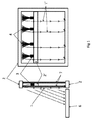
図1は、デスクを照明するための「シングル入射」照明パネル、すなわち光ファイバーに光を入射するために1つのタイプのLED光源を使用する照明パネルの例を示している。 FIG. 1 shows an example of a “single-incident” lighting panel for illuminating a desk, ie a lighting panel that uses one type of LED light source to inject light into an optical fiber.
ガラスファイバーを用いて製織された光ファイバーを含む照明用織物1が、アルミニウムフレームなどの支持構造体2により保持されている。照明用織物は、被照明対象の隣接表面6に対して実質的に垂直に配置されている。照明用織物1は、音響吸収層7をカバーしている。
A
光ファイバーの少なくとも一部が光源に接続され、そしてその長手方向の軸線が被照明対象の隣接表面6に対して実質的に垂直となるように配置されている。これらの光ファイバーの長手方向の軸線の向きは垂直である。
At least a portion of the optical fiber is connected to the light source and is arranged such that its longitudinal axis is substantially perpendicular to the
光は、これらの光ファイバーの長手方向の軸線に沿った光の伝播が被照明平面6の方へ向かうように、これらの光ファイバーの自由末端に入射する。光の伝播方向はデスク6の方に上から下へ向かう方向(1’)である。
Light is incident on the free ends of these optical fibers so that the propagation of the light along the longitudinal axis of these optical fibers is toward the illuminated
照明用織物の個々の光ファイバー又は光ファイバーの自由末端は、複数の束4に集められ、各束は、専用レンズが付随している光源3に、好ましくは白色LED光源に連結されている。
The individual optical fibers of the illuminating fabric or the free ends of the optical fibers are collected in a plurality of
光源3、好ましくは白色LED光源は、LED光源を冷却するためフレームのアルミニウムクロス部材2’に接触して、音響吸収層7の間に取り付けられている。光ファイバーが、光源、好ましくは白色LEDに接続される。
A
光ファイバーは、LED光源と照明用織物との間で実質的に180°を超えて曲げられている。 The optical fiber is bent substantially more than 180 ° between the LED light source and the illuminating fabric.
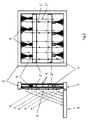
さらに、図2は、デスクを照明するための「ダブル入射」照明パネル、すなわち光ファイバーに逆方向に光を入射させるため2つのタイプのLED光源(3,5)を使用する照明パネルの例を示している。 Furthermore, FIG. 2 shows an example of a “double-incident” lighting panel for illuminating a desk, ie a lighting panel that uses two types of LED light sources (3, 5) to allow light to enter the optical fiber in the opposite direction. ing.
光は、これらの光ファイバーの長手方向の軸線に沿った光の伝播が被照明平面6の方に向けられ且つその反対の方へ向けられるように、これらの光ファイバーの自由末端に入射する。
Light is incident on the free ends of these optical fibers so that the propagation of light along the longitudinal axis of these optical fibers is directed toward the illuminated
光ファイバーは、2つのタイプの光源3に、好ましくは白色LED光源及び青色LED光源に、接続される。
The optical fiber is connected to two types of
1つのタイプの光源3、好ましくは白色LED光源3は、フレームの第一のアルミニウムクロス部材(2’)に取り付けられる。別のタイプの光源5、好ましくは青色LED光源は、第一のクロス部材の下方の第二のクロス部材(2”)に取り付けられる。
One type of
照明用織物内において、1つのタイプの光源により放出された光、好ましくは白色光の伝播方向は、デスクに向かって上方から下方への向き(1’)であり、そして別のタイプの光源により放出された光、好ましくは青色光の伝播方向は、天井に向かって下方から上方への向き(1”)である。 Within the illuminating fabric, the direction of propagation of light emitted by one type of light source, preferably white light, is from top to bottom (1 ′) towards the desk and by another type of light source. The direction of propagation of the emitted light, preferably blue light, is from the bottom to the top (1 ″) towards the ceiling.
青色光は、所定の強度、通常は約180ルクスの、較正された周波数で、使用者の目に真っ直ぐ供給することができる。青色LED光源を有することの目的は「ウインター/ライトブレイクダウン」効果を低下させることにより健康状態を作り出すことである。白色光は、デスクを照明するために、そしてデスク(6)へ入射する取り出し角度が30°であることから、上方から下方へ向かって搬送される(実線矢印)一方で、青色光は、約30°の反対向きの取り出し角度であることから、デスクで作業している人の目の方へ下方から上方へ向かって搬送される(破線矢印)。 Blue light can be delivered straight to the user's eye at a calibrated frequency of a predetermined intensity, usually about 180 lux. The purpose of having a blue LED light source is to create a health condition by reducing the “winter / light breakdown” effect. White light is conveyed from top to bottom to illuminate the desk and the take-off angle incident on the desk (6) is 30 ° (solid arrow), while blue light is about Since the take-out angle is 30 ° opposite, it is conveyed from below to above the eyes of the person working at the desk (broken arrow).
上記の例において、光ファイバーは、LED光源と入射する照明用織物との間で実質的に180°を超えて曲げられている。照明用織物の平面が連続する状態で光が入射することも可能である。光ファイバーの軸線に沿った光の方向性と光の取り出し角度は正確に同一であろう。 In the above example, the optical fiber is bent substantially more than 180 ° between the LED light source and the incident illumination fabric. It is also possible for light to be incident with the plane of the illuminating fabric being continuous. The directionality of light along the axis of the optical fiber and the light extraction angle will be exactly the same.
Claims (15)
・前記照明用織物の平面が被照明対象の隣接表面に対して実質的に垂直に配置され、
・前記光ファイバーの少なくとも一部が光源に接続され、そしてそれらの長手方向の軸線が被照明対象の隣接表面に対して実質的に垂直になるよう配置される、
ように、前記照明用織物が前記照明パネルに取り付けられており、
光が、これらの光ファイバーの長手方向の軸線に沿った光の伝播が被照明対象の平面の方に向けられ及び/又は該平面の反対の方に向けられるようにこれらの光ファイバーの自由末端に入射する、照明パネル。 A lighting panel including a support structure holding a lighting fabric, wherein the lighting fabric is a woven optical fiber coupled to a plurality of light sources and emits light laterally along their longitudinal axes. A lighting panel comprising a support structure holding a lighting fabric, comprising a woven optical fiber capable of diffusing;
The plane of the illuminating fabric is arranged substantially perpendicular to the adjacent surface of the object to be illuminated;
At least a portion of the optical fiber is connected to a light source and arranged such that their longitudinal axis is substantially perpendicular to the adjacent surface of the object to be illuminated;
The lighting fabric is attached to the lighting panel,
Light is incident on the free ends of these optical fibers so that the propagation of light along the longitudinal axis of these optical fibers is directed towards the plane of the object to be illuminated and / or directed away from the plane. Lighting panel.
Applications Claiming Priority (3)
| Application Number | Priority Date | Filing Date | Title |
|---|---|---|---|
| EP14189816.3 | 2014-10-21 | ||
| EP14189816 | 2014-10-21 | ||
| PCT/EP2015/071615 WO2016062478A1 (en) | 2014-10-21 | 2015-09-21 | A panel with integrated illumation |
Publications (2)
| Publication Number | Publication Date |
|---|---|
| JP2018500719A true JP2018500719A (en) | 2018-01-11 |
| JP2018500719A5 JP2018500719A5 (en) | 2018-10-04 |
Family
ID=51795505
Family Applications (1)
| Application Number | Title | Priority Date | Filing Date |
|---|---|---|---|
| JP2017522409A Pending JP2018500719A (en) | 2014-10-21 | 2015-09-21 | Panel with integrated lighting |
Country Status (7)
| Country | Link |
|---|---|
| US (1) | US20170329064A1 (en) |
| EP (1) | EP3209936A1 (en) |
| JP (1) | JP2018500719A (en) |
| CN (1) | CN107076405A (en) |
| CA (1) | CA2965012A1 (en) |
| SG (1) | SG11201702889QA (en) |
| WO (1) | WO2016062478A1 (en) |
Cited By (1)
| Publication number | Priority date | Publication date | Assignee | Title |
|---|---|---|---|---|
| WO2022024829A1 (en) * | 2020-07-28 | 2022-02-03 | 日東電工株式会社 | Tabletop lighting device |
Families Citing this family (4)
| Publication number | Priority date | Publication date | Assignee | Title |
|---|---|---|---|---|
| JP6915377B2 (en) * | 2017-05-24 | 2021-08-04 | トヨタ紡織株式会社 | Luminescent ornament, laying method of luminescent ornament, laying object and forming method of luminescent design |
| US10851987B2 (en) * | 2018-01-23 | 2020-12-01 | Rangine Corporation | Shelving system with integrated lighting |
| US10952534B2 (en) * | 2018-06-22 | 2021-03-23 | Product Miniature, Inc. | Low voltage modular shelf system |
| FR3096376B1 (en) * | 2019-05-23 | 2021-04-30 | Brochier Tech | METHOD OF DEPOSITING METAL NANOPARTICLES ON A TEXTILE TABLECLOTH BY PHOTOCALYSIS AND CORRESPONDING TEXTILE TABLECLOTH |
Family Cites Families (12)
| Publication number | Priority date | Publication date | Assignee | Title |
|---|---|---|---|---|
| GB328985A (en) * | 1929-02-08 | 1930-05-08 | Alexander Hirschfield | Improvements in and relating to wall and ceiling coverings and the like |
| US20050073839A1 (en) * | 2003-09-18 | 2005-04-07 | The Litebook Company Ltd | Light therapy device |
| US6908204B2 (en) * | 2002-02-02 | 2005-06-21 | Edward Robert Kraft | Flat panel luminaire having embedded light guides |
| US6851844B2 (en) * | 2002-08-23 | 2005-02-08 | The Boeing Company | Fiber optic fabric with opaque coating for directional light emission |
| FR2859737B1 (en) * | 2003-09-11 | 2006-08-18 | Cedric Brochier Soieries | METHOD FOR MANUFACTURING OPTICAL FIBER TISSUE |
| JP4282533B2 (en) * | 2004-04-19 | 2009-06-24 | 株式会社東芝 | Display device |
| FR2887996B1 (en) * | 2005-06-30 | 2007-08-17 | Prismaflex Internat Sa | RETROECTION COMMUNICATION PANEL |
| EP2115347A1 (en) * | 2007-01-30 | 2009-11-11 | Philips Intellectual Property & Standards GmbH | Light emitting floor surface |
| FR2938628B1 (en) * | 2008-11-18 | 2011-01-21 | Bpb Ltd | LIGHT PLATE |
| DE102010030660A1 (en) * | 2010-06-29 | 2011-12-29 | Lisa Dräxlmaier GmbH | Illuminated vehicle interior part |
| WO2013050908A1 (en) * | 2011-10-06 | 2013-04-11 | Koninklijke Philips Electronics N.V. | Desk partition |
| CN105698062A (en) * | 2014-11-28 | 2016-06-22 | 鸿富锦精密工业(深圳)有限公司 | Light emitting module |
-
2015
- 2015-09-21 US US15/520,110 patent/US20170329064A1/en not_active Abandoned
- 2015-09-21 SG SG11201702889QA patent/SG11201702889QA/en unknown
- 2015-09-21 CN CN201580057076.0A patent/CN107076405A/en active Pending
- 2015-09-21 CA CA2965012A patent/CA2965012A1/en not_active Abandoned
- 2015-09-21 EP EP15766179.4A patent/EP3209936A1/en not_active Withdrawn
- 2015-09-21 JP JP2017522409A patent/JP2018500719A/en active Pending
- 2015-09-21 WO PCT/EP2015/071615 patent/WO2016062478A1/en active Application Filing
Cited By (2)
| Publication number | Priority date | Publication date | Assignee | Title |
|---|---|---|---|---|
| WO2022024829A1 (en) * | 2020-07-28 | 2022-02-03 | 日東電工株式会社 | Tabletop lighting device |
| US11940120B2 (en) | 2020-07-28 | 2024-03-26 | Nitto Denko Corporation | Desktop illumination device |
Also Published As
| Publication number | Publication date |
|---|---|
| CN107076405A (en) | 2017-08-18 |
| SG11201702889QA (en) | 2017-05-30 |
| EP3209936A1 (en) | 2017-08-30 |
| US20170329064A1 (en) | 2017-11-16 |
| WO2016062478A1 (en) | 2016-04-28 |
| CA2965012A1 (en) | 2016-04-28 |
Similar Documents
| Publication | Publication Date | Title |
|---|---|---|
| JP2018500719A (en) | Panel with integrated lighting | |
| JP5658752B2 (en) | Freeform light module | |
| RU2660406C2 (en) | Sound absorbing lighting panel and modular surface system | |
| JP4145527B2 (en) | Illumination device having a point light source | |
| CN103582833B (en) | Luminaire | |
| JP5779096B2 (en) | Lighting system, lighting fixture, collimator, and display device | |
| EP3090107B1 (en) | Light-emitting acoustic panel and lighting system comprising a set of such panels | |
| JP6746397B2 (en) | Vehicle lighting | |
| JP2011522372A (en) | Illumination device having a collimator | |
| JP2010224089A (en) | Prism | |
| RU2608079C2 (en) | Lighting fixture with light plate | |
| JPWO2012128088A1 (en) | Illumination device, shelf illumination device, shelf unit equipped with this illumination device and showcase | |
| US8201956B2 (en) | Task light | |
| JP2012529737A (en) | Lighting device | |
| JP2018500719A5 (en) | ||
| JP2017126586A (en) | Luminaire | |
| WO2013050908A1 (en) | Desk partition | |
| KR20100075350A (en) | Display device | |
| KR20090112178A (en) | Flat lighting apparatus using light emitting diode | |
| RU2606946C2 (en) | Illumination device, luminaire and lighting system | |
| JP7087438B2 (en) | Lighting device and display device | |
| RU2638822C2 (en) | Lighting device based on light guide with light-scattering particles and light angle selection module | |
| JPWO2013141020A1 (en) | Light guide plate, lighting device and lighting stand | |
| JP2015505151A (en) | LED lighting device including a diffuser system | |
| JP2005539356A (en) | Light emitting device having light input and light output unit |
Legal Events
| Date | Code | Title | Description |
|---|---|---|---|
| A521 | Written amendment |
Free format text: JAPANESE INTERMEDIATE CODE: A523 Effective date: 20180821 |
|
| A621 | Written request for application examination |
Free format text: JAPANESE INTERMEDIATE CODE: A621 Effective date: 20180821 |
|
| A977 | Report on retrieval |
Free format text: JAPANESE INTERMEDIATE CODE: A971007 Effective date: 20190530 |
|
| A131 | Notification of reasons for refusal |
Free format text: JAPANESE INTERMEDIATE CODE: A131 Effective date: 20190604 |
|
| A601 | Written request for extension of time |
Free format text: JAPANESE INTERMEDIATE CODE: A601 Effective date: 20190903 |
|
| A02 | Decision of refusal |
Free format text: JAPANESE INTERMEDIATE CODE: A02 Effective date: 20200218 |