JP2018205609A - Toner container and image formation apparatus - Google Patents

Toner container and image formation apparatus Download PDF

Info

Publication number
JP2018205609A
JP2018205609A JP2017112931A JP2017112931A JP2018205609A JP 2018205609 A JP2018205609 A JP 2018205609A JP 2017112931 A JP2017112931 A JP 2017112931A JP 2017112931 A JP2017112931 A JP 2017112931A JP 2018205609 A JP2018205609 A JP 2018205609A
Authority
JP
Japan
Prior art keywords
discharge port
shutter
toner
toner container
opening
Prior art date
Legal status (The legal status is an assumption and is not a legal conclusion. Google has not performed a legal analysis and makes no representation as to the accuracy of the status listed.)
Pending
Application number
JP2017112931A
Other languages
Japanese (ja)
Inventor
直純 小川
Naozumi Ogawa
直純 小川
達也 山中
Tatsuya Yamanaka
達也 山中
花野 勧
Susumu Hanano
勧 花野
Current Assignee (The listed assignees may be inaccurate. Google has not performed a legal analysis and makes no representation or warranty as to the accuracy of the list.)
Kyocera Document Solutions Inc
Original Assignee
Kyocera Document Solutions Inc
Priority date (The priority date is an assumption and is not a legal conclusion. Google has not performed a legal analysis and makes no representation as to the accuracy of the date listed.)
Filing date
Publication date
Application filed by Kyocera Document Solutions Inc filed Critical Kyocera Document Solutions Inc
Priority to JP2017112931A priority Critical patent/JP2018205609A/en
Publication of JP2018205609A publication Critical patent/JP2018205609A/en
Pending legal-status Critical Current

Links

Images

Landscapes

  • Dry Development In Electrophotography (AREA)
  • Electrophotography Configuration And Component (AREA)

Abstract

To provide a toner container which suppresses leakage of toner extruded by a shutter closing a discharge port.SOLUTION: A toner container 15 includes: a container body 30 which has a discharge port 50 for discharging toner stored therein to the outside; a shutter mount 51 which is provided in the periphery of the discharge port 50 with a gap between the container body 30 and itself; a discharge port shutter 53 which is provided between the container body 30 and the shutter mount 51, moves to one of the opening/closing directions to close the discharge port 50, and moves to the other of the opening/closing directions to open the discharge port 50; and a film 52 which has a recess 54 fixed to the shutter mount 51, contacting in the state where the discharge port shutter 53 slides, formed into the recessed shape at a position deviating to one of the opening/closing directions with respect to the discharge port 50 and storing toner extruded by the discharge port shutter 53 moving to the one of the opening/closing directions.SELECTED DRAWING: Figure 10

Description

本発明は、トナー容器および画像形成装置に関する。   The present invention relates to a toner container and an image forming apparatus.

画像形成装置には、内部にトナーを収容したトナー容器が装着されている。   The image forming apparatus is provided with a toner container containing toner therein.

例えば、特許文献1に記載のトナーコンテナ(トナー容器)は、現像装置にトナーを供給するために画像形成装置に着脱自在に設けられている。現像装置には、トナー補給口を開閉するための第一のシャッターがスライド可能に設けられている。トナーコンテナの下部には、トナー排出口を開閉するための第二のシャッターがスライド可能に設けられている。トナーコンテナが画像形成装置に装着されると、第一および第二のシャッターは移動してトナー補給口およびトナー排出口を開放する。一方、トナーコンテナが画像形成装置から離脱されると、第一および第二のシャッターは移動してトナー補給口およびトナー排出口を閉塞する。   For example, a toner container (toner container) described in Patent Document 1 is detachably provided in an image forming apparatus in order to supply toner to a developing device. The developing device is slidably provided with a first shutter for opening and closing the toner supply port. A second shutter for opening and closing the toner discharge port is slidably provided below the toner container. When the toner container is mounted on the image forming apparatus, the first and second shutters move to open the toner supply port and the toner discharge port. On the other hand, when the toner container is detached from the image forming apparatus, the first and second shutters move to close the toner supply port and the toner discharge port.

特開2012−118281号公報JP 2012-118281 A

しかしながら、上記のトナーコンテナでは、トナーコンテナの離脱に伴って第二のシャッターが移動すると、第二のシャッターに開口した排出口の内側に残されたトナーが押し出されて外部に漏れ出すことがあった。   However, in the above toner container, if the second shutter moves as the toner container is detached, the toner remaining inside the discharge port opened in the second shutter may be pushed out and leaked to the outside. It was.

本発明は、上記課題を解決するために、排出口を閉塞するシャッターに押し出されたトナーの漏出を抑制するトナー容器および画像形成装置を提供する。   In order to solve the above-described problems, the present invention provides a toner container and an image forming apparatus that suppress leakage of toner pushed out by a shutter that closes a discharge port.

上記した目的を達成するため、本発明のトナー容器は、内部に収容したトナーを外部に排出するための排出口を有する容器本体と、前記容器本体との間に隙間を挟んで前記排出口の周囲に設けられているマウントと、前記容器本体と前記マウントとの間に設けられ、開閉方向一方に移動して前記排出口を閉塞させ、開閉方向他方に移動して前記排出口を開放させるシャッターと、前記マウントに固定され、前記シャッターが滑る状態で接触し、前記排出口よりも開閉方向一方にずれた位置に凹む状態に形成されて開閉方向一方に移動する前記シャッターに押し出されたトナーを収容する凹部を有しているフィルムと、を備えている。   In order to achieve the above-described object, the toner container of the present invention has a container body having a discharge port for discharging the toner accommodated inside and a container body, and a gap between the container body. A shutter provided between the mount provided around and the container main body and the mount that moves in one of the opening and closing directions to close the discharge port and moves to the other in the opening and closing direction to open the discharge port And the toner which is fixed to the mount, contacts in a state where the shutter slides, and is recessed in a position shifted to one side in the opening / closing direction from the discharge port, and pushed out to the shutter moving in one direction in the opening / closing direction. And a film having a recess to be accommodated.

この場合、前記マウントは、前記排出口と前記凹部との間に亘って開口している長穴を有し、前記フィルムは、前記排出口に対向して開口しているフィルム側開口部を有し、前記シャッターは、開閉方向他方に移動して前記排出口を開放した場合に、前記排出口と前記フィルム側開口部とを連通させるシャッター側開口部を有し、前記凹部は、前記シャッターが前記排出口を閉塞した状態で、前記シャッター側開口部に対向する位置で前記フィルムに形成されていることが好ましい。   In this case, the mount has a long hole that opens between the discharge port and the recess, and the film has a film-side opening that opens to face the discharge port. The shutter has a shutter-side opening that allows the discharge port and the film-side opening to communicate with each other when the shutter is moved in the open / close direction and the discharge port is opened. It is preferable that the film is formed on the film at a position facing the shutter side opening with the discharge port closed.

上記した目的を達成するため、本発明の画像形成装置は、上記の何れかのトナー容器と、前記シャッターが前記排出口を開放した状態で、前記トナー容器に連結され、前記排出口から排出されたトナーを用いて像担持体に担持された潜像をトナー像に現像する現像装置と、を備え、前記現像装置は、前記トナー容器との連結部分に凹む状態に形成されて前記フィルムの前記凹部が配置される装置側凹部を有している。   In order to achieve the above object, an image forming apparatus of the present invention is connected to the toner container with one of the toner containers described above and the shutter opened, and is discharged from the discharge opening. A developing device that develops the latent image carried on the image carrier using the toner into a toner image, wherein the developing device is formed in a recessed state in a connecting portion with the toner container, and It has a device-side recess in which the recess is disposed.

この場合、前記シャッターは、前記トナー容器を前記現像装置に連結する動作に連動して前記排出口を開放させ、前記トナー容器を前記現像装置から分離する動作に連動して前記排出口を閉塞させることが好ましい。   In this case, the shutter opens the discharge port in conjunction with the operation of connecting the toner container to the developing device, and closes the discharge port in conjunction with the operation of separating the toner container from the development device. It is preferable.

本発明によれば、排出口を閉塞するシャッターに押し出されたトナーの漏出を抑制することができる。   According to the present invention, it is possible to suppress leakage of toner pushed out by a shutter that closes the discharge port.

本発明の一実施形態に係る画像形成装置を示す概略図(正面図)である。1 is a schematic view (front view) illustrating an image forming apparatus according to an embodiment of the present invention. 本発明の一実施形態に係るトナー供給装置を示す斜視図である。1 is a perspective view showing a toner supply device according to an embodiment of the present invention. 図2のIII−III断面図である。It is III-III sectional drawing of FIG. 本発明の一実施形態に係る現像装置を示す斜視図である。1 is a perspective view showing a developing device according to an embodiment of the present invention. 図4のV−V断面図である。It is VV sectional drawing of FIG. 本発明の一実施形態に係るトナーコンテナを示す斜視図である。FIG. 3 is a perspective view showing a toner container according to an embodiment of the present invention. 本発明の一実施形態に係るトナーコンテナのトナー排出機構を示す斜視図である。FIG. 3 is a perspective view showing a toner discharge mechanism of a toner container according to an embodiment of the present invention. 本発明の一実施形態に係るトナーコンテナの排出口シャッターが閉塞位置に配置された状態を示す断面図である。FIG. 6 is a cross-sectional view illustrating a state in which the outlet shutter of the toner container according to the exemplary embodiment of the present invention is disposed at a closed position. 本発明の一実施形態に係るトナーコンテナの排出口シャッターが開放位置に配置された状態を示す断面図である。FIG. 6 is a cross-sectional view illustrating a state in which the discharge port shutter of the toner container according to the embodiment of the present invention is disposed at an open position. 本発明の一実施形態に係るトナーコンテナの排出口シャッターが開放位置から閉塞位置に向かって移動する過程を示す断面図である。FIG. 5 is a cross-sectional view illustrating a process in which a discharge port shutter of a toner container according to an exemplary embodiment of the present invention moves from an open position toward a closed position.

以下、添付の図面を参照しつつ、本発明の実施形態について説明する。なお、各図に示す「L」は「左」を示し、「R」は「右」を示し、「U」は「上」を示し、「D」は「下」を示している。   Hereinafter, embodiments of the present invention will be described with reference to the accompanying drawings. In each figure, “L” indicates “left”, “R” indicates “right”, “U” indicates “upper”, and “D” indicates “lower”.

[画像形成装置の全体構成]
図1を参照して、画像形成装置1の全体の構成について説明する。図1は画像形成装置1を示す概略図(正面図)である。
[Entire configuration of image forming apparatus]
The overall configuration of the image forming apparatus 1 will be described with reference to FIG. FIG. 1 is a schematic view (front view) showing an image forming apparatus 1.

画像形成装置1は、プリント装置1Aと、スキャン装置1Bと、を備えた複合機である。プリント装置1Aは、外部機器(図示せず)から入力された画像を電子写真方式でシートSに印刷する。スキャン装置1Bは、プリント装置1Aの上面に配置され、原稿の画像情報を光学的に読み取る装置である。なお、スキャン装置1Bは公知の構造であるため、その詳細な説明は省略する。   The image forming apparatus 1 is a multifunction machine including a printing apparatus 1A and a scanning apparatus 1B. The printing apparatus 1A prints an image input from an external device (not shown) on the sheet S by an electrophotographic method. The scanning device 1B is a device that is disposed on the upper surface of the printing device 1A and optically reads image information of a document. Since the scanning device 1B has a known structure, detailed description thereof is omitted.

プリント装置1Aは、略直方体状の外観を構成する装置本体2を備えている。装置本体2の下側には、紙製のシートSを収容する給紙カセット3が着脱可能に設けられている。装置本体2の上面には、排紙トレイ4が設けられている。なお、シートSは、紙製に限らず、樹脂製等であってもよい。   The printing apparatus 1A includes an apparatus main body 2 that forms a substantially rectangular parallelepiped appearance. A paper feed cassette 3 that stores paper sheets S is detachably provided below the apparatus main body 2. A paper discharge tray 4 is provided on the upper surface of the apparatus main body 2. Note that the sheet S is not limited to paper, and may be made of resin or the like.

プリント装置1Aは、作像装置6と、定着装置7と、を装置本体2の内部に備えている。作像装置6は、給紙カセット3から排紙トレイ4まで延びた搬送路8の中間部に設けられている。定着装置7は、搬送路8の下流側に設けられている。   The printing apparatus 1 </ b> A includes an image forming device 6 and a fixing device 7 inside the apparatus main body 2. The image forming device 6 is provided in an intermediate portion of a conveyance path 8 extending from the paper feed cassette 3 to the paper discharge tray 4. The fixing device 7 is provided on the downstream side of the conveyance path 8.

作像装置6は、感光体ドラム10(像担持体)と、転写ローラー11と、トナー供給装置12と、光走査装置13と、を含んでいる。感光体ドラム10は、軸周りに回転し、帯電装置(図示せず)によって帯電される。転写ローラー11は、感光体ドラム10に接触して転写ニップを形成している。トナー供給装置12は、現像装置14と、これに供給するトナー(現像剤)を収容するトナーコンテナ15と、を含んでいる。現像装置14は感光体ドラム10の左側に隣接し、トナーコンテナ15は現像装置14の左側に隣接している。なお、本実施形態では、トナーの一例として、磁性トナーから成る一成分現像剤が用いられているが、これに限らず、トナーとキャリア(強磁性体)とを含む二成分現像剤が用いられていてもよい。   The image forming device 6 includes a photosensitive drum 10 (image carrier), a transfer roller 11, a toner supply device 12, and an optical scanning device 13. The photosensitive drum 10 rotates around an axis and is charged by a charging device (not shown). The transfer roller 11 is in contact with the photosensitive drum 10 to form a transfer nip. The toner supply device 12 includes a developing device 14 and a toner container 15 that stores toner (developer) supplied thereto. The developing device 14 is adjacent to the left side of the photosensitive drum 10, and the toner container 15 is adjacent to the left side of the developing device 14. In the present embodiment, a one-component developer made of a magnetic toner is used as an example of the toner. However, the present invention is not limited to this, and a two-component developer including a toner and a carrier (ferromagnetic material) is used. It may be.

光走査装置13は、トナーコンテナ15の上方に配置され、帯電した感光体ドラム10を露光して静電潜像を形成する。現像装置14は、トナーコンテナ15から供給されたトナーを用いて感光体ドラム10に担持された静電潜像をトナー像に現像する。感光体ドラム10に担持されたトナー像は、転写ニップを通過するシートSに転写される。定着装置7は、転写されたトナー像をシートSに定着させる。その後、シートSは、排紙トレイ4に排出される。   The optical scanning device 13 is disposed above the toner container 15 and exposes the charged photosensitive drum 10 to form an electrostatic latent image. The developing device 14 develops the electrostatic latent image carried on the photosensitive drum 10 into a toner image using the toner supplied from the toner container 15. The toner image carried on the photosensitive drum 10 is transferred to the sheet S passing through the transfer nip. The fixing device 7 fixes the transferred toner image on the sheet S. Thereafter, the sheet S is discharged to the paper discharge tray 4.

[トナー供給装置]
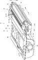
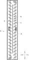
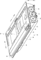
次に、図2ないし図9を参照して、トナー供給装置12について説明する。図2はトナー供給装置12を示す斜視図である。図3は、図2のIII−III断面図である。図4は現像装置14を示す斜視図である。図5は、図4のV−V断面図である。図6はトナーコンテナ15を示す斜視図である。図7はトナーコンテナ15のトナー排出機構34を示す斜視図である。図8は排出口シャッター53が閉塞位置P1に配置された状態を示す断面図である。図9は排出口シャッター53が開放位置P2に配置された状態を示す断面図である。
[Toner supply device]
Next, the toner supply device 12 will be described with reference to FIGS. FIG. 2 is a perspective view showing the toner supply device 12. 3 is a cross-sectional view taken along the line III-III in FIG. FIG. 4 is a perspective view showing the developing device 14. 5 is a cross-sectional view taken along the line VV in FIG. FIG. 6 is a perspective view showing the toner container 15. FIG. 7 is a perspective view showing the toner discharge mechanism 34 of the toner container 15. FIG. 8 is a cross-sectional view showing a state where the discharge port shutter 53 is disposed at the closing position P1. FIG. 9 is a cross-sectional view showing a state where the discharge port shutter 53 is disposed at the open position P2.

図2に示すように、トナー供給装置12は、現像装置14と、トナーコンテナ15と、を含んでいる。現像装置14とトナーコンテナ15とは横並びに隣接しているため、トナー供給装置12の高さが低く抑えられている。したがって、光走査装置13をトナーコンテナ15の上方に配置しても、画像形成装置1(装置本体2)の小型化を図ることができている(図1参照)。   As shown in FIG. 2, the toner supply device 12 includes a developing device 14 and a toner container 15. Since the developing device 14 and the toner container 15 are adjacent to each other, the height of the toner supply device 12 is kept low. Therefore, even if the optical scanning device 13 is disposed above the toner container 15, the image forming apparatus 1 (device main body 2) can be downsized (see FIG. 1).

<現像装置>
図2ないし図4に示すように、現像装置14は、筐体20と、2つの現像スクリュー21と、現像ローラー22と、現像駆動機構23と、を含んでいる。
<Developing device>
As shown in FIGS. 2 to 4, the developing device 14 includes a housing 20, two developing screws 21, a developing roller 22, and a developing drive mechanism 23.

筐体20は、例えば、合成樹脂製で前後方向に長い略直方体状に形成されている。筐体20の内部には、トナーコンテナ15から補給されたトナーが収容される。図4に示すように、筐体20の左上部には、筐体20の上面よりも一段下がった位置に接続面20Aが形成されている。接続面20Aには、トナーコンテナ15から補給されたトナーを受け入れるための補給口24が形成されている。接続面20Aには、前後方向(開閉方向)に移動して補給口24を開閉する補給口シャッター25が設けられている。補給口シャッター25は、前方に移動して補給口24を閉塞させ、後方に移動して補給口24を開放させる。なお、補給口シャッター25は、バネ等の付勢部材(図示せず)によって補給口24を閉じる方向に付勢されている。また、補給口24の周囲には、ゴム製等のシール(図示せず)が設けられている。   The casing 20 is made of, for example, a synthetic resin and has a substantially rectangular parallelepiped shape that is long in the front-rear direction. The toner supplied from the toner container 15 is accommodated in the housing 20. As shown in FIG. 4, a connection surface 20 </ b> A is formed on the upper left portion of the housing 20 at a position lower than the upper surface of the housing 20. A supply port 24 for receiving toner supplied from the toner container 15 is formed on the connection surface 20A. The connection surface 20A is provided with a supply port shutter 25 that moves in the front-rear direction (open / close direction) to open and close the supply port 24. The supply port shutter 25 moves forward to close the supply port 24 and moves backward to open the supply port 24. The supply port shutter 25 is urged in a direction to close the supply port 24 by an urging member (not shown) such as a spring. A rubber seal (not shown) is provided around the replenishing port 24.

詳細は後述するが、接続面20Aは、トナーコンテナ15との連結部分となっている。また、現像装置14は、接続面20Aに凹む状態に形成された装置側凹部28を有している。装置側凹部28は、平面から見て、前後方向に長い略長方形状に形成され、接続面20Aにおいて略バスタブ状に窪んでいる。装置側凹部28は、補給口24の後方に隣接し、補給口24に連なった状態に形成されている(図8参照)。   Although the details will be described later, the connection surface 20 </ b> A is a connection portion with the toner container 15. Further, the developing device 14 has a device-side recess 28 formed in a state of being recessed in the connection surface 20A. The device-side recess 28 is formed in a substantially rectangular shape that is long in the front-rear direction when viewed from the plane, and is recessed in a substantially bathtub shape on the connection surface 20A. The apparatus-side recess 28 is formed adjacent to the rear of the supply port 24 and connected to the supply port 24 (see FIG. 8).

図3および図5に示すように、2つの現像スクリュー21は、それぞれ、前後方向に延びたシャフトと、この外周面に固定された螺旋状の羽根と、を含んでいる。2つの現像スクリュー21は、筐体20の内部に左右方向に並んで配置され、筐体20に回転可能に支持されている。2つの現像スクリュー21は、軸周りに回転して筐体20内のトナーを攪拌しながら図5の矢印方向に循環させる機能を有している。なお、補給口24の直下に位置する現像スクリュー21の羽根は、他の部分よりも小さな直径になっている。   As shown in FIGS. 3 and 5, the two developing screws 21 each include a shaft extending in the front-rear direction and a spiral blade fixed to the outer peripheral surface. The two developing screws 21 are arranged in the left-right direction inside the housing 20 and are rotatably supported by the housing 20. The two developing screws 21 have a function of rotating around the axis and circulating the toner in the housing 20 in the arrow direction of FIG. 5 while stirring. Note that the blades of the developing screw 21 located immediately below the supply port 24 have a smaller diameter than other portions.

図2ないし図4に示すように、現像ローラー22は、前後方向に長い円筒状に形成されている。現像ローラー22は、筐体20の右上部から一部を露出させた状態で、筐体20に回転可能に支持されている。現像ローラー22は、筐体20内のトナーを感光体ドラム10の表面に搬送する機能を有している。   As shown in FIGS. 2 to 4, the developing roller 22 is formed in a cylindrical shape that is long in the front-rear direction. The developing roller 22 is rotatably supported by the housing 20 with a part exposed from the upper right portion of the housing 20. The developing roller 22 has a function of conveying the toner in the housing 20 to the surface of the photosensitive drum 10.

図4に示すように、現像駆動機構23は、駆動モーター26と、現像側ジョイント27と、を含んでいる。駆動モーター26は、ギア列やシャフト等(図示せず)を介して、各現像スクリュー21、現像ローラー22および現像側ジョイント27等に接続されている。現像側ジョイント27は、筐体20の後部に回転可能に支持され、その前端部を筐体20の後部から前方に露出させている。   As shown in FIG. 4, the development drive mechanism 23 includes a drive motor 26 and a development side joint 27. The drive motor 26 is connected to each developing screw 21, the developing roller 22, the developing side joint 27, and the like via a gear train, a shaft, and the like (not shown). The development side joint 27 is rotatably supported at the rear portion of the housing 20, and the front end portion thereof is exposed forward from the rear portion of the housing 20.

<トナーコンテナ>
図2、図3および図6に示すように、トナー容器の一例としてのトナーコンテナ15は、容器本体30と、2つの攪拌部材31と、搬送スクリュー32と、容器側ジョイント33と、トナー排出機構34と、を含んでいる。このトナーコンテナ15は、装置本体2に着脱可能に装着されている。
<Toner container>
As shown in FIGS. 2, 3 and 6, the toner container 15 as an example of a toner container includes a container main body 30, two stirring members 31, a transport screw 32, a container side joint 33, and a toner discharge mechanism. 34. The toner container 15 is detachably attached to the apparatus main body 2.

容器本体30は、例えば、合成樹脂製で前後方向に長い略直方体状に形成されている。容器本体30の内部には、現像装置14に補給するためのトナーが収容される。容器本体30は、ケース部35と、リッド部36と、を含んでいる。   The container body 30 is made of, for example, a synthetic resin and has a substantially rectangular parallelepiped shape that is long in the front-rear direction. The container main body 30 contains toner for replenishing the developing device 14. The container body 30 includes a case portion 35 and a lid portion 36.

ケース部35は、前後方向に長い略バスタブ状に形成されている。ケース部35の内部には、トナーを収容するトナー収容室R1が形成されている(図3参照)。ケース部35の上端周縁部には、外側に広がる環状のケース側フランジ部40が形成されている(図6の破線参照)。ケース部35の右側上端部には接続フランジ部41が外側(右側)に延びた状態に形成され、その接続フランジ部41の先端部に右側のケース側フランジ部40が形成されている(図3参照)。つまり、右側一辺に形成されたフランジ形状は、他辺のフランジ形状よりも幅広く形成されている。トナーコンテナ15が装置本体2に装着されると、右側のケース側フランジ部40および接続フランジ部41は、現像装置14の接続面20Aに重ねられた状態になる(図3参照)。   The case part 35 is formed in a substantially bathtub-like shape that is long in the front-rear direction. A toner storage chamber R1 for storing toner is formed inside the case portion 35 (see FIG. 3). An annular case-side flange 40 that extends outward is formed on the peripheral edge of the upper end of the case 35 (see the broken line in FIG. 6). A connecting flange portion 41 is formed on the right upper end of the case portion 35 so as to extend outward (right side), and a right case-side flange portion 40 is formed at the tip of the connecting flange portion 41 (FIG. 3). reference). That is, the flange shape formed on the right side is wider than the flange shape on the other side. When the toner container 15 is mounted on the apparatus main body 2, the right case side flange portion 40 and the connection flange portion 41 are overlaid on the connection surface 20 </ b> A of the developing device 14 (see FIG. 3).

リッド部36は、略板状に形成され、ケース部35の上面開口部を覆ってケース部35を密封する。リッド部36の外周部には、ケース側フランジ部40に超音波溶着される環状のリッド側フランジ部45が形成されている(図6の破線参照)。   The lid portion 36 is formed in a substantially plate shape, covers the upper surface opening of the case portion 35, and seals the case portion 35. An annular lid-side flange portion 45 that is ultrasonically welded to the case-side flange portion 40 is formed on the outer periphery of the lid portion 36 (see the broken line in FIG. 6).

リッド部36の右端部においてリッド側フランジ部45を避けた位置には、回転体収容部43およびジョイント収容部44が一体に形成されている。リッド部36をケース部35に接着した状態で、回転体収容部43およびジョイント収容部44は接続フランジ部41の上面に配置される。回転体収容部43は、リッド部36の上面から上方に膨出するように形成されている。回転体収容部43の内部右側には、搬送スクリュー32を収容するためのスクリュー配置室R2が形成されている(図3参照)。回転体収容部43の左側下面は、トナー収容室R1とスクリュー配置室R2とを連通させるように開口している(図3参照)。ジョイント収容部44は、回転体収容部43の後端部に連なった状態に形成されている。   The rotating body housing portion 43 and the joint housing portion 44 are integrally formed at a position where the lid side flange portion 45 is avoided at the right end portion of the lid portion 36. In a state where the lid portion 36 is bonded to the case portion 35, the rotating body housing portion 43 and the joint housing portion 44 are disposed on the upper surface of the connection flange portion 41. The rotating body accommodating portion 43 is formed so as to bulge upward from the upper surface of the lid portion 36. A screw arrangement chamber R2 for accommodating the conveying screw 32 is formed on the right side inside the rotating body accommodating portion 43 (see FIG. 3). The lower surface on the left side of the rotator accommodating portion 43 is open so as to allow the toner accommodating chamber R1 and the screw arrangement chamber R2 to communicate with each other (see FIG. 3). The joint housing portion 44 is formed in a state of being connected to the rear end portion of the rotating body housing portion 43.

図3に示すように、2つの攪拌部材31は、それぞれ、前後方向に延びた攪拌シャフト31Aと、これに固定された可撓性を有する攪拌片31Bと、を含んでいる。2つの攪拌部材31は、ケース部35の内部に左右方向に並んで配置され、ケース部35に回転可能に支持されている。各攪拌片31Bは攪拌シャフト31Aから径方向外側に延びて、その先端部が容器本体30の内壁の一部に接触するようになっている。各攪拌シャフト31Aの後端部はケース部35の後壁を貫通しており、ケース部35を貫通した各攪拌シャフト31Aの後端部には出力ギアG2が固定されている(図6参照)。また、ケース部35の後面には、各出力ギアG2に噛み合い、且つ駆動モーター26に回転駆動される中間ギアG1が設けられている(図6参照)。   As shown in FIG. 3, each of the two stirring members 31 includes a stirring shaft 31A extending in the front-rear direction and a flexible stirring piece 31B fixed to the stirring shaft 31A. The two stirring members 31 are arranged side by side in the left-right direction inside the case portion 35 and are rotatably supported by the case portion 35. Each stirring piece 31 </ b> B extends radially outward from the stirring shaft 31 </ b> A, and a tip portion thereof comes into contact with a part of the inner wall of the container body 30. The rear end portion of each stirring shaft 31A passes through the rear wall of the case portion 35, and an output gear G2 is fixed to the rear end portion of each stirring shaft 31A passing through the case portion 35 (see FIG. 6). . An intermediate gear G1 that meshes with each output gear G2 and is rotationally driven by the drive motor 26 is provided on the rear surface of the case portion 35 (see FIG. 6).

図3に示すように、搬送スクリュー32は、前後方向に延びたシャフトと、その外周面に固定された螺旋状の羽根と、を含んでいる。搬送スクリュー32は、回転体収容部43の内部で回転可能に支持されている。搬送スクリュー32の後端部は、ジョイント収容部44まで延びている。   As shown in FIG. 3, the conveying screw 32 includes a shaft extending in the front-rear direction and a spiral blade fixed to the outer peripheral surface thereof. The conveying screw 32 is supported so as to be rotatable inside the rotating body housing portion 43. The rear end portion of the conveying screw 32 extends to the joint housing portion 44.

図6に示すように、容器側ジョイント33は、ジョイント収容部44の内部に配置され、搬送スクリュー32の後端部に着脱可能に取り付けられている。トナーコンテナ15が装置本体2に装着された状態で、容器側ジョイント33は現像側ジョイント27に連結し(図2参照)、駆動モーター26の駆動力を搬送スクリュー32に伝達する。   As shown in FIG. 6, the container side joint 33 is disposed inside the joint housing portion 44 and is detachably attached to the rear end portion of the conveying screw 32. In a state where the toner container 15 is mounted on the apparatus main body 2, the container side joint 33 is connected to the development side joint 27 (see FIG. 2), and the driving force of the driving motor 26 is transmitted to the conveying screw 32.

(トナー排出機構)
図3および図7に示すように、トナー排出機構34は、容器本体30内のトナーを現像装置14に向けて排出するために接続フランジ部41に設けられている。トナー排出機構34は、排出口50と、シャッターマウント51(マウント)と、フィルム52と、排出口シャッター53(シャッター)と、を含んでいる。
(Toner discharge mechanism)
As shown in FIGS. 3 and 7, the toner discharge mechanism 34 is provided in the connection flange portion 41 for discharging the toner in the container main body 30 toward the developing device 14. The toner discharge mechanism 34 includes a discharge port 50, a shutter mount 51 (mount), a film 52, and a discharge port shutter 53 (shutter).

(排出口50)
排出口50は、容器本体30の内部に収容したトナーを現像装置14(外部)に排出するための開口である。排出口50は、容器本体30の接続フランジ部41の前側に形成されている(図3参照)。排出口50は、底面から見て、前後方向に長い略長方形状に形成されている。トナーコンテナ15が装置本体2に装着された状態で、排出口50は現像装置14の補給口24に対向するようになっている。
(Discharge port 50)
The discharge port 50 is an opening for discharging the toner accommodated in the container body 30 to the developing device 14 (outside). The discharge port 50 is formed in the front side of the connection flange part 41 of the container main body 30 (refer FIG. 3). The discharge port 50 is formed in a substantially rectangular shape that is long in the front-rear direction when viewed from the bottom. With the toner container 15 mounted on the apparatus main body 2, the discharge port 50 faces the supply port 24 of the developing device 14.

(シャッターマウント)
シャッターマウント51は、例えば、ABS(アクリロニトリル,ブタジエン,スチレン)樹脂製で、前後方向(開閉方向)に長い略矩形枠状(環状)に形成されている。つまり、シャッターマウント51には、前後方向に長い略長方形状の長穴51Aが形成されている(図7参照)。シャッターマウント51は、接続フランジ部41の下面41F(容器本体30の開口面)から下方に離間して設けられている。すなわち、シャッターマウント51は、接続フランジ部41の下面41F(容器本体30)との間に隙間を挟んで排出口50の周囲に設けられている(図8参照)。
(Shutter mount)
The shutter mount 51 is made of, for example, ABS (acrylonitrile, butadiene, styrene) resin, and is formed in a substantially rectangular frame shape (annular) that is long in the front-rear direction (opening / closing direction). That is, the shutter mount 51 is formed with a substantially rectangular slot 51A that is long in the front-rear direction (see FIG. 7). The shutter mount 51 is provided to be spaced downward from the lower surface 41F of the connection flange portion 41 (the opening surface of the container body 30). That is, the shutter mount 51 is provided around the discharge port 50 with a gap between the lower surface 41F (container body 30) of the connection flange portion 41 (see FIG. 8).

(フィルム)
図7および図8に示すように、フィルム52は、前後方向に長い略長方形状に形成されている。フィルム52は、例えば、PET(ポリエチレンテレフタレート)樹脂製で、厚さ0.1mm程度に形成された薄膜である。フィルム52は、例えば、両面テープ等を用いてシャッターマウント51に貼付(固定)されて長穴51Aを略塞いでいる。また、フィルム52は、排出口50に対向して開口しているフィルム側開口部52Aを有している。フィルム側開口部52Aは、底面から見て、前後方向に長い略長方形状に形成されている。
(the film)
As shown in FIGS. 7 and 8, the film 52 is formed in a substantially rectangular shape that is long in the front-rear direction. The film 52 is a thin film made of, for example, PET (polyethylene terephthalate) resin and having a thickness of about 0.1 mm. The film 52 is attached (fixed) to the shutter mount 51 using, for example, a double-sided tape or the like, and substantially closes the long hole 51A. Further, the film 52 has a film-side opening 52 </ b> A that opens to face the discharge port 50. The film-side opening 52A is formed in a substantially rectangular shape that is long in the front-rear direction when viewed from the bottom.

フィルム52には、排出口50よりも後方(開閉方向一方)にずれた位置に凹部54が凹む状態に形成されている。凹部54は、平面(底面)から見て、前後方向に長い略長方形状に形成され、フィルム52において略バスタブ状に窪んでいる。凹部54は、例えば、フィルム52の一部に弛みを持たせつつ、フィルム52の他の部分をシャッターマウント51に接着することで形成される。なお、凹部54は、フィルム52を金型で挟むプレス加工で形成されてもよい。また、上記したシャッターマウント51の長穴51Aは、排出口50(フィルム側開口部52A)と凹部54との間に亘る範囲に開口している(図7参照)。   The film 52 is formed in a state where a recess 54 is recessed at a position shifted rearward (one in the opening / closing direction) from the discharge port 50. The recess 54 is formed in a substantially rectangular shape that is long in the front-rear direction when viewed from the plane (bottom surface), and is recessed in a substantially bathtub shape in the film 52. The concave portion 54 is formed, for example, by adhering the other part of the film 52 to the shutter mount 51 while giving a slack to a part of the film 52. In addition, the recessed part 54 may be formed by the press work which pinches | interposes the film 52 with a metal mold | die. Further, the long hole 51A of the shutter mount 51 described above opens in a range extending between the discharge port 50 (film side opening 52A) and the recess 54 (see FIG. 7).

(排出口シャッター)
図7および図8に示すように、排出口シャッター53は、例えば、ABS樹脂製で、前後方向に長い略矩形板状に形成されている。排出口シャッター53は、接続フランジ部41の下面41F(容器本体30)とシャッターマウント51との間にスライド可能に設けられている(図8参照)。排出口シャッター53は、シャッターマウント51の長穴51A内に表出したフィルム52の上面を滑る状態で接触している。排出口シャッター53は、後方(開閉方向一方)に移動して排出口50を閉塞させ、前方(開閉方向他方)に移動して排出口50を開放させる。排出口シャッター53は、排出口50を閉じる閉塞位置P1(図8参照)と、排出口50を開く開放位置P2(図9参照)と、の間で移動する。なお、排出口シャッター53は、バネ等の付勢部材(図示せず)によって閉塞位置P1に向けて付勢されている。
(Discharge shutter)
As shown in FIGS. 7 and 8, the outlet shutter 53 is made of, for example, ABS resin and is formed in a substantially rectangular plate shape that is long in the front-rear direction. The outlet shutter 53 is slidably provided between the lower surface 41F (container body 30) of the connection flange portion 41 and the shutter mount 51 (see FIG. 8). The discharge port shutter 53 is in contact with the upper surface of the film 52 exposed in the long hole 51 </ b> A of the shutter mount 51 while sliding. The discharge port shutter 53 moves backward (one in the opening / closing direction) to close the discharge port 50, and moves forward (the other in the opening / closing direction) to open the discharge port 50. The discharge port shutter 53 moves between a closing position P1 (see FIG. 8) for closing the discharge port 50 and an open position P2 (see FIG. 9) for opening the discharge port 50. The outlet shutter 53 is biased toward the closing position P1 by a biasing member (not shown) such as a spring.

排出口シャッター53は、前方(開閉方向他方)に移動して排出口50を開放した場合(開放位置P2に配置された状態)に、排出口50とフィルム側開口部52Aとを連通させるシャッター側開口部53Aを有している(図9参照)。シャッター側開口部53Aは、排出口シャッター53の後側に開口している。また、シャッター側開口部53Aは、平面(底面)から見て、前後方向に長い略長方形状に形成されている。   When the discharge port shutter 53 moves forward (the other in the opening and closing direction) to open the discharge port 50 (a state where the discharge port shutter 53 is disposed at the open position P2), the discharge side shutter 53 communicates with the film side opening 52A. An opening 53A is provided (see FIG. 9). The shutter side opening 53 </ b> A opens to the rear side of the discharge port shutter 53. The shutter-side opening 53A is formed in a substantially rectangular shape that is long in the front-rear direction when viewed from the plane (bottom surface).

なお、図7に示すように、シャッター側開口部53Aは、平面(底面)から見て、上記したフィルム52のフィルム側開口部52Aと略同じ大きさとなる略長方形状に形成されている。また、上記したシャッターマウント51の長穴51Aは、平面(底面)から見て、シャッター側開口部53A等よりも前後方向および左右方向に大きい略長方形状に形成されている。また、上記したフィルム52の凹部54は、平面(底面)から見て、シャッター側開口部53Aよりも小さな略長方形状に形成されている。凹部54は、排出口シャッター53が排出口50を閉塞した状態で、シャッター側開口部53Aに対向する位置でフィルム52に形成されている(図8参照)。また、凹部54は、排出口シャッター53が排出口50を開放した状態で、接続面20Aに形成された装置側凹部28に配置されるようになっている(図9参照)。装置側凹部28は、平面(底面)から見て、凹部54よりも大きな略長方形状に形成されている。   As shown in FIG. 7, the shutter-side opening 53A is formed in a substantially rectangular shape having substantially the same size as the film-side opening 52A of the film 52 as viewed from the plane (bottom surface). Further, the long hole 51A of the shutter mount 51 described above is formed in a substantially rectangular shape that is larger in the front-rear direction and the left-right direction than the shutter-side opening 53A and the like when viewed from the plane (bottom surface). The concave portion 54 of the film 52 is formed in a substantially rectangular shape smaller than the shutter-side opening 53A when viewed from the plane (bottom surface). The recess 54 is formed in the film 52 at a position facing the shutter side opening 53A in a state where the discharge port shutter 53 closes the discharge port 50 (see FIG. 8). Further, the recess 54 is arranged in the apparatus-side recess 28 formed in the connection surface 20A in a state where the discharge port shutter 53 opens the discharge port 50 (see FIG. 9). The device-side recess 28 is formed in a substantially rectangular shape larger than the recess 54 when viewed from the plane (bottom surface).

また、図7に示すように、排出口シャッター53の前端部には、左右一対のアーム部53Bが形成されている。一対のアーム部53Bは、排出口シャッター53の側端面から左右方向外側に延びた後に屈曲して前方に向かって延びている。排出口シャッター53が開放位置P2に配置された状態で、一対のアーム部53Bの先端部がシャッターマウント51に形成された一対の係合穴(図示せず)に引っ掛かるようになっている。また、排出口シャッター53の前端下面には、突起部53Cが下方に向かって突出している。   As shown in FIG. 7, a pair of left and right arm portions 53 </ b> B are formed at the front end portion of the discharge port shutter 53. The pair of arm portions 53B extend from the side end surface of the outlet shutter 53 to the outside in the left-right direction and then bend and extend forward. In a state where the discharge shutter 53 is disposed at the open position P <b> 2, the tip ends of the pair of arm portions 53 </ b> B are hooked into a pair of engagement holes (not shown) formed in the shutter mount 51. Further, a protrusion 53C protrudes downward from the lower surface of the front end of the discharge port shutter 53.

[トナー供給装置の作用]
次に、図8ないし図10を参照して、トナー供給装置12の作用について説明する。図10は排出口シャッター53が開放位置P2から閉塞位置P1に向かって移動する過程を示す断面図である。
[Operation of toner supply device]
Next, the operation of the toner supply device 12 will be described with reference to FIGS. FIG. 10 is a cross-sectional view showing a process in which the discharge port shutter 53 moves from the open position P2 toward the closed position P1.

<トナーコンテナの装着>
トナーコンテナ15が装置本体2から離脱された状態(未装着状態)で、現像装置14の補給口シャッター25は、前方に移動して補給口24を閉塞している(図4参照)。また、この状態で、トナーコンテナ15の排出口シャッター53は、後方に移動して(閉塞位置P1に配置されて)排出口50を閉塞している(図8参照)。
<Installation of toner container>
In a state where the toner container 15 is detached from the apparatus main body 2 (non-attached state), the supply port shutter 25 of the developing device 14 moves forward to close the supply port 24 (see FIG. 4). In this state, the discharge port shutter 53 of the toner container 15 moves rearward (arranged at the closing position P1) and closes the discharge port 50 (see FIG. 8).

トナーコンテナ15は、装置本体2の正面から後方に向かって押し込まれて装置本体2に装着される(図8の白抜き矢印参照)。トナーコンテナ15を押し込む過程で、シャッターマウント51の後端部は、現像装置14の補給口シャッター25に当接する(図示せず)。トナーコンテナ15の押し込みが進むと、補給口シャッター25は、後方に移動して補給口24を開放する。   The toner container 15 is inserted into the apparatus main body 2 by being pushed rearward from the front of the apparatus main body 2 (see the white arrow in FIG. 8). In the process of pushing in the toner container 15, the rear end portion of the shutter mount 51 comes into contact with the supply port shutter 25 of the developing device 14 (not shown). When the toner container 15 is pushed in, the supply port shutter 25 moves rearward to open the supply port 24.

また、トナーコンテナ15の押し込みが進むと、排出口シャッター53の突起部53Cが現像装置14の接続面20Aの一部に当接する(図8参照)。トナーコンテナ15の押し込みが更に進むと、排出口シャッター53は相対的に前方にスライドする。すなわち、排出口シャッター53は、閉塞位置P1から開放位置P2に移動して排出口50を開放する(図9参照)。   When the toner container 15 is pushed in, the protrusion 53C of the discharge port shutter 53 comes into contact with a part of the connection surface 20A of the developing device 14 (see FIG. 8). When the toner container 15 is further pushed in, the discharge port shutter 53 slides relatively forward. That is, the discharge port shutter 53 moves from the closing position P1 to the open position P2 to open the discharge port 50 (see FIG. 9).

以上によって、トナーコンテナ15が装置本体2の所定位置に装着された状態になる。この状態で、排出口50、シャッター側開口部53A、フィルム側開口部52Aおよび補給口24は略一列に並ぶ位置に配置され、フィルム52の凹部54は装置側凹部28に配置される(図9参照)。また、トナーコンテナ15の容器側ジョイント33は、現像装置14の現像側ジョイント27に連結される(図2参照)。   As described above, the toner container 15 is attached to a predetermined position of the apparatus main body 2. In this state, the discharge port 50, the shutter side opening 53A, the film side opening 52A, and the replenishment port 24 are arranged in a substantially lined position, and the concave portion 54 of the film 52 is arranged in the apparatus side concave portion 28 (FIG. 9). reference). Further, the container side joint 33 of the toner container 15 is connected to the developing side joint 27 of the developing device 14 (see FIG. 2).

トナーコンテナ15が現像装置14に連結された状態で、駆動モーター26が駆動されると、2つの攪拌部材31および搬送スクリュー32が、それぞれ軸周りに回転する(図3参照)。各攪拌部材31は、トナー収容室R1に貯留されたトナーをスクリュー配置室R2に向かって弾き飛ばす。搬送スクリュー32は、スクリュー配置室R2内のトナーを排出口50に向かって搬送する。トナーは、排出口50、シャッター側開口部53A、フィルム側開口部52Aおよび補給口24を通って現像装置14(筐体20)内に補給される(図9の白抜き矢印参照)。そして、現像装置14は、排出口シャッター53が排出口50を開放した状態で、トナーコンテナ15に連結され、排出口50から排出されたトナーを用いて感光体ドラム10に担持された潜像をトナー像に現像する。   When the drive motor 26 is driven in a state where the toner container 15 is connected to the developing device 14, the two agitating members 31 and the conveying screw 32 rotate around their axes (see FIG. 3). Each stirring member 31 blows off the toner stored in the toner storage chamber R1 toward the screw placement chamber R2. The conveying screw 32 conveys the toner in the screw arrangement chamber R2 toward the discharge port 50. The toner is supplied into the developing device 14 (housing 20) through the discharge port 50, the shutter side opening 53A, the film side opening 52A, and the supply port 24 (see the white arrow in FIG. 9). The developing device 14 is connected to the toner container 15 in a state where the discharge port shutter 53 opens the discharge port 50, and uses the toner discharged from the discharge port 50 to display the latent image carried on the photosensitive drum 10. Develop to toner image.

ここで、補給口24の直下では現像スクリュー21の羽根が小径であるため(図5参照)、トナーの搬送力が弱くなっている。したがって、トナーコンテナ15から補給されたトナーは、補給口24の直下で滞留する。そして、現像装置14がトナーを消費すると、トナーがトナーコンテナ15から定常的に補給されるようになっている。以上のように、現像装置14は、補給口24内をトナーで満たすようにトナーコンテナ15からトナーの補給を受け、筐体20内に収容されるトナーの量を一定にする。   Here, since the blades of the developing screw 21 have a small diameter immediately below the replenishing port 24 (see FIG. 5), the toner conveying force is weak. Accordingly, the toner replenished from the toner container 15 stays immediately below the replenishing port 24. When the developing device 14 consumes toner, the toner is constantly replenished from the toner container 15. As described above, the developing device 14 replenishes toner from the toner container 15 so as to fill the replenishing port 24 with toner, and makes the amount of toner accommodated in the housing 20 constant.

<トナーコンテナの離脱>
トナーコンテナ15に収容されたトナーを略使い切ると、トナーコンテナ15は、装置本体2から取り外され、新しいトナーコンテナ15に交換される。トナーコンテナ15は、手前側に引き出されることで、装置本体2の所定位置から離脱される(図9の破線矢印参照)。トナーコンテナ15を引き出すと、容器側ジョイント33と現像側ジョイント27との連結が解除される。トナーコンテナ15の引き出しが進むと、排出口シャッター53は、付勢部材に付勢され、相対的に後方にスライドする。すなわち、排出口シャッター53は、開放位置P2から閉塞位置P1に移動して排出口50を閉塞する(図8参照)。なお、トナーコンテナ15の引き出しが進むと、補給口シャッター25は、付勢部材に付勢され、前方に移動して補給口24を閉塞する(図4参照)。
<Removal of toner container>
When the toner contained in the toner container 15 is almost used up, the toner container 15 is removed from the apparatus main body 2 and replaced with a new toner container 15. The toner container 15 is pulled away from the predetermined position of the apparatus main body 2 by being pulled out toward the front side (see the broken line arrow in FIG. 9). When the toner container 15 is pulled out, the connection between the container side joint 33 and the development side joint 27 is released. When the toner container 15 is pulled out, the discharge port shutter 53 is urged by the urging member and slides relatively rearward. That is, the discharge port shutter 53 moves from the open position P2 to the closing position P1, and closes the discharge port 50 (see FIG. 8). As the toner container 15 is pulled out, the supply port shutter 25 is urged by the urging member and moves forward to close the supply port 24 (see FIG. 4).

図10に示すように、トナーコンテナ15を引き出すと、シャッターマウント51やフィルム52は容器本体30と共に前方に移動するため、排出口シャッター53は付勢部材に付勢されて相対的に後方に移動する。また、フィルム52の凹部54は、装置側凹部28内から補給口24内に移動する。ここで、補給口24等にはトナーが溜まっているため、排出口シャッター53は、補給口24等に溜まったトナーをすり切りながら相対的に後方に移動する。詳細には、シャッター側開口部53Aの前縁部53Fは、フィルム側開口部52Aの前縁部52Fおよび後縁部52Rとすれ違う。また、シャッター側開口部53Aの後縁部53Rは、フィルム側開口部52Aの後縁部52Rとすれ違う。シャッター側開口部53Aの内側に溜まったトナーは、後方(開閉方向一方)に相対移動する排出口シャッター53(前縁部53F)に押し出されて凹部54に流れ込むことになる。   As shown in FIG. 10, when the toner container 15 is pulled out, the shutter mount 51 and the film 52 move forward together with the container main body 30, so that the discharge port shutter 53 is urged by the urging member and moves relatively rearward. To do. Further, the recess 54 of the film 52 moves from the apparatus-side recess 28 into the supply port 24. Here, since toner is accumulated in the replenishing port 24 and the like, the discharge port shutter 53 moves relatively rearward while scraping off the toner accumulated in the replenishing port 24 and the like. Specifically, the front edge 53F of the shutter side opening 53A passes the front edge 52F and the rear edge 52R of the film side opening 52A. Further, the rear edge portion 53R of the shutter side opening 53A passes the rear edge portion 52R of the film side opening 52A. The toner accumulated inside the shutter side opening 53A is pushed out to the discharge port shutter 53 (front edge portion 53F) that moves relatively rearward (one in the opening and closing direction) and flows into the recess 54.

そして、トナーコンテナ15は、後方に押し出されたトナーを凹部54に収容(保持)した状態で、装置本体2の外部に引き出される。トナーコンテナ15が完全に引き出されると、排出口シャッター53は閉塞位置P1に配置され、排出口50を閉塞する(図8参照)。なお、装置本体2から引き出された(取り出された)トナーコンテナ15は、リサイクルのために回収されたり、廃棄処分されたりすることになる。   Then, the toner container 15 is pulled out of the apparatus main body 2 in a state where the toner pushed backward is accommodated (held) in the concave portion 54. When the toner container 15 is completely pulled out, the discharge port shutter 53 is disposed at the closing position P1, and closes the discharge port 50 (see FIG. 8). Note that the toner container 15 drawn out (taken out) from the apparatus main body 2 is collected for recycling or discarded.

以上説明した本実施形態に係るトナーコンテナ15では、凹部54が排出口50よりも後方(装着方向下流側)においてフィルム52に窪む構成とした。この構成によれば、排出口50を閉塞する排出口シャッター53に押し出されたトナーを、凹部54の内部空間に収容することができる。これにより、排出口50を閉塞する排出口シャッター53に押し出されたトナーの漏出を抑制することができる。   In the toner container 15 according to the present embodiment described above, the recess 54 is recessed in the film 52 behind the discharge port 50 (downstream in the mounting direction). According to this configuration, the toner pushed out by the discharge port shutter 53 that closes the discharge port 50 can be stored in the internal space of the recess 54. Thereby, the leakage of the toner pushed out by the discharge port shutter 53 that closes the discharge port 50 can be suppressed.

また、本実施形態に係るトナーコンテナ15では、凹部54が、閉塞位置P1に配置された排出口シャッター53のシャッター側開口部53Aに対向する構成とした。この構成によれば、シャッター側開口部53Aの内側に残されたトナーを適切に凹部54に保持させることができる。これにより、このトナーの漏出を有効に抑制することができる。   Further, in the toner container 15 according to the present embodiment, the concave portion 54 is configured to face the shutter side opening 53A of the discharge port shutter 53 disposed at the closing position P1. According to this configuration, the toner remaining inside the shutter-side opening 53A can be appropriately held in the recess 54. Thereby, the leakage of the toner can be effectively suppressed.

また、本実施形態に係る画像形成装置1によれば、排出口シャッター53が排出口50を開放した状態で、フィルム52の凹部54が装置側凹部28に配置されているため、凹部54をフィルム52の表面から凹んだ形状に維持することができる。   Further, according to the image forming apparatus 1 according to the present embodiment, since the concave portion 54 of the film 52 is disposed in the concave portion 28 on the apparatus side with the discharge port shutter 53 opening the discharge port 50, the concave portion 54 is formed on the film. It can be maintained in a concave shape from the surface of 52.

また、本実施形態に係る画像形成装置1では、排出口シャッター53は、トナーコンテナ15を現像装置14に連結する動作に連動して排出口50を開放させ、トナーコンテナ15を現像装置14から分離する動作に連動して排出口50を閉塞させる構成とした。この構成によれば、トナーコンテナ15と現像装置14との連結解除(分離)に伴って排出口シャッター53が排出口50を閉塞し、この排出口シャッター53に押し出されたトナーを凹部54に収容することができる。これにより、トナーコンテナ15の分離時に、トナーの漏出を抑制することができ、このトナーによって画像形成装置1(装置本体2)の内部が汚染されることを抑制することができる。   Further, in the image forming apparatus 1 according to the present embodiment, the discharge port shutter 53 opens the discharge port 50 in conjunction with the operation of connecting the toner container 15 to the developing device 14 and separates the toner container 15 from the developing device 14. The discharge port 50 is closed in conjunction with the operation. According to this configuration, the discharge port shutter 53 closes the discharge port 50 as the toner container 15 and the developing device 14 are disconnected (separated), and the toner pushed out by the discharge port shutter 53 is accommodated in the recess 54. can do. Thereby, when the toner container 15 is separated, leakage of toner can be suppressed, and contamination of the inside of the image forming apparatus 1 (apparatus main body 2) by this toner can be suppressed.

なお、本実施形態に係る画像形成装置1では、排出口シャッター53(排出口50)の開閉動作が、トナーコンテナ15と現像装置14との連結動作に連動する構成としていたが、本発明はこれに限定されない。例えば、トナーコンテナに排出口シャッター53を開閉操作するためのレバーが設けられていてもよい(図示せず)。この場合、トナーコンテナを装置本体2に装着した後にレバーを操作して排出口シャッター53を開閉させる。また、この場合、排出口シャッター53が排出口50を開放および閉塞した状態で、フィルム52の凹部54が現像装置14の装置側凹部28に配置されることになる。これにより、排出口50を閉塞する排出口シャッター53に押し出されたトナーを凹部54に収容することができ、このトナーの漏出を抑制することができる。   In the image forming apparatus 1 according to the present embodiment, the opening / closing operation of the discharge port shutter 53 (discharge port 50) is linked to the connecting operation of the toner container 15 and the developing device 14, but the present invention is not limited thereto. It is not limited to. For example, a lever for opening and closing the discharge port shutter 53 may be provided in the toner container (not shown). In this case, after attaching the toner container to the apparatus main body 2, the lever is operated to open and close the discharge port shutter 53. In this case, the concave portion 54 of the film 52 is disposed in the concave portion 28 on the apparatus side of the developing device 14 with the discharge port shutter 53 opening and closing the discharge port 50. Thereby, the toner pushed out by the discharge port shutter 53 that closes the discharge port 50 can be accommodated in the recess 54, and leakage of the toner can be suppressed.

また、本実施形態に係る画像形成装置1は、所謂複合機であったが、これに限らず、例えば、プリンター、複写機、ファクシミリ等に本発明が適用されていてもよい。   Further, the image forming apparatus 1 according to the present embodiment is a so-called multi-function machine, but is not limited thereto, and the present invention may be applied to, for example, a printer, a copier, a facsimile machine, and the like.

なお、上記実施形態の説明は、本発明に係るトナー容器および画像形成装置における一態様を示すものであって、本発明の技術範囲は、上記実施形態に限定されるものではない。   The description of the above embodiment shows one aspect of the toner container and the image forming apparatus according to the present invention, and the technical scope of the present invention is not limited to the above embodiment.

1 画像形成装置
10 感光体ドラム(像担持体)
14 現像装置
15 トナーコンテナ(トナー容器)
28 装置側凹部
30 容器本体
50 排出口
51 シャッターマウント(マウント)
51A 長穴
52 フィルム
52A フィルム側開口部
53 排出口シャッター(シャッター)
53A シャッター側開口部
54 凹部
1 Image forming apparatus 10 Photosensitive drum (image carrier)
14 Developing Device 15 Toner Container (Toner Container)
28 Device-side recess 30 Container body 50 Discharge port 51 Shutter mount
51A long hole 52 film 52A film side opening 53 outlet shutter (shutter)
53A Shutter side opening 54 Recess

Claims (4)

内部に収容したトナーを外部に排出するための排出口を有する容器本体と、
前記容器本体との間に隙間を挟んで前記排出口の周囲に設けられているマウントと、
前記容器本体と前記マウントとの間に設けられ、開閉方向一方に移動して前記排出口を閉塞させ、開閉方向他方に移動して前記排出口を開放させるシャッターと、
前記マウントに固定され、前記シャッターが滑る状態で接触し、前記排出口よりも開閉方向一方にずれた位置に凹む状態に形成されて開閉方向一方に移動する前記シャッターに押し出されたトナーを収容する凹部を有しているフィルムと、を備えていることを特徴とするトナー容器。
A container main body having a discharge port for discharging the toner contained inside to the outside;
A mount provided around the discharge port with a gap between the container body, and
A shutter that is provided between the container body and the mount, moves in one of the opening and closing directions to close the discharge port, and moves in the other opening and closing direction to open the discharge port;
The toner is fixed to the mount, contacts in a state where the shutter slides, is recessed in a position shifted to one side in the opening / closing direction from the discharge port, and accommodates the toner pushed out by the shutter moving in one direction in the opening / closing direction. And a film having a recess.
前記マウントは、前記排出口と前記凹部との間に亘って開口している長穴を有し、
前記フィルムは、前記排出口に対向して開口しているフィルム側開口部を有し、
前記シャッターは、開閉方向他方に移動して前記排出口を開放した場合に、前記排出口と前記フィルム側開口部とを連通させるシャッター側開口部を有し、
前記凹部は、前記シャッターが前記排出口を閉塞した状態で、前記シャッター側開口部に対向する位置で前記フィルムに形成されていることを特徴とする請求項1に記載のトナー容器。
The mount has a long hole that opens between the discharge port and the recess,
The film has a film side opening that is open to face the discharge port,
The shutter has a shutter-side opening that allows the discharge port and the film-side opening to communicate with each other when the discharge port is opened by moving to the other opening / closing direction;
2. The toner container according to claim 1, wherein the recess is formed in the film at a position facing the shutter-side opening in a state where the shutter closes the discharge port.
請求項1または2に記載のトナー容器と、
前記シャッターが前記排出口を開放した状態で、前記トナー容器に連結され、前記排出口から排出されたトナーを用いて像担持体に担持された潜像をトナー像に現像する現像装置と、を備え、
前記現像装置は、前記トナー容器との連結部分に凹む状態に形成されて前記フィルムの前記凹部が配置される装置側凹部を有していることを特徴とする画像形成装置。
Toner container according to claim 1 or 2,
A developing device that is connected to the toner container with the shutter opened, and that develops a latent image carried on the image carrier using the toner discharged from the discharge port into a toner image; Prepared,
2. The image forming apparatus according to claim 1, wherein the developing device includes a device-side concave portion that is formed in a recessed state in a connection portion with the toner container and in which the concave portion of the film is disposed.
前記シャッターは、前記トナー容器を前記現像装置に連結する動作に連動して前記排出口を開放させ、前記トナー容器を前記現像装置から分離する動作に連動して前記排出口を閉塞させることを特徴とする請求項3に記載の画像形成装置。   The shutter opens the discharge port in conjunction with an operation of connecting the toner container to the developing device, and closes the discharge port in conjunction with an operation of separating the toner container from the development device. The image forming apparatus according to claim 3.
JP2017112931A 2017-06-07 2017-06-07 Toner container and image formation apparatus Pending JP2018205609A (en)

Priority Applications (1)

Application Number Priority Date Filing Date Title
JP2017112931A JP2018205609A (en) 2017-06-07 2017-06-07 Toner container and image formation apparatus

Applications Claiming Priority (1)

Application Number Priority Date Filing Date Title
JP2017112931A JP2018205609A (en) 2017-06-07 2017-06-07 Toner container and image formation apparatus

Publications (1)

Publication Number Publication Date
JP2018205609A true JP2018205609A (en) 2018-12-27

Family

ID=64957787

Family Applications (1)

Application Number Title Priority Date Filing Date
JP2017112931A Pending JP2018205609A (en) 2017-06-07 2017-06-07 Toner container and image formation apparatus

Country Status (1)

Country Link
JP (1) JP2018205609A (en)

Similar Documents

Publication Publication Date Title
EP2960723B1 (en) Developer container and image forming apparatus including the same
US9817337B2 (en) Image forming apparatus that restrains use of apparatus in state where developer is not replenishable
JP6682232B2 (en) Conveying device, cleaning device, developing device, process cartridge, and image forming device
JP5481502B2 (en) Image forming apparatus and developing device
CN103558743B (en) Image processing system
JP6711239B2 (en) Image forming device
JP2017054023A (en) Image forming apparatus
JP4729317B2 (en) Packaging material and toner container for replacement toner container to be attached to and detached from the image forming apparatus
JP2009210966A (en) Image forming apparatus
JP2006235306A (en) Developing device
US10955797B2 (en) Attachment and detachment structure of toner container and image forming apparatus
JP2018205609A (en) Toner container and image formation apparatus
JP6406232B2 (en) Toner container and image forming apparatus having the same
JP6701994B2 (en) Toner container and image forming apparatus including toner container
US9513578B2 (en) Developing device, process cartridge and image forming apparatus
JP2011081093A (en) Developer container and image forming apparatus
JP5891281B2 (en) Image forming apparatus
JP6558303B2 (en) Toner container and image forming apparatus having the same
JP6365471B2 (en) Toner container shutter opening / closing device and image forming apparatus
JP6604303B2 (en) Toner container, toner supply device, and image forming apparatus
JP5657770B2 (en) Image forming apparatus
JP2022080152A (en) Toner storage container, image forming apparatus, and shutter unit
JP2679022B2 (en) Toner cartridge
JP2013171202A (en) Powder container and image forming apparatus
JP2018146914A (en) Image forming apparatus and toner container