JP2018201823A - Ultrasound measurement apparatus and extracorporeal circulation apparatus - Google Patents
Ultrasound measurement apparatus and extracorporeal circulation apparatus Download PDFInfo
- Publication number
- JP2018201823A JP2018201823A JP2017110091A JP2017110091A JP2018201823A JP 2018201823 A JP2018201823 A JP 2018201823A JP 2017110091 A JP2017110091 A JP 2017110091A JP 2017110091 A JP2017110091 A JP 2017110091A JP 2018201823 A JP2018201823 A JP 2018201823A
- Authority
- JP
- Japan
- Prior art keywords
- blood
- ultrasonic
- flow rate
- circuit
- dialysate
- Prior art date
- Legal status (The legal status is an assumption and is not a legal conclusion. Google has not performed a legal analysis and makes no representation as to the accuracy of the status listed.)
- Pending
Links
Images


Abstract
Description
本発明は、患者の血液を体外で循環させる体外循環系に用いられる超音波測定装置に関する。 The present invention relates to an ultrasonic measurement device used in an extracorporeal circulation system that circulates blood of a patient outside the body.
血液透析や血漿交換、吸着療法等の治療に用いられる血液浄化装置や、人工心肺装置等の体外循環装置は、一般に、血液を流すための血液導管、血液浄化器や血液濃縮器等の血液処理手段、血液を送出する血液ポンプ、を備え、患者の血液を体外で循環させる。
患者からの脱血不良や血栓による血液導管の閉塞等を検知するため、血液導管を流れる血液の流量をモニタする必要があり、この血液の流量のモニタに超音波流量計が用いられている(特許文献1及び2参照)。
Blood purification devices used for treatments such as hemodialysis, plasma exchange, and adsorption therapy, and extracorporeal circulation devices such as an artificial cardiopulmonary device are generally blood treatments such as blood conduits, blood purifiers, and blood concentrators for flowing blood. Means, a blood pump for delivering blood, and circulating the patient's blood outside the body.
It is necessary to monitor the blood flow rate through the blood conduit in order to detect poor blood removal from the patient, clogging of the blood conduit due to thrombus, etc., and an ultrasonic flow meter is used to monitor this blood flow rate ( (See Patent Documents 1 and 2).
また、血液浄化療法においては、体外循環する血液から血液浄化手段により水分の除去が行われる。そこで、除水量が適切となるよう血液濃度をヘマトクリットセンサ等の濃度計によりモニタし、除水速度の制御が行われる(特許文献3参照)。 In blood purification therapy, water is removed from blood circulating outside the body by a blood purification means. Therefore, the blood concentration is monitored by a concentration meter such as a hematocrit sensor so that the water removal amount is appropriate, and the water removal speed is controlled (see Patent Document 3).
上述したように、体外循環では血液の流量測定には流量計を、血液の濃度測定には濃度計を、それぞれ用いる必要があり、装置の生産コスト増や血液回路の組み立て作業が煩雑になる等の問題があった。 As described above, in the extracorporeal circulation, it is necessary to use a flow meter for blood flow measurement and a concentration meter for blood concentration measurement, respectively, which increases the production cost of the apparatus and makes the assembly work of the blood circuit complicated. There was a problem.
そこで本発明では、体外循環装置に用いられ、血液の流量及び濃度を測定可能な超音波測定装置を提供することを目的とする。 Therefore, an object of the present invention is to provide an ultrasonic measurement device that is used in an extracorporeal circulation device and can measure the flow rate and concentration of blood.
本発明は、血液浄化療法においては、血液を流すための血液回路と、該血液回路に接続され血液中の水分を除去可能な血液浄化手段と、を備え、血液を体外循環させる体外循環装置に用いられる超音波測定装置であって、前記血液回路に取り付けられ、電気信号と超音波信号とを変換して超音波信号を送受する超音波送受波器と、前記超音波送受波器で送受される超音波信号に基づいて血液の流量及び濃度を測定する測定回路と、を備え、前記測定回路は、前記超音波送受波器に電気信号を送信する送信部と、前記超音波送受波器から電気信号を受信する受信部と、前記送信部により送信された送信信号及び前記受信部により受信された受信信号に基づいて血液流量を算出する流量算出部と、前記送信信号の振幅に対する前記受信信号の振幅の減衰度合に基づいて血液濃度を算出する濃度算出部と、を備える超音波測定装置に関する。 In the blood purification therapy, an extracorporeal circulation apparatus comprising a blood circuit for flowing blood and blood purification means connected to the blood circuit and capable of removing water in the blood, and circulating the blood extracorporeally. An ultrasonic measurement device to be used, which is attached to the blood circuit, converts an electrical signal and an ultrasonic signal, and transmits and receives an ultrasonic signal, and is transmitted and received by the ultrasonic transmitter / receiver. A measurement circuit that measures the flow rate and concentration of blood based on the ultrasonic signal, and the measurement circuit includes: a transmission unit that transmits an electrical signal to the ultrasonic transducer; and the ultrasonic transducer A receiving unit that receives an electrical signal, a flow rate calculating unit that calculates a blood flow rate based on the transmission signal transmitted by the transmitting unit and the received signal received by the receiving unit, and the received signal with respect to the amplitude of the transmission signal Amplitude of A density calculation section for calculating a blood concentration based on the attenuation degree, an ultrasonic measuring device comprising a.
また、血液浄化療法においては、前記血液回路は、前記血液浄化手段に導入される血液を流すための動脈側ラインと、前記血液浄化手段から導出される血液を流すための静脈側ラインと、を含んで構成され、前記超音波送受波器は、前記動脈側ラインに取り付けられることが好ましい。 In the blood purification therapy, the blood circuit includes an arterial line for flowing blood introduced into the blood purification means, and a vein side line for flowing blood derived from the blood purification means. Preferably, the ultrasonic transducer is attached to the arterial line.
また、前記超音波測定装置は、前記血液回路を流れる血液の流れ方向に所定の距離をおいて該血液回路を挟んで又は血液の流路線上に対向して配置される少なくとも一対の前記超音波送受波器を備え、前記超音波送受波器は、血液の流れ方向に対して斜めに又は流れ方向に対して上下流に超音波信号を送受することが好ましい。 In addition, the ultrasonic measurement device may include at least a pair of the ultrasonic waves arranged at a predetermined distance in the flow direction of the blood flowing through the blood circuit, with the blood circuit interposed therebetween, or opposed to the blood flow line. It is preferable to provide a transducer, and the ultrasonic transducer transmits and receives an ultrasonic signal obliquely with respect to the blood flow direction or upstream and downstream with respect to the flow direction.
また、前記流量算出部は、前記超音波送受波器間でそれぞれ送受される超音波信号の血液中における伝搬時間をそれぞれ測定し、伝搬時間逆数差法により血液流量を算出することが好ましい。 Further, it is preferable that the flow rate calculation unit measures a propagation time in blood of ultrasonic signals transmitted and received between the ultrasonic transducers, and calculates a blood flow rate by a reciprocal propagation time difference method.
また、本発明は、前記超音波測定装置と、血液を流すための血液回路と、前記血液回路に接続され血液中の水分を除去可能な血液浄化手段と、を備え、血液を体外循環させる体外循環装置に関する。 The present invention further includes an extracorporeal device for circulating the blood extracorporeally, comprising the ultrasonic measuring device, a blood circuit for flowing blood, and blood purification means connected to the blood circuit and capable of removing water in the blood. It relates to a circulation device.
また、前記濃度算出部により算出された算出濃度に基づいて、前記血液浄化手段における除水速度を制御する制御部を更に備えることが好ましい。 Moreover, it is preferable to further include a control unit that controls the water removal rate in the blood purification means based on the calculated concentration calculated by the concentration calculating unit.
また、前記流量算出部により算出された算出流量に異常がある場合に、異常を報知する報知手段を更に備えることが好ましい。 In addition, it is preferable that a notification unit for notifying the abnormality is further provided when the calculated flow rate calculated by the flow rate calculation unit is abnormal.
本発明の超音波測定装置によれば、超音波送受波器により送受された超音波信号に基づいて血液の流量を測定可能であり、また、血液中を伝播した超音波信号の減衰度合に基づいて血液の濃度を測定可能である。 According to the ultrasonic measurement device of the present invention, the blood flow rate can be measured based on the ultrasonic signal transmitted and received by the ultrasonic transducer, and based on the attenuation degree of the ultrasonic signal propagated in the blood. Blood concentration can be measured.
以下、本発明の超音波測定装置及び体外循環装置の好ましい各実施形態について、図面を参照しながら説明する。本発明では体外循環装置の一例として、血液透析を行う血液浄化装置について説明する。
血液透析では、腎不全患者や薬物中毒患者の血液を所定の流量で体外循環させながら血液を浄化すると共に、血液中の余分な水分を除去する。血液中の水分を徐々に除去することに伴い、徐々に血液濃度が上昇して行く。本発明に係る超音波測定装置は、この血液濃度を測定すると共に血液流量を測定可能とするものである。
Hereinafter, preferred embodiments of the ultrasonic measurement device and the extracorporeal circulation device of the present invention will be described with reference to the drawings. In the present invention, a blood purification apparatus that performs hemodialysis will be described as an example of an extracorporeal circulation apparatus.
In hemodialysis, blood is purified while circulating blood of a renal failure patient or a drug addicted patient at a predetermined flow rate, and excess water in the blood is removed. As the water in the blood is gradually removed, the blood concentration gradually increases. The ultrasonic measurement apparatus according to the present invention is capable of measuring the blood concentration and measuring the blood flow rate.
<第1実施形態>
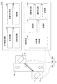
図1は、本発明の第1実施形態に係る体外循環装置としての血液浄化装置100A及び該装置に用いられる超音波測定装置1Aの構成を示す説明図であり、図2は、血液浄化装置100Aの概略構成を示す図である。
<First Embodiment>
FIG. 1 is an explanatory diagram showing the configuration of a
図1及び図2に示すように、血液浄化装置100Aは、血液を流すための血液回路110と、血液浄化手段としてのダイアライザ120と、透析液回路130と、制御部140Aと、血液回路110に配置される超音波測定装置1Aと、を備える。
As shown in FIGS. 1 and 2, the
血液回路110は、動脈側ライン111と、静脈側ライン112と、薬剤ライン113と、排出ライン114と、を有する。動脈側ライン111、静脈側ライン112、薬剤ライン113及び排出ライン114は、いずれも液体が流通可能な可撓性を有する軟質のチューブを主体として構成される。
The
動脈側ライン111は、一端側が後述するダイアライザ120の血液導入口122aに接続される。動脈側ライン111には、患者側動脈接続部111a、動脈側気泡検知器111b、血液ポンプ111c及び後述の超音波測定装置1Aが配置される。
患者側動脈接続部111aは、動脈側ライン111の他端側に配置される。患者側動脈接続部111aには、患者の血管に穿刺される針が接続される。
動脈側気泡検知器111bは、チューブ内の気泡の有無を検出する。
血液ポンプ111cは、動脈側ライン111における動脈側気泡検知器111bよりも下流側に配置される。血液ポンプ111cは、動脈側ライン111を構成するチューブをローラーでしごくことにより、動脈側ライン111の内部の血液やプライミング液等の液体を送出する。
図2に示すように、超音波測定装置1Aは、動脈側ライン111における血液ポンプ111cよりも下流側に配置される。超音波測定装置1Aは血液回路110におけるいずれの位置に取り付けてもよいが、本実施形態では、動脈側ライン111の血液ポンプ111cより下流側に超音波測定装置1Aが取り付けられる。この位置に取り付けることで、ダイアライザ120による除水や注水の影響を受けにくく、除水や注水を計算することが不要となり、測定誤差を小さくできる。
One end side of the
The patient-side
The
The
As shown in FIG. 2, the ultrasonic measurement apparatus 1 </ b> A is disposed on the downstream side of the
尚、血液回路110(動脈側ライン111)は、超音波測定装置1Aが取り付けられる部位において、流量の測定に影響を与える血液回路110内の気泡が滞留しないように血液の流れ方向が略鉛直となるように保持される。また、気泡が速やかに上昇できるように、透析工程の血液の流れ方向における上流側を下部に、下流側を上部に配置することが望ましい。
超音波測定装置1Aの具体的な構成については、後に説明する。
The blood circuit 110 (arterial line 111) has a blood flow direction substantially vertical so that bubbles in the
A specific configuration of the
静脈側ライン112は、一端側が後述するダイアライザ120の血液導出口122bに接続される。静脈側ライン112には、患者側静脈接続部112a、静脈側気泡検知器112b、ドリップチャンバ112c、及び静脈側クランプ112dが配置される。
患者側静脈接続部112aは、静脈側ラインの他端側に配置される。患者側静脈接続部112aには、患者の血管に穿刺される針が接続される。
静脈側気泡検知器112bは、チューブ内の気泡の有無を検出する。
静脈側気泡検知器112bは、ドリップチャンバ112cよりも下流側に配置される。ドリップチャンバ112cは、静脈側ライン112に混入した気泡や凝固した血液等を除去するため、また、静脈圧を測定するため、一定量の血液を貯留する。
静脈側クランプ112dは、静脈側気泡検知器112bよりも下流側に配置される。静脈側クランプ112dは、静脈側気泡検知器112bによる気泡の検出結果に応じて制御され、静脈側ライン112の流路を開閉する。
One end side of the
The patient side
The
The
The vein-
薬剤ライン113は、血液透析中に必要な薬剤を動脈側ライン111に供給する。薬剤ライン113は、一端側が薬剤を送り出す薬液ポンプ113aに接続され、他端側が動脈側ライン122に接続される。本実施形態では、薬剤ライン113の他端側は、動脈側ライン122における超音波測定装置1Aよりも下流側に接続される。
The
排出ライン114は、ドリップチャンバ112cに接続される。排出ライン114には、排出ライン用クランプ114aが配置される。排出ライン114は、後述するプライミング工程でプライミング液を排出するためのラインである。
The
ダイアライザ120は、例えば、筒状に形成された容器本体121と、この容器本体121の内部に収容された透析膜(図示せず)と、を備え、容器本体121の内部は、透析膜により血液側流路と透析液側流路とに区画される(いずれも図示せず)。容器本体121には、血液回路110に連通する血液導入口122a及び血液導出口122bと、透析液回路130に連通する透析液導入口123a及び透析液導出口123bと、が形成される。
The
以上の血液回路110及びダイアライザ120によれば、対象者(透析患者)の動脈から取り出された血液は、血液ポンプ111cにより動脈側ライン111を流通してダイアライザ120の血液側流路に導入される。ダイアライザ120に導入された血液は、透析膜を介して後述する透析液回路130を流通する透析液により浄化される。ダイアライザ120において浄化された血液は、静脈側ライン112を流通して対象者の静脈に返血される。
According to the
透析液回路130は、本実施形態では、いわゆる密閉容量制御方式の透析液回路130により構成される。この透析液回路130は、透析液供給ライン131aと、透析液排出ライン131bと、透析液導入ライン132aと、透析液導出ライン132bと、透析液送液部133と、を備える。
In the present embodiment, the
透析液送液部133は、透析液チャンバ1331と、バイパスライン1332と、除水/逆ろ過ポンプ1333と、を備える。
透析液チャンバ1331は、一定容量(例えば、300ml〜500ml)の透析液を収容可能な硬質の容器で構成され、この容器の内部は軟質の隔膜(ダイアフラム)で区画され、送液収容部1331a及び排出収容部1331bに区画される。
バイパスライン1332は、透析液導出ライン132bと透析液排出ライン131bとを接続する。
The
The
The
除水/逆ろ過ポンプ1333は、バイパスライン1332に配置される。除水/逆ろ過ポンプ1333は、バイパスライン1332の内部の透析液を透析液排出ライン131b側に流通させる方向(除水方向)及び透析液導出ライン132b側に流通させる方向(逆ろ過方向)に送液可能に駆動するポンプにより構成される。
The dewatering /
透析液供給ライン131aは、基端側が透析液供給装置(図示せず)に接続され、先端側が透析液チャンバ1331に接続される。透析液供給ライン131aは透析液チャンバ1331の送液収容部1331aに透析液を供給する。
The
透析液導入ライン132aは、透析液チャンバ1331とダイアライザ120の透析液導入口123aとを接続し、透析液チャンバ1331の送液収容部1331aに収容された透析液をダイアライザ120の透析液側流路に導入する。
The
透析液導出ライン132bは、ダイアライザ120の透析液導出口123bと透析液チャンバ1331とを接続し、ダイアライザ120から排出された透析液を透析液チャンバ1331の排出収容部1331bに導出する。
The dialysate lead-out
透析液排出ライン131bは、基端側が透析液チャンバ1331に接続され、排出収容部1331bに収容された透析液の排出を排出する。
The proximal end side of the
以上の透析液回路130によれば、透析液チャンバ1331を構成する硬質の容器の内部を軟質の隔膜(ダイアフラム)により区画することで、透析液チャンバ1331からの透析液の導出量(送液収容部1331aへの透析液の供給量)と、透析液チャンバ1331(排出収容部1331b)に回収される排出の量と、を同量にできる。
これにより、除水/逆ろ過ポンプ1333を停止させた状態では、ダイアライザ120に導入される透析液の流量とダイアライザ120から導出される透析液(排出)の量とを同量にできる。
According to the
Thereby, in a state where the water removal / back-
また、除水/逆ろ過ポンプ1333を逆ろ過方向に送液するように駆動させた場合には、透析液チャンバ1331から排出された排出の一部がバイパスライン1332及び透析液導出ライン132bを通って再び透析液チャンバ1331に回収される。そのため、ダイアライザ120から導出される透析液の量は、透析液チャンバ1331に回収される量(即ち、透析液導入ライン132aを流通する透析液の量)から、バイパスライン1332を流通する透析液の量を減じた量となる。これにより、ダイアライザ120から導出される透析液の量は、バイパスライン1332を通って再び透析液チャンバ1331に回収される透析液(排出)の量分だけ、透析液導入ライン132aを流通する透析液の流量よりも少なくなる。即ち、除水/逆ろ過ポンプ1333を逆ろ過方向に送液するように駆動させた場合は、ダイアライザ120において、血液回路110に所定量の透析液が注入(逆ろ過)される(図4参照)。
In addition, when the dewatering /
一方、除水/逆ろ過ポンプ1333を除水方向に送液するように駆動させた場合には、透析液導出ライン132bを流通する透析液の量は、透析液チャンバ1331に回収される透析液の量(即ち、透析液導入ライン132aを流通する透析液の量)に、バイパスライン1332を流通する透析液の量を加えた量となる。これにより、透析液導出ライン132bを流通する透析液の量は、バイパスライン1332を通って透析液排出ライン131bに排出される透析液(排出)の量分だけ、透析液導入ライン132aを流通する透析液の量よりも多くなる。即ち、除水/逆ろ過ポンプ1333を除水方向に送液するように駆動させた場合は、ダイアライザ120において、血液から所定量の除水が行われる(図3参照)。
On the other hand, when the water removal /
制御部140Aは、情報処理装置(コンピュータ)により構成され、制御プログラムを実行することにより、血液浄化装置100Aの動作を制御する。また、制御部140Aは、超音波測定装置1Aと接続され、制御部140Aには、測定された血液流量や血液濃度の情報が伝達される。
具体的には、制御部140Aは、血液回路110及び透析液回路130に配置された各種のポンプやクランプ等の動作を制御して、血液浄化装置100Aにより行われる各種工程、例えば、プライミング工程、脱血工程、透析工程、急速補液工程、返血工程等を実行する。
140 A of control parts are comprised by information processing apparatus (computer), and control operation | movement of 100 A of blood purification apparatuses by running a control program. Further, the
Specifically, the
各種工程について簡単に説明する。
プライミング工程では、逆ろ過透析液や生理食塩水等のプライミング液により血液回路110及びダイアライザ120を洗浄して清浄化する。透析工程に入る前の脱血工程では、患者の血液を吸引して動脈側ライン111及び静脈側ライン112に血液を充填させる。脱血工程の後、図3に示す血液を浄化すると伴に水分を除去する透析工程が行われる。
透析工程の途中で必要に応じて図4に示す急速補液工程が行われる。透析工程終了後、患者に血液を戻す返血工程が行われる。
Various processes will be briefly described.
In the priming step, the
A rapid fluid replacement step shown in FIG. 4 is performed during the dialysis step as necessary. After completion of the dialysis process, a blood return process for returning blood to the patient is performed.
以下に、血液浄化装置100Aにより行われる各種工程のうち、血液の濃度変化に関わる透析工程及び急速補液工程について、詳しく説明する。
Below, among the various processes performed by the
図3を参照して透析工程について説明する。
透析工程において、患者側動脈接続部111aから導入される患者の血液は、動脈側ライン111を通ってダイアライザ120で浄化され、静脈側ライン112を通って患者側静脈接続部112aから患者に戻される。
The dialysis process will be described with reference to FIG.
In the dialysis process, the blood of the patient introduced from the patient-side
透析工程では、図3に示すように、患者側動脈接続部111a及び患者側静脈接続部112aは、それぞれ患者の血管に穿刺される針に接続された状態であり、排出ライン用クランプ114aは閉状態、静脈側クランプ112dは開状態である。
In the dialysis step, as shown in FIG. 3, the patient-side
例えば、ダイアライザ120に対して、透析液チャンバ1331から500ml/minの送液量で透析液を供給し、除水/逆ろ過ポンプ1333を除水方向に送液するように作動させる。除水/逆ろ過ポンプ1333の送給量を一例として10ml/minとすることで、ダイアライザ120において、10ml/minの除水が行われる(透析液回路130からは510ml/minの流量で透析液が排出される)。
血液ポンプ111cは、例えば200ml/min程度で患者側動脈接続部111a側からダイアライザ120側に血液を送出する。
ダイアライザ120内には、血液導入口122aから200ml/minの流量で血液が流入し、10ml/minの流量で除水されて、血液導出口122bから190ml/minの流量で浄化された血液が導出される。また、透析液は、透析液導出口123bから導出される。
このようにして、透析工程において、血液中から徐々に水分が除去され、それに伴い血液濃度も徐々に上昇して行く。
For example, the dialysate is supplied to the
The
Blood flows into the
In this way, in the dialysis step, water is gradually removed from the blood, and the blood concentration gradually increases accordingly.
次に、図4を参照して急速補液工程について説明する。
急速補液工程は、透析工程の途中で除水による血圧の低下等が認められる場合に行われるものであり、血液回路110に逆ろ過透析液を補充する工程である。
Next, the rapid replenishment process will be described with reference to FIG.
The rapid replenishment step is performed when a decrease in blood pressure due to water removal is observed during the dialysis step, and is a step of replenishing the
急速補液工程では、図4に示すように、透析工程と同様に患者側動脈接続部111a及び患者側静脈接続部112aは、それぞれ患者の血管に穿刺される針に接続された状態であり、排出ライン用クランプ114aは閉状態、静脈側クランプ112dは開状態である。
In the rapid fluid replacement process, as shown in FIG. 4, the patient-side
例えば、ダイアライザ120に対して、透析液チャンバ1331から500ml/minの送液量で透析液を供給し、除水/逆ろ過ポンプ1333を、逆ろ過方向に送液するように作動させる。除水/逆ろ過ポンプ1333の送給量を一例として100ml/minとすることで、ダイアライザ120において、100ml/minの注水が行われる(透析液回路130からは400ml/minの流量で透析液が排出される)。
血液ポンプ111cは、例えば、透析工程中の200ml/minから50ml/min程度まで流量を減少させ、患者側動脈接続部111a側からダイアライザ120側に血液を送出する。
ダイアライザ120内には、血液導入口122aから50ml/minの流量で血液が流入し、逆ろ過透析液が100ml/minの流量で注水されて、血液導出口122bから希釈された血液が150ml/minの流量で導出される。このようにして、急速補液工程において血液中に水分が補充される。
For example, dialysate is supplied from the
For example, the
Blood flows into the
次に超音波測定装置1Aについて、図1を参照して詳細に説明する。
超音波測定装置1Aは、一対の超音波送受波器10A及び10Bと、血液の流量及び濃度を測定する測定回路20Aと、を備え、血液浄化装置100Aが備える血液回路110に取り付けられる。
Next, the
The
超音波送受波器10A及び10Bは、それぞれ圧電素子11と、圧電素子カバー12とを含んで構成される。超音波送受波器10A及び10Bは、血液回路110を流れる血液や逆ろ過透析液等の液体の流れ方向について所定の距離をおいて配置される。例えば、超音波送受波器10A及び10Bは、血液回路110(チューブ)の外側に接触するように、血液回路110を挟んで斜めに対向して取り付けられ、超音波信号を送受可能である。
圧電素子11の両面には、それぞれ不図示の電極が取り付けられており、圧電素子11は、入力された電気信号を機械的振動に変換し、また、伝達された機械的振動を電気信号に変換して出力することができる。圧電素子11は、硬質塩化ビニルやポリカーボネイト等により形成される圧電素子カバー12の内部に埋め込まれて配置される。圧電素子の材料としては、チタン酸ジルコン酸鉛等の圧電セラミックス、酸化亜鉛等の圧電薄膜、フッ化ビニリデン等の圧電高分子膜等が適用可能である。本実施形態では、圧電素子の材料としてチタン酸ジルコン酸鉛を用いた。
The ultrasonic transducers 10 </ b> A and 10 </ b> B each include a
Electrodes (not shown) are respectively attached to both surfaces of the
尚、超音波送受波器10A及び10Bを、血液回路110の同じ側に所定の距離を置いて取り付けて、血液回路110を構成するチューブの内面で反射した超音波信号を受信する構成としてもよい。しかしながら、後に説明する濃度算出部25において、超音波信号の減衰度合を測定して濃度を算出するので、チューブ内面での反射による減衰も考慮する必要がある反射波ではなく、主に血液中の血球における減衰を反映した透過波を受信可能なように、超音波送受波器10A及び10Bを対向して配置する方が望ましい。
また、適度に減衰した状態の超音波信号を測定するため、血液回路110を流れる血液の流れ方向における超音波送受波器10A及び10B間の距離は、血液回路110を構成するチューブの外径の1倍〜2倍程度にすることが望ましい。1倍より短い距離では、伝搬時間逆数差法において時間差が小さくなるため望ましくない。また、2倍より長い距離では、減衰量が大きすぎることにより減衰した超音波信号の測定誤差が大きくなるため、望ましくない。
The
In addition, in order to measure the ultrasonic signal in a moderately attenuated state, the distance between the
測定回路20Aは、送信部21と、受信部22と、送受信切替部23と、流量算出部24Aと、濃度算出部25と、記憶部26と、を備え、超音波送受波器10A及び10Bで送受される超音波信号に基づいて血液の流量及び濃度を測定する。
超音波を用いた流量測定方法には、伝搬速度差法(伝搬時間差法、伝搬時間逆数差法)、ドップラー法等、様々な方法があるが、本実施形態においては、伝搬速度差法のうち伝搬時間逆数差法を用いた例について説明する。
The
There are various methods for measuring flow rate using ultrasonic waves, such as a propagation speed difference method (propagation time difference method, propagation time reciprocal difference method), a Doppler method, etc. An example using the propagation time reciprocal difference method will be described.
送信部21は、送受信切替部23を介して超音波送受波器10A又は10Bの圧電素子11に接続され、超音波送受波器10A、10Bに電気信号を送信する。
受信部22は、送受信切替部23を介して超音波送受波器10A又は10Bの圧電素子11に接続され、超音波送受波器10A、10Bから電気信号を受信し、受信した電気信号を増幅する。
送受信切替部23は、超音波送受波器10A及び10Bの一方を送信部21に、他方を受信部22に切り替える。これにより、送受信切替部23は、超音波送受波器10Aから超音波信号を送信して超音波送受波器10Bで受信する時の伝搬時間と、超音波送受波器10Bから超音波信号を送信して超音波送受波器10Aで受信する時の伝搬時間とを測定可能としている。
The transmitting
The receiving
The transmission /
流量算出部24Aは、送信部21により送信された電気信号である送信信号及び受信部22により受信された電気信号である受信信号に基づいて流量を算出する。流量算出部24Aは、送信部21において送信信号を送信したタイミング及び受信部22において受信信号を受信したタイミングを測定することにより、超音波送受波器10A及び10B間を伝搬する超音波信号の伝搬時間を算出する。
The flow rate calculation unit 24 </ b> A calculates the flow rate based on the transmission signal that is the electrical signal transmitted by the
伝搬時間逆数差法を用いた流量Qの算出方法について、以下に詳細に説明する。超音波送受波器10A及び10Bは、液体の流れ方向に対して斜めに超音波信号を送受する。具体的には、超音波信号を送受する方向と液体の流れ方向とがなす角が所定の角度φとなるように血液回路110(動脈側ライン)の外側に対向して配置され、交互に超音波信号を送受し、超音波信号の伝搬に要する時間を測定する。
A method for calculating the flow rate Q using the propagation time reciprocal difference method will be described in detail below. The
超音波送受波器10Aから10Bへ超音波信号が伝搬する時間をTAB、超音波送受波器10Bから10Aへ超音波信号が伝搬する時間をTBA、超音波信号の伝搬する距離をL、音速をC、血液回路110内の液体の流速をVとする。
血液回路110内に液体が満たされた状態で、実流量がゼロ、即ち流速Vがゼロの場合、TABとTBAとは等しく、
TAB=TBA=L/C ・・・(a)
となる。
The time for the ultrasonic signal to propagate from the
When the actual flow rate is zero, that is, the flow velocity V is zero when the
T AB = T BA = L / C (a)
It becomes.
図1に示すように液体が流速Vで超音波送受波器10A側から超音波送受波器10B側へ向かって流れる場合、
TAB=L/(C+Vcosφ) ・・・(b)
となり、
TBA=L/(C−Vcosφ) ・・・(c)
となる。これら(b)及び(c)式の関係からそれぞれの伝搬時間TAB、TBAの逆数の差を取ると、
1/TAB−1/TBA=(2Vcosφ)/L ・・・(d)
となる。(d)式から流速Vを求めると、
V=L/(2cosφ)×(1/TAB−1/TBA) ・・・(e)
となる。(e)式によれば、超音波信号の伝搬時間を測定することにより、流速Vが算出できる。
As shown in FIG. 1, when the liquid flows at a flow velocity V from the
T AB = L / (C + V cos φ) (b)
And
T BA = L / (C−V cos φ) (c)
It becomes. From the relationship between these equations (b) and (c), taking the difference of the reciprocals of the propagation times T AB and T BA ,
1 / T AB -1 / T BA = (2 V cos φ) / L (d)
It becomes. When the flow velocity V is obtained from the equation (d),
V = L / (2cosφ) × (1 / T AB −1 / T BA ) (e)
It becomes. According to the equation (e), the flow velocity V can be calculated by measuring the propagation time of the ultrasonic signal.
(e)式においては、流速Vは濃度が異なる血液や透析液等の流体の種類や温度に依存する音速Cに依らないため、測定対象である液体の種類や温度が変化してもその影響を受けずに流速Vを算出でき、その流速Vに血液回路110を構成するチューブの断面積Aを乗じて流量Qを算出することができる。
Q=V×A ・・・(f)
In the equation (e), the flow velocity V does not depend on the speed of sound C depending on the type and temperature of fluids such as blood and dialysate having different concentrations. The flow rate V can be calculated without multiplying the flow rate V, and the flow rate Q can be calculated by multiplying the flow rate V by the cross-sectional area A of the tube constituting the
Q = V × A (f)
濃度算出部25は、送信部21により送信された送信信号の振幅に対する受信部22により受信された受信信号の振幅の減衰度合に基づいて血液濃度を算出する。ここで、血液濃度は、一般的にヘマトクリット値で評価することができる。ヘマトクリット値とは、血液中に存在する赤血球の割合を表す。血球は、全血液量の約45%を占め、赤血球、白血球及び血小板が含まれるが、その大部分が赤血球である。従って、ヘマトクリット値は赤血球の存在割合を示し、血液濃度の指標として用いられる。
超音波信号は血液中を伝搬する際に、血液中に存在する血球で散乱することにより減衰する。よって、血液濃度に応じて、送信信号の振幅に対する受信信号の振幅の減衰度合は変化する。そこで、血液濃度が既知の試料について、予め血液濃度と減衰度合との対応関係を求め、その対応関係を記憶部26に記憶しておく。
濃度算出部25は、濃度未知の血液について、受信信号の減衰度合及び記憶部26に記憶された血液濃度と減衰度合と対応関係に基づいて、血液濃度を算出する。
The
When propagating through the blood, the ultrasonic signal is attenuated by being scattered by blood cells existing in the blood. Therefore, the degree of attenuation of the amplitude of the reception signal with respect to the amplitude of the transmission signal changes according to the blood concentration. Therefore, a correspondence relationship between the blood concentration and the degree of attenuation is obtained in advance for a sample with a known blood concentration, and the correspondence relationship is stored in the
The
血液浄化装置100Aは、透析工程中において濃度算出部25により算出された算出濃度に基づいて、制御部140Aにより透析液送液部133を制御してダイアライザ120における除水速度を調節することにより、患者の血圧低下を抑制しながら治療することが可能である。
Based on the calculated concentration calculated by the
以上説明した第1実施形態の超音波測定装置1A及びに血液浄化装置100Aよれば、以下のような効果を奏する。
The
(1)超音波測定装置1Aを、超音波送受波器10A、10Bと、測定回路20Aと、を備え、測定回路20Aが、超音波送受波器10A、10Bに電気信号を送信する送信部21と、超音波送受波器10A、10Bから電気信号を受信する受信部22と、送信部21により送信された送信信号及び受信部22により受信された受信信号に基づいて血液の流量を算出する流量算出部24Aと、送信信号の振幅に対する受信信号の振幅の減衰度合に基づいて血液濃度を算出する濃度算出部と、を備えるものとした。これにより、流量計及び濃度計の2つの測定装置を用いなくとも1つの超音波測定装置1Aで、血液の流量及び濃度を測定することができる。よって、簡易な構成により血液の流量及び濃度を測定できる血液浄化装置100Aを実現できる。
(1) The
(2)血液回路110を、血液浄化手段(ダイアライザ)120に導入される血液を流すための動脈側ライン111と、血液浄化手段(ダイアライザ)120から導出される血液を流すための静脈側ライン112と、を含んで構成し、超音波送受波器10A、10Bは、動脈側ライン111に取り付けるものとした。これにより、測定部位における血液の流量は、血液浄化手段(ダイアライザ)120による除水や注水の影響を受けにくく、除水や注水を計算することが不要となり、測定誤差を小さくできる。
(2)
(3)超音波測定装置1Aを、血液回路110を流れる血液の流れ方向について所定の距離をおいて血液回路110を挟んで対向して配置される一対の超音波送受波器10A及び10Bを備えるものとし、例えば、超音波送受波器10A及び10Bは、血液の流れ方向に対して斜めに超音波信号を送受するものとした。これにより、測線が1本の簡易な構成で液体の流量を測定することができ、測線が複数本の構成に比べて製造コストを小さくすることができる。また、超音波送受波器10A(又は10B)から送信された超音波信号は、血液回路110を構成するチューブの内面で反射する反射波ではなく、透過波として超音波送受波器10B(又は10A)で受信されるので、チューブの内面における反射の減衰がないため、受信信号の減衰度合の測定精度を上げることができる。
(3) The
(4)血液回路110を流れる血液の流れ方向における超音波送受波器10A及び10B間の距離は、血液回路110を構成するチューブの外径の1倍〜2倍とした。これにより、血液の流量及び濃度を好適に測定できる。
(4) The distance between the ultrasonic transducers 10 </ b> A and 10 </ b> B in the direction of blood flow through the
(5)流量算出部24Aを、一対の超音波送受波器10A及び10B間でそれぞれ送受される超音波信号の血液中における伝搬時間をそれぞれ測定し、伝搬時間逆数差法により血液流量を算出するものとした。これにより、血液濃度や温度依存性のある音速Cが変化してもその影響を受けずに流量を算出することができる。
(5) The flow
(6)血液回路110(動脈側ライン111)が、超音波測定装置1Aが取り付けられる部位において、液体の流れ方向が略垂直となるように保持されるものとした。これにより、血液回路110内の気泡が滞留しないようにできるため、気泡が血液の流量及び濃度の測定に与える影響を小さくできる。
(6) The blood circuit 110 (arterial line 111) is held so that the flow direction of the liquid is substantially vertical at the site where the
(7)血液回路110(動脈側ライン111)が、超音波測定装置1Aが取り付けられる部位において、液体の流れ方向における上流側を下部に、下流側を上部になるように配置するものとした。これにより、流量測定部位における血液回路110内の気泡が速やかに上昇できるため、気泡が血液の流量及び濃度の測定に与える影響を小さくできる。
(7) The blood circuit 110 (arterial line 111) is arranged so that the upstream side in the liquid flow direction is the lower side and the downstream side is the upper side in the site where the
(8)血液浄化装置100Aの制御部140Aを、濃度算出部25により算出された算出濃度に基づいて、血液浄化手段としてのダイアライザ120における除水速度を調節するもととした。これにより、透析工程において患者の血圧低下を抑制しながら治療することが可能である。
(8) Based on the calculated concentration calculated by the
<第2実施形態>
次に、図5を参照しながら第2実施形態について説明する。
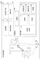
図5は、本発明の第2実施形態に係る血液浄化装置100B及び該装置に用いられる超音波測定装置1Bの構成を示す説明図である。第1実施形態と同様の構成については、同じ符号を付して説明を省略する。第2実施形態においては、血液浄化装置が報知手段を備え、超音波測定装置の測定回路が血液浄化装置の制御基板に組み込まれている点で第1実施形態と異なる。
Second Embodiment
Next, a second embodiment will be described with reference to FIG.
FIG. 5 is an explanatory diagram showing the configuration of the
図5に示すように、血液浄化装置100Bは、血液回路110と、血液浄化手段としてのダイアライザ120と、透析液回路130と、制御部140Bと、報知手段150と、制御基板160と、超音波測定装置1Bと、を備える。
血液浄化装置100Bにおいて実施される各工程は、第1実施形態の場合と同様であるので、説明を省略する。
As shown in FIG. 5,
Since each process implemented in the
超音波測定装置1Bは、血液回路110に取り付けられる一対の超音波送受波器10A及び10Bと、血液の流量及び濃度を測定する測定回路20Bと、を備える。
The
超音波送受波器10A及び10Bは、それぞれ圧電素子11と、圧電素子カバー12とを含んで構成される。超音波送受波器10A及び10Bは、血液回路110を流れる液体の流れ方向について所定の距離をおいて配置される。
The ultrasonic transducers 10 </ b> A and 10 </ b> B each include a
測定回路20Bは、送信部21と、受信部22と、送受信切替部23と、流量算出部24Bと、濃度算出部25と、記憶部26と、を備え、超音波送受波器10A及び10Bで送受される超音波信号に基づいて血液の流量及び濃度を測定する。
The
流量算出部24Bは、送信部21により送信された電気信号である送信信号及び受信部22により受信された電気信号である受信信号に基づいて流量を算出する。流量算出部24Bは、送信部21において送信信号を送信したタイミング及び受信部22において受信信号を受信したタイミングを測定することにより、超音波送受波器10A及び10B間を伝搬する超音波信号の伝搬時間を算出する。
The flow rate calculation unit 24 </ b> B calculates the flow rate based on the transmission signal that is the electrical signal transmitted by the
本実施形態においては、第1実施形態で用いた伝搬時間逆数差法とは異なる伝搬時間差法を用いて以下のように流量Qを算出する。超音波送受波器10A及び10Bは、液体の流れ方向に対して斜めに超音波信号を送受する。具体的には、超音波信号を送受する方向と液体の流れ方向とがなす角が所定の角度φとなるように血液回路110の外側に対向して配置され、交互に超音波信号を送受し、超音波信号の伝搬に要する時間を測定する。
In the present embodiment, the flow rate Q is calculated as follows using a propagation time difference method different from the propagation time reciprocal difference method used in the first embodiment. The
超音波送受波器10Aから10Bへ超音波信号が伝搬する時間をTAB、超音波送受波器10Bから10Aへ超音波信号が伝搬する時間をTBA、超音波信号の伝搬する距離をL、音速をC、血液回路110内の液体の流速をVとする。
血液回路110内に液体が満たされた状態で、実流量がゼロ、即ち流速Vがゼロの場合、TABとTBAとは等しく、
TAB=TBA=L/C ・・・(a)
となる。
The time for the ultrasonic signal to propagate from the
When the actual flow rate is zero, that is, the flow velocity V is zero when the
T AB = T BA = L / C (a)
It becomes.
図5に示すように液体が流速Vで超音波送受波器10A側から超音波送受波器10B側へ向かって流れる場合、
TAB=L/(C+Vcosφ) ・・・(b)
となり、
TBA=L/(C−Vcosφ) ・・・(c)
となる。これら(b)及び(c)式の関係からそれぞれの伝搬時間TAB、TBAの差を取ると、流速Vの2乗は音速Cの2乗に比べて十分小さいので近似して、
TAB−TBA=(2LVcosφ)/(C2−V2cos2φ)
≒(2LVcosφ)/C2 ・・・(d)’
となる。(d)’式から流速Vを求めると、
V=C2/(2Lcosφ)×(TBA−TAB) ・・・(e)’
となる。(e)’式によれば、超音波信号の伝搬時間を測定することにより、流速Vが算出できる。
When the liquid flows from the
T AB = L / (C + V cos φ) (b)
And
T BA = L / (C−V cos φ) (c)
It becomes. Taking the difference between the propagation times T AB and T BA from the relationship of these equations (b) and (c), the square of the flow velocity V is sufficiently smaller than the square of the sound velocity C, so it is approximated,
T AB −T BA = (2LV cos φ) / (C 2 −V 2 cos 2 φ)
≒ (2LVcosφ) / C 2 ··· (d) '
It becomes. (D) '
V = C 2 / (2L cos φ) × (T BA −T AB ) (e) ′
It becomes. According to the equation (e) ′, the flow velocity V can be calculated by measuring the propagation time of the ultrasonic signal.
(e)’式において、流速Vに血液回路110を構成するチューブの断面積Aを乗じて流量Qを算出することができる。
Q=V×A ・・・(f)
In the equation (e) ′, the flow rate Q can be calculated by multiplying the flow velocity V by the cross-sectional area A of the tube constituting the
Q = V × A (f)
伝搬時間差法を用いて流量を算出する場合、血液濃度の変化に応じて僅かながら音速Cが変化する。よって、(e)’を用いて流量を算出する際に、濃度算出部25により算出された算出濃度に応じて補正した音速Cを用いることにより、更に流量の測定精度を向上させることができる。
When the flow rate is calculated using the propagation time difference method, the sound speed C slightly changes according to the change in blood concentration. Therefore, when the flow rate is calculated using (e) ', the measurement accuracy of the flow rate can be further improved by using the sound velocity C corrected in accordance with the calculated concentration calculated by the
制御部140Bは、情報処理装置(コンピュータ)により構成され、制御プログラムを実行することにより、血液浄化装置100B及び超音波測定装置1Bの動作を制御する。
具体的には、制御部140Bは、血液回路110及び透析液回路130に配置された各種のポンプやクランプ等の動作を制御して、血液浄化装置100Bにより行われる各種工程、例えば、プライミング工程、脱血工程、透析工程、急速補液工程、返血工程等を実行する。
また、制御部140Bは、流量算出部24Bにより算出された算出流量と血液ポンプ111cの設定流量との差が大きい場合に脱血不良状態等の異常があると判断する。制御部140Bは、異常があると判断した場合に、血液ポンプ111cの設定流量を小さく又は血液ポンプ111cを停止するよう制御し、また、後述の報知手段150が作動するように制御する。また、制御部140Bは、透析工程中において濃度算出部25により算出された算出濃度に応じて、透析液送液部133を制御してダイアライザ120における除水速度を制御する。
The
Specifically, the
The
報知手段150は、制御部140Bにより算出流量に異常があると判断された場合に作動して、医療従事者に異常を知らせる。
The
制御基板160は、血液浄化装置100Bの本体内部に組み込まれており、この制御基板160には、測定回路20B及び制御部140Aを構成する回路が実装される。従って、測定回路20Bが備える流量算出部24B及び濃度算出部25との信号の送受信を同一基板上で行うことができる。
The
以上説明した第2実施形態の超音波測定装置1B及び血液浄化装置100Bよれば、上述の効果(1)〜(4)及び(6)〜(8)に加えて、以下のような効果を奏する。
According to the
(9)流量算出部24Bを、一対の超音波送受波器10A及び10B間でそれぞれ送受される超音波信号の血液中における伝搬時間をそれぞれ測定し、伝搬時間差法により血液流量を算出するものとした。これにより、伝搬時間逆数差法を用いて流量を算出する場合に比べ、伝搬時間の測定の分解能が大きくても測定精度を保つことができる。
(9) The flow
(10)流量算出部24Bを、濃度算出部25により算出された算出濃度に対応して補正した音速Cを用いて、伝搬時間差法により血液流量を算出するものとした。これにより、更に流量の測定精度を向上させることができる。
(10) The blood flow rate is calculated by the propagation time difference method using the sound velocity C corrected by the flow
(11)体外循環装置100Bを、流量算出部24Bにより算出された算出流量に異常がある場合に、異常を報知する報知手段150を更に備えるものとした。これにより、脱血不良等の異常が生じた場合に速やかに医療従事者に報知することができる。
(11) The
(12)血液浄化装置100Bが備える制御基板160は、血液浄化装置100Bの本体内部に組み込まれており、測定回路20B及び制御部140Bを構成する回路が実装されるものとした。これにより、測定回路20Bが備える流量算出部24B及び濃度算出部25との信号の送受信を同一基板上で行うことができるので、測定回路20B及び制御部140B間における情報の伝達の遅延を減少させることができる。よって、制御部140Bが脱血不良等の異常があると判断した場合に、血液ポンプ111cの設定流量を変更する制御、また、報知手段150を作動させる等の制御を速やかに行うことができる。また、同一基板上に回路をまとめて実装することで、製造コストを低減させることができる。
(12) The
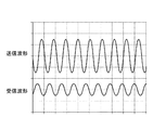
次に、第1実施形態で説明した超音波測定装置1A及び血液浄化装置100Aを用いて、濃度の異なる血液について超音波信号の減衰度合を測定した結果を図6A及びBに示す。
[実施例1]
血液回路110に、温度36℃、ヘマトクリット値30%、45%の牛血を、血液ポンプ111cの設定流量200ml/minで流して、超音波測定装置1Aにより超音波信号の減衰度合を測定した。具体的には、送信部21により送信された電気信号の波形(以下、送信波形とする)と、受信部22により受信された電気信号の波形(以下、受信波形とする)とを比較することにより、超音波信号の減衰度合を算出した。
実施例においては、測定部位は、図7に示すように、コの字型形状で、内径10mmのポリプロピレンにより形成されたパイプを用いた。
超音波送受波器10A及び10Bは、血液回路110の血液の流れ方向について、10mmの間隔を空けて配置した。
送信部21は、例えば、セラミック振動子等を用いて数百kHz〜数MHzの電気信号を送信可能な発振回路で構成されており、受信部22は、受信した微弱な超音波信号による電圧を増幅する増幅回路で構成されている。
Next, FIGS. 6A and 6B show the results of measuring the attenuation degree of the ultrasonic signal for blood with different concentrations using the
[Example 1]
Bovine blood at a temperature of 36 ° C., a hematocrit value of 30%, and 45% was passed through the
In the example, as shown in FIG. 7, the measurement site was a U-shaped pipe made of polypropylene having an inner diameter of 10 mm.
The ultrasonic transducers 10 </ b> A and 10 </ b> B are arranged at an interval of 10 mm in the blood flow direction of the
The
ヘマトクリット値が30%の場合の送信波形及び受信波形を図6Aに、45%の場合の送信波形及び受信波形を図6Bに示す。超音波信号の減衰度合は、ヘマトクリット値が30%及び45%の場合に、それぞれ約60%及び約40%となり、血液濃度が高くなるほど、減衰度合が大きくなることが分かった。このように、血液濃度に対応して超音波信号の減衰度合が変化するので、この対応関係及び超音波信号の減衰度合に基づいて、血液濃度を算出することが可能となる。 FIG. 6A shows a transmission waveform and a reception waveform when the hematocrit value is 30%, and FIG. 6B shows a transmission waveform and a reception waveform when the hematocrit value is 45%. The attenuation level of the ultrasonic signal was about 60% and about 40% when the hematocrit values were 30% and 45%, respectively, and it was found that the attenuation level increased as the blood concentration increased. Thus, since the attenuation level of the ultrasonic signal changes corresponding to the blood concentration, it is possible to calculate the blood concentration based on this correspondence and the attenuation level of the ultrasonic signal.
以上、本発明の超音波測定装置及び血液浄化装置の好ましい各実施形態及び各実施例について説明したが、本発明は、上述した実施形態及び実施例に制限されるものではなく、適宜変更が可能である。
例えば、上述の実施形態では、体外循環装置の一例として血液透析(HD)を行う血液浄化装置を用いて説明したが、血液ろ過(HF)、血液ろ過透析(HDF)等の血液透析療法、血漿交換療法や血液吸着療法等を行う血液浄化装置にも適用可能である。また、人工心肺装置等の体外循環装置にも適用可能である。
The preferred embodiments and examples of the ultrasonic measurement device and blood purification device of the present invention have been described above, but the present invention is not limited to the above-described embodiments and examples, and can be modified as appropriate. It is.
For example, in the above-described embodiment, a blood purification device that performs hemodialysis (HD) has been described as an example of an extracorporeal circulation device, but hemodialysis therapy such as blood filtration (HF) and blood filtration dialysis (HDF), plasma It can also be applied to blood purification devices that perform exchange therapy, blood adsorption therapy, and the like. It can also be applied to extracorporeal circulation devices such as an oxygenator.
また、超音波測定装置における流量の算出方法について、一例として第1実施形態では伝搬時間逆数差法を、第2実施形態では伝搬時間差法を示したが、シングアラウンド法、ドップラー法等の周知の算出方法を用いることができる。 As an example of the flow rate calculation method in the ultrasonic measurement apparatus, the first embodiment shows the propagation time reciprocal difference method and the second embodiment shows the propagation time difference method. However, well-known methods such as the sing-around method and the Doppler method are used. A calculation method can be used.
また、超音波測定装置の血液導管への配置方法について、第1実施形態及び第2実施形態では一対の超音波送受波器を斜めに対向させて配置させて取り付ける例を示したがこれに限らない。例えば、一対の超音波送受波器を同じ側に配置させて取り付けてもよいし、2対の超音波送受波器をそれぞれ斜めに対向させて取り付けてもよいし、超音波信号の送受を1つの超音波送受波器を用いて行う構成でもよい。 In addition, regarding the method of arranging the ultrasonic measuring device in the blood conduit, the first embodiment and the second embodiment have shown an example in which a pair of ultrasonic transducers are arranged so as to face each other diagonally, but this is not limitative. Absent. For example, a pair of ultrasonic transducers may be arranged and attached on the same side, or two pairs of ultrasonic transducers may be installed facing each other diagonally, or transmission / reception of ultrasonic signals is 1 A configuration in which two ultrasonic transducers are used may be used.
1A、1B 超音波測定装置
10A、10B 超音波送受波器
20A、20B 測定回路
21 送信部
22 受信部
23 送受信切替部
24A、24B 流量算出部
25 濃度算出部
26 記憶部
100A、B 体外循環装置(血液浄化装置)
110 血液回路
111 動脈側ライン
111c 血液ポンプ
112 静脈側ライン
120 血液浄化手段(ダイアライザ)
130 透析液回路
140A、140B 制御部
150 報知手段
160 制御基板
1A, 1B
110
130
Claims (7)
前記血液回路に取り付けられ、電気信号と超音波信号とを変換して超音波信号を送受する超音波送受波器と、
前記超音波送受波器で送受される超音波信号に基づいて血液の流量及び濃度を測定する測定回路と、を備え、
前記測定回路は、
前記超音波送受波器に電気信号を送信する送信部と、
前記超音波送受波器から電気信号を受信する受信部と、
前記送信部により送信された送信信号及び前記受信部により受信された受信信号に基づいて血液流量を算出する流量算出部と、
前記送信信号の振幅に対する前記受信信号の振幅の減衰度合に基づいて血液濃度を算出する濃度算出部と、
を備える超音波測定装置。 An ultrasonic measurement device used for an extracorporeal circulation device that circulates blood extracorporeally, comprising a blood circuit for flowing blood, and a blood purification means connected to the blood circuit and capable of removing water in the blood,
An ultrasonic transducer that is attached to the blood circuit, converts electrical signals and ultrasonic signals, and transmits and receives ultrasonic signals;
A measurement circuit that measures the flow rate and concentration of blood based on an ultrasonic signal transmitted and received by the ultrasonic transducer, and
The measurement circuit includes:
A transmitter for transmitting an electrical signal to the ultrasonic transducer;
A receiver for receiving an electrical signal from the ultrasonic transducer;
A flow rate calculation unit that calculates a blood flow rate based on a transmission signal transmitted by the transmission unit and a reception signal received by the reception unit;
A concentration calculation unit that calculates a blood concentration based on the degree of attenuation of the amplitude of the reception signal with respect to the amplitude of the transmission signal;
An ultrasonic measurement device comprising:
前記超音波送受波器は、前記動脈側ラインに取り付けられる請求項1に記載の超音波測定装置。 The blood circuit includes an arterial line for flowing blood introduced into the blood purification means, and a venous side line for flowing blood derived from the blood purification means,
The ultrasonic measurement apparatus according to claim 1, wherein the ultrasonic transducer is attached to the artery-side line.
前記超音波送受波器は、血液の流れ方向に対して斜めに超音波信号を送受する請求項1又は2に記載の超音波測定装置。 The ultrasonic measurement device includes at least a pair of the ultrasonic transducers disposed opposite to each other with a predetermined distance in the flow direction of blood flowing through the blood circuit, with the blood circuit interposed therebetween,
The ultrasonic measurement apparatus according to claim 1, wherein the ultrasonic transducer transmits and receives an ultrasonic signal obliquely with respect to a blood flow direction.
血液を流すための血液回路と、
前記血液回路に接続され血液中の水分を除去可能な血液浄化手段と、
を備え、血液を体外循環させる体外循環装置。 The ultrasonic measurement device according to any one of claims 1 to 4,
A blood circuit for flowing blood;
Blood purification means connected to the blood circuit and capable of removing water in the blood;
An extracorporeal circulation apparatus that circulates blood extracorporeally.
Priority Applications (1)
| Application Number | Priority Date | Filing Date | Title |
|---|---|---|---|
| JP2017110091A JP2018201823A (en) | 2017-06-02 | 2017-06-02 | Ultrasound measurement apparatus and extracorporeal circulation apparatus |
Applications Claiming Priority (1)
| Application Number | Priority Date | Filing Date | Title |
|---|---|---|---|
| JP2017110091A JP2018201823A (en) | 2017-06-02 | 2017-06-02 | Ultrasound measurement apparatus and extracorporeal circulation apparatus |
Publications (1)
| Publication Number | Publication Date |
|---|---|
| JP2018201823A true JP2018201823A (en) | 2018-12-27 |
Family
ID=64955921
Family Applications (1)
| Application Number | Title | Priority Date | Filing Date |
|---|---|---|---|
| JP2017110091A Pending JP2018201823A (en) | 2017-06-02 | 2017-06-02 | Ultrasound measurement apparatus and extracorporeal circulation apparatus |
Country Status (1)
| Country | Link |
|---|---|
| JP (1) | JP2018201823A (en) |
Citations (9)
| Publication number | Priority date | Publication date | Assignee | Title |
|---|---|---|---|---|
| US4015470A (en) * | 1973-12-26 | 1977-04-05 | Trw Inc. | Flow measuring method and apparatus |
| JPH02211173A (en) * | 1988-08-13 | 1990-08-22 | Fresenius Ag | Blood purifier having measuring device for change intravascular blood volume |
| US5440936A (en) * | 1992-11-16 | 1995-08-15 | Triton Technology, Inc. | Compact x-cross transducer array for a transit time flowmeter, particularly for use during in-vivo blood flow measurement |
| JPH09330132A (en) * | 1996-06-12 | 1997-12-22 | Omron Corp | Semiconductor pressure sensor module with valve, pressure controller using the same, and standard pressure generating device and sphygmomanometer using the same pressure controller |
| JPH11290452A (en) * | 1998-03-07 | 1999-10-26 | Fresenius Medical Care Deutsche Gmbh | Dialysis liquid supply device and monitoring method for selected dialysis liquid parameter |
| JP2004097782A (en) * | 2002-07-18 | 2004-04-02 | Nikkiso Co Ltd | Hematocrit sensor |
| JP2008023269A (en) * | 2006-07-25 | 2008-02-07 | Nipro Corp | Method to detect trouble causing blood removal failure and hemodialyzer |
| JP2008512652A (en) * | 2004-09-07 | 2008-04-24 | トランソニック システムズ インク | Non-intrusive test for materials between spaced walls |
| CN103610454A (en) * | 2013-12-06 | 2014-03-05 | 黄志海 | Blood pressure measurement method and system |
-
2017
- 2017-06-02 JP JP2017110091A patent/JP2018201823A/en active Pending
Patent Citations (9)
| Publication number | Priority date | Publication date | Assignee | Title |
|---|---|---|---|---|
| US4015470A (en) * | 1973-12-26 | 1977-04-05 | Trw Inc. | Flow measuring method and apparatus |
| JPH02211173A (en) * | 1988-08-13 | 1990-08-22 | Fresenius Ag | Blood purifier having measuring device for change intravascular blood volume |
| US5440936A (en) * | 1992-11-16 | 1995-08-15 | Triton Technology, Inc. | Compact x-cross transducer array for a transit time flowmeter, particularly for use during in-vivo blood flow measurement |
| JPH09330132A (en) * | 1996-06-12 | 1997-12-22 | Omron Corp | Semiconductor pressure sensor module with valve, pressure controller using the same, and standard pressure generating device and sphygmomanometer using the same pressure controller |
| JPH11290452A (en) * | 1998-03-07 | 1999-10-26 | Fresenius Medical Care Deutsche Gmbh | Dialysis liquid supply device and monitoring method for selected dialysis liquid parameter |
| JP2004097782A (en) * | 2002-07-18 | 2004-04-02 | Nikkiso Co Ltd | Hematocrit sensor |
| JP2008512652A (en) * | 2004-09-07 | 2008-04-24 | トランソニック システムズ インク | Non-intrusive test for materials between spaced walls |
| JP2008023269A (en) * | 2006-07-25 | 2008-02-07 | Nipro Corp | Method to detect trouble causing blood removal failure and hemodialyzer |
| CN103610454A (en) * | 2013-12-06 | 2014-03-05 | 黄志海 | Blood pressure measurement method and system |
Similar Documents
| Publication | Publication Date | Title |
|---|---|---|
| US9750864B2 (en) | Process and device for monitoring the supply of substitution fluid during an extracorporeal treatment of blood | |
| JP5574966B2 (en) | Method and apparatus for monitoring the supply of replacement fluid during extracorporeal blood processing | |
| US8574183B2 (en) | Method and device for monitoring a blood treatment unit of an extracorporeal blood treatment device | |
| US9283315B2 (en) | Apparatus and method for real time measurement of a constituent of blood to monitor blood volume | |
| US9616164B2 (en) | Device and method for detecting the recirculation during an extracorporeal blood treatment | |
| US20130303961A1 (en) | Blood ultrafiltration substitution target method and device | |
| US10596311B2 (en) | Fiber-optic clot detector with an ultrasonic clot neutralizer | |
| JPH02211173A (en) | Blood purifier having measuring device for change intravascular blood volume | |
| CN108853622A (en) | A kind of haemodialysis fault detection alarm device | |
| US20100237011A1 (en) | Blood treatment systems and related methods | |
| US20160067398A1 (en) | Method of ultrasonic degassing of liquids for dialysis | |
| JP2018201823A (en) | Ultrasound measurement apparatus and extracorporeal circulation apparatus | |
| JP6922440B2 (en) | Ultrasonic measuring device and extracorporeal circulation device | |
| CN111247397A (en) | Ultrasonic flowmeter and blood purification device | |
| JP6930347B2 (en) | Blood circuit and extracorporeal circulation device including the blood circuit | |
| JP6988342B2 (en) | Blood circuit and extracorporeal circulation device | |
| CN111295573B (en) | Ultrasonic flowmeter and blood purification device | |
| TW202210116A (en) | System and method for detecting venous needle dislodgement | |
| JPS6315857B2 (en) | ||
| JP2010234107A (en) | Method and apparatus for monitoring supply of substitution fluid during extracorporeal blood circulation treatment |
Legal Events
| Date | Code | Title | Description |
|---|---|---|---|
| A711 | Notification of change in applicant |
Free format text: JAPANESE INTERMEDIATE CODE: A711 Effective date: 20190705 |
|
| A521 | Request for written amendment filed |
Free format text: JAPANESE INTERMEDIATE CODE: A821 Effective date: 20190705 |
|
| A621 | Written request for application examination |
Free format text: JAPANESE INTERMEDIATE CODE: A621 Effective date: 20200417 |
|
| A977 | Report on retrieval |
Free format text: JAPANESE INTERMEDIATE CODE: A971007 Effective date: 20210216 |
|
| A131 | Notification of reasons for refusal |
Free format text: JAPANESE INTERMEDIATE CODE: A131 Effective date: 20210224 |
|
| A521 | Request for written amendment filed |
Free format text: JAPANESE INTERMEDIATE CODE: A523 Effective date: 20210426 |
|
| A131 | Notification of reasons for refusal |
Free format text: JAPANESE INTERMEDIATE CODE: A131 Effective date: 20210629 |
|
| A521 | Request for written amendment filed |
Free format text: JAPANESE INTERMEDIATE CODE: A523 Effective date: 20210830 |
|
| A02 | Decision of refusal |
Free format text: JAPANESE INTERMEDIATE CODE: A02 Effective date: 20211005 |