JP2018201732A - Game machine - Google Patents
Game machine Download PDFInfo
- Publication number
- JP2018201732A JP2018201732A JP2017108851A JP2017108851A JP2018201732A JP 2018201732 A JP2018201732 A JP 2018201732A JP 2017108851 A JP2017108851 A JP 2017108851A JP 2017108851 A JP2017108851 A JP 2017108851A JP 2018201732 A JP2018201732 A JP 2018201732A
- Authority
- JP
- Japan
- Prior art keywords
- unit
- game ball
- path
- game
- view
- Prior art date
- Legal status (The legal status is an assumption and is not a legal conclusion. Google has not performed a legal analysis and makes no representation as to the accuracy of the status listed.)
- Pending
Links
Images


Landscapes
- Pinball Game Machines (AREA)
Abstract
Description
本発明は、パチンコ機などの遊技機に関するものである。 The present invention relates to a gaming machine such as a pachinko machine.
従来より、パチンコ機などの遊技機は、遊技盤面上に設けられた始動口に遊技球が入球すると、遊技の当否が抽選され、その抽選結果が当たりであった場合には、遊技者に有利となる特典遊技が実行されていた。 Conventionally, a gaming machine such as a pachinko machine, when a game ball enters the start opening provided on the surface of the game board, lottery of the game is won, and if the lottery result is a win, An advantageous bonus game was being executed.
ところで、上記した遊技機は、特典遊技中には、遊技が単調となってしまう遊技に飽きてしまうという不具合があった。上記した遊技機において、遊技者に早期に遊技に飽きてしまう不具合を抑制できる遊技機を提供することを目的とする。 By the way, the above-described gaming machine has a problem that, during the bonus game, the player gets tired of the game that makes the game monotonous. An object of the present invention is to provide a gaming machine that can suppress a problem that a player gets bored of the game at an early stage.
この目的を達成するために請求項1記載の遊技機は、遊技球が入球可能な第1入球手段と、その第1入球手段に遊技球が入球したことを検出可能な第1検出手段と、その第1検出手段により遊技球が入球したことが検出された場合に、第1信号を出力する第1信号出力手段と、前記第1入球手段に入球した遊技球が通過可能な第1流路と、その第1流路の一部を通過する遊技球を視認可能にする視認部と、を有し、前記第1入球手段に入球しなかった遊技球が入球可能な第2入球手段と、その第2入球手段に遊技球が入球したことを検出可能な第2検出手段と、その第2検出手段により遊技球が入球したことが検出された場合に、第2信号を出力する第2信号出力手段と、前記第2入球手段に入球した遊技球を前記第1流路へと誘導する第1流路誘導手段と、前記第1信号を受信してから第1期間が経過したことに基づいて、第1演出を実行する第1演出実行手段と、前記第2信号を受信してから第2期間が経過したことに基づいて、第2演出を実行する第2演出実行手段と、を有するものである。
In order to achieve this object, a gaming machine according to
請求項2記載の遊技機は、請求項1記載の遊技機において、前記第1入球手段に遊技球が入球したことに基づいて、その入球に対応した情報が表示される表示手段と、前記表示手段に表示された前記情報を前記第1入球手段に入球した遊技球に対応して更新する更新手段と、を有し、前記更新手段は、少なくとも前記第2演出が実行されるタイミングに合わせて前記情報を更新するものである。
The gaming machine according to
請求項3記載の遊技機は、請求項1または2記載の遊技機において、前記第1入球手段と前記第2入球手段とに入球しなかった遊技球を前記第1誘導路へと誘導する第3誘導手段と、前記第3誘導手段により誘導された遊技球が前記視認部に到達するタイミングで第3演出を実行可能な第3演出実行手段と、を有するものである。
The gaming machine according to
請求項4記載の遊技機は、請求項3記載の遊技機において、前記更新手段は、少なくとも前記第3演出が実行されるタイミングで前記情報を更新するものである。 A gaming machine according to a fourth aspect is the gaming machine according to the third aspect, wherein the updating means updates the information at a timing at which the third effect is executed.
請求項5記載の遊技機は、請求項1から4いずれかに記載の遊技機において、前記第1期間は、前記第1入球手段に入球した遊技球が前記視認部に到達するまでに要する第1流下期間以上に設定されているものであり、前記第2期間は、前記第2入球手段に入球した遊技球が前記視認部に到達するまでに要する第2流下期間以上に設定されているものである。
The gaming machine according to
請求項1記載の遊技機によれば、遊技球が入球可能な第1入球手段と、その第1入球手段に遊技球が入球したことを検出可能な第1検出手段と、その第1検出手段により遊技球が入球したことが検出された場合に、第1信号を出力する第1信号出力手段と、前記第1入球手段に入球した遊技球が通過可能な第1流路と、その第1流路の一部を通過する遊技球を視認可能にする視認部と、を有し、前記第1入球手段に入球しなかった遊技球が入球可能な第2入球手段と、その第2入球手段に遊技球が入球したことを検出可能な第2検出手段と、その第2検出手段により遊技球が入球したことが検出された場合に、第2信号を出力する第2信号出力手段と、前記第2入球手段に入球した遊技球を前記第1流路へと誘導する第1流路誘導手段と、前記第1信号を受信してから第1期間が経過したことに基づいて、第1演出を実行する第1演出実行手段と、前記第2信号を受信してから第2期間が経過したことに基づいて、第2演出を実行する第2演出実行手段と、を有するものである。 According to the gaming machine of the first aspect, the first entrance means capable of entering a game ball, the first detection means capable of detecting that the game ball has entered the first entrance means, When it is detected by the first detection means that a game ball has entered, a first signal output means for outputting a first signal, and a game ball that has entered the first ball entry means can pass through the first signal output means. A flow path and a visual recognition section that allows a game ball passing through a part of the first flow path to be visually recognized, and a game ball that has not entered the first ball entry means can (2) When the second entry means, the second detection means capable of detecting that the game ball has entered the second entry means, and the second detection means detect that the game ball has entered, A second signal output means for outputting a second signal; a first flow path guiding means for guiding a game ball that has entered the second ball entering means to the first flow path; Based on the fact that the first period has elapsed since the reception of the first signal, the first effect executing means for executing the first effect, and the fact that the second period has elapsed since the reception of the second signal. And second effect executing means for executing the second effect.
よって、遊技者が早期に遊技に飽きてしまう不具合を抑制できるという効果がある。 Therefore, there is an effect that it is possible to suppress a problem that the player gets bored with the game at an early stage.
請求項2記載の遊技機によれば、請求項1記載の遊技機の奏する効果に加え、次の効果を奏する。即ち、前記第1入球手段に遊技球が入球したことに基づいて、その入球に対応した情報が表示される表示手段と、前記表示手段に表示された前記情報を前記第1入球手段に入球した遊技球に対応して更新する更新手段と、を有し、前記更新手段は、少なくとも前記第2演出が実行されるタイミングに合わせて前記情報を更新するものである。 According to the gaming machine of the second aspect, in addition to the effect of the gaming machine of the first aspect, the following effect can be obtained. That is, based on the fact that a game ball has entered the first entry means, display means for displaying information corresponding to the entry, and the information displayed on the display means as the first entry Updating means for updating corresponding to the game ball that has entered the means, and the updating means updates the information at least in accordance with the timing at which the second effect is executed.
よって、入球手段に入球しているかのように遊技者に思わせることができるという効果がある。 Therefore, there is an effect that it is possible to make the player think as if the player has entered the ball entry means.
請求項3記載の遊技機によれば、請求項1または2記載の遊技機の奏する効果に加え、次の効果を奏する。即ち、前記第1入球手段と前記第2入球手段とに入球しなかった遊技球を前記第1誘導路へと誘導する第3誘導手段と、前記第3誘導手段により誘導された遊技球が前記視認部に到達するタイミングで第3演出を実行可能な第3演出実行手段と、を有するものである。
According to the gaming machine according to
よって、遊技者に多くの遊技球が入球手段に入球しているように思わせることができるという効果がある。 Therefore, there is an effect that it is possible to make the player think that a lot of game balls are entering the entrance means.
請求項4記載の遊技機によれば、請求項3記載の遊技機の奏する効果に加え、次の効果を奏する。即ち、前記更新手段は、少なくとも前記第3演出が実行されるタイミングで前記情報を更新するものである。 According to the gaming machine of the fourth aspect, in addition to the effect produced by the gaming machine according to the third aspect, the following effect is produced. In other words, the updating means updates the information at least at the timing when the third effect is executed.
よって、遊技の興趣を向上できるという効果がある。 Therefore, there is an effect that the interest of the game can be improved.
請求項5記載の遊技機によれば、請求項1から4いずれかに記載の遊技機の奏する効果に加え、次の効果を奏する。即ち、前記第1期間は、前記第1入球手段に入球した遊技球が前記視認部に到達するまでに要する第1流下期間以上に設定されているものであり、前記第2期間は、前記第2入球手段に入球した遊技球が前記視認部に到達するまでに要する第2流下期間以上に設定されているものである。 According to the gaming machine of the fifth aspect, in addition to the effect produced by the gaming machine according to any one of the first to fourth aspects, the following effect is achieved. That is, the first period is set to be equal to or longer than the first flow period required for the game ball that has entered the first ball entry means to reach the visual recognition unit, and the second period includes It is set to be equal to or longer than the second flow-down period required for the game ball that has entered the second entry means to reach the visual recognition unit.
よって、視認部を入球手段であるかのように思わせることができるという効果がある。 Therefore, there is an effect that it is possible to make the visual recognition part appear as if it is a ball entry means.
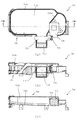
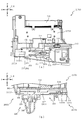
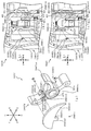
以下、本発明の実施形態について、添付図面を参照して説明する。まず、図1から図111を参照し、第1実施形態として、本発明をパチンコ遊技機(以下、単に「パチンコ機
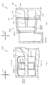
」という)10に適用した場合の一実施形態について説明する。図1は、第1実施形態に
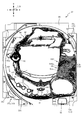
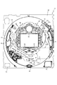
おけるパチンコ機10の正面図であり、図2はパチンコ機10の遊技盤13の正面図であ
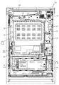
り、図3はパチンコ機10の背面図である。
Embodiments of the present invention will be described below with reference to the accompanying drawings. First, with reference to FIG. 1 to FIG. 111, an embodiment in which the present invention is applied to a pachinko gaming machine (hereinafter simply referred to as “pachinko machine”) 10 will be described as a first embodiment. 1 is a front view of a
なお、以下の説明では、図1に示す状態のパチンコ機10に対して、紙面手前側を前方
(正面)側として、紙面奥側を後方(背面)側として説明する。また、図1に示す状態の
パチンコ機10に対して、上側を上方(上)側として、下側を下方(下)側として、右側
を右方(右)側として、左側を左方(左)側としてそれぞれ説明する。さらに、図中の矢
印U−D,L−R,F−Bは、パチンコ機10の上下方向,左右方向,前後方向をそれぞ
れ示している。
In the following description, the front side of the paper is the front (front) side and the back side of the paper is the rear (back) side of the
図1に示すように、パチンコ機10は、略矩形状に組み合わせた木枠により外殻が形成
される外枠11と、その外枠11と略同一の外形形状に形成され外枠11に対して開閉可
能に支持された内枠4とを備えている。外枠11には、内枠4を支持するために正面視(
図1参照)左側の上下2カ所に金属製のヒンジ18が取り付けられ、そのヒンジ18が設
けられた側を開閉の軸として内枠4が正面手前側へ開閉可能に支持されている。
As shown in FIG. 1, the
1) Metal hinges 18 are attached to two places on the upper left and lower sides, and the
内枠4には、多数の釘や入賞口63,64等を有する遊技盤13(図2参照)が裏面側
から着脱可能に装着される。この遊技盤13の前面を球(遊技球)が流下することにより
弾球遊技が行われる。なお、内枠4には、球を遊技盤13の前面領域に発射する球発射ユ
ニット112a(図4参照)やその球発射ユニット112aから発射された球を遊技盤1
3の前面領域まで誘導する発射レール(図示せず)等が取り付けられている。
A game board 13 (see FIG. 2) having a large number of nails, winning
A launch rail (not shown) or the like for guiding to the
内枠4の前面側には、その前面上側を覆う前扉5と、その下側を覆う下皿ユニット15
とが設けられている。前扉5および下皿ユニット15を支持するために正面視(図1参照
)左側の上下2カ所に金属製のヒンジ19が取り付けられ、そのヒンジ19が設けられた
側を開閉の軸として前扉5および下皿ユニット15が正面手前側へ開閉可能に支持されて
いる。なお、内枠4の施錠と前扉5の施錠とは、シリンダ錠20の鍵穴21に専用の鍵を
差し込んで所定の操作を行うことでそれぞれ解除される。
On the front side of the
And are provided. In order to support the
前扉5は、装飾用の樹脂部品や電気部品等を組み付けたものであり、その略中央部には
略楕円形状に開口形成された窓部5cが設けられている。前扉5の裏面側には2枚の板ガ
ラス8を有するガラスユニット16が配設され、そのガラスユニット16を介して遊技盤
13の前面がパチンコ機10の正面側に視認可能となっている。
The
前扉5には、球を貯留する上皿17が前方へ張り出して上面を開放した略箱状に形成さ
れており、この上皿17に賞球や貸出球などが排出される。上皿17の底面は正面視(図
1参照)右側に下降傾斜して形成され、その傾斜により上皿17に投入された球が球発射
ユニット112a(図4参照)へと案内される。また、上皿17の上面には、枠ボタン2
2が設けられている。この枠ボタン22は、例えば、第3図柄表示装置81(図2参照)
で表示される演出のステージを変更したり、スーパーリーチの演出内容を変更したりする
場合などに、遊技者により操作される。
On the
2 is provided. The
This is operated by the player when changing the stage of the effect displayed at or changing the contents of the effect of super reach.
前扉5には、その周囲(例えばコーナー部分)に各種ランプ等の発光手段が設けられて
いる。これら発光手段は、大当たり時や所定のリーチ時等における遊技状態の変化に応じ
て、点灯又は点滅することにより発光態様が変更制御され、遊技中の演出効果を高める役
割を果たす。窓部5cの周縁には、LED等の発光手段を内蔵した電飾部29〜33が設
けられている。パチンコ機10においては、これら電飾部29〜33が大当たりランプ等
の演出ランプとして機能し、大当たり時やリーチ演出時等には内蔵するLEDの点灯や点
滅によって各電飾部29〜33が点灯または点滅して、大当たり中である旨、或いは大当
たり一歩手前のリーチ中である旨が報知される。また、前扉5の正面視(図1参照)左上
部には、LED等の発光手段が内蔵され賞球の払い出し中とエラー発生時とを表示可能な
表示ランプ34が設けられている。
The
また、右側の電飾部32下側には、前扉5の裏面側を視認できるように裏面側より透明
樹脂を取り付けて小窓35が形成され、遊技盤13前面の貼着スペースK1(図2参照)
に貼付される証紙等がパチンコ機10の前面から視認可能とされている。また、パチンコ
機10においては、より煌びやかさを醸し出すために、電飾部29〜33の周りの領域に
クロムメッキを施したABS樹脂製のメッキ部材36が取り付けられている。
Further, a
A stamp or the like affixed to the
窓部5cの下方には、貸球操作部40が配設されている。貸球操作部40には、度数表
示部41と、球貸しボタン42と、返却ボタン43とが設けられている。パチンコ機10
の側方に配置されるカードユニット(球貸しユニット)(図示せず)に紙幣やカード等を
投入した状態で貸球操作部40が操作されると、その操作に応じて球の貸出が行われる。
具体的には、度数表示部41はカード等の残額情報が表示される領域であり、内蔵された
LEDが点灯して残額情報として残額が数字で表示される。球貸しボタン42は、カード
等(記録媒体)に記録された情報に基づいて貸出球を得るために操作されるものであり、
カード等に残額が存在する限りにおいて貸出球が上皿17に供給される。返却ボタン43
は、カードユニットに挿入されたカード等の返却を求める際に操作される。なお、カード
ユニットを介さずに球貸し装置等から上皿17に球が直接貸し出されるパチンコ機、いわ
ゆる現金機では貸球操作部40が不要となるが、この場合には、貸球操作部40の設置部
分に飾りシール等を付加して部品構成は共通のものとしても良い。カードユニットを用い
たパチンコ機と現金機との共通化を図ることができる。
A ball
When the ball
Specifically, the
Lending balls are supplied to the
Is operated when requesting the return of a card inserted into the card unit. In addition, in a pachinko machine in which a ball is lent directly to the
上皿17の下側に位置する下皿ユニット15には、その中央部に上皿17に貯留しきれ
なかった球を貯留するための下皿50が上面を開放した略箱状に形成されている。下皿5
0の右側には、球を遊技盤13の前面へ打ち込むために遊技者によって操作される操作ハ
ンドル51が配設される。
In the
On the right side of 0, an
操作ハンドル51の内部には、球発射ユニット112aの駆動を許可するためのタッチ
センサ51aと、押下操作している期間中には球の発射を停止する発射停止スイッチ51
bと、操作ハンドル51の回動操作量(回動位置)を電気抵抗の変化により検出する可変
抵抗器(図示せず)などが内蔵されている。操作ハンドル51が遊技者によって右回りに
回動操作されると、タッチセンサ51aがオンされると共に可変抵抗器の抵抗値が回動操
作量に対応して変化し、その可変抵抗器の抵抗値に対応した強さ(発射強度)で球が発射
され、これにより遊技者の操作に対応した飛び量で遊技盤13の前面へ球が打ち込まれる
。また、操作ハンドル51が遊技者により操作されていない状態においては、タッチセン
サ51aおよび発射停止スイッチ51bがオフとなっている。
Inside the
b, and a variable resistor (not shown) for detecting the amount of rotation (rotation position) of the operation handle 51 based on a change in electrical resistance. When the operation handle 51 is rotated clockwise by the player, the
下皿50の正面下方部には、下皿50に貯留された球を下方へ排出する際に操作するた
めの球抜きレバー52が設けられている。この球抜きレバー52は、常時、右方向に付勢
されており、その付勢に抗して左方向へスライドさせることにより、下皿50の底面に形
成された底面口が開口して、その底面口から球が自然落下して排出される。この球抜きレ
バー52の操作は、通常、下皿50の下方に下皿50から排出された球を受け取る箱(一
般に「千両箱」と称される)を置いた状態で行われる。下皿50の右方には、上述したよ
うに操作ハンドル51が配設され、下皿50の左方には灰皿53が取り付けられている。
In the lower part of the front of the
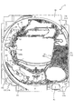
図2に示すように、遊技盤13は、正面視略正方形状に切削加工したベース板60に、
球案内用の多数の釘(図示せず)や風車の他、レール76,77、一般入賞口63、第1
入賞口64、第2入賞口640、可変入賞装置65、第1スルーゲート66、可変表示装
置ユニット80等を組み付けて構成され、その周縁部が内枠4(図1参照)の裏面側に取
り付けられる。ベース板60は薄い板材を張り合わせた木材からなり、その正面側からベ
ース板60の背面側に配設された各種構造体を遊技者に目視できないように形成される。
一般入賞口63、第1入賞口64、第2入賞口640、可変入賞装置65、可変表示装置
ユニット80は、ルータ加工によってベース板60に形成された貫通穴に配設され、遊技
盤13の前面側からタッピングネジ等により固定されている。
As shown in FIG. 2, the
In addition to a large number of nails (not shown) for ball guidance and windmills, rails 76 and 77, general winning
The winning
The general winning
遊技盤13の前面中央部分は、前扉5の窓部5c(図1参照)を通じて内枠4の前面側
から視認することができる。以下に、主に図2を参照して、遊技盤13の構成について説
明する。
The front center portion of the
遊技盤13の前面には、帯状の金属板を略円弧状に屈曲加工して形成した外レール77
が植立され、その外レール77の内側位置には外レール77と同様に帯状の金属板で形成
した円弧状の内レール76が植立される。この内レール76と外レール77とにより遊技
盤13の前面外周が囲まれ、遊技盤13とガラスユニット16(図1参照)とにより前後
が囲まれることにより、遊技盤13の前面には、球の挙動により遊技が行われる遊技領域
が形成される。遊技領域は、遊技盤13の前面であって2本のレール76,77とレール
間を繋ぐ樹脂製の外縁部材73とにより区画して形成される領域(入賞口等が配設され、
発射された球が流下する領域)である。
An
As in the case of the
The area where the fired ball flows down).
2本のレール76,77は、球発射ユニット112a(図4参照)から発射された球を
遊技盤13上部へ案内するために設けられたものである。内レール76の先端部分(図2
の左上部)には戻り球防止部材68が取り付けられ、一旦、遊技盤13の上部へ案内され
た球が再度球案内通路内に戻ってしまうといった事態が防止される。外レール77の先端
部(図2の右上部)には、球の最大飛翔部分に対応する位置に返しゴム69が取り付けら
れ、所定以上の勢いで発射された球は、返しゴム69に当たって、勢いが減衰されつつ中
央部側へ跳ね返される。
The two
The return
遊技領域の正面視左側下部(図2の左側下部)には、発光手段である複数のLEDおよ
び7セグメント表示器を備える第1図柄表示装置37A,37Bが配設されている。第1
図柄表示装置37A,37Bは、主制御装置110(図4参照)で行われる各制御に応じ
た表示がなされるものであり、主にパチンコ機10の遊技状態の表示が行われる。本実施
形態では、第1図柄表示装置37A,37Bは、球が、第1入賞口64へ入賞したか、第
2入賞口640へ入賞したかに応じて使い分けられるように構成されている。具体的には
、球が、第1入賞口64へ入賞した場合には、第1図柄表示装置37Aが作動し、一方で
、球が、第2入賞口640へ入賞した場合には、第1図柄表示装置37Bが作動するよう
に構成されている。
A first
The
また、第1図柄表示装置37A,37Bは、LEDにより、パチンコ機10が確変中か
時短中か通常中であるかを点灯状態により示したり、変動中であるか否かを点灯状態によ
り示したり、停止図柄が確変大当たりに対応した図柄か普通大当たりに対応した図柄か外
れ図柄であるかを点灯状態により示したり、保留球数を点灯状態により示すと共に、7セ
グメント表示装置により、大当たり中のラウンド数やエラー表示を行う。なお、複数のL
EDは、それぞれのLEDの発光色(例えば、赤、緑、青)が異なるよう構成され、その
発光色の組み合わせにより、少ないLEDでパチンコ機10の各種遊技状態を示唆するこ
とができる。
In addition, the first
The ED is configured so that the emission colors (for example, red, green, and blue) of the respective LEDs are different, and various gaming states of the
なお、本パチンコ機10では、第1入賞口64,第2入賞口640のいずれかに入賞が
あったことを契機として抽選が行われる。パチンコ機10は、その抽選において、大当た
りか否かの当否判定(大当たり抽選)を行うと共に、大当たりと判定した場合はその大当
たり種別の判定も行う。ここで判定される大当たり種別としては、15R確変大当たり、
4R確変大当たり、15R通常大当たりが用意されている。第1図柄表示装置37A,3
7Bには、変動終了後の停止図柄として抽選の結果が大当たりであるか否かが示されるだ
けでなく、大当たりである場合はその大当たり種別に応じた図柄が示される。
In the
4R probability variation jackpot and 15R regular jackpot are prepared. 1st
7B shows not only whether the lottery result is a big hit as a stop symbol after the end of the change, but also a symbol corresponding to the jackpot type if it is a big hit.
ここで、「15R確変大当たり」とは、最大ラウンド数が15ラウンドの大当たりの後
に高確率状態へ移行する確変大当たりのことであり、「4R確変大当たり」とは、最大ラ
ウンド数が4ラウンドの大当たりの後に高確率状態へ移行する確変大当たりのことである
。また、「15R通常大当たり」は、最大ラウンド数が15ラウンドの大当たりの後に、
低確率状態へ移行すると共に、所定の変動回数の間(例えば、100変動回数)は時短状
態となる大当たりのことである。
Here, the “15R probability variation jackpot” is a probability variation jackpot in which the maximum number of rounds shifts to a high probability state after a jackpot of 15 rounds, and “4R probability variation jackpot” is a jackpot with a maximum number of rounds of four. It is a probabilistic jackpot that shifts to a high probability state after. In addition, “15R regular jackpot” is the maximum number of rounds after 15 jackpots,
While shifting to the low-probability state, during a predetermined number of fluctuations (for example, 100 fluctuations) is a jackpot that becomes a short-time state.
また、「高確率状態」とは、大当たり終了後に付加価値としてその後の大当たり確率が
アップした状態、いわゆる確率変動中(確変中)の時をいい、換言すれば、特別遊技状態
へ移行し易い遊技の状態のことである。本実施形態における高確率状態(確変中)は、後
述する第2図柄の当たり確率がアップして第2入賞口640へ球が入賞し易い遊技の状態
を含む。「低確率状態」とは、確変中でない時をいい、大当たり確率が通常の状態、即ち
、確変の時より大当たり確率が低い状態をいう。また、「低確率状態」のうちの時短状態
(時短中)とは、大当たり確率が通常の状態であると共に、大当たり確率がそのままで第
2図柄の当たり確率のみがアップして第2入賞口640へ球が入賞し易い遊技の状態のこ
とをいう。一方、パチンコ機10が通常中とは、確変中でも時短中でもない遊技の状態(
大当たり確率も第2図柄の当たり確率もアップしていない状態)である。
In addition, the “high probability state” means a state in which the jackpot probability thereafter increases as an added value after the jackpot ends, that is, when the probability change is in progress (probability change), in other words, a game that easily shifts to the special game state. It is a state of. The high probability state (during probability change) in the present embodiment includes a game state in which the hit probability of the second symbol, which will be described later, is increased and the ball is likely to win the second winning
Neither the big hit probability nor the second symbol hit probability is up).
確変中や時短中は、第2図柄の当たり確率がアップするだけではなく、第2入賞口64
0に付随する第1電動役物640aが開放される時間も変更され、通常中と比して長い時
間が設定される。第1電動役物640aが開放された状態(開放状態)にある場合は、そ
の第1電動役物640aが閉鎖された状態(閉鎖状態)にある場合と比して、第2入賞口
640へ球が入賞しやすい状態となる。よって、確変中や時短中は、第2入賞口640へ
球が入賞し易い状態となり、大当たり抽選が行われる回数を増やすことができる。
During probability change and short time, not only the winning probability of the second symbol increases, but also the
The time for opening the first
なお、確変中や時短中において、第2入賞口640に付随する第1電動役物640aの
開放時間を変更するのではなく、または、その開放時間を変更することに加えて、1回の
当たりで第1電動役物640aが開放する回数を通常中よりも増やす変更を行うものとし
てもよい。また、確変中や時短中において、第2図柄の当たり確率は変更せず、第2入賞
口640に付随する第1電動役物640aが開放される時間および1回の当たりで第1電
動役物640aが開放する回数の少なくとも一方を変更するものとしてもよい。また、確
変中や時短中において、第2入賞口640に付随する第1電動役物640aが開放される
時間や、1回の当たりで第1電動役物640aを開放する回数は変更せず、第2図柄の当
たり確率だけを、通常中と比してアップするよう変更するものであってもよい。
In addition, during the probability change or during the short time, instead of changing the opening time of the first
遊技領域には、球が入賞することにより5個から15個の球が賞球として払い出される
複数の一般入賞口63が配設されている。また、遊技領域の中央部分には、可変表示装置
ユニット80が配設されている。可変表示装置ユニット80には、第1入賞口64、第2
入賞口640のいずれかの入賞(始動入賞)をトリガとして、第1図柄表示装置37A,
37Bにおける変動表示と同期させながら、第3図柄の変動表示を行う液晶ディスプレイ
(以下単に「表示装置」と略す)で構成された第3図柄表示装置81と、第1スルーゲー
ト66の球の通過をトリガとして第2図柄を変動表示するLEDで構成される第2図柄表
示装置(図示せず)とが設けられている。
The game area is provided with a plurality of general winning
The first
The third
また、可変表示装置ユニット80には、第3図柄表示装置81の外周を囲むようにして
、センターフレーム86が配設されている。このセンターフレーム86の中央に開口され
る開口部から第3図柄表示装置81が視認可能とされる。
The variable
第3図柄表示装置81は9インチサイズの大型の液晶ディスプレイで構成されるもので
あり、表示制御装置114(図4参照)によって表示内容が制御されることにより、例え
ば上、中および下の3つの図柄列が表示される。各図柄列は複数の図柄(第3図柄)によ
って構成され、これらの第3図柄が図柄列毎に横スクロールして第3図柄表示装置81の
表示画面上にて第3図柄が可変表示されるようになっている。本実施形態の第3図柄表示
装置81は、主制御装置110(図4参照)の制御に伴った遊技状態の表示が第1図柄表
示装置37A,37Bで行われるのに対して、その第1図柄表示装置37A,37Bの表
示に応じた装飾的な表示を行うものである。なお、表示装置に代えて、例えばリール等を
用いて第3図柄表示装置81を構成するようにしても良い。
The third
第2図柄表示装置は、球が第1スルーゲート66を通過する毎に表示図柄(第2図柄(
図示せず))としての「○」の図柄と「×」の図柄とを所定時間交互に点灯させる変動表
示を行うものである。パチンコ機10では、球が第1スルーゲート66を通過したことが
検出されると、当たり抽選が行われる。その当たり抽選の結果、当たりであれば、第2図
柄表示装置において、第2図柄の変動表示後に「○」の図柄が停止表示される。また、当
たり抽選の結果、外れであれば、第2図柄表示装置において、第3図柄の変動表示後に「
×」の図柄が停止表示される。
Each time the sphere passes through the first through
(Not shown)), the symbol “◯” and the symbol “x” are alternately displayed for a predetermined time. In the
The symbol “x” is stopped and displayed.
パチンコ機10は、第2図柄表示装置における変動表示が所定図柄(本実施形態におい
ては「○」の図柄)で停止した場合に、第2入賞口640に付随された第1電動役物64
0aが所定時間だけ作動状態となる(開放される)よう構成されている。
The
It is configured such that 0a is activated (opened) for a predetermined time.
第2図柄の変動表示にかかる時間は、遊技状態が通常中の場合よりも、確変中または時
短中の方が短くなるように設定される。これにより、確変中および時短中は、第2図柄の
変動表示が短い時間で行われるので、当たり抽選を通常中よりも多く行うことができる。
よって、当たり抽選において当たりとなる機会が増えるので、第2入賞口640の第1電
動役物640aが開放状態となる機会を遊技者に多く与えることができる。よって、確変
中および時短中は、第2入賞口640へ球が入賞しやすい状態とすることができる。
The time required for the variable display of the second symbol is set to be shorter during the probability change or during the shorter time than when the game state is normal. As a result, during the probability change and during the time reduction, since the variation display of the second symbol is performed in a short time, the winning lottery can be performed more than during normal.
Therefore, since the chances for winning in the winning lottery increase, the player can be given many opportunities for the first
なお、確変中または時短中において、当たり確率を高める、1回に当たりに対する第1
電動役物640aの開放時間や開放回数を増やすなど、その他の方法によっても、確変中
または時短中に第2入賞口640へ球が入賞しやすい状態としている場合は、第2図柄の
変動表示にかかる時間を遊技状態にかかわらず一定としてもよい。一方、第2図柄の変動
表示にかかる時間を、確変中または時短中において通常中よりも短く設定する場合は、当
たり確率を遊技状態にかかわらず一定にしてもよいし、また、1回の当たりに対する第1
電動役物640aの開放時間や開放回数を遊技状態にかかわらず一定にしてもよい。
In the meantime, the probability of winning is increased during probability change or in a short time.
Even if other methods such as increasing the opening time or the number of times of opening the
The opening time and the number of times of opening of the
第1スルーゲート66は、可変表示装置ユニット80の右側の領域において遊技盤に組
み付けられる。第1スルーゲート66は、遊技盤に発射された球のうち、遊技盤を流下す
る球の一部が通過可能に構成されている。第1スルーゲート66を球が通過すると、第2
図柄の当たり抽選が行われる。当たり抽選の後、第2図柄表示装置にて変動表示を行い、
当たり抽選の結果が当たりであれば、変動表示の停止図柄として「○」の図柄を表示し、
当たり抽選の結果が外れであれば、変動表示の停止図柄として「×」の図柄を表示する。
The first through
A symbol winning lottery is performed. After winning the lottery, the 2nd symbol display device displays the change,
If the winning lottery result is a win, a “○” symbol will be displayed as the stop symbol for variable display.
If the winning lottery result is out of place, a symbol “x” is displayed as the variable display stop symbol.
球の第1スルーゲート66の通過回数は、合計で最大4回まで保留され、その保留球数
が上述した第1図柄表示装置37A,37Bにより表示されると共に第2図柄保留ランプ
(図示せず)においても点灯表示される。第2図柄保留ランプは、最大保留数分の4つ設
けられ、第3図柄表示装置81の下方に左右対称に配設されている。
The total number of passages of the first through
なお、第2図柄の変動表示は、本実施形態のように、第2図柄表示装置において複数の
ランプの点灯と非点灯を切り換えることにより行うものの他、第1図柄表示装置37A,
37Bおよび第3図柄表示装置81の一部を使用して行うようにしても良い。同様に、第
2図柄保留ランプの点灯を第3図柄表示装置81の一部で行うようにしても良い。また、
第1スルーゲート66の球の通過に対する最大保留球数は4回に限定されるものでなく、
3回以下、又は、5回以上の回数(例えば、8回)に設定しても良い。また、スルーゲー
トの組み付け数は2つに限定されるものではなく、3つ以上の複数であっても良い。また
、スルーゲートの組み付け位置は可変表示装置ユニット80の左右両側に限定されるもの
ではなく、例えば、可変表示装置ユニット80の下方でも良い。また、第1図柄表示装置
37A,37Bにより保留球数が示されるので、第2図柄保留ランプにより点灯表示を行
わないものとしてもよい。
In addition, the variation display of the second symbol is performed by switching on and off of a plurality of lamps in the second symbol display device as in the present embodiment, as well as the first
37B and part of the third
The maximum number of balls held for passing the ball of the first through
It may be set to 3 times or less, or 5 times or more (for example, 8 times). Further, the number of through gates to be assembled is not limited to two, and may be three or more. Further, the assembly position of the through gate is not limited to the left and right sides of the variable
可変表示装置ユニット80の下方には、球が入賞し得る第1入賞口64が配設されてい
る。この第1入賞口64へ球が入賞すると遊技盤13の裏面側に設けられる第1入賞口ス
イッチ(図示せず)がオンとなり、その第1入賞口スイッチのオンに起因して主制御装置
110(図4参照)で大当たりの抽選がなされ、その抽選結果に応じた表示が第1図柄表
示装置37Aで示される。
Below the
一方、第1入賞口64の正面視右方には、球が入賞し得る第2入賞口640が配設され
ている。第2入賞口640へ球が入賞すると遊技盤13の裏面側に設けられる第2入賞口
スイッチ(図示せず)がオンとなり、その第2入賞口スイッチのオンに起因して主制御装
置110(図4参照)で大当たりの抽選がなされ、その抽選結果に応じた表示が第1図柄
表示装置37Bで示される。
On the other hand, a second winning
また、第1入賞口64,第2入賞口640は、それぞれ、球が入賞すると5個の球が賞
球として払い出される入賞口の1つにもなっている。なお、本実施形態においては、第1
入賞口64へ球が入賞した場合に払い出される賞球数と第2入賞口640へ球が入賞した
場合に払い出される賞球数とを同じに構成したが、第1入賞口64へ球が入賞した場合に
払い出される賞球数と第2入賞口640へ球が入賞した場合に払い出される賞球数とを異
なる数、例えば、第1入賞口64へ球が入賞した場合に払い出される賞球数を3個とし、
第2入賞口640へ球が入賞した場合に払い出される賞球数を5個として構成してもよい
。
In addition, each of the first winning
The number of prize balls to be paid out when a ball is won at the winning
The number of prize balls to be paid out when a ball wins the second prize opening 640 may be five.
さらに、第1入賞口64の正面視左側には、球が入賞し得る第3入賞口82が配設され
ている。第3入賞口82は、球が入賞すると送球ユニット600を介して後述する振分け
ユニット500の第1開口511へ入賞した球を送球することができる。即ち、第3入賞
口82は後述する第1開口511と連通した状態で配置されている。
Further, on the left side of the first winning
第3入賞口82には第3電動役物82aが付随されている。この第3電動役物82aは
、遊技盤13に対して回転変位して開閉可能に構成されており、通常は第3電動役物82
aが閉鎖状態(縮小状態)となって球が第3入賞口82へ入賞し難い状態となっている。
一方、第1入賞口64又は第2入賞口640の入賞を契機とする大当たりの判定があった
場合、その大当たり前、後、又は大当たり中に、第3電動役物82aが所定時間開放(拡
大状態)となり、球が第3入賞口82へ入賞しやすい状態となる。また、第3入賞口82
の下流側には、通過した球を検出するセンサ装置SE1が搭載される。
The third winning
“a” is in a closed state (reduced state), and it is difficult for the ball to enter the third winning
On the other hand, if there is a jackpot determination triggered by winning of the first winning
A sensor device SE1 for detecting a passed sphere is mounted on the downstream side.
なお、第3電動役物82aの開放のタイミングは、第1入賞口64及び第2入賞口56
40の入賞を契機にして行われるものでなくても良く、第1スルーゲート66寝の球の通
過を契機として行われる第2図柄の変動表示の結果、「○」の図柄が第2図柄表示装置に
表示された場合、開放されるものであっても良い。
Note that the opening timing of the third
It may not be performed with 40 winnings as a trigger, and as a result of the variation display of the second symbol that is triggered by the passage of the first through
第2入賞口640には第1電動役物640aが付随されている。この第1電動役物64
0aは開閉可能に構成されており、通常は第1電動役物640aが閉鎖状態(縮小状態)
となって、球が第2入賞口640へ入賞しにくい状態となっている。一方、第1スルーゲ
ート66への球の通過を契機として行われる第2図柄の変動表示の結果、「○」の図柄が
第2図柄表示装置に表示された場合、第1電動役物640aが開放状態(拡大状態)とな
り、球が第2入賞口640へ入賞しやすい状態となる。
The
0a is configured to be openable and closable, and normally the first
Thus, it is difficult for the ball to win the second winning
上述した通り、確変中および時短中は、通常中と比して第2図柄の当たり確率が高く、
また、第2図柄の変動表示にかかる時間も短いので、第2図柄の変動表示において「○」
の図柄が表示され易くなって、第1電動役物640aが開放状態(拡大状態)となる回数
が増える。更に、確変中または時短中は、第1電動役物640aが開放される時間も、通
常中より長くなる。よって、確変中または時短中は、通常時と比して、第2入賞口640
へ球が入賞しやすい状態を作ることができる。
As mentioned above, the probability of hitting the second pattern is higher during probability change and during shorter time than normal,
In addition, since the time required for displaying the variation of the second symbol is short, “○” is displayed in the variation display of the second symbol.
The number of times that the first
This makes it easy for the ball to win.
ここで、第1入賞口64に球が入賞した場合と第2入賞口640へ球が入賞した場合と
で、大当たりとなる確率は、低確率状態であっても高確率状態でも同一である。しかしな
がら、大当たりとなった場合に選定される大当たりの種別として15R確変大当たりとな
る確率は、第2入賞口640へ球が入賞した場合のほうが第1入賞口64へ球が入賞した
場合よりも高く設定されている。一方、第1入賞口64は、第2入賞口640にあるよう
な第1電動役物640aは有しておらず、球が常時入賞可能な状態となっている。
Here, the probability of winning a big hit is the same in both the low probability state and the high probability state when the ball wins the first winning
よって、通常中においては、第2入賞口640に付随する電動役物が閉鎖状態にある場
合が多く、第2入賞口640に入賞しづらいので、電動役物のない第1入賞口64へ向け
て、可変表示装置ユニット80の左方を球が通過するように球を発射し(所謂「左打ち」
)、第1入賞口64への入賞によって大当たり抽選の機会を多く得て、大当たりとなるこ
とを狙った方が、遊技者にとって有利となる。
Therefore, during normal times, the electric winnings associated with the second winning
) It is more advantageous for the player to aim at winning big wins by obtaining many opportunities for winning big wins by winning at the first winning
一方、確変中や時短中は、第1スルーゲート66に球を通過させることで、第2入賞口
640に付随する第1電動役物640aが開放状態となりやすく、第2入賞口640に入
賞しやすい状態であるので、第2入賞口640へ向けて、可変表示装置ユニット80の右
方を球が通過するように球を発射し(所謂「右打ち」)、第1スルーゲート66を通過さ
せて第1電動役物640aを開放状態にすると共に、第2入賞口640への入賞によって
15R確変大当たりとなることを狙った方が、遊技者にとって有利となる。
On the other hand, during a certain change or in a short time, passing the ball through the first through
このように、本実施形態のパチンコ機10は、パチンコ機10の遊技状態(確変中であ
るか、時短中であるか、通常中であるか)に応じて、遊技者に対し、球の発射の仕方を「
左打ち」と「右打ち」とに変えさせることができる。よって、遊技者に対して、球の打ち
方に変化をもたらすことができるので、遊技を楽しませることができる。
As described above, the
It can be changed between “left-handed” and “right-handed”. Thus, the player can be changed in the way the ball is hit, so that the game can be enjoyed.
第1入賞口64の右側には可変入賞装置65が配設されており、その略中央部分に横長
矩形状の特定入賞口(大開放口)65aが設けられている。パチンコ機10においては、
第1入賞口64,第2入賞口640のいずれかの入賞に起因して行われた大当たり抽選が
大当たりとなると、所定時間(変動時間)が経過した後に、大当たりの停止図柄となるよ
う第1図柄表示装置37A又は第1図柄表示装置37Bを点灯させると共に、その大当た
りに対応した停止図柄を第3図柄表示装置81に表示させて、大当たりの発生が示される
。その後、球が入賞し易い特別遊技状態(大当たり)に遊技状態が遷移する。この特別遊
技状態として、通常時には閉鎖されている特定入賞口65aが、所定時間(例えば、30
秒経過するまで、或いは、球が10個入賞するまで)開放される。
A variable winning
If the jackpot lottery performed due to the winning of either the first winning
Open until seconds have passed or 10 balls have been won).
この特定入賞口65aは、所定時間が経過すると閉鎖され、その閉鎖後、再度、その特
定入賞口65aが所定時間開放される。この特定入賞口65aの開閉動作は、最高で例え
ば15回(15ラウンド)繰り返し可能にされている。この開閉動作が行われている状態
が、遊技者にとって有利な特別遊技状態の一形態であり、遊技者には、遊技上の価値(遊
技価値)の付与として通常時より多量の賞球の払い出しが行われる。
The
可変入賞装置65は、具体的には、特定入賞口65aを覆う横長矩形状の開閉板と、そ
の開閉板の下辺を軸として前方側に開閉駆動するための大開放口ソレノイド(図示せず)
とを備えている。特定入賞口65aは、通常時は、球が入賞できないか又は入賞し難い閉
状態になっている。大当たりの際には大開放口ソレノイドを駆動して開閉板を前面下側に
傾倒し、球が特定入賞口65aに入賞しやすい開状態を一時的に形成し、その開状態と通
常時の閉状態との状態を交互に繰り返すように作動する。
Specifically, the variable winning
And. The special winning
なお、上記した形態に特別遊技状態は限定されるものではない。特定入賞口65aとは
別に開閉される大開放口を遊技領域に設け、第1図柄表示装置37A,37Bにおいて大
当たりに対応したLEDが点灯した場合に、特定入賞口65aが所定時間開放され、その
特定入賞口65aの開放中に、球が特定入賞口65a内へ入賞することを契機として特定
入賞口65aとは別に設けられた大開放口が所定時間、所定回数開放される遊技状態を特
別遊技状態として形成するようにしても良い。また、特定入賞口65aは1つに限るもの
ではなく、1つ若しくは2以上の複数(例えば3つ)配置しても良く、また配置位置も第
1入賞口64の右側に限らず、例えば、可変表示装置ユニット80の左方でも良い。
Note that the special gaming state is not limited to the above-described form. When the game area is provided with a large opening that is opened and closed separately from the specific winning
遊技盤13の下側における右隅部には、証紙や識別ラベル等を貼着するための貼着スペ
ースK1が設けられ、貼着スペースK1に貼られた証紙等は、前扉5の小窓35(図1参
照)を通じて視認することができる。
In the lower right corner of the
遊技盤13には、第1アウト口71が設けられている。遊技領域を流下する球であって
、いずれの入賞口63,64,65a,640,82,にも入賞しなかった球は、第1ア
ウト口71を通って図示しない球排出路へと案内される。第1アウト口71は、第1入賞
口64の下方に配設される。
The
遊技盤13には、球の落下方向を適宜分散、調整等するために多数の釘が植設されてい
るとともに、風車等の各種部材(役物)とが配設されている。
A number of nails are planted on the
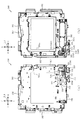
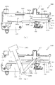
図3に示すように、パチンコ機10の背面側には、制御基板ユニット90,91と、裏
パックユニット94とが主に備えられている。制御基板ユニット90は、主基板(主制御
装置110)と音声ランプ制御基板(音声ランプ制御装置113)と表示制御基板(表示
制御装置114)とが搭載されてユニット化されている。制御基板ユニット91は、払出
制御基板(払出制御装置111)と発射制御基板(発射制御装置112)と電源基板(電
源装置115)とカードユニット接続基板116とが搭載されてユニット化されている。
As shown in FIG. 3,
裏パックユニット94は、保護カバー部を形成する裏パック92と払出ユニット93と
がユニット化されている。また、各制御基板には、各制御を司る1チップマイコンとして
のMPU、各種機器との連絡をとるポート、各種抽選の際に用いられる乱数発生器、時間
計数や同期を図る場合などに使用されるクロックパルス発生回路等が、必要に応じて搭載
されている。
The
なお、主制御装置110、音声ランプ制御装置113および表示制御装置114、払出
制御装置111および発射制御装置112、電源装置115、カードユニット接続基板1
16は、それぞれ基板ボックス100〜104に収納されている。基板ボックス100〜
104は、ボックスベースと該ボックスベースの開口部を覆うボックスカバーとを備えて
おり、そのボックスベースとボックスカバーとが互いに連結されて、各制御装置や各基板
が収納される。
The
16 are accommodated in the
また、基板ボックス100(主制御装置110)および基板ボックス102(払出制御
装置111および発射制御装置112)は、ボックスベースとボックスカバーとを封印ユ
ニット(図示せず)によって開封不能に連結(かしめ構造による連結)している。また、
ボックスベースとボックスカバーとの連結部には、ボックスベースとボックスカバーとに
亘って封印シール(図示せず)が貼着されている。この封印シールは、脆性な素材で構成
されており、基板ボックス100,102を開封するために封印シールを剥がそうとした
り、基板ボックス100,102を無理に開封しようとすると、ボックスベース側とボッ
クスカバー側とに切断される。よって、封印ユニット又は封印シールを確認することで、
基板ボックス100,102が開封されたかどうかを知ることができる。
In addition, the substrate box 100 (main control device 110) and the substrate box 102 (dispensing
A seal seal (not shown) is attached to the connecting portion between the box base and the box cover so as to cover the box base and the box cover. This seal seal is made of a brittle material. If the seal is to be peeled off in order to open the
It can be known whether or not the
払出ユニット93は、裏パックユニット94の最上部に位置して上方に開口したタンク
130と、タンク130の下方に連結され下流側に向けて緩やかに傾斜するタンクレール
131と、タンクレール131の下流側に縦向きに連結されるケースレール132と、ケ
ースレール132の最下流部に設けられ、払出モータ216(図4参照)の所定の電気的
構成により球の払出を行う払出装置133とを備えている。タンク130には、遊技ホー
ルの島設備から供給される球が逐次補給され、払出装置133により必要個数の球の払い
出しが適宜行われる。タンクレール131には、当該タンクレール131に振動を付加す
るためのバイブレータ134が取り付けられている。
The
また、払出制御装置111には状態復帰スイッチ120が設けられ、発射制御装置11
2には可変抵抗器の操作つまみ121が設けられ、電源装置115にはRAM消去スイッ
チ122が設けられている。状態復帰スイッチ120は、例えば、払出モータ216(図
4参照)部の球詰まり等、払出エラーの発生時に球詰まりを解消(正常状態への復帰)す
るために操作される。操作つまみ121は、発射ソレノイドの発射力を調整するために操
作される。RAM消去スイッチ122は、パチンコ機10を初期状態に戻したい場合に電
源投入時に操作される。
Further, the dispensing
2 is provided with a variable
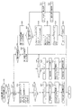
次に、図4を参照して、本パチンコ機10の電気的構成について説明する。図4は、パ
チンコ機10の電気的構成を示すブロック図である。
Next, the electrical configuration of the
主制御装置110には、演算装置である1チップマイコンとしてのMPU201が搭載
されている。MPU201には、該MPU201により実行される各種の制御プログラム
や固定値データを記憶したROM202と、そのROM202内に記憶される制御プログ
ラムの実行に際して各種のデータ等を一時的に記憶するためのメモリであるRAM203
と、そのほか、割込回路やタイマ回路、データ送受信回路などの各種回路が内蔵されてい
る。主制御装置110では、MPU201によって、大当たり抽選や第1図柄表示装置3
7A,37Bおよび第3図柄表示装置81における表示の設定、第2図柄表示装置におけ
る表示結果の抽選といったパチンコ機10の主要な処理を実行する。
The
In addition, various circuits such as an interrupt circuit, a timer circuit, and a data transmission / reception circuit are incorporated. In the
The main processing of the
なお、払出制御装置111や音声ランプ制御装置113などのサブ制御装置に対して動
作を指示するために、主制御装置110から該サブ制御装置へ各種のコマンドがデータ送
受信回路によって送信されるが、かかるコマンドは、主制御装置110からサブ制御装置
へ一方向にのみ送信される。
Various commands are transmitted from the
RAM203は、各種エリア、カウンタ、フラグのほか、MPU201の内部レジスタ
の内容やMPU201により実行される制御プログラムの戻り先番地などが記憶されるス
タックエリアと、各種のフラグおよびカウンタ、I/O等の値が記憶される作業エリア(
作業領域)とを有している。なお、RAM203は、パチンコ機10の電源の遮断後にお
いても電源装置115からバックアップ電圧が供給されてデータを保持(バックアップ)
できる構成となっており、RAM203に記憶されるデータは、すべてバックアップされ
る。
The
Work area). Note that the
All data stored in the
停電などの発生により電源が遮断されると、その電源遮断時(停電発生時を含む。以下
同様)のスタックポインタや、各レジスタの値がRAM203に記憶される。一方、電源
投入時(停電解消による電源投入を含む。以下同様)には、RAM203に記憶される情
報に基づいて、パチンコ機10の状態が電源遮断前の状態に復帰される。RAM203へ
の書き込みはメイン処理(図示せず)によって電源遮断時に実行され、RAM203に書
き込まれた各値の復帰は電源投入時の立ち上げ処理(図示せず)において実行される。な
お、MPU201のNMI端子(ノンマスカブル割込端子)には、停電等の発生による電
源遮断時に、停電監視回路252からの停電信号SG1が入力されるように構成されてお
り、その停電信号SG1がMPU201へ入力されると、停電時処理としてのNMI割込
処理(図示せず)が即座に実行される。
When the power is shut down due to the occurrence of a power failure or the like, the stack pointer and the value of each register when the power is shut off (including when the power failure occurs, the same applies hereinafter) are stored in the
主制御装置110のMPU201には、アドレスバスおよびデータバスで構成されるバ
スライン204を介して入出力ポート205が接続されている。入出力ポート205には
、払出制御装置111、音声ランプ制御装置113、第1図柄表示装置37A,37B、
第2図柄表示装置、第2図柄保留ランプ、特定入賞口65aの開閉板の下辺を軸として前
方側に開閉駆動するための大開放口ソレノイドや電動役物を駆動するためのソレノイドな
どからなるソレノイド209が接続され、MPU201は、入出力ポート205を介して
これらに対し各種コマンドや制御信号を送信する。
An input /
Solenoid comprising a second symbol display device, a second symbol holding lamp, a large opening solenoid for opening and closing the front side with the lower side of the opening and closing plate of the specific winning
また、入出力ポート205には、図示しないスイッチ群およびスライド位置検出センサ
Sや回転位置検出センサRを含むセンサ群などからなる各種スイッチ208、電源装置1
15に設けられた後述のRAM消去スイッチ回路253が接続され、MPU201は各種
スイッチ208から出力される信号や、RAM消去スイッチ回路253より出力されるR
AM消去信号SG2に基づいて各種処理を実行する。
The input /
15 is connected to a RAM erase
Various processes are executed based on the AM erase signal SG2.
払出制御装置111は、払出モータ216を駆動させて賞球や貸出球の払出制御を行う
ものである。演算装置であるMPU211は、そのMPU211により実行される制御プ
ログラムや固定値データ等を記憶したROM212と、ワークメモリ等として使用される
RAM213とを有している。
The
払出制御装置111のRAM213は、主制御装置110のRAM203と同様に、M
PU211の内部レジスタの内容やMPU211により実行される制御プログラムの戻り
先番地などが記憶されるスタックエリアと、各種のフラグおよびカウンタ、I/O等の値
が記憶される作業エリア(作業領域)とを有している。RAM213は、パチンコ機10
の電源の遮断後においても電源装置115からバックアップ電圧が供給されてデータを保
持(バックアップ)できる構成となっており、RAM213に記憶されるデータは、すべ
てバックアップされる。なお、主制御装置110のMPU201と同様、MPU211の
NMI端子にも、停電等の発生による電源遮断時に停電監視回路252から停電信号SG
1が入力されるように構成されており、その停電信号SG1がMPU211へ入力される
と、停電時処理としてのNMI割込処理(図示せず)が即座に実行される。
The
A stack area for storing the contents of the internal register of the
Even after the power is turned off, the backup voltage is supplied from the
1 is input, and when the power failure signal SG1 is input to the
払出制御装置111のMPU211には、アドレスバスおよびデータバスで構成される
バスライン214を介して入出力ポート215が接続されている。入出力ポート215に
は、主制御装置110や払出モータ216、発射制御装置112などがそれぞれ接続され
ている。また、図示はしないが、払出制御装置111には、払い出された賞球を検出する
ための賞球検出スイッチが接続されている。なお、該賞球検出スイッチは、払出制御装置
111に接続されるが、主制御装置110には接続されていない。
An input /
発射制御装置112は、主制御装置110により球の発射の指示がなされた場合に、操
作ハンドル51の回動操作量に応じた球の打ち出し強さとなるよう球発射ユニット112
aを制御するものである。球発射ユニット112aは、図示しない発射ソレノイドおよび
電磁石を備えており、その発射ソレノイドおよび電磁石は、所定条件が整っている場合に
駆動が許可される。具体的には、遊技者が操作ハンドル51に触れていることをタッチセ
ンサ51aにより検出し、球の発射を停止させるための発射停止スイッチ51bがオフ(
操作されていないこと)を条件に、操作ハンドル51の回動操作量(回動位置)に対応し
て発射ソレノイドが励磁され、操作ハンドル51の操作量に応じた強さで球が発射される
。
When the
a is controlled. The
The firing solenoid is excited in accordance with the amount of rotation (rotation position) of the operation handle 51 on the condition that the operation handle 51 is not operated), and a ball is launched with a strength corresponding to the amount of operation of the operation handle 51. .
音声ランプ制御装置113は、音声出力装置(図示しないスピーカなど)226におけ
る音声の出力、ランプ表示装置(電飾部29〜33、表示ランプ34など)227におけ
る点灯および消灯の出力、変動演出(変動表示)や予告演出といった表示制御装置114
で行われる第3図柄表示装置81の表示態様の設定などを制御するものである。演算装置
であるMPU221は、そのMPU221により実行される制御プログラムや固定値デー
タ等を記憶したROM222と、ワークメモリ等として使用されるRAM223とを有し
ている。
The sound
The setting of the display mode of the 3rd
音声ランプ制御装置113のMPU221には、アドレスバスおよびデータバスで構成
されるバスライン224を介して入出力ポート225が接続されている。入出力ポート2
25には、主制御装置110、表示制御装置114、音声出力装置226、ランプ表示装
置227、その他装置228、枠ボタン22などがそれぞれ接続されている。その他装置
228には、駆動モータKM1,KM2,KM3が含まれる。
An input /
25, a
音声ランプ制御装置113は、主制御装置110から受信した各種のコマンド(変動パ
ターンコマンド、停止種別コマンド等)に基づいて、第3図柄表示装置81の表示態様を
決定し、決定した表示態様をコマンド(表示用変動パターンコマンド、表示用停止種別コ
マンド等)によって表示制御装置114へ通知する。また、音声ランプ制御装置113は
、枠ボタン22からの入力を監視し、遊技者によって枠ボタン22が操作された場合は、
第3図柄表示装置81で表示されるステージを変更したり、スーパーリーチ時の演出内容
を変更したりするように、表示制御装置114へ指示する。ステージが変更される場合は
、変更後のステージに応じた背面画像を第3図柄表示装置81に表示させるべく、変更後
のステージに関する情報を含めた背面画像変更コマンドを表示制御装置114へ送信する
。ここで、背面画像とは、第3図柄表示装置81に表示させる主要な画像である第3図柄
の背面側に表示される画像のことである。表示制御装置114は、この音声ランプ制御装
置113から送信されるコマンドに従って、第3図柄表示装置81に各種の画像を表示す
る。
The sound
The
また、音声ランプ制御装置113は、表示制御装置114から第3図柄表示装置81の
表示内容を表すコマンド(表示コマンド)を受信する。音声ランプ制御装置113では、
表示制御装置114から受信した表示コマンドに基づき、第3図柄表示装置81の表示内
容に合わせて、その表示内容に対応する音声を音声出力装置226から出力し、また、そ
の表示内容に対応させてランプ表示装置227の点灯および消灯を制御する。
Further, the sound
Based on the display command received from the
表示制御装置114は、音声ランプ制御装置113および第3図柄表示装置81が接続
され、音声ランプ制御装置113より受信したコマンドに基づいて、第3図柄表示装置8
1における第3図柄の変動演出などの表示を制御するものである。また、表示制御装置1
14は、第3図柄表示装置81の表示内容を通知する表示コマンドを適宜音声ランプ制御
装置113へ送信する。音声ランプ制御装置113は、この表示コマンドによって示され
る表示内容にあわせて音声出力装置226から音声を出力することで、第3図柄表示装置
81の表示と音声出力装置226からの音声出力とをあわせることができる。
The
1 is used to control the display of the variation effect of the third symbol in 1. The
14 appropriately transmits a display command for notifying the display content of the third
電源装置115は、パチンコ機10の各部に電源を供給するための電源部251と、停
電等による電源遮断を監視する停電監視回路252と、RAM消去スイッチ122(図3
参照)が設けられたRAM消去スイッチ回路253とを有している。電源部251は、図
示しない電源経路を通じて、各制御装置110〜114等に対して各々に必要な動作電圧
を供給する装置である。その概要としては、電源部251は、外部より供給される交流2
4ボルトの電圧を取り込み、各種スイッチ208などの各種スイッチや、ソレノイド20
9などのソレノイド、モータ等を駆動するための12ボルトの電圧、ロジック用の5ボル
トの電圧、RAMバックアップ用のバックアップ電圧などを生成し、これら12ボルトの
電圧、5ボルトの電圧およびバックアップ電圧を各制御装置110〜114等に対して必
要な電圧を供給する。
The
RAM erase
Taking in the voltage of 4 volts, various switches such as various switches 208 and
It generates a 12 volt voltage for driving a solenoid such as 9 and a motor, a 5 volt voltage for logic, a backup voltage for RAM backup, etc., and these 12 volt voltage, 5 volt voltage and backup voltage are generated. Necessary voltages are supplied to the
停電監視回路252は、停電等の発生による電源遮断時に、主制御装置110のMPU
201および払出制御装置111のMPU211の各NMI端子へ停電信号SG1を出力
するための回路である。停電監視回路252は、電源部251から出力される最大電圧で
ある直流安定24ボルトの電圧を監視し、この電圧が22ボルト未満になった場合に停電
(電源断、電源遮断)の発生と判断して、停電信号SG1を主制御装置110および払出
制御装置111へ出力する。停電信号SG1の出力によって、主制御装置110および払
出制御装置111は、停電の発生を認識し、NMI割込処理を実行する。なお、電源部2
51は、直流安定24ボルトの電圧が22ボルト未満になった後においても、NMI割込
処理の実行に充分な時間の間、制御系の駆動電圧である5ボルトの電圧の出力を正常値に
維持するように構成されている。よって、主制御装置110および払出制御装置111は
、NMI割込処理(図示せず)を正常に実行し完了することができる。
The power
201 and a circuit for outputting a power failure signal SG1 to each NMI terminal of the
51, the output of the voltage of 5 volts, which is the drive voltage of the control system, is set to a normal value for a time sufficient for the execution of the NMI interrupt processing even after the DC stable voltage of 24 volts becomes less than 22 volts. Configured to maintain. Therefore,
RAM消去スイッチ回路253は、RAM消去スイッチ122(図3参照)が押下され
た場合に、主制御装置110へ、バックアップデータをクリアさせるためのRAM消去信
号SG2を出力するための回路である。主制御装置110は、パチンコ機10の電源投入
時に、RAM消去信号SG2を入力した場合に、バックアップデータをクリアすると共に
、払出制御装置111においてバックアップデータをクリアさせるための払出初期化コマ
ンドを払出制御装置111に対して送信する。
The RAM erase
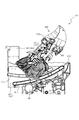
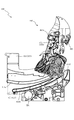
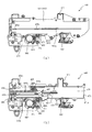
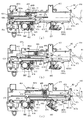
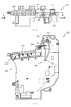
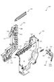
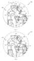
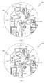
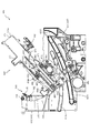
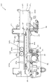
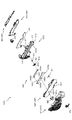
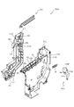
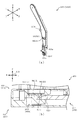
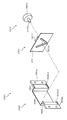
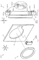
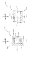
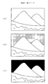
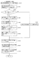
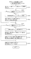
次いで、図5から図10を参照して、動作ユニット200の概略構成について説明する
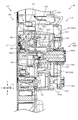
。図5は、パチンコ機10の分解斜視正面図であり、図6は、動作ユニット200及び遊
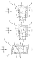
技盤13の分解斜視正面図である。また、図7から図10は、動作ユニット200の正面
図である。
Next, a schematic configuration of the
なお、図7では、上変位部材940が上方に退避されると共に、下変位部材440が下
方に退避された状態が、図8では、図7に示す状態から、上変位部材940が下方に回転
変位された状態が、図9では、図7に示す状態から、下変位部材440が後述する第1張
出位置に張り出された状態が、図10では、下変位部材440が、最大の張り出し位置で
ある第2張出位置に変位された状態が、それぞれ図示される。
In FIG. 7, the
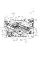
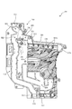
図5及び図6に示すように、動作ユニット200は、箱状に形成される背面ケース30
0を備え、その背面ケース300の内部空間に、上変位ユニット900、下変位ユニット
400、回転ユニット700及び遊技盤13の背面に取着される振分けユニット5あ00
と送球ユニット600とが収容される。
As shown in FIGS. 5 and 6, the
0, and in the inner space of the
And the
背面ケース300は、正面視略矩形の底壁部301と、その底壁部301の4辺の外縁
から正面へ向けて立設される外壁部302とを備え、それら各壁部301,302により
一面側(正面側)が開放された箱状に形成される。底壁部301には、その中央に正面視
矩形の開口301aが開口形成され、その開口301aを通じて、底壁部301の背面に
配設される第3図柄表示装置81(図2参照)が視認可能とされる。
The
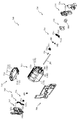
上変位ユニット900は、背面ケース300の底壁部301のうちの開口301aの上
側部分に配設される正面視矩形横長のベース部材910と、そのベース部材910に摺動
可能に配設される上変位部材940とを備え、背面ケース300の開口301a(即ち、
第3図柄表示装置81)の正面側で、上変位部材940を摺動させつつ回転変位させる演
出を実行可能に形成される。なお、上変位ユニット900の詳しい説明は後述する。
The
On the front side of the 3rd symbol display device 81), an effect of rotating and displacing the
下変位ユニット400は、背面ケース300の底壁部301のうちの開口301aの下
側部分に配設される正面視矩形横長のベース部材410と、そのベース部材410に摺動
可能に配設される下変位部材440とを備え、背面ケースの開口301a(即ち、第3図
柄表示装置81)の正面側で、下変位部材440を摺動させつつ回転変位させる演出を実
行可能に形成される。なお、下変位ユニット400の詳しい説明は後述する。
The
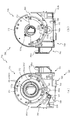
回転ユニット700は、背面ケース300の底壁部301のうちの開口301aの下側
部分の正面視右側(矢印)に配設される正面視略矩形の背面ベース720と、その背面ベ
ース720の前方に配設される回転体800とを備え、遊技盤13の正面視右側下方に形
成される透明の板部を介して回転体800を回転変位させる演出を遊技者に視認可能とさ
れる。なお、回転ユニット700の詳細な説明については後述する。
The
送球ユニット600は、遊技盤13の背面側に取着され、遊技盤13の第3入賞口82
から遊技盤13の背面側に送球される遊技球を後述する振分けユニット500の第1開口
511に送球する経路が形成される。
The
A path through which game balls sent to the back side of the
振分けユニット500は、遊技盤13の背面側に取着される経路形成部材510と、経
路形成部材510との対向に所定の隙間を形成した状態で配設されるベース板520と、
そのベース板520に取着され経路形成部材510とベース板520との対向間を流下す
る遊技球を各送球経路(第2送球経路KR2又は第3送球経路KR3)に振り分ける振分
け部材540とを備える。この振分け部材540に振り分けられた遊技球が下変位ユニッ
ト400に送球される。なお、振分けユニット500の詳しい説明は後述する。
The
A
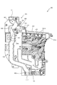
<第1の装飾体と第2の装飾体が前後方向に隣り合う位置に配置される>
次いで、図11から図16を参照して、遊技盤13に配設される一般入賞口ユニット1
50について説明する。
<A 1st decoration body and a 2nd decoration body are arrange|positioned in the position adjacent to the front-back direction>
Next, referring to FIG. 11 to FIG. 16, the general winning a
50 will be described.
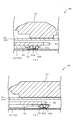
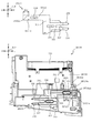
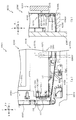
初めに、図11及び図12を参照して、一般入賞口ユニット150について説明する。
図11は、遊技盤13の分解斜視正面図であり、図12(a)は、一般入賞口ユニット1
50の正面図であり、図12(b)は、図12(a)のXIIb−XIIb線における一
般入賞口ユニット150の断面図である。
First, the general winning
FIG. 11 is an exploded perspective front view of the
FIG. 12B is a cross-sectional view of the general winning a
図11及び図12に示すように、遊技盤13は、正面視略矩形状の板部材から形成され
るベース板60と、そのベース板60に形成される開口部分に配設されるセンターフレー
ム86及び一般入賞口ユニット150と、を備える。
As shown in FIGS. 11 and 12, the
ベース板60は、正面視において中央部分に開口される第1開口部60aと、レール部
材76,77により形成される遊技領域の重力方向下側に開口される第2開口部60bと
、を備える。第1開口部60aには、センターフレーム86が配設され、第2開口部60
bには、一般入賞口ユニット150が配設される。また、ベース板60には、正面側(矢
印F方向側)に装飾(模様や図柄等)が形成されたシールが貼付されて、遊技者にその装
飾を視認させることができる。なお、ベース板60の正面側の装飾は、シールに限られる
ものではなく、ベース板60の正面に装飾が印刷(塗装)されるものであっても良い。
The
In b, a general winning
一般入賞口ユニット150は、遊技盤13の遊技領域(ベース板60の正面)に配設さ
れ、遊技領域を流下する遊技球の経路を変更可能とされる。また、一般入賞口ユニット1
50は、内レール76及び外レール77により囲われて形成される遊技領域に対して、正
面視(矢印B方向視)における重力方向下側(矢印D方向側)の端部に沿う位置に配置さ
れる。なお、図13〜図16では、ベース板60に配設されるシールが装飾部材60cの
符号を付して図示される。また、本実施形態では、装飾部材60cにキャラクター(人)
が描かれる。
The general winning a
50 is arranged at a position along the lower end of the gravity direction (arrow D direction side) in the front view (arrow B direction view) with respect to a game area formed by being surrounded by the
Is drawn.
一般入賞口ユニット150は、正面視において三日月状に形成される本体部151と、
その本体部151の端部から正面側(矢印F方向側)に立設される第1立設部152と、
その第1立設部152の重力方向上側(矢印U方向側)の端部から遊技領域の中央側に向
かって延設される第2立設部153と、本体部151の背面側に配設される装飾部材15
4と、本体部151の正面側に形成される複数(本実施形態では3個)の一般入賞口63
と、を主に備える。
The general winning
A
A
4 and a plurality of (three in this embodiment) general winning holes 63 formed on the front side of the
And mainly.
本体部151は、ベース板60の板厚方向に開口される第2開口部60bの開口形状よ
りも若干大きい外形に設定され、第2開口部60bの開口に覆設された状態でベース板6
0の正面側に配設される。また、第2開口部60bにより、本体部151に配設される一
般入賞口63に流入する遊技球を遊技盤13(ベース板60)の背面側に送球できる。さ
らに、本体部151は、正面視において内側部分から外側の端部に向かうほどベース板6
0側に傾斜する傾斜面151aと、ベース板60側(矢印B方向側)の背面に凹設される
凹部151bと、その凹部151bを除いた本体部151の背面を形成する背面部151
dと、を主に備えて形成される。
The
0 is disposed on the front side. Further, the
An
d.
傾斜面151aは、ベース板60の正面に対して略30度ほど傾斜して形成される。こ
れにより、遊技盤13の遊技領域を流下する遊技球を、傾斜面151aに当接させて傾斜
面151aの傾斜に沿って流下させて、本体部151の正面側に移動させることができる
。
The
ここで、本体部151の端部に傾斜面151aが形成されず、本体部151の側面が、
ベース板60の正面に対して垂直に形成される場合には、遊技盤13の遊技領域を流下す
る遊技球が、本体部151の側面に対して直交する方向から当接(衝突)して、その当接
した遊技球が流下方向と反対方向に跳ね返る恐れがある。
Here, the
When formed perpendicular to the front surface of the
これに対し、本実施形態では、傾斜面151aにより、本体部151の側面に当接する
遊技球を本体部の正面側に移動させることができるので、遊技領域を流下する遊技球の流
下が一時的に停滞することを抑制できる。その結果、ベース板60の正面側から一般入賞
口ユニット150の本体部151の正面に遊技球をスムーズに流下させることができる。
On the other hand, in this embodiment, the game ball that contacts the side surface of the
背面部151dは、上述したように本体部151の背面であり、背面視における凹部1
51bの周囲に一定の幅で形成される。また、背面部151dは、一般入賞口ユニット1
50がベース板60に配設された状態において、ベース板60(装飾部材60c)の正面
に当接して配設される。
As described above, the
A constant width is formed around 51b. In addition, the
In a state where 50 is disposed on the
凹部151bは、正面側(矢印F方向側)に向かって凹設される。また、凹部151b
は、凹設方向の底面となる凹設底面151b2と、その凹設底面151b2の外縁から背
面側(矢印B方向側)に向かって立設される内側面151b3と、を有する。
The
Has a concave bottom surface 151b2 which is a bottom surface in the concave direction, and an inner side surface 151b3 which is erected from the outer edge of the concave bottom surface 151b2 toward the back side (arrow B direction side).
凹設底面151b2は、後述する装飾部材154の接着面であり、本体部151の正面
と平行な平面として形成される。これにより、本体部151を介して装飾部材154の装
飾を視認した場合に、装飾部材154の装飾を一様に視認させることができる。
The concave bottom surface 151b2 is an adhesive surface of a
内側面151b3は、正面視における前後方向(矢印F−B方向)に延設される。また
、内側面151b3の正面視における形状は、後述する装飾部材154の外形と略同一に
形成される。これにより、凹部151bに装飾部材154を配設した場合に、装飾部材1
54が凹部151bの外側に突出することを抑制できる。従って、一般入賞口ユニット1
50が、ベース板60に配設された際に、背面部151dとベース板60との間に装飾部
材154が挟まることで本体部151の背面部151dとベース板60との間に隙間が形
成されることを抑制できる。これにより、本体部151がベース板60に対して、通常の
配設位置よりも正面側に張り出すことを抑制できる。その結果、ベース板60の正面側か
ら一般入賞口ユニット150の本体部151の正面に遊技球をスムーズに流下させること
ができる。
Inner side surface 151b3 is extended in the front-back direction (arrow FB direction) in front view. Further, the shape of the inner side surface 151b3 in a front view is formed to be substantially the same as the outer shape of a
It can suppress that 54 protrudes outside the recessed
When the
凹部151bは、その凹設空間に後述する装飾部材154を収容する凹みであり、凹設
深さ(正面側(矢印F方向側)への凹設距離)が、装飾部材154の厚み寸法よりも大き
く設定される。また、凹部151bは、正面視における本体部151の端部から本体部1
51の内側に一定の距離を隔てた位置で本体部151の端部の形状に沿って凹設される。
The
51 is recessed along the shape of the end of the
よって、凹部151bの内側に装飾部材154を配設した場合に、装飾部材154の背
面が、本体部151よりも背面側に張り出すことを抑制できる。従って、一般入賞口ユニ
ット150がベース板60に配設された際に、凹設底面151b2とベース板60との間
に装飾部材154が挟まることで本体部151の背面部151dとベース板60との間に
隙間が形成されることを抑制できる。これにより、本体部151がベース板60に対して
通常の配設位置よりも正面側に張り出すことを抑制できる。その結果、本体部151の重
力方向上方(矢印U方向)から一般入賞口ユニット150の本体部151の正面に遊技球
をスムーズに流下させることができる。
Therefore, when the
第1立設部152は、遊技領域の端部側(内レール76側)における本体部151の端
部から正面側(矢印F方向側)に立設される。第1立設部152は、その立設寸法がベー
ス板60(装飾部材60c)の正面に植立される内レール76の植立方向の幅寸法と略同
一に設定される。また、第1立設部152は、遊技盤13の正面側を覆う前扉5のガラス
ユニット16との対向間の間隔が遊技球の直径よりも小さく設定される。これにより、本
体部151の正面側を流下する遊技球を、遊技領域の重力方向下側の端部で第1立設部1
52に衝突させることができる。その結果、本体部151の正面側を流下する遊技球が内
レール76に衝突することを抑制でき、内レール76が遊技球と衝突して曲げられること
を抑制できる。
The
52. As a result, it is possible to suppress the game ball flowing down the front side of the
ここで、内レール76と外レール77との対向間は、球発射ユニット112a(図4参
照)から発射された遊技球を遊技盤13の上部へ案内するための空間であり、内レール7
6と外レール77との対向間に補強等を配設するスペースが限られる。そのため、内レー
ル76が曲がることを防止する目的で補強を配設することが困難であり、遊技領域を流下
する遊技球が内レール76に衝突して、内レール76が曲がる恐れがあった。
Here, the space between the
A space for providing reinforcement or the like between the facing of the
これに対して、本実施形態では、遊技領域内に配設される一般入賞口ユニット150(
第1立設部152)により遊技領域を流下する遊技球が内レール76に衝突しにくくする
ことができる。従って、内レール76が曲ることで、内レール76及び外レール77の対
向間の距離が変更されることを抑制できる。その結果、遊技球を安定して遊技領域に打ち
出すことができる。
On the other hand, in the present embodiment, the general winning a prize opening unit 150 (
The first standing portion 152) can make it difficult for the game ball flowing down the game area to collide with the
第2立設部153は、正面視において第1立設部152の重力方向上側(矢印U方向側
)の端部から遊技領域の中央(第1入賞口64)に向かって下降傾斜して延設される(図
2参照)。これにより、内レール76とセンターフレーム83との対向間(図2参照)を
流下する遊技球が、第2立設部153の下降傾斜する延設部分の上面(矢印U方向側の面
)に送球されると、その遊技球を第2立設部153の下降傾斜に沿って転動させて、遊技
領域の中央に向けて送球することができる。これにより、内レール76と外レール77と
の対向間側(矢印L方向側)の遊技領域を流下する遊技球を、遊技領域の中央に配設され
る第1入賞口64に入賞(流入)させやすくできる。
The
装飾部材154は、板状に形成されると共に、本体部151の背面側に接着される。ま
た、装飾部材154は、本体部151側の正面にベース板60の装飾部材60cに形成さ
れる装飾と正面視において連なる装飾が形成される。これにより、ベース板60に形成さ
れる装飾を装飾部材154の装飾と合わせて1の装飾に視認させることができる。なお、
本実施形態では、装飾部材154にキャラクター(人)の一部が描かれており、装飾部材
60cのキャラクターと装飾部材154のキャラクターとを合わせて1人のキャラクター
として視認させることができる。
The
In the present embodiment, a part of the character (person) is drawn on the
また、装飾部材154は、光透過性材料から形成される。これにより、ベース板60の
背面側(矢印B方向側)から第2開口部60bを通した光を装飾部材154の背面から入
射させて、装飾部材154の正面側(矢印F方向側)から出射させることができる。よっ
て、装飾部材154の正面に形成される装飾を明るくして、遊技者に視認させることがで
き、遊技者に装飾部材154の装飾を視認させやすくできる。
The
次いで、図13を参照して、ベース板60と一般入賞口ユニット150とについて説明
する。図13は、図2のXIII−XIII線における遊技盤13の断面図である。
Next, the
図13に示すように、装飾部材154は、ベース板60の第2開口部60bの正面視に
おける開口形状よりも外形が大きく形成される。これにより、一般入賞口ユニット150
がベース板60に配設されると、装飾部材154の端部は、本体部151の凹部151b
の凹設底面151b2とベース板60(装飾部材60c)との間に配置される。よって、
本体部151と装飾部材154との接着が経年劣化等により剥がれた場合に、装飾部材1
54が遊技盤13から脱落することを抑制できる。
As shown in FIG. 13, the
Is disposed on the
Between the concave bottom surface 151b2 and the base plate 60 (
When the adhesion between the
It is possible to prevent 54 from falling off the
また、装飾部材154は、ベース板60と前後方向(矢印F−B方向)において重なる
幅寸法が、後述する本体部151の背面から突設される突起155が挿入されるベース板
60の円形状の開口60g(図11参照)の直径よりも大きく設定される。これにより、
装飾部材154の本体部151に対する配置の位置ずれ、又は、装飾部材60cを形成し
た位置のずれにより、正面視における装飾部材154及び装飾部材60cの装飾の間に隙
間が形成されることを抑制できる。その結果、ベース板60の装飾部材60cと装飾部材
154の装飾とを1の装飾として遊技者に認識させやすくできる。
Further, the
It is possible to suppress the formation of a gap between the decoration of the
また、本体部151に配設される3個の一般入賞口63は、遊技盤13の背面側に配設
される振り分けユニット500(図71参照)の開口514〜516に接続されており、
一般入賞口63に入賞した遊技球は、振り分けユニット500の第4送球経路KR4に送
球される。なお、振り分けユニット500についての詳しい説明は後述する。
Further, the three general winning
The game balls that have won the general winning
さらに、振り分けユニット500には、正面側に光を照射可能な光源を備える基板(図
示しない)がベース板520(図71参照)に配設されており、その基板から照射される
光がベース板60の第2開口部60bを挿通して一般入賞口ユニット150の背面に照射
される。
Further, in the
よって、第2開口部60bは、一般入賞口ユニット150の一般入賞口63から入賞す
る遊技球の経路および一般入賞口ユニット150の背面に光を照射する空間として利用さ
れる。これにより、遊技球を送球するための開口と、光を通過させるための開口と、2箇
所の開口を分けて形成する必要がなくなるので、一般入賞口ユニット150の背面の全域
に光を照射しやすくすることができると共に、一般入賞口ユニット150の本体部151
の全域に一般入賞口63を配置することができる。その結果、一般入賞口ユニット150
の設計の自由度を向上することができると共に、一般入賞口ユニット150の全域から光
を出射して一般入賞口ユニット150の装飾(装飾部材154)を遊技者に視認させやす
くできる。
Therefore, the
The general winning
The design freedom can be improved, and light can be emitted from the entire area of the general
また、本実施形態によれば、図13に示すように、遊技盤13のベース板60の装飾部
材60cと連なる装飾の装飾部材154は、ベース板60の正面に沿って配設される本体
部151の背面に配置されるので、ベース板60の装飾部材60cと装飾部材154の装
飾とを前後方向(矢印F−B方向)に隣合う(近づいた)位置に配置することができる。
これにより、装飾部材60c及び装飾部材154の正面視に対して傾斜した角度(例えば
、パチンコ機10(図1参照)の重力方向上側端部と同じ高さの視点)から装飾部材60
c及び装飾部材154を視認した際に、一般入賞口ユニットの装飾が一般入賞口ユニット
の正面に配設される場合に比べて、装飾部材60c及び装飾部材154の装飾がずれて視
認されることを抑制できる。その結果、ベース板60の装飾部材60cと装飾部材154
の装飾との連結部分を遊技者の視点に関わらず同様の位置関係で遊技者に視認させること
ができ、遊技盤13の意匠性を向上できる。
Further, according to the present embodiment, as shown in FIG. 13, the
Accordingly, the
When visually recognizing c and the
The player can visually recognize the connection portion with the decoration of the player regardless of the player's viewpoint, and can improve the design of the
次いで、図14を参照して、装飾部材154及びベース板60の装飾部材60cの連結
について詳しく説明する。図14は、図13の範囲XIVにおける遊技盤13の部分拡大
断面図である。なお、図14では、遊技者に視認される光の経路が2点鎖線で図示される
。
Next, the connection of the
上述したように、ベース板60の装飾部材60cと装飾部材154の装飾とは、合わせ
て1の装飾として遊技者に視認される。従って、ベース板60の装飾部材60cと装飾部
材154の装飾とを1の装飾(模様)として遊技者に視認させるために、両者の装飾の位
置ずれを抑える必要がある。しかしながら、ベース板60に装飾を形成する際、又は、本
体部151に装飾部材154を配設する際に、その装飾を正確な位置(毎回同じ位置)に
配置することが困難である。従って、ベース板60に一般入賞口ユニット150を配設し
た場合に、ベース板60の装飾部材60cに対する装飾部材154の装飾の位置がずれて
配設されることで、装飾部材60cと装飾部材154との装飾を合わせて1の装飾として
遊技者に視認させにくくなるという問題点があった。
As described above, the
これに対して、本実施形態によれば、装飾部材154は、その端部が傾斜面151aの
背面側に配置される。これにより、装飾部材154の装飾とベース板60の装飾部材60
cの装飾との連結部分が、遊技者から正確に認識されにくくする(連結部分をぼやかして
遊技者に視認させる)ことができる。よって、装飾部材60cと装飾部材154とを1の
装飾として遊技者に認識させることができる。
On the other hand, according to this embodiment, the end of the
It is possible to make it difficult for the player to accurately recognize the connecting portion with the decoration of c (the player can visually recognize the connecting portion by blurring the connecting portion). Therefore, the player can recognize the
詳しく説明すると、図14に示すように、装飾部材154の装飾と装飾部材60cの装
飾との連結部(以下、「境界P1」(図14参照)と称す)は、本体部151の傾斜面1
51aの背面側に位置される。よって、境界P1から遊技者の視点に向かって出射される
光と、本体部151の正面と傾斜面151aとの連結部(以下、「境界P2」(図14参
照)と称す)から遊技者の視点に向かって出射される光とを、装飾部材60c又は装飾部
材154の異なる位置で反射した光にすることができる(即ち、境界P1から遊技者の視
点に向かって出射される光の経路上に、境界P2が形成されることを抑制できる)。
More specifically, as shown in FIG. 14, the connecting portion (hereinafter referred to as “boundary P <b> 1” (see FIG. 14)) between the decoration of the
It is located on the back side of 51a. Therefore, the light emitted from the boundary P1 toward the player's viewpoint and the connecting portion between the front surface of the
従って、境界P1では、装飾部材154に対する装飾部材60cの配置のずれが装飾の
位置ずれとして遊技者に認識されやすく、又、境界P2では、光の屈折方向の違いによる
装飾の位置ずれが遊技者に認識されやすいところ、境界P1及び境界P2のそれぞれの位
置から遊技者が視認する装飾を異なる位置の装飾にすることができるので、境界P1及び
境界P2における装飾の位置ずれが、同一の位置で遊技者に視認されることを抑制できる
。従って、境界P1における装飾の位置ずれと、境界P2における装飾の位置ずれとが合
わさり、装飾の位置ずれ量が大きくなって遊技者に認識されることを抑制できる。その結
果、装飾部材60cと装飾部材154との装飾を遊技者に1の装飾として認識させやすく
でき、遊技盤13の意匠性を向上できる。
Accordingly, at the boundary P1, the player can easily recognize the displacement of the
さらに、境界P1を傾斜面151aの背面側に配置することで、遊技者の視点において
、装飾部材60c及び本体部151の連結部(以下、「境界P3」(図14参照)と称す
)と、境界P2との間に境界P1を配置することができる。よって、本体部151から光
が出射する際に光が屈折することによる装飾の位置ずれ位置(境界P2,P3)の間に、
境界P1を配置することができる。従って、装飾の位置がずれて認識される領域が間延び
することを抑制できる。即ち、装飾の位置がずれて視認される領域を遊技盤13の正面に
対して限定的にすることができる。その結果、装飾の位置ずれ領域を遊技盤13の遊技領
域に対して、少なくすることができるので、装飾部材60c及び装飾部材154の装飾を
遊技者に1の装飾として認識させやすくできる。
Furthermore, by arranging the boundary P1 on the back side of the
A boundary P1 can be arranged. Therefore, it is possible to suppress the extension of the recognized area by shifting the decoration position. That is, it is possible to limit the area where the position of the decoration is visually recognized with respect to the front of the
なお、本実施例では、ベース板60の装飾部材60cにキャラクターの顔が装飾され、
一般入賞口ユニット150の装飾部材154に装飾部材60cに装飾されたキャラクター
の体が装飾される。即ち、装飾部材60cと装飾部材154との装飾の連結部分には、そ
の装飾の輪郭が位置される。よって、装飾部材60cと装飾部材154との連結部分の位
置ずれを装飾の輪郭線であると遊技者に認識させることができる。その結果、装飾部材6
0c及び装飾部材154の装飾を遊技者に1の装飾として認識させやすくできる。
In this embodiment, the character's face is decorated on the
The body of the character decorated on the
It is possible to make the player easily recognize the decoration of 0c and the
さらに、本実施例では、ベース板60の装飾部材60cにキャラクターの顔の首元まで
が装飾され、一般入賞口ユニット150の装飾部材154に装飾部材154に装飾部材6
0cに装飾されたキャラクターの体が着用する服が装飾され、キャラクターの顔(首)と
服との色合いが異なるもの(本実施例では、顔が肌色で服が黒色)で装飾される。これに
より、装飾部材60cと装飾部材154との連結部分の位置ずれを色合いの異なる部分と
することで、装飾部材60cと装飾部材154とが分割されていることを遊技者に認識さ
せにくくすることができる。その結果、装飾部材60c及び装飾部材154の装飾を遊技
者に1の装飾として認識させやすくできる。
Further, in the present embodiment, the
The clothes worn by the character's body decorated in 0c are decorated, and the character's face (neck) and clothes are different in color (in this embodiment, the face is skin color and the clothes are black). This makes it difficult for the player to recognize that the
本体部151には、上述したように背面側に凹部151bが凹設され、その内側に装飾
部材154が配設される。また、凹部151bの内側の側面(内側面151b3)の形状
は、正面視における装飾部材154の外形と略同一に設定される。これにより、装飾部材
154を本体部151に配設する際には、凹部151bの内側面151b3をガイド(位
置決め)として利用することができる。その結果、装飾部材154を本体部151に貼付
する際に、装飾部材154の配置が本体部151に対して位置ずれすることを抑制できる
。
As described above, the
さらに、本体部151の背面側には円柱状に突出する突起155(図15参照)が複数
個所(本実施形態では、3箇所(図15参照))に形成される。突起155は、一般入賞
口ユニット150をベース板60に配設する場合にベース板60との位置決めをする位置
決め突起であり、ベース板60に凹設される凹部60dに挿入される。また、突起155
は、少なくとも1箇所(本実施形態では1箇所)が、凹部151bの凹設底面151b2
から突設され、装飾部材154に形成される開口に挿入される。従って、突起155を本
体部151に装飾部材154を配設する場合の位置決めとして利用することができる。
Further, on the back side of the
Is at least one place (one place in the present embodiment) is a concave bottom surface 151b2 of the
And is inserted into an opening formed in the
よって、突起155により、一般入賞口ユニット150をベース板60に配設する際の
位置決めをすることができると共に、装飾部材154を本体部151に配設する際の位置
決めをすることができる。従って、装飾部材60cの正面側に装飾部材154を配置する
際の位置決めとなる部分を同一の部分とすることができるので、装飾部材60cの装飾と
装飾部材154の装飾とが位置ずれすることを抑制できる。その結果、装飾部材60cの
装飾と装飾部材154の装飾とを合わせて1の装飾として遊技者に認識させやすくできる
。
Therefore, the
さらに、凹設底面151b2から突設される突起155は、後述する範囲E1(図15
参照)の領域(接着テープ154aの貼付領域)に形成される。これにより、本体部15
1に装飾部材154を配設する際に、装飾部材154の開口に突起155を挿入した状態
で、装飾部材154の縁部の一箇所を凹部151bの内側面151b3に位置を合わせて
配設することで、本体部151に対して装飾部材154の2箇所を位置決めすることがで
きる。従って、装飾部材154の縁部を凹部151bの内側面151b3の2箇所で位置
をあわせて、装飾部材154を本体部151に配設する必要がなくなる。その結果、装飾
部材154の本体部151への配設作業を簡易にできる。
Further, the
Reference) region (attachment region of the
When the
次いで、図15及び図16を参照して、本体部151と装飾部材154との接着につい
て説明する。図15は、一般入賞口ユニット150の背面図であり、図16は、図13の
範囲XIVにおける遊技盤13の部分拡大断面図である。なお、図15では、装飾部材1
54に貼付される接着テープ154aの範囲が、E1の符号を付して2点鎖線で図示され
る。また、図14では、遊技者に視認される光の経路が2点鎖線で図示される。なお、本
実施形態では、接着テープ154aが、光透過性の両面のテープから形成されて、範囲E
1に貼付される。
Next, adhesion between the
The range of the
1 is affixed.
図15及び図16に示すように、装飾部材154と本体部151とを接着する接着テー
プ154aは、装飾部材154の端部に沿って一定の幅で貼付される。これにより、接着
テープ154aが貼付されていない領域(範囲E1以外の部分)では、接着テープ154
aの厚みの分、本体部151(凹設底面151b2)と装飾部材154(装飾部材の正面
)との間に所定の幅の隙間(空間)が形成される。
As shown in FIGS. 15 and 16, the
A gap (space) having a predetermined width is formed between the main body 151 (recessed bottom surface 151b2) and the decorative member 154 (front surface of the decorative member) by the thickness of a.
また、接着テープ154aは、装飾部材154の端部から境界P3を通過して傾斜面1
51aと直交する仮想線PK1(図14参照)を超える領域に接着される。これにより、
本体部151を通過して傾斜面151aから出射される光が、装飾部材154の装飾の影
響を受ける部分(波長が変化される部分)を接着テープ154aを貼付した範囲E1(装
飾部材154の端部)とすることができる。その結果、遊技者が所定以上の角度から一般
入賞口ユニット150を視認した場合にも、装飾部材60cと装飾部材154の装飾とを
1の装飾として遊技者に視認させやすくすることができる。
Further, the
It is bonded to a region exceeding the virtual line PK1 (see FIG. 14) orthogonal to 51a. This
A range E1 (the end of the decoration member 154) where the
ここで、遊技者が、通常よりも高い位置(例えば、パチンコ機10(図1参照)の重力
方向上側端部と同じ高さの視点)から遊技盤13を視認する場合には、図16に示すよう
に、傾斜面151aから遊技者の目線に向かって抜け出る光Lが、本体部151の正面お
よび背面を繰り返し反射して、本体部151の内部を通過する。この場合、装飾部材15
4の正面の全域が接着テープ154aを介して本体部151と当接するものであると、装
飾部材154側で反射される度に装飾部材154の装飾により光の波長が変更される。従
って、本体部151の内部を通過して傾斜面151aから出射される光は、装飾部材15
4の端部の装飾による波長の変化のみで反射することができない。よって、傾斜面151
aから遊技者に認識される装飾が本体部151の正面から遊技者に視認される装飾の波長
と異なるために、本体部151と傾斜面151aとで、装飾が連ならなくなるという問題
点があった。
Here, when the player visually recognizes the
If the entire area of the front face of 4 is in contact with the
4 cannot be reflected only by the change of the wavelength due to the decoration of the end of 4. Therefore, the
Since the decoration recognized by the player from a is different from the wavelength of the decoration visually recognized by the player from the front of the
これに対し、本実施形態では、装飾部材154の本体部151への接着部分を範囲E1
のみとすることで、本体部151の内部を反射して通過する光Lが、装飾部材154の装
飾の影響を受けないよう(光の波長が変更されないよう)にすることができる。その結果
、図16に示すように、本体部151を通過して傾斜面151aから出射される光が、装
飾部材154の装飾の影響を受ける部分(波長が変化される部分)を接着テープ154a
を貼付した範囲E1(装飾部材154の端部)とすることができ、遊技者に視認される傾
斜面151aの装飾と隣合う装飾と連なるものとして遊技者に視認させやすくできる。そ
の結果、遊技盤13の意匠性を向上できる。
On the other hand, in this embodiment, the adhesion part to the main-
By using only, it is possible to prevent the light L reflected and passing through the inside of the
Can be made the range E1 (end portion of the decorative member 154), and can be easily recognized by the player as being connected to the decoration of the
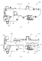
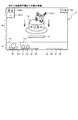
次いで、図17から図36を参照して、特別入賞装置550について説明する。初めに
、図17を参照して、特別入賞装置550の配設方法について説明する。図17は、セン
ターフレーム86の分解斜視正面図である。
Next, the
図17に示すように、センターフレーム86は、ベース板60の中央の開口を取り囲む
略円形の枠状に形成されるベース枠86aと、そのベース枠86aの径方向外側に突出さ
れる突設部86bと、を備えて構成される。
As shown in FIG. 17, the
ベース枠86aは、ベース板60の中央の開口に沿う形状とされ、その中央の開口の内
側にベース枠86aの一部が挿入されると共に、ベース枠86aの一部を除く部分がベー
ス板60の正面側に張り出した状態でベース板60に配設される。
The
突設部86bは、遊技盤13の遊技領域に対して、正面視右側(矢印R方向側)に突設
される。これにより、突設部86bに配設される特別入賞装置550を遊技領域に対して
正面視右側(矢印R方向側)に配設することができ、特別遊技状態となった際の右打ち時
の遊技球の送球経路の一部を特別入賞装置550により構成することができる。
The projecting
また、突設部86bは、前後方向(矢印F−B方向)に開口する開口部86b1と、そ
の開口部86b1の上方(矢印U方向)に位置し背面側(矢印B方向側)に向かって凹設
される凹部86b2と、を主に備える。
The projecting
開口部86b1は、後述する特別入賞装置550の第1ユニット551の一部が挿入さ
れる。これにより、第1ユニット551を、突設部86bの背面側に配設される特別入賞
装置550の第2ユニット552と開口部86b1を介して連結することができる。
A part of the
凹部86b2は、後述する特別入賞装置550の第1ユニット551の一部を内側に収
容可能とされる。また、凹部86b2には、遊技球の通過を検知可能な検出装置86b3
が配設される。これにより、第1ユニット551の凹部86b2の内側に収容される部分
を通過する遊技球を検出することができる。
The recess 86b2 can accommodate a part of the
Is disposed. Thereby, it is possible to detect the game ball passing through the portion accommodated inside the recess 86b2 of the
特別入賞装置550は、センターフレーム86の突設部86bの正面側(矢印F方向側
)に配設される第1ユニット551と、突設部86bの背面側(矢印B方向側)に配設さ
れる第2ユニット552と、を主に備えて構成される。
The special prize-winning
第1ユニット551は、その内部を遊技球が流下可能な空間(経路)を備え、一部が遊
技盤13の遊技領域に配設される。また、第1ユニット551は、第2ユニット552を
挿通されたネジによりセンターフレーム86に配設される。なお、第1ユニット551及
び第2ユニット552の配設方法についての詳しい説明は後述する。
The
次いで、図18から図20を参照して、特別入賞装置550の第1ユニット551の構
成について説明する。図18(a)は、第1ユニット551の正面図であり、図18(b
)は、第1ユニット551の側面図であり、図18(c)は、第1ユニット551の背面
図である。図19は、第1ユニット551の分解斜視正面図であり、図20は、第1ユニ
ット551の分解斜視背面図である。
Next, the configuration of the
) Is a side view of the
図18から図20に示すように、第1ユニット551は、正面側に配設される第1経路
部材560と、その第1経路部材560の背面側に配設される第2経路部材570と、そ
の第2経路部材570の背面に配設される第3経路部材580と、を主に備えて形成され
る。
As shown in FIGS. 18 to 20, the
第1経路部材560は、遊技盤13の遊技領域の正面に沿った板状に形成される正面板
564と、上方側(矢印U方向側)が開放する断面略U字状に形成され、正面板564の
上方側端部から背面側に突設される第1受入部561、第2受入部562及び第3受入部
563と、その第1受入部561、第2受入部562及び第3受入部563の下側(矢印
D方向側)に連なって形成されると共に、正面板564の一部の端部に沿って延設される
第1壁部565と、その第1壁部565の下方に形成され、所定の間隔を隔てた2箇所か
ら突設される2組の第2壁部566及び第3壁部567と、を主に備える。
The
正面板564は、後述する第2経路部材570又は第3経路部材580との対向間に形
成される遊技球の流下経路の正面側の壁部となる板部材であり、光透過部材から形成され
る。これにより、遊技者は、第1ユニット551の内部を流下する遊技球を正面板564
を介して(通して)視認することができる。
The
(Through) can be visually recognized.
また、正面板564は、第2経路部材570側(背面側(矢印B方向側)に突設される
案内部564aを備える。
Further, the
案内部564aは、第1ユニット551の内側を流下する遊技球により、正面板564
の壁面の全域が汚れることを抑制する壁部であり、後述する第2経路部材570又は第3
経路部材580との対向間を流下する遊技球の流下経路に沿って延設される。また、案内
部564aは、第1ユニット551を流下する遊技球の転動面から遊技球の半径分離れた
位置に突設される。言い換えると、案内部564aは、第1経路部材560を流下する遊
技球の中心位置と、略同一の位置に突設される。これにより、正面板564と遊技球とが
当接する部分を案内部564aの突設先端部に限定することができる。従って、正面板5
64の全域に遊技球と当接することにより傷が生じることや遊技球に付着した汚れが移着
することを抑制できる。その結果、正面板564を介して第1経路部材560の内部を流
下する遊技球を遊技者に視認させやすくできる。
The
It is a wall part which suppresses that the whole region of the wall surface of a wall becomes dirty, and the 2nd path |
It extends along the flow path of the game ball flowing down between the facing members of the
It can suppress that a damage | wound arises by contact | abutting with a game ball in the whole region of 64, and the stain | pollution | contamination adhering to a game ball transfers. As a result, it is possible to make it easier for the player to visually recognize the game ball flowing down inside the
第1受入部561、第2受入部562及び第3受入部563は、第1ユニット551の
上方(矢印U方向)の遊技領域から流下する遊技球を第1ユニット551の内部に受け入
れる部分であり、上方側の開口が遊技球の直径よりも大きい寸法に設定される。また、第
1受入部561、第2受入部562及び第3受入部563は、正面板564の上方側(矢
印U方向側)の端部に左右方向(矢印L−R方向)に並設される。
The
第1受入部561は、第2受入部562及び第3受入部563よりも遊技球の受け入れ
幅(左右方向(矢印L−R方向)の幅寸法)が大きく設定される。これにより、特別入賞
装置550に流入する遊技球は、第2受入部562又は第3受入部563よりも第1受入
部561に流入しやすくされる。
The
また、第1受入部561は、第1ユニット551の内側に形成される流下経路に連通さ
れる。これにより、第1受入部561に受け入れられた遊技球は、第1ユニット551の
内側を流下される。なお、第1ユニット551の遊技球の流下経路については後述する。
Further, the first receiving
第2受入部562及び第3受入部563は、後述する第2ユニット552の内側に形成
される流下経路に連通される。これにより、第2受入部562及び第3受入部563に受
け入れられた遊技球が第2ユニット552の内側を流下される。なお、第2ユニット55
2の流下経路については後述する。
The 2nd receiving
The second flow path will be described later.
第1壁部565は、後述する第2経路部材570に形成される第4壁部573との対向
間に遊技球を送球する空間を形成する内壁である。第1壁部565は、一端が上述した第
1受入部561の下方側に連結され、他端側が第2受入部562及び第3受入部563の
下側に亘って左右方向(矢印L−R方向)に延設される上方側壁部565aと、背面視略
C字状に湾曲して形成され上方側壁部565aに連結する湾曲壁部565bと、から主に
構成される。
The
上方側壁部565aは、後述する第4壁部573の上面(矢印U方向側の面)を遊技球
が転動する際に、その転動面の上方を覆う内壁であり、第4壁部573の上面と直交する
方向に遊技球の直径よりも上方側(矢印U方向側)に離間する位置に形成される。
The upper
湾曲壁部565bは、後述する第4壁部573の上面を転動する遊技球の転動方向を変
更する内壁であり、第4壁部573の転動側端部と対向する位置に形成される。また、湾
曲壁部565bは、第4壁部573の転動側端部を中心とする半円弧状に形成される。こ
れにより、第4壁部573の上面を転動する遊技球を、湾曲壁部565bの内壁に沿って
流下させることで、第4壁部573の下面側に案内することができると共に、その転動方
向を第4壁部573の上面の転動方向と反対にすることができる。
The
第2壁部566は、第1ユニット551の内部を流下する遊技球の主の流下経路から分
岐する経路の空間を形成する内壁であり、正面板564の背面から突設される一対の壁部
の対向間が、遊技球の直径よりも若干大きい寸法に設定される。これにより、第1ユニッ
ト551を流下する経路を増やすことができる。
The
第3壁部567は、第1ユニット551の内部を流下する遊技球の主の送球経路(主経
路SK3)から分岐する経路の内面を形成する壁部であり、正面板564の背面から突設
される一対の壁部の対向間が、遊技球の直径よりも若干大きい寸法に設定される。これに
より、第1ユニット551を流下する遊技球の経路を増やすことができる。
The
また、第2壁部566と第3壁部567とは、それぞれ下流側の端部が第1ユニット5
51の左右方向(矢印L−R方向)の反対側に配置される。これにより、後述する分岐通
路から第1ユニット551の左右方向の両側に遊技球を送球することができる。
In addition, the
51 is arranged on the opposite side of the left-right direction (arrow LR direction). Thereby, a game ball can be sent to the both sides of the left-right direction of the
第2経路部材570は、第1経路部材560の正面板564と対向する板状のベース板
571と、そのベース板571の正面から第1経路部材560側に突設される第4壁部5
73と、その第4壁部573から下方側に所定の距離離間する位置に突設される第5壁部
574と、その第5壁部574から下方側に所定の距離離間する位置に突設される第6壁
部575と、を主に備えて形成される。
The
73, a
ベース板571は、第1経路部材560の正面板564と遊技球の直径よりも若干大き
い距離を隔てる位置に配設される。これにより、正面板564とベース板571との間に
遊技球を流下させることができる。また、ベース板571は、第1受入部561、第2受
入部562及び第3受入部563のそれぞれに対応する位置に開口する第1開口部571
a、第2開口部571b及び第3開口部571cと、第1開口部571aの下方に開口す
る第4開口部571dと、第5壁部574及び第6壁部575のそれぞれの上方に開口す
る第5開口部571e及び第6開口部571fと、第5壁部574および第6壁部575
の間に位置し背面側に凹設される凹設部571gと、を備える。
The
a, a
And a recessed
第1開口部571a、第2開口部571b及び第3開口部571cは、上述した第1経
路部材560の第1受入部561、第2受入部562及び第3受入部563に流入する遊
技球をベース板571の背面側に通過させる開口である。
The
また、ベース板571は、第1開口部571a、第2開口部571b及び第3開口部5
71cの下側端部から背面側に突出する第1転動部576、第2転動部577及び第3転
動部578を備える。これにより、第1開口部571aを通過する遊技球は、後述する第
3経路部材580に、第2開口部571b又は第3開口部571cを通過する遊技球は、
後述する第2ユニット552に、それぞれ送球される。
The
The
Each ball is sent to a
第1開口部571a及び第4開口部571dは、背面側に後述する第3経路部材580
の一部が覆設される。これにより、第1開口部571aを通過する遊技球は、第4開口部
571dからベース板571の正面側(矢印F方向側)に送球される。
The
A part of is covered. Thereby, the game ball passing through the
第4壁部573は、第4開口部571dの下側端部に沿ってベース板571から突設さ
れると共に、左右方向(矢印L−R方向)に延設される。また、第4壁部573は、ベー
ス板571の正面視左側に開口される第4開口部571d側から正面視右側(矢印R方向
側)に向かう程、上面が下方に傾斜して形成される。これにより、第4開口部571dを
通過してベース板571の正面側に送球される遊技球を、第4壁部573の上面に乗せる
と共に、第4壁部573の上面の傾斜によりベース板571の右側(矢印R方向側)に送
球できる。
The
第5壁部574は、上述した第1壁部565の湾曲壁部565bから送球される遊技球
の転動面となる部分であり、第4壁部573の下面と直交する方向に遊技球の直径よりも
下方側に離間する位置に突設されると共に、ベース板571の左右方向(矢印L−R方向
)に延設される。また、第5壁部は、湾曲壁部565b側(矢印R方向側)から後述する
凹設部574g側(矢印L方向側)に向かう程、上面(矢印U方向側の面)が下方に傾斜
して形成される。これにより、湾曲壁部565bから第5壁部574の上面に送球される
遊技球を、凹設部574g側に転動させることができる。さらに、第5壁部574は、遊
技球の転動面に下方側に向かって凹む第1受入凹部574a及び第2受入凹部574bを
備える。
The
第1受入凹部574a及び第2受入凹部574bは、第5壁部574の延設方向に並設
される。また、第1受入凹部574a及び第2受入凹部574bは、凹設幅および凹設深
さが、遊技球の直径よりも大きい寸法に設定される。さらに、第1受入凹部574a及び
第2受入凹部574bの内側には、ベース板571に開口する第5開口部571eが形成
される。これにより、第1受入凹部574a又は第2受入凹部574bに流入する遊技球
は、第5開口部571eを通過してベース板571の背面側に送球される。
The
凹設部574gは、第5壁部574の下流側端部(矢印L方向側の端部)の上方に形成
されており、第5壁部574の上面を転動する遊技球を凹設部574gの内側に流入させ
ると共に凹設部574gの下方(矢印D方向)に形成される第6壁部575の上部に送球
することができる。
The recessed portion 574g is formed above the downstream end portion (end portion on the arrow L direction side) of the
第6壁部575は、第5壁部574を転動して凹設部574gに送球される遊技球の転
動面となる部分であり、第5壁部574の下面から下方側に遊技球の直径よりも離間する
位置でベース板571から突設され、ベース板571の左右方向(矢印L−R)方向に延
設される。また、第6壁部575は、凹設部574g側(矢印L方向側)から上述した第
3壁部567側に向かって上面が下方に傾斜して形成される。これにより、凹設部574
gから第6壁部575の上面に送球される遊技球を、第3壁部567により形成される送
球経路側に転動させることができる。また、第6壁部575は、遊技球の転動面に下方側
に向かって凹む第3受入凹部575a及び第4受入凹部575bを備える。
The
The game ball sent from g to the upper surface of the
第3受入凹部575a及び第4受入凹部575bは、第6壁部575の延設方向に並設
される。また、第3受入凹部575a及び第4受入凹部575bは、凹設幅および凹設深
さが、遊技球の直径よりも大きい寸法に設定される。さらに、第3受入凹部575a及び
第4受入凹部575bの内側には、ベース板571に開口する第6開口部571fが形成
される。これにより、第3受入凹部575a及び第4受入凹部575bに流入した遊技球
は、第6開口部571fを通過してベース板571の背面側に送球される。
The
第3経路部材580は、第2経路部材570の重力方向上方側(矢印U方向側)の背面
に配設される第1覆設部材581と、第2経路部材570の重力方向下方側(矢印D方向
側)の背面に配設される第2覆設部材582と、第1覆設部材581及び第2覆設部材5
82の間に配設される第1駆動ユニット583と、第2覆設部材582の背面に配設され
る第2駆動ユニット584とを主に備えて構成される。
The
The
第1覆設部材581は、上述した第1開口部571a及び第4開口部571dの背面側
に配設される湾曲部581aと、その湾曲部581aの下方側に連なる板状の取付部58
1bと、を主に備える。
The
1b.
湾曲部581aは、第1開口部571a及び第4開口部571d(第2経路部材570
)側が開放される断面U字状に湾曲して形成され、その内側に第1転動部576が配設さ
れる(図24(a)参照)。また、湾曲部581aの湾曲内側の壁面と第1転動部576
の突設先端部との離間距離は、遊技球の直径よりも大きく設定される。これにより、第1
転動部576を転動する遊技球を湾曲部581aの内壁に沿って流下させて、第1転動部
581aの下方側に送球することができる。よって、背面側に湾曲する湾曲部581aに
遊技球を送球することで、遊技球の転動時間を長くすることができる。その結果、遊技盤
13の遊技領域と平行な平面上に遊技球の転動面を確保できない場合でも、遊技球の転動
速度を遅くすることができる。
The
) Side is opened and curved in a U-shaped cross section, and a
The distance from the projecting tip is set larger than the diameter of the game ball. As a result, the first
A game ball that rolls on the rolling
さらに、湾曲部581aは、下方側の端部が、第4開口部571dの下側内縁よりも若
干高い位置に配置される。これにより、第1転動部576から湾曲部581aの内壁に沿
って流下されて第4開口部571dに送球された遊技球が逆流して、湾曲部581aの内
側に流入することを抑制できる。
Further, the
取付部581bは、第1覆設部材581を第2経路部材570の背面に締結するための
ネジを挿通する貫通孔581b1が2箇所に貫通形成される。また、取付部581bは、
背面側に向かって円柱状に突設される柱状体551aを備える。柱状体551aは、後述
する第2ユニット552を第1ユニット551に締結するためのネジ穴が先端に穿設され
る。これにより、第2ユニット552の背面側から挿通されるネジを柱状体551aに螺
合させて第1ユニット551と第2ユニット552とを締結することができる。
The
A
第2覆設部材582は、第6開口部571fの背面側に配設される第2湾曲部582a
と、第1受入凹部574a〜第4受入凹部575bの背面側に配設される背面側壁部58
2bと、を主に備える。
The
And the back side wall 58 disposed on the back side of the
2b.
第2湾曲部582aは、第6開口部571f(第2経路部材570)側が開放される断
面U字状に湾曲して形成される(図24(c)参照)。また、第2湾曲部582aは、正
面側から背面側に向かって立設される立設壁582a1をU字の内側に備える。立設壁5
82a1により、第2湾曲部582aの内部空間が、正面視左側(矢印L方向側)の第1
空間582a2と、立設壁582a1を間に挟んで第1空間582a2の隣に形成される
第2空間582a3とに分けられる。
The second
By 82a1, the internal space of the
The space 582a2 is divided into a second space 582a3 formed adjacent to the first space 582a2 with the standing wall 582a1 interposed therebetween.
第1空間582a2及び第2空間582a3は、遊技球の直径よりも大きい空間であり
、正面側から背面側に向かって形成される。また、第1空間582a2及び第2空間58
2a3は、背面側で連結される。また、第1空間582a2の内面は、背面側に向かう程
、下方に傾斜して形成され、第2空間582a3の内面は正面側に向かう程、下方に傾斜
して形成される。これにより、凹設部571gから第2湾曲部582aに送球される遊技
球は、第1空間582a2の傾斜により、背面側に転動されると共に背面側の端部で第2
湾曲部582aの湾曲により第2空間582a3に送球され、第2空間582a3の傾斜
により正面側に転動され、第6開口部571fの開口を通過して、ベース板571の正面
側に送球される。
The first space 582a2 and the second space 582a3 are spaces larger than the diameter of the game ball, and are formed from the front side toward the back side. Also, the first space 582a2 and the second space 58
2a3 is connected on the back side. Further, the inner surface of the first space 582a2 is formed to be inclined downward toward the back side, and the inner surface of the second space 582a3 is formed to be inclined downward as it is directed to the front side. As a result, the game ball sent from the recessed
The ball is sent to the second space 582a3 by the bending of the bending
背面側壁部582bは、第1受入凹部574a〜第4受入凹部575bに送球されて、
第5開口部571e及び第6開口部571fを通過する遊技球を特別入賞装置550の下
方に案内する送球経路の背面側の壁部である。これにより、第1受入凹部574a〜第4
受入凹部575bに送球される遊技球を回収することができる。従って、第1受入凹部5
74a〜第4受入凹部575bに送球されて、後述する検出装置SE3〜SE6を通過し
て遊技価値を遊技者に付与した遊技球が再度遊技領域を流下して、遊技価値が再度遊技者
に付与されることを防止できる。
The
This is a wall portion on the back side of the pitching path that guides the game balls passing through the fifth opening 571e and the
The game balls sent to the receiving
The game balls that are sent to 74a to the
第1駆動ユニット583は、電力により前後方向に変位する軸を備える第1ソレノイド
583aと、その第1ソレノイド583aの軸に連結される第1可変板583bと、第1
ソレノイド583a及び第1可変板583bの周囲を囲む第1保護部材583cと、を主
に備える。
The
And a
第1可変板583bは、左右方向(矢印L−R方向)に長い矩形状の板部材であり、第
1ソレノイド583aの軸の変位に合わせて前後方向(矢印F−B方向)に変位される。
また、第1可変板583bが正面側に張り出された状態では、その第1可変板583bの
先端が上述した第5開口部571eに挿入されると共に、第1受入凹部574a及び第2
受入凹部574bの上側に配置される。これにより、第1可変板583bが正面側に張り
出された状態では、その第1可変板583bにより第1受入凹部574a及び第2受入凹
部574bへの遊技球の流入を防止することができる。
The first
In addition, in a state where the first
It arrange | positions above the receiving recessed
第1保護部材583cは、第2経路部材570側が開放する箱状に形成され、その内部
に第1ソレノイド583aの軸と第1可変板583bとを連結する機構が配設される。ま
た、第1保護部材583cは、前後方向に貫通する貫通孔583c1を複数備える。
The
貫通孔583c1は、第1駆動ユニット583を第2経路部材570に締結するための
ネジを挿通する部分である。貫通孔583c1を挿通されたネジは、第1覆設部材581
の貫通孔581b1、又は、第2覆設部材582の貫通孔582b1を挿通されて、第2
経路部材570に穿設される孔に螺合される。よって、第1駆動ユニット583を第2経
路部材570に配設することで、第1覆設部材581及び第2覆設部材582を第2経路
部材570に配設することができる。これにより、第1覆設部材581及び第2覆設部材
582のネジの締結部分を少なくすることができ、製造コストを削減できる。
The through hole 583c1 is a portion through which a screw for fastening the
The second through-hole 581b1 or the second through-hole 582b1 of the
It is screwed into a hole formed in the
また、第1覆設部材581又は第2覆設部材582を第2経路部材570と第1駆動ユ
ニット583との間に挟んだ状態とすることができるので、第1駆動ユニット583が、
特別入賞装置550から無理に外された場合に、第1覆設部材581又は第2覆設部材5
82と第2経路部材570との締結を不完全として、遊技球が第1覆設部材581又は第
2覆設部材582を通過できない状態としやすい。その結果、不正がされた状態で、遊技
が継続されることを抑制できる。
Further, since the
The
It is easy to make the game ball incapable of passing through the
第2駆動ユニット584は、第1駆動ユニット583と同様に、電力により前後方向に
変位する軸を備える第2ソレノイド584aと、その第2ソレノイド584aの軸に連結
される第2可変板584bと、第2ソレノイド584a及び第2可変板584bの周囲を
覆う第2保護部材584cと、を主に備える。
Similarly to the
第2可変板584bは、左右方向(矢印L−R方向)に長い板状体から形成されると共
に、正面視においてクランク状に屈曲して形成される。また、第2可変板584bが正面
側に張り出された状態では、その第2可変板584bの先端が、上述した第6開口部57
1fに挿入されると共に、第3受入凹部575a及び第4受入凹部575bの上側に配置
される。これにより、第2可変板584bが正面側に張り出された状態では、その第2可
変板584bにより第3受入凹部575a及び第4受入凹部575bへの遊技球の流入を
防止することができる。
The second
It is inserted into If and disposed above the
第2保護部材584cは、第2経路部材570側が開放する箱状に形成され、その内部
に第2ソレノイド584aの軸と第2可変板584bとを連結する機構が配設される。ま
た、第2保護部材584cは、第1経路部材560の第2壁部566により形成される送
球経路の背面側を覆う背面側壁部584c1を備える。これにより、背面側壁部584c
1と第2壁部566とで送球経路を形成できるだけでなく、背面側壁部584c1と第2
壁部566とで、第2経路部材570を覆うことができる。その結果、第1ユニット55
1の側面から不正部材が挿入されて、第2経路部材570に配設される検出装置SE3〜
SE6に不正が行われることを抑制しやすくできる。
The second
1 and the
The
Detection devices SE <b> 3 to 3 are arranged in the
It is possible to easily suppress fraud in SE6.
次いで、図21から図24を参照して第1受入部561から第1ユニット551の内部
に流入する遊技球の送球経路について説明する。図21は、図18(b)のXXI−XX
I線における第1ユニット551の断面図である。図22は、図21に示す第1ユニット
551の模式断面図である。図23は、図18(b)のXXIII−XXIII線におけ
る第1ユニット551の断面図である。図24(a)は、図21のXXIVa−XXIV
a線における第1ユニット551の断面図であり、図24(b)は、図21のXXIVb
−XXIVb線における第1ユニット551の断面図であり、図24(c)は、図21の
XXIVc−XXIVc線における第1ユニット551の断面図である。
Next, with reference to FIG. 21 to FIG. 24, a description will be given of the pitch of a game ball that flows from the first receiving
It is sectional drawing of the
It is sectional drawing of the
FIG. 24C is a cross-sectional view of the
なお、第1ユニット内部に流入する遊技球は、遊技球の主経路SK1〜SK6を主経路
SK1、主経路SK2、主経路SK3、主経路SK4、主経路SK5、主経路SK6の順
に流下する。又は、主経路SK1〜SK6を流下する途中の主経路SK3から主経路SK
3に連通する副経路HK1に流入されて副経路HK1を流下する。もしくは、主経路SK
1〜主経路SK6を流下する途中の主経路SK5から主経路SK5に連通する副経路HK
2又は副経路HK3のどちらかに流入されて副経路HK2又は副経路HK3のどちらかを
流下する。
The game balls that flow into the first unit flow down the main paths SK1 to SK6 of the game balls in the order of the main path SK1, the main path SK2, the main path SK3, the main path SK4, the main path SK5, and the main path SK6. Alternatively, the main route SK is changed from the main route SK3 on the way down the main routes SK1 to SK6.
3 is flown into the sub route HK1 communicating with 3 and flows down the sub route HK1. Or main route SK
1 to sub route HK communicating with main route SK5 from main route SK5 flowing down main route SK6
2 or the sub route HK3 and flow down either the sub route HK2 or the sub route HK3.
また、副経路HK1〜HK3には、遊技球の通過を検知する検出装置SE3〜SE6が
配設されており、その検出装置SE3〜SE6の遊技球の検出により、遊技者に所定の遊
技価値が付与される。本実施形態では、所定の球数の賞球により、遊技者に遊技価値が付
与される。
The sub-paths HK1 to HK3 are provided with detection devices SE3 to SE6 that detect the passage of a game ball. The detection device SE3 to SE6 detects the game ball, and the player has a predetermined game value. Is granted. In this embodiment, a game value is given to the player by a predetermined number of prize balls.
図21から図24に示すように、主経路SK1は、第1覆設部材581の湾曲部581
a及び第2経路部材570の第1転動部576(図24(a)参照)により形成される空
間であり、第1開口部571aと第4開口部571dとを連通する。上述したように、湾
曲部581aは、第1開口部571a及び第4開口部571d(第2経路部材570)側
が開放される断面U字状に湾曲して形成され、主経路SK1を通過する遊技球を背面側に
迂回させることができる。これにより、正面視における領域が限られる空間(第1開口部
571a又は第4開口部571dの内側を遊技球が通過する際に、遊技球の左右方向にお
ける移動量を少なくすることができるので、主経路SK1を通過する遊技球を遊技者に視
認させやすくすることができる。これにより、第1ユニット551を通過する遊技球を遊
技者に視認させやすくして、遊技者の興趣を高めることができる。
As shown in FIGS. 21 to 24, the main path SK <b> 1 is a
a and a space formed by the first rolling
また、後述するように、主経路SK1に流入する遊技球は、遊技者に所定の遊技価値が
付与されるので、遊技者に遊技価値が付与される可能性がある遊技球の転動を遊技者に視
認させやすくできる。その結果、遊技者に興趣を与えやすくすることができる。なお、主
経路SK1は、後述する主経路SK2と連通されており、主経路SK1を通過する遊技球
を主経路SK2に流入させることができる。
In addition, as will be described later, the game ball that flows into the main route SK1 is given a predetermined game value to the player, so that it is possible to play the rolling of the game ball that may give the game value to the player. It can be made easy to visually recognize. As a result, it is possible to make it easier to give the player interest. The main route SK1 communicates with a main route SK2 described later, and a game ball passing through the main route SK1 can flow into the main route SK2.
また、主経路SK1の湾曲部581aは、上述したセンターフレーム86の凹部86b
2(図17参照)に収容されて配設される。これにより、主経路SK1に遊技球が詰まっ
た(流れが遅い)場合に、その不具合を検出装置86b3(図17参照)により検出して
、エラーを報知することができる。
Further, the
2 (see FIG. 17). Thereby, when the game ball is clogged in the main route SK1 (the flow is slow), the malfunction can be detected by the detection device 86b3 (see FIG. 17) and an error can be notified.
さらに、主経路SK1の通路幅は、遊技球の直径よりも若干大きく設定されると共に、
検出装置SE3〜SE7(図23参照)の遊技球が通過する開口よりも小さく設定される
。これにより、基準の遊技球の直径(11ミリメートル)よりも直径の大きい遊技球(不
正な遊技球)が製造されて、その球で不正(遊技)が行われた場合に、その球を主経路S
K1の内側に留めることができる。よって、不正な遊技球が、主経路SK1の下流側に配
設される検出装置SE3〜SE7に流下して不正が行われることを抑制できる。また、不
正な遊技球を主経路SK1に留めることで、検出装置86b3(図17参照)により検出
して、エラー(不正)を報知することができる。なお、この場合の不正とは、検出装置S
E3〜SE7のいずれかの開口に不正な遊技球を嵌めて、検出装置SE3〜SE7に検出
を継続させて、不正な遊技球の払い出し(遊技価値)を得ることである。
Furthermore, the passage width of the main route SK1 is set slightly larger than the diameter of the game ball,
It is set smaller than the opening through which the game balls of the detection devices SE3 to SE7 (see FIG. 23) pass. As a result, when a game ball (illegal game ball) having a diameter larger than the diameter (11 mm) of the reference game ball is manufactured, and the ball is illegal (game), the ball passes through the main path. S
Can be kept inside K1. Therefore, it is possible to suppress illegal game balls from flowing down to the detection devices SE3 to SE7 disposed on the downstream side of the main route SK1 and performing fraud. Further, by stopping the illegal game ball on the main route SK1, it is possible to detect the error (injustice) by detecting it by the detection device 86b3 (see FIG. 17). The fraud in this case is the detection device S
An illegal game ball is fitted into any one of the openings E3 to SE7, and detection is continued by the detection devices SE3 to SE7 to obtain an illegal game ball payout (game value).
主経路SK2は、第1経路部材560の第1壁部565と、第2経路部材570の第4
壁部573との間に形成される空間である。主経路SK2に流入される遊技球は、第4壁
部573の上面を転動して流下される。上述したように、第4壁部573は、左右方向(
矢印L−R方向)に延設され第4開口部571dから離間するにつれて下降傾斜して形成
される。
The main path SK2 includes a
It is a space formed between the
(In the direction of the arrow LR) and is formed so as to be inclined downward as it is separated from the
従って、上述した湾曲部581a(背面側への湾曲経路)は、遊技球の送球方向の切り
替え部分(主経路SK1と主経路SK2との連結部分)に形成されるので、遊技者が、主
経路SK1を流下する遊技球を見失うことを抑制できる。即ち、左右方向に延びる直線状
の送球経路(例えば、主経路SK2)の途中に背面側に湾曲する経路が形成される場合に
は、その湾曲する経路で一定の加速度で転動する遊技球の加速度が変化される(小さくな
る)ので、遊技球を追っていた目線が遊技球よりも先行してしまうことで、遊技者が遊技
球を見失う恐れがある。
Therefore, the above-described
これに対し、遊技球の転動方向が切り替えられて本来遊技球の転動速度が遅くされる部
分に背面側への湾曲経路を形成するので、遊技者の目線が遊技球よりも先行することを抑
制して、遊技者が遊技球を見失うことを抑制できる。
On the other hand, since the rolling direction of the game ball is switched and a curved path to the back side is formed at a portion where the rolling speed of the game ball is originally slowed down, the player's eyes must precede the game ball. It is possible to suppress the player from losing sight of the game ball.
また、主経路SK1の内壁である湾曲部581aは、遊技盤13の左右方向中央部に対
して若干右方(矢印R方向)に配設される第1ユニット551の正面視左側(矢印L方向
側の端部)に形成される。よって、遊技盤13の正面に位置する遊技者から第1ユニット
551を視認しやすい側に、背面側への湾曲経路(主経路SK1)が形成されるので、遊
技者が主経路SK1から主経路SK2を通過する遊技球を見失うことを抑制しやすくでき
る。
Further, the
また、主経路SK2は、湾曲経路WK1に連通されており、湾曲経路WK1を介して、
後述する主経路SK3と連通される。これにより、主経路SK2を通過する遊技球は、湾
曲経路WK1を介して、主経路SK3に流入される。なお、湾曲経路WK1についての詳
しい説明は後述する。
Further, the main path SK2 communicates with the curved path WK1, and through the curved path WK1,
It communicates with a main route SK3 described later. Thereby, the game ball passing through the main route SK2 flows into the main route SK3 via the curved route WK1. A detailed description of the curved path WK1 will be described later.
主経路SK3は、第2経路部材570の第4壁部573と、第5壁部574との間に形
成される空間である。主経路SK3に流入される遊技球は、第5壁部574の上面を転動
して流下される。また、主経路SK3には、上述した第1駆動ユニット583の第1可変
板583bが張出時に主経路SK3上に突出される。この主経路SK3上に第1可変板5
83bが突出した状態では、第5壁部574の上部を転動する遊技球が、第1可変板58
3bの上面を転動して主経路SK4に送球される。
The main path SK3 is a space formed between the
In the state in which 83b protrudes, the game ball rolling on the upper portion of the
The upper surface of 3b rolls and is sent to the main route SK4.
一方、主経路SK3上から第1可変板583bが退避した状態では、第5壁部574に
形成される第1受入凹部574a及び第2受入凹部574bの内部に形成される空間の副
経路HK1に遊技球が流入される。副経路HK1は、第5開口部571eを介して背面側
壁部582bにより形成される回収経路に送球される。
On the other hand, in a state in which the first
この様に、第1ユニット551は、遊技球の送球経路上に張り出し、又は、送球経路上
から退避する第1可変板583bを備え、第1可変板583bの変位により、第1ユニッ
ト551の主経路SK3を流下する遊技球が副経路HK1に案内される場合と、主経路S
K4に案内される場合と、に変更することができるので、第1ユニット551を流下する
遊技球の流下方向に変化を与えることができる。
As described above, the
Since it can be changed to the case of being guided by K4, it is possible to change the flow direction of the game ball flowing down the
この場合、副経路HK1に流入する遊技球は、遊技者に所定の遊技価値が付与されるの
で、遊技者に、遊技球が副経路HK1に流入したかどうかを注視させることができる。ま
た、第1可変板583bは、第1ユニット551に形成される送球経路の途中に配置され
、遊技者の視認方向(矢印F−B方向)に変位されるので、遊技者から第1可変板583
bの変位を視認させにくくすることができる。その結果、第1ユニット551の流下する
遊技球に注視させることができ、遊技者に遊技球の流下による興趣を与えやすくできる。
In this case, the game ball that flows into the sub route HK1 is given a predetermined game value to the player, so that the player can watch whether the game ball has flowed into the sub route HK1. Further, the first
It is possible to make it difficult to visually recognize the displacement of b. As a result, the game balls flowing down by the
また、副経路HK1は、正面視において遊技球を右側(矢印R方向側)から左側(矢印
L方向側)に送球する主経路SK3と、その主経路SK3の下方に位置し遊技球を左側か
ら右側に送球する主経路SK6との間を形成する第5壁部574に形成される。従って、
副経路HK1は、遊技球を左右に送球させる間の空間を利用して形成されるので、第1ユ
ニット551の外形が上下方向に大きくなることを抑制できる。その結果、第1ユニット
551の外形を小さくすることで、遊技者が遊技球を目で追う範囲を狭めることができ、
遊技者に第1ユニット551を流下する遊技球を視認させやすくすることができる。
In addition, the sub route HK1 is a main route SK3 for sending a game ball from the right side (arrow R direction side) to the left side (arrow L direction side) when viewed from the front, and a lower side of the main route SK3 and the game ball from the left side. It is formed in the
Since the sub route HK1 is formed using the space between the game balls being sent to the left and right, it is possible to prevent the outer shape of the
It is possible to make it easier for the player to visually recognize the game ball flowing down the
主経路SK4は、凹設部571gと第1経路部材560の突起568とにより形成され
る空間である。主経路SK4に流入する遊技球は、突起568に当接して凹設部571g
の内側(背面側)に送球された後に、凹設部の内面に沿って突起568の周囲を転動して
凹設部の外側(正面側)に送球される。即ち、遊技球は、突起568を迂回するように転
動される。また、主経路SK4は、主経路SK5に連通されており、主経路SK4を通過
する遊技球を主経路SK5に流入させることができる。
The main path SK4 is a space formed by the recessed
After the ball is sent to the inner side (back side), the ball rolls around the
主経路SK5は、上述した第3経路部材580の第2覆設部材582の第1空間582
a2及び第2空間582a3により形成される空間である。主経路SK5に流入される遊
技球は、上述したように第1空間582a2の内部を背面側に転動した後に、第2空間5
82a3の内部を正面側に転動される。また、主経路SK5には、上述した第2駆動ユニ
ット584の第2可変板584bが張出時に主経路SK5上に突出する。この主経路SK
5上に第2可変板584bが突出した状態では、第2湾曲部582aの内部を転動する遊
技球が、主経路SK6に送球される。
The main path SK5 is the
This is a space formed by a2 and the second space 582a3. As described above, the game ball flowing into the main path SK5 rolls in the first space 582a2 to the back side, and then the
The inside of 82a3 is rolled to the front side. In the main path SK5, the second
In a state where the second
一方、主経路SK5上から第2可変板584bが退避した状態では、第6壁部575に
形成される第3受入凹部575a及び第4受入凹部575bの内部に形成される空間の副
経路HK2に遊技球が流下される。副経路HK2は、第6開口部571fを介して背面側
壁部582bにより形成される回収経路に送球される。
On the other hand, in a state in which the second
また、主経路SK5を構成する第2湾曲部582aは、上述したように背面側に湾曲し
て形成されており、主経路SK5を通過する遊技球を背面側に迂回させることができる。
これにより、正面視における領域が所定の限られた空間に設定される場合でも、遊技球が
転動可能な距離を長くすることができる。
Further, as described above, the
Thereby, even when the area | region in front view is set to the predetermined limited space, the distance which a game ball can roll can be lengthened.
さらに、第2可変板584bは、主経路SK5の上流側の一部と、主経路SK5の下流
側の一部とで張出し、又は、退避の変位がされるように構成され、それら主経路SK5の
上流側と主経路SK5の下流側との間に背面側への湾曲経路が形成されるので、主経路S
K5を通過する遊技球により遊技者に遊技価値が付与される可能性がある時間を長くでき
る。その結果、遊技者に興趣を与える時間を長くすることができる。
Further, the second
The time during which a game value may be given to a player by the game ball passing through K5 can be lengthened. As a result, it is possible to lengthen the time for providing the player with interest.
主経路SK4と主経路SK5との連通部分には、副経路HK3が連通される。副経路H
K3は、第1経路部材560の第2壁部566と、第3経路部材580の背面側壁部58
4c1との対向間に形成される空間である。
The sub route HK3 communicates with the communication portion between the main route SK4 and the main route SK5. Sub route H
K3 is the
4c1 is a space formed between facing the 4c1.
副経路HK3は、主経路SK4から主経路SK5に遊技球が流入した際の遊技球の流下
方向(正面視右方向(矢印R方向)と異なる方向(正面視左方向(矢印L方向))に開口
される。また、副経路HK3は、その流入口の下側内縁が第2可変板584bよりも下方
(矢印D方向)に設定される。
The sub route HK3 is in a direction different from the flow direction of the game ball when the game ball flows from the main route SK4 into the main route SK5 (right direction in front view (arrow R direction)) (left direction in front view (arrow L direction)). In addition, the lower inner edge of the inflow port of the sub route HK3 is set below (in the direction of arrow D) below the second
ここで、遊技球が主経路SK4から主経路SK5に正常に(重力以外の外力が作用しな
い状態で)流下する場合には、主経路SK4から主経路SK5又は副経路HK2に遊技球
が流入される。一方、遊技球が主経路SK4から副経路HK2に流入するタイミングで第
2可変板584bが張出されて第2可変板584bの先端面と遊技球が当接して、遊技球
に重力以外の外力が作用した場合には、第2可変板584bにより副経路HK3の流入口
に遊技球が押し出されて副経路HK3に流入される。
Here, when the game ball normally flows from the main route SK4 to the main route SK5 (in a state where an external force other than gravity does not act), the game ball flows into the main route SK5 or the sub route HK2. The On the other hand, when the game ball flows from the main path SK4 into the sub-path HK2, the second
よって、第1ユニット551は、遊技球の送球経路上に張り出し、又は、送球経路上か
ら退避する第2可変板584bを備え、第2可変板584bの変位により、第1ユニット
551の主経路SK4又は主経路SK5を流下する遊技球が主経路SK5、副経路HK2
又は副経路HK3のいずれかに案内されるので、第1ユニット551を流下する遊技球の
流下方向に変化を与えることができる。
Therefore, the
Alternatively, since it is guided to one of the sub-paths HK3, it is possible to change the flow direction of the game balls flowing down the
この場合、副経路HK2又は副経路HK3に流入する遊技球により遊技者に所定の遊技
価値が付与されるので、遊技者に、遊技球が副経路HK2又は副経路HK3に流入したか
どうかを注視させることができる。また、第2可変板584bは、第1ユニット551に
形成される送球経路の途中に配置されるので、遊技者から板部材584b2の変位を視認
させにくくすることができる。その結果、第1ユニット551を流下する遊技球に注視さ
せることができ、遊技者に遊技球の流下による興趣を与えやすくできる。
In this case, since a predetermined game value is given to the player by the game ball flowing into the sub route HK2 or the sub route HK3, it is noted whether the game ball has flowed into the sub route HK2 or the sub route HK3. Can be made. In addition, since the second
また、上述したように、主経路SK4を挟んで上流側では、第1可変板583bにより
、遊技球の流下する経路が切り替えられる。よって、上流側の副経路HK1に流入せず遊
技者に遊技価値が付与されていない遊技球をさらに下流に流下させて副経路HK2又はH
K3に流入させることができる。従って、遊技者に遊技価値が一度付与される可能性があ
った遊技球を流下経路の切り替え部分を通過させることで、遊技球が副経路HK2及びH
K3に流入する願望を遊技者に再度持たせることができる。
Further, as described above, on the upstream side of the main route SK4, the route through which the game ball flows down is switched by the first
Can flow into K3. Therefore, by passing the game ball that may have been given game value to the player once through the switching part of the flow-down path, the game ball is moved to the sub-paths HK2 and H
The player can have the desire to flow into K3 again.
さらに、遊技球の流下する経路が切り替えられる主経路SK3と主経路SK5との間に
は、背面側に湾曲する主経路SK4が配設される。従って、正面視における所定の範囲内
で遊技球を転動させることができ、遊技者に遊技球の位置を認識させやすくできる。即ち
、主経路SK3を流下した後に、主経路SK4を通して遊技球の位置を遊技者に認識させ
ることで、主経路SK4の下流に連結される主経路SK5を転動する遊技球を遊技者に注
視させやすくできる。その結果、遊技球が副経路HK2及びHK3に流入する遊技球を遊
技者に視認させやすくでき、遊技者の興趣を向上できる。
Further, a main path SK4 that is curved to the back side is disposed between the main path SK3 and the main path SK5 where the path of the game ball is switched. Therefore, the game ball can be rolled within a predetermined range in front view, and the player can easily recognize the position of the game ball. That is, after flowing down the main route SK3, the player recognizes the position of the game ball through the main route SK4, so that the player pays attention to the game ball rolling on the main route SK5 connected downstream of the main route SK4. It can be made easy. As a result, it is easy for the player to visually recognize the game balls in which the game balls flow into the sub-paths HK2 and HK3, and the player's interest can be improved.
また、第2可変いた584bの正面側の左右の両端部には、左右方向の端部に向かう程
、背面側に傾斜する傾斜面584b1(図24(c)参照)が形成される。これにより、
遊技球が主経路SK4から副経路HK2に流入するタイミングで第2可変板584bが張
出されて第2可変板584bの先端面と遊技球とが当接した際に、傾斜面584b1によ
り遊技球を副経路HK3の流入口側に押し出すことができる。従って、傾斜面584b1
及び副経路HK2により第2可変板584bと第1経路部材560との間に遊技球が挟ま
ることを防止することができると共に、遊技球が流下されるタイミングの違いにより流下
方向が切り替えられる経路を複数(本実施形態では3経路)形成することができる。
In addition, inclined surfaces 584b1 (see FIG. 24C) that are inclined toward the back side are formed at the left and right end portions on the front side of the second variable 584b toward the ends in the left-right direction. This
When the second
In addition, it is possible to prevent the game ball from being caught between the second
主経路SK6は、第1経路部材560の第3壁部567で囲われる空間である。主経路
SK6を流下する遊技球は、遊技盤13の遊技領域に送球される。従って、第1受入部5
61に流入した遊技球が、第1受入凹部574a〜第4受入凹部575bに流入されない
場合には、遊技者に遊技価値が付与されず、主経路SK6から遊技盤13の遊技領域に送
球されて、遊技盤13に形成されるアウト口71から回収される。
The main path SK6 is a space surrounded by the
When the game ball that has flowed into 61 does not flow into the
<遊技球を前後方向に変位させる案内手段>
次いで、図25から図28を参照して、主経路SK2から主経路SK3への遊技球の流
下について説明する。図25(a)及び図26(a)は、図21の範囲XXVaにおける
第1ユニット551の部分拡大図であり、図25(b)及び図26(b)は、図25(a
)のXXVb−XXVb線における第1ユニット551の断面図である。図27(a)は
、図25(a)のXXVIIa−XXVIIa線における第1ユニット551の模式断面
図であり、図27(b)は、図25(a)のXXVIIb−XXVIIb線における第1
ユニット551の模式断面図であり、図27(c)は、図25(a)のXXVIIc−X
XVIIc線における第1ユニット551の模式断面図である。図28(a)は、図25
(a)のXXVb−XXVb線における第1ユニット551の模式断面図であり、図28
(b)は、図25(a)のXXVIIIb−XXVIIIb線における第1ユニット55
1の模式断面図である。なお、図26では、湾曲経路WK1を流下する遊技球が図示され
る。
<Guide means for displacing the game ball in the front-rear direction>
Next, with reference to FIGS. 25 to 28, the flow of the game ball from the main route SK2 to the main route SK3 will be described. FIG. 25A and FIG. 26A are partially enlarged views of the
2 is a cross-sectional view of the
FIG. 27C is a schematic cross-sectional view of the
It is a schematic cross section of the
FIG. 28 is a schematic cross-sectional view of the
(B) is the first unit 55 in the line XXVIIIb-XXVIIIb in FIG.
1 is a schematic cross-sectional view of FIG. In FIG. 26, a game ball flowing down the curved path WK1 is shown.
図25から図28に示すように、主経路SK2、主経路SK3及び湾曲経路WK1は、
第2経路部材570のベース板571に、背面側に向かって断面円弧状に凹設される第1
凹部571h、第2凹部571i及び第3凹部571jと、主経路SK2上の内壁から正
面側に階段状に突出する第1段部571kと、主経路SK3上の内壁から階段状に突出す
る第2段部571mと、を備える。
As shown in FIGS. 25 to 28, the main route SK2, the main route SK3, and the curved route WK1 are:
A first recess is formed in the
The
第1経路部材560の正面板564は、第1凹部571h、第2凹部571i及び第3
凹部571jと対向する位置に、それぞれ第1凸部564b、第2凸部564c及び第3
凸部564dが突設される。
The
The first
A
第2凹部571iと第2凸部564cとの対向間寸法L11(図28(a)参照)は、
遊技球の直径よりも大きい値に設定されると共に、正面板564及びベース板571の対
向間の距離寸法L12(図28(a)参照)よりも小さい値に設定される。これにより、
第1凹部571h、第2凹部571i及び第3凹部571jと、第1凸部564b、第2
凸部564c及び第3凸部564dとの対向間に送球される遊技球を第1凹部571h、
第2凹部571i及び第3凹部571jと、第1凸部564b、第2凸部564c及び第
3凸部564dに当接させて、遊技球の転動(流下)速度を遅くすることができる。
The facing dimension L11 (see FIG. 28A) between the second
It is set to a value larger than the diameter of the game ball, and is set to a value smaller than the distance dimension L12 between the
The first
A game ball that is sent between facing the
The rolling (flowing) speed of the game ball can be reduced by contacting the second
また、第1凹部571h及び第1凸部564bの対向間寸法と、第3凹部571j及び
第3凸部564dの対向間寸法とは、第2凹部571iと第2凸部564cとの対向間寸
法L11と略同一の距離に設定される。
Further, the dimension between the first
さらに、第1凸部564b、第2凸部564c及び第3凸部564dの突設先端面と、
第1凹部571h、第2凹部571i及び第3凹部571jを除くベース板571の正面
との対向間の距離寸法L13(図28(a)参照)は、遊技球の直径よりも小さく設定さ
れる。これにより、第1凹部571h、第2凹部571i及び第3凹部571jと、第1
凸部564b、第2凸部564c及び第3凸部564dとの対向間に送球される遊技球を
第1凸部564b、第2凸部564c及び第3凸部564dに衝突させることができる。
その結果、遊技球の転動(流下)速度を遅くすることができる。
Furthermore, the projecting tip surfaces of the first
A distance dimension L13 (see FIG. 28A) between the front surface of the
A game ball sent between the facing of the
As a result, the rolling (downflow) speed of the game ball can be reduced.
また、この場合、第1凸部564b、第2凸部564c及び第3凸部564dに当接し
た遊技球は、第1凹部571h、第2凹部571i及び第3凹部571jの内側を流下さ
れる。従って、流下する遊技球を第1凹部571h、第2凹部571i及び第3凹部57
1jの凹設方向に案内することができる。
Further, in this case, the game balls that are in contact with the first
1j can be guided in the recessed direction.
段部571kは、主経路SK2の背面側の内壁から正面側に突出される。また、段部5
71kは、主経路SK2の経路内における下流側に形成される。段部571kは、主経路
SK2の上流側の端部が、ベース板571の正面から正面側に突出した位置に設定される
と共に、下流側の端部が彎曲経路WK1の背面と同一の位置に設定される。これにより、
主経路SK2を流下する遊技球を、段部571kに当接させて、正面側に移動させること
ができる。
The
71k is formed on the downstream side in the main route SK2. The stepped
A game ball flowing down the main path SK2 can be brought into contact with the
また、段部571kは、上流側の端部が上流側から下流側に向かって正面側に突出する
傾斜面として形成される。これにより、主経路SK2を流下して段部571kの上流側の
端部に当接する遊技球を正面側に案内しつつ下流側に流下させることができる。
Further, the
さらに、段部571kは、上流側の端部が、正面板564に形成される第1凸部564
bよりも主経路SK2の上流側に形成される。これにより、段部571kに当接して正面
側に案内される遊技球を第1凸部564bに当接させやすくすることができる。
Further, the stepped
It is formed on the upstream side of the main path SK2 from b. Thereby, it is possible to make it easier for the game ball guided to the front side to come into contact with the
第1凹部571hは、主経路SK2を構成するベース板571に凹設されており、正面
視において、水平方向(矢印L−R方向)に長い楕円形状に形成される。また、第1凹部
571hは、段部571kにより正面側に突出された位置におけるベース板571に形成
される。第1凹部571hの上下方向の中心における背面側への凹設深さは、段部571
kの正面側への高さ寸法L22(図27(b)参照)と、略同一に設定される。これによ
り、暴れずに主経路SK2を送球される遊技球を、第1凹部571hの凹設方向(背面側
(矢印B方向側)に変位させなくても、第1凹部571hの内側に流入させることができ
る。
The
It is set to be substantially the same as the height dimension L22 to the front side of k (see FIG. 27B). Accordingly, the game ball that is sent through the main path SK2 without being violated is allowed to flow inside the
一方、暴れた状態で主経路SK2を送球される遊技球は、段部571kの上流側の端部
に当接させて、主経路SK2の正面側に案内して、正面板564の第1凸部564bに当
接させる。これにより、遊技球の暴れを抑制しつつ、遊技球を第1凹部571hの内側に
送球することができる。
On the other hand, the game ball sent on the main route SK2 in a violent state is brought into contact with the upstream end of the
さらに、第1凹部571hは、主経路SK2の上流側における遊技球の転動面(第4壁
部573の矢印U方向側の面)から直交する方向の凹設底面までの高さ寸法Y8(図25
(a)参照)が遊技球の半径分に設定され、主経路SK2の下流側における遊技球の転動
面(第4壁部573の矢印U方向側の面)から直交する方向の凹設底面までの高さ寸法Y
9(図25(a)参照)が遊技球の半径分よりも高く設定される。これにより、主経路S
K2を流下する遊技球を第1凹部571hに沿って送球する際に、重力方向上側(矢印U
方向側)に持ち上がる方向の抵抗を遊技球に作用させて、遊技球の転動速度を小さくする
ことができる。その結果、湾曲経路WK1に流入する遊技球の転動速度を十分に小さくす
ることができ、遊技球をスムーズに流下させやすくすることができる。
Further, the
(See (a)) is set to the radius of the game ball, and a concave bottom surface in a direction perpendicular to the rolling surface of the game ball (the surface on the arrow U direction side of the fourth wall portion 573) on the downstream side of the main path SK2. Up to Y
9 (see FIG. 25A) is set higher than the radius of the game ball. Thereby, the main route S
When a game ball flowing down K2 is sent along the
The rolling speed of the game ball can be reduced by applying resistance in the direction of lifting to the direction side to the game ball. As a result, the rolling speed of the game ball flowing into the curved path WK1 can be made sufficiently small, and the game ball can be made to smoothly flow down.
第1凹部571hの断面における半径X11(図27(b)参照)は、遊技球の半径よ
りも大きい値に設定されており、第1凹部571hの内側に遊技球が送球された際に、そ
の内壁に遊技球を当接可能とされる。これにより、第1凹部571hと当接する遊技球の
当接部分が2箇所になることを抑制して、当接部分が増えることによる遊技球の転動に対
する抵抗が大きくなることを抑制できる。その結果、遊技球が主経路SK2で停止するこ
とを抑制できる。
The radius X11 (see FIG. 27B) in the cross section of the
第1凹部571hと対向する位置に形成される第1凸部564bは、第1凹部571h
の上流側の端部から主経路SK2の遊技球の送球方向(図27(b)の矢印R方向)に離
間する位置に形成され、その離間する値が遊技球の半径よりも小さい寸法に設定される。
これにより、主経路SK2を流下する遊技球を第1凸部564bに当接させて第1凹部5
71hの内側に送球しやすくできる。
The first
Is formed at a position that is separated from the upstream end of the game path in the main path SK2 in the direction in which the game ball is sent (in the direction of arrow R in FIG. 27 (b)), and the distance is set to a size smaller than the radius of the game ball. Is done.
As a result, the game ball flowing down the main path SK2 is brought into contact with the first
It is easy to send the ball to the inside of 71h.
第2凹部571iは、湾曲経路WK1のベース板571に凹設されており、正面視にお
ける外形が重力方向(矢印U−D方向)に長い楕円形状に形成される。また、第2凹部5
71iは、正面視における上下方向(矢印U−D方向)中央位置が、湾曲経路WK1の経
路の中間位置に設定される。さらに、第2凹部571iは、正面視における左右方向(矢
印L−R方向)中央位置が湾曲経路WK1の送球方向に対して直交する方向の中央位置に
形成される。
The
In 71i, the center position in the vertical direction (arrow UD direction) in the front view is set to an intermediate position of the curved path WK1. Further, the second
なお、主経路SK1、湾曲経路WK1及び主経路SK2は、正面視において遊技球の送
球方向に対して直交する幅寸法L18(図25(a)参照)がすべて同一の寸法に設定さ
れており、その幅寸法L18が、遊技球の直径の略1.1倍に設定される。
The main path SK1, the curved path WK1, and the main path SK2 are all set to have the same width dimension L18 (see FIG. 25 (a)) perpendicular to the direction in which the game ball is sent in the front view. The width dimension L18 is set to approximately 1.1 times the diameter of the game ball.
また、第1凹部571h、第2凹部571i及び第3凹部571jは、正面視における
短手方向の最大の幅寸法が、上述した幅寸法L18の略1/2に設定される。これにより
、各経路(主経路SK1、湾曲経路WK1及び主経路SK2)を通過する遊技球の中心を
第1凹部571h、第2凹部571i及び第3凹部571jの正面側を通過させることが
できるので、遊技球を第1凹部571h、第2凹部571i及び第3凹部571jの内側
に送球しやすくできる。
Further, the first width of the
段部571mは、主経路SK3の背面側の内壁から正面側に突出される。また、段部5
71mは、主経路SK3の経路内における上流側に形成される。段部571mは、主経路
SK3の下流側の端部が、ベース板571の正面側に突出した位置に設定されると共に、
上流側の端部が彎曲経路WK1の背面と同一の位置に設定される。これにより、主経路S
K3を流下する遊技球が、段部571mよりも下流側に送球された後に、段部571mを
超えて上流側に逆流(跳ね返る)することを抑制できる。
The
71m is formed on the upstream side in the route of the main route SK3. The
The upstream end is set at the same position as the back surface of the curved path WK1. Thereby, the main route S
It is possible to prevent the game ball flowing down K3 from flowing back (bounces back) upstream beyond the
第3凹部571jは、主経路SK3の内壁を構成するベース板571に形成されており
、正面視において、水平方向(矢印L−R方向)に長い楕円形状に形成される。また、第
3凹部571jは、段部571mにより正面側に突出された位置におけるベース板571
に形成される。第3凹部571jの上下方向の中心における背面側への凹設深さは、段部
571mの正面側への高さ寸法L23(図27(c)参照)と、略同一に設定される。こ
れにより、主経路KR3を送球される遊技球を、第3凹部571jの内側から外側に流出
させやすくできる。
The
Formed. The depth of the recess on the back side at the center of the
さらに、主経路SK3の下流側における第3凹部571jの端部は、後述する副経路H
K1に流下する経路を切り替える第1可変板583bの主経路SK3の上流側における端
部(矢印R方向側の端部)の重力方向上方(矢印U方向)に配置される。これにより、第
1可変板583bの停止位置がその変位により重力方向上方にずれた場合(可変板583
bが、湾曲壁部565bの下流側端部よりも上方に配置された場合)に、主経路SK3を
通過する遊技球を第3凹部571jの内面に沿って送球することで、第1可変板583b
に引っ掛かることなく送球できる。その結果、第1壁部565と第1可変板583bとが
隣合う部分において、第1可変板583bを下方に配置する必要がなくなり、第1ユニッ
ト551の上下方向寸法が大きくなることを抑制できる。
Furthermore, the end of the
The first
b is disposed above the downstream end of the
You can send a ball without getting caught. As a result, it is not necessary to dispose the first
また、この場合、第3凹部571jは、正面視における長手方向が、水平方向(矢印L
−R方向)に形成されており、主経路SK3を流下する遊技球に対して上方に離間される
ので、第1壁部565から第1可変板583bに送球される遊技球に対して、上方側に持
ち上がる方向の抵抗を作用させることができる。その結果、第1壁部565から第1可変
板583bに送球される遊技球が、第1可変板583bに引っ掛かることを抑制できる。
In this case, the
-R direction) and is spaced upward with respect to the game balls flowing down the main path SK3, so that the game balls sent from the
さらに、第1ユニット551は、正面視における遊技盤13に対して水平方向の一側(
矢印R方向側)に遊技球を送球する主経路SK2と、その主経路SK2から送球された遊
技球を主経路SK2の案内方向と反対方向の水平方向の他側に送球する主経路SK3と、
主経路SK2および主経路SK3の一側同士を連結する湾曲経路WK1と、を備え、湾曲
経路WK1は、遊技盤に対して正面側または背面側の少なくとも一方に遊技球を送球する
案内手段(第2凸部564c及び第2凹部571i)を遊技盤に対して正面側および背面
側の内壁に備えるので、湾曲経路WK1を通過する遊技球を正面側または背面側(正面視
における遊技盤13の前後方向)に移動させることができる。
Further, the
A main route SK2 for sending a game ball in the direction of arrow R), and a main route SK3 for sending a game ball sent from the main route SK2 to the other side in the horizontal direction opposite to the guide direction of the main route SK2,
A curved path WK1 that connects one side of the main path SK2 and the main path SK3, and the curved path WK1 guides the game ball to at least one of the front side or the back side with respect to the game board (first Since the two
従って、湾曲経路WK1を通過する遊技球の送球経路が正面視における前後方向に同一
の平面に形成される場合よりも、主経路SK2(第1経路)を転動して加速した遊技球の
流下速度を遅くすることができる。よって、遊技球の流下速度を遅くできる分、湾曲経路
WK1の内壁に衝突した遊技球が主経路SK2に戻る、又は、湾曲経路WK1の内側で主
経路SK2の送球方向(正面視における水平方向(矢印L−R方向))に揺れ動く(ぶれ
る)ことを抑制できる。これにより、湾曲経路WK1を通過する遊技球を遊技者の視線が
一定方向に追うことができる。その結果、湾曲経路WK1に送球された遊技球を遊技者に
視認させやすくすることができる。
Accordingly, the flow of the game ball accelerated by rolling on the main route SK2 (first route) is more than when the pitch of the game ball passing through the curved route WK1 is formed in the same plane in the front-rear direction in the front view. You can slow down. Therefore, the game ball that collides with the inner wall of the curved path WK1 returns to the main path SK2 by the amount that the flow velocity of the game ball can be slowed, or the pitching direction of the main path SK2 inside the curved path WK1 (horizontal direction in front view ( (Swaying in the direction of arrow LR))) can be suppressed. Thereby, the player's line of sight can follow the game ball passing through the curved path WK1 in a certain direction. As a result, it is possible to make it easier for the player to visually recognize the game ball sent to the curved path WK1.
また、正面視における遊技盤13に対して遊技球が水平方向(正面視左右方向)に揺れ
動く(ぶれる)ことを抑制できるので、その分、主経路SK2および主経路SK3を連結
する湾曲経路WK1の経路を長くして遊技球が揺れ動くことを抑制する必要がなくなり、
湾曲経路WK1の経路を短くすることができる。その結果、第1ユニット551を遊技盤
13に対して所定の領域内に収めることができ、遊技盤13に対する第1ユニット551
の配設スペースを確保できる。
In addition, since the game ball can be prevented from swinging (blurring) in the horizontal direction (left-right direction in the front view) with respect to the
The curved path WK1 can be shortened. As a result, the
Can be secured.
さらに、第1凹部571hは、主経路SK2の上流側に向かって、その主経路SK2の
流下方向と直交する方向(矢印U−D方向)に凹設幅が大きくされる。これにより、主経
路SK2を流下する遊技球を第1凹部571hに受け入れやすくできる。また、第1凹部
571hは、主経路SK2の下流側に向かって、凹設幅が小さく設定されるので、第1凹
部571hに受け入れられた遊技球を同じ位置から抜け出させやすい。即ち、第1凹部5
71hは、主経路SK2の上流側で遊技球を受け入れやすく、主経路SK2の下流側で同
じ位置から遊技球を抜け出させやすくできる。その結果、主経路SK2の下流に連通され
る湾曲経路WK1の第2凹部571iに遊技球を送球しやすくできる。
Furthermore, the first recessed
71h can easily accept the game ball on the upstream side of the main route SK2, and can easily escape the game ball from the same position on the downstream side of the main route SK2. As a result, it is possible to easily send the game ball to the
この場合、第1凹部571hの主経路SK2の流下方向(矢印R方向)における凹設端
部は、主経路SK2を送球される遊技球の転動方向において主経路SK2の転動面(第4
壁部573の上面)を超える位置に形成される。従って、第1凹部571hを抜け出る遊
技球に、主経路SK2の転動面の影響を受けにくくすることができる。その結果、第1凹
部571hから抜け出た遊技球を湾曲経路WK1の第2凹部571iに送球しやすくでき
る。
In this case, the concave end portion of the
It is formed at a position exceeding the upper surface of the
また、主経路SK2は、第4開口部571d側から湾曲壁部565b側(即ち、正面視
左側(矢印L方向側)から正面視右側(矢印R方向側))に向かって、その経路の内部空
間が正面板564側(正面側(矢印F方向側))に傾斜して形成される。また、主経路S
K2は、その転動面(第4壁部573の重力方向上側の面)が正面側に向かって下降傾斜
して形成される。これにより、主経路SK2を流下する遊技球を正面板564側を転動さ
せやすくすることができ、その遊技球を正面板564に形成される第1凸部564bに当
接させやすくできる。その結果、第1凸部564bで遊技球の転動速度を遅くさせやすく
でき、主経路SK2を流下する遊技球が湾曲壁部565bと衝突した反力で主経路SK2
を逆流することを抑制できる。その結果、遊技球の送球方向の変更箇所で遊技球を安定し
て流下させることができる。
Further, the main path SK2 is located inside the path from the
K2 is formed such that its rolling surface (the surface on the upper side in the gravity direction of the fourth wall portion 573) is inclined downward toward the front side. Thereby, the game ball flowing down the main path SK2 can be easily rolled on the
Can be prevented from flowing backward. As a result, it is possible to stably flow down the game ball at the change location of the game ball sending direction.
第2凹部571iは、その上方端部(矢印U方向側端部)が、主経路SK2(第4壁部
573)を転動する遊技球の中心の転動軌跡に沿って直線状に描かれる仮想線IL3(図
25(a)参照)と接する位置に形成される。これにより、主経路SK2を比較的速い速
度で送球されて湾曲経路WK1に流入する遊技球を第2凹部571iに受け入れやすくす
ることができる。
The
遊技球の送球方向の変更箇所(湾曲経路WK1)には、第2凹部571i及び第2凸部
564cが形成される。上述したように、第1凸部564b、第2凸部564c及び第3
凸部564dの突設先端面と、第1凹部571h、第2凹部571i及び第3凹部571
jを除くベース板571の正面との対向間の距離寸法L13(図28(a)参照)は、遊
技球の直径よりも小さく設定されるので、第2凹部571i及び第2凸部564cの間を
流下する遊技球を第2凸部564cに当接させて第2凹部571iの内側に押し入れるこ
とができる。よって、主経路SK3に流入する(第2凹部571i及び第2凸部564c
の間から抜け出る)遊技球を、第2凹部571iの内面の円弧に沿って流下させることが
できる。
A second
The protruding front end surface of the
Since the distance dimension L13 (see FIG. 28A) between the front surface of the
The game ball exiting from the space) can flow down along the arc of the inner surface of the
ここで、主経路SK2から湾曲経路WK1に送球された遊技球は、主経路SK2の遊技
球の転動方向に寄った位置を流下しやすくなる。従って、第2凹部571iの内側を流下
する遊技球は、第2凹部571iの正面視右側(矢印R方向側)の領域の内面に当接して
流下される。よって、主経路SK3に流入する遊技球の送球方向を主経路SK3の流下方
向(湾曲壁部565b側から凹設部571g(図21参照)側)に向けやすくできる。そ
の結果、遊技球の送球方向の変更箇所で、遊技球が湾曲壁部565bと衝突して流下が一
時的に停止することを抑制できる(図28参照)。
Here, the game ball sent from the main route SK2 to the curved route WK1 can easily flow down the position of the game ball on the main route SK2 close to the rolling direction. Therefore, the game ball flowing down inside the
さらに、湾曲経路WK1から主経路SK3に送球される遊技球の送球方向を主経路SK
3の流下方向に向かう方向に向けることができるので、遊技球が湾曲壁部565bに衝突
する力を小さくすることができる。その結果、湾曲壁部565bに遊技球が繰り返し衝突
することによる湾曲壁部565bの破損を抑制できる。
Further, the direction in which the game ball is sent from the curved path WK1 to the main path SK3 is set to the main path SK.
3 can be directed in the direction toward the flow-down
また、第1凸部564bは、正面側に配設される第1経路部材560に形成され、第1
凹部571hは、背面側に配設される第2経路部材570に形成される。
Further, the first
The
ここで、第1経路部材560に正面側に向かって凹設される凹部(第2経路部材570
の第1凹部571hに対応する凹部)を形成すると、凹部を凹設する分第1経路部材56
0の板厚を厚くする必要がある。よって、第1経路部材560の板厚が増す分、第1経路
部材560の透過性が悪くなり、第1ユニット551を通過する遊技球を遊技者が視認し
にくくなる。
Here, a recess (second path member 570) is provided in the
The first recess member corresponding to the
It is necessary to increase the plate thickness of zero. Therefore, as the plate thickness of the
また、第1経路部材560の正面に部分的に膨出する膨出部分の背面に凹設部分を形成
すると、第1経路部材560の正面側に膨出部分が膨出する分、遊技盤13の正面側に配
設されるガラスユニット16(図1参照)との間の隙間を大きくする必要がある。よって
、第1経路部材560がガラスユニット16から離れる分、第1経路部材560の内部を
通過する遊技球を遊技者が視認しにくくなる。
In addition, when the recessed portion is formed on the back surface of the bulging portion that partially bulges in front of the
これに対し、第1凸部564bは、正面側に配設される第1経路部材560に形成され
、第1凹部571hは、背面側に配設される第2経路部材570に形成されるので、正面
側に配設される第1経路部材560の厚みを薄くすることができる。また、第1経路部材
560の正面側に部分的に突出する部分が形成されないので、第1経路部材560をガラ
スユニット16に近づけて配設することができる。その結果、第1経路部材560の内部
を通過する遊技球を遊技者に視認させやすくできる。
In contrast, the first
第2凸部564cは、主経路SK2(第4壁部573の上面)よりも重力方向下方(矢
印D方向)に位置すると共に、正面視における主経路SK2の転動方向と略同一方向に下
降傾斜して形成される。これにより、第2凸部564cと第2凹部571iとの対向間を
流下する遊技球を、第2凸部564cの傾斜により第2凹部571iの正面視右側(矢印
R方向側)の領域に案内することができる。上述したように、第2凹部571iは、凹設
面が湾曲して形成されるので、第2凹部571iの正面視右側(矢印R方向側)の領域の
内側に当接して流下する遊技球を主経路SK3の流下方向(湾曲壁部565b側から凹設
部571g(図21参照)側)に向けて送球することができる。その結果、湾曲経路WK
1から主経路SK3への遊技球の流入をスムーズにさせることができる。
The second
The inflow of game balls from 1 to the main route SK3 can be made smooth.
また、第2凹部571iは、正面視における下方側(矢印D方向側)の端部が主経路S
K3を転動する遊技球の中心の転動軌跡に沿って直線状に描かれる仮想線IL4(図25
(a)参照)に接する位置に形成される。これにより、第2凹部571iの下流側端部か
ら排出される遊技球の中心の高さを仮想線IL4上に設定することができる。上述したよ
うに、本実施形態では、第2凹部571iから排出される遊技球を主経路SK3の流下方
向(湾曲壁部565b側から凹設部571g(図21参照)側)に向けて送球することが
できるので、第2凹部571iから排出される遊技球が、主経路SK3又は湾曲経路WK
1の内面と当接して主経路SK3に送球される遊技球が、湾曲経路WK1の内壁と衝突し
てそれらの経路の内側で停滞することを抑制できる。
Further, the
An imaginary line IL4 drawn linearly along the rolling trajectory at the center of the game ball rolling on K3 (FIG. 25).
(See (a)). Thereby, the height of the center of the game ball discharged from the downstream end of the
It is possible to suppress a game ball that is brought into contact with the inner surface of 1 and is sent to the main path SK3 from colliding with the inner wall of the curved path WK1 and stagnating inside these paths.
主経路SK3に流入する遊技球の流下方向を、主経路SK3の転動面に近い位置で、主
経路SK3の送球方向に向けることができる。これにより、湾曲経路WK1から主経路S
K3に流入する遊技球が、湾曲経路WK1の遊技球の送球方向に対して直交する方向に送
球されることを抑制できる。その結果、主経路SK3に送球される遊技球が、湾曲経路W
K1の内壁と衝突して停滞することを抑制できる。
The direction in which the game ball flows into the main route SK3 can be directed in the direction of the main route SK3 in a position close to the rolling surface of the main route SK3. As a result, the curved path WK1 to the main path S
It is possible to suppress the game ball flowing into K3 from being sent in a direction orthogonal to the direction in which the game ball of the curved path WK1 is sent. As a result, the game ball sent to the main route SK3 is changed to the curved route W.
It can suppress that it collides with the inner wall of K1 and stagnates.
<高い遊技価値が付与される第1部材を正面側に配設する>
次いで、図29から図31を参照して第2ユニット552の構成について説明する。図
29(a)は、第2ユニット552の正面図であり、図29(b)は、第2ユニット55
2の背面図である。図30は、第2ユニット552の分解斜視正面図であり、図31は、
第2ユニット552の分解斜視背面図である。
<Disposing the first member to which a high game value is given on the front side>
Next, the configuration of the
2 is a rear view of FIG. FIG. 30 is an exploded perspective front view of the
FIG. 46 is an exploded perspective rear view of the
図29から図31に示すように、第2ユニット552は、第1ユニット551側(正面
側(矢印F方向側))に配設される第4経路部材610と、その第4経路部材610の背
面側(矢印B方向側)に配設される第5経路部材620と、その第5経路部材620の背
面側に配設され第5経路部材620との対向間に遊技球の送球経路を形成する第6経路部
材630と、第2ユニット552の側面に配設される装飾部材650と、を主に備える。
As shown in FIGS. 29 to 31, the
第4経路部材610は、上述したセンターフレーム86を介して、第1ユニット551
の背面側(矢印B方向側)に取付される。また、第4経路部材610は、正面視縦長矩形
の板状に形成される取付板611と、その取付板611の端部から第1ユニット551側
(正面側(矢印F方向側))に立設される側壁部612と、第1ユニット551の第2転
動部577及び第3転動部578に内部空間が連通される第1連通路615及び第2連通
路616と、を備える。
The
It is attached to the back side (arrow B direction side). The
取付板611は、第1ユニット551側(正面側(矢印F方向側))に円形状に凹設さ
れると共にその凹設底面に貫通孔が形成される挿通部617と、第5経路部材620側(
背面側(矢印B方向側))に円形状に突設されると共に突設先端面にネジが螺合する孔が
穿設される経路側締結部618及び装飾側締結部619と、取付板611の中央に開口さ
れる開口部613と、その開口部613の外側に開口される第2挿通部614と、を備え
る。
The
A path-
挿通部617は、第1ユニット551と第2ユニット552とを締結するためのネジの
先端を挿通する部分であり、取付板611の複数個所(本実施形態では、3箇所)に形成
される。
The
経路側締結部618は、後述する第6経路部材630の挿通孔632に挿通されるネジ
が螺合される部分であり、挿通孔632と対向する位置に形成される。これにより、第6
経路部材630を第4経路部材610に締結できる。
The path-
The
装飾側締結部619は、後述する装飾部材650に形成される締結孔652に挿通され
るネジが螺合される部分であり、締結孔652と対向する位置に形成される。これにより
、装飾部材650を第4経路部材610に締結できる。
The decorative
開口部613は、第1ユニット551に配設される第1ソレノイド583a及び第2ソ
レノイド584aと対向する位置に形成される。これにより、第1ユニット551の背面
に第4経路部材610を配設した際に、開口部613の内側に第1ソレノイド583a及
び第2ソレノイド584aを配設した状態とできる。従って、第1ユニット551の背面
に第4経路部材610を配設した際に、第4経路部材610が前後方向に大きくなること
を抑制できると共に、第1ソレノイド583a及び第2ソレノイド584aの周囲を第4
経路部材610で囲むことができる。
The
It can be surrounded by a
第1連通路615及び第2連通路616は、正面視において上方側(矢印U方向側)が
開放するU字状に形成されると共に、前後方向(矢印F−B方向)に延設される。また、
第1連通路615及び第2連通路616は、正面側の端部が第1ユニット551の第2転
動部577及び第3転動部578の背面側に当接されると共に、背面側の端部が後述する
第5経路部材620の第1流入口625及び第2流入口626の端部の正面側に当接され
る。さらに、第1連通路615及び第2連通路616は、第1ユニット551側から第5
経路部材620に向かって下降傾斜して形成される。これにより、第1ユニット551の
第2転動部577及び第3転動部578から第1連通路615及び第2連通路616に送
球される遊技球を、その第1連通路615及び第2連通路616を転動させて、第5経路
部材620の第1流入口625及び第2流入口626に流入させることができる。
The
The
It is formed to be inclined downward toward the
第2挿通部614は、第4経路部材610をセンターフレーム86の突設部86bに締
結する際に、突設部86bのネジ孔86b4に螺合するネジを挿通する穴であり、突設部
86bに形成されるネジ孔86b4(図35参照)と対応する位置に形成される。これに
より、センターフレーム86の突設部86bの背面に第4経路部材610を配設できる。
The
側壁部612は、第1ユニット551及び第2ユニット552とが締結された際に、第
1ユニット551の背面側(矢印B方向側)に配置される第1ソレノイド583aの側面
及び第2ソレノイド584aの側面を覆う板部材であり、取付板611の端部全域から第
1ユニット551側(正面側(矢印F方向側))に立設される。なお、側壁部612の正
面側(第1ユニット551側)への立設寸法は、センターフレーム86の突設部86bと
当接する長さに設定される。これにより、第1ユニット551及び第2ユニット552と
の間に側壁部612が配置されるので、第1ユニット551及び第2ユニット552との
間に隙間が形成されることを抑制できる。その結果、第1ユニット551及び第2ユニッ
ト552との間に不正物が挿入されることを抑制できる。
When the
第5経路部材620は、正面視略矩形の板から形成される板部材621と、その板部材
621に開口される第1流入口625及び第2流入口626と、第2流入口626の周囲
から第2流入口626の下方に亘って第6経路部材630側(背面側(矢印B方向側))
に立設される第2立設壁623と、第1流入口625の周囲から第1流入口625の下方
に亘って第6経路部材630側に立設される第1立設壁624と、板部材621から第6
経路部材630側に突設される被締結部627と、を主に備える。
The
A
And a fastened
板部材621は、第4経路部材610の正面視における外形よりも小さい外形に形成さ
れると共に、第4経路部材610の背面側(矢印B方向側)に配設される。また、板部材
621は、正面視における中央部に開口される中央開口部622を備える。この中央開口
部622は、背面視における第2ソレノイド584aの外形よりも大きく形成されると共
に、第2ソレノイド584aと対応する位置に形成される。これにより、板部材621(
第5経路部材620)を第4経路部材610の背面側に配設した際に、第4経路部材61
0の開口部613の内側を挿通される第2ソレノイド584aを中央開口部622の内側
に配置できる。
The
When the fifth path member 620) is disposed on the back side of the
A
第1流入口625及び第2流入口626は、上述したように第4経路部材610の第1
連通路615及び第2連通路616を連動する遊技球を第5経路部材620及び第6経路
部材630の対向間に受け入れる部分(流入させる開口)である。
As described above, the
It is a part (opening to which it flows) which receives the game ball which interlocks the communicating
被締結部627は、後述する第6経路部材630に形成される締結孔633を挿通され
たネジの先端を螺合させる部分であり、締結孔633と対応する位置に形成される。これ
により、第5経路部材620と第6経路部材630とが締結される。また、被締結部62
7の第6経路部材630側への突出寸法は、遊技球の直径よりも大きく設定される。これ
により、第5経路部材620と第6経路部材630との間に遊技球を流下可能な隙間が形
成される。
The fastened
7 projecting toward the
第1立設壁624は、第1流入口625から第5経路部材620及び第6経路部材63
0の対向間に流入される遊技球を案内する壁であり、下方側に延設されると共に第2立設
壁623と連結される。第2立設壁623は、第2流入口から第5経路部材620に流入
された遊技球を案内する壁であり、板部材621の上下方向に亘って延設される。なお、
第1立設壁624及び第2立設壁623により形成される送球経路についての説明は後述
する。
The
This wall guides a game ball that flows in between 0 facing, extends downward, and is connected to the
A description will be given later of the pitching path formed by the
第6経路部材630は、正面視略矩形の板から形成されるベース板631と、第5経路
部材620の中央開口部622と対向する位置のベース板631に開口される第2中央開
口部634と、ベース板631の第2中央開口部634の周囲に貫通形成される挿通孔6
32及び締結孔633と、を備える。
The
32 and a
第2中央開口部634は、正面視において第5経路部材620の中央開口部622と略
同一の大きさに形成され、第5経路部材620と第6経路部材630とが組み合わされた
際に、第5経路部材620の中央開口部622と連通される。これにより、第2ユニット
552が第1ユニット551の背面側に配設された際に、第1ユニット551の第1ソレ
ノイド583aを第2中央開口部634の内側に配置できる。
The second
次いで、図32を参照して、第5経路部材620により形成される送球経路について説
明する。図32は、図29のXXXII−XXXII線における第2ユニット552の断
面図である。
Next, with reference to FIG. 32, the pitching path formed by the
図32に示すように、第2ユニット552は、第5経路部材620の第1立設壁624
に囲われて形成される副経路HK4と、第2立設壁623に囲われて形成される副経路H
K5とを備える。
As shown in FIG. 32, the
A sub-path HK4 formed surrounded by the
K5.
副経路HK4は、第1流入口625から下方に延設された後、後述する副経路HK5側
に屈曲されて、副経路HK5に連通される。また、副経路HK4には、下方への延設部分
に遊技球の通過を検出する検出装置SE7が配設される。これにより、副経路HK4を遊
技球が通過したことを検出できる。また、検出装置SE7が遊技球の通過を検出すると、
遊技者に所定の遊技価値が付与される(本実施形態では、遊技球の賞球)。
The sub route HK4 extends downward from the
A predetermined game value is given to the player (in this embodiment, a prize ball of game balls).
なお、本実施形態では、検出装置SE7を遊技球が通過することに伴って遊技者に賞球
される遊技球の数(例えば3個)が、第1ユニット551に配設される検出装置SE3〜
SE6を遊技球が通過することに伴って遊技者に賞球される遊技球の数(例えば15個)
よりも少なくされる。即ち、検出装置SE7を通過することに伴って遊技者に付与される
遊技価値は、第1ユニット551に配設される検出装置SE3〜SE6を遊技球が通過す
ることに伴って遊技者に付与される遊技価値よりも高く設定される。これにより、第1ユ
ニット551を通過する遊技球に注目させやすくできる。その結果、遊技者に興趣を与え
やすくすることができる。
In the present embodiment, the number of game balls (for example, three) awarded to the player as the game ball passes through the detection device SE7 is the detection device SE3 disposed in the
Number of game balls (for example, 15) awarded to the player as the game ball passes SE6
Less than. That is, the game value given to the player as it passes through the detection device SE7 is given to the player as the game ball passes through the detection devices SE3 to SE6 arranged in the
副経路HK5は、第2流入口626から下方に延設されると共に、第2ユニット552
の下方でパチンコ機10の回収経路に連通される。従って、副経路HK5を流下する遊技
球は、遊技者に遊技価値が付与されることなく回収される。また、副経路HK4を流下し
て検出装置SE7に検出された遊技球は、副経路HK5に送球されて、パチンコ機10に
回収される。
The sub-path HK5 extends downward from the
Is connected to the recovery path of the
また、特別入賞装置550は、光を透過可能な材料から形成されて遊技領域の正面側に
配設される第1ユニット551と、その第1ユニット551の背面側に配設される第2ユ
ニット552と、を備え、第1ユニット551は、遊技球を入球可能な第1受入部561
を備え、第2ユニット552は、遊技球を入球可能な第2受入部562及び第3受入部5
63を備え、第1受入部561に入球する遊技球の方が、第2受入部562及び第3受入
部563に入球する遊技球よりも遊技者に高い遊技価値(遊技球の払い出し)が付与され
る。
The special prize-winning
The
63, the game ball entering the
従って、第1ユニット551及び第2ユニット552の遊技球の送球経路の取り回しが
複雑に形成される(例えば、第1ユニット551の送球経路と第2ユニット552の送球
経路とが正面視における前後方向に交差する)場合に比べて、第1ユニット551および
第2ユニット552に同じタイミングで遊技球が流下された場合に第1ユニット551を
流下する遊技球を遊技者に注視させやすくできる。よって、遊技価値の高い第1受入部5
61を備える第1ユニット551を流下する遊技球を遊技者に視認させやすくすることが
できる。その結果、遊技者に高い遊技価値が付与される経路を通過する遊技球を遊技者に
視認させることができるので、遊技者の興趣を向上させやすくできる。
Therefore, the handling of the game ball sending paths of the
It is possible to make it easier for the player to visually recognize the game ball flowing down the
また、第1ユニット551へ遊技球を送球する送球経路の流入口(第1受入部561)
と、第2ユニット552へ遊技球を送球する送球経路の流入口(第2受入部562及び第
3受入部563)は、隣り合う位置に形成されるので、高い遊技価値が付与される第1ユ
ニット551に流入するか、低い遊技価値が付与される第2ユニット552に流入するか
、遊技球が流入するまで遊技者に判断させにくくすることできる。その結果、遊技球が特
別入賞装置550に流入する直前まで遊技者に興趣を与えやすくできる。
In addition, the inflow port (first receiving portion 561) of the pitching path for sending game balls to the
Since the inflow port (the
次いで、図33から図37を参照して、センターフレーム86への特別入賞装置550
の配設状態について説明する。図33(a)は、センターフレーム86の正面図であり、
図33(b)は、センターフレーム86の側面図である。図34(a)は、センターフレ
ーム86の斜視正面図であり、図34(b)は、センターフレーム86の斜視背面図であ
る。図35は、センターフレーム86の分解斜視背面図である。図36は、図33のXX
XVI−XXXVI線におけるセンターフレーム86の断面図である。図37(a)は、
遊技盤13の模式断面図であり、図37(b)は、遊技盤13の模式分解断面図である。
なお、図37(a)及び図37(b)は、図36の断面に対応する。
Next, with reference to FIG. 33 to FIG.
The arrangement state will be described. FIG. 33 (a) is a front view of the
FIG. 33B is a side view of the
It is sectional drawing of the
FIG. 37B is a schematic cross-sectional view of the
Note that FIG. 37A and FIG. 37B correspond to the cross section of FIG.
<第1部材をベース部材側に付勢する固定手段>
図33から図37に示すように、特別入賞装置550は、センターフレーム86を間に
挟んで、そのセンターフレーム86の正面側に取り外し可能な第1ユニット551と、セ
ンターフレーム86の背面側に取り外し可能な第2ユニットと、から構成される。
<Fixing means for urging the first member toward the base member>
As shown in FIG. 33 to FIG. 37, the special prize-winning
第1ユニット551は、その第1ユニット551の背面側に配設される第1ソレノイド
583a及び第2ソレノイド584aがセンターフレーム86の開口部86b1に挿入さ
れた状態で、突設部86bの正面側に配設される。また、第1ユニット551は、第2ユ
ニット552側に円柱状に突出する柱状体551aを備える。
The
柱状体551aは、第2ユニット552の第4経路部材610に形成される挿通部61
7と対向する位置に形成されると共に、挿通部617を挿通したネジが螺合する孔を先端
に備える。
The
7 and a hole into which the screw inserted through the
第1ユニット551のセンターフレーム86への固定は、第2ユニット552の第4経
路部材610に形成される挿通部617及び第2挿通部614に挿通されるネジにより固
定される。詳しく説明すると、第1ユニット551は、背面側(矢印B方向側)に配設さ
れる第4経路部材610との間にセンターフレーム86の突設部86bを介した状態で配
設される。また、第1ユニット551は、第4経路部材610の挿通部617から挿通さ
れるネジが柱状体551aに螺合されることで、第2ユニット552と締結される。
The
さらに、第1ユニット551と第2ユニット552とを締結した状態で、第2ユニット
552に形成される第2挿通部614に挿通されたネジを突設部86bに凹設されるネジ
孔86b4(図35参照)に螺合させることで、突設部86bと第4経路部材610とを
締結できる。上述したように、第4経路部材610と第1ユニット551とは、締結固定
されるので、第4経路部材610が突設部86bに締結されることで第1ユニット551
が突設部86bに対して締結される。
Further, in a state where the
Is fastened to the protruding
また、図37に示すように、ベース板60の第1開口部60aの上下方向における開口
寸法Y1(図37(b)参照)は、第1ユニット551(第2経路部材570)の上下方
向寸法Y2(図37(b)参照)よりも若干小さく設定される。また、第1ユニット55
1のベース板60の正面との当接面から、第2ユニット552のベース板60への当接面
までの距離寸法Y4(図37(b)参照)は、第1ユニット551と第2ユニット552
とが締結された際に、ベース板60の厚み寸法Y3(図37(b)参照)よりも若干小さ
く設定される。
As shown in FIG. 37, the opening dimension Y1 in the vertical direction of the
The distance dimension Y4 (see FIG. 37B) from the contact surface of the
Are set slightly smaller than the thickness dimension Y3 of the base plate 60 (see FIG. 37B).
これにより、第1ユニット551と第2ユニットと552とを締結した場合に、第1ユ
ニット551をベース板60側(背面側)に付勢することができる。よって、ベース板6
0の正面と第1ユニット551との間に隙間が形成されることを抑制できる。従って、第
1ユニット551をベース板60の正面側からネジで締結する必要がなくなり、その分、
ネジの締結代を第1ユニット551の正面に必要としてないので、その分、第1ユニット
551の正面側の領域を遊技球の送球空間として利用することができる。その結果、第1
ユニット551に形成される遊技球の送球空間を確保することができる。
Thereby, when the
It can suppress that a clearance gap is formed between the front of 0 and the
Since the screw fastening allowance is not required on the front face of the
A space for sending game balls formed in the
また、第1ユニット551と第2ユニット552との締結部分(柱状体551a)は、
第1ユニット551の背面側に突出形成されるので、締結部分がベース板60の正面側に
形成される場合に比べて、第1ユニット551に形成される遊技球の送球空間を確保する
ことができる。
In addition, the fastening portion (
Since it protrudes and is formed on the back side of the
また、第2ユニット552をベース板60(正面側)に付勢することができるので、第
2ユニット552とベース板60との間に隙間が形成されることを抑制できる。従って、
第2ユニット552とベース板60との対向間から針金やピアノ線等の不正物が挿入され
て、第1ユニット551の第1ソレノイド583a及び第2ソレノイド584aに不正が
されることを抑制できる。
Further, since the
It is possible to prevent the
さらに、第1ユニット551は、ベース板60の背面側から挿通されるネジによりベー
ス板60に配設されるので、第1ユニット551の正面側にベース板60との締結代(ネ
ジが挿通される開口が形成される延設部分)を形成する必要がなくなる。その結果、正面
視における第1ユニット551の外形に対して、全域を送球経路として利用でき、第1ユ
ニット551の送球経路を大きくすることができる。
Furthermore, since the
また、ベース板60と第1ユニット551との締結部分がベース板60の背面側である
ので、遊技盤13の正面側からされる不正によりベース板60と第1ユニット551との
締結部分が外されることを抑制できる。その結果、第1ユニット551への不正を抑制で
きる。さらに、ベース板60と第1ユニット551との締結部分がベース板60の背面側
であるので、遊技者からネジの頭部を認識させにくくすることができる。その結果、第1
ユニット551をベース板60に固定するための構成が遊技者に認識されることにより、
遊技者の興趣が低下することを抑制できる。
Further, since the fastening portion between the
By recognizing the configuration for fixing the
It can suppress that a player's interest falls.
また、第1ユニット551は、ベース板60の背面側から締結される固定手段(ネジ)
により、ベース板60に対し背面側に付勢された状態でベース板60に配設されるので、
第1ユニット551に作用する背面側への付勢力により、第1ユニット551とベース板
60とを密着した状態で配設することができる。
Further, the
Thus, the
The
さらに、第1ユニット551と第2ユニット552とは、それぞれに遊技球を送球可能
な送球経路が形成された状態でセンターフレーム86に配設されるので、第1ユニット5
51の送球経路および第2ユニット552の送球経路が、第1ユニット551と第2ユニ
ット552との組立時にずれることを抑制できる。その結果、第1ユニット551及び第
2ユニット552の内部を流下する遊技球が、第1ユニット551及び第2ユニット55
2の送球経路で停止することを抑制できる。
Furthermore, the
51 can be prevented from shifting when the
It is possible to suppress stopping at the two pitching paths.
また、第1ユニット551は、第1ユニット551に送球された遊技球を第2ユニット
552に流入させるための転動面(第2転動部577及び第3転動部578)を備える。
従って、第1ユニット551及び第2ユニット552のそれぞれが、センターフレーム8
6の突設部86bに締結されるものであると、センターフレーム86に対する第1ユニッ
ト551の組付け誤差が生じて、第1ユニット551から第2ユニット552への遊技球
の送球がスムーズに行われなくなる恐れがあった。
The
Accordingly, each of the
If the first projecting
これに対し、本実施形態では、上述したように第1ユニット551は、第2ユニット5
52に締結されるので、第1ユニット551及び第2ユニット552の締結時の誤差を最
小(締結した際に誤差ができる箇所を最小)とすることができる。その結果、第1ユニッ
ト551から第2ユニット552への遊技球の送球をスムーズに行うことができる。
On the other hand, in the present embodiment, as described above, the
Since the
第4経路部材610に締結される第5及び第6経路部材620,630は、背面視にお
いて第4経路部材610の挿通部617及び第2挿通部614の少なくとも一部と重なる
位置に配置される。これにより、第1ユニット551は、第4経路部材610に締結され
る第5及び第6経路部材620,630を取り外した後でのみセンターフレーム86から
取り外し可能とされる。これにより、主経路SK1〜SK6を形成する第1ユニット55
1がセンターフレーム86から取り外されて主経路SK1〜SK6に不正が行われること
を抑制できる。
The fifth and
1 can be prevented from being removed from the
さらに、突設部86bは、端部に第2ユニット552側に立設する(折り返される)立
設部86b5を備える(図33(b)参照)。これにより、第1ユニット551と第2ユ
ニット552とが、センターフレーム86の突設部86bを間に介してセンターフレーム
86に配設された状態では、立設部86b5が、第1ユニット551の背面側に配設され
る第1ソレノイド583a及び第2ソレノイド584aを取り囲んだ状態とされる。
Furthermore, the projecting
よって、第1ユニット551及び第2ユニット552がセンターフレーム86に配設さ
れた状態で、第1ユニット551及び第2ユニット552の対向間から針金やピアノ線な
どの不正物が挿入されることを抑制できる。その結果、第1ユニット551及び第2ユニ
ット552がセンターフレーム86に配設された状態で第1ユニット551の第1ソレノ
イド583a及び第2ソレノイド584aに不正が行われることを抑制できる。
Therefore, in the state where the
また、第1ユニット551と第2ユニット552との間には、第1ソレノイド583a
及び第2ソレノイド584aの正面側の一部が配設されると共に、立設部86b5が介設
される。よって、立設部86b5が配設される空間を利用して、第1ソレノイド583a
及び第2ソレノイド584aの正面側の一部を配設することができる。従って、第1ソレ
ノイド583a及び第2ソレノイド584aの正面側の一部が、第1ユニット551と第
2ユニット552との間に収容される分、第1ソレノイド583a及び第2ソレノイド5
84aが背面側に突出することを抑制できる。その結果、第1ソレノイド583a及び第
2ソレノイド584aの背面側の周囲を第2ユニット552により取り囲みやすくするこ
とができ、第1ソレノイド583a及び第2ソレノイド584aに背面側から不正がされ
ることを第2ユニット552により抑制することができる。
Further, a
In addition, a part of the front side of the
In addition, a part of the front side of the
It can suppress that 84a protrudes to the back side. As a result, the periphery of the
さらに、第1ユニット551と第2ユニット552との間には、第1ソレノイド583
a及び第2ソレノイド584aの正面側の一部が配設されるので、第2ユニット552を
流下する遊技球を第1ソレノイド583a及び第2ソレノイド584aで隠して遊技者側
から視認しにくくすることができる。これにより、第1ユニット551を流下する遊技球
の動線と第2ユニット552を流下する遊技球の動線とが正面視において重なる場合であ
っても、第1ユニット551を流下する遊技球を遊技者に視認させやすくできる。その結
果、第2ユニット552を流下する遊技球により遊技者に付与される遊技価値よりも高い
遊技価値が遊技者に付与される第1ユニット551を流下する遊技球を遊技者に視認させ
ることができるので、遊技者に興趣を与えやすくできる。
Further, a
a and a part of the front side of the
また、第1ユニット551及び第2ユニット552がセンターフレーム86に配設され
た状態では、装飾部材650が、センターフレーム86のベース枠86aの内側の側面を
覆う状態で配設される。これにより、センターフレーム86のベース枠86aの開口を介
して(挿通して)特別入賞装置550に針金やピアノ線などの不正物が挿入されることを
抑制できる。
Further, in a state where the
図36及び図37に示すように、第1ユニット551に配設される第1ソレノイド58
3aは、背面側が第2ユニット552の第4経路部材610及び第5経路部材620に形
成される中央開口部622及び第2中央開口部634の内側に挿入される。これにより、
第2ユニット552が背面側(矢印B方向側)に膨出することを抑制できると共に、第1
ソレノイド583aに針金やピアノ線等の不正物がアクセスされることを抑制できる。
As shown in FIGS. 36 and 37, the first solenoid 58 disposed in the
3a is inserted on the inner side of the
While suppressing that the
It is possible to prevent unauthorized objects such as wires and piano wires from accessing the
また、第1ソレノイド583aの荷重を第2ユニット552により支持することができ
るので、第1ソレノイド583aが配設される第1ユニット551の第2経路部材570
が撓むことを抑制できる。その結果、第1ユニット551の遊技球の通過を安定させるこ
とができる。
Further, since the load of the
Can be prevented from bending. As a result, the passage of the game ball of the
さらに、上述したように、センターフレーム86に形成される突設部86bの開口部8
6b1に第1ソレノイド583a及び第2ソレノイド584aが囲われて配設されるので
、比較的荷重の大きい(重い)第1ソレノイド583a及び第2ソレノイド584aを開
口部86b1(突設部86b)により支持することができる。その結果、突設部86bが
、特別入賞装置550の荷重により撓むことを抑制できる。
Further, as described above, the
Since the
よって、ベース板60に配設されるセンターフレーム86が曲る(撓む)ことを抑制で
きるので、センターフレーム86に配設される第1ユニット551の配置がベース板60
に対して位置ずれすることを抑制できる。その結果、遊技盤13の遊技領域から第1ユニ
ット551(特別入賞装置550)に遊技球をスムーズに流入させることができる。
Therefore, the
Can be prevented from being displaced. As a result, it is possible to smoothly flow the game ball from the game area of the
また、第1ユニット551から第2ユニット552へ遊技球を送球する第2転動部57
7及び第3転動部578は、突設部86bの開口部86b1の外側に形成される。これに
より、開口部86b1の内側に配置される第1ソレノイド583a及び第2ソレノイド5
84aの駆動により発生する電磁力により、第1ユニット551から第2ユニット552
に送球される遊技球の転動が阻害されることを抑制できる。言い換えると、第1ソレノイ
ド583a及び第2ソレノイド584aの駆動により発生する電磁力が突設部86bの外
側に作用することを突設部86bにより抑制できる。その結果、第1ユニット551から
第2ユニット552への遊技球の送球を安定させることができる。
In addition, a second rolling part 57 that sends a game ball from the
7 and the third rolling
The
It can suppress that the rolling of the game ball sent to is inhibited. In other words, the projecting
上述したように、第1ソレノイド583aは、背面側が第2ユニット552の中央開口
部622及び第2中央開口部634に挿入されて配設される。これにより、第1ユニット
551の検出装置SE3〜6及び第1ソレノイド583aの配線を中央開口部622及び
第2中央開口部634を挿通させて配設することができる。また、それらの配線を第1ソ
レノイド583aに沿って配設することができるので、配線が絡まることを抑制できる。
As described above, the
さらに、第1ソレノイド583aの荷重を、第2ユニット552の中央開口部622及
び第2中央開口部634により支えることができるので、第1ユニット551が配設され
る突設部86bが撓むことを抑制できる。よって、ベース板60に配設されるセンターフ
レーム86が曲る(撓む)ことを抑制できるので、センターフレーム86に配設される第
1ユニット551の配置がベース板60に対してずれることを抑制できる。その結果、遊
技盤13の遊技領域から第1ユニット551(特別入賞装置550)に遊技球をスムーズ
に流入させることができる。
Furthermore, since the load of the
<基板ユニットの固定部材を背面部材に配設する変位部材>
次いで、図38から図42を参照して、背面ケース300及び基板ユニット110の連
結構造についての詳しい説明する。まず、図38及び図39を参照して、背面ケース30
0の構造について説明する。
<Displacement member for disposing the fixing member of the substrate unit on the back member>
Next, with reference to FIG. 38 to FIG. 42, the connection structure of the
The structure of 0 will be described.
図38(a)は、背面ケース300の正面図であり、図38(b)は、背面ケース30
0の背面図である。図39(a)は、背面ケース300の分解斜視正面図であり、図39
(b)は、背面ケース300の分解斜視背面図である。
FIG. 38A is a front view of the
FIG. FIG. 39A is an exploded perspective front view of the
FIG. 4B is an exploded perspective rear view of the
図38及び図39に示すように、背面ケース300は、底壁部301の正面側(箱状に
形成された開放側(矢印F方向側))に配設される係合部材310と、背面ケース300
の背面側(矢印B方向側)に配設され、上述した基板ボックス100(主制御装置110
)を固定する固定部材320と、を主に備える。
As shown in FIGS. 38 and 39, the
The board box 100 (main controller 110) described above is disposed on the back side (arrow B direction side).
) Is mainly provided.
また、背面ケース300は、底壁部301に正面側の2箇所から突設される突設部30
1bと、固定部材320と対向する位置に開口する第1開口部301cと、係合部材31
0と対向する位置に開口する第2開口部301dと、を備える。
Further, the
1b, a
突設部301bは、係合部材310をスライド可能な状態で保持するための軸であり、
後述する係合部材310に開口する摺動溝314の内側に挿通される。また、突設部30
1bは、円環状に突設されており、その円環状の内側にネジを螺合できる。よって、突設
部301bを摺動溝314の内側に挿通した後に、摺動溝314の溝幅よりも直径の大き
い頭部を有するネジを突設部301bに螺合することで、係合部材310を背面ケース3
00に配設できる。
The projecting
The sliding
1b is projected in an annular shape, and a screw can be screwed inside the annular shape. Therefore, after inserting the protruding
00.
第1開口部301cは、後述する固定部材320の一部(係合部材310との係合部分
)を挿通するための開口であり、固定部材320の係合部分(後述する被係合部332)
を挿通可能な形状に形成される。これにより、背面ケース300(底壁部301)の背面
側に配設される固定部材320を、背面ケース300(底壁部301)の正面側に配設さ
れる係合部材310で係合させることができる。
The
It is formed in the shape which can be inserted. As a result, the fixing
また、第1開口部301cは、固定部材320と係合部材310との係合側(矢印L方
向側)の反対側(矢印R方向側)となる端部に背面側に突出する突壁301c1を備える
。突壁301c1は、背面側の突設先端が略90度屈曲する鉤状に形成され、その屈曲方
向が、第1開口部301cから離間する方向(矢印R方向)に設定される。
Further, the
突壁301c1は、先端が後述する固定部材320の係止部331に挿入される。これ
により、固定部材320と係合部材310との係合部分の反対側(矢印R方向側)を係止
させることができる。その結果、背面ケース300に配設される固定部材320を左右(
矢印L−R方向)の両端で支持する(係合させる)ことができ、固定部材320と係合部
材310との係合部分に力が集中することを抑制して固定部材320及び係合部材310
が破損することを抑制できる。なお、第1開口部301cへの固定部材320の配設につ
いての詳しい説明は後述する。
The tip of the protruding wall 301c1 is inserted into a locking
The fixing
Can be prevented from being damaged. A detailed description of the arrangement of the fixing
第2開口部301dは、後述する係合部材310の一部(操作子315)を背面ケース
300の背面側に挿通するための開口であり、これにより、係合部材310を背面ケース
の背面側から操作することができる。よって、上述したように、固定部材320を背面ケ
ース300の背面に配置した後に、背面ケース300の背面側から係合部材310を操作
して、固定部材320と係合部材とを背面ケース300(底壁部301)の正面側で係合
させることができる。
The
係合部材310は、正面視における外形がクランク状に形成されており、互いに平行と
なる方向に延設される第1片311及び第2片312と、その第1片311及び第2片3
12の端部同士を第1片311及び第2片312の延設方向と直交する方向に連結する第
3片313とから構成される。
The engaging
12 end parts are comprised from the
上述した2の摺動溝314は、第1片311及び第2片第312にそれぞれ1箇所づつ
形成され、第1片311及び第2片312の延設方向(矢印L−R方向)に長い長穴状に
開口される。これにより、係合部材310は、第1片311及び第2片312の延設方向
(矢印L−R方向)に摺動可能とされる。
The above-described two sliding
第1片311は、第3片313が連結される他側(矢印L方向側)と反対側の一側(矢
印R方向側)の端部が、後述する固定部材320との係合部分として形成されており、第
1片311の延設方向と略直交する方向である上下方向(矢印U−D方向)の両外側に突
出する係合部316と、その2箇所の係合部316の略中間位置から第1片311の延設
方向(矢印L−R方向)に凹設される凹部317と、背面ケース300の底壁部301側
(背面側(矢印B方向側))に向かって突出する操作子315と、を備える。
The
係合部316は、正面視における外形が略三角形状に形成され、一側(矢印R方向側)
の外面が、一側の端部から他側(矢印L方向側)に向かう程、第1片311の外側に突出
する傾斜面として形成される一方、他側の外面が、第1片311の延設方向(矢印L−R
方向)に対して略直交する方向である上下方向(矢印U−D方向)延設される。
The engaging
The outer surface of the
The vertical direction (arrow UD direction) which is a direction substantially orthogonal to (direction) is extended.
凹部317は、第1片311の厚み方向に切り欠いて形成されると共に、第1片311
の一側(矢印R方向側)端部から他側(矢印L方向側)に向かって凹設される。よって、
第1片311の一側が二股に分割される。これにより、第1片311の一側の剛性を他側
に比べて低くすることができる。その結果、第1片311の一側を弾性変形させやすくし
て、係合部材310を固定部材320と係合させやすくできる。なお、係合部材310と
固定部材320との係合についての詳しい説明は後述する。
The
Is recessed from one end (arrow R direction side) end to the other side (arrow L direction side). Therefore,
One side of the
操作子315は、係合部材310を操作する操作部分であり、第1片311の他側の端
部に形成され、その突出寸法が、背面ケース300の底壁部301の板厚よりも大きい値
に設定され、少なくとも作業者が指で掴める程度の寸法分、背面ケース300の背面側に
突出される。これにより、操作子315を底壁部301の第2開口部301dから突出さ
せることができると共に、その突出部分(操作子315の先端)を掴ませて操作させるこ
とができる。
The
第2片312は、正面側に円形に凹設される締結孔318を備える。締結孔318は、
後述する回転ユニット700の背面ベース720に貫通される孔(図89参照)に挿通さ
れるネジを螺合させる部分である。これにより、背面ケース300の内側(底壁部301
の正面側)に回転ユニット700を配設した後、回転ユニット700の背面側に配設され
る係合部材310を操作して、係合部材310を規定位置(後述する固定部材320との
係合位置)に操作することができると共に、締結孔318にネジを螺合して係合部材31
0と回転ユニット700(背面ベース720)とを締結することができる。従って、規定
位置に配置される係合部材310を背面ケース300の背面側から突出する操作子315
の操作のみでは、操作不能にすることができる。その結果、パチンコ機10が組み上げら
れた状態で、操作子315が不正に操作されて、固定部材320と基板ボックス100(
主制御装置110)とが、不正な基板ボックスに簡易に交換されることを抑制できる。
The
This is a part for screwing a screw inserted into a hole (see FIG. 89) penetrating through the
After the
0 and the rotation unit 700 (rear base 720) can be fastened. Therefore, the operating
The operation can be disabled only by the operation of. As a result, in the state where the
It is possible to prevent the main controller 110) from being easily replaced with an unauthorized substrate box.
なお、この場合、回転ユニット700の背面ベース720の孔を挿通して締結孔318
に締結されるネジは、遊技盤13に配設される第1入賞口64を取り外した孔から操作可
能としてもよい。この場合、遊技盤13と背面ケース300との締結を解除する必要がな
くなるので、正常な基板ボックス100への交換作業が複雑化することを抑制できる。そ
の結果、正常な基板ボックス100の交換作業を簡易にすることができる。
In this case, the
The screw to be fastened may be operable from the hole from which the first winning
固定部材320は、背面ケース300と別部材から構成される。これにより、背面ケー
ス300に比べて外形の小さい固定部材320に基板ボックス100をカシメ固定させる
ことができるので、固定部材320が背面ケース300と一体に形成される場合に比べて
、基板ボックス100を配設しやすくできる。その結果、基板ボックス100が固定部材
320から取り外されにくい状態で基板ボックス100を背面ケース300に配設しやす
くできる。
The fixing
また、背面ケース300は、それぞれのパチンコ機の型式で同一形状の部品として流用
することができるところ、基板ボックス100は、それぞれのパチンコ機10の型式で形
状や大きさが異なるので、基板ボックス100が配設される固定部材320を別のパチン
コ機との流用品とすることができない。従って、固定部材320が背面ケース300と一
体に形成される場合に比べて、背面ケース300の成形時の金型を別のパチンコ機と同一
の金型とすることができる。その結果、背面ケース300に比べて外形の小さい固定部材
320の金型を形成するだけですむので、製造コストを削減できる。
Further, the
固定部材320は、上述した係合部材310と係合する介設部材330と、その介設部
材330に締結される軸支部材340とから構成される。これにより、軸支部材340を
別の遊技機の固定部材と同一の形状の流用品として使用することができる。
The fixing
介設部材330は、正面側(矢印F方向側)が開放する箱状に形成され、他側(矢印L
方向側)の側面に突設される係止部331と、他側(矢印L方向側)の側面から背面ケー
ス300側(正面側)に突出して枠状に形成される被係合部332と、箱状の底面に円形
状に開口する挿通孔333と、背面から軸支部材340側に突出する突部334と、を主
に備える。
The
A locking
係止部331は、固定部材320の他側(矢印L方向側)を底壁部301に係合させる
ための開口を備え、その開口に上述した第1開口部301cの周囲から断面L字状に突設
される突壁301c1が挿通されることで底壁部301に係合される。これにより、介設
部材330(固定部材320)を背面ケース300に配設する際に、介設部材330の係
止部331に突壁301c1を挿通させて介設部材330の一側(矢印R方向側)を背面
ケース300に対して係止することができる。
The locking
被係合部332は、係合部材310と係合する部分であり、背面ケース300側(矢印
F方向側)への突出寸法が、背面ケース300に配設される係合部材310を超える寸法
に設定され、囲われる空間の正面側(矢印F方向側)の内面から底壁部301の正面まで
の距離寸法が、係合部材310の正面から底壁部301の正面までの距離よりも大きく設
定される。これにより、被係合部332により囲われる空間と係合部材310とが、前後
方向(矢印F−B方向)において重なる位置に配置される。
The engaged
挿通孔333は、介設部材330を後述する軸支部材340と締結するネジを挿通する
貫通孔であり、軸支部材340の締結孔343と同軸上に設定される。
The
突部334は、断面略L字状に形成され、その屈曲側の先端部と介設部材330の底面
との間の距離が後述する軸支部材340の挿入部344の板厚よりも大きく設定される。
これにより、突部334の屈曲側の先端部と介設部材330の底面との対向間に挿入部3
44を挿入して配設できる。
The
Thereby, the
44 can be inserted.
軸支部材340は、背面ケース300側(矢印F方向側)が開放する箱状に形成される
本体部341と、その本体部341の背面側(矢印B方向側)から断面略U字状に膨出す
る支持部342と、を主に備えて形成される。
The
本体部341は、上方側(矢印U方向側)の側面から上方に向かって突出する挿入部3
44と、箱状に形成される本体部341の底面側(矢印D方向側)から背面側(矢印B方
向側)に向かって凹設される締結孔343とを主に備える。
The
44 and a
挿入部344は、上述したように突部334の屈曲側の先端部と介設部材330の底面
との対向間に挿入される板部材である。これにより、軸支部材340の上方側が背面ケー
ス300の背面側に傾倒することを抑制できる。
The
締結孔343は、挿入部344と反対側の端部に偏る下方側(矢印D方向側)に配置さ
れる。また、上述したように、締結孔343は、介設部材330の挿通孔333(図39
(b)参照)を挿通するネジを締結する孔である。従って、軸支部材340は、上方側(
矢印U方向側)の挿入部344が介設部材330の突部334に挿入されると共に、下方
側が介設部材330と締結固定される。よって、軸支部材340は、下方側のネジの締結
のみで介設部材330に固定されるので、締結部分を少なくすることができ、製造工程の
簡易化をすることができる。
The
This is a hole for fastening a screw to be inserted through (b). Therefore, the
The
支持部342は、上述した基板ボックス100(主制御装置110)の軸受部117と
かしめ締結される部分であり、内部にかしめ金具を配設可能な中空状に形成される。なお
、基板ボックス100は、かしめ金具による締結により、軸支部材340に対して回転可
能な状態で保持される。
The
次いで、図40(a)から図41(b)を参照して、係合部材310と固定部材320
との係合について説明する。図40(a)は、係合部材310及び固定部材320の係合
前の状態における背面ケース300の正面図であり、図40(b)は、係合部材310及
び固定部材320の係合前の状態における背面ケース300の背面図である。図41(a
)は、係合部材310及び固定部材320の係合後の状態における背面ケース300の正
面図であり、図41(b)は、係合部材310及び固定部材320の係合後の状態におけ
る背面ケース300の背面図である。なお、図40(b)及び図41(b)では、背面ケ
ース300と重なる係合部材310の外形の一部が鎖線で図示される。
Next, referring to FIGS. 40A to 41B, the engaging
The engagement with will be described. FIG. 40A is a front view of the
FIG. 41B is a front view of the
図40(a)及び図40(b)に示すように、係合部材310及び固定部材320の係
合前に、介設部材330及び軸支部材340が介設部材330側(正面側(矢印F方向側
))から挿入されるネジにより締結されて組み合わされる。これにより、介設部材330
及び軸支部材340が背面ケース300の背面側から不正に分解される(締結されたネジ
が取り外される)ことを抑制できる。その結果、軸支部材340にかしめ固定される基板
ボックス100が不正な基板ボックスに交換されることを抑制できる。
As shown in FIGS. 40A and 40B, before the
And it can suppress that the
締結された状態の介設部材330及び軸支部材340(固定部材320)は、上述した
ように介設部材330の係止部331の内側に第1開口部301cに形成される突壁30
1c1が挿入される。この場合、締結された状態の介設部材330及び軸支部材340(
固定部材320)は、突壁301c1の屈曲側(矢印R方向側)から第1開口部301c
に配設される。
The interposed
1c1 is inserted. In this case, the interposed
The fixing member 320) has a
It is arranged.
背面ケース300に固定部材320が配置されると、被係合部332により囲われる空
間が、係合部材310の一側(係合部316側)端部と対向する位置に配置される。これ
により、係合部材310をスライド変位させることで、係合部材310の一側(矢印R方
向側)端部を被係合部332に囲われる空間に挿入できる。
When the fixing
ここで、係合部材310の2箇所の係合部316の上下方向(矢印U−D方向)におけ
る外側寸法は、上述した固定部材320の被係合部332により囲われる空間の上下方向
における開口寸法よりも大きく設定される。そのために、被係合部332により囲われる
空間に係合部材310を配設できないという問題点がある。
Here, the outer dimension in the vertical direction (arrow UD direction) of the two
これに対して、係合部材310は、上述したように第1片311の一側(矢印R方向側
)に凹設される凹部317により、第1片311を弾性変形しやすくできると共に、係合
部316の三角形状により、係合部材310がスライド変位されて被係合部332の内縁
と当接した際の力を係合部材310の凹部317側に作用させることができる。その結果
、二股に形成される第1片311を弾性変形させて被係合部332に囲われる空間に挿入
できる。
In contrast, the engaging
図41(a)及び図41(b)に示すように、係合部材310及び固定部材320は、
係合部材310がスライド変位されて、係合部材310の第1片311が、介設部材33
0の被係合部332により囲われる空間に挿通されると、弾性変形された第1片311が
変形前の形状に戻される。上述したように、係合部316は、他側の側面が第1片311
の延設方向と略直交する方向に延設される。従って、係合部材310を反対方向にスライ
ド変位させる力のみでは、第1片311を凹部317側に弾性変形させる力が作用されな
い。即ち、係合部316の傾斜面および凹部317により第1片311を被係合部332
により囲われる空間に挿入しやすくできると共に、係合部316の他側(矢印L方向側)
の側面により被係合部332により囲われる空間に挿入された第1片311を抜けにくく
することができる。その結果、遊技者の不正行為により、背面ケース300の背面側から
固定部材320が取り外されることを抑制でき、固定部材320にかしめ締結される基板
ボックス100(主制御装置110)が不正な基板ボックスに交換されることを抑制でき
る。
As shown in FIGS. 41A and 41B, the engaging
The engaging
When inserted into the space surrounded by the 0 engaged
It extends in a direction substantially orthogonal to the extending direction. Therefore, the force that elastically deforms the
It can be easily inserted into the space surrounded by, and the other side of the engaging portion 316 (arrow L direction side)
It is possible to make it difficult for the
また、背面ケース300は、ベース板60及び背面ケース300の間に配設され、ベー
ス板60の背面側(矢印B方向側)であって、ベース板60および背面ケース300(底
壁部301)の対向間の外側から操作可能な係合部材310を備え、固定部材320は、
背面ケース300の正面側(矢印F方向側)に突出する被係合部332を備え、その被係
合部332と係合部材310とが係合して、背面ケース300に配設されるので、ベース
板60及び背面ケース300の間に役物装置(本実例では、回転ユニット700)を配設
した状態で、ベース板60及び背面ケース300の間の外側から係合部材310を操作し
て、係合部材310と固定部材320とを係合させることができる。
The
Since the engaged
従って、係合部材310をベース板60及び背面ケース300の対向間に配設される役
物装置に邪魔されることなく、固定部材320を背面ケース300に配設することができ
る。その結果、固定部材320を背面ケース300に簡易に配設することができる。
Therefore, the fixing
また、背面ケース300の正面側(矢印F方向側)に配設される被係合部332に係合
部材310を係合させるので、背面ケース300と固定部材320との係合部分をベース
板60及び背面ケース300の対向間に配置することができる。これにより、ベース板6
0の背面側(矢印B方向側)から係合部材310と固定部材320との係合部分へのアク
セスが困難とされる。その結果、ベース板60の背面側から係合部材310と固定部材3
20との係合が解除されて、固定部材320に不正がされる(例えば、不正な固定部材に
交換される)ことを抑制できる。
Further, since the engaging
It is difficult to access the engaging portion between the engaging
Therefore, it is possible to prevent the fixing
また、背面ケース300は、固定部材320が配設される部分に開口される第1開口部
301cと、係合部材310が配設される部分に開口される第2開口部301dとを備え
、係合部材310は、背面ケース300の正面側(矢印F方向側)に配設されると共に第
2開口部301dを介して(挿通して)背面ケース300の背面側(矢印B方向側)から
操作可能とされ、固定部材320は、第1開口部301cを通過した被係合部332が背
面ケース300の正面側に配置されるので、係合部材310と固定部材320の被係合部
332との係合部分に背面ケース300の背面側からアクセスし難くできる。その結果、
背面ケース300に配設される役物装置の大きさに関係なく、固定部材320を背面ケー
ス300に固定することができると共に、遊技盤13の背面側から操作されて不正な基板
ボックスに交換されることを防止することができる。
The
Regardless of the size of the accessory device arranged in the
さらに、係合部材310は、第2開口部301dを挿通して背面ケース300の背面側
(矢印B方向側)に突出する操作子315を備えるので、背面ケース300の正面側(矢
印F方向側)に係合部材310を配設した状態で係合部材310を操作しやすくできる。
その結果、係合部材310と固定部材320の被係合部332との係合操作をさせやすく
できる。
Furthermore, since the engaging
As a result, the engaging operation between the engaging
また、係合部材310は、背面ケース300(底壁部301)の正面側と平行な平面上
をスライド変位可能とされるので、係合部材310が、背面ケース300に対して前後方
向(矢印F−B方向)に変位されない分、係合部材310の正面側(矢印F方向側)を背
面ケース300に配設される役物装置の配設スペースとして利用しやすくできる。その結
果、背面ケース300(底壁部301)の正面側の領域を役物装置の配設スペースとして
利用しやすくできる。
Further, since the engaging
次いで、図41に示す状態から、背面ケース300から固定部材320を取り外す場合
の操作について説明する。
Next, an operation for removing the fixing
図41に示すように、第1開口部301cは、正面視略L字状に開口されており、固定
部材320の被係合部332と係合状態における係合部材310の凹部317が、第1開
口部301cを介して背面ケース300の背面側(矢印B方向側)から操作可能とされる
。
As shown in FIG. 41, the
よって、係合部材310の凹部317の外側部分を、専用の工具等で凹部317の凹設
側に弾性変形させることで、係合部材310の係合部316と被係合部332との係合が
解除される。この係合を解除した状態で、係合部材310を被係合部332により係合さ
れる内部空間から引き出す方向(矢印L方向)に変位させた後、係合部材310の変形を
戻すことで、係合部材310と被係合部332との係合を解除することができる。
Therefore, the outer portion of the
なお、係合部材310の凹部317の外側部分と第1開口部301cとの隙間は、なる
べく小さく形成されることが好ましい。これによれば、背面ケース300から固定部材3
20を取り外す人の指を挿入不可能にできると共に、専用の工具の挿入は可能とされる。
その結果、専用の工具を有する作業者のみに基板ボックス100(主制御装置110)を
交換可能とさせることができ、不正な基板ボックス100に交換されることを抑制できる
。
In addition, it is preferable that the clearance gap between the outer side part of the recessed
The finger of the person who removes 20 can be made non-insertable, and a dedicated tool can be inserted.
As a result, only the operator who has a dedicated tool can exchange the substrate box 100 (main control device 110), and can be prevented from being replaced with an
次いで、図42(a)及び図42(b)を参照して、軸支部材340にかしめ締結され
る基板ボックス100(主制御装置110)について説明する。図42(a)は、背面ケ
ース300及び基板ボックス100(主制御装置110)の斜視背面図であり、図42(
b)は、背面ケース300及び基板ボックス100(主制御装置110)の背面図である
。なお、図42(b)では、基板ボックス100と重なる係合部材310の外形が鎖線で
図示される。
Next, with reference to FIG. 42A and FIG. 42B, the board box 100 (main control device 110) that is caulked and fastened to the
b) is a rear view of the
図42(a)及び図42(b)に示すように、基板ボックス100は、一端側(矢印R
方向側)の端部から突出する軸受部117を備える。軸受部117は、上下方向(矢印U
−D方向)に所定の間隔を隔てて一対配設される。一対の軸受部117は、上述したよう
に軸支部材340の支持部342とかしめ締結される部分であり、支持部342の上下方
向(矢印U−D方向)の寸法と対向間の間隔が略同一に設定される。これにより、基板ボ
ックス100は、一対の軸受部117の対向間に支持部342を配設すると共に、軸受部
117の上方からかしめピンを挿入してかしめ固定することで、軸支部材340に締結さ
れる。
As shown in FIG. 42A and FIG. 42B, the
The bearing
A pair is arranged at a predetermined interval in the -D direction). As described above, the pair of bearing
以上のように構成される基板ボックス100によれば、基板ボックス100は、軸支部
材340に対して回転可能に保持されると共に、係合部材310の背面側に配設されるの
で、上述したように、操作子315を操作して係合部材310を固定部材320に係合さ
せる場合には、基板ボックス100を回転させることで、操作子315を操作させやすく
できる。また、係合部材310を固定部材320に係合させた後には、基板ボックス10
0を係合部材310の背面側に配置することで、操作子315を背面ケース300の背面
側から操作しにくくできる。その結果、パチンコ機10が組み立てられた後に、操作子3
15が操作されて、不正な基板ボックスに交換されることを抑制できる。
According to the
By disposing 0 on the back side of the engaging
It can suppress that 15 is operated and is replaced | exchanged for an illegal board | substrate box.
なお、基板ボックス100の他端側(矢印L方向側)は、背面ケース300の底壁部3
01に向かって、基板ボックス100の背面側(矢印B方向側)から挿入されて背面ケー
ス300に締結されるネジにより固定される。これにより、基板ボックス100は、背面
ケース300の背面側に回転(動作)不能な状態で配設される。
The other end side (arrow L direction side) of the
Toward 01, the
次いで、図43から図69を参照して、下変位ユニット400の詳細な構成を説明する
。まず、図43から図46を参照して、下変位部材440を変位させる構造について説明
する。
Next, a detailed configuration of the
図43は、下変位ユニット400の正面図であり、図44は、下変位ユニット400の
背面図である。図45は、下変位ユニット400の分解斜視正面図であり、図46は、下
変位ユニット400の分解斜視背面図である。なお、図43から図14では、下変位部材
440が退避位置(ベース部材410に対して一番下方に配置された位置)に配置された
状態が図示される。
FIG. 43 is a front view of the
図43から図46に示すように、下変位ユニット400は、背面ケース300の底壁部
301(図6参照)に配設されるベース部材410と、そのベース部材410に配設され
る伝達部材420と、ベース部材410に連結されると共に伝達部材420の変位に伴っ
て変位されるリンク部材430と、一端がベース部材410に摺動可能に連結されると共
に他端がリンク部材430に連結されてリンク部材430から駆動力を伝達されることで
変位する下変位部材440とを主に備えて形成される。
As shown in FIGS. 43 to 46, the
ベース部材410は、正面視矩形横長の板部材を前後方向に2枚組み合わせて形成され
、正面側に配置される正面ベース411と、背面側に配置される背面ベース412とを備
える。正面ベース411と背面ベース412との対向間には、伝達部材420及びリンク
部材430とが配置される。
The
正面ベース411は、前後方向(図43紙面奥行方向)に貫通した2つの摺動溝411
a,411bと、背面側に突出する円柱状の2本の軸支ピン411c,411dと、軸支
ピン411dを軸とした円弧状に突出する湾曲壁部411eとを主に備えて形成される。
The
a, 411b, two columnar shaft support pins 411c, 411d projecting to the back side, and a
摺動溝411a,411bは、下変位部材440の背面側から突出する2本の突起47
2,473がそれぞれ挿通される孔である。摺動溝411a,411bは、それぞれ左右
方向に長く伸びて形成される。よって、摺動溝411a,411bに挿通された突起47
2,473を摺動溝411a,411bに沿って変位させることで、下変位部材440を
左右方向に摺動させることができる。
The sliding
2 and 473 are holes to be inserted. The sliding
By displacing 2,473 along the sliding
また、摺動溝411a,411bは、それぞれ円弧状に湾曲して形成されており、正面
ベース411の左側(図43左側)端部から右側(図43右側)端部にかけて上方(図4
3上方向)に開口される。さらに、摺動溝411a,411bは、それぞれの円弧の軸が
異なる位置に配置され、上下方向(図43上下方向)における対向間の隙間が左端部から
右端部にかけて狭くされる。
The sliding
3 upward). Furthermore, the sliding
後述する下変位部材440のベース部材470の突起472,473は、その間の距離
が変わらないので、下変位部材440を摺動溝に沿って摺動させた場合には、下変位部材
440を回転させつつ変位させることができる。即ち、2つの摺動溝411a,411b
の間の距離を変更することで、下変位部材440に回転の駆動力を与えることなく下変位
部材440を摺動に伴って回転させることができる。なお、下変位部材440の詳しい変
位の態様は後述する。
Since the distance between the
By changing the distance between the
軸支ピン411cは、後述する伝達部材420のカム部材422の軸部422aに挿入
される突起であり、軸部422aの内径よりも小さい外径の円柱状に形成される。また、
軸支ピン411cは、金属製の棒状体から形成され、正面ベース411に外嵌される。よ
って、カム部材422にその外周面から軸方向に向かって力が作用した際に、軸支ピン4
11cが折れる(破損する)ことを抑制できる。
The
The
It can suppress that 11c bends (breaks).
軸支ピン411dは、後述する第1リンク部材431の一端に形成される貫通孔431
aに挿入される突起であり、貫通孔431aの内径よりも小さい外径の円柱状に形成され
る。また、軸支ピン411dは、金属性の棒状体から形成され、正面ベース411に外嵌
される。よって、第1リンク部材431に貫通孔431aの方向に向かって力が作用した
際に、軸支ピン411dが折れる(破損する)ことを抑制できる。
The
It is a protrusion inserted into a, and is formed in a cylindrical shape having an outer diameter smaller than the inner diameter of the through
湾曲壁部411eは、正面ベース411の背面側から突出すると共に、軸支ピン411
dの軸を中心に湾曲して形成される。湾曲壁部411eの突出距離は、後述する第1リン
ク部材431の板状突起431bの突出先端面に当接する距離に設定される。よって、第
1リンク部材431が前方側に位置ずれすることが抑制される。また、湾曲壁部411e
は、軸支ピン411dの軸を中心に湾曲して形成されるので、第1リンク部材431が軸
支ピン411dの軸周りに回転された場合でも、第1リンク部材431の板状突起431
bを湾曲壁部411eの突出先端面と当接させることができる。
The
It is formed to be curved around the axis d. The protruding distance of the
Is curved around the axis of the
b can be brought into contact with the protruding front end surface of the
回収口411fは、後述する下変位部材440の球受部467の移動により、出射開口
471から出された球を、回収口411fに流入させて回収するための開口である。回収
口411fの下流側は、球の回収経路に連結される。回収口411fは、正面ベース41
1の右側端部に突出して形成される孔であり、その開口面が、退避状態における下変位部
材440と対向した面および第1張出状態における下変位部材440の出射開口471の
重力方向下側に位置する面とされる。
The
1 is a hole formed so as to protrude from the right end of the first member, and has an opening surface below the surface facing the
また、退避状態における下変位部材440の出射開口471は、回収口411fの上方
に配置される。よって、出射開口471から出射された球を回収口411fに受け入れて
速やかに回収することができる。
In addition, the
背面ベース412は、正面側(図44紙面手前側)から背面側に向かって凹設される溝
部412a,412bと、溝部412bの近傍に正面側に向かって突出形成される係止部
412cとを主に備えて形成される。
The
溝部412aは、上述した正面ベース411の軸支ピン411cの先端側を挿入する孔
であり、軸支ピン411cの外径よりも大きい内径の円形に形成されると共に、軸支ピン
411cと対向する位置に凹設される。よって、カム部材422は、軸部422aに軸支
ピン411cを挿通した後に、正面ベース411と背面ベース412とが組み合されるこ
とで、ベース部材410から脱落不能に保持される。また、背面ベース412が、軸支ピ
ン411cの先端部を保持することができるので、カム部材422にその外周面から軸方
向に力が作用した際に、軸支ピン411cが正面ベース411との連結部から曲がって折
れることを抑制できる。
The
溝部412bは、上述した正面ベース411の軸支ピン411dの先端側を挿入する孔
であり、軸支ピン411dの外径よりも大きい内径の円形に形成されると共に、軸支ピン
411dと対向する位置に凹設される。よって、第1リンク部材431は、貫通孔431
aに軸支ピン411dを挿通した後に、正面ベース411と背面ベース412とが組み合
わされることで、ベース部材410から脱落不能に保持される。また、背面ベース412
が、軸支ピン411dの先端部を保持することができるので、第1リンク部材431に貫
通孔431aの方向に力が作用した際に、軸支ピン411dが正面ベース411との連結
部から曲がって折れることを抑制できる。
The
After the
However, since the tip end portion of the
係止部412cは、後述する付勢ばねSP1の一端側を係止する板であり、付勢ばねS
P1の外側に形成される。これにより、付勢ばねSP1の一端側を係止することができる
。なお、付勢ばねSP1の詳しい説明は後述する。
The locking
It is formed outside P1. Thereby, the one end side of urging | biasing spring SP1 can be latched. A detailed description of the urging spring SP1 will be described later.
伝達部材420は、正面ベース411の正面側に取着される駆動モータKM1の軸に連
結される伝達ギヤ421と、その伝達ギヤ421と歯合され伝達ギヤ421の駆動に伴っ
て回転されるカム部材422とを主に備えて形成される。
The
伝達ギヤ421は、外周面全域に歯合面を有するギヤであり、駆動モータKM1の軸部
に外嵌される。よって、駆動モータKM1に電力が付与されて軸部が回転されると、伝達
ギヤ421も同様に回転される。
The
カム部材422は、正面視における外形が大きさの異なる2つの半円の一端同士を組み
合わせた形状に形成されると共に、前後方向に所定の厚みを有する板状体から形成される
。カム部材422の外形の小さい半円部には、外周面に伝達ギヤ421と歯合する歯面4
22bが刻設されると共に、半円の中心に軸部422aが貫通形成される。カム部材42
2の外形の大きい半円部には、後述するリンク部材430と対向する背面側に凹設される
摺動溝422cが形成される。
The
22b is engraved, and a
In the semicircular portion having a large
軸部422aは、上述したように軸支ピン411cを挿通する孔であり、軸支ピン41
1cに軸部422aが回転可能に軸支されることで、カム部材422が軸支ピン411c
の軸を中心に回転可能に保持される。
As described above, the
Since the
It is held so as to be rotatable around its axis.
カム部材422は、歯面422bが伝達ギヤ421と歯合した状態でベース部材410
に配設されるので、伝達ギヤ421が回転されると、カム部材422が軸部422aの軸
を中心に回転できる。
The
Therefore, when the
摺動溝422cは、カム部材422の半径の大きい半円部の外周部に沿って凹設される
。従って、一端側から他端側に向かうにつれて軸部422aとの距離が大きくされる。ま
た、摺動溝422cは、下変位部材440が後述する退避状態に位置する際に第1リンク
部材431の摺動突起431dから貫通孔431aの方向に延設される段部422c1と
、下変位部材440が後述する第2張出状態に位置する際に摺動突起431dから貫通孔
431aの方向に延設される段部422c3と、下変位部材440が退避状態と第2張出
状態との中間状態の第1張出状態に位置する際に摺動突起431dから貫通孔431aの
方向に延設される段部422c2とを備える。
The sliding
リンク部材430は、第1リンク部材431と第2リンク部材432との2つのリンク
部材から形成される。また、リンク部材430は、第1リンク部材431と第2リンク部
材432とのそれぞれの端部が回転可能に連結して形成される。
The
第1リンク部材431は、正面視略くの字形状に屈曲して形成されると共に、前後方向
に所定の厚みを有する板状に形成される。第1リンク部材431は、カム部材422の変
位に伴って変位するリンクであり、一端側に前後方向に貫通する貫通孔431aと、他端
側に背面側に突出する円柱状の連結突起431cと、上述した湾曲壁部411eと対向す
る位置に突出する板状突起431bと、屈曲部分の正面側に突出する円柱状の摺動突起4
31dとを主に備えて形成される。
The
And 31d.
貫通孔431aは、上述したように軸支ピン411dが挿入される貫通孔である。第1
リンク部材431は、貫通孔431aに軸支ピン411dが挿入された状態で正面ベース
411と背面ベース412とが組み合わされることで、ベース部材410に対して回転可
能に保持される。
The through
The
板状突起431bは、第1リンク部材431が前後方向に位置ずれすることを抑制して
、第1リンク部材431が前方に配置されるカム部材422と衝突することを抑制する突
起であり、貫通孔431aを軸とした湾曲状に突出する板状体に形成されると共に、その
突出長さが、カム部材422の前後方向の厚みよりも大きく設定される。これによりカム
部材422の背面と第1リンク部材431の正面とが衝突することを抑制できる。
The plate-
また、板状突起9431bの突設寸法は、カム部材422の厚み(矢印F−B方向寸法
)寸法よりも大きく設定される。さらに、板状突起431bの突設先端面と対向するベー
ス部材410(湾曲壁部411e)とは、若干の隙間(距離X14(図55(a)参照)
)を隔てて配置される。
Further, the projecting dimension of the plate-
).
カム部材422は、板状突起431bを除く第1リンク部材9431の正面と湾曲壁部
411eの突出面(背面)との対向間における領域を変位可能な状態で配置される。また
、カム部材422及び第1リンク部材431との対向間の隙間と、カム部材422及びベ
ース部材410の対向間の隙間と、を合わせた2箇所の隙間の寸法は、上述した距離X1
4よりも大きく設定される。
The
It is set to be larger than 4.
これにより、上述した距離X14が小さくなる方向(矢印F方向)に第1リンク部材9
431が、撓んだ際に板状突起431bの突設先端面を対向するベース部材410(湾曲
壁部411e)に当接させることができる。よって、板状突起9431bを除く第1リン
ク部材9431の正面と湾曲壁部411eの突出面(背面)との対向間にカム部材422
が挟まれて変位が規制されることを抑制できる。
As a result, the
When the 431 is bent, the protruding front end surface of the plate-
It is possible to prevent the displacement from being restricted due to being sandwiched.
連結突起431cは、後述する第2リンク部材432と連結される軸部であり、第2リ
ンク部材432の貫通孔432aに挿入されると共に、背面側から頭部の外径が貫通孔4
32aよりも大きいネジ等が締結される。これにより、第1リンク部材431と第2リン
ク部材432とが回転可能に連結される。
The
A screw or the like larger than 32a is fastened. Thereby, the
貫通孔431aの縁部には、背面側に突出する壁部431fが形成される。壁部431
fは、後述する付勢ばねSP1をその外周面にはめ込んで保持するための壁面である。
A
f is a wall surface for fitting and holding an urging spring SP1 to be described later on its outer peripheral surface.
リンク側係合部431eは、壁部431fにはめ込んだ付勢ばねSP1の他端側を係止
する突起であり、第1リンク部材431の一端側の背面側に鉤状に突出して形成される。
よって、付勢ばねSP1は、一端側が背面ベース412の係止部412cに係合された状
態とされ、他端側が第1リンク部材431のリンク側係合部431eに係合された状態と
される。従って、付勢ばねSP1の付勢力を、第1リンク部材431の他端側をベース部
材410に対して上方に回転させる方向に作用させることができる。その結果、下変位部
材440を回転変位させる際に、付勢ばねSP1の付勢力が作用するので、駆動モータK
M1の消費エネルギーを抑えることができる。
The link
Therefore, the biasing spring SP1 is in a state where one end side is engaged with the engaging
The energy consumption of M1 can be suppressed.
摺動突起431dは、貫通孔431aからカム部材422の軸部422aとの離間距離
と略同一距離貫通孔431aから離間した位置に形成される。また、摺動突起431dは
、その先端部分が摺動溝422cの内側に挿入される。即ち、摺動突起431dは、その
外径の大きさが、摺動溝422cの対向間における幅寸法よりも小さく形成される。
The sliding
摺動突起431dは、摺動溝422cの内側に配置されることで、カム部材422の回
転変位に伴って、摺動溝422cの内側を摺動して変位される。即ち、カム部材422が
変位されることで、第1リンク部材431が、貫通孔431aの軸を中心に回転変位され
る。なお、第1リンク部材431の変位についての詳しい説明は後述する。
Since the sliding
また、摺動突起431dと板状突起431bとは、近接する位置に形成されるので、板
状突起431bにより第1リンク部材431の前方への変位が抑制される。よって、摺動
突起431dがカム部材422を前方に押し出すことを抑制できる。その結果、カム部材
422に凹設される摺動溝422cの凹設深さを深くする必要がなくなり、カム部材42
2の前後方向の厚さを厚くすることなくその剛性を確保できる。
Moreover, since the sliding
The rigidity can be ensured without increasing the thickness of 2 in the front-rear direction.
第2リンク部材432は、一方が長い正面視矩形に形成されると共に、前後方向に所定
の厚みを備えた板状に形成される。第2リンク部材432は、一端側に前後方向に貫通形
成される貫通孔432aと、他端側に前後方向に貫通形成される貫通孔432bとを主に
備えて形成される。
The
貫通孔432aは、上述したように第1リンク部材431と連結されるための孔であり
、内部に連結突起431cが挿入される。これにより、第2リンク部材432は、第1リ
ンク部材431に対して回転可能に連結される。
As described above, the through
貫通孔432bは、後述する下変位部材440と連結されリンク部材430の変位を下
変位部材440に伝達できる。貫通孔432bは、後述する背面ケース482の突起48
2aが挿入される孔であり、その内径が突起482aの外径よりも大きく形成される。よ
って、貫通孔432bに突起482aを挿入すると共に、突起482aの先端部に貫通孔
432bの内径よりも大きい頭部を有するネジ等を締結することで、下変位部材440が
、第2リンク部材432に対して回転可能に保持される。よって、下変位部材440の駆
動は、カム部材422が回転変位された際に、その変位がリンク部材430を介して伝達
される。
The through
2a is a hole into which the inner diameter is formed larger than the outer diameter of the
次いで、図47から図52を参照して、下変位部材440の変位動作について説明する
。図47は、退避状態における下変位ユニット400の正面図であり、図48は、第1張
出状態における下変位ユニット400の正面図であり、図49は、第2張出状態における
下変位ユニット400の正面図である。図50は、退避状態における下変位ユニット40
0の背面図であり、図51は、第1張出状態における下変位ユニット400の背面図であ
り、図52は、第2張出状態における下変位ユニット400の背面図である。なお、図5
0から図52では、背面ベース412が透明視された状態が図示される。また、図50か
ら図52では、第1リンク部材431の板状突起431b及び湾曲壁部411eの一部が
鎖線で図示される。
Next, the displacement operation of the
FIG. 51 is a rear view of the
From 0 to FIG. 52, a state in which the
また、退避状態とは、摺動溝422cの内側に配置される摺動突起431dが、段部4
42c1の対向間に配置され、下変位部材440が下側に配置された状態である。第2張
出状態とは、摺動突起431dが段部442c3の対向間に配置され、下変位部材440
の先端側が一番上方に配置された状態である。第1張出状態とは、摺動突起431dが段
部442c2の対向間に配置され、下変位部材440が、退避状態と第2張出状態との中
間状態に配置された状態である。
In the retracted state, the sliding
This is a state in which the
This is a state in which the tip end side is arranged at the uppermost position. The first overhanging state is a state in which the sliding
図47及び図50に示すように、退避状態における下変位ユニット400は、第1位置
のカム部材422が、伝達ギヤ421に回転されて摺動溝422cの他端側(段部422
c3側)を軸部422aの背面視右側(図50右側)へ位置させた状態とされる。この場
合、第1リンク部材431の摺動突起431dは、摺動溝422cの内壁に沿って案内さ
れて、段部422c1に位置した状態とされる。よって、第1リンク部材431は、他端
側(連結突起431c側)が、一端側の貫通孔431aの背面視右側(図50右側)に位
置した状態(貫通孔431aを軸に回転して他端側を回転可能な範囲の下端に位置させた
状態(第1従動位置))とされる。
As shown in FIGS. 47 and 50, in the
The c3 side) is positioned on the right side (right side in FIG. 50) in the rear view of the
第2リンク部材432は、第1リンク部材431に連結されるので、第1リンク部材4
31に連結される一端側(貫通孔432a側)が、背面視右側(図50右側)へ位置され
る。これにより、第2リンク部材432に連結される下変位部材440は、正面ベース4
11と連結される突起472,473が、摺動溝411a,411bの背面視右側(図5
0右側)に位置された状態とされる。上述したように、摺動溝411a,411bの垂直
方向の対向間の距離は、背面視右側の方が左側よりも大きくされるので、下変位部材44
0は、長手方向を左右方向と略平行にした状態で配置される。即ち、正面ベース411の
前方に配置された状態とされる。
Since the
One end side (through-
11,
0 right side). As described above, the distance between the vertical facing of the sliding
0 is arranged with its longitudinal direction substantially parallel to the left-right direction. That is, it is in a state of being arranged in front of the
図47及び図50に示す退避状態から図46及び図51に示す第1張出状態への変位は
、カム部材422が変位されることで行われる。
The displacement from the retracted state shown in FIGS. 47 and 50 to the first extended state shown in FIGS. 46 and 51 is performed by the
第1張出状態では、駆動モータKM1の駆動力により伝達ギヤ421が回転され、カム
部材422が、退避状態の位置から略90度回転されて第3位置に変位される。これによ
り、カム部材422の他端側(段部422c3側)を軸部422aの上方に位置した状態
とされる。この回転変位により、摺動溝422cの内壁に案内される第1リンク部材43
1の摺動突起431dが摺動溝422cの変位に伴って変位されて、第3従動位置に配置
される。なお、第1張出状態では、摺動突起431dが、摺動溝422cの段部422c
2の内壁の対向間に案内される。
In the first overhang state, the
One sliding
It is guided between two opposing inner walls.
よって、第1リンク部材431は、摺動突起431dの変位により貫通孔431aを中
心に略30度回転され、他端側(連結突起431c側)が退避状態の位置から、背面視左
上(図51左上)に変位される。
Therefore, the
第1リンク部材431の回転変位により、第1リンク部材431に連結される第2リン
ク部材432が変位され、第2リンク部材432に連結される下変位部材440が変位さ
れる。この場合、下変位部材440は、突起472,473が、正面ベース411の摺動
溝411a,411bに摺動可能に連結されるので、摺動溝411a,411bの形状に
沿って変位される。上述したように、摺動溝411a,411bの垂直方向の対向間の距
離は、背面視右側から左側に行くに従って狭くされるので、下変位部材440は、正面視
右側(図48右側)にスライド変位されつつ、先端側が上方に回転変位される。
Due to the rotational displacement of the
また、第1張出状態では、先端側の重力方向下側に回収口411fが位置された状態と
される。即ち、下変位部材440を退避状態から第1張出状態への遷移の際に、スライド
変位させつつ回転変位させることで、下変位部材440の先端側をベース部材410の正
面視右側に張り出させることなく変位させることができる。その結果、他の変位役物の可
変領域と異なる変位領域を形成しやすくできる。他の変位役物と衝突することを抑制でき
る。
In the first overhanging state, the
また、回収口411fが下変位部材440の一端側(正面ベース411に連結される突
起472、473側と反対側)の下方に位置されるので、後述する下変位部材440の球
受部467が発射動作して、球が出射開口471からそのまま下方に落下した場合に、球
を回収口411fに送球させることができる。
Further, since the
図48及び図51に示す第1張出状態から図49及び図52に示す第2張出状態への変
位は、第1張出状態から更にカム部材422が変位されることで行われる。
The displacement from the first projecting state shown in FIGS. 48 and 51 to the second projecting state shown in FIGS. 49 and 52 is performed by further displacing the
第2張出状態では、第1張出状態から、駆動モータKM1の駆動力により伝達ギヤ42
1が回転され、カム部材422が、第1張出状態の位置(第3位置)から略90度回転さ
れた第2位置に配置される。よって、カム部材422の他端側(段部422c3側が軸部
422aの上方に位置した状態とされる。また、この回転変位により摺動溝422cの内
壁に案内される第1リンク部材431の摺動突起431dが摺動溝422cの変位に伴っ
て変位されて、第2従動位置に配置される。なお、第2張出状態では、摺動突起431d
が、摺動溝422cの段部422c1の内壁の対向間に案内される。
In the second overhang state, the
1 is rotated, and the
Is guided between the inner walls of the step portion 422c1 of the sliding
よって、第1リンク部材431は、摺動突起431dの変位により貫通孔431aを中
心に略30度回転され、他端側(連結突起431c側)が第1張出状態の位置から、背面
視略左上(図52左上)に変位される。
Therefore, the
第1リンク部材431の回転変位により、第1リンク部材431に連結される第2リン
ク部材432が変位され、第2リンク部材432に連結される下変位部材440が変位さ
れる。この場合、下変位部材440は、突起472,473が、正面ベース411の摺動
溝411a,411bに摺動可能に連結されるので、摺動溝411a,411bの形状に
沿って変位される。上述したように、摺動溝411a,411bの垂直方向の対向間の距
離は、背面視右側から左側に行くに従って狭くされるので、下変位部材440は、正面視
右側(図49右側)にスライド変位されつつ、先端側が上方に回転変位される。
Due to the rotational displacement of the
また、第1張出状態と同様に、第2張出状態では、先端側の重力方向下側に回収口41
1fが位置された状態とされる。即ち、下変位部材440を退避状態から第2張出状態へ
の遷移の際に、スライド変位させつつ回転変位させることで、下変位部材440の先端側
をベース部材410の正面視右側に張り出させることなく変位させることができる。その
結果、他の変位役物の可変領域と異なる変位領域を形成しやすくでき、他の変位役物と衝
突することを抑制できる。
Further, similarly to the first overhanging state, in the second overhanging state, the
If is located. In other words, when the
次いで、図53を参照して、各状態における第1リンク部材431とカム部材422と
の位置関係を説明する。図53(a)は退避状態における、図53(b)は第1張出状態
における、図53(c)は第2張出状態における、第1リンク部材431とカム部材42
2との背面図である。なお、図53(a)から図53(c)では、カム部材422の第1
リンク部材431と重なる部分が鎖線で図示される。
Next, the positional relationship between the
FIG. In FIGS. 53 (a) to 53 (c), the first of the
A portion overlapping the
図53(a)に示すように、退避状態では、第1リンク部材431の摺動突起431d
が、摺動溝422cの段部422c1の内壁の対向間に配置される。また、上述したよう
に、摺動突起431dは、貫通孔431aからカム部材422の軸部422aとの離間距
離と略同一距離、貫通孔431aから離間した位置に形成される。よって、退避状態に位
置する第1リンク部材431に貫通孔431aの軸を中心に回転する力が作用する際に、
その力を摺動突起431dから、カム部材422の軸部422aに作用させることできる
。従って、第1リンク部材431の回転力で、カム部材422が回転することを抑制でき
る。その結果、退避状態において、第2リンク部材432を介して第1リンク部材431
に連結される下変位部材440が変位されること抑制できる。
As shown in FIG. 53A, in the retracted state, the sliding
Is disposed between the inner walls of the step portion 422c1 of the sliding
The force can be applied to the
It can suppress that the
図53(b)に示すように、第1張出状態では、第1リンク部材431の摺動突起43
1d、摺動溝422cの段部422c2の内壁の対向間に配置される。よって、退避状態
と同様に、第1張出状態に位置する第1リンク部材431に貫通孔431aを中心に回転
する力が作用する際に、その力を摺動突起431dから、カム部材422の軸部422a
に作用させることができる。従って、第1リンク部材431の回転力で、カム部材422
が回転することを抑制できる。その結果、第1張出状態において、第2リンク部材432
を介して第1リンク部材431に連結される下変位部材440が変位されることを抑制で
きる。
As shown in FIG. 53 (b), in the first overhanging state, the sliding
1d, between the opposing inner walls of the step portion 422c2 of the sliding
Can act on. Therefore, the
Can be prevented from rotating. As a result, in the first overhang state, the
It can suppress that the
ここで、第1張出位置では、下変位部材440の変位の中間位置となるために停止した
状態を維持させるためには、駆動モータKM1を停止状態で維持させる必要がある。その
ため、第1張出位置(変位の中間位置)で下変位部材440を停止させていると消費エネ
ルギーが嵩むという問題があった。
Here, in the first overhang position, the drive motor KM1 needs to be maintained in the stopped state in order to maintain the stopped state because the intermediate position of the displacement of the
これに対し、本実施形態では、第1張出状態では、第1リンク部材431の摺動突起4
31dが、摺動溝422cの段部422c2の内壁の対向間に配置されるので、上述した
ように、下変位部材440が変位されることを抑制できる。よって、下変位部材440を
変位の途中の位置で停止させた際に、駆動モータKM1の電力を停止させたとしても、下
変位部材440が変位することを抑制できる。その結果、下変位部材440を変位途中で
停止した際に駆動モータKM1の消費エネルギーが嵩むことを抑制できる。
On the other hand, in the present embodiment, the sliding
Since 31d is arrange | positioned between the opposing inner walls of the step part 422c2 of the sliding
図53(c)に示すように、第2張出状態では、第1リンク部材431の摺動突起43
1d、摺動溝422cの段部422c2の内壁の対向間に配置される。よって、退避状態
および第1張出状態と同様に、第2張出状態に位置する第1リンク部材431に貫通孔4
31aの軸を中心に回転する力が作用する際に、その力を摺動突起431dから、カム部
材422の軸部422aに作用させることができる。従って、第1リンク部材431の回
転力で、カム部材422が回転することを抑制できる。その結果、第2張出状態において
、第2リンク部材432を介して第1リンク部材431に連結される下変位部材440が
変位されることを抑制できる。
As shown in FIG. 53 (c), in the second overhanging state, the sliding
1d, between the opposing inner walls of the step portion 422c2 of the sliding
When a force rotating around the axis of 31a is applied, the force can be applied to the
また、各段部422c1,422c2,422c3は、摺動突起431dと貫通孔43
1aとを結ぶ方向に延設されるので、第1リンク部材431の摺動突起431dが変位す
る方向の摺動溝422cの幅寸法を小さくできる。よって、退避位置、第1張出位置およ
び第2張出位置での、第1リンク部材431が貫通孔431aの軸を中心に回転変位でき
る摺動溝422cと摺動突起431dとの隙間を小さくできる。従って、各状態における
第1リンク部材431が、貫通孔431aの軸を中心に回転変位可能な隙間を小さくでき
る。その結果、各状態における下変位部材440が振動や変位停止時の慣性力で揺れ動く
幅を小さくでき、遊技者に停止した状態を視認させやすくできる。
Further, each step portion 422c1, 422c2, 422c3 has a sliding
Since it extends in the direction connecting 1a, the width dimension of the sliding
よって、下変位部材440を駆動する伝達部材420及びリンク部材430(駆動機構
)は、球受部467から遊技球が出射される際の反作用の方向に下変位部材440が変位
されることを規制することができるので、反作用に伴って下変位部材440がベース部材
410に対して変位されることを抑制できる。その結果、下変位部材440のがたつきを
抑制できる。
Therefore, the
次いで、図54を参照して、リンク部材430及びカム部材422との前後方向の関係
を説明する。図54(a)は、図50のLIVa−LIVa線における下変位ユニット4
00の断面模式図であり、図54(b)は、図51のLIVb−LIVb線における下変
位ユニット400の断面模式図である。なお、図51及び図52では、背面ベース412
を透明視して図示したが、図54(a)及び(b)では、透明視していない状態の下変位
ユニット400の断面図が図示される。
Next, the front-rear direction relationship between the
FIG. 54B is a schematic cross-sectional view of the
54 (a) and 54 (b) are cross-sectional views of the
図54(a)に示すように、退避状態における下変位ユニット400のリンク部材43
0は、背面ベース412とカム部材422との間に配置される。よって、下変位部材44
0が前後方向に揺れ動くことを抑制できる。即ち、第1リンク部材431の他端側は、第
2リンク部材432を介して複数の備品を組み合わせて構成される下変位部材440に連
結されるので、下変位部材440の荷重により前後方向に撓む恐れがあるところ、カム部
材422が前方に配置されるので、第1リンク部材431が前方に撓むことを抑制できる
。その結果、第1リンク部材431が前方に動くことを抑制できるので、下変位部材44
0が前後方向へ揺れ動くことを抑制できる。
As shown in FIG. 54A, the
0 is disposed between the
It can suppress that 0 rocks back and forth. That is, the other end side of the
It can suppress that 0 swings back and forth.
図54(b)に示すように、第1張出状態における下変位ユニット400のリンク部材
430は、退避状態の場合と同様に、背面ベース412とカム部材422との間に配置さ
れる。よって、下変位部材440が前後方向に揺れ動くことを抑制できる。
As shown in FIG. 54B, the
また、退避状態および第1張出状態では、カム部材422がリンク部材430の第1リ
ンク部材431と第2リンク部材432との連結部分の前方側に配置される。よって、リ
ンク部材430は、2の部材から形成されるとその連結部分を回転可能にする必要がある
ためその隙間の分、他の部分より剛性が弱くなり屈曲しやすくなるところ、前方側にカム
部材422が配置されるので、リンク部材430の連結部分が屈曲することを抑制できる
。その結果、下変位部材440が前後方向にゆれ動くことを抑制できる。
Further, in the retracted state and the first extended state, the
<従動部材の変位を規制する規制手段により変位部材の変位を規制する>
次いで、図55及び図56を参照して、カム部材422と湾曲壁部411eとの関係に
ついて説明する。図55(a)は、図50のLVa−LVa線における下変位ユニット4
00の断面図であり、図55(b)は、図51のLVb−LVb線における下変位ユニッ
ト400の断面図であり、図55(c)は、図52のLVc−LVc線における下変位ユ
ニット400の断面図である。
<The displacement of the displacement member is regulated by the regulation means for regulating the displacement of the driven member>
Next, with reference to FIGS. 55 and 56, the relationship between the
FIG. 55B is a sectional view of the
図55(a)に示すように、下変位ユニット400が退避状態(第1位置)とされる場
合には、カム部材422と湾曲壁部411eとが、前後方向(矢印F−B方向)において
異なる位置に配置される。従って、下変位ユニット400を退避状態(第1位置)から第
1張出状態(第3位置)へ変位させる際に、カム部材422に作用する抵抗が大きくなる
ことを抑制できる。その結果、下変位部材440の変位開始を安定させることができる。
As shown in FIG. 55 (a), when the
図55(b)及び図55(c)に示すように、下変位ユニット400が第1張出状態(
第3位置)とされる場合には、カム部材422の一部が、湾曲壁部411eの正面側(矢
印F方向側)に所定の隙間を隔てる位置に配置される。これにより、カム部材422が正
面方向に変位する場合に、カム部材422の軸方向の側面を湾曲壁部411eに当接させ
て、カム部材422が正面側に変位することを抑制できる。
As shown in FIGS. 55 (b) and 55 (c), the
In the case of the third position), a part of the
なお、カム部材422の正面ベース411側(矢印F方向側)の面は、正面ベース41
1のの背面と平行な平坦面に形成される(図45参照)。これにより、カム部材422が
湾曲壁部411e側に変位した場合に、カム部材422の平坦面を湾曲壁部411eに当
接させることができる。よって、カム部材422が湾曲壁部411eに部分的に当接する
ことを抑制して、一部に力が集中することを抑制できる。その結果、カム部材422が破
損することを抑制できる。
The surface of the
1 is formed on a flat surface parallel to the back surface (see FIG. 45). Thereby, when the
ここで、上述したように、下変位部材440は、退避状態(第1位置)から第1張出状
態(第3位置)に変位される場合に先端側(正面ベース411に連結される突起473と
長手方向反対側)が上方(矢印U方向)に回転変位される。よって、下変位部材440の
長手方向の方向成分が重力方向に近づく分、下変位部材440が前後方向に傾倒する力成
分が大きくされる。従って、第1張出状態(第3位置)とされる場合には、退避状態(第
1位置)とされる場合よりも、下変位部材440を支えるリンク部材430に作用する前
後方向の力が大きくされる。その結果、リンク部材430に連結されるカム部材422が
、前後方向に変位されやすくなる。
Here, as described above, when the
これに対し、本実施形態では、下変位ユニット400が退避状態(第1位置)から第1
張出状態(第3位置)を超えて変位される場合に、カム部材422の一部が湾曲壁部41
1eの正面側に配設されるので、正面側へのカム部材422の変位を規制することができ
る。その結果、第1張出状態(第3位置)から第2張出状態(第2位置)の間で下変位部
材440が前後方向に揺れ動くことを抑制でき、下変位部材440の変位を遊技者に視認
させやすくできる。
On the other hand, in the present embodiment, the
In the case where the
Since it is arrange | positioned at the front side of 1e, the displacement of the
なお、リンク部材430の背面側への変位は、上述したようにリンク部材430を背面
ベース412及びカム部材422との間に配設することで規制できる。即ち、リンク部材
430が背面側に揺れ動く場合には、リンク部材430を背面ベース412に当接させて
、リンク部材430の変位を規制することができる。その結果、下変位部材440が前後
方向に揺れ動くことを抑制できる。
The displacement of the
また、正面ベース411は、リンク部材430の従動方向以外の方向の揺動を規制する
規制手段(湾曲壁部411e)を備え、カム部材422は、第1位置と第2位置との間で
変位され、第1位置から第1位置および第2位置の中間位置の第3位置を変位する第1変
位領域と、第3位置から第2位置を変位する第2変位領域とを変位可能とされ、リンク部
材430は、カム部材422が第1位置から第2位置に変位されることで、第1従動位置
から第2従動位置に従動され、第1従動位置から第1従動位置および第2従動位置との中
間位置の第3従動位置を変位する第1従動領域と、第3従動位置から第2従動位置を変位
する第2従動領域とを変位可能とされ、第2変位領域と第1従動領域との一部が同一の領
域に設定され、カム部材422が第2変位領域を変位される際に、規制手段(湾曲壁部4
11e)によりカム部材422の変位方向以外の方向の揺動が規制されるので、規制手段
(湾曲壁部411e)の同一の部分を利用してリンク部材430およびカム部材422の
揺動を規制することができる。
Further, the
11e) restricts the swing of the
従って、規制手段(湾曲壁部411e)を1箇所に形成すれば良いので、カム部材42
2とリンク部材430とのそれぞれに変位を規制する規制手段が形成される場合に比べて
、規制手段の形状を簡易にでき、製造コストを抑えることができる。
Therefore, the
Compared to the case where the restricting means for restricting displacement is formed in each of the
また、リンク部材430およびカム部材422の揺動を規制手段(湾曲壁部411e)
の同一の部分を利用して規制することができるので、1の規制手段(湾曲壁部411e)
にリンク部材430とカム部材422と規制部分をそれぞれ形成する必要がないので、そ
の分、規制手段(湾曲壁部411e)を小さくすることができる。
Further, the
Since it can regulate using the same part, one regulation means (
In addition, since it is not necessary to form the
また、下変位ユニット400が、退避状態から第2張出状態に変位される場合には、正
面ベース411に形成される摺動溝411a,411bに挿入される下変位部材440の
突起472,473(突起472,473に配設されるカラーC(図14参照))がカム
部材422の変位に伴って、カム部材422の他端側(段部422c3側)の正面側(矢
印F方向側)に移動される(図50から図52参照)。これにより、カム部材422の他
端側(段部422c3側)が、突起472,473(突起472,473に配設されるカ
ラーC)により背面側に押し出されると、カム部材422が、軸部422aを中心に前後
方向に回転変位されてリンク部材430と当接する恐れがある。
Further, when the
これに対し、本実施形態では、上述したように、正面側へのカム部材422の変位を湾
曲壁部411eに当接させて規制することができるので、カム部材422が軸部422a
を中心に前後方向に回転変位することを抑制できる。その結果、リンク部材430とカム
部材422とが当接することを抑制できる。
On the other hand, in the present embodiment, as described above, the displacement of the
It is possible to suppress rotational displacement in the front-rear direction around the center. As a result, the contact between the
また、本実施形態では、カム部材422が、第1張出状態(第3位置)を超えて変位さ
れる場合に湾曲壁部411eにより変位が規制されるので、カム部材422が初期動作時
に湾曲壁部411eと当接して摩擦抵抗が大きくなることを抑制できる。その結果、カム
部材422の初期動作を安定させることができる。
Further, in the present embodiment, when the
次いで、図56を参照して、下変位ユニット400が第2変位状態とされる場合の、カ
ム部材422と第1リンク部材431とについて説明する。図56(a)は、図52のL
VIa−LVIa線における下変位ユニット400の断面図であり、図56(b)は、第
2張出状態(第2位置)における下変位ユニット400の第1リンク部材431及びカム
部材422の正面図である。なお、図56(b)では、ベース部材410の外形が鎖線で
図示される。
Next, the
It is sectional drawing of the
図56に示すように、下変位ユニット400が、第2変位状態とされる場合には、カム
部材422の端部が、第1リンク部材431の板状突起431bと当接する。これにより
、下変位ユニット400を退避状態(第1位置)から第2変位状態に変位する方向へのカ
ム部材422の回転変位を規制することができる。その結果、カム部材422の回転変位
を停止する動作を、伝達ギヤ421及び歯面422bの歯合部分と、カム部材422及び
第1リンク部材431の当接部分とに分散することができ、伝達ギヤ421及び歯面42
2bの歯面が破損することを抑制できる。
As shown in FIG. 56, when the
It can suppress that the tooth surface of 2b is damaged.
また、下変位ユニット400が第2変位状態とされる場合には、第1リンク部材431
の板状突起431bとカム部材422との当接面が、カム部材422の軸部422aとそ
の当接部分とを通る仮想線KS1と直交する方向に設定される。これにより、第1リンク
部材431の軸周りに、第2変位状態から退避状態(第1位置)の方向に変位する力が作
用する際に、その力が、カム部材422の軸部422aの軸周りに回転する方向に作用す
ることを抑制できる。その結果、第1リンク部材431に作用する力でカム部材422が
回転することを抑制できる。
When the
The contact surface between the plate-
ここで、上述したように、下変位部材440が先端側(正面ベース411に連結される
突起473と長手方向反対側)が上方(矢印U方向)に回転変位される。従って、下変位
部材440の長手方向の方向成分が重力方向に近づく分、下変位部材440を支える第1
リンク部材431の貫通孔431aの軸周りに作用する回転方向の力が最大となるところ
、第1リンク部材431からカム部材422への力の伝達が抑制されるので、下変位部材
440を第2変位状態の位置で維持しやすくできる。
Here, as described above, the
When the force in the rotational direction acting around the axis of the through
さらに、カム部材422が第2変位状態の位置に配置される際には、下変位部材440
の荷重により第1リンク部材431の貫通孔431aの軸周りに回転する力が作用される
。この場合、カム部材422の端部が板状突起431bに押し出されてカム部材422が
軸部422aの軸周りに回転する方向の力PW1(図56(b)参照)と、カム部材42
2の摺動溝422cの内壁が摺動突起431dより押し出されてカム部材422が軸部4
22aの軸周りに回転する方向の力PW2(図56(b)参照)と、が打ち消し合う方向
に作用する。その結果、カム部材422が第1リンク部材431から作用される力で回転
することを抑制できる。
Further, when the
The force of rotating around the axis of the through-
2, the inner wall of the sliding
The force PW2 (see FIG. 56B) in the direction of rotation around the axis 22a acts in a direction that cancels out. As a result, the
次いで、図57から図60を参照して、下変位部材440の構成について詳細な説明を
する。図57(a)は、下変位部材440の正面図であり、図57(b)は、下変位部材
440の背面図である。図58は、下変位部材440の分解斜視正面図であり、図59は
、下変位部材440の分解斜視背面図である。図60(a)及び(b)は、下変位部材4
40の正面図である。
Next, the configuration of the
FIG.
なお、図60(a)では、下変位部材440の装飾部材450が透明視された状態が図
示され、図60(b)では、下変位部材440の装飾部材450及び正面ケース481が
透明視された状態が図示される。
60A shows a state in which the
図57から図60に示すように、下変位部材440は、正面ベース411に連結される
ベース部材470と、そのベース部材470の前後を覆うケース部材480と、ケース部
材480とベース部材470との間に変位可能に配設される伝達機構460と、ケース部
材480の前後を覆う態様で形成される装飾部材450とを主に備えて形成される。
57 to 60, the
ベース部材470は、正面視矩形横長に形成される板部材であり、一端側の背面側に突
出する突起472,473と、他端側の縁部から正面側に立設する立設壁471aと、左
右方向(図57左右方向)中央部の上端から正面側に上下反対のU字状に突出する突設壁
477と、ベース部材470の上端に突設壁477の端部から一端側に刻設されるラック
ギヤ476と、正面側に突出する軸部474,475と、ベース部材470の一端側の背
面に取着される長方形状の配線係止部478と、ベース部材470の上下方向中央部に一
端側から他端側に延びて凹設される開口479とを主に備えて形成される。
The
突起472,473は、上述したように正面ベース411の摺動溝411a,411b
に挿入されて、下変位部材440と正面ベース411とを連結する連結部分である。よっ
て、摺動溝411a,411bの内壁の対向間の寸法よりも小さい外径の円柱状に形成さ
れる。
As described above, the
It is a connection part which is inserted in and connects the
立設壁471aは、後述する正面ケース481が、ベース部材470に取着された際に
、正面ケース481とベース部材470との対向間に隙間を形成するための壁部であり、
球の直径よりも大きい立設寸法に設定される。
The standing
The standing dimension is set larger than the diameter of the sphere.
軸部474,475は、後述する伝達機構460の伝達ギヤ462,463の軸に挿入
され伝達ギヤ462,463を回転可能に保持する突起であり、伝達ギヤ462,463
の軸孔の内径よりも小さい外径の円柱状に形成される。
The
It is formed in a cylindrical shape having an outer diameter smaller than the inner diameter of the shaft hole.
ラックギヤ476は、後述する伝達ギヤ465と歯合する歯面が刻設される。これによ
り、後述する可動ラック464が、ベース部材470に対してスライド変位することで、
伝達ギヤ465を回転させることができる。
The
The
突設壁477は、後述する送球ユニット600から送球される球を、装飾部材450の
開口451aを介してベース部材470の前方に受け入れた際に、球が下変位部材440
の外側に落下することを抑制するための壁面であり、略U字に形成された対向する壁部の
間は、球の直径よりも大きく形成される。
When the projecting
It is a wall surface for suppressing falling to the outside, and the space between the opposing wall portions formed in a substantially U shape is formed larger than the diameter of the sphere.
配線係止部478は、ベース部材470の背面側に配設される制御基板へのフレキシブ
ル配線(図示せず)を係止するための部材であり、ベース部材470との間にフレキシブ
ル配線の一端を介した状態でベース部材470の背面側に取着される。これにより、下変
位部材440がベース部材410に対して変位可能に配設されるものであっても、フレキ
シブル配線が絡むことを抑制できる。
The
また、配線係止部478は、背面側に、円柱状に突出する突起478aを備える。突起
478aの突出距離は、背面側に連結されるリンク部材430よりも背面側に突出する距
離に設定されると共に、背面ベース412の正面と当接可能な距離に設定される。これに
より、下変位部材440が後方側に揺れ動くことを抑制できると共に、リンク部材430
が背面ベース412と衝突することを抑制できる。
Moreover, the wiring latching | locking
Can be prevented from colliding with the
開口469は、正面側に配設される可動ラック464のスライド変位方向を規定する開
口であり、後述する可動ラック464の案内板464dが内部に挿入される。
The opening 469 is an opening that defines a sliding displacement direction of the
伝達機構460は、ベース部材470の前方に配置される部材であり、伝達ギヤ461
,462,463と、その伝達ギヤ461に軸部分が連結される駆動モータKM2と、伝
達ギヤ463と歯合する歯面を有し、ベース部材470の前方にスライド変位可能に配設
される可動ラック464と、その可動ラック464に回転可能に配置されると共に、ラッ
クギヤ476に歯合した状態とされる伝達ギヤ465と、その伝達ギヤ465に歯合され
る歯面を有し可動ラック464の前方をスライド変位可能に配設されるラック466と、
そのラック466の一端側に回転可能に配設される球受部467とを主に備えて形成され
る。
The
, 462, 463, a drive motor KM2 whose shaft portion is coupled to the
The
伝達ギヤ461は、駆動モータKM2の軸部分が軸孔に内嵌されるギヤであり、駆動モ
ータKM2に連結された状態で駆動モータKM2がベース部材470に取着されることで
、ベース部材470に配設される。
The
伝達ギヤ462,463は、上述したように、軸孔にベース部材470の軸部474,
475が挿入されてベース部材に回転可能に保持される。また、伝達ギヤ461から46
3はそれぞれ歯合されたギヤ列であり、伝達ギヤ461が駆動モータKM2により回転さ
れることで、終端の伝達ギヤ463が回転される。
As described above, the transmission gears 462 and 463 are formed in the
475 is inserted and held rotatably on the base member. Also, transmission gears 461 to 46
可動ラック464は、正面視矩形横長の板状に形成され、下端面に刻設されるラックギ
ヤ464aと、正面側から円柱状に突出する軸部464bと、上端面の一端側から上方に
突出する当接板464cと、上下方向略中央位置に一端から他端にかけて突出される案内
板464dと、その案内板464dと反対の正面側に突出するラック案内部464eと、
下方の他端に突出する衝突部464fとを主に備えて形成される。
The
It is mainly provided with a
ラックギヤ464aは、伝達ギヤ463と歯合する歯面である。よって、ベース部材4
70にラックギヤ464aと伝達ギヤ463を歯合した状態で配置することで、可動ラッ
ク464を駆動モータKM2の駆動で変位可能とできる。
The
By disposing the
軸部464bは、伝達ギヤ465が回転可能に保持される軸部分であり、伝達ギヤ46
5の軸孔よりも小さい外径の円柱状に形成される。
The
It is formed in a cylindrical shape having an outer diameter smaller than that of the five axial holes.
当接板464cは、後述する振分けユニット500の振分け部材540に当接して振分
け部材540を変位させる当接部である。即ち、可動ラック464の変位によって、振分
け部材540を変位可能とされる。なお、当接板464cと振分け部材540との当接態
様については後述する。
The
案内板464dは、上述したように、ベース部材470の開口479の内部に挿入され
る板状体であり、駆動モータKM2の駆動により変位される可動ラック464の変位方向
を規定することができる。即ち、駆動モータKM2の駆動により変位される可動ラック4
64を開口479の延設方向に沿って変位させることができる。なお、本実施形態では、
開口479は、左右方向に延設されるので、可動ラック464をベース部材470に対し
て左右方向にスライド変位させることができる。
As described above, the
64 can be displaced along the extending direction of the
Since the
ラック案内部464eは、後述するラック466の変位方向を規制するための突壁であ
り、左右方向に一端から他端に亘って突設される。
The
衝突部464fは、後述する変位部材492の突起492bと当接して変位部材492
を変位させる壁部であり、可動ラック464の下端に突出して形成される。また、衝突部
464fは、他端側が傾斜した状態に形成される。これにより、変位部材492の突起4
92bをその傾斜面に沿って摺動させて変位させることができる。
The
, And is formed so as to protrude from the lower end of the
92b can be displaced by sliding along the inclined surface.
ラック466は、正面視矩形横長の棒状体から形成され、上端面に刻設されるラックギ
ヤ466aと、他端側の端部から背面側に円柱状に突出する軸部466bと、正面側に突
出する2つの摺動板466cと、背面側に一端から他端に亘って凹設される凹設部466
dとを主に備えて形成される。
The
d.
ラックギヤ466aは、可動ラック464に取着される伝達ギヤ465に歯合される。
これにより、ラック466が可動ラック464の前方に配置された状態では、可動ラック
464がスライド変位することで、そのスライド変位に伴って伝達ギヤ465が回転され
、ラック466に駆動力が伝達される。従って、ラック466は、可動ラック464に対
して変位できる。
The
As a result, in a state where the
軸部466bは、後述する球受部467の軸孔467bに挿入される突起であり、軸孔
467bの内径よりも大きい外径の円柱状に形成される。これにより、球受部467を回
転可能に保持できる。
The
摺動板466cは、後述する正面ケース481の開口481aに挿入される突起であり
、所定の厚みを有する板状体から形成される。これにより、ラック466に伝達ギヤ46
5から駆動力が伝達され、ラック466が可動ラック464に対して変位された場合に、
ラック466の変位方向を開口481aの延設される方向に規定することができる。
The sliding
5 when the driving force is transmitted and the
The displacement direction of the
凹設部466dは、ラック466が可動ラック464の前方に配設された際に、内側に
ラック案内部464eを配置した状態とされる。これにより、ラック466に伝達ギヤ4
65から駆動力が伝達され、ラック466が可動ラック464に対して変位された場合に
、ラック466の変位方向をラック案内部464eの延設方向に規定することができる。
The recessed
When the driving force is transmitted from 65 and the
ここで、ラック466の変位方向を規制するためには、凹設部466d及びラック案内
部464eを形成すれば、ラック466の変位方向をラック案内部464eの延設方向に
規定することができる。しかしながら、下変位部材440は、左右方向にスライド変位し
つつ回転変位するものであるので、下変位部材440の変位状態によっては、自重により
伝達ギヤ465及びラック466の歯合の状態が変わり、伝達ギヤ465からラック46
6へ駆動力がうまく伝達されなくなる恐れがあった。
Here, in order to regulate the displacement direction of the
There was a risk that the driving force could not be transmitted to 6 well.
これに対し、本実施形態では、ラック466の変位方向を規定する箇所が、摺動板46
6c及び開口481aと凹設部466d及びラック案内部464eとの2箇所形成される
ので、下変位部材440の変位状態が変化された際に、伝達ギヤ465及びラック466
の歯合状態が変化することを抑制できる。その結果、伝達ギヤ465からラック466へ
の駆動の伝達が阻害されることを抑制できる。
On the other hand, in this embodiment, the location that defines the displacement direction of the
6c, the
It can suppress that the occlusal state changes. As a result, it is possible to prevent the drive transmission from the
また、摺動板466cは、ラック466の左右方向(図57(a)左右方向)の2箇所
から突出形成されており、他端側(軸部466bの反対側)の摺動板466cが、ラック
の変位終端位置(ラック466が可動ラック464に対して一番張り出された位置)にお
いて、伝達ギヤ465の下方(図57下側)に配置される。
Further, the sliding
ここで、変位終端位置では、後述するようにラック466の軸部466bに配設される
球受部467が発射動作(回転変位)をするので、ラック466の一端側に配設される球
受部467の変位による慣性力で、ラックの他端側が変位しやすい。そのため、伝達ギヤ
465及びラック466の歯合面に負荷がかかり易く、伝達ギヤ465及びラック466
が破損する恐れがあった。
Here, at the displacement end position, since the
There was a risk of damage.
これに対し、本実施形態では、他端側(軸部466bの反対側)の摺動板466cが、
ラックの変位終端位置(ラック466が可動ラック464に対して一番張り出された位置
)において、伝達ギヤ465の下方(図57下側)に配置されるので、球受部467が発
射動作(回転動作)をした際に、伝達ギヤ465及びラック466との歯合する位置のラ
ック466が変位することを抑制できる。その結果、伝達ギヤ465及びラック466が
破損することを抑制できる。
On the other hand, in the present embodiment, the sliding
At the displacement end position of the rack (the position where the
球受部467は、遊技球を保持する部分であり、正面視略U字に形成され、U字の内側
部分に球を受け入れることが可能に形成される。即ち、球受部467のU字の内側は、球
の外形よりもやや大きく形成される。これにより、球受部467の内側部分に1球可能と
される。また、球受部467は、U字の下端位置に前後方向に貫通する軸孔467bと、
下方の外周面から、下側に突出する脚部467aとを主に備えて形成される。
The
A
軸孔467bは、上述したように、ラック466に球受部467を回転可能な状態で保
持するための軸孔であり、ラック466の軸部466bの外径よりも大きい内径に形成さ
れる。よって、球受部467は、ラック466の軸部466bを軸孔467bに挿入する
ことで回転可能に保持できる。また、軸部466bを軸孔467bに挿入した後に、付勢
ばねSP2が軸部466bの軸周囲に配設され、軸部466bに軸孔467bの内径より
も頭部の大きいネジ等が締結される。これにより、球受部467は、正面視右周りに付勢
された状態でラック466に配設される。なお、球受部467の態様について詳しい説明
は後述する。
As described above, the
脚部467aは、球受部467が付勢ばねSP2により回転されることを付勢する突起
であり、球受部467のU字の開放部分を上方に向けた状態で、先端が後述する正面ケー
ス481の底壁部481bに当接する位置に設定される。これにより、球受部467が回
転されることを規制できる。
The
ケース部材480は、ベース部材470の前後を覆設する部材であり、ベース部材47
0の正面側に配設される正面ケース481と、背面側に配設される背面ケース482とを
主に備える。
The
A
正面ケース481は、正面視矩形横長の板状に形成され、重力方向略中間位置に左右方
向に広がる開口481aと、背面側の下端面に突出形成される底壁部481bと、下方縁
部に前後方向に貫通する軸孔481cとを主に備えて形成される。
The
開口481aは、前後方向に貫通形成されており、上述したように、ベース部材470
に正面ケース481が配設されると内部にラックの摺動板466cが挿入された状態とさ
れる。
The
When the
底壁部481bは、正面ケース481の下端部から背面側に突出形成されると共に、左
右方向に延設される。また、底壁部481bは、正面ケース481がベース部材470に
配設された状態では、その上面に球受部467の脚部467aが当接した状態とされる。
The
背面ケース482は、ベース部材470の背面側に制御基板491を配設するための板
部材であり、正面視における外形が、ベース部材470の外形よりも小さい矩形横長に形
成される。また、背面ケース482は、背面側に突出する突起482aを備える。
The
突起482aは、上述したように、第2リンク部材432の貫通孔432bと連結され
る連結部であり、貫通孔432bの内径よりも小さい外径の円柱状に形成される。よって
、突起482aを貫通孔432bに挿入した後に、突起482aの先端に貫通孔432b
の内径よりも頭部の大きいネジ等を締結することで、背面ケース482と第2リンク部材
432とを回転可能な状態で連結できる。
As described above, the
The
装飾部材450は、模様やキャラクターを模した外形形状に形成され、表面にその模様
やキャラクターの絵が描かれる。装飾部材450は、正面ケース481の正面側に配設さ
れる正面側装飾部451と、背面ケース482の背面側に配設される背面側装飾部452
とを主に備えて形成される。なお、本実施形態では、装飾部材450にサメの模様(キャ
ラクター)が描かれる。
The
And is mainly provided. In the present embodiment, a shark pattern (character) is drawn on the
正面側装飾部451は、正面視において正面ケース481の外形よりも大きい外径に形
成され、正面ケース481に取着される。これにより、正面側装飾部の背面側に配設され
る部材(ケース部材480、ベース部材470等)を遊技者から視認不可能とすることが
できる。
The front side
背面側装飾部452は、正面側装飾部451の上端後方に配設される。これにより、背
面側装飾部452の上方から正面側装飾部451の背面側に配置される部材を遊技者から
視認不能とすることができる。
The back side
また、正面側装飾部451と前後方向同一平面上に変位部材492が配設される。変位
部材492は、背面側に突出する軸部492aと、突起492bとを主に備えて形成され
る。
Further, a
軸部492aは、正面ケース481の軸孔481cの内径よりも小さい外径の円柱状に
形成される。よって、軸部492aを軸孔481cに挿入することで、変位部材492を
回転可能な状態で正面ケースに連結できる。また、軸孔481cを挿入された軸部492
aの先端側には、付勢ばねSP3が配設される。これにより、変位部材492を付勢した
状態で配設することができる。なお、変位部材492の変位の詳しい説明は後述する。
The shaft portion 492a is formed in a columnar shape having an outer diameter smaller than the inner diameter of the
A biasing spring SP3 is disposed on the tip end side of a. Thereby, the
軸部492aは、上述した可動ラック464の衝突部464fに衝突されることで、変
位部材492に軸部492aの軸を中心に回転する駆動力を伝達できる。即ち、可動ラッ
ク464は、その変位に伴って変位部材492を回転変位させることができる。
The shaft portion 492a can transmit a driving force rotating around the shaft of the shaft portion 492a to the
よって、下変位部材440は、下変位部材440(基部材)に変位可能に配設される変
位部材492(配設部材)を備え、球受部467(変位部材)は、遊技球を保持可能かつ
射出可能に形成され、変位部材492は、球受部467から遊技球が出射される際に変位
可能とされるので、下変位部材440のがたつきの発生を抑制することができる。
Therefore, the
即ち、球受部467から遊技球が発射されると、遊技球の重さの分、下変位部材440
の重心位置が変化されるところ、例えば、遊技球の発射に伴う重心位置の変化を相殺する
方向へ変位部材492を変位させる構成を採用した場合には、重心位置の変化に伴う下変
位部材440のがたつきの発生を抑制できる。また、球受部467から遊技球が発射され
ると、その遊技球の発射に伴い下変位部材440が反作用を受けるところ、例えば、遊技
球の発射に伴う反作用を相殺する方向へ変位部材492を変位させる構成を採用した場合
には、反作用に伴う下変位部材440のがたつきの発生を抑制できる。
That is, when a game ball is launched from the
When the configuration in which the
また、上述したように、カム部材422が第2変位状態の位置に配置される際には、カ
ム部材422が軸部422aの軸周りに回転する方向の力PW1(図56(b)参照)と
、カム部材422が軸部422aの軸周りに回転する方向の力PW2(図56(b)参照
)とが打ち消し合う方向に作用して、カム部材422が第1リンク部材431から作用さ
れる力で回転することを抑制できる。従って、第2変位状態では、カム部材422とリン
ク部材430とを安定した状態で配置することができる。よって、第2変位状態の位置で
、下変位部材440の球受部467から遊技球が発射された際に、その遊技球の発射によ
る慣性力で第1リンク部材431またはカム部材422が揺れ動くことを抑制できる。
Further, as described above, when the
さらに、変位部材492の変位は、球受部467の変位により衝突部464fが、軸部
492aに衝突されることで行われるので、変位部材492を変位させるための駆動手段
を別途設ける必要がない。即ち、球受部467を変位させるための駆動モータKM2を、
変位部材492を変位させるための駆動手段として、兼用することができる。よって、そ
の分、下変位部材440を軽量化して、そのがたつきを抑制しやすくできる。
Further, since the
It can also be used as a driving means for displacing the
また、球受部467の変位に機械的に同期させて変位部材492を変位させることがで
きるので、例えば、球受部467の位置をセンサ装置で検出し、その検出結果に応じて変
位部材492を駆動手段で駆動する制御を不要とでき、その分、製品コストの削減を図る
ことができると共に、球受部467に対する変位部材492の変位動作の信頼性を確保で
きる。
Further, since the
次いで、図61から図64を参照して、伝達機構460の遷移について説明する。図6
1は、第1位置における下変位部材440の正面図であり、図62は、第2位置における
下変位部材440の正面図であり、図63は、第3位置における下変位部材440の正面
図である。図64(a)から(c)は、下変位部材440の部分拡大図である。
Next, transition of the
1 is a front view of the
なお、第1位置は、球受部467がベース部材470に対して左右方向(図61左右方
向)略中央位置に配置された位置である。第2位置は、球受部467が、突設壁477の
重力方向下側(図62下側)に配置された位置である。第3位置は、球受部467が、ベ
ース部材470の左右方向右端に配置された位置である。
The first position is a position where the
また、図61から図64では、下変位部材440の装飾部材450及び正面ケース48
1が透明視されると共に、正面ケース481の底壁部481bの外形が鎖線で図示される
。さらに、図64(a)及び(b)では、第3位置に変位する直前の遷移状態が順に図示
され、図64(c)では、第3位置における下変位部材440が図示される。
61 to 64, the
1 is transparent, and the outer shape of the
図61に示すように、第1位置における下変位部材440は、可動ラック464が、ベ
ース部材470に対して左右方向左端に位置した状態とされる。また、第1位置では、ラ
ック466が可動ラック464の前方に配置され、ラック466と可動ラック464とが
前後方向に重なった状態とされる。即ち、ラック466も可動ラック464と同様に、ベ
ース部材470に対して左右方向左端に位置される。よって、ラック466に連結される
球受部467はベース部材470に対して左右方向略中央位置に配置される。
As shown in FIG. 61, the
第1位置では、上述したように、可動ラック464、ラック466がベース部材470
の左右方向左端に集められた状態とされる。ここで、下変位部材440は、スライド変位
しつつ回転変位する(退避状態から第1及び第2張出状態に変位する)ので、下変位部材
440の重心位置が、回転する軸の近傍に配置された状態とすることが望ましい。
In the first position, as described above, the
Are collected at the left end in the left-right direction. Here, since the
本実施形態によれば、球受部467を変位させる伝達機構460が可動ラック464及
びラック466を前後に重畳した状態(2段ラック)とされるので、その重心位置を正面
ベース411の摺動溝411a,411b側(下変位部材440の回転軸側)に近づける
ことができる。
According to the present embodiment, the
従って、上述したように下変位部材440を退避状態の位置から第1及び第2張出状態
の位置に変位させる際には、下変位部材440を第1位置とすることで、下変位部材44
0を回転変位させる際の駆動力を小さくできる。よって、下変位部材440を変位させる
駆動モータKM1の消費エネルギーを抑えることができる。
Therefore, as described above, when the
The driving force when rotating and rotating 0 can be reduced. Therefore, the energy consumption of the drive motor KM1 that displaces the
図61に示す第1位置から図62に示す第2位置への変位は、駆動モータKM2を駆動
させることで行われる。
The displacement from the first position shown in FIG. 61 to the second position shown in FIG. 62 is performed by driving the drive motor KM2.
第1位置から駆動モータKM2が駆動されると、駆動モータKM2の軸に連結される伝
達ギヤ461が回転される。これにより、伝達ギヤ462及び伝達ギヤ463が回転され
る。伝達ギヤ463が回転されると、伝達ギヤ463と歯合するラックギヤ464aから
、可動ラック464に駆動力が伝達されて可動ラック464がベース部材470に対して
右方向にスライド変位される。
When the drive motor KM2 is driven from the first position, the
可動ラック464がスライド変位されると、そのスライド変位に伴って可動ラック46
4に配設される伝達ギヤ465がベース部材470のラックギヤ476により回転される
。これにより、伝達ギヤ465に歯合されるラックギヤ466aによりラック466へ駆
動力が伝達される。その結果、ラック466が可動ラック464に対して左右方向右側へ
スライド変位されて、球受部467が第2位置へ変位される。
When the
4 is rotated by the
図62に示す第2位置から図63に示す第3位置への変位は、第1位置から第2位置ま
での変位と同様に、駆動モータKM2の駆動により行われる。なお、駆動モータKM2か
らラック466までの駆動の伝達については第1位置から第2位置までの変位と同様であ
るため、その詳細な説明は省略する。
The displacement from the second position shown in FIG. 62 to the third position shown in FIG. 63 is performed by driving the drive motor KM2, similarly to the displacement from the first position to the second position. Note that the drive transmission from the drive motor KM2 to the
図63及び図64に示すように、第3位置に球受部467が変位されると、球受部46
7は、脚部467aと正面ケース481の底壁部481bとの当接状態が解除され、軸部
466bに配置した付勢ばねSP2の付勢力により軸孔467bの軸を中心に回転変位さ
れる。
As shown in FIGS. 63 and 64, when the
7 is released from the contact state between the
詳しく説明すると、第1及び第2位置(第3位置における球受部467よりも正面視左
側に球受部467が配置されている状態)では、球受部467の脚部467aの先端が正
面ケース481の底壁部481bの上面に当接した状態とされ、付勢ばねSP2の付勢力
による軸孔467bを中心に正面視時計回りへの回転が規制される。
More specifically, in the first and second positions (a state in which the
一方、球受部467の脚部467aの先端部は、第3位置へ変位されると、底壁部48
1bの端部よりも正面視右側に配置され、底壁部481bとベース部材470の立設壁4
71aとの対向間に形成される凹部481b1の内側に配置される。よって、球受部46
7は付勢ばねSP2の付勢力により軸孔467bの軸を中心に回転される。第3位置で球
受部467が回転されると、脚部467aの先端が底壁部481bの端面と当接して、球
受部467の軸孔467bを中心とする回転が規制される。これにより、球受部467は
、軸孔467bを中心に略40度回転された位置で停止される。なお、以下では、第3位
置における球受部467の回転変位を発射動作と称して説明する。
On the other hand, when the tip of the
1b is arranged on the right side of the front view from the end of 1b, and the standing
It arrange | positions inside the recessed part 481b1 formed between opposing to 71a. Therefore, the ball receiver 46
7 is rotated about the axis of the
また、球受部467が第1位置から第3位置方向(第1方向)へ変位する際の軌道領域
に凹設される凹部481b1を備え、球受部467は、第1方向へ変位する際に、凹部4
81b1に係合される脚部467aを備えると共に、脚部467aが凹部481b1に係
合されることで姿勢が変化可能に形成されるので、球受部467の姿勢を変化させるため
の構造を簡素化できる。
The
A
さらに、球受部467が第2位置から第3位置へ変位されると、衝突部464fが可動
ラック464の変位により正面視右側にスライド変位され、変位部材492の突起492
bと衝突する。これにより、変位部材492が軸部492aの軸を中心に回転変位される
。
Further, when the
collide with b. As a result, the
即ち、球受部467が、第3位置に変位されると、球受部467が回転変位されると共
に、変位部材492が回転変位される。よって、球受部467が、発射動作をして球受部
467の内側から球が排出されて、下変位部材440が軽くなることで下変位部材440
が揺れ動く力と、変位部材492が回転変位する慣性力とを反対方向に作用させることが
できる。その結果、下変位部材440の内部から球が排出された際に下変位部材440が
揺れ動くことを抑制できる。
That is, when the
Can be applied in the opposite direction to the force that causes the
次いで、図65を参照して、球受部467への球の受入動作について説明する。図65
(a)から(c)は、下変位部材440の正面図である。なお、図65(a)から(c)
では、球受部467へ球を受け入れる受入動作する遷移状態が順に図示される。
Next, with reference to FIG. 65, a ball receiving operation to the
(A) to (c) are front views of the
Then, the transition states in which the receiving operation for receiving the ball into the
また、図65(a)から(c)では、下変位部材440の装飾部材450及び正面ケー
ス481が透明視されると共に、正面ケース481の底壁部481bの外形が鎖線で図示
される。
In FIGS. 65A to 65C, the
更に、図65(a)から(c)では、下変位部材440が退避状態における水平方向が
仮想線H1の符号を付して2点鎖線で図示されると共に、下変位部材440が第1張出状
態における水平方向が仮想線H2の符号を付して図示される。また、下変位部材440が
退避状態の位置から第1張出状態の位置まで回転された角度を角度θの符号を付して図示
される。なお、仮想線H1,仮想線H2及び角度θは図65以降の図にも図示される。
Further, in FIGS. 65 (a) to 65 (c), the horizontal direction in the retracted state of the
図65(a)に示すように、退避状態(下変位部材440の長手方向を仮想線H1と平
行にした状態)の下変位ユニット400において、下変位部材440の球受部467を第
1位置に変位させることで、後述する振分けユニット500から遊技球T1が下変位部材
440の正面側装飾部451に形成される開口451aに送球される。開口451aに送
球される遊技球T1は突設壁477の内側に送球されて、下変位部材440の内部に送球
される。
As shown in FIG. 65A, in the
図65(b)に示すように、開口451aに遊技球T1が送球されると下変位部材44
0が第2位置へ変位される。よって、上述したように第2位置では、球受部467が突設
壁477の下方に配置されるので、突設壁477の内側に送球された遊技球T1を、球受
部467の内側に送球できる。球受部467に遊技球T1が受け入れられることで、球受
部467の動作に伴って遊技球T1を変位させることができる。
As shown in FIG. 65 (b), when the game ball T1 is sent to the
0 is displaced to the second position. Therefore, as described above, in the second position, since the
図65(c)に示すように、球受部に遊技球T1が送球されると、下変位部材440は
、第1位置へ変位される。これにより、球受部467に遊技球T1を配置した状態で第1
位置に球受部467を配置した状態とできる。
As shown in FIG. 65 (c), when the game ball T1 is sent to the ball receiving portion, the
The
ここで、ベース部材と、そのベース部材に一側が変位可能に配設される基部材と、その
基部材に変位可能に配設される変位部材とを備えた遊技機が知られている。この遊技機に
よれば、基部材を遊技領域へ張り出して遊技者から視認可能にされる張出位置と、遊技領
域から後退される退避位置との間で変位される演出に加え、基部材を張出位置に配置した
状態において変位部材を変位させる演出を行うことができる。
Here, a gaming machine is known that includes a base member, a base member that is displaceably disposed on one side of the base member, and a displacement member that is displaceably disposed on the base member. According to this gaming machine, in addition to the effect of being displaced between the extended position where the base member is extended to the game area and made visible to the player and the retracted position retracted from the game area, the base member is An effect of displacing the displacement member in a state where the displacement member is disposed at the overhang position can be performed.
しかしながら、上述した従来の遊技機では、ベース部材に基部材の一側が変位可能に配
設されるため、変位部材が変位されると、一側を死点として、ベース部材に対する基部材
のがたつきが発生しやすいという問題点があった。特に、変位部材を停止状態から変位さ
せる際には、加速度の変化が最大となるため、慣性力の影響により、基部材のがたつきが
発生しやすい。
However, in the conventional gaming machine described above, since one side of the base member is displaceably disposed on the base member, when the displacement member is displaced, the back of the base member with respect to the base member becomes a dead center. There was a problem that stickiness was likely to occur. In particular, when the displacement member is displaced from the stopped state, the change in acceleration is maximized, so that the base member is likely to rattle due to the influence of inertial force.
これに対し、本実施形態では、球受部467は、第2位置から変位を開始する態様と、
第1位置よりも下変位部材440(基部材)の一側に近い第1位置から変位を開始する態
様とを形成可能に形成され、少なくとも下変位部材440がベース部材410に対して所
定位置に配置された状態(例えば、下変位部材440が遊技領域へ張り出して遊技者から
視認可能とされる第1張出状態)では、第1位置から変位を開始するので、基部材の下変
位部材440のがたつきを抑制することができる。即ち、第1位置は、第2位置よりも、
下変位部材の一側に近い位置とされるので、かかる第1位置を球受部467の変位開始位
置とすることで、球受部467の重さを、下変位部材440がベース部材410に対して
がたつく際の死点に近づけておくことができ、その分、球受部467を停止状態から変位
される際の慣性力の影響を下変位部材440に作用させ難くできる。その結果、下変位部
材440のがたつきを抑制しやすくできる。
On the other hand, in the present embodiment, the
A mode in which displacement is started from a first position closer to one side of the lower displacement member 440 (base member) than the first position is formed, and at least the
Since the position is close to one side of the lower displacement member, by setting the first position as the displacement start position of the
また、下変位部材440は、上述したように、スライド変位しつつ回転変位(退避状態
から第1及び第2張出状態に変位)される。そのため、遊技球T1を回転軸の遠方に配置
した状態で下変位部材440が回転変位されると、遊技球T1に遠心力が発生しやすくな
り、遊技球T1が動いて球受部467の内壁と遊技球T1との衝突による衝突音が発生、
又は球受部467が破損するという問題点があった。
Further, as described above, the
Or there was a problem that the
これに対し、本実施形態では、遊技球T1を球受部467に受け入れた後に、下変位部
材440を第1位置に変位させることができるので、遊技球T1を下変位部材440の回
転軸の近傍に配置する(近づける)ことができる。従って、下変位部材440に遊技球T
1を受け入れた状態で下変位部材440を、回転変位(退避状態から第1及び第2張出状
態に変位)させた際に、遊技球T1に遠心力が発生することを抑制できる。その結果、遊
技球T1と球受部467とが衝突した際に衝突音が発生する、又は球受部467が破損す
ることを抑制できる。
On the other hand, in this embodiment, since the
When the
さらに、本実施形態では、下変位部材440は、球受部467を動作させる伝達機構4
60が可動ラック464、伝達ギヤ465(ピニオンギヤ)及びラック466(ラック部
材)で形成され、ラック466に球受部467が配設されるので、球受部467の変位を
第1位置から開始する際には、ラック466の重さだけでなく可動ラック464、ラック
466の重さも下変位部材440の一側(下変位部材440がベース部材410に対して
がたつく際の支点)に近づけておくことができる。その結果、球受部467を停止状態か
ら変位される際の下変位部材440のがたつきを抑制しやすくできる。
Further, in the present embodiment, the
60 is formed of a
また、球受部467に遊技球T1を受け入れた状態では、遊技球T1の荷重分、下変位
部材440の荷重が重くされる。そのため、上述したように、下変位部材440を第1位
置にした状態とすることで、下変位部材440の重心位置を正面ベース411の摺動溝4
11a,411b側(下変位部材440の回転軸側)に移動させ易くできる。従って、下
変位部材440を退避状態の位置から第1及び第2張出状態の位置に変位させる際には、
下変位部材440を第1位置とすることで、下変位部材440を回転変位させる際の駆動
力を小さくできる。よって、下変位部材440を変位させる駆動モータKM1の消費エネ
ルギーを抑えることができる。
Further, in a state where the game ball T1 is received in the
11a, 411b side (rotation shaft side of the lower displacement member 440) can be easily moved. Therefore, when displacing the
By setting the
次いで、図66を参照して、球の払出動作について説明する。図66(a)から(c)
は、下変位部材440の正面図である。なお、図66(a)から(c)では、球の払出動
作における下変位部材440の遷移状態が順に図示される。また、図66(a)から(c
)では、下変位部材440の装飾部材450及び正面ケース481が透明視されると共に
、正面ケース481の底壁部481bの外形が鎖線で図示される。さらに、球の払出動作
とは、下変位部材440の球受部467に受け入れた遊技球T1を出射開口471から下
変位部材440の外方に払い出す動作である。
Next, with reference to FIG. 66, the ball payout operation will be described. 66 (a) to (c)
These are front views of the
), The
図66(a)から(c)に示すように、下変位部材440の球受部467に受け入れた
球を払い出す払出動作は、下変位部材440を第1位置から順に第3位置まで変位させる
ことで行われる。
As shown in FIGS. 66 (a) to 66 (c), in the paying-out operation of paying out the balls received in the
即ち、受入動作で球受部467の内側に遊技球T1を受け入れて、第1位置に配置され
た下変位部材440を、第3位置に変位させることで、遊技球T1が球受部467の変位
に伴って、出射開口471側に運搬される。出射開口471側に移動された遊技球T1は
、球受部467のスライド変位と第3位置における球受部467の発射動作とにより、出
射開口471側への慣性力が付与されて、球受部467の内側から飛び出される。これに
より下変位部材440の内部から球を払い出すことができる。
That is, the game ball T1 is received inside the
ここで、球受部467(変位部材)が第1位置から変位を開始する際の変位方向は、下
変位部材440の位置側から離間する方向であるので、球受部467が第1位置に配置さ
れた状態では、ラック466(ラック部材)をより下変位部材440の一側からベース部
材410へ近づけることができる。即ち、下変位部材440の一側から、離間する方向へ
球受部467(ラック466)が変位するためには、ラック466は、球受部467の変
位が開始された後に、伝達ギヤ465(ピニオンギヤ)が歯合されるラックギヤ466a
側の部分を下変位部材440の一側に向けることとなる。よって、ラック466の重さを
より下変位部材440の一側(下変位部材440が、ベース部材410に対してがたつく
際の支点)に近づけておくことができ、その結果、球受部467を停止状態から変位され
る際の下変位部材440のがたつきを抑制しやすくできる。
Here, since the displacement direction when the ball receiving portion 467 (displacement member) starts to be displaced from the first position is a direction away from the position side of the
The side portion is directed to one side of the
球受部467は、第3位置方向(第1方向)へ変位され、第3位置に達すると姿勢が変
化可能に形成されるので、第3位置までは、1球の遊技球T1を球受部467が保持した
状態を維持しやすくして、球受部467からの遊技球T1の脱落を抑制できる一方、第2
位置に達した際には、球受部467の姿勢の変化を利用して、遊技球T1を球受部467
の内側から払出しやすくできる。
The
When the position is reached, the change in the posture of the
Easy to pay out from inside.
なお、下変位部材440を退避状態(下変位部材440の長手方向を仮想線H1と水平
に配置した状態)の位置で図66(a)から図66(c)に示す球受部467の払出動作
を行う場合は、下変位部材440の外側に払い出された遊技球が、回収口411fの内部
に送球される。
66 (a) to 66 (c) when the
一方、下変位部材440が第1張出状態(下変位部材440の長手方向が仮想線H1か
ら角度θ回転された状態)の位置で球受部467の払出動作を行う場合は、下変位部材4
40の外側に払い出された遊技球が、回転ユニット700の球受台710の上部に送球さ
れる。
On the other hand, when the
The game balls paid out to the outside of 40 are sent to the upper part of the
次いで、図67及び図68参照して、下変位部材440の内部に2球以上の球が送球さ
れた際の排出動作について説明する。図67(a)から(c)及び図68(a)から(c
)は、下変位部材440の正面図である。
Next, with reference to FIGS. 67 and 68, the discharging operation when two or more balls are sent into the
) Is a front view of the
なお、図43(a)から(c)及び図44(a)から(c)では、排出動作の遷移状態
が順に図示される。また、図43(a)から(c)及び図44(a)から(c)では、下
変位部材440の装飾部材450及び正面ケース481が透明視されると共に、正面ケー
ス481の底壁部481bの外形が2点鎖線で図示される。
In FIGS. 43A to 43C and FIGS. 44A to 44C, the transition state of the discharging operation is illustrated in order. 43 (a) to 43 (c) and 44 (a) to 44 (c), the
図67(a)から(c)に示すように、後述する振分けユニット500から2球以上の
球が連続して送球された場合には、下変位部材440を受入動作させることで、2球目の
遊技球T2を球受部467の変位経路上に落下させることができる。
As shown in FIGS. 67 (a) to (c), when two or more balls are continuously sent from the
即ち、球受部467を第1位置から第2位置へ変位させて1球目の遊技球T1を球受部
467の内側に送球することができ、2球目の遊技球T2を1球目の遊技球T1に当接さ
せて、突設壁477の内側に留めて置くことができる(図67(b)参照)。第2位置で
1球目の遊技球T1を受け入れた後に球受部467を第1位置に変位させることで、球受
部467に1球目の遊技球T1を受け入れた状態で、球受部467を第1位置に変位させ
て、2球目の遊技球T2を球受部467の変位経路上に落下させることができる。
That is, the
ここで、第2位置で球受部467に受け入れる球を球受部467の変位により、第3位
置へ変位させる遊技機では、後述する振分けユニット500の振分け部材540の変位に
動作不良が生じると規定数以上の遊技球が球受部467の軌道領域に送球される恐れがあ
り、この場合、規定数を超えた分の遊技球により不具合を生じる恐れがあるという問題点
があった。例えば、規定数を超えた分の遊技球が、球受部467を駆動させる伝達機構4
60に入り込み、可動部分に噛み込まれることで、破損を招く恐れがあった。或いは、規
定数を超えた分の遊技球が遊技領域外(例えば、遊技盤13の背面側または背面ケース3
00の内側)へ流出する恐れがあった。
Here, in the gaming machine in which the ball received by the
There was a risk of breakage due to entering 60 and biting into the movable part. Alternatively, game balls exceeding the specified number are out of the game area (for example, the back side of the
There was a risk of spilling out to the inside of (00).
これに対し、本実施形態によれば、球受部467が、第2位置から球の送球方向と反対
方向となる第1位置に変位可能に形成されるので、その分、球受部467の軌道領域を拡
大できる。よって、例えば、振分け部材540に動作不良が生じ、規定数以上の遊技球が
送球された場合でも、球受部467の軌道領域が拡大されている分、規定数を超えた分の
遊技球を軌道領域に受け入れることができる。その結果、規定数を超えた分の遊技球を、
球受部467の第3位置への変位に伴って移動させることができる。よって、規定数を超
えた分の遊技球が、球受部467を駆動させる伝達機構460に入り込むことや、遊技領
域外へ流出することを抑制でき、その結果、規定数を超えた分の遊技球による不具合を生
じ難くできる。
On the other hand, according to the present embodiment, the
The
また、球受部467は、第2位置において後述する振分けユニット500から送球され
た1球の遊技球T1を受け取って保持可能とされると共に、第2位置から第1位置の方向
(第2方向)へ少なくとも、遊技球の直径を超える距離だけ変位可能に形成されるので、
第2位置において1球の遊技球を受け取った後、球受部467を第2位置から第3方向(
第1方向)へ変位させることで、規定数を超える分の遊技球を球受部467の軌道領域(
球受部の467よりも第1方向の領域)に送球させることができる。よって、2球目以降
の遊技球T2を、球受部467の第3位置方向(第1方向)への変位に伴って移動させる
ことができる。
In addition, the
After receiving one game ball at the second position, the
By displacing in the first direction), the number of game balls exceeding the specified number are orbital regions (
The ball can be sent to a region in the first direction with respect to 467 of the ball receiving portion. Therefore, the second and subsequent game balls T2 can be moved in accordance with the displacement of the
この場合、1球目の遊技球T1を球受部467が保持し、2球目以降の遊技球T2を球
受部467の軌道領域に送球できるので、1球目の遊技球T1と、2球目以降の遊技球T
2とを分離することができる。よって、例えば、球受部467を第3位置方向(第1方向
)へ変位させることで、1球目の遊技球T1を球受部材が保持した状態を維持しつつ、2
球目以降の遊技球T2のみを軌道領域から排出する動作が可能となる。
In this case, the first game ball T1 is held by the
2 can be separated. Therefore, for example, by displacing the
Only the game balls T2 after the ball can be discharged from the track area.
また、球受部467を第2位置に変位させて1球目の球を受け入れた後に、第3位置に
変位させて球受部467の内側から遊技球T1を排出するものでは、2球目の遊技球T2
がラック466の上部に落下して、2球目の遊技球T2が球受部467と伝達ギヤ465
との間に送球されて、2球目の遊技球T2を下変位部材440の外方に排出不能となる恐
れがある。
Further, in the case where the
Falls to the top of the
May cause the second game ball T2 to be discharged out of the
これに対し、本実施形態では、球受部467に球を受け入れる受入動作を、第2位置で
球受部467の内側に遊技球T1を受け入れた後、出射開口471とは反対の第1位置へ
変位させることができるので、2球目の遊技球T2が下変位部材440の外方に排出不能
となることを抑制できる。
On the other hand, in the present embodiment, the receiving operation for receiving the ball in the
言い変えると、役物内に送球された遊技球を排出する排出動作をする役物を備える遊技
機では、球を排出する部材(本実施形態では球受部467)の動作を球を受け入れる位置
(第2位置)と球を排出する位置(第3位置)に変位させるのみであると、2球以上の遊
技球が役物内に送球された場合に、球を排出する部材に対して排出口(出射開口471)
と反対側に2球目の遊技球T2を排出する恐れがあるところ、本実施形態では、1球目の
遊技球T1を受け入れた後に、球受部467を出射開口471と反対側の第1位置に変位
させることで、2球目の遊技球T2を球受部467と出射開口471との間に送球するこ
とができる。
In other words, in a gaming machine equipped with an accessory that performs a discharging operation for discharging a game ball sent into the accessory, the position of the member that discharges the ball (the
In this embodiment, after the first game ball T1 is received, the
図68(a)から(c)に示すように、2球目の遊技球T2を球受部467の変位経路
上に送球した後に、球受部467を発射動作する前の第3位置まで変位させることで、2
球目の遊技球T2を球受部467に当接させた状態で出射開口471側に転動させること
ができる。その結果、2球目の遊技球T2を出射開口471から排出することができる。
As shown in FIGS. 68 (a) to (c), after the second game ball T2 is sent on the displacement path of the
The spherical game ball T2 can be rolled to the
この場合、球受部467は、そのU字部分の下端面が球受部467の変位経路上に送球
される2球目の遊技球T2の中心位置よりも上方(図68(a)上方)に配置される。ま
た、脚部467aが底壁部481bの上面と当接した状態において、底壁部481bとの
当接面に対して略45度傾倒した状態で配置される。さらに、球受部467のU字の右側
(図68(a)右側)の側面が脚部467aの右側の端部と上下方向に同一となる位置に
配置されるので、2球目の遊技球T2の外面を脚部467aに当接させることができる。
In this case, the
また、脚部467aは、底壁部481bの上面に対して略45度傾倒した状態とされる
ので、2球目の遊技球T2の下半球(底壁部481b側の下半球)の外面と当接される。
これにより、2球目の遊技球T2を出射開口471側に転動させる際に、脚部467aの
傾斜面で2球目の遊技球T2を上方に持ち上げる力を発生させることができる。よって、
2球目の遊技球T2が底壁部481bの上面を転動する際の2球目の遊技球T2と底壁部
481bとの摩擦力を小さくできる。その結果、2球目の遊技球T2を出射開口471側
に転動する際に、球受部467が停止されることを抑制できる。
In addition, since the
Thereby, when rolling the second game ball T2 to the
The frictional force between the second game ball T2 and the
言い変えると、脚部467aは、球受部467から第1位置から第3位置に向かう方向
(第1方向)へ向けて突設されると共に、その突設先端が、球受部467の軌道領域へ送
球された遊技球(即ち、2球目以降の遊技球T2)の下半面に当接可能に形成されるので
、球受部467が第1位置から第3位置方向(第1方向)へ変位される際には、遊技球を
その下半面を脚部467aで押しつつ移動させることができる。その結果、2球目以降の
遊技球T2を球受部467の軌道領域から排出しやすくできる。
In other words, the
また、球受部467に保持される1球目の遊技球T1と、球受部467の軌道領域へ送
球された遊技球(2球目以降の遊技球T2)との間に脚部467aが介在することで、か
かる脚部467aの突設長さの分、1球目の遊技球T1と2球目以降の遊技球T2との間
隔を確保できる。よって、1球目の遊技球T1を球受部467が保持した状態を維持しつ
つ、2球目以降の遊技球T2のみを軌道領域から排出しやすくできる。
Further, a
さらに、凹部481b1との係合により、球受部467の姿勢を変化させる役割と、遊
技球をその下半面を押しつつ移動させる役割とを脚部467aに兼用させるので、その分
、部品点数を削減して製品コストの削減を図ることができる。
Further, the engagement with the recess 481b1 allows the
また、凹部481b1は、第1位置から第3位置方向(第1方向)における大きさが遊
技球の直径よりも小さくされるので、球受部467の軌道領域へ送球された遊技球(即ち
、2球目以降の遊技球T2)が、球受部467の第1方向への変位に伴って移動される際
に、凹部481b1を通過しやすくできる。その結果、2球目以降の遊技球T2を軌道領
域から排出しやすくできる。
Further, since the size of the recess 481b1 from the first position to the third position direction (first direction) is made smaller than the diameter of the game ball, the game ball sent to the track area of the ball receiving unit 467 (that is, When the second and subsequent game balls T2) are moved along with the displacement of the
上述したように、下変位ユニット400が退避状態に配置されると、下変位部材440
の出射開口471の下方に回収口411fが配置された状態とされる。よって、退避状態
において排出動作された遊技球T2は、回収口411fに送球される。
As described above, when the
The
一方、下変位ユニット400が第1張出状態に配置されると、回収口411fは、出射
開口471の下方に位置した状態とされる。また、回収口411fの開口は、上方側が開
口される。よって、排出動作された遊技球T2は、回収口411fに送球される。
On the other hand, when the
即ち、回収口411fは、ベース部材470における第1方向側(立設壁471a側)
の端部の鉛直方向下方に配設されると共に鉛直方向上に開口を有するので、球受部467
の第3位置方向(第1方向)への移動に伴って移動され、球受部467の軌道領域から排
出される遊技球(即ち、2球目以降の遊技球T2)を回収口411fの開口から受け入れ
て回収することができる。
That is, the
Since it has an opening in the vertical direction and is disposed below the end of the ball, the
The game balls that are moved in the third position direction (first direction) and discharged from the track area of the ball receiving portion 467 (that is, the second and subsequent game balls T2) are opened to the
また、回収口411fの開口は、少なくとも退避状態、第1張出状態および第2張出状
態のそれぞれの位置において、ベース部材470における第1方向側(立設壁471a側
)の端部の鉛直方向下方に配設される。これにより、下変位ユニット400が、退避位置
、第1張出状態および第2張出状態のいずれに変位された場合でも球受部467の軌道領
域から排出される遊技球(即ち、2球目以降の遊技球T2)を回収部材の開口から受け入
れて回収することができる。
Further, the opening of the
なお、下変位部材440を退避状態(下変位部材440の長手方向を仮想線H1と水平
に配置した状態)の位置で図67(a)から(c)及び図68(a)から(c)に示す球
受部467の排出動作を行う場合は、下変位部材440の外側に払い出された遊技球が、
回収口411fの内部に送球される。また、下変位部材440が第1張出状態(下変位部
材440の長手方向が仮想線H1から角度θ回転された状態)の位置で球受部467の排
出動作を行う場合は、下変位部材440の外側に払い出された遊技球が、上述したように
回収口411fに送球される。
67 (a) to 67 (c) and 68 (a) to 68 (c) at the position of the
The ball is sent into the
次に図69を参照して、2球目の遊技球T2が出射開口471から排出される際の構成
について説明する。図69(a)は、図68(b)の範囲LXIXaにおける下変位部材
440の部分拡大図であり、図69(b)は、図68(a)の範囲LXIXbにおける下
変位部材440の部分拡大図である。
Next, a configuration when the second game ball T2 is discharged from the
図69に示すように、球受部467が発射動作の直前の第3位置まで変位されると、遊
技球T2を立設壁471a側の球受部467の側面に当接させて、出射開口471から下
変位部材440の外方に押し出すことができる。
As shown in FIG. 69, when the
この場合、球受部467の脚部467aが底壁部481bと立設壁471aとの間に挿
入されて球受部467が回転動作する際に遊技球T2と球受部467とを当接させること
で、球受部467の回転の力を遊技球T2に伝達させることができる。その結果、遊技球
T2を出射開口471から排出させやすくできる。また、球受部467が遊技球T2に当
接された際の反発力を利用して球受部467を回転動作する前の状態に戻すことができる
。よって、球受部467の軌道領域に送球された遊技球T2を排出する際に、球受部46
7に保持した1球目の遊技球T1が脱落することを抑制できる。
In this case, when the
It is possible to prevent the first game ball T1 held at 7 from dropping out.
さらに、下変位部材440は、球受部467が第2位置から第3位置方向(第1方向)
へ変位する際の軌道領域に遊技球の半径よりも低い高さで立設されると共に凹部481b
1よりも第1方向側に位置する立設壁471aを備え、球受部467の軌道領域へ送球さ
れた2球目以降の遊技球が球受部467の第1方向への変位に伴って移動されると、その
遊技球T2が立設壁471aと球受部467とに当接されて、球受部467の姿勢変化が
規制可能に形成されるので、1球目の遊技球T1を球受部467が保持した状態を維持し
つつ、2球目の以降の遊技球のみを軌道領域から排出しやすくできる。
Further, in the
And a
The second and subsequent game balls sent to the track area of the
即ち、立設壁471aは、底壁部481bの上面から立設先端までの高さが遊技球の半
径よりも低い高さで立設されるので、球受部467の第1方向への変位に伴って脚部に押
されて遊技球T2が移動されると、遊技球T2の下半面を立設壁471aに当接させて、
かかる立設壁471aを遊技球が乗り越え易くできる。この場合、球受部467に遊技球
T2が当接され(即ち、球受部467と立設壁471aとの間に遊技球T2が介在され)
、遊技球T2から球受部467へ反力を作用させることができるので、球受部の姿勢変化
を規制でき、球受部467が保持している1球目の遊技球が脱落することを抑制できる。
その結果、1球目の遊技球を球受部467が保持した状態を維持しつつ、2球目以降の遊
技球T2のみを遊技領域から排出しやすくできる。
That is, the standing
The game ball can easily get over the standing
Since the reaction force can be applied from the game ball T2 to the
As a result, it is possible to easily discharge only the second and subsequent game balls T2 from the game area while maintaining the state in which the
一方、球受部467の軌道領域に2球目以降の遊技球T2が送球されていない場合には
、立設壁471aと球受部467との間に遊技球が介在されていないので、脚部467a
が凹部に481b1に係合されることで、球受部467の姿勢を変化させることができる
。その結果、球受部467の姿勢の変化を利用して1球目の遊技球T1(即ち、球受部4
67に保持されている遊技球)を球受部467から排出しやすくできる。
On the other hand, when the second and subsequent game balls T2 are not sent to the trajectory region of the
Is engaged with the concave portion at 481b1, whereby the posture of the
The game balls held in 67 can be easily discharged from the
次いで、図70から図72を参照して、振分けユニット500について詳細な説明をす
る。図70(a)は、振分けユニット500の上面図であり、図70(b)は、振分けユ
ニット500の背面図である。図71は、振分けユニット500の分解正面斜視図であり
、図72は、振分けユニット500の分解背面斜視図である。
Next, the
図70から図72に示すように、振分けユニット500は、正面視略矩形の板状体に形
成されるベース板520と、そのベース板520の正面側に取着されベース板520との
対向間に球が流下可能な複数の流下経路を形成する経路形成部材510と、ベース板52
0の背面側に回転可能に取着される振分け部材540と、ベース板520の端面に取着さ
れベース板520と経路形成部材510との対向間に形成される球の流下経路を延長する
延長経路部材530とを主に備えて形成される。
As shown in FIGS. 70 to 72, the
The
ベース板520は、背面側に突出する円柱状の軸部523と、その軸部523の軸を中
心とする円弧形状に貫通形成される第1開口521と、その第1開口521よりも半径の
大きい円弧形状に貫通形成される第2開口522と、上端の側面に上端側が開放する断面
U字状形成されると共に左右方向に延設される転動部525と、背面側に鉤状に突出する
係止部524とを主に備えて形成される。
The
軸部523は、後述する振分け部材540の軸孔545に挿入されて、振分け部材54
0を回転可能な状態でベース部材に取着する軸であり、軸孔545の内径よりも小さい外
径に形成される。
The
The shaft is attached to the base member in a state where 0 can be rotated, and is formed to have an outer diameter smaller than the inner diameter of the
第1開口521及び第2開口522は、後述する振分け部材540の規制板541及び
貯留板542が挿通される開口であり、規制板541及び貯留板542の板の厚みよりも
大きい幅の開口に形成される。また、振分け部材540は、回転可能な状態でベース板5
20に取着されるので、第1開口521及び第2開口522は、規制板541及び貯留板
542の正面視における周方向の寸法よりも円弧の長さが大きく形成される。
The
20, the
係止部524は、振分け部材540に形成される係止部544とで付勢ばねSP4を係
止する係合部であり、付勢ばねSP4の一端が係止される。
The locking
転動部525は、球が転動する底面であり、背面視左側(図70(b)左側)の一端に
向かって下側に傾斜して形成されると共にU字に形成される湾曲形状が球の外形よりも大
きく形成される。よって、転動部525を転動する球が転動部で停止することを抑制して
、一端側に球を転動させることができる。
The rolling
また転動部525は、前後の側面からU字の内側に向かって突出する複数の突起525
bと、一端側の端部に背面側に開口する開口525aとを備える。
Moreover, the rolling
b, and an
突起525bは、前後の側面に一定の間隔を隔てて形成されると共に、前方側に形成さ
れる突起525bと背面側に形成される突起525bとが正面視において互い違いとなる
位置に形成される。よって、転動部525を転動する球を、突起525bに衝突させるこ
とができるので、転動部525を転動する球の転動速度を遅くすることができる。
The
ここで、上述したように、下変位ユニット400の球受部467への球の送球は、球受
部467を第1位置へ配置した状態で行われる(図65(a)及び図65(b)参照)。
そのため、第3送球経路KR3の転動部525を転動する遊技球の送球速度が速くされる
と、球受部467を第2位置へ移動する前に遊技球が下変位部材440の内部に送球され
る恐れがある。
Here, as described above, the ball is sent to the
Therefore, when the speed at which the game ball that rolls on the rolling
これに対し、本実施形態では、第3送球経路KR3の転動部525の内面に突設される
複数の突起525bが形成され、第3送球経路KR3の転動部525を通過する遊技球に
抵抗を付与することができるので、第3送球経路KR3を通過する遊技球の速度を遅くす
ることができる。よって、その分、切り替え位置(第1位置)から受け取り位置(第2位
置)まで球受部467が変位する際に、必要とされる時間を長くできるので、球受部46
7に遊技球を確実に受け取らせることができる。また、球受部467に必要とされる変位
速度を遅くできる分、駆動モータKM2の変位速度の出力を小さくして、製品コストの削
減を図ることができる。
On the other hand, in the present embodiment, a plurality of
7 can reliably receive a game ball. Further, the output of the displacement speed of the drive motor KM2 can be reduced by the amount that the displacement speed required for the
開口525aは、転動部525の一端の背面側に開放して形成されており、その背面視
における外形は球の大きさよりも大きく形成される。よって、転動部525を一端側に転
動する球は、開口525aから排出される。
The
経路形成部材510は、ベース板520よりも左右方向の横幅が小さい矩形縦長の板状
に形成されると共に、背面側に遊技球の外径よりも大きい複数の壁が形成され、その複数
の壁の対向間を球の外径よりも大きく形成することで、その内部に複数の球の流下経路が
形成される。
The
経路形成部材510は、上端面に開口する第1開口511と、第1開口511の側壁の
対向間に形成される第1送球経路KR1と、第1送球経路KR1に連結される第2送球経
路KR2及び第3送球経路KR3と、第2送球経路KR2及び第3送球経路KR3の端部
において経路形成部材510の側面に開口する第2開口512及び第3開口513と、前
後方向に貫通形成される複数の開口514,515,516と、開口514,515,5
16の背面側の壁で形成される第4送球経路KR4と、その第4送球経路KR4の端部に
おいて経路形成部材510の側面に開口する第4開口517とを主に備えて形成される。
The
16 is formed mainly including a fourth pitching path KR4 formed by the back side wall and a
第1開口511は、後述する送球ユニット600から送球される球を振分けユニットの
内部に流入させるための開口であり、経路形成部材510の上端の側面に形成されると共
に、その外形が球よりも大きく形成される。また、第1開口511は、送球ユニット60
0と連結されており送球ユニット600から送球される球を流入可能とされる。
The
The ball sent from the
第1送球経路KR1は、第1開口511から流入した球をベース板520及び経路形成
部材510との対向間を流下させる経路であり、下方向に延設して形成される。また、第
4送球経路KR4は、経路形成部材510の上下方向略3分の1程度に延設して形成され
ており下流の端部が、第2送球経路KR2及び第3送球経路KR3に連結される。即ち、
第1送球経路KR1を流下する球が、第2送球経路KR2又は第3送球経路KR3に流下
可能に形成される。
The first ball feeding path KR1 is a path that causes the ball that has flowed in through the
A sphere that flows down the first pitching path KR1 is formed to be able to flow down to the second pitching path KR2 or the third pitching path KR3.
第2送球経路KR2は、上述したように、第1送球経路KR1に連結されて形成される
経路であり、下流側の端部が第2開口512に連結される。即ち、第1開口511から流
下して第1送球経路KR1を流下する球が第2送球経路KR2へ流下すると、第2開口5
12から振分けユニット500の外方へ排出される。
As described above, the second pitching route KR2 is a route formed by being connected to the first pitching route KR1, and the downstream end is connected to the
12 is discharged to the outside of the
第2開口512は、球を回収する回収経路(図示せず)に連結される。よって、第2開
口から排出される球は、回収経路により回収される。また、第2開口512の内側(第2
送球経路KR2の下流端)には、遊技球の通過を検出するセンサ装置SE2が配置される
。よって、第3入賞口82を通過する遊技球の球数をセンサ装置SE1で検出すると共に
、第2送球経路KR2を通過する遊技球の球数をセンサ装置SE2で検出することで、第
3送球経路KR3を通過する遊技球の個数を検知することができる。
The
A sensor device SE2 for detecting the passage of the game ball is arranged at the downstream end of the ball sending path KR2. Therefore, the number of game balls passing through the third winning
即ち、後述する規制板541の上流に所定の球数(1球)の遊技球が貯留されたか否か
をセンサ装置SE1及びセンサ装置SE1の差で検知することができる。例えば、第3電
動役物82aの一回の開放時に、第3入賞口82(センサ装置SE1)を通過する球数が
8個であり、第2送球経路KR2(センサ装置SE2)を通過する球数が7個の場合は、
第3送球経路KR3に1球分の遊技球を流下(貯留)した状態であることを検出できる。
That is, it is possible to detect whether or not a predetermined number (1) of game balls is stored upstream of a
It can be detected that one game ball has flowed down (stored) in the third pitch path KR3.
第3送球経路KR3は、上述したように、第1送球経路KR1に連結されて形成される
経路であり、下流側の端部が第3開口513に連結される。即ち、第1開口511から流
下して第1送球経路KR1を流下する球が第3送球経路KR3へ流下すると、第3開口5
13から排出される。
As described above, the third pitching path KR3 is a path formed by being coupled to the first pitching path KR1, and the downstream end is coupled to the
13 is discharged.
第3開口513は、ベース板520の転動部525の他端側(開口525aの反対の端
部側)の上方に形成される。よって、第3開口513から排出される球は、転動部525
の内側に送球される。即ち、第3送球経路KR3に送球される球は、第3開口513を介
して転動部525に送球される。
The
The ball is sent inside. That is, the ball sent to the third pitching route KR3 is sent to the rolling
開口514から516は、それぞれ遊技盤13に形成される第3入賞口82の背面側に
形成されており、第3入賞口82に入賞した球が送球される。即ち、遊技盤13の正面側
の遊技領域を流下する球が第3入賞口82に入賞すると、球は開口514から516に振
分けユニット500の内部に送球される。
The
第4送球経路KR4は、開口514から516に連結して形成されており、下流側で1
つの経路に連結されて、経路形成部材510の下端面に形成される第4開口に連結される
。第4開口は、球を回収する回収経路(図示せず)に連結される。よって、遊技盤13の
第3入賞口82に入賞した球は、振分けユニット500の第4送球経路KR4に送球され
た後に、第4開口517から排出されて回収される。
The fourth pitching path KR4 is formed to be connected to the
It connects with one path | route, and is connected with the 4th opening formed in the lower end surface of the path |
延長経路部材530は、下側が開放する断面U字に形成されると共に、左右方向に延設
される。また、延長経路部材530は、そのU字の内径が球の外径よりも大きく形成され
る。よって、ベース板520の転動部525の上部に配設されることで、転動部525の
上部に送球される球を、転動部525及び延長経路部材530の内側を送球可能にできる
と共に、転動部を転動する球が、転動部525から落下することを抑制できる。
The
さらに、延長経路部材530は、転動部525に形成される突起525bと左右方向同
じ位置に一定の間隔で形成される突起531が形成される。これにより、突起525bと
同様に転動部525を転動する球の転動速度を遅くすることができる。
Further, the
振分け部材540は、一方が長く形成される正面視矩形に形成され、前後方向に所定の
厚みを備えて形成される。振分け部材540は、正面側に板状体で突出する規制板541
及び貯留板542と、上方の一端側に貫通形成される軸孔545と、背面側に鉤状に形成
される係止部544とを主に備えて形成される。
The
And a
軸孔545は、上述したように、ベース板520の軸部523が挿入される貫通孔であ
り、前後方向に貫通して形成される。振分け部材540は、ベース板520の軸部523
を軸孔545に挿通すると共に、背面側から軸孔よりも頭部の大きいネジ等を軸部523
に締結することにより、ベース板520に回転可能な状態で取着される。
As described above, the
Is inserted into the
Are attached to the
規制板541は、第1開口521を介して第1送球経路KR1と第2送球経路KR2と
の連結部分に配置されて第1送球経路KR1を流下する球が第2送球経路KR2へ流入す
ることを規制する板部材であり、軸孔545の正面側の端面よりも正面側に突出して形成
されると共に、ベース板520から正面側への突出距離が球の半径よりも大きく設定され
る。
The restricting
また、規制板541は、軸孔545の軸を中心とする円弧状に湾曲して形成される。こ
れにより、振分け部材540が軸孔545の軸を中心に回転変位された際に、規制板54
1の変位領域を最小にすることができる。
Further, the
One displacement region can be minimized.
貯留板542は、第2開口522を介して第2送球経路KR2上に配置され、第2送球
経路KR2を流下する球を貯留板542の上流側に貯留する板部材であり、軸孔545の
正面側の端面よりも正面側に突出して形成されると共に、ベース板520から正面側への
突出距離が、球の半径よりも大きく設定される。
The
また、貯留板542は、軸孔545の軸を中心とする円弧状に湾曲して形成されると共
に、その円弧の半径が規制板541の湾曲部分の半径よりも大きく形成される。よって、
貯留板542は、軸孔545から規制板541よりも離間した位置に形成される。これに
より、規制板541を第1送球経路KR1と第2送球経路KR2との連結部分に突出させ
ることができると共に、貯留板542を第2送球経路KR2上に配置することができる。
さらに、振分け部材540が軸孔545の軸を中心に回転変位された際の変位領域を最小
にすることができる。
The
The
Furthermore, the displacement region when the
突起部543は、上述した下変位部材440の当接板464cに衝突されることで、振
分け部材540に回転の駆動力を作用させる駆動伝達部材であり、振分け部材540の他
端側に突出して形成される。即ち、振分け部材540の回転軸となる軸孔545が形成さ
れる一端側と反対側に、駆動力が伝達される突起部543が形成される。これにより、下
変位部材440の当接板464cの衝突する力を小さくすることができる。
The projecting
従って、当接板464cを変位させる駆動モータKM3の駆動力を小さくすることがで
きるので、駆動モータKM3の消費エネルギーを小さくすることができる。また、駆動の
際に、当接板464cが突起部543と衝突する際のエネルギーを小さくできるので、当
接板464cと突起部543とが衝突した際に衝突音を小さくすることができる。なお、
当接板464cと突起部543との衝突の際の詳しい態様については後述する。
Accordingly, since the driving force of the driving motor KM3 that displaces the
A detailed mode at the time of a collision between the
さらに、突起部543の突出先端の当接板464cとの当接箇所は、円形状に膨出する
膨出部543aが形成される。膨出部543aに当接板464cを当接させることで、当
接板と振分け部材540との接地面積を小さくすることができる。従って、振分け部材5
40を回転変位させる際に、突起部543(膨出部543a)と当接板464cと摩擦抵
抗を小さくすることができる。その結果、駆動モータKM3の消費エネルギーが大きくな
ることを抑制できる。
Furthermore, a bulging
When rotating 40, the protrusion 543 (the bulging
係止部544は、上述したようにベース板520の係止部524との間で付勢ばねSP
4を係止する部分である。よって、振分け部材540の他端側が常に係止部524側に回
転する力を付与することができるので、振分け部材540がパチンコ機10の振動等でゆ
れ動くことを抑制できる。
As described above, the locking
4 is a part for locking. Therefore, since the force at which the other end side of the sorting
次いで、図73を参照して、振分けユニット500の球の流下経路について詳しく説明
する。図73は、図70(a)のLXXIII−LXXIII線における振分けユニット
500の断面図である。なお、図73では、振分け部材540が、鎖線で図示される。ま
た、図73では、振分け部材540が貯留位置に配置された状態が図示される。
Next, with reference to FIG. 73, the flow path of the balls of the
ここで、振分け部材540が貯留位置に配置された状態とは、振分け部材540が付勢
ばねSP4の付勢力により回転され、第2送球経路KR2上に貯留板542を配置した状
態のことである。
Here, the state in which the
図73に示すように、第1送球経路KR1は、その流下経路の下端側が、ベース板52
0の左右方向(図73左右方向)の中央部分に向かって傾倒されると共に、その傾倒部分
が緩やかなS字状に湾曲して形成される。また、S字状に湾曲した先端部分が第3送球経
路KR3に連結され、第2送球経路KR2が、第1送球経路KR1の端部に第1送球経路
KR1の傾倒する方向と反対方向に傾倒した状態で連結される。
As shown in FIG. 73, the first pitching path KR1 has a
It is tilted toward the central portion in the left-right direction of 0 (left-right direction in FIG. 73), and the tilted portion is formed in a gentle S-shape. Further, the tip portion curved in an S shape is connected to the third pitching path KR3, and the second pitching path KR2 tilts in the direction opposite to the direction in which the first pitching path KR1 tilts at the end of the first pitching path KR1. It is connected in the state.
これにより、第1送球経路KR1を流下する球を傾倒部分の下面に衝突させることで、
球の流下方向を重力方向から第1送球経路KR1の傾倒する方向に向けることができる。
よって、球を第3送球経路KR3の入り口(第1送球経路KR1と第3送球経路KR3と
の連結部分)に向かって流下させることができる。従って、振分け部材540が配置され
ていない状態では、第1送球経路KR1を流下する球を第3送球経路KR3に送球するこ
とができる。
Thereby, by causing the sphere flowing down the first pitching path KR1 to collide with the lower surface of the tilted portion,
The downward direction of the sphere can be directed from the direction of gravity to the direction in which the first pitching path KR1 is tilted.
Therefore, the ball can flow down toward the entrance of the third pitching path KR3 (the connecting portion between the first pitching path KR1 and the third pitching path KR3). Therefore, in a state where the sorting
ここで、遊技球が流下する流下経路と、その流下経路から分岐される第1分岐通路およ
び第2分岐通路と、流下通路を流下した遊技球を第1分岐通路または第2分岐通路の一方
へ振り分ける遊技機が知られている。
Here, the flow path through which the game ball flows down, the first branch path and the second branch path branched from the flow path, and the game ball flowing down the flow path to one of the first branch path and the second branch path There is a known game machine to distribute.
しかしながら、従来の遊技機では、流下通路を流下した遊技球を第1分岐通路と第2分
岐通路とへ1球ずつ交互に振り分ける構造であるため、流下通路を流下する遊技球が、第
1分岐通路と第2分岐通路とに均等に(即ち、半数ずつ)振分けられる。即ち、第1分岐
通路へ振り分ける遊技球の数を変更できないという問題点があった。
However, since the conventional gaming machine has a structure in which the game balls that have flowed down the flow-down passage are alternately distributed to the first branch passage and the second branch passage one by one, the game balls that flow down the flow-down passage are the first branch The passages and the second branch passages are equally distributed (that is, half each). That is, there is a problem that the number of game balls distributed to the first branch passage cannot be changed.
これに対し、本実施形態では、変位可能に形成されると共に第3送球経路KR3から遊
技球を受け取る球受部467を備え、球受部467に連動する当接板464cが振分け部
材540に当接して変位されることで、振分け部材540が変位されるので、球受部46
7の変位に応じて、第3送球経路KR3または第2送球経路へ振り分ける遊技球の数を変
更できる。即ち、第3送球経路KR3へ振り分ける遊技球の数を変更できる。
In contrast, in the present embodiment, a
In accordance with the displacement of 7, the number of game balls distributed to the third pitching path KR3 or the second pitching path can be changed. That is, it is possible to change the number of game balls distributed to the third pitching route KR3.
なお、振分け部材540の変位は、球受部467の変位を利用して、振分け部材540
を変位させることができるので、かかる振分け部材540を変位させるための駆動手段や
伝達機構を別途設けることを不要とできる。よって、その分、部品点数を削減して、製品
コストの削減を図ることができる。
The displacement of the
Therefore, it is not necessary to separately provide a driving means and a transmission mechanism for displacing the
また、例えば、センサ装置による位置検出や駆動手段による駆動を利用して振分け部材
540の変位を制御する構造では、検出不良や制御不良による誤作動によって、振分け部
材の振分け動作の信頼性の低下を招くところ、本実施形態によれば、振分け部材540に
よる振分け先を、球受部467の変位に機械的に同期させて切り換えることができるので
、振分け動作の信頼性の向上を図ることができる。
Further, for example, in a structure in which the displacement of the
特に、球受部467は、第3送球経路KR3の転動部525から遊技球を受けとる部材
であるので、かかる球受部467の変位に同期させて振分け部材540の振分け先を第3
送球経路に切り替えることで、第3送球経路KR3に振分けられた遊技球を変位部材に確
実に受け取らせることができる。
In particular, since the
By switching to the pitching route, the game balls distributed to the third pitching route KR3 can be reliably received by the displacement member.
さらに、従来の遊技機では、流下経路を流下する遊技球が、第1分岐通路または第2分
岐通路の一方へ振り分けられるのみであるため、遊技者に興趣を与えることが不十分であ
った。
Furthermore, in the conventional gaming machine, the game ball flowing down the flow path is only distributed to one of the first branch path and the second branch path, and therefore it has been insufficient to give the player interest.
これに対し、本実施形態によれば、規制板541(振分手段)による振り分け先が第3
送球経路KR3(第1分岐通路)とされた状態では、第3における遊技球の流下を規制し
、振分け部材540による振り分け先が、第2送球経路KR2(第2分岐通路)とされた
状態では第3送球経路KR3における遊技球の流下を許容する貯留板542(流下状態変
更手段)を備えるので、遊技者に興趣を与えることができる。
On the other hand, according to the present embodiment, the distribution destination by the restriction plate 541 (distribution means) is the third destination.
In the state where the ball-sending route KR3 (first branch passage) is set, the flow of game balls in the third is restricted, and in the state where the sorting destination by the sorting
即ち、規制板541による振り分け先が第3送球経路とされると、第3送球経路KR3
へ振り分けられた遊技球の流下を規制して第3送球経路KR3に遊技球を貯留すると共に
、規制板541による振り分け先が第2送球経路KR2とされると、第3送球経路KR3
における遊技球の流下を許容し、第3送球経路KR3に貯留されていた遊技球を流下させ
る(開放する)ことができる。これにより、第1送球経路KR1(流下経路)を流下する
遊技球を第3送球経路KR3又は、第2送球経路KR2の一方へ振り分ける動作に加え、
第3送球経路KR3に振り分けられた遊技球を流下させる(開放する)動作を形成できる
。更に、これら貯留および開放の動作を、振分け動作に連動して、交互に形成できる。そ
の結果、遊技者に興趣を与えることができる。
In other words, when the distribution destination by the
When the flow of the game balls distributed to is restricted to store the game balls in the third throwing path KR3, and the sorting destination by the
Is allowed to flow down (release) the game ball stored in the third pitching path KR3. Thereby, in addition to the operation of distributing the game balls flowing down the first pitching path KR1 (downflow path) to one of the third pitching path KR3 or the second pitching path KR2,
An operation can be formed in which the game balls distributed to the third pitching path KR3 flow down (release). Further, these storage and release operations can be alternately formed in conjunction with the distribution operation. As a result, interest can be given to the player.
また、規制板541(振分手段)と貯留板542(流下状態変更手段)とが一体に形成
される振分け部材540(一体部材)を備えるので、それら規制板541と貯留板542
とを動作させる構造の簡素化と動作の信頼性の向上とを図ることができる、即ち、規制板
541と貯留板542とが別体に形成される場合には、2部品となるため、それら2部品
を動作させる構造が複雑化すると共に動作の信頼性の低下を招く。
In addition, since the regulating plate 541 (distribution means) and the storage plate 542 (flowing state changing means) are provided with a sorting member 540 (integral member), the
Can be simplified and the reliability of the operation can be improved. That is, when the
これに対し、本実施形態によれば、規制板541と貯留板542とを一部品として形成
できるので、その分、構造を簡素化でき、製品コストの削減と動作の信頼性の向上とを図
ることができる。
On the other hand, according to the present embodiment, since the
さらに、振分け部材540は、貯留位置(第1状態位置)と規制位置(第2状態位置)
とに変位可能に形成され、振分け部材540が貯留位置に変位された状態では、規制板5
41が第3送球経路KR3(第1分岐通路)を振分け先とする位置に配置され且つ貯留板
542が第3送球経路KR3における遊技球の流下を規制する位置に配置され、振分け部
材540が規制位置に変位された状態では、規制板541が第2送球経路KR2を振分け
先とする位置に配置され且つ貯留板542が第3送球径路における遊技球の流下を許容す
る位置に配置されるので、振分け部材540を2位置(貯留位置および規制位置)で変位
させることで、第1送球経路KR1(流下通路)を流下する遊技球を第3送球経路KR3
又は第2送球経路の一方へ振り分ける動作に加え、第3送球経路KR3に振り分けられた
遊技球の流下を一端停止させる(貯留する)動作と、その停止された(貯留された)遊技
球を流下させる(開放する)動作とを形成できると共に、これら貯留および開放の動作を
、振り分け動作に連動して、交互に形成できる。即ち、構造を簡素化して、製品コストの
削減と動作の信頼性の向上とを図ることができる。
Further, the sorting
In the state where the
41 is disposed at a position where the third pitching path KR3 (first branch path) is a distribution destination, the
Alternatively, in addition to the operation of distributing to one of the second pitching paths, the operation of stopping (reserving) the flow of game balls allocated to the third pitching path KR3 and the flow of the stopped (stored) gaming balls In addition to forming (opening) operation, the storage and release operations can be alternately formed in conjunction with the sorting operation. That is, the structure can be simplified, and the product cost can be reduced and the operation reliability can be improved.
振分け部材540(一体部材)は、回転可能に形成され、貯留板542(流下状態変更
手段)は、第3送球経路KR3(第1分岐通路)に対して出没可能に形成され、第3送球
経路KR3へ突出することで遊技球の流下を規制すると共に、振分け部材540の回転軸
を中心とする円弧状に湾曲した形状に形成されるので、規制板541の出没の為に第3送
球経路KR3の内壁に開口される孔(凹部519)の面積を小さくすることができる。
The distribution member 540 (integral member) is formed to be rotatable, and the storage plate 542 (flowing state changing means) is formed to be able to protrude and retract with respect to the third pitching path KR3 (first branch path). By projecting to KR3, the flow of the game ball is regulated, and the arc is bent in an arc shape centering on the rotation axis of the distributing
貯留板542(流下状態変更手段)は、第3送球経路KR3(第1分岐通路)の上流を
臨む側が凹となる姿勢で配設されるので、第3送球経路KR3への貯留板542が突出し
始めた初期の状態(即ち、通路内へ流下状態変更手段の先端側のみが突出されている状態
)において、貯留板542の先端側の形状を遊技球の流下を規制しやすい向きで配置でき
、第3送球経路KR3に振り分けられた遊技球の流下を規制しやすくできる。
Since the storage plate 542 (flowing state changing means) is arranged in a posture in which the side facing the upstream side of the third pitching path KR3 (first branch path) is concave, the
また、貯留板542が、第3送球経路へ最大に突出され遊技球の流下を規制する状態で
は、貯留板542の凹により遊技球を安定して保持できるので、遊技球の暴れを抑制でき
る。
In addition, in a state where the
振分けユニット500は、振分け部材540(一体部材)に付勢力を付与して、規制板
541が第3送球経路(第1分岐通路)へ突出する方向へ付勢する付勢ばねSP4(付勢
手段)を備え、規制板541から振分け部材540の回転軸までの距離が、規制板541
から振分け部材540の回転軸までの距離よりも大きくされるので、付勢ばねSP4の付
勢力を利用して、振分け部材540を貯留板542が第3応急経路へ突出する姿勢(即ち
、貯留位置)に維持しやすくできる。
The allocating
Therefore, the position where the
この場合、貯留板542から振分け部材540の回転軸までの距離が、規制板541か
ら振分け部材540の回転軸までの距離よりも大きくされるので、流下する遊技球が衝突
されると、回転軸からの距離が大きい分、同じ衝撃力が作用した場合でも、貯留板542
が没入しやすいところ、付勢ばねSP4の付勢方向が、貯留板542が第3送球経路KR
3へ突出する方向とされることで、その付勢力の分、貯留板542が凹部519へ没入さ
れることを抑制できる。
In this case, since the distance from the
Is easy to immerse, the biasing direction of the biasing spring SP4 is that the
3, the
また、振分け部材540(一体部材)は、その自重により貯留板542(流下状態変更
手段)が第3送球経路(第1分岐通路)へ突出する方向へ回転されるので、かかる自重を
利用して振分け部材540を、貯留板542が第3送球経路KR3へ突出する姿勢(即ち
、貯留位置)に維持しやすくできる。よって、遊技球が衝突した場合には、その自重の分
、貯留板542が凹部519へ没入されることを抑制できる。
Moreover, since the distribution member 540 (integral member) is rotated in the direction in which the storage plate 542 (flowing state changing means) protrudes to the third pitching path (first branch path) by its own weight, the weight is utilized. The
また、付勢ばねSP4(付勢手段)が脱落した場合でも、振分け部材540を、その自
重により、規制板541が第3送球経路KR3へ突出した姿勢に維持して、第3送球経路
へ遊技球が流下することを抑制できる。
Even when the urging spring SP4 (the urging means) falls off, the distributing
さらに、振分け部材540に付勢力を付与して、振分け部材540による振分け先を第
3送球経路KR3又は第2送球経路KR2の一方に維持させる付勢ばねSP4を備え、球
受部467が振分け部材540を付勢ばねSP4の方向に抗する方向へ変位させることで
、振分け部材540による振分け先が第3送球経路KR3または第2送球経路KR2の他
方に切替えられると共に、付勢ばねの付勢力によって、振分け部材540による振分け先
が第3送球経路KR3または第2送球経路KR2の一方に復帰される。
Furthermore, an urging spring SP4 is provided to apply an urging force to the allocating
従って、振分け部材540による振り分け先が不用意に切り換えられることを抑制でき
る。この場合、球受部467の変位に伴って振分け部材540が変位され、その振り分け
先が切り替えられた後、切り替え前の振り分け先への復帰は、付勢ばねSP4の付勢力に
より行うことができるので、球受部467に連動する当接板464cが振分け部材540
と当接されていることを不要とできる。即ち、球受部467に連動する当接板464cを
振分け部材540から離間させることができる。よって、球受部467の可動範囲の設計
の自由度を高めることができる。
Therefore, it is possible to prevent the assignment destination by the
It is unnecessary to be in contact with. That is, the abutting
次いで、図74を参照して、振分け部材540の変位について説明する。図74(a)
及び(b)は、図73の範囲LXXIVにおける振分けユニット500の部分拡大図であ
る。なお、図74(a)は、振分け部材540が貯留位置に位置する状態が、図74(b
)は、振分け部材540が規制位置に位置する状態がそれぞれ図示される。また、振分け
部材540が規制位置に配置された状態とは、振分け部材540の突起部543に下変位
部材440の当接板464cが衝突して、振分け部材540が軸孔545の軸を中心に回
転されて、第1送球経路KR1と第3送球経路KR3との連結部分に規制板541を配置
した状態のことである。
Next, the displacement of the
And (b) is a partially enlarged view of the
) Shows the state in which the sorting
図74(a)に示すように、振分け部材540が貯留位置に配置された状態では、貯留
板542が第3送球経路KR3上に配置されると共に、規制板541が経路形成部材51
0の背面側の壁に形成される凹部518の内側に配置される。
As shown in FIG. 74 (a), in a state where the sorting
It is arranged inside a
この場合、貯留板542の第3送球経路KR3の内側に突出した先端の端部とその先端
と対向する第3送球経路KR3の内壁との距離寸法L1は、球の直径よりも小さくされる
。よって、第3送球経路KR3の上流(第1送球経路KR1)から送球される球は、貯留
板542の上流側に停止される。
In this case, the distance dimension L1 between the end portion of the
また、貯留板542の湾曲した部分の内側から第1送球経路KR1と第3送球経路KR
3との連結部分までの距離寸法L2は、球の半径よりも大きく設定されると共に、球の直
径よりも小さく設定される。これにより、貯留板542の上流側に停止される球の数を1
球とすることができる。なお、以下では、貯留板542の上流側に球を1球停止させた振
分けユニット500の状態を貯留状態と称す。
In addition, the first throwing path KR1 and the third throwing path KR from the inside of the curved portion of the
3 is set to be larger than the radius of the sphere and smaller than the diameter of the sphere. As a result, the number of spheres stopped on the upstream side of the
It can be a sphere. Hereinafter, the state of the
一方、図74(b)に示すように、振分け部材540が、規制位置に配置された状態で
は、規制板541が第1送球経路KR1と第3送球経路KR3との連結部分に配置される
と共に、貯留板542が、経路形成部材510の背面側の壁部に形成される凹部519の
内側に配置される。
On the other hand, as shown in FIG. 74 (b), in the state in which the sorting
この場合、規制板541の第1送球経路KR1内側に突出した先端の端部と第3送球経
路KR3の入り口の内壁までの距離寸法L3は、球の直径よりも小さくされる。よって、
第1送球経路KR1を流下する球は、規制板541に衝突して、第2送球経路KR2に送
球される。
In this case, the distance L3 between the end of the front end of the restricting
The ball flowing down the first pitching path KR1 collides with the
即ち、振分け部材540を規制位置と貯留位置とで切り換えることで、第1送球経路K
R1を送球される球を第3送球経路KR3に送球して、第3送球経路KR3上に停止させ
る状態と、第1送球経路KR1を流下する球を第3送球経路KR3に流入不能として、第
2送球経路KR2に送球される状態とを形成することができる。
That is, by switching the
A state in which the ball that is sent R1 is sent to the third pitch KR3 and stopped on the third pitch KR3, and the sphere that flows down the first pitch KR1 is not allowed to flow into the third pitch KR3, It is possible to form a state in which a ball is sent to the two-ball pitch route KR2.
よって、1つの振分け部材540を変位させることで、1の流下する経路から2の流下
する経路に分かれる場合に、球の流下経路をどちらかに確実に切り替えることができる。
Therefore, by displacing one sorting
また、付勢ばねSP4は、振分け部材540に付勢力を付与して、振分け部材540に
よる振り分け先を第2送球経路KR2に維持させるので、球受部467が遊技球を受け取
り不能な状態において、振分け部材540による振り分け先が第3送球経路に切り替えら
れることを抑制できる。
Further, the biasing spring SP4 applies a biasing force to the sorting
さらに、規制板541(振分手段)は、第1送球経路KR1(流下通路)または第3送
球経路KR3(第1分岐通路)に対して出没可能に形成されると共に、その出没位置が、
第1送球経路KR1の下流端における流下方向の延長線上における内壁とされるので、第
1送球経路KR1の下端側から流下する遊技球に近い位置で、規制板541を突出させる
ことができる。よって、規制板541を流下通路または第3送球経路KR3(第1分岐通
路)へ突出させ始めてから遊技球を振り分けできる状態となるまでに要する時間を短くす
ることができる。その結果、規制板541による振り分け先の切り替えを確実に行うこと
ができる。
Further, the restriction plate 541 (distribution means) is formed so as to be capable of appearing and retracting with respect to the first pitching path KR1 (downflow path) or the third pitching path KR3 (first branch path),
Since the inner wall is on the extension line in the flow-down direction at the downstream end of the first pitching path KR1, the
また、規制板541(振分手段)は、第3送球経路KR3(第1分岐通路)に突出され
ることで、第1送球経路KR1(流下通路)を流下する遊技球を第2送球経路(第2分岐
通路)へ振り分けるものであり、規制板541の突出方向が、第2送球経路KR2の上流
端を指向する方向に設定されるので、第1送球経路KR1を流下する遊技球が突出動作の
途中の規制板に当接した場合には、かかる遊技球を規制板の突出動作に伴って、第2送球
経路KRへ押し込むことができる。その結果、第2送球経路KR2への振り分けをより確
実に行うことができる。
Further, the restricting plate 541 (distribution means) protrudes into the third pitching path KR3 (first branch path), thereby allowing the game balls flowing down the first pitching path KR1 (downflow path) to pass through the second pitching path ( Since the projecting direction of the restricting
なお、本実施形態では、振分け部材540の規制板541が、貯留板542よりも軸孔
545と近接した位置に配置されるが、規制板541が規制板541よりも軸孔545と
離間した位置に配置されてもよい。即ち、振分け部材540の軸孔545を図74(a)
及び図74(b)に示す第3送球経路KR3の下流側の背面のポイントPの位置に振分け
部材540の軸を配置してもよい。この場合、振分け部材540に形成される規制板54
1及び貯留板542の配置位置は、本実施形態と同一の位置に形成される。
In this embodiment, the
And the axis | shaft of the
1 and the
軸孔545をポイントPに配置した状態では、振分け部材540を回転変位させた際の
規制板541の変位速度を貯留板542よりも早くできる。そのため、後述するように振
分け部材540を貯留位置から規制位置に変位させた際には、規制板541を早く流下経
路上に突出させることができる。その結果、規制位置から貯留位置に振分け部材540を
切り替えたタイミングで、第1送球経路KR1を流下する遊技球が第3送球経路KR3に
流入することを抑制することができる。
In a state where the
また、この場合、規制板541及び貯留板542の正面視における形状は、ポイントP
を中心とする円弧状に形成される。これにより、振分け部材540が規制位置から貯留位
置(又は反対)に変位される際に規制板541及び貯留板542の変位領域を最小とする
ことができる。さらに、規制板541及び貯留板542を第3送球経路KR3の外側に受
け入れる凹部518,519は、規制板541及び規制板541の変位軌跡に沿った凹設
形状とされる。
In this case, the shape of the
It is formed in a circular arc shape centered at. Thereby, when the
次いで、図75及び図76を参照して、振分け部材540が貯留位置に配置される際に
、送球経路から2球以上の球が送球された場合の説明をする。図75(a)及び(b)は
、振分けユニット500の部分拡大図である。図76(a)及び(b)は、振分けユニッ
ト500の部分拡大図である。
Next, with reference to FIGS. 75 and 76, a description will be given of a case where two or more balls are sent from the pitching path when the
なお、図78(a)及び(b)は、図74(a)の振分けユニット500の部分拡大図
と対応する。また、図75(a)から図76(b)までは、球が流入された際の球の遷移
状態が順に図示される。さらに、図75(a)から図76(b)は、振分け部材540が
貯留位置に配置された状態とされる。
78 (a) and 78 (b) correspond to a partially enlarged view of the
図75(a)及び(b)に示すように、振分け部材540が貯留位置に配置された状態
で、1球目の遊技球T1が第1送球経路KR1に送球されると、上述したように、遊技球
T1は、第3送球経路KR3に送球されて、貯留板542の上方に停止される。
As shown in FIGS. 75 (a) and 75 (b), when the first game ball T1 is sent to the first pitching route KR1 in a state where the
この場合、貯留板542は、第3送球経路KR3の上端から球の半径から直径の間の距
離下流側に配置された位置とされるので、貯留板542の上部に停止された球の一部が、
第1送球経路KR1側に突出された状態とされる(図75参照)。
In this case, the
The state is projected to the first pitching path KR1 side (see FIG. 75).
よって、第3送球経路KR3(第1分岐通路)は、上述したように、下流へ向けて下降
傾斜して形成されると共に、その重力方向側の内壁を遊技球が転動可能に形成され、貯留
板542(流下状態変更手段)は、重力方向下側の内壁から第3送球経路KR3内へ出没
可能に形成されるので、貯留板542を第3送球経路KR3内へ突出させ始めてから遊技
球の流下を規制できる状態となるまでに要する時間を短くすることができる。その結果、
規制板541の振り分け先が第2送球経路KR2(第2分岐通路)から第3送球経路KR
3に切り替えられ、第3送球経路KR3に遊技球が振分けられた際に、その遊技球の流下
の規制に貯留板542の突出を間に合わせ易くできる。
Therefore, as described above, the third pitching path KR3 (first branch path) is formed so as to be inclined downward toward the downstream side, and is formed so that the game ball can roll on the inner wall on the gravity direction side, Since the storage plate 542 (flowing state changing means) is formed so as to be able to protrude into and out of the third pitching path KR3 from the inner wall on the lower side in the gravity direction, the game ball is started after the
The distribution destination of the
3 and when the game balls are distributed to the third pitching path KR3, the protrusion of the
また、規制板541は、第3送球経路KR3に対して出没可能に形成され、第3送球経
路KR3に最大に突出した状態では、突出する方向の力成分が遊技球から貯留板542へ
作用されるので、第3送球経路KR3へ振り分けられた遊技球の流下を規制する際に、そ
の遊技球が衝突した際の衝撃で貯留板542が凹部519に没入することを抑制できる。
よって、遊技球の流下を規制しやすくできる。
In addition, the
Therefore, it is possible to easily regulate the flow of the game ball.
次に、図76(a)及び(b)に示すように、振分けユニット500が貯留状態の場合
に第1送球経路KR1に2球目の遊技球T2が送球されると、遊技球T2は、第1送球経
路KR1から第3送球経路KR3の上端に方向に送球される。第3送球経路KR3の上端
部には遊技球T1が停止された状態とされるので、遊技球T2は、遊技球T1に衝突して
第2送球経路KR2に送球される。
Next, as shown in FIGS. 76 (a) and 76 (b), when the second game ball T2 is sent to the first pitch route KR1 when the
この場合、上述したように、遊技球T1は、第1送球経路KR1側に突出した状態とさ
れるので、遊技球T2を第3送球経路KR3の内側に送球することなく第2送球経路KR
2に案内することができるので、遊技球T2を第3送球経路KR3の内部に留まることな
く第2送球経路KR2に送球することができる。よって、第1送球経路KR1及び第2送
球経路KR2の送球を安定させることができる。
In this case, as described above, the game ball T1 is projected to the first pitching route KR1 side, so that the second pitching route KR is not sent to the inside of the third pitching route KR3.
Therefore, the game ball T2 can be sent to the second pitch route KR2 without staying inside the third pitch route KR3. Therefore, the pitching of the first pitching route KR1 and the second pitching route KR2 can be stabilized.
即ち、第1送球経路KR1(流下通路)における第2送球経路KR2(第2分岐通路)
を望む側の内壁は、第1送球経路KR1を流下する遊技球を、第3送球経路KR3(第1
分岐通路)に貯留された規定数(1球)の遊技球のうちの末尾の遊技球を第3送球経路K
R3の側面へ案内可能に形成されるので、第1送球経路KR1を流下する遊技球を、規定
数の遊技球のうちの末尾の遊技球に衝突させた後、第2送球経路KR2へ流下させやすく
できる。
That is, the second pitching path KR2 (second branch path) in the first pitching path KR1 (downflow path).
The inner wall on the side that desires the game ball flowing down the first pitching path KR1, the third pitching path KR3 (first
The last game ball of the specified number (one ball) of game balls stored in the branch passage) is sent to the third pitch K
Since it is formed so that it can be guided to the side surface of R3, the game ball flowing down the first pitching path KR1 is collided with the last gaming ball of the prescribed number of game balls and then allowed to flow down to the second pitching path KR2. Easy to do.
なお、規定数の遊技球のうち、末尾の遊技球とは、上流側(規制板541と反対側)に
位置する遊技球を意味する。また、本実施形態では、規定数は1球に設定される。この場
合、末尾の遊技球は、第3送球経路KR3に貯留されている遊技球そのものを意味する。
Of the specified number of game balls, the last game ball means a game ball located on the upstream side (the side opposite to the restriction plate 541). In the present embodiment, the specified number is set to one sphere. In this case, the last game ball means the game ball itself stored in the third pitching route KR3.
また、上述したように、第1送球経路KR1(流下通路)は、その流下経路の下端側が
、ベース板520の左右方向(図73左右方向)の中央部分に向かって傾倒されると共に
、その傾倒部分が緩やかなS字状に湾曲して形成される。即ち、第1送球経路KR1(流
下通路)の下流端の流下方向は、第3送球経路KR3の上流端の流下方向に形成されるの
で、第1送球経路KR1を流下する遊技球が、第3送球経路に貯留された規定数の遊技球
のうちの末尾の遊技球に衝突した際に、末尾の遊技球に作用される反発力の方向を第3送
球経路KR3の上流端の流下方向と異ならせることができる。その結果、衝突の際の反発
力で、末尾の遊技球が第3送球経路KR3の上流端から飛び出して、第2送球経路KR2
へ流入されることを抑制できる。
Further, as described above, the first pitching path KR1 (downflow path) is tilted at the lower end side of the downflow path toward the central portion of the
Can be prevented from flowing into
さらに、第3送球経路KR3の上端部は、第1送球経路KR1の下端部の傾斜方向に傾
斜して形成されるので、遊技球T2が遊技球T1と衝突する位置を遊技球T1の上半球に
すると共に、第2送球経路KR2側とすることができる。よって、遊技球T1に衝突した
遊技球T2の跳ね返り方向を第2送球経路KR2の入り口(上端)側とすることができる
。従って、遊技球T1に衝突する遊技球T2を第2送球経路KR2に送球しやすくできる
。その結果、第1送球経路KR1及び第2送球経路KR2に球が停滞することを抑制でき
る。
Furthermore, since the upper end portion of the third pitching route KR3 is formed to be inclined in the tilt direction of the lower end portion of the first pitching route KR1, the position at which the gaming ball T2 collides with the gaming ball T1 is set at the upper hemisphere of the gaming ball T1. And the second pitching route KR2 side. Therefore, the rebound direction of the game ball T2 that has collided with the game ball T1 can be the entrance (upper end) side of the second pitching path KR2. Therefore, the game ball T2 colliding with the game ball T1 can be easily sent to the second pitching path KR2. As a result, it is possible to suppress the stagnation of the ball in the first pitching route KR1 and the second pitching route KR2.
また、規制板541による振り分け先が、第3送球経路KR3(第1分岐通路)とされ
ると共に第3送球経路KR3における遊技球の流下が貯留板542(流下状態変更手段)
により規制され、第3送球経路KR3に規定数(1球)の遊技球が貯留された状態では、
第1送球経路KR1(流下通路)を流下する遊技球が第2送球経路KR2(第2分岐通路
)へ流下可能に形成されるので、規定数以上の遊技球が流下通路を流下する場合に、規定
数を超える分の遊技球(2球目以降の遊技球T2)が第1送球経路KR1に滞ることを抑
制できる。よって、規制板541の変位(振り分け先を第2送球経路KR2とする動作)
が、第1送球経路KR1に滞った遊技球によって阻害されることを抑制できる。
Further, the distribution destination by the
In a state where a prescribed number (1 ball) of game balls are stored in the third pitch path KR3,
The game balls that flow down the first pitching path KR1 (downflow passage) are formed to be able to flow down to the second pitching path KR2 (second branch path), so when more than a prescribed number of gaming balls flow down the downflow path, It can suppress that the game ball (game ball T2 after the 2nd ball) exceeding the regulation number stagnates in the 1st pitch route KR1. Therefore, the displacement of the restricting plate 541 (operation in which the distribution destination is the second pitching path KR2)
However, it can suppress that it is inhibited by the game ball which stagnated in the 1st pitch route KR1.
次いで、図77を参照して、振分け部材540が規制位置に配置される際に、送球経路
に球が送球された場合の説明をする。図77(a)及び(b)は、振分けユニット500
の部分拡大図である。
Next, with reference to FIG. 77, a description will be given of a case where a ball is sent to the pitching path when the sorting
FIG.
なお、図77(a)及び(b)は、図74(a)の振分けユニット500の部分拡大図
と対応する。また、図77(a)及び(b)は、球が流入された際の球の遷移状態がそれ
ぞれ図示される。さらに、図77(a)及び(b)は、振分け部材540が規制位置に配
置された状態とされる。
77 (a) and 77 (b) correspond to a partially enlarged view of the
図77(a)及び(b)に示すように、振分け部材540が規制位置に配置された状態
で第1送球経路KR1に球が送球されると、送球された遊技球T1は、第1送球経路KR
1の下端で規制板541に衝突する。これにより、遊技球T1は、第2送球経路KR2に
案内されて、第2送球経路KR2を流下する。
As shown in FIGS. 77 (a) and 77 (b), when a ball is sent to the first pitching path KR1 in a state where the sorting
1 collides with the restricting
次いで、図78を参照して、第3送球経路KR3の下流側に球を流下させる際の動作に
ついて説明する。図78(a)及び(b)は、振分けユニット500の部分拡大図である
。
Next, with reference to FIG. 78, an operation when the ball is caused to flow down to the downstream side of the third pitching path KR3 will be described. 78A and 78B are partially enlarged views of the
なお、図78(a)及び(b)は、図74(a)の振分けユニット500の部分拡大図
と対応する。また、図78(a)及び(b)は、球が流入された際の球の遷移状態がそれ
ぞれ図示される。さらに、図78(a)は振分け部材540が貯留位置に配置された状態
が、図78(b)は振分け部材540が規制位置に配置された状態が、それぞれ図示され
る。
78 (a) and 78 (b) correspond to a partially enlarged view of the
図78(a)及び(b)に示すように、振分けユニット500が貯留状態(図78(a
)に示す状態)とされた際に、振分け部材540が変位されて規制位置に配置されると、
貯留板542の上方に停滞された遊技球T1が第3送球経路KR3の下流側に流下される
。
As shown in FIGS. 78 (a) and 78 (b), the
When the
The game ball T1 stagnated above the
即ち、第3送球経路KR3への球の流下は、貯留板542の上方に停滞された球のみと
される。また、上述したように貯留板542の上方に停滞する球は、1とされるので第3
送球経路KR3への球の流下を1球ずつ行うことができる。よって、第3送球経路KR3
の下流側に流下される球の数を安定させることができるので、第3送球経路KR3に意図
しない球数の球が流下されることを抑制できる。
That is, the spheres flow down to the third pitching path KR3 are only spheres that are stagnant above the
The balls can flow down to the pitching route KR3 one by one. Therefore, the third pitch KR3
Since the number of spheres flowing down to the downstream side can be stabilized, it is possible to suppress the spheres having an unintended number of spheres from flowing into the third pitching path KR3.
よって、振分け部材540(振分手段)は、その振分け部材540の変位に伴って第3
送球経路(第1分岐通路)に対して出没可能に形成される規制板541(第1出没部)及
び貯留板(第2出没部)を備え、規制板541は、第3送球経路へ突出することで、第1
送球経路KR1(流下通路)を流下する遊技球を第2送球経路KR2(第2分岐通路)へ
振り分け可能に形成され、貯留板542は、規制板541よりも第3送球経路KR3の下
流側に位置すると共に、第3送球経路KR3に突出することで、第3送球経路KR3に振
り分けられた遊技球の流下を規制可能に形成され、それら規制板541及び貯留板542
は、一方が第3送球経路KR3の通路内へ突出した状態では他方が第3送球経路KR3の
通路外(凹部518,519の内側)に退避されるので、球受部467(変位部材)の変
位に伴って振分け部材540を変位させることで、規定数(1球)の遊技球のみを第3送
球経路KR3へ振り分けて球受部467に受け取らせることができる。
Therefore, the distribution member 540 (distribution means) is moved to the third position as the
A regulation plate 541 (first in / out portion) and a storage plate (second in / out portion) formed so as to be capable of appearing and retracting with respect to the pitching path (first branch path) are provided, and the
The game balls flowing down the pitching path KR1 (downflow path) are formed so as to be distributed to the second pitching path KR2 (second branch path), and the
In the state where one protrudes into the passage of the third pitching path KR3, the other is retracted outside the path of the third pitching path KR3 (inside the
即ち、規制板541が突出することで、第1送球経路KR1を流下する遊技球を第2送
球経路へ振り分ける第1の状態と、規制板541は退避することで、第1送球経路KR1
を流下する遊技球を第3送球経路へ振り分ける第2の状態と、第2出没部が突出すること
で、第3送球経路KR3へ振り分けられた遊技球の流下を規制(遊技球を貯留)する第3
の状態と、第2出没部が退避することで、第3送球経路に貯留されていた遊技球を流下さ
せて球受部へ受け取らせる第4の状態とを形成することができ、これら各状態を組み合わ
せることで、規定数(1球)の遊技球のみを第3送球経路KR3へ振り分けて球受部46
7に受け取らせることができる。
That is, when the
The second state in which the game balls flowing down to the third pitching path are distributed, and the flow of the game balls allocated to the third pitching path KR3 is regulated (the game balls are stored) by projecting the second in / out part. Third
And the fourth state in which the game balls stored in the third pitching path are allowed to flow down and received by the ball receiving unit by retreating the second in / out part. Are combined to distribute only a specified number (1 ball) of game balls to the third pitching path KR3.
7 can be received.
また、振分け部材540が、規制板541及び542を備える、即ち、1の部品として
形成されるので、振分け部材540の構造(規制板541及び貯留板542を動作させ、
それらの機能を発揮させるための構造)を簡略かできる。更に、規制板541及び貯留板
542は、一方が第3送球経路KR3の通路内へ突出した状態では、他方が第3送球経路
KR3の通路外へ退避されるので、球受部467の2つの位置(第1位置および第2位置
)に応じて、振分け部材540も2つの位置に変位可能に形成されれば足りる。即ち、振
分け部材540を2つの位置で変位させることで、上述した第1から第4の状態を形成で
きる。よって、振分け部材540の構造および球受部467の変位に伴い振分け部材54
0を変位させる構造を簡素化でき、その分、遊技球の振り分け動作の信頼性の向上を図る
ことができる。
Further, since the
The structure for exerting these functions can be simplified. Further, when one of the regulating
The structure for displacing 0 can be simplified, and the reliability of the game ball distribution operation can be improved accordingly.
次いで、図79から図80を参照して、振分けユニット500及び下変位ユニット40
0について説明する。図79は、振分けユニット500及び下変位ユニット400の正面
図である。図80は、振分けユニット500及び下変位ユニット400の上面図である。
なお、下変位ユニット400は、退避位置に配置された状態が図示される。
Next, referring to FIGS. 79 to 80, the
0 will be described. FIG. 79 is a front view of the
In addition, the state where the
図79及び図80に示すように、振分けユニット500は、下変位ユニット400の正
面側(図80下側)に配置される。この場合、振分けユニット500の転動部525に形
成される開口525aと、下変位部材440の装飾部材450に形成される開口451a
とが前後方向に重なる位置に配置される。よって、転動部525を転動される球は、開口
525a及び開口451aを介して下変位部材440の内部に送球される。
As shown in FIGS. 79 and 80, the
Are arranged at positions overlapping each other in the front-rear direction. Therefore, the ball rolled on the rolling
言い変えると、下変位部材440への球の送球は、遊技盤13の前方の遊技領域を流下
する球を遊技盤13に形成される第3入賞口82から送球ユニット600及び振分けユニ
ット500を介して行われる。
In other words, the ball is sent to the
よって、振分けユニット500は、球受部467の軌道領域に連通される転動部525
を備え、振分け部材540は、転動部525における遊技球の通過を規制するので、例え
ば、振分け部材540に動作不良が生じ、2球目以降の遊技球T2が送球された場合でも
、2球目以降の遊技球T2を、転動部525を介して、振分け部材540の軌道領域へ確
実に送球させることができる。その結果、2球目以降の遊技球T2による不具合を生じ難
くできる。
Therefore, the
Since the
次いで、図81から図86を参照して、振分け部材540と下変位部材440との関係
について説明する。図81、図83及び図85は、下変位ユニット400の正面図であり
、図82、図84及び図86は、振分けユニット500の断面図である。なお、図81、
図83及び図85では、下変位部材440の装飾部材450及び正面ケース481が透明
視されると共に、正面側に配設される振分けユニット500の振分け部材540のみが図
示される。また、図82、図84及び図86では、振分け部材540が鎖線で図示される
と共に、背面側に配設される下変位部材440の当接板464cが鎖線で図示される。
Next, the relationship between the
83 and 85, the
さらに、図81及び図82では、下変位部材440の球受部467が第1位置に、振分
け部材540が規制位置にそれぞれ配置された状態が図示されると共に、下変位部材44
0が退避状態に位置する状態が図示される。図83及び図84では、下変位部材440の
球受部467が第2位置に、振分け部材540が貯留位置にそれぞれ配置された様態が図
示されると共に、下変位部材440が退避状態に位置する状態が図示される。図85及び
図86では、下変位部材440の球受部467が第1位置に、振分け部材540が貯留位
置にそれぞれ配置された状態が図示されると共に、下変位部材440が第1張出状態に位
置する状態が図示される。
81 and 82 show a state in which the
A state where 0 is located in the retracted state is illustrated. 83 and 84 show a state in which the
図81及び図82に示すように、下変位部材440が退避状態に配置された状態および
下変位部材440の球受部467が第1位置に配置された状態では、上述したように球受
部467を駆動するラック466が下変位部材440の他端側(下変位部材440の正面
視左側)に配置されると共に、背面側に可動ラック464が前後方向に重なった状態に配
置される。
As shown in FIGS. 81 and 82, in the state where the
即ち、可動ラック464は、ラック466と同様に、下変位部材440の他端側(下変
位部材440の正面視左側)に配置された状態とされる。よって、可動ラック464に形
成される当接板464cは、下変位部材440の他端側に位置される。この場合、当接板
464cの他端側の側面(正面視左側の面)が、振分け部材540の突起部543に当接
した状態とされる。これにより、振分け部材540は、軸孔545の軸を中心に回転の駆
動力が作用されて、規制板541を第1送球経路KR1に突出させた位置(規制位置)に
変位される。
That is, the
従って、下変位部材440が退避状態にされると共に、球受部467が第1位置に配置
された状態では、振分けユニット500の第1送球経路KR1に送球される球は、第3送
球経路KR3に流下されず、第2送球経路KR2に送球される。また、上述したように、
貯留板542の上方に球を貯留した貯留状態から振分け部材540を規制位置へ変位させ
ることで、第3送球経路KR3の下流側(貯留板542の下流側)に遊技球を送球できる
。この際に、球受部467を球受動作させることで球受部467の内側に遊技球を送球す
ることができる。
Therefore, when the
The game ball can be sent to the downstream side of the third pitching path KR3 (downstream side of the storage plate 542) by displacing the sorting
なお、遊技球を振分けユニット500に貯留した状態とするための第3電動役物82a
の開放動作は、球受部467が第1位置に変位する前に行われ、球受部467が第1位置
に変位される際には、第3電動役物82aが閉鎖した状態とされる。これにより、振分け
部材540を貯留位置から規制位置に変位させた際に、第1送球経路KR1を通過する遊
技球が規制板541及び貯留板542により流下が規制されず、意図しない遊技球が第3
送球経路KR3の下流側に送球されることを抑制できる。
Note that the third
The opening operation is performed before the
It is possible to suppress the pitching to the downstream side of the pitching route KR3.
また、振分け部材540は、球受部467の変位に連動して動作可能に形成されるので
、球受部467の変位に応じて、球受部467の軌道領域への遊技球の送球を規制または
、許容できる。即ち、遊技球の送球の規制または許容を、球受部467の変位に機械的に
同期させて切り替えることができるので、例えば、振分け部材540の位置を検出するセ
ンサの検出結果に応じて振分け部材540を駆動する、駆動手段、或いは、それら各手段
の制御を不要とでき、その分、製品コストの削減を図ることができると共に、動作の信頼
性の向上を図ることができる。
Further, since the sorting
さらに、振分け部材540は、球受部467が第2位置から第1位置方向(第2方向)
へ変位されることに連動して、球受部467の軌道領域へ遊技球T2を送球することを許
容するので、球受部467の軌道領域であって、球受部467よりも第1方向側の領域に
遊技球を確実に送球させることができる。
Further, in the sorting
Since the game ball T2 is allowed to be sent to the trajectory region of the
また、球受部467は、振分け部材540を切り替える切り替え位置とその切り替え位
置(第1位置)とは異なる位置に設定される受け取り位置(第2位置)とに、変位可能に
形成され、球受部467が切り替え位置に変位された状態では、振分け部材540による
振り分け先が第3送球経路KR3に切り替えられ、球受部467が受け取り位置に変位さ
れた状態では、第3送球経路から球受部467が遊技球を受け取り可能とされると共に、
振分け部材540による振り分け先が第2送球経路KR2に切り替えられるので、球受部
467が球を受け取り可能な規定数(本実施形態では1球)を超えた遊技球が第3送球経
路KR3に振り分けられることを抑制できる。
The
Since the distribution destination by the
即ち、切り替え位置と受け取り位置とを同一の位置に設定した場合には、振分け部材5
40による振り分け先が第3送球経路へ切り替えられた状態のままで、球受部467が遊
技球を受け取るため、球受部467が受け取り可能な規定数を超えて遊技球が第3送球経
路KR3へ振り分けられる恐れがある。第3送球経路KR3への遊技球の流入を規制する
手段を別途設けた場合には、構造が複雑化して信頼性が低下すると共に、製品コストの増
加を招く。
That is, when the switching position and the receiving position are set to the same position, the sorting
Since the
これに対し、実施形態では、球受部467が切り替え位置へ変位され、規定数(本実施
形態では1球)の遊技球が第3送球経路KR3へ振り分けられた後に、振分け部材540
が受け取り位置へ変位されると、振り分け先が第2送球経路KR2へ切り替えられた状態
とされるので、第3送球経路へ1球を超えた遊技球が流下しないようにできる。よって、
球受部467が、受け取り可能な規定数(1球)を超えた遊技球が第3送球経路KR3へ
振り分けられることを抑制できる。また、上述した手段(第3送球経路KR3への遊技球
の流入を規制する手段)を別途設ける必要がないので、信頼性の向上と製品コストの低減
とを図ることができる。
On the other hand, in the embodiment, the
Is displaced to the receiving position, the distribution destination is switched to the second pitching route KR2, so that it is possible to prevent the gaming balls exceeding one ball from flowing down to the third pitching route. Therefore,
The
また、パチンコ機10は、電源を入れた(オンした)際に、各動作ユニットが電源を切
った(オフした)位置から始動する。さらに、パチンコ機10の電源を切った場合にその
制御のみがリセットされる可能性がある。その場合、振分け部材540が駆動手段を備え
るものであると、電源入れた際に、貯留状態の振分けユニット500が初期動作の際に動
作して第3送球経路KR3に遊技球を流下させて、第3位置に配置された球受部467の
退避側(第1位置側)に遊技球が送球される恐れがある。
Further, the
これに対し、本実施形態では、振分け部材540の変位と球受部467の変位とが同期
されるので、パチンコ機10が所定の基準位置に位置しない状態で電源が切られたとして
も、パチンコ機10の電源を投入した際に意図しない遊技球が球受部467の軌道領域に
送球されることを抑制できる。その結果、下変位部材440の内部に遊技球が詰まること
を抑制できる。
On the other hand, in this embodiment, the displacement of the sorting
さらに、下変位部材440の軌道領域に遊技球を残した状態で、電源がオフされた場合
には、球受部467に上述した排出動作させることで、球受部467の軌道領域に残され
た遊技球を下変位部材440の外方に排出して、回収口411fから回収することができ
る。
Further, when the power is turned off with the game ball remaining in the track area of the
次いで、図83及び図84を参照して説明する。図83及び図84に示すように、下変
位部材440が退避状態に配置された状態および下変位部材440の球受部467が第2
位置または第3位置(第1位置以外の位置)に配置された状態では、上述したように、球
受部467を駆動するラック466が下変位部材440の左右方向(図83左右方向)略
中央位置に配置されると共に、可動ラック464が下変位部材440の他端側(図83左
右方向左側)の端部から、一端側に可動した位置に配置される。
Next, a description will be given with reference to FIGS. 83 and 84. FIG. 83 and 84, the state in which the
In the state where it is arranged at the position or the third position (position other than the first position), as described above, the
よって、可動ラック464に形成される当接板464cは、下変位部材4440の他端
側の端部から一端側に離間した位置に配置される。この場合、当接板464cの他端側の
面(正面視左側の面)が、振分け部材540の突起部543と離間した状態とされる。こ
れにより、振分け部材540は、振分け部材540とベース板520との間に介設される
付勢ばねSP4の付勢力により軸孔545の軸を中心に回転されて、貯留板542を第3
送球経路KR3に突出させた位置(貯留位置)に変位される。
Therefore, the
It is displaced to a position (storage position) that is projected on the pitching path KR3.
従って、下変位部材440が、退避状態にされると共に、球受部467が第2位置また
は第3位置(第1位置以外の位置)に配置された状態では、振分けユニット500の第1
送球経路KR1に送球される球が、貯留板542の上方に停止した状態とされる。また、
上述したように、振分けユニット500が貯留状態の場合に第1送球経路KR1に送球さ
れる球は、貯留板542の上方に停止した球と衝突して第2送球経路KR2に送球される
。
Accordingly, when the
The ball sent to the pitching route KR1 is stopped above the
As described above, when the
次いで、図85及び図86を参照して説明する。図85及び図86に示すように、下変
位部材440が第1張出状態または第2張出状態に配置された状態では、上述したように
下変位部材440が、正面ベース411に対してスライド変位されると共に回転変位され
る。よって、可動ラック464に形成される当接板464cは、下変位部材440の変位
に伴って変位され、振分け部材540の突起部543と離間した状態とされる。これによ
り、振分け部材540は、振分け部材540とベース板520との間に介設される付勢ば
ねSP4の付勢力により軸孔545の軸を中心に回転されて、貯留板542を第3送球経
路KR3に突出させた位置(貯留位置)に変位される。
Next, description will be made with reference to FIGS. 85 and 86. FIG. As shown in FIGS. 85 and 86, when the
従って、下変位部材440が、第1張出状態または第2張出状態とされると、振分けユ
ニット500の第1送球経路KR1に送球される球が、貯留板542の上方に停止した状
態とされる。また、上述したように、振分けユニット500が貯留状態の場合に第1送球
経路KR1に送球される球は、貯留板542の上方に停止した球と衝突して第2送球経路
KR2に送球される。
Therefore, when the
即ち、下変位部材440が、第1張出状態および第2張出状態(退避状態以外の状態)
とされる場合には、下変位部材440の変位に伴って、装飾部材450の開口451aの
位置が変位するために、開口451aと振分けユニット500の開口525aとの球の連
通状態が解除される。そのため、第3送球経路KR3に球を流下すると、開口451aか
ら球が背面ケース300の内部に排出される恐れがあるところ、本実施形態では、振分け
部材540を貯留位置とすることで第3送球経路KR3の下流側に球が流下することを抑
制することができる。その結果、背面ケース300の球が内部に球が排出されることを抑
制できる。
That is, the
When the
言い変えると、下変位ユニット400の下変位部材440は、退避状態、第1張出状態
および第2張出状態とで変位可能に形成され、退避状態に下変位部材440が位置する際
に、下変位部材440に球受部467が配設されるので、下変位部材440を退避状態に
配置した状態で球受部467を変位させる態様と、第1又は第2張出状態に配置した状態
で球受部467を変位させる態様とを形成することができる。よって、その分、演出効果
を高めることができる。
In other words, the
この場合、下変位部材440が第1又は第2張出状態に配置された状態では、球受部4
67が第3送球経路KR3の転動部525から遊技球を受け取り不能(第3送球経路KR
3の転動部525と下変位部材440の開口451aとが非連通の状態)とされるところ
かかる状態では、球受部467に連動する当接板464cが振分け部材540に当接不能
とされるので、球受部467は遊技球を受け取り不能な状態(下変位部材440が第1張
出状態または第2張出状態に配置された状態)において、振分け部材540による振り分
け先が第3送球経路KR3に切り替えられることを抑制できる。
In this case, in the state where the
67 cannot receive a game ball from the rolling
In this state, the abutting
また、振分け部材540は、下変位部材440のベース部材470と別部材として形成
される振分けユニット500のベース板520に配設されるので、その分、下変位部材4
40のベース部材470の大型化を抑制することができる。
Further, since the
The increase in size of the 40
ここで、下変位部材440の第1張出状態から退避状態への変位は左右方向への回転変
位だけでなく回転変位もされるため、傾倒状態の当接板464cその回転変位をした際に
、当接板464cの上面に振分け部材540の突起部543が当接して振分け部材540
が回転変位できない恐れがある。
Here, since the displacement of the
May not be able to rotate and displace.
これに対し、本実施形態では、下変位ユニット400が、図85に示す第1張出位置に
変位した状態から、退避状態に変位する場合には、球受部467を第1位置以外の箇所(
第2位置または第3位置)に変位させた状態とされる。これにより、退避状態に変位した
下変位部材440の当接板464cが、突起部543と衝突することを抑制できる。その
結果、当接板464cの上面に振分け部材540の突起部543が当接して振分け部材5
40が回転変位できなくなることを抑制できる。
On the other hand, in this embodiment, when the
The second position or the third position is displaced. Thereby, it can suppress that the
It can suppress that 40 cannot carry out rotational displacement.
また、振分け部材540は、上述したように膨出部543aが形成されるので、制御不
良等により、下変位ユニット400を第1張出状態から退避状態に変位させる際に、当接
板464cの上面に振分け部材540の突起部543が当接した場合にも、振分け部材5
40を回転変位させることができる。
Further, since the swelled
40 can be rotationally displaced.
即ち、膨出部543aにより当接板464cとの接地面積を小さくできるので、当接板
464cが当接した際に膨出部543aをその面に沿って摺動させやすくできる。よって
、振分け部材540を回転変位させやすくできる。その結果、当接板464cの上面に振
分け部材540の突起部543が当接して振分け部材540が回転変位できなくなること
を抑制できる。
That is, since the contact area with the
次いで、図87から図90を参照して、回転ユニット700の駆動伝達部分の構成につ
いて説明する。図87は、回転ユニット700の正面図であり、図88は、回転ユニット
700の背面図であり、図89は、回転ユニット700の分解斜視正面図であり、図90
は、回転ユニット700の分解背面斜視図である。
Next, with reference to FIGS. 87 to 90, the configuration of the drive transmission portion of the
FIG. 4 is an exploded rear perspective view of the
図87から図90に示すように、回転ユニット700は、複数の変位部材で構成される
装飾ユニット750と、その装飾ユニット750の重力方向上側に配置される球受台71
0と、その球受台710及び装飾ユニット750の背面側に配置される背面ベース720
と、装飾ユニット750の正面視左側に配設される左側伝達部材730と、装飾ユニット
750の正面視右側に配設される右側伝達部材740と、を主に備えて形成される。
As shown in FIGS. 87 to 90, the
0 and the
And a
球受台710は、上述した下変位ユニット400の下変位部材440の一側の出射開口
471から出射される遊技球を落下させる部材である。これにより、下変位部材440の
内側に送球された球を回転ユニット700に送球させることができる。なお、球受台71
0の詳細な構成については、後述する。
The
The detailed configuration of 0 will be described later.
装飾ユニット750は、側面視において上方に湾曲部分を配置した略D字状のブロック
体であり、正面側にキャラクターや模様の装飾が施される。また、装飾ユニット750は
、複数の部材から構成されており、後述する駆動の伝達により変位可能に構成される。な
お、装飾ユニット750の構成についての説明は後述する。
The
背面ベース720は、球受台710の背面側および装飾ユニット750の背面側を連結
する板部材であり、正面視略矩形に形成される。上述したように装飾ユニット750は、
複数の可動部材で構成されるために、その締結部分が限定されるところ、遊技者から視認
不能とされる位置の背面側で装飾ユニット750と球受台710とを連結することで、装
飾ユニット750の可動域を確保しつつ、装飾ユニット750と球受台710とを1つの
ユニットとして組み付けることができる。
The
Since the fastening portion is limited because it is composed of a plurality of movable members, the
左側伝達部材730は、装飾ユニット750の左側側面(図87左側)に配設される駆
動モータKM4と、その駆動モータKM4の駆動力を伝達する伝達部材730と、駆動モ
ータKM4が取着されるモータベース732と、伝達部材730を覆設するギヤカバー7
33と、そのギヤカバー733に取着されると共にギヤカバー733との対向間に所定の
隙間を形成する送球経路カバー734とを主に備えて形成される。
The
33 and a pitching path cover 734 that is attached to the
駆動モータKM4は、後述する装飾ユニット750の各部材を可動させるための駆動源
である。駆動モータKM4の駆動は、後述する伝達部材730により伝達される。
The drive motor KM4 is a drive source for moving each member of the
伝達部材730は、駆動モータKM4の軸に取着される伝達ギヤ731aと、その伝達
ギヤ731aに歯合する伝達ギヤ731bと、その伝達ギヤ731bに歯合する伝達ギヤ
731cと、その伝達ギヤ731cと隣り合って配置されると共に軸735により同軸に
配設される伝達ギヤ731dと、伝達ギヤ731dと歯合される負荷ギヤ731eとを主
に備えて形成される。
The
伝達ギヤ731aは、上述したように駆動モータKM4に取着されており、駆動モータ
KM4が回転駆動されることで回転する。
The
伝達ギヤ731bは、内部にワンウェイクラッチOW1が配設されると共に、そのワン
ウェイクラッチOW1の内輪が回転の駆動力を装飾ユニット750を右側の右側伝達部材
740に伝達する軸部JB1に連結される。
The
なお、ワンウェイクラッチOW1は、内側に配置されると共に外周面にカム面が形成さ
れる内輪と、その内輪の外側に配設される外輪と、内輪および外輪との間に複数のスプリ
ング及びローラーと、を備え、内輪に対して外輪が一方向に回転しようとするとカム面と
ローラーとの接触面圧が高くなり、抵抗となって内輪への動力を伝達し、内輪に対して外
輪が他方向に回転すると、カム面とローラーとの接触面圧が低くなり、滑って動力伝達を
切断するカム式のクラッチである。
The one-way clutch OW1 includes an inner ring that is disposed on the inner side and has a cam surface formed on the outer peripheral surface, an outer ring that is disposed on the outer side of the inner ring, and a plurality of springs and rollers between the inner ring and the outer ring. When the outer ring tries to rotate in one direction with respect to the inner ring, the contact surface pressure between the cam surface and the roller increases, and resistance is transmitted to the inner ring, and the outer ring moves in the other direction with respect to the inner ring. When this is rotated, the contact surface pressure between the cam surface and the roller becomes low, and this is a cam type clutch that slides and cuts power transmission.
よって、伝達ギヤ731bは、駆動モータKM4から一方向の駆動力が伝達されると、
軸部JB1に回転の駆動力を伝達できると共に、駆動モータKM4から他方向の駆動力が
伝達されると、内輪に対して外輪が滑って軸部JB1への駆動力の伝達が遮断される。
Therefore, the
When the rotational driving force can be transmitted to the shaft portion JB1, and the driving force in the other direction is transmitted from the driving motor KM4, the outer ring slides with respect to the inner ring, and the transmission of the driving force to the shaft portion JB1 is interrupted.
伝達ギヤ731cは、伝達ギヤ731bと同様に内部にワンウェイクラッチOW1が配
設される。また、伝達ギヤ731cのワンウェイクラッチOW1の内側には、軸735が
配設されている。
As with the
よって、伝達ギヤ731cは、駆動モータKM4から一方向の駆動力が伝達されると、
軸735に回転の駆動力を伝達できると共に、駆動モータKM4から他方向の駆動力が伝
達されると、内輪に対して外輪が滑って軸735への駆動力の伝達が遮断される。また、
伝達ギヤ731cは、伝達ギヤ731bと歯合されており、互いの回転方向は反対方向と
される。そのため、伝達ギヤ731bが一方向の回転とされる際には、伝達ギヤ731c
が他方向の回転とされる。一方、伝達ギヤ731bが他方向の回転とされる際には、伝達
ギヤ731bが一方向の回転とされる。即ち、駆動モータKM4の回転方向が切り換えら
れることにより、軸部JB1が回転する態様または軸735が回転する態様に切り換えら
れる。
Therefore, the
When the rotational driving force can be transmitted to the
The
Is the rotation in the other direction. On the other hand, when the
伝達ギヤ731dは、軸735に取着される。上述したように軸735は、伝達ギヤ7
31cが一方向に回転された場合にのみ回転される。よって、伝達ギヤ731cは、伝達
ギヤ731cが一方向に回転された場合のみ一方向に回転し、他方向への回転は非回転と
される。
The
It is rotated only when 31c is rotated in one direction. Therefore, the
負荷ギヤ731eは、軸孔が箱部材760に取着される抵抗部材791の軸部791a
に連結される。抵抗部材791は、箱部材760に締結されるベース部分に対して回転可
能な軸部791aを備えて形成される。抵抗部材791は、軸部791aがベース部分に
対して回転する際に所定量の抵抗が作用するように形成される。即ち、軸部791aを回
転させるには、所定量の力が必要とされるので、軸部791aに連結される負荷ギヤ73
1eを回転させる力も同様に所定量以上の力が必要とされる。
The
Connected to The
Similarly, the force for rotating 1e is required to be a predetermined amount or more.
これにより、伝達ギヤ731dに歯合される回転体800が伝達ギヤ731dの回転に
より、回転されて停止した際にその、慣性力によって回転することを抑制できる。即ち、
軸部791aがベース部分に対して回転する際の抵抗は、回転体800の回転が停止した
際に回転体800の軸周りに作用する慣性力よりも大きく設定される。
Thereby, when the
The resistance when the
また、負荷ギヤ731eは、伝達ギヤ731cと同軸に配設される伝達ギヤ731dに
連結される。よって、駆動モータKM4にかかる負荷ギヤ731eの抵抗を、伝達ギヤ7
31dを回転させる一方向の回転のみとすることができる。即ち、伝達ギヤ731cが、
他方向に回転される際には、伝達ギヤ731cと伝達ギヤ731dとの駆動の伝達が遮断
されるので、負荷ギヤ731eの抵抗が作用することを抑制できる。その結果、伝達ギヤ
731bを一方向に回転かせる際には、負荷ギヤ731eの抵抗が作用することを抑制で
きる。
The
Only one direction of rotation for rotating 31d can be used. That is, the
When rotating in the other direction, the transmission of the drive between the
モータベース732は、装飾ユニット750側が開放する箱状体に形成され、箱の底部
分の外側(図87左側)に駆動モータKM4が軸を箱の内側に挿通した状態で配設される
。これにより、駆動モータKM4の軸に連結される伝達ギヤ731aをモータベース73
2の内側に配設できる。即ち、モータベース732の箱の深さ寸法は、伝達ギヤ731a
の幅寸法よりも大きく設定される。その結果、モータベース732に駆動モータKM4及
び伝達ギヤ731aを取着した状態で装飾ユニット750に配置することができると共に
、伝達ギヤ731aが装飾ユニット750に衝突することを抑制できる。
The
2 can be disposed inside. That is, the depth of the box of the
It is set larger than the width dimension. As a result, the
ギヤカバー733は、背面視縦長矩形に形成されると共に、間に左側伝達部材730を
配置した状態で装飾ユニット750に締結される。また、装飾ユニット750には、後述
する回転体800の軸孔と対向する位置に貫通孔733aが貫通形成される。これにより
、回転体800の内部を転動する球を貫通孔733aを介して外方に排出することができ
る。なお、回転体800に送球される球についての説明は後述する。
The
送球経路カバー734は、ギヤカバー733の外側(図87左側)に配置される部材で
あり、板状体から形成されると共に、その縁部からギヤカバー733側に突出する壁部が
立設される。これにより、ギヤカバー733と送球経路カバー734との対向間に隙間を
形成することができ、ギヤカバー733の貫通孔733aを挿通された球をその隙間を挿
通させて回転ユニット700の外側に排出することができる。ギヤカバー733と送球経
路カバーとの対向間の隙間から排出された球は図示しない回収経路に送球されて回収され
る。
The ball path cover 734 is a member disposed on the outer side (left side in FIG. 87) of the
右側伝達部材740は、上述した軸部JB1の他端側に連結される回転部材741と、
その回転部材741に一端が連結されるアーム部材742と、回転部材741及びアーム
部材742とを覆設した状態で装飾ユニット750に配設されるクランクカバー743と
を主に備えて形成される。
The
The
回転部材741は、円盤状の板状に形成される本体部741bと、その本体部741b
の軸にはめ込まれるワンウェイクラッチOW1と、装飾ユニット750の反対側(図87
右側)に突出する円柱状の突起741aとを主に備えて形成される。
The rotating
The one-way clutch OW1 fitted to the shaft of the other side of the decorative unit 750 (FIG. 87).
And a
回転部材741に取着されるワンウェイクラッチOW1は、内輪の軸孔が軸部JBの他
端側に挿入される。また、ワンウェイクラッチOW1は、軸部JB1の回転方向と反対の
回転が内輪に入力されると内輪と外輪とが非伝達とされるように配置される。
In the one-way clutch OW1 attached to the rotating
これにより、回転部材741に軸部JB1から伝達される回転速度よりも速い回転速度
の駆動力をワンウェイクラッチOW1の外輪に入力した場合に、外輪のみを回転させて回
転部材741を駆動モータKM4の駆動以外の駆動力で回転させることができる。その結
果、回転部材741に速度の異なる2つ以上の回転をさせることができる。
As a result, when a driving force having a rotational speed faster than the rotational speed transmitted from the shaft portion JB1 to the rotating
アーム部材742は、側面視C字とI字とを組み合わせた形状であり、C字の一端にI
字の他端が連結されて形成される。また、アーム部材742は、C字部分とI字部分との
連結部分に貫通形成される軸孔742aと、I字部分の一端に貫通形成される楕円状の第
1摺動溝742bと、C字部分の他端に貫通形成される楕円状の第2摺動溝742cとを
主に備えて形成される。
The
It is formed by connecting the other ends of the letters. In addition, the
軸孔742aは、後述する箱部材760の右側側面板764に形成される軸部764a
が挿入される孔であり、軸部764aの外径よりも大きい内径に形成される。よって、ア
ーム部材742は、軸孔742aに軸部764aが挿入されて、装飾ユニット750に配
設されるので、装飾ユニット750に対して回転可能とされる。
The
Is formed in the inner diameter larger than the outer diameter of the
第1摺動溝742bは、回転部材741の突起741aが挿入される孔であり、楕円に
形成された短手方向の幅寸法が、突起741aの外径よりも大きく設定される。よって、
第1摺動溝742bの内側に突起741aを挿入できると共に、回転部材741の回転に
より、アーム部材742を回転変位させることができる。
The first sliding
The
また、回転部材741は、外径がアーム部材742のI字部分の長手方向寸法よりも小
さく形成されると共に、軸がアーム部材742の軸孔742aからI字部分の長手方向寸
法の半分の距離よりも離間した位置に配置される。これにより、回転部材741を回転さ
せることでアーム部材742に軸孔742aの軸を中心とした回転の往復運動をさせるこ
とができる。
The rotating
第2摺動溝742cは、後述する右側蓋部773の突起773aが挿入される孔であり
、楕円に形成された短手方向の幅寸法が、突起773aの外径よりも大きく設定される。
よって、第2摺動溝742cの内側に突起773aを挿入できる。また、右側蓋部773
は、箱部材760に対して回転変位可能に形成されている。よって、上述したように回転
部材741が回転されて、アーム部材742が回転の往復運動をすることで、アーム部材
742の他端に連結される右側蓋部773を箱部材760に対して回転させることができ
る。
The second sliding
Therefore, the
Is formed so as to be capable of rotational displacement with respect to the
クランクカバー743は、背面視楕円に形成される楕円部分743aと、その楕円部分
743aの背面側に連なって形成される球送球部743bとを主に備えて形成される。
The
楕円部分743aは、アーム部材742を覆設するカバーであり、側面視における外形
がアーム部材742及びアーム部材742の変位領域よりも大きく形成されると共に、縁
部から装飾ユニット750側にアーム部材742の厚みよりも大きく突出する壁部が形成
される。これにより、クランクカバー743を装飾ユニット750に配設した際に、クラ
ンクカバー743と装飾ユニット750との対向間にアーム部材742を配設できる。
The
球送球部743bは、遊技盤13の前方の流下領域を流下する球が所定の回収口より回
収された際に、その球を回収経路に送球するための経路部材であり、内部に所定の大きさ
の空間を備える棒状に形成される。また、球送球部743bは、上端側が、開口され遊技
盤13の回収口に連結されると共に、下端側が、装飾ユニット750に形成される開口に
連結される。これにより、遊技盤13に回収された球を、球送球部743bを介して装飾
ユニット750の内部に通して図示しない回収経路に案内することができる。
The
次いで、図91から図95を参照して装飾ユニット750について説明する。図91は
、装飾ユニット750の正面図である。図92(a)は、図91の矢印XCIIa方向視
における装飾ユニット750の側面図であり、図92(b)は、図91の矢印XCIIb
方向視における装飾ユニット750の側面図である。図93は、装飾ユニット750の分
解斜視正面図であり、図94は、装飾ユニット750の分解斜視背面図である。なお、図
91(b)及び図91(c)では、箱部材760の右側側面板764及び左側側面板76
5と透明視された状態が図示される。
Next, the
It is a side view of the
5 shows a transparent view.
図91から図94に示すように、装飾ユニット750は、装飾ユニット750の外側の
装飾部分となる箱部材760及び箱部材760の重力方向上側(図91(a)上側)に配
設される蓋部材770と、箱部材760及び蓋部材770の内部に配設される回転体80
0とを主に備えて形成される。
As shown in FIGS. 91 to 94, the
0 is mainly provided.
箱部材760は、回転体800の下方に配設されるベース部材762と、そのベース部
材762の前方に配設される前面板761と、ベース部材762の底面に配置される下面
板763と、ベース部材762の正面視右側に配設される右側側面板764と、ベース部
材762の正面視左側に配設される左側側面板765とを主に備えて形成される。
The
ベース部材762は、上面視において回転体800よりも大きい矩形横長に形成される
と共に、重力方向に球の外径よりも大きい厚みを備えて形成される。ベース部材762は
、上面が回転体800の軸と同軸の曲面に形成される。これにより、ベース部材762を
回転体800の近傍に配置した際にベース部材762と回転体800の衝突を抑制できる
。
The
ベース部材762は、上面に左右方向に亘って下側に凹設される凹部762aと、底面
に略L字に凹設される球送球部762bとを主に備えて形成される。
The
凹部762aは、内側に上述した軸部JB1が配設される溝であり、装飾ユニット75
0の側面に配設される伝達ギヤ731bの軸上に凹設される。これにより、軸部JB1を
介して駆動モータKM4の駆動力を伝達することができる。
The
It is recessed on the axis of the
球送球部762bは、底面にL字に屈曲して凹設されており、一端側が、右側側面板7
64の開口764bに連結されると共に、他端側が、前面板761の入賞口761aの背
面側に連結される。また、球送球部762bの凹設幅は、球の直径よりも大きく形成され
る。これにより、下側に下面板763が配設されることで箱部材760の内部に球を送球
可能とできる。
The
The other end side is connected to the back side of the winning
前面板761は、正面視矩形横長に形成されると共に、背面側に所定の厚みを備えて形
成される。また、前面板761は、正面側に球が挿入可能な大きさの入賞口761aが形
成される。入賞口761aは、上述したように背面側に配設されるベース部材762の球
送球部762bに連結される。よって、入賞口761aの内部に送球された球は、ベース
部材762の球送球部762bに送球される。
The
右側側面板764は、側面視における外形が上方が湾曲するD字状に形成される。また
、右側側面板764は、装飾ユニット750の外側に突出する軸部764aと、その軸部
764aの下方に貫通形成される軸受部764cと、回転体800の回転軸と同一の軸の
湾曲状に開口形成される湾曲開口764dと、クランクカバー743の球送球部762b
の下端と対向する位置に開口する開口764bと、回転体800の回転軸の軸上に側面視
半円形に貫通形成される係合部764eとを主に備えて形成される。
The
An
開口764bは、クランクカバー743の球送球部から送球される球をベース部材76
2へ送球可能にするための孔であり、球の外径よりも大きく形成される。これにより、ク
ランクカバー743に送球された球を、ベース部材762に送球できる。
The
2 is a hole for enabling the ball to be sent to 2, and is formed larger than the outer diameter of the sphere. Thereby, the ball sent to the crank
軸受部764cは、上述した軸部JB1が挿入される孔であり、軸部JB1の外径より
も大きい内径に形成される。これにより、上述した右側伝達部材740に駆動力を伝達す
ることができる。
The bearing
湾曲開口764dは、右側蓋部773突出する突起773aが内部に挿通される開口で
ある。また、湾曲開口764dは、蓋部材770が回転変位されるために、蓋部材770
の回転軸と同軸の円弧形状に形成される。これにより、蓋部材770が回転変位された際
に、突起773aと湾曲開口764dとが衝突することを抑制できる。
The
It is formed in a circular arc shape coaxial with the rotation axis. Thereby, when the
係合部764eは、回転体800の内部に配設されるベース板810の正面視右側の端
部と係合してベース板810を回転不能に保持する部材である。即ち、ベース板810の
右端部811の先端部811aが係合部764eに挿入されて配置される。これにより、
ベース板810が回転不能とされる。
The engaging
The
左側側面板765は、側面視における外形が右側側面板764と略同一に形成される。
また、左側側面板765は、回転体800の軸上に貫通形成される貫通孔765aと、回
転体800側に向かって突出する軸部765bと、抵抗部材791の軸部791aが挿入
される貫通孔765cとを主に備えて形成される。
The
The
貫通孔765aは、回転体800の正面視左側における開口から排出される球を、上述
したモータベース732の貫通孔733aに挿通するための開口である。即ち、貫通孔7
65aは、回転体800の軸上に形成されると共に、その内径の大きさが回転体800の
正面視左における開口の内径と同一の大きさに設定される。
The through
65a is formed on the axis of the
軸部765bは、後述する回転規制部材780に形成される軸孔781に挿入されて、
回転規制部材780を回転可能な状態で保持できる。なお、回転規制部材780の変位に
ついては後述する。
The
The
貫通孔765cは、上述したように抵抗部材791の軸部791aを挿通する孔であり
、上述した負荷ギヤ731eの側面と対向する位置に形成される。
The through
下面板763は、ベース部材762の下面に配設されることで、ベース部材762の球
送球部762bと下面板763とで、球が通過可能な送球経路を形成する板部材である。
また、下面板763には、上下方向に貫通する開口763aが形成される。開口763a
は、球送球部762bの内側を送球された球を、図示しない回収経路に送球するための開
口である。よって、前面板761の入賞口761aに入賞した球および遊技領域から右側
伝達部材740の球送球部743bに送球され球を装飾ユニット750の内部から排出で
きる。
The
The
Is an opening for sending the ball sent inside the
蓋部材770は、回転体800の軸と同軸の湾曲状に形成される湾曲蓋部771と、そ
の湾曲蓋部771の正面視右側の側面に締結される右側蓋部773と、湾曲蓋部771の
正面視左側の側面に締結される左側蓋部772とを主に備えて形成される。
The
湾曲蓋部771は、上述したように側面視における外形が、回転体800の軸と同軸の
湾曲形状に形成されると共に、回転体800のよりも大きい半径で形成される。湾曲蓋部
771は、正面側の一部に透明板から形成される透明部771aを備える。
As described above, the
透明部771aは、遊技者から回転体800の外周面に描かれた模様やキャラクターな
どを遊技者に視認可能にさせる板である。即ち、遊技者は、回転体800が蓋部材770
に上端側が覆設された態様であっても、透明部771aを介して回転体800の表示を視
認可能とされる。
The
Even if the upper end side is covered, the display of the
右側蓋部773は、側面視円環状に形成され、円環外側の半径が湾曲蓋部771の半径
と略同一に設定される。また、右側蓋部773の内径は、回転体800の右端部811の
側面視における外形の大きさよりも大きく形成される。これにより、右側蓋部773は、
円環状の内側部分に回転体800の右端部811を挿通した状態で配設される。
The
It is disposed in a state where the
さらに、右側蓋部773は、装飾ユニット750の外側(正面視右側)に突出する突起
773aと、外周縁部に径方向内側に向かって凹設される凹部773bとを主に備えて形
成される。突起773aは、上述したように、アーム部材742の第2摺動溝742cに
挿入される突起である。
Further, the
凹部773bは、後述する開閉部材870の突起871が挿入されることで、開閉部材
870を回転させることができる。よって、凹部773bは、凹設幅が、突起871の外
形よりも大きく設定される。また、凹部773bは、湾曲蓋部771が配設される右側蓋
部773の縁部と略反対の位置に形成される。
The
左側蓋部772は、側面視円環状に形成され、円環外側の半径が湾曲蓋部771の半径
と略同一に設定される。また、左側蓋部772の内径は、後述する左回転部880の歯面
881aの外径よりも大きく形成される。これにより、左側蓋部772は、円環状の内側
部分に回転体800の左回転部880を挿通した状態で配設される。
The
また、左側蓋部772は、装飾ユニット750の外側(正面視左側)に突出する板状体
のセンサ板772aが形成される。センサ板772aは、図示しない二股状のセンサの対
向間に配置されることで、左側蓋部772の位置を検出できる。
Further, the
ここで、回転体800に対する蓋部材770について説明する。回転体800を組み上
げた状態での蓋部材770の配設は、組み上げ前(別部材)の右側蓋部773及び左側蓋
部772の内側に回転体800の左右の端部をそれぞれ挿入した状態とする。それから、
右側蓋部773及び左側蓋部772と湾曲蓋部771を組み上げることで回転体800と
蓋部材770とが連結される。よって、蓋部材770は、回転体800の軸を中心に、回
転体に対して回転可能とされる。
Here, the
The
回転規制部材780は、側面視略L字状に屈曲して形成される。回転規制部材780は
、屈曲部分に貫通した軸孔781と、一端側に屈曲方向に突出する突起782と、他端側
の先端に平坦に形成される当接面783とを主に備えて形成される。
The
軸孔781には、上述したように左側側面板765の軸部765bが挿入される。これ
により、回転規制部材780は、左側側面板765に対して回転可能に保持される。また
、軸部には、付勢ばねSP5が挿入される。その結果、回転規制部材780には、1方向
の回転力が作用される。
As described above, the
突起782は、後述する左回転部880の係合突起882と係合することで、回転体8
00の回転変位を規制できる。当接面783は、上述した蓋部材770の背面側の端部が
当接する面であり、蓋部材770が当接されることで、回転規制部材780を回転させる
ことができる。なお、回転規制部材780と回転体800との規制態様については後述す
る。
The
00 rotational displacement can be regulated. The
次いで、図95から図96を参照して、駆動モータKM4が回転された場合の駆動力の
伝達経路を説明する。図95(a)及び図96(a)は、図89の矢印XCVa方向視に
おける回転ユニット700であり、図95(b)及び図96(b)は、図89の矢印XC
Vbにおける回転ユニット700である。
Next, with reference to FIGS. 95 to 96, the transmission path of the driving force when the driving motor KM4 is rotated will be described. 95 (a) and 96 (a) show the
It is the
なお、図95では、駆動モータKM4の軸が正方向(時計回り)に回転された際の各部
材の変位方向が2点鎖線で図示される。図96では、駆動モータKM4の軸が負方向(反
時計回り)に回転された際に各部材の変位方向が2点鎖線で図示される。
In FIG. 95, the direction of displacement of each member when the shaft of the drive motor KM4 is rotated in the forward direction (clockwise) is indicated by a two-dot chain line. In FIG. 96, when the shaft of the drive motor KM4 is rotated in the negative direction (counterclockwise), the displacement direction of each member is indicated by a two-dot chain line.
図95(a)及び図95(b)に示すように、駆動モータKM4が正方向に駆動される
と、伝達ギヤ731aが正方向に回転される。伝達ギヤ731aが正方向に回転されると
、伝達ギヤ731bが負方向に回転されると共に、伝達ギヤ731cが正方向に回転され
る。
As shown in FIGS. 95A and 95B, when the drive motor KM4 is driven in the forward direction, the
この場合、伝達ギヤ731bに配設されるワンウェイクラッチOW1は、外輪の回転を
内輪に非伝達とされ、軸部JB1が非回転とされる。よって、軸部JB1に連結される回
転部材741に駆動力が非伝達とされ、アーム部材742は停止状態とされる。
In this case, in the one-way clutch OW1 disposed in the
一方、伝達ギヤ731に配設されるワンウェイクラッチOW1は、外輪の回転を内輪に
伝達する状態とされ、軸735が回転される。よって、軸735に連結される伝達ギヤ7
31dが回転される。これにより、伝達ギヤ731dに歯合される負荷ギヤ731eおよ
び回転体800の歯面881aが回転される。即ち、駆動モータKM4が正回転をすると
、蓋部材770への駆動力は非伝達とされると共に、回転体800への駆動力は伝達状態
とされる。
On the other hand, the one-way clutch OW1 disposed in the
31d is rotated. Thereby, the
図96(a)及び図96(b)に示すように、駆動モータKM4が負方向に駆動される
と、伝達ギヤ731aが負方向に回転される。伝達ギヤ731aが負方向に回転されると
、伝達ギヤ731bが正方向に回転されると共に、伝達ギヤ731cが負方向に回転され
る。
As shown in FIGS. 96A and 96B, when the drive motor KM4 is driven in the negative direction, the
この場合、伝達ギヤ731bに配設されるワンウェイクラッチOW1は、外輪の回転を
内輪に伝達する状態とされ、軸部JB1が回転される。よって、軸部JB1に連結される
回転部材741に駆動力が伝達され、回転部材741が回転される。これにより、アーム
部材742が軸孔742aの軸を中心とする回転往復運動をして、蓋部材770が変位さ
れる。
In this case, the one-way clutch OW1 disposed in the
一方、伝達ギヤ731に配設されるワンウェイクラッチOW1は、外輪の回転を内輪に
非伝達とされ、軸735が非回転とされる。よって、軸735に連結される伝達ギヤ73
1dに駆動力が非伝達とされ、回転体800及び負荷ギヤ731eは非回転状態とされる
。即ち、駆動モータKM4が負回転をすると、蓋部材770への駆動力は伝達状態とされ
ると共に、回転体800への駆動力は非伝達とされる。
On the other hand, in the one-way clutch OW1 provided in the
The driving force is not transmitted to 1d, and the
よって、駆動モータKM4からの駆動力を、回転体800へ伝達する伝達ギヤ731c
(回転側駆動手段)と蓋部材770を介して後述する開閉部材870へ伝達する伝達ギヤ
731b(変位側伝達手段)とに、ワンウェイクラッチOW1を配設することで、駆動モ
ータKM4の回転方向に応じて、その回転力を伝達ギヤ731cまたは伝達ギヤ731b
の一方へ伝達すると共に他方への伝達を遮断することができる。その結果、駆動モータK
M4の回転方向を切り替えるのみで、その回転駆動力により駆動する駆動対象を切り替え
ることができる、即ち、駆動モータKM4の回転方向に応じて、回転体800の回転およ
びその回転の停止と、開閉部材870の変位およびその停止とを切り替えることができ、
複数の態様を形成可能としつつ、構造を簡素化できる。
Therefore, the
The one-way clutch OW1 is disposed in the rotation direction of the drive motor KM4 in the (rotation-side drive means) and the
And transmission to the other can be cut off. As a result, the drive motor K
Only by switching the rotation direction of M4, it is possible to switch the driving object to be driven by the rotation driving force. That is, according to the rotation direction of the drive motor KM4, the rotation of the
The structure can be simplified while a plurality of modes can be formed.
ここで、ワンウェイクラッチOW1を利用して駆動手段の回転方向に応じて、その駆動
対象(回転体800または開閉部材870(蓋部材770)を切り替える構造では、駆動
モータKM4からの駆動力の伝達が遮断されると、駆動力により駆動されていた方向への
回転または変位が自在な状態となる。そのため、例えば、駆動手段の駆動対象が回転体8
00から開閉部材870(蓋部材770)に切り替えられ、駆動力の伝達が遮断されると
、回転体800は、回転自在な状態となり慣性力により回転が継続(自転)される恐れが
ある。
Here, in the structure in which the driving target (the
When switching from 00 to the opening / closing member 870 (lid member 770) and the transmission of the driving force is interrupted, the
これに対し、本実施形態では、伝達ギヤ731cにより駆動される伝達ギヤ731dに
歯合される負荷ギヤ731e(負荷用歯車)を備えるので、駆動モータKM4からの回転
の駆動力の伝達が遮断されても、負荷ギヤ731eを回転させる際の負荷(抵抗)を利用
して、回転体800の回転が継続されることを抑制できる。
On the other hand, in this embodiment, since the
次いで、図97及び図98を参照して、蓋部材770の変位について説明する。図97
(a)及び図98(c)は閉鎖状態の、図97(b)及び図98(b)は中間状態の、図
97(c)及び図98(a)は開放状態の、それぞれにおける装飾ユニット750及び右
側伝達部材740の側面図である。
Next, displacement of the
Fig. 97 (a) and Fig. 98 (c) are in the closed state, Fig. 97 (b) and Fig. 98 (b) are in the intermediate state, and Fig. 97 (c) and 98 (a) are in the open state. FIG. 750 is a side view of 750 and the
なお、図97(a)から図97(c)及び図98(a)から図98(c)では、右側伝
達部材740のクランクカバー743が取り外された状態が図示される。また、装飾ユニ
ット750の閉鎖状態とは、蓋部材770が回転体800の上方(図97(a)上方)半
面を覆う状態に配置された状態であり、開放状態とは、蓋部材770が回転変位され、回
転体800の背面側(図97(c)右側)に配置された状態である。中間状態とは、蓋部
材770が、閉鎖状態と開放状態との間の位置に配置された状態である。
97 (a) to 97 (c) and FIGS. 98 (a) to 98 (c) show a state in which the
さらに、図97(a)から図97(c)では、閉鎖状態から開放状態へ変位される状態
が順に図示され、図98(a)から図98(c)では、開放状態から閉鎖状態へ変位され
る状態が順に図示される。
Further, in FIGS. 97 (a) to 97 (c), the state of being displaced from the closed state to the open state is illustrated in order, and in FIGS. 98 (a) to 98 (c), the state of being displaced from the open state to the closed state is illustrated. The states to be performed are illustrated in order.
まず、図97を参照して、閉鎖状態から開放状態へ変位される際の蓋部材770の変位
について説明する。アーム部材742への駆動力の伝達は、上述したように駆動モータK
M4を負方向に回転させることで行われる。
First, with reference to FIG. 97, the displacement of the
This is done by rotating M4 in the negative direction.
閉鎖状態では、回転部材741の突起741aは、アーム部材742の軸孔742aよ
りも背面側(図97(a)右側)に配置された状態とされる。よって、アーム部材742
は、突起741aが挿入される第1摺動溝742bが軸孔742aよりも背面側に配置さ
れる。
In the closed state, the
The first sliding
アーム部材742の軸孔742aと第1摺動溝742bと第2摺動溝742cとは略同
一直線上に形成される。従って、第1摺動溝742bの反対側の端部に形成される第2摺
動溝742cが軸孔742aよりも正面側(図97(a)左側)に配置された状態とされ
る。その結果、蓋部材770の右側面に突出する突起773aが、第2摺動溝742cに
案内されて、蓋部材770の湾曲蓋部771を回転体800の上方に配置した状態とされ
る。
The
次に、図97(b)に示すように、回転部材741を略90度回転させて、突起741
aを回転部材741の軸の下方に位置させると、アーム部材742の第1摺動溝742b
が、突起741aの変位に伴って軸孔742aの重力方向下側(図97(b)下側)に変
位される。
Next, as shown in FIG. 97 (b), the rotating
When a is positioned below the axis of the rotating
Is displaced to the lower side in the gravity direction of the
従って、第1摺動溝742bの反対側の端部に形成される第2摺動溝742cが、軸孔
742aの重力方向上側(図97(b)上側)に配置された状態とされる。その結果、蓋
部材770の突起773aが、第2摺動溝742cに案内されて、蓋部材770の湾曲蓋
部771を回転体800の背面側に回転変位させた位置に配置した状態とされる。
Therefore, the second sliding
この場合、蓋部材770の重心位置が、蓋部材770の回転軸(円柱状に形成される回
転体800の中心位置)よりも背面側に配置される。よって、蓋部材770の荷重により
、蓋部材770を閉鎖状態から開放状態へ変位させる方向に回転力が作用される。上述し
たように、回転部材741は、ワンウェイクラッチOW1が配設されており、外輪が内輪
に対して先行して回転可能に構成されるので、蓋部材770の荷重により駆動モータKM
4の駆動を停止して蓋部材770を継続して回転させることができる。
In this case, the position of the center of gravity of the
4 can be stopped and the
図97(c)に示すように、蓋部材770は、回転体の背面側まで変位されると、回転
部材741の突起741aが中間状態の位置から略90度回転された位置に停止される。
即ち、突起741aの変位領域の一番左側(図97左側)端部とされる。よって、アーム
部材742の回転が規制され、蓋部材770の回転が停止される。
As shown in FIG. 97 (c), when the
That is, it is the leftmost end (left side in FIG. 97) of the displacement region of the
即ち、閉鎖状態から開放状態への蓋部材770の変位は、駆動モータKM4を駆動して
中間状態に変位させる動作と、蓋部材770の荷重り落下する動作とで行われる。
That is, the displacement of the
その結果、蓋部材770を閉鎖状態から開放状態へ変位させる際には、駆動モータKM
4を駆動させる区間を全区間の半分とすることができるので、駆動モータKM4の消費エ
ネルギーを小さくできる。
As a result, when the
4 can be reduced to half of all the sections, so that the energy consumption of the drive motor KM4 can be reduced.
さらに、閉鎖状態から中間状態への変位速度は、駆動モータKM4の回転速度に従う態
様に、中間状態から開放状態までの変位速度は、蓋部材770の荷重に従う態様に、それ
ぞれすることができるので、閉鎖状態から開放状態までの変位速度を2段階に変化させる
ことができる。従って、駆動モータKM4の変位速度を変更することなく蓋部材770の
変位速度を変更させることができるので、制御を複雑化する必要がない。その結果、制御
を簡易にでき、制御不良が発生することを抑制できる。
Further, the displacement speed from the closed state to the intermediate state can be changed to an aspect according to the rotational speed of the drive motor KM4, and the displacement speed from the intermediate state to the open state can be changed to an aspect according to the load of the
なお、蓋部材770が駆動モータKM4の回転速度に従う変位区間を第1区間と称し、
蓋部材770が蓋部材770の荷重に従う変位区間を第2区間と称し、第1区間には、D
K1の符号を、第2区間には、DK2の符号を付して説明する。
The displacement section where the
A displacement section in which the
The reference numeral K1 is described, and the second section is described with reference numeral DK2.
次に、図98を参照して、開放状態から閉鎖状態へ変位される際の蓋部材770の変位
について説明する。
Next, displacement of the
上述したように、開放状態では、回転部材741の突起741aは、アーム部材742
の軸孔742aよりも正面側(図98(a)左側)配置された状態とされて、蓋部材77
0の湾曲蓋部771を回転体800の背面側に配置した状態とされる。
As described above, in the opened state, the
The
The 0
次に、図98(b)に示すように、回転部材741を略90度回転させて、突起741
aを回転部材741の軸の上方に位置させると、アーム部材742の第1摺動溝742b
が突起741aの変位に伴って軸孔742aの重力方向下側(図98(b)下側)に変位
される。
Next, as shown in FIG. 98 (b), the rotating
When a is positioned above the axis of the rotating
Is displaced downward in the gravity direction of the
従って、第1摺動溝742bの反対側の端部に形成される第2摺動溝742cが、軸孔
742aの重力方向上側(図98(b)上側)に配置された状態とされる。その結果、蓋
部材770の突起773aが、第2摺動溝742cに案内されて、蓋部材770の湾曲蓋
部771を回転体800の背面側に位置させた状態から略45度上方に回転変位させた位
置に配置した状態とされる。
Accordingly, the second sliding
また、閉鎖状態の位置(図97(a)の位置)に変位させた蓋部材770は、遊技領域
(遊技盤13の正面側)に配置されており、開放状態の位置(図97(c)の位置)に変
位させた蓋部材770は、遊技領域の領域外(遊技盤13の背面側)に配置される。よっ
て、遊技領域を流下する遊技球が回転体800に衝突して、かかる回転体800が回転さ
れることを抑制できる。特に、本実施形態では後述するように回転体800には、遊技領
側へ向かって変位する開閉部材870が配設されるので、遊技領域を流下する遊技機が開
閉部材870に衝突して、かかる開閉部材870が開放される(張り出される)ことを抑
制できる。
The
また、蓋部材770は、開放状態の位置では、遊技領域の領域外に配置されるので、蓋
部材770の開放状態の位置への変位により、開閉部材870が遊技領域へ張り出すため
のスペースを確保することができる。よって、その分、回転体800の外面を遊技領域側
へ近づけることができ、遊技者に開閉部材870を視認させやすくできる。
In addition, since the
さらに、蓋部材770は、回転体800の回転軸と略平行な軸まわりに回転可能に形成
されると共に、回転体800の外面に沿って、湾曲する板状に形成されるので、閉鎖状態
の位置(覆設位置)及び開放状態の位置(退避位置)の間で変位する際に必要なスペース
を抑制できる、よって、その分、他の部材を配設するためのスペースを確保できる。また
、このように蓋部材770が湾曲して形成されることで、遊技領域を流下する遊技球が、
閉鎖状態の位置に配置された蓋部材770上に停留されることを抑制して、スムーズに流
下させることができる。
Furthermore, since the
It is possible to suppress the stopping on the
次に、図98(c)に示すように、回転部材741を更に略90度回転させて、突起7
1aを回転部材741の軸の右側に変位させると、アーム部材742の第1摺動溝742
bが突起741aの変位に伴って軸孔742aよりも背面側(図98(c)右側)に変位
される。
Next, as shown in FIG. 98 (c), the rotating
When 1a is displaced to the right side of the axis of the rotating
b is displaced to the back side (right side in FIG. 98 (c)) with respect to the
従って、第1摺動溝742bの反対側の端部に形成される第2摺動溝742cが、軸孔
742aよりも正面側(図98(c)左側)に配置された状態とされる。その結果、蓋部
材770の突起773aが、第2摺動溝742cに案内されて、蓋部材770の湾曲蓋部
771を回転体800の上方に配置した状態とされる。
Accordingly, the second sliding
この場合、蓋部材770の変位に伴って、蓋部材770の重心位置が、蓋部材770の
回転軸よりも正面側に変位される。よって、中間状態から閉鎖状態の途中で、蓋部材77
0の荷重により、蓋部材770を開放状態から閉鎖状態へ変位させる方向に回転力が作用
される。よって、駆動モータKM4の駆動を停止した状態でも、蓋部材770の荷重によ
り蓋部材770を継続して回転させることができる。
In this case, with the displacement of the
With a zero load, a rotational force is applied in a direction to displace the
よって、蓋部材770の荷重により蓋部材770を閉鎖状態とすることができるので、
蓋部材770を確実に閉鎖状態とできる。
Therefore, since the
The
ここで、蓋部材770の回転変位が駆動モータKM4のみにより変位するものであると
、駆動モータKM4の駆動停止動作がずれた場合に、蓋部材770を正常な位置で停止で
きなくなる恐れがある。また、本実施形態のように、回転部材741の回転方向が1つの
場合、駆動モータKM4の停止動作が遅れた場合に、正常な位置へ戻すには1回転分の回
転が必要となる。
Here, if the rotational displacement of the
これに対し、本実施形態では、蓋部材770を停止させる位置を蓋部材770の荷重を
利用して機械的に停止させることができるので、蓋部材770の停止位置がずれることを
抑制することができる。
On the other hand, in this embodiment, since the position where the
ここで、駆動力を発生する駆動手段と、その駆動手段の駆動力により変位される変位部
材と、その変位部材への駆動力を伝達する伝達手段とを備えた遊技機が知られている。し
かしながら、上述した従来の遊技機では、駆動手段から変位部材への伝達手段による駆動
力の伝達状態が常に一定であるため、駆動手段が一定の駆動速度で駆動されると、変位部
材も一定の速度で変位され、かかる変位部材の変位態様に変化を付与することができない
。そのため、変位部材の変位に伴う演出の演出効果が不十分であるという問題点があった
。
Here, there is known a gaming machine including a driving unit that generates a driving force, a displacement member that is displaced by the driving force of the driving unit, and a transmission unit that transmits the driving force to the displacement member. However, in the conventional gaming machine described above, since the transmission state of the driving force by the transmission means from the driving means to the displacement member is always constant, when the driving means is driven at a constant driving speed, the displacement member is also constant. It is displaced at a speed, and a change cannot be given to the displacement mode of the displacement member. For this reason, there is a problem in that the effect of the effect accompanying the displacement of the displacement member is insufficient.
なお、駆動手段の駆動速度を増減させれば、変位部材の変位速度を変化させることはで
きるが、変位部材の変位区間のうちの所定の区間における変位速度を他の区間における変
位速度と異なる変位速度とするためには、変位部材の位置を検出するセンサ装置を配置し
、そのセンサ装置の検出結果に応じて、駆動手段の出力を増減させる制御が必要となり、
製品コストや制御コストの増加を招く。また、構造および制御が複雑となり、その信頼性
の低下を招く。
Although the displacement speed of the displacement member can be changed by increasing / decreasing the drive speed of the drive means, the displacement speed in the predetermined section of the displacement section of the displacement member is different from the displacement speed in the other sections. In order to achieve the speed, a sensor device that detects the position of the displacement member is arranged, and in accordance with the detection result of the sensor device, it is necessary to control to increase or decrease the output of the driving means,
Product costs and control costs increase. In addition, the structure and control become complicated, leading to a decrease in reliability.
これに対し、本実施形態では、伝達手段(回転部材741及びアーム部材742)は、
ワンウェイクラッチOW1を備え、ワンウェイクラッチOW1の内輪(第1部材)がワン
ウェイクラッチOW1の外輪(第2部材)に対して、一方向に変位される場合には、内輪
および外輪にローラーが係合して、駆動力が伝達されると共に、内輪が外輪に対して他方
向へ変位される場合には、内輪および外輪へのローラーの係合が解除されて、駆動力の伝
達が遮断され、蓋部材770(変位部材)の変位区間のうちの第2区間DK2(所定の区
間)では、外輪が内輪に対して一方向へ向けて変位されるので、回転部材741の駆動状
態にかかわらず、第2区間DK2における蓋部材770の変位速度を、他の区間における
蓋部材770の変位速度よりも速くすることができる。よって、蓋部材770に変化を付
与して、その蓋部材770の変位に伴う演出効果を高めることができる。
On the other hand, in this embodiment, the transmission means (the rotating
When the one-way clutch OW1 is provided and the inner ring (first member) of the one-way clutch OW1 is displaced in one direction with respect to the outer ring (second member) of the one-way clutch OW1, rollers are engaged with the inner ring and the outer ring. When the driving force is transmitted and the inner ring is displaced in the other direction with respect to the outer ring, the engagement of the rollers with the inner ring and the outer ring is released, the transmission of the driving force is interrupted, and the lid member In the second section DK2 (predetermined section) of the displacement section of 770 (displacement member), the outer ring is displaced in one direction with respect to the inner ring. The displacement speed of the
また、駆動モータKM4の駆動状態に関わらず、外輪を内輪に対して一方向に先行させ
ることができるので、例えば、蓋部材770の変位区間における全区間において、駆動モ
ータKM4を一定の駆動速度で駆動でき、蓋部材770の変位区間の途中で(即ち第1区
間DK1か第2区間DK2かに応じて)、駆動モータKM4の駆動速度を増減させる必要
がない。その結果、制御を簡略化して、制御コストを削減できると共に、動作の信頼性の
向上を図ることができる。或いは、第2区間DK2では、駆動手段の動作を停止させるこ
とができ、この場合には、消費エネルギーの抑制を図ることができる。
Further, the outer ring can be advanced in one direction with respect to the inner ring regardless of the driving state of the driving motor KM4. Therefore, for example, the driving motor KM4 is driven at a constant driving speed in all the sections of the displacement section of the
また、内輪を外輪に対して他方向へ変位させる方向の駆動状態では、ローラーの係合が
解除されて、駆動力の伝達が遮断されるので、変位部材を停止状態(被駆動状態)とする
ことができ、かかる駆動状態における駆動手段(駆動モータKM4)の駆動力を回転体8
00を駆動するための駆動力として利用することができる。即ち、駆動手段(駆動モータ
KM4)の駆動方向を切り替えることで蓋部材770と回転体800との2部材をそれぞ
れ変位させることができる。
Further, in the driving state in which the inner ring is displaced in the other direction with respect to the outer ring, the engagement of the rollers is released and the transmission of the driving force is interrupted, so that the displacement member is in the stopped state (driven state). The driving force of the driving means (driving motor KM4) in such a driving state can be applied to the
It can be used as a driving force for driving 00. That is, the two members of the
また、蓋部材770は、回転可能に形成されると共に、その重心位置が回転中心から偏
心された位置に配置され、第2区間DK2では、蓋部材770の重さが外輪を一方向へ変
位させる方向へ作用可能に形成されるので、かかる蓋部材770の重さを利用して、外輪
を内輪に対して一方向へ先行して変位させることができる。即ち、第2区間DK2におけ
る蓋部材770の変位速度を、第1区間DK1の区間における蓋部材770の変位速度よ
りも速くすることができる。その結果、蓋部材770の変位態様に変化を付与して、その
変位部材の変位に伴う演出効果を高めることができる。
In addition, the
さらに、駆動力の伝達は、ワンウェイクラッチOW1の外輪が取着される本体部741
b及びその本体部741bから突出すると共に、その本体部741cの回転中心から変位
して位置する突起741a(ピン部)を有する回転部材741(クランク部材)と、アー
ム部材742とで行われるので、外輪によって回転部材741を回転させ、突起741a
を第1摺動溝742bに沿って摺動させることで、回転部材741の他端側(第2摺動溝
742c側)を往復運動させることができる。この場合、アーム部材742の他端側が蓋
部材770の往復運動に伴って、蓋部材770を開放状態の位置と閉鎖状態の位置との間
で往復動作させることができる。即ち、駆動モータKM4の駆動方向を切り替えることな
く、蓋部材770の変位方向を切り替えることができる。
Further, the transmission of the driving force is performed by the
b and the
Is slid along the first sliding
またこの場合、第2区間DKの区間を往復動作の両方に形成することができるので、蓋
部材770が往復動作される際には、いずれの方向へ変位させる際にも、その変位の途中
から蓋部材770の変位速度を早くすることができる、その結果、蓋部材770の変位態
様に変化を付与して、その蓋部材の変位に伴う演出効果を高めることができる。
Further, in this case, since the section of the second section DK can be formed in both reciprocating operations, when the
次いで、図99を参照して、回転規制部材780の変位について説明する。図99(a
)は閉鎖状態における装飾ユニット750の側面図であり、図99(b)は開放状態にお
ける装飾ユニット750の側面図である。なお、図99(a)及び図99(b)では、箱
部材760の左側側面板765が透明視された状態が図示される。
Next, the displacement of the
) Is a side view of the
図99(a)に示すように、蓋部材770が閉鎖状態とされる場合には、回転規制部材
780は、付勢ばねSP5の付勢力により、突起782側が下方に押し下げられた状態(
図99(a)において軸孔781の軸を中心に時計回りに回転された状態)とされる。
As shown in FIG. 99 (a), when the
In FIG. 99A, the
よって、回転体800の回転軸から係合突起882の外側までの距離寸法L4は、回転
体800の回転軸から回転規制部材780の突起782の先端までの距離寸法L5よりも
小さくされる(L4<L5)。
Therefore, the distance dimension L4 from the rotating shaft of the
従って、回転体800と回転規制部材780とは係合されず、回転体800は回転可能
とされる。
Therefore, the
一方、図99(b)に示すように、蓋部材770が開放状態とされる場合には、回転規
制部材780は、当接面783が回転体800の背面側に変位される蓋部材770と当接
して、当接面783が下方に押し下げられた状態(図99(b)において軸孔781の軸
を中心に反時計回りに回転された状態)とされる。
On the other hand, as shown in FIG. 99 (b), when the
よって、回転体800の回転軸から係合突起882の外側までの距離寸法L4は、回転
体800の回転軸から回転規制部材780の突起782の先端までの距離寸法L6よりも
大きくされる(L6<L4)。
Therefore, the distance dimension L4 from the rotating shaft of the
その結果、左回転部880の係合突起882を重力方向一番下方に配置した状態の回転
体800において、係合突起882の内側に回転規制部材780の突起782を挿入する
ことができる。即ち、回転体800と回転規制部材780とが係合されるので、回転体8
00が回転不能とされる。なお、本実施形態では、回転体800の回転を不能とする位置
(係合突起882の内側に突起782が挿入される位置)が後述する回転体800の開閉
部材870が開放状態とされる位置に設定される。
As a result, the
00 cannot be rotated. In the present embodiment, the position where the rotation of the
即ち、回転体800の回転を規制する回転規制部材780(回転規制手段)は、開閉部
材870(変位部材)が、開放位置(第2位置)へ変位され、変位部材の他側が遊技領域
に張り出された場合に回転体800の回転を規制するので、開閉部材870が張り出され
た状態で回転体800が回転されて、その回転軌跡上に位置する他の部材に開閉部材87
0が干渉することを抑制できる。また、遊技領域を流下する遊技球を変位部材が受け止め
た際に作用する荷重や変位部材の上面を転動する遊技球の重さにより回転体800が回転
されることを抑制できる。
That is, in the rotation restricting member 780 (rotation restricting means) that restricts the rotation of the
It can suppress that 0 interferes. Further, it is possible to suppress the rotation of the
ここで、変位可能に形成される第1部材および第2部材を備え、第1部材が、第2部材
の少なくとも一部を視認不能に覆う覆設位置と、その覆設位置に配置された状態よりも第
2部材を視認不能に覆う領域を減少させる退避位置との間で変位可能に形成された遊技機
が知られている。この遊技機によれば、第1部材を覆設位置に配置し、第2部材を遊技者
から視認不能とした状態から、第1部材を退避位置に変位させることで、第2部材を露出
させて遊技者に視認させる演出を行うことができる。
Here, the first member and the second member that are formed so as to be displaceable are provided, and the first member is disposed at a covering position that covers at least a part of the second member invisible, and at the covering position. There is also known a gaming machine that is formed so as to be displaceable between a retreat position that reduces a region that covers the second member invisible. According to this gaming machine, the second member is exposed by disposing the first member at the cover position and displacing the first member to the retracted position from the state in which the second member is not visible to the player. It is possible to produce an effect that the player can visually recognize.
しかしながら、上述した従来の遊技機では、第2部材が変位可能に形成されているため
、第2部材が露出された際に、かかる第2部材が変位される恐れがある。そのため、遊技
者に第2部材を適正な状態で視認させることができず、演出効果が低下するという問題点
があった。
However, in the conventional gaming machine described above, since the second member is formed to be displaceable, the second member may be displaced when the second member is exposed. For this reason, there is a problem in that the player cannot visually recognize the second member in an appropriate state, and the effect of production is reduced.
これに対し、本実施形態によれば、蓋部材770(第1部材)は、開放状態の位置(退
避位置)に変位された状態において、回転体800(第2部材)の変位を規制可能に形成
されるので、かかる回転体800を適正な状態で遊技者に視認させることができ、演出効
果を確保できる。即ち、蓋部材770を開放状態の位置へ変位させ、回転体800を露出
させるという演出を行う際に、その演出のために行わざる得ない蓋部材770の開放状態
の位置への変位を、回転体800の変位を規制する手段として利用する。よって、回転体
800の変位を規制するための機構を別途設けることや制御を行う必要がなく、その分、
構造を簡素化できる。
On the other hand, according to the present embodiment, the lid member 770 (first member) can regulate the displacement of the rotating body 800 (second member) in a state where the lid member 770 (first member) is displaced to the open position (retracted position). Since it is formed, such a
The structure can be simplified.
また、回転体800は、後述するように外周面の形状が回転中心から非対称に形成され
る(図101参照)。よって、回転体800は、回転可能に形成されると共に、その重心
位置が回転中心から偏心されるので、かかる回転体800の設計の自由度を高めることが
できる。即ち、回転体800をその重心位置が、回転中心に位置する形状とする必要がな
く、回転軸に対して非対称の形状を採用できるので、かかる回転体800による演出効果
を高めることができる。一方で、このように、回転体800の重心位置が偏心されている
と、回転体800がその重力で、回転中心まわりに回転(自転される恐れがある)よって
、閉鎖状態の位置に変位された蓋部材770が、回転体800の変位を規制可能に形成さ
れる構成が特に有効となり、これにより、回転体800を適正な状態で遊技者に視認させ
ることができ、演出効果を確保できる。
Further, as will be described later, the outer surface of the
なお、回転体800は、軸を中心に対称に形成されていてもよい。この場合、回転体8
00を比重の異なる2つ以上の部材から形成することでその重心位置を回転軸と異なる位
置に配置することができる。例えば、半面を金属材料から形成して、残りの半面を可撓性
材料から形成することで、一般的に可撓性材料よりも比重の大きい金属材料側に重心を位
置させることができる。
The
By forming 00 from two or more members having different specific gravities, the position of the center of gravity can be arranged at a position different from the rotation axis. For example, by forming the half surface from a metal material and forming the remaining half surface from a flexible material, the center of gravity can generally be located on the metal material side having a larger specific gravity than the flexible material.
次いで、図100から図102を参照して回転体800の構成について説明する。図1
00(a)は、回転体800の正面図であり、図100(b)は、図100(a)の矢印
Cb方向視における回転体800の側面図であり、図100(c)は、図100(a)の
矢印Cc方向視における回転体800の側面図である。図101は、回転体800の分解
斜視正面図であり、図102は、回転体800の分解斜視背面図である。
Next, the configuration of the
00 (a) is a front view of the
図100から図102に示すように、回転体800は、複数の部材を組み合わせること
で円柱状に形成される。回転体800は、軸部分に配置されるベース板810と、そのベ
ース板810を取り囲んで配置され円環状に組み合わせられる第1表示部830、第2表
示部840、第3表示部850及び第4表示部860と、軸方向の一端に配設される右回
転部89と、軸方向の他端に配設される左回転部880と、第1表示部830の内側に配
設される開閉部材870とを主に備えて形成される。
As shown in FIGS. 100 to 102, the
ベース板810は、軸方向視における断面が断面略L字に形成されると共に、軸方向に
延設した形状に形成される。ベース板810は、左右の両端部から外側に突出する右端部
811及び左端部812を備えて形成される。
The
右端部811は、ベース板810の正面視右側(図100(a)右側)から円環状に突
出して形成される。右端部811は、その右端部811の突出先端に部分的に突出する先
端部811aと、円環状の内側部分の連通孔811bとを主に備えて形成される。
The
先端部811aは、右端部811の先端部分から、軸方向にさらに突出されると共に、
右側側面視(図100(c)の方向視)における突出領域が右側側面板764の係合部7
64eの内側の領域よりも小さく設定される。先端部811aは、上述したように右側側
面板764の係合部764eの内側に挿入される。これにより、ベース板810と右側側
面板764(蓋部材770)とが係合された状態とされる。その結果、ベース板810を
後述する各表示面(第1表示部830、第2表示部840、第3表示部850及び第4表
示部860)の回転変位に対して停止した状態にできる。
The
The protruding region in the right side view (the direction view in FIG. 100C) is the engaging
It is set smaller than the area inside 64e. The
連通孔811bは、後述するLED基盤820に連結される配線(図示せず)を挿通す
る開口であり、ベース板810の正面視右側の側面に貫通形成される。これにより、配線
を挿通することができる。
The
左端部812は、ベース板810の正面視左側(図100(a)左側)から円環状に突
出して形成される。左端部812は、その左端部812の下側半円から突出する先端部8
12aと、円環状の内側部分の連通孔812bとを主に備えて形成される。
The
12a and a
先端部812aは、左端部812の先端部分から、軸方向にさらに突出されると共に、
左側側面視(図100(b)の方向視)における突出形状が円環状の下半円とされる。
The
The protruding shape in the left side view (the direction view in FIG. 100B) is the lower half circle of the annular shape.
連通孔812bは、後述する開閉部材870により回転体800の内部に送球された球
を回転体800の外側に排出するための経路である。連通孔812bは、その内径が、球
よりも大きく設定されると共に、ギヤカバー733に形成された貫通孔733aと略同一
に設定される。
The
また、連通孔812bは、ギヤカバー733の貫通孔733aに連結される開口であり
、左端部812の突出距離が貫通孔733aと当接する距離に設定される。さらに、貫通
孔733aの端面の上半球には、突起733bが形成される。突起733bの突出距離は
、先端部812aの突出距離と略同一に設定される。これにより、ベース板810とギヤ
カバー733(左側伝達部材730)とが係合された状態とされる。その結果、ベース板
810を後述する各表示面(第1表示部830、第2表示部840、第3表示部850及
び第4表示部860)の回転変位に対して停止した状態にできる。
Further, the
ベース板810の底面には、逆回転防止部材813が回転可能状態で配設される。逆回
転防止部材813は、上面視略円形に形成されると共に、一端側に傾斜した突起813a
が形成される。また、逆回転防止部材813は、ベース板810との間に付勢ばねSP6
が配設されており、これにより、突起813aを常に正面視左側(図100(a)左側)
に付勢した状態とされる。
A reverse
Is formed. Further, the reverse
Accordingly, the protrusion 813a is always left on the front view (left side in FIG. 100 (a)).
It is in a state of being energized.
右回転部890は、所定の厚みの板状に形成されると共に、側面視円環状に形成される
。右回転部890は、円環の内側の内径がベース板810の右端部811の大きさよりも
大きく形成される。これにより、右回転部890の内側にベース板810の右端部811
を挿入できる。また、右回転部890は、左右方向に貫通する軸孔891と、その軸孔8
91を中心に湾曲して開口される摺動溝892とを主に備えて形成される。
The
Can be inserted. The right
It is mainly provided with a sliding
軸孔891は、後述する開閉部材870の軸部872が挿入される孔であり、軸部87
2の外径よりも大きい内径に形成される。これにより、開閉部材870の軸部872が第
1表示部830に対して変位することを抑制できる。
The
The inner diameter is larger than the outer diameter of 2. Thereby, it can suppress that the
摺動溝892は、軸孔891を中心とした湾曲形状に形成され、その半径は、開閉部材
870の突起871及び軸部872までの離間距離と同一に設定される。これにより、摺
動溝892の内部に開閉部材870の突起871が挿入されることで、開閉部材870の
変位の際に突起871を摺動溝892の内部を摺動させることができる。
The sliding
左回転部880は、所定の厚みの板状に形成されると共に、側面視円環状に形成される
。左回転部880は、円環の内側の内径がベース板810の左端部812の大きさよりも
大きく形成される。これにより、左回転部880の内側に、ベース板810の左端部81
2を挿入できる。また、左回転部880は、内縁部分から円環状に突出する壁部881と
、側壁から突出する係合突起882と、内縁部に傾斜面を連続して並べた係止部883と
を主に備えて形成される。
The left
2 can be inserted. The left
壁部881は、回転体800の正面視左側に突出して形成される。壁部881は、突出
先端の外周面にギヤの歯面881aが刻設されると共に、内側に開口する連通孔881b
を備える。歯面881aは、上述したように伝達ギヤ881dに歯合される。これにより
、駆動モータKM4の駆動力を回転体800に伝達させることができる。
The
Is provided. The
連通孔881bは、回転体800の内部空間と外部空間とを連通する開口であり、後述
する開閉部材870の開放により回転体800の内部に送球された球を排出できる。
The
係合突起882は、上述したように、回転規制部材780が係合される突起である。係
合突起882は、左回転部880の正面視左側の側面から突出して形成される。また、係
合突起882は、所定の距離離間した位置に2つ形成されており、その間に回転規制部材
780の突起782が挿入可能に形成される。
As described above, the
係止部883は、その断面が鋸歯状に形成される。左回転部880は、ベース板810
に配設されると、係止部883に上述した逆回転防止部材813の突起813aの先端が
当接された状態とされる。これにより、左回転部880を一方向へ回転させる回転力が作
用する際には、係止部883の傾斜面に沿って突起813aを摺動させて左回転部880
を回転させることができるが、左回転部880を他方向へ回転させる回転力が作用する際
には、係止部883の面が突起813aに引っ掛り回転が抑制される。
The locking
If it arrange | positions, it will be in the state which the front-end | tip of the protrusion 813a of the reverse
However, when a rotational force that rotates the
これにより、回転体800が駆動モータKM4の回転駆動力により回転される方向とは
逆方向へ回転されることを規制することができるので、例えば、回転体800の重心位置
の偏りや遊技球の衝突などに起因して回転体が逆回転されることを抑制できる。
As a result, it is possible to restrict the
第1表示部830から第4表示部860は、それぞれが同一の湾曲形状に形成されてお
り、互いの端面が連結されることで、一つの円環状にできる。また、1つの円環にされた
第1表示部830から第4表示部860の内径は、左右の回転部880,890の外径と
略同一に設定される。これにより、各表示部830〜860を左右の回転部880,89
0に配設することで第1表示部830から第4表示部860を1つの円柱状に形成するこ
とができる。
Each of the
By disposing at 0, the
また、第1表示部830から第4表示部860は、それぞれにキャラクターや模様が描
かれており、上述したように左回転部880から駆動力が伝達されることで回転して、そ
れぞれのキャラクターや模様を遊技者に視認させることができる。
Further, the
第1表示部830は、その湾曲面に開口した開口831と、軸側に開放すると共にU字
状に突出形成される軸受部832とを主に備えて形成される。
The
開口831は、内部に後述する開閉部材870を配置する開口であり、開閉部材870
の外形と略同一の内径の開口に形成される。軸受部832は、開放したU字部分に開閉部
材870の軸部872を挿入可能な大きさに形成される。よって、開閉部材870を開口
831に挿入すると共に、開閉部材870の軸部872を軸受部832に挿入することで
、開閉部材870を第1表示部830に対して回転変位させることができる。なお、開閉
部材870の変位態様についての説明は後述する。
The
It is formed in an opening having an inner diameter substantially the same as the outer shape of. The bearing
LED基盤820は、電力が供給されることで、LED基盤820に搭載されたLED
ライトを発光させることができる。またLED基盤820は、ベース板810の背面側に
取着される。
Light can be emitted. The
次いで、図103を参照して、開閉部材870の開閉について説明する。図103(a
)は、開閉部材870が閉鎖状態における回転体800の側面図である。図103(b)
は、開閉部材870が開放状態における回転体800の側面図である。なお、図103で
は、開閉部材870が他の部材と重なる際に、その外径が鎖線で図示される。
Next, the opening / closing of the opening / closing
) Is a side view of the
These are side views of the
また、開閉部材870の閉鎖状態とは、開閉部材870の外周面が、第1表示部830
の外周面と略平行に配置された状態である。一方、開閉部材870の開放状態とは、開閉
部材870の外周面が第1表示部830の外周面と交差する状態に配置された状態である
。
The closed state of the opening / closing
It is the state arrange | positioned substantially in parallel with the outer peripheral surface. On the other hand, the open state of the opening / closing
図103(a)に示すように、開閉部材870が閉鎖状態における回転体800は、開
閉部材870の突起871が、右回転部890の摺動溝892の一端側(図103(a)
では軸部872の下方側)に位置される。
As shown in FIG. 103 (a), in the
Then, it is located on the lower side of the
一方、図103(b)に示すように、開閉部材870が開放状態における回転体800
は、開閉部材870の突起871が、右回転部890の摺動溝892の他端側に位置され
る。即ち、開閉部材870の変位は、突起871が右回転部890の摺動溝892の内部
を摺動することで行われる。
On the other hand, as shown in FIG. 103 (b), the
The
次いで、図104を参照して、突起871の変位について説明する。図104(a)及
び(b)は、装飾ユニット750の側面図である。なお、図104(a)及び図104(
b)では、箱部材760の右側側面板764が透明視された状態で図示される。
Next, displacement of the
In b), the
また、図104(a)では、装飾ユニット750が閉鎖状態とされ、開閉部材870が
閉鎖状態とされた状態が図示される。図104(b)では、装飾ユニット750が開放状
態とされ、開閉部材870が開放状態とされた状態が図示される。
FIG. 104 (a) shows a state in which the
図104(a)に示すように、装飾ユニット750が閉鎖状態とされると、右側蓋部7
73の外縁部が突起871と当接した状態とされる。装飾ユニット750が閉鎖状態にお
いて、右側蓋部773の下半面における回転軸からの外径L7は、右回転部890の軸か
ら摺動溝892の一端側までの距離L8よりも小さくされる(L7<L8)。
As shown in FIG. 104 (a), when the
The
また、L7とL8との寸法の差は、突起871の外径と略同一に設定される。よって、
右側蓋部773の外縁部が突起871と当接した状態では、突起871が摺動溝892の
一端側に変位される。その結果、開閉部材870が閉鎖状態とされる。即ち、装飾ユニッ
ト750が閉鎖状態とされる際に、開閉部材870が開放状態に変位することを抑制でき
る。
Further, the difference in dimension between L7 and L8 is set to be substantially the same as the outer diameter of the
In a state where the outer edge portion of the
図104(b)に示すように、装飾ユニット750が開放状態とされると、右側蓋部7
73の変位に伴って外縁部に形成される凹部773bが変位する。この場合、凹部773
bの内側に突起871が挿入される。これにより、突起871は、摺動溝892を他側に
変位可能とされる。その結果、軸部872と第1表示部830との間に配設される付勢ば
ねSP7の付勢力により、開閉部材870が開放状態とされる。
As shown in FIG. 104 (b), when the
With the displacement of 73, the
A
上述したように、開閉部材870の開放状態への変位は、蓋部材770の変位に従って
行うことができる。よって、開閉部材870を駆動させる駆動源を回転体800に配設す
る必要がないため、回転体800を小さく形成できる。
As described above, the opening / closing
また、開閉部材870を変位させるための駆動モータKM4を蓋部材770を変位させ
るための駆動手段として兼用できる。この場合、開閉部材870と蓋部材770とを別々
の駆動手段の駆動力により変位させる場合には、制御不良が生じると開閉部材870と蓋
部材770とが干渉するおそれがあるところ、開閉部材870と蓋部材770とを機械的
に連結してそれらの変位を同期させることができるので、開閉部材870と蓋部材770
とが干渉することを抑制できる。
Further, the drive motor KM4 for displacing the opening / closing
Can be prevented from interfering with each other.
図104(b)に示すように、開閉部材870を開放すると、回転の先端側は、箱部材
760の入賞口761aの上方に配置される。これにより、後述する球受台710の送球
部711cから送球される球を開閉部材870の上面に落下させることができる。
As shown in FIG. 104 (b), when the opening / closing
この場合、開閉部材870は、回転先端側が、軸部872よりも上方に配置される。よ
って、上面に落下する球を回転体800の内部側へ転動させることができる。回転体80
0の内部へ転動される遊技球は、回転体800の内部に配設されるベース板810の上面
に転動される。更に、ベース板810は、左端部812側に向かって下方に傾斜した状態
とされるので、ベース板810の上面に転動される球を左端部812側に転動させて、そ
の内側から回転体800の外方に排出することができる。即ち、回転体800の内部を球
の送球経路として利用することができる。
In this case, the opening / closing
The game ball that is rolled into the interior of 0 is rolled onto the upper surface of the
また、回転体800には、上述したように、回転体800の回転を規制する回転規制部
材780が配設されるので、蓋部材770を開放状態の位置に変位させ、回転体800を
露出させる演出を行う際には、更に、開閉部材870を変位させることで、その演出効果
を高めることができる。一方で、回転体800が回転(自転)される恐れがある。よって
開放状態の位置に変位された蓋部材770が、回転体800の変位を規制可能に形成され
るという構成が特に有効となり、これにより、回転体800を適正な状態で遊技者に視認
させることができ、演出効果を確保できる。
Further, as described above, the
ここで、回転可能に形成され、その回転軸まわりの外面が、遊技者に視認可能に配設さ
れる回転部材を備えた遊技機が知られている。この遊技機によれば、回転部材が円筒状に
形成され、その外周面の表示(図柄)を回転部材を回転させつつ、又は、回転部材を停止
させて遊技者に視認させることができる。しかしながら、上述した従来の遊技機では、遊
技者に視認させるための表示をその外面に保持するための部材のとして利用されるのみで
、回転部材の活用が不十分であるという問題点があった。即ち、回転部材は、遊技者が視
認可能な程度の表示を保持する必要があるため、比較的大型に形成される。そのため、そ
の占有空間が嵩む一方、その外面以外の部分は活用されていない。
Here, a gaming machine is known that includes a rotating member that is formed so as to be rotatable and whose outer surface around the rotation axis is disposed so as to be visible to a player. According to this gaming machine, the rotating member is formed in a cylindrical shape, and the player can visually recognize the display (symbol) on the outer peripheral surface while rotating the rotating member or stopping the rotating member. However, in the conventional gaming machine described above, there is a problem in that the rotation member is insufficiently utilized only as a member for holding a display for the player to visually recognize on the outer surface. . In other words, the rotating member is required to hold a display that can be visually recognized by the player, and is therefore relatively large. Therefore, while the occupied space increases, portions other than the outer surface are not utilized.
これに対し、本実施形態によれば、回転体800(回転部材)は、その内部に形成され
る内部空間を外部に連通させると共に、遊技球が通過可能に形成される開口831及び連
通孔881b(連通口)を備えるので、遊技領域を流下する遊技球を、開口831及び連
通孔881bを介して内部空間へ流入または内部空間から流出させることができる。よっ
て、デッドスペースとされる回転体800の内部空間を遊技球の貯留空間または送球通路
として機能させることができ、その分、回転体800を活用できる。
On the other hand, according to the present embodiment, the rotating body 800 (rotating member) allows the internal space formed therein to communicate with the outside, and the
また、上述した従来の遊技機では、回転部材を停止に伴って、外周面の表示を遊技者に
視認させる演出態様を形成できるのみであるため、演出態様の変化が乏しく、演出効果が
不十分であるいう問題点があった。
In addition, in the conventional gaming machine described above, since only the effect mode in which the player can visually recognize the display on the outer peripheral surface can be formed when the rotating member is stopped, the change in the effect mode is scarce and the effect of the effect is insufficient. There was a problem of being.
これに対し、本実施形態によれば、回転体800(回転部材)の外面に変位可能に配設
される開閉部材870(変位部材)を備えるので、回転体800の回転または停止に伴っ
て外面の表示を遊技者に視認させる演出態様に加え、開閉部材870を変位させる演出態
様を形成できるので、その分、演出態様に変化を付与して、演出効果を高めることができ
る。
On the other hand, according to the present embodiment, since the opening / closing member 870 (displacement member) is disposed on the outer surface of the rotating body 800 (rotating member) so as to be displaceable, the outer surface of the
蓋部材770(変位部材)は、閉鎖位置(第1位置)に変位されると、回転体800(
回転部材)の外面の一部が開閉部材870により形成されるので、回転体800の外形を
小さくでき、その分、回転体800が回転するのに要するスペースを小さくできる。一方
、開閉部材870が、開放位置(第2位置)へ変位されると、回転体800の径方向外方
へ開閉部材870が突出されるので、開閉部材870の変位を遊技者に視認させやすくで
き、演出効果を高めることができる。また、開閉部材870を閉鎖位置に配置した状態で
回転体800を回転させると共に、その回転を停止した際に開閉部材870を開放位置に
配置する(変位させる)ことで、回転体800の外面として視認していた部分(開閉部材
870)が、回転体800の径方向外方へ突出される態様を形成でき、興趣を高めること
ができる。
When the lid member 770 (displacement member) is displaced to the closed position (first position), the rotating body 800 (
Since a part of the outer surface of the rotating member) is formed by the opening / closing
また、回転体800の内部空間にベース板810に光を発光するLED基盤820が配
設される。よって、開閉部材870が開放位置にされることで、回転体800の外面が開
放され内部空間が外部に連通され、LED基盤820からの発光を外部に出射させること
ができる。一方、開閉部材870が閉鎖位置にされることで、回転体800の外面が閉鎖
され、LED基盤820からの発光が外部へ出射されること遮断することができる。その
結果、演出効果を高めることができる。
In addition, an
ここで、回転体800を回転可能にすると共に、その回転体800に開閉部材870を
変位可能に配設するためには、回転体800及び開閉部材870のそれぞれに駆動手段が
必要となり、製品コストが嵩む。また、開閉部材870を変位させるための駆動手段を回
転体800に搭載すると、回転体800の重量が増加するため、回転体800の回転の開
始または、停止を円滑に行うことが困難となる。
Here, in order to make the
これに対し、本実施形態によれば、開閉部材870は、蓋部材770の変位に伴って変
位され、蓋部材770及び回転体800は同一の駆動モータKM4により変位されるので
、1の駆動モータKM4を兼用して、回転体800の回転と、開閉部材870の変位とを
行うことができる。よって、製品コストの削減を図ることができる。また、開閉部材を変
位させるための駆動手段を回転体800に搭載する必要がないので、回転体800の重量
を軽量化でき、回転体800の回転の開始または停止を円滑に行うことができる。
On the other hand, according to the present embodiment, the opening / closing
また、開口831(第1連通口)及び連通孔881b(第二連通口)は、異なる位置に
形成されるので、開口831を外部から内部空間に遊技球を流入させる流入口とし、連通
孔881bを内部空間から外部へ遊技球を流出させる流出口とすることができる。即ち、
回転体800(回転部材)を回転させなくても(停止状態に維持したままで)、回転体8
00を遊技球の送球通路として活用できる。
Further, since the opening 831 (first communication port) and the
Even if the rotating body 800 (rotating member) is not rotated (while maintaining the stopped state), the
00 can be used as a game ball sending passage.
さらに、開口831は、回転体800の外周面に形成され、連通孔881bは、回転体
800の軸方向の端面に形成されるので、回転体800(回転部材)の内部空間への遊技
球の流入を遊技者に視認しやすくできると共に、回転体800を停止状態に維持したまま
で、遊技球を排出することができる。
Further, the
即ち、回転体800は、外面が遊技者から視認可能に配設されるところ、その外面に、
開口831(流入口)が形成されるので、遊技球の流入を遊技者に視認させやすくできる
。一方、回転体800の外面に連通孔881bが形成されると、かかる連通孔881bが
上方となる回転位置に回転体800が配置されると、内部空間から遊技球を流出させるこ
とができないところ、連通孔881b(流出口)は、回転体800の回転軸方向の端面に
形成されるので、回転体800の回転位置に関わらず、内部空間から遊技球を流出可能な
状態を形成できる。
That is, the
Since the opening 831 (inlet) is formed, it is possible to make it easier for the player to visually recognize the inflow of the game ball. On the other hand, when the
また、開口831(第1連通口)の内側には、変位可能な開閉部材870(変位部材)
が配設され、開閉部材870が閉鎖位置(第1位置)へ変位されると、開口831が開閉
部材870によって遮蔽され、開閉部材870が開放位置(第2位置)へ変位されると、
開口831が開放されるので、開口831を介した遊技球の流入を遮蔽状態と許容状態と
に切り替えることができる。
In addition, a displaceable opening / closing member 870 (displacement member) is disposed inside the opening 831 (first communication port).
When the opening / closing
Since the
さらに、開閉部材870(変位部材)は、一側が回転体800(回転部材)に回転可能
に軸支され、開閉部材870が開放位置(第2位置)に変位されると、一側と反対側とな
る他側が遊技領域へ張り出されるので、遊技領域を流下する遊技球を開閉部材870の上
面に受け止めさせることができる。よって、開口831が、流入口として形成されると、
遊技領域を流下する遊技球を開閉部材870を利用して、回転体800の内部空間へ流入
させやすくできる。
Furthermore, one side of the opening / closing member 870 (displacement member) is pivotally supported by the rotating body 800 (rotating member) so that the opening / closing
The game ball flowing down the game area can be easily introduced into the internal space of the
また、遊技領域を流下する遊技球を開閉部材870の上面に止め易くさせることができ
る。よって、例えば、回転体800に遊技球の流入口が形成される場合には、遊技領域を
流下する遊技球を、開閉部材870を利用して、流入口に流入させやすくすることができ
る。この場合、遊技領域を流下する遊技球を開閉部材870に受け止めさせると、その際
に作用する荷重や変位部材の上面を転動する遊技球の重さにより回転体800が回転され
る恐れがある。よって、開放状態の位置に変位された蓋部材770が、回転規制部材78
0を変位させて回転体800の変位を規制可能に形成されるという構成が特に有効となり
、これにより、開閉部材870を遊技領域の所定の位置に張り出せた状態を維持しやすく
できる。
In addition, the game ball flowing down the game area can be easily stopped on the upper surface of the opening / closing
The configuration in which the displacement of the
開閉部材870の軸部872は、回転体800の回転方向側に配置される。言い変える
と、開閉部材870(変位部材)は、その一側が他側よりも回転体800(回転部材)の
回転方向前方側に位置される。よって、回転体800が回転される際に、その回転部材の
周りに配設される部材に開閉部材870が干渉したとしても、かかる干渉により発生する
力を開閉部材870を閉じる(閉鎖位置へ変位させる)方向へ作用させることができる。
即ち、回転体800の回転時に開閉部材870が他の部材に干渉して張り出される(第2
位置)へ変位されることを抑制できる。また、開閉部材870が他の部材に係合して回転
体800の回転が阻害されることを抑制できる。
The
That is, when the
It is possible to suppress displacement to (position). Moreover, it can suppress that the opening / closing
また、回転体800の内部空間に配設されるベース板810(固定部材)は、回転体8
00が回転可能に配設される箱部材760(ベース部材)に対して非回転とされるので、
開口831から回転体800の内部空間に流入された遊技球をベース板810の上面を連
通孔881bへ向けて転動させることで、回転体800の回転に伴って、遊技球が内部空
間で暴れる又は、遊技球の転動が阻害され内部空間に留まることを抑制できる。
Further, the base plate 810 (fixing member) disposed in the internal space of the
00 is not rotated with respect to the box member 760 (base member) that is rotatably arranged,
By rolling the game ball that has flowed into the internal space of the
上述したように、開閉部材870の開閉動作は、蓋部材770の変位によって規制され
るので、開放状態(第2位置)へ変位された開閉部材870が回転体800の周囲の部材
に干渉することを抑制できる。
As described above, since the opening / closing operation of the opening / closing
上述したように、回転体800には、ベース板810の背面側に取着されるLED基盤
820への配線を挿通させる連通孔811bが、連通孔881bが形成された回転体80
0の端面と反対の端面に形成される。よって、連通孔881bおよび連通孔811bのそ
れぞれに使用できるスペースを確保しやすくできる。
As described above, the
It is formed on the end face opposite to the zero end face. Therefore, it is possible to easily secure a space that can be used for each of the
即ち、回転体800の内部に配設するLED基盤に電気的な配線をする場合、回転体8
00の外周面から配線を挿通すると回転体800の回転により配線が絡まるため、回転体
の軸方向端面から配線することが好ましいところ、回転体800の軸方向両端面に遊技球
が流入する開口および遊技球が流出する開口を形成するものであると、配線を挿通させる
スペースが確保し難くなる。
That is, when electrical wiring is performed on the LED base disposed inside the
When the wiring is inserted from the outer peripheral surface of 00, the wiring is entangled by the rotation of the
これに対し、本実施形態では、回転体800の遊技球の流入口をその外周面とできるの
で、回転体800の軸方向端面の一方を遊技球の流出口とすると共に、他方を配線の挿入
口とすることができるので、配線を挿通させるスペースを確保しやすくできる。
On the other hand, in this embodiment, since the inflow port of the game ball of the
その結果、連通孔881bを介して遊技球の排出をスムーズに行わせることができると
共に、電気的接続線(LED基盤820への配線)の開口への配線作業を行いやすくでき
る。また、連通孔881bと連通孔811bとを最大限離間させることができるので、回
転体800の内部空間を連通孔881bへ転動する遊技球と電気的接続線との干渉を抑制
しやすくできる。
As a result, the game ball can be discharged smoothly through the
次いで、図105及び図106を参照して、下変位ユニット400及び回転ユニット7
00について説明する。図105は、下変位ユニット400及び回転ユニット700の正
面図であり、図106は、図105の矢印CVI方向視における下変位ユニット400の
上面図である。なお、図105及び図106では、退避状態における下変位ユニット40
0が図示される。
Next, referring to FIG. 105 and FIG. 106, the
00 will be described. 105 is a front view of the
0 is illustrated.
図105及び図106に示すように、下変位ユニット400及び回転ユニット700は
、左右方向に隣合う位置に配置される。また、前後方向(図106上下方向)における下
変位ユニット400及び回転ユニット700は、球受台710の前後方向略中央位置に下
変位部材440の出射開口471が配置される。
As shown in FIGS. 105 and 106, the
次いで、図107を参照して、下変位ユニット400から回転ユニット700への球の
送球を態様を説明する。図107は、下変位ユニット400及び回転ユニット700の正
面図である。なお、図107では、下変位ユニット400が第1張出状態に配置された状
態が図示される。
Next, with reference to FIG. 107, a mode of sending a ball from the
図107に示すように、下変位ユニット400が、第1張出状態とされ、下変位部材4
40の内部に配設された球受部467が内側に球を受け入れた状態(球受動作をした状態
)で発射動作をすると、上述したように、下変位部材440の出射開口471から球受部
467の内部に配置された球が下変位部材440の外方に排出される。
As shown in FIG. 107, the
When the
下変位部材440の出射開口471から排出された球は、自由落下をして、正面視右側
に配設される回転ユニット700の球受台710に落下する。その結果、下変位ユニット
400から回転体800へ球を送球することができる。
The sphere discharged from the
次いで、図108及び図109を参照して、球受台710の構成について説明する。図
108(a)は、球受台710の上面図であり、図108(b)は、球受台710の正面
図であり、図108(c)は、図108(a)のCVIIIc−CVIIIc線における
球受台710の断面図である。図109は、球受台710の分解斜視図である。
Next, the configuration of the
図108及び図109に示すように、球受台710は、箱状に形成される皿受部711
と、その皿受部711の内側に配設されるソレノイド712と、そのソレノイド712に
連結される変位部材713と、ソレノイド712を覆設するカバー部材714とを主に備
えて形成される。
As shown in FIG. 108 and FIG. 109, the
And a
皿受部711は、底面を形成する底板711aと、その底板711aの縁部に立設され
る立設部711bと、底板711aの外縁の一部から突出する送球部711cと、その送
球部711cの縁部に立設される立設部711bに貫通形成される軸孔711dとを主に
備えて形成される。
The
底板711aは、後述する送球部711c側に向かって下方に撓んだ形状に形成される
。これにより、底板711aの上部に送球された球をその撓み(傾斜)で送球部711c
側に転動させることができる。
The
Can be rolled to the side.
また、底板711aは、可撓性材料で形成されると共に、底板711aの下面(図10
8(c)下面)には、シボ加工が施され、表面に細かい凹凸が形成される。これにより、
底板711aを成形した際に、熱収縮する比率を上面と底面とで異ならせて、底面側に撓
み易くできる。即ち、シボ加工が施される底面は、凹凸により熱収縮した際に底板側を凸
に湾曲させる方向へ力が作用し難くなる。一方、上面側は、平坦面に形成されるので熱収
縮した際に水平方向に引張る力が作用して端部が上方に変化し易くなる(上面側が凹の湾
曲を形成しやすい)。従って、熱収縮した際に球が転動しやすくなる方向に撓み易くでき
る。その結果、底板711aを成形した際に不良品となることを抑制できる。
The
8 (c) lower surface) is subjected to a texture process, and fine irregularities are formed on the surface. This
When the
立設部711bは、送球部711cの外縁部から重力方向上側(図108(c)上側)
に立設される壁部である。立設部711bの立設距離は、球の外径よりも大きく設定され
る。これにより、底板711aの上部に送球される球がその縁部から下方に落下すること
を抑制できる。なお、本実施形態では、立設部711bの立設寸法が球の直径の略1.5
倍に設定される。
The standing
It is a wall part erected on the wall. The standing distance of the standing
Set to double.
また、立設部711bは、底板711aの領域を2つに分断する中央立設部711b1
が立設部711bに連結して形成される。中央立設部711b1により、一方を球が送球
される領域に、他方を後述するソレノイド712が配設される領域に、底板711aの上
部の領域が分けられる。
The standing
Is connected to the standing
送球部711cは、底板711aの正面側に形成される。また、左右方向(図108(
a)左右方向)の位置が底板711aの略中央位置よりも右側(図108右側)に配置さ
れる。さらに、送球部711cは、底板から突出される従って下方に湾曲される。これに
より、底板711aから送球される球を送球部711cを介して下方に落下させることが
できる。なお、送球部711cの下側には、蓋部材770の入賞口761aが配設されて
おり(図106参照)、送球部711cから落下する球を入賞口761aの内部に送球で
きる。
The
a) The position in the left-right direction) is arranged on the right side (right side in FIG. 108) of the substantially center position of the
軸孔711dは、後述する変位部材713の軸部713aが挿入される。これにより、
変位部材713を軸孔711dの軸を中心に回転変位させることができる。
A
The
ソレノイド712は、電力が付与されることで、ソレノイド712の内部に挿入した軸
をピストン変位させることができる。ソレノイド712の軸には、伝達部材712aが取
着される。伝達部材712aは、ソレノイド712の駆動力を後述する変位部材713に
伝達する部材であり、先端に連通孔712a1が貫通形成される。
The
変位部材713は、断面C字状に形成され、その一端にC字の外側に突出する突起71
3bと、両端にC字の内側に突出する軸部713aとを主に備えて形成される。
The
3b and
突起713bは、ソレノイド712の連通孔712a1に挿入される突起であり、連通
孔712a1の内径よりも大きい外径の円柱状に形成される。これにより、ソレノイド7
12の変位が伝達部材712aを介して変位部材713に伝達される。
The
The 12 displacements are transmitted to the
軸部713aは、軸孔711dに挿入される軸である。軸部713aが軸孔711dに
挿入されることで、変位部材713は、軸部713aの軸を中心に回転できる。即ち、ソ
レノイド712の変位により、変位部材713が駆動される。
The
カバー部材714は、ソレノイド712の外形よりも大きい外形に形成されており、底
板711aの上部に配置されたソレノイド712の上方に配置されると共に、皿受部71
1に締結固定される。これにより、ソレノイド712を固定することができる。
The
1 is fastened and fixed. Thereby, the
次いで、図110を参照して球受台710に落下する球について説明する。図110(
a)及び図110(b)は、球受台710の断面図である。なお、図110(a)及び図
110(b)は、図108(c)の球受台710の断面と対応する。
Next, the sphere that falls on the
FIG. 110A and FIG. 110B are cross-sectional views of the
図110に示すように、下変位ユニット400の下変位部材440から送球される球は
、重力方向に自由落下すると共に、球受部467の発射動作により回転ユニット700側
(図110(a)右側)へ変位する。即ち、球受台710の底板711aに対して正面視
右下方向に落下される。
As shown in FIG. 110, the ball sent from the
この場合、上述したように、底板711aは、送球部711c側に向かって下方に撓ん
で形成され、送球部711cは底板711aに対して右側に形成されるので、球が落下す
る底板711aの上面を右側に向かって下方に傾斜する傾斜面にできる。よって、球の変
位方向と球が落下する底板711aの傾斜方向とを平行に近づけることができる。
In this case, as described above, the
これにより、図110(b)に示すように、底板711aに落下した球が上方向(図1
10(b)上方向)にバウンドすることを抑制できる。従って、下変位ユニット400の
下変位部材440から回転ユニット700の球受台710に送球される球が、球受台71
0から落下することを抑制できる。
Thereby, as shown in FIG. 110 (b), the sphere dropped on the
10 (b) upward direction) can be suppressed. Accordingly, a ball sent from the
It can suppress falling from zero.
さらに、底板711aに落下した球を、その落下の勢いで送球部711c側に転動させ
ることができる。よって、送球部711cまでの球の転動時間を短くすることができる。
その結果、下変位部材440から球受台710へ送球される球をスムーズに送球すること
ができる。
Furthermore, the sphere that has fallen on the
As a result, a ball sent from the
次いで、図111を参照して、球受台710の発光について説明する。図111(a)
及び(b)は、図87のCXI−CXI線における回転ユニット700の断面模式図であ
る。なお、図111(a)は、装飾ユニット750が閉鎖状態に、図111(b)では、
装飾ユニット750が開放状態に、それぞれ配置された状態が図示される。
Next, with reference to FIG. 111, light emission of the
And (b) is a schematic cross-sectional view of the
A state in which the
図111(a)に示すように、装飾ユニット750が閉鎖状態に配置された状態での球
受台710への光の発光は、背面ベース720の背面側に配置されるLED基盤721に
より行われる。
As shown in FIG. 111 (a), light emission to the
詳しく説明すると、LED基盤721のLED721aから発光する光を、蓋部材77
0の背面側に反射させることで、球受台710の底板711aへ入射させる。また、上述
したように、底板711aの底面には、シボ加工が施されるので、シボ加工の凹凸により
入射された光を乱反射させることができる。これにより、球受台710の底面全体を発光
させることができる。
More specifically, the light emitted from the
It is made incident on the
一方、図111(b)に示すように、装飾ユニット750が開放状態に配置された状態
では、上述したように、蓋部材770に透明部771aが形成されるので、LED基盤7
21のLED721aは、蓋部材770に反射されず透過される。蓋部材770の内側に
は回転体800が形成されるので、回転体800の外周面で反射させて球受台710へ入
射させることができる。
On the other hand, as shown in FIG. 111 (b), in the state where the
The
またこの場合、回転体800の第3表示部850を球受台710側(図111(b)上
側)に回転させることで、ベース板810の背面側に配置されるLED基盤820のLE
D821から発光する光を、回転体800の内壁に反射させて第3表示部850から出射
させることができる。
In this case, the LE of the
The light emitted from D821 can be reflected from the inner wall of the
上述したように、第3表示部850の内壁には、シボ加工が施されており、表面に複数
の凹凸が形成される。よって、他の表示部よりも第3表示部850は、回転体800の外
側に光を出射させやすくできる。そのため、第3表示部850を球受台710側に配置す
ることが好ましい。
As described above, the inner wall of the
次いで、図112から図118を参照して、上変位ユニット900の詳細な構成を説明
する。まず、図112から図114を参照して、上変位部材940を変位させる構造につ
いて説明する。
Next, a detailed configuration of the
図112は、上変位ユニット900の正面図である。図113は、上変位ユニット90
0の分解斜視正面図である。図114は、上変位ユニット900の分解背面斜視である。
なお、図112から図114では、上変位部材940が退避位置(ベース部材910に対
して一番上方に配置された位置)に配置された状態が図示される。
FIG. 112 is a front view of the
FIG. FIG. 114 is an exploded rear perspective view of the
112 to 114 show a state in which the
図112から図114に示すように、上変位ユニット900は、背面ケース300の底
壁部301(図6参照)に配設されるベース部材910と、そのベース部材910の内部
に配設される伝達部材920と、ベース部材910に回転可能に連結されると共に伝達部
材920の変位に伴って変位される回転部材930と、一端がベース部材410に摺動変
位可能に連結されると共に回転部材930に連結されて回転部材930から駆動力を伝達
されることで変位する上変位部材940とを主に備えて形成される。
As shown in FIGS. 112 to 114, the
ベース部材910は、正面視矩形横長の板部材を前後方向に2枚組み合わされて形成さ
れ、正面側に配設される正面ベース911と、背面側に配設される背面ベース912とを
備える。正面ベース911及び背面ベース912との対向間には、伝達部材920及び回
転部材930とが配設される。
The
正面ベース911は、前後方向(図112紙面奥行方向)に貫通した3つの摺動溝91
1c,911d,911eと、周方向中央位置の背面側に突出する軸支ピン911bと、
正面ベースの一端側(正面視左側)の正面に突出する軸部911fと、一端側の前後方向
に貫通する開口911aとを主に備えて形成される。
The
1c, 911d, 911e, and a
A
開口911aは、正面ベース911に配設される駆動モータKM5の軸を背面側に挿通
させるための開口である。これにより、正面ベース911の正面側に配設される駆動モー
タKM5の軸を正面ベース911の背面側に挿通することができる。
The
軸支ピン911g,911bは、後述する伝達ギヤ922及び伝達ギヤ923の軸孔に
挿通され、伝達ギヤ922及び伝達ギヤ923を回転可能に保持できる。即ち、軸支ピン
911g,911bは、伝達ギヤ922及び伝達ギヤ923の軸孔の内径よりも小さい外
径の円柱状に形成される。
The shaft support pins 911g and 911b are inserted through shaft holes of a
摺動溝911cは、軸支ピン911bの軸を中心とする円弧状に貫通形成される。摺動
溝911cは、後述する伝達ギヤ923の軸支ピン923aが挿通される開口であり、そ
の円弧の半径が、後述する伝達ギヤ923の軸孔から軸支ピン923aまでの距離と略同
一に設定される。これにより、軸支ピン923aを摺動溝911cの内部に挿通した状態
で伝達ギヤ923を回転させた際に、軸支ピンと、摺動溝911cの内壁とが衝突するこ
とを抑制できる。
The sliding
摺動溝911d,911eは、後述する上変位部材940の軸支ピン951,952が
挿入される溝であり、その短手方向の幅寸法が軸支ピン951,952の外径よりも大き
く設定される。
The sliding
摺動溝911eは、正面ベース911の長手方向(正面視左右方向)に直線状に形成さ
れる。一方、摺動溝911dは、正面ベース911の下方を中心とした円弧状に形成され
る。即ち、摺動溝911eおよび摺動溝911dは、非平行に形成される。よって、左右
方向に異なる位置では、2つの摺動溝911e,911dの上下方向の対向間の距離寸法
が異なる状態に形成される。これにより、摺動溝911e,911dの内部を軸支ピン9
51,952を摺動させた場合に、その上下方向の対向間の距離寸法の差によって、上変
位部材940が回転しつつ摺動される。
The sliding
When 51 and 952 are slid, the
軸部911fは、正面側に円柱状に突出して形成される。軸部911fは、後述する回
転部材930の一端に形成される貫通孔931に挿通して、回転部材930を回転可能な
状態で保持することができる。即ち、軸部911fは、回転部材930の貫通孔931の
内径よりも小さい外径に形成される。
The
背面ベース912は、正面ベース911の背面側に所定の間隔を隔てて取着される板部
材である。背面ベース912は、金属材料から形成される。これにより、ベース部材91
0の全体の剛性を向上することができる。その結果、横長矩形に形成されるベース部材9
10に比較的重量の重い上変位部材940が配設された際に、ベース部材910がねじれ
ることを抑制できる。
The
The overall rigidity of 0 can be improved. As a result, the
When the
伝達部材920は、正面ベース911と背面ベース912との対向間に配設される。伝
達部材920は、駆動モータKM5の軸に連結される伝達ギヤ921と、その伝達ギヤ9
21に歯合される伝達ギヤ922と、その伝達ギヤ922に歯合される伝達ギヤ923と
を主に備えて形成される。
The
The
伝達ギヤ921は、上述したように軸孔に正面ベース911の正面側に配設された駆動
モータKM5の軸が挿入されて駆動モータKM5と連結される。これにより、伝達ギヤ9
21は、駆動モータKM5の駆動力により回転変位することができる。
As described above, the
21 can be rotationally displaced by the driving force of the driving motor KM5.
伝達ギヤ922は、上述したように伝達ギヤ921及び伝達ギヤ923と歯合される。
これにより、伝達ギヤ921の回転の駆動力を伝達ギヤ923に伝達することができる。
The
Thereby, the driving force for rotation of the
伝達ギヤ923は、その外周縁部に正面側に突出する軸支ピン923aを備えて形成さ
れる。よって、伝達ギヤ923が回転されると、軸支ピン923aは、伝達ギヤ923の
軸周りに回転変位される。
The
回転部材930は、一方側が長い棒状に形成され、一端側の端部に前後方向に貫通形成
される貫通孔931と、長手方向略中央位置に長手方向に延設された開口932とを主に
備えて形成される。
The rotating
貫通孔931は、上述したように、正面ベース911の軸部911fが挿入される開口
であり、軸部911fが挿入されることで、回転部材930を正面ベース911に対して
回転可能な状態で保持することができる。また、軸部911fの先端には、付勢ばねSP
8が配設される。これにより、回転部材930は、正面ベース911に対して他端側を上
方に持ち上げる方向に付勢される。
As described above, the through-
8 is disposed. Thereby, the rotating
開口932は、伝達ギヤ923の軸支ピン923aが挿入される溝であり、内部を軸支
ピン923aが摺動可能に形成される。上述したように、伝達ギヤ923が回転変位され
て軸支ピン923aの配置が変位する際に、開口932の内側を軸支ピン923aが変位
する。よって、回転部材930は、一端が回転可能に軸支された状態で配置されるので、
軸支ピン923aの変位により一端を軸に回転される。
The
One end is rotated about the shaft by the displacement of the
また、回転部材930の他端側には、正面視円環状に形成されると共に、背面側に所定
の厚みを備えた板状に形成される円環部材933が配設される。
In addition, an
円環部材933の正面側には、その外周縁に沿って対称の位置に凹設される2つの摺動
溝933aを備えて形成される。円環部材933は、後述する上変位部材940との連結
される部分であり、内側に上変位部材940の軸部953が挿入される。また、円環部材
933と上変位部材940とは回転可能に連結されており、回転部材930が回転変位す
るに共に伴って上変位部材940が変位可能とされる。
On the front side of the
摺動溝933aには、内側に上変位部材940の突起961が挿入されており、上変位
部材940が回転部材に対して回転変位することで、突起961が摺動溝933aの内部
を摺動できる。
A
また、摺動溝933aの円弧軸は、回転部材930に対する上変位部材940の回転軸
とは、異なる位置に配置される。これにより、上変位部材940が回転部材930に対し
て回転変位した際に、第1開放部960を変位できる。なお、第1開放部960の詳しい
説明は後述する。
Further, the arc axis of the sliding
なお、回転部材930の一端側(回転軸側)には、前方に板状体から形成される軸部カ
バー913及び変形規制カバー914が配設される。軸部カバー913は、回転部材93
0の回転軸部分の前方に配設されており、回転部材930が前後方向にがたつくことが抑
制される。変形規制カバー914は、回転軸から所定距離離間した位置に配設されており
、回転部材930が他端側に配設される上変位部材940の重みで前後方向に変形するこ
とを抑制できる。
In addition, a
It is arrange | positioned ahead of the rotating shaft part of 0, and it is suppressed that the rotating
上変位部材940は、正面ベース911及び回転部材930に連結されるベース体95
0と、そのベース体950の背面側に回転可能に配設される2つの第1開放部960と、
ベース体950の正面側に回転可能に配設される2つの第2開放部970と、一端側に配
設される可変部980とを主に備えて形成される。
The
0, and two first opening
The
ベース体950は、一端側の背面に突出形成される2つの軸支ピン951,952と、
他端側の背面に突出形成される軸部953とを主に備えて形成される。
The
It is mainly provided with a shaft portion 953 that protrudes from the back surface on the other end side.
軸支ピン951,952は、上述したように正面ベース911の摺動溝911e,91
1dに挿入される突起である。よって、上変位部材940が、回転部材930により駆動
された際に、軸支ピン951,952が摺動溝911e,911dに沿って摺動すること
で、上変位部材940を左右方向にスライド変位させると共に、他端側を下方に回転変位
させることができる。
As described above, the shaft support pins 951 and 952 have the sliding
It is a protrusion inserted into 1d. Therefore, when the
軸部953は、上述したように、円環部材933に挿入されて回転部材930と連結さ
れる突起であり、円環部材933の内径よりも小さい外径の円柱状に形成される。これに
より、上変位部材940を回転部材930に回転可能に連結できる。よって、回転部材9
30が駆動モータKM5の駆動力により、一端を軸に回転変位されると、円環部材933
の変位により、上変位部材940に駆動力が伝達される。その結果、上変位部材940が
、摺動溝911e,911dに沿って変位することができる。
As described above, the shaft portion 953 is a protrusion that is inserted into the
When 30 is rotationally displaced about one end by the driving force of the drive motor KM5, the
Due to this displacement, the driving force is transmitted to the
第1開放部960は、前後方向に所定の厚みを備えた板部材であり、ベース体950の
背面側に2枚配設される。第1開放部960は、ベース体950の他端側に回転可能に軸
支されて配設される。また、第1開放部960は、背面側に突出すると共に、円環部材9
33の摺動溝933aの内側に配設される突起961を備える。これにより、上変位部材
940が回転部材930の変位により回転部材930に対して回転変位した際に、突起9
61を摺動溝933aの内側を摺動させることができる。
The
The
61 can be slid inside the sliding
この場合、上述したように摺動溝933aの湾曲軸は、回転部材930に対する上変位
部材940の回転軸と異なる位置に配置されるので、突起961が摺動溝933aの内側
を摺動するに伴って、ベース体950に軸支された第1開放部960を回転変位すること
ができる。
In this case, as described above, the curved axis of the sliding
第2開放部970は、前後方向に所定の厚みを備えた板部材であり、ベース体950の
正面側に2枚配置される。第2開放部970は、ベース体950の他端側に回転可能に軸
支されて配設される。また。第2開放部970は、第1開放部960が所定の変位をされ
た際に係合する係合突起(図示せず)を備えて形成される。これにより、上述したように
第1開放部960が、上変位部材940が所定の回転変位をされた際に、軸支部分を軸に
回転変位されると、第2開放部970と係合して第2開放部970を回転変位させること
ができる。
The
次いで、図115から図117を参照して、上変位部材940の変位について説明する
。図115は、上変位部材940が退避位置に配置された状態における上変位ユニット9
00の正面図である。図116は、上変位部材940が中間位置に配置された状態におけ
る上変位ユニット900の正面図である。図117は、上変位部材940が張出位置に配
置された状態における上変位ユニット900の正面図である。
Next, the displacement of the
FIG. FIG. 116 is a front view of the
なお、上変位部材940の退避位置とは、軸支ピン951,952が、正面ベース91
1の摺動溝911d,911eの他端側(正面ベース911の正面視右側)に配置された
状態の位置である。また、張出位置とは、軸支ピン951,952が、正面ベース911
の摺動溝911d,911eの一端側(正面ベース911の正面視左側)に配置され状態
の位置である。更に、中間位置とは、上変位部材940が退避位置と張出位置との中間の
位置に変位された状態の位置である。
The retraction position of the
It is a position in a state where it is arranged on the other end side (right side of the
The sliding
図115から図117に示すように、上変位部材940が正面ベース911に対して変
位されると、上変位部材940は、その長手方向を略水平方向(図115左右方向)から
略鉛直方向(図117上下方向)に回転変位される。
115 to 117, when the
また、その回転変位に伴って、上変位部材940の一端側の位置が、正面ベース911
の正面視右側端部の位置から正面視略中央位置に変位される。即ち、上変位部材940は
、上述したように駆動モータKM5の駆動力により回転部材930が回転されると、スラ
イド変位しつつ回転変位される。
Further, with the rotational displacement, the position of one end side of the
Is shifted from the position of the right end of the front view to the substantially central position of the front view. That is, the
また、図116に示す中間位置から、図117に示す張出位置までの変位時に、上変位
部材940に配設される第1開放部960がベース体950に対して回転変位される、よ
って、第1開放部960の回転変位に係合して変位する第2開放部970も同様にベース
体950に対して回転変位される。よって、張出位置では、上変位部材940の長手方向
を鉛直方向に向けると共に、第1開放部960及び第2開放部970が変位した状態とさ
れる。
In addition, the
なお、本実施形態では、上変位部材940は、人間の腕(手も含む)形を模した形状に
形成されている。よって、第1位置から第3位置に変位して、第1開放部960及び第2
開放部970が変位されることで、人間の腕が太くなるような変位を遊技者に視認させる
ことができる。
In the present embodiment, the
By displacing the
次いで、図118を参照して、可変部980の詳細な説明をする。図118(a)は、
可変部980の正面図であり、図118(b)は、可変部980の背面図である。
Next, the
FIG. 118B is a front view of the
図118(a)及び図118(b)に示すように、可変部980は、人間の手を模した
形状に形成されており、手の後部分を形成する本体部981と、本体部981に連結され
て手の指部分を形成する指部982〜986とを主に備えて形成される。
As shown in FIGS. 118A and 118B, the
本体部981の内部には、駆動モータ(図示しない)が配設されており、内部に配設さ
れる可変板(図示しない)を前後方向(図118(a)上下方向)にピストン変位可能と
される。
A drive motor (not shown) is arranged inside the
指部982は、親指に相当する部分であり、基部側が本体部981の可変板に連結され
る。これにより、可変板がピストン運動をされることで指部982を変位させることがで
きる。
The
指部983〜986は、その内側に基部側に配設される第1リンクRB1と、先端側に
配設される第2リンクRB2とを主に備えて形成される。
The
第1リンクRB1は、先端側が第2リンクRB2に回転可能な状態で連結されると共に
基部側が本体部981の可変板に連結される。従って、本体部981の可変板がピストン
運動をされることで、第1リンクRB1および第1リンクRB1を介して第2リンクRB
2を変位させることができる。これにより、指部983〜986を変位させることができ
る。なお、本実施形態では、指部982〜986を変位させることで、手の指を開閉する
動作を遊技者に視認させることができる。
The first link RB <b> 1 is connected to the second link RB <b> 2 in a rotatable state at the distal end side, and is connected to the variable plate of the
2 can be displaced. Thereby, the finger parts 983-986 can be displaced. In the present embodiment, the player can visually recognize the operation of opening and closing the fingers of the hand by displacing the
正面ベース411は、前後方向(図43紙面奥行方向)に貫通した2つの摺動溝411
a,411bと、背面側に突出する円柱状の2本の軸支ピン411c,411dと、軸支
ピン411dを軸とした円弧状に突出する湾曲壁部411eとを主に備えて形成される。
The
a, 411b, two columnar shaft support pins 411c, 411d projecting to the back side, and a
摺動溝411a,411bは、下変位部材440の背面側から突出する2本の突起47
2,473がそれぞれ挿通される孔である。摺動溝411a,411bは、それぞれ左右
方向に長く伸びて形成される。よって、摺動溝411a,411bに挿通された突起47
2,473を摺動溝411a,411bに沿って変位させることで、下変位部材440を
左右方向に摺動させることができる。
The sliding
2 and 473 are holes to be inserted. The sliding
By displacing 2,473 along the sliding
また、摺動溝411a,411bは、それぞれ円弧状に湾曲して形成されており、正面
ベース411の左側(図43左側)端部から右側(図43右側)端部にかけて上方(図4
3上方向)に開口される。さらに、摺動溝411a,411bは、それぞれの円弧の軸が
異なる位置に配置され、上下方向(図43上下方向)における対向間の隙間が左端部から
右端部にかけて狭くされる。
The sliding
3 upward). Furthermore, the sliding
下変位部材440のベース部材470の突起472,473は、その間の距離が変わら
ないので、下変位部材440を摺動溝に沿って摺動させた場合には、下変位部材440を
回転させつつ変位させることができる。即ち、2つの摺動溝411a,411bの間の距
離を変更することで、下変位部材440に回転の駆動力を与えることなく下変位部材44
0を摺動に伴って回転させることができる。
Since the distance between the
0 can be rotated with sliding.
軸支ピン411cは、後述する伝達部材420のカム部材422の軸部422aに挿入
される突起であり、軸部422aの内径よりも小さい外径の円柱状に形成される。また、
軸支ピン411cは、金属製の棒状体から形成され、正面ベース411に外嵌される。よ
って、カム部材422にその外周面から軸方向に向かって力が作用した際に、軸支ピン4
11cが折れる(破損する)ことを抑制できる。
The
The
It can suppress that 11c bends (breaks).
次いで、図119から図121を参照して、第2実施形態における下変位部材2440
について説明する。第1実施形態では、可動ラック464及びラック466が、駆動モー
タKM2の駆動力により同方向に変位する場合を説明したが、第2実施形態における下変
位部材2440は、可動ラック2464及びラック466が駆動モータKM2の駆動力に
より反対方向に変位される。なお、上記第1実施形態と同一の部分には、同一の符号を付
してその説明は、省略する。
Next, referring to FIG. 119 to FIG. 121, the
Will be described. In the first embodiment, the case where the
まず、第2実施形態における下変位部材2440の全体構成について、図119及び図
120を参照して説明する。図119は、第2実施形態における下変位部材2440の分
解斜視正面図である。図120は、下変位部材2440の正面図である。なお、図120
では、下変位部材2440の装飾部材450及び正面ケース481が透明視された状態が
図示される。
First, the overall configuration of the
The figure shows a state in which the
図119及び図120に示すように、第2実施形態における下変位部材2440は、正
面ベース411に連結されるベース部材2470と、そのベース部材2470の前後を覆
うケース部材480と、ケース部材480とベース部材2470との間に変位可能に配設
される伝達機構2460と、ケース部材480の前後を覆う態様で形成される装飾部材4
50とを主に備えて形成される。
As shown in FIGS. 119 and 120, the
50 mainly.
ベース部材2470は、正面視矩形横長に形成される板部材であり、一端側の背面に突
出する突起472,473と、他端側の縁部から正面側に立設する立設壁471aと、左
右方向(図120左右方向)中央部の上端から正面側に上下方向反対のU字状に突出する
突設壁477と、正面側に突設する軸部474,475と、その軸部474,475より
も上方に突設する軸部2470a,2470bとを主に備えて形成される。
The
軸部2470aは、後述する伝達ギヤ2468aが回転可能に軸支される軸部材であり
、伝達ギヤ2468aの軸孔よりも小さく形成される。
The
軸部2470bは、後述する伝達ギヤ2468bが回転可能に軸支される軸部材であり
、伝達ギヤ2468bの軸孔よりも小さく形成される。後述するように、伝達ギヤ246
8a及び軸部2470aとは、その外周面に刻設されるギヤ歯面が歯合された状態で配設
される。即ち、軸部2470a及び軸部2470bの正面視における間隔は、伝達ギヤ2
468a及び伝達ギヤ2468bの半径分の距離に設定される。
The
8a and the
The distance is set to a distance corresponding to the radius of 468a and the
伝達機構2460は、ベース部材470の前方に配置されており、伝達ギヤ461,4
62,463と、その伝達ギヤ461に軸部分が連結される駆動モータKM2と、伝達ギ
ヤ463と歯合する歯面を有し、ベース部材470の前方にスライド変位可能に配設され
る可動ラック2464と、その可動ラック2464に歯合する伝達ギヤ2468aと、そ
の伝達ギヤ2468aに歯合する伝達ギヤ2468bと、その伝達ギヤ2468bに歯合
するラック46と、そのラック466の一端側に回転可能に配設される球受部467とを
主に備えて形成される。
The
62, 463, a drive motor KM2 whose shaft portion is connected to the
可動ラック2464は、正面視矩形横長の板状体に形成され、下端面に刻設されるラッ
クギヤ464aと、上端面に刻設されるラックギヤ2464gと、下方の端部に突出する
衝突部464fとを主に備えて形成される。
The
ラックギヤ2464gは、後述する伝達ギヤ2468aに歯合される。これにより、駆
動モータKM4から駆動が伝達されてラック466が変位されると、その変位に伴って伝
達ギヤ2468aを回転させることができる。
The
伝達ギヤ2468a,2468bは、上述したように互いに歯合した状態でベース部材
2470の軸部2470a,2470bにそれぞれ軸支される。これにより、伝達ギヤ2
468aが回転されると、伝達ギヤ2468bが回転される。また、伝達ギヤ2468b
は、ラック466のラックギヤ466aに歯合されており伝達ギヤ2468bが回転され
ると、ラック466に駆動力が伝達されてラック466が変位される。
The transmission gears 2468a and 2468b are pivotally supported on the
When 468a is rotated, the
Is engaged with the
即ち、駆動モータKM4の駆動力によりラック466を駆動させることができる。なお
、伝達ギヤ2468a,2468bは、一部前後方向にずれた位置に配置されており、伝
達ギヤ2468aはラック466に、伝達ギヤ2468bは可動ラック2464にそれぞ
れ衝突することが抑制される。
That is, the
次いで、図121を参照して、下変位部材2440の変位について説明する。図121
は、下変位部材2440の正面図である。なお、図121では、図120と同様に、下変
位部材2440の装飾部材450及び正面ケース481が透明視された状態で図示される
。
Next, the displacement of the
These are front views of the
図121に示すように、駆動モータKM2に電力が付与されて、上述した伝達機構24
60により、球受部467が発射位置に変位されると、可動ラック464及びラック46
6が互いに異なる方向に変位される。
As shown in FIG. 121, electric power is applied to the drive motor KM2, and the
When the
6 are displaced in different directions.
詳しく説明すると、駆動モータKM4が回転されることで、可動ラック464は、下変
位部材440の他端側(図121左側)に変位される。この変位に伴って、伝達ギヤ24
68a,2468bが回転されて、ラック466が一端側(図3右側)に変位される。こ
れにより、球受部467を第3位置に変位させることができる。
More specifically, when the drive motor KM4 is rotated, the
68a and 2468b are rotated, and the
よって、球受部467が、第1位置から変位されると、その球受部467の変位方向と
逆方向となる変位成分を形成することができるので、球受部467の変位に伴い、下変位
部材2440の重心位置が変化されることを可動ラック464の変位で小さくすることが
できる。その結果、重心位置の変化に起因する下変位部材2440のがたつきを抑制でき
る。
Therefore, when the
次いで、図122から図127を参照して、第3実施形態における下変位部材3440
について説明する。第1実施形態では、ラックピニオン機構により球受部467をスライ
ド変位させる場合を説明したが、第3実施形態における下変位部材3440は、リンク機
構により球受部467がスライド変位される。なお、上記各実施形態と同一の部分には、
同一の符号を付してその説明は省略する。
Next, with reference to FIGS. 122 to 127, the
Will be described. In the first embodiment, the case where the
The same reference numerals are given and description thereof is omitted.
まず、第3実施形態における下変位部材3440の全体構成について、図122から図
125を参照して説明する。図122(a)は、第3実施形態における下変位部材344
0の正面図であり、図122(b)は、下変位部材3440の背面図である。図123は
、下変位部材3440の分解斜視正面図であり、図124は、下変位部材3440の分解
斜視背面図である。図125(a)及び91(b)は、下変位部材3440の正面図であ
る。
First, the overall configuration of the
FIG. 122B is a rear view of the
なお、図125(a)では、下変位部材3440の装飾部材450が透明視された状態
が図示され、図125(b)では、下変位部材3440の装飾部材450及び正面ケース
3481が透明視された状態が図示される。
125A shows a state in which the
図122から図125に示すように、第3実施形態における下変位部材3440は、正
面ベース411に連結されるベース部材3470とそのベース部材3470の前後を覆う
ケース部材480と、ケース部材480とベース部材3470との間に変位可能に配設さ
れる伝達機構3460と、ケース部材480の前後を覆う態様で形成される装飾部材45
0とを主に備えて形成される。
As shown in FIGS. 122 to 125, the
0 is mainly provided.
ベース部材3470は、正面視矩形横長に形成される板部材であり、一端側の背面に突
出する突起472,473と、他端側の縁部から正面側に立設する立設壁471aと、そ
の立設壁471aの基端側から連なって形成されると共にベース部材3470の下方の縁
部に立設される摺動壁3470cと、左右方向(図122(a)左右方向)中央部の上端
から正面側に上下方向反対のU字状に突出する突設壁477と、ベース部材470の上下
方向中央部に一端側から他端側に延びつつ凹設される開口479とを主に備えて形成され
る。
The
摺動壁3470cは、球受部467の脚部467aと当接して、その球受部467の位
置(態様)を規制するための壁部である。即ち、球受部467の下方の位置まで突出形成
される。これにより、球受部467をそのU字部分の開口を上方に向けた状態で保持する
ことができる。
The sliding
また、摺動壁3470cは、立設壁471a側の端部の下方に凹設される凹部3470
c1が形成される。凹部3470c1は、球受部467の脚部467aの先端をその内部
に受け入れる溝である。これにより、球受部467が後述する伝達機構3460により立
設部側に摺動された際に、球受部467を凹部に受け入れて球受部467を回転させるこ
とができる。その結果、球受部467に発射動作(U字の内部に保持された球を下変位部
材3440の外方に排出する動作)をさせることができる。
The sliding
c1 is formed. The concave portion 3470c1 is a groove that receives the tip of the
伝達機構3460は、後述する正面ケース3480に取着される駆動モータKM2と、
駆動モータKM2の軸に連結されて回転可能に配設される第1リンク部材3468と、そ
の第1リンク部材3468に回転可能な状態で連結される第2リンク部材3469と、そ
の第2リンク部材3469の一端側に連結される球受部467とを主に備えて形成される
。
The
A
第1リンク部材3468は、矩形横長の板状体から形成され、一端側に貫通形成される
軸孔3468bと、駆動モータKM2の軸に連結される連結孔3468aと、他端側に膨
出して形成される荷重部3468cとを主に備えて形成される。
The
軸孔3468bは、後述する第2リンク部材3469の回転軸3469aが挿通される
貫通孔であり、回転軸3469aの外径よりも大きい内径で前後方向に貫通形成される。
The
連結孔3468aは、上述したように駆動モータKM2の軸に締結される孔であり、駆
動モータKM2の軸の外径と略同一の内径に形成される。連結孔3468aに駆動モータ
KM2の軸が内嵌されて締結されることで、第1リンク部材3468が、駆動モータKM
2の駆動力で回転可能とされる。
The
It can be rotated with a driving force of 2.
荷重部3468cは、連結孔3468aよりも他端側に膨出して形成される。荷重部3
46cは、第1リンク部材3468の重心を連結孔3468aよりも他端側に位置させる
ための荷重を与えるための部材であり、一端側よりも外側に膨出して形成される。
The
46c is a member for applying a load for positioning the center of gravity of the
第2リンク部材3469は、矩形横長の状態に形成されると共に、第1リンク部材34
68の背面側に配設される。第2リンク部材3469は、他端側から正面に向かって円柱
状に突出する回転軸3469aと、一端側に前後方向に貫通形成される貫通孔3469b
とを主に備えて形成される。
The
68 on the back side. The
And is mainly provided.
回転軸3469aは、上述したように、第1リンク部材3468の軸孔3468bに挿
入される。これにより、第1リンク部材3468と第2リンク部材3469とを回転可能
な状態で連結することができる。
As described above, the
貫通孔3469bは、球受部467を第2リンク部材3469に連結するための開口で
ある。また、貫通孔3469bは球受部467の軸孔467bの内径より小さく形成され
る。よって、球受部467の軸孔467bと貫通孔3469bとを同軸上に配置すると共
に、開口469の短手方向の幅よりも頭の大きいネジをベース部材3470背面側から開
口479及び軸孔467bを挿通させて貫通孔3469bに締結させることで、球受部4
67が回転可能な状態で第2リンク部材に連結される。
The through
67 is connected to the second link member in a rotatable state.
ケース部材480は、ベース部材470の前後を覆設する部材であり、ベース部材47
0の正面側に配設される正面ケース3481と、背面側に配設される背面ケース482と
を主に備える。
The
A
正面ケース3481は、正面視矩形横長の板状に形成され、駆動モータKM2と対向す
る位置に貫通される開口3481dと、背面側の下端面に突出形成される底壁部481b
と、下方縁部に前後方向に貫通する軸孔481cとを主に備えて形成される。
The
And a
開口3481dは、正面ケース3481の正面側に配設される駆動モータKM2の軸を
背面側に挿通させるための孔であり、駆動モータKM2の軸よりも大きい外径に形成され
る。これにより、正面ケース3481の正面側に配設される駆動モータKM2の駆動力を
背面側に配置される第1リンク部材3468に伝達できる。
The
次いで、図126及び図127を参照して、下変位部材3440の変位について説明す
る。図126(a)は、第1位置における下変位部材440の正面図であり、図126(
b)は、第2位置における下変位部材440の正面図である。図127(a)は、第3位
置における下変位部材440の正面図であり、図127(b)は、第2位置における下変
位部材440の正面図である。
Next, the displacement of the
b) is a front view of the
なお、図126(a)から図127(b)までは、下変位部材440の遷移状態が順に
図示される。また、図126(a)及び図126(b)または図127(a)及び図12
7(b)は、下変位部材3440の装飾部材450及び正面ケース481が透明視された
状態が図示される。
126A to 127B, the transition state of the
FIG. 7B shows a state in which the
図126及び図127に示すように、第1位置における下変位部材440は、第1リン
ク部材3468及び第2リンク部材3469がその長手方向(図126(a)左右方向)
をベース部材3470の長手方向(図126(a)左右方向)と略平行な状態とされると
共に、第1リンク部材3468及び第2リンク部材3469が前後方向に重なる態様で配
置される。
As shown in FIGS. 126 and 127, the
Is substantially parallel to the longitudinal direction of the base member 3470 (FIG. 126 (a) left-right direction), and the
即ち、第1リンク部材3468及び第2リンク部材3469との連結部分をベース部材
3470の一端側(図126(a)左側)に配置した状態とされる。これにより、第2リ
ンク部材3469が一端側に配置される。その結果、球受部467が第1位置に配置され
る。
That is, the connecting portion between the
次いで、図126(b)に示すように、第1位置の状態から、駆動モータKM2が回転
されて、第1リンク部材3468が回転変位されると、第1リンク部材3468の一端側
がベース部材3470に対して変位される。これにより、第1リンク部材3468の一端
側に連結される第2リンク部材3469が変位される。この場合、第2リンク部材346
9の一端側は、球受部467に連結されると共にベース部材3470の開口479に沿っ
て摺動可能とされるので、第2リンク部材3469の一端側がベース部材3470の他端
側に押し出される。その結果、第2リンク部材3469の他端側に連結される球受部46
7を第2位置に変位させることができる。
Next, as shown in FIG. 126 (b), when the drive motor KM2 is rotated from the state of the first position and the
9 is connected to the
7 can be displaced to the second position.
次に、図127(a)に示すように、第2位置の状態から、駆動モータKM2がさらに
回転変位されて、第1リンク部材3468が、第1位置の状態から略180度回転される
と、第1リンク部材3468と第2リンク部材3469との連結部分がその回転軸に対し
てベース部材3470の他端側に配置された状態とされる。よって、第2リンク部材34
69の一端側が更にベース部材3470の他端側に押し出されて、球受部467が第3位
置に配置される。
Next, as shown in FIG. 127 (a), when the drive motor KM2 is further rotationally displaced from the second position, and the
One end side of 69 is further pushed out to the other end side of the
この場合、球受部467の脚部467aの先端が、凹部3470c1の内側に配置され
ることで、球受部467が付勢ばねSP2により回転されて発射動作される。
In this case, the tip of the
さらに、第1リンク部材3468の荷重部3468cが、ベース部材3470の一端側
に変位される。これにより、球受部467がベース部材に対して変位した際に下変位部材
3440の重心位置が変化されることを抑制できる。その結果、下変位部材3440のが
たつきを抑制できる。
Further, the
即ち、球受部467が、第1位置から変位されると、その球受部467の変位方向と逆
方向となる変位成分を形成することができるので、球受部467の変位に伴い、下変位部
材3440の重心位置が変化されることを荷重部3468cの変位で小さくすることがで
きる。その結果、重心位置の変化に起因する下変位部材440のがたつきを抑制できる。
That is, when the
また、第3実施形態では、図127(b)に示すように、第1リンク部材3468の回
転を継続させることで、球受部467を第2位置および第1位置に退避させることができ
る。よって、駆動モータKM2の制御を切り替える必要がなく、第2位置または第1位置
への変位を早く行うことができる。
In the third embodiment, as shown in FIG. 127 (b), the
従って、球受部467の内側から遊技球を排出した際には、下変位部材440の重心位
置が変化するので、下変位部材3440ががたつき易くなるところ、球受部467を素早
く退避させて、その重心位置を下変位部材440の回転軸に素早く近づけることで下変位
部材3440のがたつきを抑制することができる。
Accordingly, when the game ball is discharged from the inside of the
更に、球受部467の変位を直ちに行うことで、球受部467の内側から遊技球を排出
した際の排出動作の反作用による下変位部材3440のぐらつきを抑えることができる。
Further, by immediately displacing the
即ち、球受部467の内側から遊技球を排出した際には、排出された遊技球の分、下変
位部材440の荷重が軽くなり、反作用で下変位部材3440が上方に変位しやすいとこ
ろ、球受部467を直ちに変位させることで、球受部467の回転変位による反作用でベ
ース部材470を下方に変位させる力を作用させて、下変位部材3440から球が排出さ
れた際の反作用を打ち消すことができる。
That is, when the game ball is discharged from the inside of the
次いで、図128から図130を参照して、第4実施形態における下変位ユニット44
00について説明する。第1実施形態では、退避状態に配置された下変位部材440が発
射動作可能に形成される場合を説明したが、第4実施形態における下変位ユニット440
0は、退避状態に配置された下変位部材440の発射動作が規制される。なお、上記各実
施形態と同一の部分には同一の符号と付してその説明は省略する。
Next, referring to FIGS. 128 to 130, the lower displacement unit 44 in the fourth embodiment.
00 will be described. In the first embodiment, the case where the
When 0, the firing operation of the
まず、第4実施形態における下変位ユニット4400の全体構成について図128を参
照して説明する。図128は、第4実施形態における下変位ユニット4400の正面図で
ある。なお、図128では、下変位部材440の装飾部材450及び正面ケース481が
透明視された状態が図示されると共に、正面ケース481の底壁部481bが、鎖線で図
示される。また、図128では、下変位部材440が退避状態であって、球受部467が
第1位置に配置された状態が図示される。
First, the overall configuration of the
図128に示すように、第4実施形態における下変位ユニット4400は、下変位部材
440のベース部材470に、立設壁471aと正面ケース481の底壁部481bとの
対向間に開口される開口4471bが形成される。
As shown in FIG. 128, the
開口4471bは、内部に後述する係合壁4411gの先端部分4411g1が挿入さ
れる。即ち、開口4471bは、先端部分4411g1よりも大きく開口される。
In the
正面ベース411には、回収口411fの底面に連続する略L字状に形成された係合壁
4411gが形成される。
The
係合壁4411gは、略L字に屈曲した先端部分4411g1が開口4471bに挿入
されることで、球受部467が第3位置で回転されること(発射動作すること)を規制す
ることができる。即ち、先端部分4411g1の先端位置が、退避状態に位置する下変位
部材440の底壁部481bの上面の高さと略同一に設定される。
The
次いで、図129及び図130を参照して、下変位ユニット4400の各部材が変位さ
れた状態について説明する。図129及び図130は、下変位ユニット4400の正面図
である。なお、図129及び図130では、図128と同様に下変位部材440の装飾部
材450及び正面ケース481が透明視された状態が図示されると共に、正面ケース48
1の底壁部481bが、鎖線で図示される。
Next, a state in which each member of the
One
また、図129では、下変位部材440が退避状態であって、球受部467が第3位置
に配置された状態が図示される。また、図130では、下変位部材440が第1張出状態
であって、球受部467が第1位置に配置された状態が図示される。
FIG. 129 shows a state where the
図129に示すように、球受部467が第3位置に変位されると、球受部467の脚部
467aの先端が係合壁4411gの先端部分4411g1の上面に当接して凹部481
b1又は開口4471bへの侵入が規制される。これにより、球受部467が回転される
ことが規制される。
As shown in FIG. 129, when the
Intrusion into b1 or the
よって、球受部467の軌道領域上に送球された球を、下変位部材440の外方に排出
するために球受部467に払出動作をさせた際に、第3位置で球受部467が回転して、
球受部467の内側に保持した遊技球が排出されることを抑制できる。
Therefore, when the
It is possible to prevent the game ball held inside the
即ち、球受部467の第3位置への変位に伴って、規定数(1球)を超える遊技球を球
受部467の軌道領域から排出する際に、球受部467の姿勢が変化されることを規制で
きる。よって、規定数を超える分の遊技球のみを軌道領域から排出しやすくできる。
That is, as the
一方、図130に示すように、下変位部材440が第1張出状態の位置(退避状態の位
置ではない位置)に変位されると、ベース部材470に対して、下変位部材440が変位
されるので、下変位部材440の開口4471bと係合壁4411gとが離間される。よ
って、第1張出状態では、球受部467を第3位置に変位させて発射動作をすることがで
きる。
On the other hand, as shown in FIG. 130, when the
即ち、球受部467の第3位置への変位に伴って、規定数(1球)を超える分の遊技球
を球受部467の軌道領域から排出する際に、球受部467の姿勢が変化されることを抑
制して、規定数の遊技球を球受部467が保持した状態を維持しやすくできる一方、下変
位部材440が第1及び第2張出位置に変位されると係合壁4411gが開口4471b
の内部空間から離間されるので、球受部467の第3位置への変位に伴って脚部467a
が開口4471bに係合されることで、球受部467の姿勢を変化させ、規定数の遊技球
を球受部467から排出しやすくできる。
That is, when the
Since the
Is engaged with the
次いで、図131から図135を参照して、第5実施形態における振分けユニット55
00について説明する。第1実施形態では、振分け部材540が回転して貯留状態と規制
状態とを形成する場合を説明したが、第5実施形態における振分け部材540は、スライ
ド変位して貯留状態と規制状態とを形成する。なお、上記各実施形態と同一の部分には同
一の符号を付してその説明は省略する。
Next, with reference to FIG. 131 to FIG. 135, the distribution unit 55 in the fifth embodiment.
00 will be described. In the first embodiment, the case where the
まず、第5実施形態における振分けユニット5500の全体構成について図131から
図134を参照して説明する。図131(a)は、第5実施形態における振分けユニット
5500の上面図であり、図131(b)は、振分けユニット5500の背面図である。
図132は、振分けユニット5500の分解斜視正面図であり、図133は、振分けユニ
ット5500の分解斜視背面図である。図134は、図131(a)のCXXXIV−C
XXXIV線における振分けユニット5500の断面図である。なお、図134では、振
分け部材540の外形が鎖線で図示される。
First, the overall configuration of the
132 is an exploded perspective front view of the
It is sectional drawing of the
図131から図133に示すように、第5実施形態における振分けユニット5500は
、正面視略矩形に形成されるベース板5520と、そのベース板5520の正面側に取着
されベース板5520との対向間に球が流下可能な複数の流下経路を形成する経路形成部
材510と、ベース板5520の背面側にスライド可能に取着される振分け部材5540
と、ベース板5520の端面に取着されベース板5520と経路形成部材510との対向
間に形成される球の流下経路を延長する延長経路部材530とを主に備えて形成される。
As shown in FIGS. 131 to 133, the
And an
ベース板5520は、背面側に突出する円柱状の2本の軸部5526と、長方形状に貫
通形成される第1開口5521及び第2開口5522と、上端の側面に上端側が開放する
断面U字状形成されると共に左右方向に延設される転動部525と、背面側に鉤状に突出
する係止部524とを主に備えて形成される。
The
軸部5526は、背面側に2本突出して形成されており、それぞれ後述する2つの摺動
溝5546の内部に挿入される。
The
第1開口5521及び第2開口5522は、後述する振分け部材5540の規制板54
1及び貯留板5542が挿通される開口であり、規制板5541及び貯留板5542の板
の厚みよりも大きい幅の開口に形成される。また、振分け部材5540は、スライド可能
な状態でベース板5520に取着されるので、第1開口5521及び第2開口5522は
、規制板5541及び貯留板5542よりも振分け部材5540のスライド方向に大きい
開口に形成される。
The
1 and an opening through which the
振分け部材5540は、一方が長く形成される正面視矩形に形成され、前後方向に所定
の厚みを備えて形成される。振分け部材5540は、正面側に板状に突出する規制板55
41及び貯留板5542と、その規制板5541及び貯留板5542の延設方向と略同一
方向に長い長穴に形成される摺動溝5546と、背面側に鉤状に形成される係止部544
とを主に備えて形成される。
The
41, the
And is mainly provided.
規制板5541は、第1開口5521を介して、第1送球経路KR1と第2送球経路K
R2との連結部分に配設されて、第1送球経路KR1を流下する遊技球が第2送球経路K
R2へ流入することを規制する板部材であり、第1開口5521から突出される距離が遊
技球の半径よりも大きい距離に設定される。
The restricting
A game ball that is disposed at a connection portion with R2 and flows down the first pitching path KR1 is the second pitching path K.
It is a plate member that restricts the flow into R2, and the distance protruding from the
また、規制板5541は、正面視直線状に形成され、その延設される方向が、振分け部
材540のスライド方向と略同一に設定される。これにより、振分け部材5540がスラ
イド変位された際に、規制板5541の変位領域を最小にすることができる。その結果、
第1開口5521の開口領域を最小にすることができ、ベース板5520の剛性を確保す
ることができる。
Further, the
The opening area of the
貯留板5542は、第2開口5522を介して、第2送球経路KR2上に配置され、第
2送球経路KR2を流下する遊技球を貯留板5542の上流側に流下する板部材であり、
第2開口5522から突出される距離が遊技球の半径よりも大きい距離に設定される。
The
The distance protruding from the
また、貯留板5542は、正面視直線状に形成され、その延設される方向が、振分け部
材540のスライド方向と略同一に設定される。これにより、振分け部材5540がスラ
イド変位された際に、貯留板5542の変位領域を最小にすることができる。その結果、
第2開口5522の開口領域を最小にすることができ、ベース板5520の剛性を確保す
ることができる。
Further, the
The opening area of the
摺動溝5546は、前後方向に貫通形成される長穴である。摺動溝5546は、その内
部にベース板5520の軸部5526が挿入される。よって、軸部5526を摺動溝55
46に挿入する共に、背面側からネジ等を軸部5526の先端に締結することで、振分け
部材5540をベース板5520に対してスライド変位可能な状態で保持することができ
る。
The sliding
In addition to being inserted into 46, a sorting
摺動溝5546は、2箇所に形成されそれぞれの長手方向が平行に形成される。これに
より、振分け部材5540が回転変位することを抑制しつつ、振分け部材5540をスラ
イド変位させることができる。
The sliding
次いで、図135を参照して、振分け部材5540の変位について説明する。図135
(a)及び図135(b)は、図134の範囲CXXXVにおける振分けユニット550
0の部分拡大図である。なお、図135(a)では、振分け部材5540が貯留位置に配
置された状態が、図135(b)では、振分け部材5540が規制位置に配置された状態
が、それぞれ図示される。
Next, the displacement of the sorting
(A) and FIG. 135 (b) show the
FIG. In FIG. 135 (a), a state where the
図135(a)に示すように、振分け部材5540が規制位置配置された状態では、貯
留板5542が第3送球経路KR3状に配置される共に、規制板5541が経路形成部材
510の背面側の壁に形成される凹部518の内側に配置される。
As shown in FIG. 135 (a), in a state where the
この場合、貯留板5542の第3送球経路KR3の内側に突出した先端とその先端と対
向する第3送球経路の内壁との距離寸法L9は、遊技球の直径よりも小さくされる。よっ
て、第3送球経路KR3の上流(第1送球経路KR1)から送球される球は、貯留板55
42の上流側に停止される。
In this case, the distance L9 between the tip of the
42 is stopped upstream of 42.
一方、図135(b)に示すように、振分け部材5540が、規制位置に配置された状
態では、規制板5541が第1送球経路KR1と第3送球経路KR3との連結部分に配置
されると共に、規制板5541が第1送球経路KR1と第3送球経路KR3との連結部分
に配置され、貯留板5542が、経路形成部材510の背面側の壁部に形成される凹部5
19の内側に配置される。
On the other hand, as shown in FIG. 135 (b), in the state in which the sorting
19 is disposed inside.
この場合、規制板5541の第1送球経路KR1の内側に突出した先端の端部と第3送
球経路KR3の入り口の内壁までの距離寸法L10は、遊技球の直径よりも小さくされる
。よって、第1送球経路KR1を流下する球は、規制板5541に衝突して第2送球経路
KR2に送球される。
In this case, the distance dimension L10 from the end of the restricting
即ち、振分け部材5540を規制位置と貯留位置とで切り換えることで、第1送球経路
KR1を送球される球を第3送球経路KR3に送球して、第3送球経路KR3上に停止さ
せる状態と、第1送球経路KR1を流下する球を第3送球経路KR3に流入不能として、
第2送球経路KR2に送球される状態とを形成することができる。
That is, by switching the sorting
It is possible to form a state where the ball is sent to the second pitching route KR2.
よって、1つの振分け部材5540をスライド変位させることで、1の流下する経路か
ら2の流下する経路に分かれる場合に、球の流下経路をどちらかに確実に切り替えること
ができる。
Therefore, by sliding and displacing one
また、規制板5541(振分手段)は、第1送球経路KR1(流下通路)または第3送
球経路KR3(第1分岐通路)に対して出没可能に形成されると共に、その出没位置が、
第1送球経路KR1の下流端における流下方向の延長線上における内壁とされる。よって
、第1送球経路KR1の下端側から流下する遊技球に近い位置で、規制板5541を突出
させることができる。よって、規制板5541を流下通路または第3送球経路KR3(第
1分岐通路)へ突出させ始めてから遊技球を振り分けできる状態となるまでに要する時間
を短くすることができる。その結果、規制板5541による振り分け先の切り替えを確実
に行うことができる。
Further, the restriction plate 5541 (distribution means) is formed so as to be able to appear and retract with respect to the first pitching path KR1 (downflow path) or the third pitching path KR3 (first branch path),
It is an inner wall on the extension line in the flow-down direction at the downstream end of the first pitching path KR1. Therefore, the
また、規制板5541(振分手段)は、第3送球経路KR3(第1分岐通路)に突出さ
れることで、第1送球経路KR1(流下通路)を流下する遊技球を第2送球経路(第2分
岐通路)へ振り分けるものであり、規制板5541の突出方向が、第2送球経路KR2の
上流端を指向する方向に設定されるので、第1送球経路KR1を流下する遊技球が突出動
作の途中の規制板に当接した場合には、かかる遊技球を規制板の突出動作に伴って、第2
送球経路KRへ押し込むことができる。その結果、第2送球経路KR2への振り分けをよ
り確実に行うことができる。
Further, the restricting plate 5541 (distribution means) is projected to the third pitching path KR3 (first branch path), thereby allowing the game balls flowing down the first pitching path KR1 (downflow path) to pass through the second pitching path ( Since the projecting direction of the
It can be pushed into the pitching route KR. As a result, the distribution to the second pitching route KR2 can be performed more reliably.
次いで、図136から図140を参照して、第6実施形態における回転ユニット670
0について説明する。第1実施形態では、回転体800の駆動に負荷ギヤ731eが連結
され、回転体800が慣性力で動作することが規制される場合を説明したが、第6実施形
態における回転体800は、負荷ギヤ731eが取り外される。なお、上記各実施形態と
同一の部分には同一の符号を付してその説明は省略する。
Next, referring to FIG. 136 to FIG. 140, the rotation unit 670 in the sixth embodiment.
0 will be described. In the first embodiment, a case has been described in which the
まず、第6実施形態における回転ユニット6700の全体構成について図136から図
138を参照して説明する。図136は、第6実施形態における回転ユニット6700の
正面図であり、図137は、回転ユニット6700の分解斜視正面図である。図138は
、振分けユニット6500の分解斜視背面図である。
First, the overall configuration of the
図136から図138に示すように、回転ユニット6700は、回転変位する回転体8
00を備える装飾ユニット6750と、その装飾ユニット6750の重力方向上側に配置
される球受台710と、その球受台710及び装飾ユニット6750の背面側に配置され
る背面ベース720と、装飾ユニット6750の正面視左側に配設される左側伝達部材7
30と、装飾ユニット6750の正面視右側に配設されるクランクカバー743と、を主
に備えて形成される。
As shown in FIGS. 136 to 138, the rotating
30 and a
装飾ユニット6750は、重力方向上側が開放される箱形状に形成される箱部材760
と、その箱部材の内側に回転可能に配設される回転体800とを主に備えて形成される。
即ち、第1実施形態では、装飾ユニット750は、箱部材760と蓋部材770との内側
に回転体800が配置されたが、第6実施形態では、蓋部材770が取り外された状態で
形成される。
The
And a
That is, in the first embodiment, the
左側伝達部材730は、装飾ユニット750の左側側面(図136左側)に配設される
駆動モータKM4と、その駆動モータKM4の駆動力を伝達する伝達部材6731と、駆
動モータKM4が取着されるモータベース732と、伝達部材6731を覆設するギヤカ
バー733と、そのギヤカバー733に取着されると共にギヤカバー733との対向間に
所定の隙間を有して形成される送球経路カバー734とを主に備えて形成される。
The
伝達部材6731は、駆動モータKM4の軸に取着される伝達ギヤ731aと、その伝
達ギヤ731aに歯合する伝達ギヤ6731bと、その伝達ギヤ6731bに歯合する伝
達ギヤ731cと、その伝達ギヤ731cと隣り合って配置されると共に軸735により
同軸に配設される伝達ギヤ731dとを主に備えて形成される。
The
伝達ギヤ6731bは、伝達ギヤ731cに駆動力を伝達するギヤである。なお、第1
実施形態では、伝達ギヤ731bの内部にワンウェイクラッチOW1が取着されたが、第
6実施形態の伝達ギヤ6731bには、ワンウェイクラッチOW1が取り外される。また
、伝達ギヤ731c及び伝達ギヤ731dについては、第1実施形態と同じであるので、
その詳細な説明は省略する。
The
In the embodiment, the one-way clutch OW1 is attached inside the
Detailed description thereof is omitted.
よって、駆動モータKM4から一方向の駆動力が伝達されると、軸735に回転の駆動
力を伝達できると共に、駆動モータKM4から他方向の駆動力が伝達されるとワンウェイ
クラッチOW1の内輪に対して外輪が滑って(空転して)軸735への駆動力の伝達が遮
断される。
Therefore, when driving force in one direction is transmitted from the driving motor KM4, rotational driving force can be transmitted to the
次いで、図139及び図140を参照して、回転体800の回転について説明する。図
139(a)から図139(c)は、図138の矢印CXXXIX方向視における装飾ユ
ニット6750の側面図であり、図140(a)から図140(c)は、図138の矢印
CXXXIX方向視における装飾ユニット6750の側面図である。
Next, the rotation of the
なお、図139及び図140では、箱部材760の左側側面板765が透明視された状
態が図示される。また、図139(a)から図139(c)では、回転体800の重心G
が第2区間DK2を変位する態様が順に図示され、図140(a)から図140(c)で
は、回転体800の重心Gが第1区間DK1を変位する態様が順に図示される。
139 and 140 show a state where the
A mode in which the second section DK2 is displaced is illustrated in order, and in FIGS. 140 (a) to 140 (c), a mode in which the center of gravity G of the
図139に示すように、回転体800は、駆動モータKM4から一方向の駆動力が伝達
されると左方向視(図139方向視)右回り(時計回り)に回転変位される。
As shown in FIG. 139, the
回転体800は、上述したように回転軸を中心を非対称に形成され、回転軸と異なる位
置に重心Gが配置される。そのため、回転体800が図140(a)に示す重心Gを回転
軸の上側に配置した状態から回転されて、図140(b)に示めす重心Gを回転軸と略水
平の位置に変位し始めると、その荷重により回転方向に回転する力が作用される。
The
そのため、伝達ギヤ731cに配置されたワンウェイクラッチOW1の外輪と内輪との
間に介設されるローラーの係合が解除され、外輪(回転体800側)が内輪(駆動モータ
側)に対して先行して駆動する状態とされる。即ち、第2区間では、回転体800の回転
速度を駆動モータKM4の回転速度よりも速くして回転させることができる。
Therefore, the engagement of the roller interposed between the outer ring and the inner ring of the one-way clutch OW1 arranged in the
なお、第2区間DK2をその荷重で回転する回転体800は、その荷重により、図13
9(c)に示す重心Gを回転軸の下側に位置する位置まで回転される。
Note that the
The center of gravity G shown in FIG. 9C is rotated to a position located below the rotation axis.
一方、図140に示すように、第1区間DK1を回転体800の重心Gが変位する場合
には、回転体800の荷重がその回転する方向と反対方向に作用する。そのため、回転体
800は、駆動モータKM4の回転速度に従って回転される。
On the other hand, as shown in FIG. 140, when the center of gravity G of the
よって、第6実施形態では、第2区間DK2における回転体800の変位速度を第1区
間DK1における回転体800の変位速度よりも早くすることができる。その結果、回転
体800の変位態様に変化を付与して、その回転体800の変位に従う演出効果を高める
ことができる。
Therefore, in the sixth embodiment, the displacement speed of the
次いで、図141から図144を参照して、第7実施形態について説明する。上述した
第1実施形態では、蓋部材770がその自重により、ワンウェイクラッチOW1の外輪を
内輪に対して先行させる(即ち、蓋部材770の変位速度を速くする)場合を説明したが
、第7実施形態における変位部材7710は、遊技球の重さを利用して、ワンウェイクラ
ッチOW1の外輪を内輪に対して先行させる(即ち、変位部材7710の変位速度を速く
する)。なお、上述した各実施形態と同一の部分には同一の符号を付して、その説明は省
略する。
Next, a seventh embodiment will be described with reference to FIGS. 141 to 144. In the first embodiment described above, the case has been described in which the
図141及び図142は、第7実施形態における変位ユニット7700の側面模式図で
ある。なお、図141では、変位部材7710が上昇位置に配置された状態が、図142
では、変位部材7710が下降位置に配置された状態が、それぞれ模式的に図示される。
141 and 142 are schematic side views of the
Then, the state in which the
図141及び図142に示すように、変位ユニット7700は、スライド変位可能に形
成される変位部材7710と、その変位部材7710へ駆動手段(図示せず、例えば、電
動モータ)の回転駆動力を伝達する伝達部材7720と、変位部材7710のスライド変
位に伴って回転される負荷ギヤ7730とを主に備える。
As shown in FIGS. 141 and 142, the
変位部材7710は、図示しない支持機構によって仮想線L1に沿って直線変位可能に
支持される部材であり、その変位部材7710の側面から突設される被駆動ピン7711
と、変位部材7710の下面に仮想線L1に沿って刻設されるラックギヤ7712と、変
位部材7710の先端に回転可能に軸支される球受け部材7713とを主に備える。
The
And a
なお、仮想線L1は、図141に示す上昇位置から図142に示す下降位置へ向かうに
従って下降傾斜する直線として設定される。即ち、上昇位置では、下降位置よりも、変位
部材7710が重力方向上方に位置される。
The imaginary line L1 is set as a straight line that inclines downward from the ascending position shown in FIG. 141 toward the descending position shown in FIG. That is, in the raised position, the
被駆動ピン7711は、伝達部材7720のアーム部材7723における駆動溝772
3bに摺動可能に挿通される部材であり、駆動溝7723bの溝幅よりも若干小さな外形
の円柱状体として形成される。ラックギヤ7712には、負荷ギヤ7730が歯合されて
おり、かかる負荷ギヤ7730が変位部材7710のスライド変位に伴って回転される。
The driven
This is a member that is slidably inserted into 3b and is formed as a cylindrical body having an outer shape slightly smaller than the groove width of the
球受け部材7713は、変位部材7710の上面に遊技球を保持するための部材であり
、回転軸7713aを中心に回転されることで、図141に示す起立状態と図142に示
す傾倒状態とを形成可能とされる。起立状態では、一端側が変位部材7710の上面より
も突出されることで、遊技球を保持可能とされる(図143参照)。一方、傾倒状態では
、一端側が変位部材7710の上面よりも下方に位置されることで、変位部材7710の
上面から遊技球を排出可能とされる(図144参照)。
The
なお、球受け部材7713は、図示しない付勢ばね(例えば、ねじりばね)から作用す
る付勢力により起立状態に維持される。変位部材7710(球受け部材7713)の軌道
上には、係合ピン7740が固定されており、変位部材7710が下降位置へスライド変
位されると、球受け部材7713の他端側に係合ピン7740が係合されることで、球受
け部材7713が回転されて、傾倒状態とされる。一方、変位部材7710が上昇位置へ
スライド変位されると、球受け部材7713が付勢ばねの弾性回復力により回転されて、
傾倒状態に復帰される。
The
Return to the tilted state.
伝達部材7720は、上述した図示しない駆動手段により回転駆動される円板状の回転
部材7721と、その回転部材7721の軸方向端面から突設されると共に回転部材77
21の回転中心から偏心して位置する円柱状の駆動ピン7722と、その駆動ピン772
2が一端側に摺動可能に挿通される被駆動溝7723aが開口形成されるアーム部材77
23とを主に備える。
The
A
23 mainly.
回転部材7721と駆動手段との間には、ワンウェイクラッチOW1が介設される。詳
細には、ワンウェイクラッチOW1は、内輪が駆動手段に連結されると共に、外輪が回転
部材7721に連結され、内輪が駆動手段により矢印A方向(図141の時計周り)に回
転駆動されると、その回転駆動力を外輪に伝達する(即ち、回転部材7721を矢印A方
向へ回転させる)一方、内輪が駆動手段により矢印A方向と反対方向(図141の反時計
周り)に回転駆動されると、外輪(回転部材7721)への動力伝達を切断する。
A one-way clutch OW1 is interposed between the rotating
アーム部材7723は、被駆動溝7723aが開口形成される一端側とは反対側となる
他端側に、変位部材の7710の被駆動ピン7711が摺動可能に挿通される駆動溝77
23bが開口形成されると共に、それら被駆動溝7723a及び駆動溝7723bの間(
中間部分)が回転軸7723cにより回転可能に軸支される。
The
23b is formed, and between the driven
The intermediate portion is rotatably supported by a
なお、駆動ピン7722は、被駆動溝7723aの溝幅よりも若干小さな外形の円柱状
体として形成される。また、被駆動溝7723a及び駆動溝7723bは、アーム部材7
723の長手方向に沿った直線状の溝として形成される。
Note that the
723 is formed as a linear groove along the longitudinal direction of 723.
以上のように形成された変位ユニット7700によれば、変位部材7710が図141
に示す上昇位置に配置された状態から、回転部材7721が矢印A方向(図141の時計
回り)に回転されると、駆動ピン7722が被駆動溝7723aの内壁面に作用して、ア
ーム部材7723が回転軸7723cを中心として図141時計回りに回転される。この
アーム部材7723の時計回りの回転に伴って、駆動溝7723bの内壁面が被駆動ピン
7711を押し下げる方向へ作用することで、変位部材7710が、仮想線L1に沿って
スライド変位され、図142に示す下降位置に配置される。
According to the
When the rotating
一方、変位部材7710が図142に示す下降位置に配置された状態から、回転部材7
721が矢印A方向(図141の時計回り)に更に回転されると、駆動ピン7722が被
駆動溝7723aの内壁面に作用して、アーム部材7723が回転軸7723cを中心と
して図141反時計回りに回転される。このアーム部材7723の反時計周りの回転に伴
って、駆動溝7723bの内壁面が被駆動ピン7711を押し上げる方向に作用すること
で、変位部材7710が、仮想線L1に沿ってスライド変位され、図141に示す上昇位
置に配置される。
On the other hand, from the state where the
When 721 is further rotated in the direction of arrow A (clockwise in FIG. 141), the
ここで、負荷ギヤ7730は、第1実施形態における負荷ギヤ731eと同様に、回転
する際に所定量の抵抗が発生するように形成される。これにより、変位部材7710の重
さ(自重)がアーム部材7723に作用して、回転部材7721を矢印A方向(図141
の時計周り)に回転させることで、ワンウェイクラッチOW1の外輪が内輪に対して一方
向(矢印A方向)へ先行することを抑制できる。即ち、遊技球を保持していない状態では
、上昇位置から下降位置へ向かう際の変位部材7710の変位速度が速くされることを抑
制できる。
Here, like the
By rotating the outer ring of the one-way clutch OW1 ahead of the inner ring in one direction (arrow A direction). That is, in a state where the game ball is not held, it is possible to suppress an increase in the displacement speed of the
即ち、駆動手段の回転駆動力により回転部材7721が矢印A方向(図141及び図1
42の時計回り)に回転されている間、その回転駆動手段の回転駆動の速度に応じたスラ
イド速度で、変位部材7710が上昇位置と下降位置との間を往復変位(スライド変位)
される。
That is, the rotating
42), the
Is done.
図143及び図144は、変位部材7710に遊技球が保持された場合における変位ユ
ニット7700の側面模式図である。なお、図143では、変位部材7710が上昇位置
に配置された状態が、図144では、変位部材7710が下降位置に配置された状態が、
それぞれ模式的に図示される。
FIGS. 143 and 144 are schematic side views of the
Each is schematically illustrated.
図143及び図144に示すように、変位部材7710は、その上面に遊技球を保持可
能に形成される。即ち、本実施形態では、変位ユニット7700が遊技領域において遊技
球が流下される領域に配置され、その流下する遊技球を変位部材7710がその上面で受
け止め可能に形成される。なお、図143では、符号Tで示す4球の遊技球が変位部材7
710の上面に保持された状態が例示される。
As shown in FIGS. 143 and 144, the
The state held on the upper surface of 710 is illustrated.
この場合、変位部材7710が遊技球を保持した状態では、その遊技球の重さの分、変
位部材7710全体としての重さを大きく(重く)して、負荷ギヤ7730の回転に伴う
抵抗を越えさせることができる。即ち、変位部材7710全体の重さ(遊技球を含む重さ
)をアーム部材7723に作用させ、回転部材7721を矢印A方向(図143の時計周
り)に回転させることで、ワンウェイクラッチOW1の外輪を内輪に対して一方向(矢印
A方向)へ先行させることができる。その結果、上昇位置から下降位置へ向かう際の変位
部材7710の変位速度を、遊技球を保持していない場合(図141参照)の変位速度よ
りも、速くすることができる。
In this case, in a state where the
また、保持されている遊技球の数に応じて、変位部材7710全体としての重さを異な
らせることができる。これにより、変位部材7710に遊技球が保持されているか否かだ
けでなく、保持している遊技球の数に応じても、変位部材7710の変位速度を異ならせ
る(変化させる)ことができる。その結果、変位部材7710の変位速度のバリエーショ
ンを増やすことができ、その分、変位部材7710の変位に伴う演出の演出効果を高める
ことができる。
Further, the weight of the
上述したように、変位部材7710には、その先端(下方傾斜側の端部)に球受け部材
7713が配設される。よって、遊技領域を流下される遊技球を変位部材7710(その
上面または球受け部材7713)が受け止めた際には、その遊技球から変位部材7710
に作用される力を、下降位置へ向けてスライド変位させる力として作用させることができ
る。即ち、かかる力を、アーム部材7723及び回転部材7721を介して、ワンウェイ
クラッチOW1の外輪を内輪に対して一方向(矢印A方向)へ先行させる方向へ作用させ
ることができる。
As described above, the
The force applied to can be made to act as a force for sliding displacement toward the lowered position. That is, this force can be applied to the direction in which the outer ring of the one-way clutch OW1 precedes the inner ring in one direction (arrow A direction) via the
これにより、流下する遊技球を、変位部材7710(その上面または球受け部材771
3)が受け止めた際に、その遊技球の運動エネルギーを利用して、変位部材7710の下
降位置へ向かう方向へのスライド変位の変位速度をより速くすることができる。
As a result, the game ball flowing down is moved to the displacement member 7710 (the upper surface or the ball receiving member 771).
When 3) is received, the displacement speed of the slide displacement in the direction toward the lowered position of the
この場合、流下する遊技球は、その流下方向や流下速度がそれぞれ異なる。そのため、
受け止める遊技球の流下状態(流下方向や流下速度)の差に応じて、変位部材7710に
作用される力(運動エネルギーの大きさ)を異ならせることができる。これにより、変位
部材7710に遊技球が保持されているか否かや保持されている遊技球の数だけでなく、
遊技球の流下状態に応じても、変位部材7710の変位速度を異ならせる(変化させる)
ことができる。その結果、変位部材7710の変位速度のバリエーションを増やすことが
でき、その分、変位部材7710の変位に伴う演出の演出効果を高めることができる。
In this case, the flowing game balls have different flow directions and flow speeds. for that reason,
The force (the magnitude of the kinetic energy) applied to the
The displacement speed of the
be able to. As a result, the variation of the displacement speed of the
また、第7実施形態では、回転部材7721の回転方向が一方向とされるので、駆動手
段の駆動方向を切り替える必要がない。言い変えると、回転手段を一方向に連続して回転
させることで、変位部材7710を往復変位させることができる。よって、駆動手段の駆
動方向を切り替える時間をなくすことができる。その結果、駆動手段の切り替えを必要と
しない分、変位部材7710を直ちに変位させることができる。
In the seventh embodiment, since the rotation direction of the
この場合、変位部材7710の変位を直ちに行うことで、球受け部材7713が回転変
位して変位部材7710(その上面または球受け部材7713)が受け止めた遊技球を落
下させる動作をした際の反作用による変位部材7710のがたつきを抑制することができ
る。
In this case, by immediately displacing the
即ち、変位部材7710(球受け部材7713)から遊技球を落下させた際には、落下
された遊技球の分、変位部材7710の荷重が軽くなり、反作用で変位部材7710が上
方に変位しやすいところ、変位部材7710を直ちに変位させることで、球受け部材77
13の変位による反作用で、変位部材7710を下方に変位させる力を作用させて、変位
部材7710から球が落下された際の反作用を打ち消すことができる。
That is, when a game ball is dropped from the displacement member 7710 (ball receiving member 7713), the load of the
By the reaction caused by the displacement of 13, a force for displacing the
なお、遊技領域を流下する遊技球とは、遊技盤13の前面(正面)を重力方向に沿って
移動する遊技球に限定されず、重力方向と異なる方向へ移動する遊技球も含まれる。重力
方向と異なる方向へ移動する遊技球としては、例えば、釘やチューリップ、役物などに衝
突して、重力方向と異なる方向へ移動する遊技球や、ステージを転動した後、そのステー
ジから飛び出して、重力方向と異なる方向へ移動する遊技球が例示される。
The game ball flowing down the game area is not limited to the game ball moving along the gravity direction on the front surface (front surface) of the
ここで、本実施形態では、負荷ギヤ7730を設けることで、変位部材7710が遊技
球を保持していない状態では(図141参照)、変位部材7710が下降位置へ向けてス
ライド変位される際に、ワンウェイクラッチOW1の外輪が内輪に対して一方向(矢印A
方向)へ先行しない(即ち、変位部材7710の変位速度が速くならない)ように構成し
た。
Here, in the present embodiment, by providing the
Direction) (that is, the displacement speed of the
これに対し、負荷ギヤ7730を省略する又はその負荷ギヤ7730の抵抗を小さい値
に設定して、変位部材7710が下降位置へ向けてスライド変位される際に、ワンウェイ
クラッチOW1の外輪が内輪に対して一方向(矢印A方向)へ先行する(即ち、変位部材
7710の変位速度が速くなる)ように構成しても良い。即ち、変位部材7710の重さ
(自重)のみを、アーム部材7723に作用させ、回転部材7721を矢印A方向(図1
41の時計周り)に回転させた場合でも、ワンウェイクラッチOW1の外輪が内輪に対し
て先行するようにしても良い。
On the other hand, when the
Even when it is rotated clockwise (41), the outer ring of the one-way clutch OW1 may precede the inner ring.
次いで、図145から図148を参照して、第8実施形態における上皿8017につい
て説明する。第8実施形態における上皿8017には、正面視した左右方向略中央位置に
回転操作ユニット8650が配設される。なお、上記各実施形態と同一の部分には、同一
の符号を付してその説明を省略する。
Next, with reference to FIGS. 145 to 148, an
まず、第8実施形態における回転操作ユニット8650の全体構成について、図145
から図147を参照して説明する。図145は、第8実施形態におけるパチンコ機10の
正面図である。図146は、回転操作ユニット8650の分解斜視正面図である。図14
7は、図145のCXLVII−CXLVII線におけるパチンコ機10の断面模式図で
ある。
First, with respect to the overall configuration of the
Will be described with reference to FIG. FIG. 145 is a front view of the
7 is a schematic cross-sectional view of the
図145から図147に示すように、回転操作ユニット8650は、パチンコ機10の
上皿8017の内部空間に配置されると共に、後述する回転操作部8654の外周面が上
皿8017の外方に突出した状態で配設される。
As shown in FIGS. 145 to 147, the
回転操作ユニット8650は、駆動モータKM6と、その駆動モータKM6の軸部に連
結される伝達ギヤ8651と、その伝達ギヤ8651の外周面に歯合される伝達ギヤ86
52と、その伝達ギヤ8652の軸孔に内嵌される軸部8653と、その軸部8653に
内輪が外嵌するワンウェイクラッチOW1と、そのワンウェイクラッチOW1の外輪が内
嵌される回転操作部8654とを主に備えて形成される。
The
52, a
伝達ギヤ8651は、駆動モータKM6の軸に連結される。よって、駆動モータKM6
に回転の駆動力が付与されることで、伝達ギヤ8651を回転できる。上述したように、
伝達ギヤ8651には、伝達ギヤ8652が歯合された状態で配置される。従って、駆動
モータKM6に回転の駆動力が付与されると、伝達ギヤ8651を介して伝達ギヤ865
2を回転できる。
When the rotational driving force is applied to the
The
2 can be rotated.
軸部8653は、円柱状に形成された棒部材であり、その軸方向長さは回転操作部86
54の左右方向の幅寸法よりも長く形成される。軸部8653は、上述したように、一方
が伝達ギヤ8652の軸孔に内嵌されると共に、他方がワンウェイクラッチOW1の内輪
に挿入される。これにより、伝達ギヤ8652が回転された際の駆動力をワンウェイクラ
ッチOW1に伝達することができる。
The
54 is formed longer than the width dimension in the left-right direction. As described above, one of the
ワンウェイクラッチOW1は、上述したように内輪と外輪とその間に係合されるローラ
ーとから形成されており、内輪が一方向に回転されると内輪の回転を外輪に伝達できると
共に内輪が他方向に回転されると内輪の回転を外輪に非伝達にできる。
As described above, the one-way clutch OW1 is formed by the inner ring, the outer ring, and the roller engaged between them. When the inner ring is rotated in one direction, the rotation of the inner ring can be transmitted to the outer ring and the inner ring is moved in the other direction. When rotated, the rotation of the inner ring can be made non-transmitted to the outer ring.
回転操作部8654は、円環状に形成されており、その外周面の一部が上皿8017か
ら突出した状態で配設される。また、回転操作部8654の内円部には、ワンウェイクラ
ッチOW1の外輪が内嵌される。即ち、回転操作部8654の内傾は、ワンウェイクラッ
チOW1の外径と略同一に形成される。よって、回転操作部8654は、ワンウェイクラ
ッチOW1の外輪が回転されることで、回転が伝達される。
The
その結果、駆動モータKM6が駆動されて、一方向に回転されると、その回転が伝達ギ
ヤ8651,8652及びワンウェイクラッチOW1の内輪を介してワンウェイクラッチ
OW1の外輪に伝達されて、回転操作部8654が回転される。一方、駆動モータKM6
が駆動されて、他方向に回転されると、ワンウェイクラッチOW1の内輪と外輪とが非伝
達とされ回転操作部8654への回転駆動の伝達が遮断される。
As a result, when the drive motor KM6 is driven and rotated in one direction, the rotation is transmitted to the outer ring of the one-way clutch OW1 via the transmission gears 8651 and 8852 and the inner ring of the one-way clutch OW1, and the
Is driven and rotated in the other direction, the inner ring and the outer ring of the one-way clutch OW1 are not transmitted, and the transmission of the rotational drive to the
次に、図148を参照して、遊技者が回転操作部8654を操作する場合の説明をする
。図148は、パチンコ機10の断面模式図である。なお、図148の断面は、図147
と対応する。
Next, with reference to FIG. 148, a case where the player operates the
And corresponding.
上述したように、回転操作部8654は、駆動モータKM6が回転されることで、回転
操作部8654が回転する態様と、駆動モータKM6の回転を非回転とすることで、回転
操作部8654の回転変位が停止された態様を形成することができる。
As described above, the
さらに、図148に示すように、駆動モータKM6が一方向へ回転され、回転操作部8
654がA方向に回転される際に、遊技者が回転操作部8654の外周面を操作して回転
操作部8654に回転A方向と同一方向に回転力を発生させると、ワンウェイクラッチO
W1の外周面および回転操作部8654が先行して回転される。即ち、回転操作部865
4は、遊技者の操作により駆動モータKM6の回転速度よりも速い速度の回転で操作する
ことができる。
Further, as shown in FIG. 148, the drive motor KM6 is rotated in one direction, and the
When the player operates the outer peripheral surface of the
The outer peripheral surface of W1 and the
4 can be operated by a player's operation at a rotation speed faster than the rotation speed of the drive motor KM6.
また、回転操作部8654が非回転(駆動モータKM6が非回転)とされる際に、遊技
者が回転A方向に回転操作部8654に駆動力を付与することで回転操作部8654を回
転変位させることができる。
Further, when the
よって、第8実施形態では、回転操作部8654が、駆動モータKM6の駆動により非
回転または回転状態の態様を形成するだけでなく、回転操作部8654が遊技者の操作に
より停止状態から回転する態様および回転操作部8654が遊技者の操作により回転状態
から更に早い速度で回転される態様を形成することができる。
Therefore, in the eighth embodiment, the
その結果、回転操作部8654の変位態様を遊技者に視認させる態様を複数形成するこ
とができるので、遊技者に興趣を与えることができる。また、回転操作部8654の回転
態様を複数形成することで、パチンコ機10の演出態様を複数形成することができるので
、その演出を増加できる分、遊技者に興趣を与えることができる。
As a result, since a plurality of modes for allowing the player to visually recognize the displacement mode of the
なお、回転操作部8654の側面には、その回転回数を計測するセンサ装置等が配置さ
れており、回転操作部8654の回転数や回転速度に基づいて変化される演出を行うこと
ができる。
Note that a sensor device or the like that measures the number of rotations is disposed on the side surface of the
次いで、図149を参照して、第9実施形態における第1リンク部材9431について
説明する。第9実施形態における第1リンク部材9431の板状突起9431bは、カム
部材422との当接面が傾斜して形成される傾斜面9431b1を備える。なお、上記各
実施形態と同一の部分には同一の符号を付してその説明を省略する。
Next, the
図149(a)は、第9実施形態における第1リンク部材9431の斜視正面図であり
、図149(b)は、下変位ユニット400の断面模式図である。なお、図149(b)
は、図56(a)の断面模式図と対応する。
FIG. 149 (a) is a perspective front view of the
Corresponds to the schematic cross-sectional view of FIG.
なお、第9実施形態における下変位ユニット400は、第1実施形態における下変位ユ
ニット400と同様に、背面ケース300の底壁部301(図6参照)に配設されるベー
ス部材410と、そのベース部材410に配設される伝達部材420と、その伝達部材4
20から駆動力が伝達されることで変位する下変位部材440(図45参照)と、を備え
る。また、第9実施形態における下変位ユニット400は、ベース部材410及び下変位
部材440に連結されると共に伝達部材420の駆動に伴って変位されるリンク部材94
30を備え、そのリンク部材9430の変位により下変位部材440が変位される。
The
And a lower displacement member 440 (see FIG. 45) that is displaced by the transmission of the driving force from 20. Further, the
30 and the
図149に示すように、第9実施形態における第1リンク部材9431は、正面視略く
の字形状に屈曲して形成されると共に、前後方向に所定の厚みを有する板状に形成される
。第1リンク部材9431は、一端側(図149(a)矢印D方向側)の前後方向に貫通
する貫通孔431aと、他端側(図149(a)矢印U方向側)の背面側に突出する円柱
状の連結突起431c(図46参照)と、ベース部材410の湾曲壁部411eと対向す
る位置に突出する板状突起9431bと、屈曲部分の正面側に突出する円柱状の摺動突起
431dと、備える。
As shown in FIG. 149, the
板状突起9431bは、貫通孔431aの軸を中心に湾曲状に延設されると共に、正面
側(正面ベース411側(矢印F方向側))に向かって突設される。また、板状突起94
31bの突設寸法は、カム部材422の厚み(矢印F−B方向寸法)寸法よりも大きく設
定される。さらに、板状突起9431bの突設先端面と対向するベース部材410(湾曲
壁部411e)とは、若干の隙間(距離X14(図149(b)参照))を隔てて配置さ
れる。
The plate-shaped
The protruding dimension of 31b is set to be larger than the thickness (dimension in the direction of arrow FB) of the
カム部材422は、板状突起9431bを除く第1リンク部材9431の正面と湾曲壁
部411eの突出面(背面)との対向間における領域を変位可能な状態で配置される。ま
た、カム部材422及び第1リンク部材9431との対向間の隙間と、カム部材422及
びベース部材410の対向間の隙間と、を合わせた2箇所の隙間の寸法は、上述した距離
X14よりも大きく設定される。
The
これにより、上述した距離X14が小さくなる方向(矢印F方向)に第1リンク部材9
431が、撓んだ際に板状突起9431bの突設先端面を対向するベース部材410(湾
曲壁部411e)に当接させることができる。よって、板状突起9431bを除く第1リ
ンク部材9431の正面と湾曲壁部411eの突出面(背面)との対向間にカム部材42
2が挟まれて変位が規制されることを抑制できる。
As a result, the
When the 431 is bent, the protruding front end surface of the plate-
It can suppress that 2 is pinched | interposed and a displacement is controlled.
また、板状突起9431bは、カム部材422側(図149(b)矢印L方向側)の周
方向の側面に、カム部材422に向かうに従って正面側に突出する傾斜面9431b1を
備える。傾斜面9431b1は、図149(b)に示すように、突出側(矢印F方向側)
に向かって略45度傾斜して形成される。
Further, the plate-
Inclined approximately 45 degrees toward the surface.
これにより、下変位ユニット400が第2変位状態とされてカム部材422の端部が板
状突起9431bに当接した際に、カム部材422を第1リンク部材9431の背面(矢
印F方向側の面)に押し付ける(変位させる)ことができると共に、第1リンク部材94
31の板状突起9431bの突設先端面(矢印F方向側の面)を湾曲壁部411eに押し
付けることができる。その結果、カム部材422及び第1リンク部材9431が前後方向
(矢印F−B方向)に揺れ動くことを抑制でき、下変位部材440を第2変位状態の位置
で維持しやすくできる。
As a result, when the
The protruding tip end surface (surface on the arrow F direction side) of the 31 plate-
なお、この場合、カム部材422の端部には、傾斜面9431b1との当接部分に傾斜
面9431b1と平行な平面が形成されることが好ましい。これにより、カム部材422
と傾斜面9431b1とが当接した際に、カム部材422を背面側(矢印B方向側)に変
位させやすくできる。
In this case, it is preferable that a flat surface parallel to the inclined surface 9431b1 is formed at the end of the
The
次いで、図150を参照して、第10実施形態における一般入賞口ユニット10150
について説明する。上記第1実施形態では、一般入賞口ユニット150は、接着テープ1
54aが、装飾部材154の端部に貼付される場合について説明したが、第10実施形態
では、接着テープ10154aが装飾部材10154の端部から所定の幅を隔てる内側に
貼付される。なお、上記各実施形態と同一の部分には、同一の符号を付してその説明は省
略する。
Next, with reference to FIG. 150, the general winning a
Will be described. In the first embodiment, the general winning
In the tenth embodiment, the
図150は、第10実施形態における遊技盤13の断面図である。なお、図150は、
図16の断面図に対応する。また、第10実施形態における一般入賞口ユニット1015
0は、第1実施形態における一般入賞口ユニット150と同様に、遊技盤13の遊技領域
(ベース板60の正面)に配設され、遊技領域を流下する遊技球の経路を変更可能とされ
る。また、一般入賞口ユニット10150は、内レール76及び外レール77により囲わ
れて形成される遊技領域に対して、正面視(矢印B方向視)における重力方向下側(矢印
D方向側)の端部に沿う位置に配置される。
FIG. 150 is a cross-sectional view of the
This corresponds to the cross-sectional view of FIG. Also, the general winning a prize opening unit 1015 in the tenth embodiment.
0 is arranged in the game area (front surface of the base plate 60) of the
さらに、一般入賞口ユニット10150は、正面視において三日月状に形成される本体
部151と、その本体部151の端部から正面側(矢印F方向側)に立設される第1立設
部152(図12参照)と、その第1立設部152の重力方向上側(矢印U方向側)の端
部から遊技領域の中央側に向かって延設される第2立設部153(図12(a)参照)と
、本体部151の正面側に形成される複数(本実施形態では3個)の一般入賞口63(図
12(a)参照)と、備える。
Further, the general winning a
図150に示すように、第10実施形態における一般入賞口ユニット10150は、本
体部10151の背面に配設される装飾部材10154を備える。装飾部材10154は
、本体部151と接着される接着テープ10154aが、装飾部材10154の端部から
所定の幅を隔てる内側に貼付される。これにより、接着テープ10154aの厚みの分、
本体部151と装飾部材10154との間に所定の隙間(空間)が装飾部材10154の
端部に形成される。その結果、遊技者が所定以上の角度(例えば、パチンコ機10(図1
参照)の重力方向上側端部と同じ高さの視点)から一般入賞口ユニット10150を視認
した場合に、装飾部材60cと装飾部材10154の装飾との境界を遊技者に視認させに
くくすることができる。
As shown in FIG. 150, the general winning a
A predetermined gap (space) is formed between the
When the general winning a
詳しく説明すると、装飾部材10154の端部に本体部151との間の空気層を形成す
ることで、本体部151の内部を反射して本体部151の端部(傾斜面151a)から遊
技者側に出射する光Lが、装飾部材10154の端部での装飾の影響を受けないようにす
る(光Lの波長が変更されにくくする)ことができる。また、接着テープ10154aの
内部を通過して、装飾部材10154の装飾の影響の受ける光は、本体部151の内部を
繰り返し反射されることで本体部151の外側に出射されるので、遊技者の視点に向かっ
て反射される際に、装飾部材10154の装飾の影響を少なくすることができる。
More specifically, by forming an air layer between the
よって、遊技者に出射される光Lの波長の変化を少なくすることができ、遊技者が所定
以上の角度から一般入賞口ユニット10150を視認した場合に、装飾部材60cと装飾
部材10154の装飾との境界を認識させにくくすることができる。その結果、通常の角
度(例えば、遊技盤13の重力方向略中間位置と同一の高さの視点)から装飾部材60c
と装飾部材10154の装飾を遊技者が視認する場合には、ベース板の装飾部材60cと
装飾部材10154の装飾とを1の装飾として遊技者に視認させやすくできると共に、所
定の角度(例えば、パチンコ機10(図1参照)の重力方向上側端部と同じ高さの視点)
から視認する場合には、境界部分の装飾を見にくくして、装飾が分割されていることを遊
技者に分かりにくくすることができる。
Therefore, the change in the wavelength of the light L emitted to the player can be reduced, and when the player visually recognizes the general
When the player visually recognizes the decoration of the decoration member 10154, the decoration of the base
When viewing from the side, it is difficult to see the decoration at the boundary, and it is difficult for the player to understand that the decoration is divided.
次いで、図151から図153を参照して、第11実施形態における下変位部材114
40について説明する。上記第1実施形態では、下変位部材440の背面側に配設される
制御基板491により装飾部材450に光を照射する場合について説明したが、第11実
施形態の下変位部材11440は、制御基板491から照射される光により内部の遊技球
の位置を遊技者に認識させることができる。なお、上記各実施形態と同一の部分には、同
一の符号を付してその説明は省略する。
Next, referring to FIGS. 151 to 153, the
40 will be described. In the first embodiment, the case where the
初めに、図151及び図152を参照して、第11実施形態における下変位部材114
40の全体構成について説明する。図151は、第11実施形態における下変位部材11
440の分解斜視正面図である。図152(a)及び図152(b)は、下変位部材11
440の正面図である。なお、図152(a)では、制御基板491に配設される発光体
11491aの外形が鎖線で図示され、図152(b)では、装飾部材11450が取り
外された状態が図示される。
First, referring to FIGS. 151 and 152, the
The overall configuration of 40 will be described. FIG. 151 shows the
FIG. 440 is an exploded perspective front view of 440; 152A and 152B show the
FIG. In FIG. 152A, the outer shape of the
図152(a)及び図152(b)に示すように、第11実施形態における下変位部材
11440は、正面ベース411(図45参照)に連結されるベース部材470と、その
ベース部材470の前後を覆うケース部材480と、ケース部材480及びベース部材4
70の間に変位可能に配設される伝達機構11460と、ケース部材480の前後(矢印
F−B方向)を覆う態様で形成される装飾部材11450と、を主に備えて形成される。
As shown in FIGS. 152A and 152B, the
70 is mainly provided with a
装飾部材11450は、模様やキャラクターを模した外形に形成され、表面にその模様
やキャラクターの絵が描かれる。装飾部材11450は、正面ケース481の正面側(矢
印F方向側)に配設される正面側装飾部11451と、背面ケース482の背面側(矢印
B方向側)に配設される背面側装飾部452とを主に備えて形成される。なお、本実施形
態では、装飾部材11450にサメの模様(キャラクター)が描かれる。
The
正面側装飾部11451は、正面視において正面ケース481の外形よりも大きい外形
に形成され、正面ケース481に取着される。これにより、正面側装飾部11451の背
面側に配設される部材(ケース部材480、ベース部材470等)を遊技者から視認不可
能とすることができる。また、正面側装飾部11451は、正面視における内側に光透過
性材料から形成される透過部11451bを備える。
The front side
透過部11451bは、後述する制御基板491に配設される複数の発光体11491
aと対向する位置の全域に形成されており、複数の発光体11491aから照射される光
を遊技者側に導光可能とされる。また、透過部11451bは、正面側(矢印F方向側)
が、上下方向(矢印U−D方向)の外側端部に向かって背面側(矢印B方向側)に湾曲し
て形成される。これにより、透過部11451bの背面側から入射される光が透過部11
451bの内部を通過して正面側から出射される際に、拡散しやすくされる。
The
It is formed in the whole area of the position facing a, and light emitted from the plurality of
Is curved toward the back side (arrow B direction side) toward the outer end in the vertical direction (arrow UD direction). Thereby, the light incident from the back side of the
When it passes through the inside of 451b and is emitted from the front side, it is easily diffused.
伝達機構11460は、ベース部材470の正面側(矢印F方向側)に配置される部材
であり、伝達ギヤ461,462,463と、その伝達ギヤ461に軸部分が連結される
駆動モータKM2と、伝達ギヤ463と歯合する歯面を有し、ベース部材470の正面側
をスライド変位可能に配設される可動ラック464と、その可動ラック464に回転可能
に配置される伝達ギヤ465と、ベース部材470に形成され、伝達ギヤ465が歯合さ
れる歯面のラックギヤ476と、伝達ギヤ465に歯合される歯面を有し可動ラック46
4の正面側をスライド変位可能に配設されるラック11466と、そのラック11466
の一端側に回転可能に配設される球受部467と、を主に備える。
The
4, a
And a
ラック11466は、正面視矩形横長の棒状体から形成され、上端面に刻設されるラッ
クギヤ466aと、長手方向の他端側(矢印L方向側)の端部から背面側(矢印B方向側
)に円柱状に突出する軸部466bと、正面側(矢印F方向側)に突出する2つの摺動板
466cと、長手方向の一端(矢印R方向側)から他端に亘って背面に凹設される凹設部
466d(図59参照)と、ラックギヤ466aの正面側から上方(矢印U方向)に突設
される遮蔽板11466eと、を備える。
The
遮蔽板11466eは、非光透過性の材料から形成されており、発光体11491aか
ら出射される光を遮断可能とされる。また、遮蔽板11466eは、上方への突設高さ(
矢印U方向高さ)が、背面側に配設される発光体11491aよりも高い位置(矢印U方
向側の位置)とされる。これにより、ラック11466の変位に伴って、遮蔽板1146
6eを前後方向(矢印F−B方向)に変位させて、発光体11491aから照射される光
を遮断できる。
The shielding
The height in the direction of arrow U) is a position higher than the
6e can be displaced in the front-rear direction (arrow FB direction) to block the light emitted from the
制御基板491は、ベース部材470の背面側(矢印B方向側)に配設されており、正
面側に光を照射できる発光体11491aを複数個備える。複数の発光体11491aは
、下変位部材11440の長手方向(矢印L−R方向)に並設されると共に、ベース部材
470を介して正面側(矢印F方向側)に配設される球受部467よりも上方(矢印U方
向)に配設される。これにより、球受部467により、発光部11491aから出射され
た光が遮られることを抑制できる。
The
次いで、図153を参照して、遊技球が球受部467の内側に送球された状態について
説明する。図153(a)は、下変位部材11440の正面図であり、図153(b)は
、図153(a)のCLIIIb−CLIIIb線における下変位部材11440の断面
模式図であり、図153(c)は、図153(a)のCLIIIc−CLIIIc線にお
ける下変位部材11440の断面模式図である。
Next, with reference to FIG. 153, a state where the game ball is sent to the inside of the
図153に示すように、球受部467に遊技球が受け入れられると、受け入れられた遊
技球が、発光体11491aの正面側(矢印F方向側)に重なる位置に配置される。これ
により、球受部467により受け入れられた遊技球で、発光体11491aから遊技者側
に照射される光を遮断することができる。その結果、下変位部材11440の内側に送球
された遊技球の位置を光が遮断されてできる影により遊技者に認識させることができる。
As shown in FIG. 153, when a game ball is received by the
また、第11実施形態では、装飾部材11450の背面側に配設され、球受部467の
変位領域に向けて光を出射可能な制御基板491を備え、制御基板491は、球受部46
7の背面側に配設され、球受部467または球受部467に受け入れられた遊技球により
、制御基板491から出射される光を遮断して、装飾部材11450から出射される光の
光量を部分的に異ならせるので、球受部467または球受部467に受け入れられた遊技
球の正面側に位置する装飾部材11450から出射される光の光量と、その他の位置の装
飾部材11450から出射される光の光量と、を異ならせる(暗くして影を形成する)こ
とで、その光量の異なる部分の背面側に球受部467または球受部467に受け入れられ
た遊技球が位置することを遊技者に認識させることができる。
In the eleventh embodiment, the
7 is arranged on the back side, and the light received from the
詳しく説明すると、球受部467の背面側に制御基板491が配設される場合には、制
御基板491から出射される光を球受部467または球受部467に受け入れた遊技球に
より遮断することで、球受部467または球受部467に受け入れた遊技球の正面側の装
飾部材11450から出射される光の光量を装飾部材11450の他の部分よりも暗くす
ることができる。その結果、装飾部材11450から出射される光量の少ない(暗い)部
分の背面側に球受部467または球受部467に受け入れた遊技球が位置することを遊技
者に認識させることができる。
More specifically, when the
また、球受部467は、遊技球の下半球を受け入れる形状に形成され、発光体1149
1aは、球受部467に受け入れられる遊技球の中心よりも高い位置に配置されるので、
発光体11491aから照射される光が球受部467に照射されにくくすることができる
。従って、発光体11491aから照射される光により、遊技球を受け入れる球受部46
7及び球受部467をスライド変位させるラック11466の外形が影となって、透過部
11451bに影が形成されることを抑制できる。その結果、球受部467に受け入れら
れた遊技球でのみ、透過部11451bに影を形成することができるので、遊技球が球受
部467に受け入れられていない状態で球受部467が変位する場合に、遊技者の視線が
球受部467に注目されることを抑制できる。
The
Since 1a is arranged at a position higher than the center of the game ball received by the
It is possible to make it difficult for the light received from the
7 and the outer shape of the
次いで、図154及び図155を参照して、第12実施形態における球受部12467
について説明する。上記第11実施形態では、球受部467に受け入れた遊技球により発
光体11491aから照射される光を遮断する場合について説明したが、第12実施形態
では、球受部12467に配設される第3片12467eにより発光体11491aから
照射される光を遮蔽する。なお、上記各実施形態と同一の部分には、同一の符号を付して
その説明は省略する。
Next, with reference to FIGS. 154 and 155, the
Will be described. In the eleventh embodiment, the case where the light emitted from the
初めに、図154を参照して、第12実施形態における球受部12467の構成につい
て説明する。図154(a)は、第12実施形態における球受部12467の分解斜視正
面図であり、図154(b)は、球受部12467の正面図である。なお、図154(a
)では、球受部12467の一部が鎖線で図示される。
First, with reference to FIG. 154, the configuration of the
), A part of the
なお、第12実施形態における下変位部材12440は、上記第11実施形態における
下変位部材11440と同様に、正面ベース411(図45参照)に連結されるベース部
材470と、そのベース部材470の前後を覆うケース部材480と、ケース部材480
の前後(矢印F−B方向)を覆う態様で形成される装飾部材11450と、を主に備えて
形成される。また、第12実施形態における下変位部材12440は、ケース部材480
及びベース部材470の間に変位可能に配設され、遊技球を受け入れることで変形可能な
球受部12467cを有する伝達機構12460を備える。
Note that the
And a
And a transmission mechanism 12460 having a
図154に示すように、第12実施形態における球受部12467は、正面視略L字に
屈曲して形成される第1片12467cと、その第1片12467cに連結される第2片
12467dと、その第2片12467dに連結されると共に第1片12467c及び第
2片12467dの背面側に配設される第3片12467eと、を備える。
As shown in FIG. 154, the
第1片12467c及び第2片12467dは、開口451a(図57参照)から下変
位部材12440の内側に送球された遊技球を保持する部分であり、第1片12467c
及び第2片12467dの対向間に遊技球が送球されると、第1片12467cに対して
第2片12467dが離間する方向に変位され、第1片12467cの一部と第2片12
467dとが正面視においてU字状に配置され、そのU字の内側部分に遊技球を保持する
ことができる。
The
When a game ball is sent between the
467d is arranged in a U shape in a front view, and a game ball can be held in an inner portion of the U shape.
第1片12467cは、正面視においてL字に形成される一方の延設側を形成する受入
片12467c4と、他方の延設側を形成する脚部467aと、受入片12467c4及
び脚部467aとの連結部分(屈曲部分)に前後方向(矢印F−B方向)に貫通する軸孔
467bが形成される円環状の屈曲部12467c5と、屈曲部12467c5を間に挟
んで反対側に突出する連結部12467c1と、を備える。
The
受入片12467c4は、1片12467c及び第2片12467dにより正面視U字
状に形成される他方側(矢印R方向側)の側面を形成する部分であり、正面において三日
月状に形成されると共に、第2片12467dから離間する方向に凹となる湾曲形状に形
成される。
The receiving piece 12467c4 is a part that forms a side surface on the other side (arrow R direction side) formed in a U shape in front view by the one
連結部12467c1は、屈曲部12467c5の軸方向(矢印F−B方向)に所定の
間隔を隔てて2箇所から突設される。また、連結部12467c1は、後述する第2片1
2467d及び第3片12467eを連結する部分であり、軸孔467bの軸方向に沿っ
て延設されると共に断面円形状に開口される連結孔12467c2を備える。
The connecting portion 12467c1 protrudes from two locations at a predetermined interval in the axial direction (arrow FB direction) of the bent portion 12467c5. The connecting portion 12467c1 is a
2467d and the
連結孔12467c2は、後述する第3片12467eに突設される軸部12467e
3が挿入される開口である。連結孔12467c2は、後述する第2片12467dに形
成される挿通孔12467d3に挿通した軸部12467e3が背面側(矢印B方向側)
から挿入される。また、軸部12467e3は、連結孔12467c2の挿入側と反対側
(正面側(矢印F方向側))から挿入されるネジにより締結される。これにより、第1片
12467cに第2片12467d及び第3片12467eを締結することができる。
The connecting hole 12467c2 is a
An
Is inserted from. Further, the shaft portion 12467e3 is fastened by a screw inserted from the side opposite to the insertion side of the coupling hole 12467c2 (front side (arrow F direction side)). Accordingly, the
また、第1片12467cは、連結部12467c1の突設基端側に重力方向下側(矢
印D方向側)に凹む凹部12467c3を備える。凹部12467c3の凹設底面は、第
1片12467c及び第2片12467dにより遊技球が保持される底面の中で一番低い
位置(最下部)に形成される。これにより、第1片12467c及び第2片12467d
に保持される遊技球は、凹部12467c3の内側に転動される。
The
The game ball held in the roll is rolled inside the recess 12467c3.
第2片12467dは、第1片12467cの受入片12467c4及び第2片124
67dにより正面視U字状に形成される他方側(矢印L方向側)の側面を形成する部分で
あり、正面視において三日月状に形成されると共に、受入片12467c4から離間する
方向に凹となる湾曲形状に形成される。また、第1片12467c、第2片12467d
の連結部分に前後方向(矢印F−B方向)に円形状に開口する挿通孔12467d3と、
背面側(矢印B方向側)から正面側(矢印F方向側)に向かって断面円形状に凹設される
凹設部12467d2と、を主に備える。
The
67d is a portion that forms a side surface on the other side (arrow L direction side) formed in a U shape when viewed from the front, is formed in a crescent shape when viewed from the front, and is concave in a direction away from the receiving piece 12467c4. It is formed in a curved shape. The
An insertion hole 12467d3 that opens circularly in the front-rear direction (arrow F-B direction) in the connecting portion of
And a recessed portion 12467d2 that is recessed in a circular cross section from the back side (arrow B direction side) to the front side (arrow F direction side).
第2片12467dは、挿通孔12467d3に、第3片12467eの軸部1246
7e3が挿入され、凹設部12467d2に、第3片12467eの連結軸12467e
4が挿入される。従って、第2片12567dが変位されると、第3片12467eも同
様に変位される。よって、第2片12567dが第1片12467cに対して回転変位さ
れると、第3片12567eも同様に第1片12467cに対して回転変位される。
The
7e3 is inserted, and the connecting
4 is inserted. Accordingly, when the second piece 12567d is displaced, the
さらに、第2片12467dは、第1片12467cの2箇所に突設される連結部12
467c1の対向間に配設されて、第1片12467cに連結される。これにより、第2
片12467dが挿通孔12467d3の軸方向にねじれた場合に、連結部12467c
1の対向側の側面に第2片12467dを当接させて軸部12467e3が折れることを
抑制できる。
Further, the
It arrange | positions between the opposition of 467c1, and is connected with the
When the
It is possible to suppress the shaft portion 12467e3 from being broken by causing the
凹設部12467d2は、後述する第3片12467eの連結軸12467e4を挿入
する孔であり、連結軸12467e4と略同一の形状に凹設される。
The recessed portion 12467d2 is a hole into which a connecting shaft 12467e4 of a
第3片12467eは、正面視略半円形の板状に形成される遮蔽板12467e1と、
その遮蔽板12467e1から正面側(矢印F方向側)に向かって突設される軸部124
67e3及び連結軸12467e4と、を備える。
The
67e3 and a connecting shaft 12467e4.
遮蔽板12467e1は、非光透過性の材料から形成されており、発光体11491a
の正面側に配置される場合に、発光体11491aから照射される光を遮蔽することがで
きる。なお、遮蔽板12467e1による発光体11491aの光の遮蔽については後述
する。
The shielding plate 12467e1 is formed of a non-light-transmitting material, and the
When arranged on the front side, the light emitted from the
軸部12467e3は、上述したように第1片12467cの連結孔12467c2及
び第2片12467dの挿通孔12467d3に挿入される円柱体である。また、軸部1
2467e3の突設先端面には、軸部12467e3の挿入側と反対側から連結孔124
67c2に挿入されるネジを螺合可能な孔が形成される。よって、軸部12467e3を
連結孔12467c2及び挿通孔12467d3に挿入した状態で、軸部12467e3
の挿入先端面にネジを締結することで、第1片12467c、第2片12467d及び第
3片12467eを連結することができると共に、第3片12467eを第1片1246
7cに対して回転可能な状態にできる。
As described above, the shaft portion 12467e3 is a cylindrical body that is inserted into the connection hole 12467c2 of the
In the projecting front end surface of 2467e3, a connecting
A hole into which a screw inserted into 67c2 can be screwed is formed. Therefore, the shaft portion 12467e3 is inserted in the connecting hole 12467c2 and the insertion hole 12467d3.
The
7c can be rotated.
連結軸12467e4は、上述したように、第2片12467dの凹設部12467d
2に挿入される。これにより、第2片12467dが第1片12467cに対して軸部1
2467e3を中心に回転変位した際に、連結軸12467e4を第2片12467dの
変位に伴って変位させることができる。従って、第3片12467eを第2片12467
dの変位に伴って変位させることができる。
As described above, the connecting shaft 12467e4 is provided with the recessed
2 is inserted. As a result, the
When the rotational displacement is performed around 2467e3, the connecting shaft 12467e4 can be displaced along with the displacement of the
It can be displaced with the displacement of d.
次いで、図155を参照して、第12実施形態における球受部12467の変位につい
て詳しく説明する。図155(a)及び図155(b)は、下変位部材12440の正面
図であり、図155(c)は、図155(b)のCLVc−CLVc線における下変位部
材12440の断面模式図である。なお、図155(a)及び図155(b)では、下変
位部材12440の一部および発光体11491aが鎖線で図示される。また、図155
(a)では、遊技球が球受部12467に受け入れられる前(保持される前)の状態が図
示され、図155(b)では、遊技球が球受部12467に受け入られた(保持された)
状態が図示される。
Next, the displacement of the
In (a), the state before the game ball is received (held) by the
The state is illustrated.
図155に示すように、球受部12467は、遊技球が第1片12467c及び第2片
12467dの対向間に受け入れられる前の状態では、第3片12467eの荷重により
第2片12467dが第1片12467c側に近づいた状態とされ、第3片12467e
が、球受部12467の背面側に配設される発光体11491aよりも下方に位置される
。従って、球受部12467に遊技球が受け入れられる前では、発光体11491aから
照射される光を遊技者側に出射することができる。
As shown in FIG. 155, in the state before the game ball is received between the
Is positioned below the
一方、第1片12467c及び第2片12467dの対向間に遊技球が受け入れられる
と、受け入れられた遊技球は、第1片12467c及び第2片12467dの受入面(正
面視U字に形成される内側の側面)を転動して、その受入面の最下端に位置する凹部12
467c3に案内される。これにより、遊技球の外面で第2片12467dを軸部124
67e3を中心に第1片12467cから離間する方向に回転させることができる。その
結果、第2片12467dの変位に伴って移動する第3片12467eを球受部1246
7の背面側に配設される発光体11491aの正面側(矢印F方向側)に配置することが
できる。
On the other hand, when a game ball is received between the
467c3. As a result, the
It can be rotated in the direction away from the
7 on the front side (arrow F direction side) of the
従って、発光体11491aから出射される光を第3片12467eの遮蔽板1246
7e1により遮蔽することができる。その結果、球受部12467に遊技球が受け入れら
れた場合にのみ、発光体11491aから出射される光を遮蔽しやすくできるので、下変
位部材12440に受け入れられた遊技球の位置を発光体11491aの光を遮蔽する影
の位置で遊技者に認識させることができる。
Therefore, the light emitted from the
It can be shielded by 7e1. As a result, the light emitted from the
また、第2片12467dは、凹設部12467d2に連結軸12467e4が挿入さ
れて、第3片12467eの荷重が常に作用される。第3片12467eの重心G(図1
54(b)参照)は、第2片12567d及び第3片12567eとの連結部分から、軸
部12467e3を挟んで反対側に設定される。これにより、第2片12467dおよび
第3片12467deに重力以外の力が作用していない状態では、第3片12467eの
荷重により、第2片12467dを第1片12467c4側に、回転させることができる
。
The
54 (b)) is set on the opposite side across the shaft portion 12467e3 from the connecting portion between the second piece 12567d and the third piece 12567e. Thereby, in the state where forces other than gravity are not acting on the
従って、球受部12467から遊技球が排出される(取り出される)と、第3片124
67eの荷重により第2片12467dを第1片12467cの球受片12467c4側
に変位させることができる。
Accordingly, when the game ball is discharged (taken out) from the
The
さらに、球受部12467は、第1実施形態における球受部467と同様に、下変位部
材12440の内部をスライド変位させる動作により、軸穴12467bを中心に回転さ
れて、下変位部材12440の出射開口471(図66参照)から受け入れた遊技球が外
側に排出される。
Further, the
ここで、球受部12467に受け入れられた遊技球を排出する構造として、球受部12
467のスライド移動に伴って、軸孔467bを中心に球受部12467の回転させる構
造では、球受部12467のスライド速度により、軸孔467bを中心とする球受部12
467の回転速度が変更される。従って、球受部12467のスライド速度のみに回転速
度が依存するので、球受部12467からの遊技球の排出速度が安定しないという問題点
があった。
Here, as a structure for discharging the game ball received by the
In the structure in which the
The rotation speed of 467 is changed. Therefore, since the rotational speed depends only on the sliding speed of the
これに対し、第12実施形態では、第3片12467eの荷重により第2片12467
dが回転する方向と、遊技球を出射する際の軸孔467bを軸とする球受部12467の
回転方向とが略同一の方向に設定されるので、出射開口471から出射される遊技球に第
2片12467dが変位する際の駆動力を付与することができる。従って、球受部124
67を変位させて出射開口471から遊技球を排出する際の球受部12467から遊技球
に作用させる力を小さくしても、出射される遊技球の速度を維持することができる。その
結果、球受部12467から出射される遊技球の排出速度を安定させることができる。
On the other hand, in the twelfth embodiment, the
The rotation direction of d and the rotation direction of the
Even if the force applied to the game ball from the
次いで、図156から図158を参照して、第13実施形態における特別入賞装置13
550について説明する。上記第1実施形態では、特別入賞装置550の第1ユニット5
51の内部に流入した遊技球の送球経路を第3経路部材580の第1及び第2駆動ユニッ
ト583,584により切り替える場合を説明したが、第13実施形態では、特別入賞装
置13550の送球経路の対向間隔を変更することで、特別入賞装置13550の内部を
流下する遊技球の流下経路を調整する。なお、上記各実施形態と同一の部分には、同一の
符号を付してその説明は省略する。
Next, with reference to FIGS. 156 to 158, the special winning
550 will be described. In the first embodiment, the
In the thirteenth embodiment, the pitch of the game balls flowing into the 51 is switched by the first and
初めに、図156及び図157を参照して、第13実施形態における特別入賞装置13
550の全体構成について説明する。図156(a)は、第13実施形態における特別入
賞装置13550の正面図であり、図156(b)は、特別入賞装置13550の斜視正
面図であり、図156(c)は、図156(a)のCLVIc−CLVIc線における特
別入賞装置13550の断面図である。図157は、特別入賞装置13550の分解斜視
正面図である。
First, referring to FIG. 156 and FIG. 157, the special winning
The overall configuration of 550 will be described. FIG. 156 (a) is a front view of the
図156及び図157に示すように、第13実施形態における特別入賞装置13550
は、正面側に配設される第1経路部材13560と、その第1経路部材13560の背面
側に配設される第2経路部材13570と、を備える。
As shown in FIGS. 156 and 157, the special prize-winning
Includes a
第1経路部材13560は、遊技盤13の遊技領域の正面に沿った板状に形成される正
面板13564と、その正面板13564の左右の端部から背面側(ベース板60側)に
突設される第1壁部13565と、を主に備える。
The
正面板13564は、後述する第2経路部材13570との対向間に形成される遊技球
の流下経路の正面側の壁部となる板部材であり、光透過部材から形成される。これにより
、遊技者は、特別入賞装置13550の内部を流下する遊技球を正面板13564を介し
て視認することができる。また、正面板13564は、第2経路部材13570側に突出
する第1凸部13564b、第2凸部13564cと、その第1凸部13564b、第2
凸部13564cの下方に位置し第2経路部材13570側に突設される第3凸部135
64dと、を備える。
The
The third convex portion 135 is located below the
64d.
第1凸部13564b及び第2凸部13564cは、特別入賞装置13550の内部を
流下する遊技球を案内するための突起であり、正面板13564の左右方向外側(矢印L
−R方向外側)から正面板13564の左右方向中央側に向かって下降傾斜して形成され
る。
The 1st
-R direction outer side) is inclined downward from the
第3凸部13564dは、正面板13564の左右方向(矢印L−R方向)中央に位置
し重力方向(矢印U−D方向)に延設される。なお、第13実施形態では、遊技盤13の
遊技領域において、特別入賞装置13550の左右方向(矢印L−R方向)略中央位置の
左右で特別入賞装置13550から流下する遊技球の送球経路が異なり、特別入賞装置1
3550の正面視左側から流下する遊技球は、第1入賞口64(図2参照)に送球され、
送球された遊技球により、遊技者に特定の遊技価値が付与される(所定数の遊技球が払い
出される)。一方、特別入賞装置13550の正面視右側から流下する遊技球は、遊技盤
13のアウト口71に送球され、パチンコ機10に回収される。
The
The game ball flowing down from the left side of the front view of 3550 is sent to the first winning port 64 (see FIG. 2),
A specific game value is given to the player by the sent game ball (a predetermined number of game balls are paid out). On the other hand, the game ball flowing down from the right side of the
なお、第13実施形態では、特別入賞装置13550の左側(矢印L方向側)の下方(
矢印D方向側に第1入賞口64が配置される。これにより、特別入賞装置13550の正
面視左側から流下する遊技球を第1入賞口64に流入させることができる。
In the thirteenth embodiment, the lower side (the arrow L direction side) below the special winning device 13550 (
A first winning
第1壁部13565は、遊技盤13のベース板60と特別入賞装置13550とを連結
する部分であり、突設先端部に左右外側に突出する連結板13565aを左右の第1壁部
13565にそれぞれ2箇所ずつ備える。
The
連結板13565aは、特別入賞装置13550を遊技盤13のベース板60に締結す
るためのネジを挿入するための貫通孔13565a1が貫通形成される。この貫通穴13
565a1に挿通したネジにより、特別入賞装置13550をベース板60に締結するこ
とができる。
The
The special prize-winning
第2経路部材13570は、第1経路部材13560の正面板13564と対向する板
状のベース板13571と、そのベース板13571の左右(矢印L−R方向)の端部か
ら第1経路部材13560の正面板13564側に突設される第4壁部13573と、を
備える。
The
ベース板13571は、第1経路部材13560の正面板13564との対向間の隙間
で遊技球の送球経路を形成する部材であり、正面視における外形が正面板13564の外
形よりも小さく形成される。これにより、ベース板13571の正面側を正面板1356
4で覆うことができるので、遊技者側からベース板13571を視認しにくくすることが
できる。
The
4 can cover the
また、ベース板13571は、第1経路部材13560側に突出する第4凸部1357
1b、第5凸部13571cと、それら第4凸部13571b及び第5凸部13571c
の下方に位置し正面板13564側に突設される第6凸部13571dと、を主に備える
。
Further, the
1b, 5th
6th
第4凸部13571b及び第5凸部13571cは、特別入賞装置13550の内部を
流下する遊技球を案内するための突起であり、ベース板13571の左右方向外側(矢印
(L−R方向外側)からベース板13571の中央側に向かって下降傾斜して形成される
。
The 4th
第6凸部13571dは、上述した第3凸部13564dと対向する位置に形成されて
おり、第3凸部13564dの先端と所定の隙間を有する長さに形成される。なお、第3
凸部13564dと、第6凸部13571dとの対向間の隙間は、遊技球の直径よりも小
さい寸法に設定される。
The sixth
A gap between the facing of the
第4壁部13573は、第1経路部材13560を挿通したネジを締結するための締結
孔13573aが左右の第4壁部13573のそれぞれに2箇所ずつ穿設される。これに
より、第1経路部材13560と第2経路部材13570とが締結固定される。
In the
また、第4壁部13573の締結孔13573aの周囲には、第1経路部材13560
と第2経路部材13570との対向間の隙間を調整するシム部材SIが配設される。
Further, around the
And a shim member SI for adjusting the gap between the
シム部材SIは、薄い板状の透明材料から形成されており、遊技者側から視認されにく
くされる。また、本実施形態では、シム部材SIは、正面視左側の端部に配設され、正面
視左側の正面板13564とベース板13571の対向間の間隔が大きくされる。
The shim member SI is formed of a thin plate-like transparent material, and is hardly visible from the player side. In the present embodiment, the shim member SI is disposed at an end portion on the left side when viewed from the front, and the interval between the
次いで、図158を参照して、第13実施形態における特別入賞装置13550の内部
を流下する遊技球について説明する。図158(a)は、特別入賞装置13550の上面
図であり、図158(b)は、図158(a)のCLVIIIb−CLVIIIb線にお
ける特別入賞装置13550の断面図である。
Next, with reference to FIG. 158, the game ball flowing down inside the special prize-winning
図158に示すように、特別入賞装置13550は、正面視左側の端部にシム部材SI
が配設され、正面視左側における正面板13564とベース板13571との対向間の間
隔L14(図158(a)参照)が、正面視右側における正面板13564とベース板1
3571との対向間の間隔L15(図158(a)参照)よりも大きく設定される(L1
4>L15)。
As shown in FIG. 158, the special prize-winning
, And a distance L14 (see FIG. 158 (a)) between the
It is set to be larger than the distance L15 (refer to FIG. 158 (a)) between the opposite to 3571 (L1).
4> L15).
なお、間隔L14は、正面板13564とベース板13571とが対向する位置におけ
る左側(矢印L方向側)端部の間隔である。また、間隔L15は、正面板13564とベ
ース板13571とが対向する位置における右側(矢印R方向側)端部の間隔である。さ
らに、間隔L15は、遊技球の直径よりも大きく設定されており、特別入賞装置1355
0の上方から流下する遊技球を左右方向のどの位置からでも特別入賞装置13550の内
部に流入させることができる(L14>L15>遊技球の直径)。
The interval L14 is the interval between the left end (arrow L direction side) at the position where the
A game ball flowing down from above 0 can flow into the special prize-winning
また、特別入賞装置13550は、第3凸部13564d及び第6凸部13571dに
より下流側が左右に区画される。これにより、特別入賞装置13550の上流側の主経路
SK1(図158(b)参照)を流下する遊技球は、特別入賞装置13550の正面視左
側に形成される主経路SK2と、正面視右側に形成される副経路HK1とのどちらか一方
に流入される。なお、上述したように、特別入賞装置13550の下流側の遊技領域は、
特別入賞装置13550の左右方向の略中央位置で送球経路が異なって形成されている。
従って、主経路SK2から遊技領域に送球される遊技球は、特定の入賞口に送球され、副
経路HK1から遊技領域に送球される遊技球は、遊技板13のアウト口71に送球される
。
Further, the
The pitching paths are formed differently at a substantially central position in the left-right direction of the special prize-winning
Accordingly, a game ball sent from the main route SK2 to the game area is sent to a specific winning opening, and a game ball sent from the sub route HK1 to the game area is sent to the
さらに、上述した正面板13564の第1凸部13564b及び第2凸部13564c
と、ベース板13571の第4凸部13571b及び第5凸部13571cとの突出寸法
は、略同一に設定される。即ち、正面板13564から背面側に向かって突出する第1凸
部13565bと第2凸部13564cとは、その突出寸法が同一に設定される。また、
ベース板13571から正面側に向かって突出する第4凸部13571bと第5凸部13
571cとは、その突出寸法が同一に設定される。さらに、第1凸部13565bと第4
凸部13571bとの突出寸法が同一に設定される。
Furthermore, the first
And the protrusion dimension of the 4th
Fourth
571c has the same protruding dimension. Furthermore, the first convex portion 13565b and the fourth
The protrusion dimension with the
また、第1凸部13564b及び第2凸部13564cと第4凸部13571b及び第
5凸部13571cとは、上下方向の高さが異なる位置に配置される。即ち、正面板13
564から背面側に向かって突出する第1凸部13565bと第2凸部13564cとは
、同一の高さから突出される。また、ベース板13571から正面側に向かって突出する
第4凸部13571bと第5凸部13571cとは、同一の高さから突出される。さらに
、第1凸部13565bと第4凸部13571bとは、異なる高さに配置され、第4凸部
13571bが、第1凸部13565bよりも下方に配置される。また、重力方向2箇所
から突設される第4凸部13571bの中間位置に、重力方向の2箇所から突設される第
1凸部13565bの下方側が配置される。
In addition, the first
The 1st convex part 13565b and the 2nd
これにより、特別入賞装置13550の内部を流下する遊技球を第1凸部13564b
及び第4凸部13571b又は第2凸部13564c及び第5凸部13571cに順に衝
突させつつ流下させることができる。その結果、遊技球を第1凸部13564b及び第2
凸部13564cと第4凸部13571b及び第5凸部13571cの延設方向に沿って
流下させることができる。
Thereby, the game ball flowing down inside the special prize-winning
And it can be made to flow down, making it collide with the 4th
It can be made to flow down along the extending direction of the
特別入賞装置13550の正面視左側における正面板13564及び第4凸部1357
1b又は、ベース板13571及び第1凸部13564bの対向間の距離寸法L16(図
158(a)参照)は、シム部材SIにより遊技球の直径よりも大きく設定されると共に
、特別入賞装置13550の正面視右側における正面板13564及び第5凸部1357
1c又は、ベース板13571及び第2凸部13564cの対向間の距離寸法L17は、
遊技球の直径よりも小さく設定される。
1b or a distance dimension L16 (see FIG. 158 (a)) between the facing of the
1c or the distance dimension L17 between the facing of the
It is set smaller than the diameter of the game ball.
なお、間隔L16は、第4凸部13571b及び第1凸部13564bの第5凸部13
571c及び第2凸部13564c側(矢印R方向側)の端部における正面板13564
又はベース板13571との対向間の距離寸法である。また、間隔L17は、第5凸部1
3571c及び第2凸部13564cの第4凸部13571b及び第1凸部13564b
側(矢印L方向側)の端部における正面板13564又はベース板13571との対向間
の距離寸法である。
The interval L16 is the fifth
Or it is a distance dimension between opposing to the
The fourth
It is the distance dimension between facing the
さらに、第13実施形態では、特別入賞装置13550の左側(矢印L方向側)の下方
(矢印D方向側に第1入賞口64が配置される。これにより、特別入賞装置13550の
正面視左側から流下する遊技球を第1入賞口64に流入させることができる。
Further, in the thirteenth embodiment, the first winning
よって、特別入賞装置13550の正面視右側(矢印R方向側)から特別入賞装置13
550の主経路SK1に流入される遊技球は、第2凸部13564c及び第5凸部135
71cに当接しやすくされ、第2凸部13564c及び第5凸部13571cの延設方向
に沿って流下させて副経路HK1側に案内されやすくなる。一方、特別入賞装置1355
0の正面視左側(矢印L方向側)から特別入賞装置13550の主経路SK1に流入され
る遊技球は、第1凸部13564b及び第4凸部13571bに衝突し難くされ、そのま
ま副経路HK1に送球されやすくなる。その結果、特別入賞装置13550の内部に流入
した遊技球の流下方向を変更することができる。
Therefore, the special winning
The game balls that flow into the main path SK1 of 550 are the second
It is easy to come into contact with 71c, and can flow down along the extending direction of the second
The game balls that flow into the main path SK1 of the special prize-winning
なお、本実施形態では、第1凸部13564b、第2凸部13564c、第4凸部13
571b及び第5凸部13571cが、第6凸部13571d及び第3凸部13564d
(主経路HK1と副経路SK6との遊技球の流入口)よりも上方(矢印U方向)に形成さ
れる。よって、主経路SK1を流下する遊技球の大半を副経路HK1に流下させることが
できると共に、副経路HK1よりも相対的に少ない個数の遊技球を主経路SK6に流下さ
せることができる。
In the present embodiment, the first
571b and the fifth
It is formed above (in the direction of the arrow U) above (the game ball inlets of the main route HK1 and the sub route SK6). Therefore, most of the game balls flowing down the main route SK1 can flow down to the sub route HK1, and a relatively smaller number of game balls than the sub route HK1 can flow down to the main route SK6.
また、第13実施形態では、第1経路部材13560と第2経路部材13570との対
向間をシム部材SIにより調整すると共に非平行として、第1経路部材13560と第2
経路部材13570との対向間を流下する遊技球の位置(遊技球の流下する方向)を調整
することができる。
In the thirteenth embodiment, the distance between the
It is possible to adjust the position of the game ball flowing down between facing the path member 13570 (the direction in which the game ball flows down).
従って、ベース板60の正面に打ち付けられた釘のベース板60の正面に対する角度を
変更して遊技球が流下されやすい方向を調整する場合に比べて、特別入賞装置13550
の内側を流下されやすい方向を遊技者に認識させにくくすることができる。その結果、遊
技者が遊技機で遊技をする前に遊技が不利であると認識することを抑制でき、遊技機の稼
動率を向上できる。
Accordingly, the special prize-winning
It is possible to make it difficult for the player to recognize the direction in which the player tends to flow down. As a result, it is possible to suppress the player from recognizing that the game is disadvantageous before playing the game with the gaming machine, and the operating rate of the gaming machine can be improved.
また、第1経路部材13560及び第2経路部材13570の対向方向の2方向(前後
方向(矢印F−B方向))を変更することのみで、特別入賞装置13550の内側を流下
する遊技球の流下方向を変更できるので、遊技盤13(ベース板60)の正面に対して全
方向に調整可能な釘よりも、その調整を簡易にできる。その結果、調整者の意図する方向
に遊技球を流下させやすくできる。
In addition, the flow of the game ball flowing down inside the special prize-winning
なお、調整者の意図する方向とは、例えば、副経路HK1側(矢印L方向側)の第1経
路部材13560及び第2経路部材13570の対向間を主経路SK6側(矢印R方向側
)の第1経路部材13560及び第2経路部材13570の対向間よりも大きくして、特
別入賞装置13550の内側を流下する遊技球が副経路HK1に流下する、又は、主経路
SK6側(矢印R方向側)の第1経路部材13560及び第2経路部材13570の対向
間を副経路HK1側(矢印L方向側)の第1経路部材13560及び第2経路部材135
70の対向間よりも大きくして、特別入賞装置13550の内側を流下する遊技球が主経
路SK6に流下することである。
Note that the direction intended by the adjuster is, for example, a distance between the
That is, the game ball flowing down the inside of the special prize-winning
さらに、正面側に配設される第1経路部材13560に対して、シム部材SIを挟むこ
とにより背面側に配設される第2経路部材13570を前後方向(矢印F−B方向)に移
動させることができるので、第1経路部材13560と第2経路部材13570との対向
間の距離を遊技者に認識させにくくすることができる。即ち、遊技者から遠方側に配設さ
れる第2経路部材13570が前後方向に移動されるので、遊技者から近い第1経路部材
13560が変位される場合に比べて、第1経路部材13560と第2経路部材1357
0の対向間の距離を遊技者に把握されにくくすることができる。その結果、遊技機の稼動
率を向上することができる。
Furthermore, with respect to the
It is possible to make it difficult for the player to grasp the distance between the zero facing. As a result, the operating rate of the gaming machine can be improved.
次いで、図159を参照して、第14実施形態における係合部材14310について説
明する。上記第1実施形態では、係合部材310の操作子315が、背面ケース300の
底壁部301側(背面側(矢印B方向側))に向かって突出して形成される場合について
説明したが、第14実施形態における操作子14315は、突出先端面が基端側に向かっ
て傾斜して形成される。なお、上記各実施形態と同一の部分には、同一の符号を付してそ
の説明は省略する。
Next, with reference to FIG. 159, an
図159(a)は、第14実施形態における背面ケース300の背面図であり、図15
9(b)は、図159(a)のCLIXb−CLIXb線における背面ケース300の模
式断面図である。
FIG. 159 (a) is a rear view of the
9 (b) is a schematic cross-sectional view of the
なお、第14実施形態における背面ケース14300は、第1実施形態における背面ケ
ース300と同様に、正面視略矩形の底壁部301と、その底壁部301の4辺の外縁か
ら正面へ向けて立設される外壁部302とを備え、それら各壁部301,302により一
面側(正面側)が開放された箱状に形成される。底壁部301には、その中央に正面視矩
形の開口301aが開口形成され、その開口301aを通じて、底壁部301の背面に配
設される第3図柄表示装置81(図2参照)が視認可能とされる。
Note that the
また、第14実施形態における背面ケース14300は、底壁部301の正面側(箱状
に形成された開放側(矢印F方向側))に配設される係合部材14310と、背面ケース
14300の背面側(矢印B方向側)に配設され、基板ボックス100(主制御装置11
0)を固定する固定部材320と、を主に備える。
Further, the
0) is mainly provided.
図159に示すように、第14実施形態における係合部材14310は、正面視におけ
る外形がクランク状に形成されており、互いに平行となる方向に延設される第1片143
11及び第2片312と、その第1片14311及び第2片312の端部同士を第1片1
4311及び第2片312の延設方向と直交する方向に連結する第3片313とから構成
される。
As shown in FIG. 159, the engaging
11 and the
4311 and a
第1片14311は、第3片313が連結される他側と反対側の一側(矢印R方向側)
の端部が、固定部材320の被係合部332(図41(a)参照)との係合部分として形
成されており、第1片14311の延設方向と略直交する方向である上下方向(矢印U−
D方向)の両外側に突出する係合部316と、その2箇所の係合部316の略中間位置か
ら第1片14311の延設方向(矢印L−R方向)に凹設される凹部317と、背面ケー
ス300の底壁部301側(背面側(矢印B方向側))に向かって突出する操作子143
15と、を備える。
The
Is formed as an engagement portion with the engaged portion 332 (see FIG. 41A) of the fixing
The engaging
15.
操作子14315は、第1片14311の他側(矢印L方向側)の端部に形成され、そ
の突出寸法が、背面ケース300の底壁部301の板厚よりも大きい値に設定され、少な
くとも作業者が指で掴める程度の寸法分、背面ケース14300(底壁部301)の背面
側に突出される。これにより、操作子14315を底壁部301の第2開口部301dか
ら突出させることができると共に、その突出部分(操作子14315の先端)を掴ませて
操作させることができる。
The
また、操作子14315の突出先端面は、係合部316側(第1片14311の他側(
矢印L方向側)に向かうほど操作子14315の基端側に近づく傾斜面14315aとし
て形成される。これにより、係合部材14310と固定部材320との係合を解除する方
向(矢印L方向側)に作業者が操作子14315を操作する際に、係合部材14310と
固定部材320との係合を解除する方向に作用する力を小さくすることができる。
Further, the protruding tip surface of the
It is formed as an
即ち、傾斜面14315aにより作業者が操作子14315を操作した力を分散するこ
とができる。これにより、背面ケース300の背面側から操作子14315を操作して係
合部材14310と固定部材320との係合を解除し難くすることができる。その結果、
不正に固定部材320に配設される基板ボックス100を交換しようとする作業者が、背
面ケース300の背面側から操作子14315を操作して、固定部材320を背面ケース
300から取り外すことを抑制できる。
That is, the force by which the operator operates the
An operator who tries to replace the
また、傾斜面14315aの係合部316側の端部は、背面ケース300の底壁部30
1の背面よりも正面側(矢印F方向側)に配置される。これにより、係合部材14310
と固定部材320との係合を解除する目的で操作子14315を操作する作業者の手を傾
斜面14315aに当接させることができる。その結果、操作子14315を操作し難く
して、固定部材320に配設される基板ボックス100を不正に交換しようとする作業者
が、背面ケース300の背面側から操作子14315を操作して、固定部材320を背面
ケース300から取り外すことを抑制できる。
Further, the end of the
1 is arranged on the front side (arrow F direction side) from the back side. Thus, the engaging
The operator's hand operating the
次いで、図160(a)を参照して、第15実施形態における係合部材15310につ
いて説明する。上記第1実施形態では、係合部材310の操作子315は、背面ケース3
00の底壁部301側(背面側(矢印B方向側))に向かって突出して形成される場合に
ついて説明したが、第15実施形態における操作子15315は、係合部材15310の
第1片15311に軸支される。なお、上記各実施形態と同一の部分には、同一の符号を
付してその説明は省略する。
Next, an
Although the case where it is formed to protrude toward the
図160(a)は、第15実施形態における背面ケース300の模式断面図である。な
お、図160(a)の断面は、図159(b)の断面と対応する。
FIG. 160 (a) is a schematic cross-sectional view of the
なお、第15実施形態における背面ケース15300は、第1実施形態における背面ケ
ース300と同様に、正面視略矩形の底壁部301と、その底壁部301の4辺の外縁か
ら正面へ向けて立設される外壁部302とを備え、それら各壁部301,302により一
面側(正面側)が開放された箱状に形成される。底壁部301には、その中央に正面視矩
形の開口301a(図5参照)が開口形成され、その開口301aを通じて、底壁部30
1の背面に配設される第3図柄表示装置81(図2参照)が視認可能とされる。
The
The 3rd symbol display device 81 (refer FIG. 2) arrange | positioned by the back surface of 1 is made visible.
また、第15実施形態における背面ケース15300は、底壁部301の正面側(箱状
に形成された開放側(矢印F方向側))に配設される係合部材15310と、背面ケース
15300の背面側(矢印B方向側)に配設され、基板ボックス100(主制御装置11
0)を固定する固定部材320(図41参照)と、を主に備える。
The
0), and a fixing member 320 (see FIG. 41).
図160(a)に示すように、第15実施形態における係合部材15310は、正面視
における外形がクランク状に形成されており、互いに平行となる方向に延設される第1片
15311及び第2片312(図41参照)と、その第1片14311及び第2片312
の端部同士を第1片15311及び第2片312の延設方向と直交する方向に連結する第
3片313(図41参照)とから構成される。
As shown in FIG. 160 (a), the engaging
Of the
第1片15311は、第3片313が連結される他側(矢印L方向側)と反対側の一側
(矢印R方向側)の端部が、固定部材320の被係合部332(図41(a)参照)との
係合部分として形成されており、第1片15311の延設方向と略直交する方向である上
下方向(矢印U−D方向)の両外側に突出する係合部316(図41参照)と、その2箇
所の係合部316の略中間位置から第1片15311の延設方向(矢印L−R方向)に凹
設される凹部317(図41参照)と、背面ケース300の第2開口部301dに挿通さ
れる操作子15315と、その操作子15315が軸支される軸受部15319と、を主
に備える。
The
軸受部15319は、第1片15311の第3片313が連結される他側(矢印L方向
側)に第1片15311から突設される。また、軸受部15319は、後述する操作子1
5315を重力方向(矢印U−D方向)に挿通した円柱状の軸部材15315cが挿入さ
れる凹部が形成される。
The bearing
A recess is formed into which a
操作子15315は、棒状に形成されると共に、第1片15311側の端部に重力方向
に貫通する貫通孔15315bと、その貫通孔15315bに挿入される軸部材1531
5cと、を備える。
The
5c.
よって、操作子15315は、貫通孔15315bに挿入された軸部材15315cが
、軸受部15319の凹部に挿入されることで、第1片15311に対して回転変位可能
な状態で保持される。また、操作子15315の回転軸(軸部材15315c)は、第1
片15311よりも正面側に配置される。これにより、図160(a)に示す状態の操作
子15315の上方視における右方向(時計回り)の回転を第1片15311の他側の端
部に当接させて規制することができると共に、左方向(反時計回り)の回転を許容するこ
とができる。
Therefore, the
It arrange | positions rather than the
よって、係合部材15310と固定部材320との係合を解除する方向(矢印L方向側
)に作業者が操作子15315を操作する際(図160(a)に示す状態の操作子153
15を反時計周りに回転させる際)に、係合部材15310と固定部材320との係合を
解除する方向(矢印L方向)に作用する力を小さくすることができる。これにより、背面
ケース300の背面側から操作子15315を操作して係合部材15310と固定部材3
20との係合を解除しにくくすることができる。その結果、固定部材320に配設される
基板ボックス100を不正に交換しようとする遊技者が、背面ケース300の背面側から
操作子15315を操作して、固定部材320を背面ケース300から取り外すことを抑
制できる。
Therefore, when the operator operates the
The force acting in the direction of releasing the engagement between the
The engagement with 20 can be made difficult to release. As a result, a player who intends to illegally replace the
次いで、図160(b)を参照して、第16実施形態における係合部材15310につ
いて説明する。上記第1実施形態では、係合部材310のスライド操作を操作子315に
より行われる場合について説明したが、第16実施形態では、係合部材16310の第1
片16311の端部が操作されることで行われる。なお、上記各実施形態と同一の部分に
は、同一の符号を付してその説明は省略する。
Next, with reference to FIG. 160 (b), an
This is done by operating the end of the
図160(b)は、第16実施形態における背面ケース300の模式断面図である。な
お、図160(b)の断面は、図160(a)の断面と対応する。また、第16実施形態
における背面ケース16300は、第1実施形態における背面ケース300と同様に、正
面視略矩形の底壁部301と、その底壁部301の4辺の外縁から正面へ向けて立設され
る外壁部302とを備え、それら各壁部301,302により一面側(正面側)が開放さ
れた箱状に形成される。底壁部301には、その中央に正面視矩形の開口301a(図5
参照)が開口形成され、その開口301aを通じて、底壁部301の背面に配設される第
3図柄表示装置81(図2参照)が視認可能とされる。
FIG. 160B is a schematic cross-sectional view of the
The third symbol display device 81 (see FIG. 2) disposed on the back surface of the
さらに、第16実施形態における背面ケース16300は、底壁部301の正面側(箱
状に形成された開放側(矢印F方向側))に配設される係合部材16310と、背面ケー
ス16300の背面側(矢印B方向側)に配設され、基板ボックス100(主制御装置1
10)を固定する固定部材320(図41参照)と、を主に備える。
Furthermore, the
10), and a fixing member 320 (see FIG. 41).
図160(b)に示すように、第16実施形態における係合部材16310は、正面視
における外形がクランク状に形成されており、互いに平行となる方向に延設される第1片
16311及び第2片312(図41参照)と、その第1片16311及び第2片312
の端部同士を第1片16311及び第2片312の延設方向と直交する方向に連結する第
3片313(図41参照)とから構成される。また、第16実施形態における係合部材1
6310は、背面ケース300に形成される第2開口部301dに背面側から挿通させた
指によりスライド変位可能とされる。
As shown in FIG. 160 (b), the engaging
Of the
6310 can be slidably displaced by a finger inserted from the back side into the
第1片16311は、第3片313が連結される他側(矢印L方向側)と反対側の一側
(矢印R方向側)の端部が、固定部材320の被係合部332(図41参照)との係合部
分として形成されており、第1片311の延設方向と略直交する方向である上下方向(矢
印U−D方向)の両外側に突出する係合部316(図41参照)と、その2箇所の係合部
316の略中間位置から第1片16311の延設方向(矢印L−R方向)に凹設される凹
部317(図41参照)と、を主に備える。
The
図160(b)に示すように、係合部材16310の係合部316と固定部材320の
被係合部332とが係合した状態では、第1片16311の他側(矢印L方向側)の端部
が第2開口部301dの開口に対して水平方向外側に配置される。従って、係合部材16
310と固定部材320との係合を解除する方向(矢印L方向側)に作業者が係合部材1
6310を操作する際には、背面ケース300の第2開口部301dから挿入する指で、
係合部材16310と固定部材320との係合を解除する方向に係合部材16310を変
位させにくくすることができる。その結果、固定部材320に配設される基板ボックス1
00を交換しようとしてする作業者が、背面ケース300の背面側から係合部材1631
0を不正に操作して、固定部材320を背面ケース300から取り外すことを抑制できる
。
As shown in FIG. 160 (b), when the engaging
In the direction in which the engagement between 310 and the fixing
When operating 6310, with a finger inserted from the
It is possible to make it difficult to displace the
An operator who wants to replace 00 is engaged by the engaging member 1631 from the back side of the
It is possible to prevent the fixing
次いで、図161を参照して、第17実施形態における背面ケース17300について
説明する。上記第1実施形態では、背面ケース300の第2開口部301dから、係合部
材310の操作子315が突出する場合について説明したが、第17実施形態では、背面
ケース17300の第2開口部301dから突出する操作子315が、所定の位置で背面
ケースの一部に覆われる。なお、上記各実施形態と同一の部分には同一の符号を付してそ
の詳しい説明を省略する。
Next, with reference to FIG. 161, a
図161(a)は、第17実施形態における背面ケース17300の背面図であり、図
161(b)は、図161(a)のCLXIb−CLXIb線における背面ケース173
00の断面図である。
161 (a) is a rear view of the
FIG.
図161に示すように、第17実施形態における背面ケース17300は、正面視略矩
形の底壁部17301と、その底壁部17301の4辺の外縁から正面へ向けて立設され
る外壁部302とを備え、それら各壁部17301,302により一面側(正面側)が開
放された箱状に形成される。底壁部17301には、その中央に正面視矩形の開口301
aが開口形成され、その開口301aを通じて、底壁部17301の背面に配設される第
3図柄表示装置81(図2参照)が視認可能とされる。
As shown in FIG. 161, the
a is formed, and the third symbol display device 81 (see FIG. 2) disposed on the back surface of the
また、背面ケース17300は、底壁部17301に正面側の2箇所から突設される突
設部301bと、固定部材320と対向する位置に開口する第1開口部301cと、係合
部材310と対向する位置に開口する第2開口部301dと、その第2開口部301dの
第1開口部301c側(矢印R方向側)の背面を覆設する覆設部17301eと、を備え
る。
Further, the
覆設部17301eは、第2開口部301dの第1開口部301c側(矢印R方向側)
の端部から背面側(矢印B方向側)に向かって立設される。また、覆設部17301eは
立設先端部が背面視における第2開口部301dの開口の内側に向かって屈曲する屈曲部
17301e1を備える。これにより、覆設部17301eは、第1開口部301c側(
矢印R方向側)と反対側(矢印L方向側)が開口する箱形状に形成される。
The covering
From the end of the head toward the back side (arrow B direction side). Further, the covering
It is formed in a box shape in which the opposite side (arrow L direction side) and the opposite side (arrow L direction side) are open.
また、覆設部17301eの立設距離(底壁部17301cの背面から屈曲部1730
1e1の正面との間の距離)は、底壁部17301cから突出する操作子315の突出寸
法よりも大きく設定される。さらに、覆設部17301eは、背面視における屈曲部17
301e1の左右方向(矢印L−R方向)の寸法が、背面視における操作子315の左右
方向の寸法よりも大きく設定される。
Further, the standing distance of the covering
1e1) is set to be larger than the projecting dimension of the
The dimension of 301e1 in the left-right direction (arrow LR direction) is set to be larger than the dimension in the left-right direction of
これにより、係合部材310の係合部316と固定部材320の被係合部332とが係
合した状態では、図161(b)に示すように、操作子315が覆設部材17301eの
内側に配置される。従って、係合部材310と固定部材320との係合を解除する方向(
矢印L方向側)に係合部材310を作業者が操作する際に、背面ケース17300の背面
側から操作子315を掴みにくくすることができる。これにより、係合部材310と固定
部材320との係合を解除する方向(矢印L方向側)に係合部材310が変位されること
を抑制できる。その結果、固定部材320に配設される基板ボックス100を不正に交換
しようとしてする作業者(遊技者)が、背面ケース17300の背面側から係合部材31
0を操作して、固定部材320を背面ケース17300から取り外すことを抑制できる。
As a result, in the state where the engaging
When the operator operates the engaging
It is possible to suppress the removal of the fixing
次いで、図162から図164を参照して、第18実施形態における背面ケース183
00について説明する。上記第1実施形態では、係合部材310が、直線方向(矢印L−
R方向)にスライド変位される場合について説明したが、第18実施形態における係合部
材18310は、背面ケース18300に対して回転変位される。なお、上記各実施形態
と同一の部分については、同一の符号を付してその詳しい説明を省略する。
Next, with reference to FIGS. 162 to 164, the rear case 183 in the eighteenth embodiment.
00 will be described. In the first embodiment, the
Although the case of sliding displacement in the R direction) has been described, the engaging
初めに、図162及び図163を参照して、第18実施形態における背面ケース183
00の構成および係合部材18310の操作について説明する。図162(a)及び図1
63(a)は、第18実施形態における背面ケース18300の正面図であり、図162
(b)及び図163(b)は、背面ケース18300の背面図である。なお、図162(
a)及び図162(b)では、係合部材18310と固定部材18320とが係合した状
態が図示され、図163(a)及び図163(b)では、係合部材18310と固定部材
18320との係合が解除された状態が図示される。
First, referring to FIG. 162 and FIG. 163, the rear case 183 in the eighteenth embodiment.
00 and the operation of the engaging
63 (a) is a front view of the
FIG. 16B and FIG. 163B are rear views of the
FIGS. 162A and 162B show a state where the engaging
図162及び図163に示すように、第18実施形態における背面ケース18300は
、正面視略矩形の底壁部18301と、その底壁部18301の4辺の外縁から正面へ向
けて立設される外壁部18302とを備え、それら各壁部18301,18302により
一面側(正面側)が開放された箱状に形成される。また、背面ケース18300は、底壁
部18301の正面側(箱状に形成された開放側(矢印F方向側))に配設される係合部
材18310と、背面ケース18300の背面側に配設され、基板ボックス100(主制
御装置110)を固定する固定部材18320と、を備える。
As shown in FIGS. 162 and 163, the
底壁部18301は、その中央に正面視矩形の開口301aが開口形成され、その開口
301aを通じて、底壁部18301の背面に配設される第3図柄表示装置81(図2参
照)が視認可能とされる。また、底壁部18301は、固定部材18320と対向する位
置に開口する第1開口部18301cと、その第1開口部18301cの下方(矢印D方
向)に位置し、正面側に突出する突設部18301bと、を備える。
The
第1開口部18301cは、後述する固定部材18320の被係合部18332を挿通
するための開口であり、正面視において被係合部18332よりも大きい形状に形成され
る。これにより、背面ケース18300の内側に役物装置(回転ユニット700)を配設
した後で、背面ケース18300の背面側から固定部材18320の係合部分を背面ケー
ス18300の正面側に配置することができる。
The
突設部18301bは、後述する係合部材18310を軸支する部材であり、底壁部1
8301bの正面から円柱状に突設される。また、突設部18301bの突設先端面には
、ネジを螺合する孔が凹設される。これにより、係合部材18310を背面ケース183
00に配設した状態で、突設部18301bにネジを螺合することで、係合部材1831
0が突設部18301bから抜け出ることを規制できる。
The protruding
It protrudes in a cylindrical shape from the front of 8301b. In addition, a hole for screwing a screw is recessed in the protruding front end surface of the protruding
In the state of being arranged at 00, the engagement member 1831 is screwed into the projecting
0 can be prevented from coming off the protruding
外壁部18302は、正面視において右側(矢印R方向側)の側面に左右方向(矢印L
−R方向)に開口する開口部18302aを備える。開口部18302aは、後述する係
合部材18310の回転軌跡上に形成される。これにより、係合部材18310を背面ケ
ース18300の内側に配設した後に、係合部材18310を回転させることで係合部材
18310を背面ケース18300の外側に突出させることができる。
The
-R direction) is provided with an
固定部材18320は、後述する係合部材18310と係合する介設部材18330と
、その介設部材18330に締結される軸支部材340と、から構成される。
The fixing
介設部材18330は、正面側が開放する箱状に形成され、他側(矢印L方向側)の側
面に突設される係止部18331と、一側(矢印R方向側)の側面から背面ケース300
側に突出して枠状に形成される被係合部18332と、箱状の底面(矢印B方向側の側面
)に円形状に開口する挿通孔333(図39(b)参照)と、背面から突出する突部33
4と、を主に備える。
The interposing
The engaged
4 is mainly provided.
係止部18331は、固定部材320の他側(矢印L方向側)を底壁部18301に係
合させるための開口を備え、その開口に上述した第1開口部18301cの周囲から断面
L字状に突設される突壁18301c1が挿通されることで底壁部18301に係合され
る。
The locking
これにより、介設部材18330(固定部材18320)を背面ケース18300に配
設する際に、介設部材18330の係止部18331に突壁18301c1を挿通させて
介設部材18330の他側(矢印L方向側)を背面ケース18300に対して係止するこ
とができる。
Thus, when the interposed member 18330 (fixing member 18320) is disposed on the
被係合部18332は、係合部材18310と係合する部分であり、背面ケース183
00側(矢印F方向側)への突出寸法が、背面ケース18300に配設される係合部材1
8310を超える寸法に設定され、囲われる空間の正面側(矢印F方向側)の内面から底
壁部18301の正面までの距離寸法が、係合部材18310の正面から底壁部1830
1の正面までの距離よりも大きく設定される。これにより、被係合部18332により囲
われる空間と係合部材18310とが、前後方向(矢印F−B方向)において重なる位置
に配置される。
The engaged
The projecting dimension toward the 00 side (arrow F direction side) is the
The distance between the front surface of the enclosed space and the front surface of the
It is set larger than the distance to the front of 1. As a result, the space surrounded by the engaged
係合部材18310は、正面視略L字状に形成されており、背面ケース18300の突
設部18301bに軸支される第2片18312と、その第2片18312の一方の端部
から屈曲して形成される第1片18311と、から構成される。
The engaging
第2片18312は、第1片18311が形成される側と反対側の端部に前後方向(矢
印F−B方向)に円形状に開口される軸支孔18312aを備える。軸支孔18312a
は、上述した背面ケース18300の突設部18301bが挿入される孔であり、これに
より、係合部材18310を背面ケース18300の内側に軸支した状態で配設できる。
The
Is a hole into which the protruding
第1片18311は、上述した軸支孔18312aの軸を中心として円弧状に延設され
る。これにより、係合部材18310を軸支孔18312aの軸を中心として回転させた
際に第1片18311の変位領域を最小とすることができる。また、第1片18311は
、第2片18312との連結側と反対側の端部に、軸支孔18312aから径方向の両側
に突出する係合部18316と、その2箇所の係合部316の略中間位置から第1片18
311の延設方向に凹設される凹部18317と、を備える。
The
And a
2箇所の係合部18316は、正面視における外形が略三角形状に形成される。また、
2箇所の係合部18316の一方の係合部18316は、第2片18312との連結部と
反対側の端部から第2片18312との連結部側に向かう程、第1片18311の径方向
外側に突出する外形に形成される。2箇所の係合部18316の他方の係合部18316
は、第2片18312との連結部と反対側の端部から第2片18312との連結部側に向
かう程、第1片18311の径方向内側に突出する外形に形成される。
The two
One
Is formed in an outer shape that protrudes radially inward of the
凹部18317は、第1片18311の厚み方向に切り欠いて形成されると共に、第1
片18311の第2片18312との連結側と反対側の端部から、第1片18311の延
設方向に沿って第2片18312との連結側に向かって凹設される。よって、第1片18
311の端部が二股に分割される。これにより、第1片18311の第2片18312と
の連結側と反対側の端部を、第2片18312との連結側よりも弾性変形させやすくして
、係合部材18310を固定部材18320と係合させやすくできる。
The
The end of the
The end of 311 is split into two. Thus, the end of the
次いで、係合部材18310と固定部材18320との係合について説明する。図16
3に示すように、介設部材18330及び軸支部材340は、係合部材18310との係
合前に介設部材18330側から挿入されるネジにより締結されて組み合わされる。
Next, the engagement between the engaging
As shown in FIG. 3, the
また、係合部材18310は、上述したように背面ケース18300の突設部1830
1bに軸支された状態で配設され、第1片18311と第2片18312との連結部が、
背面ケース18300の開口部18302aから突出された状態で配設される。
Further, the engaging
1b is provided in a state of being pivotally supported, and the connecting portion between the
The
なお、背面ケース18300に軸支された係合部材18310は、重心が背面ケース1
8300の突設部18301bよりも開口部18302a側に位置しており、外部の力が
作用していない状態では、重力により第1片18311と第2片18312との連結部が
背面ケース18300の開口部18302aから突出する方向に回転される力が、係合部
材18310に作用される。これにより、係合部材18310と固定部材18320との
係合が不完全であった場合に、係合部材18310を背面ケース18300の外側に突出
させて、係合部材18310と固定部材18320との係合の忘れを防止することができ
る。
The engaging
8300 is located closer to the
締結された状態の介設部材18330及び軸支部材340(固定部材18320)は、
介設部材18330の係止部18331に第1開口部18301cの周囲から突設される
突壁18301c1が挿入されて、固定部材18320の正面視左側(矢印L方向側)が
背面ケース18300に係止される。この場合、固定部材18320の被係合部1833
2が、第1開口部18301cの内側に挿入され、その被係合部18332に囲われた空
間が係合部材18310の第1片18311の先端と対向する位置に配設される。
The interposed
The protruding wall 18301c1 protruding from the periphery of the
2 is inserted inside the
次に、係合部材18310を固定部材18320に係合させる作業者は、背面ケース1
8300の開口部18302aから突出した係合部材18310(第1片18311と第
2片18312との連結部)を背面ケース18300の内側(矢印R1方向側)に押し込
む(図163参照)ことで、係合部材18310を突設部18301bを中心に回転させ
る。
Next, the operator who engages the engaging
By engaging the
これにより、図162に示すように、係合部材18310の先端を、被係合部1833
2の内部空間に挿入できる。この場合、2箇所の係合部18316の外側端部同士の離間
寸法は、被係合部18332の内部空間の上下方向の開口寸法よりも大きく設定されるが
、係合部材18310の凹部18317により、第1片18311が弾性変形させやすく
されるので、第1片18311の端部を凹部18317の内側に弾性変形させて、2箇所
の係合部18316の外側端部同士の離間寸法を、被係合部18332の内部空間の上下
方向の開口寸法よりも小さくして第1片18311の端部を被係合部18332の内側に
挿入できる。
Thereby, as shown in FIG. 162, the tip of the engaging
2 can be inserted into the internal space. In this case, the distance between the outer end portions of the two
また、係合部材18310の第1片18311と第2片18312との連結部分は、背
面ケース18300の開口部18302aの内側に挿入されるので、係合部材18310
が、係合された状態で係合部材18310が背面ケース18300の外側から操作される
ことを抑制できる。その結果、係合部材18310が不正に操作されて、固定部材183
20に連結される基板ボックス100(主制御装置110)が不正な基板に交換されるこ
とを抑制できる。
Further, the connecting portion between the
However, it can suppress that the engaging
The board box 100 (main control device 110) connected to the
次に、第18実施形態における係合部材18310と固定部材18320との係合の解
除は、について説明する。図163(a)に示すように、第1開口部18301cは、正
面視略L字状に開口されており、固定部材18320の被係合部18332と係合状態に
おける係合部材18310の凹部18317が、第1開口部18301cを介して背面ケ
ース1300の背面側(矢印B方向側)から操作可能とされる。
Next, release of engagement between the engaging
よって、係合部材18310の凹部18317の外側部分を、専用の工具等で凹部18
317の凹設側に弾性変形させることで、係合部材18310の係合部18316と被係
合部18332との係合が解除される。この係合を解除した状態で、係合部材18310
を被係合部18332により係合される内部空間から引き出す方向(矢印L方向)に変位
させた後、係合部材310の変形を戻すことで、係合部材18310と被係合部1833
2との係合を解除することができる。
Therefore, the outer portion of the
By being elastically deformed to the concave side of 317, the engagement between the engaging
Is displaced in a direction (arrow L direction) to be pulled out from the internal space engaged by the engaged
The engagement with 2 can be released.
なお、係合部材18310の凹部18317の外側部分と第1開口部18301cとの
隙間は、なるべく小さく形成されることが好ましい。これによれば、背面ケース300か
ら固定部材18320を取り外す人の指を挿入不可能にできると共に、専用の工具の挿入
は可能とされる。その結果、専用の工具を有する作業者のみに基板ボックス100(主制
御装置110)を交換可能とさせることができ、不正な基板ボックス100に交換される
ことを抑制できる。
In addition, it is preferable that the clearance gap between the outer side part of the recessed
次いで、図164を参照して、係合部材18310を固定部材18320に係合し忘れ
た場合についての説明をする。図164(a)は、遊技盤13の模式上面図であり、図1
64(b)は、パチンコ機10の模式上面図である。なお、図164(a)及び図164
(b)では、係合部材18310を被係合部18332に係合し忘れた状態が図示される
。また、図164(a)及び図164(b)では、正面視において枠状に形成される外枠
11の上方側の一片を取り外した状態が図示される。
Next, a case where the
64 (b) is a schematic top view of the
In (b), the state which forgot to engage the engaging
上述したように、係合部材18310と被係合部18332との係合が不完全であった
場合に、重力により係合部材18310を背面ケース18300の外側に突出させること
ができる。この場合、遊技盤13の左右方向(矢印L−R方向)における係合部材183
10の端部から背面ケース18300の右側(矢印R方向側)の端部までの距離寸法LR
1(図164(a)参照)が、遊技盤13が配設される外枠11の左右方向における内側
の左右方向寸法LR2(図164(b)参照)よりも大きく設定される。これにより、係
合部材18310と固定部材18320とが非係合の場合に、遊技盤13を外枠11の内
側に挿入しようとすると、係合部材18310の背面側を外枠11の正面に当接させるこ
とができる。その結果、係合部材18310と固定部材18320とが非係合の場合に、
遊技盤13が外枠11に配設されることを抑制して、係合部材18310と固定部材18
320との係合の忘れを抑制することができる。
As described above, when the engagement between the
Distance dimension LR from the end of 10 to the right side (arrow R direction side) of
1 (see FIG. 164 (a)) is set larger than the inner left / right dimension LR2 (see FIG. 164 (b)) in the left / right direction of the
The
Forgetting engagement with 320 can be suppressed.
次いで、図165及び図166を参照して、第19実施形態における係合部材1931
0について説明する。上記第18実施形態では、外枠11の内側に係合部材18310を
配置して係合部材18310が不正に操作されることを抑制したが、第19実施形態では
、係合部材19310の解除方向への回転を規制して、係合部材18310が不正に操作
されることを抑制する。なお、上記各実施形態と同一の部分については、同一の符号を付
してその詳しい説明を省略する。
Next, referring to FIGS. 165 and 166, the engaging member 1931 in the nineteenth embodiment.
0 will be described. In the eighteenth embodiment, the engaging
図165は、第19実施形態における係合部材19310の分解斜視正面図である。図
166(a)は、背面ケース18300の正面図であり、図166(b)は、図165の
CLXVIb−CLXVIb線におけるワンウェイ19350の断面図である。
FIG. 165 is an exploded perspective front view of the engaging
図165に示すように、第19実施形態における係合部材19310は、正面視略L字
状に形成されており、背面ケース19300に対して回転軸を有する第2片19312と
、その第2片19312の一方の端部から屈曲して形成される第1片18311と、から
構成される。
As shown in FIG. 165, the
第2片19312は、第1片18311が形成される側と反対側の端部に前後方向(矢
印F−B方向)に円形状に開口する嵌合孔19312bを備える。嵌合孔19312bは
、後述するワンウェイ19350が嵌合される孔であり、ワンウェイ19350の外輪1
9351と略同一の内径に形成される。
The
The inner diameter is substantially the same as 9351.
ワンウェイ19350は、外周面にカム面が形成される内輪19352と、その内輪1
9352との外側を囲む円環状に形成される外輪19351と、それら外輪19351及
び内輪19352の間に配設される複数のスプリング19353及びローラ19354と
、を備え(図166(b)参照)、外輪19351に対して内輪19352が一方向に回
転しようとするとカム面とローラ19354との接触面圧が高くなり、抵抗となって外輪
への動力を伝達し、外輪19351に対して内輪が他方向に回転すると、カム面とローラ
10354との接触面圧が低くなり滑って動力伝達を切断するカム式のクラッチである。
なお、ワンウェイ19350の詳しい説明は後述する。
The one-
An
A detailed description of the one-
また、ワンウェイ19350の内輪19352には、中心に操作子19360が挿入さ
れる。操作子19360は、背面ケース19300の背面側(矢印B方向側)に配置され
る操作部19361と、その操作部19361の正面側(矢印F方向側)に突設される挿
入部19362と、を主に備える。
An
操作部19361は、背面ケース19300の背面側から操作子19360を作業者が
操作する部分であり、円形状に形成され、その外形が後述する挿入部19362が挿通さ
れる開口よりも大きく形成される。これにより、操作子19360を背面ケース1930
0の背面側から配設した場合に、操作部19361が背面ケース19300の正面側(矢
印F方向側)に抜け出ることを抑制できる。
The
When arranged from the back side of 0, the
挿入部19362は、操作部19361の軸と同軸上の円柱状に形成され、正面側(矢
印F方向側)に突設される。また、挿入部19362は、その外周面に径方向に突設され
る突壁19362aを備える。
The
突壁19362aは、挿入部19362に対してワンウェイ19350の内輪1935
2が空転することを防止する係合部分であり、内輪19352に形成される凹部1935
2aに挿入される。これにより、操作子19360に作用する回転力が内輪19352に
非伝達とされることを防止できる。
The projecting
2 is an engagement portion that prevents the
2a is inserted. Thereby, it is possible to prevent the rotational force acting on the
さらに、挿入部19362の突設先端面には、正面視円形状に凹設される凹部が形成さ
れており、その凹部に正面側から背面側に向かってネジを螺合させることで、ワンウェイ
19350に対して操作子19360を連結できる。
Furthermore, a concave portion that is formed in a circular shape when viewed from the front is formed on the projecting distal end surface of the
次いで、図166を参照して背面ケース19300と係合部材19310との配設状態
について説明する。背面ケース19300は、正面視略矩形状の底壁部19301と、そ
の底壁部19301の4辺の外縁から正面へ向けて立設される外壁部302とを備え、そ
れら各壁部19301,302により一面側(正面側)が開放された箱状に形成される。
また、背面ケース19300は、底壁部19301の正面側(箱状に形成された開放側(
矢印F方向側))に配設される係合部材19310と、背面ケース19300の背面側に
配設され、基板ボックス100(主制御装置110)を固定する固定部材18320と、
を備える。
Next, an arrangement state of the
Further, the
An
Is provided.
底壁部19301は、その中央に正面視矩形の開口301aが開口形成され、その開口
301aを通じて、底壁部19301の背面に配設される第3図柄表示装置81(図2参
照)が視認可能とされる。また、底壁部19301には、固定部材18320と対向する
位置に開口する第1開口部18301cと、その第1開口部18301cの下方(矢印D
方向)に位置し、前後方向に開口して内側に上述した操作子19360の挿入部1936
2が挿入される開口(図示しない)と、を備える。
The
) And is open in the front-rear direction, and the insertion portion 1936 of the
And an opening (not shown) into which 2 is inserted.
上述した係合部材19310は、嵌合孔19312bの内側にワンウェイ19350を
内観した状態の係合部材19310を底壁部10301の正面側に配設した後に、背面ケ
ース19300の背面側から操作子19360の挿入部19362を背面ケース1930
0の開口を介してワンウェイ19350の内輪19352の内側に挿入することで底壁部
19301に配設される。
The engaging
It is disposed on the
次いで、ワンウェイ19350の動作について説明する。上述したようにワンウェイ1
9350は、内輪19352の一方向と他方向との回転方向で外輪19351への動力の
伝達が許容される場合と遮断される場合とに切り替えられる。
Next, the operation of the one-
9350 is switched between the case where transmission of power to the
初めに、内輪19352の動力が外輪に伝達される場合について説明する。図166(
b)に示すように、内輪19352が一方向(矢印LK方向(図166(b)参照))に
回転されると、内輪19352のカム面と外輪19351の内周面との間にローラ193
54が挟まり、ローラ19354の接触が抵抗となって、内輪19352の動力が外輪1
9351に伝達される。この場合、一方向の回転方向が、係合部材19310を固定部材
18320に係合させる方向に設定される。
First, the case where the power of the
b), when the
54, the contact of the roller 19354 becomes resistance, and the power of the
9351. In this case, the rotation direction in one direction is set to a direction in which the engaging
次いで、内輪19352の動力が遮断される場合について説明する。内輪19352が
他方向(矢印RK方向(図166(b)参照))に回転されると、ローラ19354が外
輪19351の内周面と接触する抵抗により、内輪19352の径方向内側に変位される
。これにより、外輪19351の内周面とローラ19354との接触面圧が低くなり、ロ
ーラ19354が外輪19351に対して滑って動力伝達を遮断する。この場合、他方向
の回転方向が、係合部材19310を固定部材18320との係合を解除する方向に設定
される。
Next, the case where the power of the
これにより、係合部材19310を背面ケース19300に配設した状態で、操作子1
9360を回転させて係合部材19310を固定部材18320に係合させることができ
る。さらに、係合部材19310と固定部材18320とが係合した状態から操作子19
360を回転させて係合部材19310と固定部材18320との係合を解除することが
規制される。その結果、係合部材19310(操作子19360)が不正に操作されて、
固定部材18320に連結される基板ボックス100(主制御装置110)が不正な基板
に交換されることを抑制できる。
As a result, the operating member 1310 is disposed in a state where the engaging
The
It is restricted that the
It is possible to prevent the substrate box 100 (main control device 110) connected to the fixing
次いで、図167から図169を参照して、第20実施形態における係合部材2031
0について説明する。上記第1実施形態では、係合部材310の移動が回転ユニット70
0の背面ベース720に挿通されるネジにより規制される場合について説明したが、第2
0実施形態では、係合部材20310が固定部材320に係合された際に、係合部材20
310の移動が回転ユニット20700の背面ベース20720に形成される係合部20
724aに係合されることで規制される。なお、上記各実施形態と同一の部分については
、同一の符号を付してその詳しい説明を省略する。
Next, referring to FIG. 167 to FIG. 169, the engaging member 2031 in the twentieth embodiment.
0 will be described. In the first embodiment, the movement of the engaging
Although the case where the screw is inserted into the 0
In the 0 embodiment, when the engaging
310 is formed on the
It is regulated by being engaged with 724a. In addition, about the part same as said each embodiment, the same code | symbol is attached | subjected and the detailed description is abbreviate | omitted.
初めに、図167及び図168を参照して、第20実施形態における係合部材2031
0及び回転ユニット20700について説明する。図167は、第20実施形態における
背面ケース20300及び回転ユニット20700の分解斜視図である。図168(a)
は、係合部材20310の正面図であり、図168(b)は、回転ユニット20700及
び係合部材20310の背面図である。
First, referring to FIGS. 167 and 168, the engaging member 2031 in the twentieth embodiment.
0 and the
FIG. 168 is a front view of the engaging
なお、第20実施形態における背面ケース20300は、第1実施形態における背面ケ
ース300と同様に、正面視略矩形の底壁部301と、その底壁部301の4辺の外縁か
ら正面へ向けて立設される外壁部302とを備え、それら各壁部301,302により一
面側(正面側)が開放された箱状に形成される。底壁部301には、その中央に正面視矩
形の開口301a(図5参照)が開口形成され、その開口301aを通じて、底壁部30
1の背面に配設される第3図柄表示装置81(図2参照)が視認可能とされる。
The
The 3rd symbol display device 81 (refer FIG. 2) arrange | positioned by the back surface of 1 is made visible.
また、第20実施形態における背面ケース20300は、底壁部301の正面側(箱状
に形成された開放側(矢印F方向側))に配設される係合部材20310と、背面ケース
20300の背面側(矢印B方向側)に配設され、基板ボックス100(主制御装置11
0)を固定する固定部材320と、を主に備える。さらに、第20実施形態における背面
ケース20300には、底壁部301の正面に回転ユニット20700が配設される。
The
0) is mainly provided. Further, the
図167及び図168に示すように、第20実施形態における背面ケース20300の
底壁部301の正面側(矢印F方向側)に配設される係合部材20310は、正面視にお
ける形状がクランク状に形成されており、互いに平行となる方向に延設される第1片31
1及び第2片20312と、その第1片311及び第2片20312の端部同士を第1片
311及び第2片20312の延設方向と直交する方向に連結する第3片313とから構
成される。
As shown in FIGS. 167 and 168, the engaging
1 and the
第1片311及び第2片20312には、その延設方向に長い長穴の摺動溝314がそ
れぞれ形成されており、これにより、係合部材20310は、第1片311及び第2片2
0312の延設方向(矢印L−R方向)に摺動可能とされる。
The
It is possible to slide in the extending direction of 0312 (arrow LR direction).
また、第2片20312は、係合部材20310の摺動方向と平行な側面に凹設される
凹部20312cを備える。凹部20312cは、後述する回転ユニット20700の背
面ベース20720の係合部20724aの先端が挿入される凹みであり、係合部207
24aの外形と略同一の形状に形成される。
The
It is formed in a shape substantially the same as the outer shape of 24a.
詳しく説明すると、凹部20312cは、第2片20312の第3片313との連結側
と反対側(矢印L方向側)の端部までの寸法SH1(図168(a)参照)が、係合部材
20310の摺動溝314の内部を突設部301bが摺動可能な寸法SH2(図168(
b)参照)と略同一に設定される。また、凹部20312cは、正面視における角度が直
角の三角形に凹設されると共に、その直角の部分が第2片20312の第3片313との
連結側(矢印R方向側)に設定される。
More specifically, the
It is set substantially the same as b). The
回転ユニット20700は、背面ケース20300の底壁部301のうちの開口301
aの下側部分の右側(矢印R方向側に配設される正面視矩形状の背面ベース20720と
、その背面ベース20720の正面側(矢印F方向側)に配設される回転体800(図9
3参照)とを備え、遊技盤13に配設される光透過性のセンターフレーム86を介して回
転体800を回転変位させる演出を遊技者に視認させることができる。
The
a right side of the lower part of a (a front-side
3), and the player can visually recognize the effect of rotationally displacing the
背面ベース20720は、球受台710の背面および装飾ユニット750の背面側(矢
印B方向側)を連結する板部材であり、球受台710及び装飾ユニット750の背面側に
配設される。また、背面ベース20720は、背面から立設される立設壁20724を備
える。
The
立設壁20724は、背面ケース20300に配設される係合部材20310の外縁を
取り囲む形状に延設される。また、立設壁20724は、係合部材20310の凹部20
312cと対向する位置に形成され、凹部20312cの内側に先端が挿入される係合部
20724aを備える。
The standing
An engaging
係合部20724aは、係合部材20310を固定部材320に係合させる方向(矢印
R方向)に立設壁20724から突設され、係合部材20310の摺動方向と直交する方
向において、立設壁20724と所定の隙間を隔てて形成される。これにより、係合部2
0724aの剛性を低くして、係合部20724aを弾性変形させやすくできる。また、
立設壁20724と係合部20724aとの隙間の分、係合部20724aが弾性変形可
能な領域を確保することができる。
The engaging
The rigidity of 0724a can be reduced, and the engaging
An area in which the engaging
また、係合部20724aは、突設先端部に係合部材20310側に屈曲する屈曲部2
0724a1を備え、その屈曲部20724a1の正面視形状が、上述した凹部2031
2cと略同一形状の三角形状に形成される。これにより、係合部材20310は、固定部
材320との係合前において、係合部材20310の凹部20312cの内側に屈曲部2
0724a1が配置される。よって、係合部材20310を、その変位方向(矢印L−R
方向)に摺動させにくくすることができる(図168(b)参照)。
Further, the engaging
0724a1 and the bent portion 20724a1 has the shape of the bent portion 2031 described above in front view.
It is formed in a triangular shape substantially the same shape as 2c. As a result, the
0724a1 is arranged. Therefore, the
Direction) can be made difficult to slide (see FIG. 168 (b)).
従って、係合部材20310が背面ケース20300に対して振動や揺れ等の力により
振動して、固定部材320との係合方向(矢印R方向)に移動することを抑制できる。よ
って、背面ケース20300に固定部材320が配設される前に、係合部材20310の
位置が変位して、固定部材320を背面ケース20300に配設した際に、固定部材32
0の被係合部332が係合部材20310と当接することを抑制できる。言い換えると、
背面ケース20300に固定部材320を配設する際に、固定部材320の被係合部33
2(図167参照)を配設する際の変位領域内に、係合部材20310が位置することを
抑制できる。その結果、係合部材20310を固定部材320との係合を解除する方向に
操作する必要がなくなるので、係合部材20310と固定部材320とを係合させる際の
作業性を向上することができる。
Therefore, it can be suppressed that the engaging
It is possible to suppress the 0 engaged
When the fixing
It is possible to suppress the
次いで、図169を参照して、係合部材20310と固定部材320とが係合された状
態における係合部材20310及び回転ユニット20700について説明する。図169
(a)は、回転ユニット20700及び係合部材20310の背面図であり、図169(
b)は、背面ケース20300の背面図である。なお、図169(a)及び図169(b
)では、係合部材20310と固定部材20320とが係合した状態が図示される。また
、図169(b)では、係合部材20310の一部および立設壁20724の外形が鎖線
で図示される。
Next, with reference to FIG. 169, the
(A) is a rear view of the
b) is a rear view of the
) Shows a state in which the engaging
図169に示すように、背面ケース20300の背面側(矢印B方向側)から操作子3
15が操作されて係合部材20310が、背面ケース20300の底壁部301に対して
正面視左側(矢印L方向側)に配置された状態から、背面ケース20300の底壁部30
1に対して正面視右側(矢印R方向側)に変位されると、係合部材20310の凹部20
312cの内側に配設された屈曲部20724a1が、その凹部20312cの傾斜面に
より凹部20312cに押し出される。
As shown in FIG. 169, the
15 is operated, and the
1, the
The bent portion 20724a1 disposed inside 312c is pushed out into the
ここで、上述したように、凹部20312cは、第2片20312の第3片313との
連結側と反対側(矢印L方向側)の端部までの距離寸法SH1(図168(a)参照)が
、係合部材20310の摺動溝314の内部を突設部301bが摺動可能な寸法SH2(
図168(b)参照)と略同一に設定されるので、係合部材20310が固定部材320
と係合する位置まで変位されると、係合部材20310の第2片20312の第3片31
3との連結側と反対側(矢印L方向側)の端部が、屈曲部20724a1と係合部材20
310の変位方向(矢印L−R方向)に隣合う位置に配置される。これにより、係合部材
20310が、固定部材320との係合を解除する方向(矢印L方向)に不正に変位され
ることを抑制できる。
Here, as described above, the
168 (b)), the engaging
The
3 is connected to the bent portion 20724a1 and the engaging
It is arrange | positioned in the position adjacent to the displacement direction (arrow LR direction) of 310. FIG. Thereby, it can suppress that the engaging
なお、上記第1実施形態と同様に、係合部材20310は、係合部316が固定部材3
20の被係合部332に引っ掛かる(係合する)ことで、係合部材20310の固定部材
320との係合を解除する方向への変位が規制される。しかしながら、固定部材320の
被係合部332を背面ケース300の第1開口部301cを挿通させるので、被係合部3
32と係合部316との係合は、第1開口部301cを介して不正に解除される恐れがあ
った。
As in the first embodiment, the engaging
By being hooked (engaged) with the 20 engaged
There is a possibility that the engagement between the
これに対して、第20実施形態では、係合部材20310の固定部材320との係合を
解除する方向への変位を、固定部材320と係合する係合部材20310の係合部316
と反対側の端部を屈曲部20724a1に当接させて規制することができるので、第1開
口部301cから不正物が挿入されて、係合部材20310の端部と屈曲部20724a
1との係合が解除されることを抑制できる。その結果、係合部材20310と固定部材3
20との係合が不正に解除されて、固定部材320に連結される基板ボックス100(主
制御装置110)が不正な基板に交換されることを抑制できる。
On the other hand, in the twentieth embodiment, the
Since the end on the opposite side can be brought into contact with the bent portion 20724a1 and regulated, an improper object is inserted from the
It can suppress that engagement with 1 is cancelled | released. As a result, the engaging
The board box 100 (main control device 110) connected to the fixing
なお、固定部材320と係合部材20310とは、背面ケース20300の内側(底壁
部301)に配設される回転ユニット20700を背面ケース20300から取り外して
、係合部材20310の端部と屈曲部20724a1との係合を解除した後に、係合部材
20310の第1片311の端部を弾性変形させて、係合部材20310の端部を被係合
部332の内部空間から引き出すことで両者の係合を解除できる。
Note that the fixing
従って、背面ケース20300から、固定部材320を取り外す場合には、背面ケース
20300の正面側から回転ユニット20700を取り外す必要があるので、係合部材2
0310と固定部材320との係合が不正に解除されて、固定部材320に連結される基
板ボックス100(主制御装置110)が不正な基板に交換されることを抑制できる。
Therefore, when removing the fixing
It can be suppressed that the engagement between 0310 and the fixing
さらに、係合部材20310は、上述したように正面視における形状がクランク状に屈
曲して形成されるので、第1片311側から挿入される針金やワイヤー等の不正物が直線
状に第2片20312の端部まで送られることを規制できる。従って、第1片311側か
ら挿入される不正物が正確に第2片20312と屈曲部20724a1との係合部分に送
れることを抑制できる。その結果、係合部材20310と固定部材320との係合が不正
に解除されて、固定部材320に連結される基板ボックス100(主制御装置110)が
不正な基板に交換されることを抑制できる。
Further, since the engaging
次いで、図170から図173を参照して、第21実施形態における回転ユニット21
700について説明する。上記第1実施形態では、回転ユニット700の背面ベース72
0に挿通されるネジにより係合部材310の移動が規制される場合について説明したが、
第21実施形態では、回転ユニット21700の背面ベース21720に形成される挿入
部21724bに第1片311が挿入されることで、係合部材310の移動が規制される
。なお、上記各実施形態と同一の部分については、同一の符号を付してその詳しい説明を
省略する。
Next, with reference to FIGS. 170 to 173, the
700 will be described. In the first embodiment, the rear base 72 of the
Although the case where the movement of the engaging
In the twenty-first embodiment, the movement of the
初めに、図170及び図171を参照して、第21実施形態における係合部材310及
び回転ユニット21700の全体構成について説明する。図170は、第21実施形態に
おける背面ケース300及び回転ユニット21700の分解斜視図である。図171(a
)は、回転ユニット21700及び係合部材310の背面図であり、図171(b)は、
図171(a)のCLXXIb−CLXXIb線における回転ユニット21700の模式
断面図である。
First, with reference to FIGS. 170 and 171, the entire configuration of the engaging
) Is a rear view of the
171 is a schematic cross-sectional view of a
なお、第21実施形態における背面ケース21300は、第1実施形態における背面ケ
ース300と同様に、正面視略矩形の底壁部301と、その底壁部301の4辺の外縁か
ら正面へ向けて立設される外壁部302とを備え、それら各壁部301,302により一
面側(正面側)が開放された箱状に形成される。底壁部301には、その中央に正面視矩
形の開口301aが開口形成され、その開口301aを通じて、底壁部301の背面に配
設される第3図柄表示装置81(図2参照)が視認可能とされる。
The
また、第21実施形態における背面ケース21300は、底壁部301の正面側(箱状
に形成された開放側(矢印F方向側))に配設される係合部材310と、背面ケース21
300の背面側(矢印B方向側)に配設され、基板ボックス100(主制御装置110)
を固定する固定部材320と、を主に備える。さらに、第21実施形態における背面ケー
ス21300には、底壁部301の正面に回転ユニット21700が配設される。
Further, the
The board box 100 (main control device 110) is disposed on the back side of the 300 (arrow B direction side).
And a fixing
図170及び図171に示すように、第21実施形態における回転ユニット21700
は、背面ケース300の底壁部301のうちの開口301aの下側(矢印D方向側)部分
の右側(矢印R方向側)に配設される正面視矩形状の背面ベース21720と、その背面
ベース21720の正面側に配設される回転体800(図93参照)と、を備え、遊技盤
13に配設される光透過性のセンターフレーム86を介して回転体800を回転変位させ
る演出を遊技者に視認させることができる。
As shown in FIGS. 170 and 171, the
A
背面ベース21720は、球受台710の背面および装飾ユニット750の背面側を連
結する板部材であり、球受台710及び装飾ユニット750の背面側に配設される。また
、背面ベース21720は、その背面に立設される立設壁21724を備える。
The
立設壁21724は、背面ケース300に配設された状態の係合部材310の外縁を取
り囲む形状に延設される。また、立設壁21724は、係合部材310が背面ケース30
0に対して左側(矢印L方向側)端部に位置する状態(係合部材310と固定部材320
との係合が解除された状態)において、係合部材310の凹部317に向かって(矢印L
方向に向かって)突設される挿入部21724bを備える。
The standing
A state (
In a state where the engagement with the
The
挿入部21724bは、立設壁21724から係合部材310の変位方向(矢印L−R
方向)と平行な方向に延設されると共に、固定部材320と係合された状態における係合
部材310と重力方向(矢印U−B方向)に重なる寸法に設定される。また、挿入部21
724bの先端部には、背面側(係合部材310側)に屈曲する屈曲部21724b1が
形成され、その屈曲部21742b1の屈曲先端部が、パチンコ機10の前後方向(矢印
F−B方向)において、係合部材310と重なる長さに設定される。
The
And a dimension that overlaps with the engaging
A bent portion 21724b1 bent to the back side (
さらに、挿入部21742bの上下方向(矢印U−D方向)における幅寸法は、係合部
材310の凹部317の上下方向における幅寸法よりも小さい寸法に設定される。従って
、挿入部21724bは、係合部材310が固定部材320と係合された状態において、
屈曲部21724b1が凹部317の内側に挿入された状態とされる。これにより、係合
部材310及び固定部材320が係合された状態から係合部材310の第1片311が凹
部317の凹設内側に弾性変形されることを抑制できる。その結果、係合部材20310
と固定部材320との係合が不正に解除されて、固定部材320に連結される基板ボック
ス100(主制御装置110)が不正な基板に交換されることを抑制できる。
Furthermore, the width dimension in the up-down direction (arrow UD direction) of the insertion portion 21742b is set to be smaller than the width dimension in the up-down direction of the
The bent portion 21724b1 is inserted inside the
It is possible to prevent the board box 100 (main control device 110) connected to the fixing
次いで、図171から図173を参照して、係合部材310を固定部材320に係合さ
せる場合の挿入部21724bの動作について説明する。図172(a)及び図173(
a)は、回転ユニット21700及び係合部材310の背面図である。図172(b)及
び図173(b)は、背面ケース300及び回転ユニット21700の模式断面図である
。なお、図172(a)及び図172(b)では、係合部材310と固定部材320との
係合が解除された状態が図示され、図173(a)及び図173(b)では、係合部材3
10が、固定部材320へ係合される途中の状態が図示される。
Next, with reference to FIGS. 171 to 173, the operation of the
a) is a rear view of the
A state in which 10 is engaged with the fixing
図172及び図173に示すように、係合部材310は、固定部材320との係合が解
除された状態から、係合部材310の第1片311の端部が固定部材320の被係合部3
32の内部空間に挿入される際に、第1片311の端部が凹部317の内側に向かって弾
性変形される。これにより、凹部317は、その上下方向(矢印U−D方向)における幅
寸法が、挿入部21724bの上下方向の幅寸法よりも小さくされる。
As shown in FIGS. 172 and 173, the
When inserted into the
また、係合部316が、被係合部332の内部空間に位置する場合(図173(a)に
示す位置の場合)、第1片311の端部が挿入部21724bの突設先端部を超える位置
に配置される。言い換えると、係合部316の左右方向における長さ寸法が、挿入部21
724bの突設先端部から固定部材320の被係合部332の端部までの対向間寸法より
も大きく設定される。
Further, when the engaging
It is set to be larger than the facing distance from the projecting tip of 724b to the end of the engaged
よって、係合部316が、被係合部332の内部空間から押し出される際に、係合部材
310の第1片311側の端部を挿入部21724bの屈曲部21724b1に当接させ
ることができる。この場合、挿入部21724bは、屈曲部21724b1の傾斜面に沿
って先端が正面側(矢印F方向側)に押し出される。これにより、係合部材310を固定
部材320と係合する位置まで変位させることができる。
Therefore, when the engaging
なお、図171に示すように、係合部316が、被係合部332の内部空間から抜け出
された場合には、上述したように、第1片311の上下方向における凹部317の幅寸法
よりも、挿入部21724bの上下方向における幅寸法が大きくされるため、凹部317
の内側に屈曲部21724b1が挿入される。
As shown in FIG. 171, when the engaging
The bent portion 21724b1 is inserted into the inside.
従って、上述したように、係合部材310の第1片311が凹部317の凹設内側に弾
性変形されることを抑制できる。その結果、係合部材20310と固定部材320との係
合が不正に解除されて、固定部材320に連結される基板ボックス100(主制御装置1
10)が不正な基板に交換されることを抑制できる。
Therefore, as described above, it is possible to suppress the
10) can be prevented from being replaced with an unauthorized substrate.
なお、係合部材310と固定部材320とは、背面ケース300の内側(底壁部301
)に配設される回転ユニット21700を背面ケース21300から取り外して、係合部
材310の端部と背面ケース20300との係合を解除した後に、係合部材310の第1
片311の端部を弾性変形させて、係合部材310の端部を被係合部332の内部空間か
ら引き出すことで両者の係合を解除することができる。
Note that the engaging
) Is removed from the
The end of the
従って、背面ケース21300から、固定部材320を取り外す場合には、背面ケース
21300の正面側から回転ユニット21700を取り外す必要があるので、係合部材3
10と固定部材320との係合が背面ケース21300の背面側から不正に解除されて、
固定部材320に連結される基板ボックス100(主制御装置110)が不正な基板に交
換されることを抑制できる。
Therefore, when removing the fixing
10 and the fixing
It is possible to prevent the board box 100 (main control device 110) connected to the fixing
次いで、図174から図176を参照して、第22実施形態における係合部材2231
0及び固定部材22320について説明する。上記第1実施形態では、固定部材320の
被係合部332に係合部材310の係合部316が係合される場合について説明したが、
第22実施形態では、係合部材22310に凹設される凹部22311aに固定部材22
320に形成される屈曲部22332a1が係合される。なお、上記各実施形態と同一の
部分については、同一の符号を付してその詳しい説明を省略する。
Next, referring to FIGS. 174 to 176, the engaging
0 and the fixing
In the twenty-second embodiment, the fixing
A bent portion 22332a1 formed at 320 is engaged. In addition, about the part same as said each embodiment, the same code | symbol is attached | subjected and the detailed description is abbreviate | omitted.
図174から図176(a)を参照して、第22実施形態における係合部材22310
及び固定部材22320の構成について説明する。図174は、係合部材22310及び
固定部材22320の斜視正面図である。図175(a)及び図175(b)は、背面ケ
ース22300の正面図である。図176(a)は、図175(b)のCLXXVIa−
CLXXVIa線における背面ケース22300の模式断面図である。なお、図175(
a)では、係合部材22310と固定部材22320とが係合前の状態が図示され、図1
75(b)では、係合部材22310と固定部材22320とが係合された状態が図示さ
れる。
With reference to FIG. 174 to FIG. 176 (a), the engaging
The structure of the fixing
It is a schematic cross section of
FIG. 1A shows a state before the engaging
75 (b) shows a state in which the engaging
図174から図176(a)に示すように、第22実施形態における背面ケース223
00は、正面視略矩形状の底壁部301と、その底壁部301の4辺の外縁から正面へ向
けて立設される外壁部302とを備え、それら各壁部301,302により、一面側が開
放される箱状に形成される。また、背面ケース22300は、底壁部301の正面側(箱
状に形成された開放側(矢印F方向側))に配設される係合部材22310と、底壁部3
01の背面側に配設され、基板ボックス100(主制御装置110)を固定する固定部材
22320とを備える。
As shown in FIGS. 174 to 176 (a), the
00 includes a
And a fixing
係合部材22310は、正面視における外形がクランク形状に形成されており、互いに
平行となる方向に延設される第1片22311及び第2片312と、その第1片2231
1及び第2片312の端部同士を第1片22311及び第2片312の延設方向と直交す
る方向に連結する第3片313とから構成される。
The engaging
The first and
また、第1片22311及び第2片312には、その延設方向に長い長穴の摺動溝31
4がそれぞれ形成されており、これにより、係合部材22310は、第1片22311及
び第2片312の延設方向(矢印L−R方向)に摺動可能とされる。
In addition, the
4 is formed, whereby the engaging
第1片22311は、第3片313が連結される側と反対側の端部の正面側(矢印F方
向側)に背面側(矢印B方向側)に向かって凹設される凹部22311aを備える。
The
凹部22311aは、後述する固定部材22320に形成される屈曲部22332a1
が挿入されて、係合部材22310と固定部材22320とを係合させる部分であり、後
述するように、係合部材22310の第1片22311の一側(矢印R方向側)の端部を
固定部材22320の被係合部22332の内部空間に収容した場合に、固定部材223
20の22332aと対向する位置に形成される。
The
Is inserted to engage the engaging
20 is formed at a position facing 22232a.
また、凹部22311aの内部形状は、断面が略直角三角形状に形成されており、直角
部分が、第1片22311の端部側(矢印R方向側)に設定されると共に、凹設底面が第
1片22311の端部側に向かって背面側(矢印B方向)に深くなる傾斜面として形成さ
れる。
In addition, the internal shape of the
固定部材22320は、上述した係合部材22310に係合する介設部材22330と
、その介設部材22330の背面側に締結される軸支部材340とから構成される。
The fixing
介設部材22330は、正面側(矢印F方向側)が開放する箱状に形成され、一側(矢
印R方向側)の側面に突出する係止部331と、他側(矢印L方向側)の側面から背面ケ
ース22300の底壁部301側(背面側(矢印B方向側))に突出して枠状に形成され
る被係合部22332と、箱状の底面(矢印B方向側の側面)に円形状に開口する挿通孔
333(図39(b)参照)と、背面から突出する突部334と、を主に備える。
The
被係合部22332は、その囲われた内部空間に係合部材22310の第1片2231
1の一側(矢印R方向側)の端部が挿入される部分であり、その内縁形状が、第1片22
311の外形よりも若干大きく設定される。また、被係合部22332は、枠状に形成さ
れるうちの正面側(矢印F方向側)の1辺から係合部材22310の被係合部22332
への挿入方向(矢印R方向側)に突出する突部22332aを備える。
The engaged
1 is a portion into which an end on one side (arrow R direction side) is inserted, and an inner edge shape thereof is a
It is set slightly larger than the outer shape of 311. The engaged
And a
突部22332aは、先端の端部に正面側(矢印F方向側)に屈曲する屈曲部2233
2a1を備え、その屈曲部22332a1が、上述した係合部材22310の凹部223
11aに挿入されることで、係合部材22310と固定部材22320とを係合させるこ
とができる。即ち、屈曲部22332a1は、係合部材22310が被係合部22332
へ挿入された状態における凹部22311aと対向する位置に形成される。
The
2a1 and the bent portion 22332a1 thereof is the
By being inserted into 11a, the engaging
It is formed at a position facing the
この場合、図176(a)に示すように、係合部材22310と固定部材22320と
の係合部分が、背面ケース22300の底壁部301に対して係合部材22310を挟ん
で正面側に形成される。従って、底壁部301に形成される第1開口部301cから係合
部材22310と固定部材22320との係合部分を離間させることができるので、第1
開口部301cから針金やワイヤなどの不正部材が挿入されて、係合部材22310と固
定部材22320との係合が不正に解除されることを抑制できる。
In this case, as shown in FIG. 176 (a), the engaging portion of the engaging
It can be suppressed that an unauthorized member such as a wire or a wire is inserted from the
さらに、底壁部301と係合部材22310及び固定部材22320の係合部分との間
に、係合部材22310の第1片22311を配置することができるので、底壁部301
に形成される第1開口部301c等の開口部から不正に挿入された針金やワイヤ等が、直
線的に係合部材22310及び固定部材22320の係合部分に到達することを抑制でき
る。その結果、底壁部301の開口から不正部材(針金やワイヤ等)が挿入されて、係合
部材22310と固定部材22320との係合が不正に解除されることを抑制できる。
Further, since the
It is possible to suppress a wire, a wire, or the like that is illegally inserted from the opening such as the
また、本実施形態では、突部22332aが、被係合部22332の内部空間への係合
部材22310の挿入方向に突設される。従って、係合部材22310と固定部材223
20との係合部分が、固定部材22320の正面側に設定される。これにより、底壁部3
01の第1開口部301cから針金やワイヤ等の不正部材が挿入された場合に、係合部材
22310と固定部材22320との係合部分に到達する不正部材の挿入方向を底壁部3
01の正面に対して斜めに傾かせることができる。これにより、不正部材の先端から係合
部材22310と固定部材22320との係合部分の係合を解除する方向の力が伝達され
にくくすることができる。その結果、底壁部301の第1開口部301cから不正部材が
挿入されて、係合部材22310と固定部材22320との係合が不正に解除されること
を抑制できる。
In the present embodiment, the
20 is set on the front side of the fixing
When an unauthorized member such as a wire or a wire is inserted from the
It can be inclined with respect to the front of 01. Thereby, it is possible to make it difficult to transmit the force in the direction of releasing the engagement of the engagement portion between the
次いで、図176(b)を参照して、第23実施形態における係合部材23310及び
固定部材23320について説明する。上記第22実施形態では、係合部材22310の
被係合部22332への挿入方向に係合部材22310を係合させる突部22332aが
突設される場合を説明したが、第23実施形態では、係合部材23310の被係合部23
332の挿入方向と反対方向に突部23332aが突設される。なお、上記各実施形態と
同一の部分については、同一の符号を付してその詳しい説明を省略する。
Next, with reference to FIG. 176 (b), an
A
図176(b)は、第23実施形態における背面ケース23300の断面図である。な
お、図176(b)の断面図は、図176(a)の断面図と対応する。また、第23実施
形態は、上述したように、第22実施形態における係合部材22310と固定部材223
20と、係合位置が異なるのみであるので、係合部材23310と固定部材23320と
の係合部分以外は、第22実施形態と同一であるのでその説明は省略する。
FIG. 176 (b) is a cross-sectional view of the
20, only the engagement position is different. Therefore, the portions other than the engagement portion between the
なお、第23実施形態における背面ケース22300は、正面視略矩形の底壁部233
01と、その底壁部23301の4辺の外縁から正面へ向けて立設される外壁部302と
を備え、それら各壁部23301,302により一面側(正面側)が開放された箱状に形
成される。底壁部301には、その中央に正面視矩形の開口301a(図5参照)が開口
形成され、その開口301aを通じて、底壁部301の背面に配設される第3図柄表示装
置81(図2参照)が視認可能とされる。
Note that the
01 and an
また、第23実施形態における背面ケース23300は、底壁部23301の正面側(
箱状に形成された開放側(矢印F方向側))に配設される係合部材23310と、背面ケ
ース23300の背面側(矢印B方向側)に配設され、基板ボックス100(主制御装置
110)を固定する固定部材23320と、を主に備える。
Further, the
An
図176(b)に示すように、第23実施形態では、上述したように被係合部2333
2から突出される突部23332aの突出方向が、第22実施形態の突部22332a(
図176(a)参照)と反対方向(矢印L方向)に設定され、その突部23332aの突
出先端に背面側(矢印B方向側)に向かって屈曲する屈曲部23332a1が形成される
。
As shown in FIG. 176 (b), in the twenty-third embodiment, the engaged portion 2333 is as described above.
The projecting direction of the projecting
A bent portion 23332a1 that is set in the opposite direction (arrow L direction) to that of the protrusion 233332a and is bent toward the back side (arrow B direction side) is formed.
係合部材23310は、屈曲部23332a1と対向する位置に屈曲部23332a1
の外形よりも大きい矩形状の開口23310bが形成される。これにより、係合部材23
310が、固定部材23320の被係合部23332の内部空間に挿入されると、開口2
3310bの内側に屈曲部23332a1が挿入されて、係合部材23310と固定部材
23320とが係合される。
The
A
When 310 is inserted into the internal space of the engaged
The bent portion 23332a1 is inserted inside 3310b, and the engaging
また、第23実施形態における背面ケース23300の底壁部23301には、固定部
材23320と対向する位置に、第3開口部23301eが形成される。この第3開口部
23301eにより、作業者は底壁部23301の背面側から係合部材23310と固定
部材23320との係合部分を解除することができる。その結果、背面ケース23300
から固定部材23320の取り外しの作業を簡易にすることができる。
Further, in the
Thus, the work of removing the fixing
次いで、図177及び図178を参照して、第24実施形態における背面ケース243
00について説明する。上記第18実施形態では、固定部材18320を底壁部1830
1から取り外す場合に、固定部材18320と係合部材18310との係合を解除する場
合について説明したが、第24実施形態では、固定部材24320を底壁部24301か
ら取り外す場合に、係合部材24310の固定部材24320への挿入部分を切断する。
なお、上記各実施形態と同一の部分については、同一の符号を付してその詳しい説明を省
略する。
Next, referring to FIGS. 177 and 178, the back case 243 in the twenty-fourth embodiment.
00 will be described. In the eighteenth embodiment, the fixing
In the case where the fixing
In addition, about the part same as said each embodiment, the same code | symbol is attached | subjected and the detailed description is abbreviate | omitted.
図177(a)は、第24実施形態における背面ケース24300の正面図であり、図
177(b)は、図177(a)のCLXXVIIb−CLXXVIIb線における背面
ケース24300の断面図である。図178は、図177(b)のCLXXVIII−C
LXXVIII線における背面ケース24300の断面図である。
FIG. 177 (a) is a front view of the
It is sectional drawing of the
図177及び図178に示すうように、第24実施形態における背面ケース24300
は、正面視略矩形状の底壁部24301と、その底壁部24301の4辺の外縁から正面
へ向けて立設される外壁部302とを備え、それら各壁部24301,302により一面
側(正面側)が開放された箱状に形成される。また、背面ケース24300は、底壁部2
4301の正面側(箱状に形成された開放側(矢印F方向側))に配設される係合部材2
4310と、底壁部24301の背面側に配設され、基板ボックス100(主制御装置1
10)を固定する固定部材24320と、を備える。
As shown in FIGS. 177 and 178, the
Includes a
4310 and the back side of the
10) and a fixing
底壁部24301は、その中央に正面視矩形状の開口301aが開口形成され、その開
口301aを通して、底壁部24301の背面に配設される第3図柄表示装置81(図2
参照)が視認可能とされる。また、底壁部24301には、固定部材24320と対向す
る位置に開口する第1開口部24301cと、その第1開口部24301cの左側(矢印
L方向側)に位置し、前後方向(矢印F−B方向)に開口して内側に後述する操作子24
360の挿入部24362が挿入される開口(図示しない)と、を備える。
The
Reference) is visible. Further, the
360 (not shown) into which the
係合部材24310は、正面視T字状に形成される第2片24312と、その第2片2
4312の端部から屈曲して円弧状に延設される第1片24311と、を主に備える。第
2片24312は、直交する2本の延設部分の連結部分に前後方向に貫通する貫通孔24
312dを備え、その貫通孔24312dから第2片24312の延設部分の外側までの
距離距離が、それぞれ略同一に設定される。
The engaging
And a
312d is provided, and the distance from the through-
貫通孔24312dは、後述する操作子24360の挿入部24362が挿入される部
分であり、挿入部24362の外形と略同一の円形状に形成される。これにより、操作子
24360が回転操作されることで、貫通孔24312dを中心に係合部材24310が
回転変位される。
The through
第1片24311は、貫通孔24312dを中心とする円弧形状に形成され、第2片2
4312のそれぞれの端部から一方向の回転(正面視左回転)方向に突設される。また、
各第1片24311は、突設先端部に貫通孔24312dの軸を中心とする径方向の両側
に突出する係合部24316と、突設先端面から第2片24312との連結側に向かって
凹設される凹部24317と、を備える。
The
Each end of 4312 protrudes in one direction of rotation (front view left rotation). Also,
Each of the
係合部24316は、後述する固定部材24320と係合させる部分であり、凹部24
317により第1片24311の突設先端部(係合部24316が形成される部分)を弾
性変形して固定部材24320に形成される被係合部24332に係合させることができ
る。なお、係合部24316と凹部24317との形状についての詳しい説明は後述する
。
The engaging
By 317, the protruding tip end portion (the portion where the engaging
操作子24360は、底壁部24301の背面側(矢印B方向側)からの操作を底壁部
24301の正面側(矢印F方向側)に配設される係合部材24310に伝達する操作部
材であり、円柱状に形成される操作部24361と、その操作部24361と同軸上に突
出される挿入部24362と、を備える。操作部24361は、底壁部24301に形成
され、挿入部24362を挿通する開口よりも大きい寸法に外径が設定される。これによ
り、操作子24360の全体が底壁部24301の正面側に変位されることを抑制できる
。
The
挿入部24362は、上述したように係合部材24310の貫通孔24312dに挿入
される部分であり、これにより、操作部24361から入力された回転力を係合部材24
310に伝達できる。
The
310.
固定部材24320は、上述した係合部材24310と係合する介設部材24330と
、その介設部材24330の背面側に配設される軸支部材340と、から構成される。
The fixing
介設部材24330は、正面側(矢印F方向側)が開放する箱状に形成される。また、
介設部材24330は、正面から突設されると共に、下方側(矢印D方向側)が開放され
た箱状に形成される収容部24335を備える。収容部24335は、内部に係合部材2
4310の係合部分(第1片24311の先端部分)を挿入する部分であり、下方側の開
放部分が上述した係合部材24310の第1片24311の変位軌跡上に配置される。こ
れにより、係合部材24310を回転させて、係合部材24310の第1片24311の
端部を収容部24335の内部空間に収容することができる。
The interposed
The interposed
4310 is the portion into which the engagement portion (the tip portion of the first piece 24311) is inserted, and the lower open portion is arranged on the displacement locus of the
また、収容部24335は、その内部空間が1箇所の係合部材24310の係合部分よ
りも大きく形成される。これにより、後述するように係合部材24310が切断された場
合に、収容部24335の内部空間に係合部材24310の切断部分を収容することがで
きる。なお、本実施形態では、収容部24335の内部空間の大きさが、係合部材243
10の係合部分(第1片24311の先端部分)の略3倍に設定されており、収容部24
335の内部空間に少なくとも3個以上の係合部材24310が収容可能とされる。
In addition, the
10 engaging portions (the tip portion of the first piece 24311) is set to approximately three times the receiving
At least three
収容部24335は、図178に示すように、下方側が開口されると共に、開口部分に
段部24335aが階段状に突出され、その段部24335aに収容部24335の内側
に収容される係合部材24310の係合部24316が係合される。これにより、係合部
材24310を回転した場合に、第1片24311の先端部を収容部24335の内側に
挿入すると共に、係合部材24310と固定部材24320と係合させることができる。
As shown in FIG. 178, the
また、この場合、凹部24317の凹設深さSH3(図178参照)は、収容部243
35に収容され係合された状態の第1片24311の端部から収容部24335の下方側
端までの距離寸法SH4よりも小さく設定される。従って、係合された第1片24311
に形成される凹部24317が、収容部24335の内側に収容された状態とされる。こ
れにより、第1片24311の端部が弾性変形されて係合部材24310と固定部材24
320との係合が解除されることを抑制できる。
In this case, the recessed depth SH3 (see FIG. 178) of the recessed
35 is set to be smaller than the distance dimension SH4 from the end of the
The recessed
It can suppress that engagement with 320 is cancelled | released.
従って、第24実施形態では、収容部24335の内側に挿入される第1片24311
の収容部24335から突出する第1片24311を切断することで、底壁部24301
から固定部材24320を取り外すことができる。
Therefore, in the twenty-fourth embodiment, the
By cutting the
The fixing
この場合、収容部24335の上部内縁から第1片24311の先端部までの距離寸法
SH5(図178参照)が、上述した距離寸法SH4よりも大きく設定される。これによ
り、第1片24311の切断した部分を収容部24335の上方に移動させることができ
、収容部24335の開放側(矢印F方向側)から他の第1片24311を挿入して段部
24335aに係合させることができる。
In this case, the distance dimension SH5 (see FIG. 178) from the upper inner edge of the
よって、固定部材24320が底壁部24301から取り外された回数を係合部材24
310の残りの第1片24311の個数または収容部24335に収容される切断された
第1片24311の個数により、判断させることができる。その結果、固定部材2432
0が底壁部24301から不正に取り外されて、その固定部材24320に連結される基
板ボックス100(主制御装置110)が不正な基板に交換された場合に、係合部材24
310の残りの第1片24311の個数または収容部24335に収容される切断された
第1片24311の個数によ、不正に固定部材24320が取り外されたことを作業者に
認識させることができる。
Therefore, the number of times the fixing
This can be determined by the number of remaining
When 0 is illegally removed from the
The operator can recognize that the fixing
また、係合部材24310は上述したように第2片24312が、正面視T字状に形成
され、第1片24311が形成されていない側(T字の上方側)の領域を利用して、係合
部材24310を回転させて第1片24311を固定部材24320に挿入することがで
きる。また、第1片24311が切断されるとその第1片24311の切断された領域を
利用して、係合部材24310を回転可能とされ、次(他)の第1片24311を固定部
材24320に挿入することができる。これにより、第1片24311の収容部2433
5に収容される順番を決定することができる。よって、作業者は、切断されていない第1
片24311がどの位置にあるのかを視認して、固定部材24320が不正に解除されて
いないのかを判断することができるので、第1片24311の個数を作業者が数える場合
よりも、不正がされた痕跡を作業者が見落とすことを抑制できる。
Further, as described above, the engaging
5 can be determined. Therefore, the operator is not cut first
Since it is possible to determine where the
次いで、図179を参照して、第25実施形態における遊技盤25013について説明
する。上記第1実施形態では、一般入賞口ユニット150の装飾部材154が、本体部1
51に接着される場合について説明したが、第25実施形態では、装飾部材154が、ベ
ース板60の正面側に接着される。なお、上記各実施形態と同一の部分については、同一
の符号を付してその詳しい説明を省略する。
Next, with reference to FIG. 179, a
In the twenty-fifth embodiment, the
図179(a)及び図179(b)は、第25実施形態における遊技盤25013の断
面図である。なお、図179(a)及び図179(b)は、図14の断面図と対応する。
また、図179(b)では、ベース板60から一般入賞口ユニット25150が分解され
た状態が図示される。
FIGS. 179 (a) and 179 (b) are cross-sectional views of a
FIG. 179 (b) shows a state in which the general
なお、第25実施形態における遊技盤25013は、第1実施形態における遊技盤13
と同様に、遊技盤25013は、正面視略矩形状の板部材から形成されるベース板60と
、そのベース板60に形成される開口部分に配設されるセンターフレーム86を備える。
また、遊技盤25013は、正面視略正方形状に切削加工したベース板60に、球案内用
の多数の釘(図示せず)や風車の他、レール76,77、一般入賞口63、第1入賞口6
4、第2入賞口640、可変入賞装置65、第1スルーゲート66、可変表示装置ユニッ
ト80等(図2参照)を組み付けて構成され、その周縁部が内枠4(図1参照)の裏面側
に取り付けられる。さらに、第25実施形態では、ベース60の第2開口部60b(図1
1参照)の開口部分に一般入賞口ユニット25150が配設される。
The
Similarly, the
The
4, a second winning
1) is provided with a general winning
図179に示すように、第25実施形態における遊技盤25013のベース板60の正
面側に配設される一般入賞口ユニット25150は、ベース板60の正面に沿って配設さ
れる本体部151と、その本体部151の端部に立設される第1立設部152と、本体部
141の正面から立設されると共に、一端が第1立設部152に連結される第2立設部1
53と、本体部151の背面側に配設される装飾部材25154と、本体部151に形成
される複数(本実施形態では3個)の一般入賞口63と、を主に備える。
As shown in FIG. 179, the general
53, a
装飾部材25154は、光透過性材料から板状に形成されると共に、ベース板60の正
面側に配設される装飾部材60cと連なる模様や文字(絵柄)の装飾が施される。また、
装飾部材25154は、その外縁の形状が、本体部151に形成される凹部151bの内
縁の形状よりも若干小さく形成される。
The
The
また、装飾部材25154は、ベース板60(装飾部材60c)の正面に接着させる接
着テープ25154aを装飾部材25154の背面の端部に備える。これにより、装飾部
材25154をベース板60に接着して配設することができる。従って、作業者は、装飾
部材25154をベース板60へ配置する際に、ベース板60の装飾部材60cの装飾を
視認しつつ装飾部材25154をベース板60の正面に貼付することができる。よって、
装飾部材25154とベース板60の装飾部材60cとの装飾の位置を合わせやすくする
ことができる。その結果、装飾部材25154とベース板60の装飾部材60cとの装飾
の位置がずれることを抑制して、遊技者に装飾部材25154とベース板60の装飾部材
60cとを1の装飾として遊技者に視認させやすくできる。
In addition, the
It is possible to easily align the decoration positions of the
さらに、装飾部材25154がベース板60(装飾部材60c)の正面に直接貼付され
るので、本体部151の正面側に装飾が施される場合よりも、装飾部材25154と装飾
部材60cとの前後方向(矢印F−B方向)における配置を近づけることができる。その
結果、遊技者が装飾部材25154を斜めから視認した場合の各装飾部材25154,6
0cの装飾の位置ずれが大きくなることを抑制できる。その結果、遊技者に装飾部材25
154とベース板60の装飾部材60cとを1の装飾として遊技者に視認させやすくでき
る。
Further, since the
It can suppress that the position shift of the decoration of 0c becomes large. As a result, the
The player can easily recognize the 154 and the
また、第25実施形態では、本体部151の凹部151bの凹設寸法X1が、装飾部材
25154及び接着テープ25154aとを合わせた前後方向(矢印F―B方向)におけ
る幅寸法X2よりも、小さく設定される。これにより、装飾部材25154の正面側(矢
印F方向側)から、本体部151を配設した場合に、装飾部材25154を凹部151b
の凹設底面151b2に装飾部材25154の正面が当接することを抑制できる。
In the twenty-fifth embodiment, the concave dimension X1 of the
It can suppress that the front surface of the
従って、凹部151bを除いた本体部151の背面を形成する背面部151dをベース
板60の正面に当接させることができ、背面部151dとベース板60との間に隙間が形
成されることを抑制できる。その結果、背面部151dとベース板60との間にゴミ等が
入ってベース板60の装飾部材60cの装飾が視認されにくくなることを抑制できる。
Therefore, the
次いで、図180を参照して第26実施形態における遊技盤26013について説明す
る。上記第1実施形態では、一般入賞口ユニット150の本体部151の端部に直線状の
傾斜面151aが形成される場合について説明したが、第26実施形態では、本体部26
151の端部に形成される傾斜面26151aが外側に膨出する断面円弧状に形成される
。なお、上記各実施形態と同一の部分については、同一の符号を付してその詳しい説明を
省略する。
Next, a
An
図180(a)及び図180(b)は、第26実施形態における遊技盤26013の断
面図である。なお、図180(a)及び図180(b)は、図14の断面図に対応する。
また、図180(a)では、遊技者が遊技盤26013を通常よりも高い位置(例えば、
パチンコ機10(図1参照)の重力方向上側端部と同じ高さの視点)から視認した場合の
視線が2点鎖線で図示され、図180(b)では、遊技者が遊技盤26013を通常の位
置(例えば、遊技盤26013の重力方向略中間位置と同一の高さの視点)から視認した
場合の視線が2点鎖線で図示される。
180 (a) and 180 (b) are cross-sectional views of a
In FIG. 180 (a), the player places the
The line of sight when viewed from the upper end of the pachinko machine 10 (see FIG. 1) in the direction of gravity is shown by a two-dot chain line. In FIG. The line of sight when viewed from the position (for example, a viewpoint having the same height as the substantially intermediate position in the gravity direction of the game board 26013) is indicated by a two-dot chain line.
なお、第26実施形態における遊技盤26013は、第1実施形態における遊技盤13
と同様に、遊技盤26013は、正面視略矩形状の板部材から形成されるベース板60と
、そのベース板60に形成される開口部分に配設されるセンターフレーム86(図2参照
)を備える。また、遊技盤26013は、正面視略正方形状に切削加工したベース板60
に、球案内用の多数の釘(図示せず)や風車の他、レール76,77、一般入賞口63、
第1入賞口64、第2入賞口640、可変入賞装置65、第1スルーゲート66、可変表
示装置ユニット80等(図2参照)を組み付けて構成され、その周縁部が内枠4(図1参
照)の裏面側に取り付けられる。さらに、第26実施形態では、ベース60の第2開口部
60b(図11参照)の開口部分に一般入賞口ユニット26150が配設される。
The
Similarly, the
In addition to a large number of nails (not shown) for ball guidance and windmills, rails 76 and 77, a general winning
The first winning
図180に示すように、第26実施形態における遊技盤26013のベース板60の正
面側に配設される一般入賞口ユニット26150は、ベース板60の正面に沿う板状の本
体部26151と、その本体部26151の背面側に配設される装飾部材154と、を備
える。
As shown in FIG. 180, the general
本体部26151は、透明の樹脂材料から形成され、背面側に配設される装飾部材15
4の模様や文字等(絵柄)の装飾を遊技者側から視認可能とされる。また、本体部261
51は、正面視における端部が背面側に向かって傾斜すると共に、断面円弧状に膨出する
傾斜面26151aと、本体部26151の背面から正面側に向かって凹設される凹部1
51bと、を主に備えて形成される。
The
The decoration of 4 patterns, characters, etc. (patterns) can be viewed from the player side. In addition, the main body 261
51, an end face in front view is inclined toward the back side, and an
51b.
傾斜面26151aは、本体部26151の正面側の平面との連結点と、背面側の端部
と、を連結する仮想線IL1のベース板60の正面に対する傾斜角度θ1が、45度より
も小さく設定される。これにより、傾斜角度θ1が、45度よりも大きく設定される場合
よりも、本体部26151を水平方向に進む光が傾斜面26151aから本体部2615
1の外側に入射する際の入射角が大きくされる。よって、本体部26151の外側に光が
出射させた際に、その光の進行方向を上方側に屈曲させやすくできる。従って、遊技者が
、遊技盤26013に対して通常の位置よりも高い位置から一般入賞口ユニット2615
0を視認した場合に、装飾部材154,60cの連結部分を正面側から視認させやすくで
きる。その結果、装飾部材154,60cの連結部分の前後方向の位置の違いを遊技者に
認識されにくくすることができるので、一般入賞口ユニット26150の装飾部材154
と、ベース板60の装飾部材60cとを合わせて1の装飾として視認させやすくできる。
なお、本実施形態では、角度θ1が40度に設定される。
In the
The incident angle at the time of entering the outside of 1 is increased. Therefore, when light is emitted to the outside of the
When 0 is visually recognized, the connecting portions of the
And the
In the present embodiment, the angle θ1 is set to 40 degrees.
また、上述したように傾斜面26151aは、外側に膨出する断面円弧状に形成される
ので、本体部26151の中央側(図180(a)下側)に向かうほど、本体部2615
1を水平方向に進む光が傾斜面26151aから本体部26151の外側に入射する際の
入射角が大きくされる。従って、本体部26151の中央側(図180(a)下側)に向
かうほど、本体部26151を水平方向に進む光が傾斜面26151aから本体部261
51の外側に入射する際の入射角が大きくされる。
Further, as described above, the
The incident angle when the light traveling in the
The incident angle when entering the outside of 51 is increased.
よって、遊技者が傾斜面26151aを介して、本体部26151の正面側の平面との
連結点と背面側の端部との中間位置を通過する水平線HR1(図180(a)参照)より
も下方側の装飾を視認した場合に、本体部26151内を通過する遊技者の視線の角度を
ベース板60の正面に対して直交する方向(水平方向)に近づけやすくできる。
Therefore, the player is below the horizontal line HR1 (see FIG. 180 (a)) passing through an intermediate position between the connection point between the front surface side plane of the
さらに、凹部151bの内側に配設される装飾部材154は、その端部の位置が、本体
部26151の正面側の平面との連結点と背面側の端部との中間位置を通過する水平線H
R1(図180(a)参照)よりも下方に設定されると共に、傾斜面26151aの背面
側に設定される。上述したように、水平線HR1(図180(a)参照)よりも下方側の
装飾を、遊技者が傾斜面26151aを介して視認した場合に、本体部26151内を通
過する遊技者の視線の角度をベース板60の正面に対して直交する方向(水平方向)に近
づけやすくできる。
Further, the
It is set below R1 (see FIG. 180 (a)) and at the back side of the
従って、図180(a)に示すように、遊技者が遊技盤26013を通常よりも高い位
置から一般入賞口ユニット26150及びベース板60を視認した場合にも、傾斜面26
151aを介してベース板60の装飾部材60cの装飾と、一般入賞口ユニット2615
0の装飾部材154の装飾とを合わせて遊技者に視認させやすくできる。その結果、一般
入賞口ユニット26150の装飾部材154と、ベース板60の装飾部材60cとを合わ
せて1の装飾として視認させやすくできる。
Therefore, as shown in FIG. 180 (a), even when the player views the
The decoration of the
Together with the decoration of the zero
一方、図180(b)に示すように、遊技者が遊技盤26013を通常の高さから一般
入賞口ユニット26150及びベース板60を視認した場合には、傾斜面26151aの
膨出形状により、本体部26151を水平方向に進む光が傾斜面26151aから本体部
26151の外側に入射する際の入射角が直角に近似するので、本体部26151の外側
に出射される光を屈折しにくくできる。よって、傾斜面26151aを介した際に遊技者
の視線の方向が屈曲することを抑制して、一般入賞口ユニット26150の装飾部材15
4と、ベース板60の装飾部材60cと、の前後方向位置ずれを遊技者に認識させにくく
することができる。その結果、一般入賞口ユニット26150の装飾部材154と、ベー
ス板60の装飾部材60cとを合わせて1の装飾として視認させやすくできる。
On the other hand, as shown in FIG. 180 (b), when the player views the
4 and the
次いで、図181を参照して、第27実施形態における遊技盤27013について説明
する。上記第1実施形態では、一般入賞口ユニット150の本体部151の端部に直線状
の傾斜面151aが形成される場合について説明したが、第27実施形態では、本体部2
6151の端部形成される傾斜面27151aが、本体部27151の内側に凹む断面円
弧状に形成される。なお、上記各実施形態と同一の部分については、同一の符号を付して
その詳しい説明を省略する。
Next, with reference to FIG. 181, a
An
図181(a)及び図181(b)は、第27実施形態における遊技盤27013の断
面図である。なお、図181(a)及び図181(b)は、図14の断面図に対応する。
また、図181(a)では、遊技者が遊技盤27013を通常よりも高い位置(例えば、
パチンコ機10(図1参照)の重力方向上側端部と同じ高さの視点)から視認した場合の
視線が2点鎖線で図示され、図181(b)では、遊技者が遊技盤27013を通常の位
置(例えば、遊技盤27013の重力方向略中間位置と同一の高さの視点)から視認した
場合の視線が2点鎖線で図示される。
FIG. 181 (a) and FIG. 181 (b) are cross-sectional views of a
In FIG. 181 (a), the player places the
The line of sight when viewed from the upper edge of the pachinko machine 10 (see FIG. 1) in the direction of gravity is shown by a two-dot chain line, and in FIG. 181 (b), the player usually holds the
なお、第27実施形態における遊技盤27013は、第1実施形態における遊技盤13
と同様に、遊技盤27013は、正面視略矩形状の板部材から形成されるベース板60と
、そのベース板60に形成される開口部分に配設されるセンターフレーム86(図2参照
)を備える。また、遊技盤27013は、正面視略正方形状に切削加工したベース板60
に、球案内用の多数の釘(図示せず)や風車の他、レール76,77、一般入賞口63、
第1入賞口64、第2入賞口640、可変入賞装置65、第1スルーゲート66、可変表
示装置ユニット80等(図2参照)を組み付けて構成され、その周縁部が内枠4(図1参
照)の裏面側に取り付けられる。さらに、第27実施形態では、ベース60の第2開口部
60b(図11参照)の開口部分に一般入賞口ユニット27150が配設される。
The
Similarly, the
In addition to a large number of nails (not shown) for ball guidance and windmills, rails 76 and 77, a general winning
The first winning
図181に示すように、第27実施形態における遊技盤27013のベース板60の正
面側に配設される一般入賞口ユニット27150は、ベース板60の正面に沿う板状の本
体部27151と、その本体部27151の背面側に配設される装飾部材154と、を備
える。
As shown in FIG. 181, the general winning
本体部27151は、透明の樹脂材料から形成され、背面側に配設される装飾部材15
4の模様や文字等(絵柄)の装飾を遊技者側から視認可能とされる。また、本体部271
51は、正面視における端部が背面側に向かって傾斜し、本体部27151の内側に向か
って凹設される断面円弧状の傾斜面27151aと、本体部27151の背面から正面側
に向かって凹設される凹部151bと、を主に備えて形成される。
The
The decoration of 4 patterns, characters, etc. (patterns) can be viewed from the player side. In addition, the main body 271
51, an end face in front view is inclined toward the back surface side, and is inclined toward the front side from the back surface of the
傾斜面27151aは、本体部27151の正面側の平面との連結点と、背面側の端部
と、を連結する仮想線IL2のベース板60の正面に対する傾斜角度θ2が、45度より
も大きく設定される。これにより、傾斜面2751aの外側への突出距離を小さくするこ
とができ、本体部27151の外形が大きくなることを抑制できる。
The
また、上述したように、傾斜面27151aは、本体部27151の内側に凹設される
断面円弧状に形成されるので、遊技者が傾斜面27151aを介して、各装飾部材60c
,154を視認する場合に、その凹設形状により傾斜面27151aを介して各装飾部材
60c,154の装飾を視認可能な領域を広げることができる。即ち、本体部27151
の内側に向かって凹設される断面円弧状により、各装飾部材60c,154から傾斜面2
7151aに入射される光を屈折させて、遊技者の視点に向かって集光することができる
。その結果、傾斜面27151a介して視認される模様や文字(絵柄)を小さくして、各
装飾部材60c,154の連結を遊技者に分かりにくくすることができる。その結果、各
装飾部材60c,154の位置ずれを遊技者に分かりにくくさせることができ、遊技者の
興趣が損なわれることを抑制できる。
In addition, as described above, the
, 154 can be visually recognized through the
Of the
The light incident on 7151a can be refracted and condensed toward the player's viewpoint. As a result, it is possible to reduce the patterns and characters (pictures) that are visually recognized through the
さらに、凹部151bの内側に配設される装飾部材154は、その端部の位置が、本体
部27151の正面側の平面との連結点と背面側の端部との中間位置を通過する水平線H
R2よりも上方に設定されると共に、傾斜面27151aの背面側に設定される。
Further, the
It is set above R2 and set on the back side of the
これにより、図181(a)に示すように、遊技者が遊技盤26013を通常よりも高
い位置から一般入賞口ユニット27150及びベース板60を視認した場合には、装飾部
材60cと装飾部材154との連結部分の正面側の本体部26151を水平方向に進む光
が傾斜面26151aから本体部26151の外側に入射する際の入射角が大きくされる
。従って、装飾部材154との連結部分の正面側の本体部27151を水平方向に進む光
は、遊技者の視点側に屈折されやすくなるので、遊技者が、遊技盤27013に対して通
常の位置よりも高い位置から一般入賞口ユニット27150を視認した場合に、装飾部材
154,60cの連結部分を正面側から視認させやすくできる。その結果、装飾部材15
4,60cの連結部分の前後方向の位置の違いを遊技者に認識されにくくすることができ
るので、一般入賞口ユニット27150の装飾部材154と、ベース板60の装飾部材6
0cとを合わせて1の装飾として視認させやすくできる。
Accordingly, as shown in FIG. 181 (a), when the player visually recognizes the general
Since it is possible to make it difficult for the player to recognize the difference in the position in the front-rear direction of the connecting portion of 4, 60c, the
Together with 0c, it can be easily recognized as one decoration.
一方、図181(b)に示すように、遊技者が遊技盤27013を通常の高さから一般
入賞口ユニット27150及びベース板60を視認した場合には、傾斜面27151aの
凹設形状により、装飾部材154との連結部分の正面側の本体部27151を水平方向に
進む光が傾斜面27151aから本体部27151の外側に入射する際の入射角が直角に
近似するので、本体部27151の外側に出射される光を屈折しにくくできる。よって、
傾斜面27151aを介した際に遊技者の視線の方向が屈曲することを抑制して、一般入
賞口ユニット27150の装飾部材154と、ベース板60の装飾部材60cと、の前後
方向位置ずれを遊技者に認識させにくくすることができる。その結果、一般入賞口ユニッ
ト27150の装飾部材154と、ベース板60の装飾部材60cとを合わせて1の装飾
として視認させやすくできる。
On the other hand, as shown in FIG. 181 (b), when the player visually recognizes the
The direction of the player's line of sight is prevented from being bent when the
次いで、図182(a)を参照して、第28実施形態における遊技盤28013につい
て説明する。上記第1実施形態では、一般入賞口ユニット150の本体部151に凹設さ
れる凹部151bの端部の内面は、本体部151の板厚方向と平行とされる場合について
説明したが、第28実施形態における凹部28151bの端部の内面は、凹設底面151
b2側に向かって内側に傾斜される。なお、上記各実施形態と同一の部分については、同
一の符号を付してその詳しい説明を省略する。
Next, with reference to FIG. 182 (a), a
It is inclined inward toward the b2 side. In addition, about the part same as said each embodiment, the same code | symbol is attached | subjected and the detailed description is abbreviate | omitted.
図182(a)は、第28実施形態における遊技盤28013の断面図である。なお、
図182(a)は、図14の断面図に対応する。また、図182(a)では、遊技者が遊
技盤28013を通常の位置(例えば、遊技盤28013の重力方向略中間位置と同一の
高さの視点)から視認した場合の視線が2点鎖線で図示される。
FIG. 182 (a) is a cross-sectional view of a
FIG. 182 (a) corresponds to the cross-sectional view of FIG. In FIG. 182 (a), the line of sight when the player views the
なお、第28実施形態における遊技盤28013は、第1実施形態における遊技盤13
と同様に、遊技盤28013は、正面視略矩形状の板部材から形成されるベース板60と
、そのベース板60に形成される開口部分に配設されるセンターフレーム86(図2参照
)を備える。また、遊技盤28013は、正面視略正方形状に切削加工したベース板60
に、球案内用の多数の釘(図示せず)や風車の他、レール76,77、一般入賞口63、
第1入賞口64、第2入賞口640、可変入賞装置65、第1スルーゲート66、可変表
示装置ユニット80等(図2参照)を組み付けて構成され、その周縁部が内枠4(図1参
照)の裏面側に取り付けられる。さらに、第28実施形態では、ベース60の第2開口部
60b(図11参照)の開口部分に一般入賞口ユニット28150が配設される。
Note that the
Similarly, the
In addition to a large number of nails (not shown) for ball guidance and windmills, rails 76 and 77, a general winning
The first winning
図182(a)に示すように、第28実施形態における遊技盤28013のベース板6
0の正面側に配設される一般入賞口ユニット28150は、ベース板60の正面に沿う板
状の本体部28151と、その本体部28151の背面側に配設される装飾部材154と
、を備える。
As shown in FIG. 182 (a), the
The general
本体部28151は、透明の樹脂材料から形成され、背面側に配設される装飾部材15
4の模様や文字等(絵柄)の装飾を遊技者側から視認可能とされる。また、本体部281
51は、端部が背面側に向かって傾斜される傾斜面151aと、本体部28151の背面
から正面側に向かって凹設される凹部28151bとを主に備える。
The
The decoration of 4 patterns, characters, etc. (patterns) can be viewed from the player side. In addition, the main body 281
51 mainly includes an
凹部28151bの内側面28151b3は、上述したように、凹設底面151b2側
から凹設開口側に向かって(矢印F方向側から矢印B方向側に向かって)外側に本体部2
8151の端部側に向かって傾斜して形成される。この場合、その凹部28151bの断
面における内側面28151b3のベース板60の正面に対する傾斜角度θ3(図182
(a)参照)が、本体部151の傾斜面151aのベース板60に対する傾斜角度θ4(
図182(a)参照)よりも小さく設定される。
As described above, the inner side surface 28151b3 of the
Inclined toward the end of 8151. In this case, an inclination angle θ3 of the inner side surface 28151b3 with respect to the front surface of the
(See (a)) is an inclination angle θ4 (with respect to the
It is set smaller than (see FIG. 182 (a)).
これにより、図182(a)示すように、遊技者が本体部28151の傾斜面2815
1aを介して装飾部材60cを視認する場合に、本体部28151を通過することで屈曲
して遊技者に視認される虚像の装飾位置と、本体部28151を介さずに装飾部材60c
を視認した際の実像の装飾位置とを近づけることができる。即ち、本体部28151の傾
斜面28151a及び凹部の内側面28151b3で屈折されて視認される装飾部材60
cの位置を遊技者の視線の延長線上に位置させることができる。その結果、遊技者に本体
部28151を介して装飾部材60cを視認させた際に、光の屈折により生じる装飾の位
置ずれを抑制して、遊技者の興趣が損なわれることを抑制できる。
Thereby, as shown in FIG. 182 (a), the player can use the inclined surface 2815 of the
When visually recognizing the
Can be brought closer to the decoration position of the real image when the user visually recognizes. That is, the
The position of c can be positioned on an extension line of the player's line of sight. As a result, when the player visually recognizes the
次いで、図182(b)を参照して、第29実施形態における遊技盤29013につい
て説明する。上記第28実施形態では、凹部29151bの断面における内側面2915
1b3のベース板60の正面に対する傾斜角度θ3が、傾斜面151aのベース板60に
対する傾斜角度θ4よりも小さく設定される場合について説明したが、第29実施形態で
は、凹部29151bの断面における内側面29151b3のベース板60の正面に対す
る傾斜角度θ5が、傾斜面151aのベース板60に対する傾斜角度θ6よりも大きく設
定される。なお、上記各実施形態と同一の部分については、同一の符号を付してその詳し
い説明を省略する。
Next, with reference to FIG. 182 (b), a
Although the case where the inclination angle θ3 of the 1b3 with respect to the front surface of the
図182(b)は、第29実施形態における遊技盤29013の断面図である。なお、
図182(b)は、図14の断面図に対応する。また、図182(b)では、遊技者が遊
技盤29013を通常の位置(例えば、遊技盤29013の重力方向略中間位置と同一の
高さの視点)から視認した場合の視線が2点鎖線で図示される。
FIG. 182 (b) is a cross-sectional view of the
FIG. 182 (b) corresponds to the cross-sectional view of FIG. In FIG. 182 (b), the line of sight when the player views the
なお、第29実施形態における遊技盤29013は、第1実施形態における遊技盤13
と同様に、遊技盤29013は、正面視略矩形状の板部材から形成されるベース板60と
、そのベース板60に形成される開口部分に配設されるセンターフレーム86(図2参照
)を備える。また、遊技盤29013は、正面視略正方形状に切削加工したベース板60
に、球案内用の多数の釘(図示せず)や風車の他、レール76,77、一般入賞口63、
第1入賞口64、第2入賞口640、可変入賞装置65、第1スルーゲート66、可変表
示装置ユニット80等(図2参照)を組み付けて構成され、その周縁部が内枠4(図1参
照)の裏面側に取り付けられる。さらに、第29実施形態では、ベース60の第2開口部
60b(図11参照)の開口部分に一般入賞口ユニット29150が配設される。
Note that the game board 29003 in the 29th embodiment is the same as the
Similarly, the
In addition to a large number of nails (not shown) for ball guidance and windmills, rails 76 and 77, a general winning
The first winning
図182(b)に示すように、第29実施形態における遊技盤29013のベース板6
0の正面側に配設される一般入賞口ユニット29150は、ベース板60の正面に沿う板
状の本体部29151と、その本体部29151の背面側に配設される装飾部材154と
、を備える。
As shown in FIG. 182 (b), the
The general
本体部29151は、透明の樹脂材料から形成され、背面側に配設される装飾部材15
4の模様や文字等(絵柄)の装飾を遊技者側から視認可能とされる。また、本体部291
51は、端部が背面側に向かって傾斜される傾斜面151aと、本体部29151の背面
から正面側に向かって凹設される凹部29151bとを主に備える。
The
The decoration of 4 patterns, characters, etc. (patterns) can be viewed from the player side. In addition, the main body 291
51 mainly includes an
凹部29151bの内側面29151b3は、上述したように、凹設底面151b2側
から凹設開口側に向かって(矢印F方向側から矢印B方向側に向かって)外側に本体部2
9151の端部側に向かって傾斜して形成される。この場合、その凹部29151bの断
面における内側面29151b3のベース板60の正面に対する傾斜角度θ5(図182
(b)参照)が、本体部151の傾斜面151aのベース板60に対する傾斜角度θ6(
図182(b)参照)よりも大きく設定される。
As described above, the inner side surface 29151b3 of the
It is formed to be inclined toward the end side of 9151. In this case, the inclination angle θ5 of the inner side surface 29151b3 with respect to the front surface of the
(See (b)) is an inclination angle θ6 (with respect to the
(See FIG. 182 (b)).
これにより、図182(b)示すように、遊技者が本体部29151の傾斜面151a
を介して装飾部材60cを視認する場合に、装飾部材60c及び装飾部材154から傾斜
面151aを介して遊技者の視点に照射される光を、凹部29151bの内側面2915
1b3の傾斜に対して、略直交する方向に照射される光とすることができる。従って、装
飾部材60c及び装飾部材154から凹部29151bの内側面29151b3に光が入
射する際に、光が屈折すること抑制できる。その結果、凹部29151bの内側面291
51b3に光が入射する際に、光が屈折することで、装飾部材60c及び装飾部材154
の連結部分が重力方向上側から視認されることを抑制でき、装飾部材60c及び装飾部材
154を1の装飾として遊技者に視認させやすくできる。
Thereby, as shown in FIG. 182 (b), the player can move the
When the
The light can be emitted in a direction substantially orthogonal to the inclination of 1b3. Therefore, when light enters the inner surface 29151b3 of the
When light enters 51b3, the light is refracted so that the
Can be suppressed from being viewed from the upper side in the direction of gravity, and the
また、凹部29151bの内側面29151b3と装飾部材154の端部との間に所定
の隙間を備えるので、その隙間により装飾部材154が形成される際に生じる寸法誤差を
吸収することができる。
In addition, since a predetermined gap is provided between the inner surface 29151b3 of the
次いで、図183(a)を参照して、第30実施形態における一般入賞口ユニット30
150について説明する。上記第28実施形態では、凹部28151bの内側面2815
1b3が傾斜して形成される場合について説明したが、第30実施形態では、凹部301
51bの内側面30151b3が凹部28151bの内側に膨出すると共に断面円弧状に
湾曲して形成される。なお、上記各実施形態と同一の部分については、同一の符号を付し
てその詳しい説明を省略する。
Next, referring to FIG. 183 (a), the general winning a
150 will be described. In the twenty-eighth embodiment, the inner side surface 2815 of the
Although the case where 1b3 is formed to be inclined has been described, in the thirtieth embodiment, the
An inner side surface 30151b3 of 51b bulges inside the
なお、第30実施形態における遊技盤30013は、第1実施形態における遊技盤13
と同様に、遊技盤30013は、正面視略矩形状の板部材から形成されるベース板60と
、そのベース板60に形成される開口部分に配設されるセンターフレーム86(図2参照
)を備える。また、遊技盤30013は、正面視略正方形状に切削加工したベース板60
に、球案内用の多数の釘(図示せず)や風車の他、レール76,77、一般入賞口63、
第1入賞口64、第2入賞口640、可変入賞装置65、第1スルーゲート66、可変表
示装置ユニット80等(図2参照)を組み付けて構成され、その周縁部が内枠4(図1参
照)の裏面側に取り付けられる。さらに、第30実施形態では、ベース60の第2開口部
60b(図11参照)の開口部分に一般入賞口ユニット30150が配設される。
Note that the
Similarly, the
In addition to a large number of nails (not shown) for ball guidance and windmills, rails 76 and 77, a general winning
The first winning
図183(a)は、第30実施形態における一般入賞口ユニット30150の断面図で
ある。なお、図183(a)は、図14の断面図に対応する。また、図183(a)では
、遊技者が、遊技盤30013を通常の位置(例えば、遊技盤30013の重力方向略中
間位置と同一の高さの視点)から視認した場合の視線が2点鎖線で図示される。
FIG. 183 (a) is a cross-sectional view of a general
図183(a)に示すように、第30実施形態における遊技盤30013のベース板6
0の正面側に配設される一般入賞口ユニット30150は、ベース板60の正面に沿う板
状の本体部30151と、その本体部30151の背面側に配設される装飾部材154と
、を備える。
As shown in FIG. 183 (a), the
The general
本体部30151は、透明の樹脂材料から形成され、背面側に配設される装飾部材15
4の模様や文字等(絵柄)の装飾を遊技者側から視認可能とされる。また、本体部301
51は、端部が背面側に向かって傾斜される傾斜面151aと、本体部30151の背面
から正面側に向かって凹設される凹部30151bとを主に備える。
The
The decoration of 4 patterns, characters, etc. (patterns) can be viewed from the player side. The
51 mainly includes an
凹部30151bの内側面30151b3は、凹設底面151b2側から凹設開口側に
向かって(矢印F方向側から矢印B方向側に向かって)外側に本体部30151の端部側
に傾斜して形成される共に、凹部30151bの内側に向かって断面円弧状に膨出する。
これにより、凹部30151bを介して装飾部材60cを視認する遊技者の視線を装飾部
材60cの装飾面と直交する方向(水平方向)に向けやすくできる。その結果、凹部30
151bを介して遊技盤30013の装飾を視認した場合に、装飾部材154の端部が視
認されることを抑制して、装飾部材60c及び装飾部材154を1の装飾として遊技者に
視認させやすくできる。
The inner side surface 30151b3 of the
Thereby, it is possible to easily direct the line of sight of the player who visually recognizes the
When the decoration of the
次いで、図183(b)を参照して第31実施形態における一般入賞口ユニット311
50について説明する。上記第1実施形態では、傾斜面151aは、断面が直線状の面と
して形成される場合について説明したが、第31実施形態における傾斜面31151aは
、複数の凹設部31151a1を備える。なお、上記各実施形態と同一の部分については
、同一の符号を付してその詳しい説明を省略する。
Next, with reference to FIG. 183 (b), the general winning a
50 will be described. In the said 1st Embodiment, although the
図183(b)は、第31実施形態における一般入賞口ユニット31150の断面図で
ある。なお、図183(b)は、図14の断面図に対応する。また、第31実施形態にお
ける遊技盤31013は、第1実施形態における遊技盤13と同様に、遊技盤31013
は、正面視略矩形状の板部材から形成されるベース板60と、そのベース板60に形成さ
れる開口部分に配設されるセンターフレーム86(図2参照)を備える。また、遊技盤3
1013は、正面視略正方形状に切削加工したベース板60に、球案内用の多数の釘(図
示せず)や風車の他、レール76,77、一般入賞口63、第1入賞口64、第2入賞口
640、可変入賞装置65、第1スルーゲート66、可変表示装置ユニット80等(図2
参照)を組み付けて構成され、その周縁部が内枠4(図1参照)の裏面側に取り付けられ
る。さらに、第31実施形態では、ベース60の第2開口部60b(図11参照)の開口
部分に一般入賞口ユニット31150が配設される。
FIG. 183 (b) is a cross-sectional view of a general
Includes a
Reference numeral 1013 denotes a
The peripheral edge is attached to the back side of the inner frame 4 (see FIG. 1). Further, in the thirty-first embodiment, a general winning
図183(b)に示すように、第31実施形態における遊技盤31013のベース板6
0の正面側に配設される一般入賞口ユニット31150は、ベース板60の正面に沿う板
状の本体部31151と、その本体部31151の背面側に配設される装飾部材154と
を備える。
As shown in FIG. 183 (b), the
The general
本体部31151は、透明の樹脂材料から形成され、背面側に配設される装飾部材15
4の模様や文字等(絵柄)の装飾を遊技者側から視認可能とされる。また、本体部311
51は、端部が背面側に向かって傾斜される傾斜面31151aと、本体部31151の
背面から正面側に向かって凹設される凹部151bとを主に備える。
The
The decoration of 4 patterns, characters, etc. (patterns) can be viewed from the player side. The
51 mainly includes an
傾斜面31151aは、その傾斜方向と直行する方向に凹設される複数の凹設部311
51a1を備える。複数の凹設部31151a1は、傾斜面31151aの傾斜方向に複
数個並設されると共に、正面視における本体部31151の端部に沿って延設される。こ
れにより、本体部31151の内部に入射されて本体部31151の端部(傾斜面311
51a)から出射される光を乱反射させることができる。従って、傾斜面31151aを
介して視認される装飾をぼやかした状態で遊技者に視認させることができる。
The
51a1 is provided. The plurality of recessed portions 31151a1 are arranged in parallel in the direction of inclination of the
The light emitted from 51a) can be irregularly reflected. Accordingly, the player can visually recognize the decoration visually recognized through the
ここで、本体部31151に配設される装飾部材154の端部は、第1実施形態と同様
に傾斜面31151aの背面側に配設されるので、装飾部材154の装飾と装飾部材60
cの装飾の連結部分をぼやかした状態で遊技者に視認させることができる。その結果、遊
技者に各装飾部材の連結を認識させにくくすることができ、装飾部材60cの装飾と装飾
部材154の装飾とを1の装飾として遊技者に認識させやすくできる。
Here, since the end of the
It is possible to make the player visually recognize the connecting part of the decoration of c in a blurred state. As a result, it is possible to make it difficult for the player to recognize the connection of the decoration members, and it is easy for the player to recognize the decoration of the
<対向間の間隔を調整して流下方向を変更する調整手段>
次いで、図184から図186を参照して、第32実施形態における特別入賞装置32
550について説明する。上記第13実施形態では、第1経路部材13560と第2経路
部材13570との間にシム部材SIを挟むことで、第1経路部材13560と第2経路
部材13570との対向間隔を調整する場合について説明したが、第32実施形態では、
第1経路部材32560と第2経路部材32570との対向間隔をネジの締結位置により
調整する場合について説明する。なお、上記各実施形態と同一の部分には、同一の符号を
付してその説明は省略する。
<Adjustment means for adjusting the flow direction by adjusting the distance between the opposing faces>
Next, with reference to FIG. 184 to FIG. 186, the special winning
550 will be described. In the thirteenth embodiment, the facing distance between the
The case where the opposing space | interval of the 1st path |
初めに、図184及び図185を参照して、第32実施形態における特別入賞装置32
550の構成について説明する。図184は、第32実施形態における特別入賞装置32
550の分解斜視正面図である。図185(a)は、特別入賞装置32550の正面図で
あり、図185(b)は、特別入賞装置32550の上面図であり、図185(c)は、
図185(a)のCLXXXVc−CLXXXVc線における特別入賞装置32550の
断面図である。
First, with reference to FIG. 184 and FIG. 185, the special winning
The configuration of 550 will be described. FIG. 184 shows the special winning
It is a disassembled perspective front view of 550. FIG. FIG. 185 (a) is a front view of the
185 is a cross-sectional view of the special prize-winning
図184及び図185に示すように、第32実施形態における特別入賞装置32550
は、正面側に配設される第1経路部材32560と、その第1経路部材32560の背面
側に配設される第2経路部材32570と、を備える。
As shown in FIGS. 184 and 185, the special prize-winning
Includes a
第1経路部材32560は、非光透過の材料から形成される。また、第1経路部材32
560は、板状に形成され遊技領域の正面側に配設される正面板32564と、その正面
板32564の左右の端部から背面側(ベース板60側)に突設される第1壁部3256
5と、を備える。
The
5 is provided.
正面板32564は、後述する第2経路部材32570との対向間で形成される遊技球
の流下経路の正面側の壁部となる板部材であり、非光透過の材料から形成される。これに
より、遊技者に特別入賞装置33550の内部を流下する遊技球を視認不能にできる。そ
の結果、遊技者が特別入賞装置33550の内部の遊技球の流下方向を把握することを抑
制して、遊技者が遊技をやめることを抑制できる。
The
第1壁部32565は、第2経路部材32570と連結(締結)される部分であり、左
右方向(板厚方向)に円形状に貫通する貫通孔32565cと、2の第1壁部32565
の対向面に複数個並設されると共に断面三角形状に突設される一側突部32565dと、
第1壁部32565の上下の両端から2の第2壁部32566の対向面側に立設される立
設部32565eとを主に備える。
The
A plurality of
The
貫通孔32565cは、第1経路部材32560を第2経路部材32570に締結させ
るためのネジを挿通する貫通穴であり、各第1壁部32565に1箇所ずつ形成される。
The through-
一側突部32565dは、後述する第2経路部材32570の他側凹部32573cに
挿入されて、第1経路部材32560を第2経路部材32570に対して位置決めをする
部分であり、前後方向(矢印F−B方向)に並設されると共に、上下方向(矢印U−D)
方向に延設される。
The one-
It extends in the direction.
立設部32565eは、一側突部32565dを覆設して、遊技者から一側突部325
65dを不可視にする部分であり、一側突部32565dの突設距離より大きく設定され
る。これにより、一側突部32565dが他側凹部32573cに挿入された位置を視認
されることを抑制して、第2経路部材32570に対する第1経路部材32560の位置
が遊技者に認識されることを抑制できる。その結果、遊技者が不利と判断してパチンコ機
10を遊技しなくなることを抑制できる。
The standing
This is a portion that makes 65d invisible, and is set to be larger than the protruding distance of the one-
第2経路部材32570は、第1経路部材32560の正面板32564と対向する板
状のベース板32571と、そのベース板32571の左右(矢印L−R方向)の端部か
ら第1経路部材32560の正面板32564側に突設される第4壁部32573と、を
備える。
The
ベース板32571は、第1経路部材32560の正面板32564との対向間の隙間
で遊技球の送球経路を形成する部材であり、正面視におけるベース板32571の上下方
向(矢印U−D方向)の大きさが正面板32564よりも小さくされる。これにより、遊
技者側からベース板32571が視認されることを抑制できる。その結果、遊技者が、ベ
ース板32571と正面板32564との対向間隔を視認して遊技が有利または不利であ
ると判断することを防止できる。
The
また、ベース板32571は、第1経路部材32560側に突出する第4凸部3257
1b及び第5凸部32571cと、それら第4凸部32571b及び第5凸部32571
cの下方に位置し、正面板32564側に突設される第6凸部32571dと、を備える
。
In addition, the
1b and the 5th
6th
第4凸部32571b及び第5凸部32571cは、特別入賞装置32550の内部を
流下する遊技球を案内するための突起であり、ベース板32571の左右方向外側(矢印
L−R方向外側)からベース板32571の中央側に向かって下降傾斜して形成される。
これにより、ベース板32571と正面板32564との対向間を流下して、第4凸部3
2571b又は第5凸部32571cに衝突する遊技球を、それら第4凸部32571b
又は第5凸部32571cの傾斜方向に流下させやすくすることができる。
The 4th
As a result, the fourth
Game balls that collide with 2571b or the fifth
Or it can make it easy to make it flow down in the inclination direction of the 5th
第6凸部32571dは、上述した第4凸部32571b及び第5凸部32571cの
下方側に形成されると共に、ベース板32571の左右方向略中央位置に形成される。ま
た第6凸部32571dは、重力方向に延設される。これにより、ベース板32571と
正面板32564との対向間を流下して、第4凸部32571b又は第5凸部32571
cに案内される遊技球を第6凸部32571dの左右のどちらかに振り分けられる。
The sixth
The game balls guided by c are distributed to either the left or right of the sixth
対向する2箇所の第4壁部32573は、対向方向外側の側面に対向方向の内側に向か
って凹設される複数の他側凹部32573cと、対向方向に貫通される調整孔32573
bと、2箇所の第4壁部32573の対向方向内側に形成されると共に調整孔32573
bを取り囲む収容部32573dと、を主に備える。
Two opposing
b and an
a
他側凹部32573cは、第4壁部32573の前後方向(矢印F−B方向)に複数個
並設されると共に、重力方向に延設される。また、他側凹部32573cは、断面略三角
形状に凹設して形成され、その断面形状が、一側突部32565dと略同一に設定される
。これにより、一側突部32565dを他側凹部32573cに挿入して第1経路部材3
2560を位置決めすることができる。
A plurality of other-
2560 can be positioned.
調整孔32573bは、上述した第1経路部材32560の貫通孔32565cを挿通
したネジの先端を収容部32573d側に挿通させる部分である。また、調整孔3257
3bは、前後方向(矢印F−B方向)に長い長穴に形成されており、これにより、第2経
路部材32570に対する第1経路部材32560の移動が許容される。
The
3b is formed in a long hole that is long in the front-rear direction (arrow F-B direction), whereby the movement of the
収容部32573dは、正面視において断面コ字状に形成されると共に、その両端部が
第4壁部32573に連結される。また、収容部32573dは、ベース板32571の
正面から第4壁部32573の正面側の端部に亘って延設される。これにより、収容部3
2573dにより囲われた空間内に、貫通孔32565c及び調整孔32573bを挿通
したネジを螺合する螺合板32590を収容できる。
The
In a space surrounded by 2573d, a screwing
螺合板32590は、収容部32573dにより形成される空間に挿入可能な寸法に設
定されると共に、前後方向(矢印F−B方向)における幅寸法が収容部32573dによ
り形成される空間の前後方向寸法(第4壁部32573の正面側への突設寸法)よりも小
さく設定される。これにより、螺合板32590を収容部32573dの内側に挿入でき
ると共に、前後方向に移動可能とされる。
The
また、螺合板32590は、貫通孔32565c及び調整孔32573bを挿通したネ
ジを螺合する螺合孔32591と、その螺合孔32591の前後方向(矢印F−B方向)
の両端から2箇所の第4壁部32573の対向面に向かって突設される案内突部3259
2とを備える。
The
Guide protrusions 3259 projecting from opposite ends of the four walls toward the opposing surfaces of the
2 is provided.
螺合孔32591は、2箇所形成されており、上下方向に並んで形成される。また、2
箇所の螺合孔32591は、上端から一方の螺合孔32591の距離寸法と下端から他方
の螺合孔32591の距離寸法とが同一となる位置に形成される。これにより、どちらか
一方の螺合孔32591のネジ溝が潰れた場合に、螺合板32590を上下反転させるこ
とで他方の螺合孔32591を利用してネジを締結することができる。
The screw holes 32591 are formed in two places, and are formed side by side in the vertical direction. 2
The screw holes 32591 are formed at positions where the distance dimension of one
案内突部32592は、前後の両端部分から左右方向の両外側に所定量突設されると共
に、螺合孔32591側に向かって傾斜する傾斜面を備える。これにより、貫通孔325
65c及び調整孔32573bを挿通したネジの先端を螺合孔32591に案内すること
ができる。特に本実施形態では、螺合孔32591が破損した場合に、上下を反転させる
ことで新しい螺合孔32591を使用できる。この場合、ネジの先端に対する螺合孔32
591の位置が合わなくなりやすいので、本実施形態のように、ネジの先端を螺合孔32
591に案内する構成が特に有効となる。
The
The tip of the screw inserted through 65c and the
Since the position of 591 tends to be out of alignment, the tip of the screw is inserted into the
The configuration guided to 591 is particularly effective.
以上のように構成される特別入賞装置32550の第2経路部材32570に対する第
1経路部材32560の調整方法は、初めに、第1経路部材32560の貫通孔3256
5cに挿通されると共に螺合板32590に螺合されるネジを緩める。これにより、第2
経路部材32570に対し第1経路部材32560の移動が許容された状態とされる。
The adjustment method of the 1st path |
The screw inserted through 5c and screwed into the screwing
The movement of the
次に、第1壁部32565を正面板32564に対して左右方向外側に弾性変形させる
ことで、第2経路部材32570の他側凹部32573cに挿入された第1経路部材32
560の一側突部32565dを他側凹部32573cから引き出した後に、前後方向の
位置を調整して調整後の位置で、第1壁部32655の弾性変形を戻して再度一側突部3
2565dを他側凹部32573cに挿入させる。これにより、第2経路部材32570
に対して第1経路部材32560を仮止め(位置決め)することができる。
Next, the
After the one-
2565d is inserted into the other-
In contrast, the
最後に、第1経路部材32560の貫通孔32565cに挿通されると共に螺合板32
590に螺合されるネジを再度締めなおすことで、第2経路部材32570に対する第1
経路部材32560の調整が完了される。
Finally, the threaded
By retightening the screw that is screwed into 590, the first relative to the
Adjustment of the
これによれば、上述したように、一側突部32565dと他側凹部32573cとが対
応する形状に形成されるので、仮止めした後にネジを締結することで、一側突部3256
5dを他側凹部32573cに押し込むことができる。よって、一側突部32565dを
他側凹部32573cに挿入可能なそれぞれの位置で、常に同じ位置となるように調整さ
せることができる。その結果、調整を行う作業者によって、遊技球の流れにばらつきが発
生することを抑制でき、調整を簡易にすることができる。
According to this, as described above, since the one-
5d can be pushed into the other-
次いで、図186を参照して、第1経路部材32560の第2経路部材32570の位
置調整について説明する。図186(a)は、特別入賞装置32550の断面図であり、
図186(b)は、図186(a)のCLXXXVIb−CLXXXVIb線における特
別入賞装置32550の断面図である。
Next, with reference to FIG. 186, position adjustment of the
FIG. 186 (b) is a cross-sectional view of the special prize-winning
図186に示すように、左側(矢印L方向側)の第1経路部材32560が第2経路部
材32570に対して正面側(矢印F方向側)に引き出された場合には、図185に示す
ように、左側の正面板32564及びベース板32571との対向間の距離が右側に比べ
て広くされる。この場合、正面板32564及びベース板32571の対向間を流下する
遊技球は、左側の第4凸部32571bに衝突し難くなるので、その分、遊技球を、左側
の対向間を流下しやすくできる。これにより、正面板32564及びベース板32571
の対向間を流下する遊技球を左側の下方から排出させやすくできる。
As shown in FIG. 186, when the
It is possible to easily discharge the game balls flowing down between the opposite sides from the lower left side.
次いで、図187を参照して第33実施形態における特別入賞装置33550について
説明する。上記第32実施形態では、第1経路部材32560の第1壁部32565を弾
性変形させた状態で第2経路部材32570に対する第2経路部材32570の位置を調
整する場合について説明したが、第33実施形態では、第1壁部33565を正面板32
564に対して可変可能に連結される。なお、上記各実施形態と同一の部分については、
同一の符号を付してその詳しい説明を省略する。
Next, with reference to FIG. 187, a
564 is variably connected. In addition, about the same part as each said embodiment,
The same reference numerals are assigned and detailed description thereof is omitted.
図187(a)は、第33実施形態における第1経路部材33560の分解斜視正面図
であり、図187(b)は、特別入賞装置33550の断面図である。なお、図187(
b)は、図186(c)の断面図と対応する。
FIG. 187 (a) is an exploded perspective front view of the
b) corresponds to the cross-sectional view of FIG. 186 (c).
図187に示すように、第33実施形態における特別入賞装置33550は、正面側に
配設される第1経路部材33560と、その第1経路部材33560の背面側に配設され
る第2経路部材32570と、を備える。
As shown in FIG. 187, the special prize-winning
第1経路部材33560は、板状に形成され遊技領域の正面側に配設される正面板33
564と、その正面板33564の左右の端部に軸支される第1壁部33565と、を備
える。
The
564 and a
正面板32564は、後述する第2経路部材32570との対向間で形成される遊技球
の流下経路の正面側の壁部となる板部材であり、非光透過の材料から形成される。これに
より、遊技者に特別入賞装置33550の内部を流下する遊技球を視認不能にできる。そ
の結果、特別入賞装置33550の内部の遊技球の流下方向を遊技者が把握することを抑
制して、遊技者が遊技をやめることを抑制できる。
The
保持部33564eは、後述する第1壁部33565を軸支するロッドRDを保持する
部材であり、円環状に形成された内側部分にロッドRDを挿入可能な大きさに設定される
。また、保持部33564eは、上下方向に所定の距離を隔てる2箇所に形成されており
、それら保持部33564eの円環部分の軸が上下方向に同軸とされる。また、2箇所の
保持部33564eのうち下方側に形成される保持部33564eは、正面板33564
の下側端部に形成されると共に、下端側が塞がれる。これにより、ロッドRDを保持部3
3564eの上方側から保持部33564eの内側に挿入した場合に、ロッドRDが保持
部33564eの下端から脱落する(抜け出る)ことを抑制できる。
The holding
And the lower end side is closed. Thereby, the rod RD is held by the holding
When the rod RD is inserted into the inside of the holding
第1壁部33565は、第2経路部材32570と連結(締結)される部分であり、左
右方向(板厚方向)に円形状に貫通する貫通孔32565cと、2箇所の第1壁部325
65の対向面に複数個並設されると共に断面三角形状に突設される一側突部32565d
と、第1壁部32565の上下(矢印U−D方向)の両端から2の第2壁部32566の
対向面側に立設される立設部32565eと、正面板33564側に断面円環形状に突出
する被軸支部33565fと、を主に備える。
The
A plurality of
And an
被軸支部33565fは、上述した正面板33564の保持部33564eに挿入され
るロッドRDが挿入される部分であり、円環状に形成された内側部分がロッドRDを挿入
可能な大きさに設定される。また、被軸支部33565fは、上下方向に所定の距離を隔
てる2箇所に形成されており、それら被軸支部33565fの円環部分の軸が上下方向に
同軸とされる。また、2箇所の被軸支部33565fは、その間に上述した保持部335
64eのうち上方に形成される保持部33564eが配設される。
The pivoted
A holding
これにより、正面板33564及び第1壁部33565との連結は、保持部33564
eと被軸支部33565fとを同軸上に配置すると共に、それら保持部33564eと被
軸支部33565fとの内側に上方側からロッドRDを挿入することで、正面板3356
4に第1壁部33565が回転可能な状態で配設される。
Accordingly, the connection between the
e and the supported
4, the
これにより、図187(b)に示すように、第2経路部材32570のベース板325
71に対して、第1経路部材33560の正面板33564が非平行に配設される場合に
、正面板33564に対して第1壁部33565の角度を変更して配設できる。
Thereby, as shown in FIG. 187 (b), the base plate 325 of the
When the
即ち、上記第32実施形態では、第2経路部材32570のベース板32571に対し
て第1経路部材32560の正面板32564を非平行に配設した場合に、正面板325
64に対して第1壁部33565を弾性変形させた状態で保持する必要がある。また、第
2経路部材32570に対して第1経路部材32560の位置を調整する際に、第1壁部
32565を正面板32564に対して左右方向外側に弾性変形させて、第2経路部材3
2570の他側凹部32573cに挿入された第1経路部材32560の一側突部325
65dを他側凹部32573cから引き出す必要がある。そのために、正面板32564
と第1壁部32565との連結部分が破損する可能性があった。
That is, in the thirty-second embodiment, when the
It is necessary to hold the
1570: One side protrusion 325 of the
It is necessary to pull out 65d from the other-
There is a possibility that the connecting portion between the
これに対し、第33実施形態では、正面板33564に対して、第1壁部33565を
回転させることができるので、第1経路部材33560を弾性変形させる必要がなくなり
、正面板33564と第1壁部33565との連結部分が破損することを抑制できる。
On the other hand, in the thirty-third embodiment, since the
以上のように構成される特別入賞装置33550の第2経路部材32570に対する第
1経路部材33560の調整方法は、初めに、第1経路部材33560の貫通孔3256
5cに挿通されると共に螺合板32590に螺合されるネジを緩める。これにより、第2
経路部材32570に対し第1経路部材33560の移動が許容された状態とされる。
The adjustment method of the 1st path |
The screw inserted through 5c and screwed into the screwing
The movement of the
次に、第1壁部33565を正面板33564に対して左右方向外側に回転させること
で、第2経路部材32570の他側凹部32573cに挿入された第1経路部材3356
0の一側突部32565dを他側凹部32573cから引き出した後に、前後方向の位置
を調整して調整後の位置で、第1壁部33565の回転を戻して再度一側突部32565
dを他側凹部32573cに挿入させる。これにより、第2経路部材32570に対して
第1経路部材32560を仮止めすることができる。
Next, the first path member 3356 inserted into the other-
After the one-
d is inserted into the other-
最後に、第1経路部材33560の貫通孔32565cに挿通されると共に螺合板32
590に螺合されるネジを再度締めなおすことで、第2経路部材32570に対する第1
経路部材33560の調整が完了される。
Finally, the threaded
By retightening the screw that is screwed into 590, the first relative to the
Adjustment of the
次いで、図188から図190を参照して第34実施形態における特別入賞装置345
50について説明する。上記第13実施形態では、特別入賞装置13550の前後の板の
対向間隔を調整することで、遊技球の流下する方向を調整する場合について説明したが、
第34実施形態では、流下経路の内側に向かって突設される突起の位置を変更することで
、遊技球の流下する方向を調整できる。なお、上記各実施形態と同一の部分については、
同一の符号を付してその詳しい説明を省略する。
Next, with reference to FIGS. 188 to 190, the special prize-winning device 345 in the 34th embodiment.
50 will be described. In the thirteenth embodiment, the case where the direction in which the game balls flow down is adjusted by adjusting the facing distance between the front and back plates of the special prize-winning
In the thirty-fourth embodiment, the direction in which the game ball flows down can be adjusted by changing the position of the protrusion protruding toward the inside of the flow-down path. In addition, about the same part as each said embodiment,
The same reference numerals are assigned and detailed description thereof is omitted.
初めに、図188及び図189を参照して、特別入賞装置34550の全体構成につい
て説明する。図188(a)は、第34実施形態における遊技盤34013の正面図であ
り、図188(b)は、図188(a)のCLXXXVIIIb−CLXXXVIIIb
線における遊技盤34013の断面図である。図189は、遊技盤34013の分解斜視
正面図である。
First, the overall configuration of the special prize-winning
It is sectional drawing of the
図188及び図189に示すように、第34実施形態における特別入賞装置34550
は、遊技盤34013に配設される第1入賞口64の上方に配設される。また、特別入賞
装置34550は、正面側に配設される第1経路部材34560の左右方向における中心
線が第1入賞口64の左右方向における中心線と正面視において同一直線状に配設される
。
As shown in FIGS. 188 and 189, the special prize-winning
Is disposed above the first winning
さらに、特別入賞装置34550と第1入賞口64とは、重力方向(矢印U−D方向)
に遊技球の直径分離れた位置に配設される。これにより、特別入賞装置34550から排
出される遊技球を遊技者に視認させることができる。
Further, the special prize-winning
The game balls are arranged at positions separated from each other in diameter. Thereby, the player can visually recognize the game ball discharged from the
特別入賞装置34550は、正面側(矢印F方向側)に配設される第1経路部材345
60と、その第1経路部材34560の背面側(矢印B方向側)に配設される第2経路部
材34570と、その第2経路部材34570の背面側に螺合される固定具34553と
、を備える。
The special prize-winning
60, a
第1経路部材34560は、後述する第2経路部材34570との対向間で形成される
遊技球の流下経路の正面側の壁部となる板部材であり、非光透過の材料から形成される。
これにより、遊技者に特別入賞装置34550の内部を流下する遊技球を視認不能にでき
る。その結果、特別入賞装置34550の内部の遊技球の流下方向を遊技者が把握するこ
とを抑制して、遊技者が遊技をやめることを抑制できる。
The
This makes it impossible for the player to visually recognize the game ball flowing down inside the special prize-winning
また、第1経路部材34560は、板状に形成され、遊技領域の正面側(矢印F方向側
)に配設される正面板34564と、その正面板34564の左右の端部から背面側(矢
印B方向側)に立設される第1壁部34565と、を備える。
Further, the
正面板34564は、後述する第2経路部材32570との対向間で形成される遊技球
の流下経路の正面側の壁部となる板部材であり、後述する第2経路部材34570のベー
ス板34571よりも正面視における外形が大きく形成される。これにより、第1経路部
材34560の背面側(矢印B方向側)に配設される第2経路部材34570を正面板3
4564で視認しにくくすることができる。従って、遊技者側から第2経路部材3457
0が視認されることを抑制できる。よって、第2経路部材34570の位置を変更した場
合に、その変更が遊技者に認識されることを抑制できる。
The
4564 can make it difficult to visually recognize. Therefore, the second path member 3457 from the player side.
It can suppress that 0 is visually recognized. Therefore, when the position of the
第1壁部34565は、遊技盤13のベース板34060に締結される部分であり、断
面略L字形状に形成される。第1壁部34565の背面側への立設寸法は、正面板345
64と後述するベース板34571の第4凸部34571bとの対向間寸法X3(図18
8(b)参照)が、遊技球の直径よりも若干大きい値に設定される。
The
64 and a facing distance X3 between a fourth
8 (b)) is set to a value slightly larger than the diameter of the game ball.
また、第1壁部34565は、立設先端部からベース板34060の正面と平行な方向
に屈曲される屈曲部34565gを有し、その屈曲部34565gに前後方向に貫通する
貫通孔34565g1が形成される。貫通孔34565g1は、ネジが挿通される孔であ
り、貫通孔34565g1に挿通したネジをベース板34060に螺合することで、第1
経路部材34560をベース板34060に締結できる。
The
The
第2経路部材34570は、第1経路部材34560の正面板34564と対向する板
状のベース板34571と、そのベース板34571の背面側から円柱状に突設される支
持部34579と、を備える。
The
ベース板34571は、第1経路部材34560の正面板34564との対向間の隙間
で遊技球の送球経路を形成する部材であり、正面板34564と所定量離間する位置に形
成される。また、ベース板34571は、正面板34564側に突出する第4凸部345
71bを備える。これにより、ベース板34571及び正面板34564の対向間を流下
する遊技球を第4凸部34571bに衝突させて流下する方向を変更することができる。
The
71b. Thereby, it is possible to change the direction in which the game ball flowing down between the opposing side of the
支持部34579は、第2経路部材34570を軸支する部分であり、円柱状の軸が、
ベース板34571の軸と同軸上となる位置(ベース板34571の中心)に形成される
。また、遊技盤34013のベース板34060には、支持部34579と対応する位置
に円形状の貫通穴34060dが開口され、その貫通穴34060dの内側に支持部34
579が挿入される。これにより、第2経路部材34570が、ベース板34060に軸
支される。
The
It is formed at a position that is coaxial with the axis of the base plate 34571 (the center of the base plate 34571). In addition, a circular through
579 is inserted. Thus, the
支持部34579は、その突設先端に締結孔34579aが凹設される。締結孔345
79aは、支持部34579の軸と同軸上に凹設されると共に、内周面に雌ネジ加工がさ
れる。これにより、ベース板34060の背面側から貫通孔34060dに挿通される固
定具34553のネジ部34553bを締結孔34579aに螺合させることができる。
The
79a is recessed coaxially with the axis of the
固定具34553は、上述した第2経路部材34570を遊技盤34013のベース板
34060に締結するための締結部材であり、円柱状に形成される操作部34553aと
、その操作部34553aの正面側に突設されるネジ部34553bと、を備える。
The
操作部34553aは、第2経路部材34570をベース板34060に配設する作業
者が把持する部分であり、ベース板34060に形成される貫通孔34060dよりも大
きい外形に形成される。また、操作部34553aは、ベース板34060の貫通穴34
060dの内径よりも大きい外径に設定される。
The
The outer diameter is set larger than the inner diameter of 060d.
これにより、固定具34553のネジ部34553bを締結孔34579aに螺合させ
て、第2経路部材34570をベース板34060に配設した場合に、固定具34553
が貫通穴34060dを介してベース板34060の正面側に抜け出ることを抑制できる
。
Accordingly, when the
Can be prevented from coming out to the front side of the
ネジ部34553bは、操作部34553aの軸と同軸の円柱状に形成されると共に、
その外周面に雄ネジ加工がされる。ネジ部34553bは、上述したように、第2経路部
材34570の締結孔34579aに螺合される部分であり、ベース板34060の貫通
孔34060dよりも小さい外径に設定され、貫通孔34060dを挿通して第2経路部
材34570の締結孔34579aに螺合される。
The
The outer peripheral surface is processed with a male screw. As described above, the
以上のように構成される特別入賞装置34550によれば、特別入賞装置34550か
ら排出される遊技球の排出位置を変更する場合に、作業者は、遊技盤13のベース板34
060に形成される第1開口部60a(センターフレーム86)を介して遊技盤13の正
面側(矢印F方向側)から手(腕)をベース板34060の背面側(矢印B方向側)に挿
通させて、固定具34553の操作部34553aにアクセスさせる。
According to the
A hand (arm) is inserted from the front side (arrow F direction side) of the
次に、操作部34553aを回転させて、第2経路部材34570の締結孔34579
aに螺合されるネジ部34553bを緩める。これにより、第2経路部材34570を支
持部34579を中心に回転変位可能な状態にして、第2経路部材34570を回転させ
て、第2経路部材34570の第4凸部34571bの位置を変更する。第4凸部345
71bの位置が変更されると、特別入賞装置34550の内部を流下する遊技球が第4凸
部34571bと衝突する位置が変更されるので、特別入賞装置34550から排出され
る遊技球の排出位置を変更することができる。
Next, the
The
When the position of 71b is changed, the position at which the game ball flowing down inside the special prize-winning
この場合、上述したように、第2経路部材34570のベース板34571は、正面視
円形状に形成され、その軸と同軸上に支持部34579が形成されるので、第2経路部材
34570を回転させた場合に、正面視におけるベース板34060に対する第2経路部
材34570の配置が変化することを抑制できる。よって、第2経路部材34570の回
転されたことを遊技者が認識することを抑制できる。その結果、遊技者が不利と判断して
遊技をしなくなることを抑制できる。
In this case, as described above, the
次に、図190を参照して、第4凸部34571b(第2経路部材34570)の位置
を変化させた場合の遊技球の排出位置の変化について説明する。図190(a)から図1
90(d)は、図188のCXC−CXC線におけるパチンコ機34010の断面図であ
る。
Next, with reference to FIG. 190, a change in the discharge position of the game ball when the position of the
90 (d) is a cross-sectional view of the pachinko machine 34010 taken along line CXC-CXC in FIG.
図190に示すように、第4凸部34571bは、正面視における突出形状が、略V字
状に形成される。従って、図190(a)に示すように、V字の屈曲側を下方側に配置し
た場合には、特別入賞装置34550の上方から流入する遊技球をV字の傾斜に沿って中
央部分に送球しやすくできる。その結果、特別入賞装置34550の下方に配設される入
賞口64に遊技球を流入させやすくすることができる。
As shown in FIG. 190, the
一方、図190(b)に示すように、V字の屈曲側を上方側に配置した場合には、特別
入賞装置34550の上方から流入する遊技球をV字の傾斜に沿って左右の両端に送球し
やすくできる。その結果、特別入賞装置34550の下方に配設される入賞口64に遊技
球を流入させにくくすることができる。
On the other hand, as shown in FIG. 190 (b), when the bent side of the V-shape is arranged on the upper side, the game balls flowing in from above the special prize-winning
また、図190(c)及び図190(b)に示すように、V字の屈曲側を左右のどちら
かの端部に配置した場合には、特別入賞装置34550の上方から流入する遊技球をV字
の上方側の傾斜に沿って送球しやすくできると共に、V字の上方側に衝突されずV字の下
方側に送球される遊技球をV字の下方側の傾斜に沿って送球することができる。従って、
V字の上方側とV字の下方側とで遊技球を衝突させる領域の違いで、遊技球が送球される
方向を変更することができる。
In addition, as shown in FIGS. 190 (c) and 190 (b), when the bent side of the V-shape is arranged at either of the left and right ends, a game ball flowing from above the special prize-winning
The direction in which the game ball is sent can be changed by the difference in the area where the game ball collides between the upper side of the V shape and the lower side of the V shape.
なお、詳しい説明は省略するが、図190(a)から図190(d)に示す位置以外の
位置に、第4凸部34571bの屈曲部分を配置することも可能である。例えば、図19
0(a)に示す位置から第2経路部材34570を正面視右方向に10度回転させた場合
には、特別入賞装置34550の上方から流入する遊技球を、V字の傾斜に沿って流下さ
せて、特別入賞装置34550の下方に配設される入賞口64の上方側から若干左側(矢
印L方向側)にずれた位置から遊技球を排出しやすくできる。
Although not described in detail, the bent portion of the
When the
次いで、図191から図193を参照して第35実施形態における特別入賞装置355
50について説明する。上記第34実施形態では、第2経路部材34570を回転させて
第4凸部34571bの位置を変更する場合について説明したが、第35実施形態では、
第2経路部材35570をスライドさせて第4凸部35571bの位置を変更する。なお
、上記各実施形態と同一の部分については、同一の符号を付してその詳しい説明を省略す
る。
Next, with reference to FIG. 191 to FIG. 193, a special winning
50 will be described. In the thirty-fourth embodiment, the case where the
The
初めに、図191及び図192を参照して、第35実施形態における特別入賞装置35
550について説明する。図191(a)は、第35実施形態における遊技盤35013
の正面図であり、図191(b)は、図191(a)のCXCIb−CXCIb線におけ
る遊技盤35013の断面図である。図192は、特別入賞装置35550の分解斜視図
である。
First, with reference to FIG. 191 and FIG. 192, the special winning
550 will be described. FIG. 191 (a) shows a
FIG. 191 (b) is a cross-sectional view of the
図191及び図192に示すように、第35実施形態における特別入賞装置35550
は、遊技盤35013に配設される第1入賞口64の上方側(矢印U方向側)に配設され
る。また、特別入賞装置35550は、正面側(矢印F方向側)に配設される第1経路部
材35560の左右方向における中心線が第1入賞口64の左右方向における中心線と正
面視において同一直線状に配設される。
As shown in FIGS. 191 and 192, a special prize-winning
Are arranged on the upper side (arrow U direction side) of the first winning
さらに、特別入賞装置35550と第1入賞口64とは、重力方向(矢印U−D方向)
に遊技球の直径分離れた位置に配設される。これにより、特別入賞装置35550から排
出される遊技球を遊技者に視認させることができる。
Further, the special winning
The game balls are arranged at positions separated from each other in diameter. Thereby, the player can visually recognize the game ball discharged from the special winning
特別入賞装置34550は、正面側(矢印F方向側)に配設される第1経路部材355
60と、その第1経路部材35560の背面側(矢印B方向側)に配設される第2経路部
材35570と、その第2経路部材35570の背面側に螺合される固定具34553と
、を備える。
The special winning
60, a
第1経路部材35560は、後述する第2経路部材35570との対向間で形成される
遊技球の流下経路の正面側の壁部となる板部材であり、非光透過の材料から形成される。
これにより、遊技者に特別入賞装置35550の内部の遊技球の流下方向を視認不能にで
きる。その結果、遊技者が、特別入賞装置35550の内部の遊技球の流下方向を把握す
ることを抑制して、遊技者が遊技をやめることを抑制できる。
The
This makes it impossible for the player to visually recognize the flow direction of the game ball inside the
また、第1経路部材35560は、板状に形成され、遊技領域の正面側に配設される正
面板34564と、その正面板34564の左右の端部から背面側(矢印B方向側)に立
設される第1壁部35565と、を備える。
In addition, the
正面板35564は、後述する第2経路部材35570との対向間で形成される遊技球
の流下経路の正面側(矢印F方向側)の壁部となる板部材であり、後述する第2経路部材
35570のベース板35571よりも正面視における外形が大きく形成される。これに
より、第1経路部材35560の背面側(矢印B方向側)に配設される第2経路部材35
570を正面板35564で視認しにくくすることができる。従って、遊技者側から第2
経路部材35570が視認されることを抑制できる。よって、第2経路部材35570の
位置を変更した場合に、その変更が遊技者に認識されることを抑制できる。
The
570 can be made difficult to visually recognize with the
Visibility of the
第1壁部35565は、遊技盤35013のベース板60に締結される部分であり、断
面略L字形状に形成される第1壁部34565の背面側への立設寸法は、正面板3556
4と後述するベース板35571の第4凸部35571bとの対向間寸法X4(図191
(b)参照)が、遊技球の直径よりも若干大きい値に設定される。
The
4 and a facing distance X4 between a fourth
(See (b)) is set to a value slightly larger than the diameter of the game ball.
また、第1壁部35565は、立設先端部からベース板60の正面と平行な方向に屈曲
される屈曲部35565gを有し、その屈曲部35565gに前後方向(矢印F−B方向
)に貫通する貫通孔35565g1と、屈曲部35565gの背面から正面側(矢印F方
向側)に向かって凹設される凹設部35565g2とが形成される。
The
貫通孔35565g1は、ネジが挿通される孔であり、貫通孔35565g1に挿通し
たネジをベース板60に螺合することで、第1経路部材35560をベース板60に締結
できる。
The through hole 35565g1 is a hole through which a screw is inserted, and the
凹設部35565g2は、後述する第2経路部材35570のベース板35571の左
右(矢印L−R方向側)の両端を内側に収容する部分であり、屈曲部35565gの基端
から凹設されると共に、屈曲部35565gの上下方向中央部に凹設される。これにより
、ベース板35571の左右の両端を凹設部35565g2の内側に収容した際に、ベー
ス板35571の左右の両端を屈曲部35365gにより隠すことができる。よって、遊
技者にベース板35571の位置が認識されることを抑制できる。その結果、遊技者が不
利と判断して遊技をしなくなることを抑制できる。
The recessed portion 35565g2 is a portion that accommodates both left and right (arrow LR direction side) ends of a
また、凹設部35565g2の凹設寸法は、ベース板35571の板厚よりも大きい深
さ寸法に設定されると共に、屈曲部35565gの左右の両端の離間距離X5(図191
(b)参照)が、ベース板35571の左右方向の幅寸法X6(図191(b)参照)よ
りも大きく設定される。これにより、ベース板35571(第2経路部材35570)を
左右方向に変位させることができる。なお、ベース板35571(第2経路部材3557
0)の変位方法については後述する。
The recessed dimension of the recessed portion 35565g2 is set to a depth dimension larger than the plate thickness of the
(See (b)) is set to be larger than the width dimension X6 in the left-right direction of the base plate 35571 (see FIG. 191 (b)). Thereby, the base plate 35571 (second path member 35570) can be displaced in the left-right direction. The base plate 35571 (second path member 3557
The displacement method 0) will be described later.
第2経路部材35570は、第1経路部材35560の正面板35564と対向する板
状のベース板35571と、そのベース板35571の背面側(矢印B方向側)から背面
視矩形状に突設される支持部35579と、を備える。
The
ベース板35571は、第1経路部材35560の正面板35564との対向間の隙間
で遊技球の送球経路を形成する部材であり、正面板35564と所定量離間する位置に形
成される。また、ベース板35571は、正面板35564側(矢印F方向側)に突出す
る第4凸部35571bを備える。これにより、ベース板35571及び正面板3556
4の対向間を流下する遊技球を第4凸部35571bに衝突させて流下する方向を変更す
ることができる。
The
It is possible to change the direction in which the game ball flowing down between the four opposing surfaces collides with the fourth
支持部35579は、第2経路部材35570を軸支する部分であり、ベース板345
71の軸と同軸上となる位置(ベース板34571の中心)に円柱状の軸が形成される。
また、遊技盤34013のベース板60には、支持部35579と対応する位置に左右方
向に長い長穴形状の摺動孔35060eが開口され、その摺動孔35060eの内側に支
持部35579が挿入される。これにより、第2経路部材35570がベース板60に支
持される。
The
A cylindrical shaft is formed at a position (the center of the base plate 34571) that is coaxial with the
Further, the
摺動孔35060eは、支持部35579の上下方向(矢印U−D方向)寸法と略同一
の寸法に短手方向(矢印U−D方向)の幅寸法が設定されると共に、支持部35579の
左右方向(矢印L−R方向)寸法よりも長手方向(矢印L−R方向)の幅寸法が大きく設
定される。これにより、摺動孔35060eの内側に挿入される支持部35579を摺動
孔35060eの長手方向に摺動可能にできる。
The sliding
また、支持部35579は、その突設先端に締結孔35579aが凹設される。締結孔
35579aは、内周面に雌ネジ可能がされ、固定具34553のネジ部34553bを
締結孔35579aに螺合させることができる。なお、支持部34579の突設寸法は、
ベース板60の厚み寸法よりも小さく設定されており、締結孔35579aに固定具34
553のネジ部34553bを螺合させることで、第2経路部材35570をベース板6
0に固定することができる。
In addition, the
It is set smaller than the thickness dimension of the
The
It can be fixed to zero.
以上のように構成される特別入賞装置35550によれば、特別入賞装置35550か
ら排出される遊技球の排出位置を変更する場合に、作業者は、遊技盤35013のベース
板60に形成される第1開口部60a(センターフレーム86)を介して遊技盤3501
3の正面側(矢印F方向側)から手(腕)をベース板60の背面側(矢印B方向側)に挿
通させて、固定具34553の操作部34553aにアクセスさせる。
According to the
3, the hand (arm) is inserted from the front side (arrow F direction side) to the back side (arrow B direction side) of the
次に、操作部34553aを回転させて、第2経路部材35570の締結孔35579
aに螺合されるネジ部34553bを緩める。これにより、第2経路部材35570を左
右方向にスライド変位可能な状態にして、第2経路部材35570をスライド変位させて
、第2経路部材35570の第4凸部35571bの位置を変更する。第4凸部3557
1bの位置が変更されると、特別入賞装置35550の内部を流下する遊技球が第4凸部
35571bと衝突する位置が変更されるので、特別入賞装置35550から排出される
遊技球の排出位置を変更することができる。
Next, the
The
When the position of 1b is changed, the position at which the game ball flowing down inside the special prize-winning
次に、図193を参照して、第4凸部35571b(第2経路部材35570)の位置
を変化させた場合の遊技球の排出位置の変化について説明する。図193(a)から図1
93(c)は、図191(b)のCXCIII−CXCIII線における遊技盤3501
3の断面図である。なお、図193(a)から図193(c)では、図193(b)にお
ける第2経路部材35570の位置を基準位置として、図193(a)では、第2経路部
材35570が基準位置から正面視左側に変位された状態が図示され、図193(c)で
は、第2経路部材35570が基準位置から正面視右側(矢印R方向側)に変位された状
態が図示される。
Next, with reference to FIG. 193, a change in the game ball discharge position when the position of the fourth
93 (c) is a game board 3501 on the CXCIII-CXCIII line of FIG. 191 (b).
FIG. In FIGS. 193 (a) to 193 (c), the position of the
図193に示すように、第4凸部35571bは、正面視における突出形状が、略V字
状に形成され、特別入賞装置35550の上方から流入する遊技球が、V字の傾斜に沿っ
て中央部分(V字の屈曲部分)に案内される。
As shown in FIG. 193, the fourth
よって、図193(b)に示すように、第4凸部35571bのV字の屈曲部分が、第
1入賞口64の上方に配設される場合には、特別入賞装置35550の下方から排出され
る遊技球を第1入賞口64に流入させやすくできる。
Therefore, as shown in FIG. 193 (b), when the V-shaped bent portion of the fourth
一方、図193(a)及び図193(c)に示すように、第2経路部材35570を基
準位置(図193(b)に示す位置)から移動した場合には、第4凸部35571bのV
字の屈曲部分が第1入賞口64の上部から左右のどちらかにずれた位置に配置されるので
、第2経路部材35570が基準位置に配置される場合に比べて、特別入賞装置3555
0の下方から排出される遊技球が、第1入賞口64に流入しにくくされる。
On the other hand, as shown in FIGS. 193 (a) and 193 (c), when the
Since the bent portion of the character is arranged at a position shifted to the left or right from the upper part of the first winning
The game balls discharged from below 0 are less likely to flow into the first winning
次いで、図194を参照して、第36実施形態における特別入賞装置36550につい
て説明する。上記第1実施形態では、ベース板60の正面側に配設される第1ユニット5
51が、ベース板60の背面側に配設される第2ユニット552に締結されて、ベース板
60の背面側に向かって付勢された状態で保持される場合について説明したが、第36実
施形態では、第1ユニット36551に形成される締結部36551bの弾性回復力によ
り第1ユニット36551がベース板60の背面側に向かって付勢される。なお、上記各
実施形態と同一の部分については、同一の符号を付してその詳しい説明を省略する。
Next, with reference to FIG. 194, a
The case where 51 is fastened to the
図194(a)は、第36実施形態における遊技盤36013を模式的に示した分解斜
視正面図であり、図194(b)は、遊技盤36013の断面模式図である。なお、図1
94は、図36の断面図と対応する。
FIG. 194 (a) is an exploded perspective front view schematically showing the
94 corresponds to the cross-sectional view of FIG.
図194に示すように、第36実施形態における特別入賞装置36550は、センター
フレーム86が配設される第1開口部60aの内側からスライド変位されて、ベース板6
0に配設される第1ユニット36551から形成される。
As shown in FIG. 194, the special prize-winning
The
第1ユニット36551は、その内部に遊技球を送球可能な空間を備え、その空間がベ
ース板60の正面側(矢印F方向側)に配設される。これにより、ベース板60の正面を
流下する遊技球を第1ユニット36551の内部に流入させることができる。また、第1
ユニット36551は、ベース板60正面と隣合う側面(背面)から背面側(矢印B方向
側)に向かって突設される締結部36551bを備える。
The
The
締結部36551bは、第1ユニット36551をベース板60に締結するネジが挿通
される部分であり、背面側(矢印B方向側)に向かって突設されると共に、ベース板60
の背面と平行な方向に突設先端が屈曲される。
The
The projecting tip is bent in a direction parallel to the back surface of the.
また、締結部36551bは、その屈曲側の側面に正面側(矢印F方向側)に膨出する
膨出部36551b2と、その膨出部36551b2よりも屈曲先端側に板厚方向(矢印
F−B方向)に貫通する貫通孔36551b1と、を備える。
Further, the
また、締結部36551bは、第1ユニット36551がベース板60に装着されてい
ない状態における基端(第1ユニット36551の背面)から屈曲部分の正面までの距離
寸法X7(図194(b)参照)が、ベース板60の厚み寸法よりも大きく設定される。
また、締結部36551bは、第1ユニット36551がベース板60に装着されていな
い状態における基端(第1ユニット36551の背面)から膨出部36551b2の膨出
先端位置までの距離寸法X8(図194(b)参照)が、ベース板60の厚み寸法と同一
または、若干小さく設定される。
The
Further, the
膨出部36551b2は、貫通孔36551b1にネジが締結された場合に、ネジが締
結される力を第1ユニット36551をベース板60の背面側(矢印F方向側)に押し付
ける(付勢する)力に変換する部分であり、締結部36551bの屈曲部分の基端と貫通
孔36551b1との間に形成される。
When the screw is fastened to the through hole 36551b1, the bulging portion 36551b2 is a force that presses (biases) the
これにより、締結部36551bを挿通したネジをベース板60の背面に締結させた場
合に、膨出部36551b2がベース板60の背面と当接することで、屈曲部分とベース
板60との隙間の分、ネジにより屈曲先端側をベース板60側に押し込む力を屈曲部分の
基端側を背面側(矢印B方向側)に引き抜く力に変換することができる。これにより、第
1ユニット36551の背面と、ベース板60の正面との間に隙間が形成されることを抑
制できる。
As a result, when the screw inserted through the
その結果、正面側から第1ユニット36551を挿通させたネジをベース板60に締結
する必要がなくなり、その締結代の分、第1ユニット36551を大きく形成しやすくで
きる。また、第36実施形態では、第1ユニット36551は、センターフレーム86が
締結される第1開口部60aを利用してベース板60に取付られるので、第1ユニット3
6551をスライド変位させてベース板60の第1開口部60aに装着しやすくできる。
As a result, it is not necessary to fasten the screw through which the
The 6551 can be slid to be easily attached to the
次いで、図195を参照して、第37実施形態における特別入賞装置37550につい
て説明する。上記第1実施形態では、ベース板60の正面側に配設される第1ユニット5
51が、ベース板60の背面側に配設される第2ユニット552に締結されて、ベース板
60の背面側に向かって付勢された状態で保持される場合について説明したが、第37実
施形態では、第1ユニット37551がベース板60の背面側から挿通されるネジにより
締結されて、ベース板60の背面側に向かって付勢された状態で保持される。なお、上記
各実施形態と同一の部分については、同一の符号を付してその詳しい説明を省略する。
Next, with reference to FIG. 195, a
The case where 51 is fastened to the
図195(a)は、第37実施形態における遊技盤37013を模式的に示した分解斜
視正面図であり、図195(b)は、遊技盤37013の断面模式図である。なお、図1
95は、(b)は、図36の断面図と対応する。
FIG. 195 (a) is an exploded perspective front view schematically showing the
95 corresponds to the cross-sectional view of FIG.
図195に示すように、第37実施形態における特別入賞装置37550は、ベース板
60の正面に配設される第1ユニット37551から形成される。
As shown in FIG. 195, the special prize-winning
第1ユニット37551は、その内部に遊技球を送球可能な空間を備え、その空間がベ
ース板60の正面側(矢印F方向側)に配設される。これにより、ベース板60の正面を
流下する遊技球を第1ユニット37551の内部に流入させることができる。また、第1
ユニット37551は、背面側(矢印B方向側)に円環状に突設される複数の円環凸部3
7551bを備える。
The
The
7551b.
円環凸部37551bは、ベース板60の背面側から挿通されるネジを螺合する部分で
あり、内周面に雌ネジ加工がされる。なお、本実施形態では、円環凸部37551bが第
1ユニット37551の背面に4箇所形成される。
The annular
また、円環凸部37551bと対向する位置のベース板60には、円形状に凹設される
凹部37060dが形成される。凹部37060dは、円環凸部37551bを内側に挿
入する部分であり、円環凸部37551bの外径と略同一の内径に形成される。また、凹
部37060dの凹設深さは、円環凸部37551bの突設寸法よりも大きく設定される
。
In addition, the
また、凹部37060dの凹設底面には、凹部37060の同軸上の円形状に貫通形成
される貫通孔37060d1が形成される。貫通孔37060d1は、円環凸部3755
1bに螺合されるネジの先端が挿通される孔であり、凹部37060dの内径よりも小さ
い内径の開口に形成される。これにより、ベース板60の背面側(矢印B方向側)からベ
ース板60の正面側(矢印F方向側)に配設される第1ユニット37551にネジを締結
できる。
In addition, a through hole 37060d1 is formed on the bottom surface of the
This is a hole through which the tip of a screw threaded into 1b is inserted, and is formed in an opening having an inner diameter smaller than the inner diameter of the
この場合、上述したように、凹部37060dの凹設深さは、円環凸部37551bの
突設寸法よりも大きく設定されるので、ネジを円環凸部37551bに螺合させることで
、円環凸部37551b(第1ユニット37551)を背面側(矢印B方向側)に付勢し
た状態で、第1ユニット37551をベース板60に配設できる。これにより、第1ユニ
ット37551の背面と、ベース板60の正面との間に隙間が形成されることを抑制でき
る。
In this case, as described above, the concave depth of the
その結果、正面側から第1ユニット37551を挿通させたネジをベース板60に締結
する必要がなくなり、その締結代の分、第1ユニット37551を大きく形成しやすくで
きる。また、第37実施形態では、第1ユニット37551の締結部分をベース板60の
凹部37060dの内側に収容することができるので、その分、第1ユニット37551
に形成される遊技球を送球する空間を大きくすることができる。
As a result, it is not necessary to fasten the screw through which the
It is possible to increase the space for sending game balls formed on the board.
<正面側に出射される光の光量を遊技球により変更する>
次いで、図196及び図197を参照して、第38実施形態における下変位部材384
40について説明する。上記第11実施形態では、制御基板491から照射される光によ
り下変位部材11440に収容された遊技球の位置に影を形成して、その影の位置で遊技
球の位置を認識させる場合について説明したが、第38実施形態における下変位部材11
440は、制御基板491から照射される光を遊技球の外面で反射させて、その光量が多
くされる位置で遊技球の位置を認識させる。なお、上記各実施形態と同一の部分について
は、同一の符号を付してその詳しい説明を省略する。
<Change the amount of light emitted to the front side with a game ball>
Next, referring to FIGS. 196 and 197, the lower displacement member 384 in the thirty-eighth embodiment.
40 will be described. In the eleventh embodiment, a case is described in which a shadow is formed at the position of the game ball accommodated in the
440 reflects the light emitted from the
図196は、第38実施形態における下変位部材38440の分解斜視正面図である。
図197(a)は、下変位部材38440の正面図であり、図197(b)は、図197
(a)のCXCVIIb−CXCVIIb線における下変位部材38440の断面図であ
り、図197(c)は、図197(a)のCXCVIIc−CXCVIIc線における下
変位部材38440の断面図である。なお、図197(a)では、正面側装飾部材384
51及び正面ケース38481が取り外された状態が図示されると共に、正面ケース38
481に配設されるLED38483bが2点鎖線で図示される。また、図197(b)
及び図197(c)では、正面側装飾部451が取付られた状態が図示される。
FIG. 196 is an exploded perspective front view of the
FIG. 197 (a) is a front view of the
It is sectional drawing of the
51 and the
The
And in FIG. 197 (c), the state where the front side
図196及び図197に示すように、第38実施形態における下変位部材38440は
、正面ベース411(図46参照)に連結されるベース部材470と、そのベース部材4
70の前後方向(矢印F−B方向)両側を覆うケース部材38480と、そのケース部材
38480とベース部材470との間に変位可能に配設される伝達機構460と、ケース
部材38480の前後を覆う態様で形成される装飾部材11450とを主に備えて形成さ
れる。
As shown in FIGS. 196 and 197, the
A
ケース部材38480は、ベース部材470の前後方向(矢印F−B方向)両側を覆設
する部材であり、ベース部材470の正面側(矢印F方向側)に配設される正面ケース3
8481と、背面側(矢印B方向側)に配設される背面ケース482とを主に備える。
The
8481 and a
正面ケース38481は、正面視矩形横長の板状に形成される。また、正面ケース38
481は、上下方向(矢印U−D方向)略中間位置に左右方向(矢印L−R方向)に広が
る開口481aと、背面側(矢印B方向側)の下端面に突出形成される底壁部481bと
、下方の端部に前後方向に貫通する軸孔481cと、背面側に配設されるLED基板38
483と、を主に備える。
The
483.
LED基板38483は、下変位部材38440(正面ケース38481)の内部を発
光させる部材であり、板状に形成される本体部38483aと、その本体部38483a
に配設されると共に光を照射する複数のLED38483bと、を備える。
The
And a plurality of
本体部38483aは、複数のLED38483bに電気を通す配線が敷設される基盤
であり、球受部467の変位方向(矢印L−R方向)に延設される。複数のLED384
83bは、本体部38483aの延設方向(矢印L−R方向)に所定の間隔で配設される
。
The
83b are arranged at predetermined intervals in the extending direction of the
また、各LED38483bは、各LED38483bの背面側(矢印B方向側)を遊
技球が通過する際の遊技球の中心に向かう方向に設定される。これにより、各LED38
483bの背面側に遊技球が位置する場合に、LEDの光を遊技球の外面に反射させて正
面側装飾部11451に照射させることができる。従って、上述したように、正面側装飾
部11451は、光を透過可能な透過部11451bを備えるので、遊技球の外面に反射
されて正面側装飾部11451に照射された光を、透過部11451bを介して遊技者側
(矢印F方向側)に出射させることができる。よって、透過部11451bを介して遊技
者側から視認される光を、遊技球により反射された部分を他の部分よりも光量を多くする
ことができる。その結果、光の光量を多く(変更)することで、下変位部材38440の
内部に送球された遊技球の位置を遊技者に認識させることができる。
Each
When the game ball is located on the back side of 483b, the light of the LED can be reflected on the outer surface of the game ball to irradiate the front
なお、本実施形態では、複数のLED38483bが配設される間隔が遊技球の直径よ
りも小さく設定される。これにより、球受部467に受け入れられた遊技球が変位された
場合でも、遊技球の少なくとも一部にLED38483bから出射される光を照射するこ
とができる。よって、LED38483bから出射される光を、球受部467に受け入れ
られた遊技球に常時照射させることができる。
In the present embodiment, the interval at which the plurality of
また、第38実施形態によれば、LED38483bよりも背面側(矢印B方向側)に
配設されるベース部材470、伝達機構460及び背面ケース482は、光の吸収率が高
い部材が好ましい。例えば、各部材の外面が黒い配色を構成する。これによれば、LED
38483bから出射された光が、ケース部材38480(下変位部材38440)の内
部を反射して正面側装飾部11451の透過部11451bから出射されることを抑制で
きる。その結果、遊技球が配置される正面と、それ以外の正面とで光の出射量の違いを大
きくすることができ、遊技者に下変位部材39440の内側に受け入れられた遊技球の位
置を認識させやすくすることができる。
According to the thirty-eighth embodiment, the
It is possible to suppress the light emitted from 38483b from being reflected from the inside of the case member 38480 (the lower displacement member 38440) and emitted from the
次いで、図198及び図199を参照して第39実施形態における下変位部材3944
0について説明する。上記第38実施形態では、遊技球で光を反射させて遊技球が配設さ
れる位置を遊技者に認識させる場合について説明したが、第39実施形態では、球受部3
9467に配設される反射部材により光を反射させて遊技球の位置を認識させる。なお、
上記各実施形態と同一の部分については、同一の符号を付してその詳しい説明を省略する
。
Next, referring to FIG. 198 and FIG. 199, the lower displacement member 3944 in the 39th embodiment.
0 will be described. In the thirty-eighth embodiment, the case where the player recognizes the position where the game ball is reflected by reflecting light with the game ball has been described, but in the thirty-third embodiment, the
The light is reflected by the reflecting member disposed at 9467 to recognize the position of the game ball. In addition,
About the same part as said each embodiment, the same code | symbol is attached | subjected and the detailed description is abbreviate | omitted.
図198は、第39実施形態における下変位部材39440の分解斜視背面図である。
図199(a)は、下変位部材39440の正面図であり、図199(b)及び図199
(c)は、下変位部材39440の断面図である。なお、図199(b)及び図199(
c)は、図198(c)の断面と対応する。
FIG. 198 is an exploded perspective rear view of the
FIG. 199 (a) is a front view of the
(C) is a cross-sectional view of the
c) corresponds to the cross section of FIG. 198 (c).
図198及び図199に示すように、第39実施形態における下変位部材39440は
、正面ベース411(図46参照)に連結されるベース部材470と、そのベース部材4
70の前後を覆うケース部材38480と、ケース部材38480とベース部材470と
の間に変位可能に配設される伝達機構39460と、ケース部材38480の前後を覆う
態様で配設される装飾部材11450と、を備える。
As shown in FIGS. 198 and 199, a
A
伝達機構39460は、ベース部材470の正面側に配置される部材であり、伝達ギヤ
461,462,463と、その伝達ギヤ461に軸部分が連結される駆動モータKM2
と、伝達ギヤ463と歯合する歯面を有し、ベース部材470の正面側をスライド変位可
能に配設される可動ラック464と、その可動ラック464に回転可能に配置されると共
に、ラックギヤ476に歯合した状態とされる伝達ギヤ465と、その伝達ギヤ465に
歯合される歯面を有し可動ラック464の正面側をスライド変位可能に配設されるラック
39466と、そのラック39466の一端側に回転可能に配設される球受部39467
とを主に備えて形成される。
The
And a
And is mainly provided.
ラック39466は、正面視矩形横長の棒状体から形成され、上端面に刻設されるラッ
クギヤ466aと、他端側の端部から正面側に円柱状に突出する軸部39466bと、正
面側に突出する2つの摺動板466cと、背面側に一端から他端に亘って凹設される凹設
部466dとを主に備えて形成される。
The
軸部39466bは、後述する球受部39467の軸孔467bに挿入される突起であ
り、軸孔467bの内径よりも大きい外径の円柱状に形成される。これにより、球受部4
67を回転可能に保持できる。
The
67 can be rotatably held.
球受部39467は、正面視略L字に屈曲して形成される第1片39467cと、その
第1片39467cに連結される第2片39467dと、その第2片39467dに連結
されると共に第1片39467c及び第2片39467dの正面側(矢印F方向側)に配
設される第3片39467eと、を備える。
The
第1片39467c及び第2片39467dは、開口451a(図57参照)から下変
位部材39440の内側に送球された遊技球を保持する部分であり、第1片39467c
及び第2片39467dの対向間に遊技球が送球されると、第1片39467cに対して
第2片39467dが離間する方向に変位され、第1片39467cの一部と第2片39
467dとが正面視においてU字状に配置され、そのU字の内側部分に遊技球を保持する
ことができる。
The first piece 39467c and the
When a game ball is sent between the
467d is arranged in a U shape in a front view, and a game ball can be held in an inner portion of the U shape.
第1片39467cは、正面視においてL字に形成される一方の延設側を形成する受入
片39467c4と、他方の延設側を形成する脚部467aと、受入片39467c4及
び脚部467aとの連結部分(屈曲部分)に前後方向(矢印F−B方向)に貫通する軸孔
467bが形成される円環状の屈曲部39467c5と、屈曲部39467c5を間に挟
んで反対側に突出する連結部39467c1と、を備える。
The first piece 39467c includes a receiving piece 39467c4 that forms one extending side formed in an L shape in a front view, a
受入片39467c4は、1片39467c及び第2片39467dにより正面視U字
状に形成される他方側(矢印R方向側)の側面を形成する部分であり、正面において三日
月状に形成されると共に、第2片39467dから離間する方向に凹となる湾曲形状に形
成される。
The receiving piece 39467c4 is a part forming a side surface on the other side (arrow R direction side) formed in a U-shape in front view by the one piece 39467c and the
連結部39467c1は、屈曲部39467c5の軸方向(矢印F−B方向)に所定の
間隔を隔てて2箇所から突設される。また、連結部39467c1は、後述する第2片3
9467d及び第3片39467eを連結する部分であり、軸孔467bの軸方向に沿っ
て延設されると共に断面円形状に開口される連結孔39467c2を備える。
The connecting portion 39467c1 protrudes from two locations at a predetermined interval in the axial direction (arrow F-B direction) of the bent portion 39467c5. Further, the connecting portion 39467c1 is a
9467d and the
連結孔39467c2は、後述する第3片39467eに突設される軸部39467e
3が挿入される開口である。連結孔39467c2は、後述する第2片39467dに形
成される挿通孔39467d3に挿通した軸部39467e3が正面側(矢印F方向側)
から挿入される。また、軸部39467e3は、連結孔39467c2の挿入側と反対側
(矢印B方向側)から挿入されるネジにより締結される。これにより、第1片39467
cに第2片39467d及び第3片39467eを締結することができる。
The connecting hole 39467c2 has a
An
Is inserted from. Further, the shaft portion 39467e3 is fastened by a screw inserted from the opposite side (arrow B direction side) to the insertion side of the coupling hole 39467c2. Thus, the
The
また、第1片39467cは、連結部39467c1の突設基端側に重力方向下側(矢
印D方向側)に凹む凹部39467c3を備える。凹部39467c3の凹設底面は、第
1片39467c及び第2片39467dにより遊技球が保持される側面のうち一番低い
位置(最下部)に形成される。これにより、第1片39467c及び第2片39467d
に保持される遊技球は、凹部39467c3の内側に転動される。その結果、遊技球の荷
重により第2片39467dを第1片39467cに対して変位させやすくできる。
The first piece 39467c includes a recess 39467c3 that is recessed downward in the direction of gravity (arrow D direction side) on the projecting proximal end side of the connecting portion 39467c1. The recessed bottom surface of the recess 39467c3 is formed at the lowest position (lowermost part) of the side surfaces where the game balls are held by the first piece 39467c and the
The game ball held in the roll is rolled inside the recess 39467c3. As a result, the
第2片39467dは、第1片39467cの受入部39467c4及び第2片394
67dにより正面視U字状に形成される他方側(矢印L方向側)の側面を形成する部分で
あり、正面視において三日月状に形成されると共に、第1片39467cから離間する方
向に凹となる湾曲形状に形成される。また、第2片39467dは、第1片39467c
の連結部分に前後方向に円形状に開口する挿通孔39467d3と、正面側(矢印F方向
側)から背面側(矢印B方向側)に向かって円形状に凹設される凹設部39467d2と
を主に備える。
The
67d is a portion that forms the side surface of the other side (arrow L direction side) formed in a U shape when viewed from the front, is formed in a crescent shape when viewed from the front, and is recessed in a direction away from the first piece 39467c. Formed into a curved shape. Further, the
An insertion hole 39467d3 that opens circularly in the front-rear direction and a recessed portion 39467d2 that is recessed in a circular shape from the front side (arrow F direction side) to the back side (arrow B direction side) Prepare mainly.
第2片39467dは、挿通孔39467d3に、第3片39467eの軸部3946
7e3が挿入され、凹設部39467d2に、第3片39467eの連結軸39467e
4が挿入される。従って、第2片39567dが変位されると、第3片39467eも同
様に変位される。よって、第2片39567dが第1片39467cに対して回転変位さ
れると、第3片39567eも同様に第1片39467cに対して回転変位される。
The
7e3 is inserted, and the connecting
4 is inserted. Accordingly, when the second piece 39567d is displaced, the
さらに、第2片39467dは、第1片39467cの2箇所に突設される連結部39
467c1の対向間に配設されて、第1片39467cに連結される。これにより、第2
片39467dが挿通孔39467d3の軸方向にねじれた場合に、連結部39467c
1の対向側の側面に第2片39467dを当接させて軸部39467e3が折れることを
抑制できる。
Further, the
It arrange | positions between opposing of 467c1 and is connected with the 1st piece 39467c. As a result, the second
When the
It is possible to suppress the shaft portion 39467e3 from being bent by causing the
凹設部39467d2は、後述する第3片39467eの連結軸39467e4を挿入
する孔であり、連結軸39467e4と略同一の形状に凹設される。
The recessed portion 39467d2 is a hole into which a connecting shaft 39467e4 of a
第3片39467eは、正面視略半円形の板状に形成される反射板39467e1と、
その反射板39467e1から背面側(矢印B方向側)に向かって突設される軸部394
67e3及び連結軸39467e4と、を備える。
The
A shaft portion 394 protruding from the reflecting plate 39467e1 toward the back side (arrow B direction side).
67e3 and a connecting shaft 39467e4.
反射板39467e1は、樹脂材料から形成されると共に外面にメッキの塗装が施され
る。これにより、反射板39467e1にLED38483bから出射される光が照射さ
れた場合に、その外面で光を反射させることができる。また、反射板39467e1は、
全体が正面側(矢印F方向側)に向かって円弧状に湾曲して形成される。これにより、正
面側から照射される光を反射した場合に、その光を所定の部分に集光させることができる
。なお、反射板39467e1による発光体11491aの光の遮蔽については後述する
。
The reflection plate 39467e1 is formed of a resin material and is plated on the outer surface. Thereby, when the light radiate | emitted from LED38483b is irradiated to the reflecting plate 39467e1, light can be reflected in the outer surface. In addition, the reflection plate 39467e1
The entirety is formed to be curved in an arc shape toward the front side (arrow F direction side). Thereby, when the light irradiated from the front side is reflected, the light can be condensed on a predetermined part. In addition, shielding of the light of the
軸部39467e3は、上述したように第1片39467cの連結孔39467c2及
び第2片39467dの挿通孔39467d3に挿入される円柱体である。また、軸部3
9467e3の突設先端面には、軸部39467e3の挿入側と反対側から連結孔394
67c2に挿入されるネジを螺合可能な孔が形成される。よって、軸部39467e3を
連結孔39467c2及び挿通孔39467d3に挿入した状態で、軸部39467e3
の挿入先端面にネジを締結することで、第1片39467c、第2片39467d及び第
3片39467eを連結することができると共に、第3片39467eを第1片3946
7cに対して回転可能な状態にできる。
As described above, the shaft portion 39467e3 is a columnar body that is inserted into the connection hole 39467c2 of the first piece 39467c and the insertion hole 39467d3 of the
The protruding end surface of 9467e3 has a connecting hole 394 from the side opposite to the insertion side of the shaft portion 39467e3.
A hole into which a screw inserted into 67c2 can be screwed is formed. Therefore, in a state where the shaft portion 39467e3 is inserted into the connecting hole 39467c2 and the insertion hole 39467d3, the shaft portion 39467e3 is inserted.
The first piece 39467c, the
7c can be rotated.
連結軸39467e4は、上述したように、第2片39467dの凹設部39467d
2に挿入される。これにより、第2片39467dが第1片39467cに対して軸部3
9467e3を中心に回転変位した際に、連結軸39467e4を第2片39467dの
変位に伴って変位させることができる。従って、第3片39467eを第2片39467
dの変位に伴って変位させることができる。
As described above, the connecting shaft 39467e4 has the recessed
2 is inserted. As a result, the
When the rotational displacement is performed around 9467e3, the connecting shaft 39467e4 can be displaced along with the displacement of the
It can be displaced with the displacement of d.
よって、図199に示すように、球受部39467は、第1片39467c及び第2片
39467dの対向間に遊技球が受け入れられると、受け入れられた遊技球が、第1片3
9467c及び第2片39467dの受入面(正面視U字に形成される内側の側面)を転
動して、その受入面の最下端に位置する凹部39467c3に案内される。これにより、
遊技球の外面で第2片39467dを軸部39467e3を中心に第1片39467cか
ら離間する方向に回転させることができる。その結果、第2片39467dの変位に伴っ
て移動する第3片39467eを上方に変位させてLED38483bの光の照射上に配
置できる。
Accordingly, as shown in FIG. 199, when the
9467c and the receiving surface of the
The
従って、LED38483bから出射される光を、第3片39467eの反射板394
67e1により下変位部材39440の正面側(矢印F方向側)に反射させて、透過部1
1451bから出射させることができる。これにより、透過部11451bから出射され
る光量を部分的に多くして、遊技者に下変位部材39440の内部に送球された遊技球の
位置を認識させることができる。
Therefore, the light emitted from the
67e1 reflects to the front side (arrow F direction side) of the
1451b. Thereby, the amount of light emitted from the
また、第2片39467dは、凹設部39467d2に連結軸39467e4が挿入さ
れて、第3片39467eの荷重が常に作用される。第3片39467eの重心Gは、第
2片39567d及び第3片39567eとの連結部分から、軸部394673eを挟ん
で反対側に設定される。これにより、第2片39467dおよび第3片39467deに
重力以外の力が作用していない状態では、第3片39467eの荷重により、第2片39
467eを第1片39467c4側に、回転させることができる。
In the
467e can be rotated to the first piece 39467c4 side.
従って、球受部39467から遊技球が排出される(取り出される)と、第3片394
67eの荷重により第2片39467dを第1片39467cの球受片39467c4側
に変位させることができる。よって、球受部39467に遊技球が受け入れられた場合に
のみ、反射板39467e1により反射されて透過部11451bから出射される光量を
部分的に大きくすることができる。その結果、球受部39467の位置出し動作等により
、反射板39467e1で光が反射されることを抑制できる。
Accordingly, when the game ball is discharged (taken out) from the
The
さらに、球受部39467は、第1実施形態における球受部467と同様に、下変位部
材39440の内部をスライド変位させる動作により、軸穴39467bを中心に回転さ
れて、下変位部材39440の出射開口471(図66参照)から受け入れた遊技球が外
側に排出される。
Further, the
ここで、球受部39467に受け入れられた遊技球を排出する構造として、球受部39
467のスライド移動に伴って、軸孔467bを中心に球受部39467の回転させる構
造では、球受部39467のスライド速度により、軸孔467bを中心とする球受部39
467の回転速度が変更される。従って、球受部39467のスライド速度のみに回転速
度が依存するので、球受部39467からの遊技球の排出速度が安定しないという問題点
があった。
Here, as a structure for discharging the game ball received by the
In the structure in which the
The rotation speed of 467 is changed. Therefore, since the rotation speed depends only on the sliding speed of the
これに対し、第39実施形態では、第3片39467eの荷重により第2片39467
dが回転する方向と、遊技球を出射する際の軸孔467bを軸とする球受部39467の
回転方向とが略同一の方向に設定されるので、出射開口471から出射される遊技球に第
2片39467dが変位する際の駆動力を付与することができる。従って、球受部394
67を変位させて出射開口471から遊技球を排出する際の球受部39467から遊技球
に作用させる力を小さくしても、出射される遊技球の速度を維持することができる。その
結果、球受部39467から出射される遊技球の排出速度を安定させることができる。
In contrast, in the thirty-ninth embodiment, the
The direction in which d rotates and the rotation direction of the
Even if the force applied to the game ball from the
次いで、図200を参照して、第40実施形態における第1ユニット40551につい
て説明する。上記第1実施形態では、主経路SK1の湾曲部581aに遊技球が詰まった
場合にその不具合を報知する場合について説明したが、第40実施形態では、規定の大き
さ以外の遊技球が主経路SK1を通過する場合に不正を報知できる。なお、上記各実施形
態と同一の部分については、同一の符号を付してその詳しい説明を省略する。
Next, with reference to FIG. 200, a
図200(a)は、第40実施形態における第1ユニット40551の模式断面図であ
り、図200(b)は、図200(a)のCCb−CCb線における第1ユニット405
51の模式断面図である。なお、図200(a)の断面図は、図25の断面図と対応する
。
FIG. 200A is a schematic cross-sectional view of the
FIG. Note that the cross-sectional view of FIG. 200A corresponds to the cross-sectional view of FIG.
図200に示すように、第40実施形態における第1ユニット40551は、正面側(
矢印F向側)に配設される第1経路部材560と、その第1経路部材560の背面側(矢
印B方向側)に配設される第2経路部材570と、その第2経路部材570の背面に配設
される第3経路部材40580と、を主に備えて形成される。
As shown in FIG. 200, the
The
第3経路部材40580は、第2経路部材570の上方側(矢印U方向側)の背面に配
設される第1覆設部材40581と、第2経路部材570の下方側(矢印D方向側)の背
面に配設される第2覆設部材582(図19参照)と、第1覆設部材40581及び第2
覆設部材582の間に配設される第1駆動ユニット583(図19参照)と、第2覆設部
材582の背面に配設される第2駆動ユニット584(図19参照)と、を主に備えて構
成される。
The
A first drive unit 583 (see FIG. 19) disposed between the covering
第1覆設部材40581は、背面側(矢印B方向側)に略U字状に湾曲する遊技球の送
球経路を形成する部材であり、第1開口部571a及び第4開口部571dの背面側を連
結する湾曲部40581aと、その湾曲部40581aの下方側に連なる板状の取付部4
0581bと、を主に備える。
The
0581b.
湾曲部40581aは、第1開口部571a及び第4開口部571d(第2経路部材5
70)側が開放される断面U字状に湾曲して形成され、その内側に第1転動部576が配
設される。また、湾曲部40581aは、左右方向(矢印L−R方向)における幅寸法が
、背面側(矢印B方向側)に向かって小さく形成されており、断面U字の湾曲部分におけ
る左右方向の幅寸法X10(図200(a)参照)が遊技球の直径に対して1.1倍以下
の大きさに形成される。これにより、規定の遊技球よりも直径が1.1倍以上の遊技球が
送球された場合に、その遊技球を湾曲部40581a(主経路SK1)の内部で停止させ
ることができる。
The
70) It is formed to be curved in a U-shaped cross section that is open on the side, and a
また、湾曲部40581aは、第1実施形態における湾曲部581aと同様に、センタ
ーフレーム86の凹部86b2(図17参照)の内側に配設される。よって、湾曲部40
581aの内部に停止した遊技球を検出装置86b3(図17参照)により検出してパチ
ンコ機10にエラー(不正)を報知させることができる。
Further, the bending
The game ball stopped inside 581a can be detected by the detection device 86b3 (see FIG. 17), and the
さらに、湾曲部40581aは、断面U字の湾曲部分に開口する開口40581a1と
、その開口40481a1の背面側の端部から上方が開放する箱状に突設される収容部4
0581a2とを備える。
Furthermore, the
0581a2.
開口40581a1は、規定の遊技球の直径よりも小さい直径の球を主経路SK1から
排出する開口であり、左右方向(矢印L−R方向)における開口寸法X15(図200(
a)参照)が、遊技球の直径の0.9倍よりも大きい寸法に形成される。なお、開口40
581a1は、第1転動部576を転動する遊技球の転動方向となる湾曲部40581の
背面側に形成されており、主経路SK1を通過する遊技球を開口40581a1に送球す
ることができる。これにより、規定の遊技球よりも直径が0.9割以上小さい遊技球が送
球された場合に、その遊技球を開口40581a1から主経路SK1の外側に排出するこ
とができる。
The opening 40581a1 is an opening that discharges a sphere having a diameter smaller than the diameter of the prescribed game sphere from the main path SK1, and has an opening dimension X15 in the left-right direction (arrow LR direction) (FIG. 200 (
a) is formed to a size larger than 0.9 times the diameter of the game ball. The
581a1 is formed on the back side of the
収容部40581a2は、開口40581a1から排出される遊技球を収容する箱であ
り、内側の空間が遊技球の直径よりも大きい大きさに形成される。これにより、開口40
581a1から排出された遊技球を収容部40581a2に収容することができ、その収
容された遊技球を検出装置86b3により検出してパチンコ機10にエラー(不正)を報
知させることができる。
The storage portion 40581a2 is a box that stores the game balls discharged from the opening 40581a1, and the inner space is formed in a size larger than the diameter of the game balls. As a result, the
The game ball discharged from 581a1 can be stored in the storage portion 40581a2, and the stored game ball can be detected by the detection device 86b3 to notify the
なお、第40実施形態では、幅寸法X10及び開口寸法X11が、規定の直径(11ミ
リメートル)の遊技球に対して0.1倍の異なる大きさで形成される場合について説明し
たが、必ずしもこれに限られるものではなく、遊技球に対する大きさの倍率を変更しても
良い。
In the 40th embodiment, the case has been described in which the width dimension X10 and the opening dimension X11 are formed with a different size of 0.1 times that of a game ball having a prescribed diameter (11 millimeters). It is not restricted to this, You may change the magnification of the magnitude | size with respect to a game ball.
次いで、図201及び図202を参照して第41実施形態における第1ユニット415
51について説明する。上記第1実施形態では、主経路SK2、湾曲経路WK1及び主経
路SK3に形成される第1凹部571h、第2凹部571i及び第3凹部571jが、湾
曲経路WK1の湾曲部分を中心に上下(矢印U−D方向)で略対象に形成される場合につ
いて説明したが、第41実施形態における第1凹部41571h、第2凹部41571i
及び第3凹部41571jは、それぞれ異形に形成されるなお、上記各実施形態と同一の
部分については、同一の符号を付してその詳しい説明を省略する。
Next, referring to FIG. 201 and FIG. 202, the first unit 415 in the 41st embodiment.
51 will be described. In the first embodiment, the
The
図201(a)は、第41実施形態における第1ユニット41551の模式断面図であ
り、図201(b)は、図201(a)のCCIb−CCIb線における第1ユニット4
1551の模式断面図である。図202(a)は、図201(a)のCCIIa−CCI
Ia線における第1ユニット41551の模式断面図であり、図202(b)は、図20
1(a)のCCIIb−CCIIb線における第1ユニット41551の模式断面図であ
る。
201A is a schematic cross-sectional view of the
FIG. 202 (a) shows the CCIIa-CCI of FIG. 201 (a).
FIG. 202 is a schematic cross-sectional view of the
It is a schematic cross section of the
図201及び図202に示すように、第41実施形態における第1ユニット41551
は、正面側に配設される第1経路部材41560と、その第1経路部材41560の背面
側に配設される第2経路部材41570と、その第2経路部材41570の背面に配設さ
れる第3経路部材580(図19参照)と、を主に備えて形成される。
As shown in FIGS. 201 and 202, the
The
第1経路部材41560は、遊技盤13(図2参照)の遊技領域の正面に沿った板状に
形成される正面板41564と、上方側(矢印U方向側)が開放する断面略U字状に形成
され、正面板41564の上方側(矢印U方向側)端部から背面側(矢印B方向側)に突
設される第1受入部561、第2受入部562及び第3受入部563と(図21参照)、
その第1受入部561、第2受入部562及び第3受入部563の下側(矢印D方向側)
に連なって突設されると共に、正面板41564の一部の端部に沿って延設される第1壁
部41565と、その第1壁部565の下方に形成され、所定の間隔を隔てた2箇所から
突設される2組の第2壁部566及び第3壁部567(図21参照)と、を主に備える。
The
Below the first receiving
The
正面板41564は、後述する第2経路部材41570及び第3経路部材580の対向
間に形成される遊技球の流下経路の正面側(矢印F方向側)の壁部となる板部材であり、
光透過部材から形成される。これにより、遊技者は、第1ユニット551の内部を流下す
る遊技球を正面板41564を介して(通して)視認することができる。
The
It is formed from a light transmission member. Thereby, the player can visually recognize the game ball flowing down inside the
また、正面板564は、後述する第1凹部41571h、第2凹部41571i及び第
3凹部41571jと対向する位置に、それぞれ第1凸部41564b、第2凸部415
64c及び第3凸部41564dが突設される。
Further, the
64c and the 3rd
第2経路部材41570は、第1経路部材41560の正面板41564と対向する板
状のベース板41571と、そのベース板41571の正面(矢印F方向側)から第1経
路部材41560側に突設される第4壁部573(図21参照)と、その第4壁部573
から下方側に所定の距離離間する位置に突設される第5壁部574(図21参照)と、そ
の第5壁部574から下方側に所定の距離離間する位置に突設される第6壁部575(図
21参照)と、を主に備えて形成される。
The
A fifth wall 574 (see FIG. 21) that protrudes downward from the fifth wall by a predetermined distance, and a sixth wall that protrudes from the
ベース板41571は、正面板41564との対向間で形成される遊技球の送球経路(
主経路SK2、湾曲経路WK1及び主経路SK3)に凹設される第1凹部41571h、
第2凹部41571i及び第3凹部41571jを備える。
The
A
A
第1凹部41571h、第2凹部41571i及び第3凹部41571jは、背面側に
向かって湾曲形状に凹設されて形成される。また、第1凹部41571h及び第1凸部4
1564bの対向間寸法と、第2凹部41571i及び第2凸部41564cの対向間寸
法と、第3凹部41571j及び第3凸部41564dの対向間寸法は、それぞれ同一の
対向間寸法L19(図201(b)参照)に設定される。
The
The dimension between the opposing faces of 1564b, the dimension between the opposing faces of the
また、対向間寸法L19は、遊技球の直径よりも大きい値に設定されると共に、正面板
41564の背面およびベース板571の正面の対向間寸法L20(図201(b)参照
)よりも小さい値に設定される。これにより、第1凹部41571h、第2凹部4157
1i及び第3凹部41571jと、第1凸部41564b、第2凸部41564c及び第
3凸部41564dとの対向間に送球される遊技球を第1凹部41571h、第2凹部4
1571i及び第3凹部41571jと、第1凸部41564b、第2凸部41564c
及び第3凸部41564dに当接させて、遊技球の転動(流下)速度を遅くすることがで
きる。
The facing distance L19 is set to a value larger than the diameter of the game ball, and is smaller than the facing distance L20 between the back surface of the
1i and the third
1571i and third
In addition, the rolling (flowing) speed of the game ball can be reduced by abutting against the third
さらに、第1凸部41564b、第2凸部41564c及び第3凸部41564dのベ
ース板41571側への突出寸法は同一に設定される。また、第1凸部41564b、第
2凸部41564c及び第3凸部41564dの突設先端面と、第1凹部41571h、
第2凹部41571i及び第3凹部41571jを除くベース板41571の正面との対
向間の距離寸法L21(図201(b)参照)は、遊技球の直径よりも小さく設定される
。これにより、第1凹部41571h、第2凹部41571i及び第3凹部41571j
と、第1凸部41564b、第2凸部41564c及び第3凸部41564dとの対向間
に送球される遊技球を第1凸部41564b、第2凸部41564c及び第3凸部415
64dに衝突させることができる。その結果、遊技球の転動(流下)速度を遅くすること
ができる。
Further, the projecting dimensions of the first
A distance dimension L21 (refer to FIG. 201 (b)) between the front surface of the
And the first
64d. As a result, the rolling (downflow) speed of the game ball can be reduced.
第1凹部41571hは、主経路SK2のベース板41571に形成されており、主経
路SK2の遊技球の送球方向に沿って長く凹設される。これにより、第1凹部41571
hの内側に送球された遊技球が第1凹部41571hの内部を送球された際に、第1凹部
41571hとの摩擦抵抗が増加することを抑制できる。その結果、主経路SK2を流下
する遊技球が第1凹部41571hとの当接により停止することを抑制できる。
The
It is possible to suppress an increase in frictional resistance with the
第1凹部41571hとの対向面に突設される第1凸部41564bは、第1凹部41
571hの延設方向と直交する方向に延設される。これにより、主経路SK2を送球され
る遊技球を第1凸部41564bに当接させた際に、その遊技球を第1凹部41571h
の内側に送球しやすくできる。
The first
It extends in a direction orthogonal to the extending direction of 571h. Thereby, when the game ball sent through the main path SK2 is brought into contact with the first
It is easy to throw the ball inside.
第2凹部41571iは、湾曲経路WK1のベース板41571に形成されており、重
力方向(矢印U−D方向)に沿って長く凹設される。また、第2凹部41571iは、正
面視における形状が上下方向に長い楕円に形成され、その楕円の左右方向における中間位
置が、上下方向に延びる湾曲経路WK1の左右方向中間位置に設定される。また、第2凹
部41571iの楕円の上方側(主経路SK2側)の湾曲中心が、主経路SK2を送球さ
れる遊技球の中心の送球軌跡上に配置される。従って、第2凹部41571iは、主経路
SK2から送球される遊技球の送球軌跡よりも上方側に凹設されるので、主経路SK2を
遊技球が比較的速い速度で送球された場合でも、その遊技球の中心を第2凹部41571
iの正面側を通過させることができる。その結果、主経路SK2を通過する遊技球を第2
凹部41571iの内側に送球して遊技球の速度を遅くしやすくでき、湾曲経路WK1で
遊技球が暴れることを抑制できる。
The
The front side of i can be passed. As a result, the game balls passing through the main route SK2 are second
It is possible to easily reduce the speed of the game ball by sending the ball to the inside of the
第2凹部41571iとの対向面に突設される第2凸部41564cは、正面視におい
て略L字状に屈曲して形成される。また、第2凸部41564cは、屈曲部分が正面視に
おける第2凹部41571iの楕円の上方側の湾曲中心の正面側に設定される。また、第
2凸部41564cの一方側の屈曲部分が、湾曲経路WK1の遊技球の送球方向と直交す
る方向に延設されると共に、他方側の屈曲部分が、主経路SK2の遊技球の送球方向と直
交する方向に延設される。これにより、主経路SK2から湾曲経路WK1に送球される遊
技球を他方側の第2凸部41564cに当接させて第2凹部41571iの内側に送球す
ると共に、一方側の第2凸部41564cに当接させて湾曲経路WK11を送球される遊
技球の送球速度を低下しやすくできる。その結果、湾曲経路WK1に送球された遊技球が
暴れることを抑制して、遊技球をスムーズに送球することができる。
The second
第3凹部41571jは、主経路SK3のベース板41571に形成されており、主経
路SK3の遊技球の送球方向に長い楕円形状に凹設される。これにより、第3凹部415
71jの内側に送球された遊技球が第3凹部41571jの内側を送球された際に、第3
凹部41571jとの摩擦抵抗が増加することを抑制できる。その結果、主経路SK3を
流下する遊技球が第3凹部41571jとの当接により停止することを抑制できる。
The
When the game ball sent to the inside of 71j is sent to the inside of the
It can suppress that the frictional resistance with the recessed
また、第3凹部41571jは、遊技球の送球経路の上流側の端部の湾曲中心が第2凹
部41571iの左右方向中央位置の下方側に設定される。これにより、湾曲経路WK1
の第2凹部41571iの内側を流下した遊技球を第2凹部41571iに受け入れやす
くすることができ、湾曲経路WK1から主経路SK3へ遊技球を送球しやすくできる。
Further, in the
The game ball that has flowed down inside the
第3凹部415671jとの対向面に突設される第3凸部41564dは、正面視にお
いて略L字状に屈曲して形成される。また、第3凸部41564dは、屈曲部分が正面視
における第3凹部41571jの上流側端部の湾曲中心の正面側に設定される。第3凸部
41564dの一方側の屈曲部分が、主経路SK3の遊技球の送球方向と直交する方向に
延設され、他方側の屈曲部分が、湾曲経路WK1の遊技球の送球方向と直交する方向に延
設される。これにより、湾曲経路WK1から主経路SK3に送球される遊技球を他方側の
第3凸部41564dに当接させて第3凹部41571jの内側に送球すると共に、一方
側の第3凸部41564dに当接させて主経路SK3を送球する遊技球の送球速度を低下
させることができる。その結果、湾曲経路WK1から主経路SK1に送球された遊技球が
暴れることを抑制して、遊技球をスムーズに送球することができる。
The third
次いで、図203から図206を参照して、第42実施形態における遊技盤42013
について説明する。上記第1実施形態では、背面ケース300に配設される基板ボックス
100(主制御装置110)の他端側が、基板ボックス100の背面側から挿通されるネ
ジにより背面ケース300に固定される場合について説明したが、第42実施形態では、
背面ケース42300に配設される第2係合部材42370が基板ボックス42100に
係合される場合について説明する。
Next, with reference to FIGS. 203 to 206, the
Will be described. In the first embodiment, the other end side of the substrate box 100 (main control device 110) disposed in the
A case where the
初めに、図203及び図204を参照して、第42実施形態における背面ケース423
00の全体構成について説明する。図203は、第42実施形態における背面ケース42
300の分解斜視正面図である。図204(a)は、背面ケース42300の正面図であ
り、図204(b)は、図204(a)のCCIVb−CCIVb線における背面ケース
42300の模式断面図である。なお、上記各実施形態と同一の部分には同一の符号を付
してその詳しい説明を省略する。
First, referring to FIG. 203 and FIG. 204, the rear case 423 in the forty-second embodiment.
The overall configuration of 00 will be described. FIG. 203 shows a
3 is an exploded perspective front view of 300. FIG. 204 (a) is a front view of the
図203及び図204に示すように、第42実施形態における背面ケース42300は
、正面視略矩形の底壁部42301と、その底壁部42301の4辺の外縁から正面へ向
けて立設される外壁部42302とを備え、それら各壁部42301,42302により
一面側(正面側)が開放された箱状に形成される。
As shown in FIGS. 203 and 204, a
また、背面ケース42300は、底壁部42301の正面側(箱状に形成された開放側
(矢印F方向側))に配設される係合部材310と、背面ケース42300の背面側に配
設され、基板ボックス42100の一端側を固定する固定部材320と、底壁部4230
1の正面側に配設され、基板ボックス42100の他端側を固定する第2係合部材423
70と、を備える。
The
1, a second engagement member 423 that is disposed on the front side of the first board and fixes the other end of the
70.
底壁部42301は、その中央に正面視矩形の開口301aが、開口形成され、その開
口301aを通じて、底壁部42301の背面に配設される第3図柄表示装置81(図2
参照)が視認可能とされる。また、底壁部42301には、正面側に円柱状に突設され、
係合部材310の摺動溝314に挿入される突設部301bと、固定部材320と対向す
る位置に開口する第1開口部301cと、係合部材310と対向する位置に開口する第2
開口部301dと、底壁部42301の正面側(矢印F方向側)に円柱状に突設され、後
述する第2係合部材42370の摺動溝42372に挿入される第2突設部42301f
と、その第2突設部42301fの上方(矢印U方向)に板厚方向(矢印F−B方向)に
貫通形成される第3開口部42301gと、を備える。
The
Reference) is visible. In addition, the
The protruding
A second protruding
And a
第2突設部42301fは、第2係合部材42370の変位方向を規定する突起であり
、重力方向の2箇所に並んで形成される。また、第2突設部42301fの外径は、後述
する第2係合部材42370の摺動溝42372の短手方向の溝幅よりも若干小さい寸法
に設定される。さらに、2箇所の第2突設部42301fは、互いの中心の離間距離が摺
動溝42372の長手方向の溝幅よりも小さい寸法に設定される。これにより、摺動溝4
2372の内側に2箇所の第2突設部42301fを挿入して配設できる。
The
Two second projecting
第3開口部42301gは、内側に後述する基板ボックス42100の突設部4211
8が挿入される開口であり、正面視における突設部42118の外形よりも大きい寸法で
開口される。また、第3開口部42301gは、係合部材310と固定部材320とが係
合された状態(図204(a)に示す状態)において、係合部材310を固定部材320
との係合を解除する方向(矢印L方向)に隣合う位置に形成される。これにより、第3開
口部42301gに突設部42118が挿入された状態において、係合部材310を固定
部材320との係合を解除することを不能とできる。なお、突設部42118と係合部材
310との位置関係についての詳しい説明は後述する。
The
8 is an opening into which the
Is formed at a position adjacent to the direction of releasing the engagement (direction of arrow L). This makes it impossible to release the engagement of the engaging
外壁部42302は、正面視において下方側(矢印D方向側)の側面に上下方向(矢印
U−D方向)に開口する第2開口部42302bを備える。第2開口部42302bは、
後述する第2係合部材42370の下方側(矢印D方向側)の端部を挿通させる開口であ
り、第2係合部材42370の変位領域に開口形成される。これにより、第2係合部材4
2370を変位させることができる。
The
This is an opening through which a lower end (arrow D direction side) end of a
2370 can be displaced.
基板ボックス42100は、正面視における外形が、横長矩形の長方形に形成されると
共に、内側に主制御装置110が配設される。また、基板ボックス42100は、一端側
(矢印R方向側)の端部から突出する軸受部117(図206(a)参照)と、基板ボッ
ク42100の正面側の一面から突設される突設部42118と、を備える。
The
突設部42118は、上述したように、背面ケース42300の第3開口部42301
gに挿入される部分であり、基板ボックス42100の正面と背面ケース42300の背
面とが平行となる状態において、背面ケース42300の底壁部42301の正面側に後
述する開口部42118aが配置される長さに設定される。また、突設部42118は、
重力方向に開口する開口部42118aを備えており、その開口部42118aの内側に
後述する第2係合部材42370が挿通した状態で配設される。これにより、基板ボック
ス42100が固定部材320を中心に回転することを抑制して、基板ボックス4210
0を背面ケース42300の背面側(矢印B方向側)に変位不能な状態で配設できる。
As described above, the projecting
g is a portion inserted into g, and in a state where the front surface of the
An
0 can be disposed on the rear side (arrow B direction side) of the
また、突設部42118が挿入される第3開口部42301gは、上述したように係合
部材310と固定部材320とが係合された状態(図204(a)に示す状態)において
、係合部材310を固定部材320との係合を解除する方向(矢印L方向)に隣合う位置
に形成されるので、突設部42118が係合部材310と隣り合う位置に配設される。ま
た、突設部42118の第3開口部42301gへの挿入寸法Y6(図204(b)参照
)は、係合部材310の正面と底壁部42301の正面との離間距離Y7(図204(b
)参照)よりも大きく設定される。これにより、図204(b)に示すように、係合部材
310と突設部42118とが前後方向(矢印F−B方向)位置において重なる位置に配
設される。
Further, the
It is set larger than (see). As a result, as shown in FIG. 204 (b), the engaging
従って、突設部42118の開口部42118aに第2係合部材42370が挿入され
た状態において、係合部材310が固定部材320との係合を解除する方向(突設部42
118が配設された方向)への変位が規制される。その結果、開口部42118aに第2
係合部材42370が挿入された状態で、係合部材310が固定部材320との係合が不
正に解除されることを抑制でき、基板ボックス42100(主制御装置110)が不正な
基盤に交換されることを抑制できる。
Therefore, in a state where the second engaging
The displacement in the direction in which 118 is disposed is restricted. As a result, the
With the
また、突設部42118の開口部42118aは、重力方向に開口されており、その開
口部42118aに挿入される第2係合部材42370が重力方向に変位されて挿入され
る。従って、第2係合部材42370の変位方向(重力方向)と、係合部材310の変位
方向(水平方向)と、直行する方向に設定されるので、係合部材310が遊技者の不正に
より無理に操作された場合の力を、開口部42118aに挿入される第2係合部材423
70で受け止めやすくすることができる。その結果、係合部材310が遊技者の不正によ
り無理に操作された場合に、固定部材320との係合が解除されることを抑制できる。
The
70 can be easily received. As a result, it is possible to prevent the engagement with the fixing
第2係合部材42370は、正面視縦長矩矩形の板状に形成される板部材42371と
、その板部材42371の上方側(矢印U方向側)の端部から下方(矢印D方向)に向か
って凹設される凹設部42374と、板部材42371の上方側(矢印U方向側)端部の
水平方向外側(矢印L−R方向)に突設される第2係合部42373と、凹設部4237
4の下方に位置に前後方向(矢印F−B方向)に開口される摺動溝42372と、を主に
備える。
The
4 is mainly provided with a sliding
摺動溝42372は、上述したように、第2係合部材42370を変位可能に配設する
ための開口であり、重力方向(矢印U−D方向)に長く開口される。また、摺動溝423
72は、短手方向(矢印L−R方向)の幅寸法が、摺動溝42372の内側に配設される
第2突設部42301fの直径と略同一に設定される。よって、上述したように摺動溝4
2372に第2突設部42301fが挿入されると、第2係合部材42370の摺動方向
が摺動溝42372の開口の長手方向に規定される。
As described above, the sliding
72, the width dimension in the short direction (arrow LR direction) is set to be substantially the same as the diameter of the second protruding
When the second projecting
凹設部42374は、板部材42371の上方側の端部を弾性変形やすくするための開
口であり、下方に向かって凹設されると共に、前後方向に切り欠かれる。これにより、板
部材42371の上方側の端部の剛性を低くして、弾性変形やすくできる。
The recessed
第2係合部42373は、上述した突設部42118の開口部42118aの端部と係
合する部分であり、凹設部42374の切り欠き方向と直行する方向の両側面から突設さ
れ、その両側の突設先の端部の離間距離X12(図204(a)参照)が、開口部421
18aの左右方向の開口寸法X13(図204(b)参照)よりも大きく設定される。こ
れにより、第2係合部材42370が開口部42118aに挿入された場合に、第2係合
部42373が開口部42118aの端部と係合することで、第2係合部42373が開
口部42118aから抜け出ることを抑制できる。
The second
It is set to be larger than the opening dimension X13 in the left-right direction of 18a (see FIG. 204 (b)). Accordingly, when the second engaging
なお、第2係合部42373は、板部材42371の上方側から下方側に向かって水平
方向外側に突設する形状に形成される。これにより、第2係合部材42370が開口部4
2118aに挿入される際に、第2係合部42373を開口部42118aの内側に当接
させて、板部材42371の上方側を弾性変形させやすくすることができる。
The second
When inserted into 2118a, the upper side of the
また、第2係合部材42370は、開口部42118aに挿入された状態(係合部42
373が突設部42118と係合した状態)において、下方側の端部が、外壁部4230
2の第2開口部42302bの内側に配置される。これにより、第2係合部42370が
背面ケース42300の外側から操作されることを抑制できる。その結果、第2係合部4
2373と突設部42118との係合が不正に解除されて、基板ボックス42100(主
制御装置110)が不正な基盤に交換されることを抑制できる。
The
373 is engaged with the protruding portion 42118), the lower end portion is the outer wall portion 4230.
It arrange | positions inside the 2nd
It can be suppressed that the engagement between 2373 and the projecting
次いで、図204及び図205を参照して、背面ケース42300への基板ボックス4
2100の配設方法について説明する。図205(a)は、背面ケース42300の正面
図であり、図205(b)は、図205(a)のCCVb−CCVb線における背面ケー
ス42300の模式断面図である。なお、図204(a)及び図204(b)では、背面
ケース42300に基板ボックス42100が配設された後の状態が図示され、図205
(a)及び図205(b)では、背面ケース42300に基板ボックス42100が配設
される前の状態が図示される。
Next, with reference to FIG. 204 and FIG. 205, the
A method of arranging 2100 will be described. 205 (a) is a front view of the
FIGS. 205A and 205B show a state before the
第42実施形態における基板ボックス42100は、上述した第1実施形態と同様に、
初めに、固定部材320が係合部材310と係合されて、一側が背面ケース42300の
背面側に配設される。
The
First, the fixing
なお、図205(a)及び図205(b)に示すように、係合部材310が固定部材3
20に係合前(変位前)の状態では、係合部材310の第2片312の先端が、第3開口
部42301gの正面側に配設される。これにより、係合部材310と固定部材320と
が係合される前に、基板ボックス42100の突設部42118が第3開口部42301
gの内側に挿通されることを抑制できる。その結果、基板ボックス42100が、突設部
42118及び第2係合部42370の係合のみで、背面ケース42300に配設される
ことを抑制できる。
205 (a) and 205 (b), the engaging
20, the front end of the
It can suppress that it is penetrated inside g. As a result, it is possible to suppress the
次に、基板ボックス42100は、他側が一側の固定部材と320との連結部分を軸に
回転され、突設部42118が背面ケース42300の第3開口部42301gの内側に
挿通される。これにより、突設部42118が第2係合部材42370と係合可能な位置
配置される。
Next, the
なお、第2係合部材42370は、第3開口部42301gの内側に挿通前の状態にお
いて、下方側が第2開口部42302bに挿通されて背面ケース42300の外側に配置
される(図205(a)参照)。これにより、基板ボックス42100を背面ケース42
300に配設する作業者は、背面ケース42300の外側から第2係合部材42370を
操作して、第2係合部材42370は、第3開口部42301gの内側に挿通させること
ができる。
The second engaging
An operator disposed in 300 can operate the
また、第2係合部材42370は、その変位方向が重力方向に設定されるので、第3開
口部42301gの内側に挿通前の状態において、重力の作用により下方側の端部に配設
される。これにより、突設部42118が背面ケース42300の第3開口部42301
gの内側に挿通される際に、第2係合部材42370と衝突することを抑制できる。その
結果、作業者の作業効率を向上できる。
Further, since the displacement direction of the
It can suppress colliding with the 2nd engaging
また、第2係合部材42370を突設部42118に係合し忘れた場合に、第2係合部
材42370を背面ケース42300の外側に配置することができるので、作業者に正常
な状態でないことを認識やすくすることができる。その結果、第2係合部材42370と
突設部42118との係合し忘れを防止できる。
In addition, when the
次に、図206を参照して、背面ケース42300とベース板42060とについて説
明する。図206(a)は、遊技盤13の背面図であり、図206(b)は、図206(
a)のCCVIb−CCVIb線における遊技盤13の断面図である。
Next, the
It is sectional drawing of the
図206に示すように、第42実施形態におけるベース板42060の背面には、立設
部材42060fが配設される。立設部材42060fは、ベース板42060の背面側
(矢印B方向側)に向かって立設されており、その立設先端位置が、背面ケース4230
0の底壁部42301の同一平面状に設定される。また、立設部材42060fは、第2
係合部材42370の下方側に配置されると共に、背面ケース42300の外側に配設さ
れる。これにより、第2係合部材42370と突設部42118とを係合し忘れた状態で
、背面ケース42300を遊技盤42013に配設した場合に、立設部42060fを第
2係合部材42370の下方側に衝突させることができる。その結果、第2係合部材42
370と突設部42118とを係合し忘れた状態、又は、背面ケース42300に基板ボ
ックス42100を配設し忘れた状態で、背面ケース42300がベース板42060に
配設されることを抑制できる。
As shown in FIG. 206, a standing
The zero
It is disposed below the engaging
It is possible to suppress the
なお、本実施形態では、立設部42060fに、背面ケース42300の内側を照射す
る発光基板が配設される。これにより、立設部42060fを光を照射する部分と、異常
な状態で背面ケース42300とベース板42060とが係合されることを抑制する部分
と、兼用させることができる。その結果、ベース板42060の外形が大きくなることを
抑制できる。
In the present embodiment, a light emitting substrate that irradiates the inside of the
以上、上記実施形態に基づき本発明を説明したが、本発明は上記形態に何ら限定される
ものではなく、本発明の趣旨を逸脱しない範囲内で種々の変形改良が可能であることは容
易に推察できるものである。
Although the present invention has been described based on the above embodiment, the present invention is not limited to the above embodiment, and various modifications can be easily made without departing from the spirit of the present invention. It can be guessed.
上記第1実施形態では、球受部467を第3位置から第2位置または第1位置に退避さ
せるには、駆動モータKM2の駆動に従う形態とされたが、第3位置から第2位置または
第1位置に退避させる駆動を付勢ばねにより駆動させても良い。例えば、ラック466又
は可動ラック464とベース部材470との間に付勢ばねを配設して、ラック466又は
可動ラック464の変位に伴って弾性力が付与される形態とする。
In the first embodiment, in order to retract the
この場合、球受部467が、第3位置まで変位され払出動作をした際に、駆動モータK
M3の駆動をオフすることで、付勢ばねの付勢力により球受部467を第2位置または第
1位置側へ変位させることができる。
In this case, when the
By turning off the driving of M3, the
よって、駆動モータKM2の駆動力を第3位置で切り換えるまでの間の時間を利用し、
球受部467を変位させることができるので、球受部467の内側から遊技球を排出した
際の排出動作の反作用による下変位部材440のぐらつきを抑えることができる。
Therefore, using the time until the driving force of the driving motor KM2 is switched at the third position,
Since the
即ち、球受部467の内側から遊技球を排出した際には、排出された遊技球の分、下変
位部材440の荷重が軽くなり、反作用で下変位部材440が上方に変位しやすいところ
、球受部467を直ちに変位させることで、球受部467の回転変位による反作用でベー
ス部材470を下方に変位させる力を作用させて、下変位部材440から球が排出された
際の反作用を打ち消すことができる。
That is, when the game ball is discharged from the inside of the
上記第1実施形態では、回転体800の回転を規制する係合突起882が回転体800
の側面に所定の間隔を隔てて2つ形成される場合を説明したが、必ずしもこれに限られる
ものではない。例えば、回転体800の側壁に所定の間隔を隔てて複数個連設してもよい
。この場合、回転体800の回転の規制をどの位置においても可能とすることができ、蓋
部材770が開放状態とされた際に回転体800が外力で回転することを規制することが
できる。
In the first embodiment, the engaging
Although the case where two are formed on the side surface with a predetermined interval has been described, the present invention is not necessarily limited thereto. For example, a plurality of continuous members may be provided on the side wall of the
上記第1実施形態では、開口831が、回転体800の外周面に形成されて、遊技球が
開口831から送球される場合を説明したが、開口831が回転体800の連通孔881
bと反対側の側面に形成されてもよい。即ち、回転体800の軸方向の両側の側面に開口
が形成され、一方を球の流入口とし、他方を球の排出口としてもよい。この場合、回転体
800の内部に球の送球経路を形成できるので、特に遊技盤13の背面側に配置スペース
がない場合に、役物(回転体800)を送球経路として利用することができるので、遊技
盤13を大型化することなく送球経路を確保することができる。
In the first embodiment, the case where the
You may form in the side surface on the opposite side to b. That is, an opening may be formed on both side surfaces of the
上記第1実施形態では、回転体800は、外形が円柱状に形成される場合を説明したが
、必ずしもこれに限られるものではない。例えば、多角形状、楕円形状またはそれらを組
み合わせて形状としてもよい。この場合、回転体800の形状を複雑化することができる
ので、回転体800の回転変位により演出が切り替わったことを遊技者に視認させやすく
できる。
In the said 1st Embodiment, although the
上記第8実施形態では、回転操作部8654の外周面が遊技者により操作可能に形成さ
れる場合を説明したが、回転操作部8654の外周面に押込み式のボタンを配設してもよ
い。この場合、遊技者は、回転操作部8654に回転力を付与する操作だけでなく、押し
ボタンを押す操作、又は、回転操作部8654の回転操作と押す操作とを組み合わせた操
作をすることができる。その結果、回転操作部8654の操作形態を複数形成することが
できるので、遊技者に興趣を与えることができる。
In the eighth embodiment, the case where the outer peripheral surface of the
上記第8実施形態では、伝達ギヤ8651と伝達ギヤ8652とが歯合した状態とされ
る場合を説明したが、必ずしもこれに限られるものではない。例えば、伝達ギヤ8651
と、伝達ギヤ8652との間に、過負荷がかかると駆動力の伝達を遮るトルクリミッタ等
を介設してもよい。
In the eighth embodiment, the case where the
In addition, a torque limiter or the like that interrupts transmission of the driving force when an overload is applied may be interposed between the transmission gear 8852 and the transmission gear 8852.
この場合、遊技者が回転状態の回転操作部8654の回転を停止させた際に、駆動モー
タKM6からの回転の駆動力の伝達を遮り、回転操作部8654の回転が継続されること
を抑制できる。その結果、回転操作部8654にA方向の回転と反対方向の回転が遊技者
から入力された際に、回転操作ユニット8650が壊れることを抑制できる。
In this case, when the player stops the rotation of the
さらに、遊技者が回転操作部8654を操作した際に、遊技者の指や衣服が回転操作部
8654の回転方向側の上皿8017との間に挟み込んだ際に、その回転を停止させて、
遊技者の指や衣服が更に挟み込まれることを抑制できる。よって、遊技者が回転操作部8
654と上皿8017との間に挟まれて怪我をすることを抑制できる。
Further, when the player operates the
Further pinching of the player's fingers and clothes can be suppressed. Therefore, the player can use the
It is possible to suppress injury by being sandwiched between 654 and the
上記第8実施形態では、回転操作部8654の回転方向をA方向としたが必ずしもこれ
に限られるものではない。例えば、回転操作部8654の回転方向をパチンコ機10に対
して左右方向としてもよい。この場合、その遊技機の演出に伴った動作を遊技者にさせる
ことができ、演出効果を向上させることができる。例えば、左手で回転操作部8654を
右方向に回転するように叩いて操作させることで、第3図柄表示装置81上に表示したキ
ャラクター等を叩く(ビンタする)ような演出をすることができる。
In the eighth embodiment, the rotation direction of the
上記第1実施形態では、固定部材320に基板ボックス100が配設されて、固定部材
320を係合部材310と係合させることで、基板ボックス100が不正な基板に交換さ
れることを抑制する場合について説明したが、必ずしもこれに限られるものではなく、固
定部材320に配設されることで、不正に取り外されることを抑制できる効果を奏するも
のであれば他の部材(例えば、第3図柄表示装置81や不正な電波または振動等の不正な
入力を検出できる検出装置)であっても良い。
In the first embodiment, the
上記第1実施形態では、第1ユニット551に形成される第1凹部571h、第2凹部
571i及び第3凹部571jと、第1凸部564b、第2凸部564c及び第3凸部5
64dは、互いに対向する位置に形成される場合について説明したが、必ずしもこれに限
られるものではなく、例えば、第1凸部564b、第2凸部564c及び第3凸部564
dを、第1凹部571h、第2凹部571i及び第3凹部571jに対して上流側に配置
して、流下する遊技球を第1凸部564b、第2凸部564c及び第3凸部564dに当
接させた後に第1凹部571h、第2凹部571i及び第3凹部571jに受け入れられ
るように形成してもよい。
In the first embodiment, the first
The case where 64d is formed at positions facing each other has been described, but is not necessarily limited thereto, and for example, the first
d is arranged upstream of the first
上記第1実施形態では、装飾部材154は、その厚み寸法が本体部151の凹部151
bの凹設深さよりも小さくされる場合について説明したが必ずしもこれに限られるもので
はない。例えば、装飾部材154を弾性変形可能な材料から形成すると共に、本体部15
1の凹部151bの凹設深さよりも厚く形成してもよい。この場合、一般入賞口ユニット
150をベース板60に配設する際に圧縮して弾性変形させることで、本体部151をベ
ース板60に当接した状態で配設することができる。
In the first embodiment, the
Although the case where it was made smaller than the recessed depth of b was demonstrated, it is not necessarily restricted to this. For example, the
It may be formed thicker than the recessed depth of one
上記第1実施形態では、カム部材422が第2変位状態の位置に配置される際には、第
1リンク部材431からカム部材422に作用される力PW1及びPW2が互いに打ち消
し合う方向に作用する場合について説明したが、必ずしもこれに限られるものではない。
例えば、カム部材422の端部と板状突起431bとが当接する点からカム部材422に
入力される力の方向が、その当接点から軸部422aの軸心に向かう方向に設定しても良
い。これによれば、軸部422aを軸に回転する方向の力がカム部材422に作用するこ
とを抑制できる。
In the first embodiment, when the
For example, the direction of the force input to the
上記第1実施形態では、基板ボックス100の他端側が、ネジにより背面ケース300
の背面側に配設される場合を説明したが、必ずしもこれに限られるものではない。例えば
、基板ボックス100の他端側が背面ケース300に係合されると取り外し不能とされる
封印具により固定されていても良い。詳しく説明すると、背面ケース300の背面側の複
数箇所に凹設される挿入部に、背面ケース300の他端側の複数箇所に形成される開口を
挿通した円柱状の封印具を挿入して、挿入部と封印具とを係合させることで、基板ボック
ス100を背面ケース300の背面側に回転(動作)不能な状態で配設する。
In the first embodiment, the other end side of the
Although the case where it is arrange | positioned at the back side of was demonstrated, it is not necessarily restricted to this. For example, the other end side of the
なお、基板ボックス100を取り外す場合には、挿入部と封印具との係合部分を切断す
ることで、背面ケース300から基板ボックス100の他端側を取り外すことができる。
また、再度、基板ボックス100の他端側を背面ケース300に配設する場合には、新し
い封印具を、基板ボックス100の未使用の開口に挿通させて、背面ケース300の未使
用の挿入部に係合させることで基板ボックス100の他端側を背面ケース300に配設す
ることができる。
When removing the
Further, when the other end side of the
上記第1実施形態では、正面視における装飾部材154の外形が、第2開口部60bの
開口形状よりも大きく形成され、装飾部材154の端部がベース板60の装飾部材60c
と前後方向に重なる状態で配設される場合について説明したが、必ずしもこれに限られる
ものではない。例えば、正面視における装飾部材154の外形が、第2開口部60bの開
口形状と略同一に設定されてもよい。
In the first embodiment, the outer shape of the
However, the present invention is not necessarily limited to this. For example, the outer shape of the
この場合、一般入賞口ユニット150の装飾部材154と、ベース板60の装飾部材6
0cとを同一の材料から形成することで、装飾部材154と装飾部材60cとを一枚から
なるシートで形成し、そのシートから装飾部材154を切断することで、装飾部材154
と装飾部材60cとを形成することができる。従って、装飾部材154を別工程で形成す
る必要がなくなるので、装飾部材154を形成する際の歩留まりを向上できる。
In this case, the
By forming 0c from the same material, the
And the
なお、正面視における装飾部材154の外形を第2開口部60bの開口形状と略同一に
形成する場合には、装飾部材154を第2開口部60bの内側に配設して、装飾部材15
4と装飾部材60cとの正面を同一の平面上に配置することが好ましい。この場合、装飾
部材154と装飾部材60cとの装飾面が正面視における前後方向に一致するので、装飾
部材154と装飾部材60cとの装飾を1の装飾として遊技者に認識させることができる
。
When the outer shape of the
4 and the
上記第1実施形態では、第1ユニット551の遊技球の送球経路の正面側(矢印F方向
側)の内面に背面側(矢印B側方向側)に向かって突設される第1凸部571h、第2凸
部571i、第3凸部571kが形成され、第1ユニット511の遊技球の送球経路の背
面側の内面に背面側に向かって凹設される第1凹部571h、第2凹部571i及び第3
凹部571jを備える場合について説明したが、必ずしもこれに限られるものではない。
In the first embodiment, the first
Although the case where the recessed
例えば、第1凹部571h、第2凹部571i及び第3凹部571jと第1凸部571
h、第2凸部571i及び第3凸部571kとを正面視における前後方向で反対側の内面
に形成にしても良い。
For example, the first
h, 2nd
また、第2凹部571iと対向する位置の正面側の内面に正面画に向かって凹設される
凹部が形成されても良い。この場合、湾曲経路WK1の送球空間に凹部が凹設される分、
送球空間を大きくすることができる。従って、湾曲経路WK1で遊技球の流下が遅くなり
すぎることを抑制できる。その結果、湾曲経路WK1で遊技球が留まることを抑制できる
。
Moreover, the recessed part recessed toward the front image may be formed in the inner surface of the front side of the position facing the 2nd recessed
The pitching space can be increased. Therefore, it is possible to prevent the game ball from flowing down too slowly on the curved path WK1. As a result, it is possible to suppress the game ball from staying on the curved path WK1.
上記第9実施形態では、傾斜面9431b1が、カム部材422に向かうに従って正面
側に突出する場合について説明したが、必ずしもこれに限られるものではない。例えば、
傾斜面9431b1が、カム部材422に向かうに従って正面側への突出量が小さくされ
る傾斜として形成されていても良い。
In the ninth embodiment, the case where the inclined surface 9431b1 protrudes to the front side toward the
The inclined surface 9431b1 may be formed as an inclination that reduces the amount of protrusion to the front side toward the
この場合、下変位ユニット400が第2変位状態とされてカム部材422の端部が板状
突起9531aに当接した際に、カム部材422を正面ベース411の湾曲壁部411e
に押し付けることができる。その結果、カム部材422が前後方向に揺れ動くことを抑制
でき、下変位部材440を第2変位状態の位置で維持しやすくできる。
In this case, when the
Can be pressed against. As a result, the
上記第11実施形態では、発光体11491aが、球受部467に受け入れられる遊技
球の中心よりも高い(矢印U方向)位置に形成される場合について説明したが、必ずしも
これに限られるものではなく、例えば、球受部467に受け入れられる遊技球の中心と略
同一の高さに発光体11491aが配設されていても良い。この場合、透過部11451
bの高さ位置が、球受部467に受け入れられる遊技球の中心から中心よりも上方側に亘
って形成されることが好ましい。
In the eleventh embodiment, the case where the
It is preferable that the height position of b is formed from the center of the game ball received by the
これによれば、発光体11491aから出射された光の一部を遊技球により遮断した場
合に、透過部11451bに形成される遊技球の影を、遊技球の上方側半球により半円形
状に形成できる。これより、透過部11451bに形成される影に遊技球の丸みを形成で
きるので、遊技者に球受部467に受入られた遊技球の位置を認識させやすくすることが
できる。
According to this, when a part of the light emitted from the
上記第12,第39実施形態では、第3片12467e,39467eの変位を遊技球
の荷重により行う場合について説明したが、必ずしもこれに限られるものではない。例え
ば、球受部12467,39467に遊技球を送球する送球経路に遊技球が通過したこと
を検知するセンサを取り付けて、そのセンサにより遊技球が検出されたことに起因して第
3片12467e,39467eを単独で変位させても良い。これによれば、第2片12
467d,39467dを遊技球の荷重により変位させる必要がなくなるので球受部12
467,39467の変位の信頼性を向上できる。なお、この場合、第3片12467e
,39467eを単独で変位させる駆動装置が球受部12467,39467に配設され
る。
In the twelfth and thirty-ninth embodiments, the case where the
Since it is not necessary to displace 467d and 39467d by the load of the game ball, the
The reliability of displacement of 467 and 39467 can be improved. In this case, the
, 39467e are disposed in the
上記第12,第39実施形態では、第3片12467e,39467eが回転変位する
際の回転軸を第1片12467c,39467cに形成する場合について説明したが、必
ずしもこれに限られるものではない。例えば、第3片12467e,39467eの軸部
12467e3,39467e3をラック466に形成される開口に挿入して、第3片1
2467e,39467eをラック466に対して回転変位させても良い。この場合、回
転軸と第2片12467d,39467dとの連結部分との距離を大きくしやすくできる
ので、第2片12467d,39467dの変位量に対する第3片12467e,394
67eの変位量を大きくしやすくできる。その結果、第3片12467eの遮蔽板124
67e1を発光体11491aの正面側に配置しやすくできる。なお、この場合、ラック
466に形成される開口は、軸部12467e3,39467e3が摺動可能な長穴に形
成される。
In the twelfth and thirty-ninth embodiments, the case where the rotation axis when the
2467e and 39467e may be rotationally displaced with respect to the
The displacement amount of 67e can be easily increased. As a result, the shielding
67e1 can be easily arranged on the front side of the
上記第13実施形態では、第2経路部材13570を第1経路部材13560に対して
前後方向に移動させる場合について説明したが、必ずしもこれに限られるものではなく、
例えば、第1経路部材13560を第2経路部材13570に対して、前後方向に移動さ
せても良い。この場合、第2経路部材13570とベース板60(遊技盤13)の正面と
の相対的な位置関係により第1部材と第2部材との対向間の間隔が遊技者に把握されるこ
とを抑制できる。その結果、遊技機の稼動率を向上させることができる。
In the thirteenth embodiment, the case where the
For example, the
上記第1、第10、第25実施形態では、装飾部材154,10154,25154が
、接着テープ154a,10154a,25154aにより貼付される場合について説明
したが、必ずしもこれに限られるものではなく、例えば、液状体からなる接着剤を用いて
も良い。
In the first, tenth, and twenty-fifth embodiments, the case where the
上記第13、第32、第33、第34、第35実施形態では、正面側に配設される第1
経路部材13560,32560,33560,34560,35560が非光透過性材
料から形成されて第1経路部材13560,32560,33560,34560,35
560と第2経路部材13570,32570,34570との対向間が遊技者から認識
されにくくされる場合について説明したが、必ずしもこれに限られるものではない。
In the thirteenth, thirty-second, thirty-third, thirty-fourth, and thirty-fifth embodiments, the first disposed on the front side.
The
Although the case where it is difficult for the player to recognize the opposing space between 560 and the
例えば、第1経路部材13560,32560,33560,34560,35560
に遊技球の直径よりも小さい幅のスリット状に開口される開口部を形成して第1経路部材
13560,32560,33560,34560,35560と第2経路部材1357
0,32570,34570との対向間を流下する遊技球を開口部を介して遊技者に視認
させてもよい。なお、この場合、スリット状に形成される複数の開口部は、隣の開口部ま
での距離が遊技球の直径よりも小さく設定される。
For example, the
The
The player may visually recognize the game ball flowing down between 0, 32570 and 34570 through the opening. In this case, the plurality of openings formed in the slit shape are set such that the distance to the adjacent opening is smaller than the diameter of the game ball.
これにより、第1経路部材13560,32560,33560,34560,355
60と第2経路部材13570,32570,34570との対向間を流下する遊技球を
開口部を介して遊技者に認識させることができる。
Accordingly, the
It is possible for the player to recognize the game ball flowing down between the opposite of the
また、第1経路部材13560,32560,33560,34560,35560に
遊技球の直径よりも小さい円形に開口される開口部を形成して第1経路部材13560,
32560,33560,34560,35560と第2経路部材13570,3257
0,34570との対向間を流下する遊技球を開口部を介して遊技者に視認させてもよい
。この場合、複数の開口部同士の隣り合う幅寸法が遊技球の直径よりも小さく形成される
。従って、開口部がスリット状に形成される場合に比べて開口部の開口を小さくすること
ができるので、開口部を介して第1経路部材13560,32560,33560,34
560,35560と第2経路部材13570,32570,34570との対向間の間
隔が遊技者に認識されることを抑制できる。
In addition, the
32560, 33560, 34560, 35560 and
A game ball that flows down between 0 and 34570 may be visually recognized by the player through the opening. In this case, the adjacent width dimension of the plurality of openings is formed smaller than the diameter of the game ball. Therefore, since the opening of the opening can be made smaller than when the opening is formed in a slit shape, the
It can suppress that the space | interval between facing 560,35560 and 2nd path |
上記第18実施形態では、変位部材18310が係合される部分(被係合部18332
)を固定部材18320に形成する場合について説明したが、必ずしもこれに限られるも
のではない。例えば、変位部材18310が係合される被係合部18332を、固定部材
18320にカシメ固定される基板ボックス100に形成してもよい。
In the eighteenth embodiment, the portion to which the
) Is formed on the fixing
この場合、基板ボックス100が背面ケース18300に配設されていない状態では、
変位部材18310を背面ケース18300の内側に配置することができず、変位部材1
8310を自重により背面ケース18300の外側に突出した状態とすることができる。
In this case, in a state where the
The
8310 can be made to protrude to the outside of the
その結果、基板ボックス100が背面ケース18300に取り付け忘れた場合には、遊
技盤18013が外枠11に配設される際に、変位部材18310を外枠11に引っ掛け
る(図164(b)参照)ことで、作業者に基板ボックス100の取り付け忘れを気付か
せることができる。
As a result, when the
上記第21実施形態では、背面ケース300の底壁部302の正面側(矢印F方向側)
に配設される回転ユニット21700の挿入部21724bが変位部材310の凹部31
7の内側に挿入されて変位部材310と固定部材320との係合が不正に解除されること
を防止する場合について説明したが、必ずしもこれに限られるものではない。例えば、変
位部材310の凹部317の内側に挿入される挿入部21724bを固定部材320に配
設される基板ボックス100に形成してもよい。
In the twenty-first embodiment, the front side (arrow F direction side) of the
The
7, the case where the engagement between the
なお、この場合、挿入部21724bは、固定部材320に穿設される開口を介して底
壁部302の正面側に配設される。さらに、挿入部21724bは、固定部材320にカ
シメ固定する軸が挿入される部分に形成される。これにより、基板ボックス100の軸受
部117が切断されて背面ケース21300から不正に取り外された場合に、挿入部21
724bを変位部材310の凹部317の内側に取り残すことができる。その結果、背面
ケース21300から固定部材320を取り外すことを困難とすることができる。
In this case, the
724b can be left inside the
従って、固定部材320を交換する場合には、基板ボックス100と固定部材320と
のカシメ部分を正しく(カシメ部分を切断する)必要がある。これにより、固定部材32
0を背面部材21300から不正に取り外すことを困難とすることができるので、固定部
材320が取り外されて不正な基板ボックスに交換されることを抑制できる。
Therefore, when the fixing
Since it can be difficult to illegally remove 0 from the
上記第42実施形態では、立設部42060fに、光を照射する発光基板を配設する場
合を説明したが、必ずしもこれに限られるものではなく、例えば、ベース板42060に
配設される駆動部材を制御する制御基板や、遊技球を送球する通路として形成しても良い
。
In the forty-second embodiment, the case where the light emitting substrate for irradiating light is arranged on the
<第1制御例>
次に、図207〜図287を参照して、本発明の第1制御例について説明する。なお、第1制御例は、上述した各実施形態に対して、一部構成を変更して、その制御例について説明するものであり、上記各実施形態と同様の構成については、その詳細な説明は省略する。なお、本制御例において用いられる構成にて、上記各実施形態と同一の構成に対して異なる符号を付しているものもあるが、それは、本制御例の発明を分かり易く説明するためのものであり、具体的な構成の内容については上記各実施形態の対応する構成と同一であるためその詳細な説明を省略する。
<First control example>
Next, a first control example of the present invention will be described with reference to FIGS. 207 to 287. In the first control example, the configuration is partially changed with respect to each of the above-described embodiments, and the control example is described. The same configuration as that of each of the above-described embodiments is described in detail. Is omitted. Note that some of the configurations used in this control example are given the same reference numerals for the same configurations as those in the above embodiments, but this is for easy understanding of the invention of this control example. Since the specific configuration is the same as the corresponding configuration in each of the above embodiments, detailed description thereof is omitted.
従来より、特別図柄の抽選で大当たりに当選した場合に大当たり遊技を実行し、その大当たり遊技中に入賞装置(例えば、可変入賞装置)へ球を入賞させ易くすることにより、遊技者に対して大当たり遊技を目指して遊技を行わせるパチンコ機10がある。このようにパチンコ機10では、遊技者が苦労して大当たりに当選し大当たり遊技が実行された場合に、入賞装置(可変入賞装置)に入賞する球の割合が低いと遊技者の遊技意欲を低下させてしまうという問題があった。
Conventionally, a jackpot game is executed when a jackpot is won in a special symbol lottery, and it is easy to win a ball to a winning device (for example, a variable winning device) during the jackpot game. There is a
このような問題は、遊技盤13上に形成された遊技領域を球が流下する際に、遊技盤13に設けられた複数の障害物(例えば、釘)と衝突することで球の流下方向が可変されることにより、可変入賞装置65へ入賞する球数が増減してしまうことに起因するものであるため、パチンコ機10において避けることの出来ない問題であった。
Such a problem is that when the ball flows down the game area formed on the
これに対して、本第1制御例では、大当たり遊技中に開放動作されるアタッカ(可変入賞装置)65と同期させて疑似アタッカ(演出用アタッカ)165(図208参照)を駆動させるように構成し、且つ、疑似アタッカ165には可変入賞装置65に入賞した球以外にも右一般入賞口163(図208参照)や特定アウト口166(図208参照)に入球した球も流入するように構成している。そして、可変入賞装置65よりも疑似アタッカ165のほうが遊技者に視認し易くなるように構成している。
On the other hand, in the first control example, the pseudo-attacker (effect attacker) 165 (see FIG. 208) is driven in synchronization with the attacker (variable winning device) 65 that is opened during the big hit game. Further, in addition to the ball that has won the variable winning
このように構成することで、大当たり遊技が開始されると、遊技者は疑似アタッカ165に入賞する球を見ながら大当たり遊技を実行することになる。よって、大当たり遊技中に実際に可変入賞装置65に入賞した球よりも多くの球が大当たり遊技中に可変入賞装置65へ入賞しているように思わせることができる。
With this configuration, when the jackpot game is started, the player executes the jackpot game while looking at the ball that wins the
また、大当たり遊技中に実行される右打ち遊技において発射された球のうち、可変入賞装置65に入賞していない球(可変入賞装置65に到達するまでに他の入賞(球)口に入賞(球)した球)を疑似アタッカ165に入賞させるように構成している。よって可変入賞装置65への球の入賞数が減少した場合には、他の入賞(球)口(以下、入賞口等という)に入賞(球)する球数が増加し易くなるため、可変入賞装置65への球の入賞数の増減に関わらず安定して所定数の球を疑似アタッカ165に入賞させることができる。
Of the balls fired in the right-handed game executed during the jackpot game, the balls that have not won the variable winning device 65 (the other winning (ball) ports are won by the time they reach the variable winning device 65 ( Sphere) is awarded to the
また、本第1制御例では、各入賞口等(特定入賞口65a、右一般入賞口163、特定アウト口166)に入賞(入球)した球が疑似アタッカ165に入賞するタイミングに合わせて、入賞演出を実行するように構成している。
Further, in the first control example, in accordance with the timing at which a ball that has won (entered) each winning award (specific winning
これにより、疑似アタッカ165に球が入賞したタイミングで可変入賞装置65への球の入賞に基づく入賞演出を実行することができるため、遊技者に対して疑似アタッカ165を本物のアタッカ(可変入賞装置65)と思わせることができる。なお、可変入賞装置65への球の入賞に基づいて実行される入賞演出とは、例えば、可変入賞装置65に球が入賞したことを遊技者に報知するための入賞音報知演出や、第3図柄表示装置81に可変入賞装置65に球が入賞したことに基づいて遊技者に付与される特典(賞球)の量を示すための情報(獲得情報)を表示させる賞球数表示演出等である。
As a result, it is possible to execute a winning effect based on the winning of the ball to the variable winning
さらに、本制御例では、異なる複数の入賞口等に入賞した球を疑似アタッカ165に入賞させるために、各入賞口等を通過した球が疑似アタッカ165の上方に誘導されるように誘導流路690(図208参照)を設けているが、各入賞口から疑似アタッカ165までの距離が異なるため、各入賞口等に球が入賞した順番と、疑似アタッカ165に球が入賞する順番が異なる場合がある。そこで、本第1制御例では、球が入賞した入賞口の種別と、入賞タイミングと、に基づいて、疑似アタッカ165に入賞する順序を判別可能に構成している。そして、疑似アタッカ165が継続して開放している期間中に所定個数(可変入賞装置65の閉鎖条件が成立する個数(例えば、10個))を超える場合には特定の入賞演出(オーバーフロー演出)を実行するように構成している。
Further, in this control example, in order to make the pseudo-attacker 165 win a ball that has won a plurality of different winning holes, etc., the guiding flow path is such that the ball that has passed through each winning hole etc. is guided above the pseudo-attacker 165. 690 (see FIG. 208) is provided, but because the distance from each winning opening to the
このように、各入賞口等に入賞した球が誘導流路690を流下する構成において、各入賞口等に入賞した順番では無く、疑似アタッカ165に入賞する順番を算出し、その算出結果に基づいて特定の入賞演出(オーバーフロー演出)を実行するように構成することで、遊技者に違和感を与えること無く入賞演出を実行することができる。
In this way, in the configuration in which the balls won at each winning opening etc. flow down the guiding
なお、本制御例では、上述した入賞演出を各入賞口等に球が入賞したことを検知するための検知センサ65s1,65s2,163s,166s(図208参照)の検知結果に基づいて実行するように構成しているため、疑似アタッカ165に入賞する球を用いた入賞演出を実行するための専用の検知センサを設ける必要が無い。よって、パチンコ機10に取り付ける検知手段(センサ)の数を減らすことができるため、設計コストを抑えることができる。
In this control example, the above-described winning effect is executed based on the detection results of the detection sensors 65s1, 65s2, 163s, and 166s (see FIG. 208) for detecting that a ball has won a prize opening or the like. Therefore, it is not necessary to provide a dedicated detection sensor for executing a winning effect using a ball that wins the
次に、本第1制御例のパチンコ機10に用いられる特徴的な演出内容について簡単に説明をする。従来より、特別図柄の抽選権利を、所定個数(例えば4個)を上限に保留記憶可能な構成を有し、抽選権利が保留記憶されてから実際に特別図柄の抽選が実行されるまでの期間中に、保留記憶された抽選権利に含まれる情報(入賞情報)を用いて大当たりの抽選結果を事前に判別(予測)する処理(所謂、先読み処理)を行い、その事前判別結果に基づいた演出(所謂、先読み演出)を実行するパチンコ機10がある。
Next, characteristic production contents used in the
このような構成を用いた従来型の遊技機では、例えば、保留記憶されている抽選権利を示すための識別情報(所謂、保留図柄)の表示態様を可変させることで遊技者に対して抽選結果を事前に報知する先読み演出が実行される場合がある。このような先読み演出を実行することで、保留図柄の表示態様が可変された場合に、その保留図柄に対応する特別図柄抽選で大当たりに当選するのではと、その保留図柄に対応する特別図柄抽選が実行されるまでの期間(対応する保留図柄よりも前に実行される特別図柄抽選期間)、遊技者に継続して期待感を持たせることができる。 In a conventional gaming machine using such a configuration, for example, a lottery result is given to a player by changing a display mode of identification information (so-called hold symbol) for indicating a lottery right that is reserved and stored. May be executed in advance. By executing such a pre-reading effect, if the display mode of the reserved symbol is changed, the special symbol lottery corresponding to the reserved symbol may be won in the special symbol lottery corresponding to the reserved symbol. It is possible to continuously give the player a sense of expectation during the period until the game is executed (special symbol lottery period executed before the corresponding reserved symbol).
しかしながら、上述した先読み演出の場合、表示態様が可変された保留図柄(可変保留図柄)に対応する特別図柄抽選が実行されてしまうと、可変保留図柄の表示が消えてしまうため、現在実行中の特別図柄抽選(変動)が、可変保留図柄に対応するものであるか否かを遊技者が容易に判別することが困難になるという問題があった。これに対して、本制御例では、現在実行されている特別図柄抽選(変動)に対応していた保留図柄の可変表示態様に基づいた実行中表示態様を表示するように構成している。これにより、遊技者に対して、実行中の特別図柄抽選(変動)が、可変保留図柄に対応するものであるか否かを容易に判別させることができる。 However, in the case of the pre-reading effect described above, if the special symbol lottery corresponding to the reserved symbol (variable reserved symbol) whose display mode is changed is executed, the display of the variable reserved symbol disappears, so that it is currently being executed. There is a problem that it is difficult for the player to easily determine whether or not the special symbol lottery (variation) corresponds to the variable holding symbol. On the other hand, this control example is configured to display a display mode during execution based on the variable display mode of the reserved symbols corresponding to the currently executed special symbol lottery (variation). This makes it possible for the player to easily determine whether or not the special symbol lottery (fluctuation) being executed corresponds to the variable holding symbol.
また、上述したように保留図柄の表示態様を可変させることにより、特別図柄の抽選結果を遊技者に事前に報知する先読み演出にて、複数種類の演出結果を報知するように構成する場合には(例えば、大当たり当選の期待度が異なる複数の演出結果を報知するように構成する場合には)、各演出結果を容易に識別できるようにするために可変表示態様を分かり易く異ならせる必要があることから、多くの情報を事前に報知し難いという問題があった。 In addition, by changing the display mode of the reserved symbol as described above, in the case of a configuration in which a plurality of types of effect results are notified in the pre-reading effect informing the player in advance of the lottery result of the special symbol. (For example, when it is configured to notify a plurality of performance results having different expectations of winning a big hit), it is necessary to make the variable display mode different in an easy-to-understand manner so that each performance result can be easily identified. Therefore, there is a problem that it is difficult to notify a lot of information in advance.
これに対し、本制御例では、上述した先読み演出に加え、第3図柄表示装置81とは別に設けた演出装置(宝箱役物750(図210参照))の表示態様を可変させる演出を実行するように構成している。そして、先読み処理によって取得した複数の情報のうち、保留図柄の表示態様を可変させることによって遊技者に事前報知する情報(例えば、大当たりの当否判別結果を示すための事前先読み情報)と、宝箱役物750の表示態様を可変させることによって遊技者に事前報知する情報(例えば、当選した大当たりの種別を示すための事前先読み情報)と、を異ならせるように構成している。
On the other hand, in this control example, in addition to the above-described pre-reading effect, an effect of changing the display mode of the effect device (treasure box accessory 750 (see FIG. 210)) provided separately from the third
このように、先読み演出に用いる被演出対象物を複数設け、各被演出対象物により事前報知される情報の種別を異ならせることにより、遊技者に対して多くの情報を事前に報知し易くすることができる。加えて、本制御例では、第3図柄表示装置81以外の演出装置を用いているため、先読み演出の演出結果を継続して報知し易くすることができる。
In this way, by providing a plurality of performance objects to be used for pre-reading effects and making different types of information to be notified in advance by each performance object, it is easy to notify a lot of information to the player in advance. be able to. In addition, in the present control example, an effect device other than the third
また、従来より、特別図柄の抽選結果を示すための識別情報(第3図柄)を第3図柄表示装置81の表示画面にて変動表示(動的表示)させた後に停止表示させる変動演出を実行させるものがある。このようなパチンコ機10によれば、第3図柄の変動演出態様によって今回の特別図柄の抽選結果が大当たりであるか否かを予測させることができ、遊技の興趣を高めることができるものであった。しかしながら、第3図柄の変動演出態様が特別図柄の抽選結果にのみ基づいて決定されてしまうことから、長時間遊技を行う遊技者に対して、実行される変動演出態様によって特別図柄の抽選結果を容易に判別されてしまうという問題があった。
Further, conventionally, a variation effect is executed in which identification information (third symbol) for indicating a lottery result of a special symbol is variably displayed (dynamically displayed) on the display screen of the third
加えて、特別図柄の抽選結果が遊技者にとって有利となる抽選結果(例えば、大当たり)であることを示す特定変動演出態様(第3図柄の停止表示態様)を実行するには、特別図柄の抽選結果が遊技者にとって有利となる抽選結果(例えば、大当たり)であることが条件となるため、その変動演出態様が実行される頻度が低くなってしまうという問題があった。 In addition, in order to execute a specific variation effect mode (stop display mode of the 3rd symbol) indicating that the lottery result of the special symbol is a lottery result (for example, jackpot) that is advantageous to the player, the special symbol lottery Since it is a condition that the result is a lottery result (for example, a big hit) that is advantageous to the player, there is a problem that the frequency of executing the variation effect mode is low.
これに対して、本第1制御例では、特別図柄の抽選結果を示すための第3図柄の変動演出態様を用いて特別図柄以外の図柄(例えば、普通図柄)の抽選結果を報知することが可能となるように構成している。このように構成することで、特別図柄の抽選結果以外の情報(例えば、普通図柄の抽選結果)に基づいて第3図柄の変動演出態様を設定することができるため、実行される変動演出態様によって特別図柄の抽選結果が容易に判別されてしまうことを抑制することができる。 In contrast, in the first control example, a lottery result of a symbol other than the special symbol (for example, a normal symbol) is notified using the variation effect mode of the third symbol for indicating the lottery result of the special symbol. It is configured to be possible. By configuring in this way, the variation effect mode of the third symbol can be set based on information other than the special symbol lottery result (for example, the normal symbol lottery result). It can suppress that the lottery result of a special symbol will be discriminate | determined easily.
さらに、普通図柄の抽選結果が遊技者に有利となる抽選結果(例えば、当たり)である場合にも特定変動演出態様を実行することができるため、特定変動演出態様の実行頻度を高めることができる。 Furthermore, since the specific variation effect mode can be executed even when the normal symbol lottery result is a lottery result (for example, a win) that is advantageous to the player, the execution frequency of the specific variation effect mode can be increased. .
また、本第1制御例では、特別図柄の抽選結果に基づいて設定された変動時間(特図変動時間)に基づいて設定される変動演出を用いて普通図柄の抽選結果に示すために、普通図柄の変動時間が経過するタイミングにて第3図柄を仮停止(実際には動いている(揺動している)が、ほぼ停止している状態)させるように構成している。これにより、普通図柄の停止タイミングに合わせて第3図柄が停止表示されたように見せることができる。 Further, in the first control example, in order to indicate the normal symbol lottery result using the variation effect set based on the variation time (special symbol variation time) set based on the special symbol lottery result, The third symbol is temporarily stopped (actually moved (swinged) but almost stopped) at the timing when the symbol variation time elapses. As a result, it is possible to make the third symbol appear to be stopped and displayed in accordance with the stop timing of the normal symbol.
加えて、本制御例では、特別図柄の抽選結果に基づいて設定された変動時間(特図変動時間)に対応する変動演出中において、普通図柄の停止タイミングで第3図柄を仮停止させた場合に、その仮停止タイミングからの残時間(仮停止タイミングから、特別図柄が停止表示されるまでの時間)に基づいて残時間中に実行される残時間演出の演出態様を異ならせるように構成しており、例えば、残時間が3秒未満の場合は、第3図柄の仮停止表示が継続する残時間演出を実行し、残時間が3秒以上の場合は、仮停止中の第3図柄を再度変動表示させるように構成している。 In addition, in this control example, when the third symbol is temporarily stopped at the stop timing of the normal symbol during the variation effect corresponding to the variation time (special symbol variation time) set based on the lottery result of the special symbol In addition, it is configured to vary the production mode of the remaining time effect executed during the remaining time based on the remaining time from the temporary stop timing (the time from the temporary stop timing until the special symbol is stopped and displayed). For example, if the remaining time is less than 3 seconds, a remaining time effect is displayed in which the temporary stop display of the third symbol continues. If the remaining time is longer than 3 seconds, the third symbol that is temporarily stopped is displayed. It is configured to display the variation again.
これにより、残時間が短い(例えば、0.5秒)にも関わらず、仮停止中の第3図柄の再度変動させてしまい、遊技者に分かり難い演出が実行されてしまうことを抑制することができる。また、残時間が長い(例えば、10秒)にも関わらず、仮停止表示を継続してしまい遊技者が遊技に飽きてしまうことを抑制することができる。 As a result, even though the remaining time is short (for example, 0.5 seconds), the third symbol that is temporarily stopped is changed again, and an effect that is difficult for the player to execute is suppressed. Can do. Further, it is possible to prevent the player from getting bored of the game because the temporary stop display is continued even though the remaining time is long (for example, 10 seconds).
さらに、本第1制御例では、残時間の長さを大まかに区分け(例えば、3秒間隔に区分け)し、その区分けに対応した再変動演出を実行するように構成している。これにより、残時間の長さに対応した再変動演出を実行し易くすることができる。また、再変動演出として設定可能な演出態様は、その演出期間が3秒、6秒、9秒・・・と3秒間隔で予め設定されており、残時間に対応する演出期間を設定した後に、詳細な残時間に対応させるために演出態様の前半部分を所定時間削除した再変動演出を実行するように構成している。 Furthermore, in this first control example, the length of the remaining time is roughly divided (for example, divided into intervals of 3 seconds), and a re-change effect corresponding to the division is executed. Thereby, it is possible to easily execute the re-variation effect corresponding to the length of the remaining time. In addition, the production modes that can be set as the re-variation production are set in advance at intervals of 3 seconds, 3 seconds, 6 seconds, 9 seconds, etc., and after setting the production period corresponding to the remaining time In order to correspond to the detailed remaining time, a re-variation effect is executed by deleting the first half of the effect mode for a predetermined time.
このように構成することで、一定間隔で予め設定された演出期間を用いてランダムに算出される残時間に対応した再変動演出を実行することができるため、再変動用に用いられる演出データの容量を削減することができる。なお、詳細な説明は省略するが、本制御例では残時間に対応させて予め設定されている演出態様の前半部分(1秒分)として、第3図柄が揺動する演出が設定されている。これにより、実際の残時間に対応させて演出態様の前半部分の一部を削除したとしても、遊技者に違和感を与える演出が実行されることを抑制することができる。 By configuring in this way, it is possible to execute a re-variation effect corresponding to the remaining time that is randomly calculated using a pre-set effect period at regular intervals. Capacity can be reduced. Although detailed description is omitted, in this control example, an effect in which the third symbol swings is set as the first half (for one second) of the effect mode set in advance corresponding to the remaining time. . Thereby, even if a part of the first half part of the effect mode is deleted in correspondence with the actual remaining time, it is possible to suppress the effect that gives the player a sense of incongruity.
また、本制御例では、特別図柄の抽選結果が大当たり以外の場合であって、遊技者に大当たり遊技よりも少量の特典(賞球)を付与可能な抽選結果である小当たりに当選した場合にも、上述した特定変動演出が実行されるように構成している。 In addition, in this control example, when the lottery result of the special symbol is other than the jackpot, when the player wins the jackpot, which is the lottery result that can give the player a smaller amount of privilege (prize ball) than the jackpot game. Also, the above-described specific variation effect is configured to be executed.
そして、小当たりに当選した場合に実行される小当たり遊技として、上述した大当たりに当選した場合に実行される大当たり遊技の初期期間(1ラウンド目のラウンド遊技期間)にて実行される当たり遊技と同一の遊技内容が実行されるように構成している。 And, as a small hit game executed when winning a small win, a win game executed in the initial period (the first round game period) of the big hit game executed when winning the big hit mentioned above The same game content is configured to be executed.
これにより、特定変動演出が実行された後に当たり遊技が実行されたとしても、その時点では今回の当たり遊技が大当たり当選に基づく当たり遊技なのか、小当たり当選に基づく当たり遊技なのかを遊技者に分かり難くすることができるため、遊技者に対して大当たり当選に対する期待感を長期間抱かせることができる。 As a result, even if a winning game is executed after the specific variation effect is executed, at this point, the player is informed whether the current winning game is a winning game based on a big win or a winning game based on a small win. Since it can be made difficult to understand, it is possible to make the player have a sense of expectation for the big win for a long time.
なお、本第1制御例では、大当たり遊技と小当たり遊技とで同一の遊技内容が実行される期間を用いて、実行中の当たり遊技が大当たり遊技であるか小当たり遊技であるかを遊技者に報知するための報知演出を実行するように構成している。このように構成することで、当たり遊技の内容だけでは判別困難な情報を演出により報知することができるため、演出効果を高めることができる。 In the first control example, the player determines whether the winning game being executed is a jackpot game or a jackpot game using a period in which the same game content is executed in the jackpot game and the jackpot game. It is configured to execute a notification effect for informing the user. By configuring in this way, information that is difficult to discriminate only by the content of the winning game can be notified by the effect, so that the effect of the effect can be enhanced.
従来より、特別図柄の抽選結果を遊技者に示唆するための演出(予告演出)として、遊技者に操作手段(枠ボタン22)を操作させることにより予告内容を表示する演出(操作演出)を実行するものがある。このような操作演出を実行する際には、操作手段の操作を有効に判別可能な期間(操作有効期間)を設定し、その操作有効期間内に操作手段が操作された場合に予告内容を表示するように構成するのが一般的である。そして、上述した操作有効期間が設定されていることを遊技者に報知するために、例えば、操作手段を模した表示態様(ボタン表示)と、操作有効期間を示す表示態様(例えば、タイムゲージ表示)を第3図柄表示装置81に表示するものがある。さらに、1回の操作演出において、遊技者に操作手段を複数回操作させるために、複数のボタン表示のそれぞれに対してタイムゲージを付した表示態様が表示されるものがある。
Conventionally, as an effect (notice effect) for suggesting a player with a lottery result of a special symbol, an effect (operation effect) for displaying the notice content by causing the player to operate the operation means (frame button 22) is executed. There is something to do. When executing such an operation effect, a period (operation effective period) during which the operation of the operation means can be effectively discriminated is set, and a notice content is displayed when the operation means is operated within the operation effective period. In general, it is configured to do so. In order to notify the player that the above-described operation valid period is set, for example, a display mode (button display) simulating the operation means and a display mode (for example, time gauge display) indicating the operation valid period ) Is displayed on the third
このような構成を有した遊技機によれば、遊技者は各ボタン表示に対応する操作有効期間内に操作手段を操作することで複数の予告内容を把握することができるため、遊技者に対して積極的に演出に参加させることができるものであった。しかしながら、操作有効期間が設定されているボタン表示が同時期に複数表示される場合に、枠ボタン22に対する操作を一時的に怠ってしまうと、個々に設定されている操作有効期間のそれぞれに対して適切に操作手段を操作することが困難となるため、操作有効期間が設定されている最中に演出への参加意欲が低下してしまうという問題があった。
According to the gaming machine having such a configuration, the player can grasp a plurality of notice contents by operating the operation means within the operation effective period corresponding to each button display. It was possible to actively participate in the production. However, if a plurality of button displays for which the operation valid period is set are displayed at the same time, if the operation on the
これに対して、本第1制御例では、操作有効期間が重複する複数の操作演出を実行可能に構成し、さらに、各操作演出の操作有効期間が所定条件を満たした場合に、各操作演出を融合させた融合操作演出を実行するように構成している。具体的には、操作有効期間の残期間を示すタイムゲージの表示態様が複数の操作演出間で同一となった場合に、融合操作演出が実行されるように構成している。 On the other hand, in the first control example, a plurality of operation effects with overlapping operation effective periods are configured to be executable, and each operation effect is provided when the operation effective period of each operation effect satisfies a predetermined condition. It is configured to execute a fusion operation effect that fuses the two. Specifically, when the display mode of the time gauge indicating the remaining period of the operation effective period is the same among the plurality of operation effects, the fusion operation effect is configured to be executed.
このように構成することにより、複数の操作演出が1つの融合操作演出へと可変する可能性を持たせることができるため、最後まで操作演出を完遂させる可能性を残すことが可能となる。よって、操作演出中に操作演出に対する参加意欲が低下してしまうことを抑制することができる。 By configuring in this way, there is a possibility that a plurality of operation effects can be changed to one fusion operation effect, so that it is possible to leave the possibility of completing the operation effect until the end. Therefore, it is possible to suppress a decrease in the willingness to participate in the operation effect during the operation effect.
また、従来型のパチンコ機10には、操作演出に対して設定される操作有効期間内に操作手段が操作されない場合にも特定の予告内容が表示されるように構成しているものがある。このようなパチンコ機10では、遊技者が操作手段を操作しない場合にも特定の予告内容を表示することができるため、操作有効期間内に操作手段を操作できなかった遊技者の遊技意欲が低下してしまうことを抑制することができる。しかしながら、このような構成では操作有効期間内に操作手段を操作することと、予告内容が表示されることの関連性が低くなってしまい演出効果が低下してしまうという問題があった。
In addition, some
これに対して、本第1制御例では、操作有効期間のうち所定期間が経過した時点で操作手段が操作されていない場合に、自動的に操作手段が操作される演出(自動押下演出)を実行するように構成している。これにより、操作有効期間内に操作手段を操作することと、予告内容が表示されることとの関連性を強くすることができ演出効果を高めることができる。 On the other hand, in the first control example, an effect (automatic press effect) in which the operation means is automatically operated when the operation means is not operated when a predetermined period of the operation effective period has elapsed. It is configured to run. As a result, it is possible to strengthen the relevance between operating the operation means within the operation effective period and displaying the content of the advance notice, and to enhance the production effect.
さらに、本第1制御例では、自動押下演出中に遊技者が操作手段を操作した場合に、遊技者の操作に対応させて自動押下演出の演出態様を可変させることができるように構成している。よって、操作有効期間が設定されている期間の最後まで遊技者に操作手段を操作させる楽しみを提供することができる。 Further, in the first control example, when the player operates the operation means during the automatic pressing effect, the effect mode of the automatic pressing effect can be changed according to the player's operation. Yes. Therefore, it is possible to provide pleasure for the player to operate the operation means until the end of the period in which the operation effective period is set.
ここで、本第1制御例に用いるパチンコ機10の構成について図207を参照して説明をする。図207は第1制御例におけるパチンコ機10の正面図である。図207に示した通り、本第1制御例のパチンコ機10は、上述した第1実施形態におけるパチンコ機10(図2参照)に対して、遊技盤13の左側領域(可変表示装置ユニット80の左側に形成された遊技領域)に、スルーゲート67を設けた点で相違し、それ以外は同一である。同一の構成については同一の符号を付してその詳細な説明を省略する。
Here, the configuration of the
本第1制御例のパチンコ機10は図207に示した通り、左側領域にスルーゲート67を設けており、遊技者が左打ち遊技(遊技盤13の左側領域へ球を流下させるための遊技)をした際に発射した球が全てスルーゲート67を通過するように構成している。このように構成することにより、遊技者が左打ち遊技(遊技盤13の左側領域へ球を流下させるための遊技)を行い、第1入賞口64に球を入賞させて第1特別図柄の抽選を行っている間にも普通図柄の抽選を実行することが可能となる。これにより、第3図柄表示装置81にて第1特別図柄の抽選結果を示すための識別情報(第3図柄)を動的表示させる変動演出(特図1変動演出)を用いて普通図柄の抽選結果を示すことができる。
As shown in FIG. 207, the
特図1変動演出の詳細な内容については図212を参照して後述するが、本第1制御例では、普通図柄の抽選結果が停止表示されるタイミングに合わせて、特別図柄の動的表示期間中(第3図柄変動中)に、第3図柄を仮停止表示(遊技者に対して第3図柄が停止表示していると思わせる程度に第3図柄を揺動させて表示)するように構成している。これにより、第3図柄を用いて普通図柄の抽選結果を報知することができるため、遊技者に意外性のある演出を提供することができる。 Although the detailed content of the special figure 1 variation effect will be described later with reference to FIG. 212, in the first control example, the special symbol dynamic display period is matched with the timing at which the lottery result of the normal symbol is stopped and displayed. In the middle (during 3rd symbol fluctuation), the 3rd symbol is displayed as a temporary stop (the 3rd symbol is swung and displayed to the extent that the player thinks that the 3rd symbol is stopped). It is composed. Thereby, since the lottery result of the normal symbol can be notified using the third symbol, an unexpected effect can be provided to the player.
また、本第1制御例では普通図柄の当たりに当選した場合と、特別図柄の当たりに当選した場合とで同一の当たり表示態様で第3図柄を停止(仮停止)表示させる演出(チャージ演出(図212参照))を実行するように構成している。これにより、遊技者に対して停止表示された当たり表示態様が特別図柄の抽選結果を示すための表示態様であるのか普通図柄の抽選結果を示すための表示態様であるのかを遊技者に判別させ難くすることができる。よって、第3図柄が停止表示された後に実行される当たり遊技に対して期待感を持たせ易くすることができる。 In the first control example, the third symbol is stopped (temporarily stopped) and displayed in the same winning display mode when the normal symbol is won and when the special symbol is won (charge effect ( (See FIG. 212). This allows the player to determine whether the winning display mode stopped for the player is a display mode for displaying a special symbol lottery result or a normal symbol lottery result. Can be difficult. Therefore, it is possible to easily give a sense of expectation to the winning game executed after the third symbol is stopped and displayed.
さらに、普通図柄の当たりに当選した場合と、特別図柄の当たりに当選した場合の何れかで上述したチャージ演出を実行するように構成しているため、特別図柄の当たりに当選した場合のみチャート演出が実行される場合に比べてチャージ演出の実行頻度を高めることができる。 In addition, since the charge effect described above is executed either when winning a normal symbol or when winning a special symbol, chart effect only when winning a special symbol. The execution frequency of the charge effect can be increased compared to the case where is executed.
図207に戻り説明を続ける。遊技盤13の右側領域には、樹脂製の外縁部材73(73b)に覆われた遊技領域(右下遊技領域)が形成されている。この右下遊技領域は、透過性があり、且つ、光を乱反射させる表面加工(例えば、シボ加工)が施されている外縁部材73bに覆われているため、他の遊技領域よりも遊技者が視認困難な遊技領域となる。
Returning to FIG. In the right area of the
詳細な説明は、図208を参照して後述するが、右下遊技領域には、球を流下させるための流路と、球が入賞可能な各種入賞口と、を有する特別入賞装置550が設けられており、さらに、各種入賞口に入賞した球を擬似的な演出に用いるための排出流路が形成されている。そして、右下遊技領域を流下した球は、図示しないアウト口に入球してパチンコ機10の外部へと排出されるように構成している。
The detailed description will be described later with reference to FIG. 208. In the lower right game area, a
次に、図208を参照して、特別入賞装置550に設けられている入球口(入賞口)の種別と、各入球口へと入球した遊技球の流下経路とについて説明する。なお、特別入賞装置550の第1ユニット551の内部に流入した遊技球の流下経路(主経路SK1〜SK6)については、第1実施形態において図22等を参照して説明済みであるので、ここではその詳細については省略する。図208は、特別入賞装置550の模式断面図である。図208に示した通り、特別入賞装置550における正面視右上には、特定アウト口166が設けられ、特定アウト口166に対して正面視左側には、特定一般入賞口163が設けられている。特定一般入賞口163は、上述した第1実施形態の説明における第2受入部562(図22参照)に相当しており、説明を分かり易くするため(入球口であることを明確にするため)に、名称の変更を行っている。同様に、特定アウト口166は、上述した第1実施形態の説明における第3受入部563(図22参照)の名称変更を行ったものである。特定一般入賞口163およびアウト口166には、図208に示した通り、遊技球の入球を検出することが可能な一般入賞センサ163sおよびアウト入球センサ166sが設けられている。特定一般入賞口163は、1個の遊技球の入賞(入球)に対して3個の賞球が付与される入賞口として構成されており、一般入賞センサ163sによって遊技球の入球が検出される毎に、3個の賞球が払い出される。一方、特定アウト口166は、遊技球が入球したとしても賞球が付与されない(単に入球した遊技球を外部へと排出させるのみの)入球口として構成されており、アウト入球センサ166sによって遊技球の入球が検出されたとしても、賞球が払い出されることはない。
Next, with reference to FIG. 208, a description will be given of the types of the entrances (winning entrances) provided in the special prize-winning
また、図208に示した通り、特別入賞装置550における略中央部分には、遊技球が入球可能な特定入賞口65aを有する可変入賞装置65が設けられている。この可変入賞装置65は、上述した第1実施形態の説明における第1可変板583bと、第1受入凹部574aと、第2受入凹部574bとで構成されており、入賞口(入球口)である点を明確にするために、本第1制御例の説明では、第1可変板583bを開閉扉65f1と称し、第1受入凹部574aと、第2受入凹部574bとを、単に特定入賞口65aと称している。大当たり抽選により大当たりになると、開閉扉65f1が所定回数(6〜16ラウンド)開放されて(正面側に張り出された状態から、奥側に退避した状態に変位して)、特定入賞口65aへと遊技球が入球可能な状態になる。
As shown in FIG. 208, a variable winning
図208に示した通り、特定入賞口65aには、遊技球の入球を検出することが可能な特定入賞センサ65s1,65s2(第1実施形態の説明における検出装置SE3,SE4)がそれぞれ設けられている。特定入賞口65aは、1個の遊技球の入賞(入球)に対して15個の賞球が付与される入賞口として構成されており、特定入賞センサ65s1,65s2によって遊技球の入球が検出される毎に、15個の賞球が払い出される。大当たりの各ラウンドでは、特定入賞口65aが所定時間(例えば、30秒経過するまで、或いは、遊技球が10個入賞するまで)開放される(開閉扉65f1が奥側に退避する)ので、大当たりの間に特定入賞口65aを狙って遊技球を発射する(可変表示装置ユニット80に対して正面視右側の流路に向けて遊技球を発射する)ことにより、多量の賞球の払い出しを受けることができる。よって、大当たりにおける遊技者の遊技に対する興趣を向上させることができる。
As shown in FIG. 208, the specific winning
また、図208に示した通り、特別入賞装置550における可変入賞装置65の左下には、第2入球口(第2入賞口)640(第1実施形態の説明における第3受入凹部575a、第4受入凹部575b、図22参照)と、第2入球口(第2入賞口)640を開閉する第1電動役物640a(第1実施形態の説明における第2可変部材584b)とが設けられている。第2入球口640へと遊技球が入球すると、大当たり抽選(特別図柄の抽選)が実行されて、大当たりになると、特定入賞口65aが複数回開閉される大当たり遊技が実行される。また、第1電動役物640aは、上述した通り、第1スルーゲート66を遊技球が通過したことに基づいて実行される普通図柄の抽選で当たりになった場合に所定時間だけ作動状態となる。
In addition, as shown in FIG. 208, the second winning opening (second winning opening) 640 (the
特定一般入賞口163(第2受入部562)へと入球した遊技球は、第2転動部577(図20参照)を転動することにより正面視奥側(ベース板60の背面側)へと誘導される。正面視奥側へと誘導された遊技球は、図208において破線により示した誘導流路690に流入する。同様に、特定アウト口166へと入球した遊技球は、第3転動部578(図20参照)を転動することによりベース板60の背面側へと誘導され、誘導流路690に流入する。また、特定入賞口65aへと入球した遊技球は、副経路HK1(図22参照)を転動してベース板60の背面側へと誘導され、誘導流路690に流入する。即ち、特定一般入賞口163へと入球した遊技球と、特定アウト口166へと入球した遊技球と、特定入賞口65aへと入球した遊技球とは、いずれも誘導流路690を流下する。
The game ball that has entered the specific general winning opening 163 (second receiving portion 562) rolls on the second rolling portion 577 (see FIG. 20), thereby causing the rear view side (the back side of the base plate 60). Be guided to. The game ball guided to the rear side when viewed from the front flows into the
図208に示した通り、誘導流路690は、特定一般入賞口163へと入球した遊技球を誘導流路690に流入させるための一般送球部690aと、特定アウト口166へと入球した遊技球を誘導流路690に流入させるためのアウト送球部690bと、特定入賞口65aへと入球した遊技球を誘導流路690に流入させるための特定送球部690cと、特定流路690の最下流に設けられ、ベース板60の背面側から演出用流路691(第1実施形態の説明における副経路HK3)へと遊技球を流下(合流)させるための合流経路690dと、で少なくとも構成されている。一般送球部690a、アウト送球部690b、および特定送球部690cのうち何れかを介して特定流路690へと流入した遊技球は、合流経路690dを介して演出用流路691へと誘導される。演出用流路691へと誘導された遊技球は、演出用流路691の下端の排出部691aから、疑似アタッカ165(第1実施形態の説明における装飾ユニット750、図91参照)に向けて落下する。この疑似アタッカ165は、遊技球が入球可能な疑似入賞口165aと、その疑似入賞口165aへと遊技球が入球可能となる開放状態と、疑似入賞口165aへの入球が不可能となる閉鎖状態とに可変可能に構成されている疑似扉165f1(第1実施形態の説明における開閉部材870、図104(b)参照)とで少なくとも構成されている。また、疑似アタッカ165の手前側には、疑似扉165f1が閉鎖されている状態で疑似アタッカ165へと到達した遊技球を外部へと排出するためのアウト口167(第1実施形態の説明における入賞口761a)が配設されている。
As shown in FIG. 208, the
詳細については後述するが、本第1制御例では、大当たり遊技の各ラウンドにおいて、特定入賞口65aを開閉させると共に、疑似アタッカ165の疑似扉165f1を開閉させる構成としている。そして、本第1制御例では、疑似入賞口165aに対する遊技球の入球タイミングに合わせて、賞球の払い出しを示唆する演出(疑似入賞演出)を実行する構成としている。言い換えれば、特定入賞口65aへの入球を検出したことに基づいて賞球の払い出しを報知する演出を実行するのではなく、疑似入賞口165aへと入球するタイミングに合わせて疑似入賞演出を実行する構成としている。即ち、第1経路部材560に覆われている特定入賞口65aよりも視認し易い疑似アタッカ165を用いて賞球が払い出されるか否かの示唆を行う構成とすることにより、大当たりにおいて賞球が払い出される契機を、遊技者に対してより明確に理解させることができる。
Although details will be described later, in the first control example, the specific winning
なお、特定入賞センサ65s1,65s2のいずれかによって入球が検出されてから、当該検出された遊技球が誘導流路690および演出用流路691を流下して疑似入賞口165aへと入球するまでの間には0.5秒程度の時間を要する。このため、本第1制御例では、大当たりの各ラウンドにおいて特定入賞口65aが開放されるタイミングおよび閉鎖されるタイミングに対して、疑似入賞口165aが開放されるタイミングおよび閉鎖されるタイミングを0.5秒間遅延させる構成としている。これにより、特定入賞口65aへと入賞(入球)した全ての遊技球を、疑似入賞口165aへと入球させることができる。
In addition, after a winning ball is detected by one of the specific winning sensors 65s1 and 65s2, the detected game ball flows down the guiding
また、本第1制御例では、上述した通り、特定一般入賞口163や、特定アウト口166へと入球した遊技球も疑似アタッカ165へと到達可能に構成している。遊技者の見た目上は、いずれの入球口へ入球して疑似アタッカ165へと到達した遊技球であるのかが区別困難となるので、入球口の種別によらず、疑似入賞口165aへの全ての入球に対して疑似入賞演出を実行する構成としている。これにより、大当たりのラウンド期間の間に、特定一般入賞口163や特定アウト口166へと遊技球がより多く入球する程、疑似入賞演出の実行回数も多くなるので、実際よりも多くの賞球を獲得したかのように錯覚させることができる。よって、大当たり遊技における遊技者の満足感をより大きくすることができる。なお、上述した通り、大当たりの各ラウンドは、特定入賞口65aへと遊技球が10回入球することにより終了される。これに対し、疑似入賞口165aに対しては、特定入賞口65aへと入球した遊技球に加え、特定一般入賞口163や特定アウト口166へと入球した遊技球も入球し得る構成となっているので、大当たりの各ラウンドにおいて、10個以上の遊技球が疑似入賞口165aへと入球し易くなる。よって、大当たりの各ラウンドにおいて、通常よりも多くの遊技球が特定入賞口65aに入賞しているかのように遊技者に思わせることができるので、遊技者に対してより大きな満足感を抱かせることができる。ここで、本第1制御例では、1の疑似扉165f1の開放期間の間における疑似入賞口165aへの入球回数が、規定回数(10回)を超えたか否かによって、疑似入賞演出の態様(疑似入賞音)を異ならせる構成としている。これにより、疑似入賞音が変化した場合に、規定個数を超えて特定入賞口65aへと入球した(オーバー入賞した)かのように遊技者に錯覚させることができるので、遊技者に対してより大きな満足感を抱かせることができる。
Further, in the first control example, as described above, the game balls that have entered the specific general winning
また、本第1制御例では、疑似入賞演出の実行可否、および実行タイミングを、各入球口(特定一般入賞口163、特定アウト口166、特定入賞口65a)への入球を検出したタイミングで判別する構成としている。即ち、各入球口への入球を検出したタイミングで、当該入球が検出された遊技球が疑似アタッカ165へと到達するタイミングが疑似扉165f1の開放期間中であるか否かを予測して、開放期間中である場合に(即ち、入球を検出した遊技球が疑似扉165f1の開放期間中に疑似入賞口165aに入球すると予測される場合に)、疑似入賞演出の実行を決定する構成としている。言い換えれば、疑似入賞口165aに対しては、遊技球の入球を検出するための構成を何ら設けることなく、各入球口に元々設けられている入賞センサのみによって疑似入賞演出の実行可否、および実行タイミングを判別する構成としている。このように構成することで、入球を検出するためのセンサの個数を削減することができるので、部品点数の削減によりパチンコ機10の原価率を低減することができる。
Further, in the first control example, whether or not the pseudo winning effect can be executed and the execution timing are set as the timing at which a winning at each winning entrance (specific general winning
なお、本第1制御例では、特定一般入賞口163への入球が検出されてから、当該入球が検出された遊技球が疑似アタッカ165に到達するまでには1.5秒前後の期間を要し、特定アウト口166への入球が検出されてから、当該入球が検出された遊技球が疑似アタッカ165に到達するまでには1秒前後の期間を要し、特定入賞口65aへの入球が検出されてから、当該入球が検出された遊技球が疑似アタッカ165に到達するまでには0.5秒前後の期間を要する。このため、特定一般入賞口163への入球を検出した場合には、1.5秒後に疑似扉165f1が開放されているか否かを判別(予測)して、疑似扉165f1が開放されている(入球を検出した遊技球が疑似入賞口165aに入球する)と予測した場合には、1.5秒後に疑似入賞演出が実行されるように設定する構成としている。また、同様に、特定アウト口166への入球を検出した場合には、1秒後に疑似扉165f1が開放されているか否かを判別(予測)して、疑似扉165f1が開放されている(入球を検出した遊技球が疑似入賞口165aに入球する)と予測した場合に、1秒後に疑似入賞演出が実行されるように設定する。特定入賞口65aへの入球を検出した場合には、0.5秒後に疑似扉165f1が開放されているか否かを判別(予測)して、疑似扉165f1が開放されている(入球を検出した遊技球が疑似入賞口165aに入球する)と予測した場合に、0.5秒後に疑似入賞演出が実行されるように設定する。これにより、疑似入賞口165aへと遊技球が入球するタイミングに合わせて疑似入賞演出を実行することができるので、大当たりにおいて、より確実に、疑似アタッカ165へと入球することにより賞球が付与されているかのように遊技者に錯覚させることができる。よって、大当たりにおいて、疑似アタッカ165へと遊技球が入球するか否かに注目して遊技を行わせることができるので、遊技者の遊技に対する興趣を向上させることができる。
In the first control example, a period of about 1.5 seconds is required until the game ball in which the pitch is detected reaches the pseudo-attacker 165 after the pitch at the specific general winning
なお、本第1実施形態では、特定入賞口65aへと入球した遊技球だけでなく、特定一般入賞口163や、特定アウト口166へと入球した遊技球も疑似アタッカ165へと到達可能に構成していたが、これに限られるものではない。例えば、特定一般入賞口163と、特定アウト口166とのうち、少なくとも一方に入球した遊技球が疑似アタッカ165へと到達不可能に構成してもよい。このように構成することで、疑似入賞演出の回数から推測される賞球数と、実際に払い出された賞球数とが乖離してしまうことを抑制(防止)することができる。
In the first embodiment, not only the game balls that have entered the specific winning
本第1実施形態では、特定入賞口65aを特定一般入賞口163や特定アウト口166よりも下流側に設ける構成としていたが、各入球口の配置は任意に定めてよい。
In the first embodiment, the specific winning
図207に戻り説明を続ける。遊技盤13の略中央部分に設けられた可変表示装置ユニット80には、第3図柄表示装置81の外周を囲むようにして、センターフレーム86が配設されている。このセンターフレーム86の中央に開口される開口部から第3図柄表示装置81が視認可能とされる。また、センターフレーム86は、遊技盤13の前面側に突出して第3図柄表示装置81の周囲を囲んでおり、第3図柄表示装置81に遊技球が当接することを防止している。
Returning to FIG. A
第3図柄表示装置81は9インチサイズの大型の液晶ディスプレイで構成されるものであり、表示制御装置114(図4参照)によって表示内容が制御されることにより、例えば左、中および右の3つの図柄列が表示される。各図柄列は複数の図柄(第3図柄)によって構成され、これらの第3図柄が図柄列毎に縦スクロールして第3図柄表示装置81の表示画面上にて第3図柄が可変表示(変動表示)されるようになっている。本実施形態の第3図柄表示装置81は、主制御装置110(図4参照)の制御に伴った遊技状態の表示が第1図柄表示装置37a,37bで行われるのに対して、その第1図柄表示装置37a,37bの表示に応じた装飾的な表示を行うものである。なお、表示装置に代えて、例えばリール等を用いて第3図柄表示装置81を構成するようにしても良い。
The third
次に、本制御例における第3図柄表示装置81の表示内容について図209を参照して説明する。図209(a)は本制御例における第3図柄表示装置81の表示画面の構成を模式的に示した模式図であって、図209(b)は本制御例における第3図柄表示装置81の表示内容を模式的に示した模式図である。第3図柄表示装置81は、15インチサイズの液晶ディスプレイで構成されるものであり、表示制御装置114(図4参照)によって表示内容が制御されることにより、例えば左、中及び右の3つの図柄列が表示される。
Next, the display content of the 3rd
図209(a)に示すように、第3図柄表示装置81の表示画面は、大きくは上下に2分割され、上側の2/3が第3図柄を変動表示する主表示領域Dm、それ以外の下側の1/3が予告演出、キャラクタおよび保留球数などを表示する副表示領域Dsとなっている。
As shown in FIG. 209 (a), the display screen of the third
第3図柄表示装置81の表示画面に表示される第3図柄(特別図柄1または特別図柄2)は、「0」から「9」の数字を模した10種類の主図柄によりそれぞれ構成されている。また、本実施形態のパチンコ機10においては、主制御装置110(図4参照)による抽選結果が大当たりであった場合に、同一の主図柄が揃う(例えば「777」)変動表示が行われ、その変動表示が終わった後に大当たりが発生するよう構成されている。つまり、第3図柄は、主制御装置110による特別図柄の抽選結果を示すための図柄として第3図柄表示装置81に表示されるものである。
The third symbol (
具体的には、主表示領域Dmは、左・中・右のそれぞれ3つの図柄列L1,L2,L3が表示される。各図柄列L1〜L3には、上述した第3図柄が規定の順序で表示される。即ち、各図柄列L1〜L3には、数字の昇順または降順に主図柄が配列され、図柄列L1〜L3毎に周期性をもって上から下へとスクロールして変動表示が行われる。 Specifically, in the main display area Dm, three symbol rows L1, L2, and L3 of left, middle, and right are displayed. In each of the symbol rows L1 to L3, the above-described third symbols are displayed in a prescribed order. That is, the main symbols are arranged in ascending or descending numbers in the symbol rows L1 to L3, and the symbols are scrolled from top to bottom with periodicity for each symbol row L1 to L3.
また、主表示領域Dmには、有効ラインV1上に各図柄列の第3図柄が停止表示される。その第3図柄が有効ラインV1上に大当たり図柄の組合せ(本第1制御例では、同一の主図柄の組合せ)で揃って停止されれば、大当たりとして大当たり動画が表示される。 In the main display area Dm, the third symbol of each symbol row is stopped and displayed on the effective line V1. If the third symbol is stopped with a combination of jackpot symbols on the effective line V1 (in the first control example, the same main symbol combination), the jackpot moving image is displayed as a jackpot.
なお、第3図柄表示装置81における第3図柄の変動表示の態様は、上記のものに限定されることはなく任意であり、図柄列の数、図柄列における図柄の変動表示の方向、各図柄列の図柄数などは適宜変更可能である。また、第3図柄表示装置81にて変動表示される図柄は上記に限られることはなく、例えば図形やキャラクタ等の画像と数字とを組み合わせた図柄を第3図柄として構成してもよい。さらに、第3図柄が変動表示される領域を可変させる構成にしてもよく、例えば、第3図柄表示装置81の表示画面上で特定の演出が実行される場合は、第3図柄の変動表示領域を小さくしたり、変動表示領域を遊技者が視認し難い位置(例えば、表示画面の隅部)へと移動させたりすることで、第3図柄が変動しているか否かを遊技者が分かり難くするようにしてもよい。また、特別図柄が変動している期間中に、第3図柄の変動を一旦停止(仮停止)させ、再度変動させるように構成してもよい。
In addition, the mode of the variable display of the 3rd symbol in the 3rd
さらに、本実施形態では、第1特別図柄の変動に対応した第3図柄の表示態様と、第2特別図柄の変動に対応した第3図柄の表示態様とが同一(遊技者が識別困難な程度の相違も含む)となるように構成しているが、変動している特別図柄の種別に対応するように第3図柄の表示態様や表示領域を異ならせても良い。 Further, in the present embodiment, the display mode of the third symbol corresponding to the variation of the first special symbol is the same as the display mode of the third symbol corresponding to the variation of the second special symbol (the degree to which the player is difficult to identify). However, the display mode and display area of the third symbol may be varied so as to correspond to the changing type of the special symbol.
加えて、本第1制御例では中図柄列Z2にて変動表示される第3図柄として特定図柄を停止表示させることが可能に構成されている。この特定図柄の詳細については図212を参照して後述するが、数字とは異なる識別情報(例えば、「チャージ」)が付された表示態様で構成されており、この特定図柄が有効ラインV1上に停止表示することにより、特別図柄の抽選結果が特定の抽選結果であることを報知可能に構成している。 In addition, the first control example is configured such that the specific symbol can be stopped and displayed as the third symbol variably displayed in the middle symbol row Z2. The details of this specific symbol will be described later with reference to FIG. 212, but it is configured in a display form with identification information (for example, “charge”) different from the number, and this specific symbol is on the active line V1. By stopping and displaying, the fact that the lottery result of the special symbol is a specific lottery result can be notified.
本制御例では、所定条件が成立した場合、例えば、左図柄列L1と、右図柄列L3とに同一の数字を示す第3図柄が停止表示した場合に、変動中の中図柄列L2の特定箇所(例えば、数字の「0」と「9」との間の箇所)に割り込んで特定図柄が表示されるように構成している。これにより、第3図柄の変動表示が所定期間経過した後に突然特定図柄が表示されるため、遊技者に対して意外性のある変動演出を提供することができる。 In this control example, when the predetermined condition is satisfied, for example, when the third symbol indicating the same number is stopped and displayed in the left symbol row L1 and the right symbol row L3, the middle symbol row L2 that is changing is specified. A specific symbol is displayed by interrupting a location (for example, a location between the numbers “0” and “9”). Thereby, since the specific symbol is suddenly displayed after the variation display of the third symbol has elapsed for a predetermined period, an unexpected variation effect can be provided to the player.
なお、特定図柄を表示させるための条件は上述した条件以外でも良く、例えば、左図柄列L1と、右図柄列L3とに停止表示された第3図柄が示す数字が所定の組み合わせであることを条件としても良いし、第3図柄の変動表示中に遊技者が操作手段を操作することを条件としても良い。また、特別図柄の抽選結果に基づいて成立する条件としても良い。加えて、第3図柄の変動表示が開始されてから所定期間経過後に特定図柄が表示される変動演出を変動演出設定時(変動開始時)に予め設定しておいても良い。 The condition for displaying the specific symbol may be other than the above-described conditions. For example, the number indicated by the third symbol stopped and displayed in the left symbol row L1 and the right symbol row L3 is a predetermined combination. It may be a condition, or it may be a condition that the player operates the operating means during the variation display of the third symbol. Moreover, it is good also as conditions established based on the lottery result of a special symbol. In addition, a variation effect in which a specific symbol is displayed after a predetermined period has elapsed since the start of variation display of the third symbol may be set in advance when the variation effect is set (at the start of variation).
また、特定図柄を表示させる場合に、予め設定されている図柄列に割り込ませて表示させる手法以外を用いても良く、例えば、図柄列に予め設定されている1つの第3図柄と置き換えても良い。この場合、例えば、中図柄列L2に設定されている第3図柄のうち、特定の第3図柄が停止表示された場合に特別図柄の大当たり当選を示すこととなる第3図柄の組み合わせが停止表示される状態、即ち、リーチ状態であれば、その特定の第3図柄の前後に設定されている第3図柄に置き換えて特定図柄を表示させるように構成すると良い。これにより、連続する複数の第3図柄の何れが停止表示されたとしても遊技者に有利な抽選結果を示すことになるため、遊技者に期待感を抱かせながら変動演出を注視させることができる。 In addition, when displaying a specific symbol, a method other than a method of interrupting and displaying a predetermined symbol sequence may be used. For example, it may be replaced with one third symbol preset in the symbol sequence. good. In this case, for example, among the third symbols set in the middle symbol row L2, when a specific third symbol is stopped and displayed, the combination of the third symbols that will show the special symbol jackpot win is stopped and displayed. If the state is a reach state, that is, the reach state, it is preferable that the specific symbol is displayed by replacing the third symbol set before and after the specific third symbol. As a result, even if any of the plurality of consecutive third symbols is stopped and displayed, the lottery result advantageous to the player is shown, so that the player can keep an eye on the changing effect while keeping the player expectation. .
本制御例では、特別図柄の抽選結果として、「大当たり」、「小当たり」、「外れ」の3種類が特別図柄の抽選結果として設定可能に構成されており、大当たりに当選した場合には、実行される大当たり遊技の内容や大当たり遊技終了後に設定される遊技状態を異ならせた複数の大当たり種別のうち一の大当たり種別が設定されるように構成している。そして、第3図柄表示装置81に停止表示される第3図柄の組み合わせによって、特別図柄の抽選結果、及び、大当たり当選時における大当たり種別を遊技者に示唆(報知)するように構成している。
In this control example, as the special symbol lottery results, three types of “big hit”, “small hit”, and “out” can be set as the special symbol lottery results. One jackpot type is set among a plurality of jackpot types with different contents of the jackpot game to be executed and game states set after the jackpot game ends. The combination of the third symbols stopped and displayed on the third
例えば、特別図柄の抽選結果が遊技者に最も有利となる大当たり種別が設定される「大当たりD」であれば、奇数番号である「3,7」の主図柄のうち、いずれかがぞろ目で揃って停止表示される変動表示が行われる。また、「大当たりA」、「大当たりB」、「大当たりC」、「大当たりE」であれば、「0〜9」の主図柄のうちいずれかがぞろ目で揃う変動表示が行われる。さらに、特別図柄の抽選結果が「小当たり」である場合には、「341」の組み合わせで構成されたチャンス目が表示されるように構成されている。なお、このチャンス目の組み合わせは、抽選結果が外れである場合には選択されないように構成されている。本実施形態では、チャンス目を特定の第3図柄の組み合わせで表示するように構成したが、それに限らず、0〜9までの通常の第3図柄とは異なる特殊図柄(例えば、金色の魚図柄)を一つまたは、複数の組み合わせで表示するように構成してもよいし、「チャンス」等の文字を表示して報知するように構成してもよい。 For example, if the lottery result of the special symbol is “big hit D” in which the jackpot type that is most advantageous to the player is set, one of the main symbols of “3, 7”, which is an odd number, is a line. In this way, a variable display is displayed in which the stop is displayed together. In addition, in the case of “big hit A”, “big hit B”, “big hit C”, and “big hit E”, a variable display in which any one of the main symbols “0 to 9” is arranged in a line is performed. Furthermore, when the lottery result of the special symbol is “small hit”, a chance item composed of a combination of “341” is displayed. Note that this chance combination is configured not to be selected when the lottery result is out of place. In this embodiment, the chances are configured to be displayed as a combination of specific third symbols. However, the present invention is not limited to this, and a special symbol (for example, a gold fish symbol) different from the normal third symbols from 0 to 9 is used. ) May be displayed in one or a plurality of combinations, or may be configured to display and notify characters such as “chance”.
副表示領域Dsは、2つの小領域に区画されており、特別図柄の変動表示を実行可能な表示画面では、小領域Ds1にて現在実行中の特別図柄の入賞情報を示すための情報(実行中図柄m0)が表示され、小領域Ds2にて保留記憶されている特別図柄の入賞情報を示すための情報(特図1第1保留図柄m1〜特図1第4保留図柄m4、特図2第1保留図柄m5〜特図2第4保留図柄m8)が表示されるように構成している。また、副表示領域Dsに表示される情報(内容)は、遊技状態によって切り替わるように構成されており、例えば、大当たり遊技中であれば、大当たり遊技中の遊技内容を案内するための案内表示態様が表示され、第3図柄の変動表示中においても、大当たりに当選している期待度が高く設定されている変動演出が実行されている場合には、その変動演出の大当たり期待度を遊技者に示すための表示態様が表示される。また、第3図柄表示装置81の表示画面の全体を用いて変動演出を実行する場合には、副表示領域Dsが消去するように構成している。
The sub display area Ds is divided into two small areas. On the display screen capable of executing the special symbol variable display, information (execution information) indicating the winning information of the special symbol currently being executed in the small area Ds1. Medium symbol m0) is displayed and information for indicating the winning information of the special symbol that is reserved and stored in the small area Ds2 (Special Fig. 1 First Reserved Symbol m1-Special Fig. 1 Fourth Reserved Symbol m4, Special Fig. 2) The first reserved symbol m5 to the special figure 2 fourth reserved symbol m8) are displayed. Further, the information (contents) displayed in the sub display area Ds is configured to be switched depending on the gaming state. For example, if the jackpot game is being played, a guidance display mode for guiding the gaming content during the jackpot game Is displayed, and even if a variation effect with a high expectation of winning the jackpot is being executed even when the variation of the third symbol is displayed, the player expects the jackpot expectation of the variation effect to the player. A display mode for showing is displayed. Further, when the changing effect is executed using the entire display screen of the third
次に、第3図柄表示装置81に実際に表示される内容について図209(b)を参照して説明をする。図209(b)に示した通り、主表示領域Dmにおける正面視左上には、第1特別図柄の変動表示に連動させて第4図柄を変動表示させる特図1表示領域Dm1aと、第2特別図柄の変動表示に連動させて第4図柄を変動表示させる特図2表示領域Dm1bと、を形成し、主表示領域Dmにおける正面視右上には、普通図柄の変動表示に連動させて変動表示される普図表示領域Dm2が停止表示されるように構成している。
Next, the contents actually displayed on the third
なお、図209(b)に示した模式図では、特図1表示領域Dm1a、特図2表示領域Dm1b、普図表示領域Dm2を遊技者が視認可能な程度の大きさで示しているが、実際には、遊技者が視認困難な程度の大きさで形成されている。このように構成することで、遊技者に対して主表示領域Dmにて実行される第3図柄の変動演出を注視させることができる。 In the schematic diagram shown in FIG. 209 (b), the special figure 1 display area Dm1a, the special figure 2 display area Dm1b, and the common figure display area Dm2 are shown in a size that can be visually recognized by the player. Actually, it is formed in a size that is difficult for the player to visually recognize. By configuring in this way, it is possible to make the player pay attention to the variation effect of the third symbol executed in the main display area Dm.
また、第3図柄の変動演出として表示画面全体を用いた演出が実行される場合や、第3図柄表示装置81近傍に設けられた演出用可動役物(例えば、下変位部材440(図9参照))が可動し、第3図柄表示装置81の表示画面を覆った場合に対応させて特図1表示領域Dm1a、特図2表示領域Dm1b、普図表示領域Dm2の表示領域の大きさを縮小させたり、表示位置を可変させたり、一時的に非表示にしたりしても良い。これにより迫力のある演出を違和感無く提供することができる。
In addition, when an effect using the entire display screen is executed as the variation effect of the third symbol, or the effect movable accessory provided near the third symbol display device 81 (for example, the lower displacement member 440 (see FIG. 9) )) Is movable and the size of the display area of the special figure display area Dm1a, special figure 2 display area Dm1b, and general figure display area Dm2 is reduced corresponding to the case where the display screen of the third
さらに、特図1表示領域Dm1a、特図2表示領域Dm1b、普図表示領域Dm2に代えて、第3図柄表示装置81外に第1特別図柄、第2特別図柄、普通図柄の変動表示に連動して動的表示する第4図柄を表示するように構成しても良い。この場合、パチンコ機10に多数設けられる装飾用のLEDと同様の箇所に第4図柄用のLEDを各図柄に対応させて設けると良い。これにより、遊技者に分かり難く各図柄の変動表示に対応した第4図柄の動的表示を実行することができる。
Furthermore, instead of the special figure 1 display area Dm1a, the special figure 2 display area Dm1b, and the universal figure display area Dm2, the first special symbol, the second special symbol, and the normal symbol are linked to the variable display outside the third
<第1制御例における演出内容について>
次に、図210〜図218を参照して、本第1制御例において実行される各種演出の内容について説明をする。まず、図210及び図211を参照して第3図柄表示装置81に表示される保留図柄と、第3図柄表示装置外に設けられた演出役物である宝箱役物750とを用いた先読み演出について説明をする。
<About production contents in the first control example>
Next, with reference to FIGS. 210 to 218, the contents of various effects executed in the first control example will be described. First, referring to FIG. 210 and FIG. 211, a look-ahead effect using a reserved symbol displayed on the third
本第1制御例では、特別図柄の変動表示中に特別図柄始動口(第1入球口64、第2入球口640)に球が入球した場合において、特別図柄の抽選権利(球が入球した際に取得した各種カウンタの値(入賞情報)を用いて特別図柄の抽選を実行する権利)が所定個数(各特別図柄で4個)を上限に記憶(保留記憶)されるように構成されている。そして、保留記憶された抽選権利の数を示すための表示態様として第3図柄表示装置81の副表示領域Dsの小領域Ds2に保留図柄が表示されるように構成している。
In the first control example, if a ball enters the special symbol start opening (the
さらに、保留記憶されている入賞情報の内容を実際に特別図柄の抽選が実行されるよりも前に事前判別し、その判別結果に基づいて保留図柄の表示態様や宝箱役物750の表示態様を可変させる演出(先読み演出)を実行するように構成している。
Further, the contents of the winning information stored on hold are discriminated in advance before the special symbol lottery is actually executed, and the display mode of the reserved symbols and the display mode of the
この先読み演出を実行すると、第3図柄表示装置81の副表示領域Dsの小領域Ds2に表示される保留図柄の表示態様が可変される。そして、表示態様が可変された保留図柄に対応した特別図柄抽選を実行する際には、図210(a)に示した通り、表示態様が可変された保留図柄に対応した表示態様で実行中図柄m0が小領域Ds1に表示される。つまり、小領域Ds1に表示される実行中図柄m0は、先読み演出によって可変された保留図柄の表示態様を、その保留図柄に基づく特別図柄変動が実行されている最中にも遊技者に報知することができるように構成している。
When this pre-reading effect is executed, the display mode of the reserved symbols displayed in the small area Ds2 of the sub-display area Ds of the third
加えて、本制御例では、図211(b)に示した通り、先読み演出によって保留図柄に加えて宝箱役物750の表示態様も可変させることができるように構成している。さらに、同一の入賞情報を対象にして保留図柄の表示態様を可変させる先読み演出と、宝箱役物750の表示態様を可変させる先読み演出と、を実行する場合であっても、その先読み演出の結果が異なる様に構成している。
In addition, in this control example, as shown in FIG. 211 (b), the display mode of the
図210にて示した例によれば、抽選結果が大当たりD(16ラウンド大当たり)である特別図柄の変動表示中において、実行中図柄m0には大当たりに当選している期待度が高いことを示す「緑色」の表示態様(図210(a)では、格子模様の表示態様)を表示することで、実行中の特別図柄変動が大当たり変動である可能性を遊技者に示唆している。そして、宝箱役物750は大当たり種別が大当たりDである期待度が高いことを示す「赤色」の表示態様(図210(b)では、斜線模様の表示態様)が表示される。
According to the example shown in FIG. 210, during the dynamic display of the special symbol whose lottery result is the jackpot D (16 rounds jackpot), the running symbol m0 indicates that the expectation of winning the jackpot is high. By displaying the “green” display mode (in FIG. 210 (a), the grid pattern display mode), it is suggested to the player that the special symbol variation being executed is a jackpot variation. The
また、図211に示した例によれば、抽選結果が大当たりA(6ラウンド大当たり)である特別図柄の変動表示中において、実行中図柄m0には大当たりに当選している期待度が高いことを示す「緑色」の表示態様(図211(a)では、格子模様の表示態様)を表示することで、実行中の特別図柄変動が大当たり変動である可能性を遊技者に示唆している。そして、宝箱役物750は大当たり種別が大当たりAである期待度が高いことを示す「緑色」の表示態様(図211(b)では、格子模様の表示態様)が表示される。
Further, according to the example shown in FIG. 211, while the special symbol with a lottery result of jackpot A (six rounds jackpot) is being displayed, the symbol m0 being executed has a high expectation of winning the jackpot. By displaying the “green” display mode shown (in FIG. 211 (a), the grid pattern display mode), it is suggested to the player that the special symbol variation being executed is a jackpot variation. The
つまり、本第1制御例では、保留図柄の表示態様を可変させる先読み演出は、対象となる入賞情報のうち大当たりの当否判定結果を示す情報を主として先読み演出の演出態様を設定するのに対して、宝箱役物750の表示態様を可変させる先読み演出は、対象となる入賞情報のうち大当たりに当選した場合に選択される大当たり種別を示す情報を主として先読み演出の演出態様を設定するように構成している。
In other words, in the first control example, the pre-reading effect that changes the display mode of the reserved symbol is mainly set as the pre-playing effect mode of the information indicating the success / failure determination result of the jackpot among the target winning information. The look-ahead effect that changes the display mode of the
これにより、遊技者は、先読み演出により表示態様が可変される複数の被演出物の表示態様を総合的に判別して対象となる入賞情報に基づく特別図柄の抽選結果を予測するために様々な演出を注意深く見ることになる。よって、遊技者が遊技に早期に飽きてしまうことを抑制することができる。 Accordingly, the player can comprehensively determine the display mode of a plurality of performance objects whose display modes are changed according to the pre-reading effect, and predict various lottery results of special symbols based on the target winning information. Watch the production carefully. Therefore, it can suppress that a player gets tired of a game early.
また、図210および図211に示した通り、宝箱役物750の表示態様は遅くとも、第3図柄表示装置81の主表示領域Dmにて変動表示される第3図柄の一部が停止表示するよりも前に可変するように先読み演出が実行されるように構成している。即ち、上述した通り、第3図柄の数字と大当たり種別には関連性を持たせており、且つ、実際に大当たりした場合には所定の組み合わせ(例えば、ぞろ目)で各第3図柄が停止表示されることから、第3図柄の数字はより直接的に今回の特別図柄抽選の結果(大当たり種別)を遊技者に示唆するものであるため、その第3図柄が停止表示する前に宝箱役物750の表示態様を可変させるようにしている。
In addition, as shown in FIGS. 210 and 211, even if the display mode of the
このように構成することで、特別図柄の抽選結果を遊技者に対して順を追って示唆することができ、実行される各種演出に対して最後まで興味を持たせることができる。 By configuring in this way, it is possible to suggest the lottery result of the special symbol to the player in order, and it is possible to give interest to various effects to be executed to the end.
なお、本制御例では、先読み演出が実行されると保留図柄や宝箱役物750の表示態様を先読み演出の演出結果を示す表示態様に可変するように構成しているが、最終的に先読み演出の演出結果を示す表示態様に可変すれば良く、例えば、先読み演出の演出結果を最終段階として段階的に表示態様を可変させるように構成しても良い。この場合、先読み演出の演出結果を遊技者に付与する特典の大きさに対応させて複数段階設定可能に構成すると良い。これにより、より多く表示態様が可変することを期待しながら演出を楽しむことができる。
In this control example, when the pre-reading effect is executed, the display mode of the reserved symbol and the
さらに、保留図柄の表示態様を可変させる先読み演出を実行するか否かの判別と、宝箱役物750の表示態様を可変させる先読み演出を実行するか否かの判別と、を異ならせるように構成しているため、入賞情報を保留記憶してからその入賞情報に対応する特別図柄の変動が開始されるまでの期間の中でどのタイミングでどの被演出対象物の表示態様が可変するのかを分かり難くすることができるため、先読み演出の演出結果が既に表示されている場合であっても、さらに表示態様が可変するのではと期待を抱かせることができる。
Furthermore, it is configured so that the determination as to whether or not to execute the pre-reading effect that changes the display mode of the reserved symbol and the determination as to whether or not to execute the pre-reading effect that changes the display mode of the
上述した通り、本制御例では、先読み演出として、複数の被演出対象物の表示態様をランダムに可変表示させることができるように構成しているが、先読み演出として表示態様が可変表示する被演出対象物の順番を予め定めておくように構成しても良い。これにより、次に表示態様が可変し得る被演出対象物がどれであるのかを遊技者に分かりすく伝えることができる。よって、表示態様が可変したことを容易に判別することができる。 As described above, in this control example, the pre-reading effect is configured so that the display modes of the plurality of target objects can be variably displayed at random, but the display mode is variable as the pre-reading effect. You may comprise so that the order of a target object may be predetermined. Thereby, it is possible to clearly tell the player which object to be rendered whose display mode can be changed next. Therefore, it can be easily determined that the display mode has changed.
また、本制御例のように複数の被演出対象物の表示態様をランダムに可変表示させる場合には、実際に表示態様が可変するタイミングの直前でどの被演出対象物の表示態様が可変するのかを報知するように構成することで同様の効果を奏することができる。 In addition, when the display mode of a plurality of performance target objects is variably displayed at random as in this control example, which display mode of the target target object is variable immediately before the timing at which the display mode is actually changed. The same effect can be obtained by configuring so as to be notified.
さらに、本制御例では被演出対象物の表示態様を可変表示させるタイミングをランダムに設定しているが、予め定められた特定のタイミングで表示態様を可変させるように構成しても良いし、遊技者が操作手段を操作したことに基づいて表示態様を可変させるように構成しても良い。 Furthermore, in this control example, the timing for variably displaying the display mode of the target object is set at random. However, the display mode may be varied at a predetermined specific timing. The display mode may be changed based on the fact that the user operates the operating means.
さらに、本制御例では、保留図柄の表示態様を可変させることにより、今回の先読み演出の対象となる入賞情報を遊技者に分かり易く報知するともに、対象となる入賞情報が分かり難い宝箱役物750の表示態様を可変させる先読み演出を実行するように構成している。これにより、例えば、保留図柄の表示態様より先に、宝箱役物750の表示態様が可変した場合には、どの入賞情報に対して先読み演出を実行しているのかを遊技者に予測させる楽しみを提供することができる。
Further, in this control example, by changing the display mode of the reserved symbols, the prize information that is the target of the current look-ahead effect is notified to the player in an easy-to-understand manner, and the target prize information that is difficult to understand is 750. The pre-reading effect that changes the display mode is executed. Thereby, for example, when the display mode of the
なお、本制御例では、先読み演出の対象となる入賞情報に対応した保留図柄の表示態様を可変させるように構成したが、これに限られること無く例えば、その前後の保留図柄の表示態様を可変させるように構成しても良い。これにより、保留図柄を用いた先読み演出を実行した場合でも、どの保留図柄(入賞情報)を対象として先読み演出が実行されているのかを遊技者に分かり難くすることができる。また、宝箱役物750の表示態様を可変させる先読み演出において、対象となる保留図柄(入賞情報)を遊技者に報知するように構成しても良い。
In this control example, the display mode of the reserved symbols corresponding to the winning information that is the target of the pre-reading effect is configured to be variable. However, the present invention is not limited to this. For example, the display mode of the reserved symbols before and after the variable is changed. You may comprise so that it may be made. Thereby, even when the pre-reading effect using the reserved symbol is executed, it is possible to make it difficult for the player to know which reserved symbol (winning information) the pre-reading effect is being executed. Further, in the pre-reading effect that changes the display mode of the
加えて、本制御例では先読み演出として、一つの入賞情報に対して複数の被演出対象物を用いることにより複数の可変表示演出を実行するように構成しているが、これに限ること無く、複数の被演出対象物のそれぞれが異なる入賞情報に対して先読み演出を実行するように構成しても良いし、例えば、一つの入賞情報に対して複数の被演出対象物を用いた先読み演出を実行するか否かを判別し、その判別の結果、先読み演出を実行しないと判別された被演出対象物のみ、他の入賞情報を対象とした先読み演出の被演出対象物として設定するように構成しても良い。これにより、遊技者は複数の被演出対象物の表示態様が可変した場合に、一つの入賞情報に対して実行されている先読み演出なのか、複数の入賞情報に対して実行されている複数の先読み演出なのかを分かり難くすることができる。よって、先読み演出の内容に対して早期に飽きてしまうことを抑制することができる。 In addition, in this control example, as a pre-reading effect, it is configured to execute a plurality of variable display effects by using a plurality of effects target objects for one winning information, but not limited thereto, Each of the plurality of performance target objects may be configured to execute a pre-reading effect on different winning information, for example, a pre-reading effect using a plurality of performance target objects for one winning information. It is configured to determine whether or not to execute, and as a result of the determination, only the target object determined to not execute the pre-reading effect is set as the target object of the pre-reading effect for other winning information You may do it. Thereby, when the display mode of the plurality of performance target objects is changed, the player is a pre-reading effect that is executed for one winning information, or a plurality of that is executed for a plurality of winning information It can be difficult to understand whether it is a look-ahead production. Therefore, it is possible to suppress getting bored early with respect to the content of the pre-reading effect.
次に、図212及び図213を参照して、第3図柄として特定図柄(チャージ図柄)を表示させるチャージ演出の内容について説明をする。 図212(a)は、チャージ演出中に表示される表示画面の一例を示した模式図であり、図212(b)は、チャージ演出において特定図柄Z4が仮停止表示した場合の一例を示した模式図である。 Next, with reference to FIG. 212 and FIG. 213, the contents of the charge effect for displaying the specific symbol (charge symbol) as the third symbol will be described. FIG. 212 (a) is a schematic diagram showing an example of a display screen displayed during the charge effect, and FIG. 212 (b) shows an example when the specific symbol Z4 is temporarily stopped in the charge effect. It is a schematic diagram.
このチャージ演出とは、左図柄Z1と右図柄Z3とに同一の数字を示す第3図柄が停止した状態(即ち、リーチ状態)において中図柄Z2が変動表示中の中図柄列L2(図210(a)参照)に特定図柄(チャージ図柄)Z4を割り込ませて表示させる演出である。そして、特定図柄Z4が中図柄列L2に停止表示すると、特別図柄の大当たり或いは小当たりに当選したことを示す第3図柄の組み合わせとなる。さらに、このチャージ演出中では、普通図柄(第2図柄)が当たりを示す表示態様で停止表示された場合に、その停止タイミングで特定図柄Z4を仮停止させる演出が実行される。 This charge effect is the middle symbol row L2 in which the middle symbol Z2 is variably displayed in the state where the third symbol indicating the same number in the left symbol Z1 and the right symbol Z3 is stopped (ie, the reach state) (FIG. 210 ( This is an effect in which a specific symbol (charge symbol) Z4 is interrupted and displayed in (a). Then, when the specific symbol Z4 is stopped and displayed in the middle symbol row L2, a combination of the third symbol indicating that the special symbol jackpot or small bonus is won. Furthermore, during this charge effect, when the normal symbol (second symbol) is stopped and displayed in a display mode indicating winning, an effect of temporarily stopping the specific symbol Z4 at the stop timing is executed.
具体的には、図212(a)に示した通り、左図柄Z1と、右図柄Z3とが「7」を示す表示態様で停止表示し、中図柄列L2が変動表示中、即ち、「7」のリーチ状態になると、中図柄列L2に特定図柄Z4が通常の中図柄列L2の中に割り込んで表示される。この状態では、特図1表示領域Dm1aでは第1特別図柄が変動表示していることを示す第4図柄の変動表示態様が実行されており、普通図柄表示領域Dm2では普通図柄が変動表示していることを示す変動表示態様が表示されている。 Specifically, as shown in FIG. 212 (a), the left symbol Z1 and the right symbol Z3 are stopped and displayed in a display mode indicating “7”, and the middle symbol row L2 is being displayed in a variable manner, that is, “7 ”Is reached, the specific symbol Z4 is interrupted and displayed in the normal middle symbol row L2 in the middle symbol row L2. In this state, the variation display mode of the fourth symbol indicating that the first special symbol is variably displayed is executed in the special symbol display area Dm1a, and the normal symbol is variably displayed in the normal symbol display region Dm2. A variable display mode is displayed to indicate that the
そして、図212(a)に示した状態から、普通図柄が停止表示されるタイミングに到達すると、図212(b)に示した通り、中図柄列L2にて特定図柄Z4が仮停止表示される。この仮停止表示とは、実際には完全に停止表示されておらず、遊技者が、特定図柄Z4が停止したと認識できる程度に特定図柄Z4を揺動させている表示状態である。この状態では、特図1表示領域Dm1aでは第1特別図柄が変動表示していることを示す第4図柄の変動表示態様が実行されており、普通図柄表示領域Dm2では普通図柄が当たりを示す表示態様で停止表示したことを示す変動表示態様が表示されている。そして、図212(b)では普通図柄の当たりに当選した場合の例を示しているので、特定図柄Z4の仮停止後(普通図柄の変動停止後)に、第1電動役物640aが開放動作される。
Then, when reaching the timing at which the normal symbol is stopped and displayed from the state shown in FIG. 212 (a), the specific symbol Z4 is temporarily stopped and displayed in the middle symbol row L2, as shown in FIG. 212 (b). . This temporary stop display is a display state in which the specific symbol Z4 is swung to such an extent that the player can recognize that the specific symbol Z4 has stopped without actually being completely stopped. In this state, the variation display mode of the fourth symbol indicating that the first special symbol is variably displayed is executed in the special symbol display area Dm1a, and the normal symbol is displayed in the normal symbol display region Dm2. A variable display mode indicating that the stop display is performed in the mode is displayed. And since FIG. 212 (b) shows an example in the case of winning the normal symbol, after the temporary stop of the specific symbol Z4 (after the normal symbol fluctuation stop), the first
このように構成することで、第3図柄表示装置81の主表示領域Dmに特定図柄Z4が停止(仮停止)した場合は、遊技者に対して特別図柄の当たり(大当たり、小当たり)に当選したのか、普通図柄の当たりに当選したのかを分かり難く報知することができる。よって、特定図柄Z4が停止(仮停止)した後に実行される遊技内容に興味を持たせることができる。
With this configuration, when the specific symbol Z4 stops (temporarily stops) in the main display area Dm of the third
さらに、特別図柄の当たりに当選した場合と、普通図柄の当たりに当選した場合とで上述したチャージ演出(特定図柄Z4が停止(仮停止)表示される演出)を実行することができるため、チャージ演出の実行頻度を上げ演出効果を高めることができる。 Furthermore, the charge effect described above (the effect that the specific symbol Z4 is stopped (temporarily stopped)) can be executed when the special symbol is won and when the normal symbol is won. The execution effect can be enhanced by increasing the execution frequency of the production.
次に、上述したチャージ演出は、特別図柄の抽選結果が大当たりの場合でも、小当たりの場合でも実行されるように構成されているため、特別図柄の抽選結果に基づいて特定図柄Z4が停止表示された場合には、遊技者により有利な抽選結果(大当たり)であることを遊技者に期待させることができるものであったが、例えば、特定図柄Z4が停止表示された後に実行される大当たり遊技の遊技内容と、小当たり遊技の遊技内容とが全く異なる(例えば、開放動作されるアタッカ(可変入賞装置)が異なる)ように構成してしまうと、遊技者が今回の特別図柄の抽選結果を即座に判別してしまうため、遊技者に期待感を継続して抱かせることが困難となる。 Next, since the above-described charge effect is configured to be executed even when the special symbol lottery result is a big win or small win, the specific symbol Z4 is stopped and displayed based on the special symbol lottery result. In such a case, the player can be expected to have a lottery result (big win) more advantageous to the player. For example, the jackpot game executed after the specific symbol Z4 is stopped and displayed. If the game content of the game and the game content of the small hit game are completely different (for example, the attacker (variable winning device) to be opened is different), the player will draw the special symbol lottery result Since the determination is made immediately, it is difficult for the player to continue to have a sense of expectation.
これに対して、本第1制御例では、特定図柄Z4が停止表示された後に実行される大当たり遊技の初期遊技内容と、小当たり遊技の遊技内容と、が同一となるように構成している。これにより、大当たり遊技、或いは小当たり遊技が実行された直後に、実行中の当たり遊技が何であるのかを遊技者に容易に判別されてしまうことを抑制することができる。さらに、同一の遊技内容が設定されている期間(共通遊技期間)を用いて第3図柄表示装置81の表示画面にて今回の当選結果を遊技者に報知する演出(ルーレット演出)を実行するように構成している。
On the other hand, in the first control example, the initial game content of the big hit game executed after the specific symbol Z4 is stopped and displayed is the same as the game content of the small hit game. . Thereby, it is possible to prevent the player from easily determining what the winning game is being executed immediately after the big hit game or the small hit game is executed. Furthermore, an effect (roulette effect) for notifying the player of the current winning result on the display screen of the 3rd
ここで、図213を参照して上述したルーレット演出の内容について説明をする。図213(a)は、ルーレット演出の実行中に表示される第3図柄表示装置81の表示画面の一例を示した模式図であり、図213(b)は、ルーレット演出の演出結果を表示する表示画面の一例を示した模式図である。
Here, the contents of the roulette effect described above will be described with reference to FIG. FIG. 213 (a) is a schematic diagram showing an example of the display screen of the third
図212(a)に示した通り、ルーレット演出が実行されると、主表示領域Dmに、ルーレット演出の主人公となる男の子を模したキャラクタ811bと、今回の特別図柄の抽選結果(大当たり又は小当たり)を示すためのルーレット811cと、ルーレット811cを用いて特別図柄の抽選結果を報知するための剣811kと、が表示される。
As shown in FIG. 212 (a), when the roulette effect is executed, a
図212(a)に示した例は、特別図柄の小当たりに当選した場合に実行されるルーレット演出であるため、特図1表示領域Dm1aには小当たりに当選したことを示す表示態様「三角」で第4図柄が停止表示されている。つまり、このルーレット演出は、小当たり遊技中に実行されるものである。 The example shown in FIG. 212 (a) is a roulette effect that is executed when a special symbol is won, so the special figure 1 display area Dm1a has a display mode "triangle" The 4th symbol is stopped and displayed. That is, this roulette effect is executed during the small hit game.
ルーレット811cには、今回の特別図柄の抽選結果が大当たりであったことを示す大当たり領域(「丸」が付してある領域)811c1と、小当たりであったことを示す小当たり領域(「バツ」が付してある領域)811c2とが同一の大きさになるように形成されており、遊技者が各領域を識別可能な速度で右方向に回転表示されている。その後、ルーレット811cが高速度(遊技者が各領域を識別困難な速度)で回転表示され、剣811kがルーレット811cに向けて投げられる演出が実行される。
The
剣811kがルーレット811cに刺さるとルーレット811cの回転速度が徐々に低下し、図213(b)に示したようにルーレット811cが停止表示される。この状態において剣811kが刺さっている領域が今回の特別図柄の抽選結果であることを遊技者に報知する。図213(b)では、小当たりに当選した後に実行されるルーレット演出(小当たり遊技中に実行されるルーレット演出)を示しているため、剣811kが小当たり領域811c2に刺さる演出が実行される。
When the
なお、上述したルーレット演出は、小当たり遊技の遊技内容と、大当たり遊技の遊技内容が同一の期間(共通遊技期間)中に実行されるものであるため、ルーレット演出中は、当たり遊技の遊技内容からは今回の特別図柄の抽選結果を判別することができない。よって、いち早く今回の特別図柄の抽選結果を知ろうとする遊技者は実行中のルーレット演出の演出態様を注視することとなるため演出効果を高めることができる。 The roulette effect described above is executed during the same period (common game period) of the game content of the small hit game and the game content of the jackpot game, so during the roulette effect, the game content of the win game Cannot determine the lottery result of this special symbol. Therefore, the player who wants to know the result of the lottery for the special symbol as soon as possible pays attention to the effect mode of the roulette effect that is being executed.
なお、上述した例においては、ルーレット811cに形成される大当たり領域811c1と小当たり領域811c2とが同一の大きさで形成されている例を示しているが、これに限ること無く、特別図柄の抽選結果に応じて各領域の大きさを可変させるように構成すると良い。これにより、ルーレット演出開始時(ルーレット811cが高速度で回転する前)においてルーレット811cの表示態様(各領域の大きさ)を把握することで今回の特別図柄の抽選結果を遊技者に予測させることができる。また、上述した例では、大当たり領域811c1と小当たり領域811c2とが1つずつ形成される表示態様を示しているが、これに限ること無く、例えば、複数個の大当たり領域811c1と小当たり領域811c2とが交互に形成されるようにしても良い。
In the above-described example, the big hit area 811c1 and the small hit area 811c2 formed in the
また、上述した例では、特別図柄の抽選結果を示す領域として大当たり領域811c1と小当たり領域811c2との2種類を形成する例を示しているが、これに限ること無く、例えば、大当たり領域811c1を当選した大当たりの大当たり種別毎にさらに細分化しても良い。 In the above-described example, two types of the big hit area 811c1 and the small hit area 811c2 are formed as areas indicating the lottery result of the special symbol. However, the present invention is not limited to this, and for example, the big hit area 811c1 is selected. It may be further subdivided for each jackpot type of winning jackpot.
加えて、ルーレット811cの回転表示態様や、剣811kの表示態様や、キャラクタ811bの表示態様を可変させることにより今回の特別図柄の抽選結果を示唆するように構成しても良い。
In addition, the lottery result of the current special symbol may be suggested by varying the rotation display mode of the
本第1制御例では、当たり遊技が開始された場合に上述したルーレット演出が実行され、自動的にその演出結果が表示されるように構成しているが、これに限ること無く、例えば、当たり遊技の開始に基づいてルーレット演出を開始し、共通遊技期間中に開放動作されるアタッカに球が入賞したことに基づいてルーレット演出の演出結果を表示するように構成しても良いし、共通遊技期間中に操作手段に対して所定の操作が行われたことに基づいてルーレット演出の演出結果を表示するように構成しても良い。これにより、遊技者を演出に意欲的に参加させることができる。 In the first control example, when the winning game is started, the above-described roulette effect is executed, and the effect result is automatically displayed. The roulette effect may be started based on the start of the game, and the result of the roulette effect may be displayed based on the winning of the ball to the attacker that is released during the common game period. You may comprise so that the effect result of a roulette effect may be displayed based on predetermined operation being performed with respect to the operation means during the period. Thereby, a player can be actively participated in production.
また、本第1制御例では、当たり遊技中にルーレット演出を実行するように構成しているが、これに限ること無く、例えば、特別図柄の変動中にルーレット演出を実行するように構成しても良い。つまり、例えば、ルーレット演出の演出期間を10秒とし、チャージ演出の演出期間を15秒とする場合には、特別図柄の変動停止タイミングの25秒前にチャージ演出を開始し、変動停止タイミングの10秒前にルーレット演出を実行するように特別図柄変動に対応した変動演出が設定されるように構成しても良い。
In the first control example, the roulette effect is executed during the winning game. However, the present invention is not limited to this. For example, the roulette effect is executed during the change of the special symbol. Also good. That is, for example, when the effect period of the roulette effect is 10 seconds and the effect period of the charge effect is 15 seconds, the charge effect is started 25 seconds before the change stop timing of the special symbol, and the
このように当たり遊技中では無く、特別図柄の変動表示中にルーレット演出を実行可能に構成した場合には、普通図柄の当たり当選に基づいて実行されるチャージ演出においても、上述したルーレット演出を実行させることが可能となる。この場合、例えば、特別図柄の変動期間中に当たり当選した普通図柄が停止されると判別した場合に、その停止タイミングを算出し、算出された停止タイミングの10秒前にルーレット演出が実行されるように(チャージ演出にて特定図柄Z4が仮停止表示されるように)、チャージ演出の演出態様を設定すれば良い。また、ルーレット演出にて表示されるルーレット811cに、大当たり領域811c1と小当たり領域811c2に加え普通図柄の当たりを示す普図当たり領域を形成するように設定すれば良い。これにより、普通図柄の当たりに当選した場合にもルーレット演出を実行することが可能となるため、ルーレット演出の実行頻度を高めることができる。
In this way, when the roulette effect can be executed during the special symbol variation display, not in the winning game, the above-described roulette effect is executed even in the charge effect executed based on the winning winning of the normal symbol. It becomes possible. In this case, for example, when it is determined that the normal symbol that is won during the special symbol variation period is stopped, the stop timing is calculated, and the roulette effect is executed 10 seconds before the calculated stop timing. (The specific design Z4 is temporarily stopped and displayed in the charge effect), and the effect aspect of the charge effect may be set. Further, the
次に、図214及び図215を参照して、遊技者に操作手段を操作される操作演出の1つである第1操作演出(ボタン融合演出)の演出内容について説明をする。図214(a)は、第1操作演出(ボタン融合演出)が開始された時点における演出内容の一例を示した模式図であり、図214(b)は、その後、一定期間が経過した後の演出内容の一例を示した模式図であり、図215(a)は、第1操作演出(ボタン融合演出)にて遊技者が操作手段(枠ボタン22)を1回操作した場合における演出内容の一例を示した模式図であり、図215(b)は、第1操作演出(ボタン融合演出)にてボタン融合された後の演出内容の一例を示した模式図である。 Next, with reference to FIG. 214 and FIG. 215, the content of the first operation effect (button fusion effect) that is one of the operation effects in which the player operates the operation means will be described. FIG. 214 (a) is a schematic diagram showing an example of the content of the effect at the time when the first operation effect (button fusion effect) is started, and FIG. 214 (b) is a diagram after a certain period of time has elapsed. FIG. 215 (a) is a schematic diagram showing an example of the content of the effect. FIG. 215 (a) shows the effect content when the player operates the operation means (the frame button 22) once in the first operation effect (button fusion effect). It is the schematic diagram which showed an example, FIG.215 (b) is the schematic diagram which showed an example of the content of the effect after button fusion by the 1st operation effect (button fusion effect).
ここで、第1操作演出(ボタン融合演出)の演出内容について説明をする。この第1操作演出(ボタン融合演出)では、遊技者が操作手段を操作することにより、今回の特別図柄の抽選結果が第3図柄表示装置81の主表示領域Dmに表示される演出である。そして、特別図柄の抽選結果を示すための第3図柄の数(本制御例では3つ)に対応した回数(3回)操作手段を操作させるものである。
Here, the contents of the first operation effect (button fusion effect) will be described. This first operation effect (button fusion effect) is an effect in which the lottery result of the special symbol this time is displayed in the main display area Dm of the third
各操作手段の操作にはそれぞれ操作有効期間が設定されており、操作有効期間内に操作手段を操作しなかった場合には、特別図柄の抽選結果を示す第3図柄が表示されない。また、各操作手段の操作に設定されている操作有効期間に対応して表示されるタイムゲージの表示態様が所定条件を満たした場合(同一の表示態様となった場合)には、各操作手段の操作を融合させ、1回の操作手段の操作に基づいて複数の第3図柄が表示される。これにより、操作有効期間の残期間が少ない場合であっても、全ての第3図柄を表示させることが可能となるため、遊技者に最後まで操作手段を意欲的に操作させることができる。 An operation effective period is set for each operation means operation, and if the operation means is not operated within the operation effective period, the third symbol indicating the special symbol lottery result is not displayed. Further, when the display mode of the time gauge displayed corresponding to the operation valid period set for the operation of each operation unit satisfies a predetermined condition (when the same display mode is obtained), each operation unit By combining these operations, a plurality of third symbols are displayed based on a single operation of the operating means. Thereby, even if the remaining period of the operation effective period is small, it is possible to display all the third symbols, so that the player can be motivated to operate the operation means to the end.
図214(a)に示した通り、変動表示中の左図柄列L1、中図柄列L2、右図柄列L3を覆い隠すように左表示領域81a、中表示領域81b、右表示領域81cが形成される。そして、左表示領域81aには第1ボタン822aと、その第1ボタン822aの操作有効期間を示すためのタイムゲージt1が表示され、中表示領域81bには第2ボタン822bと、その第2ボタン822bの操作有効期間を示すためのタイムゲージt2が表示され、右表示領域81cには第3ボタン822cと、その第3ボタン822cの操作有効期間を示すためのタイムゲージt3が表示される。
As shown in FIG. 214 (a), the
この状態において、遊技者が操作手段(枠ボタン22)を操作すると、まず第1ボタン822aの表示態様が、操作手段が操作されたことを示す表示態様に可変し、左表示領域81aに左第3図柄Z1が停止表示される(図215(a)参照)。
In this state, when the player operates the operating means (the frame button 22), the display mode of the
各ボタン822a〜cに対応する操作有効期間は全て同一の長さ(5秒)で、且つ、操作有効期間の開始タイミングも同一となるように構成しているが、図214(a)では、表示画面上では、各タイムゲージt1〜t3の残時間表示t1a〜t3aが異なる残時間を示す表示態様で表示されている。具体的には、残時間表示t1aは残時間が4秒であることを示す表示態様で表示され、残時間表示t2aは残時間が3.5秒であることを示す表示態様で表示され、残時間表示t3aは残時間が5秒であることを示す表示態様で表示される。
The operation effective periods corresponding to the
また、本制御例では、各タイムゲージt1〜t3のゲージの移動速度(図214(a)の矢印の長さ)が同一となるように構成されている。つまり、同一の操作有効期間が設定されている状態において、各タイムゲージt1〜t3の移動開始タイミング(減算表示タイミング)が異なるように構成している。 Moreover, in this control example, it is comprised so that the moving speed (the length of the arrow of FIG. 214 (a)) of the time gauges t1-t3 may become the same. That is, the movement start timings (subtraction display timings) of the time gauges t1 to t3 are different in a state where the same operation valid period is set.
このように同一の操作有効期間が設定されている複数の操作演出を実行する場合において、見た目上の残時間を異ならせるように表示することで、遊技者に対して操作演出の順番を視覚的に判別させることが可能となる。また、残時間の減少(減算)具合に応じていち早く操作手段を操作しなければならないと思わせることができ意欲的に操作手段を操作させることができる。 In the case of executing a plurality of operation effects having the same operation effective period in this way, the order of the operation effects is visually indicated to the player by displaying the remaining time different in appearance. Can be discriminated. Further, it is possible to make the user think that the operating means must be operated quickly according to the decrease (subtraction) of the remaining time, and the operating means can be operated eagerly.
ここで、同一の操作有効期間が設定され、且つ、各タイムゲージt1〜t3のゲージの移動速度(図214(a)の矢印の長さ)が同一となるように構成されている本演出において、各タイムゲージt1〜t3の移動開始タイミング(減算表示タイミング)を異ならせてしまうと、残時間が0になるタイミングが異なってしまう虞がある。そこで、本制御例では、図214(b)に示すようにタイムゲージを点滅させる演出を実行し、タイムゲージが消灯している(非表示にしている)期間は残時間を減少させないように構成している。これにより、タイミングの移動速度を複数用意しなくても各タイムゲージt1〜t3の残時間が0になるタイミングを容易に統一させることができる。なお、本制御例では、各操作演出に設定される操作有効期間の残時間が1秒のタイミングで各タイムゲージt1〜t3の残時間表示が同一となるように設定されている。 In this effect, the same operation effective period is set and the movement speeds of the gauges of the respective time gauges t1 to t3 (the length of the arrow in FIG. 214 (a)) are the same. If the movement start timing (subtraction display timing) of each of the time gauges t1 to t3 is changed, the timing at which the remaining time becomes 0 may be different. Therefore, in this control example, as shown in FIG. 214 (b), an effect of blinking the time gauge is executed, and the remaining time is not reduced during a period in which the time gauge is off (hidden). doing. As a result, the timing at which the remaining time of each of the time gauges t1 to t3 becomes 0 can be easily unified without preparing a plurality of timing moving speeds. In this control example, the remaining time display of each of the time gauges t1 to t3 is set to be the same at the timing of 1 second of the operation effective period set for each operation effect.
図214(b)では、第1ボタン822aの操作有効期間を示すタイムゲージt1の残時間t1bが2.5秒を示す点滅表示態様(破線で示す表示態様)で表示され、第2ボタン822bの操作有効期間を示すタイムゲージt2の残時間t2bが3.5秒を示す点滅表示態様(破線で示す表示態様)で表示され、第3ボタン822cの操作有効期間を示すタイムゲージt3の残時間t3bが4.5秒を示す表示態様で表示されている。つまり、図214(b)に示す状態では、タイムゲージt1、タイムゲージt2の移動速度が、タイムゲージt3の移動速度よりも低くなるように表示される。
In FIG. 214 (b), the remaining time t1b of the time gauge t1 indicating the operation effective period of the
図214(b)に示した状態で、遊技者が枠ボタン22を1回操作すると、図215(a)に示した通り、左表示領域81aに左第3図柄Z1が「7」を示す表示態様で表示される。この状態においても、図214(b)と同様にタイムゲージt2は点滅表示態様、タイムゲージt3は通常の表示態様で表示される。
In the state shown in FIG. 214 (b), when the player operates the
そして、図215(a)の状態で所定期間が経過すると、タイムゲージt2の移動速度よりもタイムゲージt3の移動速度のほうが速いため、タイムゲージt2とタイムゲージt3の残時間表示が同一となる。2つのタイムゲージt2,t3の残時間表示態様が同一になると、図215(b)に示したように、第2ボタン822bと第3ボタン822cとが融合した融合ボタン822dが表示され、タイムゲージt2と、タイムゲージt3とが融合した融合タイムゲージt4が表示される融合操作演出が実行を実行する。
Then, when the predetermined period elapses in the state of FIG. 215 (a), since the moving speed of the time gauge t3 is faster than the moving speed of the time gauge t2, the remaining time display of the time gauge t2 and the time gauge t3 becomes the same. . When the remaining time display modes of the two time gauges t2 and t3 are the same, as shown in FIG. 215 (b), a
上述した通り、本制御例では、各操作演出に設定される操作有効期間の残時間が1秒のタイミングで各タイムゲージt1〜t3の残時間表示が同一となるように設定されているため、融合タイムゲージt4では残時間表示t4aが残時間1秒を示す表示態様で表示される。この融合ボタン822dが表示されている状態で遊技者が操作手段を操作すると、中表示領域81bに中図柄Z2が、右表示領域81cに右図柄Z3が一度に表示される。
As described above, in this control example, the remaining time of the operation effective period set for each operation effect is set to be the same as the remaining time display of each time gauge t1 to t3 at the timing of 1 second. In the fusion time gauge t4, the remaining time display t4a is displayed in a display mode indicating the remaining time of 1 second. When the player operates the operating means while the
なお、図214および図215を参照して上述した例では、既に左図柄Z1が表示されている状態で融合ボタン822dが表示される例を示したが、第1操作演出中に一度も操作手段が操作されること無く、操作有効期間の残時間が1秒となった場合には、左表示領域81a〜右表示領域81cの全てを用いて融合ボタン822dが表示される。
In the example described above with reference to FIG. 214 and FIG. 215, the example in which the
このように、融合ボタン822dが表示される表示領域が操作手段を操作した場合に実行される演出(第3図柄を表示させる演出)の範囲を示しているため、遊技者に分かり易い操作演出を提供することができる。
Thus, since the display area where the
なお、本制御例では、融合操作演出が設定された場合に、融合ボタン822dを表示することで、遊技者に対して分かり易い演出を実行するように構成しているが、これに限ること無く、例えば、融合操作演出が設定された後も、図214(a)に示した表示画面を継続して表示し、遊技者が操作手段を操作したことに基づいて、融合操作演出を実行するように構成しても良い。これにより、遊技者に対して意外性のある演出を提供することができる。
In this control example, when the fusion operation effect is set, the
また、本制御例では、各操作演出に設定される操作有効期間の残時間を示す表示態様が同一となった場合に融合操作演出が実行されるように構成しているが、それ以外の条件で融合操作演出を実行するように構成しても良く、例えば、複数の操作演出が開始されてから所定期間(例えば、0.5秒)内に操作手段を操作した場合に融合操作演出を実行しても良いし、複数の操作演出に設定される操作有効期間の残時間が全て所定のタイミング条件(例えば、残時間が全て奇数、残時間を示す特定の桁の値が0、残時間を示す数値の各桁の値を加算した加算値が10)を満たした場合に融合操作演出を実行しても良い。これにより、意外性のある操作演出を提供することができる。 Moreover, in this control example, it is configured so that the fusion operation effect is executed when the display mode indicating the remaining time of the operation valid period set for each operation effect is the same, but other conditions The fusion operation effect may be configured to be executed when, for example, the operation means is operated within a predetermined period (for example, 0.5 seconds) after a plurality of operation effects are started. Or, the remaining time of the operation valid period set in the plurality of operation effects may be all predetermined timing conditions (for example, the remaining time is all odd, the specific digit value indicating the remaining time is 0, the remaining time is The fusion operation effect may be executed when the addition value obtained by adding the values of the digits of the numerical values shown satisfies 10). Thereby, an unexpected operation effect can be provided.
本制御例では、複数の操作演出が同時に実行される場合について説明をしたが、これに限ること無く、複数の操作演出に設定される操作有効期間が重複すればよく、各操作演出の開始タイミングを異ならせても良いし、各操作有効期間の長さを異ならせても良い。 In the present control example, the case where a plurality of operation effects are executed at the same time has been described. However, the present invention is not limited to this, and the operation effective periods set for the plurality of operation effects only need to be overlapped. May be made different, or the length of each operation effective period may be made different.
次に、図216〜図218を参照して、本制御例における第2操作演出(自動押下演出)の演出内容について説明をする。図216は第2操作演出において実行される演出の流れを示したタイミングチャートであって、図217(a)は自動押下演出の初期期間(第1期間)にて実行される演出内容を模式的に示した模式図であって、図217(b)は自動押下演出の中間期間(第2期間)にて実行される演出内容を模式的に示した模式図であって、図218(a)は自動押下演出の最終期間(第3期間)にて実行される演出内容を模式的に示した模式図である。 Next, with reference to FIGS. 216 to 218, the contents of the second operation effect (automatic press effect) in the present control example will be described. FIG. 216 is a timing chart showing the flow of effects executed in the second operation effect, and FIG. 217 (a) schematically shows the contents of effects executed in the initial period (first period) of the automatic press effect. FIG. 217 (b) is a schematic diagram schematically showing the contents of the effect executed in the intermediate period (second period) of the automatic press effect, and FIG. 218 (a). Is a schematic diagram schematically showing the content of the effect executed in the final period (third period) of the automatic press effect.
ここで、図216を参照して、本制御例における自動押下演出の内容について説明をする。本制御例では、自動押下演出が実行される操作演出として、10秒間の操作有効期間が設定され、その操作有効期間経過後に2秒間の演出結果表示期間が設定される。そして、10秒間の操作有効期間のうち、最初の8秒間は、枠ボタン22(操作手段)が操作されたことに基づいて即座に演出結果が表示されるボタン操作即対応期間として設定され、残りの2秒間は、所定期間が経過したタイミングで所定期間内に枠ボタン22(操作手段)が操作されているか否かを判別し、操作されていた場合に演出結果が表示されるボタン操作定期対応期間として設定されている。 Here, with reference to FIG. 216, the contents of the automatic press effect in this control example will be described. In this control example, an operation effective period of 10 seconds is set as an operation effect in which an automatic pressing effect is executed, and an effect result display period of 2 seconds is set after the operation effective period has elapsed. The first 8 seconds of the 10-second operation effective period is set as a button operation immediate response period in which an effect result is immediately displayed based on the operation of the frame button 22 (operation means). For 2 seconds, it is determined whether or not the frame button 22 (operation means) is operated within the predetermined period at the timing when the predetermined period has passed, and the button operation is periodically displayed when the operation result is displayed. It is set as a period.
ボタン操作即対応期間中は、第3図柄表示装置81の主表示領域Dmに対応するボタン表示Z8(図217参照)が表示され、ボタン操作即対応期間が経過すると、図216に示した通り、自動押下演出が実行される。この自動押下演出は操作有効期間の残り2秒間(操作有効期間が設定されてから8秒が経過してから10秒が経過するまでの2秒間)に実行される演出であって、詳細な説明は図217および図218を参照して後述するが、主表示領域Dmに出現したキャラクタがボタン表示Z8を押下する演出が実行される。
During the button operation immediate response period, the button display Z8 (see FIG. 217) corresponding to the main display area Dm of the third
本制御例では自動押下演出を3つの期間(第1期間、第2期間、第3期間)に区分けして設定しており、第1期間中に自動演出1(ボタン自動押下演出1)が実行され、第2期間中に自動演出2(ボタン自動押下演出2)が実行され、第3期間中に自動演出3(ボタン自動押下演出3)が実行されるように構成している。 In this control example, the automatic press effect is set by dividing it into three periods (first period, second period, and third period), and automatic effect 1 (button automatic press effect 1) is executed during the first period. Thus, the automatic effect 2 (button automatic press effect 2) is executed during the second period, and the automatic effect 3 (button automatic press effect 3) is executed during the third period.
このように構成された第2操作演出において、例えば、ボタン操作即対応期間中に枠ボタン22を操作すると(図216の(例1)参照)、そのボタン操作が実行された直後から演出結果表示期間が終了するまでの間、演出結果を示す表示態様が主表示領域Dmに表示される。また、第1期間中に枠ボタン22を操作すると(図216の(例2)参照)、第1期間が経過するまでの待機期間を経て、第2期間となるタイミングから演出結果表示期間が終了するまでの間、演出結果を示す表示態様が主表示領域Dmに表示される。さらに、第3期間中に枠ボタン22を操作すると(図216の(例3)参照)、操作有効期間中に操作手段を操作しなかった場合と同一の演出結果を示す表示態様が主表示領域Dmに表示されるように構成している。
In the second operation effect thus configured, for example, when the
このように、自動押下演出が実行されている最中をボタン操作定期対応期間として設定することにより、自動押下演出中に枠ボタン22が操作されたとしても、実行中の演出が急に途切れてしまい違和感のある演出が実行されてしまうことを抑制することができるとともに、自動押下演出を枠ボタン22の操作によりキャンセルすることができる。よって、操作演出に対して意欲的に遊技者を参加させることができる。
In this way, by setting the period during which the automatic press effect is being executed as the button operation periodic response period, even if the
また、自動押下演出実行中の枠ボタン22を操作した場合に発生する待機期間中においては、第3図柄表示装置81の主表示領域Dmでは、継続して自動押下演出が実行されるが、音声や発光手段に対して待機期間中であることを示す演出態様が設定されるように構成している。これにより、遊技者に対して枠ボタン22を操作したことを確実に報知することができる。
In addition, during the standby period that occurs when the
ここで、図217および図218を参照して自動押下演出中の演出内容について説明をする。図217(a)に示した通り、自動押下演出が実行され、ボタン自動押下演出1が実行されると、主表示領域Dmに鳥を模したキャラクタ811aが登場しボタン表示Z8の上に着陸しようとする演出が実行される。この状態ではボタン表示Z8の操作有効期間を示すタイムゲージt5の残時間表示t5aが2秒(第1期間)であることを示している。
Here, with reference to FIG. 217 and FIG. 218, the contents of the effect during the automatic press effect will be described. As shown in FIG. 217 (a), when the automatic press effect is executed, and the button
そして、操作有効期間の残時間が1.5秒(第2期間)になると、図217(b)に示したボタン自動押下演出2が実行される。このボタン自動押下演出2は、ボタン表示Z8の上にキャラクタ811aが乗って周りを見渡す演出が実行される。この状態ではボタン表示Z8の操作有効期間を示すタイムゲージt5の残時間表示t5bが1.5秒(第2期間)であることを示している。次いで、操作有効期間の残時間が1秒(第3期間)になると、図218に示したボタン自動押下演出3が実行される。このボタン自動押下演出3は、ボタン表示Z8の上に乗っているキャラクタ811aがボタンを押下する演出が実行される。
Then, when the remaining time of the operation effective period becomes 1.5 seconds (second period), the button
上述した通り、本制御例では、自動押下演出としてキャラクタ811aが登場し、ボタンを押下する演出が実行され、自動押下演出が完了したタイミング(操作有効期間が経過したタイミング)で操作結果表示期間が設定され操作演出の演出結果が表示されるため、遊技者に対して、操作演出と演出結果との関連性を持たせることができる。
As described above, in this control example, the
また、自動押下演出中に枠ボタン22が操作された場合は、現在設定されている期間(第1期間〜第3期間)が経過したタイミングで演出結果表示が実行されるように構成しているが、この場合に、演出結果表示の開始態様(開始してから0.5秒間実行される演出態様)を枠ボタン22が操作された期間に応じて異ならせている。具体的には、第1期間中に枠ボタン22が操作された場合は、空を飛んでいるキャラクタ811aが落下してボタン表示Z8を押下する演出態様が設定され、第2期間中に枠ボタン22が押下された場合は、鳥を模した別のキャラクタがボタン表示Z8の上に乗り重みでボタン表示Z8が押される演出態様が設定される。
Further, when the
このように構成することで、自動押下演出の演出態様を枠ボタン22の操作に基づいて可変させること無く、且つ、違和感を与えること無く演出結果を表示させることができる。なお、本制御例では、各期間において実行される自動押下演出の演出態様を枠ボタン22への操作の有無に応じて可変させないように構成しているが、例えば、演出内容のうち変更処理が容易な要素(例えば、色の変更やコメントの追加)のみ可変させるように構成しても良く、この場合、演出結果が遊技者にとって有利となる演出結果で有る場合にのみ演出内容を変更すると良い。これにより、自動押下演出中に枠ボタン22を操作する楽しみを遊技者に提供することができるため、遊技意欲を高めることができる。
With this configuration, it is possible to display the effect result without changing the effect mode of the automatic press effect based on the operation of the
次に、図219を参照して、疑似アタッカ165を用いた大当たり演出中における第3図柄表示装置81の表示画面に表示される演出内容について説明をする。図219(a)は、疑似アタッカ165を用いた大当たり演出中に可変入賞装置65に球が入賞した時点の表示画面を模式的に示した模式図であって、図219(b)は、疑似アタッカ165に球が入賞する時点の表示画面を模式的に示した模式図である。
Next, with reference to FIG. 219, the contents of the effect displayed on the display screen of the third
図219(a)に示した通り、特別入賞装置550内に設けられた可変入賞装置65が開放動作される大当たり(大当たりD)に当選し、その大当たり遊技が実行されると第3図柄表示装置81では大当たり遊技中画面が表示される。この大当たり遊技中画面では、主表示領域Dmに大当たり遊技中であることを示す大当たり表示830が表示され、その大当たり遊技中に獲得した賞球数を示すための獲得情報831が表示される。そして、副表示領域Dsは、小領域Ds1と小領域Ds2とが統合し、大当たり遊技中の遊技方法を示す「右打ちしてね」のコメントが表示される。
As shown in FIG. 219 (a), when the variable winning
図219(a)は、右打ち遊技によって発射された球が特別入賞装置550内の特定入賞口65a(可変入賞装置65が開放したことにより球が入賞可能となる入賞口)に球が入賞した際の表示内容を示しているが、獲得情報831には特定入賞口65aに球が入賞したことに基づいて付与される賞球数が加算されていない状態で表示される。
FIG. 219 (a) shows that a ball launched by a right-handed game has won a special winning
そして、図219(b)に示した通り、図219(a)に示した状態で特定入賞口65aに入賞した球が疑似アタッカ165に入賞するタイミングに合わせて特定入賞口65aに球が入賞したことに基づいて付与される賞球数が加算されるように構成している。具体的には、特定入賞口65aに球が入賞したことを特定入賞センサ65s1,65s2(図208参照)が検知した場合に、その時点から0.5秒経過したタイミング、即ち、特定入賞口65aに入賞した球が疑似アタッカ165に到達するまでに要する期間(0.5秒)が経過したタイミングで賞球が付与されたことを示す表示態様が表示されるように構成している。
Then, as shown in FIG. 219 (b), the ball has won the specific winning
このように構成することで、遊技者に対してあたかも疑似アタッカ165に球が入賞したことに基づいて賞球が付与されていると思わせることができる。また、球が可変入賞装置65に入賞したことを音声で報知するための入賞音も、上述した獲得情報831の更新タイミングに合わせて遅延させるように構成しているため、図219(b)に示したタイミングで音声出力装置226から入賞音が出力される。
By configuring in this manner, it is possible to make the player think that a prize ball is awarded based on the fact that a ball has won a prize in the
<第1制御例におけるパチンコ機10における電気的構成について>
図4を参照して上述した通り、主制御装置110には、演算装置である1チップマイコンとしてのMPU201が搭載されている。MPU201には、該MPU201により実行される各種の制御プログラムや固定値データを記憶したROM202と、そのROM202内に記憶される制御プログラムの実行に際して各種のデータ等を一時的に記憶するためのメモリであるRAM203と、そのほか、割込回路やタイマ回路、データ送受信回路などの各種回路が内蔵されている。なお、払出制御装置111や音声ランプ制御装置113などのサブ制御装置に対して動作を指示するために、主制御装置110から該サブ制御装置へ各種のコマンドがデータ送受信回路によって送信されるが、かかるコマンドは、主制御装置110からサブ制御装置へ一方向にのみ送信される。
<About the electrical configuration of the
As described above with reference to FIG. 4, the
主制御装置110では、特別図柄の抽選、普通図柄の抽選、第1図柄表示装置37における表示の設定、第2図柄表示装置83における表示の設定といったパチンコ機10の主要な処理を実行する。そして、RAM203には、これらの処理を制御するための各種カウンタが設けられている。
The
ここで、図220を参照して、主制御装置110のRAM203内に設けられるカウンタ等について説明する。図220は、本第1制御例における主制御装置110のRAM203内に設けられるカウンタ等について模式的に示した模式図である。これらのカウンタ等は、特別図柄の抽選、普通図柄の抽選、第1図柄表示装置37における表示の設定、第2図柄表示装置83における表示の設定、および、第3図柄表示装置81における表示の設定などを行うために、主制御装置110のMPU201で使用される。
Here, a counter and the like provided in the
特別図柄の抽選や、第1図柄表示装置37および第3図柄表示装置81の表示の設定には、特別図柄の抽選に使用する特別当たり乱数カウンタC1と、特別図柄の大当たり種別を選択するために使用する特別当たり種別カウンタC2と、特別図柄の停止種別(リーチ当たり種別、リーチ以外外れ(外れ長A、外れ短A)、リーチ外れ種別)を決定するための停止種別選択カウンタC3、変動パターン選択に使用する変動種別カウンタCS1と、特別当たり乱数カウンタC1の初期値設定に使用する初期値乱数カウンタCINI1と、が用いられる。また、普通図柄の抽選には、普通当たり乱数カウンタC4が用いられ、普通当たり乱数カウンタC4の初期値設定には普通初期値乱数カウンタCINI2が用いられる。これら各カウンタは、更新の都度、前回値に1が加算され、最大値に達した後0に戻るループカウンタとなっている。
In order to select the special symbol random number counter C1 used for the special symbol lottery and the special symbol jackpot type in the special symbol lottery and the display setting of the first
各カウンタは、例えば、タイマ割込処理(図238参照)の実行間隔である2ミリ秒間隔で更新され、また、一部のカウンタは、メイン処理(図253参照)の中で不定期に更新されて、その更新値がRAM203の所定領域に設定されたカウンタ用バッファに適宜格納される。RAM203には、第1特別図柄の保留球を記憶するための4つの保留エリア(保留第1〜第4エリア)からなる特別図柄1保留球格納エリア203aと、第2特別図柄の保留球を記憶するための4つの保留エリア(保留第1〜第4エリア)からなる特別図柄2保留球格納エリア203bとがそれぞれ設けられており、第1特別図柄と第2特別図柄との共通の特別図柄保留球実行エリアが設けられている。特別図柄1保留球格納エリア203aの各エリアには、第1入球口64への入球タイミングに合わせて、特別当たり乱数カウンタC1、特別当たり種別カウンタC2、停止種別選択カウンタC3、変動種別カウンタCS1の各値がそれぞれ格納される。同様に、特別図柄2保留球格納エリア203bの各エリアについても、第2入球口640への入球タイミングに合わせて、同様の値がそれぞれ格納される。
Each counter is updated, for example, at an interval of 2 milliseconds, which is an execution interval of timer interrupt processing (see FIG. 238), and some counters are updated irregularly in the main processing (see FIG. 253). Then, the updated value is appropriately stored in a counter buffer set in a predetermined area of the
また、RAM203には、1つの実行エリアと4つの保留エリア(保留第1〜第4エリア)とからなる普通図柄保留球格納エリア203cが設けられており、これらの各エリアには、球が左右何れかの第2入球口(スルーゲート)67を通過したタイミングに合わせて、普通当たり乱数カウンタC4の値が格納される。
In addition, the
次に、各カウンタについて詳しく説明する。特別当たり乱数カウンタC1は、所定の範囲(例えば、0〜499)内で順に1ずつ加算され、最大値(例えば、0〜499の値を取り得るカウンタの場合は499)に達した後0に戻る構成となっている。特に、特別当たり乱数カウンタC1が1周した場合、その時点の初期値乱数カウンタCINI1の値が当該特別当たり乱数カウンタC1の初期値として読み込まれる。 Next, each counter will be described in detail. The special hit random number counter C1 is incremented by 1 within a predetermined range (for example, 0 to 499) and reaches 0 after reaching the maximum value (for example, 499 in the case of a counter that can take a value of 0 to 499). The configuration is back. In particular, when the special hit random number counter C1 makes one round, the value of the initial value random number counter CINI1 at that time is read as the initial value of the special hit random number counter C1.
また、初期値乱数カウンタCINI1は、特別当たり乱数カウンタC1と同一範囲で更新されるループカウンタとして構成される。即ち、例えば、特別当たり乱数カウンタC1が0〜499の値を取り得るループカウンタである場合には、初期値乱数カウンタCINI1もまた、0〜499の範囲のループカウンタである。この初期値乱数カウンタCINI1は、タイマ割込処理(図238参照)の実行毎に1回更新されると共に、メイン処理(図253参照)の残余時間内で繰り返し更新される。 The initial value random number counter CINI1 is configured as a loop counter that is updated in the same range as the special hit random number counter C1. That is, for example, when the special hit random number counter C1 is a loop counter that can take a value of 0 to 499, the initial value random number counter CINI1 is also a loop counter in the range of 0 to 499. The initial value random number counter CINI1 is updated once every time the timer interrupt process (see FIG. 238) is executed, and is repeatedly updated within the remaining time of the main process (see FIG. 253).
特別当たり乱数カウンタC1の値は、例えば定期的に(本実施形態ではタイマ割込処理毎に1回)更新され、球が第1入球口64または第2入球口640に入賞したタイミングでRAM203の特別図柄1保留球格納エリア203aまたは特別図柄2保留球格納エリア203bに格納される。そして、特別図柄の大当たりとなる乱数の値は、主制御装置110のROM202に格納される特別図柄大当たり乱数テーブル202a(図222(a)参照)によって設定されており、特別当たり乱数カウンタC1の値が、特別図柄大当たり乱数テーブル202aによって設定された大当たりとなる乱数の値と一致する場合に、特別図柄の大当たりと判定する。また、この特別図柄大当たり乱数テーブル202aは、特別図柄の低確率時(特別図柄の低確率状態である期間)用と、その低確率時より特別図柄の大当たりとなる確率の高い高確率時(特別図柄の高確率状態である期間)用との2種類に分けられ、それぞれに含まれる大当たりとなる乱数の個数が異なって設定されている。
The value of the special hit random number counter C1 is updated, for example, periodically (in this embodiment, once for each timer interrupt process), and at the timing when the ball wins the
このように、大当たりとなる乱数の個数を異ならせることにより、特別図柄の低確率時と特別図柄の高確率時とで、大当たりとなる確率が変更される。なお、特別図柄の高確率時用の特別図柄大当たり乱数テーブル202a(図222(a)参照)と、特別図柄の低確率時用の特別図柄大当たり乱数テーブル202a(図222(a)参照)とは、主制御装置110のROM202内に設けられている。
In this way, by changing the number of random numbers that are jackpots, the probability of jackpots is changed between when the special symbol has a low probability and when the special symbol has a high probability. The special symbol jackpot random number table 202a (see FIG. 222 (a)) for a special symbol with a high probability and the special symbol jackpot random number table 202a (see FIG. 222 (a)) for a special symbol with a low probability. , Provided in the
特別当たり種別カウンタC2は、特別図柄の大当たりとなった場合に、第1図柄表示装置37の表示態様を決定するものであり、所定の範囲(例えば、0〜99)内で順に1ずつ加算され、最大値(例えば、0〜99の値を取り得るカウンタの場合は99)に達した後0に戻る構成となっている。特別当たり種別カウンタC2の値は、例えば、定期的に(本実施形態ではタイマ割込処理毎に1回)更新され、球が第1入球口64または第2入球口640に入賞したタイミングでRAM203の特別図柄1保留球格納エリア203aまたは特別図柄2保留球格納エリア203bに格納される。
The special hit type counter C2 determines the display mode of the first
ここで、特別図柄1保留球格納エリア203aまたは特別図柄2保留球格納エリア203bに格納された特別当たり乱数カウンタC1の値が、特別図柄の大当たりとなる乱数でなければ、即ち、特別図柄の外れとなる乱数であれば、第1図柄表示装置37に表示される停止図柄に対応した表示態様は、特別図柄の外れ時のものとなる。
Here, the value of the special winning random number counter C1 stored in the
一方で、特別図柄1保留球格納エリア203aまたは特別図柄2保留球格納エリア203bに格納された特別当たり乱数カウンタC1の値が、特別図柄の大当たりとなる乱数であれば、第1図柄表示装置37に表示される停止図柄に対応した表示態様は、特別図柄の大当たり時のものとなる。この場合、その大当たり時の具体的な表示態様は、同じ特別図柄1保留球格納エリア203aまたは特別図柄2保留球格納エリア203bに格納されている特別当たり種別カウンタC2の値が示す表示態様となる。本実施形態では、大当たり種別は、「大当たりA」、「大当たりB」、「大当たりC」、「大当たりD」、「大当たりE」との5種類が設定されており、特別当たり種別カウンタC2によって、いずれかが決定される。そして、その大当たり種別を示す表示態様が大当たり図柄として第1図柄表示装置37に表示される。
On the other hand, if the value of the special winning random number counter C1 stored in the
本制御例のパチンコ機10における特別当たり乱数カウンタC1は、0〜499の範囲の2バイトのループカウンタとして構成されている。この特別当たり乱数カウンタC1において、特別図柄の低確率時に、特別図柄の大当たりとなる乱数値は5個あり、その乱数値である「0〜4」は、低確率時用の特別図柄大当たり乱数テーブル202aに格納されている。このように特別図柄の低確率時には、乱数値の総数が500ある中で、大当たりとなる乱数値の総数が5なので、特別図柄の大当たりとなる確率は、「1/100」となる。
The special hit random number counter C1 in the
一方で、特別図柄の高確率時に、特別図柄の大当たりとなる乱数値は6個あり、その値である「4〜9」は、高確率時用の特別図柄大当たり乱数テーブル202aに格納されている。このように特別図柄の高確率時には、乱数値の総数が500ある中で、大当たりとなる乱数値の総数が6なので、特別図柄の大当たりとなる確率は、「6/500」となる。 On the other hand, when the special symbol has a high probability, there are six random numbers that are jackpots of the special symbol, and the values “4 to 9” are stored in the special symbol jackpot random number table 202a for the high probability. . As described above, when the special symbol has a high probability, the total number of random numbers that are jackpots is 6 among the total number of random number values, and therefore, the probability that the special symbol is jackpot is “6/500”.
なお、本制御例では、低確率時用の特別図柄大当たり乱数テーブルに格納されている大当たりとなる乱数値と、高確率時用の特別図柄大当たり乱数テーブルに格納されている大当たりとなる乱数値とで、重複した値とならないように、それぞれの大当たりとなる乱数値を設定している。ここで、大当たりとなる乱数値としてパチンコ機10の状況にかかわらず常に用いられる値が存在すれば、その乱数値が外部より入力されて、不正に大当たりを引き当てられやすくなるおそれがある。これに対して、本制御例のように、状況に応じて(即ち、パチンコ機10が特別図柄の高確率状態か、特別図柄の低確率状態かに応じて)、大当たりとなる乱数値を変えることで、特別図柄の大当たりとなる乱数値が予測され難くすることができるので、不正に対する抑制を図ることができる。
In this control example, the jackpot random number stored in the special symbol jackpot random number table for the low probability time and the jackpot random number value stored in the special symbol jackpot random number table for the high probability In order to avoid duplicate values, random numbers for each jackpot are set. Here, if there is a value that is always used as a jackpot random number regardless of the situation of the
また、本制御例のパチンコ機10における特別当たり種別カウンタC2の値は、0〜99の範囲のループカウンタとして構成されている。そして、図223(a)に示すように、大当たり種別を決定するための大当たり種別選択テーブル202dには、第1特別図柄の抽選に対応して参照される特図1大当たり種別選択テーブル202d1と第2特別図柄の抽選に対応して参照される特図2大当たり種別選択テーブル202d2とがそれぞれ設定されている。
Further, the value of the special hit type counter C2 in the
特図1大当たり種別選択テーブル202d1は、第1特別図柄の変動が停止する場合に、その変動における抽選結果が大当たりであると、特別図柄保留球実行エリアに設定(取得され記憶)されている特別当たり種別カウンタC2の値と照合(判定)するための判定値が大当たり種別に対応させて記憶されている。 The special figure 1 jackpot type selection table 202d1 is set (acquired and stored) in the special symbol holding ball execution area when the fluctuation of the first special symbol stops and the lottery result in the fluctuation is a big hit. A determination value for collating (determining) with the value of the hit type counter C2 is stored in association with the big hit type.
図223(b)は、この特図1大当たり種別選択テーブル202d1の内容を模式的に示したデータテーブルである。特図1大当たり種別選択テーブル202d1では、取得している特別当たり種別カウンタにおける乱数値が「0〜49」であった場合の大当たり種別は、「大当たりA」となる。また、値が「50〜68」であった場合の大当たり種別は、「大当たりB」、「69〜98」であった場合の大当たり種別は、「大当たりC」、「99」の値であった場合の大当たり種別は、「大当たりD」がそれぞれ設定されている。 FIG. 223 (b) is a data table schematically showing the contents of the special figure 1 jackpot type selection table 202d1. In the special figure 1 jackpot type selection table 202d1, the jackpot type when the acquired random number value in the special jackpot type counter is “0 to 49” is “jackpot A”. Further, when the value is “50 to 68”, the jackpot type is “hits B”, and when the value is “69 to 98”, the jackpot type is “hits C” and “99”. In this case, “big hit D” is set as the big hit type.
このように、本制御例のパチンコ機10は、第1特別図柄(特図1)で大当たりに当選した場合には、特別当たり種別カウンタC2が示す乱数の値によって、4種類の当たり種別が決定されるように構成されている。
Thus, in the case of the
また、特図2大当たり種別選択テーブル202d2は、第2特別図柄の変動が停止する場合に、その変動における抽選結果が大当たりであると、特別図柄保留球実行エリアに設定(取得され記憶)されている特別当たり種別カウンタC2の値と照合(判定)するための判定値が大当たり種別に対応させて記憶されている。 The special figure 2 jackpot type selection table 202d2 is set (acquired and stored) in the special symbol holding ball execution area when the fluctuation of the second special symbol stops and the lottery result in the fluctuation is a big hit. A determination value for collating (determining) with the value of the special hit type counter C2 is stored in association with the jackpot type.
図223(c)は、この特図2大当たり種別選択テーブル202d2の内容を模式的に示したデータテーブルである。特図2大当たり種別選択テーブル202d2では、取得している特別当たり種別カウンタにおける乱数値が「0〜49」であった場合の大当たり種別は、「大当たりD」となる。また、値が「50〜99」であった場合の大当たり種別は、「大当たりE」が設定されている。 FIG. 223 (c) is a data table schematically showing the contents of the special figure 2 jackpot type selection table 202d2. In the special figure 2 jackpot type selection table 202d2, the jackpot type when the acquired random number value in the special jackpot type counter is “0 to 49” is “jackpot D”. The jackpot type when the value is “50 to 99” is set to “jackpot E”.
このように、本制御例のパチンコ機10は、特別当たり種別カウンタC2が示す乱数の値によって、5種類の当たり種別が決定されるように構成されている。また、第1特別図柄と第2特別図柄とで判定結果が大当たりとなった場合に選択される大当たり種別の選択割合が異ならせてあるので、遊技者に第1特別図柄、第2特別図柄とのどちらで抽選が実行されているかに興味を持たせることができる。また、第1特別図柄、第2特別図柄ともに確変が付与される確変大当たりの選択割合は同一(100%)としたので、第1特別図柄と第2特別図柄とで確変割合が異なり、遊技機全体として確変割合が一定とならない不具合を抑制できる。また、第2特別図柄における大当たりDの選択割合を高く設定したので、第1特別図柄よりも16R確変大当たりが選択される確率が高く設定されており、遊技者に有利となるように構成されている。
Thus, the
変動種別カウンタCS1は、0〜198の範囲内で順に1ずつ加算され、最大値(つまり198)に達した後0に戻る構成となっている。上述した停止種別選択カウンタC3と変動種別カウンタCS1とによって、いわゆる短時間外れ、長時間外れ、ノーマルリーチ、スーパーリーチ等の大まかな表示態様が決定される。表示態様の決定は、具体的には、図柄変動の変動時間の決定である。停止種別選択カウンタC3、変動種別カウンタCS1により決定された変動時間に基づいて、音声ランプ制御装置113や表示制御装置114により第3図柄表示装置81で表示される第3図柄のリーチ種別や細かな図柄変動態様が決定される。変動種別カウンタCS1の値は、後述するメイン処理(図253参照)が1回実行される毎に1回更新され、当該メイン処理内の残余時間内でも繰り返し更新される。なお、停止種別選択カウンタC3、変動種別カウンタCS1の値(乱数値)から、図柄変動の変動時間を決定する乱数値を格納した変動パターン選択テーブル202b(図224参照)は、主制御装置110のROM202内に設けられている。
The variation type counter CS1 is incremented one by one within the range of 0 to 198 and reaches 0 after reaching the maximum value (that is, 198). The above-described stop type selection counter C3 and fluctuation type counter CS1 determine rough display modes such as so-called short-time deviation, long-term deviation, normal reach, and super reach. Specifically, the display mode is determined by determining the variation time of the symbol variation. Based on the variation time determined by the stop type selection counter C3 and the variation type counter CS1, the voice
図224(b)に示すように、変動パターン選択テーブル202bには、普通図柄の当否判定確率が低確率である場合の遊技状態(通常状態、潜確状態)に使用される通常・潜確用変動パターン選択テーブル202b1と、普通図柄の当否判定確率が高確率である場合の遊技状態(確変状態)に使用される確変用変動パターンテーブル202b2とがそれぞれ設定されている。 As shown in FIG. 224 (b), in the variation pattern selection table 202b, the normal / latent probabilities used for the gaming state (normal state, latent state) when the probability of determining whether or not the normal symbol is correct is low. A variation pattern selection table 202b1 and a probability variation variation pattern table 202b2 used for a gaming state (probability variation state) when the probability of determining whether or not a normal symbol is high are set.
なお、本制御例におけるパチンコ機10は、遊技状態として通常状態(特別図柄の低確率状態、普通図柄の低確率状態)、確変状態(特別図柄の高確率状態、普通図柄の高確率状態)、潜確状態(特別図柄の高確率状態、普通図柄の低確率状態)との3つの遊技状態を設定可能に構成しており、大当たり遊技の終了時に、当選した大当たりの種別、或いは、大当たりに当選した時点において設定されていた遊技状態に応じた遊技状態が設定されるように構成している。
In addition, the
後述する音声ランプ制御装置113における変動パターンの選択についての説明でさらに詳細に説明するが、主制御装置110では、当否判定結果と、保留球数と、停止種別選択カウンタC3の値と、変動種別カウンタCS1の値とに基づいて、大まかな変動パターンの内容(リーチ、スーパーリーチ、非リーチ等)と変動時間とが決定されて、その決定内容を示した変動パターンコマンドが設定される。
As will be described in more detail in the description of the selection of the fluctuation pattern in the sound
次に、図225、及び図226を参照して、主制御装置110が変動パターンを選択する場合に使用する変動パターン選択テーブル202bについて説明する。図225は、通常・潜確用変動パターン選択テーブル202b1の内容を模式的に示したデータテーブルである。通常・潜確用変動パターン選択テーブル202b1では、特別図柄の抽選結果に対応させて、各種変動パターンがそれぞれ設定されており、その変動パターンのそれぞれに対して、停止種別選択カウンタC3の値と、変動種別カウンタCS1との値が割り付けされている。また、当否判定結果が当たりである場合には、決定される大当たり種別(取得している特別当たり種別カウンタC2の値により大当たり種別選択テーブル202dより決定される大当たり種別)に対応してそれぞれ変動パターンが設定されている。
Next, the variation pattern selection table 202b used when the
次に、図226を参照して、時短用変動パターンテーブル202b2の内容を模式的に示したデータテーブルである。時短用変動パターンテーブル202b2では、特別図柄の抽選結果に対応させて、各種変動パターンがそれぞれ設定されており、その変動パターンのそれぞれに対して、停止種別選択カウンタC3の値と、変動種別カウンタCS1との値が割り付けされている。また、当否判定結果が当たりである場合には、決定される大当たり種別(取得している特別当たり種別カウンタC2の値により大当たり種別選択テーブル202dより決定される大当たり種別)に対応してそれぞれ変動パターンが設定されている。 Next, referring to FIG. 226, it is a data table schematically showing the contents of the time variation pattern table 202b2. In the short time variation pattern table 202b2, various variation patterns are set corresponding to the lottery result of the special symbol, and for each variation pattern, the value of the stop type selection counter C3 and the variation type counter CS1 are set. And the value is assigned. In addition, when the determination result is a win, the variation pattern corresponding to the determined jackpot type (the jackpot type determined from the jackpot type selection table 202d by the value of the acquired special hit type counter C2), respectively. Is set.
普通当たり乱数カウンタC4は、例えば0〜239の範囲内で順に1ずつ加算され、最大値(つまり239)に達した後0に戻るループカウンタとして構成されている。また、普通当たり乱数カウンタC4が1周した場合、その時点の普通初期値乱数カウンタCINI2の値が当該普通当たり乱数カウンタC4の初期値として読み込まれる。普通当たり乱数カウンタC4の値は、本制御例ではタイマ割込処理毎に、例えば定期的に更新され、球が左右何れかの第2入球口(スルーゲート)67を通過したことが検知された時に取得され、RAM203の普通図柄保留球格納エリア203cに格納される。
The normal winning random number counter C4 is configured as a loop counter that is incremented one by one in the range of 0 to 239, for example, and reaches 0 after reaching the maximum value (that is, 239). Further, when the ordinary hit random number counter C4 makes one round, the value of the ordinary initial value random number counter CINI2 at that time is read as the initial value of the ordinary hit random number counter C4. In this control example, the value of the normal random number counter C4 is updated periodically, for example, every timer interruption process, and it is detected that the ball has passed through the second entrance (through gate) 67 on either the left or right side. And is stored in the normal symbol reserved
そして、普通図柄の当たりとなる乱数の値は、主制御装置のROM202に格納される普通当たり乱数テーブル202c(図222(c)参照)によって設定されており、普通当たり乱数カウンタC4の値が、普通当たり乱数テーブル202cによって設定された当たりとなる乱数の値と一致する場合に、普通図柄の当たりと判定する。また、この普通当たり乱数テーブル202c(図221(c)参照)は、普通図柄の低確率時(普通図柄の通常状態である期間)用と、その低確率時より普通図柄の当たりとなる確率の高い高確率時(普通図柄の時短状態である期間)用との2種類に分けられ、それぞれに含まれる大当たりとなる乱数の個数が異なって設定されている。さらに、普通図柄の当たりの種別は、通常当たりと長時間当たりとが設定されており、それぞれ普通当たり乱数カウンタC4の値が設定されている。
The value of the random number that is a hit of the normal symbol is set by the normal random number table 202c (see FIG. 222 (c)) stored in the
ここで、本制御例では、普通図柄の低確率状態中にのみロング当たりに当選し得るように構成されており、ロング当たりに当選すると、4秒間の開放時間で電動役物640aが開放されるロング当たりが実行される。これにより、通常状態において一時的に特図2抽選を実行することが可能となる。上述したロング当たり以外の普通図柄の通常当たり(ショート当たり)は、0.2秒の開放時間で電動役物640aが開放状態に作動される動作が、1回実行される当たりである。
Here, in this control example, it is configured so that it can be won per long only during the low probability state of the normal symbol, and when winning per long, the
なお、本制御例では、通常当たりにおける時短中、確変期間で実行される電動役物640aの開放動作と長時間当たりにおける開放動作とを同じに設定したが、それに限らず、長時間当たりを別の開放動作としてもよい。具体的には、例えば3秒間の間、開放状態となる動作を1回行うようにしてもよい。このように構成することで、長時間当たり時に、より第1入球口64または第2入球口640へ球を入球させることができ、通常遊技中に、第2特別図柄での変動表示を実行させ易くすることができ、新鮮味のある予告表示等が表示される第2特別図柄の変動表示により遊技者に遊技演出の変化を楽しませることができる。
In this control example, the opening operation of the
本制御例では、図222(c)に示すように、普通図柄の低確率時において、取得した普通当たり乱数カウンタC4の値が「5」であれば普通図柄の通常当たりであると判別され、「6」であれば、ロング当たりであると判別される。一方、普通図柄の高確率時において、取得した普通当たり乱数カウンタC4の値が5から204のいずれかであれば、普通図柄の通常当たりであると判別される。 In this control example, as shown in FIG. 222 (c), when the value of the acquired normal hit random number counter C4 is “5” at the low probability of the normal symbol, it is determined that the normal symbol is normal hit. If it is “6”, it is determined that it is a long hit. On the other hand, when the value of the acquired normal hit random number counter C4 is any of 5 to 204 at the time of high probability of the normal symbol, it is determined that the normal symbol is normal hit.
このように、当たりとなる乱数の個数を異ならせることにより、普通図柄の低確率時と普通図柄の高確率時とで、当たりとなる確率が変更される。よって、低確率時には、電動役物640aが動作される頻度を低くして、第1入球口64または第2入球口640へ入球する頻度を少なくすることができる。従って、遊技者の遊技球の消費を多くして、遊技店側の利益を増大させることができる。一方、高確率となる時短中と確変期間では、電動役物640aが動作する機会を「1/1.2」の確率で与えることができ、第1入球口64または第2入球口640への入球機会を増大させることができる。よって、遊技者の遊技球の消費を抑制して、遊技者に有利な遊技状態を設定することができる。従って、遊技者が、高確率での遊技を目指して遊技をすることができ、より多くの時間遊技を行わせることができる。
In this way, by changing the number of random numbers to be won, the probability of winning is changed between the low probability of the normal symbol and the high probability of the normal symbol. Therefore, when the probability is low, the frequency with which the
普通初期値乱数カウンタCINI2は、普通当たり乱数カウンタC4と同一範囲で更新されるループカウンタとして構成され(値=0〜239)、タイマ割込処理(図238参照)毎に1回更新されると共に、メイン処理(図253参照)の残余時間内で繰り返し更新される。 The normal initial value random number counter CINI2 is configured as a loop counter that is updated in the same range as the normal hit random number counter C4 (value = 0 to 239), and is updated once every timer interrupt process (see FIG. 238). The update is repeated within the remaining time of the main process (see FIG. 253).
このように、RAM203には種々のカウンタ等が設けられており、主制御装置110では、このカウンタ等の値に応じて大当たり抽選や第1図柄表示装置37および第3図柄表示装置81における表示の設定、第2図柄表示装置83における表示結果の抽選といったパチンコ機10の主要な処理を実行することができる。
As described above, the
図218に戻り、説明を続ける。RAM203は、図219に図示した各種カウンタのほか、MPU201の内部レジスタの内容やMPU201により実行される制御プログラムの戻り先番地などが記憶されるスタックエリアと、各種のフラグおよびカウンタ、I/O等の値が記憶される作業エリア(作業領域)とを有している。
Returning to FIG. 218, the description will be continued. In addition to the various counters shown in FIG. 219, the
なお、RAM203は、パチンコ機10の電源の遮断後においても電源装置115からバックアップ電圧が供給されてデータを保持(バックアップ)できる構成となっており、RAM203に記憶されるデータは、すべてバックアップされる。
Note that the
停電などの発生により電源が遮断されると、その電源遮断時(停電発生時を含む。以下同様)のスタックポインタや、各レジスタの値がRAM203に記憶される。一方、電源投入時(停電解消による電源投入を含む。以下同様)には、RAM203に記憶される情報に基づいて、パチンコ機10の状態が電源遮断前の状態に復帰される。RAM203への書き込みはメイン処理(図255参照)によって電源遮断時に実行され、RAM203に書き込まれた各値の復帰は電源投入時の立ち上げ処理(図251参照)において実行される。なお、MPU201のNMI端子(ノンマスカブル割込端子)には、停電等の発生による電源遮断時に、停電監視回路252からの停電信号SG1が入力されるように構成されており、その停電信号SG1がMPU201へ入力されると、停電時処理としてのNMI割込処理(図253参照)が即座に実行される。
When the power is shut down due to the occurrence of a power failure or the like, the stack pointer and the value of each register when the power is shut off (including when the power failure occurs, the same applies hereinafter) are stored in the
図221(a)に示すように、主制御装置110のMPU201のROM202には、上記説明した特別図柄大当たり乱数テーブル202a(図222参照)、変動パターン選択テーブル202b(図224参照)、普通当たり乱数テーブル202c(図222(c)参照)、大当たり種別選択テーブル202d(図223参照)の他に、小当たり乱数テーブル202e、大当たりシナリオテーブル202f、小当たりシナリオテーブル202gが設定されている。また、本制御例では省略したが、ROM202には、上記したものの他、遊技に必要な各種データや、プログラム等が記憶されている。
As shown in FIG. 221 (a), in the
小当たり乱数テーブル202eは、特別図柄の抽選において、大当たりに当選した場合よりは少ない特典が遊技者に付与され得る小当たりに当選したか否かを判別する際に参照されるテーブルである。ここで、図222(b)を参照して、小当たり乱数テーブル202eの内容について説明をする。図222(b)に示した通り、本制御例では、特図1の抽選に限り小当たりに当選するように構成している。 The small hit random number table 202e is a table that is referred to when determining whether or not a special winning lottery that can be given to the player is less than in the special symbol lottery. Here, the contents of the small hit random number table 202e will be described with reference to FIG. 222 (b). As shown in FIG. 222 (b), in this control example, only the lottery shown in FIG.
大当たりシナリオテーブル202f、小当たりシナリオテーブル202gは、それぞれ、大当たり遊技中の遊技動作内容、小当たり遊技中の遊技動作内容が、決定された当たり種別に対応付けて記憶されているデータテーブルであって、このデータテーブルに記憶されている情報(シナリオ)に基づいて各当たり中の遊技動作が実行される。 The jackpot scenario table 202f and the jackpot scenario table 202g are data tables in which the game operation content during the jackpot game and the game operation content during the jackpot game are stored in association with the determined hit type. Based on the information (scenario) stored in the data table, each winning game operation is executed.
また、主制御装置110のMPU201のRAM203は、図221(b)に示すように、特別図柄1保留球格納エリア203aと、特別図柄2保留球格納エリア203bと、普通図柄保留球格納エリア203cと、特別図柄1保留球数カウンタ203dと、特別図柄2保留球数カウンタ203e、普通図柄保留球数カウンタ203fと、小当たり中フラグ203gと、時短中カウンタ203jと、確変カウンタ203mと、その他メモリエリア203zを有している。
Further, as shown in FIG. 221 (b), the
特別図柄1保留球格納エリア203aは、第1特別図柄に対する1つの実行エリアと、4つの保留エリア(保留第1エリア〜保留第4エリア)とを有しており、これらの各エリアには、特別当たり乱数カウンタC1、特別当たり種別カウンタC2、及び停止種別選択カウンタC3の各値がそれぞれ格納される。
The
より具体的には、球が第1入球口64へ入賞(始動入賞)したタイミングで、各カウンタC1〜C3の各値が取得され、その取得されたデータが、4つの保留エリア(保留第1エリア〜保留第4エリア)の空いているエリアの中で、エリア番号(第1〜第4)の小さいエリアから順番に記憶される。つまり、エリア番号の小さいエリアほど、時間的に古い入賞に対応するデータが記憶され、保留第1エリアには、時間的に最も古い入賞に対応するデータが記憶される。尚、4つの保留エリアの全てにデータが記憶されている場合には、新たに何も記憶されない。 More specifically, each value of each of the counters C1 to C3 is acquired at the timing when the ball wins the first entrance 64 (start winning), and the acquired data is stored in four holding areas (holding first). Among the vacant areas (1 area to reserved 4th area), the areas are stored in order from the area with the smallest area number (1st to 4th). That is, as the area number is smaller, the data corresponding to the winning that is older in time is stored, and the data corresponding to the winning that is older in time is stored in the first reserved area. If data is stored in all four reserved areas, nothing is newly stored.
その後、主制御装置110において、特別図柄の抽選が行われる場合には、特別図柄1保留球格納エリア203aの保留第1エリアに記憶されている各カウンタC1〜C3の各値が、実行エリアへシフトされ(移動させられ)、その実行エリアに記憶された各カウンタC1〜C3の各値に基づいて、特別図柄の抽選などの判定が行われる。
Thereafter, when the special controller lottery is performed in the
尚、保留第1エリアから実行エリアへデータをシフトすると、保留第1エリアが空き状態となる。そこで、他の保留エリア(保留第2エリア〜保留第4エリア)に記憶されている入賞のデータを、エリア番号の1小さい保留エリア(保留第1エリア〜保留第3エリア)に詰めるシフト処理が行われる。本制御例では、特別図柄1保留球格納エリア203aにおいて、入賞のデータが記憶されている保留エリア(第2保留エリア〜第4保留エリア)についてのみデータのシフトが行われる。また、特別図柄2保留球格納エリア203bは、特別図柄1保留球格納エリア203aに対して、第2特別図柄に対応する記憶エリアであることが相違するのみである。
Note that when the data is shifted from the reserved first area to the execution area, the reserved first area becomes empty. Therefore, a shift process is performed in which winning data stored in other reserved areas (holding second area to holding fourth area) is packed into a holding area having a smaller area number (holding first area to holding third area). Done. In this control example, in the
普通図柄保留球格納エリア203cは、特別図柄1保留球格納エリア203aと同様に、1つの実行エリアと、4つの保留エリア(保留第1エリア〜保留第4エリア)とを有している。これらの各エリアには、普通当たり乱数カウンタC4が格納される。
Similarly to the
より具体的には、球が左右何れかのスルーゲート67を通過したタイミングで、カウンタC4の値が取得され、その取得されたデータが、4つの保留エリア(保留第1エリア〜保留第4エリア)の空いているエリアの中で、エリア番号(第1〜第4)の小さいエリアから順番に記憶される。つまり、特別図柄1保留球格納エリア203aと同様に、入賞した順序が保持されつつ、入賞に対応するデータが格納される。尚、4つの保留エリアの全てにデータが記憶されている場合には、新たに何も記憶されない。
More specifically, the value of the counter C4 is acquired at the timing when the ball passes through the left or right through
その後、主制御装置110において、普通図柄の当たりの抽選が行われる場合には、普通図柄保留球格納エリア203cの保留第1エリアに記憶されているカウンタC4の値が、実行エリアへシフトされ(移動させられ)、その実行エリアに記憶されたカウンタC4の値に基づいて、普通図柄の当たりの抽選などの判定が行われる。
Thereafter, when the
尚、保留第1エリアから実行エリアへデータをシフトすると、保留第1エリアが空き状態となるので、特別図柄1保留球格納エリア203aの場合と同様に、他の保留エリアに記憶されている入賞のデータを、エリア番号の1小さい保留エリアに詰めるシフト処理が行われる。また、データのシフトも、入賞のデータが記憶されている保留エリアについてのみ行われる。
Note that when the data is shifted from the reserved first area to the execution area, the reserved first area becomes empty, so that the winnings stored in the other reserved areas are the same as in the case of the
特別図柄1保留球数カウンタ203dは、第1入球口64への入球(始動入賞)に基づいて第1図柄表示装置37で行われる特別図柄(第1図柄)の変動表示(第3図柄表示装置81で行われる変動表示)の保留球数(待機回数)を最大4回まで計数するカウンタである。この特別図柄1保留球数カウンタ203dは、初期値がゼロに設定されており、第1入球口64へ球が入球して変動表示の保留球数が増加する毎に、最大値4まで1加算される。一方、特別図柄1保留球数カウンタ203dは、新たに特別図柄の変動表示が実行される毎に、1減算される。
The
この特別図柄1保留球数カウンタ203dの値(特別図柄における変動表示の保留回数N)は、保留球数コマンドによって音声ランプ制御装置113に通知される。保留球数コマンドは、特別図柄1保留球数カウンタ203dの値が変更される度に、主制御装置110から音声ランプ制御装置113に対して送信されるコマンドである。
The value of the
特別図柄2保留球数カウンタ203eは、第2入球口640に入賞したことに基づく保留球をカウントするカウンタであり、その他の構成については、特別図柄1保留球数カウンタ203dと同一であるのでその詳細な説明は省略する。
The
音声ランプ制御装置113は、特別図柄1保留球数カウンタ203d、特別図柄2保留球数カウンタ203eの値が変更される度に、主制御装置110より送信される保留球数コマンドによって、主制御装置110に保留された変動表示の保留球数そのものの値を取得することができる。これにより、音声ランプ制御装置113の特別図柄1保留球数カウンタ223a、特別図柄2保留球数カウンタ223bによって管理される変動表示の保留球数が、ノイズ等の影響によって、主制御装置110に保留された実際の変動表示の保留球数からずれてしまった場合であっても、次に受信する保留球数コマンドによって、そのずれを修正することができる。
The sound
尚、音声ランプ制御装置113は、保留球数コマンドに基づいて保留球数を管理し、保留球数が変化する度に表示制御装置114に対して、保留球数を通知するための表示用保留球数コマンドを送信する。表示制御装置114は、この表示用保留球数コマンドによって通知された保留球数を基に、第3図柄表示装置81の小領域Ds1に保留球数図柄を表示する。
The voice
普通図柄保留球数カウンタ203fは、スルーゲート67における球の通過に基づいて第2図柄表示装置83で行われる普通図柄(第2図柄)の変動表示の保留球数(待機回数)を最大4回まで計数するカウンタである。この普通図柄保留球数カウンタ203fは、初期値がゼロに設定されており、球がスルーゲート67を通過して変動表示の保留球数が増加する毎に、最大値4まで1加算される。一方、普通図柄保留球数カウンタ203fは、新たに普通図柄(第2図柄)の変動表示が実行される毎に、1減算される。
The normal symbol reserved
球が左右何れかのスルーゲート67を通過した場合に、この普通図柄保留球数カウンタ203fの値(普通図柄における変動表示の保留回数M)が4未満であれば、普通当たり乱数カウンタC4の値が取得され、その取得されたデータが、普通図柄保留球格納エリア203cに記憶される。一方、球が左右何れかのスルーゲート67を通過した場合に、この普通図柄保留球数カウンタ203fの値が4であれば、普通図柄保留球格納エリア203cには新たに何も記憶されない。
If the value of the normal symbol hold
小当たり中フラグ203gは、小当たり遊技が実行されている間オンに設定されるフラグである。確変カウンタ203mは、確変状態が継続する期間を計測するためのカウンタであって、確変状態が設定された場合に、予め定められた値が設定される。そして、確変状態中に特別図柄抽選の抽選結果が停止表示されたタイミングでカウンタの値が更新され、更新後の値が予め定められた値に到達した場合に、確変状態を終了させる処理が実行される。
The small hitting
時短中カウンタ203jは、パチンコ機10が普通図柄の時短状態であるか否かを示すカウンタであり、時短中カウンタ203jの値が1以上であれば、パチンコ機10が普通図柄の時短状態であることを示し、時短中カウンタ203jの値が0であれば、パチンコ機10が普通図柄の通常状態であることを示す。この時短中カウンタ203jは、初期値がゼロに設定されており、主制御装置110において特別図柄の抽選が行われ、特別図柄の大当たりと判定される度に、その大当たり種別に応じた値が設定される。即ち、特別図柄の大当たりになった場合には、時短中カウンタ203jの値が幾つであるかに関わらず、大当たり種別に応じた値が新たに設定される。
The hour /
その他メモリエリア203zには、主制御装置110のMPUが実行するその他の制御処理における必要なフラグ、カウンタ、記憶データ等が設定されるが、詳細については省略する。
In the
主制御装置110のMPU201には、アドレスバス及びデータバスで構成されるバスライン204を介して入出力ポート205が接続されている。入出力ポート205には、払出制御装置111、音声ランプ制御装置113、第1図柄表示装置37、第2図柄表示装置83、第2図柄保留ランプ84、特定入賞口65aの開閉板の下辺を軸として前方側に開閉駆動するための大開放口ソレノイドや電動役物を駆動するためのソレノイドなどからなるソレノイド209が接続され、MPU201は、入出力ポート205を介してこれらに対し各種コマンドや制御信号を送信する。
An input /
また、入出力ポート205には、図示しないスイッチ群やセンサ群などからなる各種スイッチ208や、電源装置115に設けられた後述のRAM消去スイッチ回路253が接続され、MPU201は各種スイッチ208から出力される信号や、RAM消去スイッチ回路253より出力されるRAM消去信号SG2に基づいて各種処理を実行する。
The input /
払出制御装置111は、払出モータ216を駆動させて賞球や貸出球の払出制御を行うものである。演算装置であるMPU211は、そのMPU211により実行される制御プログラムや固定値データ等を記憶したROM212と、ワークメモリ等として使用されるRAM213とを有している。
The
払出制御装置111のRAM213は、主制御装置110のRAM203と同様に、MPU211の内部レジスタの内容やMPU211により実行される制御プログラムの戻り先番地などが記憶されるスタックエリアと、各種のフラグおよびカウンタ、I/O等の値が記憶される作業エリア(作業領域)とを有している。RAM213は、パチンコ機10の電源の遮断後においても電源装置115からバックアップ電圧が供給されてデータを保持(バックアップ)できる構成となっており、RAM213に記憶されるデータは、すべてバックアップされる。なお、主制御装置110のMPU201と同様、MPU211のNMI端子にも、停電等の発生による電源遮断時に停電監視回路252から停電信号SG1が入力されるように構成されており、その停電信号SG1がMPU211へ入力されると、停電時処理としてのNMI割込処理(図253参照)が即座に実行される。
The
払出制御装置111のMPU211には、アドレスバス及びデータバスで構成されるバスライン214を介して入出力ポート215が接続されている。入出力ポート215には、主制御装置110や払出モータ216、発射制御装置112などがそれぞれ接続されている。また、図示はしないが、払出制御装置111には、払い出された賞球を検出するための賞球検出スイッチが接続されている。なお、該賞球検出スイッチは、払出制御装置111に接続されるが、主制御装置110には接続されていない。
An input /
発射制御装置112は、主制御装置110により球の発射の指示がなされた場合に、操作ハンドル51の回転操作量に応じた球の打ち出し強さとなるよう球発射ユニット112aを制御するものである。球発射ユニット112aは、図示しない発射ソレノイドおよび電磁石を備えており、その発射ソレノイドおよび電磁石は、所定条件が整っている場合に駆動が許可される。具体的には、遊技者が操作ハンドル51に触れていることをタッチセンサ290により検出し、球の発射を停止させるための打ち止めスイッチ51bがオフ(操作されていないこと)を条件に、操作ハンドル51の回動量に対応して発射ソレノイドが励磁され、操作ハンドル51の操作量に応じた強さで球が発射される。
The
音声ランプ制御装置113は、音声出力装置(図示しないスピーカなど)226における音声の出力、ランプ表示装置(電飾部29〜33、表示ランプ34など)227における点灯および消灯の出力、変動演出(変動表示)や連続予告演出といった表示制御装置114で行われる第3図柄表示装置81の表示態様の設定などを制御するものである。演算装置であるMPU221は、そのMPU221により実行される制御プログラムや固定値データ等を記憶したROM222と、ワークメモリ等として使用されるRAM223とを有している。
The sound
音声ランプ制御装置113のMPU221には、アドレスバス及びデータバスで構成されるバスライン224を介して入出力ポート225が接続されている。入出力ポート225には、主制御装置110、表示制御装置114、音声出力装置226、ランプ表示装置227、枠ボタン22などがそれぞれ接続されている。
An input /
音声ランプ制御装置113は、枠ボタン22からの入力を監視し、遊技者によって枠ボタン22が操作された場合は、第3図柄表示装置81で表示される背景モードを変更したり、スーパーリーチ時の演出内容を変更したりするように、音声出力装置226、ランプ表示装置227を制御し、また、表示制御装置114へ指示する。
The voice
音声ランプ制御装置113は、主制御装置110からのコマンドや、音声ランプ制御装置113に接続された各種装置等の状況に応じてエラーを判定し、そのエラーの種別を含めてエラーコマンドを表示制御装置114へ送信する。表示制御装置114では、受信したエラーコマンドによって示されるエラー種別(例えば、振動エラー)に応じたエラーメッセージ画像を第3図柄表示装置81に遅滞無く表示させる制御が行われる。
The sound
音声ランプ制御装置113のROM222には、図227(a)に示すように、変動パターン選択テーブル222a、保留ランク選択テーブル222b、保留態様選択テーブル222c、宝箱態様選択テーブル222dが格納されている。
As shown in FIG. 227 (a), the
変動パターン選択テーブル222aは、主制御装置110より出力された変動パターンコマンドに基づいて変動パターンを決定するための選択テーブルである。変動パターンコマンドに対応した変動時間、変動パターン種別に対応してそれぞれ複数の変動パターンが設定されており、図示しない選択用のカウンタ値を取得して1の変動パターンを決定する。
The variation pattern selection table 222a is a selection table for determining a variation pattern based on the variation pattern command output from the
保留ランク選択テーブル222bは、主制御装置110から受信した入賞コマンドに含まれる入賞情報に基づいて先読み演出の実行の有無に関するランク(保留ランク)を選択するためのデータテーブルである。本制御例では、受信した入賞コマンドに対応する入賞情報の全てに対して保留ランクを設定するように構成し、設定された保留ランクに応じて、先読み演出を実行するか否か、或いは、先読み演出を実行する場合における演出態様を設定するように構成している。
The reserved rank selection table 222b is a data table for selecting a rank (holding rank) related to the presence or absence of the prefetch effect based on the winning information included in the winning command received from the
ここで、図228(a)を参照して、保留ランク選択テーブル222bに規定されている内容について説明をする。図228(a)は、保留ランク選択テーブル222bの内容を模式的に示したものである。図228(a)に示した通り、保留ランク選択テーブル222bは、受信した入賞コマンドに含まれる当否判定結果の種別と、演出カウンタ群223pが有する保留ランク用カウンタ223p1の値とに対応させて、複数の保留ランク(ランク1〜ランク4)が規定されている。
Here, with reference to FIG. 228 (a), the contents defined in the reserved rank selection table 222b will be described. FIG. 228 (a) schematically shows the contents of the reserved rank selection table 222b. As shown in FIG. 228 (a), the hold rank selection table 222b is associated with the type of determination result of the winning / failure included in the received winning command and the value of the hold rank counter 223p1 included in the
具体的には、当否判定結果が遊技者にとって最も有利な「大当たりD」である場合には、保留ランク用カウンタ223p1の値が「0〜69」の範囲に「ランク2」が、「70〜89」の範囲に「ランク3」が、「90〜99」の範囲に「ランク1」が規定されており、当否判定結果が「大当たりA,B,E」である場合には、保留ランク用カウンタ223p1の値が「0〜69」の範囲に「ランク3」が、「70〜89」の範囲に「ランク2」が、「90〜99」の範囲に「ランク3」が規定されている。
Specifically, when the determination result is “big hit D” that is most advantageous to the player, “
そして、当否判定結果が「大当たりC、小当たり」である場合には、保留ランク用カウンタ223p1の値が「0〜69」の範囲に「ランク3」が、「70〜89」の範囲に「ランク4」が、「90〜99」の範囲に「ランク2」が規定されており、当否判定結果が遊技者にとって最も不利な「外れ」である場合には、保留ランク用カウンタ223p1の値が「0〜69」の範囲に「ランク4」が、「70〜89」の範囲に「ランク4」が、「90〜99」の範囲に「ランク3」が規定されている。
When the determination result is “big hit C, small win”, the value of the holding rank counter 223p1 is “0 to 69” in the range “
つまり、本制御例では、各入賞情報に対して選択される保留ランクの種別として「ランク1」〜「ランク4」の4種類を選択可能に構成しており、当否判定結果が遊技者に有利なほど、有利なランク(値が少ないランク)が選択され易く設定されている。
In other words, in this control example, four types of “
このように、複数の先読み演出を実行する場合において、入賞情報の当否判定結果に基づいて各先読み演出の演出態様を設定するのでは無く、入賞情報の当否判定結果に基づいて保留ランクを設定し、その保留ランクに基づいて各先読み演出の演出態様を設定するように構成することで、実行される先読み演出の演出態様に対して遊技者に違和感を抱かせることを抑制することが可能となる。 In this way, in the case of executing a plurality of pre-reading effects, instead of setting the effect mode of each pre-reading effect based on the determination result of winning information, a holding rank is set based on the determination result of winning information. In addition, by configuring so as to set the production mode of each pre-reading effect based on the reserved rank, it is possible to suppress the player from feeling uncomfortable with respect to the production mode of the pre-reading production to be executed. .
つまり、当否判定結果が外れの場合に先読み演出を実行する際には、遊技者に期待感を抱かせるために、当たりの期待度が高い演出態様を設定可能にしながらも、遊技者に過度な期待を抱かせてしまい遊技意欲が低下してしまうことを抑制するために、当たり期待度の低い演出態様も設定可能に構成することが一般的であり、例えば、当否判定結果が外れであって先読み演出を実行する場合には、約90%の割合で当たり期待度の低い演出態様が設定され、約10%の割合で当たり期待度の高い演出態様が設定されるように構成することで、遊技者に不快感を与えること無く先読み演出が実行される。 In other words, when the pre-reading effect is executed when the result of the determination is wrong, in order to make the player have a sense of expectation, it is possible to set an effect mode with a high expectation level, but it is excessive for the player. In order to suppress expectation and a decrease in gaming motivation, it is common to configure an effect mode with a low expectation level. When performing a pre-reading effect, a configuration is made such that an effect mode with a low expectation degree is set at a rate of about 90%, and an effect mode with a high expectation level is set at a rate of about 10%, The pre-reading effect is executed without causing discomfort to the player.
このように構成されたパチンコ機10にて、当否判定結果に基づいて各先読み演出の演出態様を設定してしまうと、一方の先読み演出の演出態様として当たり期待度の低い演出態様が設定され、他方の先読み演出の演出態様として当たり期待度の高い演出態様が設定されてしまい、先読み演出の演出効果を高めることができなくなるという問題があった。
In the
これに対して、当否判別結果に基づいて予め保留ランクを設定し、設定された保留ランクに応じて各先読み演出の演出態様を設定するように構成することで、例えば、当否判定結果が外れの場合において、各先読み演出の演出態様を当たり期待度の低い演出態様から選択する低期待度先読み演出と、当たり期待度の高い演出態様から選択する高期待度先読み演出と、を区分けして実行することができるため、上述した問題を発生させることなく適正な演出態様を各先読み演出に対して設定することができる。 On the other hand, by setting the hold rank in advance based on the determination result, and configuring the production mode of each pre-reading effect according to the set hold rank, for example, the determination result is not correct. In this case, a low-expectation look-ahead effect that selects an effect mode of each pre-reading effect from a low-expectation effect mode and a high-expectation look-ahead effect selected from an effect mode with a high expectation level are executed separately. Therefore, an appropriate effect mode can be set for each prefetch effect without causing the above-described problem.
また、例えば、当否判定結果の種別よりも多くの保留ランクを設定可能に構成することで、より多彩な先読み演出を違和感無く実行することができる。 In addition, for example, by configuring so that more reservation ranks can be set than the type of the determination result, it is possible to execute a variety of prefetch effects without a sense of incongruity.
保留態様選択テーブル222cは、第3図柄表示装置81の副表示領域Dsの小領域Ds2に表示される保留図柄の表示態様を選択するためのデータテーブルである。本制御例では、主制御装置110から入賞コマンドを受信したタイミング、または、新たな特別図柄変動(抽選)が開始されるタイミングで保留図柄の表示態様を可変させることができるように構成されている。
The holding mode selection table 222c is a data table for selecting the display mode of the holding symbols displayed in the small area Ds2 of the sub display area Ds of the third
ここで、図228(b)を参照して、保留態様選択テーブル222cに規定されている内容について説明をする。図228(b)は、保留態様選択テーブル222cの内容を模式的に示した模式図である。図228(b)に示した通り、保留態様選択テーブル222cは、保留ランク選択テーブル222bを用いて選択された保留ランクと、演出カウンタ群223pが有する保留態様用カウンタ223p2の値とに対応させて、複数の保留態様が規定されている。
Here, with reference to FIG. 228 (b), the contents defined in the hold mode selection table 222c will be described. FIG. 228 (b) is a schematic diagram schematically showing the contents of the reservation mode selection table 222c. As shown in FIG. 228 (b), the hold mode selection table 222c is associated with the hold rank selected using the hold rank selection table 222b and the value of the hold mode counter 223p2 included in the
本制御例では保留態様として保留図柄の色を可変させるように構成しており、通常は「白」で表示されている保留図柄の色を、当たり期待度が高い順に「虹」、「赤」、「緑」、「黄」、「青」へと可変させるように構成している。 In this control example, the color of the reserved symbol is varied as the reserved mode, and the colors of the reserved symbols normally displayed in “white” are “rainbow” and “red” in descending order of expectation. , “Green”, “yellow”, and “blue”.
具体的には、当たり期待度が最も高い(大当たりDに当選している場合にのみ設定される)「保留ランク1」である場合には、保留態様用カウンタ223p2の値が「0〜69」の範囲に「赤」が、「70〜89」の範囲に「−(変化なし)」が、「90〜93」の範囲に「緑」、「94〜96」の範囲に「黄」が、「97〜99」の範囲に「虹」が規定されており、「保留ランク2」である場合には、保留態様用カウンタ223p2の値が「0〜69」の範囲に「緑」が、「70〜79」の範囲に「黄」が、「80〜89」の範囲に「−(変化なし)」が、「90〜96」の範囲に「赤」が、「97〜99」の範囲に「青」が規定されている。
Specifically, in the case of “holding
そして、「保留ランク3」である場合には、保留態様用カウンタ223p2の値が「0〜69」の範囲に「−(変化なし)」が、「70〜79」の範囲に「黄」が、「80〜89」の範囲に「緑」が、「90〜96」の範囲に「青」が、「97〜99」の範囲に「赤」が規定されており、「保留ランク4」である場合には、保留態様用カウンタ223p2の値が「0〜89」の範囲に「−(変化なし)」が、「90〜93」の範囲に「青」が、「94〜96」の範囲に「黄」が、「97〜98」の範囲に「緑」が、「99」の値に「赤」が規定されている。
In the case of “
なお、本制御例では、保留態様として保留図柄の色を可変させる態様を選択するように構成しているが、これに限ること無く、保留図柄の形状を可変させるように設定しても良いし、保留図柄の近傍(対象となる保留図柄を遊技者が識別可能な範囲)に先読み演出の演出結果を示す表示態様を表示させるように構成しても良い。 In this control example, the mode for changing the color of the reserved symbol is selected as the reserved mode. However, the present invention is not limited to this, and the shape of the reserved symbol may be set to be variable. In addition, a display mode indicating the effect of the pre-reading effect may be displayed in the vicinity of the reserved symbol (a range in which the player can identify the target reserved symbol).
宝箱態様選択テーブル222dは、宝箱役物750の表示態様(色)を選択する際に参照されるデータテーブルであって、対応する入賞情報に含まれる大当たり種別に基づいて表示態様を設定するものである。
The treasure box mode selection table 222d is a data table that is referred to when selecting the display mode (color) of the
ここで、図229を参照して宝箱態様選択テーブル222dに規定されている内容について説明をする。図229は、宝箱態様選択テーブル222dの内容を模式的に示した模式図である。図229に示した通り、宝箱態様選択テーブル222dは、入賞情報に含まれる大当たり種別情報(当否判定結果)と、対応する入賞情報を示す保留図柄の表示態様の変化の有無(保留態様が既に可変されているものか否か)、及び、演出カウンタ群223pが有する宝箱態様用カウンタ223p3の値とに対応させて、複数の宝箱態様が規定されている。
Here, the contents defined in the treasure chest form selection table 222d will be described with reference to FIG. FIG. 229 is a schematic diagram schematically showing the contents of the treasure chest form selection table 222d. As shown in FIG. 229, the treasure box mode selection table 222d is a jackpot type information (win / fail judgment result) included in the winning information and presence / absence of change in the display mode of the holding symbol indicating the corresponding winning information (the holding mode is already variable). A plurality of treasure box modes are defined in correspondence with the value of the treasure box mode counter 223p3 of the
具体的には、当否判定結果が「大当たりD」であって、対応する保留図柄の表示態様が可変していない場合では、宝箱態様用カウンタ223p3の値が「0〜69」の範囲に「赤」が、「70〜89」の範囲に「虹」が、「90〜99」の範囲に「−(変化なし)」が規定され、対応する保留図柄の表示態様が可変している場合では、宝箱態様用カウンタ223p3の値が「0〜89」の範囲に「赤」が、「90〜99」の範囲に「虹」が規定されている。 Specifically, when the determination result is “big hit D” and the display mode of the corresponding reserved symbol is not variable, the value of the treasure box mode counter 223p3 is “red” in the range of “0 to 69”. ”Is defined as“ rainbow ”in the range of“ 70 to 89 ”,“ − (no change) ”in the range of“ 90 to 99 ”, and the display mode of the corresponding reserved symbol is variable, The value of the treasure box mode counter 223p3 is defined as “red” in the range of “0 to 89” and “rainbow” in the range of “90 to 99”.
つまり、本制御例では、「大当たりD」に当選していることを示す入賞情報に対応する保留図柄に対して、既に保留図柄の表示態様が可変されている場合には、宝箱役物750の表示態様も必ず可変させ、一方、保留図柄の表示態様が可変されていない状態では、宝箱役物750の表示態様を可変させない場合があるように構成している。これにより、保留図柄の表示態様も、宝箱役物750の表示態様も変化することなく特別図柄の抽選結果が表示される演出パターンを設定することができる。
In other words, in the present control example, when the display pattern of the reserved symbol has already been changed with respect to the reserved symbol corresponding to the winning information indicating that the “big hit D” has been won, The display mode is always changed. On the other hand, in the state where the display mode of the reserved symbols is not changed, the display mode of the
また、保留態様が変更されていないほうが、保留態様が変更されている場合よりも、最も当たり期待度が高い「虹」の表示態様が選択される割合がなるように構成している。これにより、先読み演出によって保留図柄の表示態様(保留態様)が可変されることなく宝箱役物750が当たり期待度の最も高い表示態様「虹」に可変され易くなるため、遊技者に対して、どの保留図柄に対して宝箱役物750の表示態様が可変したのかを予測する楽しみを提供しながら意外性のある演出を実行することができる。
Further, the display mode of “rainbow” having the highest expectation degree is selected when the hold mode is not changed, compared to when the hold mode is changed. Thereby, since the
次いで、当否判定結果が「大当たりB」であって、対応する保留図柄の表示態様が可変していない場合では、宝箱態様用カウンタ223p3の値が「0〜69」の範囲に「青」が、「70〜89」の範囲に「−(変化なし)」が、「90〜99」の範囲に「赤」が規定され、対応する保留図柄の表示態様が可変している場合では、宝箱態様用カウンタ223p3の値が「0〜69」の範囲に「青」が、「70〜99」の範囲に「赤」が規定されている。 Next, in a case where the determination result is “big hit B” and the display mode of the corresponding reserved symbol is not variable, the value of the treasure box mode counter 223p3 is “0 to 69” in the range of “blue” When “-(no change)” is defined in the range of “70 to 89”, “red” is defined in the range of “90 to 99”, and the display mode of the corresponding reserved symbol is variable, the treasure box mode The value of the counter 223p3 is defined as “blue” in the range of “0 to 69” and “red” in the range of “70 to 99”.
そして、当否判定結果が「大当たりA,C,E、または小当たり」であって、対応する保留図柄の表示態様が可変していない場合では、宝箱態様用カウンタ223p3の値が「0〜69」の範囲に「−(変化なし)」が、「70〜89」の範囲に「青」が、「90〜99」の範囲に「−(変化なし)」が規定され、対応する保留図柄の表示態様が可変している場合では、宝箱態様用カウンタ223p3の値が「0〜89」の範囲に「青」が、「90〜99」の範囲に「赤」が規定されている。 When the determination result is “big hit A, C, E, or small win” and the display mode of the corresponding reserved symbol is not variable, the value of the treasure box mode counter 223p3 is “0 to 69”. “-(No change)” is specified in the range of “70”, “blue” is specified in the range of “70 to 89”, “-(no change)” is specified in the range of “90 to 99”, and the corresponding reserved symbols are displayed. When the mode is variable, the value of the treasure box mode counter 223p3 is defined as “blue” in the range of “0 to 89” and “red” in the range of “90 to 99”.
最後に、当否判定結果が「外れ」であって、対応する保留図柄の表示態様が可変していない場合では、宝箱態様用カウンタ223p3の値が「0〜89」の範囲に「−(変化なし)」が、「90〜99」の範囲に「青」が規定され、対応する保留図柄の表示態様が可変している場合では、宝箱態様用カウンタ223p3の値が「0〜69」の範囲に「青」が、「70〜99」の範囲に「−(変化なし)」が規定されている。 Finally, when the result of the determination is “out” and the display mode of the corresponding reserved symbol is not variable, the value of the treasure box mode counter 223p3 is “− (no change) in the range of“ 0 to 89 ”. ) ”Is defined as“ blue ”in the range of“ 90 to 99 ”, and the value of the corresponding reserved symbol display mode is variable, the value of the treasure box mode counter 223p3 is in the range of“ 0 to 69 ”. “Blue” is defined as “− (no change)” in the range of “70 to 99”.
また、音声ランプ制御装置113のRAM223には、図227(b)に示すように、特別図柄1保留球数カウンタ223a、特別図柄2保留球数カウンタ223b、普通保留球数カウンタ223c、変動開始フラグ223d、停止種別選択フラグ223e、入賞情報格納エリア223f、状態設定エリア223g、操作演出中フラグ223h、操作演出種別格納エリア223i、押下済みフラグ223k、保留演出情報格納エリア223m、操作有効タイマ223n、演出カウンタ群223p、保留演出中フラグ223q、宝箱演出中フラグ223r、疑似入賞順記憶エリア223s、普図用変動開始フラグ223t、普図演出禁止フラグ223u、普図演出中フラグ223v、その他メモリエリア223zが少なくとも設けられている。
Further, in the
特別図柄1保留球数カウンタ223aは、第1図柄表示装置37(および第3図柄表示装置81)で行われる第1特別図柄の変動表示であって、主制御装置110において保留されている第1特別図柄の変動演出の保留球数(待機回数)を特別図柄の種別毎に最大4回まで計数するカウンタで、入賞情報コマンドを受信した場合や、変動パターンコマンドを受信した場合といった保留球数が増減するタイミングに合わせて更新する。
The
特別図柄2保留球数カウンタ223bは、特別図柄1保留球数カウンタ223aと同様に、第1図柄表示装置37(および第3図柄表示装置81)で行われる第2特別図柄の変動表示であって、主制御装置110において保留されている第2特別図柄の変動演出の保留球数(待機回数)を特別図柄の種別毎に最大4回まで計数するカウンタで、入賞情報コマンドを受信した場合や、変動パターンコマンドを受信した場合といった保留球数が増減するタイミングに合わせて更新する。
The
上述したように、音声ランプ制御装置113は、主制御装置110に直接アクセスして、主制御装置110のRAM203に格納されている特別図柄1保留球数カウンタ203dや特別図柄2保留球数カウンタ203eの値を取得することができない。よって、音声ランプ制御装置113では、主制御装置110から送信される保留球数コマンドに基づいて保留球数をカウントし、特別図柄1保留球数カウンタ223a、および特別図柄2保留球数カウンタ223bにて、その保留球数を特別図柄の種別毎に管理するようになっている。
As described above, the sound
具体的には、主制御装置110では、始動入賞を検出して変動表示の保留球数が加算された場合、又は、主制御装置110において特別図柄における変動表示が実行されて保留球数が減算された場合に、加算後または減算後の特別図柄1保留球数カウンタ203d、または特別図柄2保留球数カウンタ203eの値を示す保留球数コマンドを、音声ランプ制御装置113へ送信する。
Specifically, in the
音声ランプ制御装置113は、主制御装置110より送信される保留球数コマンドを受信すると、その保留球数コマンドから、主制御装置110の特別図柄1保留球数カウンタ203d、または特別図柄2保留球数カウンタ203eの値を取得して、特別図柄1保留球数カウンタ223a、または特別図柄2保留球数カウンタ223bのうち、コマンドに対応するカウンタに格納する(図298のS2207参照)。このように、音声ランプ制御装置113では、主制御装置110より送信される保留球数コマンドに従って、特別図柄1保留球数カウンタ223a、および特別図柄2保留球数カウンタ223bの値を更新するので、主制御装置110の特別図柄1保留球数カウンタ203d、および特別図柄2保留球数カウンタ203eの値と同期させながら、その値を更新することができる。
When the voice
特別図柄1保留球数カウンタ223a、および特別図柄2保留球数カウンタ223bの値は、第3図柄表示装置81における保留球数図柄の表示に用いられる。即ち、音声ランプ制御装置113は、保留球数コマンドの受信に応じて、そのコマンドにより示される保留球数を特別図柄1保留球数カウンタ223a、または特別図柄2保留球数カウンタ223bに格納すると共に、格納後の特別図柄1保留球数カウンタ223a、または特別図柄2保留球数カウンタ223bの値を表示制御装置114に通知するべく、表示用保留球数コマンドを表示制御装置114に対して送信する。
The values of the
表示制御装置114では、この表示用保留球数コマンドを受信すると、そのコマンドにより示される保留球数の値、即ち、音声ランプ制御装置113の特別図柄1保留球数カウンタ223a、または特別図柄2保留球数カウンタ223bの値分の保留球数図柄を第3図柄表示装置81の副表示領域Dsに表示するように、画像の描画を制御する。上述したように、特別図柄1保留球数カウンタ223aは、主制御装置110の特別図柄1保留球数カウンタ203dと同期しながら、その値が変更され、特別図柄2保留球数カウンタ223bは、主制御装置110の特別図柄2保留球数カウンタ203eと同期しながら、その値が変更される。従って、第3図柄表示装置81の副表示領域Dsに表示される保留球数図柄の数も、主制御装置110の特別図柄1保留球数カウンタ203d、特別図柄2保留球数カウンタ203eの値に同期させながら、変化させることができる。よって、第3図柄表示装置81には、変動表示が保留されている保留球の数を正確に表示させることができる。
When the
普通保留球数カウンタ223cは、上述した特別図柄1保留球数カウンタ223a、及び特別図柄2保留球数カウンタ223bと同様の内容を、対象を特別図柄から普通図柄へと変更した点で相違しているだけであり、その技術的制御思想は同一であるため詳細な説明を省略する。
The normal reserved
変動開始フラグ223dは、主制御装置110から送信される第1特別図柄の変動パターンコマンド、または第2特別図柄の変動パターンコマンドを受信した場合にオンされ(図259のS2302参照)、第3図柄表示装置81における変動表示の設定がなされるときにオフされる(図267のS3002参照)。変動開始フラグ223dがオンになると、受信した変動パターンコマンドから抽出された変動パターンに基づいて、表示用変動パターンコマンドが設定される。
The
ここで設定された表示用変動パターンコマンドは、RAM223に設けられたコマンド送信用のリングバッファに記憶され、MPU221により実行されるメイン処理(図257参照)のコマンド出力処理(S2102)の中で、表示制御装置114に向けて送信される。表示制御装置114では、この表示用変動パターンコマンドを受信することによって、表示用変動パターンコマンドによって示される変動パターンで、第3図柄表示装置81において第3図柄の変動表示が行われるように、その変動演出の表示制御が開始される。
The display variation pattern command set here is stored in the command transmission ring buffer provided in the
停止種別選択フラグ223eは、主制御装置110から送信される特別図柄の停止種別コマンドを受信した場合にそれぞれオンされ(図258のS2204参照)、第3図柄表示装置81における停止種別の設定がなされるときにオフされる(図267のS3007参照)。停止種別選択フラグ223eがオンになると、受信した停止種別コマンドから抽出された停止種別(大当たりの場合には大当たり種別)に基づいて、停止種別が決定される。
The stop
入賞情報格納エリア223fは、1つの実行エリアと、第1特別図柄に対応する4つのエリア(第1エリア〜第4エリア)と、第2特別図柄に対応する4つのエリア(第1エリア〜第4エリア)と、普通図柄に対応する4つのエリア(第1エリア〜第4エリア)を有しており、これらの各エリアには、入賞情報がそれぞれ格納される。本パチンコ機10では、主制御装置110において第1入球口64、または第2入球口640に対する始動入賞が検出された場合に、その始動入賞に応じて取得された特別当たり乱数カウンタC1、特別当たり種別カウンタC2、及び変動種別カウンタCS1の各値から、その始動入賞に対応する特別図柄の抽選が行われた場合に得られる各種情報(当否、大当たりの場合の大当たり種別、変動パターン)が主制御装置110において予測(推定)され、その予測された各種情報が、主制御装置110から音声ランプ制御装置113へ入賞情報コマンドによって通知される。
The winning
また、スルーゲート67への球の通過が検出された場合に、その通過に応じて取得された第2当たり乱数カウンタC4の値から、その通過に対応する普通図柄の抽選が行われた場合における抽選結果が事前に予測され、その予測された各種情報が主制御装置110から音声ランプ制御装置113へ入賞情報コマンドによって通知される。
Further, when the passage of a sphere to the through
音声ランプ制御装置113では、入賞情報コマンドが受信されると、その入賞情報コマンドにより通知された各種情報(特別図柄の入賞情報の場合は、当否、大当たりの場合の大当たり種別、変動パターン、普通図柄の入賞情報の場合は、当否)が入賞情報として抽出されて、その入賞情報が、入賞情報格納エリア223fに記憶される。より具体的には、抽出された入賞情報が、入球を検出した入球口の種別(第1入球口64、または第2入球口640)、或いは普通図柄に対応する4つのエリア(第1エリア〜第4エリア)、の空いているエリアの中で、エリア番号(第1〜第4)の小さいエリアから順番に記憶される。つまり、エリア番号の小さいエリアほど、時間的に古い入賞に対応するデータが記憶され、第1エリアには、時間的に最も古い入賞に対応するデータが記憶される。
When the winning information command is received, the sound
なお、本第1制御例では、主制御装置110において、始動入賞に対応する特別図柄の抽選が行われた場合に得られる各種情報(当否、大当たりの場合の大当たり種別、変動パターン)に基づいて入賞情報コマンドを設定し、音声ランプ制御装置113へ通知する構成を用いているが、それ以外の構成を用いても良い。
In the first control example, the
例えば、始動入賞が発生した場合に、その始動入賞に対応して予測された各種情報に、既に、特別図柄1保留球格納エリア203a或いは特別図柄2保留球格納エリア203bに格納されている各種情報を加えて入賞情報コマンドを設定する設定手段と、入賞情報コマンドを受信した場合に、既に、入賞情報格納エリア223fに格納されている各種情報(入賞情報)と、受信した入賞情報コマンドに含まれる各種情報(入賞情報)とが合致するかを判別する判別手段とを設ける構成としてもよい。これにより、入賞情報格納エリア223fに格納されている各種情報(入賞情報)が適切に格納されているかを判別することが可能となる。
For example, when a start winning occurs, various information already stored in the
また、本第1制御例では、新たな始動入賞が発生した場合に入賞情報コマンドを設定し、音声ランプ制御装置113へ通知する構成を用いているが、入賞情報コマンドを音声ランプ制御装置113へ通知するタイミングは、上述したタイミング(入賞情報コマンドを設定したタイミング)に限定されるものでは無く、例えば、入賞情報コマンドを一時的に記憶する記憶手段を設け、始動入賞したタイミングに加え、定期的(例えば、5秒間隔)、遊技条件可変時(例えば、遊技状態が時短状態から通常状態へと移行した場合や、大当たり遊技が開始又は終了した場合等)、または、特別図柄の変動開始(又は停止)時に、記憶手段に記憶されている入賞情報コマンドを音声ランプ制御装置113へ通知する構成を用いても良い。このように構成することで、入賞情報格納エリア223fに格納されている入賞情報を用いた演出(所謂、先読み演出)を適切に実行することができる。
Further, in the first control example, a configuration is used in which a winning information command is set and notified to the voice
本制御例では、入賞情報格納エリア223fに格納された各入賞情報に基づいて、先読み演出として、保留図柄の表示色の変更等の演出態様の設定等が実行される。このように、入賞情報格納エリア223fに格納された各入賞情報に基づいて各種演出(先読み演出)を実行することで、変動表示が開始されるよりも前から各保留球に対して遊技者に大当たりとなる期待感を抱かせることができる。また、複数回の変動表示期間を用いた長期間の演出を実行することも可能となる。
In this control example, setting of an effect mode such as a change in the display color of the reserved symbol is executed as a pre-read effect based on each winning information stored in the winning
状態設定エリア223gは、パチンコ機10に設定されている現在の遊技状態と、所定期間前の遊技状態(例えば、現在が大当たり遊技中であれば、その大当たりに当選した時点における遊技状態)とが設定(記憶)される記憶領域である。
The
この状態設定エリア223gには、主制御装置110から出力される各種状態コマンドをコマンド判定処理(図258のS2114参照)によって受信した場合に、受信した状態コマンドに含まれる遊技状態を示す情報を抽出し、現在の遊技状態が設定される。また、コマンド判定処理(図258のS2114参照)において、大当たり遊技が実行されることを示すコマンドを受信したと判別した場合に、現在の遊技状態として設定(記憶)されている情報を、直前に設定されていた遊技状態として設定(記憶)されるように構成されている。これにより、大当たり遊技終了後に実行される変動演出の演出態様を、大当たり当選時に設定されていた遊技状態に応じて可変させることが可能となる。また、例えば、同一の大当たり種別の大当たりであっても、当選時の遊技状態に応じて、大当たり遊技終了後に実行される遊技状態を可変させるような構成を有している場合において、大当たり遊技中に大当たり遊技終了後に設定される遊技状態を音声ランプ制御装置113側で予測し、その予測結果を示唆するための大当たり遊技中の演出を実行することができる。
In the
操作演出中フラグ223hは、操作演出が実行されていることを示すためのものであって、操作演出が実行されている場合にオンに設定されるフラグであり、操作演出中フラグ223hの設定状況に応じて、操作手段が操作された際の処理内容を異ならせるように構成している。
The
この操作演出中フラグ223hは、変動演出設定処理(図268のS3004参照)において、今回実行する変動パターンに操作演出が含まれていると判別した場合に(図268のS3105:Yes)実行される操作演出設定処理(図269のS3106)においてオンに設定され(図269のS3204参照)、枠ボタン入力監視・演出処理(図271のS2107参照)において参照され(図271のS3304)、オンに設定されている場合に(図271のS3304:Yes)、押下済フラグ223kをオンに設定する(図271のS3305参照)。そして、操作演出管理処理(図273のS2111参照)においても参照され(図273のS3501参照)、実行中の操作演出に対して枠ボタン22操作の有無に基づく操作演出の演出態様が設定される。
This
操作演出種別格納エリア223iは、実行される操作演出の種別を一時的に格納するための記憶領域であって、操作演出設定処理(図269のS3106参照)において判別された操作演出の演出種別を示す情報が格納される(図269のS3203,S3207参照)。ここで格納された操作演出の演出種別は、操作演出管理処理(図273のS2111参照)において現在実行中の操作演出が何であるかを判別する際に参照される(図273のS3502,S3509参照)。これにより、操作演出の種別に応じて異なる処理を実行することができる。また、操作演出種別格納エリア223iに格納された情報は、操作演出が終了した場合に(対応する変動パターン演出が終了した場合に)クリアされる。 The operation effect type storage area 223i is a storage area for temporarily storing the type of operation effect to be executed, and indicates the effect type of the operation effect determined in the operation effect setting process (see S3106 in FIG. 269). Is stored (see S3203 and S3207 in FIG. 269). The effect type of the operation effect stored here is referred to when determining which operation effect is currently being executed in the operation effect management process (see S2111 in FIG. 273) (see S3502 and S3509 in FIG. 273). ). Thereby, a different process can be performed according to the kind of operation effect. Further, the information stored in the operation effect type storage area 223i is cleared when the operation effect ends (when the corresponding variation pattern effect ends).
押下済フラグ223kは、遊技者が枠ボタン22(操作手段)を押下(操作)したことを示すためのものであって、操作演出中に枠ボタン22が押下された場合にオンに設定されるものである。
The pressed
この押下済フラグ223kは、枠ボタン入力監視・演出処理(図271のS2107参照)において、枠ボタン22の操作を操作演出フラグ223hがオンに設定されている状態で行ったと判別した場合に(図271のS3304:Yes)、オンに設定され(図271のS3305参照)、操作演出管理処理(図273のS2111参照)にて参照される(図273のS3503,S3511,S3518)。そして、参照結果に基づいた操作演出の演出態様が設定された後にオフに設定される(図273のS3505,S3513,S3520)。
This pressed
本制御例では、操作演出として、遊技者が操作手段を操作した直後に演出態様を可変させる場合と、所定期間が経過した後に演出態様を可変させる場合とがある。このような場合において、押下済フラグ223kを用いることで確実に操作手段の操作結果に基づいて操作演出の演出態様を可変させることができる。
In this control example, there are a case where the effect mode is changed immediately after the player operates the operating means, and a case where the effect mode is changed after a predetermined period has passed. In such a case, by using the pressed
保留演出情報格納エリア223mは、先読み演出を実行するために設定される各種情報を格納するための記憶領域であって、第1特別図柄の保留球数に対応する4つの格納エリアと、第2特別図柄の保留球数に対応する4つの格納エリアと、から形成されており、各格納エリアに、保留ランク、保留態様、宝箱態様を示す情報が格納されるように構成している。そして、新たな特別図柄変動が開始された場合には入賞情報格納エリア223fと同様に各格納エリアに格納されている各種情報がシフトするように構成している。
The reserved effect
本制御例では、この保留演出情報格納エリア223mに格納されている情報を用いることで、入賞コマンドを受信した際に設定された情報(例えば、保留ランクを示す情報)を、特別図柄変動が開始されるまで保持することができるため、その情報を用いた先読み演出をどのタイミングでも実行することが可能となる。これにより、遊技者に対して意外性のある先読み演出を実行することができ、演出効果を高めることができる。
In this control example, by using the information stored in the hold effect
なお、本制御例では、先読み演出の演出態様を決定したタイミングで、その先読み演出を実行するように構成しているが、これ以外にも例えば、決定した先読み演出の演出態様を保留演出情報格納エリア223mに格納しておき、所定条件が成立した場合に、格納されている演出態様を用いて先読み演出を実行するように構成しても良い。このように構成することで、例えば、別の保留図柄に対して先読み演出が実行されていることにより、先読み演出の実行が禁止されている期間中に受信した入賞コマンドに含まれる入賞情報を用いて先読み演出の演出態様を決定しておき、別の保留図柄に対して実行される先読み演出が終了したことに基づいて新たな先読み演出を実行することが可能となる。
In this control example, the pre-reading effect is configured to be executed at the timing when the pre-reading effect mode is determined. However, for example, the determined pre-reading effect mode is stored in the hold effect information. It may be configured to store in the
また、先読み演出の演出態様を設定する処理を一度実行した場合に、再度先読み演出の演出態様を設定する処理が実行されることを所定期間(例えば、特別図柄の変動が2回実行されるまでの期間)禁止する処理を用いる場合には、その禁止期間が規定された情報を保留演出情報格納エリア223mに格納するように構成しても良いし、次に実行される特別図柄変動を示す保留図柄に対応する保留演出情報が格納される格納エリアに格納されている保留演出情報に基づく先読み演出の実行を禁止するように特定の格納エリア固有の禁止情報を格納エリア側に設定するように構成しても良い。
In addition, when the process of setting the effect mode of the prefetch effect is executed once, the process of setting the effect mode of the prefetch effect is executed again for a predetermined period (for example, until the variation of the special symbol is executed twice). In the case of using a prohibition process, information specifying the prohibition period may be stored in the hold effect
操作有効タイマ223nは、操作演出中における操作有効期間(遊技者が操作手段(枠ボタン22)を操作したことを有効に判別する期間)を計時するためのタイマであって、操作演出が実行される場合に対応する期間を計時するための値が設定される。この操作有効タイマ223nは、音声ランプ制御装置113のメイン処理(図257参照)において1ミリ秒間隔で実行されるカウンタ更新処理(S2113)にて設定される値が定期的に減算される。
The operation
演出カウンタ群223pは、各種演出の選択に使用されるカウンタを複数有するカウンタ群である。この演出カウンタ群223pが有する各種カウンタの内容について図230を参照して説明をする。図230は、演出カウンタ群223pの内容を模式的に示した模式図である。図230に示した通り、本制御例では、演出カウンタ群223pとして、保留ランク用カウンタ223p1、保留態様カウンタ223p2、宝箱態様用カウンタ223p3、その他カウンタ223pzを有しており、各カウンタが「0〜99」の範囲で繰り返し更新されるループカウンタで構成されている。
The
この演出カウンタ群223pが有する各カウンタは、音声ランプ制御装置113のMPU221が実行するメイン処理(図257参照)が実行される毎に1ずつ更新される。そして、各カウンタが同期すること無く所定範囲(例えば、0〜99)内で更新するように構成されている。
Each counter included in the
保留演出中フラグ223qは、先読み演出の一つである保留演出が実行されていることを示すためのフラグであって、保留演出が実行されている場合にオンに設定されるものである。この保留演出中フラグ223qは、保留態様選択処理(図261のS2405参照)においてオンに設定され(図261のS2506参照)、オンに設定されている場合には新たな保留態様が設定されないように参照される(図261のS2501参照)。そして、停止処理(図266参照)において、保留演出の対象となる特別図柄変動が停止したと判別した場合に(図266のS2957:Yes)、オフに設定される(図266のS2958参照)。
The on-holding
このように構成することで、複数の保留図柄に対して同時に保留演出が実行されることを防ぐことができるため、遊技者に対して特定の保留図柄に対して実行される先読み演出に注視させることができる。また、既に当否判定結果が外れである先読み演出が実行されている状態で当否判定結果が当たりであることを示す入賞コマンドを受信した場合に、その入賞コマンドに対応する入賞情報に対する先読み演出の実行を抑制することができるので、先読み演出が実行されていない保留図柄に対応する特別図柄変動の変動結果が大当たりとなる意外性のある演出を提供することができる。 By configuring in this way, it is possible to prevent a holding effect from being simultaneously executed for a plurality of holding symbols, so that the player pays attention to a pre-reading effect executed for a specific holding symbol. be able to. In addition, when a winning command indicating that the winning / failing determination result is correct in a state where a pre-reading effect in which the winning / failing determination result is out of execution has been received, execution of the pre-reading effect on the winning information corresponding to the winning command Therefore, it is possible to provide an unexpected effect in which the fluctuation result of the special symbol variation corresponding to the reserved symbol for which the pre-reading effect is not executed becomes a big hit.
なお、本制御例では、保留演出中フラグ223qを用いることで複数の保留図柄に対して先読み演出が実行されることを抑制するように構成しているが、これに限ること無く、例えば、2つの保留図柄に対してまで先読み演出を実行するように構成しても良いし、実行中の先読み演出に対応する特別図柄の抽選結果よりも、遊技者に有利な抽選結果を示す入賞情報があると判別した場合に、先読み演出の対象となる保留図柄を切り替えるように構成しても良い。
In the present control example, the use of the pending
宝箱演出中フラグ223rは、先読み演出の一つである宝箱演出が実行されていることを示すためのフラグであって、宝箱演出が実行されている場合にオンに設定されるものである。この宝箱演出中フラグ223rは、上述した保留演出中フラグ223qの対象を宝箱役物750の表示態様を可変させる先読み演出に代えた点で相違しているだけであるため、その詳細な説明を省略する。
The treasure
疑似入賞順記憶エリア223sは、特別入賞装置550に設けられた各入賞口(右一般入賞口163、特定アウト口166、特定入賞口65a)に入賞した球に対して算出された疑似アタッカ165に到達する順番(疑似入賞順)を一時的に記憶するための記憶エリアである。この疑似入賞順記憶エリア223sには、右アタッカ大当たり関連処理(図264のS2702参照)にて実行される疑似アタッカ演出処理(図265のS2812参照)において、各入賞口に球が入賞したことを示すコマンドを受信した場合に、各入賞口から疑似アタッカ165までの球流下期間を加算することで、疑似アタッカ165への入賞順が算出され、その算出結果が記憶される(図265のS2903)。そして、入賞順記憶エリア223sに記憶されている入賞順が10以降の疑似入賞情報に対して特定演出態様(オーバーフロー演出態様)を設定する際に参照される。疑似入賞順記憶エリア223sに記憶されている情報は1回のラウンド遊技が終了する毎にクリアされる(図264のS2808参照)。
The pseudo winning
普図演出可能フラグ223tは、ロング開放当たりに当選した普通図柄の変動パターンが実行されるか否かを示すためのフラグであって、ロング開放当たりに当選した普通図柄の変動パターンが実行される場合にオンに設定される。これにより、特別図柄の抽選結果に基づいてチャージ演出が実行されている最中に、その演出態様を普通図柄の抽選結果に基づいて可変させることが可能な状態であるかを判別することができる。なお、ロング開放当たりに当選した普通図柄の変動パターンが実行されることを示す変動パターンコマンドを受信した際に、チャージ演出の演出態様を差し替えることが出来ない状態であると判別した場合には(図259のS2305:No)、オンに設定されることが無い。
The ordinary drawing effect
普図演出禁止フラグ223uは、普図演出(チャージ演出の演出態様を普通図柄の抽選結果に基づいて可変させる演出)の実行を禁止していることを示すためのフラグであって、普図演出の実行を禁止すると判別した場合にオンに設定されるものである。この普図演出禁止フラグ223uは、入賞情報関連処理(図260のS2209参照)において、特別図柄の当たり(大当たり、又は小当たり)に当選することを示す入賞情報があると判別した場合に(図260のS2407参照)、オンに設定される(図260のS2408参照)。
The general drawing
そして、変動パターン受信処理(図259のS2202参照)において、普通図柄のロング開放当たり(普図長当たり)に対応する変動パターンコマンドを受信した場合に参照され(図259のS2305)、参照結果に基づいて普図演出可能フラグ223tの設定状況が可変される。この普図演出禁止フラグ223uは、当たり(大当たり、小当たり)を示す特別図柄が停止表示される場合にオフに設定される。
Then, in the fluctuation pattern reception process (see S2202 in FIG. 259), it is referred to when a fluctuation pattern command corresponding to a long open of a normal symbol (per normal figure length) is received (S2305 in FIG. 259). Based on this, the setting status of the normal
このように構成することで、遊技者にとって普図のロング開放当たりよりも有利となる特別図柄の当たり(大当たり、小当たり)を示す入賞情報が存在する場合に普通図柄の抽選結果に基づいて特別図柄の変動演出が可変されることを抑制することができる。よって、例えば、当たりを示す入賞情報に基づいて先読み演出が実行されている最中に普図長当たりに基づく演出が実行されることにより遊技者に分かり難い演出が提供されてしまうことを抑制することができる。 By configuring in this way, a special symbol based on the lottery result of the normal symbol is provided when there is winning information indicating a special symbol hit (big hit, small hit) that is advantageous to the player over the long open of the normal symbol. It is possible to suppress the variation effect of the symbol from being varied. Therefore, for example, it is possible to prevent the player from providing an incomprehensible effect by executing the effect based on the common figure length while the pre-reading effect is being executed based on the winning information indicating the winning. be able to.
なお、本制御例では、特別図柄の当たり(大当たり、又は小当たり)に当選することを示す入賞情報があると判別した場合に普図演出禁止フラグ223uをオンにするように構成しているが、それ以外の条件で普図演出禁止フラグ223uをオンに設定するように構成しても良く、例えば、特別図柄の抽選結果を示す変動演出が高速変動中以外のタイミングでは普図演出禁止フラグ223uをオンに設定しても良い。これにより、実行中の変動演出が急に切り替わってしまうという違和感を遊技者に与えてしまうことを抑制することができる。
Note that, in this control example, it is configured to turn on the ordinary
さらに、普図のロング開放当たりに対応する変動パターンを受信したタイミングに加え、普図ロング開放当たり遊技が実行されるタイミングに基づいて普図演出禁止フラグ223uをオンに設定するように構成しても良い。
Furthermore, in addition to the timing of receiving the fluctuation pattern corresponding to the normal figure per long opening, the general figure
普図演出中フラグ223vは、普図演出が実行されていることを示すためのフラグであって、普図演出が実行されている場合にオンに設定されるものである。この普図演出中フラグ223vは、液晶演出実行管理処理(図272のS2110参照)において普図演出を実行する場合にオンに設定される(図272のS3406参照)。そして、特別図柄の停止タイミングで表示させる第3図柄の表示態様を設定するために、特別図柄の停止コマンドを受信した場合に実行される停止処理(図266のS2213参照)において参照される(図266のS2952)。また、特別図柄の変動開始に合わせて設定される変動演出の変動パターンを設定するためにも参照される(図268のS3103参照)。
The ordinary
継続フラグ223xは、複数の特別図柄変動を跨ぐように普図演出が実行されることを判別するためのフラグであって、複数の特別図柄変動を跨ぐように普図演出が実行される場合にオンに設定されるものである。この継続フラグ223xは、チャージ演出設定処理(図270のS3104参照)において、実行中の特図変動時間よりも普図変動時間のほうが長いと判別した場合(図270のS3224:Yes)、オンに設定される(図270のS3231参照)。そして、停止処理(図266のS3103参照)において参照され(図266のS2953参照)、オンに設定されていると判別した場合は(図266のS2953:Yes)、普図演出(チャージ演出)を違和感無く継続させるために第3図柄を縮小させて停止させるための縮小第3図柄を表示するための処理が実行される。
The
このように、特別図柄の抽選結果に基づいてチャージ演出が実行されている最中に、普通図柄の抽選結果に基づいてチャージ演出の演出態様を可変させる処理を行う場合において、普通図柄の変動停止タイミングが特別図柄の変動停止タイミングよりも後になる場合であっても、継続フラグ223xを用いることで、特別図柄の変動停止タイミングを跨いでチャージ演出を実行することが可能となる。また、特別図柄の変動停止タイミングを跨いでチャージ演出を実行する場合には、特別図柄の抽選結果を示す第3図柄の停止表示態様を通常の停止表示態様よりも遊技者が判別し難くなるように可変設定することにより、遊技者に違和感無くチャージ演出を実行させることができる。
In this way, when the charge effect is executed based on the lottery result of the special symbol, when the process of changing the effect mode of the charge effect is performed based on the lottery result of the normal symbol, the fluctuation of the normal symbol is stopped. Even when the timing is later than the special symbol variation stop timing, the
表示制御装置114は、音声ランプ制御装置113及び第3図柄表示装置81が接続され、音声ランプ制御装置113より受信したコマンドに基づいて、第3図柄表示装置81における第3図柄の変動表示(変動演出)を制御するものである。この表示制御装置114の詳細については、図231を参照して後述する。
The
電源装置115は、パチンコ機10の各部に電源を供給するための電源部251と、停電等による電源遮断を監視する停電監視回路252と、RAM消去スイッチ122(図3参照)が設けられたRAM消去スイッチ回路253とを有している。電源部251は、図示しない電源経路を通じて、各制御装置110〜114等に対して各々に必要な動作電圧を供給する装置である。その概要としては、電源部251は、外部より供給される交流24ボルトの電圧を取り込み、各種スイッチ208などの各種スイッチや、ソレノイド209などのソレノイド、モータ等を駆動するための12ボルトの電圧、ロジック用の5ボルトの電圧、RAMバックアップ用のバックアップ電圧などを生成し、これら12ボルトの電圧、5ボルトの電圧及びバックアップ電圧を各制御装置110〜114等に対して必要な電圧を供給する。
The
停電監視回路252は、停電等の発生による電源遮断時に、主制御装置110のMPU201及び払出制御装置111のMPU211の各NMI端子へ停電信号SG1を出力するための回路である。停電監視回路252は、電源部251から出力される最大電圧である直流安定24ボルトの電圧を監視し、この電圧が22ボルト未満になった場合に停電(電源断、電源遮断)の発生と判断して、停電信号SG1を主制御装置110及び払出制御装置111へ出力する。停電信号SG1の出力によって、主制御装置110及び払出制御装置111は、停電の発生を認識し、NMI割込処理を実行する。なお、電源部251は、直流安定24ボルトの電圧が22ボルト未満になった後においても、NMI割込処理の実行に充分な時間の間、制御系の駆動電圧である5ボルトの電圧の出力を正常値に維持するように構成されている。よって、主制御装置110及び払出制御装置111は、NMI割込処理(図251参照)を正常に実行し完了することができる。
The power
RAM消去スイッチ回路253は、RAM消去スイッチ122(図3参照)が押下された場合に、主制御装置110へ、バックアップデータをクリアさせるためのRAM消去信号SG2を出力するための回路である。主制御装置110は、パチンコ機10の電源投入時に、RAM消去信号SG2を入力した場合に、バックアップデータをクリアすると共に、払出制御装置111においてバックアップデータをクリアさせるための払出初期化コマンドを払出制御装置111に対して送信する。
The RAM erase
次に、図231を参照して、表示制御装置114の電気的構成について説明する。図231は、表示制御装置114の電気的構成を示すブロック図である。表示制御装置114は、MPU231と、ワークRAM233と、キャラクタROM234と、常駐用ビデオRAM235と、通常用ビデオRAM236と、画像コントローラ237と、入力ポート238と、出力ポート239と、バスライン240,241とを有している。
Next, an electrical configuration of the
入力ポート238の入力側には音声ランプ制御装置113の出力側が接続され、入力ポート238の出力側には、MPU231、ワークRAM233、キャラクタROM234、画像コントローラ237がバスライン240を介して接続されている。画像コントローラ237には、常駐用ビデオRAM235及び通常用ビデオRAM236が接続されると共に、バスライン241を介して出力ポート239が接続されている。また、出力ポート239の出力側には、第3図柄表示装置81が接続されている。
The input side of the
なお、パチンコ機10は、特別図柄の大当たりとなる抽選確率や、1回の特別図柄の大当たりで払い出される賞球数が異なる別機種であっても、第3図柄表示装置81で表示される図柄構成が全く同じ仕様の機種があるので、表示制御装置114は共通部品化されコスト低減が図られている。
It should be noted that the
以下では、先にMPU231、キャラクタROM234、画像コントローラ237、常駐用ビデオRAM235、通常用ビデオRAM236について説明し、次いで、ワークRAM233について説明する。
In the following, the
まず、MPU231は、主制御装置110の変動パターンコマンドに基づく音声ランプ制御装置113から出力された表示用変動パターンコマンドに基づいて、第3図柄表示装置81の表示内容を制御するものである。MPU231は、命令ポインタ231aを内蔵しており、命令ポインタ231aで示されるアドレスに格納された命令コードを読み出してフェッチし、その命令コードに従って各種処理を実行する。MPU231には、電源投入(停電からの復電を含む。以下、同じ。)直後に、電源装置115からシステムリセットがかけられるようになっており、そのシステムリセットが解除されると、命令ポインタ231aは、MPU231のハードウェアによって自動的に「0000H」に設定される。そして、命令コードがフェッチされる度に、命令ポインタ231aは、その値が1ずつ加算される。また、MPU231が命令ポインタの設定命令を実行した場合は、その設定命令により指示されたポインタの値が命令ポインタ231aにセットされる。
First, the
なお、詳細については後述するが、本実施形態において、MPU231によって実行される制御プログラムや、その制御プログラムで使用される各種の固定値データは、従来の遊技機のように専用のプログラムROMを設けて記憶させるのではなく、第3図柄表示装置81に表示させる画像のデータを記憶させるために設けられたキャラクタROM234に記憶させている。
Although details will be described later, in this embodiment, the control program executed by the
詳細については後述するが、キャラクタROM234は、小面積で大容量化を図ることが可能なNAND型フラッシュメモリ234aによって構成されている。これにより、画像データだけでなく制御プログラム等を十分に記憶させておくことができる。そして、キャラクタROM234に制御プログラム等を記憶させておけば、制御プログラム等を記憶する専用のプログラムROMを設ける必要がない。よって、表示制御装置114における部品点数を削減することができ、製造コストを削減できるほか、部品数増加による故障発生率の増加を抑制することができる。
As will be described in detail later, the
一方で、NAND型フラッシュメモリは、特にランダムアクセスを行う場合において読み出し速度が遅くなるという問題点がある。例えば、複数のページに連続して並んだデータの読み出しを行う場合において、2ページ目以降のデータは高速読み出しが可能であるが、最初の1ページ目のデータの読み出しには、アドレスが指定されてからデータが出力されるまでに大きな時間を要する。また、連続していないデータを読み出す場合は、そのデータを読み出す度に大きな時間を要する。このように、NAND型フラッシュメモリは、その読み出しに係る速度が遅いため、MPU231が直接キャラクタROM234から制御プログラムを読み出して各種処理を実行するように構成すると、制御プログラムを構成する命令の読み出しに時間がかかる場合が発生し、MPU231として高性能のプロセッサを用いても、表示制御装置114の処理性能を悪化させてしまうおそれがある。
On the other hand, the NAND flash memory has a problem that the reading speed becomes slow particularly when random access is performed. For example, in the case of reading data continuously arranged on a plurality of pages, the data on the second and subsequent pages can be read at high speed, but an address is specified for reading the data on the first page. It takes a long time for the data to be output. Further, when reading non-continuous data, a long time is required every time the data is read. As described above, since the NAND flash memory is slow in reading, if the
そこで、本実施形態では、MPU231のシステムリセットが解除されると、まず、キャラクタROM234のNAND型フラッシュメモリ234aに記憶されている制御プログラムを、各種データの一時記憶用に設けたワークRAM233に転送して格納する。そして、MPU231はワークRAM233に格納された制御プログラムに従って、各種処理を実行する。ワークRAM233は、後述するようにDRAM(Dynamic RAM)によって構成され、高速でデータの読み書きが行われるので、MPU231は遅滞なく制御プログラムを構成する命令の読み出しを行うことができる。よって、表示制御装置114において高い処理性能を保つことができ、第3図柄表示装置81を用いて、多様化、複雑化させた演出を容易に実行することができる。
Therefore, in this embodiment, when the system reset of the
キャラクタROM234は、MPU231において実行される制御プログラムや、第3図柄表示装置81に表示される画像のデータを記憶したメモリであり、MPU231とバスライン240を介して接続されている。MPU231は、バスライン240を介してシステムリセット解除後にキャラクタROM234に直接アクセスし、そのキャラクタROM234の後述する第2プログラム記憶エリア234a1に記憶された制御プログラムを、ワークRAM233のプログラム格納エリア233aへ転送する。また、バスライン240には画像コントローラ237も接続されており、画像コントローラ237はキャラクタROM234の後述するキャラクタ記憶エリア234a2に格納された画像データを、画像コントローラ237に接続されている常駐用ビデオRAM235や通常用ビデオRAM236へ転送する。
The
このキャラクタROM234は、NAND型フラッシュメモリ234a、ROMコントローラ234b、バッファRAM234c、NOR型ROM234dをモジュール化して構成されている。
The
NAND型フラッシュメモリ234aは、キャラクタROM234におけるメインの記憶部として設けられる不揮発性のメモリであり、MPU231によって実行される制御プログラムの大部分や第3図柄表示装置81を駆動させるための固定値データを記憶する第2プログラム記憶エリア234a1と、第3図柄表示装置81に表示させる画像(キャラクタ等)のデータを格納するキャラクタ記憶エリア234a2とを少なくとも有している。
The NAND flash memory 234a is a non-volatile memory provided as a main storage unit in the
ここで、NAND型フラッシュメモリは、小さな面積で大きな記憶容量が得られる特徴を有しており、キャラクタROM234を容易に大容量化することができる。これにより、本パチンコ機において、例えば2ギガバイトの容量を持つNAND型フラッシュメモリ234aを用いることにより、第3図柄表示装置81に表示させる画像として、多くの画像をキャラクタ記憶エリア234a2に記憶させることができる。よって、遊技者の興趣をより高めるために、第3図柄表示装置81に表示される画像を多様化、複雑化することができる。
Here, the NAND flash memory has a feature that a large storage capacity can be obtained with a small area, and the capacity of the
また、NAND型フラッシュメモリ234aは、多くの画像データをキャラクタ記憶エリア234a2に記憶させた状態で、更に、制御プログラムや固定値データも第2プログラム記憶エリア234a1に記憶させることができる。このように、制御プログラムや固定値データを、従来の遊技機のように専用のプログラムROMを設けて記憶させることなく、第3図柄表示装置81に表示させる画像のデータを記憶させるために設けられたキャラクタROM234に記憶させることができるので、表示制御装置114における部品点数を削減することができ、製造コストを削減できるほか、部品数増加による故障発生率の増加を抑制することができる。
In addition, the NAND flash memory 234a can store a control program and fixed value data in the second program storage area 234a1 in a state where a lot of image data is stored in the character storage area 234a2. Thus, the control program and fixed value data are provided for storing the image data to be displayed on the third
ROMコントローラ234bは、キャラクタROM234の動作を制御するためのコントローラであり、例えば、バスライン240を介してMPU231や画像コントローラ237から伝達されたアドレスに基づいて、NAND型フラッシュメモリ234a等から該当するデータを読み出し、バスライン240を介してMPU231又は画像コントローラ237へ出力する。
The
ここで、NAND型フラッシュメモリ234aは、その性質上、データの書き込み時にエラービット(誤ったデータが書き込まれたビット)が比較的多く発生したり、データを書き込むことができない不良データブロックが発生したりする。そこで、ROMコントローラ234bは、NAND型フラッシュメモリ234aから読み出したデータに対して公知の誤り訂正を施し、また、不良データブロックを避けてNAND型フラッシュメモリ234aへのデータの読み書きが行われるように公知のデータアドレスの変換を実行する。
Here, because of the nature of the NAND flash memory 234a, a relatively large number of error bits (bits in which erroneous data has been written) are generated when data is written, or defective data blocks in which data cannot be written are generated. Or Therefore, the
このROMコントローラ234bにより、エラービットを含むNAND型フラッシュメモリ234aから読み出されたデータに対して誤り訂正が行われるので、キャラクタROM234としてNAND型フラッシュメモリ234aを用いたとしても、誤ったデータに基づいてMPU231が処理を行ったり、画像コントローラ237が各種画像を生成したりすることを抑制することができる。
The
また、ROMコントローラ234bによってNAND型フラッシュメモリ234aの不良データブロックが解析され、その不良データブロックへのアクセスが回避されるので、MPU231や画像コントローラ237は、個々のNAND型フラッシュメモリ234aで異なる不良データブロックのアドレス位置を考慮することなく、キャラクタROM234へのアクセスを容易に行うことができる。よって、キャラクタROM234にNAND型フラッシュメモリ234aを用いても、キャラクタROM234へのアクセス制御が複雑化することを抑制することができる。
In addition, since the
バッファRAM234cは、NAND型フラッシュメモリ234aから読み出したデータを一時的に記憶するバッファとして用いられるメモリである。MPU231や画像コントローラ237からバスライン240を介してキャラクタROM234に割り振られたアドレスが指定されると、ROMコントローラ234bは、その指定されたアドレスに対応するデータを含む1ページ分(例えば、2キロバイト)のデータがバッファRAM234cにセットされているか否かを判断する。そして、セットされていなければ、その指定されたアドレスに対応するデータを含む1ページ分(例えば、2キロバイト)のデータをNAND型フラッシュメモリ234a(またはNOR型ROM234d)より読み出してバッファRAM234cに一旦セットする。そして、ROMコントローラ234bは、公知の誤り訂正処理を施した上で、指定されたアドレスに対応するデータを、バスライン240を介してMPU231や画像コントローラ237に出力する。
The
このバッファRAM234cは、2バンクで構成されており、1バンク当たりNAND型フラッシュメモリ234aの1ページ分のデータがセットできるようになっている。これにより、ROMコントローラ234bは、例えば、一方のバンクにデータをセットした状態のまま他方のバンクを使用して、NAND型フラッシュメモリ234aのデータを外部に出力したり、MPU231や画像コントローラ237より指定されたアドレスに対応するデータを含む1ページ分のデータをNAND型フラッシュメモリ234aから一方のバンクに転送してセットする処理と、MPU231や画像コントローラ237によって指定されたアドレスに対応するデータを他方のバンクから読み出してMPU231や画像コントローラ237に対して出力する処理とを、並列して処理したりすることができる。よって、キャラクタROM234の読み出しにおける応答性を向上させることができる。
The
NOR型ROM234dは、キャラクタROM234におけるサブの記憶部として設けられる不揮発性のメモリであり、NAND型フラッシュメモリ234aを補完することを目的にそのNAND型フラッシュメモリ234aよりも極めて小容量(例えば、2キロバイト)に構成されている。このNOR型ROM234dには、キャラクタROM234に記憶される制御プログラムのうち、NAND型フラッシュメモリ234aの第2プログラム記憶エリア234a1に記憶されていないプログラム、具体的には、MPU231においてシステムリセット解除後に最初に実行されるブートプログラムの一部を格納する第1プログラム記憶エリア234d1が少なくとも設けられている。
The NOR
ブートプログラムは、第3図柄表示装置81に対する各種制御が実行可能となるように表示制御装置114を起動するための制御プログラムであり、システムリセット解除後にMPU231が先ずこのブートプログラムを実行する。これにより、表示制御装置114において各種制御が実行可能に状態とすることができる。第1プログラム記憶エリア234d1は、このブートプログラムのうち、バッファRAM234cの1バンク分(即ち、NAND型フラッシュメモリ234aの1ページ分)の容量の範囲で、システムリセット解除後にMPU231によって最初に処理すべき命令から所定数の命令(例えば、1ページの容量が2キロバイトであれば、1024ワード(1ワード=2バイト)分の命令)を格納する。なお、第1プログラム記憶エリア234d1に格納されるブートプログラムの命令数は、バッファRAM234cの1バンク分の容量以下に収まっていればよく、表示制御装置114の仕様に合わせて適宜設定されるものであってもよい。
The boot program is a control program for activating the
MPU231は、システムリセットが解除されると、ハードウェアによって命令ポインタ231aの値を「0000H」に設定すると共に、バスライン240に対して命令ポインタ231aにて示されるアドレス「0000H」を指定するように構成されている。一方、キャラクタROM234のROMコントローラ234bは、バスライン240にアドレス「0000H」が指定されたことを検知すると、NOR型ROM234dの第1プログラム記憶エリア234d1に記憶されたブートプログラムをバッファRAM234cの一方のバンクにセットして、対応するデータ(命令コード)をMPU231へ出力する。
When the system reset is released, the
MPU231は、キャラクタROM234から受け取った命令コードをフェッチすると、そのフェッチした命令コードに従って各種処理を実行するとともに、命令ポインタ231aを1だけ加算し、命令ポインタ231aにて示されるアドレスをバスライン240に対して指定する。そして、キャラクタROM234のROMコントローラ234bは、バスライン240によって指定されたアドレスがNOR型ROM234dに記憶されたプログラムを指し示すアドレスである間、先にNOR型ROM234dからバッファRAM234cにセットされたプログラムの中から、対応するアドレスの命令コードをバッファRAM234cより読み出して、MPU231に対して出力する。
When the
ここで、本実施形態において、制御プログラムを全てNAND型フラッシュメモリ234aに格納するのではなく、ブートプログラムのうち、システムリセット解除後にMPU231によって最初に処理すべき命令から所定数の命令をNOR型ROM234dに格納するのは、次の理由による。即ち、NAND型フラッシュメモリ234aは、上述したように、最初の1ページ目のデータの読み出しにおいて、アドレスを指定してからデータが出力されるまでに大きな時間を要する、というNAND型フラッシュメモリ特有の問題がある。
In this embodiment, instead of storing all the control programs in the NAND flash memory 234a, a predetermined number of instructions from the first instruction to be processed by the
このようなNAND型フラッシュメモリ234aに対して制御プログラムを全て格納すると、システムリセット解除後にMPU231が最初に実行すべき命令コードをフェッチするためにMPU231からバスライン240を介してアドレス「0000H」が指定された場合、キャラクタROM234はアドレス「0000H」に対応するデータ(命令コード)を含む1ページ分のデータをNAND型フラッシュメモリ234aから読み出してバッファRAM234cにセットしなければならい。そして、NAND型フラッシュメモリ234aの性質上、その読み出しからバッファRAM234cへのセットに多大な時間を要することになるので、MPU231は、アドレス「0000H」を指定してからアドレス「0000H」に対応する命令コードを受け取るまでに多くの待ち時間を消費する。よって、MPU231の起動にかかる時間が長くなるので、結果として、表示制御装置114における第3図柄表示装置81の制御が即座に開始されないおそれがあるという問題点が生じる。
When all the control programs are stored in the NAND flash memory 234a, the address “0000H” is designated from the
これに対し、NOR型ROMは高速にデータを読み出すことが可能なメモリであるので、ブートプログラムのうち、システムリセット解除後にMPU231によって最初に処理すべき命令から所定数の命令をNOR型ROM234dに格納することによって、システムリセット解除後にMPU231からバスライン240を介してアドレス「0000H」が指定されると、キャラクタROM234は即座にNOR型ROM234dの第1プログラム記憶エリア234d1に記憶されたブートプログラムをバッファRAM234cにセットして、対応するデータ(命令コード)をMPU231へ出力することができる。よって、MPU231は、アドレス「0000H」を指定してから短い時間でアドレス「0000H」に対応する命令コードを受け取ることができ、MPU231の起動を短時間で行うことができる。従って、読み出し速度の遅いNAND型フラッシュメモリ234aで構成されたキャラクタROM234に制御プログラムを格納しても、表示制御装置114における第3図柄表示装置81の制御を即座に開始することができる。
On the other hand, since the NOR-type ROM is a memory that can read data at high speed, a predetermined number of instructions from the first instruction to be processed by the
さて、ブートプログラムは、NAND型フラッシュメモリ234aの第2プログラム記憶エリア234a1に記憶されている制御プログラム、即ち、NOR型ROM234dの第1プログラム記憶エリア234d1に記憶されているブートプログラムを除く制御プログラムや、その制御プログラムで用いられる固定値データ(例えば、後述する表示データテーブル、転送データテーブルなど)を、所定量(例えば、NAND型フラッシュメモリ234aの1ページ分の容量)ずつワークRAM233のプログラム格納エリア233aやデータテーブル格納エリア233bへ転送するようにプログラミングされている。そして、MPU231は、まず、システムリセット解除後に第1プログラム記憶エリア234d1から読み出したブートプログラムに従って、第2プログラム記憶エリア234a1に記憶されている制御プログラムを、第1プログラム記憶エリア234d1のブートプログラムがセットされているバッファRAM234cのバンクとは異なるバンクを使用しながら、所定量だけプログラム格納エリア233aに転送し、格納する。
The boot program is a control program other than the control program stored in the second program storage area 234a1 of the NAND flash memory 234a, that is, the boot program stored in the first program storage area 234d1 of the NOR
ここで、第1プログラム記憶エリア234d1に記憶されているブートプログラムは、上述したように、バッファRAM234cの1バンク分に相当する容量で構成されているので、内部バスのアドレスが「0000H」に指定されたことを受けて第1プログラム記憶エリア234d1のブートプログラムがバッファRAM234cにセットされる場合、そのブートプログラムはバッファRAM234cの一方のバンクにのみセットされる。よって、第1プログラム記憶エリア234d1のブートプログラムに従って、第2プログラム記憶エリア234a1に記憶されている制御プログラムをプログラム格納エリア233aに転送する場合は、バッファRAM234cの一方のバンクにセットされた第1プログラム記憶エリア234d1のブートプログラムを残したまま、他方のバンクを使用してその転送処理を実行することができる。従って、その転送処理後に、第1プログラム記憶エリア234d1のブートプログラムを再度バッファRAM234cにセットし直すといった処理が不要であるので、ブート処理に係る時間を短くすることができる。
Here, since the boot program stored in the first program storage area 234d1 has a capacity corresponding to one bank of the
第1プログラム記憶エリア234d1に記憶されているブートプログラムは、第2プログラム記憶エリア234a1に記憶されている制御プログラムを所定量だけプログラム格納エリア233aに転送すると、命令ポインタ231aをプログラム格納エリア233a内の第1の所定番地に設定するようにプログラミングされている。これにより、システムリセット解除後、MPU231によって第2プログラム記憶エリア234a1に記憶されている制御プログラムが所定量だけプログラム格納エリア233aに転送されると、命令ポインタ231aがプログラム格納エリア233aの第1の所定番地に設定される。
When the boot program stored in the first program storage area 234d1 transfers a predetermined amount of the control program stored in the second program storage area 234a1 to the
よって、第2プログラム記憶エリア234a1に記憶されている制御プログラムのうち所定量のプログラムがプログラム格納エリア233aに格納されると、MPU231は、そのプログラム格納エリア233aに格納された制御プログラムを読み出して、各種処理を実行することができる。即ち、MPU231は、第2プログラム記憶エリア234a1を有するNAND型フラッシュメモリ234aから制御プログラムを読み出して命令フェッチするのではなく、プログラム格納エリア233aを有するワークRAM233に転送された制御プログラムを読み出して命令フェッチし、各種処理を実行することになる。後述するように、ワークRAM233はDRAMによって構成されるため、高速に読み出し動作が行われる。よって、制御プログラムの殆どを読み出し速度の遅いNAND型フラッシュメモリ234aに記憶させた場合であっても、MPU231は高速に命令をフェッチし、その命令に対する処理を実行することができる。
Therefore, when a predetermined amount of programs stored in the second program storage area 234a1 is stored in the
ここで、第2プログラム記憶エリア234a1に記憶されている制御プログラムには、第1プログラム記憶エリア234d1に記憶されていない残りのブートプログラムが含まれている。一方、第1プログラム記憶エリア234d1に記憶されているブートプログラムは、ワークRAM233のプログラム格納エリア233aに所定量だけ第2プログラム記憶エリア234a1から転送される制御プログラムの中に、その残りのブートプログラムが含まれるようにプログラミングされていると共に、プログラム格納エリア233aに格納されたその残りのブートプログラムの先頭アドレスを第1の所定番地として命令ポインタ231aを設定するようにプログラミングされている。
Here, the control program stored in the second program storage area 234a1 includes the remaining boot programs that are not stored in the first program storage area 234d1. On the other hand, the boot program stored in the first program storage area 234d1 is the control program transferred from the second program storage area 234a1 by a predetermined amount to the
これにより、MPU231は、第1プログラム記憶エリア234d1に記憶されているブートプログラムによって、第2プログラム記憶エリア234a1に記憶されている制御プログラムを所定量だけプログラム格納エリア233aに転送した後、その転送した制御プログラムに含まれる残りのブートプログラムを実行する。
Thereby, the
この残りのブートプログラムでは、プログラム格納エリア233aに転送されていない残りの制御プログラムやその制御プログラムで用いられる固定値データ(例えば、後述する表示データテーブル、転送データテーブルなど)を全て第2プログラム記憶エリア234a1から所定量ずつプログラム格納エリア233a又はデータテーブル格納エリア233bに転送する処理を実行する。また、ブートプログラムの最後で、命令ポインタ231aをプログラム格納エリア233a内の第2の所定番地に設定する。具体的には、この第2の所定番地として、プログラム格納エリア233aに格納された、ブートプログラムによるブート処理(図274のS6001参照)の終了後に実行される初期化処理(図274のS6002参照)に対応するプログラムの先頭アドレスを設定する。
In this remaining boot program, the remaining control program that has not been transferred to the
MPU231は、この残りのブートプログラムを実行することによって、第2プログラム記憶エリア234a1に記憶されている制御プログラムや固定値データが全てプログラム格納エリア233a又はデータテーブル格納エリア233bに転送される。そして、ブートプログラムがMPU231により最後まで実行されると、命令ポインタ231aが第2の所定番地に設定され、以後、MPU231は、NAND型フラッシュメモリ234aを参照することなく、プログラム格納エリア233aに転送された制御プログラムを用いて各種処理を実行する。
By executing the remaining boot program, the
よって、制御プログラムの殆どを読み出し速度の遅いNAND型フラッシュメモリ234aによって構成されるキャラクタROM234に記憶させた場合であっても、システムリセット解除後にその制御プログラムをワークRAM233のプログラム格納エリア233aに転送することで、MPU231は、読み出し速度が高速なDRAMによって構成されるワークRAMから制御プログラムを読み出して各種制御を行うことができる。従って、表示制御装置114において高い処理性能を保つことができ、第3図柄表示装置81を用いて、多様化、複雑化させた演出を容易に実行することができる。
Therefore, even when most of the control program is stored in the
また、上述したように、NOR型ROM234dにブートプログラムを全て格納せずに、システムリセット解除後にMPU231によって最初に処理すべき命令から所定数の命令を格納しておき、残りのブートプログラムについては、NAND型フラッシュメモリ234aの第2プログラム記憶エリア234a1に記憶させても、第2プログラム記憶エリア234a1に記憶されている制御プログラムを確実にプログラム格納エリア233aに転送することができる。よって、キャラクタROM234は、極めて小容量のNOR型ROM234dを追加するだけで、MPU231の起動を短時間で行うことができるようになるので、その短時間化に伴うキャラクタROM234のコスト増加を抑制することができる。
Further, as described above, a predetermined number of instructions are stored from the first instruction to be processed by the
画像コントローラ237は、画像を描画し、その描画した画像を所定のタイミングで第3図柄表示装置81に表示させるデジタル信号プロセッサ(DSP)である。画像コントローラ237は、MPU231から送信される後述の描画リスト(図237参照)に基づき1フレーム分の画像を描画して、後述する第1フレームバッファ236bおよび第2フレームバッファ236cのいずれか一方のフレームバッファに描画した画像を展開すると共に、他方のフレームバッファにおいて先に展開された1フレーム分の画像情報を第3図柄表示装置81へ出力することによって、第3図柄表示装置81に画像を表示させる。画像コントローラ237は、この1フレーム分の画像の描画処理と1フレーム分の画像の表示処理とを、第3図柄表示装置81における1フレーム分の画像表示時間(本実施形態では、20ミリ秒)の中で並列処理する。
The
画像コントローラ237は、1フレーム分の画像の描画処理が完了する20ミリ秒毎に、MPU231に対して垂直同期割込信号(以下、「V割込信号」と称す)を送信する。MPU231は、このV割込信号を検出する度に、V割込処理(図276(b)参照)を実行し、画像コントローラ237に対して、次の1フレーム分の画像の描画を指示する。この指示により、画像コントローラ237は、次の1フレーム分の画像の描画処理を実行すると共に、先に描画によって展開された画像を第3図柄表示装置81に表示させる処理を実行する。
The
このように、MPU231は、画像コントローラ237からのV割込信号に伴ってV割込処理を実行し、画像コントローラ237に対して描画指示を行うので、画像コントローラ237は、画像の描画処理および表示処理間隔(20ミリ秒)毎に、画像の描画指示をMPU231より受け取ることができる。よって、画像コントローラ237では、画像の描画処理や表示処理が終了していない段階で、次の画像の描画指示を受け取ることがないので、画像の描画途中で新たな画像の描画を開始したり、表示中の画像情報が格納されているフレームバッファに、新たな描画指示に伴って画像が展開されたりすることを防止することができる。
As described above, the
画像コントローラ237は、また、MPU231からの転送指示や、描画リストに含まれる転送データ情報に基づいて、画像データをキャラクタROM234から常駐用ビデオRAM235や通常用ビデオRAM236に転送する処理も実行する。
The
尚、画像の描画は、常駐用ビデオRAM235および通常用ビデオRAM236に格納された画像データを用いて行われる。即ち、描画の際に必要となる画像データは、その描画が行われる前に、MPU231からの指示に基づき、キャラクタROM234から常駐用ビデオRAM235または通常用ビデオRAM236へ転送される。
The image drawing is performed using image data stored in the
ここで、NAND型フラッシュメモリは、ROMの大容量化を容易にする一方、読み出し速度がその他のROM(マスクROMやEEPROMなど)と比して遅い。これに対し、表示制御装置114では、MPU231が、キャラクタROM234に格納されている画像データのうち一部の画像データを電源投入後に常駐用ビデオRAM235に転送するように、画像コントローラ237に対して指示するよう構成されている。そして、後述するように、常駐用ビデオRAM235に格納された画像データは、上書きされることなく常駐されるように制御される。
Here, the NAND flash memory facilitates an increase in the capacity of the ROM, while the reading speed is slower than other ROMs (mask ROM, EEPROM, etc.). On the other hand, in the
これにより、電源が投入されてから常駐用ビデオRAM235に常駐すべき画像データの転送が終了した後は、常駐用ビデオRAM235に常駐された画像データを使用しながら、画像コントローラ237にて画像の描画処理を行うことができる。よって、描画処理に使用する画像データが常駐用ビデオRAM235に常駐されていれば、画像描画時に読み出し速度の遅いNAND型フラッシュメモリ234aで構成されたキャラクタROM234から対応する画像データを読み出す必要がないため、その読み出しにかかる時間を省略でき、画像の描画を即座に行って第3図柄表示装置81に描画した画像を表示することができる。
Thus, after the transfer of the image data to be resident in the
特に、常駐用ビデオRAM235には、頻繁に表示される画像の画像データや、主制御装置110または表示制御装置114によって表示が決定された後、即座に表示すべき画像の画像データを常駐させるので、キャラクタROM234をNAND型フラッシュメモリ234aで構成しても、第3図柄表示装置81に何らかの画像を表示させるまでの応答性を高く保つことができる。
In particular, the
また、表示制御装置114は、常駐用ビデオRAM235に非常駐の画像データを用いて画像の描画を行う場合は、その描画が行われる前に、キャラクタROM234から通常用ビデオRAM236に対して描画に必要な画像データを転送するように、MPU231が画像コントローラ237に対して指示するよう構成されている。後述するように、通常用ビデオRAM236に転送された画像データは、画像の描画に用いられた後、上書きによって削除される可能性はあるものの、画像描画時には、読み出し速度の遅いNAND型フラッシュメモリ234aで構成されたキャラクタROM234から対応する画像データを読み出す必要がなく、その読み出しにかかる時間を省略できるので、画像の描画を即座に行って第3図柄表示装置81に描画した画像を表示することができる。
Further, when the image is drawn using the non-resident image data in the
また、通常用ビデオRAM236にも画像データを格納することによって、全ての画像データを常駐用ビデオRAM235に常駐させておく必要がないため、大容量の常駐用ビデオRAM235を用意する必要がない。よって、常駐用ビデオRAM235を設けたことによるコスト増大を抑えることができる。
Further, by storing the image data in the
画像コントローラ237は、NAND型フラッシュメモリ234aの1ブロック分の容量である132キロバイトのSRAMによって構成されたバッファRAM237aを有している。
The
MPU231が、転送指示や描画リストの転送データ情報によって画像コントローラ237に対して行う画像データの転送指示には、転送すべき画像データが格納されているキャラクタROM234の先頭アドレス(格納元先頭アドレス)と最終アドレス(格納元最終アドレス)、転送先の情報(常駐用ビデオRAM235及び通常用ビデオRAM236のいずれに転送するかを示す情報)、及び転送先(常駐用ビデオRAM235又は通常用ビデオRAM236)の先頭アドレスが含まれる。なお、格納元最終アドレスに代えて、転送すべき画像データのデータサイズを含めてもよい。
In the image data transfer instruction that the
画像コントローラ237は、この転送指示の各種情報に従って、キャラクタROM234の所定アドレスから1ブロック分のデータを読み出して一旦バッファRAM237aに格納し、常駐用ビデオRAM235または通常用ビデオRAM236の未使用時に、バッファRAM237aに格納された画像データを常駐RAM235または通常用ビデオRAM236に転送する。そして、転送指示により示された格納元先頭アドレスから格納元最終アドレスに格納された画像データが全て転送されるまで、その処理を繰り返し実行する。
The
これにより、キャラクタROM234から時間をかけて読み出された画像データを一旦そのバッファRAM237aに格納し、その後、その画像データをバッファRAM237aから常駐用ビデオRAM235又は通常用ビデオRAM236へ短時間で転送することができる。よって、キャラクタROM234から画像データが常駐用ビデオRAM235又は通常用ビデオRAM236へ転送される間に、常駐用ビデオRAM235又は通常用ビデオRAM236が、その画像データの転送で長時間占有されるのを防止することができる。従って、画像データの転送により常駐用ビデオRAM235や通常用ビデオRAM236が占有されることで、画像の描画処理にそれらのビデオRAM235,236が使用できず、結果として必要な時間までに画像の描画や、第3図柄表示装置81への表示が間に合わないことを防止することができる。
Thus, the image data read from the
また、バッファRAM234cから常駐用ビデオRAM235又は通常用ビデオRAM236への画像データへの転送は、画像コントローラ237によって行われるので、常駐用ビデオRAM235及び通常用ビデオRAM236が画像の描画処理や第3図柄表示装置81への表示処理に未使用である期間を容易に判定することができ、処理の単純化を図ることができる。
In addition, since the
常駐用ビデオRAM235は、キャラクタROM234より転送された画像データが、電源投入中、上書きされることがなく保持され続けるように用いられ、電源投入時主画像エリア235a、背面画像エリア235c、キャラクタ図柄エリア235e、エラーメッセージ画像エリア235fが設けられているほか、電源投入時変動画像エリア235b、第3図柄エリア235dが少なくとも設けられている。
The
電源投入時主画像エリア235aは、電源が投入されてから常駐用ビデオRAM235に常駐すべき全ての画像データが格納されるまでの間に第3図柄表示装置81に表示する電源投入時主画像に対応するデータを格納する領域である。また、電源投入時変動画像エリア235bは、第3図柄表示装置81に電源投入時主画像が表示されている間に遊技者によって遊技が開始され、第1始動口64aへの入球が検出された場合に、主制御装置110において行われた抽選結果を変動演出によって表示する電源投入時変動画像に対応する画像データを格納する領域である。
The power-on
MPU231は、電源部251から電源供給が開始されたときに、キャラクタROM234から電源投入時主画像および電源投入時変動画像に対応する画像データを電源投入時主画像エリア235aへ転送するように、画像コントローラ237へ転送指示を送信する(図274参照)。
When the power supply from the
ここで、電源投入時変動画像について説明する。表示制御装置114は、電源投入直後に、キャラクタROM234から電源投入時主画像および電源投入時変動画像に対応する画像データを、電源投入時主画像エリア235aおよび電源投入時変動画像エリア235bへ転送すると、続いて、常駐用ビデオRAM235に格納すべき残りの画像データを、キャラクタROM234から常駐用ビデオRAM235に対して転送する。この残りの画像データの転送が行われている間、表示制御装置114は、先に電源投入時主画像エリア235aに格納された画像データを用いて、電源投入時主画像(図35参照)を第3図柄表示装置81に表示させる。
Here, the power-on variation image will be described. The
このとき、変動開始の指示コマンドである主制御装置110からの変動パターンコマンドに基づき音声ランプ制御装置113から送信される表示用変動パターンコマンドを受信すると、表示制御装置114は、電源投入時主画像の表示画面上に、画面に向かって右下の位置に「○」図柄の電源投入時変動画像と、「○」図柄と同位置に「×」図柄の電源投入時変動画像とを、変動期間中、交互に繰り返して表示する。そして、主制御装置110からの変動パターンコマンドや停止種別コマンドに基づき音声ランプ制御装置113から送信される表示用変動パターンコマンドおよび表示用停止種別コマンドから、主制御装置110にて行われた抽選の結果を判断し、「特別図柄の大当たり」である場合は、それを示す画像を変動演出の停止後に一定期間表示させ、「特別図柄の外れ」である場合はそれを示す画像を変動演出の停止後に一定期間表示させる。
At this time, when the display variation pattern command transmitted from the sound
MPU231は、常駐用ビデオRAM235に常駐すべき全ての画像データが常駐用ビデオRAM235に対して転送されるまで、画像コントローラ237に対し、電源投入時主画像エリア235aに格納された画像データを用いて電源投入時主画像の描画を行うよう指示する。これにより、残りの常駐すべき画像データが常駐用ビデオRAM235に転送されている間、遊技者やホール関係者は、第3図柄表示装置81に表示された電源投入時主画像を確認することができる。よって、表示制御装置114は、電源投入時主画像を第3図柄表示装置81に表示させている間に、時間をかけて残りの常駐すべき画像データをキャラクタROM234から常駐用ビデオRAM235に転送することができる。また、遊技者等は、電源投入時主画像が第3図柄表示装置81に表示されている間、何らかの処理が行われていることを認識できるので、残りの常駐用ビデオRAM235に常駐すべき画像データが、キャラクタROM234から常駐用ビデオRAM235に転送されるまでの間、動作が停止していないか、といった不安を持つことなく、常駐用ビデオRAM235への画像データの転送が完了するまで待機することができる。
The
また、製造時の工場等における動作チェックにおいても、電源投入時主画像がすぐに第3図柄表示装置81に表示されることによって、第3図柄表示装置81が電源投入によって問題なく動作が開始されていることをすぐに確認することができ、更に、キャラクタROM234に読み出し速度の遅いNAND型フラッシュメモリ234aを用いることにより動作チェックの効率が悪化することを抑制できる。
Also in the operation check at the factory or the like at the time of manufacturing, the main image at the time of turning on the power is immediately displayed on the third
また、電源投入時主画像が第3図柄表示装置81に表示されている間に遊技者が遊技を開始し、第1入口球64に入球が検出された場合は、電源投入時変動画像エリア235bに常駐された電源投入時変動画像に対応する画像データを用いて電源投入時変動画像が描画され、「○」、「×」を示す画像が交互に第3図柄表示装置81に表示されるように、MPU231から画像コントローラ237に対して指示される。これにより、電源投入時変動画像を用いて簡単な変動演出を行うことができる。よって、遊技者は、電源投入時主画像が第3図柄表示装置81に表示されている間であっても、その簡単な変動演出によって確実に抽選が行われたことを確認することができる。
In addition, when the player starts playing while the main image at the time of power-on is displayed on the third
また、電源投入時主画像が第3図柄表示装置81に表示される段階で、すでに電源投入時変動演出画像に対応する画像データが電源投入時変動画像エリア235bに常駐されているので、電源投入時主画像が第3図柄表示装置81に表示されている間に第1入口球64に入球が検出された場合は、対応する変動演出を第3図柄表示装置81に即座に表示させることができる。
Further, when the main image at power-on is displayed on the third
図231に戻って、説明を続ける。背面画像エリア235cは、第3図柄表示装置81に表示される背面画像に対応する画像データを格納する領域である。第3図柄エリア235dは、第3図柄表示装置81に表示される変動演出において使用される第3図柄を常駐するためのエリアである。即ち、第3図柄エリア235dには、第3図柄である「0」から「9」の数字を付した上述の10種類の主図柄(図209参照)に対応する画像データが常駐される。これにより、第3図柄表示装置81にて変動演出を行う場合、逐一キャラクタROM234から画像データを読み出す必要がないので、キャラクタROM234にNAND型フラッシュメモリ234aを用いても、第3図柄表示装置81において素早く変動演出を開始することができる。よって、第1始動口64aまたは第2始動口64bへの入球が発生してから、第1図柄表示装置37では変動演出が開始されているにも関わらず、第3図柄表示装置81において変動演出が即座に開始されないような状態が発生するのを抑制することができる。
Returning to FIG. 231, the description will be continued. The
キャラクタ図柄エリア235eは、第3図柄表示装置81に表示される各種演出で使用されるキャラクタ図柄に対応する画像データを格納する領域である。本パチンコ機10では、「少年」をはじめとする様々なキャラクタが各種演出にあわせて表示されるようになっており、これらに対応するデータがキャラクタ図柄エリア235eに常駐されることにより、表示制御装置114は、音声ランプ制御装置113より受信したコマンドの内容に基づいてキャラクタ図柄を変更する場合、キャラクタROM234から対応の画像データを新たに読み出すのではなく、常駐用ビデオRAM235のキャラクタ図柄エリア235eに予め常駐されている画像データを読み出すことによって、画像コントローラ237にて所定の画像を描画できるようになっている。これにより、キャラクタROM234から対応の画像データを読み出す必要がないので、キャラクタROM234に読み出し速度の遅いNAND型フラッシュメモリ234aを用いても、キャラクタ図柄を即座に変更することができる。
The
エラーメッセージ画象エリア235fは、パチンコ機10内にエラーが発生した場合に表示されるエラーメッセージに対応する画像データを格納する領域である。本パチンコ機10では、例えば、遊技盤13の裏面に取り付けられた振動センサ(図示せず)の出力から、音声ランプ制御装置113によって振動を検出すると、音声ランプ制御装置113は振動エラーの発生をエラーコマンドによって表示制御装置114に通知する。また、音声ランプ制御装置113により、その他のエラーの発生が検出された場合にも、音声ランプ制御装置113は、エラーコマンドによって、そのエラーの発生をそのエラー種別と共に表示制御装置114へ通知する。表示制御装置114では、エラーコマンドを受信すると、その受信したエラーに対応するエラーメッセージを第3図柄表示装置81に表示させるように構成されている。
The error
ここで、エラーメッセージは、遊技者の不正防止やエラーに対する遊技者の保護の観点から、エラーの発生とほぼ同時に表示されることが求められる。本パチンコ機10では、エラーメッセージ画像エリア235fに、各種エラーメッセージに対応する画像データが予め常駐されているので、表示制御装置114は、受信したエラーコマンドに基づいて、常駐用ビデオRAM235のエラーメッセージ画象エリア235fに予め常駐されている画像データを読み出すことによって、画像コントローラ237にて各エラーメッセージ画像を即座に描画できるようになっている。これにより、キャラクタROM234から逐次エラーメッセージに対応する画像データを読み出す必要がないので、キャラクタROM234に読み出し速度の遅いNAND型フラッシュメモリ234aを用いても、エラーコマンドを受信してから対応するエラーメッセージを即座に表示させることができる。
Here, the error message is required to be displayed almost simultaneously with the occurrence of the error from the viewpoint of preventing the player's fraud and protecting the player against the error. In the
通常用ビデオRAM236は、データが随時上書きされ更新されるように用いられるもので、画像格納エリア236a、第1フレームバッファ236b、第2フレームバッファ236cが少なくとも設けられている。
The
画像格納エリア236aは、第3図柄表示装置81に表示させる画像の描画に必要な画像データのうち、常駐用ビデオRAM235に常駐されていない画像データを格納するためのエリアである。画像格納エリア236aは、複数のサブエリアに分割されており、各サブエリア毎に、そのサブエリアに格納される画像データの種別が予め定められている。
The
MPU231は、常駐用ビデオRAM235に常駐されていない画像データのうち、その後の画像の描画で必要となる画像データを、キャラクタROM234から通常用ビデオRAM236の画像格納エリア236aに設けられたサブエリアのうち、その画像データの種別を格納すべき所定のサブエリアに転送するように、画像コントローラ237に対して指示をする。これにより画像コントローラ237は、MPU231により指示された画像データをキャラクタROM234から読み出し、バッファRAM237aを介して、画像格納エリア236aの指定された所定のサブエリアにその読み出した画像データを転送する。
The
尚、画像データの転送指示は、MPU231が画像コントローラ237に対して画像の描画を指示する後述の描画リストの中に、転送データ情報を含めることによって行われる。これにより、MPU231は、画像の描画指示と、画像データの転送指示とを、描画リストを画像コントローラ237に送信するだけで行うことができるので、処理負荷を低減することができる。
The image data transfer instruction is performed by including transfer data information in a drawing list (to be described later) in which the
第1フレームバッファ236bおよび第2フレームバッファ236cは、第3図柄表示装置81に表示すべき画像を展開するためのバッファである。画像コントローラ237は、MPU231からの指示に従って描画した1フレーム分の画像を、第1フレームバッファ236bおよび第2フレームバッファ236cのいずれか一方のフレームバッファに書き込むことによって、そのフレームバッファに1フレーム分の画像を展開すると共に、その一方のフレームバッファに画像を展開している間、他方のフレームバッファから先に展開された1フレーム分の画像情報を読み出し、駆動信号と共に第3図柄表示装置81に対してその画像情報を送信することによって、第3図柄表示装置81に、その1フレーム分の画像を表示させる処理を実行する。
The
このように、フレームバッファとして、第1フレームバッファ236bおよび第2フレームバッファ236cの2つを設けることによって、画像コントローラ237は、一方のフレームバッファに描画した1フレーム分の画像を展開しながら、同時に、他方のフレームバッファから先に展開された1フレーム分の画像を読み出して、第3図柄表示装置81にその読み出した1フレーム分の画像を表示させることができる。
As described above, by providing the
そして、1フレーム分の画像を展開するフレームバッファと、第3図柄表示装置81に画像を表示させるために1フレーム分の画像情報が読み出されるフレームバッファとは、1フレーム分の画像の描画処理が完了する20ミリ秒毎に、MPU231によって、それぞれ第1フレームバッファ236bおよび第2フレームバッファ236cのいずれかが交互に入れ替えて指定される。
A frame buffer for developing an image for one frame and a frame buffer for reading out image information for one frame for displaying an image on the third
即ち、あるタイミングで、1フレーム分の画像を展開するフレームバッファとして第1フレームバッファ236bが指定され、1フレーム分の画像情報が読み出されるフレームバッファとして第2フレームバッファ236cが指定されて、画像の描画処理および表示処理が実行されると、1フレーム分の画像の描画処理が完了する20ミリ秒後に、1フレーム分の画像を展開するフレームバッファとして第2フレームバッファ236cが指定され、1フレーム分の画像情報が読み出されるフレームバッファとして第1フレームバッファ236bが指定される。これにより、先に第1フレームバッファ236bに展開された画像の画像情報が読み出されて第3図柄表示装置81に表示させることができると同時に、第2フレームバッファ236cに新たな画像が展開される。
That is, at a certain timing, the
そして、更に次の20ミリ秒後には、1フレーム分の画像を展開するフレームバッファとして第1フレームバッファ236bが指定され、1フレーム分の画像情報が読み出されるフレームバッファとして第2フレームバッファ236cが指定される。これにより、先に第2フレームバッファ236cに展開された画像の画像情報が読み出されて第3図柄表示装置81に表示させることができると同時に、第1フレームバッファ236bに新たな画像が展開される。以後、1フレーム分の画像を展開するフレームバッファと、1フレーム分の画像情報が読み出されるフレームバッファとを、20ミリ秒毎に、それぞれ第1フレームバッファ236bおよび第2フレームバッファ236cのいずれかを交互に入れ替えて指定することによって、1フレーム分の画像の描画処理を行いながら、1フレーム分の画像の表示処理を20ミリ秒単位で連続的に行わせることができる。
Further, after the next 20 milliseconds, the
ワークRAM233は、キャラクタROM234に記憶された制御プログラムや固定値データを格納したり、MPU231による各種制御プログラムの実行時に使用されるワークデータやフラグを一時的に記憶するためのメモリであり、DRAMによって構成される。このワークRAM233は、プログラム格納エリア233a、データテーブル格納エリア233b、簡易画像表示フラグ233c、表示データテーブルバッファ233d、転送データテーブルバッファ233e、ポインタ233f、描画リストエリア233g、計時カウンタ233h、格納画像データ判別フラグ233i、描画対象バッファフラグ233jを少なくとも有している。
The
プログラム格納エリア233aは、MPU231によって実行される制御プログラムを格納するためのエリアである。MPU231は、システムリセットが解除されると、キャラクタROM234から制御プログラムを読み出してワークRAM233へ転送し、このプログラム格納エリア233aに格納する。そして、全ての制御プログラムをプログラム格納エリア233aに格納すると、以後、MPU231はプログラム格納エリア233aに格納された制御プログラムを用いて各種制御を実行する。上述したように、ワークRAM233はDRAMによって構成されるため、高速に読み出し動作が行われる。よって、制御プログラムを読み出し速度の遅いNAND型フラッシュメモリ234aによって構成されるキャラクタROM234に記憶させた場合であっても、表示制御装置114において高い処理性能を保つことができ、第3図柄表示装置81を用いて、多様化、複雑化させた演出を容易に実行することができる。
The
データテーブル格納エリア233bは、主制御装置110からのコマンドに基づき表示させる一の演出に対し、時間経過に伴い第3図柄表示装置81に表示すべき表示内容を記載した表示データテーブルと、表示データテーブルにより表示される一の演出において使用される画像データのうち常駐用ビデオRAM235に常駐されていない画像データの転送データ情報ならびに転送タイミングを規定した転送データテーブルとが格納される領域である。
The data
これらのデータテーブルは、通常、キャラクタROM234のNAND型フラッシュメモリ234aに設けられた第2プログラム記憶エリア434に固定値データの一種として記憶されており、システムリセット解除後にMPU231によって実行されるブートプログラムに従って、これらのデータテーブルがキャラクタROM234からワークRAM233へ転送され、このデータテーブル格納エリア233bに格納される。そして、全てのデータテーブルがデータテーブル格納エリア233bに格納されると、以後、MPU231は、データテーブル格納エリア233bに格納されたデータテーブルを用いて第3図柄表示装置81の表示を制御する。上述したように、ワークRAM233はDRAMによって構成されるため、高速に読み出し動作が行われる。よって、各種データテーブルを読み出し速度の遅いNAND型フラッシュメモリ234aによって構成されるキャラクタROM234に記憶させた場合であっても、表示制御装置114において高い処理性能を保つことができ、第3図柄表示装置81を用いて、多様化、複雑化させた演出を容易に実行することができる。
These data tables are normally stored as a kind of fixed value data in the second program storage area 434 provided in the NAND flash memory 234a of the
ここで、各種データテーブルの詳細について説明する。まず、表示データテーブルは、主制御装置110からのコマンドに基づいて第3図柄表示装置81に表示される各演出の演出態様毎に1つずつ用意されるもので、例えば、変動演出、ラウンド演出、エンディング演出、デモ演出に対応する表示データテーブルが用意されている。
Here, details of various data tables will be described. First, the display data table is prepared for each effect mode of each effect displayed on the third
変動演出は、音声ランプ制御装置113からの表示用変動パターンコマンドを受信した場合に、第3図柄表示装置81おいて開始される演出である。尚、表示用変動パターンコマンドが受信される場合には、変動演出の停止種別を示す表示用停止種別コマンドも受信される。例えば、変動演出が開始された場合に、その変動演出の停止種別が外れであれば、外れを示す停止図柄が最終的に停止表示される一方、その変動演出の停止種別が大当たりA、大当たりBのいずれかであれば、それぞれの大当たり示す停止図柄が最終的に停止表示される。遊技者は、この変動演出における停止図柄を視認することで大当たり種別を認識でき、大当たり種別に応じて付与される遊技価値を容易に判断することができる。
The variation effect is an effect that is started in the third
また、第1始動口64aは、球が入球すると5個の球が賞球として払い出される入賞口であるので、普通図柄の大当たりとなって電動役物が開放され、球が第2始動口64bへ入り易くなると賞球が多くなる。これにより、パチンコ機10は、遊技を行っても、持ち玉が減りにくい状態、又は、持ち玉が減らない状態になるので、遊技者は、持ち玉が減りにくい状態、又は、持ち玉が減らない状態で特別図柄の大当たりを得られるという期間感を得ることができる。従って、遊技者の遊技への参加意欲を高めることができるので、遊技者に遊技への参加意欲を継続して持たせることができる。
Since the first starting port 64a is a winning port from which five balls are paid out as winning balls when a ball enters the ball, the electric symbol is released as a big hit of a normal symbol, and the ball becomes the second starting port. As it becomes easier to enter 64b, the number of prize balls increases. As a result, the
尚、デモ演出は、上述したように、一の変動演出が停止してから所定時間経過しても、始動入賞に伴う次の変動演出が開始されない場合に、第3図柄表示装置81に表示される演出であり、「0」から「9」の数字が付されていない主図柄からなる第3図柄が停止表示されると共に、背面画像のみが変化する。第3図柄表示装置81にデモ演出が表示されていれば、遊技者やホール関係者が、当該パチンコ機10において遊技が行われていないことを認識することができる。
As described above, the demonstration effect is displayed on the third
データテーブル格納エリア233bには、ラウンド演出、エンディング演出およびデモ演出に対応する表示データテーブルをそれぞれ1つずつ格納する。また、変動演出用の表示データテーブルである変動表示データテーブルは、設定される変動演出パターンが32パターンあれば、1変動演出パターンに1テーブル、合計で32テーブルが用意される。
The data
ここで、図235を参照して、表示データテーブルの詳細について説明する。図235は、表示データテーブルのうち、変動表示データテーブルの一例を模式的に示した模式図である。表示データテーブルは、第3図柄表示装置81において1フレーム分の画像が表示される時間(本実施形態では、20ミリ秒)を1単位として表したアドレスに対応させて、その時間に表示すべき1フレーム分の画像の内容(描画内容)を詳細に規定したものである。 Here, the details of the display data table will be described with reference to FIG. FIG. 235 is a schematic diagram schematically showing an example of the variable display data table in the display data table. The display data table should be displayed at the time corresponding to the address in which the time for displaying an image for one frame on the third symbol display device 81 (in this embodiment, 20 milliseconds) is represented as one unit. The content (drawing content) of an image for one frame is defined in detail.
描画内容には、1フレーム分の画像を構成する表示物であるスプライト毎に、そのスプライトの種別を規定すると共に、そのスプライトの種別に応じて、表示位置座標、拡大率、回転角度、半透明値、αブレンディング情報、色情報、フィルタ指定情報といった、スプライトを第3図柄表示装置81に描画させるための描画情報が規定されている。
The drawing content specifies the type of sprite for each sprite that is a display object constituting an image for one frame, and the display position coordinates, magnification, rotation angle, and translucency according to the type of sprite. Drawing information for drawing the sprite on the third
スプライトの種別は、表示すべきスプライトを特定するための情報である。表示位置座標は、そのスプライトを表示すべき第3図柄表示装置81上の座標を特定するための情報である。拡大率は、そのスプライトに対して予め設定された標準的な表示サイズに対する拡大率を指定するための情報で、その拡大率に従って表示されるスプライトの大きさが特定される。尚、拡大率が100%より大きい場合は、そのスプライトが標準的な大きさよりも拡大されて表示され、拡大率が100%未満の場合は、そのスプライトが標準的な大きさもよりも縮小されて表示される。
The type of sprite is information for specifying the sprite to be displayed. The display position coordinates are information for specifying coordinates on the third
回転角度は、スプライトを回転させて表示させる場合の回転角度を特定するための情報である。半透明値は、スプライト全体の透明度を特定するためのものであり、半透明値が高いほど、スプライトの背面側に表示される画像が透けて見えるように画像が表示される。αブレンディング情報は、他のスプライトとの重ね合わせ処理を行う場合に用いられる既知のαブレンディング係数を特定するための情報である。色情報は、表示すべきスプライトの色調を指定するための情報である。そして、フィルタ指定情報は、指定されたスプライトを描画する場合に、そのスプライトに対して施すべき画像フィルタを指定するための情報である。 The rotation angle is information for specifying the rotation angle when the sprite is rotated and displayed. The translucency value is for specifying the transparency of the entire sprite. The higher the translucency value, the more the image is displayed so that the image displayed on the back side of the sprite can be seen through. The α blending information is information for specifying a known α blending coefficient used when performing superimposition processing with other sprites. The color information is information for designating the color tone of the sprite to be displayed. The filter designation information is information for designating an image filter to be applied to the sprite when the designated sprite is drawn.
変動表示データテーブルでは、各アドレスに対応して規定される1フレーム分の描画内容として、1つの背面画像、9個の第3図柄(図柄1,図柄2,・・・)、その画像において光の差し込みなどを表現するエフェクト、少年画像や文字などの各種演出に用いられるキャラクタといった各スプライトに対する描画情報が、アドレス毎に規定されている。尚、エフェクトやキャラクタに関する情報は、そのフレームに表示すべき内容に合わせて、1つ又は複数規定される。
In the variable display data table, as a drawing content for one frame defined corresponding to each address, one back image, nine third symbols (
ここで、背面画像は、表示位置は第3図柄表示装置81の画面全体に固定され、拡大率、回転角度、半透明値、αブレンディング情報、色情報およびフィルタ指定情報は、時間経過に対して一定とされるので、変動表示データテーブルでは、背面画像の種別を特定するための情報である背面種別のみが規定されている。
Here, the display position of the back image is fixed to the entire screen of the third
MPU231は、この背面種別によって、背景モードに対応した背景(海中、浜辺、準備期間の背景、時間演出専用の背景)のいずれかを表示させることが特定される場合は、背景のうち遊技者によって指定されたステージに対応する背面画像を描画対象として特定し、また、そのフレームに対して表示すべき背面画像の範囲を時間経過に合わせて特定する。
When the
尚、本実施形態では、表示データテーブルにおいて、背面画像の描画内容として背面種別のみを規定する場合について説明するが、これに代えて、背面種別と、その背面種別に対応する背面画像のどの範囲を表示すべきかを示す位置情報とを規定するようにしてもよい。この位置情報は、例えば、初期位置に対応する範囲の背面画像が表示されてからの経過時間を示す情報であってもよい。この場合、MPU231は、そのフレームに対して表示すべき背面画像の範囲を、位置情報により示される初期位置に対応する範囲の背面画像が表示されてからの経過時間に基づいて特定する。
In this embodiment, the case where only the back surface type is specified as the rendering content of the back image in the display data table will be described, but instead, the back surface type and which range of the back image corresponding to the back surface type is described. Position information indicating whether or not should be displayed may be defined. This position information may be, for example, information indicating the elapsed time since the rear image in the range corresponding to the initial position is displayed. In this case, the
また、位置情報は、この表示データテーブルに基づく画像の描画(もしくは、第3図柄表示装置81の表示)が開始されてからの経過時間を示す情報であってもよい。この場合、MPU231は、そのフレームに対して表示すべき背面画像の範囲を、表示用データベースに基づき画像の描画(もしくは、第3図柄表示装置81の表示)が開始された段階で表示されていた背面画像の位置と、位置情報により示される該画像の描画(もしくは、第3図柄表示装置81の表示)が開始されてからの経過時間とに基づいて特定する。
Further, the position information may be information indicating an elapsed time from the start of image drawing (or display on the third symbol display device 81) based on the display data table. In this case, the
更に、位置情報は、背面種別に応じて、初期位置に対応する範囲の背面画像が表示されてからの経過時間を示す情報および表示データテーブルに基づく画像の描画(もしくは、第3図柄表示装置81の表示)が開始されてからの経過時間を示す情報のいずれかを示すものであってもよいし、背面種別および位置情報とともに、その位置情報の種別情報(例えば、初期位置に対応する範囲の背面画像が表示されてからの経過時間を示す情報であるか、表示用データベースに基づく画像の描画(もしくは、第3図柄表示装置81の表示)が開始されてからの経過時間を示す情報であるかを示す情報)を、背面画像の描画内容として規定してもよい。その他、位置情報は、経過時間を示す情報ではなく、表示すべき背面画像の範囲が格納されたアドレスを示す情報であってもよい。
Further, the position information includes information indicating the elapsed time since the rear image in the range corresponding to the initial position is displayed and the drawing of the image based on the display data table (or the third
第3図柄(図柄1,図柄2,・・・)は、表示すべき第3図柄を特定するための図柄種別情報として、図柄種別オフセット情報が記載されている。このオフセット情報は、各第3図柄に付された数字の差分を表す情報である。第3図柄の種別を直接特定するのではなく、オフセット情報を特定するのは、変動演出における第3図柄の表示は、1つ前に行われた変動演出の停止図柄および今回行われる変動演出の停止図柄に応じて変わるためであり、変動が開始されてから所定時間経過するまでの図柄オフセット情報では、1つ前に行われた変動演出の停止図柄からのオフセット情報を記載する。これにより、1つ前の変動演出における停止図柄から変動演出が開始される。
In the third symbol (
一方、変動が開始されてから所定時間経過後は、音声ランプ制御装置113を介して主制御装置110より受信した停止種別コマンド(表示用停止種別コマンド)に応じて設定される停止図柄からのオフセット情報を記載する。これにより、変動演出を、主制御装置110より指定された停止種別に応じた停止図柄で停止させることができる。
On the other hand, after a lapse of a predetermined time from the start of the fluctuation, an offset from the stop symbol set according to the stop type command (display stop type command) received from the
なお、各第3図柄には固有の数字が付されているので、1つ前の変動演出における変動図柄や、主制御装置110より指定された停止種別に応じた停止図柄を、その第3図柄に付された数字で管理し、また、オフセット情報を、各第3図柄に付された数字の差分で表すことにより、そのオフセット情報から容易に表示すべき第3図柄を特定することができる。
In addition, since a unique number is attached to each 3rd symbol, the 3rd symbol is displayed as a variation symbol in the previous variation effect or a stop symbol corresponding to the stop type specified by the
また、図柄オフセット情報において、1つ前に行われた変動演出の停止図柄のオフセット情報から今回行われている変動演出の停止図柄のオフセット情報に切り替えられる所定時間は、第3図柄が高速に変動表示されている時間となるように設定されている。第3図柄が高速に変動表示されている間は、その第3図柄が遊技者に視認不能な状態であるので、その間に、図柄オフセット情報を1つ前に行われた変動演出の停止図柄のオフセット情報から今回行われている変動演出の停止図柄のオフセット情報に切り替えることによって、第3図柄の数字の連続性が途切れても、その数字の連続性の途切れを遊技者に認識させないようにすることができる。
Also, in the symbol offset information, the third symbol fluctuates at a high speed for a predetermined time during which the offset information of the stop symbol of the variation effect performed immediately before is changed to the offset information of the stop symbol of the variation effect currently performed. It is set to be the displayed time. While the third symbol is variably displayed at a high speed, the third symbol is invisible to the player, and during that time, the symbol of the change effect that was performed immediately before the symbol offset information is displayed. By switching from the offset information to the offset information of the stop symbol of the variation effect currently being performed, even if the continuity of the
表示データテーブルの先頭アドレスである「0000H」には、データテーブルの開始を示す「Start」情報が記載され、表示データテーブルの最終アドレス(図36の例では、「02F0H」)には、データテーブルの終了を示す「End」情報が記載されている。そして、「Start」情報が記載されたアドレス「0000H」と「End」情報が記載されたアドレスとの間の各アドレスに対して、その表示データテーブルで規定すべき演出態様に対応させた描画内容が記載されている。 “0000H”, which is the head address of the display data table, describes “Start” information indicating the start of the data table, and the last address of the display data table (“02F0H” in the example of FIG. 36) contains the data table. "End" information indicating the end of is described. Then, for each address between the address “0000H” in which “Start” information is described and the address in which “End” information is described, the rendering contents corresponding to the rendering mode to be specified in the display data table Is described.
MPU231は、主制御装置110からのコマンド等に基づき音声ランプ制御装置113から送信されるコマンド(例えば、表示用変動パターンコマンド)等に応じて、使用する表示データテーブルを選定し、その選定した表示データテーブルをデータテーブル格納エリア233bから読み出して、表示データテーブルバッファ233dに格納すると共に、ポインタ233fを初期化する。そして、1フレーム分の描画処理が完了する度にポインタ233fを1加算し、表示データテーブルバッファ233dに格納された表示データテーブルにおいて、ポインタ233fが示すアドレスに規定された描画内容に基づき、次に描画すべき画像内容を特定して後述する描画リスト(図237参照)を作成する。この描画リストを画像コントローラ237に送信することで、その画像の描画指示を行う。これにより、ポインタ233fの更新に従って、表示データテーブルで規定された順に描画内容が特定されるので、その表示データテーブルで規定された通りの画像が第3図柄表示装置81に表示される。
The
このように、本パチンコ機10では、表示制御装置114において、主制御装置110からのコマンド等に基づき音声ランプ制御装置113から送信されるコマンド(例えば、表示用変動パターンコマンド)等に応じて、MPU231により実行すべきプログラムを変更するのではなく、表示データテーブルを表示データテーブルバッファ233dに適宜置き換えるという単純な操作だけで、第3図柄表示装置81に表示すべき演出画像を変更することができる。
As described above, in the
ここで、従来のパチンコ機のように、第3図柄表示装置81に表示させる演出画像を変更する度にMPU231で実行されるプログラムを起動するように構成した場合、演出画像の多種多様化に伴って複雑かつ膨大化するプログラムの起動や実行の処理に多大な負荷がかかるため、表示制御装置114における処理能力が制限となって、制御可能な演出画像の多様化に限界が生じてしまうおそれがあった。これに対し、本パチンコ機10では、表示データテーブルを表示データテーブルバッファ233dに適宜置き換えるという単純な操作だけで、第3図柄表示装置81に表示すべき演出画像を変更することができるので、表示制御装置114の処理能力に関係なく、多種態様な演出画像を第3図柄表示81に表示させることができる。
Here, when the program executed by the
また、このように各演出態様に対応して表示データテーブルを用意し、表示すべき演出態様に応じた表示データテーブルバッファを設定して、その設定されたデータテーブルに従い、1フレームずつ描画リストを作成することができるのは、パチンコ機10では、始動入賞に基づいて行われる抽選の結果に基づいて、予め第3図柄表示装置81に表示させる演出が決定されるためである。これに対し、パチンコ機といった遊技機を除くゲーム機などでは、ユーザの操作に基づいてその場その場で表示内容が変わるため、表示内容を予測することができず、よって、上述したような各演出態様に対応する表示データテーブルを持たせることはできない。このように、各演出態様に対応して表示データテーブルを用意し、表示すべき演出態様に応じた表示データテーブルバッファを設定して、その設定されたデータテーブルに従い、1フレームずつ描画リストを作成する構成は、パチンコ機10が、始動入賞に基づいて行われる抽選の結果に基づき予め第3図柄表示装置81に表示させる演出態様を決定する構成であることに基づいて初めて実現できるものである。
Also, in this way, a display data table is prepared corresponding to each effect mode, a display data table buffer corresponding to the effect mode to be displayed is set, and a drawing list is displayed frame by frame according to the set data table. The reason that the
次いで、図236を参照して、転送データテーブルの詳細について説明する。図236は、転送データテーブルの一例を模式的に示した模式図である。転送データテーブルは、各演出毎に用意された表示データテーブルに対応して用意されるもので、上述したように、表示データテーブルで規定されている演出において使用されるスプライトの画像データのうち、常駐用ビデオRAM235に常駐されていない画像データをキャラクタROM234から通常用ビデオRAM236の画像格納エリア236aに転送するための転送データ情報ならびにその転送タイミングが規定されている。
Next, details of the transfer data table will be described with reference to FIG. FIG. 236 is a schematic diagram schematically illustrating an example of the transfer data table. The transfer data table is prepared corresponding to the display data table prepared for each effect, and as described above, among the sprite image data used in the effect specified in the display data table, Transfer data information and transfer timing for transferring image data not resident in the
尚、表示データテーブルに規定された演出において使用されるスプライトの画像データが、全て常駐用ビデオRAM235に格納されていれば、その表示データテーブルに対応する転送データテーブルは用意されていない。これにより、データテーブル格納エリア233bの容量増大を抑制することができる。
If all the sprite image data used in the production defined in the display data table is stored in the
転送データテーブルは、表示データテーブルにおいて規定されるアドレスに対応させて、そのアドレスで示される時間に転送を開始すべきスプライトの画像データ(以下、「転送対象画像データ」と称す)の転送データ情報が記載されている(図236のアドレス「0001H」及び「0097H」が該当)。ここで、表示データテーブルに従って所定のスプライトの描画が開始されるまでに、その所定のスプライトに対応する画像データが画像格納エリア236aに格納されるように、その転送対象画像データの転送開始タイミングが設定されており、転送データテーブルでは、その転送開始タイミングに対応するアドレスに対応させて、転送対象画像データの転送データ情報が規定される。
The transfer data table corresponds to an address defined in the display data table, and transfer data information of sprite image data (hereinafter referred to as “transfer target image data”) to be transferred at the time indicated by the address. (Addresses “0001H” and “0097H” in FIG. 236 are applicable). Here, the transfer start timing of the transfer target image data is set so that the image data corresponding to the predetermined sprite is stored in the
一方、表示データテーブルにおいて規定されるアドレスで示される時間に、転送を開始すべき転送対象画像データが存在しない場合は、そのアドレスに対応して転送を開始すべき転送対象画像データが存在しないことを意味するNullデータが規定される(図236のアドレス「0002H」が該当)。 On the other hand, if there is no transfer target image data to start transfer at the time indicated by the address specified in the display data table, there is no transfer target image data to start transfer corresponding to the address. Is defined (corresponding to the address “0002H” in FIG. 236).
転送データ情報としては、その転送対象画像データが格納されているキャラクタROM234の先頭アドレス(格納元先頭アドレス)と最終アドレス(格納元最終アドレス)、及び、転送先(通常用ビデオRAM236)の先頭アドレスが含まれる。
As the transfer data information, the start address (storage source start address) and the end address (storage source end address) of the
尚、転送データテーブルの先頭アドレスである「0000H」には、表示データテーブルと同様に、データテーブルの開始を示す「Start」情報が記載され、転送データテーブルの最終アドレス(図236の例では、「02F0H」)には、データテーブルの終了を示す「End」情報が記載されている。そして、「Start」情報が記載されたアドレス「0000H」と「End」情報が記載されたアドレスとの間の各アドレスに対して、その転送データテーブルで規定すべき転送対象画像データの転送データ情報が記載されている。 Note that “0000H”, which is the start address of the transfer data table, describes “Start” information indicating the start of the data table, similarly to the display data table, and the final address of the transfer data table (in the example of FIG. 236, “02F0H”) describes “End” information indicating the end of the data table. For each address between the address “0000H” in which “Start” information is described and the address in which “End” information is described, transfer data information of transfer target image data to be defined in the transfer data table Is described.
MPU231は、主制御装置110からのコマンド等に基づき音声ランプ制御装置113から送信されるコマンド(例えば、表示用変動パターンコマンド)等に応じて、使用する表示データテーブルを選定すると、その表示データテーブルに対応する転送データテーブルが存在する場合は、その転送データテーブルをデータテーブル格納エリア233bから読み出して、後述するワークRAM233の転送データテーブルバッファ233eに格納する。そして、ポインタ233fの更新毎に、表示データテーブルバッファ233dに格納された表示データテーブルから、ポインタ233fが示すアドレスに規定された描画内容を特定して、後述する描画リスト(図237参照)を作成すると共に、転送データテーブルバッファ233eに格納された転送データテーブルから、その時点において転送を開始すべき所定のスプライトの画像データの転送データ情報を取得して、その転送データ情報を作成した描画リストに追加する。
When the
例えば、図236の例では、ポインタ233fが「0001H」や「0097H」となった場合に、MPU231は、転送データテーブルの当該アドレスに規定された転送データ情報を、表示データテーブルに基づいて作成した描画リストに追加して、その追加後の描画リストを画像コントローラ237へ送信する。一方、ポインタ233fが「0002H」である場合、転送データテーブルのアドレス「0002H」には、Nullデータが規定されているので、転送を開始すべき転送対象画像データが存在しないと判断し、生成した描画リストに転送データ情報を追加せずに、描画リストを画像コントローラ237へ送信する。
For example, in the example of FIG. 236, when the
そして、画像コントローラ237は、MPU231より受信した描画リストに転送データ情報が記載されていた場合、その転送データ情報に従って、転送対象画像データを、キャラクタROM234から画像格納エリア236aの所定のサブエリアに転送する処理を実行する。
When the transfer data information is described in the drawing list received from the
ここで、上述したように、表示データテーブルに従って所定のスプライトの描画が開始されるまでに、その所定のスプライトに対応する画像データが画像格納エリア236aに格納されるように、転送データテーブルでは、転送対象画像データの転送データ情報が所定のアドレスに対して規定されているので、この転送データテーブルに規定された転送データ情報に従って、画像データをキャラクタROM234から画像格納エリア236aに転送することにより、表示データテーブルに従って所定のスプライトを描画する場合に、そのスプライトの描画に必要な常駐用ビデオRAM235に常駐されていない画像データを、必ず画像格納エリア236aに格納させておくことができる。そして、その画像格納エリア236aに格納された画像データを用いて、表示データテーブルに基づき、所定のスプライトの描画を行うことができる。
Here, as described above, in the transfer data table, the image data corresponding to the predetermined sprite is stored in the
これにより、読み出し速度の遅いNAND型フラッシュメモリ234aによってキャラクタROM234を構成しても、遅滞なく表示に必要な画像を予めキャラクタROM234から読み出し、通常用ビデオRAM236へ転送しておくことができるので、表示データテーブルで指定された各スプライトの画像を描画しながら、対応する演出を第3図柄表示装置81に表示させることができる。また、転送データテーブルの記載によって、常駐用ビデオRAM235に非常駐の画像データだけを容易に且つ確実にキャラクタROM234から通常用ビデオRAM236へ転送することができる。
As a result, even if the
また、本パチンコ機10では、表示制御装置114において、主制御装置110からのコマンド等に基づき音声ランプ制御装置113から送信されるコマンド(例えば、表示用変動パターンコマンド)等に応じて、表示データテーブルを表示データテーブルバッファ233dに設定するのに合わせて、その表示データテーブルに対応する転送データテーブルが転送データテーブルバッファ233eに設定されるので、その表示データテーブルで用いられるスプライトの画像データを、所望のタイミングで確実にキャラクタROM234から通常用ビデオRAM236へ転送することができる。
Further, in the
また、転送データテーブルでは、スプライトに対応する画像データ毎にキャラクタROM234から通常用ビデオRAM236へ画像データが転送されるように、その転送データ情報を規定する。これにより、その画像データの転送をスプライト毎に管理し、また、制御することができるので、その転送に係る処理を容易に行うことができる。そして、スプライト単位でキャラクタROM234から通常用ビデオRAM236への画像データの転送を制御することにより、その処理を容易にしつつ、詳細に画像データの転送を制御できる。よって、転送にかかる負荷の増大を効率よく抑制することができる。
In the transfer data table, the transfer data information is defined so that the image data is transferred from the
また、転送データテーブルは、表示データテーブルと同様のデータ構造を有し、表示データテーブルにおいて規定されるアドレスに対応させて、そのアドレスで示される時間に転送を開始すべき転送対象画像データの転送データ情報が規定されているので、表示データテーブルバッファ233dに設定された表示データテーブルに基づいて所定のスプライトの画像データが用いられる前に、確実にその画像データが通常用ビデオRAM236へ格納されるように、転送開始のタイミングを指示することができるので、読み出し速度の遅いNAND型フラッシュメモリ234aによってキャラクタROM234を構成しても、多種多様な演出画像を容易に第3図柄表示装置81に表示させることができる。
The transfer data table has a data structure similar to that of the display data table, and transfers image data to be transferred that should start transfer at the time indicated by the address corresponding to the address defined in the display data table. Since the data information is defined, the image data is surely stored in the
簡易画像表示フラグ233cは、第3図柄表示装置81に、図35に示す電源投入時画像(電源投入時主画像および電源投入時変動画像)を表示するか否かを示すフラグである。この簡易画像表示フラグ233cは、電源投入時主画像および電源投入時変動画像に対応する画像データが常駐用ビデオRAMの電源投入時主画像エリア235a又は電源投入時変動画像エリア235bに転送された後に、MPU231により実行されるメイン処理(図274参照)の中でオンに設定される(図274のS6005参照)。そして、画像転送処理の常駐画像転送処理によって、全ての常駐対象画像データが常駐用ビデオRAM235に格納された段階で、第3図柄表示装置81に電源投入時画像以外の画像を表示させるために、オフに設定される(図285(b)のS7705参照)。
The simple
この簡易画像表示フラグ233cは、画像コントローラ237から送信されるV割込信号を検出する毎にMPU231によって実行されるV割込処理の中で参照され(図276(b)のS6301参照)、簡易画像表示フラグ233cがオンである場合は、電源投入時画像が第3図柄表示装置81に表示されるように、簡易コマンド判定処理(図276(b)のS6308参照)および簡易表示設定処理(図276(b)のS6309参照)が実行される。一方、簡易画像表示フラグ233cがオフである場合は、主制御装置110からのコマンド等に基づき音声ランプ制御装置113から送信されるコマンドに応じて、種々の画像が表示されるように、コマンド判定処理(図277〜図282参照)および表示設定処理(図283〜図284(b)参照)が実行される。
The simple
また、簡易画像表示フラグ233cは、V割込処理の中でMPU231により実行される転送設定処理の中で参照され(図285(a)のS7601参照)、簡易画像表示フラグ233cがオンである場合は、常駐用ビデオRAM235に格納されていない常駐対象画像データが存在するため、常駐対象画像データをキャラクタROM234から常駐用ビデオRAM235へ転送する常駐画像転送設定処理(図285(b)参照)を実行し、簡易画像表示フラグ233cがオフである場合は、描画処理に必要な画像データをキャラクタROM234から通常用ビデオRAM236へ転送する通常画像転送設定処理(図286参照)を実行する。
Further, the simple
表示データテーブルバッファ233dは、主制御装置110からのコマンド等に基づき音声ランプ制御装置113から送信されるコマンド等に応じて第3図柄表示装置81に表示させる演出態様に対応する表示データテーブルを格納するためのバッファである。MPU231は、その音声ランプ制御装置113から送信されるコマンド等に基づいて、第3図柄表示装置81に表示させる演出態様を判断し、その演出態様に対応する表示データテーブルをデータテーブル格納エリア233bから選定して、その選定された表示データテーブルを表示データテーブルバッファ233dに格納する。そして、MPU231は、ポインタ233fを1ずつ加算しながら、表示データテーブルバッファ233dに格納された表示データテーブルにおいてそのポインタ233fで示されるアドレスに規定された描画内容に基づき、1フレーム毎に画像コントローラ237に対する画像描画の指示内容を記載した後述の描画リスト(図237参照)を生成する。これにより、第3図柄表示装置81には、表示データテーブルバッファ233dに格納された表示データテーブルに対応する演出が表示される。
The display
MPU231は、ポインタ233fを1ずつ加算しながら、表示データテーブルバッファ233dに格納された表示データテーブルにおいてそのポインタ233fで示されるアドレスに規定された描画内容に基づき、1フレーム毎に画像コントローラ237に対する画像描画の指示内容を記載した後述の描画リスト(図237参照)を生成する。これにより、第3図柄表示装置81には、表示データテーブルに対応する演出が表示される。
The
転送データテーブルバッファ233eは、主制御装置110からのコマンド等に基づき音声ランプ制御装置113から送信されるコマンド等に応じて、表示データテーブルバッファ233dに格納された表示データテーブルに対応する転送データテーブルを格納するためのバッファである。MPU231は、表示データテーブルバッファ233dに表示データテーブルを格納するのに合わせて、その表示データテーブルに対応する転送データテーブルをデータテーブル格納エリア233bから選定して、その選定された転送データテーブルを転送データテーブルバッファ233eに格納する。尚、表示データテーブルバッファ233dに格納される表示データテーブルにおいて用いられるスプライトの画像データが全て常駐用ビデオRAM235に格納されている場合は、その表示データテーブルに対応する転送データテーブルが用意されていないので、MPU231は、転送データテーブルバッファ233eに転送対象画像データが存在しないことを意味するNullデータを書き込むことで、その内容をクリアする。
The transfer
そして、MPU231は、ポインタ233fを1ずつ加算しながら、転送データテーブルバッファ233eに格納された転送データテーブルにおいてそのポインタ233fで示されるアドレスに規定された転送対象画像データの転送データ情報が規定されていれば(即ち、Nullデータが記載されていなければ)、1フレーム毎に生成される画像コントローラ237に対する画像描画の指示内容を記載した後述の描画リスト(図237参照)に、その転送データ情報を追加する。
Then, the
これにより、画像コントローラ237は、MPU231より受信した描画リストに転送データ情報が記載されていた場合、その転送データ情報に従って、転送対象画像データを、キャラクタROM234から画像格納エリア236aの所定のサブエリアに転送する処理を実行する。ここで、上述したように、表示データテーブルに従って所定のスプライトの描画が開始されるまでに、その所定のスプライトに対応する画像データが画像格納エリア236aに格納されるように、転送データテーブルでは、転送対象画像データの転送データ情報が所定のアドレスに対して規定されている。よって、この転送データテーブルに規定された転送データ情報に従って、画像データをキャラクタROM234から画像格納エリア236aに転送することにより、表示データテーブルに従って所定のスプライトを描画する場合に、そのスプライトの描画に必要な常駐用ビデオRAM235に常駐されていない画像データを、必ず画像格納エリア236aに格納させておくことができる。
Thereby, when the transfer data information is described in the drawing list received from the
これにより、読み出し速度の遅いNAND型フラッシュメモリ234aによってキャラクタROM234を構成しても、遅滞なく表示に必要な画像を予めキャラクタROM234から読み出し、通常用ビデオRAM236へ転送しておくことができるので、表示データテーブルで指定された各スプライトの画像を描画しながら、対応する演出を第3図柄表示装置81に表示させることができる。また、転送データテーブルの記載によって、常駐用ビデオRAM235に非常駐の画像データだけを容易に且つ確実にキャラクタROM234から通常用ビデオRAM236へ転送することができる。
As a result, even if the
ポインタ233fは、表示データテーブルバッファ233dおよび転送データテーブルバッファ233eの各バッファにそれぞれ格納された表示データテーブルおよび転送データテーブルから、対応する描画内容もしくは転送対象画像データの転送データ情報を取得すべきアドレスを指定するためのものである。MPU231は、表示データテーブルバッファ233dに表示データテーブルが格納されるのに合わせて、ポインタ233fを一旦0に初期化する。そして、画像コントローラ237から1フレーム分の画像の描画処理が完了する20ミリ秒ごとに送信されるV割込信号に基づいてMPU231により実行されるV割込処理の表示設定処理(図276(b)のS6303参照)の中で、ポインタ更新処理(図284(b)のS7305参照)が実行され、ポインタ233fの値が1ずつ加算される。
The
MPU231は、このようなポインタ233fの更新が行われる毎に、表示データテーブルバッファ233dに格納された表示データテーブルから、ポインタ233fが示すアドレスに規定された描画内容を特定して、後述する描画リスト(図237参照)を作成すると共に、転送データテーブルバッファ233eに格納された転送データテーブルから、その時点において転送を開始すべき所定のスプライトの画像データの転送データ情報を取得して、その転送データ情報を作成した描画リストに追加する。
Each time the
これにより、表示データテーブルバッファ233dに格納された表示データテーブルに対応する演出が第3図柄表示装置81に表示される。よって、表示データテーブルバッファ233dに格納する表示データテーブルを変更するだけで、容易に第3図柄表示装置81に表示させる演出を変更することができる。従って、表示制御装置114の処理能力に関わらず、多種多様な演出を表示させることができる。
Thereby, the effect corresponding to the display data table stored in the display
また、転送データテーブルバッファ233eに格納された転送データテーブルが格納されている場合は、その転送データテーブルに基づいて、対応する表示データテーブルによって所定のスプライトの描画が開始されるまでに、そのスプライトの描画で用いられる常駐用ビデオRAM235に常駐されていない画像データを、必ず画像格納エリア236aに格納させておくことができる。これにより、読み出し速度の遅いNAND型フラッシュメモリ234aによってキャラクタROM234を構成しても、遅滞なく表示に必要な画像を予めキャラクタROM234から読み出し、通常用ビデオRAM236へ転送しておくことができるので、表示データテーブルで指定された各スプライトの画像を描画しながら、対応する演出を第3図柄表示装置81に表示させることができる。また、転送データテーブルの記載によって、常駐用ビデオRAM235に非常駐の画像データだけを容易に且つ確実にキャラクタROM234から通常用ビデオRAM236へ転送することができる。
Further, when the transfer data table stored in the transfer
描画リストエリア233gは、表示データテーブルバッファ233dに格納された表示データテーブル、及び、転送データテーブルバッファ233eに格納された転送データテーブルに基づいて生成される、1フレーム分の画像の描画を画像コントローラ237に指示する描画リストを格納するためのエリアである。
The
ここで、図237を参照して、描画リストの詳細について説明する。図237は、描画リストの内容を模式的に示した模式図である。描画リストは、画像コントローラ237に対して、1フレーム分の画像の描画を指示する指示表であり、図38に示すように、1フレームの画像で使用する背面画像、第3図柄(図柄1,図柄2,・・・)、エフェクト(エフェクト1,エフェクト2,・・・)、キャラクタ(キャラクタ1,キャラクタ2,・・・,保留球数図柄1,保留球数図柄2,・・・,エラー図柄)といった各スプライト毎に、そのスプライトの詳細な描画情報(詳細情報)を記述したものである。また、描画リストには、画像コントローラ237に対して所定の画像データをキャラクタROM234から通常用ビデオRAM236へ転送させるための転送データ情報もあわせて記述される。
Here, the details of the drawing list will be described with reference to FIG. FIG. 237 is a schematic diagram schematically showing the contents of the drawing list. The drawing list is an instruction table for instructing the
各スプライトの詳細な描画情報(詳細情報)には、対応するスプライト(表示物)の画像データが格納されているRAM種別(常駐用ビデオRAM235か、通常用ビデオRAM236か)を示す情報と、そのアドレスとが記述されており、画像コントローラ237は、そのRAM種別およびアドレスによって指定されるメモリ領域から、当該スプライトの画像データを取得する。また、その詳細な描画情報(詳細情報)には、表示位置座標、拡大率、回転角度、半透明値、αブレンディング情報、色情報およびフィルタ指定情報が含まれており、画像コントローラ237は、各種ビデオRAMより読み出した当該スプライトの画像データにより生成される標準的な画像に対し、拡大率に応じて拡大縮小処理を施し、回転角度に応じて回転処理を施し、半透明値に応じて半透明化処理を施し、αブレンディング情報に応じて他のスプライトとの合成処理を施し、色情報に応じて色調補正処理を施し、フィルタ指定情報に応じてその情報により指定された方法でフィルタリング処理を施した上で、表示位置座標に示される表示位置に各種処理を施して得られた画像を描画する。そして、描画した画像は、画像コントローラ237によって、描画対象バッファフラグ233jで指定される第1フレームバッファ236b又は第2フレームバッファ236cのいずれかに展開される。
Detailed drawing information (detailed information) of each sprite includes information indicating the RAM type (
MPU231は、表示データテーブルバッファ233dに格納された表示データテーブルにおいて、ポインタ233fによって示されるアドレスに規定された描画内容と、その他の描画すべき画像の内容(例えば、保留球数図柄を表示する保留画像や、エラーの発生を通知する警告画像など)とに基づき、1フレーム分の画像の描画に用いられる全スプライトに対する詳細な描画情報(詳細情報)を生成すると共に、その詳細情報をスプライト毎に並び替えることによって描画リストを作成する。
In the display data table stored in the display
ここで、各スプライトの詳細情報のうち、スプライト(表示物)のデータの格納RAM種別とアドレスとは、表示データテーブルに規定されるスプライト種別や、その他の画像の内容から特定されるスプライト種別に応じて生成される。即ち、スプライト毎に、そのスプライトの画像データが格納される常駐用ビデオRAM235のエリア、又は、通常用ビデオRAM236の画像格納エリア236aのサブエリアが固定されているので、MPU231は、スプライト種別に応じて、そのスプライトの画像データが格納されている格納RAM種別とアドレスとを即座に特定し、それらの情報を描画リストの詳細情報に容易に含めることができる。
Here, among the detailed information of each sprite, the storage RAM type and address of the data of the sprite (display object) are the sprite type specified in the display data table and the sprite type specified from the contents of other images. Is generated accordingly. That is, for each sprite, the area of the
また、MPU231は、各スプライトの詳細情報のうち、その他の情報(表示位置座標、拡大率、回転角度、半透明値、αブレンディング情報、色情報およびフィルタ指定情報)について、表示データテーブルに規定されるそれらの情報をそのままコピーする。
In addition, the
また、MPU231は、描画リストを生成するにあたり、1フレーム分の画像の中で、最も背面側に配置すべきスプライトから前面側に配置すべきスプライト順に並び替えて、それぞれのスプライトに対する詳細な描画情報(詳細情報)を記述する。即ち、描画リストでは、一番最初に背面画像に対応する詳細情報が記述され、次いで、第3図柄(図柄1,図柄2,・・・)、エフェクト(エフェクト1,エフェクト2,・・・)、キャラクタ(キャラクタ1,キャラクタ2,・・・,保留球数図柄1,保留球数図柄2,・・・,エラー図柄)の順に、それぞれのスプライトに対応する詳細情報が記述される。
Further, when generating the drawing list, the
画像コントローラ237では、描画リストに記述された順番に従って、各スプライトの描画処理を実行し、フレームバッファにその描画されたスプライトを上書きによって展開していく。従って、描画リストによって生成した1フレーム分の画像において、最初に描画したスプライトが最も背面側に配置させ、最後に描画したスプライトが最も前面側に配置させることができるのである。
The
また、MPU231は、転送データテーブルバッファ233eに格納された転送データテーブルにおいて、ポインタ233fによって示されるアドレスに転送データ情報が記載されている場合、その転送データ情報(転送対象画像データが格納されたキャラクタROM234における格納元先頭アドレスおよび格納元最終アドレスと、その転送対象画像データを格納すべき画像格納エリア236aに設けられたサブエリアの格納先先頭アドレス)を、描画リストの最後に追加する。画像コントローラ237は、描画リストにこの転送データ情報が含まれていれば、その転送データ情報に基づいて、キャラクタROM234の所定の領域(格納元先頭アドレスおよび格納元最終アドレスによって示される領域)から画像データを読み出して、通常用ビデオRAM236の画像格納エリア236aに設けられた所定のサブエリア(格納先アドレス)に、転送対象となる画像データを転送する。
In addition, when the transfer data information is described at the address indicated by the
計時カウンタ233hは、表示データテーブルバッファ233dに格納された表示データテーブルにより第3図柄表示装置81にて表示される演出の演出時間をカウントするカウンタである。MPU231は、表示データテーブルバッファ233dに一の表示データテーブルを格納するのに合わせて、その表示データテーブルに基づいて表示される演出の演出時間を示す時間データを設定する。この時間データは、演出時間を第3図柄表示装置81における1フレーム分の画像表示時間(本実施形態では、20ミリ秒)で割った値である。
The
そして、1フレーム分の画像の描画処理および表示処理が完了する20ミリ秒毎に画像コントローラ237から送信されるV割込信号に基づいて、MPU231により実行されるV割込処理(図276(b)参照)の表示設定処理が実行される度に、計時カウンタ233hが1ずつ減算される(図283のS7307参照)。その結果、計時カウンタ233hの値が0以下となった場合、MPU231は、表示データテーブルバッファ233dに格納された表示データテーブルにより表示される演出が終了したことを判断し、演出終了に合わせて行うべき種々の処理を実行する。
Then, the V interrupt process executed by the
格納画像データ判別フラグ233iは、対応する画像データが常駐用ビデオRAM235に常駐されない全てのスプライトに対して、それぞれ、そのスプライトに対応する画像データが通常用ビデオRAM236の画像格納エリア236aに格納されているか否かを表す格納状態を示すフラグである。
The stored image data discrimination flag 233i is stored in the
この格納画像データ判別フラグ233iは、電源投入時にメイン処理の中でMPU231により実行される初期設定処理(図274のS6002参照)によって生成される。ここで生成される格納画像データ判別フラグ233iは、全てのスプライトに対する格納状態が、画像格納エリア236aに格納されていないことを示す「オフ」に設定される。
The stored image data determination flag 233i is generated by an initial setting process (see S6002 in FIG. 274) executed by the
そして、格納画像データ判別フラグ233iの更新は、MPU231により実行される通常画像転送設定処理(図286参照)の中で、一のスプライトに対応する転送対象画像データの転送指示を設定した場合に行われる。この更新では、転送指示が設定された一のスプライトに対応する格納状態を、対応する画像データが画像格納エリア236aに格納されていることを示す「オン」に設定する。また、その一のスプライトと同じ画像格納エリア236aのサブエリアに格納されることになっているその他のスプライトの画像データは、一のスプライトの画像データが格納されることによって必ず未格納状態となるので、その他のスプライトに対応する格納状態を「オフ」に設定する。
The stored image data determination flag 233i is updated when a transfer instruction of transfer target image data corresponding to one sprite is set in the normal image transfer setting process (see FIG. 286) executed by the
また、MPU231は、常駐用ビデオRAM235に画像データが常駐されていないスプライトの画像データをキャラクタROM234から通常用ビデオRAM236へ転送する際に、格納画像データ判別フラグ233iを参照し、転送対象のスプライトの画像データが、既に通常用ビデオRAM235の画像格納エリア236aに格納されているか否かを判断する(図286のS7809参照)。そして、転送対象のスプライトに対応する格納状態が「オフ」であり、対応する画像データが画像格納エリア236aに格納されていなければ、その画像データの転送指示を設定し(図286のS7810参照)、画像コントローラ237に対して、その画像データをキャラクタROM234から画像格納エリア236aの所定サブエリアに転送させる。一方、転送対象のスプライトに対応する格納状態が「オン」であれば、既に対応する画像データが画像格納エリア236aに格納されているので、その画像データの転送処理を中止する。これにより、無駄にキャラクタROM234から通常用ビデオRAM236に対して転送されるのを抑制することができ、表示制御装置114の各部における処理負担の軽減や、バスライン240におけるトラフィックの軽減を図ることができる。
Further, the
描画対象バッファフラグ233iは、2つのフレームバッファ(第1フレームバッファ236bおよび第2フレームバッファ236c)の中から、画像コントローラ237によって描画された画像を展開するフレームバッファ(以下、「描画対象バッファ」と称す)を指定するためのフラグで、描画対象バッファフラグ233jが0である場合は描画対象バッファとして第1フレームバッファ236bを指定し、1である場合は第2フレームバッファ236cを指定する。そして、この指定された描画対象バッファの情報は、描画リストと共に画像コントローラ237に送信される(図287のS7902参照)。
The drawing target buffer flag 233i is a frame buffer for developing an image drawn by the
これにより、画像コントローラ237は、描画リストに基づいて描画した画像を、指定された描画対象バッファ上に展開する描画処理を実行する。また、画像コントローラ237は、描画処理と同時並列的に、描画対象バッファとは異なるフレームバッファから先に展開済みの描画画像情報を読み出し、駆動信号と共に第3図柄表示装置81に対して、その画像情報を転送することで、第3図柄表示装置81に画像を表示させる表示処理を実行する。
As a result, the
描画対象バッファフラグ233jは、描画対象バッファ情報が描画リストと共に画像コントローラ237に対して送信されるのに合わせて、更新される。この更新は、描画対象バッファフラグ233jの値を反転させることにより、即ち、その値が「0」であった場合は「1」に、「1」であった場合は「0」に設定することによって行われる。これにより、描画対象バッファは、描画リストが送信される度に、第1フレームバッファ236bと第2フレームバッファ236cとの間で交互に設定される。また、描画リストの送信は、1フレーム分の画像の描画処理および表示処理が完了する20ミリ秒毎に画像コントローラ237から送信されるV割込信号に基づいて、MPU231により実行されるV割込処理(図276(b)参照)の描画処理が実行される度に、行われる(図287のS7902参照)。
The drawing target buffer flag 233j is updated when the drawing target buffer information is transmitted to the
即ち、あるタイミングで、1フレーム分の画像を展開するフレームバッファとして第1フレームバッファ236bが指定され、1フレーム分の画像情報が読み出されるフレームバッファとして第2フレームバッファ236cが指定されて、画像の描画処理および表示処理が実行されると、1フレーム分の画像の描画処理が完了する20ミリ秒後に、1フレーム分の画像を展開するフレームバッファとして第2フレームバッファ236cが指定され、1フレーム分の画像情報が読み出されるフレームバッファとして第1フレームバッファ236bが指定される。これにより、先に第1フレームバッファ236bに展開された画像の画像情報が読み出されて第3図柄表示装置81に表示させることができると同時に、第2フレームバッファ236cに新たな画像が展開される。
That is, at a certain timing, the
そして、更に次の20ミリ秒後には、1フレーム分の画像を展開するフレームバッファとして第1フレームバッファ236bが指定され、1フレーム分の画像情報が読み出されるフレームバッファとして第2フレームバッファ236cが指定される。これにより、先に第2フレームバッファ236cに展開された画像の画像情報が読み出されて第3図柄表示装置81に表示させることができると同時に、第1フレームバッファ236bに新たな画像が展開される。以後、1フレーム分の画像を展開するフレームバッファと、1フレーム分の画像情報が読み出されるフレームバッファとを、20ミリ秒毎に、それぞれ第1フレームバッファ236bおよび第2フレームバッファ236cのいずれかを交互に入れ替えて指定することによって、1フレーム分の画像の描画処理を行いながら、1フレーム分の画像の表示処理を20ミリ秒単位で連続的に行わせることができる。
Further, after the next 20 milliseconds, the
<主制御装置110の制御処理について>
次に、図238から図255のフローチャートを参照して、主制御装置110内のMPU201により実行される各制御処理を説明する。かかるMPU201の処理としては大別して、電源投入に伴い起動される立ち上げ処理と、その立ち上げ処理後に実行されるメイン処理と、定期的に(本実施形態では2m秒間隔で)起動されるタイマ割込処理と、NMI端子への停電信号SG1の入力により起動されるNMI割込処理とがあり、説明の便宜上、はじめにタイマ割込処理とNMI割込処理とを説明し、その後、立ち上げ処理とメイン処理とを説明する。
<Regarding control processing of
Next, each control process executed by the
図238は、主制御装置110内のMPU201により実行されるタイマ割込処理を示すフローチャートである。タイマ割込処理は、例えば2ミリ秒毎に実行される定期処理である。タイマ割込処理では、まず各種入賞スイッチの読み込み処理を実行する(S101)。即ち、主制御装置110に接続されている各種スイッチの状態を読み込むと共に、当該スイッチの状態を判定して検出情報(入賞検知情報)を保存する。
FIG. 238 is a flowchart showing timer interrupt processing executed by the
次に、初期値乱数カウンタCINI1と普通初期値乱数カウンタCINI2の更新を実行する(S102)。具体的には、初期値乱数カウンタCINI1を1加算すると共に、そのカウンタ値が最大値(本実施形態では299)に達した際、0にクリアする。そして、初期値乱数カウンタCINI1の更新値を、RAM203の該当するバッファ領域に格納する。同様に、普通初期値乱数カウンタCINI2を1加算すると共に、そのカウンタ値が最大値(本実施形態では239)に達した際、0にクリアし、その普通初期値乱数カウンタCINI2の更新値をRAM203の該当するバッファ領域に格納する。
Next, the initial value random number counter CINI1 and the normal initial value random number counter CINI2 are updated (S102). Specifically, the initial value random number counter CINI1 is incremented by 1 and cleared to 0 when the counter value reaches the maximum value (299 in this embodiment). Then, the updated value of the initial value random
更に、特別当たり乱数カウンタC1、特別当たり種別カウンタC2、普通当たり乱数カウンタC4の更新を実行する(S103)。具体的には、特別当たり乱数カウンタC1、特別当たり種別カウンタC2、普通当たり乱数カウンタC4をそれぞれ1加算すると共に、それらのカウンタ値が最大値(本実施形態ではそれぞれ、299,99,239)に達した際、それぞれ0にクリアする。そして、各カウンタC1〜C2、C4の更新値を、RAM203の該当するバッファ領域に格納する。
Further, the special hit random number counter C1, the special hit type counter C2, and the normal hit random number counter C4 are updated (S103). Specifically, the special hit random number counter C1, the special hit type counter C2, and the normal hit random number counter C4 are each incremented by 1 and their counter values are maximized (in this embodiment, 299, 99, and 239, respectively). When it reaches, each clears to 0. The updated values of the counters C1 to C2 and C4 are stored in the corresponding buffer area of the
次に、第1図柄表示装置37において表示を行うための処理であると共に、第3図柄表示装置81による第3図柄の変動パターンなどを設定する特別図柄変動処理を実行し(S104)、その後、第1始動口64aへの入賞(始動入賞)に伴う始動入賞処理を実行する(S105)。尚、特別図柄変動処理、始動入賞処理の詳細は、図33〜図36を参照して後述する。
Next, a special symbol variation process for setting a variation pattern of the third symbol by the third
始動入賞処理を実行した後は、第2図柄表示装置83において表示を行うための処理である普通図柄変動処理を実行し(S106)、スルーゲート67における球の通過に伴うスルーゲート通過処理を実行する(S107)。尚、普通図柄変動処理、及び、スルーゲート通過処理の詳細は、図37および図39を参照して後述する。スルーゲート通過処理を実行した後は、発射制御処理を実行し(S108)、次に、その他入賞処理を実行する(S109)。更に、定期的に実行すべきその他の処理を実行して(S110)、タイマ割込処理を終了する。なお、発射制御処理は、遊技者が操作ハンドル51に触れていることをタッチセンサ51aにより検出し、且つ、発射を停止させるための打ち止めスイッチ51bが操作されていないことを条件に、球の発射のオン/オフを決定する処理である。主制御装置110は、球の発射がオンである場合に、発射制御装置112に対して球の発射指示をする。
After executing the start winning process, the normal symbol variation process, which is a process for displaying on the second
次に、図33を参照して、主制御装置110内のMPU201により実行される特別図柄変動処理(S104)について説明する。図33は、この特別図柄変動処理(S104)を示すフローチャートである。この特別図柄変動処理(S104)は、タイマ割込処理(図238参照)の中で実行され、第1図柄表示装置37において行う特別図柄(第1図柄)の変動表示や、第3図柄表示装置81において行う第3図柄の変動表示などを制御するための処理である。
Next, with reference to FIG. 33, the special symbol variation process (S104) executed by the
この特別図柄変動処理では、まず、今現在が、特別図柄の大当たり中であるか否かを判定する(S201)。特別図柄の大当たり中としては、第1図柄表示装置37及び第3図柄表示装置81において特別図柄の大当たり(特別図柄の大当たり遊技中も含む)を示す表示がなされている最中と、特別図柄の大当たり遊技終了後の所定時間の最中とが含まれる。判定の結果、特別図柄の大当たり中であれば(S201:Yes)、そのまま本処理を終了する。
In this special symbol variation process, first, it is determined whether or not the present symbol is a special symbol jackpot (S201). During the special symbol jackpot, the special symbol jackpot (including the special symbol jackpot game) is being displayed on the first
特別図柄の大当たり中でなければ(S201:No)、第1図柄表示装置37の表示態様が変動中であるか否かを判定し(S202)、第1図柄表示装置37の表示態様が変動中でなければ(S202:No)、特別図柄2保留球数カウンタ203eの値(特別図柄における変動表示の保留回数N2)を取得する(S203)。次に、特別図柄2保留球数カウンタ203eの値(N2)が0よりも大きいか否かを判別し(S204)、特別図柄2保留球数カウンタ203eの値(N2)が0でなければ(S204:Yes)、特別図柄2保留球数カウンタ203eの値(N2)を1減算し(S205)、演算により変更された特別図柄2保留球数カウンタ203eの値を示す保留球数コマンドを設定する(S206)。ここで設定された保留球数コマンドは、RAM203に設けられたコマンド送信用のリングバッファに記憶され、MPU201により実行される後述のメイン処理(図253参照)の外部出力処理(S1001)の中で、音声ランプ制御装置113に向けて送信される。音声ランプ制御装置113は、保留球数コマンドを受信すると、その保留球数コマンドから特別図柄2保留球数カウンタ203eの値を抽出し、抽出した値をRAM223の第2特別図柄保留球数カウンタ223bに格納する。
If the special symbol is not big hit (S201: No), it is determined whether or not the display mode of the first
S206の処理により保留球数コマンドを設定した後は、特別図柄2保留球格納エリア203bに格納されたデータをシフトする(S207)。S207の処理では、特別図柄2保留球格納エリア203bの保留第1エリア〜保留第4エリアに格納されているデータを、実行エリア側に順にシフトさせる処理を行う。より具体的には、保留第1エリア→実行エリア、保留第2エリア→保留第1エリア、保留第3エリア→保留第2エリア、保留第4エリア→保留第3エリアといった具合に各エリア内のデータをシフトする。S207の処理が実行された後には、S213の処理が実行される。
After setting the reserved ball number command by the process of S206, the data stored in the
一方、S204の処理において、第2特別図柄保留球数カウンタ203dの値が0であると判別された場合には(S204:No)、特別図柄1保留球数カウンタ203dの値(N1)を取得する(S208)。S208の処理において取得した特別図柄1保留球数カウンタ203dの値(N1)が0であるか判別する(S209)。特別図柄1保留球数カウンタ203dの値(N1)が0であると判別した場合には(S209:No)、この処理を終了する。一方、S209の処理において、特別図柄1保留球数カウンタ203dの値(N1)が0でないと判別した場合には(S209:Yes)、特別図柄1保留球数カウンタ203dの値(N1)を1減算し(S210)、演算により変更された特別図柄1保留球数カウンタ203dの値を示す保留球数コマンドを設定する(S211)。ここで設定された保留球数コマンドは、RAM203に設けられたコマンド送信用のリングバッファに記憶され、MPU201により実行される後述のメイン処理(図253参照)の外部出力処理(S1001)の中で、音声ランプ制御装置113に向けて送信される。音声ランプ制御装置113は、保留球数コマンドを受信すると、その保留球数コマンドから特別図柄1保留球数カウンタ203dの値を抽出し、抽出した値をRAM223の第1特別図柄保留球数カウンタ223aに格納する。
On the other hand, if it is determined in the process of S204 that the value of the second special symbol reserved
S211の処理により保留球数コマンドを設定した後は、特別図柄1保留球格納エリア203aに格納されたデータをシフトする(S212)。S212の処理では、特別図柄1保留球格納エリア203aの保留第1エリア〜保留第4エリアに格納されているデータを、実行エリア側に順にシフトさせる処理を行う。より具体的には、保留第1エリア→実行エリア、保留第2エリア→保留第1エリア、保留第3エリア→保留第2エリア、保留第4エリア→保留第3エリアといった具合に各エリア内のデータをシフトする。データをシフトした後は、第1図柄表示装置37において変動表示を開始するための特別図柄変動開始処理を実行する(S213)。なお、特別図柄変動開始処理については、図34を参照して後述する。
After setting the reserved ball number command by the processing of S211, the data stored in the
S202の処理において、第1図柄表示装置37の表示態様が変動中であれば(S202:Yes)、第1図柄表示装置37において実行している変動表示の変動時間が経過したか否かを判別する(S214)。第1図柄表示装置37において実行される変動表示の変動時間は、変動種別カウンタCS1により選択された変動パターンに応じて決められており(変動パターンコマンドに応じて決められており)、この変動時間が経過していなければ(S214:No)、本処理を終了する。
In the process of S202, if the display mode of the first
一方、S214の処理において、実行している変動表示の変動時間が経過していれば(S214:Yes)、第1図柄表示装置37の停止図柄に対応した表示態様を設定する(S215)。停止図柄の設定は、図240及び図241を参照して後述する特別図柄2変動開始処理(S208)と特別図柄1変動開始処理(S213)とによって予め行われる。この特別図柄2変動開始処理(S208)、或いは、特別図柄1変動開始処理(S213)が実行されると、特別図柄1保留球格納エリア203aと特別図柄2保留球格納エリア203bとに共通して設けられた実行エリアに格納された各種カウンタの値に基づいて、特別図柄の抽選が行われる。より具体的には、特別当たり乱数カウンタC1の値に応じて特別図柄の大当たりか否かが決定されると共に、特別図柄の大当たりである場合には、特別当たり種別カウンタC2の値に応じて大当たり種別が決定される。
On the other hand, if the variation time of the variation display being executed has elapsed in the process of S214 (S214: Yes), a display mode corresponding to the stop symbol of the first
尚、本実施形態では、大当たりAになる場合には、第1図柄表示装置37において青色のLEDを点灯させ、大当たりBになる場合には赤色のLEDを点灯させる。また、外れである場合には赤色のLEDと緑色のLEDとを点灯させる。なお、各LEDの表示は、次の変動表示が開始される場合に点灯が解除されるが、変動の停止後数秒間のみ点灯させるものとしても良い。
In this embodiment, when the jackpot A is reached, the blue LED is turned on in the first
S215の処理が終了した後は、第1図柄表示装置37の停止表示を設定する(S216)。そして、第1図柄表示装置37において実行中の変動表示が開始されたときに、特別図柄2変動開始処理(S208)、或いは、特別図柄1変動開始処理(S213)によって行われた特別図柄の抽選結果(今回の抽選結果)が、特別図柄の大当たりであるかを判定する(S217)。今回の抽選結果が特別図柄の大当たりであれば(S217:Yes)、大当たりシナリオテーブル202fに対応した大当たりシナリオを設定する(S218)。その後、確変カウンタ203mと時短中カウンタ203jの値を0に設定し(S219)、大当たり中フラグ203nをオンに設定する(S220)。そして、停止コマンドを設定し(S221)、本処理を終了する。
After the process of S215 is completed, stop display of the first
一方、S217の処理において、今回の抽選結果が大当たりではないと判別した場合には(S217:No)、小当たり設定処理(S222)を実行する。小当たり設定処理(S222)については、図242を参照して後述する。次に、遊技状態更新処理(S223)を実行する。遊技状態更新処理(S223)については、図239を参照して後述する。そして、停止コマンドを設定し(S221)、本処理を終了する。 On the other hand, if it is determined in the process of S217 that the current lottery result is not a big win (S217: No), a small hit setting process (S222) is executed. The small hit setting process (S222) will be described later with reference to FIG. Next, a game state update process (S223) is executed. The game state update process (S223) will be described later with reference to FIG. Then, a stop command is set (S221), and this process ends.
次に、図240を参照して、主制御装置110内のMPU201により実行される特別図柄2変動開始処理(S208)について説明する。図240は、特別図柄2変動開始処理(S209)を示したフローチャートである。この特別図柄2変動開始処理(S208)は、タイマ割込処理(図238参照)の特別図柄変動処理(図239参照)の中で実行される処理であり、特別図柄2保留球格納エリア203bの実行エリアに格納された各種カウンタの値に基づいて、「特別図柄の大当たり」又は「特別図柄の外れ」の抽選(当否判定)を行うと共に、第1図柄表示装置37および第3図柄表示装置81で行われる変動演出の演出パターン(変動演出パターン)を決定するための処理である。
Next, with reference to FIG. 240, the
特別図柄2変動開始処理(S208)では、まず、特別図柄2保留球格納エリア203bの実行エリアに格納されている特別当たり乱数カウンタC1、特別当たり種別カウンタC2、変動種別カウンタCS1の各値を取得する(S251)。次に、現在、遊技状態が確変期間中(高確率遊技状態)であるか判別する(S252)。なお、確変期間であるか否かの判断は、確変カウンタ203mがオンであるか判別することにより実行される。この確変カウンタ203mは、大当たりD、大当たりEに基づく大当たり遊技が終了したことに基づいて、オンに設定される。一方、大当たり遊技の開始に基づいて、オフに設定される。
In the
確変中であると判別された場合には(S252:Yes)、パチンコ機10が特別図柄の確変状態であるので、S253の処理に移行する。S253の処理では、S251の処理で取得した特別当たり乱数カウンタC1の値と、特別図柄大当たり乱数テーブル202a(図222(a)参照)とに基づいて、特別図柄の大当たりか否かの抽選結果を取得する(S253)。具体的には、特別当たり乱数カウンタC1の値を、特別図柄大当たり乱数テーブル202aに格納されている500の乱数値と1つ1つ比較する。上述したように、確変遊技状態(特別遊技状態)における特別図柄の大当たりとなる乱数値としては、「5〜10」の6個が設定されており、特別当たり乱数カウンタC1の値と、これらの当たりとなる乱数値とが一致する場合に、特別図柄の大当たりであると判定する。特別図柄の抽選結果を取得したら、S255の処理へ移行する。
If it is determined that the probability change is in progress (S252: Yes), since the
一方、S252の処理において、パチンコ機10が特別図柄の通常遊技状態であると判別した場合には(S252:No)、S254の処理を実行する。S254の処理では、S251の処理で取得した特別当たり乱数カウンタC1の値と、特別図柄大当たり乱数テーブル202aとに基づいて、特別図柄の大当たりか否かの抽選結果を取得する(S254)。具体的には、特別当たり乱数カウンタC1の値を、特別図柄大当たり乱数テーブル202aに格納されている500の乱数値と1つ1つ比較する。通常遊技状態(低確率遊技状態)における特別図柄の大当たりとなる乱数値としては、「0〜4」の5個が設定されており、特別当たり乱数カウンタC1の値と、これらの当たりとなる乱数値とが一致する場合に、特別図柄の大当たりであると判定する。特別図柄の抽選結果を取得したら、S255の処理へ移行する。
On the other hand, when it is determined in the process of S252 that the
S255の処理では、S253またはS254の処理によって取得した特別図柄の抽選結果が、特別図柄の大当たりであるか(即ち、取得している特別当たり乱数カウンタC1の値と、特別図柄大当たり乱数テーブル202aに設定されている判定値と一致するか)を判別し(S255)、特別図柄の大当たりであると判別された場合には(S255:Yes)、S251の処理で取得した特別当たり種別カウンタC2の値に基づいて、大当たり時の表示態様を設定する(S256)。より具体的には、S251の処理で取得した特別当たり種別カウンタC2の値と、特図2大当たり種別選択テーブル202d2に格納されている乱数値とを比較し、2種類ある特別図柄の大当たり((大当たりD、大当たりE))のうち、大当たり種別が何であるかを判別する。上述したように、特別当たり種別カウンタC2の値が「0〜49」の範囲にあれば、大当たりD(16R確変大当たり)であると判別し、「50〜99」の範囲にあれば、大当たりEと判別する(図223(c)参照)。 In the process of S255, whether the special symbol lottery result acquired by the process of S253 or S254 is a big win of the special symbol (that is, the value of the special special random number counter C1 acquired and the special symbol big hit random number table 202a (S255), if it is determined that the special symbol is a big hit (S255: Yes), the value of the special hit type counter C2 obtained in the processing of S251 The display mode at the time of jackpot is set based on (S256). More specifically, the value of the special hit type counter C2 acquired in the process of S251 is compared with the random value stored in the special figure 2 big hit type selection table 202d2, and the big win (( Among the jackpots D and jackpots E)), the type of jackpot is determined. As described above, if the value of the special hit type counter C2 is in the range of “0 to 49”, it is determined that it is a big hit D (16R probability variation big hit), and if it is in the range of “50 to 99”, the big hit E (See FIG. 223 (c)).
このS256の処理では、判別された大当たり種別(大当たりD、大当たりE)に応じて、第1図柄表示装置37の表示態様(LED37aの点灯状態)が設定される。また、大当たり種別に対応した停止図柄を、第3図柄表示装置81において停止表示させるべく、大当たり種別(大当たりD、大当たりE)が停止種別として設定される。
In the process of S256, the display mode (the lighting state of the
次に、大当たり時の変動パターンを通常用変動パターン選択テーブル202b1に基づき決定する(S257)。S257の処理で変動パターンが設定されると、第1図柄表示装置37における変動演出の変動時間(表示時間)が設定されると共に、第3図柄表示装置81において大当たり図柄で停止するまでの第3図柄の変動時間が決定される。このとき、RAM203のカウンタ用バッファに格納されている変動種別カウンタCS1の値を確認し、停止種別選択カウンタC3の値に基づいてノーマルリーチ、スーパーリーチ等の図柄変動の変動時間を決定する。なお、停止種別選択カウンタC3の数値と図柄変動の種別との関係は、通常用変動パターン選択テーブル202b1に規定されている。具体的には、今回の判別された大当たり種別が大当たりA、大当たりB、大当たりDであった場合、停止種別選択カウンタC3の値が「0〜50」の範囲であればノーマルリーチ、「51〜250」の範囲にあればスーパーリーチの変動パターンを決定する。
Next, the variation pattern at the time of big hit is determined based on the variation pattern selection table for normal 202b1 (S257). When the variation pattern is set in the process of S257, the variation time (display time) of the variation effect in the first
なお、変動パターンにおいて、主制御装置110では、当否判定結果を報知する第3図柄の変動時間を決定し、音声ランプ制御装置113に対して通知する。音声ランプ制御装置113では、その変動時間と当否判定結果に従い、実際に第3図柄表示装置81に表示する変動表示態様の内容(変動パターン)を決定する。主制御装置110では、外れリーチの表示態様であっても、音声ランプ制御装置113では、リーチ表示態様としない外れの表示態様に同じ変動時間であれば切り替えることもできるように構成されている。これにより、多様な表示態様を表示させることができ、演出を多様化することができる。
In the variation pattern,
例えば、外れ用の変動パターンとしては、「短外れ」、「長外れ」、「外れノーマルリーチ」各種、「外れスーパーリーチ」各種が規定されている。大当たりA、大当たりB、大当たりD共用の変動パターンとしては、「ノーマルリーチ」各種、「スーパーリーチ」各種が規定されている。 For example, as variation patterns for detachment, “short out”, “long out”, “out normal reach”, and “out super reach” are defined. Various variations of “normal reach” and “super reach” are defined as fluctuation patterns for common use of jackpot A, jackpot B, and jackpot D.
一方、S255の処理において、特別図柄の外れであると判別された場合には(S255:No)、外れ時の表示態様を設定する(S258)。S258の処理では、第1図柄表示装置37の表示態様を外れ図柄に対応した表示態様に設定すると共に、特別図柄2保留球格納エリア203bの実行エリアに格納されている停止種別選択カウンタC3の値に基づいて、第3図柄表示装置81において表示する変動時間(変動パターン)を設定する。
On the other hand, if it is determined in the process of S255 that the special symbol is out (S255: No), the display mode at the time of removal is set (S258). In the process of S258, the display mode of the first
次に、外れ時の変動パターンを決定する(S259)。ここでは、第1図柄表示装置37の表示時間が設定されると共に、第3図柄表示装置81において外れ図柄で停止するまでの第3図柄の変動時間が決定される。このとき、S258の処理と同様に、特別図柄2保留球格納エリア203bの実行エリアに格納されている停止種別選択カウンタC3の値を確認し、停止種別選択カウンタC3の値に基づいてノーマルリーチ、スーパーリーチ等の図柄変動の変動時間を決定する。
Next, the fluctuation pattern at the time of deviation is determined (S259). Here, the display time of the first
S257の処理またはS259の処理が終わると、次に、S257の処理またはS259の処理で決定した変動パターンを表示制御装置114へ通知するための変動パターンコマンドを設定する(S260)。次いで、S257の処理またはS259の処理で設定された停止種別を表示制御装置114へ通知するための停止種別コマンドを設定する(S261)。S261の処理が終わると、特別図柄変動処理(S104)へ戻る。
When the process of S257 or the process of S259 is completed, a change pattern command for notifying the
次に、図241を参照して、主制御装置110内のMPU201により実行される特別図柄1変動開始処理(S213)について説明する。図241は、特別図柄1変動開始処理(S213)を示したフローチャートである。この特別図柄1変動開始処理(S213)は、タイマ割込処理(図238参照)の特別図柄変動処理(図239参照)の中で実行される処理であり、特別図柄1保留球格納エリア203aの実行エリアに格納された各種カウンタの値に基づいて、「特別図柄の大当たり」又は「特別図柄の外れ」の抽選(当否判定)を行うと共に、第1図柄表示装置37および第3図柄表示装置81で行われる変動演出の演出パターン(変動演出パターン)を決定するための処理である。
Next, with reference to FIG. 241, the
この特別図柄1変動開始処理(S214)では、特別図柄1変動開始処理(S209)と同様に、まずS271の処理によって取得した、特別図柄1保留球格納エリア203aの実行エリアに格納されている特別当たり乱数カウンタC1、特別当たり種別カウンタC2の各値を取得する(S271)。
In this
次に、現在、遊技状態が確変期間中(高確率遊技状態)であるか判別する(S272)確変期間中であると判別された場合には(S272:Yes)、パチンコ機10が特別図柄の確変状態であるので、S273の処理に移行する。S273の処理では、S271の処理で取得した特別当たり乱数カウンタC1の値と、特別図柄大当たり乱数テーブル202aとに基づいて、特別図柄の大当たりか否かの抽選結果を取得する(S273)。具体的には、特別当たり乱数カウンタC1の値を、特別図柄大当たり乱数テーブル202aに格納されている500の乱数値と1つ1つ比較する。上述したように、特別図柄の大当たりとなる乱数値としては、「5〜10」の11個が設定されており、特別当たり乱数カウンタC1の値と、これらの当たりとなる乱数値とが一致する場合に、特別図柄の大当たりであると判別する。特別図柄の抽選結果を取得したら、S275の処理へ移行する。
Next, it is determined whether the gaming state is currently in the probability variation period (high probability gaming state) (S272). If it is determined that the gaming state is in the probability variation period (S272: Yes), the
一方、S272の処理において、パチンコ機10が確変状態でないと判別した場合には(S272:No)、S274の処理を実行する。S274の処理では、S271の処理で取得した特別当たり乱数カウンタC1の値と、特別図柄大当たり乱数テーブル202aとに基づいて、特別図柄の大当たりか否かの抽選結果を取得する(S254)。具体的には、特別当たり乱数カウンタC1の値を、特別図柄大当たり乱数テーブル202aに格納されている500の乱数値と1つ1つ比較する。特別図柄の大当たりとなる乱数値としては、「0〜4」の5個が設定されており、特別当たり乱数カウンタC1の値と、これらの当たりとなる乱数値とが一致する場合に、特別図柄の大当たりであると判別する。特別図柄の抽選結果を取得したら、S275の処理へ移行する。
On the other hand, in the process of S272, when it is determined that the
S275の処理では、S273またはS274の処理によって取得した特別図柄の抽選結果が、特別図柄の大当たりであるかを判別し(S275)、特別図柄の大当たりであると判別された場合には(S275:Yes)、S271の処理で取得した特別当たり種別カウンタC2の値に基づいて、大当たり時の表示態様を設定する(S276)。より具体的には、S271の処理で取得した特別当たり種別カウンタC2の値と、特図1大当たり種別選択テーブル202d1に格納されている乱数値とを比較し、4種類ある特別図柄の大当たり(大当たりA、大当たりB、大当たりC、大当たりD)のうち、大当たり種別が何であるかを判別する。上述したように、特別当たり種別カウンタC2の値が「0〜49」の範囲にあれば、大当たりA(6R確変大当たり)であると判別し、「50〜68」の範囲にあれば、大当たりB(16R確変大当たり)であると判別し、「69〜98」の範囲にあれば、大当たりC(8R確変大当たり)であると判別し、「99」の範囲にあれば、大当たりCであると判別する(図223(c)参照)。 In the process of S275, it is determined whether the lottery result of the special symbol acquired by the process of S273 or S274 is a special symbol jackpot (S275), and if it is determined that the special symbol is a big jackpot (S275: Yes), the display mode for the big hit is set based on the value of the special hit type counter C2 acquired in the process of S271 (S276). More specifically, the value of the special hit type counter C2 acquired in the process of S271 is compared with the random number value stored in the special figure 1 big hit type selection table 202d1, and the big win (big hit) of the four types of special symbols is compared. A, jackpot B, jackpot C, jackpot D) are determined as to which jackpot type. As described above, if the value of the special hit type counter C2 is in the range of “0 to 49”, it is determined that it is a big hit A (6R probability variable big hit), and if it is in the range of “50 to 68”, the big hit B If it is in the range of “69-98”, it is determined that it is a jackpot C (8R probability variation jackpot), and if it is in the range of “99”, it is determined that it is a jackpot C. (See FIG. 223 (c)).
このS276の処理では、判別された大当たり種別(大当たりA、大当たりB、大当たりC、大当たりD)に応じて、第1図柄表示装置37の表示態様(LED37aの点灯状態)が設定される。また、大当たり種別に対応した停止図柄を、第3図柄表示装置81において停止表示させるべく、大当たり種別(大当たりA、大当たりB、大当たりC、大当たりD)が停止種別として設定される。
In the process of S276, the display mode of the first symbol display device 37 (the lighting state of the
次に、大当たり時の変動パターンを通常用変動パターン選択テーブル202b1に基づき決定する(S277)。S277の処理で変動パターンが設定されると、第1図柄表示装置37における変動演出の変動時間(表示時間)が設定されると共に、第3図柄表示装置81において大当たり図柄で停止するまでの第3図柄の変動時間が決定される。このとき、RAM203のカウンタ用バッファに格納されている変動種別カウンタCS1の値を確認し、停止種別選択カウンタC3の値に基づいてノーマルリーチ、スーパーリーチ等の図柄変動の変動時間を決定する。なお、停止種別選択カウンタC3の数値と図柄変動の種別との関係は、通常用変動パターン選択テーブル202b1に規定されている。具体的には、今回の判別された大当たり種別が大当たりAであった場合、停止種別選択カウンタC3の値が「0〜50」の範囲であればノーマルリーチ、「51〜250」の範囲にあればスーパーリーチの変動パターンを決定する。
Next, the variation pattern at the time of big hit is determined based on the variation pattern selection table for normal 202b1 (S277). When the variation pattern is set in the process of S277, the variation time (display time) of the variation effect in the first
なお、変動パターンにおいて、主制御装置110では、当否判定結果を報知する第3図柄の変動時間を決定し、音声ランプ制御装置113に対して通知する。音声ランプ制御装置113では、その変動時間と当否判定結果に従い、実際に第3図柄表示装置81に表示する変動表示態様の内容(変動パターン)を決定する。主制御装置110では、外れリーチの表示態様であっても、音声ランプ制御装置113では、リーチ表示態様としない外れの表示態様に同じ変動時間であれば切り替えることもできるように構成されている。これにより、多様な表示態様を表示させることができ、演出を多様化することができる。
In the variation pattern,
例えば、外れ用の変動パターンとしては、「外れ(長時間用)」、「外れ(短時間用)」、「外れノーマルリーチ」各種、「外れスーパーリーチ」各種、「外れスペシャルリーチ」各種が規定されている。大当たりA、大当たりB、大当たりD共用の変動パターンとしては、「ノーマルリーチ」各種、「スーパーリーチ」各種、が規定されている。 For example, variation patterns for detachment are defined as “displacement (for a long time)”, “detachment (for a short time)”, “reason normal reach”, “reason superreach”, and “reason special reach”. ing. As a variation pattern for the jackpot A, jackpot B, and jackpot D, “normal reach” and “super reach” are defined.
S275の処理において、特別図柄の外れである判別された場合には(S275:No)、外れ時の表示態様を設定する(S278)。S278の処理では、第1図柄表示装置37の表示態様を外れ図柄に対応した表示態様に設定すると共に、特別図柄1保留球格納エリア203aの実行エリアに格納されている停止種別選択カウンタC3の値に基づいて、第3図柄表示装置81において表示する変動時間(変動パターン)を設定する。
In the process of S275, when it is determined that the special symbol is off (S275: No), the display mode at the time of the off is set (S278). In the process of S278, the display mode of the first
次に、外れ時の変動パターンを決定する(S279)。ここでは、第1図柄表示装置37の表示時間が設定されると共に、第3図柄表示装置81において外れ図柄で停止するまでの第3図柄の変動時間が決定される。このとき、S278の処理と同様に、特別図柄1保留球格納エリア203aの実行エリアに格納されている停止種別選択カウンタC3の値を確認し、停止種別選択カウンタC3の値に基づいてノーマルリーチ、スーパーリーチ等の図柄変動の変動時間を決定する。
Next, the fluctuation pattern at the time of deviation is determined (S279). Here, the display time of the first
S277の処理またはS279の処理が終わると、次に、S277の処理またはS279の処理で決定した変動パターンを表示制御装置114へ通知するための変動パターンコマンドを設定する(S280)。次いで、S277の処理またはS279の処理で設定された停止種別を表示制御装置114へ通知するための停止種別コマンドを設定する(S281)。S281の処理が終わると、特別図柄変動処理(S104)へ戻る。
When the processing of S277 or S279 is completed, a variation pattern command for notifying the
次に、図242を参照して、主制御装置110内のMPU201により実行される小当たり設定処理(S222)について説明する。図242は、小当たり設定処理(S222)を示したフローチャートである。この小当たり設定処理(S222)は、タイマ割込処理(図238参照)の特別図柄変動処理(図239参照)の中で実行される処理であり、特別図柄1保留球格納エリア203aの実行エリアに格納された各種カウンタの値に基づいて、小当たりであるかどうか判別する処理を行うと共に、第1図柄表示装置37および第3図柄表示装置81で行われる小当たりのシナリオを決定するための処理である。
Next, with reference to FIG. 242, the small hit setting process (S222) executed by the
小当たり設定処理(S222)では、まず、今回の抽選結果は小当たりかどうか判別する(S301)。今回の抽選結果は小当たりであると判別した場合には(S301:Yes)、小当たりシナリオテーブル202gに基づいて、小当たりシナリオを設定する(S302)。次に、小当たり中フラグ203gをオンに設定し(S303)、本処理を終了する。一方、S301の処理において、今回の抽選結果は小当たりではないと判別した場合には(S301:No)、そのまま本処理を終了する。
In the small hit setting process (S222), first, it is determined whether or not the current lottery result is a small hit (S301). When it is determined that the current lottery result is a small hit (S301: Yes), a small hit scenario is set based on the small hit scenario table 202g (S302). Next, the small hitting /
次に、図243を参照して、主制御装置110内のMPU201により実行される遊技状態更新処理(S223)について説明する。図242は、遊技状態更新処理(S223)を示したフローチャートである。この遊技状態更新処理(S223)は、タイマ割込処理(図238参照)の特別図柄変動処理(図239参照)の中で実行される処理であり、確変カウンタ203mと時短中カウンタ203jの値を減算する処理を実行し、その減算した値に基づいて、遊技状態を更新するための処理である。
Next, with reference to FIG. 243, the game state update process (S223) executed by the
遊技状態更新処理(S223)では、まず、確変カウンタ203mの値が1より大きいかどうか判別する(S351)。確変カウンタ203mの値が1より小さい(即ち、0である)と判別した場合には(S351:No)、そのまま本処理を終了する。一方、確変カウンタ203mの値が1より大きい値であると判別した場合には(S351:Yes)、確変カウンタ203mの値を1減算する(S352)。次に、S352の処理において、減算した確変カウンタ203mの値が、0であるかどうか判別する(S353)。確変カウンタ203mの値が0であると判別した場合には(S353:Yes)、確変を終了するタイミングであるため、通常状態を示す状態コマンドを設定し(S354)、本処理を終了する。
In the game state update process (S223), first, it is determined whether or not the value of the
一方、S353の処理において、確変カウンタ203mの値が0ではないと判別した場合には(S353:No)、時短中カウンタ203jの値が1より大きいかどうか判別する(S355)。1より小さい(即ち0である)と判別した場合には(S355:No)、そのまま本処理を終了する。一方、S355の処理において、時短中カウンタ203jの値の値が1より大きいと判別した場合には(S355:Yes)、時短中カウンタ203jの値を1減算する(S356)。次に、S356の処理において減算した時短中カウンタ203jの値が0であるかどうか判別する(S357)。時短中カウンタ203jの値が0であると判別した場合には(S357:Yes)、潜確状態への移行を示す状態コマンドを設定し(S358)、本処理を終了する。一方、S357の処理において、時短中カウンタ203jの値が0ではないと判別した場合には(S357:No)、そのまま本処理を終了する。
On the other hand, in the process of S353, when it is determined that the value of the
次に、図244を参照して、主制御装置110のMPU201により実行される始動入賞処理(S105)を説明する。図244は、この始動入賞処理(S105)を示すフローチャートである。この始動入賞処理(S105)は、タイマ割込処理(図238参照)の中で実行され、第1入賞口64への入賞(始動入賞)の有無を判断し、始動入賞があった場合に、各種乱数カウンタが示す値の保留処理と、その保留された各種乱数カウンタが示す値から、特別図柄における抽選結果の先読みを実行するための処理である。
Next, the start winning process (S105) executed by the
始動入賞処理が実行されると、まず、球が第1入賞口64に入賞(始動入賞)したか否かを判定する(S401)。ここでは、第1入賞口64への入球を3回のタイマ割込処理にわたって検出する。そして、球が第1入賞口64に入賞したと判別されると(S401:Yes)、特別図柄1保留球数カウンタ203dの値(特別図柄における変動表示の保留回数N1)を取得する(S402)。そして、特別図柄1保留球数カウンタ203dの値(N1)が上限値(本実施形態では4)未満であるか否かを判定する(S403)。
When the start winning process is executed, first, it is determined whether or not the ball has won the first winning opening 64 (start winning prize) (S401). Here, the ball entering the first winning
そして、第1入賞口64への入賞がないか(S401:No)、或いは、第1入賞口64への入賞があっても特別図柄1保留球数カウンタ203dの値(N1)が4未満でなければ(S403:No)、S407の処理へ移行する。一方、第1入賞口64への入賞があり(S401:Yes)、且つ、特別図柄1保留球数カウンタ203dの値(N)が4未満であれば(S403:Yes)、特別図柄1保留球数カウンタ203dの値(N)を1加算する(S404)。そして、演算により変更された特別図柄1保留球数カウンタ203dの値を示す第1特別図柄の保留球数コマンドを設定する(S405)。
Then, there is no winning in the first winning opening 64 (S401: No), or even if there is a winning in the first winning
ここで設定された保留球数コマンドは、RAM203に設けられたコマンド送信用のリングバッファに記憶され、MPU201により実行される後述のメイン処理(図253参照)の外部出力処理(S1301)の中で、音声ランプ制御装置113に向けて送信される。音声ランプ制御装置113は、保留球数コマンドを受信すると、その保留球数コマンドから特別図柄1保留球数カウンタ203dの値を抽出し、抽出した値をRAM223の特別図柄1保留球数カウンタ223aに格納する。
The held ball number command set here is stored in a ring buffer for command transmission provided in the
S405の処理により保留球数コマンドを設定した後は、上述したタイマ割込処理のS103で更新した特別当たり乱数カウンタC1、特別当たり種別カウンタC2、停止種別選択カウンタC3、変動種別カウンタCS1の各値を、RAM203の特別図柄1保留球格納エリア203aの空き保留エリア(保留第1エリア〜保留第4エリア)のうち最初のエリアに格納する(S406)。尚、S406の処理では、特別図柄1保留球カウンタ203dの値を参照し、その値が0であれば、保留第1エリアを最初のエリアとする。同様に、その値が1であれば保留第2エリアを、その値が2であれば保留第3エリアを、その値が3であれば保留第4エリアを、それぞれ最初のエリアとする。
After the pending ball number command is set by the process of S405, each value of the special hit random number counter C1, the special hit type counter C2, the stop type selection counter C3, and the fluctuation type counter CS1 updated in S103 of the timer interrupt process described above. Is stored in the first area among the empty reserved areas (the reserved first area to the reserved fourth area) of the
次に、S408〜S414については、上記説明したS401〜S406の各処理について、第1入賞口64に入賞したことに対する処理が第2始動口64bに入賞したことに対する処理に変更されるのみで、同様の処理が実行されるので、その詳細な説明は省略する。なお、第2入賞口640に遊技球が入賞した場合に、保留球として記憶される場合にも、特別当たり乱数カウンタC1、特別当たり種別カウンタC2の各値が取得されて、対応する特別図柄2保留球格納エリア203bの空き保留エリアに記憶される。
Next, about S408-S414, about each process of S401-S406 demonstrated above, the process with respect to having won the
このように、第2入賞口640への入球に基づく、第2特別図柄に対しても第1特別図柄と同様の特別当たり乱数カウンタC1、特別当たり種別カウンタC2の各値を取得することで、第1特別図柄と第2特別図柄とで共通の乱数を用いて抽選が実行できるので、第1特別図柄と第2特別図柄とでも当たり確率を一定にすることができる。
As described above, by acquiring the respective values of the special hit random number counter C1 and the special hit type counter C2 similar to those of the first special symbol for the second special symbol based on the entry to the second winning
S413の処理を実行した後には、先読み処理を実行する(S414)。先読み処理(S414)についての詳細は、図245を参照して、詳細について説明するが、第1入賞口64または第2入賞口640への入球に対して取得された各種カウンタの値に基づいて、変動開始時に実行される各抽選結果を事前に判定する処理を実行する。
After performing the process of S413, a prefetch process is performed (S414). Details of the look-ahead process (S414) will be described with reference to FIG. 245, but based on the values of various counters acquired for entering the first winning
なお、本実施形態では、各カウンタの値を入球に基づいて、選択するように構成したが、変動開始時に選択するように構成してもよい。このように構成することで、変動開始時まで、各カウンタの値を記憶しておく記憶領域が必要なく、RAM203の記憶領域の使用を抑制できる。また、各カウンタのうち、一部のカウンタ(例えば、変動種別カウンタCS1のみ)を変動開始時に取得するように構成してもよい。このように構成することで、入球時に当否判定に関わるカウンタを取得し、当否判定に関わらないカウンタについては、後から取得することができ、遊技の公平性を保ちつつ、記憶するデータ量を抑制することができる。
In the present embodiment, the value of each counter is configured to be selected based on the incoming ball, but may be configured to be selected at the start of fluctuation. With this configuration, there is no need for a storage area for storing the value of each counter until the start of fluctuation, and the use of the storage area of the
次に、図36を参照して、主制御装置110のMPU201により実行される始動入賞処理(S105)内の一処理である先読み処理(S414)について説明する。図36は、この先読み処理(S414)を示したフローチャートである。
Next, with reference to FIG. 36, the prefetching process (S414) which is one process in the start winning process (S105) executed by the
先読み処理(図36、S414)では、まず、取得した特別当たり乱数カウンタC1の値に基づいて、変動開始時の当否判定を判定する(S421)。変動開始時の当否判定とは、変動開始となるときの遊技状態が通常遊技状態(低確率)であるか、確変遊技状態(高確率遊技状態)であるかを、特別図柄1保留球格納エリア203a、特別図柄2保留球格納エリア203bに格納されている各カウンタ値より先に変動表示されるものの当否判定とその当たり種別により判定する。
In the prefetching process (FIG. 36, S414), first, determination of whether or not to start the change is made based on the acquired value of the special hit random number counter C1 (S421). The determination of success / failure at the start of change is a
S422の処理では、S421の処理において実行した判別結果が当たりであるか判別する(S422)。判別結果が当たりであると判別した場合には(S422:Yes)、当たり種別は大当たりAであるか特別当たり種別カウンタC2に基づいて判別する(S423)。当たり種別が大当たりAであると判別された場合には(S423:Yes)、大当たりAを示す入賞コマンドを設定する(S424)。一方、大当たり種別が大当たりBであると判別した場合には(S423:No)、大当たりBであることを示す入賞コマンドを設定する(S425)。また、S422の処理において、判別した当否判定の結果が外れであると判別した場合には(S422:No)、外れ入賞コマンドを設定する(S426)。 In the process of S422, it is determined whether or not the determination result executed in the process of S421 is a win (S422). When it is determined that the determination result is a win (S422: Yes), it is determined based on the special hit type counter C2 whether the hit type is a big hit A (S423). When it is determined that the hit type is jackpot A (S423: Yes), a winning command indicating the jackpot A is set (S424). On the other hand, if it is determined that the jackpot type is jackpot B (S423: No), a winning command indicating that the jackpot B is set is set (S425). Also, in the process of S422, when it is determined that the determined result of the determination is not good (S422: No), a winning prize command is set (S426).
このように、変動開始となる前に、事前に当否判定をした結果が、保留球が成立した毎に音声ランプ制御装置113に対して入賞コマンドとして出力されるので、音声ランプ制御装置113は、事前に当否判定結果とその当たり種別を認識できる。よって、音声ランプ制御装置113によって、入賞コマンドに基づいて、遊技者に事前に保留球に対する当否判定結果を報知する予告演出(例えば、保留図柄の色について当否判定結果を報知する色に可変させたり、保留球の中の当否判定結果を報知するための報知音を出力する等の演出)を実行させることができる。また、入賞コマンドは、保留球が成立した毎にその保留球に対して一つの入賞コマンドが出力されるので、音声ランプ制御装置113では、保留球の成立に対しても認識することができる。
As described above, since the result of the determination of whether or not prior to the start of the fluctuation is output as a winning command to the sound
次に、図245を参照して、主制御装置110内のMPU201により実行される始動入賞処理(図244のS105参照)内の1処理である先読み処理(S407)について説明する。図245は、この先読み処理(S407)を示すフローチャートである。
Next, with reference to FIG. 245, the pre-reading process (S407) which is one process in the start winning process (see S105 of FIG. 244) executed by the
この先読み処理(S407)では、まず、第1入賞口64または第2入賞口640に新たな入賞があるかどうかが判定される(S501)。判定の結果、第1入賞口64または第2入賞口640に新たな入賞がない場合(S501:No)、そのまま本処理を終了する。一方、第1入賞口64または第2入賞口640に新たな入賞があった場合(S501:Yes)、次いで、その入賞が第1特別図柄の入賞であるか否かを判別する(S502)。
In this prefetching process (S407), it is first determined whether or not there is a new winning in the first winning
S502の処理において、入賞が第1特別図柄の入賞であると判別された場合は(S502:Yes)、特別図柄大当たり乱数テーブル202a1、特図1大当たり種別選択テーブル202d1及び小当たり乱数テーブル202eに基づいて、抽選結果、大当たり種別及び小当たり種別を取得し(S503)、S504の処理へ移行する。S504の処理では、S503(又はS505)で取得した、大当たり判定結果、大当たり種別、小当たり判定結果、及び、小当たり種別を含む入賞情報コマンドを設定し(S504)、本処理を終了する。 In the process of S502, when it is determined that the winning is the winning of the first special symbol (S502: Yes), based on the special symbol big hit random number table 202a1, the special figure big hit type selection table 202d1, and the small hit random number table 202e. The lottery result, the jackpot type and the jackpot type are acquired (S503), and the process proceeds to S504. In the process of S504, the winning information command including the jackpot determination result, the jackpot type, the jackpot determination result, and the jackpot type acquired in S503 (or S505) is set (S504), and this process ends.
一方、S502の処理において、入賞が第2特別図柄の入賞であると判別された場合は(S502:No)、特別図柄大当たり乱数テーブル202a、特図2大当たり選択テーブル202d2に基づいて、抽選結果、大当たり種別を取得し(S505)、S504の処理を実行し、本処理を終了する。 On the other hand, if it is determined in the process of S502 that the winning is the winning of the second special symbol (S502: No), the lottery result, The jackpot type is acquired (S505), the process of S504 is executed, and this process ends.
次に、図246を参照して、主制御装置110内のMPU201により実行される普通図柄変動処理(S106)について説明する。図246は、この普通図柄変動処理(S106)を示すフローチャートである。この普通図柄変動処理(S106)は、タイマ割込処理(図238参照)の中で実行され、第2図柄表示装置83において行う第2図柄の変動表示や、第2入賞口640に付随する第1電動役物640の開放時間などを制御するための処理である。
Next, the normal symbol variation process (S106) executed by the
この普通図柄変動処理では、まず、今現在が、普通図柄(第2図柄)の当たり中であるか否かを判定する(S601)。普通図柄(第2図柄)の当たり中としては、第2図柄表示装置83において当たりを示す表示がなされている最中と、第2入賞口640に付随する第1電動役物640の開閉制御がなされている最中とが含まれる。判定の結果、普通図柄(第2図柄)の当たり中であれば(S601:Yes)、そのまま本処理を終了する。
In this normal symbol variation process, first, it is determined whether or not the present symbol is being hit by a normal symbol (second symbol) (S601). As for the normal symbol (second symbol) being hit, the second
一方、普通図柄(第2図柄)の当たり中でなければ(S601:No)、第2図柄表示装置83の表示態様が変動中であるか否かを判定し(S602)、第2図柄表示装置83の表示態様が変動中でなければ(S602:No)、普通図柄保留球数カウンタ203fの値(普通図柄における変動表示の保留回数M)を取得する(S603)。次に、普通図柄保留球数カウンタ203fの値(M)が0よりも大きいか否かを判別し(S604)、普通図柄保留球数カウンタ203fの値(M)が0であれば(S604:No)、そのまま本処理を終了する。一方、普通図柄保留球数カウンタ203fの値(M)が0でなければ(S604:Yes)、普通図柄保留球数カウンタ203fの値(M)を1減算する(S605)。
On the other hand, if the normal symbol (second symbol) is not hit (S601: No), it is determined whether the display mode of the second
次に、普通図柄保留球格納エリア203cに格納されたデータをシフトする(S606)。S606の処理では、普通図柄保留球格納エリア203cの保留第1エリア〜保留第4エリアに格納されているデータを、実行エリア側に順にシフトさせる処理を行う。より具体的には、保留第1エリア→実行エリア、保留第2エリア→保留第1エリア、保留第3エリア→保留第2エリア、保留第4エリア→保留第3エリアといった具合に各エリア内のデータをシフトする。データをシフトした後は、普通図柄保留球格納エリア203cの実行エリアに格納されている普通当たり乱数カウンタC4の値を取得する(S607)。
Next, the data stored in the normal symbol reserved
次に、普通図柄変動開始処理を実行して(S608)、本処理を終了する。尚、普通図柄変動開始処理は図247を参照して後述する。S602の処理において、第2図柄表示装置83の表示態様が変動中であれば(S602:Yes)、第2図柄表示装置83において実行している変動表示の変動時間が経過したか否かを判別する(S609)。尚、ここでの変動時間は、第2図柄表示装置83において変動表示が開始される前に、図38のS637の処理またはS638の処理によって予め設定された時間である。
Next, a normal symbol variation start process is executed (S608), and this process ends. The normal symbol variation start process will be described later with reference to FIG. In the process of S602, if the display mode of the second
S609の処理において、変動時間が経過していなければ(S609:No)、本処理を終了する。一方、S609の処理において、実行している変動表示の変動時間が経過していれば(S609:Yes)、第2図柄表示装置83の停止表示を設定する(S610)。S610の処理では、普通図柄の抽選が当たりとなって、図247のS707の処理またはS710の処理により表示態様が設定されていれば、第2図柄としての「○」図柄が、第2図柄表示装置83において停止表示(点灯表示)されるように設定される。一方、普通図柄の抽選が外れとなって、図247のS713の処理により表示態様が設定されていれば、第2図柄としての「×」図柄が、第2図柄表示装置83において停止表示(点灯表示)されるように設定される。S610の処理により、停止表示が設定されると、次にメイン処理(図253参照)の第2図柄表示更新処理(S1307参照)が実行された場合に、第2図柄表示装置83における変動表示が終了し、図38のS707の処理またはS710の処理またはS713の処理で設定された表示態様で、停止図柄(第2図柄)が第2図柄表示装置83に停止表示(点灯表示)される。
If the variation time has not elapsed in the processing of S609 (S609: No), this processing is terminated. On the other hand, if the variation time of the variation display being executed has elapsed in the processing of S609 (S609: Yes), the stop display of the second
次に、第2図柄表示装置83において実行中の変動表示が開始されたときに、普通図柄変動処理によって行われた普通図柄の抽選結果(今回の抽選結果)が、普通図柄の当たりであるかを判定する(S611)。今回の抽選結果が普通図柄の当たりであれば(S611:Yes)、第2入賞口640に付随する第1電動役物640の開閉制御開始を設定し(S612)、普図当たり動作コマンドを設定し(S613)、本処理を終了する。S612の処理によって、第1電動役物640の開閉制御開始が設定されると、次にメイン処理(図253参照)の電動役物開閉処理(S1306参照)が実行された場合に、第1電動役物640の開閉制御が開始され、図247のS709の処理またはS712の処理で設定された開放時間および開放回数が終了するまで第1電動役物640の開閉制御が継続される。一方、S611の処理において、今回の抽選結果が普通図柄の外れであれば(S611:No)、S612及びS613の処理をスキップして、本処理を終了する。
Next, whether or not the normal symbol lottery result (the current lottery result) performed by the normal symbol variation process is the normal symbol hit when the variation display being executed in the second
次に、図247のフローチャートを参照して、主制御装置110内のMPU201により実行される普通図柄変動開始処理(S608)を説明する。図247は、この普通図柄変動開始処理(S608)を示すフローチャートである。この普通図柄変動開始処理(S608)は、タイマ割込処理(図238参照)の中で実行される普通図柄変動処理(図246参照)の中で実行される普通図柄の変動開始時の設定を実行するための処理である。
Next, the normal symbol variation start process (S608) executed by the
今現在が、特別図柄の大当たり中であるか否かを判定する(S701)。特別図柄の大当たり中としては、第1図柄表示装置37及び第3図柄表示装置81において特別図柄の大当たり(特別図柄の大当たり遊技中も含む)を示す表示がなされている最中と、特別図柄の大当たり遊技終了後の所定時間の最中とが含まれる。判定の結果、特別図柄の大当たり中であれば(S701:Yes)、S704の処理に移行する。
It is determined whether or not the present symbol is a big hit with a special symbol (S701). During the special symbol jackpot, the special symbol jackpot (including the special symbol jackpot game) is being displayed on the first
S701の処理において、特別図柄の大当たり中でなければ(S701:No)、確変中であるか否かを判別する(S702)。確変中でもなければ(S702:No)、S704の処理に移行する。 In the process of S701, if the special symbol is not big hit (S701: No), it is determined whether or not the probability change is in progress (S702). If it is not surely changed (S702: No), the process proceeds to S704.
確変中であれば(S702:Yes)、パチンコ機10が特別図柄の大当たり中ではなく、パチンコ機10が普通図柄の時短状態であるので、図246のS607の処理で取得した普通当たり乱数カウンタC4の値と、高確率時用の普通当たり乱数テーブル202c(図222(c)参照)と基づいて、普通図柄の当たりか否かの抽選結果を取得する(S703)。具体的には、普通当たり乱数カウンタC4の値と、高確率時用の普通当たり乱数テーブル202c(図222(c)参照)に格納されている乱数値と比較する。上述したように、第2当たり種別カウンタC4の値が「5〜204」の範囲にあれば、普通図柄の当たりであると判定し、「0〜4,205〜239」の範囲にあれば、普通図柄の外れであると判定する(図222(c)参照)。
If the probability change is in progress (S702: Yes), the
S704の処理では、パチンコ機10が特別図柄の大当たり中であるか、又は、パチンコ機10が普通図柄の通常状態であるので、図246のS607の処理で取得した普通当たり乱数カウンタC4の値と、低確率時用の普通当たり乱数テーブル202c(図222(c)参照)とに基づいて、普通図柄の当たりか否かの抽選結果を取得する(S704)。具体的には、普通当たり乱数カウンタC4の値と、低確率時用の普通当たり乱数テーブル202c(図222(c)参照)に格納されている乱数値と比較する。上述したように、第2当たり種別カウンタC4の値が「5」の範囲にあれば、普通図柄のショート当たりであると判定し、「6」の範囲にあれば、普通図柄の長時間当たりであると判定し、「0〜4,205〜239」の範囲にあれば、普通図柄の外れであると判定する(図222(c)参照)。
In the process of S704, since the
本実施形態では、特別図柄の大当たり中は、普通図柄の抽選が当たりとなりにくくなるように構成されている。これは、特別図柄の大当たり中(即ち、特別遊技状態中)は、遊技者が特定入賞口65aに入賞させようとして球を打つので、第2入賞口640に付随する第1電動役物640が開放されて、特定入賞口65aに入賞させようとした球が、第2入賞口640に入ることをできるだけ抑制するためである。尚、特定入賞口65aは、第2入賞口640の直ぐ下に設けられているので、特別図柄の大当たり中に第2入賞口640に球が入ることを抑制していても、第2入賞口640には球が多く入球する。その結果、殆どの場合、パチンコ機10が特別遊技状態に移行している間に、第2入賞口640についての保留球数は最大(4回)になる。
In the present embodiment, the special symbol lottery is difficult to win during the special symbol jackpot. This is because, during the big hit of the special symbol (that is, during the special game state), the player hits a ball in an attempt to make a prize at the specific prize opening 65a. This is because a ball that has been opened and intended to win the specific winning opening 65a is prevented from entering the second winning
次に、S703またはS704の処理によって取得した普通図柄の抽選結果が、普通図柄の当たりであるかを判定し(S705)、普通図柄の当たりであると判定された場合には(S705:Yes)、普通図柄の当たりの種別は長時間当りか判定する(S706)。普通図柄の当たりの種別は長時間当りと判定された場合には(S706:Yes)、長時間当たり時の表示態様を設定する(S707)。このS707の処理では、第2図柄表示装置83における変動表示が終了した後に、停止図柄(第2図柄)として「○」の図柄が点灯表示されるように設定する。次に、普図長当たり変動パターンコマンドを設定し(S708)、第1電動役物640の開放時間および回数を2秒間×2回に設定し(S709)、そして、S715の処理へ移行する。
Next, it is determined whether the normal symbol lottery result acquired by the processing of S703 or S704 is a normal symbol win (S705). If it is determined that the normal symbol wins (S705: Yes). Then, it is determined whether the hit type of the normal symbol is for a long time (S706). When it is determined that the normal symbol hit type is long time hit (S706: Yes), the display mode for the long time hit is set (S707). In the process of S707, after the variable display on the second
S706の処理で、普通図柄の当たりの種別は通常当たりであると判定されると(S706:No)、通常当たり時の表示態様を設定する(S710)。次に、普図当たり変動パターンコマンドを設定する(S711)。第2入賞口640に付随する第1電動役物640の開放期間を0.2秒間に設定すると共に、その開放回数を1回に設定し(S712)、S636の処理へ移行する。
If it is determined in step S706 that the normal symbol hit type is normal hit (S706: No), the normal hit display mode is set (S710). Next, a variation pattern command per common map is set (S711). The opening period of the first
S705の処理において、普通図柄の外れであると判定された場合には(S705:No)、外れ時の表示態様を設定する(S713)。このS713の処理では、第2図柄表示装置83における変動表示が終了した後に、停止図柄(第2図柄)として「×」の図柄が点灯表示されるように設定する。外れ時の表示態様の設定が終了したら、普図外れ変動パターンコマンドを設定し(S714)、S715の処理へ移行する。
In the process of S705, when it is determined that the symbol is out of the normal symbol (S705: No), the display mode at the time of disconnection is set (S713). In the process of S713, after the variable display on the second
S715の処理では、確変中か否かを判定し(S715)、確変中であれば(S715:Yes)、第2図柄表示装置83における変動表示の変動時間を3秒間に設定して(S716)、本処理を終了する。一方、S715の処理で確変中でなければ(S715:No)、第2図柄表示装置83における変動表示の変動時間を30秒間に設定して(S717)、本処理を終了する。このように、特別図柄の大当たり中を除き、普通図柄の高確率時には、普通図柄の低確率時と比較して、変動表示の時間が「30秒→3秒」と非常に短くなり、更に、第2入賞口640の解放期間が「0.2秒×1回→2秒間×2回」と非常に長くなるので、第2入賞口640へ球が入球し易い状態となる。
In the process of S715, it is determined whether or not the probability change is in progress (S715). If the probability change is in progress (S715: Yes), the change time of the change display in the second
なお、本実施形態では、長時間当たりにおける開放時間や開放回数を確変状態、時短状態で普通図柄の当たりとなった場合と同一の動作としたが、それに限らず、異なる開放時間、開放回数で設定するように構成してもよい。 In the present embodiment, the opening time and the number of times of opening for a long time are the same as the case where the normal symbol is hit in the probabilistic state and the short time state. You may comprise so that it may set.
次に、図248のフローチャートを参照して、主制御装置110内のMPU201により実行されるスルーゲート通過処理(S107)を説明する。図248は、このスルーゲート通過処理(S107)を示すフローチャートである。このスルーゲート通過処理(S107)は、タイマ割込処理(図238参照)の中で実行され、第1スルーゲート66における球の通過の有無を判断し、球の通過があった場合に、普通当たり乱数カウンタC4が示す値を取得し保留するための処理である。
Next, the through-gate passage process (S107) executed by the
スルーゲート通過処理では、まず、球が第1スルーゲート66を通過したか否かを判定する(S801)。ここでは、第1スルーゲート66における球の通過を3回のタイマ割込処理にわたって検出する。そして、球が第1スルーゲート66を通過したと判定されると(S801:Yes)、普通図柄保留球数カウンタ203fの値(普通図柄における変動表示の保留回数M)を取得する(S802)。そして、普通図柄保留球数カウンタ203fの値(M)が上限値(本実施形態では4)未満であるか否かを判定する(S803)。
In the through gate passing process, first, it is determined whether or not the sphere has passed through the first through gate 66 (S801). Here, the passage of the sphere in the first through
球が第1スルーゲート66を通過していないか(S801:No)、或いは、球が第1スルーゲート66を通過していても普通図柄保留球数カウンタ203fの値(M)が4未満でなければ(S803:No)、S806の処理へ移行する。一方、球が第1スルーゲート66を通過し(S801:Yes)、且つ、普通図柄保留球数カウンタ203fの値(M)が4未満であれば(S803:Yes)、普通図柄保留球数カウンタ203fの値(M)を1加算する(S804)。そして、上述したタイマ割込処理のS103で更新した普通当たり乱数カウンタC4の値を、RAM203の普通図柄保留球格納エリア203cの空き保留エリア(保留第1エリア〜保留第4エリア)のうち最初のエリアに格納して(S805)、S806の処理へ移行する。尚、S805の処理では、普通図柄保留球カウンタ203dの値を参照し、その値が0であれば、保留第1エリアを最初のエリアとする。同様に、その値が1であれば保留第2エリアを、その値が2であれば保留第3エリアを、その値が3であれば保留第4エリアを、それぞれ最初のエリアとする。次に、普図先読み処理(S806)を実行し、本処理を終了する。
Whether the ball has not passed through the first through gate 66 (S801: No), or even if the ball has passed through the first through
次に、図249を参照して、普図先読み処理について説明する(S806)。図249は、この普図先読み処理(S806)の内容を示したフローチャートである。普図先読み処理(S806)では、まず、普通図柄保留球格納エリア203cに新たに格納した普通当たり乱数カウンタC4の値に基づいた事前判別を実行する(S901)。具体的には、S805の処理で新たに格納した普通当たり乱数カウンタC4の値と、普通当たり乱数テーブル202cに格納されている乱数値とを比較する。
Next, with reference to FIG. 249, the general-purpose prefetching process will be described (S806). FIG. 249 is a flow chart showing the contents of this general-purpose prefetching process (S806). In the general symbol prefetching process (S806), first, prior discrimination based on the value of the normal hit random number counter C4 newly stored in the normal symbol reserved
次に、事前判別の結果に基づいて、当たり事前判定結果及び変動時間判定結果を取得する(S902)。その後、普図入賞情報コマンドを設定し(S903)、本処理を終了する。 Next, based on the result of prior discrimination, a hit prior determination result and a variation time determination result are acquired (S902). Thereafter, a general winning information command is set (S903), and this process is terminated.
次に、図250のフローチャートを参照して、主制御装置110内のMPU201により実行されるその他入賞処理(S109)を説明する。図250は、その他入賞処理(S109)の内容を示すフローチャートである。このその他入賞処理(S109)は、タイマ割込処理(図238参照)の中で実行され、特定入賞口65aと特定アウトロにおける球の入球の有無を判断し、入球があった場合に、コマンドを設定するための処理である。
Next, the other winning process (S109) executed by the
その他入賞処理(S109)では、まず、特定入賞口65aに入賞があるかどうか判別する(S1001)。特定入賞口65aに入賞があると判別した場合には(S1001:Yes)、特定入賞コマンドを設定し、S1003の処理に移行する。一方、S1001の処理において、特定入賞口に入賞があると判別した場合には(S1001:No)、S1002の処理をスキップし、S1003の処理に移行する。
In the other winning process (S109), first, it is determined whether or not there is a winning in the specific winning
S1001、或いはS1002の処理を実行した後、次に特定アウトロに入球があるかどうか判別する(S1003)。特定アウトロに入球があると判別した場合には(S1003:Yes)、特定アウト入球コマンドを設定し(S1004)、本処理を終了する。一方、S1003の処理において、特定アウトロに入球がないと判別した場合には(S1003:No)、S1004の処理をスキップし、本処理を終了する。 After executing the processing of S1001 or S1002, it is next determined whether or not there is a ball in the specific outro (S1003). If it is determined that there is a ball in the specific outro (S1003: Yes), a specific out ball entering command is set (S1004), and this process is terminated. On the other hand, in the process of S1003, when it is determined that there is no entry in the specific outro (S1003: No), the process of S1004 is skipped and this process is terminated.
図40は、主制御装置110内のMPU201により実行されるNMI割込処理を示すフローチャートである。NMI割込処理は、停電の発生等によるパチンコ機10の電源遮断時に、主制御装置110のMPU201により実行される処理である。このNMI割込処理により、電源断の発生情報がRAM203に記憶される。即ち、停電の発生等によりパチンコ機10の電源が遮断されると、停電信号SG1が停電監視回路252から主制御装置110内のMPU201のNMI端子に出力される。すると、MPU201は、実行中の制御を中断してNMI割込処理を開始し、電源断の発生情報の設定として、電源断の発生情報をRAM203に記憶し(S801)、NMI割込処理を終了する。
FIG. 40 is a flowchart showing an NMI interrupt process executed by the
なお、上記のNMI割込処理は、払出発射制御装置111でも同様に実行され、かかるNMI割込処理により、電源断の発生情報がRAM213に記憶される。即ち、停電の発生等によりパチンコ機10の電源が遮断されると、停電信号SG1が停電監視回路252から払出制御装置111内のMPU211のNMI端子に出力され、MPU211は実行中の制御を中断して、NMI割込処理を開始するのである。
The above NMI interrupt process is executed in the same manner in the payout and
次に、図41を参照して、主制御装置110に電源が投入された場合に主制御装置110内のMPU201により実行される立ち上げ処理について説明する。図41は、この立ち上げ処理を示すフローチャートである。この立ち上げ処理は電源投入時のリセットにより起動される。立ち上げ処理では、まず、電源投入に伴う初期設定処理を実行する(S901)。例えば、スタックポインタに予め決められた所定値を設定する。次いで、サブ側の制御装置(音声ランプ制御装置113、払出制御装置111等の周辺制御装置)が動作可能な状態になるのを待つために、ウエイト処理(本実施形態では1秒)を実行する(S902)。そして、RAM203のアクセスを許可する(S903)。
Next, a startup process executed by the
その後は、電源装置115に設けたRAM消去スイッチ122(図3参照)がオンされているか否かを判別し(S904)、オンされていれば(S904:Yes)、処理をS913へ移行する。一方、RAM消去スイッチ122がオンされていなければ(S904:No)、更にRAM203に電源断の発生情報が記憶されているか否かを判別し(S905)、記憶されていなければ(S905:No)、前回の電源遮断時の処理が正常に終了しなかった可能性があるので、この場合も、処理をS913へ移行する。
Thereafter, it is determined whether or not the RAM erase switch 122 (see FIG. 3) provided in the
RAM203に電源断の発生情報が記憶されていれば(S905:Yes)、RAM判定値を算出し(S906)、算出したRAM判定値が正常でなければ(S907:No)、即ち、算出したRAM判定値が電源遮断時に保存したRAM判定値と一致しなければ、バックアップされたデータは破壊されているので、かかる場合にも処理をS913へ移行する。なお、図253のS1014の処理で後述する通り、RAM判定値は、例えばRAM203の作業領域アドレスにおけるチェックサム値である。このRAM判定値に代えて、RAM203の所定のエリアに書き込まれたキーワードが正しく保存されているか否かによりバックアップの有効性を判断するようにしても良い。
If the power failure occurrence information is stored in the RAM 203 (S905: Yes), the RAM determination value is calculated (S906). If the calculated RAM determination value is not normal (S907: No), that is, the calculated RAM If the determination value does not match the RAM determination value stored when the power is shut off, the backed up data has been destroyed. In such a case as well, the process proceeds to S913. Note that the RAM determination value is, for example, a checksum value at the work area address of the
S913の処理では、サブ側の制御装置(周辺制御装置)となる払出制御装置111を初期化するために払出初期化コマンドを送信する(S913)。払出制御装置111は、この払出初期化コマンドを受信すると、RAM213のスタックエリア以外のエリア(作業領域)をクリアし、初期値を設定して、遊技球の払い出し制御を開始可能な状態となる。主制御装置110は、払出初期化コマンドの送信後は、RAM203の初期化処理(S914,S915)を実行する。
In the process of S913, a payout initialization command is transmitted in order to initialize the
上述したように、本パチンコ機10では、例えばホールの営業開始時など、電源投入時にRAMデータを初期化する場合にはRAM消去スイッチ122を押しながら電源が投入される。従って、立ち上げ処理の実行時にRAM消去スイッチ122が押されていれば、RAMの初期化処理(S914,S915)を実行する。また、電源断の発生情報が設定されていない場合や、RAM判定値(チェックサム値等)によりバックアップの異常が確認された場合も同様に、RAM203の初期化処理(S914,S915)を実行する。RAMの初期化処理(S914,S915)では、RAM203の使用領域を0クリアし(S914)、その後、RAM203の初期値を設定する(S915)。RAM203の初期化処理の実行後は、S911の処理へ移行する。
As described above, in the
一方、RAM消去スイッチ122がオンされておらず(S904:No)、電源断の発生情報が記憶されており(S905:Yes)、更にRAM判定値(チェックサム値等)が正常であれば(S907:Yes)、長時間開放フラグ203iに基づいて状態コマンドを送信する(S908)。次に、RAM203にバックアップされたデータを保持したまま、電源断の発生情報をクリアする(S909)。次に、サブ側の制御装置(周辺制御装置)を駆動電源遮断時の遊技状態に復帰させるための復電時の払出復帰コマンドを送信し(S910)、S911の処理へ移行する。払出制御装置111は、この払出復帰コマンドを受信すると、RAM213に記憶されたデータを保持したまま、遊技球の払い出し制御を開始可能な状態となる。
On the other hand, if the RAM erase
S911の処理では、演出許可コマンドを音声ランプ制御装置113へ送信し、音声ランプ制御装置113および表示制御装置114に対して各種演出の実行を許可する。次いで、割込みを許可して(S912)、後述するメイン処理に移行する。
In the process of S911, an effect permission command is transmitted to the sound
次に、図253を参照して、上記した立ち上げ処理後に主制御装置110内のMPU201により実行されるメイン処理について説明する。図253は、このメイン処理を示すフローチャートである。このメイン処理では遊技の主要な処理が実行される。その概要として、4m秒周期の定期処理としてS1301〜S1307の各処理が実行され、その残余時間でS1310,S1311のカウンタ更新処理が実行される構成となっている。
Next, with reference to FIG. 253, the main process executed by the
メイン処理においては、まず、タイマ割込処理(図238参照)の実行中に、RAM203に設けられたコマンド送信用のリングバッファに記憶されたコマンド等の出力データをサブ側の各制御装置(周辺制御装置)に送信する外部出力処理を実行する(S1301)。具体的には、タイマ割込処理(図238参照)におけるS131のスイッチ読み込み処理で検出した入賞検知情報の有無を判別し、入賞検知情報があれば払出制御装置111に対して獲得球数に対応する賞球コマンドを送信する。また、特別図柄変動処理(図239参照)や始動入賞処理(図244参照)で設定された保留球数コマンドを音声ランプ制御装置113に送信する。また、始動入賞処理や先読み処理(図245参照)で設定された入賞コマンドを音声ランプ制御装置113に送信する。更に、この外部出力処理により、第3図柄表示装置81による第3図柄の変動表示に必要な変動パターンコマンド、停止種別コマンド等を音声ランプ制御装置113に送信する。
In the main processing, first, during execution of the timer interrupt processing (see FIG. 238), output data such as commands stored in the command transmission ring buffer provided in the
次に、変動種別カウンタCS1の値を更新する(S1302)。具体的には、変動種別カウンタCS1を1加算すると共に、そのカウンタ値が最大値(本実施形態では198)に達した際、0にクリアする。そして、変動種別カウンタCS1の更新値を、RAM203の該当するバッファ領域に格納する。
Next, the value of the variation type counter CS1 is updated (S1302). Specifically, the variation type counter CS1 is incremented by 1 and cleared to 0 when the counter value reaches the maximum value (198 in this embodiment). Then, the update value of the variation
変動種別カウンタCS1の更新が終わると、払出制御装置111より受信した賞球計数信号や払出異常信号を読み込み(S1303)、次いで、特別図柄の大当たり状態である場合に、大当たり演出の実行や、可変入賞装置65の特定入賞口(大開放口)65aを開放又は閉鎖するための大当たり制御処理を実行する(S1304)。大当たり制御処理では、大当たり状態のラウンド毎に特定入賞口65aを開放し、特定入賞口65aの最大開放時間が経過したか、又は特定入賞口65aに球が規定数入賞したかを判定する。そして、これら何れかの条件が成立すると特定入賞口65aを閉鎖する。この特定入賞口65aの開放と閉鎖とを所定ラウンド数繰り返し実行する。尚、本実施形態では、大当たり制御処理(S1304)をメイン処理において実行しているが、タイマ割込処理において実行しても良い。
When the update of the variation type counter CS1 is completed, the winning ball counting signal and the payout abnormality signal received from the
次いで、特別図柄の小当たり状態である場合に、小当たり演出の実行や、第3電動役物の第3入賞口82を開放又は閉鎖するための小当たり制御処理を実行する(S1305)。大当たり制御処理では、小当たり状態のラウンド毎に第3入賞口82を開放し、第3入賞口82の最大開放時間が経過したか、又は第3入賞口82に球が規定数入賞したかを判定する。そして、これら何れかの条件が成立すると第3入賞口82を閉鎖する。この第3入賞口82の開放と閉鎖とを所定ラウンド数繰り返し実行する。尚、本実施形態では、小当たり制御処理(S1305)をメイン処理において実行しているが、タイマ割込処理において実行しても良い。
Next, when the special symbol is in the small hit state, a small hit effect is executed, or a small hit control process for opening or closing the third winning
次に、第2入賞口640に付随する第1電動役物640の開閉制御を行う電動役物開閉処理を実行する(S1305)。電動役物開閉処理では、普通図柄変動処理(図246参照)のS612の処理によって第1電動役物640aの開閉制御開始が設定された場合に、第1電動役物640aの開閉制御を開始する。尚、この第1電動役物640aの開閉制御は、普通図柄変動開始処理における図247のS709の処理またはS712の処理で設定された開放時間および開放回数が終了するまで継続される。
Next, an electrical accessory opening / closing process for performing opening / closing control of the first
次に、第1図柄表示装置37の表示を更新する第1図柄表示更新処理を実行する(S1306)。第1図柄表示更新処理では、特別図柄2変動開始処理(図240参照)のS257の処理またはS259の処理、或いは、特別図柄1変動開始処理(図241参照)のS277の処理またはS279の処理によって変動パターンが設定された場合に、その変動パターンに応じた変動表示を、第1図柄表示装置37において開始する。本実施形態では、第1図柄表示装置37のLED37aの内、変動が開始されてから変動時間が経過するまでは、例えば、現在点灯しているLEDが赤であれば、その赤のLEDを消灯すると共に緑のLEDを点灯させ、緑のLEDが点灯していれば、その緑のLEDを消灯すると共に青のLEDを点灯させ、青のLEDが点灯していれば、その青のLEDを消灯すると共に赤のLEDを点灯させる。
Next, the 1st symbol display update process which updates the display of the 1st
なお、メイン処理は4ミリ秒毎に実行されるが、そのメイン処理の実行毎にLEDの点灯色を変更すると、LEDの点灯色の変化を遊技者が確認することができない。そこで、遊技者がLEDの点灯色の変化を確認することができるように、メイン処理が実行される毎にカウンタ(図示せず)を1カウントし、そのカウンタが100に達した場合に、LEDの点灯色の変更を行う。即ち、0.4s毎にLEDの点灯色の変更を行う。尚、カウンタの値は、LEDの点灯色が変更されたら、0にリセットされる。 The main process is executed every 4 milliseconds, but if the LED lighting color is changed every time the main process is executed, the player cannot confirm the change in the LED lighting color. Therefore, a counter (not shown) is counted once every time the main process is executed so that the player can confirm the change in the lighting color of the LED. Change the lighting color of. That is, the lighting color of the LED is changed every 0.4 s. The counter value is reset to 0 when the lighting color of the LED is changed.
また、第1図柄表示更新処理では、特別図柄2変動開始処理(図240参照)のS257の処理またはS259の処理、或いは、特別図柄1変動開始処理(図241参照)のS277の処理またはS279の処理によって設定された変動パターンに対応する変動時間が終了した場合に、第1図柄表示装置37において実行されている変動表示を終了し特別図柄2変動開始処理(図208参照)のS256の処理またはS258の処理、或いは、特別図柄1変動開始処理(図241参照)のS276の処理またはS278の処理によって設定された表示態様で、停止図柄(第1図柄)を第1図柄表示装置37に停止表示(点灯表示)する。
In the first symbol display update process, the process of S257 or S259 of the
次に、第2図柄表示装置83の表示を更新する第2図柄表示更新処理を実行する(S1307)。第2図柄表示更新処理では、普通図柄変動開始処理(図247参照)のS716の処理またはS717の処理によって第2図柄の変動時間が設定された場合に、第2図柄表示装置83において変動表示を開始する。これにより、第2図柄表示装置83では、第2図柄としての「○」の図柄と「×」の図柄とを交互に点灯させる変動表示が行われる。また、第2図柄表示更新処理では、普通図柄変動処理(図246参照)のS610の処理によって第2図柄表示装置83の停止表示が設定された場合に、第2図柄表示装置83において実行されている変動表示を終了し、普通図柄変動開始処理(図247参照)のS707の処理またはS710の処理によって設定された表示態様で、停止図柄(第2図柄)を第2図柄表示装置83に停止表示(点灯表示)する。
Next, a second symbol display update process for updating the display of the second
その後は、RAM203に電源断の発生情報が記憶されているか否かを判別し(S1308)、RAM203に電源断の発生情報が記憶されていなければ(S1308:No)、停電監視回路252から停電信号SG1は出力されておらず、電源は遮断されていない。よって、かかる場合には、次のメイン処理の実行タイミングに至ったか否か、即ち今回のメイン処理の開始から所定時間(本実施形態では4m秒)が経過したか否かを判別し(S1309)、既に所定時間が経過していれば(S1309:Yes)、処理をS1301へ移行し、上述したS1301以降の各処理を繰り返し実行する。
Thereafter, it is determined whether or not the power failure occurrence information is stored in the RAM 203 (S1308). If the power failure occurrence information is not stored in the RAM 203 (S1308: No), the power
一方、今回のメイン処理の開始から未だ所定時間が経過していなければ(S1309:No)、所定時間に至るまで間、即ち、次のメイン処理の実行タイミングに至るまでの残余時間内において、初期値乱数カウンタCINI1、普通初期値乱数カウンタCINI2及び変動種別カウンタCS1の更新を繰り返し実行する(S1310,S1311)。 On the other hand, if the predetermined time has not yet elapsed from the start of the current main process (S1309: No), the initial time is reached until the predetermined time is reached, that is, within the remaining time until the execution timing of the next main process. The value random number counter CINI1, the normal initial value random number counter CINI2, and the variation type counter CS1 are repeatedly updated (S1310, S1311).
まず、初期値乱数カウンタCINI1と普通初期値乱数カウンタCINI2との更新を実行する(S1310)。具体的には、初期値乱数カウンタCINI1と普通初期値乱数カウンタCINI2を1加算すると共に、そのカウンタ値が最大値(本実施形態では299、239)に達した際、0にクリアする。そして、初期値乱数カウンタCINI1と普通初期値乱数カウンタCINI2の更新値を、RAM203の該当するバッファ領域にそれぞれ格納する。次に、変動種別カウンタCS1の更新を、S1302の処理と同一の方法によって実行する(S1311)。
First, the initial value random number counter CINI1 and the normal initial value random number counter CINI2 are updated (S1310). Specifically, the initial value random number counter CINI1 and the ordinary initial value random number counter CINI2 are incremented by 1 and cleared to 0 when the counter value reaches the maximum value (299, 239 in this embodiment). Then, the updated values of the initial value random number counter CINI1 and the ordinary initial value random number counter CINI2 are stored in the corresponding buffer areas of the
ここで、S1301〜S1307の各処理の実行時間は遊技の状態に応じて変化するため、次のメイン処理の実行タイミングに至るまでの残余時間は一定でなく変動する。故に、かかる残余時間を使用して初期値乱数カウンタCINI1と普通初期値乱数カウンタCINI2の更新を繰り返し実行することにより、初期値乱数カウンタCINI1と普通初期値乱数カウンタCINI2(即ち、特別当たり乱数カウンタC1の初期値、普通当たり乱数カウンタC4の初期値)をランダムに更新することができ、同様に変動種別カウンタCS1についてもランダムに更新することができる。 Here, since the execution time of each process of S1301 to S1307 changes according to the state of the game, the remaining time until the next main process execution timing is not constant and varies. Therefore, the initial value random number counter CINI1 and the ordinary initial value random number counter CINI2 are repeatedly updated by using the remaining time, whereby the initial value random number counter CINI1 and the ordinary initial value random number counter CINI2 (that is, the special hit random number counter C1). The initial value of the normal random number counter C4) can be updated at random, and similarly, the variation type counter CS1 can be updated at random.
また、S1308の処理において、RAM203に電源断の発生情報が記憶されていれば(S1308:Yes)、停電の発生または電源のオフにより電源が遮断され、停電監視回路252から停電信号SG1が出力された結果、図40のNMI割込処理が実行されたということなので、S1312以降の電源遮断時の処理が実行される。まず、各割込処理の発生を禁止し(S1312)、電源が遮断されたことを示す電源断コマンドを他の制御装置(払出制御装置111や音声ランプ制御装置113等の周辺制御装置)に対して送信する(S1313)。そして、RAM判定値を算出して、その値を保存し(S1314)、RAM203のアクセスを禁止して(S1315)、電源が完全に遮断して処理が実行できなくなるまで無限ループを継続する。ここで、RAM判定値は、例えば、RAM203のバックアップされるスタックエリア及び作業エリアにおけるチェックサム値である。
In the processing of S1308, if the power failure occurrence information is stored in the RAM 203 (S1308: Yes), the power failure is caused by the occurrence of a power failure or the power is turned off, and the power
なお、S1308の処理は、S1301〜S1307で行われる遊技の状態変化に対応した一連の処理の終了時、又は、残余時間内に行われるS1310とS1311の処理の1サイクルの終了時となるタイミングで実行されている。よって、主制御装置110のメイン処理において、各設定が終わったタイミングで電源断の発生情報を確認しているので、電源遮断の状態から復帰する場合には、立ち上げ処理の終了後、処理をS1301の処理から開始することができる。即ち、立ち上げ処理において初期化された場合と同様に、処理をS1301の処理から開始することができる。よって、電源遮断時の処理において、MPU201が使用している各レジスタの内容をスタックエリアへ退避したり、スタックポインタの値を保存しなくても、初期設定の処理(S901)において、スタックポインタが所定値(初期値)に設定されることで、S1301の処理から開始することができる。従って、主制御装置110の制御負担を軽減することができると共に、主制御装置110が誤動作したり暴走することなく正確な制御を行うことができる。
Note that the processing of S1308 is performed at the timing when the series of processing corresponding to the game state change performed in S1301 to S1307 ends, or at the end of one cycle of the processing of S1310 and S1311 performed within the remaining time. It is running. Therefore, in the main process of the
次に、図254のフローチャートを参照して、主制御装置110内のMPU201により実行される大当たり制御処理(S2204)を説明する。図254は、この大当たり制御処理(S2204)を示すフローチャートである。この大当たり制御処理(S2204)は、メイン処理(図257参照)の中で実行され、パチンコ機10が特別図柄の大当たり状態である場合に、大当たりに応じた各種演出の実行や、特定入賞口(大開放口)65aを開放又は閉鎖するための処理である。
Next, the jackpot control process (S2204) executed by the
大当たり制御処理(S1304)では、まず、大当たりシナリオが設定されているかを判別する(S1401)。大当たりシナリオが設定されていないと判別された場合は(S1401:No)、そのまま本処理を終了する。一方、S1401の処理において、大当たりシナリオが設定されていると判別された場合は(S1401:Yes)、大当たりシナリオを更新し(S1402)、大当たりシナリオのオープニング開始のタイミングであるかを判別する(S1403)。より具体的には、S1402の処理において、大当たりシナリオカウンタ(図示せず)のカウンタ値に1を加算し、S1403の処理において、大当たりシナリオカウンタ(図示せず)のカウンタ値が大当たりシナリオのオープニング開始に該当する値であるかを判別する。 In the jackpot control process (S1304), first, it is determined whether or not a jackpot scenario is set (S1401). If it is determined that the jackpot scenario is not set (S1401: No), this processing is terminated as it is. On the other hand, if it is determined in the processing of S1401 that the jackpot scenario is set (S1401: Yes), the jackpot scenario is updated (S1402), and it is determined whether it is the opening start timing of the jackpot scenario (S1403). ). More specifically, in the process of S1402, 1 is added to the counter value of the jackpot scenario counter (not shown), and in the process of S1403, the counter value of the jackpot scenario counter (not shown) starts the opening of the jackpot scenario It is determined whether the value falls within the range.
S1403の処理において、大当たりシナリオのオープニング開始のタイミングであると判別された場合は(S1403:Yes)、大当たり用オープニングコマンドを設定し(S1404)、本処理を終了する。一方、大当たりシナリオのオープニング開始のタイミングないと判別した場合は(S1403:No)、次いで、大当たりシナリオの新たなラウンドの開始タイミングであるかを判別する(S1405)。 In the process of S1403, when it is determined that the opening timing of the jackpot scenario is reached (S1403: Yes), a jackpot opening command is set (S1404), and this process ends. On the other hand, if it is determined that the opening timing of the jackpot scenario is not reached (S1403: No), it is then determined whether it is the start timing of a new round of the jackpot scenario (S1405).
S1405の処理において、大当たりシナリオの新たなラウンドの開始タイミングであると判別した場合は(S1405:Yes)、大当たり中の特定入賞口65aの開放を設定し(S1406)、新たに開始するラウンド数を示すラウンド数コマンドを設定し(S1407)、本処理を終了する。
In the process of S1405, when it is determined that it is the start timing of a new round of the jackpot scenario (S1405: Yes), the special winning
一方、S1405の処理において、大当たりシナリオの新たなラウンドの開始タイミングではないと判別した場合は(S1405:No)、次に、現在実行されているラウンドのラウンド終了条件が成立したかを判別する(S1408)。ここで、本制御例では、特定入賞口65aが開放されている間に、合計で球が所定数(例えば、5個)入賞した場合、または、特定入賞口65aの開放期間が所定時間経過している場合に、ラウンド終了条件が成立したと判別する。特定入賞口65aのラウンド終了条件が成立していると判定した場合は(S1408:Yes)、S1409の処理にて特定入賞口65aが閉鎖されるよう設定し(特定入賞口65aの開閉板65f1が閉状態となるようソレノイドをオフに設定し)、本処理を終了する。なお、上述したS1405〜S1409までの判別処理は、大当たりシナリオに設定されている大当たりのラウンド数分繰り返し実行される。
On the other hand, if it is determined in the processing of S1405 that it is not the start timing of a new round of the jackpot scenario (S1405: No), it is next determined whether the round end condition of the currently executed round is satisfied (S1405: No). S1408). Here, in this control example, when the total number of balls (for example, five) is won while the specific winning
一方、S1409の処理において、現在実行されているラウンドのラウンド終了条件が成立していないと判別した場合は(S1409:No)、エンディング演出の開始タイミングであるかを判別し(S1410)、エンディング演出の開始タイミングであれば(S1410:Yes)、大当たり用エンディングコマンドを設定し(S1411)、本処理を終了する。ここで設定されたエンディングコマンドは、RAM203に設けられたコマンド送信用のリングバッファに記憶され、MPU201により実行されるメイン処理(図253参照)の外部出力処理(S1301)の中で、音声ランプ制御装置113に向けて送信される。音声ランプ制御装置113は、エンディングコマンドを受信すると、表示用エンディングコマンドを表示制御装置114へ送信する。表示制御装置114によって表示用エンディングコマンドが受信されると、第3図柄表示装置81において大当たりの終了を示すエンディング演出が開始される。
On the other hand, in the process of S1409, when it is determined that the round end condition of the currently executed round is not satisfied (S1409: No), it is determined whether it is the start timing of the ending effect (S1410), and the ending effect is determined. Is the start timing (S1410: Yes), a jackpot ending command is set (S1411), and this process is terminated. The ending command set here is stored in a ring buffer for command transmission provided in the
一方、S1410の処理において、エンディング演出の開始タイミングでないと判別した場合は(S1410:No)、大当たりの終了タイミングであるかを判別する(S1412)。ここで、大当たりの終了タイミングとは、エンディング演出の実行期間が経過した場合を示す。S1412の処理において、大当たりの終了タイミングであると判別した場合は(S1412:Yes)、今回の大当たり種別に基づいて、時短中カウンタ203jの値を設定し(S1413)、大当たり種別に基づいて、確変カウンタ203mの値を設定し(S1414)、大当たり中フラグ203nをオフに設定し(S1415)、本処理を終了する。一方、S1412の処理において、大当たり終了のタイミングではないと判別した場合には(S1412:No)、そのまま本処理を終了する。
On the other hand, in the process of S1410, when it is determined that it is not the start timing of the ending effect (S1410: No), it is determined whether it is the jackpot end timing (S1412). Here, the jackpot end timing indicates a case where an ending effect execution period has elapsed. In the process of S1412, when it is determined that it is the jackpot end timing (S1412: Yes), the value of the hour /
次に、図255を参照して、主制御装置110のMPU201により実行されるメイン処理(図253参照)内の一処理である小当たり制御処理(S1305)について説明する。図255は、この小当たり制御処理(S1305)の内容を示したフローチャートである。
Next, with reference to FIG. 255, the small hit control process (S1305) which is one process in the main process (refer FIG. 253) performed by MPU201 of the
小当たり制御処理(S1305)では、まず、小当たりシナリオが設定されているかを判別する(S1501)。具体的には、特図2外れ停止処理(図45参照)のS1604の処理が実行され、小当たりシナリオが設定されているかを判別する。S1501の処理において、小当たりシナリオが設定されていなければ(S1501:No)、そのまま本処理を終了する。 In the small hit control process (S1305), first, it is determined whether or not a small hit scenario is set (S1501). Specifically, the process of S1604 of the special figure 2 off stop process (see FIG. 45) is executed to determine whether or not a small hit scenario is set. If the small hit scenario is not set in the processing of S1501 (S1501: No), this processing is terminated as it is.
一方、S1501の処理において、小当たりシナリオが設定されていれば(S1501:Yes)、小当たりシナリオを更新し(S1502)、小当たりシナリオのオープニング開始のタイミングであるかを判別する(S1503)。より具体的には、S1502の処理において、小当たりシナリオカウンタ(図示せず)のカウンタ値に1を加算し、S1503の処理において、小当たりシナリオカウンタ(図示せず)のカウンタ値が小当たりシナリオのオープニング開始に該当する値であるかを判別する。 On the other hand, if a small hit scenario is set in the processing of S1501 (S1501: Yes), the small hit scenario is updated (S1502), and it is determined whether it is the opening start timing of the small hit scenario (S1503). More specifically, in the process of S1502, 1 is added to the counter value of the small hit scenario counter (not shown), and in the process of S1503, the counter value of the small hit scenario counter (not shown) is changed to the small hit scenario. It is determined whether the value corresponds to the start of the opening.
S1503の処理において、小当たりシナリオのオープニング開始のタイミングであると判別した場合は(S1503:Yes)、小当たり用オープニングコマンドを設定し(S1504)、本処理を終了する。一方、小当たりシナリオのオープニング開始のタイミングでないと判別した場合は(S1503:No)、次いで、小当たりシナリオのラウンド開始のタイミングであるかを判別する(S1505)。 In the process of S1503, when it is determined that it is the opening start timing of the small hit scenario (S1503: Yes), a small hit opening command is set (S1504), and this process ends. On the other hand, if it is determined that it is not the timing for starting the opening of the small hit scenario (S1503: No), it is then determined whether it is the timing for starting the round of the small hit scenario (S1505).
S1505の処理において、小当たりシナリオのラウンド開始のタイミングであると判別した場合は(S1505:Yes)、第3入賞口82の開放を設定し(S1506)、次にラウンド開始コマンドを設定し(S1507)、そのまま本処理を終了する。一方、小当たりシナリオのラウンド開始のタイミングでないと判別した場合は(S1505:No)、次いで、現在実行されているラウンドのラウンド終了条件が成立したかを判別する(S1508)。ここで、本制御例では、第3入賞口82が開放されている間に、合計で球が所定数(例えば、5個)入賞した場合、または、第3入賞口82の開放期間が所定時間経過している場合に、ラウンド終了条件が成立したと判別する。
If it is determined in the processing of S1505 that it is the timing for starting the round of the small hit scenario (S1505: Yes), the third winning
S1508の処理において、現在実行されているラウンドのラウンド終了条件が成立していると判定した場合は(S1508:Yes)、S1509の処理にて第3入賞口82が閉鎖されるよう設定し、本処理を終了する。一方、第3入賞口82のラウンド終了条件が成立していないと判別した場合は(S1508:No)、エンディング演出の開始のタイミングであるかを判別する(S1510)。
In the process of S1508, when it is determined that the round end condition of the currently executed round is satisfied (S1508: Yes), the third winning
S1510の処理において、エンディング演出の開始のタイミングであると判別した場合は(S1510:Yes)、小当たり用エンディングコマンドを設定し(S1511)、本処理を終了する。ここで設定されたエンディングコマンドは、RAM203に設けられたコマンド送信用のリングバッファに記憶され、MPU201により実行されるメイン処理(図253参照)の外部出力処理(S1301)の中で、音声ランプ制御装置113に向けて送信される。音声ランプ制御装置113は、エンディングコマンドを受信すると、表示用エンディングコマンドを表示制御装置114へ送信する。表示制御装置114によって表示用エンディングコマンドが受信されると、第3図柄表示装置81において小当たりの終了を示すエンディング演出が開始される。
In the process of S1510, when it is determined that it is the start timing of the ending effect (S1510: Yes), a small hitting ending command is set (S1511), and this process ends. The ending command set here is stored in a ring buffer for command transmission provided in the
一方、S1510の処理において、エンディング演出の開始タイミングでないと判別した場合は(S1510:No)、小当たりの終了タイミングであるかを判別する(S1512)。ここで、小当たりの終了タイミングとは、エンディング演出の実行期間が経過した場合を示す。 On the other hand, when it is determined in the processing of S1510 that it is not the start timing of the ending effect (S1510: No), it is determined whether it is the end timing of the small hit (S1512). Here, the small hit end timing indicates a case where the execution period of the ending effect has elapsed.
S1512の処理において、小当たりの終了タイミングであると判別した場合は(S1512:Yes)、小当たり中フラグ203gをオフに設定し(S1513)、本処理を終了する。一方、小当たりの終了タイミングでなければ(S1513:No)、本処理を終了する。
If it is determined in the processing of S1512 that it is the end timing of the small hit (S1512: Yes), the small hitting
<音声ランプ制御装置113により実行される制御処理>
次に、図256から図273を参照して、音声ランプ制御装置113内のMPU221により実行される各制御処理を説明する。かかるMPU221の処理としては大別して、電源投入に伴い起動される立ち上げ処理と、その立ち上げ処理後に実行されるメイン処理とがある。
<Control processing executed by the sound
Next, with reference to FIG. 256 to FIG. 273, each control process executed by the
まず、図256を参照して、音声ランプ制御装置113内のMPU221により実行される立ち上げ処理を説明する。図256は、この立ち上げ処理を示したフローチャートである。この立ち上げ処理は電源投入時に起動される。
First, a startup process executed by the
立ち上げ処理が実行されると、まず、電源投入に伴う初期設定処理を実行する(S2001)。具体的には、スタックポインタに予め決められた所定値を設定する。その後、電源断処理中フラグがオンしているか否かによって、今回の立ち上げ処理が瞬間的な電圧降下(瞬間的な停電、所謂「瞬停」)によって、S2119の電源断処理(図257参照)の実行途中に開始されたものであるか否かが判断される(S2002)。図257を参照して後述する通り、音声ランプ制御装置113は、主制御装置110から電源断コマンドを受信すると(図257のS2116参照)、S2119の電源断処理を実行する。かかる電源断処理の実行前に、電源断処理中フラグがオンされ、該電源断処理の終了後に、電源断処理中フラグはオフされる。よって、S2119の電源断処理が実行途中であるか否かは、電源断処理中フラグの状態によって判断できる。
When the start-up process is executed, first, an initial setting process associated with power-on is executed (S2001). Specifically, a predetermined value set in advance for the stack pointer is set. Thereafter, depending on whether or not the power-off processing flag is turned on, the current power-off processing in S2119 is performed due to an instantaneous voltage drop (momentary power failure, so-called “momentary power failure”) (see FIG. 257). ) Is determined during execution (S2002). As will be described later with reference to FIG. 257, when the sound
電源断処理中フラグがオフであれば(S2002:No)、今回の立ち上げ処理は、電源が完全に遮断された後に開始されたか、瞬間的な停電が生じた後であってS2119の電源断処理の実行を完了した後に開始されたか、或いは、ノイズなどによって音声ランプ制御装置113のMPU221にのみリセットがかかって(主制御装置110からの電源断コマンドを受信することなく)開始されたものである。よって、これらの場合には、RAM223のデータが破壊されているか否かを確認する(S2003)。
If the power-off process flag is off (S2002: No), the current start-up process is started after the power supply is completely shut off, or after a momentary power failure occurs and the power-off process in S2119 is performed. It was started after the execution of the process was completed, or started only after the
RAM223のデータ破壊の確認は、次のように行われる。即ち、RAM223の特定の領域には、S2006の処理によって「55AAh」のキーワードとしてのデータが書き込まれている。よって、その特定領域に記憶されるデータをチェックし、該データが「55AAh」であればRAM223のデータ破壊は無く、逆に「55AAh」でなければRAM223のデータ破壊を確認することができる。RAM223のデータ破壊が確認されれば(S2003:Yes)、S2004へ移行して、RAM223の初期化を開始する。一方、RAM223のデータ破壊が確認されなければ(S2003:No)、S2008の処理へ移行する。
Confirmation of data destruction of the
なお、今回の立ち上げ処理が、電源が完全に遮断された後に開始された場合には、RAM223の特定領域に「55AAh」のキーワードは記憶されていないので(電源断によってRAM223の記憶は喪失するから)、RAM223のデータ破壊と判断され(S2003:Yes)、S2004へ移行する。一方、今回の立ち上げ処理が、瞬間的な停電が生じた後であってS2118の電源断処理の実行を完了した後に開始されたか、或いは、ノイズなどによって音声ランプ制御装置113のMPU221にのみリセットがかかって開始された場合には、RAM223の特定領域には「55AAh」のキーワードが記憶されているので、RAM223のデータは正常と判断されて(S2003:No)、S2208の処理へ移行する。
If the current start-up process is started after the power supply is completely shut down, the keyword “55AAh” is not stored in the specific area of the RAM 223 (the memory in the
電源断処理中フラグがオンであれば(S2002:Yes)、今回の立ち上げ処理は、瞬間的な停電が生じた後であって、S2119の電源断処理の実行途中に、音声ランプ制御装置113のMPU221にリセットがかかって開始されたものである。かかる場合は電源断処理の実行途中なので、RAM223の記憶状態は必ずしも正しくない。よって、かかる場合には制御を継続することはできないので、処理をS2004へ移行して、RAM223の初期化を開始する。
If the power-off process flag is on (S2002: Yes), the startup process of this time is after the momentary power failure has occurred and during the execution of the power-off process of S2119, the sound
S2004の処理では、RAM223の全範囲の記憶領域をチェックする(S2004)。チェック方法としては、まず、1バイト毎に「0FFh」を書き込み、それを1バイト毎に読み出して「0FFh」であるか否かを確認し、「0FFh」であれば正常と判別する。かかる1バイト毎の書き込み及び確認を、「0FFh」に次いで、「55h」、「0AAh」、「00h」の順に行う。このRAM223の読み書きチェックにより、RAM223のすべての記憶領域が0クリアされる。
In the process of S2004, the entire storage area of the
RAM223のすべての記憶領域について、読み書きチェックが正常と判別されれば(S2005:Yes)、RAM223の特定領域に「55AAh」のキーワードを書き込んで、RAM破壊チェックデータを設定する(S2006)。この特定領域に書き込まれた「55AAh」のキーワードを確認することにより、RAM223にデータ破壊があるか否かがチェックされる。一方、RAM223のいずれかの記憶領域で読み書きチェックの異常が検出されれば(S2005:No)、RAM223の異常を報知して(S2007)、電源が遮断されるまで無限ループする。RAM223の異常は、表示ランプ34により報知される。なお、音声出力装置226により音声を出力してRAM223の異常報知を行うようにしても良いし、表示制御装置114にエラーコマンドを送信して、第3図柄表示装置81にエラーメッセージを表示させるようにしてもよい。
If it is determined that the read / write check is normal for all the storage areas of the RAM 223 (S2005: Yes), the keyword “55AAh” is written in the specific area of the
S2008の処理では、電源断フラグがオンされているか否かを判別する(S2008)。電源断フラグはS2119の電源断処理の実行時にオンされる(図259のS2118参照)。つまり、電源断フラグは、S2119の電源断処理が実行される前にオンされるので、電源断フラグがオンされた状態でS2008の処理に至るのは、今回の立ち上げ処理が、瞬間的な停電が生じた後であってS2119の電源断処理の実行を完了した状態で開始された場合である。従って、かかる場合には(S2008:Yes)、音声ランプ制御装置113の各処理を初期化するためにRAMの作業エリアをクリアし(S2009)、RAM223の初期値を設定した後(S2010)、割込み許可を設定して(S2011)、メイン処理へ移行する。なお、RAM223の作業エリアとしては、主制御装置110から受信したコマンド等を記憶する領域以外の領域をいう。
In the process of S2008, it is determined whether or not the power-off flag is turned on (S2008). The power-off flag is turned on when the power-off process in S2119 is executed (see S2118 in FIG. 259). In other words, the power-off flag is turned on before the power-off process in S2119 is executed. Therefore, the current start-up process is instantaneous because the power-off flag is turned on. This is a case where the process is started after a power failure has occurred and the execution of the power-off process in S2119 is completed. Therefore, in such a case (S2008: Yes), the RAM work area is cleared to initialize each process of the sound lamp control device 113 (S2009), the initial value of the
一方、電源断フラグがオフされた状態でS2008の処理に至るのは、今回の立ち上げ処理が、例えば電源が完全に遮断された後に開始されたためにS2004からS2006の処理を経由してS2008の処理へ至ったか、或いは、ノイズなどによって音声ランプ制御装置113のMPU221にのみリセットがかかって(主制御装置110からの電源断コマンドを受信することなく)開始された場合である。よって、かかる場合には(S2008:No)、RAM223の作業領域のクリア処理であるS2009をスキップして、処理をS2010へ移行し、RAM223の初期値を設定した後(S2010)、割込み許可を設定して(S2011)、メイン処理へ移行する。その後、主制御装置110より状態コマンドを受信したか判別する(S2012)。なお、この状態コマンドは、主制御装置110のMPU201が実行する立ち上げ処理(図252参照)のS1208の処理におい設定されるコマンドである。S2012の処理において、状態コマンドを受信していると判別された場合には(S2012:Yes)、受信した状態コマンドを示す情報を状態設定エリア223gに設定し、本処理を終了する(S2013)。
On the other hand, when the power-off flag is turned off, the process of S2008 is reached because the current start-up process is started after the power supply is completely shut down, for example, through the processes of S2004 to S2006. This is a case where the processing has been reached, or the
このように、電源投入時に、普通図柄の長時間当たり中であるか否かを判別できるコマンドが主制御装置110より出力されることで、音声ランプ制御装置113側も、その状態を判別することができる。
In this way, when the power is turned on, a command that can determine whether or not a normal symbol is being hit for a long time is output from the
なお、S2009のクリア処理をスキップするのは、S2004からS2006の処理を経由してS2008の処理へ至った場合には、S2004の処理によって、既にRAM223のすべての記憶領域はクリアされているし、ノイズなどによって音声ランプ制御装置113のMPU221にのみリセットがかかって、立ち上げ処理が開始された場合には、RAM223の作業領域のデータをクリアせず保存しておくことにより、音声ランプ制御装置113の制御を継続できるからである。
Note that the reason for skipping the clear process of S2009 is that when the process from S2004 to S2006 is reached via the process of S2006, all the storage areas of the
次に、図257を参照して、音声ランプ制御装置113の立ち上げ処理後に音声ランプ制御装置113内のMPU221により実行されるメイン処理について説明する。図257は、このメイン処理を示したフローチャートである。メイン処理が実行されると、まず、メイン処理が開始されてから、又は、今回のS2101の処理が実行されてから1m秒以上が経過したか否かが判別され(S2101)、1m秒以上経過していなければ(S2101:No)、S2102〜S2113の処理を行わずにS2114の処理へ移行する。S2101の処理で、1m秒経過したか否かを判別するのは、S2102〜S2113が主に表示(演出)に関する処理であり、短い周期(1m秒以内)で編集する必要がないのに対して、S2114のコマンド判定処理や、S2115の変動表示設定処理や、図示を省略した各種カウンタ値を更新する処理を短い周期で実行する方が好ましいからである。即ち、S2114の処理が短い周期で実行されることにより、主制御装置110から送信されるコマンドの受信洩れを防止でき、S2115の処理が短い周期で実行されることにより、コマンド判定処理によって受信されたコマンドに基づき、変動演出に関する設定を遅滞なく行うことができる。
Next, with reference to FIG. 257, the main process executed by the
S2101の処理で1m秒以上経過していれば(S2101:Yes)、まず、S2103〜S2115の処理によって設定された、表示制御装置114に対する各種コマンドを、表示制御装置114に対して送信する(S2102)。次いで、表示ランプ34の点灯態様の設定や後述するS2108の処理で編集されるランプの点灯態様となるよう各ランプの出力を設定し(S2103)、その後電源投入報知処理を実行する(S2104)。電源投入報知処理は、電源が投入された場合に所定の時間(例えば30秒)電源が投入されたことを知らせる報知を行うものであり、その報知は音声出力装置226やランプ表示装置227により行われる。また、第3図柄表示装置81の画面において電源が供給されたことを報知するようコマンドを表示制御装置114に送信するものとしても良い。なお、電源投入時でなければ、電源投入報知処理による報知は行わずにS2105の処理へ移行する。
If 1 msec or more has elapsed in the processing of S2101 (S2101: Yes), first, various commands for the
S2105の処理では客待ち演出処理が実行され、その後、保留個数表示更新処理が実行される(S2106)。客待ち演出処理では、パチンコ機10が遊技者により遊技されない時間が所定時間経過した場合に、第3図柄表示装置81の表示をタイトル画面に切り替える設定などが行われ、その設定がコマンドとして表示制御装置114に送信される。保留個数表示更新処理では、特別図柄1保留球数カウンタ223a、特別図柄2保留球数カウンタ223bの値や、普通保留球数カウンタ223cの値に応じて保留ランプ(図示せず)を点灯させる処理が行われる。
In the process of S2105, a customer waiting effect process is executed, and then a hold number display update process is executed (S2106). In the customer waiting effect process, when a predetermined period of time elapses when the
その後、枠ボタン入力監視・演出処理が実行される(S2107)。この枠ボタン入力監視・演出処理では、演出効果を高めるために遊技者に操作される枠ボタン22が押されたか否かの入力を監視し、枠ボタン22の入力が確認された場合に対応した演出を行うよう設定する処理である。なお、この枠ボタン入力監視・演出処理(S2107)については、図271を参照して、詳細について後述する。
Thereafter, the frame button input monitoring / effect process is executed (S2107). This frame button input monitoring / production process monitors the input of whether or not the
枠ボタン入力監視・演出処理が終わると、ランプ編集処理を実行し(S2108)、その後音編集・出力処理を実行する(S2109)。ランプ編集処理では、第3図柄表示装置81で行われる表示に対応するよう電飾部29〜33の点灯パターンなどが設定される。音編集・出力処理では、第3図柄表示装置81で行われる表示に対応するよう音声出力装置226の出力パターンなどが設定され、その設定に応じて音声出力装置226から音が出力される。
When the frame button input monitoring / production process ends, the lamp editing process is executed (S2108), and then the sound editing / output process is executed (S2109). In the lamp editing process, lighting patterns and the like of the
S2109の処理後、液晶演出実行管理処理が実行され(S2110)、S2111の処理へ移行する。液晶演出実行管理処理では、主制御装置110から送信される変動パターンコマンドに基づいて第3図柄表示装置81で行われる変動表示に要する時間と同期した時間が設定される。この液晶演出実行監視処理で設定された時間に基づいてS2108のランプ編集処理が実行される。S2109の音編集・出力処理も第3図柄表示装置81で行われる変動表示に要する時間と同期した時間で実行される。なお、上述した液晶演出実行管理処理(S2110)については、図272を参照して、詳細について後述する。
After the process of S2109, the liquid crystal effect execution management process is executed (S2110), and the process proceeds to S2111. In the liquid crystal effect execution management process, a time synchronized with the time required for the variable display performed by the third
S2110の処理が終わると、操作演出管理処理を実行する(S2111)。この操作演出管理処理(S2111)については、図273を参照して、詳細について後述するが、操作演出中に表示される演出態様を、操作手段(枠ボタン22)への操作の有無に応じて可変させるための処理が実行される。 When the process of S2110 ends, an operation effect management process is executed (S2111). The operation effect management process (S2111) will be described in detail later with reference to FIG. 273, but the effect mode displayed during the operation effect depends on whether or not the operation means (frame button 22) is operated. A process for varying is executed.
操作演出管理処理(S2111)を実行した後には、動作制御処理(S2112)を実行する。この動作制御処理(S2112)では、本第1制御例のパチンコ機10に設けられた各種演出用可動役物の動作制御が実行される。この各種演出用可動役物の動作制御は、特別図柄の抽選結果や普通図柄の抽選結果や操作手段(枠ボタン22)の操作結果や、大当たり遊技中における遊技結果等に基づいて設定される演出用可動役物の動作シナリオの内容に従って実行されるものであり、その詳細な説明は省略する。
After executing the operation effect management process (S2111), the operation control process (S2112) is executed. In this motion control process (S2112), motion control of various effect movable accessories provided in the
S2112の処理が終わると、カウンタ更新処理を実行する(S2113)。このカウンタ更新処理(S2113)では、各種演出を実行する場合に必要となる計時情報用のカウンタ(タイマ)、例えば、操作有効タイマ223nの値を更新するための処理が実行される。
When the process of S2112 is completed, a counter update process is executed (S2113). In this counter update process (S2113), a process for updating the value of a counter (timer) for timekeeping information necessary for executing various effects, for example, the operation
S2113の処理が終了すると、次にコマンド判定処理を実行する(S2114)。このコマンド判定処理(S2114)については、図258を参照して、詳細について後述する。コマンド判定処理(S2114)を実行した後には、変動表示設定処理が実行される(S2115)。変動表示設定処理では、第3図柄表示装置81において変動演出を実行させるために、主制御装置110より受信した変動パターンコマンドに基づいて表示用変動パターンコマンドが生成されて設定される。その結果、そのコマンドが表示制御装置114に送信される。尚、この変動表示設定処理の詳細については、図267を参照して後述する。
When the process of S2113 is completed, a command determination process is executed next (S2114). The command determination process (S2114) will be described later in detail with reference to FIG. After executing the command determination process (S2114), the variable display setting process is executed (S2115). In the variation display setting process, a variation pattern command for display is generated and set based on the variation pattern command received from the
S2115の処理が終わると、ワークRAM233に電源断の発生情報が記憶されているか否かを判別する(S2116)。電源断の発生情報は、主制御装置110から電源断コマンドを受信した場合に記憶される。S2116の処理で電源断の発生情報が記憶されていれば(S2116:Yes)、電源断フラグ及び電源断処理中フラグを共にオンして(S2118)、電源断処理を実行する(S2119)。電源断処理の実行後は、電源断処理中フラグをオフし(S2120)、その後、処理を、無限ループする。電源断処理では、割込処理の発生を禁止すると共に、各出力ポートをオフして、音声出力装置226およびランプ表示装置227からの出力をオフする。また、電源断の発生情報の記憶も消去する。
When the processing of S2115 is finished, it is determined whether or not the information on occurrence of power interruption is stored in the work RAM 233 (S2116). The information on the occurrence of power-off is stored when a power-off command is received from the
一方、S2116の処理で電源断の発生情報が記憶されていなければ(S2116:No)、RAM223に記憶されるキーワードに基づき、RAM223が破壊されているか否かが判別され(S2117)、RAM223が破壊されていなければ(S2117:No)、S2101の処理へ戻り、繰り返しメイン処理が実行される。一方、RAM223が破壊されていれば(S2117:Yes)、以降の処理の実行を停止させるために、処理を無限ループする。ここで、RAM破壊と判別されて無限ループするとメイン処理が実行されないので、その後、第3図柄表示装置81による表示が変化しない。よって、遊技者は、異常が発生したことを知ることができるので、ホールの店員などを呼びパチンコ機10の修復などを頼むことができる。また、RAM223が破壊されていると確認された場合に、音声出力装置226やランプ表示装置227によりRAM破壊の報知を行うものとしても良い。
On the other hand, if the information on occurrence of power interruption is not stored in the process of S2116 (S2116: No), it is determined whether or not the
次に、図258を参照して、音声ランプ制御装置113内のMPU221により実行されるコマンド判定処理(S2114)について説明する。図258は、このコマンド判定処理(S2114)を示したフローチャートである。このコマンド判定処理(S2114)は、音声ランプ制御装置113内のMPU221により実行されるメイン処理(図257参照)の中で実行され、上述したように、主制御装置110から受信したコマンドを判定する。
Next, a command determination process (S2114) executed by the
コマンド判定処理(S2114:図258)では、まず、RAM223に設けられたコマンド記憶領域から、未処理のコマンドのうち主制御装置110より受信した最初のコマンドを読み出し、解析して、主制御装置110より変動パターンコマンドを受信したか否かを判別する(S2201)。変動パターンコマンドを受信した場合には(S2201:Yes)、変動パターン受信処理を実行し(S2202)、本処理を終了する。変動パターン受信処理(S2202)の詳細については、図259を参照して、後述する。
In the command determination process (S2114: FIG. 258), first, the first command received from the
一方、S2201の処理において、変動パターンコマンドを受信しなかった場合には(S2201:No)、停止種別コマンドを受信したか否かを判別する(S2203)。停止種別コマンドを受信した場合には(S2203:Yes)、RAM223に設けられた停止種別選択フラグ223eをオンにし(S2204)、受信したコマンドから停止種別を抽出し(S2205)、本処理を終了する。
On the other hand, when the variation pattern command is not received in the processing of S2201 (S2201: No), it is determined whether or not a stop type command is received (S2203). When the stop type command is received (S2203: Yes), the stop
S2203の処理において、停止種別コマンドを受信しなかった場合には(S2203:No)、保留球数コマンドを受信したか否かを判別する(S2206)。保留球数コマンドを受信した場合には(S2206:Yes)、受信したコマンドから保留球数を抽出し、対応する特別図柄保留球数カウンタ(特別図柄1保留球数カウンタ223a、特別図柄2保留球数カウンタ223b)に格納(S2207)し、本処理を終了する。ここでは、第1特別図柄に対応する保留球数については、特別図柄1保留球数カウンタ223aに格納され、第2特別図柄に対応する保留球数については、特別図柄2保留球数カウンタ223bに格納される。また、普通図柄の保留球数を示す保留球数コマンドを受信した場合には、その保留球数を示すための情報を普通保留球数カウンタに格納する。
In the process of S2203, when the stop type command is not received (S2203: No), it is determined whether or not the reserved ball number command is received (S2206). When the reserved ball number command is received (S2206: Yes), the reserved ball number is extracted from the received command, and the corresponding special symbol reserved ball number counter (
一方、S2206の処理において、保留球数コマンドを受信しなかった場合には(S2206:No)、入賞関連コマンドを受信したか否かを判別する(S2208)。入賞関連コマンドを受信した場合には(S2208:Yes)、入賞情報関連処理を開始し(S2209)、本処理を終了する。入賞情報関連処理(S2209)の詳細については、図260を参照して、後述するが、主制御装置110より出力された入賞コマンド(特別図柄に対応する入賞コマンド、普通図柄に対応する入賞コマンド)に基づいて、入賞コマンドに含まれる入賞情報を事前判別し、その事前判別結果に基づいた演出(先読み演出)を実行する処理と、その事前判別結果を一時的に記憶するための処理とが実行される。 On the other hand, in the process of S2206, if no pending ball number command has been received (S2206: No), it is determined whether or not a winning-related command has been received (S2208). When a prize-related command is received (S2208: Yes), a prize information-related process is started (S2209), and this process is terminated. Details of the winning information related process (S2209) will be described later with reference to FIG. 260, but a winning command output from the main control device 110 (a winning command corresponding to a special symbol, a winning command corresponding to a normal symbol). Based on this, a process for pre-determining the winning information included in the winning command and executing an effect (pre-reading effect) based on the pre-determination result and a process for temporarily storing the pre-determination result are executed. Is done.
S2208の処理において、入賞関連コマンドを受信しなかった場合には(S2208:No)、次いで、当たり関連コマンドを受信したかを判別し(S2210)、受信したと判別した場合は(S2210:Yes)、当たり関連処理を実行し(S2211)、本処理を終了する。この当たり関連処理(S2211)については、図263を参照して後述する。 In the process of S2208, when no winning-related command is received (S2208: No), it is then determined whether a winning-related command has been received (S2210), and if it is determined that it has been received (S2210: Yes). Then, a hit-related process is executed (S2211), and this process ends. This winning association process (S2211) will be described later with reference to FIG.
S2210の処理において、当たり関連コマンドを受信していないと判別した場合は(S2210:No)、停止コマンドを受信したかを判別する(S2212)。ここで停止コマンドを受信したと判別した場合は(S2212:Yes)、停止処理を実行し(S2213)、本処理を狩猟する。この停止処理(S2213)については、図264を参照して後述する。一方、S2212の処理において停止コマンドを受信していないと判別した場合は(S2212:No)、そのまま本処理を終了する。 If it is determined in step S2210 that a hit-related command has not been received (S2210: No), it is determined whether a stop command has been received (S2212). If it is determined that a stop command has been received (S2212: Yes), the stop process is executed (S2213), and the process is hunted. This stop process (S2213) will be described later with reference to FIG. On the other hand, when it is determined that the stop command has not been received in the process of S2212 (S2212: No), this process is ended as it is.
次に、図259を参照して、コマンド判定処理(S2114:図258)内の一処理である変動パターン受信処理(S2202)の詳細について説明する。図259は、この変動パターン受信処理を示したフローチャートである。この変動パターン受信処理(S2202)では、受信した変動パターンコマンドに基づいて、変動パターン選択テーブル222aを用いて特別図柄の変動パターン(変動演出)が設定される。また、普通図柄抽選の結果を示す変動パターンコマンドを受信した場合には、普通図柄の抽選結果に基づいた特別図柄の変動演出を実行可能か否かの判別が実行される。 Next, the details of the variation pattern reception process (S2202), which is one process in the command determination process (S2114: FIG. 258), will be described with reference to FIG. FIG. 259 is a flowchart showing this variation pattern reception process. In this variation pattern reception process (S2202), a variation pattern (variation effect) of a special symbol is set using the variation pattern selection table 222a based on the received variation pattern command. When a variation pattern command indicating the result of the normal symbol lottery is received, it is determined whether or not the special symbol variation effect can be executed based on the normal symbol lottery result.
変動パターン受信処理(S2202:図259)では、まず、今回受信した変動パターンコマンドが特図用であるかを判別し(S2301)、特図用の変動パターンコマンド、即ち特別図柄の変動パターンを示すコマンドであると判別した場合は(S2301:Yes)、RAM223に設けられた変動開始フラグ223dをオンに設定し(S2302)、受信したコマンドに基づいて変動パターン選択テーブル222aを用いて変動パターンを抽出して(S2303)、本処理を終了する。
In the fluctuation pattern reception process (S2202: FIG. 259), first, it is determined whether or not the fluctuation pattern command received this time is for a special figure (S2301), and a fluctuation pattern command for a special figure, that is, a fluctuation pattern of a special symbol is shown. If it is determined that the command is a command (S2301: Yes), the
一方、S2301の処理において、今回受信した変動パターンコマンドが特図用では無いと判別した場合、即ち、普図用の変動パターンコマンドを受信したと判別した場合は(S2301:No)、次に、今回受信した普図用の変動パターンコマンドが普図長当たり(ロング開放当たり)に当選したことを示す変動パターンコマンドであるかを判別する(S2304)。S2304の処理において、普図長当たり(ロング開放当たり)に当選したことを示す変動パターンコマンドを受信したと判別した場合は(S2304:Yes)、次いで、普図演出禁止フラグ223uがオンに設定されているかを判別し(S2305)、オンに設定されていないと判別した場合は(S2305:No)、普図演出可能フラグ223tをオンに設定し、本処理を終了する。
On the other hand, if it is determined in the process of S2301 that the variation pattern command received this time is not for special drawing, that is, if it is determined that the variation pattern command for ordinary drawing has been received (S2301: No), then, It is determined whether or not the variation pattern command received for this time is a variation pattern command indicating that it has been won per unit length (per long opening) (S2304). In the process of S2304, if it is determined that a variation pattern command indicating that the winning is per ordinary figure length (per long opening) has been received (S2304: Yes), then the ordinary figure
S2304の処理において、普図長当たり(ロング開放当たり)に当選したことを示す変動パターンコマンド以外のコマンドを受信したと判別した場合(S2304:No)、或いは、S2305の処理において、普図演出禁止フラグ223uがオンに設定されていると判別した場合は(S2305:Yes)、普図演出可能フラグ223tをオンに設定することなく、本処理を終了する。
In the processing of S2304, when it is determined that a command other than the variation pattern command indicating that the winning is per long (long opening) is received (S2304: No), or the normal drawing is prohibited in the processing of S2305. If it is determined that the
次に、図260を参照して、音声ランプ制御装置113内のMPU221により実行されるコマンド判定処理(S2114:図258参照)内の一処理である入賞情報関連処理(S2209)について説明する。図258は、この入賞情報関連処理(S2209)を示したフローチャートである。この入賞情報関連処理(S2209)は、音声ランプ制御装置113内のMPU221により実行されるコマンド判定処理(図258参照)の中で実行される。
Next, with reference to FIG. 260, the winning information related process (S2209), which is one process in the command determination process (S2114: see FIG. 258) executed by the
入賞情報関連処理(S2209)では、まず受信した入賞情報コマンドが特別図柄の入賞情報を示すコマンド(特図用の入賞情報コマンド)であるかを判別し(S2401)、特図用の入賞情報コマンドであると判別した場合は(S2401:Yes)、受信した入賞情報コマンドに含まれる入賞情報を読み出し(S2402)、読み出した入賞情報に含まれる当否判定結果と、取得した保留ランク用カウンタ223p1の値とを用いて保留ランク選択テーブル222bに基づいて保留ランクを選択する(S2403)。 In the winning information related process (S2209), it is first determined whether or not the received winning information command is a command indicating special symbol winning information (a special information winning information command) (S2401), and a special drawing winning information command is determined. (S2401: Yes), the winning information included in the received winning information command is read (S2402), the determination result of the winning / notifying determination included in the read winning information, and the value of the acquired hold rank counter 223p1. Is used to select a reservation rank based on the reservation rank selection table 222b (S2403).
そして、S2403の処理で選択された保留ランクを保留演出情報格納エリア223mのうち、今回受信した入賞情報コマンドに対応する箇所に格納する(S2404)。その後、保留態様選択処理(S2405)、宝箱態様選択処理(S2406)を実行する。ここで、保留態様選択処理(S2405)は、今回読み出した入賞情報に基づいて対応する保留図柄の表示態様を可変させる先読み演出(保留演出)を設定するための処理を実行するものであり、その詳細な説明は図261を参照して後述する。また、宝箱態様選択処理(S2406)は、今回読み出した入賞情報に基づいて宝箱役物750の表示態様を可変させる先読み演出(宝箱演出)を設定するための処理を実行するものであり、その詳細な説明は図262を参照して後述する。
Then, the hold rank selected in the process of S2403 is stored in the place corresponding to the winning information command received this time in the hold effect
S2406の処理を終えると、次に、今回読み出した入賞情報に当たり情報が含まれているかを判別し(S2407)、当たり情報が含まれていると判別した場合は(S2407:Yes)、普図演出禁止フラグ223uをオンに設定し(S2408)、受信した入賞情報を入賞情報格納エリア223fの対応位置に格納し(S2409)、本処理を終了する。
When the processing of S2406 is completed, it is next determined whether or not the winning information read this time includes winning information (S2407). If it is determined that the winning information is included (S2407: Yes), the ordinary drawing effect is performed. The
一方、S2401の処理において、今回受信した入賞情報コマンドが普通図柄(普図)用であると判別した場合は(S2401:No)、S2402〜S2408の処理をスキップして本処理を終了する。なお、詳細な説明は省略しているが、入賞情報関連処理(S2209)において、普図用の入賞情報コマンドを受信した場合には、受信した入賞情報コマンドに当たり情報が含まれているか否か、及び、当たり情報が含まれている場合には、ロング開放当たり遊技が実行される当たり情報が含まれている否か、さらに、普図変動時間が判別されるように構成されており、その判別結果を入賞情報格納エリア223fの普図用エリアに格納するように構成している。
On the other hand, if it is determined in the process of S2401 that the winning information command received this time is for a normal symbol (ordinary figure) (S2401: No), the processes of S2402 to S2408 are skipped and the process is terminated. Although detailed description is omitted, in the winning information related process (S2209), when a winning information command for ordinary use is received, whether the received winning information command includes information or not, In addition, when winning information is included, it is configured to determine whether or not winning information for executing a game per long opening is included, and further, a normal time change time is determined. The result is stored in the paying
これにより、普図当たりによってロング開放当たり遊技が何秒後に実行されるのかを事前に判別することが可能となるため、特別図柄と同様に普通図柄の抽選結果を複数の普通図柄変動に跨がって示唆する演出(普図先読み演出)を実行することが可能となる。また、実行中の特別図柄変動期間中にロング開放当たり遊技が実行されるか否かを判別することも可能となるため、例えば、特別図柄の外れ変動中に普図変動に基づく演出を割り込ませることも可能となる。 As a result, it is possible to determine in advance how many seconds the game per long opening will be executed according to the normal symbol, so that the lottery result of the normal symbol across multiple normal symbol fluctuations as well as the special symbol It is possible to execute an effect (a pre-reading effect). In addition, since it is possible to determine whether or not a game per long opening is executed during the special symbol variation period being executed, for example, an effect based on the normal symbol variation is interrupted during the special symbol deviation variation It is also possible.
よって、複数の異なる図柄の抽選(特別図柄の抽選と、普通図柄の抽選)が並行して実行されるパチンコ機10において、遊技者にとって有利となる抽選結果である側の図柄変動に基づいて変動演出(第3図柄表示装置81にて実行される変動演出)を実行することができるため、遊技の興趣を向上させることができる。また、遊技者に不利となる抽選結果(外れ)に基づく変動演出が実行されることを抑制することができるため、遊技者の遊技意欲が低下してしまうことを抑制することができる。
Therefore, in the
次に、図261を参照して、入賞情報関連処理(図260参照)にて実行される保留態様選択処理(S2405)の内容について説明をする。図261は保留態様選択処理(S2405)の内容を示したフローチャートである。この保留態様選択処理(S2405)では、今回受信した入賞情報に基づいて保留図柄の表示態様を可変させる演出である保留演出を設定するための処理が実行される。 Next, with reference to FIG. 261, the contents of the hold mode selection process (S2405) executed in the winning information related process (see FIG. 260) will be described. FIG. 261 is a flowchart showing the contents of the hold mode selection process (S2405). In the hold mode selection process (S2405), a process for setting a hold effect that is an effect of changing the display mode of the hold symbol based on the winning information received this time is executed.
保留態様選択処理(S2405)が実行されると、まず、保留演出中フラグ223qがオンに設定されているかを判別し(S2501)、保留演出中フラグ223qがオンに設定されていないと判別した場合(S2501:No)、即ち、現在保留演出が設定(実行)されていないと判別した場合は、新たな保留演出を設定することが可能な状態であるため、保留演出を設定するためのS2502〜S2506の処理を実行する。一方で、S2501の処理において、保留演出中フラグ223qがオンに設定されていると判別した場合は(S2501:Yes)、新たな保留演出を設定(実行)することができない状態であるため、上述したS2502〜S2506の処理をスキップして本処理を終了する。
When the hold mode selection process (S2405) is executed, it is first determined whether the
S2502の処理が実行されると、保留演出情報格納エリアに格納されている保留ランクを読み出し(S2502)、S2502の処理にて読み出した保留ランクと、取得した保留態様カウンタ223p2の値と、を用いて保留態様選択テーブル222cに基づいて保留態様を選択する(S2503)。 When the process of S2502 is executed, the hold rank stored in the hold effect information storage area is read (S2502), and the hold rank read in the process of S2502 and the acquired value of the hold mode counter 223p2 are used. Then, a hold mode is selected based on the hold mode selection table 222c (S2503).
そして、選択した保留態様に対応する表示用保留コマンドを設定し(S2504)、選択した保留態様を保留演出情報格納エリア223mに格納し(S2505)、保留図柄の表示態様を可変させる保留態様が選択されている場合には保留演出中フラグ223qをオンに設定し(S2506)、本処理を終了する。
Then, a hold command for display corresponding to the selected hold mode is set (S2504), the selected hold mode is stored in the hold effect
以上、説明をした通り、本制御例では、入賞情報を取得した際に保留図柄の表示態様を可変させる保留演出を実行することができるように構成している。また、保留演出中フラグ223qを用いることで、重複して保留演出が設定することを抑制することができる。
As described above, this control example is configured to execute a holding effect that changes the display mode of the holding symbol when winning information is acquired. Moreover, it can suppress that a holding | maintenance effect is set redundantly by using the
なお、本制御例では、保留演出が実行(設定)されている間は、新たに受信した入賞コマンドに基づいて新たな保留演出が実行(設定)されないようにすることで、先読み演出(保留演出)が重複して実行されてしまい遊技者に対して分かり難い演出が実行されてしまうことを抑制することができるように構成しているが、これに限ること無く、例えば、所定回数(例えば、2つ)を上限に保留演出を重複させて実行するように構成しても良い。 In this control example, while the hold effect is being executed (set), the pre-read effect (hold effect) is prevented from being executed (set) based on the newly received winning command. ) Are executed in duplicate, and it is possible to prevent the player from executing a performance that is difficult to understand for the player. However, the present invention is not limited to this, for example, a predetermined number of times (for example, You may comprise so that a holding | maintenance effect may be overlapped and executed with an upper limit of 2).
また、本制御例では、保留演出中フラグ223qがオンに設定されていない場合に必ず保留演出を選択する処理が実行されるように構成しているが、これに限ることなく、例えば、入賞コマンドを受信した場合に実行される入賞情報関連処理(図260のS2209参照)において所定の抽選を実行し、その抽選結果が所定の抽選結果である場合に、上述した保留態様選択処理を実行するように構成しても良い。このように保留演出を設定する処理をランダムに実行させるように構成することで、保留演出が実行されなかった保留図柄が、保留態様選択処理が実行されたにも関わらず保留演出が実行されなかったのか、保留態様選択処理が実行されなかったのかを分かり難くすることができる。よって、遊技者に対して保留演出が実行されなかった保留図柄に対応する特別図柄の変動演出に興味を持たせることができる。
Further, in this control example, the process for selecting the hold effect is always executed when the
また、一度保留演出が実行された場合に、その後、所定条件(例えば、特別図柄の変動回数が10回に到達した場合に成立する条件や、時間が10分経過した場合に成立する条件)が成立したかを判別する判別手段を設け、その判別手段により所定条件が成立したと判別されるまで新たな保留態様選択処理が実行されないように構成しても良い。これにより、意図的に保留演出が実行されない期間を設定することができる。
In addition, once the holding effect is executed, a predetermined condition (for example, a condition that is satisfied when the number of times the special symbol fluctuates
加えて、本制御例では、保留態様選択処理において保留図柄の表示態様を可変させる保留演出が選択された場合(保留態様選択テーブル222cにより「−」以外が選択された場合(図228参照))に保留演出中フラグ223qをオンに設定するように構成しているが、例えば、保留態様選択処理において保留図柄の表示態様を可変させない場合にも保留演出中フラグ223qをオンに設定するように構成しても良い。この場合、上述した意図的に保留演出が実行されない期間を設けるようにすると良い。このように構成することで、保留図柄の表示態様が可変されない期間をよりランダムに設定することが可能となり、演出効果を高めることが出来る。
In addition, in this control example, when the hold effect that changes the display mode of the hold symbol is selected in the hold mode selection process (when other than “−” is selected by the hold mode selection table 222c (see FIG. 228)). However, for example, when the display mode of the holding symbol is not changed in the holding mode selection process, the holding
次に、図262を参照して、入賞情報関連処理(図260参照)にて実行される保留態様選択処理(S2405)の内容について説明をする。図262は宝箱態様選択処理(S2406)の内容を示したフローチャートである。この宝箱態様選択処理(S2406)では、今回受信した入賞情報に基づいて宝箱役物750の表示態様を可変させる演出である宝箱演出(図210(b)参照)を設定(実行)するための処理が実行される。
Next, with reference to FIG. 262, the contents of the hold mode selection process (S2405) executed in the winning information related process (see FIG. 260) will be described. FIG. 262 is a flowchart showing the contents of the treasure box mode selection process (S2406). In this treasure box mode selection process (S2406), a process for setting (executing) a treasure box effect (see FIG. 210 (b)) that is an effect of changing the display mode of the
宝箱態様選択処理(S2406)が実行されると、まず、宝箱演出中フラグ223rがオンに設定されているかを判別し(S2601)、宝箱演出中フラグ223rがオンに設定されていないと判別した場合(S2601:No)、即ち、宝箱演出が設定(実行)されていないと判別した場合は、新たな宝箱演出を設定することが可能な状態であるため、宝箱演出を設定するためのS2602〜S2606の処理を実行する。一方で、S2601の処理において、宝箱演出中フラグ223rがオンに設定されていると判別した場合は(S2601:Yes)、新たな宝箱演出を設定(実行)することができない状態であるため、上述したS2602〜S2606の処理をスキップして本処理を終了する。
When the treasure box mode selection process (S2406) is executed, first, it is determined whether or not the treasure
S2602の処理が実行されると、入賞情報格納エリア223fに格納されている入賞情報より報知判定結果を読み出し(S2602)、次いで、保留演出情報格納エリア223mに格納されている情報より保留態様変更の有無を示す情報(保留演出が実行される保留図柄であるか否かを示す情報)を読み出す(S2603)。そして、S2602の処理で読み出した当否判定結果と、S2603の処理で読み出した保留態様変更の有無を示す情報と、取得した宝箱態様カウンタ223p3の値と、を用いて宝箱態様選択テーブル222dに基づいて宝箱態様を選択する(S2604)。
When the process of S2602 is executed, the notification determination result is read from the winning information stored in the winning
そして、選択した宝箱態様に対応するランプ用宝箱コマンドを設定し(S2605)、選択した宝箱態様を保留演出情報格納エリア223mの対応する箇所に格納し(S2606)、宝箱役物750の表示態様を可変させる宝箱態様が選択されている場合には宝箱演出中フラグ223rをオンに設定し(S2606)、本処理を終了する。
Then, a lamp treasure chest command corresponding to the selected treasure chest mode is set (S2605), the selected treasure chest mode is stored in a corresponding location in the holding effect
S2605の処理によって設定されたランプ用宝箱コマンドに基づいて宝箱役物750の表示態様が可変制御される。なお、宝箱役物750の表示態様を可変制御させる手段を音声ランプ制御装置113が有しても良いし、音声ランプ制御装置113とは別の制御装置を用いても良い。
The display mode of the
以上、説明をした通り、本制御例では、上述した保留態様選択処理(図261のS2405参照)と同様に入賞情報関連処理(図260のS2209参照)にて宝箱態様選択処理(図262のS2406参照)を実行するように構成している。そして、この宝箱態様選択処理において宝箱役物750の表示態様を可変させた宝箱態様を選択する際には、対象となる保留図柄の表示態様が可変表示されるか否かの判別結果に基づいて宝箱態様を選択するように構成しており、さらに、1回の入賞情報関連処理(図260のS2209)において、保留態様選択処理(図261のS2405)を実行した後に、宝箱態様設定処理(図262のS2406)を実行するように構成している。これにより、適正な演出を確実に設定することができる。
As described above, in this control example, the treasure box mode selection process (S2406 in FIG. 262) is performed in the winning information related process (see S2209 in FIG. 260) in the same manner as the above-described hold mode selection process (see S2405 in FIG. 261). See). Then, when selecting a treasure box mode in which the display mode of the
次に、図263を参照して、当たり関連処理(図263のS2211)の内容について説明をする。図263は、当たり関連処理(S2211)の内容を示したフローチャートである。この当たり関連処理(S2211)は、音声ランプ制御装置113のコマンド判定処理(図258のS2114参照)にて実行されるものであって、主制御装置110から当たり(大当たり、小当たり)に関連するコマンドを受信した場合に実行されるものである。
Next, with reference to FIG. 263, the contents of the hit-related process (S2211 in FIG. 263) will be described. FIG. 263 is a flowchart showing the contents of the hit related process (S2211). This hit-related process (S2211) is executed in the command determination process (see S2114 in FIG. 258) of the sound
本制御例では、特別図柄の抽選によって大当たりCに当選した場合と、小当たりに当選した場合には、遊技盤13の左側領域に設けられた第3電動役物82a(図207参照)を開放させる当たり遊技(左当たり遊技)を実行し、特別図柄の抽選によって大当たりA,B,D,Eに当選した場合には、遊技盤13の右側領域に設けられた可変入賞装置65を開放動作させる当たり遊技(右当たり遊技)を実行するように構成しており、当たり関連処理(図263のS2211)では、当たり遊技に関する情報を第3図柄表示装置81に表示させるための表示用コマンドを設定する処理と、実行される当たり遊技の種別に応じて異なる当たり演出と、が実行されるように構成している。
In this control example, the third
当たり関連処理(図263のS2211)が実行されると、まず、今回受信したコマンドが大当たりC、或いは小当たりに関連するコマンド、即ち、左当たり遊技に関連するコマンドであるかを判別する(S2701)。ここで、大当たりC、或いは、小当たりに関連するコマンドであると判別した場合は、(S2701:Yes)、左当たり遊技に関する各種表示内容を設定するために、S2703〜S2709の処理を実行する。一方、今回受信したコマンドが大当たりC、或いは小当たりに関連するコマンドでは無い、即ち、右当たり遊技に関連するコマンドであると判別した場合は(S2701:No)、右当たり遊技に関する各種表示内容を設定するために、右アタッカ大当たり関連処理を実行し(S2702)、本処理を終了する。なお、右アタッカ大当たり関連処理(S2702)の内容については図264を参照して後述し、まずは、左当たり遊技に関する各種表示内容を設定するためのS2703〜S2709の処理について説明をする。 When the hit-related process (S2211 in FIG. 263) is executed, first, it is determined whether the command received this time is a command related to jackpot C or a jackpot, that is, a command related to a left hit game (S2701). ). Here, when it is determined that the command is related to the big hit C or the small hit (S2701: Yes), the processing of S2703 to S2709 is executed in order to set various display contents regarding the left hit game. On the other hand, if it is determined that the command received this time is not a command related to the big hit C or the small hit, that is, a command related to the right hit game (S2701: No), various display contents regarding the right hit game are displayed. In order to set, right attacker jackpot related processing is executed (S2702), and this processing is terminated. The contents of the right attacker jackpot related process (S2702) will be described later with reference to FIG. 264. First, the processes of S2703 to S2709 for setting various display contents related to the left winning game will be described.
S2703の処理が実行されると、今回受信したコマンドが当たりの開始を示す当たり開始コマンドであるかを判別し(S2703)、当たり開始コマンドであると判別した場合は(S2703:Yes)、当たり種別に対応するルーレット演出(図213参照)を決定し(S2704)、決定したルーレット演出に対応する表示用コマンドを設定し(S2705)、本処理を終了する。 When the process of S2703 is executed, it is determined whether the command received this time is a hit start command indicating a hit start (S2703). If it is determined that the command is a hit start command (S2703: Yes), A roulette effect (see FIG. 213) corresponding to is determined (S2704), a display command corresponding to the determined roulette effect is set (S2705), and this process ends.
ここで、図213を参照して上述したルーレット演出は、所定期間(5秒間)の間実行される演出であって、小当たり遊技が実行される場合はその小当たり遊技期間(5秒)、即ち、小当たり遊技のオープニング期間(2秒)、ラウンド遊技期間(1.5秒)、エンディング期間(1.5秒)を用いて実行される。また、大当たり(大当たりC)遊技が実行される場合は、大当たり遊技が開始されてからの5秒間、即ち、オープニング期間(2秒)、1ラウンド目のラウンド遊技期間の一部(ラウンド遊技開始から3秒間)を用いて実行される。 Here, the roulette effect described above with reference to FIG. 213 is an effect executed for a predetermined period (5 seconds), and when a small hit game is executed, the small hit game period (5 seconds), In other words, the game is executed using the opening period (2 seconds), the round game period (1.5 seconds), and the ending period (1.5 seconds) of the small hit game. When a jackpot (bonus C) game is executed, 5 seconds after the jackpot game is started, that is, an opening period (2 seconds), a part of the first round game period (from the start of the round game) 3 seconds).
本制御例では、特別図柄の抽選結果に関わらずルーレット演出が実行されている期間は同一の当たり動作が実行されるように構成されている。即ち、大当たりCに対応する大当たり遊技は、オープニング期間が2秒に設定され、1ラウンド目のラウンド遊技として、ラウンド遊技が開始されてから1.5秒間、第3電動役物82aを開放させた後に、3秒間の閉鎖期間(第3電動役物82aを閉鎖させる期間)を経て、その後、第3電動役物82aを28.5秒開放させるラウンド遊技が設定されている。
In this control example, the same hitting operation is executed during the period in which the roulette effect is being executed regardless of the lottery result of the special symbol. That is, the jackpot game corresponding to the jackpot C has the opening period set to 2 seconds, and as the first round game, the third
このように構成することで、ルーレット演出が実行されている最中(小当たり遊技、或いは大当たりCに対応する大当たり遊技の前半期間が実行されている最中)は、実行中の当たり遊技の内容に基づいて、現在実行されている当たり遊技が大当たり遊技であるか小当たり遊技であるかを遊技者に判別され難くすることができる。さらに、上述した通り、大当たり遊技における1ラウンド目のラウンド遊技として、ルーレット演出の実行期間(5秒間)が経過した後に1.5秒の閉鎖期間が設定されている。これにより、ルーレット演出の演出結果が表示されてからその演出結果を遊技者が認識するまでの間、第3電動役物82aが開放されることが無いため、演出効果を高めることができる。
By configuring in this way, while the roulette effect is being executed (while the first half period of the jackpot game corresponding to the jackpot game or the jackpot C is being executed), the contents of the hit game being executed Based on this, it is possible to make it difficult for the player to determine whether the hit game currently being executed is a big hit game or a small hit game. Further, as described above, as the first round game in the jackpot game, a closing period of 1.5 seconds is set after the execution period (5 seconds) of the roulette effect has elapsed. As a result, the third
なお、本制御例では、図213で示した通り、ルーレット演出により実行中の当たり遊技の種別を遊技者に報知するように構成しているが、このようなルーレット演出に加え、実行中の当たり遊技の種別とは異なる当たり種別を遊技者に報知するルーレット演出(ガセルーレット演出)を実行するように構成しても良く、この場合は、実際には大当たり遊技が実行されているにも関わらず、ガセルーレット演出の演出結果として小当たり遊技を示す演出結果を表示するように構成すると良い。これにより、遊技者に対して意外性のある演出を提供することが可能となり、遊技の興趣を向上させることができる。 In this control example, as shown in FIG. 213, the player is informed of the type of winning game being executed by the roulette effect, but in addition to such a roulette effect, It may be configured to execute a roulette effect (Gascellulet effect) for notifying the player of a hit type different from the type of game. In this case, even though the jackpot game is actually executed The effect result indicating the small hit game may be displayed as the effect result of the gaserulette effect. Thereby, it is possible to provide an unexpected effect to the player, and the interest of the game can be improved.
図263に戻り説明を続ける。S2703の処理において、今回受信したコマンドが当たり開始コマンドでは無いと判別した場合には(S2703:No)、次に、今回受信したコマンドがラウンド数コマンドであるかを判別し(S2706)、ラウンド数コマンドであると判別した場合は(S2706:Yes)、受信したラウンド数コマンドに含まれるラウンド数情報が示すラウンド数に基づいて表示用ラウンド数コマンドを設定し(S2707)、本処理を終了する。 Returning to FIG. In the process of S2703, when it is determined that the command received this time is not a hit start command (S2703: No), it is then determined whether the command received this time is a round number command (S2706). If it is determined that the command is a command (S2706: Yes), a display round number command is set based on the number of rounds indicated by the round number information included in the received round number command (S2707), and this process ends.
S2706の処理で、今回受信したコマンドがラウンド数コマンドでは無いと判別した場合は(S2706:No)、今回受信したコマンドがエンディングコマンドであるかを判別し(S2708)、エンディングコマンドであると判別した場合は(S2708:Yes)、表示用エンディングコマンドを設定し(S2709)、本処理を終了する。また。S2708の処理においてエンディングコマンドを受信していないと判別した場合は(S2708:No)、そのまま本処理を終了する。 If it is determined in the processing of S2706 that the command received this time is not a round number command (S2706: No), it is determined whether the command received this time is an ending command (S2708), and it is determined that it is an ending command. In this case (S2708: Yes), a display ending command is set (S2709), and this process is terminated. Also. If it is determined in step S2708 that an ending command has not been received (S2708: No), this process ends.
次に、当たり関連処理(図263のS2701参照)において、今回受信した当たり関連コマンドが大当たりA,B,D,Eに関するコマンドであると判別した場合(図263のS2701:No)に実行される右アタッカ大当たり関連処理(S2702)の内容について図264を参照して説明をする。図264は、右アタッカ大当たり関連処理(S2702)の内容を示したフローチャートである。 Next, in the hit related process (see S2701 in FIG. 263), it is executed when it is determined that the hit related command received this time is a command related to the jackpot A, B, D, E (S2701: No in FIG. 263). The contents of the right attacker jackpot related process (S2702) will be described with reference to FIG. FIG. 264 is a flowchart showing the contents of the right attacker jackpot related process (S2702).
本制御例では、遊技盤13の右側領域の特別入賞装置550内に設けられた可変入賞装置65を開放動作させる大当たり遊技が実行された場合に、疑似アタッカ165を用いた疑似大当たり演出を実行するように構成している(図219参照)。そして、右アタッカ大当たり関連処理(S2702)では、疑似アタッカ165を用いた疑似大当たり演出の演出内容を実際に実行される大当たり遊技(右当たり遊技)に対応させるために必要な処理が実行される。
In this control example, when a jackpot game is executed to open the variable winning
右アタッカ大当たり関連処理(S2702)が実行されると、まず、今回受信したコマンドが大当たり開始コマンドであるかを判別し(S2801)、大当たり開始コマンドであると判別した場合には(S2801:Yes)、表示用大当たり開始コマンドを設定し(S2802)、本処理を終了する。 When the right attacker jackpot related processing (S2702) is executed, first, it is determined whether the command received this time is a jackpot start command (S2801). If it is determined that the command is a jackpot start command (S2801: Yes). Then, a display jackpot start command is set (S2802), and this process ends.
S2801の処理において、大当たり開始コマンドを受信していないと判別した場合は(S2801:No)、次に、今回受信したコマンドがラウンド数コマンドであるかを判別し(S2803)、ラウンド数コマンドであると判別した場合は(S2803:Yes)、ラウンド数に基づいて表示用ラウンド数コマンドを設定し(S2804)、疑似アタッカ165を開放させるための開放動作を設定し(S2805)、本処理を終了する。S2805の処理で開放動作が設定されると、音声ランプ制御装置113のメイン処理(図257参照)で実行される動作制御処理(S2112参照)において、疑似アタッカ165を作動させるためのソレノイド(図示せず)がオンに設定され、疑似アタッカ165が球を入球困難な閉鎖状態から球が入球し易い開放状態へと可変動作される。
If it is determined in step S2801 that the jackpot start command has not been received (S2801: No), it is then determined whether the command received this time is a round command (S2803), and the command is a round command. Is determined (S2803: Yes), a display round number command is set based on the number of rounds (S2804), an opening operation for opening the
このように、主制御装置110から新たなラウンド遊技が開始されることを示すためのラウンド数コマンドを受信したタイミングで疑似アタッカ165の開放動作が実行されるように構成することで、実際の大当たり遊技内容と、疑似アタッカ165を用いた疑似大当たり演出とを類似させることができるため、遊技者に違和感を与えること無く疑似大当たり演出を実行することができる。
As described above, the actual jackpot is configured by performing the release operation of the pseudo-attacker 165 at the timing of receiving the round number command for indicating that a new round game is started from the
S2803の処理において、ラウンド数コマンドを受信していないと判別した場合は(S2803:No)、次に、閉鎖コマンドを受信したかを判別し(S2806)、閉鎖コマンドを受信したと判別した場合は(S2806:Yes)、疑似アタッカ165の閉鎖動作を設定し(S2807)、疑似入賞順記憶エリア223sに記憶されている情報をクリアし(S2808)、本処理を終了する。
In the process of S2803, if it is determined that a round number command has not been received (S2803: No), then it is determined whether a close command has been received (S2806), and if it has been determined that a close command has been received (S2806: Yes), the closing operation of the
一方、S2806の処理において、閉鎖コマンドを受信していないと判別した場合は(S2806:No)、エンディングコマンドを受信したかを判別し(S2809)、エンディングコマンドを受信したと判別した場合は(S2809:Yes)、表示用エンディングコマンドを設定し(S2810)、本処理を終了する。また、S2809の処理において、エンディングコマンドを受信していないと判別した場合は(S2809:No)、次に、入賞関連コマンドを受信したかを判別する(S2811)。 On the other hand, if it is determined in step S2806 that a close command has not been received (S2806: No), it is determined whether an ending command has been received (S2809). If it is determined that an ending command has been received (S2809). : Yes), the display ending command is set (S2810), and this process is terminated. If it is determined in step S2809 that an ending command has not been received (S2809: No), it is then determined whether a winning-related command has been received (S2811).
ここで入賞関連コマンドとは、遊技者が大当たり遊技中に右打ち遊技を行った場合に球が入賞(入球)し得る入賞口に球が入賞した場合に出力される各種コマンドのことであり、具体的には、特定入賞口65aに球が入賞したことを示すための特定入賞コマンドと、特定一般入賞口163に球が入賞したことを示すための特定一般入賞コマンドと、特定アウト口166に球が入球したことを示すための特定アウト入球コマンドを示す。
Here, winning-related commands are various commands that are output when a ball wins a winning opening where a ball can win (win) when a player plays a right-handed game during a big hit game. Specifically, a specific winning command for indicating that the ball has won the specific winning
なお、本制御例では、球が入球したことに基づいて賞球を付与する入賞口と、賞球を付与しない入球口(アウト口)との何れも球の入賞(入球)の有無判別を主制御装置110が実行するように構成しているが、これに限ること無く、例えば、特定アウト口166に球が入球したことを判別する手段を音声ランプ制御装置113側に設けても良い。
In this control example, whether or not there is a winning of a ball (entering a ball) in any of a winning entrance that gives a prize ball based on the fact that the ball has entered and a entrance (out) that does not give a prize ball. The
つまり、球が入賞(入球)した場合に賞球を付与しなければならない入賞口の場合には、その賞球を付与するための処理を実行するために主制御装置110が球の入賞を判別する構成を有しているためその構成を流用することができる。一方、特定アウト口166に球が入球した場合に主制御装置110が実行しなければならない処理は特に無いため、特定アウト口166に球が入球したことを判別する構成は音声ランプ制御装置113側に設けても良い。このように構成することで、主制御装置110の制御処理の負荷を軽減することができる。
That is, in the case of a winning opening that must be awarded when a ball wins (wins), the
S2811の処理において、入賞関連コマンドを受信したと判別した場合は(S2811:Yes)、疑似アタッカ演出処理を実行し(S2812)、本処理を終了する。一方、S2811の処理において、入賞関連コマンドを受信していないと判別した場合は(S2811:No)、そのまま本処理を終了する。 If it is determined in the process of S2811 that a prize-related command has been received (S2811: Yes), a pseudo-attacker effect process is executed (S2812), and this process ends. On the other hand, in the process of S2811, when it is determined that a winning-related command has not been received (S2811: No), this process is terminated as it is.
次に、図265を参照して、疑似アタッカ演出処理(S2812)の内容について説明をする。図265は、疑似アタッカ演出処理(S2812)の内容を示したフローチャートである。この疑似アタッカ演出処理(S2812)では、疑似アタッカ165を開放させる疑似大当たり演出中に実行される各種演出を設定するための処理が行われる。 Next, with reference to FIG. 265, the contents of the pseudo attacker production process (S2812) will be described. FIG. 265 is a flowchart showing the contents of the pseudo-attacker effect process (S2812). In this pseudo-attacker effect process (S2812), a process for setting various effects executed during the pseudo jackpot effect that opens the pseudo-attacker 165 is performed.
疑似アタッカ演出処理(S2812)が実行されると、まず、今回受信したコマンドが特定入賞コマンドであるか、即ち、可変入賞装置65の特定入賞口65a(図208参照)に球が入球したことを示すコマンドを受信したかを判別する(S2901)。そして、特定入賞コマンドを受信したと判別した場合は(S2901:Yes)、0.5秒後に疑似入賞演出を設定する(S2902)。
When the pseudo-attacker effect process (S2812) is executed, first, it is confirmed that the command received this time is a specific winning command, that is, a ball has entered the specific winning
この処理で疑似入賞演出が設定されると、その設定情報に基づいて音声出力装置226から入賞音が出力されるとともに、第3図柄表示装置81の表示画面に、特定入賞口65aへの球の入賞に基づいて付与される賞球数を示すための獲得情報831が表示される。また、パチンコ機10に設けられる各種演出用装置に対して可変入賞装置65に球が入賞したことを示すための演出を実行させる。
When a pseudo winning effect is set in this process, a winning sound is output from the
S2902の処理を終えると、次いで、疑似入賞順記憶エリア223sに今回設定した疑似入賞演出が実行されるタイミングを記憶する(S2903)。ここで、S2903の処理について詳細に説明をすると、疑似入賞順記憶エリア223sは、疑似入賞演出が実行されるタイミング、即ち、疑似アタッカ165に球が入賞する(到達する)タイミングを時系列で並べて記憶するための記憶領域である。この疑似入賞順記憶エリア223sには、疑似入賞演出が実行される順番に対応させて20個のタイミング情報を記憶可能な領域が設けられており、疑似入賞演出が実行されるタイミングが設定される毎に、疑似入賞演出の実行順(疑似入賞順)に各領域にタイミング情報が格納される。
When the processing of S2902 is completed, the timing at which the pseudo winning effect set this time is executed is stored in the pseudo winning
なお、本制御例では、特別入賞装置550に設けられた各入賞口(入球口)から疑似アタッカ165までの距離(球の流下距離)が異なるように構成されているため、各入賞口(入球口)に球が入賞した順序と、その球が疑似アタッカ165に到達(入賞)する順序とが異なる場合があり、例えば、特定一般入賞口163に球が入賞した時点から0.2秒後に特定入賞口65aに球が入賞した場合は、後に入賞した特定入賞口65aの入賞球のほうが先に疑似アタッカ165に到達することとなる。
In this control example, since the distance from each prize opening (ball entry opening) provided to the special
よって、疑似入賞順記憶エリア223sは、既に記憶されている複数のタイミング情報の順序に割り込むように、後に設定されたタイミング情報を記憶することができるように、各領域に記憶されている情報を容易にシフト可能に構成している。さらに、疑似入賞順記憶エリア223sに記憶されるタイミング情報の上限数(30個)が、大当たり遊技中に実行されるラウンド遊技の閉鎖条件となる入賞数(10個)よりも大きくなるように構成し、ラウンド遊技の閉鎖条件となる入賞数(10個)内に記憶されているタイミング情報(通常タイミング情報)と、ラウンド遊技の閉鎖条件となる入賞数(10個)外に記憶されているタイミング情報(オーバタイミング情報)とを識別するように構成している。
Therefore, the pseudo winning
これにより、大当たり遊技中に可変入賞装置65の特定入賞口65aに入賞した球に対応して設定したタイミング情報に加え、特定一般入賞口163や特定アウト口166に入賞(入球)した球に対応して設定したタイミング情報も確実に記憶することができる。
Thereby, in addition to the timing information set corresponding to the ball won in the specific winning
S2903の処理を終えると、次に、疑似入賞順記憶エリア223sに記憶されている情報に基づいて、疑似アタッカ165に入賞する入賞順が10以降の領域に記憶されているタイミング情報、即ち、オーバータイミング情報に対して、オーバー疑似入賞演出を設定し(S2904)、本処理を終了する。
When the processing of S2903 is finished, next, based on the information stored in the pseudo winning
このS2904の処理で設定されるオーバー疑似入賞演出としては、例えば、音声出力装置226から出力される入賞音の音声態様を可変したり、第3図柄表示装置81の表示画面に、オーバー入賞したことを示す表示態様を表示させたり、パチンコ機10に設けられる各種演出用装置に対してオーバー入賞したことを示すための演出を実行させたりする演出が該当する。
As the over pseudo-winning effect set in the processing of S2904, for example, the sound mode of the winning sound output from the
S2901の処理において、今回受信したコマンドが特定入賞コマンドでは無いと判別した場合は(S2901:No)、次に、受信したコマンドが特定一般入賞コマンドであるかを判別し(S2905)、特定一般入賞コマンドであると判別した場合は(S2905:Yes)、1.5秒後に疑似入賞演出を設定し(S2906)、上述したS2903,S2904の処理を実行し、本処理を終了する。 If it is determined in the process of S2901 that the command received this time is not a specific winning command (S2901: No), it is then determined whether the received command is a specified general winning command (S2905). If it is determined that the command is received (S2905: Yes), a pseudo winning effect is set after 1.5 seconds (S2906), the processes of S2903 and S2904 described above are executed, and this process ends.
一方、S2905の処理において、受信したコマンドが特定一般入賞コマンドでは無いと判別した場合は(S2905:No)、次いで、受信したコマンドが特定アウト入球コマンドであるかを判別し(S2907)、特定アウト入球コマンドであると判別した場合は(S2907:Yes)、1秒後に疑似入賞演出を設定し(S2908)、上述したS2903,S2904の処理を実行し、本処理を終了する。S2907の処理において、特定アウト入球コマンドを受信していないと判別した場合は(S2907:No)、そのまま本処理を終了する。 On the other hand, if it is determined in the processing of S2905 that the received command is not a specific general winning command (S2905: No), it is then determined whether the received command is a specific out-entry command (S2907). If it is determined that the command is an out-ball entering command (S2907: Yes), a pseudo winning effect is set after one second (S2908), the processing of S2903 and S2904 described above is executed, and this processing ends. In the process of S2907, when it is determined that the specific out-ball entering command has not been received (S2907: No), this process is ended as it is.
なお、本制御例では、特定入賞口65aに球が入賞された場合と、特定一般入賞口163に球が入賞した場合には、賞球が付与されるように構成されており、特定アウト口166に球が入賞した場合には、賞球が付与されないように構成されている。よって、特定入賞口65a、および、特定一般入賞口163に球が入賞したことに基づいて設定される疑似入賞演出(図265のS2902,S2906)では、賞球数を示すための獲得情報831が第3図柄表示装置81に表示され、特定アウト口166に球が入球したことに基づいて設定される疑似入賞演出(図265のS2908)では、賞球数を示すための獲得情報831が第3図柄表示装置81に表示されないように構成している。
In this control example, when a ball is won at the specific winning
このように構成することで、疑似アタッカ165を用いた疑似大当たり演出中に第3図柄表示装置81の表示画面に表示される獲得情報831の表示態様と、実際に遊技者に払い出される賞球数とに大きな誤差が生じてしまうことを抑制することができる。また、疑似大当たり演出中には、多くの球が疑似アタッカ165へ入賞するため、疑似アタッカ165へ入賞するそれぞれの球に対して獲得情報831の表示態様を更新させる処理を実行しなくても遊技者に違和感を与えること無く獲得情報831の表示態様を更新することができる。
With this configuration, the display mode of the acquired
また、本制御例では、獲得情報831の表示態様を更新させる際に、獲得情報831に表示される値が設定された表示態様に対応する値に到達するまで最小単位(例えば、数値であれば「1」)毎に更新されるように構成している。このように構成することで、獲得情報831の表示態様がどの球の入賞に基づいて実行されているのかを分かり難くすることができるため、より違和感の少ない演出を遊技者に提供することができる。
Further, in this control example, when the display mode of the
上述した通り、本制御例では、疑似大当たり演出として、賞球が発生する入賞口に球が入賞したことに基づいて獲得情報831の表示態様を更新するように構成しているが、これに限ること無く、例えば、大当たり遊技中に獲得した賞球数を記憶する記憶手段と、その記憶手段に記憶されている賞球数に基づいて第3図柄表示装置81の表示画面に表示される獲得情報831の更新処理を実行する更新手段と、記憶手段に記憶されている賞球数のうち、更新手段による処理が実行されていない賞球数(未報知賞球数)を判別する判別手段と、を設け、その未報知賞球数が所定数(例えば、10球)以上である場合には、定期的に更新手段により更新処理を実行するように構成しても良い。
As described above, in this control example, as a pseudo jackpot effect, the display mode of the
さらに、疑似アタッカ165に球が入賞したことを検知する検知手段を設け、その検知手段が球を検知した場合に、上述した記憶手段に記憶されている賞球数に基づいて更新手段を実行するように構成しても良いし、特別入賞装置550が有する各入賞口に球が入賞したことを検知したことに基づいて更新処理を実行するように構成しても良い。
Further, the pseudo-attacker 165 is provided with detection means for detecting that a ball has won, and when the detection means detects the ball, the update means is executed based on the number of prize balls stored in the storage means described above. Alternatively, the update process may be executed on the basis of detecting that a winning ball has been received in each winning port of the
次に、図266を参照して、停止処理(S2213)の内容について説明する。図266は停止処理(S2213)の内容を示したフローチャートである。この停止処理(S2213)では、特別図柄の変動停止タイミングに応じて第3図柄表示装置81にて停止表示される第3図柄の表示態様を設定するための処理が実行される。
Next, the content of the stop process (S2213) will be described with reference to FIG. FIG. 266 is a flowchart showing the content of the stop process (S2213). In this stop process (S2213), a process for setting the display mode of the third symbol that is stopped and displayed on the third
この停止処理(S2213)が実行されると、まず、今回の停止コマンドに対応する特別図柄変動(実行中の特図変動)が特図当たり変動(大当たり変動、小当たり変動)であるかを判別し(S2951)、特図当たり変動では無いと判別した場合は(S2951:No)、次に、普図演出中フラグ223vがオンに設定されているかを判別し(S2952)、普図演出中フラグ223vがオンに設定されていると判別した場合は(S2952:Yes)、次いで、継続フラグ223xがオンに設定されているかを判別する(S2953)。
When this stop process (S2213) is executed, first, it is determined whether or not the special symbol fluctuation (special figure fluctuation being executed) corresponding to the current stop command is a fluctuation per special figure (big hit fluctuation, small hit fluctuation). If it is determined that there is no fluctuation per special figure (S2951: No), it is then determined whether the normal
つまり、上述したS2951〜S2953の処理では、今回の特図停止タイミングを跨いで普図演出が実行される状態であるかを判別するための処理が実行される。S2953の処理において、継続フラグ223xがオンに設定されていると判別した場合(S2953:Yes)、即ち、特図変動停止後も継続して普図演出が実行される場合は、縮小第3図柄を示す表示用停止コマンドを設定し(S2954)、対応する第3図柄の停止表示を設定し(S2955)、S2957の処理へ移行する。
That is, in the above-described processing of S2951 to S2953, processing for determining whether or not the normal drawing effect is executed across the current special figure stop timing is executed. In the process of S2953, when it is determined that the
このように、特図変動停止後も継続して普図演出が実行される場合に、縮小第3図柄が表示されるように構成することで、特別図柄の変動停止タイミングを遊技者に分かり難くすることができるため、遊技者に対して実行中のチャージ演出(図212参照)が特別図柄の抽選に基づいて実行されているものであるか、普通図柄の抽選に基づいて実行されているものであるのかを遊技者に判別させ難くすることができ演出効果を高めることができる。 In this way, it is difficult for the player to know the timing for stopping the special symbol variation by configuring the reduced third symbol to be displayed when the ordinary diagram effect is continuously executed even after the special symbol variation stop. Therefore, the charge effect (see FIG. 212) being executed for the player is executed based on a special symbol lottery or based on a normal symbol lottery. It can be made difficult for the player to determine whether or not it is.
一方で、S2951の処理において、特図当たり変動であると判別した場合(S2951:Yes)、或いは、S2952の処理において普図演出中フラグ223vがオンに設定されていない(オフに設定されている)と判別した場合(S2952:No)、は実行中の特別図柄変動中にチャージ演出が実行されなかったものであるため、縮小第3図柄を設定すること無く、S2955の処理へ移行する。
On the other hand, if it is determined in the process of S2951 that there is a fluctuation per special figure (S2951: Yes), or the normal
また、S2953の処理において継続フラグ223xがオンに設定されていないと判別した場合(S2953:No)、即ち、現在の特別図柄変動中に普図演出が完了した場合は、通常の第3図柄を停止表示すれば良いため、普図演出中フラグ223vをオフに設定し(S2956)、S2955の処理へ移行する。
Further, when it is determined in the process of S2953 that the
S2957の処理では、今回の特別図柄変動が保留演出(図210(a)参照)、或いは宝箱演出(図210(b)参照)の対象となる変動であるかを判別する。ここでは保留演出情報格納エリア223mに格納されている情報に基づいて判別が実行される。そして、対象変動であると判別した場合は(S2957:Yes)、保留演出中フラグ223q、宝箱演出中フラグ223rをオフに設定し(S2958)、本処理を終了する。一方、S2957の処理で対象変動では無いと判別した場合は(S2957:No)、そのまま本処理を終了する。
In the process of S2957, it is determined whether or not the current special symbol variation is a variation that is a target of a holding effect (see FIG. 210 (a)) or a treasure box effect (see FIG. 210 (b)). Here, the determination is performed based on the information stored in the hold effect
次に、図267を参照して、音声ランプ制御装置113内のMPU221により実行される変動表示設定処理(S2115)について説明する。図267は、この変動表示設定処理(S2115)を示したフローチャートである。この変動表示設定処理(S2115)は、音声ランプ制御装置113内のMPU221により実行されるメイン処理(図257参照)の中で実行され、第3図柄表示装置81において変動演出を実行させるために、主制御装置110より受信した変動パターンコマンドに基づいて表示用変動パターンコマンドを生成し設定する。
Next, with reference to FIG. 267, the variable display setting process (S2115) executed by the
変動表示設定処理(S2115:図267)では、まず、RAM223に設けられた変動開始フラグ223dがオンか否かを判別する(S3001)。そして、変動開始フラグ223dがオンではない(即ち、オフである)と判別された場合には(S3001:No)、主制御装置110より変動パターンコマンドを受信していない状態であるので、S3006の処理へ移行する。一方、変動開始フラグ223dがオンであると判別された場合には(S3001:Yes)、変動開始フラグ223dをオフし(S3002)、表示用変動パターンコマンドから抽出した変動演出における変動パターン種別を、RAM223より取得する(S3003)。
In the variation display setting process (S2115: FIG. 267), first, it is determined whether or not the
次いで、変動演出設定処理を実行し(S3004)、取得した変動パターン種別に基づいて、表示制御装置114へ通知するための表示用変動パターンコマンドを生成して、そのコマンドを表示制御装置114へ送信するために設定する(S3005)。なお、S3004の処理において実行される変動演出設定処理の内容については、図268を参照して後述する。
Next, a variation effect setting process is executed (S3004), a variation pattern command for display for notification to the
表示制御装置114では、この表示用変動パターンコマンドを受信することによって、この表示用変動パターンコマンドによって示される変動パターンで、第3図柄表示装置81において第3図柄の変動表示が行われるように、その変動演出の表示制御が開始される。
The
次いで、図示は省略したが、入賞情報格納エリア223fに格納されたデータをシフトする。この処理では、入賞情報格納エリア223fの第1エリア〜第4エリアに格納されているデータを、実行エリア側に順にシフトさせる処理を行う。より具体的には、第1エリア→実行エリア、第2エリア→第1エリア、第3エリア→第2エリア、第4エリア→第3エリアといった具合に各エリア内のデータをシフトする。データをシフトした後は、S3006の処理へ移行する。
Next, although not shown, the data stored in the winning
S3006の処理では、RAM223に設けられた停止種別選択フラグ223eがオンか否かを判別する(S3006)。そして、停止種別選択フラグ223eがオンではない(即ち、オフである)と判別された場合には(S3006:No)、本処理を終了する。一方、停止種別選択フラグ223eがオンであると判別された場合には(S3006:Yes)、停止種別選択フラグ223eをオフし(S3007)、停止種別コマンドから抽出された変動演出における停止種別を、RAM223より取得する(S3008)。次に、主制御装置110からの停止種別コマンドによって指示された停止種別をそのまま、第3図柄表示装置81における変動演出の停止種別として設定し(S3009)、S3010の処理へ移行する。
In the process of S3006, it is determined whether or not the stop
S3010の処理では、設定された停止種別に基づいて、表示制御装置114へ通知するための表示用停止種別コマンドを生成して、そのコマンドを表示制御装置114へ送信するために設定する(S3010)。表示制御装置114では、この表示用停止種別コマンドを受信することによって、この表示用停止種別コマンドによって示される停止種別に応じた停止図柄が、第3図柄表示装置81で停止表示されるように、変動演出の停止表示が制御される。Z2509の処理が実行された後、本処理を終了する。
In the processing of S3010, based on the set stop type, a display stop type command for notification to the
次に、図268を参照して、音声ランプ制御装置113内のMPU221により実行される変動表示設定処理(図267参照)内の一処理である変動演出設定処理(S3004)の内容について説明をする。図268は、変動演出設定処理(S3004)の内容を示したフローチャートである。この変動演出設定処理(S3004)では、特別図柄の変動に対応した第3図柄の変動演出の詳細な演出態様(予告内容)を設定するための処理が実行される。
Next, with reference to FIG. 268, the contents of the variable effect setting process (S3004), which is one process in the variable display setting process (see FIG. 267) executed by the
変動演出設定処理(S3004)が実行されると、まず、現在の遊技状態が確変状態であるかを判別する(S3101)。ここでは、状態設定エリア223gに設定されている情報に基づいて現在の遊技状態が確変状態であるかを判別する。S3101の処理において、現在が確変状態であると判別した場合は(S3101:Yes)、抽出した変動パターンに基づいて確変中の表示用パターンコマンドを設定し(S3102)、本処理を終了する。
When the variation effect setting process (S3004) is executed, it is first determined whether or not the current gaming state is a probable variation state (S3101). Here, based on the information set in the
一方、S3101の処理において現在が確変状態では無いと判別した場合は(S3101:No)、次に、普図演出中フラグ223vがオンに設定されているかを判別し(S3103)、オンに設定されていると判別した場合、即ち、前回の特別図柄変動に対応する変動演出で普図演出(普通図柄抽選の結果に基づくチャージ演出)が実行され、その普図演出が今回の特別図柄変動に跨がって実行される場合は(S3103:Yes)、チャージ演出設定処理を実行し(S3104)、本処理を終了する。
On the other hand, if it is determined in the processing of S3101 that the current state is not in a probable state (S3101: No), it is then determined whether the normal
このチャージ演出設定処理(S3104)の詳細な内容については、図270を参照して後述するが、普図演出の残期間と、今回の特別図柄変動の変動時間(変動パターン)とに基づいて、継続して実行されるチャージ演出、及び、チャージ演出終了後の変動演出の演出態様が設定される。 The detailed contents of the charge effect setting process (S3104) will be described later with reference to FIG. 270, but based on the remaining period of the normal drawing effect and the change time (variation pattern) of this special symbol change, An effect mode of a charge effect that is continuously executed and a change effect after the end of the charge effect is set.
一方、S3103の処理において、普図演出中フラグ223vがオンに設定されていないと判別した場合は(S3103:No)、今回取得した変動パターンに操作演出があるかを判別し(S3105)、操作演出があると判別した場合は(S3105:Yes)、操作演出設定処理を実行し(S3106)、本処理を終了する。なお、操作演出設定処理(S3106)の詳細な内容ついては、図269を参照して後述する。
On the other hand, if it is determined in the processing of S3103 that the normal
S3105の処理において、今回取得した変動パターンに操作演出が含まれていないと判別した場合は(S3105:No)、次いで、チャージ演出(特別図柄抽選に基づいて実行されるチャージ演出)が含まれているかを判別し(S3107)、チャージ演出が含まれていると判別した場合は(S3107:Yes)、チャージ演出中フラグ223yをオンに設定し(S3108)、本処理を終了する。ここでチャージ演出中フラグ223yをオンに設定することにより、普図演出を実行可能なタイミングであることを判別可能となる。
In the process of S3105, if it is determined that the operation pattern is not included in the variation pattern acquired this time (S3105: No), then a charge effect (a charge effect executed based on a special symbol lottery) is included. If it is determined that a charge effect is included (S3107: Yes), the
そして、S3107の処理において、今回取得した変動パターンにチャージ演出が含まれていないと判別した場合は(S3107:No)、保留態様選択処理を実行し(S3109)、宝箱態様選択処理を実行し(S3110)、本処理を終了する。なお、保留態様選択処理(S3109)では、上述した保留態様選択処理(S2405)と同一の処理が実行され、宝箱態様選択処理(S3110)では、上述した宝箱態様選択処理(S2406)と同一の処理が実行されるため、その詳細な説明を省略する。 In the process of S3107, when it is determined that the charge pattern is not included in the variation pattern acquired this time (S3107: No), the hold mode selection process is executed (S3109), and the treasure box mode selection process is executed ( S3110), the process is terminated. In the hold mode selection process (S3109), the same process as the hold mode selection process (S2405) described above is executed, and in the treasure box mode selection process (S3110), the same process as the treasure box mode selection process (S2406) described above. Therefore, detailed description thereof is omitted.
このように、本制御例では、特別図柄の入賞コマンドを受信したタイミングと、特別図柄の変動を開始するタイミング、即ち、特別図柄に対応する保留図柄の数が可変されるタイミングで先読み演出(保留演出、宝箱演出)を実行するように構成している。 As described above, in this control example, the look-ahead effect (holding) is performed at the timing of receiving the special symbol winning command and the timing of starting the fluctuation of the special symbol, that is, the timing at which the number of reserved symbols corresponding to the special symbol is varied. Production, treasure chest production).
次に、図269を参照して、変動演出設定処理(図268のS3004参照)にて実行される操作演出設定処理(S3106)の内容について説明をする。図269は操作演出設定処理(S3106)の内容を示したフローチャートである。この操作演出設定処理(S3106)では、今回の変動パターンに含まれる操作演出種別に応じた準備処理が実行される。 Next, the contents of the operation effect setting process (S3106) executed in the variation effect setting process (see S3004 in FIG. 268) will be described with reference to FIG. FIG. 269 is a flowchart showing the contents of the operation effect setting process (S3106). In this operation effect setting process (S3106), a preparation process corresponding to the operation effect type included in the current variation pattern is executed.
操作演出設定処理(S3106)が実行されると、まず、今回の操作演出が第1操作演出(図214参照)であるかを判別し(S3201)、第1操作演出であると判別した場合(S3201:Yes)は、第1操作演出に対応する操作コマンドを設定し(S3202)、操作演出種別格納エリアに第1操作演出種別を格納し(S3203)、操作演出フラグをオンに設定し(S3204)、本処理を終了する。 When the operation effect setting process (S3106) is executed, first, it is determined whether the current operation effect is the first operation effect (see FIG. 214) (S3201), and when it is determined that the operation effect is the first operation effect (S3201). S3201: Yes) sets an operation command corresponding to the first operation effect (S3202), stores the first operation effect type in the operation effect type storage area (S3203), and sets the operation effect flag to ON (S3204). ), This process is terminated.
一方、S3201の処理において、第1操作演出では無いと判別した場合は(S3201:No)、第2操作演出であるかを判別し(S3205)、第2操作演出であると判別した場合は(S3205:Yes)、第2操作演出に対応する演出コマンドを設定し(S3206)、操作演出種別格納エリアに第2操作演出手段を格納し(S3207)、S3204の処理へ移行する。また、S3205の処理で第2操作演出では無いと判別した場合には(S3205:No)、その他操作演出に対応する演出コマンドを設定し(S3208)、上述したS3204の処理を実行し、本処理を終了する。 On the other hand, in the process of S3201, when it is determined that it is not the first operation effect (S3201: No), it is determined whether it is the second operation effect (S3205), and when it is determined that it is the second operation effect ( (S3205: Yes), an effect command corresponding to the second operation effect is set (S3206), the second operation effect means is stored in the operation effect type storage area (S3207), and the process proceeds to S3204. If it is determined in step S3205 that it is not the second operation effect (S3205: No), an effect command corresponding to the other operation effect is set (S3208), and the above-described process of S3204 is executed. Exit.
本制御例では、第1操作演出のほうが第2操作演出よりも設定される頻度が高くなるように構成している。そして、設定される頻度が高い順に判別するように構成している。このように構成することで、処理速度を高めることができる。 In this control example, the first operation effect is configured to be set more frequently than the second operation effect. And it is comprised so that it may discriminate | determine in order with the high frequency set. With this configuration, the processing speed can be increased.
次に、図270を参照して、変動演出設定処理(図268参照)にて実行されるチャージ演出設定処理(S3104)の内容について説明をする。図270は、チャージ演出設定処理(S3104)の内容を示したフローチャートである。チャージ演出設定処理(S3104)が実行されると、まず、対応する特別図柄の抽選結果が当たり(大当たり、小当たり)であるかを判別し(S3221)、当たりであると判別した場合は(S3221:No)、普図演出可能フラグ223tをオフに設定し(S3222)、本処理を終了する。
Next, the contents of the charge effect setting process (S3104) executed in the variable effect setting process (see FIG. 268) will be described with reference to FIG. FIG. 270 is a flowchart showing the contents of the charge effect setting process (S3104). When the charge effect setting process (S3104) is executed, first, it is determined whether the lottery result of the corresponding special symbol is a win (big hit, small win) (S3221), and if it is determined that it is a win (S3221). : No), the ordinary drawing effect
このように構成することで、普通図柄の抽選結果が当たり(普図当たり)であることを示すチャージ演出(普図演出)が、その普図当たりよりも遊技者に有利となり得る特別図柄の抽選結果を示すための変動演出よりも優先度を下げて設定されることになる。これにより、遊技者が最も興味を持つ演出(例えば、大当たり当選したことを示すための演出)の実行が、それ以外の演出に阻害されてしまうことを抑制することができる。 By configuring in this way, a special symbol lottery where the charge effect (ordinary symbol effect) indicating that the normal symbol lottery result is a win (per normal symbol) may be more advantageous to the player than per regular symbol. The priority is set lower than the variation effect for indicating the result. Thereby, it is possible to suppress the execution of an effect that the player is most interested in (for example, an effect for indicating that the jackpot is won) from being obstructed by other effects.
S3221の処理において抽選結果が当たりではない(外れである)と判別した場合は(S3221:No)、今回の特図変動パターンから抽出した特図変動時間と、現時点における普図変動の残期間とを判別する処理を実行し(S3223)、S3223の判別結果に基づいて、普図変動時間のほうが長いかを判定する(S3224)。S3224の処理において普図変動時間の方が短い、即ち、今回の特図変動期間中に普図演出の対象となる普図変動が終了すると判定された場合は(S3224:No)、次に、その差が3秒以上あるかを判定し(S3225)、3秒以上あると判定した場合は(S3225:Yes)、普図変動終了タイミングに合わせてチャージ図柄(特定図柄)Z4を仮停止させる変動パターン(変動演出)を決定する(S3226)。 If it is determined in the process of S3221 that the lottery result is not a win (is out of place) (S3221: No), the special figure fluctuation time extracted from the current special figure fluctuation pattern, and the remaining period of the current figure fluctuation Is determined (S3223), and based on the determination result of S3223, it is determined whether the normal map change time is longer (S3224). If it is determined in the process of S3224 that the normal map change time is shorter, that is, the normal map change that is the target of the normal map effect during this special map change period ends (S3224: No), then, It is determined whether the difference is 3 seconds or more (S3225), and if it is determined that there is 3 seconds or more (S3225: Yes), the charge symbol (specific symbol) Z4 is temporarily stopped in accordance with the usual symbol variation end timing. A pattern (variation effect) is determined (S3226).
そして、特定図柄Z4を仮停止させた後の残期間を用いた変動パターンを決定し(S3227)、普図演出中フラグ223vをオンに設定し(S3228)、本処理を終了する。一方、S3225の処理において、普通図柄の停止タイミングと、特別図柄の停止タイミングとの差が3秒以上無いと判別した場合は(S3225:No)、普図変動終了タイミングから特図変動終了タイミングまでチャージ図柄(特定図柄)Z4を仮停止させる変動パターンを決定し、S3228の処理へ移行する。
Then, the variation pattern using the remaining period after the specific symbol Z4 is temporarily stopped is determined (S3227), the normal
即ち、本制御例では、新たな特別図柄変動に対応する変動演出を設定する際に、実行中の普通図柄変動の抽選結果を示すための演出(普図演出)が実行されているかを判別し、普図演出が継続して実行される場合には、その普図演出に対応させた変動演出を実行するように構成している。これにより、複数の特別図柄変動を跨いで実行される普図変動に対応させた変動演出(普図演出)を容易に設定することができる。 That is, in this control example, when setting a variation effect corresponding to a new special symbol variation, it is determined whether an effect (ordinary diagram effect) for indicating the lottery result of the normal symbol variation being executed is being executed. When the ordinary drawing effect is continuously executed, a variation effect corresponding to the ordinary drawing effect is executed. As a result, it is possible to easily set a variation effect (ordinary effect) corresponding to a general symbol variation executed across a plurality of special symbol variations.
また、普図演出の抽選結果を示すための識別情報の表示態様(チャージ図柄)と、特別図柄の抽選結果を示すための識別情報(チャージ図柄)とが同一(若干の誤差は含む)の表示態様となるように構成しており、さらに、特別図柄の変動演出(例えば、チャージ演出)の一部を用いて普図演出を実行するように構成しているため、チャージ演出の演出結果(チャージ図柄表示)が特別図柄の抽選結果を表示しているのか、普通図柄の抽選結果を表示しているのかを遊技者に分かり難くすることができる。 Moreover, the display mode (charge symbol) of the identification information for indicating the lottery result of the usual drawing and the identification information (charge symbol) for indicating the lottery result of the special symbol are the same (including some errors). In addition, since it is configured to execute the normal drawing effect using a part of the special symbol variation effect (for example, the charge effect), the charge effect effect result (charge It is possible to make it difficult for the player to determine whether the symbol display) displays the lottery result of the special symbol or the lottery result of the normal symbol.
さらに、本制御例では、普通図柄の変動停止タイミングから特別図柄の変動停止タイミングまでの時間が所定期間(例えば、3秒)よりも長い場合は、普図演出終了後に、今回の特別図柄の抽選結果を示すための特図用変動演出を実行するように構成している。これにより、遊技者に抽選結果を確実に報知することができる。 Furthermore, in this control example, if the time from the fluctuation stop timing of the normal symbol to the fluctuation stop timing of the special symbol is longer than a predetermined period (for example, 3 seconds), the special symbol lottery of this time will be performed after the end of the regular drawing production. It is configured to execute a special drawing variation effect for indicating the result. Thereby, it is possible to reliably notify the player of the lottery result.
一方で、本制御例では、普通図柄の変動停止タイミングから特別図柄の変動停止タイミングまでの時間が所定期間(例えば、3秒)よりも短い場合は、特図用変動演出を短期間実行したとしても、分かり難い変動演出が実行されるだけであるため、特図用変動演出を実行すること無く、普通図柄の抽選結果を示す図柄を長時間停止表示(仮停止表示)させるように構成している。図270の処理に戻り説明を続ける。S3224の処理において、普図変動時間のほうが短いと判別した場合は、チャージ演出を継続させる変動パターンを決定し、本処理を終了する。 On the other hand, in this control example, if the time from the fluctuation stop timing of the normal symbol to the fluctuation stop timing of the special symbol is shorter than a predetermined period (for example, 3 seconds), However, it is configured so that the symbol indicating the lottery result of the normal symbol is displayed for a long time stop (temporary stop display) without executing the special symbol variation effect. Yes. Returning to the process of FIG. In the process of S3224, when it is determined that the normal time change time is shorter, a change pattern for continuing the charge effect is determined, and this process ends.
次に、図271を参照して、音声ランプ制御装置113のMPU221により実行されるメイン処理(図257参照)内の一処理である枠ボタン入力監視・演出処理(S2107)について説明する。図271は、この枠ボタン入力監視・演出処理(S2107)を示したフローチャートである。枠ボタン入力監視・演出処理(S2107)では、枠ボタン22の押下動作が判別されて、押下されたことに基づいて、予告演出等の実行が設定される。
Next, with reference to FIG. 271, the frame button input monitoring / effect process (S2107), which is one process in the main process (see FIG. 257) executed by the
枠ボタン入力監視・演出処理(S2107:図271参照)では、まず、枠ボタン22が操作されたかを判別し(S3301)、枠ボタン22が操作されていないと判別した場合は(S3301:No)、そのまま本処理を終了する。枠ボタン22が操作されたと判別した場合は(S3301:Yes)、現在が操作有効期間中であるかを判別する(S3302)。このS3302の処理では、操作演出設定処理(図269のS3106)において操作演出の種別が設定された場合に、その種別に対応した操作有効期間が操作有効タイマ223nに設定され、その操作有効タイマ223nの値が操作有効期間を示しているか否かを判別する。
In the frame button input monitoring / production process (S2107: see FIG. 271), first, it is determined whether the
S3302の処理において、操作有効期間中であると判別した場合は(S3302:Yes)、次いで、押下済フラグ223kがオンに設定されているかを判別し(S3303)、押下済フラグ223kがオンに設定されていないと判別した場合は(S3303:No)、操作演出中フラグ223hがオンであるかを判別し(S3304)、操作演出中フラグ223hがオンに設定されていると判別した場合は(S3304:Yes)、押下済フラグ223kをオンに設定して本処理を終了する。
If it is determined in the processing of S3302 that the operation is valid (S3302: Yes), then it is determined whether the pressed
つまり、本制御例では、操作演出のうち、第1操作演出、第2操作演出が設定された場合には、その操作有効期間中に枠ボタン22が操作(押下)された場合に、押下済フラグ223kをオンに設定し、その押下済フラグ223kの設定状況に応じて第1操作演出、第2操作演出の進行に合わせた演出態様を設定するように構成している。これにより、枠ボタン22を操作した直後に操作に基づく演出を実行させたり、枠ボタン22を操作してから所定期間経過に操作に基づく演出を実行させたりすることができるため、操作演出のバリエーションを増加させることができる。
That is, in this control example, when the first operation effect and the second operation effect are set among the operation effects, the
一方、S3304の処理において、操作演出中フラグ223hがオンに設定されていないと判別した場合は(S3304:No)、設定されている操作有効期間に対応する操作態様を決定し(S3306)、決定した操作態様に対応する表示用コマンドを設定し(S3307)、本処理を終了する。また、S3302の処理において、操作有効期間中ではないと判別した場合(S3302:No)、或いは、S3303の処理で押下済フラグ223kがオンであると判別した場合(S3303:Yes)、には、そのまま本処理を終了する。
On the other hand, if it is determined in the process of S3304 that the
なお、本制御例では、枠ボタン22を1回操作(押下)したことに基づいて、操作演出の演出態様を可変させるための可変条件が成立する例を示しているが、これに限ること無く、操作有効期間内に枠ボタン22を所定回数(例えば、20回)操作(押下)した場合に可変条件が成立するように構成しても良いし、複数の操作方法を有する操作手段を設け、操作手段に対して特定の操作方法で操作がされた場合に可変条件が成立するように構成しても良い。
In this control example, an example is shown in which the variable condition for changing the effect mode of the operation effect is established based on the operation (pressing) of the
さらに、本制御例では、操作手段が操作されたことを1つのフラグ(押下済フラグ223k)をオンに設定することで示しているが、これに限ること無く、例えば、操作手段に対する操作方法によって、異なる操作結果を示すように構成し、操作演出の演出態様を、操作結果の種別に応じて可変させるように構成しても良い。
Further, in this control example, the fact that the operating means has been operated is indicated by setting one flag (pressed
また、本制御例では、操作手段を操作したことに基づいて演出態様が可変される操作演出として第3図柄表示装置81の表示画面に表示される表示演出を例に挙げて説明をしているが、これに限ること無く、枠ボタン22(操作手段)の操作に基づいて、パチンコ機10に設けられた装飾用可動装置を可動させる演出を実行するように構成しても良い。
Further, in this control example, a display effect displayed on the display screen of the third
本制御例では、第1操作演出、或いは第2操作演出以外の操作演出が実行されている場合に、枠ボタン22を操作すると、設定されている操作有効期間に対応する操作態様が決定されるように構成しているが(図271のS3306参照)、これ以外の構成を用いても良い。
In this control example, when an operation effect other than the first operation effect or the second operation effect is being executed, operating the
具体的には、第3図柄表示装置81にて実行される表示演出の演出期間内に、枠ボタン22(操作手段)の操作を有効に判別可能な操作有効期間を設定し、設定された操作有効期間を判別するために操作有効タイマ223nの値を設定する。そして、設定された操作有効期間の長さを記憶する記憶手段と、操作手段が操作された時点における操作有効タイマ223nの値に基づいて、操作有効期間の残期間を算出する算出手段を設ける。さらに、算出手段により算出された残期間の長さに応じて異なる操作態様が規定される操作態様選択テーブルを設けるように構成するとよい。
Specifically, an operation effective period during which the operation of the frame button 22 (operation means) can be effectively determined is set within the production period of the display effect executed by the third
このように構成することで、遊技者が操作手段を操作するタイミングに応じて(操作手段を操作した時点における残時間に応じて)異なる操作態様が選択されるため、遊技者に多彩な演出を提供することができる。 By configuring in this way, different operation modes are selected according to the timing at which the player operates the operation means (according to the remaining time at the time when the operation means is operated). Can be provided.
加えて、複数の操作有効期間の中から、一の操作有効期間を決定し、表示演出の演出期間内に設定可能な操作有効期間設定手段と、操作手段が操作された時点における操作有効タイマ223nの値に基づいて、操作有効期間の進行割合(%)を算出する算出手段とを設けるように構成しても良い。このように構成することで、同一の表示態様の表示演出に対して、異なる操作有効期間が設定可能となり、さらに、設定された操作有効期間の長さと、操作手段を操作したタイミングとに基づいて算出される操作有効期間の進行割合、即ち、操作有効期間全体の長さを100とし、既に経過した期間(或いは、未経過の期間)の割合を百分率で算出した値(%)に応じて、実行される操作態様を異ならせることができる。
In addition, one operation effective period is determined from a plurality of operation effective periods, and an operation effective period setting unit that can be set within the display effect production period, and an operation
これにより、第3図柄表示装置81にて実行される表示演出を基準に同一タイミングで操作手段を操作したとしても、異なる操作態様を設定することができるため、遊技者により多彩な演出を提供することができる。
Thereby, even if the operation means is operated at the same timing based on the display effect executed by the third
さらに、操作有効期間の残期間(経過期間)の長さに応じて操作態様を設定するのでは無く、算出手段により算出された百分率の値に応じて操作態様を設定することにより、操作態様を選択するためのデータテーブルに規定される範囲を「1〜100」に制限することができる。つまり、操作有効期間の残期間(経過期間)の長さに応じて操作態様を設定する場合、例えば、操作有効期間の長さとして2〜15秒が設定可能に構成される場合において、6秒が設定された場合の3秒目に操作手段が操作された場合(残時間3秒)と、14秒が設定された場合の7秒目に操作手段が操作された場合(残時間7秒)と、で残時間が異なるため、異なる操作態様が設定されることになる。
Furthermore, instead of setting the operation mode according to the length of the remaining period (elapsed period) of the operation effective period, the operation mode is set by setting the operation mode according to the percentage value calculated by the calculation means. The range defined in the data table for selection can be limited to “1-100”. That is, when the operation mode is set according to the length of the remaining period (elapsed period) of the operation effective period, for example, in the case where 2 to 15 seconds can be set as the length of the operation effective period, 6 seconds When the operation means is operated in the third second when the time is set (remaining
また、上述した例においては、何れの場合も操作有効期間の中間地点で操作手段が操作されており、同一の操作難易度であることから、同一の操作態様を設定しようとする場合に、操作有効期間の残時間だけでは無く、設定された操作有効期間の長さと、操作手段が操作された時点における操作有効期間の残時間とに基づいて操作態様を選択するようにデータテーブルを規定する必要がある。 In the above-described examples, the operation means is operated at the midpoint of the operation valid period and the operation difficulty is the same, so that the operation is performed when setting the same operation mode. It is necessary to specify the data table so that the operation mode is selected based not only on the remaining time of the effective period but also on the length of the set operation effective period and the remaining time of the effective operation period at the time when the operation means is operated. There is.
この場合、操作有効期間の長さを複数の長さに可変可能に設定してしまうと、上述したデータテーブルの容量が大幅に増加してしまいデータ容量を圧迫してしまうという事態が生じてしまう。これに対して、上述したように百分率の値を用いて操作態様を選択するように構成することで、操作有効期間の長さに関わらず同一の値を用いることができるため、操作態様を選択するためのデータテーブルのデータ容量を削減することができる。 In this case, if the length of the operation effective period is set to be variable to a plurality of lengths, the capacity of the above-described data table is greatly increased, and a situation occurs in which the data capacity is compressed. . On the other hand, since the operation value is selected using the percentage value as described above, the same value can be used regardless of the length of the operation effective period. Therefore, the data capacity of the data table can be reduced.
加えて、算出手段により算出された百分率の値を複数の範囲に区分けする区分け手段として、例えば、「1%〜50%」と「51%〜99%」とに区分けする第1区分け手段と、「1%〜10%」と「11%〜20%」と「21%〜30%」と「41%〜50%」と「51%〜60%」と「61%〜70%」と「71%〜80%」と「81%〜90%」と「91%〜99%」とに区分けする第2区分け手段とを設け、さらに、特別図柄の抽選結果などの所定条件の成立の有無に基づいて何れの区分け手段を用いるかを決定する決定手段と設け、その決定手段により決定された区分け手段により算出手段により算出された百分率の値を区分けし、その区分けした情報に基づいて操作態様を選択するように構成しても良い。 In addition, as a classification means for dividing the percentage value calculated by the calculation means into a plurality of ranges, for example, a first classification means for dividing into “1% to 50%” and “51% to 99%”; “1% -10%”, “11% -20%”, “21% -30%”, “41% -50%”, “51% -60%”, “61% -70%”, “71” % To 80% "," 81% to 90% "and" 91% to 99% "are provided, and further based on whether or not a predetermined condition such as a lottery result of special symbols is established. And determining means to determine which classification means to use, classifying the percentage value calculated by the calculation means by the classification means determined by the determination means, and selecting the operation mode based on the classified information You may comprise so that it may do.
また、このように、操作手段の操作タイミングに応じて、その後に実行される操作態様を可変させる構成を用いる場合には、例えば、操作手段が操作されることにより実行される操作演出としてパチンコ機10に設けられる演出用可動役物を可動させる演出を用いると良い。これにより、設定された操作態様に基づいて実行される操作演出の期間と、表示手段に表示される表示演出期間と、を気にすること無く操作演出を実行することができる。 In addition, in the case of using a configuration in which an operation mode to be executed thereafter is changed according to the operation timing of the operation means, for example, a pachinko machine is used as an operation effect executed by operating the operation means. It is preferable to use the effect of moving the effect movable accessory provided at 10. Thus, the operation effect can be executed without worrying about the period of the operation effect executed based on the set operation mode and the display effect period displayed on the display means.
次に、図272を参照して、液晶演出実行管理処理(S2110)の内容について説明をする。図272は、液晶演出実行管理処理(S2110)の内容を示したフローチャートである。液晶演出実行管理処理(S2110)では、第3図柄表示装置81にて実行中特図変動演出の演出態様を予め定められた変動パターンに基づいて更新する処理と、特図変動演出の演出態様を普通図柄抽選に基づいた演出(普図演出)に差し替えるための処理が実行される。
Next, with reference to FIG. 272, the contents of the liquid crystal effect execution management process (S2110) will be described. FIG. 272 is a flowchart showing the contents of the liquid crystal effect execution management process (S2110). In the liquid crystal effect execution management process (S2110), the third
液晶演出実行管理処理(S2110)が実行されると、まず、チャージ演出中フラグ223yがオンに設定されているかを判別し(S3401)、オンに設定されていると判別した場合は(S3401:Yes)、現在実行中の特図変動が当たり変動中であるかを判別する(S3402)。S3402の処理において、当たり変動中では無いと判別した場合は(S3402:No)、次に、普図演出可能フラグ223tがオンに設定されているかを判別し(S3403)、オンに設定されていると判別した場合は(S3403:Yes)、現在が演出差替可能期間内であるかを判別する(S3404)。
When the liquid crystal effect execution management process (S2110) is executed, it is first determined whether the
本制御例では、特別図柄変動が高速変動をしている期間(何れの第3図柄Z1〜Z3も停止表示されていない期間)、及び、最初に停止表示される第3図柄Z1のみが停止表示されている期間のみ、特別図柄の抽選結果に基づいて設定された変動演出の演出態様を、普通図柄抽選の結果に基づいた演出態様に差し替え可能に構成している。このように構成することで、特別図柄の変動演出が進行し、遊技者が特別図柄の抽選結果を予測し得る状態(例えば、リーチ状態)となった後に、変動演出の演出態様が差し替えられてしまい遊技者に分かり難い演出が実行されてしまうことを抑制することができる。 In this control example, the period during which the special symbol variation is changing at high speed (the period in which none of the third symbols Z1 to Z3 is stopped and displayed), and only the third symbol Z1 that is stopped and displayed first are stopped and displayed. Only during the set period, the effect mode of the changing effect set based on the lottery result of the special symbol can be replaced with the effect mode based on the result of the normal symbol lottery. By configuring in this way, after the special symbol variation effect has progressed and the player has been able to predict the lottery result of the special symbol (for example, the reach state), the variation effect effect mode has been replaced. Therefore, it is possible to suppress the performance that is difficult for the player to understand.
S3404の処理において、演出差替可能期間内であると判別した場合は(S3404:Yes)、普図演出可能フラグ223tをオフに設定し(S3405)、普図演出中フラグ223vをオンに設定し(S3406)、差替用表示コマンドを設定し(S3407)、その他の液晶演出実行管理処理を実行し(S3408)、本処理を終了する。
In the process of S3404, when it is determined that it is within the period where the effect can be replaced (S3404: Yes), the ordinary
一方、S3401の処理において、チャージ演出中フラグ223yがオンに設定されていないと判別した場合(S3401:No)、S3402の処理において、当たり変動中であると判別した場合(S3402:Yes)、S3403の処理において、普図演出可能フラグ223tがオンに設定されていないと判別した場合(S3403:No)、S3404の処理において、演出差替可能期間内では無いと判別した場合(S3404:No)は、普図演出を実行することが出来ない状態であるため、そのままS3408の処理へ移行する。
On the other hand, if it is determined in the process of S3401 that the
次に、図273を参照して、操作演出管理処理(S2111)の内容について説明をする。図273は、操作演出管理処理(S2111)の内容を示したフローチャートである。この操作演出管理処理(S2111)では、操作演出が実行されている期間中において枠ボタン22の操作に基づく演出態様を設定するための処理が実行される。
Next, the contents of the operation effect management process (S2111) will be described with reference to FIG. FIG. 273 is a flowchart showing the contents of the operation effect management process (S2111). In this operation effect management process (S2111), a process for setting the effect mode based on the operation of the
操作演出管理処理(S2111)が実行されると、まず、操作演出中フラグ223hがオンに設定されているかを判別する(S3501)。そして、操作演出中フラグ223hがオンに設定されていない、即ち、現在が操作演出中では無いと判別した場合は(S3501:No)、そのまま本処理を終了する。操作演出中フラグ223hがオンに設定されていると判別した場合は(S3501:Yes)、次に、操作演出種別格納エリア223iに格納されている情報に基づいて、第1操作演出が実行されているかを判別し(S3502)、第1操作演出中であると判別した場合は(S3502)、次いで、押下済フラグ223kがオンに設定されているかを判別する(S3503)。
When the operation effect management process (S2111) is executed, it is first determined whether or not the
S3503の処理で押下済フラグ223kがオンに設定されていると判別した場合は(S3503:Yes)、対応するボタン演出を設定し(S3504)、押下済フラグ223kをオフに設定し(S3505)、第1操作演出に関する処理を終了してS3509の処理へ移行する。一方、S3503の処理において、押下済フラグ223kがオンに設定されていないと判別した場合(S3503:No)は、次に、各操作演出に設定されている操作有効期間の残期間を示す表示態様が一致するタイミング(本制御例では、操作有移行期間の残期間が1秒となったタイミング)であるかを判別する(S3506)。
When it is determined in the process of S3503 that the pressed
ここで、一致タイミングであると判別した場合は(S3506:Yes)、現時点で未操作であるボタン表示を融合ボタン表示に変更するための融合演出表示態様を設定する。一方で、S3506の処理で一致タイミングでは無いと判別した場合は、そのままS3509の処理へ移行する。これにより、第1操作演出が実行されている状態において、複数の操作演出に対して枠ボタン22を操作せずに所定条件が成立すると、複数の操作演出を融合させた融合操作演出が実行されることになる。これにより、遊技者に意外性のある演出を提供することができ、演出効果を高めることができる。
Here, when it is determined that it is the coincidence timing (S3506: Yes), a fusion effect display mode for changing the button display which is not operated at the present time to the fusion button display is set. On the other hand, if it is determined in the processing of S3506 that the coincidence timing is not reached, the processing proceeds to S3509 as it is. Thereby, in a state where the first operation effect is being executed, if a predetermined condition is satisfied without operating the
次に、S3509の処理では、第2操作演出(図216参照)であるかを判別する。そして、第2操作演出中であると判別した場合は(S3509:Yes)、現在が、第1操作期間(ボタン操作即対応期間)中であるかを判別する(S3510)。図216を参照して上述した通り、本制御例の第2操作演出では、10秒間の操作有効期間が設定され、そのうち最初の8秒間が、枠ボタン22の操作に即座に対応して演出結果が表示される期間(ボタン操作即対応期間)として設定され、残りの2秒間が、枠ボタン22が操作されたか否かを定期的(0.5秒間隔、1秒間隔)に判別し、その判別結果に基づいて演出結果が表示される期間(ボタン操作定期対応期間)として設定されている。
Next, in the processing of S3509, it is determined whether or not the second operation effect (see FIG. 216). If it is determined that the second operation effect is being performed (S3509: Yes), it is determined whether the current operation is in the first operation period (button operation immediate response period) (S3510). As described above with reference to FIG. 216, in the second operation effect of this control example, an operation effective period of 10 seconds is set, and the first 8 seconds of the effect result immediately corresponds to the operation of the
S3510の処理において、第1操作期間中であると判別した場合は(S3510:Yes)、押下済フラグ223kがオンであるかを判別し(S3511)、押下済フラグ223kがオンに設定されていないと判別した場合は(S3511:No)、そのまま本処理を終了する。一方、S3511の処理で押下済フラグ223kがオンに設定されていると判別した場合は(S3511:Yes)、対応するボタン演出を設定し(S3512)、押下済フラグ223kをオフに設定し(S3513)、本処理を終了する。
In the process of S3510, when it is determined that the first operation period is being performed (S3510: Yes), it is determined whether the pressed
一方、S3510の処理において、現在が第1操作期間中では無いと判別した場合は(S3510:No)、次に、第1操作期間経過タイミングであるかを判別する(S3514)。ここで、第1操作期間が経過したタイミングであると判別した場合は(S3516:Yes)、自動押下演出態様を設定し(S3515)、次いで、現在が第2操作期間中であるかを判別する(S3516)。S3516において、第2操作期間中であると判別した場合は(S3516:Yes)、現在が枠ボタン22の操作状況を判別するタイミングであるか(所定期間経過したか)を判別し(S3517)、判別するタイミングでは無いと判別した場合は(S3517:No)、そのまま本処理を終了する。 On the other hand, in the process of S3510, when it is determined that the current time is not during the first operation period (S3510: No), it is next determined whether it is the first operation period elapsed timing (S3514). Here, when it is determined that it is the timing at which the first operation period has elapsed (S3516: Yes), an automatic pressing effect mode is set (S3515), and then it is determined whether the current operation is in the second operation period. (S3516). If it is determined in S3516 that the second operation period is in progress (S3516: Yes), it is determined whether the current timing is to determine the operation status of the frame button 22 (whether a predetermined period has elapsed) (S3517). When it is determined that it is not the timing to determine (S3517: No), this processing is ended as it is.
また、S3517の処理において、所定期間経過したと判別した場合は(S3517:Yes)、次に、押下済フラグ223kがオンに設定されているかを判別し(S3518)、押下済フラグ223kがオンに設定されていると判別した場合は(S3518:Yes)、対応するボタン演出を設定し(S3519)、押下済フラグ223kをオフに設定し(S3520)、S3522の処理へ移行する。一方、S3518の処理において、押下済フラグ223kがオンに設定されていないと判別した場合は(S3518:No)、自動押下演出を設定し(S3521)、S3522の処理へ移行する。S3522の処理では、設定された各演出態様に対応する表示用演出コマンドを設定し、本処理を終了する。
If it is determined in step S3517 that the predetermined period has elapsed (S3517: Yes), it is then determined whether the pressed
<表示制御装置114における制御処理について>
次に、図274から図287を参照して、表示制御装置114のMPU231により実行される各制御について説明する。かかるMPU231の処理としては大別して、電源投入後から繰り返し実行されるメイン処理と、音声ランプ制御装置113よりコマンドを受信した場合に実行されるコマンド割込処理と、画像コントローラ237より1フレーム分の画像の描画処理が完了する20ミリ秒毎に送信されるV割込信号をMPU231が検出した場合に実行されるV割込処理とがある。MPU231は、通常、メイン処理を実行し、コマンドの受信やV割込信号の検出に合わせて、コマンド割込処理やV割込処理を実行する。尚、コマンドの受信とV割込信号の検出とが同時に行われた場合は、コマンド受信処理を優先的に実行する。これにより、音声ランプ制御装置113より受信したコマンドの内容を素早く反映して、V割込処理を実行させることができる。
<Regarding Control Processing in
Next, with reference to FIGS. 274 to 287, each control executed by the
まず、図274を参照して、表示制御装置114内のMPU231により実行されるメイン処理について説明する。図274は、このメイン処理を示したフローチャートである。メイン処理は、電源投入時の初期化処理を実行するものである。
First, a main process executed by the
このメイン処理の起動は、具体的には、以下の流れに従って行われる。電源回路115から表示制御装置114に対して電源が投入され、システムリセットが解除されると、MPU231は、そのハードウェア構成によって、MPU231内に設けられた命令ポインタ231aを「0000H」に設定すると共に、命令ポインタ231aにて示されるアドレス「0000H」をバスライン240に対して指定する。キャラクタROM234のROMコントローラ234bは、バスライン240に指定されたアドレスが「0000H」であることを検知すると、NOR型ROM234dの第1プログラム記憶エリア234d1に記憶されたブートプログラムをバッファRAM234cにセットして、対応するデータ(命令コード)をMPU231へ出力する。そして、MPU231は、キャラクタROM234から受け取った命令コードをフェッチし、そのフェッチした命令に応じた処理の実行を開始することで、メイン処理を起動する。
Specifically, the main process is activated according to the following flow. When power is turned on from the
ここで、仮にシステムリセット解除後にMPU231によって最初に処理されるブートプログラムを全てNAND型フラッシュメモリ234aに記憶させた場合、キャラクタROM234は、バスライン240に指定されたアドレスが「0000H」であることを検知すると、アドレス「0000H」に対応するデータ(命令コード)を含む1ページ分のデータをNAND型フラッシュメモリ234aから読み出してバッファRAM234cにセットしなければならない。そして、NAND型フラッシュメモリ234aの性質上、その読み出しからバッファRAM234cへのセットに多大な時間を要するので、MPU231は、アドレス「0000H」を指定してからアドレス「0000H」に対応する命令コードを受け取るまでに多くの待ち時間を消費することとなる。よって、MPU231の起動にかかる時間が長くなるので、結果として、表示制御装置114における第3図柄表示装置81の制御が即座に開始されないおそれがあるという問題点が生じる。
Here, if all the boot programs processed first by the
これに対し、本実施形態のように、ブートプログラムのうち、システムリセット解除後にMPU231によって最初に処理すべき命令から所定数の命令がNOR型ROM234dに格納されることにより、NOR型ROMは高速にデータを読み出すことが可能なメモリであるため、システムリセット解除後にMPU231からバスライン240を介してアドレス「0000H」が指定されると、キャラクタROM234は即座にNOR型ROM234dの第1プログラム記憶エリア234d1に記憶されたブートプログラムをバッファRAM234cにセットして、対応するデータ(命令コード)をMPU231へ出力することができる。よって、MPU231は、アドレス「0000H」を指定してから短い時間でアドレス「0000H」に対応する命令コードを受け取ることができるので、MPU231においてメイン処理の起動を短時間で行うことができる。従って、読み出し速度の遅いNAND型フラッシュメモリ234aで構成されたキャラクタROM234に制御プログラムを格納しても、表示制御装置114における第3図柄表示装置81の制御を即座に開始することができる。
On the other hand, as in this embodiment, a predetermined number of instructions from the first instruction to be processed by the
以上のようにしてメイン処理が実行されると、まず、ブートプログラムによって実行されるブート処理を実行し(S6001)、第3図柄表示装置81に対する各種制御が実行可能となるように表示制御装置114を起動する。
When the main processing is executed as described above, first, the boot processing executed by the boot program is executed (S6001), and the
ここで、図275を参照して、ブート処理(S6001)について説明する。図275は、表示制御装置114のMPU231において、メイン処理の中で実行されるブート処理(S6001)を示すフローチャートである。
Here, the boot process (S6001) will be described with reference to FIG. FIG. 275 is a flowchart showing a boot process (S6001) executed in the main process in the
上述したように、本実施形態では、MPU231によって実行される制御プログラムや固定値データは、従来の遊技機のように専用のプログラムROMを設けて記憶させるのではなく、第3図柄表示装置81に表示させる画像のデータを記憶させるために設けられたキャラクタROM234に記憶させている。そしてキャラクタROM234は、小面積で大容量化を図ることが可能なNAND型フラッシュメモリ234aによって構成されているため、画像データだけでなく制御プログラム等を十分に記憶させておくことができる一方、制御プログラム等を記憶する専用のプログラムROMを設ける必要がない。よって、表示制御装置114における部品点数を削減することができ、製造コストを削減できるほか、部品数増加による故障発生率の増加を抑制することができる。
As described above, in the present embodiment, the control program and fixed value data executed by the
一方、NAND型フラッシュメモリは、特にランダムアクセスを行う場合において読み出し速度が遅いため、MPU231がNAND型フラッシュメモリ234aに格納された制御プログラムや固定値データを直接読み出して処理していては、MPU231として高性能のプロセッサを用いても、表示制御装置114の処理性能を悪化させてしまうおそれがある。そこで、本ブート処理では、NAND型フラッシュメモリ234aの第2プログラム記憶エリア234a1に記憶されている制御プログラム及び固定値データを、DRAMによって構成されるワークRAM233に設けられたプログラム格納エリア233aやデータテーブル格納エリア233bへ転送し格納する処理を実行する。
On the other hand, the NAND flash memory has a slow read speed especially when random access is performed. Even if a high-performance processor is used, the processing performance of the
具体的には、まず、上述のMPU231及びキャラクタROM234のハードウェアによる動作に基づき、システムリセット解除後にNOR型ROM234dの第1プログラム記憶エリア234d1より読み出されバッファRAM234cにセットされたブートプログラムに従って、第2プログラム記憶エリア234a1に記憶されている制御プログラムのうち、所定量だけプログラム格納エリア233aへ転送する(S6101)。ここで転送される所定量の制御プログラムには、第1プログラム記憶エリア234d1に記憶されていない残りのブートプログラムが含まれる。
Specifically, first, based on the above-described hardware operations of the
そして、命令ポインタ231aをプログラム格納エリア233aの第1の所定番地、即ち、プログラム格納エリア233aに格納されたその残りのブートプログラムの先頭アドレスを設定する(S6102)。これにより、MPU231は、S6101の処理によってプログラム格納エリア233aに転送され格納された制御プログラムに含まれる残りのブートプログラムの実行を開始する。
Then, the instruction pointer 231a is set to the first predetermined address of the
また、S6102の処理により命令ポインタ231aをプログラム格納エリア233aの所定番地に設定することで、MPU231は、そのワークRAM233のプログラム格納エリア233aに格納された制御プログラムを読み出しながら、各種処理を実行することになる。即ち、MPU231は、第2プログラム記憶エリア234a1を有するNAND型フラッシュメモリ234aから制御プログラムを読み出して命令フェッチするのではなく、プログラム格納エリア233aを有するワークRAM233に転送された制御プログラムを読み出して命令フェッチし、各種処理を実行する。上述したように、ワークRAM233はDRAMによって構成されるため、高速に読み出し動作が行われる。よって、制御プログラムを読み出し速度の遅いNAND型フラッシュメモリ234aによって構成されるキャラクタROM234に記憶させた場合であっても、MPU231は高速に命令をフェッチし、その命令に対する処理を実行することができる。
Also, by setting the instruction pointer 231a to a predetermined address in the
S6102の処理により命令ポインタ231aが設定されると、続いて、その設定された命令ポインタ231aによって実行が開始される残りのブートプログラムに従って、NAND型フラッシュメモリ234aの第2プログラム記憶エリア234a1に記憶されている制御プログラムのうちプログラム格納エリア233aに未転送である残りの制御プログラムと固定値データとを、所定量ずつプログラム格納エリア233a又はデータテーブル格納エリア233bへ転送する(S6103)。具体的には、制御プログラムおよび一部の固定データを、ワークRAM233のプログラム格納エリア233aに格納し、また、固定値データのうち上述の各種データテーブル(表示データテーブル、転送データテーブル)をデータテーブル格納エリア233bに転送する。
When the instruction pointer 231a is set by the processing of S6102, subsequently, the instruction pointer 231a is stored in the second program storage area 234a1 of the NAND flash memory 234a according to the remaining boot program to be executed by the set instruction pointer 231a. The remaining control programs and fixed value data that have not been transferred to the
そして、ブート処理に必要なその他の処理を実行(S6104)した後、命令ポインタ231aをプログラム格納エリア233aの第2の所定番地、即ち、このブート処理(図274のS6001参照)の終了後に実行すべき初期化処理(図274のS6002参照)に対応するプログラムの先頭アドレスを設定することで(S6105)、ブートプログラムの実行を終え、本ブート処理を終了する。
Then, after executing other processes necessary for the boot process (S6104), the instruction pointer 231a is executed after the second predetermined address in the
このように、ブート処理(S6001)が実行されることによって、NAND型フラッシュメモリ234aの第2プログラム記憶エリア234a1に記憶されている制御プログラム及び固定値データは、全てDRAMによって構成されたワークRAM233のプログラム格納エリア233a及びデータテーブル格納エリア233bに転送され、格納される。そして、ブート処理の終了時に、命令ポインタ231aが上述の第2の所定番地に設定され、以後、MPU231は、NAND型フラッシュメモリ234aを参照することなく、プログラム格納エリア233aに転送された制御プログラムを用いて各種処理を実行する。
As described above, by executing the boot process (S6001), the control program and the fixed value data stored in the second program storage area 234a1 of the NAND flash memory 234a are all stored in the
よって、制御プログラムを読み出し速度の遅いNAND型フラッシュメモリ234aによって構成されるキャラクタROM234に記憶させた場合であっても、システムリセット解除後にその制御プログラムや固定値データをワークRAM233のプログラム格納エリア233a及びデータテーブル格納エリア233bに転送することで、MPU231は、読み出し速度が高速なDRAMによって構成されるワークRAMから制御プログラムや固定値データを読み出して各種制御を行うことができるので、表示制御装置114において高い処理性能を保つことができ、補助演出部を用いて、多様化、複雑化させた演出を容易に実行することができる。
Therefore, even when the control program is stored in the
一方、NOR型ROM234dにブートプログラムを全て格納せずに、システムリセット解除後にMPU231によって最初に処理すべき命令から所定数の命令を格納しておき、残りのブートプログラムについては、NAND型フラッシュメモリ234aの第2プログラム記憶エリア234a1に記憶させても、第2プログラム記憶エリア234a1に記憶されている制御プログラムを確実にプログラム格納エリア233aに転送することができる。よって、キャラクタROM234は、極めて小容量のNOR型ROM234dを追加するだけで、MPU231の起動を短時間で行うことができるようになるので、その短時間化に伴うキャラクタROM234のコスト増加を抑制することができる。
On the other hand, not all boot programs are stored in the NOR-
尚、図275に示すブート処理では、S6101の処理によってプログラム格納エリア233aに転送される所定量の制御プログラムに、第1プログラム記憶エリア234d1に記憶されていない残りのブートプログラムが全て含まれるように構成されているが、必ずしもこれに限られるものではなく、S6101の処理によってプログラム格納エリア233aに転送される所定量の制御プログラムは、S6102の処理に続いて処理すべきブート処理を実行するブートプログラムの一部としてもよい。ここで転送されるブートプログラムは、残りのブートプログラムを全て含む制御プログラムを所定量だけプログラム格納エリア233aに転送し、更に、これによりプログラム格納エリア233aに格納されたブートプログラムの先頭アドレスを命令ポインタ231aに設定する処理を実行するものであってもよい。そして、プログラム格納エリア233aに格納された残り全てのブートプログラムによって、S6103〜S6105の処理を実行するようにしてもよい。
In the boot process shown in FIG. 275, the predetermined amount of control program transferred to the
また、S6101の処理によって転送されるブートプログラムは、残りのブートプログラムの一部を更に所定量だけプログラム格納エリア233aに転送し、続いて、これによりプログラム格納エリア233aに格納されたブートプログラムの先頭アドレスを命令ポインタ231aに設定する処理を実行するものであってもよい。また、この処理によってプログラム格納エリア233aに格納された一部のブートプログラムは、更に残りのブートプログラムの一部を所定量だけプログラム格納エリア233aに転送し、続いて、これによりプログラム格納エリア233aに格納されたブートプログラムの先頭アドレスを命令ポインタ231aに設定する処理を実行するものであってもよい。そして、残りのブートプログラムの一部を所定量だけプログラム格納エリア233aに転送し、続いて、これによりプログラム格納エリア233aに格納されたブートプログラムの先頭アドレスを命令ポインタ231aに設定する処理を、S6101及びS6102の処理を含めて複数回繰り返した後、S6103〜S6105の処理を実行するようにしてもよい。
In addition, the boot program transferred by the processing of S6101 further transfers a part of the remaining boot program by a predetermined amount to the
これにより、ブートプログラムのプログラムサイズが大きく、第1プログラム記憶エリア234d1に記憶されていない残りのブートプログラムが一度にプログラム格納エリア233aへ転送できなくても、MPU231はプログラム格納エリア233aに既に格納されたブートプログラムを使用して、所定量ずつプログラム格納エリア233aに転送することができる。
Thus, even if the boot program has a large program size and the remaining boot programs not stored in the first program storage area 234d1 cannot be transferred to the
また、本実施形態では、第1プログラム記憶エリア234d1に、ブートプログラムのうち、システムリセット解除時にまずMPU231によって実行されるブートプログラムの一部を記憶させる場合について説明したが、全てのブートプログラムを第1プログラム記憶エリア234d1に記憶させてもよい。この場合、MPU231は、ブート処理を開始すると、S6101及びS6102の処理を行わずに、S6103〜S6105の処理を実行してもよい。これにより、ブートプログラムをプログラム格納エリア233aへ転送する処理が不要となるので、キャラクタROM234かプログラム格納エリア233aへのプログラムの転送処理回数が減るため、ブート処理の処理時間を減らすことができる。よって、ブート処理後に可能となるMPU231における補助演出部の制御の開始をより早く行うことができる。
In the present embodiment, a case has been described in which a part of the boot program executed by the
ここで、図274の説明に戻る。ブート処理を終了すると、次いで、ワークRAM233のプログラム格納エリア233aに転送され格納された制御プログラムに従って、初期設定処理を実行する(S6002)。具体的には、スタックポインタの値をMPU231内に設定すると共に、MPU231内のレジスタ群や、I/O装置等に対する各種の設定などを行う。また、ワークRAM233、常駐用ビデオRAM235、通常用ビデオRAM236の記憶をクリアする処理などが行われる。更に、ワークRAM233に各種フラグを設け、それぞれのフラグに初期値を設定する。尚、各フラグの初期値として、特に明示した場合を除き、「オフ」又は「0」が設定される。
Here, the description returns to FIG. 274. When the boot process is completed, an initial setting process is executed in accordance with the control program transferred and stored in the
更に、初期設定処理では、画像コントローラ237の初期設定を行った後、第3図柄表示装置81に特定の色の画像が画面全体に表示されるように、画像コントローラ237に対して、画像の描画および表示処理の実行を指示する。これにより、電源投入直後において、第3図柄表示装置81には、まず、特定の色の画像が画面全体に表示される。ここで、電源投入直後に第3図柄表示装置81の画面全体に表示される画像の色が、パチンコ機の機種に応じて異なる色となるように設定されている。これにより、製造時の工場等における動作チェックにおいて、電源投入直後に、その機種に応じた色の画像が第3図柄表示装置81に表示されるか否かを検査することで、パチンコ機10が正常に起動開始できるか否かを簡易かつ即座に判断することができる。
Further, in the initial setting process, after the initial setting of the
次いで、電源投入時主画像に対応する画像データを常駐用ビデオRAM235の電源投入時主画像エリア235aへ転送するように、画像コントローラ237に対して転送指示を送信する(S6003)。この転送指示には、電源投入時主画像に対応する画像データが格納されているキャラクタROM234の先頭アドレスおよび最終アドレスと、転送先の情報(ここでは、常駐用ビデオRAM235)と、転送先である電源投入時主画像エリア235aの先頭アドレスとが含まれており、画像コントローラ237は、この転送指示に従って、電源投入時主画像に対応する画像データがキャラクタROM234から常駐用ビデオRAM235の電源投入時主画像エリア235aに転送される。
Next, a transfer instruction is transmitted to the
そして、転送指示により示された画像データの転送が全て完了すると、画像コントローラ237は、MPU231に対して転送終了を示す転送終了信号を送信する。MPU231はこの転送終了信号を受信することにより、転送指示で指定した画像データの転送が終了したことを把握することができる。なお、画像コントローラ237は、転送指示により示された画像データの転送を全て完了した場合、画像コントローラ237の内部に設けられたレジスタまたは内蔵メモリの一部領域に、転送終了を示す転送終了情報を書き込むようにしてもよい。そして、MPU231は随時このレジスタまたは内蔵メモリの一部領域の情報を読み出し、画像コントローラ237による転送終了情報の書き込みを検出することによって、転送指示で指定した画像データの転送が終了したことを把握するようにしてもよい。
When the transfer of the image data indicated by the transfer instruction is completed, the
電源投入時主画像エリア235aに転送された画像データは、電源が遮断されるまで上書きされないように保持される。S6003の処理により画像コントローラ237に対して送信された転送指示に基づき、電源投入時主画像に対応する画像データの電源投入時主画像エリア235aへの転送が終了すると、次いで、電源投入時変動画像に対応する画像データを常駐用ビデオRAM235の電源投入時変動画像エリア235bへ転送するように、画像コントローラに対して転送指示を送信する(S6004)。この転送指示には、電源投入時変動画像に対応する画像データが格納されているキャラクタROM234の先頭アドレスと、その画像データのデータサイズと、転送先の情報(ここでは、常駐用ビデオRAM235)と、転送先である電源投入時変動画像エリア235bの先頭アドレスとが含まれており、画像コントローラは、この転送指示に従って、電源投入時変動画像に対応する画像データがキャラクタROM234から常駐用ビデオRAM235の電源投入時変動画像エリア235bに転送される。そして、電源投入時変動画像エリア235bに転送された画像データは、電源が遮断されるまで上書きされないように保持される。
The image data transferred to the
S6004の処理により画像コントローラ237に対して送信された転送指示に基づき、電源投入時変動画像に対応する画像データの電源投入時変動画像エリア235bへの転送が終了すると、次いで、簡易画像表示フラグ233cをオンする(S6005)。これにより、簡易画像表示フラグ233cがオンの間は、後述する転送設定処理(図285(a)参照)において、常駐用ビデオRAM235に常駐すべき全ての画像データをキャラクタROM234から常駐用ビデオRAM235へ転送するように画像コントローラ237へ転送を指示する常駐画像転送設定処理が実行される(図285(a)のS7602参照)。
When the transfer of the image data corresponding to the power-on variation image to the power-on
また、簡易画像表示フラグ233cは、この常駐画像転送設定処理による画像コントローラ237への転送指示に基づき、常駐用ビデオRAM235に常駐すべき全ての画像データのキャラクタROM234から常駐用ビデオRAM235への転送が終了するまでの間、オンに維持される。これにより、その間は、V割込処理(図276(b)参照)において、に示す電源投入時画像(電源投入時主画像や電源投入時変動画像)が描画されるように、簡易コマンド判定処理(図276(b)のS6308参照)および簡易表示設定処理(図276(b)のS6309参照)が実行される。
The simple
上述したように、本パチンコ機10では、キャラクタROM234にNAND型フラッシュメモリ234aを用いているため、その読み出し速度が遅いことに起因して、常駐用ビデオRAM235に格納すべき全ての画像データが、キャラクタROM234から常駐用ビデオRAM235に転送されるまでに多くの時間を要する。そこで、本メイン処理のように、電源が投入された後、まず先に電源投入時主画像および電源投入時変動画像をキャラクタROM234から常駐用ビデオRAM235へ転送し、電源投入時主画像を第3図柄表示装置81に表示することで、残りの常駐すべき画像データが常駐用ビデオRAM235に転送されている間、遊技者やホール関係者は、第3図柄表示装置81に表示された電源投入時主画像を確認することができる。よって、表示制御装置114は、電源投入時主画像を第3図柄表示装置81に表示させている間に、時間をかけて残りの常駐すべき画像データをキャラクタROM234から常駐用ビデオRAM235に転送することができる。一方、遊技者等は、電源投入時主画像が第3図柄表示装置81に表示されている間、何らかの初期化処理が行われていることを認識できるので、残りの常駐用ビデオRAM235に常駐すべき画像データがキャラクタROM234から常駐用ビデオRAM235に転送されるまでの間、動作が停止していないか、といった不安を持つことなく、初期化が完了するまで待機することができる。
As described above, since the
また、製造時の工場等における動作チェックにおいても、電源投入時主画像がすぐに第3図柄表示装置81に表示されることによって、第3図柄表示装置81が電源投入によって問題なく動作が開始されていることをすぐに確認することができ、キャラクタROM234に読み出し速度の遅いNAND型フラッシュメモリ234aを用いることにより動作チェックの効率が悪化することを抑制できる。
Also in the operation check at the factory or the like at the time of manufacturing, the main image at the time of turning on the power is immediately displayed on the third
また、パチンコ機10の表示制御装置114では、電源投入後に電源投入時主画像とあわせて電源投入時変動画像もキャラクタROM234から常駐用ビデオRAM235へ転送するので、電源投入時主画像が第3図柄表示装置81に表示されている間に遊技者が遊技を開始したことにより、第1始動口64へ入球(始動入賞)があり、変動演出の開始指示が主制御装置110より音声ランプ制御装置113を介してあった場合、即ち、表示用変動パターンコマンドを受信した場合は、図示を省略した電源投入時変動画像をその変動演出期間中に即座に表示させ、簡単な変動演出を行うことができる。よって、遊技者は、電源投入時主画像が第3図柄表示装置81に表示されている間であっても、その簡単な変動演出によって確実に抽選が行われたことを確認することができる。
In the
また、上述したように、残りの常駐すべき画像データがキャラクタROM234から常駐用ビデオRAM235に転送されている間は、第3図柄表示装置81に電源投入時主画像が表示され続けるが、キャラクタROM234は読み出し速度の遅いNAND型フラッシュメモリ234aによって構成されているので、その転送に時間がかかるので、電源投入後、電源投入時主画像が表示され続ける時間も長くなる。しかしながら、本パチンコ機10では、電源投入後に常駐用ビデオRAM235に転送された電源投入時変動画像を用いて簡易的な変動演出を行うことができるので、電源が投入された直後、例えば、停電復帰直後などにおいて、電源投入時主画像が表示されている間であっても、遊技者に安心して遊技を行わせることができる。
As described above, while the remaining image data to be resident is transferred from the
S6005の処理の後、割込許可を設定し(S6006)、以後、メイン処理は電源が切断されるまで、無限ループ処理を実行する。これにより、S6006の処理によって割込許可が設定されて以降、コマンドの受信およびV割込信号の検出に従って、コマンド割込処理およびV割込処理を実行する。 After the process of S6005, interrupt permission is set (S6006), and thereafter, the main process executes an infinite loop process until the power is turned off. Thereby, after the interrupt permission is set by the process of S6006, the command interrupt process and the V interrupt process are executed according to the reception of the command and the detection of the V interrupt signal.
次いで、図276(a)を参照して、表示制御装置114のMPU231で実行されるコマンド割込処理について説明する。図276(a)は、そのコマンド割込処理を示すフローチャートである。上述したように、音声ランプ制御装置113からコマンドを受信すると、MPU231によってコマンド割込処理が実行される。
Next, a command interrupt process executed by the
このコマンド割込処理では、受信したコマンドデータを抽出し、ワークRAM233に設けられたコマンドバッファ領域に、その抽出したコマンドデータを順次格納して(S6201)、終了する。このコマンド割込処理によってコマンドバッファ領域に格納された各種コマンドは、後述するV割込処理のコマンド判定処理または簡易コマンド判定処理によって読み出され、そのコマンドに応じた処理が行われる。 In this command interruption process, the received command data is extracted, the extracted command data is sequentially stored in the command buffer area provided in the work RAM 233 (S6201), and the process is terminated. Various commands stored in the command buffer area by the command interrupt process are read by a command determination process or a simple command determination process of a V interrupt process described later, and a process corresponding to the command is performed.
次いで、図276(b)を参照して、表示制御装置114のMPU231で実行されるV割込処理について説明する。図276(b)は、そのV割込処理を示すフローチャートである。このV割込処理では、コマンド割込処理によってコマンドバッファ領域に格納されたコマンドに対応する各種処理を実行すると共に、第3図柄表示装置81に表示させる画像を特定した上で、その画像の描画リスト(図237参照)を作成し、その描画リストを画像コントローラ237に送信することで、画像コントローラ237に対し、その画像の描画処理および表示処理の実行を指示するものである。
Next, the V interrupt process executed by the
上述したように、このV割込処理は、画像コントローラ237からのV割込信号が検出されることによって実行が開始される。このV割込信号は、画像コントローラ237において、1フレーム分の画像の描画処理が完了する20ミリ秒毎に生成され、MPU231に対して送信される信号である。よって、このV割込信号に同期させてV割込処理を実行することにより、画像コントローラ237に対して描画指示が、1フレーム分の画像の描画処理が完了する20ミリ秒毎に行われることになる。よって、画像コントローラ237では、画像の描画処理や表示処理が終了していない段階で、次の画像の描画指示を受け取ることがないので、画像の描画途中で新たな画像の描画を開始したり、表示中の画像情報が格納されているフレームバッファに、新たな描画指示に伴って画像が展開されたりすることを防止することができる。
As described above, the execution of this V interrupt process is started when the V interrupt signal from the
ここでは、まず、V割込処理のフローの概略について説明し、次いで、各処理の詳細について他の図面を参照して説明する。このV割込処理では、図276(b)に示すように、まず、簡易画像表示フラグ233cがオンであるか否かを判別し(S6301)、簡易画像表示フラグ233cがオンではない、即ち、オフであれば(S6301:No)、常駐用ビデオRAM235に常駐すべき全ての画像データの転送が完了していることを意味するので、電源投入時画像ではなく、通常の演出画像を第3図柄表示装置81に表示させるべく、コマンド判定処理(S6302)を実行し、次いで、表示設定処理(S6303)を実行する。
Here, the outline of the flow of the V interrupt process will be described first, and then the details of each process will be described with reference to other drawings. In this V interrupt process, as shown in FIG. 276 (b), first, it is determined whether or not the simple
コマンド判定処理(S6302)では、コマンド割込処理によってコマンドバッファ領域に格納された音声ランプ制御装置113からのコマンドの内容を解析し、そのコマンドに応じた処理を実行すると共に、表示用デモコマンドや表示用変動パターンコマンドが格納されていた場合は、デモ用表示データテーブル又は変動パターン種別に応じた変動表示データテーブルを表示データテーブルバッファ233dに設定すると共に、設定された表示データテーブルに対応する転送データテーブルを転送データテーブルバッファ233eに設定する。
In the command determination process (S6302), the contents of the command from the voice
このコマンド判定処理では、その時点でコマンドバッファ領域に格納されている全てのコマンドを解析して、処理を実行する。これは、コマンド判定処理が、V割込処理の実行される20ミリ秒間隔で行われるため、その20ミリ秒の間に複数のコマンドがコマンドバッファ領域に格納されている可能性が高いためである。特に、主制御装置110において、変動演出の開始が決定された場合、表示用変動パターンコマンドや表示用停止種別コマンドなどが同時にコマンドバッファ領域に格納されている可能性が高い。従って、これらのコマンドを一度に解析して実行することによって、主制御装置110や音声ランプ制御装置113によって選定された変動演出の態様や停止種別を素早く把握し、その態様に応じた演出画像を第3図柄表示装置81に表示させるように、画像の描画を制御することができる。尚、このコマンド判定処理の詳細については、図277〜図282を参照して後述する。
In this command determination process, all commands stored in the command buffer area at that time are analyzed and the process is executed. This is because the command determination process is performed at intervals of 20 milliseconds when the V interrupt process is executed, and it is highly likely that a plurality of commands are stored in the command buffer area during the 20 milliseconds. is there. In particular, when the
表示設定処理(S6303)では、コマンド判定処理(S6302)などによって表示データテーブルバッファ233dに設定された表示データテーブルの内容に基づき、第3図柄表示装置81において次に表示すべき1フレーム分の画像の内容を具体的に特定する。また、処理の状況などに応じて、第3図柄表示装置81に表示すべき演出態様を決定し、その決定した演出態様に対応する表示データテーブルを表示データテーブルバッファ233dに設定する。尚、この表示設定処理の詳細については、図283〜図284を参照して後述する。
In the display setting process (S6303), an image for one frame to be displayed next on the third
表示設定処理が実行された後、次いで、タスク処理を実行する(S6304)。このタスク処理では、表示設定処理(S6303)もしくは簡易表示設定処理(S6309)によって特定された、第3図柄表示装置81に表示すべき次の1フレーム分の画像の内容に基づき、その画像を構成するスプライト(表示物)の種別を特定すると共に、各スプライト毎に、表示座標位置や拡大率、回転角度といった描画に必要な各種パラメータを決定する。
After the display setting process is executed, a task process is then executed (S6304). In this task process, the image is constructed based on the content of the next one frame image to be displayed on the third
次に、転送設定処理を実行する(S6305)。この転送設定処理では、簡易画像表示フラグ233cがオンである間は、画像コントローラ237に対して、常駐用ビデオRAM235に常駐すべき画像データをキャラクタROM234から常駐用ビデオRAM235の所定エリアへ転送させる転送指示を設定する。また、簡易画像表示フラグ233cがオフである間は、転送データテーブルバッファ233eに設定される転送データテーブルの転送データ情報に基づき、画像コントローラ237に対して、所定の画像データをキャラクタROM234から通常用ビデオRAM236の画像格納エリア236aの所定サブエリアへ転送させる転送指示を設定すると共に、音声ランプ制御装置113から連続予告コマンド(図示省略)を受信した場合にも、画像コントローラ237に対して、連続予告演出で使用する連続予告画像の画像データや変更後の背面画像の画像データをキャラクタROM234から通常用ビデオRAM236の画像格納エリア236aの所定サブエリアへ転送させる転送指示を設定する。尚、転送設定処理の詳細については、図285および図286を参照して後述する。
Next, a transfer setting process is executed (S6305). In this transfer setting process, while the simple
次いで、描画処理を実行する(S6306)。この描画処理では、タスク処理(S6304)で決定された、1フレームを構成する各種スプライトの種別やそれぞれのスプライトの描画に必要なパラメータと、転送設定処理(S6305)により設定された転送指示とから、図237に示す描画リストを生成し、描画対象バッファ情報と共に、その描画リストを画像コントローラ237に対して送信する。これにより、画像コントローラ237では、描画リストに従って、画像の描画処理を実行する。尚、描画処理の詳細については、図287を参照して後述する。
Next, a drawing process is executed (S6306). In this drawing process, the types of sprites constituting one frame determined in the task process (S6304), parameters necessary for drawing each sprite, and the transfer instruction set in the transfer setting process (S6305) are used. The drawing list shown in FIG. 237 is generated, and the drawing list is transmitted to the
次いで、表示制御装置114に設けられた各種カウンタの更新処理を実行する(S6307)。そして、V割込処理を終了する。S6307の処理によって更新されるカウンタとしては、例えば、停止図柄を決定するための停止図柄カウンタ(図示せず)がある。この停止図柄カウンタの値は、ワークRAM233に格納され、V割込処理が実行される度に、更新処理が行われる。そして、コマンド判定処理において、表示用停止種別コマンドの受信が検出されると、表示用停止種別コマンドにより示される停止種別(大当たりA、大当たりB1、大当たりB2、大当たりC)に対応する停止種別テーブルと停止種別カウンタとが比較され、第3図柄表示装置81に表示される変動演出後の停止図柄が最終的に設定される。
Next, update processing of various counters provided in the
一方、S6301の処理において、簡易画像表示フラグ233cがオンであると判別されると(S6301:Yes)、常駐用ビデオRAM235に常駐すべき全ての画像データの転送が完了していないことを意味するので、電源投入時画像(図示省略)を第3図柄表示装置81に表示させるべく、簡易コマンド判定処理(S6308)を実行し、次いで、簡易表示設定処理(S6309)を実行して、S6304の処理へ移行する。
On the other hand, if it is determined in the process of S6301 that the simple
次いで、図277〜図282を参照して、表示制御装置114のMPU231で実行されるV割込処理の一処理である上述のコマンド判定処理(S6302)の詳細について説明する。まず、図277は、このコマンド判定処理を示すフローチャートである。
Next, with reference to FIG. 277 to FIG. 282, details of the above-described command determination process (S6302) which is one process of the V interrupt process executed by the
このコマンド判定処理(図277、S6302)では、図277に示すように、まず、コマンドバッファ領域に未処理の新規コマンドがあるか否かを判別し(S6401)、未処理の新規コマンドがなければ(S6401:No)、コマンド判定処理を終了してV割込処理に戻る。一方、未処理の新規コマンドがあれば(S6401:Yes)、オン状態で新規コマンドを処理したことを表示設定処理(S6303)に通知する新規コマンドフラグをオンに設定し(S6402)、次いで、コマンドバッファ領域に格納されている未処理のコマンドすべてについて、そのコマンドの種別を解析する(S6403)。 In this command determination process (FIGS. 277 and S6302), as shown in FIG. 277, it is first determined whether or not there is an unprocessed new command in the command buffer area (S6401). (S6401: No), the command determination process is terminated and the process returns to the V interrupt process. On the other hand, if there is an unprocessed new command (S6401: Yes), the new command flag for notifying the display setting process (S6303) that the new command has been processed in the ON state is set to ON (S6402), and then the command For all unprocessed commands stored in the buffer area, the command type is analyzed (S6403).
そして、未処理のコマンドの中に、まず、表示用変動パターンコマンドがあるか否かを判別し(S6404)、表示用変動パターンコマンドがあれば(S6404:Yes)、変動パターンコマンド処理を実行して(S6405)、S6401の処理へ戻る。 First, it is determined whether or not there is a display variation pattern command among unprocessed commands (S6404). If there is a display variation pattern command (S6404: Yes), the variation pattern command processing is executed. (S6405), the process returns to S6401.
ここで、図278(a)を参照して、変動パターンコマンド処理(S6405)の詳細について説明する。図278(a)は、変動パターンコマンド処理を示すフローチャートである。この変動パターンコマンド処理は、音声ランプ制御装置114より受信した表示用変動パターンコマンドに対応する処理を実行するものである。
Here, with reference to FIG. 278 (a), details of the variation pattern command processing (S6405) will be described. FIG. 278 (a) is a flowchart showing the variation pattern command process. This variation pattern command process executes a process corresponding to the display variation pattern command received from the sound
変動パターンコマンド処理では、まず、表示用変動パターンコマンドによって示される変動演出パターンに対応した変動表示データテーブルを決定し、その決定した変動表示データテーブルをデータテーブル格納エリア233bから読み出して、表示データテーブルバッファ233dに設定する(S6501)。
In the variation pattern command processing, first, a variation display data table corresponding to the variation effect pattern indicated by the display variation pattern command is determined, the determined variation display data table is read from the data
ここで、主制御装置110において変動の開始の判断は、必ず数秒以上離れて行われるので、20ミリ秒以内に2以上の表示用変動パターンコマンドを受信することはなく、したがって、コマンド判定処理を実行する場合に、コマンドバッファ領域に2以上の表示用変動パターンコマンドが格納されている場合はあり得ないが、ノイズ等の影響によってコマンドの一部が変化し、別のコマンドが誤って表示用変動パターンコマンドとして解釈されるおそれもあり得る。S6501の処理では、このような場合に備え、2以上の表示用変動パターンコマンドがコマンドバッファ領域に格納されていると判断される場合は、変動時間が最も短い変動パターンに対応する変動表示データテーブルを表示データテーブルバッファ233dに設定する。
Here, since the determination of the start of fluctuation is always performed several seconds or more in the
仮に、変動時間の長い変動パターンに対応する変動表示データテーブルを表示データテーブルバッファ233dに設定してしまうと、実際には、設定した表示データテーブルよりも短い変動時間を有する変動演出が主制御装置110によって指示されていた場合に、設定された変動表示データテーブルに従った変動演出を第3図柄表示装置81に表示させている最中に主制御装置110から次の表示用変動パターンコマンドを受信することとなり、別の変動表示が急に開始されてしまうので、遊技者に対して違和感を持たせるおそれがあった。
If a change display data table corresponding to a change pattern with a long change time is set in the display
これに対し、本実施形態のように、変動時間が最も短い変動パターンに対応する変動表示データテーブルを表示データテーブルバッファ233dに設定することで、実際には、設定した表示データテーブルよりも長い変動時間を有する変動演出が主制御装置110によって指示されていた場合であっても、後述するように、表示データテーブルバッファ233dに従った変動演出が終了したのち、主制御装置110から次の表示用パターンコマンドを受信するまでの間、デモ演出が表示されるように、表示設定処理によって、第3図柄表示装置81の表示が制御されるので、遊技者は違和感なく第3図柄表示装置81における第3図柄の変動を見続けることができる。
On the other hand, as shown in the present embodiment, by setting the display
次いで、S6501で設定された表示データテーブルに対応する転送データテーブルを決定してデータテーブル格納エリア233bから読み出し、それを転送データテーブルバッファ233eに設定する(S6502)。そして、各変動パターンに対応する変動表示データテーブル毎に設けられたデータテーブル判別フラグのうち、S6501の処理によって設定された変動表示データテーブルに対応するデータテーブル判別フラグをオンすると共に、その他の変動表示データテーブルに対応するデータテーブル判別フラグをオフに設定する(S6503)。表示設定処理では、S6503の処理によって設定されるデータテーブル判別フラグを参照することによって、表示データテーブルバッファ233dに設定された変動表示データテーブルが、どの変動パターンに対応するものであるかを容易に判断することができる。
Next, a transfer data table corresponding to the display data table set in S6501 is determined and read from the data
次いで、S6501の処理によって表示データテーブルバッファ233dに設定された変動表示データテーブルに対応する変動パターンの変動時間を基に、その変動時間を表す時間データを計時カウンタ233hに設定し(S6504)、ポインタ233fを0に初期化する(S6505)。そして、デモ表示フラグおよび確定表示フラグをいずれもオフに設定して(S6506)、変動パターンコマンドを終了し、コマンド判定処理に戻る。
Next, based on the variation time of the variation pattern corresponding to the variation display data table set in the display
この変動パターンコマンド処理が実行されることにより、表示設定処理では、S6505の処理によって初期化されたポインタ233fを更新しながら、S6501の処理によって表示データテーブルバッファ233dに設定された変動表示データテーブルから、ポインタ233fに示されるアドレスに規定された描画内容を抽出し、第3図柄表示装置81において次に表示すべき1フレーム分の画像の内容を特定すると同時に、S6502の処理によって転送データテーブルバッファ233eに設定された転送データテーブルから、ポインタ233fに示されるアドレスに規定された転送データ情報を抽出し、設定された変動表示データテーブルにおいて必要なスプライトの画像データが、予めキャラクタROM234から通常用ビデオRAM236の画像格納エリア236aに転送されるように、画像コントローラ237を制御する。
By executing this variation pattern command processing, in the display setting processing, while updating the
また、表示設定処理では、S6504の処理によって時間データが設定された計時カウンタ233hを用いて、変動表示データテーブルで規定された変動演出の時間を計時し、変動表示データテーブルにおける変動演出が終了すると判断された場合、主制御装置110からの表示用停止種別コマンドに応じた停止図柄を第3図柄表示装置81に表示するように、その停止表示の設定を制御する。
In the display setting process, the time of the variation effect defined in the variation display data table is measured using the
ここで、図277の説明に戻る。S6404の処理において、表示用変動パターンコマンドがないと判別されると(S6404:No)、次いで、未処理のコマンドの中に、表示用停止種別コマンドがあるか否かを判別し(S6406)、表示用停止種別コマンドがあれば(S6406:Yes)、停止種別コマンド処理を実行して(S6407)、S6401の処理へ戻る。 Here, the description returns to FIG. 277. If it is determined in the process of S6404 that there is no display variation pattern command (S6404: No), then it is determined whether there is a display stop type command among the unprocessed commands (S6406). If there is a display stop type command (S6406: Yes), stop type command processing is executed (S6407), and the process returns to S6401.
ここで、図278(b)を参照して、停止種別コマンド処理(S6407)の詳細について説明する。図278(b)は、停止種別コマンド処理を示すフローチャートである。この停止種別コマンド処理は、音声ランプ制御装置114より受信した表示用変動種別コマンドに対応する処理を実行するものである。
Here, the details of the stop type command process (S6407) will be described with reference to FIG. 278 (b). FIG. 278 (b) is a flowchart showing stop type command processing. This stop type command process executes a process corresponding to the display variation type command received from the sound
停止種別コマンド処理では、まず、表示用停止種別コマンドによって示される停止種別情報(大当たりA、大当たりB1、大当たりB2、大当たりC)に対応する停止種別テーブルを決定し(S6601)、その停止種別テーブルと、V割込処理(図276(b)参照)が実行されるたびに更新される停止種別カウンタの値とを比較して、第3図柄表示装置81に表示される変動演出後の停止図柄を最終的に設定する(S6602)。
In the stop type command processing, first, a stop type table corresponding to the stop type information (big hit A, big hit B1, big hit B2, big hit C) indicated by the display stop type command is determined (S6601). The stop symbol after the change effect displayed on the third
そして、各停止図柄毎に設けられた停止図柄判別フラグのうち、S6602の処理によって設定された停止図柄に対応する停止図柄判別フラグをオンすると共に、その他の停止図柄に対応する停止図柄判別フラグをオフに設定する(S6603)。その後、図277のS6401の処理に戻る。 Then, among the stop symbol determination flags provided for each stop symbol, the stop symbol determination flag corresponding to the stop symbol set by the processing of S6602 is turned on, and the stop symbol determination flags corresponding to other stop symbols are set. It is set to off (S6603). Thereafter, the processing returns to S6401 in FIG.
ここで、上述したように、変動表示データテーブルでは、そのデータテーブルに基づく変動が開始されてから所定時間経過後において、第3図柄表示装置81に表示すべき第3図柄を特定する種別情報として、S6602の処理によって設定された停止図柄からのオフセット情報(図柄オフセット情報)が記載されている。上述のタスク処理(S6304)では、変動が開始されてから所定時間が経過した後、S6603によって設定された停止図柄判別フラグからS6602の処理によって設定された停止図柄を特定すると共に、その特定した停止図柄に対して表示設定処理により取得された図柄オフセット情報を加算することによって、実際に表示すべき第3図柄を特定する。そして、この特定された第3図柄に対応する画像データが格納されたアドレスを特定する。尚、第3図柄に対応する画像データは、上述したように、常駐用ビデオRAM235の第3図柄エリア235dに格納されている。
Here, as described above, in the variation display data table, as the type information for specifying the third symbol to be displayed on the third
図277に戻り、説明を続ける。S6406の処理において、表示用停止種別コマンドがないと判別されると(S6406:No)、次いで、未処理のコマンドの中に、表示用予告表示コマンドがあるか判別する(S6408)。表示用予告表示コマンドを受信していると判別した場合には(S6408:Yes)、予告演出表示処理を実行する(S6409)。予告演出表示処理(S6409)の詳細については、図279(a)を参照して、詳細について説明するが、特別図柄の変動表示中において、第3図柄表示装置81に表示する大当たりへの期待度や大当たりであることの報知等を遊技者に予告報知する予告表示態様の設定を実行する。
Returning to FIG. 277, the description will be continued. If it is determined that there is no display stop type command in the process of S6406 (S6406: No), it is then determined whether there is a display notice display command among the unprocessed commands (S6408). If it is determined that the display notice display command for display is received (S6408: Yes), the notice effect display process is executed (S6409). The details of the notice effect display processing (S6409) will be described with reference to FIG. 279 (a), but the expectation degree to the jackpot displayed on the third
ここで、図279(a)を参照して、予告演出表示処理(S6409)について説明する。図279(a)は、この予告演出表示処理(S6409)を示したフローチャートである。 Here, with reference to FIG. 279 (a), the notice effect display process (S6409) will be described. FIG. 279 (a) is a flowchart showing the notice effect display processing (S6409).
予告演出表示処理(図279(a)、S6409)では、まず、受信した表示用予告表示コマンドに対応した表示データテーブルを決定して表示データテーブルバッファに設定する(S6701)。受信した表示用予告表示コマンドが示す予告表示の表示タイミングに基づいた表示タイミングで表示するための設定した予告用の表示データテーブルに対応する転送データテーブルを決定して転送データテーブルバッファ233eに設定する(S6702)。
In the notice effect display process (FIG. 279 (a), S6409), first, a display data table corresponding to the received display notice display command is determined and set in the display data table buffer (S6701). A transfer data table corresponding to the set display data table for the advance notice to be displayed at the display timing based on the display timing of the advance notice display indicated by the received display advance notice display command is determined and set in the transfer
次いで、データテーブル判別フラグをオンに設定し(S6703)、設定表示データテーブルバッファ233dに設定された変動表示データテーブルに対応する変動パターンの変動時間を基に、その変動時間を表す時間データを計時カウンタ233hに設定し(S6704)、ポインタ233fを0に初期化する(S6705)。
Next, the data table determination flag is set to ON (S6703), and time data representing the variation time is counted based on the variation time of the variation pattern corresponding to the variation display data table set in the setting display
このように、音声ランプ制御装置113より出力された表示用予告表示コマンドに基づいて、予告表示が設定され、指示されたタイミングで第3図柄表示装置81に表示される。よって、多様な表示態様を第3図柄表示装置81に表示させることができ、同じ変動パターンであっても異なる表示態様であるかのように遊技者に見せることができる。
In this way, the advance notice display is set based on the display advance notice display command output from the sound
なお、本実施形態では、音声ランプ制御装置113のMPU221により予告表示の内容や、表示タイミングを選択したが、それに限らず、表示制御装置114のMPU231によって、予告表示の選択を実行するように構成してもよい。
In the present embodiment, the content of the notice display and the display timing are selected by the
また、本実施形態では、予告用の表示データテーブルを設定するように構成したが、それに限らず、すでに設定されている表示データテーブルに予告表示の設定をして上書きするように構成してもよい。 In the present embodiment, the display data table for notice is set. However, the present invention is not limited to this, and the display data table that has already been set may be overwritten by setting the notice display. Good.
図277に戻って説明を続ける。S6408の処理において、表示用予告表示コマンドがないと判別した場合には(S6408:No)、未処理のコマンドの中に、表示用変動差替コマンドがあるか判別する(S6410)。表示用変動差替コマンドがあると判別した場合には(S6410:Yes)、変動差替表示処理を実行する(S6411)。この変動差替表示処理(S6411)については、図279(b)を参照して、詳細について説明する。 Returning to FIG. In the process of S6408, when it is determined that there is no display preview display command (S6408: No), it is determined whether there is a display change replacement command among the unprocessed commands (S6410). When it is determined that there is a display variation replacement command (S6410: Yes), a variation replacement display process is executed (S6411). The details of the change replacement display process (S6411) will be described with reference to FIG. 279 (b).
ここで、図279(b)を参照して、変動差替表示処理(S6411)について説明する。図279(b)は、この変動差替表示処理(S6411)を示したフローチャートである。 Here, the change replacement display process (S6411) will be described with reference to FIG. 279 (b). FIG. 279 (b) is a flowchart showing the change replacement display process (S6411).
変動差替表示処理(図279(b)、S6411)では、まず、受信した表示用変動差替コマンドに対応した表示データテーブルを決定して表示データテーブルバッファに設定する(S6801)。受信した表示用変動差替コマンドが示す変動差替表示の表示タイミングに基づいた表示タイミングで表示するための設定した変動差替用の表示データテーブルに対応する転送データテーブルを決定して転送データテーブルバッファ233eに設定する(S6802)。
In the change replacement display process (FIG. 279 (b), S6411), first, a display data table corresponding to the received display change replacement command is determined and set in the display data table buffer (S6801). The transfer data table is determined by determining the transfer data table corresponding to the set display data table for the change display for display at the display timing based on the display timing of the change display indicated by the received display change display command. It is set in the
次いで、データテーブル判別フラグをオンに設定し(S6803)、設定表示データテーブルバッファ233dに設定された変動表示データテーブルに対応する変動パターンの変動時間を基に、その変動時間を表す時間データを計時カウンタ233hに設定し(S6804)、ポインタ233fを0に初期化する(S6805)。
Next, the data table discrimination flag is set to ON (S6803), and time data representing the variation time is counted based on the variation time of the variation pattern corresponding to the variation display data table set in the setting display
このように、音声ランプ制御装置113より出力された表示用変動差替コマンドに基づいて、変動差替表示が設定され、指示されたタイミングで第3図柄表示装置81に表示される。よって、多様な表示態様を第3図柄表示装置81に表示させることができ、同じ変動パターンであっても異なる表示態様であるかのように遊技者に見せることができる。
Thus, based on the display variation replacement command output from the sound
なお、本実施形態では、音声ランプ制御装置113のMPU221により変動差替表示の内容や、表示タイミングを選択したが、それに限らず、表示制御装置114のMPU231によって、変動差替表示の選択を実行するように構成してもよい。
In this embodiment, the content and display timing of the variable replacement display are selected by the
また、本実施形態では、変動差替用の表示データテーブルを設定するように構成したが、それに限らず、すでに設定されている表示データテーブルに変動差替表示の設定をして上書きするように構成してもよい。 In the present embodiment, the display data table for variable replacement is set. However, the present invention is not limited to this, and the display of the variable replacement display is overwritten by setting the display data table already set. It may be configured.
図277に戻って説明を続ける。S6410の処理において、表示用変動差替コマンドがないと判別した場合には(S6410:No)、未処理のコマンドの中に、表示用操作演出コマンドがあるか判別する(S6412)。表示用操作演出コマンドがあると判別した場合には(S6412:Yes)、操作演出表示処理を実行する(S6413)。この操作演出表示処理(S6413)については、図280(a)を参照して、詳細について説明する。 Returning to FIG. If it is determined in the process of S6410 that there is no display change replacement command (S6410: No), it is determined whether there is a display operation effect command among the unprocessed commands (S6412). When it is determined that there is a display operation effect command (S6412: Yes), an operation effect display process is executed (S6413). This operation effect display process (S6413) will be described in detail with reference to FIG. 280 (a).
ここで、図280(a)を参照して、操作演出表示処理(S6413)について説明する。図280(a)は、この操作演出表示処理(S6413)を示したフローチャートである。 Here, with reference to FIG. 280 (a), the operation effect display process (S6413) will be described. FIG. 280 (a) is a flowchart showing the operation effect display process (S6413).
操作演出表示処理(図280(a)、S6413)では、まず、受信した表示用操作演出コマンドに対応した表示データテーブルを決定して表示データテーブルバッファに設定する(S6901)。受信した表示用操作演出コマンドが示す操作演出表示の表示タイミングに基づいた表示タイミングで表示するための設定した操作演出用の表示データテーブルに対応する転送データテーブルを決定して転送データテーブルバッファ233eに設定する(S6902)。
In the operation effect display process (FIG. 280 (a), S6413), first, a display data table corresponding to the received display operation effect command is determined and set in the display data table buffer (S6901). A transfer data table corresponding to the set display data table for the operation effect for display at the display timing based on the display timing of the operation effect display indicated by the received display operation effect command is determined and stored in the transfer
次いで、データテーブル判別フラグをオンに設定し(S6903)、設定表示データテーブルバッファ233dに設定された変動表示データテーブルに対応する変動パターンの変動時間を基に、その変動時間を表す時間データを計時カウンタ233hに設定し(S6904)、ポインタ233fを0に初期化する(S6905)。
Next, the data table determination flag is set to ON (S6903), and time data representing the variation time is counted based on the variation time of the variation pattern corresponding to the variation display data table set in the setting display
このように、音声ランプ制御装置113より出力された表示用操作演出コマンドに基づいて、操作演出表示が設定され、指示されたタイミングで第3図柄表示装置81に表示される。よって、多様な表示態様を第3図柄表示装置81に表示させることができ、同じ変動パターンであっても異なる表示態様であるかのように遊技者に見せることができる。
As described above, the operation effect display is set based on the display operation effect command output from the sound
なお、本実施形態では、音声ランプ制御装置113のMPU221により操作演出表示の内容や、表示タイミングを選択したが、それに限らず、表示制御装置114のMPU231によって、操作演出表示の選択を実行するように構成してもよい。
In the present embodiment, the contents of the operation effect display and the display timing are selected by the
また、本実施形態では、操作演出用の表示データテーブルを設定するように構成したが、それに限らず、すでに設定されている表示データテーブルに操作演出表示の設定をして上書きするように構成してもよい。 In this embodiment, the display data table for operation effects is set. However, the present invention is not limited to this, and the display data table that has already been set is set to overwrite operation display settings. May be.
図277に戻って説明を続ける。S6412の処理において、表示用操作演出コマンドがないと判別した場合には(S6412:No)、未処理のコマンドの中に、表示用ボタン融合コマンドがあるか判別する(S6414)。表示用ボタン融合コマンドがあると判別した場合には(S6414:Yes)、ボタン融合表示処理を実行する(S6415)。このボタン融合表示処理(S6415)については、図280(b)を参照して、詳細について説明する。 Returning to FIG. If it is determined in the process of S6412 that there is no display operation effect command (S6412: No), it is determined whether there is a display button fusion command among the unprocessed commands (S6414). If it is determined that there is a display button fusion command (S6414: Yes), button fusion display processing is executed (S6415). The button fusion display process (S6415) will be described in detail with reference to FIG. 280 (b).
ここで、図280(b)を参照して、ボタン融合表示処理(S6415)について説明する。図280(b)は、このボタン融合表示処理(S6415)を示したフローチャートである。 Here, the button fusion display process (S6415) will be described with reference to FIG. 280 (b). FIG. 280 (b) is a flowchart showing the button fusion display process (S6415).
ボタン融合表示処理(図280(b)、S6415)では、まず、受信した表示用ボタン融合コマンドに対応した表示データテーブルを決定して表示データテーブルバッファに設定する(S7001)。受信した表示用ボタン融合コマンドが示すボタン融合表示の表示タイミングに基づいた表示タイミングで表示するための設定したボタン融合用の表示データテーブルに対応する転送データテーブルを決定して転送データテーブルバッファ233eに設定する(S7002)。
In the button fusion display process (FIG. 280 (b), S6415), first, a display data table corresponding to the received display button fusion command is determined and set in the display data table buffer (S7001). A transfer data table corresponding to the set button fusion display data table for display at the display timing based on the display timing of the button fusion display indicated by the received button fusion command for display is determined and stored in the transfer
次いで、データテーブル判別フラグをオンに設定し(S7003)、設定表示データテーブルバッファ233dに設定された変動表示データテーブルに対応する変動パターンの変動時間を基に、その変動時間を表す時間データを計時カウンタ233hに設定し(S7004)、ポインタ233fを0に初期化する(S7005)。
Next, the data table discrimination flag is set to ON (S7003), and time data representing the variation time is counted based on the variation time of the variation pattern corresponding to the variation display data table set in the setting display
このように、音声ランプ制御装置113より出力された表示用ボタン融合コマンドに基づいて、ボタン融合表示が設定され、指示されたタイミングで第3図柄表示装置81に表示される。よって、多様な表示態様を第3図柄表示装置81に表示させることができ、同じ変動パターンであっても異なる表示態様であるかのように遊技者に見せることができる。
As described above, the button fusion display is set based on the display button fusion command output from the sound
なお、本実施形態では、音声ランプ制御装置113のMPU221によりボタン融合表示の内容や、表示タイミングを選択したが、それに限らず、表示制御装置114のMPU231によって、ボタン融合表示の選択を実行するように構成してもよい。
In this embodiment, the button fusion display content and display timing are selected by the
また、本実施形態では、ボタン融合用の表示データテーブルを設定するように構成したが、それに限らず、すでに設定されている表示データテーブルにボタン融合表示の設定をして上書きするように構成してもよい。 In the present embodiment, the display data table for button fusion is configured to be set. However, the present invention is not limited thereto, and the display data table that has already been set is configured to be overwritten by setting button fusion display. May be.
図277に戻って説明を続ける。S6414の処理において、表示用ボタン融合コマンドがないと判別した場合には(S6414:No)、未処理のコマンドの中に、表示用疑似入賞コマンドがあるか判別する(S6416)。表示用疑似入賞コマンドがあると判別した場合には(S6416:Yes)、疑似入賞表示処理を実行する(S6417)。この疑似入賞表示処理(S6417)については、図281を参照して、詳細について説明する。 Returning to FIG. If it is determined in the processing of S6414 that there is no display button fusion command (S6414: No), it is determined whether there is a display pseudo-winning command among unprocessed commands (S6416). If it is determined that there is a display pseudo winning command (S6416: Yes), a pseudo winning display process is executed (S6417). The details of the pseudo winning display process (S6417) will be described with reference to FIG.
ここで、図281を参照して、疑似入賞表示処理(S6417)について説明する。図281は、この疑似入賞表示処理(S6417)を示したフローチャートである。 Here, with reference to FIG. 281, the pseudo winning display process (S6417) will be described. FIG. 281 is a flowchart showing this pseudo winning display process (S6417).
疑似入賞表示処理(図281、S6417)では、まず、受信した表示用疑似入賞コマンドに対応した表示データテーブルを決定して表示データテーブルバッファに設定する(S7101)。受信した表示用疑似入賞コマンドが示す疑似入賞表示の表示タイミングに基づいた表示タイミングで表示するための設定した疑似入賞用の表示データテーブルに対応する転送データテーブルを決定して転送データテーブルバッファ233eに設定する(S7102)。
In the pseudo winning display process (FIG. 281, S6417), first, a display data table corresponding to the received pseudo winning command for display is determined and set in the display data table buffer (S7101). A transfer data table corresponding to the set display data table for pseudo winning that is set to be displayed at the display timing based on the display timing of the pseudo winning display indicated by the received display pseudo winning command is determined and stored in the transfer
次いで、データテーブル判別フラグをオンに設定し(S7103)、設定表示データテーブルバッファ233dに設定された変動表示データテーブルに対応する変動パターンの変動時間を基に、その変動時間を表す時間データを計時カウンタ233hに設定し(S7104)、ポインタ233fを0に初期化する(S7105)。
Next, the data table discrimination flag is set to ON (S7103), and time data representing the variation time is counted based on the variation time of the variation pattern corresponding to the variation display data table set in the setting display
このように、音声ランプ制御装置113より出力された表示用疑似入賞コマンドに基づいて、疑似入賞表示が設定され、指示されたタイミングで第3図柄表示装置81に表示される。よって、多様な表示態様を第3図柄表示装置81に表示させることができ、同じ変動パターンであっても異なる表示態様であるかのように遊技者に見せることができる。
In this manner, the pseudo winning display is set based on the display pseudo winning command output from the sound
なお、本実施形態では、音声ランプ制御装置113のMPU221により疑似入賞表示の内容や、表示タイミングを選択したが、それに限らず、表示制御装置114のMPU231によって、疑似入賞表示の選択を実行するように構成してもよい。
In this embodiment, the contents of the pseudo winning display and the display timing are selected by the
また、本実施形態では、疑似入賞用の表示データテーブルを設定するように構成したが、それに限らず、すでに設定されている表示データテーブルに疑似入賞表示の設定をして上書きするように構成してもよい。 In this embodiment, the display data table for pseudo winning is set. However, the display data table is not limited to this, and the display data table that has already been set is set to be overwritten by overwriting. May be.
図277に戻って説明を続ける。S6416の処理において、表示用疑似入賞コマンドがないと判別した場合には(S6416:No)、未処理のコマンドの中に、エラーコマンドがあるか否かを判別し(S6418)、エラーコマンドがあれば(S6418:Yes)、エラーコマンド処理を実行して(S6419)、S6401の処理へ戻る。 Returning to FIG. If it is determined in step S6416 that there is no display pseudo winning command (S6416: No), it is determined whether there is an error command among unprocessed commands (S6418). If (S6418: Yes), the error command process is executed (S6419), and the process returns to S6401.
ここで、図282を参照して、エラーコマンド処理(S6419)の詳細について説明する。図282は、エラーコマンド処理を示すフローチャートである。このエラーコマンド処理は、音声ランプ制御装置114より受信したエラーコマンドに対応する処理を実行するものである。
Details of the error command process (S6419) will be described with reference to FIG. FIG. 282 is a flowchart showing error command processing. This error command processing is to execute processing corresponding to the error command received from the sound
エラーコマンド処理では、まず、オン状態でエラーが発生していることを示すエラー発生フラグをオンに設定する(S7201)。そして、エラー種別毎に設けられたエラー判別フラグのうち、エラーコマンドによって示されるエラー種別に対応するエラー判別フラグをオンすると共に、その他のエラー判別フラグをオフに設定して(S7202)、エラーコマンド処理を終了し、コマンド判定処理に戻る。 In the error command processing, first, an error occurrence flag indicating that an error has occurred in the ON state is set to ON (S7201). Then, among the error determination flags provided for each error type, the error determination flag corresponding to the error type indicated by the error command is turned on, and the other error determination flags are set to OFF (S7202). The process ends, and the process returns to the command determination process.
表示設定処理では、S7201の処理によって設定されたエラー発生フラグに基づいて、エラーの発生を検出すると、S7202の処理によって設定されたエラー判別フラグから発生したエラー種別を判断し、そのエラー種別に対応する警告画像を第3図柄表示装置81に表示させるように処理を実行する。
In the display setting process, when the occurrence of an error is detected based on the error occurrence flag set by the process of S7201, the error type generated from the error determination flag set by the process of S7202 is determined, and the error type is dealt with. The processing is executed so that the warning image to be displayed is displayed on the third
尚、2以上のエラーコマンドがコマンドバッファ領域に格納されていると判断される場合、S7202に処理では、それぞれのエラーコマンドによって示される全てのエラー種別に対応するエラー判別フラグをオンに設定する。これにより、全てのエラー種別に対応する警告画像が第3図柄表示装置81に表示されるので、遊技者やホール関係者が、エラーの発生状況を正しく把握することができる。
If it is determined that two or more error commands are stored in the command buffer area, in step S7202, the error determination flags corresponding to all error types indicated by the respective error commands are set to ON. As a result, warning images corresponding to all error types are displayed on the third
ここで、図277の説明に戻る。S6418の処理において、エラーコマンドがないと判別されると(S6418:No)、次いで、その他の未処理のコマンドに対応する処理を実行し(S6420)、S6401の処理へ戻る。 Here, the description returns to FIG. 277. If it is determined that there is no error command in the processing of S6418 (S6418: No), then processing corresponding to other unprocessed commands is executed (S6420), and the processing returns to S6401.
各コマンドの処理が実行された後に再び実行されるS6401の処理では、再度、コマンドバッファ領域に未処理の新規コマンドがあるか否かを判別し、未処理の新規コマンドがあれば(S6401:Yes)、再びS6402〜S6420の処理を実行する。そして、コマンドバッファ領域に未処理の新規コマンドがなくなるまで、S6401〜S6420の処理が繰り返し実行され、S6401の処理で、コマンドバッファ領域に未処理の新規コマンドがないと判別されると、このコマンド判定処理を終了する。 In the process of S6401, which is executed again after the process of each command is executed, it is determined again whether there is an unprocessed new command in the command buffer area, and if there is an unprocessed new command (S6401: Yes). ), The processes of S6402 to S6420 are executed again. Then, the processing of S6401 to S6420 is repeatedly executed until there is no unprocessed new command in the command buffer area. If it is determined in S6401 that there is no unprocessed new command, this command determination End the process.
尚、V割込処理(図276(b)参照)において簡易画像表示フラグ233cがオンの場合に実行される簡易コマンド判定処理(S6308)も、コマンド判定処理と同様の処理が行われる。ただし、簡易コマンド判定処理では、コマンドバッファ領域に格納されている未処理のコマンドから、図35に示す電源投入時画像を表示するのに必要なコマンド、即ち、表示用変動パターンコマンドおよび表示用停止種別コマンドだけを抽出して、それぞれのコマンドに対応する処理である、変動パターンコマンド処理(図278(a)参照)および停止種別コマンド処理(図278(b)参照)を実行すると共に、その他のコマンドについては、そのコマンドに対応する処理を実行せずに破棄する処理を行う。
In the V interrupt process (see FIG. 276 (b)), the simple command determination process (S6308) executed when the simple
ここで、この場合に実行される、変動パターンコマンド処理(図278(a)参照)では、S6501の処理で、電源投入時変動画像の表示に対応した表示データテーブルバッファが表示データテーブルバッファ233dに設定され、また、その場合に必要となる電源投入時主画像および電源投入時変動画像の画像データは常駐用ビデオRAM235の電源投入時主動画像エリア235aおよび電源投入時変動動画像エリア235bに格納されているので、S6502の処理では、転送データテーブルバッファ233eにはNullデータを書き込み、その内容をクリアする処理が行われる。
Here, in the variation pattern command processing (see FIG. 278 (a)) executed in this case, the display data table buffer corresponding to the display of the variation image at power-on is displayed in the display
次いで、図283〜図284を参照して、表示制御装置114のMPU231で実行されるV割込処理の一処理である上述の表示設定処理(S6303)の詳細について説明する。図283は、この表示設定処理を示すフローチャートである。
Next, with reference to FIGS. 283 to 284, the details of the display setting process (S6303) described above, which is one process of the V interrupt process executed by the
この表示設定処理では、図283に示すように、新規コマンドフラグがオンであるか否かを判別し(S7301)、新規コマンドフラグがオンではない、即ち、オフであれば(S7301:No)、先に実行されるコマンド判定処理おいて新規コマンドが処理されていないと判断して、S7302〜S7304の処理をスキップし、S7305の処理へ移行する。一方、新規フラグがオンであれば(S7301:Yes)、先に実行されるコマンド判定処理おいて新規コマンドが処理されたと判断し、新規コマンドフラグをオフに設定した後(S7302)、S7303〜S7304の処理によって、新規コマンドに対応する処理を実行する。 In this display setting process, as shown in FIG. 283, it is determined whether or not the new command flag is on (S7301). If the new command flag is not on, that is, if it is off (S7301: No), In the command determination process executed first, it is determined that a new command has not been processed, the process of S7302 to S7304 is skipped, and the process proceeds to S7305. On the other hand, if the new flag is on (S7301: Yes), it is determined that a new command has been processed in the command determination process executed first, and after setting the new command flag to off (S7302), S7303 to S7304. By this process, the process corresponding to the new command is executed.
S7303の処理では、エラー発生フラグがオンであるか否かを判別する(S7303)。そして、エラー発生フラグがオンであれば(S7303:Yes)、警告画像設定処理を実行する(S7304)。 In the process of S7303, it is determined whether or not the error occurrence flag is ON (S7303). If the error occurrence flag is on (S7303: Yes), the warning image setting process is executed (S7304).
ここで、図284(a)を参照して、警告画像設定処理の詳細について説明する。図284(a)は、警告画像設定処理を示すフローチャートである。この処理は、発生したエラーに対応する警告画像を第3図柄表示装置81に表示させる画像データを展開するための処理で、まず、エラー判別フラグを参照し、オンが設定された全てのエラー判別フラグに対応したエラーの警告画像を第3図柄表示装置81に表示させる警告画像データを展開する(S7401)。
Here, details of the warning image setting process will be described with reference to FIG. FIG. 284 (a) is a flowchart showing the warning image setting process. This process is a process for developing image data that causes the third
タスク処理では、この展開された警告画像データを元に、その警告画像を構成するスプライト(表示物)の種別を特定すると共に、各スプライト毎に、表示座標位置や拡大率、回転角度といった描画に必要な各種パラメータを決定する。 In the task processing, the type of sprite (display object) constituting the warning image is specified based on the developed warning image data, and the display coordinate position, the enlargement ratio, and the rotation angle are drawn for each sprite. Determine the various parameters required.
そして、警告画像設定処理では、S7401の処理の後、エラー発生フラグをオフに設定して(S7402)、表示設定処理に戻る。 In the warning image setting process, after the process of S7401, the error occurrence flag is set to OFF (S7402), and the process returns to the display setting process.
ここで、図283の説明に戻る。警告画像設定処理(S7304)の後、又は、S7303の処理において、エラー発生フラグがオンではない、即ち、オフであると判別されると(S7303:No)、次いで、S7305の処理へ移行する。 Here, the description returns to FIG. 283. After the warning image setting process (S7304) or in the process of S7303, if it is determined that the error occurrence flag is not on, that is, is off (S7303: No), the process proceeds to S7305.
S7305では、ポインタ更新処理を実行する(S7305)。ここで、図284(b)を参照して、ポインタ更新処理の詳細について説明する。図284(b)は、ポインタ更新処理を示すフローチャートである。このポインタ更新処理は、表示データテーブルバッファ233dおよび転送データテーブルバッファ233eの各バッファにそれぞれ格納された表示データテーブルおよび転送データテーブルから、対応する描画内容もしくは転送対象画像データの転送データ情報を取得すべきアドレスを指定するポインタ233fの更新を行う処理である。
In S7305, pointer update processing is executed (S7305). Here, the details of the pointer update process will be described with reference to FIG. 284 (b). FIG. 284 (b) is a flowchart showing pointer update processing. This pointer update processing acquires the corresponding drawing content or transfer data information of the transfer target image data from the display data table and transfer data table respectively stored in the display
このポインタ更新処理では、まず、ポインタ233fに1を加算する(S7501)。即ち、ポインタ233fは、原則、V割込処理が実行される度に1だけ加算されるように更新処理が行われる。また、上述したように、各種データテーブルは、アドレス「0000H」には、Start情報が記載されており、それぞれのデータの実体はアドレス「0001H」以降に規定されているところ、表示データテーブルが表示データテーブルバッファ233dに格納されるのに合わせてポインタ233fの値が0に初期化された場合は、このポインタ更新処理によってその値が1に更新されるので、アドレス「0001H」から順に、それぞれのデータテーブルから実体的なデータを読み出すことができる。
In this pointer update process, first, 1 is added to the
S7501の処理によって、ポインタ233fの値を更新した後、次いで、表示データテーブルバッファ233dに設定された表示データテーブルにおいて、その更新後のポインタ233fで示されるアドレスのデータがEnd情報であるか否かを判別する(S7502)。その結果、End情報であれば(S7502:Yes)、表示データテーブルバッファ233dに設定された表示データテーブルにおいて、その実体データが記載されたアドレスを過ぎてポインタ233fが更新されたことを意味する。
After updating the value of the
そこで、表示データテーブルバッファ233dに格納されている表示データテーブルがデモ用表示データテーブルであるか否かを判別して(S7503)、デモ用表示データテーブルであれば(S7503:Yes)、表示データテーブルバッファ233dに設定されているデモ用表示データテーブルの演出時間に対応する時間データを計時カウンタ233hに設定し(S7504)、ポインタ233fを1に設定して初期化し(S7505)、本処理を終了し、表示設定処理に戻る。これにより、表示設定処理では、デモ用表示データテーブルの先頭から順に描画内容を展開することができるので、第3図柄表示装置81には、デモ演出を繰り返し表示させることができる。
Therefore, it is determined whether or not the display data table stored in the display
一方、S7503の処理において、表示データテーブルバッファ233dに格納されている表示データテーブルがデモ用表示データテーブルでないと判別された場合は(S7503:No)、ポインタ233fの値を1だけ減算して(S7506)、本処理を終了し、表示設定処理に戻る。これにより、表示設定処理では、表示データテーブルバッファ233dにデモ用表示データテーブル以外の表示データテーブル、例えば、変動表示データテーブルが設定されている場合は、End情報が記載された1つ前のアドレスの描画内容が常に展開されるので、第3図柄表示装置81には、その表示データテーブルで規定される最後の画像を停止させた状態で表示させることができる。一方、S7502の処理において、更新後のポインタ233fで示されるアドレスのデータがEnd情報でなければ(S7502:No)、本処理を終了し、表示設定処理に戻る。
On the other hand, in the process of S7503, when it is determined that the display data table stored in the display
ここで、図283に戻り説明を続ける。ポインタ更新処理の後、表示データテーブルバッファ233dに設定されている表示データテーブルから、ポインタ更新処理によって更新されたポインタ233fで示されるアドレスの描画内容を展開する(S7306)。タスク処理では、先に展開された警告画像などと共に、S7306の処理で展開された描画内容を元に、画像を構成するスプライト(表示物)の種別を特定すると共に、各スプライト毎に、表示座標位置や拡大率、回転角度といった描画に必要な各種パラメータを決定する。
Here, it returns to FIG. 283 and continues description. After the pointer update process, the drawing content at the address indicated by the
次いで、計時カウンタ233hの値を1だけ減算し(S7307)、減算後の計時カウンタ233hの値が0以下であるか否かを判別する(S7308)。そして、計時カウンタ233hの値が1以上である場合は(S7308:No)、そのまま表示設定処理を終了してV割込処理に戻る。一方、計時カウンタ233hの値が0以下である場合は(S7308:Yes)、表示データテーブルバッファ233dに設定されている表示データテーブルに対応する演出の演出時間が経過したことを意味する。このとき、表示データテーブルバッファ233dに変動表示データテーブルが設定されている場合は、その変動表示を終了すると共に停止表示を行うタイミングであるので、確定表示フラグがオンであるか否かを確認する(S7309)。
Next, 1 is subtracted from the value of the
その結果、確定表示フラグがオフであれば(S7309:No)、まだ確定表示の演出を行っておらず、確定表示の演出を行うタイミングなので、まず、確定表示データテーブルを表示データテーブルバッファ233dに設定し(S7310)、次いで、転送データテーブルバッファ233eにNullデータを書き込むことで、その内容をクリアする(S7311)。そして、確定表示データテーブルの演出時間に対応する時間データを計時カウンタ233hに設定し(S7312)、更に、ポインタ233fの値を0に初期化する(S7313)。そして、オン状態で確定表示演出中であることを示す確定表示フラグをオンに設定した後(S7314)、停止図柄判別フラグの内容をそのままワークRAM233に設けられた前回停止図柄判別フラグにコピーして(S7315)、V割込処理に戻る。
As a result, if the confirmed display flag is off (S7309: No), the confirmed display data table has not been performed yet, and the confirmed display effect is at the timing for performing the confirmed display, so first the confirmed display data table is stored in the display
これにより、表示データテーブルバッファ233dに変動表示データテーブルが設定されている場合などにおいて、その演出の終了に合わせて、変動演出における停止図柄の確定表示演出が第3図柄表示装置81に表示されるように、その描画内容を設定することができる。また、表示データテーブルバッファ233dに設定される表示データテーブルを確定表示データテーブルに変更するだけで、容易に、第3図柄表示装置81に表示させる演出を確定表示演出に変更することができる。そして、従来のように、別のプログラムを起動させることによって表示内容を変更する場合と比較して、プログラムが複雑かつ肥大化することなく、よって、MPU231に多大な負荷がかかることがないので、表示制御装置114の処理能力に関係なく、多種態様な演出画像を第3図柄表示81に表示させることができる。
As a result, when the variable display data table is set in the display
尚、S7315の処理によって設定された前回停止図柄判別フラグは、次に行われる変動演出において第3図柄表示装置81に表示すべき第3図柄を特定するために用いられる。即ち、上述したように、変動演出における第3図柄の表示は、1つ前に行われた変動演出の停止図柄に応じて変わるためであり、変動表示データテーブルでは、そのデータテーブルに基づく変動が開始されてから所定時間経過するまでは、1つ前に行われた変動演出の停止図柄からの図柄オフセット情報が記載されている。タスク処理(S6304)では、変動が開始されてから所定時間が経過するまで、S7315によって設定された前回停止図柄判別フラグから、1つ前に行われた変動演出の停止図柄を特定すると共に、その特定した停止図柄に対して表示設定処理により取得された図柄オフセット情報を加算することによって、実際に表示すべき第3図柄を特定する。これにより、1つ前の変動演出における停止図柄から変動演出が開始される。
The previous stop symbol determination flag set by the processing of S7315 is used to specify the third symbol to be displayed on the third
一方、S7309の処理において、確定表示フラグがオフではなくオンであれば(S7309:Yes)、デモ表示フラグがオンであるか否かを判別する(S7316)。そして、デモ表示フラグがオフであれば(S7316:No)、確定表示演出の終了に伴って計時カウンタ233hの値が0以下になったことを意味するので、デモ用表示データテーブルを表示データテーブルバッファ233dに設定し(S7317)、次いで、転送データテーブルバッファ233eにNullデータを書き込むことで、その内容をクリアする(S7318)。そして、デモ表示データテーブルの演出時間に対応する時間データを計時カウンタ233hに設定する(S7319)。そして、ポインタ233fを0に初期化し(S7320)、オン状態でデモ演出中であることを示すデモ表示フラグをオンに設定して(S7321)、本処理を終了し、V割込処理に戻る。
On the other hand, in the process of S7309, if the confirmation display flag is on instead of off (S7309: Yes), it is determined whether the demonstration display flag is on (S7316). If the demo display flag is off (S7316: No), it means that the value of the
S7316の処理において、デモ表示フラグがオンであれば(S7316:Yes)、確定表示演出が終了した後にデモ演出が行われ、そのデモ演出が終了したことを意味するので、そのまま表示設定処理を終了し、V割込処理に戻る。そして、この場合、次回のV割込処理の中で実行されるポインタ更新処理によって、上述したように、再びデモ演出が開始されるように、各種設定が行われるので、音声ランプ制御装置113より新たな表示用変動パターンコマンドを受信するまでは、デモ演出を繰り返し第3図柄表示装置81に表示させることができる。
In the process of S7316, if the demonstration display flag is on (S7316: Yes), it means that the demonstration effect is performed after the final display effect is ended, and the demonstration effect is ended. Then, the process returns to the V interrupt process. In this case, as described above, various settings are made so that the demonstration effect is started again by the pointer update process executed in the next V interrupt process. The demonstration effect can be repeatedly displayed on the third
尚、V割込処理(図276(b)参照)において簡易画像表示フラグ233cがオンの場合に実行される簡易表示設定処理(S6309)でも、表示設定処理と同様の処理が行われる。ただし、簡易表示設定処理では、電源投入時変動画像による変動演出の演出時間が終了した後、所定時間、表示用停止種別コマンドに基づいて設定された停止図柄に応じた電源投入時変動画像の一方の画像(図35)を停止表示させることを規定した表示データテーブルを、表示データテーブルバッファ233dに設定する処理が行われる。
Note that, in the simple display setting process (S6309) executed when the simple
次いで、図285及び図286を参照して、表示制御装置114のMPU231で実行されるV割込処理の一処理である上述の転送設定処理(S6305)の詳細について説明する。まず、図285(a)は、この転送設定処理を示すフローチャートである。
Next, with reference to FIGS. 285 and 286, details of the above-described transfer setting process (S6305), which is one process of the V interrupt process executed by the
この転送設定処理では、まず、簡易画像表示フラグ233cがオンか否かを判別する(S7601)。そして、簡易画像表示フラグ233cがオンであれば、(S7601:Yes)、常駐用ビデオRAM235に常駐すべき全ての画像データがキャラクタROM234から常駐用ビデオRAM235に転送されていないので、常駐画像転送設定処理を実行して(S7602)、転送設定処理を終了し、V割込処理へ戻る。これにより、画像コントローラ237に対して、常駐用ビデオRAM235に常駐すべき画像データをキャラクタROM234から常駐用ビデオRAM235へ転送させるための転送指示が設定される。なお、常駐画像転送設定処理の詳細については、図285(b)を参照して後述する。
In this transfer setting process, first, it is determined whether or not the simple
一方、S7601の処理の結果、簡易画像表示フラグ233cがオンではない、即ち、オフであれば、(S7601:No)、常駐用ビデオRAM235に常駐すべき全ての画像データがキャラクタROM234から常駐用ビデオRAM235に転送されている。この場合は、通常画像転送設定処理を実行し(S7603)、転送設定処理を終了して、V割込処理へ戻る。これにより、以後のキャラクタROM234からの画像データの転送は、通常用ビデオRAM236に対して行われるように転送指示が設定される。なお、通常画像転送設定処理の詳細については、図286を参照して後述する。
On the other hand, if the simple
次いで、図285(b)を参照して、表示制御装置114のMPU231で実行される転送設定処理(S6305)の一処理である常駐画像転送設定処理(S7602)について説明する。図285(b)は、この常駐画像転送設定処理(S7602)を示すフローチャートである。
Next, the resident image transfer setting process (S7602), which is one process of the transfer setting process (S6305) executed by the
この常駐画像転送設定処理では、まず、画像コントローラ237に対して、未転送の画像データの転送指示をしているか否かを判別し(S7701)、転送指示を送信していれば(S7701:Yes)、更に、その転送指示に基づき画像コントローラ237により行われる画像データの転送処理が終了したか否かを判別する(S7702)。このS7702の処理では、画像コントローラ237に対して画像データの転送指示を行った後、画像コントローラ237から、転送処理の終了を示す転送終了信号を受信した場合に、転送処理が終了したと判断する。そして、S7702の処理により、転送処理が終了していないと判別される場合(S7702:No)、画像コントローラ237において画像の転送処理が継続して行われているので、この常駐画像転送設定処理を終了する。一方、転送処理が終了したと判別される場合(S7702:Yes)、S7703の処理へ移行する。また、S7701の処理の結果、画像コントローラ237に対して、未転送の画像データの転送指示を送信していない場合も(S7701:No)、S7703の処理へ移行する。
In this resident image transfer setting process, first, it is determined whether or not an instruction to transfer untransferred image data is issued to the image controller 237 (S7701), and if a transfer instruction is transmitted (S7701: Yes). Further, based on the transfer instruction, it is determined whether or not the image data transfer process performed by the
S7703の処理では、常駐用ビデオRAM235に常駐すべき全ての常駐対象画像データを転送したか否かを判別し(S7703)、未転送の常駐対象画像データがあれば(S7703:No)、その未転送の常駐対象画像データをキャラクタROM234から常駐用ビデオRAM235へ転送するように、画像コントローラ237に対する転送指示を設定し(S7704)、常駐画像転送設定処理を終了する。
In the process of S7703, it is determined whether or not all the resident target image data to be resident in the
これにより、描画処理において画像コントローラ237に対して送信される描画リストに、未転送の常駐対象画像データに関する転送データ情報が含められることになり、画像コントローラ237は、その描画リストに記載された転送データ情報を基に、常駐対象画像データをキャラクタROM234から常駐用ビデオRAM236へ転送することができる。尚、転送データ情報には、常駐対象画像データが格納されているキャラクタROM234の先頭アドレスと最終アドレス、転送先の情報(この場合は、常駐用ビデオRAM235)、及び転送先(ここで転送される常駐対象画像データを格納すべき常駐用ビデオRAM235に設けられたエリア)の先頭アドレスが含められる。画像コントローラ237は、この転送データ情報に基づいて画像転送処理を実行し、転送処理で指定された画像データをキャラクタROM234から読み出して一旦バッファRAM237aに格納した後、常駐用ビデオRAM236の未使用期間中に、常駐用ビデオRAM236の指定されたアドレスに転送する。そして、転送が完了すると、MPU231に対して、転送終了信号を送信する。
As a result, transfer data information relating to untransferred resident object image data is included in the drawing list transmitted to the
S7703の処理の結果、全ての常駐対象画像データが転送されていれば(S7703:Yes)、簡易画像表示フラグ233cをオフに設定して(S7705)、常駐画像転送設定処理を終了する。これにより、V割込処理(図276(b)参照)において、簡易コマンド判定処理(図276(b)のS6308参照)および簡易表示設定処理(図276(b)のS6309参照)ではなく、コマンド判定処理(図277〜図282参照)および表示設定処理(図283〜図284(b)参照)が実行されるので、通常時の画像の描画が設定されることになり、第3図柄表示装置81には通常時の画像が表示される。また、以後のキャラクタROM234からの画像データの転送は、通常画像転送設定処理(図286参照)により、通常用ビデオRAM236に対して行われる(図285(a)のS7601:No参照)。
If all the resident target image data has been transferred as a result of the processing of S7703 (S7703: Yes), the simple
MPU231は、この常駐画像転送設定処理を実行することにより、既にメイン処理の中で転送されている電源投入時主画像および電源投入時変動画像を除く、常駐用ビデオRAM235に常駐すべき全ての常駐対象画像データをキャラクタROM234から常駐用ビデオRAM235に対して転送することができる。そして、MPU231は、常駐用ビデオRAM235に転送された画像データを、電源投入中、上書きすることなく保持され続けるよう制御する。これにより、常駐画像転送設定処理によって常駐用ビデオRAM235に転送された画像データは、電源投入中、常駐用ビデオRAM235に常駐されることになる。
By executing this resident image transfer setting process, the
よって、常駐用ビデオRAM235に常駐すべき全ての画像データが常駐用ビデオRAM235に転送された後、表示制御装置114は、この常駐用ビデオRAM235に常駐された画像データを使用しながら、画像コントローラ237にて画像の描画処理を行うことができる。これにより、描画処理に使用する画像データが常駐用ビデオRAM235に常駐されていれば、画像描画時に読み出し速度の遅いNAND型フラッシュメモリ234aで構成されたキャラクタROM234から対応する画像データを読み出す必要がないため、その読み出しにかかる時間を省略でき、画像の描画を即座に行って第3図柄表示装置81に描画した画像を表示することができる。
Therefore, after all image data to be resident in the
特に、常駐用ビデオRAM235には、背面画像や、第3図柄、キャラクタ図柄、エラーメッセージといった、頻繁に表示される画像の画像データや、主制御装置110、音声ランプ制御装置113や表示制御装置114などによって表示が決定された後、即座に表示すべき画像の画像データを常駐させるので、キャラクタROM234をNAND型フラッシュメモリ234aで構成しても、遊技者によって任意のタイミングで行われる種々の操作から、第3図柄表示装置81に何らかの画像を表示させるまでの応答性を高く保つことができる。
In particular, in the
次いで、図286を参照して、表示制御装置114のMPU231で実行される転送設定処理(S6305)の一処理である通常画像転送設定処理(S7603)について説明する。図286は、この通常画像転送設定処理(S7603)を示すフローチャートである。
Next, a normal image transfer setting process (S7603), which is a process of the transfer setting process (S6305) executed by the
この通常画像転送設定処理では、まず、転送データテーブルバッファ233eに設定されている転送データテーブルから、先に実行された表示設定処理(S6303)のポインタ更新処理(S7305)によって更新されたポインタ233fで示されるアドレスに記載された情報を取得する(S7801)。そして、取得した情報が転送データ情報であるか否かを判別し(S7802)、転送データ情報であれば(S7802:Yes)、その転送データ情報から、転送対象画像データが格納されているキャラクタROM234の先頭アドレス(格納元先頭アドレス)と最終アドレス(格納元最終アドレス)、及び、転送先(通常用ビデオRAM236)の先頭アドレスを抽出して、ワークRAM233に設けられた転送データバッファに格納し(S7803)、更に、ワークRAM233に設けられ、オン状態で転送開始すべき画像データが存在することを示す転送開始フラグをオンに設定して(S7804)、S7805の処理へ移行する。
In this normal image transfer setting process, first, from the transfer data table set in the transfer
また、S7802の処理において、取得した情報が転送データ情報ではなく、Nullデータであれば(S7802:No)、S7803及びS7804の処理をスキップして、S7805の処理へ移行する。S7805の処理では、画像コントローラ237に対して、前回行われた画像データの転送が終了した後に、新たに画像データの転送指示を設定したか否かを判別し(S7805)、転送指示を設定していれば(S7805:Yes)、更に、その転送指示に基づき画像コントローラ237により行われる画像データの転送が終了したか否かを判別する(S7806)。
In the process of S7802, if the acquired information is not transfer data information but Null data (S7802: No), the process of S7803 and S7804 is skipped and the process proceeds to S7805. In the processing of S7805, it is determined whether or not a new image data transfer instruction has been set for the
このS7806の処理では、画像コントローラ237に対して画像データの転送指示を設定した後、画像コントローラ237から、転送処理の終了を示す転送終了信号を受信した場合に、転送処理が終了したと判断する。そして、S7806の処理により、転送処理が終了していないと判別される場合(S7806:No)、画像コントローラ237において画像の転送処理が継続して行われているので、この通常画像転送設定処理を終了する。一方、転送処理が終了したと判別される場合(S7806:Yes)、S7807の処理へ移行する。また、S7805の処理の結果、前回の転送処理の終了後に、画像コントローラ237に対して画像データの転送指示を設定していない場合も(S7805:No)、S7807の処理へ移行する。
In the process of S7806, when an image data transfer instruction is set to the
S7807の処理では、転送開始フラグがオンか否かを判別し(S7807)、転送開始フラグがオンであれば(S7807:Yes)、転送開始すべき画像データが存在しているので、転送開始フラグをオフにし(S7808)、S7803の処理によって転送データバッファに格納した各種情報によって示されるスプライトの画像データを転送対象画像データに設定した上で、S7809の処理へ移行する。一方、転送開始フラグがオンではなく、オフであれば(S7807:No)、この処理を終了する。 In the process of S7807, it is determined whether or not the transfer start flag is on (S7807). If the transfer start flag is on (S7807: Yes), there is image data to be transferred, so the transfer start flag is present. Is turned off (S7808), the image data of the sprite indicated by the various information stored in the transfer data buffer in the process of S7803 is set as the transfer target image data, and the process proceeds to S7809. On the other hand, if the transfer start flag is not on but off (S7807: No), this process ends.
S7809の処理では、転送対象画像データが通常用ビデオRAM236に既に格納されているか否かを判別する(S7809)。このS7809の処理における判別では、格納画像データ判別フラグ233iを参照することによって行われる。即ち、転送対象画像データとされたスプライトに対応する格納状態を格納画像データ判別フラグ233iより読み出して、その格納状態が「オン」であれば、転送対象となったスプライトの画像データが通常用ビデオRAM236に格納されていると判断し、格納状態が「オフ」であれば、転送対象となったスプライトの画像データが通常用ビデオRAM236に格納されていないと判断する。
In the process of S7809, it is determined whether the transfer target image data is already stored in the normal video RAM 236 (S7809). The determination in the process of S7809 is performed by referring to the stored image data determination flag 233i. That is, when the storage state corresponding to the sprite that is the transfer target image data is read from the stored image data determination flag 233i and the storage state is “ON”, the image data of the sprite that is the transfer target is the normal video. If it is determined that the image is stored in the
そして、S7809の処理の結果、転送対象画像データが通常用ビデオRAM236に格納されていれば(S7809:Yes)、キャラクタROM234から通常用ビデオRAM236に対して、その画像データを転送する必要がないので、そのまま通常画像転送設定処理を終了する。これにより、無駄に画像データがキャラクタROM234から通常用ビデオRAM236に対して転送されるのを抑制することができ、表示制御装置114の各部における処理負担の軽減や、バスライン240におけるトラフィックの軽減を図ることができる。
If the transfer target image data is stored in the
一方、S7809の処理の結果、転送対象画像データが通常用ビデオRAM236に格納されていなければ(S7809:No)、その転送対象画像データの転送指示を設定する(S7810)。これにより、描画処理において画像コントローラ237に対して送信される描画リストに、転送対象画像データの転送データ情報が含められることになり、画像コントローラ237は、その描画リストに記載された転送データ情報を基に、転送対象画像の画像データをキャラクタROM234から通常用ビデオRAM236へ転送することができる。尚、転送データ情報には、転送対象画像の画像データが格納されているキャラクタROM234の先頭アドレスと最終アドレス、転送先の情報(この場合は、通常用ビデオRAM236)、及び転送先(ここで転送される転送対象画像の画像データを格納すべき通常用ビデオRAM236の画像格納エリア236aに設けられたサブエリア)の先頭アドレスが含められる。画像コントローラ237は、この転送データ情報に基づいて画像転送処理を実行し、転送処理で指定された画像データをキャラクタROM234から読み出して、指定されたビデオRAM(ここでは、通常用ビデオRAM236)の指定されたアドレスに転送する。そして、転送が完了すると、MPU231に対して、転送終了信号を送信する。
On the other hand, if the transfer target image data is not stored in the
S7810の処理の後、格納画像データ判別フラグ233iを更新し(S7811)、この通常用転送設定処理を終了する。格納画像データ判別フラグ233iの更新は、上述したように、転送対象画像データとなったスプライトに対応する格納状態を「オン」に設定し、また、その一のスプライトと同じ画像格納エリア236aのサブエリアに格納されることになっているその他のスプライトに対応する格納状態を「オフ」に設定することによって行われる。
After the process of S7810, the stored image data discrimination flag 233i is updated (S7811), and the normal transfer setting process is terminated. As described above, the stored image data determination flag 233i is updated by setting the storage state corresponding to the sprite that has become the transfer target image data to “ON”, and also in the same
このように、この通常用画像転送処理を実行することによって、先に実行されたコマンド判定処理の中で、表示用停止種別コマンドに対応する処理が実行され、その結果、表示用停止種別コマンドによって示される停止種別情報が大当たりの停止種別であると判別された場合は、ファンファーレ演出において使用する画像データを遅滞なくキャラクタROM234から通常用ビデオRAM236に転送させることができる。また、先に実行されたコマンド判定処理の中で背面画像変更コマンドの受信に基づいて背面画像の変更が行われた場合は、その背面画像で用いられる画像データのうち、常駐用ビデオRAM235の背面画像エリア235cに格納されていない画像データを、遅滞なく、キャラクタROM234から通常用ビデオRAM236に転送させることができる。
As described above, by executing the normal image transfer process, the process corresponding to the display stop type command is executed in the command determination process executed earlier, and as a result, the display stop type command is used. When it is determined that the stop type information shown is a jackpot stop type, the image data used in the fanfare effect can be transferred from the
また、本実施形態では、主制御装置110からのコマンド等に基づき音声ランプ制御装置113から送信されるコマンド(例えば、表示用変動パターンコマンド)等に応じて、表示データテーブルが表示データテーブルバッファ233dに設定されるのに合わせて、その表示データテーブルに対応する転送データテーブルが転送データテーブルバッファ233eに設定される。そして、MPU231は、通常画像転送設定処理を実行することにより、転送データテーブルバッファ233eに設定された転送データテーブルのポインタ233fで示されるエリアに記載されている転送データ情報に従って、画像コントローラ237に対し転送対象画像データの転送指示を設定するので、表示データテーブルバッファ233dに設定された表示データテーブルで用いられるスプライトの画像データを、所望のタイミングで確実にキャラクタROM234から通常用ビデオRAM236へ転送することができる。
In the present embodiment, the display data table is displayed in the display
ここで、表示データテーブルに従って所定のスプライトの描画が開始されるまでに、その所定のスプライトに対応する画像データが画像格納エリア236aに格納されるように、転送データテーブルでは、転送対象画像データの転送データ情報が所定のアドレスに対して規定されているので、この転送データテーブルに規定された転送データ情報に従って、画像データをキャラクタROM234から画像格納エリア236aに転送することにより、表示データテーブルに従って所定のスプライトを描画する場合に、そのスプライトの描画に必要な常駐用ビデオRAM235に常駐されていない画像データを、必ず画像格納エリア236aに格納させておくことができる。
In the transfer data table, the image data corresponding to the predetermined sprite is stored in the
これにより、読み出し速度の遅いNAND型フラッシュメモリ234aによってキャラクタROM234を構成しても、遅滞なく表示に必要な画像を予めキャラクタROM234から読み出し、通常用ビデオRAM236へ転送しておくことができるので、表示データテーブルで指定された各スプライトの画像を描画しながら、対応する演出を第3図柄表示装置81に表示させることができる。また、転送データテーブルの記載によって、常駐用ビデオRAM235に非常駐の画像データだけを容易に且つ確実にキャラクタROM234から通常用ビデオRAM236へ転送することができる。
As a result, even if the
また、転送データテーブルでは、スプライトに対応する画像データ毎にキャラクタROM234から通常用ビデオRAM236へ画像データが転送されるように、その転送データ情報を規定する。これにより、その画像データの転送をスプライト毎に管理し、また、制御することができるので、その転送に係る処理を容易に行うことができる。そして、スプライト単位でキャラクタROM234から通常用ビデオRAM236への画像データの転送を制御することにより、その処理を容易にしつつ、詳細に画像データの転送を制御できる。よって、転送にかかる負荷の増大を効率よく抑制することができる。
In the transfer data table, the transfer data information is defined so that the image data is transferred from the
次いで、図287を参照して、表示制御装置114のMPU231で実行されるV割込処理の一処理である上述の描画処理(S6306)の詳細について説明する。図287は、この描画処理を示すフローチャートである。
Next, with reference to FIG. 287, details of the above drawing process (S6306), which is one process of the V interrupt process executed by the
描画処理では、タスク処理(S6304)で決定された1フレームを構成する各種スプライトの種別ならびにそれぞれのスプライトの描画に必要なパラメータ(表示位置座標、拡大率、回転角度、半透明値、αブレンディング情報、色情報、フィルタ指定情報)、及び、転送設定処理(S6305)により設定された転送指示から、図237に示す描画リストを生成する(S7901)。即ち、S7901の処理では、タスク処理(S6304)で決定された1フレームを構成する各種スプライトの種別から、各スプライト毎に、そのスプライトの画像データが格納されている格納RAM種別とアドレスとを特定し、その特定された格納RAM種別とアドレスとに対して、タスク処理で決定されたそのスプライトに必要なパラメータを対応付ける。そして、各スプライトを、1フレーム分の画像の中で最も背面側に配置すべきスプライトから前面側に配置すべきスプライト順に並び替えた上で、その並び替え後のスプライト順に、それぞれのスプライトに対する詳細な描画情報(詳細情報)として、スプライトの画像データが格納されている格納RAM種別ならびにアドレスおよびそのスプライトの描画に必要なパラメータを記述することで、描画リストを生成する。また、転送設定処理(S6305)により転送指示が設定された場合は、その描画リストの末尾に、転送データ情報として、転送対象画像データが格納されているキャラクタROM234の先頭アドレス(格納元先頭アドレス)と最終アドレス(格納元最終アドレス)、及び、転送先(通常用ビデオRAM236)の先頭アドレスを追記する。
In the drawing process, various sprite types constituting one frame determined in the task process (S6304) and parameters necessary for drawing each sprite (display position coordinates, enlargement ratio, rotation angle, translucency value, α blending information) , Color information, filter designation information) and the transfer instruction set by the transfer setting process (S6305), the drawing list shown in FIG. 237 is generated (S7901). That is, in the process of S7901, the storage RAM type and address in which the image data of the sprite is stored are specified for each sprite from the types of various sprites constituting one frame determined in the task process (S6304). Then, the parameters necessary for the sprite determined by the task processing are associated with the specified storage RAM type and address. Then, after rearranging each sprite in the order of the sprite that should be placed on the front side from the sprite that should be placed on the back side in the image for one frame, the details for each sprite in the order of the sprite after the rearrangement As a drawing information (detailed information), a drawing list is generated by describing a storage RAM type and address where sprite image data is stored, and parameters necessary for drawing the sprite. If a transfer instruction is set by the transfer setting process (S6305), the head address (storage head address) of the
尚、上述したように、スプライト毎に、そのスプライトの画像データが格納される常駐用ビデオRAM235のエリア、又は、通常用ビデオRAM236の画像格納エリア236aのサブエリアが固定されているので、MPU231は、スプライト種別に応じて、そのスプライトの画像データが格納されている格納RAM種別とアドレスとを即座に特定し、それらの情報を描画リストの詳細情報に容易に含めることができる。
As described above, since the area of the
描画リストを生成すると、その生成した描画リストと、描画対象バッファフラグ233jによって特定される描画対象バッファ情報とを画像コントローラへ送信する(S7902)。ここでは、描画対象バッファフラグ233jが0である場合は、描画対象バッファ情報として第1フレームバッファ236bに描画された画像を展開するよう指示する情報を含め、描画対象バッファフラグ233jが1である場合は、描画対象バッファ情報として第2フレームバッファ236cに描画された画像を展開するよう指示する情報を含める。
When the drawing list is generated, the generated drawing list and the drawing target buffer information specified by the drawing target buffer flag 233j are transmitted to the image controller (S7902). Here, when the drawing target buffer flag 233j is 0, the drawing target buffer flag 233j is 1 including information instructing to expand the image drawn in the
画像コントローラ237は、MPU231より受信した描画リストに基づいて、その描画リストの先頭に記述されたスプライトから順に画像を描画し、それを描画対象バッファ情報によって指示されたフレームバッファに上書きによって展開する。これにより、描画リストによって生成された1フレーム分の画像において、最初に描画したスプライトが最も背面側に配置させ、最後に描画したスプライトが最も前面側に配置させることができる。
Based on the drawing list received from the
また、描画リストに転送データ情報が含まれている場合は、その転送データ情報から、転送対象画像データが格納されているキャラクタROM234の先頭アドレス(格納元先頭アドレス)と最終アドレス(格納元最終アドレス)、及び、転送先(通常用ビデオRAM236)の先頭アドレスを抽出し、その格納元先頭アドレスから格納元最終アドレスまでに格納された画像データを順にキャラクタROM234から読み出してバッファRAM237aに一時的に格納した後、通常用ビデオRAM236が未使用状態にあるときを見計らって、バッファRAM237aに格納した画像データを通常用ビデオRAM236の転送先先頭アドレスによって示されるエリアに順次転送する。そして、この通常用ビデオRAM236に格納された画像データは、その後にMPU231より送信される描画リストに基づいて使用され、描画リストに従った画像の描画が行われる。
Further, when transfer data information is included in the drawing list, the start address (storage source start address) and the final address (storage source final address) of the
尚、画像コントローラ237は、描画対象バッファ情報によって指示されたフレームバッファとは異なるフレームバッファから、先に展開された画像の画像情報を読み出して、駆動信号と共にその画像情報を第3図柄表示装置81に送信する。これにより、第3図柄表示装置81に対して、フレームバッファに展開した画像を表示させることができる。また、一方のフレームバッファに描画した画像を展開しながら、一方のフレームバッファから展開した画像を第3図柄表示81に表示させることができ、描画処理と表示処理とを同時並列的に処理することができる。
The
描画処理は、S7902の処理の後、描画対象バッファフラグ233jを更新する(S7903)。そして、描画処理を終了して、V割込処理に戻る。描画対象バッファフラグ233jの更新は、その値を反転させることにより、即ち、値が「0」であった場合は「1」に、「1」であった場合は「0」に設定することによって行われる。これにより、描画対象バッファは、描画リストが送信される度に、第1フレームバッファ236bと第2フレームバッファ236cとの間で交互に設定される。
In the drawing process, after the process of S7902, the drawing target buffer flag 233j is updated (S7903). Then, the drawing process ends, and the process returns to the V interrupt process. The drawing target buffer flag 233j is updated by inverting the value, that is, by setting the value to “1” when the value is “0” and setting it to “0” when the value is “1”. Done. As a result, the drawing target buffer is alternately set between the
ここで、描画リストの送信は、1フレーム分の画像の描画処理および表示処理が完了する20ミリ秒毎に画像コントローラ237から送信されるV割込信号に基づいて、MPU231により実行されるV割込処理(図276(b)参照)の描画処理が実行される度に、行われることになる。これにより、あるタイミングで、1フレーム分の画像を展開するフレームバッファとして第1フレームバッファ236bが指定され、1フレーム分の画像情報が読み出されるフレームバッファとして第2フレームバッファ236cが指定されて、画像の描画処理および表示処理が実行されると、1フレーム分の画像の描画処理が完了する20ミリ秒後に、1フレーム分の画像を展開するフレームバッファとして第2フレームバッファ236cが指定され、1フレーム分の画像情報が読み出されるフレームバッファとして第1フレームバッファ236bが指定される。よって、先に第1フレームバッファ236bに展開された画像の画像情報が読み出されて第3図柄表示装置81に表示させることができると同時に、第2フレームバッファ236cに新たな画像が展開される。
Here, the drawing list is transmitted based on the V interrupt signal executed by the
そして、更に次の20ミリ秒後には、1フレーム分の画像を展開するフレームバッファとして第1フレームバッファ236bが指定され、1フレーム分の画像情報が読み出されるフレームバッファとして第2フレームバッファ236cが指定される。よって、先に第2フレームバッファ236cに展開された画像の画像情報が読み出されて第3図柄表示装置81に表示させることができると同時に、第1フレームバッファ236bに新たな画像が展開される。以後、1フレーム分の画像を展開するフレームバッファと、1フレーム分の画像情報が読み出されるフレームバッファとを、20ミリ秒毎に、それぞれ第1フレームバッファ236bおよび第2フレームバッファ236cのいずれかを交互に指定することによって、1フレーム分の画像の描画処理を行いながら、1フレーム分の画像の表示処理を20ミリ秒単位で連続的に行わせることができる。
Further, after the next 20 milliseconds, the
また、上記実施形態では、音声ランプ制御装置113と、表示制御装置114とを別々に設けているが、代わりに、それぞれの装置113,114を一体化し、一つの装置として設けても良い。
Moreover, in the said embodiment, although the audio | voice
また、上記実施形態では、まず、主制御装置110から音声ランプ制御装置113へコマンドが送信され、音声ランプ制御装置113によりコマンドが受信されると、音声ランプ制御装置113において表示制御装置114へ送信すべきコマンドが決定され、その後、音声ランプ制御装置113から表示制御装置114へコマンドが送信されるように構成されている。これに対して、まず、主制御装置110から表示制御装置114へコマンドが送信し、表示制御装置114によりコマンドが受信されたら、表示制御装置114において音声ランプ制御装置113へ送信すべきコマンドを決定させ、その後、表示制御装置114から音声ランプ制御装置113へコマンドを送信するように構成しても良い。
In the above embodiment, first, a command is transmitted from the
また、上記実施形態では、画像コントローラ237がキャラクタROM234から常駐用ビデオRAM235又は通常用ビデオRAM236へ画像データを転送する処理を実行する場合について説明したが、必ずしもこれに限られるものではない。例えば、MPU231が直接キャラクタROM234にアクセスし、キャラクタROM234から画像データを読み出して、常駐用ビデオRAM235又は通常用ビデオRAM236へ転送してもよい。そして、この場合、MPU231がキャラクタROM234から読み出した画像データを一旦バッファRAM237aに格納し、次いで、MPU231が、転送先の常駐用ビデオRAM235又は通常用ビデオRAM236が未使用であるか否かを判別して、未使用であれば、バッファRAM237aから転送先の常駐用ビデオRAM235又は通常用ビデオRAM236へ画像データを転送するようにしてもよい。
In the above embodiment, the case where the
この場合、転送先の常駐用ビデオRAM235又は通常用ビデオRAM236が未使用であるか否かの判別は、画像コントローラ237が常駐用ビデオRAM235にアクセスしていること(即ち、使用中であること)を示す常駐用ビデオRAMアクセスフラグ(図示せず)と、画像コントローラ237が通常用ビデオRAM236にアクセスしていること(即ち、使用中であること)を示す通常用ビデオRAMアクセスフラグ(図示せず)とを画像コントローラ237に設け、MPU231が転送先のバッファRAMに対応するアクセスフラグを確認することで行うようにしてもよい。
In this case, whether or not the transfer destination
或いは、画像コントローラ237と常駐用ビデオRAM235との間で送受信される信号、或いは、画像コントローラ237と通常用ビデオRAM236との間で送受信される信号をMPU231によって監視し、その信号の状態から常駐用ビデオRAM235や通常用ビデオRAM236が未使用であるか否かを確認してもよい。或いは、画像コントローラ237が常駐用ビデオRAM235や通常用ビデオRAM236に対してアクセスを開始する場合や、アクセスを終了する場合に、随時、その情報を画像コントローラ237からMPU231に通知することによって、MPU231はその通知に基づいて常駐用ビデオRAM235や通常用ビデオRAM236が未使用であるか否かを判断してもよい。
Alternatively, a signal transmitted / received between the
或いは、画像コントローラ237が第3図柄表示装置81を走査する場合に、その走査がブランク期間中であるか否かを、MPU231が画像コントローラ237の駆動状態を確認するか若しくは画像コントローラ237からの通知によって把握し、走査状態がブランク期間にある場合は、各ビデオRAM235,236が未使用中であると判断してもよい。これにより、画像コントローラ237は第3図柄表示装置81の走査状態だけを確認して、未使用中であるか否かを判断するので、その判断を簡単に行うことができる。
Alternatively, when the
また、この場合、MPU231は、転送データテーブルバッファ233eに設定された転送データテーブル、又は、表示データテーブルバッファ233dに設定された表示データテーブルにおいて、ポインタ233fで示されるアドレスにNullデータではない転送データ情報が存在する場合に、その転送データ情報に従って、キャラクタROM234から画像データを読み出して、通常用ビデオRAM236へ転送する処理を開始するようにしてもよい。ここで、表示データテーブル等に従って所定のスプライトの描画が開始されるまでに、その所定のスプライトに対応する画像データが通常用ビデオRAM236に格納されるように、転送対象画像データの転送データ情報が所定のアドレスに対して規定されているので、この転送データテーブルに規定された転送データ情報に従って画像データを転送することにより、表示データテーブル等に従って所定のスプライトを描画する場合に、そのスプライトの描画に必要な常駐用ビデオRAM235に常駐されていない画像データを、必ず通常用ビデオRAM236に格納させておくことができる。そして、その通常用ビデオRAM236に格納された画像データを用いて、表示データテーブルに基づき、所定のスプライトの描画を行うことができる。
In this case, the
なお、キャラクタROM234から画像データを読み出して、通常用ビデオRAM236へ転送する処理は、MPU231によって実行される表示メイン処理またはメイン処理のループの中で行うようにしてもよい。これにより、MPU231において、コマンド割込処理やV割込処理といった表示制御装置114における重要な処理が行われていない時間を利用して、画像データの転送処理を実行することができる。また、コマンド割込処理やV割込処理は、表示メイン処理などよりも優先して実行される処理であるので、コマンド割込処理やV割込処理に影響を与えることなく、MPU231が画像データの転送処理を実行することができる。
Note that the process of reading the image data from the
上記実施形態において、MPU231は、常駐用ビデオRAM235及び通常用ビデオRAM236のそれぞれが持つアドレスを用いて、各ビデオRAMを管理するのではなく、常駐用ビデオRAM235及び通常用ビデオRAM236とで共通に用いられるアドレス体系の中で、各ビデオRAM毎に異なるアドレス領域を割り当てて、それぞれのビデオRAMを管理してもよい。このようにすれば、MPU231から画像コントローラ237に対して、アクセスしたいビデオRAM(常駐用ビデオRAM235か、通常用ビデオRAM236か)を直接指定することなく、単にアドレスを指定するだけで、そのアドレスで指定された領域が常駐用ビデオRAM235に対するものであるのか、通常用ビデオRAM236に対するものであるのかを画像コントローラ237が判断することができる。即ち、MPU231から画像コントローラ237に対して、アクセスすべきビデオRAMとそのビデオRAMの領域のアドレスとを指定する場合に、単に共通のアドレス体系の中で設定されたアドレスを指定すればよいので、その指定を行う命令の構成を単純化することができる。例えば、MPU231から画像コントローラ237に対して送信され描画リストにおいて、スプライトのデータの格納先を示す情報として、格納RAM種別を含めることなく、単に共通のアドレス体系の中で設定されたアドレスを用いて格納先のアドレスを指定するだけでよいので、その描画リストの構成を単純化することができる。
In the above embodiment, the
上記実施形態では、キャラクタROM234をMPU231と画像コントローラ237の接続される内部バス(バスライン240)に直接接続して設ける場合について説明したが、必ずしもこれに限られるものではなく、キャラクタROM234を画像コントローラ237に直接接続して設けてもよい。また、キャラクタROM234の入出力仕様を、マスクROMの入出力仕様に変換するブリッジ回路を設け、そのブリッジ回路を介してキャラクタROM234を内部バス(バスライン240)または画像コントローラ237に接続して設けてもよい。
In the above embodiment, the case where the
このブリッジ回路を設けることにより、キャラクタROMとして一般的なマスクROMを用いることを前提に設計された既存の画像コントローラ237又は内部バス(バスライン240)をそのまま使用して、NAND型フラッシュメモリ234aにより構成されたキャラクタROM234を接続することができる。尚、キャラクタROM234が画像コントローラ237やブリッジ回路を介して接続される場合であっても、MPU231からキャラクタROM234に直接アクセスできるように構成してもよい。
By providing this bridge circuit, the NAND flash memory 234a uses the existing
上記実施形態では、キャラクタROM234がNAND型フラッシュメモリ234aで構成される場合について説明したが、必ずしもこれに限られるものではなく、大容量で且つ安価な不揮発性の記憶手段、例えば、ハードディスクなどによって構成されてもよい。このような大容量で且つ安価な記憶手段は、一般的に読み出し速度が遅いが、表示制御装置114を上記実施形態で説明した構成とすることにより、表示させたい時間に画像を問題なく表示させることができる。
In the above embodiment, the case where the
上記実施形態では、キャラクタROM234にNOR型ROM234dを設け、その第1プログラム格納エリア234d1にMPU231においてシステムリセット解除後に最初に実行されるブートプログラムの一部を格納する場合について説明したが、必ずしもこれに限られるものではなく、NAND型フラッシュメモリ234aよりも高速に読み出し動作が可能な不揮発性の記憶媒体によって構成されたメモリに第1プログラム格納エリアを設けて、そのエリアにMPU231においてシステムリセット解除後に最初に実行されるブートプログラムの一部を格納するようにしてもよい。例えば、NOR型ROM234dに代えて、FeRAM(Ferroelectric RAM)、MRAM(Magnetoresistive RAM)又はPRAM(Phase change RAM)などをキャラクタROM234に設け、それに第1プログラム格納エリアを設けて、MPU231においてシステムリセット解除後に最初に実行されるブートプログラムの一部を格納してもよい。
In the above embodiment, the case where the NOR
また、上記実施形態では、内部バス(バスライン240)に接続されたNOR型ROM234dに第1プログラム格納エリア234d1を設け、そのエリアにMPU231においてシステムリセット解除後に最初に実行されるブートプログラムの一部を格納する場合について説明したが、必ずしもこれに限られるものではなく、NAND型フラッシュメモリ234aよりも高速に読み出し動作が可能な不揮発性の記憶媒体によって構成されたメモリを内部バス(バスライン240)に接続し、そのメモリに第1プログラム格納エリアを設けて、そのエリアにMPU231においてシステムリセット解除後に最初に実行されるブートプログラムの一部を格納するようにしてもよい。例えば、NOR型ROM234dに代えて、FeRAM(Ferroelectric RAM)、MRAM(Magnetoresistive RAM)又はPRAM(Phase change RAM)などを内部バス(バスライン240)に設け、それに第1プログラム格納エリアを設けて、MPU231においてシステムリセット解除後に最初に実行されるブートプログラムの一部を格納してもよい。
In the above embodiment, the first program storage area 234d1 is provided in the NOR-
上記実施形態では、ROMコントローラ234bにおいて、内部バス(バスライン240)のアドレスが「0000H」に指定されたことを検知すると、第1プログラム記憶エリア234d1に記憶されているブートプログラムをバッファRAM234cへセットした上で、指定されたアドレスに対応するデータ(命令コード)をバッファRAM234cから読み出して、内部バス(バスライン240)を介してMPU231へ出力する場合について説明した。これに対し、ROMコントローラ234bが電源装置115から電源が投入されたことを検出すると、ROMコントローラ234bが第1プログラム記憶エリア234d1に記憶されているブートプログラムをバッファRAM234cへセットしておき、次いで、ROMコントローラ234bにおいて内部バス(バスライン240)のアドレスが「0000H」に指定されたことを検知すると、指定されたアドレスに対応するデータ(命令コード)をバッファRAM234cから読み出して、内部バス(バスライン240)を介してMPU231へ出力してもよい。この場合、MPU231がシステムリセット解除後に内部バス(バスライン240)に対してアドレス「0000H」を指定すると、既にバッファRAM234cに第1プログラム記憶エリア234d1に記憶されているブートプログラムがセットされているか、セットされる途中であるので、キャラクタROM234は、アドレス「0000H」がMPU231によって指定されてからより少ないディレイで対応するデータ(命令コード)を出力することができる。従って、MPU231は、アドレス「0000H」を指定してから短い時間でアドレス「0000H」に対応する命令コードを受け取ることができるので、MPU231において表示メイン処理の起動を短時間で行うことができる。その結果、読み出し速度の遅いNAND型フラッシュメモリ234aで構成されたキャラクタROM234に制御プログラムを格納しても、表示制御装置114における補助演出部または第3図柄表示装置81の制御を即座に開始することができる。
In the above embodiment, when the
また、ROMコントローラ234bは、内部バス(バスライン240)に指定されたアドレスが、第1プログラム記憶エリア234d1に記憶されている制御プログラムを指定するものであると検知すると、第1プログラム記憶エリア234d1から直接、指定されたアドレスに対応するデータ(命令コード)を読み出し、内部バス(バスライン240)を介してMPU231に対して出力するようにしてもよい。これにより、MPU231は、アドレス「0000H」を指定してから短い時間でアドレス「0000H」に対応する命令コードを受け取ることができるので、MPU231において表示メイン処理の起動を短時間で行うことができる。その結果、読み出し速度の遅いNAND型フラッシュメモリ234aで構成されたキャラクタROM234に制御プログラムを格納しても、表示制御装置114における補助演出部または第3図柄表示装置81の制御を即座に開始することができる。また、この場合、第1プログラム記憶エリア234d1に記憶されている制御プログラム(ブートプログラム)をバッファRAM234cにセットする処理を行わないようにしてもよい。これにより、キャラクタROM234における電力消費を抑制することができる。
Further, when the
上記実施形態では、常駐用ビデオRAM235を画像コントローラ237に接続して設ける場合について説明したが、必ずしもこれに限られるものではなく、MPU231とキャラクタROM234と画像コントローラ237とが接続される内部バス(バスライン240)に直接接続して設けてもよい。また、キャラクタROM234が上記ブリッジ回路を介して内部バス(バスライン240)または画像コントローラ237に接続される場合、そのブリッジ回路に常駐用ビデオRAM235を接続して設けてもよい。ブリッジ回路に常駐用ビデオRAM235を接続するように構成すれば、既存の画像コントローラ237又は内部バス(バスライン240)が、常駐用ビデオRAM235を直接接続可能に構成されていなくても、常駐用ビデオRAM235を表示制御装置114に容易に設けることができる。
In the above embodiment, the case where the
上記実施形態では、表示制御装置114に1つの常駐用ビデオRAM235と1つの通常用ビデオRAM236とを設ける場合について説明したが、各種ビデオRAMの数はこれに限定されるものではなく、より多くのビデオRAMを設けてもよい。また、常駐用ビデオRAMを複数設け、それぞれに各種モードなどに応じた画像に対応する画像データを常駐させておき、そのモードに応じて使用する常駐用ビデオRAMを選択するようにしてもよい。
In the above embodiment, the case where one
上記実施形態では、常駐用ビデオRAM235や通常用ビデオRAM236を、1ポート型(入出力ポートが1ポート)のDRAMによって構成される場合について説明したが、必ずしもこれに限られるものではなく、マルチポート型のRAMを用いてもよい。これにより、常駐用ビデオRAM235や通常用ビデオRAM236への書き込みと読み出しを同時に行うことができるので、例えば、通常用ビデオRAM236から画像データを読み出して画像の描画を行いながら、キャラクタROM234から読み出された画像データを通常用ビデオRAM236へ書き込む処理を並列処理することができる。よって、画像データの書き込みによって描画処理が遅延するおそれを抑制することができる。
In the above-described embodiment, the case where the
また、上記実施形態では、常駐用ビデオRAM235と通常用ビデオRAM236とを別のメモリによって構成する場合について説明したが、必ずしもこれに限られるものではなく、1つのRAMを常駐領域と通常領域とに分割し、それぞれの領域に対して、常駐用ビデオRAM235及び通常用ビデオRAM236のそれぞれと同一の内容が記憶されるようにしてもよい。尚、1つのRAMで常駐領域と通常領域とを構成する場合、そのメモリの入出力ポートが、常駐領域および通常領域のうち一方の領域によって、読み出し又は書き込み処理で占有されることを防止するため、マルチポート型のRAMを用いるのが望ましい。
In the above embodiment, the case where the
上記実施形態における常駐用ビデオRAM235に格納される画像データの種類は一例であり、その種類は、第3図柄表示装置81に表示させる画像の内容に応じて適宜設定されるものであってもよい。この場合、主制御装置110または音声ランプ制御装置113から受信した受信コマンドやその他外部からの入力に応じて、即座に第3図柄表示装置81へ表示すべき画像に対応する画像データを少なくとも常駐用ビデオRAM235へ常駐させるのが好ましい。
The type of image data stored in the
上記実施形態では、キャラクタROM234に格納された画像データの一部を常駐用ビデオRAM235へ転送し、常駐させる場合について説明したが、キャラクタROM234に格納された全ての画像データを常駐用ビデオRAM235へ転送してもよい。この場合、常駐用ビデオRAM235に非常駐のキャラクタROM234に格納された画像データは存在しないので、通常用ビデオRAM236は、画像コントローラ237による描画によって得られた描画画像データを格納するための専用メモリとして用いてもよい。
In the above embodiment, a case has been described in which a part of the image data stored in the
上記実施形態では、常駐用ビデオRAM235は、電源投入中、上書きされずにその内容が保持され続ける場合について説明したが、必ずしもこれに限られるものではなく、主制御装置110または音声ランプ制御装置113から受信したコマンドに基づき、第3図柄表示装置81に表示させる画像を大きく異ならせる場合など、所定の契機に基づいて、常駐用ビデオRAM235に常駐させる画像データを上書きして更新するようにしてもよい。この場合、第3図柄表示装置81に表示させる画像を変更する間、移行期間として所定の移行画像を表示させてもよい。また、その移行画像に対応する画像データは、電源投入時に常駐用ビデオRAM235に格納され、その他の常駐用画像が更新されるときにも更新されずに常駐用ビデオRAM235に保持され続けるようにしておいてもよい。また、その移行画像を表示させている間に、MPU231が直接キャラクタROM234にアクセスして新たに常駐すべき画像データを読み出し、その読み出した画像データを、バッファRAM237aを介して、常駐用ビデオRAM235の未使用中(即ち、移行画像に対応する画像データが読み出されていない期間中)に転送するようにしてもよい。或いは、その移行画像を表示させている間に、MPU231が画像コントローラ237に対して新たに常駐すべき画像データの転送指示(転送データ情報)を送信し、画像コントローラ237が、その転送指令(転送データ情報)に従ってキャラクタROM234から常駐すべき画像データを読み出し、バッファRAM237aを介して、常駐用ビデオRAM235の未使用中(即ち、移行画像に対応する画像データが読み出されていない期間中)に転送するようにしてもよい。
In the above embodiment, the case where the contents of the
また、常駐用ビデオRAM235を更新する場合、予め移行画像に対応する画像データをキャラクタROM234から通常用ビデオRAM236へ転送しておき、通常用ビデオRAM236に格納された画像データを用いて移行画像を第3図柄表示装置81に表示させもよい。そして、その移行画像が表示されている間に、MPU231が直接キャラクタROM234にアクセスして、新たに常駐すべき画像データを読み出し、その読み出した画像データを、バッファRAM237aを介して転送するようにしてもよい。或いは、MPU231より常駐すべき画像データの転送指示を受けた画像コントローラ237がキャラクタROM234にアクセスして、新たに常駐すべき画像データを読み出し、その読み出した画像データを、バッファRAM237aを介して転送するようにしてもよい。移行画像を表示させている間に、常駐用ビデオRAM235の内容を更新することにより、遊技者に違和感を持たせることなく、その常駐用ビデオRAM235の更新を行うことができる。
When the
上記実施形態において、常駐用ビデオRAM235に常駐すべき画像データを全て常駐した後、停電解消時に常駐用ビデオRAM235のデータが正常か否かを判定するためのRAM判定値を記憶させておき、電源投入後に表示制御装置114のMPU231で実行される表示メイン処理またはメイン処理の中で、電源投入時主画像データをキャラクタROM234から常駐用ビデオRAM235へ転送開始する前に、RAM判定値を確認し、そのRAM判定値が正常な値であれば、常駐用ビデオRAM235に常駐すべき画像データが正常に格納され続けていることを意味するので、常駐用ビデオRAM235への画像データの転送を非実行とするように構成してもよい。この場合、簡易画像表示フラグをオフにすることで、常駐用ビデオRAM235への画像データの転送を非実行となるようにしてもよい。これにより、瞬停の発生によって、表示制御装置114にシステムリセットが入力され、MPU231によって表示メイン処理またはメイン処理の実行が開始された場合であっても、常駐用ビデオRAM235のデータが正常に格納されている場合は、無駄にキャラクタROM234から常駐用ビデオRAM235に画像データが転送されるのを防ぐことができ、停電復帰にかかる時間を短縮することができる。特に、キャラクタROM234は、読み出し速度の遅いキャラクタROM234aによって構成されているので、キャラクタROM234から常駐用ビデオRAM235に画像データを転送する場合には長い時間を要する。これに対し、本変形例のように常駐用ビデオRAM235にRAM判定値を記憶させることで、瞬停などにより常駐用ビデオRAM235のデータが正常に残っている場合は、その画像データの転送に要する時間を短縮できるので、第3図柄表示装置81に対して、即座に通常の演出画像を表示させることができる。よって、遊技者に即座に遊技を開始させることができる。なお、RAM判定値は、例えば常駐用ビデオRAM235に記憶される画像データのチェックサム値であってもよい。また、このRAM判定値に代えて、常駐用ビデオRAM235の所定のエリアに書き込まれたキーワードが正しく保存されているか否かによりデータの有効性を判断するようにしても良い。
In the above embodiment, after all the image data to be resident in the
上記実施形態では、バッファRAM237aを画像コントローラ237内に設ける場合について説明したが、必ずしもこれに限られるものではなく、画像コントローラ237の外に設けてもよい。例えば、バッファRAMを単独で構成し、内部バス(バスライン240)に直接接続するように構成してもよい。また、キャラクタROM234が上記ブリッジ回路を介して内部バス(バスライン240)または画像コントローラ237に接続される場合、そのブリッジ回路内にバッファRAMを設けてもよい。更に、そのバッファRAMを有するブリッジ回路に常駐用ビデオRAM235が直接接続されてもよい。この場合、ブリッジ回路に接続されたキャラクタROM234から、ブリッジ回路に設けられたバッファRAMを介して、常駐用ビデオRAM235へ画像データを転送できるので、データ信号のやりとりが多い内部バス(バスライン240)に影響されることなく、効率的に転送を行うことができる。
Although the case where the
上記実施形態では、バッファRAM237aの記憶容量を、NAND型フラッシュメモリ234aの1ブロック分とする場合について説明したが、必ずしもこれに限られるものではなく、適宜設定されるものであってもよい。例えば、第3図柄表示装置81が有する表示画面の走査期間のうち、実際の画像が表示される表示領域以外の走査領域であるブランク領域上を走査している期間(ブランク期間)中に、バッファRAM237aから常駐用ビデオRAM235又は通常用ビデオRAM236へ画像データの転送が完了できる程度のデータ容量を、バッファRAM237aの記憶容量としてもよい。これにより、バッファRAM237aから常駐用ビデオRAM235又は通常用ビデオRAM236への画像データへの転送は、このブランク期間に生じる各ビデオRAM235,236の未使用期間を利用することで、確実に行うことができる。
In the above-described embodiment, the case where the storage capacity of the
上記実施形態では、バッファRAM237aを1つ設ける場合について説明したが、必ずしもこれに限られるものではなく、バッファRAMを2つまたはそれ以上設けてもよい。この場合、一のバッファRAMにキャラクタROM234から読み出された画像データを格納している間に、別のバッファRAMから常駐用ビデオRAM235又は通常用ビデオRAM236へ格納された画像データを転送するように構成してもよい。また、1つのバッファRAMの中で領域を2つ又はそれ以上に分割し、一の領域にキャラクタROM234から読み出された画像データを格納している間に、画像データが格納されている別の領域から常駐用ビデオRAM235又は通常用ビデオRAM236へ、その画像データを転送するように構成してもよい。いずれの場合であっても、キャラクタROM234から読み出された画像データのバッファRAMへの書き込みと、バッファRAMに書き込まれた画像データの常駐用ビデオRAM235又は通常用ビデオRAM236への転送とを並列して処理できるので、その処理にかかる時間を短縮できる。
In the above embodiment, the case where one
上記実施形態では、電源投入時主画像に対応する画像データを電源投入後にキャラクタROM234から常駐用ビデオRAM235の電源投入時主画像エリア235aへ転送する場合について説明したが、この電源投入時主画像に対応する画像データを電源投入後にキャラクタROM234から通常用ビデオRAM236へ転送してもよい。これにより、通常用ビデオRAM236に格納された電源投入時主画像に対応する画像データを用いて、電源投入時主画像を表示させながら、キャラクタROM234から常駐用ビデオRAM235へ常駐すべき画像データを転送することができる。そして、この間、常駐用ビデオRAM235からは画像データが読み出されないので、常駐用ビデオRAM235の使用状態を監視することなく、キャラクタROM234から常駐用ビデオRAM235へ画像データを転送できるので、その画像データの転送を早く完了させることができると共に、処理の簡素化を図ることができる。
In the above embodiment, the case where the image data corresponding to the main image at power-on is transferred from the
同様に、上記実施形態では、電源投入時主画像および電源投入時変動画像に対応する画像データを電源投入後にキャラクタROM234から常駐用ビデオRAM235の電源投入時主画像エリア235aおよび電源投入時変動画像エリア235bへ転送する場合について説明したが、この電源投入時主画像および電源投入時変動画像に対応する画像データを電源投入後にキャラクタROM234から通常用ビデオRAM236へ転送してもよい。これにより、通常用ビデオRAM236に格納された電源投入時主画像や電源投入時変動画像に対応する画像データを用いて、第3図柄表示装置81に電源投入時画像を表示させながら、キャラクタROM234から常駐用ビデオRAM235へ常駐すべき画像データを転送することができる。そして、この間、常駐用ビデオRAM235からは画像データが読み出されないので、常駐用ビデオRAM235の使用状態を監視することなく、キャラクタROM234から常駐用ビデオRAM235へ画像データを転送できるので、その画像データの転送を早く完了させることができると共に、処理の簡素化を図ることができる。
Similarly, in the above embodiment, the power-on
上記実施形態では、電源投入時主画像に対応する画像データをキャラクタROM234からバッファRAM237aを介して常駐用ビデオRAM235の電源投入時主画像エリア235aへ転送する場合について説明したが、電源投入時主画像に対応する画像データを転送する間は、常駐用ビデオRAM235から画像データの読み出しが行われないので、電源投入時主画像に対応する画像データをキャラクタROM234からバッファRAM237aを介さずに常駐用ビデオRAM235の電源投入時主画像エリア235aへ直接転送してもよい。また、電源投入時主画像に対応する画像データを電源投入後にキャラクタROM234から通常用ビデオRAM236へ転送し、通常用ビデオRAM236に格納された電源投入時主画像に対応する画像データを用いて電源投入時主画像を表示させることなどにより、キャラクタROM234から常駐用ビデオRAM235へ常駐すべき画像データを転送する間、常駐用ビデオRAM235から画像データの読み出しが行われないように構成されている場合は、常駐すべき画像データをキャラクタROM234からバッファRAM237aを介さずに常駐用ビデオRAM235へ直接転送してもよい。これにより、バッファRAM237aを介さずに、より早く画像データの転送を終えることができる。
In the above embodiment, the case where image data corresponding to the main image at power-on is transferred from the
同様に、上記実施形態では、電源投入時主画像および電源投入時変動画像に対応する画像データをキャラクタROM234からバッファRAM237aを介して常駐用ビデオRAM235の電源投入時主画像エリア235aおよび電源投入時変動画像エリア235bへ転送する場合について説明したが、電源投入時主画像および電源投入時変動画像に対応する画像データを転送する間は、常駐用ビデオRAM235から画像データの読み出しが行われないので、電源投入時主画像および電源投入時変動画像に対応する画像データをキャラクタROM234からバッファRAM237aを介さずに常駐用ビデオRAM235の電源投入時主画像エリア235aおよび電源投入時変動画像エリア235bへ直接転送してもよい。また、電源投入時主画像および電源投入時変動画像に対応する画像データを電源投入後にキャラクタROM234から通常用ビデオRAM236へ転送し、通常用ビデオRAM236に格納された電源投入時主画像および電源投入時変動画像に対応する画像データを用いて第3図柄表示装置81に電源投入時画像を表示させることなどにより、キャラクタROM234から常駐用ビデオRAM235へ常駐すべき画像データを転送する間、常駐用ビデオRAM235から画像データの読み出しが行われないように構成されている場合は、常駐すべき画像データをキャラクタROM234からバッファRAM237aを介さずに常駐用ビデオRAM235へ直接転送してもよい。これにより、バッファRAM237aを介さずに、より早く画像データの転送を終えることができる。
Similarly, in the above embodiment, the image data corresponding to the power-on main image and the power-on variation image is transferred from the
上記実施形態では、遊技者によって枠ボタン22が操作された場合に、音声ランプ制御装置113により背面画像変更コマンドや枠ボタン操作コマンドが生成され、表示制御装置114によってその背面画像変更コマンドや枠ボタン操作コマンドに基づき、第3図柄表示装置81に表示される背面画像やスーパーリーチの演出態様を変更する場合について説明したが、必ずしもこれに限られるものではない。例えば、音声ランプ制御装置113は、主制御装置110より受信したコマンドの内容に基づいて、遊技機10の遊技状態を把握し、その遊技状態に応じて、例えば、遊技状態の変更にあわせて、背面画像変更コマンドや遊技状態コマンドを生成してもよい。これにより、表示制御装置114では、その背面画像変更コマンドや遊技状態コマンドに基づき、遊技状態に応じて背面画像やスーパーリーチの演出態様を変更することができる。また、表示制御装置114が直接遊技機10の遊技状態を把握し、その遊技状態に応じて、背面画像やスーパーリーチの演出態様を変更してもよい。そして、変更後の背面画像、または、変更後の演出態様のスーパーリーチに対応する背面画像の少なくとも一部の範囲に対応する画像データが常駐用ビデオRAM235の背面画像エリア235cに常駐されることによって、その常駐された範囲から、その背面画像を、背面画像エリア235cに常駐された画像データを用いて即座に表示させることができる。
In the above embodiment, when the
また、表示制御装置114は、表示データテーブル、転送データテーブル、追加データテーブルや合成データテーブルの規定に従って背面画像を変更してもよい。この場合、変更後の背面画像に対応する画像データは、転送データテーブル、合成データテーブルや表示データテーブルに記載された転送データ情報に従って、キャラクタROM234から通常用ビデオRAM236へ予め転送されるように構成してもよい。ここで、転送データテーブル、合成データテーブルや表示データテーブルに記載された転送データ情報によって背面画像の画像データを転送する場合、元々の背面画像が格納された通常用ビデオRAM236の画像格納エリア236aのサブエリアに新たな背面画像が格納されるように転送データテーブルの転送データ情報を規定してもよいし、元々の背面画像が格納された通常用ビデオRAM236の画像格納エリア236aのサブエリアとは別のエリアに新たな背面画像が格納されるように転送データテーブルの転送データ情報を規定してもよい。後者の場合、背面画像を遊技者によって選択されて表示されていた元の背面画像に戻す際に、改めて元の背面画像に対応する画像データを転送する必要がないので、表示制御装置114の処理負荷の増大を抑制することができる。
Further, the
また、上記実施形態では、振動センサの出力信号を音声ランプ制御装置113に入力し、音声ランプ制御装置113にて振動エラーが検出された場合、エラーコマンドを表示制御装置114へ送信することにより、表示制御装置114にて第3図柄表示装置81へ即座に警告画像を表示させる場合について説明したが、必ずしもこれに限られるものではなく、振動センサの出力信号を主制御装置110へ入力し、主制御装置110にて振動エラーを検出して、主制御装置110からそのエラーを通知するエラーコマンドを音声ランプ制御装置113および表示制御装置114のいずれかへ送信するようにしてもよい。そして、音声ランプ制御装置113に対してエラーコマンドが送信される場合は、音声ランプ制御装置113がそのエラーコマンドを受けて、表示制御装置114へ更にそのエラーを通知するエラーコマンドを送信するようにしてもよい。
In the above embodiment, the output signal of the vibration sensor is input to the sound
一方、振動センサの出力信号を表示制御装置114に入力し、表示制御装置114にて振動エラーの有無を検出するように構成してもよい。そして、振動エラーが検出された場合、エラー発生フラグをオンにし、更に、振動エラーに対応するエラー判別フラグをオンすることによって、表示設定処理(図283参照)においてエラー発生フラグがオンであることを判別した場合に警告画像設定処理(図284(a)参照)を実行することで、第3図柄表示装置81へ即座に警告画像を表示させてもよい。この場合、これにより、音声ランプ制御装置113から表示制御装置114へのエラーコマンドの送受信が不要となるため、より早く警告画像を第3図柄表示装置81へ表示させることができる。
On the other hand, the output signal of the vibration sensor may be input to the
また、上記実施形態では、振動センサが遊技板13の裏面に取り付けられている場合について説明したが、振動センサに代えて、若しくは、振動センサと共に、磁石センサが遊技板13の裏面に取り付けられてもよい。この磁石センサは、磁石などの磁界によって球の流れが変えられ、意図的に入球口への入球が行われることを抑制するために、遊技板に加えられた磁界を検出するためのセンサであり、磁石センサの出力信号は、主制御装置110,音声ランプ制御装置113および表示制御装置114のいずれかに入力されるようにしてもよい。そして、磁石センサの出力信号が主制御装置110に入力される場合は、その磁石センサの出力信号に基づき主制御装置110によって遊技板13に磁界が加えられたと判断されると、その磁界エラーを伝えるエラーコマンドが主制御装置110から音声ランプ制御装置113経由で、または、直接、表示制御装置114に対して送信されるようにしてもよい。また、磁石センサの出力信号が音声ランプ制御装置113に入力される場合は、その磁石センサの出力信号に基づき音声ランプ制御装置113によって遊技板13に磁界が加えられたと判断されると、その磁界エラーを伝えるエラーコマンドが音声ランプ制御装置113から表示制御装置114に対して送信されるようにしてもよい。そして、表示制御装置113の常駐用ビデオRAM235のエラーメッセージ画象エリア235fには、磁界エラーを第3図柄表示装置81の表示によって報知するためのエラーメッセージ画像に対応する画像データが常駐されるように構成し、主制御装置110又は音声ランプ制御装置113から磁界エラーを伝えるエラーコマンドを受信すると、表示制御装置113は、第3図柄表示装置81にその警告画像を表示するようにしてもよい。また、磁石センサの出力信号が表示制御装置110に入力される場合は、その磁石センサの出力信号に基づき表示制御装置114によって遊技板13に磁界が加えられたと判断されると、表示制御装置113は、エラー発生フラグをオンすると共に、磁界エラーに対応するエラー種別フラグをオンに設定することで、第3図柄表示装置81にその警告画像を表示するようにしてもよい。これにより、表示制御装置114は、主制御装置110又は音声ランプ制御装置113からのエラーコマンドを受信し、或いは、磁石センサからの出力信号に基づいて、磁界エラーの発生を把握すると、キャラクタROM234をNAND型フラッシュメモリ234aで構成した場合であっても、常駐用ビデオRAM235のエラーメッセージ画像エリア235fに常駐されているエラーメッセージ画像を用いて、遅滞なく磁界エラーを報知するエラーメッセージ画像を第3図柄表示装置81に表示させることができる。よって、遊技者により遊技板に対して磁界が加えられると、第3図柄表示装置81によるエラーメッセージ画像の表示によって、その磁界エラーが即座に報知されるので、遊技者に対して不正な行動を抑止させることができる。
Moreover, although the said embodiment demonstrated the case where the vibration sensor was attached to the back surface of the
一の演出における一部または全部の色調を変化させるために必要な描画内容を追加データテーブル又は表示データテーブルによって規定する場合、その追加データテーブル又は表示データテーブルでは、第3図柄表示装置81において1フレーム分の画像が表示される時間(本実施形態では、20ミリ秒)を1単位として表したアドレスに対応させて、その時間において、色調を変化させるスプライトの種別と、そのスプライトにおける変化後の色調を指定する色情報とを規定するものであってもよい。そして、MPU231は、表示データテーブルバッファ452dに設定された表示データテーブルに規定される追加描画内容においてポインタ233fにより示されるアドレスに色調を変化させるスプライトの種別と、そのスプライトにおける変化後の色調を指定する色情報とが規定されていた場合、表示データテーブルバッファ233dに設定された表示データテーブルに規定される描画内容においてポインタ233fにより示されるアドレスに規定された対応のスプライト種別の色情報を、表示データテーブルの追加描画内容により規定された色情報に置き換えて、描画リストを作成するようにしてもよい。これにより、画像コントローラ237では、追加データテーブルによって規定された色情報に基づいて、そのスプライトの色調を変化させながら画像の描画を行うことができる。
When the drawing contents necessary for changing a part or all of the color tone in one effect are defined by the additional data table or the display data table, the additional data table or the display data table uses 1 in the third
また、一の演出において表示される画像を変更して表示させるために必要な描画内容が表示データテーブルによって規定される場合、その表示データテーブルでは、第3図柄表示装置81において1フレーム分の画像が表示される時間(本実施形態では、20ミリ秒)を1単位として表したアドレスに対応させて、その時間において、置き換え対象のスプライト種別と、新たに表示すべきスプライト種別と、その新たに表示すべきスプライトの描画情報とを規定するものであってもよい。そして、MPU231は、表示データテーブルバッファ452dに設定された表示データテーブルに規定される追加描画内容において、ポインタ233fにより示されるアドレスに、置き換え対象のスプライト種別と、新たに表示すべきスプライト種別と、その新たに表示すべきスプライトの描画情報とが規定されていた場合、表示データテーブルバッファ233dに設定された表示データテーブルに規定される描画内容において、ポインタ233fにより示されるアドレスに規定された各種スプライトのうち、置き換え対象のスプライトに代えて、新たに表示すべきスプライト種別と、そのスプライトの描画情報とを描画リストに含めるようにしてもよい。これにより、画像コントローラ237では、新たに表示すべきスプライトを含む画像の描画を行うことができる。
In addition, when the display data table defines the drawing content necessary to change and display the image displayed in one effect, the display data table displays an image for one frame in the third
また、上記実施形態では、表示データテーブルにおいて、その表示データテーブルに規定された描画内容に従って画像を描画する場合に必要となる画像データの転送データ情報を含める場合について説明したが、それに加えて、表示データテーブルに規定された追加描画内容に従って画像を描画する場合に必要となる画像データの転送データ情報(追加転送データ情報)を含めてもよい。この場合、追加転送データ情報は、各アドレス毎に、その追加表示可能な演出を識別するための識別情報(「追加演出1」、「追加演出2」・・・等)に対応付けて、追加描画内容と共にまたは追加描画内容とは別個に規定されるものであってもよい。そして、MPU231は、追加して表示すべき演出を決定すると、その決定された演出に対応する識別情報に対応付けられた追加描画内容と追加転送データ情報とを含めて、描画リストを作成するように構成してもよい。
Further, in the above-described embodiment, the case has been described in which the transfer data information of the image data necessary for drawing the image according to the drawing content defined in the display data table is included in the display data table. Transfer data information (additional transfer data information) of image data required when an image is drawn according to the additional drawing content defined in the display data table may be included. In this case, the additional transfer data information is added in association with identification information (“
これにより、画像コントローラ237では、描画リストに従って、追加描画内容に従った描画で用いられるスプライトの画像データを、その画像データが用いられる前に予め通常用ビデオRAM236に転送しておくことができる。よって、読み出し速度の遅いNAND型フラッシュメモリ234aによってキャラクタROM234を構成しても、追加して表示すべき演出を容易に且つ確実に第3図柄表示装置81に表示させることができる。また、表示データテーブルに規定された追加転送データ情報を用いることによって、追加描画内容に基づく画像の描画を指示しながら、必要な画像データを通常用ビデオRAM236へ転送しておくことができるので、追加描画内容によって多くのスプライトの描画を指定することができる。よって、読み出し速度の遅いNAND型フラッシュメモリ234aによってキャラクタROM234を構成しても、多種態様な演出を第3図柄表示装置81に表示させることができる。
As a result, the
上記実施形態では、遊技者にスーパーリーチを選択させる変動パターンに対応する表示テーブルにおいて、遊技者により選択され得る全てのスーパーリーチに対応する描画内容を表示データテーブル内に規定しておき、遊技者によって選択されたスーパーリーチに対応する描画内容だけを特定する場合について説明したが、必ずしもこれに限られるものではなく、選択されたスーパーリーチに対応する描画内容を、表示データテーブルに追記するようにしてもよい。これによって、遊技者により選択されたスーパーリーチの描画内容を容易に特定することができる。また、表示データテーブルに全てのスーパーリーチに対応する描画内容を規定しておく必要がないので、表示データテーブルのデータサーズが大きくなることを抑制できる。 In the above embodiment, in the display table corresponding to the variation pattern that allows the player to select a super reach, the drawing contents corresponding to all the super reach that can be selected by the player are defined in the display data table. However, the present invention is not limited to this, and the drawing content corresponding to the selected super reach is added to the display data table. May be. Thereby, the drawing contents of the super reach selected by the player can be easily specified. Moreover, since it is not necessary to prescribe the drawing contents corresponding to all the super reach in the display data table, it is possible to suppress an increase in the data size of the display data table.
上記実施形態では、表示データテーブルに、描画内容と、転送データ情報とを含める場合について説明したが、必ずしもこれに限られるものではなく、表示データテーブルには、描画内容と転送データ情報とを規定し、追加して表示すべき演出の追加描画内容は、追加データテーブルに規定してもよい。この場合、ワークRAM233には、追加データテーブルバッファを設け、追加して表示すべき演出が決定された場合に、その演出に対応する追加データテーブルを追加データテーブルバッファに設定するようにしてもよい。また、その追加データテーブルは、追加描画内容だけでなく、その追加描画内容に従って行われる画像の描画に必要な画像データの転送データ情報(追加転送データ情報)を含めて規定するものであってもよい。これにより、追加データテーブルを用いて追加して表示すべき演出の描画内容と、その描画に必要な画像の転送データ情報とを特定することができるので、追加データテーブルおよび追加用転送データテーブルからそれぞれ描画内容と転送データ情報とを特定する場合と比較して、その特定に要する処理の負荷を軽くすることができる。
In the above embodiment, the case where the display data table includes the drawing content and the transfer data information has been described. However, the present invention is not limited to this, and the display data table defines the drawing content and the transfer data information. The additional drawing contents of the effects to be additionally displayed may be defined in the additional data table. In this case, the
上記実施形態では、表示制御装置114において、表示用変動パターンコマンドによって示される変動パターン毎に表示データテーブルを用意する場合について説明したが、必ずしもこれに限られるものではなく、変動演出を、例えば、「変動立ち上げ」、「高速変動」、「予告演出」、「ノーマルリーチ」、「スーパーリーチ」といった各要素毎に表示データテーブルを用意し、表示用変動パターンコマンドに示される変動パターンに応じてその変動演出に必要な要素を特定した上で、その特定された変動演出に必要な用紙に対応する表示データテーブルを1つにまとめて、その変動パターンに対応する最終定期な表示データテーブルを生成するようにしてもよい。「変動立ち上げ」、「高速変動」、「ノーマルリーチ」などは、それぞれの変動パターンに共通した表示が行われる場合が多い。よって、このように変動演出を要素化し、それぞれの要素に対応して表示データテーブルを用意することで、データテーブルを効率的に持たせることができる。
In the above embodiment, the
上記実施形態では、表示データテーブルおよび転送データテーブルで、共通のポインタ233fを用いて、そのポインタ233fによって示されるアドレスから描画内容や転送データ情報を特定する場合について説明したが、それぞれのデータテーブルに対して、ポインタを用意してもよい。
In the above embodiment, a case has been described in which the display data table and the transfer data table use the
上記実施形態では、画像コントローラ237が、描画処理を終了する1フレーム分の画像の表示間隔毎(上記実施形態では20ミリ秒毎)に、V割込信号をMPU231に対して送信する場合について説明したが、画像コントローラ237は、第3図柄表示装置81を駆動して1フレーム分の画像を表示させる度に、このV割込信号をMPU231に対して送信するようにしてもよい。第3図柄表示装置81の駆動は、常に1フレーム分の画像を常に等時間間隔(20ミリ秒間隔)で表示されるように行われるので、1フレーム分の画像の表示毎にV割込信号を送信することで、その時間間隔を計時しなくても正確に保つことができる。
In the above-described embodiment, a case where the
上記実施形態では、画像コントローラ237は、MPU231から送信される描画対象バッファ情報に基づいて、描画した画像を展開すべきフレームバッファを特定すると共に、もう一方のフレームバッファから先に展開された画像情報を読み出して、第3図柄表示装置81に送信する場合について説明したが、必ずしもこれに限られるものではなく、画像コントローラ237が、描画リストを受信する毎に、描画した画像を展開すべきフレームバッファを交互に選択するようにし、その選択されたフレームバッファとは異なるフレームバッファから、先に展開された画像情報を読み出して、第3図柄表示装置81に送信するようにしてもよい。また、画像コントローラ237が、第3図柄表示装置81に1フレーム分の画像情報を送信する度に、描画した画像を展開すべきフレームバッファと、第3図柄表示装置81に対して画像情報を出力するフレームバッファとを入れ替えるようにしてもよい。
In the above embodiment, the
上記実施形態では、確定表示演出に対応する確定表示データテーブルが表示データテーブルバッファ233dに設定された後、その確定表示演出が終了するまでに、音声ランプ制御装置113を介して主制御装置110より変動パターンコマンド(表示用変動パターンコマンド)及びデモコマンド(表示用デモコマンド)のいずれも受信しなかった場合は、デモ演出に対応するデモ用表示データテーブルを表示データテーブルバッファ233dに設定する場合について説明したが、これを、再び確定表示演出に対応する確定表示データテーブルを表示データテーブルバッファ233dに設定するようにしてもよい。また、この場合、音声ランプ制御装置113を介して主制御装置110より変動パターンコマンド(表示用変動パターンコマンド)及びデモコマンド(表示用デモコマンド)のいずれかが受信されるまで、確定表示演出が終了するたびに、確定表示演出に対応する確定表示データテーブルを表示データテーブルバッファ233dに再設定するようにしてもよい。これにより、主制御装置110から変動パターンコマンド又はデモコマンドを受信するまで、第3図柄表示装置81に確定表示演出を表示させ続けることができる。
In the above-described embodiment, after the confirmed display data table corresponding to the confirmed display effect is set in the display
上記実施形態では、デモ演出が、背面画像を変化させると共に「0」から「9」の数字が付されていない主図柄からなる第3図柄を停止表示させるものである場合について説明したが、必ずしもこれに限られるものではなく、数字の付された主図柄または数字の付されていない主図柄からなる第3図柄を、半透明状態で停止表示させるものであってもよい。また、第3図柄を表示させずに背面画像だけを変化させるものであってもよい。また、変動表示で用いられる第3図柄や背面画像とは全く異なるキャラクタや背面画像を表示させるものであってもよい。 In the above-described embodiment, the case where the demonstration effect is to change and display the back image and stop and display the third symbol composed of the main symbols without the numerals “0” to “9”, is not necessarily described. However, the present invention is not limited to this, and a third symbol composed of a main symbol with a number or a main symbol without a number may be stopped and displayed in a semi-transparent state. Alternatively, only the back image may be changed without displaying the third symbol. Moreover, you may display a character and back image completely different from the 3rd pattern and back image used by a variable display.
上記実施形態では、表示制御手段114において、電源投入後にまず電源投入時主画像および電源投入時変動画像に対応する画像データをキャラクタROM234から常駐用ビデオRAM235の電源投入時主画像エリア235aおよび電源投入時変動画像エリア235bへ転送し、その転送完了後に電源投入時主画像を第3図柄表示装置81に表示させてから、残りの常駐すべき画像データをキャラクタROM234から常駐用ビデオRAM235へ転送する場合について説明したが、必ずしもこれに限られるものではない。例えば、表示制御手段114において、電源投入後にまず電源投入時主画像に対応する画像データのみをキャラクタROM234から常駐用ビデオRAM235の電源投入時主画像エリア235aへ転送し、その転送完了後に電源投入時主画像を第3図柄表示装置81に表示させてから、電源投入時変動画像に対応する画像データを含む常駐すべき画像データをキャラクタROM234から常駐用ビデオRAM235へ転送するようにしてもよい。これにより、電源投入時主画像を電源投入後により早く第3図柄表示装置81へ表示させることができるので、遊技者やホール関係者、又は、製造時の工場等における動作チェックにおいて、パチンコ機10が電源投入によって問題なく動作が開始されていることをすぐに確認することができる。
In the above embodiment, after the power is turned on, the
また、この場合、MPU231が、電源投入時変動画像に対応する画像データの電源投入時変動画像エリア235bへの転送完了を監視するようにしてもよい。これにより、電源投入時変動画像エリア235bに電源投入時変動画像に対応する画像データが格納されて以降に、音声ランプ制御装置113より表示用変動パターンコマンドを受信すれば、その表示用変動パターンコマンドに基づき、電源投入時変動画像エリア235bに格納された電源投入時変動画像に対応する画像データを用いて、簡易的な変動表示を第3図柄表示装置81に表示させることができる。なお、電源投入時変動画像に対応する画像データの電源投入時変動画像エリア235bへの転送は、電源投入時主画像を第3図柄表示装置81に表示させた直後に行うのが望ましい。これにより、電源投入時変動画像による変動表示をより早く行えるようにすることができる。
In this case, the
上記実施形態において、表示データテーブルおよび転送データテーブルは、20ミリ秒を1単位として表した時間に対応して、その時間に描画すべき画像の内容(描画内容)や、その時間に転送すべき画像データの情報(転送データ情報)を規定する場合について説明したが、必ずしもこれに限られるものではなく、所定の時間間隔毎に表示内容を規定するものであればよい。この所定の時間間隔は、第3図柄表示装置81のフレームレートにあわせて設定するようにしてもよい。例えば、第3図柄表示装置81のフレームレートが30fps、即ち、第3図柄表示装置81が、1秒間に30フレームの画像を表示するものである場合は、第3図柄表示装置81は1/30秒毎に1フレームの画像が表示されるので、表示データテーブルは、1/30秒間隔毎に表示内容を規定するものにしてもよい。
In the above embodiment, the display data table and the transfer data table correspond to the time represented by 20 milliseconds as one unit, and the content of the image to be rendered (rendering content) at that time and the data to be transferred at that time. Although the case of defining the image data information (transfer data information) has been described, the present invention is not necessarily limited to this, and any display content may be defined at predetermined time intervals. This predetermined time interval may be set in accordance with the frame rate of the third
また、表示データテーブルにおいて、所定の時間間隔毎に規定される描画すべきスプライト種別として、そのスプライト種別そのものを指示するのではなく、そのスプライト種別に対応する画像データが格納されたキャラクタROM234のアドレスを規定するものであってもよい。表示制御装置114では、第3図柄表示装置81に表示すべきスプライト種別に対応する画像データをキャラクタROM234から読み出すため、各スプライト種別に対応付けて、そのスプライト種別の画像データが格納されたキャラクタROM234のアドレスを管理している。よって、表示データテーブルにおいて、所定の時間間隔毎に規定される表示内容として、そのスプライト種別に対応する画像データが格納されたキャラクタROM234のアドレスを規定すれば、各スプライト種別に対応付けて、スプライトを特定する情報とキャラクタROM234のアドレスとの両方を管理する必要がなくなるため、処理負担の軽減を図ることができる。
Further, in the display data table, the sprite type to be drawn specified at predetermined time intervals is not indicated, but the address of the
上記実施形態では、表示制御装置114のワークRAM233に格納画像データ判別フラグ233iを設け、スプライト毎に、対応する画像データが通常用ビデオRAM236の画像格納エリア236aに格納されているか否かを記憶させる場合について説明したが、これに代えて、画像格納エリア236aに格納されているスプライト種別を示す情報をワークRAM233に記憶させてもよい。この場合、MPU231は、所定のスプライト種別の画像データを転送指示する場合に、ワークRAM233に記憶された画像格納エリア236aに格納されているスプライト種別を示す情報を参照して、その所定の画像データが既に画像格納エリア236aに格納されているか否かを判別し、格納されていなければ、その所定のスプライト種別の画像データの転送指示を設定してもよい。また、MPU231は、所定のスプライト種別の画像データの転送指示を設定した場合、その転送指示が設定されたスプライト種別を示す情報をワークRAM233に格納すると共に、そのスプライト種別の画像データが格納される画像格納エリア236aのサブエリアに格納されていたスプライト種別を示す情報を消去するようにしてもよい。
In the above embodiment, the stored image data determination flag 233i is provided in the
上記実施形態では、キャラクタROM234から通常用ビデオRAM236へ所定のスプライト種別の画像データを転送する際に、格納画像データ判別フラグ233iに基づいて、そのスプライト種別の画像データが通常用ビデオRAM236に格納されているか否かを判断し、通常用ビデオRAM236に、その所定のスプライト種別の画像データが格納されていれば、その転送処理を非実行とする処理を、MPU231が行う場合について説明したが、この処理を、画像コントローラ237が行うようにしてもよい。この場合、画像コントローラ237に設けられたワークRAMに、格納画像データ判別フラグ233iと同等のフラグを用意して、各スプライト毎に、対応する画像データが通常用ビデオRAM236に格納されているかどうかを記憶させてもよい。また、画像コントローラ237に設けられたワークRAMに、通常用ビデオRAM236の画像格納エリア236aに格納されているスプライト種別を記憶させるようにしてもよい。なお、この場合、MPU231は、キャラクタROM234から通常用ビデオRAM236への所定のスプライト種別の画像データの転送が必要であれば、通常用ビデオRAM236における画像データの格納状態に関わらず、画像コントローラ237に対して、その画像データの転送データ情報を送信するようにしてもよい。
In the above embodiment, when image data of a predetermined sprite type is transferred from the
上記実施形態では、複数の背面画像のうち、「背面A」に対応する画像データのみを常駐用ビデオRAM235の背面画像エリア235cに常駐させる場合について説明したが、必ずしもこれに限られるものではなく、2以上の背面画像に対応する画像データを常駐用ビデオRAM235の背面画像エリア235cに常駐させるようにしてもよい。例えば、一部のスーパーリーチで用いられる背面画像の画像データを常駐用ビデオRAM235の背面画像エリア235cに常駐させてもよい。特に、出現頻度が高い又は高いと予想されるスーパーリーチの背面画像を常駐用ビデオRAM235の背面画像エリア235cに常駐させることにより、キャラクタROM737から通常用ビデオRAM536への画像データの転送処理が実行される回数を抑制することができる。
In the above embodiment, the case where only the image data corresponding to “Back A” among the plurality of back images is made resident in the
上記実施形態では、転送データテーブル又は表示データテーブルによって、ポインタ233fで示されるアドレスに対応付けて画像データの転送指令が規定され、MPU231は、その表示ポインタにより規定される所定の時間にその転送指令で指示された画像データをキャラクタROM234から通常用ビデオRAM236へ転送するように画像コントローラ237を制御する場合について説明したが、必ずしもこれに限られるものではなく、表示データテーブルの先頭に、その表示データテーブルにおいて必要となるスプライト種別に関する情報を記載し、MPU231は、その表示データテーブルの先頭に記載された情報に基づいて、必要な画像データをキャラクタROM234から通常用ビデオRAM236へ転送するように画像コントローラ237を制御してもよい。若しくは、音声ランプ制御装置113から受信したコマンドに基づき、MPU231がそのコマンドに対応して第3図柄表示装置81に表示すべきスプライト種別を判断して、その画像種別の画像データをキャラクタROM234から通常用ビデオRAM236へ転送するように画像コントローラ237を制御してもよい。
In the above embodiment, the transfer data table or the display data table defines the image data transfer command in association with the address indicated by the
上記実施形態では、「島ステージ」の背面画像である背面Cにおいて、その画像の一部の色調が時間と共に変化する場合について説明したが、画像全体の色調が時間と共に変化するものであってもよい。また、背面画像として、時間の経過と共にスクロールしたり、色調が変化したりするものだけではなく、また、そのような背面画像に代えて、時間の経過と共に、登場する物体(例えば、人物)が移動したり、変化したりするようなものであってもよい。 In the above embodiment, a case has been described in which the color tone of a part of the image changes with time on the back C, which is the back image of the “island stage”, but even if the color tone of the entire image changes with time. Good. In addition, the back image is not limited to scrolling or changing in color as time passes. In addition, instead of such back image, an object (for example, a person) that appears over time is displayed. It may be something that moves or changes.
上記実施形態では、主制御装置110が、音声ランプ制御装置113に対して通知する始動入賞時に取得した各種カウンタ(特別当たり乱数カウンタC1,特別当たり種別カウンタC2)の情報を、保留球数コマンドに含める場合について説明したが、必ずしもこれに限られるものではなく、別のコマンドによって、始動入賞時に取得した各種カウンタ(特別当たり乱数カウンタC1,特別当たり種別カウンタC2)の情報を音声ランプ制御装置113に通知してもよい。
In the above embodiment, the information on the various counters (special hit random number counter C1 and special hit type counter C2) acquired when the
上記実施形態では、変動演出を実行する場合に、全図柄Z1〜Z3を遊技者が視認不可な程度に高速にスクロールする高速変動を表示させる場合について説明したが、この高速変動の表示に代えて、全図柄Z1〜Z3をそれぞれ視認不可な程度に縮小して表示したり、全図柄Z1〜Z3をそれぞれ多数の白い点がランダムに表示されるスノーノイズ状の画像として表示してもよい。 In the above-described embodiment, when the variation effect is executed, the case where the high-speed variation is displayed in which all the symbols Z1 to Z3 are scrolled at such a high speed that the player cannot visually recognize is displayed. All the symbols Z1 to Z3 may be reduced and displayed so as not to be visually recognized, or all the symbols Z1 to Z3 may be displayed as snow noise-like images in which many white dots are randomly displayed.
上記実施形態において、球が入球した場合に特別図柄の大当たりの抽選が開始される第1始動口64aが遊技盤13に1つ配設されている場合について説明したが、必ずしもこれに限られるものではなく、それぞれ独立して入球が検出されて大当たりの抽選が開始される複数(例えば、2つ)の第1入球口が遊技盤13に配設されていてもよい。この場合、各第1入球口において保留があった場合に主制御装置110が音声ランプ制御装置113へ送信する保留球数コマンドには、いずれの第1入球口による保留であるかを示す情報を含めてもよい。また、変動を開始する場合に主制御装置110が音声ランプ制御装置113へ送信する変動パターンコマンドにも、いずれの第1入球口により保留された変動演出であるかを示す情報を含めてもよい。これにより、音声ランプ制御装置113において、第1入球口毎にそれぞれ保留球数カウンタを用意しておき、保留球数コマンドを受信した場合、その保留球数コマンドに示された第1入球口に対する保留球数カウンタに保留球数を設定し、変動パターンコマンドを受信した場合、その変動パターンコマンドに示された第1入球口に対する保留球数カウンタを1減らせば、第1入球口毎に保留球数をカウントすることができる。
In the above embodiment, a case has been described in which one first start port 64a is provided in the
上記実施形態では、主制御装置110において特別図柄1保留球数カウンタ203dの値(N)が更新される度(即ち、増加した場合や、減少した場合にそれぞれ)に、保留球数コマンドを主制御装置110から音声ランプ制御装置113へ送信する場合について説明したが、必ずしもこれに限られるものではない。例えば、主制御装置110において特別図柄1保留球数カウンタ203dの値(N)が増加する場合だけ、保留数コマンドを主制御装置110から音声ランプ制御装置113へ送信する。また、音声ランプ制御装置113では、主制御装置110より送信された変動パターンコマンドを受信すると、特別図柄保留球数カウンタ223bの値を1減らすように構成する。これにより、主制御装置110が音声ランプ制御装置113へ保留数コマンドを送信する回数と、音声ランプ制御装置113が保留数コマンドを受信する回数とをそれぞれ減らすことができるので、主制御装置110および音声ランプ制御装置113の制御的負担を軽減することができる。
In the above embodiment, each time the value (N) of the
上記実施形態においては、第1始動口64aへの入賞およびスルーゲート67の通過は、それぞれ最大4回まで保留されるように構成したが、最大保留球数は4回に限定されるものでなく、3回以下、又は、5回以上の回数(例えば、8回)に設定してもよい。また、第1始動口64aへの入賞に基づく変動表示の保留球数を、第3図柄表示装置81の一部において、数字で、或いは、4つに区画された領域を保留球数分だけ異なる態様(例えば、色や点灯パターン)にして表示するようにしてもよく、第1図柄表示装置37とは別体でランプ等の発光部材を設け、該発光部材によって保留球数を通知するように構成してもよい。
In the above embodiment, the winning to the first start port 64a and the passage of the through
また、上記実施形態に示すように、動的表示の一種である変動表示は、第3図柄表示装置81の表示画面上で識別情報としての図柄を縦方向にスクロールさせるものに限定されず、縦方向あるいはL字形等の所定経路に沿って図柄を移動表示して行うものであってもよい。また、識別情報の動的表示としては、図柄の変動表示に限られるものではなく、例えば、1又は複数のキャラクタを図柄と共に、若しくは、図柄とは別に多種多様に動作表示または変化表示させて行われる演出表示なども含まれるのである。この場合、1又は複数のキャラクタが、第3図柄として用いられる。
In addition, as shown in the above embodiment, the variable display, which is a kind of dynamic display, is not limited to the one that scrolls the symbol as identification information in the vertical direction on the display screen of the third
<第2制御例>
次に、図288〜図306を参照して、第2制御例におけるパチンコ機10について説明する。上述した第1実施形態におけるパチンコ機10で説明した内容に加えて、本第2制御例では、ポイントを遊技者に対して付与する演出を実行して、そのポイントによって特別図柄の当否判定結果や、リーチ内容等を遊技者自身が所有しているポイントを消費して選択することができる構成における制御例について主に説明する。なお、第1制御例と同一の内容についてはその説明を省略する。また、本第2制御例では、第1制御例で説明した演出等を削除した制御処理で説明している箇所もあるが、説明の便宜上省略しているものであり、当然、第1制御例で説明したすべての内容に加えて、本第2制御例の内容を追加した構成であってもよい。以下、第1制御例と同一の要素には同一の符号を付し、その図示と説明とを省略する。
<Second control example>
Next, the
図288〜図291を参照して、本制御例における第3図柄表示装置81に表示されるポイント獲得演出、ポイント消費演出の一例について説明する。図288は、ポイント獲得演出の一例である。本制御例では、遊技者に与える特典として、大当たり遊技や一般入賞口等に遊技球が入球することにより遊技者に払い出される賞球以外にも、演出上の特典としてポイント(数字の特典)が付与され、付与されたポイントが累積されていくポイント演出が実行されるように構成されている。
With reference to FIGS. 288 to 291, an example of the point acquisition effect and the point consumption effect displayed on the third
図288(a)〜(b)は、音声ランプ制御装置113により決定される変動パターンの1種で、ポイント獲得演出の実行が設定されるポイント獲得演出変動パターンにおける表示態様の一部を示した図である。このポイント獲得演出変動パターンは、当否判定結果が当たりまたは外れの場合に主制御装置110から取得した変動パターンコマンドに基づいて抽選により決定される変動パターンである。当たりの場合には、最終的に当たりであることを報知する図柄(第3図柄が同一のぞろ目の組み合わせ)で表示される変動パターン(動的表示態様)で構成されており、外れの場合には、最終的に外れであることを報知する図柄(第3図柄がぞろ目以外のばらけ目の組み合わせ)で表示される変動パターンで構成されている。
FIGS. 288 (a) to 288 (b) show a part of the display mode in the point acquisition effect variation pattern in which the execution of the point acquisition effect is set as one type of the variation pattern determined by the sound
図288(a)は、ポイント獲得演出変動パターンにおいて、ポイント獲得演出の実行が開始された場合における第3図柄表示装置81で表示される表示態様を示した図である。このポイント獲得演出は、当たり、外れに関係なく、変動パターンの実行期間(動的表示期間)の途中で開始されるように設定されており、表示されていた第3図柄は、非表示または、半透明で表示されるポイント獲得演出が視認し易い状態に表示されて、竜巻の表示と共に、複数のポイント値を示す情報値(数字図柄)が竜巻のように回転して表示される。同一の表示領域には、竜巻と対峙して勇者のキャラクタが表示されて、複数(例えば、4本)の剣が勇者の頭上に表示される。図288(a)の例では、4本の剣(a1〜a4)が表示される。竜巻と共に回転して表示されている多数のポイント値に対して、剣がポイント値を突き刺すことで遊技者がポイント値を獲得できる演出であることが報知される。また、表示領域の下部には、ポイントを遊技者が獲得することができる演出であることを示唆する報知態様して、「ポイントをGETしろ!!」という文字が表示され、遊技者に竜巻と共に回転しているポイント値のいずれかが遊技者に付与されることが報知される演出であることが分かり易く報知されている。また、現在、遊技者が獲得しているポイント値の合計値が表示領域の左下(実行中の保留図柄の表示領域Dsの上部)に表示されている(図288(a)の例では、現在のポイントは、500ポイント)。
FIG. 288 (a) is a diagram showing a display mode displayed on the third
図288(b)は、ポイント獲得演出において、勇者の頭上に表示された剣がポイント値に向けて放たれて(飛ぶ演出がされて)、それぞれの剣がポイント値を突き刺した演出が実行された場合の表示態様の一例を示した図である。 FIG. 288 (b) shows that, in the point acquisition effect, the sword displayed above the hero's head is released toward the point value (the effect of flying), and the effect that each sword has stabbed the point value is executed. It is the figure which showed an example of the display mode in the case of.
図288(b)の例では、剣a1が100ポイントのポイント値に、剣a2が20ポイントのポイント値に、剣a3が50ポイントのポイント値に、剣a4が70ポイントのポイント値にそれぞれ突き刺さっている場合が示されている。4本の剣により獲得された合計ポイント値が表示領域の下方に「240ポイントGET!!」という文字で表示されている。 In the example of FIG. 288 (b), the sword a1 is stabbed at the point value of 100 points, the sword a2 is stabbed at the point value of 20 points, the sword a3 is stabbed at the point value of 50 points, and the sword a4 is stabbed at the point value of 70 points. The case is shown. The total point value acquired by the four swords is displayed in the lower part of the display area with the characters “240 points GET !!”.
詳細には、後述するが、本制御例では、遊技者にポイントが付与されるタイミングは、主に、特別図柄の変動期間中であり、特別図柄の抽選結果が表示されるタイミング(変動表示期間の終了間際から確定時までの期間)よりも前に、抽選結果を示唆する予告表示が実行される期間に合わせて表示される。変動開始している特別図柄の抽選結果や、保留記憶されている特別図柄の抽選結果を変動開始前に判別した結果(先読み結果)を選択情報の一つとして、ポイント値が選択されて、遊技者に付与される予告演出が実行される。 Although details will be described later, in the present control example, the timing at which points are awarded to the player is mainly during the special symbol fluctuation period, and the special symbol lottery result is displayed (variation display period). Is displayed in accordance with a period in which a notice display indicating a lottery result is executed prior to (a period from the end of the period to the time of confirmation). A point value is selected by selecting the result of lottery of a special symbol that has begun to fluctuate or the result of determining the lottery result of a special symbol that has been stored on hold before the start of fluctuation (pre-reading result) as one of the selection information. The notice effect given to the person is executed.
変動表示や、記憶されている保留の当否判定結果が当たりである場合には、外れである場合よりも高いポイント値が決定され易く構成されている。これにより、高いポイント値の予告態様が表示されることで、変動中の特別図柄や、保留記憶されている特別図柄の抽選結果が当たりではないかと期待させることができ、当該の特別図柄の変動だけで無く、既に記憶されている保留球に対しても当たりへの期待を持たせて遊技を行わせることができる。即ち、予告表示として表示されるポイント値を遊技者に付与する予告表示演出は、表示された当該変動の特別図柄だけでなく、複数の変動に跨がって変動表示される特別図柄の抽選結果に対する予告表示演出であり、より長い期間予告演出に対応する期待を遊技者に持たせることができる。 When the variation display or the stored determination result of the hold is successful, a higher point value is more easily determined than when the result is a miss. As a result, the notice mode of the high point value is displayed, so that it can be expected that the lottery result of the special symbol that is fluctuating or the special symbol that is stored on hold will be a win. In addition to this, it is possible to play a game with expectation of winning even for a stored ball already stored. That is, the notice display effect that gives the player the point value displayed as the notice display is not only the displayed special symbol of the change, but also the lottery result of the special symbol displayed variably over a plurality of changes. The player can have an expectation corresponding to the notice effect for a longer period of time.
また、ポイント値が付与されたものの、当該変動や、保留記憶された特別図柄の抽選結果に当たりとなるものがなかった場合にも、付与されたポイント値は累積されて、後に実行される付与されたポイント値を使用した演出(ポイント値を使用してリーチ態様を選択する演出等)に対して使用することができ、累積して貯まってきたポイント値の合計値が大きいほど、大当たりの期待度の高いリーチ表示態様を遊技者がポイント値を使用して選択することができるように構成されている。 In addition, even if a point value is given but there is nothing to win the fluctuation or the lottery result of the special symbol stored on hold, the given point value is accumulated and given later. Can be used for effects that use point values (effects that use point values to select reach, etc.), and the greater the total value of accumulated point values, the higher the expectation of jackpot The high reach display mode can be selected by the player using the point value.
これにより、累積されているポイント値の合計値が大きくなっている状態で、リーチ表示態様の種別を遊技者がポイント値を使用して選択できるリーチ選択変動パターンが実行されると、遊技者に大当たり遊技への期待感を高く持たせることができる。よって、ポイント値が付与される演出は、当該の特別図柄の変動と、保留記憶されている特別図柄の抽選結果を遊技者に予告するためのだけのものではなく、この先に第1入賞口64または第2入賞口640に遊技球が入球して抽選が実行される未来の抽選結果の報知に利用するものでもあり、遊技者により長い期間当たりへの期待を持たせることができる。
As a result, when the reach selection variation pattern that allows the player to select the type of reach display mode using the point value is executed while the total value of the accumulated point values is large, You can have a high expectation for jackpot games. Therefore, the effect to which the point value is given is not only for notifying the player of the change of the special symbol and the lottery result of the special symbol that is stored on hold, but the first winning
なお、詳細には後述するが、図288(a)に表示されるポイント獲得演出の竜巻と共に表示されるポイント値の表示データは、それぞれ個別に識別可能に設定できるように個別データが表示制御装置114に設定されており、音声ランプ制御装置113により、ポイント獲得演出の表示タイミングとなると、現在のポイント値、当該変動または保留記憶されている特別図柄の抽選結果に基づいて抽選により剣(a1〜a4)に突き刺されるポイント値がそれぞれ決定される。
Although details will be described later, the display data of the point values displayed together with the tornado of the point acquisition effect displayed in FIG. 114, and when the display timing of the point acquisition effect is reached by the voice
詳細には、ポイント獲得演出変動パターン(ポイント消費演出の変動パターン)の変動開始タイミングに基本となるポイント値として第1基本ポイント値、第2基本ポイント値(低)、第2基本ポイント値(高)が決定される。変動開始時は、現在の累積しているポイント値の合計、変動する特別図柄の抽選結果(当否判定結果)、保留記憶(入賞情報)されている特別図柄の抽選結果に基づいてポイント値が決定される。 Specifically, the first basic point value, the second basic point value (low), and the second basic point value (high) are used as basic point values for the change start timing of the point acquisition effect variation pattern (point consumption effect variation pattern). ) Is determined. At the start of change, the point value is determined based on the current accumulated point value, the lottery result of the special symbol that fluctuates (result of determination of success / failure), and the lottery result of the special symbol that is stored on hold (winning information) Is done.
しかしながら、本制御例の構成では、特別図柄の変動が開始されてから、ランダムなタイミングで、ポイント値を付与する予告演出が実行されるので、実際にポイント獲得演出が実行されるタイミングでは、累積されているポイント値の合計値は、上昇していたり、新たに入賞した保留球(第1入賞口64または第2入賞口640に入賞することで記憶された新たな保留球)の先読み結果が当たりである等の変化が生じている。このポイント値を付与する予告演出が実行されるタイミングで、再度現在のポイント値や抽選結果の状態を判別して、付与するポイント値と決定する必要がある。
However, in the configuration of this control example, since the notice effect that gives the point value is executed at a random timing after the change of the special symbol is started, the accumulation is performed at the timing when the point acquisition effect is actually executed. The total value of the point values that have been increased is the result of the pre-reading of the reserved ball that has been increased or newly won (the new reserved ball stored by winning at the first winning
ここで、本制御例では、ポイント獲得演出変動パターンの実行時に決定されるポイント値には、第1基本ポイント(付与予定の一部のポイント値を2本の剣のどちらかまたは双方に振り分け)、付与予定のポイント値から第1基本ポイントを減算した値よりも少ないポイント値である第2基本ポイント(低)と付与予定のポイント値から第1基本ポイントを減算したポイント値である第2基本ポイント(高)との2つのポイント値を決定しておくことで、ポイント獲得演出の実行タイミングで、決定時よりも累積ポイントが基準値以上(例えば、500ポイント以上)増加している場合には、第1基本ポイントと第2基本ポイント(低)を示す表示用コマンドが表示制御装置114に対して出力される。
Here, in this control example, the point value determined when the point acquisition effect variation pattern is executed includes the first basic point (partial point values to be assigned are distributed to either or both of the two swords). The second basic point which is a point value obtained by subtracting the first basic point from the second basic point (low) which is less than the value obtained by subtracting the first basic point from the point value to be provided By determining the two point values (high), when the accumulated points are increased by more than the reference value (for example, 500 points or more) at the time of execution of the point acquisition effect than when it was determined A display command indicating the first basic point and the second basic point (low) is output to the
また、決定時よりも累積ポイント値が基準値以上、上昇している場合にも、当たりとなる保留球が記憶されている場合には、第1基本ポイントと第2基本ポイント(高)を示す表示用コマンドが表示制御装置114に対して出力される。
In addition, even when the accumulated point value is higher than the reference value by the time of the determination, when the winning ball is stored, the first basic point and the second basic point (high) are indicated. A display command is output to the
このように、決定時に予め2パターンのポイント値が決定されているので、ポイント獲得演出の実行時における制御負荷を軽減することができる。 As described above, since the two patterns of point values are determined in advance at the time of determination, the control load during execution of the point acquisition effect can be reduced.
次に、図289〜図291を参照して、本制御例におけるポイント演出について説明する。まず、図289(a)は、ポイント獲得演出変動パターンにおいて、保留球でのポイント獲得演出の実行が開始された場合の表示態様の一例を示した図である。図289(a)では、特別図柄の変動が実行されており、主表示領域Dmのポイント表示領域Dm3には、現在獲得済みの合計ポイント(図289(a)の例では900ポイント)が表示され、現在獲得済みのポイントが遊技者に分かりやすく報知されている。そして、副表示領域には、実行中図柄m0と第1保留図柄m1と第2保留図柄m2とが表示されており、第2保留図柄m2には、500pと書かれた保留球が表示されている。このように、本制御例では保留記憶されている特別図柄の抽選結果を変動開始前に判別した結果(先読み結果)、当該変動から2変動目にポイント値が付与されることを保留球を用いて遊技者に報知することが出来る。このように構成することで、遊技者に対して、当該変動の結果だけではなく、保留記憶されている特別図柄の変動でポイント値を得られるという期待感を持つことができる。また保留球を用いたポイント付与演出は、保留記憶されている保留球に限ることなく、実行中図柄m0に対して表示させてもよい。このように構成することで、予期せぬポイント獲得を遊技者は期待しながら遊技を実行することが出来る。 Next, with reference to FIGS. 289 to 291, point effects in this control example will be described. First, FIG. 289 (a) is a diagram showing an example of a display mode in the case where execution of the point acquisition effect on the holding ball is started in the point acquisition effect variation pattern. In FIG. 289 (a), the special symbol change is executed, and the total points currently acquired (900 points in the example of FIG. 289 (a)) are displayed in the point display area Dm3 of the main display area Dm. The points that have been earned are reported to the player in an easily understandable manner. In the sub-display area, an executing symbol m0, a first reserved symbol m1, and a second reserved symbol m2 are displayed, and a reserved ball written as 500p is displayed in the second reserved symbol m2. Yes. As described above, in this control example, the result of determining the lottery result of the special symbol stored on hold before starting the change (pre-read result), the point value is given to the second change from the change using the hold ball To inform the player. By configuring in this way, the player can have a sense of expectation that a point value can be obtained not only by the result of the change but also by the change of the special symbol stored on hold. Further, the point giving effect using the holding ball may be displayed on the running symbol m0 without being limited to the holding ball stored and held. With this configuration, the player can execute the game while expecting an unexpected point acquisition.
図289(b)は、現在までに獲得しているポイント値を消費することで、次変動で遊技者が希望するリーチを選択することができる演出の表示態様の一例を示した図である。 FIG. 289 (b) is a diagram showing an example of an effect display mode in which the player can select the reach desired by the next change by consuming the point value acquired so far.
図289(b)の例では、ポイント表示領域Dm3に現在獲得済みのポイント値が表示され(図289(b)の例では1800ポイント)、これを用いて、遊技者は次変動のリーチを選択することができる。主表示領域Dmには、今回選択できるリーチパターンが表示されており、左選択肢822eと中選択肢822fと右選択肢822gとが表示されている。主表示領域Dmの上部には、「リーチを買ってね!!」という文字が表示され、遊技者に現在のポイント値を用いて、次変動のリーチを選択できることが遊技者に分かりやすく報知される。また、主表示領域Dmの中央部にはカーソルkaが表示されている。詳しくは、後述するが、遊技者が枠ボタン22を押下することで、表示されているカーソルkaが選択肢822e〜822gの下を移動し、遊技者が希望する選択肢にカーソルkaを合わせて選択することができる。
In the example of FIG. 289 (b), the currently acquired point value is displayed in the point display area Dm3 (1800 points in the example of FIG. 289 (b)), and using this, the player selects the reach of the next variation. can do. In the main display area Dm, reach patterns that can be selected this time are displayed, and a
選択肢822e〜822gには、それぞれリーチ内容と必要ポイント値が表示され、図289(b)の例では、左選択肢822eには「Aリーチ500ポイント」、中選択肢822fには「Bリーチ800ポイント」、右選択肢822gには「SPリーチ10000ポイント」とそれぞれ表示されている。そのそれぞれの選択肢の表示内容とポイント表示領域Dm3に表示されている現在の獲得ポイント値とを基準に遊技者は、リーチを選択することが出来る。図289(b)の例では、現在のポイント値は1800ポイントであるため、遊技者は左選択肢822eの「Aリーチ」と「Bリーチ」とを選択することができる。
In the
このように、現在の獲得ポイント値に応じて、遊技者が次変動の変動パターンを選択できるよう構成することで、遊技者がポイント獲得遊技に対して期待感をもつことができ、遊技の興趣を高めることが出来る。また、本制御例では、右選択肢822gのように、現在のポイント値では選択することができないリーチも表示されるよう構成したが、現在のポイント値で選択できるリーチだけを表示するよう構成してもよい。このように構成することで、遊技者に希望するリーチを選択できないという失望感を持たせずに遊技させることができる。
In this way, by configuring the player to select the variation pattern of the next variation according to the current earned point value, the player can have a sense of expectation for the point earning game, and the interest of the game Can be increased. In this control example, the reach that cannot be selected with the current point value is displayed as in the
図290は、第3図柄表示装置81による特別図柄の疑似変動を実行した場合に、ポイントを用いて再変動させることが出来るという演出内容の一例を示した図である。
FIG. 290 is a diagram showing an example of the content of the effect that when the special symbol pseudo-variation by the third
図290(a)の例では、主表示領域Dmには、特別図柄の外れの結果が仮停止して表示されている。左図柄Z1には7が、右図柄Z3には7が、表示されリーチとなったが中図柄Z2には4が停止され、外れの表示態様となって仮停止している。そして、主表示領域Dmの右下隅には、「500ポイントを使って再変動!!」という文字が表示され、遊技者に現在獲得済みのポイント値を用いることで、特別図柄を再変動させることが出来ることを遊技者に対して報知している。 In the example of FIG. 290 (a), the result of the special symbol detachment is temporarily stopped and displayed in the main display area Dm. 7 is displayed on the left symbol Z1 and 7 is displayed on the right symbol Z3, but 4 is stopped on the middle symbol Z2, and it is temporarily stopped as a display mode of disengagement. Then, in the lower right corner of the main display area Dm, the characters “Change again using 500 points!” Are displayed, and the special symbol can be changed again by using the point value currently acquired by the player. The player is informed that he can.
図290(b)は、ポイントを使用して、図290(a)から特別図柄を再変動させた時の表示内容の一例を示した図である。主表示領域Dmには、左図柄Z1と右図柄Z3とには7が停止表示され、中図柄Z2が再変動して表示される。 FIG. 290 (b) is a diagram showing an example of display contents when the special symbol is changed again from FIG. 290 (a) using points. In the main display area Dm, 7 is stopped and displayed on the left symbol Z1 and the right symbol Z3, and the middle symbol Z2 is re-variably displayed.
このように、特別図柄の変動パターンとして疑似変動が設定された場合にもポイント消費演出を設定することで、図柄の変動停止後もどきどき感を遊技者に提供することが出来る。 Thus, even when pseudo variation is set as the variation pattern of the special symbol, by setting the point consumption effect, it is possible to provide the player with a thrilling feeling even after the symbol variation is stopped.
図291は、獲得したポイント値を用いて、第3図柄表示装置81に表示される図柄の一部を変動させない(固定する)表示内容の一例を示した図である。図291(a)では、図柄Z1〜Z3が変動表示されている。そして主表示領域Dmの上部には、「2000ポイントで左図柄を3変動7図柄でHOLD!!」と文字で表示されている。つまり、2000ポイントを使用すれば、当該変動から3変動の間は、左図柄Z1を、より期待度の高い大当たりに当選しやすい7図柄で固定されることが遊技者に分かりやすく報知される。
FIG. 291 is a diagram showing an example of display contents that do not change (fix) a part of the symbols displayed on the third
そして図291(b)は、左図柄Z1を7で固定した時の表示内容の一例を示した図である。主表示領域Dmには、図柄が7で固定された左図柄Z1と、変動中の中図柄Z2と右図柄Z3とが表示されている。主表示領域Dmの上部には「残り2変動HOLD」と表示されており、左図柄Z1が固定される残りの変動数が遊技者に分かりやすく報知する。 FIG. 291 (b) is a diagram showing an example of display content when the left symbol Z1 is fixed at 7. FIG. In the main display area Dm, a left symbol Z1 in which the symbol is fixed at 7, a middle symbol Z2 and a right symbol Z3 being changed are displayed. In the upper part of the main display area Dm, “Remaining 2 variation HOLD” is displayed, and the remaining number of variations in which the left symbol Z1 is fixed is notified to the player in an easy-to-understand manner.
このように構成することで、ポイント演出を実行する機会が増え、遊技者がポイント演出に対して、更に期待感を持つことができる。 By configuring in this way, the opportunity to execute the point effect increases, and the player can have further expectation for the point effect.
<第2制御例における電気的構成>
本第2制御例における電気的構成について、図292から図296を参照して説明する。本第2制御例では、第1制御例に対して、音声ランプ制御装置113のROM222において、ポイント選択テーブル222ad、変動ポイント選択テーブル222ae、消費ポイント選択テーブル222afがそれぞれ追加されている点で相違する。その他の構成については、第1制御例と同一であるのでその説明を省略する。
<Electric Configuration in Second Control Example>
An electrical configuration in the second control example will be described with reference to FIGS. 292 to 296. The second control example is different from the first control example in that a point selection table 222ad, a variable point selection table 222ae, and a consumption point selection table 222af are added to the
ポイント選択テーブル222adは、予告等で遊技者に付与するポイント値を選択するための選択テーブルである。具体的には、図293,図294に示すように、保留球がある状態と保留球が無い状態とで選択テーブルが切り替えられるように構成されており、保留球がある状態(図293参照)では、保留演出(保留図柄を可変させてポイントを付与する演出(保留図柄の中にポイント値が表示))、PUSH演出(枠ボタン22を押下することでポイント値が表示されて付与される演出)、キャラ演出(予告用のキャラクタが特別図柄の変動中に表示されてキャラクタがポイントを獲得する演出)のいずれかが取得した演出カウンタによって決定されて、テーブルに設定されているポイント値が設定される。例えば、取得した演出カウンタの値が100であれば、キャラ演出で200ptが決定される。 The point selection table 222ad is a selection table for selecting a point value to be given to the player in advance notice or the like. Specifically, as shown in FIGS. 293 and 294, the selection table is configured to be switched between a state where there is a holding ball and a state where there is no holding ball, and a state where there is a holding ball (see FIG. 293). Then, the hold effect (the effect of changing the hold symbol to give the point (point value is displayed in the hold symbol)), the PUSH effect (the point value is displayed and given by pressing the frame button 22) ), Character effect (the effect that the character for the notice is displayed while the special symbol is changing and the character gains points) is determined by the effect counter acquired, and the point value set in the table is set Is done. For example, if the value of the acquired effect counter is 100, 200 pt is determined as the character effect.
また、特別図柄が変動表示していない状態(確定タイミング等)では、保留演出が強制的に選択され、例えば、演出カウンタの値が100であれば、200ptの保留演出が選択される。 Further, in the state where the special symbol is not variably displayed (determined timing or the like), the hold effect is forcibly selected. For example, if the value of the effect counter is 100, the hold effect of 200 pt is selected.
次に、保留球が無い状態では、図294に示したポイント選択テーブル222aeから選択される。なお、保留球が無い状態では、保留演出が選択されないように構成されている点で相違する。 Next, when there is no reservation ball, it is selected from the point selection table 222ae shown in FIG. In addition, in the state without a holding ball, it is different by the point comprised so that a holding | maintenance effect may not be selected.
変動ポイント選択テーブル222aeは、図288に示すポイント獲得演出で設定されるポイント値を設定するための選択テーブルである。変動ポイント選択テーブルでは、第1基本ポイント(第1)と第2基本ポイント(第2(低)、第2(高))とを選択するためのテーブルである。変動開始時には、第1基本ポイントと、第2基本ポイント(低)、第2基本ポイント(高)とが選択される。第1基本ポイントは、いかなる状態でも演出で表示されるポイント値であり、第2基本ポイント値は、実際の演出実行タイミングでの遊技者が保留しているポイント値等によって、高いポイント値である第2基本ポイント(高)を選択するか低いポイント値である第2基本ポイント(低)が選択される。第2基本ポイント(高)は、選択時に対して保有ポイントが1000pt以上高くなっていない場合に選択され、一方、1000pt以上高くなっている場合には第2基本ポイント(低)が表示されるように構成されている。 The variation point selection table 222ae is a selection table for setting a point value set in the point acquisition effect shown in FIG. The variable point selection table is a table for selecting a first basic point (first) and a second basic point (second (low), second (high)). At the start of the change, the first basic point, the second basic point (low), and the second basic point (high) are selected. The first basic point is a point value that is displayed in the production in any state, and the second basic point value is a high point value depending on the point value that the player holds at the actual production execution timing. The second basic point (high) is selected, or the second basic point (low), which is a low point value, is selected. The second basic point (high) is selected when the possession point is not higher than 1000 pt with respect to the selection time, while the second basic point (low) is displayed when it is higher than 1000 pt. It is configured.
このように、変動開始時にポイント値の変動があっても対応可能なように選択をしておくことで演出実行時の処理負荷を軽減することができる。 In this way, the processing load at the time of performing the performance can be reduced by selecting so that even if the point value varies at the start of the variation.
また、図288(a)に示されているように、どの剣(a1〜a4)にポイント値がいくつ付与されるかは、図295(b)に示した表示位置表に基づいて振り分けられて決定される。取得した演出カウンタが100である場合には、第1基本ポイント値が剣a4と剣a3に振り分けられる。この振り分けは、図288(a)に表示されているポイント値に対して可能な組み合わせで選択した第1基本ポイント値内となるように振り分けられる。例えば、演出カウンタが100で保留ポイント値が300である場合には、第1基本ポイント値として60ポイント、第2基本ポイント(低)として60ポイント、第2基本ポイント(高)として120ポイントが選択される。また、表示位置表では、第1基本ポイント値である60ポイントが例えば、剣a4に40ポイント、剣a3に20ポイントが設定される。ここで、表示制御装置は、表示データとして、図288(a)に示した各剣と各ポイント値との表示データをポイント値毎に個別に設定されており、その各剣と各ポイント値データとを対応させて設定することで変動ポイント選択テーブルで選択されたポイント値が各剣に振り分けられて遊技者が獲得する演出が実行できるように構成されている。 Further, as shown in FIG. 288 (a), how many point values are assigned to which swords (a1 to a4) is distributed based on the display position table shown in FIG. 295 (b). It is determined. When the acquired effect counter is 100, the first basic point value is distributed to the sword a4 and the sword a3. This distribution is performed so as to be within the first basic point value selected in a possible combination with respect to the point value displayed in FIG. For example, when the production counter is 100 and the holding point value is 300, 60 points are selected as the first basic point value, 60 points are selected as the second basic point (low), and 120 points are selected as the second basic point (high). Is done. In the display position table, 60 points that are first basic point values are set, for example, 40 points for the sword a4 and 20 points for the sword a3. Here, the display control device individually sets the display data of each sword and each point value shown in FIG. 288 (a) as the display data for each point value, and each sword and each point value data. Are set so as to correspond to each other, the point value selected in the variable point selection table is distributed to each sword, and an effect that the player acquires can be executed.
このように構成することで、同じ第1基本ポイントが選択されたとしても、各剣に対応するポイント値をランダムにすることができ、多様な演出をすることができる。このように構成することで、変動パターン毎に獲得できるポイント値の演出を複数設定するよりも少ない変動パターンで多様なポイント獲得演出を実行することができる。 With this configuration, even if the same first basic point is selected, the point value corresponding to each sword can be made random, and various effects can be achieved. By configuring in this way, it is possible to execute various point acquisition effects with less variation patterns than setting a plurality of point value effects that can be acquired for each variation pattern.
当たり消費ポイント選択テーブル222gは、当否判定結果が当たりの変動が実行されている場合に、図289(b)に示した消費演出における各リーチの消費ポイントを決定するための選択テーブルである。具体的には、図296(a)に示したように現在の保有ポイントと取得した演出カウンタの値とに基づいて選択される。 The winning consumption point selection table 222g is a selection table for determining the consumption points of each reach in the consumption effect shown in FIG. 289 (b) when the winning / non-winning determination result is changed. Specifically, as shown in FIG. 296 (a), the selection is made based on the current possession point and the value of the acquired effect counter.
外れ消費ポイント選択テーブル222gは、外れの変動表示が実行されている場合に選択されるポイント値を決定するためのテーブルである(図296(b)参照)。なお、具体的な構成は、当たり消費ポイント選択テーブルと同様であるのでその説明を省略する。 The outlier consumption point selection table 222g is a table for determining a point value to be selected when outlier variation display is executed (see FIG. 296 (b)). Note that the specific configuration is the same as that of the hit consumption point selection table, and thus the description thereof is omitted.
<第2制御例における音声ランプ制御装置の制御処理について>
次に、図297から図304を参照して、第2制御例における音声ランプ制御装置113のMPU221によって実行される各種制御処理について説明を行う。本第2制御例における音声ランプ制御装置113の制御処理は、上述した第1制御例における音声ランプ制御装置113の制御処理に対して、予告設定処理(S2131)、特殊ポイント選択処理(S2132)、消費リーチ選択処理(S2133)が追加される点、コマンド判定処理(図258のS2114)に替えてコマンド判定処理2(S2134)を実行する点で相違する。なお、その他の処理については、上記第1実施形態と同一の部分には同一の符号を付して、その説明は省略する。
<Regarding Control Process of Sound Lamp Control Device in Second Control Example>
Next, various control processes executed by the
まず、図297を参照して本第2制御例におけるメイン処理について説明する。図297は、本第2制御例におけるメイン処理の内容を示したフローチャートである。本第2制御例におけるメイン処理では、第1制御例のメイン処理(図257参照)に対して、液晶演出実行管理処理(S2110)を実行した後、予告設定処理(S2031)、特殊ポイント選択処理(S2132)、消費リーチ選択処理(S2133)を追加する点、枠ボタン入力監視・演出処理(S2107)に替えて枠ボタン入力監視・演出処理2(S2130)、コマンド判定処理(S2114)に替えてコマンド判定処理2(S2134)で相違する。その他の処理については同一の処理であるため、その詳細な説明は省略する。 First, the main process in the second control example will be described with reference to FIG. FIG. 297 is a flowchart showing the contents of the main process in the second control example. In the main process in the second control example, after executing the liquid crystal effect execution management process (S2110) for the main process in the first control example (see FIG. 257), the notice setting process (S2031), the special point selection process (S2132), point of addition of consumption reach selection processing (S2133), frame button input monitoring / effect processing (S2107) instead of frame button input monitoring / effect processing 2 (S2130), command determination processing (S2114) The difference is in the command determination process 2 (S2134). Since the other processes are the same, detailed description thereof is omitted.
次に、図298を参照して、本第2制御例におけるコマンド判定処理2(S2134)について説明する。図298は、本第2制御例におけるコマンド判定処理2(S2134)の内容を示したフローチャートである。本第2制御例におけるコマンド判定処理2(S2134)では、第1制御例のコマンド判定処理(S2114)に対して、変動パターンコマンドを受信したと判別した場合に(S2201:Yes)、変動パターン受信処理2(S2220)を実行する点で相違する。その他の処理については同一の処理であるため、その詳細な説明は省略する。 Next, with reference to FIG. 298, the command determination process 2 (S2134) in the second control example will be described. FIG. 298 is a flowchart showing the contents of command determination processing 2 (S2134) in the second control example. In the command determination process 2 (S2134) in the second control example, when it is determined that a variation pattern command has been received (S2201: Yes), the variation pattern reception is performed in response to the command determination process (S2114) in the first control example. The difference is that the process 2 (S2220) is executed. Since the other processes are the same, detailed description thereof is omitted.
次に、図299を参照して、本第2制御例における変動パターン受信処理2(S2220)について説明する。図299は、本第2制御例における変動パターン受信処理2(S2220)の内容を示したフローチャートである。本第2制御例における変動パターン受信処理2(S2220)は、第1制御例の変動パターン受信処理(S2202)に対して、今回受信した変動パターンコマンドがポイント獲得演出であるかどうか判別し、ポイント選択処理を実行する点で相違する。その他の処理については同一の処理であるため、その詳細な説明は省略する。 Next, with reference to FIG. 299, the fluctuation pattern reception process 2 (S2220) in the second control example will be described. FIG. 299 is a flowchart showing the contents of variation pattern reception processing 2 (S2220) in the second control example. The variation pattern reception process 2 (S2220) in the second control example determines whether the variation pattern command received this time is a point acquisition effect with respect to the variation pattern reception process (S2202) of the first control example. The difference is that the selection process is executed. Since the other processes are the same, detailed description thereof is omitted.
変動パターン受信処理2(S2220)では、まず、変動開始フラグ223dをオンに設定し(S2221)、今回受信した変動パターンコマンドと変動パターン選択カウンタ223aaの値とに基づいて、変動パターンを決定する(S2222)。次に、S2222の処理において決定した変動パターンが、ポイント獲得演出かどうか判別する(S2223)。決定した変動パターンがポイント獲得演出であると判別した場合には(S2223:Yes)、ポイント選択処理を実行し(S2224)、本処理を終了する。一方、決定した変動パターンがポイント獲得演出ではないと判別した場合には(S2223:No)、そのまま本処理を終了する。
In the fluctuation pattern reception process 2 (S2220), first, the
次に、図300を参照して本第2制御例における変動パターン受信処理2(S2220)の一処理であるポイント選択処理(S2224)について説明する。図300は、ポイント選択処理(S2224)の内容を示したフローチャートである。 Next, the point selection process (S2224) which is one process of the variation pattern reception process 2 (S2220) in the second control example will be described with reference to FIG. FIG. 300 is a flowchart showing the content of the point selection process (S2224).
ポイント選択処理(S2224)では、まずポイント記憶エリア223abの値を取得し(S2321)、今回決定した変動パターンが当たりであるかどうか判別する(S2322)。今回決定した変動パターンが当たりであると判別した場合には(S2322:Yes)、受信している入賞情報に当たりがあるかどうか判別する(S2323)。入賞情報に当たりがあると判別した場合には(S2323:Yes)、ポイントなし演出を設定し(S2324)、本処理を終了する。一方、S2322の処理において、今回の変動パターンは当たりではない(即ち、外れである)と判別した場合(S2322:No)、或いは、受信している入賞情報に当たりがないと判別した場合には(S2323:No)、変動ポイント選択テーブル222aeから現在のポイントに基づき、基本ポイントを選択して第1基本ポイント設定エリアに設定する(S2325)。そして、現在のポイント値に基づいて、第2基本ポイント選択テーブル222ae2よりポイント値を選択して、現在のポイント値と選択したポイント値を第2基本ポイント設定エリアに設定し(S2326)、本処理を終了する。 In the point selection process (S2224), first, the value of the point storage area 223ab is acquired (S2321), and it is determined whether or not the variation pattern determined this time is a win (S2322). If it is determined that the variation pattern determined this time is a win (S2322: Yes), it is determined whether or not the received winning information is a win (S2323). When it is determined that the winning information is a win (S2323: Yes), a pointless effect is set (S2324), and this process is terminated. On the other hand, if it is determined in the processing of S2322 that the current variation pattern is not a win (ie, it is out of place) (S2322: No), or if it is determined that the received winning information is not hit ( S2323: No), based on the current point from the variation point selection table 222ae, a basic point is selected and set in the first basic point setting area (S2325). Then, based on the current point value, a point value is selected from the second basic point selection table 222ae2, and the current point value and the selected point value are set in the second basic point setting area (S2326). Exit.
次に、図301を参照して、本第2制御例における枠ボタン入力監視・演出処理2(S2130)について説明する。図301は、本第2制御例における枠ボタン入力監視・演出処理2(S2130)の内容を示したフローチャートである。本第2制御例における枠ボタン入力監視・演出処理2(S2130)では、第1制御例のコマンド判定処理(S2114)に対して、変動パターンコマンドを受信したと判別した場合に(S2201:Yes)、ポイントの選択や決定に関する操作処理を実行する点で相違する。 Next, with reference to FIG. 301, the frame button input monitoring / production process 2 (S2130) in the second control example will be described. FIG. 301 is a flowchart showing the contents of frame button input monitoring / effect processing 2 (S2130) in the second control example. In the frame button input monitoring / production process 2 (S2130) in the second control example, when it is determined that a variation pattern command has been received with respect to the command determination process (S2114) in the first control example (S2201: Yes). The point of difference is that operation processing relating to point selection and determination is executed.
枠ボタン入力監視・演出処理2(S2130)では、まず、操作有効タイマ223nの値が0より大きいかどうか、即ち、ボタン操作の有効期間であるかどうか判別する(S2421)。操作有効タイマ223nの値が0より大きくない(即ち、0である)と判別した場合には(S2421:No)、そのまま本処理を終了する。一方、S2421の処理において、操作有効タイマ223nの値が0より大きいと判別した場合には(S2421:No)、操作有効タイマ223nの値を減算し(S2422)、次に、S2422の処理において減算した操作有効タイマ223nの値が0より大きいかどうか判別する(S2423)。減算した操作有効タイマ223nの値が0より大きいと判別した場合には(S2423:Yes)、カーソル位置に対応したリーチ内容を示す表示用コマンドを設定し(S2424)、S2425の処理に移行する。一方、S2423の処理において、操作有効タイマ223nの値が0であると判別した場合には(S2423:No)、S2424の処理をスキップし、S2425の処理に移行する。
In the frame button input monitoring / production process 2 (S2130), it is first determined whether or not the value of the operation
S2423、或いは、S2425の処理を実行した後、選択操作が実行されたどうか判別する(S2425)。選択操作が実行されたと判別した場合には(S2425:Yes)、操作に対応した情報をカーソル位置記憶エリア223acに記憶し(S2426)、カーソル位置に対応した表示用コマンドを設定し(S2427)、本処理を終了する。一方、S2425の処理において選択操作が実行されていないと判別した場合には(S2425:No)、決定操作が実行されたかどうか判別する(S2428)。決定操作が実行されたと判別した場合には(S2428:Yes)、S2428の処理において決定されたリーチ内容の表示用リーチコマンドを設定し(S2429)、その決定されたリーチ内容に対応するポイントを減算し(S2430)、本処理を終了する。一方、S2428の処理において決定操作が実行されたと判別した場合には(S2428:No)、そのまま本処理を終了する。 After performing the processing of S2423 or S2425, it is determined whether or not a selection operation has been performed (S2425). If it is determined that the selection operation has been executed (S2425: Yes), information corresponding to the operation is stored in the cursor position storage area 223ac (S2426), and a display command corresponding to the cursor position is set (S2427). This process ends. On the other hand, when it is determined that the selection operation has not been executed in the processing of S2425 (S2425: No), it is determined whether the determination operation has been executed (S2428). When it is determined that the determination operation has been executed (S2428: Yes), the reach command for displaying the reach content determined in the processing of S2428 is set (S2429), and the point corresponding to the determined reach content is subtracted. (S2430), and the process ends. On the other hand, when it is determined that the determination operation has been executed in the process of S2428 (S2428: No), this process is ended as it is.
次に、図302を参照して、予告設定処理(S2131)の内容について説明をする。図302は、予告設定処理(S2131)の内容を示すフローチャートである。予告設定処理(S2131)は、本第2制御例におけるメイン処理(図297)内の一処理であり特別図柄の変動中の場合に、ポイント演出のポイント値をポイント選択テーブル222adから選択する処理が実行される。 Next, the contents of the advance notice setting process (S2131) will be described with reference to FIG. FIG. 302 is a flowchart showing the contents of the advance notice setting process (S2131). The advance notice setting process (S2131) is a process in the main process (FIG. 297) in the second control example, and a process of selecting a point value of point effect from the point selection table 222ad when the special symbol is changing Executed.
予告設定処理(S2131)では、まず、特別図柄の変動中であるかどうか判別する(S2511)。特別図柄の変動中ではないと判別した場合には(S2511:No)、そのまま本処理を終了する。一方、S2511の処理において特別図柄の変動中であると判別した場合には(S2511:Yes)、予告演出の実行期間内かどうか判別する(S2512)。予告演出の実行期間内であると判別した場合には(S2512:Yes)、演出カウンタ223adの値を取得し(S2513)、S2513の処理で取得した演出カウンタ223adの値に基づいて、ポイント選択テーブル222adからポイント値を選択し(S2514)、本処理を終了する。 In the advance notice setting process (S2131), first, it is determined whether or not the special symbol is changing (S2511). If it is determined that the special symbol is not changing (S2511: No), this processing is terminated as it is. On the other hand, when it is determined that the special symbol is changing in the processing of S2511 (S2511: Yes), it is determined whether or not it is within the execution period of the notice effect (S2512). When it is determined that it is within the execution period of the notice effect (S2512: Yes), the value of the effect counter 223ad is acquired (S2513), and the point selection table is based on the value of the effect counter 223ad acquired in the process of S2513. A point value is selected from 222ad (S2514), and this process ends.
一方、S2512の処理において予告が実行できる期間内ではないと判別した場合には(S2512:No)、保留球数が0より多いかどうか判別する(S2515)。保留球数が0より多いと判別した場合には(S2515:Yes)、保留演出を実行できる期間であるため、演出カウンタ223adの値を取得し(S2516)、S2516の処理において取得した演出カウンタ223adの値に基づいて、ポイント選択テーブル222adから保留演出のポイントを選択し(S2517)、本処理を終了する。一方、S2515の処理において保留球数が0であると判別した場合には(S2515:No)、予告を設定できないと判別し、そのまま本処理を終了する。 On the other hand, if it is determined in the processing of S2512 that the notice is not within the period during which the advance notice can be executed (S2512: No), it is determined whether the number of reserved balls is greater than 0 (S2515). If it is determined that the number of held balls is greater than 0 (S2515: Yes), since it is a period during which a holding effect can be executed, the value of the effect counter 223ad is acquired (S2516), and the effect counter 223ad acquired in the processing of S2516 Based on this value, the point of the hold effect is selected from the point selection table 222ad (S2517), and this process is terminated. On the other hand, if it is determined that the number of reserved balls is 0 in the processing of S2515 (S2515: No), it is determined that the advance notice cannot be set, and this processing is terminated as it is.
次に、図303を参照して、特殊ポイント選択処理(S2132)の内容について説明をする。図303は、特殊ポイント選択処理(S2132)の内容を示すフローチャートである。 Next, the contents of the special point selection process (S2132) will be described with reference to FIG. FIG. 303 is a flowchart showing the contents of the special point selection process (S2132).
特殊ポイント選択処理(S2132)では、まず、ポイント演出が実行される変動中かどうか判別する(S2611)。ポイント演出が実行される変動ではないと判別した場合には(S2611:No)、そのまま本処理を終了する。一方、S2611の処理において、ポイント設定のタイミングであるかどうか判別する(S2612)。ポイント設定のタイミングではないと判別した場合には(S2612:No)、そのまま本処理を終了する。一方、ポイント設定のタイミングであると判別した場合には(S2612:Yes)、今回のポイント演出が0ポイントを設定する演出かどうか判別する(S2613)。今回のポイントが0ポイントを設定する演出であると判別した場合には(S2613:Yes)、そのまま本処理を終了する。一方、S2613の処理において今回の演出が0ポイントを設定する演出ではないと判別した場合には(S2613:No)、S2614の処理へ移行する。 In the special point selection process (S2132), first, it is determined whether or not the point effect is being changed (S2611). If it is determined that the change is not a change in which the point effect is executed (S2611: No), this process is terminated as it is. On the other hand, in the processing of S2611, it is determined whether or not it is the point setting timing (S2612). If it is determined that it is not the point setting timing (S2612: No), this processing is terminated. On the other hand, if it is determined that it is the point setting timing (S2612: Yes), it is determined whether or not the current point effect is an effect for setting 0 points (S2613). If it is determined that the current point is an effect for setting 0 point (S2613: Yes), the present process is terminated. On the other hand, if it is determined in the process of S2613 that the current effect is not the effect of setting 0 points (S2613: No), the process proceeds to S2614.
S2613の処理を実行した後、次に、入賞情報格納エリア223fに当たり情報があるかどうか判別する(S2614)。入賞情報格納エリア223fに当たりがあると判別した場合には(S2614:Yes)、第1基本ポイント設定エリアと第2基本ポイント設定エリアとの高ポイントを示す表示用コマンドを設定し(S2615)、本処理を終了する。一方、S2614の処理において、入賞情報格納エリア223fに当たりがないと判別した場合には(S2614:No)、今回取得するポイントと現在のポイントとの差異が1000ポイント以上かどうか判別する(S2616)。今回取得するポイントと現在のポイントとの差異が1000ポイント以上であると判別した場合には(S2616:Yes)、上述したS2615の処理を実行し、本処理を終了する。一方、S2616の処理において、今回取得するポイントと現在のポイントとの差異は1000ポイント以上ではないと判別した場合には(S2616:No)、第1基本ポイント設定エリアと第2基本ポイント設定エリアとの低ポイントを示す表示用コマンドを設定し(S2617)、本処理を終了する。
After executing the processing of S2613, it is next determined whether or not there is any winning information in the winning
次に、図304を参照して、消費リーチ選択処理(S2133)の内容について説明をする。図304は、消費リーチ選択処理(S2133)の内容を示すフローチャートである。 Next, the contents of the consumption reach selection process (S2133) will be described with reference to FIG. FIG. 304 is a flowchart showing the contents of the consumption reach selection process (S2133).
消費リーチ選択処理(S2133)では、まず、消費リーチが実行可能であるかどうか判別する(S2711)。消費リーチが実行可能ではないと判別した場合には(S2711:No)、そのまま本処理を終了する。一方、消費リーチが実行可能であると判別した場合には(S2711:Yes)、リーチデータの選択タイミングであるかどうか判別する(S2712)。リーチデータの選択タイミングではないと判別した場合には(S2712:No)、そのまま本処理を終了する。一方、リーチデータの選択タイミングであると判別した場合には(S2712:Yes)、S2713の処理に移行する。 In the consumption reach selection process (S2133), first, it is determined whether or not the consumption reach can be executed (S2711). If it is determined that the consumption reach is not executable (S2711: No), this processing is terminated as it is. On the other hand, if it is determined that the consumption reach can be executed (S2711: Yes), it is determined whether it is the reach data selection timing (S2712). If it is determined that it is not the reach data selection timing (S2712: No), this process is terminated. On the other hand, if it is determined that it is the reach data selection timing (S2712: Yes), the process proceeds to S2713.
S2713の処理では、今回の変動が当たりの変動パターンであるかどうか判別する(S2713)。今回の変動が当たりであると判別した場合には(S2713:Yes)、当たり用の消費ポイント選択テーブル222afより現在のポイント数に基づいて、消費ポイントを設定し(S2714)、S2717の処理へ移行する。一方、S2713の処理において今回の変動が当たりの変動パターンではない(即ち、外れである)と判別した場合には、現在のポイントが設定値以上かどうか判別する(S2715)。現在のポイントが設定値以上ではないと判別した場合には(S2715:No)、そのまま本処理を終了する。 In the processing of S2713, it is determined whether or not the current variation is a winning variation pattern (S2713). When it is determined that the current fluctuation is a win (S2713: Yes), a consumption point is set based on the current number of points from the winning consumption point selection table 222af (S2714), and the process proceeds to S2717. To do. On the other hand, if it is determined in the process of S2713 that the current variation is not the winning variation pattern (that is, it is out of place), it is determined whether or not the current point is greater than or equal to the set value (S2715). If it is determined that the current point is not equal to or greater than the set value (S2715: No), this process is terminated as it is.
一方、S2715の処理において現在のポイントが設定値以上であると判別した場合には(S2715:Yes)、外れ用の消費ポイント選択テーブル222afより現在のポイント数に基づき、消費ポイントを設定し(S2716)、S2717の処理へ移行する。S2717の処理では、選択された消費ポイントを設定した選択リーチ演出に対応した表示用リーチ選択コマンドを設定し(S2717)、本処理を終了する。 On the other hand, if it is determined in the process of S2715 that the current point is equal to or greater than the set value (S2715: Yes), a consumption point is set based on the current number of points from the outlier consumption point selection table 222af (S2716). ), The process proceeds to S2717. In the process of S2717, a display reach selection command corresponding to the selected reach effect in which the selected consumption point is set is set (S2717), and this process ends.
<第2制御例における表示制御装置の制御処理について>
次に、図305から図306を参照して、本第2制御例における表示制御装置114のMPU231により実行される各制御処理について説明する。本第2制御例における表示制御装置114での処理では、第1制御例における表示制御装置114での処理に対して、V割込処理(図276(b)参照)に替えてV割込処理2(図305参照)を実行する点、コマンド判定処理(図277のS6302)に替えてコマンド判定処理2(図306のS6311)を実行する点で相違する。なお、その他の処理については、上記第1制御例と同一の部分には同一の符号を付して、その説明は省略する。
<Regarding Control Processing of Display Control Device in Second Control Example>
Next, with reference to FIGS. 305 to 306, each control process executed by the
次に、図305を参照して、本第2制御例における表示制御装置114のMPU231により実行されるV割込処理2について説明する。図305はV割込処理2の内容を示したフローチャートである。本第2制御例におけるV割込処理2では、コマンド判定処理(S6302)に替えてコマンド判定処理2(S6311)を実行する点で相違する。その他の処理については同一であるため、その詳細な説明は省略する。
Next, with reference to FIG. 305, the V interrupt
次に、図306を参照して、本第2制御例における表示制御装置114のMPU231により実行されるコマンド判定処理2(S6311)について説明する。図306はコマンド判定処理2(S6311)の内容を示したフローチャートである。
Next, with reference to FIG. 306, the command determination process 2 (S6311) executed by the
本第2制御例におけるコマンド判定処理2(S6311)では、S6408の処理において今回の表示用予告表示コマンドがないと判別した場合には(S6408:No)、表示用ポイントコマンドがあるかどうか判別する(S6421)。表示用ポイントコマンドがあると判別した場合には(S6421:Yes)、表示用ポイント記憶エリアに、今回受信したポイントコマンドを設定し(S6422)、S6401の処理に戻る。一方、S6421の処理において、表示用ポイントコマンドがないと判別した場合には(S6421:No)、表示用演出ポイントコマンドがあるかどうか判別する(S6423)。表示用演出ポイントコマンドがあると判別した場合には(S6423:Yes)、ポイント表示処理(S6424)を実行し、S6401の処理に戻る。 In the command determination process 2 (S6311) in the second control example, when it is determined in the process of S6408 that there is no current display notice display command (S6408: No), it is determined whether there is a display point command. (S6421). If it is determined that there is a display point command (S6421: Yes), the point command received this time is set in the display point storage area (S6422), and the process returns to S6401. On the other hand, if it is determined in step S6421 that there is no display point command (S6421: No), it is determined whether there is a display effect point command (S6423). If it is determined that there is a display effect point command (S6423: Yes), a point display process (S6424) is executed, and the process returns to S6401.
一方、S6423の処理において、表示用演出ポイントコマンドがないと判別した場合には(S6423:No)、表示用リーチコマンドがあるかどうか判別する(S6425)。表示用リーチコマンドがあると判別した場合には(S6425:Yes)、今回受信したコマンドに対応するリーチの表示データテーブルを設定し(S6426)、S6401の処理に戻る。一方、S6425の処理において表示用リーチコマンドがないと判別した場合には(S6425:No)、表示用リーチ選択コマンドがあるかどうか判別する(S6427)、表示用リーチ選択コマンドがあると判別した場合には(S6427:Yes)、対応する選択リーチの表示データテーブルを設定し(S6428)、S6401の処理に戻る。一方、表示用リーチ選択コマンドがないと判別した場合には(S6427:No)、S6418の処理に移行する。 On the other hand, if it is determined in step S6423 that there is no display effect point command (S6423: No), it is determined whether there is a display reach command (S6425). If it is determined that there is a display reach command (S6425: Yes), a reach display data table corresponding to the command received this time is set (S6426), and the process returns to S6401. On the other hand, if it is determined in step S6425 that there is no display reach command (S6425: No), it is determined whether there is a display reach selection command (S6427). If it is determined that there is a display reach selection command. (S6427: Yes), the corresponding selection reach display data table is set (S6428), and the process returns to S6401. On the other hand, if it is determined that there is no display reach selection command (S6427: No), the process proceeds to S6418.
<第3制御例について>
次に、図307〜図319を参照して、第3制御例におけるパチンコ機10について説明する。本第2制御例では、上述した下変位ユニット400における制御について説明する。なお、上述した第1制御例および第2制御例を本第3制御例に組み合わせても当然よいが、便宜上一部について第1制御例、第2制御例についてはその図示を省略して説明する。
<Regarding the third control example>
Next, the
本第3制御例では、下変位ユニット400の動作制御および、出射開口400から遊技球が発射される構成における制御について説明する。なお、第1制御例と同一の内容についてはその説明を省略する。以下、第1制御例と同一の要素には同一の符号を付し、その図示と説明とを省略する。
In the third control example, operation control of the
<第3制御例における下変位ユニット400の構成について>
図307は、本第3制御例における下変位ユニット400の正面図であり、上述して説明した図66と略同図であるが、貯留センサSP5が追加されている。貯留センサSP5は、開口451aから遊技球が入球したことを検出すると共に、球受部467に遊技球が入球しているかを検出することも可能に構成されている。さらに、球受部467の両先端部を検出可能な位置に配置されているので、球受部467の位置を検出することも可能に構成されている。
<Configuration of
FIG. 307 is a front view of the
球受部の位置を検出する方法としては、可動ラック464を原点位置から出射開口471方向へ可動させる場合には、球受部467の先端が貯留センサSP5によって検知され、その後、後方側の球受部467の先端を検出する。この場合に、前方側の貯留センサSP5がオンとなった状態から10ステップ、スライドモータを駆動させた後に、停止制御されることで、球受位置(図307(b)に示した位置)に球受部467が位置するように可動させることができる。
As a method of detecting the position of the ball receiving portion, when the
また、球受部467の前方側の先端を貯留センサが検出した後に、20ステップ、スライドモータKM2が駆動する前に貯留センサがオンとなると、球受部467に遊技球が保持されている(球受部467に遊技球が入球している)状態であると判別することができる。また、可動ラック464が発射位置(図307(c)に示す位置)まで可動している状態から原点位置(図307(a)に示す位置)へと可動される場合にも、後方側の先端(球受部467)を先に貯留センサSP5が検出することが変わるが、球受部467の位置を検出する方法については同様である。
Further, after the storage sensor detects the front end of the
なお、貯留センサSP5は、反射型のレーザー出力センサで構成されており、貯留センサSP5から前面に出力されるレーザー光が遮られて貯留センサSP5の検出部で反射したレーザー光が検出される(オン状態)センサである。 The storage sensor SP5 is configured by a reflective laser output sensor, and the laser light output from the storage sensor SP5 to the front surface is blocked and the laser light reflected by the detection unit of the storage sensor SP5 is detected ( ON state) sensor.
よって、貯留センサSP5は、開口451aを遊技球が入球したことを検出するだけで無く、球受部467に遊技球が入球している状態の検出、球受部467の位置検出、可動ラック464の位置も検出することができる。
Therefore, the storage sensor SP5 not only detects that a game ball has entered the
初期状態(電源投入後の初期動作終了時)には、図307(a)に示す原点位置に可動ラック464は可動されている。図81を参照して既に説明したように、原点位置では、当接板464cが膨出部543aを後方向に回動させて、開口451aに遊技球が振り分けられるのを規制している。原点位置から球受位置(図307(b)参照)へと可動ラック464が可動することで、膨出部543aが前方へと回動して、開口部451aへと遊技球が振り分けられる。ここで、可動ラック363が可動されて球受位置まで可動するのに要する時間は、振分部材540が回動して遊技球を開口451a方向へと振り分けた遊技球が開口451aに到達するまでの時間よりも短い時間で可動されるように構成されている。これにより、球受位置へと球受部467が移動する前に遊技球が入球して、球受部467に遊技球を受け入れることができない不具合を抑制することができる。
In the initial state (at the end of the initial operation after the power is turned on), the
球受部467に遊技球が受け入れられると、その受け入れられた状態で原点位置へと可動ラック464が移動されて、その後、下変位ユニット400の傾動モータKM1が駆動して下変位ユニット400を第1張出状態(図48参照)へと上昇するように回転駆動される。これにより、球受部467が下変位ユニット400の回転軸側に配置されている状態で下変位ユニットが上昇駆動されることで、上昇に必要な駆動力を小さくすることができ、モータ等への負荷を小さくすることができる。
When the game ball is received by the
下変位ユニット400が第1張出状態となると、遊技者の枠ボタン22の操作によって、下変位ユニット400が上方向へ駆動される。この駆動はスライドモータKM2が30ステップ駆動されると停止されて次に、枠ボタン22が操作されると、30ステップスライドモータKM2が下方向へした変位ユニット400を駆動させるように駆動させる。この際に、30ステップ駆動するのと共に下変位ユニット400が第1張出状態の位置にあることを検出する上昇位置センサにより検出されるか(オンと検出される)判定しており、検出したタイミングで停止制御されるように構成されている。また、30ステップ駆動しても上昇位置センサがオンしない状態では、さらに上昇位置センサがオンするまでスライドモータKM2が駆動される。なお、15ステップ駆動しても上昇位置センサがオンしない場合には、15ステップ上昇させた位置で下変位ユニット400を停止させる。このように、明らかに上昇位置センサがオンしない不具合であると判定し、ステップ数のみの制御に切り替えて遊技を行なうことができる。この場合には、ランプや表示、外部端子等でエラーを報知するように構成してもよい。
When the
大当たり時のエンディングが設定されると、下変位ユニットは上昇位置に可動された後に、可動ラック464が発射位置方向へと移動されて、球受部467に保持している遊技球を出射開口471より遊技球を発射させる。なお、発射させるタイミングは、遊技者が枠ボタン22を操作したタイミングであり、枠ボタン22の有効時間が経過しても枠ボタン22が操作されない場合には、自動的に発射動作が実行される。
When the big hitting ending is set, the lower displacement unit is moved to the ascending position, and then the
電源投入時には、後述する初期動作が下可変ユニット400においても実行される。電源断が発生する状態で、小当たりや大当たりCが実行されている場合には、電源投入が実行されると、実行されていた小当たりや大当たりCが電源断時の状態で復帰されて第3電動役物が開放状態とされる。その場合には、音声ランプ制御装置113により実行される下可変ユニット400の初期動作が終了していない状態で遊技球が第3電動役物に入球して遊技球が下可変ユニット400へと流下する虞がある。
When the power is turned on, an initial operation described later is also executed in the lower
その場合には、下可変ユニット400の開口451aより遊技球が入球して球受部467に遊技球が入球した状態となったり、開口451aより遊技球が入球して下可変ユニット400内に遊技球が入球した状態(図67(c)参照)となる不具合がある。しかしながら、本第3制御例では、初期動作が実行されている期間に第3電動役物の遊技球が入球したことに基づく主制御装置110からのコマンド(払い出しコマンドまたは入賞した演出(払い出し賞球数に対応する値を第3図柄表示装置81に表示するためのコマンド)を実行する為、)を受信すると、貯留センサSP5の監視を開始して、初期動作が終了してからエンディングコマンド、変動パターンコマンド、客待ちコマンド(一定期間、変動が実行されない又は一定期間変動も発射ハンドルも操作されない状態が継続した場合に主制御装置110より出力されたコマンド)のいずれかを受信してから2秒間経過するまで貯留センサSP5がオンとなるかの監視(遊技球が通過可能な間隔(例えば、4ms)毎にオンであるかを識別する)を実行する。
In that case, a game ball enters from the
このように構成することで、初期動作が実行されたタイミングにより第3電動役物が開放する期間であっても、開口451aに遊技球が入球することが可能となる期間の間、貯留センサSP5の監視をすることができ、遊技球が下可変ユニット400内へ入球した状態であるかを監視することが出来る。貯留センサSP5の監視を実行して、遊技球の通過を検出した場合には、エンディングコマンド(大当たり遊技の終了時に出力されるコマンド)、変動パターンコマンド、客待ちコマンドのいずれかが出力されて2秒が経過したタイミングで遊技球を下可変ユニット400から排出する動作では排出動作(下可変ユニット400の回動が原点位置にある状態で稼働ラック464が発射位置まで可動する動作した後に、原点位置まで可動する動作)が実行されて、下可変ユニット400の出射開口471より排出された遊技球が回収口411f(図43参照)より回収される動作が実行される。
With this configuration, the storage sensor can be used for a period during which the game ball can enter the
これにより、初期動作中の下可変ユニット400内へと遊技球が誘導された場合にも、下可変ユニット400へと遊技球が入球しない状態となってから排出動作が実行される。
Thus, even when the game ball is guided into the lower
上記した各コマンドから2秒経過した後に排出動作を実行するのは、可動ラック464が発射位置にある状態から原点位置まで可動して、振り分け部材540が遊技球を下可変ユニット400へと遊技球を振り分けない状態となってから、開口451aに遊技球が到達する(最後に振り分けられた遊技球)までの期間を考慮して2秒の経過が設定されている。
The discharging operation is executed after 2 seconds have elapsed from each command described above. The
なお、初期動作が実行されている期間に主制御装置110より第3電動役物に入球したことに基づいて出力される上記コマンドを受信した場合には、貯留センサ監視フラグ223biがオンとなると排出動作が終了するまで下可変ユニット400を傾動させる演出(変動パターン)の選択が禁止されて、その実行が禁止されるように構成されている。即ち、排出動作が終了した変動までが下可変ユニット400を使用した演出が禁止される。
In addition, when the above-mentioned command output based on having entered the 3rd electric accessory from
一方、コマンドを受信したものの、貯留センサ監視フラグ223biがオンとならない場合(即ち、OFF)には、エンディングコマンド(大当たり遊技の終了時に出力されるコマンド)、変動パターンコマンド、客待ちコマンドのいずれかを受信して2秒経過するまでの監視期間が経過するまで、貯留センサSP5の監視を実行して、その実行が終了するまでに開始される変動に対して下可変ユニット400を使用した演出を禁止するように構成されている。
On the other hand, when the command is received but the storage sensor monitoring flag 223bi is not turned on (that is, OFF), either an ending command (a command output at the end of the jackpot game), a variation pattern command, or a waiting for customer command The monitoring of the storage sensor SP5 is executed until the monitoring period until 2 seconds elapses after receiving the signal, and the effect using the lower
このように構成することで、初期動作によって下可変ユニット400に遊技球が不用意に入球した状態で下可変ユニット400が傾動動作しないように構成されているので遊技球が下可変ユニット400に入球した状態で傾動動作されて傾動モータKM1に過剰な負荷がかかり破損する不具合を抑制することができる。
With this configuration, the lower
<第3制御例における電気的構成にとついて>
本第3制御例では、音声ランプ制御装置113のROM222に第1制御例のROM222に対して初期動作データ222ba、発射動作データ222bb、原点動作データ222bc、排出動作データ222bd、第1動作データ222be、第2動作データ222bfが追加されている。その他の点については、第1制御例と同一であるので、その説明を省略する。
<About the electrical configuration in the third control example>
In the third control example, the initial operation data 222ba, the firing operation data 222bb, the origin operation data 222bc, the discharge operation data 222bd, the first operation data 222be, and the
初期動作データ222baは、パチンコ機10に電源が投入された場合に実行される下可変ユニット400の初期動作を実行するために設定される可動データである。具体的には、図309に示すように、動作ステータス毎に駆動されるモータ種別、駆動方向、モータの停止条件がそれぞれ設定されている。電源が投入された場合に実行される音声ランプ瀬制御装置113のMPU221が実行する立ち上げ処理において実行される初期動作設定処理(S2021、図312参照)で設定されて動作ステータスが初期値0から開始されて、1ずつ加算されて、その動作ステータスに対応する駆動が実行されて、その実行が終了する毎に動作ステータスが加算されて必要な初期動作が順に実行される。なお、初期動作データ222baに設定された駆動方向について、スライドモータの+方向は原点位置から発射位置方向へと可動ラック464を可動させる方向へモータを駆動させる方向であり、傾動モータのプラス方向は、原点位置(退避位置センサがオン)から第1張出状態方向へと下可変ユニット400を回動させる方向である。
The initial operation data 222ba is movable data that is set to execute the initial operation of the lower
発射動作データ222bbは、可動ラック464を原点位置から発射位置まで駆動させて出射開口471から遊技球が発射される動作データである。具体的には、図310(a)に示すようにスライドモータが+方向に発射位置センサがオンとなるまで駆動されるデータで構成されている。
The launch operation data 222bb is operation data in which the
原点動作データ222bcは、可動ラック464、下可変ユニット400を原点位置まで可動させるための原点復帰用の可動データである。具体的には、図310(b)に示すように、遊技球を出射開口471から発射させた後には、スライドモータを−方向(原点位置方向へと駆動させる)に原点位置センサがオンとなるまで駆動させ、傾動モータを−方向(退避位置(原点位置)方向へ駆動させる)退避位置センサがオンとなるまで駆動させる。
The origin operation data 222bc is origin return movable data for moving the
また、下可変ユニット400が退避位置(原点位置)にある状態で可動ラック464の動作によって排出動作を実行する場合には、傾動モータにおける可動データの設定は実行されないように構成されている。
Further, when the discharge operation is executed by the operation of the
排出動作データ222bdは、下可変ユニット400内に入球した遊技球を排出するための動作データであり、発射動作データ222bbと同様のデータが設定される。
The discharge operation data 222bd is operation data for discharging the game ball that has entered the lower
第1動作データは、下可変ユニット400が退避位置にある状態で球受部467に遊技球を受け入れるための動作データであり、可動ユニット464を原点位置から球受位置に可動させた後に、原点位置へと移動させる駆動データである(図311(a)参照)。
The first operation data is operation data for receiving the game ball in the
第2動作データ222bcは、下可変ユニット400を上昇位置(第1張出状態)まで可動させて、枠ボタン22の操作に基づいて30ステップ上昇させた後に、次に枠ボタン22が操作されると上昇センサがオンするまで下降させる煽り動作(揺動動作)を実行させるためのデータである。また、下変位ユニット400に模した表示態様が第3図柄表示装置81に表示することが可能であり、下変位ユニット400の出射開口471から遊技球を発射する演出では、下変位ユニット400を動作させずに下変位ユニットに模した表示態様が第1張出状態に可変して、遊技球が発射される演出を表示態様で代替して表示することができる。また、下変位ユニット400を揺動演出する際には、下変位ユニット400を第1張出状態まで可変させるものの、揺動演出では、下変位ユニット400は揺動させずに第1張出状態の位置で停止させておき、下変位ユニット400の背面側の第3図柄表示装置81において下変位ユニット400に模した図柄を停止されている下変位ユニット400から所定可動範囲で揺動するのを模した表示態様を表示させて表示態様と下変位ユニット400とを融合させて揺動演出をするようにすることができる。ここでは、音声ランプ制御装置113に日時を計時可能なRTCを搭載しておき、一定の期間の経過後(例えば、1年後等)から下変位ユニット400の揺動演出を実行させずに、表示態様と融合させた揺動演出に切り替えることで、下変位ユニット400の耐久性を超えて可動して下変位ユニット400が故障することを抑制できる。また、下変位ユニット400の動作データを設定しても動作しない故障を検出した場合に、下変位ユニット400が動作する演出に代えて、下変位ユニット400に模した表示態様を可変表示して代用するようにしてもよい。
The second operation data 222bc is that the lower
<第3制御例における音声ランプ制御装置の制御処理について>
次に、図312から図319を参照して、第3制御例における音声ランプ制御装置113のMPU221によって実行される各種制御処理について説明を行う。本第3制御例における音声ランプ制御装置113の制御処理は、上述した第1制御例における音声ランプ制御装置113の制御処理に対して、初期動作設定処理(S2071)、初期排出動作設定処理(S2140)、動作制御処理(S2112)が追加される点で、相違する。具体的には、下変位ユニット400の動作を制御する処理や立ち上げ処理時に下変位ユニット400の初期動作を確認する処理が追加される。
<Regarding Control Process of Sound Lamp Control Device in Third Control Example>
Next, various control processes executed by the
次に、図312を参照して本第3制御例における立ち上げ処理の一処理である初期動作設定処理(S2071)について説明する。図312は、初期動作設定処理(S2071)の内容を示したフローチャートである。初期動作設定処理(S2071)は、立ち上げ処理時に下変位ユニット400の動作内容を確認するための処理である。
Next, an initial operation setting process (S2071) which is one process of the start-up process in the third control example will be described with reference to FIG. FIG. 312 is a flowchart showing the contents of the initial operation setting process (S2071). The initial operation setting process (S2071) is a process for confirming the operation content of the
初期動作設定処理(S2071)では、まず、貯蓄センサ監視フラグ223biがオンであるかどうか判別する(S2031)。貯蓄センサ監視フラグ223biがオンではないと判別した場合には(S2031:No)、左上賞球コマンドを受信したかどうか判別する(S2032)。左上賞球コマンドを受信したと判別した場合には(S2032:Yes)、動作禁止カウンタ223bkに2を設定し(S2033)、貯蓄センサ監視フラグ223biをオンに設定し(S2034)、S2038の処理に移行する。一方、S2032の処理において、左上賞球コマンドを受信していないと判別した場合には(S2032)、S2033〜S2034の処理をスキップし、S2038の処理に移行する。 In the initial operation setting process (S2071), first, it is determined whether or not the saving sensor monitoring flag 223bi is on (S2031). If it is determined that the saving sensor monitoring flag 223bi is not on (S2031: No), it is determined whether an upper left prize ball command has been received (S2032). If it is determined that the upper left prize ball command has been received (S2032: Yes), the operation prohibition counter 223bk is set to 2 (S2033), the saving sensor monitoring flag 223bi is set to ON (S2034), and the processing of S2038 is performed. Transition. On the other hand, if it is determined in the processing of S2032 that the upper left prize ball command has not been received (S2032), the processing of S2033 to S2034 is skipped and the processing proceeds to S2038.
一方、S2031の処理において、貯蓄センサ監視フラグ223biがオンであると判別した場合には(S2031:Yes)、球排出フラグ223bjがオンであるかどうか判別する(S2035)。球排出フラグ223bjがオン」ではないと判別した場合には(S2035:No)、球排出フラグ223bjをオンに設定し(S2036)、貯蓄センサ監視フラグ223biをオフに設定し(S2037)、S2038の処理に移行する。一方、S2035の処理において、球排出フラグ223bjがオンであると判別した場合には(S2035:Yes)、S2036〜S2037の処理をスキップし、S2038の処理に移行する。 On the other hand, in the process of S2031, when it is determined that the storage sensor monitoring flag 223bi is on (S2031: Yes), it is determined whether or not the ball discharge flag 223bj is on (S2035). When it is determined that the ball discharge flag 223bj is not “ON” (S2035: No), the ball discharge flag 223bj is set to ON (S2036), the saving sensor monitoring flag 223bi is set to OFF (S2037), Transition to processing. On the other hand, if it is determined in the process of S2035 that the ball discharge flag 223bj is on (S2035: Yes), the processes of S2036 to S2037 are skipped and the process proceeds to S2038.
S2038の処理では、球排出動作は完了したか、又は、動作ステータス記憶エリア223bfに記憶されている動作ステータスの値が0かどうか判別する。球排出動作が完了していないと判別した場合には(S2038:No)、動作が完了するまで、S2031〜S2037の処理を繰り返し実行する。一方、動作が完了したと判別した場合には(S2038:Yes)、動作ステータスが5に設定されているかどうか判別する(S2039)。動作ステータスに5が設定されていないと判別した場合には(S2039:No)、動作ステータスに+1を設定し(S2040)、対応する動作データを設定し(S2041)、確定表示データテーブルを基に時間データを計時カウンタに設定し(S2042)、S2031の処理に戻る。一方、S2039の処理において、動作ステータスは5であると判別した場合には(S2039:Yes)、動作ステータスをリセットし(S2043)、本処理を終了する。 In the processing of S2038, it is determined whether or not the ball discharge operation has been completed or the value of the operation status stored in the operation status storage area 223bf is 0. If it is determined that the ball discharge operation has not been completed (S2038: No), the processing of S2031 to S2037 is repeatedly executed until the operation is completed. On the other hand, if it is determined that the operation is completed (S2038: Yes), it is determined whether the operation status is set to 5 (S2039). If it is determined that the operation status is not set to 5 (S2039: No), the operation status is set to +1 (S2040), the corresponding operation data is set (S2041), and the fixed display data table is used. The time data is set in the time counter (S2042), and the process returns to S2031. On the other hand, if it is determined in the process of S2039 that the operation status is 5 (S2039: Yes), the operation status is reset (S2043), and this process ends.
次に、図313を参照して、本第3制御例における音声ランプ制御装置113のMPU221が実行するメイン処理について説明する。本第3制御例におけるメイン処理では、第1制御例におけるメイン処理(図257参照)のS2101〜S2111と同一の処理を実行した後、初期排出動作設定処理(S2140)と動作制御処理(S2141)とを追加する点で相違する。その他の処理については同一の処理であるため、その詳細な説明は省略する。
Next, with reference to FIG. 313, the main process executed by the
次に、図314を参照して本第3制御例におけるメイン処理(図313参照)の一処理である初期排出動作設定処理(S2140)について説明する。図314は、初期排出動作設定処理(S2140)の内容を示したフローチャートである。 Next, an initial discharge operation setting process (S2140) which is one process of the main process (see FIG. 313) in the third control example will be described with reference to FIG. FIG. 314 is a flowchart showing the contents of the initial discharge operation setting process (S2140).
初期排出動作設定処理(S2140)では、まず、貯留センサ監視フラグ223biがオンであるかどうか判別する(S3901)。貯留センサ監視フラグ223biがオンではないと判別した場合には(S3901:No)、球受けユニット455に球が貯留されていない状態にあるため、そのまま本処理を終了する。一方、貯留センサ監視フラグ223biがオンであると判別した場合には(S3901:Yes)、待機カウンタ223blの値が0より大きいかどうか判別する(S3902)。待機カウンタ223blの値が0より、大きい値ではない(即ち、0である)と判別した場合には(S3902:No)、球排出フラグ223bjはオンであるかどうか判別する(S3903)。球排出フラグ223bjはオンではないと判別した場合には(S3903:No)、貯留センサがオンであるかどうか判別する(S3904)。貯留センサがオンであると判別した場合には(S3904:Yes)、球排出フラグ223bjをオンに設定し(S3905)、S3906の処理に移行する。一方、S3903の処理において、球排出フラグ223bjがオンであると判別した場合(S3903:Yes)、或いは、S3904の処理において、貯留センサがオンではないと判別した場合には(S3904:No)、S3905の処理をスキップし、S3906の処理に移行する。
In the initial discharge operation setting process (S2140), first, it is determined whether or not the storage sensor monitoring flag 223bi is on (S3901). If it is determined that the storage sensor monitoring flag 223bi is not on (S3901: No), since the ball is not stored in the
S3906の処理では、大当たりのエンディングコマンド、変動パターンコマンド、客待ちコマンドのいずれかを受信したかどうか判別する(S3906)。大当たりのエンディングコマンド、変動パターンコマンド、客待ちコマンドのいずれかを受信したと判別した場合には(S3906:Yes)、2秒に対応する待機カウンタの値を設定し(S3907)、本処理を終了する。一方、大当たりのエンディングコマンド、変動パターンコマンド、客待ちコマンドのいずれも受信していないと判別した場合には(S3906:No)、そのまま本処理を終了する。 In the process of S3906, it is determined whether any one of the jackpot ending command, the variation pattern command, or the customer waiting command is received (S3906). When it is determined that any of the jackpot ending command, fluctuation pattern command, or customer waiting command has been received (S3906: Yes), the value of the standby counter corresponding to 2 seconds is set (S3907), and this processing is terminated. To do. On the other hand, if it is determined that none of the jackpot ending command, variation pattern command, or customer waiting command has been received (S3906: No), this processing is terminated.
一方、S3902の処理において、待機カウンタ223blの値が0より大きいと判別した場合には(S3902:Yes)、球排出フラグ223bjがオンであるかどうか判別する(S3908)。球排出フラグ223bjはオンではないと判別した場合には(S3908:No)、貯留センサがオンであるかどうか判別する(S3909)。貯留センサがオンであると判別した場合には(S3909:Yes)、球排出フラグ223bjをオンに設定し(S3910)、S3911の処理に移行する。一方、S3908の処理において、球排出フラグ223bjがオンであると判別した場合(S3908:Yes)、或いは、S3904の処理において、貯留センサがオンではないと判別した場合には(S3909:No)、S3910の処理をスキップし、S3911の処理に移行する。 On the other hand, in the process of S3902, when it is determined that the value of the standby counter 223bl is greater than 0 (S3902: Yes), it is determined whether or not the ball discharge flag 223bj is on (S3908). When it is determined that the ball discharge flag 223bj is not on (S3908: No), it is determined whether the storage sensor is on (S3909). If it is determined that the storage sensor is on (S3909: Yes), the ball discharge flag 223bj is set to on (S3910), and the process proceeds to S3911. On the other hand, when it is determined in the process of S3908 that the ball discharge flag 223bj is on (S3908: Yes), or when it is determined that the storage sensor is not on in the process of S3904 (S3909: No). The process of S3910 is skipped, and the process proceeds to S3911.
S3911の処理では、待機カウンタ223blの値を1減算する(S3911)。次に、S3911の処理において減算した待機カウンタ223blの値が0であるかどうか判別する(S3912)。待機カウンタ223blの値が0であると判別した場合には(S3912:Yes)、球排出フラグ223bjがオンであるかどうか判別する(S3913)。球排出フラグ223bjがオンであると判別した場合には(S3913:Yes)、排出動作データを設定し(S3914)、本処理を終了する。一方、S3912の処理において、待機カウンタ223blの値が0ではない(即ち、1以上である)と判別した場合(S3912:No)、或いは、S3913の処理において、球排出フラグ223bjがオンではないと判別した場合には(S3913:No)、そのまま本処理を終了する。 In the process of S3911, 1 is subtracted from the value of the standby counter 223bl (S3911). Next, it is determined whether or not the value of the standby counter 223bl subtracted in the process of S3911 is 0 (S3912). If it is determined that the value of the standby counter 223bl is 0 (S3912: Yes), it is determined whether or not the ball discharge flag 223bj is on (S3913). If it is determined that the ball discharge flag 223bj is on (S3913: Yes), discharge operation data is set (S3914), and this process ends. On the other hand, when it is determined that the value of the standby counter 223bl is not 0 (that is, 1 or more) in the process of S3912 (S3912: No), or the ball discharge flag 223bj is not turned on in the process of S3913. If it is determined (S3913: No), this processing is terminated as it is.
次に、図315を参照して、本第3制御例におけるメイン処理(図313参照)の一処理である動作制御処理(S2141)について説明をする。図315は、動作制御処理(S2141)の内容を示すフローチャートである。この動作制御処理(S2141)では、遊技状態に応じて、下変位ユニット400の動作を制御するための処理を実行する。
Next, the operation control process (S2141), which is one process of the main process (see FIG. 313) in the third control example, will be described with reference to FIG. FIG. 315 is a flowchart showing the contents of the operation control process (S2141). In this operation control process (S2141), a process for controlling the operation of the
動作制御処理(S2141)では、まず、小当たり中フラグ223ac、又は大当たり中フラグ223abはオンであるかどうか、即ち、現在の遊技状態は小当たり、或いは、大当たりかどうか判別する(S4001)。小当たり中フラグ223ab、又は大当たり中フラグ223abはオンではあると判別した場合には、第1動作設定処理を実行し(S4002)、本処理を終了する。 In the operation control process (S2141), first, it is determined whether or not the small hit / medium flag 223ac or the big hit / medium flag 223ab is on, that is, whether the current gaming state is a small hit or a big win (S4001). When it is determined that the small hit / medium flag 223ab or the big hit / medium flag 223ab is on, the first operation setting process is executed (S4002), and this process is terminated.
ここで、図316を参照して、動作制御処理(S2141)内の一処理である第1動作設定処理(S4002)について説明をする。図316は、第1動作設定処理(S4002)の内容を示すフローチャートである。この第1動作設定処理(S4002)では、遊技状態が小当たり、或いは、大当たり中である場合球受けユニット445の動作を制御するための処理を実行する。
Here, with reference to FIG. 316, the first operation setting process (S4002), which is one process in the operation control process (S2141), will be described. FIG. 316 is a flowchart showing the contents of the first operation setting process (S4002). In the first action setting process (S4002), a process for controlling the action of the
第1動作設定処理(S4002)では、まず、動作ステータスは0かどうか判別する(S4101)。具体的には、動作ステータス記憶エリア223bfに記憶されている値が0であるかどうか判別する。動作ステータスは0であると判別した場合には(S4101:Yes)、動作ステータスに1を設定し(S4102)、球受けユニット445に動作データを設定する(S4103)。動作ステータス1は第1動作データ222be(図310(a)参照)に規定されているが、動作ステータスに1が設定されると、スライドモータKMが駆動し、原点位置からプラス方向に駆動する。そして、第1センサがオンに設定されると停止する。このように駆動させることで、第3入賞口82から流入してきた球を球受部467で受け止めることができる位置まで駆動させることができる。
In the first operation setting process (S4002), first, it is determined whether or not the operation status is 0 (S4101). Specifically, it is determined whether or not the value stored in the operation status storage area 223bf is zero. If it is determined that the operation status is 0 (S4101: Yes), 1 is set to the operation status (S4102), and operation data is set to the ball receiving unit 445 (S4103). The
一方、S4101の処理において動作ステータスが0ではないと判別した場合には、動作ステータスが1かどうか判別する(S4104)。動作ステータスが1であると判別した場合には(S4104:Yes)、第2位置センサはオンであるかどうか判別する(S4105)。第2位置センサはオンではないと判別した場合には(S4105:No)、第2位置まで球受けユニット445が駆動していないため、S4106〜S4107の処理をスキップし、S4108の処理に移行する。一方、第2位置センサがオンであると判別した場合には、動作ステータスに2を設定し(S4106)、動作データを設定する(S4107)。動作ステータス2では第3入賞口82から球受部467に球が貯留されるまで待機を設定する。
On the other hand, if it is determined that the operation status is not 0 in the process of S4101, it is determined whether or not the operation status is 1 (S4104). If it is determined that the operation status is 1 (S4104: Yes), it is determined whether or not the second position sensor is on (S4105). If it is determined that the second position sensor is not on (S4105: No), the
一方、S4104の処理において、動作ステータスが1ではないと判別した場合には動作ステータスが2であるかどうか判別する(S4108)。動作ステータスが2であると判別した場合には(S4108:Yes)、貯留センサがオンであるかどうか判別する(S4109)。貯留センサがオンではないと判別した場合には(S4109)、第3入賞口82から入球してきた球を貯留していない状態であるために、S4110〜S4111の処理をスキップしS4112の処理に移行する。一方、S4109の処理において、貯留センサがオンであると判別した場合には(S4109:Yes)、動作ステータスに3を設定し(S4110)、動作データを設定し(S4111)、S4112の処理に移行する。動作ステータス3では第3入賞口82から球受部467に球が貯留されると、スライドモータがマイナス方向に駆動する。そして原点センサがオンに設定されると停止する。つまり、球受けユニット445は第3入賞口82から球を貯留すると、一度原点位置に戻るよう制御されている。そして、後述する排出動作設定処理(S4004)や発射動作設定処理(S4008)で貯留した球を排出する。
On the other hand, if it is determined in step S4104 that the operation status is not 1, it is determined whether the operation status is 2 (S4108). When it is determined that the operation status is 2 (S4108: Yes), it is determined whether or not the storage sensor is on (S4109). If it is determined that the storage sensor is not on (S4109), since the ball entered from the third winning
一方、S4108の処理において、動作ステータス2ではないと判別した場合には(S4108:No)、動作ステータスが3であるかどうか判別する(S4112)。動作ステータスが3であると判別した場合には(S4112:Yes)、原点センサはオンであるかどうか判別する(S4113)。原点センサがオンであると判別した場合には(S4113:Yes)、動作ステータスをリセットし(S4114)、本処理を終了する。 On the other hand, if it is determined in step S4108 that the operation status is not 2 (S4108: No), it is determined whether the operation status is 3 (S4112). If it is determined that the operation status is 3 (S4112: Yes), it is determined whether or not the origin sensor is on (S4113). If it is determined that the origin sensor is on (S4113: Yes), the operation status is reset (S4114), and this process is terminated.
図315に戻り説明を続ける。S4001の処理において、小当たり中フラグ223bb、又は大当たり中フラグ223baはオンではないと判別した場合には(S4001:No)、小当たりエンディングフラグ223bdはオンに設定されているかどうか判別する(S4003)。小当たりエンディングフラグ223bdがオンであると判別した場合には(S4003:Yes)、排出動作設定処理(S4004)を実行し、本処理を終了する。 Returning to FIG. If it is determined in the processing of S4001 that the small hitting / medium flag 223bb or big hitting / medium flag 223ba is not on (S4001: No), it is determined whether or not the small hitting ending flag 223bd is set to on (S4003). . If it is determined that the small hitting ending flag 223bd is on (S4003: Yes), the discharge operation setting process (S4004) is executed, and this process is terminated.
ここで、図317を参照して、動作制御処理(S2141)内の一処理である排出動作設定処理(S4004)について説明をする。図317は、排出動作設定処理(S4004)の内容を示すフローチャートである。この排出動作設定処理(S4004)では、小当たりのエンディングのタイミングで球受けユニット445から球を排出する動作を制御するための処理を実行する。
Here, the discharge operation setting process (S4004), which is one process in the operation control process (S2141), will be described with reference to FIG. FIG. 317 is a flowchart showing the contents of the discharge operation setting process (S4004). In the discharge operation setting process (S4004), a process for controlling the operation of discharging the ball from the
排出動作設定処理(S4004)では、まず、原点動作フラグ223bhがオンであるかどうか判別する。原点動作フラグ223bhがオンではないと判別した場合には(S4201:No)、排出動作データを設定する(S4202)。そして発射位置センサがオンに設定されたか判別する(S4203).発射位置センサがオフであると判別した場合には(S4203:Yes)、原点動作データを設定し(S4204)、原点動作フラグ223bhをオンに設定し(S4205)、S4206の処理に移行する。一方、S4201の処理において、原点動作フラグ223bhがオフであると判別した場合には(S4201:No)、S4201〜S4205の処理をスキップし、S4206の処理に移行する。 In the discharge operation setting process (S4004), first, it is determined whether or not the origin operation flag 223bh is on. If it is determined that the origin operation flag 223bh is not on (S4201: No), discharge operation data is set (S4202). Then, it is determined whether the launch position sensor is set to ON (S4203). If it is determined that the firing position sensor is off (S4203: Yes), the origin operation data is set (S4204), the origin operation flag 223bh is set on (S4205), and the process proceeds to S4206. On the other hand, in the process of S4201, if it is determined that the origin operation flag 223bh is OFF (S4201: No), the process of S4201 to S4205 is skipped and the process proceeds to S4206.
次に、原点センサがオンであるかどうか判別する(S4206)。原点センサがオンであると判別した場合には(S4206:Yes)、原点動作フラグをオフに設定し(S4207)、小当たりエンディングフラグ223bdをオフに設定し(S4208)、本処理を終了する。一方、S4206の処理において、原点センサがオンではないと判別した場合には(S4206:No)、そのまま本処理を終了する。 Next, it is determined whether or not the origin sensor is on (S4206). If it is determined that the origin sensor is on (S4206: Yes), the origin operation flag is set to off (S4207), the small hitting ending flag 223bd is set to off (S4208), and this process ends. On the other hand, in the process of S4206, when it is determined that the origin sensor is not on (S4206: No), this process is ended as it is.
図315に戻り説明を続ける。S4003の処理において、小当たりエンディングフラグ223bdはオフであると判別した場合には(S4003:No)、大当たりのラウンドが8ラウンド目かどうか判別する(S4005)。大当たりのラウンドが8ラウンド目であると判別した場合には(S4005:Yes)、第2動作設定処理(S4006)を実行し、本処理を終了する。 Returning to FIG. In the process of S4003, when it is determined that the small hitting ending flag 223bd is OFF (S4003: No), it is determined whether the big hit round is the eighth round (S4005). When it is determined that the jackpot round is the eighth round (S4005: Yes), the second operation setting process (S4006) is executed, and this process is terminated.
ここで、図318を参照して、動作制御処理(S2141)内の一処理である第2動作設定処理(S4006)について説明をする。図318は、第2動作設定処理(S4006)の内容を示すフローチャートである。この第2動作設定処理(S4006)は、大当たりの8ラウンド目において、下変位ユニット400を発射位置まで上昇させ、遊技者が枠ボタン22を押下した場合に、上下の煽り演出を実行するための制御処理である。
Here, with reference to FIG. 318, the second operation setting process (S4006), which is one process in the operation control process (S2141), will be described. FIG. 318 is a flowchart showing the contents of the second operation setting process (S4006). In the second action setting process (S4006), in the eighth round of the big hit, the
第2動作設定処理(S4006)では、まず、動作ステータスは0かどうか判別する(S4301)。具体的には、動作ステータス記憶エリア223bfに記憶されている値が0であるかどうか判別する。動作ステータスは0であると判別した場合には(S4301:Yes)、動作ステータスに1を設定し(S4302)、下変位ユニット400に動作データを設定する(S4303)。動作ステータス1は第2動作データ222bf(図310(b)参照)に規定されているが、動作ステータスに1が設定されると、傾動モータが駆動し、原点位置からプラス方向に駆動する。そして、上昇センサがオンに設定されると停止する。
In the second operation setting process (S4006), first, it is determined whether or not the operation status is 0 (S4301). Specifically, it is determined whether or not the value stored in the operation status storage area 223bf is zero. If it is determined that the operation status is 0 (S4301: Yes), 1 is set to the operation status (S4302), and operation data is set to the lower displacement unit 400 (S4303). The
一方、S4301の処理において動作ステータスが0ではないと判別した場合には(S4301:No)、動作ステータスが1かどうか判別する(S4304)。動作ステータスが1であると判別した場合には(S4304:Yes)、上昇センサはオンであるかどうか判別する(S4305)。上昇センサはオンではないと判別した場合には(S4305:No)、第1位置まで下変位ユニット400が駆動していないため、S4306〜S4307の処理をスキップし、S4308の処理に移行する。一方、上昇センサがオンであると判別した場合には、動作ステータスに2を設定し(S4306)、動作データを設定する(S4307)。
On the other hand, if it is determined in the process of S4301 that the operation status is not 0 (S4301: No), it is determined whether the operation status is 1 (S4304). If it is determined that the operation status is 1 (S4304: Yes), it is determined whether the ascending sensor is on (S4305). If it is determined that the ascending sensor is not on (S4305: No), since the
一方、S4304の処理において、動作ステータスが1ではないと判別した場合には(S4304:No)、動作ステータスが2であるかどうか判別する(S4308)。動作ステータスが2であると判別した場合には(S4308:Yes)、上昇センサがオンであるかどうか判別する(S4309)。上昇センサがオンではないと判別した場合には(S4309)、下変位ユニット400は原点位置で待機状態であるために、S4310〜S4312の処理をスキップし、S4313の処理に移行する。一方、S4308の処理において、上昇センサがオンであると判別した場合には(S4309:Yes)、枠ボタン22が押下されたか判別する(S4310)。枠ボタン22が押下されていないと判別した場合には(S4310:No)、そのまま本処理を終了する。一方、枠ボタン22が押下されたと判別した場合には(S4310:Yes)動作ステータスに3を設定し(S4311)、動作データを設定し(S4312)、S4313の処理に移行する。動作ステータス3では第3入賞口82から球受部467に球が貯留されると、傾動モータをプラス方向に駆動する。そして下変位ユニット400が30ステップの上昇が設定されると停止する。
On the other hand, if it is determined in the process of S4304 that the operation status is not 1 (S4304: No), it is determined whether the operation status is 2 (S4308). If it is determined that the operation status is 2 (S4308: Yes), it is determined whether the ascending sensor is on (S4309). If it is determined that the ascending sensor is not on (S4309), the
一方、S4308の処理において、動作ステータス2ではないと判別した場合には(S4308:No)、動作ステータスが3であるかどうか判別する(S4313)。動作ステータスが3であると判別した場合には(S4313:Yes)、下変位ユニット400は30ステップ上昇したかどうか判別する(S4314)。下変位ユニット400が30ステップ上昇したと判別した場合には(S4314:No)、そのまま本処理を終了する。一方、下変位ユニット400が30ステップ上昇したと判別した場合には(S4314:Yes)、枠ボタン22が押下されたか判別する(S4315)。枠ボタン22が押下されていないと判別した場合には(S4315:No)、そのまま本処理を終了する。一方、S4315の処理において枠ボタン22が押下されたと判別した場合には(S4315:Yes)、動作ステータスに2を設定し(S4316)、動作データを設定し(S4317)、本処理を終了する。
On the other hand, in the process of S4308, when it is determined that the operation status is not 2 (S4308: No), it is determined whether or not the operation status is 3 (S4313). When it is determined that the operation status is 3 (S4313: Yes), it is determined whether the
図315に戻り説明を続ける。S4005の処理において、大当たりの8ラウンド目はないと判別した場合には(S4005:No)、大当たりエンディングフラグ223bcかどうか判別する(S4007)。大当たりエンディングフラグ223bcがオンであると判別した場合には(S4007:Yes)、発射動作設定処理(S4008)を実行し、本処理を終了する。一方、大当たりエンディングフラグ223bcがオンではないと判別した場合には(S4007:No)、そのまま本処理を終了する。 Returning to FIG. In the process of S4005, if it is determined that there is no eighth round of jackpot (S4005: No), it is determined whether the jackpot ending flag is 223bc (S4007). If it is determined that the jackpot ending flag 223bc is on (S4007: Yes), the firing operation setting process (S4008) is executed, and this process ends. On the other hand, when it is determined that the jackpot ending flag 223bc is not on (S4007: No), this processing is ended as it is.
ここで、図318を参照して、動作制御処理(S2141)内の一処理である発射動作設定処理(S4008)について説明をする。図318は、発射動作設定処理(S4008)の内容を示すフローチャートである。この発射動作設定処理(S4008)は、大当たりのエンディングにおいて、下変位ユニット400から第1動作設定処理(S4002)で貯留した球を発射させるための処理を実行する。
Here, with reference to FIG. 318, the firing operation setting process (S4008) which is one process in the operation control process (S2141) will be described. FIG. 318 is a flowchart showing the contents of the firing operation setting process (S4008). This launching action setting process (S4008) executes a process for launching the sphere stored in the first action setting process (S4002) from the
発射動作設定処理(S4008)では、まず、上昇センサがオンであるかどうか判別する(S4401)。上昇センサがオンではないと判別した場合には(S4401:No)、下降30ステップデータを設定し(S4402)、S4411の処理に移行する。一方、上昇センサがオンであると判別した場合には(S4401:Yes)、発射演出フラグ223beがオンであるかどうか、即ち、発射演出が設定されているかどうか判別する(S4403)。発射演出フラグ223beがオンではないと判別した場合には(S4403:No)、発射演出が設定されていないため、発射演出フラグ223beをオンに設定し(S4404)、発射演出を設定し(S4405)、S4411の処理に移行する。
In the firing operation setting process (S4008), first, it is determined whether or not the ascending sensor is on (S4401). If it is determined that the ascending sensor is not on (S4401: No),
一方、S4403の処理において、発射演出フラグ223beがオンであると判別した場合には(S4403:Yes)、枠ボタン22がオンであるかどうか判別する(S4406)。枠ボタン22がオンであると判別した場合には(S4406:Yes)、S4407〜S4410の処理をスキップし、S4411の処理に移行する。枠ボタン22が押下されていないと判別した場合には(S4406:No)、発射中演出を設定し(S4407)、発射演出フラグ223beをオフに設定する(S4408)。次に、発射動作データを設定し(S4409)、発射演出中動作フラグ223bgをオンに設定し(S4410)、S4411の処理に移行する。
On the other hand, if it is determined in the process of S4403 that the firing effect flag 223be is on (S4403: Yes), it is determined whether the
S4411の処理では、発射位置センサがオンであるかどうか判別する(S4411)。発射位置センサがオンであると判別した場合には(S4411:Yes)、下変位ユニット400を原点位置に復帰させるため、原点動作データを設定し(S4412)、原点動作フラグ223bhをオンに設定し(S4413)、S4414の処理に移行する。一方、S4411の処理において、発射位置センサがオフであると判別した場合には(S4411:No)、下変位ユニット400は発射位置ではないため、S4412,S4413の処理をスキップし、S4414の処理に移行する。
In the process of S4411, it is determined whether or not the launch position sensor is on (S4411). If it is determined that the launch position sensor is on (S4411: Yes), origin operation data is set to return the
S4411、或いは、S4413の処理を実行した後、原点センサがオンであるか、即ち、下変位ユニット400は原点位置かどうか判別する(S4414)。原点センサがオンであると判別した場合には(S4414:Yes)、大当たりエンディングフラグ223bcをオフに設定し(S4415)、原点動作フラグ223bhをオフに設定し(S4416)、本処理を終了する。一方、S4414の処理において、原点センサがオンではないと判別した場合には(S4414:No)、本処理を終了する。
After executing the processing of S4411 or S4413, it is determined whether the origin sensor is on, that is, whether the
<第4制御例>
次に、図320〜図351を参照して、第4制御例について説明をする。この第4制御例は、上述した第1制御例に対して、遊技盤13の構成を変更した点と、主制御装置110の制御内容を変更した点と、音声ランプ制御装置113の制御内容を変更した点と、で相違している。なお、上述した第1制御例と同一の要素については、同一の符号を付して、その詳細な説明を省略する。
<Fourth control example>
Next, a fourth control example will be described with reference to FIGS. 320 to 351. This fourth control example is different from the first control example described above in that the configuration of the
本第4制御例と上述した第1制御例との大きな相違点について簡単に説明をする。上述した第1制御例では、第1特別図柄と第2特別図柄とが同時に(並行して)動的表示することが無いように主制御装置110の制御処理を実行していたのに対して、本第4制御例では、第1特別図柄と第2特別図柄とが同時に(並行して)動的表示するように制御処理を実行する点で大きく相違している。
A large difference between the fourth control example and the first control example described above will be briefly described. In the first control example described above, the control process of the
また、上述した第1制御例では、大当たり遊技が実行されている最中に、疑似アタッカ165を用いた疑似大当たり演出を実行するように構成していたのに対して、本第4制御例では、遊技状態として潜確状態が設定される場合に、疑似アタッカ165を用いた疑似大当たり演出を実行するように構成している点で大きく相違している。さらに、疑似大当たり演出の内容を異ならせている点でも大きく相違している。
In the first control example described above, the pseudo jackpot effect using the
まず、図320及び図321を参照して本第4制御例における遊技盤13の構成について説明をする。本第4制御例におけるパチンコ機10の遊技盤13は、上述した第1制御例におけるパチンコ機10の遊技盤13の構成に対して、遊技盤13の下方領域に下第1入球口64Dと、その下第1入球口64Dに付随する下電動役物64Daを設けた点と、その下第1入賞口64Dの下方に第2可変入賞装置650(第2特定入賞口650a)を設けた点と、遊技盤13の右側領域に特別入賞装置550に代えて特別入賞装置1550を設けた点で相違している。
First, the configuration of the
下第1入球口64Dは、普通図柄の抽選によって当たりに当選した場合に球が入球し難い閉鎖位置から開放位置へと可変制御される下電動役物64Daによって球が入球し難い状態と球が入球し易い状態とを設定可能な入球手段である。この下第1入球口64Daに球が入球すると、第1入球口64に球が入球した場合と同一の処理が実行される。
The lower
そして、この下第1入球口64Dは、第1入球口64よりも遊技者に見えにくい箇所に配設され、且つ第1入球口64よりも遊技者が見にくい形状で構成されているものであって、第1入球口64Dに球が入球し易い状態となったことを遊技者に報知しないように構成している。これにより、遊技者に対してどのタイミングで特図1の抽選権利を獲得したのかを把握させ難くすることができる。なお、本制御例では、下第1入球口64Dを第1入球口64の直下に設け、第1入球口64を狙って発射した球のうち、第1入球口64に入球しなかった球が下第1入球口64Dに入球し得るように構成することで、遊技者に違和感を与えること無く下第1入賞口64Dに球を入球させることができるようにしたが、下第1入球口64Dの配設位置はこれに限ること無く、第1入球口64よりも上方に設けても良いし、一般入賞口63の近傍に設け目立たなくさせても良い。
The lower
第2可変入賞装置650は特図1の抽選で特定の大当たりに当選した場合に開放動作される入賞装置であって、開閉扉650f1を開放させることで球が入賞し易い開放状態となり、開閉扉650f1を閉鎖させることで球が入賞し難い閉鎖状態となるように動作制御されるものである。本制御例では、第2可変入賞装置650が開放動作される大当たりに当選した場合には少量(約40個)の賞球しか付与されない大当たり遊技が実行される。よって、第2可変入賞装置650が開放動作される大当たりの当選は、賞球を獲得するために狙う大当たりでは無く、遊技者に有利な遊技状態(本制御例では潜確状態)へ移行させるために狙う大当たりとなる。このように、1回の大当たり当選によって遊技者に付与される賞球数が少ない大当たりであっても、その大当たり終了後に遊技者に有利な遊技状態が設定されるものであれば、その大当たり遊技(大当たり当選)は遊技者に有利な特典を付与するものとなる。
The second variable winning
次に、図321を参照して、本第4制御例において、上述した第1制御例における特別入賞装置550に代えて設けられている特別入賞装置1550の詳細について説明する。図208は、特別入賞装置1550の模式断面図である。図208に示した通り、第4制御例における特別入賞装置1550では、第1制御例における特別入賞装置550に対して、特定一般入賞口163が配設されていた位置(特定アウト口166の正面視左側)に第2入球口640が設けられている点、第2入球口640の上方に疑似スルーゲート1167が設けられている点、演出用流路691の上方に、疑似第2入球口1640が設けられている点、誘導流路690の上流側(一般送球部690aの周辺)に、誘導流路690とは異なる流路(疑似第2入球口1640へと遊技球を流下させるための第2誘導流路694)へと分岐する分岐部694aが設けられている点、分岐部694aへと到達した遊技球を誘導流路690に流下させるか、第2誘導流路694へと流下させるかを切り替える流路切替部材695が設けられている点で相違している。また、第1制御例における特定一般入賞口163が設けられていた位置に第2入球口640が移設されたことに伴って、第1制御例において第2入球口640が設けられていた位置が空洞となっている点で相違している。更に、特定入賞口65aへの入球を検出した場合に払い出される賞球数が10個に変更されている点で相違している。
Next, with reference to FIG. 321, details of the
図321に示した通り、本第4制御例における第2入球口640は、その上方に疑似スルーゲート1167が設けられているのみであり、何ら入球を妨げる構成が設けられていないため、遊技者が右打ちを行うことにより、常時入球可能となる。より具体的には、右打ちされた遊技球の約1/3が第2入球口640へと入球し、約2/3が主経路SK1へと流入する。第2入球口640へと入球した遊技球が到達可能な位置に設けられている分岐部694aは、一般送球部690aにおける正面視奥側に向けて分岐しており、流路切替部材695が退避位置(正面視奥側)へと退避した状態においては、誘導流路690の傾斜に沿って遊技球が流下するので、分岐部694aを介して第2誘導流路694へと流下することはない。一方で、流路切替部材694aが図321に示す張出位置に張り出した状態においては、誘導流路690を進行することが不可能となる。また、流路切替部材695は、張出位置において正面視奥側へと遊技球を誘導する向きに傾斜しているため、遊技球は流路切替部材695の傾斜により分岐部694aへと誘導されて誘導流路694へと振り分けられる。なお、流路切替部材695は、後述する潜確演出Bの実行中において、第2入球口640へと入球したことに基づいて第2特別図柄の抽選が実行された場合に一時的に張出位置へと可動され、第2特別図柄の抽選の契機となった遊技球を第2誘導流路694へと振り分けた後で退避位置へと退避される。
As shown in FIG. 321, the
図321に示した通り、第2誘導流路694には、遊技球の通過を検出可能な誘導流路センサ694sが設けられている。この誘導流路センサ694sにより遊技球の通過を検出した場合は、疑似第2入球口1640に付随する疑似電動役物1640aが2秒間の間開放されて、疑似第2入球口1640へと入球可能な状態となる。第2誘導流路694の最も下流側には、第2誘導流路694を流下した遊技球を、正面視奥側から正面視手前側に転動させて疑似第2入球口1640へと落下させることが可能な球排出部694bが設けられている。この球排出部694bから落下した遊技球は、疑似第2入球口1640へと入球するか、又は、疑似第2入球口1640の左側に設けられているアウト口1640bへと入球して、パチンコ機10の外部へと排出される。なお、第2誘導流路694の流下に要する期間は約1秒間となるため、基本的に第2誘導流路694を流下した遊技球は、疑似電動役物1640aの開放期間である2秒間の間に疑似第2入球口1640へと入球する。アウト口1640bは、球詰まり等のイレギュラーな自体が生じ、疑似電動役物1640aの開放期間の経過後に疑似第2入球口1640へと到達した遊技球を正常に外部へと排出する目的で設けられている。
As shown in FIG. 321, the
図321に示した通り、疑似第2入球口1640には、疑似電動役物1640aが付随して設けられている。この疑似電動役物1640aは、遊技者にとって最も有利な潜確モード(特別図柄の高確率状態、且つ、普通図柄の低確率状態)における興趣演出(潜確演出B)の一環として開閉される。詳細については後述するが、一旦潜確モードに移行すると、第2特別図柄の抽選で外れとなった場合に、高確率で、特定入賞口65aが1秒間開放される特殊な外れ(小当たり)となる。これにより、潜確モードにおいては、右打ちを行い続けるだけで、第2入球口640へと入球させて第2特別図柄の抽選を実行させることができるのに加えて、第2特別図柄の抽選で小当たりとなった場合に主経路SK1〜SK3を流下させて、開放されている特定入賞口65aへと遊技球を入球させることができる。即ち、持ち球を減らさずに第2特別図柄の抽選を実行させることができる有利な状態となる。更に、潜確モードにおいて第2特別図柄の抽選で大当たりになると、確変リミット回数に到達しない限り、大当たり終了後の遊技状態が再度潜確モードに設定される。つまり、確変リミット回数に到達するまでの間、潜確モードと大当たりとが繰り返される。なお、本第4制御例では、確変リミット回数が36回に設定されているので、最大で36回大当たりとなるまで有利な潜確モードと大当たりとが繰り返される(潜確モードをループする)。
As shown in FIG. 321, the pseudo
しかしながら、確変リミット回数や小当たり等は、搭載されている機種が比較的少なく、多くの遊技者にとって馴染みが浅い仕様であるので、遊技性を理解し難くなってしまい、パチンコ機10での遊技を遊技者に敬遠されてしまう虞がある。そこで、本第4制御例では、有利な潜確モードにおける挙動を、疑似的に、一般的な機種の確変状態であるかのように遊技者に認識させる演出(潜確演出B)を実行する構成としている。より具体的には、潜確モード(且つ、後述する疑似大当たり演出を実行していない場合)において第2特別図柄の抽選が実行されると、当該第2特別図柄の抽選の契機となった遊技球(第2入球口640へと入球した遊技球)を、第2誘導流路694に流下させ(即ち、流路切替部材695を張出位置に可動させ)、誘導流路センサ694sによって通過が検出されたタイミングで疑似電動役物1640aを開放させ、第2誘導流路694を流下した遊技球を開放状態の疑似第2入球口1640へと入球させる構成としている。そして、第3図柄表示装置81においては、疑似第2入球口1640へと遊技球が入球してから大当たりの変動表示演出を実行する構成としている。また、疑似スルーゲート1167を通過しなければ第2入球口640へと入球できない盤面構成としている。これらにより、疑似スルーゲート1167を遊技球が通過したことに基づいて疑似電動役物1640aが開放されたかのように遊技者に思わせることができる。また、疑似第2入球口1640へと入球したことに基づいて第2特別図柄の抽選が実行されたかのような演出を実行することができる。即ち、一般的な遊技機における確変状態(電動役物が開放され易く、大当たり確率が高い遊技状態)の挙動と類似する挙動(有利な確変状態では、右打ちによりスルーゲートを通過させると高確率で第2始動口の電動役物が開放され、第2始動口へと遊技球を入球させることで、高確率で大当たりとなる挙動)を実現することができる。
However, the number of probability variation limits, small hits, etc. are relatively few, and the specifications are not familiar to many players, making it difficult to understand the gameplay and playing on the
なお、潜確モード以外の全ての遊技状態(モード)においては、一般的な遊技機における通常状態(電動役物が開放され難く、大当たり確率も低い遊技状態)の挙動と類似する挙動となるように演出態様等が設定される。これにより、幅広い遊技者に理解し易く、メリハリのついた遊技を実現することができる。 It should be noted that in all game states (modes) other than the latent probability mode, the behavior is similar to the behavior in a normal state (a game state in which an electric accessory is hard to be released and a jackpot probability is low) in a general gaming machine. The production mode and the like are set in Thereby, it is easy for a wide range of players to understand, and a game with sharpness can be realized.
また、本第4制御例では、確変モードにおいて、複数回(例えば、5回分)の大当たりを1の大当たりであるかのように見せる演出(疑似大当たり演出)を実行する構成としている。より具体的には、大当たりにおける複数のラウンド(例えば、5ラウンド)を、演出によって1のラウンドであるかのように見せる構成とすることで、1の大当たりにおける賞球数が実際の賞球数よりも多いかのように錯覚させることができる。よって、大当たりとなった場合に、遊技者に対してより大きな満足感を抱かせることができる。また、上述した通り、本第4制御例では、一旦潜確モードになると、最大で36回大当たりになるまで大当たりと潜確モードとが繰り返されるので、実際の内部状態と演出内容とをリンクさせてしまうと、大当たりと潜確モードとが頻繁に切り替わるため、遊技者に対して煩わしさを感じさせてしまう可能性がある。これに対して本第4制御例では、複数の大当たり(および大当たり間の潜確モード)を1の大当たりであるかのように見せる演出(疑似大当たり演出)を行う構成としているので、少ない大当たりでより多くの賞球を獲得することができたかのように感じさせることができる。よって、遊技者に煩わしさを感じさせてしまうことを抑制できる。また、本第4制御例では、一旦潜確モードに移行すると、確変リミット回数に到達するまで潜確モードをループする構成としているので、潜確モードに移行した時点で残りの大当たり回数を容易に把握することが可能となる。これにより、何回分の大当たりを1の疑似大当たり演出とすれば、潜確モードの終了時(即ち、確変リミット回数到達時)に疑似大当たり演出をきりよく終了させることができるのかを容易に判別できる。よって、疑似大当たり演出をより自然な態様で実行することができる。 Further, in the fourth control example, in the probability variation mode, an effect (pseudo-hit effect) in which a jackpot of a plurality of times (for example, five times) is shown as if it is a jackpot of 1 is executed. More specifically, a configuration in which a plurality of rounds (for example, five rounds) in a jackpot are made to appear as if they were one round by production, so that the number of winning balls in one jackpot is the actual number of winning balls. The illusion can be as if more. Therefore, when a big hit is made, the player can have a greater satisfaction. In addition, as described above, in the fourth control example, once the latent accuracy mode is entered, the big hit and the latent accuracy mode are repeated until the maximum of 36 hits, so the actual internal state and the production contents are linked. If this happens, the jackpot and the latent mode are frequently switched, which may make the player feel annoying. On the other hand, in the fourth control example, since a plurality of jackpots (and a latent probability mode between jackpots) are configured to produce an effect (a pseudo jackpot effect) that appears as if one jackpot, You can make it feel as if you could have won more prize balls. Therefore, it can be suppressed that the player feels bothersome. Further, in the fourth control example, once the mode is changed to the latent probability mode, the latent probability mode is looped until the probability variation limit number is reached. It becomes possible to grasp. As a result, if the number of jackpots is set as one pseudo jackpot effect, it is possible to easily determine whether the pseudo jackpot effect can be finished perfectly when the latent mode is finished (that is, when the probability variation limit number is reached). . Therefore, the pseudo jackpot effect can be executed in a more natural manner.
なお、本第4制御例では、潜確モードであり、且つ、疑似大当たり演出の実行中でない場合には、第2入球口640へと遊技球が入球する毎に、当該入球した遊技球を疑似第2入球口1640へと入球させて、あたかも疑似第2入球口1640への入球を契機に第2特別図柄の変動表示演出が実行されたかのように見せかける構成としていたが、これに限られるものではない。例えば、第2特別図柄の抽選で大当たりとなった場合にのみ、当該大当たり抽選の契機となった遊技球を疑似第2入球口1640へと流下させる構成としてもよい。このように構成することで、潜確モードでは、疑似第2入球口1640へと入球すると、必ず大当たりになるかのような挙動を実現することができるので、疑似第2入球口1640へと遊技球が入球するか否かにより注目して遊技を行わせることができる。よって、遊技者の遊技に対する興趣をより向上させることができる。
In the fourth control example, when the game is in the latent mode and the pseudo jackpot effect is not being executed, each time the game ball enters the
次に、図322を参照して、本第4制御例における遊技の流れについて説明をする。図322は、遊技状態の流れを模式的に示した遷移図である。図322に示した通り、本第4制御例におけるパチンコ機10は、4つの遊技状態(通常状態、確変状態、潜確状態、時短状態)を設定可能に構成している。そして、特別図柄の大当たりに当選した場合には、その大当たり遊技終了後に必ず特別図柄の高確率状態が設定されるように構成している。加えて、特別図柄の高確率状態が連続して設定される回数に上限が設定されており、特別図柄の高確率状態が連続して設定される回数が上限に到達した状態(確変リミット状態)において大当たりに当選した場合にのみ、その大当たり終了後に特別図柄の低確率状態(時短状態)が設定されるように構成している。
Next, with reference to FIG. 322, the flow of games in the fourth control example will be described. FIG. 322 is a transition diagram schematically showing the flow of the gaming state. As shown in FIG. 322, the
また、本第4制御例では、特別図柄の高確率状態が設定される遊技状態のうち、確変状態よりも潜確状態のほうが遊技者に有利な遊技状態となるように構成している。さらに、一度潜確状態に移行すると、確変リミット状態に到達するまで潜確状態を連続して設定し易くなるように構成している。このように構成することで、特別図柄の高確率状態が連続して設定される回数が少ないうちに潜確状態に移行させることで、遊技者に有利な遊技を行わせることができる。 In the fourth control example, the gaming state in which the high probability state of the special symbol is set is configured such that the latent state is more advantageous to the player than the probability variation state. Further, once the state shifts to the latent state, the latent state is easily set continuously until the probability variation limit state is reached. By configuring in this way, it is possible to cause the player to play an advantageous game by shifting to the latent state while the number of times that the high probability state of the special symbol is continuously set is small.
遊技状態として通常状態が設定されている場合は、特図1の抽選が主に行われる遊技状態となり(通常状態における特図2抽選は変動時間として長期間(例えば、10分))が設定される)、特図1の大当たりに当選した場合の99.5%が確変状態へと移行し、0.5%が潜確状態へと移行するように構成している。
When the normal state is set as the gaming state, it becomes a gaming state in which the
確変状態が設定されている間は、普通図柄の高確率状態が設定されることから、通常状態よりも下第1入球口64Dに球が入賞し易くなるため、特図1の抽選を行いやすくなる。さらに、特図1の大当たり当選確率も通常状態よりも高く設定され、且つ特図1の大当たりに当選した場合における潜確状態への移行率が通常状態の10倍(5%)となる。なお、確変状態が設定されている状態でも特図2抽選の変動時間として長時間(例えば、10分)が設定されるため、この確変状態中も特図1の抽選が主に行われる遊技状態となる。
While the probability variation state is set, since the high probability state of the normal symbol is set, it becomes easier for the ball to win the lower
そして、潜確状態では、特図1抽選の変動時間が長時間(例えば、10分)に設定され、特図2抽選の変動時間が短期間に設定されることから、特図2の抽選が主に行われる遊技状態となり、遊技者に対して右打ち遊技を行わせるように構成している。特図2抽選で大当たりに当選した場合は、確変リミット状態に到達するまで再度潜確状態が設定されるように構成している。また、特図2抽選では大当たりに当選しなかった場合の殆どで小当たりに当選するように設定してある。よって、潜確状態中における特図2抽選は、最も遊技者に有利な抽選となり、潜確状態中が最も遊技者に有利な遊技状態となる。
In the latent state, the fluctuation time of the special figure 1 lottery is set to a long time (for example, 10 minutes), and the fluctuation time of the special figure 2 lottery is set to a short time. The game state is mainly performed, and the player is configured to play a right-handed game. When the big win is won in the special figure 2 lottery, the latent probability state is set again until the probability variation limit state is reached. Also, in the
確変リミット状態で大当たりに当選すると、時短状態が設定される。この時短状態では、特図1の抽選が主に行われる遊技状態となり、通常状態と同一の大当たり確率で特図1の大当たり抽選が実行される。普通図柄の高確率状態が設定されているため、通常状態よりも特図1抽選が実行し易くなる。また、時短状態は大当たり当選以外の所定条件(例えば、特別図柄の変動回数が所定回数(50回)に到達する条件、小当たりに所定回数(1回)当選する条件など)が成立するまで継続するように構成しており、この時短状態中に大当たりに当選した場合には、高確率(95%)で遊技者に最も有利な潜確状態へと移行するように構成している。このように時短状態から潜確状態へと移行する(引き戻す)ことで、特別図柄の高確率状態が連続して設定される回数の1回目から潜確状態で遊技を実行することができるため、遊技者に遊技な遊技を提供することができる。
If you win a jackpot in the probable limit state, the short time state is set. In this short time state, the game state in which the
本制御例では特図1抽選でも小当たりに当選し、小当たりに当選した場合に、特図1の大当たり当選と同様に第2可変入賞装置650を開放させる小当たり遊技を実行するように構成している。これにより、第2可変入賞装置65が開放動作された回数に基づいて現在の確変回数(確変リミット状態までの残回数)を把握させ難くすることができる。
In this control example, a special winning lottery game in which the second variable winning
なお、本制御例の構成とは異なり、小当たりに当選したことに基づいて現在の確変回数(確変リミット状態までの残回数)を遊技者に示唆する示唆演出を実行するように構成しても良い。 Unlike the configuration of this control example, it may be configured to execute a suggestion effect that suggests to the player the current probability of change (remaining number of times until the probability change limit state) based on winning the small hit. good.
次に、図323を参照して、本第4制御例において実行される演出のうち、設定される遊技状態に応じて実行される演出(演出モード)について説明をする。図323は遊技状態に対応して実行される演出の移行内容を示した遷移図である。図323に示した通り、通常状態と確変状態が設定されている状態では、同一の演出モード(通常演出モード)が設定され、遊技者に対して現在が通常状態であるか確変状態であるかを分かり難くするように構成している。これにより、確変リミット状態までの残確変回数を容易に把握させ難くすることができる。 Next, with reference to FIG. 323, an effect (effect mode) executed according to the set gaming state will be described among effects executed in the fourth control example. FIG. 323 is a transition diagram showing the transition contents of effects executed corresponding to the gaming state. As shown in FIG. 323, in the state in which the normal state and the probability change state are set, the same effect mode (normal effect mode) is set, and whether the player is currently in the normal state or the probability change state. It is configured to make it difficult to understand. As a result, it is possible to make it difficult to easily grasp the remaining probability variation number until the probability variation limit state.
本制御例では、確変リミット状態に到達した状態で大当たりに当選した場合のみ時短状態が設定されるように構成しているため、時短状態中に大当たりに当選することなく、通常演出モードが実行された場合のみ、遊技者に現在が通常状態であると把握させることが可能となる。よって、長時間遊技を行っている遊技者に対してのみ有利な遊技情報を提供することができる。 In this control example, since the time-short state is set only when the jackpot is won in the state where the probability variation limit state has been reached, the normal performance mode is executed without winning the jackpot during the time-short state. Only in the case where it is possible to make the player know that the current state is normal. Therefore, it is possible to provide game information that is advantageous only to a player who has played a game for a long time.
また、本制御例では、通常状態と確変状態とで特図1抽選に基づいて設定される変動時間が同一となるように構成している(同一の変動パターン選択テーブルを用いるように構成している)。これにより、実行される特図1抽選の変動時間によって現在の遊技状態を判別されることを抑制することができる。なお、これに限ること無く、確変状態、或いは、通常状態の何れかのみ設定され得る変動時間を設定可能に構成し、その変動時間が設定された場合に、現在の遊技状態を示唆可能に構成しても良い。さらに、現在の確変回数(確変リミット状態までの残回数)に応じて異なる変動パターン選択テーブルを参照して変動時間を設定するように構成し、実行される特図1抽選の変動時間に応じて現在の確変回数を遊技者が判別できるように構成しても良い。
In this control example, the normal state and the probability change state are configured so that the change times set based on the
次いで、通常演出が実行されている状態(通常状態、確変状態が設定されている状態)で、潜確状態へと移行する場合には、現在の確変回数に応じて2つの演出モードが設定される。具体的には、潜確状態が設定された状態で確変リミット状態までの残回数が30以上である場合には、大当たりを示す第3図柄として奇数のぞろ目(例えば、777)が停止表示され、その大当たり遊技の開始から確変リミット状態に到達した状態で実行される大当たり遊技の終了までの期間で擬似的な大当たり遊技演出を実行する潜確演出Aモードが設定される。 Next, when transitioning to the latent probability state in a state where the normal performance is being executed (a state in which the normal state and the probability variation state are set), two rendering modes are set according to the current number of probability variations. The Specifically, when the remaining number of times until the probability variation limit state is 30 or more in the state where the latent probability state is set, an odd number of slots (for example, 777) are stopped and displayed as the third symbol indicating the big hit. Then, in the period from the start of the jackpot game to the end of the jackpot game executed in a state where the probability variation limit state has been reached, the latent effect stage A mode for executing the pseudo jackpot game effect is set.
そして、潜確状態が設定された状態で確変リミット状態までの残回数が30未満である場合には、大当たりを示す第3図柄として偶数のぞろ目(例えば、666)が停止表示され、その大当たり遊技の終了から確変リミット状態に到達した状態で実行される大当たり遊技の終了までの期間、所定回数(1〜5回)の大当たりに当選するまでの期間、潜確状態中の遊技演出を実行し、その後、所定回数(1〜5回)の大当たりに当選するまでの期間、擬似的な大当たり遊技演出を実行する潜確演出Bモードが設定される。 When the latent state is set and the remaining number of times until the probability variation limit state is less than 30, an even number of crests (for example, 666) are stopped and displayed as the third symbol indicating the big hit, Executes the game effect in the latent state, during the period from the end of the jackpot game to the end of the jackpot game executed in the state where the probability variation limit state has been reached, until the winning of the predetermined number (1-5 times) of the jackpot Then, a latent production effect B mode for executing a pseudo jackpot game effect is set for a period until winning a jackpot of a predetermined number of times (1 to 5 times).
つまり、本制御例では、大当たり遊技状態と、潜確状態中における連続する小当たり遊技状態(所謂、小当たりRUSH)の2つの状態で遊技者に多くの賞球を付与するように構成しているが、潜確状態中は頻繁に小当たりに当選するだけでは無く、高確率で大当たりにも当選するため、実際の大当たり当選に基づいて大当たり遊技演出を実行し、小当たり当選に基づいて小当たり遊技演出を実行するように構成してしまうと、演出が煩雑になり遊技者に分かり難い演出を実行してしまうことになるという問題があった。 In other words, this control example is configured to give a player a lot of prize balls in two states: a big hit gaming state and a continuous small hit gaming state (so-called small hit RUSH) in the latent state. However, during the latent state, not only do you win the jackpot frequently, but also win the jackpot with a high probability, so the jackpot game production will be performed based on the actual jackpot winning, If it is configured to perform the hit game effect, there is a problem that the effect becomes complicated and an effect that is difficult for the player to execute is executed.
これに対して、本制御例では上述した通り、潜確状態が設定されている期間において、大当たり遊技、小当たり遊技に関わらず、擬似的に大当たり遊技演出を実行する期間と、擬似的に潜確状態遊技演出(小当たりRUSH演出)を実行する期間と、を設定するように構成している。これにより、実行される演出が煩雑になることを抑制し、遊技者に分かり易いパチンコ機10を提供することができる。
On the other hand, in this control example, as described above, in the period in which the latent probability state is set, regardless of whether the jackpot game or the small hit game, the pseudo jackpot game effect is executed in a pseudo manner. A period during which the certain state game effect (small hit RUSH effect) is executed is set. Thereby, it is possible to suppress the effect to be executed from being complicated and provide the
また、確変リミット状態に到達し、その後、時短状態が設定されると、引き戻しモードが設定され、遊技者に対して潜確状態へと移行し易い遊技状態であることを示すための煽り演出が実行される。 In addition, when the probability variation limit state is reached, and then the time reduction state is set, the pullback mode is set, and a roaring effect is shown to indicate that the game state is easy to shift to the latent state for the player. Executed.
次に、図324を参照して、本第4制御例における特徴的な演出内容について説明をする。まず、図324(a)を参照して、潜確演出Aモード中に実行される疑似大当たり演出(超大当たり演出)の内容について説明をする。図324(a)は、潜確演出Aモード中に実行される疑似大当たり演出(超大当たり演出)の一例を模式的に示した模式図である。なお、上述した第1制御例における表示画面と同一の要素については、同一の符号を付し、その詳細な説明を省略する。 Next, with reference to FIG. 324, characteristic production contents in the fourth control example will be described. First, with reference to FIG. 324 (a), the contents of the pseudo jackpot effect (super jackpot effect) executed during the latent effect A mode will be described. FIG. 324 (a) is a schematic diagram schematically showing an example of a pseudo jackpot effect (super jackpot effect) executed during the latent effect A mode. The same elements as those of the display screen in the first control example described above are denoted by the same reference numerals, and detailed description thereof is omitted.
図324(a)に示した通り、潜確演出Aモード中に実行される疑似大当たり演出(超大当たり演出)では、主表示領域Dmに超大当たり中であることを示すコメントが表示され、超大当たり演出中に付与された賞球数を示す獲得情報803が表示される。そして、その獲得情報803が増加していることを動的画像で遊技者に示すための貯留画像が中央に表示される。そして、遊技者に右打ち遊技を案内するための案内表示Dm9が表示される。
As shown in FIG. 324 (a), in the pseudo jackpot effect (super jackpot effect) executed during the latent performance A mode, a comment indicating that a super jackpot is being displayed is displayed in the main display area Dm.
ここで、潜確演出Aモード中は、潜確状態中に付与される賞球、即ち、潜確状態中に右打ち遊技された球が各入賞口に入賞したことにより付与される賞球(第2入球口640に入球した球と、小当たり遊技によって可変入賞装置65に入賞した球とに基づいて付与される賞球)の全てを、大当たり遊技中に獲得した賞球として扱うように疑似大当たり演出が実行されるように構成しており、潜確演出Aモード中は、流路切替部材695(図321参照)が埋設位置に位置し、第2入球口640に入球した球が疑似アタッカ165に入賞する球流れとなるように構成している。
Here, in the latent performance A mode, a prize ball given during the latent probability state, that is, a prize ball given when each right-handed game ball won during the latent probability state wins each prize opening ( All of the balls that have entered the
これにより、潜確状態中の入賞球を全て疑似アタッカ165に入賞させる疑似大当たり演出を実行するとともに、第3図柄表示装置81にて大当たり遊技が継続して実行されていることを示す疑似大当たり演出を実行することができる。よって、遊技者に違和感を与えること無く、潜確状態中に擬似的な大当たり演出を実行することができる。
As a result, a pseudo jackpot effect that causes all of the winning balls in the latent state to win the
次に、図324(b)を参照して、潜確演出Bモード中に実行される演出のうち、疑似潜確状態遊技演出の内容について説明をする。図324(b)は、疑似潜確状態遊技演出の一例を示した模式図である。図324(b)に示した通り、疑似潜確状態遊技演出では、現在が潜確遊技状態であることを示すための「RUSH」の文字が表示され、小当たり遊技が実行されるか否かを示す演出(キャラクタ811が宝箱812を開け、宝箱812の中身が「V」であれば小当たりに当選したことを示す遊技)が実行される。この疑似潜確状態遊技演出は、潜確状態および所定回数に到達するまでの大当たり遊技が行われている期間に実行されるものであり、疑似潜確状態遊技演出中に大当たりに当選し、大当たり遊技が実行される場合には、大当たり遊技中に付与される賞球数、小当たり遊技によって付与された賞球であるように獲得情報803に報知される。
Next, with reference to FIG. 324 (b), the contents of the pseudo-latent state game effect among the effects executed during the latent effect B mode will be described. FIG. 324 (b) is a schematic diagram showing an example of a pseudo latent game effect. As shown in FIG. 324 (b), in the pseudo-latent state game effect, the characters “RUSH” for indicating that the current state is the latent game state are displayed, and whether or not the small hit game is executed. (A game indicating that the
ここで、潜確演出Bモード中のうち、疑似潜確状態遊技演出が実行されている期間は、第2入球口640に球が入球した場合に、特図2抽選が実行されていることを遊技者に示す必要があるため、流路切替部材695(図321参照)が突出位置に位置し、第2入球口640に入球した球が疑似電動役物1640aに向かって流下する球流れとなるように構成している。
Here, during the period in which the pseudo-latency state game effect is being executed during the latent effect stage B mode, when a ball enters the
なお、上述した各演出において表示される獲得情報803の更新タイミング、及び、演出態様の更新タイミングは、上述した第1制御例と同様に、実際に球が入賞したタイミングに基づいて、擬似的な入賞口に球が到達したタイミングを予測し、その予測結果に基づいたタイミングに合わせて設定するものである。その詳細な内容は上述した第1制御例と同一であるため省略する。
In addition, the update timing of the
<第4制御例における主制御装置の電気的構成について>
本第4制御例の主制御装置110のROM202は、上述した第1制御例の主制御装置110のROM202に対して、特別図柄当たり乱数テーブル202aに代えて特別図柄当たり乱数4テーブル202caを、変動パターン選択テーブル202bに代えて変動パターン選択4テーブル202cbを、普通当たり乱数テーブル202cに代えて普通当たり乱数4テーブル202ccを、特図1大当たり種別選択テーブル202d1に代えて特図1大当たり種別選択4テーブル202cd1を、特図2大当たり種別選択テーブル202d2に代えて特図2大当たり種別選択4テーブル202cd2を、小当たり乱数テーブル202eに代えて小当たり乱数4テーブル202ceを設けた点で相違している。
<Electric Configuration of Main Controller in Fourth Control Example>
The
そして、本第4制御例の主制御装置110のRAMは、上述した第1制御例の主制御装置110のRAM203に対して、確変フラグ203ca、遊技状態格納エリア203cb、大当たり中フラグ203cc、特図1変動停止フラグ203cd、特図2変動停止フラグ203ce、小当たりフラグ203cf、特図1仮停止フラグ203cg、特図1変動時間カウンタ203ch、特図2変動時間カウンタ203ci、確変上限カウンタ203cjを追加した点で相違している。それ以外の要素については同一であり、同一の要素については同一の符号を付しその詳細な説明を省略する。
The RAM of the
まず、図325(a)を参照して、特別図柄当たり乱数4テーブル202caの内容について説明をする。この特別図柄当たり乱数4テーブル202caは上述した特別図柄当たり乱数テーブル202aに対して、特図の大当たりとなる第1当たり乱数カウンタC1の値の範囲を異ならせている点で相違している。具体的には、特別図柄の低確率状態においては「0〜4」の範囲が、特別図柄の高確率状態においては「0〜39」の範囲が、それぞれ大当たりに対応する範囲に規定されている。
First, the contents of the
次に、図325(b)を参照して、小当たり乱数4テーブル202ceの内容について説明をする。この小当たり乱数4テーブル202ceは、上述した小当たり乱数テーブル202eとは異なり、特図1、特図2のそれぞれが小当たりに当選するように構成している。具体的には、特図1の場合は第1当たり乱数カウンタC1の値が「50〜59」の範囲が、特図2の場合は「50〜479」の範囲がそれぞれ大当たりと判別されるように規定している。つまり、本第4制御例では、特図1の抽選において約1/50の確率で小当たりに当選し、特図2の抽選では約1/1.1の確率で小当たりに当選するように構成している。
Next, the contents of the small hit
次に、図325(c)を参照して、普通当たり乱数4テーブル202ccの内容について説明をする。この普通当たり乱数4テーブル202ccは、上述した普通当たり乱数テーブル202cに対して、ロング開放当たりの要素を削除した点と、普通図柄の低確率状態において当たりに当選する確率を低くした点と、普通図柄の高確率状態において当たりに当選する確率を高くした点で相違し、それ以外は同一である。
Next, with reference to FIG. 325 (c), the contents of the ordinary
次に、特図1大当たり種別選択4テーブル202cd1の内容について図326(a)を参照して説明をする。図326(a)は特図1大当たり種別選択4テーブル202cd1の内容を模式的に示した模式図である。図326(a)に示した通り、通常状態にて特図1の大当たりに当選した場合には、第1アタッカ(第2可変入賞装置650)を開放させ、確変状態が設定される大当たり(大当たりA、大当たりB)と、第2アタッカ(可変入賞装置65)を開放させ、潜確状態が設定される大当たり(大当たりC)が、特別当たり種別カウンタC2の値に対応づけて規定されている。
Next, the contents of the special figure 1 big
次に、特図2大当たり種別選択4テーブル202cd2の内容について図326(b)を参照して説明をする。図326(b)は特図2大当たり種別選択4テーブル202cd2の内容を模式的に示した模式図である。図326(b)に示した通り、特図2の大当たりに当選した場合には、第2アタッカ(可変入賞装置65)を開放させ、潜確状態が設定される大当たり(大当たりC)が、特別当たり種別カウンタC2の値に対応づけて規定されている。
Next, the contents of the special figure 2
次に、図327〜図329を参照して、変動パターン選択4テーブル202cbの内容について説明をする。図327に示した通り、本制御例では、通常状態、確変状態が設定されている場合に用いられる通常、確変用4テーブル202cb1と、潜確状態が設定されている場合に用いられる潜確用4テーブル202cb2と、時短状態が設定されている場合に用いられる時短用4テーブル202cb3と、を有しており、設定されている遊技状態に対応したテーブルが参照される。
Next, the contents of the
図328は、通常、確変用4テーブル202cb1の内容を示した模式図である。図328に示した通り、本制御例では、通常状態、確変状態が設定されている状態では特図2の変動パターンとして長時間の変動パターンが設定される。よって、実質特図1の抽選遊技が行われる。 FIG. 328 is a schematic diagram showing the contents of the four tables for probability variation 202cb1. As shown in FIG. 328, in this control example, a long-time variation pattern is set as the variation pattern in FIG. 2 when the normal state and the probability variation state are set. Therefore, the lottery game of the real special figure 1 is performed.
図329(a)は、潜確用4テーブル202cb2の内容を示した模式図である。図329(a)に示した通り、本制御例では、潜確状態が設定されている状態では、特図1の変動パターンとして長時間の変動パターンが設定される。よって、実質特図2の抽選遊技が行われる。 FIG. 329 (a) is a schematic diagram showing the contents of the latent probability four table 202cb2. As shown in FIG. 329 (a), in the present control example, a long-time variation pattern is set as the variation pattern of FIG. Therefore, the lottery game of the real special figure 2 is performed.
図329(b)は、時短用4テーブル202cb3の内容を示した模式図である。図329(b)に示した通り、本制御例では、時短状態が設定されている状態では、特図2の変動パターンとして長時間の変動パターンが設定される。よって、実質特図1の抽選遊技が行われる。そして、通常、確変用4テーブル202cb1よりも特図1の変動パターンとして選択される変動時間の長さが短くなるように規定されている。よって、通常、確変状態よりも効率良く特図1変動を実行させることができる。
FIG. 329 (b) is a schematic diagram showing the contents of the
次に、図330を参照して、本第4制御例の主制御装置110のRAM203の構成について説明をする。図330はRAM203の構成を模式的に示した模式図である。本制御例では、上述した第1制御例に対して、下記の構成を追加した点で相違する。それ以外の要素については同一であるため、その詳細な説明は省略する。
Next, the configuration of the
確変フラグ203caは、特別図柄の高確率状態が設定されているか否かを示すフラグであって、オンに設定されている場合に、特別図柄が高確率状態であることを示すものである。つまり、確変フラグ203caがオンに設定されている場合は、遊技状態として、確変状態(特別図柄:高確率状態、普通図柄:高確率状態)、或いは、潜確状態(特別図柄:高確率状態、普通図柄:低確率状態)の何れかが設定されていることになる。 The probability variation flag 203ca is a flag indicating whether or not a high probability state of the special symbol is set, and indicates that the special symbol is in the high probability state when set to ON. That is, when the probability variation flag 203ca is set to ON, as the gaming state, the probability variation state (special symbol: high probability state, normal symbol: high probability state), or the latent probability state (special symbol: high probability state), One of the normal symbols (low probability state) is set.
この確変フラグ203caは、当選した大当たり種別が大当たり終了後に確変状態、或いは潜確状態を設定する大当たりである場合に、その大当たりの終了時にオンに設定される。そして、特別図柄の抽選結果が大当たりであることを示す図柄が停止表示されると、オフに設定される。 The probability variation flag 203ca is set to ON at the end of the jackpot when the winning jackpot type is a jackpot for setting a probability variation state or a latent probability state after the jackpot is completed. And when the symbol which shows that the lottery result of the special symbol is a big hit is stopped and displayed, it is set to off.
なお、本実施形態では、上述した通り、特別図柄の大当たり当選に基づいて特別図柄の高確率状態を設定し、次回大当たりに当選するまで特別図柄の高確率状態を継続するように構成しているが、これに限ること無く、例えば、特別図柄の高確率状態を終了させるための特図高確終了条件として、特別図柄の高確率状態(特図高確状態)が設定されてからの特別図柄変動回数(特図変動回数)が予め定められた所定回数(例えば、50回)に到達した場合に、確変フラグ203caをオフに設定するように構成しても良い。この場合、確変フラグ203caをオフに設定するタイミングを図るために、特図高確終了条件としての特図変動回数を予め記憶しておく記憶手段と、特図高確状態が設定されてからの特図変動回数を計測する計測手段と、計測手段により計測された特図変動回数が記憶手段に記憶されている特図変動回数(特図高確終了条件)を満たしているかを判別する終了判別手段と、を設ければ良い。 In the present embodiment, as described above, the high probability state of the special symbol is set based on the special symbol jackpot winning, and the high probability state of the special symbol is continued until the next jackpot is won. However, the present invention is not limited to this, for example, a special symbol after a special symbol high probability state (special symbol high probability state) is set as a special symbol high probability end condition for ending the special symbol high probability state. The probability variation flag 203ca may be set to OFF when the number of times of fluctuation (number of times of special figure fluctuation) reaches a predetermined number of times (for example, 50 times). In this case, in order to set the timing when the probability variation flag 203ca is set to OFF, the storage means for preliminarily storing the number of special diagram fluctuations as the special diagram high accuracy end condition, and the time after the special diagram high accuracy state is set Measuring means for measuring the number of special figure fluctuations, and end judgment for judging whether the number of special figure fluctuations measured by the measuring means satisfies the number of special figure fluctuations (special figure high-precision termination condition) stored in the storage means And means.
さらに、特図高確終了条件を複数用意し、例えば、特図高確状態における第1特別図柄の変動回数のみに基づいて成立し得る特図1高確終了条件や、第2特別図柄の変動回数のみに基づいて成立し得る特図2高確終了条件や、特別図柄の抽選結果が所定の抽選結果(例えば、小当たりに当選する抽選結果)である場合に成立し得る抽選終了条件といった様々な特図高確終了条件を容易し、いずれかの特図高確終了条件が成立した場合に確変フラグ203caをオフに設定するように構成しても良い。 Furthermore, a plurality of special figure high-accuracy end conditions are prepared. For example, a special figure 1 high-precision end condition that can be established based only on the number of fluctuations of the first special symbol in the special figure high-accuracy state or the variation of the second special symbol A special figure 2 high-precision end condition that can be established based only on the number of times, and a lottery end condition that can be established when the lottery result of the special symbol is a predetermined lottery result (for example, a lottery result that wins a small hit) Such a special figure high-accuracy end condition may be facilitated, and the probability variation flag 203ca may be set to OFF when any special figure high-accuracy end condition is satisfied.
特図1大当たりフラグは、第1入球口64に入球したことに基づいて取得した第1当たり乱数カウンタC1の値が、変動開始時に大当たり判定値に一致すると判定された場合に、オンに設定されるフラグである。この特図1大当たりフラグは、大当たりに対応する停止図柄の表示を設定する際にオフに設定される。
The special figure 1 jackpot flag is turned on when it is determined that the value of the first hit random number counter C1 acquired based on entering the
この特図1大当たりフラグがオンの状態で、第1特別図柄の変動表示の変動時間が終了すると、第2特別図柄を外れ図柄で強制停止させる処理が実行される。これにより、第1特別図柄と第2特別図柄とで、一方の大当たりの実行中に他方が大当たり又は小当たりとなってしまう不具合を防止できる。
When the
特図2大当たりフラグは、第2入球口640に入球したことに基づいて取得した第1当たり乱数カウンタC1の値が、変動開始時に大当たり判定値に一致すると判定された場合に、オンに設定されるフラグである。この特図2大当たりフラグは、大当たりに対応する停止図柄の表示を設定する際にオフに設定される。
The special figure 2 jackpot flag is turned on when it is determined that the value of the first hit random number counter C1 acquired based on entering the
この特図2大当たりフラグがオンの状態で、第2特別図柄の変動表示の変動時間が終了すると、第1特別図柄を外れ図柄で強制停止させる処理が実行される。これにより、第1特別図柄と第2特別図柄とで、一方の大当たりの実行中に他方が大当たり又は小当たりとなってしまう不具合を防止できる。
When the
遊技状態格納エリア203cbは、現在設定されている遊技状態と、大当たりに当選した時点における遊技状態とを示す情報を格納するための記憶領域である。具体的には、大当たりに当選した時点の遊技状態が通常状態であれば(時短中カウンタ203jの値が0で、確変フラグ203caがオフであれば)、この遊技状態格納エリア203cbの当選時状態エリアに、通常状態を示す情報として「00H」が格納される。一方、大当たりに当選した時点の遊技状態が確変状態であれば(時短中カウンタ203jの値が1以上で、確変フラグ203caがオンであれば)、この遊技状態格納エリア203cbの当選時状態エリアに、確変状態を示す情報として「01H」が格納される。また、大当たりに当選した時点の遊技状態が潜確状態であれば(時短中カウンタ203jの値が0で、確変フラグ203caがオンであれば)、この遊技状態格納エリア203cbの当選時状態エリアに、潜確状態を示す情報として「02H」が格納される。
The gaming state storage area 203cb is a storage area for storing information indicating the currently set gaming state and the gaming state at the time of winning the jackpot. Specifically, if the gaming state at the time of winning the jackpot is the normal state (if the value of the hour /
この遊技状態格納エリア203cbに格納された情報は、大当たりの終了時まで保持され、大当たりが終了した後の遊技状態を設定する際に参照される。 The information stored in the game state storage area 203cb is held until the end of the jackpot, and is referred to when setting the gaming state after the jackpot ends.
小当たりフラグ203cfは、第2入球口640に入球したことに基づいて取得した第1当たり乱数カウンタC1の値が、変動開始時に小当たり判定値に一致すると判定された場合に、オンに設定されるフラグである。この小当たりフラグ203cfは、小当たりに対応する停止図柄の表示を設定する際にオフに設定される。この小当たりフラグ203cfがオンの状態で、第2特別図柄の変動表示の変動時間が終了すると、他方の特別図柄の変動を一時的に仮停止(特別図柄の変動時間を計測するカウンタの減算を停止)させる処理が実行される。これにより、第2特別図柄の小当たりを実行中に、第1特別図柄の抽選で大当たりとなり、小当たり中に大当たりが開始されてしまう不具合が発生してしまうことを防止(抑制)することができる。
The small hit flag 203cf is turned on when it is determined that the value of the first hit random number counter C1 acquired based on having entered the
特図1変動時間カウンタ203ch、および特図2変動時間カウンタ203ciは、それぞれ第1特別図柄、および第2特別図柄の変動時間を計時するためのカウンタであり、第1特別図柄、および第2特別図柄の変動パターンが選択された場合に、選択された変動パターンに対応する変動時間が設定される。この特図1変動時間カウンタ203ch、および特図2変動時間カウンタ203ciの計時結果によって各特別図柄の変動時間が終了したか否かが判別される。 The special figure 1 fluctuation time counter 203ch and the special figure 2 fluctuation time counter 203ci are counters for measuring the fluctuation times of the first special symbol and the second special symbol, respectively. The first special symbol and the second special symbol When a symbol variation pattern is selected, a variation time corresponding to the selected variation pattern is set. It is determined whether or not the variation time of each special symbol has ended based on the time measurement results of the special figure 1 fluctuation time counter 203ch and the special figure 2 fluctuation time counter 203ci.
大当たり中フラグ203ccは、大当たり中であるか否かを示すフラグである。この大当たり中フラグ203ccがオンであれば、パチンコ機10が大当たり中であることを示し、オフであれば、大当たり中ではないことを示す。この大当たり中フラグ203ccは、大当たりの開始を設定した場合にオンに設定される。一方、大当たりの終了時に実行される大当たり終了処理の中でオフに設定される。
The jackpot flag 203cc is a flag indicating whether or not a jackpot is being hit. If this jackpot flag 203cc is on, it indicates that the
小当たり中フラグは、小当たり中であるか否かを示すフラグである。この小当たり中フラグがオンであれば、パチンコ機10が小当たり中であることを示し、オフであれば、小当たり中ではないことを示す。この小当たり中フラグは、小当たりの開始を設定した場合にオンに設定される。一方、小当たりの終了時にオフに設定される。
The small hitting / measuring flag is a flag indicating whether or not the small hitting is being hit. If this small hitting flag is on, it indicates that the
本実施形態のパチンコ機10は、第2特別図柄で小当たりに当選するように構成されており、小当たりに当選した場合に(小当たり中フラグがオンに設定された場合に)、第1特別図柄の変動表示を中断させるように構成している。つまり、複数種別の特別図柄(第1特別図柄、第2特別図柄)のうち、一方の特別図柄(第2特別図柄)の抽選で小当たりに当選し、小当たり中フラグがオンに設定されている状態では、他方の特別図柄(第1特別図柄)の変動表示が終了することが無いため、遊技者に対して、小当たり遊技に注目させて遊技を行わせることができる。また、小当たり遊技中において、他方の特別図柄の変動表示が終了し、大当たり遊技が開始されてしまうことを防止することができる。
The
なお、本制御例では、第1特別図柄でも上述した第2特別図柄と同様に小当たりに当選するように構成している。そして、第1特別図柄の抽選で小当たりに当選した際の処理は、第2特別図柄の抽選で小当たりに当選した際の処理と同一であるため、その詳細な説明を省略する。 Note that, in this control example, the first special symbol is also configured to win a small hit like the second special symbol described above. Since the process when winning the small bonus in the lottery of the first special symbol is the same as the process when winning the bonus in the lottery of the second special symbol, detailed description thereof will be omitted.
特図2変動停止フラグ203ceは、第1特別図柄の変動が大当たりの停止図柄で停止表示(確定表示)されてから、大当たりを開始させるまでの間の期間であることを示すフラグである。この特図2変動停止フラグ203ceがオンに設定されている場合には、第2入球口640に対して新たな入球があった場合にも、第2特別図柄の変動表示の実行が回避される。この特図2変動停止フラグ203ceは、第2特別図柄を外れ図柄で強制停止させる場合にオンに設定され、第2特別図柄の変動表示を実行するための処理を回避した場合にオフに設定される。
The special figure 2 fluctuation stop flag 203ce is a flag indicating that it is a period from when the change of the first special symbol is stopped and displayed (determined display) with the jackpot stop symbol until the jackpot is started. When the special figure 2 fluctuation stop flag 203ce is set to ON, even when there is a new entry to the
なお、本制御例では、上述した特図2変動停止フラグ203ceに対して、対象を特図2から特図1へと代えた特図2変動停止フラグ203cdを設けているが、その内容は上述した特図2変動停止フラグ203ceの対象を特図2から特図1へと代えた点で相違しているだけであるため、その詳細な説明を省略する。 In this control example, a special figure 2 fluctuation stop flag 203cd is provided in which the target is changed from the special figure 2 to the special figure 1 with respect to the special figure 2 fluctuation stop flag 203ce described above. The only difference is that the target of the special figure 2 fluctuation stop flag 203ce is changed from the special figure 2 to the special figure 1, and therefore detailed description thereof will be omitted.
本実施形態のパチンコ機10では、小当たり遊技の遊技内容として第1特定入賞口65aを開放させる期間が1.5秒で、入賞個数により成立するラウンドの終了条件が10個となるように設定している。つまり、小当たり遊技中に第1特定入賞口65aに球が10個入賞するまでに(入賞個数に対するラウンド終了条件が成立するまでに)、ラウンド遊技の有効期間(1.5秒)が経過することになる。よって、小当たり遊技の期間を一定にすることができるため、小当たり遊技中を跨いだ演出(一の特別図柄の変動開始から小当たり遊技を経由して他の特別図柄の変動終了までの期間に実行される一連の演出)の演出期間を予め定めることができる。よって、特別図柄の変動タイミングと演出の実行タイミングとを容易に同期することができ、演出効果を高めることができる。
In the
特図1仮停止フラグ203cgは、特図1の変動時間の更新(減算)を停止する期間を示すフラグであって、オンに設定されている場合に変動時間の更新(減算)を停止し、オンに設定された状態からオフに設定された場合に、停止されていた変動時間の更新(減算)が再開されるものである。 The special figure 1 temporary stop flag 203cg is a flag indicating a period during which the fluctuation time update (subtraction) of the special figure 1 is stopped, and when it is set to ON, the fluctuation time update (subtraction) is stopped. When it is set to OFF from the state set to ON, the updating (subtraction) of the stopped fluctuation time is resumed.
この特図1仮停止フラグ203cgは、抽選結果が小当たりである第2特別図柄(特図2)の変動を停止する際にオンに設定され、特別図柄変動処理(図32参照)において参照される。参照した結果、オンに設定されている場合には、特図1に対応する第1図柄表示装置の表示を変動中と同様に更新する処理が実行される。つまり、特図1仮停止フラグ203cgがオンに設定されている間は、変動時間の更新(減算)は停止しているが、第1図柄表示装置は変動表示が継続して実行される状態となる。これにより、特図1仮停止フラグ203cgがオンに設定されたことにより、特図1の変動が強制停止されていないことを報知することができる。そして、第1特別図柄変動実行中処理においてオンに設定されていると判別された場合に、オフに設定される。 This special figure 1 temporary stop flag 203cg is set to ON when stopping the fluctuation of the second special symbol (special figure 2) whose lottery result is a small hit, and is referred to in the special symbol fluctuation process (see FIG. 32). The As a result of the reference, if it is set to ON, a process of updating the display of the first symbol display device corresponding to the special figure 1 in the same manner as when changing is executed. That is, while the special figure 1 temporary stop flag 203cg is set to ON, the update (subtraction) of the fluctuation time is stopped, but the first symbol display device is in a state where the fluctuation display is continuously executed. Become. Thereby, it is possible to notify that the fluctuation of the special figure 1 is not forcibly stopped because the special figure 1 temporary stop flag 203cg is set to ON. Then, when it is determined that the first special symbol variation executing process is set to ON, it is set to OFF.
なお、本実施形態では、第2特別図柄の抽選のみ小当たりに当選し得るように構成しているため、小当たりに当選したことに基づいて変動表示が仮停止される特別図柄が第1特別図柄のみとなるが、第1特別図柄の抽選についても小当たりに当選し得るように構成した場合は、第2特別図柄の変動表示を仮停止させるために特図2仮停止フラグを設けても良い。
In the present embodiment, only the lottery of the second special symbol can be won by the small bonus, so the special symbol whose variable display is temporarily stopped based on the winning of the small bonus is the first special symbol. If the lottery of the first special symbol can be won in small hits, the special
確変上限カウンタ203cjは、確変状態が連続して設定される上限値を設定するためのカウンタである。本制御例では、大当たり終了後に確変状態が連続して設定される上限回数が規定されている(36回)。そして、確変状態が連続して設定されている回数が上限回数に到達したか否かを判別する際に、確変上限カウンタ203cjの値が参照される。この確変上限カウンタ203cjの値は、大当たり遊技終了時に確変状態が設定される毎に1加算される。そして、通常状態、或いは時短状態が設定された場合にカウンタの値がクリアされる。 The probability variation upper limit counter 203cj is a counter for setting an upper limit value at which the probability variation state is continuously set. In this control example, the upper limit number of times that the probability variation state is continuously set after the jackpot is ended is defined (36 times). Then, the value of the probability variation upper limit counter 203cj is referred to when determining whether or not the number of times that the probability variation state is continuously set has reached the upper limit number. The value of the probability variation upper limit counter 203cj is incremented by 1 every time the probability variation state is set at the end of the big hit game. The counter value is cleared when the normal state or the short time state is set.
上述した通り、本実施形態では、一方の特別図柄の抽選結果が大当たりである場合には、大当たりを示す組み合わせで一方の特別図柄が停止したことに基づいて(大当たり遊技が実行されることに基づいて)、他方の特別図柄の変動表示を強制的に外れで停止させる処理と、一方の特別図柄の抽選結果が小当たりである場合には、小当たりを示す組み合わせで一方の特別図柄が停止したことに基づいて、他方の特別図柄の変動表示を一旦停止(小当たり遊技が終了するまで停止)するように構成している。 As described above, in the present embodiment, when the lottery result of one special symbol is a jackpot, based on the fact that one special symbol is stopped in a combination indicating a jackpot (based on the fact that the jackpot game is executed) When the other special symbol's change display is forcibly stopped and the lottery result of one special symbol is a small hit, one special symbol is stopped with a combination that indicates a small hit Based on this, the variable display of the other special symbol is temporarily stopped (stopped until the small hit game ends).
即ち、一方の特別図柄の抽選結果に応じて、他方の特別図柄の変動表示を様々な態様に加工することができるように構成している。このように構成することで、一方の特別図柄の抽選結果が遊技者に最も有利な遊技結果(例えば、大当たり)となり、その遊技結果を示すための変動表示が実行されている最中に、他方の特別図柄(抽選結果は小当たり)が停止表示されてしまい、小当たりによって大当たりが消去されてしまうことを抑制することができる。 That is, according to the lottery result of one special symbol, the variable display of the other special symbol can be processed into various modes. With this configuration, the lottery result of one special symbol becomes the game result that is most advantageous to the player (for example, a big hit), and while the variable display for indicating the game result is being executed, the other The special symbol (the lottery result is a small hit) is stopped and displayed, and it is possible to prevent the big hit from being erased by the small hit.
<第4制御例における音声ランプ制御装置の電気的構成について>
次に、図331を参照して本第4制御例における音声ランプ制御装置113のRAM223の構成について説明をする。本第4制御例におけるパチンコ機10のRAM223は、上述した第1制御例におけるパチンコ機10のRAM223に対して、演出モード記憶エリア223caと、確変上限回数カウンタ223cbと、を追加した点で相違している。それ以外は同一であり、同一の要素については同一の符号を付してその詳細な説明を省略する。
<Electric Configuration of Sound Lamp Control Device in Fourth Control Example>
Next, the configuration of the
演出モード記憶エリア223caは、現在設定されている演出モードを記憶するためのエリアである。本第4制御例では、遊技状態として潜確状態が設定されている場合に設定される演出モードとして、大当たり遊技中に実行される大当たり遊技演出を擬似的に再現した疑似大当たり演出(図324(a)参照)を実行する潜確演出Aモードと、連続して設定される潜確状態を所定期間(例えば、大当たりに3回当選するまでの期間)に区分けして、各区分けに対して疑似潜確遊技演出(図324(b)参照)を実行する潜確演出Bモードと、を設定可能に構成している。 The effect mode storage area 223ca is an area for storing the currently set effect mode. In the fourth control example, as the effect mode set when the latent state is set as the game state, a pseudo jackpot effect that simulates the jackpot game effect executed during the jackpot game (FIG. 324 ( a) (see below)) is divided into a predetermined period (for example, a period of time for winning three times of jackpots), and a pseudo state is executed for each division. It is configured to be able to set a latent probability effect B mode for executing a latent probability game effect (see FIG. 324 (b)).
この演出モード記憶エリア223caには、潜確状態以外の遊技状態(通常状態、確変状態、時短状態)で大当たりに当選し、その大当たり遊技終了後に潜確状態が設定される場合における確変上限カウンタ223cbの値に基づいて選択された演出モードが記憶される。そして、連続して潜確状態が設定されている間、同一の演出モードが記憶され、潜確状態以外の遊技状態が設定されたことに基づいて記憶されていた情報(演出モード)がクリアされる。 In this effect mode storage area 223ca, a probability variation upper limit counter 223cb in a case where a big win is won in a gaming state other than the latent probability state (normal state, probability variation state, short time state), and the latent probability state is set after the jackpot game ends. The effect mode selected based on the value of is stored. Then, while the latent state is continuously set, the same effect mode is stored, and the stored information (effect mode) based on the setting of the game state other than the latent state is cleared. The
確変上限回数カウンタ223cbは、連続して特別図柄の高確率状態(確変状態、潜確状態)が設定された回数を計測するためのカウンタであって、連続して設定された特別図柄の高確率状態(確変状態、潜確状態)の回数が上限回数(例えば、36回)に到達したかを判別する際に参照される。この確変上限回数カウンタ223cbは、大当たり遊技終了後に特別図柄の高確率状態が設定された場合にカウンタ値が1加算され、大当たり遊技終了後に特別図柄の高確率状態が設定されなかった場合にクリアされる。 The probability variation upper limit counter 223cb is a counter for measuring the number of times that a special symbol high probability state (probability variation state, latent probability state) is continuously set, and the special symbol high probability continuously set. This is referred to when determining whether the number of states (probability change state, latent probability state) has reached the upper limit number (for example, 36 times). The probability variation upper limit counter 223cb is incremented by 1 when the special symbol high probability state is set after the jackpot game ends, and is cleared when the special symbol high probability state is not set after the jackpot game ends. The
<第4制御例における主制御装置の制御処理について>
次に、図332〜図347のフローチャートを参照して、主制御装置110内のMPU201により実行される各制御処理を説明する。かかるMPU201の処理としては大別して、電源投入に伴い起動される立ち上げ処理と、その立ち上げ処理後に実行されるメイン処理と、定期的に(本制御例では2m秒間隔で)起動されるタイマ割込処理と、NMI端子への停電信号SG1の入力により起動されるNMI割込処理とがあり、説明の便宜上、はじめにタイマ割込処理とNMI割込処理とを説明し、その後、立ち上げ処理とメイン処理とを説明する。
<Regarding Control Processing of Main Controller in Fourth Control Example>
Next, each control process executed by the
まず、図332を参照して、本制御例における主制御装置110内のMPU201により実行される特別図柄変動処理4(S104)の内容について説明をする。図332は特別図柄変動処理4(S104)の内容を示すフローチャートである。特別図柄変動処理4(S104)が実行されると、まず、現在が大当たり又は小当たり中であるかを判別し(S4501)、大当たり中又は小当たり中であると判別した場合は(S4501:Yes)、次に、特図1仮停止フラグ203cgがオンに設定されているかを判別する(S4502)。このS4502の処理では、一方の特図が当たりを示す図柄で停止表示されたことにより、変動中の他方の特図変動時間の減算を中断している状態かを判別している。S4502の処理において、特図1仮停止フラグ203cgがオンに設定されていると判別した場合は(S4502:Yes)、仮停止されている特図に対応する第1図柄表示装置37の表示を更新し(S4503)、即ち、変動時間の減算が中断されている特図に対して、第1図柄表示装置37の変動表示を継続させる処理を実行して、本処理を終了する。これにより、特図変動を強制停止していないことを遊技者に報知することができる。
First, with reference to FIG. 332, the contents of the special symbol variation process 4 (S104) executed by the
一方、S4501の処理において、現在が大当たり又は小当たり中であると判別した場合は(S4501:No)、特図1変動時間カウンタ203chの値が0よりも大きいか(即ち、特図1が変動中であるか)を判別し(S4504)、特図1変動時間カウンタ203chの値が0よりも大きくない(0である)と判別した場合は(S4504:No)、第1特別図柄変動開始処理(S4508)を実行し、その後、特図2に関する変動処理を実行するS4509に移行する。第1特別図柄変動開始処理(S4508)の詳細については、図333を参照して後述する。 On the other hand, if it is determined in the processing of S4501 that the current big hit or small win is being made (S4501: No), whether the value of the special figure 1 fluctuation time counter 203ch is larger than 0 (that is, the special figure 1 fluctuates). (S4504), if it is determined that the value of the special figure 1 variation time counter 203ch is not greater than 0 (0) (S4504: No), the first special symbol variation start process (S4508) is executed, and thereafter, the flow shifts to S4509, where the variation processing related to the special figure 2 is executed. Details of the first special symbol variation start process (S4508) will be described later with reference to FIG.
S4504の処理において、特図1変動時間カウンタ203chの値が0よりも大きいと判別した場合は(S4504:Yes)、第1特別図柄変動実行中処理4(S4505)を実行する。この第1特別図柄変動実行中処理4(S4505)は、特図1変動中の処理を実行するものであり、図336を参照してその詳細な説明を後述する。
In the process of S4504, when it is determined that the value of the special figure 1 fluctuation time counter 203ch is larger than 0 (S4504: Yes), the first special symbol fluctuation execution process 4 (S4505) is executed. The first special symbol variation executing process 4 (S4505) executes the process during the
第1特別図柄変動実行中処理4(S4505)を終えると、次に、変動時間の終了タイミングであるか(特図1変動時間カウンタ203chが0であるか)を判別し(S4506)、変動時間の終了タイミングであると判別した場合は(S4506:Yes)、第1特別図柄変動停止処理(S4507)を実行し、その後、S4509へ移行する。一方、S4506の処理において、変動時間の終了タイミングでは無いと判別した場合は(S4506:No)、S4507の処理をスキップしてS4509へ移行する。 When the first special symbol variation execution process 4 (S4505) is completed, it is then determined whether it is the end time of the variation time (whether the special diagram 1 variation time counter 203ch is 0) (S4506), and the variation time. When it is determined that it is the end timing (S4506: Yes), the first special symbol variation stop process (S4507) is executed, and then the process proceeds to S4509. On the other hand, in the process of S4506, when it is determined that it is not the end timing of the variation time (S4506: No), the process of S4507 is skipped and the process proceeds to S4509.
S4509〜S4513の処理では、特図1に対して実行したS4504〜S4507と同様の処理が実行される。S4509の処理が実行されると、まず、特図2変動時間カウンタ203ciの値が0よりも大きいか(即ち、特図2が変動中であるか)を判別し(S4509)、特図2変動時間カウンタ203ciの値が0よりも大きくない(0である)と判別した場合は(S4509:No)、第2特別図柄変動開始処理4(S4510)を実行し、その後、本処理を終了する。この第2特別図柄変動開始処理4(S4510)の詳細については、図338を参照して後述する。 In the processing of S4509 to S4513, the same processing as S4504 to S4507 executed for the special figure 1 is executed. When the processing of S4509 is executed, first, it is determined whether or not the value of the special figure 2 fluctuation time counter 203ci is larger than 0 (that is, whether the special figure 2 is changing) (S4509), and the special figure 2 fluctuation is detected. If it is determined that the value of the time counter 203ci is not greater than 0 (0) (S4509: No), the second special symbol variation start process 4 (S4510) is executed, and then this process is terminated. Details of the second special symbol variation start process 4 (S4510) will be described later with reference to FIG.
一方、S4509の処理において、特図2変動時間カウンタ203ciの値が0よりも大きいと判別した場合は(S4509:Yes)、第2特別図柄変動実行中処理4(S4511)を実行する。この第2特別図柄変動実行中処理4(S4511)は、特図2変動中の処理を実行するものであり、図343を参照して後述する。
On the other hand, if it is determined in the process of S4509 that the value of the special figure 2 variation time counter 203ci is greater than 0 (S4509: Yes), the second special symbol variation execution process 4 (S4511) is executed. This second special symbol variation executing process 4 (S4511) executes the process during the
第2特別図柄変動実行中処理4(S4511)を終えると、次に、変動時間の終了タイミングであるか(特図2変動時間カウンタ203ciが0であるか)を判別し(S4512)、変動時間の終了タイミングであると判別した場合は(S4512:Yes)、第2特別図柄変動停止処理4(S4513)を実行し、本処理を終了する。一方、S4512の処理において、変動時間の終了タイミングでは無いと判別した場合は(S4512:No)、S4513の処理をスキップして本処理を終了する。 When the second special symbol variation executing process 4 (S4511) is completed, it is next determined whether it is the end time of the variation time (whether the special diagram 2 variation time counter 203ci is 0) (S4512), and the variation time. When it is determined that it is the end timing (S4512: Yes), the second special symbol variation stop process 4 (S4513) is executed, and this process ends. On the other hand, in the process of S4512, when it is determined that it is not the end timing of the variation time (S4512: No), the process of S4513 is skipped and this process is terminated.
次に、図333を参照して、主制御装置110内のMPU201により実行される特別図柄変動処理4(図332のS104)の一処理である第1特別図柄変動開始処理(S4508)について説明する。図333は、この第1特別図柄変動開始処理(S4508)を示すフローチャートである。
Next, with reference to FIG. 333, the first special symbol variation start process (S4508), which is a process of the special symbol variation process 4 (S104 in FIG. 332) executed by the MPU 201 in the
第1特別図柄変動開始処理(S4508)では、まず、第1特別図柄保留球数カウンタ203dの値(N1)を取得し(S4601)、取得した第1特別図柄保留球数カウンタ203dの値(N1)が0より大きい値であるか判別する(S4602)。S4602の処理において、第1特別図柄保留球数カウンタ203dの値(N1)が0より大きいと判別した場合には(S4602:Yes)、第1特別図柄保留球数カウンタ203dの値(N1)を1減算して(S4603)、減算後の第1特別図柄保留球数カウンタ203dの値を示す保留球数コマンドを、音声ランプ制御装置113に通知するための保留球数コマンドを設定する(S4604)。
In the first special symbol variation starting process (S4508), first, the value (N1) of the first special symbol reserved
ここで設定された保留球数コマンドは、RAM203に設けられたコマンド送信用のリングバッファに記憶され、MPU201により実行される後述のメイン処理(図52参照)の外部出力処理(S2201)において、音声ランプ制御装置113に向けて送信される。音声ランプ制御装置113は、保留球数コマンドを受信すると、その保留球数コマンドから第1特別図柄保留球数カウンタ203dの値を抽出し、抽出した値をRAM223の第1特別図柄保留球数カウンタ223cに格納する。このように、音声ランプ制御装置113では、主制御装置110より送信される保留球数コマンドに従って、第1特別図柄保留球数カウンタ223cの値を更新するので、主制御装置110の第1特別図柄保留球数カウンタ203dの値と同期させながら、その値を更新することができる。
The reserved ball number command set here is stored in a ring buffer for command transmission provided in the
S4604の処理が終了すると、次に、第1特別図柄保留球格納エリア203aのデータを一つ前のデータにシフトする(S4605)。より具体的には、保留エリア1→実行エリア、保留エリア2→保留エリア1、保留エリア3→保留エリア2、保留エリア4→保留エリア3といった具合に各エリア内のデータをシフトする。
When the process of S4604 is completed, the data in the first special symbol reservation
S4605の処理が終了すると、次いで、第1特別図柄大当たり判定処理を実行する(S4606)。この第1特別図柄大当たり判定処理(S4606)については、図334を参照して、詳しく後述するが、第1特別図柄保留球格納エリア203aの実行エリアにシフトされた第1当たり乱数カウンタC1の値に基づいて、設定されている遊技状態に基づいて、大当たりか否かの大当たり判定を実行するための処理である。
When the process of S4605 ends, the first special symbol jackpot determination process is then executed (S4606). The first special symbol jackpot determination process (S4606) will be described in detail later with reference to FIG. 334. The value of the first special random number counter C1 shifted to the execution area of the first special symbol reservation
S4606の処理が終了すると、次に、第1特別図柄変動パターン選択処理4を実行する(図335参照)。詳細については後述するが、この第1特別図柄変動パターン選択処理4(S4607)は、第1特別図柄の当否判定結果、および第1特別図柄保留球格納エリア203aの実行エリアに格納された変動種別カウンタCS1の値に基づいて変動パターンを選択するための処理である。
When the processing of S4606 is completed, next, the first special symbol variation
第1特別図柄変動パターン選択処理4(S4607)が終了すると、次いで、時短中カウンタ203jの値が0より大きいか判別する(S4608)。時短中カウンタ203jの値が0より大きいと判別した場合には(S4608:Yes)、時短中カウンタ203jの値を1減算し(S4609)、本処理を終了する。一方、S4608の処理において、時短中カウンタ203jの値が0より大きい値ではないと判別した場合には(S4608:No)、そのまま本処理を終了する。
When the first special symbol variation pattern selection process 4 (S4607) ends, it is then determined whether or not the value of the hour /
一方、S4602の処理において、第1特別図柄保留球数カウンタ203dの値(N1)が0であると判別した場合は(S4602:No)、そのまま本処理を終了する。
On the other hand, in the process of S4602, when it is determined that the value (N1) of the first special symbol reserved
次に、図334を参照して、主制御装置110内のMPU201により実行される第1特別図柄変動開始処理(図333のS4504)の一処理である第1特別図柄大当たり判定処理(S4606)について説明する。図334は、この第1特別図柄大当たり判定処理(S4606)を示すフローチャートである。本制御例のパチンコ機10では、何れか一方の特別図柄において大当たりに当選した変動表示(大当たり変動)が実行されている期間中は、他方の特別図柄抽選にて大当たりに当選したか否かの判別を行わないように構成している。
Next, referring to FIG. 334, a first special symbol jackpot determination process (S4606), which is a process of the first special symbol variation start process (S4504 in FIG. 333) executed by the
つまり、一方の特別図柄抽選によって所定期間後(変動時間経過後)に大当たり遊技が実行されることが確定している状態において、他方の特別図柄抽選によって大当たりに当選し、短期間で複数回の大当たりに当選してしまい過剰に特典を付与してしまうことを抑制するように構成している。 In other words, in a state where it is determined that the jackpot game will be executed after a predetermined period (after the lapse of the fluctuation time) by one special symbol lottery, the other special symbol lottery will win a big hit, and multiple times in a short period of time It is configured to suppress winning a jackpot and giving a privilege excessively.
このように、通常の特別図柄抽選と同様に各種カウンタ値を取得する処理を行い、その処理において取得した各種カウンタ値に基づく判定をスキップし、外れ図柄をセットするように構成することで、他方の特別図柄抽選の抽選結果にいち早く対応することができる。 In this way, by performing the process of acquiring various counter values in the same manner as the normal special symbol lottery, skipping the determination based on the various counter values acquired in the process, and setting the out symbol, the other It is possible to respond quickly to the lottery result of the special symbol lottery.
第1特別図柄大当たり判定処理(S4606)では、まず、第1特別図柄保留球格納エリア203aの実行エリアに記憶されている各カウンタ値を取得する(S4701)。次いで、確変フラグ203caがオンに設定されているか判別する(S4702)。即ち、特別図柄の高確率状態(確変状態、潜確状態)であるか否かを判別する。確変フラグ203caがオンである(即ち、特別図柄の確変状態である)と判別した場合には(S4702:Yes)、高確率時用の第1当たり乱数テーブル202aに規定された大当たりとなる乱数値と、カウンタ用バッファより取得された第1当たり乱数カウンタC1の値とが一致するか否か判別し、その判別結果(抽選結果)を取得する(S4703)。一方、S4702の処理において、確変フラグ203caがオフである(即ち、特別図柄の低確率状態である)と判別した場合には(S4702:No)、低確率時用の第1当たり乱数テーブル202aに規定された大当たりとなる乱数値と、カウンタ用バッファより取得された第1当たり乱数カウンタC1の値とが一致するか否か判別し、その抽選結果を取得する(S4704)。
In the first special symbol jackpot determination process (S4606), first, each counter value stored in the execution area of the first special symbol holding
次に、S4703またはS4704で取得した抽選結果が大当たりであるかを判定し(S4705)、抽選結果が大当たりであれば(S4705:Yes)、第1特別図柄に対して特図1大当たりフラグ203ckをオンに設定し(S4706)、第1特別図柄の抽選結果を大当たりに設定する(S4707)。そして、取得した当たり種別カウンタの値に基づいて、第1図柄表示装置37に表示する第1特別図柄の大当たり図柄をセットし(S4709)、本処理を終了する。
Next, it is determined whether the lottery result acquired in S4703 or S4704 is a big hit (S4705). If the lottery result is a big hit (S4705: Yes), the special figure 1 big hit flag 203ck is set for the first special symbol. It is set to ON (S4706), and the lottery result of the first special symbol is set to jackpot (S4707). Then, based on the value of the acquired hit type counter, the big win symbol of the first special symbol displayed on the first
一方、S4705の処理において、抽選結果が外れであると判別された場合には(S4705:No)、第1図柄表示装置37に表示する第1特別図柄の外れ図柄をセットし(S4709)、その後、本処理を終了する。
On the other hand, if it is determined in the process of S4705 that the lottery result is out (S4705: No), the off symbol of the first special symbol displayed on the first
次に、図335を参照して、第1特別図柄変動開始処理(図333のS4508)の一処理である第1特別図柄変動パターン選択処理4(S4607)について説明する。図335はこの第1特別図柄変動パターン選択処理4(S4607)を示すフローチャートである。 Next, with reference to FIG. 335, the first special symbol variation pattern selection process 4 (S4607), which is one process of the first special symbol variation start process (S4508 in FIG. 333), will be described. FIG. 335 is a flowchart showing the first special symbol variation pattern selection process 4 (S4607).
第1特別図柄変動パターン選択処理4(図335のS4607)では、まず、第1特別図柄大当たり判定処理(図334のS4606)において、第1特別図柄の抽選結果が大当たりと判定されたか、即ち、第1特別図柄の大当たりが設定されているか否かを判別する(S4801)。ここで、大当たりであるか否かの判定は、特図1大当たりフラグ203ckがオンであるか否かで判別される。この特図1大当たりフラグ203ckは、上述した第1特別図柄大当たり判定処理(図334参照)におけるS4707の処理でオンに設定されるものである。 In the first special symbol variation pattern selection process 4 (S4607 in FIG. 335), first, in the first special symbol jackpot determination process (S4606 in FIG. 334), whether the lottery result of the first special symbol has been determined to be a jackpot, It is determined whether or not the jackpot of the first special symbol is set (S4801). Here, whether or not the jackpot is determined is determined by whether or not the special figure 1 jackpot flag 203ck is on. The special figure 1 jackpot flag 203ck is set to ON in the process of S4707 in the first special symbol jackpot determination process (see FIG. 334) described above.
S4801の処理において、第1特別図柄の大当たりが設定されていると判別した場合には(S4801:Yes)、上述した第1特別図柄大当たり判定処理(図334参照)におけるS4701の処理で取得した第1当たり種別カウンタC2の値に基づいて、特図1大当たり種別選択4テーブル202d1(図326(a)参照)より大当たり種別を決定し(S4802)、S4803の処理へ移行する。
If it is determined in the process of S4801 that the first special symbol jackpot is set (S4801: Yes), the first special symbol jackpot determination process (see FIG. 334) described above is obtained in the process of S4701. Based on the value of the hit type counter C2, the big hit type is determined from the special figure 1 big
一方、S4801の処理において、第1特別図柄の抽選結果が外れである(即ち、特図1大当たりフラグ203ckがオフである)と判別した場合には(S4801:No)、S4802の処理をスキップして、S4803の処理へ移行する。 On the other hand, in the process of S4801, when it is determined that the lottery result of the first special symbol is out (that is, the special figure 1 big hit flag 203ck is off) (S4801: No), the process of S4802 is skipped. Thus, the process proceeds to S4803.
S4803の処理では、第1特別図柄保留球格納エリア203aの実行エリアから変動種別カウンタCS1の値を取得する(S4803)。次いで、遊技状態に応じた変動パターン選択テーブル(図327〜329参照)を読み出して(S4804)、S4805の処理へ移行する。なお、遊技状態は、確変フラグ203caの状態と、時短カウンタ203fの値とに基づいて判別される。S4805の処理では、読み出した変動パターン選択テーブルから変動種別カウンタCS1の値に対応する変動パターンを選択し(S4805)、その後、選択した変動パターンに基づいて、特図1変動パターンコマンドを設定する(S4806)。
In the process of S4803, the value of the variation type counter CS1 is acquired from the execution area of the first special symbol reserved
S4806の処理を終えると、停止図柄を示す特図1停止種別コマンドを設定し(S4807)、次いで、第1図柄表示装置37で第1特別図柄の変動開始を設定し(S4808)、S4805の処理において選択した変動パターンの変動時間を示す値を、特図1変動時間カウンタ203chにセットし、本処理を終了する。 When the process of S4806 is completed, a special figure 1 stop type command indicating a stop symbol is set (S4807), then the first special symbol change start is set on the first symbol display device 37 (S4808), and the process of S4805 is performed. A value indicating the variation time of the variation pattern selected in is set in the special figure 1 variation time counter 203ch, and this processing is terminated.
次に、図336を参照して、主制御装置110内のMPU201により実行される特別図柄変動処理4(図332のS154参照)において実行される第1特別図柄変動実行中処理4(S4505)の内容について説明をする。図336は、第1特別図柄変動実行中処理4(S4505)の内容を示すフローチャートである。この第1特別図柄変動実行中処理4(S4505)では、特図1の変動時間の減算を中断している場合にその減算を再開する処理、および、変動時間を減算する処理が実行される。
Next, referring to FIG. 336, the first special symbol variation executing process 4 (S4505) executed in the special symbol variation process 4 (see S154 of FIG. 332) executed by the
第1特別図柄変動実行中処理4(S4505)が実行されると、まず、特図1仮停止フラグ203cgがオンに設定されているかを判別する(S4901)。ここで、特図1仮停止フラグ203cgがオンに設定されている状態で本処理が実行される場合について簡単に説明をする。上述したように特図1仮停止フラグ203cgは、特図1が変動中において、特図2が当たり(小当り)を示す図柄で停止表示される場合にオンに設定されるものである。そして、特図1仮停止フラグ203cgがオンに設定されると、その処理内で大当たり中フラグ203oがオンに設定されるため、主制御装置110にて2ミリ秒毎に実行されるタイマ割込処理がループし、次回(特図1仮停止フラグ203cgがオンに設定された2ミリ秒後)の特別図柄変動処理4(図332参照)が実行される際には、S4501の処理において大当たり中であると判別されるため、第1特別図柄変動実行中処理4(S4505)が実行されることがない。そして、大当たり遊技(又は小当り遊技)が終了し、S4501の処理において大当たり中(又は小当り中)では無いと判別されることで、第1特別図柄変動実行中処理4(S4505)が実行されることになる。このように構成することで、特図1仮停止フラグ203cgがオンに設定されている状態で第1特別図柄変動実行中処理4(S4505)が実行される状態が、大当たり(又は小当り)遊技が終了し、変動時間の減算を中断していた特図変動の変動時間の減算を再開するタイミングとなるように構成している。
When the first special symbol variation executing process 4 (S4505) is executed, it is first determined whether or not the special figure 1 temporary stop flag 203cg is set to ON (S4901). Here, a brief description will be given of a case where this processing is executed in a state where the special figure 1 temporary stop flag 203cg is set to ON. As described above, the special figure 1 temporary stop flag 203cg is set to ON when the special figure 1 is changing and the special figure 2 is stopped and displayed with a symbol indicating that it is a hit (small hit). When the special figure 1 temporary stop flag 203cg is set to on, the big hit flag 203o is set to on in the processing, so that the timer interrupt executed every 2 milliseconds in the
図336に戻り説明を続ける。S4901の処理において、特図1仮停止フラグ203cgがオンに設定されていると判別した場合は(S4901:Yes)、次に、特図1変動再開コマンドを設定し(S4902)、特図1仮停止フラグ203cgをオフに設定し(S4903)、S4904へ移行する。一方、S4901の処理において、特図1仮停止フラグ203cgがオンに設定されていない(オフに設定されている)と判別した場合は(S4901:No)、S4902,S4903の処理をスキップしてS4904の処理へ移行する。 Returning to FIG. 336, the description will be continued. In the process of S4901, if it is determined that the special figure 1 temporary stop flag 203cg is set to ON (S4901: Yes), then a special figure 1 change restart command is set (S4902). The stop flag 203cg is set to OFF (S4903), and the process proceeds to S4904. On the other hand, if it is determined in the process of S4901 that the special figure 1 temporary stop flag 203cg is not set to ON (set to OFF) (S4901: No), the processes of S4902 and S4903 are skipped and S4904. Move on to processing.
S4904の処理では特図1変動時間カウンタ203chを1減算して更新し(S4904)、第1図柄表示装置37の表示を更新し(S4905)、本処理を終了する。
In the process of S4904, the special figure 1 variation time counter 203ch is decremented and updated by 1 (S4904), the display of the first
次に、図337を参照して、特別図柄変動処理4(図332のS154)の一処理である第1特別図柄変動停止処理(S4507)について説明する。図337はこの第1特別図柄変動停止処理(S4507)を示すフローチャートである。 Next, with reference to FIG. 337, the first special symbol variation stop process (S4507), which is a process of the special symbol variation process 4 (S154 in FIG. 332), will be described. FIG. 337 is a flowchart showing the first special symbol fluctuation stopping process (S4507).
第1特別図柄変動停止処理(S4507)では、まず、第1特別図柄(特図1)に対して、特図1大当たりフラグ203ckがオンに設定されているか判別する(S5001)。第1特別図柄に対して特図1大当たりフラグ203ckがオンに設定されていると判別した場合には(S5001:Yes)、特図2変動停止フラグ203ceをオンに設定し(S5002)、特図2変動停止フラグ203ceがオンになったことを示す特図2変動停止コマンドを設定する(S5003)。次いで、第1図柄表示装置37の第2特別図柄を外れ図柄で停止表示する(S5004)。
In the first special symbol variation stop process (S4507), first, it is determined whether or not the
S5004の処理を終えると、特図2変動時間カウンタ203ciの値を0に設定し(S5005)、特図2大当たりフラグ203clがオンに設定されているかどうか判別する(S5006)。特図2大当たりに対する記憶情報を削除し(S5008)、S5009の処理へ移行する。一方、S5006の処理において、特図2大当たりフラグ203clがオフに設定されていると判別した場合には(S5006:No)、S5007〜S5008の処理をスキップし、S5009の処理に移行する。 When the processing of S5004 is completed, the value of the special figure 2 fluctuation time counter 203ci is set to 0 (S5005), and it is determined whether or not the special figure 2 big hit flag 203cl is set to ON (S5006). The stored information for the special figure 2 jackpot is deleted (S5008), and the process proceeds to S5009. On the other hand, if it is determined in the process of S5006 that the special figure 2 big hit flag 203cl is set to OFF (S5006: No), the processes of S5007 to S5008 are skipped and the process proceeds to S5009.
S5006、或いは、S5008の処理を実行した後、大当たりシナリオを設定する(S5009)。次に、特図1大当たりフラグ203ck、確変フラグ203ca、時短中カウンタ203jをリセットし(S5010)、大当たり中フラグ203ccをオンに設定し(S5011)、S5012の処理に移行する。一方、S5001の処理において、特図1大当たりフラグ203ckがオンではないと判別した場合にも(S5001:No)、S5012の処理に移行する。
After executing the processing of S5006 or S5008, a jackpot scenario is set (S5009). Next, the special figure 1 big hit flag 203ck, the probability variation flag 203ca and the hourly /
S5012の処理では、第1特別図柄を確定停止することを音声ランプ制御装置113に対して通知するための特図1確定コマンドを設定する(S5012)。その後、第1図柄表示装置37で変動表示している第1特別図柄の変動表示を停止する処理を実行し(S5013)、本処理を終了する。
In the process of S5012, a special figure 1 confirmation command for notifying the sound
このように、第1特別図柄停止処理(S4507)では、第1抽選遊技の判定結果を示す図柄で変動表示を停止する処理(S5002〜S5009)が実行される。また、第1特別図柄の抽選結果が大当たりと判別された場合に(S5001:Yes)、変動表示中の第2特別図柄を強制的に停止する処理(S5003,S5004)が実行される。 Thus, in the first special symbol stop process (S4507), the process of stopping the variable display (S5002 to S5009) with the symbol indicating the determination result of the first lottery game is executed. In addition, when the lottery result of the first special symbol is determined to be a big win (S5001: Yes), processing for forcibly stopping the second special symbol during the variable display (S5003, S5004) is executed.
なお、本第4制御例では、第1特別図柄の停止図柄を大当たり図柄で停止表示させる場合に、変動表示中の第2特別図柄を外れ図柄で強制的に停止表示させる構成としているが、これに限られるものではない。例えば、第1特別図柄の大当たり図柄を停止表示させる時点で、第2特別図柄の変動表示を中断(仮停止)するように構成してもよい。そして、第1特別図柄の大当たりが終了した後で、第2特別図柄の変動表示を再開する構成としてもよい。これにより、外れで強制停止させる場合に比較して、自然な態様の演出にすることができる。 In addition, in the fourth control example, when the stop symbol of the first special symbol is stopped and displayed as a jackpot symbol, the second special symbol during the variable display is configured to be stopped and forcibly stopped and displayed as a symbol. It is not limited to. For example, the variable display of the second special symbol may be interrupted (temporarily stopped) when the jackpot symbol of the first special symbol is stopped and displayed. And it is good also as a structure which restarts the fluctuation | variation display of a 2nd special symbol after the jackpot of a 1st special symbol is complete | finished. Thereby, compared with the case where it stops compulsorily by off, it can be set as a natural aspect effect.
次に、図338を参照して、主制御装置110内のMPU201により実行される特別図柄変動処理4(図332)において実行される第2特別図柄変動開始処理4(S4510)の内容について説明をする。図338は、第2特別図柄変動開始処理4(S4510)の内容を示すフローチャートである。この第2特別図柄変動開始処理4(S4510)では、特図2の変動を開始するための処理が実行される。尚、図333〜図337を参照して上述した第1特別図柄の変動に関する処理に対して、変動の対象を第1特別図柄から第2特別図柄へと図柄の対象を異ならせただけである要素については、その詳細な説明を省略する。
Next, with reference to FIG. 338, the contents of the second special symbol variation start process 4 (S4510) executed in the special symbol variation process 4 (FIG. 332) executed by the
第2特別図柄変動開始処理4(S4510)では、まず、特図2変動停止フラグ203ceがオンに設定されているかを判別する(S5101)。特図2変動停止フラグ203ceがオンに設定されていると判別した場合には(S5101:Yes)、特図2変動停止フラグ203ceをオフに設定し(S5102)、本処理を終了する。特図2変動停止フラグ203ceは、上述した通り、第1特別図柄の大当たり変動が終了する際に、第2特別図柄を外れに対応する停止図柄で停止表示させると共にオンに設定されるフラグである。即ち、特図2変動停止フラグ203ceがオンであれば、大当たりが開始されることを意味するので、第2特別図柄の変動開始を設定すべきではない。このため、S5101の処理で特図2変動停止フラグ203ceがオンの場合は、変動開始を設定するS5102〜S5107の各処理を実行せずに、そのまま本処理を終了する構成としている。
In the second special symbol variation start process 4 (S4510), first, it is determined whether or not the
一方、S5101の処理において、特図2変動停止フラグ203ceがオフに設定されている(即ち、オンに設定されていない)と判別した場合には(S5101:No)、第2特別図柄実行エリアのデータ(各種カウンタ値)を取得する(S5103)。次に、S5103の処理において取得したデータに基づいて、取得したデータがあるかどうか判別する(S5104)。即ち、第2特別図柄実行エリアにデータがないと判別した場合には(S5104:No)、そのまま本処理を終了する。一方、S5103の処理において、データがあると判別した場合には(S5104:Yes)、格納した各カウンタ値に基づいて第2特別図柄の大当たり判定を実行するための第2特別図柄大当たり判定処理4を実行する(S5105)。この第2特別図柄大当たり判定処理4の詳細については、図339を参照して後述する。
On the other hand, if it is determined in the processing of S5101 that the special figure 2 fluctuation stop flag 203ce is set to off (that is, not set to on) (S5101: No), the second special symbol execution area Data (various counter values) is acquired (S5103). Next, based on the data acquired in the process of S5103, it is determined whether there is acquired data (S5104). That is, when it is determined that there is no data in the second special symbol execution area (S5104: No), this process is ended as it is. On the other hand, if it is determined in the processing of S5103 that there is data (S5104: Yes), the second special symbol
S5105の処理が終了すると、次いで、第2特別図柄の抽選結果、およびS5103の処理で取得したデータに基づいて、変動パターンを選択するための第2特別図柄変動パターン選択処理4を実行する(S5106)。この第2特別図柄変動パターン選択処理4(S5106)の詳細については、図341を参照して後述する。S5106の処理が終了した後は、時短中カウンタ203jの値が0より大きいかどうか判別する(S5107)。時短中カウンタ203jの値が0より大きいと判別した場合には(S5107:Yes)、時短中カウンタ203jの値を1減算し(S5108)、本処理を終了する。一方、S5107の処理において、時短中カウンタ203jの値が0である、即ち、時短中ではないと判別した場合には(S5107:No)、そのまま本処理を終了する。
When the process of S5105 is completed, the second special symbol variation
次に、図339を参照して、主制御装置110内のMPU201により実行される第2特別図柄変動開始処理4(図338のS4510)の一処理である第2特別図柄大当たり判定処理4(S5105)について説明する。図339はこの第2特別図柄大当たり判定処理4(S5105)を示すフローチャートである。
Next, referring to FIG. 339, second special symbol jackpot determination processing 4 (S5105), which is one processing of second special symbol variation start processing 4 (S4510 in FIG. 338) executed by
この第2特別図柄大当たり判定処理4(S5105)では、上述した第1特別図柄大当たり判定処理(図334参照)と同様の処理が実行されるので、第1特別図柄大当たり判定処理(図334参照)との相違点について中心に説明する。 In the second special symbol jackpot determination process 4 (S5105), the same process as the first special symbol jackpot determination process (see FIG. 334) described above is executed, so the first special symbol jackpot determination process (see FIG. 334). Differences from the above will be mainly described.
第2特別図柄大当たり判定処理4(S5105)が実行されると、第2特別図柄実行エリアに格納された各カウンタ値を取得する(S5201)。そして、取得した各カウンタ値と、確変フラグ203caの状態とに基づいて大当たりか否かの抽選結果を取得するためのS5202〜S5204の処理を実行する。これらの各処理では、抽選(判定)に用いるカウンタ値を第2特別図柄実行エリアから取得する点が相違するのみで、その他については第1特別図柄大当たり判定処理(図334参照)と同一の制御が実行される。 When the second special symbol jackpot determination process 4 (S5105) is executed, each counter value stored in the second special symbol execution area is acquired (S5201). And the process of S5202-S5204 for acquiring the lottery result whether it is a big win based on each acquired counter value and the state of the probability change flag 203ca is performed. Each of these processes is different in that the counter value used for the lottery (determination) is acquired from the second special symbol execution area, and the other control is the same as the first special symbol jackpot determination process (see FIG. 334). Is executed.
S5203、またはS5204の処理が終了すると、取得した抽選結果が大当たりであるか否かを判別し(S5205)、大当たりであると判別した場合は(S5205:Yes)、第2特別図柄の抽選結果を大当たりに設定するためのS5206〜S5208の処理を実行し、本処理を終了する。これらのS5206〜S5208の各処理では、それぞれ第1特別図柄大当たり判定処理(図334参照)において第1特別図柄の抽選結果を大当たりに設定するためのS4706〜S4708の各処理と同様の処理が実行される。 When the processing of S5203 or S5204 is completed, it is determined whether or not the acquired lottery result is a big win (S5205). If it is determined that the big win is obtained (S5205: Yes), the lottery result of the second special symbol is displayed. The processing of S5206 to S5208 for setting the jackpot is executed, and this processing is terminated. In each of these processes of S5206 to S5208, the same processes as the processes of S4706 to S4708 for setting the lottery result of the first special symbol as a jackpot in the first special symbol jackpot determination process (see FIG. 334) are executed. Is done.
一方、S5205の処理において、取得した第2特別図柄の抽選結果が大当たりでないと判別した場合は(S5205:No)、第2特別図柄の小当たり、または外れに対応する停止図柄を設定するための特図2外れ変動処理4を実行し(S5209)、本処理を終了する。この特図2外れ変動処理4(S5209)の詳細について、図41を参照して説明する。図41は、この特図2外れ変動処理4(S5209)を示すフローチャートである。
On the other hand, in the process of S5205, when it is determined that the acquired lottery result of the second special symbol is not a big win (S5205: No), a stop symbol corresponding to the small special hit or miss of the second special symbol is set. The special figure 2
特図2外れ変動処理4(S5209)では、まず、図339のS5203、またはS5204の処理で取得した抽選結果が第2特別図柄の小当たりであるかを判定し(S5301)、抽選結果が小当たりであると判別した場合(S5301:Yes)、小当たりフラグ203cfをオンに設定して(S5302)、第2特別図柄の抽選結果を小当たりに設定する(S5303)。そして、取得した小当たり種別カウンタC5の値に対応する小当たり種別を示す小当たり図柄を、第1図柄表示装置37に表示する停止図柄としてセットし(S5304)、本処理を終了する。 In the special figure 2 deviation variation process 4 (S5209), first, it is determined whether or not the lottery result acquired in the process of S5203 or S5204 of FIG. 339 is a small hit of the second special symbol (S5301), and the lottery result is small. When it is determined that it is a win (S5301: Yes), the small hit flag 203cf is set to ON (S5302), and the lottery result of the second special symbol is set to a small win (S5303). Then, a small hit symbol indicating the small hit type corresponding to the value of the acquired small hit type counter C5 is set as a stop symbol to be displayed on the first symbol display device 37 (S5304), and this process is terminated.
一方、S5301の処理において抽選結果が外れであると判別された場合には(S5301:No)、第1図柄表示装置37に表示する第2特別図柄の外れ図柄をセットし(S5305)、その後、本処理を終了する。
On the other hand, if it is determined in the process of S5301 that the lottery result is out (S5301: No), the off symbol of the second special symbol displayed on the first
次に、図341を参照して、主制御装置110内のMPU201により実行される第2特別図柄変動開始処理4(図338のS4510)の一処理である第2特別図柄変動パターン選択処理4(S5106)について説明する。図341はこの第2特別図柄変動パターン選択処理4(S5106)を示すフローチャートである。
Next, referring to FIG. 341, second special symbol variation pattern selection processing 4 (one of the second special symbol variation start processing 4 (S4510 in FIG. 338)) executed by the
第2特別図柄変動パターン選択処理4(図341のS5106)では、まず、第2特別図柄実行エリアから、変動種別カウンタCS1の値を取得する(S5401)。次いで、第2特別図柄大当たり判定処理4(図339のS5105)において、第2特別図柄の抽選結果が大当たりであるか否か、即ち、第2特別図柄の大当たりが設定されているか否かを判別する(S5402)。ここで、大当たりであるか否かの判定は、第2特別図柄に対して特図2大当たりフラグ203clがオンであるか否かで判別される。この特図2大当たりフラグ203clは、上述した第2特別図柄大当たり判定処理4(図339参照)におけるS5207の処理でオンに設定されるものである。 In the second special symbol variation pattern selection process 4 (S5106 in FIG. 341), first, the value of the variation type counter CS1 is acquired from the second special symbol execution area (S5401). Next, in the second special symbol jackpot determination process 4 (S5105 in FIG. 339), it is determined whether or not the lottery result of the second special symbol is a jackpot, that is, whether or not the second special symbol jackpot is set. (S5402). Here, whether or not the jackpot is determined is determined by whether or not the special figure 2 jackpot flag 203cl is on for the second special symbol. The special figure 2 jackpot flag 203cl is set to ON in the process of S5207 in the second special symbol jackpot determination process 4 (see FIG. 339) described above.
S5402の処理において、第2特別図柄の大当たりが設定されていると判別された場合には(S5402:Yes)、現在の遊技状態に対応した変動パターン選択テーブル(図328および図329参照)を読み出す(S5403)。そして、上述した第2特別図柄大当たり判定処理4(図339参照)におけるS5201の処理で取得した第1当たり種別カウンタC2の値に基づいて、特図2大当たり種別選択4テーブル202cd2(図326(b)参照)より大当たり種別を決定する(S5404)。
If it is determined in the process of S5402 that the big special symbol of the second special symbol has been set (S5402: Yes), the variation pattern selection table (see FIGS. 328 and 329) corresponding to the current gaming state is read out. (S5403). Then, based on the value of the first hit type counter C2 acquired in the process of S5201 in the second special symbol jackpot determination process 4 (see FIG. 339) described above, the special figure 2
S5404の処理が終了すると、読み出した変動パターン選択テーブルから変動種別カウンタCS1の値に対応する変動パターンを選択し(S5405)、その後、選択した変動パターンに基づいて、特図2変動パターンコマンドを設定する(S5406)。そして、S5408の処理へ移行する。 When the processing of S5404 is completed, a fluctuation pattern corresponding to the value of the fluctuation type counter CS1 is selected from the read fluctuation pattern selection table (S5405), and then a special figure 2 fluctuation pattern command is set based on the selected fluctuation pattern. (S5406). Then, the process proceeds to S5408.
一方、S5402の処理において、第2特別図柄の大当たりが設定されていないと判別された場合には(S5402:No)、特図2外れ変動パターン選択処理4(S5407)を実行し、S5408の処理へ移行する。 On the other hand, if it is determined in the process of S5402 that the second special symbol jackpot is not set (S5402: No), the special figure 2 deviation variation pattern selection process 4 (S5407) is executed, and the process of S5408 is performed. Migrate to
S5408の処理では、停止図柄を示す特図2停止種別コマンドを設定する(S5408)。次いで、第1図柄表示装置37で第2特別図柄の変動開始を設定し(S5409)、S5405の処理において選択した変動パターンの変動時間を示す値を、特図2変動時間カウンタ203ciにセットし(S5410)、本処理を終了する。
In the process of S5408, a special figure 2 stop type command indicating a stop symbol is set (S5408). Next, the first
次に、図342を参照して、この特図2外れ変動パターン選択処理4(S5407)について説明する。図342は、特図2外れ変動パターン選択処理4(S5407)の内容を示したフローチャートである。 Next, with reference to FIG. 342, the special figure 2 deviation variation pattern selection process 4 (S5407) will be described. FIG. 342 is a flowchart showing the contents of the special figure 2 deviation variation pattern selection process 4 (S5407).
特図2外れ変動パターン選択処理4(図342のS5407)では、まず、第2特別図柄の抽選結果は、小当たりであるか判別する(S5501)。ここでは、小当たりフラグ203cfがオンに設定されているか判別する(S5501)。小当たりフラグ203cfがオンであると判別した場合には(S5501:Yes)、第2特別図柄実行エリアから小当たり種別カウンタC5の値を取得する(S5502)。そして、取得した小当たり種別カウンタC5の値と小当たり種別選択テーブル202ce(図示せず)に基づいて、小当たり種別を選択する(S5503)。 In the special figure 2 deviation variation pattern selection process 4 (S5407 in FIG. 342), first, it is determined whether the lottery result of the second special symbol is a small hit (S5501). Here, it is determined whether or not the small hit flag 203cf is set to ON (S5501). When it is determined that the small hit flag 203cf is ON (S5501: Yes), the value of the small hit type counter C5 is acquired from the second special symbol execution area (S5502). Then, based on the acquired value of the small hit type counter C5 and the small hit type selection table 202ce (not shown), the small hit type is selected (S5503).
次に、現在の遊技状態に対応した変動パターン選択テーブル(図327〜図389参照)を読み出し(S5504)、読み出した変動パターン選択テーブルから、変動種別カウンタCS1の値に対応する小当たりの変動パターンを選択する(S5505)。その後、選択した小当たり変動パターンを示す特図2変動パターンコマンドを設定し(S5506)、本処理を終了する。 Next, the variation pattern selection table (see FIGS. 327 to 389) corresponding to the current gaming state is read (S5504), and the small variation pattern corresponding to the value of the variation type counter CS1 is read from the read variation pattern selection table. Is selected (S5505). Thereafter, a special figure 2 variation pattern command indicating the selected small hit variation pattern is set (S5506), and this process is terminated.
一方、S5501の処理において、第2特別図柄の抽選結果が小当たりでない(即ち、外れである)と判別した場合には(S5501:No)、現在の遊技状態に対応した変動パターン選択テーブル(図327〜図389参照)を読み出し(S5507)、読み出した変動パターン選択テーブルより、変動種別カウンタCS1の値に対応する外れの変動パターンを選択する(S5508)。その後、選択した外れの変動パターンに基づいて、特図2変動パターンコマンドを設定し(S5509)、本処理を終了する。 On the other hand, if it is determined in the process of S5501 that the lottery result of the second special symbol is not a small hit (ie, it is out of place) (S5501: No), the variation pattern selection table corresponding to the current gaming state (FIG. 327 to 389) (S5507), and a deviation pattern corresponding to the value of the fluctuation type counter CS1 is selected from the read fluctuation pattern selection table (S5508). Thereafter, a special figure 2 fluctuation pattern command is set based on the selected deviation fluctuation pattern (S5509), and the present process is terminated.
次に、図343を参照して、主制御装置110内のMPU201により実行される特別図柄変動処理(図332のS154参照)内の一処理である第2特別図柄変動実行中処理4(S4511)の内容について説明をする。図343は、第2特別図柄変動実行中処理4(S4511)の内容を示すフローチャートである。この第2特別図柄変動実行中処理4(S4511)では、特図2の変動時間の減算を中断している場合にその減算を再開する処理、および、変動時間を減算する処理が実行される。
Next, referring to FIG. 343, second special symbol variation executing process 4 (S4511) which is one processing in the special symbol variation processing (see S154 of FIG. 332) executed by
第2特別図柄変動実行中処理4(S4511)が実行されると、まず、特図2変動時間カウンタ203ciを1減算して更新し(S5601)、第1図柄表示装置37の第2特別図柄の表示を更新し(S5602)、本処理を終了する。
When the second special symbol variation executing process 4 (S4511) is executed, first, the
次に、図344を参照して、主制御装置110内のMPU201により実行される第2特別図柄変動停止処理4(S4513)の内容について説明をする。図344は、第2特別図柄変動停止処理4(S4513)の内容を示すフローチャートである。この第2特別図柄変動停止処理4(S4513)は、特図2の変動を停止する際の処理を実行するものである。
Next, the contents of the second special symbol variation stop process 4 (S4513) executed by the
第2特別図柄変動停止処理4(S4513)が実行されると、まず、特図2大当たりフラグ203clはオンに設定されているか判別し(S5701)、特図2大当たりフラグ203clはオンに設定されていると判別した場合には(S5701:Yes)、特図1変動の停止を示す特図1変動停止コマンドを設定する(S5703)。次にS5703の処理を終えると、第1図柄表示装置37の第1特別図柄を外れ図柄で停止表示させる(S5704)。次に、特図1大当たりフラグ203ckがオンであるかどうか判別する(S5706)。特図1大当たりフラグ203ckがオンであると判別した場合には(S5706:Yes)、特図1大当たりフラグ203ckをオフに設定し(S5707)、特図1大当たりに対する記憶情報を削除し(S5708)、S5709の処理に移行する。一方、S5706の処理において、特図1大当たりフラグ203ckがオフであると判別した場合には(S5706:No)、S5707〜S5708の処理をスキップし、S5709の処理に移行する。
When the second special symbol variation stop process 4 (S4513) is executed, first, it is determined whether or not the special figure 2 jackpot flag 203cl is set to on (S5701), and the special figure 2 jackpot flag 203cl is set to on. If it is determined that there is a special figure 1 fluctuation stop command (S5703: Yes), a special figure 1 fluctuation stop command is set (S5703). Next, when the process of S5703 is completed, the first special symbol of the first
S5709の処理では、選択されている大当たり種別に対応する大当たりシナリオを設定し(S5709)、特図2大当たりフラグ203clと確変フラグ203caと時短中カウンタ203jをリセットする(S5710)。次いで、大当たり中フラグ203ccをオンに設定し(S5711)、S5712の処理へ移行する。
In the process of S5709, a jackpot scenario corresponding to the selected jackpot type is set (S5709), and the special figure 2 jackpot flag 203cl, the probability variation flag 203ca, and the hour /
S5712の処理では、第2特別図柄を確定停止することを音声ランプ制御装置113に対して通知するための特図2確定コマンドを設定する(S5712)。その後、第1図柄表示装置37で変動表示している第2特別図柄の変動表示を停止する処理を実行し(S5713)、本処理を終了する。
In the process of S5712, a special figure 2 confirmation command for notifying the sound
一方、S5701の処理において、特図2大当たりフラグ203clがオンに設定されていないと判別した場合には(S5701:No)、特図2外れ停止処理4を実行し(S5702)、上述したS5712、S5713の処理を実行し、本処理を終了する。
On the other hand, if it is determined in the process of S5701 that the special figure 2 jackpot flag 203cl is not set to ON (S5701: No), the special figure 2 off
次に、図345を参照して、第2特別図柄変動停止処理4(図344のS4513)の一処理である特図2外れ停止処理4(S5702)について説明する。図345は、特図2外れ停止処理4(S5702)を示すフローチャートである。この特図2外れ停止処理4(S5702)では、第2特別図柄(特図2)の抽選結果が大当たり以外(小当たり、外れ)である場合において、その抽選結果を示す特図2が停止表示される場合に実行する処理であって、特図2の抽選結果が小当たりである場合には、実行中の特図1変動を仮停止させるための処理が実行される。 Next, with reference to FIG. 345, the special figure 2 outage stop process 4 (S5702), which is one process of the second special symbol fluctuation stop process 4 (S4513 in FIG. 344), will be described. FIG. 345 is a flowchart showing the special figure 2 off stop processing 4 (S5702). In the special figure 2 outage stop process 4 (S5702), when the lottery result of the second special symbol (special figure 2) is other than the big hit (small hit, out), the special figure 2 indicating the lottery result is stopped and displayed. If the lottery result of FIG. 2 is a small hit, a process for temporarily stopping the fluctuation of the special figure 1 being executed is executed.
特図2外れ停止処理4(S5702)では、まず、小当たりフラグ203cfがオンに設定されているか判別する(S5801)。小当たりフラグ203cfがオンに設定されていると判別した場合には(S5801:Yes)、特図1仮停止フラグ203cgをオンに設定する(S5802)。次いで、特図1仮停止フラグ203cgのオンを示す特図1仮停止コマンドを設定する(S5803)。 In the special figure 2 off stop processing 4 (S5702), first, it is determined whether or not the small hit flag 203cf is set to ON (S5801). If it is determined that the small hit flag 203cf is set to ON (S5801: Yes), the special figure 1 temporary stop flag 203cg is set to ON (S5802). Next, a special figure 1 temporary stop command indicating ON of the special figure 1 temporary stop flag 203cg is set (S5803).
S5803の処理を終えると、選択されている小当たり種別に基づいた小当たりシナリオを設定する(S5804)。その後、小当たりフラグ203cfをオフに設定し(S5805)、小当たり中フラグ203gをオンに設定する(S5806)。
When the processing of S5803 is completed, a small hit scenario based on the selected small hit type is set (S5804). Thereafter, the small hit flag 203cf is set to OFF (S5805), and the small hit
S5806の処理が終了すると、第2特別図柄を確定停止することを音声ランプ制御装置113に対して指示するための特図2確定コマンドを設定する(S5807)。その後、第1図柄表示装置37で変動表示している第2特別図柄を小当たり図柄で変動停止し(S5808)、本処理を終了する。
When the process of S5806 is completed, a special figure 2 confirmation command for instructing the voice
一方、S5801の処理において、小当たりフラグ203cfがオフである(即ち、第2特別図柄の抽選結果が外れである)と判別された場合は(S5801:No)、第2特別図柄を確定停止することを音声ランプ制御装置113に対して指示するための特図2確定コマンドを設定する(S5809)。その後、第1図柄表示装置37で変動表示している第2特別図柄を外れ図柄で変動停止し(S5810)、本処理を終了する。
On the other hand, if it is determined in the process of S5801 that the small hit flag 203cf is off (that is, the lottery result of the second special symbol is out) (S5801: No), the second special symbol is confirmed and stopped. A special figure 2 confirmation command for instructing the voice
以上のように、第1特別図柄と第2特別図柄との変動表示の制御はそれぞれ独立して並行して実行可能に構成されているので、第1特別図柄と第2特別図柄とを同時に変動表示させることができる。よって、所定時間内に、より多くの特別図柄の抽選遊技を実行させることができ、遊技者に大当たりが所定時間内に付与される確率が高くできる。従って、遊技者は、効率よく遊技を行うことができる。 As described above, the variable display control of the first special symbol and the second special symbol can be executed independently and in parallel, so the first special symbol and the second special symbol can be changed simultaneously. Can be displayed. Therefore, a lottery game with more special symbols can be executed within a predetermined time, and the probability that a big hit will be given to the player within the predetermined time can be increased. Therefore, the player can play a game efficiently.
なお、本制御例では、第1特別図柄と第2特別図柄とのどちらか一方で大当たりを示す特別図柄が停止表示される場合に、他方の特別図柄を強制的に停止表示させるように構成したが、それに限らず、他方の特別図柄を仮停止または変動時間の計測を中断した状態で変動表示するように構成してもよい。このような場合では、仮停止した特別図柄は、仮停止中であることが遊技者に分かる表示態様または報知態様で停止されているので、遊技者は変動表示途中であった抽選遊技が消滅していないことを把握することができ、安心して大当たり遊技を行うことができる。 In addition, in this control example, when the special symbol which shows a big hit in one of the first special symbol and the second special symbol is stopped and displayed, the other special symbol is forcibly stopped and displayed. However, the present invention is not limited to this, and the other special symbol may be variably displayed in a state where the temporary stop or the measurement of the variation time is interrupted. In such a case, the special symbol that has been temporarily stopped is stopped in a display mode or a notification mode that allows the player to know that the temporary stop is in progress, so that the player loses the lottery game that was in the middle of the variable display. You can grasp what is not, you can play the jackpot game with confidence.
次に、図346を参照して、主制御装置110内のMPU201により実行される普通図柄変動処理(S156)について説明する。図346は、この普通図柄変動処理(S156)を示すフローチャートである。この普通図柄変動処理(S156)は、タイマ割込処理の中で実行され、第2図柄表示装置83において行う第2図柄の変動表示及び変動時間、下第1入球口64Dに付随する下電動役物64Daの開放動作及び開放時間などを制御するための処理である。
Next, with reference to FIG. 346, the normal symbol variation process (S156) executed by the
この普通図柄変動処理(図346のS156)では、まず、今現在が、普通図柄(第2図柄)の当たり中であるか否かを判別する(S5901)。普通図柄(第2図柄)の当たり中としては、第2図柄表示装置83において当たりを示す表示がなされている最中と、下第1入球口64Dに付随する下電動役物64Daの開閉制御がなされている最中とが含まれる。判別の結果、普通図柄(第2図柄)の当たり中であると判別した場合は(S5901:Yes)、新たな普通図柄変動(抽選)を開始(実行)することができない状態であるため、そのまま本処理を終了する。
In this normal symbol variation process (S156 in FIG. 346), first, it is determined whether or not the present symbol is hitting the normal symbol (second symbol) (S5901). As a normal symbol (second symbol) being hit, the second
一方、普通図柄(第2図柄)の当たり中では無いと判別した場合は(S5901:No)、次に、第2図柄表示装置83の表示態様が変動中(普通図柄変動中)であるかを判別し(S5902)、第2図柄表示装置83の表示態様が変動中(普通図柄変動中)では無いと判別した場合(S5902:No)、即ち、現在が普通図柄の当たり中でも、普通図柄の変動中でも無い状態、つまり、新たな普通図柄変動(抽選)を開始(実行)することが可能な状態であると判別した場合は、普通図柄保留球数カウンタ203eの値(普通図柄における変動表示の保留回数M)を取得する(S5903)。
On the other hand, if it is determined that the normal symbol (second symbol) is not hit (S5901: No), then it is determined whether the display mode of the second
次に、普通図柄保留球数カウンタ203eの値(M)が0よりも大きいか否かを判別し(S5904)、普通図柄保留球数カウンタ203eの値(M)が0であると判別した場合には(S5904:No)、そのまま本処理を終了する。一方、普通図柄保留球数カウンタ203eの値(M)が0でないと判別した場合には(S5904:Yes)、普通図柄保留球数カウンタ203eの値(M)を1減算し(S5905)、普通図柄保留球格納エリア203cに格納されたデータをシフトする(S5906)。
Next, it is determined whether or not the value (M) of the normal symbol reserved
S5906の処理では、普通図柄保留球格納エリア203cの普通図柄保留第1〜第4エリアに格納されているデータを、実行エリア側に順にシフトさせる処理を行う。より具体的には、普通図柄保留第1エリア→実行エリア、普通図柄保留第2エリア→普通図柄保留第1エリア、普通図柄保留第3エリア→普通図柄保留第2エリア、普通図柄保留第4エリア→普通図柄保留第3エリアといった具合に各エリア内のデータをシフトする。データをシフトした後は、普通図柄保留球格納エリア203cの実行エリアに格納されている第2当たり乱数カウンタC4の値を取得する(S5907)。
In the process of S5906, the data stored in the normal symbol holding first to fourth areas of the normal symbol holding
そして、時短中カウンタ203jの値が0より大きいかどうか判別する(S5908)。時短中カウンタ203jの値が0より大きいと判別した場合には(S5908:Yes)、時短状態であるため、高確率時用の普通当たり乱数4テーブル202ccに基づいて、抽選結果を取得する(S5909)。具体的には、第2当たり種別カウンタC4の値が「0〜204」の範囲にあれば、普通図柄の当たりであると判別し、「205〜232」の範囲にあれば、普通図柄の外れであると判別する。一方、S5908の処理において、時短中カウンタ203jの値が0より大きくない(即ち、0である)と判別した場合には(S5908:No)、低確率時用の普通当たり乱数4テーブル202ccに基づいて、抽選結果を取得する(S5910)。具体的には、低確率時用の普通図柄の当たり乱数4テーブル202ccに基づいて抽選結果を取得する。第2当たり種別カウンタC4の値が「5」の範囲であれば普通図柄の当たりであると判別し、「0〜4、6〜232」の範囲にあれば、普通図柄の外れであると判別する。
Then, it is determined whether or not the value of the hour /
次に、S5909、或いは、S5910の処理によって取得した普通図柄の抽選結果が、普通図柄の当たりであるかを判別し(S5911)、普通図柄の当たりであると判別した場合には(S5911:Yes)、当たり時の表示態様を設定し(S5912)、S5914の処理へ移行する。このS5911の処理では、第2図柄表示装置における変動表示が終了した後に、停止図柄(第2図柄)として「○」の図柄が点灯表示されるように設定する。 Next, it is determined whether the normal symbol lottery result obtained by the processing of S5909 or S5910 is a normal symbol win (S5911), and if it is determined that it is a normal symbol win (S5911: Yes) ), The display mode for winning is set (S5912), and the process proceeds to S5914. In the process of S5911, after the variable display on the second symbol display device is completed, the symbol “◯” is set to be lit on as the stop symbol (second symbol).
一方、S5911の処理において、普通図柄の外れであると判別した場合には(S5911:No)、外れ時の表示態様を設定し(S5913)、S5914の処理へ移行する。このS5913の処理では、第2図柄表示装置における変動表示が終了した後に、停止図柄(第2図柄)として「×」の図柄が点灯表示されるように設定する。外れ時の表示態様の設定が終了したら、S5914の処理へ移行する。S5912の処理、或いは、S5913の処理が終了すると、普通図柄変動種別カウンタの値に基づいて、普通図柄の変動時間を決定し(S5914)、本処理を終了する。 On the other hand, if it is determined in the process of S5911 that the symbol is out of the normal symbol (S5911: No), the display mode at the time of disconnection is set (S5913), and the process proceeds to S5914. In the process of S5913, after the variable display on the second symbol display device is completed, the symbol “x” is set to be lit on as the stop symbol (second symbol). When the setting of the display mode at the time of removal is completed, the process proceeds to S5914. When the process of S5912 or the process of S5913 is completed, the variation time of the normal symbol is determined based on the value of the normal symbol variation type counter (S5914), and this process is terminated.
S5912又はS5914の処理が終了すると、S591の処理において、パチンコ機10が普通図柄の高確率状態(時短状態)であるかを判別し(S5911)、パチンコ機10が普通図柄の高確率状態(時短状態)であると判別した場合は(S5911:Yes)、第2図柄表示装置における普通図柄の変動時間を3秒間に設定し(S5913)、次に普図短変動フラグ203tをオンに設定して(S5914)、本処理を終了する。一方、パチンコ機10が普通図柄の高確率状態(時短状態)では無い(普通図柄の低確率状態である)と判別した場合は(S5911:No)、第2図柄表示装置における普通図柄の変動時間を10秒間に設定して(S5915)、本処理を終了する。
When the processing of S5912 or S5914 ends, it is determined whether the
一方、S5902の処理において、第2図柄表示装置83の表示態様が変動中であると判別した場合は(S5902:Yes)、第2図柄表示装置83において実行している変動表示の変動時間が経過したか否かを判別する(S5915)。尚、ここでの変動時間は、第2図柄表示装置83において変動表示が開始される前に、S5910の処理またはS5912の処理によって予め設定された時間である。
On the other hand, if it is determined in the process of S5902 that the display mode of the second
S5915の処理において、変動時間が経過していないと判別した場合は(S5915:No)、本処理を終了する。一方、S5915の処理において、実行している変動表示の変動時間が経過していると判別すると(S5915:Yes)、次に、第2図柄表示装置の停止表示を設定する(S5916)。S5916の処理では、普通図柄の抽選が当たりとなって、S5912の処理により表示態様が設定されていれば、第2図柄としての「○」図柄が、第2図柄表示装置において停止表示(点灯表示)されるように設定される。一方、普通図柄の抽選が外れとなって、S5913の処理により表示態様が設定されていれば、第2図柄としての「×」図柄が、第2図柄表示装置において停止表示(点灯表示)されるように設定される。なお、第2図柄が停止表示される期間は、第2図柄が変動中であることを示す点滅表示(「○」と「×」との交互表示)における1つの箇所を点灯させる期間よりも長くなるように(確定表示する)構成している。これにより、遊技者に対して第2図柄が停止表示されたことを容易に把握させることができる。 In the process of S5915, when it is determined that the variation time has not elapsed (S5915: No), this process ends. On the other hand, if it is determined in the process of S5915 that the variation time of the variation display being executed has elapsed (S5915: Yes), then a stop display of the second symbol display device is set (S5916). In the process of S5916, if the normal symbol lottery is won and the display mode is set by the process of S5912, the symbol “◯” as the second symbol is displayed as a stop display (lighted display) on the second symbol display device. ). On the other hand, if the normal symbol lottery is lost and the display mode is set by the processing of S5913, the “x” symbol as the second symbol is stopped and displayed (lit display) on the second symbol display device. Is set as follows. It should be noted that the period during which the second symbol is stopped and displayed is longer than the period during which one part is lit in the blinking display (alternate display of “◯” and “x”) indicating that the second symbol is changing. (Confirmed display). Thereby, it can be made to grasp | ascertain easily that the 2nd symbol was stopped and displayed with respect to the player.
S5916の処理を終えると、次に、第2図柄表示装置において実行中の変動表示が開始されたときに、普通図柄変動処理(S156)によって行われた普通図柄の抽選結果(今回の抽選結果)が、普通図柄の当たりであるかを判別する(S5917)。今回の抽選結果が普通図柄の外れであると判別した場合は(S5917:No)、そのまま本処理を終了する。一方、今回の抽選結果が普通図柄の当たりであると判別した場合は(S5917:Yes)、次に、時短中カウンタ203jの値が0より大きいかどうか判別する(S5918)。
When the processing of S5916 is completed, the normal symbol lottery result (current lottery result) performed by the normal symbol variation processing (S156) when the variation display being executed in the second symbol display device is started next. Is determined to be a normal symbol hit (S5917). If it is determined that the current lottery result is out of the normal symbols (S5917: No), this process is terminated. On the other hand, if it is determined that the current lottery result is a normal symbol (S5917: Yes), it is then determined whether or not the value of the hour /
S5918の処理において、時短中カウンタ203jの値が0であると判別した場合、即ち、今回の普通図柄の抽選(変動)を開始したタイミングにおける遊技状態が通常状態であると判別した場合は(S5919:No)、下電動役物64Daの開放時間を0.9秒間に設定すると共に、その開放回数を2回に設定し(S5920)、S5921の処理へ移行する。
In the process of S5918, when it is determined that the value of the hour /
一方、S5918の処理において、時短中カウンタ203jの値が0より大きいと判別した場合、即ち、今回の普通図柄の抽選(変動)を開始したタイミングにおける遊技状態が時短状態であると判別した場合は(S5918:Yes)、下第1入球口64Dに付随する下電動役物64Daの開放期間を1秒間に設定すると共に、その開放回数を2回に設定し(S5924)、S5923の処理へ移行する。
On the other hand, in the process of S5918, when it is determined that the value of the time-
以上、説明をした通り、本制御例では、普通図柄の抽選(変動)が実行されるタイミングと、普通図柄の当たり当選に基づいて実行される下電動役物64Daの開放動作を設定するタイミングと、が共に時短状態である場合にのみ、下電動役物64Daの開放動作として遊技者に有利な開放動作(ロング開放)を設定するように構成している。 As described above, in this control example, the timing at which the normal symbol lottery (variation) is executed, and the timing at which the lower electric accessory 64Da opening operation to be executed based on the normal symbol winning is set. Only when both are in the time-short state, the opening operation (long opening) advantageous to the player is set as the opening operation of the lower electric accessory 64Da.
このように構成することで、遊技者に有利となる開放動作が設定される条件を厳密に設定することができるため、例えば、遊技状態として通常状態が設定されている状態で普通図柄の抽選(変動)が実行されて当たりに当選し、その普通図柄の変動時間(10秒)が終了するまでの間に時短状態が設定されたとしても、下電動役物64Daの動作としてロング開放が設定されることが無い。また、同様に時短状態が設定されている状態で実行された普通図柄の変動(抽選)において当たりに当選し、その普通図柄の変動が停止するまでの間に遊技状態として通常状態が設定された場合にも下電動役物64Daのロング開放が設定されることが無い。よって、遊技者に対して過剰に有利な特典(下電動役物64Daのロング開放)が提供されてしまうことを抑制することができる。 By configuring in this way, it is possible to strictly set the conditions for setting the opening action that is advantageous to the player. For example, in the state where the normal state is set as the gaming state, the normal symbol lottery ( Even if a short-time state is set before the normal symbol fluctuation time (10 seconds) ends, a long open is set as the operation of the lower electric accessory 64Da. There is nothing to do. Similarly, the normal state is set as the gaming state until the normal symbol change (lottery) executed in the state where the time reduction state is set is won and the normal symbol change stops. Even in this case, the lower opening of the lower electric accessory 64Da is not set. Therefore, it can be suppressed that a privilege (long opening of the lower electric accessory 64Da) that is excessively advantageous to the player is provided.
さらに、遊技状態として通常状態が設定されている状態において下電動役物64Daがロング開放することを抑制することができるため、遊技者に有利な特別図柄(第2特別図柄)の抽選が実行され易い期間を時短状態中に制限することができる。なお、本制御例では、普通図柄の抽選(変動)が開始されるタイミングと、下電動役物64Daの開放動作を設定するタイミングと、における遊技状態を判別し、各タイミングにおいて設定される遊技状態に基づいて下電動役物64Daの開放動作内容を設定する構成として、上述した構成を用いているが、それ以外の構成を用いても良い。 Furthermore, since it is possible to prevent the lower electric accessory 64Da from being long open in the state where the normal state is set as the gaming state, a lottery of a special symbol (second special symbol) advantageous to the player is executed. The easy period can be limited to the short-time state. In this control example, the gaming state at the timing at which the normal symbol lottery (variation) is started and the timing at which the lower electric accessory 64Da is set to open is determined, and the gaming state set at each timing. Although the above-described configuration is used as the configuration for setting the opening operation content of the lower electric accessory 64Da based on the above, other configurations may be used.
例えば、普通図柄の抽選(変動)が開始されるタイミングと、下電動役物64Daの開放動作を設定するタイミングと、が共に通常状態である場合のみ遊技者に不利となる開放動作(図346のS5924で設定される開放動作)を設定し(ショート開放を設定し)、それ以外の状態ではロング開放(図346のS5922で設定される開放動作)が設定されるように構成しても良い。このように構成することで、遊技者に有利な遊技状態である時短状態が設定されている前後の期間において実行される普通図柄変動に対しても遊技者に有利な特典(ロング開放)を提供することができるため、時短状態を遊技者により有利な状態をすることができる。 For example, an opening operation that is disadvantageous to the player only when the timing for starting the lottery (variation) of the normal symbol and the timing for setting the opening operation of the lower electric accessory 64Da are both in the normal state (see FIG. 346). (Open operation set in S5924) may be set (short open is set), and long open (open operation set in S5922 of FIG. 346) may be set in other states. By configuring in this way, a benefit (long release) that is advantageous to the player is provided even for normal symbol fluctuations that are executed in the period before and after the short time state that is a gaming state advantageous to the player is set. Therefore, it is possible to make the time-saving state more advantageous to the player.
このように、遊技状態として時短状態が設定されている間は、通常状態が設定されている場合と比較して、普通図柄の変動時間が「10秒→3秒」と非常に短くなり、更に、下第1入球口64Dの開放期間が「0.2秒×1回→2秒間×2回」と非常に長くなるので、下第1入球口64Dへ球が入球し易い状態となる。なお、本制御例では大当たり遊技が実行される場合には時短状態が終了するように構成しているため、大当たり遊技中は通常状態となる。一方、小当たり遊技が実行される場合には、時短終了条件が成立しない限り継続して時短状態が設定されるように構成しているため、時短状態が設定されている間に実行される小当たり遊技中は、小当たり遊技において第1可変入賞装置65が開放し、且つ、下電動役物64Daがロング開放する期間となり、複数の入賞口(第1特定入賞口65a、下第1入球口64D)への球の入球が容易となる特定期間となる。
In this way, while the time reduction state is set as the gaming state, the variation time of the normal symbol becomes very short as “10 seconds → 3 seconds” compared to the case where the normal state is set, Since the opening period of the lower
このような構成を用いることにより、例えば、図2に示した遊技盤13の構成に代えて、第1可変入賞装置65の上方に下電動役物64Da及び下第1入球口64Dを配設し、小当たり遊技中に2つの入賞口(V入賞装置65a、下第1入球口64D)に球が入球するように構成すると良い、これにより、小当たり遊技中に獲得可能な賞球数を増加させることができ、遊技者により有利な特典を付与することが可能となる。
By using such a configuration, for example, instead of the configuration of the
図346に戻り説明を続ける。S5920の処理では、下第1入球口64Dに付随する下電動役物64Daの開閉制御開始を設定し(S5921)、本処理を終了する。S5923の処理によって、下電動役物64Daの開閉制御開始が設定されると、次にメイン処理の電動役物開閉処理が実行された場合に、電動役物の開閉制御が開始され、S5924の処理またはS5922の処理で設定された開放時間および開放回数が終了するまで電動役物の開閉制御が継続される。
Returning to FIG. 346, the description will be continued. In the process of S5920, the opening / closing control start of the lower electric accessory 64Da associated with the lower
次に、図347を参照して、大当たり終了処理(S1451)について説明する。図347は、大当たり終了処理(S1451)を示すフローチャートである。大当たり終了処理(S1451)は、大当たり遊技の終了時に、大当たり後の遊技状態を設定するための処理が実行される。 Next, with reference to FIG. 347, the jackpot end process (S1451) will be described. FIG. 347 is a flowchart showing the jackpot end processing (S1451). In the jackpot end process (S1451), a process for setting a game state after the jackpot is executed at the end of the jackpot game.
大当たり終了処理(S1451)では、まず、確変上限カウンタ203cjの値が35以下かどうか判別する(S5951)。確変上限カウンタ203cjの値が35以下であると判別した場合には(S5951:Yes)、確変フラグ203caをオンに設定し(S5952)、確変上限カウンタ203cjの値を1加算する(S5953)。次に、確変上限カウンタ203cjの値を示す回数コマンドを設定し(S5954)、S5955の処理に移行する。 In the jackpot end process (S1451), first, it is determined whether or not the value of the probability variation upper limit counter 203cj is 35 or less (S5951). When it is determined that the value of the probability variation upper limit counter 203cj is 35 or less (S5951: Yes), the probability variation flag 203ca is set to ON (S5952), and the value of the probability variation upper limit counter 203cj is incremented by 1 (S5953). Next, the number command indicating the value of the probability variation upper limit counter 203cj is set (S5954), and the process proceeds to S5955.
S5955の処理では、S5953の処理において加算した確変上限カウンタ203cjの値が35かどうか判別する(S5955)。確変上限カウンタ203cjの値が35であると判別した場合には(S5955:Yes)、上限到達前の状態コマンドを設定し(S5956)、S5957の処理に移行する。一方、S5955の処理において、確変上限カウンタ203cjの値が35ではないと判別した場合には(S5955:No)、S5956の処理をスキップし、S5957の処理に移行する。 In the process of S5955, it is determined whether or not the value of the probability variation upper limit counter 203cj added in the process of S5953 is 35 (S5955). When it is determined that the value of the probability variation upper limit counter 203cj is 35 (S5955: Yes), a state command before reaching the upper limit is set (S5956), and the process proceeds to S5957. On the other hand, if it is determined in the process of S5955 that the value of the probability variation upper limit counter 203cj is not 35 (S5955: No), the process of S5956 is skipped and the process proceeds to S5957.
S5957の処理では、今回実行した大当たり種別の読み出しを実行する(S5957)。次に、S5957の処理で読み出した大当たり種別が大当たりCであるかどうか判別する(S5958)。読み出した大当たり種別が大当たりCであるであると判別した場合には(S5958:Yes)、時短中カウンタ203jの値に0を設定し(S5960)、本処理を終了する。
In the process of S5957, the big hit type read executed this time is executed (S5957). Next, it is determined whether or not the jackpot type read in the process of S5957 is jackpot C (S5958). If it is determined that the read jackpot type is jackpot C (S5958: Yes), the value of the hour /
一方、S5958の処理において大当たり種別が大当たりCではないと判別した場合には(S5958:No)、読み出した大当たり種別が大当たりBであるかどうか判別する(S5959)。読み出した大当たり種別が大当たりBであると判別した場合には(S5959:Yes)、遊技状態格納エリア203cbより当選時の遊技状態の読み出しを実行する(S5961)。次に、S5962の処理において読み出した当選時の遊技状態が潜確か、或いは、確変状態であるかどうか判別する(S5962)。当選時の遊技状態は、潜確状態、或いは、確変状態ではない(即ち、通常状態か時短状態である)と判別した場合には(S5962:No)、時短中カウンタ203jの値に10000を設定し(S5964)、本処理を終了する。
On the other hand, if it is determined in the process of S5958 that the jackpot type is not jackpot C (S5958: No), it is determined whether or not the read jackpot type is jackpot B (S5959). When it is determined that the read jackpot type is jackpot B (S5959: Yes), the game state at the time of winning is read from the game state storage area 203cb (S5961). Next, it is determined whether or not the gaming state at the time of winning read in the process of S5962 is a latent probability or a probability changing state (S5962). When it is determined that the gaming state at the time of winning is not a latent state or a state of probability change (that is, a normal state or a time-short state) (S5962: No), the value of the time-
一方、S5962の処理において、当選時の遊技状態が潜確状態、或いは、確変状態ではあると判別した場合には(S5962:Yes)、時短中カウンタ203jの値に0を設定し(S5963)、本処理を終了する。一方、S5959の処理において大当たりBではないと判別した場合には(S5959:No)、遊技状態格納エリア203cbより当選時の遊技状態の読み出しを実行する(S5965)。次に、当選時の遊技状態が時短状態であるかどうか判別する(S5966)。当選時の遊技状態が時短状態であると判別した場合には(S5966:Yes)、時短中カウンタ203jに0を設定し(S5960)、本処理を終了する。一方、S5966の処理において、当選時の遊技状態は時短状態ではないと判別した場合には(S5966:No)、時短中カウンタ203jに10000を設定し(S5964)、本処理を終了する。
On the other hand, if it is determined in the process of S5962 that the gaming state at the time of winning is a latent probability state or a probability variation state (S5962: Yes), the value of the hour /
一方、S5951の処理において、確変上限カウンタ203cjの値が35以下ではないと判別した場合には(S5951:No)、時短中カウンタ203jの値に50を設定し(S5967)、確変上限カウンタ203cjの値をクリアに設定し(S5968)、本処理を終了する。
On the other hand, if it is determined in the process of S5951 that the value of the probability variation upper limit counter 203cj is not 35 or less (S5951: No), the value of the hour /
<第4制御例における音声ランプ制御装置の制御処理について>
次に、図348〜図351のフローチャートを参照して、本第4制御例における音声ランプ制御装置110内のMPU201により実行される各制御処理を説明する。まず、図348を参照して、本第4制御例におけるメイン処理4について説明する。このメイン処理4は、第1制御例におけるメイン処理(図257参照)に代えて実行される処理である。
<Regarding Control Process of Sound Lamp Control Device in Fourth Control Example>
Next, each control process executed by the
この第4制御例におけるメイン処理4(図348参照)のうち、S2101〜S2113、およびS2115〜S2120の各処理では、それぞれ第1制御例におけるメイン処理(図257参照)のS2101〜S2113、およびS2115〜S2120の各処理と同一の処理が実行される。また、本第4制御例におけるメイン処理4(図348参照)では、第1制御例におけるメイン処理(図257参照)のコマンド判定処理(S2114、図258参照)に代えて、コマンド判定処理4を実行し(S2171)、処理をS2115へと移行する。このコマンド判定処理4(S2171)は、第1制御例におけるコマンド判定処理(図258参照)と同様に、主制御装置110から受信したコマンドの種別に応じた制御を実行するための処理である。このコマンド判定処理4(S2171)の詳細について、図349を参照して説明する。
Of the main process 4 (see FIG. 348) in the fourth control example, the processes of S2101 to S2113 and S2115 to S2120 are respectively S2101 to S2113 and S2115 of the main process (see FIG. 257) in the first control example. The same processes as those in steps S2120 to S2120 are executed. In the main process 4 (see FIG. 348) in the fourth control example, the
図349は、上述したコマンド判定処理4(S2171)を示したフローチャートである。このコマンド判定処理4(S2171)は、上述した通り、第1制御例におけるコマンド判定処理(図258参照)に代えて実行される処理である。この第4制御例におけるコマンド判定処理4(S2171)のうち、S2201〜S2213の各処理では、それぞれ第1制御例におけるコマンド判定処理(図258参照)のS2201〜S2213の各処理と同一の処理が実行される。 FIG. 349 is a flowchart showing the above-described command determination process 4 (S2171). This command determination process 4 (S2171) is a process executed in place of the command determination process in the first control example (see FIG. 258) as described above. Of the command determination process 4 (S2171) in the fourth control example, the processes of S2201 to S2213 are the same as the processes of S2201 to S2213 of the command determination process (see FIG. 258) in the first control example. Executed.
また、本第4制御例におけるコマンド判定処理4(図349参照)では、S2212の処理において、主制御装置110から受信した未処理のコマンドの中に停止コマンドが含まれていないと判別した場合は(S2212:No)、次いで、未処理のコマンドの中に状態コマンドが含まれているか否かを判別し(S2251)、状態コマンドが含まれていると判別した場合は(S2251:Yes)、状態コマンドにより通知された遊技状態に応じた制御を実行するための状態コマンドを実行する(S2252)。この状態コマンド処理(S2252)の詳細については、図350を参照して後述する。また、状態コマンド処理(S2252)が終了すると、疑似演出(疑似アタッカ165を用いた疑似的な大当たり演出や、疑似第2入球口1640を用いた疑似的な変動演出等)の演出種別および演出期間を設定するための疑似演出設定処理を実行して(S2253)、本処理を終了する。この疑似演出設定処理(S2253)の詳細については、図351を参照して後述する。
In the command determination process 4 (see FIG. 349) in the fourth control example, when it is determined in the process of S2212 that the unprocessed command received from the
また、本第4制御例におけるコマンド判定処理4(図349参照)では、S2251の処理において、主制御装置110から受信した未処理のコマンドの中に状態コマンドが含まれていないと判別した場合は(S2251:No)、次に、未処理のコマンドの中に確変回数コマンドが含まれているか否かを判別し(S2254)、未処理のコマンドの中に確変回数コマンドが含まれていると判別した場合は(S2254:Yes)、確変回数コマンドにより通知された確変状態の連続回数(主制御装置110のRAM203に設けられている確変上限カウンタ203cjの値)を、確変上限回数カウンタ223cbの値として設定して(S2255)、本処理を終了する。このS2255の処理により、主制御装置110側で確変上限カウンタ203cjの値が変更される毎に(大当たりが終了して特別図柄の確変状態、または特別図柄の低確率状態が設定される毎に)、確変上限回数カウンタ223cbの値を確変上限カウンタ203cjの値に同期させて更新することができる。よって、音声ランプ制御装置113側において、確変状態の上限に到達するまでの残りの大当たり回数を正確に把握することができる。なお、S2251の処理において、未処理のコマンドの中に確変回数コマンドが含まれていないと判別した場合は(S2251:No)、そのまま本処理を終了する。
In the command determination process 4 (see FIG. 349) in the fourth control example, if it is determined in the process of S2251 that the status command is not included in the unprocessed commands received from the
次に、図350を参照して、状態コマンド処理4(S2252)の詳細について説明する。この状態コマンド処理4(S2252)は、上述した通り、主制御装置110から受信した状態コマンドにより通知された遊技状態の種別に応じた制御を実行するための処理である。
Next, with reference to FIG. 350, the details of the status command process 4 (S2252) will be described. This state command process 4 (S2252) is a process for executing control according to the type of gaming state notified by the state command received from the
この状態コマンド処理4(図350参照)では、まず、遊技状態の変更が通知されたか否かを判別し(S3601)、遊技状態が変更されていない(即ち、時短回数が1減算されたことが通知された等)と判別した場合は(S2601:No)、処理をS3609へと移行する。一方で、状態コマンドによって遊技状態の変更が通知されたと判別した場合は(S3601:Yes)、変更後の遊技状態が通常状態(通常モード)、又は確変状態(確変モード)のどちらかであるかを判別し(S3602)、通常状態、または確変状態のいずれかであると判別した場合は(S3602:Yes)、通常演出モードを示す表示用コマンドを設定して、処理をS3609へと移行する。なお、通常演出モードとは、上述した通り、一般的な遊技機における通常状態であるかのようにみせかける演出が実行される演出モードである。 In this state command process 4 (see FIG. 350), first, it is determined whether or not a change in gaming state has been notified (S3601), and the gaming state has not been changed (that is, 1 is subtracted from the number of time reductions). If it is determined that the notification is received (S2601: No), the process proceeds to S3609. On the other hand, if it is determined that the change of the gaming state is notified by the state command (S3601: Yes), whether the changed gaming state is the normal state (normal mode) or the probability change state (probability change mode) Is determined (S3602), and if it is determined that the current state is either the normal state or the probability variation state (S3602: Yes), the display command indicating the normal performance mode is set, and the process proceeds to S3609. The normal effect mode is an effect mode in which an effect that appears as if in a normal state in a general gaming machine is executed as described above.
上述した通り、本第4制御例では、通常状態と、確変状態とが、いずれも第1入球口64を狙って左打ち遊技を行うことにより遊技を進行する遊技状態となる。また、大当たりになったとしても、大当たり終了後の遊技状態が潜確状態にならない場合は、大当たりとなったこと自体を秘匿し、単に通常状態において一般入賞口に遊技球が入球したことにより賞球が付与されたかのように見せかける構成としている。このように構成することで、最も有利な潜確状態(潜確モード)に移行するまでの間の比較的複雑な状態移行を遊技者に意識させずに遊技を行わせることができる。言い換えれば、大当たりになったにもかかわらず、賞球を少し(40個)しか獲得できないことで、遊技者を落胆させてしまったり、確変状態に移行して下電動役物64Daが開閉され易くなっているにもかかわらず、遊技者にとって不利となっていることにより遊技者に違和感を抱かせてしまったりすること等を抑制することができる。これにより、遊技者にとって比較的不利な通常状態、確変状態、および潜確状態に移行しない種別の大当たり状態中を、単に不利な遊技状態が継続しているだけであるかのように遊技者に見せかけることができるので、遊技者に対して、より分かり易い演出を提供することができる。よって、遊技性が遊技者に理解し難くなってしまうことを抑制できるので、遊技者がパチンコ機10による遊技を敬遠してしまうことを防止できる。よって、パチンコ機10の稼働率を向上させることができる。
As described above, in the fourth control example, the normal state and the probability variation state are both a game state in which a game proceeds by performing a left-handed game aiming at the
また、本第4制御例における状態コマンド処理4(図350参照)では、S3602の処理において、今回の状態コマンドにより通知されたのが通常状態でも確変状態でもないと判別した場合は(S3602:No)、状態コマンドにより通知された遊技状態が潜確状態(潜確モード)、または時短状態のどちらかであることを意味するので、次に、状態コマンドにより通知された遊技状態が潜確状態であるか否かを判別する(S3604)。S3604の処理において、潜確状態(潜確モード)への移行が状態コマンドにより通知されたと判別した場合は(S3604:Yes)、次いで、確変上限回数カウンタ223cbの値が5以下であるか否かを判別し(S3605)、確変上限回数カウンタ223bの値が5以下である(即ち、確変リミット回数に到達するまでの間に潜確モードをループする回数が30回以上残っている)と判別した場合は(S3605:Yes)、潜確演出Aモードを示す表示用コマンドを設定して(S3606)、処理をS3609へと移行する。これにより、潜確モードが終了するまでの間、大当たり状態が継続しているかのような演出(図324(a)参照)を実行し続けることができるので、60ラウンド以上という非常に多いラウンド数の大当たりが実行されたかのように遊技者に錯覚させることができる。よって、遊技者に対してより大きな満足感を抱かせることができる。
In the state command process 4 (see FIG. 350) in the fourth control example, if it is determined in the process of S3602 that the current state command is not the normal state or the probability change state (S3602: No). ), Which means that the gaming state notified by the state command is either the latent state (latent mode) or the short time state, so that the gaming state notified by the state command is the latent state It is determined whether or not there is (S3604). In the process of S3604, when it is determined that the shift to the latent state (latent mode) has been notified by the state command (S3604: Yes), next, whether or not the value of the probability variation upper limit number counter 223cb is 5 or less. (S3605), and it is determined that the value of the probability variation upper
これに対し、S3605の処理において、確変上限回数カウンタ223bの値が6以上である(即ち、確変リミット回数に到達するまでの間に潜確モードをループする回数が30回未満である)と判別した場合は(S3605:No)、潜確演出Bモードを示す表示用コマンドを設定して(S3607)、処理をS3609へと移行する。この潜確演出Bモードでは、大別して、疑似特2変動演出により、第2特別図柄の抽選が実行される毎に疑似電動役物1640aが開放されて疑似第2入球口1640へと遊技球が入球し、変動表示演出が実行される期間と、疑似アタッカ165を用いた疑似大当たり演出が実行される期間とが設定される。疑似大当たり演出では、最大5回分の大当たり(および大当たり間の潜確モード)を1の大当たりであるかのように見せる演出が実行される。これにより、あたかも疑似第2入球口1640への入球に基づいて特別図柄の抽選が実行され、疑似アタッカ165が開閉される大当たり状態になったかのような演出動作にすることができるので、遊技者にとってより分かり易い動作を実現することができる。よって、パチンコ機10の稼働率を向上させることができる。
On the other hand, in the process of S3605, it is determined that the value of the probability variation
一方、S3604の処理において、状態コマンドにより通知された遊技状態が潜確状態ではないと判別した場合は(S3604:No)、状態コマンドにより時短状態(時短モード)への移行が通知されたことを意味するので、時短モードを示す表示用コマンドを設定して(S3608)、本処理を終了する。 On the other hand, in the process of S3604, when it is determined that the gaming state notified by the state command is not the latent state (S3604: No), it is confirmed that the transition to the time-saving state (time-saving mode) is notified by the state command. This means that a display command indicating the time reduction mode is set (S3608), and this process ends.
S3609の処理では、受信した状態コマンドが示す情報を、状態設定エリア223gに格納(記憶)し(S3609)、S3603,S3606,S3607,S3608のいずれかの処理により設定された演出モードに応じた情報を演出モード記憶エリア223caに記憶して(S3610)、本処理を終了する。この状態コマンド処理4(図350参照)を実行することにより、主制御装置110から通知された遊技状態に応じた演出モードを設定することができる。
In the process of S3609, the information indicated by the received status command is stored (stored) in the
次に、図351を参照して、上述した疑似演出設定処理(S2253)の詳細について説明する。この疑似演出設定処理(S2253)は、状態コマンド処理4(図350参照)において設定された疑似演出の種別に応じた演出動作を設定するための処理である。 Next, with reference to FIG. 351, the details of the above-described pseudo effect setting process (S2253) will be described. This pseudo effect setting process (S2253) is a process for setting the effect operation according to the type of the pseudo effect set in the state command process 4 (see FIG. 350).
この疑似演出設定処理(図351参照)では、まず、演出モード記憶エリア223caに記憶されている情報を読み出して(S3701)、読み出した情報が潜確演出Aモードを示す情報であるか否かを判別する(S3702)。S3702の処理において、潜確演出Aモードを示す情報が演出モード記憶エリア223caに格納されていると判別した場合は(S3702:Yes)、流路切替部材695の閉鎖および開放を制御するための排出経路切替ソレノイドをオフに設定することで、流路切替部材695が開放された状態に設定する(S3703)。次に、超大当たり演出のラウンド数として、確変上限回数カウンタ223cbの値に対応するラウンド数を設定して(S3704)、処理をS3705へと移行する。なお、超大当たり演出では、実際の大当たりの5ラウンド分を1ラウンドであるかのように見せる演出が実行される。第2特別図柄の大当たりは全て10ラウンドであるので、超大当たり演出のラウンド数としては、確変リミット回数までの残りの大当たり回数の値(36から確変上限回数カウンタ223cbの値を減じた値)に2を乗じた値が設定される。一方で、S3702の処理において、演出モード記憶エリア223caに格納されている情報が潜確演出Aモードを示す情報ではないと判別した場合は(S3702)、S3703,S3704の各処理をスキップして、処理をS3705へと移行する。
In this pseudo effect setting process (see FIG. 351), first, information stored in the effect mode storage area 223ca is read (S3701), and whether or not the read information is information indicating the latent effect A mode. It is determined (S3702). In the process of S3702, when it is determined that information indicating the latent effect A mode is stored in the effect mode storage area 223ca (S3702: Yes), the discharge for controlling the closing and opening of the flow
S3705の処理では、演出モード記憶エリア223caに格納されている情報が潜確演出Bモードを示す情報であるか否かを判別し(S3705)、潜確演出Bモードを示す情報であると判別した場合は(S3705:Yes)、確変上限回数カウンタ223cbの値を読み出して(S3706)、読み出したカウンタ値に基づいて疑似大当たり演出の演出期間を設定するとともに(S3707)、設定した大当たり演出の演出期間外(疑似大当たり演出の実行期間外)の期間を、疑似特図2変動演出の演出期間として設定して(S3708)、処理をS3709へと移行する。 In the process of S3705, it is determined whether or not the information stored in the effect mode storage area 223ca is information indicating the latent effect B mode (S3705), and is determined to be information indicating the latent effect B mode. In this case (S3705: Yes), the value of the probability variation upper limit number counter 223cb is read (S3706), and the effect period of the pseudo jackpot effect is set based on the read counter value (S3707), and the set effect period of the set jackpot effect is set An outside period (outside the execution period of the pseudo jackpot effect) is set as an effect period of the pseudo special figure 2 variation effect (S3708), and the process proceeds to S3709.
このS3707,S3708の処理では、例えば、各疑似大当たりがなるべく実際の大当たり5回分となるように設定し、残りの大当たり回数(確変リミット回数までの残りの大当たり回数)が5で割り切れない値の場合には、5で割った余りの回数分の大当たりを、初回の疑似大当たり演出の継続期間に設定する。より具体的には、例えば、S3705の処理において、確変上限カウンタ223cbの値が8であると判別した場合は、確変リミット回数までの残りの大当たり回数(今回の潜確モードにおいて当選する大当たりの回数)が28回であることを意味するので、1回目〜3回目(28回を5で割った余りである3回分)の大当たり(および大当たり間の潜確モードの期間)を1の疑似大当たり演出の演出期間として設定する。また、以降は大当たり間の潜確モード期間とリンクする疑似特2変動演出期間と、5回分の大当たり(および大当たり間の潜確モード期間)に渡って継続する疑似大当たり演出期間とが繰り返されるように設定する。
In the processing of S3707 and S3708, for example, each pseudo jackpot is set so as to be as many as five actual jackpots, and the remaining jackpot count (the remaining jackpot count up to the probability variation limit count) is a value that cannot be divided by 5. In this case, the jackpot corresponding to the number of times divided by 5 is set as the duration of the first pseudo jackpot effect. More specifically, for example, in the process of S3705, when it is determined that the value of the probability variation upper limit counter 223cb is 8, the remaining jackpot number up to the probability variation limit number (the number of jackpots to be won in the current latent probability mode) )
一方、S3705の処理において、演出モード記憶エリア223caに格納されている情報が潜確演出Bモードを示す情報ではないと判別した場合は(S3705:No)、S3706〜S3708の各処理をスキップして、処理をS3709へと移行する。S3709の処理では、設定された各演出に対応する表示用演出コマンドを設定して、本処理を終了する。 On the other hand, in the process of S3705, when it is determined that the information stored in the effect mode storage area 223ca is not information indicating the latent effect B mode (S3705: No), the processes of S3706 to S3708 are skipped. The process proceeds to S3709. In the process of S3709, a display effect command corresponding to each set effect is set, and this process ends.
この疑似演出設定処理(図351参照)を実行することにより、潜確モードにおいて実行される疑似演出の演出態様を、残りの大当たり回数(確変リミット回数に到達するまでの間に当選する大当たり回数)に応じた態様に設定することができる。よって、潜確モード中の遊技に対する興趣を向上させることができる。 By executing this pseudo effect setting process (see FIG. 351), the effect mode of the pseudo effect executed in the latent mode is changed to the remaining jackpot number (the number of jackpots to be won before reaching the probability variable limit number). It can set to the mode according to. Therefore, the interest for the game in the latent mode can be improved.
なお、本第4制御例では、潜確演出Bモードにおいて、なるべく5回分の大当たりの期間が1の疑似大当たり演出の演出期間となるように合わせ込む構成としていたが、これに限られるものではない。例えば、各疑似大当たり演出の演出期間がなるべく近い期間(大当たり回数)となるように構成してもよい。具体的には、例えば、確変上限カウンタ223cbの値が8であると判別した場合において、疑似演出として、4回分の大当たりの実行期間(および大当たり間の潜確モード期間)で構成される疑似大当たり演出が2回設定され、5回分の大当たりの実行期間(および大当たり間の潜確モード期間)で構成される疑似大当たり演出が4回設定されるように構成してもよい。このように構成することで、各疑似大当たり演出の継続期間や獲得賞球数の差を少なくすることができるので、遊技者に対して違和感を抱かせてしまうことを抑制できる。 In the fourth control example, in the latent performance B mode, the arrangement is made so that the jackpot period for five times is as long as the pseudo-big jackpot effect period as much as possible. However, the present invention is not limited to this. . For example, you may comprise so that the production | presentation period of each pseudo jackpot effect may become the period (number of jackpots) as close as possible. Specifically, for example, when it is determined that the value of the probability variation upper limit counter 223cb is 8, a pseudo jackpot configured with four jackpot execution periods (and a jackpot mode period between jackpots) as a pseudo effect. An effect may be set twice, and a pseudo jackpot effect configured with five jackpot execution periods (and a jackpot latent mode period) may be set four times. By configuring in this way, it is possible to reduce the duration of each pseudo jackpot effect and the difference in the number of winning prize balls, so that the player can be prevented from feeling uncomfortable.
<第1制御例の変形例について>
次に、上述した第1制御例の変形例について図352を参照して説明をする。図352は、本変形例における遊技盤13を模式的に示した正面図である。上述した第1制御例の遊技盤13の構成では、第2入球口640及び第2入球口640に付随する電動役物640aが右側領域に設けられていた(図208参照)。これに対して、本変形例では、第2入球口640及び第2入球口640に付随する電動役物640aを右側領域に設けた点で相違している。
<Modification of the first control example>
Next, a modification of the above-described first control example will be described with reference to FIG. FIG. 352 is a front view schematically showing the
このように構成することで、左打ち遊技を行っている最中に、普図当たりに当選した場合に、遊技方法を変えること無く、第2入球口に球を入球させることができる。よって、チャージ演出の演出態様を普図抽選結果に基づいて可変させた場合に、遊技者に有利な抽選結果に対する報知をすることができるため、実行される演出内容に注視させることができるという効果がある。 With this configuration, when a left-handed game is being performed, if the player wins a normal game, the ball can enter the second entrance without changing the game method. Therefore, when the effect mode of the charge effect is varied based on the usual drawing lottery result, the player can be notified of the lottery result advantageous to the player, so that the effect content to be executed can be watched closely. There is.
本発明を上記各実施形態とは異なるタイプのパチンコ機等に実施してもよい。例えば、一度大当たりすると、それを含めて複数回(例えば2回、3回)大当たり状態が発生するまで、大当たり期待値が高められるようなパチンコ機(通称、2回権利物、3回権利物と称される)として実施してもよい。また、大当たり図柄が表示された後に、所定の領域に球を入賞させることを必要条件として遊技者に所定の遊技価値を付与する特別遊技を発生させるパチンコ機として実施してもよい。また、Vゾーン等の特別領域を有する入賞装置を有し、その特別領域に球を入賞させることを必要条件として特別遊技状態となるパチンコ機に実施してもよい。更に、パチンコ機以外にも、アレパチ、雀球、スロットマシン、いわゆるパチンコ機とスロットマシンとが融合した遊技機などの各種遊技機として実施するようにしても良い。 You may implement this invention in the pachinko machine etc. of a different type from said each embodiment. For example, once a big hit, a pachinko machine that raises the expected value of the big hit until a big hit state occurs (for example, two times or three times) including that (for example, a two-time right item, a three-time right item) May also be implemented. Further, after the jackpot symbol is displayed, it may be implemented as a pachinko machine that generates a special game that gives a player a predetermined game value on the condition that a ball is won in a predetermined area. Further, the present invention may be implemented in a pachinko machine that has a special area such as a V-zone and has a special gaming state as a necessary condition for winning a ball in the special area. Further, in addition to the pachinko machine, the game machine may be implemented as various game machines such as an alepatchi, a sparrow ball, a slot machine, a game machine in which a so-called pachinko machine and a slot machine are integrated.
さらに、上記各実施形態では、複数の特別図柄種別として第1特別図柄と第2特別図柄との2種類の特別図柄を用いているが、特別図柄の種別はこれに限ること無く、3つ以上の特別図柄種別を用いても良いし、1つの特別図柄種別のみ用いるように構成しても良い。また、上述した各実施形態では、複数の特別図柄が予め定められた規則に従って抽選(変動)が行われる遊技性と、個々に独立して抽選(変動)が行われる遊技性と、を説明したが、各実施形態にて説明をした遊技性のそれぞれを入れ替えたり、組み合わせたりしても良い。 Further, in each of the above embodiments, two types of special symbols, the first special symbol and the second special symbol, are used as a plurality of special symbol types, but the number of special symbols is not limited to this, and three or more special symbols are used. These special symbol types may be used, or only one special symbol type may be used. Further, in each of the above-described embodiments, the gameability in which a lottery (variation) is performed according to a rule in which a plurality of special symbols is determined and the gameability in which a lottery (variation) is performed independently have been described. However, each of the gaming properties described in each embodiment may be interchanged or combined.
なお、スロットマシンは、例えばコインを投入して図柄有効ラインを決定させた状態で操作レバーを操作することにより図柄が変動され、ストップボタンを操作することにより図柄が停止されて確定される周知のものである。従って、スロットマシンの基本概念としては、「複数の識別情報からなる識別情報列を変動表示した後に識別情報を確定表示する表示装置を備え、始動用操作手段(例えば操作レバー)の操作に起因して識別情報の変動表示が開始され、停止用操作手段(例えばストップボタン)の操作に起因して、或いは、所定時間経過することにより、識別情報の変動表示が停止して確定表示され、その停止時の識別情報の組合せが特定のものであることを必要条件として、遊技者に所定の遊技価値を付与する特別遊技を発生させるスロットマシン」となり、この場合、遊技媒体はコイン、メダル等が代表例として挙げられる。 In the slot machine, for example, a symbol is changed by operating a control lever in a state where a symbol effective line is determined by inserting coins, and a symbol is stopped and confirmed by operating a stop button. Is. Accordingly, the basic concept of the slot machine is that it is provided with a display device for confirming and displaying the identification information after variably displaying the identification information string composed of a plurality of identification information, and resulting from the operation of the starting operation means (for example, the operation lever). The variation display of the identification information is started, and the variation display of the identification information is stopped and fixedly displayed due to the operation of the operation means for stop (for example, the stop button) or when a predetermined time elapses. It is a slot machine that generates a special game that gives a player a predetermined game value on the condition that the combination of identification information at the time is a specific condition. In this case, the game medium is typically a coin, medal, etc. Take as an example.
また、パチンコ機とスロットマシンとが融合した遊技機の具体例としては、複数の図柄からなる図柄列を変動表示した後に図柄を確定表示する表示装置を備えており、球打出用のハンドルを備えていないものが挙げられる。この場合、所定の操作(ボタン操作)に基づく所定量の球の投入の後、例えば操作レバーの操作に起因して図柄の変動が開始され、例えばストップボタンの操作に起因して、或いは、所定時間経過することにより、図柄の変動が停止され、その停止時の確定図柄がいわゆる大当たり図柄であることを必要条件として遊技者に所定の遊技価値を付与する特別遊技が発生させられ、遊技者には、下部の受皿に多量の球が払い出されるものである。かかる遊技機をスロットマシンに代えて使用すれば、遊技ホールでは球のみを遊技価値として取り扱うことができるため、パチンコ機とスロットマシンとが混在している現在の遊技ホールにおいてみられる、遊技価値たるメダルと球との別個の取扱による設備上の負担や遊技機設置個所の制約といった問題を解消し得る。 In addition, as a specific example of a gaming machine in which a pachinko machine and a slot machine are fused, a display device is provided that displays a symbol after a symbol string composed of a plurality of symbols is variably displayed, and has a handle for launching a ball. What is not. In this case, after throwing a predetermined amount of spheres based on a predetermined operation (button operation), for example, the change of the symbol is started due to the operation of the operation lever, for example, due to the operation of the stop button, or With the passage of time, the variation of the symbol is stopped, and a special game that gives a predetermined game value to the player is generated on the condition that the determined symbol at the time of stoppage is a so-called jackpot symbol. In this case, a large amount of balls are paid out to the lower tray. If such a gaming machine is used in place of a slot machine, only a ball can be handled as a gaming value in the gaming hall. Therefore, the gaming value seen in the current gaming hall in which pachinko machines and slot machines are mixed is used. Problems such as the burden on equipment due to the separate handling of medals and balls and restrictions on the location of the gaming machine can be solved.
以下に、本発明の遊技機に加えて上述した実施形態に含まれる各種発明の概念を示す。 The concept of various inventions included in the above-described embodiment in addition to the gaming machine of the present invention is shown below.
<下変位ユニット400を一例とする発明の概念について>
基準位置から第1方向へ変位可能に形成され前記第1方向への変位に伴って遊技球を移
動可能に形成される変位部材と、その変位部材の軌道領域外から変位部材の軌道領域へ遊
技球が送球されることを規制する規制手段とを備えた遊技機において、前記変位部材は、
前記第1方向と反対方向となる第2方向へ前記基準位置から変位可能に形成されることを
特徴とする遊技機A1。
<Concept of the Invention Taking the
A displacement member formed so as to be displaceable in a first direction from a reference position and configured to be able to move a game ball in accordance with the displacement in the first direction, and a game from outside the track region of the displacement member to the track region of the displacement member In a gaming machine provided with a restricting means that restricts a ball from being sent, the displacement member includes:
The gaming machine A1 is formed to be displaceable from the reference position in a second direction opposite to the first direction.
ここで、基準位置から第1方向へ変位可能に形成され第1方向への変位に伴って遊技球
を移動可能に形成される変位部材と、その変位部材の軌道領域外から変位部材の軌道領域
へ遊技球が送球されることを規制する規制手段とを備えた遊技機が知られている(例えば
、特開2010−166997号)。この遊技機によれば、規制手段の規制により、規定
数以上の遊技球が変位部材の軌道領域へ送球されることを抑制できる。しかしながら、上
述した従来の遊技機では、例えば、固着や摩耗などに起因して、規制手段に動作不良が生
じると、規定数以上の遊技球が変位部材の軌道領域へ向けて送球される恐れがあり、この
場合、規定数を越えた分の遊技球により不具合を生じる恐れがあるという問題点があった
。即ち、例えば、規定数を越えた分の遊技球が、変位部材の駆動機構に入り込み、可動部
分に噛み込まれることで、破損を招く恐れがあった。或いは、規定数を越えた分の遊技球
が遊技領域外(例えば、遊技盤の背面側)へ流出する恐れがあった。
Here, a displacement member formed so as to be displaceable in the first direction from the reference position and formed so as to be able to move the game ball in accordance with the displacement in the first direction, and a track region of the displacement member from outside the track region of the
これに対し、遊技機A1によれば、変位部材が、第1方向と反対方向となる第2方向へ
基準位置から変位可能に形成されるので、その分、変位部材の軌道領域を拡大できる。よ
って、例えば、規制手段に動作不良が生じ、規定数以上の遊技球が送球された場合でも、
変位部材の軌道領域が拡大されている分、規定数を越えた分の遊技球を軌道領域に受け入
れることができる。その結果、規定数を越えた分の遊技球を、変位部材の第1方向への変
位に伴って移動させることができる。よって、規定数を越えた分の遊技球が、変位部材の
駆動機構部分に入り込むことや、遊技領域外へ流出することを抑制でき、その結果、規定
数を越えた分の遊技球による不具合を生じ難くできる。
On the other hand, according to the gaming machine A1, the displacement member is formed so as to be displaceable from the reference position in the second direction opposite to the first direction, so that the trajectory region of the displacement member can be expanded accordingly. Therefore, for example, even when a malfunction occurs in the restricting means and more than a specified number of game balls are sent,
Since the track area of the displacement member is enlarged, the game balls exceeding the specified number can be received in the track area. As a result, the game balls that exceed the specified number can be moved along with the displacement of the displacement member in the first direction. Therefore, it is possible to suppress the game balls exceeding the specified number from entering the drive mechanism portion of the displacement member and out of the game area, and as a result, the game balls exceeding the specified number can be prevented from being defective. It can be made difficult to occur.
遊技機A1において、遊技球が通過可能な通路として形成され下流が前記変位部材の軌
道領域に連通される通路部材を備え、前記規制手段は、前記通路部材における遊技球の通
過を規制することを特徴とする遊技機A2。
The gaming machine A1 includes a passage member that is formed as a passage through which a game ball can pass and whose downstream is communicated with the track region of the displacement member, and the restricting means restricts the passage of the game ball in the passage member. Characteristic gaming machine A2.
遊技機A2によれば、遊技機A1の奏する効果に加え、遊技球が通過可能な通路として
形成され下流が変位部材の軌道領域に連通される通路部材を備え、規制手段は、通路部材
における遊技球の通過を規制するので、例えば、規制手段に動作不良が生じ、規定数以上
の遊技球が送球された場合でも、規定数を超える分の遊技球を、通路部材を介して、変位
部材の軌道領域へ確実に送球させることができる。その結果、規定数を越えた分の遊技球
による不具合を生じ難くできる。
According to the gaming machine A2, in addition to the effects produced by the gaming machine A1, the gaming machine A2 includes a passage member that is formed as a passage through which a game ball can pass and that communicates with the track region of the displacement member on the downstream side. Since the passage of the ball is regulated, for example, even when a malfunction occurs in the regulating means and a specified number or more of the game balls are sent, the extra number of game balls are passed through the passage member through the passage member. The ball can be reliably sent to the orbital area. As a result, problems caused by game balls exceeding the specified number can be made difficult to occur.
遊技機A2において、前記変位部材は、前記基準位置において前記通路部材から送球さ
れた規定数の遊技球を受け取って保持可能に形成されると共に、前記基準位置から第2方
向へ少なくとも遊技球の直径を越える距離だけ変位可能に形成されることを特徴とする遊
技機A3。
In the gaming machine A2, the displacement member is formed so as to receive and hold a specified number of game balls sent from the passage member at the reference position, and at least the diameter of the game ball from the reference position in the second direction. The gaming machine A3 is formed so as to be displaceable by a distance exceeding.
遊技機A3によれば、遊技機A2の奏する効果に加え、変位部材は、基準位置において
通路部材から送球された規定数の遊技球を受け取って保持可能に形成されると共に、基準
位置から第2方向へ少なくとも遊技球の直径を越える距離だけ変位可能に形成されるので
、基準位置において規定数の遊技球を受け取った後、変位部材を基準位置から第2方向へ
変位させることで、規定数を越える分の遊技球を変位部材の軌道領域(変位部材よりも第
1方向側の領域)に送球させることができる。よって、規定数を越えた分の遊技球を、変
位部材の第1方向への変位に伴って移動させることができる。
According to the gaming machine A3, in addition to the effects produced by the gaming machine A2, the displacement member is formed so as to be able to receive and hold a prescribed number of gaming balls sent from the passage member at the reference position, and from the reference position to the second position. Since it is formed to be displaceable by a distance exceeding at least the diameter of the game ball in the direction, after receiving the prescribed number of game balls at the reference position, the prescribed number is obtained by displacing the displacement member from the reference position in the second direction. The extra game balls can be sent to the trajectory region of the displacement member (the region on the first direction side of the displacement member). Therefore, it is possible to move the game balls in excess of the specified number as the displacement member is displaced in the first direction.
この場合、規定数の遊技球を変位部材が保持し、規定数を越える分の遊技球を軌道領域
に送球できるので、これら規定数の遊技球と、規定数を越える分の遊技球とを分離するこ
とができる。よって、例えば、変位部材を第1方向へ変位させることで、規定数の遊技球
を変位部材が保持した状態を維持しつつ、規定数を越える分の遊技球のみを軌道領域から
排出する動作が可能となる。
In this case, the displacement member holds the specified number of game balls, and the game balls exceeding the specified number can be sent to the trajectory area. Therefore, the specified number of game balls and the game balls exceeding the specified number are separated. can do. Therefore, for example, by displacing the displacement member in the first direction, the operation of discharging only the game balls exceeding the specified number from the track area while maintaining the state where the specified number of game balls are held by the displacement member. It becomes possible.
遊技機A3において、前記変位部材は、前記第1方向へ変位され所定位置に達すると姿
勢が変化可能に形成されることを特徴とする遊技機A4。
In gaming machine A3, gaming machine A4 is characterized in that the displacement member is formed to be capable of changing its posture when displaced in the first direction and reaches a predetermined position.
遊技機A4によれば、遊技機A3の奏する効果に加え、変位部材は、第1方向へ変位さ
れ所定位置に達すると姿勢が変化可能に形成されるので、所定位置までは、規定数の遊技
球を変位部材が保持した状態を維持しやすくして、変位部材からの遊技球の脱落を抑制で
きる一方、所定位置に達した際には、変位部材の姿勢の変化を利用して、遊技球を変位部
材から排出しやすくできる。
According to the gaming machine A4, in addition to the effects achieved by the gaming machine A3, the displacement member is formed so that its posture can be changed when it is displaced in the first direction and reaches a predetermined position. While it is easy to maintain the state where the ball is held by the displacement member and the fall of the game ball from the displacement member can be suppressed, when the ball reaches a predetermined position, the change of the posture of the displacement member is used to play the game ball. Can be easily discharged from the displacement member.
遊技機A4において、前記変位部材が前記基準位置から前記第1方向へ変位する際の軌
道領域に凹設される凹部を備え、前記変位部材は、前記第1方向へ変位する際に前記凹部
に係合される突部を備えると共に前記突部が前記凹部に係合されることで姿勢が変化可能
に形成されることを特徴とする遊技機A5。
In the gaming machine A4, the gaming machine A4 includes a recess formed in a track region when the displacement member is displaced from the reference position in the first direction, and the displacement member is disposed in the recess when the displacement member is displaced in the first direction. A gaming machine A5 comprising a projecting portion to be engaged, and the projecting portion is formed so as to be changeable by being engaged with the concave portion.
遊技機A5によれば、遊技機A4の奏する効果に加え、変位部材が基準位置から第1方
向へ変位する際の軌道領域に凹設される凹部を備え、変位部材は、第1方向へ変位する際
に凹部に係合される突部を備えると共に突部が凹部に係合されることで姿勢が変化可能に
形成されるので、変位部材の姿勢を変化させるための構造を簡素化できる。
According to the gaming machine A5, in addition to the effects achieved by the gaming machine A4, the gaming machine A5 includes a recess that is recessed in the track region when the displacement member is displaced in the first direction from the reference position, and the displacement member is displaced in the first direction. Since the protrusion is engaged with the recess and the protrusion is engaged with the recess so that the posture can be changed, the structure for changing the posture of the displacement member can be simplified.
遊技機A5において、前記突部は、前記変位部材から前記第1方向へ向けて突設される
と共に、その突設先端が、前記変位部材の軌道領域へ送球された遊技球の下半面に当接さ
れることを特徴とする遊技機A6。
In the gaming machine A5, the protruding portion protrudes from the displacement member toward the first direction, and the protruding tip is in contact with the lower half surface of the gaming ball sent to the track region of the displacement member. A gaming machine A6 that is touched.
遊技機A6によれば、遊技機A5の奏する効果に加え、突部は、変位部材から第1方向
へ向けて突設され、その突設先端が、変位部材の軌道領域へ送球された遊技球(即ち、規
定数を越える分の遊技球)の下半面に当接可能に形成されるので、変位部材が第1方向へ
変位される際には、遊技球を、その下半面を突部で押しつつ移動させることができる。そ
の結果、規定数を越えた分の遊技球を軌道領域から排出しやすくできる。
According to the gaming machine A6, in addition to the effects produced by the gaming machine A5, the projecting part projects from the displacement member in the first direction, and the projecting tip is sent to the track region of the displacement member. Since it is formed so as to be able to contact the lower half surface (that is, the game balls exceeding the specified number), when the displacement member is displaced in the first direction, the game ball is placed on the lower half surface with the protrusion. It can be moved while pushing. As a result, it is possible to easily discharge game balls in excess of the specified number from the track area.
また、変位部材に保持される規定数の遊技球と、変位部材の軌道領域へ送球された遊技
球(規定数を越える分の遊技球)との間に突部が介在することで、かかる突部の突設長さ
の分、規定数の遊技球と規定数を越える分の遊技球との間隔を確保できる。よって、規定
数の遊技球を変位部材が保持した状態を維持しつつ、規定数を越える分の遊技球のみを軌
道領域から排出しやすくできる。
Further, the protrusion is interposed between the specified number of game balls held by the displacement member and the game balls sent to the track area of the displacement member (game balls exceeding the specified number). It is possible to secure an interval between a specified number of game balls and a game ball exceeding the specified number by the protruding length of the portion. Therefore, it is possible to easily discharge only the game balls exceeding the specified number from the track area while maintaining the state where the specified number of game balls are held by the displacement member.
更に、凹部との係合により変位部材の姿勢を変化させる役割と、遊技球をその下半面を
押しつつ移動させる役割とを突部に兼用させるので、その分、部品点数を削減して、製品
コストの削減を図ることができる。
Furthermore, the role of changing the attitude of the displacement member by engaging with the recess and the role of moving the game ball while pushing the lower half of the ball are used as the protrusion, so the number of parts is reduced accordingly, and the product Cost can be reduced.
遊技機A5又はA6において、前記凹部は、前記第1方向における大きさが遊技球の直
径よりも小さくされることを特徴とする遊技機A7。
In gaming machine A5 or A6, gaming machine A7 is characterized in that the size of the recess in the first direction is smaller than the diameter of the gaming ball.
遊技機A7によれば、遊技機A5又はA6の奏する効果に加え、凹部は、第1方向にお
ける大きさが遊技球の直径よりも小さくされるので、変位部材の軌道領域へ送球された遊
技球(即ち、規定数を越える分の遊技球)が変位部材の第1方向への変位に伴って移動さ
れる際に凹部を通過しやすくできる。その結果、規定数を越えた分の遊技球を軌道領域か
ら排出しやすくできる。
According to the gaming machine A7, in addition to the effect played by the gaming machine A5 or A6, the size of the recess in the first direction is made smaller than the diameter of the gaming ball, so that the gaming ball sent to the trajectory region of the displacement member That is, it is possible to easily pass through the recess when the displacement ball is moved along with the displacement of the displacement member in the first direction. As a result, it is possible to easily discharge game balls in excess of the specified number from the track area.
遊技機A5からA7のいずれかにおいて、前記変位部材が前記基準位置から前記第1方
向へ変位する際の軌道領域に前記遊技球の半径よりも低い高さで立設されると共に前記凹
部よりも前記第1方向側に位置する壁部を備え、前記変位部材の軌道領域へ送球された遊
技球が前記変位部材の第1方向への変位に伴って移動されると、前記遊技球が前記壁部と
前記変位部材とに当接されて、前記変位部材の姿勢変化が規制されることを特徴とする遊
技機A8。
In any one of the gaming machines A5 to A7, the displacement member is erected at a height lower than the radius of the game ball in a track region when the displacement member is displaced from the reference position in the first direction, and more than the recess. When the game ball sent to the trajectory region of the displacement member is moved along with the displacement of the displacement member in the first direction, the game ball is moved to the wall. The game machine A8 is characterized in that a change in the posture of the displacement member is regulated by being in contact with the portion and the displacement member.
遊技機A8によれば、遊技機A5からA7のいずれかにおいて、変位部材が基準位置か
ら第1方向へ変位する際の軌道領域に遊技球の半径よりも低い高さで立設されると共に凹
部よりも第1方向側に位置する壁部を備え、変位部材の軌道領域へ送球された遊技球が変
位部材の第1方向への変位に伴って移動されると、その遊技球が壁部と変位部材とに当接
されて、変位部材の姿勢変化が規制可能に形成されるので、規定数の遊技球を変位部材が
保持した状態を維持しつつ、規定数を越える分の遊技球のみを軌道領域から排出しやすく
できる。
According to the gaming machine A8, in any of the gaming machines A5 to A7, the concave member is erected at a height lower than the radius of the gaming ball in the track region when the displacement member is displaced in the first direction from the reference position. When the game ball sent to the trajectory region of the displacement member is moved along with the displacement of the displacement member in the first direction, the game ball is separated from the wall portion. Since the change in posture of the displacement member is formed so as to be able to be regulated by being in contact with the displacement member, only the number of game balls exceeding the prescribed number are maintained while maintaining the state where the displacement member holds the prescribed number of game balls. Easy to discharge from the orbital area.
即ち、壁部は、遊技球の半径よりも低い高さで立設されるので、変位部材の第1方向へ
の変位に伴って突部に押されて遊技球が移動されると、遊技球の下半面を壁部に当接させ
て、かかる壁部を遊技球が乗り越えさせやすくできる。この場合、変位部材に遊技球が当
接され(即ち、変位部材と壁部との間に遊技球が介在され)、遊技球から変位部材へ反力
を作用させることができるので、変位部材の姿勢変化を規制でき、変位部材が保持してい
る規定数の遊技球が脱落することを抑制できる。その結果、規定数の遊技球を変位部材が
保持した状態を維持しつつ、規定数を越える分の遊技球のみを軌道領域から排出しやすく
できる。
That is, since the wall portion is erected at a height lower than the radius of the game ball, when the game ball is moved by being pushed by the protrusion as the displacement member is displaced in the first direction, the game ball is moved. By making the lower half surface abut against the wall portion, the game ball can easily get over the wall portion. In this case, the game ball is brought into contact with the displacement member (that is, the game ball is interposed between the displacement member and the wall portion), and a reaction force can be applied from the game ball to the displacement member. The posture change can be restricted, and it is possible to prevent the prescribed number of game balls held by the displacement member from dropping off. As a result, while maintaining the state in which the displacement member holds the specified number of game balls, only the game balls exceeding the specified number can be easily discharged from the track area.
一方、変位部材の軌道領域に遊技球(即ち、規定数を越える遊技球)が送球されていな
い場合には、壁部と変位部材との間に遊技球が介在されないので、突部が凹部に係合され
ることで、変位部材の姿勢を変化させることができる。その結果、変位部材の姿勢の変化
を利用して、規定数の遊技球(即ち、変位部材に保持されている遊技球)を変位部材から
排出しやすくできる。
On the other hand, when game balls (that is, game balls exceeding a specified number) are not sent to the trajectory region of the displacement member, no game ball is interposed between the wall portion and the displacement member, so that the protrusion is in the recess. By engaging, the posture of the displacement member can be changed. As a result, it is possible to easily discharge a specified number of game balls (that is, game balls held by the displacement member) from the displacement member by utilizing the change in the posture of the displacement member.
遊技機A1からA8のいずれかにおいて、前記規制手段は、前記変位部材の変位に連動
して動作可能に形成されることを特徴とする遊技機A9。
In any one of the gaming machines A1 to A8, the restricting means is formed to be operable in conjunction with the displacement of the displacement member.
遊技機A9によれば、遊技機A1からA8のいずれかの奏する効果に加え、規制手段は
、変位部材の変位に連動して動作可能に形成されるので、変位部材の変位に応じて、変位
部材の軌道領域への遊技球の送球を規制または許容できる。即ち、遊技球の送球の規制ま
たは許容を、変位部材の変位に機械的に同期させて切り替えることができるので、例えば
、規制手段の位置を検出するセンサ装置やそのセンサ装置の検出結果に応じて規制手段を
駆動する駆動手段、或いは、それら各手段の制御を不要とでき、その分、製品コストの削
減を図ることができると共に、動作の信頼性の向上を図ることができる。
According to the gaming machine A9, in addition to the effect of any of the gaming machines A1 to A8, the restricting means is formed to be operable in conjunction with the displacement of the displacement member. It is possible to restrict or allow the game ball to be sent to the track region of the member. That is, the restriction or allowance of the game ball can be switched in synchronism with the displacement of the displacement member, so that, for example, according to the sensor device for detecting the position of the restricting means and the detection result of the sensor device. The driving means for driving the regulating means or the control of each means can be made unnecessary, and accordingly, the product cost can be reduced and the reliability of the operation can be improved.
遊技機A9において、前記規制手段は、前記変位部材が前記基準位置から前記第2方向
へ変位されることに連動して、前記変位部材の軌道領域へ遊技球を送球することを許容す
ることを特徴とする遊技機A10。
In the gaming machine A9, the restricting means allows the game ball to be sent to the track region of the displacement member in conjunction with the displacement member being displaced in the second direction from the reference position. Characteristic gaming machine A10.
遊技機A10によれば、遊技機A9の奏する効果に加え、規制手段は、前記変位部材の
前記基準位置から前記第2方向への変位に連動して、前記変位部材の軌道領域への遊技球
の送球を許容するので、変位部材の軌道領域であって、変位部材よりも第1方向側の領域
に遊技球を確実に送球させることができる。
According to the gaming machine A10, in addition to the effect produced by the gaming machine A9, the restricting means is a game ball that moves the displacement member to the track region in conjunction with the displacement of the displacement member from the reference position in the second direction. Therefore, the game ball can be reliably sent to the trajectory region of the displacement member and to the region on the first direction side of the displacement member.
遊技機A1からA10のいずれかにおいて、前記変位部材が変位可能に配設されるベー
ス部材と、そのベース部材における前記第1方向側の端部の鉛直方向下方に配設されると
共に鉛直方向上方に開口を有する回収部材とを備えることを特徴とする遊技機A11。
In any one of the gaming machines A1 to A10, a base member in which the displacement member is displaceably disposed, and a vertically lower portion and an upper portion in the vertical direction of an end portion on the first direction side of the base member. And a recovery member having an opening in the game machine A11.
遊技機A11によれば、遊技機A10の奏する効果に加え、変位部材が変位可能に配設
されるベース部材と、そのベース部材における第1方向側の端部の鉛直方向下方に配設さ
れると共に鉛直方向上方に開口を有する回収部材とを備えるので、変位部材の第1方向へ
の移動に伴って移動され、変位部材の軌道領域から排出される遊技球(即ち、規定数を越
える分の遊技球)を回収部材の開口から受け入れて回収することができる。
According to the gaming machine A11, in addition to the effects produced by the gaming machine A10, the displacement member is disposed so as to be displaceable, and disposed below the end of the base member on the first direction side in the vertical direction. And a recovery member having an opening in the vertical direction upward, so that a game ball that is moved in accordance with the movement of the displacement member in the first direction and is discharged from the track region of the displacement member (that is, an amount exceeding a specified number) Game balls) can be received from the opening of the collecting member and collected.
遊技機A11において、前記ベース部材は、退避位置と変位位置との間で変位可能に形
成され、前記回収部材の開口は、少なくとも前記退避位置または変位位置に変位された前
記ベース部材における前記第1方向側の端部の鉛直方向下方に位置する大きさで形成され
ることを特徴とする遊技機A12。
In the gaming machine A11, the base member is formed to be displaceable between a retracted position and a displaced position, and the opening of the recovery member is at least the first member in the base member displaced to the retracted position or the displaced position. A gaming machine A12 that is formed in a size that is located below the direction side end in the vertical direction.
遊技機A12によれば、遊技機A11の奏する効果に加え、ベース部材は、退避位置と
変位位置との間で変位可能に形成され、回収部材の開口は、少なくとも退避位置または変
位位置に変位されたベース部材における第1方向側の端部の鉛直方向下方に位置する大き
さで形成されるので、ベース部材が退避位置または変位位置のいずれに変位された場合で
も、変位部材の軌道領域から排出される遊技球(即ち、規定数を越える分の遊技球)を回
収部材の開口から受け入れて回収することができる。
According to the gaming machine A12, in addition to the effects produced by the gaming machine A11, the base member is formed to be displaceable between the retracted position and the displaced position, and the opening of the recovery member is displaced at least to the retracted position or the displaced position. Since the base member has a size that is positioned vertically below the end portion on the first direction side of the base member, the base member is discharged from the track region of the displacement member regardless of whether the base member is displaced to the retracted position or the displaced position. The game balls to be played (that is, game balls in excess of the specified number) can be received from the opening of the collection member and collected.
遊技機A5からA8のいずれかにおいて、前記凹部の凹設空間内に挿入されることで、
前記凹部に前記突部が係合することを規制する挿入部材を備えることを特徴とする遊技機
A13。
In any of the gaming machines A5 to A8, by being inserted into the recessed space of the recess,
A gaming machine A13 comprising an insertion member for restricting the protrusion from engaging with the recess.
遊技機A13によれば、遊技機A5からA8のいずれかにおいて、凹部の凹設空間内に
挿入されることで、凹部に突部が係合することを規制する挿入部材を備えるので、変位部
材の第1方向への変位に伴って、規定数を越える分の遊技球を変位部材の軌道領域から排
出する際に、変位部材の姿勢が変化されることを抑制できる。よって、規定数の遊技球を
変位部材が保持した状態を維持しつつ、規定数を越える分の遊技球のみを軌道領域から排
出しやすくできる。
According to the gaming machine A13, in any of the gaming machines A5 to A8, the displacement member is provided with an insertion member that restricts the protrusion from engaging with the recess by being inserted into the recessed space of the recess. With the displacement in the first direction, it is possible to prevent the posture of the displacement member from being changed when the game balls exceeding the specified number are discharged from the track region of the displacement member. Therefore, it is possible to easily discharge only the game balls exceeding the specified number from the track area while maintaining the state where the specified number of game balls are held by the displacement member.
遊技機A13において、退避位置と変位位置との間で変位可能に形成されると共に前記
変位部材が変位可能に配設されるベース部材を備え、前記挿入部材は、前記ベース部材が
退避位置に変位されると前記凹部の凹設空間内に挿入されると共に、前記ベース部材が変
位位置に変位されると前記凹部の凹設空間内から離間されることを特徴とする遊技機A1
4。
The gaming machine A13 includes a base member that is formed to be displaceable between a retracted position and a displaced position, and the displaceable member is disposed so as to be displaceable, and the insertion member displaces the base member to the retracted position. When this is done, the gaming machine A1 is inserted into the recessed space of the recess, and separated from the recessed space of the recess when the base member is displaced to the displacement position.
4.
遊技機A14によれば、遊技機A13の奏する効果に加え、ベース部材が退避位置に変
位されると挿入部材が凹部の凹設空間内に挿入されるので、変位部材の第1方向への変位
に伴って、規定数を越える分の遊技球を変位部材の軌道領域から排出する際に、変位部材
の姿勢が変化されることを抑制して、規定数の遊技球を変位部材が保持した状態を維持し
やすくできる一方、ベース部材が変位位置に変位されると挿入部材が凹部の凹設空間内か
ら離間されるので、変位部材の第1方向への変位に伴って突部が凹部に係合されることで
、変位部材の姿勢を変化させ、規定数の遊技球を変位部材から排出しやすくできる。
According to the gaming machine A14, in addition to the effects produced by the gaming machine A13, when the base member is displaced to the retracted position, the insertion member is inserted into the recessed space of the recess, so that the displacement member is displaced in the first direction. As a result, when the amount of game balls exceeding the specified number is discharged from the track area of the displacement member, the displacement member is prevented from changing its posture, and the specified number of game balls are held by the displacement member. On the other hand, when the base member is displaced to the displacement position, the insertion member is separated from the recessed space of the recess, so that the protrusion is engaged with the recess as the displacement member is displaced in the first direction. By being combined, it is possible to change the posture of the displacement member and to easily discharge a specified number of game balls from the displacement member.
<振分けユニット500を一例とする発明の概念について>
遊技球が流下する流下通路と、その流下通路から分岐される第1分岐通路および第2分
岐通路と、前記流下通路を流下する遊技球を前記第1分岐通路または前記第2分岐通路の
一方へ振り分ける振分手段とを備えた遊技機において、変位可能に形成されると共に前記
第1分岐通路から遊技球を受け取る変位部材を備え、前記変位部材が前記振分手段に当接
して変位されることで、前記振分手段が変位され、振り分け先が切り替えられることを特
徴とする遊技機B1。
<Concept of Invention with
A downflow path through which the game ball flows down, a first branch path and a second branch path branched from the downflow path, and a game ball flowing down the downflow path to one of the first branch path or the second branch path A gaming machine comprising a sorting means for sorting, comprising a displacement member formed to be displaceable and receiving a game ball from the first branch passage, wherein the displacement member is displaced in contact with the sorting means. In the gaming machine B1, the distribution means is displaced and the distribution destination is switched.
ここで、遊技球が流下する流下通路と、その流下通路から分岐される第1分岐通路およ
び第2分岐通路と、流下通路を流下した遊技球を第1分岐通路または第2分岐通路の一方
へ振り分ける振分手段とを備えた遊技機が知られている(例えば、特開2014−223
176号)。しかしながら、上述した従来の遊技機では、流下通路を流下した遊技球を、
第1分岐通路と第2分岐通路とへ1球ずつ交互に振り分ける構造であるため、流下通路を
流下する遊技球が、第1分岐通路と第2分岐通路とに均等に(即ち、半数ずつ)振り分け
られる。即ち、第1分岐通路へ振り分ける遊技球の数を変更できないという問題点があっ
た。
Here, the downflow passage through which the game ball flows down, the first branch passage and the second branch passage branched from the downflow passage, and the game ball flowing down the downflow passage to one of the first branch passage and the
176). However, in the conventional gaming machine described above, the game ball that has flowed down the downflow passage,
Since one ball is alternately distributed to the first branch passage and the second branch passage, the game balls flowing down the flow passage are equally distributed between the first branch passage and the second branch passage (ie, half each). Sorted. That is, there is a problem that the number of game balls distributed to the first branch passage cannot be changed.
これに対し、遊技機B1によれば、変位可能に形成されると共に第1分岐通路から遊技
球を受け取る変位部材を備え、変位部材が振分手段に当接して変位されることで、振分手
段が変位され、振り分け先が切り替えられるので、変位部材の変位に応じて、第1分岐通
路または第2分岐通路へ振り分けられる遊技球の数を変更できる。即ち、第1分岐通路へ
振り分ける遊技球の数を変更できる。
On the other hand, the gaming machine B1 includes a displacement member that is formed to be displaceable and that receives a game ball from the first branch passage, and the displacement member abuts on the distribution means to be displaced. Since the means is displaced and the distribution destination is switched, the number of game balls distributed to the first branch path or the second branch path can be changed according to the displacement of the displacement member. That is, the number of game balls distributed to the first branch passage can be changed.
なお、遊技機B1によれば、変位部材の変位を利用して、振分手段を変位させることが
できるので、かかる振分手段を変位させるための駆動手段や伝達機構を別途設けることを
不要とできる。よって、その分、部品点数を削減して、製品コストの削減を図ることがで
きる。
According to the gaming machine B1, since the allocating means can be displaced using the displacement of the displacement member, it is not necessary to separately provide a driving means and a transmission mechanism for displacing the allocating means. it can. Therefore, the number of parts can be reduced correspondingly, and the product cost can be reduced.
また、例えば、センサ装置による位置検出や駆動手段による駆動を利用して振分手段の
変位を制御する構造では、検出不良や制御不良による誤作動によって、振分手段の振り分
け動作の信頼性の低下を招くところ、遊技機B1によれば、振分手段による振り分け先を
、変位部材の変位に機械的に同期させて切り替えることができるので、振り分け動作の信
頼性の向上を図ることができる。
Further, for example, in a structure in which the displacement of the sorting means is controlled using position detection by the sensor device or driving by the driving means, the reliability of the sorting operation of the sorting means is reduced due to malfunction due to detection failure or control failure. However, according to the gaming machine B1, the sorting destination by the sorting means can be switched in mechanical synchronization with the displacement of the displacement member, so that the reliability of the sorting operation can be improved.
特に、変位部材は、第1分岐通路から遊技球を受け取る部材であるので、かかる変位部
材の変位に同期させて振分手段の振り分け先を第1分岐通路に切り替えることができるこ
とで、第1分岐通路に振り分けられた遊技球を変位部材に確実に受け取らせることができ
る。
In particular, since the displacement member is a member that receives a game ball from the first branch passage, the distribution destination of the distribution means can be switched to the first branch passage in synchronization with the displacement of the displacement member, so that the first branch The game balls distributed to the passage can be reliably received by the displacement member.
遊技機B1において、前記振分手段に付勢力を付与して、前記振分手段による振り分け
先を前記第1分岐通路または前記第2分岐通路の一方に維持させる付勢手段を備え、前記
変位部材が前記振分手段を前記付勢力の方向に抗する方向へ変位させることで、前記振分
手段による振り分け先が前記第1分岐通路または前記第2分岐通路の他方に切り替えられ
ると共に、前記付勢手段の付勢力によって、前記振分手段による振り分け先が前記第1分
岐通路または前記第2分岐通路の一方に復帰されることを特徴とする遊技機B2。
In the gaming machine B1, the displacing member includes an urging unit that applies an urging force to the allocating unit and maintains a distribution destination by the allocating unit in one of the first branch passage and the second branch passage. By displacing the allocating means in a direction against the direction of the urging force, the distribution destination by the allocating means is switched to the other of the first branch path or the second branch path, and the urging force The gaming machine B2 is characterized in that the distribution destination by the distribution means is returned to one of the first branch path and the second branch path by the biasing force of the means.
遊技機B2によれば、遊技機B1の奏する効果に加え、振分手段に付勢力を付与して、
振分手段による振り分け先を第1分岐通路または前記第2分岐通路の一方に維持させる付
勢手段を備えるので、振分手段による振り分け先が不用意に切り替えられることを抑制で
きる。この場合、変位部材の変位に伴って振分手段が変位され、その振り分け先が切り替
えられた後、切り替え前の振り分け先への復帰は、付勢手段の付勢力により行うことがで
きるので、変位部材が振分手段と当接されていることを不要とできる。即ち、変位部材を
振分手段から離間させることができる。よって、変位部材の可動範囲の設計の自由度を高
めることができる。
According to the gaming machine B2, in addition to the effect played by the gaming machine B1, a biasing force is applied to the sorting means,
Since the urging means for maintaining the distribution destination by the distribution means in one of the first branch passage and the second branch passage is provided, it is possible to prevent the distribution destination by the distribution means from being inadvertently switched. In this case, since the distribution means is displaced in accordance with the displacement of the displacement member and the distribution destination is switched, the return to the distribution destination before switching can be performed by the urging force of the urging means. It is not necessary that the member is in contact with the distributing means. That is, the displacement member can be separated from the distribution means. Therefore, the freedom degree of design of the movable range of a displacement member can be raised.
遊技機B2において、前記付勢手段は、前記振分手段に付勢力を付与して、前記振分手
段による振り分け先を前記第2分岐通路に維持させることを特徴とする遊技機B3。
In the gaming machine B2, the urging means applies an urging force to the allocating means to maintain the distribution destination by the allocating means in the second branch passage.
遊技機B3によれば、遊技機B2の奏する効果に加え、付勢手段は、振分手段に付勢力
を付与して、振分手段による振り分け先を第2分岐通路に維持させるので、変位部材が遊
技球を受け取り不能な状態において、振分手段による振り分け先が第1分岐通路に切り替
えられることを抑制できる。
According to the gaming machine B3, in addition to the effect produced by the gaming machine B2, the biasing means applies a biasing force to the sorting means and maintains the sorting destination by the sorting means in the second branch passage, so that the displacement member However, it is possible to prevent the sorting destination by the sorting means from being switched to the first branch path in a state where the game ball cannot be received.
遊技機B3において、第1位置と第2位置との間で変位可能に形成されると共に前記変
位部材が配設されるベース部材を備え、前記ベース部材が前記第1位置に配置された状態
では、前記変位部材が、前記第1分岐通路から遊技球を受け取り可能とされると共に、前
記振分手段に当接可能とされ、前記ベース部材が前記第2位置に配置された状態では、前
記変位部材が、前記第1分岐通路から遊技球を受け取り不能とされると共に、前記振分手
段に当接不能とされることを特徴とする遊技機B4。
In the gaming machine B3, the gaming machine B3 includes a base member that is formed so as to be displaceable between a first position and a second position and on which the displacement member is disposed, and the base member is disposed at the first position. The displacement member is capable of receiving a game ball from the first branch passage and is capable of contacting the distribution means, and the displacement member is in the state where the base member is disposed at the second position. A gaming machine B4, wherein the member is made incapable of receiving a game ball from the first branch passage and incapable of contacting the distributing means.
遊技機B4によれば、遊技機B3の奏する効果に加え、第1位置と第2位置との間で変
位可能に形成されるベース部材を備え、そのベース部材に変位部材が配設されるので、ベ
ース部材を第1位置に配置した状態で変位部材を変位させる態様と、ベース部材を第2位
置に配置した状態で変位部材を変位させる態様とを形成することができる。よって、その
分、演出効果を高めることができる。
According to the gaming machine B4, in addition to the effects produced by the gaming machine B3, the gaming machine B4 includes a base member formed so as to be displaceable between the first position and the second position, and the displacement member is disposed on the base member. The aspect which displaces a displacement member in the state which has arrange | positioned the base member in the 1st position, and the aspect which displaces a displacement member in the state which has arrange | positioned the base member in the 2nd position can be formed. Therefore, the production effect can be enhanced accordingly.
この場合、ベース部材が第2位置に配置された状態では、変位部材が第1分岐通路から
遊技球を受け取り不能とされるところ、かかる状態では変位部材が振分手段に当接不能と
されるので、変位部材が遊技球を受け取り不能な状態(ベース部材が第2位置に配置され
た状態)において、振分手段による振り分け先が第1分岐通路に切り替えられることを抑
制できる。
In this case, when the base member is located at the second position, the displacement member is unable to receive the game ball from the first branch passage, and in such a state, the displacement member is unable to contact the distribution means. Therefore, in a state where the displacement member cannot receive the game ball (a state where the base member is disposed at the second position), it is possible to suppress switching of the distribution destination by the distribution unit to the first branch passage.
遊技機B4において、前記ベース部材とは別部材として形成される第2ベース部材を備
え、その第2ベース部材に前記振分手段が配設されることを特徴とする遊技機B5。
The gaming machine B4 includes a second base member formed as a separate member from the base member, and the distribution means is disposed on the second base member.
遊技機B5によれば、遊技機B4の奏する効果に加え、ベース部材とは別部材として形
成される第2ベース部材を備え、その第2ベース部材に振分手段が配設されるので、その
分、ベース部材の大型化を抑制することができる。
According to the gaming machine B5, in addition to the effects produced by the gaming machine B4, the gaming machine B5 includes the second base member formed as a separate member from the base member, and the second base member is provided with the distributing means. Therefore, the increase in size of the base member can be suppressed.
遊技機B1からB5のいずれかにおいて、前記変位部材は、切り替え位置とその切り替
え位置とは異なる位置に設定される受け取り位置とに少なくとも変位可能に形成され、前
記変位部材が前記切り替え位置に変位された状態では、前記振分手段による振り分け先が
前記第1分岐通路に切り替えられ、前記変位部材が前記受け取り位置に変位された状態で
は、前記第1分岐通路から前記変位部材が遊技球を受け取り可能とされる共に、前記振分
手段による振り分け先が前記第2分岐通路に切り替えられることを特徴とする遊技機B6
。
In any of the gaming machines B1 to B5, the displacement member is formed to be displaceable at least between a switching position and a receiving position set at a position different from the switching position, and the displacement member is displaced to the switching position. In this state, the distribution destination by the distribution means is switched to the first branch passage, and when the displacement member is displaced to the receiving position, the displacement member can receive the game ball from the first branch passage. And the distribution destination by the distribution means is switched to the second branch passage.
.
遊技機B6によれば、遊技機B1からB5のいずれかの奏する効果に加え、変位部材は
、切り替え位置とその切り替え位置とは異なる位置に設定される受け取り位置とに少なく
とも変位可能に形成され、変位部材が切り替え位置に変位された状態では、振分手段によ
る振り分け先が第1分岐通路に切り替えられ、変位部材が受け取り位置に変位された状態
では、第1分岐通路から変位部材が遊技球を受け取り可能とされる共に、振分手段による
振り分け先が第2分岐通路に切り替えられるので、変位部材が受け取り可能な規定数を越
えた遊技球が第1分岐通路へ振り分けられることを抑制できる。
According to the gaming machine B6, in addition to the effect of any of the gaming machines B1 to B5, the displacement member is formed to be at least displaceable between a switching position and a receiving position set at a position different from the switching position, In the state where the displacement member is displaced to the switching position, the distribution destination by the distribution means is switched to the first branch passage, and in the state where the displacement member is displaced to the reception position, the displacement member receives the game ball from the first branch passage. In addition to being able to receive, the distribution destination by the distribution means is switched to the second branch passage, so that it is possible to prevent the game balls exceeding the prescribed number that can be received by the displacement member from being distributed to the first branch passage.
即ち、切り替え位置と受け取り位置とを同一の位置に設定した場合には、振分手段によ
る振り分け先が第1分岐通路へ切り替えられた状態のままで、変位部材が遊技球を受け取
るため、変位部材が受け取り可能な規定数を越えて遊技球が第1分岐通路へ振り分けられ
る恐れがある。第1分岐通路への遊技球の流入を規制する手段を別途設けた場合には、構
造が複雑化して信頼性が低下すると共に、製品コストの増加を招く。
That is, when the switching position and the receiving position are set to the same position, the displacement member receives the game ball while the distribution destination by the distribution means is switched to the first branch passage, so the displacement member There is a possibility that the game balls are distributed to the first branch passage beyond the prescribed number that can be received. When a means for restricting the inflow of game balls to the first branch passage is separately provided, the structure becomes complicated and the reliability is lowered, and the product cost is increased.
これに対し、遊技機B6によれば、変位部材が切り替え位置へ変位され、規定数(又は
、規定数以下)の遊技球が第1分岐通路へ振り分けられた後に、変位部材が受け取り位置
へ変位されると、振り分け先が第2分岐通路へ切り替えられた状態とされるので、第1分
岐通路へ規定数を越えた遊技球が流下しないようにできる。よって、変位部材が受け取り
可能な規定数を越えた遊技球が第1分岐通路へ振り分けられることを抑制できる。また、
上述した手段を別途設ける必要がないので、信頼性の向上と製品コストの低減とを図るこ
とができる。
On the other hand, according to the gaming machine B6, the displacement member is displaced to the switching position, and after the prescribed number (or less than the prescribed number) of game balls are distributed to the first branch passage, the displacement member is displaced to the receiving position. Then, since the distribution destination is switched to the second branch passage, it is possible to prevent the game balls exceeding the specified number from flowing down to the first branch passage. Therefore, it can suppress that the game ball exceeding the regulation number which a displacement member can receive is distributed to a 1st branch passage. Also,
Since there is no need to provide the above-described means separately, it is possible to improve the reliability and reduce the product cost.
遊技機B6において、前記第1分岐通路は、その内壁面に突設または凹設される一又は
複数の突起または凹部として形成され、前記第1分岐通路を通過する遊技球に抵抗を付与
する抵抗手段を備えることを特徴とする遊技機B7。
In the gaming machine B6, the first branch passage is formed as one or a plurality of protrusions or recesses protruding or recessed on an inner wall surface thereof, and provides resistance to a game ball passing through the first branch passage. A gaming machine B7 comprising means.
遊技機B7によれば、遊技機B6の奏する効果に加え、第1分岐通路は、その内壁面に
突設または凹設される一又は複数の突起または凹部として形成され、第1分岐通路を通過
する遊技球に抵抗を付与する抵抗手段を備えるので、第1分岐通路を通過する遊技球の速
度を遅くすることができる。よって、その分、切り替え位置から受け取り位置まで変位部
材が変位する際に必要とされる時間を長くできるので、変位部材に遊技球を確実に受け取
らせることができる。また、変位部材に必要とされる変位速度を遅くできる分、駆動手段
の出力を小さくして、製品コストの削減を図ることができる。
According to the gaming machine B7, in addition to the effects of the gaming machine B6, the first branch passage is formed as one or a plurality of protrusions or recesses protruding or recessed on the inner wall surface, and passes through the first branch passage. Since the resistance means for applying resistance to the game ball to be played is provided, the speed of the game ball passing through the first branch passage can be reduced. Therefore, the time required when the displacement member is displaced from the switching position to the reception position can be lengthened accordingly, so that the game ball can be reliably received by the displacement member. Further, the output of the driving means can be reduced by the amount that the displacement speed required for the displacement member can be reduced, and the product cost can be reduced.
遊技機B6又はB7において、前記振分手段は、その振分手段の変位に伴って前記第1
分岐通路に対して出没可能に形成される第1出没部および第2出没部を備え、前記第1出
没部は、前記第1分岐通路へ突出することで、前記流下通路を流下する遊技球を前記第2
分岐通路へ振り分け可能に形成され、前記第2出没部は、前記第1出没部よりも前記第1
分岐通路の下流側に位置すると共に、前記第1分岐通路へ突出することで、前記第1分岐
通路に振り分けられた遊技球の流下を規制可能に形成され、それら第1出没部および第2
出没部は、一方が前記第1分岐通路の通路内へ突出した状態では他方が前記第1分岐通路
の通路外へ退避されることを特徴とする遊技機B8。
In the gaming machine B6 or B7, the allocating means moves the first according to the displacement of the allocating means.
A first in / out portion and a second in / out portion formed so as to be capable of intruding into and from the branch passage are provided, and the first in / out portion projects the game ball flowing down the down passage by projecting into the first branch passage. The second
It is formed so as to be able to be distributed to the branch passage, and the second in / out part is more in the first in / out part than the first in / out part.
It is located on the downstream side of the branch passage and protrudes to the first branch passage so that the flow of the game balls distributed to the first branch passage can be regulated.
A gaming machine B8, wherein one of the protruding and retracting portions is retracted out of the first branch passage in a state where one protrudes into the passage of the first branch passage.
遊技機B8によれば、遊技機B6又はB7の奏する効果に加え、振分手段は、その振分
手段の変位に伴って第1分岐通路に対して出没可能に形成される第1出没部および第2出
没部を備え、第1出没部は、第1分岐通路へ突出することで、流下通路を流下する遊技球
を第2分岐通路へ振り分け可能に形成され、第2出没部は、第1出没部よりも第1分岐通
路の下流側に位置すると共に、第1分岐通路へ突出することで、第1分岐通路に振り分け
られた遊技球の流下を規制可能に形成され、それら第1出没部および第2出没部は、一方
が第1分岐通路の通路内へ突出した状態では他方が第1分岐通路の通路外へ退避されるの
で、変位部材の変位に伴って振分手段を変位させることで、規定数の遊技球のみを第1分
岐通路へ振り分けて変位部材に受け取らせることができる。
According to the gaming machine B8, in addition to the effects produced by the gaming machine B6 or B7, the distribution means includes a first in / out portion formed so as to be in / out with respect to the first branch passage according to the displacement of the distribution means, and A first in / out part is provided so that the first in / out part protrudes to the first branch passage so that a game ball flowing down the down passage can be distributed to the second branch passage. It is located on the downstream side of the first branch path with respect to the in / out part and protrudes into the first branch path so that the flow of the game balls distributed to the first branch path can be regulated, and the first in / out part In the state where one protrudes into the passage of the first branch passage, the other is retracted out of the passage of the first branch passage, so that the distribution means is displaced in accordance with the displacement of the displacement member. Then, only the specified number of game balls are distributed to the first branch passage and used as the displacement member. It can be only taken.
即ち、第1出没部が突出することで、流下通路を流下する遊技球を第2分岐通路へ振り
分ける第1の状態と、第1出没部が退避することで、流下通路を流下する遊技球を第1分
岐通路へ振り分ける第2の状態と、第2出没部が突出することで、第1分岐通路へ振り分
けられた遊技球の流下を規制(遊技球を貯留)する第3の状態と、第2出没部が退避する
ことで、第1分岐通路に貯留されていた遊技球を流下させて変位部材へ受け取らせる第4
の状態とを形成することができ、これら各状態を組み合わせることで、規定数の遊技球の
みを第1分岐通路へ振り分けて変位部材に受け取らせることができる。
That is, the first state where the first in / out portion protrudes to distribute the game balls flowing down the down passage to the second branch passage, and the first in / out portion retreats so that the game balls flowing down the down passage A second state for distributing to the first branch passage, a third state for restricting the flow of game balls distributed to the first branch passage (reserving game balls) by projecting the second in / out part, The fourth in which the game ball stored in the first branch passage flows down and is received by the displacement member by the withdrawal of the in / out part.
By combining these states, only a prescribed number of game balls can be distributed to the first branch passage and received by the displacement member.
また、遊技機B8によれば、振分手段が第1出没部および第2出没部を備える、即ち、
一部品として形成されるので、振分手段の構造(第1出没部および第2出没部を動作させ
それらの機能を発揮させるための構造)を簡素化できる。更に、第1出没部および第2出
没部は、一方が第1分岐通路の通路内へ突出した状態では他方が第1分岐通路の通路外へ
退避されるので、変位部材の2位置(切り替え位置および受け取り位置)に応じて、振分
手段も2位置に変位可能に形成されれば足りる。即ち、振分手段を2位置で変位させるこ
とで、上述した第1から第4の状態を形成できる。よって、振分手段の構造および変位部
材の変位に伴い振分手段を変位させる構造を簡素化でき、その分、遊技球の振り分け動作
の信頼性の向上を図ることができる。
Further, according to the gaming machine B8, the sorting means includes the first in / out part and the second in / out part, that is,
Since it is formed as one component, the structure of the distribution means (structure for operating the first and second protrusions and the second protrusions and exerting their functions) can be simplified. Furthermore, since one of the first protruding part and the second protruding part is retracted out of the passage of the first branch passage when one protrudes into the passage of the first branch passage, the two positions of the displacement member (switching position) It is sufficient that the distribution means is formed to be displaceable in two positions according to the receiving position. That is, the first to fourth states described above can be formed by displacing the distributing means at two positions. Therefore, the structure of the allocating means and the structure for displacing the allocating means in accordance with the displacement of the displacing member can be simplified, and the reliability of the game ball allocating operation can be improved accordingly.
<振分けユニット500を一例とする発明の概念について>
遊技球が流下する流下通路と、その流下通路から分岐される第1分岐通路および第2分
岐通路と、前記流下通路を流下する遊技球を前記第1分岐通路または前記第2分岐通路の
一方へ振り分ける振分手段とを備えた遊技機において、前記振分手段よりも下流側に位置
し、前記第1分岐通路における遊技球の流下を規制または許容する流下状態変更手段を備
えることを特徴とする遊技機C1。
<Concept of Invention with
A downflow path through which the game ball flows down, a first branch path and a second branch path branched from the downflow path, and a game ball flowing down the downflow path to one of the first branch path or the second branch path A gaming machine comprising a sorting means for sorting, characterized in that it comprises a flow-down state changing means that is positioned downstream of the sorting means and that regulates or allows the flow of game balls in the first branch passage. Game machine C1.
ここで、遊技球が流下する流下通路と、その流下通路から分岐される第1分岐通路およ
び第2分岐通路と、流下通路を流下する遊技球を第1分岐通路または第2分岐通路の一方
へ振り分ける振分手段とを備えた遊技機が知られている(例えば、特開2014−223
176号)。しかしながら、上述した従来の遊技機では、流下通路を流下する遊技球が、
第1分岐通路または第2分岐通路の一方へ振り分けられるのみであるため、遊技者に興趣
を与えることが不十分であるという問題点があった。
Here, the downflow passage from which the game ball flows down, the first branch passage and the second branch passage branched from the downflow passage, and the game ball flowing down the downflow passage to one of the first branch passage and the
176). However, in the conventional gaming machine described above, the game ball flowing down the downflow passage is
Since it is only distributed to one of the first branch passage and the second branch passage, there is a problem that it is insufficient to provide interest to the player.
これに対し、遊技機C1によれば、前記振分手段よりも下流側に位置し、前記第1分岐
通路における遊技球の流下を規制または許容する流下状態変更手段を備えるので、遊技者
に興趣を与えることができる。
On the other hand, according to the gaming machine C1, the game machine C1 is provided with a flow state changing means that is located downstream of the distribution means and restricts or allows the flow of game balls in the first branch passage. Can be given.
即ち、流下状態変更手段の動作により、第1分岐通路へ振り分けられた遊技球の流下を
規制して第1分岐通路に遊技球を貯留すると共に、第1分岐通路における遊技球の流下を
許容し、第1分岐通路に貯留されていた遊技球を流下させる(開放する)ことができる。
これにより、流下通路を流下する遊技球を第1分岐通路または第2分岐通路の一方へ振り
分ける動作に加え、第1分岐通路に振り分けられた遊技球の流下を一端停止させる(貯留
する)動作と、その停止された(貯留された)遊技球を流下させる(開放する)動作とを
形成できる。その結果、遊技者に興趣を与えることができる。
That is, the operation of the flow-down state changing means regulates the flow of the game balls distributed to the first branch passage, stores the game balls in the first branch passage, and allows the game balls to flow down in the first branch passage. The game balls stored in the first branch passage can be made to flow down (open).
Thereby, in addition to the operation of distributing the game balls flowing down the flow-down passage to one of the first branch passage and the second branch passage, the operation of stopping (reserving) the flow of the game balls distributed to the first branch passage is temporarily stopped. Then, the stopped (stored) game ball can be caused to flow down (release). As a result, interest can be given to the player.
遊技機C1において、前記振分手段と前記流下状態変更手段とが一体に形成される一体
部材を備え、前記振分手段による振り分け先が前記第1分岐通路とされた状態では前記第
1分岐通路における遊技球の流下が前記流下状態変更手段により規制され、前記振分手段
による振り分け先が前記第2分岐通路とされた状態では前記第1分岐通路における遊技球
の流下が前記流下状態変更手段により許容されることを特徴とする遊技機C2。
In the gaming machine C1, the first branch passage is provided in a state in which the distribution means and the flow-down state changing means are integrally formed, and the distribution destination by the distribution means is the first branch passage. In the state where the flow of the game ball in the flow is regulated by the flow state change means and the distribution destination by the distribution means is the second branch passage, the flow of the game ball in the first branch passage is caused by the flow state change means. A gaming machine C2 that is allowed.
遊技機C2によれば、遊技機C1の奏する効果に加え、振分手段と流下状態変更手段と
が一体に形成される一体部材を備えるので、それら振分手段と流下状態変更手段とを動作
させる構造の簡素化と動作の信頼性の向上とを図ることができる。即ち、振分手段と流下
状態変更手段とが別体に形成される場合には、2部品となるため、それら2部品を動作さ
せる構造が複雑化すると共に動作の信頼性の低下を招く。これに対し、遊技機C2によれ
ば、振分手段と流下状態変更手段とを一部品として形成できるので、その分、構造を簡素
化でき、製品コストの削減と動作の信頼性の向上とを図ることができる。
According to the gaming machine C2, in addition to the effects produced by the gaming machine C1, since the allocating means and the flow-down state changing means are integrally formed, the allocating means and the flow-down state changing means are operated. It is possible to simplify the structure and improve the operation reliability. That is, when the distribution means and the flow-down state changing means are formed separately, there are two parts, so that the structure for operating these two parts is complicated and the reliability of the operation is reduced. On the other hand, according to the gaming machine C2, since the distributing means and the flow-down state changing means can be formed as one part, the structure can be simplified correspondingly, and the product cost can be reduced and the operation reliability can be improved. Can be planned.
また、この場合、一体部材の動作により、振分手段による振り分け先が第1分岐通路と
されると、第1分岐通路へ振り分けられた遊技球の流下を流下状態変更手段により規制し
て第1分岐通路に遊技球を貯留すると共に、振分手段による振り分け先が第2分岐通路と
されると、第1分岐通路における遊技球の流下を流下状態変更手段により許容し、第1分
岐通路に貯留されていた遊技球を流下させる(開放する)ことができる。即ち、流下通路
を流下する遊技球を第1分岐通路または第2分岐通路の一方へ振り分ける動作に加え、第
1分岐通路に振り分けられた遊技球の流下を一端停止させる(貯留する)動作と、その停
止された(貯留された)遊技球を流下させる(開放する)動作とを形成できるだけでなく
、これら貯留および開放の動作を、振り分け動作に連動して、交互に形成できる。
Further, in this case, if the distribution destination by the distribution means is the first branch path by the operation of the integral member, the flow of the game balls distributed to the first branch path is regulated by the flow state changing means and the first When the game balls are stored in the branch passage and the distribution destination by the distribution means is the second branch passage, the flow of game balls in the first branch passage is allowed by the flow-down state changing means and stored in the first branch passage. The game ball that has been made can be allowed to flow down (release). That is, in addition to the operation of distributing the game balls flowing down the flow-down passage to one of the first branch passage or the second branch passage, the operation of stopping (reserving) the flow of the game balls distributed to the first branch passage, In addition to forming an action to flow down (open) the stopped (stored) game ball, these storage and release actions can be alternately formed in conjunction with the sorting operation.
遊技機C2において、前記一体部材は、第1状態位置と第2状態位置とに変位可能に形
成され、前記一体部材が前記第1状態位置に変位された状態では、前記振分手段が前記第
1分岐通路を振り分け先とする位置に配置され且つ前記流下状態変更手段が前記第1分岐
通路における遊技球の流下を規制する位置に配置され、前記一体部材が前記第2状態位置
に変位された状態では、前記振分手段が前記第2分岐通路を振り分け先とする位置に配置
され且つ前記流下状態変更手段が前記第1分岐通路における遊技球の流下を許容する位置
に配置されることを特徴とする遊技機C3。
In the gaming machine C2, the integral member is formed to be displaceable between a first state position and a second state position, and in the state where the integral member is displaced to the first state position, the distribution means is the first state position. It is arranged at a position where the one branch passage is assigned as a distribution destination, and the flow state changing means is arranged at a position for restricting the flow of the game ball in the first branch passage, and the integrated member is displaced to the second state position. In the state, the distribution means is arranged at a position where the second branch passage is assigned as a distribution destination, and the flow-down state changing means is arranged at a position allowing the flow of game balls in the first branch passage. A gaming machine C3.
遊技機C3によれば、遊技機C2の奏する効果に加え、一体部材は、第1状態位置と第
2状態位置とに変位可能に形成され、一体部材が第1状態位置に変位された状態では、振
分手段が第1分岐通路を振り分け先とする位置に配置され且つ流下状態変更手段が第1分
岐通路における遊技球の流下を規制する位置に配置され、一体部材が第2状態位置に変位
された状態では、振分手段が前記第2分岐通路を振り分け先とする位置に配置され且つ流
下状態変更手段が第1分岐通路における遊技球の流下を許容する位置に配置されるので、
一体部材を2位置(第1状態位置および第2状態位置)で変位させることで、流下通路を
流下する遊技球を第1分岐通路または第2分岐通路の一方へ振り分ける動作に加え、第1
分岐通路に振り分けられた遊技球の流下を一端停止させる(貯留する)動作と、その停止
された(貯留された)遊技球を流下させる(開放する)動作とを形成できると共に、これ
ら貯留および開放の動作を、振り分け動作に連動して、交互に形成できる。即ち、構造を
簡素化して、製品コストの削減と動作の信頼性の向上とを図ることができる。
According to the gaming machine C3, in addition to the effects produced by the gaming machine C2, the integral member is formed to be displaceable between the first state position and the second state position, and in the state where the integral member is displaced to the first state position. The distribution means is disposed at a position where the first branch passage is assigned to the distribution destination, and the flow state changing means is disposed at a position for restricting the flow of the game ball in the first branch passage, and the integral member is displaced to the second state position. In this state, since the distributing means is arranged at a position where the second branch passage is assigned as the distribution destination, and the flow-down state changing means is arranged at a position allowing the flow of game balls in the first branch passage,
In addition to the operation of distributing the game ball flowing down the flow-down passage to one of the first branch passage or the second branch passage by displacing the integral member at two positions (first state position and second state position), the first member
It is possible to form an operation that stops (stores) the flow of the game balls distributed to the branch passages once, and an operation that flows (opens) the stopped (stored) game balls, and stores and releases them. Can be alternately formed in conjunction with the sorting operation. That is, the structure can be simplified, and the product cost can be reduced and the operation reliability can be improved.
遊技機C3において、前記一体部材は、回転可能に形成され、少なくとも前記流下状態
変更手段は、前記第1分岐通路に対して出没可能に形成され、前記第1分岐通路へ突出す
ることで遊技球の流下を規制すると共に、前記一体部材の回転軸を中心とする円弧状に湾
曲した形状に形成されることを特徴とする遊技機C4。
In the gaming machine C3, the one-piece member is formed to be rotatable, and at least the flow-down state changing means is formed to be able to move in and out with respect to the first branch passage, and the game ball is projected by projecting to the first branch passage. The game machine C4 is formed in a shape curved in an arc shape with the rotation axis of the integral member as a center.
遊技機C4によれば、遊技機C3の奏する効果に加え、一体部材は、回転可能に形成さ
れ、少なくとも流下状態変更手段は、第1分岐通路に対して出没可能に形成され、第1分
岐通路へ突出することで遊技球の流下を規制すると共に、一体部材の回転軸を中心とする
円弧状に湾曲した形状に形成されるので、流下状態変更手段の出没のために第1分岐通路
の内壁に開口される孔の面積を小さくすることができる。
According to the gaming machine C4, in addition to the effects produced by the gaming machine C3, the integral member is formed to be rotatable, and at least the flow-down state changing means is formed to be capable of appearing and retracting with respect to the first branch path. The flow of the game ball is regulated by projecting to the inner wall of the first branch passage so as to be curved and curved in the shape of the arc around the rotation axis of the integral member. It is possible to reduce the area of the hole that is opened.
遊技機C4において、前記流下状態変更手段は、前記第1分岐通路の上流を臨む側が凹
となる姿勢で配設されることを特徴とする遊技機C5。
In the gaming machine C4, the flow state changing means is arranged in a posture in which the side facing the upstream of the first branch passage is concave.
遊技機C5によれば、遊技機C4の奏する効果に加え、流下状態変更手段は、第1分岐
通路の上流を臨む側が凹となる姿勢で配設されるので、第1分岐通路へ流下状態変更手段
が突出し始めた初期の状態(即ち、通路内へ流下状態変更手段の先端側のみが突出されて
いる状態)において、流下状態変更手段の先端側の形状を、遊技球の流下を規制しやすい
向きに配置でき、第1分岐通路に振り分けられた遊技球の流下を規制しやすくできる。
According to the gaming machine C5, in addition to the effects produced by the gaming machine C4, the flow-down state changing means is arranged in a posture in which the side facing the upstream of the first branch passage is concave, so that the flow-down state change to the first branch passage In the initial state in which the means starts to protrude (that is, the state where only the front end side of the flow state changing means protrudes into the passage), the shape of the front end side of the flow state changing means is easy to regulate the flow of the game ball It can arrange | position in direction and can make it easy to regulate the flow-down of the game ball distributed to the 1st branch passage.
また、流下状態変更手段が第1分岐通路へ最大に突出され遊技球の流下を規制する状態
では、流下状態変更手段の凹により遊技球を安定して保持できるので、遊技球の暴れを抑
制できる。
Further, in a state where the flow state changing means protrudes to the first branch passage to the maximum and restricts the flow of the game ball, the game ball can be stably held by the recess of the flow state changing means, so that the game ball can be prevented from rampage. .
遊技機C4又はC5において、前記一体部材に付勢力を付与して、前記流下状態変更手
段が前記第1分岐通路へ突出する方向へ付勢する付勢手段を備え、前記流下状態変更手段
から前記一体部材の回転軸までの距離が、前記振分手段から前記一体部材の回転軸までの
距離よりも大きくされることを特徴とする遊技機C6。
In the gaming machine C4 or C5, the gaming machine C4 or C5 includes a biasing unit that applies a biasing force to the integrated member and biases the flow-down state changing unit in a direction protruding into the first branch passage. A gaming machine C6, wherein the distance to the rotating shaft of the integral member is made larger than the distance from the distributing means to the rotating shaft of the integral member.
遊技機C6によれば、遊技機C4又はC5の奏する効果に加え、一体部材に付勢力を付
与して、流下状態変更手段が第1分岐通路へ突出する方向へ付勢する付勢手段を備えるの
で、かかる付勢力を利用して、一体部材を、流下状態変更手段が第1分岐通路へ突出する
姿勢(即ち、第1状態位置)に維持しやすくできる。
According to the gaming machine C6, in addition to the effects produced by the gaming machine C4 or C5, the gaming machine C6 is provided with a biasing means that biases the integral member in a direction in which the flow-down state changing means projects into the first branch passage. Therefore, the urging force can be used to easily maintain the integrated member in a posture (that is, the first state position) in which the flow state changing means protrudes to the first branch passage.
この場合、遊技機C6では、流下状態変更手段から一体部材の回転軸までの距離が、振
分手段から一体部材の回転軸までの距離よりも大きくされるので、流下する遊技球が衝突
されると、回転軸からの距離が大きい分、同じ衝撃力が作用した場合でも、流下状態変更
手段が没入しやすいところ、付勢手段の付勢方向が、流下状態変更手段が第1分岐通路へ
突出する方向とされることで、その付勢力の分、流下状態変更手段が没入されることを抑
制できる。
In this case, in the gaming machine C6, the distance from the flow state changing means to the rotating shaft of the integrated member is made larger than the distance from the distributing means to the rotating shaft of the integrated member, so that the game balls flowing down collide with each other. Even when the same impact force is applied due to the large distance from the rotating shaft, the flow-down state changing means is likely to be immersed, but the biasing direction of the biasing means is such that the flow-down state changing means protrudes into the first branch passage. By being made into the direction to do, it can suppress that the flowing-down state change means is immersed by the amount of the urging force.
遊技機C6において、前記一体部材は、その自重により前記流下状態変更手段が前記第
1分岐通路へ突出する方向へ回転されることを特徴とする遊技機C7。
In the gaming machine C6, the integrated member is rotated by its own weight in a direction in which the flow-down state changing means protrudes into the first branch passage.
遊技機C7によれば、遊技機C6の奏する効果に加え、一体部材は、その自重により流
下状態変更手段が第1分岐通路へ突出する方向へ回転されるので、かかる自重を利用して
、一体部材を、流下状態変更手段が第1分岐通路へ突出する姿勢(即ち、第1状態位置)
に維持しやすくできる。よって、遊技球が衝突した場合には、その自重の分、流下状態変
更手段が没入されることを更に抑制できる。
According to the gaming machine C7, in addition to the effects produced by the gaming machine C6, the integrated member is rotated in the direction in which the flow-down state changing means protrudes into the first branch passage due to its own weight. A posture in which the flow state changing means protrudes to the first branch passage (that is, the first state position).
Easy to maintain. Therefore, when the game ball collides, it is possible to further suppress the immersion state changing means from being immersed by its own weight.
また、付勢手段が脱落した場合でも、一体部品を、その自重により、流下状態変更手段
が前記第1分岐通路へ突出した姿勢に維持して、第1分岐通路へ遊技球が流下することを
抑制できる。
In addition, even when the urging means falls off, it is possible for the game ball to flow down to the first branch passage by maintaining the integrated part in a posture in which the flow state changing means protrudes to the first branch passage by its own weight. Can be suppressed.
遊技機C2からC7のいずれかにおいて、前記振分手段による振り分け先が前記第1分
岐通路とされると共に前記第1分岐通路における遊技球の流下が前記流下状態変更手段に
より規制され、前記第1分岐通路に規定数の遊技球が貯留された状態では、前記流下通路
を流下する遊技球が前記第2分岐通路へ流下可能に形成されることを特徴とする遊技機C
8。
In any one of the gaming machines C2 to C7, the distribution destination by the distribution unit is the first branch passage, and the flow of game balls in the first branch passage is restricted by the flow state changing unit, A gaming machine C, wherein a gaming ball that flows down the flow-down passage is formed to be able to flow down to the second branch passage when a specified number of game balls are stored in the branch passage.
8.
遊技機C8によれば、遊技機C2からC7のいずれかの奏する効果に加え、振分手段に
よる振り分け先が第1分岐通路とされると共に第1分岐通路における遊技球の流下が流下
状態変更手段により規制され、第1分岐通路に規定数の遊技球が貯留された状態では、流
下通路を流下する遊技球が第2分岐通路へ流下可能に形成されるので、規定数以上の遊技
球が流下通路を流下する場合に、規定数を越える分の遊技球が流下通路に滞ることを抑制
できる。よって、振分手段の変位(振り分け先を第2分岐通路とする動作)が、流下通路
に滞った遊技球によって阻害されることを抑制できる。
According to the gaming machine C8, in addition to the effects of any of the gaming machines C2 to C7, the distribution destination by the distribution means is the first branch passage, and the flow of the game ball in the first branch passage is the flow-down state changing means In a state where a prescribed number of game balls are stored in the first branch passage, the game balls flowing down the flow passage are formed to be able to flow down to the second branch passage, so that more than the prescribed number of game balls flow down When flowing down the passage, it is possible to suppress the amount of game balls that exceed the specified number from staying in the downflow passage. Therefore, it is possible to suppress the displacement of the distribution means (operation using the distribution destination as the second branch passage) from being hindered by the game balls stagnating in the flow-down passage.
遊技機C8において、前記流下通路における前記第2分岐通路を臨む側の内壁は、前記
流下通路を流下する遊技球を、前記第1分岐通路に貯留された前記規定数の遊技球のうち
の末尾の遊技球における前記第2分岐通路側の側面へ案内可能に形成されることを特徴と
する遊技機C9。
In the gaming machine C8, an inner wall facing the second branch passage in the flow-down passage has a game ball flowing down the flow-down passage as a tail end of the prescribed number of game balls stored in the first branch passage. The game machine C9 is formed so as to be capable of being guided to the side surface of the game ball of the second branch passage side.
遊技機C9によれば、遊技機C8の奏する効果に加え、流下通路における第2分岐通路
を臨む側の内壁は、流下通路を流下する遊技球を、第1分岐通路に貯留された規定数の遊
技球のうちの末尾の遊技球における第2分岐通路側の側面へ案内可能に形成されるので、
流下通路を流下する遊技球を、規定数の遊技球のうちの末尾の遊技球に衝突させた後、第
2分岐通路へ流下させやすくできる。
According to the gaming machine C9, in addition to the effects achieved by the gaming machine C8, the inner wall facing the second branch passage in the downflow passage has a predetermined number of game balls flowing down the downflow passage stored in the first branch passage. Since it is formed so that it can be guided to the side surface on the second branch passage side in the last game ball of the game balls,
The game ball flowing down the downflow passage can easily flow down to the second branch passage after colliding with the last game ball of the prescribed number of game balls.
なお、規定数の遊技球のうちの末尾の遊技球とは、上流側(流下状態変更手段と反対側
)に位置する遊技球を意味する。また、規定数が1の場合には、末尾の遊技球は、第1分
岐通路に貯留されている遊技球そのものを意味する。
Note that the last game ball among the prescribed number of game balls means a game ball located on the upstream side (opposite to the flow-down state changing means). When the specified number is 1, the last game ball means the game ball itself stored in the first branch passage.
遊技機C8又はC9において、前記流下通路の下流端の流下方向は、前記第1分岐通路
の上流端の流下方向と異なる方向に形成されることを特徴とする遊技機C10。
In the gaming machine C8 or C9, the gaming machine C10 is characterized in that a downstream direction of the downstream end of the downstream passage is formed in a direction different from a downstream direction of the upstream end of the first branch passage.
遊技機C10によれば、遊技機C8又はC9の奏する効果に加え、流下通路の下流端の
流下方向は、第1分岐通路の上流端の流下方向と異なる方向に形成されるので、流下通路
を流下する遊技球が、第1分岐通路に貯留された規定数の遊技球のうちの末尾の遊技球に
衝突した際に、末尾の遊技球に作用される反発力の方向を第1分岐通路の上流端の流下方
向と異ならせることができる。その結果、衝突の際の反発力で末尾の遊技球が第1分岐通
路の上流端から飛び出して、第2分岐通路へ流入されることを抑制できる。
According to the gaming machine C10, in addition to the effects produced by the gaming machine C8 or C9, the flow-down direction at the downstream end of the flow-down passage is formed in a direction different from the flow-down direction at the upstream end of the first branch passage. When the game ball that flows down collides with the last game ball of the specified number of game balls stored in the first branch passage, the direction of the repulsive force applied to the last game ball is set in the first branch passage. It can be different from the flow direction at the upstream end. As a result, it is possible to prevent the last game ball from jumping out of the upstream end of the first branch passage and flowing into the second branch passage due to the repulsive force at the time of collision.
遊技機C2からC10のいずれかにおいて、前記振分手段は、前記流下通路または前記
第1分岐通路に対して出没可能に形成されると共に、その出没位置が、前記流下通路の下
流端における流下方向の延長線上における内壁とされることを特徴とする遊技機C11。
In any one of the gaming machines C2 to C10, the allocating means is formed so as to be capable of appearing and retracting with respect to the flow-down passage or the first branch passage, and a position of the protrusion and discharge is a flow-down direction at a downstream end of the flow-down passage A gaming machine C11 characterized in that it is an inner wall on an extension line of
遊技機C11によれば、遊技機C2からC10のいずれかの奏する効果に加え、振分手
段は、流下通路または第1分岐通路に対して出没可能に形成されると共に、その出没位置
が、流下通路の下流端における流下方向の延長線上における内壁とされるので、流下通路
の下流端から流下する遊技球に近い位置で振分手段を突出させることができる。よって、
振分手段を流下通路または第1分岐通路へ突出させ始めてから遊技球を振り分けできる状
態となるまでに要する時間を短くすることができる。その結果、振分手段による振り分け
先の切り替えをより確実に行うことができる。
According to the gaming machine C11, in addition to the effects exerted by any of the gaming machines C2 to C10, the sorting means is formed so as to be able to appear and retract with respect to the flow-down passage or the first branch passage, Since it is the inner wall on the extension line in the flow-down direction at the downstream end of the passage, the sorting means can be projected at a position close to the game ball flowing down from the downstream end of the flow-down passage. Therefore,
It is possible to shorten the time required for the game balls to be distributed after the sorting means starts to project into the flow-down passage or the first branch passage. As a result, the distribution destination can be switched more reliably by the distribution means.
遊技機C11において、前記振分手段は、前記流下通路または前記第1分岐通路に突出
されることで、前記流下通路を流下する遊技球を前記第2分岐通路へ振り分けるものであ
り、その振分手段の突出方向が前記第2分岐通路の上流端を指向方向に設定されること特
徴とする遊技機C12。
In the gaming machine C11, the allocating means distributes the game ball flowing down the flow-down path to the second branch path by projecting into the flow-down path or the first branch path, The gaming machine C12 is characterized in that the projecting direction of the means is set so that the upstream end of the second branch passage is directed.
遊技機C12によれば、遊技機C11の奏する効果に加え、振分手段は、流下通路また
は第1分岐通路に突出されることで、流下通路を流下する遊技球を第2分岐通路へ振り分
けるものであり、その振分手段の突出方向が第2分岐通路の上流端を指向する方向に設定
されるので、流下通路を流下する遊技球が突出動作の途中の振分手段に当接した場合には
、かかる遊技球を振分手段の突出動作に伴って第2分岐通路へ押し込むことができる。そ
の結果、第2分岐通路への振り分けをより確実に行うことができる。
According to the gaming machine C12, in addition to the effects produced by the gaming machine C11, the sorting means projects the game ball flowing down the flow-down path to the second branch path by protruding into the flow-down path or the first branch path. Since the projecting direction of the distributing means is set to a direction directed to the upstream end of the second branch passage, when the game ball flowing down the downflow passage comes into contact with the distributing means in the middle of the projecting operation The game ball can be pushed into the second branch passage in accordance with the protruding operation of the sorting means. As a result, the distribution to the second branch passage can be performed more reliably.
遊技機C1からC12のいずれかにおいて、前記第1分岐通路は、下流へ向けて下降傾
斜して形成されると共にその重力方向下方側の内壁を遊技球が転動可能に形成され、前記
流下状態変更手段は、前記重力方向下方側の内壁から前記第1分岐通路内へ出没可能に形
成されることを特徴とする遊技機C13。
In any one of the gaming machines C1 to C12, the first branch passage is formed so as to be inclined downward toward the downstream side, and a game ball is formed on the inner wall on the lower side in the gravitational direction so as to be capable of rolling. The game machine C13 is characterized in that the changing means is formed so as to be able to appear and retract from the inner wall on the lower side in the gravity direction into the first branch passage.
遊技機C13によれば、遊技機C1からC12のいずれかの奏する効果に加え、第1分
岐通路は、下流へ向けて下降傾斜して形成されると共にその重力方向下方側の内壁を遊技
球が転動可能に形成され、流下状態変更手段は、重力方向下方側の内壁から第1分岐通路
内へ出没可能に形成されるので、流下状態変更手段を第1分岐通路内へ突出させ始めてか
ら遊技球の流下を規制できる状態となるまでに要する時間を短くすることができる。その
結果、振分手段の振り分け先が第2分岐通路から第1分岐通路に切り替えられ、第1分岐
通路に遊技球が振り分けられた際に、その遊技球の流下の規制に流下状態変更手段の突出
を間に合わせやすくできる。
According to the gaming machine C13, in addition to the effects exerted by any of the gaming machines C1 to C12, the first branch passage is formed to be inclined downward toward the downstream side, and the gaming ball is placed on the inner wall on the lower side in the gravity direction. The flow state changing means is formed so as to be able to roll, and is formed so as to be able to protrude and retract into the first branch passage from the inner wall on the lower side in the direction of gravity, so that the game is started after the flow state change means starts to protrude into the first branch passage. It is possible to shorten the time required until the flow of the sphere can be regulated. As a result, the distribution destination of the distribution means is switched from the second branch passage to the first branch passage, and when the game ball is distributed to the first branch passage, the flow-down state change means It is easy to keep the protrusion in time.
遊技機C1からC13のいずれかにおいて、前記流下状態変更手段は、前記第1分岐通
路に対して出没可能に形成され、少なくとも前記第1分岐通路へ最大に突出した状態では
、突出する方向への力成分が遊技球から前記流下状態変更手段へ作用されることを特徴と
する遊技機C14。
In any of the gaming machines C1 to C13, the flow-down state changing means is formed so as to be able to appear and retract with respect to the first branch passage, and at least protrudes to the first branch passage in the protruding direction. A gaming machine C14, wherein a force component is applied from the game ball to the flow-down state changing means.
遊技機C14によれば、遊技機C1からC13のいずれかにおいて、流下状態変更手段
は、第1分岐通路に対して出没可能に形成され、少なくとも第1分岐通路へ最大に突出し
た状態では、突出する方向への力成分が遊技球から前記流下状態変更手段へ作用されるの
で、第1分岐通路へ振り分けられた遊技球の流下を規制する際に、その遊技球が衝突した
際の衝撃で流下状態変更手段が没入することを抑制できる。よって、遊技球の流下を規制
しやすくできる。
According to the gaming machine C14, in any of the gaming machines C1 to C13, the flow-down state changing means is formed so as to be capable of appearing and retracting with respect to the first branch passage, and at least protrudes to the first branch passage. Since the force component in the direction of the action is applied from the game ball to the flow state changing means, when the flow of the game ball distributed to the first branch passage is restricted, the game ball flows down due to the impact when the game ball collides. It is possible to suppress the state changing means from being immersed. Therefore, it is possible to easily regulate the flow of the game ball.
<下変位ユニット400を一例とする発明の概念について>
ベース部材と、そのベース部材に一側が変位可能に配設される基部材と、その基部材に
変位可能に配設される変位部材とを備えた遊技機において、前記変位部材の変位に伴う基
部材の反作用を抑制する抑制手段を備えることを特徴とする遊技機D1。
<Concept of the Invention Taking the
In a gaming machine comprising a base member, a base member disposed on one side of the base member so as to be displaceable, and a displacement member disposed on the base member so as to be displaceable, a base associated with the displacement of the displacement member. A gaming machine D1 comprising a suppressing means for suppressing the reaction of the members.
ここで、ベース部材と、そのベース部材に一側が変位可能に配設される基部材と、その
基部材に変位可能に配設される変位部材とを備えた遊技機が知られている(例えば、特開
2015−029849)。この遊技機によれば、基部材を、遊技領域へ張り出して遊技
者から視認可能とされる張出位置と、遊技領域から後退される退避位置との間で変位させ
る演出に加え、基部材を張出位置に配置した状態において、変位部材を変位させる演出を
行うことができる。
Here, a gaming machine is known that includes a base member, a base member that is displaceably disposed on one side of the base member, and a displacement member that is displaceably disposed on the base member (for example, JP, 2015-029849). According to this gaming machine, in addition to the effect of displacing the base member between the extended position where the base member extends to the gaming area and is visible from the player, and the retracted position retracted from the gaming area, An effect of displacing the displacement member can be performed in a state where the displacement member is disposed at the overhang position.
しかしながら、上述した従来の遊技機では、ベース部材に基部材の一側が変位可能に配
設されるため、変位部材が変位されると、一側を支点として、ベース部材に対する基部材
のがたつきが発生しやすいという問題点があった。
However, in the conventional gaming machine described above, since one side of the base member is displaceably disposed on the base member, when the displacement member is displaced, the base member rattling with respect to the base member with the one side serving as a fulcrum. There was a problem that was likely to occur.
これに対し、遊技機D1によれば、変位部材の変位に伴う基部材の反作用を抑制する抑
制手段を備えるので、変位部材が変位される際のベース部材に対する基部材のがたつきの
発生を抑制することができる。
On the other hand, according to the gaming machine D1, since the suppression means for suppressing the reaction of the base member due to the displacement of the displacement member is provided, the occurrence of rattling of the base member with respect to the base member when the displacement member is displaced is suppressed. can do.
なお、変位部材の変位に伴う反力としては、例えば、変位部材の変位に伴う重心の変化
により発生するもの、変位部材の変位速度の増減(加速度の変化)に伴う慣性力の作用に
より発生するもの、変位部材が変位して遊技球を出射する際の反力に伴い発生するものな
どが例示される。
The reaction force accompanying the displacement of the displacement member is generated, for example, by a change in the center of gravity accompanying the displacement of the displacement member, or by an action of an inertial force accompanying an increase or decrease (change in acceleration) of the displacement member. Examples thereof include those generated by the reaction force when the displacement member is displaced and emitted from the game ball.
遊技機D1において、前記抑制手段は、前記基部材に変位可能に配設される配設部材を
備え、前記変位部材は、遊技球を保持可能かつ出射可能に形成され、前記配設部材は、前
記変位部材から遊技球が出射される際に変位可能に形成されることを特徴とする遊技機D
2。
In the gaming machine D1, the suppression means includes a disposition member that is displaceably disposed on the base member, and the displaceable member is formed so as to be able to hold and emit a game ball, and the disposition member includes: A gaming machine D, which is formed to be displaceable when a game ball is emitted from the displacement member.
2.
遊技機D2によれば、遊技機D1の奏する効果に加え、抑制手段は、基部材に変位可能
に配設される配設部材を備え、変位部材は、遊技球を保持可能かつ出射可能に形成され、
配設部材は、変位部材から遊技球が出射される際に変位可能に形成されるので、ベース部
材に対する基部材のがたつきの発生を抑制することができる。即ち、変位部材から遊技球
が発射されると、遊技球の重さの分、基部材の重心位置が変化されるところ、例えば、遊
技球の発射に伴う重心位置の変化を相殺する方向へ配設部材を変位させる構成を採用した
場合には、重心位置の変化に伴う基部材のがたつきの発生を抑制できる。また、変位部材
から遊技球が発射されると、その遊技球の発射に伴い基部材が反作用を受けるところ、例
えば、遊技球の発射に伴う反作用を相殺する方向へ配設部材を変位させる構成を採用した
場合には、反作用に伴う基部材のがたつきの発生を抑制できる。
According to the gaming machine D2, in addition to the effects produced by the gaming machine D1, the suppression means includes a disposing member that is displaceably disposed on the base member, and the displaceable member is formed so as to be able to hold and emit the game ball. And
Since the arrangement member is formed to be displaceable when the game ball is emitted from the displacement member, it is possible to suppress the occurrence of rattling of the base member with respect to the base member. That is, when a game ball is fired from the displacement member, the center of gravity of the base member is changed by the weight of the game ball, for example, in a direction that cancels out the change in the center of gravity due to the launch of the game ball. When the structure which displaces an installation member is employ | adopted, generation | occurrence | production of the shakiness of the base member accompanying the change of a gravity center position can be suppressed. Further, when a game ball is fired from the displacement member, the base member receives a reaction as the game ball is fired. For example, the arrangement member is displaced in a direction that cancels the reaction caused by the game ball being fired. When it employs, the occurrence of rattling of the base member due to the reaction can be suppressed.
遊技機D1又はD2において、前記変位部材が変位されると、その変位部材の変位方向
と逆方向となる変位成分を少なくとも有して変位される逆部材を備えることを特徴とする
遊技機D3。
In the gaming machine D1 or D2, the gaming machine D3 is provided with a reverse member that is displaced with at least a displacement component that is opposite to the displacement direction of the displacement member when the displacement member is displaced.
遊技機D3によれば、遊技機D1又はD2の奏する効果に加え、変位部材が変位される
と、その変位部材の変位方向と逆方向となる変位成分を少なくとも有して変位される逆部
材を備えるので、変位部材の変位に伴い基部材の重心位置が変化することを、逆部材の変
位で小さくすることができる。その結果、重心位置の変化に起因する基部材のがたつきを
抑制できる。
According to the gaming machine D3, in addition to the effect produced by the gaming machine D1 or D2, when the displacement member is displaced, the reverse member that is displaced with at least a displacement component that is opposite to the displacement direction of the displacement member. Since it is provided, it can be made small by the displacement of a reverse member that the gravity center position of a base member changes with the displacement of a displacement member. As a result, rattling of the base member due to the change in the center of gravity position can be suppressed.
なお、変位部材の変位が開始される際に、逆部材の変位が開始される構成であれば、両
者の慣性力の少なくとも一部を打ち消し合わせることができる。その結果、変位部材を停
止状態から変位される際の基部材のがたつきを抑制しやすくできる。
In addition, when the displacement member is started to be displaced, if the displacement of the opposite member is started, at least a part of both inertia forces can be canceled out. As a result, it is possible to easily suppress rattling of the base member when the displacement member is displaced from the stopped state.
遊技機D2又はD3において、前記変位部材の変位を前記配設部材または(及び)前記
逆部材へ伝達して前記配設部材または(及び)前記逆部材を変位させる伝達機構を備える
ことを特徴とする遊技機D4。
The gaming machine D2 or D3 includes a transmission mechanism that transmits the displacement of the displacement member to the arrangement member or (and) the reverse member to displace the arrangement member or (and) the reverse member. A gaming machine D4 to play.
遊技機D4によれば、遊技機D2又はD3の奏する効果に加え、変位部材の変位を配設
部材または(及び)逆部材に伝達して配設部材または(及び)逆部材を変位させる伝達機
構を備えるので、配設部材または(及び)逆部材を変位させるための駆動手段を別途設け
る必要がない。即ち、変位部材を変位させるための駆動手段を、配設部材または(及び)
逆部材を変位させるための駆動手段として兼用することができる。よって、その分、基部
材を軽量化して、そのがたつきを抑制しやすくできる。
According to the gaming machine D4, in addition to the effects produced by the gaming machine D2 or D3, a transmission mechanism for transmitting the displacement of the displacement member to the arrangement member or (and) the reverse member to displace the arrangement member or (and) the reverse member. Therefore, it is not necessary to separately provide driving means for displacing the arrangement member or / and the reverse member. That is, the driving means for displacing the displacement member is the disposing member or (and)
It can also serve as a driving means for displacing the reverse member. Therefore, the base member can be reduced in weight and the rattling can be easily suppressed.
また、変位部材の変位に機械的に同期させて配設または(及び)逆部材を変位させるこ
とができるので、例えば、変位部材の位置をセンサ装置で検出し、その検出結果に応じて
配設部材または(及び)逆部材を駆動手段で駆動する制御を不要とでき、その分、製品コ
ストの削減を図ることができると共に、変位部材に対する変位部材または(及び)逆部材
の変位動作の信頼性を確保できる。
Further, since it is possible to mechanically synchronize with the displacement of the displacement member and / or to displace the reverse member, for example, the position of the displacement member is detected by a sensor device and disposed according to the detection result. Control of driving the member or (and) the reverse member with the driving means can be made unnecessary, and the product cost can be reduced correspondingly, and the reliability of the displacement operation of the displacement member or (and) the reverse member with respect to the displacement member can be reduced. Can be secured.
遊技機D1からD4のいずれかにおいて、前記変位部材は、第2位置から変位を開始す
る態様と、前記第2位置よりも前記基部材の一側に近い第1位置から変位を開始する態様
とを形成可能に形成され、少なくとも前記基部材がベース部材に対して所定位置に配置さ
れた状態では、前記第1位置から変位を開始することを特徴とする遊技機D5。
In any one of the gaming machines D1 to D4, the displacement member starts displacement from a second position, and the displacement start from a first position closer to one side of the base member than the second position. The game machine D5 starts to be displaced from the first position in a state where at least the base member is disposed at a predetermined position with respect to the base member.
ここで、変位部材を停止状態から変位させる際には、加速度の変化が最大となるため、
慣性力の影響により、基部材のがたつきが発生しやすい。
Here, when the displacement member is displaced from the stopped state, the change in acceleration is maximized,
Shaking of the base member is likely to occur due to the influence of inertial force.
これに対し、遊技機D5によれば、遊技機D1からD4のいずれかの奏する効果に加え
、変位部材は、第2位置から変位を開始する態様と、第2位置よりも基部材の一側に近い
第1位置から変位を開始する態様とを形成可能に形成され、少なくとも基部材がベース部
材に対して所定位置に配置された状態(例えば、基部材が、遊技領域へ張り出して遊技者
から視認可能とされる張出位置)では、第1位置から変位を開始するので、基部材のがた
つきを抑制することができる。即ち、第1位置は、第2位置よりも基部材の一側に近い位
置とされるので、かかる第1位置を変位部材の変位の開始位置とすることで、変位部材の
重さを、基部材がベース部材に対してがたつく際の支点に近づけておくことができ、その
分、変位部材を停止状態から変位される際の慣性力の影響を基部材に作用させ難くできる
。その結果、基部材のがたつきを抑制しやすくできる。
On the other hand, according to the gaming machine D5, in addition to the effect of any of the gaming machines D1 to D4, the displacement member has a mode of starting displacement from the second position and one side of the base member from the second position. And a state in which the base member is arranged at a predetermined position with respect to the base member (for example, the base member protrudes into the game area from the player). Since the displacement is started from the first position at the overhang position where the visual recognition is possible, rattling of the base member can be suppressed. That is, since the first position is closer to one side of the base member than the second position, the weight of the displacement member can be determined based on the first position as the start position of the displacement member. The member can be kept close to the fulcrum when the member shakes against the base member, and accordingly, the influence of the inertial force when the displacement member is displaced from the stopped state can be made difficult to act on the base member. As a result, it is possible to easily suppress rattling of the base member.
遊技機D5において、前記基部材に配設されるピニオンギヤと、そのピニオンギヤに歯
合されるラックギヤを有するラック部材とを備え、前記ラック部材に前記変位部材が配設
されることを特徴とする遊技機D6。
The gaming machine D5 includes a pinion gear disposed on the base member and a rack member having a rack gear meshed with the pinion gear, and the displacement member is disposed on the rack member. Machine D6.
遊技機D6によれば、遊技機D5の奏する効果に加え、基部材に配設されるピニオンギ
ヤと、そのピニオンギヤに歯合されるラックギヤが形成されるラック部材とを備え、その
ラック部材に変位部材が配設されるので、変位部材の変位を第1位置から開始する際には
、ラック部材の重さだけでなく、ラック部材の重さも基部材の一側(基部材がベース部材
に対してがたつく際の支点)に近づけておくことができる。その結果、変位部材を停止状
態から変位される際の基部材のがたつきを抑制しやすくできる。
According to the gaming machine D6, in addition to the effects achieved by the gaming machine D5, the gaming machine D6 includes a pinion gear disposed on the base member and a rack member formed with a rack gear meshed with the pinion gear, and the rack member includes a displacement member. Therefore, when starting displacement of the displacement member from the first position, not only the weight of the rack member but also the weight of the rack member is one side of the base member (the base member is relative to the base member). It can be close to the fulcrum when rattling. As a result, it is possible to easily suppress rattling of the base member when the displacement member is displaced from the stopped state.
遊技機D6において、前記変位部材が前記第1位置から変位を開始する際の変位方向は
、前記基部材の一側から離間する方向であることを特徴とする遊技機D7。
In the gaming machine D6, the displacement direction when the displacement member starts to be displaced from the first position is a direction away from one side of the base member.
遊技機D7によれば、遊技機D6の奏する効果に加え、変位部材が第1位置から変位を
開始する際の変位方向は、基部材の一側から離間する方向なので、変位部材が第1位置に
配置された状態では、ラック部材をより基部材の一側へ近づけることができる。即ち、基
部材の一側から離間する方向へ変位部材(ラック部材)が変位するためには、ラック部材
は、変位部材の変位が開始された後にピニオンギヤが歯合されるラックギヤ側の部分を基
部材の一側へ向けることとなる。よって、ラック部材の重さをより基部材の一側(基部材
がベース部材に対してがたつく際の支点)に近づけておくことができ、その結果、変位部
材を停止状態から変位される際の基部材のがたつきを抑制しやすくできる。
According to the gaming machine D7, in addition to the effects produced by the gaming machine D6, the displacement direction when the displacement member starts to be displaced from the first position is the direction away from one side of the base member, so the displacement member is in the first position. In the state where the rack member is disposed, the rack member can be brought closer to one side of the base member. That is, in order to displace the displacement member (rack member) in a direction away from one side of the base member, the rack member is based on a portion on the rack gear side where the pinion gear is engaged after the displacement member starts to be displaced. It will be directed to one side of the member. Therefore, the weight of the rack member can be made closer to one side of the base member (the fulcrum when the base member rattles against the base member), and as a result, the displacement member can be displaced from the stopped state. The backlash of the base member can be easily suppressed.
遊技機D1からD7のいずれかにおいて、前記ベース部材に前記基部材の一側を変位可
能に支持する支持構造と、その支持構造に支持される前記基部材を駆動する駆動機構とを
備え、前記変位部材は、遊技球を保持可能かつ出射可能に形成され、前記駆動機構は、前
記変位部材から遊技球が出射される際の反作用の方向に前記基部材が変位されることを規
制する規制手段を備えることを特徴とする遊技機D8。
In any one of the gaming machines D1 to D7, comprising: a support structure that supports the base member to displace one side of the base member; and a drive mechanism that drives the base member supported by the support structure, The displacement member is formed so as to be able to hold and emit the game ball, and the drive mechanism restricts the base member from being displaced in a reaction direction when the game ball is emitted from the displacement member. A gaming machine D8, comprising:
遊技機D8によれば、遊技機D1からD7のいずれかの奏する効果に加え、ベース部材
に基部材の一側を変位可能に支持する支持構造と、その支持構造に支持される基部材を駆
動する駆動機構とを備え、変位部材は、遊技球を保持可能かつ出射可能に形成され、駆動
機構は、変位部材から遊技球が出射される際の反作用の方向に基部材が変位されることを
規制する規制手段を備えるので、反作用に伴って基部材がベース部材に対して変位される
ことを抑制できる。その結果、基部材のがたつきの発生を抑制できる。
According to the gaming machine D8, in addition to the effects produced by any of the gaming machines D1 to D7, a support structure that supports the base member so that one side of the base member can be displaced, and a base member that is supported by the support structure are driven. The displacement member is formed so as to be able to hold and emit the game ball, and the drive mechanism is configured to displace the base member in a reaction direction when the game ball is emitted from the displacement member. Since the restricting means for restricting is provided, it is possible to suppress the base member from being displaced with respect to the base member due to the reaction. As a result, occurrence of rattling of the base member can be suppressed.
<回転ユニット700を一例とする発明の概念について>
回転可能に形成されその外周面が遊技者に視認可能に配設される回胴部材を備えた遊技
機において、前記回胴部材の外周面に変位可能に配設される変位部材を備えることを特徴
とする遊技機E1。
<Concept of Invention with Rotating
In a gaming machine provided with a rotating member that is formed so as to be rotatable and whose outer peripheral surface is disposed so as to be visible to a player, the gaming machine includes a displacement member disposed so as to be displaceable on the outer peripheral surface of the rotating member. A featured gaming machine E1.
ここで、回転可能に形成されその外周面が遊技者に視認可能に配設される回胴部材を備
えた遊技機が知られている(例えば、特開2009−119140号)。この遊技機では
、回胴部材が円筒状に形成され、その外周面の表示(図柄)を、回胴部材を回転させつつ
、又は、回胴部材を停止させて、遊技者に視認させる。しかしながら、上述した従来の遊
技機では、回胴部材の回転または停止に伴って、外周面の表示を遊技者に視認させる演出
態様を形成できるのみであるため、演出態様の変化が乏しく、演出効果が不十分であると
いう問題点があった。
Here, there is known a gaming machine including a rotating member that is formed to be rotatable and whose outer peripheral surface is disposed so as to be visible to a player (for example, JP 2009-119140 A). In this gaming machine, the rotating member is formed in a cylindrical shape, and the player can visually recognize the display (symbol) on the outer peripheral surface while rotating the rotating member or stopping the rotating member. However, in the conventional gaming machine described above, as the spinning member is rotated or stopped, it is only possible to form an effect mode that allows the player to visually recognize the display of the outer peripheral surface. There was a problem that was insufficient.
これに対し、遊技機E1によれば、回胴部材の外周面に変位可能に配設される変位部材
を備えるので、回胴部材の回転または停止に伴って、外周面の表示を遊技者に視認させる
演出態様に加え、変位部材を変位させる演出態様を形成できるので、その分、演出態様に
変化を付与して、演出効果を高めることができる。
On the other hand, according to the gaming machine E1, since the displacement member is disposed so as to be displaceable on the outer peripheral surface of the rotating member, the display of the outer peripheral surface is displayed to the player as the rotating member is rotated or stopped. In addition to the effect mode to be visually recognized, the effect mode of displacing the displacement member can be formed, so that the effect can be enhanced by changing the effect mode accordingly.
なお、回胴部材は、その回転軸に垂直な平面で切断した断面形状が円形である必要はな
く、多角形状、楕円形状、それらを組み合わせた形状であっても良い。よって、回胴部材
の外周面は、周面でなくても良く、平坦面や湾曲面、これらの組み合せであっても良い。
The rotating member does not need to have a circular cross-sectional shape cut along a plane perpendicular to the rotation axis, and may be a polygonal shape, an elliptical shape, or a combination thereof. Therefore, the outer peripheral surface of the rotating member may not be a peripheral surface, but may be a flat surface, a curved surface, or a combination thereof.
遊技機E1において、前記変位部材は、少なくとも第1位置および第2位置の間で変位
可能に形成され、前記第1位置では、前記回胴部材の外周面の一部が前記変位部材により
形成され、前記第2位置では、前記回胴部材の径方向外方へ前記変位部材の少なくとも一
部が突出されることを特徴とする遊技機E2。
In the gaming machine E1, the displacement member is formed to be displaceable at least between the first position and the second position, and at the first position, a part of the outer peripheral surface of the rotating member is formed by the displacement member. The gaming machine E2 is characterized in that at the second position, at least a part of the displacement member protrudes radially outward of the drum member.
遊技機E2によれば、遊技機E1の奏する効果に加え、変位部材が第1位置に変位され
ると、回胴部材の外周面の一部が変位部材により形成されるので、回胴部材の外形を小さ
くでき、その分、回胴部材が回転するのに要するスペースを小さくできる。一方、変位部
材が第2位置へ変位されると、回胴部材の径方向外方へ変位部材の少なくとも一部が突出
されるので、変位部材の変位を遊技者に視認させやすくでき、演出効果を高めることがで
きる。また、例えば、変位部材を第一位置に配置した状態で回胴部材を回転させると共に
、その回胴部材の回転を停止した際に変位部材を第2位置に配置する(変位させる)こと
で、回胴部材の外周面と視認していた部分(変位部材)が、回胴部材の径方向外方へ突出
される態様を形成でき、興趣を高めることができる。
According to the gaming machine E2, in addition to the effect produced by the gaming machine E1, when the displacement member is displaced to the first position, a part of the outer peripheral surface of the rotation member is formed by the displacement member. The outer shape can be reduced, and the space required for the rotation of the rotating drum member can be reduced accordingly. On the other hand, when the displacement member is displaced to the second position, at least a part of the displacement member protrudes radially outward of the rotating member, so that it is easy for the player to visually recognize the displacement of the displacement member. Can be increased. In addition, for example, the rotating member is rotated in a state where the displacement member is disposed at the first position, and the displacement member is disposed (displaced) at the second position when the rotation of the rotating member is stopped. The part (displacement member) visually recognized with the outer peripheral surface of a rotating member can form the aspect protruded to radial direction outward of a rotating member, and can enhance interest.
遊技機E2において、光を発光する発光手段を備え、前記回胴部材は、内部空間を有し
て形成されると共に、その内部空間に前記発光手段が配設され、前記変位部材が前記第2
位置に変位されると、前記回胴部材の外周面が開放され、前記内部空間が外部に連通され
ることを特徴とする遊技機E3。
The gaming machine E2 includes light emitting means for emitting light, and the rotating member is formed to have an internal space, the light emitting means is disposed in the internal space, and the displacement member is the second member.
When displaced to a position, an outer peripheral surface of the rotating drum member is opened, and the internal space communicates with the outside.
遊技機E3によれば、遊技機E2の奏する効果に加え、光を発光する発光手段を備え、
回胴部材は、内部空間を有して形成されると共に、その内部空間に発光手段が配設され、
変位部材が第2位置に変位されると、回胴部材の外周面が開放され、内部空間が外部に連
通されるので、発光手段による発光を外部に出射させることができると共に、変位部材が
第1位置に変位されることで、その外部への出射を遮断することができる。その結果、演
出効果を高めることができる。
According to the gaming machine E3, in addition to the effects played by the gaming machine E2, it comprises a light emitting means for emitting light,
The rotating member is formed having an internal space, and light emitting means is disposed in the internal space.
When the displacement member is displaced to the second position, the outer peripheral surface of the rotating member is opened and the internal space communicates with the outside, so that the light emitted by the light emitting means can be emitted to the outside, and the displacement member is By being displaced to one position, the emission to the outside can be blocked. As a result, the production effect can be enhanced.
遊技機E1からE3のいずれかにおいて、駆動力を発生する駆動手段と、その駆動手段
の駆動力を前記回胴部材および前記変位部材に伝達する伝達手段とを備えることを特徴と
する遊技機E4。
In any one of the gaming machines E1 to E3, the gaming machine E4 includes a driving unit that generates a driving force and a transmission unit that transmits the driving force of the driving unit to the rotating member and the displacement member. .
ここで、回胴部材を回転可能に形成すると共に、その回胴部材に変位部材を変位可能に
配設するためには、回胴部材および変位部材のそれぞれに駆動手段が必要となり、製品コ
ストが嵩む。また、変位部材を変位させるための駆動手段を回胴部材に搭載すると、回胴
部材の重量が増加するため、回胴部材の回転の開始または停止を円滑に行うことが困難と
なる。
Here, in order to form the rotator member in a rotatable manner and displace the displacing member in the rotator member, a driving means is required for each of the rotator member and the displacing member. Bulky. Further, when the driving means for displacing the displacement member is mounted on the rotating member, the weight of the rotating member increases, and it becomes difficult to smoothly start or stop the rotation of the rotating member.
これに対し、遊技機E4によれば、遊技機E1からE3のいずれかの奏する効果に加え
、駆動力を発生する駆動手段と、その駆動手段の駆動力を前記回胴部材および前記変位部
材に伝達する伝達手段とを備えるので、1の駆動手段を兼用して、回胴部材の回転と変位
部材の変位とを行うことができる。よって、製品コストの削減を図ることができる。また
、変位部材を変位させるための駆動手段を回胴部材に搭載する必要がないので、回胴部材
の重量を軽量化でき、回胴部材の回転の開始または停止を円滑に行うことができる。
On the other hand, according to the gaming machine E4, in addition to the effects produced by any of the gaming machines E1 to E3, the driving means for generating the driving force and the driving force of the driving means to the rotating member and the displacement member Since the transmission means for transmitting is provided, the rotation of the rotating member and the displacement of the displacement member can be performed by also using one drive means. Therefore, the product cost can be reduced. Moreover, since it is not necessary to mount the driving means for displacing the displacement member on the rotating member, the weight of the rotating member can be reduced, and the rotation of the rotating member can be started or stopped smoothly.
遊技機E4において、前記駆動手段は、回転駆動力を発生可能に形成され、前記伝達手
段は、前記駆動手段の回転駆動力を前記回胴部材へ伝達する回転側伝達手段と、前記駆動
手段の回転駆動力を前記変位部材へ伝達する変位側伝達手段と、前記駆動手段の回転駆動
力の回転方向に応じて前記回転駆動力を前記回転側伝達手段または変位側伝達手段の一方
へ伝達すると共に他方への伝達を遮断するワンウェイクラッチ機構とを備えることを特徴
とする遊技機E5。
In the gaming machine E4, the driving means is formed so as to be able to generate a rotational driving force, the transmitting means transmits a rotational driving force of the driving means to the rotating member, A displacement-side transmission means for transmitting the rotational driving force to the displacement member; and the rotational driving force is transmitted to one of the rotational-side transmission means or the displacement-side transmission means in accordance with the rotational direction of the rotational driving force of the driving means. A gaming machine E5, comprising a one-way clutch mechanism that blocks transmission to the other.
遊技機E5によれば、遊技機E4の奏する効果に加え、駆動手段は、回転駆動力を発生
可能に形成され、伝達手段は、駆動手段の回転駆動力を回胴部材へ伝達する回転側伝達手
段と、駆動手段の回転駆動力を変位部材へ伝達する変位側伝達手段と、駆動手段の回転駆
動力の回転方向に応じて回転駆動力を回転側伝達手段または変位側伝達手段の一方へ伝達
すると共に他方への伝達を遮断するワンウェイクラッチ機構とを備えるので、駆動手段の
回転方向を切り替えるのみで、その回転駆動力により駆動する駆動対象(回胴部材または
変位部材)を切り替えることができる。即ち、駆動手段の回転方向に応じて、回胴部材の
回転およびその回転の停止と、変位部材の変位およびその変位の停止とを切り替えること
ができ、複数の態様を形成可能としつつ、構造を簡素化できる。
According to the gaming machine E5, in addition to the effects produced by the gaming machine E4, the driving means is formed so as to be able to generate a rotational driving force, and the transmission means transmits the rotational driving force of the driving means to the rotating member. Means, a displacement-side transmission means for transmitting the rotational driving force of the driving means to the displacement member, and a rotational driving force according to the rotational direction of the rotational driving force of the driving means is transmitted to one of the rotation-side transmission means or the displacement-side transmission means. In addition, since the one-way clutch mechanism that cuts off the transmission to the other is provided, it is possible to switch the drive target (rotating member or displacement member) driven by the rotational driving force only by switching the rotation direction of the driving means. That is, according to the rotation direction of the driving means, the rotation of the rotating member and the stop of the rotation, and the displacement of the displacement member and the stop of the displacement can be switched. It can be simplified.
遊技機E5において、前記回転側伝達手段は、前記駆動手段の回転駆動力を前記回胴部
材へ伝達する伝達経路の一部または全部をなす歯車列と、その歯車列のうちの一の歯車に
歯合される負荷用歯車とを備えることを特徴とする遊技機E6。
In the gaming machine E5, the rotation-side transmission means includes a gear train that forms part or all of a transmission path for transmitting the rotational driving force of the drive means to the rotor member, and one of the gear trains. A gaming machine E6 comprising a load gear to be engaged.
ここで、ワンウェイクラッチ機構を利用して、駆動手段の回転方向に応じて、その駆動
対象(回胴部材または変位部材)を切り替える構造では、駆動手段からの駆動力の伝達が
遮断されると、駆動力により駆動されていた方向への回転または変位が自在な状態となる
。そのため、例えば、駆動手段の駆動対象が回胴部材から変位部材に切り替えられ、駆動
力の伝達が遮断されると、回胴部材は、回転自在な状態となり、慣性力により回転が継続
(自転)されるおそれがある。
Here, in the structure in which the driving object (rotating member or displacement member) is switched according to the rotation direction of the driving means using the one-way clutch mechanism, when transmission of the driving force from the driving means is interrupted, It becomes a state where the rotation or displacement in the direction driven by the driving force is free. Therefore, for example, when the driving object of the driving means is switched from the rotating member to the displacing member and the transmission of the driving force is interrupted, the rotating member becomes rotatable, and the rotation continues due to inertial force (rotation). There is a risk of being.
これに対し、遊技機E6によれば、遊技機E5の奏する効果に加え、回転側伝達手段は
、駆動手段の回転駆動力を回胴部材へ伝達する伝達経路の一部または全部をなす歯車列と
、その歯車列のうちの一の歯車に歯合される負荷用歯車とを備えるので、駆動手段からの
回転駆動力の伝達が遮断されても、負荷用歯車を回転させる際の負荷(抵抗)を利用して
、回胴部材の回転が継続されることを抑制できる。
On the other hand, according to the gaming machine E6, in addition to the effect produced by the gaming machine E5, the rotation-side transmission means is a gear train that forms part or all of the transmission path for transmitting the rotational driving force of the driving means to the rotating member. And a load gear meshed with one gear of the gear train, even when transmission of the rotational driving force from the driving means is interrupted, a load (resistance) when rotating the load gear ) Can be used to suppress the rotation of the rotating drum member.
遊技機E5又はE6において、前記駆動手段の回転駆動力により回転される方向とは逆
方向へ前記回胴部材が回転されることを規制する逆回転規制手段を備えることを特徴とす
る遊技機E7。
In the gaming machine E5 or E6, the gaming machine E7 is provided with a reverse rotation restricting means for restricting the rotating member from rotating in the direction opposite to the direction rotated by the rotational driving force of the driving means. .
遊技機E7によれば、遊技機E5又はE6の奏する効果に加え、駆動手段の回転駆動力
により回転される方向とは逆方向へ回胴部材が回転されることを規制する逆回転規制手段
を備えるので、例えば、回胴部材の重心位置の偏りや遊技球の衝突などに起因して、回胴
部材が逆回転されることを抑制できる。
According to the gaming machine E7, in addition to the effect produced by the gaming machine E5 or E6, the reverse rotation regulating means for regulating the rotation of the rotating member in the direction opposite to the direction rotated by the rotational driving force of the driving means. Since it is provided, for example, it is possible to prevent the rotating member from being reversely rotated due to a deviation in the center of gravity of the rotating member or a collision of game balls.
遊技機E2又はE3において、前記回胴部材は、内部空間を有して形成され、前記変位
部材が前記第2位置に変位されると、前記回胴部材の外周面が開放され、前記内部空間が
遊技領域に連通されることを特徴とする遊技機E8。
In the gaming machine E2 or E3, the rotating member is formed having an internal space, and when the displacement member is displaced to the second position, an outer peripheral surface of the rotating member is opened, and the internal space Is connected to the gaming area.
遊技機E8によれば、遊技機E2又はE3の奏する効果に加え、回胴部材は、内部空間
を有して形成され、変位部材が第2位置に変位されると、回胴部材の外周面が開放され、
内部空間が遊技領域に連通されるので、遊技領域を流下する遊技球を回胴部材の内部空間
へ流入させる、或いは、回胴部材の内部空間にある遊技球を遊技領域へ流出させることが
できる。また、変位部材が第1位置に変位されると、回胴部材の外周面が閉鎖されること
で、内部空間と遊技領域との間の遊技球の流出入を遮断することができる。その結果、演
出効果を高めることができる。
According to the gaming machine E8, in addition to the effects produced by the gaming machine E2 or E3, the rotating member is formed with an internal space, and when the displacement member is displaced to the second position, the outer peripheral surface of the rotating member Is released,
Since the internal space communicates with the game area, the game balls flowing down the game area can flow into the internal space of the rotating member, or the game balls in the internal space of the rotating member can flow out to the gaming area. . Further, when the displacement member is displaced to the first position, the outer peripheral surface of the rotating member is closed, so that the inflow and outflow of the game ball between the internal space and the game area can be blocked. As a result, the production effect can be enhanced.
遊技機E8において、前記変位部材は、一側が前記回胴部材に回転可能に軸支され、前
記変位部材が前記第2位置に変位されると、前記一側と反対側となる他側が前記遊技領域
へ張り出されることを特徴とする遊技機E9。
In the gaming machine E8, one side of the displacement member is rotatably supported by the rotating drum member, and when the displacement member is displaced to the second position, the other side opposite to the one side is the game. A gaming machine E9 that is projected to the area.
遊技機E9によれば、遊技機E8の奏する効果に加え、変位部材は、一側が回胴部材に
回転可能に軸支され、変位部材が第2位置に変位されると、一側と反対側となる他側が遊
技領域へ張り出されるので、遊技領域を流下する遊技球を変位部材の上面に受け止めさせ
ることができる。よって、遊技領域を流下する遊技球を、変位部材を利用して、回胴部材
の内部空間へ流入させやすくすることができる。
According to the gaming machine E9, in addition to the effects produced by the gaming machine E8, the displacement member is pivotally supported on one side by the rotating member, and when the displacement member is displaced to the second position, the opposite side to the one side Since the other side is projected to the game area, the game ball flowing down the game area can be received on the upper surface of the displacement member. Therefore, it is possible to make it easier for the game ball flowing down the game area to flow into the internal space of the rotating member using the displacement member.
遊技機E9において、前記変位部材は、第2位置に変位された状態では、その上面が前
記他側から前記一側へ向けて下降傾斜されることを特徴とする遊技機E10。
In the gaming machine E9, the upper surface of the displacement member is inclined downward from the other side toward the one side when the displacement member is displaced to the second position.
遊技機E10によれば、遊技機E9の奏する効果に加え、変位部材は、第2位置に変位
された状態では、その上面が他側から一側へ向けて下降傾斜されるので、遊技領域を流下
された遊技球を変位部材の上面で受け止めた後、その受け止めた遊技球を変位部材の上面
の下降傾斜に沿って回胴部材の内部空間へ案内する(転動させる)ことができる。よって
、遊技領域を流下する遊技球を、変位部材を利用して、回胴部材の内部空間へ流入させや
すくすることができる。
According to the gaming machine E10, in addition to the effects produced by the gaming machine E9, the displacement member is inclined downward from the other side to the one side in the state where the displacement member is displaced to the second position. After the game ball that has flowed down is received by the upper surface of the displacement member, the received game ball can be guided (rolled) along the downward slope of the upper surface of the displacement member to the inner space of the rotating member. Therefore, it is possible to make it easier for the game ball flowing down the game area to flow into the internal space of the rotating member using the displacement member.
遊技機E9又はE10において、前記回胴部材の回転位置に応じて前記変位部材の変位
を規制または許容する変位設定手段を備えることを特徴とする遊技機E11。
In the gaming machine E9 or E10, the gaming machine E11 is provided with a displacement setting means for restricting or allowing the displacement of the displacement member in accordance with the rotational position of the rotating member.
遊技機E11によれば、遊技機E9又はE10の奏する効果に加え、回胴部材の回転位
置に応じて変位部材の変位を規制または許容する変位設定手段を備えるので、張り出され
た変位部材が回胴部材の周囲の他の部材に干渉することを抑制できる。
According to the gaming machine E11, in addition to the effects produced by the gaming machine E9 or E10, the gaming machine E11 includes the displacement setting means for restricting or permitting the displacement of the displacement member according to the rotational position of the rotating drum member. Interference with other members around the rotating drum member can be suppressed.
遊技機E9からE11のいずれかにおいて、前記回胴部材の回転を規制する回転規制手
段を備え、その回転規制部材は、前記変位部材が前記第2位置へ変位され、前記変位部材
の他側が前記遊技領域へ張り出された場合に、前記回胴部材の回転を規制することを特徴
とする遊技機E12。
In any one of the gaming machines E9 to E11, a rotation restricting means for restricting the rotation of the rotating drum member is provided, and the rotation restricting member is configured such that the displacement member is displaced to the second position, and the other side of the displacement member is the A gaming machine E12 that restricts the rotation of the rotating drum member when projecting into a gaming area.
遊技機E12によれば、遊技機E9からE11のいずれかの奏する効果に加え、回胴部
材の回転を規制する回転規制手段を備え、その回転規制部材は、変位部材が第2位置へ変
位され、変位部材の他側が遊技領域へ張り出された場合に、回胴部材の回転を規制するの
で、変位部材が張り出された状態で回胴部材が回転されて、その回転軌跡上に位置する他
の部材に変位部材が干渉することを抑制できる。また、遊技領域を流下する遊技球を変位
部材が受け止めた際に作用する荷重や変位部材の上面を転動する遊技球の重さにより回胴
部材が回転されることを抑制できる。
According to the gaming machine E12, in addition to the effects produced by any of the gaming machines E9 to E11, the gaming machine E12 includes rotation regulating means for regulating the rotation of the rotating member, and the rotation regulating member has the displacement member displaced to the second position. When the other side of the displacement member is extended to the game area, the rotation of the rotation member is restricted, so that the rotation member is rotated while the displacement member is extended and is positioned on the rotation trajectory. It can suppress that a displacement member interferes with another member. Further, it is possible to suppress the rotation of the rotating member due to the load acting when the displacement member receives the game ball flowing down the game area and the weight of the game ball rolling on the upper surface of the displacement member.
<回転ユニット700を一例とする発明の概念について>
回転可能に形成されその外周面が遊技者に視認可能に配設される回胴部材を備えた遊技
機において、前記回胴部材は、その内部に形成される内部空間と、その内部空間を外部に
連通させると共に遊技球が通過可能に形成される連通口とを備えることを特徴とする遊技
機F1。
<Concept of Invention with Rotating
In a gaming machine including a rotating member that is formed to be rotatable and whose outer peripheral surface is disposed so as to be visible to a player, the rotating member includes an internal space formed therein and an internal space formed outside the internal space. And a communication port formed so that a game ball can pass therethrough and a gaming machine F1.
ここで、回転可能に形成されその外周面が遊技者に視認可能に配設される回胴部材を備
えた遊技機が知られている(例えば、特開2009−119140号)。この遊技機によ
れば、回胴部材が円筒状に形成され、その外周面の表示(図柄)を、回胴部材を回転させ
つつ、又は、回胴部材を停止させて、遊技者に視認させることができる。しかしながら、
上述した従来の遊技機では、遊技者に視認させるための表示をその外周面に保持するため
の部材として利用されるのみで、回胴部材の活用が不十分であるという問題点があった。
即ち、回胴部材は遊技者が視認可能な程度の表示を保持する必要があるため、比較的大型
に形成される。そのため、回胴部材による占有空間が嵩む一方、その外周面以外の部分は
活用されていない。
Here, there is known a gaming machine including a rotating member that is formed to be rotatable and whose outer peripheral surface is disposed so as to be visible to a player (for example, JP 2009-119140 A). According to this gaming machine, the rotator member is formed in a cylindrical shape, and the player can visually recognize the display (symbol) on the outer peripheral surface while rotating the rotator member or stopping the rotator member. be able to. However,
In the conventional gaming machine described above, there is a problem that the use of the rotating member is insufficient because it is only used as a member for holding a display for the player to visually recognize on the outer peripheral surface.
In other words, the rotator member is required to hold a display that can be visually recognized by the player, and is thus formed in a relatively large size. Therefore, while the occupied space by the rotating member is increased, portions other than the outer peripheral surface are not utilized.
これに対し、遊技機F1によれば、回胴部材は、その内部に形成される内部空間と、そ
の内部空間を外部に連通させると共に遊技球が通過可能に形成される連通口とを備えるの
で、遊技領域を流下する遊技球を、連通口を介して内部空間へ流入または内部空間から流
出させることができる。よって、デッドスペースとされる回胴部材の内部空間を遊技球の
貯留空間または送球通路として機能させることができ、その分、回胴部材を活用できる。
On the other hand, according to the gaming machine F1, the rotating member includes an internal space formed therein, and a communication port that allows the game ball to pass through while communicating with the internal space. The game ball flowing down the game area can flow into or out of the internal space through the communication port. Therefore, the internal space of the spinning member that is a dead space can function as a storage space for a game ball or a pitching passage, and the spinning member can be used accordingly.
なお、連通口は、回胴部材の1カ所のみに形成されるものであっても良く、2カ所以上
に形成されるものであっても良い。1カ所のみに連通口が形成される場合は、回胴部材の
外周面に連通口が形成される。これにより、回胴部材の回転位置に応じて連通口の位置を
上下させることができるので、かかる連通口を介して遊技球を内部空間へ流入または内部
空間から流出させる(連通口が上方を向く際に遊技球を内部空間へ流入させると共に、連
通口が下方を向く際に内部空間の遊技球を流出させる)ことができる。
In addition, a communicating port may be formed only in one place of a rotating member, and may be formed in two or more places. When the communication port is formed only at one place, the communication port is formed on the outer peripheral surface of the rotating drum member. As a result, the position of the communication port can be raised or lowered in accordance with the rotational position of the rotating drum member, so that the game ball flows into or out of the internal space via the communication port (the communication port faces upward). The game ball can flow into the internal space at the same time, and the game ball in the internal space can flow out when the communication port faces downward).
また、回胴部材は、その回転軸に垂直な平面で切断した断面形状が円形である必要はな
く、多角形状、楕円形状、それらを組み合わせた形状であっても良い。よって、回胴部材
の外周面は、周面でなくても良く、平坦面や湾曲面、これらの組み合せであっても良い。
Further, the rotating drum member does not have to have a circular cross-sectional shape cut by a plane perpendicular to the rotation axis, and may be a polygonal shape, an elliptical shape, or a combination thereof. Therefore, the outer peripheral surface of the rotating member may not be a peripheral surface, but may be a flat surface, a curved surface, or a combination thereof.
遊技機F1において、前記連通口は、第1連通口と、その第1連通口とは異なる位置に
形成される第2連通口とを備えることを特徴とする遊技機F2。
In the gaming machine F1, the communication port includes a first communication port and a second communication port formed at a position different from the first communication port.
遊技機F2によれば、遊技機F1の奏する効果に加え、連通口は、第1連通口と、その
第1連通口とは異なる位置に形成される第2連通口とを備えるので、第1連通口または第
2連通口の一方を、外部から内部空間へ遊技球を流入させる流入口とし、第1連通口また
は第2連通口の他方を、内部空間から外部へ遊技球を流出させる流出口とすることができ
る。即ち、回胴部材を回転させなくても(停止状態に維持したままで)、回胴部材を遊技
球の送球通路として活用できる。なお、回胴部材を回転させている状態において、かかる
回胴部材を送球通路として活用しても良い。
According to the gaming machine F2, in addition to the effects produced by the gaming machine F1, the communication port includes the first communication port and the second communication port formed at a position different from the first communication port. One of the communication port or the second communication port is used as an inflow port for allowing game balls to flow into the internal space from the outside, and the other of the first communication port or the second communication port is used as an outflow port for allowing game balls to flow out from the internal space to the outside. It can be. That is, even if the rotating member is not rotated (while maintaining the stopped state), the rotating member can be used as a game ball sending passage. In addition, in the state which is rotating the rotating member, you may utilize this rotating member as a pitching path.
遊技機F2において、前記第1連通口は、前記回胴部材の前記外周面に形成され、遊技
領域を流下する遊技球を前記内部空間へ流入させる流入口として形成され、前記第2連通
口は、前記回胴部材の回転軸方向の端面に形成され、前記内部空間から遊技領域へ遊技球
を流出させる流出口として形成されることを特徴とする遊技機F3。
In the gaming machine F2, the first communication port is formed on the outer peripheral surface of the rotating member, and is formed as an inflow port through which a game ball flowing down a game area flows into the internal space, and the second communication port is The gaming machine F3 is formed on an end surface of the rotating drum member in the rotation axis direction, and is formed as an outlet for allowing a game ball to flow out from the internal space to the game area.
遊技機F3によれば、遊技機F2の奏する効果に加え、第1連通口は、回胴部材の外周
面に形成され、遊技領域を流下する遊技球を内部空間へ流入させる流入口として形成され
、第2連通口は、回胴部材の回転軸方向の端面に形成され、内部空間から遊技領域へ遊技
球を流出させる流出口として形成されるので、回胴部材の内部空間への遊技球の流入を遊
技者に視認させやすくできると共に、回胴部材を停止状態に維持したままで、遊技球を排
出することができる。
According to the gaming machine F3, in addition to the effects achieved by the gaming machine F2, the first communication port is formed on the outer peripheral surface of the rotating member, and is formed as an inlet for allowing the game ball flowing down the gaming area to flow into the internal space. The second communication port is formed at the end surface of the rotating member in the rotation axis direction, and is formed as an outlet for allowing the game ball to flow out from the internal space to the game area. In addition to making it easier for the player to visually recognize the inflow, the game ball can be discharged while maintaining the rotating member in a stopped state.
即ち、回胴部材は、外周面が遊技者から視認可能に配設されるところ、その外周面に、
第1連通口(流入口)が形成されるので、遊技球の流入を遊技者に視認させやすくできる
。一方、回胴部材の外周面に第2連通口が形成されると、かかる連通口が上方となる回転
位置に回胴部材が変位されると、内部空間から遊技球を流出させることができないところ
、第2連通口(流出口)は、回胴部材の回転軸方向の端面に形成されるので、回胴部材の
回転位置に関わらず、内部空間から遊技球を流出可能な状態を形成できる。
That is, the rotating member is disposed so that its outer peripheral surface is visible from the player,
Since the first communication port (inlet) is formed, it is possible to make it easier for the player to visually recognize the inflow of game balls. On the other hand, when the second communicating port is formed on the outer peripheral surface of the rotating member, the gaming ball cannot flow out from the internal space when the rotating member is displaced to the rotational position where the communicating port is located above. Since the second communication port (outlet) is formed on the end surface of the rotating member in the rotation axis direction, it is possible to form a state in which the game ball can flow out of the internal space regardless of the rotational position of the rotating member.
遊技機F1からF3のいずれかにおいて、前記回胴部材の前記外周面に変位可能に配設
される変位部材を備え、その変位部材が第1位置へ変位されると、前記連通口が前記変位
部材によって遮蔽され、前記変位部材が第2位置へ変位されると、前記連通口が開放され
ることを特徴とする遊技機F4。
In any one of the gaming machines F1 to F3, a displacement member is disposed on the outer peripheral surface of the rotating member so as to be displaceable. When the displacement member is displaced to the first position, the communication port is displaced. The gaming machine F4, wherein the communication port is opened when the member is shielded and the displacement member is displaced to the second position.
遊技機F4によれば、遊技機F1からF3のいずれかの奏する効果に加え、回胴部材の
外周面に変位可能に配設される変位部材を備え、その変位部材が第1位置へ変位されると
、連通口が変位部材によって遮蔽され、変位部材が第2位置へ変位されると、連通口が開
放されるので、連通口を介した遊技球の流出入を遮断状態と許容状態とに切り替えること
ができる。
According to the gaming machine F4, in addition to the effects of any of the gaming machines F1 to F3, the gaming machine F4 includes a displacement member that is displaceably disposed on the outer peripheral surface of the rotating member, and the displacement member is displaced to the first position. Then, the communication port is shielded by the displacement member, and when the displacement member is displaced to the second position, the communication port is opened, so that the inflow / outflow of the game ball through the communication port is blocked and allowed. Can be switched.
遊技機F4において、前記連通口は、前記回胴部材の前記外周面に形成され、前記変位
部材は、一側が前記回胴部材に回転可能に軸支され、前記変位部材が前記第2位置に変位
されると、前記一側と反対側となる他側が遊技領域へ張り出されることを特徴とする遊技
機F5。
In the gaming machine F4, the communication port is formed in the outer peripheral surface of the rotating member, the displacement member is pivotally supported on one side so as to be rotatable on the rotating member, and the displacement member is in the second position. When displaced, the game machine F5 is characterized in that the other side opposite to the one side is projected to the gaming area.
遊技機F5によれば、遊技機E4の奏する効果に加え、変位部材は、一側が回胴部材に
回転可能に軸支され、変位部材が第2位置に変位されると、一側と反対側となる他側が遊
技領域へ張り出されるので、遊技領域を流下する遊技球を変位部材の上面に受け止めさせ
ることができる。よって、例えば、連通口が流入口として形成される場合には、遊技領域
を流下する遊技球を、変位部材を利用して、回胴部材の内部空間へ流入させやすくするこ
とができる。
According to the gaming machine F5, in addition to the effect produced by the gaming machine E4, the displacement member is pivotally supported on one side by the rotating member, and when the displacement member is displaced to the second position, the opposite side from the one side. Since the other side is projected to the game area, the game ball flowing down the game area can be received on the upper surface of the displacement member. Therefore, for example, when the communication port is formed as an inflow port, it is possible to make it easier for the game ball flowing down the game area to flow into the internal space of the rotating member using the displacement member.
遊技機F5において、前記変位部材は、その一側が他側よりも前記回胴部材の回転方向
前方側に位置されることを特徴とする遊技機F6。
In the gaming machine F5, a gaming machine F6, wherein one side of the displacement member is positioned on the front side in the rotation direction of the rotating drum member with respect to the other side.
遊技機F6によれば、遊技機F5の奏する効果に加え、変位部材は、その一側が他側よ
りも回胴部材の回転方向前方側に位置されるので、回胴部材が回転される際にその回胴部
材の周りに配設される部材に変位部材が干渉したとしても、かかる干渉により発生する力
を変位部材を閉じる(第1位置へ変位させる)方向へ作用させることができる。即ち、回
胴部材の回転時に変位部材が他の部材に干渉して張り出される(第2位置へ変位される)
ことを抑制できる。また、変位部材が他の部材に係合して、回胴部材の回転が阻害される
ことを抑制できる。
According to the gaming machine F6, in addition to the effects produced by the gaming machine F5, the displacement member is positioned on the front side in the rotational direction of the rotating member relative to the other side, so that the rotating member is rotated. Even if the displacement member interferes with members disposed around the rotating drum member, the force generated by the interference can be applied in the direction of closing the displacement member (displacement to the first position). That is, the displacement member protrudes by interfering with other members when the rotating drum member rotates (displaced to the second position).
This can be suppressed. Moreover, it can suppress that a displacement member engages with another member and rotation of a rotating member is inhibited.
遊技機F1からF6のいずれかにおいて、前記回胴部材が回転可能に配設されるベース
部材と、そのベース部材に支持されると共に前記回胴部材の内部空間に配設され前記回胴
部材に対して非回転とされる固定部材とを備えることを特徴とする遊技機F7。
In any one of the gaming machines F1 to F6, the rotating member is rotatably disposed on the base member, and is supported by the base member and disposed in the inner space of the rotating member. A gaming machine F7 comprising a fixing member that is non-rotating.
遊技機F7によれば、遊技機F1からF6のいずれかの奏する効果に加え、回胴部材が
回転可能に配設されるベース部材と、そのベース部材に支持されると共に回胴部材の内部
空間に配設され回胴部材に対して非回転とされる固定部材とを備えるので、内部空間に流
入された遊技球を固定部材に保持または固定部材上を流出口へ向けて転動させることで、
回胴部材の回転に伴って、遊技球が内部空間内で暴れる又は遊技球の転動が阻害され内部
空間に留まることを抑制できる。
According to the gaming machine F7, in addition to the effects of any of the gaming machines F1 to F6, a base member in which the rotating member is rotatably disposed, and an internal space of the rotating member supported by the base member And a fixed member that is not rotated with respect to the rotating drum member, so that the game ball that has flowed into the internal space is held by the fixed member or rolled on the fixed member toward the outlet. ,
Along with the rotation of the rotating member, it is possible to prevent the game ball from violating in the internal space or preventing the game ball from rolling and staying in the internal space.
遊技機F4からF6のいずれかにおいて、前記回胴部材の回転位置に応じて前記変位部
材の変位を規制または許容する変位設定手段を備えることを特徴とする遊技機F8。
In any one of the gaming machines F4 to F6, the gaming machine F8 is provided with a displacement setting means for restricting or allowing the displacement of the displacement member in accordance with the rotational position of the rotating member.
遊技機F8によれば、遊技機F4からF6のいずれかの奏する効果に加え、回胴部材の
回転位置に応じて変位部材の変位を規制または許容する変位設定手段を備えるので、第2
位置へ変位された変位部材が回胴部材の周囲の他の部材に干渉することを抑制できる。
According to the gaming machine F8, in addition to the effects exerted by any of the gaming machines F4 to F6, the displacement setting means for restricting or permitting the displacement of the displacement member according to the rotational position of the rotating member is provided.
It can suppress that the displacement member displaced to the position interferes with other members around the rotating drum member.
遊技機F5又はF6において、前記回胴部材の回転を規制する回転規制手段を備え、そ
の回転規制部材は、前記変位部材が前記第2位置へ変位され、前記変位部材の他側が前記
遊技領域へ張り出された場合に、前記回胴部材の回転を規制することを特徴とする遊技機
F9。
The gaming machine F5 or F6 includes rotation restricting means for restricting rotation of the rotating member, and the rotation restricting member is configured such that the displacement member is displaced to the second position, and the other side of the displacement member is moved to the game area. A gaming machine F9 that regulates rotation of the rotating drum member when overhanging.
遊技機F9によれば、遊技機F5又はF6の奏する効果に加え、回胴部材の回転を規制
する回転規制手段を備え、その回転規制部材は、変位部材が第2位置へ変位され、変位部
材の他側が遊技領域へ張り出された場合に、回胴部材の回転を規制するので、変位部材が
張り出された状態で回胴部材が回転されて、その回転軌跡上に位置する他の部材に変位部
材が干渉することを抑制できる。また、遊技領域を流下する遊技球を変位部材が受け止め
た際に作用する荷重や変位部材の上面を転動する遊技球の重さにより回胴部材が回転され
ることを抑制できる。
According to the gaming machine F9, in addition to the effects produced by the gaming machine F5 or F6, the gaming machine F9 includes rotation regulating means for regulating the rotation of the rotating member. The rotation regulating member has a displacement member displaced to the second position, and the displacement member Since the rotation of the rotating member is restricted when the other side is extended to the game area, the rotating member is rotated in a state where the displacement member is extended, and the other member located on the rotation trajectory. It is possible to suppress the interference of the displacement member. Further, it is possible to suppress the rotation of the rotating member due to the load acting when the displacement member receives the game ball flowing down the game area and the weight of the game ball rolling on the upper surface of the displacement member.
遊技機F3において、光を発光可能に形成されると共に前記回胴部材の内部空間に配設
される発光手段と、前記回胴部材の回転軸方向の端面であって前記第2連通口が形成され
る端面と反対側の端面に開口形成される開口とを備え、その開口を介して前記発光手段の
電気的接続線が配線されることを特徴とする遊技機F10。
In the gaming machine F3, light emitting means that is formed so as to be capable of emitting light and disposed in the inner space of the rotating member, and the second communication port is formed at an end surface in the rotation axis direction of the rotating member. The gaming machine F10 is provided with an opening formed in an end face opposite to the end face, and an electrical connection line of the light emitting means is wired through the opening.
遊技機F10によれば、遊技機F3の奏する効果に加え、回胴部材の回転軸方向の端面
であって第2連通口が形成される端面と反対側の端面に開口が開口形成され、その開口を
介して発光手段の電気的接続線が配線されるので、第2連通口および開口それぞれに使用
できるスペースを確保しやすくできる。その結果、第2連通口を介して遊技球の流出をス
ムーズに行わせることができると共に、電気的接続線の開口への配線作業を行いやすくで
きる。また、第2連通口と開口とを最大限離間させることができるので、内部空間を第2
連通口へ転動する遊技球と電気的接続線との干渉を抑制しやすくできる。
According to the gaming machine F10, in addition to the effects produced by the gaming machine F3, an opening is formed on the end surface of the rotating member in the rotation axis direction opposite to the end surface on which the second communication port is formed. Since the electrical connection line of the light emitting means is wired through the opening, it is possible to easily secure a usable space for each of the second communication port and the opening. As a result, the game ball can flow out smoothly through the second communication port, and the wiring work to the opening of the electrical connection line can be easily performed. In addition, since the second communication port and the opening can be separated as much as possible, the internal space can be
Interference between the game ball rolling to the communication port and the electrical connection line can be easily suppressed.
<回転ユニット700を一例とする発明の概念について>
変位可能に形成される第1部材および第2部材を備え、前記第1部材が、前記第2部材
の少なくとも一部を視認不能に覆う覆設位置と、その覆設位置に配置された状態よりも前
記第2部材を視認不能に覆う領域を減少させる退避位置との間で変位可能に形成された遊
技機において、前記第1部材は、前記退避位置に変位された状態において、前記第2部材
の変位を規制可能に形成されることを特徴とする遊技機G1。
<Concept of Invention with Rotating
A first member and a second member formed to be displaceable, wherein the first member covers at least a part of the second member in an invisible manner, and a state in which the first member is disposed at the covering position. In the gaming machine formed to be displaceable with respect to the retreat position that reduces the region that covers the second member invisible, the first member is in the state of being displaced to the retreat position. The gaming machine G1 is characterized in that the displacement of the game machine G1 can be regulated.
ここで、変位可能に形成される第1部材および第2部材を備え、第1部材が、第2部材
の少なくとも一部を視認不能に覆う覆設位置と、その覆設位置に配置された状態よりも第
2部材を視認不能に覆う領域を減少させる退避位置との間で変位可能に形成された遊技機
が知られている(例えば、特開2015−029849号)。この遊技機によれば、第1
部材を覆設位置に配置し、第2部材を遊技者から視認不能とした状態から、第1部材を退
避位置に変位させることで、第2部材を露出させて遊技者に視認させる演出を行うことが
できる。
Here, the first member and the second member that are formed so as to be displaceable are provided, and the first member is disposed at a covering position that covers at least a part of the second member invisible, and at the covering position. In addition, there is known a gaming machine that is formed so as to be displaceable between a retreat position that reduces a region that covers the second member in an invisible manner (for example, Japanese Patent Laying-Open No. 2015-029849). According to this gaming machine, the first
By disposing the member at the covering position and disabling the second member from being visible to the player, by displacing the first member to the retracted position, the second member is exposed so that the player can visually recognize it. be able to.
しかしながら、上述した従来の遊技機では、第2部材が変位可能に形成されているため
、第1部材が退避位置に変位され、第2部材が露出された際に、かかる第2部材が変位さ
れるおそれがある。そのため、遊技者に第2部材を適正な状態で視認させることができず
、演出効果が低下するという問題点があった。
However, in the conventional gaming machine described above, since the second member is formed to be displaceable, when the first member is displaced to the retracted position and the second member is exposed, the second member is displaced. There is a risk. For this reason, there is a problem in that the player cannot visually recognize the second member in an appropriate state, and the effect of production is reduced.
これに対し、遊技機G1によれば、第1部材は、退避位置に変位された状態において、
第2部材の変位を規制可能に形成されるので、かかる第2部材を適正な状態で遊技者に視
認させることができ、演出効果を確保できる。即ち、第1部材を退避位置へ変位させ、第
2部材を露出させるという演出を行う際に、その演出のために行わざるを得ない第1部材
の退避位置への変位を、第2部材の変位を規制する手段として利用する。よって、第2部
材の変位を規制するための機構を別途設けることや制御を行う必要がなく、その分、構造
を簡素化できる。
On the other hand, according to the gaming machine G1, in the state where the first member is displaced to the retracted position,
Since the second member is formed so that the displacement of the second member can be restricted, the player can visually recognize the second member in an appropriate state, and an effect of production can be ensured. That is, when performing the effect of displacing the first member to the retracted position and exposing the second member, the displacement of the first member to the retracted position, which must be performed for the effect, This is used as a means for regulating displacement. Therefore, it is not necessary to separately provide or control a mechanism for restricting the displacement of the second member, and the structure can be simplified correspondingly.
遊技機G1において、前記第2部材は、回転可能に形成されると共に、その重心位置が
回転中心から偏心されることを特徴とする遊技機G2。
In the gaming machine G1, the second member is formed so as to be rotatable, and the center of gravity is eccentric from the center of rotation.
遊技機G2によれば、遊技機G1の奏する効果に加え、第2部材は、回転可能に形成さ
れると共に、その重心位置が回転中心から偏心されるので、かかる第2部材の設計の自由
度を高めることができる。即ち、第2部材を、その重心位置が回転中心に位置する形状と
する必要がなく、例えば、回転軸に対して非対称の形状を採用できるので、かかる第2部
材による演出効果を高めることができる。一方で、このように、第2部材の重心位置が偏
心されていると、第2部材がその自重で回転中心まわりに回転(自転)されるおそれがあ
る。よって、退避位置に変位された第1部材が、第2部材の変位を規制可能に形成される
という構成が特に有効となり、これにより、第2部材を適正な状態で遊技者に視認させる
ことができ、演出効果を確保できる。
According to the gaming machine G2, in addition to the effects produced by the gaming machine G1, the second member is formed to be rotatable and its center of gravity is offset from the center of rotation, so the degree of freedom in designing the second member. Can be increased. That is, the second member does not need to have a shape whose center of gravity is located at the center of rotation, and for example, an asymmetric shape with respect to the rotation axis can be adopted, so that the effect of the second member can be enhanced. . On the other hand, if the position of the center of gravity of the second member is decentered in this way, the second member may be rotated (rotated) around the rotation center by its own weight. Therefore, the configuration in which the first member displaced to the retracted position is formed so as to be able to regulate the displacement of the second member is particularly effective, thereby allowing the player to visually recognize the second member in an appropriate state. It is possible to secure the effect.
遊技機G1又はG2において、前記第2部材に変位可能に配設される変位部材を備え、
その変位部材は、少なくとも前記第1部材が前記退避位置へ変位された状態で変位可能に
形成されることを特徴とする遊技機G3。
In the gaming machine G1 or G2, a displacement member disposed to be displaceable on the second member is provided,
The gaming machine G3, wherein the displacement member is formed to be displaceable in a state where at least the first member is displaced to the retracted position.
遊技機G3によれば、遊技機G1又はG2の奏する効果に加え、第2部材に変位可能に
配設される変位部材を備え、その変位部材は、少なくとも第1部材が退避位置へ変位され
た状態で変位可能に形成されるので、第1部材を退避位置へ変位させ、第2部材を露出さ
せるという演出を行う際には、更に、変位部材を変位させることで、その演出効果を高め
ることができる。一方で、第2部材が露出された際に変位部材を変位させると、その変位
に伴って重心位置が移動して、第2部材が回転(自転)されるおそれがある。よって、退
避位置に変位された第1部材が、第2部材の変位を規制可能に形成されるという構成が特
に有効となり、これにより、第2部材を適正な状態で遊技者に視認させることができ、演
出効果を確保できる。
According to the gaming machine G3, in addition to the effects produced by the gaming machine G1 or G2, the second member includes a displacement member that is displaceably disposed, and at least the first member is displaced to the retracted position. Since the first member is displaced to the retracted position and the second member is exposed, the displacement effect is further increased by displacing the displacement member. Can do. On the other hand, if the displacement member is displaced when the second member is exposed, the position of the center of gravity moves along with the displacement, and the second member may be rotated (spinned). Therefore, the configuration in which the first member displaced to the retracted position is formed so as to be able to regulate the displacement of the second member is particularly effective, thereby allowing the player to visually recognize the second member in an appropriate state. It is possible to secure the effect.
遊技機G3において、前記第2部材は、その外周面が遊技者に視認可能に配設され、前
記変位部材は、一側が前記第2部材の外周面に回転可能に軸支され、前記一側と反対側と
なる他側が遊技領域へ張り出し可能に形成されることを特徴とする遊技機G4。
In the gaming machine G3, the outer peripheral surface of the second member is disposed so as to be visible to a player, and the one side of the displacement member is rotatably supported on the outer peripheral surface of the second member. The gaming machine G4 is characterized in that the other side opposite to the gaming machine is formed so as to be able to project into the gaming area.
遊技機G4によれば、遊技機G3の奏する効果に加え、第2部材は、その外周面が遊技
者に視認可能に配設され、変位部材は、一側が第2部材の外周面に回転可能に軸支され、
一側と反対側となる他側が遊技領域へ張り出し可能に形成されるので、遊技領域を流下す
る遊技球を変位部材の上面に受け止めさせることができる。よって、例えば、第2部材に
遊技球の流入口が形成される場合には、遊技領域を流下する遊技球を、変位部材を利用し
て、遊技球を流入口へ流入させやすくすることができる。この場合、遊技領域を流下する
遊技球を変位部材に受け止めさせると、その際に作用する荷重や変位部材の上面を転動す
る遊技球の重さにより第2部材が回転されるおそれがある。よって、退避位置に変位され
た第1部材が、第2部材の変位を規制可能に形成されるという構成が特に有効となり、こ
れにより、変位部材を遊技領域の所定の位置に張り出させた状態を維持しやすくできる。
According to the gaming machine G4, in addition to the effects produced by the gaming machine G3, the second member is arranged so that its outer peripheral surface is visible to the player, and the displacement member is rotatable on one side to the outer peripheral surface of the second member Is pivotally supported by
Since the other side opposite to the one side is formed so as to be able to project to the game area, the game ball flowing down the game area can be received on the upper surface of the displacement member. Thus, for example, when a game ball inflow port is formed in the second member, the game ball flowing down the game area can be easily introduced into the inflow port using the displacement member. . In this case, if the game ball flowing down the game area is received by the displacement member, the second member may be rotated by the load acting at that time or the weight of the game ball rolling on the upper surface of the displacement member. Therefore, the configuration in which the first member displaced to the retracted position is formed so as to be able to regulate the displacement of the second member is particularly effective, and thus the displacement member is projected to a predetermined position in the game area. Can be easily maintained.
遊技機G4において、前記第1部材は、前記覆設位置では、前記第2部材の前記外周面
に対面しつつ前記遊技領域に配置されると共に、前記退避位置では、前記遊技領域の領域
外に配置されることを特徴とする遊技機G5。
In the gaming machine G4, the first member is disposed in the gaming area while facing the outer peripheral surface of the second member in the covering position, and is outside the gaming area in the retracted position. A gaming machine G5 that is arranged.
遊技機G5によれば、遊技機G4の奏する効果に加え、第1部材は、覆設位置では、第
2部材の外周面に対面しつつ遊技領域に配置されるので、遊技領域を流下する遊技球が第
2部材に衝突して、かかる第2部材が回転されることを抑制できる。特に、第2部材の回
転位置が、変位部材を遊技領域側へ向ける回転位置である場合には、遊技領域を流下する
遊技球が変位部材に衝突して、かかる変位部材が開放される(張り出される)ことを抑制
できる。
According to the gaming machine G5, in addition to the effects produced by the gaming machine G4, the first member is arranged in the gaming area while facing the outer peripheral surface of the second member in the covering position, so that the game flowing down the gaming area It can suppress that a ball collides with the 2nd member and this 2nd member rotates. In particular, when the rotation position of the second member is a rotation position in which the displacement member is directed toward the game area, a game ball flowing down the game area collides with the displacement member, and the displacement member is released (tensioning). Can be suppressed.
また、第1部材は、退避位置では、遊技領域の領域外に配置されるので、第1部材の退
避位置への変位により、変位部材が遊技領域へ張り出すためのスペースを確保することが
できる。よって、その分、第2部材の外周面を遊技領域側(遊技者側)へ近づけることが
でき、遊技者に変位部材を視認させやすくできる。
In addition, since the first member is disposed outside the game area in the retracted position, a space for the displacement member to protrude into the game area can be secured by the displacement of the first member to the retracted position. . Accordingly, the outer peripheral surface of the second member can be brought closer to the game area side (player side), and the player can easily make the displacement member visible.
遊技機G5において、前記第1部材は、前記第2部材の回転軸と略平行な回転軸まわり
に回転可能に形成されると共に、前記第2部材の外周面に沿って湾曲する板状に形成され
ることを特徴とする遊技機G6。
In the gaming machine G5, the first member is formed to be rotatable around a rotation axis substantially parallel to the rotation axis of the second member, and is formed in a plate shape that curves along the outer peripheral surface of the second member. A gaming machine G6 that is characterized by being played.
遊技機G6によれば、遊技機G5の奏する効果に加え、第1部材は、第2部材の回転軸
と略平行な回転軸まわりに回転可能に形成されると共に、前記第2部材の外周面に沿って
湾曲する板状に形成されるので、覆設位置および退避位置の間で変位する際に必要なスペ
ースを抑制できる。よって、その分、他の部材を配設するためのスペースを確保できる。
また、このように第1部材が湾曲して形成されることで、遊技領域を流下する遊技球が、
覆設位置に配置された第1部材上に停留されることを抑制して、スムーズに流下させるこ
とができる。
According to the gaming machine G6, in addition to the effects produced by the gaming machine G5, the first member is formed to be rotatable around a rotation axis substantially parallel to the rotation axis of the second member, and the outer peripheral surface of the second member. Therefore, it is possible to suppress a space necessary for displacement between the covering position and the retracted position. Therefore, a space for disposing other members can be ensured accordingly.
In addition, by forming the first member to be curved in this way, a game ball flowing down the game area is
It is possible to smoothly flow down by suppressing the staying on the first member arranged at the covering position.
遊技機G3からG6のいずれかにおいて、駆動力を発生する駆動手段と、その駆動手段
の駆動力を前記第2部材および前記変位部材に伝達する伝達手段とを備えることを特徴と
する遊技機G7。
In any of the gaming machines G3 to G6, the gaming machine G7 includes a driving unit that generates a driving force and a transmission unit that transmits the driving force of the driving unit to the second member and the displacement member. .
ここで、第2部材を回転可能に形成すると共に、その第2部材に変位部材を変位可能に
配設するためには、第2部材および変位部材のそれぞれに駆動手段が必要となり、製品コ
ストが嵩む。また、変位部材を変位させるための駆動手段を第2部材に搭載すると、第2
部材の重量が増加するため、第2部材の回転の開始または停止を円滑に行うことが困難と
なる。
Here, in order to form the second member to be rotatable and displace the displacement member to the second member, a driving means is required for each of the second member and the displacement member. Bulky. When the driving means for displacing the displacement member is mounted on the second member, the second
Since the weight of the member increases, it is difficult to smoothly start or stop the rotation of the second member.
これに対し、遊技機G7によれば、遊技機G3からG6のいずれかの奏する効果に加え
、駆動力を発生する駆動手段と、その駆動手段の駆動力を前記第2部材および前記変位部
材に伝達する伝達手段とを備えるので、1の駆動手段を兼用して、第2部材の回転と変位
部材の変位とを行うことができる。よって、製品コストの削減を図ることができる。また
、変位部材を変位させるための駆動手段を第2部材に搭載する必要がないので、第2部材
の重量を軽量化でき、第2部材の回転の開始または停止を円滑に行うことができる。
On the other hand, according to the gaming machine G7, in addition to the effects produced by any of the gaming machines G3 to G6, the driving means for generating the driving force and the driving force of the driving means to the second member and the displacement member Since the transmission means for transmitting is provided, the second member can be rotated and the displacement member can be displaced by also using one drive means. Therefore, the product cost can be reduced. Moreover, since it is not necessary to mount the drive means for displacing the displacement member on the second member, the weight of the second member can be reduced, and the rotation of the second member can be started or stopped smoothly.
遊技機G7において、前記第1部材と前記変位部材とを連結し、前記変位部材の変位に
前記第1部材の変位を連動させる連結手段を備えることを特徴とする遊技機G8。
In the gaming machine G7, the gaming machine G8 is provided with connecting means for connecting the first member and the displacement member and interlocking the displacement of the first member with the displacement of the displacement member.
遊技機G8によれば、遊技機G7の奏する効果に加え、第1部材と変位部材とを連結し
、変位部材の変位に第1部材の変位を連動させる連結手段を備えるので、変位部材を変位
させるための駆動手段を、第1変位部材を変位させるための駆動手段として兼用できる。
この場合、変位部材と第1部材とを別々の駆動手段の駆動力により変位させる場合には、
制御不良が生じると、変位部材と第1部材とが干渉するおそれがあるところ、変位部材と
第1部材とを機械的に連結してそれらの変位を同期させることができるので、変位部材と
第1部材とが干渉することを確実に抑制できる。
According to the gaming machine G8, in addition to the effects produced by the gaming machine G7, the first member and the displacement member are connected, and the connecting member that links the displacement of the first member to the displacement of the displacement member is provided. The driving means for causing the first displacement member to function as the driving means for displacing the first displacement member.
In this case, when the displacement member and the first member are displaced by the driving force of separate driving means,
When the control failure occurs, the displacement member and the first member may interfere with each other. Since the displacement member and the first member can be mechanically connected to synchronize their displacements, the displacement member and the first member can be synchronized. Interference with one member can be reliably suppressed.
<回転ユニット700を一例とする発明の概念について>
駆動力を発生する駆動手段と、その駆動手段の駆動力により変位される変位部材と、そ
の変位部材へ前記駆動手段の駆動力を伝達する伝達手段とを備えた遊技機において、前記
伝達手段は、第1部材と、その第1部材よりも前記駆動力の伝達経路において前記変位部
材側に位置する第2部材と、それら第1部材および第2部材の間に配設される係合部材と
を備え、前記第1部材が前記第2部材に対して一方向へ変位される場合には、前記第1部
材および第2部材に前記係合部材が係合して、前記駆動力が伝達されると共に、前記変位
部材の変位区間のうちの所定の区間では、前記第2部材が前記第1部材に対して前記一方
向へ先行して変位されることを特徴とする遊技機H1。
<Concept of Invention with Rotating
In a gaming machine comprising: a driving means for generating a driving force; a displacement member that is displaced by the driving force of the driving means; and a transmission means that transmits the driving force of the driving means to the displacement member. A first member, a second member positioned closer to the displacement member in the driving force transmission path than the first member, and an engagement member disposed between the first member and the second member When the first member is displaced in one direction with respect to the second member, the engagement member engages with the first member and the second member, and the driving force is transmitted. In addition, in a predetermined section of the displacement section of the displacement member, the second member is displaced in advance in the one direction with respect to the first member.
ここで、駆動力を発生する駆動手段と、その駆動手段の駆動力により変位される変位部
材と、その変位部材へ駆動手段の駆動力を伝達する伝達手段とを備えた遊技機が知られて
いる(例えば、特開2015−029849号)。しかしながら、上述した従来の遊技機
では、駆動手段から変位部材への伝達手段による駆動力の伝達状態が常に一定であるため
、駆動手段が一定の駆動速度で駆動されると、変位部材も一定の変位速度で変位され、か
かる変位部材の変位態様に変化を付与することができない。そのため、変位部材の変位に
伴う演出の演出効果が不十分であるという問題点があった。
Here, there is known a gaming machine including a driving unit that generates a driving force, a displacement member that is displaced by the driving force of the driving unit, and a transmission unit that transmits the driving force of the driving unit to the displacement member. (For example, JP-A-2015-029849). However, in the conventional gaming machine described above, since the transmission state of the driving force by the transmission means from the driving means to the displacement member is always constant, when the driving means is driven at a constant driving speed, the displacement member is also constant. It is displaced at a displacement speed, and a change cannot be given to the displacement mode of the displacement member. For this reason, there is a problem in that the effect of the effect accompanying the displacement of the displacement member is insufficient.
なお、駆動手段の駆動速度を増減させれば、変位部材の変位速度を変化させることはで
きるが、変位部材の変位区間のうちの所定の区間における変位速度を他の区間における変
位速度と異なる変位速度とするためには、変位部材の位置を検出するセンサ装置を配置し
、そのセンサ装置の検出結果に応じて駆動手段の出力を増減させる制御が必要となり、製
品コストや制御コストの増加を招く。また、構造および制御が複雑となり、その信頼性の
低下を招く。
Although the displacement speed of the displacement member can be changed by increasing / decreasing the drive speed of the drive means, the displacement speed in the predetermined section of the displacement section of the displacement member is different from the displacement speed in the other sections. In order to achieve speed, it is necessary to arrange a sensor device that detects the position of the displacement member, and to increase or decrease the output of the driving means in accordance with the detection result of the sensor device, resulting in an increase in product cost and control cost. . In addition, the structure and control become complicated, leading to a decrease in reliability.
これに対し、遊技機H1によれば、伝達手段は、第1部材と、その第1部材よりも駆動
力の伝達経路において変位部材側に位置する第2部材と、それら第1部材および第2部材
の間に配設される係合部材とを備え、第1部材が第2部材に対して一方向へ変位される場
合には、第1部材および第2部材に係合部材が係合して、駆動力が伝達されると共に、駆
動力の伝達が遮断され、変位部材の変位区間のうちの所定の区間では、第2部材が第1部
材に対して一方向へ向けて先行して変位されるので、駆動手段の駆動状態に関わらず、所
定の区間における変位部材の変位速度を、他の区間における変位部材の変位速度よりも速
くすることができる。よって、変位部材の変位態様に変化を付与して、その変位部材の変
位に伴う演出の演出効果を高めることができる。
On the other hand, according to the gaming machine H1, the transmission means includes the first member, the second member positioned on the displacement member side in the transmission path of the driving force relative to the first member, the first member, and the second member. An engaging member disposed between the members, and when the first member is displaced in one direction with respect to the second member, the engaging member engages with the first member and the second member. Thus, the driving force is transmitted and the transmission of the driving force is interrupted, and in a predetermined section of the displacement section of the displacement member, the second member is displaced in advance in one direction with respect to the first member. Therefore, the displacement speed of the displacement member in the predetermined section can be made faster than the displacement speed of the displacement member in the other sections regardless of the drive state of the drive means. Therefore, a change can be given to the displacement mode of a displacement member, and the presentation effect of the production accompanying the displacement of the displacement member can be heightened.
また、遊技機H1によれば、駆動手段の駆動状態に関わらず、第2部材を第1部材に対
して一方向へ先行させることができるので、例えば、変位部材の変位区間における全区間
において、駆動手段を一定の駆動速度で駆動でき、変位部材の変位区間の途中で(即ち、
所定の区間か他の区間かに応じて)、駆動手段の駆動速度を増減させる必要がない。その
結果、制御を簡素化して、制御コストを削減できると共に、動作の信頼性の向上を図るこ
とができる。或いは、所定の区間では、駆動手段の駆動を停止させることができ、この場
合には、消費エネルギーの抑制を図ることができる。
Moreover, according to the gaming machine H1, the second member can be advanced in one direction with respect to the first member regardless of the driving state of the driving means. For example, in all the sections in the displacement section of the displacement member, The driving means can be driven at a constant driving speed, and in the middle of the displacement section of the displacement member (ie,
There is no need to increase or decrease the drive speed of the drive means depending on whether it is a predetermined interval or another interval. As a result, the control can be simplified, the control cost can be reduced, and the operation reliability can be improved. Alternatively, driving of the driving means can be stopped in a predetermined section, and in this case, energy consumption can be suppressed.
また、遊技機H1によれば、第1部材を2部材に対して他方向へ変位させる方向の駆動
状態では、係合部材の係合が解除されて、駆動力の伝達が遮断されるので、変位部材を停
止状態(非駆動状態)とすることができ、かかる駆動状態における駆動手段の駆動力を、
他の部材を駆動するための駆動力として利用することができる。即ち、駆動手段の駆動方
向を切り替えることで、変位部材と他の部材との2部材をそれぞれ変位させることができ
る。
Further, according to the gaming machine H1, in the driving state in which the first member is displaced in the other direction with respect to the two members, the engagement of the engaging member is released and the transmission of the driving force is cut off. The displacement member can be in a stopped state (non-driving state), and the driving force of the driving means in such a driving state is
It can be used as a driving force for driving other members. That is, by switching the drive direction of the drive means, the two members, the displacement member and the other member, can be displaced respectively.
なお、伝達手段は、前記第1部材が前記2部材に対して他方向へ変位される場合に、前
記係合部材の係合が解除されて、前記駆動力の伝達が遮断されるように形成されるもので
あっても良い。
The transmission means is formed such that when the first member is displaced in the other direction with respect to the two members, the engagement of the engagement member is released and the transmission of the driving force is interrupted. It may be.
遊技機H1において、前記変位部材は、回転可能に形成されると共に、その重心位置が
回転中心から偏心され、前記所定の区間では、前記変位部材の重さが前記第2部材を前記
一方向へ変位させる方向へ作用可能に形成されることを特徴とする遊技機H2。
In the gaming machine H1, the displacement member is formed to be rotatable, and its gravity center position is decentered from the rotation center. In the predetermined section, the weight of the displacement member moves the second member in the one direction. A gaming machine H2 which is formed so as to be operable in a direction of displacement.
遊技機H2によれば、遊技機H1の奏する効果に加え、変位部材は、回転可能に形成さ
れると共に、その重心位置が回転中心から偏心され、所定の区間では、変位部材の重さが
第2部材を一方向へ変位させる方向へ作用可能に形成されるので、かかる変位部材の重さ
を利用して、第2部材を第1部材に対して一方向へ先行して変位させることができる。即
ち、所定の区間における変位部材の変位速度を、他の区間における変位部材の変位速度よ
りも速くすることができる。その結果、変位部材の変位態様に変化を付与して、その変位
部材の変位に伴う演出の演出効果を高めることができる。
According to the gaming machine H2, in addition to the effects produced by the gaming machine H1, the displacement member is formed to be rotatable and its center of gravity is decentered from the rotation center. Since the two members are formed so as to be able to act in a direction in which the two members are displaced in one direction, the second member can be displaced in one direction with respect to the first member by utilizing the weight of the displacement member. . That is, the displacement speed of the displacement member in the predetermined section can be made faster than the displacement speed of the displacement member in the other section. As a result, it is possible to give a change to the displacement mode of the displacement member, and to enhance the effect effect of the production accompanying the displacement of the displacement member.
例えば、変位部材がその回転軸を回転中心とする360度の回転を繰り返し可能に形成
される場合には、所定の区間における変位部材の変位速度(回転速度)が、他の区間にお
ける変位部材の変位速度(回転速度)よりも速くされた態様、即ち、1回転の間にその回
転速度が増減される回転態様を、繰り返し行うことができる。
For example, when the displacement member is formed so as to be able to repeat the rotation of 360 degrees about its rotation axis, the displacement speed (rotation speed) of the displacement member in a predetermined section is A mode in which the rotational speed is made faster than the displacement speed (rotational speed), that is, a rotational mode in which the rotational speed is increased or decreased during one rotation can be repeatedly performed.
遊技機H2において、前記伝達手段は、前記第2部材により回転駆動される本体部およ
びその本体部から突設されると共に前記本体部の回転中心から偏心して位置するピン部を
有するクランク部材と、そのクランク部材のピン部が摺動可能に挿通される摺動溝が一端
側に形成されると共に中間部分が回転可能に軸支されるアーム部材とを備え、前記アーム
部材の他端側が前記変位部材に連結されることを特徴とする遊技機H3。
In the gaming machine H2, the transmission means includes a main body portion that is rotationally driven by the second member, a crank member that protrudes from the main body portion and has a pin portion that is eccentric from the rotation center of the main body portion; A sliding groove through which a pin portion of the crank member is slidably inserted is formed on one end side, and an intermediate portion is rotatably supported on the other end side of the arm member. A gaming machine H3 that is connected to a member.
遊技機H3によれば、遊技機H2の奏する効果に加え、伝達手段は、第2部材により回
転駆動される本体部およびその本体部から突設されると共に本体部の回転中心から偏心し
て位置するピン部を有するクランク部材と、そのクランク部材のピン部が摺動可能に挿通
される摺動溝が一端側に形成されると共に中間部分が回転可能に軸支されるアーム部材と
を備えるので、第2部材によってクランク部材を回転駆動させ、ピン部材を摺動溝に沿っ
て摺動させることで、アーム部材の他端側を往復動作させることができる。この場合、ア
ーム部材の他端側が変位部材に連結されるので、かかるアーム部材の他端側の往復動作に
伴って、変位部材を第1位置および第2位置の間で往復動作させることができる。即ち、
駆動手段の駆動方向を切り替えることなく、変位部材の変位方向を切り替えることができ
る。
According to the gaming machine H3, in addition to the effects produced by the gaming machine H2, the transmission means is provided to project from the main body that is rotationally driven by the second member and the main body, and is eccentric from the center of rotation of the main body. Since it includes a crank member having a pin portion and an arm member in which a sliding groove through which the pin portion of the crank member is slidably inserted is formed on one end side and an intermediate portion is rotatably supported. The other end side of the arm member can be reciprocated by rotating the crank member with the second member and sliding the pin member along the sliding groove. In this case, since the other end side of the arm member is connected to the displacement member, the displacement member can be reciprocated between the first position and the second position in accordance with the reciprocation of the other end side of the arm member. . That is,
The displacement direction of the displacement member can be switched without switching the drive direction of the drive means.
遊技機H3において、前記変位部材は、前記アーム部材の他端側の往復動作に伴って、
第1位置および第2位置の間で往復動作され、前記第1位置から前記第2位置まで変位さ
れる間、及び、前記第2位置から前記第1位置まで変位される間のそれぞれの途中におい
て、前記変位部材の重さが前記第2部材に作用される方向が、前記第2部材を前記他方向
へ変位させる方向から前記第2部材を前記一方向へ変位させる方向へ転換されることを特
徴とする遊技機H4。
In the gaming machine H3, the displacement member is accompanied by a reciprocating operation on the other end side of the arm member.
During reciprocation between the first position and the second position and being displaced from the first position to the second position, and during being displaced from the second position to the first position The direction in which the weight of the displacement member acts on the second member is changed from the direction in which the second member is displaced in the other direction to the direction in which the second member is displaced in the one direction. Characteristic gaming machine H4.
遊技機H4によれば、遊技機H3の奏する効果に加え、変位部材は、アーム部材の他端
側の往復動作に伴って、第1位置および第2位置の間で往復動作され、第1位置から第2
位置まで変位される間、及び、第2位置から第1位置まで変位される間のそれぞれの途中
において、変位部材の重さが第2部材に作用される方向が、第2部材を他方向へ変位させ
る方向から第2部材を一方向へ変位させる方向へ転換されるので、変位部材が往復動作さ
れる際には、いずれの方向へ変位される際にも、その変位の途中から変位部材の変位速度
を速くすることができる。その結果、変位部材の変位態様に変化を付与して、その変位部
材の変位に伴う演出の演出効果を高めることができる。
According to the gaming machine H4, in addition to the effects produced by the gaming machine H3, the displacement member is reciprocated between the first position and the second position in accordance with the reciprocating operation on the other end side of the arm member, and the first position To second
During the displacement to the position and during the displacement from the second position to the first position, the direction in which the weight of the displacement member acts on the second member is the second member in the other direction. Since the second member is changed from the direction of displacement to the direction of displacing the second member in one direction, when the displacement member is reciprocated, the displacement member is moved from the middle of the displacement regardless of the direction of displacement. The displacement speed can be increased. As a result, it is possible to give a change to the displacement mode of the displacement member, and to enhance the effect effect of the production accompanying the displacement of the displacement member.
例えば、変位部材を、遊技者から視認可能に張り出した位置である張出位置(第1位置
)と、その張出位置かれ退避された位置である退避位置(第2位置)との間で往復動作さ
せる場合、退避位置から張出位置へ変位部材を張り出させる際には、途中までは一定の変
位速度で変位させつつ、途中から変位部材の変位速度を速くして、変位部材を勢い良く張
出位置に張り出させることができると共に、張出位置から張出位置へ変位部材を退避させ
る際には、途中までは一定の変位速度で変位させつつ、途中から変位部材の変位速度を速
くして、変位部材を即座に退避位置に退避させることができる。
For example, the displacement member is reciprocated between an extended position (first position) where the displacement member is visibly extended from the player and a retracted position (second position) where the extended position is retracted. When operating, when the displacement member is extended from the retracted position to the extended position, the displacement member is displaced at a constant displacement speed halfway while increasing the displacement member's displacement speed to increase the displacement member vigorously. In addition to being able to project to the overhanging position, when retracting the displacement member from the overhanging position to the overhanging position, the displacement member is displaced at a constant displacement speed up to the middle, while the displacement member speed increases from the middle. Thus, the displacement member can be immediately retracted to the retracted position.
遊技機H1において、前記変位部材は、スライド変位可能に形成され、前記所定の区間
では、前記スライド変位の方向へ向けて下降傾斜されることで、前記変位部材の重さが前
記第2部材を前記一方向へ変位させる方向へ作用可能に形成されることを特徴とする遊技
機H5。
In the gaming machine H1, the displacement member is formed so as to be slidable, and in the predetermined section, the displacement member is inclined downward in the direction of the slide displacement, so that the weight of the displacement member deviates from the second member. The gaming machine H5 is formed so as to be capable of acting in a direction to be displaced in the one direction.
遊技機H5によれば、遊技機H1の奏する効果に加え、変位部材は、スライド変位可能
に形成され、所定の区間では、スライド変位の方向へ向けて下降傾斜されることで、変位
部材の重さが第2部材を一方向へ変位させる方向へ作用可能に形成されるので、かかる変
位部材の重さを利用して、第2部材を第1部材に対して一方向へ先行して変位させること
ができる。即ち、所定の区間における変位部材の変位速度を、他の区間における変位部材
の変位速度よりも速くすることができる。その結果、変位部材の変位態様に変化を付与し
て、その変位部材の変位に伴う演出の演出効果を高めることができる。
According to the gaming machine H5, in addition to the effects produced by the gaming machine H1, the displacement member is formed to be slidable, and in a predetermined section, the displacement member is inclined downward in the direction of the slide displacement. Is formed so as to be able to act in a direction in which the second member is displaced in one direction, so that the second member is displaced in one direction with respect to the first member by utilizing the weight of the displacement member. be able to. That is, the displacement speed of the displacement member in the predetermined section can be made faster than the displacement speed of the displacement member in the other section. As a result, it is possible to give a change to the displacement mode of the displacement member, and to enhance the effect effect of the production accompanying the displacement of the displacement member.
遊技機H2からH5のいずれかにおいて、前記変位部材は、少なくとも前記所定の区間
において、遊技球を保持可能に形成されることを特徴とする遊技機H6。
In any of the gaming machines H2 to H5, the displacement member is formed so as to be able to hold a gaming ball at least in the predetermined section.
遊技機H6によれば、遊技機H2からH5のいずれかの奏する効果に加え、変位部材は
、少なくとも所定の区間において、遊技球を保持可能に形成されるので、変位部材が遊技
球を保持した状態では、その遊技球の重さの分、変位部材全体としての重さを大きくして
、所定の区間における変位部材の変位速度をより速くすることができる。また、変位部材
に遊技球が保持されている場合と、遊技球が保持されていない場合とで、或いは、保持さ
れている遊技球の数に応じて、変位部材全体としての重さを異ならせることができる。こ
れにより、それぞれの場合において、変位部材の変位速度を変化させることができる。そ
の結果、変位部材の変位態様に変化を付与して、その変位部材の変位に伴う演出の演出効
果を高めることができる。
According to the gaming machine H6, in addition to the effect exerted by any of the gaming machines H2 to H5, the displacement member is formed so as to be able to hold the game ball at least in a predetermined section, so that the displacement member holds the game ball. In the state, the weight of the entire displacement member is increased by the weight of the game ball, and the displacement speed of the displacement member in the predetermined section can be further increased. Further, the weight of the entire displacement member is varied depending on whether the game ball is held on the displacement member and the case where the game ball is not held, or depending on the number of game balls held. be able to. Thereby, in each case, the displacement speed of a displacement member can be changed. As a result, it is possible to give a change to the displacement mode of the displacement member, and to enhance the effect effect of the production accompanying the displacement of the displacement member.
遊技機H2からH6のいずれかにおいて、前記変位部材は、遊技領域を流下する遊技球
を受け止める受け止め部を備え、少なくとも前記所定の区間では、前記受け止め部が遊技
球を受け止めた際にその遊技球から前記変位部材に作用される力が、前記第2部材を前記
一方向へ変位させる方向へ作用可能に形成されることを特徴とする遊技機H7。
In any one of the gaming machines H2 to H6, the displacement member includes a receiving portion that receives a game ball flowing down the game area, and at least in the predetermined section, when the receiving portion receives the game ball, the gaming ball The gaming machine H7 is configured so that a force applied to the displacement member can be applied in a direction in which the second member is displaced in the one direction.
遊技機H7によれば、遊技機H2からH6のいずれかにおいて、変位部材は、遊技領域
を流下する遊技球を受け止める受け止め部を備え、少なくとも所定の区間では、受け止め
部が遊技球を受け止めた際にその遊技球から変位部材に作用される力が、第2部材を一方
向へ変位させる方向へ作用可能に形成されるので、受け止め部が遊技球を受け止めた際に
、その遊技球の運動エネルギーを利用して、所定の区間における変位部材の変位速度をよ
り速くすることができる。また、受け止め部が遊技球を受け止めている場合と、受け止め
ていない場合、或いは、受け止める際の遊技球の流下速度(運動エネルギーの大きさ)に
応じて、変位部材に作用される力を異ならせることができる。これにより、それぞれの場
合において、変位部材の変位速度を変化させることができる。その結果、変位部材の変位
態様に変化を付与して、その変位部材の変位に伴う演出の演出効果を高めることができる
。
According to the gaming machine H7, in any of the gaming machines H2 to H6, the displacement member includes a receiving part for receiving the game ball flowing down the gaming area, and at least in a predetermined section, when the receiving part receives the game ball Since the force applied to the displacement member from the game ball is formed so as to be able to act in a direction to displace the second member in one direction, the kinetic energy of the game ball when the receiving portion receives the game ball Can be used to increase the displacement speed of the displacement member in the predetermined section. Also, the force applied to the displacement member varies depending on whether the receiving portion receives the game ball, whether it receives the game ball, or depending on the flow velocity (the magnitude of the kinetic energy) of the game ball at the time of receiving. be able to. Thereby, in each case, the displacement speed of a displacement member can be changed. As a result, it is possible to give a change to the displacement mode of the displacement member, and to enhance the effect effect of the production accompanying the displacement of the displacement member.
なお、遊技領域を流下する遊技球とは、遊技盤の前面を重力方向に沿って移動する遊技
球に限定されず、重力方向と異なる方向へ移動する遊技球も含まれる。重力方向と異なる
方向へ移動する遊技球としては、例えば、釘やチューリップ、役物などに衝突して、重力
方向と異なる方向へ移動する遊技球や、ステージを転動した後、そのステージから飛び出
して、重力方向と異なる方向へ移動する遊技球が例示される。
Note that the game ball flowing down the game area is not limited to a game ball that moves along the direction of gravity on the front surface of the game board, but also includes a game ball that moves in a direction different from the direction of gravity. As a game ball that moves in a direction different from the direction of gravity, for example, a game ball that moves in a direction different from the direction of gravity by colliding with a nail, a tulip, an accessory, etc. Thus, a game ball that moves in a direction different from the direction of gravity is exemplified.
遊技機H6又はH7において、前記伝達手段は、前記駆動力の伝達経路の一部または全
部をなす歯車列と、その歯車列のうちの一の歯車に歯合される負荷用歯車とを備えること
を特徴とする遊技機H8。
In the gaming machine H6 or H7, the transmission means includes a gear train that forms part or all of the transmission path of the driving force, and a load gear that meshes with one gear of the gear train. A gaming machine H8 characterized by
遊技機H8によれば、遊技機H6又はH7の奏する効果に加え、伝達手段は、駆動力の
伝達経路の一部または全部をなす歯車列と、その歯車列のうちの一の歯車に歯合される負
荷用歯車とを備えるので、所定の区間において、変位部材に遊技球が保持されている又は
受け止め部により遊技球が受け止めれた際には、遊技球の重さ又は運動エネルギーを利用
して、第2部材を第1部材に対して一方向へ先行して変位させる(即ち、所定の区間にお
ける変位部材の変位速度を、他の区間における変位部材の変位速度よりも速くする)一方
、変位部材に遊技球が保持されてない又は受け止め部に遊技球が受け止められていなけれ
ば、負荷用歯車を回転させる際の負荷(抵抗)を利用して、第2部材が第1部材に対して
一方向へ先行して変位される(即ち、所定の区間における変位部材の変位速度が速くされ
る)ことを抑制できる。
According to the gaming machine H8, in addition to the effects produced by the gaming machine H6 or H7, the transmission means meshes with a gear train that forms part or all of the driving force transmission path and one gear of the gear train. In the predetermined section, when the game ball is held by the displacement member or received by the receiving portion, the weight or kinetic energy of the game ball is used. The second member is displaced in advance in one direction with respect to the first member (that is, the displacement speed of the displacement member in a predetermined section is made faster than the displacement speed of the displacement member in another section), If the game ball is not held by the displacement member, or if the game ball is not received by the receiving portion, the second member is applied to the first member by utilizing a load (resistance) when the load gear is rotated. Displaced in advance in one direction ( Chi, displacement speed of the displacement member in a predetermined interval is faster) it can be suppressed.
即ち、遊技球が変位部材に保持されていない又は受け止め部が遊技球を受け止めていな
い場合には、所定の区間における変位部材の変位速度が、他の区間における変位部材の変
位速度よりも速くなることを抑制し、遊技球が変位部材に保持されている又は受け止め部
が遊技球を受け止めた場合にのみ、所定の区間における変位部材の変位速度を、他の区間
における変位部材の変位速度よりも速くするという態様を形成しやすくできる。
That is, when the game ball is not held by the displacement member or the receiving part does not receive the game ball, the displacement speed of the displacement member in the predetermined section becomes faster than the displacement speed of the displacement member in the other sections. Only when the game ball is held by the displacement member or when the receiving part receives the game ball, the displacement speed of the displacement member in the predetermined section is made higher than the displacement speed of the displacement member in the other sections. A mode of increasing the speed can be easily formed.
<背面ケース300を一例とする発明の概念について>
遊技盤と、その遊技盤の背面側に配設される背面部材と、前記背面部材に配設される固
定部材と、を備える遊技機において、前記遊技盤から前記背面部材までの対向間に配設さ
れ、前記遊技盤の背面側であって、前記遊技盤から前記背面部材までの対向間の外側から
操作可能な変位部材を備え、前記固定部材は、前記変位部材と係合する突出部を備え、そ
の突出部と前記変位部材とが係合して、前記固定部材が前記背面部材に配設されることを
特徴とする遊技機I1。
<About the concept of the invention taking the
In a gaming machine comprising a gaming board, a back member disposed on the back side of the gaming board, and a fixing member disposed on the back member, the gaming board is disposed between the facing from the gaming board to the back member. A displacement member operable on the back side of the game board from the opposite side from the game board to the back member, wherein the fixing member has a protrusion that engages with the displacement member. The gaming machine I1 is characterized in that the protruding portion and the displacement member are engaged, and the fixing member is disposed on the back member.
従来より、遊技盤と、その遊技盤の背面側に配設される背面部材と、その背面部材の背
面側に配設される固定部材と、を備える遊技機が知られている(特開2004−3360
3号公報)。この遊技機によれば、背面部材の正面側から挿通されるネジにより固定部材
が背面部材に締結される。これにより、遊技盤の背面側から固定部材が取り外されること
が抑制される。
2. Description of the Related Art Conventionally, a gaming machine including a game board, a back member disposed on the back side of the game board, and a fixing member disposed on the back side of the back member is known (Japanese Patent Application Laid-Open No. 2004). -3360
No. 3). According to this gaming machine, the fixing member is fastened to the back member by the screw inserted from the front side of the back member. Thereby, it is suppressed that a fixing member is removed from the back side of a game board.
しかしながら、従来の遊技機では、固定部材を背面部材に配設する工程が固定部材を背
面部材に配置する工程と、固定部材を背面部材に締結する工程とが、背面部材の背面側か
らの作業と、背面部材の正面側からの作業とで反対方向からの作業となる。そのために、
固定部材を背面部材に配設する作業工程が多くなるという問題点があった。
However, in the conventional gaming machine, the step of disposing the fixing member on the back member includes the step of disposing the fixing member on the back member and the step of fastening the fixing member to the back member from the back side of the back member. And the work from the opposite direction is the work from the front side of the back member. for that reason,
There has been a problem that the number of work steps for disposing the fixing member on the back member increases.
これに対し、遊技機I1によれば、遊技盤から背面部材の対向間に配設され、遊技盤の
背面側であって、遊技盤から背面部材までの対向間の外側から操作可能な変位部材(変位
部材310)を備え、固定部材は、変位部材と係合する突出部(被係合部322)を備え
、その突出部と変位部材とが係合して、固定部材が背面部材に配設されるので、背面側か
らの一方向の作業で固定部材を背面ケースに配設することができる。従って、背面側から
作業した後に正面側に回り込む又は背面部材を反転させる工程をなくすことができる。そ
の結果、固定部材を背面部材に配設する作業工程を少なくできる。
On the other hand, according to the gaming machine I1, the displacement member is disposed between the game board and the back member and is operable on the back side of the game board from the outside between the game board and the back member. (Displacement member 310), the fixing member includes a protrusion (engaged portion 322) that engages with the displacement member, and the protrusion and the displacement member are engaged so that the fixing member is arranged on the back member. Thus, the fixing member can be disposed on the back case by one-way work from the back side. Therefore, it is possible to eliminate the step of turning to the front side or reversing the back member after working from the back side. As a result, the number of work steps for disposing the fixing member on the back member can be reduced.
遊技機I1において、前記遊技盤から前記背面部材までの対向間に配設される第1部材
を備え、その第1部材の背面側に前記変位部材が配設されることを特徴とする遊技機I2
。
The gaming machine I1 includes a first member disposed between the game board and the back member, and the displacement member is disposed on the back side of the first member. I2
.
ここで、近年の遊技機では、遊技盤から背面部材までの対向間に配設される第1部材(
役物装置等)が大型化される傾向がある。そのために、上述した従来の遊技機では、大型
化された第1部材が固定部材の正面、又は、固定部材と近接する位置に配設されると、固
定部材を背面部材の正面側から締結する際に第1部材が邪魔になる。よって、固定部材を
背面部材の正面側から挿通するネジで締結して、背面部材に固定部材を配設することが困
難となっていた。
Here, in a recent gaming machine, the first member (between the facing from the game board to the back member) (
There is a tendency to increase the size of the accessory device. Therefore, in the conventional gaming machine described above, when the enlarged first member is disposed in front of the fixing member or in a position close to the fixing member, the fixing member is fastened from the front side of the back member. In the meantime, the first member gets in the way. Therefore, it has been difficult to dispose the fixing member on the back member by fastening the fixing member with a screw inserted from the front side of the back member.
これに対し、遊技機I1によれば、遊技盤から背面部材までの対向間に配設される第1
部材を備え、その第1部材の背面側に変位部材が配設されるので、遊技盤から背面部材ま
での対向間に第1部材を配設した状態で、遊技盤から背面部材までの対向間の外側から変
位部材を操作して、変位部材と固定部材とを係合させることができる。従って、変位部材
を遊技盤から背面部材までの対向間に配設される第1部材に邪魔されることなく、固定部
材を背面部材に配設することができる。
On the other hand, according to the gaming machine I1, the first disposed between the gaming board and the back member.
Since the displacement member is provided on the back side of the first member, the gap between the game board and the back member in the state where the first member is provided between the game board and the back member. The displacement member and the fixed member can be engaged with each other by operating the displacement member from the outside. Therefore, the fixing member can be disposed on the back member without the displacement member being obstructed by the first member disposed between the game board and the back member.
また、変位部材が背面部材から第1部材までの対向間に配置されるので、変位部材と固
定部材との係合部分を背面部材から第1部材までの対向間に配置することができる。よっ
て、変位部材と固定部材との係合部分にアクセスされることを抑制できる。その結果、変
位部材と固定部材との係合が不正に解除されて、固定部材に不正がされる(例えば、不正
な固定部材に交換される)ことを抑制できる。
Further, since the displacement member is disposed between the back member and the first member, the engaging portion between the displacement member and the fixing member can be disposed between the back member and the first member. Therefore, access to the engaging portion between the displacement member and the fixing member can be suppressed. As a result, it is possible to prevent the engagement between the displacement member and the fixing member from being illegally released and the fixing member from being illegal (for example, replaced with an illegal fixing member).
遊技機I1又はI2において、前記変位部材は、前記背面部材と前記遊技盤との対向面
と平行な平面上をスライド変位されることを特徴とする遊技機I3。
In the gaming machine I1 or I2, the displacement member is slidably displaced on a plane parallel to a facing surface between the back member and the game board.
遊技機I3によれば、遊技機I1又はI2の奏する効果に加え、変位部材は、背面部材
と遊技盤との対向面と平行な平面上をスライド変位されるので、変位部材が変位した際に
、背面部材と遊技盤との対向方向への変位量を0とすることができる。これにより、変位
部材と遊技盤との対向間に第1部材を配設する空間を確保することができる。その結果、
背面部材と遊技盤との対向方向における第1部材の外形を大きくすることができ、第1部
材の設計の自由度を向上できる。
According to the gaming machine I3, in addition to the effects produced by the gaming machine I1 or I2, the displacement member is slid and displaced on a plane parallel to the opposing surface of the back member and the game board. Therefore, when the displacement member is displaced, The amount of displacement in the facing direction between the back member and the game board can be set to zero. Thereby, the space which arrange | positions a 1st member between opposing of a displacement member and a game board can be ensured. as a result,
The outer shape of the first member in the opposing direction of the back member and the game board can be increased, and the degree of freedom in designing the first member can be improved.
遊技機I1からI3のいずれかにおいて、前記背面部材は、前記遊技盤と対向する底壁
部と、その底壁部の縁部から前記遊技盤側に立設される側壁部と、を備える箱状に形成さ
れ、前記底壁部または側壁部のどちらか一方には開口部が開口形成され、前記変位部材は
、前記開口部に挿通され前記背面部材の内部から外部に突出される操作子を備えることを
特徴とする遊技機I4。
In any of the gaming machines I1 to I3, the back member includes a bottom wall portion facing the game board, and a side wall portion standing on the game board side from an edge portion of the bottom wall portion. An opening is formed in one of the bottom wall and the side wall, and the displacement member is inserted into the opening and has an operating element protruding outside from the inside of the back member. A gaming machine I4 characterized by comprising.
遊技機I4によれば、遊技機I1からI3のいずれかの奏する効果に加え、背面部材は
、遊技盤と対向する底壁部と、その底壁部の縁部から遊技盤側に立設される側壁部と、を
備える箱状に形成され、底壁部または側壁部のどちらか一方に開口形成される開口部を備
え、変位部材は、開口部を挿通して背面部材の内部から外部に突出する操作子を備えるの
で、背面部材の外部(遊技盤から背面部材までの対向間の外側)から操作子を操作して、
変位部材を変位させることができる。よって、背面部材の内側(遊技盤から背面部材まで
の対向間)に、第1部材が配設された状態であっても、第1部材に邪魔されることなく変
位部材を変位させることができる。
According to the gaming machine I4, in addition to the effects produced by any of the gaming machines I1 to I3, the back member is erected on the gaming board side from the bottom wall part facing the gaming board and the edge of the bottom wall part. A side wall, and an opening formed in either the bottom wall or the side wall. The displacement member is inserted through the opening from the inside of the back member to the outside. Because it is equipped with a protruding operator, the operator is operated from the outside of the back member (the outside between the game board and the back member),
The displacement member can be displaced. Therefore, even if the first member is disposed inside the back member (between the game board and the back member), the displacement member can be displaced without being obstructed by the first member. .
遊技機I4において、前記変位部材と前記固定部材との係合が解除された状態において
、前記変位部材を前記固定部材との係合を解除する方向に付勢する付勢手段を備えること
を特徴とする遊技機I5。
In the gaming machine I4, in the state in which the engagement between the displacement member and the fixing member is released, the gaming machine I4 includes an urging unit that urges the displacement member in a direction to release the engagement with the fixing member. A gaming machine I5.
遊技機I5によれば、遊技機I4の奏する効果に加え、変位部材と固定部材との係合が
解除された状態において、変位部材を固定部材との係合を解除する方向に付勢する付勢手
段を備えるので、変位部材と固定部材とを係合し忘れた場合、又は、変位部材と固定部材
との係合が不完全であった場合に、変位部材を固定部材との係合を解除する方向に変位さ
せることができる。よって、作業者は、変位部材と固定部材との係合が正しくされている
かを、背面部材の外側に突出する操作子が配置される位置で判断することができる。その
結果、変位部材と固定部材との係合が忘れられることを抑制できる。
According to the gaming machine I5, in addition to the effects produced by the gaming machine I4, in a state where the engagement between the displacement member and the fixing member is released, the biasing force is applied to bias the displacement member in the direction of releasing the engagement with the fixing member. Since the biasing means is provided, when the displacement member and the fixing member are forgotten to be engaged, or when the engagement between the displacement member and the fixing member is incomplete, the displacement member is engaged with the fixing member. It can be displaced in the releasing direction. Therefore, the operator can determine whether or not the engagement between the displacement member and the fixed member is correct at the position where the operation element protruding outside the back member is disposed. As a result, it is possible to suppress the forgetting engagement between the displacement member and the fixing member.
なお、付勢手段は、変位部材と背面部材との間に、スプリングやゴムなどを配設して変
位部材を固定部材との係合を解除する方向に付勢する形態や、変位部材の自重を変位部材
を固定部材との係合を解除する方向に作用させる形態等が例示される。
The urging means may include a spring or rubber disposed between the displacement member and the back member to urge the displacement member in a direction to release the engagement with the fixed member, or the weight of the displacement member. For example, the displacement member is acted on in the direction of releasing the engagement with the fixing member.
遊技機I4又はI5において、前記遊技盤および背面部材を収容可能な枠状に形成され
る外枠を備え、前記外枠の内形は、前記遊技盤および背面部材の正面視における外側の外
形と略同一に形成され、前記変位部材と前記固定部材とが非係合の状態では、前記遊技盤
から前記背面部材までの対向間の外側に前記操作子が配置されることを特徴とする遊技機
I6。
The gaming machine I4 or I5 includes an outer frame formed in a frame shape that can accommodate the game board and the back member, and an inner shape of the outer frame is an outer shape in front view of the game board and the back member. A gaming machine that is formed substantially the same, and in a state where the displacement member and the fixing member are disengaged, the operation element is arranged on the outer side between the game board and the back member. I6.
遊技機I6によれば、遊技機I4又はI5の奏する効果に加え、遊技盤および背面部材
を収容可能な枠状に形成される外枠を備え、外枠の内形は、遊技盤および背面部材の正面
視における外側の外形と略同一に形成され、変位部材と固定部材とが非係合の状態では、
遊技盤から背面部材までの対向間の外側に操作子が配置されるので、変位部材と固定部材
とが非係合とされる場合に、遊技盤および背面部材を外枠に収容すると、外枠に操作子を
当接させることができる。これにより、遊技盤および背面部材が外枠に収容されることを
抑制できる。よって、背面部材に固定部材を配設し忘れた場合、又は、変位部材と固定部
材との係合を忘れた場合に、その忘れ(異常)を作業者に気が付かせることができる。そ
の結果、背面部材に固定部材を配設し忘れた、又は、変位部材と固定部材との係合を忘れ
た状態で、遊技盤が外枠に収容されることを抑制できる。
According to the gaming machine I6, in addition to the effects produced by the gaming machine I4 or I5, the gaming machine I6 includes an outer frame formed in a frame shape that can accommodate the gaming board and the rear member, and the inner shape of the outer frame is the gaming board and the rear member. Is formed substantially the same as the outer shape in front view, and in a state where the displacement member and the fixing member are disengaged,
Since the operation element is arranged outside the opposing side from the game board to the back member, when the game board and the back member are accommodated in the outer frame when the displacement member and the fixed member are disengaged, the outer frame The operating element can be brought into contact with the sway. Thereby, it can suppress that a game board and a back member are accommodated in an outer frame. Therefore, when it is forgotten to arrange the fixing member on the back member or when the engagement between the displacement member and the fixing member is forgotten, the forgetting (abnormality) can be noticed to the operator. As a result, it is possible to prevent the game board from being housed in the outer frame in a state where the fixing member is forgotten to be disposed on the back member or the engagement between the displacement member and the fixing member is forgotten.
遊技機I4からI6のいずれかにおいて、前記変位部材と前記固定部材との係合を解除
する方向に、前記操作子が操作されることを抑制する抑制手段を備えることを特徴とする
遊技機I7。
In any one of the gaming machines I4 to I6, the gaming machine I7 is provided with suppression means for suppressing the operation element from being operated in a direction of releasing the engagement between the displacement member and the fixing member. .
遊技機I7によれば、遊技機I4からI6のいずれかの奏する効果に加え、変位部材と
固定部材との係合を解除する方向に、操作子が操作されることを抑制する抑制手段を備え
るので、操作子が操作されて、変位部材が固定部材との係合を解除する方向へ変位される
ことを抑制できる。その結果、操作子を利用して、変位部材と固定部材との係合が解除さ
れることを抑制できる。
According to the gaming machine I7, in addition to the effect exerted by any of the gaming machines I4 to I6, there is provided suppression means for suppressing the operation of the operating element in the direction of releasing the engagement between the displacement member and the fixing member. Therefore, it can suppress that the operation element is operated and the displacement member is displaced in the direction of releasing the engagement with the fixed member. As a result, it is possible to suppress the engagement between the displacement member and the fixed member using the operation element.
なお、変位部材と固定部材との係合を解除する方向に、操作子が操作されることを抑制
する抑制手段としては、操作子が係合を解除する方向に空転可能に軸支される形態、変位
部材と固定部材との係合を解除する方向に向かって操作子の突出先端が突出する傾斜面に
形成される形態、変位部材と固定部材との間に操作子が配設される形態等が例示される。
In addition, as a suppression means which suppresses that an operation element is operated in the direction which cancels | releases engagement with a displacement member and a fixing member, the form supported by the operation element so that it can idle | spin in the direction which cancels | releases engagement A configuration in which the projecting tip of the operating element protrudes in a direction in which the engagement between the displacement member and the fixing member is released, and a configuration in which the operating element is disposed between the displacement member and the fixing member Etc. are exemplified.
遊技機I1からI7のいずれかにおいて、前記変位部材は、弾性変形可能な弾性片と、
その弾性片に突設される第1突部と、を備え、前記固定部材は、前記変位部材の変位領域
に開口して、前記変位部材の変位方向に凹設される収容部を備え、前記収容部は、前記第
1突部の変位領域に突設される第2突部を備え、前記第2突部は、前記変位部材が一方向
に変位されることで、前記第1突部と当接して前記弾性片を変位可能とされ、前記変位部
材が他方向に変位されることで、前記第1部材と当接して前記変位部材と前記固定部材と
を係合可能とさせることを特徴とする遊技機I8。
In any one of the gaming machines I1 to I7, the displacement member includes an elastic piece that can be elastically deformed,
A first protrusion that protrudes from the elastic piece, and the fixing member includes an accommodating portion that opens to a displacement region of the displacement member and is recessed in a displacement direction of the displacement member, The accommodating portion includes a second protrusion protruding from a displacement region of the first protrusion, and the second protrusion is configured such that the displacement member is displaced in one direction, and the first protrusion The elastic piece can be displaced by abutting, and the displacement member is displaced in the other direction so that the displacement member and the fixing member can be engaged by abutting the first member. A gaming machine I8.
遊技機I8によれば、遊技機I1からI7の奏する効果に加え、変位部材は、弾性変形
可能な弾性片と、その弾性片に突設される第1突部と、を備え、固定部材は、変位部材の
変位領域に開口して、変位部材の変位方向に凹設される収容部を備え、収容部は、第1突
部の変位領域に突設される第2突部を備え、第2突部は、変位部材が一方向に変位される
ことで、第1突部と当接して弾性片を変位可能とされ、変位部材が他方向に変位されるこ
とで、第1部材と当接して変位部材と固定部材とを係合可能とさせるので、第2突部によ
り、変位部材の一方向の変位を許容することができると共に、変位部材の他方向の変位を
規制できる。これにより、固定部材との係合方向および脱落方向の両方向への変位部材の
変位を規制することができる。
According to the gaming machine I8, in addition to the effects produced by the gaming machines I1 to I7, the displacement member includes an elastic piece that can be elastically deformed and a first protrusion that protrudes from the elastic piece, and the fixing member is A receiving portion that opens to the displacement region of the displacement member and is recessed in the displacement direction of the displacement member, the receiving portion includes a second protrusion that protrudes from the displacement region of the first protrusion, The two projecting portions are displaced in one direction so that the elastic piece can be displaced by contacting the first projecting portion, and the first projecting member is displaced by the displacement member being displaced in the other direction. Since the displacement member and the fixing member can be engaged with each other by contact, the displacement of the displacement member in one direction can be allowed and the displacement of the displacement member in the other direction can be restricted by the second protrusion. Thereby, the displacement of the displacement member in both the engagement direction with the fixing member and the drop-off direction can be restricted.
遊技機I8において、前記収容部は、前記弾性片を収容可能な大きさに設定され、前記
第1突部と前記第2突部とが係合される際に、前記収容部に前記弾性片が収容されること
を特徴とする遊技機I9。
In the gaming machine I8, the accommodating portion is set to a size that can accommodate the elastic piece, and when the first protrusion and the second protrusion are engaged, the elastic piece A gaming machine I9 characterized in that it is accommodated.
遊技機I9によれば、遊技機I8の奏する効果に加え、収容部は、弾性片を収容可能な
大きさに設定され、第1突部と第2突部とが係合される際に、収容部に弾性片が収容され
るので、変位部材と固定部材が係合された状態では、収容部の外側から弾性片を操作しに
くくすることができる。従って、弾性片が収容部の外側から操作されて、弾性変形される
ことを抑制できる。その結果、変位部材と固定部材との係合が不正に解除されることを抑
制できる。なお、この場合、収容部の外側に位置する変位部材(被収容部の基端部分)を
切断することで固定部材を背面部材から取り外すことが可能とされる。
According to the gaming machine I9, in addition to the effects played by the gaming machine I8, the housing portion is set to a size that can accommodate the elastic piece, and when the first protrusion and the second protrusion are engaged, Since the elastic piece is accommodated in the accommodating portion, it is possible to make it difficult to operate the elastic piece from the outside of the accommodating portion in a state where the displacement member and the fixing member are engaged. Therefore, it can suppress that an elastic piece is operated from the outer side of an accommodating part, and is elastically deformed. As a result, it is possible to prevent the engagement between the displacement member and the fixing member from being illegally released. In this case, it is possible to remove the fixing member from the back member by cutting the displacement member (the base end portion of the receiving portion) located outside the receiving portion.
遊技機I9において、前記変位部材は、前記収容部に収容可能な前記弾性片を複数備え
、前記収容部は、前記弾性片を複数個収容可能な大きさに設定されることを特徴とする遊
技機I10。
In the gaming machine I9, the displacement member includes a plurality of elastic pieces that can be accommodated in the accommodating portion, and the accommodating portion is set to a size that can accommodate a plurality of elastic pieces. Machine I10.
遊技機I10によれば、遊技機I9の奏する効果に加え、変位部材は、収容部に収容可
能な弾性片を複数備え、収容部は、弾性片を複数個収容可能な大きさの空間に設定される
ので、収容部の外側に位置する変位部材(弾性片の基端部分)を切断して固定部材を背面
部材から取り外した場合に、その切断した変位部材(弾性片)を収容部の内側に残した状
態とすることができると共に、その状態で切断されていない変位部材(弾性片)を収容部
の内側に収容することができる。従って、収容部の内側に切断した変位部材(弾性片)を
収容して残すことができるので、収容部に収容された変位部材の数と、変位部材の弾性片
の切断数と、を比べることで、固定部材が不正に取り外されて、不正な固定部材に変更さ
れた場合に、その数が異なることで、遊技機に不正がされたことを作業者に察知させるこ
とができる。
According to the gaming machine I10, in addition to the effect produced by the gaming machine I9, the displacement member includes a plurality of elastic pieces that can be accommodated in the accommodating portion, and the accommodating portion is set to a space that can accommodate a plurality of elastic pieces. Therefore, when the displacement member (the base end portion of the elastic piece) located outside the housing portion is cut and the fixing member is removed from the rear member, the cut displacement member (elastic piece) is placed inside the housing portion. The displacement member (elastic piece) that is not cut in this state can be accommodated inside the accommodation portion. Therefore, since the displacement member (elastic piece) cut inside the accommodation portion can be accommodated and left, the number of displacement members accommodated in the accommodation portion is compared with the number of cut elastic pieces of the displacement member. Thus, when the fixing member is illegally removed and changed to an illegal fixing member, the number of the fixing members can be different so that the operator can detect that the gaming machine has been cheated.
遊技機I1からI10のいずれかにおいて、前記第1部材は、前記変位部材が前記固定
部材と係合した際に、前記固定部材との係合を解除する方向への前記変位部材の変位を規
制する規制手段を備えることを特徴とする遊技機I11。
In any one of the gaming machines I1 to I10, the first member regulates displacement of the displacement member in a direction to release the engagement with the fixed member when the displacement member is engaged with the fixed member. The gaming machine I11 is provided with a regulating means.
遊技機I11によれば、遊技機I1からI10の奏する効果に加え、変位部材が固定部
材と係合した際に、固定部材との係合を解除する方向への変位部材の変位を規制する規制
手段を備えるので、不正により変位部材と固定部材との係合を解除する方向に力が作用す
る場合に、変位部材が変位することを規制できる。よって、不正により変位部材が固定部
材との係合を解除する方向に力が作用する場合に、変位部材と固定部材との係合部分に力
が集中することを抑制することができるので、不正により入力される力により、変位部材
または固定部材が破損することを抑制できる。
According to the gaming machine I11, in addition to the effects produced by the gaming machines I1 to I10, when the displacement member is engaged with the fixed member, the restriction that restricts the displacement of the displacement member in the direction in which the engagement with the fixed member is released. Since the means is provided, it is possible to restrict the displacement member from being displaced when a force acts in a direction in which the engagement between the displacement member and the fixed member is released by fraud. Therefore, when force is exerted in the direction in which the displacement member disengages the fixed member due to fraud, it is possible to prevent the force from concentrating on the engaging portion between the displacement member and the fixed member. It is possible to suppress the displacement member or the fixing member from being damaged by the force input by.
また、第1部材が規制手段を備えるので、固定部材を背面部材から取り外す場合には、
第1部材を背面部材から取り外すことで、規制手段による変位部材の変位の規制を解除す
ることができる。この場合、第1部材を取り外すことで、変位部材と固定部材との係合部
分にアクセス可能とされるので、固定部材を背面部材から取り外す際の作業効率を向上で
きる。
In addition, since the first member includes the regulating means, when removing the fixing member from the back member,
By removing the first member from the back member, the restriction of the displacement of the displacement member by the restricting means can be released. In this case, by removing the first member, it is possible to access the engaging portion between the displacement member and the fixing member, so that it is possible to improve work efficiency when removing the fixing member from the back member.
なお、変位部材の変位を規制する規制手段は、係合凹部の内側に突起を配置して変位部
材の弾性変形を規制する形態や、突起を変位部材と係合させる形態等が例示される。
Examples of the restricting means for restricting the displacement of the displacement member include a form in which a protrusion is disposed inside the engagement recess to restrict the elastic deformation of the displacement member, and a form in which the protrusion is engaged with the displacement member.
<一般入賞口ユニット150を一例とする発明の概念について>
正面側に遊技領域を有するベース部材と、そのベース部材の正面に装飾を形成する第1
装飾手段と、正面視における前記第1装飾手段の装飾と連続する装飾を形成する第2装飾
手段と、を備える遊技機において、前記第1装飾手段および第2装飾手段が、正面視にお
ける前後方向に隣合う位置に配設されることを特徴とする遊技機J1。
<Concept of Invention with General
A base member having a game area on the front side, and a first forming a decoration on the front of the base member
A gaming machine comprising: decoration means; and second decoration means for forming a decoration that is continuous with the decoration of the first decoration means in front view, wherein the first decoration means and the second decoration means are in the front-rear direction in front view. The gaming machine J1 is arranged at a position adjacent to the game machine J1.
従来より、正面側に遊技領域を有するベース部材と、そのベース部材の正面に配設され
、正面に装飾が形成される第1装飾手段と、その第1装飾手段の正面に配設される第1部
材と、その第1部材の正面に配設され、正面視において第1装飾手段の装飾と連続する装
飾が形成される第2装飾手段と、を備える遊技機が知られている(例えば、特開2007
−000195号公報)。この遊技機によれば、第1装飾手段および第2装飾手段の装飾
を合わせて1の装飾として遊技者に視認させることで、ベース部材の意匠性を確保できる
。
Conventionally, a base member having a game area on the front side, a first decoration means disposed on the front surface of the base member and having a decoration formed on the front surface, and a first member disposed on the front surface of the first decoration means. 2. Description of the Related Art A gaming machine is known that includes one member and second decoration means that is disposed in front of the first member and has a decoration that is continuous with the decoration of the first decoration means in a front view (for example, JP2007
-000195). According to this gaming machine, the design of the base member can be secured by allowing the player to visually recognize the decoration of the first decoration means and the second decoration means as one decoration.
しかしながら、上述した従来の遊技機では、第2装飾手段が、第1装飾手段が第1部材
の正面に配設されるので、第1部材の厚み分、第2装飾手段が第1装飾手段から離れた位
置に配置される。そのために、遊技者が、ベース部材を視認する位置(目線の方向)によ
り、第1装飾手段の装飾と第2装飾手段の装飾とが、第1部材の厚みの分、ずれて視認さ
れ、ベース部材の意匠性が低下するという問題点があった。
However, in the above-described conventional gaming machine, since the second decoration means is arranged on the front surface of the first member, the second decoration means is separated from the first decoration means by the thickness of the first member. It is arranged at a distant position. Therefore, the decoration of the first decoration means and the decoration of the second decoration means are visually recognized as being shifted by the thickness of the first member depending on the position (the direction of the line of sight) where the player visually recognizes the base member. There was a problem that the designability of the member deteriorated.
これに対し、遊技機J1によれば、前記第1装飾手段および第2装飾手段が、正面視に
おける前後方向に隣合う位置に配設されるので、第1装飾手段と第2装飾手段との前後の
離間距離を小さくできる。これにより、第1装飾手段または第2装飾手段の正面視に対し
て傾斜した角度から第1装飾手段および第2装飾手段を視認した際に、第1装飾手段の装
飾および第2装飾手段の装飾がずれて視認されることを抑制できる。従って、遊技者に第
1装飾手段の装飾および第2装飾手段の装飾を合わせて1の装飾として視認させやすくす
ることができ、ベース部材の意匠性を向上できる。
On the other hand, according to the gaming machine J1, since the first decoration means and the second decoration means are arranged at positions adjacent to each other in the front-rear direction in the front view, the first decoration means and the second decoration means The front and rear separation distance can be reduced. Thus, when the first decoration means and the second decoration means are viewed from an angle inclined with respect to the front view of the first decoration means or the second decoration means, the decoration of the first decoration means and the decoration of the second decoration means It can suppress that it is visually recognized. Therefore, it is possible to make the player easily recognize the decoration of the first decoration means and the decoration of the second decoration means as one decoration and improve the design of the base member.
また、第1装飾手段は、装飾が形成されるものであればよく、例えば、板状の部材に装
飾を印刷したシール部材をベース部材の正面に貼り付けるもの、又は、ベース部材の正面
に装飾を印刷するものである。
Moreover, the 1st decoration means should just be a thing in which a decoration is formed, for example, sticks the sealing member which printed the decoration on the plate-shaped member on the front of a base member, or a decoration on the front of a base member Is to be printed.
なお、第2装飾手段が第1装飾手段の正面に貼付(接着)される場合には、作業者が第
1装飾手段の装飾を視認しつつ、第2装飾手段を貼付(接着)することができる。よって
、作業者は、第1装飾手段の装飾と第2装飾手段の装飾とを連続する位置で第2装飾手段
を第1装飾手段に貼付させやすい。従って、第2装飾手段を第1装飾手段に貼付する作業
者の作業性を向上させることができる。
When the second decoration means is attached (adhered) to the front of the first decoration means, the operator can attach (adhere) the second decoration means while visually checking the decoration of the first decoration means. it can. Therefore, the operator can easily attach the second decoration means to the first decoration means at a position where the decoration of the first decoration means and the decoration of the second decoration means are continuous. Accordingly, it is possible to improve the workability of the operator who attaches the second decoration means to the first decoration means.
遊技機J1において、光透過性材料から形成され、前記第2装飾手段の正面視における
外形よりも大きい外形に形成され、前記第2装飾手段の正面に配設される正面部材を備え
、前記正面部材は、前記第2装飾手段との対向面に前記第2装飾手段の外形よりも大きい
形状に凹設される凹部を備え、前記凹部の凹設寸法が、前記第2装飾手段の厚み寸法より
も大きい値に設定されることを特徴とする遊技機J2。
The gaming machine J1 includes a front member that is formed of a light-transmitting material, has an outer shape that is larger than the outer shape of the second decorative means in front view, and is disposed in front of the second decorative means. The member includes a concave portion that is recessed in a shape that is larger than the outer shape of the second decorative means on the surface facing the second decorative means, and the concave dimension of the concave portion is greater than the thickness dimension of the second decorative means. Is also set to a large value.
遊技機J2によれば、遊技機J1の奏する効果に加え、光透過性材料から形成され、第
2装飾手段の正面視における外形よりも大きい外形に形成され、第2装飾手段の正面に配
設される正面部材を備え、正面部材は、第2装飾手段との対向面に第2装飾手段の外形よ
りも大きい形状に凹設される凹部を備え、凹部の凹設寸法が、第2装飾手段の厚み寸法よ
りも大きい値に設定されるので、第2装飾手段を凹部に収容した状態で正面部材をベース
部材に配設することができる。これにより、第2装飾手段が、ベース部材と正面部材との
間から脱落することを抑制できる。
According to the gaming machine J2, in addition to the effects achieved by the gaming machine J1, the gaming machine J2 is formed from a light-transmitting material, and has a larger outer shape than that of the second decorative means when viewed from the front, and is disposed in front of the second decorative means. The front member is provided with a concave portion recessed in a shape larger than the outer shape of the second decorative means on the surface facing the second decorative means, and the concave dimension of the concave portion is the second decorative means. Therefore, the front member can be disposed on the base member in a state where the second decoration means is accommodated in the recess. Thereby, it can suppress that a 2nd decoration means falls out between between a base member and a front member.
また、凹部の凹設寸法が、第2装飾手段の厚み寸法よりも大きい値に設定されるので、
正面部材と第1装飾手段との間に隙間が形成されることを抑制できる。これにより、正面
部材と第1装飾手段との間に埃やゴミが挟まって第1装飾手段の装飾が視認されにくくな
ることを抑制できる。
Moreover, since the recessed dimension of the recess is set to a value larger than the thickness dimension of the second decoration means,
It can suppress that a clearance gap is formed between a front member and the 1st decoration means. Thereby, it can suppress that dust and dirt are pinched | interposed between a front member and a 1st decoration means, and the decoration of a 1st decoration means becomes difficult to visually recognize.
遊技機J2において、前記凹部は、内側面が前記第2装飾手段の外形に沿って形成され
、前記第2装飾手段は、前記凹部の凹設底面に接着して配設されることを特徴とする遊技
機J3。
In the gaming machine J2, the concave portion has an inner surface formed along the outer shape of the second decorative means, and the second decorative means is disposed by being adhered to the concave bottom surface of the concave portion. A gaming machine J3.
遊技機J3によれば、遊技機J2の奏する効果に加え、凹部は、内側面が第2装飾手段
の外形に沿って形成され、第2装飾手段は、凹部の凹設底面に接着して配設されるので、
正面部材の凹部に沿って第2装飾手段を配設することで、第2装飾手段を正面部材に対し
て位置決めして配設できる。これにより、正面部材を第1装飾手段の正面に配設した際に
、正面部材の縁部と第1装飾手段の対向間に第2装飾手段が挟まることを抑制できる。そ
の結果、第1装飾手段と正面部材との間に隙間が形成されることを抑制でき、正面部材と
第1装飾手段との間に埃やゴミが挟まって第1装飾手段の装飾が視認されにくくなること
を抑制できる。
According to the gaming machine J3, in addition to the effects produced by the gaming machine J2, the recess has an inner surface formed along the outer shape of the second decoration means, and the second decoration means is adhered to the recessed bottom surface of the recess. Because it is established
By disposing the second decoration means along the concave portion of the front member, the second decoration means can be positioned and disposed with respect to the front member. Thereby, when the front member is arranged in front of the first decoration means, it is possible to suppress the second decoration means from being sandwiched between the edge of the front member and the first decoration means. As a result, it is possible to suppress the formation of a gap between the first decoration means and the front member, and the decoration of the first decoration means is visually recognized with dust and dirt sandwiched between the front member and the first decoration means. It can suppress becoming difficult.
遊技機J3において、前記正面部材は、前記ベース部材との対向面から前記ベース部材
側に突出する突起を備え、前記ベース部材は、前記突起と対応する位置に開口する開口部
を備え、前記突起が前記開口部に挿入されることで、前記正面部材が前記ベース部材に対
して位置決めされることを特徴とする遊技機J4。
In the gaming machine J3, the front member includes a protrusion that protrudes toward the base member from a surface facing the base member, and the base member includes an opening that opens at a position corresponding to the protrusion. Is inserted into the opening so that the front member is positioned with respect to the base member.
遊技機J4によれば、遊技機J3の奏する効果に加え、正面部材は、ベース部材との対
向面からベース部材側に突出する突起を備え、ベース部材は、突起と対応する位置に開口
する開口部を備え、突起が開口部に挿入されることで、正面部材がベース部材に対して位
置決めされるので、第1装飾手段に対する正面部材の位置がずれることを抑制できる。ま
た、第2装飾手段は、正面部材の凹部により正面部材に対して位置決めされる。よって、
第1装飾手段に対する正面部材の位置決めをすることで、第1装飾手段と第2装飾手段と
の配置がずれることを抑制できる。その結果、第1装飾手段の装飾と第2装飾手段の装飾
とを遊技者に1の装飾として視認させやすくすることができる。
According to the gaming machine J4, in addition to the effects achieved by the gaming machine J3, the front member includes a protrusion that protrudes from the surface facing the base member toward the base member, and the base member has an opening that opens at a position corresponding to the protrusion. Since the front member is positioned with respect to the base member by inserting the protrusion into the opening, the position of the front member relative to the first decoration means can be suppressed from shifting. The second decoration means is positioned with respect to the front member by the concave portion of the front member. Therefore,
By positioning the front member with respect to the first decoration means, it is possible to suppress displacement of the arrangement of the first decoration means and the second decoration means. As a result, it is possible to make it easier for the player to visually recognize the decoration of the first decoration means and the decoration of the second decoration means as one decoration.
遊技機J4において、前記突起は、前記凹部の凹設底面に形成され、前記第2装飾手段
には、前記突起と対応する位置に貫通する貫通孔が形成され、前記貫通孔に前記突起が挿
入されることを特徴とする遊技機J5。
In the gaming machine J4, the protrusion is formed on a concave bottom surface of the recess, the second decoration means is formed with a through hole penetrating in a position corresponding to the protrusion, and the protrusion is inserted into the through hole. A gaming machine J5 that is characterized by being played.
遊技機J5によれば、遊技機J4の奏する効果に加え、突起は、凹部の凹設底面に形成
され、第2装飾手段には、突起と対応する位置に貫通する貫通孔が形成され、貫通孔に突
起が挿入されるので、正面部材に対する第2装飾手段の配置を簡易にすることができる。
即ち、正面部材の凹部の内側に第2装飾手段を配設するだけでは、第2装飾手段の縁部を
凹部に沿わせて配設する必要があるのに対し、第2装飾手段に突起が挿通される貫通孔を
形成することで、突起を貫通孔に挿通させるのみで、正面部材に対する第2装飾手段の配
置を決めることができる。その結果、正面部材に対する第2装飾手段の配置を簡易にする
ことができる。
According to the gaming machine J5, in addition to the effects achieved by the gaming machine J4, the protrusion is formed on the concave bottom surface of the recess, and the second decoration means is formed with a through-hole penetrating at a position corresponding to the protrusion. Since the protrusion is inserted into the hole, the arrangement of the second decoration means with respect to the front member can be simplified.
That is, if the second decoration means is simply disposed inside the recess of the front member, the edge of the second decoration means needs to be disposed along the recess, whereas the protrusion on the second decoration means. By forming the through hole to be inserted, the arrangement of the second decoration means relative to the front member can be determined only by inserting the protrusion into the through hole. As a result, the arrangement of the second decoration means with respect to the front member can be simplified.
また、第1装飾手段に対して、正面部材の位置決めをする突起が第2装飾手段の貫通孔
に挿通されるので、第2装飾手段と第1装飾手段とを同一の部分(突起)で位置決めする
ことができるので、装飾部材と第1装飾手段との位置決めの精度を向上させることができ
る。その結果、第1装飾手段の装飾と第2装飾手段の装飾とを遊技者に1の装飾として視
認させやすくすることができる。
In addition, since the projection for positioning the front member is inserted into the through hole of the second decoration means with respect to the first decoration means, the second decoration means and the first decoration means are positioned at the same portion (projection). Therefore, the positioning accuracy between the decorative member and the first decorative means can be improved. As a result, it is possible to make it easier for the player to visually recognize the decoration of the first decoration means and the decoration of the second decoration means as one decoration.
遊技機J2からJ5のいずれかにおいて、前記正面部材は、正面視における外縁に向か
うに従って前記第1装飾手段側に傾斜する傾斜部を備え、前記傾斜部の背面側に前記第2
装飾手段の縁部が配設されることを特徴とする遊技機J6。
In any one of the gaming machines J2 to J5, the front member includes an inclined portion that is inclined toward the first decoration means toward the outer edge in a front view, and the second member is provided on the back side of the inclined portion.
A gaming machine J6, wherein an edge of the decoration means is disposed.
ここで、第1装飾手段の装飾と第2装飾手段の装飾との両者の装飾を遊技者に1の装飾
として視認させやすくするためには、両者の装飾の位置ずれを抑える必要がある。しかし
ながら、第1装飾手段と第2装飾手段とを前後方向に重ね合わせると、第2装飾手段の厚
みの分、両者の装飾の位置が前後方向に位置ずれするために、第1装飾手段または第2装
飾手段の正面視に対して傾斜した角度から第1装飾手段と第2装飾手段とを視認した際に
、前後の位置ずれが認識される恐れがあるという問題点があった。
Here, in order to make it easier for the player to visually recognize the decoration of the first decoration means and the decoration of the second decoration means as one decoration, it is necessary to suppress the positional deviation between the decorations of both. However, when the first decoration means and the second decoration means are overlapped in the front-rear direction, the positions of the decorations of both are shifted in the front-rear direction by the thickness of the second decoration means. There is a problem that when the first decoration means and the second decoration means are visually recognized from an angle inclined with respect to the front view of the two decoration means, there is a risk that the front-rear positional deviation may be recognized.
これに対し、遊技機J6によれば、遊技機J2からJ5のいずれかの奏する効果に加え
、正面部材は、正面視における外縁に向かうに従って第1装飾手段側に傾斜する傾斜部を
備え、傾斜部の背面側に第2装飾手段の縁部が配設されるので、第2装飾手段と第1装飾
手段との前後方向の配置が異なることによる装飾の位置ずれを、正面部材の傾斜部による
光の屈折で遊技者に認識させにくくすることができる。
On the other hand, according to the gaming machine J6, in addition to the effects of any of the gaming machines J2 to J5, the front member includes an inclined portion that is inclined toward the first decoration means side toward the outer edge in the front view. Since the edge part of the second decoration means is disposed on the back side of the part, the positional deviation of the decoration due to the difference in the arrangement in the front-rear direction between the second decoration means and the first decoration means is caused by the inclined part of the front member. Refraction of light can make it difficult for a player to recognize.
詳しく説明すると、第1装飾手段または第2装飾手段の装飾に反射されて、正面部材の
内部を通過して傾斜部から出射される光は、ベース部材の正面に対して光の通過方向の傾
斜角度が、ベース部材の正面に対して傾斜部の傾斜面と直交する方向の傾斜角度よりも小
さくされる際に、ベース部材の正面に対して傾斜部からの光の出射方向の傾斜角度がベー
ス部材の正面に対して光の通過方向の傾斜角度よりも小さくされる。従って、ベース部材
の正面に対して傾斜部の傾斜面と直交する方向の傾斜角度よりも、ベース部材の正面に対
して小さい交差角度の方向から第1装飾手段と第2装飾手段との連結部分を視認する遊技
者が視認する光の通過方向を、第1装飾手段と第2装飾手段との重なり方向に近づけるこ
とができる。その結果、遊技者が第1装飾手段と第2装飾手段とを視認した際に、前後の
位置ずれを遊技者に認識されにくくすることができる。
More specifically, the light that is reflected by the decoration of the first decoration means or the second decoration means, passes through the inside of the front member, and is emitted from the inclined portion is inclined in the light passage direction with respect to the front surface of the base member. When the angle is made smaller than the inclination angle in the direction perpendicular to the inclined surface of the inclined portion with respect to the front surface of the base member, the inclination angle in the light emitting direction from the inclined portion relative to the front surface of the base member is the base. It is made smaller than the inclination angle of the light passing direction with respect to the front surface of the member. Accordingly, the connecting portion of the first decoration means and the second decoration means from the direction of the crossing angle smaller than the inclination angle in the direction orthogonal to the inclined surface of the inclined portion with respect to the front surface of the base member. The light passing direction viewed by the player who visually recognizes can be made closer to the overlapping direction of the first decoration means and the second decoration means. As a result, when the player visually recognizes the first decoration means and the second decoration means, it is possible to make it difficult for the player to recognize the front-rear positional deviation.
遊技機J6において、前記第2装飾手段は、前記正面部材に接着される接着面と、前記
正面部材に非接着の非接着面と、を備え、前記傾斜部と前記第2装飾手段とが少なくとも
対向する位置に前記非接着面を備えることを特徴とする遊技機J7。
In the gaming machine J6, the second decoration means includes an adhesion surface bonded to the front member, and a non-adhesion surface not adhered to the front member, and the inclined portion and the second decoration means are at least A gaming machine J7, which is provided with the non-adhesive surface at opposing positions.
ここで、遊技者が傾斜部の傾斜と直交する方向から、第1装飾手段と第2装飾手段との
装飾の連結部分を視認した場合には、第1装飾手段と第2装飾手段との前後方向の装飾の
位置ずれが遊技者に認識される恐れがある。
Here, when the player visually recognizes the connecting portion of the decoration of the first decoration means and the second decoration means from the direction orthogonal to the inclination of the inclined portion, the front and rear of the first decoration means and the second decoration means There is a possibility that the player will recognize the misalignment of the direction decoration.
これに対し、遊技機J7によれば、遊技機J6の奏する効果に加え、第2装飾手段は、
正面部材に接着される接着面と、正面部材に非接着の非接着面と、を備え、傾斜部と第2
装飾手段とが少なくとも対向する位置に非接着面を備えるので、非接着面における第2装
飾手段と正面部材(傾斜部)との対向間に隙間を形成して、正面部材の非接着面を通過す
る光を全反射させることができる。これにより、傾斜部の傾斜と直交する方向から傾斜部
を介して遊技者が第2装飾手段を視認した際に、遊技者に第2装飾手段の端部の装飾を視
認させなくすることができる。その結果、傾斜部の傾斜と直交する方向から傾斜部を介し
て遊技者が第1装飾手段と第2装飾手段とを視認した場合には、第2装飾手段の装飾を視
認し難くすることで、第1装飾手段と第2装飾手段の前後方向の装飾の位置ずれが遊技者
に認識されることを抑制できる。
On the other hand, according to the gaming machine J7, in addition to the effect played by the gaming machine J6, the second decoration means
An inclined surface and a second surface, each having an adhesive surface bonded to the front member and a non-adhesive surface not bonded to the front member.
Since the non-adhesive surface is provided at a position facing the decoration means at least, a clearance is formed between the second decoration means and the front member (inclined portion) on the non-adhesion surface, and passes through the non-adhesion surface of the front member. Can be totally reflected. Thereby, when the player visually recognizes the second decoration means through the inclined portion from the direction orthogonal to the inclination of the inclined portion, it is possible to prevent the player from visually recognizing the decoration at the end of the second decoration means. . As a result, when the player visually recognizes the first decoration means and the second decoration means from the direction orthogonal to the inclination of the inclination portion, it is difficult to visually recognize the decoration of the second decoration means. It is possible to prevent the player from recognizing the positional deviation of the decoration in the front-rear direction of the first decoration means and the second decoration means.
遊技機J6又はJ7において、前記傾斜部は、正面視における前記正面部材の外縁の延
設方向と直交する方向の断面の外縁が前記正面部材の外縁に向かって凸状に湾曲する円弧
形状に形成され、その傾斜部の端部同士を連結する直線の略中間位置よりも、正面視にお
ける前記正面部材の中央側に前記第2装飾手段の端部が配設されることを特徴とする遊技
機J8。
In the gaming machine J6 or J7, the inclined portion is formed in an arc shape in which an outer edge of a cross section in a direction orthogonal to an extending direction of the outer edge of the front member in a front view is curved convexly toward the outer edge of the front member. The game machine is characterized in that the end of the second decoration means is disposed on the center side of the front member in a front view with respect to a substantially intermediate position of straight lines connecting the ends of the inclined portions. J8.
遊技機J8によれば、遊技機J6またはJ7の奏する効果に加え、傾斜部は、正面視に
おける正面部材の外縁の延設方向と直交する方向の断面の外縁が正面部材の外縁に向かっ
て凸状に湾曲する円弧形状に形成され、その傾斜部の端部同士を連結する直線の略中間位
置よりも、正面視における正面部材の中央側に第2装飾手段の端部が配設されるので、第
1装飾手段または第2装飾手段の正面視に対して傾斜した角度から第1装飾手段と第2装
飾手段とを視認した際に、傾斜部の湾曲による光の屈折で、正面部材の中央側を通過する
光の方向を、第1装飾手段と第2装飾手段とが重なる方向に近づけることができる。また
、傾斜部の端部同士を連結する直線の略中間位置よりも前記正面部材の中央側に前記第2
装飾手段の端部が配設されるので、第1装飾手段と第2装飾手段との前後方向における位
置ずれが、遊技者に認識されることを抑制できる。その結果、第1装飾手段の装飾と第2
装飾手段の装飾とを遊技者に1の装飾として視認させやすくすることができる。
According to the gaming machine J8, in addition to the effects produced by the gaming machine J6 or J7, the inclined portion has an outer edge of a cross section in a direction orthogonal to the extending direction of the outer edge of the front member in front view, protruding toward the outer edge of the front member. Since the end portion of the second decoration means is disposed on the center side of the front member in front view, rather than the substantially intermediate position of the straight line connecting the end portions of the inclined portions. When the first decoration means and the second decoration means are visually recognized from an angle inclined with respect to the front view of the first decoration means or the second decoration means, the center of the front member is refracted by the bending of the inclined portion. The direction of the light passing through the side can be brought close to the direction in which the first decoration means and the second decoration means overlap. Further, the second portion is located closer to the center side of the front member than a substantially intermediate position of a straight line connecting the ends of the inclined portions.
Since the end part of the decoration means is disposed, it is possible to suppress the player from recognizing the positional deviation between the first decoration means and the second decoration means in the front-rear direction. As a result, the decoration of the first decoration means and the second
It is possible to make it easier for the player to visually recognize the decoration of the decoration means as one decoration.
遊技機J2からJ8のいずれかにおいて、前記凹部の内側面は、前記第1装飾手段側に
向かって正面視における外側に傾斜する第2傾斜部が形成され、その第2傾斜部は、前記
ベース部材の正面に対する傾斜角度が、前記ベース部材の正面に対する前記傾斜部の傾斜
角度より小さく設定されることを特徴とする遊技機J9。
In any one of the gaming machines J2 to J8, the inner side surface of the recess is formed with a second inclined portion that is inclined outward in a front view toward the first decoration means side, and the second inclined portion is formed on the base. The gaming machine J9, wherein an inclination angle with respect to the front surface of the member is set smaller than an inclination angle of the inclined portion with respect to the front surface of the base member.
遊技機J9によれば、遊技機J2からJ8の奏する効果に加え、凹部の内側面は、第1
装飾手段側に向かって正面視における外側に傾斜する第2傾斜部が形成され、その第2傾
斜部は、ベース部材の正面に対する傾斜角度が、ベース部材の正面に対する傾斜部の傾斜
角度より小さく設定されるので、傾斜部および第2傾斜部を介して視認される第1装飾手
段の装飾(虚像)の位置を、傾斜部および第2傾斜部を介さずに視認される第1装飾手段
の装飾(実像)の位置に近づけることができる。その結果、正面部材を介して第1装飾手
段を視認した際に、正面部材を介すことによる光の屈折で、第1装飾手段の装飾が視認さ
れにくくなることを抑制できる。
According to the gaming machine J9, in addition to the effects played by the gaming machines J2 to J8, the inner surface of the recess is the first
A second inclined portion that is inclined outward in front view toward the decoration means side is formed, and the second inclined portion is set such that an inclination angle with respect to the front surface of the base member is smaller than an inclination angle of the inclined portion with respect to the front surface of the base member. Therefore, the position of the decoration (virtual image) of the first decoration means visually recognized through the inclined part and the second inclined part is the decoration of the first decoration means visually recognized without passing through the inclined part and the second inclined part. It can be brought close to the position of (real image). As a result, when the first decoration means is visually recognized through the front member, it is possible to prevent the decoration of the first decoration means from being easily recognized by the refraction of light through the front member.
<特別入賞装置550を一例とする発明の概念について>
正面側に遊技領域を有する遊技盤と、その遊技盤に配設され、前記遊技領域を流下する
遊技球の送球を案内する経路を有する経路ユニットと、を備える遊技機において、前記経
路ユニットは、正面視における前記遊技盤に対して水平方向の一側に遊技球を送球する第
1経路と、その第1経路から送球された遊技球を前記第1経路の案内方向と反対方向の水
平方向の他側に送球する第2経路と、前記第1経路および第2経路の一側同士を連結する
第3経路と、を備え、前記第3経路は、前記遊技盤に対して正面側または背面側の少なく
とも一方に遊技球を送球する案内手段を前記遊技盤に対して正面側または背面側の少なく
とも一方の内壁に備えることを特徴とする遊技機K1。
<About the concept of the invention taking the
A gaming machine comprising: a game board having a game area on the front side; and a path unit that is disposed on the game board and has a path that guides a game ball that flows down the game area. A first path for sending a game ball to one side in the horizontal direction with respect to the game board in front view, and a game ball sent from the first path in a horizontal direction opposite to the guide direction of the first path A second path for sending a ball to the other side, and a third path for connecting one side of the first path and the second path, and the third path is a front side or a back side with respect to the game board A gaming machine K1 characterized in that a guide means for sending a game ball to at least one of the game boards is provided on at least one inner wall on the front side or the back side with respect to the game board.
従来より、正面側に遊技領域を有する遊技盤と、その遊技盤に配設され、遊技領域を流
下する遊技球の送球を案内する経路を有する経路ユニットと、を備える遊技機が知られて
いる(例えば、特開2015−131046号公報)。この遊技機によれば、経路ユニッ
トに形成される案内経路に流入した遊技球を、その案内経路の経路に沿って案内する(転
動させる)ことで、遊技球の転動(流下)に興趣を持たせることができる。
2. Description of the Related Art Conventionally, a gaming machine is known that includes a gaming board having a gaming area on the front side, and a path unit that is disposed on the gaming board and has a path that guides the sending of gaming balls flowing down the gaming area. (For example, Unexamined-Japanese-Patent No. 2015-131046). According to this gaming machine, the game ball that has flowed into the guide route formed in the route unit is guided (rolled) along the route of the guide route, so that the game ball rolls (down). Can be given.
しかしながら、上述した従来の遊技機では、経路ユニットの内部に所定の距離の遊技球
の送球距離を確保するために、遊技盤に対して遊技球を一側に送球する第1経路と、その
第1経路から送球された遊技球を遊技盤に対して他側に送球する第2経路と、第1経路お
よび第2経路の一側同士を連結する第3経路と、を形成すると、第1経路を転動する遊技
球の速度が第3経路との連通部分(第1経路の下流側端部)で最大とされるために、送球
の方向が変化される第3経路の内壁に遊技球が衝突して、跳ね返りやすくなる。よって、
第3経路の内壁に衝突した遊技球が第1経路に戻る、又は、第3経路の内部で第1経路の
送球方向(正面視における水平方向)に揺れ動く(ぶれる)恐れがあった。従って、第1
経路から第3経路に送球された遊技球が第3経路で揺れ動くために、第3経路に送球され
た遊技球を遊技者の視線が一定方向に追うことができなくなり、第3経路に送球された遊
技球を遊技者が視認しにくいという問題点があった。
However, in the conventional gaming machine described above, in order to secure a pitching distance of a game ball of a predetermined distance inside the path unit, a first path that sends the game ball to one side with respect to the game board, and its first When a second path for sending a game ball sent from one path to the other side with respect to the game board and a third path for connecting one side of the first path and the second path are formed, the first path Since the speed of the game ball that rolls is maximized at the communication portion with the third path (the downstream end of the first path), the game ball is placed on the inner wall of the third path where the direction of the ball is changed. Collisions make it easier to bounce. Therefore,
There is a possibility that the game ball that has collided with the inner wall of the third path returns to the first path, or swings (shakes) inside the third path in the pitching direction (horizontal direction in front view) of the first path. Therefore, the first
Since the game ball sent from the route to the third route swings in the third route, the player's line of sight cannot follow the game ball sent to the third route in a certain direction, and is sent to the third route. There is a problem that it is difficult for the player to visually recognize the game balls.
なお、この場合、第3経路の経路を長くすることで、第1経路から送球される遊技球の
送球方向を第2経路の転動方向にスムーズに切り替えて、第3経路を通過する遊技球が揺
れ動くことを防止できるが、第3経路が長く形成されるので、その分、経路ユニット全体
の大きさが大きくなり、遊技盤に経路ユニットを配設するスペースが確保できなくなる。
In this case, by making the route of the third route longer, the game ball passing from the first route can be smoothly switched to the rolling direction of the second route and the game ball passing through the third route. Can be prevented, but since the third path is formed long, the size of the entire path unit is increased correspondingly, and a space for arranging the path unit on the game board cannot be secured.
これに対し、遊技機K1によれば、経路ユニットは、正面視における遊技盤に対して水
平方向の一側に遊技球を送球する第1経路と、その第1経路から送球された遊技球を第1
経路の案内方向と反対方向の水平方向の他側に送球する第2経路と、第1経路および第2
経路の一側同士を連結する第3経路と、を備え、第3経路は、遊技盤に対して正面側また
は背面側の少なくとも一方に遊技球を送球する案内手段を遊技盤に対して正面側または背
面側の少なくとも一方の内壁に備えるので、第3経路を通過する遊技球を正面側または背
面側(正面視における遊技盤の前後方向)に移動させることができる。この正面側または
背面側の遊技球の移動により第1経路を転動して加速した遊技球を第3経路で遅くするこ
とができ、その分、第3経路の内壁に衝突した遊技球が第1経路に戻る、又は、第3経路
で第1経路の送球方向(正面視における水平方向)に揺れ動く(ぶれる)ことを抑制でき
る。これにより、第3経路から送球される遊技球を遊技者の視線が一定方向に追うことが
できる。その結果、第3経路に送球された遊技球を遊技者に視認させやすくすることがで
きる。
On the other hand, according to the gaming machine K1, the path unit has a first path for sending a game ball to one side in the horizontal direction with respect to the game board in a front view, and a game ball sent from the first path. First
A second path for sending a ball to the other side in the horizontal direction opposite to the guide direction of the path, the first path, and the second path
A third path connecting one side of the path, and the third path is a front side of the game board with guiding means for sending the game ball to at least one of the front side or the back side with respect to the game board. Alternatively, since it is provided on at least one inner wall on the back side, the game ball passing through the third path can be moved to the front side or the back side (front-back direction of the game board in front view). By the movement of the front or back side game ball, the game ball that rolls and accelerates on the first path can be delayed on the third path, and the game ball that has collided with the inner wall of the third path correspondingly It is possible to suppress returning to one path, or swinging (blurring) in the pitching direction (horizontal direction in front view) of the first path in the third path. Thereby, the player's line of sight can follow the game ball sent from the third route in a certain direction. As a result, it is possible to make it easier for the player to visually recognize the game ball sent to the third route.
また、正面視における遊技盤に対して遊技球が水平方向(正面視左右方向)に揺れ動く
(ぶれる)ことを抑制できるので、その分、第1経路および第2経路を連結する第3経路
分の経路を長くして遊技球が揺れ動くを抑制する必要がなくなり、第3経路の経路を短く
することができる。その結果、経路ユニットを遊技盤に対して所定の領域内に収めること
ができ、遊技盤に対する経路ユニットの配設スペースを確保できる。
Moreover, since it can suppress that a game ball shakes (shakes) in a horizontal direction (front view left-right direction) with respect to the game board in front view, the part for the 3rd path | route which connects the 1st path | route and the 2nd path | route. It is not necessary to lengthen the path to suppress the swinging of the game ball, and the path of the third path can be shortened. As a result, the path unit can be accommodated within a predetermined area with respect to the game board, and a space for arranging the path unit with respect to the game board can be secured.
なお、遊技球を案内する案内手段としては、凹凸による遊技球の転動方向の切り替えや
、経路の切り替え部分に変位部材を配設してその変位部材の変位により遊技球を第2経路
に案内する方法が例示される。
In addition, as a guide means for guiding the game ball, the game ball is guided to the second path by switching the rolling direction of the game ball due to unevenness or disposing a displacement member at the path switching portion and displacing the displacement member. The method of doing is illustrated.
遊技機K1において、前記案内手段は、正面側または背面側のどちらか一方の内壁に凹
設される凹部と、正面側または背面側のどちらか他方の内壁に突設される凸部とから構成
され、前記凹部と前記凸部とが互いに対向する位置に形成されることを特徴とする遊技機
K2。
In the gaming machine K1, the guide means is composed of a recess that is recessed on the inner wall on either the front side or the back side and a projection that is projected on the other inner wall on the front side or the back side. The gaming machine K2 is characterized in that the concave portion and the convex portion are formed at positions facing each other.
遊技機K2によれば、遊技機K1の奏する効果に加え、案内手段は、正面側または背面
側のどちらか一方の内壁に凹設される凹部と、正面側または背面側のどちらか他方の内壁
に突設される凸部とから構成され、前記凹部と前記凸部とが互いに対向する位置に形成さ
れるので、第3経路の経路の途中で部分的に遊技球を変位させて、遊技球の送球速度を遅
くすることができる。よって、第3経路の経路を短くすることができる。その結果、経路
ユニットを遊技盤に対して所定の領域内に収めやすくすることができ、遊技盤に対する経
路ユニットの配設スペースを確保できる。
According to the gaming machine K2, in addition to the effects achieved by the gaming machine K1, the guide means includes a recess formed in the inner wall on either the front side or the back side, and the inner wall on the other side of the front side or the back side. Since the concave portion and the convex portion are formed at positions facing each other, the game ball is partially displaced in the middle of the path of the third path, so that the game ball The pitching speed can be slowed down. Therefore, the route of the third route can be shortened. As a result, the path unit can be easily accommodated in a predetermined area with respect to the game board, and a space for arranging the path unit with respect to the game board can be secured.
遊技機K2において、前記凸部の突設先端から前記第3経路の一方の内壁までの水平方
向の離間寸法が、遊技球の直径よりも小さく設定されることを特徴とする遊技機K3。
In the gaming machine K2, a horizontal separation dimension from the protruding tip of the convex portion to one inner wall of the third path is set to be smaller than the diameter of the gaming ball.
遊技機K3によれば、遊技機K2の奏する効果に加え、凸部の突設先端から第3経路の
一方の内壁までの水平方向の離間寸法が、遊技球の直径よりも小さく設定されるので、第
3経路を流下して案内手段に送球される遊技球を、案内手段の凸部に当接させやすくする
ことができる。これにより、第1経路を流下して第3経路に送球される遊技球を、凸部に
当接させて、その転動速度を遅くしやすくできる。よって、第3経路の内壁に衝突した遊
技球が第1経路に戻る、又は、第3経路で第3経路の送球方向と異なる方向に揺れ動くこ
とを抑制できる。その結果、第3経路を通過する遊技球を遊技者に視認させやすくするこ
とができる。
According to the gaming machine K3, in addition to the effects achieved by the gaming machine K2, the horizontal separation dimension from the projecting tip of the convex portion to one inner wall of the third path is set smaller than the diameter of the gaming ball. It is possible to make it easier for the game ball flowing down the third path to be sent to the guide means to come into contact with the convex portion of the guide means. Thereby, it is possible to easily reduce the rolling speed of the game ball that flows down the first path and is sent to the third path by contacting the convex part. Therefore, it can suppress that the game ball which collided with the inner wall of the 3rd path | route returns to a 1st path | route, or swings in the direction different from the ball-feeding direction of a 3rd path | route on a 3rd path | route. As a result, it is possible to make it easier for the player to visually recognize the game ball passing through the third route.
遊技機K2又はK3において、前記凸部が、前記遊技盤に対して正面側の内壁に形成さ
れ、前記凹部が、前記遊技盤に対して背面側の内壁に形成されることを特徴とする遊技機
K4。
In the gaming machine K2 or K3, the convex portion is formed on an inner wall on the front side with respect to the gaming board, and the concave portion is formed on an inner wall on the rear side with respect to the gaming board. Machine K4.
遊技機K4によれば、遊技機K2又はK3の奏する効果に加え、凸部が、遊技盤に対し
て正面側の内壁に形成され、凹部が、遊技盤に対して背面側の内壁に形成されるので、経
路ユニットの正面側の板厚を薄くすることができる。よって、経路ユニットの正面を介し
て経路ユニットの内部を遊技者に視認させやすくすることができ、経路ユニットの内部を
送球される遊技球を遊技者に視認させやすくすることができる。また、経路ユニットの正
面側の内壁に凹部が形成されることをにより、経路ユニットの正面に案内手段が突出する
ことを抑制できるので、その分、経路ユニットを遊技者側に配設して、経路ユニットを通
過する遊技球を遊技者に視認させやすくすることができる。
According to the gaming machine K4, in addition to the effects produced by the gaming machine K2 or K3, the convex portion is formed on the inner wall on the front side with respect to the gaming board, and the concave portion is formed on the inner wall on the rear side with respect to the gaming board. Therefore, the plate | board thickness of the front side of a path | route unit can be made thin. Therefore, it is possible to make it easy for the player to visually recognize the inside of the route unit through the front of the route unit, and to make it easier for the player to visually recognize the game ball sent inside the route unit. In addition, since the concave portion is formed on the inner wall on the front side of the path unit, it is possible to suppress the guide means from projecting to the front of the path unit, and accordingly, the path unit is disposed on the player side, It is possible to make it easier for the player to visually recognize the game ball passing through the route unit.
詳しく説明すると、凹部が正面側の内面に形成される場合には、経路ユニットの正面側
の板厚を凹部の凹設深さよりも大きい板厚にする必要がある。従って、経路ユニットの正
面側の板厚が大きくなる分、その背面側を送球される遊技球が遊技者に視認されにくくな
る。また、凹部が正面側の内面に形成される場合に凹部の形状に沿って経路ユニットの正
面側の板を湾曲させることも考えられるが、この場合には、正面側に湾曲される分、遊技
領域の前面を形成するガラス板との間隔が必要となり、遊技盤全体を背面側に配置する必
要がある。従って、遊技者から背面側に離れる分、経路ユニットを送球される遊技球が遊
技者から視認しにくくなる。
More specifically, when the concave portion is formed on the inner surface on the front side, it is necessary to make the plate thickness on the front side of the path unit larger than the depth of the concave portion. Therefore, as the board thickness on the front side of the path unit increases, the game ball sent on the back side becomes less visible to the player. In addition, when the concave portion is formed on the inner surface on the front side, it is conceivable to curve the plate on the front side of the path unit along the shape of the concave portion. An interval from the glass plate forming the front surface of the area is necessary, and the entire game board needs to be arranged on the back side. Accordingly, the game ball sent through the route unit is less likely to be visually recognized by the player as the player moves away from the back side.
さらに、凹部が正面側の内面に形成される場合に凹部が形成される部分を開口すること
も考えられるが、この場合には、開口が形成される分、経路ユニットの剛性が低くなり、
経路ユニットが破損しやすくなる。また、経路ユニットの正面に開口が形成されると、そ
の開口を通過させて不正がされる恐れがある。
Furthermore, when the concave portion is formed on the inner surface on the front side, it is conceivable to open the portion where the concave portion is formed, but in this case, the rigidity of the path unit is reduced by the amount of the opening formed,
The path unit is easily damaged. In addition, if an opening is formed in the front of the path unit, there is a risk that the opening will pass and the dishonesty will be made.
これに対し、遊技機K4では、凹部を経路ユニットの背面側に形成し、凸部を経路ユニ
ットの正面側に形成するので、経路ユニットの正面側全体の板厚が厚くなることを抑制し
て経路ユニットの内部を通過する遊技球を視認しやすくできると共に、経路ユニットの正
面側に部分的に突出することを抑制して経路ユニットを遊技機の正面側に配設することで
経路ユニットの内部を通過する遊技球を視認しやすくできる。
On the other hand, in the gaming machine K4, since the concave portion is formed on the back side of the path unit and the convex portion is formed on the front side of the path unit, the thickness of the entire front side of the path unit is suppressed from increasing. It is easy to visually recognize the game ball passing through the inside of the path unit, and the path unit is arranged on the front side of the gaming machine by suppressing partial projection to the front side of the path unit. The game ball passing through can be easily seen.
遊技機K3又はK4において、前記凸部および凹部は、正面視において重力方向の断面
が円弧状に形成され、その円弧の軸が同軸上に設定されることを特徴とする遊技機K5。
In the gaming machine K3 or K4, the convex portion and the concave portion are formed such that a cross section in a gravitational direction is formed in an arc shape in a front view, and an axis of the arc is set coaxially.
遊技機K5によれば、遊技機K3又はK4において、凸部および凹部は、重力方向にお
ける断面が円弧状に形成され、その円弧の軸が同軸上に設定されるので、凸部と凹部との
離間距離を一定にすることができる。これにより、凸部と凹部との離間距離が部分的に遊
技球の直径よりも小さくなることを抑制でき、経路ユニット内部を通過する遊技球が、凸
部と内壁との間に挟まることを抑制できる。
According to the gaming machine K5, in the gaming machine K3 or K4, the convex portion and the concave portion are formed in a circular arc shape in cross section in the direction of gravity, and the axis of the circular arc is set on the same axis. The separation distance can be made constant. As a result, it is possible to suppress the separation distance between the convex portion and the concave portion from being partially smaller than the diameter of the game ball, and to prevent the game ball passing through the path unit from being sandwiched between the convex portion and the inner wall. it can.
遊技機K5において、前記凹部の上端は、正面視において前記第1経路を転動する遊技
球の中心の転動軌跡の延長線に沿う位置に形成されることを特徴とする遊技機K6。
In the gaming machine K5, the upper end of the recess is formed at a position along an extension line of a rolling locus at the center of the gaming ball rolling on the first path in a front view.
遊技機K6によれば、凹部の上端は、正面視において第1経路を転動する遊技球の中心
の転動軌跡の延長線に沿う位置に形成されるので、第1経路を転動する遊技球の転動速度
が速い場合であっても、第1経路から第3経路に送球された遊技球の中心が凹部の上端よ
りも上方に送球されることを抑制できる。その結果、第1経路から第3経路に送球される
遊技球を凹部の内側に送球することができる。
According to the gaming machine K6, the upper end of the recess is formed at a position along the extended line of the rolling trajectory at the center of the game ball rolling on the first path in front view, so that the game rolls on the first path. Even when the rolling speed of the ball is high, the center of the game ball sent from the first route to the third route can be prevented from being sent above the upper end of the recess. As a result, the game ball sent from the first route to the third route can be sent inside the recess.
遊技機K2からK6のいずれかにおいて、前記凹部は、正面視における前記第3経路の
水平方向の両側面から遊技球の半径寸法よりも離間する位置に形成されることを特徴とす
る遊技機K7。
In any one of the gaming machines K2 to K6, the concave portion is formed at a position that is separated from both side surfaces in the horizontal direction of the third path in a front view than a radial dimension of the gaming ball. .
遊技機K7によれば、遊技機K2からK6のいずれかの奏する効果に加え、凹部は、第
3経路の正面視における水平方向の両側面から遊技球の半径寸法よりも離間する位置に形
成されるので、凹部の内壁に沿って流下する遊技球が、経路ユニットの正面視における水
平方向の両側面に衝突して凹部の内側で揺れることを抑制できる。その結果、凹部の内側
に沿って送球される遊技球をスムーズに第2経路に送球することができる。
According to the gaming machine K7, in addition to the effects exerted by any of the gaming machines K2 to K6, the recess is formed at a position spaced apart from the radial dimension of the gaming ball from both horizontal sides in the front view of the third path. Therefore, it can suppress that the game ball which flows down along the inner wall of a recessed part collides with the both sides | surfaces of the horizontal direction in the front view of a path | route unit, and shakes inside a recessed part. As a result, a game ball sent along the inside of the recess can be smoothly sent to the second path.
遊技機K3からK7のいずれかにおいて、前記凹部は、正面視における前記第1経路の
送球方向における断面が、前記第3経路の水平方向における中央部を中心とする断面円弧
状に凹設され、前記凸部は、正面視における前記第1経路の送球方向における断面が、矩
形状に突設されることを特徴とする遊技K8。
In any one of the gaming machines K3 to K7, the concave portion is recessed in a circular arc shape with a cross section in the ball feeding direction of the first path in a front view centering on a central part in the horizontal direction of the third path, The game K8 is characterized in that the convex portion is provided with a rectangular cross section in the ball feeding direction of the first path in a front view.
遊技機K8によれば、遊技機K3からK7のいずれかの奏する効果に加え、凹部は、正
面視における第1経路の送球方向における断面が、断面円弧状に凹設され、凸部は、正面
視における第1経路の送球方向における断面が、矩形状に突設されるので、案内手段は、
第1経路の送球方向の両端ほど、凹部と凸部との対向間の距離が狭くされる。従って、凹
部の内側に送球された遊技球が、第1経路の送球方向に揺れ動きにくくすることができる
。その結果、第3経路に送球された遊技球を遊技者に視認させやすくすることができる。
According to the gaming machine K8, in addition to the effects exerted by any of the gaming machines K3 to K7, the recess has a cross section in the direction of the ball of the first path in a front view that is recessed in a circular arc shape, and the convex portion has a front surface. Since the section of the first path in viewing direction in the direction of the ball is projected in a rectangular shape, the guiding means
The distance between the opposing portions of the concave portion and the convex portion is narrowed toward both ends of the first path in the ball feeding direction. Therefore, it is possible to make it difficult for the game ball sent to the inside of the recess to swing in the direction of the first route. As a result, it is possible to make it easier for the player to visually recognize the game ball sent to the third route.
遊技機K8において、前記凸部は、正面視において前記第2経路の遊技球の送球方向と
反対方向の一方側に下降傾斜して延設されることを特徴とする遊技機K9。
In the gaming machine K8, the convex portion extends downwardly and inclines toward one side in a direction opposite to the direction in which the game balls of the second path are sent in a front view.
遊技機K9によれば、遊技機K8の奏する効果に加え、凸部は、正面視において第2経
路の遊技球の送球方向と反対方向の一方側に下降傾斜して延設されるので、第3経路を流
下する際に凸部に当接する遊技球を、凸部の傾斜方向に案内できる。これにより、凸部に
当接した遊技球を第2経路から離間する側の凹部の内壁に沿って案内することができる。
その結果、第3経路から第2経路に流入する遊技球を第2経路の遊技球の送球方向に転動
させることができ、第3経路から第2経路に遊技球をスムーズに流入させることができる
。
According to the gaming machine K9, in addition to the effect produced by the gaming machine K8, the convex portion extends downwardly and inclines toward one side of the second path in the direction opposite to the direction in which the game balls are sent. The game ball that comes into contact with the convex portion when flowing down the three paths can be guided in the inclination direction of the convex portion. Thereby, the game ball which contact | abutted to the convex part can be guided along the inner wall of the recessed part of the side spaced apart from a 2nd path | route.
As a result, the game ball that flows from the third path to the second path can be rolled in the direction of the game ball of the second path, and the game ball can smoothly flow from the third path to the second path. it can.
遊技機K1からK9のいずれかにおいて、前記第1経路は、前記第3経路との連結部分
に第2案内手段を備え、その第2案内手段より、前記第1経路から送球される遊技球を前
記案内手段に案内可能とされることを特徴とする遊技機K10。
In any one of the gaming machines K1 to K9, the first route includes second guide means at a connection portion with the third route, and a game ball sent from the first route is sent from the second guide means. A gaming machine K10 that is capable of being guided by the guiding means.
遊技機K10によれば、遊技機K1からK9のいずれかの奏する効果に加え、第1経路
は、第3経路との連結部分に第2案内手段を備え、その第2案内手段より、第1経路から
送球される遊技球を案内手段に案内可能とされるので、第1経路から第3経路に送球され
る遊技球を第3経路の案内手段に送球しやすくできる。これにより、第1経路から第3経
路への遊技球の送球をスムーズにすることができる。よって、第1経路から送球される遊
技球を案内手段に送球しやすくできる分、第3経路から第2経路への遊技球の流入をスム
ーズにすることができる。その結果、経路ユニット全体の遊技球の送球を安定させること
ができる。
According to the gaming machine K10, in addition to the effects of any of the gaming machines K1 to K9, the first path includes the second guide means at the connection portion with the third path, and the first guide means Since the game balls sent from the route can be guided to the guide means, the game balls sent from the first route to the third route can be easily sent to the guide means of the third route. Thereby, the game ball can be smoothly sent from the first route to the third route. Therefore, the flow of the game ball from the third route to the second route can be made smoother as the game ball sent from the first route can be easily sent to the guide means. As a result, it is possible to stabilize the pitching of game balls in the entire path unit.
遊技機K10において、前記第2案内手段は、前記第1経路の正面側または背面側の一
方に突設される第2凸部と、その第2凸部と対向する位置に凹設される第2凹部とから構
成され、前記第2凹部は、正面視において前記第1経路の上流側に向かって遊技球の流下
方向と直交する方向の幅寸法が大きく設定されることを特徴とする遊技機K11。
In the gaming machine K10, the second guide means is provided with a second convex portion projecting on one of the front side and the rear side of the first route, and a second convex portion provided at a position facing the second convex portion. The gaming machine is characterized in that the width of the second recess is set larger in a direction perpendicular to the flow-down direction of the game ball toward the upstream side of the first path in a front view. K11.
遊技機K11によれば、遊技機K10の奏する効果に加え、第2案内手段は、第1経路
の正面側または背面側の一方に突設される第2凸部と、その第2凸部と対向する位置に凹
設される第2凹部とから構成され、第2凹部は、正面視において第1経路の上流側に向か
って遊技球の流下方向と直交する方向の幅寸法が大きく設定されるので、第1経路を送球
される遊技球を第2凹部に受け入れやすくすることができる。これにより、第1経路から
第3経路への遊技球の送球をスムーズにすることができる。よって、第1経路から送球さ
れる遊技球を案内手段に送球しやすくできる分、第3経路から第2経路への遊技球の流入
をスムーズにすることができる。その結果、経路ユニット全体の遊技球の送球を安定させ
ることができる。
According to the gaming machine K11, in addition to the effects produced by the gaming machine K10, the second guiding means includes a second convex portion protruding from one of the front side and the rear side of the first path, and the second convex portion. It is comprised from the 2nd recessed part recessedly provided in the position which opposes, and the 2nd recessed part sets the width dimension of the direction orthogonal to the flow-down direction of a game ball toward the upstream of a 1st path | route in front view. Therefore, it is possible to make it easier for the second concave portion to accept the game ball sent through the first route. Thereby, the game ball can be smoothly sent from the first route to the third route. Therefore, the flow of the game ball from the third route to the second route can be made smoother as the game ball sent from the first route can be easily sent to the guide means. As a result, it is possible to stabilize the pitching of game balls in the entire path unit.
遊技機K10又はK11において、前記第2凹部は、前記第1経路の下流方向の端部が
、前記第1経路の遊技球の転動面よりも下流に位置することを特徴とする遊技機K12。
In the gaming machine K10 or K11, the second recess has the downstream end of the first path positioned downstream of the rolling surface of the gaming ball of the first path. .
遊技機K12によれば、遊技機K10またはK11の奏する効果に加え、第2凹部は、
第1経路の下流方向の端部が、第1経路の遊技球の転動面よりも下流に位置するので、第
2凹部の内壁に沿って第1経路から第3経路に流入する遊技球を、第1経路から遠方側で
第3経路に流入させることができる。その結果、第1経路から第3経路に流入する遊技球
を凹部の内側に送球しやすくでき、第3経路から第2経路への遊技球の流入をスムーズに
しやすくできる。
According to the gaming machine K12, in addition to the effects played by the gaming machine K10 or K11, the second recess is
Since the downstream end of the first path is located downstream of the rolling surface of the game ball of the first path, the game ball flowing from the first path to the third path along the inner wall of the second recess , Can flow into the third path farther from the first path. As a result, the game balls flowing into the third route from the first route can be easily sent to the inside of the recess, and the inflow of game balls from the third route to the second route can be facilitated.
<特別入賞装置550を一例とする発明の概念について>
正面側に遊技領域を有する遊技盤と、その遊技盤の正面に配設され遊技領域を流下する
遊技球の流下方向を変更する流下方向変更手段と、を備える遊技機において、前記流下方
向変更手段は、前記遊技盤の正面に配設される第1部材と、その第1部材の正面側に所定
の間隔を隔てて配設される第2部材と、前記第1部材または第2部材の少なくとも一方を
変位させる調整手段と、を備え、前記調整手段により、前記第1部材および第2部材の対
向間の間隔を変更して、前記第1部材および第2部材の対向間を流下する遊技球の流下方
向を調整可能であることを特徴とする遊技機L1。
<About the concept of the invention taking the
In the gaming machine, comprising: a game board having a game area on the front side; and a flow direction changing means for changing the flow direction of a game ball disposed in front of the game board and flowing down the game area, the flow direction changing means Is a first member disposed in front of the game board, a second member disposed at a predetermined interval on the front side of the first member, and at least one of the first member or the second member. An adjusting means for displacing one of the game balls, and the adjusting means changes a distance between the facing portions of the first member and the second member to flow down between the facing portions of the first member and the second member. The gaming machine L1 can adjust the flow direction of the game machine.
従来より、正面側に遊技領域を有する遊技盤と、その遊技盤の正面に打ち付けられる釘
と、を備える遊技機が知られている(例えば、特開平11−197311号公報)。この
遊技機によれば、遊技盤に打ち付けられる釘の角度を調整して(釘を曲げて)遊技領域を
流下する遊技球の流下方向を調整することができる。しかしながら、釘の角度を変更して
、遊技球の流下方向を変更するものでは、遊技者から釘の角度が視認されてしまい、遊技
者が不利(有利になる流路に遊技球が流下されにくい釘の角度)であると認識した場合に
、遊技者がその不利と判断した遊技機で遊技しなくなり、遊技機の稼動率が低下するとい
う問題点があった。
2. Description of the Related Art Conventionally, there has been known a gaming machine including a gaming board having a gaming area on the front side and a nail that is driven against the front of the gaming board (for example, JP-A-11-197311). According to this gaming machine, it is possible to adjust the flow direction of the game ball flowing down the game area by adjusting the angle of the nail hitting the game board (bending the nail). However, in the case of changing the flow direction of the game ball by changing the angle of the nail, the angle of the nail is visually recognized by the player, which is disadvantageous for the player (the game ball is difficult to flow down to an advantageous flow path). When it is recognized that the angle is the angle of the nail, there is a problem in that the player does not play with the gaming machine judged to be disadvantageous, and the operating rate of the gaming machine decreases.
これに対し、遊技機L1によれば、流下方向変更手段は、遊技盤の正面に配設される第
1部材と、その第1部材の正面側に所定の間隔を隔てて配設される第2部材と、第1部材
または第2部材の少なくとも一方を変位させる調整手段と、を備え、調整手段により、第
1部材および第2部材の対向間の間隔を変更して、第1部材および第2部材の対向間を流
下する遊技球の流下方向を調整可能であるので、遊技盤の正面視に対して前後の方向の距
離で遊技球の流下方向を変更(調整)できる。したがって、遊技盤の正面視に対して、水
平方向の離間距離で遊技球の流下方向を変更する釘よりも、遊技者が流下方向変更手段を
視認して、不利または有利と判断することを抑制できる。その結果、遊技機の稼働率を向
上できる。
On the other hand, according to the gaming machine L1, the flow direction changing means is a first member disposed on the front side of the game board and a first member disposed on the front side of the first member with a predetermined interval. Two members and adjusting means for displacing at least one of the first member and the second member, and the adjusting means changes the distance between the facing of the first member and the second member to change the first member and the second member. Since the flow direction of the game ball flowing down between the two members facing each other can be adjusted, the flow direction of the game ball can be changed (adjusted) by a distance in the front-rear direction with respect to the front view of the game board. Therefore, compared to the front view of the game board, it is less likely that the player visually recognizes the flow direction changing means and determines that it is disadvantageous or advantageous than a nail that changes the flow direction of the game ball at a horizontal separation distance. it can. As a result, the operating rate of the gaming machine can be improved.
遊技機L1において、前記第2部材は、前記遊技盤に固定され、前記調整手段により、
前記第1部材の位置が変位されることを特徴とする遊技機L2。
In the gaming machine L1, the second member is fixed to the game board, and the adjusting means
A gaming machine L2 in which the position of the first member is displaced.
遊技機L2によれば、遊技機L1の奏する効果に加え、第2部材は、遊技盤に固定され
、調整手段により、第1部材の位置が変位されるので、正面側に配設される第2部材によ
り背面側に配設される第1部材の少なくとも一部を隠して、第1部材の位置を遊技者から
視認しにくくすることができる。従って、第1部材の位置が変位された場合に、遊技者に
その位置の変位を認識されにくくすることができる。よって、第1部材および第2部材の
対向間の間隔が遊技者に把握されることを抑制できる。その結果、遊技者が、第1部材お
よび第2部材の対向間の間隔から不利と判断して、その遊技機で遊技を行わなくなること
を抑制できるので、遊技機の稼働率を向上できる。
According to the gaming machine L2, in addition to the effects produced by the gaming machine L1, the second member is fixed to the gaming board, and the position of the first member is displaced by the adjusting means. By hiding at least a part of the first member disposed on the back side by the two members, it is possible to make it difficult for the player to visually recognize the position of the first member. Therefore, when the position of the first member is displaced, it can be made difficult for the player to recognize the displacement of the position. Therefore, it can suppress that the space | interval between facing of a 1st member and a 2nd member is grasped | ascertained by the player. As a result, it is possible to prevent the player from judging that the player is disadvantageous from the interval between the facing portions of the first member and the second member and not playing the game on the gaming machine, so the operating rate of the gaming machine can be improved.
遊技機L2において、前記遊技盤は、前記第1部材に対応する位置に開口する第1開口
部を備え、前記遊技盤の背面側から前記第1開口部を挿通する締結部材を前記第1部材に
締結することで、前記第1部材が前記遊技盤に配設されることを特徴とする遊技機L3。
In the gaming machine L2, the gaming board includes a first opening that opens to a position corresponding to the first member, and a fastening member that is inserted through the first opening from the back side of the gaming board is the first member. The gaming machine L3 is characterized in that the first member is disposed on the gaming board by fastening to the gaming board.
遊技機L3によれば、遊技機L2の奏する効果に加え、遊技盤は、第1部材に対応する
位置に開口する第1開口部を備え、遊技盤の背面側から第1開口部を挿通する締結部材を
第1部材に締結することで、第1部材が遊技盤に配設されるので、第1部材を締結する締
結部分を遊技盤の正面側に形成する必要がなくなり、その分、正面視における第1部材の
外形を小さくすることができる。よって、遊技盤の正面に他の部材を配設するスペースを
確保しやすくできる。
According to the gaming machine L3, in addition to the effects achieved by the gaming machine L2, the gaming board includes a first opening that opens at a position corresponding to the first member, and the first opening is inserted from the back side of the gaming board. By fastening the fastening member to the first member, the first member is disposed on the game board, so there is no need to form a fastening part for fastening the first member on the front side of the game board, and accordingly, the front The external shape of the first member in view can be reduced. Therefore, it is possible to easily secure a space for disposing other members in front of the game board.
また、締結部材は、遊技盤の背面側から締結されるので、流下方向変更手段および遊技
盤が組み上げられた状態において、遊技盤の正面側から締結部材へのアクセスを困難にす
ることができる。その結果、締結部材が不正に操作されて、第1部材の位置が不正に変更
されることを抑制できる。
In addition, since the fastening member is fastened from the back side of the game board, it is possible to make it difficult to access the fastening member from the front side of the game board in a state where the flow direction changing means and the game board are assembled. As a result, it can be suppressed that the fastening member is illegally operated and the position of the first member is illegally changed.
遊技機L3において、前記第1部材は、前記遊技盤側に突出して、前記第1開口部に挿
入される突出部を備え、前記突出部の先端に前記締結部材が締結されることで、前記第1
部材が前記遊技盤に配設されることを特徴とする遊技機L4。
In the gaming machine L3, the first member includes a protruding portion that protrudes toward the gaming board and is inserted into the first opening, and the fastening member is fastened to a tip of the protruding portion. First
A gaming machine L4, wherein a member is disposed on the gaming board.
遊技機L4によれば、遊技機L3の奏する効果に加え、第1部材は、遊技盤側に突出し
て、第1開口部に挿入される突出部を備え、突出部の先端に締結部材が締結されることで
、第1部材が遊技盤に配設されるので、締結部材の締結部分を第1開口部の内側に収容す
ることができる。よって、第1部材の正面側に締結部材との締結部分が張り出すことを抑
制できるので、第1部材と第2部材との対向間の空間を確保することができる。
According to the gaming machine L4, in addition to the effects produced by the gaming machine L3, the first member has a protruding portion that protrudes toward the gaming board and is inserted into the first opening, and a fastening member is fastened to the tip of the protruding portion. Thus, since the first member is disposed on the game board, the fastening portion of the fastening member can be accommodated inside the first opening. Therefore, since it can suppress that the fastening part with a fastening member protrudes in the front side of the 1st member, the space between the opposing of a 1st member and a 2nd member can be ensured.
遊技機L4において、前記第1部材は、前記調整手段により、前記遊技盤の正面と平行
な平面上をスライド変位可能とされ、前記第1開口部は、前記突出部の変位領域と同一の
大きさに開口されることを特徴とする遊技機L5。
In the gaming machine L4, the first member can be slidably displaced on a plane parallel to the front surface of the game board by the adjusting means, and the first opening has the same size as the displacement area of the protrusion. The gaming machine L5 is characterized by being opened at the same time.
遊技機L5によれば、遊技機L4の奏する効果に加え、第1開口部は、突出部の変位領
域と同一に大きさに開口されるので、第1部材の位置を変位させる際に、突出部を第1開
口部に沿って変位させることができる。よって、第1部材の位置を変位させる際に、第1
部材が、変位方向(調整手段により変位される方向)以外の方向に変位されることを抑制
できる。その結果、作業者が第1部材の位置を調整する際の作業を簡易にできる。
According to the gaming machine L5, in addition to the effect produced by the gaming machine L4, the first opening is opened to the same size as the displacement area of the protruding portion, so that when the position of the first member is displaced, the protruding portion The portion can be displaced along the first opening. Therefore, when the position of the first member is displaced,
It can suppress that a member is displaced to directions other than a displacement direction (direction displaced by the adjustment means). As a result, it is possible to simplify the work when the operator adjusts the position of the first member.
遊技機L3からL5のいずれかにおいて、前記遊技盤は、前記第1開口部と異なる位置
に開口する第2開口部を備えることを特徴外する遊技機L6。
The gaming machine L6 according to any one of the gaming machines L3 to L5, wherein the gaming board includes a second opening that opens at a position different from the first opening.
遊技機L6によれば、遊技機L3からL5のいずれかの奏する効果に加え、遊技盤は、
第1開口部と異なる位置に開口する第2開口部を備えるので、第2開口を介して遊技盤の
背面側に締結された締結部材を操作することができる。その結果、作業者が調整手段を操
作する際の作業工程を簡易にすることができる。
According to the gaming machine L6, in addition to the effects played by any of the gaming machines L3 to L5,
Since the second opening is provided at a position different from the first opening, the fastening member fastened to the back side of the game board can be operated through the second opening. As a result, the work process when the operator operates the adjusting means can be simplified.
即ち、遊技盤の背面側には、役物装置やその役物装置を収容するケース部材が配設され
るため、締結部材を遊技盤の背面側から操作する場合には、役物装置やその役物装置を収
容するケース部材を遊技盤から取り外す必要があるところ、かかる第2開口部により、遊
技盤の正面側から締結部材を操作することができるので、作業者が遊技盤の背面側に配設
される役物装置やその役物装置を収容するケース部材を取り外す必要がなくなるので、作
業者の作業工程を簡易にすることができる。
That is, on the back side of the game board, an accessory device and a case member that accommodates the accessory device are arranged. Therefore, when operating the fastening member from the back side of the game board, When the case member that accommodates the accessory device needs to be removed from the game board, the fastening member can be operated from the front side of the game board by the second opening, so that the operator can move the back side of the game board. Since it is not necessary to remove the accessory device to be disposed and the case member that accommodates the accessory device, the operator's work process can be simplified.
遊技機L1において、前記調整手段により、前記第1部材に対して前記第2部材の位置
が、正面視における前後方向に変更されることを特徴とする遊技機L7。
In the gaming machine L1, the gaming machine L7 is characterized in that the position of the second member with respect to the first member is changed in the front-rear direction in a front view by the adjusting means.
遊技機L7によれば、遊技機L1の奏する効果に加え、第1部材に対して第2部材の位
置が、正面視における前後方向に変更されるので、第1部材に対して第2部材の位置が正
面視おける左右または上下方向に変更される場合に比べて、正面視における第2部材の位
置が変更されることを抑制できる。よって、正面視おける第2部材の位置の変更により遊
技者が有利または不利と判断することを抑制できる。その結果、遊技機の稼働率を向上で
きる。
According to the gaming machine L7, in addition to the effect of the gaming machine L1, the position of the second member is changed in the front-rear direction in the front view with respect to the first member. It is possible to suppress the position of the second member from being changed in front view as compared to the case where the position is changed in the left-right or up-down direction in front view. Therefore, it can suppress that a player judges that it is advantageous or disadvantageous by the change of the position of the 2nd member in front view. As a result, the operating rate of the gaming machine can be improved.
遊技機L2からL7のいずれかにおいて、前記第2部材は、非光透過の材料から形成さ
れ、正面視における外形が前記第1部材よりも大きく形成され、前記第1部材は、正面視
において前記第2部材に覆設されることを特徴とする遊技機L8。
In any one of the gaming machines L2 to L7, the second member is formed of a non-light-transmitting material, and an outer shape in front view is formed larger than the first member, and the first member is A gaming machine L8 that is covered with a second member.
遊技機L8によれば、遊技機L2からL7のいずれかの奏する効果に加え、第2部材は
、非光透過の材料から形成され、正面視における外形が第1部材よりも大きく形成され、
第1部材は、正面視において第2部材に覆設されるので、正面視において第1部材を第2
部材で隠すことができ、遊技者から第1部材を認識しにくくすることができる。その結果
、第1部材および第2部材の対向間の間隔が遊技者に把握されることを抑制でき、遊技機
の稼働率を向上できる。
According to the gaming machine L8, in addition to the effects of any of the gaming machines L2 to L7, the second member is formed from a non-light-transmitting material, and the outer shape in front view is formed larger than the first member,
Since the first member is covered with the second member in the front view, the first member is the second member in the front view.
The first member can be made difficult to be recognized by the player. As a result, it is possible to prevent the player from grasping the interval between the facing portions of the first member and the second member, and the operating rate of the gaming machine can be improved.
遊技機L1からL8のいずれかにおいて、前記第2部材は、非光透過の材料から形成さ
れ、前記第1部材または第2部材の少なくとも一方は、前記第1部材または第2部材の他
方に突出する突設部を備えることを特徴とする遊技機L9。
In any one of the gaming machines L1 to L8, the second member is made of a non-light transmissive material, and at least one of the first member or the second member protrudes to the other of the first member or the second member. A gaming machine L9 including a projecting portion.
遊技機L9によれば、遊技機L1からL8のいずれかの奏する効果に加え、第2部材は
、非光透過の材料から形成され、第1部材または第2部材の少なくとも一方は、第1部材
または第2部材の他方に突出する突設部を備えるので、第1部材および第2部材の対向間
に送球された遊技球を突設部に当接させて、その送球方向を変更することができる。よっ
て、第1部材および第2部材の対向間の間隔を認識することで、遊技者が有利または不利
と判断することを抑制できる。その結果、遊技機の稼働率を向上できる。
According to the gaming machine L9, in addition to the effect of any of the gaming machines L1 to L8, the second member is formed of a non-light-transmitting material, and at least one of the first member or the second member is the first member. Alternatively, since the projecting portion projecting to the other of the second members is provided, the game ball sent between the first member and the second member facing each other can be brought into contact with the projecting portion to change the direction of pitching. it can. Therefore, it can suppress that a player judges that it is advantageous or disadvantageous by recognizing the space | interval between facing of a 1st member and a 2nd member. As a result, the operating rate of the gaming machine can be improved.
遊技機L1からL9のいずれかにおいて、前記調整手段は、前記第1部材または第2部
材の一方に対して、前記第1部材または第2部材の他方の位置を段階的に調整可能な段階
調整手段を備えることを特徴とする遊技機L10。
In any of the gaming machines L1 to L9, the adjustment means can adjust the other position of the first member or the second member stepwise with respect to one of the first member or the second member. A gaming machine L10 comprising means.
遊技機L10によれば、遊技機L1からL9のいずれかの奏する効果に加え、調整手段
は、第1部材または第2部材の一方に対して、第1部材または第2部材の他方の位置を段
階的に調整可能な段階調整手段を備えるので、第1部材または第2部材の位置を変更する
作業者は、その位置の変更を段階的に調整することができる。その結果、第1部材または
第2部材の調整位置に誤差が生じることを抑制できる。よって、第1部材または第2部材
の位置調整を簡易にすることができる。
According to the gaming machine L10, in addition to the effect exerted by any of the gaming machines L1 to L9, the adjusting means sets the other position of the first member or the second member relative to one of the first member or the second member. Since the step adjustment means that can be adjusted stepwise is provided, an operator who changes the position of the first member or the second member can adjust the change of the position stepwise. As a result, it is possible to suppress an error from occurring in the adjustment position of the first member or the second member. Therefore, the position adjustment of the first member or the second member can be simplified.
なお、第1部材および第2部材の位置を段階的に調整する手段としては、第1部材また
は第2部材の一方に凹設される複数の溝に対して、第1部材または第2部材に突設される
凸部の挿入位置を変更することで、第1部材または第2部材の位置を変更する形態や、第
1部材または遊技盤の一方に凹設される複数の溝に、第1部材または遊技盤の他方に突設
される凸部の挿入位置を変更することで、第1部材の位置を変更する形態が例示される。
In addition, as a means for adjusting the positions of the first member and the second member in stages, the first member or the second member may be used with respect to a plurality of grooves recessed in one of the first member or the second member. By changing the insertion position of the projecting convex portion, the first member or the second member is changed in position, or a plurality of grooves recessed in one of the first member or the game board The form which changes the position of a 1st member by changing the insertion position of the convex part protrudingly provided by the other of a member or a game board is illustrated.
<特別入賞装置550を一例とする発明の概念について>
遊技球が流下される遊技領域と、その遊技領域を流下する遊技球の送球を案内する案内
経路を複数有し、前記遊技領域に配設される経路ユニットと、を備える遊技機において、
前記経路ユニットは、光を透過可能な材料から形成されて前記遊技領域の正面側に配設さ
れる第1の案内経路と、その第1の案内経路の背面側に配設される第2の案内経路と、を
備え、前記第1の案内経路は、遊技球を入球可能な第1の入賞口を備え、前記第2の案内
経路は、遊技球を入球可能な第2の入賞口を備え、前記第1の入賞口に入球する遊技球に
、前記第2の入賞口に入球する遊技球よりも高い遊技価値が付与されることを特徴とする
遊技機M1。
<About the concept of the invention taking the
In a gaming machine comprising: a game area where game balls flow down; and a plurality of guide paths for guiding the sending of game balls flowing down the game area, and a path unit disposed in the game area.
The path unit is formed of a material that can transmit light and is disposed on the front side of the gaming area, and a second guide path is disposed on the back side of the first guide path. A first winning path through which a game ball can be entered, and the second guiding path has a second winning port through which a game ball can be entered. The gaming machine M1 is characterized in that a gaming value entering the first prize opening is given a higher gaming value than a gaming ball entering the second prize opening.
従来より、遊技球を流下させる複数の案内経路を備える経路ユニットを遊技領域に配設
して、そのユニット内部を流下する遊技球を遊技者に視認させて遊技者の興趣を向上させ
る遊技機がある(例えば、特開2015−131046号公報)。
2. Description of the Related Art Conventionally, there is a gaming machine in which a route unit having a plurality of guide routes for flowing down a game ball is arranged in a game area, and the player can visually recognize the game ball flowing down the unit to improve the interest of the player. (For example, JP-A-2015-131046).
しかしながら、従来の遊技機では、案内経路を流下する遊技球を遊技者に視認させて遊
技者の興趣を向上するため、それぞれの案内経路の取り回しが複雑に形成される傾向があ
った。その為、それぞれの案内経路のうちのどの経路を遊技球が流下しているのか遊技者
に判断させにくくなる。よって、案内経路を流下する遊技球の遊技価値が異なる場合に、
有利(高い遊技価値が付与される)または不利(低い遊技価値が付与される)な経路を通
過しているか、を遊技者が判断しにくくなり、経路ユニットを流下する遊技球により遊技
者の興趣を十分に向上することができないという問題点があった。
However, in the conventional gaming machine, in order to improve the interest of the player by allowing the player to visually recognize the game ball flowing down the guide route, the handling of each guide route tends to be complicated. This makes it difficult for the player to determine which of the guide routes the game ball is flowing down. Therefore, when the game value of the game ball flowing down the guide route is different,
It becomes difficult for the player to judge whether the route is advantageous (high game value is given) or disadvantageous (low game value is given), and the player's interest by the game ball flowing down the route unit There was a problem that it could not be improved sufficiently.
これに対し、遊技機M1によれば、経路ユニットは、光を透過可能な材料から形成され
て遊技領域の正面側に配設される第1の案内経路と、その第1の案内経路の背面側に配設
される第2の案内経路と、を備え、第1の案内経路は、遊技球を入球可能な第1の入賞口
を備え、第2の案内経路は、遊技球を入球可能な第2の入賞口を備え、第1の入賞口に入
球する遊技球に、第2の入賞口に入球する遊技球よりも高い遊技価値が付与されるので、
第1の案内経路を流下する遊技球を遊技者に注視させやすくすることができる。また、第
1および第2の案内経路に同じタイミングで遊技球が流下された場合には、遊技価値の低
い第2の入賞口を備える第2の案内経路が第1の案内経路の背面側に形成されるので、遊
技価値の高い第1の入賞口を備える第1の案内経路を流下する遊技球を遊技者に視認させ
やすくすることができる。その結果、高い遊技価値が付与される遊技球を遊技者に視認さ
せることができるので、遊技者の興趣を向上させやすくできる。
On the other hand, according to the gaming machine M1, the path unit is formed of a material that can transmit light and is disposed on the front side of the game area, and the back surface of the first guide path. A second guide route disposed on the side, the first guide route includes a first winning opening capable of entering a game ball, and the second guide route receives a game ball. Because a game ball that has a possible second prize opening and enters the first prize opening has a higher game value than a game ball that enters the second prize opening,
It is possible to make it easier for the player to watch the game ball flowing down the first guide route. In addition, when a game ball flows down to the first and second guide routes at the same timing, the second guide route including the second winning opening having a low game value is located on the back side of the first guide route. Since it is formed, it is possible to make it easier for the player to visually recognize the game ball flowing down the first guide route having the first prize opening having a high game value. As a result, it is possible to make a player visually recognize a game ball to which a high game value is given, so that it is easy to improve the interest of the player.
なお、所定の遊技価値とは、例えば、遊技球が第1又は第2の入賞口に入球されること
で、その特典として遊技者に払い出される遊技球を意味する。
Note that the predetermined game value means, for example, a game ball that is paid out to the player as a privilege when the game ball is inserted into the first or second winning opening.
遊技機M1において、前記第1の案内経路は、正面視において水平方向の一側に遊技球
を送球する第1経路と、その第1経路から送球された遊技球を前記第1経路の遊技球の案
内方向と反対側の水平方向の他側に遊技球を送球する第2経路と、前記第1経路および第
2経路の一側同士を重力方向に連結する連結経路と、を備え、前記連結経路は、前記遊技
領域の背面側に向かって半円弧形状に湾曲して形成されることを特徴とする遊技機M2。
In the gaming machine M1, the first guide route includes a first route for sending a game ball to one side in the horizontal direction when viewed from the front, and a game ball sent from the first route as a game ball on the first route. A second path for sending a game ball to the other side in the horizontal direction opposite to the guide direction of the first path, and a connection path for connecting one side of the first path and the second path in the direction of gravity. The path is formed in a semicircular arc shape toward the back side of the gaming area, and the gaming machine M2.
遊技機M2によれば、遊技機M1の奏する効果に加え、前記第1の案内経路は、正面視
において水平方向の一側に遊技球を送球する第1経路と、その第1経路から送球された遊
技球を前記第1経路の遊技球の案内方向と反対側の水平方向の他側に遊技球を送球する第
2経路と、前記第1経路および第2経路の一側同士を重力方向に連結する連結経路と、を
備え、前記連結経路は、前記遊技領域の背面側に向かって半円弧形状に湾曲して形成され
るので、第1経路と第2経路とが最短距離で直接連結される場合よりも、送球経路の曲が
り部分を多くすることができる。これにより、遊技球の流下速度を曲がり部分で段階的に
遅くすることができ、連結経路の内壁に遊技球が衝突して連結経路内で揺れ動く(ぶれる
)ことを抑制できる。その結果、遊技球を第1経路から第2経路にスムーズに流入させる
ことができるので、第1経路から第2経路への遊技球の送球を遊技者に視認させやすくで
きる。
According to the gaming machine M2, in addition to the effects produced by the gaming machine M1, the first guide route is sent from the first route for sending the game ball to one side in the horizontal direction when viewed from the front, and from the first route. A second path for sending the game ball to the other side in the horizontal direction opposite to the guide direction of the game ball on the first path, and one side of the first path and the second path in the direction of gravity. A connecting path for connecting, and the connecting path is formed in a semicircular arc shape toward the back side of the gaming area, so that the first path and the second path are directly connected with the shortest distance. It is possible to increase the bent portion of the pitching path compared to the case where Thereby, the flow-down speed of the game ball can be gradually reduced at the bent portion, and it is possible to suppress the game ball from colliding with the inner wall of the connection path and swinging (shaking) in the connection path. As a result, the game balls can be smoothly flowed from the first route to the second route, so that the player can easily see the game balls sent from the first route to the second route.
また、遊技球が連結経路の内壁と衝突して揺れ動く(ぶれる)ことを防止するために、
連結経路の内部空間を第1経路の送球方向に大きくして、連結経路の内壁に遊技球が繰り
返し衝突することを抑制することも考えられるが、この場合には、連結経路の内部空間が
第1経路の送球方向に大きくされる分、連結経路が正面視における水平方向に突出される
。従って、正面視における経路ユニットが水平方向に大きくされるので、経路ユニットを
正面視において所定の範囲内に収めることが困難とされる。
In addition, to prevent the game ball from colliding with the inner wall of the connection path and swinging (blurring),
Although it is conceivable to increase the internal space of the connection path in the direction of pitching the first path and to prevent the game ball from repeatedly colliding with the inner wall of the connection path, in this case, the internal space of the connection path is the first space. The connection path is protruded in the horizontal direction when viewed from the front, as it is increased in the direction of pitching one path. Accordingly, since the path unit in the front view is enlarged in the horizontal direction, it is difficult to fit the path unit in a predetermined range in the front view.
これに対して、遊技機M2では、連結経路が背面側に向かって半円弧状に湾曲されるの
で、正面視における経路ユニットの外形を所定の範囲内に収めることができる。よって、
第1の案内経路を流下する遊技球を遊技者が視認する場合に、遊技者が視認する範囲を所
定の範囲内(経路ユニットの外形)に収めることができる。その結果、経路ユニットを流
下する遊技球を遊技者に視認させやすくすることができる。
On the other hand, in the gaming machine M2, the connection path is curved in a semicircular arc shape toward the back side, so that the outer shape of the path unit in the front view can be kept within a predetermined range. Therefore,
When the player visually recognizes the game ball flowing down the first guide route, the range visually recognized by the player can be kept within a predetermined range (the outer shape of the route unit). As a result, it is possible to make it easier for the player to visually recognize the game ball flowing down the path unit.
遊技機M2において、前記経路ユニットは、正面視において前記遊技領域の水平方向の
他側に配設され、前記連結経路は、正面視において前記経路ユニットの水平方向の一側に
形成されることを特徴とする遊技機M3。
In the gaming machine M2, the path unit is disposed on the other side of the gaming area in the horizontal direction when viewed from the front, and the connection path is formed on one side of the path unit in the horizontal direction when viewed from the front. Characteristic gaming machine M3.
遊技機M3によれば、遊技機M2の奏する効果に加え、経路ユニットは、正面視におい
て遊技領域の水平方向の他側に配設され、連結経路は、正面視において経路ユニットの水
平方向の一側に形成されるので、連結経路を遊技盤の正面に位置する遊技者に近い位置に
形成できる。よって、連結経路を通過する遊技球を遊技者に視認させやすくすることがで
きる。その結果、遊技球が連結経路により背面側に送球されたとしても、連結経路を通過
する遊技球を遊技者に視認させやすくすることができる。
According to the gaming machine M3, in addition to the effects produced by the gaming machine M2, the path unit is disposed on the other side in the horizontal direction of the gaming area in the front view, and the connection path is one of the horizontal directions of the path unit in the front view. Since it is formed on the side, the connection path can be formed at a position close to the player located in front of the game board. Therefore, it is possible to make it easier for the player to visually recognize the game ball passing through the connection path. As a result, even if the game ball is sent to the back side through the connection path, it is possible to make it easier for the player to visually recognize the game ball passing through the connection path.
遊技機M2又はM3において、前記第1の入賞口は、正面視において前記第1経路およ
び第2経路の間に配設されることを特徴とする遊技機M4。
In the gaming machine M2 or M3, the first prize opening is disposed between the first path and the second path in a front view.
遊技機M4によれば、遊技機M2又はM3の奏する効果に加え、前記第1の入賞口は、
正面視において第1経路および第2経路の間に配設されるので、第1経路と第2経路とを
形成したデッドスペースを利用して、第1の入賞口を第1の案内経路に形成できる。これ
により、正面視における経路ユニットの外形が大きくなることを抑制できる。その結果、
遊技者が経路ユニットを視認する範囲を小さくすることができる。その結果、遊技者に経
路ユニットを流下する遊技球を視認させやすくすることができる。
According to the gaming machine M4, in addition to the effects played by the gaming machine M2 or M3, the first prize opening is
Since it is disposed between the first route and the second route in a front view, the first winning opening is formed in the first guide route using the dead space that forms the first route and the second route. it can. Thereby, it can suppress that the external shape of the path | route unit in front view becomes large. as a result,
The range in which the player can visually recognize the route unit can be reduced. As a result, it is possible to make it easier for the player to visually recognize the game ball flowing down the path unit.
遊技機M2から遊技機M4のいずれかにおいて、前記連結経路は、前記第1経路および
第2経路との連結部分の2箇所に遊技球を入球可能な第3の入賞口と、それら第3の入賞
口を閉鎖または開放する位置に変位可能な変位部材と、を備え、前記第3の入賞口に入球
される遊技球に、前記第1の入賞口に入球する遊技球と同一の遊技価値が付与されること
を特徴とする遊技機M5。
In any one of the gaming machine M2 to the gaming machine M4, the connection path includes a third winning opening through which a game ball can be inserted at two positions of the connection part between the first path and the second path, And a displaceable member displaceable at a position for closing or opening the prize winning opening, and the game ball entering the third winning prize opening is identical to the game ball entering the first winning prize opening. A gaming machine M5 that is given a gaming value.
遊技機M5によれば、遊技機M2からM4の奏する効果に加え、連結経路は、第1経路
および第2経路との連結部分の2箇所に遊技球を入球可能な第3の入賞口と、それら第3
の入賞口を閉鎖または開放する位置に変位可能な変位部材と、を備え、第3の入賞口に入
球される遊技球に、第1の入賞口に入球する遊技球と同一の遊技価値が付与されるので、
第1経路から連結経路に送球される遊技球を2箇所の第3の入賞口のうちのどちらかに入
球させやすくすることができ、連結経路を流下する遊技球により遊技者に興趣を与えやす
くできる。
According to the gaming machine M5, in addition to the effects produced by the gaming machines M2 to M4, the connection path includes a third winning opening that allows a game ball to enter the two places of the connection part between the first path and the second path. And those third
And a displaceable member displaceable at a position for closing or opening the prize winning opening, and the game value entered into the third winning prize opening is the same game value as the game ball entering the first winning prize opening. Is given,
The game balls sent from the first route to the connection route can be easily put into one of the two third winning holes, and the game balls flowing down the connection route give the player interest. Easy to do.
即ち、連結経路および第1経路の連結部分に形成される上流側の第3の入賞口と、連結
経路および第2経路の連結部分に形成される下流側の第3の入賞口と、の間に連結経路を
配設することができるので、変位部材が第3の入賞口を閉鎖または解放する位置に所定の
タイミングで繰り返し動作される場合に、第3の入賞口が変位部材により閉鎖された際に
第1経路から連結経路に送球された遊技球を、背面側に湾曲する連結経路を流下させるこ
とで第3の入賞口が解放されるまでの時間を確保して、下流側の第3の入賞口に流入させ
ることができる。その結果、連結経路に送球される遊技球を第3の入賞口に流入させやす
くできるので、連結経路を流下する遊技球により遊技者に興趣を与えやすくできる。
That is, between the upstream third prize opening formed in the connection part of the connection path and the first path, and the downstream third prize opening formed in the connection part of the connection path and the second path. Since the connecting path can be arranged in the position, the third prize port is closed by the displacement member when the displacement member is repeatedly operated at a predetermined timing to the position for closing or releasing the third prize port. In this case, the game ball sent from the first path to the connection path is caused to flow down the connection path that curves to the back side, thereby securing a time until the third prize opening is released, and the third on the downstream side. It can be made to flow into the prize opening. As a result, the game balls sent to the connection path can be easily flown into the third winning opening, so that the game balls flowing down the connection path can easily give the player interest.
また、2箇所の第3の入賞口は、それぞれ連結経路の上流側と下流側の端部(第1経路
と第2経路との連結部分)に形成されるので、第3の入賞口に入球可能な時間を長くする
ことができる。よって、遊技者に興趣を与える時間を長くすることができ、遊技者の興趣
を高めやすくできる。
In addition, since the two third prize winning openings are formed at the upstream and downstream ends of the connection path (the connection part between the first path and the second path), respectively, Sphere time can be lengthened. Therefore, it is possible to lengthen the time for providing the player with interest, and to easily enhance the player's interest.
遊技機M2からM5のいずれかにおいて、前記連結経路の外側に、遊技球の通過を検出
する検出手段が配設されることを特徴とする遊技機M6。
In any of the gaming machines M2 to M5, the gaming machine M6 is characterized in that a detection means for detecting the passage of the gaming ball is disposed outside the connection path.
遊技機M6によれば、遊技機M2から遊技機M5のいずれかの奏する効果に加え、連結
経路に、遊技球の通過を検出する検出手段が配設されるので、遊技球が連結経路で詰まっ
た場合に、検出手段の検出が継続されることで、遊技機にエラーを検知させることができ
る。また、検出手段は、連結経路の外側に配設されるので、連結経路内に、検出手段が配
設される場合に比べて、検出手段に遊技球が引っかかることを抑制でき、その分、遊技球
が連結経路で詰まることを抑制できる。
According to the gaming machine M6, in addition to the effect produced by any of the gaming machines M2 to M5, the detecting means for detecting the passing of the gaming ball is disposed on the connection path, so that the game ball is blocked by the connection path. In this case, the detection of the detection means is continued, so that the gaming machine can detect an error. In addition, since the detection means is disposed outside the connection path, it is possible to suppress the game ball from being caught by the detection means as compared to the case where the detection means is disposed in the connection path. It is possible to prevent the sphere from clogging in the connection path.
さらに、遊技球の転動が遅くされる連結経路の外側に検出手段が配設されるので、連結
経路を通過する遊技球の数を正確に検出しやすくできる。従って、検出手段により検出さ
れる球数が第1の入賞口または第3の入賞口に入賞する球数よりも多い場合に、不正が行
われていることを遊技機に認識させることができる。その結果、不正が行われていること
を警告音や異常点灯等により報知することで、不正が継続されることを抑制できる。
Furthermore, since the detection means is disposed outside the connection path where the rolling of the game ball is slowed down, it is possible to easily detect the number of game balls passing through the connection path. Therefore, when the number of balls detected by the detection means is larger than the number of balls to be won at the first winning port or the third winning port, it is possible to make the gaming machine recognize that fraud has been performed. As a result, it is possible to prevent the fraud from continuing by notifying that the fraud has been performed by a warning sound or abnormal lighting.
遊技機M6において、前記連結経路は、正面視における内壁の対向間寸法が、遊技球の
直径よりも大きく設定され、遊技球の送球方向に対して直交する方向の前記第1経路の内
壁の対向間寸法よりも小さく設定されることを特徴とする遊技機M7。
In the gaming machine M6, the connection path has an inner wall facing dimension in front view that is set to be larger than the diameter of the game ball, and is opposed to the inner wall of the first path in a direction perpendicular to the direction in which the game ball is sent. A gaming machine M7, which is set to be smaller than the interval dimension.
遊技機M7によれば、遊技機M6の奏する効果に加え、連結経路は、正面視における内
壁の対向間寸法が、遊技球の直径よりも大きく設定され、遊技球の送球方向に対して直交
する方向の第1経路の内壁の対向間寸法よりも小さく設定されるので、所定の寸法以上の
直径(規定よりも大きい直径)の遊技球が送球される場合に、その遊技球を連結経路に留
まらせる(詰まらせる)ことができる。その結果、規定よりも大きい直径の遊技球が経路
ユニットを流下することを抑制できる。
According to the gaming machine M7, in addition to the effects achieved by the gaming machine M6, the connection path is set such that the dimension between the opposing inner walls in the front view is set larger than the diameter of the gaming ball and is orthogonal to the direction in which the gaming ball is sent. Since the dimension is set to be smaller than the opposing dimension of the inner wall of the first path in the direction, when a game ball having a diameter larger than a predetermined dimension (a diameter larger than a specified value) is sent, the game ball remains in the connection path. Can be clogged. As a result, it is possible to suppress a game ball having a diameter larger than the standard from flowing down the path unit.
また、連結経路に、遊技球の通過を検出する検出手段が配設されるので、規定よりも大
きい直径の遊技球が、連結経路に留まった(詰まった)場合に、検出手段により、遊技機
にエラーを検知させることができる。
In addition, since the detecting means for detecting the passage of the game ball is disposed in the connection path, when a game ball having a diameter larger than the standard remains in the connection path (clogged), the detection means causes the gaming machine to Can detect errors.
遊技機M6又はM7において、前記連結経路は、背面側に向かって半円弧状に湾曲する
経路の径方向外側の側壁に、遊技球の直径よりも小さい所定の値で開口する開口部が形成
されることを特徴とする遊技機M7。
In the gaming machine M6 or M7, the connection path is formed with an opening that opens at a predetermined value smaller than the diameter of the game ball on a radially outer side wall of the path that curves in a semicircular arc shape toward the back side. A gaming machine M7.
遊技機M8によれば、遊技機M6又はM7の奏する効果に加え、連結経路は、背面側に
向かって半円弧状に湾曲する経路の径方向外側の側壁に、遊技球の直径よりも小さい所定
の値で開口する開口部が形成されるので、所定の寸法以下の直径(規定よりも小さい直径
)の遊技球が送球される場合に、その遊技球を開口部の開口から連結経路の外側に排出す
ることができる。その結果、規定よりも小さい直径の遊技球が経路ユニットを流下するこ
とを抑制できる。
According to the gaming machine M8, in addition to the effects produced by the gaming machine M6 or M7, the connection path is provided on the side wall on the radially outer side of the path curved in a semicircular arc shape toward the back side, and is smaller than the diameter of the game ball. Since an opening that opens at the value of is formed, when a game ball having a diameter less than a predetermined dimension (a diameter smaller than the standard) is sent, the game ball is moved from the opening of the opening to the outside of the connection path. Can be discharged. As a result, it is possible to suppress a game ball having a diameter smaller than the standard from flowing down the path unit.
なお、開口部は、連結経路を流下する遊技球の転動面となる連結経路の径方向外側の側
壁に形成されるので、連結経路を流下する遊技球が規定よりも小さい直径の場合にその遊
技球を排出しやすくできる。
Since the opening is formed on the radially outer side wall of the connection path, which is the rolling surface of the game ball flowing down the connection path, when the game ball flowing down the connection path has a smaller diameter than the standard, It is easy to discharge game balls.
遊技機M8において、前記連結経路の径方向外側から突設されて前記開口部と連通する
箱状に形成される収容部を備え、前記収容部は、遊技球を収容可能な大きさに設定され、
前記検出手段の検出範囲に形成されることを特徴とする遊技機M9。
In the gaming machine M8, the game machine M8 is provided with a storage portion that protrudes from the outside in the radial direction of the connection path and is formed in a box shape that communicates with the opening. ,
A gaming machine M9 formed in a detection range of the detection means.
遊技機M9によれば、遊技機M8の奏する効果に加え、連結経路の径方向外側から突設
されて開口部と連通する箱状に形成される収容部を備え、収容部は、内側に遊技球を収容
可能な大きさに形成され、検出手段の検出範囲に形成されるので、開口部の開口から連結
経路の外側に排出された所定の寸法以下の直径(規定よりも小さい直径)の遊技球を、収
容部の内側に貯留することができる。また、収容部は、検出手段の検出範囲に形成される
ので、収容部の内側に貯留された遊技球を検出手段により検出することができる。その結
果、収容部の内側に遊技球が貯留された場合に、検出手段により、遊技機にエラーを検知
させることができる。
According to the gaming machine M9, in addition to the effects achieved by the gaming machine M8, the gaming machine M9 includes a housing part that is formed in a box shape that projects from the radially outer side of the connection path and communicates with the opening. Since the ball is formed in a size that can be accommodated and is formed in the detection range of the detection means, a game with a diameter (a diameter smaller than the standard) of a predetermined size or less discharged from the opening of the opening to the outside of the connection path The sphere can be stored inside the housing. In addition, since the storage unit is formed within the detection range of the detection unit, the game ball stored inside the storage unit can be detected by the detection unit. As a result, when the game ball is stored inside the housing portion, the game machine can detect an error by the detection means.
遊技機M1から遊技機M9のいずれかにおいて、前記第1の案内経路の遊技球の流入口
と、前記第2の案内経路の遊技球の流入口とが、正面視における水平方向に隣り合う位置
に形成されることを特徴とする遊技機M10。
In any one of the gaming machines M1 to M9, a position where the inflow port of the game ball on the first guide route and the inflow port of the game ball on the second guide route are adjacent to each other in the horizontal direction when viewed from the front. A gaming machine M10 that is formed as follows.
遊技機M10によれば、遊技機M1から遊技機M9のいずれかの奏する効果に加え、第
1の案内経路の遊技球の流入口と、第2の案内経路の遊技球の流入口とが、正面視におけ
る水平方向に隣り合う位置に形成されるので、遊技盤の遊技領域を流下する遊技球が第1
の案内経路または第2の案内経路のどちらに流入するのかを流入する直前まで遊技者に把
握されにくくすることができる。その結果、遊技領域を流下して経路ユニットに送球され
る遊技球を遊技者に注視させやすくできる。その結果、遊技者に興趣を与えやすくできる
。
According to the gaming machine M10, in addition to the effects produced by any of the gaming machines M1 to M9, the inlet of the gaming ball on the first guidance path and the inlet of the gaming ball on the second guidance path are: Since it is formed at a position adjacent in the horizontal direction in the front view, the game ball flowing down the game area of the game board is the first
It is possible to make it difficult for the player to know which of the guide route or the second guide route is inflow until immediately before inflow. As a result, it is possible to make it easier for the player to keep an eye on the game ball that flows down the game area and is sent to the path unit. As a result, it is easy to give interest to the player.
<下変位ユニット400を一例とする発明の概念について>
正面側に遊技領域を有するベース部材と、そのベース部材の正面側に配設され、前記遊
技領域を流下する遊技球を送球可能な空間として形成される送球経路を有する第1部材と
、を備える遊技機において、前記第1部材は、前記ベース部材の背面側から締結される固
定手段により、前記ベース部材に対し背面側に付勢された状態で前記ベース部材に配設さ
れることを特徴とする遊技機N1。
<Concept of the Invention Taking the
A base member having a game area on the front side; and a first member having a pitching path which is disposed on the front side of the base member and is formed as a space capable of sending game balls flowing down the game area. In the gaming machine, the first member is disposed on the base member in a state of being biased to the back side with respect to the base member by a fixing means fastened from the back side of the base member. A gaming machine N1 to play.
従来より、正面側に遊技領域を有するベース部材と、そのベース部材の正面側に配設さ
れ、遊技領域を流下する遊技球を送球可能な空間として形成される送球経路を有する第1
部材と、を備える遊技機がある(例えば、特開2015−131046号公報)。この遊
技機によれば、第1部材は、ベース部材の正面と平行な平面上に延設される延設部をベー
ス部材側の側面(ベース部材と当接部分)に備え、その延設部に穿設される開口に挿通さ
れたネジをベース部材に螺合することで、ベース部材の正面に密着した状態で配設される
。
Conventionally, a first member having a base member having a game area on the front side, and a pitching path formed as a space that is arranged on the front side of the base member and is capable of sending game balls flowing down the game area.
There is a gaming machine provided with a member (for example, JP-A-2015-131046). According to this gaming machine, the first member includes an extending portion that extends on a plane parallel to the front surface of the base member on the side surface (base member and contact portion) on the base member side, and the extending portion By screwing a screw inserted through an opening formed in the base member into the base member, the screw is disposed in close contact with the front surface of the base member.
しかしながら、従来の遊技機では、ベース部材の正面に密着した状態で第1部材を配設
するために、第1部材の正面側から挿通したネジをベース部材に締結させることが必須で
あり、ネジを挿通するための開口を第1部材に形成する必要がある。ここで、開口を遊技
球の送球の邪魔にならない位置に形成するには、遊技球の送球空間の外側に開口を形成す
る必要があり、開口が形成される延設部を送球空間の外側に形成する必要がある。そのた
め、第1部材の外縁に延設部が形成される分、第1部材の外形に対して、送球経路として
利用できる領域が小さくなり、第1部材の送球経路を十分に大きくすることができないと
いう問題点があった。
However, in the conventional gaming machine, in order to arrange the first member in close contact with the front surface of the base member, it is essential to fasten the screw inserted from the front side of the first member to the base member. It is necessary to form an opening for inserting the first member in the first member. Here, in order to form the opening at a position that does not interfere with the pitching of the game ball, it is necessary to form the opening outside the pitching space of the game ball, and the extending portion where the opening is formed is outside the pitching space. Need to form. For this reason, an area that can be used as a pitching path is reduced with respect to the outer shape of the first member because the extending portion is formed on the outer edge of the first member, and the pitching path of the first member cannot be sufficiently increased. There was a problem.
これに対し、遊技機N1によれば、第1部材は、ベース部材の背面側から締結される固
定手段により、ベース部材に対し背面側に付勢された状態でベース部材に配設されるので
、第1部材に作用する背面側への付勢力により、第1部材とベース部材とを密着した状態
で配設することができる。また、第1部材は、ベース部材の背面側から挿通される固定手
段によりベース部材に配設されるので、第1部材の正面側にベース部材との締結代(固定
手段が挿通される開口が形成される延設部)を形成する必要がなくなる。よって、正面視
における第1部材の外形に対して、全域を送球経路として利用できる。その結果、第1部
材の送球経路を大きくすることができる。
On the other hand, according to the gaming machine N1, the first member is disposed on the base member in a state of being biased to the back side with respect to the base member by the fixing means fastened from the back side of the base member. The first member and the base member can be disposed in close contact with each other by the biasing force acting on the first member toward the back surface. Further, since the first member is disposed on the base member by the fixing means inserted from the back side of the base member, a fastening allowance (an opening through which the fixing means is inserted) is formed on the front side of the first member. There is no need to form the extended portion to be formed. Therefore, the entire region can be used as a pitching path with respect to the outer shape of the first member in front view. As a result, the pitching path of the first member can be increased.
また、ベース部材と第1部材との締結部分が、正面側に露出されないので、不正により
ベース部材と第1部材との締結部分が外されることを抑制できると共に、締結部分が遊技
者に視認されることで遊技者の興趣が低下することを抑制できる。
In addition, since the fastening portion between the base member and the first member is not exposed to the front side, it is possible to prevent the fastening portion between the base member and the first member from being illegally removed, and the fastening portion is visually recognized by the player. It is possible to suppress the player's interest from being reduced.
遊技機N1において、前記ベース部材を介して前記第1部材の背面側に配設される第2
部材を備え、前記第2部材は、その第2部材の背面側から前記第1部材側に挿通されて前
記第1部材に固定される前記固定手段により前記第1部材に固定され、前記第1部材と所
定の隙間を有した状態で前記ベース部材に配設されることを特徴とする遊技機N2。
In the gaming machine N1, a second disposed on the back side of the first member via the base member.
The second member is fixed to the first member by the fixing means inserted into the first member side from the back side of the second member and fixed to the first member, A gaming machine N2 that is disposed on the base member with a predetermined gap from the member.
遊技機N2によれば、遊技機N1の奏する効果に加え、ベース部材を介して第1部材の
背面側に配設される第2部材を備え、第2部材は、その第2部材の背面側から第1部材側
に挿通されて第1部材に固定される固定手段により第1部材に固定され、第1部材と所定
の隙間を有した状態でベース部材に配設されるので、第1部材と第2部材とを締結する際
に、その所定の隙間の分、第1部材に背面側に付勢される力を作用させることができる。
また、第2部材には、正面側に付勢される力を作用させることができるので、ベース部材
を第1部材と第2部材とで挟持することができる。従って、第1部材と第2部材との挟持
する力により、第1部材と第2部材とがベース部材から位置ずれしにくくなるので、第1
部材または第2部材をベース部材に締結する必要がなくなり、その分、第2部材の締結を
簡易にできる。
According to the gaming machine N2, in addition to the effects achieved by the gaming machine N1, the second member is provided on the back side of the first member via the base member, and the second member is on the back side of the second member. The first member is fixed to the first member by a fixing means that is inserted from the first member to the first member and fixed to the first member, and is disposed on the base member with a predetermined gap from the first member. When the second member and the second member are fastened, a force biased toward the back side can be applied to the first member by the predetermined gap.
Moreover, since the force biased to the front side can be applied to the second member, the base member can be sandwiched between the first member and the second member. Accordingly, the first member and the second member are less likely to be displaced from the base member due to the clamping force between the first member and the second member.
There is no need to fasten the member or the second member to the base member, and the fastening of the second member can be simplified correspondingly.
なお、第1部材と第2部材との所定の隙間は、0よりも大きい値であって、正面視にお
けるベース部材の前後方向の幅寸法よりも小さい値に設定される。これにより、第1部材
と第2部材とを締結した場合に、その隙間により第1部材と第2部材との両者に互いに引
き合う力を作用させることができる。
The predetermined gap between the first member and the second member is set to a value larger than 0 and smaller than the width dimension of the base member in the front-rear direction when viewed from the front. Thereby, when the 1st member and the 2nd member are fastened, the force which mutually attracts can be made to act on both the 1st member and the 2nd member by the gap.
遊技機N1またはN2において、前記ベース部材は、前記第1部材と対向する位置に開
口形成される第1開口部を備え、前記第1部材は、前記第1開口部の内側に突出する突出
部を備え、その突出部の先端に前記固定手段が締結されることで、前記第1部材が前記ベ
ース部材に配設されることを特徴とする遊技機N3。
In the gaming machine N1 or N2, the base member includes a first opening formed at a position facing the first member, and the first member protrudes inside the first opening. The gaming machine N3 is characterized in that the first member is disposed on the base member by fastening the fixing means to the tip of the protruding portion.
遊技機N3によれば、遊技機N1またはN2の奏する効果に加え、ベース部材は、第1
部材と対向する位置に開口形成される第1開口部を備え、第1部材は、第1開口部の内側
に突出する突出部を備え、その突出部の先端に固定手段が締結されることで、第1部材が
ベース部材に配設されるので、固定手段の締結部分を第1開口部の内側に配置できる。こ
れにより、固定手段の締結部分が、ベース部材の正面側に配置されることを抑制でき、固
定手段の締結部分が第1部材の送球空間に形成されることを抑制できる。その結果、第1
部材の送球空間の大きさを確保することができる。
According to the gaming machine N3, in addition to the effects produced by the gaming machine N1 or N2, the base member is the first
A first opening formed at a position facing the member; the first member includes a protrusion protruding inside the first opening; and a fixing means is fastened to the tip of the protrusion. Since the first member is disposed on the base member, the fastening portion of the fixing means can be disposed inside the first opening. Thereby, it can suppress that the fastening part of a fixing means is arrange | positioned in the front side of a base member, and can suppress that the fastening part of a fixing means is formed in the pitching space of a 1st member. As a result, the first
The size of the pitching space of the member can be ensured.
また、突出部により固定手段の締結代(挿入深さ)を確保することができるので、固定
手段の締結が第1部材から外れることを抑制できる。その結果、第1部材に作用する背面
側への付勢力を大きくしやすくできる。
Moreover, since the fastening allowance (insertion depth) of a fixing means can be ensured by a protrusion part, it can suppress that the fastening of a fixing means remove | deviates from a 1st member. As a result, it is possible to easily increase the urging force to the back surface acting on the first member.
遊技機N1において、前記ベース部材を介して前記第1部材の背面側に配設される第2
部材と、前記第1部材と前記第2部材との対向間に配設される第3部材と、を備え、前記
ベース部材は、前記第1部材と対向する位置に開口形成される第1開口部を備え、前記第
3部材は、正面視における前後方向の寸法が前記ベース部材の正面視における前後方向の
寸法よりも小さく設定され、前記第1開口部の内側に配設され、前記第1部材は、前記第
3部材の正面側に密着した状態で配設され、前記第2部材は、前記ベース部材の背面側か
ら挿通される前記固定手段により前記第3部材と所定の隙間を有した状態で前記第3部材
の背面側に締結されることを特徴とする遊技機N4。
In the gaming machine N1, a second disposed on the back side of the first member via the base member.
And a third member disposed between the first member and the second member, wherein the base member has an opening formed at a position facing the first member. The third member is configured such that a dimension in the front-rear direction in the front view is set to be smaller than a dimension in the front-rear direction in the front view of the base member, and is disposed inside the first opening. The member is disposed in close contact with the front side of the third member, and the second member has a predetermined gap with the third member by the fixing means inserted from the back side of the base member. A gaming machine N4 that is fastened to the back side of the third member in a state.
遊技機N4によれば、遊技機N1の奏する効果に加え、ベース部材を介して第1部材の
背面側に配設される第2部材と、第1部材と第2部材との対向間に配設される第3部材と
、を備え、ベース部材は、第1部材と対向する位置に開口形成される第1開口部を備え、
第3部材は、正面視における前後方向の寸法がベース部材の正面視における前後方向の寸
法よりも小さく設定され、第1開口部の内側に配設され、第1部材は、第3部材の正面側
に密着した状態で配設され、第2部材は、ベース部材の背面側から挿通される固定手段に
より第3部材と所定の隙間を有した状態で第3部材の背面側に締結されるので、第1部材
に第3部材を介して背面側への付勢力を作用させることができる。よって、第2部材と第
3部材とを固定手段で締結する際に作用する背面側への付勢力を、第3部材にも作用させ
ることができる。その結果、第1部材のベース部材との当接部分に作用する付勢力を小さ
くすることができ、第1部材が破損することを抑制できる。
According to the gaming machine N4, in addition to the effects produced by the gaming machine N1, the second member disposed on the back side of the first member via the base member is disposed between the first member and the second member facing each other. A base member is provided with a first opening formed at a position facing the first member,
The third member has a dimension in the front-rear direction in the front view that is set smaller than a dimension in the front-rear direction in the front view of the base member, and is disposed inside the first opening. The first member is the front of the third member. Since the second member is fastened to the back side of the third member with a predetermined gap from the third member by the fixing means inserted from the back side of the base member. The biasing force toward the back side can be applied to the first member via the third member. Therefore, the urging force to the back side that acts when the second member and the third member are fastened by the fixing means can also be applied to the third member. As a result, it is possible to reduce the urging force acting on the contact portion of the first member with the base member, and it is possible to prevent the first member from being damaged.
また、第1部材の背面側に第3部材が密着することで、第1部材全体の剛性を高めるこ
とができる。よって、第1部材に作用する背面側への付勢力により、第1部材の全体が弾
性変形して、第1部材に形成される遊技球の送球経路が変形することを抑制できる。その
結果、第1部材の遊技球を送球を安定できる。
Moreover, the rigidity of the whole 1st member can be improved because a 3rd member closely_contact | adheres to the back side of a 1st member. Therefore, it is possible to suppress the whole ball of the first member from being elastically deformed by the urging force acting on the back surface acting on the first member, and the game ball feeding path formed on the first member from being deformed. As a result, the game ball of the first member can be stabilized.
遊技機N4において、前記第3部材は、前記ベース部材に開口形成される前記第2開口
部に沿って前記ベース部材の正面側に配設される枠状部材の一部であることを特徴とする
遊技機N5。
In the gaming machine N4, the third member is a part of a frame-like member disposed on the front side of the base member along the second opening formed in the base member. A gaming machine N5.
遊技機N5によれば、遊技機N4の奏する効果に加え、第3部材は、ベース部材に開口
される第2開口部に沿ってベース部材の正面側に配設される枠状部材の一部であるので、
第3部材に作用する付勢力を枠状部材を背面側に付勢する力として利用できる。従って、
枠状部材をベース部材に密着した状態で配設しやすくできる。
According to the gaming machine N5, in addition to the effects produced by the gaming machine N4, the third member is a part of the frame-like member disposed on the front side of the base member along the second opening that is opened in the base member. So
The urging force acting on the third member can be used as a force for urging the frame-shaped member to the back side. Therefore,
The frame-shaped member can be easily disposed in a state of being in close contact with the base member.
また、第2部材と第3部材とを固定手段で締結する際に作用する背面側への付勢力を、
枠状部材とベース部材との当接面に作用させることができるので、第1部材のベース部材
との当接部分に作用する力を小さくすることができ、第1部材が破損することを抑制でき
る。
Further, the biasing force to the back side acting when the second member and the third member are fastened by the fixing means,
Since it can be made to act on the contact surface of a frame-shaped member and a base member, the force which acts on the contact part with the base member of a 1st member can be made small, and it suppresses that a 1st member is damaged. it can.
遊技機N4またはN5において、前記第1部材は、その第1部材の遊技球の送球空間を
変位可能な変位部材と、前記第1部材の背面側に配設され、前記変位部材を駆動する駆動
手段と、を備え、前記第3部材は、前記駆動手段を挿入可能な大きさに開口される第3開
口部を備え、その第3開口部の内側に前記駆動手段を挿入した状態で前記第1部材の背面
側に配設されることを特徴とする遊技機。
In the gaming machine N4 or N5, the first member is disposed on the back side of the first member, and is a drive for driving the displacement member. And the third member includes a third opening that is opened to a size that allows the driving means to be inserted, and the driving member is inserted into the third opening. A gaming machine that is disposed on the back side of one member.
遊技機N6によれば、遊技機N4またはN5の奏する効果に加え、第1部材は、その第
1部材の遊技球の送球空間を変位可能な変位部材と、第1部材の背面側に配設され、変位
部材を駆動する駆動手段と、を備え、第3部材は、駆動手段を挿入可能な大きさに開口さ
れる第3開口部を備え、その第3開口部の内側に駆動手段を挿入した状態で第1部材の背
面側に配設されるので、駆動手段を第3部材で覆うことができる。これにより、遊技機の
外側から挿入される針金やピアノ線等の不正物が駆動手段にアクセスされることを抑制で
きる。その結果、駆動手段に不正がされることを抑制できる。
According to the gaming machine N6, in addition to the effects produced by the gaming machine N4 or N5, the first member is disposed on the back side of the first member, the displacement member capable of displacing the ball space of the gaming ball of the first member. Drive means for driving the displacement member, and the third member has a third opening that is opened to a size that allows the drive means to be inserted, and the drive means is inserted inside the third opening. In this state, the driving member can be covered with the third member. Thereby, it is possible to suppress unauthorized objects such as wires and piano wires inserted from the outside of the gaming machine from being accessed by the driving means. As a result, it is possible to prevent the driving means from being cheated.
遊技機N6において、前記第2部材は、前記第1部材側に突出され、前記第1部材の送
球空間と連通して前記第1部材の送球空間に送球された遊技球を前記第2部材に送球可能
な連通部を備え、前記連通部は、前記第3開口部の外側に配設されることを特徴とする遊
技機N7。
In the gaming machine N6, the second member protrudes toward the first member and communicates with the ball feeding space of the first member, and the game ball sent to the ball feeding space of the first member is used as the second member. A gaming machine N7, comprising a communicating portion capable of delivering a ball, wherein the communicating portion is disposed outside the third opening.
遊技機N7によれば、遊技機N6の奏する効果に加え、第2部材は、第1部材側に突出
され、第1部材の送球空間と連通して第1部材の送球空間に送球された遊技球を第2部材
に送球可能な連通部を備え、連通部は、第3開口部の外側に配設されることので、連通部
と駆動手段との間に第3部材を配設することができる。よって、駆動手段の駆動により発
生する磁力が連通部に作用しにくくすることができる。その結果、連通部に送球された遊
技球が、駆動手段の磁力の影響を受けて連通部を通過する速度が遅くなる、又は、連通部
で停止することを抑制でき、第1部材から第2部材への遊技球の送球を安定させることが
できる。
According to the gaming machine N7, in addition to the effects played by the gaming machine N6, the second member protrudes toward the first member, communicates with the ball feeding space of the first member, and is sent to the ball feeding space of the first member. A communication portion capable of sending a ball to the second member is provided, and the communication portion is disposed outside the third opening, so that the third member can be disposed between the communication portion and the driving means. it can. Therefore, it is possible to make it difficult for the magnetic force generated by the drive of the drive means to act on the communicating portion. As a result, it is possible to prevent the game ball sent to the communication part from being slowed down or stopped at the communication part due to the influence of the magnetic force of the driving means. It is possible to stabilize the game balls sent to the members.
遊技機N1において、前記ベース部材は、前記第1部材と対向する位置に開口形成され
る第1開口部を備え、前記第1部材は、その第1部材の背面側の少なくとも2箇所から突
出する突出部を備え、前記突出部は、前記第1部材の背面から突出して前記第1開口部を
挿通する第1片と、その第1片の端部で屈曲して前記第1開口部の外側に向かって延設さ
れる第2片と、正面視において前記ベース部材と重なる前記第2片の正面側に隆起する隆
起部と、を備え、前記第1片は、前記ベース部材の正面視における前後方向の幅寸法より
も大きい値の突出寸法に設定され、前記隆起部は、前記第1部材の背面との対向間におけ
る寸法が、前記ベース部材の正面視における前後方向の幅寸法と同一または小さく設定さ
れ、前記第2片の屈曲先端が、前記固定手段により前記ベース部材に締結されることで、
前記第1部材が前記ベース部材に対して背面側に付勢された状態で配設されることを特徴
とする遊技機N8。
In the gaming machine N1, the base member includes a first opening formed at a position facing the first member, and the first member protrudes from at least two locations on the back side of the first member. A protrusion that protrudes from the back surface of the first member and passes through the first opening; and bends at an end of the first piece to be outside the first opening. A second piece extending toward the front, and a raised portion that rises on the front side of the second piece that overlaps the base member in front view, the first piece in front view of the base member The protruding dimension is set to a value larger than the width dimension in the front-rear direction, and the protruding portion has the same dimension as the width dimension in the front-rear direction in the front view of the base member, Is set small, and the bent tip of the second piece is The base member by being fastened to the serial fixing means,
The gaming machine N8, wherein the first member is disposed in a state of being biased to the back side with respect to the base member.
遊技機N8によれば、遊技機N1の奏する効果に加え、ベース部材は、第1部材と対向
する位置に開口形成される第1開口部を備え、第1部材は、その第1部材の背面側の少な
くとも2箇所から突出する突出部を備え、突出部は、第1部材の背面から突出して第1開
口部を挿通する第1片と、その第1片の端部で屈曲して第1開口部の外側に向かって延設
される第2片と、正面視においてベース部材と重なる第2片の正面側に隆起する隆起部と
、を備え、第1片は、ベース部材の正面視における前後方向の幅寸法よりも大きい値の突
出寸法に設定され、隆起部は、第1部材の背面との対向間における寸法が、ベース部材の
正面視における前後方向の幅寸法と同一または小さく設定され、第2片の屈曲先端が、固
定手段によりベース部材に締結されることで、第1部材がベース部材に対して背面側に付
勢された状態で配設されるので、第1部材の背面側に固定手段(例えばネジ)を締結する
部分を備える必要がなくなり、第1部材に形成される遊技球の送球空間を確保することが
できる。その結果、送球空間を大きくすることができるので、第1部材に送球される遊技
球の送球方向に変化をつけて、その送球に興趣をもたせやすくできる。
According to the gaming machine N8, in addition to the effects produced by the gaming machine N1, the base member includes a first opening formed at a position facing the first member, and the first member is a back surface of the first member. A projecting portion projecting from at least two locations on the side, the projecting portion projecting from the back surface of the first member and passing through the first opening, and bent at the end of the first piece A second piece that extends toward the outside of the opening; and a raised portion that rises on the front side of the second piece that overlaps the base member in front view, the first piece in front view of the base member. The projecting dimension is set to a value larger than the width dimension in the front-rear direction, and the protruding part is set so that the dimension between the first member and the back surface is the same as or smaller than the width dimension in the front-rear direction in the front view of the base member. The bent tip of the second piece is fastened to the base member by the fixing means. As a result, the first member is disposed in a state of being urged to the back side with respect to the base member, so that it is not necessary to provide a portion for fastening fixing means (for example, a screw) on the back side of the first member. A space for sending game balls formed in the first member can be secured. As a result, the pitching space can be increased, so that the pitching direction of the game ball sent to the first member can be changed, and the pitching can be facilitated.
また、固定手段の螺合部分をベース部材にできるので、その固定手段の螺合部分に付勢
力が作用することで、第1部材の送球空間が弾性変形することを抑制できる。その結果、
第1部材が弾性変形して、第1部材の送球経路から送球される遊技球の速度が遅くなるこ
とを抑制できる。
Further, since the screwing portion of the fixing means can be used as the base member, it is possible to suppress elastic deformation of the ball feeding space of the first member by applying a biasing force to the screwing portion of the fixing means. as a result,
It can suppress that the speed of the game ball sent by the 1st member elastically deforms and is sent from the ball feed path of the 1st member becomes slow.
遊技機N8において、前記ベース部材は、正面視において前後方向に開口形成される第
2開口部と、その第2開口部に沿って前記ベース部材の正面側に配設される枠状部材とを
備え、前記第1開口部と前記第2開口部とが連通することを特徴とする遊技機N9。
In the gaming machine N8, the base member includes a second opening formed in the front-rear direction in a front view, and a frame-shaped member disposed on the front side of the base member along the second opening. A gaming machine N9, wherein the first opening and the second opening communicate with each other.
遊技機N9によれば、遊技機N8の奏する効果に加え、ベース部材は、正面視において
前後方向に開口形成される第2開口部と、その第2開口部に沿ってベース部材の正面側に
配設される枠状部材とを備え、第1開口部と第2開口部とが連通するので、前記突設部を
前記第2開口部の開口を利用して第1開口部の内側に配設することができる。よって、第
1ユニットのベース部材への配設作業を簡易にすることができるので、製造コストを削減
できる。
According to the gaming machine N9, in addition to the effects achieved by the gaming machine N8, the base member has a second opening formed in the front-rear direction in a front view, and the front side of the base member along the second opening. Since the first opening and the second opening communicate with each other, the projecting portion is arranged inside the first opening using the opening of the second opening. Can be set. Therefore, since the arrangement | work operation | work to the base member of a 1st unit can be simplified, manufacturing cost can be reduced.
<下変位ユニット400を一例とする発明の概念について>
ベース部材と、そのベース部材に変位可能に配設される変位部材と、その変位部材に連
結され、前記変位部材の変位に従動する従動部材と、を備える遊技機において、前記従動
部材の従動方向以外の方向の揺動を規制する規制手段を備え、前記変位部材は、第1位置
と第2位置との間で変位され、前記第1位置から前記第1位置および前記第2位置の中間
位置の第3位置を変位する第1変位領域と、前記第3位置から前記第2位置を変位する第
2変位領域と、を有し、前記従動部材は、前記変位部材が前記第1位置から前記第2位置
に変位されることで、第1従動位置から第2従動位置に従動され、第1従動位置から前記
第1従動位置および前記第2従動位置との中間位置の第3従動位置を変位する第1従動領
域と、前記第3従動位置から前記第2従動位置を変位する第2従動領域と、を有し、前記
第2変位領域と前記第1従動領域との少なくとも一部が同一の領域に設定され、前記変位
部材が第2変位領域を変位される際に、前記規制手段により前記変位部材の変位方向以外
の方向の揺動が規制されることを特徴とする遊技機O1。
<Concept of the Invention Taking the
In a gaming machine, comprising: a base member; a displacement member that is displaceably disposed on the base member; and a driven member that is connected to the displacement member and is driven by the displacement of the displacement member. The displacement member is displaced between a first position and a second position, and an intermediate position between the first position and the second position. And a second displacement region for displacing the second position from the third position, and the driven member has the displacement member from the first position to the second position. By being displaced to the second position, the second driven position is driven from the first driven position, and the third driven position, which is an intermediate position between the first driven position and the second driven position, is displaced from the first driven position. A first driven area to be moved forward from the third driven position A second driven region for displacing the second driven position, wherein at least a part of the second displacement region and the first driven region are set to the same region, and the displacement member has the second displacement region. The gaming machine O1 is characterized in that, when being displaced, swinging in a direction other than the displacement direction of the displacement member is restricted by the restriction means.
従来より、ベース部材と、そのベース部材に変位可能に配設される変位部材と、その変
位部材に連結され、前記変位部材の変位に従動する従動部材と、を備え、変位部材の変位
により従動部材を変位させる遊技機が知られている(例えば、特開2015−02984
9号公報)。しかしながら、従来の遊技機では、変位部材および従動部材の変位および従
動方向以外の揺動を規制するために、変位部材および従動部材の両者の揺動を規制する規
制手段を形成すると、規制手段を2箇所に形成する必要があり、その分、形状が複雑とな
り、製造コストが増加するという問題点があった。
2. Description of the Related Art Conventionally, a base member, a displacement member disposed on the base member so as to be displaceable, and a driven member connected to the displacement member and driven by the displacement of the displacement member, the driven by the displacement of the displacement member are provided. A gaming machine that displaces a member is known (for example, JP-A-2015-02984).
9). However, in the conventional gaming machine, in order to restrict the displacement of the displacement member and the driven member and the swing of the driven member other than the driven direction, if the restricting means for restricting the swing of both the displacement member and the driven member is formed, There is a problem in that it has to be formed in two places, and accordingly, the shape becomes complicated and the manufacturing cost increases.
これに対し、遊技機O1では、変位部材は、従動部材の従動方向以外の方向の揺動を規
制する規制手段を備え、変位部材は、第1位置と第2位置との間で変位され、第1位置か
ら第1位置および第2位置の中間位置の第3位置を変位する第1変位領域と、第3位置か
ら第2位置を変位する第2変位領域と、を有し、従動部材は、変位部材が第1位置から第
2位置に変位されることで、第1従動位置から第2従動位置に従動され、第1従動位置か
ら第1従動位置および第2従動位置との中間位置の第3従動位置を変位する第1従動領域
と、第3従動位置から第2従動位置を変位する第2従動領域と、を有し、第2変位領域と
第1従動領域との少なくとも一部が同一の領域に設定され、変位部材が第2変位領域を変
位される際に、規制手段により変位部材の変位方向以外の方向の揺動が規制されるので、
規制手段の同一の部分を利用して従動部材および変位部材の揺動を規制することができる
。従って、規制手段を1箇所に形成すれば良いので、その分、形状を簡易にでき、製造コ
ストを抑えることができる。
On the other hand, in the gaming machine O1, the displacement member includes a restricting means for restricting the swing of the driven member in a direction other than the driven direction, and the displacement member is displaced between the first position and the second position. A first displacement area for displacing a third position between the first position and the second position from the first position; and a second displacement area for displacing the second position from the third position. The displacement member is displaced from the first position to the second position, so that the second driven position is driven from the first driven position, and the intermediate position between the first driven position and the second driven position is changed from the first driven position. A first driven region that displaces the third driven position; and a second driven region that displaces the second driven position from the third driven position, and at least a portion of the second displaced region and the first driven region is When the displacement member is displaced in the second displacement region, the restriction means sets the same region. The direction of oscillation of the other direction of displacement of the position member is restricted,
The swinging of the driven member and the displacement member can be regulated using the same part of the regulating means. Therefore, since the restricting means only needs to be formed in one place, the shape can be simplified correspondingly, and the manufacturing cost can be reduced.
また、従動部材および変位部材の揺動を規制手段の同一の部分を利用して規制すること
ができるので、1の規制手段に従動部材と変位部材と規制部分をそれぞれ形成する必要が
ないので、その分、規制手段を小さくすることができる。
Further, since the swinging of the driven member and the displacement member can be regulated using the same part of the regulating means, it is not necessary to form a driven member, a displacement member, and a regulating part respectively for one regulating means. Accordingly, the restricting means can be reduced.
遊技機O1において、前記規制手段は、前記ベース部材から前記従動部材側に突設され
る壁部として構成され、前記従動部材は、正面視において前記ベース部材の少なくとも一
部と重なる位置で前記ベース部材と平行な平面上をスライド変位可能とされ、前記第1従
動位置から前記第2従動位置への従動に伴って、正面視において前記ベース部材と重なる
領域が次第に小さくされることを特徴とする遊技機O2。
In the gaming machine O1, the restricting means is configured as a wall portion protruding from the base member toward the driven member, and the driven member is located at a position overlapping the at least part of the base member in a front view. A sliding displacement is possible on a plane parallel to the member, and a region overlapping the base member in a front view is gradually reduced with the follower from the first follower position to the second follower position. Game machine O2.
遊技機O2によれば、遊技機O1の奏する効果に加え、前記規制手段は、ベース部材か
ら従動部材側に突設される壁部として構成され、従動部材は、正面視においてベース部材
の少なくとも一部と重なる位置でベース部材と平行な平面上をスライド変位可能とされ、
第1従動位置から第2従動位置への従動に伴って、正面視においてベース部材と重なる領
域が次第に小さくされるので、第2従動位置では、正面視において従動部材がベース部材
の外側に張り出す領域が第1従動位置に比べて大きくされる。よって、従動部材は、ベー
ス部材の外側に張り出す分、ベース部材に配設される規制手段で揺動を規制することが困
難とされる。従って、従動部材は、第1従動位置から第2従動位置に従動されるほどベー
ス部材側に揺動しやすくなるところ、従動部材に連結する変位部材の揺動を規制すること
で、規制手段による規制箇所を増加して、従動部材が揺動しにくくすることができる。そ
の結果、従動部材が第2従動領域に配置される場合に揺動することを抑制できる。
According to the gaming machine O2, in addition to the effects produced by the gaming machine O1, the restricting means is configured as a wall portion protruding from the base member to the driven member side, and the driven member is at least one of the base members in a front view. It is possible to slide and displace on a plane parallel to the base member at a position that overlaps the part,
Along with the follower from the first follower position to the second follower position, the region overlapping the base member in the front view is gradually reduced, so that in the second follower position, the follower member protrudes outside the base member in the front view. The region is made larger than the first driven position. Therefore, it is difficult to restrict the swing of the driven member by the restricting means disposed on the base member as much as the driven member protrudes outside the base member. Accordingly, the driven member is more likely to swing toward the base member as it is driven from the first driven position to the second driven position. By restricting the swing of the displacement member connected to the driven member, The number of restriction points can be increased, and the driven member can be made difficult to swing. As a result, it is possible to suppress swinging when the driven member is disposed in the second driven region.
遊技機O2において、前記従動部材は、正面視において一辺が長い矩形状に形成され、
長手方向の一側に回転可能な回転軸を有し、前記ベース部材に回転可能に配設され、前記
第1従動位置では、前記従動部材の長手方向が水平方向と略平行とされ、前記第1従動位
置から前記第2従動位置に従動されると、前記従動部材が前記回転軸を中心に回転して、
前記従動部材の他側が前記回転軸よりも重力方向上側に配置されることを特徴とする遊技
機O3。
In the gaming machine O2, the follower member is formed in a rectangular shape with a long side when viewed from the front.
A rotation shaft rotatable on one side of the longitudinal direction, and rotatably disposed on the base member; in the first driven position, the longitudinal direction of the driven member is substantially parallel to a horizontal direction; When driven from the first driven position to the second driven position, the driven member rotates about the rotation axis,
The gaming machine O3, wherein the other side of the driven member is disposed above the rotating shaft in the gravitational direction.
遊技機O3によれば、遊技機O2の奏する効果に加え、従動部材は、正面視において一
辺が長い矩形状に形成され、長手方向の一側に回転可能な回転軸を有し、ベース部材に回
転可能に配設され、第1従動位置では、従動部材の長手方向が水平方向と略平行とされ、
第1従動位置から第2従動位置に従動されると、従動部材が回転軸を中心に回転して、従
動部材の他側が回転軸よりも重力方向上側に配置されるので、従動部材は、第1従動位置
から第2従動位置に従動すると回転して長手側が起立する。従って、従動部材が起立する
分、従動部材の荷重が回転軸に向かって作用しやすくなり、従動部材が荷重が従動部材の
揺動方向に作用して、従動部材が揺動しやすくなる。
According to the gaming machine O3, in addition to the effects produced by the gaming machine O2, the driven member is formed in a rectangular shape with a long side when viewed from the front, and has a rotation shaft that can rotate on one side in the longitudinal direction. It is rotatably arranged, and in the first driven position, the longitudinal direction of the driven member is substantially parallel to the horizontal direction,
When driven from the first driven position to the second driven position, the driven member rotates about the rotation axis, and the other side of the driven member is disposed above the rotation axis in the gravitational direction. When the second driven position is driven from the first driven position, it rotates and the longitudinal side rises. Therefore, as the driven member stands, the load of the driven member is likely to act toward the rotating shaft, and the driven member is likely to swing in the swinging direction of the driven member due to the load acting in the swinging direction of the driven member.
これに対して、本実施形態では、従動部材に連結する変位部材の揺動を規制することで
、規制手段による規制箇所を増加して、従動部材が揺動しにくくすることができる。その
結果、従動部材が第2従動領域に配置される場合に揺動することを抑制できる。
On the other hand, in the present embodiment, by restricting the swing of the displacement member connected to the driven member, the number of places restricted by the restricting means can be increased, and the driven member can be made difficult to swing. As a result, it is possible to suppress swinging when the driven member is disposed in the second driven region.
また、従動部材の他端側を持ち上げる力が必要になる第1従動領域を従動部材が従動す
る場合には、変位部材の規制が解除される第1位置から第3位置(第1変位領域)を変位
させる必要があるところ、かかる変位部材は、第1変位領域では規制手段により規制が解
除されるので、変位部材の動作が規制手段により遅くされることを抑制できる。従って、
従動部材の変位力が必要な場合でに、従動部材の変位力を確保することができる。
Further, when the driven member is driven in the first driven region where the force to lift the other end of the driven member is required, the first position to the third position (first displacement region) where the restriction of the displacement member is released. Since it is necessary to displace the displacement member, the restriction member is released from the restriction by the restriction means in the first displacement region, so that the movement of the displacement member can be prevented from being delayed by the restriction means. Therefore,
When the displacement force of the driven member is required, the displacement force of the driven member can be ensured.
遊技機O2又はO3において、前記従動部材は、前記壁部に対向する位置に突設される
突設部を備え、その突設部の先端が前記壁部に当接されて前記従動部材の変位が規制され
、前記変位部材は、前記第2変位領域において前記従動部材と前記壁部との対向間の空間
を変位可能に設定され、前記従動部材と前記壁部との対向方向において前記変位部材の少
なくとも一部が前記従動部材と重なることを特徴とする遊技機O3。
In the gaming machine O2 or O3, the driven member includes a protruding portion that protrudes at a position facing the wall portion, and a distal end of the protruding portion is brought into contact with the wall portion to displace the driven member. The displacement member is set to be displaceable in a space between the driven member and the wall portion facing each other in the second displacement region, and the displacement member is disposed in a facing direction between the driven member and the wall portion. A gaming machine O3 in which at least a part of the gaming machine overlaps with the driven member.
遊技機O3によれば、遊技機O2の奏する効果に加え、従動部材は、壁部に対向する位
置に突設される突設部を備え、その突設部の先端が壁部に当接されて従動部材の変位が規
制され、変位部材は、終端の変位領域において従動部材と壁部との対向間の空間を変位可
能に設定され、従動部材と壁部との対向方向において変位部材の少なくとも一部が従動部
材と重なるので、変位部材が、壁部と反対側に傾倒することを抑制できる。その結果、従
動部材および壁部とで、変位部材の軸両方向の変位を規制することができ、変位部材が変
位する場合に、揺動することを抑制できる。
According to the gaming machine O3, in addition to the effects achieved by the gaming machine O2, the driven member includes a protruding portion that protrudes at a position facing the wall portion, and the tip of the protruding portion is in contact with the wall portion. The displacement of the driven member is restricted, and the displacement member is set so as to be able to displace a space between the facing of the driven member and the wall portion in the terminal displacement region, and at least the displacement member in the facing direction of the driven member and the wall portion. Since a portion overlaps the driven member, the displacement member can be prevented from tilting to the opposite side to the wall portion. As a result, the displacement of the displacement member in both axial directions can be restricted by the driven member and the wall, and the swinging can be suppressed when the displacement member is displaced.
遊技機O4において、前記第2従動位置において前記変位部材の側面が、前記従動部材
の前記突設部と当接されることを特徴とする遊技機O5。
In the gaming machine O4, the side surface of the displacement member is brought into contact with the protruding portion of the driven member at the second driven position.
遊技機O5によれば、遊技機O4の奏する効果に加え、第2従動位置において変位部材
の側面が従動部材の突設部に当接されるので、変位部材を第1従動位置から第2従動位置
に変位させた際に、外縁を変位部材の突設部に当接させて停止させることができる。よっ
て、突設部に壁部に当接して従動部材の変位を規制する役割と、変位部材の停止動作を補
助する役割とを兼用させることができる。従って、変位部材および従動部材の変位可能な
スペースを確保することができる。
According to the gaming machine O5, in addition to the effect achieved by the gaming machine O4, the side surface of the displacement member is brought into contact with the protruding portion of the driven member at the second driven position, so that the displacement member is moved from the first driven position to the second driven position. When displaced to the position, the outer edge can be brought into contact with the protruding portion of the displacement member and stopped. Therefore, it is possible to combine the role of the protruding portion in contact with the wall portion to restrict the displacement of the driven member and the role of assisting the stopping operation of the displacement member. Therefore, a space in which the displacement member and the driven member can be displaced can be secured.
遊技機O5において、前記従動部材は、前記ベース部材に一端が軸支され、前記変位部
材が前記第2従動位置に配置される場合に、前記従動部材の前記変位部材との連結部分の
変位方向が、前記変位部材の軸心に向かう方向に設定されることを特徴とする遊技機O6
。
In the gaming machine O5, when the driven member is pivotally supported at one end by the base member and the displacement member is disposed at the second driven position, the displacement direction of the connecting portion of the driven member with the displacement member Is set in a direction toward the axis of the displacement member.
.
遊技機O6によれば、遊技機O5の奏する効果に加え、従動部材はベース部材に一端が
軸支され、変位部材が第2従動位置に配置される場合に、従動部材の変位部材との連結部
分の変位方向が、変位部材の軸心に向かう方向に設定されるので、従動部材の荷重が変位
部材に作用した場合に、変位部材が従動部材の荷重により変位することを抑制できる。即
ち、変位部材が第2従動位置に配置される場合には、従動部材と変位部材との関係を死点
の関係にすることができるので、変位部材が変位することを抑制できる。その結果、第2
従動位置において変位部材が駆動手段以外の外力で変位することを抑制できる。
According to the gaming machine O6, in addition to the effects produced by the gaming machine O5, when the driven member is pivotally supported at one end by the base member and the displacement member is disposed at the second driven position, the driven member is connected to the displacement member. Since the displacement direction of the portion is set in a direction toward the axis of the displacement member, it is possible to suppress the displacement member from being displaced by the load of the driven member when the load of the driven member acts on the displacement member. That is, when the displacement member is disposed at the second driven position, the relationship between the driven member and the displacement member can be a dead center relationship, and therefore, the displacement member can be suppressed from being displaced. As a result, the second
It can suppress that a displacement member displaces by external forces other than a drive means in a driven position.
遊技機O5において、前記従動部材は、前記ベース部に一端が軸支され、前記変位部材
が第2従動位置に配置される場合に、前記従動部材の前記変位部材との連結部分の変位方
向と、前記突設部および変位部材の当接による反力の作用する方向と、を合成した方向が
、前記変位部材の軸心に向かう方向に設定されることを特徴とする遊技機O7。
In the gaming machine O5, when the driven member has one end pivotally supported by the base portion and the displacement member is disposed at the second driven position, the displacement direction of the connecting portion of the driven member with the displacement member is The gaming machine O7 is characterized in that a direction in which a reaction force acting due to contact between the protruding portion and the displacement member is combined is set to a direction toward the axial center of the displacement member.
遊技機O7によれば、遊技機O5の奏する効果に加え、従動部材は、ベース部材に一端
が軸支され、変位部材が第2従動位置に配置される場合に、従動部材の変位部材との連結
部分の変位方向と、突設部および変位部材の当接による反力の作用する方向と、を合成し
た方向が、変位部材の軸心に向かう方向に設定されるので、従動部材の荷重が変位部材に
作用した場合に、変位部材が従動部材の荷重により変位することを抑制できる。即ち、変
位部材が第2従動位置に配置される場合に、従動部材から変位部材に作用する力の方向を
変位部材の軸心に向けることで、変位部材に軸支部分を中心に回転する方向の力が発生す
ることを抑制できる。その結果、第2従動位置において変位部材が駆動手段以外の外力で
変位することを抑制できる。
According to the gaming machine O7, in addition to the effect produced by the gaming machine O5, the driven member is pivotally supported at one end by the base member and the displaced member is disposed at the second driven position. Since the direction in which the displacement direction of the connecting portion and the direction in which the reaction force due to the contact between the projecting portion and the displacement member acts is set to the direction toward the axis of the displacement member, the load of the driven member is When acting on the displacement member, it can be suppressed that the displacement member is displaced by the load of the driven member. That is, when the displacement member is arranged at the second driven position, the direction of the force acting on the displacement member from the driven member is directed to the axis of the displacement member, so that the displacement member rotates about the shaft support portion. The generation of the force can be suppressed. As a result, it is possible to suppress the displacement member from being displaced by an external force other than the driving means at the second driven position.
遊技機O1からO7において、前記突設部は、前記壁部と所定の隙間を備えて配設され
、前記変位部材が当接することで、前記壁部に当接されることを特徴とする遊技機O8。
In the gaming machines O1 to O7, the projecting portion is provided with a predetermined gap from the wall portion, and is brought into contact with the wall portion when the displacement member contacts. Machine O8.
ここで、従動部材の突設部と壁部とが常時当接すると、駆動手段により変位部材を変位
させる際に抵抗となり、変位部材を安定して変位させることが困難となる恐れがあった。
Here, if the projecting portion of the driven member and the wall portion are always in contact with each other, resistance is generated when the displacement member is displaced by the driving means, and it may be difficult to stably displace the displacement member.
遊技機O8によれば、突設部は、壁部と所定の隙間を備えて配設され、変位部材が当接
することで、壁部に当接されるので、変位部材が第2従動位置に変位された場合に、変位
部材が揺れ動くことを防止することができると共に、変位途中で突起と膨出部とが抵抗と
なることを抑制できる。
According to the gaming machine O8, the projecting portion is disposed with a predetermined gap from the wall portion, and is brought into contact with the wall portion when the displacement member abuts, so that the displacement member is in the second driven position. When displaced, it is possible to prevent the displacement member from swaying and to suppress the protrusion and the bulging portion from becoming resistance during the displacement.
<下変位部材440を一例とする発明の概念について>
正面視において少なくとも一部が背面側の光を透過可能な光透過性材料から形成される
装飾部材と、その装飾部材の背面側に正面と平行な平面上を変位可能な状態で配設され、
遊技球を受け入れて保持可能な受入部と、を備える遊技機において、前記装飾部材の背面
側に配設され、前記受入部の変位領域に向けて光を出射可能な発光手段を備え、前記発光
手段は、前記受入部の背面側、又は、前記装飾部材と前記受入部との間に配設され、前記
受入部または受入部に受け入れられた遊技球により、前記発光手段から出射される光を遮
断または反射して、前記装飾部材から出射される光の光量を部分的に異ならせることを特
徴とする遊技機P1。
<About the concept of the invention taking the
A decorative member formed of a light transmissive material capable of transmitting light on the back side in a front view, and disposed on the back side of the decorative member in a state displaceable on a plane parallel to the front;
A gaming machine comprising: a receiving unit capable of receiving and holding a game ball; and a light emitting unit disposed on a back side of the decorative member and capable of emitting light toward a displacement region of the receiving unit, The means is arranged on the back side of the receiving part or between the decorative member and the receiving part, and the light emitted from the light emitting means is received by the receiving part or a game ball received by the receiving part. A gaming machine P1 that is blocked or reflected to partially vary the amount of light emitted from the decorative member.
従来より、正面視において少なくとも一部が背面側の光を透過可能な光透過性材料から
形成される装飾部材と、その装飾部材の背面側に正面と平行な平面上を変位可能な状態で
配設され、遊技球を受け入れて保持可能な受入部と、を備える遊技機が知られている(例
えば、特開2010−166997号公報)。この遊技機によれば、受入部に遊技球を受
け入れて保持した後に、受入部を移動させることで、受入部の移動に伴って遊技球を移動
させる演出を行うことができる。
Conventionally, a decorative member made of a light-transmitting material capable of transmitting light on the back side in a front view and a rear surface of the decorative member arranged in a displaceable manner on a plane parallel to the front. There is known a gaming machine provided with a receiving portion that can receive and hold a game ball (for example, JP 2010-166997 A). According to this gaming machine, it is possible to produce an effect of moving the game ball with the movement of the receiving unit by moving the receiving unit after receiving and holding the game ball in the receiving unit.
しかしながら、上述した従来の遊技機では、受入部が、装飾部材の背面側に配設される
ので、その分、受入部および受入部に受け入れた遊技球の位置を遊技者が認識し難くなる
。そのため、受入部に遊技球が受け入れられた(保持された)後、受入部が移動すると、
受入部および受入部に受け入れられた(保持された)遊技球がどの方向に移動したのかを
遊技者が把握しにくくなり、受入部に受け入れられた遊技球の位置を遊技者が把握しにく
いという問題点があった。
However, in the conventional gaming machine described above, since the receiving part is disposed on the back side of the decorative member, it is difficult for the player to recognize the receiving part and the position of the game ball received in the receiving part. Therefore, after the game ball is received (held) by the receiving unit, when the receiving unit moves,
It is difficult for the player to grasp the direction in which the game ball received (held) received (held) by the reception unit and the reception unit has moved, and it is difficult for the player to grasp the position of the game ball received by the reception unit. There was a problem.
これに対し、遊技機P1では、装飾部材の背面側に配設され、受入部の変位領域に向け
て光を出射可能な発光手段を備え、発光手段は、受入部の背面側、又は、装飾部材と受入
部との間に配設され、受入部または受入部に受け入れられた遊技球により、発光手段から
出射される光を遮断または反射して、装飾部材から出射される光の光量を部分的に異なら
せるので、受入部または受入部に受け入れられた遊技球の正面側に位置する装飾部材から
出射される光の光量と、その他の位置の装飾部材から出射される光の光量と、を異ならせ
ることで、その光量の異なる部分の背面側に受入部または受入部に受け入れられた遊技球
が位置することを遊技者に認識させることができる。
On the other hand, the gaming machine P1 includes a light emitting means that is disposed on the back side of the decorative member and can emit light toward the displacement region of the receiving portion, and the light emitting means is on the back side of the receiving portion or the decorative portion. The light emitted from the light emitting means is blocked or reflected by the game ball received between the member and the receiving portion and received by the receiving portion or the receiving portion, and the amount of light emitted from the decorative member is partially Therefore, the amount of light emitted from the decorative member positioned on the front side of the game ball received by the receiving unit or the receiving unit, and the amount of light emitted from the decorative member at other positions, By making it different, it is possible to make the player recognize that the receiving part or the game ball received by the receiving part is located on the back side of the part where the light quantity is different.
詳しく説明すると、受入部の背面側に発光手段が配設される場合には、発光手段から出
射される光を受入部または受入部に受け入れた遊技球により遮断することで、受入部また
は受入部に受け入れた遊技球の正面側の装飾部材から出射される光の光量を装飾部材の他
の部分よりも暗くすることができる。その結果、装飾部材から出射される光量の少ない(
暗い)部分の背面側に受入部または受入部に受け入れた遊技球が位置することを遊技者に
認識させることができる。
More specifically, when the light emitting means is disposed on the back side of the receiving part, the light emitted from the light emitting means is blocked by the receiving part or the game ball received in the receiving part, thereby receiving the receiving part or the receiving part. It is possible to make the amount of light emitted from the decorative member on the front side of the game ball received in the darker than the other part of the decorative member. As a result, the amount of light emitted from the decorative member is small (
The player can recognize that the receiving part or the game ball received in the receiving part is located on the back side of the dark part.
一方、装飾部材と受入部との間に発光手段が配設される場合には、発光手段から出射さ
れる光を受入部または受入部に受け入れられた遊技球により反射することで、受入部また
は受入部に受け入れた遊技球の正面側の装飾部材から出射される光の光量を装飾部材の他
の部分よりも明るくすることができる。その結果、装飾部材から出射される光量の多い(
明るい)部分の背面側に受入部または受入部に受け入れた遊技球が位置することを遊技者
に認識させることができる。
On the other hand, when the light emitting means is disposed between the decorative member and the receiving part, the light emitted from the light emitting means is reflected by the receiving part or the game ball received by the receiving part, so that the receiving part or The amount of light emitted from the decorative member on the front side of the game ball received in the receiving part can be made brighter than the other parts of the decorative member. As a result, a large amount of light is emitted from the decorative member (
It is possible to make the player recognize that the receiving part or the game ball received in the receiving part is located on the back side of the bright part.
遊技機P1において、前記受入部は、その受入部に保持される遊技球の中心よりも重力
方向下側に形成され、前記発光手段は、前記受入部に保持される遊技球の中心と略同一の
高さに光の出射部分が配置され、前記装飾部材の光透過部分が、前記発光手段の光の出射
部分よりも高い位置に形成されることを特徴とする遊技機P2。
In the gaming machine P1, the receiving part is formed below the center of the game ball held in the receiving part in the gravity direction, and the light emitting means is substantially the same as the center of the game ball held in the receiving part. The gaming machine P2 is characterized in that a light emitting portion is arranged at a height, and the light transmitting portion of the decorative member is formed at a position higher than the light emitting portion of the light emitting means.
ここで、発光手段から照射された光を装飾部材を透過させて、受入部または受入部に受
け入れられる遊技球により光を反射または光を遮断する構造では、発光手段から出射され
る光が遊技球だけでなく、受入部にも照射されることで、受入部により光が反射または遮
断されやすくなる。従って、装飾部材から出射される光の光量の違いにより形成される光
の明暗が受入部の影響を受けることで、その明暗の形状が遊技球の外形と異なる形状とな
り、遊技者に光の光量の異なる部分の背面側に遊技球が配置されていることを認識させに
くくなる恐れがあった。
Here, in the structure in which the light emitted from the light emitting means is transmitted through the decoration member, and the light is reflected or blocked by the game ball received by the receiving part or the receiving part, the light emitted from the light emitting means is the game ball. In addition to irradiating not only the receiving part, light is easily reflected or blocked by the receiving part. Therefore, the brightness of the light formed by the difference in the amount of light emitted from the decorative member is affected by the receiving portion, so that the shape of the light and dark becomes different from the outer shape of the game ball, and the light amount of light is given to the player. It may be difficult to recognize that the game ball is arranged on the back side of the different parts.
これに対し、遊技機P2では、遊技機P1の奏する効果に加え、受入部は、その受入部
に保持される遊技球の中心よりも重力方向下側に形成され、発光手段は、受入部に保持さ
れる遊技球の中心と略同一の高さに光の出射部分が配置され、装飾部材の光透過部分が、
発光手段の光の出射部分よりも高い位置に形成されるので、発光手段から出射されて受入
部に遮断または反射されることで形成される光の明暗が、装飾部材の光透過部分を透過し
て装飾部材の正面側に形成されることを抑制できる。これにより、装飾部材の光透過部分
を透過して形成される光の明暗の形状を遊技球の外形(円形状)に近づけることができる
。その結果、遊技者に光の光量の異なる部分に遊技球が配置されていることを認識させや
すくできる。
On the other hand, in the gaming machine P2, in addition to the effect played by the gaming machine P1, the receiving part is formed below the center of the game ball held in the receiving part in the gravitational direction, and the light emitting means is provided in the receiving part. The light emission part is arranged at substantially the same height as the center of the held game ball, and the light transmission part of the decorative member is
Since it is formed at a position higher than the light emitting portion of the light emitting means, the brightness of light formed by being emitted from the light emitting means and blocked or reflected by the receiving portion is transmitted through the light transmitting portion of the decorative member. Thus, it is possible to suppress the formation on the front side of the decorative member. Thereby, the bright and dark shape of the light formed through the light transmitting portion of the decorative member can be brought close to the outer shape (circular shape) of the game ball. As a result, it is possible to make it easier for the player to recognize that the game ball is placed in a portion where the amount of light is different.
遊技機P1又はP2において、前記受入部は、光透過性材料から形成されることを特徴
とする遊技機P3。
In the gaming machine P1 or P2, the receiving part is formed of a light transmissive material, the gaming machine P3.
遊技機P3によれば、遊技機P1又はP2の奏する効果に加え、受入部は、光透過性材
料から形成されるので、発光手段から照射される光が受入部により反射または遮断される
ことを抑制できる。これにより、受入部に遊技球が受け入れられていない場合に、装飾部
材の光透過部分に光の光量の異なる部分が形成されることを抑制できる。従って、遊技球
が受入部に受け入れられていない場合に、受入部の位置出し動作や復帰動作を遊技者に気
づかれずに行うことができる。その結果、遊技者が受入部の位置出し動作や復帰動作で装
飾部材を注視することを抑制して、注視させたい場合の受入部の変位動作にのみ遊技者を
注視させることができる。
According to the gaming machine P3, in addition to the effects produced by the gaming machine P1 or P2, the receiving part is formed of a light transmissive material, so that the light emitted from the light emitting means is reflected or blocked by the receiving part. Can be suppressed. Thereby, when the game ball is not received by the receiving part, it can suppress that the part from which the light quantity of light differs in the light transmissive part of a decoration member is formed. Therefore, when the game ball is not received by the receiving unit, the positioning operation and the return operation of the receiving unit can be performed without being noticed by the player. As a result, it is possible to prevent the player from gazing at the decorative member during the positioning operation and the return operation of the receiving unit, and to focus the player only on the displacement operation of the receiving unit when it is desired to watch.
遊技機P2またはP3において、非光透過性の材料から形成されて前記受入部の変位方
向の一方側に連結される連結部材を備え、前記発光手段は、前記受入部の変位領域の背面
側に配設され、前記連結部材は、前記受入部の変位距離よりも前記受入部の変位方向にお
ける寸法が大きく設定され、前記装飾部材の光透過部分の背面側に配置され、前記受入部
の変位に伴って、前記発光手段と前記装飾部材との対向間に張り出し、又は、退避される
ことを特徴とする遊技機P4。
In the gaming machine P2 or P3, the game machine P2 or P3 includes a connecting member that is formed of a non-light-transmitting material and is connected to one side in the displacement direction of the receiving portion, and the light emitting means is disposed on the back side of the displacement region of the receiving portion. The connecting member is set to have a larger dimension in the displacement direction of the receiving portion than the displacement distance of the receiving portion, and is disposed on the back side of the light transmitting portion of the decorative member. Along with this, the gaming machine P4 is projected or retracted between the light emitting means and the decorative member.
遊技機P4によれば、遊技機P2又はP3の奏する効果に加え、非光透過性の材料から
形成されて受入部の変位方向の一方側に連結される連結部材を備え、発光手段は、受入部
の変位領域の背面側に配設され、連結部材は、受入部の変位距離よりも受入部の変位方向
における寸法が大きく設定され、装飾部材の光透過部分の背面側に配置され、受入部の変
位に伴って、発光手段と装飾部材との対向間に張り出し、又は、退避されるので、受入部
の変位に伴なって、装飾部材からの光の出射面積を変更することができる。即ち、連結部
材により発光手段から装飾部材に照射される光を遮断することができると共に、その光を
遮る面積を受入部の変位に伴って変更することができる。その結果、受入部、連結部材が
、発光手段と装飾部材との対向間に張り出し変位されることで、装飾部材から出射される
光の出射面積を小さくすることができる。その結果、装飾部材の光の出射面が小さくされ
るので、受入部または受入部に受け入れられる遊技球により装飾部材から出射される光量
の少ない部分を遊技者に認識させやすくできる。
According to the gaming machine P4, in addition to the effects produced by the gaming machine P2 or P3, the gaming machine P4 includes a connecting member that is formed of a non-light-transmitting material and is connected to one side in the displacement direction of the receiving portion. The connecting member is disposed on the back side of the light transmitting portion of the decorative member, and is disposed on the back side of the light transmitting portion of the decorative member. With this displacement, the light emitting means and the decorative member are projected or retracted between the light emitting means and the decorative member, so that the light emission area from the decorative member can be changed with the displacement of the receiving portion. That is, the light irradiated from the light emitting means to the decorative member can be blocked by the connecting member, and the area blocking the light can be changed with the displacement of the receiving portion. As a result, the receiving portion and the connecting member are projected and displaced between the light emitting means and the decorative member so that the emission area of light emitted from the decorative member can be reduced. As a result, since the light emission surface of the decoration member is made small, it is possible to make the player easily recognize the receiving portion or the portion with a small amount of light emitted from the decoration member by the game ball received in the reception portion.
遊技機P4において、前記連結部材は、前記受入部を駆動する駆動手段の一部であるこ
とを特徴とする遊技機P5。
In the gaming machine P4, the connecting member is a part of driving means for driving the receiving portion.
遊技機P5によれば、遊技機P4の奏する効果に加え、連結部材は、受入部を駆動する
駆動手段の一部であるので、駆動手段の駆動力を受入部に伝達する役割と、発光手段から
出射される光を遮断する役割と、を連結部材に兼用させることができる。その結果、受入
部を駆動する駆動手段の配設スペースを確保できる。
According to the gaming machine P5, in addition to the effect produced by the gaming machine P4, the connecting member is a part of the driving means for driving the receiving portion, and therefore the role of transmitting the driving force of the driving means to the receiving portion, and the light emitting means The role of blocking the light emitted from can be shared by the connecting member. As a result, it is possible to secure a space for arranging the driving means for driving the receiving portion.
遊技機P1からP5において、前記発光手段は、前記受入部の変位領域の背面側に配設
され、前記受入部は、その受入部に受け入れられる遊技球より変位可能な変位部材を備え
、前記変位部材は、非光透過性材料から形成されると共に、前記発光手段と前記装飾部材
との対向間に突出または退避する位置で変位可能とされ、前記受入部に遊技球が受け入れ
られることで、前記発光手段と前記装飾部材との対向間に突出することを特徴とする遊技
機P6。
In the gaming machines P1 to P5, the light emitting means is disposed on the back side of the displacement area of the receiving portion, and the receiving portion includes a displacement member that is displaceable from a game ball received in the receiving portion, and the displacement The member is formed of a non-light-transmitting material, and is displaceable at a position where it projects or retracts between the light emitting means and the decorative member, and when the game ball is received in the receiving portion, A gaming machine P6 that protrudes between the light emitting means and the decorative member.
遊技機P6によれば、遊技機P1からP5のいずれかの奏する効果に加え、発光手段は
、受入部の変位領域の背面側に配設され、受入部は、その受入部に受け入れられる遊技球
より変位可能な変位部材を備え、変位部材は、非光透過性材料から形成されると共に、発
光手段と装飾部材との対向間に突出または退避する位置で変位可能とされ、受入部に遊技
球が受け入れられることで、発光手段と装飾部材との対向間に突出するので、受入部に遊
技球が保持された場合にのみ、変位部材および遊技球により、発光手段から出射される光
を遮断して、装飾部材に形成される影(暗い部分)で遊技球の位置を遊技者に認識させる
ことができる。よって、遊技球が受入部に受け入れられていない場合に、受入部の位置出
し動作や復帰動作を遊技者に気づかれずに行うことができる。その結果、遊技者が間違っ
たタイミングで装飾部材を注視することを抑制して、遊技者が集中して遊技を行うことが
できる。
According to the gaming machine P6, in addition to the effects exerted by any of the gaming machines P1 to P5, the light emitting means is disposed on the back side of the displacement area of the receiving part, and the receiving part is a gaming ball that is received by the receiving part. The displacement member is provided with a displaceable member, and the displaceable member is formed of a non-light-transmitting material and is displaceable at a position where the light emitting means and the decorative member protrude or retreat between the facing members. Is received, and the light emitting means and the decorative member protrude between the facing members, so that the light emitted from the light emitting means is blocked by the displacement member and the game ball only when the game ball is held in the receiving portion. Thus, the player can recognize the position of the game ball by the shadow (dark portion) formed on the decorative member. Therefore, when the game ball is not received by the receiving unit, the positioning operation and the return operation of the receiving unit can be performed without being noticed by the player. As a result, it is possible to prevent the player from gazing at the decorative member at the wrong timing, and the player can play the game in a concentrated manner.
遊技機P1からP5において、前記発光手段は、前記受入部の変位領域の正面側に配設
され、前記受入部は、その受入部に受け入れられる遊技球より変位可能な変位部材を備え
、前記変位部材は、非光透過性材料から形成されると共に、前記発光手段と前記装飾部材
との対向間に突出または退避する位置で変位可能とされ、前記受入部に遊技球が受け入れ
られることで、前記発光手段と遊技球との対向間に突出することを特徴とする遊技機P7
。
In the gaming machines P1 to P5, the light emitting means is disposed on a front side of a displacement area of the receiving portion, and the receiving portion includes a displacement member that can be displaced by a game ball received in the receiving portion, and the displacement The member is formed of a non-light-transmitting material, and is displaceable at a position where it projects or retracts between the light emitting means and the decorative member, and when the game ball is received in the receiving portion, A gaming machine P7 that protrudes between the light emitting means and the game ball facing each other.
.
遊技機P7によれば、遊技機P1からP5のいずれかの奏する効果に加え、発光手段は
、受入部の変位領域の正面側に配設され、受入部は、その受入部に受け入れられる遊技球
より変位可能な変位部材を備え、変位部材は、非光透過性材料から形成されると共に、発
光手段と装飾部材との対向間に突出または退避する位置で変位可能とされ、受入部に遊技
球が受け入れられることで、発光手段と遊技球との対向間に突出するので、受入部に遊技
球が保持された場合にのみ、変位部材および遊技球により、発光手段から出射される光を
反射して、装飾部材に形成される明るい部分(他よりも光量が大き部分)で遊技球の位置
を遊技者に認識させることができる。よって、遊技球が受入部に受け入れられていない場
合に、受入部の位置出し動作や復帰動作を遊技者に気づかれずに行うことができる。その
結果、遊技者が間違ったタイミングで装飾部材を注視することを抑制して、遊技者が集中
して遊技を行うことができる。
According to the gaming machine P7, in addition to the effects of any of the gaming machines P1 to P5, the light emitting means is disposed on the front side of the displacement area of the receiving portion, and the receiving portion is a gaming ball that is received by the receiving portion. The displacement member is provided with a displaceable member, and the displaceable member is formed of a non-light-transmitting material and is displaceable at a position where the light emitting means and the decorative member protrude or retreat between the facing members. Is received, the light projecting between the light emitting means and the game ball is projected, so that the light emitted from the light emitting means is reflected by the displacement member and the game ball only when the game ball is held in the receiving portion. Thus, it is possible to make the player recognize the position of the game ball in a bright part (a part with a larger amount of light than others) formed on the decorative member. Therefore, when the game ball is not received by the receiving unit, the positioning operation and the return operation of the receiving unit can be performed without being noticed by the player. As a result, it is possible to prevent the player from gazing at the decorative member at the wrong timing, and the player can play the game in a concentrated manner.
なお、この場合、変位部材は、一般的に光の反射率が樹脂材料よりも高い金属材料で形
成される、又は、外面に金属の塗装がされることが好ましい。これにより、変位部材に照
射される光を反射しやすくでき、装飾部材から出射される光の光量を違いを明確にして、
遊技者に遊技球の位置を認識させやすくできる。
In this case, it is preferable that the displacement member is generally formed of a metal material whose light reflectance is higher than that of the resin material, or the outer surface is coated with metal. Thereby, it is possible to easily reflect the light irradiated to the displacement member, clarify the difference in the amount of light emitted from the decorative member,
This makes it easier for the player to recognize the position of the game ball.
遊技機P7において、前記変位部材は、背面側に凹む凹状の湾曲形状に形成されること
を特徴とする遊技機P8。
In the gaming machine P7, the displacement member is formed in a concave curved shape that is recessed on the back side.
遊技機P8によれば、遊技機P7の奏する効果に加え、変位部材は、背面側に凹む凹状
の湾曲形状に形成されるので、発光手段から変位部材に照射された光を装飾部材側に反射
した際に、その反射した光が拡散しにくく(光を集光しやすく)することができる。従っ
て、変位部材に反射されて装飾部材から出射される光を集めることで、光の光量を違いを
明確にして、遊技者に遊技球の位置を認識させやすくできる。
According to the gaming machine P8, in addition to the effects produced by the gaming machine P7, the displacement member is formed in a concave curved shape that is recessed on the back side, so that the light irradiated from the light emitting means to the displacement member is reflected to the decoration member side. In this case, the reflected light can hardly diffuse (light can be easily collected). Therefore, by collecting the light reflected from the displacement member and emitted from the decorative member, the difference in the amount of light can be clarified and the player can easily recognize the position of the game ball.
遊技機P1からP8において、前記装飾部材は、前記発光手段の照射方向に凸状に膨出
して形成されることを特徴とする遊技機P9。
In the gaming machines P1 to P8, the decoration member is formed to protrude in a convex shape in the irradiation direction of the light emitting means.
遊技機P9によれば、遊技機P1からP8の奏する効果に加え、装飾部材は、発光手段
の照射方向に凸状に膨出して形成されるので、装飾部材から透過される発光手段の光を拡
散しやすくできる。その結果、受入部に受け入れられる遊技球により形成される光の光量
が異なる部分を拡大して遊技者に認識させることができるので、受入部に受け入れられた
遊技球の位置を遊技者に認識させやすくできる。
According to the gaming machine P9, in addition to the effects produced by the gaming machines P1 to P8, the decorative member is formed to protrude in a convex shape in the irradiation direction of the light emitting means, so that the light of the light emitting means transmitted from the decorative member is transmitted. Easy to diffuse. As a result, it is possible to enlarge a portion where the amount of light formed by the game ball received by the receiving unit is different and allow the player to recognize it, so that the player can recognize the position of the game ball received by the receiving unit. Easy to do.
遊技機01からP9において、前記発光手段は、少なくとも2色以上の色を発光可能と
されることを特徴とする遊技機P10。
In the
遊技機P10によれば、遊技機P1からP9の奏する効果に加え、発光手段は、少なく
とも2色以上の色を発光可能とされるので、発光色により、受入部が配置される位置で期
待度を変化させることができる。
According to the gaming machine P10, in addition to the effects produced by the gaming machines P1 to P9, the light emitting means can emit at least two or more colors. Can be changed.
例えば、第1の発光色の第1の領域と、第2の発光色の第2の領域とで発光を分けると
共に、第1の領域に受入部が配置された方が、大当たりの期待度を高くする。その結果、
受入部に保持される遊技球の位置を遊技者に注視させやすくできる。
For example, when the first region of the first light emission color and the second region of the second light emission color are divided, and the receiving portion is arranged in the first region, the expectation of jackpot Make it high. as a result,
It is possible to make it easier for the player to watch the position of the game ball held in the receiving unit.
なお、この場合、第1の領域の範囲と第2の領域の範囲は、発光色を変更するのみで変
化させることができるので、発光する範囲を変更することで、演出の形態を複数形成する
ことができ、遊技者に興趣を与えやすくできる。
In this case, since the range of the first region and the range of the second region can be changed only by changing the emission color, a plurality of effects forms are formed by changing the emission range. Can make it easier for players to entertain.
<特徴Q群>(上下煽りで下降時に必ず発射センサとる)
第1位置とその第1位置とは異なる第2位置との間を可動可能に構成された可動手段と、その可動手段を可動制御可能な可動制御手段と、前記可動手段が前記第1位置に位置することを検出可能な第1位置検出手段と、を有した遊技機において、前記可動制御手段は、前記第1位置から前記第2位置へと可動させる場合には、前記第1位置から前記第2位置へ可動させるための予め定められた可動データに基づいて前記可動手段を可動させた後に前記可動手段を停止させるものであり、前記第2位置から前記第1位置へと可動させる場合には、前記第2位置から前記第1位置方向へ可動させるための可動データに基づいて前記可動手段を可動させ、前記第1位置検出手段により前記可動手段が検出されると前記可動手段を停止制御するものであることを特徴とする遊技機Q1。
<Characteristic Q group> (Be sure to take the firing sensor when descending vertically)
A movable means configured to be movable between a first position and a second position different from the first position, a movable control means capable of moving and controlling the movable means, and the movable means at the first position. In a gaming machine having first position detecting means capable of detecting position, when the movable control means is moved from the first position to the second position, the first position detecting means can detect the position from the first position. When the movable means is stopped based on predetermined movement data for moving to the second position and then the movable means is stopped, and when the movable means is moved from the second position to the first position. Moves the movable means based on movement data for moving from the second position toward the first position, and stops the movable means when the movable position is detected by the first position detection means. What to do Game machine Q1 characterized by Rukoto.
従来より、パチンコ機などの遊技機は、遊技盤面上に設けられた始動口に遊技球が入球すると、遊技の当否が抽選され、その抽選結果が当たりであった場合には、遊技者に有利となる特典遊技が実行されていた。さらに、抽選結果が図柄等を一定期間の間、変動表示した後に遊技者に報知される演出が実行されるが、その演出が実行される期間内に可動物等を可動させた演出を実行することで、遊技者に多様な演出態様を報知する遊技機が提案されていた(例えば、特開2012−130802号公報)。ところで、上記した遊技機は、可動物を可動させる場合に、予め定められた停止位置で停止させる停止制御を実行するが、可動物を停止させる際に予め定められた停止位置で停止させることができずに、停止位置がばらついてしまうという問題点があった。上記した遊技機において、安定して可動物を可動制御できる遊技機を提供することを目的とする。 Conventionally, a gaming machine such as a pachinko machine, when a game ball enters the start opening provided on the surface of the game board, lottery of the game is won, and if the lottery result is a win, An advantageous bonus game was being executed. In addition, an effect in which the player is notified after the lottery result variably displays the symbol or the like for a certain period of time is executed, but the effect of moving a movable object or the like is executed within the period in which the effect is executed. Thus, a gaming machine has been proposed for notifying a player of various effects (for example, JP 2012-130802 A). By the way, the above-described gaming machine executes stop control to stop at a predetermined stop position when moving a movable object, but may stop at a predetermined stop position when stopping the movable object. There was a problem that the stop position would not be able to be varied. An object of the gaming machine described above is to provide a gaming machine that can move and control a movable object stably.
遊技機Q1によれば、第1位置から第2位置へと移動させる場合には、可動データに基づいて移動させることで、可動位置を随時検出しながら可動させる場合よりも制御負荷を少なくして制御できる構成でありながらも、第2位置から第1位置へと移動させる場合には、検出手段により検出された結果に基づいて可動手段を停止制御するので、第1位置に可動された可動手段の位置が実際には、ばらつきがあったとしても、より正確な第1位置に停止させて制御することができ、第1位置へと移動された際のばらつきが可動回数によって大きくなってしまう不具合を防止でき、安定して可動物を制御できるという効果がある。 According to the gaming machine Q1, when moving from the first position to the second position, by moving based on the movable data, the control load is reduced as compared with the case where the movable position is moved while being detected at any time. Although it is a controllable structure, when moving from the second position to the first position, the movable means is controlled to stop based on the result detected by the detection means, so the movable means moved to the first position. In practice, even if there is a variation in the position, it can be controlled by stopping at the more accurate first position, and the variation when moved to the first position becomes larger depending on the number of movements. Can be prevented, and the movable object can be controlled stably.
遊技機Q1において、前記可動手段は、遊技球を発射可能な発射手段を有し、前記発射手段は、前記第1位置に可動された状態で、遊技球を発射するものであることを特徴とする遊技機Q2。 In the gaming machine Q1, the movable means includes launch means capable of launching a game ball, and the launch means launches a game ball in a state of being moved to the first position. A gaming machine Q2.
遊技機Q2によれば、遊技機Q1の奏する効果に加え、第1位置に可動された状態で遊技球が発射されるので、第1位置に正確に可動することで遊技球の発射精度にばらつきが生じる不具合を抑制できるという効果がある。 According to the gaming machine Q2, in addition to the effects played by the gaming machine Q1, since the game ball is launched while being moved to the first position, the accuracy of the game ball is varied by accurately moving to the first position. There is an effect that it is possible to suppress problems that occur.
遊技機Q1またはQ2において、前記可動手段を可動可能に固定するベース部材を有し、前記可動手段は、一端側を回動可能に前記ベース部材に軸支される軸部と、前記一端側から他端側へと遊技球を移動させる移動手段と、前記他端側に前記発射手段により遊技球を発射させるための開口部と、を少なくとも有し、前記可動手段は、原点位置から第1回動量で前記軸部を軸にして第1方向へと回動された位置に設定された前記第1位置へと可動可能であり、前記第1位置から前記第2回動量で前記軸部を軸にして前記原点位置から前記第1方向へと回動された位置に設定された前記第2位置へと可動可能に構成されたものであることを特徴とする遊技機Q3。 The gaming machine Q1 or Q2 includes a base member that movably fixes the movable means, and the movable means includes a shaft portion that is pivotally supported by the base member so that one end side thereof can be rotated, and the one end side. At least a moving means for moving the game ball to the other end side, and an opening for launching the game ball by the launching means on the other end side; It is movable to the first position set at a position rotated in the first direction with the shaft portion as an axis, and the shaft portion is pivoted from the first position with the second rotation amount. The gaming machine Q3 is configured to be movable from the origin position to the second position set at a position rotated in the first direction.
遊技機Q3によれば、遊技機Q1またはQ2の奏する効果に加え、移動手段により遊技球が移動させられることで、可動手段の重心が可変して、停止制御が困難となる構成であるが、第1位置により正確に停止させることが可能な構成であるので、可動手段の停止制御による不具合を抑制できるという効果がある。 According to the gaming machine Q3, in addition to the effect produced by the gaming machine Q1 or Q2, the moving ball is moved by the moving means, so that the center of gravity of the movable means is varied, and the stop control becomes difficult. Since it is the structure which can be stopped exactly by the 1st position, there exists an effect that the malfunction by the stop control of a movable means can be suppressed.
遊技機Q3において、前記移動手段は、前記可動手段が前記原点位置から前記第1位置へと可動制御が開始されて以降に前記軸部から前記他端側へと遊技球の移動を開始するものであることを特徴とする遊技機Q4。 In the gaming machine Q3, the moving means starts moving the game ball from the shaft portion to the other end side after the movable means starts moving control from the origin position to the first position. A gaming machine Q4 characterized by being.
遊技機Q4によれば、遊技機Q3の奏する効果に加え、第1位置へ回動する前に他端側に遊技球が移動することで、他端側の重量が重くなり、可動負荷が増大してしまう不具合を抑制できるという効果がある。また、第1位置へと可動制御が開始されて以降に移動させることで、より第1位置に可動手段が可動したタイミングに合わせて遊技球を他端側へと移動させることができるという効果がある。 According to the gaming machine Q4, in addition to the effects played by the gaming machine Q3, the game ball moves to the other end before rotating to the first position, thereby increasing the weight on the other end and increasing the movable load. There is an effect that it is possible to suppress problems that occur. Also, by moving the movable control to the first position after the start of the movable control, there is an effect that the game ball can be moved to the other end side in accordance with the timing when the movable means is moved to the first position. is there.
<特徴R群>(電源復帰のセンサ検出)
遊技球が入球可能な入球手段と、第1位置とその第1位置とは異なる第2位置へと可動可能な可動手段と、前記入球手段に入球した遊技球を前記可動手段へと誘導することが可能な誘導手段と、を有し、前記可動手段は、前記誘導手段に誘導された遊技球が入球可能な開口手段と、その開口手段より入球した遊技球を保持することが可能な保持手段と、その保持手段により保持された遊技球を移動することが可能な移動手段と、を有し、前記遊技機は、前記開口手段より入球した遊技球を前記可動手段の外部へと排出することが可能な排出動作を前記移動手段により実行させることが可能な排出制御手段を有するものであることを特徴とする遊技機R1。
<Characteristic R group> (Detection of power supply return sensor)
A ball entry means capable of entering a game ball, a movable means movable to a first position and a second position different from the first position, and a game ball entered into the ball entry means to the movable means Guidance means capable of guiding the game, and the movable means holds an opening means into which a game ball guided by the guide means can enter and a game ball that has entered from the opening means. Holding means, and moving means capable of moving the game ball held by the holding means, wherein the gaming machine moves the game ball entered from the opening means to the movable means. A gaming machine R1 having a discharge control means capable of causing the moving means to execute a discharge operation that can be discharged to the outside.
従来より、パチンコ機などの遊技機は、当たり等の当否判定結果を報知する為の演出の一つとして可動する可動物を遊技者の視認可能な位置に可動させて、遊技者に斬新な印象を与えて、遊技者が早期に遊技に飽きてしまうことを防止できる遊技機が提案されていた(例えば、特開2012−130802号公報)。ところで、上記した遊技機では、可動することによる不具合が発生する問題点があった。上記した遊技機において、不具合を抑制できる遊技機を提供することを目的とする。 Traditionally, gaming machines such as pachinko machines have moved the movable object to a position where the player can visually recognize it as one of the effects for notifying the success / failure determination result such as hitting, and a novel impression to the player A gaming machine that can prevent the player from getting bored of the game at an early stage has been proposed (for example, Japanese Patent Laid-Open No. 2012-130802). By the way, the above-described gaming machine has a problem that a malfunction occurs due to movement. An object of the gaming machine described above is to provide a gaming machine that can suppress problems.
遊技機R1によれば、遊技球を入球可能に構成され、入球した遊技球を移動させる構成の可動手段であっても、可動手段に入球した遊技球を排出動作によって外部へと排出できるように構成されているので、過剰に遊技球が可動手段に入球した場合にも、遊技球を排出して正常に動作させることができ、不具合を抑制できるという効果がある。 According to the gaming machine R1, the game ball is configured to be able to enter, and even if it is a movable means configured to move the entered game ball, the game ball that has entered the movable means is discharged to the outside by a discharge operation. Since it is comprised so that it can do, even when a game ball enters into a movable means excessively, a game ball can be discharged | emitted and can be operated normally, and there exists an effect that a malfunction can be suppressed.
遊技機R1において、遊技の制御を実行可能な主制御手段と、その主制御手段より出力される制御信号に基づいて、遊技の制御を実行することが可能な従制御手段と、前記入球手段に遊技球が入球したことを検出することが可能な入球検出手段と、を有し、前記主制御手段は、前記入球検出手段により遊技球が入球したことが検出されたことに基づいて、入球信号を前記従制御手段に対して出力する出力手段を有し、前記従制御手段は、前記開口手段より遊技球が入球したことを検出可能な開口検出手段と、前記可動手段を可動制御することが可能な可動制御手段と、前記遊技機に電源が投入された場合に、前記可動手段に対して予め定められた初期動作を前記可動制御手段により実行させる初期動作制御手段と、前記初期動作が実行されている期間に前記入球信号を受信した場合に、少なくとも前記初期動作が終了するまでの期間、前記開口検出手段により遊技球が入球したことが検出されたことに基づいて、前記排出動作を前記排出制御手段により実行させる初期排出動作制御手段と、を有するものであることを特徴とする遊技機R2。 In the gaming machine R1, a main control means capable of executing a game control, a sub control means capable of executing a game control based on a control signal output from the main control means, and the ball entry means A ball detection means capable of detecting that a game ball has entered, and the main control means detects that the game ball has entered by the ball detection means. Based on the opening detecting means capable of detecting that a game ball has entered from the opening means, and the movable control means. A movable control means capable of controlling the movable means, and an initial operation control means for causing the movable control means to execute a predetermined initial action on the movable means when the gaming machine is powered on. And the initial operation is executed And when the opening signal is received by the opening detecting means for at least a period until the initial operation is completed, And an initial discharge operation control means to be executed by the discharge control means.
遊技機R2によれば、遊技機R1の奏する効果に加え、初期動作を実行中に、可動手段内に遊技球が入球する可能性がある場合には、開口検出手段による監視が実行されて入球することで、排出動作が初期動作の終了後に実行されるので、初期動作実行における不具合を抑制できるという効果がある。 According to the gaming machine R2, in addition to the effects produced by the gaming machine R1, during the initial operation, if there is a possibility that a game ball may enter the movable means, the opening detection means is monitored. By entering the ball, the discharge operation is executed after the end of the initial operation, so that there is an effect that it is possible to suppress problems in the execution of the initial operation.
遊技機R2において、前記移動手段により所定位置に移動されている場合に、前記保持手段は、前記開口手段より入球した遊技球を保持可能に構成されているものであることを特徴する遊技機R3。 In the gaming machine R2, when the moving means is moved to a predetermined position, the holding means is configured to be able to hold a game ball entered from the opening means. R3.
遊技機R3によれば、遊技機R2の奏する効果に加え、移動手段により所定位置に移動されていることで、保持手段が開口手段より入球した遊技球を保持可能に構成されているので、保持手段が保持できるタイミングを限定して、遊技球の受け入れを制御することができるという効果がある。 According to the gaming machine R3, in addition to the effect of the gaming machine R2, the holding means is configured to be able to hold the game ball that has entered from the opening means by being moved to a predetermined position by the moving means. There is an effect that the reception of the game ball can be controlled by limiting the timing at which the holding means can hold.
遊技機R2またはR3において、前記初期動作が実行されている期間に前記入球信号を受信した場合には、前記初期動作が完了した後の所定期間が経過するまでの期間、前記開口検出手段により遊技球が検出されるかを判定する判定制御を実行する判定制御実行手段を有するものであることを特徴とする遊技機R3。 In the gaming machine R2 or R3, when the entrance signal is received during the period in which the initial operation is being executed, the opening detection means performs a period until a predetermined period elapses after the initial operation is completed. A gaming machine R3 characterized by comprising determination control execution means for executing determination control for determining whether or not a game ball is detected.
遊技機R3によれば、遊技機R2またはR3の奏する効果に加え、 初期動作が実行している期間に入球信号を受信した場合には、開口検出手段により遊技球が検出されるか判定されるので、可動手段に遊技球が入球し得ない状態では、検出処理を省略することができ、制御負荷を軽減できるという効果がある。 According to the gaming machine R3, in addition to the effects produced by the gaming machine R2 or R3, when a ball entry signal is received during the period when the initial operation is being executed, it is determined whether or not the gaming ball is detected by the opening detection means. Therefore, in a state where a game ball cannot enter the movable means, the detection process can be omitted, and the control load can be reduced.
遊技機R3において、前記所定期間は、前記主制御手段より特定の制御信号を受信した後、所定秒数が経過するまでの期間であることを特徴とする遊技機R4。 In the gaming machine R3, the predetermined period is a period until a predetermined number of seconds elapses after receiving a specific control signal from the main control means.
遊技機R4によれば、遊技機R3の奏する効果に加え、特定の制御信号を出力した後に実行されることで、排出動作が実行されるタイミングを一定にすることができ、適切なタイミングで排出動作を実行することができるという効果がある。 According to the gaming machine R4, in addition to the effect produced by the gaming machine R3, it is executed after outputting a specific control signal, so that the timing at which the discharging operation is executed can be made constant, and the discharging is performed at an appropriate timing. There is an effect that the operation can be executed.
遊技機R1からR4のいずれかにおいて、前記主制御手段は、判定を実行可能な判定手段と、その判定手段による判定結果を示すための識別情報を表示手段に動的表示させる動的表示手段と、その動的表示手段により実行される前記識別情報の動的表示態様を決定する動的表示態様決定手段と、前記表示手段に特定の前記判定結果を示すための前記識別情報が停止表示された場合に前記入球手段を遊技球が入球し易い特別状態に可変させることが可能な特別状態設定手段と、を有するものであることを特徴とする遊技機R5。 In any one of the gaming machines R1 to R4, the main control unit includes a determination unit that can execute the determination, and a dynamic display unit that dynamically displays identification information for indicating a determination result by the determination unit on the display unit. The dynamic display mode determination unit for determining the dynamic display mode of the identification information executed by the dynamic display unit, and the identification information for indicating the specific determination result is stopped and displayed on the display unit. And a special state setting means capable of changing the entrance means to a special state in which a game ball can easily enter the game machine R5.
遊技機R5によれば、遊技機R1からR4のいずれかの奏する効果に加え、判定結果が特定の判定結果となると入球手段に遊技球が入球し易くなるので、可動手段へ遊技球を入球させる機会を遊技者に与えることができ、遊技者に斬新演出を提供できるという効果がある。 According to the gaming machine R5, in addition to the effect of any of the gaming machines R1 to R4, when the determination result becomes a specific determination result, it becomes easy for the game ball to enter the ball entry means, so There is an effect that it is possible to give the player an opportunity to enter the ball and to provide a novel effect to the player.
遊技機R5において、前記特定の従制御信号は、前記特別状態の終了に基づいて出力される信号であることを特徴とする遊技機R6。 In the gaming machine R5, the specific slave control signal is a signal output based on the end of the special state, the gaming machine R6.
遊技機R6によれば、遊技機R5の奏する効果に加え、特別状態の終了後に排出動作をすることができるので、可動手段へと遊技球が入球し難い状態となった後に排出動作をすることが可能となり、より不具合を抑制できるという効果がある。 According to the gaming machine R6, in addition to the effects achieved by the gaming machine R5, the discharging operation can be performed after the special state is finished, so that the discharging operation is performed after the gaming ball is difficult to enter the movable means. It is possible to reduce the malfunction.
<特徴S群>(特別電動役物入賞時の効果音)
遊技球が入球可能な第1入球手段と、その第1入球手段に遊技球が入球したことを検出可能な第1検出手段と、その第1検出手段により遊技球が入球したことが検出された場合に、第1信号を出力する第1信号出力手段と、前記第1入球手段に入球した遊技球が通過可能な第1流路と、その第1流路の一部を通過する遊技球を視認可能にする視認部と、を有した遊技機におおいて、前記第1入球手段に入球しなかった遊技球が入球可能な第2入球手段と、その第2入球手段に遊技球が入球したことを検出可能な第2検出手段と、その第2検出手段により遊技球が入球したことが検出された場合に、第2信号を出力する第2信号出力手段と、前記第2入球手段に入球した遊技球を前記第1流路へと誘導する第1流路誘導手段と、前記第1信号を受信してから第1期間が経過したことに基づいて、第1演出を実行する第1演出実行手段と、前記第2信号を受信してから第2期間が経過したことに基づいて、第2演出を実行する第2演出実行手段と、を有するものであることを特徴とする遊技機S1。
<Characteristic S group> (Sound effect at the time of winning a special electric accessory)
A first entry means capable of entering a game ball, a first detection means capable of detecting that a game ball has entered the first entry means, and a game ball entered by the first detection means A first signal output means for outputting a first signal, a first flow path through which a game ball entering the first ball entry means can pass, and one of the first flow paths. And a visual recognition unit that makes it possible to visually recognize a game ball passing through the unit, a second ball entry means capable of entering a game ball that has not entered the first ball entry means, A second detection means capable of detecting that a game ball has entered the second ball entry means, and a second signal is output when the second detection means detects that a game ball has entered. Second signal output means, first flow path guiding means for guiding a game ball that has entered the second ball entering means to the first flow path, and the first signal The first effect executing means for executing the first effect based on the fact that the first period has passed since the transmission and the second effect based on the fact that the second period has elapsed since the reception of the second signal. A gaming machine S1 having a second effect executing means for executing an effect.
従来より、パチンコ機などの遊技機は、遊技盤面上に設けられた始動口に遊技球が入球すると、遊技の当否が抽選され、その抽選結果が当たりであった場合には、遊技者に有利となる特典遊技が実行されていた。(例えば、特開2012−217766号公報)。ところで、上記した遊技機は、特典遊技中には、遊技が単調となってしまう遊技に飽きてしまうという不具合があった。上記した遊技機において、遊技者に早期に遊技に飽きてしまう不具合を抑制できる遊技機を提供することを目的とする。 Conventionally, a gaming machine such as a pachinko machine, when a game ball enters the start opening provided on the surface of the game board, lottery of the game is won, and if the lottery result is a win, An advantageous bonus game was being executed. (For example, Unexamined-Japanese-Patent No. 2012-217766). By the way, the above-described gaming machine has a problem that, during the bonus game, the player gets tired of the game that makes the game monotonous. An object of the present invention is to provide a gaming machine that can suppress a problem that a player gets bored of the game at an early stage.
遊技機S1によれば、第1入球手段に入球せずに第2入球手段に入球した遊技球も視認部を通過するタイミングで第2演出が実行されるので、入球手段に入球したことによる第1演出と合わせて演出を多様にすることができ、遊技者が早期に遊技に飽きてしまう不具合を抑制できるという効果がある。 According to the gaming machine S1, the second effect is executed at the timing when the game ball that has entered the second entry means without passing through the first entry means also passes through the visual recognition unit. There is an effect that it is possible to diversify the production together with the first production due to entering the ball, and to suppress a problem that the player gets bored with the game at an early stage.
遊技機S1において、前記第1入球手段に遊技球が入球したことに基づいて、その入球に対応した情報が表示される表示手段と、前記表示手段に表示された前記情報を前記第1入球手段に入球した遊技球に対応して更新する更新手段と、を有し、前記更新手段は、少なくとも前記第2演出が実行されるタイミングに合わせて前記情報を更新するものであることを特徴とする遊技機S2。 In the gaming machine S1, based on the fact that a game ball has entered the first entry means, display means for displaying information corresponding to the entry, and the information displayed on the display means as the first entry. Updating means for updating corresponding to the game ball that has entered the first entry means, and the updating means updates the information at least at the timing when the second effect is executed. A gaming machine S2 characterized by that.
遊技機S2によれば、遊技機S1の奏する効果に加え、第1入球手段に入球しなかった遊技球に対して情報が更新されているかのように思わせることができ、第2入球手段に入球した遊技球も含めて入球手段に入球しているかのように遊技者に思わせることができるという効果がある。 According to the gaming machine S2, in addition to the effect played by the gaming machine S1, it is possible to make it seem as if the information has been updated with respect to the gaming ball that has not entered the first entering means. There is an effect that it is possible to make the player think as if the player has entered the ball entry means including the game ball that has entered the ball means.
遊技機S1または2において、前記第1入球手段と前記第2入球手段とに入球しなかった遊技球を前記第1誘導路へと誘導する第3誘導手段と、前記第3誘導手段により誘導された遊技球が前記視認部に到達するタイミングで第3演出を実行可能な第3演出実行手段と、を有するものであることを特徴とする遊技機S3。 In the gaming machine S1 or 2, in the gaming machine S1 or 2, the third guiding means for guiding the game ball that has not entered the first and second entering means to the first guiding path, and the third guiding means And a third effect executing means capable of executing a third effect at a timing when the game ball guided by the player reaches the visual recognition unit.
遊技機S3によれば、遊技機S1またはS2の奏する効果に加え、第3誘導手段に誘導される遊技球も視認部に誘導されて第3演出が実行されるので、入球手段に遊技球が入球した遊技球が視認部を通過するように擬似的に思わせることができ、遊技者に多くの遊技球が入球手段に入球しているように思わせることができるという効果がある。 According to the gaming machine S3, in addition to the effects produced by the gaming machine S1 or S2, the game ball guided to the third guiding means is also guided to the visual recognition unit and the third effect is executed, so that the gaming ball is used as the entering means. It is possible to make it seem that the game ball that has entered the ball passes through the visual recognition part, and it is possible to make the player seem to have many game balls entering the ball entry means. is there.
遊技機S3において、前記更新手段は、少なくとも前記第3演出が実行されるタイミングで前記情報を更新するものであることを特徴とする遊技機S4。 In the gaming machine S3, the updating means updates the information at least at a timing at which the third effect is executed.
遊技機S4によれば、遊技機S3の奏する効果に加え、第3演出が実行されるタイミングに合わせて情報が更新されることで、第1、第2入球手段に入球していない遊技球に対しても第1入球手段に入球しているかのように思わせることができ、遊技の興趣を向上できるという効果がある。 According to the gaming machine S4, in addition to the effect played by the gaming machine S3, the information is updated in accordance with the timing at which the third performance is executed, so that the game that has not entered the first and second entry means. It is also possible to make the ball appear as if it is entering the first entry means, and there is an effect that the interest of the game can be improved.
遊技機S1からS4のいずれかにおいて、前記第1期間は、前記第1入球手段に入球した遊技球が前記視認部に到達するまでに要する第1流下期間以上に設定されているものであり、前記第2期間は、前記第2入球手段に入球した遊技球が前記視認部に到達するまでに要する第2流下期間以上に設定されているものであることを特徴とする遊技機S5。 In any one of the gaming machines S1 to S4, the first period is set to be equal to or longer than a first flow-down period required for a game ball that has entered the first entry means to reach the visual recognition unit. And the second period is set to be equal to or longer than a second flow-down period required for a game ball that has entered the second entry means to reach the visual recognition unit. S5.
遊技機S5によれば、遊技機S1からS4のいずれかの奏する効果に加え、視認部に到達したタイミングにあわせて演出がされるので、視認部を入球手段であるかのように思わせることができるという効果がある。 According to the gaming machine S5, in addition to the effect of any one of the gaming machines S1 to S4, the effect is produced in accordance with the timing of reaching the visual recognition part, so that the visual recognition part seems to be a ball entry means. There is an effect that can be.
遊技機S1からS5のいずれかにおいて、前記視認部における前記第1流路には、遊技球が入球可能な開口部が前記第1流路の一部として形成されており、その開口部に入球する遊技球が視認可能に構成されていることを特徴とする遊技機S6。 In any of the gaming machines S1 to S5, an opening through which a game ball can enter is formed as a part of the first flow path in the first flow path of the visual recognition unit. A gaming machine S6, wherein a game ball to be entered is configured to be visible.
遊技機S6によれば、遊技機S1からS5の奏する効果に加え、視認部に形成された開口部を入球手段のように思わせることができ、より多くの遊技球が入球手段に入球しているかのように思わせることができるという効果がある。 According to the gaming machine S6, in addition to the effects produced by the gaming machines S1 to S5, the opening formed in the visual recognition part can be made to appear as a ball entry means, and more game balls enter the ball entry means. The effect is that you can make it appear as if it is a ball.
<特徴T群>(潜確状態中に疑似大当たり演出)
判別条件が成立した場合に所定の判別を実行する判別手段と、その判別手段による判別結果を示すための識別情報が表示される表示手段と、その表示手段に第1判別結果を示す前記識別情報が表示された場合に、遊技者に有利となる特典遊技を実行する特典遊技実行手段と、その特典遊技実行手段により実行された前記特典遊技が終了した後に、第1遊技状態と、その第1遊技状態よりも遊技者に有利な第2遊技状態とを設定可能な遊技状態設定手段と、前記特典遊技実行手段により前記特典遊技が実行されている場合に特典遊技演出を実行可能な特典遊技演出実行手段と、前記遊技状態設定手段により前記第2遊技状態が設定されている場合に前記特典遊技演出を擬似的に実行可能な疑似特典遊技演出実行手段と、を有するものであることを特徴とする遊技機T1。
<Characteristic T group> (pseudo jackpot production during the latent state)
Discriminating means for executing a predetermined discrimination when the discrimination condition is satisfied, display means for displaying identification information for indicating a discrimination result by the discrimination means, and the identification information indicating the first discrimination result on the display means Is displayed, the bonus game executing means for executing the bonus game advantageous to the player, the first gaming state and the first gaming state after the bonus game executed by the bonus game executing means is completed. A gaming state setting means capable of setting a second gaming state that is more advantageous to the player than a gaming state, and a privilege game effect capable of executing a privilege game effect when the privilege game is being executed by the privilege game executing means. An execution means, and a pseudo privilege game effect execution means capable of executing the privilege game effect in a pseudo manner when the second game state is set by the game state setting means. Game machine T1 which is characterized.
従来より、パチンコ機などの遊技機において、遊技盤面上に設けられた始動口に遊技球が入球すると、遊技の当否が抽選され、その抽選結果が当たりであった場合には、遊技者に多くの賞球を付与可能な特典遊技が実行されるものがあった。さらに、上述した抽選が実行される遊技状態として第1遊技状態と、その第1遊技状態よりも遊技者に有利となる第2遊技状態とを設定可能に構成し、第2遊技状態が設定されている場合に、遊技者に賞球を付与可能な特殊遊技が実行され易くなる遊技機が提案されていた(例えば、特開2013−226399号公報)。ところで、上記した遊技機は、特典遊技と特殊遊技とによって遊技者に賞球を付与させることが可能であることから、遊技の興趣を向上させることができるものであったが、特典遊技を狙う遊技と特殊遊技を狙う遊技とを実行する必要があるため、遊技性が複雑になってしまい、遊技者の遊技意欲を低下させてしまうという問題があった。上記した遊技機において、遊技意欲が低下することを抑制し、遊技の興趣を向上させた遊技機を提供することを目的とする。 Conventionally, in a gaming machine such as a pachinko machine, when a game ball enters the start opening provided on the surface of the game board, whether the game is won or not is drawn, and if the lottery result is a win, There was a game where a special game that can give a lot of prize balls was executed. Furthermore, the first gaming state and the second gaming state that is more advantageous to the player than the first gaming state can be set as the gaming state in which the above-described lottery is executed, and the second gaming state is set. In such a case, there has been proposed a gaming machine that facilitates execution of a special game that can give a player a prize ball (for example, JP 2013-226399 A). By the way, the above-mentioned gaming machine can give a player a prize ball by a special game and a special game, so that it can improve the interest of the game. Since it is necessary to execute a game and a game aimed at special games, there is a problem that the gameability becomes complicated and the player's willingness to play is reduced. An object of the present invention is to provide a gaming machine that suppresses a decrease in gaming motivation and improves the fun of gaming.
遊技機T1によれば、遊技者に有利となる遊技状態が設定されている場合に、疑似特典遊技演出が実行されるため、遊技者に有利な状態において実行される演出の内容を統一化することができる。よって、遊技者に分かり易い演出を実行することで、遊技意欲が低下することを抑制し、遊技の興趣を向上させることができるという効果がある。 According to the gaming machine T1, when a gaming state that is advantageous to the player is set, the pseudo privilege game effect is executed, so the contents of the effect that is executed in a state advantageous to the player are unified. be able to. Therefore, by performing an effect that is easy to understand for the player, there is an effect that the game motivation can be suppressed and the interest of the game can be improved.
また、特典遊技が実行されている場合以外にも特典遊技演出を擬似的に実行することができるため、遊技者に対して特典遊技が多く実行されていると思わせることができる。よって、遊技の興趣を向上させることができるという効果がある。 Further, since the bonus game effect can be simulated in addition to the case where the bonus game is being executed, it is possible to make the player think that a lot of bonus games are being executed. Therefore, there is an effect that the interest of the game can be improved.
遊技機T1において、球が入球可能な第1状態と、その第1状態よりも球が入球し難い第2状態とに可変可能な可変入球手段と、少なくとも前記可変入球手段に入球した遊技球が入球可能な疑似入球手段と、前記特典遊技実行手段により前記特典遊技が実行される場合に前記可変入球手段を前記第1状態へと可変させる可変制御手段と、を有し、前記疑似入球手段は、前記疑似特典遊技演出実行手段により前記疑似特典遊技演出が実行される場合に遊技球が入球されるものであることを特徴とする遊技機T2。 In the gaming machine T1, variable entry means that can be changed between a first state in which a ball can enter and a second state in which the ball is less likely to enter than the first state, and at least the variable entry means. Pseudo ball entry means capable of entering a game ball that has been balled, and variable control means for changing the variable ball entry means to the first state when the bonus game is executed by the bonus game execution means. The gaming machine T2 is characterized in that the pseudo ball entering means is a game ball to be inserted when the pseudo bonus game effect execution means executes the pseudo bonus game effect.
遊技機T2によれば、遊技機T1の奏する効果に加え、疑似特典遊技演出が実行された場合に疑似入球手段へ遊技球を入球させる演出が実行されるため、リアリティのある疑似演出を実行することができるという効果がある。 According to the gaming machine T2, in addition to the effect played by the gaming machine T1, when the pseudo bonus game effect is executed, the effect of entering the game ball into the pseudo ball entering means is executed. There is an effect that it can be executed.
遊技機T1またはT2において、前記遊技状態設定手段により前記第2遊技状態が設定される場合に、所定の演出条件が成立しているかを判別する演出条件判別手段を有し、前記疑似特典遊技演出実行手段は、前記演出条件判別手段により前記所定の演出条件が成立していると判別された場合に、前記疑似特典遊技演出を実行するものであることを特徴とする遊技機T3。 In the gaming machine T1 or T2, when the second gaming state is set by the gaming state setting unit, the gaming machine T1 or T2 has an effect condition determining unit that determines whether a predetermined effect condition is satisfied, and the pseudo privilege game effect The game machine T3, wherein the execution means executes the pseudo bonus game effect when it is determined by the effect condition determination means that the predetermined effect condition is satisfied.
遊技機T3によれば、遊技機T1またはT2の奏する効果に加え、次の効果を奏する。即ち、所定の演出条件が成立していない場合には、第2遊技状態中であっても疑似特典遊技演出が実行されることがない。このように構成することで、例えば、第2遊技状態が設定される期間が短い場合(1回の特典遊技の実行期間よりも短い場合)等に疑似特典遊技演出が実行されることを抑制することができる。よって、遊技者に違和感の与えてしまう演出が実行されてしまうことを抑制することができるため、実行される演出の演出効果を高めることができるという効果がある。 According to the gaming machine T3, in addition to the effects produced by the gaming machine T1 or T2, the following effects are produced. That is, when the predetermined effect condition is not satisfied, the pseudo privilege game effect is not executed even in the second game state. By configuring in this way, for example, when the period in which the second gaming state is set is short (when it is shorter than the execution period of one privilege game), the execution of the pseudo privilege game effect is suppressed. be able to. Therefore, since it can suppress that the production | presentation which gives a player discomfort is performed, there exists an effect that the production effect of the production performed can be heightened.
遊技機T3において、前記大当たり遊技の終了後に前記第2遊技状態が連続して設定される回数の上限値を設定する上限値設定手段と、前記遊技状態設定手段により前記第2遊技状態が連続して設定された回数を計測する設定回数計測手段と、を有し、前記演出条件判別手段は、前記設定回数計測手段により計測された前記回数が所定回数よりも少ないと判別した場合に前記演出条件が成立していると判別するものであることを特徴とする遊技機T4。 In the gaming machine T3, the upper limit value setting means for setting the upper limit value of the number of times the second gaming state is continuously set after the jackpot game is ended, and the second gaming state is continuously set by the gaming state setting means. A set number measuring means for measuring the set number of times, wherein the effect condition determining means determines that the effect condition is determined when the number of times measured by the set number of times measuring means is less than a predetermined number of times. A gaming machine T4 characterized in that it is determined that is established.
遊技機T4によれば、遊技機T3の奏する効果に加え、次の効果を奏する。即ち、第2遊技状態を連続して設定可能な上限回数を設定し、現在、何回連続して第2遊技演出が設定されているかを判別する。そして第2遊技状態の連続設定回数が所定回数よりも少ない場合に演出条件が成立する。これにより、第2遊技状態が設定される期間を確保した状態で安定した疑似特典遊技演出を実行させることができるため、遊技の興趣を向上させることができるという効果がある。 According to the gaming machine T4, in addition to the effects achieved by the gaming machine T3, the following effects are achieved. That is, the maximum number of times that the second game state can be set continuously is set, and it is determined how many times the second game effect is currently set. The effect condition is established when the number of consecutive settings in the second gaming state is less than the predetermined number. Thereby, since the stable pseudo privilege game effect can be executed in a state where the period during which the second game state is set is secured, there is an effect that the interest of the game can be improved.
遊技機T4において、前記演出条件判別手段により、前記設定回数計測手段により計測された前記回数が所定回数よりも多いと判別した場合に、前記疑似特典遊技演出とは異なる第2遊技状態演出を実行可能な第2遊技状態演出実行手段を有するものであることを特徴とする遊技機T5。 In the gaming machine T4, when the effect condition determining means determines that the number of times measured by the set number of times measuring means is greater than a predetermined number of times, a second game state effect different from the pseudo bonus game effect is executed. A gaming machine T5 characterized by having a second gaming state effect executing means.
遊技機T5によれば、遊技機T4の奏する効果に加え、次の効果を奏する。即ち、第2遊技状態の連続設定回数が所定数よりも多い場合には、疑似特典遊技演出を実行することなく、特定の第2遊技状態演出が実行されるため、遊技者に分かり易い演出を実行することが出来るという効果がある。 According to the gaming machine T5, in addition to the effects achieved by the gaming machine T4, the following effects are achieved. That is, when the number of consecutive setting of the second gaming state is greater than the predetermined number, the specific second gaming state effect is executed without executing the pseudo bonus game effect, so that the player can easily understand the effect. There is an effect that it can be executed.
<特徴U群>(ポイント消費演出)
遊技球が入球可能な入球手段と、その入球手段に遊技球が入球したことに基づいて判定を実行可能な判定手段と、その判定手段による判定結果を示すための識別情報を表示手段に動的表示する動的表示手段と、その動的表示手段により動的表示される前記識別情報の動的表示態様を決定する動的表示態様決定手段と、前記表示手段に特定の判定結果を示すための識別情報が停止表示された場合に、遊技者に遊技者に有利となる特典遊技を実行可能な特典遊技実行手段と、を有した遊技機において、所定条件の成立に基づいて、遊技者に数値情報を付与する数値演出を実行可能な数値演出実行手段と、その数値演出実行手段により実行された数値演出の数値情報が累積して記憶されることが可能な数値情報記憶手段と、遊技者が操作することが可能な操作手段と、前記数値情報記憶手段に記憶されている前記数値情報に対応して前記動的表示態様決定手段により決定される前記動的表示態様の少なくとも一部の態様を遊技者に前記操作手段を操作することで決定させることが可能な動的表示態様決定制御手段と、を有するものであることを特徴とする遊技機U1。
<Feature U group> (Point consumption effect)
Displays a ball entry means that allows a game ball to enter, a determination means that can execute a determination based on the game ball entering the ball entry means, and identification information for indicating a determination result by the determination means Dynamic display means for dynamic display on the means, dynamic display mode determination means for determining the dynamic display mode of the identification information dynamically displayed by the dynamic display means, and a determination result specific to the display means In a gaming machine having a privilege game execution means capable of executing a privilege game that is advantageous to the player when the identification information for indicating is stopped and displayed, based on establishment of a predetermined condition, Numerical effect execution means capable of executing numerical effects for giving numerical information to a player, and numerical information storage means capable of accumulating and storing numerical information of numerical effects executed by the numerical effect execution means, The player can operate An operation means capable of operating and at least a part of the dynamic display mode determined by the dynamic display mode determination unit corresponding to the numerical information stored in the numerical information storage unit. And a dynamic display mode determination control unit that can be determined by operating the operation unit.
従来より、パチンコ機などの遊技機は、遊技盤面上に設けられた始動口に遊技球が入球すると、遊技の当否が抽選され、その抽選結果が当たりであった場合には、遊技者に有利となる特典遊技が実行されていた。抽選結果を表示するための演出として、抽選結果を報知するための図柄を複数変動表示させて、その図柄が停止表示された組み合わせにより抽選結果が報知される。図柄以外の演出として抽選結果を図柄が停止するよりも先に遊技者に予告する予告演出が実行される遊技機が提案されていた。(例えば、特開2012−217766号公報)。ところで、上記した遊技機は、抽選結果が当たりとなるまでの期間、遊技者が実行される演出に飽きてしまうという問題があった。上記した遊技機において、遊技者が早期に遊技に飽きてしまう不具合を抑制できる遊技機を提供することを目的とする。 Conventionally, a gaming machine such as a pachinko machine, when a game ball enters the start opening provided on the surface of the game board, lottery of the game is won, and if the lottery result is a win, An advantageous bonus game was being executed. As an effect for displaying the lottery result, a plurality of symbols for notifying the lottery result are displayed in a variable manner, and the lottery result is notified by a combination in which the symbol is stopped and displayed. There has been proposed a gaming machine in which a notice effect for notifying a player of a lottery result before the figure stops as an effect other than the symbol is executed. (For example, Unexamined-Japanese-Patent No. 2012-217766). By the way, the above-described gaming machine has a problem that the player is bored with the performance performed by the player until the lottery result is won. An object of the gaming machine described above is to provide a gaming machine capable of suppressing a problem that the player gets bored with the game at an early stage.
遊技機U1によれば、実行される数値演出により累積された数値情報により判定結果の報知に関わる動的表示態様の内容を可変させることができるので、数値演出が実行されて、数値情報を貯めていくことに興味を持たせることができ、遊技機に早期に飽きてしまうことを抑制できるという効果がある。 According to the gaming machine U1, since the contents of the dynamic display mode related to the notification of the determination result can be changed by the numerical information accumulated by the numerical effect to be executed, the numerical effect is executed and the numerical information is accumulated. There is an effect that it is possible to make it interesting to follow and to suppress getting bored with the gaming machine at an early stage.
遊技機U1において、前記動的表示態様決定制御手段により前記一部の態様が決定される場合には、対応する前記数値情報が前記数値情報記憶手段に記憶されている前記数値情報から減算されるように更新されて記憶されるものであることを特徴とする遊技機U2。 In the gaming machine U1, when the part of the aspect is determined by the dynamic display aspect determination control means, the corresponding numerical information is subtracted from the numerical information stored in the numerical information storage means. A game machine U2 that is updated and stored as described above.
遊技機U2によれば、遊技機U1の奏する効果に加え、数値情報に対応した動的表示態様が決定されることで、累積されている数値情報が減算されるので、数値情報を使用した代償として動的表示態様を提供する演出を実行することができ、遊技者の興趣を向上できるという効果がある。 According to the gaming machine U2, the accumulated numerical information is subtracted by determining the dynamic display mode corresponding to the numerical information in addition to the effect produced by the gaming machine U1, so that the compensation using the numerical information is used. It is possible to execute an effect that provides a dynamic display mode and to improve the interest of the player.
遊技機U1またはU2において、前記数値情報記憶手段に記憶されている前記数値情報に対応する情報を報知する報知手段を有するものであることを特徴とする遊技機U3。 The gaming machine U3 or U2 has a notifying means for notifying information corresponding to the numerical information stored in the numerical information storage means.
遊技機U3によれな、遊技機U1またはU2の奏する効果に加え、記憶されている数値情報に対応する情報が報知されるので、遊技者に貯まっている数値情報の状態を分かり易く認識させることができるという効果がある。 In addition to the effects played by the gaming machine U1 or U2, the information corresponding to the stored numerical information is notified by the gaming machine U3, so that the player can easily recognize the state of the numerical information stored. There is an effect that can be.
遊技機U1からU3のいずれかにおいて、前記数値演出実行手段により実行される前記数値演出によって遊技者に付与される前記数値情報を決定する数値情報決定手段を有し、前記数値情報決定手段は、前記数値情報記憶手段により記憶されている前記数値情報に対応した数値情報を決定可能に構成されているものであることを特徴とする遊技機U4。 In any one of the gaming machines U1 to U3, there is provided numerical information determining means for determining the numerical information given to the player by the numerical effect executed by the numerical effect executing means, the numerical information determining means, The gaming machine U4 is configured to be able to determine numerical information corresponding to the numerical information stored by the numerical information storage means.
遊技機U4によれば、遊技機U1からU3の奏する効果に加え、数値演出によって付与される数値情報が数値情報記憶手段に記憶されている数値情報に対応して決定されることが可能であるので、遊技者の保有している数値情報に合わせて数値情報を付与することができるという効果がある。 According to the gaming machine U4, in addition to the effects produced by the gaming machines U1 to U3, the numerical information given by the numerical effect can be determined in correspondence with the numerical information stored in the numerical information storage means. Therefore, there is an effect that the numerical information can be given in accordance with the numerical information held by the player.
<特徴V群>(ボタン押下タイミング共通取得処理)
遊技者が操作可能な操作手段と、その操作手段が操作されたことに基づいて所定の操作演出を実行する操作演出実行手段と、前記操作手段への前記操作を有効に判別する有効期間を設定する有効期間設定手段と、その有効期間設定手段により設定される前記有効期間を含む所定期間の演出態様を設定する演出設定手段と、を有する遊技機であって、前記有効期間中に前記操作手段が操作された場合に、前記有効期間設定手段により設定された前記有効期間に基づいて操作タイミングを算出する算出手段と、その算出手段により算出された前記操作タイミングに基づいて前記操作演出実行手段により実行される前記操作演出の演出態様を設定する演出態様設定手段と、を有するものであることを特徴とする遊技機V1。
<Feature V group> (Button pressing timing common acquisition process)
An operation means that can be operated by the player, an operation effect execution means for executing a predetermined operation effect based on the operation of the operation means, and an effective period for effectively determining the operation on the operation means are set. A game machine comprising: an effective period setting means for performing, and an effect setting means for setting an effect mode for a predetermined period including the effective period set by the effective period setting means, wherein the operation means is provided during the effective period. Is operated by the operation effect executing means based on the operation timing calculated by the calculation means and the calculation means for calculating the operation timing based on the effective period set by the effective period setting means. A gaming machine V1 having a production mode setting means for setting a production mode of the operation performance to be executed.
従来より、パチンコ機等の遊技機には、当たり抽選を行い、その抽選結果を示すための変動表示演出を表示装置にて実行するものがある。さらに、その抽選結果を示唆するための示唆演出を複数設け、その複数の示唆演出の一部として遊技者が操作可能な操作手段への操作結果に基づいて特定の示唆演出を実行する遊技機が提案されている(例えば、特開2004−283442号公報)。しかしながら、上述した従来型の遊技機では、操作手段を操作したタイミングに関わらず特定の示唆演出が実行されることから、遊技者が操作手段を操作する意欲が低下してしまい、遊技者が早期に遊技に飽きてしまう不具合が生じてしまうという問題があった。 Conventionally, there is a game machine such as a pachinko machine that performs a lottery drawing and executes a variable display effect for displaying the lottery result on a display device. Furthermore, there is provided a gaming machine that provides a plurality of suggestion effects for suggesting the lottery result, and executes a specific suggestion effect based on an operation result to an operation means operable by the player as a part of the plurality of suggestion effects. It has been proposed (for example, Japanese Patent Application Laid-Open No. 2004-283442). However, in the conventional gaming machine described above, a specific suggestion effect is executed regardless of the timing at which the operating means is operated, so that the player's willingness to operate the operating means is reduced, and the player becomes early However, there was a problem that the game would get bored of the game.
遊技機V1によれば、有効期間中における操作手段の操作タイミングに基づいて操作演出の演出態様を設定することができるため、遊技者に多彩な演出を提供することができる。よって、遊技者が早期に遊技機飽きてしまうことを抑制することができるという効果がある。 According to the gaming machine V1, since it is possible to set the effect mode of the operation effect based on the operation timing of the operation means during the effective period, it is possible to provide a variety of effects to the player. Therefore, there is an effect that it is possible to prevent the player from getting bored with the gaming machine at an early stage.
遊技機V1において、前記算出手段は、前記有効期間と、前記操作手段が操作されたタイミングにおける前記有効期間の残期間との割合を算出するものであることを特徴とする遊技機V2。 In the gaming machine V1, the calculation means calculates a ratio between the effective period and the remaining period of the effective period at the timing when the operation means is operated.
遊技機V2によれば、遊技機V1の奏する効果に加え、次の効果を奏する。即ち、有効期間と、操作手段が操作されたタイミングにより算出された有効期間の残期間との割合に基づいて操作演出の演出態様が設定される。これにより、設定される有効期間の長さと、操作手段の操作タイミングとに基づいて操作演出が設定されることから、多彩な操作演出を設定することができ、演出効果を高めることができるという効果がある。 According to the gaming machine V2, in addition to the effects achieved by the gaming machine V1, the following effects are achieved. In other words, the production mode of the operation effect is set based on the ratio between the effective period and the remaining period of the effective period calculated based on the operation timing of the operation means. Thereby, since the operation effect is set based on the length of the effective period to be set and the operation timing of the operation means, it is possible to set various operation effects and enhance the effect. There is.
なお、遊技機V2の構成を用いる場合は、演出設定手段により設定される同一の演出態様に対して異なる有効期間が設定されるように構成すると良い。このように構成することで、実行されている演出態様に対して同一のタイミングで操作手段を操作した場合であっても、設定される有効期間を異ならせることにより、算出手段の算出結果を異ならせ、操作演出の演出態様を可変させることができる。 In addition, when using the structure of game machine V2, it is good to comprise so that a different effective period may be set with respect to the same effect aspect set by the effect setting means. By configuring in this way, even if the operation means is operated at the same timing with respect to the effect mode being executed, the calculation result of the calculation means can be made different by changing the set effective period. It is possible to vary the effect mode of the operation effect.
遊技機V1またはV2において、所定の演出を表示可能な表示手段と、所定の可動演出を実行可能な可動手段と、を有し、前記演出設定手段は、前記表示手段に実行される前記演出態様を設定するものであり、前記操作演出実行手段は、前記可動手段を用いた前記操作演出を実行するものであることを特徴とする遊技機V3。 The gaming machine V1 or V2 includes display means capable of displaying a predetermined effect and movable means capable of executing a predetermined movable effect, wherein the effect setting means is the effect mode executed by the display means. The gaming machine V3 is characterized in that the operation effect executing means executes the operation effect using the movable means.
遊技機V3によれば、遊技機V1またはV2の奏する効果に加え、次の効果を奏する。即ち、表示手段に表示される演出が実行されている間に、演出操作手段が操作された場合に、可動手段を可動させる操作演出が実行されるため、有効期間内のどのタイミングで操作手段を操作したとしても、表示手段に表示される演出内容を可変させることなく操作演出を実行することができる。よって、操作演出を実行するための制御を簡素化することができ、製造コストの低減化を図ることができるという効果がある。 According to the gaming machine V3, in addition to the effects produced by the gaming machine V1 or V2, the following effects are produced. In other words, when the effect operating means is operated while the effect displayed on the display means is being executed, the operation effect for moving the movable means is executed. Even if the operation is performed, the operation effect can be executed without changing the content of the effect displayed on the display means. Therefore, the control for executing the operation effect can be simplified, and the manufacturing cost can be reduced.
遊技機V2または3において、前記有効期間設定手段は、前記演出設定手段により同一の演出態様が設定される場合に異なる前記有効期間を設定可能とするものであることを特徴とする遊技機V4。 In the gaming machine V2 or 3, the effective period setting means can set different effective periods when the same effect form is set by the effect setting means.
遊技機V4によれば、遊技機V2または3の奏する効果に加え、次の効果を奏する。即ち、実行されている演出態様に対して同一のタイミングで操作手段を操作した場合であっても、設定される有効期間を異ならせることにより、算出手段の算出結果を異ならせ、操作演出の演出態様を可変させることができる。よって、常に一定のタイミングで操作手段を操作する遊技者に対して多彩な操作演出を提供することができ、遊技者が遊技に早期に飽きてしまうことを抑制することができるという効果がある。 According to the gaming machine V4, in addition to the effects produced by the gaming machine V2 or 3, the following effects are produced. That is, even when the operation means is operated at the same timing with respect to the effect mode being executed, the calculation result of the calculation means is made different by changing the set effective period, thereby producing the effect of the operation effect. Aspects can be varied. Therefore, it is possible to provide various operation effects to the player who always operates the operation means at a constant timing, and there is an effect that the player can be prevented from getting bored early in the game.
遊技機V2からV4のいずれかにおいて、前記算出手段により算出された前記割合を、第1条件で区分けする第1区分手段と、前記第1条件とは異なる第2条件で区分けする第2区分手段と、前記第1区分手段と、前記第2区分手段との何れかで前記割合を区分けするかを決定する区分決定手段と、を有し、前記演出態様設定手段は、前記区分決定手段による決定内容に基づいて前記操作演出の演出態様を設定するものであることを特徴とする遊技機V5。 In any one of the gaming machines V2 to V4, a first dividing means for dividing the ratio calculated by the calculating means by a first condition and a second dividing means for dividing by a second condition different from the first condition And a segment determining unit that determines whether the ratio is to be segmented by either the first segmenting unit or the second segmenting unit, and the presentation mode setting unit is determined by the segment determining unit The gaming machine V5 is characterized in that an effect mode of the operation effect is set based on contents.
遊技機V5によれば、遊技機V2からV4のいずれかの奏する効果に加え、次の効果を奏する。即ち、算出手段により算出された割合が異なる条件で区分けされ、区分けされた内容に基づいて操作演出の演出態様が設定されるため、算出手段の算出結果が同一の場合であっても、異なる操作演出を実行させることができる。よって、遊技者に対して多彩な操作演出を提供することができ、遊技者が遊技に早期に飽きてしまうことを抑制することができるという効果がある。 According to the gaming machine V5, in addition to the effects produced by any of the gaming machines V2 to V4, the following effects are produced. In other words, since the ratio calculated by the calculation means is divided under different conditions, and the operation effect production mode is set based on the divided contents, even if the calculation results of the calculation means are the same, different operations are performed. Production can be performed. Therefore, various operation effects can be provided to the player, and the player can be prevented from getting bored with the game early.
<特徴W群>(大当たりの先読み結果を役物報知)
遊技球が入球可能な入球手段と、その入球手段に遊技球が入球したことに基づいて情報を取得可能な取得手段と、その取得手段により取得された前記情報が記憶される記憶手段と、その記憶手段に記憶された前記情報に基づいて判定を実行可能な判定手段と、その判定手段による判定結果を示すための識別情報を表示手段に動的表示させる動的表示手段と、前記表示手段に特定の判定結果を示すための識別情報が停止表示された場合に、遊技者に有利な特典遊技を実行可能な特典遊技実行手段と、その特典遊技実行手段により前記特典遊技が実行される場合に、前記記憶手段に記憶された前記情報に基づいて実行される前記特典遊技の種別を決定する特典遊技種別決定手段と、を有した遊技機において、前記判定手段よりも先に前記記憶手段に記憶された情報に基づいて、事前判定を実行する事前判定手段と、その事前判定手段による前記事前判定の結果を示すための事前情報を前記事前判定された前記情報に対応する前記判定結果を示すための前記識別情報の動的表示が開始される前に報知する事前報知手段と、前記判定手段により特定の判定結果と判定された場合に、前記特典遊技種別決定手段により決定される前記特典遊技の種別を前記判定手段により判定される前の前記記憶手段に記憶された前記情報に対して事前に判定する特典遊技種別事前判定手段と、その特典遊技種別事前判定手段による判定結果を示すための事前遊技情報を判定された前記情報の判定結果を示すための前記識別情報の動的表示が開始される前に報知する事前特典遊技種別報知手段と、を有するものであることを特徴とする遊技機W1。
<Characteristic W group> (Notice the pre-reading result of jackpot)
Entry means capable of entering a game ball, acquisition means capable of acquiring information based on the game sphere entering the entry means, and storage storing the information acquired by the acquisition means Means, determination means capable of executing determination based on the information stored in the storage means, and dynamic display means for dynamically displaying identification information for indicating a determination result by the determination means on the display means, When the identification information for indicating a specific determination result is stopped and displayed on the display means, the privilege game executing means capable of executing the privilege game advantageous to the player, and the privilege game is executed by the privilege game executing means. In a gaming machine having a bonus game type determining unit that determines a type of the bonus game to be executed based on the information stored in the storage unit, the game machine includes the bonus game type determining unit prior to the determining unit. Storage means Based on the stored information, the determination result corresponding to the pre-determined information includes a pre-determination unit that performs a pre-determination and pre-information for indicating the result of the pre-determination by the pre-determination unit A prior notification means for informing before starting the dynamic display of the identification information for indicating the above, and when the determination means determines a specific determination result, the bonus game type determination means determines the The award game type pre-determination means for pre-determining the information stored in the storage means before the determination means determines the type of the award game, and the determination result by the privilege game type pre-determination means are shown. Pre-game type notification means for informing before starting the dynamic display of the identification information for indicating the determination result of the information for which prior game information has been determined Gaming machine W1, characterized in that.
従来より、パチンコ機などの遊技機は、遊技盤面上に設けられた始動口に遊技球が入球すると、遊技の当否が抽選され、その抽選結果が当たりであった場合には、遊技者に有利となる特典遊技が実行されていた。実行される特典遊技には複数の種類の遊技者が得ることができる特典の異なる種別が設定されており、当たりとなった場合に、1の特典遊技種別が決定されるようにすることで、当たりとなった場合にも実行されている特典遊技の種別によって遊技者の興趣を異ならせる遊技機が提案されていた(例えば、特開2012−217766号公報)。ところで、上記した遊技機は、当たり、外れに対する興趣を向上させる演出だけでなく特典遊技の種別に対する興趣を向上させることが求められていた。上記した遊技機において、さらに遊技の興趣を向上した遊技機を提供することを目的とする。 Conventionally, a gaming machine such as a pachinko machine, when a game ball enters the start opening provided on the surface of the game board, lottery of the game is won, and if the lottery result is a win, An advantageous bonus game was being executed. Different types of benefits that can be obtained by a plurality of types of players are set in the executed privilege game, and when one is won, one privilege game type is determined, There has been proposed a gaming machine that makes a player's interest different depending on the type of award game being executed even if it is a win (for example, JP 2012-217766 A). By the way, the above-described gaming machine has been required to improve not only the effect of improving the interest with respect to losing but also the interest with respect to the type of privilege game. In the above gaming machine, an object is to provide a gaming machine in which the interest of the game is further improved.
遊技機W1によれば、当たりとなった場合に実行される特典遊技の種別に対応する事前遊技情報についても報知されるので、事前判定による報知結果と合わせた演出を遊技者に提供することができ、遊技の興趣を向上できるという効果がある。 According to the gaming machine W1, since the prior game information corresponding to the type of privileged game that is executed in the case of winning is also notified, it is possible to provide the player with an effect combined with the notification result by the prior determination. It is possible to improve the interest of the game.
遊技機W1において、前記判定手段により判定される前の前記記憶手段に記憶された前記情報に対応する図柄を前記表示手段に表示する図柄表示手段を有し、前記事前報知手段は、前記図柄表示手段により表示される前記図柄の表示態様を可変させることで報知するものであることを特徴とする遊技機W2。 In the gaming machine W1, the game machine W1 includes a symbol display unit that displays a symbol corresponding to the information stored in the storage unit before being determined by the determination unit, on the display unit, and the prior notification unit includes the symbol A gaming machine W2 which is notified by changing a display mode of the symbol displayed by the display means.
遊技機W2によれば、遊技機W1の奏する効果に加え、判定結果に関わる情報が識別情報が動的表示される前の、記憶手段に記憶されている状態で図柄により識別することができ、動的表示されている識別情報の判定結果だけで無く、記憶手段に記憶されている判定結果に対しても興味を持つことができ、遊技者が早期に遊技に飽きてしまうことを抑制できるという効果がある。 According to the gaming machine W2, in addition to the effects played by the gaming machine W1, information related to the determination result can be identified by a pattern in a state stored in the storage means before the identification information is dynamically displayed, Not only the determination result of the identification information displayed dynamically but also the determination result stored in the storage means can be interested, and the player can be prevented from getting bored of the game early. effective.
遊技機W1またはW2において、前記特典遊技が実行される場合に演出を実行する演出手段と、前記事前特典遊技種別報知手段は、前記演出手段により特定演出を実行させるものであることを特徴とする遊技機W3。 In the gaming machine W1 or W2, the effect means for executing an effect when the privilege game is executed and the prior privilege game type notifying means cause the effect means to execute a specific effect. A gaming machine W3.
遊技機W3によれば、遊技機W1またはW2の奏する効果に加え、特典遊技が実行される場合に演出を実行する演出手段により、特典遊技種別についての報知が早期に実行されるので、特典遊技に関わる報知であることを分かり易く識別させることができるという効果がある。 According to the gaming machine W3, in addition to the effect played by the gaming machine W1 or W2, notification about the bonus game type is executed at an early stage by the presentation means that executes the presentation when the bonus game is executed. There is an effect that it is possible to easily identify that the notification is related to the.
遊技機W3において、前記事前特典遊技種別報知手段は、事前報知手段により前記事前判定を示すための報知が実行されることに対応して、報知を行うものであることを特徴とする遊技機W4。 In the gaming machine W3, the advance privilege game type notification means performs notification in response to execution of notification for indicating the prior determination by the prior notification means. Machine W4.
遊技機W4によれば、遊技機W3の奏する効果に加え、判定結果に関わる事前報知が実行されたことに対応して、特典遊技種別についても事前報知されるので、遊技者に判定結果との報知内容と組み合わせた事前報知を行なうことができるという効果がある。 According to the gaming machine W4, in addition to the effect played by the gaming machine W3, in response to the prior notification related to the determination result being executed, the bonus game type is also notified in advance. There is an effect that it is possible to perform prior notification combined with the notification content.
<特徴X群>(小当たりの報知とチャージ図柄)
遊技球が入球可能な入球手段と、その入球手段に遊技球が入球したことに基づいて、情報を取得可能な取得手段と、その取得手段により取得された前記情報が記憶される記憶手段と、その記憶手段に記憶された前記情報に基づいて第1判定を実行する第1判定手段と、その第1判定手段による第1判定結果を示すための識別情報を表示手段に動的表示する動的表示手段と、前記表示手段に特定の第1判定結果を示すための前記識別情報が停止表示された場合に、遊技者に有利となる特典遊技を実行可能な特典遊技実行手段と、判定条件の成立に基づいて、第2判定を実行可能な第2判定手段と、その第2判定手段による第2判定結果が特定の第2判定結果である場合に、前記入球手段に遊技球が入球容易な入球容易状態となるように可変可能な可変手段と、を有した遊技機において、前記特定の第2判定結果には、前記可変手段を前記入球容易状態に可変させる第1判定種別と、前記第1判定手段よりも前記入球手段に遊技球が入球容易となるように前記可変手段を特別入球容易状態とする第2判定種別とが設定されており、前記特典遊技実行手段は、前記判定手段により前記特定の判定結果とは異なる特殊第1判定結果と判定された場合に、前記特典遊技とは異なる特殊遊技を実行可能なものであり、前記識別情報は、前記特殊第1判定結果を示すための停止表示態様として特殊識別情報で表示されるものであり、前記識別情報の動的表示中に前記第2判定種別に対応する前記特定の第2判定結果と判定された特殊遊技が実行される場合には、その特殊遊技の実行前に、動的表示中の前記識別情報を前記特殊識別情報に切り替えて仮停止表示させるものであることを特徴とする遊技機X1。
<Characteristic X group> (Notice of small hits and charge pattern)
A ball entry means capable of entering a game ball, an acquisition means capable of acquiring information based on the game ball entering the ball entry means, and the information acquired by the acquisition means are stored. Storage means, first determination means for executing a first determination based on the information stored in the storage means, and identification information for indicating a first determination result by the first determination means are dynamically displayed on the display means. Dynamic display means for displaying, and privilege game execution means capable of executing a privilege game advantageous to the player when the identification information for indicating a specific first determination result is stopped and displayed on the display means; Based on the establishment of the determination condition, when the second determination means capable of executing the second determination and the second determination result by the second determination means is a specific second determination result, Variable so that the ball is easy to enter. In the gaming machine having variable means, the specific second determination result includes a first determination type for changing the variable means to the easy-to-enter state, and the entrance means more than the first determination means. And a second determination type that sets the variable means to a special easy-to-enter state so that a game ball can easily enter the game, and the privilege game executing means determines the specific determination result by the determination means. Can be executed a special game different from the bonus game when it is determined as a different special first determination result, and the identification information is special as a stop display mode for indicating the special first determination result. When the special game determined to be the specific second determination result corresponding to the second determination type is executed during the dynamic display of the identification information, the special game is displayed. Dynamic display before the game runs Gaming machine X1, characterized in that by switching the identification information of the special identification information is intended for the temporary stop display.
従来より、パチンコ機などの遊技機は、遊技盤面上に設けられた始動口に遊技球が入球すると、遊技の当否が抽選され、その抽選結果が当たりであった場合には、遊技者に有利となる特典遊技が実行されていた。抽選結果を表示するための演出として、抽選結果を報知するための図柄を複数変動表示させて、その図柄が停止表示された組み合わせにより抽選結果が報知される。図柄以外の演出として抽選結果を図柄が停止するよりも先に遊技者に予告する予告演出が実行される遊技機が提案されていた。(例えば、特開2012−217766号公報)。ところで、上記した遊技機は、抽選結果が当たりとなるまでの期間、遊技者が実行される演出に飽きてしまうという問題があった。上記した遊技機において、遊技者が早期に遊技に飽きてしまう不具合を抑制できる遊技機を提供することを目的とする。 Conventionally, a gaming machine such as a pachinko machine, when a game ball enters the start opening provided on the surface of the game board, lottery of the game is won, and if the lottery result is a win, An advantageous bonus game was being executed. As an effect for displaying the lottery result, a plurality of symbols for notifying the lottery result are displayed in a variable manner, and the lottery result is notified by a combination in which the symbol is stopped and displayed. There has been proposed a gaming machine in which a notice effect for notifying a player of a lottery result before the figure stops as an effect other than the symbol is executed. (For example, Unexamined-Japanese-Patent No. 2012-217766). By the way, the above-described gaming machine has a problem that the player is bored with the performance performed by the player until the lottery result is won. An object of the gaming machine described above is to provide a gaming machine capable of suppressing a problem that the player gets bored with the game at an early stage.
遊技機X1によれば、特殊識別情報が表示される頻度を高くすることができ、特殊識別情報が表示されることで特定の判定結果が報知されるまでの期間に遊技に飽きてしまう不具合を抑制できるという効果がある。 According to the gaming machine X1, it is possible to increase the frequency with which the special identification information is displayed, and to get bored with the game during the period until the specific determination result is notified by displaying the special identification information. There is an effect that it can be suppressed.
遊技機X1において、前記識別情報の動的表示が開始される場合に、前記識別情報の動的表示態様を決定する動的表示態様決定手段を有し、前記動的表示態様決定手段は、動的表示中に前記特殊遊技が実行されるかを判別して、その判別結果に基づいた動的表示態様を決定するものであることを特徴とする遊技機X2。 In the gaming machine X1, when the dynamic display of the identification information is started, the gaming machine X1 includes a dynamic display mode determination unit that determines a dynamic display mode of the identification information. A gaming machine X2 that determines whether or not the special game is executed during a target display and determines a dynamic display mode based on the determination result.
遊技機X2によれば、遊技機X1の奏する効果に加え、特殊遊技の実行を動的表示前に判別することで、特殊識別情報の設定を容易にすることができるという効果がある。 According to the gaming machine X2, in addition to the effect produced by the gaming machine X1, there is an effect that it is possible to easily set the special identification information by determining the execution of the special game before the dynamic display.
<特徴Y群>(複数のボタン演出で有効時間の終了を同一タイミングで報知)
遊技者が操作可能な操作手段と、前記操作手段が操作された場合に対応する実行される操作演出を設定する操作演出設定手段と、その操作演出設定手段により設定される操作演出に対応して、前記操作手段が操作された場合に有効と判定される有効期間を設定する有効期間設定手段と、を有した遊技機において、前記操作演出設定手段は、複数の前記操作演出を設定可能であり、前記有効期間設定手段は、前記操作演出設定手段により設定された前記複数の操作演出に対して1の有効期間を決定するものであり、前記複数の操作演出は、前記有効期間内に1の操作が遊技者により実行されたことに基づいて、予め定められた順序で1の前記操作演出が実行されるものであり、前記報知手段は、前記複数の操作演出に対応してそれぞれ個別に対応した個別有効期間を示すための識別情報を前記設定された前記有効期間に対応して報知するものであることを特徴とする遊技機Y1。
<Characteristic Y group> (The end of the effective time is notified at the same timing by a plurality of button effects)
Corresponding to operation means that can be operated by the player, operation effect setting means for setting an operation effect to be executed when the operation means is operated, and operation effects set by the operation effect setting means In the gaming machine having an effective period setting unit that sets an effective period that is determined to be effective when the operation unit is operated, the operation effect setting unit can set a plurality of the operation effects. The effective period setting means determines one effective period for the plurality of operation effects set by the operation effect setting means, and the plurality of operation effects are set within one effective period. Based on the operation performed by the player, the one operation effect is executed in a predetermined order, and the notifying means individually responds to the plurality of operation effects. Gaming machine Y1, characterized in that the identification information for indicating the individual valid period that is to broadcast in response to the set the expiration time.
従来より、パチンコ機などの遊技機は、遊技盤面上に設けられた始動口に遊技球が入球すると、遊技の当否が抽選され、その抽選結果が当たりであった場合には、遊技者に有利となる特典遊技が実行されていた。抽選結果が報知される場合には、抽選により決定された変動時間で抽選結果を報知するための図柄等が変動表示された後に抽選結果を示す図柄の組み合わせで停止表示させて報知される。変動表示が実行される期間には、遊技者が操作可能な操作部を操作することで、報知される抽選結果に関する予告表示等が表示される演出が実行される遊技機が提案されていた(例えば、特開2012−217766号公報)。ところで、上記した遊技機は、さらに操作手段を使用した多様な演出を好適に行なうことで遊技興趣を向上させることが求められていた。上記した遊技機において、さらに遊技の興趣を向上した遊技機を提供することを目的とする。 Conventionally, a gaming machine such as a pachinko machine, when a game ball enters the start opening provided on the surface of the game board, lottery of the game is won, and if the lottery result is a win, An advantageous bonus game was being executed. When the lottery result is notified, the symbol for notifying the lottery result is displayed in a variable manner during the variation time determined by the lottery, and then stopped and displayed in a combination of symbols indicating the lottery result. During the period in which the variable display is executed, a gaming machine has been proposed in which an effect is displayed in which a notice display regarding a lottery result to be notified is displayed by operating an operation unit that can be operated by a player ( For example, Unexamined-Japanese-Patent No. 2012-217766. By the way, the above-described gaming machine has been demanded to further improve the gaming interest by suitably performing various effects using the operating means. In the above gaming machine, an object is to provide a gaming machine in which the interest of the game is further improved.
遊技機Y1によれば、複数の操作演出が設定されている場合にも、それぞれ操作有効期間が報知されるので操作手段を操作できる期間を個別の操作演出として認識させることができ、遊技の興趣を向上できるという効果がある。 According to the gaming machine Y1, even when a plurality of operation effects are set, the operation effective period is notified, so that the period during which the operation means can be operated can be recognized as an individual operation effect. There is an effect that can be improved.
遊技機Y1において、前記識別情報は、前記有効期間の減少に対応して、前記予め定められた順に対応して前記個別有効期間を順に可変して報知されるものであることを特徴とする遊技機Y2。 In the gaming machine Y1, the identification information is notified by changing the individual effective period in order corresponding to the predetermined order corresponding to the decrease in the effective period. Machine Y2.
遊技機Y2によれば、遊技機Y1の奏する効果に加え、個別有効期間を示す識別情報において操作演出が実行される順に可変して表示されるので、遊技者に複数の操作演出が実行される順序を識別させることができるという効果がある。 According to the gaming machine Y2, in addition to the effects played by the gaming machine Y1, the operation information is variably displayed in the order in which the identification information indicating the individual effective period is executed, so that a plurality of operation effects are executed for the player. There is an effect that the order can be identified.
遊技機Y2において、前記複数の操作演出が設定されている状態で、前記有効期間が経過する場合には、報知されるそれぞれの前記識別情報は同じタイミングでそれぞれ有効期間が経過したことが報知されるように可変されるものであることを特徴とする遊技機Y3。 In the gaming machine Y2, when the effective period elapses in the state where the plurality of operation effects are set, each of the identification information to be notified is notified that the effective period has elapsed at the same timing. A gaming machine Y3 that is variable as described above.
遊技機Y3によれば、遊技機Y2の奏する効果に加え、有効期間の経過に合わせて個別有効期間も経過することを遊技者に報知することができ、有効時間の経過を正しく報知できるという効果がある。 According to the gaming machine Y3, in addition to the effect produced by the gaming machine Y2, it is possible to notify the player that the individual effective period has elapsed in accordance with the elapse of the effective period, and to correctly notify the elapse of the effective period There is.
遊技機Y1から遊技機Y3において、前記識別情報は、前記有効期間の減少に対応して可変する場合には、点滅表示した後に、識別情報を更新して可変させるものであることを特徴とする遊技機Y4。 In the gaming machine Y1 to the gaming machine Y3, when the identification information varies in response to the decrease in the validity period, the identification information is updated and varied after blinking display. Game machine Y4.
遊技機Y4によれば、遊技機Y1からY3の奏する効果に加え、点滅表示した後に識別情報が可変されるので、識別情報が可変される速度が一定で無くともわかり難くさせることができ、有効時間を報知する制御を容易にできるという効果がある。 According to the gaming machine Y4, in addition to the effects played by the gaming machines Y1 to Y3, the identification information can be changed after the blinking display, so that it can be difficult to understand even if the speed at which the identification information is changed is not constant. There exists an effect that the control which alert | reports time can be made easy.
<特徴Z群>(ボタン演出の自動押下)
遊技者が操作可能な操作手段と、その操作手段が操作された場合に実行される操作演出を設定する操作演出設定手段と、その操作演出設定手段により前記操作演出が設定される場合に、前記操作手段による操作が有効と判定される有効期間を設定する有効期間設定手段と、その有効期間設定手段により前記有効期間が設定された場合に、その設定された有効期間に対応する識別情報を報知する報知手段と、を有した遊技機において、前記報知手段は、前記有効期間が所定期間以下となったことに基づいて特定報知態様を報知するものであることを特徴とする遊技機Z1。
<Characteristic Z group> (automatic press of button effect)
When the operation effect is set by the operation means that can be operated by the player, the operation effect setting means that sets the operation effect that is executed when the operation means is operated, and the operation effect setting means, An effective period setting means for setting an effective period during which an operation by the operation means is determined to be effective, and when the effective period is set by the effective period setting means, identification information corresponding to the set effective period is notified. In the gaming machine having the notification means, the notification means notifies the specific notification mode based on the fact that the effective period is equal to or less than a predetermined period.
従来より、パチンコ機などの遊技機は、遊技盤面上に設けられた始動口に遊技球が入球すると、遊技の当否が抽選され、その抽選結果が当たりであった場合には、遊技者に有利となる特典遊技が実行されていた。抽選結果が報知される場合には、抽選により決定された変動時間で抽選結果を報知するための図柄等が変動表示された後に抽選結果を示す図柄の組み合わせで停止表示させて報知される。変動表示が実行される期間には、遊技者が操作可能な操作部を操作することで、報知される抽選結果に関する予告表示等が表示される演出が実行される遊技機が提案されていた(例えば、特開2012−217766号公報)。ところで、上記した遊技機は、さらに操作手段を使用した多様な演出を好適に行なうことで遊技興趣を向上させることが求められていた。上記した遊技機において、さらに遊技の興趣を向上した遊技機を提供することを目的とする。 Conventionally, a gaming machine such as a pachinko machine, when a game ball enters the start opening provided on the surface of the game board, lottery of the game is won, and if the lottery result is a win, An advantageous bonus game was being executed. When the lottery result is notified, the symbol for notifying the lottery result is displayed in a variable manner during the variation time determined by the lottery, and then stopped and displayed in a combination of symbols indicating the lottery result. During the period in which the variable display is executed, a gaming machine has been proposed in which an effect is displayed in which a notice display regarding a lottery result to be notified is displayed by operating an operation unit that can be operated by a player ( For example, Unexamined-Japanese-Patent No. 2012-217766. By the way, the above-described gaming machine has been demanded to further improve the gaming interest by suitably performing various effects using the operating means. In the above gaming machine, an object is to provide a gaming machine in which the interest of the game is further improved.
遊技機Z1によれば、有効期間が所定期間となった場合には特定報知態様が報知されるので、特定期間となったことを遊技者に分かり易く報知することができ、遊技の興趣を向上できるという効果がある。 According to the gaming machine Z1, the specific notification mode is notified when the validity period reaches a predetermined period, so that it is possible to easily notify the player that the specific period has been reached, and the interest of the game is improved There is an effect that can be done.
遊技機Z1において、前記有効期間が設定される期間に前記操作手段を操作する期間であることを遊技者に示唆する示唆態様を表示手段に表示させる示唆態様表示手段を有し、前記示唆態様表示手段は、前記操作手段が操作されたことに基づいて、前記示唆態様を操作手段が操作されたことを示す操作済み示唆態様に可変して表示するものであり、前記有効期間が所定期間以下となっても前記操作手段が操作されないことに基づいて、前記操作済み示唆態様とは異なる態様で前記操作手段が擬似的に操作されたことを示す疑似操作態様を表示するものであることを特徴とする遊技機Z2。 The gaming machine Z1 includes a suggestion mode display unit that displays on the display unit a suggestion mode that suggests to the player that the operation unit is operated during the period in which the effective period is set, and the suggestion mode display The means is configured to display the suggestion mode variably to an operated suggestion mode indicating that the operation unit has been operated based on the operation unit being operated, and the validity period is equal to or less than a predetermined period. Even if the operation means is not operated, a pseudo operation mode indicating that the operation means is operated in a pseudo manner in a mode different from the operated suggestion mode is displayed. A gaming machine Z2.
遊技機Z2によれば、遊技機Z1の奏する効果に加え、疑似操作態様が表示されることで、有効期間の経過に伴い、操作演出が自動的に実行されても、有効期間が経過したことを分かりやすく認識させることができるという効果がある。 According to the gaming machine Z2, in addition to the effect played by the gaming machine Z1, the pseudo operation mode is displayed, so that the effective period has passed even if the operation effect is automatically executed as the effective period elapses. The effect is that it can be easily recognized.
遊技機Z2において、前記示唆態様は、前記操作手段の形状を模した図柄で構成されているものであり、前記疑似操作態様は、前記図柄を操作する演出態様で構成されているものであることを特徴とする遊技機Z3。 In the gaming machine Z2, the suggestion mode is configured by a symbol imitating the shape of the operation means, and the pseudo operation mode is configured by an effect mode for operating the symbol. A gaming machine Z3 characterized by this.
遊技機Z3によれば、遊技機Z2の奏する効果に加え、操作演出が有効期間の経過により実行されたことを分かりやすく報知できるという効果がある。 According to the gaming machine Z3, in addition to the effect played by the gaming machine Z2, there is an effect that it is possible to easily notify that the operation effect has been executed due to the expiration of the effective period.
遊技機Z1からZ3のいずれかにおいて、特定報知態様が表示されるタイミングに前記操作手段が操作された場合には、前記特定報知態様に加えて特殊報知態様が報知されるものであることを特徴とする遊技機Z4。 In any of the gaming machines Z1 to Z3, when the operation means is operated at a timing when the specific notification mode is displayed, a special notification mode is notified in addition to the specific notification mode. A gaming machine Z4.
遊技機Z4によれば、遊技機Z1からZ3のいずれかの奏する効果に加え、特定報知態様が表示されるタイミングに操作手段が操作された場合には、特殊報知態様が報知されるので、遊技者が操作したことにより演出が実行されたことを実感させることができるという効果がある。 According to the gaming machine Z4, in addition to the effect of any of the gaming machines Z1 to Z3, when the operating means is operated at the timing when the specific notification mode is displayed, the special notification mode is notified. There is an effect that it is possible to realize that the performance has been executed by the operation by the person.
上述した各遊技機のいずれかにおいて、前記遊技機はスロットマシンであることを特徴とする遊技機γ1。中でも、スロットマシンの基本構成としては、「複数の識別情報からなる識別情報列を動的表示した後に識別情報を確定表示する可変表示手段を備え、始動用操作手段(例えば操作レバー)の操作に起因して識別情報の動的表示が開始され、停止用操作手段(ストップボタン)の操作に起因して、或いは、所定時間経過することにより、識別情報の動的表示が停止され、その停止時の確定識別情報が特定識別情報であることを必要条件として、遊技者に有利な特別遊技状態を発生させる特別遊技状態発生手段とを備えた遊技機」となる。この場合、遊技媒体はコイン、メダル等が代表例として挙げられる。 In any one of the above gaming machines, the gaming machine is a slot machine. Above all, the basic configuration of the slot machine is “equipped with variable display means for confirming and displaying the identification information after dynamically displaying an identification information string composed of a plurality of identification information, and for operating the starting operation means (for example, an operation lever). As a result, the dynamic display of the identification information is started, and the dynamic display of the identification information is stopped due to the operation of the stop operation means (stop button) or after a predetermined time has elapsed. The game machine is provided with special game state generating means for generating a special game state advantageous to the player on the condition that the confirmed identification information is specific identification information. In this case, examples of the game media include coins and medals.
上述した各遊技機のいずれかにおいて、前記遊技機はパチンコ遊技機であることを特徴とする遊技機γ2。中でも、パチンコ遊技機の基本構成としては操作ハンドルを備え、その操作ハンドルの操作に応じて球を所定の遊技領域へ発射し、球が遊技領域内の所定の位置に配設された作動口に入賞(又は作動口を通過)することを必要条件として、表示手段において動的表示されている識別情報が所定時間後に確定停止されるものが挙げられる。また、特別遊技状態の発生時には、遊技領域内の所定の位置に配設された可変入賞装置(特定入賞口)が所定の態様で開放されて球を入賞可能とし、その入賞個数に応じた有価価値(景品球のみならず、磁気カードへ書き込まれるデータ等も含む)が付与されるものが挙げられる。 Any of the above gaming machines, wherein the gaming machine is a pachinko gaming machine. Above all, the basic configuration of a pachinko gaming machine is provided with an operation handle, and a ball is launched into a predetermined game area according to the operation of the operation handle, and the ball is placed in an operation port disposed at a predetermined position in the game area. As a necessary condition for winning (or passing through the operating port), the identification information dynamically displayed on the display means is determined and stopped after a predetermined time. In addition, when a special gaming state occurs, a variable winning device (specific winning opening) disposed at a predetermined position in the gaming area is opened in a predetermined manner so that a ball can be won, and a value corresponding to the number of winnings is obtained. Examples include those to which values (including data written on magnetic cards as well as premium balls) are given.
上述した各遊技機のいずれかにおいて、前記遊技機はパチンコ遊技機とスロットマシンとを融合させたものであることを特徴とする遊技機γ3。中でも、融合させた遊技機の基本構成としては、「複数の識別情報からなる識別情報列を動的表示した後に識別情報を確定表示する可変表示手段を備え、始動用操作手段(例えば操作レバー)の操作に起因して識別情報の変動が開始され、停止用操作手段(例えばストップボタン)の操作に起因して、或いは、所定時間経過することにより、識別情報の動的表示が停止され、その停止時の確定識別情報が特定識別情報であることを必要条件として、遊技者に有利な特別遊技状態を発生させる特別遊技状態発生手段とを備え、遊技媒体として球を使用すると共に、前記識別情報の動的表示の開始に際しては所定数の球を必要とし、特別遊技状態の発生に際しては多くの球が払い出されるように構成されている遊技機」となる。 In any one of the gaming machines described above, the gaming machine is a combination of a pachinko gaming machine and a slot machine. Among them, the basic configuration of the merged gaming machine includes “a variable display means for confirming and displaying the identification information after dynamically displaying an identification information string composed of a plurality of identification information, and a starting operation means (for example, an operation lever). Due to the operation of the identification information, the change of the identification information is started, and the dynamic display of the identification information is stopped due to the operation of the operation means for stop (for example, the stop button) or when a predetermined time elapses. Special game state generating means for generating a special game state advantageous to the player on the condition that the fixed identification information at the time of stoppage is specific identification information, and using a ball as a game medium, and the identification information The game machine is configured such that a predetermined number of balls are required at the start of the dynamic display, and a large number of balls are paid out when the special gaming state occurs.
10 パチンコ機(遊技機) 10 Pachinko machines (game machines)
Claims (5)
その第1入球手段に遊技球が入球したことを検出可能な第1検出手段と、
その第1検出手段により遊技球が入球したことが検出された場合に、第1信号を出力する第1信号出力手段と、
前記第1入球手段に入球した遊技球が通過可能な第1流路と、
その第1流路の一部を通過する遊技球を視認可能にする視認部と、を有した遊技機において、
前記第1入球手段に入球しなかった遊技球が入球可能な第2入球手段と、
その第2入球手段に遊技球が入球したことを検出可能な第2検出手段と、
その第2検出手段により遊技球が入球したことが検出された場合に、第2信号を出力する第2信号出力手段と、
前記第2入球手段に入球した遊技球を前記第1流路へと誘導する第1流路誘導手段と、
前記第1信号を受信してから第1期間が経過したことに基づいて、第1演出を実行する第1演出実行手段と、
前記第2信号を受信してから第2期間が経過したことに基づいて、第2演出を実行する第2演出実行手段と、を有するものであることを特徴とする遊技機。 A first entry means capable of entering a game ball;
First detection means capable of detecting that a game ball has entered the first entry means;
A first signal output means for outputting a first signal when it is detected by the first detection means that a game ball has entered;
A first flow path through which a game ball that has entered the first ball entry means can pass;
In a gaming machine having a visual recognition portion that makes it possible to visually recognize a game ball passing through a part of the first flow path,
Second entry means capable of entering game balls that have not entered the first entry means;
Second detection means capable of detecting that a game ball has entered the second entry means;
Second signal output means for outputting a second signal when the second detection means detects that a game ball has entered;
First flow path guiding means for guiding a game ball that has entered the second ball entering means to the first flow path;
A first effect executing means for executing a first effect based on the fact that the first period has elapsed since receiving the first signal;
And a second effect executing means for executing a second effect based on the fact that the second period has elapsed since the reception of the second signal.
前記表示手段に表示された前記情報を前記第1入球手段に入球した遊技球に対応して更新する更新手段と、を有し、
前記更新手段は、少なくとも前記第2演出が実行されるタイミングに合わせて前記情報を更新するものであることを特徴とする請求項1記載の遊技機。 Display means for displaying information corresponding to the entry based on the game ball entering the first entry means;
Updating means for updating the information displayed on the display means corresponding to a game ball that has entered the first ball entry means,
The gaming machine according to claim 1, wherein the updating unit updates the information in accordance with at least a timing at which the second effect is executed.
前記第3誘導手段により誘導された遊技球が前記視認部に到達するタイミングで第3演出を実行可能な第3演出実行手段と、を有するものであることを特徴とする請求項1または2記載の遊技機。 Third guiding means for guiding a game ball that has not entered the first and second entering means to the first guiding path;
3. The third effect executing means capable of executing a third effect at a timing when the game ball guided by the third guiding means reaches the visual recognition unit. Game machines.
前記第2期間は、前記第2入球手段に入球した遊技球が前記視認部に到達するまでに要する第2流下期間以上に設定されているものであることを特徴とする請求項1から4いずれかに記載の遊技機。 The first period is set to be equal to or longer than a first flow period required for a game ball that has entered the first ball entry means to reach the visual recognition unit,
The second period is set to be equal to or longer than a second flow-down period required for a game ball that has entered the second ball entry means to reach the visual recognition unit. 4. A gaming machine according to any one of the above.
Priority Applications (1)
| Application Number | Priority Date | Filing Date | Title |
|---|---|---|---|
| JP2017108851A JP2018201732A (en) | 2017-05-31 | 2017-05-31 | Game machine |
Applications Claiming Priority (1)
| Application Number | Priority Date | Filing Date | Title |
|---|---|---|---|
| JP2017108851A JP2018201732A (en) | 2017-05-31 | 2017-05-31 | Game machine |
Related Child Applications (1)
| Application Number | Title | Priority Date | Filing Date |
|---|---|---|---|
| JP2020207092A Division JP7105407B2 (en) | 2020-12-14 | 2020-12-14 | game machine |
Publications (1)
| Publication Number | Publication Date |
|---|---|
| JP2018201732A true JP2018201732A (en) | 2018-12-27 |
Family
ID=64955850
Family Applications (1)
| Application Number | Title | Priority Date | Filing Date |
|---|---|---|---|
| JP2017108851A Pending JP2018201732A (en) | 2017-05-31 | 2017-05-31 | Game machine |
Country Status (1)
| Country | Link |
|---|---|
| JP (1) | JP2018201732A (en) |
Citations (5)
| Publication number | Priority date | Publication date | Assignee | Title |
|---|---|---|---|---|
| JP2006239251A (en) * | 2005-03-04 | 2006-09-14 | Sankyo Kk | Game machine |
| JP2008220801A (en) * | 2007-03-15 | 2008-09-25 | Jb:Kk | Pinball game machine |
| JP2016086946A (en) * | 2014-10-31 | 2016-05-23 | 株式会社三洋物産 | Game machine |
| JP2017196252A (en) * | 2016-04-28 | 2017-11-02 | 株式会社平和 | Game machine |
| JP2018038706A (en) * | 2016-09-09 | 2018-03-15 | 株式会社ソフイア | Game machine |
-
2017
- 2017-05-31 JP JP2017108851A patent/JP2018201732A/en active Pending
Patent Citations (5)
| Publication number | Priority date | Publication date | Assignee | Title |
|---|---|---|---|---|
| JP2006239251A (en) * | 2005-03-04 | 2006-09-14 | Sankyo Kk | Game machine |
| JP2008220801A (en) * | 2007-03-15 | 2008-09-25 | Jb:Kk | Pinball game machine |
| JP2016086946A (en) * | 2014-10-31 | 2016-05-23 | 株式会社三洋物産 | Game machine |
| JP2017196252A (en) * | 2016-04-28 | 2017-11-02 | 株式会社平和 | Game machine |
| JP2018038706A (en) * | 2016-09-09 | 2018-03-15 | 株式会社ソフイア | Game machine |
Similar Documents
| Publication | Publication Date | Title |
|---|---|---|
| JP6690600B2 (en) | Amusement machine | |
| JP2022125179A (en) | game machine | |
| JP7276392B2 (en) | game machine | |
| JP2023026545A (en) | game machine | |
| JP6686971B2 (en) | Amusement machine | |
| JP7331892B2 (en) | game machine | |
| JP2023026545A5 (en) | ||
| JP7276391B2 (en) | game machine | |
| JP7277809B2 (en) | game machine | |
| JP2019017621A (en) | Game machine | |
| JP2019017618A (en) | Game machine | |
| JP2019017616A (en) | Game machine | |
| JP2019017624A (en) | Game machine | |
| JP2020110731A (en) | Game machine | |
| JP7298734B2 (en) | game machine | |
| JP7355078B2 (en) | gaming machine | |
| JP6699626B2 (en) | Amusement machine | |
| JP2018201732A (en) | Game machine | |
| JP2018201737A (en) | Game machine | |
| JP2018201735A (en) | Game machine | |
| JP2018201734A (en) | Game machine | |
| JP2019017620A (en) | Game machine | |
| JP2019017615A (en) | Game machine | |
| JP2019017613A (en) | Game machine | |
| JP2019017619A (en) | Game machine |
Legal Events
| Date | Code | Title | Description |
|---|---|---|---|
| A621 | Written request for application examination |
Free format text: JAPANESE INTERMEDIATE CODE: A621 Effective date: 20181115 |
|
| A131 | Notification of reasons for refusal |
Free format text: JAPANESE INTERMEDIATE CODE: A131 Effective date: 20190813 |
|
| A977 | Report on retrieval |
Free format text: JAPANESE INTERMEDIATE CODE: A971007 Effective date: 20190816 |
|
| A521 | Request for written amendment filed |
Free format text: JAPANESE INTERMEDIATE CODE: A523 Effective date: 20191015 |
|
| A131 | Notification of reasons for refusal |
Free format text: JAPANESE INTERMEDIATE CODE: A131 Effective date: 20200310 |
|
| A02 | Decision of refusal |
Free format text: JAPANESE INTERMEDIATE CODE: A02 Effective date: 20200915 |