JP2018200971A - Optical heating device - Google Patents
Optical heating device Download PDFInfo
- Publication number
- JP2018200971A JP2018200971A JP2017105473A JP2017105473A JP2018200971A JP 2018200971 A JP2018200971 A JP 2018200971A JP 2017105473 A JP2017105473 A JP 2017105473A JP 2017105473 A JP2017105473 A JP 2017105473A JP 2018200971 A JP2018200971 A JP 2018200971A
- Authority
- JP
- Japan
- Prior art keywords
- partition wall
- reflector
- heating device
- heater
- heater lamp
- Prior art date
- Legal status (The legal status is an assumption and is not a legal conclusion. Google has not performed a legal analysis and makes no representation as to the accuracy of the status listed.)
- Granted
Links
Images

Landscapes
- Control Of Resistance Heating (AREA)
- Furnace Details (AREA)
Abstract
Description
この発明は、ヒータランプを用いた光加熱装置に関し、特に、ワーク(例えば、紙、金属板、ディスプレイ、半導体ウエハ、ハンダ、処理溶液等の加熱対象物)に対して複数のヒータランプを並列配置させた光加熱装置に係わる。 The present invention relates to a light heating apparatus using a heater lamp, and in particular, a plurality of heater lamps are arranged in parallel on a workpiece (for example, a heating object such as paper, a metal plate, a display, a semiconductor wafer, solder, or a processing solution). Relates to the light heating apparatus.
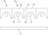
一般にヒータランプを使った光加熱装置では、棒状のヒータランプとリフレクタとを組み合わせたものが使用されており、特開平05−13355号公報(特許文献1)には、このヒータランプとリフレクタとからなる照射ユニットを複数並列配置したものが開示されている。
図3にその概略構造が示されていて、複数の棒状ヒータランプ51と、その背面側に配置されて、凹面反射面53を有するリフレクタ52とからなる照射ユニット50を複数並列配置して、ワークWに対向配置している。このような照射ユニット50を複数配置して構成したものでは、その照射ユニット50の数を増減することで、ワークWの大きさに対応できるというメリットがある。
In general, in a light heating apparatus using a heater lamp, a combination of a rod-shaped heater lamp and a reflector is used, and Japanese Patent Application Laid-Open No. 05-13355 (Patent Document 1) includes a heater lamp and a reflector. A plurality of irradiation units arranged in parallel are disclosed.
The schematic structure is shown in FIG. 3, and a plurality of
ところで、このように配置された照射ユニット50では、ヒータランプ51により加熱されたリフレクタ52を冷却する必要があり、そのためには、リフレクタ52の内部に冷却流路を形成することが必要となる。
しかして、ヒータランプ51とリフレクタ52とからなる照射ユニット50を複数配列した構造においては、隣接するヒータランプ51間にリフレクタ52により区画壁54が形成され、特許文献1のものでは、各照射ユニット50の分割面55はその区画壁54の中央に位置している。
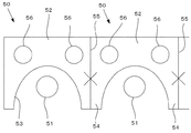
このような構造において、リフレクタ52に冷却媒体流路56を形成しようとすると、図4に示すように、凹面反射面53の後方上方の領域に形成することになる。
By the way, in the
Thus, in the structure in which a plurality of
In such a structure, when the cooling
ところが、リフレクタ52においては、ヒータランプ51の間に位置する区画壁54部分が、両側のヒータランプ51から加熱されることもあり、最も高温になるが、この区画壁54には分割面55が存在するために、この部位(図4で×印で示した部位)には冷却媒体流路56を形成することができず、当該区画壁54の冷却が困難となり、リフレクタ52全体からの効果的な排熱が難しいという問題がある。
However, in the
この発明が解決しようとする課題は、ヒータランプと、凹面反射面を有するリフレクタとからなる照射ユニットを複数並置してなる光加熱装置において、隣接するヒータランプの間に位置するリフレクタの区画壁を冷却してリフレクタ全体からの排熱を効果的に行うことができるようにした構造を提供することである。 A problem to be solved by the present invention is a light heating apparatus in which a plurality of irradiation units each including a heater lamp and a reflector having a concave reflecting surface are juxtaposed, and a partition wall of the reflector located between adjacent heater lamps is provided. It is to provide a structure that can cool and effectively exhaust heat from the entire reflector.
上記課題を解決するために、この発明に係る光加熱装置は、前記リフレクタには、前記ヒータランプの間に位置する区画壁が形成されており、隣接する前記照射ユニット間の分割面が、前記区画壁を避けるように形成されていて、前記区画壁の内部には冷却媒体流路が形成されていることを特徴とする。
また、前記凹面反射面には、前記ヒータランプの直上において、冷却風の噴出口が設けられており、前記分割面は、前記噴出口を避ける位置に形成されることを特徴とする。
また、前記噴出口は、共通のエアチャンバに接続されていることを特徴とする。
In order to solve the above-described problem, in the light heating device according to the present invention, the reflector is formed with a partition wall positioned between the heater lamps, and a dividing surface between the adjacent irradiation units is It is formed so as to avoid the partition wall, and a cooling medium flow path is formed inside the partition wall.
The concave reflecting surface is provided with an outlet for cooling air immediately above the heater lamp, and the dividing surface is formed at a position avoiding the outlet.
Further, the jet outlet is connected to a common air chamber.
この発明の光加熱装置によれば、隣接する前記照射ユニット間の分割面が、隣接するヒータランプの間の区画壁を避けるように形成されているので、当該区画壁に冷却媒体流路を形成することができ、両側のヒータランプから加熱されて最も高温となる区画壁からの排熱が効果的になされるという効果を奏する。
また、前記分割面を、凹面反射面のヒータランプの直上を避けた位置に設けることで、ヒータランプの直上位置に冷却風の噴出口を設けて、ヒータランプの冷却を効果的に行うことができる。
According to the light heating device of the present invention, since the dividing surface between the adjacent irradiation units is formed so as to avoid the partition wall between the adjacent heater lamps, the cooling medium flow path is formed in the partition wall. This is advantageous in that the exhaust heat from the partition wall that is heated by the heater lamps on both sides and becomes the highest temperature is effectively performed.
In addition, by providing the dividing surface at a position that avoids the directly above the heater lamp on the concave reflecting surface, a cooling air jet outlet is provided at a position directly above the heater lamp, so that the heater lamp can be effectively cooled. it can.
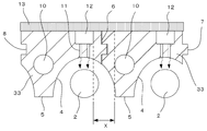
図1は本発明の光加熱装置1の全体断面図で、複数の棒状のヒータランプ2と、リフレクタ3とからなる。
リフレクタ3は、第1端部材31と第2端部材32と複数の中央部材33とからなる。第1端部材31と中央部材33、中央部材33同士、中央部材33と第2端部材32が組み合わされることで、凹面反射面4が形成され、各ヒータランプ2に対応している。
中央部材33には各ヒータランプ2の間に位置して区画壁5が形成されていて、前記第1端部材31と中央部材33、中央部材33同士、中央部材33と第2端部材32が組み合わされる分割面6は、この区画壁5を避けた位置に設けられている。
なお、これらの3部材31、32、33には、それぞれ凸部7と凹部8が形成されていて、これらを嵌合させることで容易に組み立てられる。
こうして組み立てられた各部材31、32、33と凹面反射面4およびヒータランプ2によって複数の照射ユニット9が形成される。
FIG. 1 is an overall sectional view of a
The
A
The three
A plurality of
そして、前記区画壁5には、冷却媒体流路10が形成されている。
図2にも示されるように、前記分割面6は、ヒータランプ2の直上位置も避けられていて、凹面反射面4には、前記ヒータランプ2の直上位置に、ヒータランプ2の管軸方向に沿って冷却風の噴出口11が形成されている。この噴出口11は、ヒータランプ2の管軸方向に沿って延在する共通のエアチャンバ12に接続開口している。
つまり、分割面6は、区画壁5とヒータランプ2の直上位置(より厳密には、噴出口11の端部、より好ましくはエアチャンバ12の端部)との間の範囲Xに設けることが好ましい。
A cooling
As shown in FIG. 2, the dividing
That is, the dividing
また、リフレクタ3には蓋部材13が被せられており、これにより、エアチャンバ12は密閉構造とされている。そして、不図示のエア供給管がこのエアチャンバ12に接続されて冷却風が供給され、冷却風が噴出口11から噴出して、ヒータランプ2を冷却する。
なお、噴出口11は、図2の断面視で、管軸方向に沿って2列形成したものを示したが、1列であってもよく、更には、その形状も断面円形形状でも管軸方向に延びるスリット形状であってもよい。
The
In addition, although the
以上説明したように、リフレクタに、ヒータランプの間に位置する区画壁が形成されており、隣接する照射ユニット間の分割面が、区画壁を避けるように形成されていて、区画壁の内部には冷却媒体流路が形成されている構成としたことにより、隣接するヒータランプにより加熱されて最も高温となる区画壁を直接冷却することができ、リフレクタ全体からの排熱が効果的となるという効果が奏せられる。
また、この分割面は、ヒータランプの直上位置を避けた位置に設けられることにより、当該部位に冷却風の噴出口を支障なく形成することができて、ヒータランプを効率的に冷却することができる。
As described above, a partition wall located between the heater lamps is formed in the reflector, and a dividing surface between adjacent irradiation units is formed so as to avoid the partition wall, and is formed inside the partition wall. Since the cooling medium flow path is formed, the partition wall that is heated to the highest temperature by the adjacent heater lamp can be directly cooled, and the exhaust heat from the entire reflector is effective. An effect is produced.
In addition, by providing this dividing surface at a position that avoids the position directly above the heater lamp, it is possible to form a cooling air jet outlet at that location without hindrance, and to efficiently cool the heater lamp. it can.
1 光加熱装置
2 ヒータランプ
3 リフレクタ
31 第1端部材
32 第2端部材
33 中央部材
4 凹面反射面
5 区画壁
6 分割面
9 照射ユニット
10 冷却媒体流路
11 冷却風噴出口
12 エアチャンバ
13 蓋部材
DESCRIPTION OF
Claims (3)
前記リフレクタには、前記ヒータランプの間に位置する区画壁が形成されており、
隣接する前記照射ユニット間の分割面が、前記区画壁を避けるように形成されていて、
前記区画壁の内部には冷却媒体流路が形成されていることを特徴とする光加熱装置。 In a light heating device in which a plurality of irradiation units each including a heater lamp and a reflector having a concave reflecting surface are juxtaposed,
A partition wall located between the heater lamps is formed in the reflector,
A dividing surface between adjacent irradiation units is formed so as to avoid the partition wall,
A light heating device, wherein a cooling medium flow path is formed inside the partition wall.
前記分割面は、前記噴出口を避ける位置に形成されることを特徴とする請求項1に記載の光加熱装置。 The concave reflecting portion is provided with an outlet for cooling air immediately above the heater lamp,
The light heating device according to claim 1, wherein the dividing surface is formed at a position that avoids the ejection port.
The light heating device according to claim 2, wherein the ejection port is connected to a common air chamber.
Priority Applications (1)
| Application Number | Priority Date | Filing Date | Title |
|---|---|---|---|
| JP2017105473A JP6916988B2 (en) | 2017-05-29 | 2017-05-29 | Light heating device |
Applications Claiming Priority (1)
| Application Number | Priority Date | Filing Date | Title |
|---|---|---|---|
| JP2017105473A JP6916988B2 (en) | 2017-05-29 | 2017-05-29 | Light heating device |
Publications (2)
| Publication Number | Publication Date |
|---|---|
| JP2018200971A true JP2018200971A (en) | 2018-12-20 |
| JP6916988B2 JP6916988B2 (en) | 2021-08-11 |
Family
ID=64667288
Family Applications (1)
| Application Number | Title | Priority Date | Filing Date |
|---|---|---|---|
| JP2017105473A Active JP6916988B2 (en) | 2017-05-29 | 2017-05-29 | Light heating device |
Country Status (1)
| Country | Link |
|---|---|
| JP (1) | JP6916988B2 (en) |
Cited By (1)
| Publication number | Priority date | Publication date | Assignee | Title |
|---|---|---|---|---|
| WO2023146742A1 (en) * | 2022-01-25 | 2023-08-03 | Applied Materials, Inc. | Active cooling of quartz enveloped heaters in vacuum |
Citations (3)
| Publication number | Priority date | Publication date | Assignee | Title |
|---|---|---|---|---|
| JPS56100412A (en) * | 1979-12-17 | 1981-08-12 | Sony Corp | Manufacture of semiconductor device |
| JPH02242086A (en) * | 1989-03-15 | 1990-09-26 | Natl Inst For Res In Inorg Mater | Multi-stage reflection type electric furnace |
| JP2006505123A (en) * | 2002-11-01 | 2006-02-09 | コルニック システムズ コーポレーション | Heating module for rapid thermal processing equipment |
-
2017
- 2017-05-29 JP JP2017105473A patent/JP6916988B2/en active Active
Patent Citations (3)
| Publication number | Priority date | Publication date | Assignee | Title |
|---|---|---|---|---|
| JPS56100412A (en) * | 1979-12-17 | 1981-08-12 | Sony Corp | Manufacture of semiconductor device |
| JPH02242086A (en) * | 1989-03-15 | 1990-09-26 | Natl Inst For Res In Inorg Mater | Multi-stage reflection type electric furnace |
| JP2006505123A (en) * | 2002-11-01 | 2006-02-09 | コルニック システムズ コーポレーション | Heating module for rapid thermal processing equipment |
Cited By (1)
| Publication number | Priority date | Publication date | Assignee | Title |
|---|---|---|---|---|
| WO2023146742A1 (en) * | 2022-01-25 | 2023-08-03 | Applied Materials, Inc. | Active cooling of quartz enveloped heaters in vacuum |
Also Published As
| Publication number | Publication date |
|---|---|
| JP6916988B2 (en) | 2021-08-11 |
Similar Documents
| Publication | Publication Date | Title |
|---|---|---|
| JP6261061B2 (en) | Cooling structure of illumination optical system and projection display device | |
| JP6160373B2 (en) | Light source device and video display device | |
| JP5804112B2 (en) | projector | |
| TWM447998U (en) | Mini optical image device | |
| JP2018200971A (en) | Optical heating device | |
| JP2004198940A5 (en) | ||
| JP4314552B2 (en) | Projector lamp and liquid crystal projector | |
| CN112526806A (en) | Laser projection device | |
| JP2019525244A (en) | Color wheel device and projector | |
| US11156906B2 (en) | Projector with air inlets to cool light emitting module | |
| JP2019063708A (en) | Light irradiation device | |
| JP2009072700A (en) | Ultraviolet irradiation device | |
| JP2008003262A (en) | Projection-type display device, and method for cooling lamp unit in the projection-type display device | |
| ES2776376T3 (en) | Thermal control system of an electronic panel for image reproduction | |
| WO2016042974A1 (en) | Light illumination device | |
| JP6218387B2 (en) | Projection display | |
| JP2023107102A (en) | Cooling device, light source device, image projection device, and wavelength conversion device | |
| WO2013145812A1 (en) | Led lighting device | |
| JP2014002251A (en) | Liquid crystal display device | |
| ES2822212T3 (en) | Cooktop and cooktop cooling system | |
| CN112526810B (en) | Laser projection device | |
| ES2866412T3 (en) | Cooktop and cooktop cooling system | |
| JP2014078413A (en) | Led irradiation device and led irradiation system | |
| JPWO2018042524A1 (en) | Light source device, projection display device, and method of cooling semiconductor light emitting device | |
| JP2007058242A (en) | Optical device |
Legal Events
| Date | Code | Title | Description |
|---|---|---|---|
| A621 | Written request for application examination |
Free format text: JAPANESE INTERMEDIATE CODE: A621 Effective date: 20200317 |
|
| A977 | Report on retrieval |
Free format text: JAPANESE INTERMEDIATE CODE: A971007 Effective date: 20210201 |
|
| A131 | Notification of reasons for refusal |
Free format text: JAPANESE INTERMEDIATE CODE: A131 Effective date: 20210210 |
|
| A521 | Request for written amendment filed |
Free format text: JAPANESE INTERMEDIATE CODE: A523 Effective date: 20210303 |
|
| TRDD | Decision of grant or rejection written | ||
| A01 | Written decision to grant a patent or to grant a registration (utility model) |
Free format text: JAPANESE INTERMEDIATE CODE: A01 Effective date: 20210617 |
|
| A61 | First payment of annual fees (during grant procedure) |
Free format text: JAPANESE INTERMEDIATE CODE: A61 Effective date: 20210630 |
|
| R151 | Written notification of patent or utility model registration |
Ref document number: 6916988 Country of ref document: JP Free format text: JAPANESE INTERMEDIATE CODE: R151 |