JP2018198750A - Medical system, control device for medical support arm, and control method for medical support arm - Google Patents

Medical system, control device for medical support arm, and control method for medical support arm Download PDF

Info

Publication number
JP2018198750A
JP2018198750A JP2017104748A JP2017104748A JP2018198750A JP 2018198750 A JP2018198750 A JP 2018198750A JP 2017104748 A JP2017104748 A JP 2017104748A JP 2017104748 A JP2017104748 A JP 2017104748A JP 2018198750 A JP2018198750 A JP 2018198750A
Authority
JP
Japan
Prior art keywords
support arm
unit
arm
medical
movable range
Prior art date
Legal status (The legal status is an assumption and is not a legal conclusion. Google has not performed a legal analysis and makes no representation as to the accuracy of the status listed.)
Pending
Application number
JP2017104748A
Other languages
Japanese (ja)
Inventor
優 薄井
Masaru Usui
優 薄井
Current Assignee (The listed assignees may be inaccurate. Google has not performed a legal analysis and makes no representation or warranty as to the accuracy of the list.)
Sony Corp
Original Assignee
Sony Corp
Priority date (The priority date is an assumption and is not a legal conclusion. Google has not performed a legal analysis and makes no representation as to the accuracy of the date listed.)
Filing date
Publication date
Application filed by Sony Corp filed Critical Sony Corp
Priority to JP2017104748A priority Critical patent/JP2018198750A/en
Priority to PCT/JP2018/015207 priority patent/WO2018216382A1/en
Priority to DE112018002714.7T priority patent/DE112018002714T5/en
Priority to CN201880033246.5A priority patent/CN110678142B/en
Priority to US16/614,802 priority patent/US11633240B2/en
Publication of JP2018198750A publication Critical patent/JP2018198750A/en
Pending legal-status Critical Current

Links

Images

Classifications

    • AHUMAN NECESSITIES
    • A61MEDICAL OR VETERINARY SCIENCE; HYGIENE
    • A61BDIAGNOSIS; SURGERY; IDENTIFICATION
    • A61B34/00Computer-aided surgery; Manipulators or robots specially adapted for use in surgery
    • A61B34/30Surgical robots
    • AHUMAN NECESSITIES
    • A61MEDICAL OR VETERINARY SCIENCE; HYGIENE
    • A61BDIAGNOSIS; SURGERY; IDENTIFICATION
    • A61B34/00Computer-aided surgery; Manipulators or robots specially adapted for use in surgery
    • A61B34/30Surgical robots
    • A61B34/37Master-slave robots
    • AHUMAN NECESSITIES
    • A61MEDICAL OR VETERINARY SCIENCE; HYGIENE
    • A61BDIAGNOSIS; SURGERY; IDENTIFICATION
    • A61B90/00Instruments, implements or accessories specially adapted for surgery or diagnosis and not covered by any of the groups A61B1/00 - A61B50/00, e.g. for luxation treatment or for protecting wound edges
    • A61B90/36Image-producing devices or illumination devices not otherwise provided for
    • A61B90/37Surgical systems with images on a monitor during operation
    • AHUMAN NECESSITIES
    • A61MEDICAL OR VETERINARY SCIENCE; HYGIENE
    • A61BDIAGNOSIS; SURGERY; IDENTIFICATION
    • A61B90/00Instruments, implements or accessories specially adapted for surgery or diagnosis and not covered by any of the groups A61B1/00 - A61B50/00, e.g. for luxation treatment or for protecting wound edges
    • A61B90/50Supports for surgical instruments, e.g. articulated arms
    • BPERFORMING OPERATIONS; TRANSPORTING
    • B25HAND TOOLS; PORTABLE POWER-DRIVEN TOOLS; MANIPULATORS
    • B25JMANIPULATORS; CHAMBERS PROVIDED WITH MANIPULATION DEVICES
    • B25J19/00Accessories fitted to manipulators, e.g. for monitoring, for viewing; Safety devices combined with or specially adapted for use in connection with manipulators
    • B25J19/06Safety devices
    • AHUMAN NECESSITIES
    • A61MEDICAL OR VETERINARY SCIENCE; HYGIENE
    • A61BDIAGNOSIS; SURGERY; IDENTIFICATION
    • A61B34/00Computer-aided surgery; Manipulators or robots specially adapted for use in surgery
    • A61B34/20Surgical navigation systems; Devices for tracking or guiding surgical instruments, e.g. for frameless stereotaxis
    • A61B2034/2046Tracking techniques
    • A61B2034/2059Mechanical position encoders
    • AHUMAN NECESSITIES
    • A61MEDICAL OR VETERINARY SCIENCE; HYGIENE
    • A61BDIAGNOSIS; SURGERY; IDENTIFICATION
    • A61B90/00Instruments, implements or accessories specially adapted for surgery or diagnosis and not covered by any of the groups A61B1/00 - A61B50/00, e.g. for luxation treatment or for protecting wound edges
    • A61B90/06Measuring instruments not otherwise provided for
    • A61B2090/064Measuring instruments not otherwise provided for for measuring force, pressure or mechanical tension
    • A61B2090/066Measuring instruments not otherwise provided for for measuring force, pressure or mechanical tension for measuring torque

Abstract

To more accurately control a cooperative operation related to plural medical support arms.SOLUTION: There is provided a medical system comprising an operation control part for controlling an operation of an action point on the basis of information of a movable area related to a first medical support arm which is a control object, information of a movable area related to a second medical support arm used together with the first medical support arm, and a spatial position of the action point in the first medical support arm. There is also provided a control method of a medical support arm, in which a processor controls an operation of the action point on the basis of information of the movable area related to the first medical support arm being the control object, information of the movable area related to the second medical support arm used together with the first medical support arm, and the spatial position of the action point in the first medical support arm.SELECTED DRAWING: Figure 12

Description

本開示は、医療用システム、医療用支持アームの制御装置、および医療用支持アームの制御方法に関する。   The present disclosure relates to a medical system, a medical support arm control device, and a medical support arm control method.

従来より、例えば下記の特許文献に記載されているように、医療分野においては、各種の施術(手術,検査など)を行う際に、アーム部先端に医療用ユニット(カメラ、鉗子など)が設けられた医療機器を使用する場合がある。   Conventionally, as described in the following patent document, for example, in the medical field, a medical unit (camera, forceps, etc.) has been provided at the end of the arm when performing various procedures (surgery, inspection, etc.). Medical equipment may be used.

国際公開第2015/046081号International Publication No. 2015/046081

しかしながら、手動操作可能な医療用支持アームは、操作者が直観的に操作可能である一方、操作を誤った際にはアーム部先端が患者や施術者に接触するといった想定外の事態が生じる可能性がある。医療用支持アーム使用時の安全確保においては、操作者の視覚や触覚による判断のみに頼るのでなく、機器側での操作性及び操作制限による安全担保が要求される。さらには、施術において、複数の医療用支持アームが用いられる場合においては、当該複数の医療用支持アーム間における協調動作が求められる。   However, the manually operable medical support arm can be operated intuitively by the operator, but if the operation is mistaken, an unexpected situation may occur in which the tip of the arm portion contacts the patient or the operator. There is sex. In order to ensure safety when using the medical support arm, not only the judgment based on the operator's visual sense and tactile sense but also the operability on the device side and the safety guarantee by the operation restriction are required. Further, in the case where a plurality of medical support arms are used in the treatment, a cooperative operation between the plurality of medical support arms is required.

そこで、本開示では、複数の医療用支持アームに係る協調動作をより精度高く制御することが可能な、新規かつ改良された医療用システム、医療用支持アームの制御装置、および医療用支持アームの制御方法を提案する。   Therefore, in the present disclosure, a new and improved medical system, a medical support arm control device, and a medical support arm that are capable of controlling cooperative operations related to a plurality of medical support arms with higher accuracy. A control method is proposed.

本開示によれば、制御対象である第一の医療用支持アームに係る可動域の情報と、前記第一の医療用支持アームと共に用いられる第二の医療用支持アームに係る前記可動域の情報と、前記第一の医療用支持アームにおける作用点の空間位置と、に基づいて、当該作用点の動作を制御する動作制御部、を備える、医療用システムが提供される。   According to the present disclosure, information on the movable range related to the first medical support arm to be controlled and information on the movable range related to the second medical support arm used together with the first medical support arm. And a motion control unit that controls the operation of the action point based on the spatial position of the action point in the first medical support arm.

また、本開示によれば、制御対象である第一の医療用支持アームに係る可動域の情報と、前記第一の医療用支持アームと共に用いられる第二の医療用支持アームに係る前記可動域の情報と、前記第一の医療用支持アームにおける作用点の空間位置と、に基づいて、当該作用点の動作を制御する動作制御部、を備える、医療用支持アームの制御装置が提供される。   Further, according to the present disclosure, information on a movable range related to the first medical support arm to be controlled, and the movable range related to the second medical support arm used together with the first medical support arm. And a motion control unit for controlling the operation of the action point based on the information on the first position and the spatial position of the action point in the first medical support arm. .

また、本開示によれば、プロセッサが、制御対象である第一の医療用支持アームに係る可動域の情報と、前記第一の医療用支持アームと共に用いられる第二の医療用支持アームに係る前記可動域の情報と、前記第一の医療用支持アームにおける作用点の空間位置と、に基づいて、当該作用点の動作を制御すること、を含む、医療用支持アームの制御方法が提供される。   Further, according to the present disclosure, the processor relates to information on a movable range related to the first medical support arm to be controlled and a second medical support arm used together with the first medical support arm. A method for controlling a medical support arm is provided, which includes controlling the operation of the action point based on the information on the range of motion and the spatial position of the action point in the first medical support arm. The

以上説明したように本開示によれば、複数の医療用支持アームに係る協調動作をより精度高く制御することが可能となる。   As described above, according to the present disclosure, it is possible to control the cooperative operation related to a plurality of medical support arms with higher accuracy.

なお、上記の効果は必ずしも限定的なものではなく、上記の効果とともに、または上記の効果に代えて、本明細書に示されたいずれかの効果、または本明細書から把握され得る他の効果が奏されてもよい。   Note that the above effects are not necessarily limited, and any of the effects shown in the present specification, or other effects that can be grasped from the present specification, together with or in place of the above effects. May be played.

本開示に係る医療用支持アーム装置を適用可能な内視鏡手術システムの概略的な構成の一例を示す図である。It is a figure which shows an example of schematic structure of the endoscopic surgery system which can apply the medical support arm apparatus which concerns on this indication. 図1に示すカメラヘッド及びCCUの機能構成の一例を示すブロック図である。It is a block diagram which shows an example of a function structure of the camera head and CCU shown in FIG. 本開示の実施の形態に係る医療用支持アーム装置の構成例を示す斜視図である。It is a perspective view showing an example of composition of a medical support arm device concerning an embodiment of this indication. 同実施形態に係る医療用支持アーム装置を模式的に示す説明図である。It is explanatory drawing which shows typically the medical support arm apparatus which concerns on the embodiment. 本開示の一実施形態に係る関節部のアクチュエータを、回転軸を通る断面で切断した様子を模式的に示す断面図である。It is sectional drawing which shows typically a mode that the actuator of the joint part which concerns on one Embodiment of this indication was cut | disconnected in the cross section which passes along a rotating shaft. 図3に示すトルクセンサを、駆動軸の軸方向から見た様子を模式的に示す概略図である。It is the schematic which shows typically a mode that the torque sensor shown in FIG. 3 was seen from the axial direction of the drive shaft. 図3に示すアクチュエータに適用されるトルクセンサの他の構成例を示す概略図である。It is the schematic which shows the other structural example of the torque sensor applied to the actuator shown in FIG. 本開示の一実施形態に係る理想関節制御について説明するための説明図である。It is explanatory drawing for demonstrating the ideal joint control which concerns on one Embodiment of this indication. 本開示の一実施形態に係る支持アーム制御システムの一構成例を示す機能ブロック図である。It is a functional block diagram showing an example of 1 composition of a support arm control system concerning one embodiment of this indication. 本実施形態におけるアームの可動域制限の例を示す図であって、手動誘導動作モードを示す模式図である。It is a figure which shows the example of the movable range limitation of the arm in this embodiment, Comprising: It is a schematic diagram which shows a manual guidance operation mode. 本実施形態におけるアームの可動域制限の例を示す図であって、手動誘導動作モードを示す模式図である。It is a figure which shows the example of the movable range limitation of the arm in this embodiment, Comprising: It is a schematic diagram which shows a manual guidance operation mode. 本実施形態におけるアームの可動域制限の例を示す図であって、手動誘導動作モードを示す模式図である。It is a figure which shows the example of the movable range limitation of the arm in this embodiment, Comprising: It is a schematic diagram which shows a manual guidance operation mode. 本実施形態におけるアームの可動域制限の例を示す図であって、自動誘導動作モードを示す模式図である。It is a figure which shows the example of the movable range limitation of the arm in this embodiment, Comprising: It is a schematic diagram which shows automatic guidance operation mode. 本実施形態におけるアームの可動域制限の例を示す図であって、自動誘導動作モードを示す模式図である。It is a figure which shows the example of the movable range limitation of the arm in this embodiment, Comprising: It is a schematic diagram which shows automatic guidance operation mode. 本実施形態におけるアームの可動域制限の例を示す図であって、自動誘導動作モードを示す模式図である。It is a figure which shows the example of the movable range limitation of the arm in this embodiment, Comprising: It is a schematic diagram which shows automatic guidance operation mode. 同実施形態に係る複数の支持アームの安全可動域について説明するための図である。It is a figure for demonstrating the safe movable range of the some support arm which concerns on the embodiment. 同実施形態に係る可動域共有モードの概要について説明するための図である。It is a figure for demonstrating the outline | summary of the movable range sharing mode which concerns on the embodiment. 同実施形態に係る衝突回避モードの概要について説明するための図である。It is a figure for demonstrating the outline | summary of the collision avoidance mode which concerns on the same embodiment. 同実施形態に係る衝突抑制モードの概要について説明するための図である。It is a figure for demonstrating the outline | summary of the collision suppression mode which concerns on the same embodiment. 同実施形態に係る複数の支持アームに係る協調制御を実現するための構成例を示す模式図である。It is a schematic diagram which shows the structural example for implement | achieving the cooperative control which concerns on the several support arm which concerns on the embodiment. 同実施形態に係る制御装置20による制御の基本的な流れを示すフローチャートである。It is a flowchart which shows the basic flow of control by the control apparatus 20 which concerns on the embodiment. 同実施形態に係る動域共有モードにおける制御パラメータの設定および可動域の更新の流れを示すフローチャートである。It is a flowchart which shows the flow of the setting of the control parameter in the movement area sharing mode which concerns on the same embodiment, and the update of a movable area. 同実施形態に係る衝突回避モードにおいて、自アームの優先度が高い場合における制御パラメータの設定および可動域の更新の流れを示すフローチャートである。7 is a flowchart showing a flow of control parameter setting and range of motion update when the priority of the own arm is high in the collision avoidance mode according to the embodiment. 同実施形態に係る衝突回避モードにおいて、自アームの優先度が低い場合における制御パラメータの設定および可動域の更新の流れを示すフローチャートである。6 is a flowchart showing a flow of setting control parameters and updating a movable range when the priority of the own arm is low in the collision avoidance mode according to the embodiment. 同実施形態に係る衝突抑制モードにおける制御パラメータの設定および可動域の更新の流れを示すフローチャートである。It is a flowchart which shows the flow of the setting of the control parameter in the collision suppression mode which concerns on the same embodiment, and the update of a movable range. 患部からの距離に応じて段階的に安全可動域と非安全領域を設定した例を示す模式図である。It is a schematic diagram which shows the example which set the safe movable range and the non-safe area | region in steps according to the distance from an affected part. 起動時のアーム先端位置からの距離に応じて、段階的に安全可動域を設定する例を示す模式図である。It is a schematic diagram which shows the example which sets a safe movable range in steps according to the distance from the arm tip position at the time of starting. アーム先端に3Dカメラを搭載し、3Dカメラで撮影した画像を用いた画像認識により患部の立体形状を計測してデプスマップを作成し、デプスマップより得られる患部の形状に基づいて非安全領域を設定する例を示す模式図である。A 3D camera is mounted at the tip of the arm, and a depth map is created by measuring the three-dimensional shape of the affected area through image recognition using an image taken by the 3D camera, and the non-safe area is determined based on the shape of the affected area obtained from the depth map. It is a schematic diagram which shows the example set. 図18に示す例において、アーム先端の移動を制限するパラメータとして粘性抵抗値を用い、非安全レベルが高い領域ほど粘性抵抗(粘性負荷量)を大きくした例を示す模式図である。FIG. 19 is a schematic diagram illustrating an example in which, in the example illustrated in FIG. 18, a viscous resistance value is used as a parameter for restricting movement of the arm tip, and the viscous resistance (viscous load amount) is increased in a region where the unsafe level is higher. 図18に示す例において、アーム先端の移動を制限するパラメータとして速度を用い、非安全レベルが高い領域ほど速度を低くした例を示す模式図である。FIG. 19 is a schematic diagram illustrating an example in which speed is used as a parameter for restricting movement of the arm tip in the example illustrated in FIG. 18 and the speed is decreased in a region where the unsafe level is higher. 本開示の一実施形態に係る支持アーム装置10及び制御装置20のハードウェア構成の一構成例を示す機能ブロック図である。It is a functional block diagram showing an example of 1 hardware constitutions of support arm device 10 and control device 20 concerning one embodiment of this indication.

以下に添付図面を参照しながら、本開示の好適な実施の形態について詳細に説明する。なお、本明細書及び図面において、実質的に同一の機能構成を有する構成要素については、同一の符号を付することにより重複説明を省略する。   Hereinafter, preferred embodiments of the present disclosure will be described in detail with reference to the accompanying drawings. In addition, in this specification and drawing, about the component which has the substantially same function structure, duplication description is abbreviate | omitted by attaching | subjecting the same code | symbol.

なお、説明は以下の順序で行うものとする。
1.医療用支持アーム装置についての検討
1−1.内視鏡
1−2.カートに搭載される各種の装置
1−3.医療用支持アーム装置の概略構成
1−4.光源装置
1−5.カメラヘッド及びCCU
2.本開示の一実施形態
2−1.支持アーム装置の外観
2−2.一般化逆動力学について
2−3.理想関節制御について
2−4.支持アーム制御システムの構成
2−5.アームの可動域制限と可動域拡張の概要
2−6.複数の支持アーム係る協調制御の概要
2−7.複数の支持アームに係る協調制御を実現するための構成例
2−8.制御の流れ
2−9.安全可動域と非安全領域のバリエーション
3.ハードウェア構成
4.まとめ
The description will be made in the following order.
1. 1. Examination of medical support arm device 1-1. Endoscope 1-2. Various devices mounted on cart 1-3. Schematic configuration of medical support arm device 1-4. Light source device 1-5. Camera head and CCU
2. 2. Embodiment of the present disclosure 2-1. Appearance of support arm device 2-2. Generalized inverse dynamics 2-3. Ideal joint control 2-4. Configuration of support arm control system 2-5. Overview of arm range of motion limitation and range of motion expansion 2-6. Overview of coordinated control related to multiple support arms 2-7. Configuration example for realizing cooperative control related to a plurality of support arms 2-8. Flow of control 2-9. 2. Variations in safe range of motion and non-safe range Hardware configuration Summary

<1.医療用支持アーム装置についての検討>
まず、本開示をより明確なものとするために、本発明者らが本開示に想到するに至った背景について説明する。
<1. Study on medical support arm device>
First, in order to make the present disclosure clearer, the background that the inventors have conceived of the present disclosure will be described.

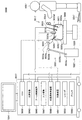
図1を参照して、本開示の一実施形態に係る支持アーム装置が医療用に用いられる場合の一適用例について説明する。図1は、本開示に係る支持アーム装置が適用され得る内視鏡手術システム5000の概略的な構成の一例を示す図である。図1では、術者(医師)5067が、内視鏡手術システム5000を用いて、患者ベッド5069上の患者5071に手術を行っている様子が図示されている。図示するように、内視鏡手術システム5000は、内視鏡5001と、その他の術具5017と、内視鏡5001を支持する支持アーム装置5027と、内視鏡下手術のための各種の装置が搭載されたカート5037とから構成される。   With reference to FIG. 1, an application example when the support arm device according to the embodiment of the present disclosure is used for medical purposes will be described. FIG. 1 is a diagram illustrating an example of a schematic configuration of an endoscopic surgery system 5000 to which the support arm device according to the present disclosure can be applied. In FIG. 1, an operator (doctor) 5067 is performing an operation on a patient 5071 on a patient bed 5069 using an endoscopic operation system 5000. As shown in the figure, an endoscopic surgery system 5000 includes an endoscope 5001, other surgical tools 5017, a support arm device 5027 that supports the endoscope 5001, and various devices for endoscopic surgery. And a cart 5037 on which is mounted.

内視鏡手術では、腹壁を切って開腹する代わりに、トロッカ5025a〜5025dと呼ばれる筒状の開孔器具が腹壁に複数穿刺される。そして、トロッカ5025a〜5025dから、内視鏡5001の鏡筒5003や、その他の術具5017が患者5071の体腔内に挿入される。図示する例では、その他の術具5017として、気腹チューブ5019、エネルギー処置具5021及び鉗子5023が、患者5071の体腔内に挿入されている。エネルギー処置具5021は、高周波電流や超音波振動により、組織の切開及び剥離、又は血管の封止等を行う処置具である。ただし、図示する術具5017はあくまで一例であり、術具5017としては、例えば攝子、レトラクタ等、一般的に内視鏡下手術において用いられる各種の術具が用いられてよい。   In endoscopic surgery, a plurality of cylindrical opening devices called trocars 5025a to 5025d are punctured into the abdominal wall instead of cutting and opening the abdominal wall. Then, the lens barrel 5003 of the endoscope 5001 and other surgical tools 5017 are inserted into the body cavity of the patient 5071 from the trocars 5025a to 5025d. In the illustrated example, as other surgical tools 5017, an insufflation tube 5019, an energy treatment tool 5021, and forceps 5023 are inserted into the body cavity of the patient 5071. The energy treatment device 5021 is a treatment device that performs incision and peeling of a tissue, sealing of a blood vessel, or the like by a high-frequency current or ultrasonic vibration. However, the illustrated surgical tool 5017 is merely an example, and as the surgical tool 5017, for example, various surgical tools generally used in endoscopic surgery such as a lever and a retractor may be used.

内視鏡5001によって撮影された患者5071の体腔内の術部の画像が、表示装置5041に表示される。術者5067は、表示装置5041に表示された術部の画像をリアルタイムで見ながら、エネルギー処置具5021や鉗子5023を用いて、例えば患部を切除する等の処置を行う。なお、図示は省略しているが、気腹チューブ5019、エネルギー処置具5021及び鉗子5023は、手術中に、術者5067又は助手等によって支持される。   An image of the surgical site in the body cavity of the patient 5071 captured by the endoscope 5001 is displayed on the display device 5041. The surgeon 5067 performs a treatment such as excision of the affected part, for example, using the energy treatment tool 5021 and the forceps 5023 while viewing the image of the surgical part displayed on the display device 5041 in real time. Although not shown, the pneumoperitoneum tube 5019, the energy treatment tool 5021, and the forceps 5023 are supported by an operator 5067 or an assistant during surgery.

<<1−1.内視鏡>>
内視鏡5001は、先端から所定の長さの領域が患者5071の体腔内に挿入される鏡筒5003と、鏡筒5003の基端に接続されるカメラヘッド5005と、から構成される。図示する例では、硬性の鏡筒5003を有するいわゆる硬性鏡として構成される内視鏡5001を図示しているが、内視鏡5001は、軟性の鏡筒5003を有するいわゆる軟性鏡として構成されてもよい。
<< 1-1. Endoscope >>
The endoscope 5001 includes a lens barrel 5003 in which a region having a predetermined length from the distal end is inserted into the body cavity of the patient 5071, and a camera head 5005 connected to the proximal end of the lens barrel 5003. In the illustrated example, an endoscope 5001 configured as a so-called rigid mirror having a rigid lens barrel 5003 is illustrated, but the endoscope 5001 is configured as a so-called flexible mirror having a flexible lens barrel 5003. Also good.

鏡筒5003の先端には、対物レンズが嵌め込まれた開口部が設けられている。内視鏡5001には光源装置5043が接続されており、当該光源装置5043によって生成された光が、鏡筒5003の内部に延設されるライトガイドによって当該鏡筒5003の先端まで導光され、対物レンズを介して患者5071の体腔内の観察対象に向かって照射される。なお、内視鏡5001は、直視鏡であってもよいし、斜視鏡又は側視鏡であってもよい。   An opening into which the objective lens is fitted is provided at the tip of the lens barrel 5003. A light source device 5043 is connected to the endoscope 5001, and light generated by the light source device 5043 is guided to the tip of the lens barrel 5003 by a light guide extending inside the lens barrel 5003. Irradiation is performed toward the observation target in the body cavity of the patient 5071 through the objective lens. Note that the endoscope 5001 may be a direct endoscope, a perspective mirror, or a side endoscope.

カメラヘッド5005の内部には光学系及び撮像素子が設けられており、観察対象からの反射光(観察光)は当該光学系によって当該撮像素子に集光される。当該撮像素子によって観察光が光電変換され、観察光に対応する電気信号、すなわち観察像に対応する画像信号が生成される。当該画像信号は、RAWデータとしてカメラコントロールユニット(CCU:Camera Control Unit)5039に送信される。なお、カメラヘッド5005には、その光学系を適宜駆動させることにより、倍率及び焦点距離を調整する機能が搭載される。   An optical system and an imaging device are provided inside the camera head 5005, and reflected light (observation light) from the observation target is condensed on the imaging device by the optical system. Observation light is photoelectrically converted by the imaging element, and an electrical signal corresponding to the observation light, that is, an image signal corresponding to the observation image is generated. The image signal is transmitted to a camera control unit (CCU) 5039 as RAW data. Note that the camera head 5005 is equipped with a function of adjusting the magnification and the focal length by appropriately driving the optical system.

なお、例えば立体視(3D表示)等に対応するために、カメラヘッド5005には撮像素子が複数設けられてもよい。この場合、鏡筒5003の内部には、当該複数の撮像素子のそれぞれに観察光を導光するために、リレー光学系が複数系統設けられる。   Note that a plurality of imaging elements may be provided in the camera head 5005 in order to cope with, for example, stereoscopic viewing (3D display). In this case, a plurality of relay optical systems are provided inside the lens barrel 5003 in order to guide observation light to each of the plurality of imaging elements.

<<1−2.カートに搭載される各種の装置>>
CCU5039は、CPU(Central Processing Unit)やGPU(Graphics Processing Unit)等によって構成され、内視鏡5001及び表示装置5041の動作を統括的に制御する。具体的には、CCU5039は、カメラヘッド5005から受け取った画像信号に対して、例えば現像処理(デモザイク処理)等の、当該画像信号に基づく画像を表示するための各種の画像処理を施す。CCU5039は、当該画像処理を施した画像信号を表示装置5041に提供する。また、CCU5039は、カメラヘッド5005に対して制御信号を送信し、その駆動を制御する。当該制御信号には、倍率や焦点距離等、撮像条件に関する情報が含まれ得る。
<< 1-2. Various devices mounted on cart >>
The CCU 5039 is configured by a CPU (Central Processing Unit), a GPU (Graphics Processing Unit), and the like, and comprehensively controls operations of the endoscope 5001 and the display device 5041. Specifically, the CCU 5039 performs various types of image processing for displaying an image based on the image signal, such as development processing (demosaic processing), for example, on the image signal received from the camera head 5005. The CCU 5039 provides the display device 5041 with the image signal subjected to the image processing. Further, the CCU 5039 transmits a control signal to the camera head 5005 to control the driving thereof. The control signal can include information regarding imaging conditions such as magnification and focal length.

表示装置5041は、CCU5039からの制御により、当該CCU5039によって画像処理が施された画像信号に基づく画像を表示する。内視鏡5001が例えば4K(水平画素数3840×垂直画素数2160)又は8K(水平画素数7680×垂直画素数4320)等の高解像度の撮影に対応したものである場合、及び/又は3D表示に対応したものである場合には、表示装置5041としては、それぞれに対応して、高解像度の表示が可能なもの、及び/又は3D表示可能なものが用いられ得る。4K又は8K等の高解像度の撮影に対応したものである場合、表示装置5041として55インチ以上のサイズのものを用いることで一層の没入感が得られる。また、用途に応じて、解像度、サイズが異なる複数の表示装置5041が設けられてもよい。   The display device 5041 displays an image based on an image signal subjected to image processing by the CCU 5039 under the control of the CCU 5039. When the endoscope 5001 is compatible with high-resolution imaging such as 4K (horizontal pixel number 3840 × vertical pixel number 2160) or 8K (horizontal pixel number 7680 × vertical pixel number 4320), and / or 3D display In the case of the display device 5041, the display device 5041 may be a display device capable of high-resolution display and / or 3D display. In the case of 4K or 8K high-resolution imaging, a more immersive feeling can be obtained by using a display device 5041 having a size of 55 inches or more. Further, a plurality of display devices 5041 having different resolutions and sizes may be provided depending on applications.

光源装置5043は、例えばLED(light emitting diode)等の光源から構成され、術部を撮影する際の照射光を内視鏡5001に供給する。   The light source device 5043 is composed of a light source such as an LED (light emitting diode), for example, and supplies irradiation light to the endoscope 5001 when photographing a surgical site.

アーム制御装置5045は、例えばCPU等のプロセッサによって構成され、所定のプログラムに従って動作することにより、所定の制御方式に従って支持アーム装置5027のアーム部5031の駆動を制御する。   The arm control device 5045 is configured by a processor such as a CPU, for example, and operates according to a predetermined program, thereby controlling driving of the arm portion 5031 of the support arm device 5027 according to a predetermined control method.

入力装置5047は、内視鏡手術システム5000に対する入力インタフェースである。ユーザは、入力装置5047を介して、内視鏡手術システム5000に対して各種の情報の入力や指示入力を行うことができる。例えば、ユーザは、入力装置5047を介して、患者の身体情報や、手術の術式についての情報等、手術に関する各種の情報を入力する。また、例えば、ユーザは、入力装置5047を介して、アーム部5031を駆動させる旨の指示や、内視鏡5001による撮像条件(照射光の種類、倍率及び焦点距離等)を変更する旨の指示、エネルギー処置具5021を駆動させる旨の指示等を入力する。   The input device 5047 is an input interface for the endoscopic surgery system 5000. The user can input various information and instructions to the endoscopic surgery system 5000 via the input device 5047. For example, the user inputs various types of information related to the operation, such as the patient's physical information and information about the surgical technique, via the input device 5047. Further, for example, the user instructs the arm unit 5031 to be driven via the input device 5047 or the instruction to change the imaging conditions (type of irradiation light, magnification, focal length, etc.) by the endoscope 5001. Then, an instruction to drive the energy treatment instrument 5021 is input.

入力装置5047の種類は限定されず、入力装置5047は各種の公知の入力装置であってよい。入力装置5047としては、例えば、マウス、キーボード、タッチパネル、スイッチ、フットスイッチ5057及び/又はレバー等が適用され得る。入力装置5047としてタッチパネルが用いられる場合には、当該タッチパネルは表示装置5041の表示面上に設けられてもよい。   The type of the input device 5047 is not limited, and the input device 5047 may be various known input devices. As the input device 5047, for example, a mouse, a keyboard, a touch panel, a switch, a foot switch 5057, and / or a lever can be applied. In the case where a touch panel is used as the input device 5047, the touch panel may be provided on the display surface of the display device 5041.

あるいは、入力装置5047は、例えばメガネ型のウェアラブルデバイスやHMD(Head Mounted Display)等の、ユーザによって装着されるデバイスであり、これらのデバイスによって検出されるユーザのジェスチャや視線に応じて各種の入力が行われる。また、入力装置5047は、ユーザの動きを検出可能なカメラを含み、当該カメラによって撮像された映像から検出されるユーザのジェスチャや視線に応じて各種の入力が行われる。さらに、入力装置5047は、ユーザの声を収音可能なマイクロフォンを含み、当該マイクロフォンを介して音声によって各種の入力が行われる。このように、入力装置5047が非接触で各種の情報を入力可能に構成されることにより、特に清潔域に属するユーザ(例えば術者5067)が、不潔域に属する機器を非接触で操作することが可能となる。また、ユーザは、所持している術具から手を離すことなく機器を操作することが可能となるため、ユーザの利便性が向上する。   Alternatively, the input device 5047 is a device worn by a user, such as a glasses-type wearable device or an HMD (Head Mounted Display), for example, and various inputs according to the user's gesture and line of sight detected by these devices. Is done. The input device 5047 includes a camera capable of detecting the user's movement, and various inputs are performed according to the user's gesture and line of sight detected from the video captured by the camera. Furthermore, the input device 5047 includes a microphone capable of collecting the user's voice, and various inputs are performed by voice through the microphone. As described above, the input device 5047 is configured to be able to input various information without contact, so that a user belonging to a clean area (for example, an operator 5067) can operate a device belonging to an unclean area without contact. Is possible. In addition, since the user can operate the device without releasing his / her hand from the surgical tool he / she has, the convenience for the user is improved.

処置具制御装置5049は、組織の焼灼、切開又は血管の封止等のためのエネルギー処置具5021の駆動を制御する。気腹装置5051は、内視鏡5001による視野の確保及び術者の作業空間の確保の目的で、患者5071の体腔を膨らめるために、気腹チューブ5019を介して当該体腔内にガスを送り込む。レコーダ5053は、手術に関する各種の情報を記録可能な装置である。プリンタ5055は、手術に関する各種の情報を、テキスト、画像又はグラフ等各種の形式で印刷可能な装置である。   The treatment instrument control device 5049 controls the drive of the energy treatment instrument 5021 for tissue ablation, incision, or blood vessel sealing. In order to inflate the body cavity of the patient 5071 for the purpose of securing the field of view by the endoscope 5001 and securing the operator's work space, the pneumoperitoneum device 5051 gas is introduced into the body cavity via the pneumoperitoneum tube 5019. Send in. The recorder 5053 is an apparatus capable of recording various types of information related to surgery. The printer 5055 is a device that can print various types of information related to surgery in various formats such as text, images, or graphs.

<<1−3.医療用支持アーム装置の概略構成>>
支持アーム装置5027は、ベース部5029から延伸するアーム部5031を備える。図示する例では、アーム部5031は、関節部5033a,5033b,5033c,及びリンク5035a,5035bから構成されており、アーム制御装置5045からの制御指令により駆動される。アーム部5031によって内視鏡5001が支持され、その位置及び姿勢が制御される。これにより、内視鏡5001の安定的な位置の固定が実現され得る。
<< 1-3. Schematic configuration of medical support arm device >>
The support arm device 5027 includes an arm portion 5031 extending from the base portion 5029. In the illustrated example, the arm portion 5031 includes joint portions 5033a, 5033b, and 5033c and links 5035a and 5035b, and is driven by a control command from the arm control device 5045. The endoscope 5001 is supported by the arm unit 5031, and the position and posture thereof are controlled. Thereby, the stable position fixing of the endoscope 5001 can be realized.

支持アーム装置5027は、基台であるベース部5029と、ベース部5029から延伸するアーム部5031と、を備える。図示する例では、アーム部5031は、複数の関節部5033a,5033b,5033cと、関節部5033bによって連結される複数のリンク5035a,5035bと、から構成されているが、図1では、簡単のため、アーム部5031の構成を簡略化して図示している。実際には、アーム部5031が所望の自由度を有するように、関節部5033a〜5033c及びリンク5035a,5035bの形状、数及び配置、並びに関節部5033a〜5033cの回転軸の方向等が適宜設定され得る。例えば、アーム部5031は、好適に、6自由度以上の自由度を有するように構成され得る。これにより、アーム部5031の可動範囲内において内視鏡5001を自由に移動させることが可能になるため、所望の方向から内視鏡5001の鏡筒5003を患者5071の体腔内に挿入することが可能になる。   The support arm device 5027 includes a base portion 5029 as a base and an arm portion 5031 extending from the base portion 5029. In the illustrated example, the arm portion 5031 includes a plurality of joint portions 5033a, 5033b, and 5033c and a plurality of links 5035a and 5035b connected by the joint portion 5033b. However, in FIG. The configuration of the arm portion 5031 is shown in a simplified manner. Actually, the shape, number and arrangement of the joint portions 5033a to 5033c and the links 5035a and 5035b, the direction of the rotation axis of the joint portions 5033a to 5033c, and the like are appropriately set so that the arm portion 5031 has a desired degree of freedom. obtain. For example, the arm portion 5031 can be preferably configured to have 6 degrees of freedom or more. Accordingly, the endoscope 5001 can be freely moved within the movable range of the arm portion 5031. Therefore, the barrel 5003 of the endoscope 5001 can be inserted into the body cavity of the patient 5071 from a desired direction. It becomes possible.

関節部5033a〜5033cにはアクチュエータが設けられており、関節部5033a〜5033cは当該アクチュエータの駆動により所定の回転軸まわりに回転可能に構成されている。当該アクチュエータの駆動がアーム制御装置5045によって制御されることにより、各関節部5033a〜5033cの回転角度が制御され、アーム部5031の駆動が制御される。これにより、内視鏡5001の位置及び姿勢の制御が実現され得る。この際、アーム制御装置5045は、力制御又は位置制御等、各種の公知の制御方式によってアーム部5031の駆動を制御することができる。   The joint portions 5033a to 5033c are provided with actuators, and the joint portions 5033a to 5033c are configured to be rotatable around a predetermined rotation axis by driving the actuators. By controlling the drive of the actuator by the arm control device 5045, the rotation angles of the joint portions 5033a to 5033c are controlled, and the drive of the arm portion 5031 is controlled. Thereby, control of the position and orientation of the endoscope 5001 can be realized. At this time, the arm control device 5045 can control the driving of the arm unit 5031 by various known control methods such as force control or position control.

例えば、術者5067が、入力装置5047(フットスイッチ5057を含む)を介して適宜操作入力を行うことにより、当該操作入力に応じてアーム制御装置5045によってアーム部5031の駆動が適宜制御され、内視鏡5001の位置及び姿勢が制御されてよい。当該制御により、アーム部5031の先端の内視鏡5001を任意の位置から任意の位置まで移動させた後、その移動後の位置で固定的に支持することができる。なお、アーム部5031は、いわゆるマスタースレイブ方式で操作されてもよい。この場合、アーム部5031は、手術室から離れた場所に設置される入力装置5047を介してユーザによって遠隔操作され得る。   For example, when the operator 5067 performs an appropriate operation input via the input device 5047 (including the foot switch 5057), the arm control device 5045 appropriately controls the driving of the arm unit 5031 according to the operation input. The position and posture of the endoscope 5001 may be controlled. By this control, the endoscope 5001 at the tip of the arm portion 5031 can be moved from an arbitrary position to an arbitrary position, and then fixedly supported at the position after the movement. Note that the arm portion 5031 may be operated by a so-called master slave method. In this case, the arm unit 5031 can be remotely operated by the user via the input device 5047 installed at a location away from the operating room.

また、力制御が適用される場合には、アーム制御装置5045は、ユーザからの外力を受け、その外力にならってスムーズにアーム部5031が移動するように、各関節部5033a〜5033cのアクチュエータを駆動させる、いわゆるパワーアシスト制御を行ってもよい。これにより、ユーザが直接アーム部5031に触れながらアーム部5031を移動させる際に、比較的軽い力で当該アーム部5031を移動させることができる。従って、より直感的に、より簡易な操作で内視鏡5001を移動させることが可能となり、ユーザの利便性を向上させることができる。   Further, when force control is applied, the arm control device 5045 receives the external force from the user and moves the actuators of the joint portions 5033a to 5033c so that the arm portion 5031 moves smoothly according to the external force. You may perform what is called power assist control to drive. Accordingly, when the user moves the arm unit 5031 while directly touching the arm unit 5031, the arm unit 5031 can be moved with a relatively light force. Therefore, the endoscope 5001 can be moved more intuitively and with a simpler operation, and user convenience can be improved.

ここで、一般的に、内視鏡下手術では、スコピストと呼ばれる医師によって内視鏡5001が支持されていた。これに対して、支持アーム装置5027を用いることにより、人手によらずに内視鏡5001の位置をより確実に固定することが可能になるため、術部の画像を安定的に得ることができ、手術を円滑に行うことが可能になる。   Here, in general, in an endoscopic operation, an endoscope 5001 is supported by a doctor called a scopist. In contrast, by using the support arm device 5027, the position of the endoscope 5001 can be more reliably fixed without relying on human hands, so that an image of the surgical site can be stably obtained. It becomes possible to perform the operation smoothly.

なお、アーム制御装置5045は必ずしもカート5037に設けられなくてもよい。また、アーム制御装置5045は必ずしも1つの装置でなくてもよい。例えば、アーム制御装置5045は、支持アーム装置5027のアーム部5031の各関節部5033a〜5033cにそれぞれ設けられてもよく、複数のアーム制御装置5045が互いに協働することにより、アーム部5031の駆動制御が実現されてもよい。   The arm control device 5045 is not necessarily provided in the cart 5037. Further, the arm control device 5045 is not necessarily a single device. For example, the arm control device 5045 may be provided in each joint portion 5033a to 5033c of the arm portion 5031 of the support arm device 5027, and the arm control device 5045 cooperates with each other to drive the arm portion 5031. Control may be realized.

<<1−4.光源装置>>
光源装置5043は、内視鏡5001に術部を撮影する際の照射光を供給する。光源装置5043は、例えばLED、レーザ光源又はこれらの組み合わせによって構成される白色光源から構成される。このとき、RGBレーザ光源の組み合わせにより白色光源が構成される場合には、各色(各波長)の出力強度及び出力タイミングを高精度に制御することができるため、光源装置5043において撮像画像のホワイトバランスの調整を行うことができる。また、この場合には、RGBレーザ光源それぞれからのレーザ光を時分割で観察対象に照射し、その照射タイミングに同期してカメラヘッド5005の撮像素子の駆動を制御することにより、RGBそれぞれに対応した画像を時分割で撮像することも可能である。当該方法によれば、当該撮像素子にカラーフィルタを設けなくても、カラー画像を得ることができる。
<< 1-4. Light source device >>
The light source device 5043 supplies irradiation light to the endoscope 5001 when photographing a surgical site. The light source device 5043 is composed of a white light source composed of, for example, an LED, a laser light source, or a combination thereof. At this time, when a white light source is configured by a combination of RGB laser light sources, the output intensity and output timing of each color (each wavelength) can be controlled with high accuracy. Adjustments can be made. Further, in this case, each RGB light source is controlled by irradiating the observation target with laser light from each of the RGB laser light sources in a time-sharing manner and controlling the driving of the image sensor of the camera head 5005 in synchronization with the irradiation timing. It is also possible to take the images that have been taken in time division. According to this method, a color image can be obtained without providing a color filter in the image sensor.

また、光源装置5043は、出力する光の強度を所定の時間ごとに変更するようにその駆動が制御されてもよい。その光の強度の変更のタイミングに同期してカメラヘッド5005の撮像素子の駆動を制御して時分割で画像を取得し、その画像を合成することにより、いわゆる黒つぶれ及び白とびのない高ダイナミックレンジの画像を生成することができる。   Further, the driving of the light source device 5043 may be controlled so as to change the intensity of light to be output every predetermined time. In synchronism with the change timing of the light intensity, the driving of the image sensor of the camera head 5005 is controlled to acquire images in a time-sharing manner, and the images are synthesized, so that high dynamics without so-called blackout and overexposure are obtained. A range image can be generated.

また、光源装置5043は、特殊光観察に対応した所定の波長帯域の光を供給可能に構成されてもよい。特殊光観察では、例えば、体組織における光の吸収の波長依存性を利用して、通常の観察時における照射光(すなわち、白色光)に比べて狭帯域の光を照射することにより、粘膜表層の血管等の所定の組織を高コントラストで撮影する、いわゆる狭帯域光観察(Narrow Band Imaging)が行われる。あるいは、特殊光観察では、励起光を照射することにより発生する蛍光により画像を得る蛍光観察が行われてもよい。蛍光観察では、体組織に励起光を照射し当該体組織からの蛍光を観察するもの(自家蛍光観察)、又はインドシアニングリーン(ICG)等の試薬を体組織に局注するとともに当該体組織にその試薬の蛍光波長に対応した励起光を照射し蛍光像を得るもの等が行われ得る。光源装置5043は、このような特殊光観察に対応した狭帯域光及び/又は励起光を供給可能に構成され得る。   The light source device 5043 may be configured to be able to supply light of a predetermined wavelength band corresponding to special light observation. In special light observation, for example, by utilizing the wavelength dependence of light absorption in body tissue, the surface of the mucous membrane is irradiated by irradiating light in a narrow band compared to irradiation light (ie, white light) during normal observation. A so-called narrow band imaging is performed in which a predetermined tissue such as a blood vessel is imaged with high contrast. Alternatively, in special light observation, fluorescence observation may be performed in which an image is obtained by fluorescence generated by irradiating excitation light. In fluorescence observation, the body tissue is irradiated with excitation light to observe fluorescence from the body tissue (autofluorescence observation), or a reagent such as indocyanine green (ICG) is locally administered to the body tissue and applied to the body tissue. What obtains a fluorescence image by irradiating excitation light corresponding to the fluorescence wavelength of the reagent can be performed. The light source device 5043 can be configured to be able to supply narrowband light and / or excitation light corresponding to such special light observation.

<<1−5.カメラヘッド及びCCU>>
図2を参照して、内視鏡5001のカメラヘッド5005及びCCU5039の機能についてより詳細に説明する。図2は、図1に示すカメラヘッド5005及びCCU5039の機能構成の一例を示すブロック図である。
<< 1-5. Camera head and CCU >>
The functions of the camera head 5005 and the CCU 5039 of the endoscope 5001 will be described in more detail with reference to FIG. FIG. 2 is a block diagram illustrating an example of functional configurations of the camera head 5005 and the CCU 5039 illustrated in FIG.

図2を参照すると、カメラヘッド5005は、その機能として、レンズユニット5007と、撮像部5009と、駆動部5011と、通信部5013と、カメラヘッド制御部5015と、を有する。また、CCU5039は、その機能として、通信部5059と、画像処理部5061と、制御部5063と、を有する。カメラヘッド5005とCCU5039とは、伝送ケーブル5065によって双方向に通信可能に接続されている。   Referring to FIG. 2, the camera head 5005 has a lens unit 5007, an imaging unit 5009, a drive unit 5011, a communication unit 5013, and a camera head control unit 5015 as its functions. Further, the CCU 5039 includes a communication unit 5059, an image processing unit 5061, and a control unit 5063 as its functions. The camera head 5005 and the CCU 5039 are connected to each other via a transmission cable 5065 so that they can communicate with each other.

まず、カメラヘッド5005の機能構成について説明する。レンズユニット5007は、鏡筒5003との接続部に設けられる光学系である。鏡筒5003の先端から取り込まれた観察光は、カメラヘッド5005まで導光され、当該レンズユニット5007に入射する。レンズユニット5007は、ズームレンズ及びフォーカスレンズを含む複数のレンズが組み合わされて構成される。レンズユニット5007は、撮像部5009の撮像素子の受光面上に観察光を集光するように、その光学特性が調整されている。また、ズームレンズ及びフォーカスレンズは、撮像画像の倍率及び焦点の調整のため、その光軸上の位置が移動可能に構成される。   First, the functional configuration of the camera head 5005 will be described. The lens unit 5007 is an optical system provided at a connection portion with the lens barrel 5003. Observation light captured from the tip of the lens barrel 5003 is guided to the camera head 5005 and enters the lens unit 5007. The lens unit 5007 is configured by combining a plurality of lenses including a zoom lens and a focus lens. The optical characteristics of the lens unit 5007 are adjusted so that the observation light is condensed on the light receiving surface of the image sensor of the imaging unit 5009. Further, the zoom lens and the focus lens are configured such that their positions on the optical axis are movable in order to adjust the magnification and focus of the captured image.

撮像部5009は撮像素子によって構成され、レンズユニット5007の後段に配置される。レンズユニット5007を通過した観察光は、当該撮像素子の受光面に集光され、光電変換によって、観察像に対応した画像信号が生成される。撮像部5009によって生成された画像信号は、通信部5013に提供される。   The imaging unit 5009 is configured by an imaging element, and is arranged at the rear stage of the lens unit 5007. The observation light that has passed through the lens unit 5007 is collected on the light receiving surface of the image sensor, and an image signal corresponding to the observation image is generated by photoelectric conversion. The image signal generated by the imaging unit 5009 is provided to the communication unit 5013.

撮像部5009を構成する撮像素子としては、例えばCMOS(Complementary Metal Oxide Semiconductor)タイプのイメージセンサであり、Bayer配列を有するカラー撮影可能なものが用いられる。なお、当該撮像素子としては、例えば4K以上の高解像度の画像の撮影に対応可能なものが用いられてもよい。術部の画像が高解像度で得られることにより、術者5067は、当該術部の様子をより詳細に把握することができ、手術をより円滑に進行することが可能となる。   As an image sensor that constitutes the image capturing unit 5009, for example, a complementary metal oxide semiconductor (CMOS) type image sensor that has a Bayer array and can perform color photographing is used. In addition, as the imaging element, for example, an element capable of capturing a high-resolution image of 4K or more may be used. By obtaining an image of the surgical site with high resolution, the surgeon 5067 can grasp the state of the surgical site in more detail, and can proceed with the surgery more smoothly.

また、撮像部5009を構成する撮像素子は、3D表示に対応する右目用及び左目用の画像信号をそれぞれ取得するための1対の撮像素子を有するように構成される。3D表示が行われることにより、術者5067は術部における生体組織の奥行きをより正確に把握することが可能になる。なお、撮像部5009が多板式で構成される場合には、各撮像素子に対応して、レンズユニット5007も複数系統設けられる。   In addition, the image sensor included in the image capturing unit 5009 is configured to have a pair of image sensors for acquiring right-eye and left-eye image signals corresponding to 3D display. By performing the 3D display, the operator 5067 can more accurately grasp the depth of the living tissue in the surgical site. When the imaging unit 5009 is configured as a multi-plate type, a plurality of lens units 5007 are also provided corresponding to each imaging element.

また、撮像部5009は、必ずしもカメラヘッド5005に設けられなくてもよい。例えば、撮像部5009は、鏡筒5003の内部に、対物レンズの直後に設けられてもよい。   The imaging unit 5009 is not necessarily provided in the camera head 5005. For example, the imaging unit 5009 may be provided inside the lens barrel 5003 immediately after the objective lens.

駆動部5011は、アクチュエータによって構成され、カメラヘッド制御部5015からの制御により、レンズユニット5007のズームレンズ及びフォーカスレンズを光軸に沿って所定の距離だけ移動させる。これにより、撮像部5009による撮像画像の倍率及び焦点が適宜調整され得る。   The drive unit 5011 includes an actuator, and moves the zoom lens and the focus lens of the lens unit 5007 by a predetermined distance along the optical axis under the control of the camera head control unit 5015. Thereby, the magnification and focus of the image captured by the imaging unit 5009 can be adjusted as appropriate.

通信部5013は、CCU5039との間で各種の情報を送受信するための通信装置によって構成される。通信部5013は、撮像部5009から得た画像信号をRAWデータとして伝送ケーブル5065を介してCCU5039に送信する。この際、術部の撮像画像を低レイテンシで表示するために、当該画像信号は光通信によって送信されることが好ましい。手術の際には、術者5067が撮像画像によって患部の状態を観察しながら手術を行うため、より安全で確実な手術のためには、術部の動画像が可能な限りリアルタイムに表示されることが求められるからである。光通信が行われる場合には、通信部5013には、電気信号を光信号に変換する光電変換モジュールが設けられる。画像信号は当該光電変換モジュールによって光信号に変換された後、伝送ケーブル5065を介してCCU5039に送信される。   The communication unit 5013 is configured by a communication device for transmitting / receiving various types of information to / from the CCU 5039. The communication unit 5013 transmits the image signal obtained from the imaging unit 5009 as RAW data to the CCU 5039 via the transmission cable 5065. At this time, in order to display a captured image of the surgical site with low latency, the image signal is preferably transmitted by optical communication. At the time of surgery, the surgeon 5067 performs the surgery while observing the state of the affected area with the captured image, so that a moving image of the surgical site is displayed in real time as much as possible for safer and more reliable surgery. Because it is required. When optical communication is performed, the communication unit 5013 is provided with a photoelectric conversion module that converts an electrical signal into an optical signal. The image signal is converted into an optical signal by the photoelectric conversion module, and then transmitted to the CCU 5039 via the transmission cable 5065.

また、通信部5013は、CCU5039から、カメラヘッド5005の駆動を制御するための制御信号を受信する。当該制御信号には、例えば、撮像画像のフレームレートを指定する旨の情報、撮像時の露出値を指定する旨の情報、並びに/又は撮像画像の倍率及び焦点を指定する旨の情報等、撮像条件に関する情報が含まれる。通信部5013は、受信した制御信号をカメラヘッド制御部5015に提供する。なお、CCU5039からの制御信号も、光通信によって伝送されてもよい。この場合、通信部5013には、光信号を電気信号に変換する光電変換モジュールが設けられ、制御信号は当該光電変換モジュールによって電気信号に変換された後、カメラヘッド制御部5015に提供される。   In addition, the communication unit 5013 receives a control signal for controlling driving of the camera head 5005 from the CCU 5039. The control signal includes, for example, information for designating the frame rate of the captured image, information for designating the exposure value at the time of imaging, and / or information for designating the magnification and focus of the captured image. Contains information about the condition. The communication unit 5013 provides the received control signal to the camera head control unit 5015. Note that the control signal from the CCU 5039 may also be transmitted by optical communication. In this case, the communication unit 5013 is provided with a photoelectric conversion module that converts an optical signal into an electric signal. The control signal is converted into an electric signal by the photoelectric conversion module, and then provided to the camera head control unit 5015.

なお、上記のフレームレートや露出値、倍率、焦点等の撮像条件は、取得された画像信号に基づいてCCU5039の制御部5063によって自動的に設定される。つまり、いわゆるAE(Auto Exposure)機能、AF(Auto Focus)機能及びAWB(Auto White Balance)機能が内視鏡5001に搭載される。   The imaging conditions such as the frame rate, exposure value, magnification, and focus are automatically set by the control unit 5063 of the CCU 5039 based on the acquired image signal. That is, a so-called AE (Auto Exposure) function, AF (Auto Focus) function, and AWB (Auto White Balance) function are mounted on the endoscope 5001.

カメラヘッド制御部5015は、通信部5013を介して受信したCCU5039からの制御信号に基づいて、カメラヘッド5005の駆動を制御する。例えば、カメラヘッド制御部5015は、撮像画像のフレームレートを指定する旨の情報及び/又は撮像時の露光を指定する旨の情報に基づいて、撮像部5009の撮像素子の駆動を制御する。また、例えば、カメラヘッド制御部5015は、撮像画像の倍率及び焦点を指定する旨の情報に基づいて、駆動部5011を介してレンズユニット5007のズームレンズ及びフォーカスレンズを適宜移動させる。カメラヘッド制御部5015は、さらに、鏡筒5003やカメラヘッド5005を識別するための情報を記憶する機能を備えてもよい。   The camera head control unit 5015 controls driving of the camera head 5005 based on a control signal from the CCU 5039 received via the communication unit 5013. For example, the camera head control unit 5015 controls driving of the imaging element of the imaging unit 5009 based on information indicating that the frame rate of the captured image is specified and / or information indicating that the exposure at the time of imaging is specified. For example, the camera head control unit 5015 appropriately moves the zoom lens and the focus lens of the lens unit 5007 via the drive unit 5011 based on information indicating that the magnification and focus of the captured image are designated. The camera head controller 5015 may further have a function of storing information for identifying the lens barrel 5003 and the camera head 5005.

なお、レンズユニット5007や撮像部5009等の構成を、気密性及び防水性が高い密閉構造内に配置することで、カメラヘッド5005について、オートクレーブ滅菌処理に対する耐性を持たせることができる。   Note that the camera head 5005 can be resistant to autoclave sterilization by arranging the lens unit 5007, the imaging unit 5009, and the like in a sealed structure with high airtightness and waterproofness.

次に、CCU5039の機能構成について説明する。通信部5059は、カメラヘッド5005との間で各種の情報を送受信するための通信装置によって構成される。通信部5059は、カメラヘッド5005から、伝送ケーブル5065を介して送信される画像信号を受信する。この際、上記のように、当該画像信号は好適に光通信によって送信され得る。この場合、光通信に対応して、通信部5059には、光信号を電気信号に変換する光電変換モジュールが設けられる。通信部5059は、電気信号に変換した画像信号を画像処理部5061に提供する。   Next, the functional configuration of the CCU 5039 will be described. The communication unit 5059 is configured by a communication device for transmitting and receiving various types of information to and from the camera head 5005. The communication unit 5059 receives an image signal transmitted from the camera head 5005 via the transmission cable 5065. At this time, as described above, the image signal can be suitably transmitted by optical communication. In this case, corresponding to optical communication, the communication unit 5059 is provided with a photoelectric conversion module that converts an optical signal into an electric signal. The communication unit 5059 provides the image processing unit 5061 with the image signal converted into the electrical signal.

また、通信部5059は、カメラヘッド5005に対して、カメラヘッド5005の駆動を制御するための制御信号を送信する。当該制御信号も光通信によって送信されてよい。   The communication unit 5059 transmits a control signal for controlling the driving of the camera head 5005 to the camera head 5005. The control signal may also be transmitted by optical communication.

画像処理部5061は、カメラヘッド5005から送信されたRAWデータである画像信号に対して各種の画像処理を施す。当該画像処理としては、例えば現像処理、高画質化処理(帯域強調処理、超解像処理、NR(Noise reduction)処理及び/又は手ブレ補正処理等)、並びに/又は拡大処理(電子ズーム処理)等、各種の公知の信号処理が含まれる。また、画像処理部5061は、AE、AF及びAWBを行うための、画像信号に対する検波処理を行う。   An image processing unit 5061 performs various types of image processing on an image signal that is RAW data transmitted from the camera head 5005. Examples of the image processing include development processing, high image quality processing (band enhancement processing, super-resolution processing, NR (Noise reduction) processing and / or camera shake correction processing, etc.), and / or enlargement processing (electronic zoom processing). Various known signal processing is included. The image processing unit 5061 performs detection processing on the image signal for performing AE, AF, and AWB.

画像処理部5061は、CPUやGPU等のプロセッサによって構成され、当該プロセッサが所定のプログラムに従って動作することにより、上述した画像処理や検波処理が行われ得る。なお、画像処理部5061が複数のGPUによって構成される場合には、画像処理部5061は、画像信号に係る情報を適宜分割し、これら複数のGPUによって並列的に画像処理を行う。   The image processing unit 5061 is configured by a processor such as a CPU or a GPU, and the above-described image processing and detection processing can be performed by the processor operating according to a predetermined program. When the image processing unit 5061 is configured by a plurality of GPUs, the image processing unit 5061 appropriately divides information related to the image signal, and performs image processing in parallel by the plurality of GPUs.

制御部5063は、内視鏡5001による術部の撮像、及びその撮像画像の表示に関する各種の制御を行う。例えば、制御部5063は、カメラヘッド5005の駆動を制御するための制御信号を生成する。この際、撮像条件がユーザによって入力されている場合には、制御部5063は、当該ユーザによる入力に基づいて制御信号を生成する。あるいは、内視鏡5001にAE機能、AF機能及びAWB機能が搭載されている場合には、制御部5063は、画像処理部5061による検波処理の結果に応じて、最適な露出値、焦点距離及びホワイトバランスを適宜算出し、制御信号を生成する。   The control unit 5063 performs various controls relating to imaging of the surgical site by the endoscope 5001 and display of the captured image. For example, the control unit 5063 generates a control signal for controlling driving of the camera head 5005. At this time, when the imaging condition is input by the user, the control unit 5063 generates a control signal based on the input by the user. Alternatively, when the endoscope 5001 is equipped with the AE function, the AF function, and the AWB function, the control unit 5063 determines the optimum exposure value, focal length, and the like according to the detection processing result by the image processing unit 5061. A white balance is appropriately calculated and a control signal is generated.

また、制御部5063は、画像処理部5061によって画像処理が施された画像信号に基づいて、術部の画像を表示装置5041に表示させる。この際、制御部5063は、各種の画像認識技術を用いて術部画像内における各種の物体を認識する。例えば、制御部5063は、術部画像に含まれる物体のエッジの形状や色等を検出することにより、鉗子等の術具、特定の生体部位、出血、エネルギー処置具5021使用時のミスト等を認識することができる。制御部5063は、表示装置5041に術部の画像を表示させる際に、その認識結果を用いて、各種の手術支援情報を当該術部の画像に重畳表示させる。手術支援情報が重畳表示され、術者5067に提示されることにより、より安全かつ確実に手術を進めることが可能になる。   In addition, the control unit 5063 causes the display device 5041 to display an image of the surgical unit based on the image signal subjected to the image processing by the image processing unit 5061. At this time, the control unit 5063 recognizes various objects in the surgical unit image using various image recognition techniques. For example, the control unit 5063 detects the shape and color of the edge of the object included in the surgical part image, thereby removing surgical tools such as forceps, specific biological parts, bleeding, mist when using the energy treatment tool 5021, and the like. Can be recognized. When displaying an image of the surgical site on the display device 5041, the control unit 5063 displays various types of surgery support information on the image of the surgical site using the recognition result. Surgery support information is displayed in a superimposed manner and presented to the operator 5067, so that the surgery can be performed more safely and reliably.

カメラヘッド5005及びCCU5039を接続する伝送ケーブル5065は、電気信号の通信に対応した電気信号ケーブル、光通信に対応した光ファイバ、又はこれらの複合ケーブルである。   A transmission cable 5065 for connecting the camera head 5005 and the CCU 5039 is an electric signal cable corresponding to electric signal communication, an optical fiber corresponding to optical communication, or a composite cable thereof.

ここで、図示する例では、伝送ケーブル5065を用いて有線で通信が行われていたが、カメラヘッド5005とCCU5039との間の通信は無線で行われてもよい。両者の間の通信が無線で行われる場合には、伝送ケーブル5065を手術室内に敷設する必要がなくなるため、手術室内における医療スタッフの移動が当該伝送ケーブル5065によって妨げられる事態が解消され得る。   Here, in the illustrated example, communication is performed by wire using the transmission cable 5065. However, communication between the camera head 5005 and the CCU 5039 may be performed wirelessly. When communication between the two is performed wirelessly, there is no need to install the transmission cable 5065 in the operating room, so that the situation where the movement of the medical staff in the operating room is hindered by the transmission cable 5065 can be eliminated.

以上、本開示に係る医療用支持アーム装置が適用され得る内視鏡手術システム5000の一例について説明した。なお、ここでは、一例として内視鏡手術システム5000について説明したが、本開示に係る技術が適用され得るシステムはかかる例に限定されない。例えば、本開示に係る医療用支持アーム装置は、検査用軟性内視鏡システムや顕微鏡手術システムに適用されてもよい。   Heretofore, an example of the endoscopic surgery system 5000 to which the medical support arm device according to the present disclosure can be applied has been described. Here, the endoscopic surgery system 5000 has been described as an example, but a system to which the technology according to the present disclosure can be applied is not limited to such an example. For example, the medical support arm device according to the present disclosure may be applied to an examination flexible endoscope system or a microscope operation system.

このように、本実施形態においては、医療分野において、支持アーム装置5027によって施術部位の撮影を行いながら手術を行うことが提案される。ここで、手術を含む各種の施術においては、より施術を効率的に行うことにより、術者5067及び患者5071の疲労や負担を軽減することが求められる。このような要求を満たすために、支持アーム装置5027には、例えば以下のような性能が求められると考えられる。   Thus, in this embodiment, in the medical field, it is proposed to perform an operation while imaging a treatment site by the support arm device 5027. Here, in various treatments including surgery, it is required to reduce fatigue and burden on the surgeon 5067 and the patient 5071 by performing the treatment more efficiently. In order to satisfy such a requirement, the support arm device 5027 is considered to require the following performance, for example.

まず、1点目として、支持アーム装置5027には、手術における作業空間を確保することが求められる。術者5067が患者5071に対して各種の処置を行っている最中に、アーム部5031や内視鏡5001が施術者の視界を妨げたり、処置を行う手の動きを妨げたりすると、手術の効率の低下につながる。また、図1では図示していないが、実際の手術現場では、ユーザに器具を渡したり、患者5071の各種のバイタルサインを確認したりといった、様々なサポート作業を行う複数の他の医師や看護師等がユーザ及び患者5071の周囲にいることが一般的であり、また、当該サポート作業を行うための他の装置等が存在するため、手術環境は煩雑である。従って、支持アーム装置5027は、より小型であることが望ましい。   First, as a first point, the support arm device 5027 is required to secure a working space in surgery. While the operator 5067 is performing various treatments on the patient 5071, if the arm 5031 or the endoscope 5001 obstructs the view of the operator or the movement of the hand performing the treatment, This leads to a decrease in efficiency. Although not shown in FIG. 1, a plurality of other doctors and nurses who perform various support operations such as handing instruments to the user and checking various vital signs of the patient 5071 in an actual surgical site. It is common for a nurse or the like to be around the user and the patient 5071, and since there are other devices for performing the support work, the surgical environment is complicated. Therefore, it is desirable that the support arm device 5027 be smaller.

次いで、2点目として、支持アーム装置5027には、内視鏡5001を移動させる際の高い操作性が求められる。例えば、手術を行う部位や手術の内容によっては、ユーザには、施術部位に対して処置を行っている最中に、同じ施術部位を様々な位置、角度から観察したいという要求がある。施術部位を観察する角度を変えるには、内視鏡5001の施術部位に対する角度を変更する必要があるが、その際、内視鏡5001の撮影方向は施術部位に固定されたまま(すなわち、同一の部位を撮影したまま)、撮影する角度だけが変化することがより望ましい。従って、例えば、内視鏡5001の撮影方向が施術部位に固定された状態で、内視鏡5001が施術部位を頂点とした円錐の面内を移動する、当該円錐の軸を旋回軸とした旋回動作(ピボット動作)のような、より自由度の高い操作性が支持アーム装置5027に求められていた。なお、内視鏡5001の撮影方向が所定の施術部位に固定されることから、ピボット動作はポイントロック動作とも呼ばれる。   Next, as a second point, the support arm device 5027 is required to have high operability when moving the endoscope 5001. For example, depending on the site to be operated and the content of the operation, the user may be required to observe the same surgical site from various positions and angles while the surgical site is being treated. In order to change the angle at which the treatment site is observed, it is necessary to change the angle of the endoscope 5001 with respect to the treatment site. At this time, the imaging direction of the endoscope 5001 remains fixed at the treatment site (that is, the same). It is more desirable that only the angle of photographing changes. Therefore, for example, in a state where the imaging direction of the endoscope 5001 is fixed to the treatment site, the endoscope 5001 moves in the plane of the cone with the treatment site as the apex, and swiveling about the cone axis as the turning axis The support arm device 5027 is required to have operability with a higher degree of freedom such as operation (pivot operation). Note that the pivoting operation is also called a point lock operation because the imaging direction of the endoscope 5001 is fixed to a predetermined treatment site.

また、内視鏡5001の位置及び角度を変化させるためには、例えばユーザが手動でアーム部5031を動かすことによって、内視鏡5001を所望の位置及び角度に動かす方法が考えられる。従って、内視鏡5001の移動や上述したピボット動作等が、例えば片手でも容易に行える操作性があることが望ましい。   Further, in order to change the position and angle of the endoscope 5001, for example, a method in which the user manually moves the arm unit 5031 to move the endoscope 5001 to a desired position and angle can be considered. Accordingly, it is desirable that there is operability in which the movement of the endoscope 5001 and the above-described pivoting operation can be easily performed with one hand, for example.

また、手術時には、例えばユーザが両手で処置を行いながら、内視鏡5001によって撮影される撮影画像の撮影中心を、処置を行っている部位から別の部位(例えば次の処置を行う部位)に移動させたいという要求も考えられる。従って、内視鏡5001の位置及び姿勢を変化させる際に、上述したような手動によってアーム部5031の駆動を制御する方法だけではなく、例えばペダル等の入力部からの操作入力によってアーム部5031の駆動を制御する方法のような、多様なアーム部5031の駆動方法が求められる。   Further, at the time of surgery, for example, while the user performs a treatment with both hands, the photographing center of the photographed image photographed by the endoscope 5001 is changed from a site where treatment is performed to another site (for example, a site where the next treatment is performed). There may be a request to move it. Therefore, when changing the position and posture of the endoscope 5001, not only the above-described method of manually controlling the driving of the arm unit 5031 but also the operation of the arm unit 5031 by an operation input from an input unit such as a pedal. Various driving methods for the arm portion 5031 such as a method for controlling driving are required.

このように、2点目の性能として、支持アーム装置5027には、例えば上述したピボット動作や手動による容易な移動を実現する、よりユーザの直感や要望に合った高い操作性が求められる。   As described above, as the second performance, the support arm device 5027 is required to have higher operability that meets the user's intuition and demands, for example, to realize the above-described pivoting operation and easy manual movement.

最後に、3点目として、支持アーム装置5027には、アーム部5031の駆動制御における安定性が求められる。アーム部5031の駆動制御に対する安定性とは、アーム部5031を駆動した際の先端ユニットの位置及び姿勢の安定性のことであってよい。また、アーム部5031の駆動制御に対する安定性には、アーム部5031を駆動した際の先端ユニットのスムーズな移動や振動の抑制(制振)も含まれる。例えば、図1に示す例のように先端ユニットが内視鏡5001である場合に、もしも内視鏡5001の位置や姿勢が安定しないと、表示装置5041の表示画面に表示される撮影画像が安定せず、ユーザに不快感を与えかねない。特に、支持アーム装置5027が手術に用いられる際には、先端ユニットとして2つの撮像ユニット(カメラユニット)を有するステレオカメラが設けられ、当該ステレオカメラによる撮影画像に基づいて生成される3次元画像(3D画像)が表示装置5041に表示される使用方法が想定され得る。このように3D画像が表示される場合に、当該ステレオカメラの位置や姿勢が不安定であると、ユーザのいわゆる3D酔いを誘発する可能性がある。また、手術を行う部位や手術の内容によっては、内視鏡5001によって撮影される観察範囲はφ15mm程度にまで拡大されることがある。このように内視鏡5001が狭い範囲を拡大して撮影している場合には、内視鏡5001の僅かな振動が撮像画像の大きな揺れやブレとなって表れる。従って、アーム部5031及び内視鏡5001の駆動制御には、許容範囲1mm程度の高い位置決め精度が要求される。このように、アーム部5031の駆動制御においては、高精度の応答性と高い位置決め精度が求められる。   Finally, as a third point, the support arm device 5027 is required to have stability in drive control of the arm portion 5031. The stability of the arm unit 5031 with respect to the drive control may be the stability of the position and posture of the tip unit when the arm unit 5031 is driven. The stability of the arm unit 5031 with respect to the drive control includes smooth movement of the tip unit and suppression of vibration (vibration suppression) when the arm unit 5031 is driven. For example, when the tip unit is the endoscope 5001 as in the example shown in FIG. 1, if the position and orientation of the endoscope 5001 are not stable, the captured image displayed on the display screen of the display device 5041 is stable. The user may feel uncomfortable. In particular, when the support arm device 5027 is used for surgery, a stereo camera having two imaging units (camera units) as a tip unit is provided, and a three-dimensional image (based on an image captured by the stereo camera) A usage method in which a 3D image) is displayed on the display device 5041 can be assumed. Thus, when a 3D image is displayed, if the position and posture of the stereo camera are unstable, there is a possibility of inducing a so-called 3D sickness of the user. Further, depending on the part to be operated and the content of the operation, the observation range imaged by the endoscope 5001 may be expanded to about φ15 mm. In this way, when the endoscope 5001 is shooting in a narrow range, a slight vibration of the endoscope 5001 appears as a large shake or blur of the captured image. Therefore, high positioning accuracy with an allowable range of about 1 mm is required for driving control of the arm unit 5031 and the endoscope 5001. Thus, in the drive control of the arm part 5031, high-accuracy responsiveness and high positioning accuracy are required.

本発明者らは、上記の3つの性能の観点から、一般的な既存のバランス型アームや位置制御による支持アーム装置について検討を行った。   The present inventors examined a general existing balance-type arm and a support arm device by position control from the viewpoint of the above three performances.

まず、1点目の手術の作業空間の確保に関しては、一般的なバランス型アームでは、通常、アーム部を移動させた際の力の均衡を取るためのカウンターバランス用ウェイト(カウンターウェイト又はバランサーとも呼称する。)がベース部の内部等に設けられるため、バランス型アームの装置の大きさを小型化することが難しく、当該性能を満たしているとは言い難い。   First, with regard to securing the work space for the first operation, a general balance arm usually has a counterbalance weight (both counterweight or balancer) for balancing the force when the arm is moved. Is provided inside the base portion, etc., it is difficult to reduce the size of the balance-type arm device, and it is difficult to say that the performance is satisfied.

また、2点目の高い操作性に関しては、一般的なバランス型アームでは、アーム部の駆動の一部のみ、例えば撮像ユニットを平面上(2次元上)で移動させるための2軸の駆動のみが電動駆動となっており、アーム部及び撮像ユニットの移動には手動による位置決めが必要となるため、高い操作性が実現できるとは言い難い。また、一般的な位置制御による支持アーム装置において、アーム部の駆動の制御、すなわち撮像ユニットの位置及び姿勢の制御に用いられる位置制御は、外力に柔軟に応じることが困難であるため、俗に「硬い制御」と呼ばれることがあり、要求されているようなユーザの直感に合った操作性を実現するには適していない。   As for the second point of high operability, in a general balanced arm, only a part of driving of the arm part, for example, only two-axis driving for moving the imaging unit on a plane (two-dimensionally) is performed. Is electrically driven, and manual positioning is required for movement of the arm unit and the imaging unit, so it is difficult to say that high operability can be realized. Further, in a general support arm device based on position control, it is difficult to flexibly respond to external force because the control of driving of the arm portion, that is, the position control used for controlling the position and orientation of the imaging unit is difficult. It is sometimes called “hard control” and is not suitable for realizing operability that matches the user's intuition as required.

また、3点目のアーム部の駆動制御における安定性に関しては、一般的に、アーム部の関節部には、摩擦や慣性等のモデル化することが困難な因子が存在する。一般的なバランス型アームや位置制御による支持アーム装置においては、関節部の駆動制御においてこれらの因子が外乱となって表れてしまうことにより、理論上適切な制御値(例えば関節部のモータに印加する電流値)を与えた場合であっても所望の駆動(例えば関節部のモータにおける所望の角度の回転)が実現しないことがあり、要求されているようなアーム部の駆動制御における高い安定性を実現することは困難である。   Regarding stability in drive control of the third arm portion, there are generally factors that are difficult to model such as friction and inertia in the joint portion of the arm portion. In general balanced arms and support arm devices based on position control, these factors appear as disturbances in joint drive control, so theoretically appropriate control values (for example, applied to the joint motor) Even when given current value), desired drive (for example, rotation at a desired angle in the joint motor) may not be realized, and high stability in drive control of the arm as required. It is difficult to realize.

以上説明したように、本発明者らは、医療用に用いられる支持アーム装置について検討した結果、支持アーム装置に関して、上述したような3点の性能に対する要求が存在するとの知見を得た。しかしながら、一般的な既存のバランス型アームや位置制御による支持アーム装置では、これらの性能を満たすことは困難であると考えられる。本発明者らは、上述した3点の性能を満たす構成について検討した結果、本開示に係る支持アーム装置、支持アームの制御装置、支持アームの制御システム(医療用システム、とも称する)、支持アーム制御方法及びプログラムに想到した。以下では、本発明者らが想到した構成における好ましい実施形態について詳細に説明する。   As described above, as a result of examining the support arm device used for medical purposes, the present inventors have found that there is a demand for the above-described three performances regarding the support arm device. However, it is considered that it is difficult to satisfy these performances with a general existing balanced arm or a support arm device based on position control. As a result of studying a configuration that satisfies the above-described three performances, the present inventors have found that a support arm device, a support arm control device, a support arm control system (also referred to as a medical system), and a support arm according to the present disclosure. I came up with a control method and program. In the following, preferred embodiments in the configuration conceived by the present inventors will be described in detail.

<2.本開示の一実施形態>
以下では、本開示の一実施形態に係る支持アーム制御システムについて説明する。本実施形態に係る支持アーム制御システムにおいては、支持アーム装置に設けられる複数の関節部の駆動を、一般化逆動力学を用いた全身協調制御により制御する。更に、外乱の影響を補正することにより指令値に対する理想的な応答を実現する理想関節制御を当該関節部の駆動制御に適用する。
<2. One Embodiment of the Present Disclosure>
Hereinafter, a support arm control system according to an embodiment of the present disclosure will be described. In the support arm control system according to the present embodiment, driving of a plurality of joint portions provided in the support arm device is controlled by whole body cooperative control using generalized inverse dynamics. Furthermore, ideal joint control that realizes an ideal response to the command value by correcting the influence of disturbance is applied to drive control of the joint.

以下の本実施形態の説明では、まず、<<2−1.支持アーム装置の外観>>で、本実施形態に係る支持アーム装置の外観を示すとともに、支持アーム装置の概略構成について説明する。次いで、<<2−2.一般化逆動力学について>>及び<<2−3.理想関節制御について>>で、本実施形態に係る支持アーム装置の制御に用いられる一般化逆動力学と理想関節制御の概要について説明する。次いで、<<2−4.支持アーム制御システムの構成>>で、本実施形態に係る支持アーム装置を制御するためのシステムの構成について機能ブロック図を用いて説明する。   In the following description of the present embodiment, first, << 2-1. The appearance of the support arm device >> shows the appearance of the support arm device according to the present embodiment, and the schematic configuration of the support arm device will be described. Then, << 2-2. Generalized inverse dynamics >> and << 2-3. With regard to ideal joint control >>, generalized inverse dynamics used for control of the support arm device according to the present embodiment and an outline of ideal joint control will be described. Then << 2-4. Configuration of Support Arm Control System >> The configuration of a system for controlling the support arm device according to the present embodiment will be described with reference to a functional block diagram.

なお、以下の説明では、本開示の一実施形態として、支持アーム装置のアーム部の先端ユニットが撮像ユニット(内視鏡装置)であり、図1に示すように手術時に当該撮像ユニットによって施術部位を撮影する場合について説明するが、本実施形態はかかる例に限定されない。本実施形態に係る支持アーム制御システムは、他の先端ユニットを有する支持アーム装置が他の用途に用いられる場合であっても適用可能である。
<<2−1.支持アーム装置の外観>>
まず、図3を参照して、本実施形態に係る支持アーム装置400の概略構成について説明する。図3は、本実施形態に係る支持アーム装置400の外観を示す概略図である。
In the following description, as an embodiment of the present disclosure, the distal end unit of the arm portion of the support arm device is an imaging unit (endoscope device), and a surgical site is performed by the imaging unit during surgery as illustrated in FIG. However, the present embodiment is not limited to such an example. The support arm control system according to the present embodiment is applicable even when a support arm device having another tip unit is used for other purposes.
<< 2-1. Appearance of support arm device >>
First, a schematic configuration of the support arm device 400 according to the present embodiment will be described with reference to FIG. FIG. 3 is a schematic view showing an appearance of the support arm device 400 according to the present embodiment.

本実施形態に係る支持アーム装置400は、ベース部410及びアーム部420を備える。ベース部410は支持アーム装置400の基台であり、ベース部410からアーム部420が延伸される。また、図3には図示しないが、ベース部410内には、支持アーム装置400を統合的に制御する制御部が設けられてもよく、アーム部420の駆動が当該制御部によって制御されてもよい。当該制御部は、例えばCPUやDSP等の各種の信号処理回路によって構成される。   The support arm device 400 according to the present embodiment includes a base portion 410 and an arm portion 420. The base portion 410 is a base of the support arm device 400, and the arm portion 420 is extended from the base portion 410. Although not shown in FIG. 3, a control unit that integrally controls the support arm device 400 may be provided in the base unit 410, and driving of the arm unit 420 may be controlled by the control unit. Good. The said control part is comprised by various signal processing circuits, such as CPU and DSP, for example.

アーム部420は、複数の能動関節部421a〜421fと、複数のリンク422a〜422fと、アーム部420の先端に設けられた先端ユニットとしての内視鏡装置423とを有する。   The arm part 420 includes a plurality of active joint parts 421a to 421f, a plurality of links 422a to 422f, and an endoscope apparatus 423 as a tip unit provided at the tip of the arm part 420.

リンク422a〜422fは略棒状の部材である。リンク422aの一端が能動関節部421aを介してベース部410と連結され、リンク422aの他端が能動関節部421bを介してリンク422bの一端と連結され、さらに、リンク422bの他端が能動関節部421cを介してリンク422cの一端と連結される。リンク422cの他端は受動スライド機構100を介してリンク422dに連結され、さらに、リンク422dの他端は受動関節部200を介してリンク422eの一端と連結される。リンク422eの他端は能動関節部421d,421eを介してリンク422fの一端と連結される。内視鏡装置423は、アーム部420の先端、すなわち、リンク422fの他端に、能動関節部421fを介して連結される。このように、ベース部410を支点として、複数のリンク422a〜422fの端同士が、能動関節部421a〜421f、受動スライド機構100及び受動関節部200によって互いに連結されることにより、ベース部410から延伸されるアーム形状が構成される。   The links 422a to 422f are substantially rod-shaped members. One end of the link 422a is connected to the base portion 410 via the active joint portion 421a, the other end of the link 422a is connected to one end of the link 422b via the active joint portion 421b, and the other end of the link 422b is connected to the active joint. It is connected to one end of the link 422c through the part 421c. The other end of the link 422c is connected to the link 422d via the passive slide mechanism 100, and the other end of the link 422d is connected to one end of the link 422e via the passive joint portion 200. The other end of the link 422e is connected to one end of the link 422f via the active joint portions 421d and 421e. The endoscope apparatus 423 is connected to the distal end of the arm part 420, that is, the other end of the link 422f via an active joint part 421f. As described above, the ends of the plurality of links 422a to 422f are connected to each other by the active joint portions 421a to 421f, the passive slide mechanism 100, and the passive joint portion 200, with the base portion 410 serving as a fulcrum. A stretched arm shape is configured.

かかるアーム部420のそれぞれの能動関節部421a〜421fに設けられたアクチュエータが駆動制御されることにより、内視鏡装置423の位置及び姿勢が制御される。本実施形態において、内視鏡装置423は、その先端が施術部位である患者の体腔内に進入して施術部位の一部領域を撮影する。ただし、アーム部420の先端に設けられる先端ユニットは内視鏡装置423に限定されず、アーム部420の先端には先端ユニットとして各種の医療用器具が接続されてよい。このように、本実施形態に係る支持アーム装置400は、医療用器具を備えた医療用支持アーム装置として構成される。   The actuators provided in the active joint portions 421a to 421f of the arm portion 420 are driven and controlled, whereby the position and posture of the endoscope apparatus 423 are controlled. In the present embodiment, the endoscope apparatus 423 enters a body cavity of a patient whose distal end is a treatment site and images a partial region of the treatment site. However, the distal end unit provided at the distal end of the arm unit 420 is not limited to the endoscope device 423, and various medical instruments may be connected to the distal end of the arm unit 420 as the distal end unit. Thus, the support arm device 400 according to the present embodiment is configured as a medical support arm device including a medical instrument.

ここで、以下では、図3に示すように座標軸を定義して支持アーム装置400の説明を行う。また、座標軸に合わせて、上下方向、前後方向、左右方向を定義する。すなわち、床面に設置されているベース部410に対する上下方向をz軸方向及び上下方向と定義する。また、z軸と互いに直交する方向であって、ベース部410からアーム部420が延伸されている方向(すなわち、ベース部410に対して内視鏡装置423が位置している方向)をy軸方向及び前後方向と定義する。さらに、y軸及びz軸と互いに直交する方向をx軸方向及び左右方向と定義する。   Here, hereinafter, the support arm device 400 will be described by defining coordinate axes as shown in FIG. Also, the vertical direction, the front-rear direction, and the left-right direction are defined according to the coordinate axes. That is, the vertical direction with respect to the base portion 410 installed on the floor is defined as the z-axis direction and the vertical direction. Further, the direction perpendicular to the z axis and extending from the base portion 410 to the arm portion 420 (that is, the direction in which the endoscope device 423 is positioned with respect to the base portion 410) is defined as the y axis. It is defined as direction and front-rear direction. Furthermore, the directions orthogonal to the y-axis and the z-axis are defined as the x-axis direction and the left-right direction.

能動関節部421a〜421fはリンク同士を互いに回動可能に連結する。能動関節部421a〜421fはアクチュエータを有し、当該アクチュエータの駆動により所定の回転軸に対して回転駆動される回転機構を有する。各能動関節部421a〜421fにおける回転駆動をそれぞれ制御することにより、例えばアーム部420を伸ばしたり、縮めたり(折り畳んだり)といった、アーム部420の駆動を制御することができる。ここで、能動関節部421a〜421fは、例えば公知の全身協調制御及び理想関節制御によってその駆動が制御され得る。上述したように、能動関節部421a〜421fは回転機構を有するため、以下の説明において、能動関節部421a〜421fの駆動制御とは、具体的には、能動関節部421a〜421fの回転角度及び/又は発生トルク(能動関節部421a〜421fが発生させるトルク)が制御されることを意味する。   The active joint portions 421a to 421f connect the links to each other so as to be rotatable. The active joint portions 421a to 421f have an actuator, and have a rotation mechanism that is driven to rotate about a predetermined rotation axis by driving the actuator. By controlling the rotation drive in each of the active joint portions 421a to 421f, it is possible to control the drive of the arm portion 420, for example, extending or contracting (folding) the arm portion 420. Here, the driving of the active joint portions 421a to 421f can be controlled by, for example, known whole body cooperative control and ideal joint control. As described above, since the active joint portions 421a to 421f have a rotation mechanism, in the following description, the drive control of the active joint portions 421a to 421f is specifically the rotation angle of the active joint portions 421a to 421f and This means that the generated torque (torque generated by the active joint portions 421a to 421f) is controlled.

受動スライド機構100は、受動形態変更機構の一態様であり、リンク422cとリンク422dとを所定方向に沿って互いに進退動可能に連結する。例えば受動スライド機構100は、リンク422cとリンク422dとを互いに直動可能に連結してもよい。ただし、リンク422cとリンク422dとの進退運動は直線運動に限られず、円弧状を成す方向への進退運動であってもよい。受動スライド機構100は、例えばユーザによって進退動の操作が行われ、リンク422cの一端側の能動関節部421cと受動関節部200との間の距離を可変とする。これにより、アーム部420の全体の形態が変化し得る。受動スライド機構100の構成の詳細は後述する。   The passive slide mechanism 100 is an aspect of a passive form changing mechanism, and connects the link 422c and the link 422d so as to be able to move forward and backward along a predetermined direction. For example, the passive slide mechanism 100 may link the link 422c and the link 422d so that they can move linearly. However, the advancing / retreating movement of the link 422c and the link 422d is not limited to a linear movement, and may be a reciprocating movement in a circular arc direction. The passive slide mechanism 100 is, for example, operated to advance and retract by a user, and the distance between the active joint portion 421c on one end side of the link 422c and the passive joint portion 200 is variable. Thereby, the whole form of the arm part 420 can change. Details of the configuration of the passive slide mechanism 100 will be described later.

受動関節部200は、受動形態変更機構の一態様であり、リンク422dとリンク422eとを互いに回動可能に連結する。受動関節部200は、例えばユーザによって回動の操作が行われ、リンク422dとリンク422eとの成す角度を可変とする。これにより、アーム部420の全体の形態が変化し得る。受動関節部200の構成の詳細は後述する。   The passive joint part 200 is an aspect of a passive form changing mechanism, and connects the link 422d and the link 422e so as to be rotatable with respect to each other. The passive joint unit 200 is rotated by a user, for example, and the angle formed by the link 422d and the link 422e is variable. Thereby, the whole form of the arm part 420 can change. Details of the configuration of the passive joint unit 200 will be described later.

なお、本明細書において、「アーム部の姿勢」とは、一つ又は複数のリンクを挟んで隣り合う能動関節部同士の間の距離が一定の状態で、制御部による能動関節部421a〜421fに設けられたアクチュエータの駆動制御によって変化し得るアーム部の状態をいう。また、「アーム部の形態」とは、受動形態変更機構が操作されることに伴って、リンクを挟んで隣り合う能動関節部同士の間の距離や、隣り合う能動関節部の間をつなぐリンク同士の成す角度が変わることで変化し得るアーム部の状態をいう。   In this specification, “the posture of the arm portion” means that the active joint portions 421a to 421f by the control portion are in a state where the distance between the adjacent active joint portions with one or a plurality of links interposed therebetween is constant. The state of the arm part which can be changed by the drive control of the actuator provided in is said. In addition, the “arm configuration” refers to the distance between adjacent active joints across the link and the link between adjacent active joints as the passive configuration changing mechanism is operated. The state of the arm part that can be changed by changing the angle formed by each other.

本実施形態に係る支持アーム装置400は、6つの能動関節部421a〜421fを有し、アーム部420の駆動に関して6自由度が実現されている。つまり、支持アーム装置400の駆動制御は制御部による6つの能動関節部421a〜421fの駆動制御により実現される一方、受動スライド機構100及び受動関節部200は、制御部による駆動制御の対象とはなっていない。   The support arm device 400 according to the present embodiment includes six active joint portions 421a to 421f, and six degrees of freedom are realized with respect to driving of the arm portion 420. That is, the drive control of the support arm device 400 is realized by the drive control of the six active joint portions 421a to 421f by the control unit, while the passive slide mechanism 100 and the passive joint unit 200 are the targets of the drive control by the control unit. is not.

具体的には、図3に示すように、能動関節部421a,421d,421fは、接続されている各リンク422a,422eの長軸方向及び接続されている内視鏡装置423の撮影方向を回転軸方向とするように設けられている。能動関節部421b,421c,421eは、接続されている各リンク422a〜422c,422e,422f及び内視鏡装置423の連結角度をy−z平面(y軸とz軸とで規定される平面)内において変更する方向であるx軸方向を回転軸方向とするように設けられている。このように、本実施形態においては、能動関節部421a,421d,421fは、いわゆるヨーイングを行う機能を有し、能動関節部421b,421c,421eは、いわゆるピッチングを行う機能を有する。   Specifically, as shown in FIG. 3, the active joint portions 421a, 421d, and 421f rotate in the major axis direction of the connected links 422a and 422e and the imaging direction of the connected endoscope device 423. An axial direction is provided. The active joint portions 421b, 421c, and 421e are connected to each of the links 422a to 422c, 422e, 422f, and the endoscope device 423 at a yz plane (a plane defined by the y axis and the z axis). The x-axis direction, which is the direction to be changed inside, is provided as the rotation axis direction. Thus, in the present embodiment, the active joint portions 421a, 421d, and 421f have a function of performing so-called yawing, and the active joint portions 421b, 421c, and 421e have a function of performing so-called pitching.

このようなアーム部420の構成を有することにより、本実施形態に係る支持アーム装置400ではアーム部420の駆動に対して6自由度が実現されるため、アーム部420の可動範囲内において内視鏡装置423を自由に移動させることができる。図3では、内視鏡装置423の移動可能範囲の一例として半球を図示している。半球の中心点RCM(遠隔運動中心)が内視鏡装置423によって撮影される施術部位の撮影中心であるとすれば、内視鏡装置423の撮影中心を半球の中心点に固定した状態で、内視鏡装置423を半球の球面上で移動させることにより、施術部位を様々な角度から撮影することができる。   By having such a configuration of the arm portion 420, the support arm device 400 according to the present embodiment realizes six degrees of freedom for driving the arm portion 420. The mirror device 423 can be moved freely. In FIG. 3, a hemisphere is illustrated as an example of the movable range of the endoscope apparatus 423. Assuming that the center point RCM (remote motion center) of the hemisphere is the imaging center of the treatment site imaged by the endoscope apparatus 423, the imaging center of the endoscope apparatus 423 is fixed to the center point of the hemisphere, By moving the endoscope apparatus 423 on the spherical surface of the hemisphere, the treatment site can be imaged from various angles.

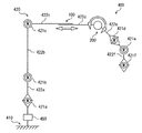
図4は、本実施形態に係る支持アーム装置400の構成を示す模式図である。支持アーム装置400のアーム部420は、根元側がベース部410に連結されて、図示しない内視鏡装置が支持される先端側へと延伸する。先端側に配置された3つの能動関節部421d,421e,421fは、主として内視鏡装置の3自由度の動作を確保して撮像方向を変化させる機能を有する。また、根元側に配置された3つの能動関節部421a,421b,421cは、主として内視鏡装置の位置を変化させる機能を有する。つまり、本実施形態に係る支持アーム装置400において、根元側の能動関節部421a,421b,421cの回転駆動により、先端側に支持された内視鏡装置のおおよその位置が決定されつつ、先端側の能動関節部421d,421e,421fの回転駆動により、内視鏡装置の撮像方向が決定される。   FIG. 4 is a schematic diagram showing the configuration of the support arm device 400 according to the present embodiment. The arm portion 420 of the support arm device 400 is connected to the base portion 410 at the base side and extends to the distal end side where an endoscope device (not shown) is supported. The three active joint portions 421d, 421e, and 421f arranged on the distal end side mainly have a function of changing the imaging direction while ensuring the operation of the three degrees of freedom of the endoscope apparatus. Further, the three active joint portions 421a, 421b, and 421c arranged on the root side mainly have a function of changing the position of the endoscope apparatus. That is, in the support arm device 400 according to the present embodiment, the approximate position of the endoscope device supported on the distal end side is determined by the rotational drive of the active joint portions 421a, 421b, and 421c on the root side, while the distal end side is determined. The imaging direction of the endoscope apparatus is determined by rotationally driving the active joint portions 421d, 421e, and 421f.

また、支持アーム装置400のアーム部420の根元部分、例えば、リンク422aとベース部410との連結部分には、アーム部420の全体の水平方向に対する傾きを検出するための姿勢センサ450が設けられてもよい。姿勢センサ450により検出されるアーム部420の全体の傾きは、アーム部420に作用する重力の算出に用いられ、制御部は、算出した重力を用いて、重力を打ち消すための制御(以下、「重力補償制御」ともいう。)を実行することができる。かかる姿勢センサ450としては、例えばジャイロセンサ及び加速度センサのうちの少なくとも1つを用いたセンサが適用され得る。   In addition, a posture sensor 450 for detecting the inclination of the entire arm portion 420 with respect to the horizontal direction is provided at the base portion of the arm portion 420 of the support arm device 400, for example, the connecting portion between the link 422 a and the base portion 410. May be. The overall inclination of the arm unit 420 detected by the posture sensor 450 is used to calculate the gravity acting on the arm unit 420, and the control unit uses the calculated gravity to control for canceling the gravity (hereinafter, “ Also called “gravity compensation control”). As the attitude sensor 450, for example, a sensor using at least one of a gyro sensor and an acceleration sensor can be applied.

受動形態変更機構としての受動スライド機構100及び受動関節部200は、能動関節部421cと能動関節部421dとの間に設けられている。つまり、受動形態変更機構は、アーム部420の先端側に配置された少なくとも3つの能動関節部421d〜421fよりも根元側に配置されている。このため、受動スライド機構100及び受動関節部200は、先端側の3つの能動関節部421d〜421fによる内視鏡装置の撮像方向の制御に大きな影響を与えることなく、アーム部420の可動範囲を変化させることができる。ただし、受動形態変更機構の配置位置は上記の例に限られない。受動形態変更機構がどの位置に配置されていてもアーム部420の形態を変化させることができる。   The passive slide mechanism 100 and the passive joint part 200 as the passive form changing mechanism are provided between the active joint part 421c and the active joint part 421d. That is, the passive form changing mechanism is arranged on the root side with respect to at least three active joint parts 421d to 421f arranged on the distal end side of the arm part 420. For this reason, the passive slide mechanism 100 and the passive joint unit 200 increase the movable range of the arm unit 420 without greatly affecting the control of the imaging direction of the endoscope apparatus by the three active joint units 421d to 421f on the distal end side. Can be changed. However, the arrangement position of the passive form changing mechanism is not limited to the above example. Regardless of the position of the passive form changing mechanism, the form of the arm part 420 can be changed.

ここで、受動形態変更機構が設けられない場合、想定される内視鏡装置の最大可動範囲に合わせてアーム部420の自由度(能動関節部の数)やアーム部420の各リンクの長さを設計すると、小さい自由度又は可動範囲で済む手術手技においては、アーム部420自身が過大となる。その結果、術者の視野やワーキングスペースが阻害されたり、手術室内の他の機材の配置が妨げられたりする原因となり得る。また、アーム部420の自由度が増えると、アクチュエータの数も増えることになり、コストやアーム部420の重量が増加する原因となり得る。さらに、各リンクの長さを長くすることによって根元側の能動関節部421aに設けられるアクチュエータに求められる出力が増大し、コストが増加する原因ともなり得る。   Here, when the passive form changing mechanism is not provided, the degree of freedom of the arm part 420 (the number of active joint parts) and the length of each link of the arm part 420 according to the assumed maximum movable range of the endoscope apparatus. Is designed, the arm part 420 itself becomes excessive in a surgical procedure that requires a small degree of freedom or a movable range. As a result, the operator's visual field and working space may be obstructed, and the arrangement of other equipment in the operating room may be hindered. Further, when the degree of freedom of the arm unit 420 increases, the number of actuators also increases, which may cause an increase in cost and weight of the arm unit 420. Furthermore, by increasing the length of each link, the output required for the actuator provided in the active joint portion 421a on the root side increases, which may increase the cost.

これに対して、本実施形態に係る支持アーム装置400は、受動スライド機構100及び受動関節部200を有することによって、アーム部420の一部の能動関節部同士の間の距離、及び一部のリンク同士の角度のうちの少なくとも一方を変化させることができる。このため、支持アーム装置400は、手術手技の目的や内容に応じてアーム部420の形態を変化させて、適切な可動範囲を確保することができる。したがって、術者の視野やワーキングスペースが必要以上に阻害されたり、手術室内の他の機材の配置が必要以上に妨げられたりすることを抑制することができる。また、支持アーム装置400は、自由度(能動関節部の数)を必要以上に増やすことなく適切な可動範囲を確保することができるために、コストの増加を抑制することができる。   On the other hand, the support arm device 400 according to the present embodiment includes the passive slide mechanism 100 and the passive joint unit 200, so that the distance between some of the active joints of the arm unit 420 and some of the distances. At least one of the angles between the links can be changed. For this reason, the support arm apparatus 400 can ensure the suitable movable range by changing the form of the arm part 420 according to the objective and content of a surgical procedure. Therefore, it is possible to prevent the surgeon's visual field and working space from being obstructed more than necessary, and the arrangement of other equipment in the operating room from being obstructed more than necessary. Moreover, since the support arm apparatus 400 can ensure a suitable movable range, without increasing a freedom degree (the number of active joint parts) more than necessary, it can suppress the increase in cost.

ここで、図5を参照して、図3に示す関節部421a〜421fの構成についてより詳細に説明する。なお、ここでは、図5を参照して、関節部421a〜421fの構成のうち、関節部421a〜421fの回転駆動に主に関係する構成であるアクチュエータの構成について説明する。   Here, with reference to FIG. 5, the structure of the joint parts 421a-421f shown in FIG. 3 is demonstrated in detail. Here, with reference to FIG. 5, the configuration of an actuator that is mainly related to the rotational drive of the joint portions 421 a to 421 f among the configurations of the joint portions 421 a to 421 f will be described.

図5は、本開示の一実施形態に係る関節部421a〜421fのアクチュエータを、回転軸を通る断面で切断した様子を模式的に示す断面図である。なお、図5では、関節部421a〜421fの構成のうち、アクチュエータのみを図示しているが、関節部421a〜421fは、他の構成を有してもよい。例えば、関節部421a〜421fは、図5に図示する構成以外にも、アクチュエータの駆動を制御するための制御部や、リンク422a〜422c及び内視鏡装置423を接続、支持するための支持部材等、アーム部420の駆動に必要な各種の構成を有する。なお、ここまでの説明及び以下の説明において、アーム部の関節部の駆動とは、関節部におけるアクチュエータの駆動を意味していてもよい。   FIG. 5 is a cross-sectional view schematically illustrating a state in which the actuators of the joint portions 421a to 421f according to the embodiment of the present disclosure are cut along a cross section passing through the rotation axis. In FIG. 5, only the actuator is illustrated among the configurations of the joint portions 421a to 421f, but the joint portions 421a to 421f may have other configurations. For example, the joint portions 421a to 421f have a control member for controlling driving of the actuator, a support member for connecting and supporting the links 422a to 422c and the endoscope device 423 in addition to the configuration illustrated in FIG. For example, various configurations necessary for driving the arm unit 420 are provided. In the description so far and in the following description, the driving of the joint portion of the arm portion may mean the driving of the actuator in the joint portion.

なお、上述したように、本実施形態においては、関節部421a〜421fは、下記<<2−3.理想関節制御について>>で後述する理想関節制御によってその駆動が制御される。従って、図5に示す関節部421a〜421fのアクチュエータは、理想関節制御に対応した駆動を行えるように構成されている。具体的には、関節部421a〜421fのアクチュエータは、当該関節部421a〜421fにおける回転角度及び回転駆動に伴うトルクを調整できるように構成されている。また、関節部421a〜421fのアクチュエータは、回転運動に対する粘性抵抗係数を任意に調整できるように構成されており、例えば外部から加えられる力に対して回転しやすい(すなわち、アーム部420を手動で移動しやすい)状態や回転し難い(すなわち、アーム部420を手動で移動し難い)状態を実現することができる。   As described above, in the present embodiment, the joint portions 421a to 421f have the following << 2-3. About ideal joint control >> The drive is controlled by ideal joint control which will be described later. Therefore, the actuators of the joint portions 421a to 421f shown in FIG. 5 are configured to be able to drive corresponding to ideal joint control. Specifically, the actuators of the joint portions 421a to 421f are configured to be able to adjust the rotation angle and torque associated with the rotation drive in the joint portions 421a to 421f. Further, the actuators of the joint portions 421a to 421f are configured so that the viscous resistance coefficient with respect to the rotational motion can be arbitrarily adjusted, and for example, the actuator easily rotates with respect to a force applied from the outside (that is, the arm portion 420 is manually operated). It is possible to realize a state of being easily moved) and a state of being difficult to rotate (that is, it is difficult to manually move the arm unit 420).

図5を参照すると、本実施形態に係る関節部421a〜421fのアクチュエータ430は、モータ424、モータドライバ425、減速機426、エンコーダ427、トルクセンサ428及び駆動軸429を有する。図5に示すように、エンコーダ427、モータ424、減速機426及びトルクセンサ428は、駆動軸429に対して直列にこの順で連結される。   Referring to FIG. 5, the actuator 430 of the joint portions 421a to 421f according to the present embodiment includes a motor 424, a motor driver 425, a speed reducer 426, an encoder 427, a torque sensor 428, and a drive shaft 429. As shown in FIG. 5, the encoder 427, the motor 424, the speed reducer 426, and the torque sensor 428 are connected in series to the drive shaft 429 in this order.

モータ424は、アクチュエータ430における原動機であり、駆動軸429をその軸周りに回転させる。例えば、モータ424は、ブラシレスDCモータ等の電動モータである。本実施形態においては、モータ424は電流を供給されることによってその回転駆動が制御される。   The motor 424 is a prime mover in the actuator 430 and rotates the drive shaft 429 around the axis. For example, the motor 424 is an electric motor such as a brushless DC motor. In the present embodiment, the rotation of the motor 424 is controlled by supplying a current.

モータドライバ425は、モータ424に電流を供給することによりモータ424を回転駆動させるドライバ回路(ドライバIC(Integrated Circuit))であり、モータ424に供給する電流量を調整することにより、モータ424の回転数を制御することができる。また、モータドライバ425は、モータ424に供給する電流量を調整することにより、上述したようなアクチュエータ430の回転運動に対する粘性抵抗係数を調整することができる。   The motor driver 425 is a driver circuit (driver IC (Integrated Circuit)) that rotates the motor 424 by supplying current to the motor 424, and the rotation of the motor 424 is adjusted by adjusting the amount of current supplied to the motor 424. The number can be controlled. Further, the motor driver 425 can adjust the viscous resistance coefficient with respect to the rotational motion of the actuator 430 as described above by adjusting the amount of current supplied to the motor 424.

減速機426は、駆動軸429に接続され、モータ424によって生じた駆動軸429の回転速度を所定の減速比で減速することにより、所定の値を有する回転駆動力(すなわち、トルク)を発生させる。減速機426には、バックラッシレス型の高性能減速機が用いられる。例えば、減速機426は、ハーモニックドライブ(登録商標)であってもよい。減速機426によって生成されたトルクは、減速機426の出力軸に接続されたトルクセンサ428を介して、後段の出力部材(図示せず。例えばリンク422a〜422cや内視鏡装置423等の連結部材)に伝達される。   The speed reducer 426 is connected to the drive shaft 429 and generates a rotational drive force (ie, torque) having a predetermined value by reducing the rotational speed of the drive shaft 429 generated by the motor 424 at a predetermined reduction ratio. . As the speed reducer 426, a backlashless high performance speed reducer is used. For example, the speed reducer 426 may be a harmonic drive (registered trademark). Torque generated by the speed reducer 426 is connected to a subsequent output member (not shown, for example, links 422a to 422c, the endoscope apparatus 423, etc.) via a torque sensor 428 connected to the output shaft of the speed reducer 426. Member).

エンコーダ427は、駆動軸429に接続され、駆動軸429の回転数を検出する。エンコーダによって検出された駆動軸429の回転数と、減速機426の減速比との関係に基づいて、関節部421a〜421fの回転角度、回転角速度及び回転角加速度等の情報を得ることができる。   The encoder 427 is connected to the drive shaft 429 and detects the rotational speed of the drive shaft 429. Based on the relationship between the rotational speed of the drive shaft 429 detected by the encoder and the reduction ratio of the speed reducer 426, information such as the rotational angles, rotational angular velocities, and rotational angular accelerations of the joint portions 421a to 421f can be obtained.

トルクセンサ428は、減速機426の出力軸に接続され、減速機426によって生成されたトルク、すなわち、アクチュエータ430によって出力されるトルクを検出する。以下の説明では、アクチュエータ430によって出力されるトルクのことを単に発生トルクとも呼称する。   The torque sensor 428 is connected to the output shaft of the speed reducer 426 and detects the torque generated by the speed reducer 426, that is, the torque output by the actuator 430. In the following description, the torque output by the actuator 430 is simply referred to as generated torque.

このように、アクチュエータ430においては、モータ424に供給する電流量を調整することにより、モータ424の回転数を調整することがでる。ここで、減速機426における減速比は、支持アーム装置400の用途に応じて適宜設定可能であってよい。従って、減速機426の減速比に応じて、モータ424の回転数を適宜調整することにより、発生トルクを制御することができる。また、アクチュエータ430においては、エンコーダ427によって検出された駆動軸429の回転数に基づいて、関節部421a〜421fの回転角度、回転角速度及び回転角加速度等の情報を得ることができ、トルクセンサ428によって、関節部421a〜421fにおける発生トルクを検出することができる。   As described above, in the actuator 430, the number of rotations of the motor 424 can be adjusted by adjusting the amount of current supplied to the motor 424. Here, the reduction ratio in the reduction gear 426 may be appropriately set according to the use of the support arm device 400. Therefore, the generated torque can be controlled by appropriately adjusting the rotational speed of the motor 424 in accordance with the reduction ratio of the speed reducer 426. In the actuator 430, information such as the rotation angle, rotation angular velocity, and rotation angular acceleration of the joint portions 421 a to 421 f can be obtained based on the rotation speed of the drive shaft 429 detected by the encoder 427, and the torque sensor 428. Thus, the generated torque in the joint portions 421a to 421f can be detected.

また、トルクセンサ428は、アクチュエータ430による発生トルクだけでなく、外部から加えられる外トルクも検出することができる。従って、トルクセンサ428によって検出された外トルクに基づいて、モータドライバ425がモータ424に供給する電流量を調整することにより、上述したような回転運動に対する粘性抵抗係数を調整することができ、例えば外部から加えられる力に対して回転しやすい状態や回転し難い状態を実現することができる。   The torque sensor 428 can detect not only torque generated by the actuator 430 but also external torque applied from the outside. Therefore, by adjusting the amount of current that the motor driver 425 supplies to the motor 424 based on the external torque detected by the torque sensor 428, the viscous resistance coefficient with respect to the rotational motion as described above can be adjusted. It is possible to realize a state that is easy to rotate or a state that is difficult to rotate with respect to a force applied from the outside.

ここで、図6A及び図6Bを参照して、トルクセンサ428の構成について詳細に説明する。図6Aは、図5に示すトルクセンサ428を、駆動軸429の軸方向から見た様子を模式的に示す概略図である。   Here, the configuration of the torque sensor 428 will be described in detail with reference to FIGS. 6A and 6B. FIG. 6A is a schematic diagram schematically showing a state where the torque sensor 428 shown in FIG. 5 is viewed from the axial direction of the drive shaft 429.

図6Aを参照すると、トルクセンサ428は、外輪部431、内輪部432、梁部433a〜433d及び歪み検出素子434a〜434dを有する。図6Aに示すように、外輪部431及び内輪部432は同心円状に配置される。本実施形態では、内輪部432が入力側、すなわち、減速機426からの出力軸と接続され、外輪部431が出力側、すなわち、後段の出力部材(図示せず。)と接続される。   Referring to FIG. 6A, the torque sensor 428 includes an outer ring portion 431, an inner ring portion 432, beam portions 433a to 433d, and strain detection elements 434a to 434d. As shown in FIG. 6A, the outer ring portion 431 and the inner ring portion 432 are arranged concentrically. In the present embodiment, the inner ring portion 432 is connected to the input side, that is, the output shaft from the speed reducer 426, and the outer ring portion 431 is connected to the output side, that is, a rear-stage output member (not shown).

4本の梁部433a〜433dは、同心円状に配置された外輪部431と内輪部432との間に配設され、外輪部431と内輪部432とを互いに接続する。図6Aに示すように、梁部433a〜433dは、隣り合う梁部433a〜433d同士が互いに90度の角度となるように、外輪部431と内輪部432との間に介設される。   The four beam portions 433a to 433d are disposed between the outer ring portion 431 and the inner ring portion 432 arranged concentrically, and connect the outer ring portion 431 and the inner ring portion 432 to each other. As shown in FIG. 6A, the beam portions 433a to 433d are interposed between the outer ring portion 431 and the inner ring portion 432 so that the adjacent beam portions 433a to 433d form an angle of 90 degrees with each other.

梁部433a〜433dのうち、互いに向かい合う、すなわち、互いに180度の角度で設けられる2本には、歪み検出素子434a〜434dが設けられる。歪み検出素子434a〜434dによって検出された梁部433a〜433dの変形量に基づいて、アクチュエータ430の発生トルク及び外トルクを検出することができる。   Of the beam portions 433a to 433d, strain detection elements 434a to 434d are provided in two of the beam portions 433a to 433d facing each other, that is, provided at an angle of 180 degrees. Based on the deformation amount of the beam portions 433a to 433d detected by the strain detection elements 434a to 434d, the generated torque and the external torque of the actuator 430 can be detected.

図6Aに示す例では、梁部433a〜433dのうち、梁部433aに歪み検出素子434a、434bが、梁部433cに歪み検出素子434c、434dが設けられる。また、歪み検出素子434a、434bは梁部433aを挟むように設けられ、歪み検出素子434c、434dは梁部433cを挟むように設けられる。例えば、歪み検出素子434a〜434dは歪みゲージであり、梁部433a、433cの表面に貼り付けられることにより、梁部433a、433cの幾何的な変形量を電気抵抗の変化に基づいて検出する。図6Aに示すように4ヶ所に歪み検出素子434a〜434dが設けられることにより、検出素子434a〜434dがいわゆるホイートストンブリッジを構成する。従って、いわゆる4ゲージ法を用いて歪みを検出することができるため、歪みを検出する軸以外の他軸の干渉や駆動軸429の偏心、温度ドリフト等の影響を低減することができる。   In the example illustrated in FIG. 6A, among the beam portions 433a to 433d, strain detection elements 434a and 434b are provided in the beam portion 433a, and strain detection elements 434c and 434d are provided in the beam portion 433c. The strain detection elements 434a and 434b are provided so as to sandwich the beam portion 433a, and the strain detection elements 434c and 434d are provided so as to sandwich the beam portion 433c. For example, the strain detection elements 434a to 434d are strain gauges, and are attached to the surfaces of the beam portions 433a and 433c, thereby detecting a geometric deformation amount of the beam portions 433a and 433c based on a change in electric resistance. As shown in FIG. 6A, the strain detection elements 434a to 434d are provided at four locations, so that the detection elements 434a to 434d constitute a so-called Wheatstone bridge. Therefore, since the strain can be detected by using a so-called 4-gauge method, it is possible to reduce the influence of interference other than the shaft for detecting strain, the eccentricity of the drive shaft 429, temperature drift, and the like.

このように、梁部433a〜433dは、歪みを検出するための起歪体の役割を果たす。なお、本実施形態に係る歪み検出素子434a〜434dの種類は歪みゲージに限定されず、他の素子が用いられてもよい。例えば、歪み検出素子434a〜434dは、磁気特性の変化に基づいて梁部433a〜433dの変形量を検出する素子であってもよい。   As described above, the beam portions 433a to 433d serve as strain generating bodies for detecting strain. Note that the types of the strain detection elements 434a to 434d according to the present embodiment are not limited to strain gauges, and other elements may be used. For example, the strain detection elements 434a to 434d may be elements that detect deformation amounts of the beam portions 433a to 433d based on changes in magnetic characteristics.

また、図5及び図6Aには図示しないが、トルクセンサ428による発生トルク及び外トルクの検出精度を向上させるために、以下に示す構成が適用されてもよい。例えば、梁部433a〜433dの外輪部431と接続する部位を他の部位よりも薄肉化することにより、支持モーメントが解放されるため、検出される変形量の線形性が向上されるとともにラジアル荷重による影響が低減される。また、外輪部431及び内輪部432をともにベアリングを介してハウジングで支持することにより、入力軸及び出力軸の双方からの他軸力、モーメントの作用を排除することができる。また、外輪部431に作用する他軸モーメントを低減するために、図5に示すアクチュエータ430の他端、すなわちエンコーダ427が配設される部位に両持ち支持用ベアリングが配設されてもよい。   Although not shown in FIGS. 5 and 6A, the following configuration may be applied to improve the detection accuracy of the torque generated by the torque sensor 428 and the external torque. For example, since the support moment is released by making the part connected to the outer ring part 431 of the beam parts 433a to 433d thinner than the other parts, the linearity of the detected deformation amount is improved and the radial load is increased. The influence of is reduced. Further, by supporting both the outer ring portion 431 and the inner ring portion 432 with the housing via the bearing, it is possible to eliminate the effects of other axial forces and moments from both the input shaft and the output shaft. Further, in order to reduce the other-axis moment acting on the outer ring portion 431, a both-end supporting bearing may be disposed at the other end of the actuator 430 shown in FIG.

以上、図6Aを参照して、トルクセンサ428の構成について説明した。以上説明したように、図6Aに示すトルクセンサ428の構成により、アクチュエータ430の発生トルク及び外トルクの検出において、高精度な検出が可能となる。   The configuration of the torque sensor 428 has been described above with reference to FIG. 6A. As described above, the configuration of the torque sensor 428 shown in FIG. 6A enables highly accurate detection of the generated torque of the actuator 430 and the external torque.

ここで、本実施形態においては、トルクセンサ428の構成は図6Aに示す構成に限定されず、他の構成であってもよい。アクチュエータ430に適用されるトルクセンサについて、トルクセンサ428以外の他の構成の一例を、図6Bを参照して説明する。   Here, in the present embodiment, the configuration of the torque sensor 428 is not limited to the configuration illustrated in FIG. 6A, and may be another configuration. An example of a configuration other than the torque sensor 428 regarding the torque sensor applied to the actuator 430 will be described with reference to FIG. 6B.

図6Bは、図5に示すアクチュエータ430に適用されるトルクセンサの他の構成例を示す概略図である。図6Bを参照すると、本変形例に係るトルクセンサ428aは、外輪部441、内輪部442、梁部443a〜443d及び歪み検出素子444a〜444dを有する。なお、図6Bでは、図6Aと同様、トルクセンサ428aを駆動軸429の軸方向から見た様子を模式的に示している。   FIG. 6B is a schematic diagram illustrating another configuration example of the torque sensor applied to the actuator 430 illustrated in FIG. 5. Referring to FIG. 6B, a torque sensor 428a according to this modification includes an outer ring portion 441, an inner ring portion 442, beam portions 443a to 443d, and strain detection elements 444a to 444d. 6B schematically shows a state where the torque sensor 428a is viewed from the axial direction of the drive shaft 429, as in FIG. 6A.

トルクセンサ428aにおいて、外輪部441、内輪部442、梁部443a〜443d及び歪み検出素子444a〜444dの機能及び構成は、図6Aを参照して説明したトルクセンサ428の外輪部431、内輪部432、梁部433a〜433d及び歪み検出素子434a〜434dの機能及び構成とほぼ同様である。本変形例に係るトルクセンサ428aは、梁部443a〜443dと外輪部441との接続部分の構成が異なる。従って、図6Bに示すトルクセンサ428aについては、図6Aに示すトルクセンサ428との相違点である梁部443a〜443dと外輪部441との接続部位の構成について主に説明を行い、重複する構成については説明を省略する。   In the torque sensor 428a, the functions and configurations of the outer ring portion 441, the inner ring portion 442, the beam portions 443a to 443d, and the strain detection elements 444a to 444d are the same as the outer ring portion 431 and the inner ring portion 432 of the torque sensor 428 described with reference to FIG. The beam portions 433a to 433d and the strain detection elements 434a to 434d have substantially the same function and configuration. The torque sensor 428a according to this modification is different in the configuration of the connection portion between the beam portions 443a to 443d and the outer ring portion 441. Therefore, with regard to the torque sensor 428a shown in FIG. 6B, the configuration of the connection portion between the beam portions 443a to 443d and the outer ring portion 441, which is different from the torque sensor 428 shown in FIG. Description of is omitted.

図6Bを参照すると、トルクセンサ428aの全体図と併せて、梁部443bと外輪部441との接続部位が拡大して図示されている。なお、図6Bでは、梁部443a〜443dと外輪部441との4ヶ所の接続部位のうちの1ヶ所である梁部443bと外輪部441との接続部位のみを拡大して図示しているが、他の3ヶ所である梁部443a、443c、443dと外輪部441との接続部位も同様の構成を有している。   Referring to FIG. 6B, the connection portion between the beam portion 443b and the outer ring portion 441 is enlarged and shown together with the overall view of the torque sensor 428a. In FIG. 6B, only the connection portion between the beam portion 443b and the outer ring portion 441, which is one of the four connection portions between the beam portions 443a to 443d and the outer ring portion 441, is illustrated in an enlarged manner. The other three portions, the beam portions 443a, 443c, 443d and the connection portion of the outer ring portion 441 have the same configuration.

図6Bにおける拡大図を参照すると、梁部443bと外輪部441との接続部位においては、外輪部441に係合凹部が設けられており、梁部443bの先端が係合凹部に係合されることにより両者が接続される。また、当該梁部443bと外輪部441との間には、間隙G1、G2が設けられる。間隙G1は梁部443bが外輪部441に向かって延伸する方向における両者の間隙を表しており、間隙G2は当該方向とは直交する方向における両者の間隙を表している。   Referring to the enlarged view in FIG. 6B, in the connection portion between the beam portion 443b and the outer ring portion 441, the outer ring portion 441 is provided with an engagement recess, and the tip of the beam portion 443b is engaged with the engagement recess. Thus, both are connected. In addition, gaps G1 and G2 are provided between the beam portion 443b and the outer ring portion 441. The gap G1 represents the gap between the beams 443b in the direction in which the beam portion 443b extends toward the outer ring portion 441, and the gap G2 represents the gap between the two in a direction orthogonal to the direction.

このように、トルクセンサ428aにおいては、梁部443a〜443dと外輪部441とが、所定の間隙G1、G2を有して分離して配設される。すなわち、トルクセンサ428aにおいては、外輪部441と内輪部442とが分離している。従って、内輪部442が外輪部441に対して拘束されず動きの自由度を有するため、例えばアクチュエータ430の駆動に際して振動が生じたとしても、振動による歪み成分を内輪部442と外輪部441との間の空隙G1、G2によって吸収することができる。よって、トルクセンサ428aをアクチュエータ430のトルクセンサとして適用することにより、より高精度な発生トルク及び外トルクの検出が実現される。   As described above, in the torque sensor 428a, the beam portions 443a to 443d and the outer ring portion 441 are separately provided with the predetermined gaps G1 and G2. That is, in the torque sensor 428a, the outer ring portion 441 and the inner ring portion 442 are separated. Accordingly, since the inner ring portion 442 is not restricted with respect to the outer ring portion 441 and has a degree of freedom of movement, for example, even if vibration occurs when the actuator 430 is driven, a distortion component due to vibration is generated between the inner ring portion 442 and the outer ring portion 441. It can be absorbed by the gaps G1 and G2. Therefore, by applying the torque sensor 428a as the torque sensor of the actuator 430, it is possible to detect the generated torque and the external torque with higher accuracy.

なお、図5、図6A及び図6Bに示すような、理想関節制御に対応するアクチュエータ430の構成については、例えば、本願出願人による先行特許出願である特開2009−269102号公報や特開2011−209099号公報を参照することができる。   As for the configuration of the actuator 430 corresponding to ideal joint control as shown in FIGS. 5, 6A and 6B, for example, Japanese Patent Application Laid-Open No. 2009-269102 and Japanese Patent Application 2011, which are prior patent applications by the present applicant. Reference can be made to -2099099.

以上、図3、図4、図5、図6A及び図6Bを参照して、本実施形態に係る支持アーム装置400の概略構成について説明した。次に、本実施形態に係る支持アーム装置400におけるアーム部420の駆動、すなわち、関節部421a〜421fの駆動を制御するための全身協調制御及び理想関節制御について説明する。   The schematic configuration of the support arm device 400 according to the present embodiment has been described above with reference to FIGS. 3, 4, 5, 6 </ b> A, and 6 </ b> B. Next, whole body cooperative control and ideal joint control for controlling driving of the arm unit 420 in the support arm device 400 according to the present embodiment, that is, driving of the joint units 421a to 421f will be described.

<<2−2.一般化逆動力学について>>
次に、本実施形態における支持アーム装置400の全身協調制御に用いられる一般化逆動力学の概要について説明する。
<< 2-2. About Generalized Inverse Dynamics >>
Next, an outline of generalized inverse dynamics used for whole body cooperative control of the support arm device 400 in the present embodiment will be described.

一般化逆動力学は、複数のリンクが複数の関節部によって連結されて構成される多リンク構造体(例えば本実施形態においては図3に示すアーム部420)において、各種の操作空間(Operation Space)における様々な次元に関する運動目的を、各種の拘束条件を考慮しながら、複数の当該関節部に生じさせるトルクに変換する、多リンク構造体の全身協調制御における基本演算である。   In generalized inverse dynamics, various operation spaces (Operation Space) are used in a multi-link structure (for example, the arm unit 420 shown in FIG. 3 in the present embodiment) in which a plurality of links are connected by a plurality of joints. ) Is a basic calculation in the whole body cooperative control of the multi-link structure, which converts the motion purpose regarding various dimensions into torque generated in a plurality of the joint portions in consideration of various constraint conditions.

操作空間は、ロボット装置の力制御における重要な概念である。操作空間は、多リンク構造体に作用する力と多リンク構造体の加速度との関係を記述するための空間である。多リンク構造体の駆動制御を位置制御ではなく力制御によって行う際に、多リンク構造体と環境との接し方を拘束条件として用いる場合に操作空間という概念が必要となる。操作空間は、例えば、多リンク構造体が属する空間である、関節空間、デカルト空間、運動量空間等である。   The operation space is an important concept in the force control of the robot apparatus. The operation space is a space for describing the relationship between the force acting on the multi-link structure and the acceleration of the multi-link structure. When drive control of the multi-link structure is performed by force control instead of position control, the concept of operation space is required when using the way of contacting the multi-link structure and the environment as a constraint condition. The operation space is, for example, a joint space, a Cartesian space, a momentum space or the like to which a multi-link structure belongs.

運動目的は、多リンク構造体の駆動制御における目標値を表すものであり、例えば、駆動制御によって達成したい多リンク構造体の位置、速度、加速度、力、インピーダンス等の目標値である。   The motion purpose represents a target value in the drive control of the multi-link structure, and is, for example, a target value such as position, speed, acceleration, force, impedance, etc. of the multi-link structure to be achieved by the drive control.

拘束条件は、多リンク構造体の形状や構造、多リンク構造体の周囲の環境及びユーザによる設定等によって定められる、多リンク構造体の位置、速度、加速度、力等に関する拘束条件である。例えば、拘束条件には、発生力、優先度、非駆動関節の有無、垂直反力、摩擦錘、支持多角形等についての情報が含まれる。   The constraint condition is a constraint condition related to the position, speed, acceleration, force, and the like of the multi-link structure, which is determined by the shape and structure of the multi-link structure, the environment around the multi-link structure, settings by the user, and the like. For example, the constraint condition includes information on generated force, priority, presence / absence of a non-driven joint, vertical reaction force, friction weight, support polygon, and the like.

一般化動力学においては、数値計算上の安定性と実時間処理可能な演算効率とを両立するため、その演算アルゴリズムは、第1段階である仮想力決定プロセス(仮想力算出処理)と、第2段階である実在力変換プロセス(実在力算出処理)によって構成される。第1段階である仮想力算出処理では、各運動目的の達成に必要な、操作空間に作用する仮想的な力である仮想力を、運動目的の優先度と仮想力の最大値を考慮しながら決定する。第2段階である実在力算出処理では、非駆動関節、垂直反力、摩擦錘、支持多角形等に関する拘束を考慮しながら、上記で得られた仮想力を関節力、外力等の実際の多リンク構造体の構成で実現可能な実在力に変換する。以下、仮想力算出処理及び実在力算出処理について詳しく説明する。なお、以下の仮想力算出処理、実在力算出処理及び後述する理想関節制御の説明においては、理解を簡単にするために、具体例として、図3及び図5に示した本実施形態に係る支持アーム装置400のアーム部420の構成を例に挙げて説明を行う場合がある。   In generalized dynamics, in order to achieve both stability in numerical computation and computation efficiency that can be processed in real time, the computation algorithm includes a first stage virtual force determination process (virtual force calculation process), It is configured by a two-stage real force conversion process (real force calculation process). In the virtual force calculation process, which is the first stage, the virtual force, which is a virtual force acting on the operation space, necessary to achieve each exercise purpose is considered in consideration of the priority of the exercise purpose and the maximum value of the virtual force. decide. In the actual force calculation process, which is the second stage, the virtual force obtained above is used as an actual force such as joint force and external force while taking into account constraints on non-drive joints, vertical reaction forces, friction weights, support polygons, etc. It is converted into a real force that can be realized by the structure of the link structure. Hereinafter, the virtual force calculation process and the actual force calculation process will be described in detail. In the following description of the virtual force calculation process, the actual force calculation process, and ideal joint control described below, as a specific example, the support according to the present embodiment shown in FIGS. The configuration of the arm unit 420 of the arm device 400 may be described as an example.

(2−2−1.仮想力算出処理)
多リンク構造体の各関節部におけるある物理量によって構成されるベクトルを一般化変数qと呼ぶ(関節値q又は関節空間qとも呼称する。)。操作空間xは、一般化変数qの時間微分値とヤコビアンJとを用いて、以下の数式(1)で定義される。
(2-2-1. Virtual force calculation process)
A vector constituted by a certain physical quantity in each joint portion of the multi-link structure is referred to as a generalized variable q (also referred to as a joint value q or a joint space q). The operation space x is defined by the following formula (1) using the time differential value of the generalized variable q and the Jacobian J.

Figure 2018198750
Figure 2018198750

本実施形態では、例えば、qはアーム部420の関節部421a〜421fにおける回転角度である。操作空間xに関する運動方程式は、下記数式(2)で記述される。   In the present embodiment, for example, q is a rotation angle in the joint portions 421a to 421f of the arm portion 420. The equation of motion related to the operation space x is described by the following equation (2).

Figure 2018198750
Figure 2018198750

ここで、fは操作空間xに作用する力を表す。また、Λ−1は操作空間慣性逆行列、cは操作空間バイアス加速度と呼ばれるものであり、それぞれ下記数式(3)、(4)で表される。 Here, f represents a force acting on the operation space x. Further, Λ −1 is called an operation space inertia inverse matrix, and c is called an operation space bias acceleration, which are expressed by the following equations (3) and (4), respectively.

Figure 2018198750
Figure 2018198750

なお、Hは関節空間慣性行列、τは関節値qに対応する関節力(例えば関節部421a〜421fおける発生トルク)、bは重力、コリオリ力、遠心力を表す項である。   H is a joint space inertia matrix, τ is a joint force corresponding to the joint value q (for example, generated torque in the joint portions 421a to 421f), and b is a term representing gravity, Coriolis force, and centrifugal force.

一般化逆動力学においては、操作空間xに関する位置、速度の運動目的は、操作空間xの加速度として表現できることが知られている。このとき、上記数式(1)から、運動目的として与えられた目標値である操作空間加速度を実現するために、操作空間xに作用するべき仮想力fは、下記数式(5)のような一種の線形相補性問題(LCP:Linear Complementary Problem)を解くことによって得られる。 In generalized inverse dynamics, it is known that the motion purpose of position and speed with respect to the operation space x can be expressed as acceleration of the operation space x. At this time, from the above equation (1), the virtual force f v to be applied to the operation space x in order to realize the operation space acceleration, which is a target value given as the purpose of exercise, is expressed by the following equation (5). It is obtained by solving a kind of linear complementarity problem (LCP: Linear Complementary Problem).

Figure 2018198750
Figure 2018198750

ここで、LとUはそれぞれ、fの第i成分の負の下限値(−∞を含む)、fの第i成分の正の上限値(+∞を含む)とする。上記LCPは、例えばIterative法、Pivot法、ロバスト加速度制御を応用する方法等を用いて解くことができる。 Here, each of L i and U i, (including -∞) negative lower limit value of the i component of f v, the positive upper limit value of the i component of f v (including + ∞). The LCP can be solved using, for example, an iterative method, a pivot method, a method applying robust acceleration control, or the like.

なお、操作空間慣性逆行列Λ−1、バイアス加速度cは、定義式である上記数式(3)、(4)の通り算出すると計算コストが大きい。従って、多リンク構造体の一般化力(関節力τ)から一般化加速度(関節加速度)を得る準動力学計算(FWD)を応用することにより、操作空間慣性逆行列Λ−1の算出処理をより高速に算出する方法が提案されている。具体的には、操作空間慣性逆行列Λ−1、バイアス加速度cは、順動力学演算FWDを用いることにより、関節空間q、関節力τ、重力g等の多リンク構造体(例えば、アーム部420及び関節部421a〜421f)に作用する力に関する情報から得ることができる。このように、操作空間に関する順動力学演算FWDを応用することにより、関節部の数Nに対してO(N)の計算量で操作空間慣性逆行列Λ−1を算出することができる。 Note that the operation space inertia inverse matrix Λ −1 and the bias acceleration c are calculated as the above formulas (3) and (4), which are defining formulas, and the calculation cost is high. Therefore, by applying quasi-dynamics calculation (FWD) that obtains generalized acceleration (joint acceleration) from the generalized force (joint force τ) of the multi-link structure, the operation space inertia inverse matrix Λ −1 is calculated. A method of calculating at higher speed has been proposed. Specifically, the operation space inertial inverse matrix Λ −1 and the bias acceleration c are obtained by using a forward dynamics calculation FWD, so that a multi-link structure (for example, an arm unit) such as a joint space q, a joint force τ, and a gravity g is used. 420 and the information on the force acting on the joint portions 421a to 421f). In this way, by applying the forward dynamics calculation FWD related to the operation space, the operation space inertia inverse matrix Λ −1 can be calculated with a calculation amount of O (N) for the number N of joints.

ここで、運動目的の設定例として、絶対値F以下の仮想力fviで操作空間加速度の目標値(xの2階微分に上付きバーを付して表す)を達成するための条件は、下記数式(6)で表現できる。 Here, as an example of setting the exercise purpose, the condition for achieving the target value of the operation space acceleration (represented by attaching a superscript bar to the second-order differential of x) with a virtual force f vi equal to or less than the absolute value F i is Can be expressed by the following mathematical formula (6).

Figure 2018198750
Figure 2018198750

また、上述したように、操作空間xの位置、速度に関する運動目的は、操作空間加速度の目標値として表すことができ、具体的には下記数式(7)で表現される(操作空間xの位置、速度の目標値を、x、xの1階微分に上付きバーを付して表す)。   Further, as described above, the motion purpose related to the position and speed of the operation space x can be expressed as a target value of the operation space acceleration, and specifically expressed by the following formula (7) (the position of the operation space x The target value of speed is expressed by adding a superscript bar to the first derivative of x and x).

Figure 2018198750
Figure 2018198750

その他、分解操作空間の考え方を用いることにより、他の操作空間の線形和で表される操作空間(運動量、デカルト相対座標、連動関節等)に関する運動目的を設定することもできる。なお、競合する運動目的間には優先度を与える必要がある。優先度毎かつ低優先度から順に上記LCPを解き、前段のLCPで得られた仮想力を次段のLCPの既知外力として作用させることができる。   In addition, by using the concept of the decomposition operation space, it is possible to set a motion purpose related to an operation space (momentum, Cartesian relative coordinates, interlocking joint, etc.) represented by a linear sum of other operation spaces. It is necessary to give priority between competing exercise purposes. The LCP can be solved for each priority and sequentially from the low priority, and the virtual force obtained by the previous LCP can be applied as a known external force of the next LCP.

(2−2−2.実在力算出処理)
一般化逆動力学の第2段階である実在力算出処理では、上記(2−2−1.仮想力決定プロセス)で得られた仮想力fを、実在の関節力と外力で置換する処理を行う。仮想力による一般化力τ=J を関節部に生じる発生トルクτと外力fとで実現するための条件は、下記数式(8)で表現される。
(2-2-2. Real force calculation processing)
In the real force calculation process that is the second stage of generalized inverse dynamics, the virtual force f v obtained in (2-2-1. Virtual force determination process) is replaced with the actual joint force and external force. I do. The condition for realizing the generalized force τ v = J v T f v due to the virtual force with the generated torque τ a generated at the joint and the external force fe is expressed by the following formula (8).

Figure 2018198750
Figure 2018198750

ここで、添え字aは駆動関節部の集合(駆動関節集合)を表し、添え字uは非駆動関節部の集合(非駆動関節集合)を表す。すなわち、上記数式(8)の上段は非駆動関節部による空間(非駆動関節空間)の力の釣り合いを表しており、下段は駆動関節部による空間(駆動関節空間)の力の釣合いを表している。Jvu、Jvaは、それぞれ、仮想力fが作用する操作空間に関するヤコビアンの非駆動関節成分、駆動関節成分である。Jeu、Jeaは、外力fが作用する操作空間に関するヤコビアンの非駆動関節成分、駆動関節成分である。Δfは仮想力fのうち、実在力で実現不能な成分を表す。 Here, the subscript a represents a set of drive joint portions (drive joint set), and the subscript u represents a set of non-drive joint portions (non-drive joint set). That is, the upper stage of the above formula (8) represents the balance of the force of the space (non-drive joint space) by the non-drive joint part, and the lower stage represents the balance of the force of the space (drive joint space) by the drive joint part. Yes. J vu and J va are a Jacobian non-drive joint component and drive joint component related to the operation space on which the virtual force f v acts, respectively. J eu and J ea are Jacobian non-drive joint components and drive joint components related to the operation space on which the external force fe is applied. Δf v represents a component of the virtual force f v that cannot be realized by the actual force.

上記数式(8)の上段は不定であり、例えば下記数式(9)に示すような2次計画問題(QP:Quadratic Programing Problem)を解くことで、f及びΔfを得ることができる。 The upper part of the above equation (8) is indefinite, and for example, fe and Δf v can be obtained by solving a quadratic programming problem (QP: Quadratic Programming Problem) as shown in the following equation (9).

Figure 2018198750
Figure 2018198750

ここで、εは上記数式(8)の上段の両辺の差であり、数式(8)の等式誤差を表す。ξはfとΔfとの連結ベクトルであり、変数ベクトルを表す。Q及びQは、最小化の際の重みを表す正定値対称行列である。また、上記数式(9)の不等式拘束は、垂直反力、摩擦錐、外力の最大値、支持多角形等、外力に関する拘束条件を表現するのに用いられる。例えば、矩形の支持多角形に関する不等式拘束は、下記数式(10)のように表現される。 Here, ε is the difference between the upper sides of the above equation (8) and represents the equation error of equation (8). ξ is a connection vector between fe and Δf v and represents a variable vector. Q 1 and Q 2 are positive definite symmetric matrices that represent weights at the time of minimization. Further, the inequality constraint in the above formula (9) is used to express a constraint condition related to an external force such as a vertical reaction force, a friction cone, a maximum value of an external force, a support polygon, and the like. For example, the inequality constraint relating to the rectangular support polygon is expressed as the following formula (10).

Figure 2018198750
Figure 2018198750

ここで、zは接触面の法線方向を表し、x及びyはzに垂直な直交2接線方向を表す。(F,F,F)及び(M,M,M)は、接触点に作用する外力及び外力モーメントである。μ及びμは、それぞれ並進、回転に関する摩擦係数である。(d,d)は支持多角形のサイズを表している。 Here, z represents the normal direction of the contact surface, and x and y represent orthogonal two tangential directions perpendicular to z. (F x , F y , F z ) and (M x , M y , M z ) are external force and external force moment acting on the contact point. μ t and μ r are friction coefficients relating to translation and rotation, respectively. (D x , d y ) represents the size of the support polygon.

上記数式(9)、(10)から、最小ノルム又は最小誤差の解f、Δfが求められる。上記数式(9)から得られたf、Δfを上記数式(8)の下段に代入することにより、運動目的を実現するために必要な関節力τを得ることができる。 From the above equations (9) and (10), the solutions f e and Δf v of the minimum norm or the minimum error are obtained. By substituting f e and Δf v obtained from the above equation (9) into the lower part of the above equation (8), the joint force τ a necessary for realizing the exercise purpose can be obtained.

基底が固定され、非駆動関節が無い系の場合は、関節力のみで全ての仮想力を置換可能であり、上記数式(8)において、f=0、Δf=0とすることができる。この場合、上記数式(8)の下段から、関節力τについて以下の数式(11)を得ることができる。 In the case of a system in which the base is fixed and there is no non-driven joint, all virtual forces can be replaced only by joint forces, and in the above formula (8), f e = 0 and Δf v = 0 can be obtained. . In this case, the following formula (11) can be obtained for the joint force τ a from the lower stage of the formula (8).

Figure 2018198750
Figure 2018198750

以上、本実施形態に係る一般化逆動力学を用いた全身協調制御について説明した。上記のように、仮想力算出処理及び実在力算出処理を順に行うことにより、所望の運動目的を達成するための関節力τを得ることができる。すなわち、逆に言えば、算出された関節力τを関節部421a〜421fの運動における理論モデルに反映することにより、関節部421a〜421fが、所望の運動目的を達成するように駆動される。 The whole body cooperative control using the generalized inverse dynamics according to the present embodiment has been described above. As described above, the joint force τ a for achieving a desired exercise purpose can be obtained by sequentially performing the virtual force calculation process and the actual force calculation process. That is, conversely, by reflecting the calculated joint force tau a the theoretical model in the motion of the joint 421A~421f, joints 421A~421f is driven to achieve the desired movement purposes .

なお、ここまで説明した一般化逆動力学を用いた全身協調制御について、特に、仮想力fの導出過程や、上記LCPを解き仮想力fを求める方法、QP問題の解法等の詳細については、例えば、本願出願人による先行特許出願である特開2009−95959号公報や特開2010−188471号公報を参照することができる。 Incidentally, for the systemic cooperative control using the generalized inverse dynamics described so far, in particular, and the process of deriving the virtual force f v, a method for obtaining the virtual force f v solves the LCP, the details of solving such a QP problem For example, JP-A-2009-95959 and JP-A-2010-188471, which are prior patent applications by the applicant of the present application, can be referred to.

<<2−3.理想関節制御について>>
次に、本実施形態に係る理想関節制御について説明する。各関節部421a〜421fの運動は、下記数式(12)の二次遅れ系の運動方程式によってモデル化される。
<< 2-3. About ideal joint control >>
Next, ideal joint control according to the present embodiment will be described. The motions of the joint portions 421a to 421f are modeled by a second-order delay system motion equation of the following formula (12).

Figure 2018198750
Figure 2018198750

ここで、Iは関節部における慣性モーメント(イナーシャ)、τは関節部421a〜421fの発生トルク、τは外部から各関節部421a〜421fに作用する外トルク、νは各関節部421a〜421fにおける粘性抵抗係数である。上記数式(12)は、関節部421a〜421fにおけるアクチュエータ430の運動を表す理論モデルとも言える。 Here, I a moment of inertia in the joint portion (inertia), tau a generation torque of the joint portion 421a~421f, τ e is an outer torque acting on each joint 421A~421f externally, [nu e each joint It is a viscous resistance coefficient in 421a-421f. The above formula (12) can be said to be a theoretical model representing the motion of the actuator 430 in the joint portions 421a to 421f.

上記<<2−2.一般化逆動力学について>>で説明したように、一般化逆動力学を用いた演算により、運動目的及び拘束条件を用いて、当該運動目的を実現するために各関節部421a〜421fに作用させるべき実在力であるτを算出することができる。従って、理想的には、算出された各τを上記数式(12)に適用することにより、上記数式(12)に示す理論モデルに従った応答が実現する、すなわち、所望の運動目的が達成されるはずである。 Above << 2-2. As described in Generalized Inverse Dynamics >>, by using the generalized inverse dynamics, the motion purpose and the constraint condition are used to operate the joint portions 421a to 421f in order to realize the motion purpose. It is possible to calculate τ a that is the actual force to be generated. Therefore, ideally, by applying each calculated τ a to the above formula (12), a response according to the theoretical model shown in the above formula (12) is realized, that is, a desired motion purpose is achieved. Should be done.

しかし、実際には、様々な外乱の影響により、関節部421a〜421fの運動と上記数式(12)に示すような理論モデルとの間には誤差(モデル化誤差)が生じる場合がある。モデル化誤差は、多リンク構造体の重量、重心、慣性テンソル等のマスプロパティに起因するものと、における関節部421a〜421f内部における摩擦や慣性等に起因するものとに大別することができる。このうち、前者のマスプロパティに起因するモデル化誤差は、CAD(Computer Aided Design)データの高精度化や同定手法の適用によって、理論モデル構築時に比較的容易に低減することが可能である。   However, in practice, an error (modeling error) may occur between the motion of the joint portions 421a to 421f and the theoretical model as shown in the equation (12) due to the influence of various disturbances. Modeling errors can be broadly classified into those caused by mass properties such as the weight, center of gravity, and inertia tensor of the multi-link structure, and those caused by friction and inertia inside the joint portions 421a to 421f. . Among these, the modeling error due to the former mass property can be reduced relatively easily during the construction of the theoretical model by increasing the accuracy of CAD (Computer Aided Design) data and applying an identification method.

一方、後者の関節部421a〜421f内部の摩擦や慣性等に起因するモデル化誤差は、例えば関節部421a〜421fの減速機426における摩擦等、モデル化が困難な現象に起因しており、理論モデル構築時に無視できないモデル化誤差が残留し得る。また、上記数式(12)におけるイナーシャIや粘性抵抗係数νの値と、実際の関節部421a〜421fにおけるこれらの値との間に誤差が生じている可能性がある。これらのモデル化が困難な誤差は、関節部421a〜421fの駆動制御において外乱となり得る。従って、このような外乱の影響により、実際には、関節部421a〜421fの運動は、上記数式(12)に示す理論モデル通りには応答しない場合がある。よって、一般化逆動力学によって算出された関節力である実在力τを適用しても、制御目標である運動目的が達成されない場合が生じる。本実施形態では、各関節部421a〜421fにアクティブな制御系を付加することで、上記数式(12)に示す理論モデルに従った理想応答を行うよう、関節部421a〜421fの応答を補正することを考える。具体的には、本実施形態では、関節部421a〜421fのトルクセンサ428、428aを用いた摩擦補償型のトルク制御を行うに留まらず、要求される発生トルクτ、外トルクτに対して、イナーシャI及び粘性抵抗係数νに至るまで理論値に従った理想応答を行うことが可能となる。 On the other hand, the modeling error due to the friction and inertia in the latter joint portions 421a to 421f is caused by a phenomenon that is difficult to model, such as friction in the speed reducer 426 of the joint portions 421a to 421f. Modeling errors that cannot be ignored during model construction may remain. Further, there is a possibility that an error occurs between the value of inertia I a and viscosity resistance coefficient [nu e in the equation (12), and these values in the actual joint 421A~421f. These errors that are difficult to model can cause disturbance in the drive control of the joint portions 421a to 421f. Therefore, in actuality, due to the influence of such disturbances, the movements of the joint portions 421a to 421f may not respond according to the theoretical model shown in the equation (12). Therefore, even if the actual force τ a that is the joint force calculated by the generalized inverse dynamics is applied, there is a case where the motion purpose that is the control target is not achieved. In this embodiment, by adding an active control system to each of the joint portions 421a to 421f, the responses of the joint portions 421a to 421f are corrected so as to perform an ideal response according to the theoretical model shown in the above formula (12). Think about it. Specifically, in the present embodiment, not only the friction compensation type torque control using the torque sensors 428 and 428a of the joint portions 421a to 421f is performed, but the generated torque τ a and the external torque τ e that are required. Te, it is possible to perform ideal response in accordance with the theoretical value up to the inertia I a and viscosity resistance coefficient [nu a.

本実施形態では、このように、支持アーム装置400の関節部421a〜421fが上記数式(12)に示すような理想的な応答を行うように関節部の駆動を制御することを、理想関節制御と呼称する。ここで、以下の説明では、当該理想関節制御によって駆動が制御されるアクチュエータのことを、理想的な応答が行われることから仮想アクチュエータ(VA:Virtualized Actuator)とも呼称する。以下、図7を参照して、本実施形態に係る理想関節制御について説明する。   
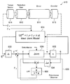
In the present embodiment, the ideal joint control is performed by controlling the joints so that the joints 421a to 421f of the support arm device 400 perform an ideal response as shown in the formula (12). Called. Here, in the following description, an actuator whose drive is controlled by the ideal joint control is also referred to as a virtual actuator (VA) because an ideal response is performed. Hereinafter, the ideal joint control according to the present embodiment will be described with reference to FIG.

図7は、本開示の一実施形態に係る理想関節制御について説明するための説明図である。なお、図7では、理想関節制御に係る各種の演算を行う概念上の演算器をブロックで模式的に図示している。   FIG. 7 is an explanatory diagram for describing ideal joint control according to an embodiment of the present disclosure. In FIG. 7, conceptual computing units that perform various computations related to ideal joint control are schematically illustrated in blocks.

図7を参照すると、アクチュエータ610は、図5に示すアクチュエータ430の機構を模式的に表しており、モータ(Motor)611、減速機(Reduction Gear)612、エンコーダ(Encoder)613及びトルクセンサ(Torque Sensor)614は、それぞれ、図5に示すモータ424、減速機426、エンコーダ427及びトルクセンサ428(又は図6Bに示すトルクセンサ428a)に対応している。   Referring to FIG. 7, the actuator 610 schematically represents the mechanism of the actuator 430 shown in FIG. 5, and includes a motor 611, a reduction gear 612, an encoder 613, and a torque sensor (Torque). Sensor 614 corresponds to the motor 424, the speed reducer 426, the encoder 427, and the torque sensor 428 (or the torque sensor 428a shown in FIG. 6B) shown in FIG.

ここで、アクチュエータ610が上記数式(12)で表される理論モデルに従った応答を行なうことは、上記数式(12)の右辺が与えられたときに、左辺の回転角加速度が達成されることに他ならない。また、上記数式(12)に示すように、理論モデルには、アクチュエータ610に作用する外トルク項τが含まれている。本実施形態では、理想関節制御を行うために、トルクセンサ614によって外トルクτを測定する。また、エンコーダ613によって測定されたアクチュエータ610の回転角度qに基づいて外乱に起因するトルクの推定値である外乱推定値τを算出するために、外乱オブザーバ620を適用する。 Here, the actuator 610 responds in accordance with the theoretical model expressed by the mathematical formula (12), and when the right side of the mathematical formula (12) is given, the rotational angular acceleration of the left side is achieved. It is none other than. Further, as shown in the mathematical formula (12), the theoretical model includes an external torque term τ e that acts on the actuator 610. In this embodiment, in order to perform ideal joint control, the external torque τ e is measured by the torque sensor 614. Further, a disturbance observer 620 is applied to calculate a disturbance estimated value τ d that is an estimated value of torque caused by a disturbance based on the rotation angle q of the actuator 610 measured by the encoder 613.

ブロック631は、上記数式(12)に示す関節部421a〜421fの理想的な関節モデル(Ideal Joint Model)に従った演算を行う演算器を表している。ブロック631は、発生トルクτ、外トルクτ、回転角速度(回転角度qの1階微分)を入力として、上記数式(12)の左辺に示す回転角加速度目標値(回転角目標値qrefの2階微分)を出力することができる。 A block 631 represents an arithmetic unit that performs an operation according to an ideal joint model (Ideal Joint Model) of the joint portions 421a to 421f shown in the equation (12). The block 631 receives the generated torque τ a , the external torque τ e , and the rotational angular velocity (the first derivative of the rotational angle q) as inputs, and the rotational angular acceleration target value (the rotational angle target value q ref ) shown on the left side of the equation (12). Can be output.

本実施形態では、上記<<2−2.一般化逆動力学について>>で説明した方法によって算出された発生トルクτと、トルクセンサ614によって測定された外トルクτが、ブロック631に入力される。一方、微分演算を行う演算器を表すブロック632に、エンコーダ613によって測定された回転角度qが入力されることにより、回転角速度(回転角度qの1階微分)が算出される。上記発生トルクτ及び外トルクτに加えて、ブロック632によって算出された回転角速度がブロック631に入力されることにより、ブロック631によって回転角加速度目標値が算出される。算出された回転角加速度目標値は、ブロック633に入力される。 In the present embodiment, the above << 2-2. The generated torque τ a calculated by the method described in the generalized inverse dynamics >> and the external torque τ e measured by the torque sensor 614 are input to the block 631. On the other hand, a rotational angular velocity (first-order differential of the rotational angle q) is calculated by inputting the rotational angle q measured by the encoder 613 to a block 632 representing a computing unit that performs a differential operation. In addition to the generated torque τ a and the external torque τ e , the rotational angular velocity calculated by the block 632 is input to the block 631, whereby the rotational angular acceleration target value is calculated by the block 631. The calculated rotational angular acceleration target value is input to block 633.

ブロック633は、アクチュエータ610の回転角加速度に基づいてアクチュエータ610に生じるトルクを算出する演算器を表す。本実施形態においては、具体的には、ブロック633は、回転角加速度目標値にアクチュエータ610における公称イナーシャ(ノミナルイナーシャ)Jを乗じることにより、トルク目標値τrefを得ることができる。理想の応答においては、アクチュエータ610に当該トルク目標値τrefを生じさせることにより、所望の運動目的が達成されるはずであるが、上述したように、実際の応答には外乱等の影響が生じる場合がある。従って、本実施形態においては、外乱オブザーバ620によって外乱推定値τを算出し、外乱推定値τを用いて当該トルク目標値τrefを補正する。 A block 633 represents a calculator that calculates torque generated in the actuator 610 based on the rotational angular acceleration of the actuator 610. Specifically, in the present embodiment, the block 633 can obtain the torque target value τ ref by multiplying the rotational angular acceleration target value by the nominal inertia (nominal inertia) J n in the actuator 610. In an ideal response, the desired motion objective should be achieved by causing the actuator 610 to generate the torque target value τ ref. However, as described above, the actual response is affected by disturbances and the like. There is a case. Accordingly, in the present embodiment, to calculate the estimated disturbance value tau d by the disturbance observer 620, corrects the torque target value tau ref using the disturbance estimated value tau d.

外乱オブザーバ620の構成について説明する。図7に示すように、外乱オブザーバ620は、トルク指令値τと、エンコーダ613によって測定された回転角度qから算出される回転角速度に基づいて、外乱推定値τを算出する。ここで、トルク指令値τは、外乱の影響が補正された後の、最終的にアクチュエータ610に生じさせるトルク値である。例えば、外乱推定値τが算出されていない場合には、トルク指令値τはトルク目標値τrefとなる。 The configuration of the disturbance observer 620 will be described. As shown in FIG. 7, the disturbance observer 620 calculates a disturbance estimated value τ d based on the torque command value τ and the rotation angular velocity calculated from the rotation angle q measured by the encoder 613. Here, the torque command value τ is a torque value finally generated in the actuator 610 after the influence of the disturbance is corrected. For example, when the disturbance estimated value τ d is not calculated, the torque command value τ becomes the torque target value τ ref .

外乱オブザーバ620は、ブロック634とブロック635とから構成される。ブロック634は、アクチュエータ610の回転角速度に基づいてアクチュエータ610に生じるトルクを算出する演算器を表す。本実施形態においては、具体的には、エンコーダ613によって測定された回転角度qから、ブロック632によって算出された回転角速度がブロック634に入力される。ブロック634は、伝達関数Jsによって表される演算を行うことにより、すなわち、当該回転角速度を微分することにより回転角加速度を求め、更に算出された回転角加速度にノミナルイナーシャJを乗じることにより、実際にアクチュエータ610に作用しているトルクの推定値(トルク推定値)を算出することができる。 The disturbance observer 620 includes a block 634 and a block 635. Block 634 represents a calculator that calculates torque generated in the actuator 610 based on the rotational angular velocity of the actuator 610. In the present embodiment, specifically, the rotational angular velocity calculated by the block 632 is input to the block 634 from the rotational angle q measured by the encoder 613. Block 634 obtains the rotational angular acceleration by performing an operation represented by the transfer function J n s, that is, differentiating the rotational angular velocity, and multiplies the calculated rotational angular acceleration by Nominal Inertia J n. Thus, an estimated value (torque estimated value) of the torque actually acting on the actuator 610 can be calculated.

外乱オブザーバ620内では、当該トルク推定値とトルク指令値τとの差分が取られることにより、外乱によるトルクの値である外乱推定値τが推定される。具体的には、外乱推定値τは、前周の制御におけるトルク指令値τと、今回の制御におけるトルク推定値との差分であってよい。ブロック634によって算出されるトルク推定値は実際の測定値に基づくものであり、ブロック633によって算出されたトルク指令値τはブロック631に示す関節部421a〜421fの理想的な理論モデルに基づくものであるため、両者の差分を取ることによって、上記理論モデルでは考慮されていない外乱の影響を推定することができるのである。 In the disturbance observer 620, a difference between the estimated torque value and the torque command value τ is taken to estimate a disturbance estimated value τ d that is a torque value due to the disturbance. Specifically, the estimated disturbance value τ d may be a difference between the torque command value τ in the previous control and the estimated torque value in the current control. The estimated torque value calculated by the block 634 is based on the actual measured value, and the torque command value τ calculated by the block 633 is based on the ideal theoretical model of the joint portions 421a to 421f shown in the block 631. Therefore, by taking the difference between the two, it is possible to estimate the influence of a disturbance that is not considered in the theoretical model.

また、外乱オブザーバ620には、系の発散を防ぐために、ブロック635に示すローパスフィルター(LPF:Low Pass Filter)が設けられる。ブロック635は、伝達関数g/(s+g)で表される演算を行うことにより、入力された値に対して低周波成分のみを出力し、系を安定化させる。本実施形態では、ブロック634によって算出されたトルク推定値とトルク指令値τrefとの差分値は、ブロック635に入力され、その低周波成分が外乱推定値τとして算出される。 The disturbance observer 620 is provided with a low pass filter (LPF) indicated by a block 635 in order to prevent system divergence. The block 635 performs the operation represented by the transfer function g / (s + g), thereby outputting only the low frequency component for the input value and stabilizing the system. In the present embodiment, the difference value between the estimated torque value calculated by the block 634 and the torque command value τ ref is input to the block 635, and the low frequency component is calculated as the estimated disturbance value τ d .

本実施形態では、トルク目標値τrefに外乱オブザーバ620によって算出された外乱推定値τを加算するフィードフォワード制御が行われることにより、最終的にアクチュエータ610に生じさせるトルク値であるトルク指令値τが算出される。そして、トルク指令値τに基づいてアクチュエータ610が駆動される。具体的には、トルク指令値τが対応する電流値(電流指令値)に変換され、当該電流指令値がモータ611に印加されることにより、アクチュエータ610が駆動される。 In the present embodiment, by a feed forward control for adding the estimated disturbance value tau d calculated by the disturbance observer 620 the torque target value tau ref performed, finally the torque command value is a torque value that causes the actuator 610 τ is calculated. Then, the actuator 610 is driven based on the torque command value τ. Specifically, the torque command value τ is converted into a corresponding current value (current command value), and the current command value is applied to the motor 611, whereby the actuator 610 is driven.

以上、図7を参照して説明した構成を取ることにより、本実施形態に係る関節部421a〜421fの駆動制御においては、摩擦等の外乱成分があった場合であっても、アクチュエータ610の応答を目標値に追従させることが可能となる。また、関節部421a〜421fの駆動制御について、理論モデルが仮定するイナーシャI及び粘性抵抗係数νに従った理想応答を行うことが可能となる。 As described above, by adopting the configuration described with reference to FIG. 7, in the drive control of the joint portions 421a to 421f according to the present embodiment, the response of the actuator 610 even when there is a disturbance component such as friction. Can follow the target value. Further, the drive control of the joint 421A~421f, it is possible to perform an ideal response that theoretical models according to the assumed inertia I a and viscosity resistance coefficient [nu a.

なお、以上説明した理想関節制御の詳細については、例えば、本願出願人による先行特許出願である特開2009−269102号公報を参照することができる。   For details of the ideal joint control described above, reference can be made to, for example, Japanese Patent Application Laid-Open No. 2009-269102, which is a prior patent application filed by the present applicant.

以上、本実施形態において用いられる一般化逆動力学について説明するとともに、図7を参照して本実施形態に係る理想関節制御について説明した。以上説明したように、本実施形態においては、一般化逆動力学を用いることにより、アーム部420の運動目的を達成するための各関節部421a〜421fの駆動パラメータ(例えば関節部421a〜421fの発生トルク値)を、拘束条件を考慮して算出する、全身協調制御が行われる。また、図7を参照して説明したように、本実施形態においては、上記一般化逆動力学を用いた全身協調制御により算出された発生トルク値に対して外乱の影響を考慮した補正を行うことにより、関節部421a〜421fの駆動制御において理論モデルに基づいた理想的な応答を実現する、理想関節制御が行われる。従って、本実施形態においては、アーム部420の駆動について、運動目的を達成する高精度な駆動制御が可能となる。   The generalized inverse dynamics used in the present embodiment has been described above, and the ideal joint control according to the present embodiment has been described with reference to FIG. As described above, in the present embodiment, by using generalized inverse dynamics, the drive parameters (for example, the joint portions 421a to 421f of the joint portions 421a to 421f) for achieving the motion purpose of the arm portion 420 are achieved. The whole body cooperative control is performed in which the generated torque value) is calculated in consideration of the constraint conditions. Further, as described with reference to FIG. 7, in the present embodiment, the generated torque value calculated by the whole body cooperative control using the generalized inverse dynamics is corrected in consideration of the influence of disturbance. Thus, ideal joint control that realizes an ideal response based on a theoretical model in drive control of the joint portions 421a to 421f is performed. Therefore, in the present embodiment, high-accuracy drive control that achieves the purpose of movement can be performed for driving the arm unit 420.

<<2−4.支持アーム制御システムの構成>>
次に、上記<<2−2.一般化逆動力学について>>及び上記<<2−3.理想関節制御について>>で説明した全身協調制御や理想関節制御が支持アーム装置の駆動制御に適用された、本実施形態に係る支持アーム制御システムの構成について説明する。
<< 2-4. Configuration of support arm control system >>
Next, the above << 2-2. About generalized inverse dynamics >> and above << 2-3. About ideal joint control The structure of the support arm control system which concerns on this embodiment in which the whole body cooperation control and ideal joint control which were demonstrated by >> was applied to the drive control of a support arm apparatus is demonstrated.

図8を参照して、本開示の一実施形態に係る支持アーム制御システムの一構成例について説明する。図8は、本開示の一実施形態に係る支持アーム制御システムの一構成例を示す機能ブロック図である。なお、図8に示す支持アーム制御システムでは、支持アーム装置のアーム部の駆動の制御に関わる構成について主に図示している。   A configuration example of the support arm control system according to an embodiment of the present disclosure will be described with reference to FIG. FIG. 8 is a functional block diagram illustrating a configuration example of a support arm control system according to an embodiment of the present disclosure. In the support arm control system shown in FIG. 8, the configuration related to the drive control of the arm portion of the support arm device is mainly illustrated.

図8を参照すると、本開示の一実施形態に係る支持アーム制御システム1は、支持アーム装置10、制御装置20及び表示装置30を備える。本実施形態においては、制御装置20によって、上記<<2−2.一般化逆動力学について>>で説明した全身協調制御及び上記<<2−3.理想関節制御について>>で説明した理想関節制御における各種の演算が行われ、その演算結果に基づいて支持アーム装置10のアーム部の駆動が制御される。なお、制御装置20は、例えばCPU等のプロセッサによって構成され、所定のプログラムに従って動作することにより、支持アーム装置10のアーム部の駆動を制御する。また、支持アーム装置10のアーム部には後述する撮像部140が設けられており、撮像部140によって撮影された画像が表示装置30の表示画面に表示される。以下、支持アーム装置10、制御装置20及び表示装置30の構成について詳細に説明する。   Referring to FIG. 8, the support arm control system 1 according to an embodiment of the present disclosure includes a support arm device 10, a control device 20, and a display device 30. In the present embodiment, the control device 20 performs the above << 2-2. Whole body cooperative control described in >>> generalized inverse dynamics and the above << 2-3. Regarding the ideal joint control, various calculations in the ideal joint control described in >> are performed, and the drive of the arm portion of the support arm device 10 is controlled based on the calculation results. The control device 20 is constituted by a processor such as a CPU, for example, and controls driving of the arm portion of the support arm device 10 by operating according to a predetermined program. Further, the arm unit of the support arm device 10 is provided with an imaging unit 140 described later, and an image captured by the imaging unit 140 is displayed on the display screen of the display device 30. Hereinafter, the configuration of the support arm device 10, the control device 20, and the display device 30 will be described in detail.

支持アーム装置10は、複数の関節部と複数のリンクから構成される多リンク構造体であるアーム部を有し、当該アーム部を可動範囲内で駆動させることにより、当該アーム部の先端に設けられる先端ユニットの位置及び姿勢の制御を行う。支持アーム装置10は、図3に示す支持アーム装置400に対応している。   The support arm device 10 has an arm part that is a multi-link structure composed of a plurality of joint parts and a plurality of links, and is provided at the tip of the arm part by driving the arm part within a movable range. The position and orientation of the tip unit to be controlled are controlled. The support arm device 10 corresponds to the support arm device 400 shown in FIG.

図8を参照すると、支持アーム装置10は、アーム制御部110及びアーム部120を有する。また、アーム部120は、関節部130及び撮像部140を有する。   Referring to FIG. 8, the support arm device 10 includes an arm control unit 110 and an arm unit 120. In addition, the arm unit 120 includes a joint unit 130 and an imaging unit 140.

アーム制御部110は、支持アーム装置10を統合的に制御するとともに、アーム部120の駆動を制御する。アーム制御部110は、図3を参照して説明した制御部(図3には図示せず。)に対応している。具体的には、アーム制御部110は駆動制御部111を有し、駆動制御部111からの制御によって関節部130の駆動が制御されることにより、アーム部120の駆動が制御される。より具体的には、駆動制御部111は、関節部130のアクチュエータにおけるモータに対して供給される電流量を制御することにより、当該モータの回転数を制御し、関節部130における回転角度及び発生トルクを制御する。ただし、上述したように、駆動制御部111によるアーム部120の駆動制御は、制御装置20における演算結果に基づいて行われる。従って、駆動制御部111によって制御される、関節部130のアクチュエータにおけるモータに対して供給される電流量は、制御装置20における演算結果に基づいて決定される電流量である。   The arm control unit 110 controls the support arm device 10 in an integrated manner and also controls the driving of the arm unit 120. The arm control unit 110 corresponds to the control unit (not shown in FIG. 3) described with reference to FIG. Specifically, the arm control unit 110 includes a drive control unit 111, and the drive of the arm unit 120 is controlled by controlling the drive of the joint unit 130 by the control from the drive control unit 111. More specifically, the drive control unit 111 controls the number of rotations of the motor by controlling the amount of current supplied to the motor in the actuator of the joint unit 130, and the rotation angle and generation in the joint unit 130. Control torque. However, as described above, the drive control of the arm unit 120 by the drive control unit 111 is performed based on the calculation result in the control device 20. Therefore, the amount of current supplied to the motor in the actuator of the joint unit 130 controlled by the drive control unit 111 is a current amount determined based on the calculation result in the control device 20.

アーム部120は、複数の関節部と複数のリンクから構成される多リンク構造体であり、アーム制御部110からの制御によりその駆動が制御される。アーム部120は、図3に示すアーム部420に対応している。アーム部120は、関節部130及び撮像部140を有する。なお、アーム部120が有する複数の関節部の機能及び構成は互いに同様であるため、図8では、それら複数の関節部を代表して1つの関節部130の構成を図示している。   The arm unit 120 is a multi-link structure including a plurality of joint units and a plurality of links, and the driving thereof is controlled by the control from the arm control unit 110. The arm part 120 corresponds to the arm part 420 shown in FIG. The arm unit 120 includes a joint unit 130 and an imaging unit 140. In addition, since the function and structure of the some joint part which the arm part 120 has are mutually the same, in FIG. 8, the structure of the one joint part 130 is illustrated on behalf of these several joint parts.

関節部130は、アーム部120においてリンク間を互いに回動可能に連結するとともに、アーム制御部110からの制御によりその回転駆動が制御されることによりアーム部120を駆動する。関節部130は、図3に示す関節部421a〜421fに対応している。また、関節部130は、アクチュエータを有し、当該アクチュエータの構成は、例えば図5、図6A及び図6Bに示す構成と同様である。   The joint portion 130 rotatably connects between the links in the arm portion 120, and drives the arm portion 120 by controlling the rotation drive by the control from the arm control portion 110. The joint part 130 corresponds to the joint parts 421a to 421f shown in FIG. The joint unit 130 includes an actuator, and the configuration of the actuator is the same as the configuration illustrated in FIGS. 5, 6A, and 6B, for example.

関節部130は、関節駆動部131及び関節状態検出部132を有する。   The joint unit 130 includes a joint drive unit 131 and a joint state detection unit 132.

関節駆動部131は、関節部130のアクチュエータにおける駆動機構であり、関節駆動部131が駆動することにより関節部130が回転駆動する。関節駆動部131は、駆動制御部111によってその駆動が制御される。例えば、関節駆動部131は、図5に示すモータ424及びモータドライバ425に対応する構成であり、関節駆動部131が駆動することは、モータドライバ425が駆動制御部111からの指令に応じた電流量でモータ424を駆動することに対応している。   The joint drive unit 131 is a drive mechanism in the actuator of the joint unit 130, and the joint unit 130 is driven to rotate when the joint drive unit 131 is driven. The drive of the joint drive unit 131 is controlled by the drive control unit 111. For example, the joint drive unit 131 has a configuration corresponding to the motor 424 and the motor driver 425 illustrated in FIG. 5, and the joint drive unit 131 is driven by a current corresponding to a command from the drive control unit 111. This corresponds to driving the motor 424 by the amount.

関節状態検出部132は、関節部130の状態を検出する。ここで、関節部130の状態とは、関節部130の運動の状態を意味していてよい。例えば、関節部130の状態には、関節部130の回転角度、回転角速度、回転角加速度、発生トルク等の情報が含まれる。本実施形態においては、関節状態検出部132は、関節部130の回転角度を検出する回転角度検出部133及び関節部130の発生トルク及び外トルクを検出するトルク検出部134を有する。なお、回転角度検出部133及びトルク検出部134は、図5に示すアクチュエータ430のエンコーダ427及び図6A及び図6Bに示すトルクセンサ428、428aに、それぞれ対応している。関節状態検出部132は、検出した関節部130の状態を制御装置20に送信する。   The joint state detection unit 132 detects the state of the joint unit 130. Here, the state of the joint 130 may mean the state of motion of the joint 130. For example, the state of the joint unit 130 includes information such as the rotation angle, rotation angular velocity, rotation angular acceleration, and generated torque of the joint unit 130. In the present embodiment, the joint state detection unit 132 includes a rotation angle detection unit 133 that detects the rotation angle of the joint unit 130, and a torque detection unit 134 that detects the generated torque and the external torque of the joint unit 130. The rotation angle detection unit 133 and the torque detection unit 134 correspond to the encoder 427 of the actuator 430 shown in FIG. 5 and the torque sensors 428 and 428a shown in FIGS. 6A and 6B, respectively. The joint state detection unit 132 transmits the detected state of the joint unit 130 to the control device 20.

撮像部140は、アーム部120の先端に設けられる先端ユニットの一例であり、撮影対象の画像を取得する。撮像部140は、図3に示す内視鏡装置423に対応している。具体的には、撮像部140は、撮影対象を動画や静止画の形式で撮影することのできるカメラ等である。より具体的には、撮像部140は、2次元上に配列された複数の受光素子を有し、当該受光素子における光電変換により、撮影対象の画像を表す画像信号を取得することができる。撮像部140は、取得した画像信号を表示装置30に送信する。   The imaging unit 140 is an example of a tip unit provided at the tip of the arm unit 120, and acquires an image to be photographed. The imaging unit 140 corresponds to the endoscope apparatus 423 shown in FIG. Specifically, the imaging unit 140 is a camera or the like that can shoot a shooting target in the form of a moving image or a still image. More specifically, the imaging unit 140 has a plurality of light receiving elements arranged two-dimensionally, and can acquire an image signal representing an image to be photographed by photoelectric conversion in the light receiving elements. The imaging unit 140 transmits the acquired image signal to the display device 30.

なお、図3に示す支持アーム装置400において内視鏡装置423がアーム部420の先端に設けられていたように、支持アーム装置10においても、実際には撮像部140がアーム部120の先端に設けられている。図8では、撮像部140が複数の関節部130及び複数のリンクを介して最終段のリンクの先端に設けられる様子を、関節部130と撮像部140との間にリンクを模式的に図示することにより表現している。   Note that, in the support arm device 10 shown in FIG. 3, the endoscope device 423 is provided at the tip of the arm unit 420, and in the support arm device 10, the imaging unit 140 is actually at the tip of the arm unit 120. Is provided. In FIG. 8, a state in which the imaging unit 140 is provided at the distal end of the link in the final stage via the plurality of joint units 130 and the plurality of links is schematically illustrated between the joint unit 130 and the imaging unit 140. It is expressed by

なお、本実施形態においては、アーム部120の先端には先端ユニットとして各種の医療用器具が接続され得る。当該医療用器具としては、例えば、メスや鉗子等の各種の施術器具や、超音波検査装置の探触子等の各種の検査装置の一ユニット等、施術に際して用いられる各種のユニットが挙げられる。また、本実施形態では、図8に示す撮像部140や、内視鏡、顕微鏡等の撮像機能を有するユニットも医療用器具に含まれてよい。このように、本実施形態に係る支持アーム装置10は、医療用器具を備えた医療用支持アーム装置であると言える。同様に、本実施形態に係る支持アーム制御システム1は、医療用支持アーム制御システム(医療用システム)であると言える。また、アーム部120の先端に、2つの撮像ユニット(カメラユニット)を有するステレオカメラが設けられ、撮像対象を3D画像として表示するように撮影が行われてもよい。   In the present embodiment, various medical instruments can be connected to the tip of the arm unit 120 as a tip unit. Examples of the medical instrument include various units used for the treatment, such as various surgical instruments such as a scalpel and forceps, and a unit of various inspection apparatuses such as a probe of an ultrasonic inspection apparatus. In the present embodiment, a unit having an imaging function such as the imaging unit 140 shown in FIG. 8, an endoscope, a microscope, or the like may be included in the medical instrument. Thus, it can be said that the support arm device 10 according to the present embodiment is a medical support arm device including a medical instrument. Similarly, it can be said that the support arm control system 1 according to the present embodiment is a medical support arm control system (medical system). Further, a stereo camera having two imaging units (camera units) may be provided at the tip of the arm unit 120, and shooting may be performed so that the imaging target is displayed as a 3D image.

以上、支持アーム装置10の機能及び構成について説明した。次に、制御装置20の機能及び構成について説明する。図8を参照すると、制御装置20は、入力部210、記憶部220及び制御部230を有する。   The function and configuration of the support arm device 10 have been described above. Next, the function and configuration of the control device 20 will be described. Referring to FIG. 8, the control device 20 includes an input unit 210, a storage unit 220, and a control unit 230.

制御部230は、制御装置20を統合的に制御するとともに、支持アーム装置10におけるアーム部120の駆動を制御するための各種の演算を行う。具体的には、制御部230は、支持アーム装置10のアーム部120の駆動を制御するために、全身協調制御及び理想関節制御における各種の演算を行う。以下、制御部230の機能及び構成について詳しく説明するが、全身協調制御及び理想関節制御については、上記<<2−2.一般化逆動力学について>>及び上記<<2−3.理想関節制御について>>で既に説明しているため、ここでは詳しい説明は省略する。   The control unit 230 integrally controls the control device 20 and performs various calculations for controlling the driving of the arm unit 120 in the support arm device 10. Specifically, the control unit 230 performs various calculations in the whole body cooperative control and the ideal joint control in order to control the driving of the arm unit 120 of the support arm device 10. Hereinafter, although the function and structure of the control part 230 are demonstrated in detail, about whole body cooperation control and ideal joint control, said << 2-2. About generalized inverse dynamics >> and above << 2-3. Since the ideal joint control has already been described in >>, detailed description is omitted here.

制御部230は、全身協調制御部240及び理想関節制御部250を有する。   The control unit 230 includes a whole body cooperative control unit 240 and an ideal joint control unit 250.

全身協調制御部240は、一般化逆動力学を用いた全身協調制御に関する各種の演算を行う。本実施形態では、全身協調制御部240は、関節状態検出部132によって検出された関節部130の状態に基づいてアーム部120の状態(アーム状態)を取得する。また、全身協調制御部240は、当該アーム状態と、アーム部120の運動目的及び拘束条件と、に基づいて、操作空間におけるアーム部120の全身協調制御のための制御値を、一般化逆動力学を用いて算出する。なお、操作空間とは、例えばアーム部120に作用する力とアーム部120に発生する加速度との関係を記述するための空間である。   The whole body cooperative control unit 240 performs various calculations related to whole body cooperative control using generalized inverse dynamics. In the present embodiment, the whole body cooperative control unit 240 acquires the state of the arm unit 120 (arm state) based on the state of the joint unit 130 detected by the joint state detection unit 132. Further, the whole body cooperative control unit 240 generates a generalized inverse power based on the control value for the whole body cooperative control of the arm unit 120 in the operation space based on the arm state, the motion purpose and the constraint condition of the arm unit 120. Calculate using science. The operation space is a space for describing the relationship between the force acting on the arm unit 120 and the acceleration generated in the arm unit 120, for example.

全身協調制御部240は、アーム状態取得部241、演算条件設定部242、仮想力算出部243及び実在力算出部244を有する。   The whole body cooperative control unit 240 includes an arm state acquisition unit 241, a calculation condition setting unit 242, a virtual force calculation unit 243, and a real force calculation unit 244.

アーム状態取得部241は、関節状態検出部132によって検出された関節部130の状態に基づいて、アーム部120の状態(アーム状態)を取得する。ここで、アーム状態とは、アーム部120の運動の状態を意味していてよい。例えば、アーム状態には、アーム部120の位置、速度、加速度、力等の情報が含まれる。上述したように、関節状態検出部132は、関節部130の状態として、各関節部130における回転角度、回転角速度、回転角加速度、発生トルク等の情報を取得している。また、後述するが、記憶部220は、制御装置20によって処理される各種の情報を記憶するものであり、本実施形態においては、記憶部220には、アーム部120に関する各種の情報(アーム情報)、例えばアーム部120を構成する関節部130及びリンクの数や、リンクと関節部130との接続状況、リンクの長さ等の情報が格納されていてよい。アーム状態取得部241は、記憶部220から当該アーム情報を取得することができる。従って、アーム状態取得部241は、関節部130の状態とアーム情報とに基づいて、複数の関節部130、複数のリンク及び撮像部140の空間上の位置(座標)(すなわち、アーム部120の形状や撮像部140の位置及び姿勢)や、各関節部130、リンク及び撮像部140に作用している力等の情報をアーム状態として取得することができる。アーム状態取得部241は、取得したアーム情報を演算条件設定部242に送信する。   The arm state acquisition unit 241 acquires the state (arm state) of the arm unit 120 based on the state of the joint unit 130 detected by the joint state detection unit 132. Here, the arm state may mean a state of movement of the arm unit 120. For example, the arm state includes information such as the position, speed, acceleration, and force of the arm unit 120. As described above, the joint state detection unit 132 acquires information such as the rotation angle, the rotation angular velocity, the rotation angular acceleration, and the generated torque in each joint unit 130 as the state of the joint unit 130. As will be described later, the storage unit 220 stores various types of information processed by the control device 20, and in the present embodiment, the storage unit 220 stores various types of information (arm information) about the arm unit 120. For example, information such as the number of the joint portions 130 and the links constituting the arm portion 120, the connection status between the links and the joint portion 130, and the link length may be stored. The arm state acquisition unit 241 can acquire the arm information from the storage unit 220. Therefore, the arm state acquisition unit 241 determines the position (coordinates) in space of the plurality of joint units 130, the plurality of links, and the imaging unit 140 based on the state of the joint unit 130 and the arm information (that is, the arm unit 120). Information such as the shape, the position and orientation of the image capturing unit 140), the force acting on each joint unit 130, the link, and the image capturing unit 140 can be acquired as an arm state. The arm state acquisition unit 241 transmits the acquired arm information to the calculation condition setting unit 242.

演算条件設定部242は、一般化逆動力学を用いた全身協調制御に関する演算における演算条件を設定する。ここで、演算条件とは、運動目的及び拘束条件であってよい。運動目的は、アーム部120の運動に関する各種の情報であってよい。具体的には、運動目的は、撮像部140の位置及び姿勢(座標)、速度、加速度並びに力等の目標値であったり、アーム部120の複数の関節部130及び複数のリンクの位置(座標)、速度、加速度及び力等の目標値であったりしてもよい。また、拘束条件は、アーム部120の運動を制限(拘束)する各種の情報であってよい。具体的には、拘束条件は、アーム部の各構成部材が移動不可能な領域の座標や、移動不可能な速度、加速度の値、発生不可能な力の値等であってよい。また、拘束条件における各種の物理量の制限範囲は、アーム部120の構造的に実現することが不可能であることから設定されてもよいし、ユーザによって適宜設定されてもよい。また、演算条件設定部242は、アーム部120の構造についての物理モデル(例えば、アーム部120を構成するリンクの数や長さ、リンクの関節部130を介した接続状況、関節部130の可動範囲等がモデル化されたもの)を有し、当該物理モデルに、所望の運動条件及び拘束条件が反映された制御モデルを生成することにより、運動条件及び拘束条件を設定してもよい。   The calculation condition setting unit 242 sets calculation conditions for calculation related to whole body cooperative control using generalized inverse dynamics. Here, the calculation condition may be an exercise purpose and a constraint condition. The exercise purpose may be various types of information regarding the exercise of the arm unit 120. Specifically, the purpose of motion is a target value such as the position and orientation (coordinates), speed, acceleration, and force of the imaging unit 140, or the positions (coordinates) of the joints 130 and the links of the arm unit 120. ), Target values such as speed, acceleration and force. Further, the constraint condition may be various types of information that limits (restrains) the movement of the arm unit 120. Specifically, the constraint condition may be coordinates of a region in which each component of the arm unit is not movable, a non-movable speed, an acceleration value, a force value that cannot be generated, or the like. In addition, the limitation range of various physical quantities in the constraint condition may be set because it is impossible to realize the structure of the arm unit 120, or may be set as appropriate by the user. The calculation condition setting unit 242 also includes a physical model for the structure of the arm unit 120 (for example, the number and length of links constituting the arm unit 120, the connection status through the link joint unit 130, and the movement of the joint unit 130). The motion condition and the constraint condition may be set by generating a control model in which the desired motion condition and the constraint condition are reflected in the physical model.

本実施形態においては、運動目的及び拘束条件を適切に設定することにより、アーム部120に所望の動作を行わせることが可能となる。例えば、運動目的として、撮像部140の位置の目標値を設定することにより撮像部140をその目標の位置に移動させることはもちろんのこと、アーム部120が空間上の所定の領域内に侵入しないようにする等、拘束条件によって移動の制約を設けてアーム部120を駆動させることも可能である。   In the present embodiment, it is possible to cause the arm unit 120 to perform a desired operation by appropriately setting the purpose of exercise and the constraint conditions. For example, by setting a target value for the position of the imaging unit 140 as an exercise purpose, the arm unit 120 does not enter a predetermined area in the space as well as moving the imaging unit 140 to the target position. For example, it is possible to drive the arm unit 120 by restricting movement according to the constraint conditions.

運動目的の具体例として、例えば、運動目的は、撮像部140の撮影方向が施術部位に固定された状態で、撮像部140が施術部位を頂点とした円錐の面内を移動する、当該円錐の軸を旋回軸とした旋回動作である、ピボット動作であってもよい。また、当該ピボット動作においては、撮像部140と円錐の頂点に当たる点との距離が一定に保たれた状態で旋回動作が行われてもよい。このようなピボット動作を行うことにより、観察部位を等距離からかつ異なる角度から観察できるようになるため、手術を行うユーザの利便性を向上させることができる。   As a specific example of the purpose of exercise, for example, the purpose of exercise is to move the imaging unit 140 in the plane of the cone with the treatment site as a vertex in a state where the imaging direction of the imaging unit 140 is fixed to the treatment site. A pivoting operation that is a pivoting operation with the axis as a pivotal axis may be used. In the pivot operation, the turning operation may be performed in a state where the distance between the imaging unit 140 and the point corresponding to the apex of the cone is kept constant. By performing such a pivoting operation, the observation site can be observed from the same distance and from different angles, so that the convenience of the user performing the operation can be improved.

また、他の具体例として、運動目的は、各関節部130における発生トルクを制御する内容であってもよい。具体的には、運動目的は、アーム部120に作用する重力を打ち消すように関節部130の状態を制御するとともに、更に外部から与えられた力の方向へのアーム部120の移動をサポートするように関節部130の状態を制御するパワーアシスト動作であってもよい。より具体的には、パワーアシスト動作においては、アーム部120の各関節部130における重力による外トルクを打ち消す発生トルクを各関節部130に生じさせるように各関節部130の駆動が制御されることにより、アーム部120の位置及び姿勢が所定の状態で保持される。この状態で更に外部から(例えばユーザから)外トルクが加えられた場合に、与えられた外トルクと同じ方向の発生トルクを各関節部130に生じさせるように各関節部130の駆動が制御される。このようなパワーアシスト動作を行うことにより、ユーザが手動でアーム部120を動かす場合に、ユーザはより小さい力でアーム部120を移動させることができるため、あたかも無重力下でアーム部120を動かしているような感覚をユーザに対して与えることができる。また、上述したピボット動作と当該パワーアシスト動作とを組み合わせることも可能である。   As another specific example, the purpose of exercise may be a content for controlling the torque generated at each joint 130. Specifically, the purpose of the exercise is to control the state of the joint 130 so as to cancel the gravity acting on the arm 120, and to further support the movement of the arm 120 in the direction of the force applied from the outside. Alternatively, a power assist operation for controlling the state of the joint 130 may be used. More specifically, in the power assist operation, the driving of each joint unit 130 is controlled so as to cause each joint unit 130 to generate generated torque that cancels the external torque due to gravity in each joint unit 130 of the arm unit 120. Thus, the position and posture of the arm unit 120 are held in a predetermined state. In this state, when an external torque is further applied from the outside (for example, from a user), the driving of each joint 130 is controlled so that a generated torque in the same direction as the applied external torque is generated in each joint 130. The By performing such a power assist operation, when the user manually moves the arm unit 120, the user can move the arm unit 120 with a smaller force, so that the arm unit 120 is moved under zero gravity. It is possible to give the user a feeling of being. It is also possible to combine the above-described pivot operation and the power assist operation.

ここで、本実施形態において、運動目的とは、全身協調制御において実現されるアーム部120の動作(運動)を意味していてもよいし、当該動作における瞬時的な運動目的(すなわち、運動目的における目標値)を意味していてもよい。例えば上記のピボット動作であれば、撮像部140がピボット動作を行うこと自体が運動目的であるが、ピボット動作を行っている最中においては、当該ピボット動作における円錐面内での撮像部140の位置や速度等の値が、瞬時的な運動目的(当該運動目的における目標値)として設定されている。また例えば上記のパワーアシスト動作であれば、外部から加えられた力の方向へのアーム部120の移動をサポートするパワーアシスト動作を行うこと自体が運動目的であるが、パワーアシスト動作を行っている最中においては、各関節部130に加えられる外トルクと同じ方向への発生トルクの値が、瞬時的な運動目的(当該運動目的における目標値)として設定されている。本実施形態における運動目的は、瞬時的な運動目的(例えばある時間におけるアーム部120の各構成部材の位置や速度、力等の目標値)と、瞬時的な運動目的が連続的に達成された結果、経時的に実現されるアーム部120の各構成部材の動作の、双方を含む概念である。全身協調制御部240における全身協調制御のための演算における各ステップでは瞬時的な運動目的がその都度設定され、当該演算が繰り返し行われることにより、最終的に所望の運動目的が達成される。   Here, in this embodiment, the exercise purpose may mean an operation (exercise) of the arm unit 120 realized in the whole body cooperative control, or an instantaneous exercise purpose (that is, an exercise purpose) in the operation. Target value). For example, in the case of the pivot operation described above, the purpose of the image capturing unit 140 to perform the pivot operation itself is a movement purpose. However, during the pivot operation, the image capturing unit 140 within the conical surface in the pivot operation is used. Values such as position and speed are set as instantaneous exercise objectives (target values for the exercise objectives). Further, for example, in the case of the power assist operation described above, the power assist operation for supporting the movement of the arm unit 120 in the direction of the force applied from the outside is itself an exercise purpose, but the power assist operation is performed. In the middle, the value of the generated torque in the same direction as the external torque applied to each joint portion 130 is set as an instantaneous exercise purpose (target value for the exercise purpose). In the present embodiment, the instantaneous movement objective (for example, the target value of the position, speed, force, etc. of each component member of the arm unit 120 at a certain time) and the instantaneous movement objective are continuously achieved. As a result, it is a concept including both of the operations of the respective constituent members of the arm unit 120 realized over time. In each step in the calculation for the whole body cooperative control in the whole body cooperative control unit 240, an instantaneous exercise purpose is set each time, and the calculation is repeatedly performed, so that the desired exercise purpose is finally achieved.

なお、本実施形態においては、運動目的が設定される際に、各関節部130の回転運動における粘性抵抗係数も適宜設定されてよい。上述したように、本実施形態に係る関節部130は、アクチュエータ430の回転運動における粘性抵抗係数を適宜調整できるように構成される。従って、運動目的の設定に際して各関節部130の回転運動における粘性抵抗係数も設定することにより、例えば外部から加えられる力に対して回転しやすい状態や回転し難い状態を実現することができる。例えば上述したパワーアシスト動作であれば、関節部130における粘性抵抗係数が小さく設定されることにより、ユーザがアーム部120を移動させる際に要する力がより小さくてよく、ユーザに与えられる無重力感がより助長される。このように、各関節部130の回転運動における粘性抵抗係数は、運動目的の内容に応じて適宜設定されてよい。   In the present embodiment, when the purpose of motion is set, the viscous resistance coefficient in the rotational motion of each joint 130 may be set as appropriate. As described above, the joint portion 130 according to the present embodiment is configured so that the viscous resistance coefficient in the rotational motion of the actuator 430 can be appropriately adjusted. Therefore, by setting the viscous resistance coefficient in the rotational motion of each joint portion 130 when setting the motion purpose, for example, it is possible to realize a state that is easy to rotate or a state that is difficult to rotate with respect to a force applied from the outside. For example, in the above-described power assist operation, the viscous resistance coefficient in the joint portion 130 is set to be small, so that the force required for the user to move the arm portion 120 may be smaller, and the feeling of weight given to the user may be reduced. More conducive. As described above, the viscous resistance coefficient in the rotational motion of each joint 130 may be appropriately set according to the content of the motion purpose.

ここで、本実施形態においては、後述するように、記憶部220には、全身協調制御に関する演算において用いられる運動目的や拘束条件等の演算条件に関するパラメータが格納されていてもよい。演算条件設定部242は、記憶部220に記憶されている拘束条件を、全身協調制御の演算に用いる拘束条件として設定することができる。   Here, in the present embodiment, as will be described later, the storage unit 220 may store parameters related to calculation conditions such as exercise objectives and constraint conditions used in calculations related to whole body cooperative control. The calculation condition setting unit 242 can set the constraint condition stored in the storage unit 220 as the constraint condition used for the calculation of the whole body cooperative control.

また、本実施形態においては、演算条件設定部242は、複数の方法によって運動目的を設定することができる。例えば、演算条件設定部242は、アーム状態取得部241から送信されるアーム状態に基づいて運動目的を設定してもよい。上述したように、アーム状態には、アーム部120の位置の情報やアーム部120に対して作用する力の情報が含まれる。従って、例えばユーザがアーム部120を手動で移動させようとしている場合には、アーム状態取得部241によって、ユーザがアーム部120をどのように移動させようとしているか、に関する情報もアーム状態として取得される。従って、演算条件設定部242は、取得されたアーム状態に基づいて、ユーザがアーム部120を移動させた位置や速度、力等を瞬時的な運動目的として設定することができる。このように運動目的が設定されることにより、アーム部120の駆動は、ユーザによるアーム部120の移動を追随し、サポートするように制御される。   In the present embodiment, the calculation condition setting unit 242 can set the exercise purpose by a plurality of methods. For example, the calculation condition setting unit 242 may set the exercise purpose based on the arm state transmitted from the arm state acquisition unit 241. As described above, the arm state includes information on the position of the arm unit 120 and information on the force acting on the arm unit 120. Therefore, for example, when the user intends to move the arm unit 120 manually, the arm state acquisition unit 241 also acquires information on how the user is moving the arm unit 120 as the arm state. The Therefore, the calculation condition setting unit 242 can set the position, speed, force, and the like at which the user moved the arm unit 120 as an instantaneous exercise purpose based on the acquired arm state. By setting the purpose of exercise in this way, the driving of the arm unit 120 is controlled so as to follow and support the movement of the arm unit 120 by the user.

また、例えば、演算条件設定部242は、入力部210からユーザによって入力される指示に基づいて運動目的を設定してもよい。後述するが、入力部210は、ユーザが制御装置20に支持アーム装置10の駆動制御に関する情報や命令等を入力するための入力インターフェースであり、本実施形態においては、ユーザによる入力部210からの操作入力に基づいて、運動目的が設定されてもよい。具体的には、入力部210は、例えばレバー、ペダル等のユーザが操作する操作手段を有し、当該レバー、ペダル等の操作に応じて、アーム部120の各構成部材の位置や速度等が、演算条件設定部242によって瞬時的な運動目的として設定されてもよい。   For example, the calculation condition setting unit 242 may set the exercise purpose based on an instruction input by the user from the input unit 210. As will be described later, the input unit 210 is an input interface for the user to input information, commands, and the like regarding drive control of the support arm device 10 to the control device 20, and in this embodiment, the input unit 210 from the input unit 210 by the user. The exercise purpose may be set based on the operation input. Specifically, the input unit 210 has operation means operated by a user such as a lever and a pedal, for example, and the position and speed of each constituent member of the arm unit 120 according to the operation of the lever and the pedal. The calculation condition setting unit 242 may set as an instantaneous exercise purpose.

更に、例えば、演算条件設定部242は、記憶部220に記憶されている運動目的を、全身協調制御の演算に用いる運動目的として設定してもよい。例えば、空間上の所定の点で撮像部140が静止するという運動目的であれば、当該所定の点の座標を運動目的として予め設定することができる。また、例えば、撮像部140が空間上において所定の軌跡上を移動するという運動目的であれば、当該所定の軌跡を表す各点の座標を運動目的として予め設定することができる。このように、運動目的が予め設定できるものである場合には、当該運動目的が予め記憶部220に記憶されていてもよい。また、例えば上述したピボット動作であれば、運動目的は円錐の面内における位置や速度等を目標値とするものに限られるし、パワーアシスト動作であれば、運動目的は力を目標値とするものに限られる。このように、ピボット動作やパワーアシスト動作のような運動目的が予め設定されている場合には、これらの運動目的における瞬時的な運動目的として設定され得る目標値の範囲や種類等に関する情報が、記憶部220に記憶されていてもよい。演算条件設定部242は、このような運動目的に関する各種の情報も含めて、運動目的として設定することができる。   Further, for example, the calculation condition setting unit 242 may set the exercise purpose stored in the storage unit 220 as the exercise purpose used for the calculation of the whole body cooperative control. For example, if the purpose of movement is to stop the imaging unit 140 at a predetermined point in space, the coordinates of the predetermined point can be set in advance as the purpose of movement. In addition, for example, if the imaging purpose 140 is a motion purpose of moving on a predetermined trajectory in space, the coordinates of each point representing the predetermined trajectory can be set in advance as the motion purpose. Thus, when the exercise purpose can be set in advance, the exercise purpose may be stored in the storage unit 220 in advance. Further, for example, in the above-described pivot operation, the purpose of motion is limited to the target value such as the position and speed in the plane of the cone, and in the power assist operation, the purpose of motion is the force as the target value. Limited to things. Thus, when exercise objectives such as pivot action and power assist action are preset, information on the range and type of target values that can be set as instantaneous exercise objectives in these exercise objectives, It may be stored in the storage unit 220. The calculation condition setting unit 242 can set the exercise purpose including various information related to the exercise purpose.

なお、演算条件設定部242が、上記のいずれの方法で運動目的を設定するかは、支持アーム装置10の用途等に応じてユーザによって適宜設定可能であってよい。また、演算条件設定部242は、また、上記の各方法を適宜組み合わせることにより、運動目的及び拘束条件を設定してもよい。なお、記憶部220に格納されている拘束条件の中に運動目的の優先度が設定されていてもよく、複数の互いに異なる運動目的が存在する場合には、演算条件設定部242は、当該拘束条件の優先度に応じて運動目的を設定してもよい。演算条件設定部242は、アーム状態並びに設定した運動目的及び拘束条件を仮想力算出部243に送信する。   It should be noted that which of the above-described methods the calculation condition setting unit 242 sets the exercise purpose may be appropriately set by the user according to the use of the support arm device 10 or the like. The calculation condition setting unit 242 may also set the exercise purpose and the constraint condition by appropriately combining the above methods. Note that the priority of the exercise purpose may be set in the constraint conditions stored in the storage unit 220, and when there are a plurality of different exercise purposes, the calculation condition setting unit 242 The exercise purpose may be set according to the priority of the condition. The calculation condition setting unit 242 transmits the arm state and the set exercise purpose and constraint condition to the virtual force calculation unit 243.

仮想力算出部243は、一般化逆動力学を用いた全身協調制御に関する演算における仮想力を算出する。仮想力算出部243が行う仮想力の算出処理は、例えば、上記(2−2−1.仮想力算出処理)で説明した一連の処理であってよい。仮想力算出部243は、算出した仮想力fを実在力算出部244に送信する。 The virtual force calculation unit 243 calculates a virtual force in a calculation related to whole body cooperative control using generalized inverse dynamics. The virtual force calculation process performed by the virtual force calculation unit 243 may be, for example, the series of processes described in (2-2-1. Virtual force calculation process). The virtual force calculation unit 243 transmits the calculated virtual force f v to the real force calculation unit 244.

実在力算出部244は、一般化逆動力学を用いた全身協調制御に関する演算における実在力を算出する。実在力算出部244が行う実在力の算出処理は、例えば、上記(2−2−2.実在力算出処理)で説明した一連の処理であってよい。実在力算出部244は、算出した実在力(発生トルク)τを理想関節制御部250に送信する。なお、本実施形態においては、実在力算出部244によって算出された発生トルクτのことを、全身協調制御における関節部130の制御値という意味で、制御値又は制御トルク値とも呼称する。 The real force calculation unit 244 calculates the real force in a calculation related to whole body cooperative control using generalized inverse dynamics. The real force calculation process performed by the real force calculation unit 244 may be, for example, a series of processes described in (2-2-2. Real force calculation process). The actual force calculation unit 244 transmits the calculated actual force (generated torque) τ a to the ideal joint control unit 250. In the present embodiment, the generated torque τ a calculated by the actual force calculation unit 244 is also referred to as a control value or a control torque value in the sense of a control value of the joint unit 130 in the whole body cooperative control.

理想関節制御部250は、一般化逆動力学を用いた理想関節制御に関する各種の演算を行う。本実施形態では、理想関節制御部250は、実在力算出部244によって算出された発生トルクτに対して外乱の影響を補正することにより、アーム部120の理想的な応答を実現するトルク指令値τを算出する。なお、理想関節制御部250によって行われる演算処理は、上記<<2−3.理想関節制御について>>で説明した一連の処理に対応している。 The ideal joint control unit 250 performs various calculations related to ideal joint control using generalized inverse dynamics. In the present embodiment, the ideal joint control unit 250 corrects the influence of disturbance on the generated torque τ a calculated by the actual force calculation unit 244, thereby realizing a torque command that realizes an ideal response of the arm unit 120. The value τ is calculated. The calculation process performed by the ideal joint control unit 250 is the above << 2-3. It corresponds to a series of processes described in the ideal joint control >>.

理想関節制御部250は、外乱推定部251及び指令値算出部252を有する。   The ideal joint control unit 250 includes a disturbance estimation unit 251 and a command value calculation unit 252.

外乱推定部251は、トルク指令値τと、回転角度検出部133によって検出された回転角度qから算出される回転角速度に基づいて、外乱推定値τを算出する。なお、ここでいうトルク指令値τは、最終的に支持アーム装置10に送信されるアーム部120での発生トルクを表す指令値である。このように、外乱推定部251は、図7に示す外乱オブザーバ620に対応する機能を有する。 The disturbance estimation unit 251 calculates a disturbance estimated value τ d based on the torque command value τ and the rotation angular velocity calculated from the rotation angle q detected by the rotation angle detection unit 133. The torque command value τ here is a command value representing the torque generated in the arm unit 120 that is finally transmitted to the support arm device 10. Thus, the disturbance estimation unit 251 has a function corresponding to the disturbance observer 620 shown in FIG.

指令値算出部252は、外乱推定部251によって算出された外乱推定値τを用いて、最終的に支持アーム装置10に送信されるアーム部120に生じさせるトルクを表す指令値であるトルク指令値τを算出する。具体的には、指令値算出部252は、上記数式(12)に示す関節部130の理想モデルから算出されるτrefに外乱推定部251によって算出された外乱推定値τを加算することにより、トルク指令値τを算出する。例えば、外乱推定値τが算出されていない場合には、トルク指令値τはトルク目標値τrefとなる。このように、指令値算出部252の機能は、図7に示す外乱オブザーバ620以外の機能に対応している。 The command value calculation unit 252 uses the estimated disturbance value τ d calculated by the disturbance estimation unit 251 to use a torque command that is a command value representing a torque generated in the arm unit 120 that is finally transmitted to the support arm device 10. The value τ is calculated. Specifically, the command value calculation unit 252 adds the disturbance estimated value τ d calculated by the disturbance estimation unit 251 to τ ref calculated from the ideal model of the joint unit 130 expressed by the mathematical formula (12). The torque command value τ is calculated. For example, when the disturbance estimated value τ d is not calculated, the torque command value τ becomes the torque target value τ ref . Thus, the function of the command value calculation unit 252 corresponds to functions other than the disturbance observer 620 shown in FIG.

以上説明したように、理想関節制御部250においては、外乱推定部251と指令値算出部252との間で繰り返し情報のやり取りが行われることにより、図7を参照して説明した一連の処理が行われる。理想関節制御部250は算出したトルク指令値τを支持アーム装置10の駆動制御部111に送信する。駆動制御部111は、送信されたトルク指令値τに対応する電流量を、関節部130のアクチュエータにおけるモータに対して供給する制御を行うことにより、当該モータの回転数を制御し、関節部130における回転角度及び発生トルクを制御する。   As described above, in the ideal joint control unit 250, the series of processing described with reference to FIG. 7 is performed by repeatedly exchanging information between the disturbance estimation unit 251 and the command value calculation unit 252. Done. The ideal joint control unit 250 transmits the calculated torque command value τ to the drive control unit 111 of the support arm device 10. The drive control unit 111 controls the number of rotations of the motor by performing control to supply a current amount corresponding to the transmitted torque command value τ to the motor in the actuator of the joint unit 130. The rotation angle and generated torque at are controlled.

本実施形態に係る支持アーム制御システム1においては、支持アーム装置10におけるアーム部120の駆動制御は、アーム部120を用いた作業が行われている間継続的に行われるため、支持アーム装置10及び制御装置20における以上説明した処理が繰り返し行われる。すなわち、支持アーム装置10の関節状態検出部132によって関節部130の状態が検出され、制御装置20に送信される。制御装置20では、当該関節部130の状態と、運動目的及び拘束条件とに基づいて、アーム部120の駆動を制御するための全身協調制御及び理想関節制御に関する各種の演算が行われ、演算結果としてのトルク指令値τが支持アーム装置10に送信される。支持アーム装置10では、当該トルク指令値τに基づいてアーム部120の駆動が制御され、駆動中又は駆動後の関節部130の状態が、再び関節状態検出部132によって検出される。   In the support arm control system 1 according to the present embodiment, the drive control of the arm unit 120 in the support arm device 10 is continuously performed while work using the arm unit 120 is performed. And the process demonstrated above in the control apparatus 20 is performed repeatedly. That is, the state of the joint 130 is detected by the joint state detector 132 of the support arm device 10 and transmitted to the control device 20. The control device 20 performs various calculations related to the whole body cooperative control and the ideal joint control for controlling the driving of the arm unit 120 based on the state of the joint unit 130, the purpose of exercise, and the constraint condition. As a torque command value τ is transmitted to the support arm device 10. In the support arm device 10, the driving of the arm unit 120 is controlled based on the torque command value τ, and the state of the joint unit 130 during or after driving is detected again by the joint state detection unit 132.

制御装置20が有する他の構成についての説明を続ける。   The description of the other configuration of the control device 20 will be continued.

入力部210は、ユーザが制御装置20に支持アーム装置10の駆動制御に関する情報や命令等を入力するための入力インターフェースである。本実施形態においては、ユーザによる入力部210からの操作入力に基づいて、支持アーム装置10のアーム部120の駆動が制御され、撮像部140の位置及び姿勢が制御されてもよい。具体的には、上述したように、ユーザによって入力部210から入力されたアームの駆動の指示に関する指示情報が演算条件設定部242に入力されることにより、演算条件設定部242が当該指示情報に基づいて全身協調制御における運動目的を設定してもよい。このように、ユーザが入力した指示情報に基づく運動目的を用いて全身協調制御が行われることにより、ユーザの操作入力に応じたアーム部120の駆動が実現される。   The input unit 210 is an input interface through which a user inputs information, commands, and the like regarding drive control of the support arm device 10 to the control device 20. In the present embodiment, the driving of the arm unit 120 of the support arm device 10 may be controlled based on the operation input from the input unit 210 by the user, and the position and orientation of the imaging unit 140 may be controlled. Specifically, as described above, when the instruction information related to the arm driving instruction input from the input unit 210 by the user is input to the calculation condition setting unit 242, the calculation condition setting unit 242 includes the instruction information. Based on this, the exercise purpose in the whole body cooperative control may be set. As described above, the whole body cooperative control is performed using the exercise purpose based on the instruction information input by the user, thereby realizing the driving of the arm unit 120 according to the operation input of the user.

具体的には、入力部210は、例えばマウス、キーボード、タッチパネル、ボタン、スイッチ、レバー及びペダル等のユーザが操作する操作手段を有する。例えば入力部210がペダルを有する場合、ユーザは当該ペダルを足で操作することによりアーム部120の駆動を制御することができる。従って、ユーザが患者の施術部位に対して両手を使って処置を行っている場合であっても、足によるペダルの操作によって撮像部140の位置及び姿勢、すなわち、施術部位の撮影位置や撮影角度を調整することができる。   Specifically, the input unit 210 includes operation means operated by a user such as a mouse, a keyboard, a touch panel, a button, a switch, a lever, and a pedal. For example, when the input unit 210 includes a pedal, the user can control the driving of the arm unit 120 by operating the pedal with a foot. Therefore, even when the user is performing treatment on the patient's surgical site using both hands, the position and posture of the imaging unit 140, that is, the imaging position and the imaging angle of the surgical site by the pedal operation with the foot Can be adjusted.

記憶部220は、制御装置20によって処理される各種の情報を記憶する。本実施形態においては、記憶部220は、制御部230によって行われる全身協調制御及び理想関節制御に関する演算において用いられる各種のパラメータを記憶することができる。例えば、記憶部220は、全身協調制御部240による全身協調制御に関する演算において用いられる運動目的及び拘束条件を記憶していてもよい。記憶部220が記憶する運動目的は、上述したように、例えば撮像部140が空間上の所定の点で静止することのような、予め設定され得る運動目的であってよい。また、拘束条件は、アーム部120の幾何的な構成や支持アーム装置10の用途等に応じて、ユーザによって予め設定され、記憶部220に格納されていてもよい。また、記憶部220には、アーム状態取得部241がアーム状態を取得する際に用いるアーム部120に関する各種の情報が記憶されていてもよい。更に、記憶部220には、制御部230による全身協調制御及び理想関節制御に関する演算における演算結果や演算過程で算出される各数値等が記憶されてもよい。このように、記憶部220には、制御部230によって行われる各種の処理に関するあらゆるパラメータが格納されていてよく、制御部230は、記憶部220と相互に情報を送受信しながら各種の処理を行うことができる。   The storage unit 220 stores various types of information processed by the control device 20. In the present embodiment, the storage unit 220 can store various parameters used in calculations related to whole body cooperative control and ideal joint control performed by the control unit 230. For example, the storage unit 220 may store an exercise purpose and a constraint condition used in a calculation related to the whole body cooperative control by the whole body cooperative control unit 240. As described above, the exercise purpose stored in the storage unit 220 may be an exercise purpose that can be set in advance, for example, the imaging unit 140 is stationary at a predetermined point in space. Further, the constraint condition may be set in advance by the user and stored in the storage unit 220 according to the geometric configuration of the arm unit 120, the use of the support arm device 10, or the like. The storage unit 220 may store various types of information related to the arm unit 120 used when the arm state acquisition unit 241 acquires the arm state. Furthermore, the storage unit 220 may store calculation results in calculations related to whole body cooperative control and ideal joint control by the control unit 230, numerical values calculated in the calculation process, and the like. As described above, the storage unit 220 may store various parameters related to various processes performed by the control unit 230, and the control unit 230 performs various processes while transmitting and receiving information to and from the storage unit 220. be able to.

以上、制御装置20の機能及び構成について説明した。なお、本実施形態に係る制御装置20は、例えばPC(Personal Computer)やサーバ等の各種の情報処理装置(演算処理装置)によって構成することができる。次に、表示装置30の機能及び構成について説明する。   The function and configuration of the control device 20 have been described above. Note that the control device 20 according to the present embodiment can be configured by various information processing devices (arithmetic processing devices) such as a PC (Personal Computer) and a server. Next, the function and configuration of the display device 30 will be described.

表示装置30は、各種の情報を表示画面上にテキスト、イメージ等様々な形式で表示することにより、当該情報をユーザに対して視覚的に通知する。本実施形態においては、表示装置30は、支持アーム装置10の撮像部140によって撮影された画像を表示画面上に表示する。具体的には、表示装置30は、撮像部140によって取得された画像信号に各種の画像処理を施す画像信号処理部(図示せず。)や処理された画像信号に基づく画像を表示画面上に表示させる制御を行う表示制御部(図示せず。)等の機能及び構成を有する。なお、表示装置30は、上記の機能及び構成以外にも、一般的に表示装置が有する各種の機能及び構成を有してもよい。表示装置30は、図1に示す表示装置550に対応している。   The display device 30 displays various types of information on the display screen in various formats such as text and images, thereby visually notifying the user of the information. In the present embodiment, the display device 30 displays an image captured by the imaging unit 140 of the support arm device 10 on the display screen. Specifically, the display device 30 displays on the display screen an image signal processing unit (not shown) that performs various types of image processing on the image signal acquired by the imaging unit 140 and an image based on the processed image signal. It has the function and configuration of a display control unit (not shown) that performs control to display. Note that the display device 30 may have various functions and configurations that are generally included in the display device in addition to the functions and configurations described above. The display device 30 corresponds to the display device 550 shown in FIG.

以上、図8を参照して、本実施形態に係る支持アーム装置10、制御装置20及び表示装置30の機能及び構成について説明した。上記の各構成要素は、汎用的な部材や回路を用いて構成されていてもよいし、各構成要素の機能に特化したハードウェアにより構成されていてもよい。また、各構成要素の機能を、CPU等が全て行ってもよい。従って、本実施形態を実施する時々の技術レベルに応じて、適宜、利用する構成を変更することが可能である。   The functions and configurations of the support arm device 10, the control device 20, and the display device 30 according to the present embodiment have been described above with reference to FIG. Each component described above may be configured using a general-purpose member or circuit, or may be configured by hardware specialized for the function of each component. In addition, the CPU or the like may perform all functions of each component. Therefore, it is possible to appropriately change the configuration to be used according to the technical level at the time of carrying out the present embodiment.

以上説明したように、本実施形態によれば、支持アーム装置10における多リンク構造体であるアーム部120が、少なくとも6自由度以上の自由度を有するとともに、当該アーム部120を構成する複数の関節部130のそれぞれの駆動が駆動制御部111によって制御される。そして、当該アーム部120の先端には医療用器具が設けられる。このように、各関節部130の駆動が制御されることにより、より自由度の高いアーム部120の駆動制御が実現され、よりユーザにとって操作性の高い医療用の支持アーム装置10が実現される。   As described above, according to the present embodiment, the arm part 120 that is a multi-link structure in the support arm device 10 has a degree of freedom of at least 6 degrees of freedom, and a plurality of parts constituting the arm part 120. Each drive of the joint part 130 is controlled by the drive control part 111. A medical instrument is provided at the tip of the arm unit 120. Thus, by controlling the drive of each joint part 130, the drive control of the arm part 120 with a higher degree of freedom is realized, and the medical support arm apparatus 10 with higher operability for the user is realized. .

より具体的には、本実施形態によれば、支持アーム装置10において、関節状態検出部132によって関節部130の状態が検出される。そして、制御装置20において、当該関節部130の状態と、運動目的及び拘束条件とに基づいて、アーム部120の駆動を制御するための一般化逆動力学を用いた全身協調制御に関する各種の演算が行われ、演算結果としてのトルク指令値τが算出される。更に、支持アーム装置10において、当該トルク指令値τに基づいてアーム部120の駆動が制御される。このように、本実施形態においては、一般化逆動力学を用いた全身協調制御により、アーム部120の駆動が制御される。従って、力制御によるアーム部120の駆動制御が実現され、よりユーザにとって操作性の高い支持アーム装置が実現される。また、本実施形態では、全身協調制御において、例えばピボット動作やパワーアシスト動作といった、よりユーザの利便性を向上させる各種の運動目的を実現する制御が可能となる。更に、本実施形態においては、例えばアーム部120を手動で移動させたり、ペダルからの操作入力により移動させたりといった、多様な駆動手段が実現されるため、ユーザの利便性の更なる向上が実現される。   More specifically, according to the present embodiment, the state of the joint portion 130 is detected by the joint state detection unit 132 in the support arm device 10. In the control device 20, various calculations related to the whole body cooperative control using generalized inverse dynamics for controlling the driving of the arm unit 120 based on the state of the joint unit 130, the purpose of exercise, and the constraint condition. And a torque command value τ as a calculation result is calculated. Further, in the support arm device 10, the driving of the arm unit 120 is controlled based on the torque command value τ. Thus, in this embodiment, the drive of the arm part 120 is controlled by the whole body cooperative control using generalized inverse dynamics. Therefore, drive control of the arm unit 120 by force control is realized, and a support arm device with higher operability for the user is realized. Further, in the present embodiment, in the whole body cooperative control, it is possible to perform control that realizes various exercise purposes that improve the convenience of the user, such as a pivot operation and a power assist operation. Furthermore, in the present embodiment, for example, various driving means such as manually moving the arm unit 120 or moving it by an operation input from a pedal are realized, so that further improvement of user convenience is realized. Is done.

また、本実施形態においては、アーム部120の駆動制御について、全身協調制御と併せて理想関節制御が適用される。理想関節制御においては、関節部130内部の摩擦や慣性等の外乱成分を推定し、推定した外乱成分を用いたフィードフォワード制御が行われる。従って、摩擦等の外乱成分がある場合であっても、関節部130の駆動について理想的な応答を実現することができる。よって、アーム部120の駆動制御において、振動等の影響がより少ない、高精度の応答性と高い位置決め精度や安定性が実現される。   In the present embodiment, ideal joint control is applied to the drive control of the arm unit 120 together with the whole body cooperative control. In ideal joint control, disturbance components such as friction and inertia inside the joint portion 130 are estimated, and feedforward control using the estimated disturbance components is performed. Therefore, even when there is a disturbance component such as friction, it is possible to realize an ideal response for driving the joint portion 130. Therefore, in the drive control of the arm unit 120, high-accuracy responsiveness and high positioning accuracy and stability that are less affected by vibration and the like are realized.

更に、本実施形態においては、アーム部120を構成する複数の関節部130のそれぞれが、例えば図5に示すような、理想関節制御に適合した構成を有し、各関節部130における回転角度、発生トルク及び粘性抵抗係数を電流値によって制御することができる。このように、各関節部130の駆動が電流値によって制御され、また、全身協調制御により各関節部130の駆動がアーム部120全体の状態を把握しながら制御されるため、カウンターバランスが不要となり、支持アーム装置10の小型化が実現される。   Furthermore, in the present embodiment, each of the plurality of joint portions 130 constituting the arm portion 120 has a configuration suitable for ideal joint control, for example, as shown in FIG. The generated torque and the viscous resistance coefficient can be controlled by the current value. In this way, the driving of each joint unit 130 is controlled by the current value, and the driving of each joint unit 130 is controlled by grasping the state of the entire arm unit 120 by the whole body cooperative control. Thus, the support arm device 10 can be reduced in size.

<<2−5.アームの可動域制限と可動域拡張の概要>>
本実施形態では、上述したような関節角度センサ及び力制御型アクチュエータで構成され、一般逆動力学に基づく理想関節制御によりコントロールされる支持アームにおいて、アーム先端位置が初期設定された安全可動域内外のいずれに位置するかを判断し、安全可動域内では力制御型アクチュエータの動作負荷を低く、安全可動域外(非安全領域)では動作負荷を高く設定することで、アーム先端位置の新規侵入領域での移動操作を制限する。また、アーム先端位置が一度通過した非安全領域をリアルタイムに記憶して、安全可動域の一部として追加拡張することで、操作中に安全可動域の動的変更を可能とする。
<< 2-5. Overview of arm range of motion limitation and range expansion >>
In this embodiment, the support arm is composed of the joint angle sensor and the force control type actuator as described above, and is controlled by ideal joint control based on general inverse dynamics. In the new intrusion region at the arm tip position, the operating load of the force-controlled actuator is set low within the safe movable range and set to a high operating load outside the safe movable range (non-safe region). Restrict movement operations. In addition, the non-safe area where the arm tip position has passed once is stored in real time and additionally expanded as a part of the safe movable range, thereby enabling dynamic change of the safe movable range during operation.

図9A〜図9Cは、本実施形態におけるアームの可動域制限の例を示す模式図であって、手動誘導動作モードを示している。図9Aに示す安全可動域300では、関節部130における粘性抵抗係数が低く、操作者は粘性負荷が低い状態でアーム部120を可動することができる。一方、非安全領域302では、粘性抵抗係数が高いため、操作者は相当程度の負荷をアームにかけないと、アーム先端(作用点P)を非安全領域302に移動することができない。これにより、アーム先端が安易に非安全領域302に入ることがなく、アーム先端が非安全領域302内に位置する患部や物体等と接触することがないため、安全性を確保できる。なお、ここで、上記のアーム先端とは、アーム部120の先端に備えられる先端ユニットを含む。また、ここでは作用点Pをアーム先端とするが、作用点Pは関節部130など、アーム部120上の任意の点であって良い。作用点Pは、アーム部120上の1又は複数の任意の点に設定することができ、例えば1又は複数の関節部130、1又は複数のリンクに設定されていても良い。また、アーム先端と関節部130(またはリンク)の双方に作用点Pを設定しても良い。   FIG. 9A to FIG. 9C are schematic views showing an example of the range of motion limitation of the arm in this embodiment, and show a manual guidance operation mode. In the safe movable range 300 shown in FIG. 9A, the viscous resistance coefficient in the joint portion 130 is low, and the operator can move the arm portion 120 in a state where the viscous load is low. On the other hand, since the viscous resistance coefficient is high in the non-safe area 302, the operator cannot move the arm tip (action point P) to the non-safe area 302 unless a considerable load is applied to the arm. As a result, the arm tip does not easily enter the non-safe area 302, and the arm tip does not come into contact with an affected part or an object located in the non-safe area 302, so that safety can be ensured. Here, the above-described arm tip includes a tip unit provided at the tip of the arm portion 120. Here, the action point P is the arm tip, but the action point P may be any point on the arm part 120 such as the joint part 130. The action point P can be set to one or a plurality of arbitrary points on the arm unit 120, and may be set to one or a plurality of joint units 130, one or a plurality of links, for example. Further, the action point P may be set on both the arm tip and the joint part 130 (or link).

また、操作者が安全可動域300を拡大したい場合は、図9Aに示す状態から図9Bに示す状態にアーム先端を動かす。この際、非安全領域302にアーム先端を入れるため、操作者は相当程度の負荷をかけてアーム先端を動かす。アーム先端が非安全領域302に入ると、安全可動域300が拡大する。図9Bに示す例では、操作者がアーム先端を下に移動し、安全可動域300を拡大した例を示している。従って、以降は、拡大された安全可動域において仮想粘性負荷が低くなり、操作者は拡大された安全可動域300内でアーム先端を容易に操作することができる。図9Cは、図9Bに示す状態から、操作者がアーム先端を右に移動し、安全可動域300を更に拡大した例を示している。   When the operator wants to expand the safe movable range 300, the arm tip is moved from the state shown in FIG. 9A to the state shown in FIG. 9B. At this time, in order to put the arm tip into the non-safe area 302, the operator moves the arm tip under a considerable load. When the arm tip enters the non-safe area 302, the safe movable range 300 is expanded. In the example shown in FIG. 9B, an example is shown in which the operator moves the arm tip downward to expand the safe movable range 300. Therefore, thereafter, the virtual viscous load is lowered in the expanded safe movable range, and the operator can easily operate the arm tip in the expanded safe movable range 300. FIG. 9C shows an example in which the operator moves the arm tip to the right from the state shown in FIG. 9B and further expands the safe movable range 300.

このように、手動誘導動作モードにおいては、操作者は、使用時の環境や状況に合わせて、自らの操作とタイミングにおいて安全可動域300の拡張が可能となる。   As described above, in the manual guidance operation mode, the operator can expand the safe movable range 300 according to his / her operation and timing in accordance with the environment and situation during use.

図10A〜図10Cは、自動誘導動作モード時を示しており、安全可動域300が図9Cに示す状態まで拡大された状態を示している。自動動作モード時は、設定された安全可動域300内でアーム先端を自動で動かすことができる。アーム先端が非安全領域302に侵入することはないため、アーム先端が非安全領域302内に位置する患部や物体等と接触することがなく、安全性を確実に担保できる。   10A to 10C show the automatic guidance operation mode, and show the state where the safe movable range 300 is expanded to the state shown in FIG. 9C. In the automatic operation mode, the arm tip can be automatically moved within the set safe movable range 300. Since the arm tip does not enter the non-safe area 302, the arm tip does not come into contact with an affected part or an object located in the non-safe area 302, and safety can be reliably ensured.

<<2−6.複数の支持アーム係る協調制御の概要>>
次に、本実施形態における複数の支持アームに係る協調制御の概要について説明する。上述したように、本実施形態に係る制御装置20は、一般逆動力学に基づく理想関節制御によりコントロールされる支持アームにおいて、アーム先端位置が初期設定された安全可動域内外のいずれに位置するかを判断し、安全可動域内では力制御型アクチュエータの動作負荷を低く、安全可動域外(非安全領域)では動作負荷を高く設定することで、アーム先端位置の新規侵入領域での移動操作を制限することができる。
<< 2-6. Overview of cooperative control for multiple support arms >>
Next, an outline of cooperative control related to a plurality of support arms in the present embodiment will be described. As described above, in the support arm controlled by the ideal joint control based on the general inverse dynamics, the control device 20 according to the present embodiment is located inside or outside the safe movable range in which the arm tip position is initially set. The movement control of the force control type actuator is reduced within the safe movable range, and the operating load is set high outside the safe movable range (non-safe area), thereby restricting the movement operation in the new entry area of the arm tip position. be able to.

しかし、上述したような支持アームが複数存在する環境下においては、各支持アームに係る作業空間の一部が重複する場合、各支持アームの移動制限域の動的更新により各支持アームとしては安全可動域内での作業が担保される状況であっても、支持アーム間の干渉による衝突などが生じる可能性が無視できない。   However, in the environment where there are a plurality of support arms as described above, if a part of the work space related to each support arm overlaps, each support arm is safe as a result of dynamic update of the movement restriction area of each support arm. Even in situations where work within the range of motion is ensured, the possibility of collision due to interference between the support arms cannot be ignored.

例えば、腹腔手術をはじめとする施術の現場においては、内視鏡装置や鉗子などの同時操作や、双手の鉗子を用いた同時操作などが行われるケースが存在する。また、施術の現場において複数の医療用ユニットを用いる施術操作としては、鉗子を操作する術者および内視鏡装置を操作するスコピストの組み合わせや、鉗子を操作する術者と吸引操作を行う助手の組み合わせなど、複数の操作者が同じ作業領域内で操作を行う場合が多数存在する。この際、誤った操作が行われると、複数の医療用ユニット同士の干渉や衝突による想定外の事態が生じる可能性がある。   For example, in the field of surgery including abdominal surgery, there are cases where simultaneous operation of an endoscopic device, forceps, and the like, simultaneous operation using double-handed forceps, and the like are performed. In addition, as a surgical operation using a plurality of medical units in a surgical operation site, a combination of an operator who operates forceps and a scopist who operates an endoscope device, and an operator who performs a suction operation with an operator who operates forceps There are many cases where a plurality of operators perform operations in the same work area, such as a combination. At this time, if an erroneous operation is performed, an unexpected situation may occur due to interference or collision between a plurality of medical units.

上記の理由により、複数の支持アーム使用時の安全確保においては、操作者の視覚や触覚による判断のみに頼るのではなく、機器側で当該複数の支持アーム間の協調動作を制御し、状況に応じた操作制限による安全担保を行うことが要求される。このため、本実施形態に係る制御装置20は、制御対象である支持アーム(第一の医療用支持アーム、とも称する)と共に用いられる他の支持アーム(第二の医療用支持アーム、とも称する)に係る安全可動域の情報を取得することで、当該他の支持アームとの協調制御を行いながら、制御対象である支持アームの移動操作を制御することを特徴の一つとする。   For the above reasons, in order to ensure safety when using multiple support arms, instead of relying solely on the operator's visual and tactile judgment, the device controls the cooperative operation between the multiple support arms, It is required to ensure security by operating restrictions. For this reason, the control device 20 according to the present embodiment has another support arm (also referred to as a second medical support arm) used together with a support arm (also referred to as a first medical support arm) that is a control target. One of the features is that the movement operation of the support arm to be controlled is controlled while acquiring coordinated control with the other support arm by acquiring information on the safe movable range according to the above.

図11Aは、本実施形態に係る複数の支持アームの安全可動域について説明するための図である。図11Aには、2つの支持アーム装置10aおよび10bが示されている。また、図11Aには、支持アーム装置10aが有するアーム先端(作用点Pa)、安全可動域300a、非安全領域302a、および支持アーム装置10bが有するアーム先端(作用点Pb)、安全可動域300b、非安全領域302bがそれぞれ示されている。   FIG. 11A is a view for explaining a safe movable range of a plurality of support arms according to the present embodiment. FIG. 11A shows two support arm devices 10a and 10b. In FIG. 11A, the arm tip (operation point Pa) of the support arm device 10a, the safe movable range 300a, the non-safety region 302a, the arm tip (operation point Pb) of the support arm device 10b, and the safe movable range 300b are shown. , Non-safe areas 302b are shown respectively.

ここで、制御装置20が支持アーム装置10aの移動操作を制御する場合、制御装置20は、制御対象である支持アーム装置10aの安全可動域300aと、支持アーム装置10aと共に用いられる取得した支持アーム装置10bの安全可動域300bと、作用点Paの空間位置と、に基づいて、支持アーム装置10の作用点Paの動作を制御することができる。   Here, when the control device 20 controls the movement operation of the support arm device 10a, the control device 20 uses the safe movable range 300a of the support arm device 10a to be controlled and the acquired support arm used together with the support arm device 10a. The operation of the action point Pa of the support arm device 10 can be controlled based on the safe movable range 300b of the apparatus 10b and the spatial position of the action point Pa.

より具体的には、本実施形態に係る制御装置20は、支持アーム装置10aの安全可動域300aと支持アーム装置10bの安全可動域300bとが重複または隣接する領域と、作用点Paの空間位置とに基づいて、支持アーム装置10の作用点Paの動作を制御してよい。   More specifically, the control device 20 according to the present embodiment includes a region where the safe movable range 300a of the support arm device 10a overlaps or is adjacent to the safe movable range 300b of the support arm device 10b, and the spatial position of the action point Pa. Based on the above, the operation of the action point Pa of the support arm device 10 may be controlled.

この際、本実施形態に係る制御装置20は、設定される動作モードに基づいて、作用点Paの動作を制御することを特徴の一つとする。ここで、上記の動作モードには、可動域共有モード、衝突回避モード、および衝突抑制モードが含まれる。   At this time, the control device 20 according to the present embodiment controls the operation of the action point Pa based on the set operation mode. Here, the operation mode includes a movable range sharing mode, a collision avoidance mode, and a collision suppression mode.

まず、本実施形態に係る可動域共有モードの概要について説明する。本実施形態に係る可動域共有モードは、複数の支持アーム装置10の間に係る安全可動域300を足し合わせた共有安全可動域を定義し、当該共有安全可動域を共有する動作モードである。図11Bは、本実施形態に係る可動域共有モードの概要について説明するための図である。図11Bには、支持アーム装置10aの安全可動域300aと支持アーム装置10bの安全可動域300bが足し合わされた領域が共有安全可動域300cとして示されている。   First, an outline of the movable range sharing mode according to the present embodiment will be described. The movable range sharing mode according to the present embodiment is an operation mode in which a shared safe movable range is defined by adding the safe movable ranges 300 between the plurality of support arm devices 10 and the shared safe movable range is shared. FIG. 11B is a diagram for describing the outline of the movable range sharing mode according to the present embodiment. FIG. 11B shows a region where the safe movable range 300a of the support arm device 10a and the safe movable range 300b of the support arm device 10b are added together as a shared safe movable range 300c.

この際、制御装置20は、制御対象である支持アーム装置10aに係る作用点Paの動作を、共有安全可動域300cに基づいて制御する。より具体的には、制御装置20は、支持アーム装置10aに係る作用点Paが共有安全可動域300cを超えて非安全領域に侵入する場合に作用点Paの動作を制限することができる。本実施形態に係る可動域共有モードによれば、各支持アーム装置10で担保された安全可動域300を複数の支持アーム装置10で共有することができ、効率的な移動制御を実現すると共に、非安全領域302における外部対象物への衝突を抑制することが可能となる。   At this time, the control device 20 controls the operation of the action point Pa related to the support arm device 10a to be controlled based on the shared safe movable range 300c. More specifically, the control device 20 can limit the operation of the action point Pa when the action point Pa related to the support arm device 10a enters the non-safe area beyond the shared safe movable range 300c. According to the movable range sharing mode according to the present embodiment, the safe movable range 300 secured by each support arm device 10 can be shared by the plurality of support arm devices 10, realizing efficient movement control, It becomes possible to suppress a collision with an external object in the non-safe area 302.

次に、本実施形態に係る衝突回避モードの概要について説明する。本実施形態に係る衝突回避モードは、複数の支持アーム装置10間における衝突を防止するモードである。本実施形態に係る衝突回避モードにおいて、制御装置20は、複数の支持アーム装置10間に設定される優先度に基づいて制御対象である支持アーム装置10aの動作を制御することで、共に用いられる他の支持アーム装置10bとの衝突を回避することができる。   Next, an overview of the collision avoidance mode according to the present embodiment will be described. The collision avoidance mode according to the present embodiment is a mode for preventing a collision between the plurality of support arm devices 10. In the collision avoidance mode according to the present embodiment, the control device 20 is used together by controlling the operation of the support arm device 10a to be controlled based on the priority set between the plurality of support arm devices 10. Collisions with other support arm devices 10b can be avoided.

図11Cは、本実施形態に係る衝突回避モードの概要について説明するための図である。なお、図11Cでは、支持アーム装置10aの優先度が支持アーム装置10bの優先度よりも低い場合の一例が示されている。図11Cには、支持アーム装置10aの安全可動域300aと支持アーム装置10bの安全可動域300bとが示されているが、図11Cにおける安全可動域300aは、図11Aにおける安全可動域300aよりも縮小されていることがわかる。   FIG. 11C is a diagram for describing an overview of the collision avoidance mode according to the present embodiment. FIG. 11C shows an example where the priority of the support arm device 10a is lower than the priority of the support arm device 10b. 11C shows the safe movable range 300a of the support arm device 10a and the safe movable range 300b of the support arm device 10b. The safe movable range 300a in FIG. 11C is more than the safe movable range 300a in FIG. 11A. You can see that it has been reduced.

このように、本実施形態に係る衝突回避モードにおいては、優先度の低い支持アーム装置10aに係る安全可動域300aが優先度の高い支持アーム装置10bの安全可動域300bに基づいて、動的に縮小されるよう制御が行われる。具体的には、制御装置20は、元の安全可動域300aから安全可動域300bと重複する領域、すなわち、支持アーム装置10aと10bとの干渉領域を差し引いた非干渉領域を新たな安全可動域300aとして定義することができる。また、この際、制御装置20は、支持アーム装置10aの作用点Paが上記の干渉領域に位置する場合には、作用点Paの動作を上記の非干渉領域への回避移動に制限する。   Thus, in the collision avoidance mode according to the present embodiment, the safe movable range 300a associated with the low priority support arm device 10a is dynamically based on the safe movable range 300b of the high priority support arm device 10b. Control is performed to reduce the size. Specifically, the control device 20 sets a region that overlaps the safe movable range 300b from the original safe movable range 300a, that is, a non-interference region obtained by subtracting the interference region between the support arm devices 10a and 10b as a new safe movable range. 300a can be defined. At this time, when the action point Pa of the support arm device 10a is located in the interference area, the control device 20 restricts the operation of the action point Pa to the avoidance movement to the non-interference area.

一方、制御装置20が優先度の高い支持アーム装置10bを制御する場合、制御装置20は、上記の干渉領域においてもスムーズに操作が行えるよう作用点Pbの動作を制御してよい。すなわち、制御装置20は、作用点Pbが安全可動域300b外に位置する場合にのみ、作用点Pbの動作を制限する。   On the other hand, when the control device 20 controls the support arm device 10b having a high priority, the control device 20 may control the operation of the action point Pb so that the operation can be smoothly performed even in the interference region. That is, the control device 20 restricts the operation of the action point Pb only when the action point Pb is located outside the safe movable range 300b.

本実施形態に係る衝突回避モードによれば、優先度の高い支持アーム装置10の安全可動域300の動的拡張に応じて優先度の低い支持アーム装置10の安全可動域300を動的に縮小し、また優先度の低い支持アーム装置10が非干渉領域へ回避移動を行うよう制御することで、支持アーム装置10間の衝突を精度高く防止することが可能となる。   According to the collision avoidance mode according to the present embodiment, the safe movable range 300 of the low priority support arm device 10 is dynamically reduced according to the dynamic expansion of the safe movable range 300 of the high priority support arm device 10. In addition, it is possible to prevent the collision between the support arm devices 10 with high accuracy by controlling the support arm device 10 having a low priority to perform the avoidance movement to the non-interference area.

次に、本実施形態に係る衝突抑制モードの概要について説明する。本実施形態に係る衝突抑制モードは、複数の支持アーム装置10間における衝突時の衝突力を抑制するモードである。本実施形態に係る衝突抑制モードにおいて、制御装置20は、複数の支持アーム装置10間の干渉領域において、作用点Pの動作制限を行うことで、衝突時の衝突力を緩和することができる。   Next, the outline | summary of the collision suppression mode which concerns on this embodiment is demonstrated. The collision suppression mode according to the present embodiment is a mode for suppressing the collision force during a collision between the plurality of support arm devices 10. In the collision suppression mode according to the present embodiment, the control device 20 can reduce the collision force at the time of the collision by restricting the operation point P in the interference region between the plurality of support arm devices 10.

図11Dは、本実施形態に係る衝突抑制モードの概要について説明するための図である。図11Dには、支持アーム装置10aの安全可動域300aと支持アーム装置10bの安全可動域300bとが重複する領域が干渉領域300dとして示されている。   FIG. 11D is a diagram for describing an overview of the collision suppression mode according to the present embodiment. In FIG. 11D, an area where the safe movable range 300a of the support arm device 10a and the safe movable range 300b of the support arm device 10b overlap is shown as an interference region 300d.

この際、本実施形態に係る制御装置20は、干渉領域300dにおいては、制御対象である支持アーム装置10aの作用点Paの動作を制限することで、作用点Pbとの衝突時における衝突力を抑制することができる。   At this time, the control device 20 according to the present embodiment restricts the operation of the action point Pa of the support arm device 10a to be controlled in the interference region 300d, thereby reducing the collision force at the time of the collision with the action point Pb. Can be suppressed.

以上、図11A〜図11Dを参照して、本実施形態における複数の支持アームに係る協調制御の概要について説明した。なお、図11A〜図11Dでは、2つの支持アーム装置10aおよび10bが存在する場合の協調制御を例に説明したが、本実施形態に係る支持アーム装置10の数は係る例に限定されない。また、本実施形態に係る支持アーム装置10は、複数のアーム部120を備えてもよい。この場合においても、本実施形態に係る制御装置20は、複数のアーム部120に係る協調制御を実現することが可能である。   The outline of the cooperative control related to the plurality of support arms in the present embodiment has been described above with reference to FIGS. 11A to 11D. 11A to 11D, the cooperative control in the case where there are two support arm devices 10a and 10b has been described as an example, but the number of the support arm devices 10 according to the present embodiment is not limited to the example. Further, the support arm device 10 according to the present embodiment may include a plurality of arm portions 120. Even in this case, the control device 20 according to the present embodiment can realize cooperative control related to the plurality of arm units 120.

また、支持アーム装置10が3台以上存在する環境下において、制御装置20が衝突回避モードに基づいて動作する場合、支持アーム装置10間における優先度は、柔軟に設定され得る。例えば、優先度は、支持アーム装置10a>支持アーム装置10b=支持アーム装置10c、と設定されてもよいし、支持アーム装置10a>支持アーム装置10b>支持アーム装置10c、と設定されてもよい。本実施形態に係る制御装置20は、上記のいずれの場合においても、共に用いられる他の支持アーム装置10との優先度の関係に基づいて、制御対象である支持アーム装置10の動作を適切に制御することが可能である。   In addition, when the control device 20 operates based on the collision avoidance mode in an environment where three or more support arm devices 10 exist, the priority between the support arm devices 10 can be set flexibly. For example, the priority may be set as support arm device 10a> support arm device 10b = support arm device 10c, or may be set as support arm device 10a> support arm device 10b> support arm device 10c. . In any of the above cases, the control device 20 according to the present embodiment appropriately controls the operation of the support arm device 10 that is the control target based on the priority relationship with the other support arm device 10 that is used together. It is possible to control.

さらには、支持アーム装置10が3台以上存在する環境下においては、2つ以上のモードが混在して設定されてもよい。例えば、支持アーム装置10aおよび10bの間では、可動域共有モードが設定され、支持アーム装置10aおよび10cの間では、衝突抑制モードが設定されてもよい。この際、支持アーム装置10aを制御対象とする制御装置20は、共に用いられる他の支持アーム装置10bおよび10cに係る動作モードにそれぞれ基づいて、支持アーム装置10aの動作制御を行うことが可能である。   Furthermore, in an environment where three or more support arm devices 10 exist, two or more modes may be set together. For example, the movable range sharing mode may be set between the support arm devices 10a and 10b, and the collision suppression mode may be set between the support arm devices 10a and 10c. At this time, the control device 20 that controls the support arm device 10a can control the operation of the support arm device 10a based on the operation modes of the other support arm devices 10b and 10c used together. is there.

また、本実施形態に係る動作モードは、先端ユニットや施術の特性などに基づいて動的に設定することも可能である。例えば、先端ユニットが鉗子などの鋭利なユニットである場合には、自動的に衝突回避モードが設定されてもよい。この際、上記の先端ユニットは、例えば、IDの読み取りや画像認識などにより特定することができる。このように、本実施形態に係る制御装置20による動作制御は、柔軟な拡張が可能である。   In addition, the operation mode according to the present embodiment can be set dynamically based on the tip unit, treatment characteristics, and the like. For example, when the tip unit is a sharp unit such as a forceps, the collision avoidance mode may be automatically set. At this time, the tip unit can be specified by, for example, ID reading or image recognition. Thus, the operation control by the control device 20 according to the present embodiment can be flexibly expanded.

<<2−7.複数の支持アームに係る協調制御を実現するための構成例>>
図12は、複数の支持アームに係る協調制御を実現するための構成例を示す模式図であって、図12に示す模式図では、図8に示した制御部230において、可動域情報取得部245、共有可動域動作決定部246、可動域情報送信部247、可動域内判定部270、理想モデル条件決定部(動作制御部)272、および可動域更新部274が追加されている。このうち、可動域情報取得部245、共有可動域動作決定部246、可動域情報送信部247は、全身協調制御部240に含まれている。また、可動域内判定部270、理想モデル条件決定部272、可動域更新部274は、演算条件設定部242に含まれている。
<< 2-7. Example of configuration for realizing cooperative control related to a plurality of support arms >>
FIG. 12 is a schematic diagram illustrating a configuration example for realizing cooperative control related to a plurality of support arms. In the schematic diagram illustrated in FIG. 12, in the control unit 230 illustrated in FIG. 245, a shared movable range motion determining unit 246, a movable range information transmitting unit 247, a within-movable range determining unit 270, an ideal model condition determining unit (motion control unit) 272, and a movable range updating unit 274 are added. Among these, the movable range information acquisition unit 245, the shared movable range operation determination unit 246, and the movable range information transmission unit 247 are included in the whole body cooperative control unit 240. Further, the in-motion range determination unit 270, the ideal model condition determination unit 272, and the motion range update unit 274 are included in the calculation condition setting unit 242.

また、図8に示した記憶部220において、動作領域記憶部222が追加されている。動作領域記憶部222には、制御対象である支持アーム装置10、および共に用いられる他の支持アーム装置10に係る作用点が動作可能な安全可動域300と非安全領域302に関する領域情報が格納されている。この領域情報は、安全可動域300と非安全領域302の境界を示す境界情報であって、三次元的な境界面を表す情報を含む。   In addition, in the storage unit 220 illustrated in FIG. 8, an operation area storage unit 222 is added. The operation area storage unit 222 stores area information regarding the safe movable area 300 and the non-safe area 302 in which the action points related to the support arm apparatus 10 to be controlled and the other support arm apparatus 10 used together can be operated. ing. This area information is boundary information indicating the boundary between the safe movable range 300 and the non-safe area 302, and includes information representing a three-dimensional boundary surface.

可動域情報取得部245は、制御対象である支持アーム装置10と共に用いられる他の支持アーム装置10を制御する制御部230bから安全可動域300に係る情報を取得する。この際、可動域情報取得部245は、図示するように他の制御装置20bが備える制御部230bから安全可動域300の情報を取得してもよいし、制御装置20aが備える他の制御部230bから安全可動域300の情報を取得してもよい。また、可動域情報取得部245は、複数の他の制御部230から安全可動域300に係る情報を取得してよい。   The movable range information acquisition unit 245 acquires information related to the safe movable range 300 from the control unit 230b that controls the other support arm device 10 that is used together with the support arm device 10 to be controlled. At this time, the movable range information acquisition unit 245 may acquire information on the safe movable range 300 from the control unit 230b included in the other control device 20b as illustrated, or the other control unit 230b included in the control device 20a. From the above, information on the safe movable range 300 may be acquired. Further, the movable range information acquisition unit 245 may acquire information related to the safe movable range 300 from a plurality of other control units 230.

共有可動域動作決定部246は、設定された動作モードに基づいて、本実施形態に係る共有可動域や干渉領域、非干渉領域などを設定し、当該領域に係る情報を可動域更新部274に出力する。可動域更新部274は、共有可動域動作決定部246から入力された情報に基づいて動作領域記憶部222が保存する可動域情報を更新する。   Based on the set operation mode, the shared movable range motion determination unit 246 sets a shared movable range, an interference region, a non-interference region, and the like according to the present embodiment, and sends information related to the region to the movable range update unit 274. Output. The range of motion update unit 274 updates the range of motion information stored in the motion region storage unit 222 based on the information input from the shared range of motion operation determination unit 246.

アーム状態取得部(位置取得部)241では、アーム部120から取得した現在のアーム状態と記憶部220から取得したアーム情報に基づき、リンク及びアーム先端の空間上の位置が算出される。   The arm state acquisition unit (position acquisition unit) 241 calculates the positions of the link and the arm tip in space based on the current arm state acquired from the arm unit 120 and the arm information acquired from the storage unit 220.

可動域内判定部270は、アーム状態取得部241が取得した作用点P(アーム先端)の空間上の位置と、動作領域記憶部222に格納された安全可動域300の領域情報を比較し、アーム先端が安全可動域300にあるか、又はアーム先端が非安全領域302にあるかを判定する。また、可動域内判定部270は、設定される動作モードに基づいて、作用点P(アーム先端)の空間上の位置が共有可動域、干渉領域、非干渉領域に位置するか否かを判定する。可動域内判定部270による判定結果は理想モデル条件決定部272に送られる。なお、ここでは作用点Pをアーム先端とするが、作用点Pは関節部130など、アーム部120上の任意の点であって良い。   The in-range-of-motion determination unit 270 compares the space position of the action point P (arm tip) acquired by the arm state acquisition unit 241 with the region information of the safe range of motion 300 stored in the operation region storage unit 222, It is determined whether the tip is in the safe movable range 300 or the arm tip is in the non-safe area 302. The in-movable range determination unit 270 determines whether the position of the action point P (arm tip) in the space is located in the shared movable range, the interference region, or the non-interference region based on the set operation mode. . The determination result by the in-motion range determination unit 270 is sent to the ideal model condition determination unit 272. Here, the action point P is the arm tip, but the action point P may be an arbitrary point on the arm part 120 such as the joint part 130.

理想モデル条件決定部272は、可動域内判定部270による判定結果に基づいて、全身協調制御部240と協働して、アーム先端が安全可動域300内にある場合は制御パラメータを調整して安全可動域300内でのアーム先端の動きを許容し、アーム先端が安全可動域300と非安全領域302の境界を超えて非安全領域302に侵入しようとする場合は、アーム先端の動きを制限する。また、理想モデル条件決定部272は、設定される動作モードに応じた動作制御を実行する。本実施形態に係る動作モードに応じた動作制御については、別途後述する。   The ideal model condition determination unit 272 cooperates with the whole-body cooperative control unit 240 based on the determination result by the in-range-of-motion determination unit 270 to adjust the control parameter when the arm tip is within the safe range of motion 300 to be safe. The movement of the arm tip is allowed when movement of the arm tip within the movable range 300 is allowed and the arm tip attempts to enter the non-safe area 302 beyond the boundary between the safe movable range 300 and the non-safe area 302. . The ideal model condition determining unit 272 executes operation control according to the set operation mode. The operation control according to the operation mode according to the present embodiment will be described later separately.

なお、制御パラメータの一例として、粘性抵抗係数が挙げられる。上述したように、運動目的が設定される際に、各関節部130の回転運動における粘性抵抗係数を適宜設定することができる。アーム先端の位置に応じて各関節部130の粘性抵抗係数を調整することで、アーム先端が安全可動域300内に位置する場合は粘性抵抗係数を低下させてアームの自由な動きを許容し、アーム先端が非安全領域302に侵入する場合は粘性抵抗係数を高くすることで、アーム先端が非安全領域302に侵入することを制限できる。   An example of the control parameter is a viscous resistance coefficient. As described above, when the purpose of motion is set, the viscous resistance coefficient in the rotational motion of each joint portion 130 can be set as appropriate. By adjusting the viscosity resistance coefficient of each joint portion 130 according to the position of the arm tip, when the arm tip is located within the safe movable range 300, the viscosity resistance coefficient is decreased to allow the arm to move freely, When the arm tip enters the non-safe area 302, it is possible to limit the arm tip from entering the non-safe area 302 by increasing the viscosity resistance coefficient.

また、上述したように、運動目的は、アーム部120の運動に関する各種の情報であっても良く、アーム先端の速度であっても良い。制御パラメータをアーム先端の速度とし、アーム先端の位置に応じてアーム先端の速度を調整することで、アーム先端が安全可動域300内に位置する場合は比較的高い速度を許容してアームの自由な動きを許容し、アーム先端が非安全領域302に侵入する場合はアーム先端の速度を制限することで、アーム先端が非安全領域302に侵入することを制限できる。   Further, as described above, the exercise purpose may be various kinds of information related to the movement of the arm unit 120, or may be the speed of the arm tip. The control parameter is the speed of the arm tip, and the arm tip speed is adjusted according to the position of the arm tip, so that when the arm tip is located within the safe movable range 300, a relatively high speed is allowed and the arm is free. When the arm tip penetrates into the non-safe area 302, the speed of the arm tip is limited to restrict the arm tip from entering the non-safe area 302.

演算条件設定部242が設定した制御パラメータは、運動目的及び拘束条件として、上述のように仮想力算出部243に送られて、上記と同様の処理が行われる。これにより、制御パラメータは、理想関節制御部250と支持アーム装置10の駆動制御部111において理想関節制御演算のためのパラメータとして使用され、安全可動域300を超える非安全領域302への新規侵入領域でのアーム先端部の移動操作の制限が実現される。なお、各領域における粘性負荷量を含む内部モデル情報は、記憶部220に記憶されている。   The control parameter set by the calculation condition setting unit 242 is sent to the virtual force calculation unit 243 as described above as the exercise purpose and the constraint condition, and the same processing as described above is performed. Thereby, the control parameter is used as a parameter for ideal joint control calculation in the ideal joint control unit 250 and the drive control unit 111 of the support arm device 10, and a new intrusion region into the non-safe region 302 exceeding the safe movable range 300. Restriction of the movement operation of the arm tip is realized. The internal model information including the viscous load amount in each region is stored in the storage unit 220.

また、以上の制御と並行して、可動域内判定部270においてアーム先端が安全可動域300外と判定された場合のアーム先端の位置情報は、可動域更新部274に送られ、可動域拡張が必要と判断された場合には、可動域更新部274により動作領域記憶部222の安全可動域300の領域情報が更新されることで、アーム操作中の安全可動域300のリアルタイムな動的変更が実現される。   In parallel with the above control, the position information of the arm tip when the arm tip is determined to be out of the safe movable range 300 by the in-movable range determination unit 270 is sent to the movable range update unit 274, and the movable range is expanded. When it is determined that it is necessary, the region information of the safe movable range 300 in the motion region storage unit 222 is updated by the movable range update unit 274, so that the real-time dynamic change of the safe movable range 300 during the arm operation is performed. Realized.

このように、可動域更新部274は、可動域内判定部270による判定結果に基づいて、アーム先端が安全可動域300と非安全領域302の境界を超えて非安全領域302に侵入した場合は、安全可動域300を拡張して、安全可動域300の領域情報を更新する。また、動作モードが衝突回避モードである場合、可動域更新部274は、優先度の高い他の支持アーム装置10の安全可動域300に基づいて、制御対象である支持アーム装置10の安全可動域300を動的に縮小する。   Thus, the movable range update unit 274, based on the determination result by the movable range determination unit 270, when the arm tip has entered the non-safe region 302 beyond the boundary between the safe movable range 300 and the non-safe region 302, The safe movable range 300 is expanded and the region information of the safe movable range 300 is updated. Further, when the operation mode is the collision avoidance mode, the movable range update unit 274, based on the safe movable range 300 of the other support arm device 10 having a higher priority, the safe movable range of the support arm device 10 that is the control target. 300 is dynamically reduced.

可動域更新部274により更新された、制御対象である支持アーム装置10の安全可動域300に係る情報は、可動域情報送信部247により他の制御部230bに送信される。   Information relating to the safe movable range 300 of the support arm device 10 to be controlled, updated by the movable range update unit 274, is transmitted to the other control unit 230b by the movable range information transmission unit 247.

以上の構成により、図9A〜図9Cに示したような手動誘導動作モードによる動作や、図11A〜Dに示したように複数の支持アーム装置10に係る協調制御を実現することができる。   With the above configuration, it is possible to realize the operation in the manual guidance operation mode as shown in FIGS. 9A to 9C and the cooperative control related to the plurality of support arm devices 10 as shown in FIGS.

図10A〜図10Cに示した自動動作モード時は、演算条件設定部242において、動作領域記憶部222に格納された安全可動域300の領域情報を拘束条件として使用することで、あらかじめ手動誘導動作モード時に記憶した安全可動域300のみを自動動作モードの物理的な可動域(バーチャルウォール)として設定する。これにより、安全可動域300の外への移動動作を抑制することができ、既に安全が確認された安全可動域300内のみでの自動動作に限定することで、安全を確保することが可能となる。自動動作は、記憶部220に記憶された自動動作のための位置情報、速度等に基づいて、自動動作制御部276によって実行される。また、自動動作制御部276は、衝突回避モードにおける作用点Pの非干渉領域への自動回避動作を制御する。   In the automatic operation mode shown in FIGS. 10A to 10C, the calculation condition setting unit 242 uses the region information of the safe movable range 300 stored in the operation region storage unit 222 as a constraint condition, so that the manual guidance operation is performed in advance. Only the safe movable range 300 stored in the mode is set as a physical movable range (virtual wall) in the automatic operation mode. As a result, the movement operation outside the safe movable range 300 can be suppressed, and it is possible to ensure safety by limiting the automatic operation only within the safe movable range 300 whose safety has already been confirmed. Become. The automatic operation is executed by the automatic operation control unit 276 based on the position information, speed, etc. for automatic operation stored in the storage unit 220. Further, the automatic operation control unit 276 controls the automatic avoidance operation of the action point P in the collision avoidance mode to the non-interference area.

なお、各動作モードは、制御装置20の記憶部220に記憶され、操作者が任意のタイミングで切替え可能である。また、上述したように、本実施形態に係る動作モードは、自動で制御されてもよい。   In addition, each operation mode is memorize | stored in the memory | storage part 220 of the control apparatus 20, and an operator can switch at arbitrary timings. Further, as described above, the operation mode according to the present embodiment may be automatically controlled.

なお、上述した例では、作用点Pとしてアーム先端を例示したが、作用点Pは、アーム部120上の1又は複数の任意の点に設定することができ、例えば1又は複数の関節部130、1又は複数のリンクに設定されていても良い。また、アーム先端と関節部130(またはリンク)の双方に作用点Pを設定しても良い。複数の作用点Pを設定した場合、各作用点Pに設定された安全可動域300及び非安全領域302の領域情報に基づいて、アーム部120全体の動きが許容又は制限されることになる。   In the above-described example, the arm tip is illustrated as the action point P. However, the action point P can be set to one or more arbitrary points on the arm unit 120, for example, one or more joint parts 130. One or a plurality of links may be set. Further, the action point P may be set on both the arm tip and the joint part 130 (or link). When a plurality of action points P are set, the movement of the entire arm unit 120 is allowed or restricted based on the area information of the safe movable range 300 and the non-safe area 302 set at each action point P.

以上、複数の支持アームに係る協調制御を実現するための構成例について説明した。なお、図12に示した構成はあくまで一例であり、本実施形態に係る制御装置20の構成は係る例に限定されない。例えば、本実施形態に係る制御装置20が有する機能は、複数の装置に分散されて実現されてもよい。一例としては、本実施形態に係るアーム状態取得部241は、制御装置20の外部に備えることも可能である。この場合、本実施形態に係る制御装置20は、外部に存在する複数のアーム状態取得部241から複数アームの作用点に係る空間位置の情報を取得し、当該複数アームの制御をそれぞれ行うことも可能である。この際、本実施形態に係る制御装置20は、例えば、複数の異なる医療機器がネットワーク化される手術室統合システムの一部として動作してもよい。本実施形態に係る制御装置20の構成は、柔軟に拡張され得る。   The configuration example for realizing the cooperative control related to the plurality of support arms has been described above. The configuration illustrated in FIG. 12 is merely an example, and the configuration of the control device 20 according to the present embodiment is not limited to the example. For example, the function of the control device 20 according to the present embodiment may be realized by being distributed to a plurality of devices. As an example, the arm state acquisition unit 241 according to the present embodiment can be provided outside the control device 20. In this case, the control device 20 according to the present embodiment acquires information on the spatial positions related to the action points of the plurality of arms from the plurality of arm state acquisition units 241 that exist outside, and controls each of the plurality of arms. Is possible. At this time, the control device 20 according to the present embodiment may operate as a part of an operating room integration system in which a plurality of different medical devices are networked, for example. The configuration of the control device 20 according to the present embodiment can be flexibly expanded.

<<2−8.制御の流れ>>
次に、本実施形態に係る制御装置20による複数の支持アームに係る協調制御の流れについて説明する。まず、本実施形態に係る制御装置20による制御の基本的な流れについて説明する。図13は、本実施形態に係る制御装置20による制御の基本的な流れを示すフローチャートである。図13を参照すると、本実施形態に係る制御装置20による制御は、作用点位置の算出(S1100)、可動域の算出(S1200)、動作モードに基づく制御パラメータの設定および可動域更新(S1300)、制御演算および動作制御(S1400)の4つに大別される。
<< 2-8. Control flow >>
Next, a flow of cooperative control related to a plurality of support arms by the control device 20 according to the present embodiment will be described. First, a basic flow of control by the control device 20 according to the present embodiment will be described. FIG. 13 is a flowchart showing a basic flow of control by the control device 20 according to the present embodiment. Referring to FIG. 13, the control by the control device 20 according to the present embodiment includes the calculation of the action point position (S 1100), the calculation of the movable range (S 1200), the setting of the control parameter based on the operation mode, and the update of the movable range (S 1300). , Control calculation and operation control (S1400).

作用点位置の算出(S1100)において、制御装置20は、まず、関節部130の状態を検出する(S1101)。次に、制御装置20は、アーム部120の状態を取得する(S1102)。次に、制御装置20は、作用点(ここではリンク及びアーム先端とする)の空間上の位置を算出する(S1103)。   In calculating the action point position (S1100), the control device 20 first detects the state of the joint part 130 (S1101). Next, the control device 20 acquires the state of the arm unit 120 (S1102). Next, the control device 20 calculates the position in space of the action point (here, the link and the arm tip) (S1103).

続いて、可動域の算出(S1200)において、制御装置20は、他のアームに係る安全可動域の情報を取得する(S1201)。この際、制御装置20の可動域情報取得部245は、他の支持アーム装置10を制御する複数の制御部230から、複数の他の支持アーム装置10に係る安全可動域の情報を取得してよい。次に、制御装置20の可動域更新部274は、動作モードに応じて、共有可動域や干渉領域、非干渉領域などを決定する(S1202)。また、可動域更新部274は、共有可動域動作決定部246から入力された情報に基づいて動作領域記憶部222が保存する可動域情報を更新する(S1203)。   Subsequently, in the calculation of the movable range (S1200), the control device 20 acquires information on the safe movable range related to the other arm (S1201). At this time, the range of motion information acquisition unit 245 of the control device 20 acquires information on the safe range of motion related to the plurality of other support arm devices 10 from the plurality of control units 230 that control the other support arm devices 10. Good. Next, the movable range update unit 274 of the control device 20 determines a shared movable range, an interference region, a non-interference region, and the like according to the operation mode (S1202). Further, the movable range update unit 274 updates the movable range information stored in the motion region storage unit 222 based on the information input from the shared movable range motion determination unit 246 (S1203).

続いて、制御装置20は、設定される動作モードに基く制御パラメータの設定および可動域の更新を実行する(S1300)。ステップS1300における動作モードに基づく制御の流れについては、別途詳細に説明する。   Subsequently, the control device 20 executes setting of control parameters and update of the movable range based on the set operation mode (S1300). The control flow based on the operation mode in step S1300 will be described in detail separately.

続いて、制御演算および動作制御(S1400)において、制御装置20は、粘性負荷量、及び、その他の運動目的及び拘束条件を決定する(S1401)。次に、制御装置20は、アーム状態、運動目的、及び拘束条件に基づいて、一般化逆動力学を用いた演算により全身協調制御値を算出する(S1402)。次に、制御装置20は、外乱推定値を用いて、全身協調制御値から理想関節制御の指令値を算出する(S1403)。次に、制御装置20は、理想関節制御の指令値に基づいて関節部130の駆動を制御する(S1404)。   Subsequently, in the control calculation and operation control (S1400), the control device 20 determines the viscous load amount and other motion purpose and constraint conditions (S1401). Next, the control device 20 calculates a whole body cooperative control value by a calculation using generalized inverse dynamics based on the arm state, the exercise purpose, and the constraint condition (S1402). Next, the control device 20 calculates a command value for ideal joint control from the whole body cooperative control value using the estimated disturbance value (S1403). Next, the control device 20 controls the driving of the joint unit 130 based on the command value for ideal joint control (S1404).

続いて、図13に示すステップS1300における動作モードに基く制御パラメータの設定および可動域の更新の流れについて詳細に説明する。   Next, the flow of setting control parameters and updating the range of motion based on the operation mode in step S1300 shown in FIG. 13 will be described in detail.

まず、動作モードが可動域共有モードである場合における制御装置20の動作の流れについて説明する。図14は、本実施形態に係る可動域共有モードにおける制御パラメータの設定および可動域の更新の流れを示すフローチャートである。   First, an operation flow of the control device 20 when the operation mode is the movable range sharing mode will be described. FIG. 14 is a flowchart showing a flow of control parameter setting and range update in the range-of-motion sharing mode according to the present embodiment.

図14を参照すると、まず、可動域内判定部270が、アーム状態取得部241により取得された作用点、すなわちアーム先端及びリンクの空間位置が、共有可動域動作決定部246により決定された共有可動域内に存在するか否かを判定する(S1311)。   Referring to FIG. 14, first, the in-motion range determination unit 270 determines that the action point acquired by the arm state acquisition unit 241, that is, the spatial position of the arm tip and the link is determined by the shared range of motion operation determination unit 246. It is determined whether or not it exists in the area (S1311).

ここで、作用点の空間位置が共有可動域内に存在しない場合(S1311:No)、理想モデル条件決定部272は、理想モデル条件として、粘性負荷量(粘性抵抗係数)を「大」に設定する(S1313)。これにより、共有可動域外における外部対象物との衝突力が抑制される。   Here, when the spatial position of the action point does not exist within the common movable range (S1311: No), the ideal model condition determination unit 272 sets the viscous load amount (viscosity resistance coefficient) to “large” as the ideal model condition. (S1313). Thereby, the collision force with the external target object outside a common movable range is suppressed.

一方、作用点の空間位置が共有可動域内に存在する場合(S1311:Yes)、理想モデル条件決定部272は、理想モデル条件として、粘性負荷量(粘性抵抗係数)を「小」に設定する(S1312)。これにより、共有可動域内での作用点、すなわちアーム先端及びリンクのスムーズな動きが許容される。   On the other hand, when the spatial position of the action point exists within the common movable range (S1311: Yes), the ideal model condition determining unit 272 sets the viscous load amount (viscosity resistance coefficient) to “small” as the ideal model condition ( S1312). Thereby, the action point in the common movable range, that is, the smooth movement of the arm tip and the link is allowed.

また、作用点が共有可動域内に存在する場合(S1311:Yes)、可動域内判定部270は、作用点の空間位置が、自アーム、すなわち制御対象である支持アーム装置10の安全可動域内に存在するか否かを判定する(S1314)。   When the action point exists in the common movable range (S1311: Yes), the in-movable range determination unit 270 indicates that the spatial position of the action point is within the safe movable range of the own arm, that is, the support arm device 10 to be controlled. It is determined whether or not to perform (S1314).

ここで、作用点が自アームの安全可動域内に存在しない場合(S1314:No)、または、共有可動域内に存在しない場合(S1311:No)、可動域更新部274は、必要性に応じて自アームの安全可動域を拡張し、動作領域記憶部222に保持される情報を更新する(S1315)。   Here, when the action point does not exist within the safe movable range of the own arm (S1314: No), or does not exist within the shared movable range (S1311: No), the movable range update unit 274 automatically determines whether it is necessary. The safe movable range of the arm is expanded, and the information held in the motion area storage unit 222 is updated (S1315).

続いて、可動域情報送信部247は、ステップS1315において更新された自アームの安全可動域の情報を、他アームの制御を行う制御部に送信する(S1316)。   Subsequently, the movable range information transmission unit 247 transmits the information on the safe movable range of the own arm updated in step S1315 to the control unit that controls the other arm (S1316).

次に、動作モードが衝突回避モードであり、自アームの優先度が他アームの優先度よりも高い場合における制御装置20の動作の流れについて説明する。図15は、本実施形態に係る衝突回避モードにおいて、自アームの優先度が高い場合における制御パラメータの設定および可動域の更新の流れを示すフローチャートである。   Next, the operation flow of the control device 20 when the operation mode is the collision avoidance mode and the priority of the own arm is higher than the priority of the other arm will be described. FIG. 15 is a flowchart showing the flow of setting control parameters and updating the range of motion when the priority of the own arm is high in the collision avoidance mode according to the present embodiment.

図15を参照すると、まず、可動域内判定部270が、アーム状態取得部241により取得された作用点の空間位置が、自アームの安全可動域内に存在するか否かを判定する(S1321)。   Referring to FIG. 15, first, the in-motion range determination unit 270 determines whether or not the spatial position of the action point acquired by the arm state acquisition unit 241 exists within the safe motion range of the own arm (S1321).

ここで、作用点の空間位置が自アームの安全可動域内に存在する場合(S1321:Yes)、理想モデル条件決定部272は、理想モデル条件として、粘性負荷量(粘性抵抗係数)を「小」に設定する(S1322)。これにより、自アームの安全可動域におけるアーム先端及びリンクのスムーズな動きが許容される。   Here, when the spatial position of the action point exists within the safe movable range of the own arm (S1321: Yes), the ideal model condition determination unit 272 sets the viscous load amount (viscosity resistance coefficient) to “small” as the ideal model condition. (S1322). Thereby, the smooth movement of the arm tip and the link in the safe movable range of the own arm is allowed.

一方、作用点の空間位置が自アームの安全可動域内に存在しない場合(S1321:No)、理想モデル条件決定部272は、理想モデル条件として、粘性負荷量(粘性抵抗係数)を「大」に設定する(S1323)。これにより、自アームの安全可動域外における外部対象物との衝突力が抑制される。   On the other hand, when the spatial position of the action point does not exist within the safe movable range of the own arm (S1321: No), the ideal model condition determination unit 272 sets the viscous load amount (viscosity resistance coefficient) to “large” as the ideal model condition. Set (S1323). Thereby, the collision force with the external target object outside the safe movable range of the own arm is suppressed.

次に、可動域更新部274は、必要性に応じて自アームの安全可動域を拡張し、動作領域記憶部222に保持される情報を更新する(S1324)。   Next, the movable range update unit 274 expands the safe movable range of the own arm according to necessity, and updates the information held in the motion region storage unit 222 (S1324).

続いて、可動域情報送信部247は、ステップS1324において更新された自アームの安全可動域の情報を、他アームの制御を行う制御部に送信する(S1325)。   Subsequently, the movable range information transmission unit 247 transmits the information on the safe movable range of the own arm updated in step S1324 to the control unit that controls the other arms (S1325).

次に、動作モードが衝突回避モードであり、自アームの優先度が他アームの優先度よりも低い場合における制御装置20の動作の流れについて説明する。図16は、本実施形態に係る衝突回避モードにおいて、自アームの優先度が低い場合における制御パラメータの設定および可動域の更新の流れを示すフローチャートである。   Next, an operation flow of the control device 20 when the operation mode is the collision avoidance mode and the priority of the own arm is lower than the priority of the other arm will be described. FIG. 16 is a flowchart showing the flow of control parameter setting and range of motion update when the priority of the own arm is low in the collision avoidance mode according to the present embodiment.

図16を参照すると、まず、可動域内判定部270が、アーム状態取得部241により取得された作用点の空間位置が、非干渉領域内に存在するか否かを判定する(S1331)。   Referring to FIG. 16, first, the in-motion range determination unit 270 determines whether or not the spatial position of the action point acquired by the arm state acquisition unit 241 exists in the non-interference region (S1331).

ここで、作用点の空間位置が非干渉領域内に存在する場合(S1331:Yes)、理想モデル条件決定部272は、理想モデル条件として、粘性負荷量(粘性抵抗係数)を「小」に設定する(S1332)。これにより、非干渉領域におけるアーム先端及びリンクのスムーズな動きが許容される。   Here, when the spatial position of the action point exists in the non-interference area (S1331: Yes), the ideal model condition determination unit 272 sets the viscous load (viscosity resistance coefficient) to “small” as the ideal model condition. (S1332). Thereby, smooth movement of the arm tip and the link in the non-interference area is allowed.

一方、作用点の空間位置が非干渉領域内に存在しない場合(S1331:No)、理想モデル条件決定部272は、作用点を非干渉領域に回避移動するための運動目的および拘束条件を設定する(S1333)。これにより、優先度の高い他アームとの衝突を精度高く回避する協調制御を実現することが可能となる。   On the other hand, when the spatial position of the action point does not exist within the non-interference area (S1331: No), the ideal model condition determination unit 272 sets a motion purpose and a constraint condition for avoiding and moving the action point to the non-interference area. (S1333). As a result, it is possible to realize cooperative control that avoids a collision with another arm having a high priority with high accuracy.

次に、動作モードが衝突抑制モードである場合における制御装置20の動作の流れについて説明する。図17は、本実施形態に係る衝突抑制モードにおける制御パラメータの設定および可動域の更新の流れを示すフローチャートである。   Next, the operation flow of the control device 20 when the operation mode is the collision suppression mode will be described. FIG. 17 is a flowchart showing a flow of control parameter setting and range of motion update in the collision suppression mode according to the present embodiment.

図17を参照すると、まず、可動域内判定部270が、アーム状態取得部241により取得された作用点の空間位置が、共有可動域動作決定部246により決定された干渉領域内に存在するか否かを判定する(S1341)。   Referring to FIG. 17, first, the in-motion range determination unit 270 determines whether the spatial position of the action point acquired by the arm state acquisition unit 241 is within the interference region determined by the shared motion range operation determination unit 246. Is determined (S1341).

ここで、作用点の空間位置が干渉領域内に存在する場合(S1341:Yes)、理想モデル条件決定部272は、理想モデル条件として、粘性負荷量(粘性抵抗係数)を「特定値」に設定する(S1342)。これにより、干渉領域における先端ユニット間の衝突時の衝突力を抑制する動作制御を実現することが可能となる。   Here, when the spatial position of the action point exists in the interference region (S1341: Yes), the ideal model condition determination unit 272 sets the viscous load (viscosity resistance coefficient) to “specific value” as the ideal model condition. (S1342). Thereby, it is possible to realize operation control that suppresses the collision force at the time of collision between the front end units in the interference region.

一方、作用点の空間位置が干渉領域内に存在しない場合(S1341:No)、続いて、可動域内判定部270は、作用点の空間位置が、自アームの安全可動域内に存在するか否かを判定する(S1343)。   On the other hand, when the spatial position of the action point does not exist within the interference region (S1341: No), the in-movable range determination unit 270 then determines whether the spatial position of the action point exists within the safe movable range of the own arm. Is determined (S1343).

ここで、作用点の空間位置が自アームの安全可動域内に存在する場合(S1343:Yes)、理想モデル条件決定部272は、理想モデル条件として、粘性負荷量(粘性抵抗係数)を「小」に設定する(S1344)。これにより、自アームの安全可動域におけるアーム先端及びリンクのスムーズな動きが許容される。   Here, when the spatial position of the action point exists within the safe movable range of the own arm (S1343: Yes), the ideal model condition determination unit 272 sets the viscous load amount (viscosity resistance coefficient) to “small” as the ideal model condition. (S1344). Thereby, the smooth movement of the arm tip and the link in the safe movable range of the own arm is allowed.

一方、作用点の空間位置が自アームの安全可動域内に存在しない場合(S1343:No)、理想モデル条件決定部272は、理想モデル条件として、粘性負荷量(粘性抵抗係数)を「大」に設定する(S1345)。これにより、自アームの安全可動域外における外部対象物との衝突力が抑制される。   On the other hand, when the spatial position of the action point does not exist within the safe movable range of the own arm (S1343: No), the ideal model condition determination unit 272 sets the viscous load amount (viscosity resistance coefficient) to “large” as the ideal model condition. Set (S1345). Thereby, the collision force with the external target object outside the safe movable range of the own arm is suppressed.

次に、可動域更新部274は、必要性に応じて自アームの安全可動域を拡張し、動作領域記憶部222に保持される情報を更新する(S1346)。   Next, the movable range update unit 274 expands the safe movable range of the own arm as necessary, and updates the information held in the motion region storage unit 222 (S1346).

続いて、可動域情報送信部247は、ステップS1346において更新された自アームの安全可動域の情報を、他アームの制御を行う制御部に送信する(S1347)。   Subsequently, the movable range information transmission unit 247 transmits the information on the safe movable range of the own arm updated in step S1346 to the control unit that controls the other arms (S1347).

以上、本実施形態に係る制御装置20による複数の支持アームに係る協調制御の流れについて詳細に説明した。このように、本実施形態に係る制御装置20によれば、誤操作などによる安全可動域外への急移動を抑制することで安全性を確保すると同時に、一度通過した空間位置を安全可動域として記憶することで、既に安全性が担保された領域においては、操作者がアームを自由に操作することが可能となる。   The flow of cooperative control related to a plurality of support arms by the control device 20 according to the present embodiment has been described in detail above. As described above, according to the control device 20 according to the present embodiment, safety is ensured by suppressing a sudden movement outside the safe movable range due to an erroneous operation or the like, and at the same time, the spatial position once passed is stored as the safe movable range. Thus, in an area where safety is already ensured, the operator can freely operate the arm.

また、本実施形態に係る制御装置20によれば、アームが未到達の領域に侵入した場合にのみ微細な操作を行うことができ、施術の進行に伴う環境変化に柔軟に対応したアーム操作を実現することが可能となる。   Further, according to the control device 20 according to the present embodiment, it is possible to perform a fine operation only when the arm enters an unreachable region, and to perform an arm operation that flexibly responds to an environmental change accompanying the progress of the treatment. It can be realized.

また、本実施形態に係る制御装置20によれば、リアルタイムに更新される安全可動域をユーザに提示することで、施術者が現状に応じた安全可動域を認識しながら操作を行うことができ、安全性を維持したまま、効率よく施術領域の拡張を行いながら施術を進行することが可能となる。   Moreover, according to the control apparatus 20 which concerns on this embodiment, a surgeon can operate while recognizing the safe movable range according to the present condition by presenting the safe movable range updated in real time to the user. It is possible to proceed with the treatment while efficiently expanding the treatment area while maintaining safety.

また、本実施形態に係る制御装置20によれば、複数アームを用いた施術が行われる場合であっても、作業空間における互いの安全可動域の情報を共有することで、安全かつ効率的な施術進行を行うことが可能となる。   Moreover, according to the control apparatus 20 which concerns on this embodiment, even if it is a case where the treatment using a several arm is performed, it is safe and efficient by sharing the information of each other's safe movable range in a work space. It is possible to proceed with the treatment.

また、本実施形態に係る制御装置20に係る衝突回避モードによれば、可動域の動的更新により作用点を回避移動させる際、他アーム以外の障害物への衝突も同時に回避することが可能となり、より安全な施術進行が可能となる。   Further, according to the collision avoidance mode according to the control device 20 according to the present embodiment, when the action point is avoided and moved by the dynamic update of the movable range, it is possible to simultaneously avoid a collision with an obstacle other than the other arm. Thus, a safer procedure can be performed.

また、本実施形態に係る制御装置20に係る衝突抑制モードによれば、可動域更新を行わずに施術を続行できるとともに、複数アーム間の衝突時の衝撃を緩和することができ、安全な施術進行を実現することが可能となる。   Further, according to the collision suppression mode according to the control device 20 according to the present embodiment, the treatment can be continued without updating the range of motion, and the impact at the time of a collision between a plurality of arms can be mitigated. Progress can be realized.

<<2−9.安全可動域と非安全領域のバリエーション>>
以下では、安全可動域と非安全領域のバリエーションについて説明する。図18は、患部からの距離に応じて段階的に安全可動域300と非安全領域302を設定した例を示す模式図である。図18に示すように、患部に最も近い領域は、非安全レベルが「高」の非安全領域302aとされる。また、非安全領域302aの外側には、非安全レベルが「中」の非安全領域302bが設定される。
<< 2-9. Variations in safe range and non-safe range >>
Below, the variation of a safe movable range and a non-safe area is demonstrated. FIG. 18 is a schematic diagram showing an example in which the safe movable range 300 and the non-safe region 302 are set in stages according to the distance from the affected part. As shown in FIG. 18, the region closest to the affected area is a non-safe region 302a having a non-safety level of “high”. In addition, a non-safe area 302b having a non-safe level of “medium” is set outside the non-safe area 302a.

また、非安全領域302bの外側には、安全可動域300が設定される。このように、患部からの距離に応じて非安全レベルが異なるように非安全領域302a302bを段階的に設けることで、領域毎に制御パラメータ(粘性抵抗係数、速度など)を異ならせることで、アーム先端が患部に接触することを確実に抑えることができる。   In addition, a safe movable range 300 is set outside the non-safe area 302b. In this way, by providing the non-safety region 302a302b in stages so that the non-safety level varies depending on the distance from the affected area, the control parameters (viscosity resistance coefficient, speed, etc.) are made different for each region. It can suppress reliably that a front-end | tip contacts an affected part.

図19は、起動時のアーム先端位置からの距離に応じて、段階的に安全可動域300を設定する例を示す模式図である。図19に示すように、起動時のアーム先端位置に対して、距離d1の範囲が安全可動域300に設定される。また、起動時のアーム先端位置に対して距離d2の範囲が非安全領域302cに設定され、起動時のアーム先端位置に対して距離d3の範囲が非安全領域302dに設定される。これにより、起動時に安全可動域300と非安全領域302をデフォルトの状態で設定することができる。デフォルトの状態で設定された安全可動域300は、図9A〜図9Cに示したような拡張操作を行うことで、適宜拡張することができる。   FIG. 19 is a schematic diagram illustrating an example in which the safe movable range 300 is set stepwise in accordance with the distance from the arm tip position at the time of activation. As shown in FIG. 19, the range of the distance d1 is set in the safe movable range 300 with respect to the arm tip position at the time of activation. Further, the range of the distance d2 with respect to the arm tip position at the time of activation is set in the non-safe area 302c, and the range of the distance d3 with respect to the arm tip position at the time of activation is set as the non-safe area 302d. Thereby, the safe movable range 300 and the non-safe area 302 can be set in a default state at the time of activation. The safe movable range 300 set in the default state can be appropriately expanded by performing an expansion operation as shown in FIGS. 9A to 9C.

図20は、アーム先端に3Dカメラ1000を搭載し、3Dカメラ1000で撮影した画像を用いた画像認識により患部の立体形状を計測してデプスマップを作成し、デプスマップより得られる患部の形状に基づいて非安全領域302を設定する例を示す模式図である。非安全領域302よりもアーム先端側には安全可動域300が設定される。デプスマップに基づいて非安全領域302を設定することで、アーム先端を患部の形状に倣って設定された安全可動域300と非安全領域302との境界まで動かすことができるため、デフォルトの状態でアーム先端をより患部に近づけることが可能となる。   FIG. 20 shows that the 3D camera 1000 is mounted on the tip of the arm, the depth shape is created by measuring the three-dimensional shape of the affected area by image recognition using the image taken by the 3D camera 1000, and the shape of the affected area obtained from the depth map is obtained. It is a schematic diagram which shows the example which sets the non-safe area | region 302 based on. A safe movable range 300 is set on the arm tip side of the non-safe region 302. By setting the non-safe area 302 based on the depth map, the arm tip can be moved to the boundary between the safe movable area 300 and the non-safe area 302 set in accordance with the shape of the affected part. It is possible to bring the arm tip closer to the affected area.

図21は、図18に示す例において、アーム先端の移動を制限する制御パラメータとして粘性抵抗値を用い、非安全レベルが高い領域ほど粘性抵抗係数(粘性負荷量)を高くした例を示す模式図である。このように、患部に近いほど非安全レベルを高くして粘性負荷量を大きくすることで、患部に近づくにつれて粘性負荷量が大きくなるため、操作者に対して患部に近づく方向にアームが操作されていることを確実に認識させることができ、安全性を高めることができる。領域毎に粘性抵抗値を設定し、アーム先端の現在の位置に応じて、対象領域における粘性抵抗値を全軸に適応することで、過度の移動動作を抑制して安全を担保することができる。また、図21において、安全可動域300内において、安全可動域300と非安全領域302との境界にアーム先端が近づくほど粘性抵抗係数を高くすることで、安全可動域300内でアーム先端を操作している際においても、非安全領域302に近づいたことを操作者に認識させることができる。   FIG. 21 is a schematic diagram illustrating an example in which, in the example illustrated in FIG. 18, the viscous resistance value is used as a control parameter for limiting the movement of the arm tip, and the viscosity resistance coefficient (viscous load amount) is increased in a region where the unsafe level is higher. It is. In this way, the closer to the affected area, the higher the non-safety level and the larger the viscous load, so that the viscous load increases as the affected area is approached. Can be surely recognized, and safety can be improved. By setting a viscous resistance value for each region and applying the viscous resistance value in the target region to all axes according to the current position of the arm tip, it is possible to suppress excessive movement and ensure safety. . In FIG. 21, the arm tip is operated within the safe movable range 300 by increasing the viscosity resistance coefficient as the arm tip approaches the boundary between the safe movable range 300 and the non-safe region 302 in the safe movable range 300. The operator can recognize that he / she has approached the non-safe area 302 even during the operation.

図22は、図18に示す例において、アーム先端の移動を制限する制御パラメータとして速度を用い、非安全レベルが高い領域ほど速度を低く制限した例を示す模式図である。領域毎に速度制限値を設定し、アーム先端位置の速度が速度制限値に到達した場合には、全身協調制御部において抑制方向の力を考慮した各軸の最適なトルク値を算出することで過度の移動動作を抑制して安全を担保することができる。このように、患部に近いほど非安全レベルを高くして速度を低くすることで、患部に近づくにつれて速度が低下するため、操作者に対して患部に近づく方向にアームが操作されていることを確実に認識させることができ、安全性を高めることができる。また、図22においても、安全可動域300内において、安全可動域300と非安全領域302との境界にアーム先端が近づくほど速度制限の度合いを高くすることで、安全可動域300内でアーム先端を操作している際においても、非安全領域302に近づいたことを操作者に認識させることができる。   FIG. 22 is a schematic diagram showing an example in which the speed is used as a control parameter for restricting the movement of the arm tip in the example shown in FIG. When a speed limit value is set for each region and the speed of the arm tip position reaches the speed limit value, the whole body cooperative control unit calculates the optimum torque value of each axis considering the force in the suppression direction. Excessive movement can be suppressed to ensure safety. In this way, the closer to the affected area, the higher the non-safety level and the lower the speed, so the speed decreases as approaching the affected area, so that the operator is operating in the direction approaching the affected area. It can be recognized reliably and safety can be improved. Also in FIG. 22, in the safe movable range 300, the speed limit is increased as the arm tip approaches the boundary between the safe movable range 300 and the non-safe region 302. The operator can be made aware that he has approached the non-safe area 302 even during the operation.

<3.ハードウェア構成>
次に、図23を参照しながら、図8に示す、本実施形態に係る支持アーム装置10及び制御装置20のハードウェア構成について、詳細に説明する。図23は、本開示の一実施形態に係る支持アーム装置10及び制御装置20のハードウェア構成の一構成例を示す機能ブロック図である。
<3. Hardware configuration>
Next, the hardware configuration of the support arm device 10 and the control device 20 according to the present embodiment shown in FIG. 8 will be described in detail with reference to FIG. FIG. 23 is a functional block diagram illustrating a configuration example of the hardware configuration of the support arm device 10 and the control device 20 according to an embodiment of the present disclosure.

支持アーム装置10及び制御装置20は、主に、CPU901と、ROM903と、RAM905と、を備える。また、支持アーム装置10及び制御装置20は、更に、ホストバス907と、ブリッジ909と、外部バス911と、インターフェース913と、入力装置915と、出力装置917と、ストレージ装置919と、ドライブ921と、接続ポート923と、通信装置925とを備える。   The support arm device 10 and the control device 20 mainly include a CPU 901, a ROM 903, and a RAM 905. The support arm device 10 and the control device 20 further include a host bus 907, a bridge 909, an external bus 911, an interface 913, an input device 915, an output device 917, a storage device 919, and a drive 921. Connection port 923 and communication device 925.

CPU901は、演算処理装置及び制御装置として機能し、ROM903、RAM905、ストレージ装置919又はリムーバブル記録媒体927に記録された各種プログラムに従って、支持アーム装置10及び制御装置20内の動作全般又はその一部を制御する。ROM903は、CPU901が使用するプログラムや演算パラメータ等を記憶する。RAM905は、CPU901が使用するプログラムや、プログラムの実行において適宜変化するパラメータ等を一次記憶する。これらはCPUバス等の内部バスにより構成されるホストバス907により相互に接続されている。CPU901は、本実施形態においては、例えば、図8に示すアーム制御部110及び制御部230に対応している。   The CPU 901 functions as an arithmetic processing unit and a control unit, and performs all or a part of the operations in the support arm unit 10 and the control unit 20 according to various programs recorded in the ROM 903, the RAM 905, the storage unit 919, or the removable recording medium 927. Control. The ROM 903 stores programs used by the CPU 901, calculation parameters, and the like. The RAM 905 primarily stores programs used by the CPU 901, parameters that change as appropriate during execution of the programs, and the like. These are connected to each other by a host bus 907 constituted by an internal bus such as a CPU bus. In the present embodiment, the CPU 901 corresponds to, for example, the arm control unit 110 and the control unit 230 illustrated in FIG.

ホストバス907は、ブリッジ909を介して、PCI(Peripheral Component Interconnect/Interface)バスなどの外部バス911に接続されている。また、外部バス911には、インターフェース913を介して、入力装置915、出力装置917、ストレージ装置919、ドライブ921、接続ポート923及び通信装置925が接続される。   The host bus 907 is connected to an external bus 911 such as a PCI (Peripheral Component Interconnect / Interface) bus via a bridge 909. In addition, an input device 915, an output device 917, a storage device 919, a drive 921, a connection port 923, and a communication device 925 are connected to the external bus 911 via an interface 913.

入力装置915は、例えば、マウス、キーボード、タッチパネル、ボタン、スイッチ、レバー及びペダル等、ユーザが操作する操作手段である。また、入力装置915は、例えば、赤外線やその他の電波を利用したリモートコントロール手段(いわゆる、リモコン)であってもよいし、支持アーム装置10及び制御装置20の操作に対応した携帯電話やPDA等の外部接続機器929であってもよい。さらに、入力装置915は、例えば、上記の操作手段を用いてユーザにより入力された情報に基づいて入力信号を生成し、CPU901に出力する入力制御回路などから構成されている。支持アーム装置10及び制御装置20のユーザは、この入力装置915を操作することにより、支持アーム装置10及び制御装置20に対して各種のデータを入力したり処理動作を指示したりすることができる。入力装置915は、本実施形態においては、例えば、図8に示す入力部210に対応する。また、本実施形態においては、入力装置915を介したユーザによる操作入力により、アーム部120の駆動における運動目的が設定され、当該運動目的に従って全身協調制御が行われてもよい。   The input device 915 is an operation unit operated by the user, such as a mouse, a keyboard, a touch panel, a button, a switch, a lever, and a pedal. The input device 915 may be, for example, remote control means (so-called remote control) using infrared rays or other radio waves, or a mobile phone, a PDA, or the like corresponding to the operation of the support arm device 10 and the control device 20. The external connection device 929 may be used. Furthermore, the input device 915 includes an input control circuit that generates an input signal based on information input by a user using the above-described operation means and outputs the input signal to the CPU 901, for example. The user of the support arm device 10 and the control device 20 can operate the input device 915 to input various data to the support arm device 10 and the control device 20 and to instruct processing operations. . In the present embodiment, the input device 915 corresponds to, for example, the input unit 210 illustrated in FIG. In the present embodiment, an exercise purpose for driving the arm unit 120 may be set by an operation input by the user via the input device 915, and whole body cooperative control may be performed according to the exercise purpose.

出力装置917は、取得した情報をユーザに対して視覚的又は聴覚的に通知することが可能な装置で構成される。このような装置として、CRTディスプレイ装置、液晶ディスプレイ装置、プラズマディスプレイ装置、ELディスプレイ装置及びランプ等の表示装置や、スピーカ及びヘッドホン等の音声出力装置や、プリンタ装置等がある。出力装置917は、例えば、支持アーム装置10及び制御装置20が行った各種処理により得られた結果を出力する。具体的には、表示装置は、支持アーム装置10及び制御装置20が行った各種処理により得られた結果を、テキスト又はイメージで表示する。他方、音声出力装置は、再生された音声データや音響データ等からなるオーディオ信号をアナログ信号に変換して出力する。本実施形態においては、アーム部120の駆動制御に関する各種の情報が、あらゆる形式で出力装置917から出力されてよい。例えば、アーム部120の駆動制御における、アーム部120の各構成部材の移動の軌跡が、グラフの形式で出力装置917の表示画面に表示されてもよい。なお、例えば、図8に示す表示装置30は、出力装置917の表示装置としての機能及び構成と、当該表示装置の駆動を制御するための制御部等の構成を備える装置であってもよい。   The output device 917 is a device that can notify the user of the acquired information visually or audibly. Examples of such devices include CRT display devices, liquid crystal display devices, plasma display devices, EL display devices, display devices such as lamps, audio output devices such as speakers and headphones, printer devices, and the like. The output device 917 outputs results obtained by various processes performed by the support arm device 10 and the control device 20, for example. Specifically, the display device displays the results obtained by various processes performed by the support arm device 10 and the control device 20 as text or an image. On the other hand, the audio output device converts an audio signal composed of reproduced audio data, acoustic data, and the like into an analog signal and outputs the analog signal. In the present embodiment, various types of information related to the drive control of the arm unit 120 may be output from the output device 917 in any format. For example, the movement trajectory of each component of the arm unit 120 in the drive control of the arm unit 120 may be displayed on the display screen of the output device 917 in the form of a graph. Note that, for example, the display device 30 illustrated in FIG. 8 may be a device including a function and configuration of the output device 917 as a display device and a configuration of a control unit for controlling driving of the display device.

ストレージ装置919は、支持アーム装置10及び制御装置20の記憶部の一例として構成されたデータ格納用の装置である。ストレージ装置919は、例えば、HDD(Hard Disk Drive)等の磁気記憶部デバイス、半導体記憶デバイス、光記憶デバイス又は光磁気記憶デバイス等により構成される。このストレージ装置919は、CPU901が実行するプログラムや各種データ等を格納する。ストレージ装置919は、本実施形態においては、例えば、図8に示す記憶部220に対応する。また、本実施形態においては、ストレージ装置919は、一般化逆動力学を用いた全身協調制御に関する演算における演算条件(運動目的及び拘束条件)を記憶することができ、支持アーム装置10及び制御装置20はストレージ装置919に記憶されているこれらの演算条件を用いて全身協調制御に関する演算を行ってもよい。   The storage device 919 is a data storage device configured as an example of a storage unit of the support arm device 10 and the control device 20. The storage device 919 includes, for example, a magnetic storage device such as an HDD (Hard Disk Drive), a semiconductor storage device, an optical storage device, or a magneto-optical storage device. The storage device 919 stores programs executed by the CPU 901 and various data. In the present embodiment, the storage device 919 corresponds to, for example, the storage unit 220 illustrated in FIG. Further, in the present embodiment, the storage device 919 can store calculation conditions (exercise purpose and constraint condition) in calculations related to whole body cooperative control using generalized inverse dynamics, and the support arm device 10 and the control device. 20 may perform calculations related to whole body cooperative control using these calculation conditions stored in the storage device 919.

ドライブ921は、記録媒体用リーダライタであり、支持アーム装置10及び制御装置20に内蔵、あるいは外付けされる。ドライブ921は、装着されている磁気ディスク、光ディスク、光磁気ディスク又は半導体メモリ等のリムーバブル記録媒体927に記録されている情報を読み出して、RAM905に出力する。また、ドライブ921は、装着されている磁気ディスク、光ディスク、光磁気ディスク又は半導体メモリ等のリムーバブル記録媒体927に記録を書き込むことも可能である。リムーバブル記録媒体927は、例えば、DVDメディア、HD−DVDメディア又はBlu−ray(登録商標)メディア等である。また、リムーバブル記録媒体927は、コンパクトフラッシュ(登録商標)(CF:CompactFlash)、フラッシュメモリ又はSDメモリカード(Secure Digital memory card)等であってもよい。また、リムーバブル記録媒体927は、例えば、非接触型ICチップを搭載したICカード(Integrated Circuit card)又は電子機器等であってもよい。本実施形態においては、アーム部120の駆動制御に関する各種の情報が、ドライブ921によって、各種のリムーバブル記録媒体927から読み出され、又は各種のリムーバブル記録媒体927に書き込まれてよい。   The drive 921 is a recording medium reader / writer, and is built in or externally attached to the support arm device 10 and the control device 20. The drive 921 reads information recorded on a removable recording medium 927 such as a mounted magnetic disk, optical disk, magneto-optical disk, or semiconductor memory, and outputs the information to the RAM 905. The drive 921 can also write a record to a removable recording medium 927 such as a magnetic disk, an optical disk, a magneto-optical disk, or a semiconductor memory that is mounted. The removable recording medium 927 is, for example, a DVD medium, an HD-DVD medium, a Blu-ray (registered trademark) medium, or the like. Further, the removable recording medium 927 may be a compact flash (registered trademark) (CF: CompactFlash), a flash memory, an SD memory card (Secure Digital memory card), or the like. Further, the removable recording medium 927 may be, for example, an IC card (Integrated Circuit card) on which a non-contact IC chip is mounted, an electronic device, or the like. In the present embodiment, various types of information related to the drive control of the arm unit 120 may be read from various types of removable recording media 927 by the drive 921 or written to various types of removable recording media 927.

接続ポート923は、機器を支持アーム装置10及び制御装置20に直接接続するためのポートである。接続ポート923の一例として、USB(Universal Serial Bus)ポート、IEEE1394ポート、SCSI(Small Computer System Interface)ポート等がある。接続ポート923の別の例として、RS−232Cポート、光オーディオ端子、HDMI(登録商標)(High−Definition Multimedia Interface)ポート等がある。この接続ポート923に外部接続機器929を接続することで、支持アーム装置10及び制御装置20は、外部接続機器929から直接各種のデータを取得したり、外部接続機器929に各種のデータを提供したりする。本実施形態においては、アーム部120の駆動制御に関する各種の情報が、接続ポート923を介して、各種の外部接続機器929から読み出され、又は各種の外部接続機器929に書き込まれてよい。   The connection port 923 is a port for directly connecting a device to the support arm device 10 and the control device 20. Examples of the connection port 923 include a USB (Universal Serial Bus) port, an IEEE 1394 port, a SCSI (Small Computer System Interface) port, and the like. Another example of the connection port 923 includes an RS-232C port, an optical audio terminal, and a HDMI (registered trademark) (High-Definition Multimedia Interface) port. By connecting the external connection device 929 to the connection port 923, the support arm device 10 and the control device 20 obtain various data directly from the external connection device 929 or provide various data to the external connection device 929. Or In the present embodiment, various types of information related to the drive control of the arm unit 120 may be read from various external connection devices 929 via the connection port 923 or written to various external connection devices 929.

通信装置925は、例えば、通信網(ネットワーク)931に接続するための通信デバイス等で構成された通信インターフェースである。通信装置925は、例えば、有線若しくは無線LAN(Local Area Network)、Bluetooth(登録商標)又はWUSB(Wireless USB)用の通信カード等である。また、通信装置925は、光通信用のルータ、ADSL(Asymmetric Digital Subscriber Line)用のルータ又は各種通信用のモデム等であってもよい。この通信装置925は、例えば、インターネットや他の通信機器との間で、例えばTCP/IP等の所定のプロトコルに則して信号等を送受信することができる。また、通信装置925に接続される通信網931は、有線又は無線によって接続されたネットワーク等により構成され、例えば、インターネット、家庭内LAN、赤外線通信、ラジオ波通信又は衛星通信等であってもよい。本実施形態においては、アーム部120の駆動制御に関する各種の情報が、通信装置925によって、通信網931を介して外部の他の機器との間で相互に送受信されてもよい。   The communication device 925 is a communication interface configured with, for example, a communication device for connecting to a communication network (network) 931. The communication device 925 is, for example, a communication card for wired or wireless LAN (Local Area Network), Bluetooth (registered trademark), or WUSB (Wireless USB). Further, the communication device 925 may be a router for optical communication, a router for ADSL (Asymmetric Digital Subscriber Line), a modem for various communication, or the like. The communication device 925 can transmit and receive signals and the like according to a predetermined protocol such as TCP / IP, for example, with the Internet or other communication devices. Further, the communication network 931 connected to the communication device 925 is configured by a wired or wireless network, and may be, for example, the Internet, a home LAN, infrared communication, radio wave communication, satellite communication, or the like. . In the present embodiment, various types of information related to the drive control of the arm unit 120 may be transmitted / received to / from other external devices via the communication network 931 by the communication device 925.

以上、本開示の実施形態に係る支持アーム装置10及び制御装置20の機能を実現可能なハードウェア構成の一例を示した。上記の各構成要素は、汎用的な部材を用いて構成されていてもよいし、各構成要素の機能に特化したハードウェアにより構成されていてもよい。従って、本実施形態を実施する時々の技術レベルに応じて、適宜、利用するハードウェア構成を変更することが可能である。なお、図23では図示しないが、支持アーム装置10は、図8に示すアーム部120に対応する各種の構成を当然備える。   Heretofore, an example of the hardware configuration capable of realizing the functions of the support arm device 10 and the control device 20 according to the embodiment of the present disclosure has been shown. Each component described above may be configured using a general-purpose member, or may be configured by hardware specialized for the function of each component. Therefore, it is possible to change the hardware configuration to be used as appropriate according to the technical level at the time of carrying out this embodiment. Although not shown in FIG. 23, the support arm device 10 naturally includes various configurations corresponding to the arm unit 120 shown in FIG.

なお、上述のような本実施形態に係る支持アーム装置10、制御装置20及び表示装置30の各機能を実現するためのコンピュータプログラムを作製し、パーソナルコンピュータ等に実装することが可能である。また、このようなコンピュータプログラムが格納された、コンピュータで読み取り可能な記録媒体も提供することができる。記録媒体は、例えば、磁気ディスク、光ディスク、光磁気ディスク、フラッシュメモリなどである。また、上記のコンピュータプログラムは、記録媒体を用いずに、例えばネットワークを介して配信してもよい。   A computer program for realizing the functions of the support arm device 10, the control device 20, and the display device 30 according to the present embodiment as described above can be produced and installed in a personal computer or the like. In addition, a computer-readable recording medium storing such a computer program can be provided. The recording medium is, for example, a magnetic disk, an optical disk, a magneto-optical disk, a flash memory, or the like. Further, the above computer program may be distributed via a network, for example, without using a recording medium.

<4.まとめ>
以上説明したように、本開示の一実施形態に係る制御装置20を含む医療用システムによれば、取得した他の支持アーム装置10の安全可動域と、制御対象となる支持アーム装置10の安全可動域と作用点の空間位置とに基づいて、当該作用点の動作を制御する機能を有する。係る構成によれば、複数の医療用支持アームに係る協調動作をより精度高く制御することが可能となる。
<4. Summary>
As described above, according to the medical system including the control device 20 according to the embodiment of the present disclosure, the acquired safe movable range of the other support arm device 10 and the safety of the support arm device 10 to be controlled. Based on the range of motion and the spatial position of the action point, it has a function of controlling the action of the action point. According to such a configuration, it is possible to control the cooperative operation related to the plurality of medical support arms with higher accuracy.

以上、添付図面を参照しながら本開示の好適な実施形態について詳細に説明したが、本開示の技術的範囲はかかる例に限定されない。本開示の技術分野における通常の知識を有する者であれば、特許請求の範囲に記載された技術的思想の範疇内において、各種の変更例または修正例に想到し得ることは明らかであり、これらについても、当然に本開示の技術的範囲に属するものと了解される。   The preferred embodiments of the present disclosure have been described in detail above with reference to the accompanying drawings, but the technical scope of the present disclosure is not limited to such examples. It is obvious that a person having ordinary knowledge in the technical field of the present disclosure can come up with various changes or modifications within the scope of the technical idea described in the claims. Of course, it is understood that it belongs to the technical scope of the present disclosure.

また、本明細書に記載された効果は、あくまで説明的または例示的なものであって限定的ではない。つまり、本開示に係る技術は、上記の効果とともに、または上記の効果に代えて、本明細書の記載から当業者には明らかな他の効果を奏しうる。   Further, the effects described in the present specification are merely illustrative or exemplary and are not limited. That is, the technology according to the present disclosure can exhibit other effects that are apparent to those skilled in the art from the description of the present specification in addition to or instead of the above effects.

また、本明細書の制御装置20の処理に係る各ステップは、必ずしもフローチャートに記載された順序に沿って時系列に処理される必要はない。例えば、制御装置20の処理に係る各ステップは、フローチャートに記載された順序と異なる順序で処理されても、並列的に処理されてもよい。   Further, each step related to the processing of the control device 20 of the present specification does not necessarily have to be processed in time series in the order described in the flowchart. For example, each step related to the processing of the control device 20 may be processed in an order different from the order described in the flowchart, or may be processed in parallel.

なお、以下のような構成も本開示の技術的範囲に属する。
(1)
制御対象である第一の医療用支持アームに係る可動域の情報と、前記第一の医療用支持アームと共に用いられる第二の医療用支持アームに係る前記可動域の情報と、前記第一の医療用支持アームにおける作用点の空間位置と、に基づいて、当該作用点の動作を制御する動作制御部、
を備える、
医療用システム。
(2)
前記動作制御部は、前記第一の医療用支持アームに係る前記可動域と前記第二の医療用支持アームに係る前記可動域とが重複または隣接する領域と、前記第一の医療用支持アームにおける前記作用点の空間位置と、に基づいて当該作用点の動作を制御する、
前記(1)に記載の医療用システム。
(3)
前記動作制御部は、設定される動作モードに基づいて、前記第一の医療用支持アームにおける前記作用点の動作を制御する、
前記(2)に記載の医療用システム。
(4)
前記動作制御部は、前記動作モードが可動域共有モードである場合、前記第一の医療用支持アームにおける前記作用点が、前記第一の医療用支持アームに係る前記可動域と前記第二の医療用支持アームに係る前記可動域とが足し合わされた領域である共有可動域を超えて非安全領域に侵入する場合に当該作用点の動作を制限する、
前記(3)に記載の医療用システム。
(5)
前記動作制御部は、前記動作モードが衝突回避モードであり、前記第一の医療用支持アームの優先度が前記第二の医療用支持アームの優先度よりも高い場合、前記第一の医療用支持アームにおける前記作用点が前記第一の医療用支持アームの前記可動域を超えて非安全領域に侵入する場合に当該作用点の動作を制限する、
前記(3)に記載の医療用システム。
(6)
前記動作制御部は、前記動作モードが衝突回避モードであり、前記第一の医療用支持アームの優先度が前記第二の医療用支持アームの優先度よりも低い場合において、前記第一の医療用支持アームにおける前記作用点が前記第二の医療用支持アームとの干渉領域に位置することに基づいて、当該作用点の動作を制限する、
前記(3)または(5)に記載の医療用システム。
(7)
前記動作制御部は、前記第一の医療用支持アームにおける前記作用点が前記干渉領域に位置することに基づいて、当該作用点の動作を前記第一の医療用支持アームの前記可動域における非干渉領域への回避移動に制限する、
前記(6)に記載の医療用システム。
(8)
前記動作制御部は、前記動作モードが衝突抑制モードである場合、前記第一の医療用支持アームにおける前記作用点が前記第二の医療用支持アームとの干渉領域に位置することに基づいて、当該作用点の動作を制限する、
前記(3)に記載の医療用システム。
(9)
前記前記第二の医療用支持アームに係る前記可動域の情報を取得する可動域情報取得部、
をさらに備える、
前記(1)〜(8)のいずれかに記載の医療用システム。
(10)
前記第一の医療用支持アームにおける前記作用点が前記第一の医療用支持アームの前記可動域を超えて非安全領域に侵入した場合に、当該作用点の前記非安全領域への侵入に伴って当該可動域を拡張する可動域更新部、
をさらに備える、
前記(1)〜(9)のいずれかに記載の医療用システム。
(11)
前記第一の医療用支持アームに係る前記可動域が更新されたことに基づいて、更新された当該可動域の情報を前記第二の医療用支持アームの動作を制限する制御部に送信する可動域情報送信部、
をさらに備える、
前記(1)〜(10)のいずれかに記載の医療用システム。
(12)
前記非干渉領域は、前記第一の医療用支持アームに係る前記可動域から前記第二の医療用支持アームに係る前記可動域を差し引いた領域である、
前記(7)に記載の医療用システム。
(13)
前記干渉領域は、前記第一の医療用支持アームに係る前記可動域と前記第二の医療用支持アームに係る前記可動域とが重複する領域である、
前記(6)〜(8)のいずれかに記載の医療用システム。
(14)
前記動作制御部は、前記第一の医療用支持アームにおける前記作用点の動作を制御するための制御パラメータに基づいて、当該作用点の動作を制御する、
前記(1)〜(13)のいずれかに記載の医療用システム。
(15)
前記制御パラメータは、前記第一の医療用支持アームが有する関節部における動作の粘性抵抗係数である、
前記(14)に記載の医療用システム。
(16)
前記制御パラメータは、前記作用点の速度である、
前記(14)に記載の医療用システム。
(17)
前記作用点は、前記第一の医療用支持アームの先端部、前記第一の医療用支持アームを構成する複数のリンクの少なくとも1つ、または複数の関節部のうちの少なくとも1つである、
前記(1)〜(16)のいずれかに記載の医療用システム。
(18)
前記第一の医療用支持アームに係る前記可動域内において、前記第一の医療用支持アームにおける前記作用点を自動で移動する自動制御部、
をさらに備える、
前記(1)〜(17)のいずれかに記載の医療用システム。
(19)
前記第一の医療用支持アームにおける前記作用点の空間位置を検出する位置取得部、
をさらに備える、
前記(1)〜(18)のいずれかに記載の医療用システム。
(20)
前記第一の医療用支持アーム、
をさらに備える、
前記(1)〜(19)のいずれかに記載の医療用システム。
(21)
制御対象である第一の医療用支持アームに係る可動域の情報と、前記第一の医療用支持アームと共に用いられる第二の医療用支持アームに係る前記可動域の情報と、前記第一の医療用支持アームにおける作用点の空間位置と、に基づいて、当該作用点の動作を制御する動作制御部、
を備える、
医療用支持アームの制御装置。
(22)
プロセッサが、制御対象である第一の医療用支持アームに係る可動域の情報と、前記第一の医療用支持アームと共に用いられる第二の医療用支持アームに係る前記可動域の情報と、前記第一の医療用支持アームにおける作用点の空間位置と、に基づいて、当該作用点の動作を制御すること、
を含む、
医療用支持アームの制御方法。
The following configurations also belong to the technical scope of the present disclosure.
(1)
Information on the movable range related to the first medical support arm to be controlled, information on the movable range related to the second medical support arm used together with the first medical support arm, and the first An operation control unit for controlling the operation of the action point based on the spatial position of the action point in the medical support arm;
Comprising
Medical system.
(2)
The operation control unit includes a region where the movable range related to the first medical support arm and the movable range related to the second medical support arm overlap or are adjacent to each other, and the first medical support arm. Controlling the action of the action point based on the spatial position of the action point in
The medical system according to (1) above.
(3)
The operation control unit controls the operation of the action point in the first medical support arm based on the set operation mode.
The medical system according to (2) above.
(4)
When the operation mode is the movable range sharing mode, the operation control unit is configured such that the action point in the first medical support arm is the movable range and the second medical support arm. Limiting the operation of the point of action when entering the non-safe area beyond the common movable range, which is the region where the movable range related to the medical support arm is added,
The medical system according to (3) above.
(5)
When the operation mode is a collision avoidance mode and the priority of the first medical support arm is higher than the priority of the second medical support arm, the operation control unit is configured to perform the first medical use. Restricting the action of the action point when the action point in the support arm enters the non-safe area beyond the movable range of the first medical support arm;
The medical system according to (3) above.
(6)
In the case where the operation mode is a collision avoidance mode and the priority of the first medical support arm is lower than the priority of the second medical support arm, the operation control unit Restricting the action of the action point based on the action point in the support arm being located in the interference area with the second medical support arm,
The medical system according to (3) or (5).
(7)
The operation control unit is configured to control the operation of the action point in the movable range of the first medical support arm based on the action point of the first medical support arm being located in the interference area. Restrict to avoiding movement to interference area,
The medical system according to (6) above.
(8)
When the operation mode is the collision suppression mode, the operation control unit is based on the fact that the action point in the first medical support arm is located in an interference area with the second medical support arm, Limit the action of the point of action,
The medical system according to (3) above.
(9)
A movable range information acquisition unit for acquiring information of the movable range related to the second medical support arm;
Further comprising
The medical system according to any one of (1) to (8).
(10)
When the action point in the first medical support arm enters the non-safe area beyond the movable range of the first medical support arm, the action point enters the non-safe area. Range of motion update unit that extends the range of motion,
Further comprising
The medical system according to any one of (1) to (9).
(11)
Based on the update of the range of motion related to the first medical support arm, the mobile unit transmits the updated information of the range of motion to the control unit that restricts the operation of the second medical support arm. Area information transmitter,
Further comprising
The medical system according to any one of (1) to (10).
(12)
The non-interference region is a region obtained by subtracting the movable range related to the second medical support arm from the movable range related to the first medical support arm.
The medical system according to (7) above.
(13)
The interference region is a region where the movable range related to the first medical support arm and the movable range related to the second medical support arm overlap.
The medical system according to any one of (6) to (8).
(14)
The operation control unit controls the operation of the action point based on a control parameter for controlling the operation of the action point in the first medical support arm.
The medical system according to any one of (1) to (13).
(15)
The control parameter is a viscous resistance coefficient of operation in a joint part of the first medical support arm.
The medical system according to (14) above.
(16)
The control parameter is the speed of the action point.
The medical system according to (14) above.
(17)
The action point is at least one of a distal end portion of the first medical support arm, a plurality of links constituting the first medical support arm, or a plurality of joint portions.
The medical system according to any one of (1) to (16).
(18)
An automatic control unit that automatically moves the action point in the first medical support arm within the movable range of the first medical support arm;
Further comprising
The medical system according to any one of (1) to (17).
(19)
A position acquisition unit for detecting a spatial position of the action point in the first medical support arm;
Further comprising
The medical system according to any one of (1) to (18).
(20)
Said first medical support arm,
Further comprising
The medical system according to any one of (1) to (19).
(21)
Information on the movable range related to the first medical support arm to be controlled, information on the movable range related to the second medical support arm used together with the first medical support arm, and the first An operation control unit for controlling the operation of the action point based on the spatial position of the action point in the medical support arm;
Comprising
Control device for medical support arm.
(22)
The processor includes information on a movable range related to the first medical support arm to be controlled, information on the movable range related to the second medical support arm used together with the first medical support arm, and Controlling the action of the action point based on the spatial position of the action point in the first medical support arm;
including,
Control method of medical support arm.

10 支持アーム装置
20 制御装置
222 動作領域記憶部
241 アーム状態取得部(位置取得部)
245 可動域情報取得部
246 共有可動域動作決定部
247 可動域情報送信部
270 可動域内判定部
272 理想モデル条件決定部(動作制御部)
274 可動域更新部
DESCRIPTION OF SYMBOLS 10 Support arm apparatus 20 Control apparatus 222 Operation | movement area memory | storage part 241 Arm state acquisition part (position acquisition part)
245 Range of motion information acquisition unit 246 Shared range of motion operation determination unit 247 Range of motion information transmission unit 270 In-motion range determination unit 272 Ideal model condition determination unit (motion control unit)
274 Range of motion update

Claims (22)

制御対象である第一の医療用支持アームに係る可動域の情報と、前記第一の医療用支持アームと共に用いられる第二の医療用支持アームに係る前記可動域の情報と、前記第一の医療用支持アームにおける作用点の空間位置と、に基づいて、当該作用点の動作を制御する動作制御部、
を備える、
医療用システム。
Information on the movable range related to the first medical support arm to be controlled, information on the movable range related to the second medical support arm used together with the first medical support arm, and the first An operation control unit for controlling the operation of the action point based on the spatial position of the action point in the medical support arm;
Comprising
Medical system.
前記動作制御部は、前記第一の医療用支持アームに係る前記可動域と前記第二の医療用支持アームに係る前記可動域とが重複または隣接する領域と、前記第一の医療用支持アームにおける前記作用点の空間位置と、に基づいて当該作用点の動作を制御する、
請求項1に記載の医療用システム。
The operation control unit includes a region where the movable range related to the first medical support arm and the movable range related to the second medical support arm overlap or are adjacent to each other, and the first medical support arm. Controlling the action of the action point based on the spatial position of the action point in
The medical system according to claim 1.
前記動作制御部は、設定される動作モードに基づいて、前記第一の医療用支持アームにおける前記作用点の動作を制御する、
請求項2に記載の医療用システム。
The operation control unit controls the operation of the action point in the first medical support arm based on the set operation mode.
The medical system according to claim 2.
前記動作制御部は、前記動作モードが可動域共有モードである場合、前記第一の医療用支持アームにおける前記作用点が、前記第一の医療用支持アームに係る前記可動域と前記第二の医療用支持アームに係る前記可動域とが足し合わされた領域である共有可動域を超えて非安全領域に侵入する場合に当該作用点の動作を制限する、
請求項3に記載の医療用システム。
When the operation mode is the movable range sharing mode, the operation control unit is configured such that the action point in the first medical support arm is the movable range and the second medical support arm. Limiting the operation of the point of action when entering the non-safe area beyond the common movable range, which is the region where the movable range related to the medical support arm is added,
The medical system according to claim 3.
前記動作制御部は、前記動作モードが衝突回避モードであり、前記第一の医療用支持アームの優先度が前記第二の医療用支持アームの優先度よりも高い場合、前記第一の医療用支持アームにおける前記作用点が前記第一の医療用支持アームの前記可動域を超えて非安全領域に侵入する場合に当該作用点の動作を制限する、
請求項3に記載の医療用システム。
When the operation mode is a collision avoidance mode and the priority of the first medical support arm is higher than the priority of the second medical support arm, the operation control unit is configured to perform the first medical use. Restricting the action of the action point when the action point in the support arm enters the non-safe area beyond the movable range of the first medical support arm;
The medical system according to claim 3.
前記動作制御部は、前記動作モードが衝突回避モードであり、前記第一の医療用支持アームの優先度が前記第二の医療用支持アームの優先度よりも低い場合において、前記第一の医療用支持アームにおける前記作用点が前記第二の医療用支持アームとの干渉領域に位置することに基づいて、当該作用点の動作を制限する、
請求項3に記載の医療用システム。
In the case where the operation mode is a collision avoidance mode and the priority of the first medical support arm is lower than the priority of the second medical support arm, the operation control unit Restricting the action of the action point based on the action point in the support arm being located in the interference area with the second medical support arm,
The medical system according to claim 3.
前記動作制御部は、前記第一の医療用支持アームにおける前記作用点が前記干渉領域に位置することに基づいて、当該作用点の動作を前記第一の医療用支持アームの前記可動域における非干渉領域への回避移動に制限する、
請求項6に記載の医療用システム。
The operation control unit is configured to control the operation of the action point in the movable range of the first medical support arm based on the action point of the first medical support arm being located in the interference area. Restrict to avoiding movement to interference area,
The medical system according to claim 6.
前記動作制御部は、前記動作モードが衝突抑制モードである場合、前記第一の医療用支持アームにおける前記作用点が前記第二の医療用支持アームとの干渉領域に位置することに基づいて、当該作用点の動作を制限する、
請求項3に記載の医療用システム。
When the operation mode is the collision suppression mode, the operation control unit is based on the fact that the action point in the first medical support arm is located in an interference area with the second medical support arm, Limit the action of the point of action,
The medical system according to claim 3.
前記前記第二の医療用支持アームに係る前記可動域の情報を取得する可動域情報取得部、
をさらに備える、
請求項1に記載の医療用システム。
A movable range information acquisition unit for acquiring information of the movable range related to the second medical support arm;
Further comprising
The medical system according to claim 1.
前記第一の医療用支持アームにおける前記作用点が前記第一の医療用支持アームの前記可動域を超えて非安全領域に侵入した場合に、当該作用点の前記非安全領域への侵入に伴って当該可動域を拡張する可動域更新部、
をさらに備える、
請求項1に記載の医療用システム。
When the action point in the first medical support arm enters the non-safe area beyond the movable range of the first medical support arm, the action point enters the non-safe area. Range of motion update unit that extends the range of motion,
Further comprising
The medical system according to claim 1.
前記第一の医療用支持アームに係る前記可動域が更新されたことに基づいて、更新された当該可動域の情報を前記第二の医療用支持アームの動作を制限する制御部に送信する可動域情報送信部、
をさらに備える、
請求項1に記載の医療用システム。
Based on the update of the range of motion related to the first medical support arm, the mobile unit transmits the updated information of the range of motion to the control unit that restricts the operation of the second medical support arm. Area information transmitter,
Further comprising
The medical system according to claim 1.
前記非干渉領域は、前記第一の医療用支持アームに係る前記可動域から前記第二の医療用支持アームに係る前記可動域を差し引いた領域である、
請求項7に記載の医療用システム。
The non-interference region is a region obtained by subtracting the movable range related to the second medical support arm from the movable range related to the first medical support arm.
The medical system according to claim 7.
前記干渉領域は、前記第一の医療用支持アームに係る前記可動域と前記第二の医療用支持アームに係る前記可動域とが重複する領域である、
請求項6に記載の医療用システム。
The interference region is a region where the movable range related to the first medical support arm and the movable range related to the second medical support arm overlap.
The medical system according to claim 6.
前記動作制御部は、前記第一の医療用支持アームにおける前記作用点の動作を制御するための制御パラメータに基づいて、当該作用点の動作を制御する、
請求項1に記載の医療用システム。
The operation control unit controls the operation of the action point based on a control parameter for controlling the operation of the action point in the first medical support arm.
The medical system according to claim 1.
前記制御パラメータは、前記第一の医療用支持アームが有する関節部における動作の粘性抵抗係数である、
請求項14に記載の医療用システム。
The control parameter is a viscous resistance coefficient of operation in a joint part of the first medical support arm.
The medical system according to claim 14.
前記制御パラメータは、前記作用点の速度である、
請求項14に記載の医療用システム。
The control parameter is the speed of the action point.
The medical system according to claim 14.
前記作用点は、前記第一の医療用支持アームの先端部、前記第一の医療用支持アームを構成する複数のリンクの少なくとも1つ、または複数の関節部のうちの少なくとも1つである、
請求項1に記載の医療用システム。
The action point is at least one of a distal end portion of the first medical support arm, a plurality of links constituting the first medical support arm, or a plurality of joint portions.
The medical system according to claim 1.
前記第一の医療用支持アームに係る前記可動域内において、前記第一の医療用支持アームにおける前記作用点を自動で移動する自動制御部、
をさらに備える、
請求項1に記載の医療用システム。
An automatic control unit that automatically moves the action point in the first medical support arm within the movable range of the first medical support arm;
Further comprising
The medical system according to claim 1.
前記第一の医療用支持アームにおける前記作用点の空間位置を検出する位置取得部、
をさらに備える、
請求項1に記載の医療用システム。
A position acquisition unit for detecting a spatial position of the action point in the first medical support arm;
Further comprising
The medical system according to claim 1.
前記第一の医療用支持アーム、
をさらに備える、
請求項1に記載の医療用システム。
Said first medical support arm,
Further comprising
The medical system according to claim 1.
制御対象である第一の医療用支持アームに係る可動域の情報と、前記第一の医療用支持アームと共に用いられる第二の医療用支持アームに係る前記可動域の情報と、前記第一の医療用支持アームにおける作用点の空間位置と、に基づいて、当該作用点の動作を制御する動作制御部、
を備える、
医療用支持アームの制御装置。
Information on the movable range related to the first medical support arm to be controlled, information on the movable range related to the second medical support arm used together with the first medical support arm, and the first An operation control unit for controlling the operation of the action point based on the spatial position of the action point in the medical support arm;
Comprising
Control device for medical support arm.
プロセッサが、制御対象である第一の医療用支持アームに係る可動域の情報と、前記第一の医療用支持アームと共に用いられる第二の医療用支持アームに係る前記可動域の情報と、前記第一の医療用支持アームにおける作用点の空間位置と、に基づいて、当該作用点の動作を制御すること、
を含む、
医療用支持アームの制御方法。
The processor includes information on a movable range related to the first medical support arm to be controlled, information on the movable range related to the second medical support arm used together with the first medical support arm, and Controlling the action of the action point based on the spatial position of the action point in the first medical support arm;
including,
Control method of medical support arm.
JP2017104748A 2017-05-26 2017-05-26 Medical system, control device for medical support arm, and control method for medical support arm Pending JP2018198750A (en)

Priority Applications (5)

Application Number Priority Date Filing Date Title
JP2017104748A JP2018198750A (en) 2017-05-26 2017-05-26 Medical system, control device for medical support arm, and control method for medical support arm
PCT/JP2018/015207 WO2018216382A1 (en) 2017-05-26 2018-04-11 Medical system, control device for medical support arm, and control method for medical support arm
DE112018002714.7T DE112018002714T5 (en) 2017-05-26 2018-04-11 MEDICAL SYSTEM, CONTROL DEVICE OF A MEDICAL CARRYING ARM AND CONTROL METHOD OF A MEDICAL CARRYING ARM
CN201880033246.5A CN110678142B (en) 2017-05-26 2018-04-11 Medical system, control device for medical support arm, and control method for medical support arm
US16/614,802 US11633240B2 (en) 2017-05-26 2018-04-11 Medical system, control device of medical support arm, and control method of medical support arm

Applications Claiming Priority (1)

Application Number Priority Date Filing Date Title
JP2017104748A JP2018198750A (en) 2017-05-26 2017-05-26 Medical system, control device for medical support arm, and control method for medical support arm

Publications (1)

Publication Number Publication Date
JP2018198750A true JP2018198750A (en) 2018-12-20

Family

ID=64396595

Family Applications (1)

Application Number Title Priority Date Filing Date
JP2017104748A Pending JP2018198750A (en) 2017-05-26 2017-05-26 Medical system, control device for medical support arm, and control method for medical support arm

Country Status (5)

Country Link
US (1) US11633240B2 (en)
JP (1) JP2018198750A (en)
CN (1) CN110678142B (en)
DE (1) DE112018002714T5 (en)
WO (1) WO2018216382A1 (en)

Cited By (2)

* Cited by examiner, † Cited by third party
Publication number Priority date Publication date Assignee Title
WO2021166305A1 (en) * 2020-02-20 2021-08-26 リバーフィールド株式会社 Surgery-assisting device
JP7373800B2 (en) 2019-02-25 2023-11-06 株式会社B.b.designLab Calibration system and interpupillary calibration method

Families Citing this family (21)

* Cited by examiner, † Cited by third party
Publication number Priority date Publication date Assignee Title
US20140005640A1 (en) 2012-06-28 2014-01-02 Ethicon Endo-Surgery, Inc. Surgical end effector jaw and electrode configurations
EP3428754B1 (en) * 2017-07-13 2023-02-15 Siemens Aktiengesellschaft Method for setting up a kinetic device and setup assembly
US11612306B2 (en) * 2017-11-01 2023-03-28 Sony Corporation Surgical arm system and surgical arm control system
WO2020028356A1 (en) * 2018-07-30 2020-02-06 Intuitive Surgical Operations, Inc. Hard stop protection system and method
US10843340B2 (en) * 2018-08-27 2020-11-24 The Boeing Company Protected worker zones around mobile robotic platforms that manufacture aircraft
JP2022533297A (en) * 2019-03-07 2022-07-22 プロセプト バイオロボティクス コーポレイション Robotic arm and method for tissue ablation and imaging
US11413102B2 (en) 2019-06-27 2022-08-16 Cilag Gmbh International Multi-access port for surgical robotic systems
US11547468B2 (en) 2019-06-27 2023-01-10 Cilag Gmbh International Robotic surgical system with safety and cooperative sensing control
US11723729B2 (en) 2019-06-27 2023-08-15 Cilag Gmbh International Robotic surgical assembly coupling safety mechanisms
US11399906B2 (en) 2019-06-27 2022-08-02 Cilag Gmbh International Robotic surgical system for controlling close operation of end-effectors
US11612445B2 (en) * 2019-06-27 2023-03-28 Cilag Gmbh International Cooperative operation of robotic arms
US11607278B2 (en) 2019-06-27 2023-03-21 Cilag Gmbh International Cooperative robotic surgical systems
CN111012525B (en) * 2020-01-20 2020-10-27 北京华腾创新科技有限公司 Neurosurgery snakelike mirror holding arm
CN111248976B (en) * 2020-02-20 2022-06-21 京东方科技集团股份有限公司 Grinding equipment
CN113397710A (en) * 2020-03-17 2021-09-17 上海奥朋医疗科技有限公司 Biplane mechanical arm device suitable for vascular intervention operation
US11096753B1 (en) * 2020-06-26 2021-08-24 Procept Biorobotics Corporation Systems and methods for defining and modifying range of motion of probe used in patient treatment
US20220105626A1 (en) * 2020-10-05 2022-04-07 Autodesk, Inc. Techniques for force and torque-guided robotic assembly
US11931026B2 (en) 2021-06-30 2024-03-19 Cilag Gmbh International Staple cartridge replacement
CN113855233B (en) * 2021-11-01 2023-05-05 杭州柳叶刀机器人有限公司 Surgical range determining method, device, electronic equipment and storage medium
CN114131606A (en) * 2021-12-07 2022-03-04 亿嘉和科技股份有限公司 Task scheduling method for double-arm inspection robot
CN115414116B (en) * 2022-11-07 2023-03-24 中南大学 Simulation positioning selection system for optimal site of laparoscope stab card

Family Cites Families (10)

* Cited by examiner, † Cited by third party
Publication number Priority date Publication date Assignee Title
JP2000300579A (en) * 1999-04-26 2000-10-31 Olympus Optical Co Ltd Multifunctional manipulator
JP3668865B2 (en) 1999-06-21 2005-07-06 株式会社日立製作所 Surgical device
JP2006321027A (en) 2005-05-20 2006-11-30 Hitachi Ltd Master slave type manipulator system and its operation input device
JP2007029232A (en) 2005-07-25 2007-02-08 Hitachi Medical Corp System for supporting endoscopic operation
JP2010240793A (en) * 2009-04-08 2010-10-28 Seiko Epson Corp Robot control method
KR101806195B1 (en) * 2012-07-10 2018-01-11 큐렉소 주식회사 Surgical Robot System and Method for Controlling Surgical Robot
CN104661612B (en) 2012-11-30 2017-04-05 奥林巴斯株式会社 The control method of operation support system and operation support system
US9539059B2 (en) 2013-09-24 2017-01-10 Sony Olympus Medical Solutions Inc. Medical robot arm apparatus, medical robot arm control system, medical robot arm control method, and program
US10478634B2 (en) * 2015-07-01 2019-11-19 Btl Medical Technologies S.R.O. Aesthetic method of biological structure treatment by magnetic field
JP2017176307A (en) * 2016-03-29 2017-10-05 ソニー株式会社 Control unit of medical support arm, control method of medical support arm device, and medical system

Cited By (3)

* Cited by examiner, † Cited by third party
Publication number Priority date Publication date Assignee Title
JP7373800B2 (en) 2019-02-25 2023-11-06 株式会社B.b.designLab Calibration system and interpupillary calibration method
WO2021166305A1 (en) * 2020-02-20 2021-08-26 リバーフィールド株式会社 Surgery-assisting device
JP2021129815A (en) * 2020-02-20 2021-09-09 リバーフィールド株式会社 Surgery support device

Also Published As

Publication number Publication date
CN110678142A (en) 2020-01-10
US11633240B2 (en) 2023-04-25
DE112018002714T5 (en) 2020-02-13
WO2018216382A1 (en) 2018-11-29
US20200197108A1 (en) 2020-06-25
CN110678142B (en) 2023-08-08

Similar Documents

Publication Publication Date Title
WO2018216382A1 (en) Medical system, control device for medical support arm, and control method for medical support arm
JP7003985B2 (en) Medical support arm system and control device
US11633245B2 (en) Robot arm apparatus and robot arm control method
US11305422B2 (en) Control apparatus and control method
EP3590405B1 (en) Medical arm system, control device, and control method
WO2020196338A1 (en) Medical arm system, control device, and control method
WO2018159336A1 (en) Medical support arm system and control device
JP2018075121A (en) Medical support arm apparatus
JP7115493B2 (en) Surgical arm system and surgical arm control system
WO2015046081A1 (en) Medical robot arm device, medical robot arm control system, medical robot arm control method, and program
WO2017169096A1 (en) Medical support arm control device, medical support arm device control method, and medical system
US20220192777A1 (en) Medical observation system, control device, and control method
CN113993478A (en) Medical tool control system, controller and non-transitory computer readable memory
JP2022020592A (en) Medical arm control system, medical arm control method, and program
WO2021049220A1 (en) Medical support arm and medical system
JP2023507063A (en) Methods, devices, and systems for controlling image capture devices during surgery