JP2018195301A - Control device and control method - Google Patents

Control device and control method Download PDF

Info

Publication number
JP2018195301A
JP2018195301A JP2018089894A JP2018089894A JP2018195301A JP 2018195301 A JP2018195301 A JP 2018195301A JP 2018089894 A JP2018089894 A JP 2018089894A JP 2018089894 A JP2018089894 A JP 2018089894A JP 2018195301 A JP2018195301 A JP 2018195301A
Authority
JP
Japan
Prior art keywords
vehicle
driver
control device
image
distance
Prior art date
Legal status (The legal status is an assumption and is not a legal conclusion. Google has not performed a legal analysis and makes no representation as to the accuracy of the status listed.)
Pending
Application number
JP2018089894A
Other languages
Japanese (ja)
Other versions
JP2018195301A5 (en
Inventor
隆弘 高橋
Takahiro Takahashi
隆弘 高橋
山田 朋宏
Tomohiro Yamada
朋宏 山田
Current Assignee (The listed assignees may be inaccurate. Google has not performed a legal analysis and makes no representation or warranty as to the accuracy of the list.)
Canon Inc
Original Assignee
Canon Inc
Priority date (The priority date is an assumption and is not a legal conclusion. Google has not performed a legal analysis and makes no representation as to the accuracy of the date listed.)
Filing date
Publication date
Application filed by Canon Inc filed Critical Canon Inc
Priority to PCT/JP2018/018305 priority Critical patent/WO2018212090A1/en
Priority to CN201880032594.0A priority patent/CN110651313A/en
Publication of JP2018195301A publication Critical patent/JP2018195301A/en
Priority to US16/682,583 priority patent/US11390276B2/en
Publication of JP2018195301A5 publication Critical patent/JP2018195301A5/ja
Pending legal-status Critical Current

Links

Images

Classifications

    • BPERFORMING OPERATIONS; TRANSPORTING
    • B60VEHICLES IN GENERAL
    • B60WCONJOINT CONTROL OF VEHICLE SUB-UNITS OF DIFFERENT TYPE OR DIFFERENT FUNCTION; CONTROL SYSTEMS SPECIALLY ADAPTED FOR HYBRID VEHICLES; ROAD VEHICLE DRIVE CONTROL SYSTEMS FOR PURPOSES NOT RELATED TO THE CONTROL OF A PARTICULAR SUB-UNIT
    • B60W30/00Purposes of road vehicle drive control systems not related to the control of a particular sub-unit, e.g. of systems using conjoint control of vehicle sub-units, or advanced driver assistance systems for ensuring comfort, stability and safety or drive control systems for propelling or retarding the vehicle
    • B60W30/14Adaptive cruise control
    • B60W30/16Control of distance between vehicles, e.g. keeping a distance to preceding vehicle
    • BPERFORMING OPERATIONS; TRANSPORTING
    • B60VEHICLES IN GENERAL
    • B60WCONJOINT CONTROL OF VEHICLE SUB-UNITS OF DIFFERENT TYPE OR DIFFERENT FUNCTION; CONTROL SYSTEMS SPECIALLY ADAPTED FOR HYBRID VEHICLES; ROAD VEHICLE DRIVE CONTROL SYSTEMS FOR PURPOSES NOT RELATED TO THE CONTROL OF A PARTICULAR SUB-UNIT
    • B60W30/00Purposes of road vehicle drive control systems not related to the control of a particular sub-unit, e.g. of systems using conjoint control of vehicle sub-units, or advanced driver assistance systems for ensuring comfort, stability and safety or drive control systems for propelling or retarding the vehicle
    • B60W30/08Active safety systems predicting or avoiding probable or impending collision or attempting to minimise its consequences
    • B60W30/09Taking automatic action to avoid collision, e.g. braking and steering
    • BPERFORMING OPERATIONS; TRANSPORTING
    • B60VEHICLES IN GENERAL
    • B60WCONJOINT CONTROL OF VEHICLE SUB-UNITS OF DIFFERENT TYPE OR DIFFERENT FUNCTION; CONTROL SYSTEMS SPECIALLY ADAPTED FOR HYBRID VEHICLES; ROAD VEHICLE DRIVE CONTROL SYSTEMS FOR PURPOSES NOT RELATED TO THE CONTROL OF A PARTICULAR SUB-UNIT
    • B60W30/00Purposes of road vehicle drive control systems not related to the control of a particular sub-unit, e.g. of systems using conjoint control of vehicle sub-units, or advanced driver assistance systems for ensuring comfort, stability and safety or drive control systems for propelling or retarding the vehicle
    • B60W30/18Propelling the vehicle
    • B60W30/18009Propelling the vehicle related to particular drive situations
    • B60W30/18163Lane change; Overtaking manoeuvres
    • BPERFORMING OPERATIONS; TRANSPORTING
    • B60VEHICLES IN GENERAL
    • B60WCONJOINT CONTROL OF VEHICLE SUB-UNITS OF DIFFERENT TYPE OR DIFFERENT FUNCTION; CONTROL SYSTEMS SPECIALLY ADAPTED FOR HYBRID VEHICLES; ROAD VEHICLE DRIVE CONTROL SYSTEMS FOR PURPOSES NOT RELATED TO THE CONTROL OF A PARTICULAR SUB-UNIT
    • B60W40/00Estimation or calculation of non-directly measurable driving parameters for road vehicle drive control systems not related to the control of a particular sub unit, e.g. by using mathematical models
    • B60W40/08Estimation or calculation of non-directly measurable driving parameters for road vehicle drive control systems not related to the control of a particular sub unit, e.g. by using mathematical models related to drivers or passengers
    • B60W40/09Driving style or behaviour
    • BPERFORMING OPERATIONS; TRANSPORTING
    • B60VEHICLES IN GENERAL
    • B60WCONJOINT CONTROL OF VEHICLE SUB-UNITS OF DIFFERENT TYPE OR DIFFERENT FUNCTION; CONTROL SYSTEMS SPECIALLY ADAPTED FOR HYBRID VEHICLES; ROAD VEHICLE DRIVE CONTROL SYSTEMS FOR PURPOSES NOT RELATED TO THE CONTROL OF A PARTICULAR SUB-UNIT
    • B60W50/00Details of control systems for road vehicle drive control not related to the control of a particular sub-unit, e.g. process diagnostic or vehicle driver interfaces
    • B60W50/08Interaction between the driver and the control system
    • B60W50/14Means for informing the driver, warning the driver or prompting a driver intervention
    • GPHYSICS
    • G05CONTROLLING; REGULATING
    • G05DSYSTEMS FOR CONTROLLING OR REGULATING NON-ELECTRIC VARIABLES
    • G05D1/00Control of position, course or altitude of land, water, air, or space vehicles, e.g. automatic pilot
    • G05D1/0055Control of position, course or altitude of land, water, air, or space vehicles, e.g. automatic pilot with safety arrangements
    • GPHYSICS
    • G05CONTROLLING; REGULATING
    • G05DSYSTEMS FOR CONTROLLING OR REGULATING NON-ELECTRIC VARIABLES
    • G05D1/00Control of position, course or altitude of land, water, air, or space vehicles, e.g. automatic pilot
    • G05D1/0088Control of position, course or altitude of land, water, air, or space vehicles, e.g. automatic pilot characterized by the autonomous decision making process, e.g. artificial intelligence, predefined behaviours
    • GPHYSICS
    • G08SIGNALLING
    • G08GTRAFFIC CONTROL SYSTEMS
    • G08G1/00Traffic control systems for road vehicles
    • G08G1/16Anti-collision systems
    • G08G1/166Anti-collision systems for active traffic, e.g. moving vehicles, pedestrians, bikes
    • BPERFORMING OPERATIONS; TRANSPORTING
    • B60VEHICLES IN GENERAL
    • B60WCONJOINT CONTROL OF VEHICLE SUB-UNITS OF DIFFERENT TYPE OR DIFFERENT FUNCTION; CONTROL SYSTEMS SPECIALLY ADAPTED FOR HYBRID VEHICLES; ROAD VEHICLE DRIVE CONTROL SYSTEMS FOR PURPOSES NOT RELATED TO THE CONTROL OF A PARTICULAR SUB-UNIT
    • B60W50/00Details of control systems for road vehicle drive control not related to the control of a particular sub-unit, e.g. process diagnostic or vehicle driver interfaces
    • B60W50/08Interaction between the driver and the control system
    • B60W50/14Means for informing the driver, warning the driver or prompting a driver intervention
    • B60W2050/143Alarm means
    • BPERFORMING OPERATIONS; TRANSPORTING
    • B60VEHICLES IN GENERAL
    • B60WCONJOINT CONTROL OF VEHICLE SUB-UNITS OF DIFFERENT TYPE OR DIFFERENT FUNCTION; CONTROL SYSTEMS SPECIALLY ADAPTED FOR HYBRID VEHICLES; ROAD VEHICLE DRIVE CONTROL SYSTEMS FOR PURPOSES NOT RELATED TO THE CONTROL OF A PARTICULAR SUB-UNIT
    • B60W2420/00Indexing codes relating to the type of sensors based on the principle of their operation
    • B60W2420/40Photo or light sensitive means, e.g. infrared sensors
    • B60W2420/403Image sensing, e.g. optical camera
    • BPERFORMING OPERATIONS; TRANSPORTING
    • B60VEHICLES IN GENERAL
    • B60WCONJOINT CONTROL OF VEHICLE SUB-UNITS OF DIFFERENT TYPE OR DIFFERENT FUNCTION; CONTROL SYSTEMS SPECIALLY ADAPTED FOR HYBRID VEHICLES; ROAD VEHICLE DRIVE CONTROL SYSTEMS FOR PURPOSES NOT RELATED TO THE CONTROL OF A PARTICULAR SUB-UNIT
    • B60W2540/00Input parameters relating to occupants
    • B60W2540/30Driving style
    • BPERFORMING OPERATIONS; TRANSPORTING
    • B60VEHICLES IN GENERAL
    • B60WCONJOINT CONTROL OF VEHICLE SUB-UNITS OF DIFFERENT TYPE OR DIFFERENT FUNCTION; CONTROL SYSTEMS SPECIALLY ADAPTED FOR HYBRID VEHICLES; ROAD VEHICLE DRIVE CONTROL SYSTEMS FOR PURPOSES NOT RELATED TO THE CONTROL OF A PARTICULAR SUB-UNIT
    • B60W2552/00Input parameters relating to infrastructure
    • B60W2552/53Road markings, e.g. lane marker or crosswalk
    • BPERFORMING OPERATIONS; TRANSPORTING
    • B60VEHICLES IN GENERAL
    • B60WCONJOINT CONTROL OF VEHICLE SUB-UNITS OF DIFFERENT TYPE OR DIFFERENT FUNCTION; CONTROL SYSTEMS SPECIALLY ADAPTED FOR HYBRID VEHICLES; ROAD VEHICLE DRIVE CONTROL SYSTEMS FOR PURPOSES NOT RELATED TO THE CONTROL OF A PARTICULAR SUB-UNIT
    • B60W2554/00Input parameters relating to objects
    • B60W2554/40Dynamic objects, e.g. animals, windblown objects
    • B60W2554/402Type
    • BPERFORMING OPERATIONS; TRANSPORTING
    • B60VEHICLES IN GENERAL
    • B60WCONJOINT CONTROL OF VEHICLE SUB-UNITS OF DIFFERENT TYPE OR DIFFERENT FUNCTION; CONTROL SYSTEMS SPECIALLY ADAPTED FOR HYBRID VEHICLES; ROAD VEHICLE DRIVE CONTROL SYSTEMS FOR PURPOSES NOT RELATED TO THE CONTROL OF A PARTICULAR SUB-UNIT
    • B60W2554/00Input parameters relating to objects
    • B60W2554/40Dynamic objects, e.g. animals, windblown objects
    • B60W2554/404Characteristics
    • B60W2554/4046Behavior, e.g. aggressive or erratic
    • BPERFORMING OPERATIONS; TRANSPORTING
    • B60VEHICLES IN GENERAL
    • B60WCONJOINT CONTROL OF VEHICLE SUB-UNITS OF DIFFERENT TYPE OR DIFFERENT FUNCTION; CONTROL SYSTEMS SPECIALLY ADAPTED FOR HYBRID VEHICLES; ROAD VEHICLE DRIVE CONTROL SYSTEMS FOR PURPOSES NOT RELATED TO THE CONTROL OF A PARTICULAR SUB-UNIT
    • B60W2554/00Input parameters relating to objects
    • B60W2554/40Dynamic objects, e.g. animals, windblown objects
    • B60W2554/404Characteristics
    • B60W2554/4047Attentiveness, e.g. distracted by mobile phone
    • BPERFORMING OPERATIONS; TRANSPORTING
    • B60VEHICLES IN GENERAL
    • B60WCONJOINT CONTROL OF VEHICLE SUB-UNITS OF DIFFERENT TYPE OR DIFFERENT FUNCTION; CONTROL SYSTEMS SPECIALLY ADAPTED FOR HYBRID VEHICLES; ROAD VEHICLE DRIVE CONTROL SYSTEMS FOR PURPOSES NOT RELATED TO THE CONTROL OF A PARTICULAR SUB-UNIT
    • B60W2554/00Input parameters relating to objects
    • B60W2554/80Spatial relation or speed relative to objects
    • B60W2554/802Longitudinal distance
    • BPERFORMING OPERATIONS; TRANSPORTING
    • B60VEHICLES IN GENERAL
    • B60WCONJOINT CONTROL OF VEHICLE SUB-UNITS OF DIFFERENT TYPE OR DIFFERENT FUNCTION; CONTROL SYSTEMS SPECIALLY ADAPTED FOR HYBRID VEHICLES; ROAD VEHICLE DRIVE CONTROL SYSTEMS FOR PURPOSES NOT RELATED TO THE CONTROL OF A PARTICULAR SUB-UNIT
    • B60W2554/00Input parameters relating to objects
    • B60W2554/80Spatial relation or speed relative to objects
    • B60W2554/804Relative longitudinal speed
    • BPERFORMING OPERATIONS; TRANSPORTING
    • B60VEHICLES IN GENERAL
    • B60WCONJOINT CONTROL OF VEHICLE SUB-UNITS OF DIFFERENT TYPE OR DIFFERENT FUNCTION; CONTROL SYSTEMS SPECIALLY ADAPTED FOR HYBRID VEHICLES; ROAD VEHICLE DRIVE CONTROL SYSTEMS FOR PURPOSES NOT RELATED TO THE CONTROL OF A PARTICULAR SUB-UNIT
    • B60W2754/00Output or target parameters relating to objects
    • B60W2754/10Spatial relation or speed relative to objects
    • B60W2754/30Longitudinal distance

Abstract

To provide a control device and a control method capable of improving safety of an own vehicle.SOLUTION: A control device controls a vehicle, and has: an input part in which an image in which other vehicle or a driver of other vehicle is reflected is input; and a control part which outputs a signal for controlling the vehicle, which is generated based on a risk of other vehicle to be determined based on the image. The risk of other vehicle is determined based not only on a driving condition of other vehicle but on driver information whether or not the driver of other vehicle is the driver at high risk. Then, a signal for controlling the vehicle is generated based on the risk of other vehicle.SELECTED DRAWING: Figure 6

Description

本発明は、制御装置及び制御方法に関する。   The present invention relates to a control device and a control method.

近時では、交通事故の抑制を図るべく、車両の制御を行う様々な技術が提案されている。特許文献1には、自車両と後続車両との車間距離が縮まった際に報知を行う技術が提案されている。また、特許文献2には、車両ランプ内に備えられて点灯状態にある光源の配列に基づいて車名情報を取得する技術が提案されている。   Recently, various techniques for controlling vehicles have been proposed in order to suppress traffic accidents. Patent Document 1 proposes a technique for performing notification when the inter-vehicle distance between the host vehicle and the following vehicle is reduced. Patent Document 2 proposes a technique for acquiring vehicle name information based on an array of light sources provided in a vehicle lamp and in a lit state.

特開2016−151913号公報JP 2006-151913 A 特許第4895126号公報Japanese Patent No. 4895126

このように、交通事故の更なる抑制を実現し得る技術が待望されており、本発明の目的は、自車両の安全性をより向上し得る制御装置及び制御方法を提供することにある。   Thus, there is a need for a technique that can realize further suppression of traffic accidents, and an object of the present invention is to provide a control device and a control method that can further improve the safety of the host vehicle.

実施形態の一観点によれば、車両を制御する制御手段を有する制御装置であって、前記制御手段は、他車両の運転者の情報を取得し、前記他車両の運転者の情報に基づいて前記車両の走行を制御するための信号を生成し、出力することを特徴とする制御装置が提供される。   According to one aspect of the embodiment, the control device includes a control unit that controls a vehicle, the control unit acquires information on a driver of another vehicle, and based on the information of the driver of the other vehicle. A control device is provided that generates and outputs a signal for controlling the running of the vehicle.

車両が道路を走行する様子の例を示す図である。It is a figure which shows the example of a mode that a vehicle drive | works a road. 第1実施形態による制御装置を示す図である。It is a figure which shows the control apparatus by 1st Embodiment. 第1実施形態による制御装置の動作を示すフローチャートである。It is a flowchart which shows operation | movement of the control apparatus by 1st Embodiment. 第1実施形態による制御装置の動作の他の例を示すフローチャートである。It is a flowchart which shows the other example of operation | movement of the control apparatus by 1st Embodiment. 第2実施形態による制御装置を示す図である。It is a figure which shows the control apparatus by 2nd Embodiment. 第2実施形態による制御装置の動作を示すフローチャートである。It is a flowchart which shows operation | movement of the control apparatus by 2nd Embodiment. 第3実施形態による制御装置を示す図である。It is a figure which shows the control apparatus by 3rd Embodiment. 他車両の例を示す図である。It is a figure which shows the example of another vehicle. 第3実施形態による制御装置の動作を示すフローチャートである。It is a flowchart which shows operation | movement of the control apparatus by 3rd Embodiment. 第4実施形態による制御装置の動作を示すフローチャートである。It is a flowchart which shows operation | movement of the control apparatus by 4th Embodiment.

本発明の実施の形態について図面を用いて以下に詳細に説明する。なお、本発明は以下の実施形態に限定されるものではない。また、以下の実施形態を適宜組み合わせてもよい。   Embodiments of the present invention will be described below in detail with reference to the drawings. In addition, this invention is not limited to the following embodiment. Further, the following embodiments may be appropriately combined.

[第1実施形態]
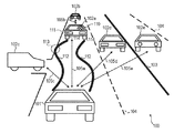
第1実施形態による制御装置及び制御方法について図面を用いて説明する。図1は、車両が道路を走行する様子の例を示す図である。図1に示すように、道路100には、走行車線を画定する白線等の標示が備えられている。例えば、道路100には、車道中央線(センターライン)103、車両通行帯境界線104、車両通行帯最外側線(図示せず)等が示されている。本実施形態による制御装置200(図2参照)が搭載された一台の車両101を自車両とし、それ以外の車両102a〜102eを他車両と称することとする。図1に示すように、車両101や他車両102a〜102eが道路100を走行する。車両101の前方を走行する他車両102aは、先行車両とも称される。先行車両102aの前方を走行する他車両102bは、先々行車両とも称される。符号105aは、車両101から先行車両102aまでの距離(車間距離)を示している。符号105bは、先行車両102aから先々行車両102bまでの距離を示している。符号105cは、車両101から脇道の他車両102cまでの距離を示している。符号105dは、車両101から追い越し車線を走行中の他車両102dまでの距離を示している。符号105eは、車両101から対向車線を走行中の他車両102eまでの距離を示している。なお、他車両一般について説明する際には符号102を用い、個々の他車両について説明する際には符号102a〜102eを用いることとする。また、距離一般や車間距離一般について説明する際には符号105を用い、個々の距離や個々の車間距離について説明する際には符号105a〜105eを用いることとする。他車両102には、初心運転者標識や高齢運転者標識等の標識110が付されている場合もある。また、他車両102には、車名プレート111等が付されている。符号112は、蛇行運転の様子を概念的に示している。符号113は、先行車両102aが車線逸脱した箇所の例を示している。
[First Embodiment]
A control device and a control method according to the first embodiment will be described with reference to the drawings. FIG. 1 is a diagram illustrating an example of how a vehicle travels on a road. As shown in FIG. 1, the road 100 is provided with a sign such as a white line that demarcates a traveling lane. For example, a road center line (center line) 103, a vehicle traffic zone boundary line 104, a vehicle traffic zone outermost line (not shown), and the like are shown on the road 100. One vehicle 101 on which the control device 200 (see FIG. 2) according to the present embodiment is mounted is referred to as a host vehicle, and the other vehicles 102a to 102e are referred to as other vehicles. As shown in FIG. 1, a vehicle 101 and other vehicles 102 a to 102 e travel on a road 100. The other vehicle 102a traveling in front of the vehicle 101 is also referred to as a preceding vehicle. The other vehicle 102b that travels in front of the preceding vehicle 102a is also referred to as a preceding vehicle. Reference numeral 105a indicates a distance (inter-vehicle distance) from the vehicle 101 to the preceding vehicle 102a. Reference numeral 105b indicates the distance from the preceding vehicle 102a to the preceding vehicle 102b. Reference numeral 105c indicates the distance from the vehicle 101 to the other vehicle 102c on the side road. Reference numeral 105d indicates the distance from the vehicle 101 to the other vehicle 102d traveling in the overtaking lane. Reference numeral 105e indicates the distance from the vehicle 101 to the other vehicle 102e traveling in the oncoming lane. It should be noted that reference numeral 102 is used when describing other vehicles in general, and reference numerals 102a to 102e are used when describing individual other vehicles. Further, reference numeral 105 is used when general distances and inter-vehicle distances are described, and reference numerals 105a to 105e are used when individual distances and individual inter-vehicle distances are described. The other vehicle 102 may be provided with a sign 110 such as an initial driver sign or an elderly driver sign. Further, the other vehicle 102 is provided with a vehicle name plate 111 and the like. Reference numeral 112 conceptually shows the state of the meandering operation. Reference numeral 113 indicates an example of a location where the preceding vehicle 102a has deviated from the lane.

車両101が先行車両102aと衝突する可能性を低減するためには、車両101が先行車両102aに近づき過ぎず、車両101が先行車両102aに対して十分な車間距離105aを確保することが重要である。確保すべき車間距離105は、車両101の走行速度から見積もられる停止距離を目安とし得る。停止距離とは、運転者が危険を感じてブレーキをかけ、ブレーキが効き始めるまでに車両が進む距離である空走距離と、ブレーキが効き始めてから車両が停止するまでに進む距離である制動距離との合計である。停止距離は、車種、積載量、タイヤの状態、路面状態等にも依存するが、一般的には、時速40kmの場合には20m程度であり、時速80kmの場合には55m程度である。車両101が他車両102に衝突する要因は、必ずしも車両101だけに存在しているわけではない。例えば、他車両102が急停止したり、他車両102がスピンしたり、他車両102が逆走したりすることによって、車両101が他車両102に衝突することもあり得る。また、一の他車両102が他の他車両102との間で起こした事故に、車両101が巻き込まれることもあり得る。従って、危険性が高いと思われる他車両102に対しては、十分に余裕のある車間距離105を確保するようにすることが好ましい。そこで、本実施形態では、撮像部201(図2参照)によって取得される画像に基づいて他車両102の危険性を判定し、他車両102の危険性に基づいて制御部202(図2参照)が車両101に及ぶ危険を低減するよう車両101を制御するための信号を生成する。具体的には、居眠り運転や脇見運転の際に生ずる蛇行走行や車線逸脱などに基づいて他車両102の危険性を判定し、判定された他車両102の危険性に基づいて車両101がより安全な状態に移行するように車両101を制御するための信号を生成する。これにより、たとえば車両101と他車両102との車間距離105が十分に確保され、自車両の安全性を向上することができる。   In order to reduce the possibility of the vehicle 101 colliding with the preceding vehicle 102a, it is important that the vehicle 101 does not get too close to the preceding vehicle 102a and that the vehicle 101 secures a sufficient inter-vehicle distance 105a with respect to the preceding vehicle 102a. is there. The inter-vehicle distance 105 to be secured may be a stop distance estimated from the traveling speed of the vehicle 101. The stop distance is the distance that the vehicle travels before the brake starts when the driver feels danger and the brake starts to work, and the braking distance that travels from when the brake starts to the vehicle stops And the sum. The stop distance depends on the vehicle type, load capacity, tire condition, road surface condition, etc., but is generally about 20 m when the speed is 40 km / h, and about 55 m when the speed is 80 km / h. The factor that the vehicle 101 collides with the other vehicle 102 does not necessarily exist only in the vehicle 101. For example, the vehicle 101 may collide with the other vehicle 102 when the other vehicle 102 stops suddenly, the other vehicle 102 spins, or the other vehicle 102 runs backward. In addition, the vehicle 101 may be involved in an accident that occurs between one other vehicle 102 and another other vehicle 102. Therefore, it is preferable to secure a sufficiently large inter-vehicle distance 105 for other vehicles 102 that are considered to be highly dangerous. Therefore, in this embodiment, the risk of the other vehicle 102 is determined based on the image acquired by the imaging unit 201 (see FIG. 2), and the control unit 202 (see FIG. 2) is based on the risk of the other vehicle 102. Generates a signal for controlling the vehicle 101 so as to reduce the risk of the vehicle 101. Specifically, the risk of the other vehicle 102 is determined based on meandering driving or lane departure that occurs during a snooze driving or a side-by-side driving, and the vehicle 101 is safer based on the determined risk of the other vehicle 102. A signal for controlling the vehicle 101 is generated so as to shift to a different state. Thereby, for example, the inter-vehicle distance 105 between the vehicle 101 and the other vehicle 102 is sufficiently secured, and the safety of the host vehicle can be improved.

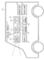
図2は、本実施形態による制御装置を示す概略図である。本実施形態による制御装置200は、車両101に搭載される。制御装置200は、撮像部201と、制御部202と、メモリ206とを備えている。なお、メモリ206が制御部202内に備えられていてもよい。また、撮像部201が、制御装置200と別個に設けられていてもよい。制御部202の入力部203には、撮像部201によって順次取得される画像が入力される。   FIG. 2 is a schematic diagram illustrating the control device according to the present embodiment. The control device 200 according to the present embodiment is mounted on the vehicle 101. The control device 200 includes an imaging unit 201, a control unit 202, and a memory 206. Note that the memory 206 may be provided in the control unit 202. In addition, the imaging unit 201 may be provided separately from the control device 200. Images sequentially acquired by the imaging unit 201 are input to the input unit 203 of the control unit 202.

また、制御部202の入力部203には、車両101に備えられた車速検出手段としての車速センサ207から出力される車速情報が入力される。車両101を制御するための制御信号が、後述するようにして制御部202によって生成される。車両101に備えられたブレーキ制御装置204にブレーキを制御させるためのブレーキ制御信号が、制御部202によって生成される。また、車両101に備えられた動力制御装置205に動力源の駆動力を制御させるための動力制御信号が、制御部202によって生成される。   In addition, vehicle speed information output from a vehicle speed sensor 207 as vehicle speed detection means provided in the vehicle 101 is input to the input unit 203 of the control unit 202. A control signal for controlling the vehicle 101 is generated by the control unit 202 as described later. A brake control signal for causing the brake control device 204 provided in the vehicle 101 to control the brake is generated by the control unit 202. Further, a power control signal for causing the power control device 205 provided in the vehicle 101 to control the driving force of the power source is generated by the control unit 202.

また、車両101に備えられた操舵制御装置209に操舵の制御を行わせるための操舵制御信号が、制御部202によって生成される。車両101の動力源がエンジンである場合、動力制御装置205は、例えばECU(エンジン・コントロール・ユニット)である。制御部202は、例えば、危険性の高い他車両102との車間距離105を増大させるため、ブレーキ制御装置204にブレーキを作動させるようなブレーキ制御信号を生成することができる。また、制御部202は、例えば、危険性の高い他車両102との車間距離105を増大させるため、動力制御装置205に動力源の駆動力を抑制させるような動力制御信号を生成することもできる。また、制御部202は、このようなブレーキ制御信号と動力制御信号の両方を生成することもできる。なお、ブレーキ制御装置204と動力制御装置205とは一つの装置によって構成されていてもよい。   Further, a steering control signal for causing the steering control device 209 provided in the vehicle 101 to perform steering control is generated by the control unit 202. When the power source of the vehicle 101 is an engine, the power control device 205 is an ECU (engine control unit), for example. For example, the control unit 202 can generate a brake control signal that causes the brake control device 204 to operate the brake in order to increase the inter-vehicle distance 105 with the other vehicle 102 having a high risk. The control unit 202 can also generate a power control signal that causes the power control device 205 to suppress the driving force of the power source, for example, in order to increase the inter-vehicle distance 105 with the other vehicle 102 with high risk. . The control unit 202 can also generate both such a brake control signal and a power control signal. Note that the brake control device 204 and the power control device 205 may be configured by a single device.

また、制御部202は、例えば、危険性の高い他車両102とは異なる走行車線に車両101の走行車線を変更するための操舵制御を操舵制御装置209に行わせるための操舵制御信号を生成することもできる。また、制御部202には、ユーザが操舵制御のための指示を送ることができるハンドル、車速の加速、原則を指示することができるアクセルペダル、ブレーキペダルなどを含む操作部210から各制御装置を操作するための指示信号が入力される。制御部202は入力信号に基づいてブレーキ制御装置204、動力制御装置205、操舵制御装置209を制御することでユーザによる手動運転を可能とする。実施形態としては上記に限らず、手動運転のための制御部を別途設ける構成にしてもよい。   In addition, the control unit 202 generates a steering control signal for causing the steering control device 209 to perform steering control for changing the traveling lane of the vehicle 101 to a traveling lane different from that of the other vehicle 102 with high risk, for example. You can also. In addition, the control unit 202 receives each control device from the operation unit 210 including a handle to which a user can send an instruction for steering control, acceleration of the vehicle speed, an accelerator pedal that can instruct a principle, a brake pedal, and the like. An instruction signal for operation is input. The control unit 202 enables manual operation by the user by controlling the brake control device 204, the power control device 205, and the steering control device 209 based on the input signal. The embodiment is not limited to the above, and a control unit for manual operation may be separately provided.

表示部211は各種の情報を表示する液晶等の表示デバイスを備えた表示装置である。表示部211は、制御部202の指示に従って車速情報やエンジンの回転数、ブレーキ動作の有無、危険車両等の各種警告の有無、撮像部201による画像やその他各種センサによるモニタリング情報などを表示する。   The display unit 211 is a display device including a display device such as a liquid crystal that displays various types of information. The display unit 211 displays vehicle speed information, engine speed, presence / absence of braking operation, presence / absence of various warnings such as dangerous vehicles, monitoring information by the imaging unit 201 and monitoring information by various sensors, and the like according to instructions from the control unit 202.

撮像部201は、視点が異なることで互いに視差のある複数の画像、即ち、視差画像を取得する。本実施形態では、撮像部201は可視波長域に感度を有する撮像部を用いている。また、撮像部201には、撮像光学系(レンズユニット)が備えられており、撮像光学系の射出瞳のうちの第1の瞳領域を通過する光束によって、第1の光学像が形成される。また、撮像光学系の射出瞳のうちの第1の瞳領域と異なる第2の瞳領域を通過する光束によって、第2の光学像が形成される。このとき第1の光学像と第2の光学像との間には視差が存在している。撮像部201は、CMOSイメージセンサである撮像素子によって第1及び第2の光学像を受光する。ここで撮像部201の撮像素子の撮像面には、単位画素が2次元状に配されており、各々の単位画素には、第1の分割画素と第2の分割画素とが備えられている。第1の分割画素と第2の分割画素とには、それぞれ光電変換部が備えられている。第1の分割画素には、第1の瞳領域を通過した光束が入射され、第2の分割画素には、第2の瞳領域を通過した光束が入射されるよう撮像光学系が構成されている。複数の第1の分割画素によってそれぞれ取得された信号によって、第1の画像が生成される。複数の第2の分割画素によってそれぞれ取得された信号によって、第2の画像が生成される。第1の光学像と第2の光学像との間に視差(位相差)が存在するため、第1の画像と第2の画像との間には視差が存在している。第1の画像と第2の画像との視差(位相差)から、三角測量の原理に基づいて、対象物までの距離を求めることが可能である。このような測距方式は、撮像面位相差測距方式と称される。また、撮像部201は、第1の分割画素によって取得される信号と第2の分割画素により取得される信号とを合成することにより得られる信号に基づいて、撮像光学系の瞳領域のより大きな部分に対応し、光量をより多く取り込んだ合成画像をも取得し得る。このような合成画像は、画質の面で視差画像より優れていることから、より精密な画像解析などに用いられる。   The imaging unit 201 acquires a plurality of images having parallax with each other by different viewpoints, that is, parallax images. In the present embodiment, the imaging unit 201 uses an imaging unit having sensitivity in the visible wavelength range. In addition, the imaging unit 201 includes an imaging optical system (lens unit), and a first optical image is formed by a light beam that passes through the first pupil region of the exit pupil of the imaging optical system. . In addition, a second optical image is formed by a light flux that passes through a second pupil region different from the first pupil region of the exit pupil of the imaging optical system. At this time, parallax exists between the first optical image and the second optical image. The imaging unit 201 receives the first and second optical images with an imaging element that is a CMOS image sensor. Here, unit pixels are two-dimensionally arranged on the imaging surface of the imaging element of the imaging unit 201, and each unit pixel includes a first divided pixel and a second divided pixel. . Each of the first divided pixel and the second divided pixel includes a photoelectric conversion unit. The imaging optical system is configured such that the light beam that has passed through the first pupil region is incident on the first divided pixel, and the light beam that has passed through the second pupil region is incident on the second divided pixel. Yes. A first image is generated by signals respectively acquired by the plurality of first divided pixels. A second image is generated by the signals respectively acquired by the plurality of second divided pixels. Since there is a parallax (phase difference) between the first optical image and the second optical image, there is a parallax between the first image and the second image. From the parallax (phase difference) between the first image and the second image, the distance to the object can be obtained based on the principle of triangulation. Such a ranging method is referred to as an imaging surface phase difference ranging method. In addition, the imaging unit 201 has a larger pupil region of the imaging optical system based on a signal obtained by combining the signal acquired by the first divided pixel and the signal acquired by the second divided pixel. A composite image corresponding to the portion and capturing a larger amount of light can also be acquired. Since such a composite image is superior to a parallax image in terms of image quality, it is used for more precise image analysis.

撮像部201は、他車両102の蛇行運転や車線逸脱等をより確実に検出することが可能となるような解像度の画像を取得することが好ましい。例えば、撮像部201は、先行車両102aの後端の位置、先行車両102aのタイヤ114の位置、走行車線を画定する白線等の標示の位置等を正確に把握し得るような解像度の画像を取得し得ることが好ましい。これらの把握が必要な最長距離においてこれらの把握が可能となるように、撮像素子のサイズ、撮像素子の画素数、撮像光学系の倍率等が適宜設定される。例えば日中の場合には、太陽光が、先行車両102a等を撮像するための光源となり得る。また、トンネル内の場合には、トンネルに備えられた照明灯が、先行車両102a等を撮像するための光源となり得る。夜間や、照明が不足する環境においては、車両101に備えられたヘッドライト等が、先行車両102a等を撮像するための光源となり得る。   It is preferable that the imaging unit 201 acquires an image having a resolution that can more reliably detect the meandering operation, lane departure, and the like of the other vehicle 102. For example, the imaging unit 201 acquires an image having a resolution that can accurately grasp the position of the rear end of the preceding vehicle 102a, the position of the tire 114 of the preceding vehicle 102a, the position of a sign such as a white line that defines the traveling lane, and the like. Preferably it can be done. The size of the image sensor, the number of pixels of the image sensor, the magnification of the image pickup optical system, and the like are appropriately set so that these can be grasped at the longest distance that requires such grasp. For example, in the daytime, sunlight can be a light source for imaging the preceding vehicle 102a and the like. In the case of a tunnel, an illumination lamp provided in the tunnel can be a light source for imaging the preceding vehicle 102a and the like. At night or in an environment where lighting is insufficient, a headlight or the like provided in the vehicle 101 can be a light source for imaging the preceding vehicle 102a and the like.

撮像部201は、撮像によって得られる画像を順次制御部202に送信する。本実施形態では、特別な指示がない限り、撮像部201は、所定の時間間隔(頻度)で撮像を行い、他車両102を被写体として含む画像を順次取得する。かかる所定の時間間隔は、特に限定されるものではないが、例えば0.1秒程度とする。この場合、例えば、1秒間当たり10組の視差画像が制御部202に入力されることとなる。   The imaging unit 201 sequentially transmits images obtained by imaging to the control unit 202. In this embodiment, unless otherwise specified, the imaging unit 201 captures images at a predetermined time interval (frequency) and sequentially acquires images including the other vehicle 102 as a subject. The predetermined time interval is not particularly limited, but is set to about 0.1 seconds, for example. In this case, for example, 10 sets of parallax images per second are input to the control unit 202.

また、他車両102は、車両101に対して様々な方向に位置し得る。例えば、車両101の前方に他車両102が位置する場合もあるし、車両101の斜め前方に他車両102が位置する場合もあるし、車両101の側方に他車両102が位置する場合もある。また、車両101の斜め後方に他車両102が位置する場合もあるし、車両101の後方に他車両102が位置する場合もある。つまり撮像部201は様々な方向の画像を取得できることが好ましい。そこで、本実施形態の撮像部201は、車両101の前方を含む180°の視野角を有する広角レンズを備えたカメラと、車両101の後方を含む180°の視野角を有する広角レンズを備えたカメラとを備え、水平面の全方位の被写体をとらえることができるものとする。上記実施形態に限らず、広角レンズを用いる場合には、撮像部201の数は少なくてすむが、広角レンズを用いない場合には、撮像部201を多数設けることを要する。また、超広角レンズを用いれば、撮像部201を1つとすることも可能であり、撮像部201の構成は複数の方面の他車両を確認出来るよう構成されていれば、本発明を適用できる。   Further, the other vehicle 102 can be positioned in various directions with respect to the vehicle 101. For example, the other vehicle 102 may be located in front of the vehicle 101, the other vehicle 102 may be located obliquely in front of the vehicle 101, or the other vehicle 102 may be located on the side of the vehicle 101. . Further, the other vehicle 102 may be located obliquely behind the vehicle 101, and the other vehicle 102 may be located behind the vehicle 101. That is, it is preferable that the imaging unit 201 can acquire images in various directions. Therefore, the imaging unit 201 of the present embodiment includes a camera having a wide-angle lens having a 180 ° viewing angle including the front of the vehicle 101 and a wide-angle lens having a 180 ° viewing angle including the rear of the vehicle 101. It is assumed that the camera is equipped with a camera that can capture subjects in all directions on a horizontal plane. Not only in the above embodiment, the number of imaging units 201 can be reduced when a wide-angle lens is used. However, when a wide-angle lens is not used, it is necessary to provide a large number of imaging units 201. If an ultra-wide-angle lens is used, the number of the imaging unit 201 can be one, and the present invention can be applied if the configuration of the imaging unit 201 is configured so that other vehicles in a plurality of directions can be confirmed.

制御部(処理部)202は、制御装置200の全体の制御を司る。制御部202には、CPU(Central Processing Unit)等が備えられており、演算処理等の様々な処理を行うことができる。制御部202は、撮像部201から入力される画像を、メモリ206に格納する。メモリ206は、例えばDRAM(Dynamic Random Access Memory)やフラッシュメモリ等によって構成し得る。撮像部201によって取得される画像から、他車両102の危険性に関する情報や、他車両102までの距離等を判定すべく、制御部202には、画像解析機能が備えられている。制御部202は、例えば、走行車線を画定する白線等の標示や、他車両102を、撮像部201によって取得される画像のうちから認識することができる。また、制御部202は、例えば、ガードレール、電信柱、歩行者等についても、撮像部201によって取得される画像のうちから認識することができる。これらの画像認識処理には周知の方法が用いられてよく、予め各被写体に対応する輝度、色、形状などの特徴量をメモリに記憶しておき、それらと比較することで被写体を特定するマッチング処理や、複数の画像間で得られる動きベクトルから被写体を認識する処理などが適用できる。また、例えば、ニューラルネットワークやサポートベクターマシンに代表される学習を用いた方法として撮像部201から取得されることが想定される画像を学習させることで、画像全体を入力として認識された被写体の情報をアウトプットとする制御部202を構成することも可能である。   The control unit (processing unit) 202 governs overall control of the control device 200. The control unit 202 includes a CPU (Central Processing Unit) and the like, and can perform various processes such as arithmetic processing. The control unit 202 stores the image input from the imaging unit 201 in the memory 206. The memory 206 can be configured by, for example, a DRAM (Dynamic Random Access Memory), a flash memory, or the like. The control unit 202 is provided with an image analysis function in order to determine information regarding the danger of the other vehicle 102, the distance to the other vehicle 102, and the like from the image acquired by the imaging unit 201. The control unit 202 can recognize, for example, a sign such as a white line that demarcates the traveling lane or the other vehicle 102 from the images acquired by the imaging unit 201. Further, the control unit 202 can recognize, for example, guardrails, telephone poles, pedestrians, and the like from the images acquired by the imaging unit 201. Well-known methods may be used for these image recognition processes, and feature quantities such as brightness, color, and shape corresponding to each subject are stored in advance in a memory, and matching is performed to identify the subject by comparing them with those. Processing, processing for recognizing a subject from motion vectors obtained between a plurality of images, and the like can be applied. Further, for example, by learning an image assumed to be acquired from the imaging unit 201 as a method using learning typified by a neural network or a support vector machine, information on a subject recognized as an input of the entire image It is also possible to configure the control unit 202 that outputs.

また、制御部202は、撮像部201によって取得される視差画像における視差量に基づいて、車両101から他車両102までの距離105を算出する。制御部202は、撮像部201によって順次取得される他車両102の画像に基づいて、他車両102までの距離を測定し、他車両の危険性を判定する。制御部202は、順次取得される画像に写っている全ての他車両102に対して、当該他車両102までの距離105や当該他車両102の危険性の判定を行うようにしてもよいし、特定の他車両102に対してのみ、これらの判定を行うようにしてもよい。また制御部202は、車速検出手段としての車速センサ207から出力される車両101の車速情報に基づいて、車両101の速度を検出する。   In addition, the control unit 202 calculates the distance 105 from the vehicle 101 to the other vehicle 102 based on the parallax amount in the parallax image acquired by the imaging unit 201. The control unit 202 measures the distance to the other vehicle 102 based on the images of the other vehicle 102 sequentially acquired by the imaging unit 201, and determines the risk of the other vehicle. The control unit 202 may determine the distance 105 to the other vehicle 102 and the risk of the other vehicle 102 for all the other vehicles 102 shown in the sequentially acquired images. These determinations may be made only for a specific other vehicle 102. The control unit 202 detects the speed of the vehicle 101 based on the vehicle speed information of the vehicle 101 output from the vehicle speed sensor 207 serving as a vehicle speed detection unit.

制御部202は、撮像部201によって順次取得される画像に基づいて、先行車両102aの蛇行走行や車線逸脱の有無を以下のようにして判定する。即ち、制御部202は、先行車両102aが撮影された画像に基づいて、エッジ検出、パターンマッチングなど公知の画像解析手法を用いて先行車両102aの位置と当該先行車両102aが走行する走行車線の位置とを把握する。さらに制御部202は、先行車両102aの全体的な位置のみならず、先行車両102aの両側の位置をも把握し得る。また、制御部202は、走行車線の両側に標示された白線等の位置をも把握し得る。制御部202は、複数フレームにわたる解析によって、走行車線の両側に標示された白線等に先行車両102aが接近する頻度や、走行車線の両側の白線に先行車両102aが交互に接近すること等を検出し、当該検出結果に基づいて、蛇行運転を検出し得る。また、制御部202は、走行車線の両側に標示された白線等の上に先行車両102aの一部が位置したこと等に基づいて、車線逸脱を検出し得る。また、制御部202が、先行車両102aのタイヤ114の位置を把握するようにしてもよい。この場合、制御部202は、走行車線の両側に標示された白線等を先行車両102aのタイヤ114が踏むことや踏み越えること等に基づいて、車線逸脱を検出し得る。走行車線の両側に標示された線としては、上述したように、例えば、車道中央線103、車両通行帯境界線104、車両通行帯最外側線(図示せず)等が挙げられる。急激な横風や大型車両の追い越し等による一過性の蛇行走行や車線逸脱であれば、他車両102の危険性は高いとはいえない。一方、蛇行走行や車線逸脱の頻度が高い場合や、蛇行走行や車線逸脱が長期に亘って生じている場合には、他車両102の危険性は高い可能性がある。従って、制御部202は、蛇行走行や車線逸脱の有無のみならず、複数フレームにわたる各種解析結果をカウンタでカウントしておくことで、蛇行走行や車線逸脱の頻度等にも基づいて他車両102の危険性を判定する。各種危険性の判定項目の出現頻度をカウントするカウンタは、所定時間あるいは所定回数カウントが更新(追加でカウント)されないことに応じてリセットされる。なお、他車両102の運転手が意図的に行う車線変更等においても、他車両102の車線逸脱は生じ得る。このため、制御部202は、当該車線逸脱等が車線変更等に起因するものであるか否かを、画像に基づき方向指示器の表示内容を解析することで判定するようにしてもよい。車線変更等に起因して車線逸脱等が生じた場合には、当該車線逸脱については危険性を判定する上では無視する(カウンタによりカウントさせない)ようにしてもよい。   Based on the images sequentially acquired by the imaging unit 201, the control unit 202 determines the presence or absence of meandering traveling or lane departure of the preceding vehicle 102a as follows. That is, the control unit 202 uses a known image analysis method such as edge detection or pattern matching based on an image of the preceding vehicle 102a to detect the position of the preceding vehicle 102a and the position of the traveling lane on which the preceding vehicle 102a travels. And grasp. Furthermore, the control unit 202 can grasp not only the overall position of the preceding vehicle 102a but also the positions on both sides of the preceding vehicle 102a. Moreover, the control part 202 can also grasp | ascertain positions, such as a white line marked on the both sides of the driving lane. The control unit 202 detects the frequency of the preceding vehicle 102a approaching the white line or the like marked on both sides of the traveling lane, the approaching vehicle 102a alternately approaching the white line on both sides of the traveling lane, etc. by analysis over a plurality of frames. The meandering operation can be detected based on the detection result. Further, the control unit 202 can detect a lane departure based on a part of the preceding vehicle 102a being positioned on a white line or the like marked on both sides of the traveling lane. In addition, the control unit 202 may grasp the position of the tire 114 of the preceding vehicle 102a. In this case, the control unit 202 can detect a lane departure based on, for example, the tire 114 of the preceding vehicle 102a stepping on or over the white line marked on both sides of the traveling lane. Examples of the lines marked on both sides of the travel lane include the roadway center line 103, the vehicle traffic zone boundary line 104, and the vehicle traffic zone outermost line (not shown) as described above. If it is a transient meandering or lane departure due to a sudden crosswind or overtaking of a large vehicle, the risk of the other vehicle 102 is not high. On the other hand, if the frequency of meandering or lane departure is high, or if meandering or lane departure occurs for a long time, the risk of other vehicle 102 may be high. Therefore, the control unit 202 counts not only the presence / absence of meandering and lane departure but also the various analysis results over a plurality of frames with a counter, so that the other vehicle 102 can be controlled based on the frequency of meandering and lane departure. Determine the risk. A counter that counts the appearance frequency of various risk determination items is reset in response to a predetermined time or a predetermined number of counts not being updated (additionally counted). Even when the driver of the other vehicle 102 intentionally changes the lane, the lane departure of the other vehicle 102 may occur. Therefore, the control unit 202 may determine whether or not the lane departure or the like is caused by a lane change or the like by analyzing the display content of the direction indicator based on the image. When a lane departure or the like occurs due to a lane change or the like, the lane departure may be ignored (not counted by a counter) in determining the danger.

先行車両102aの危険性が高い場合には、車両101と先行車両102aとの車間距離105aを十分に大きくすることが好ましい。一方、先行車両102aの危険性が低い場合には、車両101と先行車両102aとの車間距離105aを、例えば車両101の走行速度から見積もられる停止距離と同等としてもよい。制御部202は、車両101から他車両102までの距離と、当該他車両102の危険性と、車両101の走行速度から見積もられる停止距離とに基づいて、車両101を制御するための信号を生成する。即ち、制御部202は、車両101と他車両102との車間距離105を適切に確保するための信号を生成する。具体的には、制御部202は、車両101から他車両102までの距離105と、当該他車両102の危険性と、車両101の走行速度とに基づいて、ブレーキ制御装置204を制御するための信号と、動力制御装置205を制御するための信号とを生成する。そして、生成したこれらの信号を、ブレーキ制御装置204や動力制御装置205にそれぞれ送信する。   When the risk of the preceding vehicle 102a is high, it is preferable to sufficiently increase the inter-vehicle distance 105a between the vehicle 101 and the preceding vehicle 102a. On the other hand, when the risk of the preceding vehicle 102a is low, the inter-vehicle distance 105a between the vehicle 101 and the preceding vehicle 102a may be equivalent to the stop distance estimated from the traveling speed of the vehicle 101, for example. The control unit 202 generates a signal for controlling the vehicle 101 based on the distance from the vehicle 101 to the other vehicle 102, the danger of the other vehicle 102, and the stop distance estimated from the traveling speed of the vehicle 101. To do. That is, the control unit 202 generates a signal for appropriately ensuring the inter-vehicle distance 105 between the vehicle 101 and the other vehicle 102. Specifically, the control unit 202 controls the brake control device 204 based on the distance 105 from the vehicle 101 to the other vehicle 102, the danger of the other vehicle 102, and the traveling speed of the vehicle 101. A signal and a signal for controlling the power control device 205 are generated. Then, these generated signals are transmitted to the brake control device 204 and the power control device 205, respectively.

例えば、先行車両102aが蛇行走行や車線逸脱等を繰り返している危険性の高い車両であるにもかかわらず、車両101と先行車両102aとの車間距離105aが必ずしも十分に確保されていない場合には、制御部202は以下のような信号を生成し得る。即ち、この場合には、制御部202は、ブレーキの作動をブレーキ制御装置204に実行させるような信号を生成し、生成した信号をブレーキ制御装置204に送信する。また、かかる場合には、制御部202は、動力源の駆動力の抑制を動力制御装置205に行わせるような信号を生成し、生成した信号を動力制御装置205に送信する。これにより、車両101の走行速度が低下し、危険性の高い先行車両102aと車両101との車間距離105aが十分に確保される。   For example, when the preceding vehicle 102a is a high-risk vehicle that repeats meandering and lane departure, the inter-vehicle distance 105a between the vehicle 101 and the preceding vehicle 102a is not always sufficiently secured. The control unit 202 can generate the following signals. That is, in this case, the control unit 202 generates a signal that causes the brake control device 204 to execute the operation of the brake, and transmits the generated signal to the brake control device 204. In such a case, the control unit 202 generates a signal that causes the power control device 205 to suppress the driving force of the power source, and transmits the generated signal to the power control device 205. As a result, the traveling speed of the vehicle 101 decreases, and the inter-vehicle distance 105a between the preceding vehicle 102a and the vehicle 101 with high risk is sufficiently secured.

例えば、先行車両102aの危険性が高い場合には、車両101と先行車両102aとの車間距離105aを、車両101の走行速度から見積もられる停止距離の例えば2倍以上とするようにしてもよい。一方、先行車両102aの危険性が低い場合には、車両101と先行車両102aとの車間距離105aを、車両101の走行速度から見積もられる停止距離と同等とするようにしてもよい。例えば、先行車両102aの危険性が低いにもかかわらず、車両101と先行車両102aとの車間距離105aが過度に大きい場合には、制御部202は以下のような信号を生成し得る。即ち、この場合には、制御部202は、ブレーキ動作の解除をブレーキ制御装置204に行わせるような信号を生成し、生成した信号をブレーキ制御装置204に送信する。また、かかる場合には、制御部202は、動力源の駆動力の増加を動力制御装置205に行わせるような信号を生成し、生成した信号を動力制御装置205に送信する。   For example, when the risk of the preceding vehicle 102a is high, the inter-vehicle distance 105a between the vehicle 101 and the preceding vehicle 102a may be set to be, for example, twice or more the stop distance estimated from the traveling speed of the vehicle 101. On the other hand, when the risk of the preceding vehicle 102a is low, the inter-vehicle distance 105a between the vehicle 101 and the preceding vehicle 102a may be made equal to the stop distance estimated from the traveling speed of the vehicle 101. For example, when the inter-vehicle distance 105a between the vehicle 101 and the preceding vehicle 102a is excessively large even though the risk of the preceding vehicle 102a is low, the control unit 202 can generate the following signal. That is, in this case, the control unit 202 generates a signal that causes the brake control device 204 to release the brake operation, and transmits the generated signal to the brake control device 204. In such a case, the control unit 202 generates a signal that causes the power control device 205 to increase the driving force of the power source, and transmits the generated signal to the power control device 205.

なお、ここでは、説明を簡略化するために、車両101と先行車両102aとに注目して説明したが、これに限定されるものではない。制御部202は、車両101以外のあらゆる他車両102の危険性に基づいて、車両101を制御するための信号を生成し得る。例えば、車両101の斜め前方を走行する他車両102dの危険性と、当該他車両102dまでの距離105dとに基づいて、車両101を制御するための信号を生成するようにしてもよい。また、制御部202は、他車両102の危険性が高い場合や、他車両102と衝突する可能性が高い場合等に、車両101に備えられた警告発生装置208を用いて警告を発するようにしてもよい。警告発生装置208としては、例えば、シートベルト、ステアリング、シート等を振動させる警告発生装置等を用いることができる。なお、警告発生装置208はこれに限定されるものではない。例えば、表示部211にあたるメーターパネルや、カーナビゲーションシステムの表示画面等に警告を表示するようにしてもよい。また、警告を表示画面に表示するとともに、音声等によって警告を行うようにしてもよい。このように警告を通知することにより、車両101の運転者に注意を喚起することができる。   Here, in order to simplify the description, the description has been given focusing on the vehicle 101 and the preceding vehicle 102a, but the present invention is not limited to this. The control unit 202 can generate a signal for controlling the vehicle 101 based on the danger of any other vehicle 102 other than the vehicle 101. For example, a signal for controlling the vehicle 101 may be generated based on the danger of the other vehicle 102d traveling diagonally forward of the vehicle 101 and the distance 105d to the other vehicle 102d. In addition, the control unit 202 issues a warning using the warning generation device 208 provided in the vehicle 101 when the risk of the other vehicle 102 is high or when the possibility of collision with the other vehicle 102 is high. May be. As the warning generation device 208, for example, a warning generation device that vibrates a seat belt, a steering, a seat, or the like can be used. Note that the warning generation device 208 is not limited to this. For example, a warning may be displayed on a meter panel corresponding to the display unit 211, a display screen of a car navigation system, or the like. In addition to displaying a warning on the display screen, the warning may be given by voice or the like. By notifying the warning in this way, the driver of the vehicle 101 can be alerted.

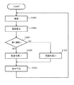
図3は、本実施形態による制御装置200の動作を示すフローチャートである。本動作は、車両101の走行開始(例えば車速情報やブレーキに関する情報)をトリガーとしてスタートする。動作の開始タイミングとしては上記に限らず、例えば操作部210へのユーザ操作による設定(車速や他車両102の検出などトリガーそのものの設定も含む)に従って、任意のタイミングでスタートさせてもよい。   FIG. 3 is a flowchart showing the operation of the control device 200 according to the present embodiment. This operation starts with the start of traveling of the vehicle 101 (for example, vehicle speed information or information about brakes) as a trigger. The start timing of the operation is not limited to the above, and may be started at an arbitrary timing according to the setting by the user operation on the operation unit 210 (including the setting of the trigger itself such as detection of the vehicle speed and other vehicle 102).

ステップS301において、撮像部201によって撮像が行われる。撮像部201によって取得された画像は、制御部202に入力される。   In step S <b> 301, imaging is performed by the imaging unit 201. An image acquired by the imaging unit 201 is input to the control unit 202.

ステップS302において、制御部202は、撮像部201によって取得された画像に基づいて他車両102を検出し、前述した方法によって車両101から他車両102までの距離105を算出する。   In step S302, the control unit 202 detects the other vehicle 102 based on the image acquired by the imaging unit 201, and calculates the distance 105 from the vehicle 101 to the other vehicle 102 by the method described above.

ステップS303において、制御部202は、撮像部201によって取得された画像に基づいて、前述した方法によって他車両102が蛇行走行や車線逸脱をしているか否かを判定する。他車両102が蛇行走行や車線逸脱をしていると判定される場合には(ステップS303においてYES)、ステップS304に移行する。一方、他車両102が蛇行走行や車線逸脱をしていないと判定される場合には(ステップS303においてNO)、ステップS306に移行する。   In step S303, the control unit 202 determines based on the image acquired by the imaging unit 201 whether the other vehicle 102 is meandering or departing from the lane by the method described above. If it is determined that the other vehicle 102 is meandering or deviating from the lane (YES in step S303), the process proceeds to step S304. On the other hand, when it is determined that the other vehicle 102 is not meandering or deviating from the lane (NO in step S303), the process proceeds to step S306.

ステップS304において、制御部202は、他車両102の蛇行走行や車線逸脱の頻度が閾値以上であるか否かを判定する。他車両102の蛇行走行や車線逸脱の頻度が閾値以上である場合には(ステップS304においてYES)、ステップS305に移行する。一方、他車両102の蛇行走行や車線逸脱の頻度が閾値未満である場合には(ステップS304においてNO)、ステップS306に移行する。また、ステップS303、S304をまとめて蛇行走行や車線逸脱が閾値以上の頻度で検出されるか否かを判定してもよい。また、閾値は1以上であればよく、例えば蛇行走行や車線逸脱を判定する(逸脱距離などの)閾値を大きくしている場合など、1度でも検出されれば危険性が高いと判定されるようにしてもよい。   In step S304, the control unit 202 determines whether or not the frequency of meandering and lane departure of the other vehicle 102 is greater than or equal to a threshold value. If the frequency of meandering or lane departure of other vehicle 102 is equal to or greater than the threshold (YES in step S304), the process proceeds to step S305. On the other hand, when the frequency of meandering or lane departure of other vehicle 102 is less than the threshold (NO in step S304), the process proceeds to step S306. In addition, steps S303 and S304 may be combined to determine whether meandering and lane departure are detected with a frequency equal to or higher than a threshold value. The threshold value may be 1 or more. For example, when the threshold value for determining meandering or lane departure (such as a deviation distance) is increased, it is determined that the risk is high if detected once. You may do it.

ステップS305において、制御部202は、他車両102の危険性は高いと判定する。この後、ステップS307に移行する。   In step S305, the control unit 202 determines that the risk of the other vehicle 102 is high. Thereafter, the process proceeds to step S307.

ステップS306において、制御部202は、他車両102の危険性は低いと判定する。この後、ステップS307に移行する。   In step S306, the control unit 202 determines that the risk of the other vehicle 102 is low. Thereafter, the process proceeds to step S307.

ステップS307において、制御部202は、車両101から他車両102までの距離105と、当該他車両102の危険性と、車両101の走行速度とに基づいて、車両101を制御するための信号を生成する。前述したように、車両101から他車両102までの距離105は、撮像部201からの画像に基づいて逐次測定しており、車両101の走行速度も車速センサ207で逐次測定している。例えば、先行車両102aが危険性の高い車両であるにもかかわらず、車両101と先行車両102aとの車間距離105aが十分に確保されていない場合には、制御部202は以下のような信号を生成し得る。例えば、車両101と他車両102との車間距離105が例えば第1の距離以上となるように車両101を制御するための信号が生成される。第1の距離は、例えば、車両101の走行速度から見積もられる停止距離の2倍程度とする。具体的には、制御部202は、ブレーキ動作をブレーキ制御装置204に行わせるような信号を生成し、生成した信号をブレーキ制御装置204に送信する。また、制御部202は、動力源の駆動力の低下を動力制御装置205に行わせるような信号を生成し、生成した信号を動力制御装置205に送信する。これにより、車両101の走行速度が低下し、車両101と他車両102との車間距離105aが例えば第1の距離以上確保される。一方、例えば、車両101と他車両102との車間距離105aが過度に大きい場合には、制御部202は以下のような信号を生成し得る。例えば、車両101と他車両102との車間距離105が例えば第2の距離よりも小さい第3の距離となるように車両101を制御するための信号が生成される。第3の距離は、例えば、車両101の走行速度から見積もられる停止距離の2倍程度とする。具体的には、制御部202は、ブレーキ動作の解除をブレーキ制御装置204に行わせるような信号を生成し、生成した信号をブレーキ制御装置204に送信する。また、制御部202は、動力源の駆動力の増加を動力制御装置205に行わせるような信号を生成し、生成した信号を動力制御装置205に送信する。これにより、車両101の走行速度が上昇し、車両101と先行車両102aとの車間距離105aが例えば第3の距離となる。そして、ステップS301以降の動作が繰り返される。また、図3に示す制御装置200のこれら一連の動作は、車両101の速度が所定速未満に低下することやエンジンの停止などに応じて終了する。   In step S307, the control unit 202 generates a signal for controlling the vehicle 101 based on the distance 105 from the vehicle 101 to the other vehicle 102, the danger of the other vehicle 102, and the traveling speed of the vehicle 101. To do. As described above, the distance 105 from the vehicle 101 to the other vehicle 102 is sequentially measured based on the image from the imaging unit 201, and the traveling speed of the vehicle 101 is also sequentially measured by the vehicle speed sensor 207. For example, when the preceding vehicle 102a is a highly dangerous vehicle but the inter-vehicle distance 105a between the vehicle 101 and the preceding vehicle 102a is not sufficiently secured, the control unit 202 outputs the following signal. Can be generated. For example, a signal for controlling the vehicle 101 is generated so that the inter-vehicle distance 105 between the vehicle 101 and the other vehicle 102 is, for example, a first distance or more. The first distance is, for example, about twice the stop distance estimated from the traveling speed of the vehicle 101. Specifically, the control unit 202 generates a signal that causes the brake control device 204 to perform a brake operation, and transmits the generated signal to the brake control device 204. In addition, the control unit 202 generates a signal that causes the power control device 205 to decrease the driving force of the power source, and transmits the generated signal to the power control device 205. As a result, the traveling speed of the vehicle 101 decreases, and the inter-vehicle distance 105a between the vehicle 101 and the other vehicle 102 is secured, for example, the first distance or more. On the other hand, for example, when the inter-vehicle distance 105a between the vehicle 101 and the other vehicle 102 is excessively large, the control unit 202 can generate the following signal. For example, a signal for controlling the vehicle 101 is generated such that the inter-vehicle distance 105 between the vehicle 101 and the other vehicle 102 is a third distance that is smaller than the second distance, for example. The third distance is, for example, about twice the stop distance estimated from the traveling speed of the vehicle 101. Specifically, the control unit 202 generates a signal that causes the brake control device 204 to release the brake operation, and transmits the generated signal to the brake control device 204. Further, the control unit 202 generates a signal that causes the power control device 205 to increase the driving force of the power source, and transmits the generated signal to the power control device 205. As a result, the traveling speed of the vehicle 101 increases, and the inter-vehicle distance 105a between the vehicle 101 and the preceding vehicle 102a becomes, for example, the third distance. And the operation | movement after step S301 is repeated. Further, the series of operations of the control device 200 shown in FIG. 3 is terminated when the speed of the vehicle 101 decreases below a predetermined speed or when the engine is stopped.

なお、図3のフローでは、他車両102の危険性が高いか低いかの判定が行われる場合を例に説明したが、本発明としてはこれに限定されるものではない。例えば、他車両102の危険性をより細かく判定するようにしてもよい。例えば、危険性のレベル(程度)、即ち、危険度は、例えば、蛇行走行や車線逸脱の頻度等に基づいて判定し得る。複数の閾値を設定し、蛇行走行や車線逸脱の頻度がいずれの閾値以上であるかに基づいて、危険性のレベルを多段階に判定するようにしてもよい。例えば、他車両102の蛇行走行や車線逸脱の頻度が、第1の閾値TH1以上である場合には、当該他車両102の危険性のレベルが3であると判定するようにしてもよい。また、他車両102の蛇行走行や車線逸脱の頻度が、第1の閾値TH1より低い第2の閾値TH2以上、第1の閾値TH1未満である場合には、当該他車両102の危険性のレベルが2であると判定するようにしてもよい。また、他車両102の蛇行走行や車線逸脱の頻度が第2の閾値TH2未満である場合や、他車両102が蛇行走行や車線逸脱をしていない場合には、当該他車両102の危険性のレベルが1であると判定してもよい。なお、ここでは、危険性のレベルは、例えば、数値が大きくなるほど高い。   In the flow of FIG. 3, the case where it is determined whether the risk of the other vehicle 102 is high or low has been described as an example, but the present invention is not limited to this. For example, the risk of the other vehicle 102 may be determined more finely. For example, the level (degree) of danger, that is, the degree of danger can be determined based on, for example, the frequency of meandering or lane departure. A plurality of threshold values may be set, and the risk level may be determined in multiple stages based on which threshold value the frequency of meandering and lane departure is higher than. For example, when the frequency of meandering and lane departure of the other vehicle 102 is equal to or higher than the first threshold value TH1, the risk level of the other vehicle 102 may be determined to be 3. Further, when the frequency of meandering and lane departure of the other vehicle 102 is equal to or higher than the second threshold TH2 lower than the first threshold TH1 and lower than the first threshold TH1, the level of danger of the other vehicle 102 is determined. May be determined to be 2. If the frequency of meandering or lane departure of the other vehicle 102 is less than the second threshold TH2, or if the other vehicle 102 does not meander or lane departure, the risk of the other vehicle 102 may be increased. It may be determined that the level is 1. Here, the level of danger is higher as the numerical value is larger, for example.

また、上記では、他車両102の危険性の程度が、高い場合にも、低い場合にも、制御部202がステップS307において信号生成を行う場合を例に説明したが、これに限定されるものではない。例えば、他車両102の危険性の程度が高い場合にのみ、制御部202がステップS307において信号生成を行うようにしてもよい。この場合には、ステップS306が完了した後、ステップS307を実行することなく、ステップS301に戻る。   Further, in the above description, the case where the control unit 202 performs signal generation in step S307 regardless of whether the danger level of the other vehicle 102 is high or low is described as an example, but the present invention is not limited thereto. is not. For example, the control unit 202 may generate a signal in step S307 only when the danger level of the other vehicle 102 is high. In this case, after step S306 is completed, the process returns to step S301 without executing step S307.

図4は、本実施形態による制御装置200の動作の他の例を示すフローチャートである。   FIG. 4 is a flowchart illustrating another example of the operation of the control device 200 according to the present embodiment.

ステップS401〜S404は、図3を用いて上述したステップS301〜S304と同様であるため、説明を省略する。他車両102が蛇行走行や車線逸脱をしている場合には(ステップS403においてYES)、ステップS404に移行する。一方、他車両102が蛇行走行や車線逸脱をしていない場合には(ステップS403においてNO)、ステップS408に移行する。   Steps S401 to S404 are the same as steps S301 to S304 described above with reference to FIG. When other vehicle 102 is meandering or deviating from the lane (YES in step S403), the process proceeds to step S404. On the other hand, when other vehicle 102 is not meandering or deviating from the lane (NO in step S403), the process proceeds to step S408.

ステップS404において、制御部202は、他車両102の蛇行走行や車線逸脱の頻度が第1の閾値TH1以上であるか否かを判定する。他車両102の蛇行走行や車線逸脱の頻度が第1の閾値TH1以上である場合には(ステップS404においてYES)、ステップS406に移行する。一方、他車両102の蛇行走行や車線逸脱の頻度が第1の閾値TH1未満である場合には(ステップS404においてNO)、ステップS405に移行する。 In step S404, the control unit 202 determines whether the frequency of meandering and lane departure of the other vehicle 102 is equal to or higher than the first threshold value TH1. If the frequency of meandering or lane departure of other vehicle 102 is equal to or higher than first threshold value TH1 (YES in step S404), the process proceeds to step S406. On the other hand, if the frequency of meandering or lane departure of other vehicle 102 is less than first threshold value TH1 (NO in step S404), the process proceeds to step S405.

ステップS405において、制御部202は、他車両102の蛇行走行や車線逸脱の頻度が第2の閾値TH2以上であるか否かを判定する。第2の閾値TH2は、第1の閾値TH1より低い。他車両102の蛇行走行や車線逸脱の頻度が第2の閾値TH2以上である場合には(ステップS405においてYES)、ステップS407に移行する。一方、他車両102の蛇行走行や車線逸脱の頻度が第2の閾値TH2未満である場合には(ステップS405においてNO)、ステップS408に移行する。   In step S405, the control unit 202 determines whether the frequency of meandering and lane departure of the other vehicle 102 is greater than or equal to the second threshold value TH2. The second threshold TH2 is lower than the first threshold TH1. If the frequency of meandering and lane departure of other vehicle 102 is equal to or higher than second threshold value TH2 (YES in step S405), the process proceeds to step S407. On the other hand, if the frequency of meandering or lane departure of other vehicle 102 is less than second threshold value TH2 (NO in step S405), the process proceeds to step S408.

ステップS406において、制御部202は、他車両102の危険性のレベルは3であると判定する。この後、ステップS409に移行する。   In step S406, the control unit 202 determines that the danger level of the other vehicle 102 is three. Thereafter, the process proceeds to step S409.

ステップS407において、制御部202は、他車両102の危険性のレベルは2であると判定する。この後、ステップS409に移行する。   In step S407, the control unit 202 determines that the danger level of the other vehicle 102 is two. Thereafter, the process proceeds to step S409.

ステップS408において、制御部202は、他車両102の危険性のレベルは1であると判定する。この後、ステップS409に移行する。   In step S <b> 408, the control unit 202 determines that the danger level of the other vehicle 102 is 1. Thereafter, the process proceeds to step S409.

ステップS409において、制御部202は、車両101から他車両102までの距離105と、当該他車両102の危険性と、車両101の走行速度とに基づいて、車両101を制御するための信号を生成する。前述したように、車両101から他車両102までの距離105は、撮像部201からの画像に基づいて逐次測定しており、車両101の走行速度も車速センサ207で逐次測定している。車両101を制御するための信号を生成する際には、他車両102の危険性のレベルが考慮される。   In step S409, the control unit 202 generates a signal for controlling the vehicle 101 based on the distance 105 from the vehicle 101 to the other vehicle 102, the danger of the other vehicle 102, and the traveling speed of the vehicle 101. To do. As described above, the distance 105 from the vehicle 101 to the other vehicle 102 is sequentially measured based on the image from the imaging unit 201, and the traveling speed of the vehicle 101 is also sequentially measured by the vehicle speed sensor 207. When generating a signal for controlling the vehicle 101, the danger level of the other vehicle 102 is taken into consideration.

車両101が他車両102に対して、走行速度から見積もられる停止距離よりも十分に(閾値以上)離れた距離で走行している場合、例えば、他車両102の危険性のレベルが3の場合には、車両101と他車両102との車間距離105が第1の距離以上となるように車両101を制御するための信号が生成される。第1の距離は、例えば、車両101の走行速度から見積もられる停止距離の3倍程度とする。また、他車両102の危険性のレベルが2の場合には、車両101と他車両102との車間距離105が第1の距離より短い第2の距離以上となるように車両101を制御するための信号が生成される。第2の距離は、例えば、車両101の走行速度から見積もられる停止距離の2倍程度とする。また、他車両102の危険性のレベルが1である場合には、車両101と他車両102との車間距離105が第2の距離より短い第3の距離以上となるように車両101を制御するための信号が生成される。第3の距離は、例えば、車両101の走行速度から見積もられる停止距離と同等とする。こうして、車両101を制御するための信号が他車両102の危険性に基づいて生成される。この後、ステップS401以降の動作が繰り返される。   When the vehicle 101 is traveling with respect to the other vehicle 102 at a distance sufficiently (more than the threshold) than the stop distance estimated from the traveling speed, for example, when the danger level of the other vehicle 102 is 3 Generates a signal for controlling the vehicle 101 such that the inter-vehicle distance 105 between the vehicle 101 and the other vehicle 102 is equal to or greater than the first distance. The first distance is, for example, about three times the stop distance estimated from the traveling speed of the vehicle 101. Further, when the danger level of the other vehicle 102 is 2, the vehicle 101 is controlled so that the inter-vehicle distance 105 between the vehicle 101 and the other vehicle 102 is not less than the second distance shorter than the first distance. Are generated. The second distance is, for example, about twice the stop distance estimated from the traveling speed of the vehicle 101. When the danger level of the other vehicle 102 is 1, the vehicle 101 is controlled such that the inter-vehicle distance 105 between the vehicle 101 and the other vehicle 102 is equal to or greater than a third distance shorter than the second distance. A signal is generated for For example, the third distance is equal to the stop distance estimated from the traveling speed of the vehicle 101. Thus, a signal for controlling the vehicle 101 is generated based on the danger of the other vehicle 102. Thereafter, the operations after step S401 are repeated.

一方、車両101が他車両102に対して、走行速度から見積もられる停止距離より近いか、少し離れた程度の距離(閾値未満の)で走行している場合、他車両102の危険性の有無にかかわらず、車間距離105を長くするための制御信号が生成されてもよい。すなわち、制御部202はブレーキ動作をブレーキ制御装置204に行わせるような信号を生成し、生成した信号をブレーキ制御装置204に送信する。また、制御部202は、動力源の駆動力の低下を動力制御装置205に行わせるような信号を生成し、生成した信号を動力制御装置205に送信する。   On the other hand, when the vehicle 101 is traveling with respect to the other vehicle 102 at a distance (less than the threshold) that is closer to or slightly away from the stop distance estimated from the traveling speed, the presence or absence of the danger of the other vehicle 102 is determined. Regardless, a control signal for increasing the inter-vehicle distance 105 may be generated. That is, the control unit 202 generates a signal that causes the brake control device 204 to perform a brake operation, and transmits the generated signal to the brake control device 204. In addition, the control unit 202 generates a signal that causes the power control device 205 to decrease the driving force of the power source, and transmits the generated signal to the power control device 205.

なお、上記では、他車両102の危険性のレベルが3である場合にも、2である場合にも、1である場合にも、制御部202がステップS409において信号生成を行う場合を例に説明したが、これに限定されるものではない。例えば、他車両102の危険性のレベルが3や2である場合にのみ、制御部202がステップS409において信号生成を行うようにしてもよい。この場合には、ステップS408が完了した後、ステップS409を実行することなく、ステップS401に戻る。   Note that, in the above, the case where the control unit 202 performs signal generation in step S409 regardless of whether the danger level of the other vehicle 102 is 3, 2, or 1, is taken as an example. Although described, the present invention is not limited to this. For example, the control unit 202 may generate a signal in step S409 only when the danger level of the other vehicle 102 is 3 or 2. In this case, after step S408 is completed, the process returns to step S401 without executing step S409.

このように、本実施形態によれば、撮像部201によって順次取得される画像に基づいて他車両102の危険性が判定される。具体的には、居眠り運転や脇見運転の際に生ずる蛇行走行の有無や頻度に基づいて、他車両102の危険性が判定される。そして、当該他車両102の危険性に基づいて、車両101を制御するための信号が生成される。このため、本実施形態によれば、車両101の安全性の向上を図ることができる。   Thus, according to the present embodiment, the danger of the other vehicle 102 is determined based on the images sequentially acquired by the imaging unit 201. Specifically, the risk of the other vehicle 102 is determined based on the presence / absence and frequency of meandering driving that occurs during a nap driving or a side-by-side driving. Then, a signal for controlling the vehicle 101 is generated based on the danger of the other vehicle 102. For this reason, according to the present embodiment, the safety of the vehicle 101 can be improved.

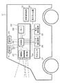
本実施形態の制御装置の他の例を図5に示す。制御装置500は、車両101に搭載される。制御装置500は、撮像部201と、制御部202と、メモリ206と、測距部501とを備えている。   Another example of the control device of this embodiment is shown in FIG. The control device 500 is mounted on the vehicle 101. The control device 500 includes an imaging unit 201, a control unit 202, a memory 206, and a distance measuring unit 501.

撮像部201は、撮像によって順次得られる画像を制御部202に送信する。本例では、測距部501を用いて車両101から他車両102までの距離105を測定することが可能であるため、撮像部201は、視差画像を取得することを要しない。ここでは、撮像部201によって取得される画像が視差画像でない場合を例に説明する。   The imaging unit 201 transmits images sequentially obtained by imaging to the control unit 202. In the present example, since the distance 105 from the vehicle 101 to the other vehicle 102 can be measured using the distance measuring unit 501, the imaging unit 201 does not need to acquire a parallax image. Here, a case where the image acquired by the imaging unit 201 is not a parallax image will be described as an example.

測距部501は、車両101から他車両102までの距離105を随時測定し、測定された距離105を制御部202に送信する。測距部501としては、TOF(Time Of Flight)センサや例えばミリ波レーダ等を用いることができる。ミリ波レーダは、光を用いて対象物までの距離を判定する手法と比較して、遠距離の対象物に対する測距精度が高く、悪天候等にも強いため好適である。上述したように、他車両102は、車両101に対して様々な方向に位置する可能性があるため、測距部501は様々な方向に位置し得る他車両102までの距離を測定することを要する。観測範囲の広い測距デバイスを用いる場合には、測距部501を構成する測距デバイスの数は少なくてすむが、観測範囲の狭い測距デバイスを用いる場合には、測距部501を構成する測距デバイスは多数設けることを要する。また、図5のように測距部501が撮像部201とは別途設けられている場合、図3、図4におけるステップS302、S402は、制御部202が距離検出手段としての測距部501の検出した距離情報を取得する検出ステップとなる。   The distance measuring unit 501 measures the distance 105 from the vehicle 101 to the other vehicle 102 as needed, and transmits the measured distance 105 to the control unit 202. As the distance measuring unit 501, a TOF (Time Of Flight) sensor or, for example, a millimeter wave radar can be used. The millimeter wave radar is preferable because it has high distance measurement accuracy with respect to an object at a long distance and is resistant to bad weather as compared with a method for determining the distance to the object using light. As described above, since the other vehicle 102 may be located in various directions with respect to the vehicle 101, the distance measuring unit 501 measures the distance to the other vehicle 102 that can be located in various directions. Cost. When a distance measuring device with a wide observation range is used, the number of distance measuring devices constituting the distance measuring unit 501 is small. However, when a distance measuring device with a narrow observation range is used, the distance measuring unit 501 is configured. It is necessary to provide a large number of ranging devices. When the distance measuring unit 501 is provided separately from the imaging unit 201 as shown in FIG. 5, steps S302 and S402 in FIGS. 3 and 4 are performed by the control unit 202 as a distance detecting unit. This is a detection step for acquiring the detected distance information.

[第2実施形態]
第2実施形態による制御装置及び制御方法について図面を用いて説明する。図1乃至図5に示す第1実施形態による制御装置及び制御方法と同一の構成要素には、同一の符号を付して説明を省略または簡潔にする。本実施形態においても、図2および図5に示す車両101のいずれも適用可能である。本実施形態の以下の説明では図2に例示する車両101に適用した場合について説明する。
[Second Embodiment]
A control device and a control method according to the second embodiment will be described with reference to the drawings. The same components as those of the control device and the control method according to the first embodiment shown in FIGS. 1 to 5 are denoted by the same reference numerals, and description thereof will be omitted or simplified. Also in this embodiment, any of the vehicles 101 shown in FIGS. 2 and 5 can be applied. In the following description of the present embodiment, a case where the present invention is applied to the vehicle 101 illustrated in FIG. 2 will be described.

他車両102の運転者が初心者である場合には、他車両102の運転者が熟練者である場合と比較して、事故を起こす可能性が高いと考えられる。また、他車両102の運転者が高齢者である場合には、他車両102の運転者が高齢者でない場合と比較して、事故を起こす可能性が高いと考えられる。そこで、本実施形態では、他車両102の運転者が初心者や高齢者であるか否かに着目して他車両102の危険性を判定し、危険性の高い他車両102に対して十分な車間距離105を確保するようにしている。   When the driver of the other vehicle 102 is a beginner, it is considered that there is a higher possibility of an accident as compared with the case where the driver of the other vehicle 102 is an expert. In addition, when the driver of the other vehicle 102 is an elderly person, it is considered that there is a higher possibility of an accident than when the driver of the other vehicle 102 is not an elderly person. Therefore, in the present embodiment, the risk of the other vehicle 102 is determined by paying attention to whether the driver of the other vehicle 102 is a beginner or an elderly person. The distance 105 is ensured.

本実施形態では、車両101における制御部202は、撮像部201によって取得される他車両102の画像に基づいて、運転者を識別することで他車両102の危険性を判定する。制御部202は、撮像部201によって取得された画像に基づいて、他車両102の運転者が危険性の高い運転者であるか否かを判定する。   In the present embodiment, the control unit 202 in the vehicle 101 determines the risk of the other vehicle 102 by identifying the driver based on the image of the other vehicle 102 acquired by the imaging unit 201. Based on the image acquired by the imaging unit 201, the control unit 202 determines whether or not the driver of the other vehicle 102 is a high-risk driver.

図6は、本実施形態による制御装置200の動作を示すフローチャートである。図3と同一のフローには同一番号を付して説明を省略する。本実施形態では、ステップS303、S304にて蛇行走行・車線逸脱が無いあるいは頻度が閾値未満であると判定された場合でも、ステップS601において危険性の高い運転者であると判定されると他車両102は危険性が高いと判定される。   FIG. 6 is a flowchart showing the operation of the control device 200 according to the present embodiment. The same numbers are assigned to the same flow as in FIG. In this embodiment, even if it is determined that there is no meandering / lane departure or the frequency is less than the threshold value in steps S303 and S304, if it is determined that the driver is a high-risk driver in step S601, the other vehicle 102 is determined to be high risk.

図6のステップS303あるいはステップS304にて制御部202によりNOと判定されると、ステップS601に進む。ステップS601では、撮像部201にて取得された画像に基づいて運転者が危険性の高い運転者であるか否かを判定する。具体的には、制御部202は、例えば初心運転者標識、高齢運転者標識などの運転者の状況を示す標識が他車両102に付されているか否かを、撮像部201によって取得される画像に基づいて判定する。標識としてはこの他、自動運転機能を搭載していることを示す標識、自動運転レベルを示す標識、無人運転者であることを示す標識などが考えられる。制御部202は、初心運転者標識、高齢運転者標識およびその他標識の画像を予めデータベースに保持している。かかるデータベースは、例えばメモリ206に記憶されている。制御部202は、このようなデータベースを用いつつ、パターンマッチング等の手法によって、初心運転者標識又は高齢運転者標識が他車両102に付されているか否かを判定する。   If the control unit 202 determines NO in step S303 or step S304 in FIG. 6, the process proceeds to step S601. In step S601, it is determined based on the image acquired by the imaging unit 201 whether the driver is a high-risk driver. Specifically, the control unit 202 obtains an image acquired by the imaging unit 201 as to whether or not a sign indicating the driver's situation such as an initial driver sign or an elderly driver sign is attached to the other vehicle 102. Determine based on. In addition to this, a sign indicating that an automatic driving function is installed, a sign indicating an automatic driving level, a sign indicating an unmanned driver, and the like are conceivable. The control unit 202 holds images of the initial driver sign, the elderly driver sign, and other signs in a database in advance. Such a database is stored in the memory 206, for example. While using such a database, the control unit 202 determines whether or not the initial driver sign or the old driver sign is attached to the other vehicle 102 by a method such as pattern matching.

制御部202は、初心運転者標識又は高齢運転者標識が他車両102に付されていると判定した場合には、他車両102の運転者は危険性の高い運転者であるとして当該他車両102の危険性は高いと判定する。一方、自動運転機能が搭載された車両であることを示す標識や、自動運転レベルを示す標識、無人運転車両であることを示す標識であると判定した場合には、危険性の高い運転者でないとして当該他車両102の危険性は高くないと判定する。ここで、自動運転レベルが所定レベル低い場合や、無人運転車両であることが危険である道路、状況などが外的要因から考慮される場合などには、これらの標識が認識された場合に危険性の高い他車両であると判定しても良い。   When the control unit 202 determines that the initial driver sign or the elderly driver sign is attached to the other vehicle 102, the driver of the other vehicle 102 is determined to be a high-risk driver and the other vehicle 102 is determined. The risk is determined to be high. On the other hand, if it is determined that it is a sign indicating that the vehicle is equipped with an automatic driving function, a sign indicating an automatic driving level, or a sign indicating that it is an unmanned driving vehicle, it is not a high-risk driver. It is determined that the risk of the other vehicle 102 is not high. Here, it is dangerous if these signs are recognized when the automatic driving level is lower than the predetermined level, or when roads and situations where it is dangerous to be an unmanned driving vehicle are considered from external factors. It may be determined that the vehicle is a highly specific other vehicle.

なお、ここでは、初心運転者標識や高齢運転者標識等の標識110に基づいて、他車両102の運転者が初心者や高齢者であるか否かを判定することで危険性の高い運転者であるか否かを判定したが、判定手法、判定項目としてはこれに限定されるものではない。例えば、他車両102が車両101の側方に位置している場合には、撮像部201は他車両102の運転者の顔など運転者自身を撮影できる場合がある。運転者の画像からは外見、脈拍等の生体情報や年齢、健康状態等を推測し得る。例えば、運転者の髪が白い場合や、運転者の顔にしわが多い場合には、当該運転者は高齢者であると推測し得る。このように、人物の顔等の画像から当該人物の年齢を判定し得る公知の技術等を用い、当該運転者が高齢者や若年者であるか否かを判定するようにしてもよい。この場合、高齢運転者標識・初心運転者標識が他車両102に付されていない場合であっても、当該他車両102の運転者を高齢者・初心者であると判定することが可能である。もちろん、外見が若くても初心者であるとは限らず、また、外見が老けていても高齢者であるとは限らない。また、若年者であっても、初心者であるとは限らない。しかし、事故を抑制する観点からは、危険性を高めに見積もることが好ましい。このように、他車両102の運転者自身の画像に基づいて、当該他車両102の危険性を判定するようにしてもよい。   It should be noted that here, it is a highly dangerous driver by determining whether or not the driver of the other vehicle 102 is a beginner or an elderly person on the basis of the sign 110 such as an initial driver sign or an elderly driver sign. Although it was determined whether or not there is, the determination method and determination items are not limited thereto. For example, when the other vehicle 102 is located on the side of the vehicle 101, the imaging unit 201 may be able to photograph the driver himself such as the driver's face of the other vehicle 102. From the image of the driver, biological information such as appearance and pulse, age, health condition, and the like can be estimated. For example, when the driver's hair is white or when the driver's face is wrinkled, it can be assumed that the driver is an elderly person. As described above, it is possible to determine whether the driver is an elderly person or a young person by using a known technique that can determine the age of the person from an image of the person's face or the like. In this case, it is possible to determine that the driver of the other vehicle 102 is an elderly person / beginner even if the elderly driver sign / initial driver sign is not attached to the other vehicle 102. Of course, even if the appearance is young, it is not necessarily a beginner, and even if the appearance is old, it is not necessarily an elderly person. Even young people are not necessarily beginners. However, from the viewpoint of suppressing accidents, it is preferable to estimate the risk higher. As described above, the risk of the other vehicle 102 may be determined based on the image of the driver of the other vehicle 102.

さらに、運転者の危険性の判定項目としては、年齢に限らない。上述したように他車両102の運転者の画像が取得できれば、運転者の顔の向きや視線、瞬き間隔、動作や姿勢を解析し、わき見、居眠り、他の機器への操作、正常に運転しているか否かなどを検出し、危険性が判断される。また、他車両102やメーカー、公共機関より随時発信されている危険性の高い運転者の有無についての情報を外部から取得してもよい。   Furthermore, the determination item of the driver's risk is not limited to age. If the image of the driver of the other vehicle 102 can be acquired as described above, the driver's face direction, line of sight, blink interval, movement and posture are analyzed, and a side view, doze, operation on other devices, and normal driving The risk is judged by detecting whether or not it is present. Moreover, you may acquire the information about the presence or absence of the driver | operator with high danger currently transmitted from the other vehicle 102, a manufacturer, and a public institution from the outside.

例えば他車両が、運転者の居眠りやわき見を監視する運転者監視手段を有する場合がある。運転者監視手段としては、運転者の上半身の映像を取得し、運転者の顔の向きや視線、瞬き間隔、動作や姿勢を解析し、わき見、居眠り、他の機器への操作、正常に運転しているか否かなどを検出し、危険性が判断される。車室内は暗いことと運転者に邪魔にならないため、非可視光である近赤外線の投光手段とそれを取得可能な撮像装置により取得した近赤外画像で行われる場合もある。映像以外の運転者監視手段としては、ハンドルを把持しているか否かを判定するためにハンドルに埋め込まれている静電容量や温度などを利用したセンサが搭載された他車両である場合もある。また、運転シートに正しく着座しているか否かを判断するために、温度や圧力を利用したセンサが搭載された他車両である場合もある。これらのセンサ情報の解析結果と先に説明した映像解析結果とを併せて他車両自信が運転者の危険性を判断し、周辺の車両やサーバーに危険性の判定情報を発信している場合、これを受信することで、当該他車両の危険性が判定できる。つまり自車両である車両101は、車両101の周辺の運転者の危険性が高い車両の有無を、交通情報を司るセンターと通信することで検出し、その車両位置を取得し、他車両102の危険性を関連付ければよい。   For example, another vehicle may have driver monitoring means for monitoring the driver's drowsiness or side effects. As a driver monitoring means, the driver's upper body video is acquired, the driver's face orientation, line of sight, blink interval, movement and posture are analyzed, sidewalk, snooze, operation to other devices, normal driving The risk is judged by detecting whether or not it is. Since the interior of the vehicle is dark and does not disturb the driver, there may be cases where a near-infrared image acquired by a near-infrared light projecting means that is invisible light and an imaging device capable of acquiring the same is used. The driver monitoring means other than the image may be another vehicle equipped with a sensor using capacitance or temperature embedded in the handle to determine whether or not the handle is being gripped. . In addition, in order to determine whether or not the user is correctly seated on the driver's seat, the vehicle may be another vehicle equipped with a sensor using temperature or pressure. When the analysis results of these sensor information and the video analysis results described above are combined to determine the danger of the driver, and the hazard judgment information is sent to the surrounding vehicles and servers, By receiving this, the danger of the other vehicle can be determined. That is, the vehicle 101 that is the host vehicle detects the presence or absence of a high-risk vehicle around the vehicle 101 by communicating with a center that manages traffic information, acquires the vehicle position, What is necessary is just to relate a risk.

また、運転者の画像から運転者の危険性を判定するための判定回路として、予め機械学習によって運転者の顔の向き、視線、動作及び姿勢について様々なパターンを有する画像を学習させた学習済プログラムを記憶したプロセッサーを用いてもよい。この判定回路に運転者の画像を入力すると、運転者の情報としてわき見、居眠り、他の機器への操作、正常に運転しているか否かなどを検出した結果が出力される。   In addition, as a determination circuit for determining the risk of the driver from the driver's image, it has been learned in advance that has learned an image having various patterns with respect to the driver's face direction, line of sight, movement and posture by machine learning A processor storing a program may be used. When the driver's image is input to the determination circuit, the driver's information is output as a result of detecting aside, dozing, operation on other devices, whether or not the vehicle is operating normally, and the like.

ステップS606において、制御部202は、車両101から他車両102までの距離105と、当該他車両102の危険性と、車両101の走行速度とに基づいて、車両101を制御するための信号を生成する。前述したように、車両101から他車両102までの距離105は、撮像部201からの画像に基づいて逐次測定しており、車両101の走行速度も車速センサ207で逐次測定している。例えば、先行車両102aが危険性の高い車両であるにもかかわらず、車両101と先行車両102aとの車間距離105aが十分に確保されていない場合には、制御部202は以下のような信号を生成し得る。例えば、車両101と他車両102との車間距離105が例えば第1の距離以上となるように車両101を制御するための信号が生成される。第1の距離は、例えば、車両101の走行速度から見積もられる停止距離の2倍程度とする。具体的には、制御部202は、ブレーキ動作をブレーキ制御装置204に行わせるような信号を生成し、生成した信号をブレーキ制御装置204に送信する。また、制御部202は、動力源の駆動力の低下を動力制御装置205に行わせるような信号を生成し、生成した信号を動力制御装置205に送信する。これにより、車両101の走行速度が低下し、車両101と他車両102との車間距離105aが例えば第1の距離以上確保される。一方、例えば、車両101と他車両102との車間距離105aが過度に大きい場合には、制御部202は以下のような信号を生成し得る。例えば、車両101と他車両102との車間距離105が例えば第2の距離よりも小さい第3の距離となるように車両101を制御するための信号が生成される。第3の距離は、例えば、車両101の走行速度から見積もられる停止距離の2倍程度とする。具体的には、制御部202は、ブレーキ動作の解除をブレーキ制御装置204に行わせるような信号を生成し、生成した信号をブレーキ制御装置204に送信する。また、制御部202は、動力源の駆動力の増加を動力制御装置205に行わせるような信号を生成し、生成した信号を動力制御装置205に送信する。これにより、車両101の走行速度が上昇し、車両101と先行車両102aとの車間距離105aが例えば第3の距離となる。そして、ステップS601以降の動作が繰り返される。また、図6に示す制御装置200のこれら一連の動作は、車両101の速度が所定速未満に低下することやエンジンの停止などに応じて終了する。   In step S606, the control unit 202 generates a signal for controlling the vehicle 101 based on the distance 105 from the vehicle 101 to the other vehicle 102, the danger of the other vehicle 102, and the traveling speed of the vehicle 101. To do. As described above, the distance 105 from the vehicle 101 to the other vehicle 102 is sequentially measured based on the image from the imaging unit 201, and the traveling speed of the vehicle 101 is also sequentially measured by the vehicle speed sensor 207. For example, when the preceding vehicle 102a is a highly dangerous vehicle but the inter-vehicle distance 105a between the vehicle 101 and the preceding vehicle 102a is not sufficiently secured, the control unit 202 outputs the following signal. Can be generated. For example, a signal for controlling the vehicle 101 is generated so that the inter-vehicle distance 105 between the vehicle 101 and the other vehicle 102 is, for example, a first distance or more. The first distance is, for example, about twice the stop distance estimated from the traveling speed of the vehicle 101. Specifically, the control unit 202 generates a signal that causes the brake control device 204 to perform a brake operation, and transmits the generated signal to the brake control device 204. In addition, the control unit 202 generates a signal that causes the power control device 205 to decrease the driving force of the power source, and transmits the generated signal to the power control device 205. As a result, the traveling speed of the vehicle 101 decreases, and the inter-vehicle distance 105a between the vehicle 101 and the other vehicle 102 is secured, for example, the first distance or more. On the other hand, for example, when the inter-vehicle distance 105a between the vehicle 101 and the other vehicle 102 is excessively large, the control unit 202 can generate the following signal. For example, a signal for controlling the vehicle 101 is generated such that the inter-vehicle distance 105 between the vehicle 101 and the other vehicle 102 is a third distance that is smaller than the second distance, for example. The third distance is, for example, about twice the stop distance estimated from the traveling speed of the vehicle 101. Specifically, the control unit 202 generates a signal that causes the brake control device 204 to release the brake operation, and transmits the generated signal to the brake control device 204. Further, the control unit 202 generates a signal that causes the power control device 205 to increase the driving force of the power source, and transmits the generated signal to the power control device 205. As a result, the traveling speed of the vehicle 101 increases, and the inter-vehicle distance 105a between the vehicle 101 and the preceding vehicle 102a becomes, for example, the third distance. And the operation | movement after step S601 is repeated. Further, the series of operations of the control device 200 shown in FIG. 6 is terminated when the speed of the vehicle 101 decreases below a predetermined speed or when the engine is stopped.

なお、ここでは、他車両102の危険性の程度が、高い場合にも、低い場合にも、制御部202がステップS606において信号生成を行う場合を例に説明したが、これに限定されるものではない。例えば、他車両102の危険性の程度が高い場合にのみ、制御部202がステップS606において信号生成を行うようにしてもよい。この場合には、ステップS605が完了した後、ステップS606を実行することなく、ステップS601に戻る。   In addition, although the case where the control unit 202 performs signal generation in step S606 has been described here as an example, whether the danger level of the other vehicle 102 is high or low, the present invention is not limited thereto. is not. For example, the control unit 202 may generate a signal in step S606 only when the risk of the other vehicle 102 is high. In this case, after step S605 is completed, the process returns to step S601 without executing step S606.

このように、本実施形態においては、撮像部201によって取得される画像に基づいて、第1の実施形態よりさらに高精度に他車両102の危険性が判定される。具体的には、他車両102の運転状況だけでなく、他車両102の運転者が危険性の高い運転者であるか否かの運転者情報に基づいて、他車両102の危険性が判定される。そして、他車両102の危険性に基づいて、車両101を制御するための信号が生成される。このため、本実施形態によってさらに、車両101の安全性の向上を図ることができる。   Thus, in the present embodiment, the risk of the other vehicle 102 is determined with higher accuracy than in the first embodiment, based on the image acquired by the imaging unit 201. Specifically, the risk of the other vehicle 102 is determined based on not only the driving situation of the other vehicle 102 but also the driver information indicating whether the driver of the other vehicle 102 is a high-risk driver. The Then, a signal for controlling the vehicle 101 is generated based on the danger of the other vehicle 102. For this reason, the safety of the vehicle 101 can be further improved by this embodiment.

[第3実施形態]
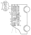
第3実施形態による制御装置及び制御方法について図面を用いて説明する。図7は、本実施形態による制御装置の一例である制御装置700を搭載した車両101を示す概略図である。図1乃至図6に示す第1又は第2実施形態による制御装置及び制御方法と同一の構成要素には、同一の符号を付して説明を省略または簡潔にする。また、本実施形態においても、図2および図5に示す車両101のいずれも適用可能である。すなわち、本実施形態で説明する各動作において、クラウドコンピュータ702が行う処理を制御部202が行い、データベース703が記憶する情報をメモリ206が記憶することで達成できる。
[Third Embodiment]
A control device and a control method according to a third embodiment will be described with reference to the drawings. FIG. 7 is a schematic diagram showing a vehicle 101 equipped with a control device 700 which is an example of the control device according to the present embodiment. The same components as those in the control device and the control method according to the first or second embodiment shown in FIGS. 1 to 6 are denoted by the same reference numerals, and description thereof will be omitted or simplified. Also in this embodiment, any of the vehicles 101 shown in FIGS. 2 and 5 can be applied. That is, in each operation described in the present embodiment, the processing performed by the cloud computer 702 is performed by the control unit 202, and the information stored in the database 703 is stored in the memory 206.

近時では、様々な安全装備が車両に備えられるようになってきている。安全装備とは、当該車両が事故を起こす危険性を低減し、安全性を増大させるための装備のことである。安全装備としては、例えば、ブレーキのロックを防止する装置、横滑りを防止する装置等が挙げられる。雪道やアイスバーン等の滑りやすい道路において、これらの安全装備が備えられているか否かは、当該車両の安全性を大きく左右する。また、安全装備として、車両の周囲の状況を監視するカメラやレーダ等も挙げられる。また、安全装備として、例えば、障害物や周囲の車両を検知して作動する自動ブレーキや、先行車両との車間距離をモニタリングしながら様々な車速域で先行車両に自動で追随する機能等も挙げられる。また、安全装備として、対向車両の有無を検知して自動でヘッドライトのロービームとハイビームとを切り替える装置や、夜間の暗い道でも歩行者や他車両をみつけ得る赤外線カメラ等も挙げられる。安全装備が備えられていない他車両102は、安全装備が備えられている他車両102と比較して、事故を起こす可能性が高い、即ち、危険性が高いと考えられる。また、安全装備の種類によっても、他車両102の危険性の度合い、即ち、危険度は異なると考えられる。   In recent years, various safety equipment has been provided in vehicles. The safety equipment is equipment for reducing the risk of the vehicle from causing an accident and increasing safety. Examples of the safety equipment include a device that prevents a brake from being locked and a device that prevents a skid. Whether or not these safety devices are provided on a slippery road such as a snowy road or an ice burn greatly affects the safety of the vehicle. Further, as safety equipment, there are a camera, a radar, and the like that monitor the situation around the vehicle. Also, as safety equipment, for example, an automatic brake that operates by detecting obstacles and surrounding vehicles, a function that automatically follows the preceding vehicle in various vehicle speed ranges while monitoring the distance between the preceding vehicle and the like, etc. It is done. Safety devices include a device that automatically detects the presence or absence of an oncoming vehicle and automatically switches between a low beam and a high beam of a headlight, and an infrared camera that can find pedestrians and other vehicles even on dark roads at night. It is considered that the other vehicle 102 that is not equipped with safety equipment has a higher possibility of causing an accident, that is, is more dangerous than the other vehicle 102 that is equipped with safety equipment. Further, it is considered that the degree of danger of the other vehicle 102, that is, the degree of danger varies depending on the type of safety equipment.

また、近時では、自動運転機能が備えられた車両が提案されている。自動運転機能を備えていない他車両102は、自動運転機能を備えている他車両102と比較して、事故を起こす可能性が高い、即ち、危険性が高いと考えられる。また、自動運転機能のレベルによっても、他車両102の危険性の度合い、即ち、危険度は異なると考えられる。なお、自動運転機能のレベルは、自動運転レベル1から自動運転レベル4までが規定されている(「戦略的イノベーション創造プログラム(SIP)自動走行システム研究開発計画」、内閣府)。自動運転レベル1は、加速・操舵・制動のいずれかをシステムが行う状態である。自動運転レベル2は、加速・操舵・制動のうち複数の操作をシステムが行う状態である。自動運転レベル3は、加速・操舵・制動を全てシステムが行い、システムが要請したときはドライバーが対応する状態である。自動運転レベル4は、加速・操舵・制動を全てドライバー以外が行い、ドライバーが全く関与しない状態である。   Recently, vehicles equipped with an automatic driving function have been proposed. It is considered that the other vehicle 102 that does not have the automatic driving function is more likely to cause an accident, that is, has a higher risk than the other vehicle 102 that has the automatic driving function. Further, it is considered that the degree of danger of the other vehicle 102, that is, the degree of danger varies depending on the level of the automatic driving function. In addition, the level of the autonomous driving function is defined from the autonomous driving level 1 to the autonomous driving level 4 ("Strategic Innovation Creation Program (SIP) Automated Driving System Research and Development Plan", Cabinet Office). The automatic driving level 1 is a state in which the system performs any one of acceleration, steering, and braking. The automatic driving level 2 is a state in which the system performs a plurality of operations among acceleration, steering, and braking. The automatic driving level 3 is a state in which the system performs all acceleration, steering, and braking, and the driver responds when the system requests it. The automatic driving level 4 is a state in which acceleration, steering and braking are all performed by a person other than the driver and the driver is not involved at all.

そこで、本実施形態では、第1、第2実施形態の車両の危険性の評価に加えて、他車両102の車種(車名)を検出し、車種に応じて他車両102の危険性(危険度)を判定する。例えば車名から各車に備えられた安全装備や自動運転機能を特定してこれらの情報に基づいて他車両102の危険性を判定する。そして危険性(危険度)の高い他車両102に対して十分な車間距離105を確保するように車両101を制御する。他車両102に備えられている安全装備や当該他車両102の自動運転レベルは、例えば、当該他車両102の車名、グレード、年式等に基づいて判定することが可能である。より精度よく他車両102の危険性を判定するための具体的なフローは図9にて詳述するが、一番単純な手順としては、予めデータベース703に危険車両とみなされる車種の情報が記憶され、制御部202あるいはクラウドコンピュータ702が、撮像部201から取得される画像から検出された車種の情報に基づいて当該他車両の危険性が高い、低いを一律に判定することである。次に有効な手順としては、車種に対応する危険性の評価が多段階に設けられ、他車両の車種に応じて車両101の制御を適応的に変更することである。例えば他車両の危険性が高いと判定されるほど、制御部202が各部を用いて、車両101と他車両102の車間距離をより空けたり、より低速で走行したり、より離れた位置に操舵されるよう制御したりする。   Therefore, in this embodiment, in addition to the evaluation of the risk of the vehicle in the first and second embodiments, the vehicle type (vehicle name) of the other vehicle 102 is detected, and the risk (danger) of the other vehicle 102 is detected according to the vehicle type. Degree). For example, the safety equipment and the automatic driving function provided in each vehicle are identified from the vehicle name, and the danger of the other vehicle 102 is determined based on these information. Then, the vehicle 101 is controlled so as to secure a sufficient inter-vehicle distance 105 for the other vehicle 102 having a high risk (risk level). The safety equipment provided in the other vehicle 102 and the automatic driving level of the other vehicle 102 can be determined, for example, based on the vehicle name, grade, year, etc. of the other vehicle 102. A specific flow for determining the danger of the other vehicle 102 with higher accuracy will be described in detail with reference to FIG. 9. As the simplest procedure, information on a vehicle type that is regarded as a dangerous vehicle is stored in the database 703 in advance. Then, the control unit 202 or the cloud computer 702 uniformly determines whether the risk of the other vehicle is high or low based on the information on the vehicle type detected from the image acquired from the imaging unit 201. The next effective procedure is to provide risk assessment corresponding to the vehicle type in multiple stages and adaptively change the control of the vehicle 101 according to the vehicle type of the other vehicle. For example, as it is determined that the risk of the other vehicle is higher, the control unit 202 uses each unit to increase the distance between the vehicle 101 and the other vehicle 102, travel at a lower speed, or steer to a more distant position. To be controlled.

図7に示す車両101について説明する。制御装置700は、撮像部201と、制御部202と、メモリ206とを備えている。制御装置700は、車両101に備えられた送受信装置701を介して、クラウドコンピュータ702にアクセスし得る。   The vehicle 101 shown in FIG. 7 will be described. The control device 700 includes an imaging unit 201, a control unit 202, and a memory 206. The control device 700 can access the cloud computer 702 via the transmission / reception device 701 provided in the vehicle 101.

撮像部201は、他車両102を撮像し、撮像により得られる画像を制御部202に送信する。本実施形態では、後述するように、画像に写っている他車両102のサイズに基づいて、車両101から他車両102までの距離を算出し得るため、撮像部201は視差画像を取得することを要さず、また、測距部501(図4参照)は備えられていない。撮像部201は、車名プレート111やグレード名プレート804等に表された文字等の確実な判読を可能とすべく、十分な解像度の画像を取得し得ることが好ましい。   The imaging unit 201 images the other vehicle 102 and transmits an image obtained by the imaging to the control unit 202. In the present embodiment, as will be described later, since the distance from the vehicle 101 to the other vehicle 102 can be calculated based on the size of the other vehicle 102 in the image, the imaging unit 201 acquires a parallax image. Further, the distance measuring unit 501 (see FIG. 4) is not provided. It is preferable that the imaging unit 201 can acquire an image with sufficient resolution so that the characters shown on the vehicle name plate 111, the grade name plate 804, and the like can be reliably read.

制御部202は、撮像部201によって取得される画像を、メモリ206に格納する。制御部202は、撮像部201によって取得される画像を、車両101に備えられた送受信装置701を介してクラウドコンピュータ702に送信し得る。制御部202は、撮像部201によって取得された画像に対して圧縮処理を施し、圧縮処理が施された画像を、送受信装置701を介してクラウドコンピュータ702に送信することもできる。また、制御部202は、撮像部201によって取得される画像のうちから他車両102の画像を抜き出し、抜き出した画像のみを、送受信装置701を介してクラウドコンピュータ702に送信することもできる。制御部202は、車速検出手段としての車速センサ207から出力される車両101の車速情報に基づいて、車両101の速度を検出する。制御部202は、当該他車両102のナンバープレート803(図8参照)の情報をメモリ206に記憶する。なお、他車両102のナンバープレート803の情報は、撮像部201によって取得される他車両102の画像に基づいて、制御部202によって検出されてもよいし、クラウドコンピュータ702によって検出されてもよい。制御部202は、クラウドコンピュータ702によって後述するようにして判定される当該他車両102の危険性に関する情報を、当該他車両102のナンバープレート803の情報と対応付けてメモリ206に記憶する。ナンバープレートの情報が検出できなかった場合は、例えば画像中で当該他車両102が検出された位置の情報と危険性に関する情報を対応づけるとよい。   The control unit 202 stores the image acquired by the imaging unit 201 in the memory 206. The control unit 202 can transmit the image acquired by the imaging unit 201 to the cloud computer 702 via the transmission / reception device 701 provided in the vehicle 101. The control unit 202 can also perform compression processing on the image acquired by the imaging unit 201 and transmit the compressed image to the cloud computer 702 via the transmission / reception device 701. The control unit 202 can also extract an image of the other vehicle 102 from the images acquired by the imaging unit 201 and transmit only the extracted image to the cloud computer 702 via the transmission / reception device 701. The control unit 202 detects the speed of the vehicle 101 based on the vehicle speed information of the vehicle 101 output from the vehicle speed sensor 207 serving as a vehicle speed detection unit. The control unit 202 stores information on the number plate 803 (see FIG. 8) of the other vehicle 102 in the memory 206. Information on the license plate 803 of the other vehicle 102 may be detected by the control unit 202 or may be detected by the cloud computer 702 based on the image of the other vehicle 102 acquired by the imaging unit 201. The control unit 202 stores information on the risk of the other vehicle 102 determined by the cloud computer 702 as described later in association with the information on the license plate 803 of the other vehicle 102 in the memory 206. When the information on the license plate cannot be detected, for example, the information on the position where the other vehicle 102 is detected in the image may be associated with the information on the danger.

クラウドコンピュータ702のデータベース703には、過去に販売された各車両の名称(車名)と、当該車名に関連付けられた各種車両情報とが格納されている。各種車両情報としては、例えば、車両サイズ、車名プレート(車名エンブレム)やグレード名プレートの画像や文字情報、車名プレートやグレード名プレートの位置に関する情報等が挙げられる。また、各種車両情報として、エンブレム(図示せず)の画像、各種安全装備の有無に関する情報、自動運転レベルに関する情報、車両の年式、各年式の車両の画像等が挙げられる。クラウドコンピュータ702は、これらの情報のセットをデータベース703に保持している。また、特定の車両が、例えば車両情報として車両のナンバーとセットで、危険性の高い車両としてデータベース703に記憶されていて、これらの情報を検出された他車両102の情報と照合することで危険な車両を検出してもよい。特定の車両は例えば過去の事故歴や盗難車両などの情報が個人情報が特定されない程度に記憶された公共のデータベースなどに基づき記憶されたものであってもよいし、車両101によって過去に車両の危険性が判定されたときの判定結果が記憶されたものでもよい。   The database 703 of the cloud computer 702 stores the name (vehicle name) of each vehicle sold in the past and various types of vehicle information associated with the vehicle name. Examples of the various vehicle information include vehicle size, vehicle name plate (vehicle name emblem), image and character information of grade name plate, information on positions of vehicle name plate and grade name plate, and the like. Examples of various vehicle information include an image of an emblem (not shown), information on the presence / absence of various safety equipment, information on an automatic driving level, vehicle year, vehicle image of each year, and the like. The cloud computer 702 holds these sets of information in the database 703. Further, for example, a specific vehicle is stored in the database 703 as a vehicle having a high risk with a vehicle number and a set as vehicle information, and it is dangerous by comparing these information with the information of the detected other vehicle 102. A simple vehicle may be detected. For example, the specific vehicle may be stored based on a public database in which information such as past accident histories or stolen vehicles is stored so that personal information is not specified. The determination result when the risk is determined may be stored.

クラウドコンピュータ702は、他車両102の車名等の認識に必要な画像認識機能を備えている。クラウドコンピュータ702は、制御装置700から送受信装置701を介して受信した画像に基づいて、画像に写っている他車両102の車名等を判定し、当該他車両102の車名等に基づいて当該他車両102の危険性を判定する。クラウドコンピュータ702には、大型のコンピュータが備えられているため、制御部202よりも処理速度が速く、大容量の画像を用いた処理に好適である。   The cloud computer 702 has an image recognition function necessary for recognizing the name of the other vehicle 102 and the like. The cloud computer 702 determines the name of the other vehicle 102 in the image based on the image received from the control device 700 via the transmission / reception device 701, and determines the name of the other vehicle 102 based on the name of the other vehicle 102. The risk of the other vehicle 102 is determined. Since the cloud computer 702 includes a large computer, the processing speed is faster than that of the control unit 202, which is suitable for processing using a large-capacity image.

クラウドコンピュータ702は、制御装置700から受け取った画像のうちから、他車両102の車両情報を検出する方法を以下に説明する。図8(a)は、他車両102を後部側から見た状態の例を示す図である。図8に示すように、他車両102の後部には、リアウィンドウ801、テールライト802L、802R、ナンバープレート803等が備えられている。図8(b)は、車名プレート及びグレード名プレートの例を示す図である。クラウドコンピュータ702は、他車両102の画像のうちから、車名プレート111を探索する。車名プレート111は、テールライト802L,802Rの上側に位置する場合が多い。従って、クラウドコンピュータ702は、まず、左右のテールライト802L,802Rの上側の領域805,806に対して車名プレート111の探索を行う。左右のテールライト802L,802Rの上側の領域805,806に車名プレート111が見つからない場合には、クラウドコンピュータ702は、左右のテールライト802L,802Rの下側の領域807,808に対して車名プレート111の探索を行う。テールライト802L,802Rの上側の領域805,806の次に車名プレート111が配される可能性が高いのは、テールライト802L,802Rの下側の領域807,808であるためである。左右のテールライト802L,802Rの下側の領域に車名プレートが見つからない場合には、クラウドコンピュータ702は、左側のテールライト802Lと右側のテールライト802Rとの間の領域809に対して車名プレート111の探索を行う。テールライト802L,802Rの下側の領域807,808の次に車名プレート111が配される可能性が高いのは、左側のテールライト802Lと右側のテールライト802Rとの間の領域809であるためである。このように、本実施形態では、車名プレート111が配されている可能性が高い領域から順に車名プレート111の探索を行うため、迅速かつ効率的に車名プレート111を検出することができる。クラウドコンピュータ702は、車名プレート111の表記、即ち、文字等を判読し、当該他車両102の車名を判定する。   A method for detecting the vehicle information of the other vehicle 102 from the image received from the control device 700 by the cloud computer 702 will be described below. FIG. 8A is a diagram illustrating an example of a state in which the other vehicle 102 is viewed from the rear side. As shown in FIG. 8, a rear window 801, taillights 802 </ b> L and 802 </ b> R, a number plate 803, and the like are provided at the rear part of the other vehicle 102. FIG. 8B is a diagram illustrating an example of a car name plate and a grade name plate. The cloud computer 702 searches for the vehicle name plate 111 from the image of the other vehicle 102. The vehicle name plate 111 is often positioned above the tail lights 802L and 802R. Accordingly, the cloud computer 702 first searches the vehicle name plate 111 for the areas 805 and 806 above the left and right taillights 802L and 802R. When the vehicle name plate 111 is not found in the upper regions 805 and 806 of the left and right taillights 802L and 802R, the cloud computer 702 moves the vehicle to the lower regions 807 and 808 of the left and right taillights 802L and 802R. The name plate 111 is searched. The reason why the vehicle name plate 111 is likely to be placed next to the upper regions 805 and 806 of the tail lights 802L and 802R is because the lower regions 807 and 808 of the tail lights 802L and 802R. When the vehicle name plate is not found in the area below the left and right taillights 802L and 802R, the cloud computer 702 displays the vehicle name for the area 809 between the left taillight 802L and the right taillight 802R. The plate 111 is searched. The area 809 between the left taillight 802L and the right taillight 802R is most likely to have the vehicle name plate 111 placed next to the lower areas 807 and 808 of the taillights 802L and 802R. Because. Thus, in this embodiment, since the vehicle name plate 111 is searched in order from the region where the vehicle name plate 111 is likely to be arranged, the vehicle name plate 111 can be detected quickly and efficiently. . The cloud computer 702 interprets the notation of the vehicle name plate 111, that is, the characters and the like, and determines the vehicle name of the other vehicle 102.

クラウドコンピュータ702は、車名プレート111の探索と同様にして、グレード名プレート804の探索を行う。クラウドコンピュータ702は、グレード名プレート804の表記、即ち、文字等を判読し、当該他車両102のグレードを判定する。   The cloud computer 702 searches for the grade name plate 804 in the same manner as the search for the car name plate 111. The cloud computer 702 reads the notation of the grade name plate 804, that is, the characters, etc., and determines the grade of the other vehicle 102.

なお、ここでは、車名が車名プレート111によって表されている場合を例に説明したが、車名は必ずしも車名プレート111によって表されるとは限らない。また、ここでは、グレード名がグレード名プレート804によって表されている場合を例に説明したが、グレード名は必ずしもグレード名プレート804によって表されるとは限らない。例えば、車名やグレード名が車体に刻印されることもあり得るし、車名やグレード名が塗料等によって車体に表されることもあり得る。クラウドコンピュータ702は、車名やグレード名が車名プレート111やグレード名プレート804以外の手段によって表されている場合であっても、当該他車両102の車名やグレード名を検出し得る。また、車名やグレード名は、アルファベットや数字等の文字である可能性が非常に高いため、クラウドコンピュータ702は、文字等を含んでいる画像のみに限定して車名やグレード名の探索を行うようにしてもよい。   Here, the case where the vehicle name is represented by the vehicle name plate 111 has been described as an example, but the vehicle name is not necessarily represented by the vehicle name plate 111. Although the case where the grade name is represented by the grade name plate 804 has been described as an example here, the grade name is not necessarily represented by the grade name plate 804. For example, a car name or grade name may be engraved on the vehicle body, and a car name or grade name may be represented on the vehicle body by paint or the like. The cloud computer 702 can detect the vehicle name and grade name of the other vehicle 102 even when the vehicle name and grade name are represented by means other than the vehicle name plate 111 and the grade name plate 804. In addition, since there is a high possibility that a car name or a grade name is a letter such as an alphabet or a number, the cloud computer 702 searches for a car name or a grade name only for images containing letters or the like. You may make it perform.

クラウドコンピュータ702は、他車両102の画像に基づいて、当該他車両102の年式を判定する。クラウドコンピュータ702のデータベース703には、上述したように、車名と、年式と、当該年式の当該車両の画像とが関連付けられて格納されている。従って、クラウドコンピュータ702は、各年式の当該車名の車両の画像と、他車両102の画像とを照合することによって、当該他車両102の年式を判定することが可能である。さらに、車名、年式と関連づけて、過去の事故歴やリコール歴などの情報も記憶されていてもよい。過去の事故歴やリコール歴のある車両の方がない車両より危険性が高く検出されるようフラグを付けるなどするとよい。   The cloud computer 702 determines the model year of the other vehicle 102 based on the image of the other vehicle 102. As described above, the database 703 of the cloud computer 702 stores the vehicle name, the year, and the image of the vehicle of the year in association with each other. Accordingly, the cloud computer 702 can determine the year of the other vehicle 102 by comparing the image of the vehicle with the vehicle name of each year with the image of the other vehicle 102. Further, information such as past accident history and recall history may be stored in association with the vehicle name and year. For example, a flag may be set so that a vehicle with a history of accidents or recalls has a higher risk than a vehicle with no history.

クラウドコンピュータ702は、車名と、年式と、グレードの情報に基づいて、他車両102に備えられた安全装備の有無や他車両102の自動運転レベルを検出する。グレード名プレート804がみつからない場合には、クラウドコンピュータ702は、車名と、年式とに基づいて、他車両102に備えられた安全装備や他車両102の自動運転レベルを判定するようにしてもよい。   The cloud computer 702 detects the presence / absence of safety equipment provided in the other vehicle 102 and the automatic driving level of the other vehicle 102 based on the vehicle name, year, and grade information. When the grade name plate 804 is not found, the cloud computer 702 determines the safety equipment provided in the other vehicle 102 and the automatic driving level of the other vehicle 102 based on the vehicle name and the model year. Also good.

クラウドコンピュータ702は、制御装置700から送受信装置701を介して受信した画像に写っている他車両102のサイズに基づいて、車両101から当該他車両102までの距離105を算出する。クラウドコンピュータ702には、上述したように、当該他車両102の車両サイズのデータが格納されている。従って、クラウドコンピュータ702に格納された当該車両サイズ(幅、高さ等)のデータと、画像に写っている他車両102のサイズ(幅、高さ等)とに基づいて、車両101から当該他車両102までの距離105を算出することが可能である。なお、車両101から他車両102間での距離は、図2、図5のような車両構成を以て、第1の実施形態に記載の方法で算出してもよい。   The cloud computer 702 calculates the distance 105 from the vehicle 101 to the other vehicle 102 on the basis of the size of the other vehicle 102 shown in the image received from the control device 700 via the transmission / reception device 701. As described above, the cloud computer 702 stores the vehicle size data of the other vehicle 102. Therefore, based on the data on the vehicle size (width, height, etc.) stored in the cloud computer 702 and the size (width, height, etc.) of the other vehicle 102 shown in the image, the other from the vehicle 101. A distance 105 to the vehicle 102 can be calculated. The distance between the vehicle 101 and the other vehicle 102 may be calculated by the method described in the first embodiment with the vehicle configuration as shown in FIGS.

クラウドコンピュータ702は、当該他車両102の危険性を示すための上述した情報と、車両101からの当該他車両102までの距離を示す情報とを、送受信装置701を介して制御装置700に備えられた制御部202に送信する。   The cloud computer 702 includes the above-described information for indicating the danger of the other vehicle 102 and information indicating the distance from the vehicle 101 to the other vehicle 102 in the control device 700 via the transmission / reception device 701. To the control unit 202.

制御部202は、クラウドコンピュータ702によって得られるこれらの情報と、車速検出手段としての車速センサ207によって検出される車両101の走行速度とに基づいて、車両101を制御するための信号を生成する。例えば、先行車両102aの危険性が高い場合には、車両101と先行車両102aとの車間距離105aを、車両101の走行速度から見積もられる停止距離の例えば2倍以上とするようにしてもよい。一方、先行車両102aの危険性が低い場合には、車両101と先行車両102aとの車間距離105aを、車両101の走行速度から見積もられる停止距離と同等とするようにしてもよい。制御部202は、他車両102の危険性が高い場合や、車両101が他車両102と衝突する可能性が高い場合には、車両101に備えられた警告発生装置208を用いて警告を発するようにしてもよい。   The control unit 202 generates a signal for controlling the vehicle 101 based on the information obtained by the cloud computer 702 and the traveling speed of the vehicle 101 detected by the vehicle speed sensor 207 as a vehicle speed detection unit. For example, when the risk of the preceding vehicle 102a is high, the inter-vehicle distance 105a between the vehicle 101 and the preceding vehicle 102a may be set to be, for example, twice or more the stop distance estimated from the traveling speed of the vehicle 101. On the other hand, when the risk of the preceding vehicle 102a is low, the inter-vehicle distance 105a between the vehicle 101 and the preceding vehicle 102a may be made equal to the stop distance estimated from the traveling speed of the vehicle 101. When the risk of the other vehicle 102 is high, or when the possibility that the vehicle 101 collides with the other vehicle 102 is high, the control unit 202 issues a warning using the warning generation device 208 provided in the vehicle 101. It may be.

図9は、本実施形態による制御装置の動作の例を示すフローチャートである。以下では、各ステップで行われる一部の演算がクラウドコンピュータ702によって行われている例を示すが、それらの制御の一部または全部は車両101内の制御部202にて行われてもよい。本動作は、車両101の走行開始(例えば車速情報やブレーキに関する情報)をトリガーとしてスタートする。動作の開始タイミングとしては上記に限らず、例えば操作部210へのユーザ操作による設定(車速や他車両102の検出などトリガーそのものの設定も含む)に従って、任意のタイミングでスタートさせてもよい。   FIG. 9 is a flowchart illustrating an example of the operation of the control device according to the present embodiment. In the following, an example is shown in which some calculations performed in each step are performed by the cloud computer 702, but some or all of these controls may be performed by the control unit 202 in the vehicle 101. This operation starts with the start of traveling of the vehicle 101 (for example, vehicle speed information or information about brakes) as a trigger. The start timing of the operation is not limited to the above, and may be started at an arbitrary timing according to the setting by the user operation on the operation unit 210 (including the setting of the trigger itself such as detection of the vehicle speed and other vehicle 102).

ステップS301において、撮像部201によって画像が取得される。撮像部201は、取得した画像を制御部202に送信する。本実施形態では、制御部202が順次適当なタイミングで送受信装置701を介してクラウドコンピュータ702に画像を送信する。   In step S <b> 301, an image is acquired by the imaging unit 201. The imaging unit 201 transmits the acquired image to the control unit 202. In the present embodiment, the control unit 202 sequentially transmits images to the cloud computer 702 via the transmission / reception device 701 at an appropriate timing.

ステップS302において、クラウドコンピュータ702は、撮像部201によって取得された画像に基づいて他車両102を検出し、例えば上述したような手法で車両101から他車両102までの距離105を算出する。   In step S302, the cloud computer 702 detects the other vehicle 102 based on the image acquired by the imaging unit 201, and calculates the distance 105 from the vehicle 101 to the other vehicle 102 by the method described above, for example.

ステップS901において、クラウドコンピュータ702は、制御装置700から受信した画像に基づいて、第1の実施形態のステップS303と同様に他車両102の蛇行走行及び車線逸脱を検出する。検出結果は対応する他車両102の情報と関連づけてメモリ206あるいはデータベース703に記憶される。   In step S901, the cloud computer 702 detects meandering and lane departure of the other vehicle 102 based on the image received from the control device 700, as in step S303 of the first embodiment. The detection result is stored in the memory 206 or the database 703 in association with the information of the corresponding other vehicle 102.

ステップS902において、クラウドコンピュータ702は、制御装置700から受信した画像に基づいて、第2の実施形態のステップS601と同様に他車両102の運転者を評価する。評価結果(危険性の高い運転者か否かの情報、あるいは運転者の危険性のレベル情報)は、対応する他車両102の情報と関連づけてメモリ206あるいはデータベース703に記憶される。   In step S <b> 902, the cloud computer 702 evaluates the driver of the other vehicle 102 based on the image received from the control device 700 as in step S <b> 601 of the second embodiment. The evaluation result (information on whether or not the driver is at high risk or information on the level of risk of the driver) is stored in the memory 206 or the database 703 in association with the corresponding information on the other vehicle 102.

ステップS903において、クラウドコンピュータ702は、制御装置700から送受信装置701を介して受信した画像に基づいて、本実施形態で上述したように、車名、年式、グレード、過去の事故歴など、他車両102の車両に関する車両情報を検出する。車両情報の検出結果は、対応する他車両102の情報と関連づけてメモリ206あるいはデータベース703に記憶される。   In step S903, the cloud computer 702, based on the image received from the control device 700 via the transmission / reception device 701, as described above in the present embodiment, the vehicle name, year, grade, past accident history, etc. Vehicle information related to the vehicle 102 is detected. The detection result of the vehicle information is stored in the memory 206 or the database 703 in association with the information of the corresponding other vehicle 102.

ステップS904において、クラウドコンピュータ702は、ステップS901〜S903での検出結果及び評価結果に基づいて他車両102の危険性を判定する。   In step S904, the cloud computer 702 determines the risk of the other vehicle 102 based on the detection results and the evaluation results in steps S901 to S903.

ステップS905において、制御部202は、車両101から他車両102までの距離と、当該他車両102の危険性と、車両101の走行速度とに基づいて、車両101を制御するための信号を生成する。   In step S <b> 905, the control unit 202 generates a signal for controlling the vehicle 101 based on the distance from the vehicle 101 to the other vehicle 102, the danger of the other vehicle 102, and the traveling speed of the vehicle 101. .

ステップS905では、他車両の危険性を判定するための情報として上述したように他車両102の蛇行走行・車線逸脱に関する情報、運転者の評価情報(危険性に関する情報)、車両の車名、年式、グレード、事故歴などの車両情報を取得している。これらの情報は情報の種類や検出結果によって優先すべき度合いが異なる。例えば車両情報からは安全装備も充実し、自動運転レベルも高く、事故歴も少ない車両であると判定されていても、激しい蛇行運転が検出されている車両に対しては危険性のレベルを高くし最優先に考慮して車両101の制御に当たらなければならない場合もある。従って、本実施形態では、蛇行走行・車線逸脱などの他車両の走行情報の優先度を1番とし、次いで運転者の評価情報、そして車両情報と順に優先度を下げることとする。具体的には、この順で評価に対する重み付けを変えて、複数の他車両102に対して、どの他車両102に対しての対応を優先すべきかを決定する。また、自車両101との距離が自車両101の現在の車速から決まる停止距離よりも近い距離にいる場合などは、当該他車両に対応する車両101の制御が最優先とすることが好ましい。
ステップS905の後、ステップS901以降の動作が繰り返される。
In step S905, as described above as information for determining the danger of the other vehicle, information on meandering / lane departure of the other vehicle 102, driver evaluation information (information on danger), vehicle name, year of the vehicle Vehicle information such as formula, grade and accident history is obtained. The degree of priority of these pieces of information varies depending on the type of information and the detection result. For example, even if it is determined from the vehicle information that the safety equipment is substantial, the automatic driving level is high, and the accident history is low, the level of danger is high for vehicles that detect severe meandering. In some cases, however, the vehicle 101 must be controlled in consideration of the highest priority. Therefore, in this embodiment, the priority of the traveling information of other vehicles such as meandering traveling and lane departure is set to the first, and then the priority is lowered in the order of the driver evaluation information and the vehicle information. Specifically, the weighting for the evaluation is changed in this order to determine which other vehicle 102 should be given priority over the plurality of other vehicles 102. In addition, when the distance from the host vehicle 101 is closer than the stop distance determined from the current vehicle speed of the host vehicle 101, it is preferable that the control of the vehicle 101 corresponding to the other vehicle has the highest priority.
After step S905, the operations after step S901 are repeated.

なお、ここでは、他車両102の危険性の程度が、高い場合にも、低い場合にも、制御部202がステップS907において信号生成を行う場合を例に説明したが、これに限定されるものではない。例えば、他車両102の危険性の程度が高い場合にのみ、制御部202がステップS907において信号生成を行うようにしてもよい。この場合、ステップS906において、他車両102の危険性の程度が低いと判定された場合には、ステップS907を実行することなく、ステップS901に戻る。また、図9に示す制御装置700のこれら一連の動作は、車両101の速度が所定速未満に低下することやエンジンの停止などに応じて終了する。   In addition, although the case where the control unit 202 performs signal generation in step S907 has been described here as an example, whether the danger level of the other vehicle 102 is high or low, the present invention is not limited thereto. is not. For example, the control unit 202 may generate a signal in step S907 only when the danger level of the other vehicle 102 is high. In this case, if it is determined in step S906 that the degree of danger of the other vehicle 102 is low, the process returns to step S901 without executing step S907. Further, the series of operations of the control device 700 shown in FIG. 9 is terminated when the speed of the vehicle 101 decreases below a predetermined speed or when the engine is stopped.

このように、本実施形態においても、撮像部201によって取得される画像に基づいて他車両102の危険性が判定される。具体的には、第1、第2の実施形態に加えてさらに他車両102の安全設備や安全運転機能を図ることができる車両情報に基づいて、他車両102の危険性が判定される。そして、他車両102の危険性に基づいて、車両101を制御するための信号が生成される。このため、本実施形態においても、車両101の安全性を向上することができる。   Thus, also in this embodiment, the risk of the other vehicle 102 is determined based on the image acquired by the imaging unit 201. Specifically, in addition to the first and second embodiments, the danger of the other vehicle 102 is determined based on the vehicle information that can further implement the safety equipment and the safe driving function of the other vehicle 102. Then, a signal for controlling the vehicle 101 is generated based on the danger of the other vehicle 102. For this reason, also in this embodiment, the safety of the vehicle 101 can be improved.

[第4実施形態]
本実施形態による制御装置及び制御方法について図面を用いて説明する。図1乃至図9に示す第1乃至第3実施形態による制御装置及び制御方法と同一の構成要素には、同一の符号を付して説明を省略または簡潔にする。
[Fourth Embodiment]
A control device and a control method according to the present embodiment will be described with reference to the drawings. The same components as those in the control device and the control method according to the first to third embodiments shown in FIGS. 1 to 9 are denoted by the same reference numerals, and description thereof will be omitted or simplified.

先行車両102aの運転者が当該先行車両102aの前方を走行する先々行車両102bに対して、いわゆる煽り運転を行っていることもあり得る。煽り運転とは、先行車両が先々行車両に対して非常に接近して走行する運転である。煽り運転は、先行車両102aが先々行車両102bに追突する危険性が高い。また、先々行車両102bが当該先々行車両102bの後方を走行する先行車両102aから圧迫感を受ける結果、当該先々行車両102bが、無理に走行速度を増大したり、無理に車線変更を行ったりする可能性がある。これらは、結果的に、先々行車両102bが事故を起こす可能性を高める。また、先行車両102aが無理な追い越しを行おうとする可能性があり、当該先行車両102aが事故を起こす可能性も高い。先々行車両102bが事故を起こせば、当該先々行車両102bの直後を走行する先行車両102aも事故に巻き込まれる可能性が高い。先行車両102aが煽り運転を行っている状態で、先々行車両102bが急停止した場合には、先行車両102aは先々行車両102bへの衝突を免れ得ない可能性が高い。そこで、本実施形態では、他車両102の煽り運転を行っているかに着目して他車両102の危険性を判定し、危険性の高い他車両102に対して十分な車間距離105を確保するようにしている。   The driver of the preceding vehicle 102a may be performing a so-called rolling operation with respect to the preceding vehicle 102b traveling in front of the preceding vehicle 102a. The rolling operation is an operation in which the preceding vehicle travels very close to the preceding vehicle. In the rolling operation, there is a high risk that the preceding vehicle 102a will collide with the preceding vehicle 102b. Further, as a result of the predecessor vehicle 102b receiving a feeling of pressure from the preceding vehicle 102a traveling behind the predecessor vehicle 102b, the predecessor vehicle 102b may forcibly increase the traveling speed or forcefully change the lane. There is. As a result, the possibility that the preceding vehicle 102b will cause an accident is increased. In addition, there is a possibility that the preceding vehicle 102a will try to overtake, and there is a high possibility that the preceding vehicle 102a will cause an accident. If the predecessor vehicle 102b causes an accident, there is a high possibility that the preceding vehicle 102a traveling immediately after the predecessor vehicle 102b is also involved in the accident. If the preceding vehicle 102b suddenly stops while the preceding vehicle 102a is running, it is highly possible that the preceding vehicle 102a cannot escape the collision with the preceding vehicle 102b. Therefore, in the present embodiment, the risk of the other vehicle 102 is determined by paying attention to whether the other vehicle 102 is running, and a sufficient inter-vehicle distance 105 is secured for the other vehicle 102 having a high risk. I have to.

本実施形態による制御装置の構成も図2、図5及び図7のいずれの車両101の構成例においても適用可能であるが、ここでは本図5を用いて説明することとする。制御装置500は、撮像部201と、制御部202と、メモリ206と、測距部501とを備えている。撮像部201は、車両101の前方、斜め左側前方、斜め右側前方、左側側方、右側側方、斜め左側後方、斜め右側後方をそれぞれ撮像するための例えば7台の撮像デバイスによって構成されている。撮像部201としては、例えば、第1実施形態において上述した撮像部201と同様に、視差画像を取得し得る撮像部が用いられている。測距部501としては、第2実施形態において上述したように、例えばミリ波レーダを用いる。本実施形態において、ミリ波レーダ等により構成される測距部501を用いるのは、以下のような理由によるものである。即ち、他車両102が遠方に位置する場合には、視差画像に基づいて距離を測定するよりも、ミリ波レーダ等を用いて距離を測定するほうが、霧や排気ガス等の影響を受けにくく、距離計測精度が低下しにくいためである。測距部501は、先行車両102a前方に位置する先々行車両102bまでの距離を測定し得る。   The configuration of the control device according to the present embodiment can also be applied to any configuration example of the vehicle 101 shown in FIGS. 2, 5, and 7, but will be described with reference to FIG. 5 here. The control device 500 includes an imaging unit 201, a control unit 202, a memory 206, and a distance measuring unit 501. The imaging unit 201 is configured by, for example, seven imaging devices for imaging the front, diagonal left front, diagonal right front, left side, right side, diagonal left rear, and diagonal right rear of the vehicle 101. . As the imaging unit 201, for example, an imaging unit that can acquire a parallax image is used, as in the imaging unit 201 described above in the first embodiment. As the distance measuring unit 501, for example, a millimeter wave radar is used as described above in the second embodiment. In the present embodiment, the distance measuring unit 501 configured by a millimeter wave radar or the like is used for the following reason. That is, when the other vehicle 102 is located far away, measuring the distance using a millimeter wave radar or the like is less affected by fog or exhaust gas than measuring the distance based on the parallax image, This is because the distance measurement accuracy is unlikely to decrease. The distance measuring unit 501 can measure the distance to the preceding vehicle 102b located in front of the preceding vehicle 102a.

制御部202は、車両101と先行車両102aとの車間距離105aについての情報を、例えば撮像部201によって取得される視差画像に基づいて取得する。また、制御部202は、車両101から先々行車両102bまでの距離についての情報を、測距部501を用いて取得する。そして、制御部202は、これらの情報に基づいて、先行車両102aと先々行車両102bとの車間距離105bを算出する。なお、ここでは、車両101と先行車両102aとの車間距離105aを撮像部201によって取得される視差画像に基づいて算出する場合を例に説明したが、これに限定されるものではない。例えば、車両101と先行車両102aとの車間距離105aについての情報を、測距部501を用いて取得するようにしてもよい。また、車両101から先々行車両102bまでの距離についての情報を、例えば、撮像部201によって取得される視差画像に基づいて算出するようにしてもよい。制御部202は、先行車両102aと先々行車両102bとの車間距離105bに基づいて、先行車両102aが煽り運転を行っているか否かを判定する。例えば、先行車両102aと先々行車両102bとが走行中であるにもかかわらず、先行車両102aと先々行車両102bとの車間距離105bが所定距離以下である場合には、先行車両102aが煽り運転を行っていると判定する。かかる所定距離としては、例えば、車両1台分、具体的には、例えば約5m程度とすることができるが、これに限定されるものではない。   The control unit 202 acquires information about the inter-vehicle distance 105a between the vehicle 101 and the preceding vehicle 102a based on, for example, a parallax image acquired by the imaging unit 201. In addition, the control unit 202 acquires information about the distance from the vehicle 101 to the preceding vehicle 102b using the distance measuring unit 501. And the control part 202 calculates the inter-vehicle distance 105b of the preceding vehicle 102a and the preceding vehicle 102b based on such information. Here, although the case where the inter-vehicle distance 105a between the vehicle 101 and the preceding vehicle 102a is calculated based on the parallax image acquired by the imaging unit 201 has been described as an example, the present invention is not limited to this. For example, information on the inter-vehicle distance 105a between the vehicle 101 and the preceding vehicle 102a may be acquired using the distance measuring unit 501. Further, information about the distance from the vehicle 101 to the preceding vehicle 102b may be calculated based on, for example, a parallax image acquired by the imaging unit 201. Based on the inter-vehicle distance 105b between the preceding vehicle 102a and the preceding vehicle 102b, the control unit 202 determines whether or not the preceding vehicle 102a is running. For example, if the inter-vehicle distance 105b between the preceding vehicle 102a and the preceding vehicle 102b is equal to or less than a predetermined distance even though the preceding vehicle 102a and the preceding vehicle 102b are traveling, the preceding vehicle 102a performs the rolling operation. It is determined that The predetermined distance may be, for example, one vehicle, specifically, for example, about 5 m, but is not limited thereto.

制御部202は、先行車両102aが煽り運転を行っていると判定した場合には、当該先行車両102aの危険性は高いと判定する。即ち、制御部202は、先行車両102aと先々行車両102bとの車間距離105bに基づいて、先行車両102aの危険性を判定する。そして、制御部202は、車両101から他車両102までの距離105と、当該他車両102の危険性と、車両101の走行速度から見積もられる停止距離とに基づいて、車両101を制御するための信号を生成する。例えば、先行車両102aが煽り運転を行っているにもかかわらず、車両101と先行車両102aとの車間距離105aが必ずしも十分に確保されていない場合には、制御部202は以下のような信号を生成し得る。即ち、この場合には、制御部202は、ブレーキの作動をブレーキ制御装置204に実行させるような信号を生成し、生成した信号をブレーキ制御装置204に送信する。また、かかる場合には、制御部202は、動力源の駆動力の抑制を動力制御装置205に行わせるような信号を生成し、生成した信号を動力制御装置205に送信する。これにより、車両101の走行速度が低下し、危険性の高い先行車両102aと車両101との車間距離105aが十分に確保される。また、制御部202は、当該先行車両102aが他車両102と衝突する危険性が高いと判定した場合には、車両101の運転者に対して例えば警告発生装置208を用いて警告を通知する。   When the control unit 202 determines that the preceding vehicle 102a is running, it determines that the risk of the preceding vehicle 102a is high. That is, the control unit 202 determines the risk of the preceding vehicle 102a based on the inter-vehicle distance 105b between the preceding vehicle 102a and the preceding vehicle 102b. The control unit 202 controls the vehicle 101 based on the distance 105 from the vehicle 101 to the other vehicle 102, the danger of the other vehicle 102, and the stop distance estimated from the traveling speed of the vehicle 101. Generate a signal. For example, when the preceding vehicle 102a is driving in spite of the fact that the inter-vehicle distance 105a between the vehicle 101 and the preceding vehicle 102a is not always sufficiently secured, the control unit 202 outputs the following signal. Can be generated. That is, in this case, the control unit 202 generates a signal that causes the brake control device 204 to execute the operation of the brake, and transmits the generated signal to the brake control device 204. In such a case, the control unit 202 generates a signal that causes the power control device 205 to suppress the driving force of the power source, and transmits the generated signal to the power control device 205. As a result, the traveling speed of the vehicle 101 decreases, and the inter-vehicle distance 105a between the preceding vehicle 102a and the vehicle 101 with high risk is sufficiently secured. In addition, when it is determined that the preceding vehicle 102a has a high risk of colliding with the other vehicle 102, the control unit 202 notifies the driver of the vehicle 101 of a warning using, for example, a warning generation device 208.

また、制御部202は、他車両102の危険性に基づいて車線変更を行うようにしてもよい。具体的には、先行車両102aとは異なる走行車線を車両101が走行するように制御するための信号を、制御部202が先行車両102aの危険性に基づいて生成するようにしてもよい。車線変更を行う場合には、制御部202は、車線変更の動作に移行する前に、車線変更を運転者に促すための警告を、警告発生装置208等を用いて発することが好ましい。例えば、車線変更を促す警告を発したにもかかわらず、運転者が車線変更を開始しない場合に、制御部202は、車線変更を自動で行うことを運転者に対して告知するようにしてもよい。そして、運転者が車線変更を許可する旨の意思表示をした場合に、車線変更を行うようにしてもよい。車線変更の意思表示は、例えば、不図示の許可ボタンを押すこと等によって行い得る。車線変更の際には、変更先の走行車線を走行している他車両102d(図1参照)が、車両101の近傍に位置していないかを把握することが重要である。また、変更先の走行車線を走行している他車両102dの危険性を、先行車両102aと同様に把握することが重要である。そして、当該他車両102dと車両101との車間距離が十分に確保されるように、車両101の走行速度を制御し、適切なタイミングで車線変更の動作を実行することが重要である。車線変更を自動で行う場合、制御部202は、車両101に備えられた操舵制御装置209に制御信号を送信する。   Further, the control unit 202 may change the lane based on the danger of the other vehicle 102. Specifically, the control unit 202 may generate a signal for controlling the vehicle 101 to travel on a traveling lane different from the preceding vehicle 102a based on the risk of the preceding vehicle 102a. When the lane change is performed, the control unit 202 preferably issues a warning for prompting the driver to change the lane using the warning generation device 208 or the like before shifting to the lane change operation. For example, when the driver does not start the lane change despite issuing a warning prompting the lane change, the control unit 202 may notify the driver that the lane change is automatically performed. Good. And when a driver | operator displays the intention to permit a lane change, you may make it perform a lane change. The intention to change lanes can be displayed, for example, by pressing a permission button (not shown). When changing lanes, it is important to know whether another vehicle 102 d (see FIG. 1) traveling in the destination travel lane is located in the vicinity of the vehicle 101. In addition, it is important to grasp the danger of the other vehicle 102d traveling in the destination travel lane in the same manner as the preceding vehicle 102a. It is important to control the traveling speed of the vehicle 101 and execute the lane change operation at an appropriate timing so that the inter-vehicle distance between the other vehicle 102d and the vehicle 101 is sufficiently secured. When the lane change is automatically performed, the control unit 202 transmits a control signal to the steering control device 209 provided in the vehicle 101.

図10は、本実施形態による制御装置の動作を示すフローチャートである。本動作は、車両101の走行開始(例えば車速情報やブレーキに関する情報)をトリガーとしてスタートする。動作の開始タイミングとしては上記に限らず、例えば操作部210へのユーザ操作による設定(車速や他車両102の検出などトリガーそのものの設定も含む)に従って、任意のタイミングでスタートさせてもよい。   FIG. 10 is a flowchart showing the operation of the control device according to the present embodiment. This operation starts with the start of traveling of the vehicle 101 (for example, vehicle speed information or information about brakes) as a trigger. The start timing of the operation is not limited to the above, and may be started at an arbitrary timing according to the setting by the user operation on the operation unit 210 (including the setting of the trigger itself such as detection of the vehicle speed and other vehicle 102).

ステップS1001において、撮像部201によって撮像が行われる。撮像部201によって取得された画像は、制御部202に入力される。   In step S1001, the imaging unit 201 performs imaging. An image acquired by the imaging unit 201 is input to the control unit 202.

ステップS1002において、制御部202は、距離算出処理を行う。具体的には、制御部202は、車両101と先行車両102aとの車間距離105aについての情報を、例えば撮像部201によって取得される視差画像に基づいて取得する。また、制御部202は、車両101から先々行車両102bまでの距離についての情報を、例えば測距部501を用いて取得する。そして、制御部202は、これらの情報に基づいて、先行車両102aと先々行車両102bとの車間距離105bを算出する。   In step S1002, the control unit 202 performs a distance calculation process. Specifically, the control unit 202 acquires information about the inter-vehicle distance 105a between the vehicle 101 and the preceding vehicle 102a based on, for example, a parallax image acquired by the imaging unit 201. In addition, the control unit 202 acquires information about the distance from the vehicle 101 to the preceding vehicle 102b using, for example, the distance measuring unit 501. And the control part 202 calculates the inter-vehicle distance 105b of the preceding vehicle 102a and the preceding vehicle 102b based on such information.

ステップS1003において、制御部202は、例えば先行車両102aと先々行車両102bとの距離に基づいて、先行車両102aが煽り運転を行っているか否かを判定する。先行車両102aが煽り運転を行っている場合には(ステップS1003においてYES)、ステップS1004に移行する。一方、先行車両102aが煽り運転を行っていない場合には(ステップS1003においてNO)、ステップS1005に移行する。   In step S1003, the control unit 202 determines whether or not the preceding vehicle 102a is running on the basis of the distance between the preceding vehicle 102a and the preceding vehicle 102b, for example. If the preceding vehicle 102a is running (YES in step S1003), the process proceeds to step S1004. On the other hand, if the preceding vehicle 102a is not driving (NO in step S1003), the process proceeds to step S1005.

ステップS1004において、制御部202は、先行車両102aの危険性は高いと判定する。この後、ステップS1006に移行する。   In step S1004, the control unit 202 determines that the risk of the preceding vehicle 102a is high. Thereafter, the process proceeds to step S1006.

ステップS1005において、制御部202は、先行車両102aの危険性は低いと判定する。この後、ステップS1006に移行する。   In step S1005, the control unit 202 determines that the risk of the preceding vehicle 102a is low. Thereafter, the process proceeds to step S1006.

ステップS1006において、制御部202は、車両101から先行車両102aまでの距離105と、当該先行車両102aの危険性と、車両101の走行速度とに基づいて、車両101を制御するための信号を生成する。例えば、先行車両102aが危険性の高い車両であるにもかかわらず、車両101と先行車両102aとの車間距離105aが十分に確保されていない場合には、制御部202は以下のような信号を生成し得る。例えば、車両101と他車両102との車間距離105が例えば第1の距離以上となるように車両101を制御するための信号が生成される。第1の距離は、例えば、車両101の走行速度から見積もられる停止距離の2倍程度とする。具体的には、制御部202は、ブレーキ動作をブレーキ制御装置204に行わせるような信号を生成し、生成した信号をブレーキ制御装置204に送信する。また、制御部202は、動力源の駆動力の抑制を動力制御装置205に行わせるような信号を生成し、生成した信号を動力制御装置205に送信する。これにより、車両101の走行速度が低下し、車両101と先行車両102aとの車間距離105aが例えば第1の距離以上確保される。そして、ステップS1001以降の動作が繰り返される。   In step S1006, the control unit 202 generates a signal for controlling the vehicle 101 based on the distance 105 from the vehicle 101 to the preceding vehicle 102a, the danger of the preceding vehicle 102a, and the traveling speed of the vehicle 101. To do. For example, when the preceding vehicle 102a is a highly dangerous vehicle but the inter-vehicle distance 105a between the vehicle 101 and the preceding vehicle 102a is not sufficiently secured, the control unit 202 outputs the following signal. Can be generated. For example, a signal for controlling the vehicle 101 is generated so that the inter-vehicle distance 105 between the vehicle 101 and the other vehicle 102 is, for example, a first distance or more. The first distance is, for example, about twice the stop distance estimated from the traveling speed of the vehicle 101. Specifically, the control unit 202 generates a signal that causes the brake control device 204 to perform a brake operation, and transmits the generated signal to the brake control device 204. Further, the control unit 202 generates a signal that causes the power control device 205 to suppress the driving force of the power source, and transmits the generated signal to the power control device 205. As a result, the traveling speed of the vehicle 101 decreases, and the inter-vehicle distance 105a between the vehicle 101 and the preceding vehicle 102a is ensured to be, for example, the first distance or more. And the operation | movement after step S1001 is repeated.

なお、ここでは、他車両102の危険性の程度が、高い場合にも、低い場合にも、制御部202がステップS1006において信号生成を行う場合を例に説明したが、これに限定されるものではない。例えば、他車両102の危険性の程度が高い場合にのみ、制御部202がステップS1006において信号生成を行うようにしてもよい。この場合には、ステップS1005が完了した後、ステップS1006を実行することなく、ステップS1001に戻る。また、図10に示す制御装置500のこれら一連の動作は、車両101の速度が所定速未満に低下することやエンジンの停止などに応じて終了する。   In addition, although the case where the control unit 202 performs signal generation in step S1006 has been described as an example regardless of whether the danger level of the other vehicle 102 is high or low, the present invention is not limited thereto. is not. For example, the control unit 202 may generate a signal in step S1006 only when the risk of the other vehicle 102 is high. In this case, after step S1005 is completed, the process returns to step S1001 without executing step S1006. Further, the series of operations of the control device 500 shown in FIG. 10 is terminated in response to the speed of the vehicle 101 decreasing below a predetermined speed, engine stop, or the like.

このように、本実施形態においても、撮像部201によって取得される画像に基づいて、他車両102の危険性が判定される。具体的には、先行車両102aが煽り運転を行っているか否かに基づいて、当該先行車両102aの危険性が判定される。そして、先行車両102aの危険性に基づいて、車両101を制御するための信号が生成される。このため、本実施形態によっても、車両101の安全性の向上を図ることができる。   Thus, also in this embodiment, the risk of the other vehicle 102 is determined based on the image acquired by the imaging unit 201. Specifically, the risk of the preceding vehicle 102a is determined based on whether or not the preceding vehicle 102a is driving. Then, a signal for controlling the vehicle 101 is generated based on the danger of the preceding vehicle 102a. For this reason, the safety of the vehicle 101 can also be improved by this embodiment.

[変形実施形態]
以上、本発明をその好適な実施形態に基づいて詳述してきたが、本発明はこれら特定の実施形態に限られるものではなく、この発明の要旨を逸脱しない範囲の様々な形態も本発明に含まれる。例えば、上記実施形態を適宜組み合わせるようにしてもよい。
[Modified Embodiment]
Although the present invention has been described in detail based on preferred embodiments thereof, the present invention is not limited to these specific embodiments, and various forms within the scope of the present invention are also included in the present invention. included. For example, you may make it combine the said embodiment suitably.

また、第1実施形態では、1つの撮像素子によって視差画像を取得し得る撮像部201を用いる場合を例に説明したが、これに限定されるものではない。例えば、互いに異なる位置にそれぞれ配された複数の撮像素子を用いて視差画像を取得する撮像部、即ち、ステレオカメラ(多眼カメラ)を用いてもよい。但し、1つの撮像素子によって視差画像を取得し得る撮像部201は、複数の撮像素子によって視差画像を取得する場合と比較して、光学系のアライメントのずれが生じにくく、小型化の観点からも好適である。   In the first embodiment, the case where the imaging unit 201 capable of acquiring a parallax image with one imaging element is described as an example. However, the present invention is not limited to this. For example, an imaging unit that acquires a parallax image using a plurality of imaging elements respectively arranged at different positions, that is, a stereo camera (multi-lens camera) may be used. However, the imaging unit 201 that can acquire a parallax image with a single imaging element is less likely to cause a misalignment of the optical system as compared to the case of acquiring a parallax image with a plurality of imaging elements, and also from the viewpoint of miniaturization. Is preferred.

また、第2実施形態では、測距部501を用いて車両101から他車両102までの距離を測定する場合を例に説明したが、これに限定されるものではない。例えば、視差画像を取得し得る撮像部201によって取得される視差画像に基づいて、車両101から他車両102までの距離を測定するようにしてもよい。この場合には、測距部501を備えることを要しない。   In the second embodiment, the case where the distance from the vehicle 101 to the other vehicle 102 is measured using the distance measuring unit 501 has been described as an example, but the present invention is not limited to this. For example, the distance from the vehicle 101 to the other vehicle 102 may be measured based on the parallax image acquired by the imaging unit 201 that can acquire the parallax image. In this case, it is not necessary to provide the distance measuring unit 501.

また、第2実施形態では、他車両102の運転者が初心者である場合の制御と、他車両102の運転者が高齢者である場合の制御とを異ならせない場合を例に説明したが、これに限定されるものではない。例えば、他車両102の運転者が初心者である場合の制御と、他車両102の運転車が高齢者である場合の制御とを異ならせてもよい。   In the second embodiment, the case where the control when the driver of the other vehicle 102 is a beginner is not different from the control when the driver of the other vehicle 102 is an elderly person is described as an example. It is not limited to this. For example, the control when the driver of the other vehicle 102 is a beginner and the control when the driver of the other vehicle 102 is an elderly person may be different.

また、第1、2実施形態では、測距部501にミリ波レーダを用いる場合を例に説明したが、これに限定されるものではない。例えば、タイム・オブ・フライト(TOF:TimeOf Flight)方式で対象物までの距離を測定する測距センサを用いるようにしてもよい。タイム・オブ・フライト方式とは、光源から対象物に光を照射し、当該対象物によって反射された光が、光源とほぼ同じ位置に配された光検出器に戻ってくるまでの時間を計測することによって、当該対象物までの距離を検出する測距方式である。光源から発せられる光としては、例えば短パルス光等が挙げられる。また、光源から発せられる光は、短パルス光に限定されるものではない。矩形波や正弦波等によって強度変調された連続光、即ち、CW(Continuous Wave)光を光源から発するようにしてもよい。この場合、光検出器によって検出される光の位相遅れに基づいて、対象物までの距離を算出することができる。また、測距センサに備えられる光検出器は、例えば、単一のフォトダイオードによって構成することが可能であるが、これに限定されるものではない。例えば、フォトダイオードが線状に配列されたラインセンサによって光検出器が構成されていてもよい。また、フォトダイオードが面状、即ち、2次元状に配列されたイメージャ(イメージセンサ)によって光検出器が構成されていてもよい。イメージャを用いて光検出器を構成した場合には、複数箇所の距離情報から成る距離画像を取得することが可能である。また、距離情報が得られる角度範囲は、光源からの光の照射範囲に依存する。広範囲の距離情報を得たい場合には、例えば、光を拡散することによって、広範囲に光を照射するようにしてもよい。また、例えば、レーザ光のようなビーム径の小さい光を照射する場合には、ガルバノミラーやポリゴンミラー等のスキャン光学系を用いて広範囲に光を照射するようにしてもよい。レーザ光源と、スキャン光学系と、単一のフォトダイオードによって構成された光検出器とを組み合わせて用いる場合、各箇所についての距離情報を順次取得し、取得された各箇所の距離情報を用いて距離画像を生成することも可能である。広範囲に光を照射する光源と、イメージャによって構成された光検出器とを組み合わせて用いる場合には、各箇所の距離情報を距離画像として一括して取得することができる。長距離を拡散せずに伝搬し得るレーザ光等を光源として用いることは、遠距離の対象物までの距離を測定する場合に好適である。一方、広範囲に照射される光源は、近距離に位置する対象物までの距離を測定する場合に適している。   In the first and second embodiments, the case where the millimeter wave radar is used for the distance measuring unit 501 has been described as an example, but the present invention is not limited to this. For example, a distance measuring sensor that measures a distance to an object by a time of flight (TOF) method may be used. The time-of-flight method measures the time it takes for the light reflected from the light source to illuminate the object and return to the photodetector located at the same position as the light source. This is a distance measuring method for detecting the distance to the object. Examples of the light emitted from the light source include short pulse light. The light emitted from the light source is not limited to short pulse light. Continuous light that is intensity-modulated by a rectangular wave, a sine wave, or the like, that is, CW (Continuous Wave) light may be emitted from a light source. In this case, the distance to the object can be calculated based on the phase delay of the light detected by the photodetector. In addition, the photodetector provided in the distance measuring sensor can be configured by, for example, a single photodiode, but is not limited thereto. For example, the photodetector may be configured by a line sensor in which photodiodes are linearly arranged. Further, the photodetector may be constituted by an imager (image sensor) in which photodiodes are arranged in a plane, that is, two-dimensionally. When a photodetector is configured using an imager, it is possible to acquire a distance image composed of distance information at a plurality of locations. Moreover, the angle range in which distance information can be obtained depends on the irradiation range of light from the light source. When it is desired to obtain a wide range of distance information, for example, the light may be irradiated over a wide range by diffusing the light. For example, when irradiating light with a small beam diameter such as laser light, a wide range of light may be irradiated using a scanning optical system such as a galvanometer mirror or a polygon mirror. When using a combination of a laser light source, a scanning optical system, and a photodetector configured by a single photodiode, distance information about each location is obtained sequentially, and the obtained distance information for each location is used. It is also possible to generate a distance image. When a light source that irradiates light over a wide range and a photodetector configured by an imager are used in combination, distance information of each location can be acquired as a distance image all at once. Using a laser beam or the like that can propagate without diffusing a long distance as the light source is suitable for measuring a distance to a long-distance object. On the other hand, a light source that is irradiated over a wide range is suitable for measuring the distance to an object located at a short distance.

また、第1、2実施形態では、測距部501にミリ波レーダを用いる場合を例に説明した画、ミリ波レーダに限定されるものではなく、例えば超音波センサ等を用いるようにしてもよい。   Further, in the first and second embodiments, the image described using the millimeter wave radar as the distance measuring unit 501 is not limited to the image and the millimeter wave radar. For example, an ultrasonic sensor or the like may be used. Good.

また、第3実施形態では、車名プレート111に基づいて車名を判定する場合を例に説明したが、これに限定されるものではない。例えば、他車両102の全体的な画像に基づいて、他車両102の車名を判定するようにしてもよい。例えば、過去に販売された各車両の画像を、クラウドコンピュータ702のデータベース703に格納しておく。そして、過去に販売された各車両の画像と、他車両102の画像との照合を行うことによって、当該他車両102の車名を判定するようにしてもよい。照合の手法としては、例えば、画像の特徴点を抽出し、特徴点を比較することによって照合する手法が挙げられる。また、一方の画像と他方の画像との相関によって照合を行うようにしてもよい。また、公知の画像類似度判定手法を適宜用いるようにしてもよい。他車両102の画像に基づいて当該他車両102の車名を判定する場合、当該他車両102の画像は、当該他車両102を後方から見た際の画像に限定されるものではない。例えば、他車両102の側部等の画像に基づいて車名等を判定することも可能である。また、対向車線を走行する他車両102の場合には、当該他車両102の前部の画像に基づいて車名等を判定することも可能である。   Moreover, in 3rd Embodiment, although the case where a vehicle name was determined based on the vehicle name plate 111 was demonstrated to the example, it is not limited to this. For example, the vehicle name of the other vehicle 102 may be determined based on the overall image of the other vehicle 102. For example, an image of each vehicle sold in the past is stored in the database 703 of the cloud computer 702. And the vehicle name of the said other vehicle 102 may be determined by collating with the image of each vehicle sold in the past, and the image of the other vehicle 102. FIG. As a matching method, for example, there is a method of matching by extracting feature points of an image and comparing the feature points. Further, the collation may be performed based on the correlation between one image and the other image. Also, a known image similarity determination method may be used as appropriate. When the vehicle name of the other vehicle 102 is determined based on the image of the other vehicle 102, the image of the other vehicle 102 is not limited to an image when the other vehicle 102 is viewed from the rear. For example, it is possible to determine a vehicle name or the like based on an image of a side portion of the other vehicle 102 or the like. In the case of the other vehicle 102 traveling in the oncoming lane, the vehicle name or the like can be determined based on the image of the front portion of the other vehicle 102.

また、第3実施形態では、他車両102の後部に車名プレート111等が付されている場合を例に説明したが、これに限定されるものではない。例えば、他車両102の側部に車名プレート111やグレード名プレート804が付されている場合には、他車両102の側部に付された車名プレート111やグレード名プレート804等に基づいて車名やグレード名等を判定することが可能である。また、例えば、他車両102の前部に当該他車両102の車種に特有のエンブレムやマーク等が付されている場合には、他車両102の前部に付されたエンブレムやマーク等に基づいて当該他車両102の車名等を判定することも可能である。   In the third embodiment, the case where the vehicle name plate 111 or the like is attached to the rear portion of the other vehicle 102 has been described as an example, but the present invention is not limited to this. For example, when the vehicle name plate 111 or the grade name plate 804 is attached to the side portion of the other vehicle 102, the vehicle name plate 111 or the grade name plate 804 attached to the side portion of the other vehicle 102 is used. It is possible to determine the car name, grade name, and the like. Further, for example, when an emblem or mark or the like peculiar to the vehicle type of the other vehicle 102 is attached to the front part of the other vehicle 102, it is based on the emblem or mark or the like attached to the front part of the other vehicle 102. It is also possible to determine the name of the other vehicle 102 and the like.

また、第3実施形態では、車名プレート111に基づいて車名を判定する場合を例に説明したが、これに限定されるものではない。例えば、当該車種に固有のエンブレムが他車両102に付されている場合もある。このような車種に固有のエンブレムに基づいて、車名を判定することも可能である。例えば、車種に固有のエンブレムの画像を、クラウドコンピュータ702のデータベース703に格納しておく。そして、かかるエンブレムの画像と、他車両のエンブレムの画像との照合を行うことによって、当該他車両102の車名を判定するようにしてもよい。   Moreover, in 3rd Embodiment, although the case where a vehicle name was determined based on the vehicle name plate 111 was demonstrated to the example, it is not limited to this. For example, an emblem specific to the vehicle type may be attached to the other vehicle 102. It is also possible to determine the vehicle name based on the emblem unique to such a vehicle type. For example, an emblem image specific to the vehicle type is stored in the database 703 of the cloud computer 702. And the vehicle name of the said other vehicle 102 may be determined by collating the image of this emblem with the image of the emblem of the other vehicle.

また、第3実施形態では、車名プレート111とグレード名プレート804とを探索する場合を例に説明したが、これに限定されるものではない。例えば、グレード名が単一の車種に用いられている場合には、車名プレート111がみつからない段階であっても、グレード名プレート804によって判定されるグレード名に基づいて車名を判定することが可能である。   In the third embodiment, the case of searching for the vehicle name plate 111 and the grade name plate 804 has been described as an example. However, the present invention is not limited to this. For example, when the grade name is used for a single vehicle type, the vehicle name is determined based on the grade name determined by the grade name plate 804 even when the vehicle name plate 111 is not found. Is possible.

また、第3実施形態では、グレードを判定する場合を例に説明したが、これに限定されるものではない。例えば、グレードによって安全装備や自動運転レベルに差異がない車種の場合には、グレードを判定する必要がないため、車名プレート111がみつかった段階で探索を終了してもよい。   In the third embodiment, the case where the grade is determined has been described as an example. However, the present invention is not limited to this. For example, in the case of a vehicle type in which there is no difference in safety equipment or automatic driving level depending on the grade, it is not necessary to determine the grade, so the search may be terminated when the vehicle name plate 111 is found.

また、第3実施形態では、画像内に写っている他車両102のサイズと、当該他車両102の車両サイズに関する情報とに基づいて、車両101から当該他車両102までの距離105を算出する場合を例に説明したが、これに限定されるものではない。撮像部201が第1、第2の実施形態と同様に視差画像を取得できる撮像光学系を有し、該視差画像群に基づいて車両101から当該他車両102までの距離105を算出するようにしてもよい。また、第1、第2実施形態と同様に撮像部201とは別に測距部501を設けて車両101から当該他車両102までの距離105を取得するようにしてもよい。   In the third embodiment, the distance 105 from the vehicle 101 to the other vehicle 102 is calculated based on the size of the other vehicle 102 shown in the image and information on the vehicle size of the other vehicle 102. However, the present invention is not limited to this. The imaging unit 201 has an imaging optical system that can acquire parallax images as in the first and second embodiments, and calculates the distance 105 from the vehicle 101 to the other vehicle 102 based on the parallax image group. May be. Further, as in the first and second embodiments, a distance measuring unit 501 may be provided separately from the imaging unit 201 to acquire the distance 105 from the vehicle 101 to the other vehicle 102.

また、第3実施形態において、ステップS904では、撮像部201から取得される画像で検出される車名プレートの字体に基づいて、他車両102の年式を判定するようにしてもよい。   In the third embodiment, in step S904, the year of the other vehicle 102 may be determined based on the character of the vehicle name plate detected in the image acquired from the imaging unit 201.

また、第3実施形態において、ステップS904では、撮像部201から取得される画像で検出される車名プレートが付されている位置に基づいて、他車両102の年式等を判定するようにしてもよい。車名プレートの付されている位置の基準は、例えば、車両の端としてもよいし、トランクリッドの上端としてもよい。また、年式固有のグレード名や年式固有のエンブレム等に基づいて、年式を判定するようにしてもよい。   Moreover, in 3rd Embodiment, in step S904, based on the position where the vehicle name plate detected by the image acquired from the imaging part 201 is attached | subjected, the model year etc. of the other vehicle 102 are determined. Also good. The reference of the position where the vehicle name plate is attached may be, for example, the end of the vehicle or the upper end of the trunk lid. Further, the year may be determined based on the grade name unique to the year, the emblem unique to the year, or the like.

また、第3実施形態において、車名プレート111の画像と他車両102の全体的な画像の両方に基づいて、車名、グレード、年式等を判定するようにしてもよい。例えば、過去に販売された各車両の各年式の画像を、クラウドコンピュータ702のデータベース703に格納しておく。そして、クラウドコンピュータ702は、車名プレート111に基づいて車名を判定する。車名が判定できたら、クラウドコンピュータ702は、当該車名の車両の画像のみをデータベース703から抽出する。そして、クラウドコンピュータ702は、データベース703から抽出した画像と、当該他車両102の全体的な画像とを対比することによって、当該他車両102のグレードや年式等を判定するようにしてもよい。他車両102の画像と対比する対象が、車名に基づいてデータベース703から抽出された画像のみとなるため、判定に要する時間を短縮することができる。   In the third embodiment, the vehicle name, grade, year, etc. may be determined based on both the image of the vehicle name plate 111 and the overall image of the other vehicle 102. For example, each year model image of each vehicle sold in the past is stored in the database 703 of the cloud computer 702. Then, the cloud computer 702 determines the vehicle name based on the vehicle name plate 111. When the vehicle name can be determined, the cloud computer 702 extracts only the vehicle image of the vehicle name from the database 703. Then, the cloud computer 702 may determine the grade or year of the other vehicle 102 by comparing the image extracted from the database 703 with the overall image of the other vehicle 102. Since the only object to be compared with the image of the other vehicle 102 is an image extracted from the database 703 based on the vehicle name, the time required for determination can be shortened.

また、第3実施形態において、年式等を判定することなく、車名に基づいて他車両102の危険性を判定するようにしてもよい。例えば、絶版車両等の旧式の車両の場合には、最後の年式であっても安全装備や自動運転機能が備えられていない場合がある。このような場合には、年式等の判定処理は無駄な処理となる。従って、このような場合には、年式等を判定することなく、車名に基づいて他車両102の危険性を判定するようにしてもよい。これにより、処理負荷の軽減を図ることができる。   In the third embodiment, the risk of the other vehicle 102 may be determined based on the vehicle name without determining the year or the like. For example, in the case of an old-style vehicle such as an out-of-print vehicle, safety equipment and an automatic driving function may not be provided even in the last year. In such a case, the determination process such as the year is a useless process. Therefore, in such a case, the risk of the other vehicle 102 may be determined based on the vehicle name without determining the year or the like. Thereby, the processing load can be reduced.

また、第3実施形態では、車両101を制御するための信号の生成を制御部202が行う場合を例に説明したが、車両101を制御するための信号の生成をクラウドコンピュータ702が行うようにしてもよい。   In the third embodiment, the case where the control unit 202 generates a signal for controlling the vehicle 101 has been described as an example. However, the cloud computer 702 generates a signal for controlling the vehicle 101. May be.

また、第3実施形態では、他車両102の解析にかかる図9や図10の各フローにおいてクラウドコンピュータ702を用いる場合を例に説明したが、必ずしもクラウドコンピュータ702を用いなくてもよい。例えば、第3実施形態においてクラウドコンピュータ702に行わせた各処理を、制御装置700に備えられた制御部202が行うようにしてもよい。また、第3実施形態においてクラウドコンピュータ702に行わせた処理の一部を、制御装置700に備えられた制御部202が行うようにしてもよい。例えば、負荷の重い処理についてはクラウドコンピュータ702に行わせ、負荷の軽い処理については、制御装置700に備えられた制御部202が行うようにしてもよい。負荷の重い処理としては、大容量(画素数、各画素のbit数の大きい)の画像データを用いた処理、多数の画像データを用いた処理、車名プレート111等の広範囲での探索処理等が挙げられる。   In the third embodiment, the case where the cloud computer 702 is used in each flow of FIG. 9 and FIG. 10 relating to the analysis of the other vehicle 102 has been described as an example. For example, the control unit 202 included in the control device 700 may perform each process performed by the cloud computer 702 in the third embodiment. In addition, a part of the processing performed by the cloud computer 702 in the third embodiment may be performed by the control unit 202 provided in the control device 700. For example, the heavy processing may be performed by the cloud computer 702, and the light processing may be performed by the control unit 202 included in the control device 700. Processing with heavy load includes processing using large-capacity image data (number of pixels, large number of bits of each pixel), processing using a large number of image data, search processing over a wide range such as the car name plate 111, etc. Is mentioned.

また、第3実施形態において、車両101が他車両102に接近し、画像内にある程度の大きさで他車両102が写っている場合に、当該画像に基づいて当該他車両102の車名の判定等を行うようにしてもよい。例えば、車名プレート111等が画像に極めて小さく写っている場合には、当該車名プレート111に基づいて車名を判定することが必ずしも容易でないためである。   In the third embodiment, when the vehicle 101 approaches the other vehicle 102 and the other vehicle 102 is captured in a certain size in the image, the vehicle name of the other vehicle 102 is determined based on the image. Etc. may be performed. For example, when the car name plate 111 or the like is shown in a very small image, it is not always easy to determine the car name based on the car name plate 111.

また、各実施形態において撮像部201は、車両101が他車両102に接近した場合には、撮像頻度を高くし、車両101から他車両102までの距離が大きい場合には、撮像頻度を低くするようにしてもよい。車両101が他車両102に接近している場合には、車名等の判定が容易となるような良好な車名プレート111等の画像を取得し得るためである。   In each embodiment, the imaging unit 201 increases the imaging frequency when the vehicle 101 approaches the other vehicle 102, and decreases the imaging frequency when the distance from the vehicle 101 to the other vehicle 102 is large. You may do it. This is because, when the vehicle 101 is approaching the other vehicle 102, it is possible to acquire a good image such as the vehicle name plate 111 that makes it easy to determine the vehicle name and the like.

また、第3実施形態において、他車両102の危険性についての判定が完了した後、他車両102の危険性等についての情報を、当該他車両102のナンバープレート803の情報に対応付けて、メモリ206、データベース703等に記憶するようにしてもよい。例えば、先行車両102aと車両101との間に、追い越し車線を走行中の他車両102dが割り込んでくることもあり得る。このような場合、先行車両102aは車両101から見えなくなるとともに、車両101と先行車両102aとの車間距離105aも増大する。この後、例えば、割り込んでいた他車両102dが追い越し車線に進路変更した場合には、先行車両102aは車両101から見えるようになるが、車両101と先行車両102aとの車間距離105aは大きくなっている。この場合、先行車両102aを撮像し、当該画像から車名等を判定しようとした場合には、当該先行車両102aの画像が小さいため、車名等の判定が困難なことも考えられる。一方、ナンバープレート803の文字(数字)は、車名プレート111に示された文字等と比較して大きいため、車間距離105aが比較的大きい場合であっても、ナンバープレート803の文字の判定は比較的容易である。従って、ナンバープレート803の情報に対応付けて当該他車両102の危険性等の情報をメモリ206等に記憶しておけば、車名の判定を行わなくても、ナンバープレート803の情報に基づいて、当該他車両102の危険性の情報を取得し得る。従って、他車両102の危険性についての判定が完了した後には、他車両102の危険性等についての情報を、当該他車両102のナンバープレート803の情報に対応付けて、メモリ206等に記憶するようにすることが好ましい。   Further, in the third embodiment, after the determination about the danger of the other vehicle 102 is completed, the information about the danger of the other vehicle 102 is associated with the information of the license plate 803 of the other vehicle 102, and the memory 206, database 703, and the like. For example, another vehicle 102d traveling on the overtaking lane may be interrupted between the preceding vehicle 102a and the vehicle 101. In such a case, the preceding vehicle 102a becomes invisible from the vehicle 101, and the inter-vehicle distance 105a between the vehicle 101 and the preceding vehicle 102a also increases. Thereafter, for example, when the other vehicle 102d that has been interrupted changes its course to the passing lane, the preceding vehicle 102a becomes visible from the vehicle 101, but the inter-vehicle distance 105a between the vehicle 101 and the preceding vehicle 102a increases. Yes. In this case, when the preceding vehicle 102a is imaged and the vehicle name or the like is to be determined from the image, it may be difficult to determine the vehicle name or the like because the image of the preceding vehicle 102a is small. On the other hand, since the characters (numbers) on the license plate 803 are larger than the characters shown on the vehicle name plate 111, the determination of the characters on the license plate 803 is possible even when the inter-vehicle distance 105a is relatively large. It is relatively easy. Therefore, if information such as the danger of the other vehicle 102 is stored in the memory 206 or the like in association with the information on the license plate 803, it is based on the information on the license plate 803 without determining the vehicle name. The risk information of the other vehicle 102 can be acquired. Therefore, after the determination about the danger of the other vehicle 102 is completed, the information about the danger of the other vehicle 102 is stored in the memory 206 or the like in association with the information of the license plate 803 of the other vehicle 102. It is preferable to do so.

また、第3実施形態では、クラウドコンピュータ702あるいは制御部202が他車両102の車名等を正確に判定し、データベース703に予め記憶されている当該車名の車両のサイズと、画像における当該他車両102のサイズとに基づいて、当該他車両102までの距離を判定する場合を例に説明した。しかし、これに限定されるものではない。例えば、他車両102の車名がA又はBであることは判定できたけれども、他車両102の車名がAであるのかBであるのかが判定できない状態において、Aの車体幅とBの車体幅とが同等であることが予め分かっている場合には、以下のようにしてもよい。即ち、他車両102の車名がAであるのかBであるのかを判定しなくてもよい。他車両102の車名がAであってもBであっても車体幅は同等であるため、他車両102の車名がAであるかBであるかが分からなくても、当該他車両102までの距離を判定する上では支障がないためである。   In the third embodiment, the cloud computer 702 or the control unit 202 accurately determines the vehicle name of the other vehicle 102, and the vehicle size of the vehicle name stored in the database 703 in advance and the other in the image. The case where the distance to the other vehicle 102 is determined based on the size of the vehicle 102 has been described as an example. However, it is not limited to this. For example, in a state where it can be determined that the vehicle name of the other vehicle 102 is A or B but it cannot be determined whether the vehicle name of the other vehicle 102 is A or B, the vehicle body width of A and the vehicle body of B When it is known in advance that the width is equal, the following may be performed. That is, it is not necessary to determine whether the vehicle name of the other vehicle 102 is A or B. Since the vehicle body width is the same regardless of whether the vehicle name of the other vehicle 102 is A or B, even if it is not known whether the vehicle name of the other vehicle 102 is A or B, the other vehicle 102 This is because there is no hindrance in determining the distance.

また、各実施形態の他車両までの距離算出(ステップS302)において、他車両102に備えられているサイズが既知の物体の、画像におけるサイズに基づいて、当該他車両102までの距離を判定するようにしてもよい。例えば、ナンバープレートのサイズは、既知である。従って、ナンバープレートの既知のサイズと、画像に写っているナンバープレートのサイズとに基づいて、当該ナンバープレートが備えられている他車両102までの距離を求め得る。なお、サイズが既知の物体は、ナンバープレートに限定されるものではない。例えば、車名プレート111等のサイズが既知である場合には、画像に写っている当該車名プレート111のサイズに基づいて、当該車名プレート111が備えられている他車両102までの距離を判定することが可能である。   In the calculation of the distance to the other vehicle in each embodiment (step S302), the distance to the other vehicle 102 is determined based on the size in the image of the object of which the other vehicle 102 has a known size. You may do it. For example, the license plate size is known. Therefore, based on the known size of the license plate and the size of the license plate shown in the image, the distance to the other vehicle 102 equipped with the license plate can be obtained. The object whose size is known is not limited to the license plate. For example, when the size of the vehicle name plate 111 or the like is known, the distance to the other vehicle 102 provided with the vehicle name plate 111 is calculated based on the size of the vehicle name plate 111 in the image. It is possible to determine.

また、各実施形態において、ヨーレートや舵角等の情報を更に取得するようにしてもよい。これにより、車両101の状態をより正確に把握することが可能となる。   In each embodiment, information such as the yaw rate and the steering angle may be further acquired. Thereby, it becomes possible to grasp the state of the vehicle 101 more accurately.

また、各実施形態では、車両101に動力源がエンジンである場合を例に説明したが、車両101の動力源はエンジンに限定されるものではない。例えば、車両101の動力源がモータ等であってもよい。   Moreover, in each embodiment, although the case where the motive power source was the engine in the vehicle 101 was demonstrated to the example, the motive power source of the vehicle 101 is not limited to an engine. For example, the power source of the vehicle 101 may be a motor or the like.

また、各実施形態において、走行速度を一定に保つことを目的としたクルーズコントロール(Cruise Control)の機能と、先行車両102aとの車間距離105aを一定に保つ機能とを、車両101が備えていてもよい。例えばこのような制御は、アダプティブクルーズコントロール(Adaptive Cruise Control)と称される。即ち、アダプティブクルーズコントロールにおいて、先行車両102aの危険性に基づいて車間距離105aが設定されてもよい。   Further, in each embodiment, the vehicle 101 has a cruise control function for keeping the traveling speed constant and a function for keeping the inter-vehicle distance 105a to the preceding vehicle 102a constant. Also good. For example, such control is referred to as adaptive cruise control (Adaptive Cruise Control). That is, in the adaptive cruise control, the inter-vehicle distance 105a may be set based on the danger of the preceding vehicle 102a.

また、各実施形態において、例えば、車両101と先行車両102aとが接近しつつある状況においては、以下のように制御するようにしてもよい。例えば、車両101と先行車両102aとの車間距離105aを相対速度によって除算することにより得られる時間内に、車両101の走行速度を目標速度まで低下させるような制御を行う。この場合、目標速度は、例えば、先行車両102aの速度以下に設定する。   In each embodiment, for example, in a situation where the vehicle 101 and the preceding vehicle 102a are approaching, the following control may be performed. For example, control is performed to reduce the traveling speed of the vehicle 101 to the target speed within the time obtained by dividing the inter-vehicle distance 105a between the vehicle 101 and the preceding vehicle 102a by the relative speed. In this case, the target speed is set to be equal to or lower than the speed of the preceding vehicle 102a, for example.

また、各実施形態において、例えば撮像部201から取得される画像に基づいて、制御部202が、脇道から進入して来ようとしている他車両102c(図1参照)を検出している場合の対応について述べる。このとき、当該他車両102cが車両101の走行する車線に進入していないか否かを取得される画像や距離情報に基づき順次検出しながら、検出結果に応じて車両101を制御することが好ましい。すなわち、当該他車両102cの車速(動き)や位置に応じて他車両102と接触してしまう可能性を下げるように車両101の走行速度や操舵方向を制御することが好ましい。この場合も、他車両102の危険性をさらに考慮することによって、より的確な走行速度や操舵方向の制御が可能となる。   In each embodiment, for example, based on an image acquired from the imaging unit 201, the control unit 202 detects a vehicle 102c (see FIG. 1) that is about to enter from a side road. Is described. At this time, it is preferable to control the vehicle 101 according to the detection result while sequentially detecting whether or not the other vehicle 102c has entered the lane in which the vehicle 101 travels based on the acquired image and distance information. . That is, it is preferable to control the traveling speed and steering direction of the vehicle 101 so as to reduce the possibility of contact with the other vehicle 102 according to the vehicle speed (movement) and position of the other vehicle 102c. In this case as well, by further considering the danger of the other vehicle 102, it is possible to control the traveling speed and steering direction more accurately.

また、各実施形態では、撮像部201が可視波長域に感度を有している場合を例に説明したが、撮像部201が可視波長域とは異なる波長域にも感度を有していてもよい。例えば、撮像部201が赤外波長域に感度を有していてもよい。また、赤外波長域に感度を有する撮像部201を用いる場合には、例えば赤外線を発する投光器(図示せず)を車両101に備えるようにしてもよい。かかる投光器は、撮影に同期して投光するようにしてもよいし、常時投光するようにしてもよい。   In each embodiment, the case where the imaging unit 201 has sensitivity in the visible wavelength range has been described as an example. However, the imaging unit 201 may have sensitivity in a wavelength range different from the visible wavelength range. Good. For example, the imaging unit 201 may have sensitivity in the infrared wavelength region. Moreover, when using the imaging part 201 which has a sensitivity in an infrared wavelength range, you may make it equip the vehicle 101 with the light projector (not shown) which emits infrared rays, for example. Such a projector may emit light in synchronization with photographing, or may always emit light.

本発明は、上述の実施形態の1以上の機能を実現するプログラムを、ネットワーク又は記憶媒体を介してシステム又は装置に供給し、そのシステム又は装置のコンピュータにおける1つ以上のプロセッサーがプログラムを読出し実行する処理でも実現可能である。また、1以上の機能を実現する回路(例えば、ASIC)によっても実現可能である。   The present invention supplies a program that realizes one or more functions of the above-described embodiments to a system or apparatus via a network or a storage medium, and one or more processors in a computer of the system or apparatus read and execute the program This process can be realized. It can also be realized by a circuit (for example, ASIC) that realizes one or more functions.

以上の通り、本発明によれば、他車両の危険性に基づいて自車両を制御するための信号が生成されるため、自車両の安全性をより向上し得る制御装置及び制御方法を提供することができる。   As described above, according to the present invention, since a signal for controlling the host vehicle is generated based on the danger of other vehicles, a control device and a control method that can further improve the safety of the host vehicle are provided. be able to.

Claims (29)

車両を制御する制御手段を有する制御装置であって、前記制御手段は、
他車両の運転者の情報を取得し、
前記他車両の運転者の情報に基づいて前記車両の走行を制御するための信号を生成し、出力する
ことを特徴とする制御装置。
A control device having control means for controlling a vehicle, wherein the control means comprises:
Get information on the driver of other vehicles,
A control device that generates and outputs a signal for controlling travel of the vehicle based on information of a driver of the other vehicle.
前記制御手段は、撮像手段によって撮像された前記他車両の画像に基づいて前記他車両の運転者の情報を取得することを特徴とする請求項1に記載の制御装置。   The control device according to claim 1, wherein the control unit acquires information on a driver of the other vehicle based on an image of the other vehicle captured by the imaging unit. 前記制御手段は、前記他車両の画像から前記他車両の運転者の年齢を推測することが可能な特定の被写体を検出することで、前記他車両の運転者の情報を取得することを特徴とする請求項2に記載の制御装置。   The control means acquires information on a driver of the other vehicle by detecting a specific subject capable of estimating the age of the driver of the other vehicle from an image of the other vehicle. The control device according to claim 2. 前記制御手段は、前記他車両の画像から前記他車両に付されている運転者を示す特定の標識を検出することで、前記他車両の運転者の情報を取得することを特徴とする請求項2に記載の制御装置。   The said control means acquires the information of the driver | operator of the said other vehicle by detecting the specific label | marker which shows the driver | operator attached to the said other vehicle from the image of the said other vehicle. 2. The control device according to 2. 前記制御手段は、前記他車両の運転者の画像から前記他車両の運転者の情報を取得することを特徴とする請求項2乃至4のいずれか1項に記載の制御装置。   5. The control device according to claim 2, wherein the control unit acquires information on a driver of the other vehicle from an image of the driver of the other vehicle. 前記制御手段は、前記他車両の運転者の画像から該運転者の年齢、脈拍、健康状態の少なくとも1つを推測することで前記他車両の運転者の情報を取得することを特徴とする請求項2乃至5のいずれか1項に記載の制御装置。   The control means acquires information on a driver of the other vehicle by estimating at least one of the age, pulse, and health of the driver from an image of the driver of the other vehicle. Item 6. The control device according to any one of Items 2 to 5. 前記制御手段は、前記他車両の運転者の画像から、該運転者の顔の向きや視線、瞬き間隔、動作や姿勢を検出することで前記他車両の運転者の情報を取得することを特徴とする請求項2乃至6のいずれか1項に記載の制御装置。   The control means acquires information on a driver of the other vehicle by detecting a direction, a line of sight, a blinking interval, an operation, and a posture of the driver from the image of the driver of the other vehicle. The control device according to any one of claims 2 to 6. 車両を運転する運転者の画像に基づいて、該運転者の情報を出力する学習済プログラムを記憶した判定手段を有し、
前記学習済プログラムは、運転者の顔の向き、視線、動作及び姿勢について様々なパターンを有する画像を機械学習させた結果であり、
前記制御手段は、前記判定手段に前記他車両の運転者の画像を入力することで、前記判定手段から出力される前記他車両の運転者の情報を取得する
ことを特徴とする請求項5乃至7のいずれか1項に記載の制御装置。
Based on the image of the driver driving the vehicle, it has a determination means that stores a learned program that outputs the information of the driver,
The learned program is a result of machine learning images having various patterns for the driver's face orientation, line of sight, movement and posture,
The control means acquires information on the driver of the other vehicle output from the determination means by inputting an image of the driver of the other vehicle to the determination means. 8. The control device according to any one of items 7.
前記制御手段は、前記他車両あるいはサーバーから発信される前記他車両の運転者の情報を受信することで前記他車両の運転者の情報を取得することを特徴とする請求項1に記載の制御装置。   2. The control according to claim 1, wherein the control unit acquires information on a driver of the other vehicle by receiving information on the driver of the other vehicle transmitted from the other vehicle or a server. apparatus. 前記制御手段は、前記他車両の運転者の情報に基づき、前記車両に設けられた警告発生手段に警告を通知させることを特徴とする請求項1乃至9のいずれか1項に記載の制御装置。   The control device according to claim 1, wherein the control unit causes a warning generation unit provided in the vehicle to notify a warning based on information of a driver of the other vehicle. . 前記制御手段は、前記他車両の車両に関する車両情報を取得し、該車両情報に基づいて前記他車両を制御するための信号を生成することを特徴とする請求項1乃至10のいずれか1項に記載の制御装置。   The said control means acquires the vehicle information regarding the vehicle of the said other vehicle, and produces | generates the signal for controlling the said other vehicle based on this vehicle information, The any one of Claim 1 thru | or 10 characterized by the above-mentioned. The control device described in 1. 前記制御手段は、前記他車両の画像を取得し、該画像から前記他車両の車名、グレード名及び年式の少なくとも1つを検出することで前記他車両の車両情報を取得することを特徴とする請求項11に記載の制御装置。   The control means acquires an image of the other vehicle, and acquires vehicle information of the other vehicle by detecting at least one of a vehicle name, a grade name, and a year type of the other vehicle from the image. The control device according to claim 11. 前記車両を制御するための前記信号は、前記他車両の危険性と、前記車両から前記他車両までの距離と、前記車両の走行速度から見積もられる停止距離とに基づいて生成されることを特徴とする請求項1乃至12のいずれか1項に記載の制御装置。   The signal for controlling the vehicle is generated based on a danger of the other vehicle, a distance from the vehicle to the other vehicle, and a stop distance estimated from a traveling speed of the vehicle. The control device according to any one of claims 1 to 12. 前記他車両の危険性は、前記他車両の蛇行走行又は車線逸脱に基づいて判定されることを特徴とする請求項1乃至13のいずれか1項に記載の制御装置。   The control device according to any one of claims 1 to 13, wherein the risk of the other vehicle is determined based on meandering travel or lane departure of the other vehicle. 前記他車両の危険性は、前記他車両の前記蛇行走行の頻度又は前記車線逸脱の頻度に基づいて判定されることを特徴とする請求項14に記載の制御装置。   The control device according to claim 14, wherein the risk of the other vehicle is determined based on a frequency of the meandering of the other vehicle or a frequency of the lane departure. 前記他車両の危険性は、複数の前記他車両のうちの第1の他車両と、前記第1の他車両の前方を走行する第2の他車両との車間距離に基づいて判定されることを特徴とする請求項1乃至15のいずれか1項に記載の制御装置。   The risk of the other vehicle is determined based on an inter-vehicle distance between a first other vehicle of the plurality of other vehicles and a second other vehicle traveling in front of the first other vehicle. The control device according to any one of claims 1 to 15, wherein: 前記他車両の危険性は、前記他車両に備えられた安全装備又は自動運転機能に基づいて判定されることを特徴とする請求項1乃至16のいずれか1項に記載の制御装置。   The control device according to any one of claims 1 to 16, wherein the risk of the other vehicle is determined based on safety equipment or an automatic driving function provided in the other vehicle. 前記他車両に備えられた前記安全装備又は前記自動運転機能は、前記他車両の車名、グレード名及び年式のうちの少なくともいずれか1つに基づいて判定されることを特徴とする請求項17に記載の制御装置。   The safety equipment or the automatic driving function provided in the other vehicle is determined based on at least one of a vehicle name, a grade name, and a year type of the other vehicle. The control device according to 17. 前記他車両の前記車名、前記グレード名又は前記年式は、前記他車両の画像又は前記他車両の画像に含まれる文字に基づいて判定されることを特徴とする請求項18に記載の制御装置。   The control according to claim 18, wherein the vehicle name, the grade name, or the year of the other vehicle is determined based on a character included in the image of the other vehicle or the image of the other vehicle. apparatus. 前記他車両の画像に含まれる前記文字を前記他車両の画像のうちから探索する際には、前記他車両のテールライトの上側の領域に対して前記文字の探索を行う第1の探索が行われ、前記第1の探索において前記文字が検出されない場合には、前記他車両の前記テールライトの下側の領域に対して前記文字の探索を行う第2の探索が行われ、前記第2の探索において前記文字が検出されない場合には、左側の前記テールライトと右側の前記テールライトとの間の領域に対して前記文字の探索を行う第3の探索が行われることを特徴とする請求項19に記載の制御装置。   When searching for the character included in the image of the other vehicle from the image of the other vehicle, a first search is performed to search for the character in a region above the taillight of the other vehicle. If the character is not detected in the first search, a second search is performed to search for the character in a region below the taillight of the other vehicle, and the second search is performed. The third search for searching for the character in an area between the taillight on the left side and the taillight on the right side is performed when the character is not detected in the search. 19. The control device according to 19. 前記他車両の前記車名、前記グレード名又は前記年式は、前記車両の外部であるサーバーに設けられたクラウドコンピュータによって判定されることを特徴とする請求項18乃至20のいずれか1項に記載の制御装置。   The vehicle name, the grade name, or the year of the other vehicle is determined by a cloud computer provided in a server that is outside the vehicle. The control device described. 前記車両を制御するための前記信号は、ブレーキ制御信号、動力制御信号、又は、操舵制御信号であることを特徴とする請求項1乃至21のいずれか1項に記載の制御装置。   The control device according to any one of claims 1 to 21, wherein the signal for controlling the vehicle is a brake control signal, a power control signal, or a steering control signal. 前記車両から前記他車両までの前記距離は、撮像部によって取得される視差画像における視差に基づいて算出されることを特徴とする請求項13に記載の制御装置。   The control apparatus according to claim 13, wherein the distance from the vehicle to the other vehicle is calculated based on a parallax in a parallax image acquired by an imaging unit. 前記車両から前記他車両までの前記距離は、前記他車両のサイズの情報と、前記画像に写っている前記他車両のサイズとに基づいて算出されることを特徴とする請求項13に記載の制御装置。   The distance from the vehicle to the other vehicle is calculated based on the size information of the other vehicle and the size of the other vehicle shown in the image. Control device. 前記他車両の危険性又は前記車両を制御するための前記信号は、前記制御部によって判定又は生成されることを特徴とする請求項1乃至24のいずれか1項に記載の制御装置。   25. The control device according to claim 1, wherein the risk of the other vehicle or the signal for controlling the vehicle is determined or generated by the control unit. 前記他車両の危険性又は前記車両を制御するための信号は、クラウドコンピュータによって判定又は生成されることを特徴とする請求項1乃至24のいずれか1項に記載の制御装置。   The control device according to any one of claims 1 to 24, wherein a risk of the other vehicle or a signal for controlling the vehicle is determined or generated by a cloud computer. 前記制御手段は、
車速検出手段で検出される前記車両の車速情報と、
距離検出手段で検出される前記車両の前記他車両までの距離情報と、
に基づいて前記車両を制御するための信号を生成することを特徴とする請求項1乃至26のいずれか1項に記載の制御装置。
The control means includes
Vehicle speed information of the vehicle detected by the vehicle speed detection means;
Distance information to the other vehicle of the vehicle detected by the distance detection means;
27. The control device according to claim 1, wherein a signal for controlling the vehicle is generated based on the control.
車両を制御する制御手段による制御方法であって、
他車両の運転者の情報を取得するステップと、
前記他車両の運転者の情報に基づいて前記車両の走行を制御するための信号を生成するステップと、
前記信号を出力するステップと、
を有することを特徴とする制御方法。
A control method by a control means for controlling a vehicle,
Obtaining information on drivers of other vehicles;
Generating a signal for controlling travel of the vehicle based on information of a driver of the other vehicle;
Outputting the signal;
A control method characterized by comprising:
コンピュータに、
他車両の運転者の情報を取得するステップと、
前記他車両の運転者の情報に基づいて車両の走行を制御するための信号を生成するステップと、
前記信号を出力するステップと、
を実行させるためのプログラム。
On the computer,
Obtaining information on drivers of other vehicles;
Generating a signal for controlling driving of the vehicle based on information of a driver of the other vehicle;
Outputting the signal;
A program for running
JP2018089894A 2017-05-15 2018-05-08 Control device and control method Pending JP2018195301A (en)

Priority Applications (3)

Application Number Priority Date Filing Date Title
PCT/JP2018/018305 WO2018212090A1 (en) 2017-05-15 2018-05-11 Control device and control method
CN201880032594.0A CN110651313A (en) 2017-05-15 2018-05-11 Control device and control method
US16/682,583 US11390276B2 (en) 2017-05-15 2019-11-13 Control device, control method, and non-transitory storage medium

Applications Claiming Priority (2)

Application Number Priority Date Filing Date Title
JP2017096717 2017-05-15

Publications (2)

Publication Number Publication Date
JP2018195301A true JP2018195301A (en) 2018-12-06
JP2018195301A5 JP2018195301A5 (en) 2021-07-26

Family

ID=64570528

Family Applications (1)

Application Number Title Priority Date Filing Date
JP2018089894A Pending JP2018195301A (en) 2017-05-15 2018-05-08 Control device and control method

Country Status (3)

Country Link
US (1) US11390276B2 (en)
JP (1) JP2018195301A (en)
CN (1) CN110651313A (en)

Cited By (21)

* Cited by examiner, † Cited by third party
Publication number Priority date Publication date Assignee Title
JP2020095466A (en) * 2018-12-12 2020-06-18 アルパイン株式会社 Electronic device
KR20200096115A (en) * 2019-01-31 2020-08-11 주식회사 스트라드비젼 Method and device for short-term path planning of autonomous driving through information fusion by using v2x communication and image processing
CN111524359A (en) * 2019-02-01 2020-08-11 丰田自动车株式会社 Information processing device, information processing system, information processing method, and program
JP2020154506A (en) * 2019-03-19 2020-09-24 株式会社Jvcケンウッド Tailgating drive warning device, and tailgating drive warning program
JP2020201753A (en) * 2019-06-11 2020-12-17 Necプラットフォームズ株式会社 Driving support device, method, program, and system
WO2021002368A1 (en) * 2019-07-01 2021-01-07 ソニー株式会社 Safety performance evaluation device, safety performance evaluation method, information processing device, and information processing method
JP2021015428A (en) * 2019-07-11 2021-02-12 本田技研工業株式会社 Vehicle control device, vehicle control method, and program
JP2021034983A (en) * 2019-08-28 2021-03-01 Kddi株式会社 Program, server, system, terminal and method for estimating external factor information affecting video stream
EP3786018A1 (en) * 2019-08-05 2021-03-03 Samsung Electronics Co., Ltd. Electronic device for vehicle and operating method thereof
JP2021103449A (en) * 2019-12-25 2021-07-15 トヨタ自動車株式会社 Information recording and reproducing device, information recording and reproducing program and information recording and reproducing system
FR3106111A1 (en) * 2020-01-15 2021-07-16 Psa Automobiles Sa Method and device for controlling a vehicle
JP2021131580A (en) * 2020-02-18 2021-09-09 和博 山内 Self-driving vehicle
WO2021256118A1 (en) * 2020-06-19 2021-12-23 株式会社小松製作所 Unmanned vehicle control system, unmanned vehicle, and unmanned vehicle control method
WO2022025086A1 (en) * 2020-07-29 2022-02-03 株式会社Soken Path confirmation device, path confirmation method, and vehicle control method
JP2022050311A (en) * 2020-12-21 2022-03-30 ペキン バイドゥ ネットコム サイエンス アンド テクノロジー カンパニー リミテッド Method for detecting lane change of vehicle, system, electronic apparatus, storage medium, roadside machine, cloud control platform, and computer program
EP3950448A4 (en) * 2019-03-29 2022-04-06 NISSAN MOTOR Co., Ltd. Vehicle control method and vehicle control device
JP2022117431A (en) * 2021-01-29 2022-08-10 三菱電機株式会社 Driving assistance information distribution device, traffic system, vehicle, vehicle control device, and computer program
WO2023021789A1 (en) * 2021-08-19 2023-02-23 住友電気工業株式会社 In-vehicle device, traffic information creating device, notifying method, traffic information creating method, notifying program, and traffic information creating program
WO2023026717A1 (en) * 2021-08-27 2023-03-02 株式会社デンソー Automated driving control device and automated driving control program
JP7367031B2 (en) 2019-07-22 2023-10-23 バイドゥドットコム タイムズ テクノロジー (ベイジン) カンパニー リミテッド System used for sensor synchronization data analysis in autonomous vehicles
JP7434882B2 (en) 2019-12-23 2024-02-21 株式会社Jvcケンウッド Dangerous driving determination device, dangerous driving determination method, and dangerous driving determination program

Families Citing this family (18)

* Cited by examiner, † Cited by third party
Publication number Priority date Publication date Assignee Title
CN108583571A (en) * 2018-04-28 2018-09-28 深圳市商汤科技有限公司 Collision control method and device, electronic equipment and storage medium
US11318961B2 (en) * 2018-07-20 2022-05-03 Lg Electronics Inc. Robot for vehicle and control method thereof
JP6900942B2 (en) * 2018-09-26 2021-07-14 株式会社デンソー Drive recorder and image storage system
JP7192443B2 (en) * 2018-11-29 2022-12-20 トヨタ自動車株式会社 Information providing system, server, in-vehicle device, vehicle, program and information providing method
JP7251120B2 (en) * 2018-11-29 2023-04-04 トヨタ自動車株式会社 Information providing system, server, in-vehicle device, program and information providing method
JP7232094B2 (en) * 2019-03-25 2023-03-02 株式会社Subaru VEHICLE CONTROL DEVICE, VEHICLE CONTROL METHOD AND PROGRAM
US11620522B2 (en) * 2019-12-31 2023-04-04 Magna Electronics Inc. Vehicular system for testing performance of headlamp detection systems
JP7431081B2 (en) * 2020-03-27 2024-02-14 本田技研工業株式会社 Vehicle control device, vehicle control method, and program
US11623639B2 (en) * 2020-07-15 2023-04-11 Charter Communications Operating, Llc Video analytics traffic monitoring and control
CN111950490B (en) * 2020-08-18 2024-04-09 东软睿驰汽车技术(沈阳)有限公司 Parking rod identification method and training method and device of identification model thereof
US11390285B2 (en) * 2020-09-30 2022-07-19 GM Global Technology Operations LLC Automated lane change system with steering wheel activation for a motor vehicle
FR3114788B1 (en) * 2020-10-07 2022-08-19 Psa Automobiles Sa Method and device for determining an indicator of dangerous lateral behavior of an autonomous vehicle traveling on a traffic lane
CN112382055A (en) * 2020-10-26 2021-02-19 北京国睿信安科技有限公司 Drowning prevention system applied to various water areas
DE102020132431A1 (en) * 2020-12-07 2022-06-09 Valeo Schalter Und Sensoren Gmbh Determination of an inattentive state of a driver of a target vehicle in an environment of an ego vehicle
US20220028270A1 (en) * 2021-07-14 2022-01-27 Subaru Corporation Vehicle detection information sharing system
CN113682301A (en) * 2021-10-25 2021-11-23 江苏日盈电子股份有限公司 Method and system for actively avoiding dangerous vehicle and vehicle
US20230138981A1 (en) * 2021-10-29 2023-05-04 Tusimple, Inc. Autonomous Vehicle Navigation in Response to an Oncoming Train on a Railroad Track
DE102022200674A1 (en) * 2022-01-21 2023-07-27 Robert Bosch Gesellschaft mit beschränkter Haftung Method of operating a vehicle

Citations (17)

* Cited by examiner, † Cited by third party
Publication number Priority date Publication date Assignee Title
JPH05238367A (en) * 1992-02-28 1993-09-17 Mazda Motor Corp Safety device for vehicle
JPH07146137A (en) * 1993-11-22 1995-06-06 Matsushita Electric Ind Co Ltd Distance-between-vehicles measuring apparatus
JPH09311996A (en) * 1996-05-23 1997-12-02 Matsushita Electric Ind Co Ltd Car navigation device
JP2002046506A (en) * 2000-04-24 2002-02-12 Matsushita Electric Ind Co Ltd Navigation device
JP2006176069A (en) * 2004-12-24 2006-07-06 Aisin Seiki Co Ltd Interchange merging support device
JP2006344154A (en) * 2005-06-10 2006-12-21 Sumitomo Electric Ind Ltd Vehicle discriminating device and method
JP2008252494A (en) * 2007-03-30 2008-10-16 Fujifilm Corp Photographing system for album creation, and device, method and program for photographing support, and system, method and program for album creation
JP2010146428A (en) * 2008-12-22 2010-07-01 Nec Corp System, method and program for retrieving vehicle to be followed
JP2013206183A (en) * 2012-03-28 2013-10-07 Fujitsu Ltd Accident prevention device, accident prevention method and program
JP2015014845A (en) * 2013-07-03 2015-01-22 エイディシーテクノロジー株式会社 Communication device
WO2015008419A1 (en) * 2013-07-19 2015-01-22 日産自動車株式会社 Driving state estimation device
JP2015102893A (en) * 2013-11-21 2015-06-04 日産自動車株式会社 Merging support system
WO2015122406A1 (en) * 2014-02-13 2015-08-20 三菱電機株式会社 Communication device, operation assistance device, and operation assistance system
JP2016139181A (en) * 2015-01-26 2016-08-04 三菱自動車工業株式会社 Driving support device
WO2016170785A1 (en) * 2015-04-21 2016-10-27 パナソニックIpマネジメント株式会社 Information processing system, information processing method, and program
JP2017004397A (en) * 2015-06-15 2017-01-05 パナソニック株式会社 Pedestrian terminal device, on-vehicle terminal device, pedestrian-to-vehicle communication system, and pedestrian terminal transmission method
JP2017030748A (en) * 2016-11-02 2017-02-09 株式会社デンソー Drive support apparatus

Family Cites Families (19)

* Cited by examiner, † Cited by third party
Publication number Priority date Publication date Assignee Title
JPH01318200A (en) * 1988-06-20 1989-12-22 Clarion Co Ltd Outside vehicle information detecting device
JP2007210403A (en) * 2006-02-08 2007-08-23 Toyota Motor Corp Vehicle drive assist device
JP2008037218A (en) * 2006-08-03 2008-02-21 Aisin Aw Co Ltd Vehicle control device
JP4895126B2 (en) 2007-08-31 2012-03-14 アイシン・エィ・ダブリュ株式会社 Image recognition device and navigation device
JP2010097443A (en) * 2008-10-17 2010-04-30 Sanyo Electric Co Ltd Inter-vehicle communication device
CN101746269B (en) * 2010-01-08 2013-04-03 东南大学 Fatigue driving fusion detection method based on soft computing
SE537958C2 (en) * 2012-09-24 2015-12-08 Scania Cv Ab Procedure, measuring device and control unit for adapting vehicle train control
JP5711721B2 (en) * 2012-12-03 2015-05-07 富士重工業株式会社 Vehicle driving support control device
JP5809653B2 (en) * 2013-02-28 2015-11-11 富士フイルム株式会社 Inter-vehicle distance calculation device and operation control method thereof
WO2015200224A2 (en) * 2014-06-23 2015-12-30 Honda Motor Co., Ltd. System and method for responding to driver state
KR102316654B1 (en) * 2014-11-04 2021-10-26 현대모비스 주식회사 Driving guidance apparatus and control method thereof
JP2016151913A (en) 2015-02-18 2016-08-22 三菱自動車工業株式会社 Driving support device
DE102015207902A1 (en) * 2015-04-29 2016-11-03 Mando Corporation Method and device for confirming the relevant inner white circle in the recognition of the environment of a circular traffic sign
CN105046255A (en) * 2015-07-16 2015-11-11 北京交通大学 Vehicle tail character recognition based vehicle type identification method and system
KR101730321B1 (en) * 2015-08-03 2017-04-27 엘지전자 주식회사 Driver assistance apparatus and control method for the same
US10493936B1 (en) * 2016-01-22 2019-12-03 State Farm Mutual Automobile Insurance Company Detecting and responding to autonomous vehicle collisions
JP6730615B2 (en) * 2016-07-12 2020-07-29 株式会社Jvcケンウッド Vehicle display control device, vehicle display system, vehicle display control method and program
US10241511B2 (en) * 2016-11-03 2019-03-26 Ford Global Technologies, Llc Emergency evacuation using autonomous driving
CN106530831A (en) * 2016-12-15 2017-03-22 江苏大学 System and method for monitoring and early warning of high-threat vehicles

Patent Citations (17)

* Cited by examiner, † Cited by third party
Publication number Priority date Publication date Assignee Title
JPH05238367A (en) * 1992-02-28 1993-09-17 Mazda Motor Corp Safety device for vehicle
JPH07146137A (en) * 1993-11-22 1995-06-06 Matsushita Electric Ind Co Ltd Distance-between-vehicles measuring apparatus
JPH09311996A (en) * 1996-05-23 1997-12-02 Matsushita Electric Ind Co Ltd Car navigation device
JP2002046506A (en) * 2000-04-24 2002-02-12 Matsushita Electric Ind Co Ltd Navigation device
JP2006176069A (en) * 2004-12-24 2006-07-06 Aisin Seiki Co Ltd Interchange merging support device
JP2006344154A (en) * 2005-06-10 2006-12-21 Sumitomo Electric Ind Ltd Vehicle discriminating device and method
JP2008252494A (en) * 2007-03-30 2008-10-16 Fujifilm Corp Photographing system for album creation, and device, method and program for photographing support, and system, method and program for album creation
JP2010146428A (en) * 2008-12-22 2010-07-01 Nec Corp System, method and program for retrieving vehicle to be followed
JP2013206183A (en) * 2012-03-28 2013-10-07 Fujitsu Ltd Accident prevention device, accident prevention method and program
JP2015014845A (en) * 2013-07-03 2015-01-22 エイディシーテクノロジー株式会社 Communication device
WO2015008419A1 (en) * 2013-07-19 2015-01-22 日産自動車株式会社 Driving state estimation device
JP2015102893A (en) * 2013-11-21 2015-06-04 日産自動車株式会社 Merging support system
WO2015122406A1 (en) * 2014-02-13 2015-08-20 三菱電機株式会社 Communication device, operation assistance device, and operation assistance system
JP2016139181A (en) * 2015-01-26 2016-08-04 三菱自動車工業株式会社 Driving support device
WO2016170785A1 (en) * 2015-04-21 2016-10-27 パナソニックIpマネジメント株式会社 Information processing system, information processing method, and program
JP2017004397A (en) * 2015-06-15 2017-01-05 パナソニック株式会社 Pedestrian terminal device, on-vehicle terminal device, pedestrian-to-vehicle communication system, and pedestrian terminal transmission method
JP2017030748A (en) * 2016-11-02 2017-02-09 株式会社デンソー Drive support apparatus

Cited By (31)

* Cited by examiner, † Cited by third party
Publication number Priority date Publication date Assignee Title
JP2020095466A (en) * 2018-12-12 2020-06-18 アルパイン株式会社 Electronic device
JP7136538B2 (en) 2018-12-12 2022-09-13 アルパイン株式会社 electronic device
KR20200096115A (en) * 2019-01-31 2020-08-11 주식회사 스트라드비젼 Method and device for short-term path planning of autonomous driving through information fusion by using v2x communication and image processing
KR102306939B1 (en) * 2019-01-31 2021-10-05 주식회사 스트라드비젼 Method and device for short-term path planning of autonomous driving through information fusion by using v2x communication and image processing
CN111524359A (en) * 2019-02-01 2020-08-11 丰田自动车株式会社 Information processing device, information processing system, information processing method, and program
JP2020154506A (en) * 2019-03-19 2020-09-24 株式会社Jvcケンウッド Tailgating drive warning device, and tailgating drive warning program
EP3950448A4 (en) * 2019-03-29 2022-04-06 NISSAN MOTOR Co., Ltd. Vehicle control method and vehicle control device
JP2020201753A (en) * 2019-06-11 2020-12-17 Necプラットフォームズ株式会社 Driving support device, method, program, and system
JP7044382B2 (en) 2019-06-11 2022-03-30 Necプラットフォームズ株式会社 Driving assistance devices, methods, programs and systems
WO2021002368A1 (en) * 2019-07-01 2021-01-07 ソニー株式会社 Safety performance evaluation device, safety performance evaluation method, information processing device, and information processing method
CN114041176A (en) * 2019-07-01 2022-02-11 索尼集团公司 Security performance evaluation device, security performance evaluation method, information processing device, and information processing method
US11572052B2 (en) 2019-07-11 2023-02-07 Honda Motor Co., Ltd. Vehicle control for facilitating control of a vehicle passing a prececeding vehicle
JP2021015428A (en) * 2019-07-11 2021-02-12 本田技研工業株式会社 Vehicle control device, vehicle control method, and program
JP7367031B2 (en) 2019-07-22 2023-10-23 バイドゥドットコム タイムズ テクノロジー (ベイジン) カンパニー リミテッド System used for sensor synchronization data analysis in autonomous vehicles
EP3786018A1 (en) * 2019-08-05 2021-03-03 Samsung Electronics Co., Ltd. Electronic device for vehicle and operating method thereof
US11807231B2 (en) 2019-08-05 2023-11-07 Samsung Electronics Co., Ltd. Electronic device for vehicle and operating method thereof
JP2021034983A (en) * 2019-08-28 2021-03-01 Kddi株式会社 Program, server, system, terminal and method for estimating external factor information affecting video stream
JP7269134B2 (en) 2019-08-28 2023-05-08 Kddi株式会社 Program, server, system, terminal and method for estimating external factor information affecting video stream
JP7434882B2 (en) 2019-12-23 2024-02-21 株式会社Jvcケンウッド Dangerous driving determination device, dangerous driving determination method, and dangerous driving determination program
JP2021103449A (en) * 2019-12-25 2021-07-15 トヨタ自動車株式会社 Information recording and reproducing device, information recording and reproducing program and information recording and reproducing system
JP7243616B2 (en) 2019-12-25 2023-03-22 トヨタ自動車株式会社 Information recording/reproducing device, information recording/reproducing program, and information recording/reproducing system
FR3106111A1 (en) * 2020-01-15 2021-07-16 Psa Automobiles Sa Method and device for controlling a vehicle
WO2021144509A1 (en) * 2020-01-15 2021-07-22 Psa Automobiles Sa Method and device for controlling a vehicle
JP2021131580A (en) * 2020-02-18 2021-09-09 和博 山内 Self-driving vehicle
WO2021256118A1 (en) * 2020-06-19 2021-12-23 株式会社小松製作所 Unmanned vehicle control system, unmanned vehicle, and unmanned vehicle control method
WO2022025086A1 (en) * 2020-07-29 2022-02-03 株式会社Soken Path confirmation device, path confirmation method, and vehicle control method
JP2022050311A (en) * 2020-12-21 2022-03-30 ペキン バイドゥ ネットコム サイエンス アンド テクノロジー カンパニー リミテッド Method for detecting lane change of vehicle, system, electronic apparatus, storage medium, roadside machine, cloud control platform, and computer program
JP2022117431A (en) * 2021-01-29 2022-08-10 三菱電機株式会社 Driving assistance information distribution device, traffic system, vehicle, vehicle control device, and computer program
JP7275238B2 (en) 2021-01-29 2023-05-17 三菱電機株式会社 Driving support information distribution device, traffic system, vehicle, vehicle control device and computer program
WO2023021789A1 (en) * 2021-08-19 2023-02-23 住友電気工業株式会社 In-vehicle device, traffic information creating device, notifying method, traffic information creating method, notifying program, and traffic information creating program
WO2023026717A1 (en) * 2021-08-27 2023-03-02 株式会社デンソー Automated driving control device and automated driving control program

Also Published As

Publication number Publication date
US20200079368A1 (en) 2020-03-12
CN110651313A (en) 2020-01-03
US11390276B2 (en) 2022-07-19

Similar Documents

Publication Publication Date Title
JP2018195301A (en) Control device and control method
KR101996419B1 (en) Sensor integration based pedestrian detection and pedestrian collision prevention apparatus and method
US9965957B2 (en) Driving support apparatus and driving support method
US9524643B2 (en) Orientation sensitive traffic collision warning system
JP4775391B2 (en) Obstacle detection device
JP6950346B2 (en) Driver status grasping device, driver status grasping system, and driver status grasping method
CN108263279A (en) The pedestrian detection and pedestrian impact avoiding device and method integrated based on sensor
JP5966640B2 (en) Abnormal driving detection device and program
EP2759999A1 (en) Apparatus for monitoring surroundings of vehicle
CN102203837A (en) System for monitoring the area around a vehicle
KR20110067359A (en) Method and apparatus for collision avoidance of vehicle
CN111354182A (en) Driving assisting method and system
CN109841088A (en) Vehicle drive assist system and method
KR20190049221A (en) an Autonomous Vehicle of pedestrians facial features
JP2006338594A (en) Pedestrian recognition system
JPWO2019106787A1 (en) Vehicle control device, vehicle with it, and control method
KR20150096924A (en) System and method for selecting far forward collision vehicle using lane expansion
WO2018212090A1 (en) Control device and control method
JP2010108180A (en) Driving intention estimation device
JP2009154775A (en) Attention awakening device
CN109823344B (en) Driving prompting method and system
KR102310433B1 (en) System and Method for Warning to Drivers by Sensing a Waiting Pedestrian Before a Crosswalk
JP5018571B2 (en) Deceleration instruction device and deceleration instruction method
JP2012103849A (en) Information provision device
JP5688396B2 (en) Object recognition device

Legal Events

Date Code Title Description
A521 Request for written amendment filed

Free format text: JAPANESE INTERMEDIATE CODE: A523

Effective date: 20210507

A621 Written request for application examination

Free format text: JAPANESE INTERMEDIATE CODE: A621

Effective date: 20210507

RD01 Notification of change of attorney

Free format text: JAPANESE INTERMEDIATE CODE: A7421

Effective date: 20220630

A131 Notification of reasons for refusal

Free format text: JAPANESE INTERMEDIATE CODE: A131

Effective date: 20220726

A02 Decision of refusal

Free format text: JAPANESE INTERMEDIATE CODE: A02

Effective date: 20230131