JP2018192575A - Workpiece holding device - Google Patents
Workpiece holding device Download PDFInfo
- Publication number
- JP2018192575A JP2018192575A JP2017099091A JP2017099091A JP2018192575A JP 2018192575 A JP2018192575 A JP 2018192575A JP 2017099091 A JP2017099091 A JP 2017099091A JP 2017099091 A JP2017099091 A JP 2017099091A JP 2018192575 A JP2018192575 A JP 2018192575A
- Authority
- JP
- Japan
- Prior art keywords
- holding
- workpiece
- work
- claws
- magnet gripper
- Prior art date
- Legal status (The legal status is an assumption and is not a legal conclusion. Google has not performed a legal analysis and makes no representation as to the accuracy of the status listed.)
- Granted
Links
Images

Classifications
-
- B—PERFORMING OPERATIONS; TRANSPORTING
- B25—HAND TOOLS; PORTABLE POWER-DRIVEN TOOLS; MANIPULATORS
- B25J—MANIPULATORS; CHAMBERS PROVIDED WITH MANIPULATION DEVICES
- B25J15/00—Gripping heads and other end effectors
- B25J15/0028—Gripping heads and other end effectors with movable, e.g. pivoting gripping jaw surfaces
-
- B—PERFORMING OPERATIONS; TRANSPORTING
- B25—HAND TOOLS; PORTABLE POWER-DRIVEN TOOLS; MANIPULATORS
- B25J—MANIPULATORS; CHAMBERS PROVIDED WITH MANIPULATION DEVICES
- B25J15/00—Gripping heads and other end effectors
- B25J15/0052—Gripping heads and other end effectors multiple gripper units or multiple end effectors
- B25J15/0061—Gripping heads and other end effectors multiple gripper units or multiple end effectors mounted on a modular gripping structure
-
- B—PERFORMING OPERATIONS; TRANSPORTING
- B25—HAND TOOLS; PORTABLE POWER-DRIVEN TOOLS; MANIPULATORS
- B25J—MANIPULATORS; CHAMBERS PROVIDED WITH MANIPULATION DEVICES
- B25J15/00—Gripping heads and other end effectors
-
- B—PERFORMING OPERATIONS; TRANSPORTING
- B25—HAND TOOLS; PORTABLE POWER-DRIVEN TOOLS; MANIPULATORS
- B25J—MANIPULATORS; CHAMBERS PROVIDED WITH MANIPULATION DEVICES
- B25J15/00—Gripping heads and other end effectors
- B25J15/02—Gripping heads and other end effectors servo-actuated
- B25J15/0206—Gripping heads and other end effectors servo-actuated comprising articulated grippers
- B25J15/024—Gripping heads and other end effectors servo-actuated comprising articulated grippers having fingers directly connected to actuator
-
- B—PERFORMING OPERATIONS; TRANSPORTING
- B25—HAND TOOLS; PORTABLE POWER-DRIVEN TOOLS; MANIPULATORS
- B25J—MANIPULATORS; CHAMBERS PROVIDED WITH MANIPULATION DEVICES
- B25J15/00—Gripping heads and other end effectors
- B25J15/06—Gripping heads and other end effectors with vacuum or magnetic holding means
- B25J15/0608—Gripping heads and other end effectors with vacuum or magnetic holding means with magnetic holding means
-
- B—PERFORMING OPERATIONS; TRANSPORTING
- B25—HAND TOOLS; PORTABLE POWER-DRIVEN TOOLS; MANIPULATORS
- B25J—MANIPULATORS; CHAMBERS PROVIDED WITH MANIPULATION DEVICES
- B25J15/00—Gripping heads and other end effectors
- B25J15/08—Gripping heads and other end effectors having finger members
- B25J15/10—Gripping heads and other end effectors having finger members with three or more finger members
- B25J15/103—Gripping heads and other end effectors having finger members with three or more finger members for gripping the object in three contact points
Landscapes
- Engineering & Computer Science (AREA)
- Robotics (AREA)
- Mechanical Engineering (AREA)
- Manipulator (AREA)
- Jigs For Machine Tools (AREA)
Abstract
Description
本発明は、複数個の保持爪でワークを保持するワーク保持装置に関する。 The present invention relates to a workpiece holding device that holds a workpiece with a plurality of holding claws.
従来、生産効率を向上させるため、生産ラインの各工程の少なくとも一部において、ロボットに作業を行わせる自動化が進められている。この場合、例えば、特許文献1に記載されるように、ワークを所定の場所から取り出して別の場所へと搬送するべく、ロボットにワーク把持装置(いわゆるロボットハンド)が取り付けられる。 2. Description of the Related Art Conventionally, in order to improve production efficiency, automation for causing a robot to perform work in at least a part of each process of a production line has been advanced. In this case, for example, as described in Patent Document 1, a workpiece gripping device (so-called robot hand) is attached to the robot in order to take out the workpiece from a predetermined location and transport it to another location.
従来のワーク把持装置は、平板形状材等の形状が単純なワークを把持することは可能であるものの、様々な形状のワークを把持することができるものではなかった。例えば、特許文献1のワーク把持装置は、異なるサイズのワークを把持できるように構成されているものの、異なる形状のワークを把持できるようには構成されていない。 A conventional workpiece gripping device can grip a workpiece having a simple shape such as a plate-shaped material, but cannot grip workpieces of various shapes. For example, the workpiece gripping device of Patent Document 1 is configured to grip workpieces of different sizes, but is not configured to grip workpieces of different shapes.
本発明はこのような課題を考慮してなされたものであり、様々な形状や姿勢のワークを保持することが可能なワーク保持装置を提供することを目的とする。 The present invention has been made in view of such problems, and an object of the present invention is to provide a work holding device capable of holding works of various shapes and postures.
前記の目的を達成するために、本発明は、ワークを保持するための複数個の保持爪を有するワーク保持装置において、
前記保持爪の各々に設けられ、該保持爪をワークに対して接近又は離間する方向に変位させることが可能な複数個の爪開閉手段と、
前記爪開閉手段の各々を個別に移動可能に保持した保持部材と、
前記保持部材を、前記保持爪と一体的に変位させることが可能な変位手段と、
を備えることを特徴とする。
To achieve the above object, the present invention provides a work holding device having a plurality of holding claws for holding a work,
A plurality of claw opening / closing means provided on each of the holding claws and capable of displacing the holding claws in a direction approaching or separating from the workpiece;
A holding member that holds each of the claw opening and closing means individually movable;
Displacement means capable of displacing the holding member integrally with the holding claws;
It is characterized by providing.
例えば、ある形状のワークを保持して変位手段の作用下に搬送した後、別の形状のワークを保持する場合、爪開閉手段を、ワークを保持することが可能な位置に移動させればよい。このように、本発明では、ワークの形状に応じて爪開閉手段の位置を変更することにより、様々な形状のワークを保持することが可能となる。 For example, when holding a workpiece of a certain shape and transporting it under the action of the displacement means, and holding a workpiece of another shape, the claw opening / closing means may be moved to a position where the workpiece can be held. . Thus, in this invention, it becomes possible to hold | maintain a workpiece | work of various shapes by changing the position of a nail | claw opening / closing means according to the shape of a workpiece | work.
しかも、複数個の保持爪が個別に開閉する。従って、例えば、1個の保持爪を稼動させてワークを保持が容易な姿勢に変化させた後、残余の保持爪を稼動させてワークを保持することができる。このようにワークの姿勢を変化させることによっても、形状が相違するワークを保持することが可能である。勿論、爪開閉手段の移動、及び保持爪の個別開閉を併用するようにしてもよい。 Moreover, the plurality of holding claws open and close individually. Therefore, for example, after the one holding claw is operated to change the posture so that the workpiece can be easily held, the remaining holding claw can be operated to hold the workpiece. By changing the posture of the workpiece in this way, it is possible to hold a workpiece having a different shape. Of course, the movement of the claw opening / closing means and the individual opening / closing of the holding claw may be used in combination.
保持爪には、ワークに磁着するマグネットグリッパを設けることが好ましい。この磁着により、ワークが保持爪から脱落することを防止することができるからである。 The holding claw is preferably provided with a magnet gripper that is magnetically attached to the workpiece. This is because the magnetic attachment can prevent the workpiece from falling off the holding claws.
また、ワークに対して接近又は離間する方向に変位することが可能であるとともに、ワークに接近したときに該ワークに対して当接する当接部を設けることが好ましい。当接部をワークの一部に当接させることで、ワークの姿勢が安定する。換言すれば、ワークが揺動することが抑制される。このため、搬送したワークを所定の位置に所定の姿勢で受け渡すことが容易となる。 Further, it is preferable to provide a contact portion that can be displaced in a direction approaching or separating from the workpiece and abuts against the workpiece when approaching the workpiece. By bringing the contact portion into contact with a part of the workpiece, the posture of the workpiece is stabilized. In other words, the workpiece is prevented from swinging. For this reason, it becomes easy to deliver the conveyed work to a predetermined position in a predetermined posture.
当接部にも、ワークに磁着するマグネットグリッパを設けるようにしてもよい。この場合、例えば、当接部のマグネットグリッパでワークを一旦磁着(保持)した後、該ワークを保持爪のマグネットグリッパに受け渡すことができる。従って、該ワークの姿勢を変化させることができる。 A magnet gripper that is magnetically attached to the workpiece may also be provided at the contact portion. In this case, for example, after the workpiece is once magnetized (held) with the magnet gripper of the contact portion, the workpiece can be transferred to the magnet gripper of the holding claw. Therefore, the posture of the workpiece can be changed.
また、例えば、当接部のマグネットグリッパで複数個のワークを同時に磁着したとき、1個のワークのみを保持爪のマグネットグリッパに受け渡すこともできる。すなわち、搬送するワークを1個のみに選別することができる。 Further, for example, when a plurality of workpieces are magnetized simultaneously with the magnet gripper of the contact portion, only one workpiece can be transferred to the magnet gripper of the holding claw. That is, it is possible to sort only one workpiece to be conveyed.
爪開閉手段を移動可能とするためには、例えば、保持部材にスリットを形成すればよい。そして、爪開閉手段をスリットに沿って移動させ、移動先で位置決め固定することにより、当該移動先で爪開閉手段の作用下に保持爪を開閉させることができるようになる。 In order to make the claw opening / closing means movable, for example, a slit may be formed in the holding member. Then, by moving the claw opening / closing means along the slit and positioning and fixing at the movement destination, the holding claw can be opened / closed under the action of the claw opening / closing means at the movement destination.
この構成では、爪開閉手段が変位するときに該爪開閉手段を案内する案内手段を設けることが好ましい。これにより、爪開閉手段をスリットに沿って移動させることが容易となる。 In this configuration, it is preferable to provide guide means for guiding the claw opening / closing means when the claw opening / closing means is displaced. Thereby, it becomes easy to move the claw opening / closing means along the slit.
保持爪の個数は、特に限定されるものではないが、3個又は4個であることが好ましい。この場合、ワークを十分に保持することができるとともに、保持爪の個数が過度に多くなることが回避されるのでコストが高騰することを回避することができるからである。 The number of holding claws is not particularly limited, but is preferably 3 or 4. In this case, it is possible to sufficiently hold the workpiece and to avoid an excessive increase in the number of holding claws, thereby preventing an increase in cost.
本発明によれば、爪開閉手段を移動可能にするとともに、保持爪を個別に開閉可能としている。すなわち、ワークの形状に応じて爪開閉手段及び保持爪を移動したり、保持爪を個別に開閉させたりすることができる。このため、様々な形状や姿勢のワークを保持して搬送することが可能である。 According to the present invention, the claw opening / closing means can be moved and the holding claw can be individually opened / closed. That is, the claw opening / closing means and the holding claw can be moved according to the shape of the workpiece, or the holding claw can be opened / closed individually. For this reason, it is possible to hold | maintain and convey the workpiece | work of various shapes and attitude | positions.
以下、本発明に係るワーク保持装置につき好適な実施形態を挙げ、添付の図面を参照して詳細に説明する。 DESCRIPTION OF EMBODIMENTS Hereinafter, preferred embodiments of a workpiece holding device according to the present invention will be described in detail with reference to the accompanying drawings.
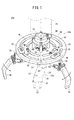
図1は、第1実施形態に係るワーク保持装置10aの要部概略斜視図である。このワーク保持装置10aは、第1ワーク12aをはじめとする様々な形状のワークを保持して搬送することが可能である。
FIG. 1 is a schematic perspective view of a main part of a
先ず、第1ワーク12aにつき概略説明する。該第1ワーク12aは、一端部に2本の円柱状突起14が設けられるとともに、長尺な平坦部16の一端に山折り部18、他端に折曲部20が形成され、且つ平坦部16に貫通孔22及び半円形状切欠24、折曲部20に別の貫通孔26が形成されることで構成されている。第1ワーク12aは、例えば、山折り部18を下方、折曲部20を上方とする姿勢で図示しないストッカ内に収容されている。
First, the
ワーク保持装置10aは、変位手段(搬送手段)である図示しないロボットと、該ロボットの先端アーム30に設けられて前記第1ワーク12aを保持する保持部32aとを備える。
The
保持部32aは、先端アーム30に設けられた保持部材としての略円盤形状の支持盤34と、爪開閉手段としての保持用シリンダ36と、複数個(第1実施形態では3個)の保持爪38とを有する。このうち、支持盤34には、4本の内周側円弧スリット40と、4本の外周側円弧スリット42とが形成される。内周側円弧スリット40は同一円周上に配置され、外周側円弧スリット42は、別の同一円周上に配置される。前記円と前記別の円は、中心を共有する同心円である。
The
保持用シリンダ36は、保持爪38の各々を個別に開閉(回動)させるべく、保持爪38の各々に個別に設けられる。すなわち、保持用シリンダ36の個数は保持爪38の個数と同一である。このため、3個の保持爪38を、例えば、逐次的に開閉させること等が可能である。
The
保持用シリンダ36の上端面には、2個の円筒状ボルト受部(図示せず)と、圧縮エアを供給・排気する給排チューブを接続するための2個の管継手50とが設けられる。円筒状ボルト受部は、外周側円弧スリット42の下方に位置するとともに、1個の管継手50は内周側円弧スリット40に対応して位置する。
The upper end surface of the holding
円筒状ボルト受部のボルト穴には、抜け止めプレート44に形成された通過孔に通されたボルト46が螺合される。すなわち、ボルト46は、通過孔及び外周側円弧スリット42に挿通され、ボルト穴に進入している。前記抜け止めプレート44が支持盤34に堰止されることにより、ボルト46の抜け止めがなされて保持用シリンダ36が支持盤34に位置決め固定される。図1では、3個の保持用シリンダ36及び保持爪38が互いに略120°で離間するように支持盤34で保持している。外周側円弧スリット42が同一円周上に位置しているので、保持爪38同士も同一円周上に位置する。
A
また、内周側円弧スリット40には前記管継手50が進入する。管継手50の一部は内周側円弧スリット40から露呈し、後述するように、保持用シリンダ36を変位させる際に内周側円弧スリット40に沿って変位することで、該保持用シリンダ36を案内する。すなわち、管継手50は案内手段として機能する。
The pipe joint 50 enters the inner circumferential arc slit 40. A part of the pipe joint 50 is exposed from the inner circumferential side arc slit 40 and is displaced along the inner circumferential side arc slit 40 when the holding
保持爪38の一端部は前記保持用シリンダ36に取り付けられ、他端部は、前記同心円の中心に向かう方向に折曲されている。保持爪38の他端部が互いに最近接したとき、該保持爪38が閉じて第1ワーク12aを把持する、いわゆるクランプ状態となる。保持爪38の他端部は、矢印方向に沿って互いに離間するように回動することが可能であり、このとき、第1ワーク12aを解放する、いわゆるアンクランプ状態となる。
One end of the holding
前記同心円の中心には、押接用シリンダ52が配設される。該押接用シリンダ52のロッド54の先端には、当接部としての押子56が設けられる。押子56は、ロッド54が前進(下降)したときには第1ワーク12aの折曲部20に当接(押接)する一方で、ロッド54が後退(上昇)したときには、第1ワーク12aから離間する。
A
第1実施形態に係るワーク保持装置10aは、基本的には以上のように構成されるものであり、次にその作用効果について説明する。
The
第1ワーク12aは、例えば、所定のワークストッカに収納されている。ロボットは、先端アーム30を適宜動作させ、先端アーム30を第1ワーク12aに近接させるとともに、第1ワーク12aの折曲部20が前記同心円の中心、換言すれば、押子56の略直下となるように位置合わせを行う。この際、保持爪38同士は互いに離間したアンクランプ状態である。
For example, the
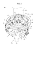
この状態で、例えば、3個の保持用シリンダ36が同時に付勢され、3個の保持爪38の先端同士が第1ワーク12aに接近するように変位する。すなわち、3個の保持爪38が閉じる。このとき、2個の保持爪38は平坦部16の一端面に当接し、残余の1個の保持爪38はその裏面に当接する。以上により、図2に示すように保持爪38がクランプ状態となって第1ワーク12aが保持爪38に把持される。
In this state, for example, the three holding
必要に応じ、押接用シリンダ52が作動してロッド54が下降する。その結果、押子56が折曲部20に押接(当接)する。この押接に伴い、第1ワーク12aが上方から押圧されて該第1ワーク12aが揺動することが抑制される。すなわち、第1ワーク12aが安定した状態で堅牢に把持される。
If necessary, the
次に、ロボットは先端アーム30を適宜動作させ、保持部32a及び第1ワーク12aを一体的に変位させる。これにより、第1ワーク12aが保持部32aとともに所定箇所に搬送される。その後、押接用シリンダ52が作動してロッド54が上昇することで押子56が第1ワーク12aから離間するとともに、3個の保持用シリンダ36が同時に作動することで3個の保持爪38が同時に第1ワーク12aから離間する。すなわち、保持爪38が開いてアンクランプ状態となり、第1ワーク12aが保持爪38から解放される。
Next, the robot appropriately moves the
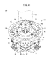
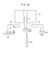
なお、保持爪38のみで堅牢に保持可能なワークであるときには、押子56をワークに押接させる必要は特にない。また、ワークの長手方向が水平方向に沿って延在する場合、保持爪38を2個のみ示すとともに、該2個の保持爪38、ロッド54、押子56を簡素化した図3に示すように、閉じた保持爪38でワークを持ち上げるとともに、押子56をワークの上端面に押接することでワークを保持するようにしてもよい。
When the work can be firmly held only by the holding
また、ワークの形状に応じ、保持爪38の位置を適切な箇所に変更することが可能である。すなわち、ボルト46を弛緩させて保持用シリンダ36を拘束から解放した後、該保持用シリンダ36を支持盤34の円周方向に沿って変位させる。この際、管継手50が内周側円弧スリット40に沿って変位することで、保持用シリンダ36が案内される。このように、支持盤34に内周側円弧スリット40を形成するとともに、該内周側円弧スリット40に管継手50を変位可能に挿入することにより、保持用シリンダ36を所定の位置に移動させることが容易となる。
Further, it is possible to change the position of the holding
ワークの形状や姿勢によっては、保持爪38を個別に回動させる(閉じる)ようにしてもよい。この場合を、保持爪38にマグネットグリッパを設けた第2実施形態として説明する。なお、第1実施形態において説明した構成要素に対応する構成要素には同一の参照符号を付し、その詳細な説明を省略する。
Depending on the shape and posture of the workpiece, the holding
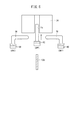
図4は、第2実施形態に係るワーク保持装置10bの要部概略斜視図である。このワーク保持装置10bは、図示しないストッカに収容された複数個の平板形状の第2ワーク12bから1個を抜き出し、所定の箇所まで搬送するためのものである。
FIG. 4 is a schematic perspective view of a main part of the
ワーク保持装置10bは、変位手段(搬送手段)であるロボットと、該ロボットの先端アーム30に設けられて前記第2ワーク12bを保持する保持部32bとを備える。
The
保持部32bは、4本の内周側円弧スリット40及び外周側円弧スリット42が形成された支持盤34と、4個の保持用シリンダ36及び保持爪38と、押接用シリンダ52とを有する。保持用シリンダ36は、抜け止めプレート44及びボルト46を介して支持盤34に位置決め固定されている。
The holding
各保持爪38の互いに対向する先端には、第1マグネットグリッパ60がそれぞれ設けられる。第1マグネットグリッパ60には圧縮エアを供給又は排出するための給排チューブ(図示せず)が接続され、圧縮エアが供給された際に第2ワーク12bに対して磁着する一方、排出された際に第2ワーク12bから離脱する。
A
また、押接用シリンダ52のロッド54の先端には、略円盤形状をなす第2マグネットグリッパ62が設けられる。第2マグネットグリッパ62も第1マグネットグリッパ60と同様に、図示しない給排チューブを介して圧縮エアが供給された際に第2ワーク12bに対して磁着する一方、排出された際に第2ワーク12bから離脱する。以上の構成は周知であることから、第1マグネットグリッパ60及び第2マグネットグリッパ62の詳細な説明は省略する。
Further, a
次に、第2実施形態に係るワーク保持装置10bの作用効果について説明する。
Next, the effect of the
ロボットは、先端アーム30を適宜動作させ、先端アーム30をストッカに近接させるとともに、複数枚並列された第2ワーク12b中の所定の1枚が、内周側円弧スリット40、外周側円弧スリット42で形成される同心円の中心、すなわち、第2マグネットグリッパ62の略直下となるように位置合わせを行う。この際、保持爪38同士は互いに離間したアンクランプ状態である。
The robot appropriately moves the
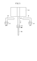
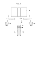
この状態で、押接用シリンダ52が作動してロッド54が下降する。その結果、図5に示すように、マグネットグリッパが第2ワーク12bの上側面に当接する。なお、図5では保持爪38を2個のみ示すとともに、該2個の保持爪38、ロッド54、第1マグネットグリッパ60、第2マグネットグリッパ62を簡素化した模式図として示しており、以降の図面も同様である。また、第1マグネットグリッパ60、第2マグネットグリッパ62は二重枠で示しており、第2ワーク12bに近接する側の枠内にハッチングが付されているときはON状態であり、離間する側の枠内にハッチングが付されているときはOFF状態であることを表す。すなわち、前者の場合には第2ワーク12bが第2マグネットグリッパ62に磁着し、後者の場合には第2ワーク12bが第2マグネットグリッパ62から解放される。
In this state, the
図5に示す状態では、第2マグネットグリッパ62がON状態である。従って、第2マグネットグリッパ62に当接した第2ワーク12bが磁着され、これにより第2ワーク12bが第2マグネットグリッパ62に保持される。
In the state shown in FIG. 5, the
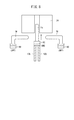
磁着された第2ワーク12bの個数が1個であるときには、この状態のままで搬送を行えばよい。すなわち、ロボットは先端アーム30を適宜動作させ、保持部32b及びワークを一体的に変位させる。これにより、ワークが保持部32bとともに所定箇所に搬送される。その後、図6に示すように、第2マグネットグリッパ62がOFF状態とされて第2マグネットグリッパ62が第2ワーク12bから離間するとともに、押接用シリンダ52が作動してロッド54が上昇する。以上により、第2ワーク12bが第2マグネットグリッパ62から解放される。
When the number of magnetized
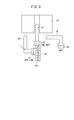
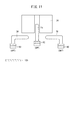
なお、図7に示すように第2マグネットグリッパ62が複数個の第2ワーク12bを磁着することがある。この場合、図8に示すように、ロッド54が上昇した後、例えば、図9に示すように、保持用シリンダ36が1個のみ作動し、1個の保持爪38の第1マグネットグリッパ60が、該第1マグネットグリッパ60に対向する第2ワーク12bの一主面に当接する。この時点で、第1マグネットグリッパ60がON状態となる一方、第2マグネットグリッパ62がOFF状態となる。
In addition, as shown in FIG. 7, the
これに伴い、図10に示すように、第1マグネットグリッパ60が当接した第2ワーク12bが、第2マグネットグリッパ62の磁力による拘束から解放され、且つ第1マグネットグリッパ60に磁着される。同時に、第1マグネットグリッパ60が当接していない第2ワーク12bは、第2マグネットグリッパ62の磁力による拘束から解放され、保持部32bから離脱する。その後、保持用シリンダ36が作動し、閉じた保持爪38が元の位置に戻るようにして開く。すなわち、第2ワーク12bは、長手方向が水平方向に沿って延在する姿勢で第1マグネットグリッパ60に保持される。
Accordingly, as shown in FIG. 10, the
次に、ロボットは先端アーム30を適宜動作させ、保持部32bと、第1マグネットグリッパ60に保持された第2ワーク12bを一体的に変位させる。これにより、第2ワーク12bが保持部32bとともに所定箇所に搬送される。その後、図11に示すように、第1マグネットグリッパ60がOFF状態とされることに伴い、第2ワーク12bが第1マグネットグリッパ60から解放される。
Next, the robot appropriately moves the
このように、保持用シリンダ36を各保持爪38に設け、各保持爪38を個別に開閉(回動)可能としたことにより、並列状態にある複数個の第2ワーク12bの中から1個のみを分別して保持することが可能となる。すなわち、必要な個数の第2ワーク12bのみを搬送することができる。
As described above, the holding
また、図5及び図10から、第2ワーク12bを異なった姿勢で搬送し得ることが分かる。このことから、ワークの形状が相違する場合、姿勢を適切に設定することで各々を搬送できることが理解される。必要に応じ、第1実施形態に準じて保持爪38の位置を適切な箇所に変更するようにしてもよい。このようにして、第2実施形態に係るワーク保持装置10bにおいても、様々な形状のワークを保持することが可能である。
5 and 10 that the
本発明は、上記した第1実施形態及び第2実施形態に特に限定されるものではなく、本発明の主旨を逸脱しない範囲で種々の変更が可能である。 The present invention is not particularly limited to the first embodiment and the second embodiment described above, and various modifications can be made without departing from the gist of the present invention.
例えば、保持爪38の個数は3個又は4個に限定されるものではなく、2個であってもよいし、4個以上であってもよい。
For example, the number of holding
また、第1マグネットグリッパ60や第2マグネットグリッパ62、押接用シリンダ52、押子56を設けることは必須ではなく、これらを省略してワーク保持装置を構成するようにしてもよい。
Further, it is not essential to provide the
10a、10b…ワーク保持装置 12a、12b…ワーク
30…先端アーム 32a、32b…保持部
34…支持盤 36…保持用シリンダ
38…保持爪 40…内周側円弧スリット
42…外周側円弧スリット 44…抜け止めプレート
50…管継手 52…押接用シリンダ
54…ロッド 56…押子
60…第1マグネットグリッパ 62…第2マグネットグリッパ
DESCRIPTION OF
Claims (7)
前記保持爪の各々に設けられ、該保持爪をワークに対して接近又は離間する方向に変位させることが可能な複数個の爪開閉手段と、
前記爪開閉手段の各々を個別に移動可能に保持した保持部材と、
前記保持部材を、前記保持爪と一体的に変位させることが可能な変位手段と、
を備えることを特徴とするワーク保持装置。 In a work holding device having a plurality of holding claws for holding a work,
A plurality of claw opening / closing means provided on each of the holding claws and capable of displacing the holding claws in a direction approaching or separating from the workpiece;
A holding member that holds each of the claw opening and closing means individually movable;
Displacement means capable of displacing the holding member integrally with the holding claws;
A workpiece holding device comprising:
Priority Applications (10)
| Application Number | Priority Date | Filing Date | Title |
|---|---|---|---|
| JP2017099091A JP6808181B2 (en) | 2017-05-18 | 2017-05-18 | Work holding device |
| RU2019141686A RU2743085C9 (en) | 2017-05-18 | 2018-04-11 | Workpiece holding device |
| CN201880032394.5A CN110621452B (en) | 2017-05-18 | 2018-04-11 | Workpiece holding device |
| KR1020197034867A KR102337111B1 (en) | 2017-05-18 | 2018-04-11 | Workpiece retainer |
| MX2019013741A MX2019013741A (en) | 2017-05-18 | 2018-04-11 | Workpiece holding device. |
| PCT/JP2018/015184 WO2018211869A1 (en) | 2017-05-18 | 2018-04-11 | Workpiece holding device |
| BR112019023905-7A BR112019023905A2 (en) | 2017-05-18 | 2018-04-11 | WORK PIECE RETENTION DEVICE |
| EP18721502.5A EP3625003B1 (en) | 2017-05-18 | 2018-04-11 | Workpiece holding device |
| US16/614,047 US11279046B2 (en) | 2017-05-18 | 2018-04-11 | Workpiece holding device |
| TW107113211A TWI666098B (en) | 2017-05-18 | 2018-04-18 | Workpiece holding device |
Applications Claiming Priority (1)
| Application Number | Priority Date | Filing Date | Title |
|---|---|---|---|
| JP2017099091A JP6808181B2 (en) | 2017-05-18 | 2017-05-18 | Work holding device |
Publications (2)
| Publication Number | Publication Date |
|---|---|
| JP2018192575A true JP2018192575A (en) | 2018-12-06 |
| JP6808181B2 JP6808181B2 (en) | 2021-01-06 |
Family
ID=62092212
Family Applications (1)
| Application Number | Title | Priority Date | Filing Date |
|---|---|---|---|
| JP2017099091A Active JP6808181B2 (en) | 2017-05-18 | 2017-05-18 | Work holding device |
Country Status (10)
| Country | Link |
|---|---|
| US (1) | US11279046B2 (en) |
| EP (1) | EP3625003B1 (en) |
| JP (1) | JP6808181B2 (en) |
| KR (1) | KR102337111B1 (en) |
| CN (1) | CN110621452B (en) |
| BR (1) | BR112019023905A2 (en) |
| MX (1) | MX2019013741A (en) |
| RU (1) | RU2743085C9 (en) |
| TW (1) | TWI666098B (en) |
| WO (1) | WO2018211869A1 (en) |
Cited By (2)
| Publication number | Priority date | Publication date | Assignee | Title |
|---|---|---|---|---|
| CN110744527A (en) * | 2019-10-30 | 2020-02-04 | 山东畜牧兽医职业学院 | Mechanical claw arm |
| JP2021137904A (en) * | 2020-03-04 | 2021-09-16 | 学校法人神奈川大学 | Gripping devices, robot arms and flying objects applicable to conical iris robot hands |
Families Citing this family (31)
| Publication number | Priority date | Publication date | Assignee | Title |
|---|---|---|---|---|
| US9789603B2 (en) | 2011-04-29 | 2017-10-17 | Sarcos Lc | Teleoperated robotic system |
| US9616580B2 (en) | 2012-05-14 | 2017-04-11 | Sarcos Lc | End effector for a robotic arm |
| US10406676B2 (en) | 2014-05-06 | 2019-09-10 | Sarcos Lc | Energy recovering legged robotic device |
| US10766133B2 (en) | 2014-05-06 | 2020-09-08 | Sarcos Lc | Legged robotic device utilizing modifiable linkage mechanism |
| US10821614B2 (en) | 2016-11-11 | 2020-11-03 | Sarcos Corp. | Clutched joint modules having a quasi-passive elastic actuator for a robotic assembly |
| US10765537B2 (en) | 2016-11-11 | 2020-09-08 | Sarcos Corp. | Tunable actuator joint modules having energy recovering quasi-passive elastic actuators for use within a robotic system |
| US10828767B2 (en) | 2016-11-11 | 2020-11-10 | Sarcos Corp. | Tunable actuator joint modules having energy recovering quasi-passive elastic actuators with internal valve arrangements |
| US10919161B2 (en) | 2016-11-11 | 2021-02-16 | Sarcos Corp. | Clutched joint modules for a robotic system |
| US10843330B2 (en) | 2017-12-07 | 2020-11-24 | Sarcos Corp. | Resistance-based joint constraint for a master robotic system |
| US11331809B2 (en) | 2017-12-18 | 2022-05-17 | Sarcos Corp. | Dynamically controlled robotic stiffening element |
| US11351675B2 (en) | 2018-12-31 | 2022-06-07 | Sarcos Corp. | Robotic end-effector having dynamic stiffening elements for conforming object interaction |
| US11241801B2 (en) | 2018-12-31 | 2022-02-08 | Sarcos Corp. | Robotic end effector with dorsally supported actuation mechanism |
| US10906191B2 (en) * | 2018-12-31 | 2021-02-02 | Sarcos Corp. | Hybrid robotic end effector |
| CN110978041A (en) * | 2020-01-03 | 2020-04-10 | 广州大学 | Electromagnet-driven flexible micro-clamping device |
| CN111185928B (en) * | 2020-01-10 | 2021-03-26 | 珠海格力智能装备有限公司 | Workpiece grabbing mechanism |
| GB202012042D0 (en) * | 2020-08-03 | 2020-09-16 | Ocado Innovation Ltd | Gripper |
| US11833676B2 (en) | 2020-12-07 | 2023-12-05 | Sarcos Corp. | Combining sensor output data to prevent unsafe operation of an exoskeleton |
| CN112692863B (en) * | 2020-12-07 | 2022-04-12 | 杭州电子科技大学 | But automatically regulated interval's software hand claw anchor clamps |
| US11794345B2 (en) | 2020-12-31 | 2023-10-24 | Sarcos Corp. | Unified robotic vehicle systems and methods of control |
| CN112743566B (en) * | 2021-03-05 | 2024-04-26 | 广东海洋大学 | Pull-in mechanical claw capable of changing shape |
| KR102473200B1 (en) * | 2021-07-20 | 2022-11-30 | 한국로봇융합연구원 | Robot and method for turn over of machined parts using the same |
| CN114193500B (en) * | 2021-12-10 | 2024-05-03 | 南京信息职业技术学院 | Mechanical claw based on dish-shaped multi-line Archimedes screw pair |
| JP2023094786A (en) * | 2021-12-24 | 2023-07-06 | 川崎重工業株式会社 | Robot controller, robot system, robot control program |
| KR102568931B1 (en) * | 2021-12-28 | 2023-08-22 | 주식회사 엠에스 오토텍 | Robot gripper |
| CN115091156B (en) * | 2022-04-19 | 2026-01-30 | 江苏远荣智能装备有限公司 | A wind turbine assembly front ring riveting and feeding device |
| US11826907B1 (en) | 2022-08-17 | 2023-11-28 | Sarcos Corp. | Robotic joint system with length adapter |
| US11717956B1 (en) | 2022-08-29 | 2023-08-08 | Sarcos Corp. | Robotic joint system with integrated safety |
| US12172298B2 (en) | 2022-11-04 | 2024-12-24 | Sarcos Corp. | Robotic end-effector having dynamic stiffening elements with resilient spacers for conforming object interaction |
| US11924023B1 (en) | 2022-11-17 | 2024-03-05 | Sarcos Corp. | Systems and methods for redundant network communication in a robot |
| US11897132B1 (en) | 2022-11-17 | 2024-02-13 | Sarcos Corp. | Systems and methods for redundant network communication in a robot |
| CN117103233B (en) * | 2023-10-19 | 2024-01-16 | 深圳市钧诚精密制造有限公司 | Adjustable manipulator for machining |
Citations (14)
| Publication number | Priority date | Publication date | Assignee | Title |
|---|---|---|---|---|
| JPS6076986A (en) * | 1983-09-30 | 1985-05-01 | 株式会社東芝 | Robot |
| JPS61297090A (en) * | 1985-06-25 | 1986-12-27 | 松下電工株式会社 | Chuck device |
| JPH0569374A (en) * | 1991-09-14 | 1993-03-23 | Toyota Central Res & Dev Lab Inc | Finger module, its structure, robot hand, and finger module signal detection takeout method |
| JPH06298355A (en) * | 1993-04-16 | 1994-10-25 | Sanyo Electric Co Ltd | Parts holding machine |
| JPH08300287A (en) * | 1995-05-09 | 1996-11-19 | Kubota Corp | Robot hand |
| JP2000061875A (en) * | 1998-08-25 | 2000-02-29 | Matsushita Electric Works Ltd | Robot hand |
| JP2003159684A (en) * | 2001-11-21 | 2003-06-03 | Ricoh Co Ltd | Robot system having slide chuck and slide chuck control method |
| JP2007032216A (en) * | 2005-06-21 | 2007-02-08 | Ssk:Kk | Mounting structure, mounting method for fitting frame using the mounting structure, and mounting metal fitting |
| US20110135436A1 (en) * | 2009-12-04 | 2011-06-09 | Hyundai Motor Company | Gripper for tailgate of vehicles |
| JP2013151210A (en) * | 2012-01-25 | 2013-08-08 | Kawasaki Heavy Ind Ltd | Vehicle equipment mounting structure of railway vehicle |
| JP2014097555A (en) * | 2012-11-15 | 2014-05-29 | Precision Machinery Research Development Center | End effector |
| US20160075036A1 (en) * | 2014-09-17 | 2016-03-17 | Joshua Aaron Lessing | Soft robotic actuator attachment hub and grasper assembly, reinforced actuators, and electroadhesive actuators |
| DE102014223118A1 (en) * | 2014-11-12 | 2016-05-12 | Schunk Gmbh & Co. Kg Spann- Und Greiftechnik | gripping device |
| US20160361821A1 (en) * | 2015-06-11 | 2016-12-15 | Joshua Aaron Lessing | Modular robotic systems |
Family Cites Families (12)
| Publication number | Priority date | Publication date | Assignee | Title |
|---|---|---|---|---|
| SU595145A1 (en) * | 1976-06-02 | 1978-02-28 | Предприятие П/Я А-7631 | Manipulator gripping head |
| SU810477A1 (en) * | 1979-04-02 | 1981-03-07 | Предприятие П/Я Р-6930 | Industrial robot gripper |
| US4765669A (en) | 1987-06-03 | 1988-08-23 | Ford Motor Company | Adaptable robotic gripper assembly |
| JP3790759B2 (en) * | 2003-10-17 | 2006-06-28 | ファナック株式会社 | Robot hand and handling robot system |
| CN201089162Y (en) | 2007-07-30 | 2008-07-23 | 王尚 | Force variable mechanical arm |
| JP3142629U (en) * | 2008-04-08 | 2008-06-19 | 伝三郎 岡井 | Lathe work holding jig |
| JP4708464B2 (en) * | 2008-09-30 | 2011-06-22 | ファナック株式会社 | Work gripping device |
| JP2013000857A (en) | 2011-06-20 | 2013-01-07 | Toyota Motor Corp | Robot hand |
| TWM451227U (en) | 2012-11-06 | 2013-04-21 | Prec Machinery Res & Dev Ct | Side effect device module |
| DE102013222314A1 (en) * | 2013-11-04 | 2015-05-07 | Dürr Ecoclean GmbH | Parallel gripper, in particular for picking up workpieces in a cleaning system |
| JP3191000U (en) * | 2014-03-20 | 2014-06-05 | 西部電機株式会社 | Chuck |
| CN106808489B (en) * | 2015-12-01 | 2021-06-01 | 鸿富锦精密电子(郑州)有限公司 | Clamping jaw mechanism |
-
2017
- 2017-05-18 JP JP2017099091A patent/JP6808181B2/en active Active
-
2018
- 2018-04-11 BR BR112019023905-7A patent/BR112019023905A2/en not_active Application Discontinuation
- 2018-04-11 EP EP18721502.5A patent/EP3625003B1/en active Active
- 2018-04-11 US US16/614,047 patent/US11279046B2/en active Active
- 2018-04-11 CN CN201880032394.5A patent/CN110621452B/en active Active
- 2018-04-11 WO PCT/JP2018/015184 patent/WO2018211869A1/en not_active Ceased
- 2018-04-11 RU RU2019141686A patent/RU2743085C9/en active
- 2018-04-11 KR KR1020197034867A patent/KR102337111B1/en active Active
- 2018-04-11 MX MX2019013741A patent/MX2019013741A/en unknown
- 2018-04-18 TW TW107113211A patent/TWI666098B/en not_active IP Right Cessation
Patent Citations (14)
| Publication number | Priority date | Publication date | Assignee | Title |
|---|---|---|---|---|
| JPS6076986A (en) * | 1983-09-30 | 1985-05-01 | 株式会社東芝 | Robot |
| JPS61297090A (en) * | 1985-06-25 | 1986-12-27 | 松下電工株式会社 | Chuck device |
| JPH0569374A (en) * | 1991-09-14 | 1993-03-23 | Toyota Central Res & Dev Lab Inc | Finger module, its structure, robot hand, and finger module signal detection takeout method |
| JPH06298355A (en) * | 1993-04-16 | 1994-10-25 | Sanyo Electric Co Ltd | Parts holding machine |
| JPH08300287A (en) * | 1995-05-09 | 1996-11-19 | Kubota Corp | Robot hand |
| JP2000061875A (en) * | 1998-08-25 | 2000-02-29 | Matsushita Electric Works Ltd | Robot hand |
| JP2003159684A (en) * | 2001-11-21 | 2003-06-03 | Ricoh Co Ltd | Robot system having slide chuck and slide chuck control method |
| JP2007032216A (en) * | 2005-06-21 | 2007-02-08 | Ssk:Kk | Mounting structure, mounting method for fitting frame using the mounting structure, and mounting metal fitting |
| US20110135436A1 (en) * | 2009-12-04 | 2011-06-09 | Hyundai Motor Company | Gripper for tailgate of vehicles |
| JP2013151210A (en) * | 2012-01-25 | 2013-08-08 | Kawasaki Heavy Ind Ltd | Vehicle equipment mounting structure of railway vehicle |
| JP2014097555A (en) * | 2012-11-15 | 2014-05-29 | Precision Machinery Research Development Center | End effector |
| US20160075036A1 (en) * | 2014-09-17 | 2016-03-17 | Joshua Aaron Lessing | Soft robotic actuator attachment hub and grasper assembly, reinforced actuators, and electroadhesive actuators |
| DE102014223118A1 (en) * | 2014-11-12 | 2016-05-12 | Schunk Gmbh & Co. Kg Spann- Und Greiftechnik | gripping device |
| US20160361821A1 (en) * | 2015-06-11 | 2016-12-15 | Joshua Aaron Lessing | Modular robotic systems |
Cited By (3)
| Publication number | Priority date | Publication date | Assignee | Title |
|---|---|---|---|---|
| CN110744527A (en) * | 2019-10-30 | 2020-02-04 | 山东畜牧兽医职业学院 | Mechanical claw arm |
| JP2021137904A (en) * | 2020-03-04 | 2021-09-16 | 学校法人神奈川大学 | Gripping devices, robot arms and flying objects applicable to conical iris robot hands |
| JP7489088B2 (en) | 2020-03-04 | 2024-05-23 | 学校法人神奈川大学 | Gripping device applicable to conical iris robot hand, robot arm and flying object |
Also Published As
| Publication number | Publication date |
|---|---|
| MX2019013741A (en) | 2020-01-15 |
| KR20200003018A (en) | 2020-01-08 |
| TWI666098B (en) | 2019-07-21 |
| TW201900366A (en) | 2019-01-01 |
| RU2743085C9 (en) | 2021-10-28 |
| CN110621452B (en) | 2023-05-09 |
| BR112019023905A2 (en) | 2020-06-02 |
| CN110621452A (en) | 2019-12-27 |
| EP3625003A1 (en) | 2020-03-25 |
| US20210154862A1 (en) | 2021-05-27 |
| US11279046B2 (en) | 2022-03-22 |
| KR102337111B1 (en) | 2021-12-08 |
| JP6808181B2 (en) | 2021-01-06 |
| EP3625003B1 (en) | 2021-03-24 |
| WO2018211869A1 (en) | 2018-11-22 |
| RU2743085C1 (en) | 2021-02-15 |
Similar Documents
| Publication | Publication Date | Title |
|---|---|---|
| JP2018192575A (en) | Workpiece holding device | |
| KR101081210B1 (en) | Holding unit for panel transmitting device | |
| JP6189428B2 (en) | Method and apparatus for removing a substantially flat workpiece from the top of the stacked workpieces | |
| CN112935116B (en) | Machine tool loading method and tool conveying device | |
| US10655658B2 (en) | Material handling system | |
| US20200262652A1 (en) | A machine for the processing of linen items in an industrial laundry, a method for operating the machine, and an industrial laundry | |
| JP2006007337A (en) | Component mounting method and apparatus | |
| JP2018507791A (en) | Clamping system that can be automated | |
| JP2009096603A (en) | Transport device | |
| JP5469657B2 (en) | Parts transfer assembly device | |
| JP6474369B2 (en) | Work transfer system and work transfer method | |
| JP5597435B2 (en) | Rivet setting device | |
| JP2013141706A (en) | Gripping tool and gripping method | |
| CN107666984B (en) | Equipment for inserting parts into workpieces | |
| WO2015068263A1 (en) | Pull tab supply device in slider assembly machine | |
| JP2005118930A (en) | Processing cell | |
| JPH11207561A (en) | Pallet change system | |
| JP2007153456A (en) | Insert nut feeder | |
| US20040183320A1 (en) | Bi-directional gripping of rectangular devices/components | |
| JP7089085B1 (en) | Unpacking supply system and unpacking supply method for binding work | |
| TH1901002981A (en) | Stacking device for heat exchanger cores | |
| JP2006137498A (en) | Pitch change transfer equipment | |
| JPS60115299A (en) | Conveyance device | |
| JP2018144726A (en) | Two-wheel body frame stamping method and two-wheel body frame stamping system | |
| JPH06144561A (en) | Parts transport device |
Legal Events
| Date | Code | Title | Description |
|---|---|---|---|
| A621 | Written request for application examination |
Free format text: JAPANESE INTERMEDIATE CODE: A621 Effective date: 20190208 |
|
| A131 | Notification of reasons for refusal |
Free format text: JAPANESE INTERMEDIATE CODE: A131 Effective date: 20191001 |
|
| A521 | Request for written amendment filed |
Free format text: JAPANESE INTERMEDIATE CODE: A523 Effective date: 20191114 |
|
| A131 | Notification of reasons for refusal |
Free format text: JAPANESE INTERMEDIATE CODE: A131 Effective date: 20200512 |
|
| A521 | Request for written amendment filed |
Free format text: JAPANESE INTERMEDIATE CODE: A523 Effective date: 20200626 |
|
| TRDD | Decision of grant or rejection written | ||
| A01 | Written decision to grant a patent or to grant a registration (utility model) |
Free format text: JAPANESE INTERMEDIATE CODE: A01 Effective date: 20201110 |
|
| A61 | First payment of annual fees (during grant procedure) |
Free format text: JAPANESE INTERMEDIATE CODE: A61 Effective date: 20201125 |
|
| R150 | Certificate of patent or registration of utility model |
Ref document number: 6808181 Country of ref document: JP Free format text: JAPANESE INTERMEDIATE CODE: R150 |
|
| R250 | Receipt of annual fees |
Free format text: JAPANESE INTERMEDIATE CODE: R250 |
|
| R250 | Receipt of annual fees |
Free format text: JAPANESE INTERMEDIATE CODE: R250 |
|
| R250 | Receipt of annual fees |
Free format text: JAPANESE INTERMEDIATE CODE: R250 |