JP2018173079A - Valve sleeve of injector and method for manufacturing valve sleeve of injector - Google Patents
Valve sleeve of injector and method for manufacturing valve sleeve of injector Download PDFInfo
- Publication number
- JP2018173079A JP2018173079A JP2018068686A JP2018068686A JP2018173079A JP 2018173079 A JP2018173079 A JP 2018173079A JP 2018068686 A JP2018068686 A JP 2018068686A JP 2018068686 A JP2018068686 A JP 2018068686A JP 2018173079 A JP2018173079 A JP 2018173079A
- Authority
- JP
- Japan
- Prior art keywords
- injector
- valve sleeve
- injector head
- sleeve
- additive manufacturing
- Prior art date
- Legal status (The legal status is an assumption and is not a legal conclusion. Google has not performed a legal analysis and makes no representation as to the accuracy of the status listed.)
- Pending
Links
- 238000004519 manufacturing process Methods 0.000 title claims abstract description 53
- 238000000034 method Methods 0.000 title claims abstract description 29
- 238000002347 injection Methods 0.000 claims abstract description 31
- 239000007924 injection Substances 0.000 claims abstract description 31
- 239000000446 fuel Substances 0.000 claims abstract description 11
- 239000000463 material Substances 0.000 claims abstract description 7
- 239000000654 additive Substances 0.000 claims description 31
- 230000000996 additive effect Effects 0.000 claims description 31
- 238000010894 electron beam technology Methods 0.000 claims description 15
- 239000002994 raw material Substances 0.000 claims description 13
- 229910052751 metal Inorganic materials 0.000 claims description 11
- 239000002184 metal Substances 0.000 claims description 11
- 238000003754 machining Methods 0.000 claims 1
- 239000000243 solution Substances 0.000 abstract 1
- 239000000843 powder Substances 0.000 description 17
- 239000007921 spray Substances 0.000 description 9
- 230000015572 biosynthetic process Effects 0.000 description 4
- 238000002844 melting Methods 0.000 description 4
- 230000008018 melting Effects 0.000 description 4
- 239000002245 particle Substances 0.000 description 4
- 239000000356 contaminant Substances 0.000 description 3
- 239000007788 liquid Substances 0.000 description 3
- 238000012545 processing Methods 0.000 description 3
- 229910000838 Al alloy Inorganic materials 0.000 description 2
- PXHVJJICTQNCMI-UHFFFAOYSA-N Nickel Chemical compound [Ni] PXHVJJICTQNCMI-UHFFFAOYSA-N 0.000 description 2
- 229910001069 Ti alloy Inorganic materials 0.000 description 2
- 229910045601 alloy Inorganic materials 0.000 description 2
- 239000000956 alloy Substances 0.000 description 2
- 238000000149 argon plasma sintering Methods 0.000 description 2
- 238000004140 cleaning Methods 0.000 description 2
- 238000002485 combustion reaction Methods 0.000 description 2
- 239000004519 grease Substances 0.000 description 2
- 239000011261 inert gas Substances 0.000 description 2
- 230000035515 penetration Effects 0.000 description 2
- 230000007704 transition Effects 0.000 description 2
- OKTJSMMVPCPJKN-UHFFFAOYSA-N Carbon Chemical compound [C] OKTJSMMVPCPJKN-UHFFFAOYSA-N 0.000 description 1
- 229910000831 Steel Inorganic materials 0.000 description 1
- 229910001315 Tool steel Inorganic materials 0.000 description 1
- 229910052799 carbon Inorganic materials 0.000 description 1
- 239000002826 coolant Substances 0.000 description 1
- 230000001419 dependent effect Effects 0.000 description 1
- 238000009826 distribution Methods 0.000 description 1
- 230000004927 fusion Effects 0.000 description 1
- 238000000227 grinding Methods 0.000 description 1
- 238000010438 heat treatment Methods 0.000 description 1
- 239000011796 hollow space material Substances 0.000 description 1
- 239000000696 magnetic material Substances 0.000 description 1
- 229910052759 nickel Inorganic materials 0.000 description 1
- 238000012805 post-processing Methods 0.000 description 1
- 230000000284 resting effect Effects 0.000 description 1
- 239000010959 steel Substances 0.000 description 1
Images


Classifications
-
- F—MECHANICAL ENGINEERING; LIGHTING; HEATING; WEAPONS; BLASTING
- F02—COMBUSTION ENGINES; HOT-GAS OR COMBUSTION-PRODUCT ENGINE PLANTS
- F02M—SUPPLYING COMBUSTION ENGINES IN GENERAL WITH COMBUSTIBLE MIXTURES OR CONSTITUENTS THEREOF
- F02M61/00—Fuel-injectors not provided for in groups F02M39/00 - F02M57/00 or F02M67/00
- F02M61/16—Details not provided for in, or of interest apart from, the apparatus of groups F02M61/02 - F02M61/14
- F02M61/18—Injection nozzles, e.g. having valve seats; Details of valve member seated ends, not otherwise provided for
- F02M61/1886—Details of valve seats not covered by groups F02M61/1866 - F02M61/188
-
- B—PERFORMING OPERATIONS; TRANSPORTING
- B23—MACHINE TOOLS; METAL-WORKING NOT OTHERWISE PROVIDED FOR
- B23P—METAL-WORKING NOT OTHERWISE PROVIDED FOR; COMBINED OPERATIONS; UNIVERSAL MACHINE TOOLS
- B23P15/00—Making specific metal objects by operations not covered by a single other subclass or a group in this subclass
- B23P15/001—Making specific metal objects by operations not covered by a single other subclass or a group in this subclass valves or valve housings
-
- F—MECHANICAL ENGINEERING; LIGHTING; HEATING; WEAPONS; BLASTING
- F02—COMBUSTION ENGINES; HOT-GAS OR COMBUSTION-PRODUCT ENGINE PLANTS
- F02M—SUPPLYING COMBUSTION ENGINES IN GENERAL WITH COMBUSTIBLE MIXTURES OR CONSTITUENTS THEREOF
- F02M61/00—Fuel-injectors not provided for in groups F02M39/00 - F02M57/00 or F02M67/00
- F02M61/16—Details not provided for in, or of interest apart from, the apparatus of groups F02M61/02 - F02M61/14
- F02M61/168—Assembling; Disassembling; Manufacturing; Adjusting
-
- F—MECHANICAL ENGINEERING; LIGHTING; HEATING; WEAPONS; BLASTING
- F02—COMBUSTION ENGINES; HOT-GAS OR COMBUSTION-PRODUCT ENGINE PLANTS
- F02M—SUPPLYING COMBUSTION ENGINES IN GENERAL WITH COMBUSTIBLE MIXTURES OR CONSTITUENTS THEREOF
- F02M61/00—Fuel-injectors not provided for in groups F02M39/00 - F02M57/00 or F02M67/00
- F02M61/16—Details not provided for in, or of interest apart from, the apparatus of groups F02M61/02 - F02M61/14
- F02M61/18—Injection nozzles, e.g. having valve seats; Details of valve member seated ends, not otherwise provided for
- F02M61/1806—Injection nozzles, e.g. having valve seats; Details of valve member seated ends, not otherwise provided for characterised by the arrangement of discharge orifices, e.g. orientation or size
-
- F—MECHANICAL ENGINEERING; LIGHTING; HEATING; WEAPONS; BLASTING
- F02—COMBUSTION ENGINES; HOT-GAS OR COMBUSTION-PRODUCT ENGINE PLANTS
- F02M—SUPPLYING COMBUSTION ENGINES IN GENERAL WITH COMBUSTIBLE MIXTURES OR CONSTITUENTS THEREOF
- F02M2200/00—Details of fuel-injection apparatus, not otherwise provided for
- F02M2200/80—Fuel injection apparatus manufacture, repair or assembly
- F02M2200/8084—Fuel injection apparatus manufacture, repair or assembly involving welding or soldering
Abstract
Description
従来技術
本発明は、部分的に付加製造法を用いて製造された、媒体を噴射するインジェクタ用の、製造が最適化された弁スリーブと、この種の弁スリーブを備えたインジェクタと、その製造方法とに関する。
PRIOR ART The present invention relates to a valve sleeve optimized for production, for an injector for injecting a medium, partially manufactured using an additive manufacturing method, an injector with such a valve sleeve, and its manufacture With respect to methods.
媒体を導入するインジェクタ、たとえば液体の燃料を噴射するまたは気体の燃料を送り込むインジェクタは、従来技術から様々な態様において公知である。この種のインジェクタは、たとえば独国特許出願公開第102013220836号明細書から公知である。このインジェクタは、通常は、別の構成部品と一緒に圧力室を取り囲んでいる、弁スリーブとインジェクタヘッドとを有する。縦軸線に沿って弁スリーブ内で、閉鎖要素が可動に配置されていて、この閉鎖要素は、軸方向移動時に閉鎖要素座と協働する。閉鎖要素は、その位置に依存して、インジェクタヘッド内に穿設された1つまたは複数の噴射孔を開閉し、燃料が高圧下で圧力室から押し出されるので、燃料は噴射孔からの流出時に噴霧される。 Injectors for introducing a medium, for example injectors for injecting liquid fuel or for feeding gaseous fuel, are known in various ways from the prior art. An injector of this kind is known, for example, from DE 10 2013 132 20836. The injector typically has a valve sleeve and an injector head that surround the pressure chamber together with other components. A closing element is movably arranged in the valve sleeve along the longitudinal axis and cooperates with the closing element seat during axial movement. Depending on its position, the closure element opens or closes one or more injection holes drilled in the injector head, so that the fuel is pushed out of the pressure chamber under high pressure, so that the fuel can be removed from the injection hole. Sprayed.
噴霧形成を考慮したインジェクタに対する要求がますます高まっていることに基づき、圧力室から噴射孔への燃料の供給は、弁スリーブ内の複雑な幾何学形状を介して行われる。この弁スリーブは、最大限の噴霧目標設定時かつ最適な浸透時に、最良の噴霧の広がりを可能にするものである。弁スリーブ内のこの複雑な幾何学形状の製造は、複数の適用されるべき製造方法と、アンダカットと、極めて小さな幾何学的寸法とに基づき、特にコストが嵩み、ひいては非効率的である。 Based on the ever increasing demand for injectors that take into account spray formation, the supply of fuel from the pressure chamber to the injection holes takes place through a complex geometry in the valve sleeve. This valve sleeve allows for the best spray spread when setting the maximum spray target and during optimal penetration. The production of this complex geometry in the valve sleeve is based on a number of production methods to be applied, undercuts and extremely small geometric dimensions, which is particularly costly and thus inefficient. .
発明の開示
これに対して、請求項1の特徴を備えた本発明によるインジェクタの弁スリーブは、弁スリーブが任意の複雑な幾何学形状を有してもよく、同時に弁スリーブの製造方法が、特に時間上の利点によってコスト上の利点が生じるように最適化されている、という利点を有する。このことは本発明によれば、弁スリーブが少なくとも1つのシリンダスリーブとインジェクタヘッドとを備え、インジェクタヘッドは閉鎖要素座と少なくとも1つの噴射孔とを有し、インジェクタヘッドは付加製造法を用いて加工され、素材接続によってシリンダスリーブに取り付けられていることによって達成される。これにより、複雑な幾何学形状を有していても、弁スリーブを、極めて効果的な方法において低コストで製造することができる。さらに、付加製造法は、従来の製造方法によって(そもそも)極めて手間をかけることでしか製造できない、インジェクタヘッド内の極めて複雑な幾何学形状、たとえばアンダカット、湾曲状の孔またはこれに類するものを実現可能にする。
DISCLOSURE OF THE INVENTION On the other hand, the valve sleeve of an injector according to the invention with the features of claim 1 may be that the valve sleeve has any complex geometry, and at the same time the method of manufacturing the valve sleeve comprises: In particular, it has the advantage of being optimized such that a time advantage results in a cost advantage. In accordance with the present invention, this means that the valve sleeve comprises at least one cylinder sleeve and an injector head, the injector head having a closing element seat and at least one injection hole, the injector head using an additional manufacturing method. This is accomplished by being machined and attached to the cylinder sleeve by a material connection. This allows the valve sleeve to be manufactured in a very effective way at low cost, even with complex geometric shapes. In addition, additive manufacturing methods are very complex geometries in the injector head, such as undercuts, curved holes or the like, which can only be manufactured with great effort (in the first place) by conventional manufacturing methods. Make it feasible.
従属請求項には、本発明の好適な改良態様が示されている。 The dependent claims show preferred refinements of the invention.
好適には、インジェクタヘッド内には、少なくとも1つの通流ポケットまたは少なくとも1つの通流孔を有する供給領域が配置されている。通流ポケットまたは通流孔は、燃料が圧力室から閉鎖要素座へと流れることができる、有効流過面を拡大する。通流ポケットまたは通流孔を、縦軸線まわりの周にわたって対称にまたは非対称に分配することができる。特に、少なくとも1つの通流ポケットまたは通流孔を少なくとも1つの噴射孔に対応して配置することにより、通流ポケットまたは通流孔をインジェクタヘッド内に非対称に配置することができる。 Preferably, a supply area having at least one flow pocket or at least one flow hole is arranged in the injector head. The flow pocket or flow hole enlarges the effective flow surface through which fuel can flow from the pressure chamber to the closure element seat. The flow pockets or flow holes can be distributed symmetrically or asymmetrically over the circumference around the longitudinal axis. In particular, by arranging at least one flow pocket or flow hole corresponding to at least one injection hole, the flow pocket or flow hole can be arranged asymmetrically in the injector head.
別の好適な態様によれば、通流ポケットは、インジェクタヘッドの内壁においてある種の溝として成形されているので、たとえば、ある種の滑り軸受として、半径方向において閉鎖要素を支持するかつ/または案内する、少なくとも1つのウェブが形成されている。これに対して通流孔を、インジェクタヘッドの内壁にある種の段部として形成された、環状に延びているウェブに形成することができる。インジェクタヘッド内での、通流ポケットと通流孔との組合せが可能である。 According to another preferred embodiment, the flow pocket is shaped as a kind of groove in the inner wall of the injector head, for example as a kind of sliding bearing, supporting the closing element in the radial direction and / or At least one web for guiding is formed. In contrast, the flow holes can be formed in an annularly extending web formed as a kind of step on the inner wall of the injector head. A combination of flow pockets and flow holes in the injector head is possible.
さらに別の好適な態様によれば、インジェクタヘッドは、それぞれ少なくとも1つの噴射孔に通じる、少なくとも1つの前段部を有する。前段部によって、噴射孔の流過面は、少なくとも一度段状に拡張されているので、前段部によって、噴射孔の有効長さが低減され、噴射孔自体はカーボン付着から保護されている。 According to still another preferred aspect, the injector head has at least one front portion that communicates with at least one injection hole. Since the flow-through surface of the injection hole is expanded stepwise at least once by the front stage part, the effective length of the injection hole is reduced by the front stage part, and the injection hole itself is protected from carbon adhesion.
好ましくは、少なくとも1つの噴射孔は、円筒状のまたは曲がった流れ通路を有する。流れ通路の形状は、目標設定および噴霧形成に影響を及ぼすことができ、これにより、噴射時に空間内での媒体の最適な分配が達成される。その際、流れ通路の横断面は、円形、楕円形および/または多角形であってもよい。 Preferably, the at least one injection hole has a cylindrical or curved flow passage. The shape of the flow passage can affect target setting and spray formation, thereby achieving optimal distribution of media in the space during injection. In that case, the cross section of the flow passage may be circular, elliptical and / or polygonal.
さらに、インジェクタヘッドが、電子ビーム溶解とも言われる電子ビーム積層造形法(Electron Beam Melting:EBM)によって、シリンダスリーブに加工して取り付けられていると、特に有利であることが明らかになった。電子ビーム積層造形法(EBM)は粉末床に基づいた方法であり、この方法では、電子ビームを用いて真空中で金属粉末が溶解される。この方法は、高いプロセス温度で進行し、インジェクタヘッドの幾何学形状に依存して支持構造を必要とすることがある。慣性のないビーム偏向(マルチビームストラテジー)によって、平行の複数の融合部を発生させることができ、ひいては1つまたは複数のインジェクタヘッドを形成する早さを高めることができ、これにより、製造時間を大幅に低減することができる。インジェクタヘッド用の原料として、好ましくは、好適には45μm〜105μmの粒径を有する球状の粉末を使用することができる。インジェクタヘッド用の原料は、導電性の溶接可能な金属の原料から形成されていなければならないが、しかし、磁性の原料は、ビーム偏向が生じうるので使用されるべきではない。電子ビーム積層造形法(EBM)に従って、後続の方法ステップにおいて、完成した弁スリーブから残留粉末を取り除くことができ、場合により余剰の支持構造を除去することができる。さらに任意に、完成したシリンダスリーブを熱処理することができる。最終的に行われる加工のために、特に、閉鎖要素でもってインジェクタを気密にかつ液密に閉鎖する閉鎖要素座を形成するために、削剥を行う方法、たとえば研削、ホーニング、旋削またはこれに類する方法を使用することができる。 Further, it has been found that it is particularly advantageous if the injector head is processed and attached to the cylinder sleeve by an electron beam melting method (EBM), which is also called electron beam melting. Electron beam additive manufacturing (EBM) is a method based on a powder bed, in which metal powder is melted in a vacuum using an electron beam. This method proceeds at high process temperatures and may require a support structure depending on the geometry of the injector head. Non-inertial beam deflection (multi-beam strategy) can generate parallel fusions and thus increase the speed with which one or more injector heads can be formed, thereby reducing production time. It can be greatly reduced. As the raw material for the injector head, a spherical powder having a particle diameter of 45 μm to 105 μm is preferably used. The raw material for the injector head must be formed from a conductive, weldable metal raw material, but magnetic raw materials should not be used because beam deflection can occur. In accordance with electron beam additive manufacturing (EBM), residual powder can be removed from the completed valve sleeve in a subsequent method step, possibly removing excess support structure. Further optionally, the completed cylinder sleeve can be heat treated. For final processing, in particular to form a closing element seat that closes the injector in a gas-tight and liquid-tight manner with the closing element, for example grinding, honing, turning or the like The method can be used.
別の有利な態様によれば、インジェクタヘッドを、選択的レーザ積層造形法(Selective Laser Melting:SLM)によって、シリンダスリーブに設けることができる。選択的レーザ積層造形法(SLM)は、直接金属レーザ焼結法(Direct Metal Laser Sintering:DMLS)、レーザビーム積層造形法(Laser Beam Melting:LBM)、LaserCUSINGまたはレーザ焼結としても公知である。選択的レーザ積層造形法(SLM)は、粉末床に基づいた方法であり、この方法では、構成部品を層状に構成する。粉末は、スキージによって層状に設けられ、これに続いてレーザを用いて局所的に溶解される。プロセスは、不活性ガス雰囲気のもとで実行され、好適には200℃〜500℃のプロセス温度を有する。インジェクタヘッドの幾何学形状に依存して、支持構造は、選択的レーザ積層造形法(SLM)のために必要であってもよい。インジェクタヘッド用の素材として、溶接可能な金属の原料は、好適には10μm〜45μmの粒径を有する球状の粉末として使用可能である。この原料としては、特に、ニッケル基合金、工具鋼、アルミニウム合金、チタン合金およびこれに類するものが挙げられる。選択的レーザ積層造形法に従って、まず弁スリーブから残留粉末を取り除き、場合により余剰の支持構造を除去し、熱処理を実行することができる。さらなる加工/仕上げ、特に機能面の加工/仕上げは、従来の製造方法を用いて問題なく実行することができる。選択的レーザ積層造形法は、電子ビーム積層造形法に比べて、磁性の原料も問題なく加工することができるという利点を有する。選択的レーザ積層造形法は、±50μmの高い寸法精度と、Rz約30μm〜50μmの比較的良好な表面品質とを有する。 According to another advantageous aspect, the injector head can be provided on the cylinder sleeve by a selective laser additive manufacturing (SLM). Selective laser additive manufacturing (SLM) is also known as Direct Metal Laser Sintering (DMLS), Laser Beam Melting (LBM), LaserCUSING, or laser sintering. Selective laser additive manufacturing (SLM) is a method based on a powder bed, in which components are constructed in layers. The powder is applied in layers by a squeegee and is subsequently melted locally using a laser. The process is carried out under an inert gas atmosphere and preferably has a process temperature of 200 ° C to 500 ° C. Depending on the geometry of the injector head, a support structure may be necessary for selective laser additive manufacturing (SLM). As a material for the injector head, a weldable metal raw material can be preferably used as a spherical powder having a particle size of 10 μm to 45 μm. Examples of the raw material include nickel base alloys, tool steels, aluminum alloys, titanium alloys, and the like. According to the selective laser additive manufacturing method, the residual powder can first be removed from the valve sleeve, optionally the excess support structure can be removed and the heat treatment can be carried out. Further processing / finishing, in particular functional surface processing / finishing, can be carried out without problems using conventional manufacturing methods. The selective laser additive manufacturing method has an advantage that a magnetic material can be processed without any problems as compared with the electron beam additive manufacturing method. The selective laser additive manufacturing method has a high dimensional accuracy of ± 50 μm and a relatively good surface quality of Rz of about 30 μm to 50 μm.
好ましくは、シリンダスリーブは、溶接可能な金属の原料から製造される回転対称の旋削部分である。シリンダスリーブは、簡単にかつ多数を低コストで製造可能な構成部品である。シリンダスリーブを、製造プロセスに従って、たとえばインジェクタヘッドを付加的に取り付けるために、適切なクリーニング方法によってクリーニングし、付加製造法にとって適切な装置に締め付けることができる。次いで、シリンダスリーブにはインジェクタヘッドが加工して取り付けられ、この場合、インジェクタヘッドは弁スリーブ全体のうちのわずかな部分しか成さない。通常は、シリンダスリーブの質量は、弁スリーブ全体の質量の約70%である。 しかし、さらなるコスト上の利点を達成するためには、質量の割合がより高いと有利である。シリンダスリーブは、好適には1つまたは複数の段部を有してもよい。 Preferably, the cylinder sleeve is a rotationally symmetric turning part made from a weldable metal source. A cylinder sleeve is a component that can be easily and inexpensively manufactured in large numbers. The cylinder sleeve can be cleaned according to the manufacturing process, for example to add an injector head, by means of a suitable cleaning method and clamped to a device suitable for the additional manufacturing method. The cylinder sleeve is then machined with an injector head, in which case the injector head comprises only a small part of the overall valve sleeve. Normally, the mass of the cylinder sleeve is about 70% of the total mass of the valve sleeve. However, a higher mass fraction is advantageous to achieve further cost advantages. The cylinder sleeve may preferably have one or more steps.
別の有利な態様によれば、インジェクタ、特に燃料インジェクタは、シリンダスリーブとインジェクタヘッドとから形成された弁スリーブを有し、この場合、インジェクタヘッドは付加的に加工されシリンダスリーブに取り付けられている。したがって、インジェクタを、低コストで製造されるべき弁スリーブによって多様にかつ個別化して使用することができる。 According to another advantageous aspect, an injector, in particular a fuel injector, has a valve sleeve formed from a cylinder sleeve and an injector head, in which case the injector head is additionally machined and attached to the cylinder sleeve. . Therefore, the injector can be used in various and individual ways depending on the valve sleeve to be manufactured at low cost.
さらに別の有利な態様によれば、弁スリーブを、少なくとも2つの方法ステップにおいて製造することができる。第1の方法ステップでは、シリンダスリーブが、低コストの旋削部分として用意され、第2の方法ステップでは、インジェクタヘッドが、付加製造法を用いて加工されシリンダスリーブに取り付けられる。 According to yet another advantageous aspect, the valve sleeve can be manufactured in at least two method steps. In the first method step, the cylinder sleeve is prepared as a low-cost turning part, and in the second method step, the injector head is processed and attached to the cylinder sleeve using an additive manufacturing method.
さらに、シリンダスリーブが、付加製造法の前にクリーニングされるので、汚染物、たとえばグリース、オイル、くず、またはこれに類するものが除去されていると、特に有利である。 Furthermore, since the cylinder sleeve is cleaned prior to the additive manufacturing process, it is particularly advantageous if contaminants such as grease, oil, litter or the like are removed.
以下に、本発明の好適な実施態様を添付の図面に関して詳説する。 In the following, preferred embodiments of the present invention will be described in detail with reference to the accompanying drawings.
発明を実施するための形態
以下に、図1〜図4に関して、本発明の好適な第1の実施態様によるインジェクタおよび弁スリーブを詳細に説明する。
BEST MODE FOR CARRYING OUT THE INVENTION Hereinafter, an injector and a valve sleeve according to a preferred first embodiment of the present invention will be described in detail with reference to FIGS.
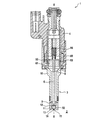
図1には、本発明による弁スリーブ3を備えたインジェクタ1の縦断面図が示されている。インジェクタ1は特に、弁スリーブ3とインジェクタハウジング4とによって取り囲まれた圧力室5を有する。この圧力室5内には、閉鎖要素6が、アクチュエータ60によって縦軸線X−Xに沿って摺動可能に配置されている。圧力室5は、高圧ポート(図示せず)によってたとえばアキュムレータに接続されていて、このアキュムレータによって350×105Paまでの非常に高圧下の媒体8で満たされている。閉鎖要素6が縦軸線X−Xに沿って移動することにより、閉鎖要素6は、弁スリーブ3内に形成された閉鎖要素座13と協働し、噴射孔15を開閉する。図1および図2には、インジェクタ1の閉鎖状態が示されている。
FIG. 1 shows a longitudinal section of an injector 1 with a valve sleeve 3 according to the invention. In particular, the injector 1 has a
インジェクタ1は、内開弁式のインジェクタ1であり、この場合、開放方向は、インジェクタ1からの流出方向Aとは逆である。 The injector 1 is an internal valve opening type injector 1, and in this case, the opening direction is opposite to the outflow direction A from the injector 1.
アクチュエータ60は、ソレノイドアクチュエータであり、アーマチュア61とコイル62とを有する。アクチュエータ60とアーマチュア61とが協働することにより、閉鎖要素6は、縦軸線X−Xに沿って可動である。閉鎖要素6は、弁ボール50とストッパ55とを備えた弁ニードルとして形成されている。戻し要素66が、閉鎖要素6のストッパ55に支持されていて、閉鎖要素6を図1および図2に示した閉鎖位置に保持する。アクチュエータ60は、ピエゾ調節器として形成されてもよい。
The
第1の実施態様によるインジェクタ1の機能は、次の通りである:開放工程が導入されると、アクチュエータ60によるアクチュエータ力がアーマチュア61に加えられるので、アーマチュア61は閉鎖要素6と一緒に、縦軸線X−Xに沿って、流出方向Aとは逆に動かされる。噴射孔15が、開放工程時に閉鎖要素6によって開放されると直ちに、圧力下の媒体8が、圧力室5から噴射孔15を通って噴霧の状態で空間2内へ、たとえば内燃機関の燃焼室内へと流れる。媒体8は、液体のまたは気体の媒体であってもよい。
The function of the injector 1 according to the first embodiment is as follows: when the opening process is introduced, the actuator force by the
図1および図2に図示されたインジェクタ1の静止状態では、弁ボール50は、戻し要素66のばね力によって、インジェクタヘッド11の閉鎖要素座13に対して押し付けられているので、流込み領域14は、残りの圧力室5から気密にかつ液密に閉鎖されているまたは分離されている。このために、閉鎖要素座13の形状は、弁ボール50の形状に適合されている。
In the resting state of the injector 1 illustrated in FIGS. 1 and 2, the
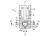
弁スリーブ3は、図2から詳細に看取可能であり、2つの部分から一体的に形成されていて、シリンダスリーブ10とインジェクタヘッド11とを有する。シリンダスリーブ10は、溶接可能な金属の原料から成る回転対称の旋削部分である。インジェクタヘッド11は、付加製造法を用いて加工されシリンダスリーブ10に取り付けられていて、縦軸線X−Xに沿って流出方向Aで、供給領域12と、閉鎖要素座13と、流れ込み領域14と、少なくとも1つの噴射孔15と、前段部16とを有する。媒体8は、インジェクタ1が開放位置にある時、圧力室5から供給領域12を通って、閉鎖要素座13の傍を通過して流込み領域14内へと流れ、この流込み領域14から離間して、噴射孔15を通って空間2の方向へと向かう。前段部16の直径は、噴射孔15の直径よりもかなり大きく設定されており、この場合、噴射孔15の図示された態様は、深さのある狭幅の前段部を備えるインジェクタ1である。流出方向Aの前段部16の長さL2は、噴射孔15の長さL1よりもかなり大きく設定されている。さらに、前段部16の流過面と噴射孔15の流過面との直径の比は、約2:1である。
The valve sleeve 3 can be seen in detail from FIG. 2 and is integrally formed from two parts and comprises a
図3には、図2に示したインジェクタ1の、断面線Y−Yの平面に沿った断面図が示されている。インジェクタヘッド11内には周にわたって、複数の通流ポケット20と、複数の通流孔21と、複数のウェブ22とが配置されている。通流ポケット20および通流孔21は、供給領域12の領域内でインジェクタ1の縦軸線X−Xの方向に、有効流過横断面を拡大するので、この横断面の拡大によって、媒体8は、可能な限り迅速にかつわずかな圧力損失で、流込み領域14ひいては噴射孔15へと流れることができる。
FIG. 3 shows a cross-sectional view of the injector 1 shown in FIG. 2 along the plane of the cross-sectional line YY. In the
このために、通流ポケット20および通流孔21は、1つまたは複数のウェブ22が形成されるように、インジェクタヘッド11内に形成されてもよい。ウェブ22は、弁ボール50または閉鎖要素6のための案内面を形成し、半径方向にこの案内面を支持する。したがって、通流ポケット20、通流孔21およびウェブ22は、閉鎖要素座13から、縦軸線X−Xに沿って流出方向Aとは逆に、少なくとも、弁ボール50がインジェクタ1の開閉時に通過する経路全体にわたって延在している。
For this purpose, the flow pockets 20 and the flow holes 21 may be formed in the
複数の噴射孔15は、周にわたって、流込み領域14内での通流ポケット20または通流孔21の位置決めに対応して、インジェクタヘッド11内に穿設されており、通流ポケット20または通流孔21の周方向の位置と噴射孔15の周方向の位置とが対応している。しかし、噴射孔15を、通流ポケット20および通流孔21に依存せずに位置決めすることもできる。
The plurality of injection holes 15 are formed in the
本態様では、本発明による弁スリーブ3の製造を、少なくとも2つの方法ステップにおいて行う。まず、シリンダスリーブ10を対称的な旋削部分として製造し、第2の方法ステップでは、インジェクタヘッド11を、付加製造法を用いてシリンダスリーブ10に接合する。インジェクタヘッド11とシリンダスリーブ10との間の領域は、移行領域9である。移行領域9では、インジェクタヘッド11を設ける時に、ごくわずかな量のシリンダスリーブ10の材料が溶解されており、したがって、シリンダスリーブ10とインジェクタヘッド11との間の素材接続が生じる。
In this aspect, the production of the valve sleeve 3 according to the invention takes place in at least two method steps. First, the
シリンダスリーブ10は、溶接可能な金属の原料から製造されていて、第2の方法ステップの前に、シリンダスリーブ10をクリーニングすることができる。シリンダスリーブ10のクリーニング時に、考えられる汚染物、たとえば、冷却剤の残留物、オイル、グリース、くず、またはこれに類するものが除去される。汚染物の除去を、部分的にだけ行ってもよい。シリンダスリーブ10は、続いて、付加製造法のために適切な装置に緊締される。このために、たとえば、液圧チャックまたは2つのハーフシェルから形成されたマルチチャックを使用することができる。
The
付加製造法として、選択的レーザ積層造形法(SLM)または電子ビーム積層造形法(EBM)が適用されている。 As an additional manufacturing method, a selective laser additive manufacturing method (SLM) or an electron beam additive manufacturing method (EBM) is applied.
電子ビーム積層造形法(EBM)は、粉末床に基づいた方法である。この方法では、金属粉末が、電子ビームを用いて真空中で縦軸線X−Xの方向でシリンダスリーブ10に沿って、漸次溶解される。慣性のないビーム偏向によって(いわゆるマルチビームストラテジーの場合)、複数の平行の溶融ゾーンを発生させることができ、これにより、複数の弁スリーブ3を同時に製造することもできる。択一的に、複数の電子ビームが、シリンダスリーブ10にインジェクタヘッド11を設けることもできる。電子ビーム積層造形法(EBM)の場合、粉末床は、45μm〜105μmの粒径を有する球状の粉末から成る。シリンダスリーブ10および金属粉末が非磁性の原料から成っていると、この方法にとって有利である。なぜならば、磁性の原料は電子ビームを偏向させるからである。
Electron beam additive manufacturing (EBM) is a method based on a powder bed. In this method, metal powder is gradually melted along the
電子ビーム積層造形法(EBM)とは択一的に、同じく粉末床に基づいた方法である選択的レーザ積層造形法(SLM)を適用することもできる。この方法では、インジェクタヘッド11は、縦軸線X−Xの方向にスキージによってシリンダスリーブ10に層状に設けられていて、これに続いてレーザを用いて局所的に溶解される。このプロセスは、不活性ガス雰囲気のもとで行われる。粉末床を形成する球状の粉末は、通常は10μm〜45μmの粒径を有する。原料として、好ましくはニッケル基合金、アルミニウム合金、チタン合金または従来の工具鋼が適している。
As an alternative to electron beam additive manufacturing (EBM), selective laser additive manufacturing (SLM), which is also based on a powder bed, can be applied. In this method, the
インジェクタヘッド11をシリンダスリーブ10に形成する早さは、インジェクタヘッド11の原料の選択に依存する。付加製造法での形成の早さは、通常は時間あたりの体積として表され、たとえば1cm3/h〜50cm3/hである。したがって、製造プロセスを可能な限り低コストでかつ効果的に行うために、インジェクタヘッド11は、シリンダスリーブ10と比べて、体積に関してより小さく構成されている。製造プロセスを特に効果的に行うために、インジェクタヘッド11内に中空スペースを設けてもよい。
The speed with which the
付加製造法に続いて、弁スリーブ3を緊締装置から取り出し、残留粉末を弁スリーブ3から吹付技術を用いて除去する。 Following the additive manufacturing method, the valve sleeve 3 is removed from the clamping device and the residual powder is removed from the valve sleeve 3 using spray techniques.
特に弁スリーブ3の機能面を、最後の作業ステップにおいて完成させることができる。付加製造法は、Rz約30μm〜150μmの表面品質と、±0.25mmまでの寸法精度を有することが判明したので、好適には、機能面、特に閉鎖要素座13を、最後の製造ステップにおいて後加工することが提案される。したがって、インジェクタ1は、閉鎖要素6と閉鎖要素座13とが協働することによって、完全に気密にかつ液密に閉鎖されている。
In particular, the functional aspects of the valve sleeve 3 can be completed in the last working step. Since the additive manufacturing method has been found to have a surface quality of Rz of about 30 μm to 150 μm and a dimensional accuracy of up to ± 0.25 mm, it is preferred that functional aspects, in particular the
特に図4では、弁スリーブ3を看取することができる。この弁スリーブ3は、本発明に従って製造されたものであり、複雑な幾何学形状を有する。媒体8の最適な噴霧形成のために、インジェクタヘッド11内には、周にわたって分配された複数の通流ポケット20と、湾曲状の複数の噴射孔15とが形成されている。したがって、噴射孔15は、縦軸線X−Xに沿って曲がった流れ通路を有する。この流れ通路の横断面は、円形、楕円形および/または多角形であってもよい。
In particular in FIG. 4, the valve sleeve 3 can be seen. This valve sleeve 3 is manufactured according to the invention and has a complex geometry. For optimal spray formation of the
本発明による弁スリーブ3は、内開弁式のインジェクタ1のためにも、外開弁式のインジェクタ1のためにも使用することができる。 The valve sleeve 3 according to the invention can be used both for the inner valve-open injector 1 and for the outer valve-open injector 1.
したがって本発明によれば、インジェクタヘッド11が複雑でかつ個々に調節可能な幾何学形状を有してもよく、同時に低コストでかつ大量生産に適して製造可能な、弁スリーブ3を提供することができる。これにより、最大限の噴霧目標設定時かつ最適な浸透時に、最善の噴霧の広がりを可能にする。
Therefore, according to the present invention, there is provided a valve sleeve 3 in which the
Claims (10)
少なくとも1つのシリンダスリーブ(10)とインジェクタヘッド(11)とを備え、
前記インジェクタヘッド(11)は、閉鎖要素座(13)と少なくとも1つの噴射孔(15)とを有し、
前記インジェクタヘッド(11)は、付加製造法を用いて加工され、素材接続によって前記シリンダスリーブ(10)に取り付けられていることを特徴とする弁スリーブ(3)。 In the valve sleeve (3) of the injector (1) for injecting the medium (8), in particular for injecting fuel,
Comprising at least one cylinder sleeve (10) and an injector head (11);
The injector head (11) has a closing element seat (13) and at least one injection hole (15);
The valve sleeve (3), wherein the injector head (11) is processed using an additive manufacturing method and is attached to the cylinder sleeve (10) by material connection.
回転対称の旋削部分から形成されたシリンダスリーブ(10)を用意するステップと、
付加製造法を用いて、少なくとも1つの噴射孔(15)と閉鎖要素座(13)とを有するインジェクタヘッド(11)を加工して、前記シリンダスリーブ(10)に取り付けるステップと、
を有することを特徴とする方法。 A method of manufacturing an injector (1), in particular a fuel injector valve sleeve (3), comprising:
Providing a cylinder sleeve (10) formed from a rotationally symmetric turning portion;
Machining an injector head (11) having at least one injection hole (15) and a closure element seat (13) using an additional manufacturing method and attaching to the cylinder sleeve (10);
A method characterized by comprising:
Applications Claiming Priority (2)
| Application Number | Priority Date | Filing Date | Title |
|---|---|---|---|
| DE102017205483.2A DE102017205483A1 (en) | 2017-03-31 | 2017-03-31 | Valve sleeve of an injector and manufacturing method therefor |
| DE102017205483.2 | 2017-03-31 |
Publications (2)
| Publication Number | Publication Date |
|---|---|
| JP2018173079A true JP2018173079A (en) | 2018-11-08 |
| JP2018173079A5 JP2018173079A5 (en) | 2022-02-28 |
Family
ID=63524427
Family Applications (1)
| Application Number | Title | Priority Date | Filing Date |
|---|---|---|---|
| JP2018068686A Pending JP2018173079A (en) | 2017-03-31 | 2018-03-30 | Valve sleeve of injector and method for manufacturing valve sleeve of injector |
Country Status (3)
| Country | Link |
|---|---|
| JP (1) | JP2018173079A (en) |
| CN (1) | CN108708810A (en) |
| DE (1) | DE102017205483A1 (en) |
Citations (4)
| Publication number | Priority date | Publication date | Assignee | Title |
|---|---|---|---|---|
| JP2014025366A (en) * | 2012-07-25 | 2014-02-06 | Hitachi Automotive Systems Ltd | Fuel injection valve |
| US20150167983A1 (en) * | 2013-12-13 | 2015-06-18 | General Electric Company | Bundled tube fuel injector tube tip |
| DE102015202417A1 (en) * | 2015-02-11 | 2016-08-11 | Ksb Aktiengesellschaft | Stömungsführendes component |
| JP2016183405A (en) * | 2015-03-25 | 2016-10-20 | 株式会社デンソー | Member production method, production method of various members, member production device and production system of various members |
Family Cites Families (4)
| Publication number | Priority date | Publication date | Assignee | Title |
|---|---|---|---|---|
| DE10049034B4 (en) * | 2000-10-04 | 2005-08-04 | Robert Bosch Gmbh | Fuel injector |
| DE102010000754A1 (en) * | 2010-01-08 | 2011-07-14 | Robert Bosch GmbH, 70469 | Fuel injector |
| DE102013220836A1 (en) | 2013-10-15 | 2015-04-16 | Robert Bosch Gmbh | Injector |
| WO2016152012A1 (en) * | 2015-03-25 | 2016-09-29 | 株式会社デンソー | Member manufacturing method, method for manufacturing members of various types, member manufacturing device, and system for manufacturing members of various types |
-
2017
- 2017-03-31 DE DE102017205483.2A patent/DE102017205483A1/en active Pending
-
2018
- 2018-03-26 CN CN201810251101.4A patent/CN108708810A/en active Pending
- 2018-03-30 JP JP2018068686A patent/JP2018173079A/en active Pending
Patent Citations (4)
| Publication number | Priority date | Publication date | Assignee | Title |
|---|---|---|---|---|
| JP2014025366A (en) * | 2012-07-25 | 2014-02-06 | Hitachi Automotive Systems Ltd | Fuel injection valve |
| US20150167983A1 (en) * | 2013-12-13 | 2015-06-18 | General Electric Company | Bundled tube fuel injector tube tip |
| DE102015202417A1 (en) * | 2015-02-11 | 2016-08-11 | Ksb Aktiengesellschaft | Stömungsführendes component |
| JP2016183405A (en) * | 2015-03-25 | 2016-10-20 | 株式会社デンソー | Member production method, production method of various members, member production device and production system of various members |
Also Published As
| Publication number | Publication date |
|---|---|
| DE102017205483A1 (en) | 2018-10-04 |
| CN108708810A (en) | 2018-10-26 |
Similar Documents
| Publication | Publication Date | Title |
|---|---|---|
| US5996227A (en) | Valve needle for an electromagnetically actuated valve and process for manufacturing the same | |
| US8245402B2 (en) | Method for manufacturing a solid housing | |
| JP4991720B2 (en) | Fuel injection valve and method for machining an injection opening | |
| JP2002327660A (en) | Modular fuel injector and its assembling method | |
| JP6039492B2 (en) | Fuel injection valve and manufacturing method thereof | |
| JP2009505028A (en) | Method for producing a rigid casing | |
| JP2001513165A (en) | Method of manufacturing valve seat for fuel injection valve and fuel injection valve | |
| US6945478B2 (en) | Fuel injector having an orifice plate with offset coining angled orifices | |
| US8245394B2 (en) | Method for producing a rigid magnetic circuit component | |
| US20150083829A1 (en) | Wear-Optimised Production of Conical Injection Holes | |
| US20090255822A1 (en) | Electrical discharge surface treatment method and dressing method | |
| JP2018173079A (en) | Valve sleeve of injector and method for manufacturing valve sleeve of injector | |
| US11969783B2 (en) | Method for improving high-pressure die casting shot sleeve by additive manufacturing metal matrix composite insert | |
| JP5766466B2 (en) | Method for manufacturing nozzle of fuel injector | |
| JP6615127B2 (en) | Turbocharger with adjustable vanes | |
| US9518542B2 (en) | Injection valve | |
| EP3352939B1 (en) | Valve needle for a fluid injection valve, fluid injection valve and method for manufacturing a valve needle | |
| US20210277861A1 (en) | Fuel injection valve | |
| CN101592111B (en) | Fuel injection valve and welding method | |
| JP2001193596A (en) | Needle valve | |
| JP6529060B2 (en) | Covered compact and method of producing coated compact | |
| EP3009660B1 (en) | Valve assembly with a guiding element and fluid injector | |
| US20180119634A1 (en) | Magnetic Pulse Welding of Engine Components | |
| CN110192022B (en) | Fuel injection valve and method for manufacturing fuel injection valve | |
| EP1353062B1 (en) | Fuel injector having an orifice plate with offset coining angled orifices |
Legal Events
| Date | Code | Title | Description |
|---|---|---|---|
| A521 | Request for written amendment filed |
Free format text: JAPANESE INTERMEDIATE CODE: A523 Effective date: 20180801 |
|
| A621 | Written request for application examination |
Free format text: JAPANESE INTERMEDIATE CODE: A621 Effective date: 20201208 |
|
| A131 | Notification of reasons for refusal |
Free format text: JAPANESE INTERMEDIATE CODE: A131 Effective date: 20210816 |
|
| A977 | Report on retrieval |
Free format text: JAPANESE INTERMEDIATE CODE: A971007 Effective date: 20210818 |
|
| A601 | Written request for extension of time |
Free format text: JAPANESE INTERMEDIATE CODE: A601 Effective date: 20211115 |
|
| A524 | Written submission of copy of amendment under article 19 pct |
Free format text: JAPANESE INTERMEDIATE CODE: A524 Effective date: 20220215 |
|
| A02 | Decision of refusal |
Free format text: JAPANESE INTERMEDIATE CODE: A02 Effective date: 20220328 |