EP3009660B1 - Valve assembly with a guiding element and fluid injector - Google Patents
Valve assembly with a guiding element and fluid injector Download PDFInfo
- Publication number
- EP3009660B1 EP3009660B1 EP14188752.1A EP14188752A EP3009660B1 EP 3009660 B1 EP3009660 B1 EP 3009660B1 EP 14188752 A EP14188752 A EP 14188752A EP 3009660 B1 EP3009660 B1 EP 3009660B1
- Authority
- EP
- European Patent Office
- Prior art keywords
- guiding element
- valve
- valve needle
- valve assembly
- needle
- Prior art date
- Legal status (The legal status is an assumption and is not a legal conclusion. Google has not performed a legal analysis and makes no representation as to the accuracy of the status listed.)
- Active
Links
- 239000012530 fluid Substances 0.000 title claims description 20
- 238000002347 injection Methods 0.000 claims description 19
- 239000007924 injection Substances 0.000 claims description 19
- 238000006073 displacement reaction Methods 0.000 claims description 12
- 230000008878 coupling Effects 0.000 claims description 4
- 238000010168 coupling process Methods 0.000 claims description 4
- 238000005859 coupling reaction Methods 0.000 claims description 4
- 239000002184 metal Substances 0.000 claims description 3
- 238000002485 combustion reaction Methods 0.000 description 13
- 230000006835 compression Effects 0.000 description 5
- 238000007906 compression Methods 0.000 description 5
- 239000000446 fuel Substances 0.000 description 5
- 230000015572 biosynthetic process Effects 0.000 description 4
- 238000007789 sealing Methods 0.000 description 4
- 239000007921 spray Substances 0.000 description 4
- 238000000227 grinding Methods 0.000 description 3
- 238000000034 method Methods 0.000 description 3
- 238000004519 manufacturing process Methods 0.000 description 2
- 238000003466 welding Methods 0.000 description 2
- 229910000639 Spring steel Inorganic materials 0.000 description 1
- 210000001015 abdomen Anatomy 0.000 description 1
- 238000012512 characterization method Methods 0.000 description 1
- 239000011248 coating agent Substances 0.000 description 1
- 238000000576 coating method Methods 0.000 description 1
- 238000002788 crimping Methods 0.000 description 1
- 230000007423 decrease Effects 0.000 description 1
- 230000001419 dependent effect Effects 0.000 description 1
- 230000036316 preload Effects 0.000 description 1
- 238000003825 pressing Methods 0.000 description 1
- 230000035945 sensitivity Effects 0.000 description 1
- 239000007787 solid Substances 0.000 description 1
- 230000006641 stabilisation Effects 0.000 description 1
- 238000011105 stabilization Methods 0.000 description 1
Images


Classifications
-
- F—MECHANICAL ENGINEERING; LIGHTING; HEATING; WEAPONS; BLASTING
- F02—COMBUSTION ENGINES; HOT-GAS OR COMBUSTION-PRODUCT ENGINE PLANTS
- F02M—SUPPLYING COMBUSTION ENGINES IN GENERAL WITH COMBUSTIBLE MIXTURES OR CONSTITUENTS THEREOF
- F02M61/00—Fuel-injectors not provided for in groups F02M39/00 - F02M57/00 or F02M67/00
- F02M61/16—Details not provided for in, or of interest apart from, the apparatus of groups F02M61/02 - F02M61/14
- F02M61/20—Closing valves mechanically, e.g. arrangements of springs or weights or permanent magnets; Damping of valve lift
-
- F—MECHANICAL ENGINEERING; LIGHTING; HEATING; WEAPONS; BLASTING
- F02—COMBUSTION ENGINES; HOT-GAS OR COMBUSTION-PRODUCT ENGINE PLANTS
- F02M—SUPPLYING COMBUSTION ENGINES IN GENERAL WITH COMBUSTIBLE MIXTURES OR CONSTITUENTS THEREOF
- F02M51/00—Fuel-injection apparatus characterised by being operated electrically
- F02M51/06—Injectors peculiar thereto with means directly operating the valve needle
- F02M51/061—Injectors peculiar thereto with means directly operating the valve needle using electromagnetic operating means
- F02M51/0625—Injectors peculiar thereto with means directly operating the valve needle using electromagnetic operating means characterised by arrangement of mobile armatures
- F02M51/0635—Injectors peculiar thereto with means directly operating the valve needle using electromagnetic operating means characterised by arrangement of mobile armatures having a plate-shaped or undulated armature not entering the winding
- F02M51/0642—Injectors peculiar thereto with means directly operating the valve needle using electromagnetic operating means characterised by arrangement of mobile armatures having a plate-shaped or undulated armature not entering the winding the armature having a valve attached thereto
- F02M51/0653—Injectors peculiar thereto with means directly operating the valve needle using electromagnetic operating means characterised by arrangement of mobile armatures having a plate-shaped or undulated armature not entering the winding the armature having a valve attached thereto the valve being an elongated body, e.g. a needle valve
-
- F—MECHANICAL ENGINEERING; LIGHTING; HEATING; WEAPONS; BLASTING
- F02—COMBUSTION ENGINES; HOT-GAS OR COMBUSTION-PRODUCT ENGINE PLANTS
- F02M—SUPPLYING COMBUSTION ENGINES IN GENERAL WITH COMBUSTIBLE MIXTURES OR CONSTITUENTS THEREOF
- F02M61/00—Fuel-injectors not provided for in groups F02M39/00 - F02M57/00 or F02M67/00
- F02M61/04—Fuel-injectors not provided for in groups F02M39/00 - F02M57/00 or F02M67/00 having valves, e.g. having a plurality of valves in series
- F02M61/08—Fuel-injectors not provided for in groups F02M39/00 - F02M57/00 or F02M67/00 having valves, e.g. having a plurality of valves in series the valves opening in direction of fuel flow
-
- F—MECHANICAL ENGINEERING; LIGHTING; HEATING; WEAPONS; BLASTING
- F02—COMBUSTION ENGINES; HOT-GAS OR COMBUSTION-PRODUCT ENGINE PLANTS
- F02M—SUPPLYING COMBUSTION ENGINES IN GENERAL WITH COMBUSTIBLE MIXTURES OR CONSTITUENTS THEREOF
- F02M61/00—Fuel-injectors not provided for in groups F02M39/00 - F02M57/00 or F02M67/00
- F02M61/04—Fuel-injectors not provided for in groups F02M39/00 - F02M57/00 or F02M67/00 having valves, e.g. having a plurality of valves in series
- F02M61/10—Other injectors with elongated valve bodies, i.e. of needle-valve type
- F02M61/12—Other injectors with elongated valve bodies, i.e. of needle-valve type characterised by the provision of guiding or centring means for valve bodies
-
- F—MECHANICAL ENGINEERING; LIGHTING; HEATING; WEAPONS; BLASTING
- F02—COMBUSTION ENGINES; HOT-GAS OR COMBUSTION-PRODUCT ENGINE PLANTS
- F02M—SUPPLYING COMBUSTION ENGINES IN GENERAL WITH COMBUSTIBLE MIXTURES OR CONSTITUENTS THEREOF
- F02M63/00—Other fuel-injection apparatus having pertinent characteristics not provided for in groups F02M39/00 - F02M57/00 or F02M67/00; Details, component parts, or accessories of fuel-injection apparatus, not provided for in, or of interest apart from, the apparatus of groups F02M39/00 - F02M61/00 or F02M67/00; Combination of fuel pump with other devices, e.g. lubricating oil pump
- F02M63/001—Fuel-injection apparatus having injection valves held closed mechanically, e.g. by springs, and opened by a cyclically-operated mechanism for a time
-
- F—MECHANICAL ENGINEERING; LIGHTING; HEATING; WEAPONS; BLASTING
- F16—ENGINEERING ELEMENTS AND UNITS; GENERAL MEASURES FOR PRODUCING AND MAINTAINING EFFECTIVE FUNCTIONING OF MACHINES OR INSTALLATIONS; THERMAL INSULATION IN GENERAL
- F16F—SPRINGS; SHOCK-ABSORBERS; MEANS FOR DAMPING VIBRATION
- F16F1/00—Springs
- F16F1/02—Springs made of steel or other material having low internal friction; Wound, torsion, leaf, cup, ring or the like springs, the material of the spring not being relevant
- F16F1/025—Springs made of steel or other material having low internal friction; Wound, torsion, leaf, cup, ring or the like springs, the material of the spring not being relevant characterised by having a particular shape
- F16F1/028—Springs made of steel or other material having low internal friction; Wound, torsion, leaf, cup, ring or the like springs, the material of the spring not being relevant characterised by having a particular shape cylindrical, with radial openings
-
- F—MECHANICAL ENGINEERING; LIGHTING; HEATING; WEAPONS; BLASTING
- F16—ENGINEERING ELEMENTS AND UNITS; GENERAL MEASURES FOR PRODUCING AND MAINTAINING EFFECTIVE FUNCTIONING OF MACHINES OR INSTALLATIONS; THERMAL INSULATION IN GENERAL
- F16K—VALVES; TAPS; COCKS; ACTUATING-FLOATS; DEVICES FOR VENTING OR AERATING
- F16K1/00—Lift valves or globe valves, i.e. cut-off apparatus with closure members having at least a component of their opening and closing motion perpendicular to the closing faces
- F16K1/32—Details
- F16K1/54—Arrangements for modifying the way in which the rate of flow varies during the actuation of the valve
-
- F—MECHANICAL ENGINEERING; LIGHTING; HEATING; WEAPONS; BLASTING
- F16—ENGINEERING ELEMENTS AND UNITS; GENERAL MEASURES FOR PRODUCING AND MAINTAINING EFFECTIVE FUNCTIONING OF MACHINES OR INSTALLATIONS; THERMAL INSULATION IN GENERAL
- F16K—VALVES; TAPS; COCKS; ACTUATING-FLOATS; DEVICES FOR VENTING OR AERATING
- F16K15/00—Check valves
- F16K15/18—Check valves with actuating mechanism; Combined check valves and actuated valves
-
- F—MECHANICAL ENGINEERING; LIGHTING; HEATING; WEAPONS; BLASTING
- F16—ENGINEERING ELEMENTS AND UNITS; GENERAL MEASURES FOR PRODUCING AND MAINTAINING EFFECTIVE FUNCTIONING OF MACHINES OR INSTALLATIONS; THERMAL INSULATION IN GENERAL
- F16K—VALVES; TAPS; COCKS; ACTUATING-FLOATS; DEVICES FOR VENTING OR AERATING
- F16K31/00—Actuating devices; Operating means; Releasing devices
- F16K31/02—Actuating devices; Operating means; Releasing devices electric; magnetic
- F16K31/06—Actuating devices; Operating means; Releasing devices electric; magnetic using a magnet, e.g. diaphragm valves, cutting off by means of a liquid
- F16K31/0644—One-way valve
- F16K31/0655—Lift valves
-
- F—MECHANICAL ENGINEERING; LIGHTING; HEATING; WEAPONS; BLASTING
- F02—COMBUSTION ENGINES; HOT-GAS OR COMBUSTION-PRODUCT ENGINE PLANTS
- F02M—SUPPLYING COMBUSTION ENGINES IN GENERAL WITH COMBUSTIBLE MIXTURES OR CONSTITUENTS THEREOF
- F02M2200/00—Details of fuel-injection apparatus, not otherwise provided for
- F02M2200/26—Fuel-injection apparatus with elastically deformable elements other than coil springs
-
- F—MECHANICAL ENGINEERING; LIGHTING; HEATING; WEAPONS; BLASTING
- F02—COMBUSTION ENGINES; HOT-GAS OR COMBUSTION-PRODUCT ENGINE PLANTS
- F02M—SUPPLYING COMBUSTION ENGINES IN GENERAL WITH COMBUSTIBLE MIXTURES OR CONSTITUENTS THEREOF
- F02M2200/00—Details of fuel-injection apparatus, not otherwise provided for
- F02M2200/80—Fuel injection apparatus manufacture, repair or assembly
- F02M2200/8069—Fuel injection apparatus manufacture, repair or assembly involving removal of material from the fuel apparatus, e.g. by punching, hydro-erosion or mechanical operation
-
- F—MECHANICAL ENGINEERING; LIGHTING; HEATING; WEAPONS; BLASTING
- F02—COMBUSTION ENGINES; HOT-GAS OR COMBUSTION-PRODUCT ENGINE PLANTS
- F02M—SUPPLYING COMBUSTION ENGINES IN GENERAL WITH COMBUSTIBLE MIXTURES OR CONSTITUENTS THEREOF
- F02M2200/00—Details of fuel-injection apparatus, not otherwise provided for
- F02M2200/90—Selection of particular materials
- F02M2200/9053—Metals
Definitions
- the valve assembly has a valve body and a valve needle.
- the valve body has a longitudinal axis and comprises a cavity with a valve seat.
- the cavity is limited by a wall of the valve body.
- the valve seat is in particular comprised by a surface of the wall which defines the cavity.
- the valve needle is received in the cavity.
- the injector further comprises an actuator assembly which is operable to exert a force for influencing a position of the valve needle.
- the actuator assembly is operable to displace the valve needle away from the closing position.
- the outer shape of the first guiding element is in particular defined by an outer diameter of the first guiding element. That the first guiding element is "bottle shaped" means in particular, that it has a smooth and curved outer shape - i.e. in particular without kinks or steps - that gradually reduces its cross section in the course from the fixation section to the bottle neck section which is in particular a second axial end section of the first guiding element, remote from the first axial end section where it is coupled to the wall of the valve body.
- the first guiding element is preferably in the basic shape of a hollow body of revolution.
- the first guiding element has in particular an outer diameter which decreases gradually from the fixation section to the bottle neck section.
- the valve needle 7 is received in the cavity 11 and axially movable relative to the valve body 5.
- the valve needle 7 is operable to prevent an injection of fluid in a closing position, in which the valve needle 7 is seated on the valve seat 13, from the cavity 11 to external to the injector 1, for example into a combustion chamber.
- the valve needle 7 is further operable to enable the injection of fluid when it is apart from the closing position.
Description
- The invention relates to a valve assembly for a fluid injector and to a fluid injector and relates particularly to an injector for injecting fuel into an internal combustion engine.
- Injection valves are in widespread use, in particular for internal combustion engines where they may be arranged in order to dose the fluid into an intake manifold of the internal combustion engine or directly into the combustion chamber of a cylinder of the internal combustion engine.
- Injection valves are manufactured in various forms in order to satisfy the various needs for the various combustion engines. Therefore, for example, their length, diameter as well as various elements of the injection valve which are responsible for the way the fluid is dosed may vary within a wide range. In addition to that, injection valves may accommodate an actuator for actuating a valve needle of the injection valve, which may, for example, be an electromagnetic actuator.
- In order to enhance the combustion process with regard to the reduction of unwanted emissions, the respective injection valve may be suited to dose fluids under very high pressures. The pressures may be, in the case of a gasoline engine for example, in the range of up to 400 bar, and in the case of diesel engines in the range of up to 3500 bar.
-
WO 2005/080786 A1 describes a contact connection for contacting a valve needle of an internal combustion engine. The valve needle is guided in its upper part in a needle guide, which is a one-pieced component intregrated within a valve body, isolated from its surroundings. -
US 5,299,346 describes an apparatus to align, burnish and secure an upper needle guide for a fuel injector valve body. The apparatus includes a lower portion having a fixture containing a spring-loaded plunger and a spring-loaded centering pin, and an upper portion having a burnishing tool, a spring-loaded stripper, and a crimping ram. The fixture aligns the needle guide and the valve body, and as the two portions are operated closed, the inside diameter of the upper needle guide is first burnished, and then the valve body is crimped onto the needle guide. The stripper holds the crimped parts against the lower portion of the apparatus while the upper and lower portions are operated open to withdraw the burnishing tool from the inside diameter of the needle guide. -
EP 1 170 502 A1 -
DE 10 2004 022619 A1 discloses a liner spring used as reset spring for valve needle of fuel injection valve. The liner spring has a hollow cylindrical shape made of intermediate bars, recesses and grooves. The grooves can be formed in U or taper shape turning away from the recesses. The recesses are formed extending in longitudinal direction while the grooves are formed at the center of the longitudinal extension of the recesses. -
WO 2004/097208 A1 relates to an actuating unit for actuating the fuel injection valve of an injection system for internal combustion engines. The actuating unit comprises a piezo-electric actuator and a hollow body in the form of a spring. - One object of the invention is to create a valve assembly, which facilitates a reliable and precise function of a fluid injector.
- The object is achieved by the features of the independent claim. Further embodiments of the invention are given in the dependent claims.
- According to one aspect of the invention, a valve assembly for a fluid injector is specified. According to another aspect, a fluid injector comprising the valve assembly is specified.
- The valve assembly has a valve body and a valve needle. The valve body has a longitudinal axis and comprises a cavity with a valve seat. The cavity is limited by a wall of the valve body. The valve seat is in particular comprised by a surface of the wall which defines the cavity. The valve needle is received in the cavity.
- Furthermore, the cavity and the valve needle are interacting to prevent an injection of fluid from the cavity to external to the valve assembly or the injector, respectively - i.e. to the outside of the valve assembly or the injector, respectively - in a closing position of the valve needle. In the closing position, the valve needle is seated on the valve seat. Moreover, the cavity and the valve needle are interacting to enable the injection of fluid when the valve needle is spaced apart from the closing position.
- According to one embodiment, the injector further comprises an actuator assembly which is operable to exert a force for influencing a position of the valve needle. In particular, the actuator assembly is operable to displace the valve needle away from the closing position.
- The valve assembly further comprises a first guiding element for axially guiding the valve needle. The first guiding element is bottle shaped and at least in part axially deformable. The first guiding element is coupled in a fixed way to the valve needle in a bottle neck section of the first guiding element. It is further coupled to the wall of the valve body in an axial end section of the first guiding element, which is facing away from the bottle neck section.
- The first guiding element is expediently configured and arranged in a way such that an axial displacement of the valve needle away from the closing position results in a widening of an outer shape of the first guiding element at least in a fixation section to press it against the wall of the valve body. This is achieved by means of the bottle shape, the deformability of the first guiding element and by means of its coupling with the valve needle and the valve body.
- A guiding of the valve needle contributes to a controlled spray formation of injected fluid. Due to its widening when axially compressed, the first guiding element enables a compensation of a manufacturing variability of a component such as the valve needle or the cavity. This contributes to a cost-efficiency of the injector. Moreover, using such first guiding element, a precision of guiding is achieved that allows for reducing a diameter of a sealing area of the injector.
- The outer shape of the first guiding element is in particular defined by an outer diameter of the first guiding element. That the first guiding element is "bottle shaped" means in particular, that it has a smooth and curved outer shape - i.e. in particular without kinks or steps - that gradually reduces its cross section in the course from the fixation section to the bottle neck section which is in particular a second axial end section of the first guiding element, remote from the first axial end section where it is coupled to the wall of the valve body. The first guiding element is preferably in the basic shape of a hollow body of revolution. The first guiding element has in particular an outer diameter which decreases gradually from the fixation section to the bottle neck section. In one embodiment, the outer contour has a belly which is arranged in the region of the fixation section. In particular, the outer diameter of the first guiding element increases from the first axial end section to the fixation section. Preferably, it is larger in the first axial end section than in the bottle neck section. The fixation area may comprise the maximum outer diameter of the first guiding element in one development. The bottle shape of the first guiding element contributes to a widening upon axial compression especially in its fixation section, thus pressing against the wall of the valve body and providing guiding functionality.
- According to one embodiment, the first guiding element comprises a spring sleeve which has the bottle shape. The spring sleeve is fixedly coupled to the valve needle in the bottle neck section. Advantageously, the spring sleeve contributes to the guiding functionality due to its axial and radial deformability.
- According to a further embodiment, the first guiding element comprises a fixing element which fixedly couples the spring sleeve to the valve needle in the bottle neck section. The fixing element is in particular a fixing ring. The fixing element is in particular arranged radially between the valve needle and the spring sleeve. Preferably, it has an inner side surface which contacts the valve needle and an outer side surface which contacts the spring sleeve. The fixing element may expediently be fixed to the valve needle and to the spring sleeve, in particular at its inner and outer surface, respectively. The fixing element enables an easy and reliable way to fixedly couple the spring sleeve to the valve needle.
- According to a further embodiment, the wall of the valve body comprises a guide seat for axially limiting an axial displacement of the first guiding element relative to the valve body. The first guiding element is operable to be seated on the guide seat with its axial end section in a way that an axial displacement of the valve needle away from the closing position results in an axial deformation of at least a part of the first guiding element, causing the outer shape of the first guiding element to widen.
- Advantageously, the guide seat provides an easy and cost-saving way to achieve an axial compression of the first guiding element when the valve needle is displaced away from the closing position.
- According to a further embodiment, the first guiding element is at least in part elastically deformable. Advantageously, this contributes to a reliable function of the first guiding element.
- According to a further embodiment, the first guiding element is at least in part made of metal. In particular the spring sleeve and/or the fixing element may be metallic. Advantageously, this contributes to a reliable function of the first guiding element.
- According to a further embodiment, the first guiding element comprises a plurality of slots. Advantageously, this contributes to an adjustable deformability of the first guiding element, influencing its overall stiffness independently from its overall size.
- According to a further embodiment, a shape of each of the slots extends transversely to the longitudinal axis when the first guiding element is in an undeformed state. Advantageously, this contributes to a satisfactory axial deformability and/or buckling resistance with respect to rotation around the longitudinal axis of the first guiding element.
- According to a further embodiment, a lateral extension of the shape of each of the slots is between 2 mm and 7 mm when the first guiding element is in an undeformed state.
- According to a further embodiment, an axial interval at which the slots are spaced apart from each other is between 0.2 mm and 0.8 mm when the first guiding element is in an undeformed state. According to a further embodiment, a lateral interval at which the slots are spaced apart from each other is between 0.4 mm and 1 mm when the first guiding element is in an undeformed state. The limits of the given regions are included in each case. Advantageously, this contributes to the deformability of the first guiding element.
- According to a further embodiment, a width of the outer shape of the first guiding element - i.e. in particular the outer diameter - changes in axial direction from the bottle neck section towards the axial end section, particularly from a value between 1.5 mm and 3.5 mm - e.g. 2.5 mm - at the bottle neck section to a value between 6 mm and 8 mm - e.g. 7 mm - at the first axial end section when the first guiding element is in an undeformed state. The limits of the given regions are included in each case. Advantageously, this enables the first guiding element to reliably radially deform outwards in order to press against the wall of the valve body.
- According to a further embodiment, an axial extension of the first guiding element is between 10 mm and 18 mm, the limits being included, when the first guiding element is in an undeformed state. For example, the axial extension has a value of 15 mm. Advantageously, this contributes to an overall stiffness of the first guiding element.
- According to a further embodiment, a wall thickness of the first guiding element is between 0.3 mm and 0.9 mm, the limits being included, when the first guiding element is in an undeformed state. For example, the wall thickness has a value of 0.5 mm.
- Advantageously, this contributes to an overall stiffness of the first guiding element.
- According to a further embodiment, the first guiding element provides a force for biasing the valve needle towards the closing position, in particular by its coupling with the valve needle and the valve body. Expediently, it may be precompressed in the valve assembly to provide the force. The actuator assembly is operable for displacing the valve needle away from the closing position against the bias of the first guiding element.
- Advantageously, this contributes to a leak tightness of the injector when the valve needle is in the closing position. In this case, an additional valve spring for biasing the valve needle towards the closing position is merely optional or can be dispensed with completely in this case, thus contributing to a cost-efficiency of the injector. The injector may however additionally comprise such a valve spring, wherein the actuator assembly is operable for displacing the valve needle away from the closing position against the bias of the valve spring and the first guiding element. The preload of the valve spring may be adjustable, for example by means of a calibration tube. In this way, the opening and closing characteristics of the valve assembly can be easily adjustable.
- Furthermore, the injector may also comprise a second guiding element for axially guiding the valve needle, being axially displaced to the first guiding element. The second guiding element may expediently be positioned adjacent to the valve seat. Advantageously, this contributes to a coaxiality of the valve needle with respect to the valve body and the longitudinal axis, thus enabling a controlled spray formation of injected fluid.
- Exemplary embodiments of the invention are explained in the following with the aid of schematic drawings and reference numbers. Identical reference numbers designate elements or components with identical functions. In the figures:
- Figure 1
- shows a first embodiment of an injector in a longitudinal section view,
- Figure 2
- shows an enlarged longitudinal section view of the injector according to
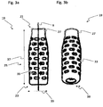
figure 1 , - Figure 3a
- shows a first guiding element of the injector according to
figure 1 in a front view, - Figure 3b
- shows the first guiding element of the injector according to
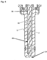
figure 1 in a perspective view, and - Figur 4
- shows a section of a longitudinal section view of a further injector.
-
Figure 1 shows a first embodiment of aninjector 1 with avalve assembly 3 and anactuator assembly 17. Thevalve assembly 3 comprises avalve body 5 and avalve needle 7. Thevalve body 5 has alongitudinal axis 9 and comprises acavity 11 with avalve seat 13, wherein thecavity 11 is radially limited by awall 15 of thevalve body 5. - The
valve needle 7 is received in thecavity 11 and axially movable relative to thevalve body 5. Thevalve needle 7 is operable to prevent an injection of fluid in a closing position, in which thevalve needle 7 is seated on thevalve seat 13, from thecavity 11 to external to theinjector 1, for example into a combustion chamber. Thevalve needle 7 is further operable to enable the injection of fluid when it is apart from the closing position. - The
injector 1 may comprise avalve spring 41 for biasing thevalve needle 7 towards the closing position, for example in order to contribute to a leak tightness of theinjector 1. Theinjector 1 may also comprise acalibration spring 45 being operable to axially bias thevalve needle 7. - In this embodiment, the
actuator assembly 17 is an electromagnetic actuator assembly, comprising amagnetic coil 49, in particular solenoid, positioned in ahousing 53 and anarmature 47, together forming a magnetic circuit when themagnetic coil 49 is energized. In other embodiments, theactuator assembly 17 may be for example a piezo-electric actuator assembly. Theactuator assembly 17 is operable to exert a force on thevalve needle 7 in order to influence a position of thevalve needle 7. Particularly, thevalve needle 7 may be axially displaced by theactuator assembly 17 relative to thevalve body 5, for example in reciprocating fashion. - The
injector 1 comprises afirst guiding element 19 in order to limit a radial displacement of thevalve needle 7 relative to thelongitudinal axis 9 and to stabilize its axial movement. Theinjector 1 may additionally comprise asecond guiding element 43, axially displaced to the first guidingelement 19 that contributes to a further stabilization of the axial movement of thevalve needle 7. In particular, stability of the axial movement of thevalve needle 7 within thewall 15 ofvalve body 5 is critical for a spray formation during the injection. Thesecond guiding element 43 may be constructed analoguous to the first guidingelement 19 or differently. In the present embodiment, thesecond guiding element 43 is represented by longitudinal bars protruding laterally from a shaft of thevalve needle 7 in a region axially adjacent to - but axially spaced apart from - thevalve seat 13. In other embodiments, thesecond guiding element 43 may be removed. - The
first guiding element 19 is bottle shaped, fixed to thevalve needle 7 and coupled to thewall 15, such that an axial displacement of thevalve needle 7 away from the closing position results in a widening of an outer shape of the first guidingelement 19, causing it to be at least partially pressed against thewall 15. In order to achieve the widening of its outer shape, the first guidingelement 19 is at least partially plastically deformable. -
Figure 2 shows an enlarged longitudinal section view of theinjector 1 according to the first embodiment, particularly of thevalve assembly 3. Thefirst guiding element 19 comprises aspring sleeve 27 which, for example, is constructed as a tubular spring. Thespring sleeve 27 is bottle shaped, with abottle neck section 21 and an axial end section 23 (in the preceding description also denoted as first axial end section), facing away from thebottle neck section 21. Thespring sleeve 27 is, for example, elastically deformable. For example, it is made of spring steel. In this context, thespring sleeve 27 may comprise a plurality ofslots 33 for increasing a deformability of thespring sleeve 27. - The
spring sleeve 27 is fixedly coupled to thevalve needle 7 in thebottle neck section 21. Thefirst guiding element 19 may comprise a fixingelement 29 for this reason, which, for example, is ring shaped. In this embodiment, the fixingelement 29 is surrounding thevalve needle 7 and fixedly coupled with it, wherein thespring sleeve 27 is surrounding thevalve needle 7, coating at least partially the fixingelement 29. An outer shape of thespring sleeve 27 may be narrowing towards the fixingelement 29 in this context. In other embodiments, the fixingelement 29 may at least partially coat thespring sleeve 27. Alternatively, the spring sleeve may be coupled directly to thevalve needle 7, without anadditional fixing element 29. - In this embodiment, the
spring sleeve 27, the fixingelement 29 and thevalve needle 7 are fixedly coupled by welding, for example a laser spot welding. In other embodiments, a press-fit or clamping is established in order to couple thespring sleeve 27 to thevalve needle 7 in a fixed way. - The
wall 15 comprises aguide seat 31 for limiting an axial displacement of the first guidingelement 19. A diameter of thecavity 11 may be decremented, in particular in stepped fashion, at theguide seat 31 in order to provide a seating surface for the first guidingelement 19. Particularly, the first guidingelement 19 is operable to be seated on theguide seat 31 with itsaxial end section 23, for example on said seating surface. - Due to a fixation of the first guiding
element 19 at itsbottle neck section 21, together with thevalve seat 31 axially limiting a displacement of the first guidingelement 19, an axial displacement of thevalve needle 7 results in an axial compression of thespring sleeve 27. - The axial compression of the
spring sleeve 27 causes a widening of its outer shape at least in afixation section 25 that is then pressed against thewall 15. In particular, thefixation section 25 is arranged between theguide seat 31 and an axial end of thewall 15, directed inwards with respect to theinjector 1. Thereby, a guiding of thevalve needle 7 is obtained, limiting a radial displacement of thevalve needle 7. Advantageously, a geometrical run-out variability in respect of thevalve needle 7 and thecavity 11 is compensated, thus contributing to a particular precise coaxiality of thevalve needle 7 with respect to thewall 15 and thelongitudinal axis 9. Particularly, no special tight tolerance of thevalve needle 7, thevalve body 5 and their position with respect to thesecond guiding element 43 is required, because the first guidingelement 19 compensates their geometrical variability. - Due to the axial compression of the
spring sleeve 27, a force is exerted on thevalve needle 7, biasing thevalve needle 7 towards the closing position. Advantageously, thevalve spring 41 is merely optional in this case. -
Figure 3a shows the first guidingelement 19 according to the first embodiment in a front view. In order to provide axial deformability, particularly axial compressibility, thespring sleeve 27 is elastically deformable. It is further made of metal. Moreover, it comprises the plurality ofslots 33. - In an undeformed state of the
spring sleeve 27, each of the slots has a shape that extends transversely to thelongitudinal axis 9. This contributes to the axial deformability of thespring sleeve 27 and its radial expansion. A lateral extension of the shape of each of theslots 33 is for example between 2 mm and 7 mm in the undeformed state of thespring sleeve 27. Theslots 33 are spaced apart from each other at an axial interval. The axial interval is between 0.2 mm and 0.8 mm in the undeformed state of thespring sleeve 27. Furthermore, theslots 33 are spaced apart at a lateral interval that is between 0.4 mm and 1 mm in the undeformed state of thespring sleeve 27. Additionally, theslots 33 may be staggered. These provisions contribute to the axial deformability of thespring sleeve 27 and influence its overall stiffness. - In the
bottle neck section 21 and/or theaxial end section 23, thespring sleeve 27 may be constructed solid, i.e. free ofslots 33. Advantageously, this contributes to the a particularly good conectability of the first guidingelement 19, particularly in view of a coupling of thespring sleeve 27 to thevalve needle 7, respectively to thewall 15. - In order to achieve a radial widening of its outer shape in the
fixation section 25, the first guidingelement 19 is bottle shaped, that is, itswidth 35 axially increases from thebottle neck section 21 towards theaxial end section 23. In particular, an outer shape of the first guidingelement 19 in thefixation section 25 is globular bellied. In this embodiment, thewidth 35 of the first guidingelement 19 is 2.5 mm at thebottle neck section axial end section 23. - An
axial extension 37 of the first guidingelement 19 is 15 mm. Awall thickness 39 of the first guiding element 19 (shown infigure 3b ) is 0.5 mm. - Typically, a reduction of a diameter of a sealing area of the
injector 1 is limited due to a required high manufacturing accuracy of thevalve body 5, thevalve needle 7 and the guidingelements valve needle 7 and general sensitivity to pressure. Such a limit of the diameter may, for example, be between 3.7 mm to 3.8 mm. - Advantageously, such
first guiding element 19 enables the reduction of the diameter of the sealing area of to, for example, 3 mm or lower, particularly also with theactuator assembly 17 being an electromagnetic actuator assembly. Moreover, an expensive and time-consuming grinding process of thevalve needle 7 as described infigure 4 can be eliminated. - Injection valves are manufactured in various forms in order to satisfy the various needs for the various combustion engines.
- Therefore, in other embodiments, for example, their length, diameter as well as various elements of the injection valve which are responsible for the way the fluid is dosed may vary within a wide range. Hence, also dimensions of the first guiding
element 19 such as itswidth 35, itsaxial extension 37 and itswall thickness 39 as well as the lateral extension of the shape of itsslots 33 and the axial and tangential interval at which theslots 33 are arranged, may vary. However, a respective relation between each of these dimensions may preferably be kept constant. In particular, a deviation of the respective relation may be between 0% and 25%, particularly less than 10%. -
Figure 4 shows a section of a longitudinal section view of a further, currently unclaimed injector. The injector differs frominjector 1 of the first embodiment with itsfurther guiding element 55, which thevalve needle 7 comprises instead of the first guidingelement 19. Thefurther guiding element 55 is, for example, constructed similar to thesecond guiding element 43. In order to achieve a very accurate gap between the guidingelements valve body 5, to avoid tilting or an instable position of thevalve needle 7 during an opening and/or closing phase of the injection and to contribute to the spray formation, special grinding machines with associated long cycle time and process concepts are used to achieve a match grinding of thevalve needle 7 after each single characterization of thevalve body 5 and a double adaption of the guide to obtain a flow continuity through theinjector 1. Such complicated processes and high accuracy are advantageously avoidably at least in part with the first guidingelement 55 according to the present invention.
Claims (15)
- Valve assembly (3) for a fluid injector (1), the valve assembly (3) comprising a valve body (5) and a valve needle (7), the valve body (5) having a longitudinal axis (9) and comprising a cavity (11) with a valve seat (13), the cavity (11) being limited by a wall (15) of the valve body (5), the valve needle (7) being received in the cavity (11), the cavity (11) and the valve needle (7) interacting to prevent an injection of fluid from the cavity (11) to the outside of the injector (1) in a closing position of the valve needle (7), in which closing position the valve needle (7) is seated on the valve seat (13), and to enable the injection of fluid when the valve needle (7) is spaced apart from the closing position, and- a first guiding element (19) for axially guiding the valve needle (7),
wherein the first guiding element (19) is configured and arranged such that an axial displacement of the valve needle (7) away from the closing position results in a widening of an outer shape of the first guiding element (19) at least in a fixation section (25) to press it against the wall (15) of the valve body (5),
by means of the first guiding element- being bottle shaped and being axially deformable at least in part,- being fixedly coupled to the valve needle (7) in a bottle neck section (21) of the first guiding element (19), and being coupled to the wall (15) of the valve body (5) in an axial end section (23) of the first guiding element (19) remote from the bottle neck section (21). - Valve assembly (3) according to claim 1, wherein the first guiding element (19) comprises a spring sleeve (27) having the bottle shape and being fixedly coupled to the valve needle (7) in the bottle neck section (21).
- Valve assembly (3) according to claim 2, wherein the first guiding element (19) comprises a fixing ring (29) which is radially arranged between the valve needle (7) and the spring sleeve (27) for fixedly coupling the spring sleeve (27) to the valve needle (7) in the bottle neck section (21) .
- Valve assembly (3) according to any of claims 1 to 3, wherein the wall (15) of the valve body (5) comprises a guide seat (31) for axially limiting an axial displacement of the first guiding element (19) relative to the valve body (5), wherein the first guiding element (19) is operable to be seated on the guide seat (31) with its axial end section (23) in a way that an axial displacement of the valve needle (7) away from the closing position results in an axial deformation of at least a part of the first guiding element (19), causing the outer shape of the first guiding element (19) to widen.
- Valve assembly .(3) according to any of claims 1 to 4, wherein the first guiding element (19) is at least in part elastically deformable.
- Valve assembly (3) according to any of claims 1 to 5, wherein the first guiding element (19) is at least in part made of metal.
- Valve assembly (3) according to any of claims 1 to 6, wherein the first guiding element (19) comprises a plurality of slots (33).
- Valve assembly (3) according to claim 7, wherein a shape of each of the slots (33) extends transversely to the longitudinal axis (9) when the first guiding element (19) is in an undeformed state.
- Valve assembly (3) according to claim 8, wherein a lateral extension of the shape of each of the slots (33) is between 2 mm and 7 mm when the first guiding element (19) is in an undeformed state.
- Valve assembly (3) according to any of claims 7 to 9, wherein an axial interval, at which the slots (33) are spaced apart from each other is between 0.2 mm and 0.8 mm when the first guiding element (19) is in an undeformed state.
- Valve assembly (3) according to any of claims 7 to 10, wherein a lateral interval, at which the slots (33) are spaced apart from each other is between 0.4 mm and 1 mm when the first guiding element (19) is in an undeformed state.
- Valve assembly (3) according to any of claims 1 to 11, wherein a width (39) of the first guiding element (19) axially changes from the bottle neck section (21) towards the axial end section (23), particularily from 2.5 mm at the bottle neck section (21) to 7 mm at the axial end section (23).
- Valve assembly (3) according to any of claims 1 to 12, wherein an axial extension (41) of the first guiding element (19) is between 10 mm and 18 mm, particularily 15 mm.
- Valve assembly (3) according to any of claims 1 to 10, wherein a wall thickness (43) of the first guiding element (19) is between 0.3 mm and 0.9 mm, particularily 0.5 mm.
- Fluid injector (1) comprising a valve assembly (3) according to any of claims 1 to 14 and an actuator assembly (17), which is operable to exert a force for displacing the valve needle (7) away from the closing position, wherein the first guiding element (19) provides a force for biasing the valve needle (7) towards the closing position, and wherein the actuator assembly (17) is operable to displace the valve needle (7) against the bias of the first guiding element (19).
Priority Applications (3)
| Application Number | Priority Date | Filing Date | Title |
|---|---|---|---|
| EP14188752.1A EP3009660B1 (en) | 2014-10-14 | 2014-10-14 | Valve assembly with a guiding element and fluid injector |
| US14/827,123 US9624885B2 (en) | 2014-10-14 | 2015-08-14 | Valve assembly with a guiding element and fluid injector |
| CN201510659556.6A CN105508108B (en) | 2014-10-14 | 2015-10-14 | Valve module and fluid ejector provided with guide element |
Applications Claiming Priority (1)
| Application Number | Priority Date | Filing Date | Title |
|---|---|---|---|
| EP14188752.1A EP3009660B1 (en) | 2014-10-14 | 2014-10-14 | Valve assembly with a guiding element and fluid injector |
Publications (2)
| Publication Number | Publication Date |
|---|---|
| EP3009660A1 EP3009660A1 (en) | 2016-04-20 |
| EP3009660B1 true EP3009660B1 (en) | 2017-05-03 |
Family
ID=51690290
Family Applications (1)
| Application Number | Title | Priority Date | Filing Date |
|---|---|---|---|
| EP14188752.1A Active EP3009660B1 (en) | 2014-10-14 | 2014-10-14 | Valve assembly with a guiding element and fluid injector |
Country Status (3)
| Country | Link |
|---|---|
| US (1) | US9624885B2 (en) |
| EP (1) | EP3009660B1 (en) |
| CN (1) | CN105508108B (en) |
Families Citing this family (1)
| Publication number | Priority date | Publication date | Assignee | Title |
|---|---|---|---|---|
| DE102020121777A1 (en) * | 2020-08-19 | 2022-02-24 | Vermes Microdispensing GmbH | valve push rod |
Family Cites Families (15)
| Publication number | Priority date | Publication date | Assignee | Title |
|---|---|---|---|---|
| US2756106A (en) * | 1954-03-18 | 1956-07-24 | Schenk Rudolf | Fuel injection valve |
| DE1053244B (en) * | 1955-10-28 | 1959-03-19 | Bosch Arma Corp | Fuel injector |
| US5299346A (en) | 1993-02-24 | 1994-04-05 | Siemens Automotive L.P. | Fuel injector upper needle guide burnishing and alignment tool |
| DE10032517A1 (en) | 2000-07-05 | 2002-01-24 | Bosch Gmbh Robert | Injector for injecting fuel into combustion chambers of internal combustion engines comprises a control part loaded by spring elements in the injector housing and guided in a guide sleeve surrounding a control space |
| DE10213382A1 (en) * | 2002-03-26 | 2003-10-16 | Bosch Gmbh Robert | Fuel injection valve |
| DE10259802A1 (en) * | 2002-12-19 | 2004-07-01 | Robert Bosch Gmbh | Fuel injection valve for internal combustion engine, has valve pin connected to slave piston of hydraulic coupler to form form-fitted unit |
| DE60308814T2 (en) * | 2003-04-16 | 2007-02-22 | Siemens Ag | Needle valve assembly and method for its manufacture |
| DE10319600A1 (en) * | 2003-05-02 | 2004-11-18 | Robert Bosch Gmbh | Actuator unit for a piezo-controlled fuel injection valve |
| WO2005080786A1 (en) | 2004-02-11 | 2005-09-01 | Siemens Aktiengesellschaft | Contact element for the valve needle of an injector for internal combustion engines |
| DE102004022619A1 (en) * | 2004-05-07 | 2005-12-08 | Robert Bosch Gmbh | Liner spring used as reset spring for valve needle of fuel injection valve, has hollow cylindrical shape made of intermediate bars, recesses and grooves |
| EP1808596A1 (en) * | 2006-01-12 | 2007-07-18 | Siemens Aktiengesellschaft | Valve assembly for an injection valve and injection valve |
| EP2282043B1 (en) * | 2009-07-02 | 2013-04-17 | Continental Automotive GmbH | Fluid injector and method and apparatus for operating the fluid injector |
| US20110073071A1 (en) * | 2009-09-30 | 2011-03-31 | Woodward Governor Company | Internally Nested Variable-Area Fuel Nozzle |
| EP2436910B1 (en) * | 2010-10-01 | 2017-05-03 | Continental Automotive GmbH | Valve assembly for an injection valve and injection valve |
| EP2527637B1 (en) * | 2011-05-23 | 2014-10-08 | Continental Automotive GmbH | Injector for injecting fluid |
-
2014
- 2014-10-14 EP EP14188752.1A patent/EP3009660B1/en active Active
-
2015
- 2015-08-14 US US14/827,123 patent/US9624885B2/en active Active
- 2015-10-14 CN CN201510659556.6A patent/CN105508108B/en active Active
Also Published As
| Publication number | Publication date |
|---|---|
| CN105508108B (en) | 2018-03-30 |
| US20160102639A1 (en) | 2016-04-14 |
| US9624885B2 (en) | 2017-04-18 |
| CN105508108A (en) | 2016-04-20 |
| EP3009660A1 (en) | 2016-04-20 |
Similar Documents
| Publication | Publication Date | Title |
|---|---|---|
| EP2093414B1 (en) | Coupling device | |
| US20110089359A1 (en) | Spring retaining sleeve | |
| EP3155305B1 (en) | Pipe connection structure | |
| EP0906508B1 (en) | A fuel injector for an internal combustion engine | |
| US20170292483A1 (en) | Fuel injection valve | |
| US10208726B2 (en) | Fuel injection device | |
| KR102274062B1 (en) | Nozzle assembly for a fuel injector, and fuel injector | |
| US20150041567A1 (en) | Fuel injector | |
| MX2010008306A (en) | Valve assembly and method of assembly. | |
| EP3009660B1 (en) | Valve assembly with a guiding element and fluid injector | |
| KR20150118918A (en) | High pressure fuel pump having a exhaust valve with a valve body and a valve ball | |
| EP1467086B1 (en) | Injection valve with two adjusting tubes and method for adjusting a pretension of a spring on a closing member of an injection valve | |
| US11092125B2 (en) | Valve for metering a fluid, in particular, a fuel injector | |
| JP2001510530A (en) | Fuel injection valve for internal combustion engine | |
| KR102096194B1 (en) | Fuel injection valve with welding ring and method for manufacturing same | |
| KR102071151B1 (en) | Injectors for combustion engines | |
| KR100791043B1 (en) | Fuel injection valve for internal combustion engines and a method for positioning and fixing the adjusting stud of the same | |
| JP6260316B2 (en) | Fuel injection valve | |
| EP2218903B1 (en) | Method for manufacturing a fuel injector servo valve | |
| EP2067981B1 (en) | Valve assembly for an injection valve and injection valve | |
| CN109416011B (en) | Method for producing an injector for injecting fuel | |
| KR20180063889A (en) | Fluid injector for internal combustion engine | |
| EP3156641A1 (en) | Injector for injecting fluid | |
| EP3359803B1 (en) | Valve assembly for an injection valve, injection valve and method for assembling an injection valve | |
| US20170260949A1 (en) | Nozzle needle for a fuel injection device, and fuel injection device |
Legal Events
| Date | Code | Title | Description |
|---|---|---|---|
| PUAI | Public reference made under article 153(3) epc to a published international application that has entered the european phase |
Free format text: ORIGINAL CODE: 0009012 |
|
| AK | Designated contracting states |
Kind code of ref document: A1 Designated state(s): AL AT BE BG CH CY CZ DE DK EE ES FI FR GB GR HR HU IE IS IT LI LT LU LV MC MK MT NL NO PL PT RO RS SE SI SK SM TR |
|
| AX | Request for extension of the european patent |
Extension state: BA ME |
|
| GRAP | Despatch of communication of intention to grant a patent |
Free format text: ORIGINAL CODE: EPIDOSNIGR1 |
|
| 17P | Request for examination filed |
Effective date: 20161020 |
|
| RBV | Designated contracting states (corrected) |
Designated state(s): AL AT BE BG CH CY CZ DE DK EE ES FI FR GB GR HR HU IE IS IT LI LT LU LV MC MK MT NL NO PL PT RO RS SE SI SK SM TR |
|
| INTG | Intention to grant announced |
Effective date: 20161124 |
|
| GRAS | Grant fee paid |
Free format text: ORIGINAL CODE: EPIDOSNIGR3 |
|
| GRAA | (expected) grant |
Free format text: ORIGINAL CODE: 0009210 |
|
| AK | Designated contracting states |
Kind code of ref document: B1 Designated state(s): AL AT BE BG CH CY CZ DE DK EE ES FI FR GB GR HR HU IE IS IT LI LT LU LV MC MK MT NL NO PL PT RO RS SE SI SK SM TR |
|
| REG | Reference to a national code |
Ref country code: GB Ref legal event code: FG4D |
|
| REG | Reference to a national code |
Ref country code: AT Ref legal event code: REF Ref document number: 890291 Country of ref document: AT Kind code of ref document: T Effective date: 20170515 Ref country code: CH Ref legal event code: EP |
|
| REG | Reference to a national code |
Ref country code: IE Ref legal event code: FG4D |
|
| REG | Reference to a national code |
Ref country code: DE Ref legal event code: R096 Ref document number: 602014009237 Country of ref document: DE |
|
| REG | Reference to a national code |
Ref country code: NL Ref legal event code: MP Effective date: 20170503 |
|
| REG | Reference to a national code |
Ref country code: AT Ref legal event code: MK05 Ref document number: 890291 Country of ref document: AT Kind code of ref document: T Effective date: 20170503 |
|
| REG | Reference to a national code |
Ref country code: LT Ref legal event code: MG4D |
|
| PG25 | Lapsed in a contracting state [announced via postgrant information from national office to epo] |
Ref country code: NO Free format text: LAPSE BECAUSE OF FAILURE TO SUBMIT A TRANSLATION OF THE DESCRIPTION OR TO PAY THE FEE WITHIN THE PRESCRIBED TIME-LIMIT Effective date: 20170803 Ref country code: FI Free format text: LAPSE BECAUSE OF FAILURE TO SUBMIT A TRANSLATION OF THE DESCRIPTION OR TO PAY THE FEE WITHIN THE PRESCRIBED TIME-LIMIT Effective date: 20170503 Ref country code: AT Free format text: LAPSE BECAUSE OF FAILURE TO SUBMIT A TRANSLATION OF THE DESCRIPTION OR TO PAY THE FEE WITHIN THE PRESCRIBED TIME-LIMIT Effective date: 20170503 Ref country code: LT Free format text: LAPSE BECAUSE OF FAILURE TO SUBMIT A TRANSLATION OF THE DESCRIPTION OR TO PAY THE FEE WITHIN THE PRESCRIBED TIME-LIMIT Effective date: 20170503 Ref country code: GR Free format text: LAPSE BECAUSE OF FAILURE TO SUBMIT A TRANSLATION OF THE DESCRIPTION OR TO PAY THE FEE WITHIN THE PRESCRIBED TIME-LIMIT Effective date: 20170804 Ref country code: HR Free format text: LAPSE BECAUSE OF FAILURE TO SUBMIT A TRANSLATION OF THE DESCRIPTION OR TO PAY THE FEE WITHIN THE PRESCRIBED TIME-LIMIT Effective date: 20170503 Ref country code: ES Free format text: LAPSE BECAUSE OF FAILURE TO SUBMIT A TRANSLATION OF THE DESCRIPTION OR TO PAY THE FEE WITHIN THE PRESCRIBED TIME-LIMIT Effective date: 20170503 |
|
| PG25 | Lapsed in a contracting state [announced via postgrant information from national office to epo] |
Ref country code: PL Free format text: LAPSE BECAUSE OF FAILURE TO SUBMIT A TRANSLATION OF THE DESCRIPTION OR TO PAY THE FEE WITHIN THE PRESCRIBED TIME-LIMIT Effective date: 20170503 Ref country code: BG Free format text: LAPSE BECAUSE OF FAILURE TO SUBMIT A TRANSLATION OF THE DESCRIPTION OR TO PAY THE FEE WITHIN THE PRESCRIBED TIME-LIMIT Effective date: 20170803 Ref country code: IS Free format text: LAPSE BECAUSE OF FAILURE TO SUBMIT A TRANSLATION OF THE DESCRIPTION OR TO PAY THE FEE WITHIN THE PRESCRIBED TIME-LIMIT Effective date: 20170903 Ref country code: LV Free format text: LAPSE BECAUSE OF FAILURE TO SUBMIT A TRANSLATION OF THE DESCRIPTION OR TO PAY THE FEE WITHIN THE PRESCRIBED TIME-LIMIT Effective date: 20170503 Ref country code: RS Free format text: LAPSE BECAUSE OF FAILURE TO SUBMIT A TRANSLATION OF THE DESCRIPTION OR TO PAY THE FEE WITHIN THE PRESCRIBED TIME-LIMIT Effective date: 20170503 Ref country code: NL Free format text: LAPSE BECAUSE OF FAILURE TO SUBMIT A TRANSLATION OF THE DESCRIPTION OR TO PAY THE FEE WITHIN THE PRESCRIBED TIME-LIMIT Effective date: 20170503 Ref country code: SE Free format text: LAPSE BECAUSE OF FAILURE TO SUBMIT A TRANSLATION OF THE DESCRIPTION OR TO PAY THE FEE WITHIN THE PRESCRIBED TIME-LIMIT Effective date: 20170503 |
|
| PG25 | Lapsed in a contracting state [announced via postgrant information from national office to epo] |
Ref country code: CZ Free format text: LAPSE BECAUSE OF FAILURE TO SUBMIT A TRANSLATION OF THE DESCRIPTION OR TO PAY THE FEE WITHIN THE PRESCRIBED TIME-LIMIT Effective date: 20170503 Ref country code: EE Free format text: LAPSE BECAUSE OF FAILURE TO SUBMIT A TRANSLATION OF THE DESCRIPTION OR TO PAY THE FEE WITHIN THE PRESCRIBED TIME-LIMIT Effective date: 20170503 Ref country code: SK Free format text: LAPSE BECAUSE OF FAILURE TO SUBMIT A TRANSLATION OF THE DESCRIPTION OR TO PAY THE FEE WITHIN THE PRESCRIBED TIME-LIMIT Effective date: 20170503 Ref country code: RO Free format text: LAPSE BECAUSE OF FAILURE TO SUBMIT A TRANSLATION OF THE DESCRIPTION OR TO PAY THE FEE WITHIN THE PRESCRIBED TIME-LIMIT Effective date: 20170503 Ref country code: DK Free format text: LAPSE BECAUSE OF FAILURE TO SUBMIT A TRANSLATION OF THE DESCRIPTION OR TO PAY THE FEE WITHIN THE PRESCRIBED TIME-LIMIT Effective date: 20170503 |
|
| REG | Reference to a national code |
Ref country code: DE Ref legal event code: R097 Ref document number: 602014009237 Country of ref document: DE |
|
| PG25 | Lapsed in a contracting state [announced via postgrant information from national office to epo] |
Ref country code: SM Free format text: LAPSE BECAUSE OF FAILURE TO SUBMIT A TRANSLATION OF THE DESCRIPTION OR TO PAY THE FEE WITHIN THE PRESCRIBED TIME-LIMIT Effective date: 20170503 |
|
| PLBE | No opposition filed within time limit |
Free format text: ORIGINAL CODE: 0009261 |
|
| STAA | Information on the status of an ep patent application or granted ep patent |
Free format text: STATUS: NO OPPOSITION FILED WITHIN TIME LIMIT |
|
| 26N | No opposition filed |
Effective date: 20180206 |
|
| PG25 | Lapsed in a contracting state [announced via postgrant information from national office to epo] |
Ref country code: SI Free format text: LAPSE BECAUSE OF FAILURE TO SUBMIT A TRANSLATION OF THE DESCRIPTION OR TO PAY THE FEE WITHIN THE PRESCRIBED TIME-LIMIT Effective date: 20170503 Ref country code: MC Free format text: LAPSE BECAUSE OF FAILURE TO SUBMIT A TRANSLATION OF THE DESCRIPTION OR TO PAY THE FEE WITHIN THE PRESCRIBED TIME-LIMIT Effective date: 20170503 |
|
| REG | Reference to a national code |
Ref country code: CH Ref legal event code: PL |
|
| REG | Reference to a national code |
Ref country code: IE Ref legal event code: MM4A |
|
| REG | Reference to a national code |
Ref country code: FR Ref legal event code: ST Effective date: 20180629 |
|
| PG25 | Lapsed in a contracting state [announced via postgrant information from national office to epo] |
Ref country code: LI Free format text: LAPSE BECAUSE OF NON-PAYMENT OF DUE FEES Effective date: 20171031 Ref country code: LU Free format text: LAPSE BECAUSE OF NON-PAYMENT OF DUE FEES Effective date: 20171014 Ref country code: CH Free format text: LAPSE BECAUSE OF NON-PAYMENT OF DUE FEES Effective date: 20171031 |
|
| REG | Reference to a national code |
Ref country code: BE Ref legal event code: MM Effective date: 20171031 |
|
| PG25 | Lapsed in a contracting state [announced via postgrant information from national office to epo] |
Ref country code: FR Free format text: LAPSE BECAUSE OF NON-PAYMENT OF DUE FEES Effective date: 20171031 Ref country code: BE Free format text: LAPSE BECAUSE OF NON-PAYMENT OF DUE FEES Effective date: 20171031 |
|
| PG25 | Lapsed in a contracting state [announced via postgrant information from national office to epo] |
Ref country code: MT Free format text: LAPSE BECAUSE OF NON-PAYMENT OF DUE FEES Effective date: 20171014 |
|
| PG25 | Lapsed in a contracting state [announced via postgrant information from national office to epo] |
Ref country code: IE Free format text: LAPSE BECAUSE OF NON-PAYMENT OF DUE FEES Effective date: 20171014 |
|
| PG25 | Lapsed in a contracting state [announced via postgrant information from national office to epo] |
Ref country code: HU Free format text: LAPSE BECAUSE OF FAILURE TO SUBMIT A TRANSLATION OF THE DESCRIPTION OR TO PAY THE FEE WITHIN THE PRESCRIBED TIME-LIMIT; INVALID AB INITIO Effective date: 20141014 |
|
| PG25 | Lapsed in a contracting state [announced via postgrant information from national office to epo] |
Ref country code: CY Free format text: LAPSE BECAUSE OF FAILURE TO SUBMIT A TRANSLATION OF THE DESCRIPTION OR TO PAY THE FEE WITHIN THE PRESCRIBED TIME-LIMIT Effective date: 20170503 |
|
| PG25 | Lapsed in a contracting state [announced via postgrant information from national office to epo] |
Ref country code: MK Free format text: LAPSE BECAUSE OF FAILURE TO SUBMIT A TRANSLATION OF THE DESCRIPTION OR TO PAY THE FEE WITHIN THE PRESCRIBED TIME-LIMIT Effective date: 20170503 |
|
| PG25 | Lapsed in a contracting state [announced via postgrant information from national office to epo] |
Ref country code: TR Free format text: LAPSE BECAUSE OF FAILURE TO SUBMIT A TRANSLATION OF THE DESCRIPTION OR TO PAY THE FEE WITHIN THE PRESCRIBED TIME-LIMIT Effective date: 20170503 |
|
| PG25 | Lapsed in a contracting state [announced via postgrant information from national office to epo] |
Ref country code: PT Free format text: LAPSE BECAUSE OF FAILURE TO SUBMIT A TRANSLATION OF THE DESCRIPTION OR TO PAY THE FEE WITHIN THE PRESCRIBED TIME-LIMIT Effective date: 20170503 |
|
| REG | Reference to a national code |
Ref country code: DE Ref legal event code: R081 Ref document number: 602014009237 Country of ref document: DE Owner name: VITESCO TECHNOLOGIES GMBH, DE Free format text: FORMER OWNER: CONTINENTAL AUTOMOTIVE GMBH, 30165 HANNOVER, DE |
|
| PG25 | Lapsed in a contracting state [announced via postgrant information from national office to epo] |
Ref country code: AL Free format text: LAPSE BECAUSE OF FAILURE TO SUBMIT A TRANSLATION OF THE DESCRIPTION OR TO PAY THE FEE WITHIN THE PRESCRIBED TIME-LIMIT Effective date: 20170503 |
|
| REG | Reference to a national code |
Ref country code: DE Ref legal event code: R081 Ref document number: 602014009237 Country of ref document: DE Owner name: VITESCO TECHNOLOGIES GMBH, DE Free format text: FORMER OWNER: VITESCO TECHNOLOGIES GMBH, 30165 HANNOVER, DE |
|
| REG | Reference to a national code |
Ref country code: GB Ref legal event code: 732E Free format text: REGISTERED BETWEEN 20230427 AND 20230503 |
|
| P01 | Opt-out of the competence of the unified patent court (upc) registered |
Effective date: 20230530 |
|
| PGFP | Annual fee paid to national office [announced via postgrant information from national office to epo] |
Ref country code: GB Payment date: 20231020 Year of fee payment: 10 |
|
| PGFP | Annual fee paid to national office [announced via postgrant information from national office to epo] |
Ref country code: IT Payment date: 20231026 Year of fee payment: 10 Ref country code: DE Payment date: 20231031 Year of fee payment: 10 |