JP2018166320A - Decoder and method for decoding serial transmission signal - Google Patents
Decoder and method for decoding serial transmission signal Download PDFInfo
- Publication number
- JP2018166320A JP2018166320A JP2017126028A JP2017126028A JP2018166320A JP 2018166320 A JP2018166320 A JP 2018166320A JP 2017126028 A JP2017126028 A JP 2017126028A JP 2017126028 A JP2017126028 A JP 2017126028A JP 2018166320 A JP2018166320 A JP 2018166320A
- Authority
- JP
- Japan
- Prior art keywords
- value
- phase
- values
- edge
- transmission signal
- Prior art date
- Legal status (The legal status is an assumption and is not a legal conclusion. Google has not performed a legal analysis and makes no representation as to the accuracy of the status listed.)
- Granted
Links
Images
Classifications
-
- H—ELECTRICITY
- H03—ELECTRONIC CIRCUITRY
- H03M—CODING; DECODING; CODE CONVERSION IN GENERAL
- H03M7/00—Conversion of a code where information is represented by a given sequence or number of digits to a code where the same, similar or subset of information is represented by a different sequence or number of digits
- H03M7/30—Compression; Expansion; Suppression of unnecessary data, e.g. redundancy reduction
-
- H—ELECTRICITY
- H04—ELECTRIC COMMUNICATION TECHNIQUE
- H04L—TRANSMISSION OF DIGITAL INFORMATION, e.g. TELEGRAPHIC COMMUNICATION
- H04L1/00—Arrangements for detecting or preventing errors in the information received
- H04L1/004—Arrangements for detecting or preventing errors in the information received by using forward error control
- H04L1/0045—Arrangements at the receiver end
-
- H—ELECTRICITY
- H03—ELECTRONIC CIRCUITRY
- H03M—CODING; DECODING; CODE CONVERSION IN GENERAL
- H03M5/00—Conversion of the form of the representation of individual digits
- H03M5/02—Conversion to or from representation by pulses
- H03M5/04—Conversion to or from representation by pulses the pulses having two levels
- H03M5/06—Code representation, e.g. transition, for a given bit cell depending only on the information in that bit cell
- H03M5/08—Code representation by pulse width
-
- H—ELECTRICITY
- H04—ELECTRIC COMMUNICATION TECHNIQUE
- H04L—TRANSMISSION OF DIGITAL INFORMATION, e.g. TELEGRAPHIC COMMUNICATION
- H04L1/00—Arrangements for detecting or preventing errors in the information received
- H04L1/004—Arrangements for detecting or preventing errors in the information received by using forward error control
- H04L1/0045—Arrangements at the receiver end
- H04L1/0047—Decoding adapted to other signal detection operation
Landscapes
- Engineering & Computer Science (AREA)
- Theoretical Computer Science (AREA)
- Computer Networks & Wireless Communication (AREA)
- Signal Processing (AREA)
- Synchronisation In Digital Transmission Systems (AREA)
- Dc Digital Transmission (AREA)
Abstract
【課題】シリアル伝送信号を復号するためのデータ復号装置および方法であって、送信機の周波数を知る必要がないデータ復号装置、および方法を提供すること。【解決手段】シリアル伝送信号を復号するための方法であって、シリアル伝送信号をサンプリングして、サンプリング周期に応じて複数のサンプル値を取得するステップと、サンプル値の遷移状態に応じて、シリアル伝送信号の周期を取得するステップと、周期およびサンプル値の遷移状態に応じて、複数の位相値を計算するステップと、位相値に応じて、複数の境界を取得するステップと、境界および遷移状態に応じて、復号済みデータを出力するステップとを含む方法が提供される。【選択図】図3PROBLEM TO BE SOLVED: To provide a data decoding device and a method for decoding a serial transmission signal, which does not need to know the frequency of a transmitter. A method for decoding a serial transmission signal, which is a step of sampling a serial transmission signal and acquiring a plurality of sample values according to a sampling cycle, and serial according to a transition state of the sample values. A step of acquiring the period of the transmission signal, a step of calculating a plurality of phase values according to the transition state of the period and the sample value, a step of acquiring a plurality of boundaries according to the phase value, and a boundary and transition state. Depending on the situation, a method including a step of outputting the decrypted data is provided. [Selection diagram] Fig. 3
Description
本発明は、シリアル伝送信号を復号するためのデータ復号装置、およびその方法に関する。特に、本発明は、シリアル伝送信号を符号化するための送信機のクロック周波数についての情報なしにシリアル伝送信号の複数の境界を検出するための方法に関する。 The present invention relates to a data decoding apparatus and method for decoding a serial transmission signal. In particular, the present invention relates to a method for detecting multiple boundaries of a serial transmission signal without information about the clock frequency of the transmitter for encoding the serial transmission signal.
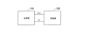
シリアル伝送信号でデータを送信するために、従来技術では、同期データ伝送方式および非同期データ伝送方式が提供される。図1Aおよび図1Bを参照されたい。ここで図1Aは同期データ伝送方式のブロック図を示し、図1Bは非同期データ伝送方式のブロック図を示す。図1Aでは、送信機110および受信機120が提供され、送信機110は受信機120に接続される。送信機110は、クロック信号CLKおよびシリアル伝送信号DSを受信機120に送信する。シリアル伝送信号DSおよびクロック信号CLKは同期しており、受信機120は、シリアル伝送信号DS上で搬送されるデータを、クロック信号CLKに応じて復号することができる。
In order to transmit data with a serial transmission signal, the prior art provides a synchronous data transmission scheme and an asynchronous data transmission scheme. See FIGS. 1A and 1B. Here, FIG. 1A shows a block diagram of a synchronous data transmission system, and FIG. 1B shows a block diagram of an asynchronous data transmission system. In FIG. 1A, a
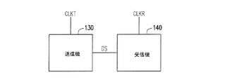
図1Bにおいて、図1Bは、送信機130および受信機140を提供する。送信機130は受信機140に接続され、送信機130は、シリアル伝送信号DSを生成するために、クロック信号CLKTに応じて送信データを符号化する。送信機130は、シリアル伝送信号DSを受信機140に送信する。受信機140は、シリアル伝送信号DSを復号してクロックCLKRに応じて送信データを取得することができる。ここで、受信機140のクロックCLKRは、送信機130のクロック信号CLKTのクロック周波数に応じて生成されることに留意すべきである。
In FIG. 1B, FIG. 1B provides a
したがって、従来技術の同期データ伝送方式と非同期データ伝送方式の両方では、受信機は、送信機のクロック信号のクロック周波数を知る必要がある。さらに、送信機が高いビット・レート精度を有していることが必要とされる。特に、高速ユニバーサル・シリアル・バス(USB)では、必要とされる送信機の精度は、480Mbps±0.05%(500ppm)である。 Therefore, in both the conventional synchronous data transmission system and asynchronous data transmission system, the receiver needs to know the clock frequency of the clock signal of the transmitter. Furthermore, it is required that the transmitter has a high bit rate accuracy. In particular, in the high-speed universal serial bus (USB), the required transmitter accuracy is 480 Mbps ± 0.05% (500 ppm).
本発明は、シリアル伝送信号を復号するためのデータ復号装置および方法を対象とし、そのデータ復号装置は、送信機の周波数を知る必要がない。 The present invention is directed to a data decoding apparatus and method for decoding a serial transmission signal, and the data decoding apparatus does not need to know the frequency of the transmitter.
本開示は、シリアル伝送信号を復号するための方法であって、シリアル伝送信号をサンプリングして、サンプリング周期に応じて複数のサンプル値を取得するステップと、サンプル値の遷移状態に応じて、シリアル伝送信号の周期を取得するステップと、周期およびサンプル値の遷移状態に応じて、複数の位相値を計算するステップと、位相値に応じて、複数の境界を取得するステップと、境界および遷移状態に応じて、復号済みデータを出力するステップとを含む方法を提供する。 The present disclosure is a method for decoding a serial transmission signal, the serial transmission signal being sampled, obtaining a plurality of sample values according to a sampling period, and a serial value depending on a transition state of the sample values A step of acquiring a cycle of the transmission signal, a step of calculating a plurality of phase values according to the transition state of the cycle and the sample value, a step of acquiring a plurality of boundaries according to the phase value, and the boundary and the transition state In response to outputting decoded data.
本開示は、信号サンプリング装置とコントローラとを含むデータ復号装置を提供する。信号サンプリング装置は、シリアル伝送信号をサンプリングして、サンプリング周期に応じて複数のサンプル値を取得する。コントローラは信号サンプリング装置に接続され、コントローラは、サンプル値の遷移状態に応じて、シリアル伝送信号の周期を取得し、周期およびサンプル値の遷移状態に応じて、複数の位相値を計算し、位相値に応じて、複数の境界を取得し、境界および遷移状態に応じて、復号済みデータを出力するように構成される。 The present disclosure provides a data decoding device including a signal sampling device and a controller. The signal sampling device samples the serial transmission signal and acquires a plurality of sample values according to the sampling period. The controller is connected to the signal sampling device, the controller obtains the period of the serial transmission signal according to the transition state of the sample value, calculates a plurality of phase values according to the transition state of the period and the sample value, and the phase A plurality of boundaries are acquired according to the values, and decoded data is output according to the boundaries and the transition state.
本発明は、シリアル伝送信号を復号してシリアル伝送信号の複数の境界を検出するための方法を提供し、その境界を参照することによって複数の出力データが生成され得る。したがって、シリアル伝送信号を符号化するための送信機のクロック周波数は、データ復号装置にとって予め必要ではない。 The present invention provides a method for decoding a serial transmission signal to detect multiple boundaries of the serial transmission signal, and multiple output data can be generated by referring to the boundaries. Therefore, the clock frequency of the transmitter for encoding the serial transmission signal is not necessary in advance for the data decoding device.
本発明の上記および他の特徴および利点を理解しやすくするために、図面が添付された、いくつかの例示的な実施形態が以下で詳細に記述される。 In order to make the aforementioned and other features and advantages of the present invention comprehensible, several exemplary embodiments accompanied with figures are described in detail below.
添付図面は、本発明のさらなる理解をもたらすために含まれており、本明細書に組み込まれ、本発明の一部を構成する。図面は、本発明の実施形態を示し、記述と併せて本発明の原理を説明する役割を果たす。 The accompanying drawings are included to provide a further understanding of the invention, and are incorporated in and constitute a part of this invention. The drawings illustrate embodiments of the invention and, together with the description, serve to explain the principles of the invention.
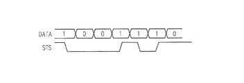
図2を参照されたい。図2は、本開示の一実施形態による、シリアル伝送信号の波形プロットを示す。図2では、シリアル伝送信号STSは、送信データDATAに応じて符号化され得る。送信データDATAを符号化するための符号化方法としては、非ゼロ復帰(NRZ)方式、マンチェスター方式、AMI(Alternate Mark Inversion:交番マーク反転)方式、MLT−3(Multilevel Transmission 3:多値伝送3)方式、および二位相符号化方式が含まれ得るが、これらには限定されない。図2では、送信データDATAは、非ゼロ復帰かつ1で反転(NRZI)の方式に応じて符号化され、シリアル伝送信号STSが取得され得る。ここで、送信データDATAが論理「1」である場合、対応するシリアル伝送信号STSの物理レベルは遷移され得、送信データDATAが論理「0」である場合、対応するシリアル伝送信号STSの物理レベルは遷移されない。 Please refer to FIG. FIG. 2 shows a waveform plot of a serial transmission signal according to one embodiment of the present disclosure. In FIG. 2, the serial transmission signal STS can be encoded according to the transmission data DATA. As encoding methods for encoding the transmission data DATA, non-zero return (NRZ) method, Manchester method, AMI (Alternate Mark Inversion) method, MLT-3 (Multilevel Transmission 3: Multi-value transmission 3) ) Scheme and two-phase encoding scheme, but are not limited to these. In FIG. 2, the transmission data DATA is encoded according to a non-zero return and 1 inversion (NRZI) scheme, and a serial transmission signal STS can be obtained. Here, when the transmission data DATA is logic “1”, the physical level of the corresponding serial transmission signal STS can be changed, and when the transmission data DATA is logic “0”, the physical level of the corresponding serial transmission signal STS. Is not transitioned.
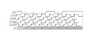
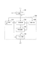
図3を参照されたい。図3は、一実施形態によるシリアル伝送信号を復号するための方法のフローチャートを示す。ステップS310において、シリアル伝送信号はサンプリングされ、サンプリング周期に応じて複数のサンプル値が取得され得る。詳細には、ステップS310に関して図4Aおよび図4Bを参照すると、図4Aおよび図4Bは、本開示の異なる実施形態による、シリアル伝送信号をサンプリングするためのそれぞれ2つの波形プロットを示す。図4Aでは、シリアル伝送信号STSは、複数のクロック信号CLK0、CLK90、CLK180、およびCLK270によってサンプリングされ得る。クロック信号CLK0、CLK90、CLK180、およびCLK270のクロック周波数は同じであってもよいが、クロック信号CLK0、CLK90、CLK180、およびCLK270の位相は異なっている。シリアル伝送信号STSは、それぞれクロック信号CLK0、CLK90、CLK180、およびCLK270の立ち上がりエッジ(または立ち下がりエッジ)によってサンプリングされ得、複数のサンプル値SVが取得され得る。この実施形態では、サンプリングされた周期はTCLK/4に等しく、TCLKは、クロック信号CLK0、CLK90、CLK180、およびCLK270のうちの1つの周期である。 Please refer to FIG. FIG. 3 shows a flowchart of a method for decoding a serial transmission signal according to one embodiment. In step S310, the serial transmission signal is sampled, and a plurality of sample values can be obtained according to the sampling period. Specifically, referring to FIGS. 4A and 4B for step S310, FIGS. 4A and 4B show two waveform plots, respectively, for sampling a serial transmission signal, according to different embodiments of the present disclosure. In FIG. 4A, the serial transmission signal STS may be sampled by a plurality of clock signals CLK0, CLK90, CLK180, and CLK270. The clock signals CLK0, CLK90, CLK180, and CLK270 may have the same clock frequency, but the clock signals CLK0, CLK90, CLK180, and CLK270 have different phases. The serial transmission signal STS can be sampled by rising edges (or falling edges) of the clock signals CLK0, CLK90, CLK180, and CLK270, respectively, and a plurality of sample values SV can be obtained. In this embodiment, the sampled period is equal to TCLK / 4, where TCLK is one period of the clock signals CLK0, CLK90, CLK180, and CLK270.
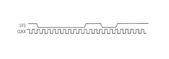
図4Bでは、シリアル伝送信号STSは、単にクロック信号CLKXによってサンプリングされるだけであり得る。クロック信号CLKXのクロック周波数は、クロック信号CLK0より高くてもよい。シリアル伝送信号STSは、クロック信号CLKXの立ち上がりエッジ(または立ち下がりエッジ)によってサンプリングされ得、複数のサンプル値SVも取得され得る。 In FIG. 4B, the serial transmission signal STS may simply be sampled by the clock signal CLKX. The clock frequency of the clock signal CLKX may be higher than that of the clock signal CLK0. The serial transmission signal STS can be sampled by the rising edge (or falling edge) of the clock signal CLKX, and a plurality of sample values SV can also be obtained.
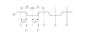
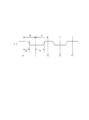
図5を参照されたい。図5は、本開示の一実施形態によるシリアル伝送信号の所定のパターンの波形プロットを示す。本開示では、シリアル伝送信号のすべてをサンプリングする必要はない。実際の用途では、複数の所定のパターンは、符号化動作中にシリアル伝送信号STSに挿入され得る。所定のパターンは、シリアル伝送信号STS上でデータを送る前に送られ、シリアル伝送信号STSのプリアンブルになる。ステップS310のサンプリング動作は、シリアル伝送信号STSの所定のパターンに対して動作されてもよい。 Please refer to FIG. FIG. 5 illustrates a waveform plot of a predetermined pattern of a serial transmission signal according to one embodiment of the present disclosure. In the present disclosure, it is not necessary to sample all of the serial transmission signals. In practical applications, a plurality of predetermined patterns can be inserted into the serial transmission signal STS during the encoding operation. The predetermined pattern is sent before sending data on the serial transmission signal STS, and becomes a preamble of the serial transmission signal STS. The sampling operation in step S310 may be performed on a predetermined pattern of the serial transmission signal STS.
図5では、時点間0〜T、T〜2T、2T〜3T、または3T〜4T・・・の周期中、シリアル伝送信号STSの遷移時点のそれぞれは、対応する周期の半分の時点に生じている。例えば、データD0に対応する遷移時点は、時点T×1/2にあり、データD1に対応する遷移時点は、時点T×3/2にある。
In FIG. 5, during the period between
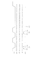
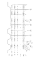
シリアル伝送信号STSの周期Tは不明なので、したがって、ステップS320は、送信信号の周期をサンプル値の遷移状態に応じて取得するために動作される。図6を参照されたい。図6は、本開示の一実施形態によるシリアル伝送信号の周期を取得するための波形プロットを示す。図6では、図5のシリアル伝送信号STSが、1つまたは複数のクロック信号CLKSによってサンプリングされ、複数のサンプル値が取得され得る。サンプル値SVのそれぞれは、論理「1」または論理「0」を対象とすることができる。さらに、サンプル値SVは、複数の指標値を生成することによってそれぞれ指標付けされ得る。指標値は、それぞれサンプル値SVに対応しており、指標値は等差数列を形成し得る。 Since the period T of the serial transmission signal STS is unknown, therefore, step S320 is operated to acquire the period of the transmission signal according to the transition state of the sample value. See FIG. FIG. 6 shows a waveform plot for obtaining the period of a serial transmission signal according to one embodiment of the present disclosure. In FIG. 6, the serial transmission signal STS of FIG. 5 may be sampled by one or more clock signals CLKS to obtain a plurality of sample values. Each of the sample values SV can be targeted for logic “1” or logic “0”. Furthermore, the sample value SV can be indexed by generating a plurality of index values. Each index value corresponds to a sample value SV, and the index values can form an arithmetic progression.
一方、複数のエッジ値EDGVは、すぐ隣同士にある2つのサンプル値の変動に応じて決定され得る。エッジ値EDGVは、シリアル伝送信号STSの遷移状態を表す。例えば、サンプル値SV1(=1)とサンプル値SV2(=0)は異なっている(変動している)ことから、値「f」を有する対応するエッジ値EG1が生成され得る。サンプル値SV3(=0)とサンプル値SV4(=1)は異なっている(変動している)ことから、値「r」を有する対応するエッジ値EG2が生成され得る。値「f」は、立ち下がりエッジに対応するエッジ値EG1を指示し、値「r」は、立ち上がりエッジに対応するエッジ値EG2を指示する。 On the other hand, the plurality of edge values EDGV can be determined according to fluctuations in two sample values immediately adjacent to each other. The edge value EDGV represents the transition state of the serial transmission signal STS. For example, since the sample value SV1 (= 1) and the sample value SV2 (= 0) are different (fluctuated), the corresponding edge value EG1 having the value “f” can be generated. Since the sample value SV3 (= 0) and the sample value SV4 (= 1) are different (fluctuated), a corresponding edge value EG2 having the value “r” can be generated. The value “f” indicates the edge value EG1 corresponding to the falling edge, and the value “r” indicates the edge value EG2 corresponding to the rising edge.
次いで、2つのエッジ値が選択され得、2つの選択されたエッジ値(A番目のエッジ値とB番目のエッジ値)にそれぞれ対応する2つの指標値間の差分値が計算され得る。エッジ値EG1(B=1)およびEG3(A=5)を例に取ると、エッジ値EG1およびEG3に対応する指標値は、それぞれ3および21であり、差分値は21−3=18である。差分値(=18)はさらに、A−B=5−1=4で割られ、周期T=18/4=4.5が取得され得る。 Then, two edge values can be selected, and a difference value between two index values respectively corresponding to the two selected edge values (Ath edge value and Bth edge value) can be calculated. Taking the edge values EG1 (B = 1) and EG3 (A = 5) as an example, the index values corresponding to the edge values EG1 and EG3 are 3 and 21, respectively, and the difference value is 21-3 = 18. . The difference value (= 18) can be further divided by AB = 5-1 = 4 and the period T = 18/4 = 4.5 can be obtained.
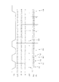
再び図3を参照されたい。ステップS330は、周期およびサンプル値の遷移状態に応じて、複数の位相値を計算するために実行される。ステップS330の詳細において、図7を参照されたい。図7は、本開示の一実施形態による、シリアル伝送信号の位相値および境界を取得するための波形プロットを示す。 Please refer to FIG. 3 again. Step S330 is executed to calculate a plurality of phase values according to the period and the transition state of the sample values. Refer to FIG. 7 for details of step S330. FIG. 7 shows a waveform plot for obtaining phase values and boundaries of a serial transmission signal according to one embodiment of the present disclosure.
図7では、位相値は、周期Tおよびサンプル値SVの遷移状態(エッジ値EDGV)に応じて計算される。詳細には、位相値のそれぞれPHV(N)は、式(1)として表され得る。
PHV(N)
=1/2×T(対応するサンプル値がエッジである場合)
=(PHV(N−1)+1)%T(対応するサンプル値がエッジではない場合) (1)
In FIG. 7, the phase value is calculated according to the transition state (edge value EDGV) of the period T and the sample value SV. Specifically, each phase value PHV (N) may be expressed as equation (1).
PHV (N)
= 1/2 × T (when the corresponding sample value is an edge)
= (PHV (N-1) +1)% T (when the corresponding sample value is not an edge) (1)
ここで、式(1)において、除算式の剰余を得るために演算子%が使用される。 Here, in equation (1), the operator% is used to obtain the remainder of the division equation.
式(1)によれば、複数の位相値PHVが取得され得る。例えば、値「0」を有するサンプル値に対応する位相値PV1は、立ち下がりエッジであり、位相値PV1=1/2×4.5=2.25である。値「1」を有するサンプル値に対応する位相値PV5は、立ち上がりエッジであり、位相値PV5=1/2×4.5=2.25である。さらに、エッジではないサンプル値に対応する位相値PV2は、位相値PV2=(2.25+1)%4.5=3.25である。エッジではないサンプル値に対応する位相値PV4は、位相値PV4=(4.25+1)%4.5=0.75である。 According to Equation (1), a plurality of phase values PHV can be acquired. For example, the phase value PV1 corresponding to the sample value having the value “0” is a falling edge, and the phase value PV1 = ½ × 4.5 = 2.25. The phase value PV5 corresponding to the sample value having the value “1” is a rising edge, and the phase value PV5 = 1/2 × 4.5 = 2.25. Further, the phase value PV2 corresponding to the sample value that is not an edge is the phase value PV2 = (2.25 + 1)% 4.5 = 3.25. The phase value PV4 corresponding to the sample value that is not an edge is the phase value PV4 = (4.25 + 1)% 4.5 = 0.75.
再び図3を参照されたい。位相値PHVが決定された後、位相値PHVに応じて複数の境界を取得するために、ステップS340が実行される。図7を参照すると、境界BD1〜BDNのそれぞれは、位相値および周期Tのそれぞれに応じて決定され得る。位相値+1が周期T以上である場合、その位相値に対応する境界が決定され得る。例えば、位相値PV3+1=5.25は、周期T(4.5)よりも大きく、境界BD1が決定され得る。上述したのと同じ理由で、境界BD2〜BDNが、位相値PHVに応じて決定され得る。 Please refer to FIG. 3 again. After the phase value PHV is determined, step S340 is executed to obtain a plurality of boundaries according to the phase value PHV. Referring to FIG. 7, each of the boundaries BD1 to BDN can be determined according to the phase value and the period T, respectively. If the phase value +1 is greater than or equal to the period T, the boundary corresponding to that phase value can be determined. For example, the phase value PV3 + 1 = 5.25 is greater than the period T (4.5), and the boundary BD1 can be determined. For the same reason as described above, the boundaries BD2 to BDN can be determined according to the phase value PHV.
境界が決定された後、境界および遷移状態に応じて、復号済みデータOUTを出力するために、図3のステップS350が実行され得る。ステップS350の詳細において、出力データOUTは、複数のデータ・ビットを含み、データ・ビットのそれぞれは、2つの連続した境界間でいずれかのエッジ値が生じたかどうかをチェックすることによって決定され得る。例えば、図7において、エッジ値「f」は境界BD1の前に生じ、論理「1」を有するデータ・ビットOT1が生成される。別のエッジ値「r」は、境界BD1とBD2の間に生じ、論理「1」を有する別のデータ・ビットOT2が生成される。さらに、境界BD5とBD6の間にはいずれのエッジ値も見つけることができず、論理「0」を有するデータ・ビットOT3が生成され得る。 After the boundary is determined, step S350 of FIG. 3 may be performed to output the decoded data OUT according to the boundary and the transition state. In details of step S350, the output data OUT includes a plurality of data bits, each of which can be determined by checking whether any edge value has occurred between two consecutive boundaries. . For example, in FIG. 7, the edge value “f” occurs before the boundary BD1, and a data bit OT1 having a logic “1” is generated. Another edge value “r” occurs between the boundaries BD1 and BD2, and another data bit OT2 having a logic “1” is generated. Furthermore, no edge value can be found between the boundaries BD5 and BD6, and a data bit OT3 having a logic “0” can be generated.
図8を参照されたい。図8は、本開示の別の実施形態によるシリアル伝送信号の所定のパターンの波形プロットを示す。図5とは異なり、図7のシリアル伝送信号STSは、1つの周期の中央の時点で遷移していない。さらに、1つの周期の立ち上がりエッジと開始時点との間の第1の時間長さ(立ち上がり値Pr)と、1つの周期の立ち下がりエッジと開始時点との間の第2の時間長さ(立ち下がり値Pf)は、異なり得る。 Please refer to FIG. FIG. 8 shows a waveform plot of a predetermined pattern of a serial transmission signal according to another embodiment of the present disclosure. Unlike FIG. 5, the serial transmission signal STS of FIG. 7 does not transition at the center of one cycle. Furthermore, the first time length (rising value Pr) between the rising edge and the start time of one cycle and the second time length (rising time) between the falling edge and the start time of one cycle. The fall value Pf) can be different.
図9を参照されたい。図9は、本開示の一実施形態による、図8のシリアル伝送信号を復号するための波形プロットを示す。図9では、シリアル伝送信号STSは、サンプリングされた周期を有する1つまたは複数のクロック信号CLKSによってサンプリングされて、複数のサンプル値SVが取得される。サンプル値SVは、指標値IDXによってそれぞれ指標付けされ得、シリアル伝送信号STSの遷移状態にある複数のエッジ値EDGVは、サンプル値SVに応じて決定され得る。 See FIG. FIG. 9 shows a waveform plot for decoding the serial transmission signal of FIG. 8 according to one embodiment of the present disclosure. In FIG. 9, the serial transmission signal STS is sampled by one or a plurality of clock signals CLKS having a sampled period to obtain a plurality of sample values SV. The sample value SV can be indexed by the index value IDX, and the plurality of edge values EDGV in the transition state of the serial transmission signal STS can be determined according to the sample value SV.
シリアル伝送信号STSの周期Tを計算するために、2つのエッジ値(エッジ値EG1およびEG5)が選択され得、選択された2つのエッジ値にそれぞれ対応する2つの指標値(3および20)間の差分値が計算され得る。したがって、周期T=(20−3)/(5−1)=4.25が取得され得る。 In order to calculate the period T of the serial transmission signal STS, two edge values (edge values EG1 and EG5) can be selected, and between two index values (3 and 20) respectively corresponding to the two selected edge values. The difference value of can be calculated. Therefore, the period T = (20-3) / (5-1) = 4.25 can be obtained.
ここで、本実施形態では、立ち上がり値Prと立ち下がり値Pfが異なることから、立ち上がり値Prと立ち下がり値Pfが別々に計算され得ることに留意すべきである。ここで、立ち下がり値Pfは、C番目のエッジ値とD番目のエッジ値との間にある1の数を計算し、その1の数を(C−D)で割ることによって取得され、立ち上がり値Prは、C番目のエッジ値とD番目のエッジ値との間にある0の数を計算し、その0の数を(C−D)で割ることによって取得される。例えば、CおよびDがそれぞれ5および1である場合、立ち下がり値Pf=7/4=1.75、および立ち上がり値Pr=10/4=2.5である。 Here, it should be noted that in the present embodiment, since the rising value Pr and the falling value Pf are different, the rising value Pr and the falling value Pf can be calculated separately. Here, the falling value Pf is obtained by calculating the number of 1s between the C-th edge value and the D-th edge value and dividing the number of 1s by (C−D). The value Pr is obtained by calculating the number of zeros between the Cth edge value and the Dth edge value and dividing the number of zeros by (CD). For example, if C and D are 5 and 1, respectively, the falling value Pf = 7/4 = 1.75 and the rising value Pr = 10/4 = 2.5.
さらに、周期T、立ち上がり値Pr、立ち下がり値Pf、およびサンプル値SVの遷移状態(エッジ値EDGV)に応じて、位相値が計算される。詳細には、位相値のそれぞれPHV(N)は、式(2)として表され得る。
PHASE(N)=
Pr(対応するサンプル値が立ち上がりエッジである場合)
Pf(対応するサンプル値が立ち下がりエッジである場合)
(PHV(N−1)+1)%T(対応するサンプル値がエッジではない場合) (2)
Furthermore, the phase value is calculated according to the transition state (edge value EDGV) of the cycle T, the rising value Pr, the falling value Pf, and the sample value SV. Specifically, each phase value PHV (N) may be expressed as equation (2).
PHASE (N) =
Pr (when the corresponding sample value is a rising edge)
Pf (when the corresponding sample value is a falling edge)
(PHV (N−1) +1)% T (when the corresponding sample value is not an edge) (2)
ここで、式(2)において、除算式の剰余を得るために演算子%が使用される。 Here, in Expression (2), the operator% is used to obtain the remainder of the division expression.
式(2)によれば、複数の位相値PHVが取得され得る。例えば、値「0」を有するサンプル値に対応する位相値PV1は立ち下がりエッジであり、位相値PV1=Pf=1.75である。値「1」を有するサンプル値に対応する位相値PV2は立ち上がりエッジであり、位相値PV2=(0.5+1)%4.5=1.5である。さらに、立ち上がりエッジであるサンプル値に対応する位相値PV2の次の位相値は、位相値=Pr=2.25である。エッジではないサンプル値に対応する位相値PV3は、位相値PV3=(3.50+1)%4.25=0.25である。 According to Equation (2), a plurality of phase values PHV can be acquired. For example, the phase value PV1 corresponding to the sample value having the value “0” is a falling edge, and the phase value PV1 = Pf = 1.75. The phase value PV2 corresponding to the sample value having the value “1” is a rising edge, and the phase value PV2 = (0.5 + 1)% 4.5 = 1.5. Further, the next phase value of the phase value PV2 corresponding to the sample value which is the rising edge is phase value = Pr = 2.25. The phase value PV3 corresponding to the sample value that is not an edge is the phase value PV3 = (3.50 + 1)% 4.25 = 0.25.
位相値PHVによれば、図3のステップS340を実行することによって境界BD1〜BDNが決定され得る。境界BD1〜BDNのそれぞれは、位相値および周期Tのそれぞれに応じて決定され得る。位相値+1が、周期T以上である場合には、位相値に対応する境界が決定され得る。境界が決定された後、境界および遷移状態に応じて復号済みデータOUTを出力するために、図3のステップS350が実行され得る。復号済み出力データOUTのデータ・ビットのそれぞれは、2つの連続した境界間にいずれかのエッジ値が生じたかどうかをチェックすることによって決定され得る。 According to the phase value PHV, the boundaries BD1 to BDN can be determined by executing step S340 of FIG. Each of the boundaries BD1 to BDN can be determined according to the phase value and the period T, respectively. If the phase value +1 is greater than or equal to the period T, a boundary corresponding to the phase value can be determined. After the boundary is determined, step S350 of FIG. 3 may be performed to output the decoded data OUT according to the boundary and the transition state. Each of the data bits of the decoded output data OUT can be determined by checking whether any edge value has occurred between two consecutive boundaries.
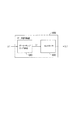
図10を参照されたい。図10は、本開示の一実施形態によるデータ復号装置の概略図を示す。データ復号装置1000は、データ・サンプリング装置1010、およびコントローラ1020を含む。データ・サンプリング装置1010は、コントローラ1020に接続される。データ・サンプリング装置1010は、シリアル伝送信号STSを受信する。シリアル伝送信号STSは、送信機から送信され得、シリアル伝送信号STSは、送信データを符号化することによって得られる。データ・サンプリング装置1010は、シリアル伝送信号STSをサンプリングして、複数のサンプル値SVを取得する。データ・サンプリング装置1010は、1つまたは複数のクロック信号を使用して、サンプリング周期に応じてシリアル伝送信号STSをサンプリングする。ハードウエア構造においては、データ・サンプリング装置1010は、サンプリング動作を実行するための1つまたは複数のDタイプ・フリップ・フロップを含んでもよい。当然ながら、データ・サンプリング装置1010は、当業者により知られている任意の他のハードウエア構造によって実装されてもよい。
Please refer to FIG. FIG. 10 shows a schematic diagram of a data decoding apparatus according to an embodiment of the present disclosure. The
コントローラ1020はサンプル値SVを受信し、コントローラ1020は、図3に示されたステップS320〜S350を実行するように構成され得、復号済みデータOUTが生成され得る。
The
他方、コントローラ1020は、演算機能を有する回路とすることができる。回路は、デジタル回路、アナログ回路、または混合モード回路とすることができる。
On the other hand, the
図11を参照されたい。図11は、本開示の一実施形態によるコントローラの概略図を示す。コントローラ1100は、データ・サンプリング装置1101に接続され、エッジ検出器1110、位相計算器1130、周期計算器1120、境界検出器1140、およびデータ出力回路1150を含む。データ・サンプリング装置1101は、シリアル伝送信号STSをクロック信号CLKSによってサンプリングして、サンプル値SVを生成する。サンプル値SVは、位相検出器1130、エッジ検出器1110、および位相計算器1120に移され、位相検出器1130とエッジ検出器1110は、それぞれエッジ値EDGVと周期Tを生成し得る。位相計算器1120は、位相検出器1130およびエッジ検出器1110に接続されて、エッジ値EDGVおよび周期Tを受信する。位相計算器1120は、サンプル値SV、エッジ値EDGV、および周期Tに応じて、位相値PHVを生成する。
Please refer to FIG. FIG. 11 shows a schematic diagram of a controller according to an embodiment of the present disclosure. The
境界検出器1140は、位相計算器とデータ出力回路1150との間に接続される。境界検出器1140は、位相値PHVを受信し、境界BDxを生成する。データ出力回路1150は、境界BDxおよびエッジ値EDGVを受信し、境界BDxおよびエッジ値EDGVに応じて復号済み出力データOUTを生成する。
The
ここで、エッジ検出器1110、位相計算器1130、周期計算器1120、境界検出器1140、およびデータ出力回路1150の詳細な動作は、上記の実施形態に記述されていることに留意されたい。エッジ検出器1110、位相計算器1130、周期計算器1120、境界検出器1140、およびデータ出力回路1150の構造は、デジタル回路によって実装され得る。当業者は、ハードウエア記述言語(HDL)または任意の他のよく知られたデジタル回路設計方式を使用して、エッジ検出器1110、位相計算器1130、周期計算器1120、境界検出器1140、およびデータ出力回路1150を、対応する機能に応じて実装することができる。エッジ検出器1110、位相計算器1130、周期計算器1120、境界検出器1140、およびデータ出力回路1150の詳細な構造は、回路合成ツールによって得ることができ、固定されていない。
Here, it should be noted that detailed operations of the
まとめると、本開示のデータ復号装置は、復号済みデータを符号化するためのクロック信号の情報を知る必要がない。データ復号装置は、サンプル値に応じて周期、位相値、エッジ値、および境界を計算することによって復号済みデータを復号することができる。したがって、送信機の高いビット・レート精度という要件は、必要ではない。 In summary, the data decoding device according to the present disclosure does not need to know information on a clock signal for encoding decoded data. The data decoding apparatus can decode the decoded data by calculating the period, the phase value, the edge value, and the boundary according to the sample value. Therefore, the requirement for high bit rate accuracy of the transmitter is not necessary.
本発明の範囲または趣旨から逸脱することなく、本発明の構造に様々な修正および変更が加えられ得ることが、当業者には明らかであろう。上記に鑑み、本発明の修正および変更が添付の特許請求の範囲およびその均等物に含まれるならば、本発明はそれらを包含することが意図される。 It will be apparent to those skilled in the art that various modifications and variations can be made to the structure of the present invention without departing from the scope or spirit of the invention. In view of the above, it is intended that the present invention cover the modifications and variations of this invention provided they come within the scope of the appended claims and their equivalents.
本開示は、復号済みデータを符号化するためのクロック信号の情報なしに、シリアル伝送信号を復号するための方法を提供する。すなわち、復号済みデータは正確に符号化され得、高速伝送動作中であってもデータが正確に送信され得る。 The present disclosure provides a method for decoding a serial transmission signal without information of a clock signal for encoding decoded data. That is, the decoded data can be encoded accurately, and the data can be transmitted accurately even during a high-speed transmission operation.
110、130 送信機
120、140 受信機
CLK、CLKT、CLK0、CLK90、CLK180、CLK270、CLKX、CLKS クロック信号
CLKR クロック
DS、STS シリアル伝送信号
DATA 送信データ
S310〜S350 復号ステップ
T、2T、3T、4T、1/2T、3/2T 時点
D0、D1 データ
SV、SV1、SV2 サンプル値
EDGV、EG1、EG2、EG3 エッジ値
PHV(N)、PV1〜PV5 位相値
BD1〜BDN、BDx 境界
OUT 復号済みデータ
OT1〜OT3 データ・ビット
Pr 立ち上がり値
Pf 立ち下がり値
IDX 指標値
1000 データ復号装置
1010 データ・サンプリング装置
1100、1020 コントローラ
1130 位相検出器
1110 エッジ検出器
1120 位相計算器
T 周期
1140 境界検出器
1150 データ出力回路
110, 130
Claims (18)
該シリアル伝送信号をサンプリングして、サンプリング周期に応じて複数のサンプル値を取得するステップと、
該サンプル値の遷移状態に応じて、該シリアル伝送信号の周期を取得するステップと、
該周期および該サンプル値の該遷移状態に応じて、複数の位相値を計算するステップと、
該位相値に応じて、複数の境界を取得するステップと、
該境界および該遷移状態に応じて、復号済みデータを出力するステップと
を備える方法。 A method for decoding a serial transmission signal, comprising:
Sampling the serial transmission signal to obtain a plurality of sample values according to a sampling period;
Obtaining a cycle of the serial transmission signal according to a transition state of the sample value;
Calculating a plurality of phase values according to the period and the transition state of the sample values;
Obtaining a plurality of boundaries according to the phase value;
Outputting decoded data in response to the boundary and the transition state.
該サンプリング周期を有するサンプリング・クロックによって、該シリアル伝送信号の複数の所定のパターンをサンプリングするステップを備え、
該所定のパターンが、該シリアル伝送信号上でデータを送る前に送られる、
請求項1に記載の方法。 Sampling the serial transmission signal, obtaining the sample value according to the sampling period,
Sampling a plurality of predetermined patterns of the serial transmission signal with a sampling clock having the sampling period;
The predetermined pattern is sent before sending data on the serial transmission signal;
The method of claim 1.
該シリアル伝送信号の複数の所定のパターンを、複数のサンプリング・クロックによってサンプリングするステップを備え、
該所定のパターンが、該シリアル伝送信号上でデータを送る前に送られる、
請求項1に記載の方法。 Sampling the serial transmission signal, obtaining the sample value according to the sampling period,
Sampling a plurality of predetermined patterns of the serial transmission signal with a plurality of sampling clocks;
The predetermined pattern is sent before sending data on the serial transmission signal;
The method of claim 1.
該サンプル値にそれぞれ対応する複数の指標値を生成するステップであって、該指標値が等差数列を形成する、生成するステップをさらに備え、
前記サンプル値の前記遷移状態に応じて、前記シリアル伝送信号の前記周期を取得する前記ステップが、
A番目のエッジ値およびB番目のエッジ値にそれぞれ対応する2つの指標値の差分値を計算するステップ、および該差分値を(A−B)で割って、該シリアル伝送信号の該周期を取得するステップを備える、請求項4に記載の方法。 Sampling the serial transmission signal, obtaining the sample value according to the sampling period,
Generating a plurality of index values respectively corresponding to the sample values, wherein the index values form an arithmetic sequence;
According to the transition state of the sample value, the step of acquiring the period of the serial transmission signal,
A step of calculating a difference value between two index values respectively corresponding to the A-th edge value and the B-th edge value, and dividing the difference value by (A−B) to obtain the period of the serial transmission signal 5. The method of claim 4, comprising the step of:
該位相値のそれぞれPHASE(N)が、前記エッジ値のうちの1つに対応する場合には、該位相値のそれぞれPHASE(N)=前記シリアル伝送信号の該周期Tの2分の1、を設定するステップと、
該位相値のそれぞれPHASE(N)に対応するエッジ値がない場合には、該位相値のそれぞれPHASE(N)=((PHASE(N−1)+1)/T)の剰余値、を設定するステップと
を備える、請求項5に記載の方法。 Depending on the period and the transition state of the sample value, calculating the phase value comprises:
If each of the phase values PHASE (N) corresponds to one of the edge values, each of the phase values PHASE (N) = 1/2 of the period T of the serial transmission signal, Steps to set
If there is no edge value corresponding to each PHASE (N) of the phase value, a residue value of PHASE (N) = ((PHASE (N−1) +1) / T) of the phase value is set. The method of claim 5 comprising the steps of:
C番目のエッジ値とD番目のエッジ値との間の1の数を計算し、該1の数を(C−D)で割って、下降値Pfを取得するステップと、
該C番目のエッジ値と該D番目のエッジ値との間の0の数を計算し、該0の数を(C−D)で割って、立ち上がり値Prを取得するステップと、
該位相値のそれぞれPHASE(N)に対応する前記エッジ値のうちの1つが立ち上がりエッジである場合には、該位相値のそれぞれPHASE(N)=Pr、を設定するステップと、
該位相値のそれぞれPHASE(N)に対応する該エッジ値のうちの1つが立ち下がりエッジである場合には、該位相値のそれぞれPHASE(N)=Pf、を設定するステップと、
該位相値のそれぞれPHASE(N)に対応するエッジ値がない場合には、該位相値のそれぞれPHASE(N)=((PHASE(N−1)+1)/T)の剰余値、を設定するステップと
を備える、請求項5に記載の方法。 Depending on the period and the transition state of the sample value, calculating the phase value comprises:
Calculating a number of 1s between the Cth edge value and the Dth edge value, dividing the number of 1s by (C−D) to obtain a falling value Pf;
Calculating a number of zeros between the C-th edge value and the D-th edge value, dividing the number of zeros by (C−D) to obtain a rising value Pr;
Setting one of the phase values, PHASE (N) = Pr, when one of the edge values corresponding to each of the phase values PHASE (N) is a rising edge;
If one of the edge values corresponding to each of the phase values PHASE (N) is a falling edge, setting each of the phase values PHASE (N) = Pf;
If there is no edge value corresponding to each PHASE (N) of the phase value, a residue value of PHASE (N) = ((PHASE (N−1) +1) / T) of the phase value is set. The method of claim 5 comprising the steps of:
該位相値のそれぞれが前記シリアル伝送信号の前記周期よりも小さいかどうかをチェックすることによって、該境界のそれぞれを取得するステップを備える、請求項1から7のいずれか一項に記載の方法。 Obtaining the boundary according to the phase value,
The method according to claim 1, comprising obtaining each of the boundaries by checking whether each of the phase values is less than the period of the serial transmission signal.
該遷移状態にある複数のエッジ値のうちの1つが、2つの連続した境界間に生じたかどうかをチェックするステップを備える、請求項1から8のいずれか一項に記載の方法。 Depending on the boundary and the transition state, outputting the decoded data comprises:
9. A method according to any one of the preceding claims, comprising checking whether one of a plurality of edge values in the transition state has occurred between two consecutive boundaries.
該シリアル伝送信号をサンプリングして、サンプリング周期に応じて複数のサンプル値を取得する信号サンプリング装置と、
該信号サンプリング装置に接続されたコントローラであって、
該シリアル伝送信号の周期を、該サンプル値の遷移状態に応じて取得し、
該周期および該サンプル値の該遷移状態に応じて、複数の位相値を計算し、
該位相値に応じて、複数の境界を取得し、
該境界および該遷移状態に応じて、復号済みデータを出力する
ように構成されたコントローラと
を備える、データ復号装置。 A data decoding device configured to decode a serial transmission signal,
A signal sampling device that samples the serial transmission signal and obtains a plurality of sample values according to a sampling period;
A controller connected to the signal sampling device,
Obtaining the period of the serial transmission signal according to the transition state of the sample value,
Calculating a plurality of phase values according to the period and the transition state of the sample values;
According to the phase value, obtain a plurality of boundaries,
A data decoding device comprising: a controller configured to output decoded data in accordance with the boundary and the transition state.
該所定のパターンが、該シリアル伝送信号上でデータを送る前に送られる、請求項10に記載のデータ復号装置。 The signal sampling device samples a plurality of predetermined patterns of the serial transmission signal by a sampling clock having the sampling period;
The data decoding device according to claim 10, wherein the predetermined pattern is sent before sending data on the serial transmission signal.
該所定のパターンが、該シリアル伝送信号上でデータを送る前に送られる、請求項10に記載のデータ復号装置。 The signal sampling device samples a plurality of predetermined patterns of the serial transmission signal by a plurality of sampling clocks,
The data decoding device according to claim 10, wherein the predetermined pattern is sent before sending data on the serial transmission signal.
前記位相値のそれぞれPHASE(N)が、前記エッジ値のうちの1つに対応する場合には、該位相値のそれぞれPHASE(N)=前記シリアル伝送信号の前記周期Tの2分の1、を設定し、
該位相値のそれぞれPHASE(N)に対応するエッジ値がない場合には、該位相値のそれぞれPHASE(N)=((PHASE(N−1)+1)/T)の剰余値、を設定する
ようにさらに構成された、請求項14に記載のデータ復号装置。 The controller is
If each of the phase values PHASE (N) corresponds to one of the edge values, each of the phase values PHASE (N) = half the period T of the serial transmission signal, Set
If there is no edge value corresponding to each PHASE (N) of the phase value, a residue value of PHASE (N) = ((PHASE (N−1) +1) / T) of the phase value is set. 15. The data decoding device according to claim 14, further configured as described above.
C番目のエッジ値とD番目のエッジ値との間の1の数を計算し、該1の数を(C−D)で割って下降値Pfを取得し、
該C番目のエッジ値と該D番目のエッジ値との間の0の数を計算し、該0の数を(C−D)で割って立ち上がり値Prを取得し、
前記位相値のそれぞれPHASE(N)に対応する前記エッジ値のうちの1つが立ち上がりエッジである場合には、該位相値のそれぞれPHASE(N)=Pr、を設定し
該位相値のそれぞれPHASE(N)に対応する該エッジ値のうちの1つが立ち下がりエッジである場合には、該位相値のそれぞれPHASE(N)=Pf、を設定し、
該位相値のそれぞれPHASE(N)に対応するエッジ値がない場合には、該位相値のそれぞれPHASE(N)=((PHASE(N−1)+1)/T)の剰余値、を設定する
ようにさらに構成された、請求項14に記載のデータ復号装置。 The controller is
Calculate the number of 1s between the Cth edge value and the Dth edge value, and divide the number of 1 by (C−D) to obtain the falling value Pf;
Calculate the number of zeros between the C-th edge value and the D-th edge value, and divide the number of zeros by (C−D) to obtain the rising value Pr;
If one of the edge values corresponding to each of the phase values PHASE (N) is a rising edge, each of the phase values is set to PHASE (N) = Pr. If one of the edge values corresponding to N) is a falling edge, set PHASE (N) = Pf for each of the phase values;
If there is no edge value corresponding to each PHASE (N) of the phase value, a residue value of PHASE (N) = ((PHASE (N−1) +1) / T) of the phase value is set. 15. The data decoding device according to claim 14, further configured as described above.
前記位相値のそれぞれが前記シリアル伝送信号の前記周期よりも小さいかどうかをチェックすることによって、前記境界のそれぞれを取得する
ようにさらに構成された、請求項10から16のいずれか一項に記載のデータ復号装置。 The controller is
The method of any one of claims 10 to 16, further configured to obtain each of the boundaries by checking whether each of the phase values is less than the period of the serial transmission signal. Data decoding apparatus.
前記遷移状態にある複数のエッジ値のうちの1つが、2つの連続した境界間に生じたかどうかをチェックする
ようにさらに構成された、請求項10から17のいずれか一項に記載のデータ復号装置。 The controller is
18. Data decoding according to any one of claims 10 to 17, further configured to check whether one of a plurality of edge values in the transition state has occurred between two consecutive boundaries. apparatus.
Applications Claiming Priority (2)
| Application Number | Priority Date | Filing Date | Title |
|---|---|---|---|
| US15/470,935 | 2017-03-28 | ||
| US15/470,935 US9722630B1 (en) | 2017-03-28 | 2017-03-28 | Decoding apparatus and method for decoding a serially transmitted signal thereof |
Publications (2)
| Publication Number | Publication Date |
|---|---|
| JP6401828B1 JP6401828B1 (en) | 2018-10-10 |
| JP2018166320A true JP2018166320A (en) | 2018-10-25 |
Family
ID=59382681
Family Applications (1)
| Application Number | Title | Priority Date | Filing Date |
|---|---|---|---|
| JP2017126028A Active JP6401828B1 (en) | 2017-03-28 | 2017-06-28 | Decoding device and method for decoding serial transmission signal |
Country Status (4)
| Country | Link |
|---|---|
| US (1) | US9722630B1 (en) |
| JP (1) | JP6401828B1 (en) |
| CN (1) | CN108667562B (en) |
| TW (1) | TWI639313B (en) |
Families Citing this family (2)
| Publication number | Priority date | Publication date | Assignee | Title |
|---|---|---|---|---|
| CN112821915B (en) * | 2019-10-31 | 2022-04-26 | 瑞昱半导体股份有限公司 | Data processing apparatus and method |
| CN112838868B (en) * | 2020-12-30 | 2022-09-09 | 天津瑞发科半导体技术有限公司 | 9B/10B coding and decoding method |
Citations (4)
| Publication number | Priority date | Publication date | Assignee | Title |
|---|---|---|---|---|
| JPH06104741A (en) * | 1992-09-22 | 1994-04-15 | Sony Corp | Digital PLL device |
| JP2004328715A (en) * | 2003-04-09 | 2004-11-18 | Sharp Corp | Waveform shaping method, waveform shaping device, electronic device, waveform shaping program, and recording medium |
| JP2008167058A (en) * | 2006-12-27 | 2008-07-17 | Rohm Co Ltd | Receiving circuit, receiving method and radio equipment using the same |
| JP2016171387A (en) * | 2015-03-11 | 2016-09-23 | 株式会社日立製作所 | Clock data recovery circuit |
Family Cites Families (16)
| Publication number | Priority date | Publication date | Assignee | Title |
|---|---|---|---|---|
| US3238298A (en) * | 1962-05-07 | 1966-03-01 | Avco Corp | Multiplex communication system with multiline digital buffer |
| US6198783B1 (en) * | 1992-03-12 | 2001-03-06 | Ntp Incorporated | System for wireless serial transmission of encoded information |
| US5742644A (en) * | 1992-03-12 | 1998-04-21 | Ntp Incorporated | Receiving circuitry for receiving serially transmitted encoded information |
| US5751773A (en) * | 1992-03-12 | 1998-05-12 | Ntp Incorporated | System for wireless serial transmission of encoded information |
| US5761254A (en) | 1996-01-31 | 1998-06-02 | Advanced Micro Devices, Inc. | Digital architecture for recovering NRZ/NRZI data |
| US6138190A (en) * | 1997-09-16 | 2000-10-24 | Cirrus Logic, Inc. | Analog front end and digital signal processing device and method |
| US6081783A (en) * | 1997-11-14 | 2000-06-27 | Cirrus Logic, Inc. | Dual processor digital audio decoder with shared memory data transfer and task partitioning for decompressing compressed audio data, and systems and methods using the same |
| US6944248B2 (en) | 2001-05-17 | 2005-09-13 | Bluebrook Associates Llc | Data rate calibration for asynchronous serial communications |
| US6611219B1 (en) | 2002-05-01 | 2003-08-26 | Macronix International Co., Ltd. | Oversampling data recovery apparatus and method |
| CN1234219C (en) * | 2003-01-29 | 2005-12-28 | 北京邮电大学 | Symbolic ynchroni zing and carrier-wave synchronizing method based on modification system of circulation prefix |
| US8140931B2 (en) | 2003-07-03 | 2012-03-20 | Dtvg Licensing, Inc. | Method and system for generating parallel decodable low density parity check (LDPC) codes |
| JP4676792B2 (en) * | 2005-03-17 | 2011-04-27 | 株式会社リコー | Data recovery method, data recovery circuit, data transmission / reception device, and information processing device |
| US8396180B2 (en) * | 2008-12-18 | 2013-03-12 | Kawasaki Microelectronics America Inc. | High jitter tolerant phase comparator |
| US8594262B2 (en) | 2010-06-17 | 2013-11-26 | Transwitch Corporation | Apparatus and method thereof for clock and data recovery of N-PAM encoded signals using a conventional 2-PAM CDR circuit |
| US9461812B2 (en) | 2013-03-04 | 2016-10-04 | Blackberry Limited | Increased bandwidth encoding scheme |
| DE102014119071A1 (en) | 2014-12-18 | 2016-06-23 | Intel IP Corporation | An apparatus and method for generating a transmission signal |
-
2017
- 2017-03-28 US US15/470,935 patent/US9722630B1/en active Active
- 2017-05-04 TW TW106114768A patent/TWI639313B/en active
- 2017-05-25 CN CN201710377151.2A patent/CN108667562B/en active Active
- 2017-06-28 JP JP2017126028A patent/JP6401828B1/en active Active
Patent Citations (4)
| Publication number | Priority date | Publication date | Assignee | Title |
|---|---|---|---|---|
| JPH06104741A (en) * | 1992-09-22 | 1994-04-15 | Sony Corp | Digital PLL device |
| JP2004328715A (en) * | 2003-04-09 | 2004-11-18 | Sharp Corp | Waveform shaping method, waveform shaping device, electronic device, waveform shaping program, and recording medium |
| JP2008167058A (en) * | 2006-12-27 | 2008-07-17 | Rohm Co Ltd | Receiving circuit, receiving method and radio equipment using the same |
| JP2016171387A (en) * | 2015-03-11 | 2016-09-23 | 株式会社日立製作所 | Clock data recovery circuit |
Also Published As
| Publication number | Publication date |
|---|---|
| CN108667562B (en) | 2021-02-26 |
| CN108667562A (en) | 2018-10-16 |
| US9722630B1 (en) | 2017-08-01 |
| TW201838347A (en) | 2018-10-16 |
| JP6401828B1 (en) | 2018-10-10 |
| TWI639313B (en) | 2018-10-21 |
Similar Documents
| Publication | Publication Date | Title |
|---|---|---|
| CN107623520B (en) | Method and related apparatus for improving clock recovery | |
| JP6461018B2 (en) | Change the state for each state period, and make data lane skew and data state transition glitches | |
| JP5066121B2 (en) | Apparatus and method for transmitting clock information and data | |
| JP6158447B1 (en) | Clock and data recovery with high jitter tolerance and fast phase locking | |
| CN112100108B (en) | Method and system for asynchronous serialization of multiple serial communication signals | |
| JPH0661992A (en) | Apparatus and method for restoration of serially transmitted data without using phase-locked loop oscillator | |
| JP5202115B2 (en) | Transmission system, receiving apparatus and transmission method | |
| US8077063B2 (en) | Method and system for determining bit stream zone statistics | |
| JP6401828B1 (en) | Decoding device and method for decoding serial transmission signal | |
| TWI436219B (en) | Sampling phase selection module for a stream of data bits | |
| JP5751290B2 (en) | Data receiving device and method for determining same bit length of received bit string | |
| JP5369524B2 (en) | Clock data recovery circuit | |
| IL259732A (en) | Serial data multiplexing | |
| JP2016171387A (en) | Clock data recovery circuit | |
| KR100899781B1 (en) | Method and apparatus for transmitting data with clock information | |
| JP5633132B2 (en) | Data transmission system and method, data transmitting apparatus and receiving apparatus | |
| JP5923730B2 (en) | Clock data recovery device | |
| TWI818521B (en) | Measuring device and measuring method | |
| US20220271911A1 (en) | Clock and data recovery processor, measurement device and method | |
| JP7647067B2 (en) | Optical transceiver and method for controlling optical transceiver | |
| JP2008283539A (en) | Clock reproducing device for multivalued signal | |
| JP2003524970A (en) | Method and apparatus for data and clock recovery in a two-phase coded data signal | |
| US9602094B2 (en) | Decoding circuit and method of decoding signal | |
| JP2017103548A (en) | Transmitting device, receiving device, communication system and communication method | |
| KR20160069092A (en) | Clock and data recovery circuit and system using the same |
Legal Events
| Date | Code | Title | Description |
|---|---|---|---|
| TRDD | Decision of grant or rejection written | ||
| A01 | Written decision to grant a patent or to grant a registration (utility model) |
Free format text: JAPANESE INTERMEDIATE CODE: A01 Effective date: 20180823 |
|
| A61 | First payment of annual fees (during grant procedure) |
Free format text: JAPANESE INTERMEDIATE CODE: A61 Effective date: 20180907 |
|
| R150 | Certificate of patent or registration of utility model |
Ref document number: 6401828 Country of ref document: JP Free format text: JAPANESE INTERMEDIATE CODE: R150 |
|
| R250 | Receipt of annual fees |
Free format text: JAPANESE INTERMEDIATE CODE: R250 |
|
| R250 | Receipt of annual fees |
Free format text: JAPANESE INTERMEDIATE CODE: R250 |
|
| R250 | Receipt of annual fees |
Free format text: JAPANESE INTERMEDIATE CODE: R250 |
|
| R250 | Receipt of annual fees |
Free format text: JAPANESE INTERMEDIATE CODE: R250 |
|
| R250 | Receipt of annual fees |
Free format text: JAPANESE INTERMEDIATE CODE: R250 |