JP2018166313A - Abnormality detection program, abnormality detection device and abnormality detection method - Google Patents
Abnormality detection program, abnormality detection device and abnormality detection method Download PDFInfo
- Publication number
- JP2018166313A JP2018166313A JP2017063838A JP2017063838A JP2018166313A JP 2018166313 A JP2018166313 A JP 2018166313A JP 2017063838 A JP2017063838 A JP 2017063838A JP 2017063838 A JP2017063838 A JP 2017063838A JP 2018166313 A JP2018166313 A JP 2018166313A
- Authority
- JP
- Japan
- Prior art keywords
- encoder
- data
- packet
- detected
- abnormality
- Prior art date
- Legal status (The legal status is an assumption and is not a legal conclusion. Google has not performed a legal analysis and makes no representation as to the accuracy of the status listed.)
- Pending
Links
Images

Classifications
-
- H—ELECTRICITY
- H04—ELECTRIC COMMUNICATION TECHNIQUE
- H04N—PICTORIAL COMMUNICATION, e.g. TELEVISION
- H04N19/00—Methods or arrangements for coding, decoding, compressing or decompressing digital video signals
- H04N19/85—Methods or arrangements for coding, decoding, compressing or decompressing digital video signals using pre-processing or post-processing specially adapted for video compression
- H04N19/89—Methods or arrangements for coding, decoding, compressing or decompressing digital video signals using pre-processing or post-processing specially adapted for video compression involving methods or arrangements for detection of transmission errors at the decoder
-
- H—ELECTRICITY
- H04—ELECTRIC COMMUNICATION TECHNIQUE
- H04N—PICTORIAL COMMUNICATION, e.g. TELEVISION
- H04N21/00—Selective content distribution, e.g. interactive television or video on demand [VOD]
- H04N21/20—Servers specifically adapted for the distribution of content, e.g. VOD servers; Operations thereof
- H04N21/23—Processing of content or additional data; Elementary server operations; Server middleware
- H04N21/236—Assembling of a multiplex stream, e.g. transport stream, by combining a video stream with other content or additional data, e.g. inserting a URL [Uniform Resource Locator] into a video stream, multiplexing software data into a video stream; Remultiplexing of multiplex streams; Insertion of stuffing bits into the multiplex stream, e.g. to obtain a constant bit-rate; Assembling of a packetised elementary stream
- H04N21/23605—Creation or processing of packetized elementary streams [PES]
-
- H—ELECTRICITY
- H04—ELECTRIC COMMUNICATION TECHNIQUE
- H04L—TRANSMISSION OF DIGITAL INFORMATION, e.g. TELEGRAPHIC COMMUNICATION
- H04L1/00—Arrangements for detecting or preventing errors in the information received
- H04L1/0078—Avoidance of errors by organising the transmitted data in a format specifically designed to deal with errors, e.g. location
- H04L1/0091—Avoidance of errors by organising the transmitted data in a format specifically designed to deal with errors, e.g. location arrangements specific to receivers, e.g. format detection
-
- H—ELECTRICITY
- H04—ELECTRIC COMMUNICATION TECHNIQUE
- H04L—TRANSMISSION OF DIGITAL INFORMATION, e.g. TELEGRAPHIC COMMUNICATION
- H04L65/00—Network arrangements, protocols or services for supporting real-time applications in data packet communication
- H04L65/60—Network streaming of media packets
- H04L65/75—Media network packet handling
- H04L65/764—Media network packet handling at the destination
-
- H—ELECTRICITY
- H04—ELECTRIC COMMUNICATION TECHNIQUE
- H04N—PICTORIAL COMMUNICATION, e.g. TELEVISION
- H04N21/00—Selective content distribution, e.g. interactive television or video on demand [VOD]
- H04N21/20—Servers specifically adapted for the distribution of content, e.g. VOD servers; Operations thereof
- H04N21/23—Processing of content or additional data; Elementary server operations; Server middleware
- H04N21/236—Assembling of a multiplex stream, e.g. transport stream, by combining a video stream with other content or additional data, e.g. inserting a URL [Uniform Resource Locator] into a video stream, multiplexing software data into a video stream; Remultiplexing of multiplex streams; Insertion of stuffing bits into the multiplex stream, e.g. to obtain a constant bit-rate; Assembling of a packetised elementary stream
- H04N21/2362—Generation or processing of Service Information [SI]
-
- H—ELECTRICITY
- H04—ELECTRIC COMMUNICATION TECHNIQUE
- H04N—PICTORIAL COMMUNICATION, e.g. TELEVISION
- H04N21/00—Selective content distribution, e.g. interactive television or video on demand [VOD]
- H04N21/20—Servers specifically adapted for the distribution of content, e.g. VOD servers; Operations thereof
- H04N21/23—Processing of content or additional data; Elementary server operations; Server middleware
- H04N21/236—Assembling of a multiplex stream, e.g. transport stream, by combining a video stream with other content or additional data, e.g. inserting a URL [Uniform Resource Locator] into a video stream, multiplexing software data into a video stream; Remultiplexing of multiplex streams; Insertion of stuffing bits into the multiplex stream, e.g. to obtain a constant bit-rate; Assembling of a packetised elementary stream
- H04N21/2368—Multiplexing of audio and video streams
-
- H—ELECTRICITY
- H04—ELECTRIC COMMUNICATION TECHNIQUE
- H04N—PICTORIAL COMMUNICATION, e.g. TELEVISION
- H04N21/00—Selective content distribution, e.g. interactive television or video on demand [VOD]
- H04N21/20—Servers specifically adapted for the distribution of content, e.g. VOD servers; Operations thereof
- H04N21/23—Processing of content or additional data; Elementary server operations; Server middleware
- H04N21/24—Monitoring of processes or resources, e.g. monitoring of server load, available bandwidth, upstream requests
- H04N21/2404—Monitoring of server processing errors or hardware failure
-
- H—ELECTRICITY
- H04—ELECTRIC COMMUNICATION TECHNIQUE
- H04N—PICTORIAL COMMUNICATION, e.g. TELEVISION
- H04N21/00—Selective content distribution, e.g. interactive television or video on demand [VOD]
- H04N21/40—Client devices specifically adapted for the reception of or interaction with content, e.g. set-top-box [STB]; Operations thereof
- H04N21/43—Processing of content or additional data, e.g. demultiplexing additional data from a digital video stream; Elementary client operations, e.g. monitoring of home network or synchronising decoder's clock; Client middleware
- H04N21/442—Monitoring of processes or resources, e.g. detecting the failure of a recording device, monitoring the downstream bandwidth, the number of times a movie has been viewed, the storage space available from the internal hard disk
- H04N21/44209—Monitoring of downstream path of the transmission network originating from a server, e.g. bandwidth variations of a wireless network
-
- H—ELECTRICITY
- H04—ELECTRIC COMMUNICATION TECHNIQUE
- H04N—PICTORIAL COMMUNICATION, e.g. TELEVISION
- H04N21/00—Selective content distribution, e.g. interactive television or video on demand [VOD]
- H04N21/60—Network structure or processes for video distribution between server and client or between remote clients; Control signalling between clients, server and network components; Transmission of management data between server and client, e.g. sending from server to client commands for recording incoming content stream; Communication details between server and client
- H04N21/63—Control signaling related to video distribution between client, server and network components; Network processes for video distribution between server and clients or between remote clients, e.g. transmitting basic layer and enhancement layers over different transmission paths, setting up a peer-to-peer communication via Internet between remote STB's; Communication protocols; Addressing
- H04N21/643—Communication protocols
- H04N21/64322—IP
-
- H—ELECTRICITY
- H04—ELECTRIC COMMUNICATION TECHNIQUE
- H04N—PICTORIAL COMMUNICATION, e.g. TELEVISION
- H04N21/00—Selective content distribution, e.g. interactive television or video on demand [VOD]
- H04N21/80—Generation or processing of content or additional data by content creator independently of the distribution process; Content per se
- H04N21/85—Assembly of content; Generation of multimedia applications
- H04N21/854—Content authoring
- H04N21/8547—Content authoring involving timestamps for synchronizing content
Landscapes
- Engineering & Computer Science (AREA)
- Multimedia (AREA)
- Signal Processing (AREA)
- Computer Networks & Wireless Communication (AREA)
- Computer Security & Cryptography (AREA)
- Databases & Information Systems (AREA)
- Compression Or Coding Systems Of Tv Signals (AREA)
- Two-Way Televisions, Distribution Of Moving Picture Or The Like (AREA)
Abstract
【課題】エンコーダの異常を検出できる異常検出プログラム等を提供する。【解決手段】コンピュータに、音声及び/又は動画にエンコード処理を施して得られたエンコードデータを多重化して出力するエンコーダから多重化データを取得する処理を実行させる。更に、コンピュータに、取得した前記多重化データに含まれる各パケットに含まれるパケット識別子に基づいて、前記多重化データから動画データに対応するパケット及び/又は音声データに対応するパケットを検出する処理を実行させる。更に、コンピュータに、検出された動画データに対応するパケット及び/又は検出された音声データに対応するパケットの数が、前記エンコーダの設定に応じた数に対応するか否かに応じて、前記エンコーダの異常を検出する処理を実行させる。【選択図】図2PROBLEM TO BE SOLVED: To provide an abnormality detection program or the like capable of detecting an abnormality of an encoder. SOLUTION: A computer is made to execute a process of acquiring multiplexed data from an encoder that multiplexes and outputs encoded data obtained by performing an encoding process on audio and / or moving image. Further, the computer is subjected to a process of detecting a packet corresponding to the moving image data and / or a packet corresponding to the voice data from the multiplexed data based on the packet identifier included in each packet included in the acquired multiplexed data. Let it run. Further, the encoder depends on whether or not the number of packets corresponding to the detected moving image data and / or the packets corresponding to the detected audio data corresponds to the number corresponding to the setting of the encoder in the computer. Execute the process to detect the abnormality of. [Selection diagram] Fig. 2
Description
本発明は、異常検出プログラム、異常検出装置及び異常検出方法に関する。 The present invention relates to an abnormality detection program, an abnormality detection device, and an abnormality detection method.
エンコーダ装置は、例えば、動画データ及び音声データをエンコード化し、エンコード化された動画データ及び音声データを対向装置に出力する。そして、対向装置のデコーダ装置は、受信した動画データ及び音声データをデコード化した出力データに基づき、データ内に欠損、すなわち異常が生じているか否かを判定する。 For example, the encoder device encodes moving image data and audio data, and outputs the encoded moving image data and audio data to the opposite device. Then, the decoder device of the opposite device determines whether there is a defect, that is, an abnormality in the data based on the output data obtained by decoding the received moving image data and audio data.
しかしながら、デコーダ装置は、デコード化した出力データに基づき、データ内に異常が生じているか否かを判定するため、異常の原因がエンコーダ装置側又はデコーダ装置側にあるのかが特定できない。従って、異常の原因がエンコーダ装置側又はデコーダ装置側にあるのかを特定することが求められている。 However, since the decoder device determines whether or not an abnormality has occurred in the data based on the decoded output data, it cannot identify whether the cause of the abnormality is on the encoder device side or the decoder device side. Therefore, it is required to specify whether the cause of the abnormality is on the encoder device side or the decoder device side.
一つの側面では、エンコーダの異常を検出できる異常検出プログラム等を提供することを目的とする。 In one side, it aims at providing the abnormality detection program etc. which can detect the abnormality of an encoder.
一つの案の異常検出プログラムでは、コンピュータに、音声及び/又は動画にエンコード処理を施して得られたエンコードデータを多重化して出力するエンコーダから多重化データを取得する処理を実行させる。更に、コンピュータに、取得した前記多重化データに含まれる各パケットに含まれるパケット識別子に基づいて、前記多重化データから動画データに対応するパケット及び/又は音声データに対応するパケットを検出する処理を実行させる。コンピュータに、検出された動画データに対応するパケット及び/又は検出された音声データに対応するパケットの数が、前記エンコーダの設定に応じた数に対応するか否かに応じて、前記エンコーダの異常を検出する処理を実行させる。 In one proposed abnormality detection program, a computer is caused to execute a process of acquiring multiplexed data from an encoder that multiplexes and outputs encoded data obtained by encoding audio and / or moving images. Furthermore, the computer detects a packet corresponding to the moving image data and / or a packet corresponding to the audio data from the multiplexed data based on a packet identifier included in each packet included in the acquired multiplexed data. Let it run. Depending on whether the number of packets corresponding to the detected moving image data and / or the number of packets corresponding to the detected audio data corresponds to the number corresponding to the setting of the encoder, The process which detects is performed.
エンコーダの異常を検出できる。 Encoder abnormality can be detected.
以下、図面に基づいて、本願の開示する異常検出プログラム、異常検出装置及び異常検出方法の実施例を詳細に説明する。尚、本実施例により、開示技術が限定されるものではない。また、以下に示す実施例は、矛盾を起こさない範囲で適宜組み合わせても良い。 Hereinafter, embodiments of an abnormality detection program, an abnormality detection apparatus, and an abnormality detection method disclosed in the present application will be described in detail based on the drawings. The disclosed technology is not limited by the present embodiment. Moreover, you may combine suitably the Example shown below in the range which does not cause contradiction.
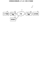
図1は、本実施例の映像配信システム1の一例を示す説明図である。図1に示す映像配信システム1は、カメラ装置2と、エンコーダ装置3と、デコーダ装置4と、端末装置5と、管理端末6と、IP(Internet Protocol)網7とを有する。カメラ装置2は、例えば、被写体を撮像して映像データ及び音声データを取得する。エンコーダ装置3は、映像データ及び音声データをエンコード化し、エンコード化された映像データ及び音声データをIPパケットに変換してIP網7に配信する。
FIG. 1 is an explanatory diagram illustrating an example of a video distribution system 1 according to the present embodiment. A video distribution system 1 shown in FIG. 1 includes a
デコーダ装置4は、IP網7から受信したIPパケットから映像データ及び音声データに分解し、映像データ及び音声データをデコード化する。端末装置5は、デコーダ装置4にてデコード化された映像データ及び音声データを表示出力する機能を内蔵した端末である。管理端末6は、映像配信システム1を保守管理する端末である。
The decoder device 4 decomposes the IP packet received from the
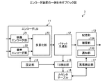
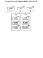
図2は、エンコーダ装置3の一例を示すブロック図である。図2に示すエンコーダ装置3は、エンコーダLSI(Large Scale Integration)11と、パケット生成部12と、配信部13と、設定部14と、TS検出部15と、カウンタテーブル16と、異常検出部17とを有する。
FIG. 2 is a block diagram illustrating an example of the encoder device 3. The encoder device 3 shown in FIG. 2 includes an encoder LSI (Large Scale Integration) 11, a
エンコーダLSI11は、映像エンコーダ部21と、音声エンコーダ部22と、多重化部23とを有する。映像エンコーダ部21は、カメラ装置2からの映像データをエンコード化して映像ES(Elementary Stream)を生成する。音声エンコーダ部22は、カメラ装置2からの音声データをエンコード化して音声ESを生成する。多重化部23は、映像ESを映像TS(Transport Stream)に変換すると共に、音声ESを音声TSに変換する。更に、多重化部23は、映像TS及び音声TS等を多重化する多重化データをTS単位で出力する。尚、TSは、188バイト固定長のパケットの連続でストリームとなる。TSパケットには、TSパケットを識別するPID(Packet Identifier)を含む。更に、多重化部23は、PAT(Program Association Table)TS及びPMT(Program Map Table)TSを生成する。尚、PATは、TS内のプログラムをPMTのPIDの一覧で格納したテーブル等の制御データである。PMTは、あるプログラムの画像や音声等の各PIDを格納したテーブル等の制御データである。
The
パケット生成部12は、音声TS及び映像TSの多重化データにIPヘッダを付加して多重化データをカプセル化したIPパケットを生成する。配信部13は、IPパケットをIP網7に配信する。多重化データは、例えば、188バイトのTSパケット単位で区分できる。各TSパケットは、4バイトのヘッダが付くため、データは184バイト単位で区分してTSパケット化できる。
The
設定部14は、映像エンコーダ21及び音声エンコーダ22のビットレート及びTSサイズを設定する。TS検出部15は、パケット生成部12内の多重化データ内のPIDを取得し、PIDに基づき、多重化データから映像TS、音声TS、PATTS及びPMTTSをカウントする。更に、TS検出部15は、映像TS、音声TS、PATTS及びPMTTSのカウント値をカウンタテーブル16内に記憶する。
The
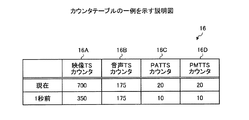
TS検出部15は、映像データの設定ビットレートが10Mbpsの場合、10Mbps/8=1250000bps/184=6793.4…となるため、すなわち映像TSの1秒間の予定値は約6793となる。尚、映像TSの予定値は図示せぬ記憶部に記憶しているものとする。また、TS検出部15は、音声データの設定ビットレートが256kbpsの場合、256kbps/8=32000bps/184=173.9…となるため、すなわち音声TSの1秒間の音声TSの予定値は約173となる。尚、音声TSの予定値は、図示せぬ記憶部に記憶しているものとする。
When the set bit rate of the video data is 10 Mbps, the
TS検出部15は、PATサイズが例えば、25バイトで、例えば、100m秒周期で出力するため、1PATサイズが184バイト以下、すなわち1TSパケット内に収まることになる。100m秒周期で1TSパケット到来するため、PATTSの1秒間の予定値は10となる。尚、PATTSの予定値は図示せぬ記憶部に記憶しているものとする。
The
TS検出部15は、PMTサイズが例えば、200バイトで、例えば、70m秒周期で出力するため、200/184=1.086…のため、1PMTにつき2TSパケットになる。TS検出部15は、1秒/70ms=14.2…、すなわち1秒間に14回PMTを出力するため、夫々2TSパケットとなり、PMTTSの1秒間の予定値は28となる。尚、PMTTSの予定値は図示せぬ記憶部に記憶しているものとする。
The
異常検出部17は、現在の映像TSのカウント値が1秒前の映像TSカウント値に1秒後の映像TSの予定値を加算した設定値未満であるか否かを判定し、現在の映像TSカウント値が設定値未満の場合、エンコード異常を検出する。異常検出部17は、現在の音声TSのカウント値が1秒前の音声TSカウント値に1秒後の音声TSの予定値を加算した設定値未満であるか否かを判定し、現在の音声TSカウント値が設定値未満の場合、エンコード異常を検出する。異常検出部17は、現在のPATTSカウント値が1秒前のPATTSカウント値に1秒後のPATTSの予定値を加算した設定値未満であるか否かを判定し、現在のPATTSカウント値が設定値未満の場合、エンコード異常を検出する。異常検出部17は、現在のPMTTSカウント値が1秒前のPMTTSカウント値に1秒後のPMTTSの予定値を加算した設定値未満であるか否かを判定し、現在のPMTTSカウント値が設定値未満の場合、エンコード異常を検出する。
The
配信部13は、破棄部13Aと、通知部13Bとを有する。破棄部13Aは、エンコード異常を検出した場合、多重化データのIPパケットを廃棄する。通知部13Bは、エンコード異常を検出した場合、異常警報を管理端末6に通知する。
The
図3は、カウンタテーブル16の一例を示す説明図である。カウンタテーブル16には、映像TSカウンタ16Aと、音声TSカウンタ16Bと、PATTSカウンタ16Cと、PMTTSカウンタ16Dとを有する。映像TSカウンタ16Aは、現在の映像TSカウント値と、1秒前の映像TSカウント値とを記憶する。音声TSカウンタ16Bは、現在の音声TSカウント値と、1秒前の音声TSカウント値とを記憶する。PATTSカウンタ16Cは、現在のPATTSカウント値と、1秒前のPATTSカウント値とを記憶する。PMTTSカウンタ16Dは、現在のPMTTSカウント値と、1秒前のPMTTSカウント値とを記憶する。
FIG. 3 is an explanatory diagram showing an example of the counter table 16. The counter table 16 includes a
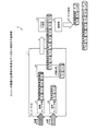
次に本実施例の映像配信システム1の動作について説明する。図4は、エンコーダ装置3の正常時の多重化データの一例を示す説明図である。映像エンコーダ部21は、映像データを映像ESに変換し、映像ESを多重化部23に入力する。音声エンコーダ部22は、音声データを音声ESに変換し、音声ESを多重化部23に入力する。多重化部23は、映像ESを映像TSに変換すると共に、音声ESを音声TSに変換し、映像TS及び音声TSを多重化し、多重化データをパケット生成部12に入力する。また、多重化部23は、所定周期毎にPMTTSやPATTSをパケット生成部12に入力する。パケット生成部12は、多重化データ内のTSパケットのヘッダ部分にIPヘッダを付加してIP網7に出力する。
Next, the operation of the video distribution system 1 of the present embodiment will be described. FIG. 4 is an explanatory diagram showing an example of multiplexed data when the encoder device 3 is normal. The
図5は、エンコーダ装置3の異常時の多重化データの一例を示す説明図である。映像エンコーダ部21は、映像データを映像ESに変換し、映像ESを多重化部23に入力する。音声エンコーダ部22は、異常が生じた場合、音声ESを多重化部23に入力できないことになる。その結果、多重化部23は、音声エンコーダ部22から設定レートの音声ESの入力がないため、本来到来すべき、音声ES分のヌルTSを出力することになる。多重化部23は、映像ESに対応する映像TS及びヌルTSの多重化データをパケット生成部12に入力すると共に、所定周期毎にPMTTSやPATTSをパケット生成部12に入力する。パケット生成部12は、多重化データ内のTSパケットのヘッダ部分にIPヘッダを付加してIP網7に出力する。
FIG. 5 is an explanatory diagram showing an example of multiplexed data when the encoder device 3 is abnormal. The
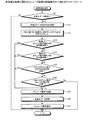
図6は、異常検出処理に関わるエンコーダ装置3の処理動作の一例を示すフローチャートである。TS検出部15は、多重化データを取得したか否かを判定する(ステップS11)。TS検出部15は、多重化データを取得した場合(ステップS11肯定)、多重化データ内のPIDを取得する(ステップS12)。TS検出部15は、PIDに基づき、多重化データから映像TS、音声TS、PATTS及びPMTTSをカウントし(ステップS13)、カウンタテーブル16内に記憶する。
FIG. 6 is a flowchart illustrating an example of the processing operation of the encoder device 3 related to the abnormality detection process. The
異常検出部17は、映像TSのカウント値が映像TSの設定値未満であるか否かを判定する(ステップS14)。尚、映像TSの設定値は、1秒前の映像TSカウント値に1秒分の映像TSの予定値を加算したカウント値である。
The
異常検出部17は、映像TSのカウント値が映像TSの設定値未満の場合(ステップS14肯定)、多重化データがエンコード異常と判断する(ステップS15)。そして、配信部13内の破棄部13Aは、多重化データを破棄する(ステップS16)。更に、配信部13内の通知部13Bは、多重化データを破棄した後、エンコード異常を管理端末6に通知し(ステップS17)、図6に示す処理動作を終了する。
If the count value of the video TS is less than the set value of the video TS (Yes at Step S14), the
異常検出部17は、映像TSのカウント値が映像TSの設定値未満でない場合(ステップS14否定)、音声TSのカウント値が音声TSの設定値未満であるか否かを判定する(ステップS18)。尚、音声TSの設定値は、1秒前の音声TSカウント値に1秒分の音声TSの予定値を加算したカウント値である。異常検出部17は、音声TSのカウント値が音声TSの設定値未満の場合(ステップS18肯定)、エンコード異常と判断すべく、ステップS15に移行する。
If the count value of the video TS is not less than the set value of the video TS (No at Step S14), the
異常検出部17は、音声TSのカウント値が音声TSの設定値未満でない場合(ステップS18否定)、PATTSのカウント値がPATTSの設定値未満であるか否かを判定する(ステップS19)。尚、PATTSの設定値は、1秒前のPATTSカウント値に1秒分のPATTSの予定値を加算したカウント値である。異常検出部17は、PATTSのカウント値がPATTSの設定値未満の場合(ステップS19肯定)、エンコード異常と判断すべく、ステップS15に移行する。
When the count value of the voice TS is not less than the set value of the voice TS (No at Step S18), the
異常検出部17は、PATTSのカウント値がPATTSの設定値未満でない場合(ステップS19否定)、PMTTSのカウント値がPMTTSの設定値未満であるか否かを判定する(ステップS20)。尚、PMTTSの設定値は、1秒前のPMTTSカウント値に1秒分のPMTTSの予定値を加算したカウント値である。異常検出部17は、PMTTSのカウント値がPMTTS設定値未満の場合(ステップS20肯定)、エンコード異常と判断すべく、ステップS15に移行する。異常検出部17は、PMTTSのカウント値がPMTTS設定値未満でない場合(ステップS20否定)、図6に示す処理動作を終了する。
If the PATTS count value is not less than the PATTS set value (No at Step S19), the
エンコーダ装置3は、映像TSのカウント値が映像TSの設定値未満の場合、多重化データがエンコード異常と判断する。その結果、エンコーダ装置3側の異常を識別できる。 When the count value of the video TS is less than the set value of the video TS, the encoder device 3 determines that the multiplexed data is abnormal in encoding. As a result, the abnormality on the encoder device 3 side can be identified.
エンコーダ装置3は、音声TSのカウント値が音声TSの設定値未満の場合、多重化データがエンコード異常と判断する。その結果、エンコーダ装置3側の異常を識別できる。 When the count value of the audio TS is less than the set value of the audio TS, the encoder device 3 determines that the multiplexed data is abnormal in encoding. As a result, the abnormality on the encoder device 3 side can be identified.
エンコーダ装置3は、PATTSのカウント値がPATTSの設定値未満の場合、多重化データがエンコード異常と判断する。その結果、エンコーダ装置3側の異常を識別できる。 When the count value of PATTS is less than the set value of PATTS, the encoder device 3 determines that the multiplexed data is abnormal in encoding. As a result, the abnormality on the encoder device 3 side can be identified.
エンコーダ装置3は、PMTTSのカウント値がPMTTSの設定値未満の場合、多重化データがエンコード異常と判断する。その結果、エンコーダ装置3側の異常を識別できる。 When the count value of PMTTS is less than the set value of PMTTS, encoder device 3 determines that the multiplexed data is abnormal in encoding. As a result, the abnormality on the encoder device 3 side can be identified.
本実施例のエンコーダ装置3は、取得した多重化データに含まれる各パケットに含まれるPIDに基づいて、多重化データから映像データに対応するパケット及び/又は音声データに対応するパケットを検出する。更に、エンコーダ装置3は、検出された映像データに対応するパケット及び/又は検出された音声データに対応するパケットの数が、エンコーダの設定に応じた数に対応するか否かに応じて、エンコーダの異常を検出する。その結果、エンコーダ装置3側の異常を識別できる。しかも、エンコーダ装置3側の異常が識別できるため、デコーダ装置4側の異常も識別できる。更に、エンコーダ装置3は、例えば、エンコードの異常で映像TSや音声TSが出力されなかった場合に、デコーダ装置4側でなくても、エンコード異常を迅速に識別できる。 The encoder device 3 according to the present embodiment detects a packet corresponding to video data and / or a packet corresponding to audio data from the multiplexed data based on the PID included in each packet included in the acquired multiplexed data. Further, the encoder device 3 determines whether the number of packets corresponding to the detected video data and / or the number of packets corresponding to the detected audio data corresponds to the number according to the setting of the encoder. Detect abnormalities. As a result, the abnormality on the encoder device 3 side can be identified. In addition, since the abnormality on the encoder device 3 side can be identified, the abnormality on the decoder device 4 side can also be identified. Further, for example, when the video TS and the audio TS are not output due to an encoding abnormality, the encoder apparatus 3 can quickly identify the encoding abnormality even if it is not on the decoder apparatus 4 side.
エンコーダ装置3は、パケットの数としてビットレートとTSサイズから求めたカウント値を用いる。その結果、エンコーダの異常のパケット数の比較判定が簡易になる。 The encoder device 3 uses a count value obtained from the bit rate and TS size as the number of packets. As a result, the comparison determination of the number of abnormal packets of the encoder is simplified.
エンコーダ装置3は、エンコーダの異常を検出した場合、エンコーダから取得した多重化データを破棄する。その結果、対向装置に対するエンコーダ異常の多重化データの出力を抑制することで通信資源の節減が図れる。 When the encoder device 3 detects an encoder abnormality, the encoder device 3 discards the multiplexed data acquired from the encoder. As a result, communication resources can be saved by suppressing the output of multiplexed data of encoder abnormality to the opposite device.
エンコーダ装置3は、エンコーダの異常を検出した場合、エンコーダが故障している旨を管理端末6に通知する。その結果、保守者は、エンコーダ装置の故障を速やかに認識できる。 When the encoder device 3 detects an abnormality in the encoder, the encoder device 3 notifies the management terminal 6 that the encoder has failed. As a result, the maintenance person can quickly recognize the failure of the encoder device.
尚、上記実施例では、エンコーダ異常を検出する際に使用するデータとして、例えば、映像TS、音声TS、PATTS及びPMTTSを例示したが、これらに限定されるものではなく、例えば、PCR(Program Clock Reference)等を使用しても良い。この場合、TS検出部15は、PCRサイズが例えば、12バイトで、例えば、30m秒周期で出力するため、1PCRサイズが184バイト以下、1TSパケット内に収まる。TS検出部15は、1秒/30ms=33.3…、すなわち1秒間に33回PCRが出力するため、夫々1TSパケットとなり、PCRTSの予定値は33となる。尚、PCRTSの予定値は図示せぬ記憶部に記憶しているものとする。また、PAT、PMT及びPCRのサイズ及び周期を例示したが、これらに限定されるものではなく、適宜設定変更可能である。
In the above-described embodiment, the video TS, the audio TS, the PATTS, and the PMTTS are exemplified as the data used when detecting the encoder abnormality. However, the present invention is not limited to these. For example, PCR (Program Clock Reference) or the like may be used. In this case, since the
また、図示した各部の各構成要素は、必ずしも物理的に図示の如く構成されていることを要しない。すなわち、各部の分散・統合の具体的形態は図示のものに限られず、その全部又は一部を、各種の負荷や使用状況等に応じて、任意の単位で機能的又は物理的に分散・統合して構成することができる。 In addition, each component of each part illustrated does not necessarily need to be physically configured as illustrated. In other words, the specific form of distribution / integration of each part is not limited to the one shown in the figure, and all or a part thereof may be functionally or physically distributed / integrated in arbitrary units according to various loads and usage conditions. Can be configured.
更に、各装置で行われる各種処理機能は、CPU(Central Processing Unit)(又はMPU(Micro Processing Unit)、MCU(Micro Controller Unit)等のマイクロ・コンピュータ)上で、その全部又は任意の一部を実行するようにしても良い。また、各種処理機能は、CPU(又はMPU、MCU等のマイクロ・コンピュータ)で解析実行するプログラム上、又はワイヤードロジックによるハードウェア上で、その全部又は任意の一部を実行するようにしても良いことは言うまでもない。 Furthermore, various processing functions performed in each device are performed on a CPU (Central Processing Unit) (or a microcomputer such as an MPU (Micro Processing Unit), MCU (Micro Controller Unit), etc.) in whole or in part. You may make it perform. Various processing functions may be executed entirely or arbitrarily on a program that is analyzed and executed by a CPU (or a microcomputer such as an MPU or MCU) or hardware based on wired logic. Needless to say.
ところで、本実施例で説明した各種の処理は、予め用意されたプログラムを情報処理装置内のCPU等のプロセッサで実行させることによって実現できる。そこで、以下では、上記実施例と同様の機能を有するプログラムを実行する情報処理装置の一例を説明する。図7は、異常検出プログラムを実行する情報処理装置の一例を示す説明図である。 By the way, the various processes described in the present embodiment can be realized by causing a program prepared in advance to be executed by a processor such as a CPU in the information processing apparatus. Therefore, in the following, an example of an information processing apparatus that executes a program having the same function as in the above embodiment will be described. FIG. 7 is an explanatory diagram illustrating an example of an information processing apparatus that executes an abnormality detection program.
図7に示す異常検出プログラムを実行する情報処理装置100は、通信部110と、HDD(Hard Disk Drive)120と、RAM(Random Access Memory)130と、ROM(Read Only Memory)140と、CPU(Central Processing Unit)150とを有する。
The information processing apparatus 100 that executes the abnormality detection program illustrated in FIG. 7 includes a
そして、ROM140には、上記実施例と同様の機能を発揮する異常検出プログラムが予め記憶されている。ROM140は、異常検出プログラムとして取得プログラム140A、第1の検出プログラム140B及び第2の検出プログラム140Cが記憶されている。尚、ROM140ではなく、HDD120でコンピュータ読取可能な記録媒体に異常検出プログラムが記録されていても良い。また、記録媒体としては、例えば、CD−ROM、DVDディスク、USBメモリ等の可搬型記録媒体、フラッシュメモリ等の半導体メモリ等でも良い。
The ROM 140 stores in advance an abnormality detection program that exhibits the same function as in the above embodiment. The ROM 140 stores an
そして、CPU150は、取得プログラム140AをROM140から読み出して取得プロセス150Aとして機能する。CPU150は、第1の検出プログラム140BをROM140から読み出して第1の検出プロセス150Bとして機能する。CPU150は、第2の検出プログラム140CをROM140から読み出して第2の検出プロセス150Cとして機能する。
Then, the CPU 150 reads the
CPU150は、音声及び/又は動画にエンコード処理を施して得られたエンコードデータを多重化して出力するエンコーダから多重化データを取得する。CPU150は、取得した前記多重化データに含まれる各パケットに含まれるパケット識別子に基づいて、前記多重化データから動画データに対応するパケット及び/又は音声データに対応するパケットを検出する。CPU150は、検出された動画データに対応するパケット及び/又は検出された音声データに対応するパケットの数が、前記エンコーダの設定に応じた数に対応するか否かに応じて、前記エンコーダの異常を検出する。その結果、エンコーダの異常を検出できる。 The CPU 150 acquires multiplexed data from an encoder that multiplexes and outputs encoded data obtained by performing encoding processing on audio and / or moving images. The CPU 150 detects a packet corresponding to moving image data and / or a packet corresponding to audio data from the multiplexed data based on a packet identifier included in each packet included in the acquired multiplexed data. The CPU 150 determines whether there is an abnormality in the encoder depending on whether the number of packets corresponding to the detected moving image data and / or the number of packets corresponding to the detected audio data corresponds to the number according to the setting of the encoder. Is detected. As a result, an encoder abnormality can be detected.
1 映像配信システム
3 エンコーダ装置
11 エンコーダLSI
12 パケット生成部
13 配信部
13A 破棄部
13B 通知部
14 設定部
15 TS検出部
17 異常検出部
21 映像エンコーダ部
22 音声エンコーダ部
23 多重化部
1 Video Distribution System 3
12
Claims (8)
取得した前記多重化データに含まれる各パケットに含まれるパケット識別子に基づいて、前記多重化データから動画データに対応するパケット及び/又は音声データに対応するパケットを検出し、
検出された動画データに対応するパケット及び/又は検出された音声データに対応するパケットの数が、前記エンコーダの設定に応じた数に対応するか否かに応じて、前記エンコーダの異常を検出する、
処理をコンピュータに実行させることを特徴とする異常検出プログラム。 Obtaining multiplexed data from an encoder that multiplexes and outputs encoded data obtained by encoding audio and / or video,
Based on a packet identifier included in each packet included in the acquired multiplexed data, a packet corresponding to moving image data and / or a packet corresponding to audio data is detected from the multiplexed data,
The abnormality of the encoder is detected according to whether or not the number of packets corresponding to the detected moving image data and / or the number of packets corresponding to the detected audio data corresponds to the number corresponding to the setting of the encoder. ,
An abnormality detection program for causing a computer to execute processing.
ことを特徴とする請求項1に記載の異常検出プログラム。 The multiplexed data is transmitted to a receiving device that receives and decodes the multiplexed data.
The abnormality detection program according to claim 1.
取得した前記多重化データに含まれる各パケットに含まれるパケット識別子に基づいて、前記多重化データから制御データに対応するパケットを検出し、
前記エンコーダの異常を検出する処理として、
検出された制御データに対応するパケットの数が、前記エンコーダの設定に応じた数に対応するか否かに応じて、前記エンコーダの異常を検出する、
処理をコンピュータに実行させることを特徴とする請求項1乃至5のいずれか一項に記載の異常検出プログラム。 As a process for detecting the packet,
Based on a packet identifier included in each packet included in the acquired multiplexed data, a packet corresponding to control data is detected from the multiplexed data;
As a process for detecting an abnormality of the encoder,
Detecting an abnormality of the encoder according to whether the number of packets corresponding to the detected control data corresponds to the number according to the setting of the encoder;
The abnormality detection program according to claim 1, which causes a computer to execute processing.
取得した前記多重化データに含まれる各パケットに含まれるパケット識別子に基づいて、前記多重化データから動画データに対応するパケット及び/又は音声データに対応するパケットを検出し、
検出された動画データに対応するパケット及び/又は検出された音声データに対応するパケットの数が、前記エンコーダの設定に応じた数に対応するか否かに応じて、前記エンコーダの異常を検出する、
処理をコンピュータが実行することを特徴とする異常検出方法。 Obtaining multiplexed data from an encoder that multiplexes and outputs encoded data obtained by encoding audio and / or video,
Based on a packet identifier included in each packet included in the acquired multiplexed data, a packet corresponding to moving image data and / or a packet corresponding to audio data is detected from the multiplexed data,
The abnormality of the encoder is detected according to whether or not the number of packets corresponding to the detected moving image data and / or the number of packets corresponding to the detected audio data corresponds to the number corresponding to the setting of the encoder. ,
An abnormality detection method characterized in that the processing is executed by a computer.
取得した前記多重化データに含まれる各パケットに含まれるパケット識別子に基づいて、前記多重化データから動画データに対応するパケット及び/又は音声データに対応するパケットを検出し、検出された動画データに対応するパケット及び/又は検出された音声データに対応するパケットの数が、前記エンコーダの設定に応じた数に対応するか否かに応じて、前記エンコーダの異常を検出する検出部と、
を有することを特徴とする異常検出装置。 An acquisition unit that acquires multiplexed data from an encoder that multiplexes and outputs encoded data obtained by performing encoding processing on audio and / or moving images;
Based on a packet identifier included in each packet included in the acquired multiplexed data, a packet corresponding to moving image data and / or a packet corresponding to audio data is detected from the multiplexed data, and the detected moving image data A detection unit for detecting an abnormality of the encoder according to whether or not the number of packets corresponding to the corresponding packet and / or detected audio data corresponds to the number according to the setting of the encoder;
An abnormality detection apparatus comprising:
Priority Applications (3)
| Application Number | Priority Date | Filing Date | Title |
|---|---|---|---|
| JP2017063838A JP2018166313A (en) | 2017-03-28 | 2017-03-28 | Abnormality detection program, abnormality detection device and abnormality detection method |
| EP18156912.0A EP3383050A1 (en) | 2017-03-28 | 2018-02-15 | Program, apparatus and method for abnormality detection of an encoder multimedia |
| US15/899,433 US20180288444A1 (en) | 2017-03-28 | 2018-02-20 | Abnormality detection program, abnormality detection apparatus and abnormality detection method |
Applications Claiming Priority (1)
| Application Number | Priority Date | Filing Date | Title |
|---|---|---|---|
| JP2017063838A JP2018166313A (en) | 2017-03-28 | 2017-03-28 | Abnormality detection program, abnormality detection device and abnormality detection method |
Publications (1)
| Publication Number | Publication Date |
|---|---|
| JP2018166313A true JP2018166313A (en) | 2018-10-25 |
Family
ID=61226467
Family Applications (1)
| Application Number | Title | Priority Date | Filing Date |
|---|---|---|---|
| JP2017063838A Pending JP2018166313A (en) | 2017-03-28 | 2017-03-28 | Abnormality detection program, abnormality detection device and abnormality detection method |
Country Status (3)
| Country | Link |
|---|---|
| US (1) | US20180288444A1 (en) |
| EP (1) | EP3383050A1 (en) |
| JP (1) | JP2018166313A (en) |
Families Citing this family (1)
| Publication number | Priority date | Publication date | Assignee | Title |
|---|---|---|---|---|
| CN114070828B (en) * | 2022-01-17 | 2022-05-17 | 中央广播电视总台 | Program stream fault detection method and device, computer equipment and readable storage medium |
Family Cites Families (8)
| Publication number | Priority date | Publication date | Assignee | Title |
|---|---|---|---|---|
| SG124307A1 (en) * | 2005-01-20 | 2006-08-30 | St Microelectronics Asia | Method and system for lost packet concealment in high quality audio streaming applications |
| JP2006262406A (en) | 2005-03-18 | 2006-09-28 | Victor Co Of Japan Ltd | Encoded data generator |
| US7817535B2 (en) * | 2005-11-02 | 2010-10-19 | Cisco Technology, Inc. | Method of fault tolerance and synchronous failover for broadcast video across the network |
| JP2007166129A (en) | 2005-12-13 | 2007-06-28 | Victor Co Of Japan Ltd | Encoded data generating device |
| WO2009023183A1 (en) * | 2007-08-13 | 2009-02-19 | Thomson Licensing | Error detection and recovery in a digital multimedia receiver system |
| JP2009164880A (en) * | 2008-01-07 | 2009-07-23 | Mitsubishi Electric Corp | Transcoder and receiver |
| JP2011114444A (en) * | 2009-11-25 | 2011-06-09 | Fujitsu Ltd | Information processor, method of generating information, and program |
| US8504713B2 (en) * | 2010-05-28 | 2013-08-06 | Allot Communications Ltd. | Adaptive progressive download |
-
2017
- 2017-03-28 JP JP2017063838A patent/JP2018166313A/en active Pending
-
2018
- 2018-02-15 EP EP18156912.0A patent/EP3383050A1/en not_active Withdrawn
- 2018-02-20 US US15/899,433 patent/US20180288444A1/en not_active Abandoned
Also Published As
| Publication number | Publication date |
|---|---|
| US20180288444A1 (en) | 2018-10-04 |
| EP3383050A1 (en) | 2018-10-03 |
Similar Documents
| Publication | Publication Date | Title |
|---|---|---|
| US20110234825A1 (en) | Accelerometer / gyro-facilitated video stabilization | |
| US10164853B2 (en) | Real-time anomaly mitigation in a cloud-based video streaming system | |
| CN106817585B (en) | Video coding method, electronic equipment and system using long-term reference frame | |
| AU2018292286B2 (en) | Techniques for detecting media playback errors | |
| US8831001B2 (en) | Device, system, and method of voice-over-IP communication | |
| US20140362864A1 (en) | Transmitting apparatus, transmitting method, and storage medium | |
| KR20180123847A (en) | Image Processing Device and Image Processing Method Performing Slice-based Compression | |
| CN106034088A (en) | Packet loss control method and apparatus thereof | |
| US9736340B2 (en) | Decoder and decoding method for audio video stream synchronization | |
| JP6365253B2 (en) | VIDEO DATA PROCESSING DEVICE, VIDEO DATA PROCESSING PROGRAM, AND VIDEO DATA PROCESSING METHOD | |
| JP2018166313A (en) | Abnormality detection program, abnormality detection device and abnormality detection method | |
| CN110601971B (en) | Data transmission method and device, electronic equipment and storage medium | |
| CN110557226A (en) | Audio transmission method and device | |
| JP4682134B2 (en) | Detection of weak or invalid signals in the data stream | |
| WO2017076325A1 (en) | Code stream playing method and apparatus | |
| JP5939884B2 (en) | Error correction coding device | |
| US8875202B2 (en) | Processing path signatures for processing elements in encoded video | |
| WO2017061280A1 (en) | Reception device and method | |
| JP6883214B2 (en) | Receiver and method, transmitter and method | |
| JP4373283B2 (en) | Video / audio decoding method, video / audio decoding apparatus, video / audio decoding program, and computer-readable recording medium recording the program | |
| US10772010B2 (en) | Transmission apparatus, method for controlling transmission, and recording medium | |
| JP7638191B2 (en) | Imaging device, image analysis system, encoding method, and encoding program | |
| JP2013153494A5 (en) | ||
| WO2019082861A1 (en) | Transmission device, reception device, and video distribution method | |
| CN118842927A (en) | Input stream fast switching method, device and computer readable storage medium |
Legal Events
| Date | Code | Title | Description |
|---|---|---|---|
| A621 | Written request for application examination |
Free format text: JAPANESE INTERMEDIATE CODE: A621 Effective date: 20191212 |
|
| A977 | Report on retrieval |
Free format text: JAPANESE INTERMEDIATE CODE: A971007 Effective date: 20200924 |
|
| A131 | Notification of reasons for refusal |
Free format text: JAPANESE INTERMEDIATE CODE: A131 Effective date: 20201104 |
|
| A02 | Decision of refusal |
Free format text: JAPANESE INTERMEDIATE CODE: A02 Effective date: 20210608 |