JP2009164880A - Transcoder and receiver - Google Patents
Transcoder and receiver Download PDFInfo
- Publication number
- JP2009164880A JP2009164880A JP2008000502A JP2008000502A JP2009164880A JP 2009164880 A JP2009164880 A JP 2009164880A JP 2008000502 A JP2008000502 A JP 2008000502A JP 2008000502 A JP2008000502 A JP 2008000502A JP 2009164880 A JP2009164880 A JP 2009164880A
- Authority
- JP
- Japan
- Prior art keywords
- error
- unit
- information
- transcoder
- specifying information
- Prior art date
- Legal status (The legal status is an assumption and is not a legal conclusion. Google has not performed a legal analysis and makes no representation as to the accuracy of the status listed.)
- Pending
Links
Images


Classifications
-
- H—ELECTRICITY
- H04—ELECTRIC COMMUNICATION TECHNIQUE
- H04N—PICTORIAL COMMUNICATION, e.g. TELEVISION
- H04N21/00—Selective content distribution, e.g. interactive television or video on demand [VOD]
- H04N21/20—Servers specifically adapted for the distribution of content, e.g. VOD servers; Operations thereof
- H04N21/23—Processing of content or additional data; Elementary server operations; Server middleware
- H04N21/236—Assembling of a multiplex stream, e.g. transport stream, by combining a video stream with other content or additional data, e.g. inserting a URL [Uniform Resource Locator] into a video stream, multiplexing software data into a video stream; Remultiplexing of multiplex streams; Insertion of stuffing bits into the multiplex stream, e.g. to obtain a constant bit-rate; Assembling of a packetised elementary stream
- H04N21/23608—Remultiplexing multiplex streams, e.g. involving modifying time stamps or remapping the packet identifiers
-
- H—ELECTRICITY
- H04—ELECTRIC COMMUNICATION TECHNIQUE
- H04N—PICTORIAL COMMUNICATION, e.g. TELEVISION
- H04N19/00—Methods or arrangements for coding, decoding, compressing or decompressing digital video signals
- H04N19/10—Methods or arrangements for coding, decoding, compressing or decompressing digital video signals using adaptive coding
- H04N19/169—Methods or arrangements for coding, decoding, compressing or decompressing digital video signals using adaptive coding characterised by the coding unit, i.e. the structural portion or semantic portion of the video signal being the object or the subject of the adaptive coding
- H04N19/17—Methods or arrangements for coding, decoding, compressing or decompressing digital video signals using adaptive coding characterised by the coding unit, i.e. the structural portion or semantic portion of the video signal being the object or the subject of the adaptive coding the unit being an image region, e.g. an object
- H04N19/174—Methods or arrangements for coding, decoding, compressing or decompressing digital video signals using adaptive coding characterised by the coding unit, i.e. the structural portion or semantic portion of the video signal being the object or the subject of the adaptive coding the unit being an image region, e.g. an object the region being a slice, e.g. a line of blocks or a group of blocks
-
- H—ELECTRICITY
- H04—ELECTRIC COMMUNICATION TECHNIQUE
- H04N—PICTORIAL COMMUNICATION, e.g. TELEVISION
- H04N19/00—Methods or arrangements for coding, decoding, compressing or decompressing digital video signals
- H04N19/40—Methods or arrangements for coding, decoding, compressing or decompressing digital video signals using video transcoding, i.e. partial or full decoding of a coded input stream followed by re-encoding of the decoded output stream
-
- H—ELECTRICITY
- H04—ELECTRIC COMMUNICATION TECHNIQUE
- H04N—PICTORIAL COMMUNICATION, e.g. TELEVISION
- H04N19/00—Methods or arrangements for coding, decoding, compressing or decompressing digital video signals
- H04N19/60—Methods or arrangements for coding, decoding, compressing or decompressing digital video signals using transform coding
- H04N19/61—Methods or arrangements for coding, decoding, compressing or decompressing digital video signals using transform coding in combination with predictive coding
-
- H—ELECTRICITY
- H04—ELECTRIC COMMUNICATION TECHNIQUE
- H04N—PICTORIAL COMMUNICATION, e.g. TELEVISION
- H04N19/00—Methods or arrangements for coding, decoding, compressing or decompressing digital video signals
- H04N19/70—Methods or arrangements for coding, decoding, compressing or decompressing digital video signals characterised by syntax aspects related to video coding, e.g. related to compression standards
-
- H—ELECTRICITY
- H04—ELECTRIC COMMUNICATION TECHNIQUE
- H04N—PICTORIAL COMMUNICATION, e.g. TELEVISION
- H04N19/00—Methods or arrangements for coding, decoding, compressing or decompressing digital video signals
- H04N19/85—Methods or arrangements for coding, decoding, compressing or decompressing digital video signals using pre-processing or post-processing specially adapted for video compression
- H04N19/89—Methods or arrangements for coding, decoding, compressing or decompressing digital video signals using pre-processing or post-processing specially adapted for video compression involving methods or arrangements for detection of transmission errors at the decoder
-
- H—ELECTRICITY
- H04—ELECTRIC COMMUNICATION TECHNIQUE
- H04N—PICTORIAL COMMUNICATION, e.g. TELEVISION
- H04N21/00—Selective content distribution, e.g. interactive television or video on demand [VOD]
- H04N21/20—Servers specifically adapted for the distribution of content, e.g. VOD servers; Operations thereof
- H04N21/23—Processing of content or additional data; Elementary server operations; Server middleware
- H04N21/234—Processing of video elementary streams, e.g. splicing of video streams, manipulating MPEG-4 scene graphs
- H04N21/2343—Processing of video elementary streams, e.g. splicing of video streams, manipulating MPEG-4 scene graphs involving reformatting operations of video signals for distribution or compliance with end-user requests or end-user device requirements
- H04N21/234309—Processing of video elementary streams, e.g. splicing of video streams, manipulating MPEG-4 scene graphs involving reformatting operations of video signals for distribution or compliance with end-user requests or end-user device requirements by transcoding between formats or standards, e.g. from MPEG-2 to MPEG-4 or from Quicktime to Realvideo
-
- H—ELECTRICITY
- H04—ELECTRIC COMMUNICATION TECHNIQUE
- H04N—PICTORIAL COMMUNICATION, e.g. TELEVISION
- H04N21/00—Selective content distribution, e.g. interactive television or video on demand [VOD]
- H04N21/20—Servers specifically adapted for the distribution of content, e.g. VOD servers; Operations thereof
- H04N21/23—Processing of content or additional data; Elementary server operations; Server middleware
- H04N21/238—Interfacing the downstream path of the transmission network, e.g. adapting the transmission rate of a video stream to network bandwidth; Processing of multiplex streams
- H04N21/2381—Adapting the multiplex stream to a specific network, e.g. an Internet Protocol [IP] network
-
- H—ELECTRICITY
- H04—ELECTRIC COMMUNICATION TECHNIQUE
- H04N—PICTORIAL COMMUNICATION, e.g. TELEVISION
- H04N21/00—Selective content distribution, e.g. interactive television or video on demand [VOD]
- H04N21/20—Servers specifically adapted for the distribution of content, e.g. VOD servers; Operations thereof
- H04N21/23—Processing of content or additional data; Elementary server operations; Server middleware
- H04N21/24—Monitoring of processes or resources, e.g. monitoring of server load, available bandwidth, upstream requests
- H04N21/2404—Monitoring of server processing errors or hardware failure
-
- H—ELECTRICITY
- H04—ELECTRIC COMMUNICATION TECHNIQUE
- H04N—PICTORIAL COMMUNICATION, e.g. TELEVISION
- H04N21/00—Selective content distribution, e.g. interactive television or video on demand [VOD]
- H04N21/60—Network structure or processes for video distribution between server and client or between remote clients; Control signalling between clients, server and network components; Transmission of management data between server and client, e.g. sending from server to client commands for recording incoming content stream; Communication details between server and client
- H04N21/63—Control signaling related to video distribution between client, server and network components; Network processes for video distribution between server and clients or between remote clients, e.g. transmitting basic layer and enhancement layers over different transmission paths, setting up a peer-to-peer communication via Internet between remote STB's; Communication protocols; Addressing
- H04N21/637—Control signals issued by the client directed to the server or network components
- H04N21/6377—Control signals issued by the client directed to the server or network components directed to server
- H04N21/6379—Control signals issued by the client directed to the server or network components directed to server directed to encoder, e.g. for requesting a lower encoding rate
Abstract
Description
この発明は、一方のネットワークから受信したメディアストリームをトランスコーディングして他方のネットワークへ送出するトランスコーダ及びこのトランスコーダからのメディアストリームを受信する受信機に関するものである。 The present invention relates to a transcoder that transcodes a media stream received from one network and sends the media stream to the other network, and a receiver that receives the media stream from the transcoder.
従来のトランスコーダは、受信したデータにエラーやロスが発生した場合でも、エラーが発生した状態のビットストリームを復号し、異なる符号化方式もしくは異なるパラメータで再符号化してネットワークに送出していた。例えば、特許文献1に開示されているトランスコーダは、受信した映像データを一旦復号し、異なる符号化パラメータで符号化するトランスコーダである。この場合、受信したデータをベースバンドのビデオデータに復号した時点で受信ストリームにエラーが存在する場合には画像に乱れが発生する。トランスコーダは、この乱れたビデオデータを再符号化して受信機に対して送出する。このストリームを再生する受信機では、ビデオストリーム自体としてはエラーは存在していないが、復号すると乱れた映像が表示されることとなる。
A conventional transcoder decodes a bitstream in which an error has occurred even if an error or loss occurs in received data, re-encodes it with a different encoding method or different parameters, and sends it to the network. For example, the transcoder disclosed in
例えば、受信機の設定として、映像データにエラーがあり、映像に乱れが発生するような場合には映像を表示せずに黒画面を表示し、次のIピクチャが到着すると再度映像を再生開始する様な設定になっている受信機の場合でも、受信する映像データにネットワークエラーはなく、シンタクスも正常なため、乱れた映像を表示することになる。
また乱れた画面を表示し続けている場合でも、エラーが発生しているわけではないため利用者に対して画面の乱れに関するメッセージを表示することはできない。
For example, if there is an error in the video data and the video is disturbed as a setting of the receiver, a black screen is displayed without displaying the video, and playback of the video starts again when the next I picture arrives Even in the case of a receiver that is set to do so, there is no network error in the received video data, and the syntax is normal, so that a distorted video is displayed.
Even if the screen is disturbed, it is not possible to display a message about the screen disruption to the user because an error has not occurred.
また、例えば特許文献2に示されているトランスコーダは、受信したメディアデータにエラーがあった場合には、端末にて誤り隠蔽処理を行うためのデータを送信している。具体的にはエラーがあった箇所に隠蔽処理を行うためのメディア符号化データをメディアデータ中に挿入して送信している。この場合に、挿入した隠蔽用のデータが利用者に違和感なく再生された場合は効果があるが、利用者がエラーの発生を認識できる再生状態になった場合でも、受信機が受信しているストリーム自体は正しいため、再生映像の乱れを検知することはできない。このため、映像に乱れが発生するような場合には映像を表示せずに黒画面を表示し、次のIピクチャが到着すると再度映像を再生開始する様な設定になっている受信機でも、乱れた映像を表示することとなる。また同様に乱れた映像が継続的に続いた場合でも、利用者に対してエラーが発生していることを通知するメッセージも表示することができなかった。
For example, the transcoder disclosed in
従来のトランスコーダでは、メディアデータを受信時にエラーが発生した場合でも、トランスコーディング後のメディアデータにはエラーは発生していないため、それを受信した受信機が映像や音声の乱れが発生していることを検知できないという問題があった。 In the conventional transcoder, even if an error occurs when receiving media data, no error has occurred in the media data after transcoding. There was a problem that it could not be detected.
この発明は上記のような課題を解決するためになされたもので、受信側でメディアデータに異常があることを検知することが可能となり、利用者へのメッセージの表示や、乱れたメディアを別画像に置き換える等の対応を行うことが可能となるトランスコーダを得ることを目的とする。 The present invention has been made to solve the above-mentioned problems, and it is possible to detect that there is an abnormality in the media data on the receiving side, and to display a message to the user and to separate the disturbed media. An object of the present invention is to obtain a transcoder capable of performing correspondence such as replacement with an image.
この発明に係るトランスコーダは、受信したメディアストリームにエラーが発生していることを検知し、その発生位置を特定するエラー抽出部と、受信時のエラーが発生したメディアストリームに対応するトランスコーディング後のアクセスユニットに、トランスコーディング前にエラーが発生していたことを通知するためのエラー特定情報を付加するエラー特定情報付加部とを備えたものである。 The transcoder according to the present invention detects that an error has occurred in the received media stream, specifies an error generation unit, and after transcoding corresponding to the media stream in which the error has occurred during reception. The access unit includes an error specifying information adding unit for adding error specifying information for notifying that an error has occurred before transcoding.
この発明のトランスコーダは、受信時のエラーが発生したメディアストリームに対応するトランスコーディング後のアクセスユニットに、トランスコーディング前にエラーが発生していたことを通知するためのエラー特定情報を付加するようにしたので、受信側でメディアデータに異常があることを検知することが可能となり、利用者へのメッセージの表示や、乱れたメディアを別画像に置き換える等の対応を行うことが可能となる。 The transcoder of the present invention adds error specifying information for notifying that an error has occurred before transcoding to an access unit after transcoding corresponding to a media stream in which an error has occurred during reception. Therefore, it is possible to detect that there is an abnormality in the media data on the receiving side, and it is possible to take measures such as displaying a message to the user and replacing the disturbed media with another image.
実施の形態1.
図1は、この発明の実施の形態1によるトランスコーダを示す構成図である。
実施の形態1におけるトランスコーダ1は、一方のネットワークであるIPネットワーク(A)2と、他方のネットワークであるIPネットワーク(B)3に接続されたトランスコーダを想定している。ここで、IPネットワーク(A)2とIPネットワーク(B)3は同一のネットワークであっても別のネットワークであって良い。トランスコーダ1が送受信する映像ストリームデータはMPEG−2TS(Transport Stream)パケットをRTP(Real-time Transport Protocol)パケット(RFC3550)のペイロードに格納したストリームであり、ペイロードへの格納方式は例えばRFC2250に記載のMPEG−2TSをRTPに格納する方式を用いる。トランスコーダ1は受信したMPEG−2ビデオ符号化ストリームを、H.264ビデオ符号化ストリームに変換するトランスコーダとする。また、本実施の形態では、フレームレートや解像度はトランスコーディング前後で変更無い設定で説明を行うが、特に本条件に限定したものではない。
FIG. 1 is a block diagram showing a transcoder according to
The
図1に示すトランスコーダ1は、受信部4、パケット分離部5、メディア分離部6、エラー抽出部7、符号化データ入力部8、映像復号化部9、映像符号化部10、符号化データ出力部11、メディア多重部12、エラー特定情報付加部13、パケット生成部14、送信部15、受信用情報16、送信用情報17を備えている。
受信部4は、受信用情報16に記載されているソースアドレスとポート番号を用いて、ネットワーク(A)2からパケットを受信し、IP(Internet Protocol)及びUDP(User Datagram Protocol)レイヤの処理を行う機能部である。受信部4において、UDPレイヤで誤りが検出された場合はそのパケットは破棄され、以降の処理ではパケットロスと同様の扱いとなる。受信部4はUDPのペイロードに格納されているRTPパケットを抽出し、パケット分離部5に転送する。パケット分離部5は、RTPパケットを受信すると、IPネットワークのジッタ吸収のため、一定量のバッファリングを行う。ここで、パケットの入れ替わりがあれば、RTPシーケンス番号を用いてその入れ替わりを修正する。バッファリングが終了すると、RTPヘッダを削除し、RTPのペイロードに格納されているTSストリームを抽出する。抽出されたTSストリームはメディア分離部6へ転送される。
A
The
メディア分離部6では、受信したTSパケットを各メディア毎に分離する。分離する際にメディア分離部6はエラー抽出部7をTSパケット毎に呼び出し、エラーが発生しているかのチェックを行う。本実施の形態では、TSのエラーはパケットロスの形態となるため、エラー抽出部7は各TSのヘッダ部に存在するPID(パケットID)とcontinuity_counterをチェックし、同一PIDのcontinuity_counterの連続性をチェックする。エラー抽出部7は、連続性が損なわれているPIDのTSがあった場合には、その部分にパケットロスが発生していると判断し、そのTSの前に同一PIDのTSにパケットロスが発生していることをメディア分離部6に返す。エラー抽出部7よりエラー抽出結果を受けたメディア分離部6はTSをメディア毎に分離し、PES(Packetized Elementary Stream)パケットを生成し、ビデオストリームの場合は、更に、PESパケットからMPEG−2ビデオのES(Elementary Stream)を抽出する。また、ビデオESをピクチャ毎に区切り、各ピクチャに対してピクチャIDを設定する。メディア分離部6はエラー抽出部7からエラー発生を通知されたTSのペイロードのデータが所属するピクチャに対して、エラー情報としてパケットロスが発生している位置を示すデータを生成する。図2にエラー情報101の詳細について示す。
The
図2に示すように、エラー情報101は、MPEG−2ビデオESデータ102の各ピクチャ毎に設定される。即ち、エラー情報101には、パケットロスが発生したピクチャIDと、パケットロスの位置情報が格納されている。
メディア分離部6は、PES毎にMPEG−2ビデオESデータ102とエラー情報101、PTS(Presentation Time Stamp)、DTS(Decoding Time Stamp)を符号化データ入力部8に転送する。また、映像以外のデータについてはメディア多重部12にエラー情報101と共にPES及びセクションの状態で転送する。
As shown in FIG. 2, the
The
図3は、メディア分離部6とエラー抽出部7によるパケットロスを検知する処理の詳細を示すフローチャートである。
RTPのペイロードには複数のTSパケットが格納されているため、エラー抽出部7は、先頭のTSパケットを取り出す。対象のTSパケットのcontinuity_counterをチェックし、同一PIDのTSパケットの前回値と比較し(ステップST1)、TSパケットのロスが有るかを判定する(ステップST2)。ステップST2において、TSパケットにロスが発見された場合は該当TSの直前にエラーが発生していることを記憶しておく(ステップST3)。次に、該当PIDのcontinuity_counterの最新値を、処理したTSパケットのcontinuity_counterで更新する(ステップST4)。また、ステップST2において、TSパケットのロスが無かった場合は、そのまま、ステップST4に移行し、該当PIDのcontinuity_counterの最新値を、処理したTSパケットのcontinuity_counterで更新する。
FIG. 3 is a flowchart showing details of processing for detecting a packet loss by the media separating
Since a plurality of TS packets are stored in the RTP payload, the
次に、メディア分離部6は、PID毎にPESを生成し、映像の場合は同時にESを抽出する(ステップST5)。次に、PESパケットが揃ったかを判定し(ステップST6)、一つのPESパケットが揃うと、エラーが発生している場合(ステップST7)は、エラー情報を生成し(ステップST8)、映像の場合は符号化データ入力部8へ、その他の場合はメディア多重部12へ転送する(ステップST9)。また、ステップST7においてエラーが発生していない場合は、そのままステップST9に移行する。ステップST9の後およびステップST6において、PESパケットが揃っていない場合は次のTSを処理し、(ステップST10)、ステップST1に戻る。
Next, the
符号化データ入力部8は、MPEG−2ESをDTSとPTSと共に映像復号化部9に転送する。同時にそのピクチャに設定されているエラー情報101は符号化データ出力部11に転送する。
映像復号化部9は、受信したMPEG−2ESパケットをDTSのタイミングで復号し、復号結果のベースバンド画像データを映像復号化部9内部のバッファに格納し、PTSのタイミングで映像符号化部10へ転送する。映像符号化部10では入力されたベースバンド映像データをH.264符号化し、DTS、PTS、ピクチャIDと共に符号化データをNAL(Network Abstraction Layer)形式として符号化データ出力部11に転送する。符号化データ出力部11は受信した符号化映像データのピクチャと符号化データ出力部11が保存しているエラー情報101を、ピクチャIDを元にマッチングし、符号化データ、DTS、PTSと共に、エラー情報101が存在する場合にはエラー情報101もメディア多重部12に転送する。ここでエラー情報101のパケットロスの位置は、符号化データが変化したため、内容を削除される。
The encoded
The
メディア多重部12では、トランスコーディングされた映像符号化データをPES化し、トランスコーディングされない他のPES、セクションデータをTSに多重化する。H.264のPES化では、1ピクチャを1つのPESに格納することとし、PESに格納されたピクチャもピクチャIDを管理し続けることで、メディア多重部12はエラー情報101とPES内のピクチャの関連を保持継続できるようにする。ここで、エラー情報を有するPESもしくはセクションデータをTSパケットに多重する際、メディア多重部12はPESパケット(もしくはセクション)とエラー情報をエラー特定情報付加部13に転送する。エラー特定情報付加部13では、エラー情報を有しているPESパケット(もしくはセクション)をTSパケット化する際に、その先頭のTSパケットのヘッダのアダプテーションフィールドに1バイトのプライベートデータを設定する。そして、プライベートデータとして0x01を設定してそのTSから開始されるPESにエラーがあることを認識できるようにエラー特定情報を付加してメディア多重部12に返す。メディア多重部12は、TS多重を行い、TSストリームをパケット生成部14に転送する。TSデータを受信したパケット生成部14は、一定個数のTS毎にRTPパケット化する。RTPヘッダの各項目はRFC2250に基づき設定する。パケット生成部14は生成したRTPパケットを送信部15へ転送する。
The
図4は、メディア多重部12およびエラー特定情報付加部13において、エラー特定情報を設定する部分のフローチャートである。
メディア多重部12では、ピクチャ単位で符号化データをPESパケット化し(ステップST11)、映像PESをTSパケット化する(ステップST12)。ここで、処置中のピクチャにエラー情報101が設定されていた場合(ステップST13)、先頭TSのヘッダ部分にエラー情報101を付加する(ステップST14)。次に、DTSタイムスタンプにより、他メディアとTS多重化を行い(ステップST15)、生成されたTSストリームをパケット生成部14へ転送する(ステップST16)。また、ステップST13において、エラー情報101が無かった場合はそのままステップST15に移行する。ここで映像以外のデータについても、エラー情報101を有している場合にはTSヘッダにエラー特定情報を設定する。
FIG. 4 is a flowchart of a part for setting the error specifying information in the
The
送信部15は、RTPパケットをUDPパケット化、更にIPパケット化し、送信用情報17に格納されている送信先アドレスとポート番号を使用してネットワーク(B)3へ送出する。
The
本構成のトランスコーダ1により、トランスコーディング前に受信したストリームにエラーが発生した場合に、トランスコーディング後に、受信時のエラーが影響するアクセスユニット(映像の場合ピクチャ)に対して、受信時にエラーが発生することを示すエラー特定情報を付加してストリームを送信することが可能になる。またトランスコーダ1の構成によると、トランスコーディングを行っていないメディアやセクションについても、受信時にエラーが発生した場合には、エラー特定情報を付加して送信することが可能となる。
これにより本ストリームを受信する受信機は、受信したストリームにはエラーが発生していなくても、トランスコーディング前にストリームにエラーが発生していたアクセスユニットをエラー特定情報を参照することにより認識でき、ユーザへのメッセージ出力や、乱れた画面表示せずに黒画面にするなどの対処が可能となる。
When an error occurs in a stream received before transcoding by the
As a result, a receiver that receives this stream can recognize an access unit in which an error has occurred in the stream before transcoding by referring to the error specifying information even if no error has occurred in the received stream. It is possible to take measures such as outputting a message to the user and making the screen black without disturbing the screen display.
次に、実施の形態1におけるトランスコーダの他の例を説明する。
図5のトランスコーダ1aは、図1のトランスコーダ1に、エラー位置抽出部19を追加し、エラー特定情報付加部13をエラー特定情報付加部20に変更し、符号化データ入力部8の機能を一部変更して符号化データ入力部18としたトランスコーダである。即ち、エラー位置抽出部19は、符号化最小単位毎にエラー位置を検出するよう構成されている。また、符号化データ入力部18は、エラー位置抽出部19からのエラー情報を符号化データ出力部11に送出するよう構成されている。更に、エラー特定情報付加部20は、エラー位置抽出部19で検出された符号化最小単位にエラー情報を付加するよう構成されている。
Next, another example of the transcoder in the first embodiment will be described.
The transcoder 1a in FIG. 5 adds an error
トランスコーダ1では、エラー特定情報はアクセスユニット単位で設定されていたが、トランスコーダ1aでは、アクセスユニットよりも小さい単位でエラー特定情報を設定する。映像の例では、受信時の映像のエラーの影響範囲はスライス単位で閉じる為、エラーが発生したスライスの位置情報をエラー特定情報にセットすることが可能となる。
In the
図6は、トランスコーダ1aが使用するエラー情報である。
図示のように、エラー情報103は、MPEG−2ビデオESデータ104におけるスライス単位に設定される。即ち、MPEG−2ビデオESデータ104におけるピクチャは複数のスライスに分割されており、エラー情報103にはスライス位置情報が格納されている。スライス位置情報は、そのエラーが復号したピクチャのどのスライス内で発生したものであるかを特定するための情報である。その他、エラー情報103に格納されているピクチャIDについてはエラー情報101と同様である。
FIG. 6 shows error information used by the transcoder 1a.
As shown in the figure, the
トランスコーダ1aにおいて、メディア分離部6から映像データが分離されて、PES単位でMPEG−2ビデオESが符号化データ入力部18に入力される部分まではトランスコーダ1の動作と同一である。
符号化データ入力部18は、受信したMPEG−2ESとDTS、PTS及びそのピクチャに発生しているエラー情報101(図2参照)をエラー位置抽出部19に送信する。エラー位置抽出部19は、MPEG−2ESのビットストリームとエラー情報101からエラーが発生しているスライスの位置を特定し、エラー情報103を生成して、ピクチャIDと該当のスライス位置を格納する。スライス位置は、例えばスライスの開始行数と、開始行からのオフセットで設定する。一例として、図6においては、ピクチャ内が複数のスライスに分割されており、エラーはスライス#4で発生しているとすると、エラー情報103のスライス位置にはスライス#4を特定するための情報としてスライス#4の開始行数と、開始行からのスライス#4の終了位置までのオフセット行数が設定される。エラー位置抽出部19は、スライス位置を設定したエラー情報103を符号化データ入力部18に転送する。また、エラー位置抽出部19は、MPEG−2ESのビットストリームとDTS、PTSを映像復号化部9に転送する。符号化データ入力部18はエラー情報103を符号化データ出力部11に送信する。以降、トランスコーダ1aの動作は、エラー特定情報付加部20の動作がエラー特定情報付加部13と異なっているのみで、他の部分はトランスコーダ1と同様である。以下に、メディア多重部12とエラー特定情報付加部20の動作について示す。
In the transcoder 1a, the operation is the same as that of the
The encoded
メディア多重部12はトランスコーディングされたH.264符号化データをPES化する。H.264のPES化では、1ピクチャを一つのPESに格納することとし、PESに格納されたピクチャもピクチャIDを管理し続けることで、メディア多重部12がエラー情報103とPES内のピクチャの関連を保持継続できるようにする。
メディア多重部12では、PESパケット(もしくはセクション)とエラー情報103をエラー特定情報付加部20に転送する。エラー特定情報付加部20では、エラー情報を有しているPESパケット(もしくはセクション)をTSパケット化する際に、エラーが発生したアクセスユニットよりも更に詳細のエラー情報を設定することが可能な場合は、例えばアダプテーションフィールドに4バイトのプライベートデータを付加する。そして、先頭の1バイトについて0x02を設定し、詳細エラー特定情報であることを示しておく。また、残りの3バイトを用いて、エラーの影響範囲をスライスの開始行数(12ビット)、開始行からのオフセット行数(12ビット)で表現してメディア多重部12に返す。ここで、複数のエラーが一つのPESに存在する場合には、3バイトのデータを繰り返し格納する。
The
The
メディア多重部12は、トランスコーディングしていないメディアのPESやセクションについてもTS多重を行う。アクセスユニット単位でエラー情報が設定されている場合は、トランスコーダ1と同様に、その先頭のTSパケットのヘッダのアダプテーションフィールドに1バイトのプライベートデータを設定し、0x01を設定してそのTSから開始されるPESにエラーがあることを認識できるようにエラー特定情報を付加する。
これによりトランスコーダは、映像については受信時のエラー情報をアクセスユニット単位よりも詳細な、受信時の符号化データに設定されていたスライス単位で特定した情報を送信することが可能となる。
従って、本ストリームを受信する受信機は、受信したストリームにはエラーが発生していなくても、トランスコーディング前にストリームにエラーが発生していたアクセスユニットをエラー特定情報を参照することにより認識でき、映像の乱れた画面部分(トランスコーディング前のスライス単位)を表示せずに黒画面にするなどの対処が可能となる。
The
As a result, the transcoder can transmit the information specified in units of slices set in the encoded data at the time of reception of the error information at the time of reception more detailed than the units of access units.
Therefore, a receiver that receives this stream can recognize an access unit in which an error has occurred in the stream before transcoding by referring to the error specifying information even if no error has occurred in the received stream. Thus, it is possible to cope with a black screen without displaying a screen portion (slice unit before transcoding) in which the video is disturbed.
図7は、エラー特定情報を付加するレイヤを変更可能なトランスコーダを示す構成図である。
図示のトランスコーダ1bが、図1のトランスコーダ1と異なる構成は、メディア多重部21、エラー特定情報付加部22、エラー特定情報付加位置選択部23、パケット生成部24、付加位置設定データ25を備えている点である。
付加位置設定データ25は、エラー特定情報を付加するレイヤを設定するための設定データである。付加位置設定データが「1」に設定されていた場合は、エラー特定情報は図1のトランスコーダ1と同様にTSレイヤに付加する。「2」に設定されていた場合にはPESのレイヤ、「3」に設定されていた場合にはRTPのレイヤに付加するものとする。
エラー特定情報付加位置選択部23は、トランスコーダ1bが起動時、もしくは送受信開始時に、付加位置設定データ25を読み込み、どのレイヤにエラー特定情報を付加するかの情報を入手して、エラー特定情報付加部22に通知するよう構成されている。付加位置設定データ25に「1」が設定されていた場合は、エラー特定情報付加部22はメディア多重部21及びパケット生成部24に対してTSレイヤにエラー特定情報を設定することを通知する。TSのレイヤにエラー特定情報を設定する場合の動作は、トランスコーダ1と同様の動作となる。
FIG. 7 is a configuration diagram showing a transcoder capable of changing a layer to which error specifying information is added.
The
The additional
The error specifying information addition
付加位置設定データ25に「2」が設定されていた場合、エラー特定情報付加部22はメディア多重部21及びパケット生成部24に対してPESのヘッダにエラー特定情報を設定することを通知する。メディア多重部21はPESパケットとエラー情報101をエラー特定情報付加部22に転送する。エラー特定情報付加部22では、エラー情報101を有しているPESパケットのヘッダのPESプライベートデータにエラー情報を格納する。プライベート先頭の1バイトを使用し、エラーがある場合は先頭の1バイトを0x01とする。
When “2” is set in the additional
付加位置設定データ25に「3」が設定されていた場合、エラー特定情報付加部22はメディア多重部21及びパケット生成部24に対してRTPのヘッダにエラー特定情報を設定することを通知する。ここで、TS化するまでの動作はトランスコーダ1と同一であるが、エラー特定情報付加部22はメディア多重部21から受信したPESパケットをTSパケット化する際にTSパケットヘッダやPESパケットヘッダにエラー特定情報を生成しない。メディア多重部21はエラーを含むピクチャの先頭を格納したTSパケットにエラー情報105を付加してパケット生成部24に送信する。
図8はエラー情報105の例を示す説明図である。
図示のように、エラー情報105は、TSパケット106のデータ列のいずれかを指定するよう設定されている。即ち、エラー情報105は、格納されているTSパケット106のどのTSパケットがエラーを含むアクセスユニットの先頭のTSパケットかを表すために、メディア多重部21からパケット生成部24に1度に送信する複数のTSパケットの先頭からエラーを含むアクセスユニットの先頭のパケットまでのパケット数を格納する。
When “3” is set in the additional
FIG. 8 is an explanatory diagram showing an example of the
As illustrated, the
TSパケット106とエラー情報105を受信したパケット生成部24は、ペイロードにTSパケット106を格納してRTPパケットを生成する。ここで、エラー情報105が存在するTSパケット106をRTPパケットに格納する場合は、RTPヘッダのExtensionビットをONし、RTPの拡張ヘッダにエラー特定情報を設定する。また、1バイト目には、格納しているエラー特定情報の数を格納し、続けてエラーを含んでいる先頭TSのパケットが、RTPペイロードの先頭からのいくつ目のTSかを格納する。拡張ヘッダは32ビット単位で拡張し、格納されているエラー特定情報の数は拡張ヘッダの先頭1バイトの情報により通知する。
これにより、トランスコーダ1bでは、エラー特定情報を設定するレイヤを、付加位置設定データに設定したレイヤに変更することが可能となり、ストリームを受信する受信機が処理可能なレイヤにエラー特定情報を設定することが可能となる。
The
As a result, the
本実施の形態では、トランスコーダが受信時にエラーを検知したピクチャについてエラー特定情報を生成し、トランスコーディング後のストリームに付与することについて説明を行ったが、このエラーによる画像への影響範囲は、エラーが発生した画像のトランスコーディング前のピクチャタイプによって異なる。そのため、エラー特定情報にエラーの発生だけでなく、そのエラーの画像への影響が終了するタイミングの情報も付与することが可能である。例えばエラーが発生していたのがBピクチャだった場合には、そのエラーはそのピクチャにしか影響を及ぼさない。しかしながらエラーが発生していたのがIやPピクチャだった場合には、その影響は次のIピクチャの前の画像まで続くことになる。そのため、エラー特定情報を3種類とし、(1)画像内のみのエラー、(2)継続するエラー、(3)エラーによる画像への影響終了、とすることで、受信側でエラー画像を表示しないで別画像に置き換える際の置き換え期間を画像が乱れている期間のみに限定して行うことが可能となる。 In the present embodiment, it has been described that the error identification information is generated for a picture in which the transcoder detects an error at the time of reception, and is added to the stream after transcoding. It depends on the picture type before transcoding of the image where the error occurred. Therefore, not only the occurrence of an error but also information on the timing at which the influence of the error on the image ends can be given to the error specifying information. For example, if an error has occurred in a B picture, the error only affects that picture. However, if an error has occurred in an I or P picture, the effect continues to the image before the next I picture. Therefore, there are three types of error identification information: (1) error only in the image, (2) continuing error, and (3) termination of the effect of the error on the image. Thus, it is possible to limit the replacement period when replacing with another image to only a period in which the image is disturbed.
以上のように、実施の形態1のトランスコーダによれば、一方のネットワークから受信したメディアストリームをトランスコーディングして他方のネットワークへ送出するトランスコーダであって、受信したメディアストリームにエラーが発生していることを検知し、その発生位置を特定するエラー抽出部と、受信時のエラーが発生したメディアストリームに対応するトランスコーディング後のアクセスユニットに、トランスコーディング前にエラーが発生していたことを通知するためのエラー特定情報を付加するエラー特定情報付加部とを備えたので、受信側でメディアデータに異常があることを検知することが可能となり、利用者へのメッセージの表示や、乱れたメディアを別画像に置き換える等の対応を行うことが可能となる。
As described above, the transcoder of
また、実施の形態1のトランスコーダによれば、エラー特定情報付加部は、符号化最小単位でエラー特定情報を付加するようにしたので、乱れたメディアを別画像に置き換えるといった場合に最小単位で行うことができる等、受信側でよりきめ細かい対応が可能となる。 Further, according to the transcoder of the first embodiment, the error specifying information adding unit adds the error specifying information in the encoding minimum unit. Therefore, when replacing the disturbed medium with another image, the error specifying information adding unit is the minimum unit. This makes it possible to take more detailed measures on the receiving side.
また、実施の形態1のトランスコーダによれば、エラー特定情報を付加するレイヤを設定する情報に基づいて、エラー特定情報を付加するレイヤを選択するエラー特定情報付加位置選択部を備え、エラー特定情報付加部は、エラー特定情報付加位置選択部で選択されたレイヤでエラー特定情報を付加するようにしたので、エラー特定情報を付加するレイヤを任意に設定することができる。 Further, according to the transcoder of the first embodiment, an error specifying information addition position selecting unit that selects a layer to which error specifying information is added is provided based on information for setting a layer to which error specifying information is added. Since the information adding unit adds the error specifying information in the layer selected by the error specifying information adding position selecting unit, the layer to which the error specifying information is added can be arbitrarily set.
実施の形態2.
実施の形態2では、複数のトランスコーダによりトランスコーディングを行うシステムを対象とする。複数のトランスコーディングについては、例えば、1台目のトランスコーダでMPEG−2ビデオの伝送レートを変更するトランスコーディングを行い、2台目のトランスコーダではMPEG−2ビデオからH.264に符号化の変換を行う場合を想定する。本発明に関連する部分はトランスコーディングの前後の符号化方式などに大きく影響されないため、本実施の形態では2台目のトランスコーダについてのみ説明するが、一台目のトランスコーダでも符号化形式が異なるだけで、本発明に関わる部分は同様の構成で実現可能である。また、送受信するTSストリームのIPパケットへの格納方式は実施の形態1と同様とする。
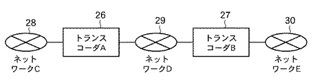
図9は複数のトランスコーダが接続されたシステムであり、2台のトランスコーダ(A)26,(B)27が、ネットワーク(C)28,(D)29,(E)30を介して接続されている。ここで、ネットワーク(C)28、ネットワーク(D)29、ネットワーク(E)30は、同一ネットワークとすることも可能とする。この様なシステム構成においては、端末に届くまでにトランスコーダ(A)26で伝送レートを変更するトランスコーディングを行い、トランスコーダ(B)27でMPEG−2ビデオからH.264ビデオに符号化変換を行うことで、複数トランスコーディングしたストリームを端末が受信可能である。 FIG. 9 shows a system in which a plurality of transcoders are connected. Two transcoders (A) 26 and (B) 27 are connected via networks (C) 28, (D) 29, and (E) 30. Has been. Here, the network (C) 28, the network (D) 29, and the network (E) 30 can be the same network. In such a system configuration, the transcoder (A) 26 performs transcoding to change the transmission rate before reaching the terminal, and the transcoder (B) 27 converts the MPEG-2 video into the H.264 format. By performing encoding conversion on H.264 video, a terminal can receive a plurality of transcoded streams.
図10は、多段のトランスコーダでトランスコードされたストリームを受信した場合に、既にエラー特定情報が格納されていた場合に対応したトランスコーダとして図9における2台目のトランスコーダ(B)27を示している。以下、トランスコーダ(B)27は、単にトランスコーダ27として説明する。
図10のトランスコーダ27において、図1に示したトランスコーダ1と異なるのは、メディア分離部31、エラー特定情報抽出部32、エラー抽出部33、エラー特定情報付加部34、トランスコーダID35を有する点である。これ以外の構成については対応する部分に同一符号を付してその説明を省略する。
ここで、トランスコーダ27が取り扱うエラー特定情報は、トランスコーダ1と同様にTSパケットレイヤに格納されているものとし、エラーのあったアクセスユニットを識別できるものとする。エラーが発生したトランスコーダを特定可能とする様に、TSヘッダに格納するエラー特定情報は、エラーの発生を示すフラグではなく、エラーが発生したトランスコーダID35を格納するものとする。例えば、トランスコーダIDが1バイトのデータとするなら、エラーが発生したPESの先頭部分を格納するTSパケットのヘッダのアダプテーションフィールドに1バイトのプライベートデータを設定し、トランスコーダIDを設定してエラーが発生したトランスコーダを識別することを可能とする。
FIG. 10 shows a case where the second transcoder (B) 27 in FIG. 9 is used as a transcoder corresponding to the case where error specifying information has already been stored when a stream transcoded by a multi-stage transcoder is received. Show. Hereinafter, the transcoder (B) 27 will be described simply as the
The
Here, it is assumed that the error specifying information handled by the
また、メディア分離部31は、実施の形態1のメディア分離部6の機能に加えて、エラー特定情報抽出部32およびエラー抽出部33と通信する機能を有している。エラー特定情報抽出部32は、エラー特定情報に基づいて、エラーがどのトランスコーダで発生したかを識別する機能部である。エラー抽出部33は、この自トランスコーダでエラーが発生した場合は、トランスコーダID35をエラー特定情報としてメディア分離部31に通知するよう構成されている。更に、エラー特定情報付加部34は、トランスコーダIDをエラー情報として付加するよう構成されている。
The
次に、各部の動作について説明する。
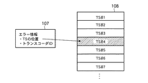
トランスコーダ1と同一の番号の部位については、トランスコーダ1と同様の動作を行うものとし、その説明を省略する。メディア分離部31に転送されたTSデータは、エラー特定情報抽出部32に入力され、TSに既に格納されているエラー特定情報を抽出し、エラー情報107を生成し、メディア分離部31へ送信する。
図11にトランスコーダ27におけるエラー情報107を示す。図11に示すように、エラー情報107は、TSパケット単位に設定される。エラー情報107には、図8に示したエラー情報105の内容に加え、トランスコーダIDを有しており、エラーがどのトランスコーダが受信したストリームで発生したかを識別可能なよう構成されている。
Next, the operation of each unit will be described.
About the site | part of the same number as the
FIG. 11
次に、メディア分離部31はTSストリームをエラー抽出部33に送信する。エラー抽出部33はエラー抽出部7と同様の方法によりTSストリーム中のエラーを抽出し、エラーの有無と自身のトランスコーダIDをメディア分離部31に返す。ここで、エラー抽出部33は、自身のトランスコーダIDをトランスコーダID35から取得する。また、メディア分離部31は、TSをメディア毎のPESに分離して、PESからMPEG−2ビデオESを抽出し、エラー特定情報抽出部32から得たエラー情報107と、エラー抽出部33の戻り値に従い、エラー情報109を生成する。図12に、エラー情報109を示す。
図12に示すように、エラー情報109は、MPEG−2ESデータ110における各ピクチャ単位に設定される。エラー情報109は図2に示したエラー情報101の内容に加え、受信時にエラーが発生したトランスコーダのトランスコーダIDが付加される。メディア分離部31はMPEG−2ESデータ110と抽出したエラー情報109、DTS、PTSを符号化データ入力部8へ送信する。その後の動作はトランスコーダ1と同様となる。次に、トランスコーダ1と異なる動作としてはエラー特定情報付加部34の動作である。
Next, the
As shown in FIG. 12, the
メディア多重部12は、エラー情報109とPESストリームをエラー特定情報付加部34に転送する。エラー特定情報付加部34は、エラー情報109が存在した場合、エラー情報109を有するPESの先頭部分を格納するTSパケットのヘッダのアダプテーションフィールドに1バイトのプライベートデータを設定し、エラー情報109内のトランスコーダIDをエラー特定情報として設定する。複数のエラーデータを同一のTSヘッダに設定する必要がある場合には、必要分のプライベートデータを設定し、エラー特定情報を格納する。
トランスコーダ27におけるその後のネットワークにストリームを送信する部分はトランスコーダ1と同様の処理を実施するものとする。
The
The part of the
これにより、複数のトランスコーダ(A)26、トランスコーダ(B)27により多段にトランスコーディングされたストリームを解析することにより、各トランスコーダの受信部で発生したエラー特定情報を発生したトランスコーダを識別して入手することが可能となる。
従って、ストリームを受信した受信機は多段のトランスコーダのどの部分でエラーが発生したかの情報を収集することが可能となり、ユーザに対してより詳細なメッセージを表示可能となる。
Thus, by analyzing the streams transcoded in multiple stages by the plurality of transcoders (A) 26 and transcoder (B) 27, the transcoder that has generated the error specifying information generated in the receiving unit of each transcoder can be obtained. It becomes possible to identify and obtain.
Therefore, the receiver that receives the stream can collect information on which part of the multi-stage transcoder has an error, and can display a more detailed message to the user.
以上のように、実施の形態2のトランスコーダによれば、エラー抽出部は、エラーの発生を検知した場合は、自トランスコーダの識別情報を特定し、エラー特定情報付加部は、エラー抽出部で特定された自トランスコーダの識別情報を付加するようにしたので、複数のトランスコーダを経由する場合であってもトランスコーダ毎のエラー特定情報を付与することができる。 As described above, according to the transcoder of the second embodiment, when the error extracting unit detects the occurrence of an error, the error extracting unit specifies the identification information of the own transcoder, and the error specifying information adding unit is the error extracting unit. Since the identification information of the own transcoder specified in (2) is added, error identification information for each transcoder can be added even when the information passes through a plurality of transcoders.
実施の形態3.
実施の形態3では、地上デジタルテレビ放送波を受信し、映像データをMPEG−2からH.264にトランスコーディングして、IPネットワーク上へ送信するトランスコーダについて説明を行う。ここで、ネットワークに送信する際にTSをIPパケットに格納する方式については実施の形態1と同様の方式を使用する。
In the third embodiment, digital terrestrial television broadcast waves are received, and video data is converted from MPEG-2 to H.264. A transcoder that transcodes to H.264 and transmits to the IP network will be described. Here, a method similar to that of the first embodiment is used as a method for storing the TS in the IP packet when transmitting to the network.
図13は、地上デジタルテレビ放送波を受信して、映像データをMPEG−2からH.264にトランスコーディングしてIPネットワーク上に転送するトランスコーダ36を示している。
ここで、トランスコーダ36が実施の形態1のトランスコーダ1と異なるのは、アンテナ37、チューナ部38、AD変換部39、復調部40、誤り訂正処理部41、暗号復号部42、メディア分離部43の構成である。これ以外の構成については、対応する部分に同一符号を付してその説明を省略する。
FIG. 13 shows the reception of terrestrial digital television broadcast waves and the conversion of video data from MPEG-2 to H.264. A
Here, the
実施の形態3のトランスコーダ36では、地上デジタルテレビ放送波をアンテナ37で受信する。受信した放送波はチューナ部38に入力され、チューナ部38は、選択されているチャンネルの放送波をAD変換部39に送出する。AD変換部39では、受信した信号をデジタル信号に変換し、復調部40に送出する。復調部40では、QPSK、16QAM、64QAMの復調・復号やTMCC復号、デインタリーブを行ってTSストリームに変換し、誤り訂正処理部41に送出する。誤り訂正処理部41は入力されたTSストリームをリードソロモン復号し、誤り訂正と誤り検出を行う。誤り訂正処理部41で誤りが検出された場合は、エラーが発生しているTSパケットを特定できるため、図8で示したようなエラー情報105を生成する。誤り訂正処理部41は、TSストリームとエラー情報105を暗号復号部42に出力し、これを受けた暗号復号部42は、暗号を復号したTSデータとエラー情報105をメディア分離部43に転送する。メディア分離部43では、TSパケットに多重化されているPES、セクションを分離し、更に、MPEG−2ESを生成する。メディア分離部43は、エラー情報105を、該当するTSのペイロードに格納されていたES内の位置を表すエラー情報101(図2参照)に変換する。MPEG−2ESデータはエラー情報101とDTS、PTSと共に符号化データ入力部8に、その他のメディアについては、メディア多重部12に転送される。これ以降の処理はトランスコーダ1の符号化データ入力部8以降の処理と同一である。
In the
以上のように、実施の形態3のトランスコーダによれば、地上デジタルテレビ放送波を受信し、映像をMPEG−2からH.264に変換し、IPネットワーク上へ送信するトランスコーダでも受信時に受信ストリームに存在したエラーの情報をトランスコーディングした映像ストリーム内に格納し、IPネットワークへ送信することが可能である。
本ストリームを受信する受信機は、受信したストリームにはエラーが発生していなくても、トランスコーディング前にストリームにエラーが発生していたアクセスユニットを、エラー特定情報を参照することにより認識でき、放送波自体にエラーがあったことを伝えるユーザへのメッセージ出力や、乱れた画面表示せずに黒画面にするなどの対処が可能となる。
As described above, according to the transcoder of the third embodiment, digital terrestrial television broadcast waves are received, and video is converted from MPEG-2 to H.264. Even a transcoder that converts to H.264 and transmits it to the IP network can store error information present in the received stream at the time of reception in the transcoded video stream and transmit it to the IP network.
A receiver that receives this stream can recognize an access unit in which an error has occurred in the stream before transcoding by referring to the error specifying information, even if no error has occurred in the received stream. It is possible to take measures such as outputting a message to the user indicating that there was an error in the broadcast wave itself, or making it a black screen without displaying a distorted screen.
実施の形態4.
実施の形態4では、IPネットワークを通じて多重化せずにメディアを送受信するトランスコーダ44について説明を行う。トランスコーダ44は受信したMPEG−2ビデオ符号化ストリームを、H.264ビデオストリームに変換するトランスコーダとする。メディアの伝送にはRTPを用い、RTPはRFC3550を使用する。MPEG−2ビデオの伝送フォーマットは、RFC2250のMPEG−2ESのRTPパケットへの格納方式を使用する。また、H.264の伝送フォーマットは、RFC3984を用いるものとする。
In the fourth embodiment, a
図14は、多重化せずにメディアを送受信するトランスコーダ44を示す構成図である。
図示のトランスコーダ44において、実施の形態1のトランスコーダ1と異なるのは、パケット分離部45、エラー抽出部46、符号化データ入力部47、エラー特定情報付加部48、パケット生成部49である。これ以外の構成については対応する部分に同一符号を付してその説明を省略する。
FIG. 14 is a block diagram showing a
The illustrated
実施の形態4のトランスコーダ44では、受信部4からRTPパケットがパケット分離部45に転送される。受信部4は、UDPの層でチェックサムの確認を行い、チェックサムエラーであるパケットはパケット分離部45に送信しない。そのため、エラーとなったパケットはRTPのレイヤではパケットロスと同等の扱いとなる。パケット分離部45は、RTPパケットを受信すると、IPネットワークのジッタ吸収のため、一定量のバッファリングを行う。ここで、RTPシーケンス番号を用いてパケットの入れ替わりがあれば、その入れ替わりを修正する。パケット分離部45は、バッファリングが終了すると、受信したRTPパケットのRTPヘッダをエラー抽出部46に送信する。
In the
エラー抽出部46では、RTPヘッダのシーケンス番号をチェックし、前回受信したパケットのシーケンス番号と連続していない場合、パケットロスが発生したと判断し、その結果をパケット分離部45に応答する。シーケンス番号が連続している場合は、パケットロス発生無しと判断する。パケット分離部45は、RTPパケットからペイロードを分離し、MPEG−2ESを生成する。また、PTSにはRTPヘッダのタイムスタンプを格納し、DTSにはBピクチャの場合はPTSと同一のタイムスタンプ、Iピクチャ及びPピクチャの場合はその一つ前のIピクチャもしくはPピクチャのPTSを格納する。ここで、ピクチャの切れ目はRTPタイムスタンプの変化点で検知し、I/P/Bピクチャの区別は、ピクチャの切れ目に格納されているピクチャヘッダのPicture Coding Typeを使用して認識するものとする。
パケット分離部45は、エラー抽出部46よりエラーありの応答があった場合、図2に示したようなエラー情報101を生成する。パケット分離部45は、MPEG−2ESデータとエラー情報101及びPTS、DTSを符号化データ入力部47に送出する。符号化データ入力部47は、MPEG−2ESデータとエラー情報101及びPTS、DTSを受信する。これ以降のMPEG−2ビデオからH.264にトランスコーディングを行う部分はトランスコーダ1と同様の処理となる。
The
When there is a response with an error from the
符号化データ出力部11は、符号化データ、DTS、PTSと共にエラー情報101が存在する場合にはエラー情報101をパケット生成部49に転送する。パケット生成部49は、RTPヘッダのタイムスタンプはPTS、シーケンス番号は前回のシーケンス番号をインクリメント、ピクチャの終了部分のパケットではMビットをONし、ペイロードにESを格納してRTPパケットを生成する。
RTPパケットがピクチャの先頭のESを格納しており、そのピクチャにエラー情報101が存在するとき、パケット生成部49は、エラー特定情報付加部48にRTPパケットを転送する。エラー特定情報付加部48では、RTPパケットとエラー情報101を受信すると、エラー特定情報を格納したRTPパケットに変換する。
エラー特定情報は、RTPヘッダの拡張ヘッダを用いて格納する。RTPヘッダのExtensionビットをONし、RTPの拡張ヘッダにエラー特定情報を設定する。エラー特定情報は1バイトで表されており、0x01を格納するものとする。但し、拡張ヘッダは32ビット単位で拡張することになっている。
生成したRTPパケットはパケット生成部49から送信部15に転送され、ネットワーク(B)3に送信される。
The encoded
When the RTP packet stores the head ES of the picture and the
The error specifying information is stored using the extension header of the RTP header. The Extension bit of the RTP header is turned ON, and error specifying information is set in the RTP extension header. The error specifying information is represented by 1 byte, and stores 0x01. However, the extension header is to be extended in units of 32 bits.
The generated RTP packet is transferred from the
以上のように、実施の形態4のトランスコーダによれば、エラー特定情報付加部は、エラー特定情報をRTPパケットヘッダ内に付加するようにしたので、多重化されずにRTPパケットで送信されるメディアについても、トランスコーダがストリーム受信時に発生したエラーの情報をトランスコード後のストリームと共に送信することが可能となる。
本ストリームを受信する受信機は、受信したストリームにはエラーが発生していなくても、トランスコーディング前にストリームにエラーが発生していたアクセスユニットをエラー特定情報を参照することにより認識でき、ユーザへのメッセージ出力や、乱れた画面表示せずに黒画面にするなどの対処が可能となる。
As described above, according to the transcoder of the fourth embodiment, the error specifying information adding unit adds the error specifying information in the RTP packet header, so that it is transmitted in the RTP packet without being multiplexed. Also for media, it is possible for the transcoder to transmit information on errors that occurred when receiving a stream, together with the stream after transcoding.
The receiver that receives this stream can recognize the access unit in which an error has occurred in the stream before transcoding by referring to the error specifying information, even if no error has occurred in the received stream. It is possible to take measures such as outputting a message to, and making it a black screen without displaying a distorted screen.
実施の形態5.
本実施の形態では、図1のトランスコーダ1が送信するマルチメディアストリームとエラー特定情報を受信する受信機について説明を行う。映像ストリームは実施の形態1と同様にMPEG−2TSに多重化されており、TSパケットのIPパケットへの格納方式についても実施の形態1と同様の方式を使用する。
In this embodiment, a receiver that receives a multimedia stream and error specifying information transmitted by the
図15は、エラー特定情報を付加したストリームを受信可能な受信機50を示す構成図である。
図示の受信機50は、受信部51、パケット分離部52、メディア分離部53、エラー特定情報抽出部54、映像復号管理部55、映像復号化部56、映像表示管理部57、映像表示部58、音声復号管理部59、音声復号化部60、音声出力管理部61、音声出力部62、エラー表示部63、モニタ64、スピーカ65、受信用情報66を備えている。
FIG. 15 is a configuration diagram illustrating a
The illustrated
受信部51は、受信用情報66に設定されている送信元アドレス、ポート番号を用いてIPネットワーク(B)3からマルチメディアストリームを受信する。受信部51ではIP層、UDP層の処理を行い、RTPパケットをパケット分離部52に送信する。パケット分離部52では、IPネットワークのジッタ吸収のため、一定量のバッファリングを行う。ここで、パケットの入れ替わりがあれば、RTPシーケンス番号を用いてその入れ替わりを修正する。バッファリングが終了すると、RTPヘッダを削除し、RTPのペイロードに格納されているTSストリームを抽出する。抽出されたTSストリームはメディア分離部53に出力される。
The receiving
メディア分離部53は入力されたTSストリームを分離する。また、分離する際にTSパケットをエラー特定情報抽出部54に転送する。エラー特定情報抽出部54では、TSパケットのヘッダのアダプテーションフィールド内の1バイトのプライベートデータを検索することでエラー特定情報を抽出し、エラー特定情報が格納されていた場合には、メディア分離部53に対し該当TSパケットにエラー通知情報が格納されていることを返す。メディア分離部53は、TSパケットを分離し、各メディア毎にPESパケットを生成する。更に、ビデオに関してはH.264NALデータをPESから抽出する。この際、メディア分離部53は、H.264NALデータをチェックし、例えば、アクセスユニットデリミタを検索することでピクチャを認識し、各ピクチャにIDを付与し、エラーが発生したピクチャに対してエラー情報111を生成する。図16にエラー情報111を示す。
The
図16に示すように、エラー情報111は、H264NALデータ112中に含まれている各ピクチャ単位に設定される。即ち、エラー情報111には、対象となるピクチャのピクチャIDが格納されている。メディア分離部53は、分離したH.264NALデータとDTS、PTS、エラー情報111が存在する場合はエラー情報111を映像復号管理部55に転送し、音声ESデータもDTS、PTSと共に音声復号管理部59に転送する。映像復号管理部55は、各NALデータをDTSのタイミングで映像復号化部56に送出する。同時に入力したピクチャに付与されていたエラー情報111とPTSをピクチャIDを付与して映像表示管理部57に送信する。映像表示管理部57は、映像復号管理部55からピクチャIDとエラー情報111、PTSを受信し、管理する。また、映像表示管理部57は、映像復号化部56より復号された画像データが出力されると、その画像データのピクチャIDを参照し、関連するPTSとエラー情報111を検索する。
As shown in FIG. 16, the
ここで、該当するピクチャIDのエラー情報111が存在しなかった場合には、PTSに従って映像表示部58に映像データを出力し、映像表示部58はその映像データをモニタ64に表示する。該当するピクチャIDのエラー情報111が存在した場合には、その映像データを映像表示部58に転送すると共に、エラー表示部63に再送信エラーの表示を行う指示を送信する。これを受けたエラー表示部63はトランスコーダ受信時にネットワークにエラーがあった旨のメッセージ表示を行うよう映像表示部58に指示する。
Here, when the
また、音声復号管理部59は音声のPESから音声の符号化データを抽出し、音声復号化部60に転送する。音声復号化部60は、復号した音声データを音声出力管理部61に出力する。音声出力管理部61は、音声のサンプリング周波数から出力時間を算出したタイミングで音声出力部62に音声データを出力し、音声出力部62はスピーカ65から音声を再生させる。ここで、実際には音声と映像を同期再生させるメカニズムが必要であるが、本受信機では同期再生は本発明の範囲と直接関係ないため省略する。
これにより、ユーザに対して映像の乱れの原因はトランスコーディング前のネットワーク状況が影響していることをメッセージにより通知することが可能となる。
Also, the speech
As a result, it is possible to notify the user that the cause of the video disturbance is due to the network condition before transcoding.
図17は、トランスコーダ受信時にエラーが発生していた場合にはその映像は表示せずに別画像を表示可能な受信機を示す構成図である。
図示の受信機67が、図15の受信機50と異なる点は、映像表示管理部68、エラー出力画像69、エラー抽出部70、メディア分離部71である。これ以外の構成については、対応する部分に同一符号を付してその説明を省略する。
FIG. 17 is a block diagram showing a receiver capable of displaying another image without displaying the video when an error has occurred during reception of the transcoder.
The
受信機67において、映像復号化部56までの処理は受信機50と同一である。但し、メディア分離部71は、TSパケットをエラー抽出部70に渡し、エラー抽出部70ではcontinuity_counterをチェックし、受信したデータのパケットロスの有無をメディア分離部71に通知する。パケットロスが発生していた場合には、エラー特定情報を抽出した場合と同様にエラー情報111(図16参照)を生成する。
映像表示管理部68は、デコードされた画像をPTSのタイミングで映像表示部58に送信する。映像表示管理部68は、デコードされた画像にエラー情報111が付与されていた場合、デコードした映像は廃棄し、エラー出力画像69に蓄積されている映像を一定時間、例えば0.5秒間表示する。エラー出力画像69を表示している間に出力するPTSが到達した画像はエラー画像同様に破棄する。エラー出力画像69には例えば黒画像やテストパターン画像等が蓄積されている。またトランスコーダが、エラー特定情報を、(1)画像内のみのエラー、(2)継続するエラー、(3)継続するエラーの終了の3種類用意していた場合、(1)の画像内のみのエラーのエラー特定情報を受信した場合は、そのピクチャのみを別画像に置き換えて表示し、(2)の継続するエラー特定情報を受信した場合は、(3)の継続するエラーの終了の直前のピクチャまで別画像に置き換えて表示することで、受信側でエラー画像を表示しないで別画像に置き換える際の置き換え期間を画像が乱れている期間のみに限定して行うことが可能となる。
これにより受信機が受信したストリームにエラーが発生した時のみでなく、トランスコーダの受信時に発生したエラーに起因して映像乱れが発生した画像も表示しないことが可能となり、エラー時の表示方式を受信機の受信時のネットワークによるエラーの影響と、トランスコーダの受信時のネットワークエラーの影響を共通的に扱うことが可能となる。
In the
The video
As a result, not only when an error occurs in the stream received by the receiver, it is possible not to display an image in which video disturbance has occurred due to the error that occurred during reception of the transcoder. It is possible to commonly handle the effects of errors caused by the network when receiving by the receiver and the effects of network errors when receiving by the transcoder.
以上のように、実施の形態5の受信機によれば、ネットワーク経由でメディアストリームを受信して再生する受信機であって、メディアストリーム中のエラー特定情報を検知するエラー特定情報抽出部を備えたので、メディアストリーム中のエラー特定情報を検知することができ、受信機でメディアデータに異常があることを検知することができる。
As described above, the receiver according to
また、実施の形態5の受信機によれば、エラー特定情報抽出部がエラー特定情報を検知した場合は、エラー特定情報に基づいて、受信したメディアストリーム中にエラーが存在することを示すエラーメッセージを表示するエラー表示部を備えたので、ユーザに対して映像の乱れの原因はトランスコーディング前のネットワーク状況が影響していることをメッセージにより通知することが可能となる。 Further, according to the receiver of the fifth embodiment, when the error specifying information extracting unit detects the error specifying information, an error message indicating that an error exists in the received media stream based on the error specifying information. Since the error display unit for displaying is provided, it is possible to notify the user that the cause of the video disturbance is the influence of the network condition before transcoding.
また、実施の形態5の受信機によれば、エラー特定情報抽出部がエラー特定情報を検知した場合は、エラー特定情報で示す映像部位を表示する代わりに予め定められた別画像を表示させる映像表示管理部を備えたので、エラーを含む映像部位を表示せずに別画像を表示することができる。 Further, according to the receiver of the fifth embodiment, when the error specifying information extracting unit detects the error specifying information, the video for displaying a predetermined different image instead of displaying the video part indicated by the error specifying information Since the display management unit is provided, another image can be displayed without displaying the video part including the error.
実施の形態6.
実施の形態6では、受信機とトランスコーダが通信を行い、エラー特定情報を格納するレイヤを設定可能な受信機と、この設定情報に基づいてエラー特定情報を格納するレイヤを設定するトランスコーダについて説明を行う。
映像ストリームは実施の形態1と同様にMPEG−2TSに多重化されており、TSパケットのIPパケットへの格納方式についても実施の形態1と同様の方式を使用する。
In the sixth embodiment, a receiver and a transcoder communicate with each other, a receiver capable of setting a layer for storing error specifying information, and a transcoder for setting a layer for storing error specifying information based on the setting information. Give an explanation.
The video stream is multiplexed in MPEG-2TS as in the first embodiment, and the same method as in the first embodiment is used for the method of storing TS packets in IP packets.
図18は、トランスコーダと通信を行い、エラー特定情報を格納するレイヤを設定可能な受信機の構成図である。
図示の受信機72が実施の形態5における図15に示す受信機50と異なる点は、エラー特定情報設定送信部73、エラー特定情報設定データ74の構成である。
FIG. 18 is a configuration diagram of a receiver that can communicate with a transcoder and set a layer for storing error specifying information.
The illustrated
図19は、受信機72と通信を行い、エラー特定情報を格納するレイヤを設定可能なトランスコーダを示す構成図である。
図示のトランスコーダ75が実施の形態1における図7に示したトランスコーダ1bと異なる点は、エラー特定情報付加位置選択部76、エラー特定情報設定受信部77、付加位置設定データ78の構成である。
FIG. 19 is a configuration diagram showing a transcoder that can communicate with the
The illustrated
受信機72のエラー特定情報設定データ74には、通信を行うトランスコーダのIPアドレスとポート番号、エラー特定情報を格納するレイヤ情報が設定されている。本実施の形態ではエラー特定情報を格納するレイヤとして、TS、PES、RTPの3種類について説明を行う。エラー特定情報を格納するレイヤ情報として、例えば、TSの場合は1、PESの場合は2、RTPの場合は3とする。受信機72のエラー特定情報設定送信部73は、エラー特定情報設定データ74を読み込み、受信を行うトランスコーダ75に関連する情報を読み込み、TCP(Transmission Control Protocol)を用いてエラー特定情報設定データ74に格納されているエラー特定情報を格納するレイヤ情報を送信する。
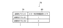
トランスコーダ75のエラー特定情報設定受信部77は、受信機72から送信されたエラー特定情報を設定するレイヤ情報を受信すると、付加位置設定データ78に受信機72のアドレスとエラー特定情報を設定するレイヤ情報を格納する。
In the error specifying
When receiving the layer information for setting the error specifying information transmitted from the
図20に付加位置設定データ78の詳細を示す。
図示のように、付加位置設定データ78は、送信先アドレス79とエラー特定情報設定レイヤ80との対応を示すデータである。送信先アドレス79には、エラー特定情報設定受信部77がデータを受信した受信機のアドレス情報、エラー特定情報設定レイヤ80には受信機が要求したエラー特定情報を設定するレイヤが格納されている。
エラー特定情報付加位置選択部76は、付加位置設定データ78が更新されると読み込みを実施する。エラー特定情報付加部22は、送信開始時にエラー特定情報付加位置選択部76に対して送信先のアドレス情報で、エラー特定情報を付加するレイヤの検索を指示し、エラー特定付加情報を設定するレイヤを決定する。
FIG. 20 shows details of the additional
As illustrated, the additional
The error specifying information addition
これにより、受信機72からエラー特定情報を付加するレイヤをトランスコーダ75に対して指定することで、受信機72が対応しているレイヤにエラー特定情報を設定することが可能となる。従って、例えば、メディア分離部や映像復号部にLSIを使用しており、エラー特定情報の処理を追加することが難しい場合でも、RTPのレイヤにエラー特定情報を設定することで、受信機側でトランスコーディング前のストリームのエラー発生状況を得ることが可能となる。
Thus, by specifying the layer to which the error specifying information is added from the
以上のように、実施の形態6の受信機によれば、受信するメディアストリーム中のエラー特定情報を格納するレイヤを指定する情報を送信するエラー特定情報設定通信部を備えたので、受信するメディアストリーム中のエラー特定情報を格納するレイヤを任意に選択することができる。 As described above, according to the receiver of the sixth embodiment, since the error specifying information setting communication unit that transmits the information specifying the layer storing the error specifying information in the received media stream is provided, the receiving medium The layer for storing the error specifying information in the stream can be arbitrarily selected.
また、実施の形態6のトランスコーダによれば、エラー特定情報を付加するレイヤを設定する情報を受信するエラー特定情報設定受信部を備え、エラー特定情報付加位置選択部は、エラー特定情報設定受信部で受信した情報に基づいてレイヤの選択を行うようにしたので、エラー特定情報を付加するレイヤを、受信する情報に応じて任意に設定することができる。 Further, according to the transcoder of the sixth embodiment, an error specifying information setting receiving unit that receives information for setting a layer to which error specifying information is added is provided, and the error specifying information adding position selecting unit receives error specifying information setting reception. Since the layer is selected based on the information received by the unit, the layer to which the error specifying information is added can be arbitrarily set according to the received information.
1,1a,1b,27,36,44,75 トランスコーダ、2 ネットワークA、3 ネットワークB、5,45,52 パケット分離部、6,31,43,53,71 メディア分離部、7,33,46,70 エラー抽出部、8,18,47 符号化データ入力部、9 映像復号化部、10 映像符号化部、11 符号化データ出力部、12,21 メディア多重部、13,20,22,34,48 エラー特定情報付加部、14,24,49 パケット生成部、19 エラー位置抽出部、23,76 エラー特定情報付加位置選択部、25,78 付加位置設定データ、26 トランスコーダA、27 トランスコーダB、28 ネットワークC、29 ネットワークD、30 ネットワークE、32 エラー特定情報抽出部、35 トランスコーダID、50,67,72 受信機、54 エラー特定情報抽出部、55 映像復号管理部、56 映像復号化部、57,68 映像表示管理部、58 映像表示部、59 音声復号管理部、60 音声復号化部、61 音声出力管理部、62 音声出力部、63 エラー表示部、64 モニタ、65 スピーカ、77 エラー特定情報設定受信部、69 エラー出力画像、73 エラー特定情報設定通信部、74 エラー特定情報設定データ、101,103,105,107,109,111 エラー情報。 1, 1a, 1b, 27, 36, 44, 75 transcoder, 2 network A, 3 network B, 5, 45, 52 packet separator, 6, 31, 43, 53, 71 media separator, 7, 33, 46, 70 Error extraction unit, 8, 18, 47 Encoded data input unit, 9 Video decoding unit, 10 Video encoding unit, 11 Encoded data output unit, 12, 21 Media multiplexing unit, 13, 20, 22, 34, 48 Error specifying information adding unit, 14, 24, 49 Packet generating unit, 19 Error position extracting unit, 23, 76 Error specifying information adding position selecting unit, 25, 78 Additional position setting data, 26 Transcoder A, 27 Trans Coder B, 28 Network C, 29 Network D, 30 Network E, 32 Error specific information extraction unit, 35 Transcoder ID, 50, 67, 72 Receiver, 54 Error specific information extraction unit, 55 Video decoding management unit, 56 Video decoding unit, 57, 68 Video display management unit, 58 Video display unit, 59 Audio decoding management unit, 60 Audio Decoding unit, 61 audio output management unit, 62 audio output unit, 63 error display unit, 64 monitor, 65 speaker, 77 error specific information setting receiving unit, 69 error output image, 73 error specific information setting communication unit, 74 error specific Information setting data, 101, 103, 105, 107, 109, 111 Error information.
Claims (10)
受信した前記メディアストリームにエラーが発生していることを検知し、その発生位置を特定するエラー抽出部と、
受信時のエラーが発生したメディアストリームに対応する前記トランスコーディング後のアクセスユニットに、前記トランスコーディング前にエラーが発生していたことを通知するためのエラー特定情報を付加するエラー特定情報付加部とを備えたトランスコーダ。 A transcoder that transcodes a media stream received from one network and sends it to the other network,
An error extraction unit that detects that an error has occurred in the received media stream and identifies the occurrence position;
An error specifying information adding unit for adding error specifying information for notifying that an error has occurred before the transcoding to the access unit after transcoding corresponding to a media stream in which an error has occurred during reception; Transcoder equipped with.
前記メディアストリーム中のエラー特定情報を検知するエラー特定情報抽出部を備えた受信機。 A receiver that receives and plays a media stream via a network,
A receiver comprising an error identification information extraction unit for detecting error identification information in the media stream.
Priority Applications (3)
| Application Number | Priority Date | Filing Date | Title |
|---|---|---|---|
| JP2008000502A JP2009164880A (en) | 2008-01-07 | 2008-01-07 | Transcoder and receiver |
| US12/140,666 US20090177952A1 (en) | 2008-01-07 | 2008-06-17 | Transcoder and receiver |
| EP20080012515 EP2077669A3 (en) | 2008-01-07 | 2008-07-10 | Transcoder and receiver |
Applications Claiming Priority (1)
| Application Number | Priority Date | Filing Date | Title |
|---|---|---|---|
| JP2008000502A JP2009164880A (en) | 2008-01-07 | 2008-01-07 | Transcoder and receiver |
Publications (1)
| Publication Number | Publication Date |
|---|---|
| JP2009164880A true JP2009164880A (en) | 2009-07-23 |
Family
ID=40577814
Family Applications (1)
| Application Number | Title | Priority Date | Filing Date |
|---|---|---|---|
| JP2008000502A Pending JP2009164880A (en) | 2008-01-07 | 2008-01-07 | Transcoder and receiver |
Country Status (3)
| Country | Link |
|---|---|
| US (1) | US20090177952A1 (en) |
| EP (1) | EP2077669A3 (en) |
| JP (1) | JP2009164880A (en) |
Families Citing this family (19)
| Publication number | Priority date | Publication date | Assignee | Title |
|---|---|---|---|---|
| JP5284652B2 (en) * | 2008-01-30 | 2013-09-11 | 京セラ株式会社 | DATA PROCESSING DEVICE, DATA PROCESSING METHOD, AND ELECTRONIC DEVICE |
| US9947299B2 (en) * | 2009-06-11 | 2018-04-17 | Gilad Odinak | System and method for offline content delivery through an active screen display |
| US9275166B2 (en) * | 2009-06-11 | 2016-03-01 | Gilad Odinak | Off-line delivery of content through an active screen display |
| KR20120078718A (en) * | 2009-09-14 | 2012-07-10 | 톰슨 라이센싱 | Distribution of mpeg-2 ts multiplexed multimedia stream with selection of elementary packets of the stream |
| KR101809880B1 (en) | 2011-09-28 | 2017-12-15 | 가부시키가이샤 제이브이씨 켄우드 | Video decoding device, video decoding method and recording medium storing video decoding program |
| TWI597973B (en) * | 2011-10-31 | 2017-09-01 | Jvc Kenwood Corp | Video encoding device, video encoding method and recording medium |
| PL2793467T3 (en) | 2011-12-13 | 2018-02-28 | JVC Kenwood Corporation | Video coding device, video coding method, video coding program, video decoding device, video decoding method, and video decoding program |
| HUE047995T2 (en) * | 2011-12-16 | 2020-05-28 | Jvc Kenwood Corp | Dynamic image encoding device, dynamic image encoding method, dynamic image encoding program |
| TWI578764B (en) * | 2011-12-21 | 2017-04-11 | Jvc Kenwood Corp | Dynamic image decoding device, dynamic image decoding method, and dynamic image decoding program |
| RU2606399C9 (en) * | 2011-12-28 | 2017-07-12 | ДжейВиСи КЕНВУД КОРПОРЕЙШН | Moving picture coding device, moving picture coding method, and moving picture coding program, and moving picture decoding device, moving picture decoding method, and moving picture decoding program |
| CN104025587B (en) | 2011-12-28 | 2017-08-29 | Jvc建伍株式会社 | Moving image decoding device and moving picture decoding method |
| WO2013099244A1 (en) | 2011-12-28 | 2013-07-04 | 株式会社Jvcケンウッド | Video encoding device, video encoding method, video encoding program, video decoding device, video decoding method, video decoding program |
| TWI577181B (en) * | 2011-12-28 | 2017-04-01 | Jvc Kenwood Corp | Dynamic video coding device, dynamic image coding method and dynamic image coding program |
| EP3833022B1 (en) | 2012-04-12 | 2022-03-30 | JVCKENWOOD Corporation | Merge candidate list construction |
| US10136147B2 (en) * | 2014-06-11 | 2018-11-20 | Dolby Laboratories Licensing Corporation | Efficient transcoding for backward-compatible wide dynamic range codec |
| KR20170068946A (en) * | 2015-12-10 | 2017-06-20 | 삼성전자주식회사 | Broadcast receiving apparatus and controlling method thereof |
| US10841621B2 (en) * | 2017-03-01 | 2020-11-17 | Wyse Technology L.L.C. | Fault recovery of video bitstream in remote sessions |
| JP2018166313A (en) * | 2017-03-28 | 2018-10-25 | 富士通株式会社 | Abnormality detection program, abnormality detection device and abnormality detection method |
| RU2666275C1 (en) * | 2017-11-13 | 2018-09-06 | ДжейВиСи КЕНВУД КОРПОРЕЙШН | Device and method of coding moving image, long term data-storage computer recorded medium which image coding program is recorded on |
Family Cites Families (4)
| Publication number | Priority date | Publication date | Assignee | Title |
|---|---|---|---|---|
| KR100571307B1 (en) | 1999-02-09 | 2006-04-17 | 소니 가부시끼 가이샤 | Coding system and its method, coding device and its method, decoding device and its method, recording device and its method, and reproducing device and its method |
| US7327791B1 (en) * | 1999-02-22 | 2008-02-05 | Mitsubishi Denki Kabushiki Kaisha | Video decoding method performing selective error concealment and resynchronization |
| CN1886946A (en) | 2003-09-30 | 2006-12-27 | 日本电气株式会社 | Method for processing encoded data in interconnecting different types of communication networks, and gateway apparatus |
| TW200743386A (en) * | 2006-04-27 | 2007-11-16 | Koninkl Philips Electronics Nv | Method and apparatus for encoding/transcoding and decoding |
-
2008
- 2008-01-07 JP JP2008000502A patent/JP2009164880A/en active Pending
- 2008-06-17 US US12/140,666 patent/US20090177952A1/en not_active Abandoned
- 2008-07-10 EP EP20080012515 patent/EP2077669A3/en not_active Withdrawn
Also Published As
| Publication number | Publication date |
|---|---|
| EP2077669A3 (en) | 2009-09-23 |
| EP2077669A2 (en) | 2009-07-08 |
| US20090177952A1 (en) | 2009-07-09 |
Similar Documents
| Publication | Publication Date | Title |
|---|---|---|
| JP2009164880A (en) | Transcoder and receiver | |
| US10009660B2 (en) | Media content transceiving method and transceiving apparatus using same | |
| KR101476934B1 (en) | Method for transceiving media files and device for transmitting/receiving using same | |
| JP6302274B2 (en) | Transmitting apparatus and receiving apparatus | |
| JP7279767B2 (en) | Transmission method and transmission device | |
| JP4195030B2 (en) | Video data transmission method and reception method for continuous video display | |
| KR101613941B1 (en) | Method for transmitting/receiving media content and transmitting/receiving apparatus thereof | |
| JP6617809B2 (en) | Decoding device, decoding method, and decoding program | |
| KR101842201B1 (en) | Apparatus and method for transmitting and receiving contents based on internet | |
| JP3987541B2 (en) | Packet stream receiver | |
| CN114430911A (en) | Random access at resynchronization points for DASH segmentation | |
| JP4192766B2 (en) | Receiving apparatus and method, recording medium, and program | |
| KR101008976B1 (en) | Method of detecting error in multimedia streaming system | |
| JP7371734B2 (en) | How to send |