JP2018160491A - Coil substrate - Google Patents
Coil substrate Download PDFInfo
- Publication number
- JP2018160491A JP2018160491A JP2017055408A JP2017055408A JP2018160491A JP 2018160491 A JP2018160491 A JP 2018160491A JP 2017055408 A JP2017055408 A JP 2017055408A JP 2017055408 A JP2017055408 A JP 2017055408A JP 2018160491 A JP2018160491 A JP 2018160491A
- Authority
- JP
- Japan
- Prior art keywords
- coil
- layer
- conductor
- coil substrate
- conductor layer
- Prior art date
- Legal status (The legal status is an assumption and is not a legal conclusion. Google has not performed a legal analysis and makes no representation as to the accuracy of the status listed.)
- Pending
Links
Images


Abstract
Description
本発明は、コイル部を有する複数の導体層が層間絶縁層を介して積層されてなるコイル基板に関する。 The present invention relates to a coil substrate in which a plurality of conductor layers having a coil portion are laminated via an interlayer insulating layer.
特許文献1には、板厚方向の中央部の複数の導電層にコイル部を有するものが示されている。 Patent Document 1 discloses that a plurality of conductive layers at the center in the thickness direction have a coil portion.
しかしながら、上記した従来のコイル基板では、コイル部に係る磁力の低下を抑えるために、コイル部からコイル基板の表面(ひょうめん)までの間に透磁率が高い絶縁層を使用する必要があり、煩雑な構造になり得る等の問題が考えられる。 However, in the above-described conventional coil substrate, it is necessary to use an insulating layer having a high magnetic permeability between the coil portion and the surface of the coil substrate in order to suppress a decrease in magnetic force related to the coil portion. Problems such as a complicated structure can be considered.
本発明は、上記事情に鑑みてなされたもので、従来より簡素な構造のコイル基板の提供を目的とする。 The present invention has been made in view of the above circumstances, and an object of the present invention is to provide a coil substrate having a simpler structure than before.
本発明に係るコイル基板は、第1外部絶縁層及び第2外部絶縁層との間に、内部絶縁層を介して積層される複数の導体層を有し、それら複数の導体層に、渦巻き状のパターンからなるコイル部が形成されている複数のコイル部有り導体層が含まれ、前記第1外部絶縁層の最外面である第1面から、その第1面に最も近い導体層である第1導体層までの距離より、前記第2外部絶縁層の最外面である第2面から、その第2面に最も近い導体層である第2導体層までの距離の方が長く、前記第1面から、その第1面に最も近い前記コイル部有り導体層までの距離より、前記第2面から、その第2面に最も近い前記コイル部有り導体層までの距離の方が長い。 The coil substrate according to the present invention has a plurality of conductor layers laminated via an inner insulating layer between the first outer insulating layer and the second outer insulating layer, and the plurality of conductor layers are spirally formed. A plurality of conductor layers having a coil portion, in which a coil portion having the pattern is formed, from a first surface which is the outermost surface of the first outer insulating layer to a conductor layer closest to the first surface. The distance from the second surface, which is the outermost surface of the second outer insulating layer, to the second conductor layer, which is the conductor layer closest to the second surface, is longer than the distance to one conductor layer. The distance from the second surface to the conductor layer with the coil part closest to the second surface is longer than the distance from the surface to the conductor layer with the coil part closest to the first surface.
[第1実施形態]
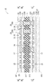
以下、本発明に係る第1実施形態を図1〜図6に基づいて説明する。図1に示すように、本実施形態のコイル基板10は、コア基板11の表裏の両側に、それぞれ導体層22と層間絶縁層21(本発明の「内部絶縁層」に相当する。)とが交互に積層され、さらに表裏の両表面にソルダーレジスト層26,27が積層された構造をなしている。なお、コア基板11の両側の導体層22及び層間絶縁層21の層数は、同じになっている。
[First Embodiment]
Hereinafter, a first embodiment according to the present invention will be described with reference to FIGS. As shown in FIG. 1, the
以下、コイル基板10の板厚方向の一端の表面を第1面10Fといい、他端の表面を第2面10Sということとする。また、コア基板11の表裏の両面のうち第1面10F側の面をF面11Fといい、その反対側の面をB面11Bということとする。さらには、複数の導体層22を区別するときには、第1面10F側の最外の導体層22から第2面10B側の最外の導体層22に向かって、順番に、第1の導体層22A(本発明の「第1導体層」に相当する。)、第2の導体層22B、第3の導体層22C,第4の導体層22D(本発明の「第2導体層」に相当する。)ということとする。
Hereinafter, the surface of one end of the
コア基板11は、補強繊維の織布(例えば、ガラスクロス)に樹脂を含浸させてなるプリプレグである。層間絶縁層21及びソルダーレジスト層26,27は、補強繊維を含んでいない樹脂層である。なお、ソルダーレジスト層26,27を区別するときには、ソルダーレジスト層26,27のうちF面10F側のソルダーレジスト層26を、F面側ソルダーレジスト層26(本発明の「第1外部絶縁層」)に相当する。」といい、B面10B側のソルダーレジスト層27をB面側ソルダーレジスト層27(本発明の「第2外部絶縁層」に相当する。)ということとする。また、層間絶縁層21は、補強繊維の織布に樹脂を含浸させてなるプリプレグであってもよい。
The
第1〜第4の導体層22A〜22Dには、それぞれコイル部23(図2又は図3参照)が備えられ、それらコイル部23がコイル基板10の板厚方向に並んでいる。また、コイル部23,23同士は、層間絶縁層21を貫通するビア導体17又はコア基板11を貫通する接続導体15によって直列接続され、その直列回路の両端末となる1対のパッド29,29がコイル基板10の第1面10Fに備えられている。以下、第1〜第4の導体層22A〜22Dに形成されているコイル部23を区別するときには、適宜、第1コイル部23A、第2コイル部23B、第3コイル部23C、第4コイル部23Dということとする。なお、ビア導体17及び接続導体15が、本発明の「層間接続部」に相当する。
The first to
具体的には、図2(A)には、コイル基板10の平面形状と共に、第1面10F側から見た第1の導体層22A及び第3の導体層22Cの平面形状が示されている。同図に示すようにコイル基板10の平面形状は、横長の四角形をなしている。第1の導体層22A及び第3の導体層22Cは、第1コイル部23Aと接続用ランド部28からなる。第1コイル部23Aは、全体が略四角形で、中央から右方向に2重に巻かれている渦巻形をなしている。
Specifically, FIG. 2A shows the planar shape of the first
また、第1コイル部23Aの内側端部は、第1コイル部23Aの中間の直線部分の幅より一辺が大きな四角形の内側ランド部24になっている。そして、その内側ランド部24が、第1コイル部23A全体の略四角形の図心に位置すると共に、コイル基板10の図心より一方の短辺10A側に僅かにずらして配置されている。一方、第1コイル部23Aの外側端部は、内側ランド部24と略同形状の外側ランド部25になっていて、コイル基板10の他方の短辺10B寄りでかつ、一方の長辺10Cの近傍に配置されている。また、接続用ランド部28は、例えば、内側ランド部24及び外側ランド部25と略同一形状の四角形になっていて、コイル基板10の他方の短辺10Bと他方の長辺10Dとの角部近傍に配置されている。
Further, the inner end portion of the
図2(B)には、第1面10F側から見た第2の導体層22Bの平面形状が示されている。第2の導体層22Bは、第2コイル部23Bと接続用ランド部28とからなり、第2コイル部23Bが、所謂、左巻きの渦巻きになっていること以外は、第1の導体層22Aと同様の構造になっている。
FIG. 2B shows a planar shape of the
図3には、第1面10F側から見た第4の導体層22Dの平面形状が示されている。第4の導体層22Dは、第4コイル部23Dと接続用ランド部28と中継部27とからなる。第4コイル部23Dは、外側端部に外側ランド部25を有していない点、及び、中継部27を有する点以外は、第2の導体層22Bと同じになっている。そして、第4コイル部23Dの外側端部と接続用ランド部28との間が中継部27によって連絡されている。
FIG. 3 shows a planar shape of the
なお、第1〜第4の導体層22A〜22Dの内側ランド部24、接続用ランド部28及び第1〜第3の導体層22A〜22Cの外側ランド部25は、コイル基板10の板厚方向から見てそれぞれ重なるように配置されている。
The
そして、第1と第2の導体層22A,22Bの間と、第3と第4の導体層22C,22Dの間とで、それぞれ内側ランド部24,24同士が層間絶縁層21を貫通するビア導体17によって接続されている。また、第2と第3の導体層22B,22Cの間は、それぞれ外側ランド部25,25同士がコア基板11を貫通する接続導体15によって接続されている。即ち、複数のコイル部23が、第1面10F側から、内側端部同士、外側端部同士、内側端部同士の順番で接続されて、複数のコイル部23の直列回路が構成されている。これにより、複数のコイル部23の直列回路に電流が流れたときには、各コイル部23に発生する磁束が同じ方向を向く。
Vias through which the
さらに、第1〜第4の導体層22に形成されている接続用ランド部28がビア導体17及び接続導体15によって接続されている。そして、第1の導体層22Aの接続用ランド部28及び外側ランド部25が、コイル基板10の第1面10F側のソルダーレジスト層26に備えたソルダーレジスト層26A,26Aの奥側で露出してパッド29,29になっている。
Further,
また、図1に示されるように、本実施形態のコイル基板10は、B面側ソルダーレジスト層27の厚みが、F面側ソルダーレジスト層26の厚みよりも大きい。B面10B側ソルダーレジスト層27は、第1絶縁部27Aと、第1絶縁部27A上に積層されている第2絶縁部27Bとの2層構造になっている。
Further, as shown in FIG. 1, in the
なお、F面10F側のソルダーレジスト層26の厚みと、第1絶縁部27Aの厚みとは略同一であり、略10〜30[μm]である。第2絶縁部27Bの厚みは20〜40[μm]である。コア基板11の厚さは、例えば、50〜70[μm]程度になっている。層間絶縁層21の厚さは、例えば、16〜25[μm]程度である。さらには、導体層22は、層間絶縁層21より薄く、例えば、14〜18[μm]程度になっている。
The thickness of the solder resist
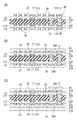
本実施形態のコイル基板10は、以下のようにして製造される。
(1)図4(A)に示すように、絶縁性基材11Kの表裏の両面に、銅箔11Cが積層されている銅張積層板11Zが用意される。絶縁性基材11Kは、エポキシ樹脂又はBT(ビスマレイミドトリアジン)樹脂を、補強繊維からなる織布(例えば、ガラスクロス)に含浸させてなるプリプレグである。
The
(1) As shown to FIG. 4 (A), the copper clad laminated board 11Z by which the
(2)図4(B)に示すように、銅張積層板11Zに接続導体15(図1参照)を形成するための貫通孔11Hが形成される。具体的には、銅張積層板11ZのF面11F側から例えばCO2レーザが照射されてテーパー孔11Aが穿孔される。次いで、銅張積層板11Zのうち前述したF面11F側のテーパー孔11Aの真裏となる位置にCO2レーザが照射されてテーパー孔11Bが穿孔され、テーパー孔11A,11Bから接続導体15用の貫通孔11Hが形成される。
(2) As shown in FIG. 4B, a through
(3)無電解めっき処理が行われ、銅箔11C上と貫通孔11Hの内面とに無電解めっき膜(図示せず)が形成される。次いで、図4(C)に示すように、銅箔11C上の無電解めっき膜上に、所定パターンのめっきレジスト33が形成される。
(3) An electroless plating process is performed, and an electroless plating film (not shown) is formed on the
(4)図4(D)に示すように、電解めっき処理が行われ、電解めっきが貫通孔11H内に充填されて接続導体15が形成されると共に、銅張積層板11ZのF面11FとS面11Sの無電解めっき膜(図示せず)のうちめっきレジスト33から露出している部分の上に電解めっき膜34,34が形成される。
(4) As shown in FIG. 4D, the electrolytic plating process is performed, and the electrolytic plating is filled in the through
(5)めっきレジスト33が剥離されると共に、めっきレジスト33の下方の無電解めっき膜(図示せず)及び銅箔11Cが除去され、図5(A)に示すように、残された電解めっき膜34、無電解めっき膜及び銅箔11Cにより、絶縁性基材11KのF面11F上に前述の第2の導体層22Bを備える一方、S面11S上に第3の導体層22Cを備えるコア基板11が得られる。また、第2と第3の導体層22B,22Cは接続導体15によって接続される。
(5) While the plating resist 33 is peeled off, the electroless plating film (not shown) and the
(6)図5(B)に示すように、第2の導体層22B上及第3の導体層22C上にそれぞれ層間絶縁層21,21が積層される。
(6) As shown in FIG. 5B,
(7)図5(C)に示すように、各層間絶縁層21,21にCO2レーザが照射されて、層間絶縁層21を貫通するテーパー状のビアホール21Hが形成される。
(7) As shown in FIG. 5C, the
(8)無電解めっき処理が行われ、各層間絶縁層21,21上とビアホール21Hの内面とに無電解めっき膜(図示せず)が形成される。次いで、図5(D)に示すように、各層間絶縁層21,21上の無電解めっき膜上に、所定パターンのめっきレジスト40が形成される。
(8) An electroless plating process is performed, and an electroless plating film (not shown) is formed on each interlayer insulating
(9)電解めっき処理が行われ、図6(A)に示すように、電解めっきがビアホール21H内に充填されてビア導体17が形成されると共に、各層間絶縁層21,21の無電解めっき膜(図示せず)のうちめっきレジスト40から露出している部分に電解めっき膜39,39が形成される。
(9) An electrolytic plating process is performed, and as shown in FIG. 6A, the electroplating is filled in the via
(10)次いで、めっきレジスト40が剥離されると共に、めっきレジスト40の下方の無電解めっき膜(図示せず)が除去され、残された電解めっき膜39及び無電解めっき膜によりF面11F側に第1の導体層22Aが形成される一方、S面11S側に第4の導体層22Dが形成される。そして、第1と第2の導体層22A,22Bがビア導体17によって接続されると共に、第3と第4の導体層22C,22Dがビア導体17によって接続される。
(10) Next, the plating resist 40 is peeled off, and the electroless plating film (not shown) below the plating resist 40 is removed, and the
(11)次いで、図6(B)に示すように、第1導電層22A上にF面側ソルダーレジスト層26が積層され、第4導体層22D上に第1絶縁部27Aが積層される。そして、F面側ソルダーレジスト層26及び第1絶縁部27Aが露光されて仮硬化される。なお、このとき、F面側ソルダーレジスト層26のうちパッド29,29が形成される部分にマスクをし、露光されないようにする。
(11) Next, as shown in FIG. 6B, the F-side solder resist
(12)次いで、図6(C)に示すように、B面10B側の第1絶縁部27A上に第2絶縁部27Bが積層されて、再び露光される。そして、F面側ソルダーレジスト層26のうち露光されていない部分を除去した後に、加熱され本硬化される。以上により、第1絶縁部27A及び第2絶縁部27BとからなるS面側ソルダーレジスト層27が形成される。また、F面側ソルダーレジスト層26の所定箇所にテーパー状の開口26Aが形成されて第1の導電層22Aの外側ランド部25及び接続用ランド28の一部がソルダーレジスト層26から露出し、1対のパッド29,29が形成される。以上により、図1に示されるコイル基板10が完成する。
(12) Next, as shown in FIG. 6C, the second insulating
本実施形態のコイル基板10の構成及び製造方法に関する説明は以上である。次に、このコイル基板10の作用効果について説明する。本実施形態のコイル基板10は、例えば、コイル素子として使用される。具体的には、例えば、コイル基板10の1対のパッド29,29が、図示しない回路基板の1対のパッドに対向配置されて、何れかのパッドに備えた半田ボールにて接続される。このようにして、コイル基板10が、回路基板上の回路を構成するコイル素子として使用することができる。
This completes the description of the configuration and manufacturing method of the
また、コイル基板10は、センサーを構成する一部品として使用することもできる。その一例としては、例えば、コイル基板10の1対のパッド29,29に抵抗が接続され、コイル基板10全体が家電製品等における可動部に固定される。その可動部を支持する支持部品には、図示しない電磁コイルを備えるセンサー本体が固定される。また、電磁コイルの一端がコイル基板10の第1面10Fに対向した状態に配置される。そして、可動部の位置に応じて変化する電磁コイルとコイル部23との相互インダクタンスの変化に基づいて可動部の位置や振動を検出する。即ち、コイル基板10をセンサーを構成する一部品として使用することができる。
Moreover, the
ここで、本実施形態のコイル基板10では、B面10B側のソルダーレジスト層27の厚みがF面10F側のソルダーレジスト層27の厚みよりも大きくなっている。即ち、コイル部23を含む導電層22が、コイル基板10のF面10F側に寄せて配置されている。これにより、従来のコイル基板で必要とされた透磁率が高い絶縁層を設ける必要がなくなる。つまり、本実施形態のコイル基板10では、従来より簡素な構造にすることができる。また、補強効果を有するコア基板11自体にも導電層22,22が積層されているので、コア基板11の有効利用が図られる。
Here, in the
[第2実施形態]
図7に示すように、第2実施形態のコイル基板10Vは、B面側ソルダーレジスト層27Vの形状が第1実施形態のコイル基板10と異なる。具体的には、第2絶縁部27VBが角環状に形成され、第1絶縁部27VAの一部を覆う構成となっている。また、第1絶縁部27VAには開口27VHが形成され、開口27VHから露出する第4導体層22Dに形成されている外側ランド部25及び接用ランド28からパッド29,29が形成される。このように、B面側ソルダーレジスト層27Vが一部を覆う構成であっても、B面10B側に配置される電子部品とコイル部23との間に隙間を設けることで、上述した第1実施形態と同様の効果を奏することができる。
[他の実施形態]
[Second Embodiment]
As shown in FIG. 7, the
[Other Embodiments]
本発明は、上記実施形態に限定されるものではなく、例えば、以下に説明するような実施形態も本発明の技術的範囲に含まれ、さらに、下記以外にも要旨を逸脱しない範囲内で種々変更して実施することができる。 The present invention is not limited to the above-described embodiment. For example, the embodiments described below are also included in the technical scope of the present invention, and various modifications are possible within the scope of the invention other than the following. It can be changed and implemented.
(1)上記実施形態のコイル基板10は、平面形状における1箇所にのみコイル部23を備えていたが、平面形状における複数箇所にコイル部23を備えていてもよい。
(1) Although the
(2)上記実施形態のコイル基板10は、隣り合うコイル部23の渦巻形の巻回方向が互いに異なっていたが、同じであってもよい。
(2) In the
(3)上記実施形態のコイル基板10は、ランドの形状が四角形であったが、丸形であってもよい。
(3) Although the land shape of the
(4)上記実施形態のコイル基板10は、コイル部23が角形の渦巻き形状であったが、丸形の渦巻き形状であってもよい。
(4) In the
(5)上記実施形態のコイル基板10は、各導体層22のコイル部23の巻き数が同じであったが、各導体層22のコイル部23の巻き数が異なっていてもよい。このとき、F面10F側の導体層22のコイル部23の巻き数よりも、B面10B側の導体層22のコイル部23の巻き数が小さいほうが好ましい。
(5) In the
(6)上記実施形態は、全ての導体層22にコイル部23が形成されているが、図8に示されるように、一部の導体層23にのみコイル部23を有する構成であってもよい。このとき、B面10B側にコイル部23を有さない複数の導体層22が設けられている。なお、B面10B側にコイル部23を有する導体層22が偏在する場合においては、B面側ソルダーレジスト層27の厚みを、最もF面10F側の近くに配されているコイル部23を有する導体層22の上面からF面10Fまでの距離よりも大きくしてもよい。
(6) Although the
(7)上記実施形態は、第1絶縁部27Aが1層で構成されているが、複数のソルダーレジスト層から構成されてもよい。また、第2絶縁部27Bが1層で構成されているが、複数のソルダーレジスト層から構成されてもよい。
(7) In the above embodiment, the first insulating
10 コイル基板
11 コア基板
15 接続導体
17 ビア導体
21 層間絶縁層(内部絶縁層)
22 導体層
23 コイル部
23K 空白部
24 内側ランド部
25 外側ランド部
26 F面側ソルダーレジスト層(外部絶縁層)
27 B面側ソルダーレジスト層(外部絶縁層)
28 接続用ランド部
10
22
27 B side solder resist layer (external insulation layer)
28 Land for connection
Claims (11)
前記第1外部絶縁層の最外面である第1面から、その第1面に最も近い導体層である第1導体層までの距離より、前記第2外部絶縁層の最外面である第2面から、その第2面に最も近い導体層である第2導体層までの距離の方が長く、
前記第1面から、その第1面に最も近い前記コイル部有り導体層までの距離より、前記第2面から、その第2面に最も近い前記コイル部有り導体層までの距離の方が長い。 Between the first outer insulating layer and the second outer insulating layer, there are a plurality of conductor layers stacked via the inner insulating layer, and a coil portion having a spiral pattern is formed on the plurality of conductor layers. A coil substrate including a plurality of coiled conductor layers,
A second surface that is the outermost surface of the second outer insulating layer from a distance from the first surface that is the outermost surface of the first outer insulating layer to the first conductor layer that is the conductor layer closest to the first surface. To the second conductor layer, which is the conductor layer closest to the second surface, is longer,
The distance from the second surface to the conductor layer with the coil part closest to the second surface is longer than the distance from the first surface to the conductor layer with the coil part closest to the first surface. .
前記第2外部絶縁層は、
前記第2導体層の外側に積層される第1絶縁部と、
前記第1絶縁部の外側に積層される第2絶縁部とを含んでなる。 The coil substrate according to claim 1,
The second outer insulating layer is
A first insulating portion laminated on the outside of the second conductor layer;
And a second insulating part stacked on the outside of the first insulating part.
前記第2外部絶縁層は、
前記第2導体層の外側に積層される第1絶縁部と、
前記第1絶縁部より外側に配置され、前記第1絶縁部の一部を覆う第2絶縁部とを含んでなる。 The coil substrate according to claim 1,
The second outer insulating layer is
A first insulating portion laminated on the outside of the second conductor layer;
And a second insulating part disposed outside the first insulating part and covering a part of the first insulating part.
前記第2外部絶縁層のうち前記第2絶縁部以外を貫通して前記最外の導体層の一部を露出させるパッドを備える。 The coil substrate according to claim 3,
A pad that penetrates the second outer insulating layer other than the second insulating portion and exposes a part of the outermost conductor layer is provided.
前記第1絶縁部の厚さは、前記第1外部絶縁層の厚さと略同一である。 The coil substrate according to any one of claims 2 to 4,
The thickness of the first insulating part is substantially the same as the thickness of the first outer insulating layer.
前記複数の導体層は、前記コイル部有り導体層のみで構成されている。 A coil substrate according to any one of claims 1 to 5,
The plurality of conductor layers are constituted only by the conductor layer with the coil portion.
前記導体層を少なくとも3つ以上有し、それら複数の導体層のうち少なくとも前記第1導体層を含みかつ前記第2導体層を含まない複数の導体層が前記コイル部有り導体層である。 The coil substrate according to claim 1,
A plurality of conductor layers having at least three conductor layers, and among the plurality of conductor layers, a plurality of conductor layers including at least the first conductor layer and not including the second conductor layer are conductor layers with a coil portion.
前記第1外部絶縁層及び前記第2外部絶縁層は、ソルダーレジストである。 The coil substrate according to any one of claims 1 to 7,
The first outer insulating layer and the second outer insulating layer are solder resists.
前記内部絶縁層を貫通して前記コイル部同士を接続する層間接続部を有する。 A coil substrate according to any one of claims 1 to 8,
It has an interlayer connection part that connects the coil parts through the internal insulating layer.
前記コイル部の渦巻の内側端部同士を接続する第1層間接続部と、前記コイル部の渦巻の外側端部同士を接続する第2層間接続部とが板厚方向で交互に配置されて複数の前記コイル部が直列接続されている。 A coil substrate according to any one of claims 1 to 9,
A plurality of first interlayer connection portions that connect the inner ends of the coil portion spirals and second interlayer connection portions that connect the outer end portions of the coil portion spirals are arranged alternately in the plate thickness direction. The coil portions are connected in series.
隣り合う前記導体層同士における前記コイル部の巻回方向が互いに異なる。 The coil substrate according to claim 10, wherein
The winding directions of the coil portions in the adjacent conductor layers are different from each other.
Priority Applications (1)
| Application Number | Priority Date | Filing Date | Title |
|---|---|---|---|
| JP2017055408A JP2018160491A (en) | 2017-03-22 | 2017-03-22 | Coil substrate |
Applications Claiming Priority (1)
| Application Number | Priority Date | Filing Date | Title |
|---|---|---|---|
| JP2017055408A JP2018160491A (en) | 2017-03-22 | 2017-03-22 | Coil substrate |
Publications (2)
| Publication Number | Publication Date |
|---|---|
| JP2018160491A true JP2018160491A (en) | 2018-10-11 |
| JP2018160491A5 JP2018160491A5 (en) | 2019-03-22 |
Family
ID=63796771
Family Applications (1)
| Application Number | Title | Priority Date | Filing Date |
|---|---|---|---|
| JP2017055408A Pending JP2018160491A (en) | 2017-03-22 | 2017-03-22 | Coil substrate |
Country Status (1)
| Country | Link |
|---|---|
| JP (1) | JP2018160491A (en) |
Cited By (4)
| Publication number | Priority date | Publication date | Assignee | Title |
|---|---|---|---|---|
| JP2021044294A (en) * | 2019-09-06 | 2021-03-18 | 株式会社村田製作所 | Inductor component |
| CN115831915A (en) * | 2021-09-17 | 2023-03-21 | 上海玻芯成微电子科技有限公司 | Isolator and chip |
| CN115966548A (en) * | 2021-09-17 | 2023-04-14 | 上海玻芯成微电子科技有限公司 | Inductor and chip |
| CN116825753A (en) * | 2022-03-22 | 2023-09-29 | 上海玻芯成微电子科技有限公司 | Capacitor isolator and chip |
-
2017
- 2017-03-22 JP JP2017055408A patent/JP2018160491A/en active Pending
Cited By (7)
| Publication number | Priority date | Publication date | Assignee | Title |
|---|---|---|---|---|
| JP2021044294A (en) * | 2019-09-06 | 2021-03-18 | 株式会社村田製作所 | Inductor component |
| US11631526B2 (en) | 2019-09-06 | 2023-04-18 | Murata Manufacturing Co., Ltd. | Inductor component |
| JP7449660B2 (en) | 2019-09-06 | 2024-03-14 | 株式会社村田製作所 | inductor parts |
| CN115831915A (en) * | 2021-09-17 | 2023-03-21 | 上海玻芯成微电子科技有限公司 | Isolator and chip |
| CN115966548A (en) * | 2021-09-17 | 2023-04-14 | 上海玻芯成微电子科技有限公司 | Inductor and chip |
| CN115966548B (en) * | 2021-09-17 | 2024-03-12 | 上海玻芯成微电子科技有限公司 | Inductor and chip |
| CN116825753A (en) * | 2022-03-22 | 2023-09-29 | 上海玻芯成微电子科技有限公司 | Capacitor isolator and chip |
Similar Documents
| Publication | Publication Date | Title |
|---|---|---|
| JP2018018868A (en) | Coil substrate and manufacturing method thereof | |
| JP6369536B2 (en) | Coil module | |
| JP2018160491A (en) | Coil substrate | |
| US8686821B2 (en) | Inductor structure | |
| US8819920B2 (en) | Method of manufacturing stacked resonated coil | |
| JP5932916B2 (en) | Inductor and manufacturing method thereof | |
| JP2018198275A (en) | Substrate with built-in coil and method of manufacturing the same | |
| JP2017017116A (en) | Coil component | |
| JP2009277916A (en) | Wiring board, manufacturing method thereof, and semiconductor package | |
| JP2016515305A (en) | Apparatus and method for planar magnetic technology using laminated polymer | |
| KR20160111153A (en) | Inductor and method of maufacturing the same | |
| JPWO2011024921A1 (en) | Printed wiring board and manufacturing method thereof | |
| US10068693B2 (en) | Multi-layer wiring structure, magnetic element and manufacturing method thereof | |
| EP4181159A1 (en) | Inductor assembly and manufacturing method therefor | |
| JP2017220502A (en) | Inductor component and manufacturing method for inductor component | |
| JP7379774B2 (en) | printed circuit board | |
| JP2018018936A (en) | Wiring board | |
| JP2013207149A (en) | Toroidal coil | |
| JP6086370B2 (en) | Inductor built-in substrate manufacturing method, inductor built-in substrate, and power supply module using the same | |
| US20160042861A1 (en) | Printed wiring board | |
| JP2008176626A (en) | Non-contact data carrier and wiring board for non-contact data carrier | |
| JP2018198277A (en) | Substrate with built-in coil | |
| JP2017157793A (en) | Electronic component built-in substrate | |
| JP2016033975A (en) | Electronic component built-in wiring board and manufacturing method of the same | |
| KR100733279B1 (en) | Method of fabricating printed circuit board with embedded inductor |
Legal Events
| Date | Code | Title | Description |
|---|---|---|---|
| A521 | Written amendment |
Free format text: JAPANESE INTERMEDIATE CODE: A523 Effective date: 20190206 |
|
| RD04 | Notification of resignation of power of attorney |
Free format text: JAPANESE INTERMEDIATE CODE: A7424 Effective date: 20190315 |