JP2018128986A - Path correction method and control device of multi-axis processing machine - Google Patents
Path correction method and control device of multi-axis processing machine Download PDFInfo
- Publication number
- JP2018128986A JP2018128986A JP2017023394A JP2017023394A JP2018128986A JP 2018128986 A JP2018128986 A JP 2018128986A JP 2017023394 A JP2017023394 A JP 2017023394A JP 2017023394 A JP2017023394 A JP 2017023394A JP 2018128986 A JP2018128986 A JP 2018128986A
- Authority
- JP
- Japan
- Prior art keywords
- tool
- path
- axis
- workpiece
- correction method
- Prior art date
- Legal status (The legal status is an assumption and is not a legal conclusion. Google has not performed a legal analysis and makes no representation as to the accuracy of the status listed.)
- Granted
Links
Images


Abstract
Description
本発明は、経路補正方法及び多軸加工機の制御装置に関するものである。 The present invention relates to a path correction method and a control device for a multi-axis machine.
例えば、特許文献1には、NCデータの各ブロックの指令位置(目標経路)に対応する実際の加工位置(予測経路)を求め、指令位置と加工位置との差を補正量としてNCデータを修正する補正方法が開示されている。この特許文献1の補正方法においては、加工位置と指令位置との誤差に基づいて、補正量を算出している。 For example, in Patent Document 1, an actual machining position (predicted path) corresponding to a command position (target path) of each block of NC data is obtained, and the NC data is corrected using a difference between the command position and the machining position as a correction amount. A correction method is disclosed. In the correction method of Patent Document 1, the correction amount is calculated based on the error between the machining position and the command position.
ところで、多軸加工機に設けられたモータの特性によって、例えば曲率の大きい形状となるように加工を行う場合に、モータが指示された出力に追従しきれず、指令位置と加工位置との間に誤差が発生する場合がある。このような場合に、特許文献1に記載された手法により補正を実施しても、例えば曲率の大きな曲線状の加工を行う場合等に、実際の加工経路が、指令された経路から大きく外れ、所望の形状に加工できない場合がある。 By the way, due to the characteristics of the motor provided in the multi-axis machine, for example, when machining so as to have a shape with a large curvature, the motor cannot follow the commanded output, and between the command position and the machining position. An error may occur. In such a case, even if correction is performed by the method described in Patent Document 1, the actual machining path is greatly deviated from the commanded path when, for example, a curved process with a large curvature is performed, There is a case where it cannot be processed into a desired shape.
本発明は、上述する問題点に鑑みてなされたもので、より正確に多軸加工機の加工経路を補正することを目的とする。 The present invention has been made in view of the above-described problems, and an object thereof is to more accurately correct a machining path of a multi-axis machining apparatus.
本発明は、上記課題を解決するための経路補正方法に係る第1の手段として、被加工物と接触する領域が曲面に設定されると共に長尺状の工具を複数の基準軸を基準として移動させることにより、上記被加工物を加工する経路補正方法であって、上記工具の先端よりも内側に設けられる基準点における予め記憶された予測経路と、上記被加工物を目標形状とするための上記基準点の目標経路との誤差に基づいて、上記工具の位置を補正する、という構成を採用する。 As a first means related to the path correction method for solving the above-mentioned problems, the area in contact with the workpiece is set to a curved surface and the long tool is moved with reference to a plurality of reference axes. A path correction method for processing the workpiece by performing a prediction path stored in advance at a reference point provided on the inner side of the tip of the tool, and for setting the workpiece to a target shape. A configuration is adopted in which the position of the tool is corrected based on an error from the target path of the reference point.
経路補正方法に係る第2の手段として、上記第1の手段において、上記工具は、エンドミルとされ、上記基準点は、上記工具の工具中心である、という構成を採用する。 As a second means related to the path correction method, a configuration is adopted in which, in the first means, the tool is an end mill, and the reference point is a tool center of the tool.
経路補正方法に係る第3の手段として、上記第1または第2の手段において、上記予測経路は、予め上記工具の運動軌跡を測定することにより算出される、という構成を採用する。 As a third means related to the path correction method, a configuration is adopted in which, in the first or second means, the predicted path is calculated by measuring the motion trajectory of the tool in advance.
経路補正方法に係る第4の手段として、上記第1または第2の手段において、上記予測経路は、予め上記工具の運動軌跡をシミュレーションすることにより算出される、という構成を採用する。 As a fourth means related to the path correction method, a configuration is adopted in which, in the first or second means, the predicted path is calculated in advance by simulating the motion trajectory of the tool.
多軸加工機の制御装置に係る第1の手段として、被加工物と接触する領域が曲面に設定されると共に長尺状の工具を複数の基準軸を基準として移動させることにより、上記被加工物を加工する多軸加工機の制御装置であって、上記工具の先端よりも内側に設けられる基準点の運動軌跡の予測経路をシミュレーションにより算出する予測経路算出手段と上記予測経路と上記被加工物を目標形状とするための上記基準点の目標経路との誤差に基づいて、上記工具の運動量を補正する補正手段とを備える、という構成を採用する。 As a first means related to the control device of the multi-axis machine, the region to be in contact with the workpiece is set as a curved surface, and the long tool is moved with reference to a plurality of reference axes, whereby the workpiece A control apparatus for a multi-axis machine tool for machining an object, wherein a predicted path calculating means for calculating a predicted path of a motion locus of a reference point provided inside a tip of the tool by simulation, the predicted path, and the workpiece A configuration is adopted in which correction means for correcting the momentum of the tool is provided based on an error from the target path of the reference point for making an object a target shape.
本発明によれば、多軸加工機の工具の先端点よりも工具の内側に設けられる基準点に基づいて補正量を決定する。したがって、制御において、基準点の位置をより正確に把握することができ、より正確に多軸加工機の加工経路を補正することができる。 According to the present invention, the correction amount is determined based on the reference point provided inside the tool with respect to the tip point of the tool of the multi-axis machine. Therefore, in the control, the position of the reference point can be grasped more accurately, and the machining path of the multi-axis machine can be corrected more accurately.
以下、図面を参照して、本発明における多軸加工機の制御装置の一実施形態について説明する。なお、以下の図面において、各部材を認識可能な大きさとするために、各部材の縮尺を適宜変更している。 Hereinafter, an embodiment of a control device for a multi-axis machining apparatus according to the present invention will be described with reference to the drawings. In the following drawings, the scale of each member is appropriately changed in order to make each member a recognizable size.
まず、本実施形態において制御装置1により制御される多軸加工機100について説明する。なお、以下の説明においては、設置面に対して平行な一方向をX軸方向とし、設置面に対して平行かつX軸方向に垂直な方向をY軸方向とし、設置面に対して垂直な方向をZ軸方向としている。また、Y軸を中心として回転する方向をB軸方向、Z軸を中心として回転する方向をC軸方向としている。
First, the
多軸加工機100は、コラム110と、Y軸ベース部120と、Z軸ベース部130と、ヘッド部140と、テーブル部150と、旋回機構160とを備えている。
The
コラム110は、上部にY軸ベース部120が設置された直方体状の部材であり、下部にY軸方向に突出したレール載置領域を有している。このレール載置領域の上面には、X軸方向に沿って2本のX軸方向レール111が形成されている。X軸方向レール111上には、テーブル部150が設置されている。X軸方向レール111に沿ってテーブル部150が移動されることにより、テーブル部150がX軸方向に移動可能とされている。Y軸ベース部120は、Z軸に垂直な平板状であり、上面にY軸方向に沿って2本のY軸方向レール121が形成されている。Y軸方向レール121上には、Z軸ベース部130が設置されている。Y軸方向レール121に沿ってZ軸ベース部130が移動されることにより、Z軸ベース部130がY軸方向に移動可能とされている。
The
Z軸ベース部130は、Y軸方向に沿って移動可能であると共に、Z軸に沿う方向の平面に、Z軸方向に沿って2本のZ軸方向レール131が設けられている。また、Z軸方向レール131上には、ヘッド部140が設置されている。Z軸方向レール131に沿ってヘッド部140が移動されることにより、ヘッド部140がX軸方向に移動可能とされている。ヘッド部140は、Z軸方向に移動可能とされ、Y軸方向及びZ軸方向下側に突出した刃物台141と、工具142を有している。
The Z-
刃物台141は、下面に多軸加工機100が備える工具142が取り付けられており、工具142を回転可能に保持している。工具142は、図1(b)に示すように、回転軸O方向に長い長尺状であり、回転軸OがZ軸に沿うように刃物台141に設置されている。工具142は、先端部が球面状のボールエンドミルとされ、先端部の球面状の領域における中心点が工具中心点P1(基準点)とされている。また、工具142において、刃物第141から最も回転軸O方向に突出した点が作用点P2とされている。
The
テーブル部150は、X軸方向に沿って移動可能とされ、Y軸方向に向けて設けられる底部と、Z軸方向に向けて立設される側壁部とを有し、Y軸方向とZ軸方向とに向けて略L字状に屈曲された部材である。テーブル部150は、側壁部に旋回機構160が設けられている。旋回機構160は、パレット161を有し、パレット161をB軸方向及びC軸方向に回転可能としている。パレット161は、被加工物Wが載置され、固定される部材である。
The
制御装置1は、多軸加工機100の加工時における経路算出を行う装置であり、経路算出部1a(予測経路算出手段)と、経路補正部1b(補正手段)とを備えている。制御装置1は、例えばコンピュータとされ、不図示の出力手段及び入力手段を備えるものとしてもよい。経路算出部1aは、被加工物Wの目標形状から工具142の工具中心点P1が辿るべき目標経路を算出し、さらに、多軸加工機100のサーボ系の特性を模擬したシミュレーションにより得られた位置および角度、または多軸加工機の各移動軸が備える位置または角度センサにより測定され記録された位置および角度から、工具中心点P1の予測される経路である予測経路を算出する。なお、目標経路及び予測経路は、複数の座標値の集合であり、それぞれテーブルとして制御装置1に記憶される。経路補正部1bは、目標経路と予測経路とを取得し、目標経路と予測経路との差分値を算出し、目標経路に対して当該差分値の符号を反転させて加算する。
The control device 1 is a device that calculates a route during machining of the
経路補正部1bの各基準軸における制御構成について、図2〜4を参照して説明する。
各基準軸のうち、X軸、Y軸及びC軸では、図2に示すように、Pコントローラaで指令値と積分器bの出力との差分値に比例演算処理を施し、PIコントローラcで当該Pコントローラaの出力と送り軸駆動部dの位置を示す制御量との差分値に比例積分処理を施している。また、Pコントローラaの出力に摩擦補償器eの出力を加算したものを操作量としてPIコントローラcに供給する。なお、上記積分器bは上記制御量を所定の時定数で積分処理して出力するものであり、上記摩擦補償器eは、上記送り軸駆動部dにおける駆動摩擦に対応する補正係数を上記制御量に乗算して出力する。
A control configuration of each reference axis of the
Among the reference axes, for the X, Y, and C axes, as shown in FIG. 2, the P controller a performs a proportional operation on the difference value between the command value and the output of the integrator b, and the PI controller c Proportional integration processing is performed on the difference value between the output of the P controller a and the control amount indicating the position of the feed shaft drive unit d. Further, an output obtained by adding the output of the friction compensator e to the output of the P controller a is supplied as an operation amount to the PI controller c. The integrator b integrates and outputs the control amount with a predetermined time constant, and the friction compensator e controls the correction coefficient corresponding to the driving friction in the feed shaft drive unit d. Multiply by quantity and output.
また、Z軸では、図3に示すように、Pコントローラaで指令値と積分器bの出力との差分値に比例演算処理を施し、PIコントローラcで当該Pコントローラaの出力と送り軸駆動部dの位置を示す制御量との差分値に比例積分処理を施している。さらに、PIコントローラcの出力に、重力による外乱力fを減算したものを操作量として送り軸駆動部dに供給する。また、Pコントローラaの出力に摩擦補償器eの出力を加算したものを操作量としてPIコントローラcに供給する。なお、上記積分器bは上記制御量を所定の時定数で積分処理して出力するものであり、上記摩擦補償器eは、上記送り軸駆動部dにおける駆動摩擦に対応する補正係数を上記制御量に乗算して出力する。 In the Z-axis, as shown in FIG. 3, the P controller a performs a proportional calculation process on the difference value between the command value and the output of the integrator b, and the PI controller c outputs the output of the P controller a and the feed shaft drive. Proportional integration processing is performed on the difference value from the control amount indicating the position of the part d. Further, a value obtained by subtracting the disturbance force f due to gravity to the output of the PI controller c is supplied as an operation amount to the feed shaft drive unit d. Further, an output obtained by adding the output of the friction compensator e to the output of the P controller a is supplied as an operation amount to the PI controller c. The integrator b integrates and outputs the control amount with a predetermined time constant, and the friction compensator e controls the correction coefficient corresponding to the driving friction in the feed shaft drive unit d. Multiply by quantity and output.
また、B軸では、図4に示すように、Pコントローラaで指令値と積分器bの出力との差分値に比例演算処理を施し、PIコントローラcで当該Pコントローラaの出力と送り軸駆動部dの位置を示す制御量との差分値に比例積分処理を施している。さらに、PIコントローラcの出力に、重力による外乱トルクgを減算したものを操作量として送り軸駆動部dに供給する。また、Pコントローラaの出力に摩擦補償器eの出力を加算したものを操作量としてPIコントローラcに供給する。なお、上記積分器bは上記制御量を所定の時定数で積分処理して出力するものであり、上記摩擦補償器eは、上記送り軸駆動部dにおける駆動摩擦に対応する補正係数を上記制御量に乗算して出力する。 For the B axis, as shown in FIG. 4, the P controller a performs a proportional calculation process on the difference value between the command value and the output of the integrator b, and the PI controller c outputs the output of the P controller a and the feed axis drive. Proportional integration processing is performed on the difference value from the control amount indicating the position of the part d. Further, the output of the PI controller c minus the disturbance torque g due to gravity is supplied as an operation amount to the feed shaft drive unit d. Further, an output obtained by adding the output of the friction compensator e to the output of the P controller a is supplied as an operation amount to the PI controller c. The integrator b integrates and outputs the control amount with a predetermined time constant, and the friction compensator e controls the correction coefficient corresponding to the driving friction in the feed shaft drive unit d. Multiply by quantity and output.
多軸加工機100は、工具142をY軸方向及びZ軸方向に移動可能であり、被加工物WをX軸方向、B軸方向及びC軸方向に移動可能である5軸加工機である。多軸加工機100は、加工時において、図5に示すように、作用点P2が常に被加工物Wに接触しながら被加工物Wの周りを回る。この際、工具142及び被加工物Wは、工具142の回転軸Oが常に被加工物Wの法線方向となるように移動される。これにより、工具142は、常に曲面状の領域において被加工物Wと接触することとなる。
The
続いて、本実施形態における制御装置1の経路補正方法を図6を参照して説明する。 Subsequently, a path correction method of the control device 1 in the present embodiment will be described with reference to FIG.
初めに、制御装置1は、目標経路を算出する(ステップS1)。ステップS1では、経路算出部1aが、被加工物Wの目標形状を取得し、目標形状から、被加工物Wに対して工具142の工具中心点P1が辿るべき目標経路を算出する。さらに、制御装置1は、予測経路を算出する(ステップS2)。ステップS2では、経路算出部1aが、数値計算シミュレーションにより、目標経路上に沿って工具142を移動させた場合の工具142の辿る経路を算出する。
First, the control device 1 calculates a target route (step S1). In step S1, the
次に、制御装置1は、目標経路と予測経路との差分を算出する(ステップS3)。ステップS3では、経路補正部1bが、工具中心点P1が辿ると予測される予測経路上の座標と、対応する目標経路上の座標との差分値を算出し、記憶する。さらに、制御装置1は、経路補正を実施する(ステップS4)。ステップS4では、図7に示すように、差分値の符号を反転させ、目標経路上の座標に加算した補正経路を算出し、算出した補正経路を新たな目標経路とし、新たな目標経路上の座標値を多軸加工機100に出力する。なお、該差分値のベクトル方向は、図7における目標経路の法線方向と同一または略同一となる。
Next, the control device 1 calculates a difference between the target route and the predicted route (step S3). In step S3, the
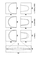
図8は、本実施形態に係る被加工物Wの目標形状と、補正を行わない場合、従来手法による補正を行った場合、および本発明による補正を行った場合における作用点(先端点)の運動軌跡を比較する図である。
被加工物Wの目標形状は、Y軸方向に長く、Y軸方向における中央領域においてX軸方向の厚みが最大となる扁平形状とされており、Y軸方向の両端部が曲率の大きな曲線状とされている。また、被加工物Wは、Y軸方向の一端よりも他端の曲率が大きく設定されている。
FIG. 8 shows the target shape of the workpiece W according to the present embodiment and the action point (tip point) when correction is not performed, when correction is performed by a conventional method, and when correction according to the present invention is performed. It is a figure which compares an exercise | movement locus | trajectory.
The target shape of the workpiece W is a flat shape that is long in the Y-axis direction, has a maximum thickness in the X-axis direction in the central region in the Y-axis direction, and has a curved shape with a large curvature at both ends in the Y-axis direction. It is said that. Further, the workpiece W is set to have a larger curvature at the other end than at one end in the Y-axis direction.
図8の(a)に示す補正を行わない場合では、被加工物WのY軸方向の端部では、破線で示す目標形状から内側に大きくずれている。そして、図8の(b)に示す従来手法による補正を行った場合の結果では、補正を行わない場合よりも破線で示す目標形状に近づいているものの、曲率が大きい側の端部では、工具と実際の加工経路の軌跡がなす角度が変化するため、誤差量が正しく算出できず、目標系上よりも形状が外側にずれている。これに対して、図8の(c)に示す本実施形態における補正形状は、工具と加工経路の軌跡とがなす角度が変化する影響を受けないため、図8における上端及び下端において目標形状と略同一となっている。 In the case where the correction shown in FIG. 8A is not performed, the end portion in the Y-axis direction of the workpiece W is greatly deviated inward from the target shape indicated by the broken line. Then, in the result when the correction by the conventional method shown in FIG. 8B is performed, the tool is closer to the target shape indicated by the broken line than when the correction is not performed. Since the angle formed by the actual machining path trajectory changes, the error amount cannot be calculated correctly, and the shape is shifted outward from the target system. On the other hand, the corrected shape in the present embodiment shown in FIG. 8C is not affected by the change in the angle formed by the tool and the path of the machining path. It is almost the same.
制御装置1に記憶された多軸加工機100の加工プログラムであるCAM(computer aided manufacturing)において、設定上の工具の作用点は、工具位置情報であるCLデータに記され、上述した作用点P2とされている。実際の加工時には、加工経路の軌跡が運動誤差を持つことにより、工具142と加工経路の軌跡とがなす角度が、工具姿勢が同じ場合でも変化する。したがって、作用点P2を基準点として誤差補正を行う従来手法は、目標形状と加工経路の軌跡との誤差量を正しく算出できないという課題を有していた。本実施形態に係る制御装置1においては、工具142の先端よりも内側に設けられる基準点(工具中心点P1)に着目しており、工具142と加工経路の軌跡とがなす角度が変化しても、影響を受けずに正確に誤差を算出できる。
In CAM (computer aided manufacturing), which is a machining program of the
このような本実施形態における多軸加工機100の制御装置1によれば、工具142の工具中心点P1の目標経路と予測経路との差分に基づいて補正経路を算出している。このため、運動誤差による軌跡の傾き等により加工プログラムにおいて設定された作用点P2の軌跡と実際に辿る作用点P2の軌跡とが異なっている場合においても、制御装置1は、多軸加工機100の工具中心点P1の位置に基づいて誤差量を正確に算出し、補正を実施することができる。したがって、図8の結果に示すように、より正確に多軸加工機100の加工経路を補正することができる。
According to the control device 1 of the
また、本実施形態における制御装置1によれば、基準点が工具中心点P1とされている。工具中心点P1は、工具142の先端部における被加工物Wとの当接位置が変化した場合にも、いずれの当接位置に対しても等距離となる。したがって、工具142の当接姿勢によって基準点を変更することなく誤差を算出し、補正を行うことができる。
Further, according to the control device 1 in the present embodiment, the reference point is the tool center point P1. The tool center point P1 is equidistant with respect to any contact position even when the contact position with the workpiece W at the tip of the
また、本実施形態における多軸加工機100は、シミュレーションにより予測経路を算出する。したがって、実際に多軸加工機100により加工することなく、容易に予測経路を算出することができる。
In addition, the
以上、図面を参照しながら本発明の好適な実施形態について説明したが、本発明は上記実施形態に限定されるものではない。上述した実施形態において示した各構成部材の諸形状や組み合わせ等は一例であって、本発明の趣旨から逸脱しない範囲において設計要求等に基づき種々変更可能である。 As mentioned above, although preferred embodiment of this invention was described referring drawings, this invention is not limited to the said embodiment. Various shapes, combinations, and the like of the constituent members shown in the above-described embodiments are examples, and various modifications can be made based on design requirements and the like without departing from the spirit of the present invention.
(1)上記実施形態においては、予測経路をシミュレーションにより算出するものとしたが、本発明はこれに限定されない。予測経路は、実際に多軸加工機100を動かすことにより測定されるものとしてもよい。この場合、制御装置1は、多軸加工機100の実際のサーボ系の特性を取得することができるため、より正確な補正を行うことができ、実機を使った結果においても、形状誤差がほぼ無くなる。
(1) In the above embodiment, the predicted route is calculated by simulation, but the present invention is not limited to this. The predicted path may be measured by actually moving the
(2)上記実施形態においては、工具142がボールエンドミルとしたが、本発明はこれに限定されない。工具142としては、ラジアスエンドミル、スクエアエンドミルやバレル工具等とすることも可能である。なお、バレル工具の場合にも、基準点がバレル工具の先端よりも内側に設けられ、被加工物Wとの当接位置が側周面であるものとする。工具の形状(種類)は上記例示したものに特に限定されるものではなく、工具中心位置P1と作用点P2等を使って予め使用する工具の運動軌跡をシミュレーション可能あれば、本発明は適用可能である。
(2) In the above embodiment, the
(3)また、上記実施形態においては、制御装置1が経路算出部1aにより、予測経路を算出するものとしたが、制御装置1が予測経路を算出せず、別個のコンピュータ等により、予測経路を算出するものとしてもよい。
(3) In the above embodiment, the control device 1 calculates the predicted route by the
(4)また、上記実施形態における制御装置1は、多軸加工機100に備えられるものとしてもよい。
(4) Moreover, the control apparatus 1 in the said embodiment is good also as what is provided in the
(5)さらに、本実施形態においては、一例として、2次元における経路補正方法について説明したが、本発明は3次元的な経路補正においても適用可能である。 (5) Furthermore, in the present embodiment, the two-dimensional path correction method has been described as an example, but the present invention can also be applied to three-dimensional path correction.
(6)また、上記実施形態においては、制御装置1は、工具中心点P1を基準点として用いるものとしたが、本発明はこれに限定されず、工具142において作用点P2よりも工具142の内側であれば、基準点の位置は限定されない。なお、工具中心点P1以外を基準点として用いる場合には、基準点と工具中心点P1との座標の差分を加算または減算することにより、工具中心点P1を基準点として用いる場合と同様に誤差を算出し、補正することができる。
(6) Moreover, in the said embodiment, although the control apparatus 1 shall use the tool center point P1 as a reference point, this invention is not limited to this, In the
1 制御装置
1a 経路算出部
1b 経路補正部
100 多軸加工機
110 コラム
111 X軸方向レール
120 Y軸ベース部
121 Y軸方向レール
130 Z軸ベース部
131 Z軸方向レール
140 ヘッド部
141 刃物台
142 工具
150 テーブル部
160 旋回機構
161 パレット
a コントローラ
b 積分器
c コントローラ
d 軸駆動部
e 摩擦補償器
f 外乱力
g 外乱トルク
O 回転軸
P1 工具中心点
P2 作用点
W 被加工物
DESCRIPTION OF SYMBOLS 1
Claims (5)
前記工具の先端よりも内側に設けられる基準点における予め記憶された予測経路と、前記被加工物を目標形状とするための前記基準点の目標経路との誤差に基づいて、前記工具の位置を補正することを特徴とする経路補正方法。 A path correction method for machining the workpiece by moving a long tool with a plurality of reference axes as a reference while an area in contact with the workpiece is set as a curved surface,
Based on an error between a pre-stored predicted path at a reference point provided inside the tip of the tool and a target path of the reference point for setting the workpiece as a target shape, the position of the tool is determined. A path correction method characterized by correcting.
前記基準点は、前記工具の工具中心であることを特徴とする請求項1記載の経路補正方法。 The tool is an end mill,
The path correction method according to claim 1, wherein the reference point is a tool center of the tool.
前記工具の先端よりも内側に設けられる基準点の運動軌跡の予測経路をシミュレーションにより算出する予測経路算出手段と
前記予測経路と前記被加工物を目標形状とするための前記基準点の目標経路との誤差に基づいて、前記工具の運動量を補正する補正手段と
を備えることを特徴とする多軸加工機の制御装置。 A control device for a multi-axis machining machine for machining the workpiece by moving a long tool with a plurality of reference axes as a reference while an area in contact with the workpiece is set to a curved surface,
A predicted path calculating means for calculating a predicted path of a motion locus of a reference point provided inside the tip of the tool by simulation; a target path of the reference point for setting the predicted path and the workpiece to a target shape; And a correction means for correcting the momentum of the tool based on the error.
Priority Applications (1)
| Application Number | Priority Date | Filing Date | Title |
|---|---|---|---|
| JP2017023394A JP6879766B2 (en) | 2017-02-10 | 2017-02-10 | Path correction method and control device for multi-axis machine |
Applications Claiming Priority (1)
| Application Number | Priority Date | Filing Date | Title |
|---|---|---|---|
| JP2017023394A JP6879766B2 (en) | 2017-02-10 | 2017-02-10 | Path correction method and control device for multi-axis machine |
Publications (2)
| Publication Number | Publication Date |
|---|---|
| JP2018128986A true JP2018128986A (en) | 2018-08-16 |
| JP6879766B2 JP6879766B2 (en) | 2021-06-02 |
Family
ID=63173465
Family Applications (1)
| Application Number | Title | Priority Date | Filing Date |
|---|---|---|---|
| JP2017023394A Active JP6879766B2 (en) | 2017-02-10 | 2017-02-10 | Path correction method and control device for multi-axis machine |
Country Status (1)
| Country | Link |
|---|---|
| JP (1) | JP6879766B2 (en) |
Cited By (4)
| Publication number | Priority date | Publication date | Assignee | Title |
|---|---|---|---|---|
| JP2019197333A (en) * | 2018-05-08 | 2019-11-14 | 株式会社Ihi | Path correction method and control device of multiple spindle processing machine |
| JP2020170355A (en) * | 2019-04-03 | 2020-10-15 | ファナック株式会社 | Evaluation work-piece, machining program and data structure |
| CN116039264A (en) * | 2022-10-31 | 2023-05-02 | 季华实验室 | Control method and device for multi-axis motion platform, terminal equipment and storage medium |
| JP7436174B2 (en) | 2019-10-07 | 2024-02-21 | ファナック株式会社 | Machine Tools |
Citations (4)
| Publication number | Priority date | Publication date | Assignee | Title |
|---|---|---|---|---|
| JPH11143548A (en) * | 1997-11-11 | 1999-05-28 | Yaskawa Electric Corp | Friction compensating method for motor |
| JP2015134400A (en) * | 2013-12-16 | 2015-07-27 | 国立大学法人 東京大学 | Spindle motor control device |
| JP2015156194A (en) * | 2014-02-21 | 2015-08-27 | 三菱重工業株式会社 | Mechanical device control device and friction compensation gain determination method |
| JP2015221491A (en) * | 2014-05-21 | 2015-12-10 | ファナック アメリカ コーポレイション | Route learning control |
-
2017
- 2017-02-10 JP JP2017023394A patent/JP6879766B2/en active Active
Patent Citations (4)
| Publication number | Priority date | Publication date | Assignee | Title |
|---|---|---|---|---|
| JPH11143548A (en) * | 1997-11-11 | 1999-05-28 | Yaskawa Electric Corp | Friction compensating method for motor |
| JP2015134400A (en) * | 2013-12-16 | 2015-07-27 | 国立大学法人 東京大学 | Spindle motor control device |
| JP2015156194A (en) * | 2014-02-21 | 2015-08-27 | 三菱重工業株式会社 | Mechanical device control device and friction compensation gain determination method |
| JP2015221491A (en) * | 2014-05-21 | 2015-12-10 | ファナック アメリカ コーポレイション | Route learning control |
Cited By (7)
| Publication number | Priority date | Publication date | Assignee | Title |
|---|---|---|---|---|
| JP2019197333A (en) * | 2018-05-08 | 2019-11-14 | 株式会社Ihi | Path correction method and control device of multiple spindle processing machine |
| JP7061013B2 (en) | 2018-05-08 | 2022-04-27 | 株式会社Ihi | Path correction method and control device for multi-axis machine |
| JP2020170355A (en) * | 2019-04-03 | 2020-10-15 | ファナック株式会社 | Evaluation work-piece, machining program and data structure |
| JP7088872B2 (en) | 2019-04-03 | 2022-06-21 | ファナック株式会社 | Evaluation workpiece and machining program |
| JP7436174B2 (en) | 2019-10-07 | 2024-02-21 | ファナック株式会社 | Machine Tools |
| CN116039264A (en) * | 2022-10-31 | 2023-05-02 | 季华实验室 | Control method and device for multi-axis motion platform, terminal equipment and storage medium |
| CN116039264B (en) * | 2022-10-31 | 2023-09-22 | 季华实验室 | Control method and device for multi-axis motion platform, terminal equipment and storage medium |
Also Published As
| Publication number | Publication date |
|---|---|
| JP6879766B2 (en) | 2021-06-02 |
Similar Documents
| Publication | Publication Date | Title |
|---|---|---|
| JP7096288B2 (en) | How to control a robot | |
| JP5632036B2 (en) | Device for correcting errors in CNC machine tools | |
| JP4056542B2 (en) | Offline teaching device for robots | |
| JP6295070B2 (en) | Geometric error identification method for multi-axis machine tools and multi-axis machine tools | |
| JP6879766B2 (en) | Path correction method and control device for multi-axis machine | |
| US9423785B2 (en) | Tool trajectory display device having function for displaying inversion position of servo axis | |
| JP6669715B2 (en) | Vibration suppressor | |
| US20070242073A1 (en) | Robot simulation apparatus | |
| JP6585666B2 (en) | Robot for performing learning control in an application that requires constant speed and its control method | |
| JP6490112B2 (en) | Robot controller | |
| JP2006293826A (en) | Apparatus for correcting robot program | |
| WO2018199947A1 (en) | Robotic structure calibrations | |
| JP2020110885A (en) | Route generation device, route generation method, and route generation program | |
| JP2015058492A (en) | Control device, robot system, robot, robot operation information generation method, and program | |
| US11003177B2 (en) | Apparatus and method for generating robot program | |
| US20160077516A1 (en) | Data compensation device, data compensation method, and machining apparatus | |
| JP2016064497A (en) | Data correction device, data correction method and processing device | |
| JP7061013B2 (en) | Path correction method and control device for multi-axis machine | |
| JP2016189136A (en) | Controller, machine tool, and computer program | |
| JP2014135068A (en) | Method and device for creating error map, and numerically controlled machine tool having error map creation function | |
| WO2014068677A1 (en) | Workpiece-attachment-information reporting device | |
| JP2007136671A (en) | Method of evaluating and correcting robot program, and device for evaluating and correcting the robot program | |
| JP2013030005A (en) | Geometrical error correction system for multiaxial machine tool | |
| JP4794937B2 (en) | Programming device for arc welding | |
| JPH0736519A (en) | Nearmiss checking method for robot |
Legal Events
| Date | Code | Title | Description |
|---|---|---|---|
| A521 | Request for written amendment filed |
Free format text: JAPANESE INTERMEDIATE CODE: A821 Effective date: 20170213 |
|
| A521 | Request for written amendment filed |
Free format text: JAPANESE INTERMEDIATE CODE: A523 Effective date: 20170316 |
|
| RD03 | Notification of appointment of power of attorney |
Free format text: JAPANESE INTERMEDIATE CODE: A7423 Effective date: 20181130 |
|
| A521 | Request for written amendment filed |
Free format text: JAPANESE INTERMEDIATE CODE: A821 Effective date: 20181130 |
|
| A621 | Written request for application examination |
Free format text: JAPANESE INTERMEDIATE CODE: A621 Effective date: 20191217 |
|
| A131 | Notification of reasons for refusal |
Free format text: JAPANESE INTERMEDIATE CODE: A131 Effective date: 20201027 |
|
| A521 | Request for written amendment filed |
Free format text: JAPANESE INTERMEDIATE CODE: A523 Effective date: 20201215 |
|
| A131 | Notification of reasons for refusal |
Free format text: JAPANESE INTERMEDIATE CODE: A131 Effective date: 20210112 |
|
| A521 | Request for written amendment filed |
Free format text: JAPANESE INTERMEDIATE CODE: A523 Effective date: 20210312 |
|
| TRDD | Decision of grant or rejection written | ||
| A01 | Written decision to grant a patent or to grant a registration (utility model) |
Free format text: JAPANESE INTERMEDIATE CODE: A01 Effective date: 20210406 |
|
| A61 | First payment of annual fees (during grant procedure) |
Free format text: JAPANESE INTERMEDIATE CODE: A61 Effective date: 20210430 |
|
| R150 | Certificate of patent or registration of utility model |
Ref document number: 6879766 Country of ref document: JP Free format text: JAPANESE INTERMEDIATE CODE: R150 |