JP2018123783A - Exhaust gas purification device - Google Patents
Exhaust gas purification device Download PDFInfo
- Publication number
- JP2018123783A JP2018123783A JP2017017582A JP2017017582A JP2018123783A JP 2018123783 A JP2018123783 A JP 2018123783A JP 2017017582 A JP2017017582 A JP 2017017582A JP 2017017582 A JP2017017582 A JP 2017017582A JP 2018123783 A JP2018123783 A JP 2018123783A
- Authority
- JP
- Japan
- Prior art keywords
- reducing agent
- exhaust gas
- temperature raising
- engine
- raising member
- Prior art date
- Legal status (The legal status is an assumption and is not a legal conclusion. Google has not performed a legal analysis and makes no representation as to the accuracy of the status listed.)
- Pending
Links
Images
Classifications
-
- F—MECHANICAL ENGINEERING; LIGHTING; HEATING; WEAPONS; BLASTING
- F01—MACHINES OR ENGINES IN GENERAL; ENGINE PLANTS IN GENERAL; STEAM ENGINES
- F01N—GAS-FLOW SILENCERS OR EXHAUST APPARATUS FOR MACHINES OR ENGINES IN GENERAL; GAS-FLOW SILENCERS OR EXHAUST APPARATUS FOR INTERNAL-COMBUSTION ENGINES
- F01N3/00—Exhaust or silencing apparatus having means for purifying, rendering innocuous, or otherwise treating exhaust
- F01N3/08—Exhaust or silencing apparatus having means for purifying, rendering innocuous, or otherwise treating exhaust for rendering innocuous
- F01N3/10—Exhaust or silencing apparatus having means for purifying, rendering innocuous, or otherwise treating exhaust for rendering innocuous by thermal or catalytic conversion of noxious components of exhaust
- F01N3/18—Exhaust or silencing apparatus having means for purifying, rendering innocuous, or otherwise treating exhaust for rendering innocuous by thermal or catalytic conversion of noxious components of exhaust characterised by methods of operation; Control
- F01N3/20—Exhaust or silencing apparatus having means for purifying, rendering innocuous, or otherwise treating exhaust for rendering innocuous by thermal or catalytic conversion of noxious components of exhaust characterised by methods of operation; Control specially adapted for catalytic conversion
- F01N3/206—Adding periodically or continuously substances to exhaust gases for promoting purification, e.g. catalytic material in liquid form, NOx reducing agents
- F01N3/2066—Selective catalytic reduction [SCR]
-
- F—MECHANICAL ENGINEERING; LIGHTING; HEATING; WEAPONS; BLASTING
- F01—MACHINES OR ENGINES IN GENERAL; ENGINE PLANTS IN GENERAL; STEAM ENGINES
- F01N—GAS-FLOW SILENCERS OR EXHAUST APPARATUS FOR MACHINES OR ENGINES IN GENERAL; GAS-FLOW SILENCERS OR EXHAUST APPARATUS FOR INTERNAL-COMBUSTION ENGINES
- F01N2240/00—Combination or association of two or more different exhaust treating devices, or of at least one such device with an auxiliary device, not covered by indexing codes F01N2230/00 or F01N2250/00, one of the devices being
- F01N2240/16—Combination or association of two or more different exhaust treating devices, or of at least one such device with an auxiliary device, not covered by indexing codes F01N2230/00 or F01N2250/00, one of the devices being an electric heater, i.e. a resistance heater
-
- F—MECHANICAL ENGINEERING; LIGHTING; HEATING; WEAPONS; BLASTING
- F01—MACHINES OR ENGINES IN GENERAL; ENGINE PLANTS IN GENERAL; STEAM ENGINES
- F01N—GAS-FLOW SILENCERS OR EXHAUST APPARATUS FOR MACHINES OR ENGINES IN GENERAL; GAS-FLOW SILENCERS OR EXHAUST APPARATUS FOR INTERNAL-COMBUSTION ENGINES
- F01N2610/00—Adding substances to exhaust gases
- F01N2610/02—Adding substances to exhaust gases the substance being ammonia or urea
-
- F—MECHANICAL ENGINEERING; LIGHTING; HEATING; WEAPONS; BLASTING
- F01—MACHINES OR ENGINES IN GENERAL; ENGINE PLANTS IN GENERAL; STEAM ENGINES
- F01N—GAS-FLOW SILENCERS OR EXHAUST APPARATUS FOR MACHINES OR ENGINES IN GENERAL; GAS-FLOW SILENCERS OR EXHAUST APPARATUS FOR INTERNAL-COMBUSTION ENGINES
- F01N2610/00—Adding substances to exhaust gases
- F01N2610/10—Adding substances to exhaust gases the substance being heated, e.g. by heating tank or supply line of the added substance
-
- Y—GENERAL TAGGING OF NEW TECHNOLOGICAL DEVELOPMENTS; GENERAL TAGGING OF CROSS-SECTIONAL TECHNOLOGIES SPANNING OVER SEVERAL SECTIONS OF THE IPC; TECHNICAL SUBJECTS COVERED BY FORMER USPC CROSS-REFERENCE ART COLLECTIONS [XRACs] AND DIGESTS
- Y02—TECHNOLOGIES OR APPLICATIONS FOR MITIGATION OR ADAPTATION AGAINST CLIMATE CHANGE
- Y02T—CLIMATE CHANGE MITIGATION TECHNOLOGIES RELATED TO TRANSPORTATION
- Y02T10/00—Road transport of goods or passengers
- Y02T10/10—Internal combustion engine [ICE] based vehicles
- Y02T10/12—Improving ICE efficiencies
Landscapes
- Chemical & Material Sciences (AREA)
- Engineering & Computer Science (AREA)
- Chemical Kinetics & Catalysis (AREA)
- Health & Medical Sciences (AREA)
- Toxicology (AREA)
- Combustion & Propulsion (AREA)
- Mechanical Engineering (AREA)
- General Engineering & Computer Science (AREA)
- Exhaust Gas After Treatment (AREA)
Abstract
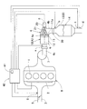
【課題】排気ガス中の還元剤の分布をより均一化する。【解決手段】エンジン8の燃焼室1から引き出された排気通路4と、排気通路4の内壁面よりも内側に設けられ通過する排気ガスによって加熱される昇温部材10と、昇温部材10よりも下流側に設けられ還元剤として尿素を排気ガス中に噴射する還元剤インジェクタ20と、尿素から生成したアンモニアによって排気ガス中の窒素酸化物を浄化する還元触媒13とを備え、還元剤インジェクタ20は、還元剤の尿素を昇温部材10の下流側端部11に向かって噴射するエンジンの排気ガス浄化装置とした。【選択図】図1A uniform distribution of a reducing agent in exhaust gas is provided. An exhaust passage 4 drawn out from a combustion chamber 1 of an engine 8, a temperature raising member 10 provided inside the inner wall surface of the exhaust passage 4 and heated by exhaust gas passing therethrough, and a temperature raising member 10 And a reducing agent injector 20 provided on the downstream side for injecting urea into the exhaust gas as a reducing agent, and a reducing catalyst 13 for purifying nitrogen oxides in the exhaust gas with ammonia generated from urea. The exhaust gas purifying device for the engine that injects the reducing agent urea toward the downstream end portion 11 of the temperature raising member 10. [Selection] Figure 1
Description
この発明は、エンジンから排出される排気ガスを浄化するエンジンの排気ガス浄化装置に関する。 The present invention relates to an engine exhaust gas purification device that purifies exhaust gas discharged from an engine.
一般に、ディーゼルエンジン等における排気ガス浄化装置として、排気ガス中に含まれているディーゼル排気微粒子(PM)や窒素酸化物(NOx)の浄化を目的として、ディーゼル用酸化触媒装置(Diesel Oxidation Catalyst)や、ディーゼル微粒子捕集フィルタ(Diesel Particulate Matter Filter)等が用いられる。 In general, as an exhaust gas purifying device in a diesel engine or the like, a diesel oxidation catalyst device (Diesel Oxidation Catalyst) for the purpose of purifying diesel exhaust particulates (PM) or nitrogen oxides (NOx) contained in exhaust gas, In addition, a diesel particulate filter or the like is used.
また、リーン排気ガス中に含まれる窒素酸化物(NOx)の浄化を目的として、窒素酸化物トラップ触媒装置(NOx Trap Catalyst)や、尿素選択触媒還元装置(Selective Catalytic Reduction)等を用いるシステムが存在する。 In addition, for the purpose of purifying nitrogen oxide (NOx) contained in lean exhaust gas, there is a system using a nitrogen oxide trap catalyst device (NOx Trap Catalyst), a urea selective catalyst reduction device (Selective Catalytic Reduction), or the like. To do.
尿素選択触媒還元装置は、還元触媒本体の上流側に設けた還元剤インジェクタを通じて、還元剤としての尿素水溶液を排気ガス中に噴射することにより、その尿素が排気ガスの熱によって分解されてアンモニア(NH3)となることを利用している。生成されたアンモニアは、還元触媒本体付近で、排気ガス中の窒素酸化物と反応して窒素ガス(N2)と水(H2O)となる。これにより、排気ガス中の窒素酸化物が浄化される。 The urea selective catalytic reduction device injects urea aqueous solution as a reducing agent into exhaust gas through a reducing agent injector provided on the upstream side of the reduction catalyst main body, whereby the urea is decomposed by the heat of the exhaust gas and ammonia ( NH 3 ) is used. The produced ammonia reacts with nitrogen oxides in the exhaust gas in the vicinity of the main body of the reduction catalyst to become nitrogen gas (N 2 ) and water (H 2 O). Thereby, nitrogen oxides in the exhaust gas are purified.
例えば、特許文献1では、ディーゼル用酸化触媒装置、ディーゼル微粒子捕集フィルタを排気通路のガス流動方向に沿って順に配置し、ディーゼル微粒子捕集フィルタの下流側に尿素選択触媒還元装置の還元剤インジェクタ、還元触媒本体を順に配置している。 For example, in Patent Document 1, a diesel oxidation catalyst device and a diesel particulate collection filter are sequentially arranged along the gas flow direction of the exhaust passage, and a reducing agent injector of the urea selective catalyst reduction device is disposed downstream of the diesel particulate collection filter. The reduction catalyst main body is arranged in order.
一般的に、尿素選択触媒還元装置は、窒素酸化物トラップ触媒装置よりも高温域での窒素酸化物の浄化特性に優れる反面、低温域ではその浄化性能が劣るという傾向がある。このため、近年は、尿素選択触媒還元装置をよりエンジンに近接する位置に配置して、高い反応温度を確保するレイアウトとする場合が多くなっている。 In general, a urea selective catalytic reduction device is superior in nitrogen oxide purification characteristics in a high temperature range than a nitrogen oxide trap catalyst device, but tends to have poor purification performance in a low temperature range. For this reason, in recent years, the urea selective catalytic reduction device is often arranged closer to the engine to obtain a layout that ensures a high reaction temperature.
尿素選択触媒還元装置をエンジンの近接位置に配置した場合、エンジンの燃焼室から尿素選択触媒還元装置の還元触媒本体に至る距離が短くなる。このため、噴射された尿素水を、排気ガスが還元触媒本体に流入するまでの間に、排気ガス全体に均一に分布させることが難しい。 When the urea selective catalyst reduction device is arranged at a position close to the engine, the distance from the combustion chamber of the engine to the reduction catalyst body of the urea selective catalyst reduction device is shortened. For this reason, it is difficult to uniformly distribute the injected urea water throughout the exhaust gas until the exhaust gas flows into the reduction catalyst main body.
仮に、排気ガス中における尿素水の均一化が不充分な場合、供給した尿素水量に対して、充分な浄化性能を発揮できないという問題がある。このため、還元剤インジェクタの下流側に、尿素水を排気ガス中に分散させるためのミキサを配置する場合が多い。 If the urea water in the exhaust gas is insufficiently uniform, there is a problem that sufficient purification performance cannot be exhibited with respect to the supplied urea water amount. For this reason, a mixer for dispersing urea water in the exhaust gas is often arranged downstream of the reducing agent injector.
ミキサは、尿素水を排気ガス中に分散させるのにある程度有効である。しかし、刻々と変化する様々な運転状況、温度条件に対して、常に、尿素水を排気ガス中に均一に分布させるには、さらなる改良が求められる。 The mixer is effective to some extent for dispersing urea water in the exhaust gas. However, further improvement is required in order to constantly distribute the urea water uniformly in the exhaust gas with respect to various operating conditions and temperature conditions that change every moment.
そこで、この発明の課題は、排気ガス中に噴射した還元剤の分布をより均一化することである。 Accordingly, an object of the present invention is to make the distribution of the reducing agent injected into the exhaust gas more uniform.
上記の課題を解決するために、この発明は、エンジンの燃焼室から引き出された排気通路と、前記排気通路の内壁面よりも内側に設けられ通過する排気ガスによって加熱される昇温部材と、前記昇温部材よりも下流側に設けられ還元剤を排気ガス中に噴射する還元剤インジェクタと、前記還元剤又は前記還元剤から生成した物質によって排気ガス中の窒素酸化物を浄化する還元触媒とを備え、前記還元剤インジェクタは、前記還元剤を前記昇温部材の下流側端部に向かって噴射するエンジンの排気ガス浄化装置を採用した。 In order to solve the above problems, the present invention includes an exhaust passage drawn from a combustion chamber of an engine, a temperature raising member that is provided inside and passes through an inner wall surface of the exhaust passage, and heated by exhaust gas passing through the exhaust passage, A reducing agent injector provided downstream of the temperature raising member and injecting the reducing agent into the exhaust gas; and a reduction catalyst for purifying nitrogen oxide in the exhaust gas by the reducing agent or a substance generated from the reducing agent; The reducing agent injector employs an engine exhaust gas purification device that injects the reducing agent toward the downstream end of the temperature raising member.
ここで、前記還元剤インジェクタの噴射口は、前記昇温部材の下流側端部に対向するよう配置される構成を採用することができる。 Here, it is possible to adopt a configuration in which the injection port of the reducing agent injector is arranged to face the downstream end of the temperature raising member.
また、前記還元剤が尿素である場合に、前記昇温部材の下流側端部に前記尿素からのアンモニアの生成を促進するアンモニア生成促進触媒が担持されている構成を採用することができる。 Further, when the reducing agent is urea, it is possible to adopt a configuration in which an ammonia generation promotion catalyst that promotes generation of ammonia from the urea is supported on the downstream end portion of the temperature raising member.
前記昇温部材は、酸化触媒装置の一部又は微粒子捕集フィルタの一部である構成を採用することができる。あるいは、前記昇温部材は、前記排気通路の内壁面よりも内側に設けられた多孔質部材、板状部材、軸状部材、網状部材、又は、ハニカム構造の部材である構成を採用することができる。 The temperature raising member may employ a configuration that is a part of an oxidation catalyst device or a part of a particulate collection filter. Alternatively, it is possible to adopt a configuration in which the temperature raising member is a porous member, a plate-like member, a shaft-like member, a net-like member, or a honeycomb structure member provided inside the inner wall surface of the exhaust passage. it can.
前記還元剤インジェクタは、前記排気通路と前記還元剤インジェクタの噴射口との間に還元剤を拡散させる拡散部を有する穴内に設けられる構成を採用することができる。 The reducing agent injector may employ a configuration provided in a hole having a diffusion portion that diffuses the reducing agent between the exhaust passage and the injection port of the reducing agent injector.
また、前記還元剤インジェクタと前記還元触媒との間にミキサを備える構成を採用することができる。 Moreover, the structure provided with a mixer between the said reducing agent injector and the said reduction catalyst is employable.
この発明は、還元剤インジェクタによる還元剤の噴射が、還元剤インジェクタよりも上流側に位置する昇温部材の下流側端部に向かって行われるので、還元剤は排気ガスの流れ方向に対向することによって、噴射時の貫徹力が弱められる。また、その噴射された還元剤は、排気ガスによって温度が高められた昇温部材の下流側端部に付着する。これにより、還元剤は、排気通路の内壁面よりも相対的に温度が高い昇温部材によって気化の促進が図られるので、排気ガス中の還元剤の分布をより均一化することができる。 In this invention, since the injection of the reducing agent by the reducing agent injector is performed toward the downstream end portion of the temperature raising member located upstream of the reducing agent injector, the reducing agent faces the exhaust gas flow direction. As a result, the penetration force at the time of injection is weakened. The injected reducing agent adheres to the downstream end of the temperature raising member whose temperature has been increased by the exhaust gas. Thus, the reducing agent is promoted to be vaporized by the temperature raising member having a temperature relatively higher than that of the inner wall surface of the exhaust passage, so that the distribution of the reducing agent in the exhaust gas can be made more uniform.
以下、この発明の一実施形態を図面に基づいて説明する。図1は、この実施形態のエンジンの排気ガス浄化装置の構成を概念的に示す模式図である。 Hereinafter, an embodiment of the present invention will be described with reference to the drawings. FIG. 1 is a schematic diagram conceptually showing the structure of an exhaust gas purification apparatus for an engine according to this embodiment.
図1に示すように、エンジン8の燃焼室1には、吸気通路3及び排気通路4が接続されている。燃焼室1には、吸気通路3を通じて空気が供給される。また、燃焼室1には、燃料噴射装置2によって燃料が噴射されるようになっている。燃焼室1からの排気ガスは、燃焼室1から引き出された排気通路4を通って送り出され、有害物質を除去する排気浄化部を通過した後に大気へ放出される。
As shown in FIG. 1, an intake passage 3 and an
燃焼室1へ通じる吸気通路3には、上流側から下流側に向かって、エアクリーナ、通路断面積を変化させて吸気の流量を制御するスロットルバルブ5、吸入空気量を検出するエアフローセンサ6等が順に設けられている。
The intake passage 3 leading to the combustion chamber 1 includes an air cleaner, a
燃焼室1から引き出された排気通路4には、上流側から下流側に向かって、機械式過給機のタービン7、上流側の排気浄化部Aとしてのディーゼル用酸化触媒装置、還元剤を排気ガス中に噴射する還元剤インジェクタ20、還元剤を排気ガス中に分散させて均一化を図るミキサ30、還元剤又は還元剤から生成した物質によって排気ガス中の窒素酸化物を浄化する還元触媒13、消音装置としてのマフラ等が順に備えられている。
The
還元剤インジェクタ20とミキサ30、還元触媒13等は、下流側の排気浄化部Bとしての尿素選択触媒還元装置14を構成する。
The reducing
ディーゼル用酸化触媒装置は、前後の排気通路4よりも大きな断面を有する空間をその内部に備え、その空間内には、担体12としてハニカム構造の部材が収容されている。担体12は、排気ガスが通過可能な多数のセルの集合を有している。その素材には、例えば、熱膨張率が小さく、耐熱衝撃性に優れた結晶質のセラミックス(コーディエライト組成)が用いられる。担体の表面には、触媒の機能を発揮するための金属が担持されている。これにより、通過する排気ガス中に含まれる一酸化炭素、炭化水素等の有害物質を、水や二酸化炭素等の無害な物質に浄化させることができる。
The diesel oxidation catalyst device includes a space having a larger cross section than the front and
このように、ディーゼル用酸化触媒装置は、排気通路4の排気管壁の内壁面よりも内側に、通過する排気ガスによって加熱される部材(前記担体12)を備えており、その加熱される部材は、外壁面が外気に触れる排気通路4の排気管壁よりも相対的に高い温度となり得る。このため、以下、このディーゼル用酸化触媒装置の加熱される部材を、昇温部材10と称する。
Thus, the diesel oxidation catalyst device includes a member (the carrier 12) that is heated by the passing exhaust gas inside the inner wall surface of the exhaust pipe wall of the
上流側の排気浄化部Aを構成する昇温部材10、下流側の排気浄化部Bである尿素選択触媒還元装置14は、いずれも、エンジン8の燃焼室1に近く、比較的高温の排気ガスに晒される機会が多い環境にある近接触媒として配置されている。
Both the
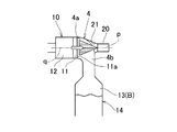
還元剤インジェクタ20は、還元剤を、昇温部材10の下流側端部11に向かって、すなわち、上流側へ向かって噴射する。ここでは、還元剤として尿素(CO(NH2)2)を採用している。
The reducing
尿素は水溶液の状態で還元剤インジェクタ20から噴射され、排気ガス中に飛散するとともに、その一部が昇温部材10に付着する。そして、尿素は、昇温部材10や排気ガスの高熱によって分解され、アンモニアを生成する。高温である昇温部材10に尿素が付着することから、その尿素のアンモニアへの分解が促進される。その外面が外気に触れる排気管壁は昇温部材10よりも温度が低いので、排気管壁に尿素が付着すると尿素の温度が低下し、気化しにくくなる。このため、昇温部材10の下流側端部11に向かって尿素が噴射されることが望ましい。
Urea is injected from the reducing
また、ここでは、昇温部材10の下流側端部11に、尿素からのアンモニアの生成を促進するアンモニア生成促進触媒11aが担持されているので、アンモニアの生成が円滑である。アンモニア生成促進触媒11aは、担体12の下流側の端部の表面に担持させることができる。
Here, since the ammonia
還元剤インジェクタ20は、排気通路4に開口する凹状のオフセット穴21内に設けられる。このため、還元剤インジェクタ20の噴射口は、排気通路4の内壁面よりもやや奥まった位置に配置される。このため、噴射口から配管までの間に拡散部を設けることができ、この拡散部により噴射口から昇温部材10までの噴射距離を長く確保でき、また、還元剤インジェクタ20を排気ガスの熱から保護することができる。さらに、還元剤インジェクタ20が排気ガスの流れを阻害しない。
The reducing
還元剤インジェクタ20は、排気通路4内の排気ガスの流れ方向に対して対向する方向に、還元剤を噴射する。この実施形態では、還元剤インジェクタ20は、排気通路4の直管部4b,4cを結ぶ屈曲部4aの外方側に配置されており、還元剤の噴射方向は、排気ガスの流れ方向に対して、180度逆向きになる方向となっている。すなわち、ここでは、図1に示すように、還元剤インジェクタ20の噴射方向の噴射中心線pと、排気通路4内の排気ガスの流れ中心線qとが、同一直線又は平行となっている。このため、排気ガスの流れによって、噴射された還元剤の貫徹力を弱めることができ、その分散、均一化の促進を図ることができる。
The reducing
還元触媒13内やその付近では、還元触媒13が備える触媒の機能により、尿素から生成したアンモニアと、排気ガスに含まれる窒素酸化物とが反応し、窒素ガスと水が生成される。これにより、排気ガスが大気開放前に浄化される。
In the vicinity of the
ここで、還元剤インジェクタ20と還元触媒13との間にはミキサ30を備えているので、還元剤である尿素の排気ガス中への分散、均一化がさらに促進されている。このためアンモニアの発生、アンモニアと窒素酸化物との反応はさらに良好である。ただし、昇温部材10付近において、還元剤の排気ガス中への分散、均一化が充分に行われている場合には、図2に示す変形例のように、ミキサ30を省略することも可能である。
Here, since the
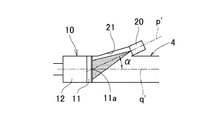
また、例えば、図3の変形例に示すように、還元剤インジェクタ20の噴射方向の噴射中心線p’が、排気通路4内の排気ガスの流れ中心線q’に対して、角度α(0<α<90度)をもって対向する方向としてもよい。この変形例においても、還元剤は、排気通路4内の排気ガスの流れ方向に対して対向する方向に噴射され、昇温部材10の下流側端部11に噴射されている。
For example, as shown in the modification of FIG. 3, the injection center line p ′ in the injection direction of the reducing
排気通路4には、図1に示すように、還元触媒13の上流側(入口付近)に、アンモニアの流入量の情報を取得するアンモニア検出部bを備えている。また、還元触媒13の下流側(出口付近)に、窒素酸化物の排出量の情報を取得する窒素酸化物検出部c、O2センサdが備えられている。さらに、昇温部材10の上流側(入口付近)には、排気ガスの温度を検出する排気ガス温度検出手段aを備えている。
As shown in FIG. 1, the
このエンジン8を搭載する車両は、電子制御ユニット(Electronic Control Unit)40を備えている。吸排気バルブや燃料噴射装置、その他エンジン8の動作に必要な機器、車両の各種装備等は、すべて電子制御ユニット40によって制御される。また、各種センサ類からの情報は、ケーブルを通じて電子制御ユニット40へ伝達される。
A vehicle equipped with the
電子制御ユニット40は、アンモニア検出部bによるアンモニアの流入量の情報と、窒素酸化物検出部cによる窒素酸化物の排出量の情報に基づいて、燃焼室1に供給される燃料の噴射量及び吸気の量を制御し、あるいは、噴射する還元剤の量や時期を制御するエンジン制御装置41を備えている。
Based on the information on the amount of inflow of ammonia by the ammonia detector b and the information on the amount of nitrogen oxide discharged by the nitrogen oxide detector c, the
エンジン制御装置41は、これらの制御により、運転状態に応じて、還元触媒13の上流側で生成するアンモニアの量を制御することで、窒素酸化物の排出量を低減することができる。
With these controls, the
なお、上記の実施形態では、昇温部材10における排気ガスで加熱される部材を、排気通路4の内壁面よりも内側に設けられたハニカム構造の担体12としたが、この担体12として、ハニカム構造の部材以外に、例えば、多孔質部材、板状部材、軸状部材、網状部材等を配置する場合も考えられる。また、昇温部材10として、ディーゼル用酸化触媒装置を構成する部材に代えて、例えば、ディーゼル微粒子捕集フィルタを構成するフィルタ部材等の他の形態の排気浄化部を構成する部材としてもよい。あるいは、昇温部材10として、排気浄化以外の目的、例えば、整流、圧力調整等を目的とする各種形状の部材としてもよい。このとき、部材の形状は、ハニカム構造の部材、多孔質部材、板状部材、軸状部材、網状部材等の場合が考えられる。
In the above embodiment, the member heated by the exhaust gas in the
また、上記の実施形態では、還元剤として尿素を採用したが、尿素以外の還元剤を採用する場合にも、この発明を適用できる。例えば、還元剤としてアンモニアを採用し、そのアンモニアの水溶液等を噴射してもよい。 Moreover, although urea was employ | adopted as a reducing agent in said embodiment, this invention is applicable also when employ | adopting reducing agents other than urea. For example, ammonia may be employed as the reducing agent and an aqueous solution of the ammonia may be injected.
さらに、上記の実施形態では、上流側の排気浄化部Aと下流側の排気浄化部Bをいずれも近接触媒としたが、上流側の排気浄化部Aと下流側の排気浄化部Bを、それぞれエンジン8の燃焼室1から遠く、比較的高温の排気ガスに晒される機会が少ない環境にある床下触媒として配置する場合にもこの発明を適用できる。
Further, in the above embodiment, the upstream side exhaust purification unit A and the downstream side exhaust purification unit B are both close catalysts, but the upstream side exhaust purification unit A and the downstream side exhaust purification unit B are respectively The present invention can also be applied to the case where the catalyst is disposed as an underfloor catalyst located in an environment far from the combustion chamber 1 of the
この実施形態では、ディーゼルエンジンにおける排気ガスの浄化について説明したが、この発明は、ディーゼルエンジン以外にも、排気ガス中への還元剤の噴射によって、その還元剤又はその還元剤から生成した物質によって、排気ガス中の窒素酸化物を浄化する還元触媒本体を備えたエンジン全般に用いることができる。 In this embodiment, the purification of exhaust gas in a diesel engine has been described. However, in addition to the diesel engine, the present invention is based on the reducing agent or a substance generated from the reducing agent by injection of the reducing agent into the exhaust gas. The engine can be used for all engines equipped with a reduction catalyst body that purifies nitrogen oxides in exhaust gas.
1 燃焼室
2 燃料噴射装置
3 吸気通路
4 排気通路
5 スロットルバルブ
6 エアフローセンサ
7 過給機
8 エンジン
10 昇温部材
11 下流側端部
11a アンモニア生成促進触媒
12 担体
13 還元触媒
14 尿素選択触媒還元装置
20 還元剤インジェクタ
21 オフセット穴
30 ミキサ
40 電子制御ユニット
41 エンジン制御装置
a 排気ガス温度検出手段
b アンモニア検出部
c 窒素酸化物検出部
d O2センサ
DESCRIPTION OF SYMBOLS 1
Claims (7)
前記排気通路の内壁面よりも内側に設けられ通過する排気ガスによって加熱される昇温部材と、
前記昇温部材よりも下流側に設けられ還元剤を排気ガス中に噴射する還元剤インジェクタと、
前記還元剤又は前記還元剤から生成した物質によって排気ガス中の窒素酸化物を浄化する還元触媒と、
を備え、
前記還元剤インジェクタは、前記還元剤を前記昇温部材の下流側端部に向かって噴射する
エンジンの排気ガス浄化装置。 An exhaust passage drawn from the combustion chamber of the engine;
A temperature raising member that is provided inside the inner wall surface of the exhaust passage and is heated by exhaust gas passing therethrough,
A reducing agent injector provided downstream of the temperature raising member and injecting the reducing agent into the exhaust gas;
A reduction catalyst for purifying nitrogen oxides in exhaust gas by the reducing agent or a substance generated from the reducing agent;
With
The reducing agent injector is an engine exhaust gas purification device that injects the reducing agent toward a downstream end of the temperature raising member.
エンジンの排気ガス浄化装置。 An exhaust gas purifying device for an engine, wherein an injection port of the reducing agent injector is arranged to face a downstream end portion of the temperature raising member.
前記昇温部材の下流側端部に前記尿素からのアンモニアの生成を促進するアンモニア生成促進触媒が担持されている
請求項1又は2に記載のエンジンの排気ガス浄化装置。 The reducing agent is urea;
The engine exhaust gas purification device according to claim 1 or 2, wherein an ammonia generation promotion catalyst for promoting generation of ammonia from the urea is supported at a downstream end portion of the temperature raising member.
請求項1〜3の何れか1項に記載のエンジンの排気ガス浄化装置。 The engine exhaust gas purification device according to any one of claims 1 to 3, wherein the temperature raising member is a part of an oxidation catalyst device or a part of a particulate collection filter.
請求項1〜4の何れか1項に記載のエンジンの排気ガス浄化装置。 The temperature raising member is a porous member, a plate-like member, a shaft-like member, a net-like member, or a honeycomb structure member provided inside the inner wall surface of the exhaust passage. The engine exhaust gas purifying apparatus according to claim 1.
請求項1〜5の何れか1項に記載のエンジンの排気ガス浄化装置。 The engine exhaust according to any one of claims 1 to 5, wherein the reducing agent injector is provided in a hole having a diffusion portion for diffusing the reducing agent between the exhaust passage and an injection port of the reducing agent injector. Gas purification device.
請求項1〜6の何れか1項に記載のエンジンの排気ガス浄化装置。 The engine exhaust gas purification apparatus according to any one of claims 1 to 6, further comprising a mixer between the reducing agent injector and the reduction catalyst.
Priority Applications (2)
| Application Number | Priority Date | Filing Date | Title |
|---|---|---|---|
| JP2017017582A JP2018123783A (en) | 2017-02-02 | 2017-02-02 | Exhaust gas purification device |
| EP18152163.4A EP3358158B1 (en) | 2017-02-02 | 2018-01-17 | Exhaust gas purification device |
Applications Claiming Priority (1)
| Application Number | Priority Date | Filing Date | Title |
|---|---|---|---|
| JP2017017582A JP2018123783A (en) | 2017-02-02 | 2017-02-02 | Exhaust gas purification device |
Publications (1)
| Publication Number | Publication Date |
|---|---|
| JP2018123783A true JP2018123783A (en) | 2018-08-09 |
Family
ID=61005746
Family Applications (1)
| Application Number | Title | Priority Date | Filing Date |
|---|---|---|---|
| JP2017017582A Pending JP2018123783A (en) | 2017-02-02 | 2017-02-02 | Exhaust gas purification device |
Country Status (2)
| Country | Link |
|---|---|
| EP (1) | EP3358158B1 (en) |
| JP (1) | JP2018123783A (en) |
Families Citing this family (1)
| Publication number | Priority date | Publication date | Assignee | Title |
|---|---|---|---|---|
| CN115898598B (en) * | 2023-02-08 | 2025-05-30 | 中船发动机有限公司 | High-voltage SCR evaporation mixing device and use method |
Family Cites Families (5)
| Publication number | Priority date | Publication date | Assignee | Title |
|---|---|---|---|---|
| DE102009021616A1 (en) * | 2009-05-15 | 2010-11-18 | Makon Engineering Gmbh | Exhaust gas post treating device for use in ship, has catalyst unit post treating exhaust gas of exhaust gas flow, and adding unit adding component during post treatment of exhaust gas, where adding unit includes fluid tank |
| US8359832B2 (en) * | 2009-12-21 | 2013-01-29 | Caterpillar Inc. | SCR reductant mixer |
| KR101251518B1 (en) | 2010-12-09 | 2013-04-05 | 기아자동차주식회사 | Dosing module for exhaust after-treatment system of vehicle |
| MY164098A (en) * | 2012-03-02 | 2017-11-30 | Continental Automotive Gmbh | Method for operating a heating catalyst |
| DE102015212485B4 (en) * | 2015-07-03 | 2018-06-14 | Ford Global Technologies, Llc | Exhaust tract with spraying against a flow direction metering device, method for operating an exhaust tract and vehicle with exhaust tract |
-
2017
- 2017-02-02 JP JP2017017582A patent/JP2018123783A/en active Pending
-
2018
- 2018-01-17 EP EP18152163.4A patent/EP3358158B1/en not_active Not-in-force
Also Published As
| Publication number | Publication date |
|---|---|
| EP3358158B1 (en) | 2020-09-16 |
| EP3358158A1 (en) | 2018-08-08 |
Similar Documents
| Publication | Publication Date | Title |
|---|---|---|
| JP4943499B2 (en) | Exhaust gas purification device for internal combustion engine | |
| US9689290B2 (en) | Reductant mixing system for an exhaust gas after-treatment device | |
| CN101779013B (en) | Exhaust purification apparatus | |
| JP4450257B2 (en) | Exhaust purification device | |
| PL1892396T3 (en) | Exhaust gas post treatment system | |
| EP2423479A2 (en) | Exhaust gas purification apparatus | |
| JP2009156071A (en) | Exhaust gas purification device for internal combustion engine | |
| CN215115382U (en) | Exhaust system | |
| JP4662334B2 (en) | Exhaust gas purification device for internal combustion engine | |
| KR101795402B1 (en) | Exhaust system | |
| CN213574303U (en) | Exhaust system | |
| JP2018123788A (en) | Exhaust gas purification device | |
| JP2018131997A (en) | Exhaust emission control device | |
| CN108060961B (en) | Reducing agent spray and exhaust flow guide and deflector | |
| KR101022018B1 (en) | Exhaust gas purification system of engine and marine engine comprising same | |
| US10329990B2 (en) | Asymmetric catalyst cone for swirl induction of exhaust gas flow | |
| JP4784761B2 (en) | Exhaust purification device | |
| JP2018123783A (en) | Exhaust gas purification device | |
| JP2010090808A (en) | Exhaust emission control device and exhaust emission control device for internal combustion engine | |
| JP4577099B2 (en) | Exhaust gas purification device for internal combustion engine | |
| JP2008128046A (en) | Exhaust purification device | |
| JP6020105B2 (en) | Diesel engine exhaust gas purification method and exhaust gas purification system | |
| JP2012092746A (en) | Exhaust emission control device | |
| JP4844766B2 (en) | Exhaust purification device | |
| US10428712B2 (en) | Variable-position mixer for an exhaust gas after-treatment system |