JP2018123777A - vehicle - Google Patents
vehicle Download PDFInfo
- Publication number
- JP2018123777A JP2018123777A JP2017017382A JP2017017382A JP2018123777A JP 2018123777 A JP2018123777 A JP 2018123777A JP 2017017382 A JP2017017382 A JP 2017017382A JP 2017017382 A JP2017017382 A JP 2017017382A JP 2018123777 A JP2018123777 A JP 2018123777A
- Authority
- JP
- Japan
- Prior art keywords
- canister
- main
- sub
- vehicle
- port
- Prior art date
- Legal status (The legal status is an assumption and is not a legal conclusion. Google has not performed a legal analysis and makes no representation as to the accuracy of the status listed.)
- Pending
Links
Images


Abstract
Description
本発明はキャニスタを備えた車両に関する。 The present invention relates to a vehicle including a canister.
内燃機関を駆動源とする車両には、燃料タンク内の燃料から蒸発する燃料蒸発ガスを燃料吸着材により吸着することで大気中への燃料蒸発ガスの放出を防止するキャニスタが設けられている。
キャニスタは、例えばフロアパネルの下方に設けられ、キャニスタには、キャニスタ内に外気を導入する大気開放管が設けられ、燃料吸着材に吸着された燃料を大気開放管から導入された外気と共にエンジンに供給して燃焼させる構成となっており、大気開放管の端部は、大気側に開放された大気開放口となっている。
この大気開放口から燃料蒸発ガスの一部が漏れることを抑制するため、メインキャニスタと大気開放管との間にサブキャニスタを介設し、メインキャニスタで吸着しきれなかった燃料蒸発ガスをサブキャニスタで吸着するようにしたキャニスタが提供されている。
特許文献1には、メインキャニスタとサブキャニスタとをそれらの延在方向を平行させかつ水平方向に並べて配置すると共に、メインキャニスタのメイン側連通ポートとサブキャニスタのサブ側連通ポートとを連通管を介して連結したキャニスタが開示されている。
そして、メインキャニスタの延在方向の一端にメイン側連通ポートを設け、サブキャニスタの延在方向の他端にサブ側連通ポートを設けている。
A vehicle having an internal combustion engine as a drive source is provided with a canister that prevents the fuel evaporative gas from being released into the atmosphere by adsorbing the fuel evaporative gas evaporating from the fuel in the fuel tank with a fuel adsorbent.
The canister is provided, for example, below the floor panel. The canister is provided with an air release pipe for introducing outside air into the canister, and the fuel adsorbed by the fuel adsorbent is introduced into the engine together with the outside air introduced from the air release pipe. It is the structure which supplies and burns, and the edge part of an atmospheric | air release pipe | tube serves as the air release port open | released by the atmosphere side.
In order to prevent a part of the fuel evaporative gas from leaking from the atmosphere opening, a sub canister is interposed between the main canister and the atmosphere opening pipe so that the fuel evaporating gas that could not be adsorbed by the main canister is sub-canister. A canister is provided that is adsorbed on the canister.
In Patent Document 1, a main canister and a sub-canister are arranged with their extending directions parallel to each other and arranged in a horizontal direction, and a communication pipe is provided between the main-side communication port of the main canister and the sub-side communication port of the sub-canister. A canister connected via a cable is disclosed.
A main communication port is provided at one end in the extending direction of the main canister, and a sub communication port is provided at the other end in the extending direction of the sub canister.
しかしながら、上記従来技術では、メインキャニスタとサブキャニスタとがそれらの延在方向を平行させ水平方向に並べられているため、平面視した場合のキャニスタの占有スペースが大きく、フロアパネル下方に設けられる他の部材との関係上、キャニスタを配設するためのスペースを確保し難い不具合がある。
また、メインキャニスタおよびサブキャニスタの延在方向の両端にメイン連通ポートとサブ側連通ポートを設けているため、車両の衝突時にメイン連通ポート、サブ側連通ポートの双方の保護を図り損傷を抑制する上で不利があり、燃料蒸発ガスの漏出を抑制する上で改善の余地がある。
本発明は、上記事情に鑑みなされたものであり、平面視した場合のキャニスタが占める面積のコンパクト化を図りつつ、車両衝突時にキャニスタの各ポートをまとめて保護しやすく、燃料蒸発ガスの漏出を抑制する上で有利な車両を提供することを目的とする。
However, in the above prior art, the main canister and the sub-canister are arranged in the horizontal direction with their extending directions parallel to each other, so that the canister occupies a large space when viewed in plan, and is provided below the floor panel. There is a problem that it is difficult to secure a space for arranging the canister due to the relationship with the member.
In addition, since the main communication port and the sub-side communication port are provided at both ends in the extending direction of the main canister and the sub-canister, both the main communication port and the sub-side communication port are protected in the event of a vehicle collision to prevent damage. There is a disadvantage in the above, and there is room for improvement in suppressing leakage of fuel evaporative gas.
The present invention has been made in view of the above circumstances, and it is easy to protect the ports of the canister together at the time of a vehicle collision while reducing the area occupied by the canister when viewed in plan, thereby preventing leakage of fuel evaporative gas. An object of the present invention is to provide a vehicle that is advantageous in terms of suppression.
上記目的を達成するために、請求項1記載の発明は、内部が主室と副室に区画されるメインキャニスタと前記メインキャニスタより容積が小さい吸着室を有するサブキャニスタとを備える車両であって、前記メインキャニスタは、燃料タンクと接続するベーパーポートと、前記車両に搭載された内燃機関の吸気通路に接続するパージポートとを有し、前記メインキャニスタと前記サブキャニスタとは前記メインキャニスタに設けられたメイン側連通ポートと前記サブキャニスタに設けられたサブ側連通ポートとで接続され、前記メインキャニスタの上方に前記サブキャニスタが重ねて配置され、下方から上方へ前記メインキャニスタの主室、前記メインキャニスタの副室、前記サブキャニスタの吸着室の順に配置され、前記ベーパーポートおよび前記パージポートと、前記メイン側連通ポート及び前記サブ側連通ポートは、車両前後方向の一方に偏って配置されていることを特徴とする。
請求項2記載の発明は、前記メインキャニスタと前記サブキャニスタは車両の下方及び後部に配置され、前記ベーパーポート、前記パージポート、前記メイン側連通ポート及び前記サブ側連通ポートは、車両の前方に向けて配置されていることを特徴とする。
請求項3記載の発明は、前記メインキャニスタはブラケットを介して前記車両の下方に固定され、車両の後方から見て、前記メインキャニスタの後部は、前記メインキャニスタを前記ブラケットで覆われていることを特徴とする。
請求項4記載の発明は、前記メイン側連通ポートと前記サブ側連通ポートとは、前記車両の車幅方向に互いに偏位して配置されていることを特徴とする。
請求項5記載の発明は、前記サブ側連通ポートは、前記メイン側連通ポートより車幅方向外側に配置されていることを特徴とする。
In order to achieve the above object, an invention according to claim 1 is a vehicle comprising a main canister whose interior is divided into a main chamber and a sub chamber, and a sub canister having a suction chamber having a smaller volume than the main canister. The main canister has a vapor port connected to a fuel tank and a purge port connected to an intake passage of an internal combustion engine mounted on the vehicle, and the main canister and the sub-canister are provided in the main canister. A main communication port and a sub communication port provided on the sub-canister, the sub-canister is disposed above the main canister, and the main chamber of the main canister The sub-chamber of the main canister and the suction chamber of the sub-canister are arranged in this order. And fine the purge port, the main-side communication port and the sub-side communication port, characterized in that it is disposed biased to one of the longitudinal direction of the vehicle.
According to a second aspect of the present invention, the main canister and the sub-canister are disposed below and at the rear of the vehicle, and the vapor port, the purge port, the main-side communication port, and the sub-side communication port are disposed in front of the vehicle. It is characterized by being arranged.
According to a third aspect of the present invention, the main canister is fixed to the lower portion of the vehicle via a bracket, and the main canister is covered with the bracket at the rear portion of the main canister as viewed from the rear of the vehicle. It is characterized by.
The invention according to claim 4 is characterized in that the main-side communication port and the sub-side communication port are displaced from each other in the vehicle width direction of the vehicle.
The invention according to claim 5 is characterized in that the sub-side communication port is arranged on the outer side in the vehicle width direction than the main-side communication port.
請求項1記載の発明によれば、燃料蒸発ガスは空気よりも比重が重く、この空気よりも比重が重い燃料蒸発ガスが、ベーパーポートから上方に向かって主室、副室、吸着室の順番で通過するため、主室、副室、吸着室の各燃料吸着材による燃料蒸発ガスの吸着効率の向上を図る上で有利となることは無論のこと、メインキャニスタとサブキャニスタとをそれらの延在方向を平行させて水平方向に並べて配置する場合に比較して平面視した場合のキャニスタが占める面積をコンパクト化でき、フロアパネル下方においてキャニスタを配設するためのスペースを確保し易い。
また、ベーパーポート、パージポート、メイン側連通ポート、サブ側連通ポートを車両前後方向の一方に偏って配置したので、車両衝突時にそれら各ポートをまとめて保護しやすく、各ポートの損傷の抑制を図り、燃料蒸発ガスの漏出を抑制する上で有利となる。
請求項2記載の発明によれば、車両の後突時にそれら各ポートに車両後方から加わる荷重を軽減でき、各ポートの損傷の抑制を図り、燃料蒸発ガスの漏出を抑制する上で有利となる。
請求項3記載の発明によれば、車両の後突時にメインキャニスタに車両後方から加わる荷重を軽減でき、メインキャニスタの損傷の抑制を図る上で有利となる。
請求項4、5記載の発明によれば、メイン側連通ポート、サブ側連通ポートを連結する連通管の全長を大きく確保でき、連通管の容積の増加を図ることで、連通管に貯留される燃料蒸発ガスの量を大きく確保できる。そのため、サブキャニスタの大気ポートから大気開放管を介して大気中に漏れ出る燃料蒸発ガスの量を抑制する上で有利となる。
また、請求項5記載の発明によれば、キャニスタを、車両の後部でリアフロアパネルの下方に配置し、かつ、リアサイドメンバの車幅方向外側に配置する場合、サブ側連通ポートが設けられているサブキャニスタの前部とリアサイドメンバとの干渉を避けつつ、メインキャニスタをリアサイドメンバに近接させて配置することが可能となる。そのため、比較的重量が大きいメインキャニスタを車体に対して安定して支持でき、キャニスタの耐久性の向上を図る上で有利となる。
According to the first aspect of the present invention, the fuel evaporative gas has a higher specific gravity than air, and the fuel evaporative gas having a higher specific gravity than air has an order of the main chamber, the sub chamber, and the adsorption chamber in the upward direction from the vapor port. Of course, it is advantageous to improve the adsorption efficiency of the fuel evaporative gas by the fuel adsorbents in the main chamber, sub chamber, and adsorption chamber, and the main canister and sub canister can be extended. The area occupied by the canister when viewed in plan can be reduced compared to the case where the present directions are arranged in parallel and arranged in the horizontal direction, and a space for arranging the canister can be easily secured below the floor panel.
In addition, because the vapor port, purge port, main side communication port, and sub-side communication port are arranged in one direction in the vehicle front-rear direction, these ports can be easily protected together in the event of a vehicle collision, and damage to each port is suppressed. This is advantageous in suppressing leakage of fuel evaporative gas.
According to the second aspect of the present invention, it is possible to reduce the load applied to each of these ports from the rear of the vehicle at the time of rear-end collision of the vehicle, which is advantageous in suppressing damage to each port and suppressing leakage of fuel evaporative gas. .
According to the third aspect of the present invention, it is possible to reduce the load applied to the main canister from the rear of the vehicle at the time of rear-end collision of the vehicle, which is advantageous in suppressing damage to the main canister.
According to the fourth and fifth aspects of the present invention, the overall length of the communication pipe connecting the main side communication port and the sub-side communication port can be secured large, and the communication pipe is stored in the communication pipe by increasing the volume of the communication pipe. A large amount of fuel evaporative gas can be secured. Therefore, it is advantageous in suppressing the amount of fuel evaporating gas that leaks from the atmospheric port of the sub-canister into the atmosphere via the atmospheric open pipe.
According to the fifth aspect of the present invention, when the canister is disposed below the rear floor panel at the rear of the vehicle and disposed outside the rear side member in the vehicle width direction, the sub-side communication port is provided. The main canister can be disposed close to the rear side member while avoiding interference between the front portion of the sub-canister and the rear side member. Therefore, the main canister having a relatively large weight can be stably supported with respect to the vehicle body, which is advantageous in improving the durability of the canister.
以下、本発明の実施の形態について図面を参照して説明する。
なお、本実施の形態は、車両が内燃機関のみを備える車両である場合について説明するが、本発明は、車両が内燃機関に加えて電気モータを備える車両、すなわち、ハイブリッド車、プラグインハイブリッド車にも無論適用可能である。
なお、図面において、矢印FRは車両の前方を示し、矢印OUTは車幅方向外側を示し、矢印INは車幅方向内側を示し、矢印UPは車両の上方を示し、本明細書において左右方向は車両の前方を向いた状態で規定するものとする。
Hereinafter, embodiments of the present invention will be described with reference to the drawings.
Although the present embodiment describes a case where the vehicle is a vehicle including only an internal combustion engine, the present invention describes a vehicle including an electric motor in addition to the internal combustion engine, that is, a hybrid vehicle and a plug-in hybrid vehicle. Of course, it is also applicable.
In the drawings, the arrow FR indicates the front of the vehicle, the arrow OUT indicates the outer side in the vehicle width direction, the arrow IN indicates the inner side in the vehicle width direction, the arrow UP indicates the upper side of the vehicle. It shall be defined with the vehicle facing forward.
まず、車両の後部の構造について説明する。
図1に示すように、車両10は、車体12、不図示のエンジン、不図示の前輪、後輪14、燃料タンク16、キャニスタ18を含んで構成されている。
車体12の後部は、一対のリアサイドメンバ20と、リアサスペンションクロスメンバ22と、リアフロアパネル24とを含んで構成されている。
一対のリアサイドメンバ20は、車両10の車幅方向に間隔をおいて車両前後方向に延在している。
リアサスペンションクロスメンバ22は、後輪14のサスペンション装置が組み付けられる箇所であり、車幅方向に延在して一対のリアサイドメンバ20を連結している。
リアフロアパネル24は、車両後部の下部に配置され、鋼板で構成され、リアフロアパネル24の下面の車幅方向の両側が一対のリアサイドメンバ20に溶接により接合されている。
エンジンは、車室前方の車両前部空間に配置され、燃料を燃焼させることにより発生した動力により駆動輪、例えば前輪を回転させる。
燃料タンク16は、燃料を貯留してエンジンに供給するものであり、リアサスペンションクロスメンバ22の前方でかつ車幅方向の中央でリアフロアパネル24の下方に配置され、不図示のクロスメンバに取着されている。
なお、図中、符号26はリアバンパビームを示し、符号28はリアフロアパネル24に形成されスペアタイヤを収容する収容部を示す。
First, the structure of the rear part of the vehicle will be described.
As shown in FIG. 1, the
The rear portion of the
The pair of
The rear
The
The engine is disposed in a vehicle front space in front of the passenger compartment, and rotates driving wheels, for example, front wheels, with power generated by burning fuel.
The
In the figure,
キャニスタ18は、車両10の後部でリアフロアパネル24の下方に配置され、本実施の形態では、リアサイドメンバ20の車幅方向外側かつリアサスペンションクロスメンバ22の後方に配置されている。
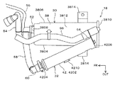
図2〜図5に示すように、キャニスタ18は、メインキャニスタ30と、サブキャニスタ32とを含んで構成され、メインキャニスタ30とサブキャニスタ32は共に細長形状を呈している。
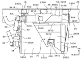
図3、図4に示すように、メインキャニスタ30とサブキャニスタ32は、メインブラケット34とサブブラケット36を介して車体12に取着されている。
The
As shown in FIGS. 2 to 5, the
As shown in FIGS. 3 and 4, the
メインキャニスタ30はメインケース38を備えている。
図2〜図4に示すように、メインケース38は、平面視長方形を有する底面3802と、底面3802の長辺から起立する一対の側面3804、3806と、底面3802の短辺から起立する一対の端面3808、3810と、それら側面3804、3806、端面3808、3810を接続し底面3802と対向する上面3812とを備えている。
メインケース38の一対の側面3804、3806にはそれぞれ取り付け部3814が設けられている。
The
As shown in FIGS. 2 to 4, the
A pair of
図3、図4に示すように、メインブラケット34は、メインケース38を保持しメインケース38をリアフロアパネル24およびリアサイドメンバ20に取り付けるものである。
メインブラケット34は、メインケース38の底面3802が載置される長方形板状の底板3402と、底板3402の長辺から起立しメインケース38の一対の側面3804、3806に沿って延在する一対の側板3404、3406と、底板3402の一方の短辺から起立しメインケース38の一方の端面3810に沿って延在する端面板3408とを含んで構成されている。
一対の側板3404、3406には、2つのケース用取り付け片3410、3412と、2つの車体用取り付け片3414、3416とが設けられている。
各ケース用取り付け片3410、3412は、メインケース38の一対の側板3404、3406の2つの取り付け部3814にそれぞれボルト40A、40Bを介して締結されている。
各車体用取り付け片3414、3416のうち一方の車体用取り付け片3414は、リアフロアパネル24に設けられた取り付け部2402にボルト40Cを介して締結され、他方の車体用取り付け片3416は、リアサイドメンバ20の底壁2002にボルト40Dを介して締結されている。
端面板3408には、1つの車体用取り付け片3418が設けられている。
車体用取り付け片3418は、リアフロアパネル24に設けられた取り付け部2404にボルト40Eを介して締結されている。
As shown in FIGS. 3 and 4, the
The
The pair of
The
One of the vehicle
One
The vehicle
図2〜図4に示すように、サブキャニスタ32は、サブケース42を備えている。
サブケース42は、円筒面4202と、円筒面4202の両端を閉塞する一対の端面4204、4206を備えている。
サブブラケット36は、サブケース42を保持しサブケース42をリアフロアパネル24に取り付けるものである。
サブブラケット36は、側板3602と、上板3604とを備えている。
側板3602は、上下方向に延在し、側板3602に設けられた開口部3606が、円筒面4202に設けられた係合凸部4210に係合し、側板3602が円筒面4202に結合されている。
上板3604は、側板3602の上端から水平方向に延在しリアフロアパネル24に設けられた取り付け部2406にボルト40Fを介して締結されている。
As shown in FIGS. 2 to 4, the sub-canister 32 includes a sub-case 42.
The
The sub bracket 36 holds the
The sub bracket 36 includes a
The
The upper plate 3604 extends from the upper end of the
メインキャニスタ30がメインブラケット34を介して、また、サブキャニスタ32がサブブラケット36を介して車体12に取り付けられることで、図3、図4に示すように、サブキャニスタ32は、メインキャニスタ30の上に配置されている。
また、図2に示すように、メインキャニスタ30はその長手方向が車両前後方向に向けて配置され、サブキャニスタ32は、後部をメインキャニスタ30の後部の上に位置させ、前部をメインキャニスタ30の前部に対して車幅方向外側に偏位した箇所に配置されている。
The
As shown in FIG. 2, the
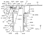
図5に示すように、メインケース38の内部は、その高さ方向の中間部が壁部3820によって主室44と、主室44の上方に位置する副室46とに仕切られている。
主室44の容積は、副室46よりも大きい。
主室44と副室46とは、壁部3820の後部に設けられた開口を介して連通している。
主室44および副室46には、例えば活性炭からなる燃料吸着材が充填されている。
図3、図5に示すように、メインケース38の一対の端面3808、3810うち車両前方に位置する前端面3808にはベーパーポート48、パージポート50、メイン側連通ポート52が前方に突出して設けられている。
ベーパーポート48は、主室44に連通し、燃料タンク16に連結されたベーパー管54の端部が連結される箇所である。
パージポート50は、主室44に連通し、不図示のエンジンの吸気管に連結されたパージ管56の端部が連結される箇所である。
メイン側連通ポート52は、副室46に連通し、サブキャニスタ32のサブ側連通ポート50に連結された連通管58の端部が連結される箇所である
As shown in FIG. 5, the inside of the
The volume of the
The
The
As shown in FIGS. 3 and 5, a
The
The
The main
図5に示すように、サブケース42の内部は、単一の吸着室60となっており、例えば活性炭からなる燃料吸着材が吸着室60に収容されている。
サブキャニスタ32の燃料吸着材はメインキャニスタ30の燃料吸着材に比較して吸着した燃料蒸発ガスが離脱しにくく、後述する大気ポート64からの燃料蒸発ガスの漏れが抑制されるように図られている。
図2、図5に示すように、サブケース42の一方の端面4204に、吸着室60に連通するサブ側連通ポート62が設けられ、サブケース42の円筒面4202の後部に、吸着室60に連通する大気ポート64が設けられている。
詳細には、車両前方に位置する前端面4204にサブ側連通ポート62が前方に突出して設けられ、円筒面4202の車両後方に位置する後部に大気ポート64が設けられている。
大気ポート64は、大気に開放された大気開放口6602を備える大気開放管66の端部が連結される箇所である。
したがって、図2に示すように、メイン側連通ポート52とサブ側連通ポート62とは、車幅方向に偏位した箇所に配置されている。本実施の形態では、サブ側連通ポート62は、メイン側連通ポート52に対して車幅方向外側に偏位した箇所に配置されている。
As shown in FIG. 5, the inside of the
The fuel adsorbent of the sub-canister 32 is designed so that the adsorbed fuel evaporative gas is less likely to separate than the fuel adsorbent of the
As shown in FIGS. 2 and 5, one
Specifically, the
The
Therefore, as shown in FIG. 2, the main-
本実施の形態によれば、メインキャニスタ30の上にサブキャニスタ32が配置され、メインキャニスタ30の主室44と副室46とサブキャニスタ32の吸着室60とは、それらの順に下方から上方に配置されている。
したがって、燃料タンク16からベーパーポート48に導入される燃料蒸発ガスは、空気よりも比重が重いため、燃料蒸発ガスは、ベーパーポート48から上方に向かって主室44、副室46、吸着室60の順番で通過するため、主室44、副室46、吸着室60の各燃料吸着材による燃料蒸発ガスの吸着効率の向上を図る上で有利となる。
また、メインキャニスタ30とサブキャニスタ32とを水平方向に並べて配置する場合に比較して平面視した場合のキャニスタ18が占める面積をコンパクト化でき、リアフロアパネル24下方においてキャニスタ18を配設するためのスペースを確保し易い。
また、ベーパーポート48、パージポート50、メイン側連通ポート52、サブ側連通ポート62を車両前後方向の一方に偏って配置したので、車両衝突時にそれら各ポート48、50、52、62をまとめて保護しやすく、各ポート48、50、30、52、62の損傷の抑制を図り、燃料蒸発ガスの漏出を抑制する上で有利となる。
また、メインキャニスタ30については、メインキャニスタ30の長手方向の一方の端面3808にポート48、50、52を集中して配置するため、長手方向の他方の端面3810を平坦面にすることができ、メインキャニスタ30の他方の端面3810を平坦面とすることで構造の簡易化を図り、メインキャニスタ30のコスト低減を図る上で有利となる。
According to the present embodiment, the sub-canister 32 is disposed on the
Accordingly, the fuel evaporative gas introduced from the
Further, the area occupied by the
Further, since the
Further, for the
また、本実施の形態では、メインキャニスタ30とサブキャニスタ32は車両10の後部に配置され、ベーパーポート48、パージポート50、メイン側連通ポート52、サブ側連通ポート62は、車両10の前方に向けて配置されているので、車両10の後突時にそれら各ポート48、50、52、62に車両後方から加わる荷重を軽減でき、各ポート48、50、52、62の損傷の抑制を図り、燃料蒸発ガスの漏出を抑制する上で有利となる。
In the present embodiment, the
また、本実施の形態では、車両10の後方から見て、メインキャニスタ30の後部は、メインキャニスタ30を支持するメインブラケット34で覆われているので、車両10の後突時にメインキャニスタ30に車両後方から加わる荷重を軽減でき、メインキャニスタ30の損傷の抑制を図る上で有利となる。
In the present embodiment, the rear portion of the
また、本実施の形態では、メイン側連通ポート52とサブ側連通ポート62とは、車幅方向に偏位した箇所に配置されている。
したがって、メイン側連通ポート52とサブ側連通ポート62を連結する連通管58の全長を大きく確保でき、連通管58の容積の増加を図る上で有利となる。連通管58の容積の増加を図ることで、連通管58に貯留される燃料蒸発ガスの量を大きく確保できるため、サブキャニスタ32の大気ポート64から大気開放管66を介して大気中に漏れ出る燃料蒸発ガスの量を抑制する上で有利となる。
In the present embodiment, the main-
Therefore, the overall length of the
また、本実施の形態では、サブ側連通ポート62は、メイン側連通ポート52に対して車幅方向外側に偏位した箇所に配置されている。
したがって、キャニスタ18を、車両10の後部でリアフロアパネル24の下方に配置し、かつ、リアサイドメンバ20の車幅方向外側に配置する場合、サブ側連通ポート62が設けられているサブキャニスタ32の前部とリアサイドメンバ20との干渉を避けつつ、メインキャニスタ30をリアサイドメンバ20に近接させて配置することが可能となる。
そのため、比較的重量が大きいメインキャニスタ30を車両10の骨格部材である剛性の高いリアサイドメンバ20に近づけて配置することができるため、メインキャニスタ30を車体12に対して安定して支持でき、キャニスタ18の耐久性の向上を図る上で有利となる。
Further, in the present embodiment, the
Accordingly, when the
Therefore, since the
10 車両
12 車体
16 燃料タンク
18 キャニスタ
20 リアサイドメンバ
24 リアフロアパネル
30 メインキャニスタ
32 サブキャニスタ
44 主室
46 副室
48 ベーパーポート
50 パージポート
52 メイン側連通ポート
54 ベーパー管
56 パージ管
58 連通管
60 吸着室
62 サブ側連通ポート
64 大気ポート
DESCRIPTION OF
Claims (5)
前記メインキャニスタは、
燃料タンクと接続するベーパーポートと、
前記車両に搭載された内燃機関の吸気通路に接続するパージポートと、
を有し、
前記メインキャニスタと前記サブキャニスタとは前記メインキャニスタに設けられたメイン側連通ポートと前記サブキャニスタに設けられたサブ側連通ポートとで接続され、
前記メインキャニスタの上方に前記サブキャニスタが重ねて配置され、
下方から上方へ前記メインキャニスタの主室、前記メインキャニスタの副室、前記サブキャニスタの吸着室の順に配置され、
前記ベーパーポートおよび前記パージポートと、前記メイン側連通ポート及び前記サブ側連通ポートは、車両前後方向の一方に偏って配置されている、
ことを特徴とする車両。 A vehicle comprising a main canister, the interior of which is divided into a main chamber and a sub chamber, and a sub canister having a suction chamber having a smaller volume than the main canister,
The main canister is
A vapor port connected to the fuel tank;
A purge port connected to an intake passage of an internal combustion engine mounted on the vehicle;
Have
The main canister and the sub-canister are connected by a main-side communication port provided in the main canister and a sub-side communication port provided in the sub-canister,
The sub-canister is placed over the main canister,
From the bottom to the top, the main chamber of the main canister, the sub chamber of the main canister, the suction chamber of the sub canister are arranged in this order,
The vapor port and the purge port, the main-side communication port and the sub-side communication port are arranged to be biased to one side in the vehicle front-rear direction.
A vehicle characterized by that.
前記ベーパーポート、前記パージポート、前記メイン側連通ポート及び前記サブ側連通ポートは、車両の前方に向けて配置されている、
ことを特徴とする請求項1記載の車両。 The main canister and the sub-canister are disposed below and at the rear of the vehicle,
The vapor port, the purge port, the main-side communication port, and the sub-side communication port are arranged toward the front of the vehicle.
The vehicle according to claim 1.
車両の後方から見て、前記メインキャニスタの後部は、前記メインキャニスタを前記ブラケットで覆われている、
ことを特徴とする請求項2記載の車両。 The main canister is fixed below the vehicle via a bracket,
As seen from the rear of the vehicle, the rear part of the main canister is covered with the bracket.
The vehicle according to claim 2.
ことを特徴とする請求項1から3の何れか1項記載の車両。 The main-side communication port and the sub-side communication port are arranged so as to be offset from each other in the vehicle width direction of the vehicle.
The vehicle according to any one of claims 1 to 3, wherein the vehicle is a vehicle.
ことを特徴とする請求項1から4の何れか1項記載の車両。 The sub-side communication port is disposed on the outer side in the vehicle width direction than the main-side communication port.
The vehicle according to any one of claims 1 to 4, characterized in that:
Priority Applications (1)
| Application Number | Priority Date | Filing Date | Title |
|---|---|---|---|
| JP2017017382A JP2018123777A (en) | 2017-02-02 | 2017-02-02 | vehicle |
Applications Claiming Priority (1)
| Application Number | Priority Date | Filing Date | Title |
|---|---|---|---|
| JP2017017382A JP2018123777A (en) | 2017-02-02 | 2017-02-02 | vehicle |
Publications (1)
| Publication Number | Publication Date |
|---|---|
| JP2018123777A true JP2018123777A (en) | 2018-08-09 |
Family
ID=63111303
Family Applications (1)
| Application Number | Title | Priority Date | Filing Date |
|---|---|---|---|
| JP2017017382A Pending JP2018123777A (en) | 2017-02-02 | 2017-02-02 | vehicle |
Country Status (1)
| Country | Link |
|---|---|
| JP (1) | JP2018123777A (en) |
-
2017
- 2017-02-02 JP JP2017017382A patent/JP2018123777A/en active Pending
Similar Documents
| Publication | Publication Date | Title |
|---|---|---|
| US8887695B2 (en) | Device for treating evaporated fuel | |
| US7614473B2 (en) | Vehicle body structure | |
| JP5983058B2 (en) | Electric vehicle battery pack mounting structure | |
| US8343263B2 (en) | Vapor storage canister arrangement | |
| JP5929609B2 (en) | In-vehicle structure of battery pack | |
| US10174722B2 (en) | Fuel vapor recovering structure | |
| JP6434888B2 (en) | Body structure | |
| JP6145486B2 (en) | Saddle riding | |
| RU2010136834A (en) | HYBRID VEHICLE | |
| JP2017152249A (en) | Mobile vehicle with electric travel driving device | |
| CN103358895B (en) | The configuration structure of absorption canister | |
| US10106030B2 (en) | Arrangement structure of canister in vehicle | |
| JP2007162539A (en) | Structure for arranging canister on vehicle | |
| JP2019033026A (en) | High pressure tank mounting structure | |
| JP2014208518A (en) | Component loading structure of vehicle | |
| JP2017204386A (en) | Under-floor structure of vehicle | |
| JP2011116209A (en) | Arrangement structure of canister | |
| JP2008238930A (en) | Vehicle body structure | |
| JP6136986B2 (en) | Vehicle power generation device | |
| JP2018123777A (en) | vehicle | |
| JP2014208517A (en) | Component loading structure of vehicle | |
| JP2017088009A (en) | Transpiration fuel processing device | |
| JP6629515B2 (en) | Automotive battery | |
| WO2022075282A1 (en) | Canister placement structure for vehicle | |
| JP5501808B2 (en) | Lower body structure |
Legal Events
| Date | Code | Title | Description |
|---|---|---|---|
| A521 | Written amendment |
Free format text: JAPANESE INTERMEDIATE CODE: A523 Effective date: 20170517 |