JP2018123727A - Valve timing adjustment device - Google Patents

Valve timing adjustment device Download PDF

Info

Publication number
JP2018123727A
JP2018123727A JP2017015285A JP2017015285A JP2018123727A JP 2018123727 A JP2018123727 A JP 2018123727A JP 2017015285 A JP2017015285 A JP 2017015285A JP 2017015285 A JP2017015285 A JP 2017015285A JP 2018123727 A JP2018123727 A JP 2018123727A
Authority
JP
Japan
Prior art keywords
linear expansion
valve timing
roller
driven
gear portion
Prior art date
Legal status (The legal status is an assumption and is not a legal conclusion. Google has not performed a legal analysis and makes no representation as to the accuracy of the status listed.)
Granted
Application number
JP2017015285A
Other languages
Japanese (ja)
Other versions
JP6760112B2 (en
Inventor
晃 岩崎
Akira Iwasaki
晃 岩崎
Current Assignee (The listed assignees may be inaccurate. Google has not performed a legal analysis and makes no representation or warranty as to the accuracy of the list.)
Denso Corp
Original Assignee
Denso Corp
Priority date (The priority date is an assumption and is not a legal conclusion. Google has not performed a legal analysis and makes no representation as to the accuracy of the date listed.)
Filing date
Publication date
Application filed by Denso Corp filed Critical Denso Corp
Priority to JP2017015285A priority Critical patent/JP6760112B2/en
Publication of JP2018123727A publication Critical patent/JP2018123727A/en
Application granted granted Critical
Publication of JP6760112B2 publication Critical patent/JP6760112B2/en
Active legal-status Critical Current
Anticipated expiration legal-status Critical

Links

Images

Abstract

PROBLEM TO BE SOLVED: To provide a valve timing adjustment device capable of suppressing occurrence of striking sound.SOLUTION: The valve timing adjustment device includes a rotary actuator and a phase adjustment part 12, and the phase adjustment part 12 has a speed reduction mechanism. The speed reduction mechanism has a driving side internal gear part of a driving rotation body, a driven side internal gear part 38 of a driven rotation body, and a planetary rotation body. The planetary rotation body has a driving side external gear part meshing with the driving side internal gear part, and a driven side external gear part 51 meshing with the driven side internal gear part. The linear expansion coefficient of the driving side external gear part is greater than the linear expansion coefficient of the driving side internal gear part, and the linear expansion coefficient of the driven side external gear part 51 is greater than a linear expansion coefficient 38 of the driven side internal gear part. Further, the linear expansion coefficient of the driving side external gear part and that of the driven side external gear part 51 have the same value, and the linear expansion coefficient of the driving side internal gear part and that of the driven side internal gear part 38 have the same value.SELECTED DRAWING: Figure 4

Description

この明細書による開示は、バルブタイミング調整装置に関する。   The disclosure herein relates to a valve timing adjustment device.

従来、内燃機関のクランク軸と連動して回転する駆動回転体と、カム軸と連動して回転する従動回転体と、駆動回転体と従動回転体との間に設けられる減速機構と、を備えたバルブタイミング調整装置が知られている。このバルブタイミング調整装置においては、駆動回転体に対して従動回転体を相対回転させることによって、カム軸が開閉駆動するバルブのバルブタイミングが調整される。このようなバルブタイミング調整装置としては、複数のローラを保持する保持器を含んで減速機構が構成された装置と、遊星歯車部を有する遊星回転体を含んで減速機構が構成された装置とがある。例えば、特許文献1には、保持器を含んで減速機構が構成されたバルブタイミング調整装置が開示されている。   Conventionally, a drive rotator that rotates in conjunction with a crankshaft of an internal combustion engine, a driven rotator that rotates in conjunction with a camshaft, and a speed reduction mechanism provided between the drive rotator and the driven rotator are provided. A known valve timing adjustment device is known. In this valve timing adjusting device, the valve timing of the valve that opens and closes the camshaft is adjusted by rotating the driven rotor relative to the drive rotor. As such a valve timing adjusting device, there are a device in which a speed reduction mechanism is configured including a cage that holds a plurality of rollers, and a device in which a speed reduction mechanism is configured including a planetary rotating body having a planetary gear unit. is there. For example, Patent Document 1 discloses a valve timing adjusting device in which a speed reduction mechanism is configured including a cage.

特許第5538053号公報Japanese Patent No. 5538053

しかしながら、バルブタイミング調整装置が作動している最中においては、減速機構が駆動回転体側の部材や従動回転体側の部材に衝突することや、減速機構が有する部材同士が衝突することにより、打音が発生することが懸念される。そこで、減速機構が有する多数の部材の寸法を1つ1つ微調整することで打音を低減することが考えられるが、これでは、バルブタイミング調整装置を製造する際の作業負担が大きくなってしまう。また、打音を低減するための専用部品を減速機構に新設したり追加したりすることも考えられるが、この方法では、バルブタイミング調整装置の部品点数が増加するため、バルブタイミング調整装置が大型化することが懸念される。   However, while the valve timing adjustment device is in operation, the speed reduction mechanism collides with a member on the drive rotator side or a member on the driven rotator side, or when members of the speed reduction mechanism collide with each other, There is a concern that this will occur. Therefore, it is conceivable to reduce the striking sound by finely adjusting the dimensions of many members of the speed reduction mechanism one by one, but this increases the work burden when manufacturing the valve timing adjusting device. End up. In addition, it is conceivable to add or add special parts to reduce the hitting sound, but this method increases the number of parts of the valve timing adjustment device, so the valve timing adjustment device is large. There is a concern that

本開示は、上記問題を鑑みてなされたもので、その目的は、打音の発生を抑制できるバルブタイミング調整装置を提供することにある。   The present disclosure has been made in view of the above problems, and an object of the present disclosure is to provide a valve timing adjusting device capable of suppressing the occurrence of a hitting sound.

上記目的を達成するため、開示された第1の態様は、
内燃機関(80)においてクランク軸(90)からの機関トルクの伝達によりカム軸(91)が開閉するバルブ(81)のバルブタイミングを調整するバルブタイミング調整装置(10)であって、
駆動歯車部(37)を有し、クランク軸に連動して回転する駆動回転体(25)と、
従動歯車部(38)を有し、カム軸に連動して回転する従動回転体(26)と、
第1遊星歯車部(50)及び第2遊星歯車部(51)を有し、これら第1遊星歯車部及び第2遊星歯車部がそれぞれ駆動歯車部及び従動歯車部に対し偏心して噛み合いつつ一体に遊星運動することにより、駆動回転体及び従動回転体の間の相対位相を変化させる遊星回転体(40)と、
を備え、
第1遊星歯車部及び第2遊星歯車部のうち一方を、径方向外側に向けて外歯(50a,51a)が延びた外歯車部(50,51)と称し、駆動歯車部及び従動歯車部のうち外歯車部に噛み合う方を、径方向内側に向けて内歯(37a,38a)が延びた内歯車部(37,38)と称した場合に、外歯車部の線膨張係数(αa1,αa2)が内歯車部の線膨張係数(αb1,αb2)に比べて大きい、バルブタイミング調整装置である。
In order to achieve the above object, the disclosed first aspect is:
A valve timing adjusting device (10) for adjusting a valve timing of a valve (81) that opens and closes a camshaft (91) by transmission of engine torque from a crankshaft (90) in an internal combustion engine (80),
A drive rotator (25) having a drive gear portion (37) and rotating in conjunction with the crankshaft;
A driven rotor (26) having a driven gear portion (38) and rotating in conjunction with the camshaft;
A first planetary gear portion (50) and a second planetary gear portion (51), and the first planetary gear portion and the second planetary gear portion are integrally engaged with each other while being eccentrically engaged with the drive gear portion and the driven gear portion, respectively. A planetary rotator (40) that changes the relative phase between the drive rotator and the driven rotator by planetary motion;
With
One of the first planetary gear portion and the second planetary gear portion is referred to as an external gear portion (50, 51) in which external teeth (50a, 51a) extend radially outward, and a drive gear portion and a driven gear portion. Of the outer gear portion is referred to as an internal gear portion (37, 38) in which the inner teeth (37a, 38a) extend radially inward, the linear expansion coefficient (αa1, This is a valve timing adjusting device in which αa2) is larger than the linear expansion coefficient (αb1, αb2) of the internal gear portion.

第1の態様によれば、外歯車部の線膨張係数が内歯車部の線膨張係数に比べて大きい。このため、内燃機関の始動時などバルブタイミング調整装置の温度が比較的低い場合に比べて、内燃機関が継続して運転状態にある時などバルブタイミング調整装置の温度が上昇した場合の方が、外歯車部と内歯車部とが相対的に移動可能な距離が小さくなる。ここで、バルブタイミング調整装置の温度が比較的低い場合に、潤滑油の粘度が大きいことで外歯車部と内歯車部との相対的な回転が規制されるということが生じないように、外歯車部と内歯車部とが相対的に移動可能な距離はある程度大きいことが好ましい。ところが、温度の上昇に伴って潤滑油の粘度が小さくなった状態で、外歯車部と内歯車部とが相対的に移動可能な距離が大きいままだと、外歯車部と内歯車部とが衝突する際の勢いが大きくなりやすく、その衝突に伴う打音が大きくなることが懸念される。   According to the first aspect, the linear expansion coefficient of the external gear portion is larger than the linear expansion coefficient of the internal gear portion. For this reason, compared to the case where the temperature of the valve timing adjustment device is relatively low, such as when the internal combustion engine is started, the case where the temperature of the valve timing adjustment device rises, such as when the internal combustion engine is continuously operating, The distance in which the outer gear portion and the inner gear portion can move relatively is reduced. Here, when the temperature of the valve timing adjusting device is relatively low, the relative rotation between the external gear portion and the internal gear portion is not restricted due to the high viscosity of the lubricating oil. It is preferable that the distance that the gear portion and the internal gear portion are relatively movable is large to some extent. However, with the viscosity of the lubricating oil decreasing as the temperature rises, if the distance that the external gear part and the internal gear part can move relatively remains large, the external gear part and the internal gear part will There is a concern that the momentum at the time of collision tends to increase, and that the hitting sound associated with the collision increases.

これに対して、上述したように、バルブタイミング調整装置の温度上昇に伴って外歯車部と内歯車部とが相対的に移動可能な距離が小さくなるため、これら外歯車部と内歯車部とが衝突する際の勢いが大きくなりにくく、衝突に伴う打音が大きくなりにくい。この場合、例えば打音を低減するための専用部品を外歯車部や内歯車部等に新設したり追加したりする必要がないため、バルブタイミング調整装置の大型化を回避しつつ、外歯車部と内歯車部との衝突に伴う打音を抑制することができる。   On the other hand, as described above, as the temperature of the valve timing adjusting device increases, the distance that the external gear portion and the internal gear portion can move relatively decreases, so that the external gear portion and the internal gear portion The momentum at the time of collision is unlikely to increase, and the hitting sound associated with the collision is unlikely to increase. In this case, for example, there is no need to newly install or add a dedicated component for reducing the hitting sound to the external gear portion or the internal gear portion, etc. And the hitting sound associated with the collision with the internal gear portion can be suppressed.

第2の態様は、
内燃機関においてクランク軸からの機関トルクの伝達によりカム軸(102)が開閉するバルブのバルブタイミングを調整するバルブタイミング調整装置であって、
クランク軸に連動して回転する駆動回転体(101)と、
カム軸に連動して回転する従動回転体(109)と、
径方向内側に向けて内歯(119a)が延び駆動回転体と共に回転する環状部材(119)と、環状部材の内周側に設けられて軸心に対して外周面が偏心した偏心回転体(130,133)と、環状部材と偏心回転体との間に設けられた複数のローラ(134)と、従動回転体と共に回転し環状部材と偏心回転体との間にてローラを保持する保持器(141)とを有し、偏心回転体の回転によって環状部材に対して保持器が相対回転することにより、駆動回転体及び従動回転体の間の相対位相を変化させる減速機構(108)と、
を備え、
偏心回転体の線膨張係数(βb)が環状部材の線膨張係数(βc)に比べて大きい、バルブタイミング調整装置である。
The second aspect is
A valve timing adjusting device for adjusting a valve timing of a valve that opens and closes a camshaft (102) by transmission of engine torque from a crankshaft in an internal combustion engine,
A drive rotor (101) that rotates in conjunction with the crankshaft;
A driven rotor (109) that rotates in conjunction with the camshaft;
An annular member (119) in which the inner teeth (119a) extend inward in the radial direction and rotates together with the drive rotating body, and an eccentric rotating body (provided on the inner peripheral side of the annular member and having an outer peripheral surface eccentric with respect to the axis) 130, 133), a plurality of rollers (134) provided between the annular member and the eccentric rotator, and a cage that rotates with the driven rotator and holds the rollers between the annular member and the eccentric rotator. (141), and a reduction mechanism (108) that changes the relative phase between the driving rotating body and the driven rotating body by rotating the cage relative to the annular member by the rotation of the eccentric rotating body,
With
In this valve timing adjustment device, the linear expansion coefficient (βb) of the eccentric rotating body is larger than the linear expansion coefficient (βc) of the annular member.

第2の態様によれば、偏心回転体の線膨張係数が環状部材の線膨張係数に比べて大きい。このため、バルブタイミング調整装置の温度上昇に伴って、偏心回転体及び環状部材がローラに対して相対的に移動可能な距離が小さくなる。ここで、バルブタイミング調整装置の温度が比較的低い場合に、潤滑油の粘度が大きいことでローラを介した偏心回転体と環状部材との相対的な回転が規制されるということが生じないように、偏心回転体及び環状部材がローラに対して相対的に移動可能な距離はある程度大きいことが好ましい。ところが、温度上昇に伴って潤滑油の粘度が小さくなった状態で、偏心回転部及び環状部材がローラに対して相対的に移動可能な距離が大きいままだと、偏心回転体や環状部材がローラに衝突する際の勢いが大きくなりやすく、それら衝突に伴う打音が大きくなることが懸念される。   According to the 2nd aspect, the linear expansion coefficient of an eccentric rotary body is large compared with the linear expansion coefficient of an annular member. For this reason, as the temperature of the valve timing adjusting device rises, the distance that the eccentric rotating body and the annular member can move relative to the roller decreases. Here, when the temperature of the valve timing adjusting device is relatively low, the relative rotation between the eccentric rotating body and the annular member via the roller is not restricted due to the large viscosity of the lubricating oil. In addition, it is preferable that the distance that the eccentric rotating body and the annular member can move relative to the roller is large to some extent. However, in the state where the viscosity of the lubricating oil becomes smaller as the temperature rises, if the distance that the eccentric rotating part and the annular member can move relative to the roller remains large, the eccentric rotating body and the annular member become the roller. There is a concern that the momentum at the time of collision is likely to increase, and that the hitting sound associated with the collision increases.

上述したように、バルブタイミング調整装置の温度上昇に伴って偏心回転体及び環状部材がローラに対して相対的に移動可能な距離が小さくなるため、これら偏心回転体や環状部材がローラに衝突する際の勢いが大きくなりにくく、衝突に伴う打音が大きくなりにくい。この場合、例えば全てのローラのそれぞれについて打音を低減するために外径寸法を微調整するなどの作業を行う必要がないため、バルブタイミング調整装置を製造する際の作業負担を低減しつつ、偏心回転体や環状部材とローラとの衝突に伴う打音を抑制することができる。   As described above, since the distance that the eccentric rotator and the annular member can move relative to the roller becomes smaller as the temperature of the valve timing adjusting device increases, the eccentric rotator and the annular member collide with the roller. The momentum is difficult to increase, and the hitting sound associated with the collision is difficult to increase. In this case, for example, it is not necessary to finely adjust the outer diameter size in order to reduce the hitting sound for each of all the rollers, so reducing the work burden when manufacturing the valve timing adjustment device, The hitting sound associated with the collision between the eccentric rotating body or the annular member and the roller can be suppressed.

第3の態様は、
内燃機関においてクランク軸からの機関トルクの伝達によりカム軸(102)が開閉するバルブのバルブタイミングを調整するバルブタイミング調整装置であって、
クランク軸に連動して回転する駆動回転体(101)と、
カム軸に連動して回転する従動回転体(109)と、
径方向内側に向けて内歯(119a)が延び駆動回転体と共に回転する環状部材(119)と、環状部材の内周側に設けられて軸心に対して外周面が偏心した偏心回転体(130,133)と、環状部材と偏心回転体との間に設けられた複数のローラ(134)と、従動回転体と共に回転し環状部材と偏心回転体との間にてローラを保持する保持器(141)とを有し、偏心回転体の回転によって環状部材に対して保持器が相対回転することにより、駆動回転体及び従動回転体の間の相対位相を変化させる減速機構(108)と、
を備え、
保持器は、当該保持器の径方向において所定間隔で並ぶローラ保持部(141a)を有しており、
ローラは、隣り合うローラ保持部の間に配置されることで、保持器により保持されており、
ローラの線膨張係数(βa)が保持器の線膨張係数(βd)に比べて大きい、バルブタイミング調整装置である。
The third aspect is
A valve timing adjusting device for adjusting a valve timing of a valve that opens and closes a camshaft (102) by transmission of engine torque from a crankshaft in an internal combustion engine,
A drive rotor (101) that rotates in conjunction with the crankshaft;
A driven rotor (109) that rotates in conjunction with the camshaft;
An annular member (119) in which the inner teeth (119a) extend inward in the radial direction and rotates together with the drive rotating body, and an eccentric rotating body (provided on the inner peripheral side of the annular member and having an outer peripheral surface eccentric with respect to the axis) 130, 133), a plurality of rollers (134) provided between the annular member and the eccentric rotator, and a cage that rotates with the driven rotator and holds the rollers between the annular member and the eccentric rotator. (141), and a reduction mechanism (108) that changes the relative phase between the driving rotating body and the driven rotating body by rotating the cage relative to the annular member by the rotation of the eccentric rotating body,
With
The cage has roller holding portions (141a) arranged at predetermined intervals in the radial direction of the cage,
The roller is held by a cage by being arranged between adjacent roller holding portions,
This is a valve timing adjusting device in which the linear expansion coefficient (βa) of the roller is larger than the linear expansion coefficient (βd) of the cage.

第3の態様によれば、ローラの線膨張係数が保持器の線膨張係数に比べて大きい。このため、バルブタイミング調整装置の温度上昇に伴って、ローラの並び方向において、ローラとローラ保持部とが相対的に移動可能な距離が小さくなる。ここで、バルブタイミング調整装置の温度が比較的低い場合に、潤滑油の粘度が大きいことでローラとローラ保持部との相対的な変位やローラの回転が規制されるということが生じないように、ローラとローラ保持部とが相対的に移動可能な距離はある程度大きいことが好ましい。ところが、温度の上昇に伴って潤滑油の粘度が小さくなった状態で、ローラとローラ保持部とが相対的に移動可能な距離が大きいままだと、ローラとローラ保持部とが衝突する際の勢いが大きくなりやすく、その衝突に伴う打音が大きくなることが懸念される。   According to the third aspect, the linear expansion coefficient of the roller is larger than the linear expansion coefficient of the cage. For this reason, as the temperature of the valve timing adjusting device rises, the distance that the roller and the roller holding portion can relatively move in the direction in which the rollers are aligned decreases. Here, when the temperature of the valve timing adjusting device is relatively low, the relative displacement between the roller and the roller holding portion and the rotation of the roller are not restricted due to the large viscosity of the lubricating oil. It is preferable that the distance that the roller and the roller holding portion can move relatively is large to some extent. However, when the distance between the roller and the roller holder is relatively large with the viscosity of the lubricating oil decreasing as the temperature rises, the roller and the roller holder may collide with each other. There is a concern that the momentum is likely to increase, and that the hitting sound associated with the collision increases.

これに対して、上述したように、バルブタイミング調整装置の温度上昇に伴ってローラとローラ保持部とが相対的に移動可能な距離が小さくなるため、これらローラとローラ保持部とが衝突際の勢いが大きくなりにくく、衝突に伴う打音が大きくなりにくい。この場合、上記第2の態様と同様に、例えば全てのローラのそれぞれについて打音を低減するために外径寸法を微調整するなどの作業を行う必要がない。このため、バルブタイミング調整装置を製造する際の作業負担を低減しつつ、ローラとローラ保持部との衝突に伴う打音を抑制することができる。   On the other hand, as described above, since the distance that the roller and the roller holding portion can move relative to each other decreases as the temperature of the valve timing adjusting device increases, The momentum is unlikely to increase, and the hitting sound associated with a collision is unlikely to increase. In this case, similarly to the second aspect, for example, it is not necessary to perform an operation such as fine adjustment of the outer diameter in order to reduce the hitting sound for each of all the rollers. For this reason, it is possible to suppress the hitting sound associated with the collision between the roller and the roller holding portion while reducing the work burden when manufacturing the valve timing adjusting device.

なお、特許請求の範囲およびこの項に記載した括弧内の符号は、後述する実施形態に記載の具体的手段との対応関係を示すものにすぎず、発明の技術的範囲を限定するものではない。   It should be noted that the reference numerals in parentheses described in the claims and in this section merely indicate correspondence with specific means described in the embodiments described later, and do not limit the technical scope of the invention. .

第1実施形態におけるバルブタイミング調整装置を示す断面図。Sectional drawing which shows the valve timing adjustment apparatus in 1st Embodiment. 図1のII-II線断面図であって、位相調整部をチェーンカバー側から見た図。It is the II-II sectional view taken on the line of FIG. 1, Comprising: The figure which looked at the phase adjustment part from the chain cover side. 図1のIII−III線断面図。III-III sectional view taken on the line of FIG. 図1のIV-IV線断面図。FIG. 4 is a sectional view taken along line IV-IV in FIG. 1. 図1のV-V線断面図。The VV sectional view taken on the line of FIG. 従動側の外径差について説明するための図。The figure for demonstrating the outer diameter difference of a driven side. ピッチ円外径及びピッチ円内径の増加率について説明するための図。The figure for demonstrating the increase rate of a pitch circle outer diameter and a pitch circle inner diameter. 内歯車分と外歯車部との外径差の変化態様について説明するための図。The figure for demonstrating the change aspect of the outer diameter difference of an internal gear part and an external gear part. 温度が上昇する前の想定距離について説明するための図。The figure for demonstrating the assumed distance before temperature rises. 温度が上昇した後の想定距離について説明するための図。The figure for demonstrating the assumed distance after temperature rises. 第2実施形態におけるバルブタイミング調整装置を示す断面図。Sectional drawing which shows the valve timing adjustment apparatus in 2nd Embodiment. 図11のXII-XII線断面図。XII-XII sectional view taken on the line of FIG. 図11のXIII-XIII線断面図。XIII-XIII sectional view taken on the line of FIG. カバー部材と第1オイルシールとの分解斜視図である。It is a disassembled perspective view of a cover member and a 1st oil seal. 図11のXV-XV線断面図。XV-XV sectional view taken on the line of FIG. 環状部材、第1ボールベアリング、ローラ、保持器の各寸法について説明するための図。The figure for demonstrating each dimension of an annular member, a 1st ball bearing, a roller, and a holder | retainer. 環状部材、第1ボールベアリング、保持器の各寸法の増加率について説明するための図。The figure for demonstrating the increase rate of each dimension of a cyclic | annular member, a 1st ball bearing, and a holder | retainer. 環状部材と第1ボールベアリングとの径差の変化態様について説明するための図。The figure for demonstrating the change aspect of the diameter difference of an annular member and a 1st ball bearing. 保持器の隣り合う突起部及びローラの各寸法について説明するための図。The figure for demonstrating each dimension of the protrusion part and roller which are adjacent to a holder | retainer. 保持器の隣り合う突起部及びローラの各寸法の増加率について説明するための図。The figure for demonstrating the increase rate of each dimension of the protrusion part and roller which adjoin a holder | retainer. 隣り合う突起部の保持距離とローラの直径との差異である寸法差の変化態様について説明するための図。The figure for demonstrating the change aspect of the dimensional difference which is a difference with the holding distance of an adjacent protrusion part, and the diameter of a roller. 温度が上昇する前について、環状部材、第1ボールベアリング、ローラ、保持器の位置関係を説明するための図。The figure for demonstrating the positional relationship of an annular member, a 1st ball bearing, a roller, and a holder | retainer before temperature rises. 温度が上昇した後について、環状部材、第1ボールベアリング、ローラ、保持器の位置関係を説明するための図。The figure for demonstrating the positional relationship of an annular member, a 1st ball bearing, a roller, and a holder | retainer after temperature rises.

以下、本開示の複数の実施形態を図面に基づいて説明する。尚、各実施形態において対応する構成要素には同一の符号を付すことにより、重複する説明を省略する場合がある。各実施形態において構成の一部分のみを説明している場合、当該構成の他の部分については、先行して説明した他の実施例の構成を適用することができる。また、各実施形態の説明において明示している構成の組み合わせばかりではなく、特に組み合わせに支障が生じなければ、明示していなくても複数の実施形態の構成同士を部分的に組み合わせることができる。そして、複数の実施形態及び変形例に記述された構成同士の明示されていない組み合わせも、以下の説明によって開示されているものとする。   Hereinafter, a plurality of embodiments of the present disclosure will be described based on the drawings. In addition, the overlapping description may be abbreviate | omitted by attaching | subjecting the same code | symbol to the corresponding component in each embodiment. When only a part of the configuration is described in each embodiment, the configuration of the other examples described above can be applied to other portions of the configuration. Moreover, not only the combination of the configurations explicitly described in the description of each embodiment, but also the configuration of a plurality of embodiments can be partially combined even if they are not explicitly described, as long as there is no problem in the combination. And the combination where the structure described in several embodiment and the modification is not specified shall also be disclosed by the following description.

(第1実施形態)
図1に示すバルブタイミング調整装置10は、車両の内燃機関80のクランク軸90に対するカム軸91の回転位相を変化させることによって、カム軸91が開閉駆動する吸気弁81又は排気弁82のうち吸気弁81のバルブタイミングを調整するものである。バルブタイミング調整装置10は、クランク軸90からカム軸91に動力を伝達する経路に設けられている。この場合、クランク軸90が駆動軸に相当し、カム軸91が従動軸に相当し、吸気弁81がバルブに当する。
(First embodiment)
The valve timing adjusting device 10 shown in FIG. 1 changes the rotational phase of the cam shaft 91 with respect to the crankshaft 90 of the internal combustion engine 80 of the vehicle to change the intake air of the intake valve 81 or the exhaust valve 82 that the cam shaft 91 is driven to open and close. The valve timing of the valve 81 is adjusted. The valve timing adjusting device 10 is provided in a path for transmitting power from the crankshaft 90 to the camshaft 91. In this case, the crankshaft 90 corresponds to the drive shaft, the camshaft 91 corresponds to the driven shaft, and the intake valve 81 hits the valve.

バルブタイミング調整装置10の構成について図1〜図5を参照して説明する。バルブタイミング調整装置10は、回転式アクチュエータ11および位相調整部12を備えている。   The configuration of the valve timing adjusting device 10 will be described with reference to FIGS. The valve timing adjustment device 10 includes a rotary actuator 11 and a phase adjustment unit 12.

図1に示すように、回転式アクチュエータ11は、例えばブラシレスモータ等の電動モータであり、カム軸91の軸方向の延長上に設けられている。回転式アクチュエータ11は、内燃機関80のチェーンカバー92に固定されるケーシング20と、ケーシング20内に設けられている図示しないステータおよびロータと、当該ロータに接続され、ケーシング20により正逆回転自在に支持されている回転軸21と、を有している。チェーンカバー92はカバー部材に相当する。ケーシング20は、チェーンカバー92の外側に設けられる露出部22と、チェーンカバー92の通孔93に挿入される挿入部23と、を有している。回転軸21は、挿入部23からカム軸91側に向かって突き出すよう設けられている。   As shown in FIG. 1, the rotary actuator 11 is an electric motor such as a brushless motor, for example, and is provided on the extension of the cam shaft 91 in the axial direction. The rotary actuator 11 is connected to the casing 20 fixed to the chain cover 92 of the internal combustion engine 80, a stator and a rotor (not shown) provided in the casing 20, and the rotor, and can be rotated forward and backward by the casing 20. And a supported rotating shaft 21. The chain cover 92 corresponds to a cover member. The casing 20 has an exposed portion 22 provided outside the chain cover 92 and an insertion portion 23 that is inserted into the through hole 93 of the chain cover 92. The rotary shaft 21 is provided so as to protrude from the insertion portion 23 toward the cam shaft 91 side.

回転式アクチュエータ11はさらに、例えばケーシング20内に設けられる図示しない通電制御部を有している。露出部22は、通電制御部を外部の電子制御ユニットと電気接続するためのコネクタ24を有している。通電制御部は、駆動ドライバおよびその制御用マイクロコンピュータ等から構成されており、ステータへの通電を制御することにより回転軸21を回転駆動する。   The rotary actuator 11 further includes an energization control unit (not shown) provided in the casing 20, for example. The exposed part 22 has a connector 24 for electrically connecting the energization control part to an external electronic control unit. The energization control unit includes a drive driver and a control microcomputer, and the like, and rotationally drives the rotary shaft 21 by controlling energization to the stator.

図1〜図5に示すように、位相調整部12は、駆動回転体25と、従動回転体26と、減速機構27とを備えている。   As shown in FIGS. 1 to 5, the phase adjustment unit 12 includes a drive rotator 25, a driven rotator 26, and a speed reduction mechanism 27.

駆動回転体25は、カム軸91の回転軸心AX1上に設けられた有底筒状の第1ハウジング28と第2ハウジング29とシグナルプレート30とを、ボルト31で締結してなる。第1ハウジング28は、外壁に一体に形成されたスプロケット32を有している。第1ハウジング28は、スプロケット32とクランク軸90のスプロケット94とに環状のタイミングチェーン95が掛け渡されることによって、クランク軸90と接続されている。この接続により、クランク軸90の機関トルクがタイミングチェーン95を通じてスプロケット32に伝達されるとき、駆動回転体25がクランク軸90と連動して回転する。なお、駆動回転体25の回転方向は、図2〜図4の時計方向に設定されている。   The drive rotating body 25 is formed by fastening a bottomed cylindrical first housing 28, a second housing 29, and a signal plate 30 provided on the rotation axis AX1 of the cam shaft 91 with bolts 31. The first housing 28 has a sprocket 32 formed integrally with the outer wall. The first housing 28 is connected to the crankshaft 90 by looping an annular timing chain 95 between the sprocket 32 and the sprocket 94 of the crankshaft 90. With this connection, when the engine torque of the crankshaft 90 is transmitted to the sprocket 32 through the timing chain 95, the drive rotator 25 rotates in conjunction with the crankshaft 90. The rotation direction of the drive rotor 25 is set in the clockwise direction in FIGS.

シグナルプレート30は、図示しないカム角センサにカム軸91の回転角度を検知させるための円盤状の部材である。図2に示すように位相調整部12をチェーンカバー92側から見たとき、シグナルプレート30は第2ハウジング29の全体を覆っている。   The signal plate 30 is a disk-shaped member for causing a cam angle sensor (not shown) to detect the rotation angle of the cam shaft 91. As shown in FIG. 2, when the phase adjustment unit 12 is viewed from the chain cover 92 side, the signal plate 30 covers the entire second housing 29.

図1、図5に示すように、従動回転体26は、有底筒状に形成されており、駆動回転体25に対して相対回転可能なよう第1ハウジング28の周壁部の内側に嵌合している。従動回転体26の底壁部は、センターボルト34を使用した螺子留めによりカム軸91の端部に直接固定されている。この固定により、従動回転体26はカム軸91と連動して回転する。なお、従動回転体26の回転方向は、駆動回転体25と同じ図5の時計方向に設定されている。   As shown in FIGS. 1 and 5, the driven rotator 26 is formed in a bottomed cylindrical shape, and is fitted inside the peripheral wall portion of the first housing 28 so as to be rotatable relative to the drive rotator 25. doing. The bottom wall portion of the driven rotor 26 is directly fixed to the end portion of the cam shaft 91 by screwing using a center bolt 34. By this fixing, the driven rotating body 26 rotates in conjunction with the cam shaft 91. The rotational direction of the driven rotator 26 is set in the clockwise direction of FIG.

図1、図4に示すように、駆動回転体25および従動回転体26には、それぞれ駆動側ストッパ部35および従動側ストッパ部36が設けられている。駆動側ストッパ部35は、第1ハウジング28の周壁部の四箇所から径方向内側に突出している。従動側ストッパ部36は、従動回転体26の周壁部の四箇所から径方向外側に突出している。   As shown in FIGS. 1 and 4, the drive rotator 25 and the driven rotator 26 are provided with a drive side stopper portion 35 and a driven side stopper portion 36, respectively. The drive side stopper portion 35 protrudes radially inward from four locations on the peripheral wall portion of the first housing 28. The driven side stopper portion 36 protrudes radially outward from four locations on the peripheral wall portion of the driven rotating body 26.

図4に示すように特定の従動側ストッパ部36が遅角方向の駆動側ストッパ部35に当接する場合、駆動回転体25に対する従動回転体26の遅角方向への相対回転が止められ、駆動回転体25と従動回転体26との間の位相が遅角側の最端位相に規制される。以下、駆動回転体と従動回転体との間の位相を「回転体間位相」と記載する。本実施形態では、遅角側の最端位相は、内燃機関80の始動を許容するための初期位相に設定されている。一方、特定の従動側ストッパ部36が進角方向の駆動側ストッパ部35に当接するときには、駆動回転体25に対する従動回転体26の進角方向への相対回転が止められて、回転体間位相が進角側の最端位相に規制される。   As shown in FIG. 4, when the specific driven side stopper portion 36 abuts on the driving side stopper portion 35 in the retarding direction, the relative rotation of the driven rotating body 26 in the retarding direction with respect to the driving rotating body 25 is stopped, and driving is performed. The phase between the rotator 25 and the driven rotator 26 is regulated to the endmost phase on the retard side. Hereinafter, the phase between the drive rotator and the driven rotator will be referred to as “phase between rotators”. In the present embodiment, the retarded phase endmost phase is set to an initial phase for allowing the internal combustion engine 80 to start. On the other hand, when the specific driven-side stopper portion 36 abuts on the drive-side stopper portion 35 in the advance angle direction, the relative rotation in the advance angle direction of the driven rotation body 26 with respect to the drive rotation body 25 is stopped, and the phase between the rotation bodies is stopped. Is regulated to the most advanced phase on the advance side.

図1〜図4に示すように、減速機構27は、駆動側内歯車部37と、従動側内歯車部38と、入力回転体39と、遊星回転体40とを備えた遊星歯車機構である。   As shown in FIGS. 1 to 4, the speed reduction mechanism 27 is a planetary gear mechanism including a driving side internal gear portion 37, a driven side internal gear portion 38, an input rotating body 39, and a planetary rotating body 40. .

駆動側内歯車部37は、第2ハウジング29の周壁部の内壁に一体に設けられている。駆動側内歯車部37の軸心は回転軸心AX1と一致する。駆動側内歯車部37は、径方向内側に向けて延びた複数の内歯37aを有している。ボルト31は、駆動側内歯車部37の歯先部と同じ周方向位置に設けられている。本実施形態では、ボルト31は、周方向において不等間隔に4本設けられている。   The drive-side internal gear portion 37 is integrally provided on the inner wall of the peripheral wall portion of the second housing 29. The axis of the drive side internal gear portion 37 coincides with the rotation axis AX1. The drive-side internal gear portion 37 has a plurality of internal teeth 37a extending radially inward. The bolt 31 is provided at the same circumferential position as the tooth tip portion of the drive-side internal gear portion 37. In the present embodiment, four bolts 31 are provided at unequal intervals in the circumferential direction.

従動側内歯車部38は、従動回転体26の周壁部の内壁に一体に設けられている。従動側内歯車部38の軸心は回転軸心AX1と一致する。従動側内歯車部38は、径方向内側に向けて延びた複数の内歯38aを有しており、従動側内歯車部38の径は駆動側内歯車部37の径よりも小さく設定され、また従動側内歯車部38の歯数は駆動側内歯車部37の歯数よりも少なく設定されている。この場合、駆動側内歯車部37のピッチ円直径であるピッチ円内径Db1は、従動側内歯車部38のピッチ円直径であるピッチ円内径Db2より大きくなっている。   The driven side internal gear portion 38 is integrally provided on the inner wall of the peripheral wall portion of the driven rotating body 26. The axis of the driven side internal gear portion 38 coincides with the rotation axis AX1. The driven side internal gear portion 38 has a plurality of internal teeth 38a extending radially inward, and the diameter of the driven side internal gear portion 38 is set smaller than the diameter of the drive side internal gear portion 37, The number of teeth of the driven side internal gear portion 38 is set to be smaller than the number of teeth of the drive side internal gear portion 37. In this case, the pitch circle inner diameter Db1 that is the pitch circle diameter of the drive side internal gear portion 37 is larger than the pitch circle inner diameter Db2 that is the pitch circle diameter of the driven side internal gear portion 38.

なお、駆動側内歯車部37が駆動歯車部に相当し、従動側内歯車部38が従動歯車部に相当する。また、駆動側内歯車部37及び従動側内歯車部38のうち一方が内歯車部に相当する。   The driving side internal gear portion 37 corresponds to a driving gear portion, and the driven side internal gear portion 38 corresponds to a driven gear portion. One of the driving side internal gear portion 37 and the driven side internal gear portion 38 corresponds to an internal gear portion.

入力回転体39は、全体として筒状であり、ベアリング41を介して第2ハウジング29により回転軸心AX1まわりに回転可能に支持されている。ベアリング41は、第2ハウジング29の底壁部に設けられている。入力回転体39の内壁には、軸方向へ延び且つ径方向内側に向かって開口する一対の嵌合溝42が形成されている。嵌合溝42は、入力回転体39の一端面から他端面まで延びている。入力回転体39は、嵌合溝42に回転軸21の継手部43が嵌合することによって、当該回転軸21と連結されている。この連結により入力回転体39は、回転軸21と共に回転駆動可能となっている。   The input rotating body 39 has a cylindrical shape as a whole, and is supported by the second housing 29 via a bearing 41 so as to be rotatable around the rotation axis AX1. The bearing 41 is provided on the bottom wall portion of the second housing 29. A pair of fitting grooves 42 extending in the axial direction and opening inward in the radial direction are formed in the inner wall of the input rotating body 39. The fitting groove 42 extends from one end surface of the input rotating body 39 to the other end surface. The input rotating body 39 is connected to the rotating shaft 21 by fitting the joint portion 43 of the rotating shaft 21 into the fitting groove 42. By this connection, the input rotator 39 can be driven to rotate together with the rotating shaft 21.

入力回転体39はさらに、回転軸心AX1に対して偏心する偏心部44を有している。偏心部44には、径方向外側に向かって開口する凹部46が当該偏心部44の偏心側に偏って一対設けられている。それら凹部46内には、復原力を発生する弾性部材47が収容されている。本実施形態では、弾性部材47は、概ねU字状の断面を有する金属製の板ばねである。   The input rotating body 39 further includes an eccentric portion 44 that is eccentric with respect to the rotation axis AX1. The eccentric portion 44 is provided with a pair of concave portions 46 that are open toward the outer side in the radial direction so as to be offset toward the eccentric side of the eccentric portion 44. An elastic member 47 that generates a restoring force is accommodated in the recesses 46. In the present embodiment, the elastic member 47 is a metal leaf spring having a substantially U-shaped cross section.

遊星回転体40は、遊星ベアリング48および遊星歯車49を組み合わせてなる。遊星ベアリング48の内輪は、入力回転体39の偏心部44の外側に所定のクリアランスをあけて配置されている。遊星ベアリング48は、偏心部44により各弾性部材47を介して内側から支持された状態下、各弾性部材47から受ける復原力を遊星歯車49へ伝達するようになっている。   The planetary rotator 40 is formed by combining a planetary bearing 48 and a planetary gear 49. The inner ring of the planetary bearing 48 is disposed outside the eccentric portion 44 of the input rotor 39 with a predetermined clearance. The planetary bearing 48 is configured to transmit the restoring force received from each elastic member 47 to the planetary gear 49 while being supported from the inside by the eccentric portion 44 via each elastic member 47.

遊星歯車49は、段付円筒状に形成され、遊星ベアリング48を介して偏心部44により偏心軸心AX2まわりに回転可能に支持されている。遊星歯車49の大径部は、駆動側内歯車部37と噛み合う駆動側外歯車部50である。遊星歯車49の小径部は、従動側内歯車部38と噛み合う従動側外歯車部51である。駆動側外歯車部50及び従動側外歯車部51は、径方向外側に向けて延びた複数の外歯50a,51aをそれぞれ有している。駆動側外歯車部50および従動側外歯車部51の歯数はそれぞれ、駆動側内歯車部37および従動側内歯車部38の歯数よりも同数ずつ少なく設定されている。この場合、駆動側外歯車部50のピッチ円直径であるピッチ円外径Da1は、従動側内歯車部37のピッチ円直径であるピッチ円外形Da2より大きくなっている。   The planetary gear 49 is formed in a stepped cylindrical shape, and is supported by the eccentric portion 44 via the planetary bearing 48 so as to be rotatable around the eccentric axis AX2. The large-diameter portion of the planetary gear 49 is a drive-side external gear portion 50 that meshes with the drive-side internal gear portion 37. The small diameter portion of the planetary gear 49 is a driven side external gear portion 51 that meshes with the driven side internal gear portion 38. The drive-side external gear portion 50 and the driven-side external gear portion 51 have a plurality of external teeth 50a and 51a extending outward in the radial direction. The number of teeth of the driving side external gear part 50 and the driven side external gear part 51 is set to be smaller by the same number than the number of teeth of the driving side internal gear part 37 and the driven side internal gear part 38, respectively. In this case, the pitch circle outer diameter Da1 that is the pitch circle diameter of the drive side external gear portion 50 is larger than the pitch circle outer shape Da2 that is the pitch circle diameter of the driven side internal gear portion 37.

遊星歯車49は、入力回転体39が回転軸心AX1まわりに回転すると、偏心軸心AX2まわりに自転しつつ回転軸心AX1まわりに公転する遊星運動を行う。このときの遊星歯車49の自転速度は、入力回転体39の回転速度に対して減速される。従動側内歯車部38および従動側外歯車部51は、遊星歯車49の自転を従動回転体26に伝達する伝達手段に相当する。   When the input rotating body 39 rotates around the rotation axis AX1, the planetary gear 49 performs a planetary motion that revolves around the rotation axis AX1 while rotating around the eccentric axis AX2. At this time, the rotation speed of the planetary gear 49 is reduced with respect to the rotation speed of the input rotor 39. The driven side internal gear portion 38 and the driven side external gear portion 51 correspond to transmission means for transmitting the rotation of the planetary gear 49 to the driven rotating body 26.

なお、遊星歯車49が遊星回転体に相当し、駆動側外歯車部50が第1遊星歯車部に相当し、従動側外歯車部51が第2遊星歯車部に相当する。また、駆動側外歯車部50及び従動側外歯車部51のうち一方が外歯車部に相当する。   The planetary gear 49 corresponds to a planetary rotating body, the driving side external gear portion 50 corresponds to a first planetary gear portion, and the driven side external gear portion 51 corresponds to a second planetary gear portion. One of the driving side external gear part 50 and the driven side external gear part 51 corresponds to an external gear part.

ここまで説明した構成の位相調整部12は、駆動回転体25に対する回転式アクチュエータ11の相対回転を減速して、駆動回転体25に対する従動回転体26の相対回転に変換することにより、それら回転体25、26間の位相である回転体間位相を調整する。具体的には、回転軸21が駆動回転体25と同速回転することで、入力回転体39が駆動回転体25に対して相対回転しないときには、遊星歯車49が遊星運動することなく回転体25、26と連れ回りする。したがって、回転体間位相が保持されることになる。   The phase adjusting unit 12 having the configuration described so far decelerates the relative rotation of the rotary actuator 11 with respect to the drive rotator 25 and converts it into relative rotation of the driven rotator 26 with respect to the drive rotator 25, thereby rotating these rotators. The phase between the rotating bodies, which is the phase between 25 and 26, is adjusted. Specifically, when the rotation shaft 21 rotates at the same speed as the drive rotator 25 and the input rotator 39 does not rotate relative to the drive rotator 25, the planetary gear 49 does not perform planetary motion and the rotator 25. , 26. Therefore, the phase between the rotating bodies is maintained.

また、回転軸21が駆動回転体25に対して低速回転又は逆回転することで、入力回転体39が駆動回転体25に対して遅角方向に相対回転するときには、遊星歯車49が遊星運動して従動回転体26が駆動回転体25に対して遅角方向に相対回転する。したがって、回転体間位相が遅角することになる。   Further, when the rotary shaft 21 rotates at a low speed or reversely with respect to the drive rotator 25 and the input rotator 39 rotates relative to the drive rotator 25 in the retarding direction, the planetary gear 49 performs a planetary motion. Thus, the driven rotator 26 rotates relative to the drive rotator 25 in the retard direction. Therefore, the phase between the rotating bodies is retarded.

また、回転軸21が駆動回転体25に対して高速回転することで、入力回転体39が駆動回転体25に対して進角方向に相対回転するときには、遊星歯車49が遊星運動して従動回転体26が駆動回転体25に対する進角方向に相対回転する。したがって、回転体間位相が進角することになる。   In addition, when the rotary shaft 21 rotates at a high speed with respect to the drive rotator 25, the planetary gear 49 rotates in a planetary motion when the input rotator 39 rotates relative to the drive rotator 25 in the advance direction. The body 26 rotates relative to the drive rotator 25 in the advance direction. Therefore, the phase between the rotating bodies is advanced.

駆動側外歯車部50のピッチ円外径Da1は、駆動側内歯車部37のピッチ円内径Db1に比べて小さく、従動側外歯車部51のピッチ円外径Da2は、従動側内歯車部38のピッチ円内径Db2に比べて大きくなっている。駆動側については、ピッチ円外径Da1とピッチ円内径Db1との差異が外径差ΔD1であり、従動側については、図6に示すように、ピッチ円内径Da2とピッチ円外径Db2との差異が外径差ΔD2である。   The pitch circle outer diameter Da1 of the drive side external gear portion 50 is smaller than the pitch circle inner diameter Db1 of the drive side internal gear portion 37, and the pitch circle outer diameter Da2 of the driven side external gear portion 51 is set to the driven side internal gear portion 38. Is larger than the pitch circle inner diameter Db2. On the driving side, the difference between the pitch circle outer diameter Da1 and the pitch circle inner diameter Db1 is the outer diameter difference ΔD1, and on the driven side, as shown in FIG. 6, the pitch circle inner diameter Da2 and the pitch circle outer diameter Db2 are different. The difference is the outer diameter difference ΔD2.

バルブタイミング調整装置10においては、各部品が熱膨張することが考えられる。例えば、歯車部37,38,50,51が熱膨張した場合には、外径差ΔD1,ΔD2が変化すると考えられる。本実施形態では、歯車部37,38,50,51の温度上昇に伴って外径差ΔD1,ΔD2が小さくなるように、これら歯車部37,38,50,51の線膨張係数αb1,αb2,αa1,αa2が設定されている。   In the valve timing adjusting device 10, it is conceivable that each component is thermally expanded. For example, when the gear portions 37, 38, 50, 51 are thermally expanded, the outer diameter differences ΔD1, ΔD2 are considered to change. In the present embodiment, the linear expansion coefficients αb1, αb2, and the like of the gear portions 37, 38, 50, and 51 are reduced so that the outer diameter differences ΔD1 and ΔD2 become smaller as the temperature of the gear portions 37, 38, 50, and 51 increases. αa1 and αa2 are set.

駆動側については、ピッチ円外径Da1の増加率がピッチ円内径Db1の増加率に比べて大きくなるように、駆動側外歯車部50の線膨張係数αa1が駆動側内歯車部37の線膨張係数αb1より大きくなっている。この場合、温度上昇に伴って外径差ΔD1が小さくなる。従動側については、ピッチ円内径Da2の増加率がピッチ円外径Db2の増加率に比べて大きくなるように、従動側外歯車部51の線膨張係数αa2が従動側内歯車部38の線膨張係数αb2より大きくなっている。これにより、温度上昇に伴って外径差ΔD2が小さくなる。   On the drive side, the linear expansion coefficient αa1 of the drive side external gear portion 50 is such that the increase rate of the pitch circle outer diameter Da1 is larger than the increase rate of the pitch circle inner diameter Db1. It is larger than the coefficient αb1. In this case, the outer diameter difference ΔD1 becomes smaller as the temperature rises. On the driven side, the linear expansion coefficient αa2 of the driven side external gear portion 51 is such that the increase rate of the pitch circle inner diameter Da2 is larger than the increase rate of the pitch circle outer diameter Db2. It is larger than the coefficient αb2. Thereby, the outer diameter difference ΔD2 becomes smaller as the temperature rises.

本実施形態では、駆動側外歯車部50の線膨張係数αa1と従動側外歯車部51の線膨張係数αa2とが同じ値になっている。これら駆動側外歯車部50及び従動側外歯車部51は、例えばS45Cといった同じ鋼材により形成されている。また、駆動側内歯車部37の線膨張係数αb1と従動側内歯車部38の線膨張係数αb2とが同じ値になっている。これら駆動側内歯車部37及び従動側内歯車部38は、例えばSUS440Cといった同じ鋼材により形成されている。また、本実施形態では、歯車部37,38,50,51の加熱及び冷却が同じように進むとして、これら歯車部37,38,50,51の各温度が同じになっているとしている。   In the present embodiment, the linear expansion coefficient αa1 of the driving side external gear portion 50 and the linear expansion coefficient αa2 of the driven side external gear portion 51 have the same value. The driving side external gear portion 50 and the driven side external gear portion 51 are formed of the same steel material such as S45C. Further, the linear expansion coefficient αb1 of the driving side internal gear portion 37 and the linear expansion coefficient αb2 of the driven side internal gear portion 38 have the same value. The driving side internal gear portion 37 and the driven side internal gear portion 38 are formed of the same steel material such as SUS440C. In the present embodiment, the heating and cooling of the gear portions 37, 38, 50, and 51 proceed in the same manner, and the temperatures of the gear portions 37, 38, 50, and 51 are assumed to be the same.

ピッチ円外径Da1,Da2の増加率がピッチ円内径Db1,Db2の増加率に比べて大きい場合、バルブタイミング調整装置10での温度が過剰に上昇すると、ピッチ円外径Da1,Da2がピッチ円内径Db1,Db2より大きくなることが懸念される。そこで、本実施形態では、内燃機関80の運転中においては、遊星歯車49の遊星運動が熱膨張によって阻害されないように、線膨張係数αb1,αb2,αa1,αa2が設定されている。   When the increase rate of the pitch circle outer diameters Da1 and Da2 is larger than the increase rate of the pitch circle inner diameters Db1 and Db2, when the temperature in the valve timing adjusting device 10 rises excessively, the pitch circle outer diameters Da1 and Da2 become pitch circles. There is a concern that it may be larger than the inner diameters Db1 and Db2. Therefore, in the present embodiment, during the operation of the internal combustion engine 80, the linear expansion coefficients αb1, αb2, αa1, and αa2 are set so that the planetary motion of the planetary gear 49 is not inhibited by thermal expansion.

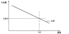
例えば、従動側の熱膨張について説明する。図7に示すように、従動側外歯車部51のピッチ円外径Da2の増加率が、従動側内歯車部38のピッチ円内径Db2の増加率に比べて大きいことに起因して、温度Tx1にてピッチ円外径Da2がピッチ円内径Db2に追いつくことがある。換言すれば、図8に示すように、従動側外歯車部51及び従動側内歯車部38の温度上昇に伴って外径差ΔD2が減少していき、この外径差ΔD2が上記温度Tx2にてゼロになることがある。   For example, the thermal expansion on the driven side will be described. As shown in FIG. 7, the temperature Tx1 is caused by the increase rate of the pitch circle outer diameter Da2 of the driven side outer gear portion 51 being larger than the increase rate of the pitch circle inner diameter Db2 of the driven side inner gear portion 38. The pitch circle outer diameter Da2 may catch up with the pitch circle inner diameter Db2. In other words, as shown in FIG. 8, the outer diameter difference ΔD2 decreases as the temperature of the driven-side outer gear portion 51 and the driven-side inner gear portion 38 increases, and this outer diameter difference ΔD2 becomes the temperature Tx2. May become zero.

ここで、ピッチ円外径Da2がピッチ円内径Db2まで大きくならなくても、外径差ΔD2が所定値より小さくなると、従動側外歯車部51が従動側内歯車部38に噛み合っていない領域において外歯51aと内歯38aとが意図せずに接触することが想定される。本実施形態では、図7、図8に示すように、外歯51aが内歯38aに意図せずに接触しない範囲で外径差ΔD2の極力小さい値を限界径差ΔDy2と称し、外径差ΔD2が限界径差ΔDy2まで小さくなる温度を限界温度Tyと称する。バルブタイミング調整装置10においては、内燃機関80の通常の運転において歯車部37,38,50,51が到達し得る温度(例えば130℃)よりも限界温度Tyが高い温度になるように、歯車部37,38,50,51の鋼材や材料が選択されている。   Here, even if the pitch circle outer diameter Da2 does not increase to the pitch circle inner diameter Db2, if the outer diameter difference ΔD2 is smaller than a predetermined value, the driven-side outer gear portion 51 is not engaged with the driven-side inner gear portion 38. It is assumed that the outer teeth 51a and the inner teeth 38a come into contact unintentionally. In the present embodiment, as shown in FIGS. 7 and 8, the smallest possible value of the outer diameter difference ΔD2 within a range where the outer teeth 51a do not contact the inner teeth 38a unintentionally is referred to as a limit diameter difference ΔDy2, and the outer diameter difference The temperature at which ΔD2 decreases to the limit diameter difference ΔDy2 is referred to as limit temperature Ty. In the valve timing adjusting device 10, the gear portion is set so that the limit temperature Ty is higher than the temperature (for example, 130 ° C.) that the gear portions 37, 38, 50, 51 can reach in the normal operation of the internal combustion engine 80. Steel materials and materials of 37, 38, 50, and 51 are selected.

従動側と同様に駆動側についても、駆動側外歯車部50及び駆動側内歯車部37の温度上昇に伴って外径差ΔD1が減少していく。ただし、図8に示すように、駆動側の外径差ΔD1は、上記温度Tx1よりも高い温度Tx2にてゼロになる。駆動側について、限界温度Tyでの外径差ΔD1を限界径差ΔDy1と称すると、従動側の限界径差ΔDy2が駆動側の限界径差ΔDy1より小さくなっている。このため、もし歯車部37,38,50,51が限界温度Tyに到達すると、従動側外歯車部51と従動側内歯車部38との衝突の方が、駆動側外歯車部50と駆動側内歯車部37との衝突に比べて発生しやい。このように、従動側の方が衝突の発生しやすい関係に設定しておくと、外歯車部50,51と内歯車部37,38との衝突に伴う打音を抑制するためには、駆動側及び従動側のうち従動側について歯車部51,38の熱膨張を管理すれば済むことになる。このため、バルブタイミング調整装置10の設計負担を低減することができる。   On the drive side as well as the driven side, the outer diameter difference ΔD1 decreases as the temperature of the drive side external gear portion 50 and the drive side internal gear portion 37 increases. However, as shown in FIG. 8, the drive-side outer diameter difference ΔD1 becomes zero at a temperature Tx2 higher than the temperature Tx1. On the drive side, when the outer diameter difference ΔD1 at the limit temperature Ty is referred to as the limit diameter difference ΔDy1, the driven-side limit diameter difference ΔDy2 is smaller than the drive-side limit diameter difference ΔDy1. For this reason, if the gear portions 37, 38, 50, 51 reach the limit temperature Ty, the collision between the driven side external gear portion 51 and the driven side internal gear portion 38 is caused by the driving side external gear portion 50 and the driving side. It is more likely to occur than a collision with the internal gear portion 37. In this way, if the driven side is set to have a relationship in which a collision is more likely to occur, in order to suppress the hitting sound caused by the collision between the external gear portions 50 and 51 and the internal gear portions 37 and 38, driving is performed. It is only necessary to manage the thermal expansion of the gear portions 51 and 38 on the driven side of the side and the driven side. For this reason, the design burden of the valve timing adjusting device 10 can be reduced.

本実施形態では、図7に示すように、限界温度Tyよりも低い温度を基準温度Tpとし、この基準温度Tpについて、従動側外歯車部51のピッチ円外径Da2を基準径Da2pとし、従動側内歯車部38のピッチ円内径Db2を基準径Db2pとしている。この場合、従属側について、従動側外歯車部51の線膨張係数αa2と、従動側内歯車部38の線膨張係数αb2とを用いると、
Da2p×αa2>Db2p×αb2…(1)
という関係が成り立つ。すなわち、基準径Da2pと線膨張係数αa2との積が、基準径Db2pと線膨張係数αb2との積に比べて大きい、という関係になっている。
In the present embodiment, as shown in FIG. 7, a temperature lower than the limit temperature Ty is set as a reference temperature Tp, and for this reference temperature Tp, the pitch circle outer diameter Da2 of the driven side external gear portion 51 is set as the reference diameter Da2p. A pitch circle inner diameter Db2 of the side internal gear portion 38 is set as a reference diameter Db2p. In this case, for the dependent side, if the linear expansion coefficient αa2 of the driven side external gear part 51 and the linear expansion coefficient αb2 of the driven side internal gear part 38 are used,
Da2p × αa2> Db2p × αb2 (1)
This relationship holds. That is, the product of the reference diameter Da2p and the linear expansion coefficient αa2 is larger than the product of the reference diameter Db2p and the linear expansion coefficient αb2.

従属側と同様に、駆動側についても、基準温度Tpについて、駆動側外歯車部50のピッチ円外径Da1を基準径Da1pとし、駆動側内歯車部37のピッチ円内径Db1を基準径Db1pとしている。この場合、駆動側外歯車部50の線膨張係数αa1と、駆動側内歯車部37の線膨張係数αb1とを用いると、
Da1p×αa1>Db1p×αb1…(2)
という関係が成り立つ。すなわち、基準径Da1pと線膨張係数αa1との積が、基準径Db1pと線膨張係数αb1との積に比べて大きい、という関係になっている。なお、基準温度Tpは例えば20℃等の常温とされる。
As with the subordinate side, on the drive side, with respect to the reference temperature Tp, the pitch circle outer diameter Da1 of the drive side outer gear portion 50 is set as the reference diameter Da1p, and the pitch circle inner diameter Db1 of the drive side inner gear portion 37 is set as the reference diameter Db1p. Yes. In this case, when the linear expansion coefficient αa1 of the driving side external gear part 50 and the linear expansion coefficient αb1 of the driving side internal gear part 37 are used,
Da1p × αa1> Db1p × αb1 (2)
This relationship holds. That is, the product of the reference diameter Da1p and the linear expansion coefficient αa1 is larger than the product of the reference diameter Db1p and the linear expansion coefficient αb1. The reference temperature Tp is a room temperature such as 20 ° C., for example.

ここまで説明した本実施形態によれば、外歯車部50,51の線膨張係数αa1,αa2が内歯車部37,38の線膨張係数αb1,αb2に比べて大きくなっている。このため、バルブタイミング調整装置10での温度上昇に伴って、外径差ΔD1,ΔD2が小さくなる。すなわち、外歯車部50,51と内歯車部37,38とが相対的に移動可能な想定距離CL1,CL2が小さくなる。想定距離CL1,CL2は、噛み合った外歯50a,51aと内歯37a,38aとが離間するように、外歯車部50,51と内歯車部37,38とを径方向に仮想で移動させた場合に、噛み合っていた外歯50a,51aと内歯37a,38aとの離間距離である。想定距離CL1は駆動側についての移動可能な距離であり、想定距離CL2は従動側についての移動可能な距離である。   According to the present embodiment described so far, the linear expansion coefficients αa1 and αa2 of the external gear portions 50 and 51 are larger than the linear expansion coefficients αb1 and αb2 of the internal gear portions 37 and 38. For this reason, as the temperature rises in the valve timing adjustment device 10, the outer diameter differences ΔD1, ΔD2 become smaller. That is, the assumed distances CL1 and CL2 at which the outer gear portions 50 and 51 and the inner gear portions 37 and 38 can move relatively become smaller. The assumed distances CL1 and CL2 are obtained by virtually moving the outer gear portions 50 and 51 and the inner gear portions 37 and 38 in the radial direction so that the meshed external teeth 50a and 51a and the internal teeth 37a and 38a are separated from each other. In this case, the distance between the external teeth 50a and 51a and the internal teeth 37a and 38a engaged with each other. The assumed distance CL1 is a movable distance on the driving side, and the assumed distance CL2 is a movable distance on the driven side.

例えば、想定距離CL2について、図9、図10を参照しつつ説明する。仮想的に移動させる前の状態において従動側外歯車部51と従動側内歯車部38とが噛み合っていた部分の外歯51aと内歯38aとについて、仮想的に移動させた後の図9、図10において最短距離を想定距離CL2としている。図9には、内燃機関80の冷間始動時などバルブタイミング調整装置10の潤滑油等の温度が十分に低下した場合の想定距離CL2が示されている。この場合、潤滑油の粘度が大きいことで従動側外歯車部51と従動側内歯車部38との相対的な移動が潤滑油によって規制されやすいため、想定距離CL2がある程度大きくても、従動側外歯車部51と従動側内歯車部38とが衝突する際の勢いが大きくなりにくい。   For example, the assumed distance CL2 will be described with reference to FIGS. FIG. 9 after the virtual movement of the external teeth 51a and the internal teeth 38a of the portion where the driven-side external gear portion 51 and the driven-side internal gear portion 38 mesh with each other in the state before being virtually moved; In FIG. 10, the shortest distance is assumed as an assumed distance CL2. FIG. 9 shows an assumed distance CL2 when the temperature of the lubricating oil or the like of the valve timing adjusting device 10 is sufficiently lowered, such as when the internal combustion engine 80 is cold started. In this case, because the viscosity of the lubricating oil is large, the relative movement between the driven side external gear portion 51 and the driven side internal gear portion 38 is easily restricted by the lubricating oil, so even if the assumed distance CL2 is somewhat large, the driven side The momentum when the outer gear portion 51 and the driven-side inner gear portion 38 collide is unlikely to increase.

一方、図10には、内燃機関80が運転中でバルブタイミング調整装置10の潤滑油等の温度が高温になった場合の想定距離CL2が示されている。この場合の想定距離CL2は、従動側外歯車部51の線膨張係数αa2が従動側内歯車部38の線膨張係数αb2に比べて大きいことに起因して、冷間始動時の想定距離CL2に比べて小さくなっている。このため、温度上昇に伴って潤滑油の粘度が小さくなっていても、従動側外歯車部51と従動側内歯車部38とが衝突する際の移動距離が小さいことに起因してその衝突の勢いが大きくなりにくい。したがって、バルブタイミング調整装置10の温度が高い場合でも低い場合でも、従動側外歯車部51と従動側内歯車部38が衝突する際の打音を低減することができる。   On the other hand, FIG. 10 shows an assumed distance CL2 when the internal combustion engine 80 is in operation and the temperature of the lubricating oil or the like of the valve timing adjusting device 10 becomes high. The assumed distance CL2 in this case is equal to the assumed distance CL2 at the time of cold start because the linear expansion coefficient αa2 of the driven side external gear part 51 is larger than the linear expansion coefficient αb2 of the driven side internal gear part 38. It is smaller than that. For this reason, even if the viscosity of the lubricating oil decreases as the temperature rises, the collision distance of the driven-side external gear portion 51 and the driven-side internal gear portion 38 is small due to the small moving distance. The momentum is difficult to increase. Therefore, even when the temperature of the valve timing adjusting device 10 is high or low, it is possible to reduce the hitting sound when the driven-side external gear portion 51 and the driven-side internal gear portion 38 collide.

本実施形態によれば、外歯車部50,51の温度上昇に伴うピッチ円外径Da1,Da2の増加率が、内歯車部37,38の温度上昇に伴うピッチ円内径Db1,Db2の増加率に比べて大きい。また、上記(1)の関係及び(2)の関係が成り立っている。これらの場合、線膨張係数αb1,αb2,αa1,αa2に加えて、ピッチ円外径Da1,Da2やピッチ円内径Db1,Db2が考慮されていることになるため、温度上昇に伴って想定距離CL1,CL2が小さくなる構成を確実に実現できる。   According to the present embodiment, the rate of increase of the pitch circle outer diameters Da1 and Da2 accompanying the temperature increase of the external gear portions 50 and 51 is the rate of increase of the pitch circle inner diameters Db1 and Db2 due to the temperature rise of the internal gear portions 37 and 38. Bigger than Further, the relationship (1) and the relationship (2) are established. In these cases, in addition to the linear expansion coefficients αb1, αb2, αa1, and αa2, the pitch circle outer diameters Da1 and Da2 and the pitch circle inner diameters Db1 and Db2 are taken into consideration, and therefore the assumed distance CL1 is increased as the temperature rises. , CL2 can be reliably reduced.

本実施形態によれば、駆動側外歯車部50の線膨張係数αa1と駆動側内歯車部37の線膨張係数αb1とが同じ値に設定されているとともに、従動側外歯車部51の線膨張係数αa2と従動側内歯車部38の線膨張係数αb2とが同じ値に設定されている。この場合、駆動側の熱膨張と従動側の熱膨張とについて、設計段階などにおいてまとめて管理することができる。このため、外歯車部50,51と内歯車部37,38との衝突に伴って意図しない打音が発生することの抑制や、予想外に打音が大きいということの抑制を容易化できる。   According to this embodiment, the linear expansion coefficient αa1 of the drive side external gear portion 50 and the linear expansion coefficient αb1 of the drive side internal gear portion 37 are set to the same value, and the linear expansion of the driven side external gear portion 51 is set. The coefficient αa2 and the linear expansion coefficient αb2 of the driven side internal gear portion 38 are set to the same value. In this case, the thermal expansion on the driving side and the thermal expansion on the driven side can be managed together at the design stage. For this reason, it is possible to easily suppress the occurrence of an unintentional hitting sound due to the collision between the outer gear parts 50 and 51 and the inner gear parts 37 and 38 and to suppress the unexpectedly high hitting sound.

本実施形態によれば、外歯車部50,51の線膨張係数αa1,αa2と内歯車部37,38の線膨張係数αb1,αb2との比を適正に設定すれば、歯車部37,38,50,51の寸法を専用値に設定しなくても、上記(1),(2)の関係が成立する。このため、バルブタイミング調整装置10の設計段階において、寸法の変更を行うという必要がなくなることで、設計作業についてのコスト負担の増加を抑制することができる。   According to this embodiment, if the ratio between the linear expansion coefficients αa1 and αa2 of the external gear portions 50 and 51 and the linear expansion coefficients αb1 and αb2 of the internal gear portions 37 and 38 is set appropriately, the gear portions 37, 38, Even if the dimensions of 50 and 51 are not set to dedicated values, the above relationships (1) and (2) are established. For this reason, in the design stage of the valve timing adjusting device 10, it is not necessary to change the dimensions, thereby suppressing an increase in cost burden for the design work.

(第2実施形態)
上記第1実施形態では、バルブタイミング調整装置10の減速機構27が遊星歯車49を有していたが、第2実施形態では、減速機構が遊星歯車49に代えて複数のローラを有している。
(Second Embodiment)
In the first embodiment, the speed reduction mechanism 27 of the valve timing adjusting device 10 has the planetary gear 49, but in the second embodiment, the speed reduction mechanism has a plurality of rollers instead of the planetary gear 49. .

図11〜図15に示すバルブタイミング調整装置100は、スプロケット101、カムシャフト102、カバー部材103、位相変更部104を有している。スプロケット101は、内燃機関のクランクシャフトによって回転駆動する駆動回転体である。カムシャフト102は、図示しないシリンダヘッド上に軸受144を介して回転自在に支持され、スプロケット101から伝達された回転力によって回転し、カム軸に相当する。カバー部材103は、スプロケット101の前方位置に配置されて、チェーンカバー140にボルトによって取り付け固定された固定部材である。位相変更部104は、スプロケット101とカムシャフト102との間に配置されて、機関運転状態に応じてスプロケット101とカムシャフト102との相対回転位相を変更する。なお、チェーンカバー140は、シリンダヘッドにボルトによって取り付け固定されている。   A valve timing adjusting device 100 shown in FIGS. 11 to 15 includes a sprocket 101, a camshaft 102, a cover member 103, and a phase changing unit 104. The sprocket 101 is a drive rotator that is rotationally driven by a crankshaft of an internal combustion engine. The camshaft 102 is rotatably supported on a cylinder head (not shown) via a bearing 144, is rotated by the rotational force transmitted from the sprocket 101, and corresponds to a camshaft. The cover member 103 is a fixing member that is disposed at the front position of the sprocket 101 and is fixed to the chain cover 140 by bolts. The phase changing unit 104 is arranged between the sprocket 101 and the camshaft 102 and changes the relative rotational phase between the sprocket 101 and the camshaft 102 according to the engine operating state. The chain cover 140 is fixedly attached to the cylinder head with bolts.

スプロケット101は、円環状のベース部101a、ギア部101bを有している。ベース部101aは、全体が鉄系金属によって一体に形成され、内周面が段差径状に形成されている。ギア部101bは、ベース部101aの外周に一体に設けられ、巻回されたタイミングチェーン142を介してクランクシャフトからの回転力を受ける。また、ベース部101aの内周側に形成された円形のベース溝101cと、カムシャフト102の前端部に一体に設けられた肉厚なフランジ部102aの外周との間には、第2ボールベアリング143が設けられている。スプロケット101は、この第2ボールベアリング143によってカムシャフト102に回転自在に支持されている。   The sprocket 101 has an annular base portion 101a and a gear portion 101b. The entire base portion 101a is integrally formed of an iron-based metal, and the inner peripheral surface is formed in a stepped diameter shape. The gear portion 101b is integrally provided on the outer periphery of the base portion 101a, and receives the rotational force from the crankshaft via the wound timing chain 142. A second ball bearing is provided between the circular base groove 101c formed on the inner peripheral side of the base portion 101a and the outer periphery of the thick flange portion 102a provided integrally with the front end portion of the camshaft 102. 143 is provided. The sprocket 101 is rotatably supported on the camshaft 102 by the second ball bearing 143.

ベース部101aの前端部外周縁には、環状のベース突起101eが一体に設けられている。ベース部101aの前端部には、ベース突起101eの内周側に同軸上に位置決めされた環状部材119が配置されていると共に、この環状部材119の前端面には大径円環状のプレート106がボルト107によって軸方向から共締め固定されている。また、ベース部101aの内周面の一部には、図23に示すように、円弧状の係合部であるストッパ突部101dが周方向に沿って所定長さ範囲まで形成されている。プレート106の前端側外周には、位相変更部104の後述する電動モータ112の一部を構成する円筒状のハウジング105がボルト111によって固定されている。   An annular base protrusion 101e is integrally provided on the outer periphery of the front end portion of the base portion 101a. An annular member 119 coaxially positioned on the inner peripheral side of the base protrusion 101e is disposed at the front end portion of the base portion 101a, and a large-diameter annular plate 106 is disposed on the front end surface of the annular member 119. The bolts 107 are fastened together from the axial direction. Further, as shown in FIG. 23, a stopper protrusion 101d, which is an arcuate engagement portion, is formed on a part of the inner peripheral surface of the base portion 101a up to a predetermined length range along the circumferential direction. A cylindrical housing 105 constituting a part of an electric motor 112 (to be described later) of the phase changing unit 104 is fixed to the outer periphery on the front end side of the plate 106 by bolts 111.

環状部材119の内周には、波形状の噛み合い部である内歯119aが形成されている。プレート106の前端側外周には、位相変更部104の後述する電動モータ112の一部を構成する円筒状のハウジング105が固定されている。プレート106の前端側外周には、位相変更部104の後述する電動モータ112の一部を構成する円筒状のハウジング105がボルト111によって固定されている。   On the inner periphery of the annular member 119, an internal tooth 119a that is a wavy engagement portion is formed. A cylindrical housing 105 constituting a part of an electric motor 112 described later of the phase changing unit 104 is fixed to the outer periphery of the front end side of the plate 106. A cylindrical housing 105 constituting a part of an electric motor 112 (to be described later) of the phase changing unit 104 is fixed to the outer periphery on the front end side of the plate 106 by bolts 111.

ハウジング105は、鉄系金属によって横断面がコ字形状に形成されてヨークとして機能し、前端側としての底部側に円環プレート状の保持部105aを一体に有している。また、ハウジング105においては、保持部105aを含めた外周側全体が、カバー部材103によって所定の隙間をもって覆われている。   The housing 105 has a U-shaped cross section made of iron-based metal and functions as a yoke. The housing 105 has an annular plate-shaped holding portion 105a integrally on the bottom side as the front end side. In addition, in the housing 105, the entire outer peripheral side including the holding portion 105 a is covered with a cover member 103 with a predetermined gap.

カムシャフト102は、外周に一気筒当たり2つの吸気弁を開作動させる一気筒当たり2つの駆動カムを有していると共に、前端部に従動回転体である従動部材109がカムボルト110によって軸方向から結合されている。各吸気弁は、図示しないバルブスプリングによってそれぞれ閉方向に付勢されている。したがって、かかるバルブスプリングのばね力などに起因してカムシャフト102に正負の交番トルクが発生する。   The camshaft 102 has two drive cams per cylinder for opening two intake valves per cylinder on the outer periphery, and a driven member 109 that is a driven rotating body at the front end portion is axially driven by a cam bolt 110. Are combined. Each intake valve is urged in a closing direction by a valve spring (not shown). Therefore, positive and negative alternating torque is generated in the camshaft 102 due to the spring force of the valve spring and the like.

また、カムシャフト102のフランジ部102aには、図13に示すように、ベース部101aのストッパ突部101dが係入するストッパ溝102bが円周方向に沿って形成されている。このストッパ溝102bは、円周方向へ所定長さの円弧状に形成されて、カムシャフト102がこの長さ範囲で回動してストッパ突部101dの端縁101f,101gに周方向の対向縁102c,102dがそれぞれ当接する。これにより、スプロケット101に対するカムシャフト102の最大進角側あるいは最大遅角側の相対回転位置をストッパ溝102bが規制するようになっている。   Further, as shown in FIG. 13, a stopper groove 102b into which the stopper protrusion 101d of the base portion 101a is engaged is formed in the flange portion 102a of the camshaft 102 along the circumferential direction. The stopper groove 102b is formed in an arc shape having a predetermined length in the circumferential direction, and the camshaft 102 rotates in this length range so that the edges 101f and 101g of the stopper projection 101d are opposed to each other in the circumferential direction. 102c and 102d contact each other. Accordingly, the stopper groove 102b regulates the relative rotational position of the camshaft 102 on the maximum advance angle side or the maximum retard angle side with respect to the sprocket 101.

ここで、カムシャフト102が回転して、図13に示すように、カムシャフト102側の一方の対向縁102dがスプロケット101側の一方の端縁101gに当接規制された状態では、最大遅角側の相対回転位相となる。この場合、逆に他方の対向縁102cが他方の端縁101fに当接規制された状態で最大進角側の相対回転位相になる。この両ストッパ突部101dとストッパ溝102bによってストッパ機構が構成されている。   Here, in the state where the camshaft 102 rotates and the one opposed edge 102d on the camshaft 102 side is in contact with the one end edge 101g on the sprocket 101 side as shown in FIG. Side relative rotation phase. In this case, on the contrary, the relative rotation phase on the maximum advance angle side is obtained in a state where the other facing edge 102c is in contact with the other end edge 101f. The stopper mechanism is constituted by the stopper protrusions 101d and the stopper groove 102b.

カムボルト110は、頭部110aと、この頭部110aに一体に有する軸部110bとからなり、頭部110aの軸部110b側の端縁にフランジ状の座面部110cが一体に形成されている。また、軸部110bの外周にカムシャフト102の先端縁から内部軸方向に形成された雌ネジ部102eに螺着する雄ネジ部110dが形成されている。   The cam bolt 110 includes a head portion 110a and a shaft portion 110b that is integrally formed with the head portion 110a, and a flange-shaped seating surface portion 110c is integrally formed at an end edge of the head portion 110a on the shaft portion 110b side. In addition, a male screw portion 110d is formed on the outer periphery of the shaft portion 110b.

従動部材109は、鉄系金属材によって一体に形成され、図11に示すように、後端側に形成された円板部109aと、この円板部109aの前端面に一体に形成された円筒状の円筒部109bと、から構成されている。   The driven member 109 is integrally formed of a ferrous metal material, and as shown in FIG. 11, a disc portion 109a formed on the rear end side and a cylinder formed integrally on the front end surface of the disc portion 109a. And a cylindrical portion 109b.

円板部109aは、後端面の径方向ほぼ中央位置にカムシャフト102のフランジ部102aとほぼ同じ外径で環状の段差突起109cが一体に設けられている。また、円板部109aは、この段差突起109cの外周面とフランジ部102aの外周面が対峙しながら第2ボールベアリング143の内輪143aの内周に挿通配置されている。これによって、組付時におけるカムシャフト102と従動部材109との軸芯作業が容易になる。なお、第2ボールベアリング143の外輪143bは、ベース部101aのベース溝101cの内周面に圧入固定されている。   The disc portion 109a is integrally provided with an annular step projection 109c having substantially the same outer diameter as the flange portion 102a of the camshaft 102 at a substantially central position in the radial direction of the rear end surface. Further, the disc portion 109a is inserted into the inner periphery of the inner ring 143a of the second ball bearing 143 while the outer peripheral surface of the step projection 109c and the outer peripheral surface of the flange portion 102a face each other. This facilitates the shaft core operation between the camshaft 102 and the driven member 109 during assembly. The outer ring 143b of the second ball bearing 143 is press-fitted and fixed to the inner peripheral surface of the base groove 101c of the base portion 101a.

また、円板部109aの外周部には、図11、図12に示すように、後述する転動体であるローラ134を保持する保持部材である保持器141が一体に設けられている。この保持器141は、円板部109aの外周部に一体に形成された円環状基部から円筒部109bと同じ方向、つまり円筒部109bの軸方向へ突出して形成された複数の突起部141aを有している。この各突起部141aは、ほぼ櫛歯状に形成されて、それぞれ横断面ほぼ矩形状に形成されていると共に、円環状基部の円周方向のほぼ等間隔位置に所定の隙間をもって形成されている。なお、突起部141aがローラ134を保持するローラ保持部に相当する。   Further, as shown in FIGS. 11 and 12, a retainer 141 that is a holding member that holds a roller 134 that is a rolling element, which will be described later, is integrally provided on the outer peripheral portion of the disc portion 109 a. The retainer 141 has a plurality of protrusions 141a formed so as to protrude from the annular base integrally formed on the outer periphery of the disc part 109a in the same direction as the cylindrical part 109b, that is, in the axial direction of the cylindrical part 109b. doing. Each of the protrusions 141a is formed in a substantially comb-like shape and has a substantially rectangular cross section, and is formed with a predetermined gap at substantially equal intervals in the circumferential direction of the annular base. . The protruding portion 141a corresponds to a roller holding portion that holds the roller 134.

円筒部109bは、図11に示すように、中央にカムボルト110の軸部110bが挿通される挿通孔109dが貫通形成されていると共に、外周側に後述するニードルベアリング128が設けられている。   As shown in FIG. 11, the cylindrical portion 109 b has a through hole 109 d through which the shaft portion 110 b of the cam bolt 110 is inserted, and a needle bearing 128 described later on the outer peripheral side.

カバー部材103は、図11及び図15に示すように、非磁性である合成樹脂材によって一体に形成され、カップ状に膨出したカバー本体103aと、このカバー本体103aの後端部外周に一体に有するブラケット103bと、から構成されている。   As shown in FIGS. 11 and 15, the cover member 103 is integrally formed of a non-magnetic synthetic resin material, and is integrally formed with a cover body 103a swelled in a cup shape and an outer periphery of a rear end portion of the cover body 103a. Bracket 103b.

カバー本体103aは、位相変更部104の前端側を覆っている。この場合、カバー本体103aは、ハウジング105の前端側の保持部105aから後端部側のほぼ全体を、所定隙間をもって覆うように配置されていると共に、ほぼ平坦状の前端壁のほぼ中央位置には作業用孔103cが貫通形成されている。この作業用孔103cは、オイルシール150と位相変更部104の同軸を合わせるためのものであって、組付完了後は、横断面ほぼコ字形状の第1栓部129が嵌着固定されて内部を閉塞するようになっている。一方、ブラケット103bには、ほぼ円環状に形成された6つのボス部にそれぞれボルト挿通孔103fが貫通形成されている。   The cover main body 103 a covers the front end side of the phase changing unit 104. In this case, the cover main body 103a is arranged so as to cover almost the entire rear end side from the holding portion 105a on the front end side of the housing 105 with a predetermined gap, and at a substantially central position of the substantially flat front end wall. Has a working hole 103c formed therethrough. The working hole 103c is for aligning the coaxiality of the oil seal 150 and the phase changing portion 104. After the assembly is completed, the first plug portion 129 having a substantially U-shaped cross section is fitted and fixed. It is designed to block the inside. On the other hand, in the bracket 103b, bolt insertion holes 103f are formed through six boss portions formed in a substantially annular shape.

また、カバー部材103は、図11に示すように、ブラケット103bのボルト挿通孔103fを挿通した複数のボルト147によってチェーンカバー140に固定されている。また、カバー本体103aの前端壁の内周面には、内外2重のスリップリング148a,148bが各内端面を露出した状態で一体的に埋設固定されている。各スリップリング148a,148bは、ほぼ薄板円環状に形成されて所定の隙間をもって内外に配置されていると共に、それぞれの軸方向の外端部が前端壁の内面側に埋設状態に固定されている。   Further, as shown in FIG. 11, the cover member 103 is fixed to the chain cover 140 by a plurality of bolts 147 inserted through the bolt insertion holes 103f of the bracket 103b. Further, double slip rings 148a and 148b, which are double inside and outside, are embedded and fixed integrally on the inner peripheral surface of the front end wall of the cover main body 103a with the inner end surfaces exposed. Each of the slip rings 148a and 148b is formed in a substantially thin annular shape and is arranged inside and outside with a predetermined gap, and the outer end portion in the axial direction is fixed in an embedded state on the inner surface side of the front end wall. .

さらにカバー部材103の上端部には、コネクタ部149が設けられている。このコネクタ部149は、基端部がカバー部材103の内部に埋設固定された長板状のコネクタ端子149aを有すると共に、カバー部材103の内部に埋設固定されている。また、コネクタ部149は、一端部がコネクタ端子149aの基端部に接続され、他端部が各スリップリング148a,148bに接続されたクランク状の導電部材149bを有している。コネクタ端子149aには、コントローラ121を介して図示しないバッテリー電源から通電あるいは通電が遮断されるようになっている。   Further, a connector portion 149 is provided at the upper end portion of the cover member 103. The connector portion 149 has a long plate-like connector terminal 149 a with a base end portion embedded and fixed inside the cover member 103, and is embedded and fixed inside the cover member 103. The connector portion 149 includes a crank-shaped conductive member 149b having one end connected to the base end of the connector terminal 149a and the other end connected to the slip rings 148a and 148b. The connector terminal 149a is energized or de-energized from a battery power source (not shown) via the controller 121.

カバー本体103aの後端部側の内周面とハウジング105の外周面との間には、図11及び図14に示すように、シール部材である大径な第1オイルシール150が介装されている。この第1オイルシール150は、横断面ほぼコ字形状に形成されて、合成ゴムの基材の内部に芯金が埋設されていると共に、外周側の円環状基部150aがカバー部材103後端部の内周面に形成された円形溝103d内に嵌着固定されている。また、円環状基部150aの内周側には、ハウジング105の外周面に当接するシール面150bが一体に形成されている。   As shown in FIGS. 11 and 14, a large-diameter first oil seal 150 as a seal member is interposed between the inner peripheral surface on the rear end side of the cover main body 103a and the outer peripheral surface of the housing 105. ing. The first oil seal 150 is formed in a substantially U-shaped cross section, a core metal is embedded in the synthetic rubber base material, and an annular base portion 150a on the outer peripheral side is a rear end portion of the cover member 103. It is fitted and fixed in a circular groove 103d formed on the inner peripheral surface of this. In addition, a seal surface 150b that contacts the outer peripheral surface of the housing 105 is integrally formed on the inner peripheral side of the annular base portion 150a.

位相変更部104は、カムシャフト102のほぼ同軸上前端側に配置されたアクチュエータである電動モータ112と、この電動モータ112の回転速度を減速してカムシャフト102に伝達する減速機構108と、から構成されている。   The phase changing unit 104 includes an electric motor 112 that is an actuator disposed on the substantially coaxial front end side of the camshaft 102, and a speed reduction mechanism 108 that reduces the rotational speed of the electric motor 112 and transmits it to the camshaft 102. It is configured.

電動モータ112は、図11に示すように、ブラシ付きのDCモータであって、スプロケット101と一体に回転するヨークであるハウジング105と、このハウジング105の内部に回転自在に設けられたモータ出力軸113と、ハウジング105の内周面に固定された半円弧状の一対の永久磁石114,115と、ハウジング保持部105aの内底面側に設けられた固定子であるステータ116と、を備えている。   As shown in FIG. 11, the electric motor 112 is a brushed DC motor, a housing 105 that is a yoke that rotates integrally with the sprocket 101, and a motor output shaft that is rotatably provided inside the housing 105. 113, a pair of semicircular permanent magnets 114 and 115 fixed to the inner peripheral surface of the housing 105, and a stator 116 which is a stator provided on the inner bottom surface side of the housing holding portion 105a. .

モータ出力軸113は、筒状に形成されてアーマチュアとして機能し、軸方向のほぼ中央位置の外周に、複数の極を持つ鉄心ロータ117が固定されていると共に、この鉄心ロータ117の外周に電磁コイル118が巻回されている。また、モータ出力軸113の前端部外周には、コミュテータ120が圧入固定されている。このコミュテータ120の鉄心ロータ117の極数と同数に分割された各セグメントに、電磁コイル118がハーネスによって接続されている。さらに、モータ出力軸113の内部には、カムボルト110が締結された後に内部を閉塞する横断面ほぼコ字形状の第2栓部131が圧入固定されている。これによって、オイルの自由な排出を阻止するようになっている。   The motor output shaft 113 is formed in a cylindrical shape and functions as an armature. An iron core rotor 117 having a plurality of poles is fixed to the outer periphery at a substantially central position in the axial direction, and an electromagnetic wave is provided on the outer periphery of the iron core rotor 117. A coil 118 is wound. A commutator 120 is press-fitted and fixed to the outer periphery of the front end portion of the motor output shaft 113. An electromagnetic coil 118 is connected to each segment divided into the same number as the number of poles of the iron core rotor 117 of the commutator 120 by a harness. Further, a second plug portion 131 having a substantially U-shaped cross section that closes the interior of the motor output shaft 113 after the cam bolt 110 is fastened is press-fitted and fixed. This prevents free draining of oil.

ステータ116は、図15に示すように、保持部105aの内底壁に4本のビス122aによって固定された円環板状の樹脂ホルダ122と、この樹脂ホルダ122と保持部105aに軸方向から貫通配置されて、各先端面が一対のスリップリング148a,148bに摺接して給電される周方向内外2つの給電用ブラシである第1ブラシ123a,123bと、樹脂ホルダ122の内周側に内方へ進退自在に保持されて、円弧状の先端部がコミュテータ120の外周面に摺接する通電切換用ブラシである第2ブラシ124a,124bと、から主として構成されている。   As shown in FIG. 15, the stator 116 includes an annular plate-shaped resin holder 122 fixed to the inner bottom wall of the holding portion 105a by four screws 122a, and the resin holder 122 and the holding portion 105a from the axial direction. First brushes 123a and 123b, which are two feeding brushes inside and outside in the circumferential direction, which are arranged in a penetrating manner so that each tip surface is slidably contacted with a pair of slip rings 148a and 148b, and on the inner peripheral side of the resin holder 122. The second brushes 124a and 124b, which are energization switching brushes that are held so as to be movable back and forth, and whose arcuate tip end is in sliding contact with the outer peripheral surface of the commutator 120, are mainly configured.

第1ブラシ123a,123bと第2ブラシ124a,124bは、ピッグテールハーネス25a,25bによって接続されていると共に、それぞれに弾接した捩りばね126a,127aのばね力によってスリップリング148a,148b側やコミュテータ120側へそれぞれ付勢されている。   The first brushes 123a, 123b and the second brushes 124a, 124b are connected by pigtail harnesses 25a, 25b, and the slip rings 148a, 148b side and the commutator 120 by the spring force of the torsion springs 126a, 127a that are elastically contacted respectively. Each side is energized.

モータ出力軸113は、図11に示すように、従動部材109の円筒部109bの外周側に設けられたニードルベアリング128と、カムボルト110の座面部110c側の軸部110bの外周側に設けられた第3ボールベアリング135と、によってカムボルト110に回転自在に支持されている。また、モータ出力軸113のカムシャフト102側の後端部には、減速機構108の一部を構成する円筒状の偏心回転体である偏心軸部130が一体に設けられている。   As shown in FIG. 11, the motor output shaft 113 is provided on the outer peripheral side of the needle bearing 128 provided on the outer peripheral side of the cylindrical portion 109 b of the driven member 109 and the shaft portion 110 b on the seating surface portion 110 c side of the cam bolt 110. The third ball bearing 135 is rotatably supported on the cam bolt 110. Further, an eccentric shaft portion 130 which is a cylindrical eccentric rotating body constituting a part of the speed reduction mechanism 108 is integrally provided at the rear end portion of the motor output shaft 113 on the camshaft 102 side.

ニードルベアリング128は、図12に示すように、偏心軸部130の内周面に圧入された円筒状のリテーナ128aと、このリテーナ128aの内部に回転自在に保持された複数のニードルローラ128bとから構成されている。このニードルローラ128bは、従動部材109の円筒部109bの外周面を転動している。   As shown in FIG. 12, the needle bearing 128 includes a cylindrical retainer 128a press-fitted into the inner peripheral surface of the eccentric shaft portion 130, and a plurality of needle rollers 128b rotatably held in the retainer 128a. It is configured. The needle roller 128 b rolls on the outer peripheral surface of the cylindrical portion 109 b of the driven member 109.

第3ボールベアリング135は、内輪135aが従動部材109の円筒部109bの前端縁とカムボルト110の座面部110cとの間に挟持状態に固定されている。一方、外輪135bがモータ出力軸113の内周に形成された段差部と抜け止めリングであるスナップリング136との間に軸方向から挟持された状態で位置決め支持されている。   In the third ball bearing 135, the inner ring 135 a is fixed between the front end edge of the cylindrical portion 109 b of the driven member 109 and the seat surface portion 110 c of the cam bolt 110. On the other hand, the outer ring 135b is positioned and supported while being sandwiched from the axial direction between a stepped portion formed on the inner periphery of the motor output shaft 113 and a snap ring 136 which is a retaining ring.

また、モータ出力軸113の外周面とプレート106の内周面との間には、減速機構108の内部から電動モータ112内への潤滑油のリークを阻止する第2オイルシール132が設けられている。この第2オイルシール132は、シール機能の他に、内周部がモータ出力軸113の外周面に弾接していることによって、このモータ出力軸113の回転に対して摩擦抵抗を付与するようになっている。   A second oil seal 132 is provided between the outer peripheral surface of the motor output shaft 113 and the inner peripheral surface of the plate 106 to prevent leakage of lubricating oil from the inside of the speed reduction mechanism 108 into the electric motor 112. Yes. In addition to the sealing function, the second oil seal 132 has an inner peripheral portion that is in elastic contact with the outer peripheral surface of the motor output shaft 113 so as to give a frictional resistance to the rotation of the motor output shaft 113. It has become.

コントローラ121は、クランク角センサやカム角センサ、エアフロメータ、水温センサ、アクセル開度センサなど各種のセンサ類から情報信号に基づいて現在の機関運転状態を検出して、点火時期や燃料噴射量などを制御している。クランク角センサはクランクシャフトの回転位置を検出し、カム角センサはカムシャフト102の回転位置を検出し、エアフロメータは吸入空気を検出する。   The controller 121 detects the current engine operating state based on information signals from various sensors such as a crank angle sensor, a cam angle sensor, an air flow meter, a water temperature sensor, an accelerator opening sensor, and the like, and the ignition timing, fuel injection amount, etc. Is controlling. The crank angle sensor detects the rotational position of the crankshaft, the cam angle sensor detects the rotational position of the camshaft 102, and the air flow meter detects intake air.

また、コントローラ121は、クランク角センサとカム角センサから出力された検出信号によってクランクシャフトとカムシャフト102の相対回転角度位相を検出する。そして、これらの検出信号に基づいて電動モータ112の電磁コイル118に通電してモータ出力軸113の正逆回転制御を行い、減速機構108を介してスプロケット101に対するカムシャフト102の相対回転位相を制御する。   Further, the controller 121 detects a relative rotation angle phase between the crankshaft and the camshaft 102 based on detection signals output from the crank angle sensor and the cam angle sensor. Based on these detection signals, the electromagnetic coil 118 of the electric motor 112 is energized to control forward / reverse rotation of the motor output shaft 113, and the relative rotation phase of the camshaft 102 with respect to the sprocket 101 is controlled via the speed reduction mechanism 108. To do.

減速機構108は、図11、図12に示すように、偏心軸部130、第1ボールベアリング133、ローラ134、保持器141及び従動部材109を有している。偏心軸部130は、偏心回転運動を行う部材であり、第1ボールベアリング133は、偏心軸部130の外周に設けられた回転部材である。ローラ134は、第1ボールベアリング133の外周に複数設けられた転動体であり、保持器141は、ローラ134を転動方向に保持しつつ径方向の移動を許容する部材である。従動部材109は、保持器141に一体的に設けられている。   As illustrated in FIGS. 11 and 12, the speed reduction mechanism 108 includes an eccentric shaft portion 130, a first ball bearing 133, a roller 134, a cage 141, and a driven member 109. The eccentric shaft portion 130 is a member that performs eccentric rotational motion, and the first ball bearing 133 is a rotating member that is provided on the outer periphery of the eccentric shaft portion 130. The roller 134 is a plurality of rolling elements provided on the outer periphery of the first ball bearing 133, and the cage 141 is a member that allows movement in the radial direction while holding the roller 134 in the rolling direction. The driven member 109 is provided integrally with the cage 141.

偏心軸部130は、円筒状に形成されて、外周面に形成されたカム面の軸心Yがモータ出力軸113の軸心Xから径方向へ僅かに偏心している。   The eccentric shaft portion 130 is formed in a cylindrical shape, and the shaft center Y of the cam surface formed on the outer peripheral surface is slightly eccentric from the shaft center X of the motor output shaft 113 in the radial direction.

第1ボールベアリング133は、大径状に形成されて、ニードルベアリング128の径方向位置で全体がほぼオーバラップする状態に配置されている。また、第1ボールベアリング133においては、内輪133aと外輪133bとの間に複数のボール33cが転動自在に支持され、内輪133aが偏心軸部130の外周面に圧入固定されていると共に、外輪133bの外周面にはローラ134が常時当接している。また、外輪133bの外周側には、図12にも示すように、三日月円環状の隙間Cが形成されて、この隙間Cを介して第1ボールベアリング133全体が偏心軸部130の偏心回転に伴って径方向へ移動可能、つまり偏心動可能になっている。そして、第1ボールベアリング133と偏心軸部130が偏心回転体として構成されている。   The first ball bearing 133 is formed in a large diameter and is disposed so as to substantially overlap the needle bearing 128 at the radial position. In the first ball bearing 133, a plurality of balls 33c are supported between the inner ring 133a and the outer ring 133b so as to be able to roll, the inner ring 133a is press-fitted and fixed to the outer peripheral surface of the eccentric shaft portion 130, and the outer ring The roller 134 is always in contact with the outer peripheral surface of 133b. Further, as shown in FIG. 12, a crescent-shaped annular gap C is formed on the outer peripheral side of the outer ring 133 b, and the entire first ball bearing 133 is rotated eccentrically through the gap C. Accordingly, it can move in the radial direction, that is, it can move eccentrically. The first ball bearing 133 and the eccentric shaft portion 130 are configured as an eccentric rotating body.

各ローラ134は、金属材からなる中実な円柱状に形成され、後述する予め外径の異なる複数形成されている中から特定のものから選択されている。また、各ローラ134は、内周面が第1ボールベアリング133の外輪133bの外周面に偏心動に伴って所定の領域のものが当接すると共に、外周側が環状部材119の内歯119aに一部が嵌入している。また、第1ボールベアリング133の偏心動に伴って径方向へ移動しつつすると共に、保持器141の各突起部141aによって周方向にガイドされつつ径方向へ揺動運動するようになっている。   Each roller 134 is formed in a solid cylindrical shape made of a metal material, and is selected from a plurality of rollers having different outer diameters which will be described later. In addition, each roller 134 has an inner peripheral surface that abuts a predetermined region with the outer peripheral surface of the outer ring 133b of the first ball bearing 133 as a result of eccentric movement, and a part of the outer peripheral side contacts the inner teeth 119a of the annular member 119. Is inserted. The first ball bearing 133 moves in the radial direction along with the eccentric movement, and swings in the radial direction while being guided in the circumferential direction by the protrusions 141a of the cage 141.

保持器141は、前述したように、周方向へ一定の間隔をもって設けられた複数の突起部141aを有し、この各突起部141aの軸方向の一端側、つまり従動部材109側が閉塞されている。保持器141においては、従動部材109とは反対側が開口されていて、この開口部141bがボルト107によって共締めされた際に、プレート106によって閉塞されるようになっている。   As described above, the retainer 141 has a plurality of protrusions 141a provided at regular intervals in the circumferential direction, and one end side in the axial direction of each protrusion 141a, that is, the driven member 109 side is closed. . The cage 141 is open on the side opposite to the driven member 109, and is closed by the plate 106 when the opening 141 b is fastened together with the bolt 107.

そして、各ローラ134は、図12の下部に示すように、第1ボールベアリング133の偏心位置によっては一部が環状部材119の各内歯119aに嵌合していない。この場合、各ローラ134は、各内歯119aから外れて各内歯119a間の山頂部に位置しているか、あるいは不完全な嵌合状態になっている。また、図12の上部に示すように、各内歯119aに完全に嵌合している状態にある領域でも、内歯119aの内面19bとローラ134の外周面との間に、微小なクリアランスが形成されている。これにより、各ローラ134の転動性やVTCの騒音の低減化、制御応答性などを確保している。   As shown in the lower part of FIG. 12, a part of each roller 134 is not fitted to each inner tooth 119 a of the annular member 119 depending on the eccentric position of the first ball bearing 133. In this case, each roller 134 is disengaged from each internal tooth 119a and is located at the top of the mountain between each internal tooth 119a, or is in an incompletely fitted state. In addition, as shown in the upper part of FIG. 12, even in a region where the inner teeth 119a are completely fitted, there is a small clearance between the inner surface 19b of the inner teeth 119a and the outer peripheral surface of the roller 134. Is formed. Thereby, the rolling property of each roller 134, the reduction of the noise of VTC, control responsiveness, etc. are ensured.

減速機構108の内部には、潤滑油供給手段によって潤滑油が供給されるようになっている。この潤滑油供給手段は、図11に示すように、油供給通路145、油供給孔146、油溝146a、オイル供給孔146bを有している。油供給通路145は、シリンダヘッドの軸受144に軸受されるカムシャフト102のジャーナルの外周に形成された円環溝状の通路である。油供給孔146は、カムシャフト102の内部軸方向に形成されて、油供給通路145に連通している。油溝146aは、カムシャフト102の先端面に形成されて、油供給孔146の下流端に接続されている。オイル供給孔146bは、従動部材109の内部軸方向に貫通形成されて、一端が油溝146aに開口し、他端がニードルベアリング128と第1ボールベアリング133の付近に開口した小径な孔である。また、潤滑油供給手段は図示しない3つのオイル排出孔を有しており、オイル排出孔は、従動部材109に貫通形成された大径な孔である。   Lubricating oil is supplied into the reduction mechanism 108 by lubricating oil supply means. As shown in FIG. 11, the lubricating oil supply means has an oil supply passage 145, an oil supply hole 146, an oil groove 146a, and an oil supply hole 146b. The oil supply passage 145 is an annular groove-like passage formed on the outer periphery of the journal of the camshaft 102 that is supported by the bearing 144 of the cylinder head. The oil supply hole 146 is formed in the inner axial direction of the camshaft 102 and communicates with the oil supply passage 145. The oil groove 146 a is formed on the distal end surface of the camshaft 102 and is connected to the downstream end of the oil supply hole 146. The oil supply hole 146b is a small-diameter hole that is formed so as to penetrate the driven member 109 in the inner axial direction, and that one end opens into the oil groove 146a and the other end opens near the needle bearing 128 and the first ball bearing 133. . The lubricating oil supply means has three oil discharge holes (not shown), and the oil discharge holes are large-diameter holes formed through the driven member 109.

油供給通路145は、シリンダヘッドの内部に形成された図示しないメインオイルギャラリーを介してオイルポンプから潤滑油が常時供給されるようになっている。したがって、ニードルベアリング128や第1ボールベアリング133及び環状部材119の内歯119a、各ローラ134、保持器141の各突起部141aなどには常時十分な潤滑油が供給されるようになっている。   The oil supply passage 145 is always supplied with lubricating oil from an oil pump through a main oil gallery (not shown) formed inside the cylinder head. Accordingly, sufficient lubricating oil is always supplied to the needle bearing 128, the first ball bearing 133, the inner teeth 119a of the annular member 119, the rollers 134, the protrusions 141a of the retainer 141, and the like.

以下、本実施形態におけるバルブタイミング調整装置100の基本的な作動について説明する。まず、機関のクランクシャフトが回転駆動するとタイミングチェーン142を介してスプロケット101が回転する。そして、その回転力が環状部材119とプレート106を介して電動モータ112のハウジング105に伝達されて永久磁石114,115やステータ116が同期回転する。一方、環状部材119の回転力が、ローラ134から保持器141及び従動部材109を経由してカムシャフト102に伝達される。これによって、カムシャフト102は、クランクシャフトの1/2の回転速度で回転しつつ外周側のカムが吸気弁をバルブスプリングのばね力に抗して開作動させる。   Hereinafter, a basic operation of the valve timing adjusting device 100 in the present embodiment will be described. First, when the crankshaft of the engine is driven to rotate, the sprocket 101 rotates via the timing chain 142. Then, the rotational force is transmitted to the housing 105 of the electric motor 112 via the annular member 119 and the plate 106, and the permanent magnets 114 and 115 and the stator 116 rotate synchronously. On the other hand, the rotational force of the annular member 119 is transmitted from the roller 134 to the camshaft 102 via the retainer 141 and the driven member 109. As a result, the camshaft 102 rotates at a half rotational speed of the crankshaft, and the cam on the outer peripheral side opens the intake valve against the spring force of the valve spring.

そして、機関始動後の通常運転時には、コントローラ121の制御信号によってバッテリー電源からスリップリング148a,148bなどを介して電動モータ112の電磁コイル118に通電される。これによって、モータ出力軸113が正逆回転制御され、この回転力が減速機構108を介してカムシャフト102に伝達されてスプロケット101に対する相対回転位相が制御されるようになっている。   During normal operation after the engine is started, the electromagnetic coil 118 of the electric motor 112 is energized from the battery power source via the slip rings 148a and 148b by the control signal of the controller 121. As a result, the motor output shaft 113 is controlled to rotate forward and backward, and this rotational force is transmitted to the camshaft 102 via the speed reduction mechanism 108 so that the relative rotational phase with respect to the sprocket 101 is controlled.

すなわち、モータ出力軸113の回転に伴い偏心軸部130が偏心回転すると、各ローラ134がモータ出力軸113の1回転毎に保持器141の各突起部141aの側面で径方向へガイドされる。これらローラ134は、ガイドされながら環状部材119の一の内歯119aを乗り越えて隣接する他の内歯119aに転動しながら移動し、これを順次繰り返しながら円周方向へ転接する。この各ローラ134の転接によってモータ出力軸113の回転が減速されつつ従動部材109を介してカムシャフト102に回転力が伝達される。このときの減速比は、ローラ134の個数などによって任意に設定することが可能であり、ローラ134の数を多くすれば減速比は小さくなり、少なくすれば大きくなる。   That is, when the eccentric shaft portion 130 rotates eccentrically with the rotation of the motor output shaft 113, each roller 134 is guided in the radial direction on the side surface of each protrusion 141 a of the retainer 141 for each rotation of the motor output shaft 113. While being guided, these rollers 134 move over one internal tooth 119a of the annular member 119 while rolling to another adjacent internal tooth 119a, and are successively contacted in the circumferential direction while repeating this. The rotation of the motor output shaft 113 is decelerated by the rolling contact of each roller 134, and the rotational force is transmitted to the camshaft 102 via the driven member 109. The reduction ratio at this time can be arbitrarily set according to the number of rollers 134, and the reduction ratio decreases as the number of rollers 134 increases, and increases as the number decreases.

これにより、カムシャフト102がスプロケット101に対して正逆相対回転して相対回転位相が変換されて、吸気弁の開閉タイミングを進角側あるいは遅角側に変換制御するのである。   As a result, the camshaft 102 is rotated relative to the sprocket 101 in the forward and reverse directions to convert the relative rotation phase, and the opening / closing timing of the intake valve is converted to the advance side or the retard side.

スプロケット101に対するカムシャフト102の正逆相対回転の最大位置規制は、前述したように、ストッパ突部101dの各端縁101f,101gがストッパ溝102bの各対向縁102c,102dのいずれか一方に当接することで行われる。   As described above, the maximum position regulation of the forward and reverse relative rotation of the camshaft 102 with respect to the sprocket 101 is such that each end edge 101f, 101g of the stopper projection 101d is in contact with one of the opposite edges 102c, 102d of the stopper groove 102b. It is done by touching.

つまり、カムシャフト102と共に回転する従動部材109が、偏心軸部130の偏心回動に伴って、図13に矢印で示すように、スプロケット101の回転方向と同方向に回転する。これにより、ストッパ突部101dの他方の端縁101fにストッパ溝102bの他方側の対向縁102cが当接してそれ以上の同方向の回転が規制される。この結果、カムシャフト102は、スプロケット101に対する相対回転位相が進角側へ最大に変更される。   That is, the driven member 109 that rotates together with the camshaft 102 rotates in the same direction as the rotation direction of the sprocket 101 as indicated by the arrow in FIG. As a result, the opposite edge 102c on the other side of the stopper groove 102b comes into contact with the other edge 101f of the stopper projection 101d, and further rotation in the same direction is restricted. As a result, the relative rotation phase of the camshaft 102 with respect to the sprocket 101 is changed to the maximum on the advance side.

一方、従動部材109がスプロケット101の回転方向と逆方向に回転することによって、ストッパ突部101dの一方の端縁101gにストッパ溝102bの一方側の対向縁102dが当接してそれ以上の同方向の回転が規制される。これにより、カムシャフト102は、スプロケット101に対する相対回転位相が遅角側へ最大に変更される。   On the other hand, when the driven member 109 rotates in the direction opposite to the rotation direction of the sprocket 101, the opposite edge 102d on one side of the stopper groove 102b comes into contact with one end edge 101g of the stopper protrusion 101d, and the same direction beyond that. Rotation is regulated. As a result, the relative rotation phase of the camshaft 102 with respect to the sprocket 101 is changed to the maximum on the retard side.

この結果、吸気弁の開閉タイミングが進角側あるいは遅角側へ最大に変換されて、機関の燃費や出力の向上が図れる。   As a result, the opening / closing timing of the intake valve is converted to the maximum on the advance side or the retard side, and the fuel efficiency and output of the engine can be improved.

このように、ストッパ突部101dとストッパ溝102bのストッパ機構によってカムシャフト102の相対回転位置を確実に規制することができる。   Thus, the relative rotational position of the camshaft 102 can be reliably regulated by the stopper mechanism of the stopper protrusion 101d and the stopper groove 102b.

バルブタイミング調整装置100においては、上記第1実施形態のバルブタイミング調整装置10と同様に、各部品が熱膨張することが考えられる。本実施形態では、各部品の線膨張係数として、ローラ134の線膨張係数βa、第1ボールベアリング133の線膨張係数βb、環状部材119の線膨張係数βc、保持器141の線膨張係数βdが設定されている。第1ボールベアリング133については、外輪133bの線膨張係数を第1ボールベアリング133の線膨張係数βbとしている。本実施形態では、線膨張係数の大きさが、βb>βd>βcの関係、及びβa>βdの関係に設定されている。環状部材119及び保持器141は、SUS440C等の鋼材により形成されており、第1ボールベアリング133の外輪133b及びローラ134は、環状部材119及び保持器141とは異なるSUJ2等の鋼材により形成されている。   In the valve timing adjusting device 100, it is conceivable that each component thermally expands, similarly to the valve timing adjusting device 10 of the first embodiment. In the present embodiment, the linear expansion coefficient βa of the roller 134, the linear expansion coefficient βb of the first ball bearing 133, the linear expansion coefficient βc of the annular member 119, and the linear expansion coefficient βd of the cage 141 are used as the linear expansion coefficients of the respective components. Is set. For the first ball bearing 133, the linear expansion coefficient of the outer ring 133 b is the linear expansion coefficient βb of the first ball bearing 133. In the present embodiment, the magnitude of the linear expansion coefficient is set to a relationship of βb> βd> βc and a relationship of βa> βd. The annular member 119 and the cage 141 are formed of a steel material such as SUS440C, and the outer ring 133b and the roller 134 of the first ball bearing 133 are formed of a steel material such as SUJ2 that is different from the annular member 119 and the cage 141. Yes.

図16に示すように、ローラ134は、直径としての外径Baを有しており、環状部材119は、ピッチ円直径であるピッチ円内径Bcを有している。第1ボールベアリング133の外径Bbは、外輪133bの外径であり、環状部材119のピッチ円内径Bcに比べて小さくなっている。本実施形態では、保持器141においては、複数の突起部141aの各中心を結んだ仮想円M(図19参照)の直径を保持径Bdと称する。この保持径Bdは、第1ボールベアリング133の外径Bbに比べて大きい一方で、環状部材119のピッチ円内径Bcに比べて小さくなっている。ここでは、第1ボールベアリング133の外径Bbと環状部材119のピッチ円内径Bcとの差異を径差ΔB1としている。なお、仮想円Mは、各突起部141aの内周側端部を結んだ円とされていてもよく、外周側端部を結んだ円とされていてもよい。   As shown in FIG. 16, the roller 134 has an outer diameter Ba as a diameter, and the annular member 119 has a pitch circle inner diameter Bc that is a pitch circle diameter. The outer diameter Bb of the first ball bearing 133 is the outer diameter of the outer ring 133b, and is smaller than the pitch circle inner diameter Bc of the annular member 119. In the present embodiment, in the cage 141, the diameter of a virtual circle M (see FIG. 19) connecting the centers of the plurality of protrusions 141a is referred to as a holding diameter Bd. The holding diameter Bd is larger than the outer diameter Bb of the first ball bearing 133, but smaller than the pitch circle inner diameter Bc of the annular member 119. Here, the difference between the outer diameter Bb of the first ball bearing 133 and the pitch circle inner diameter Bc of the annular member 119 is defined as a diameter difference ΔB1. The virtual circle M may be a circle that connects the inner peripheral side ends of the protrusions 141a, or may be a circle that connects the outer peripheral side ends.

ここで、環状部材119及び第1ボールベアリング133が熱膨張した場合には、径差ΔB1が変化すると考えられる。本実施形態では、環状部材119及び第1ボールベアリング133の温度上昇に伴って径差ΔB1が小さくなるように、これら第1ボールベアリング133の線膨張係数βbと、環状部材119の線膨張係数βcとが設定されている。図17に示すように、第1ボールベアリング133の外径Bbの増加率が環状部材119のピッチ円内径Bcの増加率に比べて大きくなっており、温度上昇に伴って径差ΔB1が小さくなる。   Here, when the annular member 119 and the first ball bearing 133 are thermally expanded, it is considered that the diameter difference ΔB1 changes. In the present embodiment, the linear expansion coefficient βb of the first ball bearing 133 and the linear expansion coefficient βc of the annular member 119 are reduced so that the diameter difference ΔB1 decreases as the temperature of the annular member 119 and the first ball bearing 133 increases. And are set. As shown in FIG. 17, the increasing rate of the outer diameter Bb of the first ball bearing 133 is larger than the increasing rate of the pitch circle inner diameter Bc of the annular member 119, and the diameter difference ΔB1 becomes smaller as the temperature rises. .

また、保持器141の保持径Bdの増加率が、第1ボールベアリング133の外径Bbの増加率より大きく、環状部材119のピッチ円内径Bcの増加率より小さくなっている。このため、第1ボールベアリング133に比べて保持器141が熱膨張しなさ過ぎて、外径Bbと保持径Bdとの差異が小さくなり過ぎて保持器141と第1ボールベアリング133との相対的な回転が阻害される、ということが抑制される。また、環状部材119に比べて保持器141が熱膨張し過ぎて、ピッチ円内径Bcと保持径Bdとの差異が小さくなり過ぎて保持器141と環状部材119との相対的な回転が阻害される、ということが抑制される。   Further, the increasing rate of the holding diameter Bd of the cage 141 is larger than the increasing rate of the outer diameter Bb of the first ball bearing 133 and smaller than the increasing rate of the pitch circle inner diameter Bc of the annular member 119. For this reason, the cage 141 does not thermally expand as compared with the first ball bearing 133, the difference between the outer diameter Bb and the holding diameter Bd becomes too small, and the relative relationship between the cage 141 and the first ball bearing 133 is reduced. It is suppressed that rotation is inhibited. In addition, the cage 141 is excessively expanded as compared with the annular member 119, and the difference between the pitch circle inner diameter Bc and the retaining diameter Bd becomes too small, and the relative rotation between the cage 141 and the annular member 119 is hindered. Is suppressed.

図17、図18に示すように、温度上昇に伴って、第1ボールベアリング133の外径Bbと環状部材119のピッチ円内径Bcとの径差ΔB1が小さくなる一方で、ローラ134の外径Baが大きくなる。すなわち、温度上昇に伴って、第1ボールベアリング133と環状部材119との間において、これら第1ボールベアリング133及び環状部材119とローラ134との離間距離が小さくなる。この場合、第1ボールベアリング133と環状部材119との間にローラ134が挟み込まれた状態になってそのローラ134の回転が阻害されるほどに径差ΔB1が小さくなると、減速機構108が適正に動作しない可能性が高くなる。   As shown in FIGS. 17 and 18, as the temperature rises, the diameter difference ΔB1 between the outer diameter Bb of the first ball bearing 133 and the pitch circle inner diameter Bc of the annular member 119 decreases, while the outer diameter of the roller 134 Ba becomes large. That is, as the temperature rises, the distance between the first ball bearing 133 and the annular member 119 and the roller 134 decreases between the first ball bearing 133 and the annular member 119. In this case, when the roller 134 is sandwiched between the first ball bearing 133 and the annular member 119 and the diameter difference ΔB1 becomes so small that the rotation of the roller 134 is hindered, the speed reduction mechanism 108 is properly operated. The possibility of not working increases.

本実施形態では、径差ΔB1が小さくなり過ぎてローラ13の回転が阻害されるという状態にならない範囲で径差ΔB1の極力小さい値を限界値ΔBz1と称し、径差ΔB1が限界値ΔBz1まで小さくなる温度を限界温度Tz1と称する。バルブタイミング調整装置100においては、内燃機関の通常の運転において環状部材119、第1ボールベアリング133及びローラ134が到達し得る温度(例えば130℃)よりも限界温度Tz1が高くなるように、これらの鋼材や材料が選択されている。すなわち、バルブタイミング調整装置100の潤滑油が到達し得る温度よりも限界温度Tz1が高くなるように、環状部材119、第1ボールベアリング133、ローラ134及び保持器141の鋼材や材料が選択されている。   In the present embodiment, the smallest possible value of the diameter difference ΔB1 is referred to as a limit value ΔBz1 within a range where the diameter difference ΔB1 does not become too small to prevent the rotation of the roller 13, and the diameter difference ΔB1 is reduced to the limit value ΔBz1. This temperature is referred to as a limit temperature Tz1. In the valve timing adjusting device 100, the limit temperature Tz1 is set to be higher than the temperature (for example, 130 ° C.) that the annular member 119, the first ball bearing 133, and the roller 134 can reach in the normal operation of the internal combustion engine. Steel materials and materials are selected. That is, the steel members and materials of the annular member 119, the first ball bearing 133, the roller 134, and the cage 141 are selected so that the limit temperature Tz1 is higher than the temperature that the lubricating oil of the valve timing adjusting device 100 can reach. Yes.

本実施形態では、限界温度Tz1よりも低い温度を基準温度Tqと称し、この基準温度Tqについて、第1ボールベアリング133の外径Bbを基準径Bbqと称する。また、この基準温度Tqについて、環状部材119のピッチ円内径Bcを基準径Bcqと称し、保持器141の保持径Bdを基準径Bdqと称し、ローラ134の外径Baを基準径Baqと称する。この場合、ローラ134の線膨張係数βaと、第1ボールベアリング133の外輪133bの線膨張係数βbと、環状部材119の線膨張係数βcとを用いると、
Baq×βa+Bbq×βb>Bcq×βc…(3)
という関係が成り立つ。すなわち、基準径Baqと線膨張係数βaとの積と、基準径Bbqと線膨張係数βbとの積との和が、基準径Bcqと線膨張係数βcとの積に比べて大きい、という関係になっている。なお、基準温度Tqは、例えば20℃等の常温とされる。
In the present embodiment, a temperature lower than the limit temperature Tz1 is referred to as a reference temperature Tq, and for this reference temperature Tq, the outer diameter Bb of the first ball bearing 133 is referred to as a reference diameter Bbq. For this reference temperature Tq, the pitch circle inner diameter Bc of the annular member 119 is referred to as a reference diameter Bcq, the holding diameter Bd of the retainer 141 is referred to as a reference diameter Bdq, and the outer diameter Ba of the roller 134 is referred to as a reference diameter Baq. In this case, using the linear expansion coefficient βa of the roller 134, the linear expansion coefficient βb of the outer ring 133b of the first ball bearing 133, and the linear expansion coefficient βc of the annular member 119,
Baq × βa + Bbq × βb> Bcq × βc (3)
This relationship holds. That is, the sum of the product of the reference diameter Baq and the linear expansion coefficient βa and the product of the reference diameter Bbq and the linear expansion coefficient βb is larger than the product of the reference diameter Bcq and the linear expansion coefficient βc. It has become. The reference temperature Tq is a room temperature such as 20 ° C., for example.

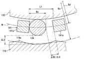
図19に示すように、保持器141において隣り合う突出部134aの離間距離である保持距離L1が、ローラ134の外径Baに比べて大きくなっている。隣り合う突出部134aにおいては、互いに対向する対向面において仮想円Mが通る点同士の直線距離を保持距離L1としている。ここでは、保持距離L1とローラ134の外径Baとの差異を寸法差ΔB2(図22、図23参照)としている。   As shown in FIG. 19, the holding distance L <b> 1, which is a separation distance between adjacent protrusions 134 a in the holder 141, is larger than the outer diameter Ba of the roller 134. In the adjacent protrusions 134a, the linear distance between the points through which the virtual circle M passes on the opposing surfaces facing each other is set as the holding distance L1. Here, the difference between the holding distance L1 and the outer diameter Ba of the roller 134 is defined as a dimensional difference ΔB2 (see FIGS. 22 and 23).

図20、図21に示すように、ローラ134及び保持器141の温度上昇に伴って寸法差ΔB2が小さくなるように、ローラ134の線膨張係数βaと、保持器141の線膨張係数βdとが設定されている。ローラ134の外径Baの増加率が保持器141の保持距離L1の増加率に比べて大きくなっており、温度上昇に伴って寸法差ΔB2が小さくなる。このため、ローラ134が保持器141に比べて熱膨張し過ぎて、隣り合う突出部134aの間にローラ134が挟み込まれてローラ134の回転が阻害される、ということが抑制される。   As shown in FIGS. 20 and 21, the linear expansion coefficient βa of the roller 134 and the linear expansion coefficient βd of the cage 141 are reduced so that the dimensional difference ΔB2 decreases as the temperature of the roller 134 and the cage 141 increases. Is set. The increasing rate of the outer diameter Ba of the roller 134 is larger than the increasing rate of the holding distance L1 of the cage 141, and the dimensional difference ΔB2 becomes smaller as the temperature rises. For this reason, it is suppressed that the roller 134 expands too much heat compared with the holder | retainer 141, and the roller 134 is inserted | pinched between the adjacent protrusion parts 134a, and rotation of the roller 134 is inhibited.

本実施形態では、隣り合う突出部134aの間に挟みこまれてローラ134の回転が阻害されるという状態にならない範囲で寸法差ΔB2が極力小さい値を限界値ΔBz2と称し、寸法差ΔB2まで小さくなる温度を限界温度Tz2と称する。バルブタイミング調整装置100においては、ローラ134及び保持器141が到達し得る温度(例えば130℃)よりも限界温度Tz2が高くなるように、これらローラ134及び保持器141の鋼材や材料が選択されている。   In the present embodiment, a value in which the dimension difference ΔB2 is as small as possible is called a limit value ΔBz2 within a range where the rotation of the roller 134 is not hindered by being sandwiched between adjacent protrusions 134a, and is reduced to the dimension difference ΔB2. This temperature is referred to as a limit temperature Tz2. In the valve timing adjusting device 100, the steel materials and materials of the roller 134 and the cage 141 are selected so that the limit temperature Tz2 is higher than the temperature (for example, 130 ° C.) that the roller 134 and the cage 141 can reach. Yes.

上記基準温度Tqは、限界温度Tz1だけでなく限界温度Tz2よりも低い温度であり、この基準温度Tqについて、ローラ134の外径Baを基準径Baqと称し、保持器141の保持距離L1を基準距離L1qと称する。この場合、ローラ134の線膨張係数βaと、保持器141の線膨張係数βdとを用いると、
Baq×βa>L1q×βd…(4)
という関係が成り立つ。すなわち、基準径Baqと線膨張係数βaとの積が基準距離L1qと線膨張係数βdとの積に比べて大きい、という関係になっている。
The reference temperature Tq is lower than the limit temperature Tz1 as well as the limit temperature Tz2. For this reference temperature Tq, the outer diameter Ba of the roller 134 is referred to as a reference diameter Baq, and the holding distance L1 of the cage 141 is used as a reference. This is referred to as distance L1q. In this case, if the linear expansion coefficient βa of the roller 134 and the linear expansion coefficient βd of the cage 141 are used,
Baq × βa> L1q × βd (4)
This relationship holds. That is, the product of the reference diameter Baq and the linear expansion coefficient βa is larger than the product of the reference distance L1q and the linear expansion coefficient βd.

また、基準温度Tqにおいては、保持器141の径方向での突起部141aの幅寸法がローラ134の外径Baより小さくなっている。この場合、ローラ134が第1ボールベアリング133や環状部材119に確実に接触する構成が実現されるため、ローラ134が第1ボールベアリング133や環状部材119に接触せずに減速機構108が適正に動作しないということを抑制できる。   At the reference temperature Tq, the width dimension of the protrusion 141a in the radial direction of the cage 141 is smaller than the outer diameter Ba of the roller 134. In this case, since the configuration in which the roller 134 reliably contacts the first ball bearing 133 and the annular member 119 is realized, the speed reduction mechanism 108 can be appropriately operated without the roller 134 contacting the first ball bearing 133 and the annular member 119. It can suppress that it does not operate.

ここまで説明した本実施形態によれば、第1ボールベアリング133の外輪133bの線膨張係数βbが環状部材119の線膨張係数βcに比べて大きくなっているため、バルブタイミング調整装置100での温度上昇に伴って、径差ΔB1が小さくなる。すなわち、第1ボールベアリング133及び環状部材119の間において、ローラ134が第1ボールベアリング133の径方向に移動可能な想定距離CL3が小さくなる。想定距離CL3,CL2は、互いに噛み合っている環状部材119の内歯119aとローラ134とが離間するように、第1ボールベアリング133と環状部材119とを径方向に仮想的に移動させた場合に、噛み合っていた内歯119aとローラ134との離間距離である。   According to the present embodiment described so far, the linear expansion coefficient βb of the outer ring 133b of the first ball bearing 133 is larger than the linear expansion coefficient βc of the annular member 119. Along with the increase, the diameter difference ΔB1 decreases. That is, the assumed distance CL3 in which the roller 134 can move in the radial direction of the first ball bearing 133 is reduced between the first ball bearing 133 and the annular member 119. The assumed distances CL3 and CL2 are obtained when the first ball bearing 133 and the annular member 119 are virtually moved in the radial direction so that the inner teeth 119a of the annular member 119 and the roller 134 that are meshed with each other are separated from each other. , The distance between the engaged inner teeth 119a and the roller 134.

想定距離CL3について、図22、図23を参照しつつ説明する。仮想的に移動させる前の状態では内歯119aとその内歯119aの底部に接触していたローラ134とについて、仮想的に移動させた後の図22、図23において内歯119aの底部とローラ134との最短距離を想定距離CL3としている。図22には、内燃機関の冷間始動時などバルブタイミング調整装置100の潤滑油等の温度が十分に低下している場合の想定距離CL3が示されている。この場合、潤滑油の粘度が大きいことで第1ボールベアリング133とローラ134と環状部材119との相対的な移動が潤滑油によって規制されやすい。このため、想定距離CL3がある程度大きくても、第1ボールベアリング133や環状部材119とローラ134とが衝突する際の勢いが大きくなりにくい。   The assumed distance CL3 will be described with reference to FIGS. In the state before the virtual movement, the inner teeth 119a and the roller 134 that has been in contact with the bottom of the internal teeth 119a are virtually moved, and the bottom of the inner teeth 119a and the rollers in FIGS. The shortest distance to 134 is assumed to be an assumed distance CL3. FIG. 22 shows an assumed distance CL3 when the temperature of the lubricating oil or the like of the valve timing adjusting device 100 is sufficiently lowered, such as when the internal combustion engine is cold started. In this case, the relative movement of the first ball bearing 133, the roller 134, and the annular member 119 is easily restricted by the lubricating oil due to the large viscosity of the lubricating oil. For this reason, even if the assumed distance CL3 is large to some extent, the momentum when the first ball bearing 133 or the annular member 119 collides with the roller 134 is unlikely to increase.

一方、図23には、内燃機関が運転中でバルブタイミング調整装置100の潤滑油等の温度が高温になった場合の想定距離CL3が示されている。この場合の想定距離CL3は、第1ボールベアリング133の外輪133bの線膨張係数βbが環状部材119の線膨張係数βcに比べて大きいことに起因して、冷間始動時の想定距離CL3に比べて小さくなっている。このため、温度上昇に伴って潤滑油の粘度が小さくなっていても、ローラ134が第1ボールベアリング133や環状部材119に衝突する際の移動距離が小さく、その衝突の勢いが大きくなりにくい。したがって、バルブタイミング調整装置100の温度が低い場合でも高い場合でも、第1ボールベアリング133や環状部材119にローラ134が衝突する際の打音を低減することができる。   On the other hand, FIG. 23 shows an assumed distance CL3 when the internal combustion engine is in operation and the temperature of the lubricating oil or the like of the valve timing adjusting device 100 becomes high. The assumed distance CL3 in this case is larger than the assumed distance CL3 at the time of cold start because the linear expansion coefficient βb of the outer ring 133b of the first ball bearing 133 is larger than the linear expansion coefficient βc of the annular member 119. It is getting smaller. For this reason, even if the viscosity of the lubricating oil decreases as the temperature rises, the moving distance when the roller 134 collides with the first ball bearing 133 or the annular member 119 is small, and the momentum of the collision is difficult to increase. Therefore, even when the temperature of the valve timing adjusting device 100 is low or high, it is possible to reduce the hitting sound when the roller 134 collides with the first ball bearing 133 or the annular member 119.

本実施形態によれば、第1ボールベアリング133の温度上昇に伴う外径Bbの増加率が、環状部材119の温度上昇に伴うピッチ円内径Bcの増加率に比べて大きい。このように、第1ボールベアリング133及び環状部材119について、線膨張係数βb,βcに加えて、外径Bbやピッチ円内径Bcが考慮されているため、温度上昇に伴って想定距離CL3が小さくなる構成を実現できる。   According to this embodiment, the increasing rate of the outer diameter Bb accompanying the temperature rise of the first ball bearing 133 is larger than the increasing rate of the pitch circle inner diameter Bc accompanying the temperature rise of the annular member 119. As described above, since the outer diameter Bb and the pitch circle inner diameter Bc are taken into consideration in addition to the linear expansion coefficients βb and βc for the first ball bearing 133 and the annular member 119, the assumed distance CL3 decreases as the temperature rises. Can be realized.

本実施形態によれば、ローラ134の外径Baの増加率が、環状部材119のピッチ円内径Bcと第1ボールベアリング133の外径Bbとの差である径差ΔB1の増加率に比べて大きい。また、上記(3)の関係が成り立っている。これら場合、第1ボールベアリング133と環状部材119との間の離間空間でのローラ134の移動態様が、ローラ134の膨張度合いまで含めて考慮されているため、温度上昇に伴って想定距離CL1が小さくなる構成をより確実に実現できる。   According to this embodiment, the increasing rate of the outer diameter Ba of the roller 134 is higher than the increasing rate of the diameter difference ΔB1 that is the difference between the pitch circle inner diameter Bc of the annular member 119 and the outer diameter Bb of the first ball bearing 133. large. Further, the relationship (3) is established. In these cases, since the movement mode of the roller 134 in the separation space between the first ball bearing 133 and the annular member 119 is considered including the degree of expansion of the roller 134, the assumed distance CL1 is increased as the temperature rises. A smaller configuration can be realized more reliably.

本実施形態によれば、第1ボールベアリング133の線膨張係数βbと環状部材119の線膨張係数βcとの比を適正に設定することで、第1ボールベアリング133や環状部材119の寸法を従来から変更しなくても、上記(3)の関係を満たすことができる。このため、バルブタイミング調整装置100の設計段階において、寸法の変更を行うという必要がなくなることで、設計変更についてのコスト負担の増加を抑制することができる。   According to the present embodiment, the dimensions of the first ball bearing 133 and the annular member 119 are conventionally set by appropriately setting the ratio of the linear expansion coefficient βb of the first ball bearing 133 and the linear expansion coefficient βc of the annular member 119. Even if it does not change from (1), the relationship (3) can be satisfied. For this reason, in the design stage of the valve timing adjusting device 100, it is not necessary to change the dimensions, and thus an increase in cost burden for the design change can be suppressed.

本実施形態によれば、ローラ134の線膨張係数βaが保持器141の線膨張係数βdに比べて大きくなっているため、バルブタイミング調整装置100での温度上昇に伴って、寸法差ΔB2が小さくなる。ここで、寸法差ΔB2は、保持器141の隣り合う突起部141aの間において、ローラ134が仮想円Mの周方向に移動可能な距離である。   According to the present embodiment, since the linear expansion coefficient βa of the roller 134 is larger than the linear expansion coefficient βd of the cage 141, the dimensional difference ΔB2 becomes smaller as the temperature of the valve timing adjusting device 100 increases. Become. Here, the dimension difference ΔB <b> 2 is a distance that the roller 134 can move in the circumferential direction of the virtual circle M between the adjacent protrusions 141 a of the cage 141.

図22に示すように、潤滑油の熱が十分に放出された状態においては、潤滑油の粘度が大きいことで保持器141の突起部141aとローラ134との相対的な移動が潤滑油によって規制されやすい。このため、寸法差ΔB2がある程度大きくても、突起部141aとローラ134とが衝突する際の勢いが大きくなりにくい。   As shown in FIG. 22, in a state where the heat of the lubricating oil is sufficiently released, the relative movement between the protrusion 141a of the cage 141 and the roller 134 is restricted by the lubricating oil because the viscosity of the lubricating oil is large. Easy to be. For this reason, even if the dimensional difference ΔB2 is large to some extent, the momentum when the protrusion 141a and the roller 134 collide is unlikely to increase.

一方、図23に示すように、潤滑油の温度が高温になった場合、寸法差ΔB2は、ローラ134の線膨張係数βaが保持器141の線膨張係数βdに比べて大きいことに起因して、冷間始動時の寸法差ΔB2に比べて小さくなっている。このため、温度上昇に伴って潤滑油の粘度が小さくなっていても、ローラ134が突起部141aに衝突する際の移動距離が小さく、その衝突の勢いが大きくなりにくい。したがって、バルブタイミング調整装置100の温度が低い場合でも高い場合でも、保持器141の突起部141aにローラ134が衝突する際の打音を低減することができる。   On the other hand, as shown in FIG. 23, when the temperature of the lubricating oil becomes high, the dimensional difference ΔB2 is caused by the fact that the linear expansion coefficient βa of the roller 134 is larger than the linear expansion coefficient βd of the cage 141. This is smaller than the dimensional difference ΔB2 at the cold start. For this reason, even if the viscosity of the lubricating oil decreases as the temperature rises, the moving distance when the roller 134 collides with the protrusion 141a is small, and the momentum of the collision is difficult to increase. Therefore, even when the temperature of the valve timing adjusting device 100 is low or high, it is possible to reduce the hitting sound when the roller 134 collides with the protrusion 141a of the retainer 141.

本実施形態によれば、ローラ134の温度上昇に伴う外径Baの増加率が、保持器141の温度上昇に伴う保持距離L1の増加率に比べて大きい。また、上記(4)の関係が成り立っている。これらの場合、ローラ134及び保持器141について、線膨張係数βa,βdに加えて、外径Baや隣り合う突起部141aの保持距離L1が考慮されているため、温度上昇に伴って寸法差ΔB2が小さくなる構成を実現できる。   According to the present embodiment, the increasing rate of the outer diameter Ba accompanying the temperature rise of the roller 134 is larger than the increasing rate of the holding distance L1 accompanying the temperature rise of the cage 141. Further, the relationship (4) is established. In these cases, in addition to the linear expansion coefficients βa and βd, the outer diameter Ba and the holding distance L1 between the adjacent protrusions 141a are taken into consideration for the roller 134 and the cage 141. Therefore, the dimensional difference ΔB2 as the temperature rises. Can be realized.

本実施形態によれば、ローラ134の線膨張係数βaと保持器141の線膨張係数βdとの比を適正に設定することで、ローラ134や保持器141の寸法を従来から変更しなくても、上記(4)の関係を満たすことが可能になる。このため、バルブタイミング調整装置100の設計段階において、寸法の変更を行うという必要がなくなることで、設計変更についてのコスト負担の増加を抑制することができる。   According to the present embodiment, by appropriately setting the ratio of the linear expansion coefficient βa of the roller 134 and the linear expansion coefficient βd of the cage 141, the dimensions of the roller 134 and the cage 141 do not have to be changed conventionally. Thus, the relationship (4) can be satisfied. For this reason, in the design stage of the valve timing adjusting device 100, it is not necessary to change the dimensions, and thus an increase in cost burden for the design change can be suppressed.

(他の実施形態)
以上、本開示による複数の実施形態について説明したが、本開示は、上記実施形態に限定して解釈されるものではなく、本開示の要旨を逸脱しない範囲内において種々の実施形態及び組み合わせに適用することができる。
(Other embodiments)
Although a plurality of embodiments according to the present disclosure have been described above, the present disclosure is not construed as being limited to the above embodiments, and can be applied to various embodiments and combinations without departing from the gist of the present disclosure. can do.

変形例1として、上記第1実施形態において、内歯車部37,38の線膨張係数αb1,αb2が同じ値になっているのではなく、これら線膨張係数αb1,αb2は異なる値になっていてもよい。すなわち、駆動側内歯車部37と従動側内歯車部38とが異なる鋼材により形成されていてもよい。同様に、外歯車部50,51の線膨張係数αa1,αabが同じ値になっていたが、これら線膨張係数αa1,αabは異なる値になっていてもよい。すなわち、駆動側外歯車部50と従動側外歯車部51とが異なる鋼材により形成されていてもよい。これらの場合でも、駆動側及び従動側のそれぞれについて、外歯車部50,51の線膨張係数αa1,αa2が内歯車部37の線膨張係数αb1,αb2に比べて大きくなっていればよい。   As a first modification, in the first embodiment, the linear expansion coefficients αb1 and αb2 of the internal gear portions 37 and 38 are not the same value, but the linear expansion coefficients αb1 and αb2 are different values. Also good. That is, the driving side internal gear portion 37 and the driven side internal gear portion 38 may be formed of different steel materials. Similarly, although the linear expansion coefficients αa1 and αab of the external gear portions 50 and 51 have the same value, these linear expansion coefficients αa1 and αab may have different values. That is, the drive side external gear part 50 and the driven side external gear part 51 may be formed of different steel materials. Even in these cases, the linear expansion coefficients αa1 and αa2 of the external gear portions 50 and 51 need only be larger than the linear expansion coefficients αb1 and αb2 of the internal gear portion 37 on the driving side and the driven side, respectively.

変形例2として、上記第1実施形態において、従動側についての限界径差ΔDy2が駆動側についての限界径差ΔDy1より小さくなっていなくてもよい。例えば、これら限界径差ΔDy1,ΔDy2が同じ値である構成とする。この構成では、もし歯車部37,38,50,51が限界温度Tyに到達した場合に、従動側外歯車部51と従動側内歯車部38との衝突と、駆動側外歯車部50と従動側内歯車部38との衝突とが同じ度合いで発生すると考えられる。   As a second modification, in the first embodiment, the limit diameter difference ΔDy2 on the driven side may not be smaller than the limit diameter difference ΔDy1 on the drive side. For example, the limit diameter differences ΔDy1 and ΔDy2 have the same value. In this configuration, if the gear portions 37, 38, 50, 51 reach the limit temperature Ty, the collision between the driven-side external gear portion 51 and the driven-side internal gear portion 38, and the driving-side external gear portion 50 and the driven It is considered that the collision with the side internal gear portion 38 occurs with the same degree.

また、駆動側についての限界径差ΔDy1が従動側についての限界径差ΔDy2より小さい構成とする。この構成では、もし歯車部37,38,50,51が限界温度Tyに到達すると、駆動側外歯車部50と従動側内歯車部38との衝突の方が、従動側外歯車部51と従動側内歯車部38との衝突に比べて発生しやすい。外歯車部50,51と内歯車部37,38との衝突に伴う打音を抑制するためには、駆動側及び従動側のうち駆動側について歯車部50,37の熱膨張を管理すれば済むことになる。   Further, the limit diameter difference ΔDy1 on the driving side is configured to be smaller than the limit diameter difference ΔDy2 on the driven side. In this configuration, if the gear portions 37, 38, 50, 51 reach the limit temperature Ty, the collision between the drive side external gear portion 50 and the driven side internal gear portion 38 is driven by the driven side external gear portion 51 and the driven side. It is more likely to occur than a collision with the side internal gear portion 38. In order to suppress the hitting sound caused by the collision between the external gear portions 50 and 51 and the internal gear portions 37 and 38, it is only necessary to manage the thermal expansion of the gear portions 50 and 37 on the drive side of the drive side and the driven side. It will be.

変形例3として、上記第1実施形態において、駆動側及び従動側のうち一方について、外歯車部50,51の線膨張係数αa1,αa2が内歯車部37の線膨張係数αb1,αb2に比べて大きくなっていなくてもよい。例えば、駆動側について、駆動側外歯車部50の線膨張係数αa1と駆動側内歯車部37の線膨張係数αb1とが同じ値になっている構成とする。   As a third modification, in the first embodiment, the linear expansion coefficients αa1 and αa2 of the external gear portions 50 and 51 are compared with the linear expansion coefficients αb1 and αb2 of the internal gear portion 37 for one of the driving side and the driven side. It does not have to be large. For example, on the driving side, the linear expansion coefficient αa1 of the driving side external gear portion 50 and the linear expansion coefficient αb1 of the driving side internal gear portion 37 are set to the same value.

変形例4として、上記第2実施形態において、環状部材119の線膨張係数βcと保持器141の線膨張係数βdとが同じ値になっているのではなく、これら線膨張係数βc,βdは異なる値になっていてもよい。すなわち、環状部材119と保持器141とは異なる鋼材により形成されていてもよい。また、ローラ134の線膨張係数βaと第1ボールベアリング133の線膨張係数βbとが同じ値になっていなくてもよい。すなわち、ローラ134と第1ボールベアリング133の外輪133bとは異なる鋼材により形成されていてもよい。これらの場合でも、第1ボールベアリング133の線膨張係数βbが環状部材119の線膨張係数βcより大きくなっていればよい。まだ、ローラ134の線膨張係数βaが保持器141の線膨張係数βdより大きくなっていればよい。   As a fourth modification, in the second embodiment, the linear expansion coefficient βc of the annular member 119 and the linear expansion coefficient βd of the cage 141 are not the same value, but the linear expansion coefficients βc and βd are different. It may be a value. That is, the annular member 119 and the cage 141 may be formed of different steel materials. Further, the linear expansion coefficient βa of the roller 134 and the linear expansion coefficient βb of the first ball bearing 133 may not be the same value. That is, the roller 134 and the outer ring 133b of the first ball bearing 133 may be formed of different steel materials. Even in these cases, it is sufficient that the linear expansion coefficient βb of the first ball bearing 133 is larger than the linear expansion coefficient βc of the annular member 119. It is only necessary that the linear expansion coefficient βa of the roller 134 is larger than the linear expansion coefficient βd of the cage 141.

変形例5として、上記第1,2実施形態について、バルブタイミング調整装置は、吸気弁のバルブタイミングを調整するのではなく、排気弁のバルブタイミングを調整してもよい。   As a fifth modification, in the first and second embodiments, the valve timing adjusting device may adjust the valve timing of the exhaust valve instead of adjusting the valve timing of the intake valve.

10…バルブタイミング調整装置、25…駆動回転体、26…従動回転体、37…駆動歯車部としての駆動側内歯車部、37a…内歯、38…従動歯車部としての従動側内歯車部、38a…内歯、80…内燃機関、49…遊星回転体としての遊星歯車、50…第1遊星歯車部としての駆動側外歯車部、51…第2遊星歯車部としての従動側外歯車部、81…吸気弁、90…クランク軸、91…カム軸、Da1…駆動側外歯車部のピッチ円外径、Da1p…基準径、Da2…従動側外歯車部のピッチ円外径、Da2p…基準径、Db1…駆動側内歯車部のピッチ円内径、Db1p…基準径、Db2…従動側内歯車部のピッチ円内径、Db2p…基準径、αa1…駆動側外歯車部の線膨張係数、αa2…従動側外歯車部の線膨張係数、αb1…駆動側内歯車部の線膨張係数、αb2…従動側内歯車部の線膨張係数、Tp…基準温度、100…バルブタイミング調整装置、101…移動回転体としてのスプロケット、102…カム軸としてのカムシャフト、108…減速機構、109…従動回転体としての従動部材、119…環状部材、119a…内歯、130…偏心回転体を構成する偏心軸部、133…偏心回転体を構成する第1ボールベアリング、134…ローラ、141…保持器、141a…ローラ保持部としての突起部、Ba…ローラの外径、Baq…基準径、Bb…第1ボールベアリングの外径、Bbq…基準径、Bc…環状部材のピッチ円内径、Bcq…基準径、Bd…保持器の保持径、Bdq…基準径、ΔB1…BbとBcとの径差、L1…隣り合う突起部の離間距離としての保持距離、L1q…基準距離、βa…ローラの線膨張係数、βb…第1ボールベアリングの線膨張係数、βc…環状部材の線膨張係数、βd…保持器の線膨張係数、Tq…基準温度。   DESCRIPTION OF SYMBOLS 10 ... Valve timing adjustment apparatus, 25 ... Drive rotary body, 26 ... Driven rotary body, 37 ... Drive side internal gear part as drive gear part, 37a ... Internal tooth, 38 ... Drive side internal gear part as driven gear part, 38a ... internal teeth, 80 ... internal combustion engine, 49 ... planetary gear as a planetary rotor, 50 ... drive side external gear part as a first planetary gear part, 51 ... driven side external gear part as a second planetary gear part, 81 ... Intake valve, 90 ... Crankshaft, 91 ... Cam shaft, Da1 ... Pitch circle outer diameter of drive side external gear part, Da1p ... Reference diameter, Da2 ... Pitch circle outer diameter of driven side external gear part, Da2p ... Reference diameter , Db1... Pitch circle inner diameter of the driving side internal gear portion, Db1p... Reference diameter, Db2... Pitch circle inner diameter of the driven side internal gear portion, Db2p... Reference diameter, αa1. Linear expansion coefficient of side external gear part, αb1... Drive Linear expansion coefficient of the internal gear part, αb2 ... Linear expansion coefficient of the driven side internal gear part, Tp ... Reference temperature, 100 ... Valve timing adjusting device, 101 ... Sprocket as a moving rotor, 102 ... Cam shaft as a cam shaft, DESCRIPTION OF SYMBOLS 108 ... Deceleration mechanism, 109 ... Driven member as driven rotator, 119 ... Ring member, 119a ... Internal tooth, 130 ... Eccentric shaft part which constitutes eccentric rotator, 133 ... First ball bearing which constitutes eccentric rotator, 134: Roller, 141: Cage, 141a: Projection as a roller holding portion, Ba: Outer diameter of roller, Baq: Reference diameter, Bb: Outer diameter of first ball bearing, Bbq: Reference diameter, Bc: Annular member Pitch circle inner diameter, Bcq ... reference diameter, Bd ... retainer holding diameter, Bdq ... reference diameter, ΔB1 ... diameter difference between Bb and Bc, L1 ... separation distance between adjacent protrusions Lifting distance, L1Q ... reference distance, the linear expansion coefficient of .beta.a ... roller, .beta.b ... linear expansion coefficient of the first ball bearing, the linear expansion coefficient of .beta.c ... annular member, the linear expansion coefficient of the .beta.d ... retainer, Tq ... reference temperature.

Claims (11)

内燃機関(80)においてクランク軸(90)からの機関トルクの伝達によりカム軸(91)が開閉するバルブ(81)のバルブタイミングを調整するバルブタイミング調整装置(10)であって、
駆動歯車部(37)を有し、前記クランク軸に連動して回転する駆動回転体(25)と、
従動歯車部(38)を有し、前記カム軸に連動して回転する従動回転体(26)と、
第1遊星歯車部(50)及び第2遊星歯車部(51)を有し、これら第1遊星歯車部及び第2遊星歯車部がそれぞれ前記駆動歯車部及び前記従動歯車部に対し偏心して噛み合いつつ一体に遊星運動することにより、前記駆動回転体及び前記従動回転体の間の相対位相を変化させる遊星回転体(40)と、
を備え、
前記第1遊星歯車部及び前記第2遊星歯車部のうち一方を、径方向外側に向けて外歯(50a,51a)が延びた外歯車部(50,51)と称し、前記駆動歯車部及び前記従動歯車部のうち前記外歯車部に噛み合う方を、径方向内側に向けて内歯(37a,38a)が延びた内歯車部(37,38)と称した場合に、前記外歯車部の線膨張係数(αa1,αa2)が前記内歯車部の線膨張係数(αb1,αb2)に比べて大きい、バルブタイミング調整装置。
A valve timing adjusting device (10) for adjusting a valve timing of a valve (81) that opens and closes a camshaft (91) by transmission of engine torque from a crankshaft (90) in an internal combustion engine (80),
A drive rotator (25) having a drive gear portion (37) and rotating in conjunction with the crankshaft;
A driven rotating body (26) having a driven gear portion (38) and rotating in conjunction with the camshaft;
A first planetary gear portion (50) and a second planetary gear portion (51) are provided, and the first planetary gear portion and the second planetary gear portion are eccentrically engaged with the drive gear portion and the driven gear portion, respectively. A planetary rotator (40) that changes a relative phase between the driving rotator and the driven rotator by performing planetary motion integrally;
With
One of the first planetary gear part and the second planetary gear part is referred to as an external gear part (50, 51) in which external teeth (50a, 51a) extend radially outward, and the drive gear part and When the driven gear portion that meshes with the external gear portion is referred to as an internal gear portion (37, 38) in which internal teeth (37a, 38a) extend inward in the radial direction, The valve timing adjusting device, wherein the linear expansion coefficient (αa1, αa2) is larger than the linear expansion coefficient (αb1, αb2) of the internal gear portion.
前記外歯車部の温度上昇に伴う当該外歯車部のピッチ円直径(Da1,Da2)の増加率は、前記内歯車部の温度上昇に伴う当該内歯車部のピッチ円直径(Db1,Db2)の増加率に比べて大きい、請求項1に記載のバルブタイミング調整装置。   The rate of increase in the pitch circle diameter (Da1, Da2) of the external gear portion accompanying the temperature increase of the external gear portion is the pitch circle diameter (Db1, Db2) of the internal gear portion accompanying the temperature rise of the internal gear portion. The valve timing adjusting device according to claim 1, wherein the valve timing adjusting device is larger than an increase rate. 前記外歯車部の線膨張係数(αa1,αa2)と、所定の基準温度(Tp)での前記外歯車部のピッチ円直径(Da1p,Da2p)との積が、前記内歯車部の線膨張係数(αb1,αb2)と、前記基準温度での前記内歯車部のピッチ円直径(Db1p,Db2p)との積に比べて大きい、請求項1又は2に記載のバルブタイミング調整装置。   The product of the linear expansion coefficient (αa1, αa2) of the external gear part and the pitch circle diameter (Da1p, Da2p) of the external gear part at a predetermined reference temperature (Tp) is the linear expansion coefficient of the internal gear part. The valve timing adjusting device according to claim 1 or 2, wherein the valve timing adjusting device is larger than a product of (αb1, αb2) and a pitch circle diameter (Db1p, Db2p) of the internal gear portion at the reference temperature. 前記第1遊星歯車部及び前記第2遊星歯車部のうち前記外歯車部だけでなく両方の線膨張係数(αa1,αa2)が、前記駆動歯車部及び前記従動歯車部のうち前記内歯車部だけでなく両方の線膨張係数(αb1,αb2)に比べて大きい、請求項1〜3のいずれか1つに記載のバルブタイミング調整装置。   Of the first planetary gear part and the second planetary gear part, not only the outer gear part but also the linear expansion coefficients (αa1, αa2) of both are only the inner gear part of the drive gear part and the driven gear part. The valve timing adjustment device according to any one of claims 1 to 3, wherein the valve timing adjustment device is larger than both of the linear expansion coefficients (αb1, αb2). 内燃機関においてクランク軸からの機関トルクの伝達によりカム軸(102)が開閉するバルブのバルブタイミングを調整するバルブタイミング調整装置であって、
前記クランク軸に連動して回転する駆動回転体(101)と、
前記カム軸に連動して回転する従動回転体(109)と、
径方向内側に向けて内歯(119a)が延び前記駆動回転体と共に回転する環状部材(119)と、前記環状部材の内周側に設けられて軸心に対して外周面が偏心した偏心回転体(130,133)と、前記環状部材と前記偏心回転体との間に設けられた複数のローラ(134)と、前記従動回転体と共に回転し前記環状部材と前記偏心回転体との間にて前記ローラを保持する保持器(141)とを有し、前記偏心回転体の回転によって前記環状部材に対して前記保持器が相対回転することにより、前記駆動回転体及び前記従動回転体の間の相対位相を変化させる減速機構(108)と、
を備え、
前記偏心回転体の線膨張係数(βb)が前記環状部材の線膨張係数(βc)に比べて大きい、バルブタイミング調整装置。
A valve timing adjusting device for adjusting a valve timing of a valve that opens and closes a camshaft (102) by transmission of engine torque from a crankshaft in an internal combustion engine,
A drive rotator (101) that rotates in conjunction with the crankshaft;
A driven rotor (109) that rotates in conjunction with the camshaft;
An annular member (119) in which an inner tooth (119a) extends radially inward and rotates together with the drive rotating body, and an eccentric rotation provided on the inner peripheral side of the annular member and having an outer peripheral surface eccentric with respect to the axis. A body (130, 133), a plurality of rollers (134) provided between the annular member and the eccentric rotating body, and the driven rotating body rotating between the annular member and the eccentric rotating body. A retainer (141) for retaining the roller, and the rotation of the eccentric rotator causes the retainer to rotate relative to the annular member, thereby allowing the drive rotator and the driven rotator to move between each other. A speed reduction mechanism (108) for changing the relative phase of
With
The valve timing adjusting device, wherein a linear expansion coefficient (βb) of the eccentric rotating body is larger than a linear expansion coefficient (βc) of the annular member.
前記偏心回転体の温度上昇に伴う当該偏心回転体の外径(Bb)の増加率は、前記環状部材の温度上昇に伴う当該環状部材のピッチ円直径(Bc)の増加率に比べて大きい、請求項5に記載のバルブタイミング調整装置。   The increasing rate of the outer diameter (Bb) of the eccentric rotating body accompanying the temperature rise of the eccentric rotating body is larger than the increasing rate of the pitch circle diameter (Bc) of the annular member accompanying the temperature rise of the annular member, The valve timing adjusting device according to claim 5. 前記ローラの直径(Ba)の増加率は、前記環状部材のピッチ円直径(Bc)と前記偏心回転体の外径(Bb)との差異(ΔB1)の増加率に比べて大きい、請求項5又は6に記載のバルブタイミング調整装置。   The increase rate of the diameter (Ba) of the roller is larger than the increase rate of the difference (ΔB1) between the pitch circle diameter (Bc) of the annular member and the outer diameter (Bb) of the eccentric rotating body. Or the valve timing adjustment apparatus of 6. 前記ローラの線膨張係数(βa)と、所定の基準温度(Tq)での前記ローラの外径(Baq)との積と、
前記偏心回転体の線膨張係数(βb)と、前記基準温度での前記偏心回転体の外径(Bbq)との積と和が、
前記環状部材の線膨張係数(βc)と、前記基準温度での前記環状部材のピッチ円直径(Bcq)との積に比べて大きい、請求項5〜7のいずれか1つに記載のバルブタイミング調整装置。
The product of the linear expansion coefficient (βa) of the roller and the outer diameter (Baq) of the roller at a predetermined reference temperature (Tq);
The product and sum of the linear expansion coefficient (βb) of the eccentric rotator and the outer diameter (Bbq) of the eccentric rotator at the reference temperature are:
The valve timing according to any one of claims 5 to 7, which is larger than a product of a linear expansion coefficient (βc) of the annular member and a pitch circle diameter (Bcq) of the annular member at the reference temperature. Adjustment device.
内燃機関においてクランク軸からの機関トルクの伝達によりカム軸(102)が開閉するバルブのバルブタイミングを調整するバルブタイミング調整装置であって、
前記クランク軸に連動して回転する駆動回転体(101)と、
前記カム軸に連動して回転する従動回転体(109)と、
径方向内側に向けて内歯(119a)が延び前記駆動回転体と共に回転する環状部材(119)と、前記環状部材の内周側に設けられて軸心に対して外周面が偏心した偏心回転体(130,133)と、前記環状部材と前記偏心回転体との間に設けられた複数のローラ(134)と、前記従動回転体と共に回転し前記環状部材と前記偏心回転体との間にて前記ローラを保持する保持器(141)とを有し、前記偏心回転体の回転によって前記環状部材に対して前記保持器が相対回転することにより、前記駆動回転体及び前記従動回転体の間の相対位相を変化させる減速機構(108)と、
を備え、
前記保持器は、当該保持器の径方向において所定間隔で並ぶローラ保持部(141a)を有しており、
前記ローラは、隣り合う前記ローラ保持部の間に配置されることで、前記保持器により保持されており、
前記ローラの線膨張係数(βa)が前記保持器の線膨張係数(βd)に比べて大きい、バルブタイミング調整装置。
A valve timing adjusting device for adjusting a valve timing of a valve that opens and closes a camshaft (102) by transmission of engine torque from a crankshaft in an internal combustion engine,
A drive rotator (101) that rotates in conjunction with the crankshaft;
A driven rotor (109) that rotates in conjunction with the camshaft;
An annular member (119) in which an inner tooth (119a) extends radially inward and rotates together with the drive rotating body, and an eccentric rotation provided on the inner peripheral side of the annular member and having an outer peripheral surface eccentric with respect to the axis. A body (130, 133), a plurality of rollers (134) provided between the annular member and the eccentric rotating body, and the driven rotating body rotating between the annular member and the eccentric rotating body. A retainer (141) for retaining the roller, and the rotation of the eccentric rotator causes the retainer to rotate relative to the annular member, thereby allowing the drive rotator and the driven rotator to move. A speed reduction mechanism (108) for changing the relative phase of
With
The cage has roller holding portions (141a) arranged at a predetermined interval in the radial direction of the cage,
The roller is disposed between the roller holding portions adjacent to each other, and is held by the cage.
The valve timing adjusting device, wherein a linear expansion coefficient (βa) of the roller is larger than a linear expansion coefficient (βd) of the cage.
前記ローラの温度上昇に伴う当該ローラの外径(Ba)の増加率は、前記保持器の温度上昇に伴う隣り合う前記ローラ保持部の離間距離(L1)の増加率に比べて大きい、請求項9に記載のバルブタイミング調整装置。   The increase rate of the outer diameter (Ba) of the roller accompanying the temperature rise of the roller is larger than the increase rate of the separation distance (L1) of the roller holding portions adjacent to each other due to the temperature rise of the cage. 9. The valve timing adjusting device according to 9. 前記ローラの前記線膨張係数(βa)と、所定の基準温度(Tq)での前記ローラの外径(Baq)との積が、前記保持器の線膨張係数(βb)と、隣り合う前記ローラ保持部の離間距離(L1q)との積に比べて大きい、請求項9又は10に記載のバルブタイミング調整装置。   The product of the linear expansion coefficient (βa) of the roller and the outer diameter (Baq) of the roller at a predetermined reference temperature (Tq) is adjacent to the linear expansion coefficient (βb) of the cage. The valve timing adjusting device according to claim 9 or 10, wherein the valve timing adjusting device is larger than a product of a separation distance (L1q) of the holding portion.
JP2017015285A 2017-01-31 2017-01-31 Valve timing adjuster Active JP6760112B2 (en)

Priority Applications (1)

Application Number Priority Date Filing Date Title
JP2017015285A JP6760112B2 (en) 2017-01-31 2017-01-31 Valve timing adjuster

Applications Claiming Priority (1)

Application Number Priority Date Filing Date Title
JP2017015285A JP6760112B2 (en) 2017-01-31 2017-01-31 Valve timing adjuster

Publications (2)

Publication Number Publication Date
JP2018123727A true JP2018123727A (en) 2018-08-09
JP6760112B2 JP6760112B2 (en) 2020-09-23

Family

ID=63109477

Family Applications (1)

Application Number Title Priority Date Filing Date
JP2017015285A Active JP6760112B2 (en) 2017-01-31 2017-01-31 Valve timing adjuster

Country Status (1)

Country Link
JP (1) JP6760112B2 (en)

Cited By (6)

* Cited by examiner, † Cited by third party
Publication number Priority date Publication date Assignee Title
WO2020039689A1 (en) * 2018-08-23 2020-02-27 日立オートモティブシステムズ株式会社 Valve timing control device for internal combustion engine
US10697334B2 (en) 2018-07-31 2020-06-30 Denso Corporation Valve timing adjusting device
WO2020179578A1 (en) 2019-03-05 2020-09-10 Ntn株式会社 Electrical actuator
JP2020148137A (en) * 2019-03-13 2020-09-17 Ntn株式会社 Electric actuator
JP2020153234A (en) * 2019-03-18 2020-09-24 株式会社デンソー Valve timing adjustment device
CN112963506A (en) * 2021-03-31 2021-06-15 杰锋汽车动力系统股份有限公司 Electric transmission device with variable compression ratio

Citations (7)

* Cited by examiner, † Cited by third party
Publication number Priority date Publication date Assignee Title
JPS62681A (en) * 1985-02-06 1987-01-06 Toyoda Mach Works Ltd Internal-gear type oil pump
JPH0320553Y2 (en) * 1985-07-08 1991-05-02
JP2013139881A (en) * 2013-03-14 2013-07-18 Nsk Ltd Rolling bearing
JP2013167173A (en) * 2012-02-14 2013-08-29 Mazda Motor Corp Valve timing adjusting device
JP5538053B2 (en) * 2010-04-28 2014-07-02 日立オートモティブシステムズ株式会社 Variable valve operating device for internal combustion engine
JP2014199119A (en) * 2013-03-29 2014-10-23 住友重機械工業株式会社 Deflective meshing type gear device
JP2015010511A (en) * 2013-06-27 2015-01-19 株式会社デンソー Valve timing adjusting device

Patent Citations (7)

* Cited by examiner, † Cited by third party
Publication number Priority date Publication date Assignee Title
JPS62681A (en) * 1985-02-06 1987-01-06 Toyoda Mach Works Ltd Internal-gear type oil pump
JPH0320553Y2 (en) * 1985-07-08 1991-05-02
JP5538053B2 (en) * 2010-04-28 2014-07-02 日立オートモティブシステムズ株式会社 Variable valve operating device for internal combustion engine
JP2013167173A (en) * 2012-02-14 2013-08-29 Mazda Motor Corp Valve timing adjusting device
JP2013139881A (en) * 2013-03-14 2013-07-18 Nsk Ltd Rolling bearing
JP2014199119A (en) * 2013-03-29 2014-10-23 住友重機械工業株式会社 Deflective meshing type gear device
JP2015010511A (en) * 2013-06-27 2015-01-19 株式会社デンソー Valve timing adjusting device

Cited By (17)

* Cited by examiner, † Cited by third party
Publication number Priority date Publication date Assignee Title
US10697334B2 (en) 2018-07-31 2020-06-30 Denso Corporation Valve timing adjusting device
JPWO2020039689A1 (en) * 2018-08-23 2021-08-26 日立Astemo株式会社 Internal combustion engine valve timing controller
WO2020039689A1 (en) * 2018-08-23 2020-02-27 日立オートモティブシステムズ株式会社 Valve timing control device for internal combustion engine
JP7085629B2 (en) 2018-08-23 2022-06-16 日立Astemo株式会社 Internal combustion engine valve timing controller
WO2020179578A1 (en) 2019-03-05 2020-09-10 Ntn株式会社 Electrical actuator
US11965437B2 (en) 2019-03-05 2024-04-23 Ntn Corporation Electric actuator
WO2020184135A1 (en) * 2019-03-13 2020-09-17 Ntn株式会社 Electric actuator
JP7261621B2 (en) 2019-03-13 2023-04-20 Ntn株式会社 electric actuator
JP2020148137A (en) * 2019-03-13 2020-09-17 Ntn株式会社 Electric actuator
WO2020189616A1 (en) * 2019-03-18 2020-09-24 株式会社デンソー Valve timing adjustment device
CN113574292A (en) * 2019-03-18 2021-10-29 株式会社电装 Valve timing adjusting device
JP2020153234A (en) * 2019-03-18 2020-09-24 株式会社デンソー Valve timing adjustment device
JP7131445B2 (en) 2019-03-18 2022-09-06 株式会社デンソー valve timing adjuster
US11434787B2 (en) 2019-03-18 2022-09-06 Denso Corporation Valve timing adjustment device
CN113574292B (en) * 2019-03-18 2024-04-02 株式会社电装 Valve timing adjusting device
CN112963506A (en) * 2021-03-31 2021-06-15 杰锋汽车动力系统股份有限公司 Electric transmission device with variable compression ratio
CN112963506B (en) * 2021-03-31 2024-05-03 杰锋汽车动力系统股份有限公司 Electric transmission device with variable compression ratio

Also Published As

Publication number Publication date
JP6760112B2 (en) 2020-09-23

Similar Documents

Publication Publication Date Title
JP6760112B2 (en) Valve timing adjuster
JP5538053B2 (en) Variable valve operating device for internal combustion engine
JP5675440B2 (en) Valve timing control device for internal combustion engine
JP5940001B2 (en) Valve timing control system for internal combustion engine
JP5978080B2 (en) Valve timing control device for internal combustion engine and controller for the valve timing control device
JP6814621B2 (en) Internal combustion engine valve timing controller
JP6309230B2 (en) Controller for variable valve operating device of internal combustion engine
JP5952400B2 (en) Variable valve operating apparatus for internal combustion engine and manufacturing method thereof
JP5379669B2 (en) Variable valve operating device for internal combustion engine
JP5411066B2 (en) Variable valve operating device for internal combustion engine
JP6042233B2 (en) Valve timing control system for internal combustion engine
JP2013167181A (en) Valve timing control apparatus for internal combustion engine
KR101624783B1 (en) System for controlling valve timing of internal combustion engine
JP6338550B2 (en) Deceleration mechanism and valve timing control device for internal combustion engine using the deceleration mechanism
CN107614840B (en) Valve timing control device for internal combustion engine
JP5719008B2 (en) Variable valve operating device for internal combustion engine
US10697334B2 (en) Valve timing adjusting device
JP4200377B2 (en) Valve timing adjustment device
JP6154521B2 (en) Valve timing control system for internal combustion engine
JP5693312B2 (en) Valve timing control device for internal combustion engine
JP5687727B2 (en) Variable valve operating device for internal combustion engine
US9752467B2 (en) Variable valve device for internal combustion engines and valve timing control device
JP6808844B2 (en) Internal combustion engine valve timing controller
JP2022018675A (en) Valve timing control device and roller reduction gear of internal combustion engine

Legal Events

Date Code Title Description
A621 Written request for application examination

Free format text: JAPANESE INTERMEDIATE CODE: A621

Effective date: 20190606

A977 Report on retrieval

Free format text: JAPANESE INTERMEDIATE CODE: A971007

Effective date: 20200423

A131 Notification of reasons for refusal

Free format text: JAPANESE INTERMEDIATE CODE: A131

Effective date: 20200602

A521 Request for written amendment filed

Free format text: JAPANESE INTERMEDIATE CODE: A523

Effective date: 20200624

TRDD Decision of grant or rejection written
A01 Written decision to grant a patent or to grant a registration (utility model)

Free format text: JAPANESE INTERMEDIATE CODE: A01

Effective date: 20200804

A61 First payment of annual fees (during grant procedure)

Free format text: JAPANESE INTERMEDIATE CODE: A61

Effective date: 20200817

R151 Written notification of patent or utility model registration

Ref document number: 6760112

Country of ref document: JP

Free format text: JAPANESE INTERMEDIATE CODE: R151

R250 Receipt of annual fees

Free format text: JAPANESE INTERMEDIATE CODE: R250