JP2018123718A - Engine device - Google Patents

Engine device Download PDF

Info

Publication number
JP2018123718A
JP2018123718A JP2017014839A JP2017014839A JP2018123718A JP 2018123718 A JP2018123718 A JP 2018123718A JP 2017014839 A JP2017014839 A JP 2017014839A JP 2017014839 A JP2017014839 A JP 2017014839A JP 2018123718 A JP2018123718 A JP 2018123718A
Authority
JP
Japan
Prior art keywords
cooling water
cylinder head
egr
egr gas
flow path
Prior art date
Legal status (The legal status is an assumption and is not a legal conclusion. Google has not performed a legal analysis and makes no representation as to the accuracy of the status listed.)
Granted
Application number
JP2017014839A
Other languages
Japanese (ja)
Other versions
JP6718573B2 (en
Inventor
恭志 小野寺
Kyoji Onodera
恭志 小野寺
Current Assignee (The listed assignees may be inaccurate. Google has not performed a legal analysis and makes no representation or warranty as to the accuracy of the list.)
Yanmar Co Ltd
Original Assignee
Yanmar Co Ltd
Priority date (The priority date is an assumption and is not a legal conclusion. Google has not performed a legal analysis and makes no representation as to the accuracy of the date listed.)
Filing date
Publication date
Priority to JP2017014839A priority Critical patent/JP6718573B2/en
Application filed by Yanmar Co Ltd filed Critical Yanmar Co Ltd
Priority to KR1020197013324A priority patent/KR102183502B1/en
Priority to CN201780078943.8A priority patent/CN110199107A/en
Priority to KR1020207033495A priority patent/KR102355836B1/en
Priority to US16/481,813 priority patent/US11002174B2/en
Priority to EP17894049.0A priority patent/EP3575588A4/en
Priority to KR1020227001673A priority patent/KR102498650B1/en
Priority to PCT/JP2017/040392 priority patent/WO2018139003A1/en
Priority to EP21174598.9A priority patent/EP3940223A1/en
Publication of JP2018123718A publication Critical patent/JP2018123718A/en
Priority to JP2020082577A priority patent/JP6944567B2/en
Application granted granted Critical
Publication of JP6718573B2 publication Critical patent/JP6718573B2/en
Priority to US17/228,673 priority patent/US20210231045A1/en
Active legal-status Critical Current
Anticipated expiration legal-status Critical

Links

Images

Classifications

    • FMECHANICAL ENGINEERING; LIGHTING; HEATING; WEAPONS; BLASTING
    • F01MACHINES OR ENGINES IN GENERAL; ENGINE PLANTS IN GENERAL; STEAM ENGINES
    • F01PCOOLING OF MACHINES OR ENGINES IN GENERAL; COOLING OF INTERNAL-COMBUSTION ENGINES
    • F01P3/00Liquid cooling
    • F01P3/02Arrangements for cooling cylinders or cylinder heads
    • FMECHANICAL ENGINEERING; LIGHTING; HEATING; WEAPONS; BLASTING
    • F02COMBUSTION ENGINES; HOT-GAS OR COMBUSTION-PRODUCT ENGINE PLANTS
    • F02FCYLINDERS, PISTONS OR CASINGS, FOR COMBUSTION ENGINES; ARRANGEMENTS OF SEALINGS IN COMBUSTION ENGINES
    • F02F1/00Cylinders; Cylinder heads 
    • F02F1/24Cylinder heads
    • F02F1/26Cylinder heads having cooling means
    • F02F1/36Cylinder heads having cooling means for liquid cooling
    • FMECHANICAL ENGINEERING; LIGHTING; HEATING; WEAPONS; BLASTING
    • F02COMBUSTION ENGINES; HOT-GAS OR COMBUSTION-PRODUCT ENGINE PLANTS
    • F02MSUPPLYING COMBUSTION ENGINES IN GENERAL WITH COMBUSTIBLE MIXTURES OR CONSTITUENTS THEREOF
    • F02M26/00Engine-pertinent apparatus for adding exhaust gases to combustion-air, main fuel or fuel-air mixture, e.g. by exhaust gas recirculation [EGR] systems
    • F02M26/13Arrangement or layout of EGR passages, e.g. in relation to specific engine parts or for incorporation of accessories
    • F02M26/22Arrangement or layout of EGR passages, e.g. in relation to specific engine parts or for incorporation of accessories with coolers in the recirculation passage
    • F02M26/23Layout, e.g. schematics
    • FMECHANICAL ENGINEERING; LIGHTING; HEATING; WEAPONS; BLASTING
    • F01MACHINES OR ENGINES IN GENERAL; ENGINE PLANTS IN GENERAL; STEAM ENGINES
    • F01PCOOLING OF MACHINES OR ENGINES IN GENERAL; COOLING OF INTERNAL-COMBUSTION ENGINES
    • F01P3/00Liquid cooling
    • F01P3/20Cooling circuits not specific to a single part of engine or machine
    • FMECHANICAL ENGINEERING; LIGHTING; HEATING; WEAPONS; BLASTING
    • F02COMBUSTION ENGINES; HOT-GAS OR COMBUSTION-PRODUCT ENGINE PLANTS
    • F02FCYLINDERS, PISTONS OR CASINGS, FOR COMBUSTION ENGINES; ARRANGEMENTS OF SEALINGS IN COMBUSTION ENGINES
    • F02F1/00Cylinders; Cylinder heads 
    • F02F1/24Cylinder heads
    • F02F1/243Cylinder heads and inlet or exhaust manifolds integrally cast together
    • FMECHANICAL ENGINEERING; LIGHTING; HEATING; WEAPONS; BLASTING
    • F02COMBUSTION ENGINES; HOT-GAS OR COMBUSTION-PRODUCT ENGINE PLANTS
    • F02FCYLINDERS, PISTONS OR CASINGS, FOR COMBUSTION ENGINES; ARRANGEMENTS OF SEALINGS IN COMBUSTION ENGINES
    • F02F1/00Cylinders; Cylinder heads 
    • F02F1/24Cylinder heads
    • F02F1/26Cylinder heads having cooling means
    • F02F1/36Cylinder heads having cooling means for liquid cooling
    • F02F1/40Cylinder heads having cooling means for liquid cooling cylinder heads with means for directing, guiding, or distributing liquid stream 
    • FMECHANICAL ENGINEERING; LIGHTING; HEATING; WEAPONS; BLASTING
    • F02COMBUSTION ENGINES; HOT-GAS OR COMBUSTION-PRODUCT ENGINE PLANTS
    • F02MSUPPLYING COMBUSTION ENGINES IN GENERAL WITH COMBUSTIBLE MIXTURES OR CONSTITUENTS THEREOF
    • F02M26/00Engine-pertinent apparatus for adding exhaust gases to combustion-air, main fuel or fuel-air mixture, e.g. by exhaust gas recirculation [EGR] systems
    • F02M26/13Arrangement or layout of EGR passages, e.g. in relation to specific engine parts or for incorporation of accessories
    • F02M26/22Arrangement or layout of EGR passages, e.g. in relation to specific engine parts or for incorporation of accessories with coolers in the recirculation passage
    • F02M26/23Layout, e.g. schematics
    • F02M26/28Layout, e.g. schematics with liquid-cooled heat exchangers
    • FMECHANICAL ENGINEERING; LIGHTING; HEATING; WEAPONS; BLASTING
    • F02COMBUSTION ENGINES; HOT-GAS OR COMBUSTION-PRODUCT ENGINE PLANTS
    • F02MSUPPLYING COMBUSTION ENGINES IN GENERAL WITH COMBUSTIBLE MIXTURES OR CONSTITUENTS THEREOF
    • F02M26/00Engine-pertinent apparatus for adding exhaust gases to combustion-air, main fuel or fuel-air mixture, e.g. by exhaust gas recirculation [EGR] systems
    • F02M26/13Arrangement or layout of EGR passages, e.g. in relation to specific engine parts or for incorporation of accessories
    • F02M26/22Arrangement or layout of EGR passages, e.g. in relation to specific engine parts or for incorporation of accessories with coolers in the recirculation passage
    • F02M26/29Constructional details of the coolers, e.g. pipes, plates, ribs, insulation or materials
    • F02M26/30Connections of coolers to other devices, e.g. to valves, heaters, compressors or filters; Coolers characterised by their location on the engine
    • FMECHANICAL ENGINEERING; LIGHTING; HEATING; WEAPONS; BLASTING
    • F02COMBUSTION ENGINES; HOT-GAS OR COMBUSTION-PRODUCT ENGINE PLANTS
    • F02MSUPPLYING COMBUSTION ENGINES IN GENERAL WITH COMBUSTIBLE MIXTURES OR CONSTITUENTS THEREOF
    • F02M26/00Engine-pertinent apparatus for adding exhaust gases to combustion-air, main fuel or fuel-air mixture, e.g. by exhaust gas recirculation [EGR] systems
    • F02M26/13Arrangement or layout of EGR passages, e.g. in relation to specific engine parts or for incorporation of accessories
    • F02M26/41Arrangement or layout of EGR passages, e.g. in relation to specific engine parts or for incorporation of accessories characterised by the arrangement of the recirculation passage in relation to the engine, e.g. to cylinder heads, liners, spark plugs or manifolds; characterised by the arrangement of the recirculation passage in relation to specially adapted combustion chambers
    • FMECHANICAL ENGINEERING; LIGHTING; HEATING; WEAPONS; BLASTING
    • F01MACHINES OR ENGINES IN GENERAL; ENGINE PLANTS IN GENERAL; STEAM ENGINES
    • F01PCOOLING OF MACHINES OR ENGINES IN GENERAL; COOLING OF INTERNAL-COMBUSTION ENGINES
    • F01P3/00Liquid cooling
    • F01P2003/006Liquid cooling the liquid being oil
    • FMECHANICAL ENGINEERING; LIGHTING; HEATING; WEAPONS; BLASTING
    • F01MACHINES OR ENGINES IN GENERAL; ENGINE PLANTS IN GENERAL; STEAM ENGINES
    • F01PCOOLING OF MACHINES OR ENGINES IN GENERAL; COOLING OF INTERNAL-COMBUSTION ENGINES
    • F01P3/00Liquid cooling
    • F01P3/02Arrangements for cooling cylinders or cylinder heads
    • F01P2003/024Cooling cylinder heads
    • FMECHANICAL ENGINEERING; LIGHTING; HEATING; WEAPONS; BLASTING
    • F01MACHINES OR ENGINES IN GENERAL; ENGINE PLANTS IN GENERAL; STEAM ENGINES
    • F01PCOOLING OF MACHINES OR ENGINES IN GENERAL; COOLING OF INTERNAL-COMBUSTION ENGINES
    • F01P7/00Controlling of coolant flow
    • F01P7/14Controlling of coolant flow the coolant being liquid
    • F01P7/16Controlling of coolant flow the coolant being liquid by thermostatic control
    • FMECHANICAL ENGINEERING; LIGHTING; HEATING; WEAPONS; BLASTING
    • F02COMBUSTION ENGINES; HOT-GAS OR COMBUSTION-PRODUCT ENGINE PLANTS
    • F02FCYLINDERS, PISTONS OR CASINGS, FOR COMBUSTION ENGINES; ARRANGEMENTS OF SEALINGS IN COMBUSTION ENGINES
    • F02F1/00Cylinders; Cylinder heads 
    • F02F1/24Cylinder heads
    • FMECHANICAL ENGINEERING; LIGHTING; HEATING; WEAPONS; BLASTING
    • F02COMBUSTION ENGINES; HOT-GAS OR COMBUSTION-PRODUCT ENGINE PLANTS
    • F02MSUPPLYING COMBUSTION ENGINES IN GENERAL WITH COMBUSTIBLE MIXTURES OR CONSTITUENTS THEREOF
    • F02M26/00Engine-pertinent apparatus for adding exhaust gases to combustion-air, main fuel or fuel-air mixture, e.g. by exhaust gas recirculation [EGR] systems
    • F02M26/13Arrangement or layout of EGR passages, e.g. in relation to specific engine parts or for incorporation of accessories
    • F02M26/22Arrangement or layout of EGR passages, e.g. in relation to specific engine parts or for incorporation of accessories with coolers in the recirculation passage
    • F02M26/29Constructional details of the coolers, e.g. pipes, plates, ribs, insulation or materials
    • F02M26/32Liquid-cooled heat exchangers
    • FMECHANICAL ENGINEERING; LIGHTING; HEATING; WEAPONS; BLASTING
    • F28HEAT EXCHANGE IN GENERAL
    • F28DHEAT-EXCHANGE APPARATUS, NOT PROVIDED FOR IN ANOTHER SUBCLASS, IN WHICH THE HEAT-EXCHANGE MEDIA DO NOT COME INTO DIRECT CONTACT
    • F28D21/00Heat-exchange apparatus not covered by any of the groups F28D1/00 - F28D20/00
    • F28D2021/0019Other heat exchangers for particular applications; Heat exchange systems not otherwise provided for
    • F28D2021/008Other heat exchangers for particular applications; Heat exchange systems not otherwise provided for for vehicles
    • F28D2021/0089Oil coolers
    • YGENERAL TAGGING OF NEW TECHNOLOGICAL DEVELOPMENTS; GENERAL TAGGING OF CROSS-SECTIONAL TECHNOLOGIES SPANNING OVER SEVERAL SECTIONS OF THE IPC; TECHNICAL SUBJECTS COVERED BY FORMER USPC CROSS-REFERENCE ART COLLECTIONS [XRACs] AND DIGESTS
    • Y02TECHNOLOGIES OR APPLICATIONS FOR MITIGATION OR ADAPTATION AGAINST CLIMATE CHANGE
    • Y02TCLIMATE CHANGE MITIGATION TECHNOLOGIES RELATED TO TRANSPORTATION
    • Y02T10/00Road transport of goods or passengers
    • Y02T10/10Internal combustion engine [ICE] based vehicles
    • Y02T10/12Improving ICE efficiencies

Abstract

PROBLEM TO BE SOLVED: To provide an engine device including a cylinder head having a structure of high rigidity.SOLUTION: An engine device 1 includes a cylinder head 2 on which a plurality of intake flow channels 36 for introducing fresh air to a plurality of intake ports, and a plurality of exhaust flow channels 37 for leading out an exhaust gas from a plurality of exhaust ports are formed. An intake manifold 3 for collecting the plurality of intake flow channels 36 is integrally formed at one side of right and left side portions of the cylinder head 2. An EGR cooler 27 is connected to a front side face of the cylinder head 2, and EGR gas flow channels 31, 32 communicated to the EGR cooler 27, and cooling water flow channels 37, 38 are disposed on a connection region with the EGR cooler 27 in the cylinder head 2.SELECTED DRAWING: Figure 11

Description

本願発明は、エンジン装置に関するものである。   The present invention relates to an engine device.

従来から、吸気ポート及び排気ポートを有するシリンダヘッドは、その左右側面に吸気マニホールドと排気マニホールドとが連結される構造とされている(特許文献1参照)。また、ディーゼルエンジン等の排気ガス対策として、排気ガスの一部を吸気側に還流させるEGR装置(排気ガス再循環装置)を設けることにより、燃焼温度を低く抑えて排気ガス中のNOx量(窒素酸化物量)を低減させるという技術が知られている(特許文献2〜4参照)。   2. Description of the Related Art Conventionally, a cylinder head having an intake port and an exhaust port has a structure in which an intake manifold and an exhaust manifold are connected to the left and right side surfaces (see Patent Document 1). In addition, as an exhaust gas countermeasure for diesel engines, etc., by providing an EGR device (exhaust gas recirculation device) that recirculates part of the exhaust gas to the intake side, the combustion temperature is kept low, and the amount of NOx (nitrogen in the exhaust gas) A technique of reducing the amount of oxide) is known (see Patent Documents 2 to 4).

特許第3876139号公報Japanese Patent No. 3876139 特許第3852255号公報Japanese Patent No. 3852255 特開2002−235607号公報JP 2002-235607 A 特許第5387612号公報Japanese Patent No. 5387612

ところで、ディーゼルエンジンの搭載スペースは搭載対象の作業車両(建設機械や農作業機等)によって様々だが、近年は、軽量化・コンパクト化の要請で、搭載スペースに制約がある(狭小である)ことが多い。このため、ディーゼルエンジンの構成部品をコンパクトにレイアウトする必要がある。また、搭載スペースの制約という問題もさることながら、EGR装置やターボ過給機などの部品をシリンダヘッドに連結して支持させるため、シリンダヘッドにおいては剛性の高い構造が要求される。   By the way, the installation space of the diesel engine varies depending on the work vehicle (construction machine, agricultural machine, etc.) to be mounted, but in recent years, there is a restriction (narrowness) in the mounting space due to demand for weight reduction and compactness. Many. For this reason, it is necessary to lay out the components of the diesel engine in a compact layout. Moreover, in addition to the problem of restrictions on the mounting space, components such as an EGR device and a turbocharger are connected to and supported by the cylinder head, so that a highly rigid structure is required for the cylinder head.

また、上記特許文献2や特許文献3に開示されたエンジンのシリンダヘッド構造は、EGRガス流路をシリンダヘッド内に構成するようになっている。しかしながら、EGRガス流路をシリンダヘッドに構成する場合には、特許文献2のように複雑な構造となり、通路のレイアウト自由度が低く、加工時間、加工コストが増加してしまうという問題がある。   Further, the engine cylinder head structure disclosed in Patent Document 2 and Patent Document 3 is configured such that the EGR gas flow path is configured in the cylinder head. However, when the EGR gas flow path is formed in the cylinder head, there is a problem that the structure becomes complicated as in Patent Document 2, the layout freedom of the passage is low, and the processing time and processing cost increase.

更に、EGRクーラを配管接続した場合、ディーゼルエンジンの発熱によるEGRガス温度の上昇により、EGRガスの体積が増大することから、十分なEGRガス量を維持できず、排気ガス中のNOx量を低減するのが困難になる。一方、冷却ファンからの冷却風などにEGR配管が曝されるなどしてEGRガスが冷却されすぎた場合も、シリンダ内の燃焼に悪影響を与える。従って、EGRガスを適温で供給するために、ディーゼルエンジンにおける各部品の適切な配置構造や冷却構造を検討する必要もある。また、EGRガスと新気の混合分布に偏りが生じた場合、複数の気筒に供給される新気中のEGRガス量がばらつくことで、気筒毎の燃焼作用やNOx低減作用に影響を与えて、ディーゼルエンジンの運転効率が低下する恐れがある。   Furthermore, when an EGR cooler is connected to the pipe, the EGR gas volume increases due to the increase in the EGR gas temperature due to the heat generated by the diesel engine. Therefore, a sufficient amount of EGR gas cannot be maintained, and the amount of NOx in the exhaust gas is reduced. It becomes difficult to do. On the other hand, when the EGR gas is excessively cooled by exposure of the EGR piping to cooling air from a cooling fan or the like, the combustion in the cylinder is also adversely affected. Therefore, in order to supply the EGR gas at an appropriate temperature, it is necessary to study an appropriate arrangement structure and cooling structure of each component in the diesel engine. Also, if there is a bias in the mixture distribution of EGR gas and fresh air, the amount of EGR gas in the fresh air supplied to multiple cylinders varies, which affects the combustion action and NOx reduction action for each cylinder. The operation efficiency of the diesel engine may be reduced.

本願発明は、上記のような現状を検討して改善を施したエンジン装置を提供することを技術的課題としている。   This invention makes it a technical subject to provide the engine apparatus which examined and improved the above present condition.

本願発明は、複数の吸気ポートに新気を導入させる複数の吸気流路と複数の排気ポートから排気ガスを導出させる複数の排気流路とが形成されるシリンダヘッドと、前記排気流路と連通する排気マニホールドと、前記排気マニホールドからの排気ガスの一部であるEGRガスを冷却するEGRクーラとを備えたエンジン装置であって、複数の前記吸気流路を集合する吸気マニホールドが、前記シリンダヘッドの左右一側部の一方に一体に形成されており、前記シリンダヘッドの前後一側面に前記EGRクーラが連結されるとともに、前記シリンダヘッドにおける前記EGRクーラとの連結部位に、前記EGRクーラと連通するEGRガス流路及び冷却水流路が設けられたものである。   The present invention includes a cylinder head in which a plurality of intake passages for introducing fresh air into a plurality of intake ports and a plurality of exhaust passages for deriving exhaust gas from the plurality of exhaust ports are formed. And an EGR cooler that cools EGR gas that is a part of exhaust gas from the exhaust manifold, wherein the intake manifold that collects the plurality of intake passages includes the cylinder head. The EGR cooler is integrally connected to one of the left and right sides of the cylinder head, and the EGR cooler is connected to one side of the cylinder head in front and back, and communicates with the EGR cooler at a connection portion of the cylinder head with the EGR cooler. The EGR gas flow path and the cooling water flow path are provided.

上記エンジン装置において、前記シリンダヘッドは、前記吸気マニホールドとの境界から前記排気マニホールドとの連結部分の領域を囲む外周壁が立設されており、当該外周壁の左右一側壁及び前後一側壁にL字形状の冷却水流路が設けられるものとしてもよい。   In the above engine device, the cylinder head has an outer peripheral wall that stands up from a boundary with the intake manifold to a region of a connection portion with the exhaust manifold, and the left and right side walls and the front and rear side walls of the outer peripheral wall have L A letter-shaped cooling water flow path may be provided.

上記エンジン装置において、前記シリンダヘッドが、前記外周壁の左右一側壁及び前後両側壁に挿通される複数のボルトによって、シリンダブロック上方に締結固定されるものとしてもよい。   In the engine device, the cylinder head may be fastened and fixed above the cylinder block by a plurality of bolts inserted through the left and right side walls and the front and rear side walls of the outer peripheral wall.

上記エンジン装置において、前記シリンダヘッドが、前後他側面側であって前記吸気マニホールド端部に隣接する位置に、前記外周壁に設けられた前記冷却水流路と連通する冷却水排水部を備えたものとしてもよい。   In the above engine apparatus, the cylinder head includes a cooling water drainage portion that communicates with the cooling water flow path provided in the outer peripheral wall at a position adjacent to the intake manifold end on the other side of the front and rear sides. It is good.

上記エンジン装置において、前記EGRクーラと連結する連結台座が前記シリンダヘッドの前後一側面に左右一対で設けられるとともに、左右一対の前記連結台座それぞれが、EGRガス流路及び冷却水流路を上下に並べて穿設した構成を有するものとしてもよい。   In the above engine device, a pair of left and right connecting bases connected to the EGR cooler are provided on the front and rear side surfaces of the cylinder head, and the pair of left and right connecting bases each have an EGR gas channel and a cooling water channel arranged vertically. It may have a perforated configuration.

上記エンジン装置において、前記連結台座の一方が、EGRガス流路を冷却水流路の上方に配置した構成となり、前記連結台座の他方が、EGRガス流路を冷却水流路の下方に配置した構成となるものとしてもよい。   In the engine apparatus, one of the connection pedestals has a configuration in which an EGR gas flow path is disposed above the cooling water flow path, and the other of the connection pedestals has a configuration in which the EGR gas flow path is disposed below the cooling water flow path. It may be.

本願発明によると、シリンダヘッドと吸気マニホールドとを一体に構成することで、吸気マニホールドから吸気流路に対する気体シール性を向上させるとともに、シリンダヘッドの剛性を高めることができる。また、シリンダヘッドにEGR装置や過給機などの付属部品を連結させる場合に、その支持剛性を高めることができるだけでなく、シリンダヘッドにおける吸気側のシール部材の部品数を低減できる。   According to the present invention, by integrally configuring the cylinder head and the intake manifold, it is possible to improve the gas sealing performance from the intake manifold to the intake passage and to increase the rigidity of the cylinder head. Further, when connecting accessory parts such as an EGR device and a supercharger to the cylinder head, not only can the support rigidity be increased, but the number of parts of the seal member on the intake side in the cylinder head can be reduced.

本願発明によると、EGRクーラをシリンダヘッドに直接的に連結することで、EGRクーラとシリンダヘッドとの間に冷却水用配管及びEGRガス用配管を設ける必要がない。そのため、EGRガスや冷却水による配管の伸縮などに影響されることなく、EGRクーラとの連結部分におけるシール性を確保できるだけでなく、熱や振動などによる外部からの変動要素に対する耐性(構造安定性)が向上する上に、コンパクトに構成できる。また、連結台座にEGRガス流路と冷却水流路とを構成するため、シリンダヘッド内に構成する各流路の形状が単純化されることから、複雑な中子を用いることなく、シリンダヘッドを容易に鋳造することができる。   According to the present invention, by directly connecting the EGR cooler to the cylinder head, there is no need to provide a cooling water pipe and an EGR gas pipe between the EGR cooler and the cylinder head. Therefore, it is not only affected by expansion and contraction of piping by EGR gas or cooling water, but it can not only secure the sealing performance at the connection part with the EGR cooler but also resistance to external fluctuation factors due to heat and vibration (structural stability) ) Is improved, and a compact configuration is possible. In addition, since the EGR gas flow path and the cooling water flow path are configured on the connection base, the shape of each flow path configured in the cylinder head is simplified, so that the cylinder head can be mounted without using a complicated core. Can be easily cast.

本願発明によると、シリンダヘッドにおける外周壁に沿って冷却水流路が形成されるため、冷却水流路を備えた側壁が梁のように構成されることとなり、シリンダヘッドのソリに対する剛性が向上する。従って、シリンダヘッドを鋳造により製造する際、鋳造後の解枠時におけるソリが改善される。また、外周壁における冷却水流路を冷却水が流れることで、気筒内の燃焼熱などによる、ボルトの伸び(熱変形)を抑制し、シリンダヘッドをシリンダブロックに高剛性に連結でき、気筒内の密封性を損なうことがない。   According to the present invention, since the cooling water flow path is formed along the outer peripheral wall of the cylinder head, the side wall provided with the cooling water flow path is configured like a beam, and the rigidity of the cylinder head with respect to the warp is improved. Therefore, when the cylinder head is manufactured by casting, warping at the time of releasing the frame after casting is improved. In addition, since the cooling water flows through the cooling water flow path in the outer peripheral wall, it is possible to suppress the elongation (thermal deformation) of the bolt due to the combustion heat in the cylinder, and to connect the cylinder head to the cylinder block with high rigidity. There is no loss of sealing performance.

本願発明によると、分離して突設させた連結台座にEGRガス流路及び冷却水流路を内設した構成とすることで、連結台座双方における熱変形の影響が緩和される。また、連結台座内において、EGRガス流路を流れるEGRガスが冷却水流路を流れる冷却水によって冷却され、連結台座における熱変形自体も抑制される。更に、連結台座それぞれにおいて、EGRガス流路と冷却水流路とが、それぞれの上下高さ位置を置換して配置されているため、連結台座における熱分布が上下逆方向となり、シリンダヘッドにおける高さ方向の熱変形の影響を低減できる。   According to the present invention, the influence of thermal deformation on both of the connection pedestals is mitigated by providing the EGR gas flow path and the cooling water flow path in the connection pedestal separated and projected. In the connection base, the EGR gas flowing through the EGR gas flow path is cooled by the cooling water flowing through the cooling water flow path, and thermal deformation in the connection base itself is also suppressed. Furthermore, since the EGR gas flow path and the cooling water flow path are arranged by replacing their vertical height positions in each of the connecting pedestals, the heat distribution in the connecting pedestal is reversed in the vertical direction, and the height in the cylinder head is changed. The influence of thermal deformation in the direction can be reduced.

エンジンの正面図である。It is a front view of an engine. エンジンの背面図である。It is a rear view of an engine. エンジンの左側面図である。It is a left view of an engine. エンジンの右側面図である。It is a right view of an engine. エンジンの平面図である。It is a top view of an engine. エンジンの底面図である。It is a bottom view of an engine. エンジンを斜め前方から見た斜視図である。It is the perspective view which looked at the engine from diagonally forward. エンジンを斜め後方から見た斜視図である。It is the perspective view which looked at the engine from diagonally backward. シリンダヘッドを吸気マニホールド側から見た拡大斜視図である。It is the expansion perspective view which looked at the cylinder head from the intake manifold side. シリンダヘッドを排気マニホールド側から見た分解斜視図である。It is the disassembled perspective view which looked at the cylinder head from the exhaust manifold side. シリンダヘッドを吸気マニホールド側から見た分解斜視図である。It is the disassembled perspective view which looked at the cylinder head from the intake manifold side. シリンダヘッドの平面図である。It is a top view of a cylinder head. シリンダヘッドの正面図である。It is a front view of a cylinder head. シリンダヘッド及びEGR装置の断面斜視図である。It is a cross-sectional perspective view of a cylinder head and an EGR device. シリンダヘッド及び排気マニホールドの断面斜視図である。It is a cross-sectional perspective view of a cylinder head and an exhaust manifold. シリンダヘッドにおけるEGRクーラとの連結部分の断面斜視図である。It is a cross-sectional perspective view of a connection part with an EGR cooler in a cylinder head. シリンダヘッド及びシリンダブロックを示す概略平面図である。It is a schematic plan view which shows a cylinder head and a cylinder block. 図17のA−A線での概略断面図である。It is a schematic sectional drawing in the AA line of FIG. 図17のE−F−G線での概略断面斜視図である。FIG. 18 is a schematic cross-sectional perspective view taken along line E-F-G in FIG. 17. シリンダヘッドにおける冷却水路の構成を示す平面断面図である。It is a top sectional view showing composition of a cooling water channel in a cylinder head. シリンダヘッドにおける排気流路及び吸気流路の構成を示す平面断面図である。It is a plane sectional view showing composition of an exhaust passage and an intake passage in a cylinder head. EGR装置の平面図である。It is a top view of an EGR device. EGR装置の断面斜視図である。It is a section perspective view of an EGR device. シリンダヘッドにおけるEGRクーラとの連結部分の断面図である。It is sectional drawing of the connection part with the EGR cooler in a cylinder head. シリンダヘッドにおけるEGRクーラとの連結部分の分解図である。It is an exploded view of a connection part with an EGR cooler in a cylinder head. EGRクーラの背面図である。It is a rear view of an EGR cooler. エンジン内における冷却水ポンプ側の冷却水流路の構成を示す背面図である。It is a rear view which shows the structure of the cooling water flow path by the side of the cooling water pump in an engine. 冷却水ポンプ及び冷却水入口管の取付構造を示す分解斜視図である。It is a disassembled perspective view which shows the attachment structure of a cooling water pump and a cooling water inlet pipe. シリンダブロックのブロック内冷却水流路を部分断面で示す平面図である。It is a top view which shows the in-block cooling water flow path of a cylinder block in a partial cross section.

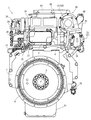
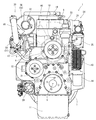
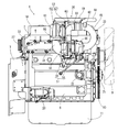
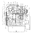
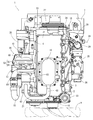
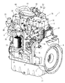
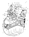
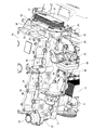
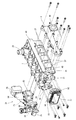
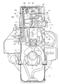
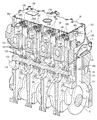
以下に、本発明を具体化した実施形態を図面に基づいて説明する。まず、図1〜図8を参照しながら、ディーゼルエンジン(エンジン装置)1の全体構造について説明する。なお、以下の説明では、クランク軸5と平行な両側部(クランク軸5を挟んで両側の側部)を左右、フライホイールハウジング7設置側を前側、冷却ファン9設置側を後側と称して、これらを便宜的に、ディーゼルエンジン1における四方及び上下の位置関係の基準としている。   DESCRIPTION OF EMBODIMENTS Embodiments embodying the present invention will be described below with reference to the drawings. First, the overall structure of a diesel engine (engine device) 1 will be described with reference to FIGS. In the following description, both side portions parallel to the crankshaft 5 (side portions on both sides of the crankshaft 5) are referred to as left and right, the flywheel housing 7 installation side is referred to as the front side, and the cooling fan 9 installation side is referred to as the rear side. For convenience, these are used as a reference for the positional relationship between the four sides and the top and bottom of the diesel engine 1.

図1〜図8に示す如く、ディーゼルエンジン1におけるクランク軸5と平行な一側部に吸気マニホールド3を、他側部に排気マニホールド4を配置している。実施形態では、シリンダヘッド2の右側面に吸気マニホールド3がシリンダヘッド2と一体に成形されており、シリンダヘッド2の左側面に排気マニホールド4が設置されている。シリンダヘッド2は、クランク軸5とピストン(図示省略)が内蔵されたシリンダブロック6上に搭載されている。   As shown in FIGS. 1 to 8, an intake manifold 3 is arranged on one side parallel to the crankshaft 5 in the diesel engine 1, and an exhaust manifold 4 is arranged on the other side. In the embodiment, the intake manifold 3 is formed integrally with the cylinder head 2 on the right side surface of the cylinder head 2, and the exhaust manifold 4 is installed on the left side surface of the cylinder head 2. The cylinder head 2 is mounted on a cylinder block 6 in which a crankshaft 5 and a piston (not shown) are built.

シリンダブロック6の前後両側面から、クランク軸5の前後先端側を突出させている。ディーゼルエンジン1におけるクランク軸5と交差する一側部(実施形態ではシリンダブロック6の前側面側)に、フライホイールハウジング7が固着されている。フライホイールハウジング7内にフライホイール8が配置されている。フライホイール8はクランク軸5の前端側に軸支されていて、クランク軸5と一体的に回転するように構成されている。作業機械(例えば油圧ショベルやフォークリフト等)の作動部に、フライホイール8を介してディーゼルエンジン1の動力を取り出すように構成されている。ディーゼルエンジン1におけるクランク軸5と交差する他側部(実施形態ではシリンダブロック6の後側面側)に、冷却ファン9が設けられている。クランク軸5の後端側からVベルト10を介して冷却ファン9に回転力を伝達するように構成されている。   The front and rear front ends of the crankshaft 5 are projected from both front and rear side surfaces of the cylinder block 6. A flywheel housing 7 is fixed to one side portion (in the embodiment, the front side surface of the cylinder block 6) that intersects the crankshaft 5 in the diesel engine 1. A flywheel 8 is disposed in the flywheel housing 7. The flywheel 8 is pivotally supported on the front end side of the crankshaft 5 and is configured to rotate integrally with the crankshaft 5. It is configured such that the power of the diesel engine 1 is taken out via a flywheel 8 to an operation part of a work machine (for example, a hydraulic excavator or a forklift). A cooling fan 9 is provided on the other side of the diesel engine 1 that intersects the crankshaft 5 (in the embodiment, the rear side of the cylinder block 6). A rotational force is transmitted from the rear end side of the crankshaft 5 to the cooling fan 9 via the V belt 10.

シリンダブロック6の下面にはオイルパン11を配置する。オイルパン11内には潤滑油が貯留されている。オイルパン11内の潤滑油は、シリンダブロック6のフライホイールハウジング7との連結部分であってシリンダブロック6の右側面側に配置されたオイルポンプ(図示省略)にて吸引され、シリンダブロック6の右側面に配置されたオイルクーラ13並びにオイルフィルタ14を介して、ディーゼルエンジン1の各潤滑部に供給される。各潤滑部に供給された潤滑油は、その後オイルパン11に戻される。オイルポンプ(図示省略)はクランク軸5の回転にて駆動するように構成されている。   An oil pan 11 is disposed on the lower surface of the cylinder block 6. Lubricating oil is stored in the oil pan 11. Lubricating oil in the oil pan 11 is sucked by an oil pump (not shown) disposed on the right side surface of the cylinder block 6 at a portion where the cylinder block 6 is connected to the flywheel housing 7. The oil is supplied to each lubricating part of the diesel engine 1 through an oil cooler 13 and an oil filter 14 arranged on the right side surface. The lubricating oil supplied to each lubricating part is then returned to the oil pan 11. The oil pump (not shown) is configured to be driven by rotation of the crankshaft 5.

シリンダブロック6のフライホイールハウジング7との連結部分に、燃料を供給するための燃料供給ポンプ15が取り付けられ、燃料供給ポンプ15がEGR装置24下方に配置される。コモンレール16が、シリンダヘッド2の吸気マニホールド3下側でシリンダブロック6側面に固定されており、燃料供給ポンプ15上方に配置されている。ヘッドカバー18で覆われているシリンダヘッド2上面部に、電磁開閉制御型の燃料噴射バルブを有する4気筒分の各インジェクタ17(図17参照)が設けられている。   A fuel supply pump 15 for supplying fuel is attached to a connecting portion of the cylinder block 6 with the flywheel housing 7, and the fuel supply pump 15 is disposed below the EGR device 24. A common rail 16 is fixed to the side of the cylinder block 6 below the intake manifold 3 of the cylinder head 2 and is disposed above the fuel supply pump 15. On the upper surface of the cylinder head 2 covered with the head cover 18, injectors 17 (see FIG. 17) for four cylinders each having an electromagnetic opening / closing control type fuel injection valve are provided.

各インジェクタ17が、燃料供給ポンプ15及び円筒状のコモンレール16を介して、作業車両に搭載される燃料タンク(図示省略)が接続されている。燃料タンクの燃料が燃料供給ポンプ15からコモンレール16に圧送され、高圧の燃料がコモンレール16に蓄えられる。各インジェクタ17の燃料噴射バルブをそれぞれ開閉制御することによって、コモンレール16内の高圧の燃料が各インジェクタ17からディーゼルエンジン1の各気筒に噴射される。   Each injector 17 is connected to a fuel tank (not shown) mounted on the work vehicle via a fuel supply pump 15 and a cylindrical common rail 16. Fuel in the fuel tank is pumped from the fuel supply pump 15 to the common rail 16, and high-pressure fuel is stored in the common rail 16. By controlling the fuel injection valves of the injectors 17 to open and close, the high-pressure fuel in the common rail 16 is injected from the injectors 17 into the cylinders of the diesel engine 1.

シリンダヘッド2上面部に設ける吸気弁136及び排気弁137(図17参照)などを覆うヘッドカバー18上面に、ディーゼルエンジン1の燃焼室などからシリンダヘッド2上面側に漏れ出たブローバイガスを取入れるブローバイガス還元装置19が設けられている。ブローバイガス還元装置19のブローバイガス出口が、還元ホース68を介して、二段過給機30の吸気部に連通される。ブローバイガス還元装置19内にて潤滑油成分が除去されたブローバイガスは、二段過給機30を介して、吸気マニホールド3に還元される。   A blow-by gas that takes in the blow-by gas leaked from the combustion chamber of the diesel engine 1 to the upper surface side of the cylinder head 2 on the upper surface of the head cover 18 that covers the intake valve 136 and the exhaust valve 137 (see FIG. 17) provided on the upper surface portion of the cylinder head 2. A gas reduction device 19 is provided. A blow-by gas outlet of the blow-by gas reduction device 19 is communicated with an intake portion of the two-stage supercharger 30 via a reduction hose 68. The blow-by gas from which the lubricating oil component has been removed in the blow-by gas reduction device 19 is reduced to the intake manifold 3 via the two-stage supercharger 30.

フライホイールハウジング7にエンジン始動用スタータ20が取り付けられ、エンジン始動用スタータ20が排気マニホールド4下方に配置される。エンジン始動用スタータ20は、シリンダブロック6とフライホイールハウジング7との連結部下方となる位置で、フライホイールハウジング7に取り付けられる。   An engine starter 20 is attached to the flywheel housing 7, and the engine starter 20 is disposed below the exhaust manifold 4. The starter 20 for starting the engine is attached to the flywheel housing 7 at a position below the connecting portion between the cylinder block 6 and the flywheel housing 7.

シリンダブロック6の後面左寄りの部位には、冷却水潤滑用の冷却水ポンプ21が冷却ファン9の下方に配置されている。クランク軸5の回転にて、冷却ファン駆動用Vベルト10を介して、冷却ファン9と共に冷却水ポンプ21が駆動される。作業車両に搭載されるラジエータ(図示省略)内の冷却水が、冷却水ポンプ21の駆動にて、冷却水ポンプ21に供給される。そして、シリンダヘッド2及びシリンダブロック6に冷却水が供給され、ディーゼルエンジン1を冷却する。   A cooling water pump 21 for cooling water lubrication is disposed below the cooling fan 9 at a portion on the left side of the rear surface of the cylinder block 6. The rotation of the crankshaft 5 drives the cooling water pump 21 together with the cooling fan 9 via the cooling fan driving V-belt 10. Cooling water in a radiator (not shown) mounted on the work vehicle is supplied to the cooling water pump 21 by driving the cooling water pump 21. Then, cooling water is supplied to the cylinder head 2 and the cylinder block 6 to cool the diesel engine 1.

冷却水ポンプ21は、排気マニホールド4下方に配置されており、ラジエータの冷却水出口と連通される冷却水入口管22が、シリンダブロック6の左側面であって冷却水ポンプ21と同一高さ位置に固設される。一方、ラジエータの冷却水入口と連通される冷却水出口管23が、シリンダヘッド2の後面上方に固設されている。シリンダヘッド2は、吸気マニホールド3後方に突設させた冷却水排水部35を有しており、当該冷却水排水部35上面に冷却水出口管23が設置される。   The cooling water pump 21 is disposed below the exhaust manifold 4, and the cooling water inlet pipe 22 communicating with the cooling water outlet of the radiator is located on the left side surface of the cylinder block 6 and at the same height as the cooling water pump 21. Fixed. On the other hand, a cooling water outlet pipe 23 communicating with the cooling water inlet of the radiator is fixed above the rear surface of the cylinder head 2. The cylinder head 2 has a cooling water drainage portion 35 protruding from the rear of the intake manifold 3, and a cooling water outlet pipe 23 is installed on the upper surface of the cooling water drainage portion 35.

吸気マニホールド3の入口側は、後述するEGR装置24(排気ガス再循環装置)のコレクタ(EGR本体ケース)25を介してエアクリーナ(図示省略)に連結されている。エアクリーナに吸い込まれた新気(外部空気)は、当該エアクリーナにて除塵・浄化されたのち、コレクタ25を介して吸気マニホールド3に送られ、そして、ディーゼルエンジン1の各気筒に供給される。実施形態では、EGR装置24のコレクタ25が、シリンダヘッド2と一体成形されてシリンダヘッド2の右側面を構成している吸気マニホールド3の右側方に連結している。すなわち、シリンダヘッド2の右側面に設けられる吸気マニホールド3の入口開口部に、EGR装置24のコレクタ25の出口開口部が連結されている。なお、本実施形態では、後述するように、EGR装置24のコレクタ25は、インタークーラ(図示省略)及び二段過給機30を介して、エアクリーナに連結している。   The inlet side of the intake manifold 3 is connected to an air cleaner (not shown) via a collector (EGR main body case) 25 of an EGR device 24 (exhaust gas recirculation device) described later. The fresh air (external air) sucked into the air cleaner is dust-removed and purified by the air cleaner, is sent to the intake manifold 3 through the collector 25, and is supplied to each cylinder of the diesel engine 1. In the embodiment, the collector 25 of the EGR device 24 is connected to the right side of the intake manifold 3 that is integrally formed with the cylinder head 2 and constitutes the right side surface of the cylinder head 2. That is, the outlet opening of the collector 25 of the EGR device 24 is connected to the inlet opening of the intake manifold 3 provided on the right side surface of the cylinder head 2. In the present embodiment, as will be described later, the collector 25 of the EGR device 24 is connected to an air cleaner via an intercooler (not shown) and the two-stage supercharger 30.

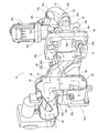
EGR装置24は、ディーゼルエンジン1の再循環排気ガス(排気マニホールド4からのEGRガス)と新気(エアクリーナからの外部空気)とを混合させて吸気マニホールド3に供給する中継管路としてのコレクタ25と、エアクリーナにコレクタ25を連通させる吸気スロットル部材26と、排気マニホールド4にEGRクーラ27を介して接続する還流管路の一部となる再循環排気ガス管28と、再循環排気ガス管28にコレクタ25を連通させるEGRバルブ部材29とを有している。   The EGR device 24 mixes the recirculated exhaust gas of the diesel engine 1 (EGR gas from the exhaust manifold 4) and fresh air (external air from the air cleaner) and supplies the air to the intake manifold 3 as a collector 25. An intake throttle member 26 for communicating the collector 25 with the air cleaner, a recirculation exhaust gas pipe 28 that is a part of a recirculation pipe connected to the exhaust manifold 4 via an EGR cooler 27, and a recirculation exhaust gas pipe 28 And an EGR valve member 29 for communicating the collector 25.

EGR装置24は、シリンダヘッド2における吸気マニホールド3の右側方に配置されている。すなわち、EGR装置24は、シリンダヘッド2の右側面に固定され、シリンダヘッド2内の吸気マニホールド3と連通されている。EGR装置24は、コレクタ25がシリンダヘッド2右側面の吸気マニホールド3に連結するとともに、再循環排気ガス管28のEGRガス入口がシリンダヘッド2右側面の吸気マニホールド3前方部分と連結して固定される。また、コレクタ25の前後それぞれにEGRバルブ部材29及び吸気スロットル部材26が連結され、EGRバルブ部材29の後端に再循環排気ガス管28のEGRガス出口が連結される。   The EGR device 24 is disposed on the right side of the intake manifold 3 in the cylinder head 2. That is, the EGR device 24 is fixed to the right side surface of the cylinder head 2 and communicates with the intake manifold 3 in the cylinder head 2. In the EGR device 24, the collector 25 is connected to the intake manifold 3 on the right side surface of the cylinder head 2, and the EGR gas inlet of the recirculation exhaust gas pipe 28 is connected to the front portion of the intake manifold 3 on the right side surface of the cylinder head 2 and fixed. The Further, an EGR valve member 29 and an intake throttle member 26 are connected to the front and rear of the collector 25, respectively, and an EGR gas outlet of the recirculated exhaust gas pipe 28 is connected to the rear end of the EGR valve member 29.

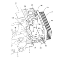
EGRクーラ27は、シリンダヘッド2の前側面に固定されており、シリンダヘッド2内を流れる冷却水とEGRガスがEGRクーラ27に流出入し、EGRクーラ27においてEGRガスが冷却される。シリンダヘッド2の前側面は、その左右位置にEGRクーラ27を連結するEGRクーラ連結台座33,34を突設し、連結台座33,34にEGRクーラ27が連結されている。すなわち、EGRクーラ27は、EGRクーラ27後端面とシリンダヘッド2の前側面とが離間するようにして、フライホイールハウジング7上方位置であってシリンダヘッド2前方位置に配置されている。   The EGR cooler 27 is fixed to the front side surface of the cylinder head 2, and cooling water and EGR gas flowing through the cylinder head 2 flow into and out of the EGR cooler 27, and the EGR gas is cooled in the EGR cooler 27. EGR cooler connection pedestals 33 and 34 for connecting the EGR cooler 27 are projected on the front side surface of the cylinder head 2 at the left and right positions, and the EGR cooler 27 is connected to the connection pedestals 33 and 34. That is, the EGR cooler 27 is disposed at a position above the flywheel housing 7 and at a front position of the cylinder head 2 so that a rear end surface of the EGR cooler 27 and a front side surface of the cylinder head 2 are separated from each other.

排気マニホールド4の側方(実施形態では左側方)に、二段過給機30が配置されている。二段過給機30は、高圧過給機51と低圧過給機52とを備える。高圧過給機51が、タービンホイール(図示省略)を内蔵した高圧タービン53とブロアホイール(図示省略)を内蔵した高圧コンプレッサ54とを有するとともに、低圧過給機52が、タービンホイール(図示省略)を内蔵した低圧タービン55とブロアホイール(図示省略)を内蔵した低圧コンプレッサ56とを有する。   A two-stage supercharger 30 is disposed on the side of the exhaust manifold 4 (on the left side in the embodiment). The two-stage supercharger 30 includes a high pressure supercharger 51 and a low pressure supercharger 52. The high-pressure supercharger 51 includes a high-pressure turbine 53 incorporating a turbine wheel (not shown) and a high-pressure compressor 54 incorporating a blower wheel (not shown), and the low-pressure supercharger 52 is a turbine wheel (not shown). And a low-pressure compressor 56 with a blower wheel (not shown).

排気マニホールド4に高圧タービン53の排気ガス入口57を連結させ、高圧タービン53の排気ガス出口58に高圧排気ガス管59を介して低圧タービン55の排気ガス入口60を連結させ、低圧タービン55の排気ガス出口61に排気ガス排出管(図示省略)の排気ガス取入れ側端部を連結させている。一方、低圧コンプレッサ56の新気取入れ口(新気入口)63に給気管62を介してエアクリーナ(図示省略)の新気供給側(新気出口側)を接続し、低圧コンプレッサ56の新気供給口(新気出口)64に低圧新気通路管65を介して高圧コンプレッサ54の新気取入れ口66を連結させ、高圧コンプレッサ54の新気供給口67に高圧新気通路管(図示省略)を介してインタークーラ(図示省略)の新気取り込み側を接続させる。   An exhaust gas inlet 57 of the high-pressure turbine 53 is connected to the exhaust manifold 4, and an exhaust gas inlet 60 of the low-pressure turbine 55 is connected to an exhaust gas outlet 58 of the high-pressure turbine 53 via a high-pressure exhaust gas pipe 59. An exhaust gas intake side end of an exhaust gas discharge pipe (not shown) is connected to the gas outlet 61. On the other hand, a fresh air supply side (new air outlet side) of an air cleaner (not shown) is connected to a fresh air intake port (fresh air inlet) 63 of the low pressure compressor 56 via an air supply pipe 62 to supply fresh air of the low pressure compressor 56. A fresh air intake port 66 of the high pressure compressor 54 is connected to a mouth (fresh air outlet) 64 via a low pressure fresh air passage tube 65, and a high pressure fresh air passage tube (not shown) is connected to a fresh air supply port 67 of the high pressure compressor 54. The fresh air intake side of the intercooler (not shown) is connected via

高圧過給機51が排気マニホールド4の排気ガス出口58に連結して、排気マニホールド4の左側方に固定される一方、低圧過給機52が高圧排気ガス管59及び低圧新気通路管65を介して高圧過給機51と連結して、排気マニホールド4の上方に固定される。すなわち、小径となる高圧過給機51と排気マニホールド4とが、大径となる低圧過給機52下方で左右に並設されることで、二段過給機30が排気マニホールド4の左側面及び上面を囲うように配置される。すなわち、排気マニホールド4と二段過給機30とが、背面視(正面視)で矩形状に配置されるようにして、シリンダヘッド2左側面にコンパクトに固定されている。   The high pressure supercharger 51 is connected to the exhaust gas outlet 58 of the exhaust manifold 4 and fixed to the left side of the exhaust manifold 4, while the low pressure supercharger 52 connects the high pressure exhaust gas pipe 59 and the low pressure fresh air passage pipe 65. And is connected to the high-pressure supercharger 51 and fixed above the exhaust manifold 4. That is, the high-pressure supercharger 51 and the exhaust manifold 4 having a small diameter are juxtaposed on the left and right below the low-pressure supercharger 52 having a large diameter, so that the two-stage supercharger 30 is located on the left side surface of the exhaust manifold 4. And disposed so as to surround the upper surface. That is, the exhaust manifold 4 and the two-stage supercharger 30 are compactly fixed to the left side surface of the cylinder head 2 so as to be arranged in a rectangular shape when viewed from the back (front view).

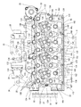
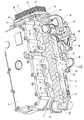
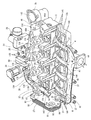
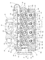
次いで、シリンダヘッド2の構成について、図9〜図21及び図27を参照して、以下に説明する。図9〜図21及び図27に示す如く、シリンダヘッド2は、複数の吸気ポート141に新気を導入させる複数の吸気流路36と複数の排気ポート142から排気ガスを導出させる複数の排気流路37とが形成されている。そして、複数の吸気流路36を集合する吸気マニホールド3が、シリンダヘッド2の右側部に一体に形成されている。シリンダヘッド2と吸気マニホールド3とを一体に構成することで、吸気マニホールド3から吸気流路36に対する気体シール性を向上させるとともに、シリンダヘッド2の剛性を高めることができる。   Next, the configuration of the cylinder head 2 will be described below with reference to FIGS. 9 to 21 and 27. As shown in FIGS. 9 to 21 and 27, the cylinder head 2 includes a plurality of exhaust flow channels for introducing exhaust gas from a plurality of intake passages 36 for introducing fresh air into a plurality of intake ports 141 and a plurality of exhaust ports 142. A passage 37 is formed. An intake manifold 3 that collects a plurality of intake passages 36 is integrally formed on the right side of the cylinder head 2. By integrally configuring the cylinder head 2 and the intake manifold 3, it is possible to improve the gas sealing performance from the intake manifold 3 to the intake flow path 36, and to increase the rigidity of the cylinder head 2.

シリンダヘッド2は、吸気マニホールド3が構成される右側面と逆側となる左側面に排気マニホールド4が連結され、左右側面と隣接する前側面(フライホイールハウジング7側側面)にEGRクーラ27が連結される。そして、EGRクーラ27と連結する連結台座(EGRクーラ連結台座)33,34がシリンダヘッド2の前側面より突出して形成され、連結台座33,34内にEGRガス流路(EGRガス中継流路)31,32と冷却水流路(冷却水中継流路)38,39とが形成されている。   In the cylinder head 2, the exhaust manifold 4 is connected to the left side opposite to the right side on which the intake manifold 3 is configured, and the EGR cooler 27 is connected to the front side (flywheel housing 7 side) adjacent to the left and right sides. Is done. Further, connecting bases (EGR cooler connecting bases) 33 and 34 connected to the EGR cooler 27 are formed so as to protrude from the front side surface of the cylinder head 2, and an EGR gas passage (EGR gas relay passage) is formed in the connecting bases 33 and 34. 31 and 32 and cooling water flow paths (cooling water relay flow paths) 38 and 39 are formed.

EGRクーラ27の連結する連結台座33,34にEGRガス中継流路31,32及び冷却水流路38,39を構成することで、EGRクーラ27とシリンダヘッド2との間に冷却水用配管及びEGRガス用配管を設ける必要がない。そのため、EGRガスや冷却水による配管の伸縮などに影響されることなく、EGRクーラ27との連結部分におけるシール性を確保できるだけでなく、熱や振動などによる外部からの変動要素に対する耐性(構造安定性)が向上する上に、コンパクトに構成できる。   The EGR gas relay passages 31 and 32 and the cooling water passages 38 and 39 are formed in the connection bases 33 and 34 to which the EGR cooler 27 is connected, so that the cooling water pipe and the EGR are provided between the EGR cooler 27 and the cylinder head 2. There is no need to provide gas piping. Therefore, not only is it not affected by the expansion and contraction of the piping due to EGR gas or cooling water, but it is possible not only to ensure the sealing performance at the connecting portion with the EGR cooler 27, but also the resistance to external fluctuation factors due to heat and vibration (structural stability) In addition, it can be made compact.

シリンダヘッド2は、左側面前方部分から前側面に連通する上流側EGRガス中継流路31を備えており、排気マニホールド4前端側に設けられたEGRガス出口41が上流側EGRガス中継流路31と連通している。また、シリンダヘッド2は、右側面前方部分(吸気マニホールド3前方)から前側面に連通する下流側EGRガス中継流路32を備えており、再循環排気ガス管28のEGRガス入口が下流側EGRガス中継流路32と連通している。シリンダヘッド2は、その前側面の左右両縁側(シリンダヘッド2の前左隅部分及び前右隅部分)を前方に突設されたEGRクーラ連結台座33,34を備えている。そして、連結台座33内に上流側EGRガス中継流路31が設けられ、連結台座34内に下流側EGRガス中継流路32が設けられている。   The cylinder head 2 includes an upstream EGR gas relay passage 31 that communicates from the front portion on the left side to the front side, and an EGR gas outlet 41 provided on the front end side of the exhaust manifold 4 has an upstream EGR gas relay passage 31. Communicated with. In addition, the cylinder head 2 includes a downstream EGR gas relay passage 32 that communicates from the front right side portion (front of the intake manifold 3) to the front side surface, and the EGR gas inlet of the recirculated exhaust gas pipe 28 is the downstream EGR. It communicates with the gas relay flow path 32. The cylinder head 2 includes EGR cooler coupling pedestals 33 and 34 projecting forward on the left and right edge sides (front left corner portion and front right corner portion of the cylinder head 2) of the front side surface. An upstream EGR gas relay flow path 31 is provided in the connection pedestal 33, and a downstream EGR gas relay flow path 32 is provided in the connection pedestal 34.

EGR装置24が、シリンダヘッド2の右側面で突設されている吸気マニホールド3と連結している。吸気マニホールド3は、シリンダヘッド2右側面後方(冷却ファン9側)寄りに設けられており、シリンダヘッド2右側面下側部分を右側方に突設して構成されており、その前後中心位置に吸気入口40を有している。EGR装置24のコレクタ25における吸気出口83が、シリンダヘッド2右側面に突設された吸気マニホールド3の吸気入口40と連結し、シリンダヘッド2の右側方にEGR装置24が固定される。   The EGR device 24 is connected to the intake manifold 3 protruding from the right side surface of the cylinder head 2. The intake manifold 3 is provided near the rear side of the right side of the cylinder head 2 (on the side of the cooling fan 9), and is configured such that the lower side part of the right side of the cylinder head 2 protrudes to the right side. An intake inlet 40 is provided. The intake outlet 83 in the collector 25 of the EGR device 24 is connected to the intake inlet 40 of the intake manifold 3 protruding from the right side surface of the cylinder head 2, and the EGR device 24 is fixed to the right side of the cylinder head 2.

シリンダヘッド2の右側面前方(フライホイールハウジング7側)に、EGRクーラ27と連結する連結台座34が前方に向かって突設されており、連結台座34右側面に下流側EGRガス中継流路32のEGRガス出口が開口している。そして、EGR装置24の再循環排気ガス管28の一端が連結台座34の右側面に連結することで、EGR装置24のコレクタ25が、再循環排気ガス管28及びEGRバルブ部材29を介して、シリンダヘッド2内の下流側EGRガス中継流路32と連通する。   A connecting pedestal 34 connected to the EGR cooler 27 is projected forward from the right side of the cylinder head 2 (on the flywheel housing 7 side). The downstream EGR gas relay channel 32 is provided on the right side of the connecting pedestal 34. The EGR gas outlet is open. Then, one end of the recirculation exhaust gas pipe 28 of the EGR device 24 is connected to the right side surface of the connection base 34, so that the collector 25 of the EGR device 24 is connected via the recirculation exhaust gas pipe 28 and the EGR valve member 29. The downstream EGR gas relay flow path 32 in the cylinder head 2 communicates.

シリンダヘッド2の右側面後方(冷却ファン9側)に、上面が開口して冷却水出口管(サーモスタットカバー)23と連通される冷却水排水部(サーモスタットケース)35が後方に向かって突設されており、その内部にサーモスタット(図示省略)が設置される。シリンダヘッド2の右側面後方でオフセットして冷却水排水部35が構成されるため、冷却ファン9が固定されるファンプーリ9aに巻回されるVベルト10を、冷却水排水部35の下側の空間に通すことができ、ディーゼルエンジン1の前後方向長さを短くできる。冷却水排水部35は、シリンダヘッド2右側面からも突出しており、シリンダヘッド2の右側面において、吸気マニホールド3と冷却水排水部35とが前後に並んで設けられている。   A cooling water drainage portion (thermostat case) 35 that is open on the right side of the cylinder head 2 (on the cooling fan 9 side) and communicates with the cooling water outlet pipe (thermostat cover) 23 is provided projecting rearward. A thermostat (not shown) is installed inside. Since the cooling water drainage portion 35 is configured to be offset behind the right side surface of the cylinder head 2, the V belt 10 wound around the fan pulley 9 a to which the cooling fan 9 is fixed is placed below the cooling water drainage portion 35. The length of the diesel engine 1 in the front-rear direction can be shortened. The cooling water drainage part 35 also protrudes from the right side surface of the cylinder head 2, and the intake manifold 3 and the cooling water drainage part 35 are provided side by side on the right side surface of the cylinder head 2.

シリンダヘッド2の左側面前方(フライホイールハウジング7側)に、EGRクーラ27と連結する連結台座33が前方に向かって突設されており、連結台座33左側面に上流側EGRガス中継流路31のEGRガス入口が開口している。すなわち、シリンダヘッド2の左側面では、上流側EGRガス中継流路31のEGRガス入口と複数の排気流路37の排気出口とが、前後方向に並んで開口している。一方、排気マニホールド4は、シリンダヘッド2左側面との連結面となる右側面に、上流側EGRガス中継流路31と連通するEGRガス出口41と、複数の排気流路37と連通する排気入口42とが、前後方向に並んで開口している。そのため、シリンダヘッド2の同一面にEGR入口及び排気出口を並べて設けるため、シリンダヘッド2と排気マニホールド4との連結部分は、1枚のガスケット45を狭持させることにより、容易に気密性(ガスシール性)を確保できる。   A connecting pedestal 33 connected to the EGR cooler 27 is projected forward from the left side of the cylinder head 2 (on the flywheel housing 7 side). The upstream EGR gas relay passage 31 is provided on the left side of the connecting pedestal 33. The EGR gas inlet is open. That is, on the left side surface of the cylinder head 2, the EGR gas inlet of the upstream EGR gas relay passage 31 and the exhaust outlets of the plurality of exhaust passages 37 are opened side by side in the front-rear direction. On the other hand, the exhaust manifold 4 has an EGR gas outlet 41 communicating with the upstream EGR gas relay passage 31 and an exhaust inlet communicating with the plurality of exhaust passages 37 on the right side which is a connection surface with the left side of the cylinder head 2. 42 are opened side by side in the front-rear direction. Therefore, since the EGR inlet and the exhaust outlet are provided side by side on the same surface of the cylinder head 2, the connecting portion between the cylinder head 2 and the exhaust manifold 4 can be easily airtight (gas gas) by sandwiching one gasket 45. (Sealability) can be secured.

排気マニホールド4には、EGRガス出口41及び排気入口42と連通している排気集合部43が、前後方向を長手方向とするように内設されており、排気マニホールド4の後方左側面に、排気集合部43と連通する排気出口44が開口されている。排気マニホールド4は、シリンダヘッド2の排気流路37からの排気ガスが排気入口42を通じて排気集合部43に流れ込むと、排気ガスの一部がEGRガスとなり、EGRガス出口41からシリンダヘッド2の上流側EGRガス中継流路31に流れ込み、排気ガスの残りが排気出口44より二段過給機30に流れ込む。   The exhaust manifold 4 is provided with an exhaust collecting portion 43 communicating with the EGR gas outlet 41 and the exhaust inlet 42 so that the longitudinal direction is the front-rear direction. An exhaust outlet 44 communicating with the collecting portion 43 is opened. In the exhaust manifold 4, when exhaust gas from the exhaust flow path 37 of the cylinder head 2 flows into the exhaust collecting portion 43 through the exhaust inlet 42, part of the exhaust gas becomes EGR gas, and from the EGR gas outlet 41 to the upstream of the cylinder head 2. Flows into the side EGR gas relay flow path 31, and the remainder of the exhaust gas flows into the two-stage supercharger 30 from the exhaust outlet 44.

シリンダヘッド2の前側面には、左右一対となるEGRクーラ連結台座33,34が、排気マニホールド4側及び吸気マニホールド3側それぞれに設けられている。そして、EGRクーラ連結台座33に、排気マニホールド4及びEGRクーラ27それぞれのEGRガス流路を連通させる上流側EGRガス中継流路31を設けている。一方、EGRクーラ連結台座34に、EGR装置24及びEGRクーラ27それぞれのEGRガス流路を連通
させる下流側EGRガス中継流路32を設けている。また、EGRクーラ連結台座33に、EGRクーラ27から冷却水が排出される下流側冷却水流路38を設けている。一方、EGRクーラ連結台座34に、EGR装置24及びEGRクーラ27へ冷却水を供給する上流側冷却水流路39を設けている。
A pair of left and right EGR cooler connection pedestals 33 and 34 are provided on the front side surface of the cylinder head 2 on the exhaust manifold 4 side and the intake manifold 3 side, respectively. The EGR cooler connecting pedestal 33 is provided with an upstream EGR gas relay flow path 31 for communicating the EGR gas flow paths of the exhaust manifold 4 and the EGR cooler 27. On the other hand, the EGR cooler connection pedestal 34 is provided with a downstream EGR gas relay flow path 32 that allows the EGR gas flow paths of the EGR device 24 and the EGR cooler 27 to communicate with each other. Further, the EGR cooler connection base 33 is provided with a downstream side cooling water flow path 38 through which cooling water is discharged from the EGR cooler 27. On the other hand, an upstream side cooling water flow path 39 for supplying cooling water to the EGR device 24 and the EGR cooler 27 is provided in the EGR cooler connection base 34.

EGRクーラ連結台座33,34を突設した構成とすることで、排気マニホールド4、EGRクーラ27、及びEGR装置24それぞれを連通させるEGRガス用の配管が不要となり、EGRガス流路における連結箇所が少なくなる。従って、EGRガスによるNOx低減を図るディーゼルエンジン1において、EGRガス漏れを低減できるだけでなく、配管の伸縮による応力変化などによる変形を抑制できる。また、EGRクーラ連結台座33,34にEGRガス中継流路31,32と冷却水流路38,39とを構成するため、シリンダヘッド2内に構成する各流路31,32,38,39の形状が単純化されることから、複雑な中子を用いることなく、シリンダヘッド2を容易に鋳造することができる。   By adopting a configuration in which the EGR cooler connection pedestals 33 and 34 are provided in a projecting manner, EGR gas piping for communicating the exhaust manifold 4, the EGR cooler 27, and the EGR device 24 is not required, and the connection location in the EGR gas flow path is reduced. Less. Therefore, in the diesel engine 1 that reduces NOx by EGR gas, not only can EGR gas leakage be reduced, but also deformation due to stress change due to expansion and contraction of the piping can be suppressed. In addition, since the EGR gas relay flow paths 31 and 32 and the cooling water flow paths 38 and 39 are formed in the EGR cooler connection bases 33 and 34, the shapes of the flow paths 31, 32, 38, and 39 that are formed in the cylinder head 2 are used. Therefore, the cylinder head 2 can be easily cast without using a complicated core.

吸気マニホールド3側のEGRクーラ連結台座33と、排気マニホールド4側のEGRクーラ連結台座34とが離間されているため、連結台座33,34それぞれにおける熱変形による相互の影響を抑制できる。従って、EGRクーラ連結台座33,34とEGRクーラ27との連結部分におけるガス漏れや破損を防止できるだけでなく、シリンダヘッド2の剛性バランスを保持できる。また、シリンダヘッド2前側面における容積を低減できることから、シリンダヘッド2の軽量化を図れる.更に、EGRクーラ27をシリンダヘッド2前側面より離間させて配置でき、EGRクーラ27の前後に空間を有する構成とできるため、EGRクーラ27の周辺に冷却空気を流すことができるため、EGRクーラ27における冷却効率を高めることができる。   Since the EGR cooler connection pedestal 33 on the intake manifold 3 side and the EGR cooler connection pedestal 34 on the exhaust manifold 4 side are separated from each other, mutual influences due to thermal deformation in the connection pedestals 33 and 34 can be suppressed. Therefore, not only can gas leakage and breakage at the connecting portion between the EGR cooler connecting pedestals 33 and 34 and the EGR cooler 27 be prevented, but also the rigidity balance of the cylinder head 2 can be maintained. Further, since the volume on the front side of the cylinder head 2 can be reduced, the weight of the cylinder head 2 can be reduced. Further, since the EGR cooler 27 can be disposed away from the front side surface of the cylinder head 2 and a space is provided before and after the EGR cooler 27, the cooling air can flow around the EGR cooler 27. Therefore, the EGR cooler 27 The cooling efficiency can be improved.

EGRクーラ連結台座33には、下流側冷却水流路38と上流側EGRガス中継流路31とが上下に配置されており、EGRクーラ連結台座34には、下流側EGRガス中継流路32と上流側冷却水流路39とが上下に配置されている。そして、下流側冷却水流路38の冷却水入口と下流側EGRガス中継流路32のEGRガス入口とが同一高さに配置される一方、上流側冷却水流路39の冷却水出口と下流側EGRガス中継流路32のEGRガス出口とが同一高さに配置される。   The EGR cooler connection pedestal 33 is provided with a downstream cooling water flow path 38 and an upstream EGR gas relay flow path 31 vertically, and the EGR cooler connection pedestal 34 has a downstream EGR gas relay flow path 32 and an upstream. The side cooling water flow path 39 is arranged vertically. The cooling water inlet of the downstream cooling water passage 38 and the EGR gas inlet of the downstream EGR gas relay passage 32 are arranged at the same height, while the cooling water outlet and the downstream EGR of the upstream cooling water passage 39 are arranged. The EGR gas outlet of the gas relay channel 32 is arranged at the same height.

分離して突設させたEGRクーラ連結台座33,34にEGRガス中継流路31,32及び冷却水流路38,39を内設した構成とすることで、EGRクーラ連結台座33,34双方における熱変形の影響が緩和される。また、EGRクーラ連結台座33,34内において、EGRガス中継流路31,32を流れるEGRガスが冷却水流路38,39を流れる冷却水による冷却され、EGRクーラ連結台座33,34における熱変形自体も抑制される。更に、EGRクーラ連結台座33,34それぞれにおいて、EGRガス中継流路31,32と冷却水流路38,39とが、それぞれの上下高さ位置を置換して配置されている。そのため、EGRクーラ連結台座33,34における熱分布が上下逆方向となり、シリンダヘッド2における高さ方向の熱変形の影響を低減できる。   Since the EGR gas relay flow paths 31 and 32 and the cooling water flow paths 38 and 39 are provided in the separated EGR cooler connection bases 33 and 34, heat in both the EGR cooler connection bases 33 and 34 is obtained. The effect of deformation is reduced. Further, in the EGR cooler connection pedestals 33 and 34, the EGR gas flowing through the EGR gas relay flow paths 31 and 32 is cooled by the cooling water flowing through the cooling water flow paths 38 and 39, and the thermal deformation itself in the EGR cooler connection pedestals 33 and 34 is performed. Is also suppressed. Furthermore, in each of the EGR cooler connection pedestals 33 and 34, the EGR gas relay flow paths 31 and 32 and the cooling water flow paths 38 and 39 are arranged with their respective vertical height positions replaced. Therefore, the heat distribution in the EGR cooler connection pedestals 33 and 34 is upside down, and the influence of thermal deformation in the height direction in the cylinder head 2 can be reduced.

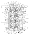
シリンダヘッド2は、その上面周縁から上方向に向かって立設させた外周壁により、ヘッドカバー18下面周縁と連結する間座46を備えている。すなわち、間座46は、左右側壁46a,46b及び前後側壁46c,46dによる外周壁で構成されている。そして、各側壁46a〜46dの上端面(頂部)には、ヘッドカバー18と連結させるカバー締結用ボルト133が螺着されるボルト穴(ヘッドカバー連結用ボルト穴)135が穿設されている。また、右側壁46b及び前後側壁46c,46dの上端面(頂部)には、シリンダブロック6と連結させるヘッド締結用ボルト186が挿入されるボルト用貫通穴(シリンダヘッド連結用貫通穴)136が穿設されている。   The cylinder head 2 includes a spacer 46 that is connected to the peripheral edge of the lower surface of the head cover 18 by an outer peripheral wall erected upward from the peripheral edge of the upper surface. That is, the spacer 46 is composed of outer peripheral walls including left and right side walls 46a and 46b and front and rear side walls 46c and 46d. Bolt holes (head cover connecting bolt holes) 135 into which cover fastening bolts 133 to be connected to the head cover 18 are screwed are formed in the upper end surfaces (top portions) of the side walls 46a to 46d. Further, a bolt through hole (cylinder head connecting through hole) 136 into which a head fastening bolt 186 to be connected to the cylinder block 6 is inserted is formed in the upper end surfaces (top portions) of the right side wall 46b and the front and rear side walls 46c and 46d. It is installed.

間座46は、右側壁46aに複数の開口部47を備えており、当該開口部47には、シリンダヘッド2に設けられたインジェクタ17とコモンレール16とを連結する燃料管48が通されている。シリンダヘッド2上方に間座46を一体に設けた構成とすることで、シリンダヘッド2の剛性を高めることとなり、シリンダヘッド2の自体の歪みを低減できるだけでなく、シリンダヘッド2に連結させる各部品を高剛性に支持できる。   The spacer 46 has a plurality of openings 47 in the right side wall 46a, and a fuel pipe 48 that connects the injector 17 provided in the cylinder head 2 and the common rail 16 is passed through the opening 47. . By adopting a structure in which the spacer 46 is integrally provided above the cylinder head 2, the rigidity of the cylinder head 2 is increased, and not only the distortion of the cylinder head 2 itself can be reduced, but also each component connected to the cylinder head 2. Can be supported with high rigidity.

シリンダヘッド2の間座46上にヘッドカバー18がカバー締結用ボルト133で連結されることで、間座46及びヘッドカバー18で覆われた空間を弁腕室として構成し、当該弁腕室内にインジェクタ17及び後述の動弁機構187が収容される。シリンダヘッド2は、間座46で囲まれた領域に、インジェクタ17が固定されるインジェクタ据付座138と、動弁機構187が固定される動弁機構据付座139と、ヘッド締結用ボルト186が固定されるボルト締結座140とが底面から上方に突設されている。動弁機構据付座139及びボルト締結座140それぞれの上端面は、間座46の上端面と同一高さとされており、ヘッド締結用ボルト186が挿入されるボルト用貫通穴(シリンダヘッド連結用貫通穴)136が穿設されている。   By connecting the head cover 18 on the spacer 46 of the cylinder head 2 with a cover fastening bolt 133, a space covered with the spacer 46 and the head cover 18 is configured as a valve arm chamber, and the injector 17 is provided in the valve arm chamber. In addition, a valve mechanism 187 described later is accommodated. In the cylinder head 2, an injector mounting seat 138 to which the injector 17 is fixed, a valve mechanism mounting seat 139 to which the valve mechanism 187 is fixed, and a head fastening bolt 186 are fixed in a region surrounded by the spacer 46. A bolt fastening seat 140 is projected upward from the bottom surface. The upper end surfaces of the valve mechanism installation seat 139 and the bolt fastening seat 140 are the same height as the upper end surface of the spacer 46, and a bolt through hole (a cylinder head coupling through hole) into which the head fastening bolt 186 is inserted. Hole) 136 is drilled.

シリンダヘッド2は、間座46における右側壁46b及び前後側壁46c,46d、動弁機構据付座139、及びボルト締結座140それぞれに設けられたボルト用貫通穴135に挿入されるヘッド締結用ボルト186により、シリンダブロック6上に締結される。吸気弁136及び排気弁137それぞれにより開閉される吸気ポート141及び排気ポート142が、シリンダヘッド2底面のインジェクタ据付座138下方位置に設けられている。そして、シリンダヘッド2内において、シリンダヘッド2右側部の吸気マニホールド3から分岐した複数の吸気流路36が、インジェクタ据付座138下方の吸気ポート141に向けて延設される。また、シリンダヘッド2左側面に固定された排気マニホールド4と連通する複数の排気流路37が、インジェクタ据付座138下方の排気ポート142に向けて延設される。   The cylinder head 2 has a head fastening bolt 186 inserted into a bolt through hole 135 provided in each of the right side wall 46b and the front and rear side walls 46c, 46d, the valve mechanism mounting seat 139, and the bolt fastening seat 140 in the spacer 46. As a result, the cylinder block 6 is fastened. An intake port 141 and an exhaust port 142 that are opened and closed by the intake valve 136 and the exhaust valve 137, respectively, are provided below the injector mounting seat 138 on the bottom surface of the cylinder head 2. In the cylinder head 2, a plurality of intake passages 36 branched from the intake manifold 3 on the right side of the cylinder head 2 are extended toward the intake port 141 below the injector mounting seat 138. A plurality of exhaust passages 37 communicating with the exhaust manifold 4 fixed to the left side surface of the cylinder head 2 are extended toward the exhaust port 142 below the injector installation seat 138.

シリンダヘッド2の前側面にEGRクーラ27が連結されるとともに、シリンダヘッド2におけるEGRクーラ27との連結部位に、EGRクーラ27と連通するEGRガス中継流路(EGRガス流路)31,32及び冷却水中継流路(冷却水流路)37,38が設けられている。EGRクーラ27をシリンダヘッド2に直接的に連結することで、EGRクーラ27とシリンダヘッド2との間に冷却水用配管及びEGRガス用配管を設ける必要がない。そのため、EGRガスや冷却水による配管の伸縮などに影響されることなく、EGRクーラ27との連結部分におけるシール性を確保できるだけでなく、シリンダヘッド2において、熱や振動などによる外部からの変動要素に対する耐性(構造安定性)が向上する上に、コンパクトに構成できる。   An EGR cooler 27 is connected to the front side surface of the cylinder head 2, and EGR gas relay flow paths (EGR gas flow paths) 31, 32 communicating with the EGR cooler 27 are connected to a connection portion of the cylinder head 2 with the EGR cooler 27. Cooling water relay flow paths (cooling water flow paths) 37 and 38 are provided. By directly connecting the EGR cooler 27 to the cylinder head 2, it is not necessary to provide a cooling water pipe and an EGR gas pipe between the EGR cooler 27 and the cylinder head 2. Therefore, it is possible not only to secure the sealing performance at the connecting portion with the EGR cooler 27 without being affected by the expansion and contraction of the piping by EGR gas or cooling water, but also in the cylinder head 2, the fluctuation factors from the outside due to heat, vibration, etc. In addition to improving resistance to (structural stability), it can be made compact.

シリンダヘッド2は、吸気マニホールド3との境界から排気マニホールド4との連結部分の領域(弁腕室を構成する領域)を囲む外周壁による間座46が立設されている。そして、間座46の右側壁46b及び前側壁46cに、L字形状の冷却水流路となる冷却水集合路143が設けられる。シリンダヘッド2における外周壁となる間座46に沿って冷却水集合路143が形成されるため、冷却水集合路143を備えた側壁46b,46cが梁のように構成されることとなり、シリンダヘッド2のソリに対する剛性が向上する。従って、シリンダヘッド2を鋳造により製造する際、鋳造後の解枠時におけるソリが改善される。   In the cylinder head 2, a spacer 46 is provided by an outer peripheral wall that surrounds a region (region constituting the valve arm chamber) of a connection portion with the exhaust manifold 4 from the boundary with the intake manifold 3. A cooling water collecting path 143 serving as an L-shaped cooling water flow path is provided on the right side wall 46b and the front side wall 46c of the spacer 46. Since the cooling water collecting path 143 is formed along the spacer 46 serving as the outer peripheral wall of the cylinder head 2, the side walls 46b and 46c provided with the cooling water collecting path 143 are configured like beams, and the cylinder head The rigidity against the warp of 2 is improved. Therefore, when the cylinder head 2 is manufactured by casting, warping at the time of releasing the frame after casting is improved.

シリンダヘッド2が、間座46の右側壁46b及び前後両側壁46c,46dに挿通される複数のヘッド締結用ボルト186によって、シリンダブロック6上方に締結固定される。このとき、右側壁46b及び前側壁46cにおける冷却水集合路143を冷却水が流れることで、気筒内の燃焼熱などによる、ヘッド締結用ボルト186の伸び(熱変形)を抑制し、シリンダヘッド2をシリンダブロック6に高剛性に連結でき、気筒内の密封性を損なうことがない。シリンダヘッド2が、後側面側であって吸気マニホールド3端部に隣接する位置に、間座46に設けられた冷却水集合路143と連通する冷却水排水部35を備えている。   The cylinder head 2 is fastened and fixed above the cylinder block 6 by a plurality of head fastening bolts 186 inserted through the right side wall 46b of the spacer 46 and the front and rear side walls 46c and 46d. At this time, the cooling water flows through the cooling water collecting passage 143 in the right side wall 46b and the front side wall 46c, thereby suppressing the extension (thermal deformation) of the head fastening bolt 186 due to the combustion heat in the cylinder and the like. Can be coupled to the cylinder block 6 with high rigidity without impairing the sealing performance in the cylinder. The cylinder head 2 includes a cooling water drainage portion 35 communicating with the cooling water collecting passage 143 provided in the spacer 46 at a position on the rear side surface and adjacent to the end portion of the intake manifold 3.

すなわち、冷却水集合路143の上流側は、前側壁46cに沿って左右方向に延設されており、その左端部(最上流点)が、シリンダヘッド2の前側面左側のEGRクーラ連結台座33に設けられた下流側冷却水中継流路38と連通している。又、冷却水集合路143の下流側は、右側壁46bに沿って前後方向に延設され、その後端部(最下流点)が冷却水排水部35と連通している。また、冷却水集合路143は、右側壁46bに設けられた下流側流路が排気マニホールド4側に向かって分岐され、吸気流路36及び排気流路37などを囲む冷却水ジャケット144と連通している。これにより、シリンダヘッド2内において、気筒毎に均一に冷却することができる。   That is, the upstream side of the cooling water collecting passage 143 extends in the left-right direction along the front side wall 46 c, and the left end portion (the most upstream point) is the EGR cooler connection base 33 on the left side of the front side surface of the cylinder head 2. Is communicated with the downstream side cooling water relay passage 38. Further, the downstream side of the cooling water collecting passage 143 extends in the front-rear direction along the right side wall 46 b, and the rear end portion (the most downstream point) communicates with the cooling water drainage portion 35. The cooling water collecting path 143 communicates with a cooling water jacket 144 in which a downstream flow path provided in the right side wall 46b is branched toward the exhaust manifold 4 and surrounds the intake flow path 36, the exhaust flow path 37, and the like. ing. Thereby, in the cylinder head 2, it can cool uniformly for every cylinder.

冷却水ジャケット144は、動弁機構据付座139及びボルト締結座140下方において、ボルト用貫通穴135を囲むように設けられており、シリンダヘッド2を貫通してシリンダブロック6に螺着されるヘッド締結用ボルト186を冷却する。そのため、冷却水ジャケット144を冷却水が流れることで、気筒内の燃焼熱や排気流路37を通過する排気ガスの熱による、ヘッド締結用ボルト186の伸び(熱変形)を抑制し、シリンダヘッド2をシリンダブロック6に高剛性に連結でき、気筒内の密封性を損なうことがない。   The cooling water jacket 144 is provided below the valve mechanism mounting seat 139 and the bolt fastening seat 140 so as to surround the bolt through hole 135 and is screwed into the cylinder block 6 through the cylinder head 2. The fastening bolt 186 is cooled. Therefore, the flow of the cooling water through the cooling water jacket 144 suppresses the extension (thermal deformation) of the head fastening bolt 186 due to the combustion heat in the cylinder and the heat of the exhaust gas passing through the exhaust flow path 37, and the cylinder head 2 can be connected to the cylinder block 6 with high rigidity, and the sealing performance in the cylinder is not impaired.

上流側冷却水中継流路39が、シリンダブロック6右側面側に内設される冷却水レール185の前端部分と上下の冷却水流路を介して連通している。そして、冷却水レール185の後端部分に、冷却水ポンプ21より冷却水が供給される冷却水導入口328が構成されている。これにより、冷却水ポンプ21から供給される冷却水が、冷却水レール185及び上流側冷却水中継流路39を通じて、EGRクーラ27に供給される。   The upstream side coolant relay passage 39 communicates with the front end portion of the coolant rail 185 provided on the right side of the cylinder block 6 via the upper and lower coolant passages. A cooling water inlet 328 to which cooling water is supplied from the cooling water pump 21 is configured at the rear end portion of the cooling water rail 185. Thereby, the cooling water supplied from the cooling water pump 21 is supplied to the EGR cooler 27 through the cooling water rail 185 and the upstream side cooling water relay passage 39.

EGRクーラ27を通過した冷却水は、下流側冷却水中継流路38を通じて、シリンダヘッド2の冷却水集合路143に流入する。そして、冷却水集合路143を通過する冷却水が、シリンダヘッド2内において気筒毎に設けられた冷却水ジャケット144に分配されて、シリンダヘッド2の各部を冷却する。なお、シリンダヘッド2の冷却水ジャケット144は、シリンダブロック6の冷却水ジャケット184と連通しており、シリンダヘッド2の冷却水ジャケット144内の冷却水は、シリンダブロック6の冷却水ジャケット184に供給された後、冷却水レール185に排水される。   The cooling water that has passed through the EGR cooler 27 flows into the cooling water collecting passage 143 of the cylinder head 2 through the downstream cooling water relay passage 38. Then, the cooling water passing through the cooling water collecting passage 143 is distributed to the cooling water jacket 144 provided for each cylinder in the cylinder head 2 to cool each part of the cylinder head 2. The cooling water jacket 144 of the cylinder head 2 communicates with the cooling water jacket 184 of the cylinder block 6, and the cooling water in the cooling water jacket 144 of the cylinder head 2 is supplied to the cooling water jacket 184 of the cylinder block 6. After being drained, it is drained to the cooling water rail 185.

また、冷却水排水部35において下方に向かって貫通させた冷却水排水流路145が、シリンダブロック6後端面側に内設された冷却水還流路146と連通している。これにより、シリンダヘッド2の冷却水集合路143から冷却水排水部35に流入した冷却水の一部が、シリンダブロック6の冷却水還流路146を通じて、冷却水ポンプ21のポンプ吸入口334に還流する。   Further, a cooling water drainage channel 145 penetrated downward in the cooling water drainage unit 35 communicates with a cooling water recirculation channel 146 provided on the rear end face side of the cylinder block 6. As a result, a part of the cooling water flowing into the cooling water drainage section 35 from the cooling water collecting path 143 of the cylinder head 2 is returned to the pump suction port 334 of the cooling water pump 21 through the cooling water return path 146 of the cylinder block 6. To do.

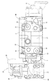
次いで、EGR装置24の構成について、図9〜図15、図22、及び図23を参照して、以下に説明する。図9〜図15、図22、及び図23に示す如く、EGR装置24は、新気とEGRガスを混合して吸気マニホールド3に供給するコレクタ(本体ケース)25を備えており、吸気マニホールド3と新気導入用の吸気スロットル部材26とがコレクタ25を介して連通接続されている。コレクタ25には、再循環排気ガス管28の出口側につながるEGRバルブ部材29が連通接続されている。   Next, the configuration of the EGR device 24 will be described below with reference to FIGS. 9 to 15, 22, and 23. As shown in FIGS. 9 to 15, 22, and 23, the EGR device 24 includes a collector (main body case) 25 that mixes fresh air and EGR gas and supplies them to the intake manifold 3. And an intake throttle member 26 for introducing fresh air are connected to each other via a collector 25. An EGR valve member 29 connected to the outlet side of the recirculation exhaust gas pipe 28 is connected to the collector 25 in communication.

コレクタ25内において、新気流れ方向とEGRガス流れ方向とが直交又は鈍角を形成して交わり、EGRガスと新気との混合ガスを吸気マニホールド3に吸気させる方向が新気流れ方向及びEGRガス流れ方向それぞれと交差する方向となる。また、新気が供給される新気入口81と、EGRガスが供給されるEGRガス入口82とが、コレクタ25の前後両側面に振り分けて開口され、吸気マニホールド3と連結する吸気出口83が、コレクタ25の左側面に開口されている。EGRガス入口82と吸気出口83とが同一高さ位置に配置されるとともに、新気入口81とEGRガス入口82が異なる高さ位置に配置されている。   In the collector 25, the fresh air flow direction and the EGR gas flow direction intersect at an orthogonal or obtuse angle, and the direction in which the mixed gas of EGR gas and fresh air is taken into the intake manifold 3 is the fresh air flow direction and the EGR gas. The direction intersects each flow direction. Further, a fresh air inlet 81 to which fresh air is supplied and an EGR gas inlet 82 to which EGR gas is supplied are opened by being distributed to both front and rear side surfaces of the collector 25, and an intake outlet 83 connected to the intake manifold 3 is provided. Opened on the left side of the collector 25. The EGR gas inlet 82 and the intake outlet 83 are arranged at the same height position, and the fresh air inlet 81 and the EGR gas inlet 82 are arranged at different height positions.

コレクタ25内において、吸気スロットル部材26から新気入口81に導入された新気が、前後方向から上下方向にL字状に屈曲して流れる一方、EGRバルブ部材29からEGRガス入口82に導入されたEGRガスが、斜め上方に向かって流れる。そのため、新気の流れる方向に向かうようにしてEGRガスが流れ込むこととなり、新気に対してEGRガスが混合しやすくなる。また、新気とEGRガスとの混合ガスが上下方向から左右方向にL字状に屈曲して流れ、吸気出口83から吸気マニホールド3に流入する。混合ガスの導出方向が、新気の導入方向及びEGRガスの導入方向だけでなく、コレクタ25内での新気及びEGRガスの流れる方向とも交差するため、EGRガスの新気への混合分布を均一化できる。   In the collector 25, fresh air introduced from the intake throttle member 26 to the fresh air inlet 81 flows while bending in an L shape from the front-rear direction to the vertical direction, while being introduced from the EGR valve member 29 to the EGR gas inlet 82. EGR gas flows obliquely upward. Therefore, the EGR gas flows in the direction in which the fresh air flows, and the EGR gas is easily mixed with the fresh air. In addition, a mixed gas of fresh air and EGR gas flows in an L shape from the vertical direction to the horizontal direction, and flows into the intake manifold 3 from the intake outlet 83. Since the direction in which the mixed gas is derived intersects not only the direction in which fresh air is introduced and the direction in which EGR gas is introduced, but also the direction in which the fresh air and EGR gas flow in the collector 25, the mixing distribution of EGR gas into fresh air It can be made uniform.

上述のように、コレクタ25内では、新気流れ方向に対するEGRガス流れ方向が90°以上となって、新気流れとEGRガス流れが交差することで、新気に対するEGRガスの混合分布を一様なものとして、吸気マニホールド3内でのEGRガスの偏流を抑制できる。結果、シリンダヘッド2における複数の吸気流路36それぞれに供給される吸気のEGRガス濃度を均一化して、ディーゼルエンジン1における各気筒の燃焼作用のバラツキを抑制できる。その結果、黒煙の発生が抑制され、ディーゼルエンジン1の燃焼状態を良好に保ちながら、NOx量を低減できる。すなわち、特定の気筒で失火を招来することなく、EGRガスの還流による排気ガスの清浄化(クリーン化)を達成できるのである。   As described above, in the collector 25, the EGR gas flow direction with respect to the fresh air flow direction is 90 ° or more, and the fresh air flow and the EGR gas flow intersect each other. As such, the drift of EGR gas in the intake manifold 3 can be suppressed. As a result, the EGR gas concentration of the intake air supplied to each of the plurality of intake passages 36 in the cylinder head 2 can be made uniform, and variations in the combustion action of each cylinder in the diesel engine 1 can be suppressed. As a result, the generation of black smoke is suppressed, and the amount of NOx can be reduced while maintaining a good combustion state of the diesel engine 1. That is, the exhaust gas can be purified (cleaned) by the recirculation of the EGR gas without causing misfire in a specific cylinder.

コレクタ25は、新気入口81を有する上側ケース(第1ケース)84と、EGRガス入口82と吸気出口83とを有する下側ケース(第2ケース)85とが連結されて構成される。コレクタ25を、上側ケース84と下側ケース85とで上下分割可能な構成とすることで、EGRガス流れと新気流れとが90°以上で交差する混合流路をコレクタ25内に容易に構成できる。そのため、コレクタ25を剛性の高い鋳物で構成することができるだけでなく、アルミニウム系の鋳造物とすることで軽量化を図れる。   The collector 25 is configured by connecting an upper case (first case) 84 having a fresh air inlet 81 and a lower case (second case) 85 having an EGR gas inlet 82 and an intake outlet 83. By configuring the collector 25 so that the upper case 84 and the lower case 85 can be divided vertically, a mixing flow path in which the EGR gas flow and the fresh air flow intersect at 90 ° or more can be easily configured in the collector 25. it can. Therefore, not only can the collector 25 be made of a highly rigid casting, but the weight can be reduced by using an aluminum casting.

EGRガスが流れるEGRガス流路86の一部である下流側EGRガス流路(第1EGRガス流路)86aと、新気とEGRガスを混合する混合室87とが、上側ケース84に設けられている。下流側EGRガス流路86aとEGRガス入口82とを連通させる上流側EGRガス流路(第2EGRガス流路)86bと、新気とEGRガスが混合された混合ガスを混合室87から吸気マニホールド3に供給する混合ガス流路88とが、下側ケース85に設けられている。   A downstream EGR gas passage (first EGR gas passage) 86a that is a part of the EGR gas passage 86 through which EGR gas flows, and a mixing chamber 87 for mixing fresh air and EGR gas are provided in the upper case 84. ing. An upstream EGR gas flow channel (second EGR gas flow channel) 86b that communicates the downstream EGR gas flow channel 86a and the EGR gas inlet 82, and a mixed gas in which fresh air and EGR gas are mixed is introduced from the mixing chamber 87 into the intake manifold. 3 is provided in the lower case 85.

下側ケース85にEGRガス入口82が設けられる一方、上側ケース84に新気入口81と混合室87とが設けられるため、混合室87において、新気入口81から流れ込む新気と下側ケース85から流れ込むEGRガスとが、互いに交差するようにして流れることなり、新気とEGRガスが効率よく混合する。更に、下側ケース85に吸気出口83が設けられることにより、上側ケース84に流入した新気が下側ケース85に向かって流れようとすることで、上側ケース84に向かって流れるEGRガスの新気への混合が均一化される。また、EGRガス流路86、混合室87、及び混合ガス流路88それぞれをコレクタ25内にコンパクトに構成でき、コレクタ25の小型化が図れる。   While the lower case 85 is provided with the EGR gas inlet 82 and the upper case 84 is provided with the fresh air inlet 81 and the mixing chamber 87, the fresh air flowing from the fresh air inlet 81 and the lower case 85 are mixed in the mixing chamber 87. The EGR gas flowing in from the air flows so as to cross each other, and the fresh air and the EGR gas are efficiently mixed. Further, the intake air outlet 83 is provided in the lower case 85 so that fresh air flowing into the upper case 84 tends to flow toward the lower case 85, so that new EGR gas flowing toward the upper case 84 can be obtained. Mixing into the air is made uniform. Further, each of the EGR gas flow path 86, the mixing chamber 87, and the mixed gas flow path 88 can be configured compactly in the collector 25, and the collector 25 can be downsized.

平面視において、下流側EGRガス流路86aが混合室87の中心軸に対して吸気出口83の設けられた側面(左側面)と反対側の側面側(右側)にオフセットして連結し、下流側EGRガス流路86aと上流側EGRガス流路86bとが連通されて、EGRガス流路86が螺旋状に構成されている。すなわち、下流側EGRガス流路86aと上流側EGRガス流路86bによるEGRガス流路86が、平面視で吸気出口83と逆側(右側)に膨らむように湾曲させた形状となっている。そして、上流側EGRガス流路86bの底が、EGRガス入口82から上側ケース84に向かう傾斜面(後方上側への傾斜面)で構成される。   In a plan view, the downstream EGR gas flow path 86a is connected to the side surface (left side) opposite to the side surface (left side surface) where the intake outlet 83 is provided with respect to the central axis of the mixing chamber 87, and is connected downstream. The side EGR gas flow path 86a and the upstream side EGR gas flow path 86b communicate with each other, and the EGR gas flow path 86 is formed in a spiral shape. That is, the EGR gas flow path 86 formed by the downstream EGR gas flow path 86a and the upstream EGR gas flow path 86b is curved so as to swell toward the opposite side (right side) to the intake outlet 83 in plan view. The bottom of the upstream EGR gas flow path 86b is formed by an inclined surface (an inclined surface toward the rear upper side) from the EGR gas inlet 82 toward the upper case 84.

混合室87においてEGRガス流路86との連通箇所が、吸気出口83と逆側となるため、混合室87内に流入するEGRガスは新気の流れに誘導されて吸気出口83まで到達することとなり、新気に対してEGRガスを均一に混合させることができる。また、EGRガス流路86から混合室87に流れ込むEGRガスは、混合室87から混合ガス流路88に向かう流れに逆らう方向に流れるため、混合室87内において、新気とEGRガスとが互いに衝突するようにして流れることとなり、EGRガスが新気にスムーズに混合する。   Since the communication point with the EGR gas flow path 86 in the mixing chamber 87 is opposite to the intake outlet 83, the EGR gas flowing into the mixing chamber 87 is guided by the flow of fresh air and reaches the intake outlet 83. Thus, EGR gas can be uniformly mixed with fresh air. Further, since the EGR gas flowing into the mixing chamber 87 from the EGR gas flow path 86 flows in a direction opposite to the flow from the mixing chamber 87 toward the mixed gas flow path 88, the fresh air and the EGR gas are mutually exchanged in the mixing chamber 87. It will flow like a collision, and the EGR gas will be smoothly mixed with fresh air.

更に、螺旋状のEGRガス流路86に沿ってEGRガスが流れているため、EGRガスは、時計回りの渦を形成する旋回流となって、混合室87内に流入することとなる。このように乱れたEGRガスが、新気ガスの流れに逆らう方向に流れ込むから、EGRガスは、混合室87内への流入と同時に、内部を流れる新気にスムーズに混合される。従って、コレクタ25内において、新気とEGRガスとを吸気マニホールド3に送り込む前に撹拌しながら効率よく混合でき(混合ガス中においてEGRガスをスムーズに分散でき)、コレクタ25内でのガス混合状態のバラツキ(ムラ)をより確実に抑制できる。その結果、ディーゼルエンジン1の各気筒にムラの少ない混合ガスを分配して、各気筒間のEGRガス量のバラツキを抑制できるため、黒煙の発生を抑制して、ディーゼルエンジン1の燃焼状態を良好に保ちながら、NOx量を低減できる。また、EGRガス流路86を螺旋状とすることで、混合室87内に流入させるEGRガスに十分な旋回性を与えるため、コレクタ25の前後方向長さを短く形成できる。   Furthermore, since the EGR gas flows along the spiral EGR gas flow path 86, the EGR gas flows into the mixing chamber 87 as a swirl flow that forms a clockwise vortex. Since the EGR gas disturbed in this way flows in a direction against the flow of the fresh gas, the EGR gas is smoothly mixed with the fresh air flowing in the interior simultaneously with the inflow into the mixing chamber 87. Accordingly, in the collector 25, fresh air and EGR gas can be efficiently mixed while being stirred before being sent to the intake manifold 3 (the EGR gas can be smoothly dispersed in the mixed gas), and the gas mixing state in the collector 25 Variation (unevenness) can be more reliably suppressed. As a result, the gas mixture with less unevenness can be distributed to each cylinder of the diesel engine 1 to suppress variations in the amount of EGR gas between the cylinders. Therefore, the generation of black smoke is suppressed and the combustion state of the diesel engine 1 is reduced. The amount of NOx can be reduced while maintaining good. In addition, since the EGR gas flow path 86 is formed in a spiral shape, the EGR gas flowing into the mixing chamber 87 is given sufficient swirlability, so that the length of the collector 25 in the front-rear direction can be reduced.

上側ケース84の下面フランジ84aと下側ケース85の上面フランジ85aとをボルト締結して、3方向(前後方向及び左方向)の開口部(新気入口81、EGRガス入口82、及び吸気出口83)を有するコレクタ25が構成される。上側ケース84は、新気入口81を開口した後面フランジ84bに、吸気スロットル部材26の新気出口がボルト締結されている。吸気スロットル部材26は、その内部にある吸気バルブ(バタフライ弁)26aの開度を調節することにより、コレクタ25への新気の供給量を調節する。   The lower surface flange 84a of the upper case 84 and the upper surface flange 85a of the lower case 85 are bolted together to open openings (new air inlet 81, EGR gas inlet 82, and intake outlet 83) in three directions (front and rear direction and left direction). ) Is configured. In the upper case 84, a fresh air outlet of the intake throttle member 26 is bolted to a rear flange 84 b that opens the fresh air inlet 81. The intake throttle member 26 adjusts the amount of fresh air supplied to the collector 25 by adjusting the opening degree of an intake valve (butterfly valve) 26 a inside the intake throttle member 26.

下側ケース85は、EGRガス入口82を開口した前面フランジ85bに、矩形管状の中継フランジ89を介して、EGRバルブ部材29のEGRガス出口がボルト締結されている。EGRバルブ部材29は、その内部にあるEGRバルブ(図示省略)の開度を調節することにより、コレクタ25へのEGRガスの供給量を調節する。EGRガス入口82に挿入されるリードバルブ90が、下側ケース85の前面フランジ85b内側で固定されている。そして、前面フランジ85bにボルト締結される中継フランジ(間座)89が、
リードバルブ90前方を覆うことで、コレクタ25は、EGRガス流路86のEGRガス入口82側にリードバルブ90を内設する。
In the lower case 85, the EGR gas outlet of the EGR valve member 29 is bolted to the front flange 85 b that opens the EGR gas inlet 82 via a rectangular tubular relay flange 89. The EGR valve member 29 adjusts the supply amount of EGR gas to the collector 25 by adjusting the opening degree of an EGR valve (not shown) in the EGR valve member 29. A reed valve 90 to be inserted into the EGR gas inlet 82 is fixed inside the front flange 85 b of the lower case 85. And the relay flange (spacer) 89 bolted to the front flange 85b is
By covering the front of the reed valve 90, the collector 25 internally installs the reed valve 90 on the EGR gas inlet 82 side of the EGR gas flow path 86.

中継フランジ89は、コレクタ25と連結する後面にEGRガス入口82と連通するEGRガス出口89aが開口されている。中継フランジ89の前面は、EGRバルブ部材29と連結するバルブ連結座89b、89cが突設しており、バルブ連結座89b,89cの開口部がEGRバルブ部材29のEGRガス出口と連通している。中継フランジ89では、上下のバルブ連結座89b,89cにおけるEGRガス入口にEGRガスを合流させて、EGRガス入口82からリードバルブ90を介してコレクタ25内のEGRガス流路86へ流入させる。   In the relay flange 89, an EGR gas outlet 89 a communicating with the EGR gas inlet 82 is opened on the rear surface connected to the collector 25. Valve connecting seats 89 b and 89 c that connect to the EGR valve member 29 protrude from the front surface of the relay flange 89, and the openings of the valve connecting seats 89 b and 89 c communicate with the EGR gas outlet of the EGR valve member 29. . In the relay flange 89, the EGR gas is merged with the EGR gas inlets in the upper and lower valve coupling seats 89b and 89c, and flows into the EGR gas flow path 86 in the collector 25 from the EGR gas inlet 82 through the reed valve 90.

EGRバルブ部材29は、バルブ本体29eに設けたEGRガス流路29fにEGRバルブ(図示省略)を内設し、当該EGRバルブの開度を調節するアクチュエータ29dをバルブ本体29e上方に設け、上下方向を長手方向として、中継フランジ89を介してコレクタ25前方に連結される。EGRバルブ部材29は、下側バルブ本体29eの後面において、中継フランジ89のバルブ連結座89b,89cそれぞれと連結する出口側フランジ29a,29bを上下に設けている。一方、EGRバルブ部材29の前面には、再循環排気ガス管28のEGRガス出口と連通するEGRガス入口を備えた入口側フランジ29cを備える。   The EGR valve member 29 is provided with an EGR valve (not shown) in an EGR gas passage 29f provided in the valve main body 29e, and an actuator 29d for adjusting the opening degree of the EGR valve is provided above the valve main body 29e. Is connected to the front side of the collector 25 via the relay flange 89. The EGR valve member 29 is provided with outlet side flanges 29a and 29b which are connected to the valve connection seats 89b and 89c of the relay flange 89 on the rear surface of the lower valve body 29e. On the other hand, the front surface of the EGR valve member 29 is provided with an inlet-side flange 29 c having an EGR gas inlet communicating with the EGR gas outlet of the recirculation exhaust gas pipe 28.

EGRバルブ部材29は、EGRクーラ27で冷却されたEGRガスが、EGRクーラ連結台座34の下流側EGRガス中継流路32及び再循環排気ガス管28を介して、入口側フランジ29cのEGRガス入口に流入すると、バルブ本体29eのEGRガス流路29fを通じてEGRガスが上下に振り分けられる。そして、EGRガス流路29fにより上下に流れたEGRガスは、EGRバルブにより流量調整されて、上下の出口側フランジ29a,29bにおけるEGRガス出口より、中継フランジ89内に流れ込む。   The EGR valve member 29 is configured such that the EGR gas cooled by the EGR cooler 27 passes through the EGR gas relay passage 32 on the downstream side of the EGR cooler connection pedestal 34 and the recirculation exhaust gas pipe 28 to the EGR gas inlet of the inlet side flange 29c. The EGR gas is distributed up and down through the EGR gas passage 29f of the valve body 29e. The EGR gas that has flowed up and down through the EGR gas flow path 29f is adjusted in flow rate by the EGR valve, and flows into the relay flange 89 from the EGR gas outlets at the upper and lower outlet side flanges 29a and 29b.

再循環排気ガス管28は、平面視でL字状に屈曲したガス管部28aと、ガス管部28aの外壁内周側から突設させた平板状のリブ28bとを有している。また、再循環排気ガス管28は、EGRバルブ部材29の入口側フランジ29cと連結する出口側フランジ28cをガス管部28a一端(後端)に設ける一方、EGRクーラ連結台座34の右側面と連結する入口側フランジ28dをガス管部28a他端(左端)に設けている。更に、再循環排気ガス管28は、ガス管部28aの屈曲部分の上面に、EGRガス温度センサを取り付けるセンサ取り付け座28eが設けられている。   The recirculation exhaust gas pipe 28 has a gas pipe portion 28a bent in an L shape in plan view, and a flat rib 28b protruding from the inner peripheral side of the outer wall of the gas pipe portion 28a. The recirculation exhaust gas pipe 28 is provided with an outlet side flange 28c connected to the inlet side flange 29c of the EGR valve member 29 at one end (rear end) of the gas pipe portion 28a, and connected to the right side surface of the EGR cooler connection base 34. The inlet side flange 28d is provided at the other end (left end) of the gas pipe portion 28a. Further, the recirculated exhaust gas pipe 28 is provided with a sensor mounting seat 28e for mounting an EGR gas temperature sensor on the upper surface of the bent portion of the gas pipe portion 28a.

EGR装置24は、コレクタ25の長さを短く構成できるため、EGRバルブ部材29と吸気スロットル部材26との距離を短くでき、結果、EGR装置24の前後長さを短く構成できる。また、EGRバルブ部材29は、アクチュエータ29dを上方に設けた構成とするため、EGRバルブ部材29、コレクタ25、及び吸気スロットル部材26それぞれの最上部を同一高さとできるため、EGR装置24の上下高さを低く構成できるだけでなく、EGR装置24の左右幅を狭く構成できる。従って、EGR装置24がコンパクトに構成されるため、吸気マニホールド3と一体形成されたシリンダヘッド2右側方向において、再循環排気ガス管28で調整するだけで容易に連結できるだけでなく、ディーゼルエンジン1の小型化に貢献する。   Since the EGR device 24 can be configured to shorten the length of the collector 25, the distance between the EGR valve member 29 and the intake throttle member 26 can be shortened, and as a result, the front and rear length of the EGR device 24 can be configured to be short. Further, since the EGR valve member 29 has a configuration in which the actuator 29d is provided above, the uppermost portions of the EGR valve member 29, the collector 25, and the intake throttle member 26 can have the same height. Not only can the height be reduced, but also the left and right width of the EGR device 24 can be reduced. Accordingly, since the EGR device 24 is configured in a compact manner, the EGR device 24 can be easily connected only by adjusting the recirculated exhaust gas pipe 28 in the right direction of the cylinder head 2 integrally formed with the intake manifold 3. Contributes to downsizing.

再循環排気ガス管28は、ガス管部28aの両端を繋ぐようにして平板状のリブ28bが連結された構成となるため、再循環排気ガス管28が高剛性に構成されるとともに、シリンダヘッド2に対してEGR装置24の前端側の支持強度をも高める。また、再循環排気ガス管28は、ガス管部28a内のEGRガス流路28fに沿って平板状のリブ28bを設けた構成となるため、リブ28bによりガス管部28aにおける放熱面積が広くなる
ため、EGRガス流路28fを流れるEGRガスの冷却効果を高めることとなる。その結果、EGR装置24で精製される混合ガスの冷却に寄与して、混合ガスによるNOx量低減効果を適正な状態に維持し易くなるという効果を奏する。
Since the recirculated exhaust gas pipe 28 has a configuration in which flat ribs 28b are connected so as to connect both ends of the gas pipe portion 28a, the recirculated exhaust gas pipe 28 is configured with high rigidity, and the cylinder head. 2, the support strength on the front end side of the EGR device 24 is also increased. Further, since the recirculated exhaust gas pipe 28 has a configuration in which a flat rib 28b is provided along the EGR gas flow path 28f in the gas pipe portion 28a, the heat radiation area in the gas pipe portion 28a is widened by the rib 28b. Therefore, the cooling effect of the EGR gas flowing through the EGR gas flow path 28f is enhanced. As a result, it contributes to the cooling of the mixed gas purified by the EGR device 24, and it is easy to maintain the NOx amount reduction effect by the mixed gas in an appropriate state.

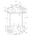
次いで、EGRクーラ27の構成について、図9〜図16及び図24〜図26を参照して、以下に説明する。図9〜図16及び図24〜図26に示す如く、EGRクーラ27は、冷却水流路とEGRガス流路とが交互に積層された熱交換部91と、熱交換部91の一側面における左右両端部分に設けられた左右一対のフランジ部92,93とを備える。そして、冷却水出口94及び冷却水入口95が左右のフランジ部92,93に振り分けて設けられる一方、EGRガス入口96及びEGRガス出口97が左右のフランジ部92,93に振り分けて設けられている。また、シリンダヘッド2の前側面に左右のフランジ部92,93が連結され、EGRクーラ27がシリンダヘッド2に固定される。   Next, the configuration of the EGR cooler 27 will be described below with reference to FIGS. 9 to 16 and FIGS. 24 to 26. As shown in FIGS. 9 to 16 and FIGS. 24 to 26, the EGR cooler 27 includes a heat exchanging portion 91 in which cooling water passages and EGR gas passages are alternately stacked, and left and right sides on one side of the heat exchanging portion 91. And a pair of left and right flange portions 92 and 93 provided at both end portions. The cooling water outlet 94 and the cooling water inlet 95 are provided separately on the left and right flange portions 92 and 93, while the EGR gas inlet 96 and the EGR gas outlet 97 are provided on the left and right flange portions 92 and 93. . Further, left and right flange portions 92 and 93 are connected to the front side surface of the cylinder head 2, and the EGR cooler 27 is fixed to the cylinder head 2.

左右一対のフランジ部92,93それぞれに、冷却水用の開口部分とEGRガス用の開口部分を設けた構成とすることで、フランジ部92,93それぞれを共通の部材で構成できるだけでなく、フランジ部92,93にかかる材料コストを抑制できる。また、フランジ部92,93は、冷却水用及びEGRガス用それぞれの貫通穴94〜97をシリンダヘッド2との連結用の平板に穿設して構成されるため、EGRクーラ27における製造が容易である。また、フランジ部92,93と熱交換部91との連結部分を最低限に構成できるため、熱交換部91に対するシリンダヘッド2からの熱の伝達量を低減でき、熱交換部91におけるEGRガスの冷却効果を高める。   By providing an opening portion for cooling water and an opening portion for EGR gas in each of the pair of left and right flange portions 92, 93, not only can each flange portion 92, 93 be constituted by a common member, but also flanges The material cost concerning the parts 92 and 93 can be suppressed. Further, since the flange portions 92 and 93 are formed by drilling through holes 94 to 97 for cooling water and EGR gas in flat plates for connection with the cylinder head 2, the manufacture in the EGR cooler 27 is easy. It is. Moreover, since the connection part of the flange parts 92 and 93 and the heat exchange part 91 can be comprised at the minimum, the amount of heat transmitted from the cylinder head 2 to the heat exchange part 91 can be reduced, and the EGR gas in the heat exchange part 91 can be reduced. Increase cooling effect.

EGRクーラ27は、フランジ部92,93を熱交換部91後面より突設した構成とすることで、熱交換部91とシリンダヘッド2の間に空間が構成される。従って、EGRクーラ27は、熱交換部91の前後面の広い範囲が外気に曝された状態となり、熱交換部91からも放熱されるため、EGRクーラ27におけるEGRガスの冷却効果が高くなる。従って、熱交換部91後面前面が取り付けられる場合に比べて、熱交換部91における積層数を減らすことができ、EGRクーラ27の前後長さを短くできるため、ディーゼルエンジン1の小型化をも図れる。   The EGR cooler 27 has a configuration in which the flange portions 92 and 93 protrude from the rear surface of the heat exchanging portion 91, so that a space is formed between the heat exchanging portion 91 and the cylinder head 2. Therefore, since the EGR cooler 27 is in a state where a wide range of the front and rear surfaces of the heat exchanging portion 91 is exposed to the outside air and is also dissipated from the heat exchanging portion 91, the cooling effect of the EGR gas in the EGR cooler 27 is enhanced. Therefore, compared with the case where the rear surface front surface of the heat exchange unit 91 is attached, the number of stacked layers in the heat exchange unit 91 can be reduced, and the front-rear length of the EGR cooler 27 can be shortened, so that the diesel engine 1 can be downsized. .

左側フランジ部92に、冷却水出口94とEGRガス入口96が設けられる一方、右側フランジ部93に、冷却水入口95とEGRガス出口97が設けられる。そして、左側フランジ部92において、冷却水出口94とEGRガス入口96とが上下に設けられている一方、右側フランジ部93において、EGRガス出口97と冷却水入口95とが上下に設けられている。また、冷却水出口94とEGRガス出口97とが同一高さに配置される一方、冷却水入口95とEGRガス入口96とが同一高さに配置される。   The left flange portion 92 is provided with a cooling water outlet 94 and an EGR gas inlet 96, while the right flange portion 93 is provided with a cooling water inlet 95 and an EGR gas outlet 97. In the left flange portion 92, the cooling water outlet 94 and the EGR gas inlet 96 are provided vertically, while in the right flange portion 93, the EGR gas outlet 97 and the cooling water inlet 95 are provided vertically. . The cooling water outlet 94 and the EGR gas outlet 97 are arranged at the same height, while the cooling water inlet 95 and the EGR gas inlet 96 are arranged at the same height.

このとき、シリンダヘッド2前側面より突出して形成されたEGRクーラ連結台座33,34それぞれに、EGRクーラ27の左右フランジ部92,93が連結される。そして、左側EGRクーラ連結台座33における上流側EGRガス中継流路31及び下流側冷却水中継流路38それぞれが、左側フランジ92のEGRガス入口96及び冷却水出口94と連通し、右側EGRクーラ連結台座34における下流側EGRガス中継流路32及び上流側冷却水中継流路39それぞれが、右側フランジ93のEGRガス出口97及び冷却水入口95と連通する。   At this time, the left and right flange portions 92 and 93 of the EGR cooler 27 are connected to the EGR cooler connection bases 33 and 34 formed so as to protrude from the front side surface of the cylinder head 2. The upstream EGR gas relay flow path 31 and the downstream cooling water relay flow path 38 in the left EGR cooler connection base 33 communicate with the EGR gas inlet 96 and the cooling water outlet 94 of the left flange 92, respectively, and the right EGR cooler connection. The downstream EGR gas relay passage 32 and the upstream cooling water relay passage 39 in the pedestal 34 communicate with the EGR gas outlet 97 and the cooling water inlet 95 of the right flange 93, respectively.

EGRクーラ27のフランジ部92,93が連結される連結台座33,34にEGRガス中継流路31,32及び冷却水流路38,39を構成し、フランジ部92,93にEGRガス入口96及び出口97と冷却水出口94及び入口95と連通させている。そのため、EGRクーラ27とシリンダヘッド2との間に冷却水用配管及びEGRガス用配管を設ける必要がない。従って、EGRガスや冷却水による配管の伸縮などに影響されることなく、EGRクーラ27とシリンダヘッド2との連結部分におけるシール性を確保できる上、EGRクーラ27は、熱や振動などによる外部からの変動要素に対する耐性が向上し、シリンダヘッド2にコンパクトに設置できる。   The connection bases 33 and 34 to which the flange portions 92 and 93 of the EGR cooler 27 are connected are provided with the EGR gas relay passages 31 and 32 and the cooling water passages 38 and 39, respectively, and the EGR gas inlet 96 and the outlet are provided at the flange portions 92 and 93. 97 is in communication with the cooling water outlet 94 and the inlet 95. Therefore, it is not necessary to provide a cooling water pipe and an EGR gas pipe between the EGR cooler 27 and the cylinder head 2. Accordingly, it is possible to ensure the sealing performance at the connecting portion between the EGR cooler 27 and the cylinder head 2 without being affected by the expansion and contraction of the piping due to EGR gas or cooling water, and the EGR cooler 27 is externally exposed to heat or vibration. The resistance to the fluctuation elements is improved, and the cylinder head 2 can be installed compactly.

フランジ部92に上下に冷却水出口94とEGRガス入口96を設ける一方で、フランジ部93に上下にEGRガス出口97と冷却水入口95を設ける構成としたため、同一形状となるフランジ部92及び93が、互いに上下反転させて熱交換部91に取り付けられることとなる。そのため、EGRクーラ27を構成する部品の種類が低減でき、EGRクーラ27の組み立て性が良くなるとともに、部品コストが低減される。   While the flange portion 92 is provided with the cooling water outlet 94 and the EGR gas inlet 96 above and below, the flange portion 93 is provided with the EGR gas outlet 97 and the cooling water inlet 95 above and below, so that the flange portions 92 and 93 having the same shape are provided. However, they are attached to the heat exchanging portion 91 by turning them upside down. For this reason, the types of parts constituting the EGR cooler 27 can be reduced, the assemblability of the EGR cooler 27 is improved, and the parts cost is reduced.

また、フランジ部92には、熱量の大きい冷却水又はEGRガスが通過する冷却水出口94とEGRガス入口96が設けられる一方、フランジ部93には、熱量の小さい冷却水又はEGRガスが通過する冷却水入口95とEGRガス出口97が設けられる。そのため、フランジ部92,93それぞれにおける熱変形による歪みが抑制されるだけでなく、フランジ部92,93が別体として構成されて、互いの熱変形による影響が少ないため、EGRクーラ27の破損や故障を防止できる。   The flange portion 92 is provided with a cooling water outlet 94 and an EGR gas inlet 96 through which the cooling water or EGR gas having a large amount of heat passes, while the cooling water or EGR gas having a small amount of heat passes through the flange portion 93. A cooling water inlet 95 and an EGR gas outlet 97 are provided. Therefore, not only the distortion due to thermal deformation in each of the flange portions 92 and 93 is suppressed, but the flange portions 92 and 93 are configured as separate bodies and are less influenced by the mutual thermal deformation. Failure can be prevented.

EGRクーラ27は、背面視において、冷却水出口94と冷却水入口95とが対角に配置されるとともに、EGRガス入口96とEGRガス出口97とが対角に配置される。熱量の異なるEGRガス及び冷却水それぞれが、対角位置より供給又は排出されるため、EGRクーラ27とシリンダヘッド2との連結部分における熱変形を互いに緩和して、連結部分の撓みや緩みを抑制できる。従って、EGRクーラ27とシリンダヘッド2におけるEGRガスや冷却水の漏れを防止できるだけでなく、連結強度の低下をも防止できる。   In the EGR cooler 27, the cooling water outlet 94 and the cooling water inlet 95 are diagonally arranged in a rear view, and the EGR gas inlet 96 and the EGR gas outlet 97 are diagonally arranged. Since each of the EGR gas and the cooling water having different heat amounts are supplied or discharged from the diagonal position, thermal deformation at the connecting portion between the EGR cooler 27 and the cylinder head 2 is alleviated to suppress bending and loosening of the connecting portion. it can. Therefore, it is possible not only to prevent leakage of EGR gas and cooling water in the EGR cooler 27 and the cylinder head 2, but also to prevent a decrease in connection strength.

板状のガスケット98が、左右のフランジ部92,93を架設するようにして、シリンダヘッド2とフランジ部92,93との間に挟持されている。フランジ部92,93における冷却水出口94及び冷却水入口95それぞれと連通するシリンダヘッド2における冷却水入口及び冷却水出口それぞれにリング状のシール部材であるOリング99が埋設され、Oリング99がフランジ部92,93で覆われている。   A plate-like gasket 98 is sandwiched between the cylinder head 2 and the flange portions 92 and 93 so that the left and right flange portions 92 and 93 are installed. An O-ring 99 which is a ring-shaped seal member is embedded in each of the cooling water inlet and the cooling water outlet in the cylinder head 2 communicating with the cooling water outlet 94 and the cooling water inlet 95 in the flange portions 92 and 93, respectively. Covered with flange portions 92 and 93.

別体とされるフランジ部92,93が、シリンダヘッド2の連結台座33,34にガスケット98を介して連結されるため、シリンダヘッド2との連結部分における熱変形により、ガスケット98に張力が働く。そのため、EGRガス入口96及びEGRガス出口97それぞれの連結部分において、ガスケット98によるシール性(密封性)が向上することとなり、シリンダヘッド2とEGRクーラ27との間を行き来するEGRガスの漏れを防止できる。また、Oリング99が、シリンダヘッド2の連結台座33,34における冷却水入口及び冷却水出口とフランジ部92,93の後端面とで構成される空間に埋設されているため、冷却水が流れた際に、連結台座33,34及びフランジ部92,93の連通部分をOリング99に当接することとなり、冷却水出入口における連結部分のシール性(密封性)を確保できる。従って、液体及び気体の流出入を行うEGRクーラ27をシリンダヘッド2に連結したとしても、液体及び気体それぞれにおけるシール性を確保でき、EGRガス及び冷却水それぞれの漏れを防止できる。   Since the flange portions 92 and 93 which are separated from each other are connected to the connecting bases 33 and 34 of the cylinder head 2 via the gasket 98, tension is applied to the gasket 98 due to thermal deformation in the connecting portion with the cylinder head 2. . For this reason, the sealing performance (sealing performance) by the gasket 98 is improved at the connecting portions of the EGR gas inlet 96 and the EGR gas outlet 97, and leakage of EGR gas flowing back and forth between the cylinder head 2 and the EGR cooler 27 is prevented. Can be prevented. Further, since the O-ring 99 is embedded in the space formed by the cooling water inlet and the cooling water outlet and the rear end surfaces of the flange portions 92 and 93 in the coupling bases 33 and 34 of the cylinder head 2, the cooling water flows. In this case, the connecting portions of the connecting pedestals 33 and 34 and the flange portions 92 and 93 come into contact with the O-ring 99, and the sealing performance (sealing performance) of the connecting portion at the cooling water inlet / outlet can be ensured. Therefore, even if the EGR cooler 27 that flows in and out of the liquid and gas is connected to the cylinder head 2, the sealing performance in each of the liquid and the gas can be secured, and the leakage of each of the EGR gas and the cooling water can be prevented.

フランジ部92,93の外周部であって外側位置に、ボルト締結用の貫通穴100が穿設されている。すなわち、左側フランジ部92は、上下及び左側に5つの貫通穴100を有しており、右側フランジ部93は、上下及び右側に5つの貫通穴100を有している。従って、左側フランジ部92は、冷却水出口94の上側、EGRガス入口96の下側、及び、冷却水出口94及びEGRガス入口96間の左側それぞれに貫通穴100が設けられることで、シリンダヘッド2の連結台座33とボルト締結した場合に、冷却水出口94及びEGRガス入口96におけるシール性が確保される。同様に、右側フランジ部93は、
冷却水入口95の下側、EGRガス出口97の上側、及び、冷却水入口95及びEGRガス出口97間の右側それぞれに貫通穴100が設けられることで、シリンダヘッド2の連結台座34とボルト締結した場合に、冷却水入口95及びEGRガス出口97におけるシール性が確保される。
A through hole 100 for fastening a bolt is formed in the outer peripheral portion of the flange portions 92 and 93 at the outer position. That is, the left flange portion 92 has five through holes 100 on the top and bottom and the left side, and the right flange portion 93 has five through holes 100 on the top and bottom and the right side. Accordingly, the left flange portion 92 is provided with a through hole 100 on the upper side of the cooling water outlet 94, on the lower side of the EGR gas inlet 96, and on the left side between the cooling water outlet 94 and the EGR gas inlet 96. When the second connection base 33 is bolted, the sealing performance at the cooling water outlet 94 and the EGR gas inlet 96 is ensured. Similarly, the right flange portion 93 is
The through holes 100 are provided on the lower side of the cooling water inlet 95, the upper side of the EGR gas outlet 97, and the right side between the cooling water inlet 95 and the EGR gas outlet 97, so that the connection base 34 of the cylinder head 2 and the bolt are fastened. In this case, the sealing performance at the cooling water inlet 95 and the EGR gas outlet 97 is ensured.

ガスケット98は、貫通穴101〜103を設けた2枚の板98a,98bを貼り合わせて構成されており、貫通穴(EGRガス用貫通穴)101をEGRガスが通過し、貫通穴(冷却水用貫通穴)102を冷却水が通過し、貫通穴(ボルト用貫通穴)103に締結用ボルトが挿入される。ガスケット98は、EGRガス用貫通穴101における内周縁が前後方向に反り返るように分岐させた形状を有しており、冷却水用貫通穴102の開口面積を冷却水出入口94,95の開口面積よりも広くなるように構成している。   The gasket 98 is configured by bonding two plates 98a and 98b provided with through holes 101 to 103, and the EGR gas passes through the through hole (EGR gas through hole) 101, and the through hole (cooling water) The cooling water passes through the through-hole (102), and the fastening bolt is inserted into the through-hole (through-hole for bolt) 103. The gasket 98 has a shape branched so that the inner peripheral edge of the EGR gas through hole 101 warps back and forth, and the opening area of the cooling water through hole 102 is larger than the opening areas of the cooling water inlets and outlets 94 and 95. Is also configured to be wide.

ガスケット98は、前側板98aのEGRガス用貫通穴101における内周縁を前側に反り返らせる一方で、後側板98bのEGRガス用貫通穴101における内周縁を後側に反り返らせおり、前側板98aと後側板98bを溶接により貼り合わせることで、EGRガス用貫通穴101における内周縁がY字状の断面となる。EGRガス用貫通穴101における内周縁が前後に反り返った形状とすることで、EGRガス用貫通穴101の内周縁における前後面を連結台座33,34及びフランジ部92,93それぞれの端面に密着させることとなり、十分な気密性を確保できる。   The gasket 98 causes the inner peripheral edge of the EGR gas through hole 101 of the front side plate 98a to warp forward, while the inner peripheral edge of the rear plate 98b of the EGR gas through hole 101 returns to the rear side. By bonding the 98a and the rear side plate 98b together by welding, the inner peripheral edge of the EGR gas through hole 101 becomes a Y-shaped cross section. By making the inner periphery of the EGR gas through hole 101 warp back and forth, the front and rear surfaces of the inner periphery of the EGR gas through hole 101 are brought into close contact with the end surfaces of the coupling bases 33 and 34 and the flange portions 92 and 93, respectively. Therefore, sufficient airtightness can be secured.

ガスケット98は、冷却水用貫通穴102の開口を冷却水出入口94,95よりも広くなるように構成することで、Oリング99が冷却水用貫通穴102に挿入される。すなわち、フランジ部92,93の冷却水出入口と連結台座33,34内の冷却水中継流路38,39との連通部分が、ガスケット98の冷却水用貫通穴102に嵌合されたOリング99により密封される。   The gasket 98 is configured so that the opening of the cooling water through hole 102 is wider than the cooling water inlets 94 and 95, so that the O-ring 99 is inserted into the cooling water through hole 102. That is, the O-ring 99 in which the communicating portion between the cooling water inlet / outlet of the flange portions 92 and 93 and the cooling water relay passages 38 and 39 in the connection bases 33 and 34 is fitted in the cooling water through hole 102 of the gasket 98. Sealed.

また、シリンダヘッド2の連結台座33,34は、冷却水出入口それぞれを段差付きで開口することで、連結台座33,34内の冷却水中継流路38,39の流路径よりも大きく開口させて、連結台座33,34の冷却水出入口に対して、冷却水中継流路38,39の外周側にOリング99が嵌合される。すなわち、Oリング99は、ガスケット98に挿入されるとともに、連結台座33,34における冷却水出入口の段差部分に嵌合されて、連結台座33,34及びフランジ部92,93により狭持される。従って、弾性材で構成されるOリング99の内側を冷却水が通過することにより、Oリング99が外側に広がるように変形し、連結台座33,34及びフランジ部92,93と密着することにより、冷却水のシール性を確保する。   Further, the connecting pedestals 33 and 34 of the cylinder head 2 are opened larger than the flow path diameters of the coolant relay passages 38 and 39 in the connecting pedestals 33 and 34 by opening the cooling water inlets and outlets with steps. The O-ring 99 is fitted to the outer peripheral side of the coolant relay passages 38 and 39 with respect to the coolant inlet / outlet of the coupling bases 33 and 34. That is, the O-ring 99 is inserted into the gasket 98 and is fitted into the stepped portion of the cooling water inlet / outlet in the connection bases 33 and 34 and is held between the connection bases 33 and 34 and the flange portions 92 and 93. Therefore, when the cooling water passes through the inside of the O-ring 99 made of an elastic material, the O-ring 99 is deformed so as to spread outward, and is brought into close contact with the coupling bases 33 and 34 and the flange portions 92 and 93. , Ensure the sealing of cooling water.

リング状のOリング99は、内周部分が前後に膨らんだ形状を備えており、Oリングの内周部分を通過する冷却水により押圧されることで、内周部分の前後縁が前後に突出するように変形する。これにより、Oリング99の内周部分が連結台座33,34及びフランジ部92,93と密着するため、シリンダヘッド2とEGRクーラ27との連結部分における冷却水のシール性を向上できる。   The ring-shaped O-ring 99 has a shape in which the inner peripheral portion swells back and forth, and the front and rear edges of the inner peripheral portion protrude forward and backward by being pressed by cooling water passing through the inner peripheral portion of the O-ring. Deform to Thereby, since the inner peripheral part of O-ring 99 closely_contact | adheres to the connection bases 33 and 34 and the flange parts 92 and 93, the sealing performance of the cooling water in the connection part of the cylinder head 2 and the EGR cooler 27 can be improved.

また、リング状のOリング99は、内周部分が前後に膨らんだ形状とした上で、その内周面に凹部を備えた形状を有している。すなわち、Oリング99の内周面を前後にそり返されたY字状の断面で構成することで、Oリングの内周部分を通過する冷却水により押圧されて、内周部分の前後縁を前後に更に突出させることとなり、Oリング99の内周部分と連結台座33,34及びフランジ部92,93との密着性を高める、従って、シリンダヘッド2とEGRクーラ27との連結部分における冷却水のシール性を向上できる。   Further, the ring-shaped O-ring 99 has a shape in which an inner peripheral portion swells back and forth and has a concave portion on its inner peripheral surface. That is, by configuring the inner peripheral surface of the O-ring 99 with a Y-shaped cross section bent back and forth, the front and rear edges of the inner peripheral portion are pressed by the cooling water passing through the inner peripheral portion of the O-ring. This further protrudes back and forth, and improves the adhesion between the inner peripheral portion of the O-ring 99 and the connecting pedestals 33 and 34 and the flange portions 92 and 93. Accordingly, the cooling water at the connecting portion between the cylinder head 2 and the EGR cooler 27 is increased. Can improve the sealing performance.

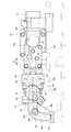
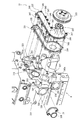
次に、図17〜図19を参照しながら、シリンダブロック6及び動弁機構の構成について説明する。シリンダブロック6には、クランク軸5を収容するクランクケース171と、ピストン172をそれぞれ収容する4気筒分のシリンダボア173が設けられている。各ピストン172は、それぞれコンロッド174を介してクランク軸5に連結され、シリンダボア173内で上下摺動自在に配置されている。   Next, the configuration of the cylinder block 6 and the valve operating mechanism will be described with reference to FIGS. The cylinder block 6 is provided with a crankcase 171 that accommodates the crankshaft 5 and cylinder bores 173 for four cylinders that respectively accommodate the pistons 172. Each piston 172 is connected to the crankshaft 5 via a connecting rod 174 and is slidable in the vertical direction within the cylinder bore 173.

また、シリンダブロック6には、カム軸175を収容するカム室176と、プッシュロッド177の下端側を収容するブロック側プッシュロッド室178(プッシュロッド室)と、タペット179を摺動自在に保持するタペット保持部180が設けられている。タペット179は、カム軸175の吸気カム175a又は排気カム175bとプッシュロッド177の間に配置され、カム軸175の駆動力をプッシュロッド177に伝達する。   The cylinder block 6 slidably holds a cam chamber 176 that houses the cam shaft 175, a block-side push rod chamber 178 (push rod chamber) that houses the lower end side of the push rod 177, and a tappet 179. A tappet holder 180 is provided. The tappet 179 is disposed between the intake cam 175 a or the exhaust cam 175 b of the cam shaft 175 and the push rod 177, and transmits the driving force of the cam shaft 175 to the push rod 177.

カム室176は、シリンダボア173の左側方でエンジン1の前後方向に延設されている。カム室176はクランクケース171と通じている。カム軸175は、気筒ごとに吸気カム及び排気カムの組を備えており、吸気カム及び排気カムの組同士の間の部位に、カム室176の軸受部に枢支されるカムジャーナル部を備えている。カム室176は、カム軸175の吸気カム及び排気カムの組ごとに(気筒ごとに)、複数の区画カム室181で区画されている。本実施形態では、カム室176は4つの区画カム室181に区画されている。   The cam chamber 176 extends in the front-rear direction of the engine 1 on the left side of the cylinder bore 173. The cam chamber 176 communicates with the crankcase 171. The cam shaft 175 includes a set of intake cams and exhaust cams for each cylinder, and includes a cam journal portion pivotally supported by a bearing portion of the cam chamber 176 at a portion between the intake cam and exhaust cam sets. ing. The cam chamber 176 is partitioned by a plurality of partitioned cam chambers 181 for each set of intake cams and exhaust cams of the cam shaft 175 (for each cylinder). In the present embodiment, the cam chamber 176 is partitioned into four partitioned cam chambers 181.

ブロック側プッシュロッド室178は、カム室176の上方に配置され、気筒ごとに区画されている。本実施形態では、エンジン1の前後方向に並ぶ4つのブロック側プッシュロッド室178が設けられている。また、シリンダブロック6のシリンダヘッド2との接合面に、ブロック側プッシュロッド室178ごとに連通穴182が形成されている。そして、各ブロック側プッシュロッド室178及び連通穴182にはプッシュロッド177の下端側が2本ずつ挿入されている。タペット保持部180は、カム室176とブロック側プッシュロッド室178の間に形成され、カム室176とブロック側プッシュロッド室178の間を仕切っている。また、シリンダブロック6には、カム室176とブロック側プッシュロッド室178を通じさせるバイパス通路183がタペット保持部180とシリンダボア173の間に形成されている。   The block-side push rod chamber 178 is disposed above the cam chamber 176 and is partitioned for each cylinder. In the present embodiment, four block-side push rod chambers 178 arranged in the front-rear direction of the engine 1 are provided. In addition, a communication hole 182 is formed for each block-side push rod chamber 178 on the joint surface of the cylinder block 6 with the cylinder head 2. Two lower ends of the push rods 177 are inserted into each block side push rod chamber 178 and the communication hole 182. The tappet holding portion 180 is formed between the cam chamber 176 and the block side push rod chamber 178 and partitions the cam chamber 176 and the block side push rod chamber 178. In the cylinder block 6, a bypass passage 183 is formed between the tappet holding portion 180 and the cylinder bore 173 through the cam chamber 176 and the block-side push rod chamber 178.

また、シリンダブロック6内には、シリンダボア173の周囲に配置された冷却水ジャケット184と、前後方向に延設された冷却水レール185が形成されている。冷却水レール185は、冷却水ジャケット184よりも低い位置でシリンダボア173の右側方に配置されている。また、冷却水レール185は、4気筒分のシリンダボア173の配置の凹凸におおよそ沿って、平面視で蛇行している。また、冷却水レール185は、平面視で、シリンダヘッド2をシリンダブロック6に固定するためのヘッド締結用ボルト186の軸線とは異なる位置に設けられている。   In the cylinder block 6, a cooling water jacket 184 disposed around the cylinder bore 173 and a cooling water rail 185 extending in the front-rear direction are formed. The cooling water rail 185 is disposed on the right side of the cylinder bore 173 at a position lower than the cooling water jacket 184. Further, the cooling water rail 185 meanders in plan view approximately along the unevenness of the arrangement of the cylinder bores 173 for four cylinders. The cooling water rail 185 is provided at a position different from the axis of the head fastening bolt 186 for fixing the cylinder head 2 to the cylinder block 6 in plan view.

シリンダヘッド2は、ヘッド締結用ボルト186によりシリンダブロック6にボルト締結されている。シリンダヘッド2の上面はヘッドカバー18で覆われている。ヘッドカバー18内部の空間は弁腕室を形成している。ヘッドカバー18内には、カム軸175に関連させた動弁機構187が配置されている。また、シリンダヘッド2内には、各気筒に対応して吸気弁136及び排気弁137が設けられている。本実施形態のエンジン1は、気筒毎に2つの吸気弁136及び2つの排気弁137を備えた4弁タイプのものになっている。   The cylinder head 2 is bolted to the cylinder block 6 by a head fastening bolt 186. The upper surface of the cylinder head 2 is covered with a head cover 18. The space inside the head cover 18 forms a valve arm chamber. A valve mechanism 187 associated with the cam shaft 175 is disposed in the head cover 18. In the cylinder head 2, an intake valve 136 and an exhaust valve 137 are provided corresponding to each cylinder. The engine 1 of the present embodiment is of a four-valve type that includes two intake valves 136 and two exhaust valves 137 for each cylinder.

また、エンジン1はOHV式のものであり、動弁機構187は、カム軸175の吸気カム及び排気カムによりタペット179及びプッシュロッド177と、プッシュロッド177の上下動にてヘッドカバー18内にある前後横長の弁腕軸188回りに揺動する弁腕189を備えている。プッシュロッド177の上端側はシリンダヘッド2に設けられたヘッド側プッシュロッド室190を介してヘッドカバー18内に突出している。プッシュロッド177の上端側は弁腕189の一端側に連結されている。弁腕189の他端側は、バルブブリッジ191を介して2つの吸気弁136又は2つの排気弁137に当接している。カム軸175の回転によってプッシュロッド177が上下動して、各弁腕189が弁腕軸188回りに揺動することにより、各気筒の吸気弁136の組と排気弁137の組とが開閉作動するように構成されている。   Further, the engine 1 is of the OHV type, and the valve operating mechanism 187 is arranged in the head cover 18 by the vertical movement of the tappet 179 and the push rod 177 and the push rod 177 by the intake cam and the exhaust cam of the cam shaft 175. A valve arm 189 that swings around a horizontally long valve arm shaft 188 is provided. The upper end side of the push rod 177 protrudes into the head cover 18 via a head side push rod chamber 190 provided in the cylinder head 2. The upper end side of the push rod 177 is connected to one end side of the valve arm 189. The other end side of the valve arm 189 is in contact with two intake valves 136 or two exhaust valves 137 via a valve bridge 191. The push rod 177 moves up and down by the rotation of the cam shaft 175, and each valve arm 189 swings around the valve arm shaft 188, thereby opening and closing the set of the intake valve 136 and the set of the exhaust valve 137 of each cylinder. Is configured to do.

クランクケース171は、カム室176、バイパス通路183及びブロック側プッシュロッド室178を介して、シリンダヘッド2のヘッド側プッシュロッド室190に通じている。クランクケース171内のブローバイガスは、カム室176、バイパス通路183及びブロック側プッシュロッド室178を介して、シリンダヘッド2側へ移動する。なお、ヘッド側プッシュロッド室190、ブロック側プッシュロッド室178、バイパス通路183及びカム室176は、ヘッドカバー18内の潤滑油をクランクケース171側へ戻すオイル落とし経路を兼ねている。   The crankcase 171 communicates with the head side push rod chamber 190 of the cylinder head 2 via the cam chamber 176, the bypass passage 183 and the block side push rod chamber 178. The blow-by gas in the crankcase 171 moves to the cylinder head 2 side via the cam chamber 176, the bypass passage 183, and the block-side push rod chamber 178. The head side push rod chamber 190, the block side push rod chamber 178, the bypass passage 183, and the cam chamber 176 also serve as an oil dropping path for returning the lubricating oil in the head cover 18 to the crankcase 171 side.

上述のように、本実施形態のエンジン1では、タペット保持部180はカム室176とブロック側プッシュロッド室178の間を仕切っている。また、カム室176とブロック側プッシュロッド室178を通じさせるバイパス通路183は、タペット保持部180とシリンダボア173の間に形成されている。これにより、カム室176、バイパス通路183及びブロック側プッシュロッド室178で構成される、タペット保持部180を迂回した折れ曲がったブローバイガス経路が形成されている。したがって、エンジン1は、当該折れ曲がったブローバイガス経路でブローバイガスを壁面に衝突させることで、壁面への潤滑油の付着やミスト状潤滑油同士の結合を促進させてブローバイガス中の潤滑油の捕集量を増加でき、クランクケース171側からカム室176、バイパス通路183及びブロック側プッシュロッド室178を介してシリンダヘッド2側へ流出する潤滑油量を低減できる。   As described above, in the engine 1 of this embodiment, the tappet holding portion 180 partitions the cam chamber 176 and the block side push rod chamber 178. Further, a bypass passage 183 that passes through the cam chamber 176 and the block-side push rod chamber 178 is formed between the tappet holding portion 180 and the cylinder bore 173. As a result, a bent blow-by gas path that bypasses the tappet holding portion 180 and is formed by the cam chamber 176, the bypass passage 183, and the block-side push rod chamber 178 is formed. Therefore, the engine 1 causes the blow-by gas to collide with the wall surface through the bent blow-by gas path, thereby promoting the adhesion of the lubricating oil to the wall surface and the coupling of the mist-like lubricating oils, thereby capturing the lubricating oil in the blow-by gas. The amount of collected oil can be increased, and the amount of lubricating oil flowing out from the crankcase 171 side to the cylinder head 2 side via the cam chamber 176, the bypass passage 183, and the block side push rod chamber 178 can be reduced.

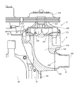
次いで、冷却水ポンプ21及び冷却水入口管22の構成について、図27〜図30等を参照して、以下に説明する。図27〜図30等に示す如く、シリンダブロック6の左側面における後側面寄りの部位に、冷却水ポンプ21(図2等参照)が取り付けられる冷却水ポンプ取付部319と、冷却水入口管22(図3等参照)が取り付けられる入口管取付座320が突設されている。冷却水ポンプ取付部319及び入口管取付座320はシリンダブロック6に一体成形されている。また、入口管取付座320の後側面側の部位は冷却水ポンプ取付部319に連結されている。冷却水ポンプ取付部319及び入口管取付座320は、クランク軸5から離れる方向に突設されており、シリンダブロック6の剛性、強度及び冷却効率を向上できる。   Next, the configuration of the cooling water pump 21 and the cooling water inlet pipe 22 will be described below with reference to FIGS. As shown in FIGS. 27 to 30 and the like, a cooling water pump mounting portion 319 to which a cooling water pump 21 (see FIG. 2 and the like) is mounted on a portion of the left side surface of the cylinder block 6 near the rear side surface, and a cooling water inlet pipe 22. An inlet pipe attachment seat 320 to which (see FIG. 3 etc.) is attached is projected. The coolant pump mounting portion 319 and the inlet pipe mounting seat 320 are integrally formed with the cylinder block 6. Further, the rear side portion of the inlet pipe mounting seat 320 is connected to the cooling water pump mounting portion 319. The cooling water pump mounting portion 319 and the inlet pipe mounting seat 320 are projected in a direction away from the crankshaft 5, and the rigidity, strength, and cooling efficiency of the cylinder block 6 can be improved.

シリンダブロック6の後側面312及び冷却水ポンプ取付部319に冷却水循環用の冷却水ポンプ21がボルト締結されている。冷却水ポンプ21は、大きく分けてベースプレート部331とカバープレート部332とポンプ用プーリ333により構成される。   The coolant pump 21 for circulating coolant is bolted to the rear side surface 312 of the cylinder block 6 and the coolant pump mounting portion 319. The cooling water pump 21 is roughly composed of a base plate portion 331, a cover plate portion 332, and a pump pulley 333.

ベースプレート部331とカバープレート部332は、ベースプレート部331の周縁部に設けられた5か所の貫通ボルト孔と、その貫通ボルト孔に対応するカバープレート部332の貫通孔にカバープレート部332側からカバー用ボルト347がそれぞれ挿入及び締結されて、周縁部が互いに密着固定されている。   The base plate portion 331 and the cover plate portion 332 are provided from the cover plate portion 332 side into five through bolt holes provided in the peripheral portion of the base plate portion 331 and through holes of the cover plate portion 332 corresponding to the through bolt holes. The cover bolts 347 are inserted and fastened, respectively, and the peripheral portions are closely fixed to each other.

また、冷却水ポンプ21は、ベースプレート部331及びカバープレート部332の周縁部の9か所に設けられた貫通孔にそれぞれ装着用ボルト348が挿入されて、プレート部331,332が共締め状態でシリンダブロック6にボルト締結されている。装着用ボルト348の締め付けにより、ベースプレート部331とカバープレート部332の周縁部が互いに密着固定されるとともに、シリンダブロック6の冷却水流路出口327の周囲部と冷却水ポンプ21のポンプ吸入口334の周囲部が互いに密着固定され、さらにシリンダブロック6の冷却水導入口328の周囲部と冷却水ポンプ21のポンプ吐出口335の周囲部が互いに密着固定される。冷却水ポンプ21の周縁部に沿ったボルト347,348の配列において、隣り合うカバー用ボルト347,347の間には1つ又は2つの装着用ボルト348が配置されている。   In addition, the cooling water pump 21 has the mounting bolts 348 inserted into the through holes provided at the nine peripheral portions of the base plate portion 331 and the cover plate portion 332 so that the plate portions 331 and 332 are tightened together. Bolts are fastened to the cylinder block 6. By tightening the mounting bolts 348, the peripheral portions of the base plate portion 331 and the cover plate portion 332 are closely fixed to each other, and the periphery of the cooling water passage outlet 327 of the cylinder block 6 and the pump inlet 334 of the cooling water pump 21 are fixed. The peripheral portions are closely fixed to each other, and the peripheral portion of the cooling water introduction port 328 of the cylinder block 6 and the peripheral portion of the pump discharge port 335 of the cooling water pump 21 are firmly fixed to each other. In the arrangement of the bolts 347 and 348 along the peripheral edge of the cooling water pump 21, one or two mounting bolts 348 are arranged between the adjacent cover bolts 347 and 347.

カバー用ボルト347によりベースプレート部331とカバープレート部332が連結されていることにより、冷却水ポンプ21を1部品として流通できるとともに、冷却水ポンプ21を装着用ボルト348によりシリンダブロック6に装着する際の取付け作業が容易になる。   When the base plate portion 331 and the cover plate portion 332 are connected by the cover bolt 347, the coolant pump 21 can be distributed as one component, and when the coolant pump 21 is attached to the cylinder block 6 by the attachment bolt 348. The installation work becomes easier.

ベースプレート部331は、例えば冷却水ポンプ取付部319の部位を含んでシリンダブロック6の後側面の左側寄りの部位に開口された冷却水流路出口327に接続されるポンプ吸入口334と、シリンダブロック6の後側面の左側寄りの部位に開口された冷却水導入口328に接続されるポンプ吐出口335を備えている。   The base plate portion 331 includes, for example, a pump suction port 334 connected to a cooling water flow path outlet 327 opened to a left side portion of the rear side surface of the cylinder block 6 including a portion of the cooling water pump mounting portion 319, and the cylinder block 6. A pump discharge port 335 is provided which is connected to a cooling water introduction port 328 opened at a portion on the left side of the rear side surface.

ベースプレート部331とカバープレート部332は互いに周縁部が密着されてポンプ吸入口334とポンプ吐出口335を接続するポンプ内冷却水流路336を形成する。ベースプレート部331とカバープレート部332の密着部にはポンプ吸入口334、ポンプ吐出口335及びポンプ内冷却水流路336を囲う環状シール部材が配置される。カバープレート部332は、一端部に羽根車(インペラ)が固着されるポンプ軸337を回転自在に軸支する。ポンプ軸337の他端部にポンプ用プーリ333が固着される。   The base plate portion 331 and the cover plate portion 332 are closely contacted with each other to form an in-pump cooling water flow path 336 that connects the pump suction port 334 and the pump discharge port 335. An annular seal member that surrounds the pump suction port 334, the pump discharge port 335, and the cooling water flow path 336 in the pump is disposed in a close contact portion between the base plate portion 331 and the cover plate portion 332. The cover plate portion 332 rotatably supports a pump shaft 337 to which an impeller (impeller) is fixed to one end portion. A pump pulley 333 is fixed to the other end of the pump shaft 337.

シリンダブロック6の左側面に冷却水流路入口329が開口されている。冷却水流路入口329は左側面に突設された入口管取付座320に開口されている。シリンダブロック6内部に、左側面に開口された冷却水流路入口329と後側面に開口された冷却水流路出口327を接続する略L字状のブロック内冷却水流路338(冷却水流路)が形成されている。   A cooling water channel inlet 329 is opened on the left side surface of the cylinder block 6. The cooling water flow path inlet 329 is opened to an inlet pipe mounting seat 320 protruding from the left side surface. A substantially L-shaped in-block cooling water flow channel 338 (cooling water flow channel) is formed in the cylinder block 6 to connect the cooling water flow channel inlet 329 opened on the left side surface and the cooling water flow channel outlet 327 opened on the rear side surface. Has been.

入口管取付座320には冷却水流路入口329を挟んで一対のボルト孔が形成されており、冷却水入口339を有する冷却水入口管22(冷却水入口部材)が入口管取付座320に着脱可能にボルト締結される。冷却水入口管22にはラジエータの冷却水出口につながる配管が接続される。ラジエータからの冷却水は、エンジン1に冷却水入口管22から取り込まれ、ブロック内冷却水流路338及び冷却水ポンプ21を介して冷却水導入口328からシリンダブロック6内へ導入される。   The inlet pipe mounting seat 320 has a pair of bolt holes sandwiching the cooling water flow path inlet 329, and the cooling water inlet pipe 22 (cooling water inlet member) having the cooling water inlet 339 is attached to and detached from the inlet pipe mounting seat 320. It is bolted as possible. A pipe connected to the cooling water outlet of the radiator is connected to the cooling water inlet pipe 22. Cooling water from the radiator is taken into the engine 1 from the cooling water inlet pipe 22 and introduced into the cylinder block 6 from the cooling water inlet 328 via the in-block cooling water flow path 338 and the cooling water pump 21.

この実施形態のエンジン1では、冷却水入口339を有する冷却水入口管22が冷却水ポンプ21のポンプ吸入口334につながる冷却水流路入口329に着脱可能に取り付けられるので、冷却水入口管22の形状等を変更するだけで冷却水入口339の位置を変更することができる。これにより、冷却水ポンプ21の冷却水入口339の位置を簡便かつ大幅な設計変更や製造コスト増大を招くことなく変更できる。   In the engine 1 of this embodiment, the cooling water inlet pipe 22 having the cooling water inlet 339 is detachably attached to the cooling water flow path inlet 329 connected to the pump suction port 334 of the cooling water pump 21. The position of the cooling water inlet 339 can be changed simply by changing the shape or the like. Thereby, the position of the cooling water inlet 339 of the cooling water pump 21 can be changed easily and without causing a significant design change or an increase in manufacturing cost.

また、ラジエータからの冷却水を冷却水ポンプ21に供給する冷却水流路出口327と、冷却水ポンプ21からの冷却水をシリンダブロック6内に導入する冷却水導入口328がシリンダブロック6の左右に振り分けて配置されている。さらに、冷却水流路出口327と冷却水導入口328を接続しているポンプ内冷却水流路336はシリンダブロック6の左側面寄りの部位から右側面寄りの部位にわたって配置されている。このような構成により、ポンプ内冷却水流路336内を通過する冷却水は、冷却水流路出口327から冷却水導入口328へ移動する間、冷却ファン9(図2参照)からの冷却風により冷却される。したがって、冷却水を冷却水導入口328からシリンダブロック6内に導入する前に冷却水ポンプ21内で冷却できるので、エンジン1の冷却効率を向上できる。   Further, a cooling water passage outlet 327 for supplying cooling water from the radiator to the cooling water pump 21 and a cooling water inlet 328 for introducing cooling water from the cooling water pump 21 into the cylinder block 6 are provided on the left and right sides of the cylinder block 6. They are arranged. Further, the in-pump cooling water flow path 336 connecting the cooling water flow path outlet 327 and the cooling water introduction port 328 is arranged from a portion on the left side of the cylinder block 6 to a portion on the right side. With such a configuration, the cooling water passing through the pump cooling water flow path 336 is cooled by the cooling air from the cooling fan 9 (see FIG. 2) while moving from the cooling water flow path outlet 327 to the cooling water inlet 328. Is done. Therefore, since the cooling water can be cooled in the cooling water pump 21 before being introduced into the cylinder block 6 from the cooling water inlet 328, the cooling efficiency of the engine 1 can be improved.

なお、本願発明における各部の構成は図示の実施形態に限定されるものではなく、本願
発明の趣旨を逸脱しない範囲で種々変更が可能である。
In addition, the structure of each part in this invention is not limited to embodiment of illustration, A various change is possible in the range which does not deviate from the meaning of this invention.

1 エンジン
2 シリンダヘッド
3 吸気マニホールド
4 排気マニホールド
5 クランク軸
6 シリンダブロック
7 フライホイールハウジング
8 フライホイール
9 冷却ファン
24 EGR装置
25 コレクタ(EGR本体ケース)
26 吸気スロットル部材
27 EGRクーラ
28 再循環排気ガス管
29 EGRバルブ部材
31 上流側EGRガス中継流路
32 下流側EGRガス中継流路
33 EGRクーラ連結台座
34 EGRクーラ連結台座
35 冷却水排水部
36 吸気流路
37 排気流路
38 下流側冷却水中継流路
39 上流側冷却水中継流路
40 吸気入口
41 EGRガス出口
42 排気入口
43 排気集合部
44 排気出口
45 ガスケット
46 間座
47 開口部
48 燃料管
91 熱交換部
92 フランジ部
93 フランジ部
94 冷却水出口
95 冷却水入口
96 EGRガス入口
97 EGRガス出口
98 ガスケット
1 Engine 2 Cylinder Head 3 Intake Manifold 4 Exhaust Manifold 5 Crankshaft 6 Cylinder Block 7 Flywheel Housing 8 Flywheel 9 Cooling Fan 24 EGR Device 25 Collector (EGR Body Case)
26 Inlet throttle member 27 EGR cooler 28 Recirculated exhaust gas pipe 29 EGR valve member 31 Upstream EGR gas relay passage 32 Downstream EGR gas relay passage 33 EGR cooler connection base 34 EGR cooler connection base 35 Cooling water drainage portion 36 Intake air Flow path 37 Exhaust flow path 38 Downstream cooling water relay flow path 39 Upstream cooling water relay flow path 40 Inlet inlet 41 EGR gas outlet 42 Exhaust inlet 43 Exhaust outlet 44 Exhaust outlet 45 Gasket 46 Spacer 47 Opening 48 Fuel pipe 91 Heat exchange part 92 Flange part 93 Flange part 94 Cooling water outlet 95 Cooling water inlet 96 EGR gas inlet 97 EGR gas outlet 98 Gasket

Claims (6)

複数の吸気ポートに新気を導入させる複数の吸気流路と複数の排気ポートから排気ガスを導出させる複数の排気流路とが形成されるシリンダヘッドと、前記排気流路と連通する排気マニホールドと、前記排気マニホールドからの排気ガスの一部であるEGRガスを冷却するEGRクーラとを備えたエンジン装置であって、
複数の前記吸気流路を集合する吸気マニホールドが、前記シリンダヘッドの左右一側部の一方に一体に形成されており、
前記シリンダヘッドの前後一側面に前記EGRクーラが連結されるとともに、前記シリンダヘッドにおける前記EGRクーラとの連結部位に、前記EGRクーラと連通するEGRガス流路及び冷却水流路が設けられたことを特徴とするエンジン装置。
A cylinder head formed with a plurality of intake passages for introducing fresh air into a plurality of intake ports and a plurality of exhaust passages for extracting exhaust gas from the plurality of exhaust ports; an exhaust manifold communicating with the exhaust passages; An engine device including an EGR cooler that cools EGR gas that is part of exhaust gas from the exhaust manifold,
An intake manifold that collects the plurality of intake passages is integrally formed on one of the left and right sides of the cylinder head,
The EGR cooler is connected to one front and rear side surfaces of the cylinder head, and an EGR gas flow path and a cooling water flow path communicating with the EGR cooler are provided at a connection portion of the cylinder head with the EGR cooler. A featured engine device.
前記シリンダヘッドは、前記吸気マニホールドとの境界から前記排気マニホールドとの連結部分の領域を囲む外周壁が立設されており、当該外周壁の左右一側壁及び前後一側壁にL字形状の冷却水流路が設けられることを特徴とする請求項1に記載のエンジン装置。   The cylinder head is provided with an outer peripheral wall that surrounds a region of a connection portion with the exhaust manifold from a boundary with the intake manifold, and an L-shaped cooling water flow is provided on the left and right side walls and the front and rear side walls of the outer peripheral wall. The engine device according to claim 1, wherein a path is provided. 前記シリンダヘッドが、前記外周壁の左右一側壁及び前後両側壁に挿通される複数のボルトによって、シリンダブロック上方に締結固定されることを特徴とする請求項2に記載のエンジン装置。   The engine device according to claim 2, wherein the cylinder head is fastened and fixed above the cylinder block by a plurality of bolts inserted through the left and right side walls and the front and rear side walls of the outer peripheral wall. 前記シリンダヘッドが、前後他側面側であって前記吸気マニホールド端部に隣接する位置に、前記外周壁に設けられた前記冷却水流路と連通する冷却水排水部を備えたことを特徴とする請求項2又は3に記載のエンジン装置。   The cylinder head includes a cooling water drainage portion that communicates with the cooling water flow path provided on the outer peripheral wall at a position adjacent to the intake manifold end portion on the other side of the front and rear sides. Item 4. The engine device according to Item 2 or 3. 前記EGRクーラと連結する連結台座が前記シリンダヘッドの前後一側面に左右一対で設けられるとともに、左右一対の前記連結台座それぞれが、EGRガス流路及び冷却水流路を上下に並べて穿設した構成を有することを特徴とする請求項1に記載のエンジン装置。   A pair of left and right connecting pedestals connected to the EGR cooler is provided on one side of the front and rear sides of the cylinder head, and the pair of left and right connecting pedestals each have a structure in which an EGR gas flow path and a cooling water flow path are vertically arranged. The engine device according to claim 1, wherein the engine device is provided. 前記連結台座の一方が、EGRガス流路を冷却水流路の上方に配置した構成となり、前記連結台座の他方が、EGRガス流路を冷却水流路の下方に配置した構成となる請求項5に記載のエンジン装置。   6. One of the connection bases has a configuration in which an EGR gas flow path is disposed above the cooling water flow path, and the other of the connection bases has a configuration in which an EGR gas flow path is disposed below the cooling water flow path. The engine device described.
JP2017014839A 2017-01-30 2017-01-30 Engine equipment Active JP6718573B2 (en)

Priority Applications (11)

Application Number Priority Date Filing Date Title
JP2017014839A JP6718573B2 (en) 2017-01-30 2017-01-30 Engine equipment
EP21174598.9A EP3940223A1 (en) 2017-01-30 2017-11-09 Engine device
KR1020207033495A KR102355836B1 (en) 2017-01-30 2017-11-09 Engine device
US16/481,813 US11002174B2 (en) 2017-01-30 2017-11-09 Engine device
EP17894049.0A EP3575588A4 (en) 2017-01-30 2017-11-09 Engine device
KR1020227001673A KR102498650B1 (en) 2017-01-30 2017-11-09 Engine device
KR1020197013324A KR102183502B1 (en) 2017-01-30 2017-11-09 Engine unit
CN201780078943.8A CN110199107A (en) 2017-01-30 2017-11-09 Engine device
PCT/JP2017/040392 WO2018139003A1 (en) 2017-01-30 2017-11-09 Engine device
JP2020082577A JP6944567B2 (en) 2017-01-30 2020-05-08 Engine equipment
US17/228,673 US20210231045A1 (en) 2017-01-30 2021-04-12 Engine Device

Applications Claiming Priority (1)

Application Number Priority Date Filing Date Title
JP2017014839A JP6718573B2 (en) 2017-01-30 2017-01-30 Engine equipment

Related Child Applications (1)

Application Number Title Priority Date Filing Date
JP2020082577A Division JP6944567B2 (en) 2017-01-30 2020-05-08 Engine equipment

Publications (2)

Publication Number Publication Date
JP2018123718A true JP2018123718A (en) 2018-08-09
JP6718573B2 JP6718573B2 (en) 2020-07-08

Family

ID=62978281

Family Applications (1)

Application Number Title Priority Date Filing Date
JP2017014839A Active JP6718573B2 (en) 2017-01-30 2017-01-30 Engine equipment

Country Status (6)

Country Link
US (2) US11002174B2 (en)
EP (2) EP3575588A4 (en)
JP (1) JP6718573B2 (en)
KR (3) KR102183502B1 (en)
CN (1) CN110199107A (en)
WO (1) WO2018139003A1 (en)

Cited By (2)

* Cited by examiner, † Cited by third party
Publication number Priority date Publication date Assignee Title
WO2021182075A1 (en) 2020-03-13 2021-09-16 ヤンマーパワーテクノロジー株式会社 Engine
WO2022196722A1 (en) 2021-03-18 2022-09-22 ヤンマーホールディングス株式会社 Engine device

Families Citing this family (3)

* Cited by examiner, † Cited by third party
Publication number Priority date Publication date Assignee Title
US10815920B2 (en) * 2018-10-19 2020-10-27 Deere & Company Engine system and method with hydrocarbon injection and EGR
JP2021169778A (en) * 2020-04-14 2021-10-28 マツダ株式会社 Intake system of engine and assembly method of the same
JP2021181772A (en) * 2020-05-20 2021-11-25 マツダ株式会社 Intake device for engine

Citations (7)

* Cited by examiner, † Cited by third party
Publication number Priority date Publication date Assignee Title
JPS6373561U (en) * 1986-10-31 1988-05-17
JP2001032750A (en) * 1999-07-13 2001-02-06 Detroit Diesel Corp Internal combustion engine having wedge-like cylinder head and integral suction manifold, and rocker cover therefor
JP2005133981A (en) * 2003-10-28 2005-05-26 Mitsubishi Fuso Truck & Bus Corp Exhaust heat exchanger
JP2007292012A (en) * 2006-04-27 2007-11-08 Nissan Motor Co Ltd Exhaust gas recirculating device of internal combustion engine
JP2011127537A (en) * 2009-12-18 2011-06-30 Toyota Motor Corp Exhaust gas cooler and exhaust gas recirculation device of internal combustion engine
GB2487591A (en) * 2011-01-28 2012-08-01 Gm Global Tech Operations Inc An EGR cooler located in an air intake manifold
JP2015034530A (en) * 2013-08-09 2015-02-19 トヨタ自動車株式会社 Egr device

Family Cites Families (26)

* Cited by examiner, † Cited by third party
Publication number Priority date Publication date Assignee Title
JPH11229955A (en) * 1998-02-13 1999-08-24 Daihatsu Motor Co Ltd Cylinder head structure in internal combustion engine
JP3852255B2 (en) 1999-11-10 2006-11-29 いすゞ自動車株式会社 EGR and oil cooling device
JP2002235607A (en) 2001-02-09 2002-08-23 Yanmar Diesel Engine Co Ltd Exhaust gas recirculation cooler
JP2002242754A (en) 2001-02-14 2002-08-28 Yanmar Diesel Engine Co Ltd Cylinder head cover of engine
DE10119484B4 (en) * 2001-04-20 2018-01-04 Bayerische Motoren Werke Aktiengesellschaft Liquid-cooled internal combustion engine with an exhaust gas recirculation system
JP3876139B2 (en) 2001-09-18 2007-01-31 株式会社クボタ engine
DE10251360B4 (en) * 2002-11-05 2005-01-20 Daimlerchrysler Ag Liquid cooled cylinder head
US7108054B2 (en) * 2003-09-11 2006-09-19 Honeywell International, Inc. Heat exchanger
KR100747193B1 (en) * 2005-12-10 2007-08-07 현대자동차주식회사 cylinder head
JP4694411B2 (en) * 2006-04-28 2011-06-08 本田技研工業株式会社 Water-cooled internal combustion engine
JP4725855B2 (en) * 2006-10-24 2011-07-13 スズキ株式会社 Engine cylinder head structure
US7363919B1 (en) * 2007-01-05 2008-04-29 Ford Global Technologies, Llc Integrated exhaust gas recirculation valve and cooler system
US8056545B2 (en) * 2009-01-06 2011-11-15 Ford Global Technologies Integrated cover and exhaust gas recirculation cooler for internal combustion engine
JP5387612B2 (en) 2010-06-25 2014-01-15 マツダ株式会社 Engine exhaust gas recirculation system
CA3027536C (en) * 2010-09-23 2022-04-12 Polaris Industries Inc. Engine
JP2012127269A (en) 2010-12-15 2012-07-05 Ud Trucks Corp Egr device of multicylinder engine
JP2012172534A (en) 2011-02-17 2012-09-10 Tokyo Roki Co Ltd Egr cooler
CN103016190B (en) * 2013-01-05 2015-04-22 安徽江淮汽车股份有限公司 Cylinder cover for turbo-charged diesel engine
JP6052134B2 (en) * 2013-10-25 2016-12-27 マツダ株式会社 Engine cooling system
US9243547B2 (en) * 2014-02-13 2016-01-26 Ford Global Technologies, Llc Dual inlet and outlet exhaust gas recirculation cooler for turbocharged engine
CN104863693B (en) * 2014-02-26 2021-08-17 西港燃料系统加拿大公司 Gas fuel combustion device for internal combustion engine
US9897046B2 (en) * 2014-07-23 2018-02-20 Hyundai Motor Company Integrated short path equal distribution EGR system
DE102015003908A1 (en) * 2015-03-27 2016-09-29 Deutz Aktiengesellschaft Internal combustion engine with exhaust gas recirculation and / or water-cooled intercooler
US10330054B2 (en) * 2016-03-24 2019-06-25 Ford Global Technologies, Llc Systems and method for an exhaust gas recirculation cooler coupled to a cylinder head
KR101970930B1 (en) * 2016-03-29 2019-08-13 얀마 가부시키가이샤 Engine gear
JP6473096B2 (en) * 2016-03-29 2019-02-20 ヤンマー株式会社 Engine equipment

Patent Citations (7)

* Cited by examiner, † Cited by third party
Publication number Priority date Publication date Assignee Title
JPS6373561U (en) * 1986-10-31 1988-05-17
JP2001032750A (en) * 1999-07-13 2001-02-06 Detroit Diesel Corp Internal combustion engine having wedge-like cylinder head and integral suction manifold, and rocker cover therefor
JP2005133981A (en) * 2003-10-28 2005-05-26 Mitsubishi Fuso Truck & Bus Corp Exhaust heat exchanger
JP2007292012A (en) * 2006-04-27 2007-11-08 Nissan Motor Co Ltd Exhaust gas recirculating device of internal combustion engine
JP2011127537A (en) * 2009-12-18 2011-06-30 Toyota Motor Corp Exhaust gas cooler and exhaust gas recirculation device of internal combustion engine
GB2487591A (en) * 2011-01-28 2012-08-01 Gm Global Tech Operations Inc An EGR cooler located in an air intake manifold
JP2015034530A (en) * 2013-08-09 2015-02-19 トヨタ自動車株式会社 Egr device

Cited By (6)

* Cited by examiner, † Cited by third party
Publication number Priority date Publication date Assignee Title
WO2021182075A1 (en) 2020-03-13 2021-09-16 ヤンマーパワーテクノロジー株式会社 Engine
JP2021143655A (en) * 2020-03-13 2021-09-24 ヤンマーパワーテクノロジー株式会社 engine
KR20220144792A (en) 2020-03-13 2022-10-27 얀마 파워 테크놀로지 가부시키가이샤 engine
US11739717B2 (en) 2020-03-13 2023-08-29 Yanmar Power Technology Co., Ltd. Engine
WO2022196722A1 (en) 2021-03-18 2022-09-22 ヤンマーホールディングス株式会社 Engine device
KR20230158470A (en) 2021-03-18 2023-11-20 얀마 홀딩스 주식회사 engine unit

Also Published As

Publication number Publication date
KR20200133829A (en) 2020-11-30
JP6718573B2 (en) 2020-07-08
KR20190057150A (en) 2019-05-27
KR102498650B1 (en) 2023-02-09
KR102183502B1 (en) 2020-11-26
EP3575588A1 (en) 2019-12-04
US11002174B2 (en) 2021-05-11
EP3575588A4 (en) 2019-12-18
KR20220013002A (en) 2022-02-04
CN110199107A (en) 2019-09-03
US20210231045A1 (en) 2021-07-29
KR102355836B1 (en) 2022-01-25
US20200003107A1 (en) 2020-01-02
EP3940223A1 (en) 2022-01-19
WO2018139003A1 (en) 2018-08-02

Similar Documents

Publication Publication Date Title
JP6473096B2 (en) Engine equipment
WO2018139003A1 (en) Engine device
WO2017169700A1 (en) Engine device
US11073075B2 (en) Engine device
JP7270087B2 (en) engine device
JP2017180227A (en) Engine device
JP6442429B2 (en) Engine equipment
JP6944567B2 (en) Engine equipment
JP7035146B2 (en) Engine equipment
JP7415068B2 (en) engine equipment
JP7445632B2 (en) engine equipment
JP2023153994A (en) engine

Legal Events

Date Code Title Description
A621 Written request for application examination

Free format text: JAPANESE INTERMEDIATE CODE: A621

Effective date: 20181221

A131 Notification of reasons for refusal

Free format text: JAPANESE INTERMEDIATE CODE: A131

Effective date: 20190911

A601 Written request for extension of time

Free format text: JAPANESE INTERMEDIATE CODE: A601

Effective date: 20191107

A521 Request for written amendment filed

Free format text: JAPANESE INTERMEDIATE CODE: A523

Effective date: 20200107

TRDD Decision of grant or rejection written
A01 Written decision to grant a patent or to grant a registration (utility model)

Free format text: JAPANESE INTERMEDIATE CODE: A01

Effective date: 20200415

A61 First payment of annual fees (during grant procedure)

Free format text: JAPANESE INTERMEDIATE CODE: A61

Effective date: 20200508

R150 Certificate of patent or registration of utility model

Ref document number: 6718573

Country of ref document: JP

Free format text: JAPANESE INTERMEDIATE CODE: R150