JP2018108183A - Endoscope case - Google Patents

Endoscope case Download PDF

Info

Publication number
JP2018108183A
JP2018108183A JP2016256917A JP2016256917A JP2018108183A JP 2018108183 A JP2018108183 A JP 2018108183A JP 2016256917 A JP2016256917 A JP 2016256917A JP 2016256917 A JP2016256917 A JP 2016256917A JP 2018108183 A JP2018108183 A JP 2018108183A
Authority
JP
Japan
Prior art keywords
cushioning material
endoscope
holding
outer box
case
Prior art date
Legal status (The legal status is an assumption and is not a legal conclusion. Google has not performed a legal analysis and makes no representation as to the accuracy of the status listed.)
Granted
Application number
JP2016256917A
Other languages
Japanese (ja)
Other versions
JP6832157B2 (en
Inventor
繁 市倉
Shigeru Ichikura
繁 市倉
哲郎 神谷
Tetsuro Kamiya
哲郎 神谷
慎介 岡田
Shinsuke Okada
慎介 岡田
Current Assignee (The listed assignees may be inaccurate. Google has not performed a legal analysis and makes no representation or warranty as to the accuracy of the list.)
Hoya Corp
Original Assignee
Hoya Corp
Priority date (The priority date is an assumption and is not a legal conclusion. Google has not performed a legal analysis and makes no representation as to the accuracy of the date listed.)
Filing date
Publication date
Application filed by Hoya Corp filed Critical Hoya Corp
Priority to JP2016256917A priority Critical patent/JP6832157B2/en
Publication of JP2018108183A publication Critical patent/JP2018108183A/en
Application granted granted Critical
Publication of JP6832157B2 publication Critical patent/JP6832157B2/en
Active legal-status Critical Current
Anticipated expiration legal-status Critical

Links

Images

Abstract

PROBLEM TO BE SOLVED: To provide an endoscope case which is made of simple material, can prevent dust and dirt from attaching to an endoscope, and allows the endoscope to be easily taken out of and housed in.SOLUTION: An endoscope case 100 includes an outer case 110 made of a corrugated cardboard, and a cushioning material 120 housed in the outer case 110 and made of a foam resin. The outer case 110 includes a bottom wall 111, later walls 112, an opening 110a, a top cover 113 and a connection part 114. The cushioning material 120 includes a lower cushioning material 130 having a concave holding part 131 holding an endoscope, and an upper cushioning material 140 covering the entire top surface 130a of the lower cushioning material 130 including the holding part 131.SELECTED DRAWING: Figure 1

Description

本発明は、内視鏡を収納するための内視鏡ケースに関する。   The present invention relates to an endoscope case for housing an endoscope.

従来から固体撮像素子等の電子部品が実装されてなる内視鏡スコ―プを収納する内視鏡収納ケ―スが知られている(下記特許文献1を参照)。特許文献1に記載された従来の内視鏡収納ケースは、ケース筐体を再資源化可能な材料で構成している。この内視鏡収納ケースは、段ボールからなるケ―ス筐体と、このケース筐体に収容される導電性発泡ポリエチレンからなる上部緩衝材および下部緩衝材とによって構成されている。ケース筐体は、扁平な矩形のケース本体を備えている。このケース本体は、厚さ方向に沿う一側面に開口部を有し、この開口部は周囲の4辺に設けられた4枚のフラップによって閉じられる。   2. Description of the Related Art Conventionally, an endoscope storage case for storing an endoscope scope on which electronic parts such as a solid-state image sensor are mounted is known (see Patent Document 1 below). In the conventional endoscope storage case described in Patent Document 1, the case housing is made of a material that can be recycled. The endoscope storage case includes a case housing made of cardboard, and an upper cushioning material and a lower cushioning material made of conductive foamed polyethylene housed in the case housing. The case housing includes a flat rectangular case body. The case body has an opening on one side surface along the thickness direction, and the opening is closed by four flaps provided on the four surrounding sides.

また、内視鏡を収納する内視鏡用収納ケースであって、板状部材の複数個所に内視鏡を位置決めする保持部を突設した内装材を備えたものが開示されている(下記特許文献2を参照)。特許文献2に記載された従来の内視鏡用収納ケースは、段ボール紙で構成された扁平な矩形のケース本体と、このケース本体に内装される内装材を構成する下部緩衝材と、この下部緩衝材に形成した保持片を通す開口が設けられた上部緩衝材とを有している。ケース本体は、厚さ方向の片側が開口している。この開口は、ケース本体に後端が連結されたケース上蓋によって閉じることができるようになっている。   Further, there is disclosed an endoscope storage case for storing an endoscope, which is provided with an interior material projecting holding portions for positioning the endoscope at a plurality of positions of a plate-like member (described below). (See Patent Document 2). A conventional endoscope storage case described in Patent Document 2 includes a flat rectangular case body made of corrugated paper, a lower cushioning material that constitutes an interior material housed in the case body, and the lower part And an upper cushioning material provided with an opening through which the holding piece formed in the cushioning material is passed. The case body is open on one side in the thickness direction. The opening can be closed by a case upper lid having a rear end connected to the case body.

特開平9−84744号公報JP-A-9-84744 特開平11−192200号公報JP 11-192200 A

前記特許文献1に記載された従来の内視鏡収納ケースは、内視鏡スコープの取り出しおよび収納が煩雑である。たとえば、内視鏡スコープを取り出すときには、ケース本体の内部に収容された内箱状の上部緩衝材と下部緩衝材を、扁平なケース本体の厚さ方向に沿う一側面の開口部から完全に抜き出す必要がある。さらに、ケース本体から抜き出した上部緩衝材と下部緩衝材とを、下部緩衝材が下になるように配置して、下部緩衝材の上部を覆う上部緩衝材を取り外すことで、ようやく内視鏡スコープを取り出すことが可能になる。   In the conventional endoscope storage case described in Patent Document 1, it is complicated to take out and store the endoscope scope. For example, when taking out the endoscope scope, the inner box-shaped upper cushioning material and lower cushioning material accommodated inside the case body are completely extracted from the opening on one side surface along the thickness direction of the flat case body. There is a need. Endoscope scope is finally obtained by arranging the upper cushioning material and lower cushioning material extracted from the case body so that the lower cushioning material is at the bottom, and removing the upper cushioning material covering the upper part of the lower cushioning material. Can be taken out.

一方、前記特許文献2に記載された従来の内視鏡用収納ケースは、収納された内視鏡を取り出すときに、ケース上蓋が上になるようにケース本体を配置し、ケース上蓋の前端側を上方に持ち上げる。これにより、ケース上蓋の後端とケース本体との間の連結部がヒンジとして機能し、ケース上蓋が上方へ開き、内視鏡を取り出すことが可能になる。したがって、特許文献1に記載された内視鏡収納ケースと比較して、簡単に内視鏡を取り出すことができ、逆の手順により簡単に内視鏡を収納することができる。   On the other hand, in the conventional endoscope storage case described in Patent Document 2, the case main body is arranged so that the case upper lid faces upward when the stored endoscope is taken out, and the front end side of the case upper lid is arranged. Lift up. As a result, the connecting portion between the rear end of the case upper lid and the case main body functions as a hinge, the case upper lid opens upward, and the endoscope can be taken out. Therefore, compared with the endoscope storage case described in Patent Document 1, the endoscope can be easily taken out, and the endoscope can be stored easily by the reverse procedure.

しかし、この特許文献2に記載された内視鏡用収納ケースは、下部緩衝材および上部緩衝材の素材が段ボール紙であるため、たとえばケース上蓋の開閉、内視鏡の取り出し、または、内視鏡の収納時の擦れによって発生したちりやほこりが内視鏡に付着しやすい。また、下部緩衝材および上部緩衝材の素材が段ボール紙であると、内視鏡の保護に必要な緩衝性が不足し、搬送時の振動や衝撃によって内視鏡に不具合が生じるおそれがある。   However, in the endoscope storage case described in Patent Document 2, since the material of the lower cushioning material and the upper cushioning material is corrugated paper, for example, opening / closing of the case upper lid, taking out of the endoscope, or endoscope Dust and dust generated by rubbing during mirror storage are likely to adhere to the endoscope. Further, if the material of the lower cushioning material and the upper cushioning material is corrugated cardboard, the cushioning property necessary for protecting the endoscope is insufficient, and there is a risk that problems may occur in the endoscope due to vibration or impact during transportation.

さらに、上部緩衝材がケース上蓋に一体化されているため、ケース上蓋の重量が増加する。そのため、ケース上蓋の開閉時にヒンジとして機能するケース本体との間の連結部に負担がかかり、内視鏡収納用ケースの耐久性を低下させるおそれがある。これに対処するために、上部緩衝材とケース上蓋とを分離することが考えられる。しかし、この場合、上部緩衝材が保持片を通す開口を有しているため、この開口を介して上部緩衝材と下部緩衝材との間にちりやほこりが侵入して内視鏡に付着するおそれがある。   Furthermore, since the upper cushioning material is integrated with the case upper lid, the weight of the case upper lid increases. For this reason, a load is applied to the connecting portion between the case main body that functions as a hinge when the case upper lid is opened and closed, and the durability of the endoscope storage case may be reduced. In order to cope with this, it is conceivable to separate the upper cushioning material and the case upper lid. However, in this case, since the upper cushioning material has an opening through which the holding piece passes, dust or dust enters between the upper cushioning material and the lower cushioning material through this opening and adheres to the endoscope. There is a fear.

本発明は、前記課題に鑑みてなされたものであり、簡素な素材からなり、緩衝性に優れ、内視鏡にちりやほこりが付着するのを防止することができ、内視鏡の取り出しおよび収納が容易な内視鏡ケースを提供することを目的とする。   The present invention has been made in view of the above problems, and is made of a simple material, has excellent buffering properties, can prevent dust and dust from adhering to the endoscope, An object is to provide an endoscope case that can be easily stored.

前記目的を達成すべく、本発明の内視鏡ケースは、内視鏡を収納するための内視鏡ケースであって、段ボール紙を素材とする外箱と、該外箱に収容され発泡樹脂を素材とする緩衝材と、を備え、前記外箱は、底壁と、該底壁の周囲に立設された側壁と、該側壁によって画定され該側壁の上端に開口する開口部と、該開口部を開閉可能な上蓋と、該上蓋の一端を前記側壁に連結する連結部と、を有し、前記緩衝材は、前記底壁に隣接して配置された下部緩衝材と、前記上蓋に隣接して配置された上部緩衝材とを有し、前記下部緩衝材は、前記内視鏡を保持する凹状の保持部を有し、前記上部緩衝材は、前記保持部を含む前記下部緩衝材の上面の全体を覆うことを特徴とする。   In order to achieve the above object, an endoscope case of the present invention is an endoscope case for storing an endoscope, which is an outer case made of corrugated paper and a foamed resin contained in the outer case. The outer box includes a bottom wall, a side wall standing around the bottom wall, an opening defined by the side wall and opening at an upper end of the side wall, An upper lid capable of opening and closing the opening, and a connecting portion for connecting one end of the upper lid to the side wall, wherein the cushioning material includes a lower cushioning material disposed adjacent to the bottom wall, and the upper lid. An upper cushioning material disposed adjacent to the lower cushioning material, wherein the lower cushioning material has a concave holding portion for holding the endoscope, and the upper cushioning material includes the holding portion. It is characterized by covering the entire top surface of the.

本発明の内視鏡ケースを構成する外箱と緩衝材は、それぞれ、簡素な素材である段ボールと発泡樹脂によって構成されている。そのため、本発明の内視鏡ケースは、軽量化が可能で、再資源化が容易であり、製造コストを抑制することができる。   The outer box and the cushioning material constituting the endoscope case of the present invention are each made up of corrugated cardboard and foamed resin, which are simple materials. Therefore, the endoscope case of the present invention can be reduced in weight, can be easily recycled, and the manufacturing cost can be suppressed.

本発明の内視鏡ケースに内視鏡を収納するときには、たとえば外箱の底壁が下になるように内視鏡ケースを配置する。そして、外箱の開口部を閉鎖する上蓋を、この上蓋の一端と外箱の側壁とを連結する連結部をヒンジとして上方に回動させて開き、外箱の開口部を開放する。次に、外箱に収容され、保持部を含む下部緩衝材の上面の全体を覆う上部緩衝材を、外箱の開口部から取り出す。   When the endoscope is housed in the endoscope case of the present invention, the endoscope case is arranged so that the bottom wall of the outer box is, for example, downward. Then, the upper lid that closes the opening of the outer box is opened by rotating upward using the connecting portion that connects one end of the upper lid and the side wall of the outer box as a hinge, thereby opening the opening of the outer box. Next, the upper cushioning material accommodated in the outer box and covering the entire upper surface of the lower cushioning material including the holding portion is taken out from the opening of the outer box.

次に、外箱の開口部から外箱の内部に内視鏡を収容し、外箱に収容された下部緩衝材の保持部に、内視鏡を配置して保持する。下部緩衝材の保持部は、たとえば下部緩衝材の上面に凹設され、内視鏡の各部の形状に対応する形状の凹部や溝である。次に、外箱の開口部から外箱の内部に上部緩衝材を収容し、上部緩衝材によって、下部緩衝材の保持部に保持された内視鏡を覆うとともに下部緩衝材の上面の全体を覆う。次に、外箱の連結部をヒンジとして上蓋を回動させて閉じ、外箱の開口部を上蓋によって閉塞する。   Next, the endoscope is accommodated in the outer box from the opening of the outer box, and the endoscope is disposed and held in the holding portion of the lower cushioning material accommodated in the outer box. The holding portion for the lower cushioning material is, for example, a recess or groove having a shape corresponding to the shape of each part of the endoscope that is recessed on the upper surface of the lower cushioning material. Next, the upper cushioning material is accommodated in the outer box from the opening of the outer box, and the upper cushioning material covers the endoscope held in the holding portion of the lower cushioning material and covers the entire upper surface of the lower cushioning material. cover. Next, the upper lid is rotated and closed using the connecting portion of the outer box as a hinge, and the opening of the outer box is closed by the upper lid.

これにより、段ボールよりも緩衝性に優れた発泡樹脂製の下部緩衝材と上部緩衝材との間に内視鏡を収納し、さらにその外側を耐久性に優れた段ボール製の外箱で覆うことができる。したがって、本発明の内視鏡ケースは、前記特許文献2に記載された従来の内視鏡用収納ケースよりも、内視鏡の保護に必要な緩衝性に優れ、搬送時の振動や衝撃をより効果的に緩和して、内視鏡に不具合が発生するのを防止することができる。   As a result, the endoscope is housed between the lower cushioning material made of foamed resin, which has better cushioning properties than the cardboard, and the upper cushioning material, and the outside is covered with an outer box made of cardboard that is superior in durability. Can do. Therefore, the endoscope case of the present invention is superior to the conventional endoscope storage case described in Patent Document 2 in terms of cushioning necessary for protecting the endoscope, and is less susceptible to vibration and impact during transportation. It can relieve more effectively and prevent the endoscope from being troubled.

また、下部緩衝材の保持部に内視鏡を配置して保持し、この保持部を含む下部緩衝材の上面の全体を上部緩衝材によって覆うことで、下部緩衝材と上部緩衝材との間にちりやほこりが侵入するのを防止することができる。したがって、本発明の内視鏡ケースによれば、下部緩衝材に設けられた保持部に保持され、上部緩衝材に覆われた内視鏡にちりやほこりが付着するのを防止することができる。   In addition, the endoscope is disposed and held in the holding portion of the lower cushioning material, and the entire upper surface of the lower cushioning material including the holding portion is covered with the upper cushioning material, so that the space between the lower cushioning material and the upper cushioning material is Dust and dust can be prevented from entering. Therefore, according to the endoscope case of the present invention, it is possible to prevent dust and dust from being attached to the endoscope that is held by the holding portion provided in the lower cushioning material and is covered by the upper cushioning material. .

本発明の内視鏡ケースに収納された内視鏡を取り出すときには、たとえば外箱の底壁が下になるように内視鏡ケースを配置し、外箱の上蓋の一端と側壁との連結部をヒンジとして上蓋を上方に回動させて開き、外箱の開口部を開放する。次に、外箱に収容され、保持部を含む下部緩衝材の上面の全体を覆う上部緩衝材を、外箱の開口部から取り出す。これにより、下部緩衝材の保持部に保持された内視鏡を取り出すことが可能になる。   When the endoscope housed in the endoscope case of the present invention is taken out, for example, the endoscope case is disposed so that the bottom wall of the outer box faces down, and a connecting portion between one end of the upper lid of the outer box and the side wall The upper lid is pivoted upward with the hinge as a hinge to open, and the opening of the outer box is opened. Next, the upper cushioning material accommodated in the outer box and covering the entire upper surface of the lower cushioning material including the holding portion is taken out from the opening of the outer box. Thereby, it becomes possible to take out the endoscope held by the holding portion of the lower cushioning material.

このように、本発明の内視鏡ケースは、外箱の連結部をヒンジとして上蓋を開閉し、外箱の開口部を介して上部緩衝材を出し入れするだけで、内視鏡を内視鏡ケースに収納し、内視鏡を内視鏡ケースから取り出すことが可能になる。したがって、本発明の内視鏡ケースによれば、前記特許文献1に記載された従来の内視鏡収納ケースと比較して、内視鏡の収納および取り出しを容易にすることができる。   As described above, the endoscope case according to the present invention is configured by opening and closing the upper lid using the connecting portion of the outer box as a hinge, and only inserting and removing the upper cushioning material through the opening of the outer box. The endoscope can be taken out from the endoscope case by being housed in the case. Therefore, according to the endoscope case of the present invention, it is possible to facilitate storing and taking out the endoscope as compared with the conventional endoscope storing case described in Patent Document 1.

前記内視鏡ケースにおいて、前記上部緩衝材は、前記下部緩衝材に対向する下面の前記保持部に対応する位置に凹部を有してもよい。この上部緩衝材の下面の凹部に、内視鏡の上部緩衝材に向けて突出する部分を収容することで、内視鏡の突出した部分と上部緩衝材との干渉を回避することができる。これにより、下部緩衝材の保持部の深さを必要以上に深くする必要がなくなり、下部緩衝材が必要以上に厚くなるのを防止することができ、さらに内視鏡を下部緩衝材の保持部から取り出しやすくすることができる。   In the endoscope case, the upper cushioning material may have a recess at a position corresponding to the holding portion on the lower surface facing the lower cushioning material. By accommodating a portion projecting toward the upper cushioning material of the endoscope in the concave portion on the lower surface of the upper cushioning material, interference between the projected portion of the endoscope and the upper cushioning material can be avoided. As a result, it is not necessary to increase the depth of the lower cushioning material holding portion more than necessary, and the lower cushioning material can be prevented from becoming thicker than necessary. Can be taken out easily.

また、前記内視鏡ケースにおいて、前記下部緩衝材の前記保持部は、前記内視鏡の操作部を保持する操作部保持部を有し、前記上部緩衝材の前記凹部は、前記操作部保持部に対向していてもよい。これにより、たとえば内視鏡の操作部の上下湾曲操作レバーや左右湾曲操作レバーなど、操作部の突出した部分と上部緩衝材との干渉を回避することができる。   In the endoscope case, the holding portion of the lower cushioning material has an operation portion holding portion that holds an operation portion of the endoscope, and the concave portion of the upper cushioning material holds the operation portion. You may face the part. Thereby, for example, interference between the protruding portion of the operation unit and the upper cushioning material, such as the up / down bending operation lever and the left / right bending operation lever of the operation unit of the endoscope, can be avoided.

また、前記内視鏡ケースにおいて、前記下部緩衝材の前記保持部は、前記内視鏡のコネクタ部を保持するコネクタ部保持部を有し、前記上部緩衝材の前記凹部は、前記コネクタ部保持部に対向していてもよい。これにより、たとえば内視鏡のコネクタ部の送気送水用口金など、コネクタ部の突出した部分と上部緩衝材との干渉を回避することができる。   In the endoscope case, the holding portion of the lower cushioning material has a connector portion holding portion that holds a connector portion of the endoscope, and the concave portion of the upper cushioning material holds the connector portion. You may face the part. Thereby, for example, interference between the protruding portion of the connector portion and the upper cushioning material such as an air / water supply base of the connector portion of the endoscope can be avoided.

また、前記内視鏡ケースにおいて、前記保持部は、前記内視鏡の操作部を保持する操作部保持部と、前記内視鏡のコネクタ部を保持するコネクタ部保持部とを有し、前記上部緩衝材は、前記操作部保持部に対向する前記凹部と、前記コネクタ部保持部に対向する前記凹部とを有し、前記上部緩衝材は、前記操作部保持部に対向する部分の厚さが前記コネクタ部保持部に対向する部分の厚さよりも厚くされ、前記操作部保持部に対向する前記凹部の深さは、前記コネクタ部保持部に対向する前記凹部の深さよりも深くされていてもよい。   In the endoscope case, the holding unit includes an operation unit holding unit that holds an operation unit of the endoscope, and a connector unit holding unit that holds a connector unit of the endoscope, The upper cushioning material has the concave portion facing the operation portion holding portion and the concave portion facing the connector portion holding portion, and the upper cushioning material has a thickness of a portion facing the operation portion holding portion. Is thicker than the portion facing the connector portion holding portion, and the depth of the concave portion facing the operation portion holding portion is deeper than the depth of the concave portion facing the connector portion holding portion. Also good.

これにより、内視鏡において最も突出した部分になりやすい操作部の上下湾曲操作レバーや左右湾曲操作レバーなどを、上部緩衝材の厚さが厚くされた部分の深い凹部に収容して、操作部の突出した部分と上部緩衝材との干渉を回避することができる。したがって、上部緩衝材に開口を形成することなく内視鏡との干渉を回避して、上部緩衝材によって下部緩衝材の保持部を含む上面の全体を覆うことが可能になる。さらに、内視鏡において操作部よりも突出高さが低くなりやすいコネクタ部を、上部緩衝材の厚さが薄くされた部分の浅い凹部に収容して、コネクタ部の突出した部分と上部緩衝材との干渉を回避することができる。したがって、上部緩衝材が必要以上に厚くなるのを回避することができる。   As a result, the upper and lower bending operation levers and the left and right bending operation levers of the operation unit that is likely to be the most protruding portion in the endoscope are accommodated in the deep recesses of the thickened portion of the upper cushioning material, and the operation unit It is possible to avoid interference between the protruding portion and the upper cushioning material. Therefore, it is possible to avoid interference with the endoscope without forming an opening in the upper cushioning material, and to cover the entire upper surface including the holding portion of the lower cushioning material with the upper cushioning material. Further, the connector portion whose protrusion height is likely to be lower than the operation portion in the endoscope is accommodated in the shallow concave portion of the portion where the thickness of the upper cushioning material is reduced, and the protruding portion of the connector portion and the upper cushioning material Can be avoided. Therefore, it is possible to avoid the upper cushioning material from becoming thicker than necessary.

また、前記内視鏡ケースにおいて、前記上部緩衝材は、前記外箱の前記上蓋に対向する上面の周縁部に設けられた枠状部と、該枠状部の内側で前記上面に設けられた凹部とを有してもよい。これにより、外箱の上蓋によって外箱の開口部を閉じた状態で、上部緩衝材の枠状部を外箱の上蓋に接触させて上部緩衝材の浮きを防止し、上部緩衝材によって下部緩衝材の上面全体を覆った状態を維持することができる。また、上部緩衝材の上面に凹部を設けることで、上部緩衝材が必要以上に厚くなるのを防止することができるだけでなく、たとえば、説明書や部品などを収納するスペースを確保することができる。   Further, in the endoscope case, the upper cushioning material is provided on the upper surface on the inner periphery of the frame-shaped portion provided on the peripheral portion of the upper surface facing the upper lid of the outer box. You may have a recessed part. As a result, with the top cover of the outer box closed by the top cover of the outer box, the upper cushioning material is prevented from floating by bringing the frame of the upper cushioning material into contact with the top cover of the outer box. The state which covered the whole upper surface of material can be maintained. Further, by providing a recess on the upper surface of the upper cushioning material, it is possible not only to prevent the upper cushioning material from becoming thicker than necessary, but also to secure a space for storing instructions, parts, etc., for example. .

また、前記内視鏡ケースにおいて、前記上部緩衝材は、前記外箱の前記上蓋に対向する上面の両側縁に段差状に設けられた持手部を有してもよい。このように、上部緩衝材に持手部を設けることで、外箱の開口の内側にわずかな隙間でぴったりとはめ込まれた上部緩衝材を外箱から取り出しやすく、また、上部緩衝材を外箱の開口の内側にわずかな隙間でぴったりと収容しやすくすることができる。さらに、上部緩衝材の下面から上面まで連続する切欠状の持手部を形成する場合と異なり、下部緩衝材の上面を露出させることがないため、上部緩衝材によって下部緩衝材の上面の全体を覆うことが可能になる。   Moreover, the said endoscope case WHEREIN: The said upper shock absorbing material may have a handle part provided in the step shape in the both-sides edge of the upper surface facing the said upper cover of the said outer box. In this way, by providing a handle on the upper cushioning material, it is easy to take out the upper cushioning material that is snugly fitted inside the opening of the outer box with a slight gap from the outer box. It can be easily accommodated with a slight gap inside the opening. Furthermore, unlike the case of forming a notch-shaped handle portion continuous from the lower surface to the upper surface of the upper cushioning material, the upper surface of the lower cushioning material is not exposed by the upper cushioning material because the upper surface of the lower cushioning material is not exposed. It becomes possible to cover.

また、前記内視鏡ケースにおいて、前記外箱は、前記側壁に把手が取り付けられ、前記下部緩衝材は、前記把手に対応する位置に切欠部を有し、前記上部緩衝材は、前記把手に対応する位置に段差部を有し、前記上部緩衝材の前記段差部は、前記下部緩衝材の前記切欠部の上に配置されてもよい。   Further, in the endoscope case, the outer box has a handle attached to the side wall, the lower cushioning material has a notch at a position corresponding to the handle, and the upper cushioning material is attached to the handle. A step portion may be provided at a corresponding position, and the step portion of the upper cushioning material may be disposed on the notch portion of the lower cushioning material.

これにより、内視鏡ケースの持ち運び時に把手をつかんで持ち運ぶことができ、内視鏡ケースの持ち運びを容易にすることができる。また、下部緩衝材の切欠部と上部緩衝材の段差部によって把手と緩衝材の干渉を回避し、ちりやほこりの発生を防止することができる。また、上部緩衝材の下面から上面まで連続する切欠部を形成する場合と異なり、下部緩衝材の切欠部の上部の開口を露出させることがないため、ちりやほこりの侵入を回避することができる。   Thereby, it is possible to carry the endoscope case by grasping the handle when carrying the endoscope case, and to carry the endoscope case easily. In addition, interference between the handle and the cushioning material can be avoided by the notch portion of the lower cushioning material and the stepped portion of the upper cushioning material, and dust and dust can be prevented from being generated. Further, unlike the case of forming a continuous notch from the lower surface to the upper surface of the upper cushioning material, the upper opening of the notch portion of the lower cushioning material is not exposed, so that intrusion of dust and dust can be avoided. .

本発明によれば、簡素な素材からなり、内視鏡の保護に必要な緩衝性に優れ、内視鏡にちりやほこりが付着するのを防止することができ、内視鏡の取り出しおよび収納が容易な内視鏡ケースを提供することができる。   ADVANTAGE OF THE INVENTION According to this invention, it consists of a simple material, is excellent in the buffer property required for protection of an endoscope, can prevent that a dust and dust adhere to an endoscope, take-out and storage of an endoscope. It is possible to provide an endoscope case that is easy to handle.

本発明の一実施形態に係る内視鏡ケースの分解斜視図。The disassembled perspective view of the endoscope case which concerns on one Embodiment of this invention. 図1に示す内視鏡ケースの外箱に緩衝材を収容して閉じた状態の斜視図。The perspective view of the state which accommodated and closed the buffer material in the outer case of the endoscope case shown in FIG. 図1に示す緩衝材を構成する下部緩衝材の平面図。The top view of the lower shock absorbing material which comprises the shock absorbing material shown in FIG. 図3に示す下部緩衝材の保持部に内視鏡を配置した状態の平面図。The top view of the state which has arrange | positioned the endoscope in the holding | maintenance part of the lower shock absorbing material shown in FIG. 図1に示す内視鏡ケースの外箱に下部緩衝材を収容した状態の斜視図。The perspective view of the state which accommodated the lower shock absorbing material in the outer case of the endoscope case shown in FIG. 図1に示す緩衝材を構成する上部緩衝材の平面図。The top view of the upper shock absorbing material which comprises the shock absorbing material shown in FIG. 図1に示す内視鏡ケースの外箱に緩衝材を収容した状態の斜視図。The perspective view of the state which accommodated the shock absorbing material in the outer case of the endoscope case shown in FIG. 図4に示す内視鏡と、その内視鏡を備えた内視鏡システムの概略構成図。The schematic block diagram of the endoscope shown in FIG. 4 and the endoscope system provided with the endoscope.

以下、図面を参照して本発明に係る内視鏡ケースの実施の形態を説明する。   Hereinafter, an embodiment of an endoscope case according to the present invention will be described with reference to the drawings.

(内視鏡ケース)
図1は、本発明の一実施形態に係る内視鏡ケース100の分解斜視図である。
(Endoscope case)
FIG. 1 is an exploded perspective view of an endoscope case 100 according to an embodiment of the present invention.

本実施形態の内視鏡ケース100は、たとえば、内視鏡を収納するための容器である。内視鏡ケース100は、段ボール紙を素材とする外箱110と、この外箱110に収容された発泡樹脂を素材とする緩衝材120と、を備えている。外箱110は、底壁111と、この底壁111の周囲に立設された側壁112と、この側壁112によって画定され、この側壁112の上端に開口する開口部110aと、この開口部110aを開閉可能な上蓋113と、この上蓋113の一端を側壁112に連結する連結部114と、を有している。   The endoscope case 100 of the present embodiment is a container for storing an endoscope, for example. The endoscope case 100 includes an outer box 110 made of corrugated cardboard and a cushioning material 120 made of foamed resin accommodated in the outer box 110. The outer box 110 has a bottom wall 111, a side wall 112 standing around the bottom wall 111, an opening 110a defined by the side wall 112 and opening at the upper end of the side wall 112, and the opening 110a. An upper lid 113 that can be opened and closed, and a connecting portion 114 that connects one end of the upper lid 113 to the side wall 112 are provided.

詳細については後述するが、本実施形態の内視鏡ケース100は、次の構成を特徴としている。外箱110に収容された緩衝材120は、外箱110の底壁111に隣接して配置された下部緩衝材130と、外箱110の上蓋113に隣接して配置された上部緩衝材140とを有している。下部緩衝材130は、内視鏡を保持する保持部131を有している。上部緩衝材140は、下部緩衝材130の保持部131を含む上面130aの全体を覆うように構成されている。以下では、この内視鏡ケース100の各構成について詳細に説明する。   Although details will be described later, the endoscope case 100 of the present embodiment is characterized by the following configuration. The cushioning material 120 accommodated in the outer box 110 includes a lower cushioning material 130 disposed adjacent to the bottom wall 111 of the outer box 110, and an upper cushioning material 140 disposed adjacent to the upper lid 113 of the outer box 110. have. The lower cushioning material 130 has a holding part 131 that holds the endoscope. The upper cushioning material 140 is configured to cover the entire upper surface 130 a including the holding portion 131 of the lower cushioning material 130. Below, each structure of this endoscope case 100 is demonstrated in detail.

なお、以下の説明において、内視鏡ケース100の縦方向、横方向、および高さ方向を、それぞれ、x軸方向、y軸方向、およびz軸方向とする直交座標系を用いて、内視鏡ケース100の各部を説明する場合がある。また、以下では、単に、縦方向、横方向、および高さ方向という場合には、それぞれ、内視鏡ケース100の縦方向(x軸方向)、横方向(y軸方向)、および高さ方向(z軸方向)を意味する。   In the following description, the endoscope case 100 is viewed using an orthogonal coordinate system in which the vertical direction, the horizontal direction, and the height direction are the x-axis direction, the y-axis direction, and the z-axis direction, respectively. Each part of the mirror case 100 may be described. In the following description, when the longitudinal direction, the lateral direction, and the height direction are simply referred to, the longitudinal direction (x-axis direction), the lateral direction (y-axis direction), and the height direction of the endoscope case 100 are described. (Z-axis direction).

また、特に説明のない限り、各図に示すx軸、y軸、z軸の正方向と負方向を、それぞれ、前(x軸正方向)、後(x軸負方向)、右(y軸正方向)、左(y軸負方向)、上(z軸正方向)、下(z軸負方向)として説明する。ただし、これらの方向は、単に内視鏡ケース100の構成を説明するためのものであり、内視鏡ケース100の使用時の方向を限定するものではない。   Unless otherwise specified, the positive and negative directions of the x-axis, y-axis, and z-axis shown in each figure are respectively the front (x-axis positive direction), rear (x-axis negative direction), and right (y-axis). The description will be given as positive direction), left (y-axis negative direction), up (z-axis positive direction), and down (z-axis negative direction). However, these directions are merely for explaining the configuration of the endoscope case 100, and do not limit the directions when the endoscope case 100 is used.

図2は、図1に示す内視鏡ケース100の外箱110に緩衝材120を収容して閉じた状態の斜視図である。   FIG. 2 is a perspective view of a state in which the cushioning material 120 is accommodated in the outer box 110 of the endoscope case 100 shown in FIG. 1 and closed.

外箱110は、たとえば、おおむね直方体の形状を有し、縦方向および横方向の寸法に対して高さ方向の寸法が小さい薄型の矩形箱形の形状を有している。外箱110は、たとえば、所定の形状に切断された複数のシート状の段ボール紙を接合し、これらの段ボール紙を所定の折目に沿って折り曲げることによって組み立てられている。外箱110を構成する段ボール紙の一方の表面は、たとえばプレスコートなどの表面加工が施されて光沢と平滑性が付与された外装面とされ、他方の表面は素材の表面が露出した内装面とされている。   The outer box 110 has, for example, a substantially rectangular parallelepiped shape, and has a thin rectangular box shape whose height dimension is smaller than the vertical and horizontal dimensions. The outer box 110 is assembled, for example, by joining a plurality of sheet-like cardboard sheets cut into a predetermined shape and bending these cardboard sheets along predetermined folds. One surface of the corrugated cardboard constituting the outer box 110 is an exterior surface that has been subjected to surface processing such as a press coat to give gloss and smoothness, and the other surface is an interior surface in which the surface of the material is exposed. It is said that.

本実施形態の内視鏡ケース100において、外箱110の外装面および内装面の色は、たとえば白色系など、外箱110の内部に収容された緩衝材120の色よりも明度の高い色である。なお、外箱110の外装面および内装面の色は、特に限定されない。また、外箱110の外装面および内装面は、任意の色、模様、文字などを有することができる。   In the endoscope case 100 of the present embodiment, the color of the exterior surface and the interior surface of the outer box 110 is a color having a higher brightness than the color of the cushioning material 120 accommodated inside the outer box 110, for example, white. is there. In addition, the color of the exterior surface and interior surface of the outer box 110 is not specifically limited. Moreover, the exterior surface and interior surface of the outer box 110 can have arbitrary colors, patterns, characters, and the like.

外箱110は、たとえば、内装面の表面粗さが外装面の表面粗さよりも高くなっている。内装面および外装面の表面粗さは、たとえば、接触式表面粗さ測定機によって計測することができる。また、外箱110は、たとえば、内装面の静摩擦係数が外装面の静摩擦係数さよりも高くなっている。内装面および外装面の静摩擦係数は、たとえば、JIS P8147:2010に準拠した測定装置によって計測することができる。   In the outer box 110, for example, the surface roughness of the interior surface is higher than the surface roughness of the exterior surface. The surface roughness of the interior surface and the exterior surface can be measured by, for example, a contact-type surface roughness measuring machine. In the outer box 110, for example, the static friction coefficient of the interior surface is higher than the static friction coefficient of the exterior surface. The static friction coefficient of the interior surface and the exterior surface can be measured by, for example, a measuring device based on JIS P8147: 2010.

外箱110は、たとえば、二枚のシート状の段ボール紙を所定の形状に切断し、これらを接合して複数の箇所を折り曲げることによって構成することができる。具体的には、たとえば、図1に示すように、一枚の段ボール紙によって、高さ方向の下端に配置される底壁111と、縦方向または前後方向に延びる一対の側壁112と、横方向または左右方向に延びる一対の側壁112を構成することができる。さらに、もう一枚の段ボール紙によって、上端に配置される上蓋113と、縦方向に延びる一対の側壁112と、横方向に延びる後側または後方側の側壁112とを構成することができる。   The outer box 110 can be configured, for example, by cutting two sheet-like cardboard sheets into a predetermined shape, joining them, and bending a plurality of locations. Specifically, for example, as shown in FIG. 1, the bottom wall 111 disposed at the lower end in the height direction, the pair of side walls 112 extending in the vertical direction or the front-rear direction, and the horizontal direction by a piece of corrugated paper Alternatively, a pair of side walls 112 extending in the left-right direction can be configured. Furthermore, the upper lid 113 disposed at the upper end, the pair of side walls 112 extending in the vertical direction, and the rear side or rear side wall 112 extending in the horizontal direction can be configured by another piece of corrugated paper.

外箱110の底壁111を構成する段ボール紙の前端部は、たとえば上方へ折り曲げられ、横方向に延びる正面の側壁112の内側部分を構成している。この外箱110の正面の側壁112の内側部分を構成する段ボール紙の前端部は、たとえば、横方向の両端部が後方へ折り曲げられ、縦方向に延びる一対の側壁112の内側で前方側の半部を構成している。   The front end portion of the corrugated cardboard constituting the bottom wall 111 of the outer box 110 is bent, for example, upward to constitute an inner portion of the front side wall 112 extending in the lateral direction. The front end portion of the corrugated cardboard constituting the inner side portion of the front side wall 112 of the outer box 110 is, for example, a pair of side end portions that are bent in the rear direction and bent in the rear direction. Part.

外箱110は、たとえば、正面の側壁112の内側部分の横方向および高さ方向の中央部に、樹脂製の把手115が取り付けられている。把手115は、たとえば、円弧状に湾曲しながら横方向に延びる帯板部と、この帯板部の長手方向の両端部に設けられた一対の平板状のストッパーとを有している。把手115のストッパーは、たとえば正面の側壁112の内側部分の内面に係合して抜けが防止されている。把手115の帯板部は、長手方向の両端部が一対のストッパーに連結され、ストッパーに交差する方向に延びて外箱110の正面の側壁112の内側部分を貫通し、この正面の側壁112の内側部分の外側で円弧状に湾曲している。   In the outer box 110, for example, a resin handle 115 is attached to a central portion in a lateral direction and a height direction of an inner portion of the front side wall 112. The handle 115 has, for example, a strip plate portion that extends in the lateral direction while being curved in an arc shape, and a pair of flat stoppers provided at both ends in the longitudinal direction of the strip plate portion. For example, the stopper of the handle 115 is engaged with the inner surface of the inner portion of the front side wall 112 to prevent the handle 115 from coming off. The band plate portion of the handle 115 is connected to a pair of stoppers at both ends in the longitudinal direction, extends in a direction crossing the stoppers, passes through an inner portion of the front side wall 112 of the outer box 110, and It is curved in an arc shape outside the inner part.

外箱110の底壁111を構成する段ボール紙の後端部は、たとえば上方へ折り曲げられ、横方向に延びる背面の側壁112の内側部分を構成している。この外箱110の背面の側壁112の内側部分を構成する段ボール紙の後端部は、たとえば、横方向の両端部が外箱110の前方へ折り曲げられ、縦方向に延びる一対の側壁112の内側で後方側の半部を構成している。   The rear end portion of the corrugated cardboard constituting the bottom wall 111 of the outer box 110 is bent upward, for example, and constitutes an inner portion of the rear side wall 112 extending in the lateral direction. The rear end portion of the corrugated cardboard constituting the inner side portion of the side wall 112 on the back surface of the outer box 110 is, for example, the inner side of a pair of side walls 112 extending in the vertical direction by bending both ends in the horizontal direction forward of the outer box 110. Constitutes the rear half.

外箱110の底壁111を構成する段ボール紙の縦方向の中央部は、たとえば横方向の両端部が上方へ折り曲げられ、縦方向に延びる一対の側壁112の外側部分を構成するとともに、これら一対の側壁112の上端部で開口部110aの内側へ下方に折り返されている。これにより、この外箱110の底壁111を構成する段ボール紙の横方向の両端部は、縦方向に延びる一対の側壁112において、外側部分および上端部、ならびに内側部分の上部を覆う折返し部112aを構成している。   The longitudinal central portion of the corrugated paper constituting the bottom wall 111 of the outer box 110 constitutes an outer portion of a pair of side walls 112 whose both ends in the lateral direction are bent upward, for example, and extends in the longitudinal direction. The upper end of the side wall 112 is folded downward to the inside of the opening 110a. Accordingly, both end portions in the horizontal direction of the corrugated cardboard constituting the bottom wall 111 of the outer box 110 are folded portions 112a covering the outer portion and the upper end portion and the upper portion of the inner portion in the pair of side walls 112 extending in the vertical direction. Is configured.

一方、外箱110の上蓋113を構成する段ボール紙の後端部は、たとえば下方へ折り曲げられて、外箱110の後側の側壁112の内側部分の外面に接合され、この後側の側壁112の外側部分を構成している。本実施形態の内視鏡ケース100は、この外箱110の上蓋113の後端と後側の側壁112との間の段ボール紙の折目が、上蓋113の一端を側壁112に連結する連結部114になっている。すなわち、外箱110の上蓋113は、上蓋113と後側の側壁112を構成する段ボール紙の折目である連結部114をヒンジとして回動させることで、外箱110の開口部110aを開閉することができるようになっている。   On the other hand, the rear end portion of the corrugated cardboard constituting the upper lid 113 of the outer box 110 is bent downward, for example, and joined to the outer surface of the inner side portion of the rear side wall 112 of the outer box 110, and this rear side wall 112. Constitutes the outer part. In the endoscope case 100 of the present embodiment, a fold of corrugated paper between the rear end of the upper lid 113 and the rear side wall 112 of the outer box 110 connects the one end of the upper lid 113 to the side wall 112. 114. That is, the upper lid 113 of the outer box 110 opens and closes the opening 110 a of the outer box 110 by rotating the connecting portion 114, which is a fold of corrugated paper that forms the upper lid 113 and the rear side wall 112, as a hinge. Be able to.

また、外箱110の上蓋113および背面の側壁112の外側部分を構成する段ボール紙の後端部は、たとえば横方向の両端部が前方へ折り曲げられ、外箱110の後方側において、縦方向に延びる一対の側壁112の外側部分と内側部分との間に挿入されている。この段ボール紙の後端部における横方向の両端部は、たとえば、外箱110の後方側において、縦方向に延びる一対の側壁112の外側部分と内側部分の少なくとも一方に接合され、これら一対の側壁112の厚さ方向の中間部分を構成している。   Further, the rear end portion of the corrugated cardboard constituting the outer portion of the upper lid 113 and the rear side wall 112 of the outer box 110 is bent, for example, at both ends in the horizontal direction, and in the vertical direction on the rear side of the outer box 110. The pair of extending side walls 112 are inserted between the outer portion and the inner portion. For example, on the rear side of the outer box 110, both end portions in the horizontal direction at the rear end portion of the corrugated paper are joined to at least one of the outer portion and the inner portion of the pair of side walls 112 extending in the vertical direction. An intermediate portion 112 in the thickness direction is formed.

また、外箱110の上蓋113を構成する段ボール紙の前端部は、図2に示すように上蓋113によって外箱110の開口部110aを閉じた状態で、下方へ折り曲げられている。これにより、外箱110の上蓋113を構成する段ボール紙の前端部は、横方向に延びる前側の側壁112の外側部分を構成している。   Further, the front end portion of the corrugated cardboard constituting the upper lid 113 of the outer box 110 is bent downward with the opening 110a of the outer box 110 closed by the upper lid 113 as shown in FIG. Thus, the front end portion of the corrugated cardboard constituting the upper lid 113 of the outer box 110 constitutes an outer portion of the front side wall 112 extending in the lateral direction.

この外箱110の前側の側壁112の外側部分を構成する段ボール紙の前端部の横方向の両端部は、一対の第1蓋挿入部113aとされている。この一対の第1蓋挿入部113aは、図2に示すように上蓋113によって外箱110の開口部110aを閉じた状態で、後方へ折り曲げられ、縦方向に延びる一対の側壁112の外側部分と内側部分との間に挿入されている。これら一対の側壁112の前方側において、一対の第1蓋挿入部113aは、これら一対の側壁112の厚さ方向の中間部分を構成している。外箱110の前方側において、縦方向に延びる一対の側壁112の外側部分と内側部分との間には、上蓋113の前端部の第1蓋挿入部113aを挿入するための間隙が形成されている。   Both ends in the horizontal direction of the front end portion of the corrugated cardboard constituting the outer side portion of the front side wall 112 of the outer box 110 serve as a pair of first lid insertion portions 113a. As shown in FIG. 2, the pair of first lid insertion portions 113a is folded rearward with the upper lid 113 closing the opening 110a of the outer box 110, and the outer portions of the pair of side walls 112 extending in the vertical direction. It is inserted between the inner part. On the front side of the pair of side walls 112, the pair of first lid insertion portions 113a constitutes an intermediate portion in the thickness direction of the pair of side walls 112. On the front side of the outer box 110, a gap for inserting the first lid insertion portion 113a at the front end of the upper lid 113 is formed between the outer portion and the inner portion of the pair of side walls 112 extending in the vertical direction. Yes.

また、横方向に延びる外箱110の前側の側壁112の外側部分の中央部には、この前側の側壁112の内側部分に取り付けられた把手115を通す貫通孔116が形成されている。貫通孔116は、横方向を長手方向とするおおむね長方形の形状を有し、横方向に沿う一対の長辺部分の中央部に、一対の半円形状の切欠きが、それぞれ、上向きと下向きに凸になるように形成されている。   In addition, a through hole 116 is formed in the center of the outer portion of the front side wall 112 of the outer box 110 extending in the lateral direction through which the handle 115 attached to the inner portion of the front side wall 112 is passed. The through-hole 116 has a generally rectangular shape with the horizontal direction as the longitudinal direction, and a pair of semicircular cutouts in the center of the pair of long side portions along the horizontal direction, respectively upward and downward. It is formed to be convex.

さらに、外箱110の上蓋113を構成する段ボール紙の横方向の両端部は、一対の第2蓋挿入部113bとされている。この一対の第2蓋挿入部113bは、図2に示すように上蓋113によって外箱110の開口部110aを閉じた状態で下方へ折り曲げられ、開口部110aの内側で縦方向に延びる一対の側壁112の内側に挿入される。これにより、上蓋113の第2蓋挿入部113bは、外箱110の縦方向に延びる一対の側壁112と、外箱110の内部に収容された緩衝材120との間に配置される。すなわち、外箱110の縦方向に延びる一対の側壁112と、外箱110の内部に収容された緩衝材120との間には、上蓋113の第2蓋挿入部113bを配置するための間隙が設けられている。   Further, both end portions in the lateral direction of the corrugated cardboard constituting the upper lid 113 of the outer box 110 serve as a pair of second lid insertion portions 113b. As shown in FIG. 2, the pair of second lid insertion portions 113b are bent downward by the upper lid 113 with the opening 110a of the outer box 110 closed, and a pair of side walls extending in the vertical direction inside the opening 110a. 112 is inserted inside. Accordingly, the second lid insertion portion 113 b of the upper lid 113 is disposed between the pair of side walls 112 extending in the vertical direction of the outer box 110 and the cushioning material 120 accommodated inside the outer box 110. That is, there is a gap for arranging the second lid insertion portion 113b of the upper lid 113 between the pair of side walls 112 extending in the vertical direction of the outer box 110 and the cushioning material 120 accommodated in the outer box 110. Is provided.

外箱110は、たとえば、底壁111の下面、縦方向に延びる左右一対の側壁112の外面、上端部、および内面の上部、横方向に延びる正面および背面の側壁112の外面、ならびに外箱110の外側を向く上蓋113の外面が、光沢を有する平滑な外装面である。また、外箱110は、たとえば、底壁111の上面、縦方向に延びる左右一対の側壁112の内面の下部、横方向に延びる正面および背面の側壁112の内面、および外箱110の内側を向く上蓋113の内面が、素材を露出させた内装面である。   The outer box 110 includes, for example, the lower surface of the bottom wall 111, the outer surfaces of the pair of left and right side walls 112 extending in the vertical direction, the upper ends of the upper and inner surfaces, the outer surfaces of the front and rear side walls 112 extending in the horizontal direction, and the outer box 110. The outer surface of the upper lid 113 facing the outside is a smooth exterior surface having gloss. The outer box 110 faces, for example, the upper surface of the bottom wall 111, the lower part of the inner surfaces of the pair of left and right side walls 112 extending in the vertical direction, the inner surfaces of the front and rear side walls 112 extending in the horizontal direction, and the inner side of the outer box 110. The inner surface of the upper lid 113 is an interior surface that exposes the material.

外箱110は、図1に示すように、たとえば、互いに対向する前側の側壁112の内側部分の外面と、前側の側壁112の外側部分の内面に、互いに係合する係合部117a,117bを有してもよい。係合部117a,117bは、特に限定されないが、たとえば、面ファスナー、スナップボタン、マグネット、剥離および再接着が可能な粘着テープなどを用いることができる。係合部117aが設けられる一方の面である外箱110の前側の側壁112の内側部分の外面は、図1に示すように、外箱110の外側および前方側を向く面である。   As shown in FIG. 1, for example, the outer box 110 has engaging portions 117 a and 117 b that engage with each other on the outer surface of the inner side portion of the front side wall 112 facing each other and the inner surface of the outer side portion of the front side wall 112. You may have. The engaging portions 117a and 117b are not particularly limited. For example, a hook-and-loop fastener, a snap button, a magnet, an adhesive tape that can be peeled off and re-adhered, or the like can be used. As shown in FIG. 1, the outer surface of the inner side portion of the side wall 112 on the front side of the outer box 110, which is one surface on which the engagement portion 117 a is provided, is a surface facing the outer side and the front side of the outer box 110.

また、係合部117bが設けられる他方の面である上蓋113の前端部に連結された正面の側壁112の外側部分の内面は、図2に示すように、外箱110の開口部110aを上蓋113によって閉じたときに、外箱110の内側および外箱110の後方側を向く面である。係合部117a,117bは、外箱110の上蓋113によって開口部110aを閉じた状態で、正面の側壁112の内側部分における把手115の下方側の位置と、正面の側壁112の外側部分における貫通孔116の下方側の位置に、それぞれ配置することができる。   Further, as shown in FIG. 2, the inner surface of the outer side portion of the front side wall 112 connected to the front end portion of the upper lid 113, which is the other surface on which the engaging portion 117b is provided, covers the opening 110a of the outer box 110 as the upper lid. It is a surface that faces the inner side of the outer box 110 and the rear side of the outer box 110 when closed by 113. The engaging portions 117a and 117b are formed in a state where the opening 110a is closed by the upper lid 113 of the outer box 110, and a position below the handle 115 in the inner portion of the front side wall 112 and a penetration in the outer portion of the front side wall 112. They can be respectively arranged at positions below the holes 116.

図1に示すように、内視鏡ケース100は、外箱110に収容された発泡樹脂を素材とする緩衝材120を備えている。緩衝材120の素材としては、たとえば、軟質ポリウレタンフォーム、硬質ポリウレタンフォーム、ポリスチレンフォーム、ポリエチレンフォーム、ポリプロピレンフォームなどの発泡樹脂を用いることができる。緩衝材120の表面は、発塵を抑制する観点から、光沢を有する平滑な表面であることが好ましい。   As shown in FIG. 1, the endoscope case 100 includes a cushioning material 120 made of a foamed resin housed in an outer box 110. As a material of the buffer material 120, for example, a foamed resin such as a flexible polyurethane foam, a rigid polyurethane foam, a polystyrene foam, a polyethylene foam, and a polypropylene foam can be used. The surface of the buffer material 120 is preferably a smooth surface having gloss from the viewpoint of suppressing dust generation.

緩衝材120の表面粗さは、たとえば、外箱110の内装面の表面粗さよりも低い。緩衝材120の表面粗さは、たとえば、接触式表面粗さ測定機によって計測することができる。また、緩衝材120の静摩擦係数は、たとえば、外箱110の内装面の静摩擦係数よりも低い。緩衝材120の静摩擦係数は、たとえばJIS K7125:1999に準拠した測定装置を用いて測定することができる。また、緩衝材120の色は、たとえば黒色系など、外箱110の色よりも明度の低い色であってもよい。緩衝材120は、前述のように、底壁111に隣接して配置された下部緩衝材130と、この下部緩衝材130の上面130aの全体を覆う上部緩衝材140とを有している。   The surface roughness of the cushioning material 120 is lower than the surface roughness of the interior surface of the outer box 110, for example. The surface roughness of the buffer material 120 can be measured by, for example, a contact-type surface roughness measuring machine. Moreover, the static friction coefficient of the buffer material 120 is lower than the static friction coefficient of the interior surface of the outer case 110, for example. The static friction coefficient of the buffer material 120 can be measured using, for example, a measuring device based on JIS K7125: 1999. In addition, the color of the buffer material 120 may be a color having a lower brightness than the color of the outer box 110, such as black. As described above, the cushioning material 120 includes the lower cushioning material 130 disposed adjacent to the bottom wall 111, and the upper cushioning material 140 that covers the entire upper surface 130 a of the lower cushioning material 130.

図3は、図1に示す緩衝材120を構成する下部緩衝材130の平面図である。図1および図3に示すように、下部緩衝材130は、たとえば、おおむね直方体の形状を有し、縦方向の寸法および横方向の寸法に対して高さ方向の寸法が小さい矩形板状の形状を有している。下部緩衝材130は、たとえば、上部緩衝材140の下面に対向する上面130aに、内視鏡を保持する保持部131を有している。また、下部緩衝材130は、たとえば、凸部132と、空洞部133と、切欠部134とを有している。   FIG. 3 is a plan view of the lower cushioning material 130 constituting the cushioning material 120 shown in FIG. 1. As shown in FIGS. 1 and 3, the lower cushioning material 130 has, for example, a generally rectangular parallelepiped shape, and has a rectangular plate shape in which the dimension in the height direction is smaller than the dimension in the vertical direction and the dimension in the horizontal direction. have. The lower cushioning material 130 has, for example, a holding portion 131 that holds an endoscope on the upper surface 130a facing the lower surface of the upper cushioning material 140. The lower cushioning material 130 includes, for example, a convex portion 132, a cavity portion 133, and a notch portion 134.

図4は、図3に示す下部緩衝材130の保持部131に内視鏡200を保持した状態を示す平面図である。なお、図3および図4では、保持部131と空洞部133を除く下部緩衝材130の上面130aにドットパターンを配し、下部緩衝材130の上面130aに設けられた保持部131および空洞部133を視認しやすくしている。   FIG. 4 is a plan view showing a state where the endoscope 200 is held by the holding portion 131 of the lower cushioning material 130 shown in FIG. 3 and 4, a dot pattern is arranged on the upper surface 130 a of the lower cushioning material 130 excluding the retaining portion 131 and the cavity 133, and the retaining portion 131 and the cavity 133 provided on the upper surface 130 a of the lower cushioning material 130. Is easy to see.

下部緩衝材130の保持部131は、たとえば、下部緩衝材130の上面130aに凹設され、内視鏡200の各部の形状に対応する形状を有する凹部または溝である。本実施形態の内視鏡ケース100は、医療用の内視鏡200を収納するケースであり、下部緩衝材130の保持部131に内視鏡200を収容して保持する。   The holding portion 131 of the lower cushioning material 130 is, for example, a recess or groove that is recessed in the upper surface 130 a of the lower cushioning material 130 and has a shape corresponding to the shape of each part of the endoscope 200. The endoscope case 100 of the present embodiment is a case for storing a medical endoscope 200, and stores and holds the endoscope 200 in a holding portion 131 of a lower cushioning material 130.

内視鏡ケース100に収容される内視鏡200は、たとえば、硬質樹脂からなる操作部210と、この操作部210に接続された可撓性を有する挿入部220およびユニバーサルチューブ230と、このユニバーサルチューブ230に接続されたコネクタ部240とを備えている。内視鏡ケース100に収容され、下部緩衝材130の保持部131に保持される内視鏡200の一例については、後で詳細に説明する。   The endoscope 200 accommodated in the endoscope case 100 includes, for example, an operation unit 210 made of a hard resin, a flexible insertion unit 220 and a universal tube 230 connected to the operation unit 210, and the universal tube 230. And a connector portion 240 connected to the tube 230. An example of the endoscope 200 housed in the endoscope case 100 and held by the holding portion 131 of the lower cushioning material 130 will be described in detail later.

下部緩衝材130の保持部131は、たとえば、内視鏡200の操作部210、ユニバーサルチューブ230、コネクタ部240、および挿入部220を、それぞれ、収容して保持する、操作部保持部135、ユニバーサルチューブ保持部136、コネクタ部保持部137、および挿入部保持部138を有している。   The holding part 131 of the lower cushioning material 130 includes, for example, an operating part holding part 135, a universal part that accommodates and holds the operating part 210, the universal tube 230, the connector part 240, and the insertion part 220 of the endoscope 200, respectively. It has a tube holding part 136, a connector part holding part 137, and an insertion part holding part 138.

操作部保持部135は、たとえば、内視鏡200の操作部210の形状に対応するおおむねL字形の凹部である。操作部保持部135は、下部緩衝材130の横方向に沿って延びる横方向延在部135aの縦方向の寸法の一部が、同方向における内視鏡200の操作部210の寸法よりもわずかに小さくされている。これにより、内視鏡200の操作部210を操作部保持部135に収容したときに、操作部保持部135の一部がわずかに弾性変形して、内視鏡200の操作部210の一部を縦方向の両側から挟持することができる。   The operation unit holding unit 135 is, for example, a generally L-shaped recess corresponding to the shape of the operation unit 210 of the endoscope 200. In the operation portion holding portion 135, a part of the longitudinal dimension of the laterally extending portion 135a extending along the lateral direction of the lower cushioning material 130 is slightly smaller than the dimension of the operation portion 210 of the endoscope 200 in the same direction. Has been made smaller. Accordingly, when the operation unit 210 of the endoscope 200 is accommodated in the operation unit holding unit 135, a part of the operation unit holding unit 135 is slightly elastically deformed, and a part of the operation unit 210 of the endoscope 200 is obtained. Can be clamped from both sides in the vertical direction.

また、操作部保持部135は、たとえば、縦方向の寸法の一部が、同方向における内視鏡200の操作部210の寸法よりも大きくされた凹部135cを有している。これにより、操作部保持部135に内視鏡200の操作部210を収容したときに、凹部135cによって操作部保持部135と内視鏡200の操作部210との間に空隙を形成し、操作部210の取り出しおよび収納を容易にすることができる。   In addition, the operation unit holding unit 135 includes, for example, a recess 135c in which a part of the size in the vertical direction is larger than the size of the operation unit 210 of the endoscope 200 in the same direction. As a result, when the operation unit 210 of the endoscope 200 is accommodated in the operation unit holding unit 135, a gap is formed between the operation unit holding unit 135 and the operation unit 210 of the endoscope 200 by the recess 135c. The portion 210 can be easily taken out and stored.

また、操作部保持部135は、たとえば、縦方向に沿って延びる縦方向延在部135bの横方向の寸法が、同方向における内視鏡200の操作部210の寸法よりもわずかに大きくされている。これにより、操作部保持部135に内視鏡200の操作部210を収容したときに、操作部保持部135と内視鏡200の操作部210との間にわずかな空隙が形成されるので、操作部保持部135に内視鏡200の操作部210を収容するのが容易になる。   In the operation unit holding unit 135, for example, the horizontal dimension of the vertical extending part 135b extending along the vertical direction is slightly larger than the dimension of the operation unit 210 of the endoscope 200 in the same direction. Yes. Thereby, when the operation unit 210 of the endoscope 200 is accommodated in the operation unit holding unit 135, a slight gap is formed between the operation unit holding unit 135 and the operation unit 210 of the endoscope 200. It becomes easy to accommodate the operation unit 210 of the endoscope 200 in the operation unit holding unit 135.

ユニバーサルチューブ保持部136は、たとえば、操作部保持部135の縦方向延在部135bに連続するおおむね環状の溝であり、第1湾曲部136aと第2湾曲部136bとを有している。第1湾曲部136aは、たとえば、操作部保持部135の縦方向延在部135bの末端から、下部緩衝材130の前側の側面に沿うように円弧状に延び、さらに半円を描くように円弧状に延びて、操作部保持部135の横方向延在部135aに隣接している。第1湾曲部136aは、たとえば、下部緩衝材130の高さ方向における深さが、操作部保持部135の縦方向延在部135bの末端に接続された部分で最も深くなり、操作部保持部135の横方向延在部135aに隣接する部分で最も浅くなるように、底部が傾斜している。   The universal tube holding portion 136 is, for example, a generally annular groove that is continuous with the longitudinally extending portion 135b of the operation portion holding portion 135, and includes a first bending portion 136a and a second bending portion 136b. The first bending portion 136a extends, for example, from the end of the longitudinally extending portion 135b of the operation portion holding portion 135 in an arc shape along the front side surface of the lower cushioning material 130, and further to draw a semicircle. It extends in an arc shape and is adjacent to the laterally extending portion 135 a of the operation portion holding portion 135. For example, the first curved portion 136a has a depth in the height direction of the lower cushioning material 130 that is deepest at a portion connected to the end of the longitudinally extending portion 135b of the operation portion holding portion 135, and the operation portion holding portion. The bottom portion is inclined so as to be shallowest at a portion adjacent to the laterally extending portion 135a of 135.

第2湾曲部136bは、たとえば、操作部保持部135の横方向延在部135aに隣接する第1湾曲部136aの終端部から、下部緩衝材130の左側の側面へ向けておおむね直線状に延び、操作部保持部135の縦方向延在部135bに交差し、さらに円弧状に湾曲して下部緩衝材130の左側の側面に近接している。第2湾曲部136bは、下部緩衝材130の左側の側面に近接する位置から、下部緩衝材130の前側の側面に沿うように円弧状に湾曲して延びている。第2湾曲部136bは、第1湾曲部136aよりも下部緩衝材130の前側の側面に近い位置で第1湾曲部136aの上に重なり、下部緩衝材130の前側の側面に沿っておおむね直線状に延びている。   For example, the second bending portion 136b extends substantially linearly from the terminal end of the first bending portion 136a adjacent to the laterally extending portion 135a of the operation portion holding portion 135 toward the left side surface of the lower cushioning material 130. Further, it intersects with the longitudinally extending portion 135b of the operation portion holding portion 135 and is further curved in an arc shape so as to be close to the left side surface of the lower cushioning material 130. The second curved portion 136b extends from a position close to the left side surface of the lower cushioning material 130 so as to be curved in an arc shape along the front side surface of the lower cushioning material 130. The second bending portion 136b overlaps the first bending portion 136a at a position closer to the front side surface of the lower cushioning material 130 than the first bending portion 136a, and is generally linear along the front side surface of the lower cushioning material 130. It extends to.

下部緩衝材130の高さ方向における第1湾曲部136aと第2湾曲部136bの深さは、たとえば、下部緩衝材130の前側の側面に沿って直線状に延びる部分において、第1湾曲部136aよりも第2湾曲部136bの方が浅くなっている。第2湾曲部136bは、さらに下部緩衝材130の右側の側面の中間部へ向けて右斜め後方へ延び、コネクタ部保持部137に連続している。   The depths of the first curved portion 136a and the second curved portion 136b in the height direction of the lower cushioning material 130 are, for example, the first curved portion 136a in a portion extending linearly along the front side surface of the lower cushioning material 130. The second curved portion 136b is shallower than the second curved portion 136b. The second curved portion 136 b further extends obliquely rearward to the right toward the middle portion of the right side surface of the lower cushioning material 130 and continues to the connector portion holding portion 137.

コネクタ部保持部137は、内視鏡200のコネクタ部240の形状に対応する凹部である。コネクタ部保持部137は、たとえば、コネクタ部240の光源用接続スリーブ242を収容する部分の周囲に空隙を形成するように設けられている。また、コネクタ部保持部137の底部は、コネクタ部保持部137に内視鏡200のコネクタ部240を収容して保持したときに、下部緩衝材130の高さ方向におけるコネクタ部240の上面が下部緩衝材130の上面130aにおおむね平行になるように、コネクタ部240のテーパ形状に対応する傾斜を有することができる。   The connector part holding part 137 is a recessed part corresponding to the shape of the connector part 240 of the endoscope 200. The connector part holding | maintenance part 137 is provided so that a space | gap may be formed around the part which accommodates the connection sleeve 242 for light sources of the connector part 240, for example. Further, when the connector part holding part 137 accommodates and holds the connector part 240 of the endoscope 200 in the bottom part of the connector part holding part 137, the upper surface of the connector part 240 in the height direction of the lower cushioning material 130 is lower. The connector portion 240 may have an inclination corresponding to the tapered shape so as to be substantially parallel to the upper surface 130a of the buffer material 130.

挿入部保持部138は、たとえば、内視鏡200の可撓性を有する挿入部220を巻回して収容するためのおおむね環状の溝であり、後方湾曲部138aと中間湾曲部138bと前方直線部138cとを有している。後方湾曲部138aは、たとえば、操作部保持部135の横方向延在部135aの末端から、下部緩衝材130の後側の側面に沿っておおむね直線状に延び、さらに下部緩衝材130の右側の側面に沿うように円弧状に湾曲し、この側面の近傍でこの側面に沿って直線状に延びている。さらに、後方湾曲部138aは、下部緩衝材130の右側の側面の近傍から、下部緩衝材130の前側の側面に沿うように円弧状に湾曲して延び、中間湾曲部138bに連続している。   The insertion portion holding portion 138 is, for example, a generally annular groove for winding and accommodating the flexible insertion portion 220 of the endoscope 200, and includes a rear bending portion 138a, an intermediate bending portion 138b, and a front straight portion. 138c. The rear curved portion 138a extends, for example, from the end of the laterally extending portion 135a of the operation portion holding portion 135 generally linearly along the rear side surface of the lower cushioning material 130, and further on the right side of the lower cushioning material 130. It curves in an arc shape along the side surface and extends linearly along the side surface in the vicinity of the side surface. Further, the rear curved portion 138a extends from the vicinity of the right side surface of the lower cushioning material 130 so as to be curved in an arc shape along the front side surface of the lower cushioning material 130, and is continuous with the intermediate curved portion 138b.

中間湾曲部138bは、たとえば、下部緩衝材130の前側の側面の近傍で、この側面に沿って直線状に延び、さらに下部緩衝材130の左側の側面に近接するように湾曲して円弧状に延びている。さらに、中間湾曲部138bは、下部緩衝材130の左側の側面に近接する位置から、操作部保持部135の縦方向延在部135bに交差するように湾曲して円弧状に延び、前方直線部138cに接続されている。   The intermediate curved portion 138b extends, for example, linearly along the side surface in the vicinity of the front side surface of the lower cushioning material 130, and further curved in a circular arc shape so as to approach the left side surface of the lower cushioning material 130. It extends. Further, the intermediate curved portion 138b extends from the position close to the left side surface of the lower cushioning material 130 so as to intersect with the longitudinally extending portion 135b of the operation portion holding portion 135, and extends in an arc shape. 138c.

なお、挿入部保持部138の中間湾曲部138bと、ユニバーサルチューブ保持部136の第2湾曲部136bとは、下部緩衝材130に対して共通の溝として形成することができる。この場合、下部緩衝材130の高さ方向において、共通の溝の下方側がユニバーサルチューブ保持部136の第2湾曲部136bであり、この共通の溝の上方側が挿入部保持部138の中間湾曲部138bである。   The intermediate bending portion 138b of the insertion portion holding portion 138 and the second bending portion 136b of the universal tube holding portion 136 can be formed as a common groove with respect to the lower cushioning material 130. In this case, in the height direction of the lower cushioning material 130, the lower side of the common groove is the second curved portion 136b of the universal tube holding portion 136, and the upper side of the common groove is the intermediate curved portion 138b of the insertion portion holding portion 138. It is.

挿入部保持部138の前方直線部138cは、操作部保持部135の横方向延在部135aに沿って、下部緩衝材130の右側面へ向けて右斜め後方へ直線状に延び、後方湾曲部138aに交差している。下部緩衝材130の高さ方向において、前方直線部138cの深さは、後方湾曲部138aに交差する下部緩衝材130の右側面の近傍の先端部において、後方湾曲部138aの深さよりも浅くなっている。なお、前方直線部138cは、中間湾曲部138bとの接続部分から先端部へ向けて、下部緩衝材130の高さ方向における深さが次第に浅くなるように、底部が傾斜していてもよい。   The front straight portion 138c of the insertion portion holding portion 138 linearly extends diagonally rightward and rearward toward the right side surface of the lower cushioning material 130 along the laterally extending portion 135a of the operation portion holding portion 135, and the rear bending portion. Crossing 138a. In the height direction of the lower cushioning material 130, the depth of the front straight portion 138c is shallower than the depth of the rear curved portion 138a at the tip portion near the right side surface of the lower cushioning material 130 that intersects the rear curved portion 138a. ing. The front straight portion 138c may be inclined at the bottom so that the depth in the height direction of the lower cushioning material 130 gradually decreases from the connecting portion with the intermediate curved portion 138b toward the tip.

空洞部133は、たとえば、下部緩衝材130の上面130aに設けられた凹部である。空洞部133は、たとえば、ユニバーサルチューブ保持部136の第1湾曲部136aの内側に形成された第1空洞部133aと、コネクタ部保持部137の前方に隣接する第2空洞部133bと、コネクタ部保持部137の後方に隣接する第3空洞部133cと、を有することができる。また、空洞部133は、たとえば、下部緩衝材130の前端の左右の角部に第4空洞部133dおよび第5空洞部133eを有することができる。   The cavity part 133 is a recessed part provided in the upper surface 130a of the lower shock absorbing material 130, for example. The cavity part 133 includes, for example, a first cavity part 133a formed inside the first curved part 136a of the universal tube holding part 136, a second cavity part 133b adjacent to the front of the connector part holding part 137, and a connector part. And a third cavity portion 133c adjacent to the rear of the holding portion 137. Moreover, the cavity part 133 can have the 4th cavity part 133d and the 5th cavity part 133e in the corner | angular part of the front end of the lower shock absorbing material 130, for example.

凸部132は、たとえば、下部緩衝材130の両側縁に沿って延在している。図示の例において、凸部132は、下部緩衝材130の横方向の両側で縦方向に延びる両側縁に沿って延在し、下部緩衝材130の上面130aから上方に突出している。図示は省略するが、下部緩衝材130は、横方向に延びる前後の両側縁に沿って延在する凸部を有してもよい。   The convex part 132 is extended along the both-sides edge of the lower shock absorbing material 130, for example. In the illustrated example, the protrusion 132 extends along both side edges extending in the vertical direction on both lateral sides of the lower cushioning material 130, and projects upward from the upper surface 130 a of the lower cushioning material 130. Although illustration is omitted, the lower cushioning material 130 may have convex portions extending along both front and rear side edges extending in the lateral direction.

凸部132は、たとえば、図1に示すように、上端部に傾斜面132aを有してもよい。傾斜面132aは、たとえば、下部緩衝材130の横方向の両側縁に、縦方向に延在する凸部132の頂部の内側に形成され、横方向の外側よりも内側が下部緩衝材130の上面130aに近づくように、下方へ傾斜している。また、一対の凸部132の横方向の外側の面は、段差なく平坦な下部緩衝材130の左右の側面の一部を構成している。   For example, as shown in FIG. 1, the convex portion 132 may have an inclined surface 132 a at the upper end portion. The inclined surfaces 132a are formed, for example, on both lateral edges of the lower cushioning material 130 on the inner side of the top of the convex portion 132 extending in the vertical direction, and the inner side of the lower cushioning material 130 is located on the inner side of the lateral outer side. It inclines below so that it may approach 130a. In addition, the laterally outer surfaces of the pair of convex portions 132 constitute part of the left and right side surfaces of the flat lower cushioning material 130 without a step.

切欠部134は、たとえば、図1および図3に示すように、下部緩衝材130の前側の側面の中央部に、後方へ向けて凹設された凹部である。切欠部134は、たとえば、下部緩衝材130の下面から上面130aまで連続して形成されている。切欠部134は、図1に示す外箱110の前側の側壁112の内側に配置された把手115のストッパーとの干渉を回避するとともに、把手115の帯板部の両端部を外箱110の内側に収容することができる横方向の幅および縦方向の深さを有している。   For example, as shown in FIG. 1 and FIG. 3, the notch portion 134 is a concave portion that is recessed rearwardly at the center of the front side surface of the lower cushioning material 130. The notch 134 is formed continuously from the lower surface of the lower cushioning material 130 to the upper surface 130a, for example. The notch part 134 avoids interference with the stopper of the handle 115 disposed inside the front side wall 112 of the outer box 110 shown in FIG. 1, and both ends of the band plate part of the handle 115 are arranged inside the outer box 110. Have a width in the horizontal direction and a depth in the vertical direction.

図5は、図1に示す内視鏡ケース100の外箱110に下部緩衝材130を収容した状態の斜視図である。   FIG. 5 is a perspective view of a state in which the lower cushioning material 130 is accommodated in the outer box 110 of the endoscope case 100 shown in FIG.

下部緩衝材130の横方向の外寸は、外箱110の横方向の内寸よりもわずかに小さくされている。これにより、下部緩衝材130の左右の側面と外箱110の左右の側壁112との間に、上蓋113の横方向の両側の第2蓋挿入部113bを挿入するための間隙が設けられている。本実施形態の内視鏡ケース100は、前述のように、外箱110の左右の側壁112の外側部分を構成する段ボール紙が、上端部で開口部110aの内側へ下方に折り返されて折返し部112aが設けられている。したがって、この折返し部112aによって覆われた外箱110の左右の側壁112の内面の上部は、外箱110の素材である段ボール紙の光沢を有する平滑な外装面になっている。   The outer dimension in the horizontal direction of the lower cushioning material 130 is slightly smaller than the inner dimension in the horizontal direction of the outer box 110. Thereby, a gap is provided between the left and right side surfaces of the lower cushioning material 130 and the left and right side walls 112 of the outer box 110 for inserting the second lid insertion portions 113b on both sides in the lateral direction of the upper lid 113. . In the endoscope case 100 of the present embodiment, as described above, the corrugated paper that forms the outer portion of the left and right side walls 112 of the outer box 110 is folded back to the inner side of the opening 110a at the upper end portion. 112a is provided. Therefore, the upper part of the inner surface of the left and right side walls 112 of the outer box 110 covered with the folded portion 112a is a smooth exterior surface having the gloss of corrugated cardboard which is the material of the outer box 110.

また、下部緩衝材130の左右の両側縁において前後に延在する一対の凸部132の頂部は、外箱110の左右の側壁112の折返し部112aの下端よりも上方に位置している。これにより、外箱110の左右の側壁112の折返し部112aの下端よりも下方の内面に露出した段ボール紙の内装面が、下部緩衝材130の下に隠されている。そのため、外箱110の左右の側壁112の内面に露出する内装面を覆うために、折返し部112aの下端を外箱110の左右の側壁112の下端まで延ばす必要がない。したがって、段ボール紙を節約して外箱110のコストを低減することができる。   Further, the top portions of the pair of convex portions 132 extending forward and backward at the left and right side edges of the lower cushioning material 130 are positioned above the lower ends of the folded portions 112 a of the left and right side walls 112 of the outer box 110. Thereby, the interior surface of the corrugated paper exposed on the inner surface below the lower end of the folded portion 112 a of the left and right side walls 112 of the outer box 110 is hidden under the lower cushioning material 130. Therefore, it is not necessary to extend the lower end of the folded portion 112 a to the lower ends of the left and right side walls 112 of the outer box 110 in order to cover the interior surface exposed on the inner surfaces of the left and right side walls 112 of the outer box 110. Accordingly, the cost of the outer box 110 can be reduced by saving cardboard paper.

また、外箱110の左右の側壁112の内面の上部の折返し部112aは、前述のように、外箱110の左右の側壁112の外側部分を構成する段ボール紙が、側壁112の上端部で開口部110aの内側へ下方に折り返されて形成されている。そのため、折返し部112aの下端部は、段ボール紙の弾性によって、横方向に開口部110aの内側へ向けて付勢され、下部緩衝材130の凸部132の下方側で、下部緩衝材130の左右の側面に当接する。これにより、外箱110に収容された下部緩衝材130の横方向の位置が、一定程度、位置決めされる。   Further, as described above, the upper folded portion 112a on the inner surface of the left and right side walls 112 of the outer box 110 is opened at the upper end of the side wall 112 by the corrugated cardboard constituting the outer portion of the left and right side walls 112 of the outer box 110. It is formed by being folded downward to the inside of the portion 110a. Therefore, the lower end portion of the folded portion 112a is urged in the lateral direction toward the inside of the opening portion 110a by the elasticity of the corrugated cardboard, and on the lower side of the convex portion 132 of the lower cushioning material 130, It abuts on the side surface. Thereby, the position of the horizontal direction of the lower shock absorbing material 130 accommodated in the outer box 110 is positioned to a certain extent.

また、外箱110の底壁111の内面、外箱110の前後の側壁112の内面は、前述のように、素材の表面が露出した内装面である。そのため、内装面の表面粗さが外装面の表面粗さよりも高い場合や、内装面の静摩擦係数が外装面の静摩擦係数さよりも高い場合に、外箱110に収容された下部緩衝材130の下面と前後の側面に内装面を当接させ、外箱110と下部緩衝材130の相対的な移動を抑制することができる。   Further, the inner surface of the bottom wall 111 of the outer box 110 and the inner surfaces of the front and rear side walls 112 of the outer box 110 are interior surfaces where the surface of the material is exposed as described above. Therefore, when the surface roughness of the interior surface is higher than the surface roughness of the exterior surface, or when the static friction coefficient of the interior surface is higher than the static friction coefficient of the exterior surface, the lower surface of the lower cushioning material 130 accommodated in the outer box 110 The inner surface can be brought into contact with the front and rear side surfaces, and the relative movement of the outer box 110 and the lower cushioning material 130 can be suppressed.

また、下部緩衝材130は、図1に示すように、前側の側面の中央部に、後方へ向けて凹設された切欠部134を有している。これにより、外箱110の前側の側壁112の内側に配置された把手115のストッパーと下部緩衝材130の干渉を回避するとともに、把手115の帯板部の両端部を外箱110の内側に収容することができる。したがって、たとえば、内視鏡ケース100を持ち運ぶときに、把手115を引き出して前方に円弧状に突出させ、内視鏡ケース100を収納するときに、把手115を後方に押し込んで外箱110の前側の側壁112に沿って平坦に収納することができる。   Further, as shown in FIG. 1, the lower cushioning material 130 has a notch 134 that is recessed rearward at the center of the front side surface. This avoids interference between the stopper of the handle 115 disposed inside the front side wall 112 of the outer box 110 and the lower cushioning material 130 and accommodates both ends of the band plate portion of the handle 115 inside the outer box 110. can do. Therefore, for example, when carrying the endoscope case 100, the handle 115 is pulled out to project forward in an arc shape, and when the endoscope case 100 is stored, the handle 115 is pushed backward to move the front side of the outer box 110. It can be accommodated flat along the side wall 112.

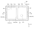
図6は、図1に示す緩衝材120を構成する上部緩衝材140の平面図である。図7は、図1に示す内視鏡ケース100の外箱110に緩衝材120を収容した状態の斜視図であり、図5に示す外箱110の内部の下部緩衝材130の上に、図6に示す上部緩衝材140を収容した状態の斜視図である。   6 is a plan view of the upper cushioning material 140 constituting the cushioning material 120 shown in FIG. FIG. 7 is a perspective view of a state in which the cushioning material 120 is accommodated in the outer box 110 of the endoscope case 100 shown in FIG. 1, and the figure is placed on the lower cushioning material 130 inside the outer box 110 shown in FIG. 6 is a perspective view of a state in which an upper cushioning material 140 shown in FIG.

前述のように、本実施形態の内視鏡ケース100は、外箱110に収容された緩衝材120が下部緩衝材130と上部緩衝材140とによって構成され、外箱110の底壁111に隣接して配置された下部緩衝材130が上面130aに内視鏡200を保持する保持部131を有し、上部緩衝材140が下部緩衝材130の保持部131を含む上面130aの全体を覆うことを特徴としている。より具体的には、上部緩衝材140は、たとえば、下部緩衝材130の平面形状に対応する矩形の平面形状を有している。また、上部緩衝材140は、縦方向および横方向の寸法よりも高さ方向の寸法が小さい矩形の平板状の形状を有している。   As described above, in the endoscope case 100 of the present embodiment, the cushioning material 120 accommodated in the outer box 110 is configured by the lower cushioning material 130 and the upper cushioning material 140, and is adjacent to the bottom wall 111 of the outer box 110. The lower cushioning material 130 arranged in this manner has a holding portion 131 for holding the endoscope 200 on the upper surface 130a, and the upper cushioning material 140 covers the entire upper surface 130a including the holding portion 131 of the lower cushioning material 130. It is a feature. More specifically, the upper cushioning material 140 has, for example, a rectangular planar shape corresponding to the planar shape of the lower cushioning material 130. Further, the upper cushioning material 140 has a rectangular flat plate shape whose dimension in the height direction is smaller than the dimension in the vertical direction and the horizontal direction.

また、外箱110の内部で下部緩衝材130の上に上部緩衝材140を配置し、これらを外箱110の開口部110aの真上から見たときに、上部緩衝材140の外縁と下部緩衝材130の外縁とが少なくとも一部で上下に重なる。また、上部緩衝材140の外縁と下部緩衝材130の外縁とが上下に重ならない部分では、上部緩衝材140の外縁の内側に下部緩衝材130の外縁が配置される。また、上部緩衝材140は、上部緩衝材140の上端面から下端面まで連通する貫通孔や切り欠きを有しない。   Further, when the upper cushioning material 140 is disposed on the lower cushioning material 130 inside the outer box 110 and viewed from right above the opening 110a of the outer box 110, the outer edge of the upper cushioning material 140 and the lower cushioning material are disposed. At least part of the outer edge of the material 130 overlaps vertically. Further, in the portion where the outer edge of the upper cushioning material 140 and the outer edge of the lower cushioning material 130 do not overlap vertically, the outer edge of the lower cushioning material 130 is disposed inside the outer edge of the upper cushioning material 140. Further, the upper cushioning material 140 does not have a through hole or a notch communicating from the upper end surface to the lower end surface of the upper cushioning material 140.

すなわち、下部緩衝材130と上部緩衝材140を上下に重ねて配置した状態で、以下のいずれかの状態になる。まず、下部緩衝材130の平面形状の輪郭の全体が、上部緩衝材140の平面形状の輪郭に一致する状態である。また、下部緩衝材130の平面形状の輪郭の一部が上部緩衝材140の平面形状の輪郭に一致し、その他の部分が上部緩衝材140の平面形状の輪郭の内側に含まれる状態である。そして、下部緩衝材130の平面形状の輪郭の全体が上部緩衝材140の平面形状の輪郭の内側に含まれる状態である。さらに、上部緩衝材140の下面140bは、下部緩衝材130の保持部131の全体と、この保持部131を除く下部緩衝材130の上面130aの全体に対向して配置される。   That is, in the state where the lower cushioning material 130 and the upper cushioning material 140 are arranged one above the other, one of the following states occurs. First, the entire planar contour of the lower cushioning material 130 matches the planar contour of the upper cushioning material 140. In addition, a part of the planar outline of the lower cushioning material 130 matches the planar outline of the upper cushioning material 140, and the other part is included inside the planar contour of the upper cushioning material 140. Then, the entire planar contour of the lower cushioning material 130 is included inside the planar contour of the upper cushioning material 140. Furthermore, the lower surface 140 b of the upper cushioning material 140 is disposed so as to face the entire holding portion 131 of the lower cushioning material 130 and the entire upper surface 130 a of the lower cushioning material 130 excluding the holding portion 131.

また、図6に示すように、上部緩衝材140は、たとえば、下部緩衝材130に対向する下面140bの保持部131に対応する位置に凹部141a,141b,141cを有している。より具体的には、上部緩衝材140の左後方の円形の凹部141aと矩形の凹部141bは、たとえば、図3に示す下部緩衝材130の操作部保持部135に対向している。また、上部緩衝材140の右前方の円形の凹部141cは、たとえば、下部緩衝材130のコネクタ部保持部137に対向している。   As shown in FIG. 6, the upper cushioning material 140 has, for example, concave portions 141 a, 141 b, and 141 c at positions corresponding to the holding portions 131 of the lower surface 140 b facing the lower cushioning material 130. More specifically, the left-side rear circular concave portion 141a and the rectangular concave portion 141b of the upper cushioning material 140 are opposed to, for example, the operation portion holding portion 135 of the lower cushioning material 130 shown in FIG. Moreover, the circular recessed part 141c on the right front side of the upper shock absorbing material 140 is opposed to the connector part holding part 137 of the lower shock absorbing material 130, for example.

さらに、上部緩衝材140は、たとえば、操作部保持部135に対向する部分の厚さがコネクタ部保持部137に対向する部分の厚さよりも厚くされ、操作部保持部135に対向する円形の凹部141aの深さは、コネクタ部保持部137に対向する円形の凹部141cの深さよりも深くされている。ここで、上部緩衝材140の厚さ、および凹部141a,141b,141cの深さは、いずれも高さ方向(z軸方向)における寸法である。   Further, the upper cushioning material 140 has a circular concave portion facing the operation portion holding portion 135, for example, with a thickness of a portion facing the operation portion holding portion 135 being thicker than a portion facing the connector portion holding portion 137. The depth of 141a is made deeper than the depth of the circular recess 141c that faces the connector holding portion 137. Here, the thickness of the upper cushioning material 140 and the depths of the recesses 141a, 141b, and 141c are all dimensions in the height direction (z-axis direction).

また、上部緩衝材140は、たとえば、外箱110の上蓋113に対向する上面140aの周縁部に設けられた枠状部142と、この枠状部142の内側で上面に設けられた凹部143a,143bとを有している。枠状部142は、たとえば、上部緩衝材140の前後の側縁に沿って横方向に延びる横枠部142aと、上部緩衝材140の左右の側縁に沿って縦方向に延びる縦枠部142bとを有している。また、枠状部142は、たとえば、左右両端の縦枠部142bの間で、前後の一対の横枠部142aの横方向の中央部を連結する中間縦枠部142cを有している。   The upper cushioning material 140 includes, for example, a frame-like portion 142 provided on the peripheral portion of the upper surface 140a facing the upper lid 113 of the outer box 110, and a recess 143a provided on the upper surface inside the frame-like portion 142, 143b. The frame-like portion 142 includes, for example, a horizontal frame portion 142a that extends in the horizontal direction along the front and rear side edges of the upper cushioning material 140, and a vertical frame portion 142b that extends in the vertical direction along the left and right side edges of the upper cushioning material 140. And have. Moreover, the frame-like part 142 has the intermediate | middle vertical frame part 142c which connects the center part of the horizontal direction of a pair of front and back horizontal frame parts 142a between the vertical frame parts 142b of both right and left ends, for example.

すなわち、上部緩衝材140は、外箱110の上蓋113に対向する上面140aに、中間縦枠部142cを介して左右に隣接する二つの矩形の凹部143a,143bを有している。この上部緩衝材140の上面140aの左側の凹部143aの深さは、右側の凹部143bの深さよりも浅くなっている。これにより、上部緩衝材140は、操作部保持部135に対向する部分の厚さがコネクタ部保持部137に対向する部分の厚さよりも厚くされている。なお、上部緩衝材140は、枠状部142を有しなくてもよい。また、上部緩衝材140の凹部141a,141b,141cの形状、大きさ、配置および数などは、特に限定されず、任意である。   That is, the upper cushioning material 140 has two rectangular recesses 143a and 143b adjacent to the left and right via the intermediate vertical frame portion 142c on the upper surface 140a facing the upper lid 113 of the outer box 110. The depth of the left recess 143a of the upper surface 140a of the upper cushioning material 140 is shallower than the depth of the right recess 143b. As a result, in the upper cushioning material 140, the thickness of the portion facing the operation portion holding portion 135 is made thicker than the thickness of the portion facing the connector portion holding portion 137. The upper cushioning material 140 may not have the frame-like portion 142. Further, the shape, size, arrangement, number, etc. of the recesses 141a, 141b, 141c of the upper cushioning material 140 are not particularly limited and are arbitrary.

また、上部緩衝材140は、たとえば、外箱110の上蓋113に対向する上面の両側縁に段差状に設けられた持手部144を有している。持手部144は、たとえば、上部緩衝材140の横方向の両側縁の中央部に形成することができる。なお、持手部144は、上部緩衝材140の前後の両側縁の横方向の中央部に形成してもよい。持手部144は、上部緩衝材140の側縁の中間部において、下方に陥没した段差状に形成され、底壁と内側壁を有している。   In addition, the upper cushioning material 140 has, for example, a handle portion 144 provided in a step shape on both side edges of the upper surface facing the upper lid 113 of the outer box 110. The handle portion 144 can be formed, for example, at the center of both lateral edges of the upper cushioning material 140 in the lateral direction. Note that the handle portion 144 may be formed at the center portion in the lateral direction of the front and rear side edges of the upper cushioning material 140. The handle portion 144 is formed in a stepped shape recessed downward in the middle portion of the side edge of the upper cushioning material 140, and has a bottom wall and an inner wall.

上部緩衝材140の右側の側縁に凹状に形成された持手部144の上方と右側は開放され、上部緩衝材140の左側の側縁に凹状に形成された持手部144の上方と左側は開放されている。また、上部緩衝材140は、持手部144が形成されることで、左右の側縁に沿う枠状部142の縦枠部142bの縦方向の中央部が横方向に外側から内側に切り欠かれ、持手部144と凹部143a,143bとの間に薄肉部145が形成されている。   The upper and right sides of the handle part 144 formed in a concave shape on the right side edge of the upper cushioning material 140 are opened, and the upper side and the left side of the handle part 144 formed in a concave shape on the left side edge of the upper cushioning material 140. Is open. Further, the upper cushioning member 140 is formed with the handle 144 so that the vertical center portion of the vertical frame portion 142b of the frame-like portion 142 along the left and right side edges is notched from the outside to the inside in the horizontal direction. In addition, a thin portion 145 is formed between the handle portion 144 and the recesses 143a and 143b.

また、上部緩衝材140は、たとえば、両側縁の下部に、下部緩衝材130の凸部132に係合する凹部146を有している。この凹部146は、たとえば、上部緩衝材140の下面140bと左右の側面との間の角部に、上方および横方向の内側へ段差状に凹設され、縦方向の全長にわたって延在している。この凹部146は、下方を向く上壁面と横方向の外側を向く側壁面とを有している。   Moreover, the upper shock absorbing material 140 has the recessed part 146 engaged with the convex part 132 of the lower shock absorbing material 130, for example in the lower part of a both-sides edge. For example, the recess 146 is formed in a stepped shape in the corner between the lower surface 140b of the upper cushioning material 140 and the left and right side surfaces in an upward and lateral direction, and extends over the entire length in the vertical direction. . The recess 146 has an upper wall surface facing downward and a side wall surface facing laterally outward.

また、上部緩衝材140は、たとえば、外箱110の側壁112に取り付けられた把手115に対応する位置に段差部147を有している。この段差部147は、たとえば、下部緩衝材130に対向する上部緩衝材140の下面140bと前方の側面との間の角部の中央部に、上方および後方に凹設されている。この段差部147は、下方を向く上壁面と前方を向く後壁面と左右の側壁面とを有し、下部緩衝材130の切欠部134の上に配置されている。   The upper cushioning material 140 has a stepped portion 147 at a position corresponding to the handle 115 attached to the side wall 112 of the outer box 110, for example. The stepped portion 147 is recessed upward and rearward, for example, at the central portion of the corner between the lower surface 140b of the upper cushioning material 140 facing the lower cushioning material 130 and the front side surface. The step portion 147 has an upper wall surface facing downward, a rear wall surface facing forward, and left and right side wall surfaces, and is disposed on the notch portion 134 of the lower cushioning material 130.

以下、本実施形態の内視鏡ケース100の作用について説明する。   Hereinafter, the operation of the endoscope case 100 of the present embodiment will be described.

本実施形態の内視鏡ケース100は、内視鏡200を輸送するときや、持ち運ぶとき、または保管するときなどに、内視鏡200を収納するためのケースであり、段ボール紙を素材とする外箱110と、この外箱110に収容され発泡樹脂を素材とする緩衝材120と、を備えている。このように、内視鏡ケース100を、簡素な素材である段ボールと発泡樹脂によって構成することで、たとえば硬質の樹脂素材や金属素材などを使用する場合と比較して、軽量化が可能で、再資源化が容易であり、製造コストを抑制することができる。   The endoscope case 100 of the present embodiment is a case for storing the endoscope 200 when transporting, carrying, or storing the endoscope 200, and is made of corrugated paper. An outer box 110 and a cushioning material 120 housed in the outer box 110 and made of foamed resin are provided. In this way, by configuring the endoscope case 100 with corrugated cardboard and foamed resin, which are simple materials, for example, compared to the case of using a hard resin material or a metal material, the weight can be reduced. Recycling is easy and manufacturing costs can be reduced.

また、内視鏡ケース100の外箱110は、前述のように、底壁111と、この底壁111の周囲に立設された側壁112と、この側壁112によって画定されこの側壁112の上端に開口する開口部110aと、この開口部110aを開閉可能な上蓋113と、この上蓋113の一端を側壁112に連結する連結部114と、を有している。そのため、内視鏡ケース100に内視鏡200を収納するときには、外箱110の連結部114をヒンジとして上蓋113を回動させて開口部110aを開放し、この開口部110aを介して外箱110の内部に内視鏡200を収容し、内視鏡ケース100に内視鏡200を収納することができる。   Further, as described above, the outer case 110 of the endoscope case 100 includes the bottom wall 111, the side wall 112 standing around the bottom wall 111, and the upper end of the side wall 112 defined by the side wall 112. It has an opening 110 a that opens, an upper lid 113 that can open and close the opening 110 a, and a connecting portion 114 that connects one end of the upper lid 113 to the side wall 112. Therefore, when the endoscope 200 is housed in the endoscope case 100, the upper lid 113 is rotated using the connecting portion 114 of the outer case 110 as a hinge to open the opening 110a, and the outer case is opened via the opening 110a. The endoscope 200 can be housed inside the endoscope 110, and the endoscope 200 can be housed in the endoscope case 100.

同様に、内視鏡ケース100から内視鏡200を取り出すときには、外箱110の連結部114をヒンジとして上蓋113を回動させて開口部110aを開放し、この開口部110aを介して外箱110の内部から内視鏡200を取り出し、内視鏡ケース100から内視鏡200を取り出すことができる。したがって、本実施形態の内視鏡ケース100によれば、たとえば前記特許文献1に記載された従来の内視鏡収納ケースと比較して、内視鏡200の収納および取り出しを容易にすることができる。   Similarly, when the endoscope 200 is taken out from the endoscope case 100, the upper lid 113 is rotated using the connecting portion 114 of the outer box 110 as a hinge to open the opening 110a, and the outer box is opened via the opening 110a. The endoscope 200 can be taken out from the inside of 110, and the endoscope 200 can be taken out from the endoscope case 100. Therefore, according to the endoscope case 100 of the present embodiment, the endoscope 200 can be easily stored and taken out as compared with the conventional endoscope storage case described in Patent Document 1, for example. it can.

また、本実施形態の内視鏡ケース100において、緩衝材120は、内視鏡200を保持する保持部131を有し底壁111に隣接して配置された下部緩衝材130と、この保持部131を含む下部緩衝材130の上面130aの全体を覆う上部緩衝材140と、を有している。内視鏡ケース100に内視鏡200を収容するときには、まず、図5に示すように、外箱110に下部緩衝材130を収容して底壁111に隣接させて配置する。   Further, in the endoscope case 100 of the present embodiment, the cushioning material 120 includes a lower cushioning material 130 that has a retaining portion 131 that retains the endoscope 200 and is disposed adjacent to the bottom wall 111, and the retaining portion. And an upper cushioning material 140 that covers the entire upper surface 130 a of the lower cushioning material 130 including 131. When the endoscope 200 is accommodated in the endoscope case 100, first, as shown in FIG. 5, the lower cushioning material 130 is accommodated in the outer box 110 and disposed adjacent to the bottom wall 111.

次に、図4に示すように、たとえば、内視鏡200の操作部210を、下部緩衝材130の保持部131の操作部保持部135に収容して保持する。さらに、内視鏡200の操作部210に接続されたユニバーサルチューブ230を、下部緩衝材130の保持部131のユニバーサルチューブ保持部136に収容して保持する。具体的には、図3に示すユニバーサルチューブ保持部136の第1湾曲部136aに、内視鏡200の操作部210に接続されたユニバーサルチューブ230を湾曲させながら収容する。その後、さらに、内視鏡200のユニバーサルチューブ230を、ユニバーサルチューブ保持部136の第2湾曲部136bに収容する。   Next, as illustrated in FIG. 4, for example, the operation unit 210 of the endoscope 200 is accommodated and held in the operation unit holding unit 135 of the holding unit 131 of the lower cushioning material 130. Furthermore, the universal tube 230 connected to the operation unit 210 of the endoscope 200 is accommodated and held in the universal tube holding unit 136 of the holding unit 131 of the lower cushioning material 130. Specifically, the universal tube 230 connected to the operation unit 210 of the endoscope 200 is accommodated in the first bending portion 136a of the universal tube holding portion 136 shown in FIG. Thereafter, the universal tube 230 of the endoscope 200 is further accommodated in the second bending portion 136b of the universal tube holding portion 136.

ここで、前述のように、第1湾曲部136aは、下部緩衝材130の高さ方向における深さが、操作部保持部135の縦方向延在部135bに隣接する部分で最も深くなり、操作部保持部135の横方向延在部135aに隣接する部分で最も浅くなるように、底部が傾斜している。また、第2湾曲部136bは、下部緩衝材130の左側の側面へ向けておおむね直線状に延び、操作部保持部135の縦方向延在部135bに交差している。これにより、内視鏡200のユニバーサルチューブ230を操作部保持部135の縦方向延在部135bに保持された操作部210の上に交差させて収納することができる。   Here, as described above, in the first bending portion 136a, the depth of the lower cushioning material 130 in the height direction is deepest in the portion adjacent to the longitudinally extending portion 135b of the operation portion holding portion 135, and the operation is performed. The bottom portion is inclined so as to be shallowest at a portion adjacent to the laterally extending portion 135 a of the portion holding portion 135. Further, the second bending portion 136 b extends substantially linearly toward the left side surface of the lower cushioning material 130, and intersects the longitudinal extending portion 135 b of the operation portion holding portion 135. As a result, the universal tube 230 of the endoscope 200 can be stored in an intersecting manner on the operation unit 210 held by the longitudinally extending portion 135b of the operation unit holding unit 135.

その後、さらに内視鏡200のユニバーサルチューブ230を、下部緩衝材130のユニバーサルチューブ保持部136の第2湾曲部136bに湾曲させながら収容する。ここで、第2湾曲部136bは、第1湾曲部136aよりも下部緩衝材130の前側の側面に近い位置で第1湾曲部136aの上に重なり、下部緩衝材130の前側の側面に沿っておおむね直線状に延びている。また、下部緩衝材130の高さ方向における第1湾曲部136aと第2湾曲部136bの深さは、下部緩衝材130の前方の側面に沿って直線状に延びる部分において、第1湾曲部136aよりも第2湾曲部136bの方が浅くなっている。これにより、ユニバーサルチューブ保持部136の第1湾曲部136aに保持された内視鏡200のユニバーサルチューブ230の上でかつ前方に隣接させて、第2湾曲部136bに内視鏡200のユニバーサルチューブ230を収容して保持することができる。   Thereafter, the universal tube 230 of the endoscope 200 is further accommodated while being bent by the second bending portion 136b of the universal tube holding portion 136 of the lower cushioning material 130. Here, the second bending portion 136b overlaps the first bending portion 136a at a position closer to the front side surface of the lower cushioning material 130 than the first bending portion 136a, and extends along the front side surface of the lower cushioning material 130. It extends almost linearly. In addition, the depth of the first curved portion 136a and the second curved portion 136b in the height direction of the lower cushioning material 130 is such that the first curved portion 136a is a portion that extends linearly along the front side surface of the lower cushioning material 130. The second curved portion 136b is shallower than the second curved portion 136b. Accordingly, the universal tube 230 of the endoscope 200 is placed on the second curved portion 136b so as to be adjacent to the front side of the universal tube 230 of the endoscope 200 held by the first curved portion 136a of the universal tube holding portion 136. Can be accommodated and held.

その後、さらに内視鏡200のユニバーサルチューブ230を、下部緩衝材130の右側の側面の中間部へ向けて右斜め後方へ延びる第2湾曲部136bに収容して保持し、内視鏡200のコネクタ部240を下部緩衝材130の保持部131のコネクタ部保持部137に収容して保持する。ここで、前述のようにコネクタ部保持部137の底部は、コネクタ部240のテーパ形状に対応する傾斜を有している。これにより、内視鏡200のコネクタ部240を下部緩衝材130のコネクタ部保持部137に収容して保持したときに、下部緩衝材130の高さ方向におけるコネクタ部240の上面を下部緩衝材130の上面130aにおおむね平行にして、上部緩衝材140との間に安定して保持することができる。   Thereafter, the universal tube 230 of the endoscope 200 is further accommodated and held in the second curved portion 136b extending obliquely rearward to the right toward the middle portion of the right side surface of the lower cushioning material 130, and the connector of the endoscope 200 is retained. The portion 240 is accommodated and held in the connector portion holding portion 137 of the holding portion 131 of the lower cushioning material 130. Here, as described above, the bottom portion of the connector portion holding portion 137 has an inclination corresponding to the tapered shape of the connector portion 240. Thereby, when the connector part 240 of the endoscope 200 is accommodated and held in the connector part holding part 137 of the lower cushioning material 130, the upper surface of the connector part 240 in the height direction of the lower cushioning material 130 is placed on the lower cushioning material 130. It can be stably held between the upper cushioning member 140 and substantially parallel to the upper surface 130a.

次に、内視鏡200の操作部210に接続された挿入部220を、下部緩衝材130の保持部131の挿入部保持部138に収容する。具体的には、可撓性を有する内視鏡200の挿入部220の操作部210に近い部分を湾曲させながら、図3に示す挿入部保持部138の後方湾曲部138aに収容する。さらに内視鏡200の挿入部220の中間部分を挿入部保持部138の中間湾曲部138bに収容する。   Next, the insertion part 220 connected to the operation part 210 of the endoscope 200 is accommodated in the insertion part holding part 138 of the holding part 131 of the lower cushioning material 130. Specifically, a portion close to the operation portion 210 of the insertion portion 220 of the endoscope 200 having flexibility is housed in the rear bending portion 138a of the insertion portion holding portion 138 shown in FIG. Furthermore, the intermediate part of the insertion part 220 of the endoscope 200 is accommodated in the intermediate bending part 138 b of the insertion part holding part 138.

ここで、前述のように、挿入部保持部138の中間湾曲部138bと、ユニバーサルチューブ保持部136の第2湾曲部136bとは、下部緩衝材130に対して共通の溝として形成されている。この場合、下部緩衝材130の高さ方向において、共通の溝の下方側がユニバーサルチューブ保持部136の第2湾曲部136bであり、この共通の溝の上方側が挿入部保持部138の中間湾曲部138bである。   Here, as described above, the intermediate bending portion 138 b of the insertion portion holding portion 138 and the second bending portion 136 b of the universal tube holding portion 136 are formed as a common groove with respect to the lower cushioning material 130. In this case, in the height direction of the lower cushioning material 130, the lower side of the common groove is the second curved portion 136b of the universal tube holding portion 136, and the upper side of the common groove is the intermediate curved portion 138b of the insertion portion holding portion 138. It is.

そのため、ユニバーサルチューブ保持部136の第2湾曲部136bに保持された内視鏡200のユニバーサルチューブ230の上に、内視鏡200の挿入部220の中間部分を重ねて収容して保持することができる。また、内視鏡200の操作部210の上方に交差させて収容したユニバーサルチューブ230の上に、内視鏡200の挿入部220の中間部分を重ねて、内視鏡200の操作部210の上方に交差させて収容および保持することができる。   Therefore, the intermediate portion of the insertion portion 220 of the endoscope 200 can be accommodated and held on the universal tube 230 of the endoscope 200 held by the second bending portion 136b of the universal tube holding portion 136. it can. In addition, an intermediate portion of the insertion portion 220 of the endoscope 200 is overlaid on the universal tube 230 that is stored so as to intersect with the upper portion of the operation portion 210 of the endoscope 200, and above the operation portion 210 of the endoscope 200. Can be housed and held in a cross.

その後、さらに内視鏡200の挿入部220の先端部を、図3に示す下部緩衝材130の保持部131の前方直線部138cに収容する。ここで、前方直線部138cは、前述のように操作部保持部135の横方向延在部135aに沿って、下部緩衝材130の右側面へ向けて右斜め後方へ直線状に延び、後方湾曲部138aに交差している。また、下部緩衝材130の高さ方向において、前方直線部138cの深さは、後方湾曲部138aに交差する下部緩衝材130の右側面の近傍の先端部において、後方湾曲部138aの深さよりも浅くなっている。さらに、前方直線部138cは、中間湾曲部138bとの接続部分から先端部へ向けて、下部緩衝材130の高さ方向における深さが次第に浅くなるように、底部が傾斜させることができる。   Thereafter, the distal end portion of the insertion portion 220 of the endoscope 200 is further accommodated in the front straight portion 138c of the holding portion 131 of the lower cushioning material 130 shown in FIG. Here, as described above, the front straight portion 138c linearly extends rearward and diagonally rightward toward the right side surface of the lower cushioning material 130 along the laterally extending portion 135a of the operation portion holding portion 135. Crosses the portion 138a. Further, in the height direction of the lower cushioning material 130, the depth of the front straight portion 138c is greater than the depth of the rear curved portion 138a at the front end portion in the vicinity of the right side surface of the lower cushioning material 130 that intersects the rear curved portion 138a. It is shallow. Furthermore, the front straight portion 138c can be inclined at the bottom so that the depth in the height direction of the lower cushioning material 130 gradually decreases from the connecting portion with the intermediate curved portion 138b toward the tip.

これにより、内視鏡200の挿入部220の先端部を操作部210に近い基端側の部分に交差させて収納することができるだけでなく、内視鏡200の挿入部220の先端部を下部緩衝材130の上面130aの近傍に配置して、取り出しを容易にすることができる。また、内視鏡200の先端部を直線状に収容して保持することができる。以上の手順により、下部緩衝材130の保持部131に、内視鏡200を収容して保持することができる。なお、以上の手順と逆の手順により、下部緩衝材130の保持部131に収容されて保持された内視鏡200を取り出すことができる。   Accordingly, the distal end portion of the insertion portion 220 of the endoscope 200 can be stored by crossing the proximal end portion close to the operation portion 210, and the distal end portion of the insertion portion 220 of the endoscope 200 can be stored in the lower portion. It can arrange | position in the vicinity of the upper surface 130a of the buffer material 130, and can take out easily. Further, the distal end portion of the endoscope 200 can be accommodated and held linearly. With the above procedure, the endoscope 200 can be accommodated and held in the holding portion 131 of the lower cushioning material 130. Note that the endoscope 200 accommodated and held in the holding portion 131 of the lower cushioning material 130 can be taken out by a procedure reverse to the above procedure.

次に、図7に示すように、外箱110の開口部110aから外箱110の内部に上部緩衝材140を収容して下部緩衝材130の上に配置する。ここで、上部緩衝材140は、保持部131を含む下部緩衝材130の上面130aの全体を覆うように設けられている。換言すると、上部緩衝材140は、下部緩衝材130の上面130aまたは保持部131の一部を露出させるような、上部緩衝材140の下端から上端まで連続する切欠きや貫通孔を有しない。これにより、下部緩衝材130と上部緩衝材140との間にちりやほこりが侵入するのを防止することができる。   Next, as shown in FIG. 7, the upper cushioning material 140 is accommodated in the outer box 110 from the opening 110 a of the outer box 110 and placed on the lower cushioning material 130. Here, the upper cushioning material 140 is provided so as to cover the entire upper surface 130 a of the lower cushioning material 130 including the holding portion 131. In other words, the upper cushioning material 140 does not have a notch or a through hole that is continuous from the lower end to the upper end of the upper cushioning material 140 so as to expose the upper surface 130a of the lower cushioning material 130 or a part of the holding portion 131. Thereby, it is possible to prevent dust and dust from entering between the lower cushioning material 130 and the upper cushioning material 140.

たとえば、上部緩衝材140が、下部緩衝材130の上面130aまたは保持部131の一部を覆わない場合には、下部緩衝材130の上面130aにちりやほこりが集まったり、凹状の収容部131にちりやほこりが侵入したりするおそれがある。この場合、たとえば、上部緩衝材140を取り出すときに、下部緩衝材130の上面130aに集まったちりやほこりが、凹状の収容部131に落下し、内視鏡200に付着するおそれがある。しかし、上部緩衝材140によって保持部131を含む下部緩衝材130の上面130aの全体を覆うことで、このような問題を解消することができる。   For example, when the upper cushioning material 140 does not cover the upper surface 130 a of the lower cushioning material 130 or a part of the holding portion 131, dust or dust collects on the upper surface 130 a of the lower cushioning material 130 or the concave accommodating portion 131. There is a risk of dust and dust entering. In this case, for example, when the upper cushioning material 140 is taken out, dust or dust collected on the upper surface 130a of the lower cushioning material 130 may fall into the concave accommodating portion 131 and adhere to the endoscope 200. However, by covering the entire upper surface 130a of the lower cushioning material 130 including the holding portion 131 with the upper cushioning material 140, such a problem can be solved.

したがって、本実施形態の内視鏡ケース100によれば、下部緩衝材130に設けられた保持部131に保持され、上部緩衝材140に覆われた内視鏡200にちりやほこりが付着するのを、効果的に防止することができる。   Therefore, according to the endoscope case 100 of the present embodiment, dust and dust adhere to the endoscope 200 that is held by the holding portion 131 provided in the lower cushioning material 130 and covered by the upper cushioning material 140. Can be effectively prevented.

さらに、本実施形態の内視鏡ケース100において、上部緩衝材140は、下部緩衝材130に対向する下面140bの保持部131に対応する位置に凹部141a,141b,141cを有している。この上部緩衝材140の下面140bの凹部141a,141b,141cに、内視鏡200の上部緩衝材140に向けて突出する部分を収容することで、内視鏡200の突出した部分と上部緩衝材140との干渉を回避することができる。   Furthermore, in the endoscope case 100 of the present embodiment, the upper cushioning material 140 has recesses 141a, 141b, and 141c at positions corresponding to the holding portions 131 of the lower surface 140b facing the lower cushioning material 130. The protruding portion of the endoscope 200 and the upper cushioning material are accommodated in the recesses 141a, 141b, and 141c of the lower surface 140b of the upper cushioning material 140 by accommodating the portions that project toward the upper cushioning material 140 of the endoscope 200. Interference with 140 can be avoided.

これにより、上部緩衝材140と内視鏡との接触による発塵を防止することができる。また、下部緩衝材130の保持部131に収容した内視鏡200の一部を、上部緩衝材140側に突出させることができるので、下部緩衝材130の保持部131の深さを必要以上に深くする必要がなくなる。これにより、下部緩衝材130を薄型化することができる。また、内視鏡200を下部緩衝材130の保持部131から取り出しやすくすることができる。   Thereby, the dust generation by contact with the upper shock absorbing material 140 and an endoscope can be prevented. In addition, since a part of the endoscope 200 accommodated in the holding portion 131 of the lower cushioning material 130 can be protruded toward the upper cushioning material 140, the depth of the holding portion 131 of the lower cushioning material 130 is made more than necessary. There is no need to deepen. Thereby, the lower buffer material 130 can be thinned. In addition, the endoscope 200 can be easily taken out from the holding portion 131 of the lower cushioning material 130.

より具体的には、本実施形態の内視鏡ケース100において、下部緩衝材130の保持部131は、内視鏡200の操作部210を保持する操作部保持部135を有している。また、上部緩衝材140の凹部141a,141bは、操作部保持部135に対向していている。これにより、内視鏡200の操作部210の上下湾曲操作レバー211や左右湾曲操作レバー212など、操作部210の突出した部分と上部緩衝材140との干渉を回避することができる。   More specifically, in the endoscope case 100 of the present embodiment, the holding unit 131 of the lower cushioning material 130 has an operation unit holding unit 135 that holds the operation unit 210 of the endoscope 200. Further, the concave portions 141 a and 141 b of the upper cushioning material 140 are opposed to the operation unit holding unit 135. Accordingly, it is possible to avoid interference between the protruding portion of the operation unit 210 and the upper cushioning material 140 such as the up / down bending operation lever 211 and the left / right bending operation lever 212 of the operation unit 210 of the endoscope 200.

また、本実施形態の内視鏡ケース100において、下部緩衝材130の保持部131は、内視鏡200のコネクタ部240を保持するコネクタ部保持部137を有している。そして、上部緩衝材140の凹部141cは、コネクタ部保持部137に対向している。これにより、内視鏡200のコネクタ部240の送気送水用口金243など、コネクタ部240の突出した部分と上部緩衝材140との干渉を回避することができる。   In the endoscope case 100 of the present embodiment, the holding part 131 of the lower cushioning material 130 has a connector part holding part 137 that holds the connector part 240 of the endoscope 200. The concave portion 141c of the upper cushioning material 140 faces the connector portion holding portion 137. Thereby, interference with the protruding part of the connector part 240, such as the air / water supply base 243 of the connector part 240 of the endoscope 200, and the upper cushioning material 140 can be avoided.

さらに、本実施形態の内視鏡ケース100において、上部緩衝材140は、操作部保持部135に対向する部分の厚さがコネクタ部保持部137に対向する部分の厚さよりも厚くされ、操作部保持部135に対向する凹部141aの深さがコネクタ部保持部137に対向する凹部141cの深さよりも深くされている。これにより、内視鏡200において最も突出した部分になりやすい操作部210の上下湾曲操作レバー211や左右湾曲操作レバー212などを、上部緩衝材140の厚さが厚くされた部分の深い凹部141aに収容して、操作部210の突出した部分と上部緩衝材140との干渉を回避することができる。   Furthermore, in the endoscope case 100 of the present embodiment, the upper cushioning material 140 is configured such that the thickness of the portion facing the operation portion holding portion 135 is larger than the thickness of the portion facing the connector portion holding portion 137. The depth of the concave portion 141 a facing the holding portion 135 is made deeper than the depth of the concave portion 141 c facing the connector portion holding portion 137. Accordingly, the up / down bending operation lever 211 and the left / right bending operation lever 212 of the operation unit 210 that is likely to be the most protruding portion in the endoscope 200 are formed in the deep concave portion 141a of the portion where the thickness of the upper cushioning material 140 is increased. It is possible to avoid the interference between the protruding portion of the operation unit 210 and the upper cushioning material 140 by accommodating.

したがって、上部緩衝材140に内視鏡200との干渉を回避するための開口を形成する必要がなくなり、上部緩衝材140によって下部緩衝材130の保持部131を含む上面130aの全体を覆うことが可能になる。さらに、内視鏡200において操作部210よりも突出高さが低くなりやすいコネクタ部240の一部を、上部緩衝材140の厚さが薄くされた部分の浅い凹部141cに収容して、コネクタ部240の突出した部分と上部緩衝材140との干渉を回避することができる。したがって、上部緩衝材140が必要以上に厚くなるのを回避することができる。   Therefore, it is not necessary to form an opening for avoiding interference with the endoscope 200 in the upper cushioning material 140, and the upper cushioning material 140 covers the entire upper surface 130a including the holding portion 131 of the lower cushioning material 130. It becomes possible. Furthermore, in the endoscope 200, a part of the connector part 240 whose protrusion height is likely to be lower than that of the operation part 210 is accommodated in the shallow concave part 141c of the part where the thickness of the upper cushioning material 140 is reduced, and the connector part Interference between the protruding portion 240 and the upper cushioning material 140 can be avoided. Therefore, it is possible to avoid the upper cushioning material 140 from becoming thicker than necessary.

さらに、本実施形態の内視鏡ケース100において、上部緩衝材140は、外箱110の上蓋113に対向する上面140aの周縁部に設けられた枠状部142と、この枠状部142の内側で上部緩衝材140の上面140aに設けられた凹部143a,143bとを有している。これにより、外箱110の上蓋113によって外箱110の開口部110aを閉じた状態で、上部緩衝材140の枠状部142を外箱110の上蓋113に接触させて上部緩衝材140の浮きを防止し、上部緩衝材140によって下部緩衝材130の上面130a全体を覆った状態を維持することができる。また、上部緩衝材140の上面140aに凹部143a,143bを設けることで、上部緩衝材140が必要以上に厚くなるのを防止することができるだけでなく、たとえば、説明書や部品などを収納するスペースを確保することができる。   Furthermore, in the endoscope case 100 of the present embodiment, the upper cushioning material 140 includes a frame-like portion 142 provided on the peripheral edge portion of the upper surface 140a facing the upper lid 113 of the outer box 110, and an inner side of the frame-like portion 142. And recesses 143a and 143b provided on the upper surface 140a of the upper cushioning material 140. As a result, in a state where the opening 110 a of the outer box 110 is closed by the upper lid 113 of the outer box 110, the frame-like portion 142 of the upper cushioning material 140 is brought into contact with the upper lid 113 of the outer box 110 to lift the upper cushioning material 140. Therefore, it is possible to maintain a state in which the entire upper surface 130a of the lower cushioning material 130 is covered by the upper cushioning material 140. Further, by providing the recesses 143a and 143b on the upper surface 140a of the upper cushioning material 140, it is possible not only to prevent the upper cushioning material 140 from becoming thicker than necessary, but also, for example, a space for storing instructions, parts, etc. Can be secured.

さらに、本実施形態の内視鏡ケース100において、上部緩衝材140は、外箱110の上蓋113に対向する上面の両側縁に段差状に設けられた持手部144を有している。このように、上部緩衝材140に持手部144を設けることで、外箱110の開口部110aの内側にわずかな隙間でぴったりとはめ込まれた上部緩衝材140を外箱110から取り出しやすくすることができる。また、上部緩衝材140を外箱110の開口部110aの内側にわずかな隙間でぴったりと収容しやすくすることができる。さらに、上部緩衝材140の下面140bから上面140aまで連続する切欠状の持手部を形成する場合と異なり、下部緩衝材130の上面130aを露出させることがないため、上部緩衝材140によって下部緩衝材130の上面130aの全体を覆うことが可能になる。   Further, in the endoscope case 100 of the present embodiment, the upper cushioning material 140 has a handle portion 144 provided in a step shape on both side edges of the upper surface facing the upper lid 113 of the outer box 110. As described above, by providing the handle portion 144 on the upper cushioning material 140, it is possible to easily take out the upper cushioning material 140 fitted into the opening 110 a of the outer box 110 with a slight gap from the outer box 110. Can do. In addition, the upper cushioning material 140 can be easily accommodated inside the opening 110a of the outer box 110 with a slight gap. Further, unlike the case of forming a notch-shaped handle portion continuous from the lower surface 140b of the upper cushioning material 140 to the upper surface 140a, the upper cushioning material 140 does not expose the upper surface 130a of the lower cushioning material 130. The entire upper surface 130a of the material 130 can be covered.

さらに、本実施形態の内視鏡ケース100において、外箱110は、側壁112に把手115が取り付けられている。下部緩衝材130は、把手115に対応する位置に切欠部134を有している。上部緩衝材140は、把手115に対応する位置に段差部147を有している。上部緩衝材140の段差部147は、下部緩衝材130の切欠部134の上に配置されている。これにより、内視鏡ケース100の持ち運び時に把手115をつかんで持ち運ぶことができ、内視鏡ケース100の持ち運びを容易にすることができる。また、下部緩衝材130の切欠部134と上部緩衝材140の段差部147によって把手115と緩衝材120の干渉を回避し、発塵を防止することができる。また、上部緩衝材140の下面140bから上面140aまで連続する切欠部を形成する場合と異なり、下部緩衝材130の切欠部134の上部の開口を露出させることがないため、ちりやほこりの侵入を回避することができる。   Further, in the endoscope case 100 of the present embodiment, the outer box 110 has a handle 115 attached to the side wall 112. The lower cushioning material 130 has a notch 134 at a position corresponding to the handle 115. The upper cushioning material 140 has a stepped portion 147 at a position corresponding to the handle 115. The step portion 147 of the upper cushioning material 140 is disposed on the cutout portion 134 of the lower cushioning material 130. Thereby, the handle 115 can be held and carried when carrying the endoscope case 100, and the carrying of the endoscope case 100 can be facilitated. Further, the notch 134 of the lower cushioning material 130 and the stepped portion 147 of the upper cushioning material 140 can avoid interference between the handle 115 and the cushioning material 120 and prevent dust generation. In addition, unlike the case of forming a continuous notch from the lower surface 140b to the upper surface 140a of the upper cushioning material 140, the upper opening of the notch 134 of the lower cushioning material 130 is not exposed, so that dust and dust can enter. It can be avoided.

図7に示すように、外箱110の開口部110aから外箱110の内部に上部緩衝材140を収容して下部緩衝材130の上に配置した後は、上蓋113を閉じて外箱110の開口部110aを閉塞する。このとき、外箱110の上蓋113の横方向両側の第2蓋挿入部113bを、外箱110の側壁112と上部緩衝材140との間に差し込んで、側壁112と上部緩衝材140および下部緩衝材130との間に配置する。これにより、外箱110の側壁112と緩衝材120との間の隙間を少なくして、緩衝材120と外箱110との相対的な移動を防止することができる。また、外箱110の左右の側壁112の上部で開口部110aの内側に下方に延びる折返し部112aが形成されているので、外箱110の上蓋113の第2蓋挿入部113bを折返し部112aによってガイドして、外箱110の側壁112と上部緩衝材140との間に円滑に差し込むことが可能になる。   As shown in FIG. 7, after the upper cushioning material 140 is accommodated in the outer box 110 through the opening 110 a of the outer box 110 and disposed on the lower cushioning material 130, the upper lid 113 is closed to close the outer box 110. The opening 110a is closed. At this time, the second lid insertion portions 113b on both sides in the lateral direction of the upper lid 113 of the outer box 110 are inserted between the side wall 112 and the upper cushioning material 140 of the outer box 110, and the side wall 112, the upper cushioning material 140 and the lower cushioning material are inserted. It arrange | positions between the materials 130. FIG. Thereby, the clearance gap between the side wall 112 of the outer box 110 and the buffer material 120 can be decreased, and the relative movement of the buffer material 120 and the outer box 110 can be prevented. In addition, since a folded portion 112a extending downward inside the opening 110a is formed on the left and right side walls 112 of the outer box 110, the second lid insertion portion 113b of the upper lid 113 of the outer box 110 is formed by the folded portion 112a. It is possible to guide and smoothly insert between the side wall 112 of the outer box 110 and the upper cushioning material 140.

その後、上蓋113の前端部の横方向の両側の第1蓋挿入部113aを、外箱110の前方側において、縦方向に延びる一対の側壁112の外側部分と内側部分との間の間隙に差し込む。そして、外箱110の正面の側壁112の外側部分を構成する上蓋113の前端部の中央部の貫通孔116に把手115を通し、上蓋113の前端部を外箱110の正面で横方向に延びる側壁112の内側部分に重ねる。これにより、互いに対向する正面の側壁112の内側部分の外面の係合部117aと、正面の側壁112の外側部分の内面の係合部117bとが、互いに係合する。以上により、内視鏡ケース100に内視鏡200を収納することができ、逆の手順により、内視鏡ケース100に収納された内視鏡200を取り出すことができる。   Thereafter, the first lid insertion portions 113a on both lateral sides of the front end portion of the upper lid 113 are inserted into the gap between the outer portion and the inner portion of the pair of side walls 112 extending in the vertical direction on the front side of the outer box 110. . A handle 115 is passed through a through hole 116 at the center of the front end of the upper lid 113 constituting the outer portion of the front side wall 112 of the outer box 110, and the front end of the upper lid 113 extends laterally in front of the outer box 110. It overlaps with the inner part of the side wall 112. Thereby, the engaging portion 117a on the outer surface of the inner side portion of the front side wall 112 and the engaging portion 117b on the inner surface of the outer side portion of the front side wall 112 are engaged with each other. As described above, the endoscope 200 can be stored in the endoscope case 100, and the endoscope 200 stored in the endoscope case 100 can be taken out by the reverse procedure.

このように、本実施形態の内視鏡ケース100によれば、段ボールよりも緩衝性に優れた発泡樹脂製の下部緩衝材130と上部緩衝材140との間に内視鏡200を収納し、さらにその外側を耐久性に優れた段ボール製の外箱110で覆うことができる。したがって、本実施形態の内視鏡ケース100は、前記特許文献2に記載された従来の内視鏡用収納ケースよりも、内視鏡200の保護に必要な緩衝性に優れ、搬送時の振動や衝撃をより効果的に緩和して、内視鏡200に不具合が発生するのを防止することができる。   Thus, according to the endoscope case 100 of the present embodiment, the endoscope 200 is housed between the lower cushioning material 130 and the upper cushioning material 140 made of foamed resin, which have better cushioning properties than cardboard, Further, the outside can be covered with a cardboard outer box 110 having excellent durability. Therefore, the endoscope case 100 according to the present embodiment is superior to the conventional endoscope storage case described in Patent Document 2 in terms of cushioning necessary for protecting the endoscope 200, and vibration during transportation. It is possible to more effectively alleviate the impact and prevent the endoscope 200 from malfunctioning.

また、本実施形態の内視鏡ケース100において、外箱110の素材である段ボール紙の外装面および内装面の色は、たとえば白色系など、外箱110の内部に収容された緩衝材120の色よりも明度の高い色である。また、緩衝材120の色は、たとえば黒色系など、外箱110の色よりも明度の低い色である。このように、緩衝材120の色を外箱110の色よりも明度の低い色にすることで、外箱110から発生したちりやほこりが付着したときに視認しやすくして、ちりやほこりを除去しやすくすることができる。   Further, in the endoscope case 100 of the present embodiment, the color of the exterior surface and interior surface of the corrugated cardboard that is the material of the outer box 110 is the color of the cushioning material 120 accommodated in the outer box 110 such as a white system, for example. The color is lighter than the color. Moreover, the color of the buffer material 120 is a color whose brightness is lower than the color of the outer box 110 such as a black color. Thus, by making the color of the cushioning material 120 lighter than the color of the outer box 110, it becomes easier to visually recognize dust and dirt generated from the outer box 110, and dust and dust are removed. It can be easily removed.

また、本実施形態の内視鏡ケース100において、下部緩衝材130は、前述のように空洞部133を有している。たとえば、ユニバーサルチューブ保持部136の第1湾曲部136aの内側に形成された第1空洞部133a、コネクタ部保持部137の前後に隣接する第2空洞部133bおよび第3空洞部133cは、比較的に大きいスペースを確保することができる。そのため、これらの空洞部133に、内視鏡200の部品などを収納することができる。また、下部緩衝材130の前端の左右の角部に第4空洞部133dおよび第5空洞部133eを有することで、これらの空洞部133によって内視鏡ケース100に加わった衝撃を緩和して内視鏡200を効果的に保護することができる。   In the endoscope case 100 of the present embodiment, the lower cushioning material 130 has the cavity 133 as described above. For example, the first cavity part 133a formed inside the first curved part 136a of the universal tube holding part 136, the second cavity part 133b and the third cavity part 133c adjacent to the front and rear of the connector part holding part 137 are relatively A large space can be secured. Therefore, the parts of the endoscope 200 and the like can be stored in these hollow portions 133. In addition, by having the fourth cavity portion 133d and the fifth cavity portion 133e at the left and right corners of the front end of the lower cushioning material 130, the impact applied to the endoscope case 100 by these cavity portions 133 can be mitigated. The endoscope 200 can be effectively protected.

また、本実施形態の内視鏡ケース100において、外箱110は、たとえば、互いに対向する正面の側壁112の内側部分の外面と、正面の側壁112の外側部分の内面に、互いに係合する係合部117a,117bを有している。これにより、たとえば、把手115をつかんで内視鏡ケース100を持ち運ぶときに、正面の側壁112の外側部分が正面の側壁112の内側部分から浮き上がることが防止され、内視鏡ケース100を安定して持ち運ぶことができ、外箱110の上蓋113が不意に開くのを防止することができる。   Further, in the endoscope case 100 of the present embodiment, the outer case 110 is engaged with, for example, the outer surface of the inner side portion of the front side wall 112 facing each other and the inner surface of the outer side portion of the front side wall 112. It has the joint part 117a, 117b. Accordingly, for example, when the endoscope case 100 is carried by holding the handle 115, the outer portion of the front side wall 112 is prevented from being lifted from the inner portion of the front side wall 112, and the endoscope case 100 is stabilized. And the upper lid 113 of the outer box 110 can be prevented from opening unexpectedly.

以上説明したように、本実施形態の内視鏡ケース100によれば、下部緩衝材130の保持部131に内視鏡200を配置して保持し、この保持部131を含む下部緩衝材130の上面130aの全体を上部緩衝材140によって覆うことで、下部緩衝材130と上部緩衝材140との間にちりやほこりが侵入するのを防止することができる。したがって、本発明の内視鏡ケース100によれば、下部緩衝材130に設けられた保持部131に保持され、上部緩衝材140に覆われた内視鏡200にちりやほこりが付着するのを防止することができる。   As described above, according to the endoscope case 100 of the present embodiment, the endoscope 200 is disposed and held in the holding portion 131 of the lower cushioning material 130, and the lower cushioning material 130 including the holding portion 131 is held. By covering the entire upper surface 130 a with the upper cushioning material 140, dust and dust can be prevented from entering between the lower cushioning material 130 and the upper cushioning material 140. Therefore, according to the endoscope case 100 of the present invention, dust and dust are attached to the endoscope 200 that is held by the holding portion 131 provided in the lower cushioning material 130 and covered by the upper cushioning material 140. Can be prevented.

図8は、図4に示す内視鏡200と、その内視鏡200を備えた内視鏡システムの構成の一例を示す概略構成図である。以下では、まず、本実施形態の内視鏡ケース100に収納される内視鏡200の一例について詳細に説明し、次に、その内視鏡200を備えた内視鏡システム300の構成の一例について詳細に説明する。   FIG. 8 is a schematic configuration diagram illustrating an example of a configuration of the endoscope 200 illustrated in FIG. 4 and an endoscope system including the endoscope 200. Hereinafter, first, an example of the endoscope 200 housed in the endoscope case 100 of the present embodiment will be described in detail, and then an example of the configuration of the endoscope system 300 including the endoscope 200 will be described. Will be described in detail.

(内視鏡)
前述の内視鏡ケース100に収納される医療用の内視鏡200は、たとえば、硬質樹脂からなる操作部210と、この操作部210に接続された挿入部220およびユニバーサルチューブ230と、このユニバーサルチューブ230に接続されたコネクタ部240と、を備えている。以下では、操作部210から延びる挿入部220の先端側を内視鏡200の前方側とし、操作部210から延びるユニバーサルチューブ230の末端側を内視鏡200の後方側とする内視鏡200の前後方向に基づいて、内視鏡200の各部を説明する場合がある。
(Endoscope)
The medical endoscope 200 housed in the endoscope case 100 described above includes, for example, an operation unit 210 made of hard resin, an insertion unit 220 and a universal tube 230 connected to the operation unit 210, and the universal tube 230. And a connector portion 240 connected to the tube 230. Hereinafter, the distal end side of the insertion portion 220 extending from the operation portion 210 is the front side of the endoscope 200, and the distal end side of the universal tube 230 extending from the operation portion 210 is the rear side of the endoscope 200. Each part of the endoscope 200 may be described based on the front-rear direction.

挿入部220は、たとえば、操作部210から前方へ向けて、可撓管部221と接続部222と湾曲部223と先端硬質部224とを有している。可撓管部221は、操作部210から前方に延び、可撓性を有している。接続部222は、挿入部220と湾曲部223とを接続している。接続部222は、たとえばABS樹脂、変性ポリフェニレンオキシド(PPO)樹脂、ポリスルホン(PSU)樹脂などの硬質の樹脂材料を素材とする円筒状の部材である。接続部222は、操作部210から延びる比較的に大径の可撓管部221と、挿入部220の前端部の比較的に小径の湾曲部223とを接続している。   The insertion part 220 has, for example, a flexible tube part 221, a connection part 222, a bending part 223, and a distal end hard part 224 from the operation part 210 to the front. The flexible tube portion 221 extends forward from the operation portion 210 and has flexibility. The connection part 222 connects the insertion part 220 and the bending part 223. The connecting portion 222 is a cylindrical member made of a hard resin material such as ABS resin, modified polyphenylene oxide (PPO) resin, polysulfone (PSU) resin, or the like. The connecting portion 222 connects the relatively large-diameter flexible tube portion 221 extending from the operation portion 210 and the relatively small-diameter curved portion 223 at the front end portion of the insertion portion 220.

接続部222は、たとえば湾曲部223が接続された前端面に、図示を省略する対物レンズが設けられている。この対物レンズの後方に隣接して、接続部222の内部に複数のレンズが設けられ、これら複数のレンズの後方に隣接して、接続部222の内部に撮像素子が設けられている。この接続部222の内部の撮像素子は、たとえば、挿入部220、操作部210、ユニバーサルチューブ230、およびコネクタ部240に通された画像信号用ケーブルを介して、コネクタ部240に突設された画像処理用接続スリーブ241に接続されている。   The connection part 222 is provided with an objective lens (not shown) on the front end face to which the bending part 223 is connected, for example. A plurality of lenses are provided inside the connection portion 222 adjacent to the rear of the objective lens, and an image sensor is provided inside the connection portion 222 adjacent to the rear of the plurality of lenses. The image sensor inside the connection unit 222 is, for example, an image projecting from the connector unit 240 via an image signal cable passed through the insertion unit 220, the operation unit 210, the universal tube 230, and the connector unit 240. It is connected to the processing connection sleeve 241.

また、接続部222は、たとえば前端面の対物レンズの両側に、図示を省略する照明用レンズが設けられている。この照明用レンズは、挿入部220、操作部210、ユニバーサルチューブ230、および、コネクタ部240に通されたライトガイドファイバを介して、コネクタ部240に突設された光源用接続スリーブ242に接続されている。   Moreover, the connection part 222 is provided with illumination lenses (not shown) on both sides of the objective lens on the front end surface, for example. This illumination lens is connected to a light source connection sleeve 242 projecting from the connector part 240 through a light guide fiber passed through the insertion part 220, the operation part 210, the universal tube 230, and the connector part 240. ing.

湾曲部223は、接続部222の前端面に接続されている。湾曲部223は、操作部210の上下湾曲操作レバー211と、左右湾曲操作レバー212によって上下左右に湾曲可能に構成されている。具体的には、たとえば湾曲部223の内部に設けられ、湾曲部223を上下左右に湾曲させる湾曲機構が、挿入部220および操作部210に通されたワイヤを介して上下湾曲操作レバー211と、左右湾曲操作レバー212に接続されている。   The bending portion 223 is connected to the front end surface of the connecting portion 222. The bending portion 223 is configured to be able to be bent up and down and left and right by the up and down bending operation lever 211 of the operation unit 210 and the left and right bending operation lever 212. Specifically, for example, a bending mechanism that is provided inside the bending portion 223 and that bends the bending portion 223 up, down, left, and right includes an up / down bending operation lever 211 via a wire passed through the insertion portion 220 and the operation portion 210, and The left / right bending operation lever 212 is connected.

先端硬質部224は、湾曲部223の前端に設けられている。先端硬質部224は、湾曲部223と同径のおおむね円柱形状を有する部材である。先端硬質部224の素材は、たとえばABS樹脂、変性PPO樹脂、PSU樹脂などの硬質樹脂材料である。先端硬質部224は、前端面に、図示を省略する対物レンズが設けられている。この対物レンズの後方に隣接して、先端硬質部224の内部に、複数のレンズと、これら複数のレンズの後方に隣接して、撮像素子が設けられている。先端硬質部224の内部の撮像素子は、挿入部220、操作部210、ユニバーサルチューブ230、およびコネクタ部240の内部に通された画像信号用ケーブルを介して、コネクタ部240に突設された画像処理用接続スリーブ241に接続されている。   The distal end hard portion 224 is provided at the front end of the bending portion 223. The distal end hard portion 224 is a member having a generally cylindrical shape having the same diameter as the curved portion 223. The material of the tip hard portion 224 is a hard resin material such as ABS resin, modified PPO resin, or PSU resin. The distal end hard portion 224 is provided with an objective lens (not shown) on the front end surface. Adjacent to the rear of the objective lens, a plurality of lenses and an imaging element are provided adjacent to the rear of the plurality of lenses inside the hard tip portion 224. The image pickup element inside the distal end hard portion 224 is an image projecting from the connector portion 240 via the insertion portion 220, the operation portion 210, the universal tube 230, and the image signal cable passed through the connector portion 240. It is connected to the processing connection sleeve 241.

また、先端硬質部224は、前端面の対物レンズの両側に照明用レンズが設けられている。この照明用レンズは、挿入部220、操作部210、およびユニバーサルチューブ230の内部に通されたライトガイドファイバを介して、コネクタ部240の光源用接続スリーブ242に接続されている。さらに先端硬質部224は、たとえば、前端面に、図示を省略する処置具挿通孔と副送水噴射孔と送気送水ノズルとを有している。この送気送水ノズルは、挿入部220、操作部210、ユニバーサルチューブ230、およびコネクタ部240の内部に通された送水チューブおよび送気チューブを介して、コネクタ部240に突設された送気送水用口金243に接続されている。送水チューブおよび送気チューブは、操作部210の送気送水ボタン213の操作によって、内部を流れる流体の流量を調整できるように構成されている。   The distal end hard portion 224 is provided with illumination lenses on both sides of the objective lens on the front end surface. This illumination lens is connected to the light source connection sleeve 242 of the connector part 240 via a light guide fiber passed through the insertion part 220, the operation part 210, and the universal tube 230. Furthermore, the distal end hard portion 224 has, for example, a treatment instrument insertion hole, a sub-water supply injection hole, and an air / water supply nozzle (not shown) on the front end surface. This air / water supply nozzle is provided with an air supply / water supply projecting from the connector part 240 via the insertion part 220, the operation part 210, the universal tube 230, and the water supply tube and the air supply tube passed through the connector part 240. It is connected to the base 243. The water supply tube and the air supply tube are configured so that the flow rate of the fluid flowing inside can be adjusted by the operation of the air / water supply button 213 of the operation unit 210.

(内視鏡システム)
最後に、本実施形態の内視鏡ケース100に収容される前述の内視鏡200を備えた内視鏡システム300の一例について、詳細に説明する。
(Endoscope system)
Finally, an example of an endoscope system 300 including the above-described endoscope 200 housed in the endoscope case 100 of the present embodiment will be described in detail.

内視鏡システム300は、たとえば内視鏡200、プロセッサ310、およびモニタ320を備えている。内視鏡200は、たとえばコネクタ部240がプロセッサ310の接続部に接続される。これにより、内視鏡200のコネクタ部240に突設された画像処理用接続スリーブ241および光源用接続スリーブ242が、プロセッサ310に内蔵された画像処理回路や光源等に接続される。   The endoscope system 300 includes, for example, an endoscope 200, a processor 310, and a monitor 320. In the endoscope 200, for example, a connector part 240 is connected to a connection part of the processor 310. As a result, the image processing connection sleeve 241 and the light source connection sleeve 242 projecting from the connector portion 240 of the endoscope 200 are connected to an image processing circuit, a light source, or the like built in the processor 310.

また、内視鏡200は、たとえばコネクタ部240の送気送水用口金243に、図示を省略する給気および送水を行う流体供給源に接続された送気送水パイプが接続される。モニタ320は、たとえば液晶表示装置などの画像表示装置であり、プロセッサ310に接続されている。プロセッサ310は、たとえばメインスイッチ311、照明スイッチ312、および画像切り換えスイッチ313を有している。   In the endoscope 200, for example, an air / water supply pipe connected to a fluid supply source for supplying air and water (not shown) is connected to the air / water supply base 243 of the connector 240. The monitor 320 is an image display device such as a liquid crystal display device, and is connected to the processor 310. The processor 310 includes, for example, a main switch 311, a lighting switch 312, and an image changeover switch 313.

このような構成を備えた内視鏡システム300は、たとえば以下の手順によって使用することができる。まず、メインスイッチ311を押下してオンにし、照明スイッチ312を押下してオンにし、さらに画像切り換えスイッチ313を切り替えて第1の切り替え位置にする。照明スイッチ312をオンにすると、プロセッサ310内の光源が発光する。   The endoscope system 300 having such a configuration can be used, for example, according to the following procedure. First, the main switch 311 is pressed to be turned on, the illumination switch 312 is pressed to be turned on, and the image switching switch 313 is switched to the first switching position. When the illumination switch 312 is turned on, the light source in the processor 310 emits light.

プロセッサ310内の光源から発せられた光は、プロセッサ310に接続された内視鏡200のコネクタ部240の光源用接続スリーブ242を介して、ライトガイドファイバに導入される。ライトガイドファイバに導入された光源からの光は、ユニバーサルチューブ230、操作部210、および挿入部220に通されたライトガイドファイバを介して、接続部222の前端面の照明用レンズおよび先端硬質部224の前端面の照明用レンズに到達し、前方に向けて照射される。   The light emitted from the light source in the processor 310 is introduced into the light guide fiber through the light source connection sleeve 242 of the connector part 240 of the endoscope 200 connected to the processor 310. The light from the light source introduced into the light guide fiber passes through the universal tube 230, the operation unit 210, and the light guide fiber passed through the insertion unit 220, and the illumination lens on the front end surface of the connection unit 222 and the hard tip portion It reaches the illumination lens on the front end surface of 224 and is irradiated forward.

また、メインスイッチ311をオンにすると、内視鏡200の接続部222内の撮像素子および先端硬質部224内の撮像素子が起動する。これにより、内視鏡200の接続部222の前端面および先端硬質部224の前端面の対物レンズの前方に位置する被写体の像が、接続部222および先端硬質部224の内部の対物レンズおよび複数レンズを通して撮像素子によって撮影される。この撮像素子によって撮影された被写体の像の画像データは、挿入部220、操作部210、およびユニバーサルチューブ230に通された画像信号用ケーブルを介してプロセッサ310内の画像処理回路に送られ、この画像処理回路によって画像処理が行われる。   When the main switch 311 is turned on, the image sensor in the connection part 222 of the endoscope 200 and the image sensor in the distal end hard part 224 are activated. As a result, the image of the subject located in front of the objective lens on the front end surface of the connection portion 222 and the front end surface of the distal end hard portion 224 of the endoscope 200 is converted into an objective lens and a plurality of objects inside the connection portion 222 and the distal end hard portion 224. Photographed by the image sensor through the lens. The image data of the subject image captured by the image sensor is sent to the image processing circuit in the processor 310 via the image signal cable passed through the insertion unit 220, the operation unit 210, and the universal tube 230. Image processing is performed by the image processing circuit.

プロセッサ310は、内視鏡200の接続部222内の撮像素子によって撮影された画像データに基づいて第1画像処理データを生成し、内視鏡200の先端硬質部224内の撮像素子によって撮像された画像データに基づいて第2画像処理データを生成する。プロセッサ310は、画像切り換えスイッチ313が第1の切り換え位置にあるときには、モニタ320に第1画像処理データを送り、画像切り換えスイッチ313が第2の切り換え位置にあるときには、モニタ320に第2画像処理データを送る。これにより、モニタ320に表示させる画像を、内視鏡200の接続部222の前方画像と、内視鏡200の先端硬質部224の前方の画像に切り換えることができる。   The processor 310 generates first image processing data based on image data captured by the image sensor in the connection unit 222 of the endoscope 200, and is imaged by the image sensor in the distal end hard portion 224 of the endoscope 200. Second image processing data is generated based on the obtained image data. The processor 310 sends the first image processing data to the monitor 320 when the image changeover switch 313 is at the first changeover position, and sends the second image processing to the monitor 320 when the image changeover switch 313 is at the second changeover position. Send data. Thereby, the image to be displayed on the monitor 320 can be switched between a front image of the connecting portion 222 of the endoscope 200 and an image of the front of the distal end hard portion 224 of the endoscope 200.

また、内視鏡200の操作部210の送気送水ボタン213の上面に形成した空気逃がし孔を塞ぐと、流体供給源から供給された圧縮空気が先端硬質部224の前端面に設けられた送気送水ノズルから隣接する対物レンズの表面に噴射される。さらに送気送水ボタン213の空気逃がし孔を塞ぎながら送気送水ボタン213を押下すると、流体供給源から供給された洗浄水が送水用パイプを介して送気送水ノズルに送水され、隣接する対物レンズの表面に噴射される。   Further, when the air escape hole formed on the upper surface of the air / water supply button 213 of the operation unit 210 of the endoscope 200 is closed, the compressed air supplied from the fluid supply source is supplied to the front end surface of the distal end hard portion 224. It is injected from the air supply nozzle onto the surface of the adjacent objective lens. Further, when the air / water supply button 213 is depressed while closing the air escape hole of the air / water supply button 213, the cleaning water supplied from the fluid supply source is supplied to the air / water supply nozzle via the water supply pipe, and the adjacent objective lens Sprayed on the surface.

以上、図面を用いて本発明の実施の形態を詳述してきたが、具体的な構成はこの実施形態に限定されるものではなく、本発明の要旨を逸脱しない範囲における設計変更等があっても、それらは本発明に含まれるものである。   The embodiment of the present invention has been described in detail with reference to the drawings, but the specific configuration is not limited to this embodiment, and there are design changes and the like without departing from the gist of the present invention. They are also included in the present invention.

100 内視鏡ケース
110 外箱
110a 開口部
111 底壁
112 側壁
113 上蓋
114 連結部
115 把手
120 緩衝材
130 下部緩衝材
130a 上面
131 保持部
134 切欠部
135 操作部保持部
137 コネクタ部保持部
140 上部緩衝材
140a 上面
140b 下面
141a 凹部
141b 凹部
141c 凹部
142 枠状部
143a 凹部
143b 凹部
144 持手部
147 段差部
200 内視鏡
210 操作部
240 コネクタ部
100 Endoscope case 110 Outer box 110a Opening portion 111 Bottom wall 112 Side wall 113 Top lid 114 Connecting portion 115 Handle 120 Buffer material 130 Lower cushioning material 130a Top surface 131 Holding portion 134 Notch portion 135 Operation portion holding portion 137 Connector portion holding portion 140 Upper portion Buffer material 140a Upper surface 140b Lower surface 141a Recess 141b Recess 141c Recess 142 Frame-like portion 143a Recess 143b Recess 144 Handle portion 147 Step portion 200 Endoscope 210 Operation portion 240 Connector portion

Claims (8)

内視鏡を収納するための内視鏡ケースであって、
段ボール紙を素材とする外箱と、該外箱に収容され発泡樹脂を素材とする緩衝材と、を備え、
前記外箱は、底壁と、該底壁の周囲に立設された側壁と、該側壁によって画定され該側壁の上端に開口する開口部と、該開口部を開閉可能な上蓋と、該上蓋の一端を前記側壁に連結する連結部と、を有し、
前記緩衝材は、前記底壁に隣接して配置された下部緩衝材と、前記上蓋に隣接して配置された上部緩衝材とを有し、
前記下部緩衝材は、前記内視鏡を保持する凹状の保持部を有し、
前記上部緩衝材は、前記保持部を含む前記下部緩衝材の上面の全体を覆うことを特徴とする内視鏡ケース。
An endoscope case for storing an endoscope,
An outer box made of corrugated paper, and a cushioning material made of foamed resin contained in the outer box,
The outer box includes a bottom wall, a side wall standing around the bottom wall, an opening defined by the side wall and opening at an upper end of the side wall, an upper lid capable of opening and closing the opening, and the upper lid A connecting portion for connecting one end of the to the side wall,
The cushioning material has a lower cushioning material disposed adjacent to the bottom wall and an upper cushioning material disposed adjacent to the upper lid,
The lower cushioning material has a concave holding portion for holding the endoscope,
The endoscope case, wherein the upper cushioning material covers the entire upper surface of the lower cushioning material including the holding portion.
前記上部緩衝材は、前記下部緩衝材に対向する下面の前記保持部に対応する位置に凹部を有することを特徴とする請求項1に記載の内視鏡ケース。   The endoscope case according to claim 1, wherein the upper cushioning material has a concave portion at a position corresponding to the holding portion on a lower surface facing the lower cushioning material. 前記下部緩衝材の前記保持部は、前記内視鏡の操作部を保持する操作部保持部を有し、
前記上部緩衝材の前記凹部は、前記操作部保持部に対向していることを特徴とする請求項2に記載の内視鏡ケース。
The holding part of the lower cushioning material has an operation part holding part for holding an operation part of the endoscope,
The endoscope case according to claim 2, wherein the concave portion of the upper cushioning material faces the operation portion holding portion.
前記下部緩衝材の前記保持部は、前記内視鏡のコネクタ部を保持するコネクタ部保持部を有し、
前記上部緩衝材の前記凹部は、前記コネクタ部保持部に対向していることを特徴とする請求項2に記載の内視鏡ケース。
The holding part of the lower cushioning material has a connector part holding part that holds the connector part of the endoscope,
The endoscope case according to claim 2, wherein the concave portion of the upper cushioning material is opposed to the connector portion holding portion.
前記保持部は、前記内視鏡の操作部を保持する操作部保持部と、前記内視鏡のコネクタ部を保持するコネクタ部保持部とを有し、
前記上部緩衝材は、前記操作部保持部に対向する前記凹部と、前記コネクタ部保持部に対向する前記凹部とを有し、
前記上部緩衝材は、前記操作部保持部に対向する部分の厚さが前記コネクタ部保持部に対向する部分の厚さよりも厚くされ、
前記操作部保持部に対向する前記凹部の深さは、前記コネクタ部保持部に対向する前記凹部の深さよりも深くされていることを特徴とする請求項2に記載の内視鏡ケース。
The holding unit includes an operation unit holding unit that holds an operation unit of the endoscope, and a connector unit holding unit that holds a connector unit of the endoscope,
The upper cushioning material has the recess facing the operation portion holding portion and the recess facing the connector portion holding portion,
In the upper cushioning material, the thickness of the part facing the operation part holding part is made thicker than the thickness of the part facing the connector part holding part,
The endoscope case according to claim 2, wherein a depth of the concave portion facing the operation portion holding portion is deeper than a depth of the concave portion facing the connector portion holding portion.
前記上部緩衝材は、前記外箱の前記上蓋に対向する上面の周縁部に設けられた枠状部と、該枠状部の内側で前記上面に設けられた凹部とを有することを特徴とする請求項1に記載の内視鏡ケース。   The upper cushioning material includes a frame-like portion provided at a peripheral edge portion of the upper surface of the outer box facing the upper lid, and a concave portion provided on the upper surface inside the frame-like portion. The endoscope case according to claim 1. 前記上部緩衝材は、前記外箱の前記上蓋に対向する上面の両側縁に段差状に設けられた持手部を有することを特徴とする請求項1に記載の内視鏡ケース。   The endoscope case according to claim 1, wherein the upper cushioning material has a handle portion provided in a step shape on both side edges of the upper surface of the outer box facing the upper lid. 前記外箱は、前記側壁に把手が取り付けられ、
前記下部緩衝材は、前記把手に対応する位置に切欠部を有し、
前記上部緩衝材は、前記把手に対応する位置に段差部を有し、
前記上部緩衝材の前記段差部は、前記下部緩衝材の前記切欠部の上に配置されることを特徴とする請求項1に記載の内視鏡ケース。
The outer box has a handle attached to the side wall,
The lower cushioning material has a notch at a position corresponding to the handle,
The upper cushioning material has a step portion at a position corresponding to the handle,
The endoscope case according to claim 1, wherein the stepped portion of the upper cushioning material is disposed on the cutout portion of the lower cushioning material.
JP2016256917A 2016-12-28 2016-12-28 Endoscope case Active JP6832157B2 (en)

Priority Applications (1)

Application Number Priority Date Filing Date Title
JP2016256917A JP6832157B2 (en) 2016-12-28 2016-12-28 Endoscope case

Applications Claiming Priority (1)

Application Number Priority Date Filing Date Title
JP2016256917A JP6832157B2 (en) 2016-12-28 2016-12-28 Endoscope case

Publications (2)

Publication Number Publication Date
JP2018108183A true JP2018108183A (en) 2018-07-12
JP6832157B2 JP6832157B2 (en) 2021-02-24

Family

ID=62843993

Family Applications (1)

Application Number Title Priority Date Filing Date
JP2016256917A Active JP6832157B2 (en) 2016-12-28 2016-12-28 Endoscope case

Country Status (1)

Country Link
JP (1) JP6832157B2 (en)

Citations (7)

* Cited by examiner, † Cited by third party
Publication number Priority date Publication date Assignee Title
JPH0984744A (en) * 1995-09-27 1997-03-31 Toshiba Corp Endoscope housing case
JPH09224902A (en) * 1996-02-28 1997-09-02 Olympus Optical Co Ltd Endoscope carrying case
JPH10229964A (en) * 1997-02-20 1998-09-02 Olympus Optical Co Ltd Endoscope case
JPH11192200A (en) * 1998-01-06 1999-07-21 Olympus Optical Co Ltd Housing casing for endscope
JP2001275929A (en) * 2000-03-31 2001-10-09 Fuji Photo Optical Co Ltd Housing case for endoscope
US8382657B1 (en) * 2009-10-05 2013-02-26 Integrated Medical Systems International, Inc Endoscope testing device and method of using same
JP2013209139A (en) * 2012-03-30 2013-10-10 Sekisui Plastics Co Ltd Packaging apparatus

Patent Citations (7)

* Cited by examiner, † Cited by third party
Publication number Priority date Publication date Assignee Title
JPH0984744A (en) * 1995-09-27 1997-03-31 Toshiba Corp Endoscope housing case
JPH09224902A (en) * 1996-02-28 1997-09-02 Olympus Optical Co Ltd Endoscope carrying case
JPH10229964A (en) * 1997-02-20 1998-09-02 Olympus Optical Co Ltd Endoscope case
JPH11192200A (en) * 1998-01-06 1999-07-21 Olympus Optical Co Ltd Housing casing for endscope
JP2001275929A (en) * 2000-03-31 2001-10-09 Fuji Photo Optical Co Ltd Housing case for endoscope
US8382657B1 (en) * 2009-10-05 2013-02-26 Integrated Medical Systems International, Inc Endoscope testing device and method of using same
JP2013209139A (en) * 2012-03-30 2013-10-10 Sekisui Plastics Co Ltd Packaging apparatus

Also Published As

Publication number Publication date
JP6832157B2 (en) 2021-02-24

Similar Documents

Publication Publication Date Title
JP5082953B2 (en) Paper sheet handling equipment
JP3210526U (en) Endoscope case
JP6886300B2 (en) Endoscope case
JP3209828U (en) Endoscope case
JP5401382B2 (en) Endoscope
JP6832157B2 (en) Endoscope case
JP3210881U (en) Endoscope case
WO2018179601A1 (en) Endoscope case
WO2018163542A1 (en) Endoscope case
US9475301B2 (en) Protection member for liquid supply unit
JP4496842B2 (en) Mask case
JP2018148972A (en) Endoscope case
JP6595728B2 (en) Endoscope case
JP2018117901A (en) Endoscope case
JP3211974U (en) Endoscope case
JP2008297054A (en) Tray mechanism of image forming device
JP2009072295A (en) Tissue paper for household-use storage container
JP2009069380A (en) Imaging apparatus
JP2016054370A (en) Reading device
JP2014209183A (en) Air filter and projector
JPH09224902A (en) Endoscope carrying case
KR102203642B1 (en) Smartphone case to protect the camera lens
JP2013011633A (en) Protection cap
JP2018062064A (en) Liquid supply unit
JP2014227210A (en) Case with lid

Legal Events

Date Code Title Description
A621 Written request for application examination

Free format text: JAPANESE INTERMEDIATE CODE: A621

Effective date: 20191224

A977 Report on retrieval

Free format text: JAPANESE INTERMEDIATE CODE: A971007

Effective date: 20200923

A131 Notification of reasons for refusal

Free format text: JAPANESE INTERMEDIATE CODE: A131

Effective date: 20201013

A521 Request for written amendment filed

Free format text: JAPANESE INTERMEDIATE CODE: A523

Effective date: 20201208

TRDD Decision of grant or rejection written
A01 Written decision to grant a patent or to grant a registration (utility model)

Free format text: JAPANESE INTERMEDIATE CODE: A01

Effective date: 20210105

A61 First payment of annual fees (during grant procedure)

Free format text: JAPANESE INTERMEDIATE CODE: A61

Effective date: 20210201

R150 Certificate of patent or registration of utility model

Ref document number: 6832157

Country of ref document: JP

Free format text: JAPANESE INTERMEDIATE CODE: R150

R250 Receipt of annual fees

Free format text: JAPANESE INTERMEDIATE CODE: R250