JP2018099731A - Manufacturing method for vehicle body component - Google Patents
Manufacturing method for vehicle body component Download PDFInfo
- Publication number
- JP2018099731A JP2018099731A JP2017231901A JP2017231901A JP2018099731A JP 2018099731 A JP2018099731 A JP 2018099731A JP 2017231901 A JP2017231901 A JP 2017231901A JP 2017231901 A JP2017231901 A JP 2017231901A JP 2018099731 A JP2018099731 A JP 2018099731A
- Authority
- JP
- Japan
- Prior art keywords
- blank
- rolling
- rolled
- hole
- manufacturing
- Prior art date
- Legal status (The legal status is an assumption and is not a legal conclusion. Google has not performed a legal analysis and makes no representation as to the accuracy of the status listed.)
- Granted
Links
- 238000004519 manufacturing process Methods 0.000 title claims abstract description 27
- 238000005096 rolling process Methods 0.000 claims abstract description 82
- 238000000034 method Methods 0.000 claims abstract description 37
- 238000000465 moulding Methods 0.000 claims abstract description 10
- 238000001816 cooling Methods 0.000 claims abstract description 5
- 238000010438 heat treatment Methods 0.000 claims description 13
- 239000011248 coating agent Substances 0.000 claims description 2
- 238000000576 coating method Methods 0.000 claims description 2
- 238000005520 cutting process Methods 0.000 claims description 2
- 238000009966 trimming Methods 0.000 abstract description 9
- 229910000831 Steel Inorganic materials 0.000 description 30
- 239000010959 steel Substances 0.000 description 30
- 238000009826 distribution Methods 0.000 description 9
- 238000005516 engineering process Methods 0.000 description 7
- 238000007747 plating Methods 0.000 description 6
- 238000003466 welding Methods 0.000 description 5
- 239000000463 material Substances 0.000 description 4
- 238000005097 cold rolling Methods 0.000 description 3
- 238000010586 diagram Methods 0.000 description 3
- 229910052782 aluminium Inorganic materials 0.000 description 2
- 229910001566 austenite Inorganic materials 0.000 description 2
- 238000005098 hot rolling Methods 0.000 description 2
- 229910000838 Al alloy Inorganic materials 0.000 description 1
- 229910000712 Boron steel Inorganic materials 0.000 description 1
- OKTJSMMVPCPJKN-UHFFFAOYSA-N Carbon Chemical compound [C] OKTJSMMVPCPJKN-UHFFFAOYSA-N 0.000 description 1
- 229910000975 Carbon steel Inorganic materials 0.000 description 1
- 238000010521 absorption reaction Methods 0.000 description 1
- 229910045601 alloy Inorganic materials 0.000 description 1
- 239000000956 alloy Substances 0.000 description 1
- 230000015572 biosynthetic process Effects 0.000 description 1
- 229910052796 boron Inorganic materials 0.000 description 1
- 229910052799 carbon Inorganic materials 0.000 description 1
- 238000005336 cracking Methods 0.000 description 1
- 230000007423 decrease Effects 0.000 description 1
- 230000003111 delayed effect Effects 0.000 description 1
- 238000002474 experimental method Methods 0.000 description 1
- 230000006698 induction Effects 0.000 description 1
- 229910000734 martensite Inorganic materials 0.000 description 1
- 229910052751 metal Inorganic materials 0.000 description 1
- 239000002184 metal Substances 0.000 description 1
- 230000001590 oxidative effect Effects 0.000 description 1
- TWNQGVIAIRXVLR-UHFFFAOYSA-N oxo(oxoalumanyloxy)alumane Chemical compound O=[Al]O[Al]=O TWNQGVIAIRXVLR-UHFFFAOYSA-N 0.000 description 1
- 238000003825 pressing Methods 0.000 description 1
- 238000010791 quenching Methods 0.000 description 1
- 230000000171 quenching effect Effects 0.000 description 1
- 238000003303 reheating Methods 0.000 description 1
- 239000002699 waste material Substances 0.000 description 1
- 239000013585 weight reducing agent Substances 0.000 description 1
- 229910052725 zinc Inorganic materials 0.000 description 1
Images


Classifications
-
- B—PERFORMING OPERATIONS; TRANSPORTING
- B23—MACHINE TOOLS; METAL-WORKING NOT OTHERWISE PROVIDED FOR
- B23P—METAL-WORKING NOT OTHERWISE PROVIDED FOR; COMBINED OPERATIONS; UNIVERSAL MACHINE TOOLS
- B23P15/00—Making specific metal objects by operations not covered by a single other subclass or a group in this subclass
-
- B—PERFORMING OPERATIONS; TRANSPORTING
- B21—MECHANICAL METAL-WORKING WITHOUT ESSENTIALLY REMOVING MATERIAL; PUNCHING METAL
- B21D—WORKING OR PROCESSING OF SHEET METAL OR METAL TUBES, RODS OR PROFILES WITHOUT ESSENTIALLY REMOVING MATERIAL; PUNCHING METAL
- B21D22/00—Shaping without cutting, by stamping, spinning, or deep-drawing
- B21D22/02—Stamping using rigid devices or tools
- B21D22/022—Stamping using rigid devices or tools by heating the blank or stamping associated with heat treatment
-
- B—PERFORMING OPERATIONS; TRANSPORTING
- B21—MECHANICAL METAL-WORKING WITHOUT ESSENTIALLY REMOVING MATERIAL; PUNCHING METAL
- B21D—WORKING OR PROCESSING OF SHEET METAL OR METAL TUBES, RODS OR PROFILES WITHOUT ESSENTIALLY REMOVING MATERIAL; PUNCHING METAL
- B21D35/00—Combined processes according to or processes combined with methods covered by groups B21D1/00 - B21D31/00
- B21D35/002—Processes combined with methods covered by groups B21D1/00 - B21D31/00
- B21D35/005—Processes combined with methods covered by groups B21D1/00 - B21D31/00 characterized by the material of the blank or the workpiece
- B21D35/006—Blanks having varying thickness, e.g. tailored blanks
-
- B—PERFORMING OPERATIONS; TRANSPORTING
- B21—MECHANICAL METAL-WORKING WITHOUT ESSENTIALLY REMOVING MATERIAL; PUNCHING METAL
- B21D—WORKING OR PROCESSING OF SHEET METAL OR METAL TUBES, RODS OR PROFILES WITHOUT ESSENTIALLY REMOVING MATERIAL; PUNCHING METAL
- B21D37/00—Tools as parts of machines covered by this subclass
- B21D37/16—Heating or cooling
-
- B—PERFORMING OPERATIONS; TRANSPORTING
- B21—MECHANICAL METAL-WORKING WITHOUT ESSENTIALLY REMOVING MATERIAL; PUNCHING METAL
- B21D—WORKING OR PROCESSING OF SHEET METAL OR METAL TUBES, RODS OR PROFILES WITHOUT ESSENTIALLY REMOVING MATERIAL; PUNCHING METAL
- B21D43/00—Feeding, positioning or storing devices combined with, or arranged in, or specially adapted for use in connection with, apparatus for working or processing sheet metal, metal tubes or metal profiles; Associations therewith of cutting devices
- B21D43/28—Associations of cutting devices therewith
-
- B—PERFORMING OPERATIONS; TRANSPORTING
- B21—MECHANICAL METAL-WORKING WITHOUT ESSENTIALLY REMOVING MATERIAL; PUNCHING METAL
- B21D—WORKING OR PROCESSING OF SHEET METAL OR METAL TUBES, RODS OR PROFILES WITHOUT ESSENTIALLY REMOVING MATERIAL; PUNCHING METAL
- B21D47/00—Making rigid structural elements or units, e.g. honeycomb structures
-
- B—PERFORMING OPERATIONS; TRANSPORTING
- B21—MECHANICAL METAL-WORKING WITHOUT ESSENTIALLY REMOVING MATERIAL; PUNCHING METAL
- B21D—WORKING OR PROCESSING OF SHEET METAL OR METAL TUBES, RODS OR PROFILES WITHOUT ESSENTIALLY REMOVING MATERIAL; PUNCHING METAL
- B21D53/00—Making other particular articles
- B21D53/88—Making other particular articles other parts for vehicles, e.g. cowlings, mudguards
-
- B—PERFORMING OPERATIONS; TRANSPORTING
- B23—MACHINE TOOLS; METAL-WORKING NOT OTHERWISE PROVIDED FOR
- B23K—SOLDERING OR UNSOLDERING; WELDING; CLADDING OR PLATING BY SOLDERING OR WELDING; CUTTING BY APPLYING HEAT LOCALLY, e.g. FLAME CUTTING; WORKING BY LASER BEAM
- B23K26/00—Working by laser beam, e.g. welding, cutting or boring
- B23K26/36—Removing material
- B23K26/38—Removing material by boring or cutting
-
- C—CHEMISTRY; METALLURGY
- C21—METALLURGY OF IRON
- C21D—MODIFYING THE PHYSICAL STRUCTURE OF FERROUS METALS; GENERAL DEVICES FOR HEAT TREATMENT OF FERROUS OR NON-FERROUS METALS OR ALLOYS; MAKING METAL MALLEABLE, e.g. BY DECARBURISATION OR TEMPERING
- C21D1/00—General methods or devices for heat treatment, e.g. annealing, hardening, quenching or tempering
- C21D1/18—Hardening; Quenching with or without subsequent tempering
-
- C—CHEMISTRY; METALLURGY
- C21—METALLURGY OF IRON
- C21D—MODIFYING THE PHYSICAL STRUCTURE OF FERROUS METALS; GENERAL DEVICES FOR HEAT TREATMENT OF FERROUS OR NON-FERROUS METALS OR ALLOYS; MAKING METAL MALLEABLE, e.g. BY DECARBURISATION OR TEMPERING
- C21D8/00—Modifying the physical properties by deformation combined with, or followed by, heat treatment
-
- C—CHEMISTRY; METALLURGY
- C21—METALLURGY OF IRON
- C21D—MODIFYING THE PHYSICAL STRUCTURE OF FERROUS METALS; GENERAL DEVICES FOR HEAT TREATMENT OF FERROUS OR NON-FERROUS METALS OR ALLOYS; MAKING METAL MALLEABLE, e.g. BY DECARBURISATION OR TEMPERING
- C21D2211/00—Microstructure comprising significant phases
- C21D2211/008—Martensite
-
- C—CHEMISTRY; METALLURGY
- C21—METALLURGY OF IRON
- C21D—MODIFYING THE PHYSICAL STRUCTURE OF FERROUS METALS; GENERAL DEVICES FOR HEAT TREATMENT OF FERROUS OR NON-FERROUS METALS OR ALLOYS; MAKING METAL MALLEABLE, e.g. BY DECARBURISATION OR TEMPERING
- C21D2261/00—Machining or cutting being involved
Abstract
Description
本発明は、衝突に関する車体部品、特に、ホットスタンピングを利用した高強度の車体部品を製造する方法に関する。 The present invention relates to a vehicle body part related to a collision, and more particularly to a method for manufacturing a high-strength vehicle body part using hot stamping.
自動車産業において最も大きなイシューの一つは軽量化及び高強度化であり、このようなイシューの中心にホットスタンピング技術がある。ホットスタンピング技術及び素材に関しては、特許文献1に紹介されている。
One of the biggest issues in the automobile industry is weight reduction and strength enhancement, and hot stamping technology is at the center of such issues. The hot stamping technology and materials are introduced in
ホットスタンピングは鋼板を900〜950℃の高温に加熱した後、プレス内で成形すると共に急冷することで高強度の軽量備品を製造する。ホットスタンピングの素材としては、0.2重量%前後の炭素を含有し、熱処理性能を向上するための元素としてMn、Bを使用する、いわゆるボロン鋼が使用される。 In hot stamping, a steel sheet is heated to a high temperature of 900 to 950 ° C., and then molded in a press and rapidly cooled to produce a light fixture having high strength. As a material for hot stamping, so-called boron steel containing about 0.2% by weight of carbon and using Mn and B as elements for improving heat treatment performance is used.
このようなホットスタンピングは、成形及び熱処理が同時に行われるため生産性が優秀なだけでなく、高温で鋼板が成形されるため成形性及び寸法精度に優れている。また、ホットスタンピングは高強度部品を成形する際、特に問題となるスプリングバックや遅延破壊を減少することができる長所がある。 Such hot stamping is excellent not only in productivity because forming and heat treatment are performed simultaneously, but also in formability and dimensional accuracy because a steel sheet is formed at a high temperature. Hot stamping has the advantage that it can reduce springback and delayed fracture, which are particularly problematic when molding high-strength parts.
ホットスタンピングは、工程が高温で非めっき鋼板(uncoated or plain steel sheet)を使用する場合、成形後にデスケーリング工程が伴うべきである。複雑なデスケーリング工程を省略するために提案されたのが、AlやZnめっき鋼板である。Alめっき鋼板については、特許文献2を参照してほしい。 Hot stamping should be accompanied by a descaling process after forming if the process uses uncoated or plain steel sheet at high temperature. In order to omit the complicated descaling process, Al and Zn plated steel sheets have been proposed. For the Al-plated steel sheet, see Patent Document 2.
車両部品の軽量化のために、自動車メーカー分野ではテーラードブランク(Tailor Welded Blank,TWB)溶接技術が適用されている。しかし、TWB技術はホットスタンピング用めっき鋼板、例えば、Alめっき鋼板に適用することができない。レーザ溶接の際、Alめっき層のため溶接部に相当は強度低下が発生するためである。特許文献3では、溶接部位のAlめっき層の一部を予め剥がしておいた後、レーザ溶接をする方式でこの問題を解決しようとしている。
In order to reduce the weight of vehicle parts, tailored blank (TWB) welding technology is applied in the automobile manufacturer field. However, the TWB technology cannot be applied to hot stamping plated steel sheets, for example, Al plated steel sheets. This is because, during laser welding, the strength is considerably reduced in the weld due to the Al plating layer. In
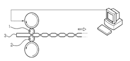
車両部品の軽量化のための他の技術として、テーラーロールドブランク(Tailor Rolled Blank,TRB)技術がある。図1に示したように、TRB技術はコイル鋼板3の圧延過程で上下ロール1、2のギャップを調整しながら鋼板の厚さを調節する方式で行われる。TRB技術によって、一方向、つまり圧延方向にのみブランクの厚さに変化を与えられるだけである。また、テーラーロールドブランクは製鋼メーカーで一律的に製造されるため、多様な車両部品の製造に提供するには限界がある。
As another technique for reducing the weight of vehicle parts, there is a tailor rolled blank (TRB) technique. As shown in FIG. 1, the TRB technique is performed by adjusting the thickness of the steel sheet while adjusting the gap between the upper and
本発明は前記のようなこの技術分野における通常の知識を有する者に対する認識に基づいたものであって、次第に多様化し高まった衝突性能の要求に対応し得る新たな車両部品の製造方法を提供しようとする。特に本発明は、TWBやTRBによらずも、厚さが互いに異なる2つ以上の領域を有する車両用部品を製造する新たな方法を提供しようとする。 The present invention is based on the above recognition for those having ordinary knowledge in this technical field, and provides a new method for manufacturing a vehicle component that can meet the increasingly diverse and increasing demand for collision performance. And In particular, the present invention seeks to provide a new method for manufacturing a vehicle component having two or more regions having different thicknesses regardless of TWB or TRB.
従来、厚さが互いに異なる2つ以上の領域を有する本体部品を製造する方案として、TWB技術の位相は独歩であったため、おそらくTWB以外に他の選択肢は考慮されたことがないと思われる。しかし、上述したように、TWB技術はめっき層を有するホットスタンピング用鋼板に適用されにくい問題がある。これまで、この分野ではこの問題の解決に集中してきただけであった。その結果のうち一つが、特許文献3で提案された方法であるが、この方法を実際に車両部品の生産に適用することは難しい。
Conventionally, as a method of manufacturing a main body part having two or more regions having different thicknesses, the phase of TWB technology has been monopolistic, and thus other options other than TWB have probably not been considered. However, as described above, the TWB technique is difficult to be applied to a hot stamping steel plate having a plating layer. So far, this area has only focused on solving this problem. One of the results is the method proposed in
本発明者らは、TWBとは接近方式が全く異なり、それに代替し得る新たな車体部品の製造方法を提供しようとする。 The inventors of the present invention intend to provide a new method for manufacturing a vehicle body part that is completely different from TWB and can be substituted for it.
本発明はまた、一つの例として、図2に示したように厚さまたは強度が異なる複数パーツP1〜P4が継ぎ目Wなく一体化された車両部品を、ホットスタンピングによって丸ごと製造することを目的とする。これまで、ホットスタンピング用めっき鋼板を利用して図2に示したような本体部品を丸ごと製造しようとした技術は提案されていない。 Another object of the present invention is to manufacture, as an example, a vehicle part in which a plurality of parts P1 to P4 having different thicknesses or strengths as shown in FIG. To do. Up to now, no technology has been proposed that attempts to manufacture the entire body part as shown in FIG. 2 using a hot stamping plated steel sheet.
図2に示したのはサイドパネルであって、このパネルはセンターピラー、フロントピラーなどの各パーツを別途成形した後、これらのパーツを互いに溶接することで製造される。このような本体部品の製造にTWB技術が考慮され得るが、TWBはホットスタンピング用めっき鋼板、例えば、Alめっき鋼板には適用することが難しい。一方向、つまり圧延方向にのみ厚さの変化があるTRBによっては、このような本体部品は得られない。 FIG. 2 shows a side panel, which is manufactured by separately molding each part such as a center pillar and a front pillar and then welding these parts together. Although TWB technology can be considered in the manufacture of such body parts, TWB is difficult to apply to hot stamping plated steel sheets, for example, Al plated steel sheets. Such a body part cannot be obtained by a TRB whose thickness changes only in one direction, that is, in the rolling direction.
本発明が解決しようとする課題は、必ずしも上述した事項に限らず、上述されていない他の課題は以下に記載される事項によって理解されるはずである。 The problem to be solved by the present invention is not necessarily limited to the above-described matters, and other problems not described above should be understood from the matters described below.
本発明に関して、特許文献4の「熱間成形された車両用鋼部品及びその製造方法」が提案されている。この出願方法は、ブランクを圧延する前に、ブランクを予備加熱して表面の皮膜を予め酸化させることをその特徴の一つとする。この出願方法は2017年2月8日に公開されており、ここに記載された発明は本発明に含まれる。
In relation to the present invention, “Hot-formed steel part for vehicle and its manufacturing method” of
前記出願発明において、圧延の前にブランクの表面に酸化層を成形する理由の一つは、圧延過程のうち表面に発生し得る微細クラックを防止するためであった。本発明者らは、前記出願発明から提案された予備加熱を省略しようとし、そのための努力の結果、本発明に至った。 In the above invention, one of the reasons for forming an oxide layer on the surface of the blank before rolling is to prevent fine cracks that may occur on the surface during the rolling process. The inventors of the present invention tried to omit the preheating proposed from the invention of the application, and as a result of that effort, the present inventors have reached the present invention.
本発明による車両用本体部品の製造方法は、a)皮膜を有する鋼板ブランクを厚さが互いに異なる2つ以上の領域を有するように圧延するステップと、b)圧延されたブランクをプレス成形に必要な形状に切断するステップと、c)切断されたブランクを加熱して熱間プレス成形及び冷却するステップと、を含む。 The method of manufacturing a vehicle main body part according to the present invention includes: a) rolling a steel plate blank having a coating so as to have two or more regions having different thicknesses; and b) pressing the rolled blank for press forming. C) and c) heating the cut blank to hot press molding and cooling.
本発明の一側面によると、前記ステップa)において、ブランクは2方向以上の互いに異なる方向に圧延される。ホットスタンピングのためのブランクをこのように圧延することは、TRB方式とはコンセプトが全く異なる。TRB技術による圧延の対象はコイル鋼板であって、成形のために一定形状及び大きさに切断されたブランクではない。テーラーロールドブランクは、コイル鋼板をアンコイルまたはリリーズしながらロールキャップの調節によって一方向に鋼板の厚さに変化を与えることで得られる。しかし、本発明ではプレスフォーミング用ブランクに対して圧延が行われ、ブランクは2方向以上の互いに異なる方向に圧延される。 According to one aspect of the present invention, in step a), the blank is rolled in two or more different directions. The concept of rolling a blank for hot stamping in this way is completely different from the TRB method. The object of rolling by the TRB technique is a coil steel plate, not a blank cut into a certain shape and size for forming. The tailor rolled blank is obtained by changing the thickness of the steel sheet in one direction by adjusting the roll cap while the coil steel sheet is uncoiled or released. However, in the present invention, the press forming blank is rolled, and the blank is rolled in two or more different directions.
本発明の他の側面によると、ブランクは圧延の前に予備加熱されなくてもよい。本発明者らは、ホットスタンピング用鋼板、例えばAlめっき鋼板はうまく制御された冷間圧延による場合、表面の微細クラックが問題にならないことが分かった。圧延されたブランクをプレス成形のためにオーステナイト温度範囲に加熱する過程でめっき層が溶融され、表面のクラック問題が緩和され得る。 According to another aspect of the invention, the blank may not be preheated before rolling. The inventors of the present invention have found that hot stamping steel sheets, such as Al-plated steel sheets, do not have a problem of fine cracks on the surface when well controlled cold rolling is performed. In the process of heating the rolled blank to the austenite temperature range for press molding, the plating layer is melted, and the surface cracking problem can be alleviated.
冷間圧延によるブランクの過度な変形が問題になる恐れがあるが、これは本発明によってブランクに適切な孔を形成することによって解決することができる。本発明のまた他の側面によると、前記ステップa)で圧延されるプランクには孔が備えられるが、孔の位置は少なくともその一部が圧延が行われる領域内にあるように設計される。この孔は、ブランクの圧延過程で発生し得るブランクの変形を吸収する。 Excessive deformation of the blank due to cold rolling can be a problem, which can be solved by forming suitable holes in the blank according to the present invention. According to another aspect of the present invention, the plank rolled in step a) is provided with holes, but the positions of the holes are designed so that at least a part thereof is in the region where rolling is performed. This hole absorbs blank deformation that may occur during the blank rolling process.
本発明による更に他の側面によると、前記ステップa)で圧延されるブランクは、孔の位置に対応するブランクの縁領域にブランクの面方向に延長されたフランジを備える。面方向はブランクの面に平行な方向と理解される。フランジは、孔の形成によって除去されたブランク部位の面積を少なくとも一部補償し得る大きさに形成される。フランジは、孔によってブランクを圧延する際に予め計画された一定な圧延領域内で過度な厚さの偏差が発生することを抑制する。このフランジは、前記ステップb)で切断される。 According to still another aspect of the present invention, the blank rolled in step a) includes a flange extending in the blank surface direction in the blank edge region corresponding to the position of the hole. The plane direction is understood as the direction parallel to the plane of the blank. The flange is sized to compensate at least in part for the area of the blank portion removed by the formation of the hole. The flange suppresses the occurrence of an excessive thickness deviation within a predetermined rolling region planned in advance when the blank is rolled by the hole. This flange is cut in step b).
上述したような本発明によると、別途の予備加熱なしに冷間における圧延を介して厚さが互いに異なる複数の領域を有する車両部品を製造することができる。 According to the present invention as described above, a vehicle component having a plurality of regions having different thicknesses can be manufactured through cold rolling without separate preheating.
また、本発明によると、通常に提供されるめっき鋼板を利用して厚さが互いに異なる2つ以上の領域を有する車両部品を自由に製造することができる。 Further, according to the present invention, it is possible to freely manufacture a vehicle part having two or more regions having different thicknesses by using a normally provided plated steel sheet.
また、本発明によると、図2に示したように厚さが互いに異なる複数のパーツP1〜P4が一体化された本体部品を、単一のブランクを利用して一度に製造することができる。 Further, according to the present invention, as shown in FIG. 2, a main body part in which a plurality of parts P1 to P4 having different thicknesses are integrated can be manufactured at a time using a single blank.
また、本発明によると、部品の設計及び製造が自由で多様な衝突性能の要求に対応することができる。 Further, according to the present invention, parts can be designed and manufactured freely and various collision performance requirements can be met.
また、本発明によると、ある圧延領域で目標とするブランクの厚さに偏差が発生することを防止することができる。 Further, according to the present invention, it is possible to prevent a deviation from occurring in the target blank thickness in a certain rolling region.
以下、本発明に添付した図面を参照して、本発明について詳細に説明する。図面において、同じ構成要素または部品は、説明の便宜上、できるだけ同じ参照符号で示している。 Hereinafter, the present invention will be described in detail with reference to the drawings attached to the present invention. In the drawings, the same components or parts are denoted by the same reference numerals as much as possible for convenience of explanation.
図3乃至図4dを参照して、実施例による車体部品の製造方法について説明する。 With reference to FIG. 3 thru | or FIG. 4 d, the manufacturing method of the vehicle body component by an Example is demonstrated.
図3に示したように、実施例によると、本体部品はブランキングS1、圧延S2、1次トリミングS3、加熱S4,熱間成形及び冷却S5、及び2次トリミングS6を経て製造される。ブランク10の素材としては、ホットスタンピング用Alめっき鋼板が使用される。この鋼板のAlめっき層は、外側のAlまたはAl合金層と内側の金属間の合金層を有する。 As shown in FIG. 3, according to the embodiment, the body part is manufactured through blanking S1, rolling S2, primary trimming S3, heating S4, hot forming and cooling S5, and secondary trimming S6. As a material for the blank 10, an Al plated steel sheet for hot stamping is used. The Al plating layer of this steel sheet has an alloy layer between an outer Al or Al alloy layer and an inner metal.
ブランキング工程S1
図4aに示したように、Alめっき鋼板はプレス成形のために予め設定された大きさと形状のブランク10にに切断される。ブランキングラインを設計する際、S2における圧延によるブランク10の延伸量と、S4における成形マージンなどが考慮される。
Blanking process S1
As shown in FIG. 4a, the Al-plated steel sheet is cut into a blank 10 having a preset size and shape for press forming. When designing the blanking line, the amount of blank 10 stretched by rolling in S2, the forming margin in S4, and the like are considered.
ブランキングステップS1において、ブランク10に孔11が形成される。孔11は、プレス成形後の部品で外観上うまく露出されない部位であるか、いずれにせよプレス成形後の製品から除去すべき部位に形成される。
In the blanking step S1, holes 11 are formed in the blank 10. The
この孔11は、S1における圧延によって発生し得るブランク10の変形を吸収する。孔11は、圧延が行われる領域内に、またはその領域と少なくとも部分的に重畳する位置に設けられる。孔11は、圧延方向や幅、厚さなどを考慮して、圧延によってブランク10で厚さが増加するか変形が発生し得る位置、またはこれを効果的に防止し得る位置に形成される。
This
図7を参照すると、ブランク20は孔21の位置に対応する縁領域に面方向に延長されたフランジ22a、22b;22を備える。フランジ22は同じ厚さ目標を有する圧延領域内で発生可能な厚さの偏差を解消するためのものであって、詳細は後述する。
Referring to FIG. 7, the blank 20 includes
圧延工程S2
圧延工程S2は、圧延をした領域とそうではない領域の間に厚さの差が発生するよう、ブランク10の一部領域を圧延する工程である。このような圧延は、互いに同じではない複数の部分的領域に対して順次に行われる。圧延前のブランク10の厚さが全体にわたって同じであれば、圧延工程S2の後まだ圧延されていない領域はブランク10の最も厚い領域になる。圧延工程S2はこのような事項を考慮して設計されるが、ブランク20の全体の面積に対して圧延する必要はない。
Rolling process S2
The rolling step S2 is a step of rolling a partial region of the blank 10 so that a difference in thickness occurs between the rolled region and the non-rolled region. Such rolling is sequentially performed on a plurality of partial regions that are not the same as each other. If the thickness of the blank 10 before rolling is the same throughout, the area that has not yet been rolled after the rolling step S2 is the thickest area of the blank 10. The rolling process S2 is designed in consideration of such matters, but it is not necessary to perform rolling on the entire area of the blank 20.
図4a乃至図4dに示したように、圧延工程S2において、ブランク10は厚さが互いに異なる2つ以上の領域、更に3つ以上の領域を有するように圧延される。TRB工程において、コイル鋼板は、鋼板の全体面に対して一方向にのみ圧延が行われる。よって、テーラーロールドブランクは圧延方向にのみ厚さの変化がある。実施例によると、ブランク10は2方向以上の互いに異なる方向に圧延されるが、これによって厚さが互いに異なる2つ以上の領域は、ある一方向にのみ配列されるよりは互いに異なる方向に配列される。 As shown in FIGS. 4a to 4d, in the rolling step S2, the blank 10 is rolled so as to have two or more regions having different thicknesses, and further three or more regions. In the TRB process, the coil steel plate is rolled only in one direction with respect to the entire surface of the steel plate. Therefore, the tailor rolled blank has a thickness change only in the rolling direction. According to the embodiment, the blank 10 is rolled in two or more different directions, so that two or more regions having different thicknesses are arranged in different directions rather than arranged in only one direction. Is done.
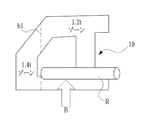
図4b乃至図4dを参照して、厚さが1.4mmのブランク10を圧延する例を説明する。図4bに示したように、ブランクは、まずA方向に圧延ロールRへと圧延される。A方向の圧延は、A方向の圧延領域の厚さが1.2mmに減少されるまで1回または数回行われる。図4c及び図4dに示したように、A方向に圧延されたブランク10はA方向とは異なるB方向に圧延される。B方向の圧延は、B方向の圧延領域の厚さが1.0mmに減少されるまで1回または数回行われる。 An example of rolling the blank 10 having a thickness of 1.4 mm will be described with reference to FIGS. 4b to 4d. As shown in FIG. 4b, the blank is first rolled into a rolling roll R in the A direction. Rolling in the A direction is performed once or several times until the thickness of the rolled region in the A direction is reduced to 1.2 mm. As shown in FIGS. 4c and 4d, the blank 10 rolled in the A direction is rolled in the B direction different from the A direction. Rolling in the B direction is performed once or several times until the thickness of the rolled region in the B direction is reduced to 1.0 mm.
図4cにおいて、b1はブランク10の厚さが1.4mmの領域と厚さが1.2mmの領域間の境界である。図4dにおいて、b2はブランク10の厚さが1.2mmの領域と厚さが1.0mmの領域間の境界、b3はブランク10の厚さが1.4mmの領域と厚さが1.0mmの領域間の境界である。 In FIG. 4c, b1 is a boundary between the region where the thickness of the blank 10 is 1.4 mm and the region where the thickness is 1.2 mm. In FIG. 4d, b2 is a boundary between a blank 10 thickness region of 1.2 mm and a 1.0 mm thickness region, and b3 is a blank 10 thickness region of 1.4 mm and a thickness of 1.0 mm. Is the boundary between the regions.
図4dに示したように、前記のような圧延を介して厚さが互いに異なる3つの領域を有するブランク10が得られる。A方向からB方向への圧延方向の変更は、例えば、圧延ロールRに進入するブランク10の方向を変更することからなる。孔11は、互いに異なる圧延方向A、Bが重畳する領域に配置される。
As shown in FIG. 4d, the blank 10 having three regions with different thicknesses is obtained through the rolling as described above. The change of the rolling direction from the A direction to the B direction includes, for example, changing the direction of the blank 10 entering the rolling roll R. The
S2における圧延は、ブランク10の縁から内側に向かって行われる。ブランクのある一部の領域に対する圧延は、1回で完了されることが好ましい。圧延はブランク表面の硬化を引き起こすが、同じ領域を繰り返し圧延する場合、回数が重なるほど圧延荷重が大きくなり、まためっき層の損傷が問題になる恐れがある。圧延を繰り返す回数を下げるために、ロールギャップなどが適切に調節される必要がある。 The rolling in S2 is performed from the edge of the blank 10 toward the inside. It is preferable that the rolling with respect to a certain area | region with a blank is completed at once. Although rolling causes hardening of the blank surface, when the same region is repeatedly rolled, the rolling load increases as the number of times overlaps, and damage to the plating layer may become a problem. In order to reduce the number of times the rolling is repeated, the roll gap or the like needs to be adjusted appropriately.
圧延ロールRは、ロールRの長さ方向に直径が互いに異なる区間を有してもよい。このような圧延ロールRを使用する場合、ブランク10を一方向に圧延することで幅方向、つまり、圧延方向に対して垂直な方向に厚さが互いに異なる領域が発生するようにしてもよい。 The rolling roll R may have sections with different diameters in the length direction of the roll R. When using such a rolling roll R, by rolling the blank 10 in one direction, regions having different thicknesses in the width direction, that is, the direction perpendicular to the rolling direction may be generated.
1次トリミング工程S3
圧延が完了されたブランク10は、プレス成形に必要な形状に外郭ラインに沿って切断される。できるだけ所望の成形品に近い形状に切断することが好ましい。切断にはレーザを利用してもよく、この工程S3で上述したフランジ22が切断される。
Primary trimming process S3
The blank 10 that has been rolled is cut along a contour line into a shape necessary for press forming. It is preferable to cut into a shape as close as possible to the desired molded product. Laser may be used for cutting, and the flange 22 described above is cut in this step S3.
加熱工程S4
ホットスタンピングのために、ブランク10をオーステナイト化温度以上に加熱する。例えば、Alめっき鋼板を約550℃程度に加熱し、表面に酸化層を形成した後、950℃に加熱する。直接通電による加熱、高周波誘導加熱、電気炉などが単独または複合に利用されてもよい。
Heating process S4
For hot stamping, the blank 10 is heated above the austenitizing temperature. For example, an Al plated steel sheet is heated to about 550 ° C., an oxide layer is formed on the surface, and then heated to 950 ° C. Direct heating, high frequency induction heating, an electric furnace or the like may be used alone or in combination.
一方、孔11と適切な圧延制御によってブランク10の変形を抑制することができるが、圧延過程S2でブランク10がある程度変形される可能性がある。よって、圧延工程S2と加熱工程S4の間に、ブランク10を平坦化するためのレべリング工程が行われてもよい。多重ローラを利用するなど、通常のレべリング工程を行うことができる。
On the other hand, the deformation of the blank 10 can be suppressed by the
熱間成形及び冷却工程S5
オーストナイト化された(austenitized)ブランク10を、所望の形態の製品にプレス成形すると共に急冷させる工程である。急冷を介し、マルテンサイト(martensite)を有する高強度の本体部品が得られる。
Hot forming and cooling step S5
This is a process in which an austenitized blank 10 is press-molded into a product in a desired form and rapidly cooled. A high-strength body part with martensite is obtained through quenching.
2次トリミング工程S6
熱間プレス成形の後は、成形された製品の縁に、製品以外の余分を除去するためのトリミング工程が行われる。ブランク10の浪費の防止及び生産効率の向上などのために、2次トリミング工程は省略されることが好ましいが、今のところはプレス成形後のトリミングが必要である。
Secondary trimming step S6
After the hot press molding, a trimming process is performed on the edge of the molded product to remove excess parts other than the product. In order to prevent the blank 10 from being wasted and to improve the production efficiency, it is preferable to omit the secondary trimming process, but for the time being, trimming after press molding is necessary.
図5乃至図6bを参照して、圧延によるブランクの厚さの変化を説明する。 With reference to FIG. 5 thru | or FIG. 6 b, the change of the thickness of the blank by rolling is demonstrated.
図5に示したブランク10’は、ドア側サイドパネルの製作実験のために、これと類似した形態にブランキングされたものである。ブランク10’は、フロント及びセンターピラーなどのサイドパネルを構成するパーツを備えており、中央部には圧延の際にブランク10’の変形防止または変形吸収のための孔11が形成される。
A blank 10 ′ shown in FIG. 5 is blanked in a similar form for a door side panel manufacturing experiment. The blank 10 ′ includes parts constituting a side panel such as a front and a center pillar, and a
ブランク10’の後方にはループレール側の延長部12aとサイドシル側の延長部12bが突出形成され、これらの延長部12a、12bとセンターピラー部14によって規定される切開部14が設けられる。この切開部14は、変形吸収のためのものではない。但し、ブランク10’の形状や圧延領域などの設計によっては、このような部位に意図的に孔が形成されることもある。
On the rear side of the blank 10 ′, an
図6a及び図6bは、図5のブランク10’を右側方向、つまり、ブランク10’の長さ方向LDに圧延した結果、得られたブランク10’の厚さ分布を示すグラフである。圧延前のブランク10’の厚さは1.4mmであり、目標とする圧延後の厚さは1.2mmであった。圧延はブランク10’の左側端から右側方向に行われており、ロールギャップは0.2〜0.6mmの範囲で変化していた。 6a and 6b are graphs showing the thickness distribution of the blank 10 'obtained as a result of rolling the blank 10' of FIG. 5 in the right direction, that is, in the length direction LD of the blank 10 '. The thickness of the blank 10 ′ before rolling was 1.4 mm, and the target thickness after rolling was 1.2 mm. Rolling was performed in the right direction from the left end of the blank 10 ′, and the roll gap varied in the range of 0.2 to 0.6 mm.
図6aは、ブランク10’の長さ方向LDに沿っての厚さの分布を示す図である。図6aにおいて、横軸は長さ方向LDの距離である。 FIG. 6 a is a diagram showing the thickness distribution along the length direction LD of the blank 10 ′. In FIG. 6a, the horizontal axis is the distance in the length direction LD.
図5及び図6aを参照すると、切開部14がある(a)区間や孔11が形成されている(c)区間の場合、ブランク10’の厚さは目標とする1.2mmから相当な偏差を示す。(a)区間において、最大0.5mm程度の厚さの偏差が発生する。センターピラー部13に対応する(b)区間において、ブランク10’の厚さは目標の1.2mmに近接し、0.1mm程度の小さい偏差を示す。ロールギャップ条件などによって差があるが、傾向的に前記のような現象が発生する。
Referring to FIGS. 5 and 6a, in the case of the section (a) where the
前記のようなブランク10’の長さ方向LDへの厚さの偏差は、ブランク10の変形を吸収するためにブランク10’に孔11を形成する場合、厚さの偏差を解消するための方案が講じられる必要があることが分かる。また、ブランク10’の形状の設計、圧延方向や圧延領域の設計において、前記結果は必ず考慮される必要がある。
The thickness deviation in the length direction LD of the blank 10 ′ as described above is a method for eliminating the thickness deviation when the
図6bは、ブランク10’の幅方向WDに沿っての厚さの分布を示す図である。図6bにおいて、横軸は幅方向WDの距離である。 FIG. 6 b is a diagram showing a thickness distribution along the width direction WD of the blank 10 ′. In FIG. 6b, the horizontal axis is the distance in the width direction WD.
図5及び図6bを参照すると、ロールギャップによって偏差があるが、大体圧延後の厚さは1.2mmに近接し、最大偏差は約0.1〜0.15程度であった。ロールギャップが小さいほど、目標厚さに近い結果が得られることが分かる。 Referring to FIGS. 5 and 6b, although there is a deviation depending on the roll gap, the thickness after rolling is close to 1.2 mm, and the maximum deviation is about 0.1 to 0.15. It can be seen that the smaller the roll gap, the closer to the target thickness.
図7では、前記のような結果を反映した改善されたブランクの形状設計案が示されている。図7に示したように、ブランク20の中央部に孔21が形成されるが、この孔21に対応するブランク20の縁領域には、ブランク20の面方向にフランジ22a、22b;22が延長形成される。フランジ22は、孔21によって除去されたブランク20部位の面積を補償し、圧延過程に孔21によって発生するブランク20の厚さの偏差を抑制する。
FIG. 7 shows an improved blank shape design proposal reflecting the above-described results. As shown in FIG. 7, a
フランジ22の形状の設計において、孔21対比のフランジ22の面積や位置が考慮される必要がある。フランジ22は、これに対応する孔21の大きさと同じ程度の大きさを有することが好ましい。しかし、フランジ22はS6におけるトリミング工程から除去されるため、材料の浪費を低減するために最小限の大きさに適正に形成すべきである。
In designing the shape of the flange 22, it is necessary to consider the area and position of the flange 22 compared with the
図7を参照すると、フランジ22a、22bは孔21の面積と同じ面積を有するよう、ブランク20の左右端部に孔21の面積の1/2ずつ形成される。圧延方向が上方向で孔21がxyの面積を有する際、各フランジ22の突出長さzは1/2xであり、各フランジ22の圧延方向への長さは1/2yである。フランジ22a、22bの形状や位置は、例えば、圧延ロールRが図7の23で示されたラインに沿って置かれているとする際、ブランク20がない孔21の面積を補償するように設計される。
Referring to FIG. 7, the
図8a及び図8bは、図7に示したような形状のブランク20を圧延した後、圧延方向、つまり、ブランク20の長さ方向LDに沿っての厚さの変化を示したグラフである。ブランク20は1.4mmであり、目標圧延厚さは1.2mmである。図8aはロールギャップが0.3mmである際の、図8bはロールギャップが0.1mmである際の厚さ分布グラフである。これらの図面において、横軸は長さ方向LDの距離を示す。 8a and 8b are graphs showing changes in thickness in the rolling direction, that is, along the length direction LD of the blank 20, after the blank 20 having the shape shown in FIG. 7 is rolled. The blank 20 is 1.4 mm, and the target rolling thickness is 1.2 mm. 8a is a thickness distribution graph when the roll gap is 0.3 mm, and FIG. 8b is a thickness distribution graph when the roll gap is 0.1 mm. In these drawings, the horizontal axis indicates the distance in the length direction LD.
図8a及び図8bにおいて、実施例(case)1乃至3は、孔21対比のフランジ22の大きさが少しずつ異なる例である。実施例1、2は、それぞれ孔21とそれに対応するフランジ22の面積が同じ例(z=1/2x)である。但し、実施例2の孔の大きさ(つまり、フランジの面積)は、実施例1の孔の大きさ(つまり、フランジの面積)より大きい。実施例3は、孔21対比のフランジ22の面積が小さい例(z<1/2x)である。
8a and 8b, Examples 1 to 3 are examples in which the size of the flange 22 is slightly different from that of the
図8a及び図8bに示したように、フランジ22の大きさが孔21の大きさより小さい実施例3よりは、両者が同じ条件である実施例1及び2における(a)区間と(b)区間の厚さの変化が小さく示される。
As shown in FIGS. 8a and 8b, the section (a) and the section (b) in the first and second embodiments are the same as those in the third embodiment where the size of the flange 22 is smaller than the size of the
前記のような実施例から分かるように、ブランキング工程S1においてブランクの形状を設計する際、圧延による変形吸収のために孔11、21が設けられる必要があり、孔11、21の位置に対応するブランクの縁領域にフランジ22が設けられる必要がある。フランジ22は圧延方向に垂直な方向、または圧延ロールの長さ方向23に形成される。
As can be seen from the above embodiment, when designing the shape of the blank in the blanking step S1, the
図9には、他の実施例による他の本体部品の製造工程が示されている。簡単に言うと、ブランクはプリヒーティングS11の後、熱間圧延S12される。これ以外の工程は上述した実施例と同じく、または類似して行われる。 FIG. 9 shows a manufacturing process of another main body component according to another embodiment. In short, the blank is hot-rolled S12 after preheating S11. The other steps are the same as or similar to the above-described embodiment.
プリヒーティングS11は、ブランク表面の皮膜を酸化させる工程である。ホットスタンピング用Alめっき鋼板を例に挙げると、鋼板表面のAlめっき層を酸化させるのである。プリヒーティングS11でブランク表面に予め緻密な酸化アルミニウムが形成されると、熱間圧延S12の際ブランク表面から発生し得る微細クラックを防止することができる。 Preheating S11 is a process of oxidizing the film on the blank surface. Taking an Al plated steel sheet for hot stamping as an example, the Al plated layer on the surface of the steel sheet is oxidized. When dense aluminum oxide is formed on the blank surface in advance by preheating S11, fine cracks that can be generated from the blank surface during hot rolling S12 can be prevented.
プリヒーティングS11の温度は、ホットスタンピング用Alめっき鋼板の場合、略580℃程度がターゲットとなる。Al皮膜が650〜700℃で溶融されるため、メインヒーティングS13の加熱速度は制限されるしかない。しかし、プリヒーティングS11を介してブランク表面に安定した酸化皮膜が形成されると、メインヒーティングS13の際にブランクをオーステナイト温度、例えば950℃まで急速加熱することができるようになる。 The temperature of the preheating S11 is about 580 ° C. in the case of an Al-plated steel sheet for hot stamping. Since the Al film is melted at 650 to 700 ° C., the heating rate of the main heating S13 can only be limited. However, when a stable oxide film is formed on the blank surface via the preheating S11, the blank can be rapidly heated to the austenite temperature, for example, 950 ° C. during the main heating S13.
前記のようなプリヒーティングS11の後、ブランクは熱間圧延S12される。ブランクの複数の領域に対して熱間圧延が行われるべきであるが、その過程でブランクの温度が低下する。低下したブランクの温度を補償するために、ブランクの再加熱が必要となる。 After the preheating S11 as described above, the blank is hot-rolled S12. Hot rolling should be performed on multiple regions of the blank, but the temperature of the blank decreases in the process. In order to compensate for the lowered blank temperature, reheating of the blank is required.
これまで本発明の特定実施例について図示し説明したが、以下の特許請求の範囲に記載された発明の技術的思想から逸脱しない範囲内で、本発明は多様に修正または変形され得ることを理解する必要がある。 While specific embodiments of the invention have been illustrated and described, it will be appreciated that the invention can be modified and varied in various ways without departing from the technical spirit of the invention as defined in the following claims. There is a need to.
10、20:ブランク
11、21:孔
22a、22b:フランジ
10, 20:
Claims (6)
b)圧延されたブランクをプレス成形に必要な形状に切断するステップと、
c)切断されたブランクを加熱して熱間プレス成形及び冷却するステップと、を含み、
前記ステップa)において、圧延されるブランクには孔が設けられ、この孔は少なくとも一部が圧延が行われる領域内に位置するように形成されることを特徴とする車体部品の製造方法。 a) rolling a blank having a coating so as to have two or more regions of different thicknesses;
b) cutting the rolled blank into a shape necessary for press molding;
c) heating the cut blank to hot press forming and cooling;
In the step a), the blank to be rolled is provided with a hole, and the hole is formed so that at least a part thereof is located in a region where the rolling is performed.
互いに同じではない複数の部分的な領域に対して順次に行われることを特徴とする請求項1に記載の車体部品の製造方法。 The rolling in step a)
2. The method of manufacturing a vehicle body part according to claim 1, wherein the method is performed sequentially on a plurality of partial areas that are not the same as each other.
ステップb)において、フランジは切断されることを特徴とする請求項1に記載の車体部品の製造方法。 The blank rolled in step a) comprises a flange extending in the surface direction in the edge region of the blank corresponding to the position of the hole so that at least part of the area of the blank part removed by the hole can be compensated. ,
2. The method of manufacturing a vehicle body part according to claim 1, wherein the flange is cut in step b).
Applications Claiming Priority (2)
| Application Number | Priority Date | Filing Date | Title |
|---|---|---|---|
| KR1020160167376A KR101881893B1 (en) | 2016-12-09 | 2016-12-09 | Mefhod for manufacturing hot formed parts |
| KR10-2016-0167376 | 2016-12-09 |
Publications (2)
| Publication Number | Publication Date |
|---|---|
| JP2018099731A true JP2018099731A (en) | 2018-06-28 |
| JP6443704B2 JP6443704B2 (en) | 2018-12-26 |
Family
ID=60543332
Family Applications (1)
| Application Number | Title | Priority Date | Filing Date |
|---|---|---|---|
| JP2017231901A Active JP6443704B2 (en) | 2016-12-09 | 2017-12-01 | Manufacturing method for body parts |
Country Status (8)
| Country | Link |
|---|---|
| US (1) | US20180161841A1 (en) |
| EP (1) | EP3342498B1 (en) |
| JP (1) | JP6443704B2 (en) |
| KR (1) | KR101881893B1 (en) |
| CN (1) | CN108213862B (en) |
| BR (1) | BR102017026289B1 (en) |
| ES (1) | ES2826396T3 (en) |
| WO (1) | WO2018105939A1 (en) |
Cited By (2)
| Publication number | Priority date | Publication date | Assignee | Title |
|---|---|---|---|---|
| JP2020093291A (en) * | 2018-12-13 | 2020-06-18 | トヨタ自動車株式会社 | Steel plate member and manufacturing method therefor |
| WO2022163614A1 (en) * | 2021-01-28 | 2022-08-04 | リセオン株式会社 | Dual heating system hot forming for manufacturing molded blank |
Families Citing this family (1)
| Publication number | Priority date | Publication date | Assignee | Title |
|---|---|---|---|---|
| CN109434384B (en) * | 2018-11-16 | 2021-06-22 | 苏州普热斯勒先进成型技术有限公司 | Preparation method and device of coated steel plate and hot stamping method |
Citations (9)
| Publication number | Priority date | Publication date | Assignee | Title |
|---|---|---|---|---|
| JPS53142349A (en) * | 1977-05-17 | 1978-12-12 | Kawasaki Steel Co | Steel plate hot rolling method |
| JPS53142351A (en) * | 1977-05-17 | 1978-12-12 | Kawasaki Steel Co | Steel plate hot rolling method |
| JPS57115904A (en) * | 1981-01-07 | 1982-07-19 | Sumitomo Metal Ind Ltd | Slab for hot rolling |
| JP2005074468A (en) * | 2003-08-29 | 2005-03-24 | Toyoda Iron Works Co Ltd | Heat treatment method of plated steel sheet for hot pressing |
| DE102009050997A1 (en) * | 2009-10-28 | 2011-05-12 | Volkswagen Ag | Method for producing a form-hardened component made of a steel-plate, comprises heating a board tailored on given dimensions in an oven within a given time at a given temperature and then form-hardening in a tool |
| US20120186705A1 (en) * | 2009-09-01 | 2012-07-26 | Thyssenkrupp Steel Europe Ag | Method and Device for Producing a Metal Component |
| KR20140006483A (en) * | 2012-07-05 | 2014-01-16 | 주식회사 포스코 | Manufacturing method of hot press forming product |
| US20150353146A1 (en) * | 2014-06-10 | 2015-12-10 | Benteler Automobiltechnik Gmbh | Method for producing a motor vehicle component from aluminum |
| US20160237585A1 (en) * | 2015-02-13 | 2016-08-18 | Muhr Und Bender Kg | Producing a product from a rolled strip material |
Family Cites Families (23)
| Publication number | Priority date | Publication date | Assignee | Title |
|---|---|---|---|---|
| US2766645A (en) * | 1952-08-20 | 1956-10-16 | Gen Motors Corp | Gap rolling method |
| AT278485B (en) * | 1967-10-30 | 1970-02-10 | Guenther Ing Lang | Method and cutting tool for the production of perforations arranged at certain pitches in profile strips made of metal, preferably steel |
| SE435527B (en) | 1973-11-06 | 1984-10-01 | Plannja Ab | PROCEDURE FOR PREPARING A PART OF Hardened Steel |
| FR2780984B1 (en) | 1998-07-09 | 2001-06-22 | Lorraine Laminage | COATED HOT AND COLD STEEL SHEET HAVING VERY HIGH RESISTANCE AFTER HEAT TREATMENT |
| US20060096099A1 (en) * | 2003-05-08 | 2006-05-11 | Noble Metal Processing, Inc. | Automotive crush tip and method of manufacturing |
| DE10333166A1 (en) * | 2003-07-22 | 2005-02-10 | Daimlerchrysler Ag | Press-hardened component and method for producing a press-hardened component |
| US7275784B2 (en) * | 2004-04-13 | 2007-10-02 | Pullman Industries, Inc. | Two-piece side and floor panel arrangement for box assembly |
| US20070163121A1 (en) * | 2006-01-19 | 2007-07-19 | Shiloh Industries, Inc. | Metal frame and method for manufacturing the same |
| US7617916B2 (en) * | 2007-10-17 | 2009-11-17 | Shape Corp. | Tapered crushable polygonal structure |
| KR100934900B1 (en) * | 2008-06-03 | 2010-01-06 | 주식회사 성우하이텍 | Door inner panel manufacturing method of vehicles using the tailor rolled blank |
| KR101008042B1 (en) * | 2009-01-09 | 2011-01-13 | 주식회사 포스코 | Aluminum Coated Steel Sheet with Excellent Corrosion Resistance and Hot Press Formed Article Using The Same and Manufacturing Method Thereof |
| DE112009004763T5 (en) * | 2009-05-08 | 2012-10-04 | Toyota Jidosha Kabushiki Kaisha | ADJUSTED ROHLING AND METHOD FOR MAKING IT A COMPONENT |
| KR101087433B1 (en) * | 2009-09-28 | 2011-11-25 | 현대제철 주식회사 | Mult-step rolling roll and rolling method using thereof |
| KR101033767B1 (en) * | 2010-11-03 | 2011-05-09 | 현대하이스코 주식회사 | Automobile part manufacturing method using quenched steel sheet |
| KR20110003447A (en) * | 2010-12-03 | 2011-01-12 | 박정원 | Door assembly |
| WO2013014481A1 (en) | 2011-07-26 | 2013-01-31 | Arcelormittal Investigación Y Desarrollo Sl | Hot-formed previously welded steel part with very high mechanical resistance, and production method |
| KR101443022B1 (en) * | 2012-12-04 | 2014-09-22 | 현대하이스코 주식회사 | Rolling roll apparatus for varying variety thickness of metal material, rolling system and rolling method thereof |
| WO2014111291A1 (en) | 2013-01-15 | 2014-07-24 | Basf Se | Polyols, production and use thereof |
| KR101585802B1 (en) * | 2014-11-21 | 2016-01-18 | 주식회사 포스코 | Uniformly coated tailor rolled steel sheet, method for manufacturing same, method for press forming using same and product thereof |
| ES2662404T3 (en) * | 2015-03-26 | 2018-04-06 | Weba Werkzeugbau Betriebs Gmbh | Procedure and device for manufacturing a partially tempered shaped part |
| CN104925009A (en) * | 2015-06-30 | 2015-09-23 | 宝山钢铁股份有限公司 | Variable-thickness automobile front bumper and manufacturing method thereof |
| DE102015118099A1 (en) * | 2015-10-23 | 2017-04-27 | Benteler Automobiltechnik Gmbh | Method for producing a motor vehicle component |
| CN105729062A (en) * | 2016-01-29 | 2016-07-06 | 芜湖市海联机械设备有限公司 | End plate and manufacturing method thereof |
-
2016
- 2016-12-09 KR KR1020160167376A patent/KR101881893B1/en active IP Right Grant
-
2017
- 2017-11-23 ES ES17203209T patent/ES2826396T3/en active Active
- 2017-11-23 EP EP17203209.6A patent/EP3342498B1/en active Active
- 2017-11-28 WO PCT/KR2017/013726 patent/WO2018105939A1/en active Application Filing
- 2017-12-01 JP JP2017231901A patent/JP6443704B2/en active Active
- 2017-12-04 US US15/830,328 patent/US20180161841A1/en not_active Abandoned
- 2017-12-05 CN CN201711267366.5A patent/CN108213862B/en active Active
- 2017-12-06 BR BR102017026289-8A patent/BR102017026289B1/en active IP Right Grant
Patent Citations (11)
| Publication number | Priority date | Publication date | Assignee | Title |
|---|---|---|---|---|
| JPS53142349A (en) * | 1977-05-17 | 1978-12-12 | Kawasaki Steel Co | Steel plate hot rolling method |
| JPS53142351A (en) * | 1977-05-17 | 1978-12-12 | Kawasaki Steel Co | Steel plate hot rolling method |
| JPS57115904A (en) * | 1981-01-07 | 1982-07-19 | Sumitomo Metal Ind Ltd | Slab for hot rolling |
| JP2005074468A (en) * | 2003-08-29 | 2005-03-24 | Toyoda Iron Works Co Ltd | Heat treatment method of plated steel sheet for hot pressing |
| US20120186705A1 (en) * | 2009-09-01 | 2012-07-26 | Thyssenkrupp Steel Europe Ag | Method and Device for Producing a Metal Component |
| JP2015226936A (en) * | 2009-09-01 | 2015-12-17 | ティッセンクルップ スチール ヨーロッパ アクチェンゲゼルシャフトThyssenKrupp Steel Europe AG | Method and device for producing metal structural component |
| DE102009050997A1 (en) * | 2009-10-28 | 2011-05-12 | Volkswagen Ag | Method for producing a form-hardened component made of a steel-plate, comprises heating a board tailored on given dimensions in an oven within a given time at a given temperature and then form-hardening in a tool |
| KR20140006483A (en) * | 2012-07-05 | 2014-01-16 | 주식회사 포스코 | Manufacturing method of hot press forming product |
| US20150353146A1 (en) * | 2014-06-10 | 2015-12-10 | Benteler Automobiltechnik Gmbh | Method for producing a motor vehicle component from aluminum |
| US20160237585A1 (en) * | 2015-02-13 | 2016-08-18 | Muhr Und Bender Kg | Producing a product from a rolled strip material |
| JP2016176142A (en) * | 2015-02-13 | 2016-10-06 | ムール ウント ベンダー コマンディートゲゼルシャフトMuhr und Bender KG | Method for producing product from rolled strip material |
Cited By (4)
| Publication number | Priority date | Publication date | Assignee | Title |
|---|---|---|---|---|
| JP2020093291A (en) * | 2018-12-13 | 2020-06-18 | トヨタ自動車株式会社 | Steel plate member and manufacturing method therefor |
| JP7155986B2 (en) | 2018-12-13 | 2022-10-19 | トヨタ自動車株式会社 | Steel plate member and its manufacturing method |
| WO2022163614A1 (en) * | 2021-01-28 | 2022-08-04 | リセオン株式会社 | Dual heating system hot forming for manufacturing molded blank |
| JP2022115180A (en) * | 2021-01-28 | 2022-08-09 | リセオン株式会社 | Dual heating system hot molding for manufacturing mold blank |
Also Published As
| Publication number | Publication date |
|---|---|
| EP3342498A1 (en) | 2018-07-04 |
| JP6443704B2 (en) | 2018-12-26 |
| BR102017026289A2 (en) | 2018-08-21 |
| ES2826396T3 (en) | 2021-05-18 |
| KR20180066917A (en) | 2018-06-20 |
| BR102017026289B1 (en) | 2022-11-16 |
| CN108213862B (en) | 2020-06-26 |
| KR101881893B1 (en) | 2018-07-26 |
| WO2018105939A1 (en) | 2018-06-14 |
| EP3342498B1 (en) | 2020-07-22 |
| CN108213862A (en) | 2018-06-29 |
| US20180161841A1 (en) | 2018-06-14 |
Similar Documents
| Publication | Publication Date | Title |
|---|---|---|
| US8733144B2 (en) | Method and apparatus for hot forming and hardening a blank | |
| CN109072322B (en) | Method for producing a motor vehicle component having at least two regions of differing strength | |
| RU2445381C1 (en) | Manufacturing method of shaped part having at least two structural areas of various ductility | |
| KR101825427B1 (en) | Method for manufacturing vehicle body parts | |
| US20170298469A1 (en) | Structural Component Including A Tempered Transition Zone | |
| JP6443704B2 (en) | Manufacturing method for body parts | |
| CA2851920A1 (en) | System and method for hot-forming blanks | |
| CN106424280B (en) | A kind of high-strength steel hot forming differentiation mechanical property distribution flexible control method | |
| KR20170077192A (en) | Method for producing a component by subjecting a sheet bar of steel to a forming process | |
| CN108026602B (en) | Method for producing prefabricated material for producing metal parts with regions of different strength | |
| US20210164069A1 (en) | Steel plate member and method of producing the same | |
| EP3516083B1 (en) | Reinforcing structural components | |
| US20100050730A1 (en) | Method of making tempered shaped part | |
| EP4054777B1 (en) | A forming sheet metal part for a vehicle frame and corresponding production method | |
| JP2019500215A (en) | Manufacturing method of steel components for vehicles | |
| US20190168341A1 (en) | Method of Manufacturing Tailor Welded Blanks | |
| KR101738985B1 (en) | Hot formed steel part for vehicles and the method for manufacturing the same | |
| JP2022110891A (en) | Manufacturing method of vehicular b-pillar | |
| KR101745351B1 (en) | Apparatus for heat treatment of steel plate | |
| KR20190120198A (en) | Optimized manufacturing method of parts with at least one auxiliary forming element |
Legal Events
| Date | Code | Title | Description |
|---|---|---|---|
| TRDD | Decision of grant or rejection written | ||
| A977 | Report on retrieval |
Free format text: JAPANESE INTERMEDIATE CODE: A971007 Effective date: 20181010 |
|
| A01 | Written decision to grant a patent or to grant a registration (utility model) |
Free format text: JAPANESE INTERMEDIATE CODE: A01 Effective date: 20181016 |
|
| A711 | Notification of change in applicant |
Free format text: JAPANESE INTERMEDIATE CODE: A711 Effective date: 20181113 |
|
| A61 | First payment of annual fees (during grant procedure) |
Free format text: JAPANESE INTERMEDIATE CODE: A61 Effective date: 20181114 |
|
| A521 | Request for written amendment filed |
Free format text: JAPANESE INTERMEDIATE CODE: A821 Effective date: 20181113 |
|
| R150 | Certificate of patent or registration of utility model |
Ref document number: 6443704 Country of ref document: JP Free format text: JAPANESE INTERMEDIATE CODE: R150 |
|
| R250 | Receipt of annual fees |
Free format text: JAPANESE INTERMEDIATE CODE: R250 |
|
| R250 | Receipt of annual fees |
Free format text: JAPANESE INTERMEDIATE CODE: R250 |
|
| R250 | Receipt of annual fees |
Free format text: JAPANESE INTERMEDIATE CODE: R250 |