JP2018094961A - Float-sink device - Google Patents
Float-sink device Download PDFInfo
- Publication number
- JP2018094961A JP2018094961A JP2016238731A JP2016238731A JP2018094961A JP 2018094961 A JP2018094961 A JP 2018094961A JP 2016238731 A JP2016238731 A JP 2016238731A JP 2016238731 A JP2016238731 A JP 2016238731A JP 2018094961 A JP2018094961 A JP 2018094961A
- Authority
- JP
- Japan
- Prior art keywords
- ballast
- ballast water
- chamber
- volume
- gas chamber
- Prior art date
- Legal status (The legal status is an assumption and is not a legal conclusion. Google has not performed a legal analysis and makes no representation as to the accuracy of the status listed.)
- Granted
Links
Images


Landscapes
- Filling Or Discharging Of Gas Storage Vessels (AREA)
Abstract
Description
本開示は、水中構造物を水中で浮沈させる浮沈装置に関する。 The present disclosure relates to a floating and sinking device that floats and sinks an underwater structure in water.
潜水艦などの水中構造物は、水中で浮沈するための浮沈装置を備えている。浮沈装置は、一般的にバラストタンクを備えており、バラストタンク内に封入される気体の体積を増減させることによって、水中構造物に作用する浮力を調整するように構成される。 An underwater structure such as a submarine is provided with a floating device for floating and sinking in water. The floatation / sink device generally includes a ballast tank, and is configured to adjust the buoyancy acting on the underwater structure by increasing / decreasing the volume of gas sealed in the ballast tank.
バラストタンク内に封入される気体の体積を増減するための手段として、従来は、圧縮気体を蓄える高圧気蓄器が用いられていた。そして、浮上時には高圧気蓄器から圧縮気体をバラストタンク内に供給してバラストタンク内のバラスト水を排水するとともに、沈降時にはバラストタンク内の気体を排出してバラストタンク内にバラスト水を引き入れることで、水中構造物の沈降操作を行っていた。 As a means for increasing or decreasing the volume of gas sealed in the ballast tank, conventionally, a high-pressure air reservoir that stores compressed gas has been used. Then, when ascending, compressed gas is supplied from the high-pressure air reservoir into the ballast tank to drain the ballast water in the ballast tank, and at the time of settling, the gas in the ballast tank is discharged and the ballast water is drawn into the ballast tank. Then, the sedimentation operation of the underwater structure was performed.
しかしながら、このような高圧気蓄器を有する浮沈装置では、高圧気蓄器に蓄えられている圧縮気体を使い切ってしまうと、バラストタンク内に気体を供給できなくなり、水中構造物を浮上させることが出来なくなってしまう。この点、バラストタンク内に供給した気体をコンプレッサなどで圧縮して再度高圧気蓄器に蓄えることも考えられるが、この場合は、コンプレッサによって圧縮した気体を高圧気蓄器に戻すための設備が別途必要になるなど、その構造が複雑になってしまう。 However, in the floatation apparatus having such a high-pressure air accumulator, if the compressed gas stored in the high-pressure air accumulator is used up, the gas cannot be supplied into the ballast tank, and the underwater structure may float. It will not be possible. In this regard, it may be possible to compress the gas supplied into the ballast tank with a compressor or the like and store it again in the high-pressure air accumulator, but in this case, there is equipment for returning the gas compressed by the compressor to the high-pressure air accumulator. The structure becomes complicated, such as being required separately.
特許文献1には、水室、水素室、及び反応室を備えた浮沈装置において、浮上時には反応室で発生させた水素を水素室に供給することで浮力を得るとともに、沈降時には水素室から排出された水素を反応室で吸収するように構成されることで、水中構造物を繰返し浮沈可能とした浮沈装置が開示されている。 In Patent Document 1, in a floating / sink device having a water chamber, a hydrogen chamber, and a reaction chamber, buoyancy is obtained by supplying hydrogen generated in the reaction chamber to the hydrogen chamber when ascending, and exhausted from the hydrogen chamber during sedimentation. There is disclosed a floatation apparatus that is configured to absorb the generated hydrogen in a reaction chamber so that an underwater structure can float and sink repeatedly.
また、特許文献2には、気体が密閉されたバラストタンクを備えた浮沈装置において、浮上時にはポンプによってバラストタンク内からバラスト水を排水することでバラストタンク内に密閉されている気体の体積を増加させるとともに、沈降時にはポンプによってバラストタンク内にバラスト水を注水することでバラストタンク内に密閉されている気体の体積を縮小させることで、水中構造物を繰返し浮沈可能とした浮沈装置が開示されている。
Further, in
しかしながら、特許文献1に記載の浮沈装置は、水素を発生させ、且つ、水素室から排出された水素を吸収するための反応室が必要となり、その構造が複雑になるとの課題があった。
また、特許文献2に記載の浮沈装置は、バラストタンク内からバラスト水を排水するときに、バラストタンク内に密閉されている気体がポンプに吸い込まれ、ポンプがバラスト水を排水できない状態(いわゆる、エア噛み)を発生させる虞があった。
However, the flotation apparatus described in Patent Document 1 requires a reaction chamber for generating hydrogen and absorbing hydrogen discharged from the hydrogen chamber, and there is a problem that the structure becomes complicated.
Further, in the floatation / sink device described in
本発明の少なくとも一実施形態は上述した従来技術に鑑みなされたものであり、シンプルな構造で水中構造物を水中で繰返し浮沈させることが出来るとともに、バラスト水を排水できない状態の発生を防止することの出来る浮沈装置を提供することを目的とする。 At least one embodiment of the present invention has been made in view of the above-described prior art, and it is possible to repeatedly float and sink an underwater structure in water with a simple structure, and to prevent occurrence of a state in which ballast water cannot be drained. An object of the present invention is to provide a floating and sinking device capable of performing the above.
(1)本発明の少なくとも一実施形態にかかる浮沈装置は、
水中構造物を水中で浮沈させる浮沈装置であって、
気体が封入される第1気体室と、バラスト水が封入されるバラスト水室とが内部に形成されるバラストタンクと、
前記バラスト水室と前記バラストタンクの外部とを連通する連通孔を介して、前記バラスト水室内の前記バラスト水を排水するためのポンプと、
前記第1気体室と前記バラスト水室とを水密に仕切るための第1仕切部材と、を備え、
前記第1仕切部材は、前記バラスト水室に前記バラスト水が注水されると、前記バラスト水室の容積を増大させるとともに前記第1気体室の容積を減少させ、前記バラスト水室から前記バラスト水が排水されると、前記バラスト水室の容積を減少させるとともに前記第1気体室の容積を増大させるように構成されている。
(1) A floatation apparatus according to at least one embodiment of the present invention includes:
A floatation device that floats and sinks an underwater structure in water,
A ballast tank in which a first gas chamber in which gas is sealed and a ballast water chamber in which ballast water is sealed are formed;
A pump for draining the ballast water in the ballast water chamber through a communication hole communicating the ballast water chamber and the outside of the ballast tank;
A first partition member for watertightly partitioning the first gas chamber and the ballast water chamber,
When the ballast water is poured into the ballast water chamber, the first partition member increases the volume of the ballast water chamber and decreases the volume of the first gas chamber, and from the ballast water chamber to the ballast water. Is drained, the volume of the ballast water chamber is decreased and the volume of the first gas chamber is increased.
上記(1)の構成によれば、沈降時にはバラスト水室にバラスト水を注水することで、バラスト水室の容積が増大するとともに第1気体室の容積が減少する。一方、浮上時には例えばポンプによってバラスト水室からバラスト水を排水することで、バラスト水室の容積が減少するとともに第1気体室の容積が増大する。このように、気体が封入される第1気体室の容積がバラスト水室の容積に応じて増減するように構成されることで、特許文献1に記載の浮沈装置のような反応室を備える必要がなく、シンプルな構造で水中構造物を水中で繰返し浮沈させることが出来る浮沈装置を提供することが出来る。 According to the configuration of (1), when the ballast water is poured into the ballast water chamber at the time of sedimentation, the volume of the ballast water chamber increases and the volume of the first gas chamber decreases. On the other hand, at the time of ascent, for example, by discharging the ballast water from the ballast water chamber by a pump, the volume of the ballast water chamber decreases and the volume of the first gas chamber increases. Thus, it is necessary to provide a reaction chamber such as the floatation apparatus described in Patent Document 1 by configuring so that the volume of the first gas chamber in which gas is enclosed increases or decreases according to the volume of the ballast water chamber. Therefore, it is possible to provide a floating / sink device that can repeatedly float and sink an underwater structure in water with a simple structure.
また、第1気体室とバラスト水室とは第1仕切部材によって水密に仕切られているとともに、バラスト水室からバラスト水が排水されると、バラスト水室の容積が減少するとともに第1気体室の容積が増大するように構成されている。そのため、例えばポンプによってバラスト水室に封入されているバラスト水を排水する場合に、第1気体室とバラスト水室とは第1仕切部材によって水密に仕切られた状態のまま、バラスト水室の容積が減少する。つまり、バラスト水室に封入されているバラスト水を排水しても、バラスト水室内には気体が混入しないような構造となっている。これにより、ポンプが気体を吸い込むことはなく、ポンプがバラスト水を排水できない状態(いわゆる、エア噛み)の発生を防止することが出来るようになっている。 In addition, the first gas chamber and the ballast water chamber are water-tightly partitioned by the first partition member, and when ballast water is drained from the ballast water chamber, the volume of the ballast water chamber decreases and the first gas chamber The volume of the is increased. Therefore, for example, when the ballast water sealed in the ballast water chamber is drained by a pump, the volume of the ballast water chamber remains in a state where the first gas chamber and the ballast water chamber are water-tightly partitioned by the first partition member. Decrease. That is, even if the ballast water sealed in the ballast water chamber is drained, the gas is not mixed into the ballast water chamber. This prevents the pump from sucking gas and prevents the pump from draining ballast water (so-called air biting).
(2)幾つかの実施形態では、上記(1)の構成において、
前記バラストタンクの内部には、前記バラストタンクの重心位置を挟んで前記第1気体室とは反対側に、気体が封入される第2気体室がさらに形成され、
前記第2気体室と前記バラスト水室とを水密に仕切るための第2仕切部材をさらに備え、
前記第2仕切部材は、前記バラスト水室に前記バラスト水が注水されると、前記バラスト水室の容積を増大させるとともに前記第2気体室の容積を減少させ、前記バラスト水室から前記バラスト水が排水されると、前記バラスト水室の容積を減少させるとともに前記第2気体室の容積を増大させるように構成されている。
(2) In some embodiments, in the configuration of (1) above,
Inside the ballast tank, a second gas chamber in which gas is sealed is further formed on the opposite side of the first gas chamber across the center of gravity of the ballast tank,
A second partition member for watertightly partitioning the second gas chamber and the ballast water chamber;
When the ballast water is poured into the ballast water chamber, the second partition member increases the volume of the ballast water chamber and decreases the volume of the second gas chamber, and from the ballast water chamber to the ballast water. Is drained, the volume of the ballast water chamber is decreased and the volume of the second gas chamber is increased.
上記(2)の構成によれば、第1気体室による浮力と、第2気体室による浮力とを、バラストタンクの重心位置を挟んで互いに反対側からバラストタンクに作用させることが出来る。これにより、バラストタンクに第1気体室による浮力のみが作用する場合と比べて、水中構造物の姿勢変動を抑制することが出来る。 According to the configuration of (2) above, the buoyancy caused by the first gas chamber and the buoyancy caused by the second gas chamber can be applied to the ballast tank from opposite sides with respect to the position of the center of gravity of the ballast tank. Thereby, compared with the case where only the buoyancy by a 1st gas chamber acts on a ballast tank, the attitude | position fluctuation | variation of an underwater structure can be suppressed.
また、バラストタンクの重心位置を挟んで第1気体室とは反対側に第2気体室を形成することで、複数のバラストタンクを備えずとも、1つのバラストタンクによって水中構造物の姿勢変動を抑制することが出来るようになっている。 Further, by forming the second gas chamber on the opposite side of the first gas chamber across the position of the center of gravity of the ballast tank, it is possible to change the posture of the underwater structure with one ballast tank without having a plurality of ballast tanks. It can be suppressed.
(3)幾つかの実施形態では、上記(2)の構成において、
前記第1気体室及び前記第2気体室の各々の容積は、前記バラスト水室の容積の増減に関わらず、互いに等しくなるように構成される。
(3) In some embodiments, in the configuration of (2) above,
The volumes of the first gas chamber and the second gas chamber are configured to be equal to each other regardless of the increase or decrease of the volume of the ballast water chamber.
上記(3)の構成によれば、バラスト水室の容積の増減に関わらず、第1気体室による浮力と第2気体室による浮力とは互いに等しくなる。これにより、上記(2)の構成に比べて、水中構造物の姿勢変動をさらに抑制させることが出来る。 According to the configuration of (3) above, the buoyancy due to the first gas chamber and the buoyancy due to the second gas chamber are equal to each other regardless of the increase or decrease in the volume of the ballast water chamber. Thereby, the attitude | position fluctuation | variation of an underwater structure can further be suppressed compared with the structure of said (2).
(4)幾つかの実施形態では、上記(2)又は(3)のいずれか一構成において、
前記第1仕切部材は、前記バラスト水室の容積の増減に応じて前記バラストタンク内を移動する第1ピストンからなり、
前記第2仕切部材は、前記バラスト水室の容積の増減に応じて前記バラストタンク内を移動する第2ピストンからなる。
(4) In some embodiments, in any one of the above configurations (2) or (3),
The first partition member comprises a first piston that moves in the ballast tank in accordance with an increase or decrease in the volume of the ballast water chamber,
The second partition member includes a second piston that moves in the ballast tank in accordance with an increase or decrease in the volume of the ballast water chamber.
上記(4)の構成によれば、第1仕切部材及び第2仕切部材は、バラスト水室の容積の増減に応じてバラストタンク内を移動するピストンからなる。このように、バラストタンク内を移動可能なピストンによってバラスト水室の容積を増減させることで、例えば後述するダイヤフラムの場合と比べて、バラスト水室の容積を大きく増減させることが可能となる。 According to the configuration of (4) above, the first partition member and the second partition member are composed of pistons that move in the ballast tank in accordance with the increase or decrease in the volume of the ballast water chamber. In this way, by increasing or decreasing the volume of the ballast water chamber by the piston that can move in the ballast tank, it is possible to greatly increase or decrease the volume of the ballast water chamber, for example, as compared to a diaphragm that will be described later.
(5)幾つかの実施形態では、上記(4)の構成において、
前記バラストタンクは、
前記第1ピストンが前記連通孔を超えて前記第2ピストン側へ移動することを規制する第1移動規制手段と、
前記第2ピストンが前記連通孔を超えて前記第1ピストン側へ移動することを規制する第2移動規制手段と、を有する。
(5) In some embodiments, in the configuration of (4) above,
The ballast tank is
First movement restricting means for restricting movement of the first piston beyond the communication hole toward the second piston;
And second movement restricting means for restricting movement of the second piston beyond the communication hole toward the first piston.
上記(5)の構成によれば、第1ピストンが連通孔を越えて第2ピストン側へ移動することを規制されるとともに、第2ピストンが連通孔を越えて第1ピストン側へ移動することを規制される。これにより、第1気体室及び第2気体室が、連通孔を介してバラストタンクの外部と連通することが確実に防止され、第1気体室及び第2気体室に気体が封入されている状態を維持することが出来る。 According to the configuration of (5), the first piston is restricted from moving to the second piston side beyond the communication hole, and the second piston is moved to the first piston side beyond the communication hole. Be regulated. This reliably prevents the first gas chamber and the second gas chamber from communicating with the outside of the ballast tank through the communication hole, and the gas is sealed in the first gas chamber and the second gas chamber. Can be maintained.
(6)幾つかの実施形態では、上記(5)の構成において、
前記第1移動規制手段及び前記第2移動規制手段は、前記バラストタンクの周壁の内面から突出するストッパからなる。
(6) In some embodiments, in the configuration of (5) above,
The first movement restricting means and the second movement restricting means include a stopper protruding from the inner surface of the peripheral wall of the ballast tank.
上記(6)の構成によれば、バラストタンクの周壁の内面から突出するストッパによって、第1ピストンの移動及び第2ピストンの移動を規制することが出来る。 According to the configuration of (6) above, the movement of the first piston and the movement of the second piston can be regulated by the stopper protruding from the inner surface of the peripheral wall of the ballast tank.
また、バラストタンクの周壁の内面から突出するストッパによって第1移動規制手段及び第2移動規制手段を構成することで、例えば、浮沈装置の製造時において、第1ピストン及び第2ピストンをバラストタンク内に挿入するのに先立ち、バラストタンク内にストッパを設置することで、第1ピストン及び第2ピストンをバラストタンク内に挿入する際の位置決めのために、このストッパを利用することが出来る。 Further, the first movement restricting means and the second movement restricting means are configured by a stopper protruding from the inner surface of the peripheral wall of the ballast tank, so that, for example, the first piston and the second piston are placed in the ballast tank when the floatation apparatus is manufactured. Prior to insertion into the ballast tank, the stopper is installed in the ballast tank, so that the stopper can be used for positioning when the first piston and the second piston are inserted into the ballast tank.
(7)幾つかの実施形態では、上記(2)又は(3)のいずれか一構成において、
前記第1仕切部材は、前記バラスト水室の容積の増減に応じて変形する第1ダイヤフラムからなり、
前記第2仕切部材は、前記バラスト水室の容積の増減に応じて変形する第2ダイヤフラムからなる。
(7) In some embodiments, in any one of the above configurations (2) or (3),
The first partition member comprises a first diaphragm that deforms in accordance with an increase or decrease in the volume of the ballast water chamber,
The second partition member includes a second diaphragm that deforms according to an increase or decrease in the volume of the ballast water chamber.
上記(7)の構成によれば、第1仕切部材及び第2仕切部材は、バラスト水室の容積の増減に応じて変形するダイヤフラムからなる。このように、ダイヤフラムが有する可撓性によってバラスト水室の容積を増減させることで、第1ダイヤフラム及び第2ダイヤフラムを移動させる必要がなく、摺動部材を必要としないことから、繰り返し且つ安定的に、バラスト水室の容積を増減させることが可能となる。 According to the structure of said (7), a 1st partition member and a 2nd partition member consist of a diaphragm which deform | transforms according to increase / decrease in the volume of a ballast water chamber. In this way, by increasing or decreasing the volume of the ballast water chamber by the flexibility of the diaphragm, there is no need to move the first diaphragm and the second diaphragm, and no sliding member is required, so that it is repeated and stable. In addition, the volume of the ballast water chamber can be increased or decreased.
(8)幾つかの実施形態では、上記(2)から(7)のいずれか一構成において、
前記バラストタンクは、
長手方向を有する形状からなる第1バラストタンクと、
長手方向を有する形状からなる第2バラストタンクであって、平面視において、前記水中構造物の重心位置を挟んで前記第1バラストタンクとは反対側において、前記第1バラストタンクの長手方向に沿って配置される第2バラストタンクと、を含む。
(8) In some embodiments, in any one of the configurations (2) to (7) above,
The ballast tank is
A first ballast tank having a shape having a longitudinal direction;
A second ballast tank having a shape having a longitudinal direction, and along the longitudinal direction of the first ballast tank on a side opposite to the first ballast tank across the center of gravity of the underwater structure in a plan view. And a second ballast tank disposed.
上記(8)の構成によれば、第1バラストタンク及び第2バラストタンクが、平面視において、水中構造物の重心位置を挟んで互いに反対側に形成されている。これにより、バラストタンクの長手方向だけでなく、バラストタンクの長手方向と直交する方向においても、水中構造物の姿勢変動を抑制することが出来る。 According to the configuration of (8) above, the first ballast tank and the second ballast tank are formed on opposite sides of the center of gravity of the underwater structure in plan view. Thereby, not only in the longitudinal direction of the ballast tank, but also in the direction orthogonal to the longitudinal direction of the ballast tank, the posture fluctuation of the underwater structure can be suppressed.
(9)幾つかの実施形態では、上記(1)の構成において、
前記バラストタンクは、前記第1気体室以外に気体が封入される気体室が前記バラストタンクの内部に形成されていない、複数の単気体室型バラストタンクを含み、
前記複数の単気体室型バラストタンクの各々は、前記複数の単気体室型バラストタンクの各々の前記第1気体室による浮力を合成した合成浮力の作用点が、前記複数の単気体室型バラストタンクの各々における前記バラスト水室の容積の増減に関わらず、平面視において、前記水中構造物の重心位置と略一致するように配置される。
(9) In some embodiments, in the configuration of (1) above,
The ballast tank includes a plurality of single gas chamber type ballast tanks in which a gas chamber in which a gas other than the first gas chamber is sealed is not formed inside the ballast tank,
Each of the plurality of single gas chamber type ballast tanks has an action point of a combined buoyancy obtained by synthesizing buoyancy due to the first gas chamber of each of the plurality of single gas chamber type ballast tanks. Regardless of the increase or decrease in the volume of the ballast water chamber in each of the tanks, the tank is disposed so as to substantially coincide with the position of the center of gravity of the underwater structure in plan view.
上記(9)の構成によれば、複数の単気体室型バラストタンクの合成浮力の作用点が、水中構造物の重心位置と平面視において略一致するように構成される。これにより、長尺形状を有する水中構造物だけでなく、例えば、円形状や矩形状などの形状を有する水中構造物においても、複数の単気体室型バラストタンクを水中構造物の形状に応じて適当に配置することによって、水中構造物の姿勢変動を抑制することが出来る。 According to the configuration of (9) above, the point of action of the combined buoyancy of the plurality of single gas chamber type ballast tanks is configured to substantially coincide with the position of the center of gravity of the underwater structure. Thereby, not only in an underwater structure having a long shape, but also in an underwater structure having a shape such as a circular shape or a rectangular shape, a plurality of single gas chamber type ballast tanks can be provided according to the shape of the underwater structure. By properly arranging, the posture change of the underwater structure can be suppressed.
本発明の少なくとも一実施形態によれば、シンプルな構造で水中構造物を水中で繰返し浮沈させることが出来るとともに、バラスト水を排水できない状態の発生を防止することが出来る。 According to at least one embodiment of the present invention, it is possible to repeatedly float and sink an underwater structure in water with a simple structure, and to prevent occurrence of a state where ballast water cannot be drained.
以下、添付図面を参照して本発明の幾つかの実施形態について説明する。ただし、実施形態として記載されている又は図面に示されている構成部品の寸法、材質、形状、その相対的配置等は、本発明の範囲をこれに限定する趣旨ではなく、単なる説明例にすぎない。
例えば、「ある方向に」、「ある方向に沿って」、「平行」、「直交」、「中心」、「同心」或いは「同軸」等の相対的或いは絶対的な配置を表す表現は、厳密にそのような配置を表すのみならず、公差、若しくは、同じ機能が得られる程度の角度や距離をもって相対的に変位している状態も表すものとする。
また例えば、四角形状や円筒形状等の形状を表す表現は、幾何学的に厳密な意味での四角形状や円筒形状等の形状を表すのみならず、同じ効果が得られる範囲で、凹凸部や面取り部等を含む形状も表すものとする。
一方、一の構成要素を「備える」、「具える」、「具備する」、「含む」、又は、「有する」という表現は、他の構成要素の存在を除外する排他的な表現ではない。
Hereinafter, some embodiments of the present invention will be described with reference to the accompanying drawings. However, the dimensions, materials, shapes, relative arrangements, etc. of the components described in the embodiments or shown in the drawings are not intended to limit the scope of the present invention, but are merely illustrative examples. Absent.
For example, expressions expressing relative or absolute arrangements such as “in a certain direction”, “along a certain direction”, “parallel”, “orthogonal”, “center”, “concentric” or “coaxial” are strictly In addition to such an arrangement, it is also possible to represent a state of relative displacement with an angle or a distance such that tolerance or the same function can be obtained.
In addition, for example, expressions representing shapes such as quadrangular shapes and cylindrical shapes not only represent shapes such as quadrangular shapes and cylindrical shapes in a strict geometric sense, but also within the range where the same effect can be obtained. A shape including a chamfered portion or the like is also expressed.
On the other hand, the expressions “comprising”, “comprising”, “comprising”, “including”, or “having” one constituent element are not exclusive expressions for excluding the existence of the other constituent elements.
本発明の少なくとも一実施形態にかかる浮沈装置は、水中構造物に備えられ、該水中構造物に作用する浮力を調整することで水中構造物を水中で浮沈させるための装置である。
以下の実施形態では、水中構造物の一例として潜水艦1を例にして説明する。
A floating / sink device according to at least one embodiment of the present invention is a device that is provided in an underwater structure, and that floats and sinks the underwater structure in water by adjusting a buoyancy acting on the underwater structure.
In the following embodiment, a submarine 1 will be described as an example of an underwater structure.
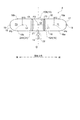
図1は、本発明の一実施形態にかかる浮沈装置を備える水中構造物である潜水艦の概略側面図である。 FIG. 1 is a schematic side view of a submarine that is an underwater structure including a floating device according to an embodiment of the present invention.
図1に示すように、潜水艦1は、船体2と、船体2から上方向に向かって突出する艦橋3と、船体2の内部に備えられる浮沈装置4と、潜水艦1を推進させるためのプロペラ5とを備える。
なお、本開示において、浮沈装置4による浮力によって潜水艦1が浮沈する方向を上下方向とし、プロペラ5が回転することで得られる推進力によって潜水艦1が推進する方向を前後方向とする。
As shown in FIG. 1, the submarine 1 includes a
In the present disclosure, the direction in which the submarine 1 floats and sinks due to the buoyancy of the sinking
潜水艦1を含む水中構造物は、通常、姿勢変動が生じないように構成される。このため、図1に示したように、上述した浮沈装置4は、潜水艦1に作用する浮力(F1)の作用点(P1)が、潜水艦1の重力(G1)が作用する重心位置(P2)と前後方向において略一致するように、船体2の内部に配置される。
また、浮沈装置4は、潜水艦1に作用する浮力(F1)の作用点(P1)が、潜水艦1の重心位置(P2)よりも側面視において上方となるように、船体2の内部に配置される。
The underwater structure including the submarine 1 is normally configured so as not to change its posture. For this reason, as shown in FIG. 1, the above-described floating /
In addition, the floating and sinking
図2は、本発明の一実施形態にかかる浮沈装置の構成を示した概略側面図である。図3は、本発明の一実施形態にかかる浮沈装置の構成を示した概略側面図である。図4は、本発明の一実施形態にかかる浮沈装置の構成を示した概略側面図である。図6は、本発明の一実施形態にかかる浮沈装置の構成を示した概略側面図である。 FIG. 2 is a schematic side view showing the configuration of the floatation apparatus according to the embodiment of the present invention. FIG. 3 is a schematic side view showing the configuration of the floatation apparatus according to the embodiment of the present invention. FIG. 4 is a schematic side view showing the configuration of the floatation apparatus according to the embodiment of the present invention. FIG. 6 is a schematic side view showing the configuration of the floatation apparatus according to the embodiment of the present invention.
本発明の一実施形態にかかる浮沈装置4は、図2、3、4、6に示すように、バラストタンク10と、ポンプ14と、第1仕切部材15と、を備える。
As shown in FIGS. 2, 3, 4, and 6, the floating /
バラストタンク10は、その内部に、気体が封入される第1気体室11及びバラスト水が封入されるバラスト水室12が形成されている。
The
本実施形態において、第1気体室11に封入される気体の圧力は、第1仕切部材15が初期状態(バラスト水室12の容積が最小となる状態)において略大気圧となっている。尚、図2、3、4に示すように、バラストタンク10は、気体を送気口19からバラストタンクの外部に送気可能に構成されている。このため、第1仕切部材15の摺動抵抗が大きいような場合には、第1気体室11内の初期状態を、第1仕切部材15の摺動抵抗に対抗するための適切な圧力に設定することができる。
In the present embodiment, the pressure of the gas sealed in the
ここで、本開示における「封入」とは、周辺の部材のよって画定された空間が特定の物質で満たされている状態を意味している。ただし、本発明の効果を奏する限りにおいて、第1気体室11に少量のバラスト水が混入している状態や、バラスト水室12に少量の気体が混入している状態も、本開示における「封入」に含まれる。
Here, “encapsulation” in the present disclosure means a state in which a space defined by peripheral members is filled with a specific substance. However, as long as the effects of the present invention are exhibited, the state in which a small amount of ballast water is mixed in the
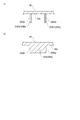
図2、3、4に示した実施形態では、バラストタンク10(10A、10B)は、両端が閉塞された略円筒形状を有し、前後方向が長尺となるように構成されている。バラストタンク10は、前後方向に沿って延在する周壁16と、バラストタンク10の前方側の端部を閉塞する前方側凸壁17と、バラストタンク10の後方側の端部を閉塞する後方側凸壁18と、を備える。周壁16は、その前方端16aから後方端16bに亘って同一の内部断面形状を有している。また、前方側凸壁17は、周壁16の前方端16aから前方に向かって突出するとともに、前方に向かうに従ってその内部断面形状が小さくなるように構成される。後方側凸壁18は、周壁16の後方端16bから後方側に向かって突出するとともに、後方に向かうに従ってその内部断面形状が小さくなるように構成される。
In the embodiment shown in FIGS. 2, 3, and 4, the ballast tank 10 (10A, 10B) has a substantially cylindrical shape with both ends closed, and is configured so that the front-rear direction is long. The
また、図2に示した実施形態では、バラストタンク10の内部の空間は、第1仕切部材15によって前後方向に2つに仕切られる。第1仕切部材15に対して一方側(前方側)には、第1仕切部材15、周壁16、前方側凸壁17によって区画され、気体が封入される第1気体室11が形成される。第1仕切部材15に対して他方側(後方側)には、第1仕切部材15、周壁16、後方側凸壁18によって区画され、バラスト水が封入されるバラスト水室12が形成される。つまり、バラストタンク10は、第1気体室11以外に気体が封入される気体室がバラストタンク10の内部に形成されず、後述する単気体室型バラストタンク10Aとして構成される。
なお、図3、4に示した実施形態にかかるバラストタンク10Bについては後述する。
In the embodiment shown in FIG. 2, the space inside the
The
ポンプ14は、バラスト水室12とバラストタンク10の外部とを連通する連通孔21を介して、バラスト水室12内のバラスト水を排水するように構成されている。
The
図2、3、4、6に示した実施形態では、連通孔21には、バラスト水室12と潜水艦1の外部とを連通するバラスト水管22が接続されている。ポンプ14は、バラスト水管22を介して、バラスト水室12と接続されている。このポンプ14は、バラスト水室12に封入されているバラスト水を、バラスト水管22を介して潜水艦1の外部に排水するためのものである。また、このポンプ14は、例えば海中において、潜水艦1の外部の海水をバラスト水として、バラスト水管22を介してバラスト水室12に注水するように構成されてもよい。
In the embodiment shown in FIGS. 2, 3, 4, and 6, a
また、図2に示した実施形態では、連通孔21は、後方側凸壁18に形成されている。すなわち、連通孔21は、バラストタンク10Aの後方側であって、周壁16の後方端16bよりも後方側の位置に設けられている。
In the embodiment shown in FIG. 2, the
また、図3、4に示した実施形態では、連通孔21は、周壁16の前後方向における中央部に形成されている。
In the embodiment shown in FIGS. 3 and 4, the
第1仕切部材15は、第1気体室11とバラスト水室12とを水密に仕切るための部材である。
The
図2、3、4に示した実施形態では、第1仕切部材15は、後述するように、バラスト水室12の容積の増減に応じてバラストタンク10内を移動する第1ピストン15Aからなる。
In the embodiment shown in FIGS. 2, 3, and 4, the
また、図6に示した実施形態では、第1仕切部材15は、後述するように、バラスト水室12の容積の増減に応じて変形する第1ダイヤフラム15Bからなる。
In the embodiment shown in FIG. 6, the
そして、第1仕切部材15は、バラスト水室12にバラスト水が注水されると、バラスト水室12の容積を増大させるとともに第1気体室11の容積を減少させるように構成される。
The
そのため、バラスト水室12にバラスト水を注水することで、バラストタンク10による浮力を減少させることが出来る。よって、浮沈装置4は、潜水艦1の重力を潜水艦1に作用する浮力より大きくさせ(G1>F1)、潜水艦1を水中で沈降させることが出来る。
Therefore, buoyancy by the
また、第1仕切部材15は、バラスト水室12からバラスト水が排水されると、バラスト水室12の容積を減少させるとともに第1気体室11の容積を増大させるように構成される。そのため、バラスト水室12からバラスト水がポンプ14によって排水されると、バラストタンク10による浮力を増大させることが出来る。よって、浮沈装置4は、潜水艦1の重力を潜水艦1に作用する浮力より小さくさせ(G1<F1)、潜水艦1を水中で浮上させることが出来る。
Further, the
このような本発明の一実施形態にかかる浮沈装置4によれば、沈降時にはバラスト水室12にバラスト水を注水することで、バラスト水室12の容積が増大するとともに第1気体室11の容積が減少する。一方、浮上時には例えばポンプ14によってバラスト水室12からバラスト水を排水することで、バラスト水室12の容積が減少するとともに第1気体室11の容積が増大する。このように、気体が封入される第1気体室11の容積がバラスト水室12の容積に応じて増減するように構成されることで、特許文献1に記載の浮沈装置のような反応室を備える必要がなく、シンプルな構造で潜水艦1を水中で繰返し浮沈させることが出来る浮沈装置4を提供することが出来る。
According to the floating and
また、第1気体室11とバラスト水室12とは第1仕切部材15によって水密に仕切られているとともに、バラスト水室12からバラスト水が排水されると、バラスト水室12の容積が減少するとともに第1気体室11の容積が増大するように構成されている。よって、例えばポンプ14によってバラスト水室12に封入されているバラスト水を排水する場合に、第1気体室11とバラスト水室12とは第1仕切部材15によって水密に仕切られた状態のまま、バラスト水室12の容積が減少する。つまり、バラスト水室12に封入されているバラスト水を排水しても、バラスト水室12内には気体が混入しないような構造となっている。これにより、ポンプ14が気体を吸い込むことはなく、ポンプ14がバラスト水を排水できない状態(いわゆる、エア噛み)の発生を防止することが出来るようになっている。
Further, the
幾つかの実施形態では、図3、4、6に示したように、バラストタンク10(10B、10C)の内部には、バラストタンク10の重心位置(P3)を挟んで第1気体室11とは反対側に、気体が封入される第2気体室23がさらに形成される。
浮沈装置4は、第2気体室23とバラスト水室12とを水密に仕切るための第2仕切部材24をさらに備える。
そして、第2仕切部材24は、バラスト水室12にバラスト水が注水されると、バラスト水室12の容積を増大させるとともに第2気体室23の容積を減少させ、バラスト水室12からバラスト水が排水されると、バラスト水室12の容積を減少させるとともに第2気体室23の容積を増大させるように構成されている。
In some embodiments, as shown in FIGS. 3, 4, and 6, the ballast tank 10 (10 </ b> B, 10 </ b> C) includes the
The floatation /
When the ballast water is poured into the
図3、4、6に示した実施形態において、第2気体室23に封入される気体の圧力は、第1仕切部材15及び第2仕切部材24が初期状態(バラスト水室12の容積が最小となる状態)において、第1気体室11に封入されている気体の圧力と同様に、略大気圧となっている。
In the embodiment shown in FIGS. 3, 4, and 6, the pressure of the gas sealed in the
また、図3、4に示した実施形態では、バラストタンク10の内部の空間は、第1仕切部材15及び第2仕切部材24によって前後方向に3つに仕切られる。第1仕切部材15に対して一方側(前方側)には、第1仕切部材15、周壁16、前方側凸壁17によって区画され、気体が封入される第1気体室11が形成される。第2仕切部材24に対して他方側(後方側)には、第2仕切部材24、周壁16、後方側凸壁18によって区画され、気体が封入される第2気体室23が形成される。そして、第1仕切部材15と第2仕切部材との間には、第1仕切部材15、第2仕切部材24、周壁16によって区画され、バラスト水が封入されるバラスト水室12が形成される。つまり、バラストタンク10Bは、第1気体室11と第2気体室23の2つの気体室が、バラスト水室12を挟んで互いに反対側に位置するように構成されている。
In the embodiment shown in FIGS. 3 and 4, the space inside the
このような構成によれば、第1気体室11による浮力(F2)と、第2気体室23による浮力(F3)とを、バラストタンク10の重心位置(P3)を挟んで互いに反対側からバラストタンク10に作用させることが出来る。これにより、バラストタンク10に第1気体室11による浮力(F2)のみが作用する場合と比べて、潜水艦1の姿勢変動を抑制することが出来る。
According to such a configuration, the buoyancy (F2) caused by the
また、バラストタンク10の重心位置(P3)を挟んで第1気体室11とは反対側に第2気体室23を形成することで、複数のバラストタンクを備えずとも、1つのバラストタンク10Bによって潜水艦1の姿勢変動を抑制することが出来るようになっている。
複数のバラストタンクを備える場合は、それに対する注排水系統もバラストタンク毎に複数必要となるが、1つのバラストタンク10だけを備える場合は、複数のバラストタンクを備える場合と比べて、注排水系統をシンプルに構成することが出来る。
Further, by forming the
When a plurality of ballast tanks are provided, a plurality of water injection / drainage systems are required for each ballast tank. Can be configured simply.
幾つかの実施形態では、図3、4、6に示したように、第1気体室11及び第2気体室23の各々の容積は、バラスト水室12の容積の増減に関わらず、互いに等しくなるように構成される。
In some embodiments, as shown in FIGS. 3, 4, and 6, the volumes of the
つまり、第1気体室11及び第2気体室23には、第1仕切部材15及び第2仕切部材24が初期状態(バラスト水室12の容積が最小となる状態)において、同じ種類の気体が同じ圧力(例えば略大気圧)で封入されている。
そして、図3、4に示した実施形態では、第1ピストン15A及び第2ピストン24Aは、バラスト水室12の容積の増減に関わらず、常に同じ距離だけ移動するように構成されている。また、図6に示した実施形態では、第1ダイヤフラム15B及び第2ダイヤフラム24Bは、バラスト水室12の容積の増減に関わらず、常に同じように変形するように構成されている。
That is, in the
In the embodiment shown in FIGS. 3 and 4, the
このような構成によれば、バラスト水室12の容積の増減に関わらず、第1気体室11による浮力(F2)と第2気体室23による浮力(F3)とは互いに等しくなる。これにより、潜水艦1の姿勢変動をさらに抑制させることが出来る。
According to such a configuration, the buoyancy (F2) due to the
また、図3、4、6に示した実施形態では、図3において説明するように、第1気体室11における浮力(F2)の作用点(P4)とバラストタンク10の重心位置(P3)との距離(L1)と、第2気体室23における浮力(F3)の作用点(P5)とバラストタンク10の重心位置(P3)との距離(L2)とが、バラスト水室12の容積の増減に関わらず、互いに等しくなるように構成される。
この場合、バラストタンク10は、重心位置(P3)を上下方向に通過する中心線Oに対して略対称に構成されている。
In the embodiment shown in FIGS. 3, 4, and 6, as described in FIG. 3, the action point (P 4) of the buoyancy (F 2) in the
In this case, the
このような構成によれば、バラスト水室12の容積の増減に関わらず、第1気体室11の浮力(F2)によってバラストタンク10に作用するモーメントと、第2気体室23の浮力(F3)によってバラストタンク10に作用するモーメントとは、互いに打ち消し合うように作用する。これにより、潜水艦1の姿勢変動をさらに抑制させることが出来る。
According to such a configuration, the moment acting on the
幾つかの実施形態では、第1仕切部材15は、上述したように、バラスト水室12の容積の増減に応じてバラストタンク10内を移動する第1ピストン15Aからなる。
また、図3、4に示したように、第2仕切部材24は、バラスト水室12の容積の増減に応じてバラストタンク10内を移動する第2ピストン24Aからなる。
In some embodiments, the
As shown in FIGS. 3 and 4, the
第1ピストン15A及び第2ピストン24Aには、その周囲にシールリング13が装着されている。そして、このシールリング13が、バラストタンク10の周壁16と摺動可能に構成されることで、第1ピストン15A及び第2ピストン24Aが移動しても、バラスト水室12と、第1気体室11及び第2気体室23とが、水密に仕切られるようになっている。
A
そして、バラスト水室12にバラスト水が注水されると、第1ピストン15Aは第1気体室11側に移動するとともに、第2ピストン24Aは第2気体室23側に移動する。これにより、バラスト水室12の容積が増大するとともに、第1気体室11の容積及び第2気体室23の容積は減少する。
一方、バラスト水室12からバラスト水が排水されると、第1ピストン15A及び第2ピストン24Aは共にバラスト水室12側に移動する。これにより、バラスト水室12の容積は減少するとともに、第1気体室11の容積及び第2気体室23の容積は増大する。
When ballast water is poured into the
On the other hand, when the ballast water is drained from the
このような構成によれば、第1仕切部材15及び第2仕切部材24は、バラスト水室12の容積の増減に応じてバラストタンク10内を移動するピストンからなる。このように、バラストタンク10内を移動可能なピストンによってバラスト水室12の容積を増減させることで、例えば後述するダイヤフラムの場合と比べて、バラスト水室12の容積を大きく増減させることが可能となる。
According to such a structure, the
幾つかの実施形態では、図4に示したように、バラストタンク10は、第1ピストン15Aが連通孔21を超えて第2ピストン24A側へ移動することを規制する第1移動規制手段25Aと、第2ピストン24Aが連通孔21を超えて第1ピストン15A側へ移動することを規制する第2移動規制手段25Bと、を有する。
In some embodiments, as shown in FIG. 4, the
このような構成によれば、第1ピストン15Aが連通孔21を越えて第2ピストン24A側へ移動することを規制されるとともに、第2ピストン24Aが連通孔21を越えて第1ピストン15A側へ移動することを規制される。これにより、第1気体室11及び第2気体室23が、連通孔21を介してバラストタンク10の外部と連通することが確実に防止され、第1気体室11及び第2気体室23に気体が封入されている状態を維持することが出来る。
According to such a configuration, the movement of the
幾つかの実施形態では、図4に示したように、第1移動規制手段25A及び第2移動規制手段25Bは、バラストタンク10の周壁16の内面16cから突出するストッパ25Sからなる。
In some embodiments, as shown in FIG. 4, the first movement restricting means 25 </ b> A and the second movement restricting means 25 </ b> B include a stopper 25 </ b> S protruding from the
図示した実施形態では、ストッパ25Sは、前後方向に沿って延在しており、ストッパ25Sの前後方向における中心位置(P10)が、中心線Oに位置するように構成されている。そして、ストッパ25Sの両端部には、第1ピストン15Aと接触する第1接触部25Sa、及び第2ピストン24Aと接触する第2接触部25Sbが形成されている。
第1接触部25Saは、前後方向において、連通孔21の周縁における最も前方側の位置(P6)よりも、前方側に位置するように構成される。第2接触部25Sbは、前後方向において、連通孔21の周縁における最も後方側の位置(P7)よりも、後方側に位置するように構成される。
In the illustrated embodiment, the
1st contact part 25Sa is comprised so that it may be located in the front side rather than the frontmost position (P6) in the periphery of the communicating
このような構成によれば、バラストタンク10の周壁16の内面16cから突出するストッパ25Sによって、第1ピストン15A及び第2ピストン24Aの移動を規制することが出来る。
According to such a configuration, the movement of the
また、バラストタンク10の周壁16の内面16cから突出するストッパ25Sによって第1移動規制手段25A及び第2移動規制手段25Bを構成することで、例えば、浮沈装置4の製造時において、第1ピストン15A及び第2ピストン24Aをバラストタンク10内に挿入するのに先立ち、バラストタンク10内にストッパ25Sを設置することで、第1ピストン15A及び第2ピストン24Aをバラストタンク10内に挿入する際の位置決めのために、このストッパ25Sを利用することが出来る。
Further, the first movement restricting means 25A and the second movement restricting means 25B are configured by the
また、図4に示した実施形態では、ストッパ25Sは、側面視において、第1接触部25Saから中心線Oまでの長さ(L3)と、第2接触部25Sbから中心線Oまでの長さ(L4)とが、同じ長さになるように構成されている。
これにより、バラスト水室12の容積が最小となる初期状態において、第1気体室11及び第2気体室23の各々の容積を互いに等しくすることが出来る。このため、何らかの原因によって、第1ピストン15Aの移動量と第2ピストン24Aの移動量とにズレが生じ、第1気体室11及び第2気体室23の各々の容積を互いに等しい状態に維持できなくなった場合であっても、バラスト水室12からバラスト水を排水してバラスト水室12の容積を最小にすることで、第1気体室11及び第2気体室23の各々の容積を互いに等しい状態に戻すことが出来る。
In the embodiment shown in FIG. 4, the
Thereby, in the initial state where the volume of the
なお、上述した説明では、第1ピストン15Aの移動及び第2ピストン24Aの移動を規制する移動規制手段として、第1接触部25Sa及び第2接触部25Sbを有するストッパ25Sを例示して説明した。しかしながら、本発明はこれに限定されない。
In the above description, the
図5は、図4に示すストッパの変形例を拡大して示す断面図である。(A)はストッパの第1変形例を、(B)はストッパの第2変形例を示す。 FIG. 5 is an enlarged sectional view showing a modification of the stopper shown in FIG. (A) shows the 1st modification of a stopper, (B) shows the 2nd modification of a stopper.
例えば、移動規制手段として、図5の(A)に示したように、バラストタンク10の周壁16の内面16cから突出する2つのストッパ25S1、25S2を設けてもよい。そして、一方のストッパ25S1が第1ピストン15Aと接触する第1接触部25Saを有することで第1ピストン15Aの移動を規制し、他方のストッパ25S2が第2ピストン24Aと接触する第2接触部25Sbを有することで第2ピストン24Aの移動を規制するように構成してもよい。
For example, as shown in FIG. 5A, two stoppers 25S1 and 25S2 that protrude from the
あるいは、移動規制手段として、図5の(B)に示したように、バラストタンク10の周壁16の内面16cに一体的に形成された段部16Sによって、第1ピストン15Aの移動及び第2ピストン24Aの移動を規制するように構成してもよい。
Alternatively, as the movement restricting means, as shown in FIG. 5B, the movement of the
幾つかの実施形態では、図6に示したように、第1仕切部材15は、バラスト水室12の容積の増減に応じて変形する第1ダイヤフラム15Bからなる。また、第2仕切部材24は、バラスト水室12の容積の増減に応じて変形する第2ダイヤフラム24Bからなる。
In some embodiments, as illustrated in FIG. 6, the
第1ダイヤフラム15B及び第2ダイヤフラム24Bは、可撓性を有する隔膜部材からなる。第1ダイヤフラム15Bは、第1気体室とバラスト水室12とを水密に仕切り、第2ダイヤフラム24Bは、第2気体室23とバラスト水室12とを水密に仕切る。
The
そして、バラスト水室12にバラスト水が注水されると、第1ダイヤフラム15Bは第1気体室11側に膨出するように変形するとともに、第2ダイヤフラム24Bは第2気体室23側に膨出するように変形する。これにより、バラスト水室12の容積が増大するとともに、第1気体室11の容積及び第2気体室23の容積は減少する。
一方、バラスト水室12からバラスト水が排水されると、第1ダイヤフラム15B及び第2ダイヤフラム24Bは共にバラスト水室12側に膨出するように変形する。これにより、バラスト水室12の容積は減少するとともに、第1気体室11の容積及び第2気体室23の容積は増大する。
When ballast water is poured into the
On the other hand, when the ballast water is drained from the
このような構成によれば、第1仕切部材15及び第2仕切部材24は、バラスト水室12の容積の増減に応じて変形するダイヤフラムからなる。このように、ダイヤフラムが有する可撓性によってバラスト水室12の容積を増減させることで、第1ダイヤフラム15B及び第2ダイヤフラム24Bを移動させる必要がなく、摺動部材を必要としないことから、繰り返し且つ安定的に、バラスト水室12の容積を増減させることが可能となる。
According to such a structure, the
また、図6に示した実施形態では、バラストタンク10Cは球形状を有している。このように、バラストタンク10が球形状を有する場合は、第1仕切部材15及び第2仕切部材24を上述したピストンによって構成することは難しいが、第1仕切部材15及び第2仕切部材24をダイヤフラムによって構成することで、バラスト水室12の容積の増減に応じて第1気体室11の容積及び第2気体室23の容積を増減させることが出来る。
In the embodiment shown in FIG. 6, the
上述した実施形態では、本発明の一実施形態にかかる浮沈装置4を備える水中構造物の一例として、潜水艦1を例に説明したが、これに限定されず、図7に示すように、沈座標的100であってもよい。ここで沈座標的100とは、例えば、試験や研究のために水中を浮沈する水中構造物である。
なお、以下の実施形態において、上述した実施形態と同じ構成については、同一の符号を付し、その詳細な説明を省略する。
In the above-described embodiment, the submarine 1 has been described as an example of the underwater structure including the floating and sinking
In the following embodiments, the same components as those in the above-described embodiments are denoted by the same reference numerals, and detailed description thereof is omitted.
図7は、本発明の一実施形態にかかる浮沈装置を備える水中構造物である沈座標的の概略側面図である。
図7に示すように、沈座標的100は、船体101と、船体101を浮沈させるための浮沈装置4と、船体101の水中での位置を固定するための錨102と、を備える。
FIG. 7 is a schematic side view of a sinking coordinate system which is an underwater structure including a floating and sinking apparatus according to an embodiment of the present invention.
As shown in FIG. 7, the sinking coordinate 100 includes a
船体101は、略矩形状を有し、前後方向が長尺となるように構成されている。船体101の両端からは係留索103が垂下されており、係留索103の先端103aには錨102が接続されている。
The
図8は、本発明の一実施形態にかかる浮沈装置を備える沈座標的の第1変形例を示した概略平面図である。 FIG. 8: is the schematic plan view which showed the 1st modification of a sinking coordinate provided with the floating / sink apparatus concerning one Embodiment of this invention.
幾つかの実施形態では、図8に示したように、沈座標的100Aを水中で浮沈させる浮沈装置4を備えるバラストタンク10は、長手方向を有する形状からなる第1バラストタンク10B1と、長手方向を有する形状からなる第2バラストタンク10B2であって、平面視において、沈座標的100Aの重心位置(P10)を挟んで第1バラストタンク10B1とは反対側において、第1バラストタンク10B1の長手方向に沿って配置される第2バラストタンク10B2と、を含む。
In some embodiments, as shown in FIG. 8, the
図示した実施形態では、第1バラストタンク10B1及び第2バラストタンク10B2は、それらの長手方向が、沈座標的100Aの前後方向に沿うように配置されている。 In the illustrated embodiment, the first ballast tank 10B1 and the second ballast tank 10B2 are arranged such that their longitudinal directions are along the front-rear direction of the subordinate coordinate 100A.
沈座標的100Aは、前後方向と直交する幅方向においても所定の大きさ有しており、幅方向においても姿勢変動を抑制する必要がある。
このような構成によれば、第1バラストタンク10B1及び第2バラストタンク10B2が、平面視において、沈座標的100Aの重心位置(P10)を挟んで互いに反対側に形成されている。これにより、バラストタンクの長手方向だけでなく、バラストタンクの長手方向と直交する方向(幅方向)においても、沈座標的100Aの姿勢変動を抑制することが出来る。
The collided coordinate 100A has a predetermined size also in the width direction orthogonal to the front-rear direction, and it is necessary to suppress posture variation in the width direction.
According to such a configuration, the first ballast tank 10B1 and the second ballast tank 10B2 are formed on opposite sides of the center of gravity (P10) of the collided 100A in plan view. Thereby, not only in the longitudinal direction of the ballast tank, but also in the direction (width direction) orthogonal to the longitudinal direction of the ballast tank, it is possible to suppress the change in the attitude of the collided 100A.
また、図示した実施形態では、沈座標的100Aを水中で浮沈させる浮沈装置4は、第1バラストタンク10B1の連通孔21B1と接続されるバラスト水管22(第1バラスト水管22B1)と、第2バラストタンク10B2の連通孔21B2と接続されるバラスト水管22(第2バラスト水管22B2)と、第1バラスト水管22B1を介して第1バラストタンク10B1に接続されるとともに、第2バラスト水管22B2を介して第2バラストタンク10B2に接続されるポンプ14と、第1バラスト水管22B1を流れるバラスト水の流量を調整するための第1調整弁151B1と、第2バラスト水管22B2を流れるバラスト水量を調整するための第2調整弁151B2と、を備えている。
In the illustrated embodiment, the float /
このような構成によれば、沈座標的100Aに幅方向の姿勢変動が生じても、第1調整弁151B1によって、第1バラストタンク10B1のバラスト水室12に封入されるバラスト水の流量を調整することが出来る。また、第2調整弁151B2によって、第2バラストタンク10B2のバラスト水室12に封入されるバラスト水の流量を調整することが出来る。これにより、第1バラストタンク10B1による浮力及び第2バラストタンク10B2による浮力を夫々調整することが出来、沈座標的100Aに幅方向の姿勢変動が生じても、沈座標的100Aの姿勢を安定的な姿勢に戻すことが出来る。
According to such a configuration, the flow rate of the ballast water sealed in the
図9は、本発明の一実施形態にかかる浮沈装置を備える沈座標的の第2変形例を示した概略平面図である。
図9に示した実施形態において、沈座標的100Bは、平面視において略円形状を有している。
FIG. 9 is a schematic plan view illustrating a second modified example of a sinking coordinate system including the floating / sinking device according to the embodiment of the present invention.
In the embodiment shown in FIG. 9, the sinking coordinate 100B has a substantially circular shape in plan view.
幾つかの実施形態では、図9に示すように、沈座標的100Bを水中で浮沈させる浮沈装置4はバラストタンク10を含み、該バラストタンク10は、第1気体室11以外に気体が封入される気体室がバラストタンク10の内部に形成されていない、複数の単気体室型バラストタンク10Aを含む。
そして、複数の単気体室型バラストタンク10Aの各々は、複数の単気体室型バラストタンク10Aの各々の第1気体室11による浮力を合成した合成浮力の作用点(P11)が、複数の単気体室型バラストタンク10Aの各々におけるバラスト水室12の容積の増減に関わらず、平面視において、沈座標的100Bの重心位置(P12)と略一致するように配置される。
In some embodiments, as shown in FIG. 9, the floating and sinking
Each of the plurality of single gas chamber
図示した実施形態では、沈座標的100Bは、平面視において略円形状を有している。
そして、ポンプ14は、複数の単気体室型バラストタンク10Aの各々とバラスト水管22を介して接続されている。
なお、図示した実施形態において、沈座標的100Bは、沈座標的100Bの重心位置(P12)を中心として放射状に配置された6つの単気体室型バラストタンク10A(10A1〜10A6)を含む。
In the illustrated embodiment, the sinking coordinate 100B has a substantially circular shape in plan view.
The
In the illustrated embodiment, the sinking coordinate 100B includes six single gas chamber
また、図示した実施形態では、複数の単気体室型バラストタンク10A1〜10A6の各々の第1気体室11は、複数の単気体室型バラストタンク10A1〜10A6の各々のバラスト水室12よりも沈座標的100Bの径方向外側に配置されている。
In the illustrated embodiment, each of the
このような構成によれば、複数の単気体室型バラストタンク10A1〜10A6の合成浮力の作用点(P11)が、沈座標的100Bの重心位置(P12)と平面視において略一致するように構成される。これにより、長尺形状を有する沈座標的100だけでなく、例えば、円形状や矩形状などの形状を有する沈座標的100Bにおいても、複数の単気体室型バラストタンク10A1〜10A6を沈座標的100Bの形状に応じて適当に配置することによって、沈座標的100Bの姿勢変動を抑制することが出来る。 According to such a configuration, the combined buoyancy action point (P11) of the plurality of single gas chamber type ballast tanks 10A1 to 10A6 is configured to substantially coincide with the gravity center position (P12) of the sunk coordinate 100B in a plan view. Is done. Thereby, not only the sinking coordinate 100 having the long shape but also the sinking coordinate 100B having a shape such as a circular shape or a rectangular shape, the plurality of single gas chamber type ballast tanks 10A1 to 10A6 are set to the sinking coordinate. By appropriately arranging according to the shape of 100B, it is possible to suppress the change in posture of the sinking 100B.
以上、本発明の一実施形態にかかる浮沈装置4について説明したが、本発明は上記の形態に限定されるものではなく、本発明の目的を逸脱しない範囲での種々の変更が可能である。
例えば、上述した実施形態では、浮沈装置4を備える水中構造物の一例として、潜水艦1又は沈座標的100を例にして説明したが、これに限定されず、例えば、UUV(自律型無人潜水機)や水中航走体などの他の水中構造物にも適用可能である。
The floatation /
For example, in the above-described embodiment, the submarine 1 or the sinking coordinate 100 has been described as an example of the underwater structure including the floating and sinking
1 潜水艦
2,101 船体
3 艦橋
4 浮沈装置
5 プロペラ
10 バラストタンク
10A 単気体室型バラストタンク
11 第1気体室
12 バラスト水室
13 シールリング
14 ポンプ
15 第1仕切部材
15A 第1ピストン
15B 第1ダイヤフラム
16 周壁
19 送気口
21 連通孔
22 バラスト水管
23 第2気体室
24 第2仕切部材
24A 第2ピストン
24B 第2ダイヤフラム
25A 第1移動規制手段
25B 第2移動規制手段
25S ストッパ
100,100A,100B 沈座標的
102 錨
103 係留索
151B1 第1調整弁
151B2 第2調整弁
DESCRIPTION OF SYMBOLS 1 Submarine 2,101
Claims (9)
気体が封入される第1気体室と、バラスト水が封入されるバラスト水室とが内部に形成されるバラストタンクと、
前記バラスト水室と前記バラストタンクの外部とを連通する連通孔を介して、前記バラスト水室内の前記バラスト水を排水するためのポンプと、
前記第1気体室と前記バラスト水室とを水密に仕切るための第1仕切部材と、を備え、
前記第1仕切部材は、前記バラスト水室に前記バラスト水が注水されると、前記バラスト水室の容積を増大させるとともに前記第1気体室の容積を減少させ、前記バラスト水室から前記バラスト水が排水されると、前記バラスト水室の容積を減少させるとともに前記第1気体室の容積を増大させるように構成されている浮沈装置。 A floatation device that floats and sinks an underwater structure in water,
A ballast tank in which a first gas chamber in which gas is sealed and a ballast water chamber in which ballast water is sealed are formed;
A pump for draining the ballast water in the ballast water chamber through a communication hole communicating the ballast water chamber and the outside of the ballast tank;
A first partition member for watertightly partitioning the first gas chamber and the ballast water chamber,
When the ballast water is poured into the ballast water chamber, the first partition member increases the volume of the ballast water chamber and decreases the volume of the first gas chamber, and from the ballast water chamber to the ballast water. When the water is discharged, the floatation apparatus is configured to decrease the volume of the ballast water chamber and increase the volume of the first gas chamber.
前記第2気体室と前記バラスト水室とを水密に仕切るための第2仕切部材をさらに備え、
前記第2仕切部材は、前記バラスト水室に前記バラスト水が注水されると、前記バラスト水室の容積を増大させるとともに前記第2気体室の容積を減少させ、前記バラスト水室から前記バラスト水が排水されると、前記バラスト水室の容積を減少させるとともに前記第2気体室の容積を増大させるように構成されている請求項1に記載の浮沈装置。 Inside the ballast tank, a second gas chamber in which gas is sealed is further formed on the opposite side of the first gas chamber across the center of gravity of the ballast tank,
A second partition member for watertightly partitioning the second gas chamber and the ballast water chamber;
When the ballast water is poured into the ballast water chamber, the second partition member increases the volume of the ballast water chamber and decreases the volume of the second gas chamber, and from the ballast water chamber to the ballast water. The floatation / sink apparatus according to claim 1, wherein when the water is drained, the volume of the ballast water chamber is decreased and the volume of the second gas chamber is increased.
前記第2仕切部材は、前記バラスト水室の容積の増減に応じて前記バラストタンク内を移動する第2ピストンからなる請求項2又は3に記載の浮沈装置。 The first partition member comprises a first piston that moves in the ballast tank in accordance with an increase or decrease in the volume of the ballast water chamber,
4. The floatation / sink device according to claim 2, wherein the second partition member includes a second piston that moves in the ballast tank according to an increase or decrease in a volume of the ballast water chamber.
前記第1ピストンが前記連通孔を超えて前記第2ピストン側へ移動することを規制する第1移動規制手段と、
前記第2ピストンが前記連通孔を超えて前記第1ピストン側へ移動することを規制する第2移動規制手段と、を有する請求項4に記載の浮沈装置。 The ballast tank is
First movement restricting means for restricting movement of the first piston beyond the communication hole toward the second piston;
5. The float / sink device according to claim 4, further comprising second movement restriction means for restricting movement of the second piston beyond the communication hole toward the first piston.
前記第2仕切部材は、前記バラスト水室の容積の増減に応じて変形する第2ダイヤフラムからなる請求項2又は3に記載の浮沈装置。 The first partition member comprises a first diaphragm that deforms in accordance with an increase or decrease in the volume of the ballast water chamber,
4. The float / sink apparatus according to claim 2, wherein the second partition member includes a second diaphragm that deforms in accordance with an increase or decrease in the volume of the ballast water chamber.
長手方向を有する形状からなる第1バラストタンクと、
長手方向を有する形状からなる第2バラストタンクであって、平面視において、前記水中構造物の重心位置を挟んで前記第1バラストタンクとは反対側において、前記第1バラストタンクの長手方向に沿って配置される第2バラストタンクと、を含む請求項2から7の何れか1項に記載の浮沈装置。 The ballast tank is
A first ballast tank having a shape having a longitudinal direction;
A second ballast tank having a shape having a longitudinal direction, and along the longitudinal direction of the first ballast tank on a side opposite to the first ballast tank across the center of gravity of the underwater structure in a plan view. The floatation / sink device according to any one of claims 2 to 7, further comprising a second ballast tank disposed in a row.
前記複数の単気体室型バラストタンクの各々は、前記複数の単気体室型バラストタンクの各々の前記第1気体室による浮力を合成した合成浮力の作用点が、前記複数の単気体室型バラストタンクの各々における前記バラスト水室の容積の増減に関わらず、平面視において、前記水中構造物の重心位置と略一致するように配置される請求項1に記載の浮沈装置。 The ballast tank includes a plurality of single gas chamber type ballast tanks in which a gas chamber in which a gas other than the first gas chamber is sealed is not formed inside the ballast tank,
Each of the plurality of single gas chamber type ballast tanks has an action point of a combined buoyancy obtained by synthesizing buoyancy due to the first gas chamber of each of the plurality of single gas chamber type ballast tanks. The floatation / sink device according to claim 1, wherein the float / sink device is arranged so as to substantially coincide with a center of gravity of the underwater structure in a plan view regardless of increase or decrease in volume of the ballast water chamber in each tank.
Priority Applications (1)
| Application Number | Priority Date | Filing Date | Title |
|---|---|---|---|
| JP2016238731A JP6657064B2 (en) | 2016-12-08 | 2016-12-08 | Flotation device |
Applications Claiming Priority (1)
| Application Number | Priority Date | Filing Date | Title |
|---|---|---|---|
| JP2016238731A JP6657064B2 (en) | 2016-12-08 | 2016-12-08 | Flotation device |
Publications (2)
| Publication Number | Publication Date |
|---|---|
| JP2018094961A true JP2018094961A (en) | 2018-06-21 |
| JP6657064B2 JP6657064B2 (en) | 2020-03-04 |
Family
ID=62631871
Family Applications (1)
| Application Number | Title | Priority Date | Filing Date |
|---|---|---|---|
| JP2016238731A Active JP6657064B2 (en) | 2016-12-08 | 2016-12-08 | Flotation device |
Country Status (1)
| Country | Link |
|---|---|
| JP (1) | JP6657064B2 (en) |
Cited By (5)
| Publication number | Priority date | Publication date | Assignee | Title |
|---|---|---|---|---|
| CN111232168A (en) * | 2020-01-13 | 2020-06-05 | 哈尔滨工程大学 | Ballast water tank based on gear scissor fork mechanism |
| JP2021079816A (en) * | 2019-11-19 | 2021-05-27 | 株式会社フジタ | Underwater measurement device and underwater measurement method |
| CN114802657A (en) * | 2022-03-18 | 2022-07-29 | 中国舰船研究设计中心 | Gyro-type cross-medium unmanned aircraft and working method thereof |
| RU221524U1 (en) * | 2023-06-19 | 2023-11-09 | Федеральное государственное казенное военное образовательное учреждение высшего образования "Военный учебно-научный центр Военно-Морского Флота "Военно-морская академия имени Адмирала флота Советского Союза Н.Г. Кузнецова" | Underwater vehicle with anchor device |
| WO2023234287A1 (en) * | 2022-06-03 | 2023-12-07 | 国立大学法人東京大学 | Float structure for offshore wind power generation |
Citations (3)
| Publication number | Priority date | Publication date | Assignee | Title |
|---|---|---|---|---|
| JPS54131297A (en) * | 1978-03-31 | 1979-10-12 | Koyo Kk | Buoyancy adjusting system sinkkanddfloat device |
| GB2228901A (en) * | 1988-10-24 | 1990-09-12 | Secr Defence | Buoyancy control means |
| WO2014163141A1 (en) * | 2013-04-03 | 2014-10-09 | 株式会社Ihi | Underwater device |
-
2016
- 2016-12-08 JP JP2016238731A patent/JP6657064B2/en active Active
Patent Citations (3)
| Publication number | Priority date | Publication date | Assignee | Title |
|---|---|---|---|---|
| JPS54131297A (en) * | 1978-03-31 | 1979-10-12 | Koyo Kk | Buoyancy adjusting system sinkkanddfloat device |
| GB2228901A (en) * | 1988-10-24 | 1990-09-12 | Secr Defence | Buoyancy control means |
| WO2014163141A1 (en) * | 2013-04-03 | 2014-10-09 | 株式会社Ihi | Underwater device |
Cited By (7)
| Publication number | Priority date | Publication date | Assignee | Title |
|---|---|---|---|---|
| JP2021079816A (en) * | 2019-11-19 | 2021-05-27 | 株式会社フジタ | Underwater measurement device and underwater measurement method |
| JP7325309B2 (en) | 2019-11-19 | 2023-08-14 | 株式会社フジタ | Underwater measuring device and underwater measuring method |
| CN111232168A (en) * | 2020-01-13 | 2020-06-05 | 哈尔滨工程大学 | Ballast water tank based on gear scissor fork mechanism |
| CN114802657A (en) * | 2022-03-18 | 2022-07-29 | 中国舰船研究设计中心 | Gyro-type cross-medium unmanned aircraft and working method thereof |
| CN114802657B (en) * | 2022-03-18 | 2024-01-26 | 中国舰船研究设计中心 | Gyro type cross-medium unmanned aircraft and working method thereof |
| WO2023234287A1 (en) * | 2022-06-03 | 2023-12-07 | 国立大学法人東京大学 | Float structure for offshore wind power generation |
| RU221524U1 (en) * | 2023-06-19 | 2023-11-09 | Федеральное государственное казенное военное образовательное учреждение высшего образования "Военный учебно-научный центр Военно-Морского Флота "Военно-морская академия имени Адмирала флота Советского Союза Н.Г. Кузнецова" | Underwater vehicle with anchor device |
Also Published As
| Publication number | Publication date |
|---|---|
| JP6657064B2 (en) | 2020-03-04 |
Similar Documents
| Publication | Publication Date | Title |
|---|---|---|
| JP2018094961A (en) | Float-sink device | |
| KR100651203B1 (en) | Buoyancy and attitude control system for deep-sea unmaned submersibles | |
| TWI571564B (en) | Underwater apparatus | |
| US11655006B2 (en) | Pontoon systems and methods | |
| BRPI0617505A2 (en) | submersible vehicle, method for operating a submersible vehicle, use of a submersible vehicle, method for docking a submersible vehicle, and method for maneuvering a submersible vehicle | |
| US10472035B2 (en) | Underwater vehicle | |
| WO2009072901A9 (en) | System and method for the active and passive stabilization of a vessel | |
| KR20180034998A (en) | Adjusting Apparatus for Ballast Water | |
| CN102596710A (en) | Apparatus for reducing pitching and rolling motion of vessel | |
| US6241425B1 (en) | Tethered marine stabilizing system | |
| US7984685B1 (en) | Neutrally buoyant submerged system using greater density ballast fluid | |
| BR112018012867B1 (en) | SEMISSUBMERSIBLE OFFSHORE STRUCTURE | |
| JP2019077258A (en) | Buoyancy adjustment device and buoyancy adjustment system | |
| KR101930999B1 (en) | Inflatable floating device with metal bladder unit for small ship | |
| KR200443276Y1 (en) | Ballast apparatus of underwater vehicle | |
| KR101964836B1 (en) | Anti-rolling apparatus | |
| KR101102347B1 (en) | Stabilizer for floating body | |
| KR101826682B1 (en) | Anti-rolling tank with chamfers and a marine structure having the tank | |
| JP2016150743A (en) | Propulsion device for submerging/floating of submarine | |
| KR101358201B1 (en) | A ship with an apparatus for reducing frictional resistance by reduced area of wetted surface by air cavity in the bottom of a ship | |
| KR101748947B1 (en) | Floating storage structure on the sea | |
| JP3210309U (en) | Ships equipped with operational stabilization devices | |
| US20240025525A1 (en) | High-capacity lightweight variable buoyancy system | |
| JP2014058275A (en) | Semi-submersible type floating structure | |
| JP5638374B2 (en) | Hull |
Legal Events
| Date | Code | Title | Description |
|---|---|---|---|
| A621 | Written request for application examination |
Free format text: JAPANESE INTERMEDIATE CODE: A621 Effective date: 20180711 |
|
| A977 | Report on retrieval |
Free format text: JAPANESE INTERMEDIATE CODE: A971007 Effective date: 20190620 |
|
| A131 | Notification of reasons for refusal |
Free format text: JAPANESE INTERMEDIATE CODE: A131 Effective date: 20190625 |
|
| A521 | Request for written amendment filed |
Free format text: JAPANESE INTERMEDIATE CODE: A523 Effective date: 20190807 |
|
| TRDD | Decision of grant or rejection written | ||
| A01 | Written decision to grant a patent or to grant a registration (utility model) |
Free format text: JAPANESE INTERMEDIATE CODE: A01 Effective date: 20200128 |
|
| A61 | First payment of annual fees (during grant procedure) |
Free format text: JAPANESE INTERMEDIATE CODE: A61 Effective date: 20200205 |
|
| R150 | Certificate of patent or registration of utility model |
Ref document number: 6657064 Country of ref document: JP Free format text: JAPANESE INTERMEDIATE CODE: R150 |