JP2018091929A - Cleaning device, intermediate transfer device, and image forming apparatus - Google Patents

Cleaning device, intermediate transfer device, and image forming apparatus Download PDF

Info

Publication number
JP2018091929A
JP2018091929A JP2016233286A JP2016233286A JP2018091929A JP 2018091929 A JP2018091929 A JP 2018091929A JP 2016233286 A JP2016233286 A JP 2016233286A JP 2016233286 A JP2016233286 A JP 2016233286A JP 2018091929 A JP2018091929 A JP 2018091929A
Authority
JP
Japan
Prior art keywords
intermediate transfer
brush
cleaning
image forming
transfer belt
Prior art date
Legal status (The legal status is an assumption and is not a legal conclusion. Google has not performed a legal analysis and makes no representation as to the accuracy of the status listed.)
Pending
Application number
JP2016233286A
Other languages
Japanese (ja)
Inventor
山田 雅之
Masayuki Yamada
雅之 山田
Current Assignee (The listed assignees may be inaccurate. Google has not performed a legal analysis and makes no representation or warranty as to the accuracy of the list.)
Kyocera Document Solutions Inc
Original Assignee
Kyocera Document Solutions Inc
Priority date (The priority date is an assumption and is not a legal conclusion. Google has not performed a legal analysis and makes no representation as to the accuracy of the date listed.)
Filing date
Publication date
Application filed by Kyocera Document Solutions Inc filed Critical Kyocera Document Solutions Inc
Priority to JP2016233286A priority Critical patent/JP2018091929A/en
Publication of JP2018091929A publication Critical patent/JP2018091929A/en
Pending legal-status Critical Current

Links

Images

Landscapes

  • Electrostatic Charge, Transfer And Separation In Electrography (AREA)

Abstract

PROBLEM TO BE SOLVED: To provide a cleaning device that can suppress a reduction in cleaning performance due to paper powder attached to an intermediate transfer device, the intermediate transfer device, and an image forming apparatus.SOLUTION: A belt cleaning part comprises: a cleaning member that removes an attachment attached to a surface of an intermediate transfer belt 361 according to application of voltage with a negative polarity; and a brush member 378 that is provided on the upstream side of the cleaning member in a direction D4 in which a toner image is conveyed by the intermediate transfer belt 361, and charges the attachment to a positive polarity according to application of voltage with a positive polarity. In the brush member 378, electric resistance in first brush parts 378C provided at the center and both ends in the left and right direction D3 is higher than electric resistance in second brush parts 378D excluding the first brush parts 378C.SELECTED DRAWING: Figure 4

Description

本発明は、電子写真方式で画像を形成する画像形成装置、画像形成装置に設けられる中間転写装置、及び中間転写装置に設けられるクリーニング装置に関する。   The present invention relates to an image forming apparatus that forms an image by electrophotography, an intermediate transfer device provided in the image forming device, and a cleaning device provided in the intermediate transfer device.

電子写真方式の画像形成装置は、感光体ドラムなどの像担持体から転写されたトナー像をシートへの転写位置まで搬送する中間転写ベルトのような中間転写体を備える。この種の画像形成装置は、中間転写体の表面に付着したトナー及び紙粉などの付着物を除去するクリーニング装置を備える。   An electrophotographic image forming apparatus includes an intermediate transfer member such as an intermediate transfer belt that conveys a toner image transferred from an image carrier such as a photosensitive drum to a transfer position to a sheet. This type of image forming apparatus includes a cleaning device that removes deposits such as toner and paper dust adhered to the surface of the intermediate transfer member.

例えば、クリーニング装置は、クリーニング部材、回収ローラー、ブレード部材、及び搬送部材などを備える。クリーニング部材は、予め定められた第1極性の電圧の印加に応じて、中間転写体の表面に付着した付着物を除去する。回収ローラーは、クリーニング部材により中間転写体の表面から除去された付着物を回収する。ブレード部材は、回収ローラーの表面に付着した付着物を掻き落とす。搬送部材は、ブレード部材によって回収ローラーの表面から掻き落とされた付着物をトナー回収容器へ搬送する。   For example, the cleaning device includes a cleaning member, a collection roller, a blade member, and a conveyance member. The cleaning member removes deposits adhering to the surface of the intermediate transfer body in response to application of a predetermined first polarity voltage. The collection roller collects deposits removed from the surface of the intermediate transfer member by the cleaning member. The blade member scrapes off deposits adhering to the surface of the collection roller. The conveying member conveys the deposits scraped off from the surface of the collecting roller by the blade member to the toner collecting container.

また、画像形成装置には、クリーニング部材よりも中間転写体によるトナー像の搬送方向の上流側にブラシ部材が設けられている(特許文献1参照)。このブラシ部材は、第1極性とは逆の第2極性の電圧の印加に応じて中間転写体の表面に付着した付着物を第2極性に帯電させる。これにより、中間転写体の表面に付着したトナーに、第1極性に帯電したトナー及び第2極性に帯電したトナーの両方が含まれる場合であっても、それら両方のトナーがクリーニング部材によって除去される。   Further, in the image forming apparatus, a brush member is provided upstream of the cleaning member in the toner image transport direction with respect to the intermediate transfer member (see Patent Document 1). The brush member charges to the second polarity the deposit attached to the surface of the intermediate transfer body in response to application of a voltage having a second polarity opposite to the first polarity. Thus, even when the toner attached to the surface of the intermediate transfer member includes both the toner charged to the first polarity and the toner charged to the second polarity, both of the toners are removed by the cleaning member. The

特開2015−106093号公報Japanese Patent Laying-Open No. 2015-106093

ところで、転写位置でシートと接触する中間転写体の表面には様々なサイズの紙粉が付着する。ここで、中間転写体の表面にサイズの大きな紙粉が付着してその紙粉がクリーニング装置へ搬送されると、その紙粉が回収ローラーとブレード部材との間に挟まるなどにより、クリーニング装置のクリーニング能力が低下することがある。これに対し、ブラシ部材の電気抵抗を高めるなどにより、ブラシ部材による紙粉の捕捉能力を向上させることで、クリーニング装置へ搬送される紙粉の量を低減させることが可能である。一方、ブラシ部材における紙粉の捕捉能力が向上すると、捕捉された紙粉によってブラシ部材による付着物への帯電が妨げられて、クリーニング部材によるクリーニング能力が低下することがある。   By the way, various sizes of paper dust adhere to the surface of the intermediate transfer member that comes into contact with the sheet at the transfer position. Here, when large-size paper dust adheres to the surface of the intermediate transfer member and the paper dust is conveyed to the cleaning device, the paper dust is sandwiched between the collection roller and the blade member. The cleaning ability may be reduced. On the other hand, it is possible to reduce the amount of paper powder conveyed to the cleaning device by improving the paper powder capturing ability of the brush member by increasing the electrical resistance of the brush member. On the other hand, when the paper powder capturing ability of the brush member is improved, charging of the deposit by the brush member is hindered by the captured paper powder, and the cleaning ability of the cleaning member may be reduced.

本発明の目的は、中間転写体に付着した紙粉によるクリーニング能力の低下を抑制可能なクリーニング装置、中間転写装置、及び画像形成装置を提供することにある。   An object of the present invention is to provide a cleaning device, an intermediate transfer device, and an image forming apparatus capable of suppressing a reduction in cleaning ability due to paper dust adhering to an intermediate transfer member.

本発明の一の局面に係るクリーニング装置は、クリーニング部材と、ブラシ部材とを備える。前記クリーニング部材は、予め定められた第1極性の電圧の印加に応じて、像担持体から転写されるトナー像を転写部によるシートへの転写位置へ搬送する中間転写体の表面に付着する付着物を除去する。前記ブラシ部材は、前記クリーニング部材による清掃位置よりも前記中間転写体による前記トナー像の搬送方向の上流側であって前記転写位置よりも前記搬送方向の下流側に設けられ、前記搬送方向と直交する前記中間転写体の幅方向に延在しており、前記第1極性とは逆の第2極性の電圧の印加に応じて前記付着物を前記第2極性に帯電させる。また、前記ブラシ部材は、前記幅方向における予め定められた位置に設けられた第1ブラシ部、及び前記第1ブラシ部を除く第2ブラシ部を有し、前記第1ブラシ部における電気抵抗が、前記第2ブラシ部における電気抵抗よりも高い。   A cleaning device according to one aspect of the present invention includes a cleaning member and a brush member. The cleaning member attaches to the surface of the intermediate transfer member that conveys the toner image transferred from the image carrier to the transfer position to the sheet by the transfer unit in response to application of a predetermined first polarity voltage. Remove the kimono. The brush member is provided on the upstream side in the transport direction of the toner image by the intermediate transfer body from the cleaning position by the cleaning member and at the downstream side in the transport direction from the transfer position, and orthogonal to the transport direction. Extending in the width direction of the intermediate transfer member, and charging the deposit to the second polarity in response to application of a voltage having a second polarity opposite to the first polarity. The brush member has a first brush portion provided at a predetermined position in the width direction and a second brush portion excluding the first brush portion, and an electric resistance in the first brush portion is The electric resistance of the second brush portion is higher.

本発明の他の局面に係る中間転写装置は、前記クリーニング装置と、前記中間転写体とを備える。   An intermediate transfer device according to another aspect of the present invention includes the cleaning device and the intermediate transfer member.

本発明の他の局面に係る画像形成装置は、前記中間転写装置と、前記像担持体と、前記転写部とを備える。   An image forming apparatus according to another aspect of the present invention includes the intermediate transfer device, the image carrier, and the transfer unit.

本発明によれば、中間転写体に付着した紙粉によるクリーニング装置のクリーニング能力の低下を抑制することが可能である。   According to the present invention, it is possible to suppress a reduction in the cleaning capability of the cleaning device due to paper dust adhering to the intermediate transfer member.

図1は、本発明の実施形態に係る画像形成装置の構成を示す図である。FIG. 1 is a diagram illustrating a configuration of an image forming apparatus according to an embodiment of the present invention. 図2は、本発明の実施形態に係る画像形成装置に設けられる中間転写装置の構成を示す図である。FIG. 2 is a diagram illustrating a configuration of an intermediate transfer device provided in the image forming apparatus according to the embodiment of the present invention. 図3は、本発明の実施形態に係る画像形成装置に設けられるベルト清掃部の構成を示す図である。FIG. 3 is a diagram illustrating a configuration of a belt cleaning unit provided in the image forming apparatus according to the embodiment of the present invention. 図4は、本発明の実施形態に係る画像形成装置に設けられるブラシ部材の構成を示す図である。FIG. 4 is a diagram illustrating a configuration of a brush member provided in the image forming apparatus according to the embodiment of the present invention.

以下、添付図面を参照しながら、本発明の実施形態について説明し、本発明の理解に供する。なお、以下の実施形態は、本発明を具体化した一例であって、本発明の技術的範囲を限定するものではない。   Hereinafter, embodiments of the present invention will be described with reference to the accompanying drawings for understanding of the present invention. The following embodiment is an example embodying the present invention, and does not limit the technical scope of the present invention.

[第1実施形態]
まず、図1及び図2を参照しつつ、本発明の第1実施形態に係る画像形成装置10の概略構成について説明する。ここで、図1は画像形成装置10の構成を示す断面模式図である。また、図2は画像形成ユニット31〜34及び中間転写装置36の構成を示す断面模式図である。
[First Embodiment]
First, the schematic configuration of the image forming apparatus 10 according to the first embodiment of the present invention will be described with reference to FIGS. 1 and 2. Here, FIG. 1 is a schematic cross-sectional view showing the configuration of the image forming apparatus 10. FIG. 2 is a schematic cross-sectional view showing the configuration of the image forming units 31 to 34 and the intermediate transfer device 36.

なお、説明の便宜上、画像形成装置10が使用可能な設置状態(図1に示される状態)で鉛直方向を上下方向D1と定義する。また、図1に示される画像形成装置10の紙面左側の面を正面(前面)として前後方向D2を定義する。また、前記設置状態の画像形成装置10の正面を基準として左右方向D3を定義する。   For convenience of explanation, the vertical direction is defined as the vertical direction D1 in the installation state in which the image forming apparatus 10 can be used (the state shown in FIG. 1). Also, the front-rear direction D2 is defined with the left surface of the image forming apparatus 10 shown in FIG. Further, the left-right direction D3 is defined with reference to the front of the image forming apparatus 10 in the installed state.

画像形成装置10は、原稿から画像データを読み取るスキャン機能、及び画像データに基づいて画像を形成するプリント機能と共に、ファクシミリ機能、及びコピー機能などの複数の機能を有する複合機である。なお、本発明は、プリンター装置、ファクシミリ装置、及びコピー機などの画像形成装置に適用可能である。   The image forming apparatus 10 is a multifunction machine having a plurality of functions such as a facsimile function and a copy function, as well as a scan function for reading image data from a document and a print function for forming an image based on the image data. The present invention is applicable to image forming apparatuses such as printers, facsimile machines, and copiers.

具体的に、図1に示されるように、画像形成装置10は、ADF(自動原稿搬送装置)1、画像読取部2、画像形成部3、給紙部4、及び操作表示部5を備える。   Specifically, as illustrated in FIG. 1, the image forming apparatus 10 includes an ADF (automatic document feeder) 1, an image reading unit 2, an image forming unit 3, a paper feeding unit 4, and an operation display unit 5.

ADF1は、不図示の原稿セット部、複数の搬送ローラー、原稿押さえ、及び排紙部などを備え、画像読取部2によって読み取られる原稿を搬送する。画像読取部2は、不図示の原稿台、光源、複数のミラー、光学レンズ、及びCCDなどを備え、原稿から画像データを読み取ることが可能である。   The ADF 1 includes a document setting unit (not shown), a plurality of conveyance rollers, a document pressing unit, a paper discharge unit, and the like, and conveys a document read by the image reading unit 2. The image reading unit 2 includes a document table (not shown), a light source, a plurality of mirrors, an optical lens, a CCD, and the like, and can read image data from the document.

操作表示部5は、不図示の制御部からの制御指示に応じて各種の情報を表示する液晶ディスプレーなどの表示部、及びユーザーの操作に応じて前記制御部に各種の情報を入力する操作キー又はタッチパネルなどの操作部を有する。   The operation display unit 5 includes a display unit such as a liquid crystal display that displays various types of information according to control instructions from a control unit (not shown), and operation keys that input various types of information to the control unit according to user operations. Alternatively, an operation unit such as a touch panel is included.

給紙部4は、図1に示されるように、給紙カセット41、シート搬送路42、及び複数の搬送ローラー43などを備える。給紙部4は、給紙カセット41に収容されるシートを画像形成部3へ供給する。例えば、給紙カセット41に収容されるシートは、紙、コート紙、ハガキ、封筒、及びOHPシートなどのシート材料である。   As shown in FIG. 1, the paper feed unit 4 includes a paper feed cassette 41, a sheet conveyance path 42, a plurality of conveyance rollers 43, and the like. The sheet feeding unit 4 supplies sheets stored in the sheet feeding cassette 41 to the image forming unit 3. For example, the sheets accommodated in the paper feed cassette 41 are sheet materials such as paper, coated paper, postcards, envelopes, and OHP sheets.

画像形成部3は、画像読取部2で読み取られた画像データに基づいて、電子写真方式でカラー又はモノクロの画像を形成する画像形成処理(印刷処理)を実行することが可能である。また、画像形成部3は、外部のパーソナルコンピューター等の情報処理装置から入力された画像データに基づいて、前記印刷処理を実行することも可能である。   The image forming unit 3 can execute an image forming process (printing process) for forming a color or monochrome image by electrophotography based on the image data read by the image reading unit 2. The image forming unit 3 can also execute the printing process based on image data input from an information processing apparatus such as an external personal computer.

具体的に、図1及び図2に示されるように、画像形成部3は、複数の画像形成ユニット31〜34、光走査装置35、中間転写装置36、二次転写ローラー38、定着装置39、及び排紙トレイ40を備える。   Specifically, as shown in FIGS. 1 and 2, the image forming unit 3 includes a plurality of image forming units 31 to 34, an optical scanning device 35, an intermediate transfer device 36, a secondary transfer roller 38, a fixing device 39, And a paper discharge tray 40.

画像形成ユニット31はY(イエロー)、画像形成ユニット32はC(シアン)、画像形成ユニット33はM(マゼンタ)、画像形成ユニット34はK(ブラック)に対応する電子写真方式の画像形成ユニットである。図1に示されるように、画像形成ユニット31〜34は、画像形成装置10の前後方向D2に沿って前方からイエロー、シアン、マゼンタ、ブラックの順に併設される。   The image forming unit 31 corresponds to Y (yellow), the image forming unit 32 corresponds to C (cyan), the image forming unit 33 corresponds to M (magenta), and the image forming unit 34 corresponds to K (black). is there. As illustrated in FIG. 1, the image forming units 31 to 34 are provided in the order of yellow, cyan, magenta, and black from the front along the front-rear direction D <b> 2 of the image forming apparatus 10.

図1及び図2に示されるように、画像形成ユニット31は、感光体ドラム311、帯電ローラー312、現像装置313、一次転写ローラー314、ドラム清掃部315、及びトナーコンテナ316を備える。また、画像形成ユニット32は、感光体ドラム321、帯電ローラー322、現像装置323、一次転写ローラー324、ドラム清掃部325、及びトナーコンテナ326を備える。また、画像形成ユニット33は、感光体ドラム331、帯電ローラー332、現像装置333、一次転写ローラー334、ドラム清掃部335、及びトナーコンテナ336を備える。また、画像形成ユニット34は、感光体ドラム341、帯電ローラー342、現像装置343、一次転写ローラー344、ドラム清掃部345、及びトナーコンテナ346を備える。ここに、感光体ドラム311、321、331、341が、本発明における像担持体の一例である。   As illustrated in FIGS. 1 and 2, the image forming unit 31 includes a photosensitive drum 311, a charging roller 312, a developing device 313, a primary transfer roller 314, a drum cleaning unit 315, and a toner container 316. The image forming unit 32 includes a photosensitive drum 321, a charging roller 322, a developing device 323, a primary transfer roller 324, a drum cleaning unit 325, and a toner container 326. The image forming unit 33 includes a photosensitive drum 331, a charging roller 332, a developing device 333, a primary transfer roller 334, a drum cleaning unit 335, and a toner container 336. The image forming unit 34 includes a photosensitive drum 341, a charging roller 342, a developing device 343, a primary transfer roller 344, a drum cleaning unit 345, and a toner container 346. Here, the photosensitive drums 311, 321, 331, and 341 are examples of the image carrier in the present invention.

光走査装置35は、画像形成ユニット31〜34が備える感光体ドラム311、321、331、341各々に静電潜像を形成する。   The optical scanning device 35 forms an electrostatic latent image on each of the photosensitive drums 311, 321, 331, and 341 included in the image forming units 31 to 34.

中間転写装置36は、中間転写ベルト361を用いて、画像形成ユニット31〜34が備える感光体ドラム311、321、331、341各々から中間転写ベルト361に転写されるトナー像を搬送する。図1及び図2に示されるように、中間転写装置36は、中間転写ベルト361、第1張架ローラー362、第2張架ローラー363、及びベルト清掃部37を備える。   The intermediate transfer device 36 uses the intermediate transfer belt 361 to convey the toner image transferred from the photosensitive drums 311, 321, 331, and 341 included in the image forming units 31 to 34 to the intermediate transfer belt 361. As shown in FIGS. 1 and 2, the intermediate transfer device 36 includes an intermediate transfer belt 361, a first stretching roller 362, a second stretching roller 363, and a belt cleaning unit 37.

中間転写ベルト361は、画像形成ユニット31〜34が備える感光体ドラム311、321、331、341各々の表面に形成されたトナー像が転写される無端状のベルト部材である。図1に示されるように、中間転写ベルト361は、画像形成装置10の前後方向D2において離間して配置された第1張架ローラー362及び第2張架ローラー363によって張架される。ここに、中間転写ベルト361が、本発明における中間転写体の一例である。   The intermediate transfer belt 361 is an endless belt member to which toner images formed on the surfaces of the photosensitive drums 311, 321, 331, and 341 included in the image forming units 31 to 34 are transferred. As shown in FIG. 1, the intermediate transfer belt 361 is stretched by a first stretching roller 362 and a second stretching roller 363 that are spaced apart from each other in the front-rear direction D <b> 2 of the image forming apparatus 10. The intermediate transfer belt 361 is an example of the intermediate transfer member in the present invention.

第1張架ローラー362は、不図示の動力源から供給される駆動力により回転方向D5(図2参照)に沿って回転駆動して、中間転写ベルト361を走行させる。これにより、中間転写ベルト361は、図1及び図2に示されるように、画像形成装置10の前後方向D2と同じ搬送方向D4に沿って走行する。そして、中間転写ベルト361は、感光体ドラム311、321、331、341各々から転写されたトナー像を二次転写ローラー38による転写位置P1(図2参照)へ搬送する。なお、前記駆動源から駆動力の供給を受けて中間転写ベルト361を走行させるローラーは、第2張架ローラー363であってもよい。   The first tension roller 362 is driven to rotate along the rotational direction D5 (see FIG. 2) by a driving force supplied from a power source (not shown) to cause the intermediate transfer belt 361 to travel. As a result, the intermediate transfer belt 361 travels in the same conveyance direction D4 as the front-rear direction D2 of the image forming apparatus 10 as shown in FIGS. The intermediate transfer belt 361 conveys the toner image transferred from each of the photosensitive drums 311, 321, 331, and 341 to a transfer position P 1 (see FIG. 2) by the secondary transfer roller 38. The roller that travels the intermediate transfer belt 361 by receiving the driving force from the driving source may be the second stretching roller 363.

ベルト清掃部37は、図2に示されるように、二次転写ローラー38によるトナー像の転写位置P1より搬送方向D4の下流側であって、画像形成ユニット31より搬送方向D4の上流側に設けられる。ベルト清掃部37については後段で詳述する。   As shown in FIG. 2, the belt cleaning unit 37 is provided on the downstream side in the transport direction D4 from the transfer position P1 of the toner image by the secondary transfer roller 38 and on the upstream side in the transport direction D4 from the image forming unit 31. It is done. The belt cleaning unit 37 will be described in detail later.

二次転写ローラー38は、画像形成ユニット31〜34によって中間転写ベルト361の表面に転写されたトナー像をシートに転写する。ここに、二次転写ローラー38が、本発明における転写部の一例である。   The secondary transfer roller 38 transfers the toner image transferred to the surface of the intermediate transfer belt 361 by the image forming units 31 to 34 onto the sheet. Here, the secondary transfer roller 38 is an example of a transfer portion in the present invention.

定着装置39は、二次転写ローラー38によってシートに転写されたトナー像をそのシートに溶融定着させる。例えば、定着装置39は、図1に示されるように、定着ローラー391及び加圧ローラー392を備える。定着ローラー391は、加圧ローラー392と接触して設けられ、シートに転写されたトナー像を加熱してそのシートに定着させる。加圧ローラー392は、定着ローラー391との間で形成される接触部を通過するシートを加圧する。   The fixing device 39 melts and fixes the toner image transferred to the sheet by the secondary transfer roller 38 on the sheet. For example, the fixing device 39 includes a fixing roller 391 and a pressure roller 392 as shown in FIG. The fixing roller 391 is provided in contact with the pressure roller 392, and heats and fixes the toner image transferred to the sheet to the sheet. The pressure roller 392 presses the sheet that passes through the contact portion formed with the fixing roller 391.

画像形成部3では、給紙部4から供給されるシートに以下の手順でカラー画像が形成され、画像形成後のシートが排紙トレイ40に排出される。   In the image forming unit 3, a color image is formed on the sheet supplied from the paper feeding unit 4 according to the following procedure, and the sheet after the image formation is discharged to the paper discharge tray 40.

まず、画像形成ユニット31において、帯電ローラー312によって感光体ドラム311の表面が所定の電位に一様に帯電される。次に、光走査装置35により感光体ドラム311の表面に画像データに基づく光が照射される。これにより、感光体ドラム311の表面に画像データに対応する静電潜像が形成される。   First, in the image forming unit 31, the surface of the photosensitive drum 311 is uniformly charged to a predetermined potential by the charging roller 312. Next, light based on image data is irradiated onto the surface of the photosensitive drum 311 by the optical scanning device 35. As a result, an electrostatic latent image corresponding to the image data is formed on the surface of the photosensitive drum 311.

そして、感光体ドラム311上の静電潜像は現像装置313によってイエローのトナー像として現像(可視像化)される。具体的に、現像装置313の現像ローラーから感光体ドラム311に対してトナーが供給されることで、感光体ドラム311上の静電潜像がトナー像として現像される。なお、現像装置313の内部では、トナーとキャリアを含む現像剤が攪拌スクリューによる攪拌で摩擦帯電されて磁気ローラーに送られ、磁気ローラーから現像剤中のトナーが現像ローラーに送られる。例えば、現像装置313の内部において、トナーは正極性に摩擦帯電される。また、現像装置313には、画像形成部3に着脱可能なトナーコンテナ316からイエローのトナーが補給される。   Then, the electrostatic latent image on the photosensitive drum 311 is developed (visualized) as a yellow toner image by the developing device 313. Specifically, toner is supplied from the developing roller of the developing device 313 to the photosensitive drum 311, whereby the electrostatic latent image on the photosensitive drum 311 is developed as a toner image. In the developing device 313, the developer including toner and carrier is frictionally charged by stirring with a stirring screw and sent to the magnetic roller, and the toner in the developer is sent from the magnetic roller to the developing roller. For example, the toner is triboelectrically charged to the positive polarity inside the developing device 313. The developing device 313 is supplied with yellow toner from a toner container 316 that can be attached to and detached from the image forming unit 3.

続いて、感光体ドラム311に形成されたイエローのトナー像は、不図示の電源によってトナーの帯電極性と逆極性(負極性)の電圧が印加された一次転写ローラー314により、中間転写ベルト361に転写される。一方、感光体ドラム311の表面に残存したトナーは、ドラム清掃部315で除去される。例えば、ドラム清掃部315では、感光体ドラム311の表面に残存したトナーがブレード状のクリーニング部材により除去される。そして、前記クリーニング部材により除去されたトナーは、搬送スクリューにより不図示のトナー収容容器まで搬送されて回収される。   Subsequently, the yellow toner image formed on the photosensitive drum 311 is applied to the intermediate transfer belt 361 by a primary transfer roller 314 to which a voltage of a polarity opposite to the toner charging polarity (negative polarity) is applied by a power source (not shown). Transcribed. On the other hand, the toner remaining on the surface of the photosensitive drum 311 is removed by the drum cleaning unit 315. For example, in the drum cleaning unit 315, the toner remaining on the surface of the photosensitive drum 311 is removed by a blade-shaped cleaning member. The toner removed by the cleaning member is conveyed to a toner storage container (not shown) by a conveying screw and collected.

次に、画像形成ユニット32〜34においても、画像形成ユニット31と同様の処理手順で、画像形成ユニット32〜34が備える感光体ドラム321、331、341各々に各色のトナー像が形成されて、中間転写ベルト361にイエロー、シアン、マゼンタ、ブラックの順に重ねて転写される。そして、中間転写ベルト361に転写されたトナー像は、不図示の電源によってトナーの帯電極性と逆極性(負極性)の電圧が印加された二次転写ローラー38により、給紙部4から供給されるシートに転写される。   Next, in the image forming units 32 to 34, toner images of the respective colors are formed on the photosensitive drums 321, 331, and 341 included in the image forming units 32 to 34 in the same processing procedure as the image forming unit 31. The images are transferred onto the intermediate transfer belt 361 in the order of yellow, cyan, magenta, and black. The toner image transferred to the intermediate transfer belt 361 is supplied from the paper feeding unit 4 by the secondary transfer roller 38 to which a voltage (negative polarity) opposite to the toner charging polarity is applied by a power source (not shown). It is transferred to the sheet.

その後、トナー像が転写されたシートは、定着装置39によりトナー像が溶融定着されることで画像が形成され、排紙トレイ40に排出される。   Thereafter, the toner image is fused and fixed by the fixing device 39 on the sheet on which the toner image is transferred, and an image is formed and discharged to the paper discharge tray 40.

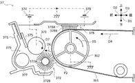
次に、図3及び図4を参照しつつ、ベルト清掃部37について説明する。ここで、図3はベルト清掃部37の構成を示す断面模式図である。また、図4はブラシ部材378の構成を示す平面模式図である。なお、図3では、各構成の通電経路が二点鎖線によって示されている。   Next, the belt cleaning unit 37 will be described with reference to FIGS. 3 and 4. Here, FIG. 3 is a schematic cross-sectional view showing the configuration of the belt cleaning unit 37. FIG. 4 is a schematic plan view showing the configuration of the brush member 378. In FIG. 3, the energization path of each component is indicated by a two-dot chain line.

ベルト清掃部37は、中間転写ベルト361の表面に付着する付着物を除去する。   The belt cleaning unit 37 removes deposits attached to the surface of the intermediate transfer belt 361.

具体的に、前記付着物は、二次転写ローラー38による転写位置P1(図2参照)を通過した後に中間転写ベルト361の表面に残存するトナーを含む。ここで、中間転写ベルト361の表面に残存するトナーには、正極性に帯電したトナーに加えて、負極性に帯電したトナーが含まれる。例えば、中間転写ベルト361上のトナーは、転写位置P1においてシートが中間転写ベルト361から分離する際に生じる剥離放電等によって負極性に帯電することがある。   Specifically, the deposit includes toner remaining on the surface of the intermediate transfer belt 361 after passing through the transfer position P1 (see FIG. 2) by the secondary transfer roller 38. Here, the toner remaining on the surface of the intermediate transfer belt 361 includes a negatively charged toner in addition to a positively charged toner. For example, the toner on the intermediate transfer belt 361 may be negatively charged by a peeling discharge or the like generated when the sheet is separated from the intermediate transfer belt 361 at the transfer position P1.

また、前記付着物は、転写位置P1でシートと接触することによって中間転写ベルト361の表面に付着した紙粉を含む。ここで、中間転写ベルト361に付着する紙粉には、転写位置P1においてシートが中間転写ベルト361から分離する際に生じる剥離放電等によって負極性に帯電した紙粉が含まれる。   Further, the adhering matter includes paper dust adhering to the surface of the intermediate transfer belt 361 by contacting the sheet at the transfer position P1. Here, the paper dust adhering to the intermediate transfer belt 361 includes paper dust charged to a negative polarity due to peeling discharge or the like generated when the sheet is separated from the intermediate transfer belt 361 at the transfer position P1.

図3に示されるように、ベルト清掃部37は、ハウジング371、クリーニング部材372、回収ローラー373、第1電源374、ブレード部材375、トナー搬送路376、搬送部材377、ブラシ部材378、及び第2電源379を備える。ここに、ベルト清掃部37が、本発明におけるクリーニング装置の一例である。   3, the belt cleaning unit 37 includes a housing 371, a cleaning member 372, a collection roller 373, a first power source 374, a blade member 375, a toner conveyance path 376, a conveyance member 377, a brush member 378, and a second member. A power supply 379 is provided. Here, the belt cleaning unit 37 is an example of a cleaning device according to the present invention.

ハウジング371は、クリーニング部材372、回収ローラー373、ブレード部材375、搬送部材377、及びブラシ部材378を収納する。また、図3に示されるように、ハウジング371の内部には、トナー搬送路376が形成される。   The housing 371 houses a cleaning member 372, a collection roller 373, a blade member 375, a conveying member 377, and a brush member 378. As shown in FIG. 3, a toner conveyance path 376 is formed inside the housing 371.

クリーニング部材372は、中間転写ベルト361の表面に付着する前記付着物を除去する。クリーニング部材372は、図3に示されるように、中間転写ベルト361の表面と接触する位置で回転可能に設けられたブラシローラーである。クリーニング部材372は、不図示の駆動源から供給される駆動力により、図3に示される回転方向D6へ回転する。   The cleaning member 372 removes the adhering matter adhering to the surface of the intermediate transfer belt 361. As shown in FIG. 3, the cleaning member 372 is a brush roller that is rotatably provided at a position in contact with the surface of the intermediate transfer belt 361. The cleaning member 372 rotates in the rotation direction D6 shown in FIG. 3 by a driving force supplied from a driving source (not shown).

具体的に、クリーニング部材372は、回転軸372A、及びブラシ毛372Bを有する。回転軸372Aは、金属製であって、左右方向D3に延在して設けられる。ブラシ毛372Bは、回転軸372Aの周面に巻き付けられた合成樹脂製の基布に植毛される。例えば、ブラシ毛372Bは、カーボンなどの含有により導電性が付与されたアクリル樹脂又はナイロン樹脂等によって形成される。   Specifically, the cleaning member 372 has a rotating shaft 372A and brush bristles 372B. The rotation shaft 372A is made of metal and is provided to extend in the left-right direction D3. The brush bristles 372B are planted on a synthetic resin base fabric wound around the circumferential surface of the rotating shaft 372A. For example, the brush bristles 372B are formed of acrylic resin or nylon resin to which conductivity is imparted by containing carbon or the like.

回収ローラー373は、クリーニング部材372によって中間転写ベルト361の表面から除去された前記付着物を回収する。回収ローラー373は、図3に示されるように、クリーニング部材372のブラシ毛372Bと接触する位置で回転可能に設けられた金属製のローラーである。   The collection roller 373 collects the deposits removed from the surface of the intermediate transfer belt 361 by the cleaning member 372. As shown in FIG. 3, the collection roller 373 is a metal roller that is rotatably provided at a position in contact with the brush bristles 372 </ b> B of the cleaning member 372.

第1電源374は、回収ローラー373の回転軸に電気的に接続されており、回収ローラー373に負極性(本発明の第1極性の一例)の電圧を印加する。回収ローラー373に電圧が印加されると、回収ローラー373を介してクリーニング部材372に負極性の電圧が印加される。これにより、回収ローラー373とクリーニング部材372との間で電位差が生じる。また、クリーニング部材372のブラシ毛372Bと中間転写ベルト361とが接触する清掃位置P2(図3参照)において、ブラシ毛372Bと中間転写ベルト361との間に電位差が生じる。   The first power supply 374 is electrically connected to the rotation shaft of the collection roller 373 and applies a negative polarity (one example of the first polarity of the present invention) voltage to the collection roller 373. When a voltage is applied to the collection roller 373, a negative voltage is applied to the cleaning member 372 through the collection roller 373. Thereby, a potential difference is generated between the collection roller 373 and the cleaning member 372. Further, a potential difference is generated between the brush bristles 372B and the intermediate transfer belt 361 at the cleaning position P2 (see FIG. 3) where the bristles 372B of the cleaning member 372 and the intermediate transfer belt 361 come into contact with each other.

中間転写ベルト361の表面に付着した前記付着物のうち、正極性に帯電した前記付着物は、清掃位置P2におけるブラシ毛372Bと中間転写ベルト361との間の電位差によりブラシ毛372Bに移転する。また、ブラシ毛372Bに移転した前記付着物は、クリーニング部材372と回収ローラー373との接触位置において、回収ローラー373とクリーニング部材372との間の電位差により回収ローラー373の表面に移転する。   Of the deposits adhered to the surface of the intermediate transfer belt 361, the deposit charged to a positive polarity is transferred to the brush bristle 372B due to a potential difference between the brush bristle 372B and the intermediate transfer belt 361 at the cleaning position P2. Further, the attached matter transferred to the brush bristles 372B is transferred to the surface of the recovery roller 373 due to a potential difference between the recovery roller 373 and the cleaning member 372 at the contact position between the cleaning member 372 and the recovery roller 373.

ブレード部材375は、回収ローラー373と接触して設けられ、回収ローラー373の表面に付着した前記付着部を掻き落とす。例えば、ブレード部材375は、一方の端部が回収ローラー373の表面と接触するように、他方の端部がハウジング371に固定されたゴムブレードである。ブレード部材375によって回収ローラー373から掻き落とされた前記付着物は、トナー搬送路376に落下する。   The blade member 375 is provided in contact with the collection roller 373 and scrapes off the adhering portion adhering to the surface of the collection roller 373. For example, the blade member 375 is a rubber blade whose other end is fixed to the housing 371 so that one end contacts the surface of the collection roller 373. The adhering matter scraped off from the collection roller 373 by the blade member 375 falls into the toner conveyance path 376.

トナー搬送路376は、ハウジング371の内部におけるブレード部材375の下方で、左右方向D3に延在して設けられる。   The toner conveyance path 376 is provided to extend in the left-right direction D3 below the blade member 375 inside the housing 371.

搬送部材377は、トナー搬送路376に回転可能に設けられ、トナー搬送路376内の前記付着物を搬送する。例えば、搬送部材377は、左右方向D3に延在して設けられた搬送スクリューである。ブレード部材375によって回収ローラー373から掻き落とされてトナー搬送路376に落下した前記付着物は、搬送部材377により不図示のトナー収容部へ搬送される。   The conveyance member 377 is rotatably provided in the toner conveyance path 376 and conveys the attached matter in the toner conveyance path 376. For example, the conveying member 377 is a conveying screw that extends in the left-right direction D3. The adhering matter scraped off from the collection roller 373 by the blade member 375 and dropped onto the toner conveyance path 376 is conveyed by the conveyance member 377 to a toner storage unit (not shown).

ブラシ部材378は、クリーニング部材372による清掃位置P2(図3参照)よりも搬送方向D4の上流側であって、転写位置P1(図2参照)よりも搬送方向D4の下流側に設けられる。また、ブラシ部材378は、搬送方向D4と直交する中間転写ベルト361の幅方向(左右方向D3)に延在して設けられる。ブラシ部材378は、中間転写ベルト361の表面に付着した前記付着物と接触して前記付着物を中間転写ベルト361上で移動させることで、前記付着物の中間転写ベルト361に対する付着力を低下させる。また、ブラシ部材378は、中間転写ベルト361の表面に付着した前記付着物を正極性(本発明の第2極性の一例)に帯電させる。   The brush member 378 is provided upstream of the cleaning position P2 (see FIG. 3) by the cleaning member 372 in the transport direction D4 and downstream of the transfer position P1 (see FIG. 2) in the transport direction D4. The brush member 378 is provided so as to extend in the width direction (left-right direction D3) of the intermediate transfer belt 361 orthogonal to the transport direction D4. The brush member 378 is brought into contact with the adhering matter adhering to the surface of the intermediate transfer belt 361 and moves the adhering matter on the intermediate transfer belt 361, thereby reducing the adhesion force of the adhering matter to the intermediate transfer belt 361. . The brush member 378 charges the adhering matter adhering to the surface of the intermediate transfer belt 361 to a positive polarity (an example of the second polarity of the present invention).

具体的に、ブラシ部材378は、基端部378A、及びブラシ毛378Bを有する。基端部378Aは、金属製であって、左右方向D3に延在して設けられる。ブラシ毛378Bは、中間転写ベルト361と接触しており、基端部378Aの表面に設けられた合成樹脂製の基布に植毛される。例えば、ブラシ毛378Bは、導電材として機能するカーボンなどの含有により導電性が付与されたアクリル樹脂又はナイロン樹脂によって形成される。ブラシ毛378Bは、その長さが基端部378Aと中間転写ベルト361との間の距離より長く、中間転写ベルト361の表面に喰い込んでいる。   Specifically, the brush member 378 has a base end 378A and brush bristles 378B. The base end portion 378A is made of metal and is provided to extend in the left-right direction D3. The brush bristles 378B are in contact with the intermediate transfer belt 361 and are planted on a synthetic resin base cloth provided on the surface of the base end portion 378A. For example, the brush bristles 378B are formed of an acrylic resin or a nylon resin imparted with conductivity by including carbon or the like that functions as a conductive material. The length of the bristle 378B is longer than the distance between the base end portion 378A and the intermediate transfer belt 361, and bites into the surface of the intermediate transfer belt 361.

第2電源379は、ブラシ部材378の基端部378Aに電気的に接続されており、ブラシ部材378に正極性の電圧を印加する。ブラシ部材378に電圧が印加されると、中間転写ベルト361とブラシ部材378との間に電位差が生じる。中間転写ベルト361の表面に付着した前記付着物のうち、負極性に帯電した前記付着物は、中間転写ベルト361とブラシ部材378との間の電位差によりブラシ毛378Bに移転し、又はブラシ毛378Bと接触した際に流れる電流により正極性に帯電される。   The second power source 379 is electrically connected to the base end portion 378 </ b> A of the brush member 378 and applies a positive voltage to the brush member 378. When a voltage is applied to the brush member 378, a potential difference is generated between the intermediate transfer belt 361 and the brush member 378. Of the deposits attached to the surface of the intermediate transfer belt 361, the deposit charged to a negative polarity is transferred to the brush bristles 378B due to a potential difference between the intermediate transfer belt 361 and the brush member 378, or the brush bristle 378B. Is positively charged by the current flowing when it comes into contact.

画像形成装置10では、ブラシ部材378によって、ブラシ部材378の配置位置を通過した前記付着物の帯電極性が正極性に揃えられる。従って、転写位置P1を通過した前記付着物に負極性に帯電したトナー及び正極性に帯電したトナーの両方が含まれる場合であっても、それら両方のトナーがクリーニング部材372によって除去される。   In the image forming apparatus 10, the charged polarity of the attached matter that has passed the arrangement position of the brush member 378 is made positive by the brush member 378. Therefore, even when the adhering material that has passed through the transfer position P1 includes both negatively charged toner and positively charged toner, both the toners are removed by the cleaning member 372.

なお、ブラシ部材378のブラシ毛378Bは、絶縁性の素材によって形成されていてもよい。具体的に、ブラシ部材378のブラシ毛378Bは、トナーとの接触によりトナーを正極性に摩擦帯電させる素材で形成されていてもよい。この場合、画像形成装置10に第2電源379は設けられていなくてもよい。   The brush bristles 378B of the brush member 378 may be formed of an insulating material. Specifically, the brush bristles 378B of the brush member 378 may be formed of a material that frictionally charges the toner positively by contact with the toner. In this case, the second power supply 379 may not be provided in the image forming apparatus 10.

ところで、転写位置P1(図1参照)でシートと接触する中間転写ベルト361の表面には様々なサイズの紙粉が付着する。ここで、中間転写ベルト361の表面にサイズの大きな紙粉が付着してその紙粉がベルト清掃部37へ搬送されると、その紙粉が回収ローラー373とブレード部材375との間に挟まるなどにより、ベルト清掃部37のクリーニング能力が低下することがある。例えば、紙粉が回収ローラー373とブレード部材375との間に挟まると、回収ローラー373とブレード部材375との間に隙間が形成される。この隙間をすり抜けたトナーが、回収ローラー373からクリーニング部材372を経由して中間転写ベルト361へ戻ることがある。これに対し、ブラシ部材378のブラシ毛378Bの剛性を高める、又はブラシ部材378のブラシ毛378Bの電気抵抗を向上させるなどにより、ブラシ部材378による紙粉の捕捉能力を向上させることで、ベルト清掃部37へ搬送される紙粉の量を低減させることが可能である。一方、ブラシ部材378における紙粉の捕捉能力が向上すると、捕捉された紙粉によってブラシ部材378による前記付着物への帯電が妨げられて、クリーニング部材372によるクリーニング能力が低下することがある。   Incidentally, various sizes of paper dust adhere to the surface of the intermediate transfer belt 361 that contacts the sheet at the transfer position P1 (see FIG. 1). Here, when large-size paper dust adheres to the surface of the intermediate transfer belt 361 and the paper dust is conveyed to the belt cleaning unit 37, the paper dust is sandwiched between the collection roller 373 and the blade member 375. As a result, the cleaning ability of the belt cleaning unit 37 may be reduced. For example, when paper dust is sandwiched between the collection roller 373 and the blade member 375, a gap is formed between the collection roller 373 and the blade member 375. The toner that has passed through the gap may return from the collection roller 373 to the intermediate transfer belt 361 via the cleaning member 372. On the other hand, by increasing the rigidity of the bristle 378B of the brush member 378 or improving the electric resistance of the bristle 378B of the brush member 378, the belt cleaning is improved by improving the paper powder capturing ability by the brush member 378. It is possible to reduce the amount of paper powder conveyed to the section 37. On the other hand, when the paper powder capturing ability of the brush member 378 is improved, charging of the deposit by the brush member 378 may be hindered by the captured paper powder, and the cleaning ability of the cleaning member 372 may be reduced.

これに対し、本発明の第1実施形態に係る画像形成装置10では、以下に説明するように、中間転写ベルト361に付着した紙粉によるベルト清掃部37のクリーニング能力の低下を抑制することが可能である。   On the other hand, in the image forming apparatus 10 according to the first embodiment of the present invention, as described below, it is possible to suppress a decrease in the cleaning ability of the belt cleaning unit 37 due to paper dust attached to the intermediate transfer belt 361. Is possible.

具体的に、第1実施形態に係る画像形成装置10において、ブラシ部材378は、図4に示されるように、左右方向D3における予め定められた位置に設けられた第1ブラシ部378C、及び第1ブラシ部378Cを除く第2ブラシ部378Dを有する。また、ブラシ部材378において、第1ブラシ部378Cと中間転写ベルト361との接触圧力は、第2ブラシ部378Dと中間転写ベルト361との接触圧力よりも高い。   Specifically, in the image forming apparatus 10 according to the first embodiment, as illustrated in FIG. 4, the brush member 378 includes a first brush portion 378 </ b> C provided at a predetermined position in the left-right direction D <b> 3 and the first brush portion 378 </ b> C. It has the 2nd brush part 378D except 1 brush part 378C. In the brush member 378, the contact pressure between the first brush portion 378C and the intermediate transfer belt 361 is higher than the contact pressure between the second brush portion 378D and the intermediate transfer belt 361.

より具体的に、ブラシ部材378において、第1ブラシ部378Cのブラシ毛378Bは、第2ブラシ部378Dのブラシ毛378Bよりも長い。これにより、第1ブラシ部378Cでは、第2ブラシ部378Dよりも紙粉に対する機械的な捕捉力が向上する。即ち、画像形成装置10では、ブラシ部材378における第1ブラシ部378Cの範囲を任意に設定することで、ブラシ部材378に捕捉される紙粉の量及びベルト清掃部37へ搬送される紙粉の量を調整することが可能である。   More specifically, in the brush member 378, the brush hair 378B of the first brush portion 378C is longer than the brush hair 378B of the second brush portion 378D. Thereby, in 1st brush part 378C, the mechanical capture power with respect to paper dust improves rather than 2nd brush part 378D. That is, in the image forming apparatus 10, by arbitrarily setting the range of the first brush portion 378 </ b> C in the brush member 378, the amount of paper dust captured by the brush member 378 and the paper dust conveyed to the belt cleaning portion 37 are set. It is possible to adjust the amount.

なお、ブラシ部材378において、第1ブラシ部378Cは、第2ブラシ部378Dよりも中間転写ベルト361との間の距離が短くてもよい。具体的に、第1ブラシ部378Cにおける基端部378Aと中間転写ベルト361との間の距離は、第2ブラシ部378Dにおける基端部378Aと中間転写ベルト361との間の距離より短くてもよい。この場合にも、第1ブラシ部378Cにおける紙粉に対する機械的な捕捉力は、第2ブラシ部378Dよりも向上する。   In the brush member 378, the distance between the first brush portion 378C and the intermediate transfer belt 361 may be shorter than that of the second brush portion 378D. Specifically, the distance between the base end portion 378A and the intermediate transfer belt 361 in the first brush portion 378C may be shorter than the distance between the base end portion 378A and the intermediate transfer belt 361 in the second brush portion 378D. Good. Also in this case, the mechanical capturing force for the paper dust in the first brush portion 378C is improved as compared with the second brush portion 378D.

また、ブラシ部材378において、第1ブラシ部378Cにおけるブラシ毛378Bの密度は、第2ブラシ部378Dにおけるブラシ毛378Bの密度よりも高くてもよい。この場合にも、第1ブラシ部378Cにおける紙粉に対する機械的な捕捉力は、第2ブラシ部378Dよりも向上する。   In the brush member 378, the density of the brush hairs 378B in the first brush portion 378C may be higher than the density of the brush hairs 378B in the second brush portion 378D. Also in this case, the mechanical capturing force for the paper dust in the first brush portion 378C is improved as compared with the second brush portion 378D.

また、ブラシ部材378において、第1ブラシ部378Cのブラシ毛378Bの剛性は、第2ブラシ部378Dのブラシ毛378Bの剛性よりも高くてもよい。この場合にも、第1ブラシ部378Cにおける紙粉に対する機械的な捕捉力は、第2ブラシ部378Dよりも向上する。   Further, in the brush member 378, the rigidity of the bristle 378B of the first brush part 378C may be higher than the rigidity of the bristle 378B of the second brush part 378D. Also in this case, the mechanical capturing force for the paper dust in the first brush portion 378C is improved as compared with the second brush portion 378D.

また、ブラシ部材378において、第1ブラシ部378Cのブラシ毛378Bは、第2ブラシ部378Dのブラシ毛378Bよりも太くてもよい。この場合にも、第1ブラシ部378Cにおける紙粉に対する機械的な捕捉力は、第2ブラシ部378Dよりも向上する。   Further, in the brush member 378, the brush hair 378B of the first brush portion 378C may be thicker than the brush hair 378B of the second brush portion 378D. Also in this case, the mechanical capturing force for the paper dust in the first brush portion 378C is improved as compared with the second brush portion 378D.

ここで、給紙部4の給紙カセット41に収容されるシートにおける左右方向D3の両端部には、他の箇所よりもシートの裁断時に発生する紙粉が多く付着している。そのため、中間転写ベルト361における左右方向D3の両端部には、他の箇所よりも多くの紙粉が付着しやすい。   Here, more paper dust is generated at both ends of the sheet stored in the sheet feeding cassette 41 of the sheet feeding unit 4 in the left-right direction D3 than when other sheets are cut. Therefore, more paper dust is more likely to adhere to both ends of the intermediate transfer belt 361 in the left-right direction D3 than at other locations.

また、画像形成装置10では、給紙部4の搬送ローラー43が、シート搬送路42における左右方向D3の中央部に設けられている。これにより、給紙部4によって転写位置P1へ供給されるシートの左右方向D3における中央部には、他の箇所よりも搬送ローラー43と擦れ合うことで発生する紙粉が多く付着している。そのため、中間転写ベルト361における左右方向D3の中央部には、他の箇所よりも多くの紙粉が付着しやすい。   In the image forming apparatus 10, the conveyance roller 43 of the sheet feeding unit 4 is provided at the center in the left-right direction D <b> 3 in the sheet conveyance path 42. As a result, more paper dust generated by rubbing against the transport roller 43 is attached to the central portion in the left-right direction D3 of the sheet supplied to the transfer position P1 by the paper feeding unit 4 than at other locations. Therefore, more paper dust is more likely to adhere to the central portion of the intermediate transfer belt 361 in the left-right direction D3 than at other locations.

そのため、画像形成装置10では、第1ブラシ部378Cが、図4に示されるように、ブラシ部材378における左右方向D3の中央及び両端に設けられている。例えば、ブラシ部材378における左右方向D3の中央に設けられる第1ブラシ部378Cは、その左右方向D3における長さが、搬送ローラー43の左右方向D3における長さより長く設定される。また、ブラシ部材378における左右方向D3の両端に設けられる第1ブラシ部378Cは、中間転写ベルト361におけるシートの左右方向D3の両端部との接触位置を含む範囲に設定される。   Therefore, in the image forming apparatus 10, the first brush portion 378C is provided at the center and both ends of the brush member 378 in the left-right direction D3, as shown in FIG. For example, the length of the first brush portion 378 </ b> C provided in the center of the brush member 378 in the left-right direction D <b> 3 is set to be longer than the length of the transport roller 43 in the left-right direction D <b> 3. Further, the first brush portions 378C provided at both ends of the brush member 378 in the left-right direction D3 are set in a range including contact positions with both ends of the intermediate transfer belt 361 in the left-right direction D3.

これにより、中間転写ベルト361における左右方向D3の紙粉が付着しやすい位置に第1ブラシ部378Cが設けられる。そのため、中間転写ベルト361に付着する様々なサイズの紙粉のうち、サイズの大きな紙粉の捕捉率を向上させることが可能である。   Accordingly, the first brush portion 378C is provided at a position on the intermediate transfer belt 361 where the paper dust in the left-right direction D3 is likely to adhere. Therefore, it is possible to improve the capture rate of large-size paper powder among various sizes of paper powder adhering to the intermediate transfer belt 361.

なお、第1ブラシ部378Cは、ブラシ部材378における左右方向D3の中央及び両端のいずれか一方に設けられていてもよい。また、第1ブラシ部378Cは、ブラシ部材378における左右方向D3の中央及び両端以外の位置に設けられてもよい。   Note that the first brush portion 378C may be provided at either the center or both ends of the brush member 378 in the left-right direction D3. The first brush portion 378C may be provided at a position other than the center and both ends of the brush member 378 in the left-right direction D3.

このように、第1実施形態に係る画像形成装置10では、ブラシ部材378に第2ブラシ部378Dよりも中間転写ベルト361との接触圧力が高い第1ブラシ部378Cが設けられている。これにより、ブラシ部材378における紙粉の捕捉量を調整することが可能となり、サイズの大きい紙粉のベルト清掃部37への搬送の抑制と、紙粉の捕捉量の増大によるブラシ部材378の帯電性能の低下の抑制との両立を図ることが可能となる。従って、中間転写ベルト361に付着した紙粉によるベルト清掃部37のクリーニング能力の低下を抑制することが可能である。   As described above, in the image forming apparatus 10 according to the first embodiment, the brush member 378 is provided with the first brush portion 378C having a higher contact pressure with the intermediate transfer belt 361 than the second brush portion 378D. As a result, the amount of paper dust captured by the brush member 378 can be adjusted, the conveyance of large paper dust to the belt cleaning unit 37 is suppressed, and the charging of the brush member 378 by increasing the amount of paper dust captured is achieved. It is possible to achieve compatibility with the suppression of performance degradation. Therefore, it is possible to suppress a reduction in the cleaning capability of the belt cleaning unit 37 due to paper dust adhering to the intermediate transfer belt 361.

[第2実施形態]
以下、本発明の第2実施形態に係る画像形成装置10について説明する。第2実施形態に係る画像形成装置10では、ブラシ部材378の構成が第1実施形態と異なる。なお、その他の構成は、第1実施形態と第2実施形態とで共通である。
[Second Embodiment]
The image forming apparatus 10 according to the second embodiment of the present invention will be described below. In the image forming apparatus 10 according to the second embodiment, the configuration of the brush member 378 is different from that of the first embodiment. Other configurations are common to the first embodiment and the second embodiment.

具体的に、第2実施形態に係る画像形成装置10のブラシ部材378において、第1ブラシ部378Cにおける電気抵抗は、第2ブラシ部378Dにおける電気抵抗よりも高い。   Specifically, in the brush member 378 of the image forming apparatus 10 according to the second embodiment, the electrical resistance in the first brush portion 378C is higher than the electrical resistance in the second brush portion 378D.

例えば、第1ブラシ部378Cは、第2ブラシ部378Dよりもカーボンの含有率が低いブラシ毛378Bを有する。また、第1ブラシ部378Cは、絶縁性の素材によって形成されたブラシ毛378Bを有していてもよい。   For example, the first brush portion 378C has brush bristles 378B having a lower carbon content than the second brush portion 378D. Further, the first brush portion 378C may have brush bristles 378B formed of an insulating material.

これにより、第1ブラシ部378Cでは、第2ブラシ部378Dよりも紙粉に対する電気的な捕捉力が向上する。そのため、第1実施形態と同様に、ブラシ部材378における紙粉の捕捉量を調整することが可能となり、サイズの大きい紙粉のベルト清掃部37への搬送の抑制と、紙粉の捕捉量の増大によるブラシ部材378の帯電性能の低下の抑制との両立を図ることが可能となる。従って、中間転写ベルト361に付着した紙粉によるベルト清掃部37のクリーニング能力の低下を抑制することが可能である。   Thereby, in the 1st brush part 378C, the electric capture power to paper dust improves rather than the 2nd brush part 378D. Therefore, similarly to the first embodiment, it is possible to adjust the amount of paper dust captured by the brush member 378, and the conveyance of large size paper dust to the belt cleaning unit 37 can be suppressed, and the amount of paper dust captured can be reduced. It is possible to achieve both the suppression of the decrease in charging performance of the brush member 378 due to the increase. Therefore, it is possible to suppress a reduction in the cleaning capability of the belt cleaning unit 37 due to paper dust adhering to the intermediate transfer belt 361.

なお、第2実施形態に係る画像形成装置10のブラシ部材378において、第1ブラシ部378Cと中間転写ベルト361との接触圧力は、第2ブラシ部378Dと中間転写ベルト361との接触圧力よりも高くてもよい。   In the brush member 378 of the image forming apparatus 10 according to the second embodiment, the contact pressure between the first brush portion 378C and the intermediate transfer belt 361 is higher than the contact pressure between the second brush portion 378D and the intermediate transfer belt 361. It may be high.

1 ADF
2 画像読取部
3 画像形成部
4 給紙部
5 操作表示部
10 画像形成装置
31〜34 画像形成ユニット
35 光走査装置
36 中間転写装置
37 ベルト清掃部
38 二次転写ローラー
39 定着装置
40 排紙トレイ
361 中間転写ベルト
362 第1張架ローラー
363 第2張架ローラー
371 ハウジング
372 クリーニング部材
373 回収ローラー
374 第1電源
375 ブレード部材
376 トナー搬送路
377 搬送部材
378 ブラシ部材
378C 第1ブラシ部
378D 第2ブラシ部
379 第2電源
1 ADF
2 Image reading unit 3 Image forming unit 4 Paper feeding unit 5 Operation display unit 10 Image forming devices 31 to 34 Image forming unit 35 Optical scanning device 36 Intermediate transfer device 37 Belt cleaning unit 38 Secondary transfer roller 39 Fixing device 40 Paper discharge tray 361 Intermediate transfer belt 362 First tension roller 363 Second tension roller 371 Housing 372 Cleaning member 373 Collection roller 374 First power source 375 Blade member 376 Toner transport path 377 Transport member 378 Brush member 378C First brush portion 378D Second brush Part 379 second power supply

Claims (5)

予め定められた第1極性の電圧の印加に応じて、像担持体から転写されるトナー像を転写部によるシートへの転写位置へ搬送する中間転写体の表面に付着する付着物を除去するクリーニング部材と、
前記クリーニング部材による清掃位置よりも前記中間転写体による前記トナー像の搬送方向の上流側であって前記転写位置よりも前記搬送方向の下流側に設けられ、前記搬送方向と直交する前記中間転写体の幅方向に延在しており、前記第1極性とは逆の第2極性の電圧の印加に応じて前記付着物を前記第2極性に帯電させるブラシ部材と、を備え、
前記ブラシ部材は、前記幅方向における予め定められた位置に設けられた第1ブラシ部、及び前記第1ブラシ部を除く第2ブラシ部を有し、前記第1ブラシ部における電気抵抗が、前記第2ブラシ部における電気抵抗よりも高いクリーニング装置。
Cleaning that removes deposits adhering to the surface of the intermediate transfer member that conveys the toner image transferred from the image carrier to the transfer position to the sheet by the transfer unit in response to application of a predetermined first polarity voltage. Members,
The intermediate transfer member, which is provided upstream of the cleaning position by the cleaning member in the transport direction of the toner image by the intermediate transfer member and downstream of the transfer position from the transfer position and orthogonal to the transport direction. And a brush member that charges the deposit to the second polarity in response to application of a voltage having a second polarity opposite to the first polarity,
The brush member has a first brush portion provided at a predetermined position in the width direction, and a second brush portion excluding the first brush portion, and the electric resistance in the first brush portion is A cleaning device having an electrical resistance higher than that of the second brush portion.
前記第1ブラシ部は、前記ブラシ部材における前記幅方向の両端に設けられている、
請求項1に記載のクリーニング装置。
The first brush portion is provided at both ends in the width direction of the brush member.
The cleaning device according to claim 1.
前記第1ブラシ部は、前記ブラシ部材における前記幅方向の中央に設けられている、
請求項1又は2に記載のクリーニング装置。
The first brush portion is provided at the center in the width direction of the brush member.
The cleaning device according to claim 1 or 2.
請求項1〜3のいずれかに記載のクリーニング装置と、前記中間転写体と、
を備える中間転写装置。
The cleaning device according to any one of claims 1 to 3, the intermediate transfer member,
An intermediate transfer device.
請求項4に記載の中間転写装置と、前記像担持体と、前記転写部と、
を備える画像形成装置。
The intermediate transfer device according to claim 4, the image carrier, the transfer unit,
An image forming apparatus comprising:
JP2016233286A 2016-11-30 2016-11-30 Cleaning device, intermediate transfer device, and image forming apparatus Pending JP2018091929A (en)

Priority Applications (1)

Application Number Priority Date Filing Date Title
JP2016233286A JP2018091929A (en) 2016-11-30 2016-11-30 Cleaning device, intermediate transfer device, and image forming apparatus

Applications Claiming Priority (1)

Application Number Priority Date Filing Date Title
JP2016233286A JP2018091929A (en) 2016-11-30 2016-11-30 Cleaning device, intermediate transfer device, and image forming apparatus

Publications (1)

Publication Number Publication Date
JP2018091929A true JP2018091929A (en) 2018-06-14

Family

ID=62563748

Family Applications (1)

Application Number Title Priority Date Filing Date
JP2016233286A Pending JP2018091929A (en) 2016-11-30 2016-11-30 Cleaning device, intermediate transfer device, and image forming apparatus

Country Status (1)

Country Link
JP (1) JP2018091929A (en)

Similar Documents

Publication Publication Date Title
US8953989B2 (en) Developing device and image forming apparatus
JP2009300721A (en) Image carrier cleaning device and image forming apparatus having the same mounted thereon
JP2007025163A (en) Cleaning device and image forming apparatus
JP5747870B2 (en) Image forming apparatus, image forming apparatus control method, and image forming apparatus control program
JP2017203813A (en) Cleaning device, transfer device, and image forming apparatus
JP2015025950A (en) Image forming apparatus
JP2018091929A (en) Cleaning device, intermediate transfer device, and image forming apparatus
JP2018091928A (en) Cleaning device, intermediate transfer device, and image forming apparatus
JP5124546B2 (en) Image forming apparatus cleaning apparatus and image forming apparatus
JP4795150B2 (en) Process cartridge and image forming apparatus
JP2017122852A (en) Image forming apparatus
JP2008026521A (en) Image forming apparatus
JP4581521B2 (en) Image forming apparatus
JP2013148757A (en) Cleaning device and image forming apparatus equipped with same
JP2012208276A (en) Image forming apparatus
JP2013222110A (en) Image forming apparatus
JP2009210933A (en) Cleaning mechanism and image forming apparatus
JP2009139752A (en) Image forming apparatus
JP2012032625A (en) Image forming apparatus
JP2009181115A (en) Image forming device
JP6853635B2 (en) Cleaning equipment, transfer equipment and image forming equipment
JP2007241013A (en) Image forming apparatus
JP6111923B2 (en) Image forming apparatus
JP2023004625A (en) Image forming apparatus and timing control method
JP6003019B2 (en) Image forming apparatus