JP2018091337A - Centrifugal fan - Google Patents
Centrifugal fan Download PDFInfo
- Publication number
- JP2018091337A JP2018091337A JP2018025576A JP2018025576A JP2018091337A JP 2018091337 A JP2018091337 A JP 2018091337A JP 2018025576 A JP2018025576 A JP 2018025576A JP 2018025576 A JP2018025576 A JP 2018025576A JP 2018091337 A JP2018091337 A JP 2018091337A
- Authority
- JP
- Japan
- Prior art keywords
- impeller
- centrifugal fan
- casing
- motor
- motor base
- Prior art date
- Legal status (The legal status is an assumption and is not a legal conclusion. Google has not performed a legal analysis and makes no representation as to the accuracy of the status listed.)
- Granted
Links
Images


Abstract
Description
本発明は遠心式ファンに関し、特に送風による騒音の低減およびコストの低減を図った遠心式ファンに関する。 The present invention relates to a centrifugal fan, and more particularly to a centrifugal fan that reduces noise caused by blowing air and reduces costs.
遠心式ファン(または単に「遠心ファン」という。)は、吸込み口と吹出し口とを有するスクロールケーシング内に、羽根車を格納して構成される。羽根車は、モータの回転軸周りに多数の翼を配置したものである。遠心ファンは、吸込み口から吸入された空気を羽根車の中心から翼間に流入させ、羽根車の回転に伴う遠心作用による流体力で、空気を羽根車の径外方に向けて吹き出させる。羽根車の外周外側から吹き出された空気は、スクロールケーシング内部を通過し、高圧の空気となって吹出し口から噴出される。 A centrifugal fan (or simply referred to as “centrifugal fan”) is configured by housing an impeller in a scroll casing having a suction port and a blow-out port. An impeller has a large number of blades arranged around a rotation axis of a motor. The centrifugal fan causes the air sucked from the suction port to flow between the blades from the center of the impeller, and blows the air toward the outside of the impeller by a fluid force due to the centrifugal action accompanying the rotation of the impeller. The air blown out from the outer periphery of the impeller passes through the inside of the scroll casing, becomes high-pressure air, and is blown out from the blowout opening.
遠心ファンは、家電機器、OA機器、産業機器の冷却、換気、空調や、車両用の送風機などに広く用いられている。遠心ファンの送風性能と騒音は、羽根車の翼形状とスクロールケーシング形状(遠心ファンの構造)に大きく影響される。 Centrifugal fans are widely used for cooling, ventilating, air-conditioning, blowers for vehicles, and the like for home appliances, OA equipment, and industrial equipment. The blowing performance and noise of the centrifugal fan are greatly influenced by the blade shape of the impeller and the scroll casing shape (the structure of the centrifugal fan).
騒音を低減させ、送風性能の向上を図るために、羽根車の形状やスクロールケーシングの構造を最適化することが行われており、いろいろな提案がなされている。羽根車においては、従来から翼形状を最適化することによって低騒音化を図る遠心ファンが提案されている(例えば、下記特許文献1参照)。
In order to reduce noise and improve air blowing performance, the shape of the impeller and the structure of the scroll casing have been optimized, and various proposals have been made. In the impeller, a centrifugal fan that has been conventionally designed to reduce noise by optimizing the blade shape has been proposed (see, for example,
図6は、下記特許文献1に記載された遠心ファンを示す平面図であり、図7は、図6に示す遠心ファンにおける羽根車を示す斜視図である。
6 is a plan view showing a centrifugal fan described in
図6および7を参照して、遠心ファン100の羽根車120は、主板121と副板122との間に複数枚の翼123を設置したものである。翼123の内周側よりも外周側が羽根車120の回転方向(図6の反時計回り)に対して遅れて回転していく。羽根車120は、渦巻状のケーシング127に取り付けられており、送風が行われる。
With reference to FIGS. 6 and 7, the
送風される空気は、羽根車120の吸込み口140から吸込まれ、羽根車120の翼123によって遠心作用による流体力を受けて羽根車120の外周から吐き出される。羽根車120の外周を囲繞する渦巻状のケーシング127によって、羽根車120の外周から吐き出された空気の圧力が増加され、空気は吹出し口141から吹き出される。
The air to be blown is sucked in from the
このように、翼123の内周側よりも外周側が羽根車120の回転方向に対して遅れて回転していく羽根構造は、後向き羽根と呼ばれる。すなわち図6に示されるように、翼123は回転方向に対して後向きに湾曲傾斜した羽根形状となっている。このような羽根形状を備えた遠心ファンは、一般にターボファンと呼ばれる。
In this way, the blade structure in which the outer peripheral side of the blades 123 rotates with respect to the rotation direction of the
図6に示すターボファンでは、主板121と、主板121と外径が等しい副板122との間に複数枚の翼123を挟持している。翼123は、副板122側の翼円弧134よりも、主板121側の翼円弧135の方が短い円弧となるように切断した後縁にしている。これによって、主板121側に位置する後縁131がケーシング舌部129を横切る時刻と、副板122側に位置する後縁132がケーシング舌部129を横切る時刻との間に時間差を設けることができる。そのため、翼123がケーシング舌部129を横切ることにより生じる圧力変動が時間的に分散されるので、音の発生エネルギーが分散されて、騒音の発生が抑制される旨、特許文献1に記載されている。
In the turbofan shown in FIG. 6, a plurality of blades 123 are sandwiched between a main plate 121 and a sub plate 122 having the same outer diameter as the main plate 121. The blade 123 has a trailing edge that is cut so that the
上記特許文献1に記載のターボファンは、翼123の形状を検討して送風時の騒音の抑制を図ったものである。しかしながら、渦巻状のケーシング127においてケーシング舌部129が形成されているため、羽根車120から吹き出された空気がケーシング舌部129に衝突する際に発生する騒音を十分に低減することができない。
The turbofan described in the above-mentioned
また特許文献1では、羽根車120の外周から吐出された空気は渦巻状のケーシング127の内壁面に沿って吹出し口141から吹き出す構成となっている。このため、渦巻状のケーシング127の内壁面や吹出し口141付近で空気の流れに乱れが生じ易く、この空気の流れの乱れが騒音の要因となっている。
Moreover, in
さらに近年、家電機器、OA機器、車両などの送風機に組み込まれる遠心ファンには、低騒音化及び小型化と共に、コスト低減が強く求められている。 Furthermore, in recent years, centrifugal fans incorporated in blowers of home appliances, OA devices, vehicles and the like have been strongly demanded to reduce costs as well as to reduce noise and size.
しかしながら、図6に示すような渦巻状のケーシング127においては、羽根車120の外周に、空気を吹出し口に導くための流路を形成する必要がある。このため、渦巻状のケーシング127の外径は通常、羽根車120の外径の2倍程度の大きさを要する。結果として、ターボファンの小型化が難しくなっている。渦巻状のケーシング127や羽根車120は一般に合成樹脂にて形成されるが、ターボファンの小型化が難しいことと相俟って、昨今の合成樹脂材料の高騰等の経済情勢から遠心ファンのコスト低減が容易ではないという問題がある。
However, in the
本発明は、上記の課題に鑑みなされたもので、送風時の低騒音化を図ると共に、小型化およびコスト低減を図った遠心ファンを提供することを目的とする。 The present invention has been made in view of the above problems, and an object of the present invention is to provide a centrifugal fan that achieves noise reduction during blowing, and that is reduced in size and cost.
上記目的を達成するためこの発明のある局面に従うと、開口を形成した上板とモータベースとで構成されるケーシングと、上板及びモータベースの間に収納されており、吸込み口及び円周方向に配列される複数の羽根を備える羽根車と、羽根車を回転させるモータと、電子部品が実装されている回路基板とを備え、羽根車の回転に伴って、上板の開口から吸込み口を通して吸入した空気を羽根車の径の外方に向けて吹き出すことが可能である遠心式ファンは、モータベースは、金属板製であって、下方に窪む凹部と、該凹部の周縁から径の外方に延在し羽根車の下面と対向してなる平面部とを有し、平面部の外周縁が空気の噴出口を構成し、モータは、凹部の底面に取りつけられており、モータのインシュレータの一部と回路基板とは、凹部の内部に収納され、回路基板の外周縁が凹部の側面に近接している。 In order to achieve the above object, according to one aspect of the present invention, a casing composed of an upper plate having an opening and a motor base, and the upper plate and the motor base are housed between the suction port and the circumferential direction. An impeller having a plurality of blades arranged on the motor, a motor for rotating the impeller, and a circuit board on which electronic components are mounted, and through the suction opening from the opening of the upper plate as the impeller rotates. A centrifugal fan that can blow inhaled air toward the outside of the diameter of the impeller has a motor base made of a metal plate, and has a recess recessed downward and a diameter from the periphery of the recess. A flat portion extending outward and facing the lower surface of the impeller, the outer peripheral edge of the flat portion forms an air outlet, and the motor is attached to the bottom surface of the recess. A part of the insulator and the circuit board are recessed. Is housed inside the outer peripheral edge of the circuit board is close to the side of the recess.
好ましくは、回路基板は、インシュレータの下部に取り付けられている。 Preferably, the circuit board is attached to the lower part of the insulator.
好ましくは、回路基板の下側に電子部品が実装されている。 Preferably, an electronic component is mounted on the lower side of the circuit board.
好ましくは、凹部の側面は、下方に向けて先細となるテーパ形状を有する。 Preferably, the side surface of the recess has a tapered shape that tapers downward.
好ましくは、羽根車の径の外方に向けて排出された空気が、ケーシングの側部であって、上板とモータベースとの間に設けられた支柱部分を除いた開口部分から吹き出すように構成されている。 Preferably, the air discharged toward the outside of the diameter of the impeller is blown out from an opening portion on a side portion of the casing except for a support portion provided between the upper plate and the motor base. It is configured.
上記発明に従うと、送風時の低騒音化を図ると共に、小型化およびコスト低減を図った遠心ファンを提供することが可能となる。 According to the above-described invention, it is possible to provide a centrifugal fan that achieves noise reduction during blowing and that is reduced in size and cost.
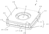
以下、本発明の実施形態を図面に基づいて説明する。図1は、本発明の実施の形態の1つにおける遠心ファンを示す斜視図であり、図2は、図1に示す遠心ファンの半断面図であり、図3は図2に示す羽根車の断面図である。 Hereinafter, embodiments of the present invention will be described with reference to the drawings. 1 is a perspective view showing a centrifugal fan according to one embodiment of the present invention, FIG. 2 is a half sectional view of the centrifugal fan shown in FIG. 1, and FIG. 3 is a view of the impeller shown in FIG. It is sectional drawing.
図1〜3を参照して、遠心ファン1は、多数の羽根4を配置した羽根車3と、羽根車3を格納したケーシング10とにより構成されている。モータ2によって羽根車3は回転駆動される。
1 to 3, the
羽根車3は、円周方向に等間隔で多数の羽根4を配置し、これらの羽根4の一端側を環状のシュラウド5で支持した構成である。羽根4の他端側には、図5に示す主板121が備えられていない。環状のシュラウド5の上面は、所定の曲面にて形成されており、シュラウド5の中央には円筒部9が形成されている。円筒部9の内側は、吸込み口8を形成している。
The
羽根車3は、その中央にカップ状のボス部6を有している。羽根4は所定の曲率で湾曲した形状であって、すべて同じ形状に形成されている。羽根4は後向き羽根であり、図6と同様に、回転方向に対して後向きに湾曲傾斜した羽根形状となっており、ターボファンを構成している。羽根4と環状のシュラウド5とボス部6とは、合成樹脂にて一体成型で形成される。カップ状のボス部6の内側にモータ2のロータが接合される。モータ2の回転に伴って、羽根車3が回転する。
The
ケーシング10の形状は四角形である。ケーシング10は、中央に円形の開口が形成された合成樹脂製の上板11を備える。上板11の4箇所のコーナー部近傍には、それぞれ略円筒状の支柱13が備えられている。上板11の開口の周縁には下方に突出する返し部12が形成されている。返し部12の内側(羽根車3の回転軸側)に所定の隙間を隔ててシュラウド5の円筒部9が配置されている。
The shape of the
上板11と対向するようにモータベース14が配置されている。上板11とモータベース14との間に4箇の支柱13が介装された構成となっている。上板11と支柱13とは、連結材28(例えば、ボルト、ねじ、リベットなど)によって結合される。支柱13とモータベース14とは、連結材28(例えば、ボルト、ねじ、リベットなど)によって結合されている。支柱13を上板11と一体成型にて形成し、支柱13とモータベース14を連結材28によって結合した構成であってもよい。
A
複数の支柱13のうち隣り合う支柱同士と、上板11と、モータベース14とによって囲まれる部分が開口となる。開口は、空気の噴出口となる。
A portion surrounded by the adjacent columns, the upper plate 11, and the
このように、本実施の形態の遠心ファン1のケーシング10の側面は、4面ともに開口が形成されている。すなわちケーシング10の側面は、支柱13のみを備えた構成(支柱13が存在する部分以外で開口が形成される構成)となっている。
As described above, the four sides of the
ケーシング10の中に収納される羽根車3の外径寸法は、ケーシング10の一辺の寸法より小さく設定されている。羽根車3の外径寸法がケーシング10の一辺の寸法より大きい場合、回転する羽根車3がケーシング10の外縁より突出してしまうため、他部材との接触や接触による破損等の虞があり、好ましくない。このため、羽根車3の外径はケーシング10の外縁から突出しないように設定することが好ましい。
The outer diameter dimension of the
モータ2は、アウターロータ型のブラシレスモータである。ロータはカップ状のロータヨーク25とリング状のマグネット27とシャフト7とから構成される。マグネット27は、ロータヨーク25の内周面に固着される。シャフト7は、ロータヨーク25の中央部に形成されたボス26に固着されている。
The
シャフト7は、ベアリングホルダー18に装着された一対のベアリング19にて回転可能に支持されている。ベアリングホルダー18の外周面には積層されたステータコア20が装着される。ステータコア20には、コイル21を巻回したインシュレータ22が装着されている。ベアリングホルダー18は、モータベース14に装着される。ベアリングホルダー18に装着されたステータコア20は、半径方向(図2左右方向)においてマグネット27と所定のギャップを隔てて対向配置されている。モータベース14は、金属製のプレート(例えば、鉄製のプレート)をプレス加工することによって形成したものである。モータベース14の形状は、ケーシング10と同様、四角形であり、中央には凹部15が形成される。外周縁は、軸方向(図2上下方向)に曲げられて側板16を構成している。側板16を形成することによって、モータベース14の剛性を向上させることができる。モータベース14の凹部15の中央には開口が形成されており、この開口にベアリングホルダー18が装着され、モータ2が凹部15に収納される。
The
ロータヨーク25に接合した羽根車3の羽根4は、軸方向(図2上下方向)においてモータベース14の平面部17と所定のギャップ長Gを隔てて対向配置されている。すなわち、羽根車3は複数の羽根4を備えているが、各々の羽根4の下部は、その少なくとも一部分がモータベース14の平面部17側に露出している。各々の羽根4は、下部の全部分がモータベース14の平面部17側に露出していてもよい。インシュレータ22の下面にはPCB基板23が取り付けられている。PBC基板23には、モータ2を制御するための電子部品24が実装されている。
The
モータ2の駆動によって羽根車3が回転することにより、吸込み口8から吸入された空気は羽根車3の羽根4の間を通過し、羽根車3の回転に伴う遠心作用による流体力で羽根車3の径外方に向けて吹き出される。
When the
モータベース14は、図7に示す従来の羽根車120の主板121の機能を兼ねると共に、ケーシング10の下板の機能も兼ねている。このため、羽根車3とモータベース14の平面部17との間に形成されたギャップ長Gの設定は重要である。ギャップ長Gが大きすぎる場合、吸込み口8から吸入された空気は、羽根4の間を通過すると共にギャップにも流れてしまう。この結果、羽根車3から吹き出された空気の圧力が低減し、送風特性が低下する。一方でギャップ長Gが小さすぎる場合において、各部品の寸法精度のバラツキが生じたとき、羽根車3の羽根4がモータベース14の平面部17に接触してしまう虞がある。このような接触を防止するためには、各部品の寸法精度を高精度に管理する必要が生じ、ひいては遠心ファン1のコスト高となってしまう。
The
上述のように、ギャップ長Gは遠心ファンの送風特性に影響を及ぼす重要な要素である。ギャップ長Gは具体的には、遠心ファンの送風特性とコストとの兼ね合いで設定される。 As described above, the gap length G is an important factor affecting the air blowing characteristics of the centrifugal fan. Specifically, the gap length G is set in consideration of the air blowing characteristics and cost of the centrifugal fan.
図4は、本発明の実施の形態における遠心ファンと従来の渦巻き状ケーシングを備える遠心ファンとの騒音の測定結果を示した図である。 FIG. 4 is a diagram showing measurement results of noise between the centrifugal fan according to the embodiment of the present invention and a centrifugal fan having a conventional spiral casing.
図4中における「比較例1」は、従来の渦巻き状ケーシングを備える遠心ファンを示す。「比較例2」は、本実施の形態による遠心ファンと同様に、外形は四角形で側面がすべて開口を形成したケーシングを使用しているが、羽根車の構造が本実施の形態と異なるものである。「比較例2」における羽根車は、羽根の一端側に環状のシュラウドを備え、羽根の他端側に(図7の符号121で示されるような)主板を備えた構造である。「比較例2」においては主板が設けられているので、モータベースに主板の機能を兼ねさせる必要がない。このため「比較例2」においては、図2に示されるような、モータベースに主板の機能を兼ねさせるためのギャップGは設けられていない(羽根の下側と主板との間隔は、0mmとなる)。図4中における「本実施の形態」は、図1〜3で説明した遠心ファンであり、羽根車3とモータベース14の平面部17との間のギャップ長Gを0.5mmに設定したものである。
"Comparative example 1" in FIG. 4 shows a centrifugal fan provided with a conventional spiral casing. “Comparative example 2” uses a casing whose outer shape is a square and all sides have openings as in the centrifugal fan according to the present embodiment, but the structure of the impeller is different from that of the present embodiment. is there. The impeller in “Comparative Example 2” has a structure including an annular shroud on one end side of the blade and a main plate (as indicated by reference numeral 121 in FIG. 7) on the other end side of the blade. In “Comparative Example 2”, since the main plate is provided, it is not necessary for the motor base to also function as the main plate. For this reason, in “Comparative Example 2”, the gap G for making the motor base also function as the main plate as shown in FIG. 2 is not provided (the interval between the lower side of the blade and the main plate is 0 mm). Become). “Embodiment” in FIG. 4 is the centrifugal fan described in FIGS. 1 to 3, and the gap length G between the
図4に示すように、従来の渦巻き状ケーシングを備える遠心ファンにおける騒音が61dB(A)であるのに対して、比較例2では57.3dB(A)、本実施の形態による遠心ファンでは58dB(A)であった。このように本実施の形態によると、騒音を抑制することができる。 As shown in FIG. 4, the noise in the centrifugal fan having the conventional spiral casing is 61 dB (A), whereas in Comparative Example 2, the noise is 57.3 dB (A), and in the centrifugal fan according to the present embodiment, the noise is 58 dB. (A). Thus, according to the present embodiment, noise can be suppressed.
図5は、本実施の形態において、外形が四角形で側面がすべて開口を形成したケーシング(図1に示されるケーシング)を使用し、羽根車3とモータベース14の平面部17との間のギャップ長G(図2参照)を、1mm、0.5mm、0mm(ギャップなし)とした場合における、静圧−風量特性を示す図である。図においては、横軸が流量、縦軸が圧力を示す。
FIG. 5 shows a gap between the
なお、ギャップ長Gが0mm(ギャップなし)とは、羽根の一端側に環状のシュラウドを備え、羽根の他端側に(図7の符号121で示されるような)主板を備えた羽根車を用いた場合を示している。 A gap length G of 0 mm (no gap) means that an impeller having an annular shroud on one end side of a blade and a main plate (as indicated by reference numeral 121 in FIG. 7) on the other end side of the blade. The case where it is used is shown.
図5に示すように、羽根車3とモータベース14の平面部17との間のギャップ長Gが大きくなるに従って最大静圧が低下していることがわかる。ギャップ長Gが1mmの場合、ギャップなしに比べて最大静圧が約25%低下している。また、ギャップ長Gが0.5mmの場合、ギャップなしに比べて最大静圧が若干低下するが、ほぼギャップなしと同等の静圧−風量特性が得られることがわかる。
As shown in FIG. 5, it can be seen that the maximum static pressure decreases as the gap length G between the
図5に示す静圧−風量特性から、羽根車3とモータベース14の平面部17との間のギャップ長Gを0.5mm以下に設定することによって、静圧−風量特性はギャップ長Gが0mm(ギャップなし)における特性に近づくことがわかる。
From the static pressure-air flow characteristics shown in FIG. 5, by setting the gap length G between the
すなわち、羽根車3とモータベース14の平面部17との間のギャップ長Gを適切に制御する必要がある。ギャップ長Gを0.5mm以下に設定することによって、羽根車3の主板を省略しても、ギャップ長Gが0mm(ギャップなし)における静圧−風量特性とほぼ同等の特性を得ることができる。
That is, it is necessary to appropriately control the gap length G between the
[実施の形態における効果] [Effects of the embodiment]
以上のように本実施の形態に係る遠心式ファンは、円周方向に多数の羽根を配設した羽根車をケーシング内に格納し、モータの回転に伴い、吸込み口から吸入した空気を羽根車の回転に伴う遠心力によって羽根車の径外方に向けて噴出してケーシングから噴出するようにした遠心式ファンである。ケーシングは、上板と下板と複数の支柱とからなる。上板と下板とは複数の支柱を挟持する。ケーシングの側面は、支柱のみを備えて開口を形成している。ケーシングの下板は、モータを装着してなるモータベースで構成される。羽根車は、環状のシュラウドと該シュラウドと一体に形成された複数の羽根とから構成される。モータベースは、複数の羽根と軸方向において所定のギャップを隔てて対向配置されてなる。 As described above, the centrifugal fan according to the present embodiment stores the impeller in which a large number of blades are arranged in the circumferential direction in the casing, and impellers the air sucked from the suction port as the motor rotates. The centrifugal fan is configured to be ejected toward the outside of the diameter of the impeller by a centrifugal force accompanying the rotation of the fan and ejected from the casing. The casing includes an upper plate, a lower plate, and a plurality of support columns. The upper plate and the lower plate sandwich a plurality of columns. A side surface of the casing includes only a support column to form an opening. The lower plate of the casing is composed of a motor base on which a motor is mounted. The impeller includes an annular shroud and a plurality of blades formed integrally with the shroud. The motor base is arranged to face the plurality of blades with a predetermined gap in the axial direction.
本実施の形態における遠心式ファンによれば、上板と下板を支柱で連結したケーシングの中に遠心式ファンの羽根車を格納している。ケーシングは図6のファンのような側壁を備えておらず、側壁の部分は開口となっている。このため、羽根車の径外方に向けて噴出された空気は、ケーシングの側壁によって乱れることがない。すなわち、ケーシング形状を改良することにより、送風時の空気の乱れによる騒音を大幅に抑制することができる遠心式ファンを提供することができる。 According to the centrifugal fan in the present embodiment, the impeller of the centrifugal fan is housed in a casing in which an upper plate and a lower plate are connected by a support column. The casing does not have a side wall like the fan of FIG. 6, and the side wall is an opening. For this reason, the air ejected toward the outer diameter of the impeller is not disturbed by the side wall of the casing. That is, by improving the casing shape, it is possible to provide a centrifugal fan that can significantly suppress noise due to air turbulence during blowing.
すなわち本実施の形態による遠心式ファンは、従来の渦巻状のケーシングに代えて、外形が四角形で側面の4面ともに開口が形成され、側面には支柱のみを備えたケーシングを採用している。ケーシングは側壁を備えていないため、ファンの騒音を低減でき、かつ遠心式ファンを小型化できる。 That is, the centrifugal fan according to the present embodiment employs a casing having a quadrangular outer shape and having four openings on the side surfaces, and provided only with support columns on the side surfaces, instead of the conventional spiral casing. Since the casing does not have a side wall, the noise of the fan can be reduced and the centrifugal fan can be downsized.
また、ケーシングは羽根車の外径寸法と略同じ寸法にて形成することができるため、従来の渦巻状のケーシングを用いた遠心式ファンに比べて小径化を図ることができる遠心式ファンを提供できる。 In addition, since the casing can be formed to have substantially the same outer diameter as the impeller, a centrifugal fan that can be reduced in diameter compared with a centrifugal fan that uses a conventional spiral casing is provided. it can.
さらに、合成樹脂にて形成される羽根車3の主板およびケーシング10の下板を廃止し、安価な金属製のモータベース14にて羽根車3の主板と共にケーシング10の下板の機能を兼ねさせている。合成樹脂製の部品を削減できる結果、遠心式ファン1のコストを大幅に低減することができる。具体例としては、モータベース14の金属としては鉄が採用される。
Further, the main plate of the
本実施の形態では、ケーシング10は正四角形にて形成しているが、これに限定されるものではない。ケーシング10は、多角形、円形、非対称形状を含め、任意のどのような形状であってもよい。支柱13はケーシング10の上板11の外周縁から内側に配置した構造に限定されるものではなく、上板11の外周縁から径外方に連接して突出させた箇所に支柱13を設けた構造であってもよい。
In the present embodiment, the
また、支柱13の形状は、連結材28を挿通できる程度の大きさを有する略円筒形状であれば、羽根車3より吹き出された空気がほとんど抵抗を受けることなくケーシング10の側面から外方に吹き出すことができる。このような支柱13の形状であれば、低騒音化を図ることができる。
Moreover, if the shape of the support |
上述の実施の形態は、すべての点で例示であって制限的なものではないと考えられるべきである。本発明の範囲は上記した説明ではなくて特許請求の範囲によって示され、特許請求の範囲と均等の意味および範囲内でのすべての変更が含まれることが意図される。 The above-described embodiment is to be considered as illustrative in all points and not restrictive. The scope of the present invention is defined by the terms of the claims, rather than the description above, and is intended to include any modifications within the scope and meaning equivalent to the terms of the claims.
1 遠心式ファン
2 モータ
3 羽根車
4 羽根
5 シュラウド
6 ボス部
7 シャフト
8 吸込み口
9 円筒部
10 ケーシング
11 上板
12 返し部
13 支柱
14 モータベース
15 凹部
16 側板
17 平面部
18 ベアリングホルダー
19 ベアリング
20 ステータコア
21 コイル
22 インシュレータ
23 PCB基板
24 電子部品
25 ロータヨーク
26 ボス部
27 マグネット
28 連結材
DESCRIPTION OF
本発明は、小型化を図った遠心ファンを提供することを目的とする。 The present invention aims at providing a centrifugal fan downsized.
上記目的を達成するためこの発明のある局面に従うと、開口を形成した上板とモータベースとで構成されるケーシングと、上板及びモータベースの間に収納されており、吸込み口及び円周方向に配列される複数の羽根を備える羽根車と、羽根車を回転させるモータとを備え、羽根車の回転に伴って、上板の開口から吸込み口を通して吸入した空気を羽根車の径の外方に向けて吹き出すことが可能である遠心式ファンは、上板とモータベースとの間に複数の支柱を介装し、支柱を除いたケーシングの側面全周が空気の噴出口を構成し、上板の外周縁から径外方に連接して突出した箇所に支柱が設けられている。 In order to achieve the above object, according to one aspect of the present invention, a casing composed of an upper plate having an opening and a motor base, and the upper plate and the motor base are housed between the suction port and the circumferential direction. comprising an impeller having a plurality of vanes arranged in, and a motor for rotating the impeller, with the rotation of the impeller, the outer diameter of the impeller the sucked air through the suction opening from the top plate of the opening can be blown toward the centrifugal fan interposed a plurality of struts between the upper plate and the motor base, side entire circumference of the casing excluding the struts constitute spout air, upper A column is provided at a location protruding from the outer peripheral edge of the plate in a radially outward manner .
好ましくは、上板と支柱とは互いに一体成型されたものである。 Preferably, the upper plate and the support column are integrally molded with each other .
好ましくは、モータベースは、下方に窪む凹部と、凹部の周縁から径外方に延在してなる平面部とを有している。 Preferably, the motor base has a concave portion that is recessed downward and a flat surface portion that extends radially outward from the periphery of the concave portion .
上記発明に従うと、小型化を図った遠心ファンを提供することが可能となる。 According to the invention, it is possible to provide a centrifugal fan downsized.
上述の実施の形態は、すべての点で例示であって制限的なものではないと考えられるべきである。本発明の範囲は上記した説明ではなくて特許請求の範囲によって示され、特許請求の範囲と均等の意味および範囲内でのすべての変更が含まれることが意図される。
なお、上記特許文献1に記載のターボファンは、翼123の形状を検討して送風時の騒音の抑制を図ったものである。しかしながら、渦巻状のケーシング127においてケーシング舌部129が形成されているため、羽根車120から吹き出された空気がケーシング舌部129に衝突する際に発生する騒音を十分に低減することができない。
また特許文献1では、羽根車120の外周から吐出された空気は渦巻状のケーシング127の内壁面に沿って吹出し口141から吹き出す構成となっている。このため、渦巻状のケーシング127の内壁面や吹出し口141付近で空気の流れに乱れが生じ易く、この空気の流れの乱れが騒音の要因となっている。
さらに近年、家電機器、OA機器、車両などの送風機に組み込まれる遠心ファンには、低騒音化及び小型化と共に、コスト低減が強く求められている。
しかしながら、図6に示すような渦巻状のケーシング127においては、羽根車120の外周に、空気を吹出し口に導くための流路を形成する必要がある。このため、渦巻状のケーシング127の外径は通常、羽根車120の外径の2倍程度の大きさを要する。結果として、ターボファンの小型化が難しくなっている。渦巻状のケーシング127や羽根車120は一般に合成樹脂にて形成されるが、ターボファンの小型化が難しいことと相俟って、昨今の合成樹脂材料の高騰等の経済情勢から遠心ファンのコスト低減が容易ではないという問題がある。
上述の実施の形態によれば、送風時の低騒音化を図ると共に、小型化およびコスト低減を図った遠心ファンを提供することができる。
The above-described embodiment is to be considered as illustrative in all points and not restrictive. The scope of the present invention is defined by the terms of the claims, rather than the description above, and is intended to include any modifications within the scope and meaning equivalent to the terms of the claims.
In addition, the turbo fan described in the above-mentioned
Moreover, in
Furthermore, in recent years, centrifugal fans incorporated in blowers of home appliances, OA devices, vehicles and the like have been strongly demanded to reduce costs as well as to reduce noise and size.
However, in the
According to the above-described embodiment, it is possible to provide a centrifugal fan that achieves noise reduction at the time of blowing and that is reduced in size and cost.
Claims (5)
前記上板及び前記モータベースの間に収納されており、吸込み口及び円周方向に配列される複数の羽根を備える羽根車と、
前記羽根車を回転させるモータと、
電子部品が実装されている回路基板とを備え、
前記羽根車の回転に伴って、前記上板の前記開口から前記吸込み口を通して吸入した空気を前記羽根車の径の外方に向けて吹き出すことが可能である遠心式ファンであって、
前記モータベースは、金属板製であって、下方に窪む凹部と、該凹部の周縁から径の外方に延在し前記羽根車の下面と対向してなる平面部とを有し、該平面部の外周縁が空気の噴出口を構成し、
前記モータは、前記凹部の底面に取りつけられており、
前記モータのインシュレータの一部と前記回路基板とは、前記凹部の内部に収納され、
前記回路基板の外周縁が前記凹部の側面に近接している、遠心式ファン。 A casing composed of an upper plate having an opening and a motor base;
An impeller that is housed between the upper plate and the motor base, and includes a suction port and a plurality of blades arranged in a circumferential direction;
A motor for rotating the impeller;
A circuit board on which electronic components are mounted,
A centrifugal fan capable of blowing air sucked from the opening of the upper plate through the suction port toward the outside of the diameter of the impeller as the impeller rotates,
The motor base is made of a metal plate, and has a recessed portion that is recessed downward, and a flat portion that extends outward from the periphery of the recessed portion and faces the lower surface of the impeller, The outer peripheral edge of the flat portion constitutes an air outlet,
The motor is attached to the bottom surface of the recess,
A part of the insulator of the motor and the circuit board are housed in the recess,
A centrifugal fan in which an outer peripheral edge of the circuit board is close to a side surface of the recess.
The air discharged toward the outside of the diameter of the impeller is blown out from an opening portion on a side portion of the casing except for a support portion provided between the upper plate and the motor base. The centrifugal fan according to any one of claims 1 to 4, wherein the centrifugal fan is configured as follows.
Priority Applications (1)
| Application Number | Priority Date | Filing Date | Title |
|---|---|---|---|
| JP2018025576A JP6589000B2 (en) | 2018-02-16 | 2018-02-16 | Centrifugal fan |
Applications Claiming Priority (1)
| Application Number | Priority Date | Filing Date | Title |
|---|---|---|---|
| JP2018025576A JP6589000B2 (en) | 2018-02-16 | 2018-02-16 | Centrifugal fan |
Related Parent Applications (1)
| Application Number | Title | Priority Date | Filing Date |
|---|---|---|---|
| JP2016099305A Division JP6294910B2 (en) | 2016-05-18 | 2016-05-18 | Centrifugal fan |
Publications (2)
| Publication Number | Publication Date |
|---|---|
| JP2018091337A true JP2018091337A (en) | 2018-06-14 |
| JP6589000B2 JP6589000B2 (en) | 2019-10-09 |
Family
ID=62564372
Family Applications (1)
| Application Number | Title | Priority Date | Filing Date |
|---|---|---|---|
| JP2018025576A Active JP6589000B2 (en) | 2018-02-16 | 2018-02-16 | Centrifugal fan |
Country Status (1)
| Country | Link |
|---|---|
| JP (1) | JP6589000B2 (en) |
Citations (4)
| Publication number | Priority date | Publication date | Assignee | Title |
|---|---|---|---|---|
| GB1420674A (en) * | 1972-03-29 | 1976-01-07 | Siemens Ag | Radial-flow fan |
| JP3038538U (en) * | 1996-12-06 | 1997-06-20 | 明烈 李 | Ultra-thin DC brushless fan |
| JP2004052735A (en) * | 2002-07-24 | 2004-02-19 | Nippon Densan Corp | Impeller, fan motor and electronic device, and method for manufacturing impeller |
| US20100329857A1 (en) * | 2008-02-19 | 2010-12-30 | Ebm-Papst Mulfingen Gmbh & Co. Kg | Compact Fan |
-
2018
- 2018-02-16 JP JP2018025576A patent/JP6589000B2/en active Active
Patent Citations (4)
| Publication number | Priority date | Publication date | Assignee | Title |
|---|---|---|---|---|
| GB1420674A (en) * | 1972-03-29 | 1976-01-07 | Siemens Ag | Radial-flow fan |
| JP3038538U (en) * | 1996-12-06 | 1997-06-20 | 明烈 李 | Ultra-thin DC brushless fan |
| JP2004052735A (en) * | 2002-07-24 | 2004-02-19 | Nippon Densan Corp | Impeller, fan motor and electronic device, and method for manufacturing impeller |
| US20100329857A1 (en) * | 2008-02-19 | 2010-12-30 | Ebm-Papst Mulfingen Gmbh & Co. Kg | Compact Fan |
Also Published As
| Publication number | Publication date |
|---|---|
| JP6589000B2 (en) | 2019-10-09 |
Similar Documents
| Publication | Publication Date | Title |
|---|---|---|
| JP5940266B2 (en) | Centrifugal fan and method of manufacturing centrifugal fan | |
| US9039360B2 (en) | Centrifugal fan | |
| US7207774B2 (en) | Centrifugal fan and casing thereof | |
| JP5665802B2 (en) | Centrifugal fan | |
| JP6063619B2 (en) | Centrifugal fan | |
| US7946804B2 (en) | Axial fan unit having reduced noise generation | |
| JP5705945B1 (en) | Centrifugal fan | |
| JP5728209B2 (en) | Centrifugal fan | |
| JP5809859B2 (en) | Centrifugal fan | |
| US20140093366A1 (en) | Centrifugal fan | |
| JP2007126976A (en) | Centrifugal fan | |
| JP5705805B2 (en) | Centrifugal fan | |
| JP6352232B2 (en) | Centrifugal fan | |
| JP6460957B2 (en) | Centrifugal fan | |
| JP6588999B2 (en) | Centrifugal fan | |
| JP6280585B2 (en) | Centrifugal fan | |
| JP5113454B2 (en) | Blower | |
| JP5905052B2 (en) | Centrifugal fan | |
| JP6297467B2 (en) | Centrifugal fan | |
| JP6589000B2 (en) | Centrifugal fan | |
| JP6294910B2 (en) | Centrifugal fan | |
| JP6620841B2 (en) | Centrifugal fan | |
| JP2017057858A (en) | Centrifugal fan | |
| JP6386990B2 (en) | Centrifugal fan | |
| JP2018059517A (en) | Centrifugal fan |
Legal Events
| Date | Code | Title | Description |
|---|---|---|---|
| A521 | Request for written amendment filed |
Free format text: JAPANESE INTERMEDIATE CODE: A523 Effective date: 20180216 |
|
| A621 | Written request for application examination |
Free format text: JAPANESE INTERMEDIATE CODE: A621 Effective date: 20180216 |
|
| A131 | Notification of reasons for refusal |
Free format text: JAPANESE INTERMEDIATE CODE: A131 Effective date: 20190129 |
|
| A521 | Request for written amendment filed |
Free format text: JAPANESE INTERMEDIATE CODE: A523 Effective date: 20190328 |
|
| TRDD | Decision of grant or rejection written | ||
| A01 | Written decision to grant a patent or to grant a registration (utility model) |
Free format text: JAPANESE INTERMEDIATE CODE: A01 Effective date: 20190827 |
|
| A61 | First payment of annual fees (during grant procedure) |
Free format text: JAPANESE INTERMEDIATE CODE: A61 Effective date: 20190913 |
|
| R150 | Certificate of patent or registration of utility model |
Ref document number: 6589000 Country of ref document: JP Free format text: JAPANESE INTERMEDIATE CODE: R150 |