JP2018073530A - Nonaqueous electrolyte secondary battery and manufacturing method of the same - Google Patents
Nonaqueous electrolyte secondary battery and manufacturing method of the same Download PDFInfo
- Publication number
- JP2018073530A JP2018073530A JP2016209449A JP2016209449A JP2018073530A JP 2018073530 A JP2018073530 A JP 2018073530A JP 2016209449 A JP2016209449 A JP 2016209449A JP 2016209449 A JP2016209449 A JP 2016209449A JP 2018073530 A JP2018073530 A JP 2018073530A
- Authority
- JP
- Japan
- Prior art keywords
- negative electrode
- sheet
- electrode sheet
- positive electrode
- separator
- Prior art date
- Legal status (The legal status is an assumption and is not a legal conclusion. Google has not performed a legal analysis and makes no representation as to the accuracy of the status listed.)
- Granted
Links
Images


Classifications
-
- C—CHEMISTRY; METALLURGY
- C09—DYES; PAINTS; POLISHES; NATURAL RESINS; ADHESIVES; COMPOSITIONS NOT OTHERWISE PROVIDED FOR; APPLICATIONS OF MATERIALS NOT OTHERWISE PROVIDED FOR
- C09D—COATING COMPOSITIONS, e.g. PAINTS, VARNISHES OR LACQUERS; FILLING PASTES; CHEMICAL PAINT OR INK REMOVERS; INKS; CORRECTING FLUIDS; WOODSTAINS; PASTES OR SOLIDS FOR COLOURING OR PRINTING; USE OF MATERIALS THEREFOR
- C09D127/00—Coating compositions based on homopolymers or copolymers of compounds having one or more unsaturated aliphatic radicals, each having only one carbon-to-carbon double bond, and at least one being terminated by a halogen; Coating compositions based on derivatives of such polymers
- C09D127/02—Coating compositions based on homopolymers or copolymers of compounds having one or more unsaturated aliphatic radicals, each having only one carbon-to-carbon double bond, and at least one being terminated by a halogen; Coating compositions based on derivatives of such polymers not modified by chemical after-treatment
- C09D127/12—Coating compositions based on homopolymers or copolymers of compounds having one or more unsaturated aliphatic radicals, each having only one carbon-to-carbon double bond, and at least one being terminated by a halogen; Coating compositions based on derivatives of such polymers not modified by chemical after-treatment containing fluorine atoms
- C09D127/16—Homopolymers or copolymers of vinylidene fluoride
-
- H—ELECTRICITY
- H01—ELECTRIC ELEMENTS
- H01M—PROCESSES OR MEANS, e.g. BATTERIES, FOR THE DIRECT CONVERSION OF CHEMICAL ENERGY INTO ELECTRICAL ENERGY
- H01M4/00—Electrodes
- H01M4/02—Electrodes composed of, or comprising, active material
- H01M4/62—Selection of inactive substances as ingredients for active masses, e.g. binders, fillers
- H01M4/621—Binders
- H01M4/622—Binders being polymers
-
- H—ELECTRICITY
- H01—ELECTRIC ELEMENTS
- H01M—PROCESSES OR MEANS, e.g. BATTERIES, FOR THE DIRECT CONVERSION OF CHEMICAL ENERGY INTO ELECTRICAL ENERGY
- H01M10/00—Secondary cells; Manufacture thereof
- H01M10/05—Accumulators with non-aqueous electrolyte
-
- H—ELECTRICITY
- H01—ELECTRIC ELEMENTS
- H01M—PROCESSES OR MEANS, e.g. BATTERIES, FOR THE DIRECT CONVERSION OF CHEMICAL ENERGY INTO ELECTRICAL ENERGY
- H01M10/00—Secondary cells; Manufacture thereof
- H01M10/04—Construction or manufacture in general
- H01M10/0431—Cells with wound or folded electrodes
-
- H—ELECTRICITY
- H01—ELECTRIC ELEMENTS
- H01M—PROCESSES OR MEANS, e.g. BATTERIES, FOR THE DIRECT CONVERSION OF CHEMICAL ENERGY INTO ELECTRICAL ENERGY
- H01M10/00—Secondary cells; Manufacture thereof
- H01M10/05—Accumulators with non-aqueous electrolyte
- H01M10/056—Accumulators with non-aqueous electrolyte characterised by the materials used as electrolytes, e.g. mixed inorganic/organic electrolytes
- H01M10/0564—Accumulators with non-aqueous electrolyte characterised by the materials used as electrolytes, e.g. mixed inorganic/organic electrolytes the electrolyte being constituted of organic materials only
- H01M10/0565—Polymeric materials, e.g. gel-type or solid-type
-
- H—ELECTRICITY
- H01—ELECTRIC ELEMENTS
- H01M—PROCESSES OR MEANS, e.g. BATTERIES, FOR THE DIRECT CONVERSION OF CHEMICAL ENERGY INTO ELECTRICAL ENERGY
- H01M10/00—Secondary cells; Manufacture thereof
- H01M10/05—Accumulators with non-aqueous electrolyte
- H01M10/056—Accumulators with non-aqueous electrolyte characterised by the materials used as electrolytes, e.g. mixed inorganic/organic electrolytes
- H01M10/0564—Accumulators with non-aqueous electrolyte characterised by the materials used as electrolytes, e.g. mixed inorganic/organic electrolytes the electrolyte being constituted of organic materials only
- H01M10/0566—Liquid materials
- H01M10/0567—Liquid materials characterised by the additives
-
- H—ELECTRICITY
- H01—ELECTRIC ELEMENTS
- H01M—PROCESSES OR MEANS, e.g. BATTERIES, FOR THE DIRECT CONVERSION OF CHEMICAL ENERGY INTO ELECTRICAL ENERGY
- H01M10/00—Secondary cells; Manufacture thereof
- H01M10/05—Accumulators with non-aqueous electrolyte
- H01M10/058—Construction or manufacture
- H01M10/0587—Construction or manufacture of accumulators having only wound construction elements, i.e. wound positive electrodes, wound negative electrodes and wound separators
-
- H—ELECTRICITY
- H01—ELECTRIC ELEMENTS
- H01M—PROCESSES OR MEANS, e.g. BATTERIES, FOR THE DIRECT CONVERSION OF CHEMICAL ENERGY INTO ELECTRICAL ENERGY
- H01M4/00—Electrodes
- H01M4/02—Electrodes composed of, or comprising, active material
- H01M4/62—Selection of inactive substances as ingredients for active masses, e.g. binders, fillers
-
- H—ELECTRICITY
- H01—ELECTRIC ELEMENTS
- H01M—PROCESSES OR MEANS, e.g. BATTERIES, FOR THE DIRECT CONVERSION OF CHEMICAL ENERGY INTO ELECTRICAL ENERGY
- H01M50/00—Constructional details or processes of manufacture of the non-active parts of electrochemical cells other than fuel cells, e.g. hybrid cells
- H01M50/40—Separators; Membranes; Diaphragms; Spacing elements inside cells
- H01M50/409—Separators, membranes or diaphragms characterised by the material
- H01M50/449—Separators, membranes or diaphragms characterised by the material having a layered structure
- H01M50/451—Separators, membranes or diaphragms characterised by the material having a layered structure comprising layers of only organic material and layers containing inorganic material
-
- H—ELECTRICITY
- H01—ELECTRIC ELEMENTS
- H01M—PROCESSES OR MEANS, e.g. BATTERIES, FOR THE DIRECT CONVERSION OF CHEMICAL ENERGY INTO ELECTRICAL ENERGY
- H01M50/00—Constructional details or processes of manufacture of the non-active parts of electrochemical cells other than fuel cells, e.g. hybrid cells
- H01M50/40—Separators; Membranes; Diaphragms; Spacing elements inside cells
- H01M50/46—Separators, membranes or diaphragms characterised by their combination with electrodes
- H01M50/461—Separators, membranes or diaphragms characterised by their combination with electrodes with adhesive layers between electrodes and separators
-
- H—ELECTRICITY
- H01—ELECTRIC ELEMENTS
- H01M—PROCESSES OR MEANS, e.g. BATTERIES, FOR THE DIRECT CONVERSION OF CHEMICAL ENERGY INTO ELECTRICAL ENERGY
- H01M50/00—Constructional details or processes of manufacture of the non-active parts of electrochemical cells other than fuel cells, e.g. hybrid cells
- H01M50/50—Current conducting connections for cells or batteries
- H01M50/531—Electrode connections inside a battery casing
- H01M50/538—Connection of several leads or tabs of wound or folded electrode stacks
-
- C—CHEMISTRY; METALLURGY
- C08—ORGANIC MACROMOLECULAR COMPOUNDS; THEIR PREPARATION OR CHEMICAL WORKING-UP; COMPOSITIONS BASED THEREON
- C08G—MACROMOLECULAR COMPOUNDS OBTAINED OTHERWISE THAN BY REACTIONS ONLY INVOLVING UNSATURATED CARBON-TO-CARBON BONDS
- C08G65/00—Macromolecular compounds obtained by reactions forming an ether link in the main chain of the macromolecule
- C08G65/02—Macromolecular compounds obtained by reactions forming an ether link in the main chain of the macromolecule from cyclic ethers by opening of the heterocyclic ring
- C08G65/04—Macromolecular compounds obtained by reactions forming an ether link in the main chain of the macromolecule from cyclic ethers by opening of the heterocyclic ring from cyclic ethers only
- C08G65/06—Cyclic ethers having no atoms other than carbon and hydrogen outside the ring
- C08G65/08—Saturated oxiranes
-
- H—ELECTRICITY
- H01—ELECTRIC ELEMENTS
- H01M—PROCESSES OR MEANS, e.g. BATTERIES, FOR THE DIRECT CONVERSION OF CHEMICAL ENERGY INTO ELECTRICAL ENERGY
- H01M2300/00—Electrolytes
- H01M2300/0085—Immobilising or gelification of electrolyte
-
- Y—GENERAL TAGGING OF NEW TECHNOLOGICAL DEVELOPMENTS; GENERAL TAGGING OF CROSS-SECTIONAL TECHNOLOGIES SPANNING OVER SEVERAL SECTIONS OF THE IPC; TECHNICAL SUBJECTS COVERED BY FORMER USPC CROSS-REFERENCE ART COLLECTIONS [XRACs] AND DIGESTS
- Y02—TECHNOLOGIES OR APPLICATIONS FOR MITIGATION OR ADAPTATION AGAINST CLIMATE CHANGE
- Y02E—REDUCTION OF GREENHOUSE GAS [GHG] EMISSIONS, RELATED TO ENERGY GENERATION, TRANSMISSION OR DISTRIBUTION
- Y02E60/00—Enabling technologies; Technologies with a potential or indirect contribution to GHG emissions mitigation
- Y02E60/10—Energy storage using batteries
-
- Y—GENERAL TAGGING OF NEW TECHNOLOGICAL DEVELOPMENTS; GENERAL TAGGING OF CROSS-SECTIONAL TECHNOLOGIES SPANNING OVER SEVERAL SECTIONS OF THE IPC; TECHNICAL SUBJECTS COVERED BY FORMER USPC CROSS-REFERENCE ART COLLECTIONS [XRACs] AND DIGESTS
- Y02—TECHNOLOGIES OR APPLICATIONS FOR MITIGATION OR ADAPTATION AGAINST CLIMATE CHANGE
- Y02P—CLIMATE CHANGE MITIGATION TECHNOLOGIES IN THE PRODUCTION OR PROCESSING OF GOODS
- Y02P70/00—Climate change mitigation technologies in the production process for final industrial or consumer products
- Y02P70/50—Manufacturing or production processes characterised by the final manufactured product
Landscapes
- Chemical & Material Sciences (AREA)
- Chemical Kinetics & Catalysis (AREA)
- Electrochemistry (AREA)
- General Chemical & Material Sciences (AREA)
- Engineering & Computer Science (AREA)
- Manufacturing & Machinery (AREA)
- Inorganic Chemistry (AREA)
- General Physics & Mathematics (AREA)
- Condensed Matter Physics & Semiconductors (AREA)
- Physics & Mathematics (AREA)
- Dispersion Chemistry (AREA)
- Life Sciences & Earth Sciences (AREA)
- Materials Engineering (AREA)
- Wood Science & Technology (AREA)
- Organic Chemistry (AREA)
- Secondary Cells (AREA)
- Cell Separators (AREA)
- Battery Electrode And Active Subsutance (AREA)
Abstract
Description
本発明は、非水電解質二次電池およびその製造方法に関する。詳しくは、扁平形状の捲回電極体を備えた非水電解質二次電池およびその製造方法に関する。 The present invention relates to a non-aqueous electrolyte secondary battery and a method for manufacturing the same. Specifically, the present invention relates to a nonaqueous electrolyte secondary battery including a flat wound electrode body and a method for manufacturing the same.
車両等に搭載される非水電解質二次電池の一典型例では、扁平形状の捲回電極体が非水電解質と共に電池ケースに収容されている。扁平形状の捲回電極体は、例えば、正極活物質層を備える帯状の正極シートと負極活物質層を備える帯状の負極シートとを、帯状のセパレータシートを介在させた状態で捲回して、さらに扁平に押し曲げることによって作製される(特許文献1参照)。 In a typical example of a non-aqueous electrolyte secondary battery mounted on a vehicle or the like, a flat wound electrode body is housed in a battery case together with the non-aqueous electrolyte. The flat wound electrode body is formed by, for example, winding a belt-like positive electrode sheet having a positive electrode active material layer and a belt-like negative electrode sheet having a negative electrode active material layer with a belt-like separator sheet interposed therebetween, and It is manufactured by pushing and bending flat (see Patent Document 1).
しかしながら、本発明者らの検討によれば、扁平形状の捲回電極体を備えた非水電解質二次電池では、負極において局所的に電荷担体(例えばLi)由来の物質が析出し易いことがあった。例えば扁平形状の捲回電極体を作製する際に大きく曲げられる部位(捲回R部)では、変形の少ない部位(捲回平坦部)に比べて相対的に大きなストレスがかかる。このことにより、例えば捲回R部と捲回平坦部との境界部分においてセパレータにシワが発生し、局所的に負極とセパレータとの間に大きな隙間が空くことがある。大きな隙間の空いた部分では、正負極間の距離が広くなり、相対的に電気抵抗が高くなる。その結果、当該部分では、負極における電荷担体の受け入れが追い付かなくなり、負極上に電荷担体由来の物質が析出してしまうことがある。 However, according to the study by the present inventors, in a nonaqueous electrolyte secondary battery including a flat wound electrode body, a substance derived from a charge carrier (for example, Li) tends to be locally deposited on the negative electrode. there were. For example, a relatively bent portion (winding R portion) that is largely bent when a flat wound electrode body is manufactured is subjected to relatively large stress as compared with a portion with little deformation (winding flat portion). For this reason, for example, wrinkles are generated in the separator at the boundary portion between the wound R portion and the wound flat portion, and a large gap may be locally formed between the negative electrode and the separator. In a portion having a large gap, the distance between the positive and negative electrodes is widened, and the electrical resistance is relatively high. As a result, in this portion, the acceptance of the charge carrier in the negative electrode cannot be caught up, and the substance derived from the charge carrier may be deposited on the negative electrode.
本発明は、かかる事情に鑑みてなされたものであり、その目的は、扁平形状の捲回電極体を備える非水電解質二次電池であって、負極における電荷担体由来の物質の析出が抑制された非水電解質二次電池を提供することにある。 The present invention has been made in view of such circumstances, and an object of the present invention is a nonaqueous electrolyte secondary battery including a flat wound electrode body, in which precipitation of charge carrier-derived substances in the negative electrode is suppressed. Another object is to provide a non-aqueous electrolyte secondary battery.
本発明により、正極シートと、負極シートと、上記正極シートと上記負極シートとの間に配置されたセパレータシートと、を備える扁平形状の捲回電極体と、非水電解質と、を備える非水電解質二次電池が提供される。上記捲回電極体は、上記負極シートと上記セパレータシートとの間に、電解液膨潤性を有する樹脂の熱重合物を含む充填層を備える。 According to the present invention, a non-aqueous comprising a flat wound electrode body comprising a positive electrode sheet, a negative electrode sheet, and a separator sheet disposed between the positive electrode sheet and the negative electrode sheet, and a non-aqueous electrolyte. An electrolyte secondary battery is provided. The wound electrode body includes a filling layer including a thermal polymer of a resin having electrolyte swellability between the negative electrode sheet and the separator sheet.
上記構成によれば、充填層が負極とセパレータとの間の隙間を埋めて、正負極間の距離の差異を低減することができる。このことにより、上記充填層を有しない電池と比べて、相対的に充放電反応を均質化することができる。その結果、負極に電荷担体由来の物質が析出することを好適に抑制することができる。 According to the above configuration, the filling layer fills the gap between the negative electrode and the separator, and the difference in distance between the positive and negative electrodes can be reduced. Thereby, compared with the battery which does not have the said filling layer, charging / discharging reaction can be homogenized relatively. As a result, it is possible to suitably suppress the deposition of the charge carrier-derived substance on the negative electrode.
ここに開示される非水電解質二次電池の好適な一態様では、上記充填層は、上記負極シートおよび上記セパレータシートのうちの少なくとも一つと一体的に構成されている。
これにより、正負極間距離の差異をより良く低減することができ、電荷担体由来の物質の析出耐性をより一層高いレベルで向上することができる。
In a preferred aspect of the nonaqueous electrolyte secondary battery disclosed herein, the filling layer is configured integrally with at least one of the negative electrode sheet and the separator sheet.
Thereby, the difference in the distance between positive and negative electrodes can be further reduced, and the precipitation resistance of the substance derived from the charge carrier can be improved at a higher level.
上記非水電解質は、充填層に含まれる樹脂を熱重合する際に使用する重合剤、例えば、重合開始剤、連鎖移動剤および重合停止剤のうちの少なくとも一つを含んでいてもよい。 The non-aqueous electrolyte may contain at least one of a polymerization agent used when thermally polymerizing a resin contained in the packed bed, for example, a polymerization initiator, a chain transfer agent, and a polymerization terminator.
本発明の他の側面として、非水電解質二次電池の製造方法が提供される。かかる製造方法は、正極シートと、負極シートと、上記正極シートと上記負極シートとの間に配置されたセパレータシートと、を備える扁平形状の捲回電極体を用意する工程、ここで、上記負極シートと上記セパレータシートとの間には、電解液膨潤性を有する樹脂を含む充填層が介在している、上記捲回電極体と、非水電解質とを電池ケースに収容して、組立体を構築する工程、ここで、上記非水電解質は、重合開始剤、連鎖移動剤および重合停止剤のうちの少なくとも一つを含んでいる、および、上記組立体を温めて、上記充填層に含まれる上記樹脂を熱重合する工程、を包含する。 As another aspect of the present invention, a method for producing a non-aqueous electrolyte secondary battery is provided. The manufacturing method includes a step of preparing a flat wound electrode body including a positive electrode sheet, a negative electrode sheet, and a separator sheet disposed between the positive electrode sheet and the negative electrode sheet, wherein the negative electrode Between the sheet and the separator sheet, a packed layer containing a resin having electrolyte swellability is interposed. The wound electrode body and the nonaqueous electrolyte are accommodated in a battery case, and the assembly is assembled. A step of constructing, wherein the non-aqueous electrolyte includes at least one of a polymerization initiator, a chain transfer agent, and a polymerization terminator, and warms the assembly to be included in the packed bed. A step of thermally polymerizing the resin.
以下、適宜図面を参照しつつ、本発明の一実施形態を説明する。なお、本明細書において特に言及している事項以外の事柄であって本発明の実施に必要な事柄(例えば、本発明を特徴付けない構成要素や電池の一般的な電池構築プロセス)は、当該分野における従来技術に基づく当業者の設計事項として把握され得る。本発明は、本明細書に開示されている内容と当該分野における技術常識とに基づいて実施することができる。また、以下の図面において、同じ作用を奏する部材・部位には同じ符号を付し、重複する説明は省略または簡略化することがある。各図における寸法関係(長さ、幅、厚み等)は必ずしも実際の寸法関係を反映するものではない。 Hereinafter, an embodiment of the present invention will be described with reference to the drawings as appropriate. Note that matters other than matters specifically mentioned in the present specification and necessary for carrying out the present invention (for example, a general battery construction process of components and batteries that do not characterize the present invention) It can be grasped as a design matter of a person skilled in the art based on the prior art in the field. The present invention can be carried out based on the contents disclosed in this specification and common technical knowledge in the field. Moreover, in the following drawings, the same code | symbol is attached | subjected to the member and site | part which show | plays the same effect | action, and the overlapping description may be abbreviate | omitted or simplified. The dimensional relationship (length, width, thickness, etc.) in each figure does not necessarily reflect the actual dimensional relationship.
<第1実施形態>
図1は、一実施形態に係る非水電解質二次電池の内部構造を模式的に示す断面図である。図1に示す非水電解質二次電池100は、捲回電極体40と、図示しない非水電解質とが、電池ケース50に収容され、構成されている。
<First Embodiment>
FIG. 1 is a cross-sectional view schematically showing the internal structure of a nonaqueous electrolyte secondary battery according to an embodiment. A nonaqueous electrolyte
電池ケース50は、上端が開口された有底の直方体形状(角形)の電池ケース本体52と、その開口を塞ぐ蓋板54とを備えている。蓋板54には、外部接続用の正極端子70および負極端子72が設けられている。
The
図2は、捲回電極体40の構成を示す模式図である。図3は、捲回電極体40の部分断面構造を示す模式図である。捲回電極体40は、帯状の正極シート10と、帯状の負極シート20と、帯状のセパレータシート30とを有している。負極シート20の表面には、充填層26が配置されている。捲回電極体40は、正極シート10と、充填層26付きの負極シート20とが、セパレータシート30を介在させた状態で重ねられ、長手方向に捲回されて構成されている。捲回電極体40の外観は、扁平形状である。捲回電極体40は、捲回軸に直交する断面において、略角丸長方形状を有している。
FIG. 2 is a schematic diagram showing the configuration of the
正極シート10は、帯状の正極集電体12と、その表面に形成された正極活物質層14とを備えている。正極集電体12としては、導電性の良好な金属(例えばアルミニウム、ニッケル等)からなる導電性部材が好適である。正極活物質層14は、正極集電体12の表面に、長手方向に沿って所定の幅で形成されている。正極集電体12の幅方向の一方(図1、図2の左側)の端部には、正極活物質層14の形成されていない正極活物質層非形成部分12nが設けられている。正極シート10は、正極活物質層非形成部分12nに設けられた正極集電板12cを介して、正極端子70と電気的に接続されている。
The
正極活物質層14は、正極活物質を含んでいる。正極活物質としては、例えば、LiNiO2、LiCoO2、LiMn2O4、LiNi1/3Co1/3Mn1/3O2、LiNi0.5Mn1.5O4等のリチウム遷移金属複合酸化物が好適である。正極活物質層14は、正極活物質以外の成分、例えば、導電材やバインダ等を含んでいてもよい。導電材としては、例えば、カーボンブラック(例えば、アセチレンブラックやケッチェンブラック)、活性炭、黒鉛等の炭素材料が例示される。バインダとしては、例えば、ポリフッ化ビニリデン(PVdF)等のハロゲン化ビニル樹脂や、ポリエチレンオキサイド(PEO)等のポリアルキレンオキサイドが例示される。
The positive electrode
負極シート20は、帯状の負極集電体22と、その表面に形成された負極活物質層24とを備えている。負極集電体22としては、導電性の良好な金属(例えば、銅、ニッケル等)からなる導電性部材が好適である。負極活物質層24は、負極集電体22の表面に、長手方向に沿って所定の幅で形成されている。負極集電体22の幅方向の一方(図1、図2の右側)の端部には、負極活物質層24の形成されていない負極活物質層非形成部分22nが設けられている。負極シート20は、負極活物質層非形成部分22nに設けられた負極集電板22cを介して、負極端子72と電気的に接続されている。
The
負極活物質層24は、負極活物質を含んでいる。負極活物質としては、例えば、天然黒鉛、人造黒鉛、非晶質コート黒鉛(黒鉛粒子の表面に非晶質カーボンをコートした形態のもの)等の黒鉛系炭素材料が好適である。負極活物質層24は、負極活物質以外の成分、例えば、増粘剤やバインダ等を含んでいてもよい。増粘剤としては、例えば、カルボキシメチルセルロース(CMC)やメチルセルロース(MC)等のセルロース類が例示される。バインダとしては、例えば、スチレンブタジエンゴム(SBR)等のゴム類や、ポリフッ化ビニリデン(PVdF)等のハロゲン化ビニル樹脂が例示される。
The negative electrode
図3に示すように、本実施形態の負極シート20は、負極活物質層24の負極集電体22と対向していない側の表面に、充填層26を備えている。言い換えれば、充填層26は、負極シート20の負極活物質層24と物理的に接着され、一体化されている。充填層26を負極シート20上に備えることで、負極シート20における電荷担体由来の物質の析出をより良く抑制することができる。したがって、ここに開示される技術の効果を高いレベルで発揮することができる。
As shown in FIG. 3, the
充填層26は、電解液膨潤性を有する樹脂の熱重合物を含んでいる。なお、本明細書において「電解液膨潤性を有する樹脂」とは、電解液に対する膨潤率が110%以上、好ましくは113%以上、例えば110〜200%の樹脂をいう。樹脂の膨潤率は、以下の方法で求めることができる。
すなわち、まず、樹脂材料を所定の溶媒(例えばアセトニトリル)に溶解させ、テフロン(登録商標)製のシャーレに流し込む。次に、これを減圧乾燥機に入れて乾燥させ、約100μmの厚みのサンプルを得る。次に、上記で得られたサンプルを所定の面積に切り出して、正確な平均厚み(厚みA)を測定する。そして、面積×厚みAから、サンプルの体積(体積A)を算出する。次に、このサンプルを所定の電解液に浸漬させて、25℃の温度で5日間放置する。5日後に電解液からサンプルを取り出し、平均厚み(厚みB)を測定する。次に、面積×厚みBから、電解液浸漬後のサンプルの体積(体積B)を算出する。そして、体積Bを体積Aで除して、百分率に直したものを「電解液に対する樹脂の膨潤率」とすることができる。
The filling
That is, first, the resin material is dissolved in a predetermined solvent (for example, acetonitrile) and poured into a petri dish made of Teflon (registered trademark). Next, this is put into a vacuum dryer and dried to obtain a sample having a thickness of about 100 μm. Next, the sample obtained above is cut into a predetermined area, and an accurate average thickness (thickness A) is measured. Then, from the area × thickness A, the volume of the sample (volume A) is calculated. Next, this sample is immersed in a predetermined electrolytic solution and left at a temperature of 25 ° C. for 5 days. After 5 days, a sample is taken out from the electrolytic solution, and the average thickness (thickness B) is measured. Next, from the area × thickness B, the volume of the sample after immersion in the electrolyte (volume B) is calculated. Then, the volume B can be divided by the volume A and the percentage can be changed to the “resin swelling rate with respect to the electrolytic solution”.
電解液膨潤性を有する樹脂としては、例えば、ポリエチレンオキシド(PEO)、ポリプロピレンオキシド(PPO)、テトラフルオロエチレン−パーフルオロアルキルビニルエーテル共重含体(PFA)、ポリオキシエチレンアルキルエーテル(AE)、ポリオキシエチレンアルキルフェニルエーテル(APE)、ポリエチレングリコール(PEG)、ポリプロピレングリコール(PPG)等のポリエーテル系樹脂、ポリメタクリル酸メチル(PMMA)、ポリ(メタ)アクリル酸(ここで(メタ)アクリル酸とは、アクリル酸およびメタクリル酸を包含する意味である。)、ポリアクリロニトリル(PAN)、ポリビニルアルコール(PVA)等のアクリル系樹脂等が例示される。なかでも、PEOが好適である。充填層26は、上記樹脂の成分のみで構成されていてもよく、樹脂以外の成分、例えば、可塑剤や酸化防止剤等の添加成分を含んでいてもよい。
Examples of the resin having electrolyte swellability include polyethylene oxide (PEO), polypropylene oxide (PPO), tetrafluoroethylene-perfluoroalkyl vinyl ether copolymer (PFA), polyoxyethylene alkyl ether (AE), and polyoxyethylene alkyl ether (AE). Polyether resins such as oxyethylene alkylphenyl ether (APE), polyethylene glycol (PEG), polypropylene glycol (PPG), polymethyl methacrylate (PMMA), poly (meth) acrylic acid (where (meth) acrylic acid and Is meant to include acrylic acid and methacrylic acid), and acrylic resins such as polyacrylonitrile (PAN) and polyvinyl alcohol (PVA). Of these, PEO is preferred. The filling
充填層26において、上記樹脂は熱重合架橋されている。これにより、樹脂間のネットワークが強固になる。また、充填層26と非水電解質との馴染みが高められ、充填層26の電解液保持性を向上することができる。例えば、電解液に対する膨潤率を、熱重合架橋前の樹脂に比べて5%以上、典型的には5〜20%、例えば10±5%程度、向上し得る。その結果、充填層26の電解液膨潤性をより良く向上することができ、充填層26に柔軟性を付与することができる。これにより、充填層26が緩衝材のように機能し得、正負極間の距離を好適に均質化することができる。したがって、負極シート20における電荷担体由来の物質の析出を好適に抑制することができる。
In the
なお、上記樹脂が熱重合されているか否かは、例えば以下の方法で判別することができる。すなわち、まず、電池を解体して充填層26を含む部材から所定の大きさのサンプルを切り取る。次に、充填層26の重量を測定した後、温度25℃、不活性あるいは大気の雰囲気下に6時間放置する。6時間後に、再び充填層26の重量を測定する。そして、6時間放置後の重量を放置前の重量で除して、百分率に直した「重量変化率」を算出する。この重量変化率が、概ね5%以下、好ましくは3%以下である場合に、「充填層26の樹脂が熱重合架橋されている」と判断することができる。
Whether or not the resin is thermally polymerized can be determined, for example, by the following method. That is, first, the battery is disassembled and a sample of a predetermined size is cut out from the member including the
充填層26において、上記樹脂の熱重合物は、熱重合に使用した重合剤、例えば、重合開始剤、連鎖移動剤、重合停止剤等の重合剤に由来する構造を主鎖端部に備えていてもよい。例えば、非水電解質二次電池100の非水電解質中に含まれている重合剤に由来する、アミノ基等のカチオン性基や、カルボキシ基、ヒドロキシ基、スルホ基、硫酸基、リン酸基、ホスホン酸基等のアニオン性基を、主鎖末端に有していてもよい。
In the packed
上記樹脂の熱重合物の重量平均分子量(標準物質を用いてゲルクロマトグラフィー(Gel Permeation Chromatography:GPC)によって測定した重量基準の平均分子量)は特に限定されないが、概ね1000以上、好ましくは1万以上、例えば1万〜100万程度であるとよい。これにより、充填層26における電解液保持性をより良く向上して、ここに開示される技術の効果をより高いレベルで安定的に発揮することができる。
The weight average molecular weight of the thermal polymer of the resin (average molecular weight based on weight as measured by gel permeation chromatography (GPC) using a standard substance) is not particularly limited, but is generally 1000 or more, preferably 10,000 or more. For example, it is good that it is about 10,000 to 1,000,000. Thereby, the electrolyte solution retainability in the
充填層26の目付量は特に限定されないが、概ね0.01mg/cm2以上、典型的には0.1mg/cm2以上、例えば0.2mg/cm2以上であるとよい。これにより、ここに開示される技術の効果をより高いレベルで発揮することができる。目付量の上限値は特に限定されないが、典型的には正極活物質層14や負極活物質層24の目付量よりも低く、概ね10mg/cm2以下、例えば5mg/cm2以下であるとよい。
The basis weight of the
充填層26の厚みは特に限定されないが、典型的には、負極シート20の正極活物質層14や負極活物質層24の厚みよりも薄い。充填層26の厚みは、セパレータシート30の樹脂基材32や耐熱層34の厚みよりも薄くてもよい。充填層26の厚みは、例えば、概ね0.01μm以上、例えば0.05μm以上であって、概ね5μm以下、例えば1μm以下であってもよい。
The thickness of the
セパレータシート30は、正極シート10と、負極シート20上の充填層26との間に配置されている。セパレータシート30は、正極活物質層14と負極活物質層24とを絶縁する。セパレータシート30は、非水電解質に含まれる電荷担体が通過可能なように、多孔質に構成されている。セパレータシート30は、空孔内に非水電解質を保持し、正極活物質層14と負極活物質層24との間にイオン伝導パスを形成する。
The
セパレータシート30は、帯状の樹脂基材32と、その表面に形成された耐熱層(Heat Resistant Layer:HRL層)34とを備えている。ただし、セパレータシート30は、耐熱層34を備えていなくてもよい。本実施形態において、耐熱層34は、負極シート20と対向するように配置されている。ただし、耐熱層34は、正極シート10と対向するように配置されていてもよい。樹脂基材32としては、例えば、ポリエチレン(PE)やポリプロピレン(PP)等のポリオレフィン系樹脂、ポリ塩化ビニル系樹脂、ポリ酢酸ビニル系樹脂、ポリイミド系樹脂、ポリアミド系樹脂、セルロース類等から成る多孔質樹脂シート(フィルム)が例示される。
The
耐熱層34は、アルミナ等の無機化合物粒子(無機フィラー)を含んでいる。耐熱層34は、耐熱性および絶縁性を有する。耐熱層34を備えることで、例えば非水電解質二次電池100の内部の温度が樹脂基材32に含まれる樹脂の融点を超えて、樹脂基材32が縮んだり破断したりした場合であっても、正極シート10と負極シート20との短絡を防ぐことができる。
The heat-
樹脂基材32の厚みは特に限定されないが、概ね5μm以上、例えば10μm以上であって、概ね50μm以下、好ましくは30μm以下、例えば25μm以下であるとよい。
耐熱層34の厚みは特に限定されないが、概ね0.5μm以上、例えば1μm以上であって、概ね20μm以下、好ましくは10μm以下、例えば5μm以下であるとよい。
The thickness of the
The thickness of the heat-
非水電解質は、典型的には非水溶媒と支持塩とを含んでいる。非水電解質は、非水電解質二次電池100の通常使用温度の範囲内(例えば、−10℃〜+50℃の範囲内)において、典型的には液状である。非水溶媒としては、例えば、カーボネート類、エステル類、エーテル類、ニトリル類、スルホン類、ラクトン類等の非水溶媒が例示される。なかでも、エチレンカーボネート(EC)、ジエチルカーボネート(DEC)、ジメチルカーボネート(DMC)、エチルメチルカーボネート(EMC)等のカーボネート類が好適である。支持塩は、非水溶媒中で解離して電荷担体を生成する。支持塩としては、リチウム塩、ナトリウム塩、マグネシウム塩等が例示される。なかでも、LiPF6、LiBF4等のリチウム塩が好適である。 The nonaqueous electrolyte typically includes a nonaqueous solvent and a supporting salt. The nonaqueous electrolyte is typically in a liquid state within the normal operating temperature range of the nonaqueous electrolyte secondary battery 100 (for example, within a range of −10 ° C. to + 50 ° C.). Examples of the non-aqueous solvent include non-aqueous solvents such as carbonates, esters, ethers, nitriles, sulfones, and lactones. Of these, carbonates such as ethylene carbonate (EC), diethyl carbonate (DEC), dimethyl carbonate (DMC), and ethyl methyl carbonate (EMC) are preferable. The supporting salt dissociates in a non-aqueous solvent to produce a charge carrier. Examples of the supporting salt include lithium salt, sodium salt, magnesium salt and the like. Of these, lithium salts such as LiPF 6 and LiBF 4 are preferable.
非水電解質中には、充填層26の樹脂を熱重合架橋させる際に使用した重合剤、例えば、重合開始剤や連鎖移動剤(分子量調節剤あるいは重合度調節剤としても把握され得る。)、重合停止剤等が残存していてもよい。
In the non-aqueous electrolyte, a polymerization agent used when the resin of the packed
重合開始剤としては、例えば、パーオキシエステル類、パーオキシジカーボネート類、ジアシルパーオキサイド類、ジアルキルパーオキサイド類、ハイドロパーオキサイド類、パーオキシケタール類等の有機過酸化物が挙げられる。具体的には、t−ブチルパーオキシピバレート、t−ヘキシルパーオキシピバレート、t−ブチルパーオキシ2−エチルヘキサノエート、t−ブチルパーオキシソプロピルカーボネート、t−ブチルパーオキシラウレート、t−ブチルパーオキシベンゾエート、イソブチリルパーオキシド、ラウロイルパーオキシド、ベンゾイルパーオキシド、ジプロピルパーオキシジカーボネート、ジイソプロピルパーオキシジカーボネート、t−ブチルハイドロパーオキサイド、1,1−ビス(t−ブチルパーオキシ)−2−メチルシクロヘキサン、1,1−ビス(t−ブチルパーオキシ)シクロヘキサン、1,1−ビス(t−ブチルパーオキシ)−3,3,5−トリメチルシクロヘキサン等が例示される。 Examples of the polymerization initiator include organic peroxides such as peroxyesters, peroxydicarbonates, diacyl peroxides, dialkyl peroxides, hydroperoxides, and peroxyketals. Specifically, t-butyl peroxypivalate, t-hexyl peroxypivalate, t-butyl peroxy 2-ethylhexanoate, t-butyl peroxysopropyl carbonate, t-butyl peroxylaurate, t-butylperoxybenzoate, isobutyryl peroxide, lauroyl peroxide, benzoyl peroxide, dipropylperoxydicarbonate, diisopropylperoxydicarbonate, t-butylhydroperoxide, 1,1-bis (t-butylperoxide Examples include oxy) -2-methylcyclohexane, 1,1-bis (t-butylperoxy) cyclohexane, 1,1-bis (t-butylperoxy) -3,3,5-trimethylcyclohexane and the like.
その他の重合開始剤としては、例えば、2,2’−アゾビスイソブチロニトリル、2,2’−アゾビス(2−アミジノプロパン)ジヒドロクロライド、2,2’−アゾビス(2,4−ジメチルバレロニトリル)、2,2’−アゾビス(2−メチルブチロニトリル)、1,1’−アゾビス(シクロヘキサン−1−カルボニトリル)、2,2’−アゾビス(2,4,4−トリメチルペンタン)、ジメチル−2,2’−アゾビス(2−メチルプロピオネート)等のアゾ化合物が挙げられる。 Examples of other polymerization initiators include 2,2′-azobisisobutyronitrile, 2,2′-azobis (2-amidinopropane) dihydrochloride, 2,2′-azobis (2,4-dimethylvalero). Nitrile), 2,2′-azobis (2-methylbutyronitrile), 1,1′-azobis (cyclohexane-1-carbonitrile), 2,2′-azobis (2,4,4-trimethylpentane), Examples include azo compounds such as dimethyl-2,2′-azobis (2-methylpropionate).
連鎖移動剤としては、例えば、α−メチルスチレンダイマー(α−メチルスチレン2量体、2,4−ジフェニル−4−メチル−1−ペンテン)や、n−オクチルメルカプタン、n−ラウリルメルカプタン、t−ドデシルメルカプタン等の炭素数が1〜15のアルキルメルカプタン、ベンジルメルカプタン、グリシジルメルカプタン、チオグリコール酸、3−メルカプトプロピオン酸、2−メルカプトエタノール、ベンジルアルコール、α−メチルベンジルアルコール、チオフェノール等が挙げられる。 Examples of the chain transfer agent include α-methylstyrene dimer (α-methylstyrene dimer, 2,4-diphenyl-4-methyl-1-pentene), n-octyl mercaptan, n-lauryl mercaptan, t- Examples thereof include alkyl mercaptans having 1 to 15 carbon atoms such as dodecyl mercaptan, benzyl mercaptan, glycidyl mercaptan, thioglycolic acid, 3-mercaptopropionic acid, 2-mercaptoethanol, benzyl alcohol, α-methylbenzyl alcohol, thiophenol and the like. .
重合停止剤としては、例えば、カプロン酸、ラウリン酸、ステアリン酸、メトキシ酢酸等のヒドロキシ基を有しないカルボン酸や、ヒドロキシアミンスルホン酸、ヒドロキシジメチルベンゼンチオカルボン酸、ヒドロキシジブチルベンゼンチオカルボン酸等のヒドロキシ酸等が挙げられる。 Examples of the polymerization terminator include carboxylic acids having no hydroxy group such as caproic acid, lauric acid, stearic acid and methoxyacetic acid, and hydroxy acids such as hydroxyamine sulfonic acid, hydroxydimethylbenzenethiocarboxylic acid and hydroxydibutylbenzenethiocarboxylic acid. Etc.
さらに、非水電解質は、例えば、ビフェニル(BP)やシクロヘキシルベンゼン(CHB)等のガス発生剤、ホウ素原子および/またはリン原子を含むオキサラト錯体化合物やビニレンカーボナート(VC)等の被膜形成剤、分散剤、増粘剤等の各種添加剤等を含んでいてもよい。 Further, the non-aqueous electrolyte is, for example, a gas generating agent such as biphenyl (BP) or cyclohexylbenzene (CHB), a film forming agent such as an oxalato complex compound containing boron and / or phosphorus atoms, or vinylene carbonate (VC), Various additives such as a dispersant and a thickener may be included.
非水電解質二次電池100は、例えば、図4に示す手順で作製することができる。図4に示す製造方法は、(ステップS1)捲回電極体の用意工程と、(ステップS2)組立体の構築工程と、(ステップS3)樹脂の熱重合工程と、を包含している。なお、電池の一般的な製造プロセスについては、従来と同様でよい。
The nonaqueous electrolyte
(ステップS1)
捲回電極体の用意工程では、充填層26の前駆体を備える扁平な捲回電極体を用意する。例えば、まず、正極集電体12と正極活物質層14とを備える正極シート10を用意する。また、負極集電体22と負極活物質層24とを備え、充填層26の前駆体と一体化された負極シート20を用意する。また、樹脂基材32と耐熱層34とを備えるセパレータシート30を用意する。
正極シート10は、例えば、正極活物質を含む正極ペーストを調製し、これを帯状の正極集電体12の表面に塗布して、乾燥することによって作製することができる。負極シート20は、例えば、負極活物質を含む負極ペーストを調製し、これを帯状の負極集電体22の表面に塗布して、乾燥することによって作製することができる。負極シート20上の充填層26の前駆体は、例えば、電解液膨潤性を有する樹脂を含むペーストを調製し、これを負極活物質層24の表面に塗布して、乾燥することによって作製することができる。セパレータシート30は、例えば、無機フィラーを含むペーストを調製し、これを帯状の樹脂基材32の表面に塗布して、乾燥することによって作製することができる。
(Step S1)
In the preparation process of the wound electrode body, a flat wound electrode body including the precursor of the
The
次に、正極シート10と上記充填層26の前駆体を備えた負極シート20とを、セパレータシート30を介して重ね合わせて、長手方向に捲回して、円筒形状の捲回電極体を作製する。充填層26の前駆体は、セパレータシート30と対向している。充填層26の前駆体は、負極シート20と、セパレータシート30との間に介在している。次に、円筒形状の捲回電極体を押し曲げることによって、扁平形状に成形する。
これにより、扁平な捲回電極体を作製することができる。
Next, the
Thereby, a flat wound electrode body can be produced.
(ステップS2)
組立体の構築工程では、ステップS1で得られた捲回電極体を、非水電解質と共に電池ケース50に収容する。このとき、非水電解質には、充填層26の前駆体に含まれる樹脂の熱重合に使用する重合剤、例えば、重合開始剤、連鎖移動剤、重合停止剤等を含ませる。重合剤としては、上記したような公知または慣用のもののから適宜選択することができる。重合剤の使用量は、通常の使用量であればよい。重合剤の使用量は、例えば、充填層26の前駆体に含まれる樹脂成分100質量部に対して、概ね0.005〜1質量部、例えば0.01〜1質量部程度としてもよい。また、非水電解質全体を100質量%としたときに、概ね0.001〜5質量%、典型的には0.01〜3質量%、例えば1〜3質量%程度としてもよい。
これにより、組立体を構築することができる。なお、組立体は未封止でもよく、封止してもよい。組立体を封止することで、次のステップで樹脂を熱重合する際の取扱性や作業性を向上することができる。
(Step S2)
In the assembly process, the wound electrode body obtained in step S1 is accommodated in the
Thereby, an assembly can be constructed. Note that the assembly may be unsealed or sealed. By sealing the assembly, it is possible to improve handling and workability when the resin is thermally polymerized in the next step.
(ステップS3)
樹脂の熱重合工程では、ステップS2で得られた組立体を温めて、充填層26の前駆体に含まれる樹脂を熱重合する。例えば、組立体を40℃以上の温度環境下で、所定の時間、エージングする。エージングの条件、例えば温度や時間については、使用する樹脂の種類や重合剤の種類等に応じて適宜設定することができる。エージングの温度は特に限定されないが、典型的には40〜80℃、例えば60〜80℃程度とすることができる。エージングの時間は、例えばエージングの温度や重合剤の1時間半減期温度等に基づいて設定することができる。
これにより、負極シート20とセパレータシート30との間に、電解液膨潤性を有する樹脂の熱重合物を含む充填層26を備えた非水電解質二次電池100を作製することができる。
(Step S3)
In the resin thermal polymerization step, the assembly obtained in step S2 is warmed to thermally polymerize the resin contained in the precursor of the packed
Thereby, the nonaqueous electrolyte
なお、本実施形態では、負極シート20上に充填層26が備えられているが、これには限定されない。ここに開示される充填層は、負極シートとセパレータシートとの間に配置されていればよい。充填層は、例えば、セパレータシート上に備えられていてもよい。あるいは、充填層は、負極シートやセパレータシートとは独立した形態で、負極シートとセパレータシートとの間に配置されていてもよい。
In the present embodiment, the filling
<第2実施形態>
図5は、第2実施形態にかかる捲回電極体40Aの部分断面構造を示す模式図である。第2実施形態の捲回電極体40Aは、正極シート10と、負極シート20Aと、セパレータシート30Aとを備えている。正極シート10については、第1実施形態と同様である。負極シート20Aは、負極集電体22と負極活物質層24とを備えている。負極シート20A上には、第1実施形態とは異なり、充填層が備えられていない。セパレータシート30Aは、樹脂基材32と耐熱層34とを備えている。セパレータシート30Aは、耐熱層34の樹脂基材32と対向していない側の表面に、充填層36を備えている。言い換えれば、充填層36は、セパレータシート30Aの耐熱層34と物理的に接着され、一体化されている。充填層36は、負極シート20Aと対向する側に配置されている。
Second Embodiment
FIG. 5 is a schematic diagram showing a partial cross-sectional structure of a
<第3実施形態>
図6は、第3実施形態にかかる捲回電極体40Bの部分断面構造を示す模式図である。第3実施形態の捲回電極体40Bでは、正極シート10と、負極シート20Bと、セパレータシート30Bと、充填シート38とを備えている。正極シート10については、第1実施形態と同様である。負極シート20Bは、負極集電体22と負極活物質層24とを備えている。負極シート20B上には、第1実施形態とは異なり、充填層が備えられていない。セパレータシート30Bについては、第1実施形態と同様である。充填シート38は、負極シート20Bやセパレータシート30Bとは別個独立した状態で、負極シート20Bとセパレータシート30Bとの間に配置されている。
<Third Embodiment>
FIG. 6 is a schematic diagram showing a partial cross-sectional structure of a
非水電解質二次電池100は各種用途に利用可能であるが、捲回電極体40を備えることで高エネルギー密度や高容量を実現し得る。また、捲回電極体40が上述のような構成を有することで、従来品に比べて、電荷担体由来の物質の析出耐性(例えば、Li析出耐性)が向上していることを特徴とする。したがって、かかる特徴を活かして、例えばハイブリッド車両や電気車両の動力源(駆動電源)として好適に利用し得る。
The nonaqueous electrolyte
以下、本発明に関するいくつかの実施例を説明するが、本発明をかかる具体例に示すものに限定することを意図したものではない。 Several examples relating to the present invention will be described below, but the present invention is not intended to be limited to the specific examples.
<比較例1の電池の作製>
正極活物質としてのLiNi1/3Co1/3Mn1/3O2(NCM、平均粒径5μm)と、バインダとしてのポリフッ化ビニリデン(PVdF)と、導電材としてのアセチレンブラック(AB)とを、質量比率(固形分比率)が、NCM:PVdF:AB=92:3:5となるように秤量し、N−メチル−2−ピロリドン(NMP)中で混合して、正極ペーストを調製した。この正極ペーストを厚み15μmの帯状のアルミニウム箔に塗布し、乾燥、所定の厚み後にプレスすることによって、100mm幅の正極活物質層を備えた正極シートを作製した。
<Preparation of Battery of Comparative Example 1>
LiNi 1/3 Co 1/3 Mn 1/3 O 2 (NCM, average particle size 5 μm) as a positive electrode active material, polyvinylidene fluoride (PVdF) as a binder, and acetylene black (AB) as a conductive material Was weighed so that the mass ratio (solid content ratio) was NCM: PVdF: AB = 92: 3: 5 and mixed in N-methyl-2-pyrrolidone (NMP) to prepare a positive electrode paste. . This positive electrode paste was applied to a strip-shaped aluminum foil having a thickness of 15 μm, dried, and pressed after a predetermined thickness to produce a positive electrode sheet having a positive electrode active material layer having a width of 100 mm.
負極活物質としての黒鉛(C、、平均粒径10μm)と、バインダとしてのスチレンブタジエンゴム(SBR)と、増粘剤としてのカルボキシメチルセルロース(CMC)とを、質量比率(固形分比率)が、C:SBR:CMC=100:0.5:0.5となるように秤量し、水中で混合して、負極ペーストを調製した。この負極ペーストを、厚み10μmの帯状の銅箔に塗布し、乾燥後、所定の厚みにプレスすることによって、105mm幅の負極活物質層を備えた負極シートを作製した。
Graphite (C,
セパレータシートとして、ポリエチレン層(PE層)の両側にポリプロピレン層(PP層)をそれぞれ積層した、PP/PE/PPの三層構造の樹脂基材(総厚み24μm)の表面に、セラミックを含む耐熱層(HRL層、厚み4μm)を備える多孔質シートを用意した。
非水電解液として、エチレンカーボネート(EC)とジメチルカーボネート(DMC)とエチルメチルカーボネート(EMC)とを、EC:DMC:EMC=3:3:4の体積比で含む混合溶媒に、支持塩としてのLiPF6を1.0Mの濃度で溶解させたものを用意した。
As a separator sheet, a heat-resisting material containing ceramic on the surface of a PP / PE / PP three-layer resin base material (
As a non-aqueous electrolyte, a mixed solvent containing ethylene carbonate (EC), dimethyl carbonate (DMC), and ethyl methyl carbonate (EMC) in a volume ratio of EC: DMC: EMC = 3: 3: 4 as a supporting salt In which LiPF 6 was dissolved at a concentration of 1.0 M was prepared.
上記正極シートと負極シートとをセパレータシートを介して積層し、捲回して、さらに扁平に押し曲げることによって、扁平形状の捲回電極体を作製した。この捲回電極体の正極シートには正極集電板を、負極シートには負極集電板を、それぞれ溶接し、非水電解質と共に電池ケースに封入した。これによって、組立体を得た。
上記組立体を所定の時間放置して、捲回電極体に非水電解液を含浸させた後、所定の電圧まで充電し、充電状態のまま60℃でエージングを行った。これによって、比較例1の電池を構築した。
The positive electrode sheet and the negative electrode sheet were laminated via a separator sheet, wound, and further flattened and bent to produce a flat wound electrode body. A positive electrode current collector plate was welded to the positive electrode sheet of this wound electrode body, and a negative electrode current collector plate was welded to the negative electrode sheet, respectively, and sealed in a battery case together with a nonaqueous electrolyte. As a result, an assembly was obtained.
The assembly was allowed to stand for a predetermined time, and the wound electrode body was impregnated with a non-aqueous electrolyte, then charged to a predetermined voltage, and aged at 60 ° C. while being charged. Thus, a battery of Comparative Example 1 was constructed.
<比較例2の電池の作製>
セパレータシートとは別に、ポリエチレン(PE、電解液に対する膨潤率:101%)製の多孔質シートを用意した。そして、上記捲回電極体の作製時に、セパレータシートと負極シートとの間にPE製の多孔質シートを介在させたこと以外は上記比較例1と同様にして、比較例2の電池を構築した。
<Production of Battery of Comparative Example 2>
Apart from the separator sheet, a porous sheet made of polyethylene (PE, swelling ratio with respect to the electrolyte: 101%) was prepared. And the battery of the comparative example 2 was constructed like the said comparative example 1 except having made the porous sheet made from PE interposed between the separator sheet and the negative electrode sheet at the time of preparation of the said winding electrode body. .
<比較例3の電池の作製>
セパレータシートとは別に、ポリプロピレン(PP、電解液に対する膨潤率:105%)製の多孔質シートを用意した。そして、上記捲回電極体の作製時に、セパレータシートと負極シートとの間にPP製の多孔質シートを介在させたこと以外は上記比較例1と同様にして、比較例3の電池を構築した。
<Production of Battery of Comparative Example 3>
Apart from the separator sheet, a porous sheet made of polypropylene (PP, swelling ratio with respect to the electrolyte: 105%) was prepared. And the battery of the comparative example 3 was constructed like the said comparative example 1 except having made the porous sheet made from PP interposed between the separator sheet and the negative electrode sheet at the time of preparation of the said winding electrode body. .
<比較例4の電池の作製>
セパレータシートとは別に、ポリエチレンオキシド(PEO、電解液に対する膨潤率:123%)製の多孔質シートを用意した。そして、上記捲回電極体の作製時に、セパレータシートと負極シートとの間にPEO製の多孔質シートを介在させたこと以外は上記比較例1と同様にして、比較例4の電池を構築した。
<Preparation of Battery of Comparative Example 4>
Apart from the separator sheet, a porous sheet made of polyethylene oxide (PEO, swelling ratio with respect to the electrolyte: 123%) was prepared. And the battery of the comparative example 4 was constructed like the said comparative example 1 except having made the porous sheet | seat made from PEO interposed between the separator sheet and the negative electrode sheet at the time of preparation of the said winding electrode body. .
<例1の電池の作製>
非水電解質中に、さらに、連鎖移動剤としてのα−メチルスチレンダイマーを1.1質量%、重合開始剤としてのt−ヘキシルパーオキシピバレート(パーヘキシル(登録商標)PV)を1.9質量%の割合で添加したこと以外は比較例4と同様にして、例1の電池を構築した。なお、例1の電池の捲回電極体は、図6に示す構成を有している。
<Preparation of Battery of Example 1>
In the non-aqueous electrolyte, 1.1% by mass of α-methylstyrene dimer as a chain transfer agent and 1.9% by mass of t-hexyl peroxypivalate (perhexyl (registered trademark) PV) as a polymerization initiator. The battery of Example 1 was constructed in the same manner as Comparative Example 4 except that it was added at a ratio of%. The wound electrode body of the battery of Example 1 has the configuration shown in FIG.
<例2の電池の作製>
PEOシートの使用にかえて、負極シートの負極活物質層の表面にポリエチレンオキシドの層(PEO層)を形成した。具体的には、粉末状のポリエチレンオキシドをアセトニトリルに溶解させて、固形分率が60%のスラリーを調製した。このスラリーを、スプレードライ法によって負極活物質層の表面に付与して、PEO層(目付量0.5mg/cm2)を形成した。そして、上記PEOシートと負極シートとにかえて、このPEO層付きの負極を用いたこと以外は例1と同様にして、例2の電池を構築した。なお、例2の電池の捲回電極体は、図3に示す構成を有している。
<例3の電池の作製>
PEOシートの使用にかえて、セパレータシートのHRL層の表面にPEO層を形成した。具体的には上記例2と同様にして、セパレータシートのHRL層の表面にPEO層(目付量0.5mg/cm2)を形成した。そして、上記PEOシートとセパレータシートとにかえて、このPEO層付きのセパレータシートを用いたこと以外は例1と同様にして、例3の電池を構築した。なお、例3の電池の捲回電極体は、図5に示す構成を有している。
<Preparation of Battery of Example 2>
Instead of using the PEO sheet, a polyethylene oxide layer (PEO layer) was formed on the surface of the negative electrode active material layer of the negative electrode sheet. Specifically, powdered polyethylene oxide was dissolved in acetonitrile to prepare a slurry having a solid content of 60%. This slurry was applied to the surface of the negative electrode active material layer by a spray drying method to form a PEO layer (weight per unit area 0.5 mg / cm 2 ). A battery of Example 2 was constructed in the same manner as Example 1 except that this negative electrode with a PEO layer was used instead of the PEO sheet and the negative electrode sheet. The wound electrode body of the battery of Example 2 has the configuration shown in FIG.
<Preparation of the battery of Example 3>
Instead of using the PEO sheet, a PEO layer was formed on the surface of the HRL layer of the separator sheet. Specifically, in the same manner as in Example 2, a PEO layer (weight per unit area 0.5 mg / cm 2 ) was formed on the surface of the HRL layer of the separator sheet. A battery of Example 3 was constructed in the same manner as Example 1 except that this separator sheet with a PEO layer was used instead of the PEO sheet and separator sheet. The wound electrode body of the battery of Example 3 has the configuration shown in FIG.
[セパレータの正負極の空きの評価]
上記作製した電池の断面をX線CTで観察して、正負極間の隙間の空きを確認した。結果を表1に示す。なお、表1では比較例1の正負極間の空きを基準(1)として、これに対する相対値を示している。この数値が大きいほど、極間の空きが小さく抑えられ、正負極間の距離が均質化されていることを示している。
[Evaluation of vacancy of positive and negative electrodes of separator]
The cross section of the produced battery was observed with X-ray CT, and a gap between positive and negative electrodes was confirmed. The results are shown in Table 1. In Table 1, the space between the positive and negative electrodes of Comparative Example 1 is used as a reference (1), and relative values are shown. The larger this value, the smaller the space between the poles, indicating that the distance between the positive and negative electrodes is homogenized.
[Li析出耐性の評価]
−10℃の環境下において、上記作製した電池に対してハイレートパルス充放電を1000サイクル繰り返した。パルス充放電の条件は、所定の定電流値で5秒間充電した後、10分間休止し、次に、所定の定電流値で5秒間放電した後、10分間休止するものとした。ハイレートパルス充放電の後、電池を解体して負極を取り出し、負極上でのLi析出の有無を確認した。そして、定電流値を徐々に大きくしていき、負極上でLi析出が認められなかった電流値のうち、最大の電流値を限界電流値とした。結果を表1に示す。なお、表1では、比較例1の電池の限界電流値を1(基準)として、規格化した値を示している。この数値が大きいほど、Li析出が生じ難く、Li析出耐性に優れているといえる。
[Evaluation of Li precipitation resistance]
Under an environment of −10 ° C., high-rate pulse charge / discharge was repeated 1000 cycles for the produced battery. The pulse charging / discharging conditions were as follows: charging for 5 seconds at a predetermined constant current value, resting for 10 minutes, then discharging for 5 seconds at a predetermined constant current value and then resting for 10 minutes. After high-rate pulse charge / discharge, the battery was disassembled, the negative electrode was taken out, and the presence or absence of Li deposition on the negative electrode was confirmed. Then, the constant current value was gradually increased, and the maximum current value among the current values where no Li deposition was observed on the negative electrode was taken as the limit current value. The results are shown in Table 1. In Table 1, normalized values are shown with the limit current value of the battery of Comparative Example 1 being 1 (reference). It can be said that the larger this value is, the less Li precipitation occurs and the more excellent Li precipitation resistance.
[セパレータのシワの評価]
上記評価の終了した電池を解体して、目視でセパレータのシワの有無を確認した。結果を表1に示す。なお、表1において、「あり」は、セパレータに折れ目や波状のくっきりしたシワが1つ以上認められたことを、「無」は、セパレータにシワが認められなかったことを、それぞれ表している。
[Evaluation of separator wrinkles]
The battery for which the above evaluation was completed was disassembled and visually checked for the presence or absence of wrinkles on the separator. The results are shown in Table 1. In Table 1, “Yes” means that one or more creases or wavy sharp wrinkles were found in the separator, and “No” means that no wrinkles were found in the separator. Yes.
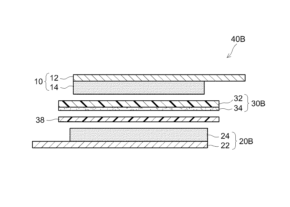
表1に示すように、比較例2,3では、負極シートとセパレータシートとの間にPE製やPP製のシートを介在させたところ、比較例1よりもさらに正負極間の空きが大きくなり、また、限界電流値も比較例1より小さくなった。言い換えれば、Li析出耐性が低下した。また、比較例4では、比較例1に比べて正負極間の空きがやや改善され、Li析出耐性もやや向上していたが、セパレータには依然としてシワが認められた。 As shown in Table 1, in Comparative Examples 2 and 3, when a sheet made of PE or PP was interposed between the negative electrode sheet and the separator sheet, the space between the positive and negative electrodes was larger than in Comparative Example 1. Further, the limit current value was also smaller than that of Comparative Example 1. In other words, the Li precipitation resistance decreased. In Comparative Example 4, the space between the positive and negative electrodes was slightly improved as compared with Comparative Example 1 and Li precipitation resistance was slightly improved, but wrinkles were still observed in the separator.
これら比較例に対して、例1〜3では、比較例1に比べて正負極間の空きが大きく改善され、Li析出耐性も大きく向上していた。さらに、セパレータのシワも認められなかった。これは、電解液膨潤性を有する樹脂(PEO)を熱重合することで、樹脂のネットワークが強固になり、電解液保持性が向上する等して、充填層の電解液膨潤性や柔軟性が高まったためと考えられる。なかでも、負極シートまたはセパレータシートの表面に充填層を配置した例2,3では、Li析出耐性が顕著に向上していた。
これらの結果は、ここに開示される技術の意義を示すものである。
Compared to Comparative Example 1, in Examples 1 to 3, the space between the positive and negative electrodes was greatly improved, and Li precipitation resistance was also greatly improved. Further, no separator wrinkles were observed. This is because the resin network (PEO) having the electrolyte swellability is thermally polymerized to strengthen the resin network and improve the electrolyte solution retention. This is thought to be due to an increase. In particular, in Examples 2 and 3 in which the filling layer was disposed on the surface of the negative electrode sheet or the separator sheet, the Li precipitation resistance was remarkably improved.
These results show the significance of the technology disclosed herein.
以上、本発明を詳細に説明したが、上記実施形態および実施例は例示にすぎず、ここで開示される発明には上述の具体例を様々に変形、変更したものが含まれる。 As mentioned above, although this invention was demonstrated in detail, the said embodiment and Example are only illustrations and what changed and changed the above-mentioned specific example is contained in the invention disclosed here.
10 正極シート
20、20A、20B 負極シート
26、36、38 充填層(充填シート)
30、30A、30B セパレータシート
40、40A、40B 捲回電極体
100 非水電解質二次電池
10
30, 30A,
Claims (4)
非水電解質と、
を備え、
前記捲回電極体は、前記負極シートと前記セパレータシートとの間に、電解液膨潤性を有する樹脂の熱重合物を含む充填層を備える、非水電解質二次電池。 A flat wound electrode body comprising a positive electrode sheet, a negative electrode sheet, and a separator sheet disposed between the positive electrode sheet and the negative electrode sheet;
A non-aqueous electrolyte,
With
The wound electrode body is a nonaqueous electrolyte secondary battery including a filling layer including a thermal polymer of a resin having electrolyte swellability between the negative electrode sheet and the separator sheet.
前記捲回電極体と、非水電解質とを電池ケースに収容して、組立体を構築する工程、ここで、前記非水電解質は、重合開始剤、連鎖移動剤および重合停止剤のうちの少なくとも一つを含んでいる、および、
前記組立体を温めて、前記充填層に含まれる前記樹脂を熱重合する工程、
を包含する、非水電解質二次電池の製造方法。 A step of preparing a flat wound electrode body comprising a positive electrode sheet, a negative electrode sheet, and a separator sheet disposed between the positive electrode sheet and the negative electrode sheet, wherein the negative electrode sheet and the separator sheet Between, there is a filling layer containing a resin having electrolyte swellability,
A step of housing the wound electrode body and the non-aqueous electrolyte in a battery case to construct an assembly, wherein the non-aqueous electrolyte is at least one of a polymerization initiator, a chain transfer agent, and a polymerization terminator. Including one and
Heating the assembly to thermally polymerize the resin contained in the packed bed;
A method for producing a non-aqueous electrolyte secondary battery.
Priority Applications (4)
| Application Number | Priority Date | Filing Date | Title |
|---|---|---|---|
| JP2016209449A JP6478122B2 (en) | 2016-10-26 | 2016-10-26 | Non-aqueous electrolyte secondary battery and manufacturing method thereof |
| CN201710944856.8A CN107994250B (en) | 2016-10-26 | 2017-10-12 | Nonaqueous electrolyte secondary battery and method for manufacturing same |
| US15/782,241 US11276900B2 (en) | 2016-10-26 | 2017-10-12 | Nonaqueous electrolyte secondary battery and method of producing the same |
| KR1020170137164A KR101985600B1 (en) | 2016-10-26 | 2017-10-23 | Nonaqueous electrolyte secondary battery and method of producing the same |
Applications Claiming Priority (1)
| Application Number | Priority Date | Filing Date | Title |
|---|---|---|---|
| JP2016209449A JP6478122B2 (en) | 2016-10-26 | 2016-10-26 | Non-aqueous electrolyte secondary battery and manufacturing method thereof |
Publications (2)
| Publication Number | Publication Date |
|---|---|
| JP2018073530A true JP2018073530A (en) | 2018-05-10 |
| JP6478122B2 JP6478122B2 (en) | 2019-03-06 |
Family
ID=61969969
Family Applications (1)
| Application Number | Title | Priority Date | Filing Date |
|---|---|---|---|
| JP2016209449A Active JP6478122B2 (en) | 2016-10-26 | 2016-10-26 | Non-aqueous electrolyte secondary battery and manufacturing method thereof |
Country Status (4)
| Country | Link |
|---|---|
| US (1) | US11276900B2 (en) |
| JP (1) | JP6478122B2 (en) |
| KR (1) | KR101985600B1 (en) |
| CN (1) | CN107994250B (en) |
Cited By (1)
| Publication number | Priority date | Publication date | Assignee | Title |
|---|---|---|---|---|
| WO2020158306A1 (en) * | 2019-01-28 | 2020-08-06 | 積水化学工業株式会社 | Electrode for lithium ion secondary battery and lithium ion secondary battery |
Families Citing this family (1)
| Publication number | Priority date | Publication date | Assignee | Title |
|---|---|---|---|---|
| JP7385816B2 (en) * | 2020-09-16 | 2023-11-24 | トヨタ自動車株式会社 | Nonaqueous electrolyte secondary battery |
Citations (2)
| Publication number | Priority date | Publication date | Assignee | Title |
|---|---|---|---|---|
| JP2005142156A (en) * | 2003-10-31 | 2005-06-02 | Samsung Sdi Co Ltd | Negative electrode for lithium metal secondary battery, its manufacturing method and lithium metal secondary battery including the negative electrode |
| JP2009016340A (en) * | 2007-06-06 | 2009-01-22 | Nissan Motor Co Ltd | Secondary battery and its manufacturing method |
Family Cites Families (13)
| Publication number | Priority date | Publication date | Assignee | Title |
|---|---|---|---|---|
| JP3990063B2 (en) * | 1999-03-03 | 2007-10-10 | 三菱化学株式会社 | Manufacturing method of secondary battery |
| KR100770105B1 (en) * | 2005-07-06 | 2007-10-24 | 삼성에스디아이 주식회사 | Lithium rechargeable battery |
| EP2001073B1 (en) | 2007-06-06 | 2012-02-22 | Nissan Motor Co., Ltd. | Secondary battery and method of producing the secondary battery |
| JP4561843B2 (en) * | 2008-02-26 | 2010-10-13 | ソニー株式会社 | Nonaqueous electrolyte battery and negative electrode |
| JP5267873B2 (en) | 2009-06-12 | 2013-08-21 | トヨタ自動車株式会社 | Secondary battery and manufacturing method thereof |
| CN103959547B (en) * | 2011-09-29 | 2016-10-26 | 日立麦克赛尔株式会社 | Lithium secondary battery |
| CN103891030B (en) * | 2011-10-20 | 2016-08-24 | 丰田自动车株式会社 | Nonaqueous electrolytic solution secondary battery and utilization thereof |
| JP6184200B2 (en) * | 2012-07-04 | 2017-08-23 | 株式会社東芝 | Non-aqueous electrolyte secondary battery and manufacturing method thereof |
| CN104904042B (en) * | 2013-02-04 | 2017-03-15 | 日本瑞翁株式会社 | Lithium ion secondary battery positive electrode slurry |
| WO2015163017A1 (en) * | 2014-04-21 | 2015-10-29 | ソニー株式会社 | Secondary cell, cell pack, electric vehicle, electric power storage system, electric tool, and electronic device |
| WO2017094381A1 (en) * | 2015-12-03 | 2017-06-08 | ソニー株式会社 | Secondary battery, battery pack, electric vehicle, electrical energy storage system, electric tool and electronic device |
| JP6776530B2 (en) * | 2015-12-14 | 2020-10-28 | 株式会社村田製作所 | Batteries, battery packs, electronic devices, electric vehicles, power storage devices and power systems |
| CN105406009A (en) * | 2015-12-23 | 2016-03-16 | 梁百胜 | Gel black core lithium ion battery and manufacturing method thereof |
-
2016
- 2016-10-26 JP JP2016209449A patent/JP6478122B2/en active Active
-
2017
- 2017-10-12 US US15/782,241 patent/US11276900B2/en active Active
- 2017-10-12 CN CN201710944856.8A patent/CN107994250B/en active Active
- 2017-10-23 KR KR1020170137164A patent/KR101985600B1/en active IP Right Grant
Patent Citations (2)
| Publication number | Priority date | Publication date | Assignee | Title |
|---|---|---|---|---|
| JP2005142156A (en) * | 2003-10-31 | 2005-06-02 | Samsung Sdi Co Ltd | Negative electrode for lithium metal secondary battery, its manufacturing method and lithium metal secondary battery including the negative electrode |
| JP2009016340A (en) * | 2007-06-06 | 2009-01-22 | Nissan Motor Co Ltd | Secondary battery and its manufacturing method |
Cited By (2)
| Publication number | Priority date | Publication date | Assignee | Title |
|---|---|---|---|---|
| WO2020158306A1 (en) * | 2019-01-28 | 2020-08-06 | 積水化学工業株式会社 | Electrode for lithium ion secondary battery and lithium ion secondary battery |
| JPWO2020158306A1 (en) * | 2019-01-28 | 2021-02-25 | 積水化学工業株式会社 | Electrodes for lithium-ion secondary batteries and lithium-ion secondary batteries |
Also Published As
| Publication number | Publication date |
|---|---|
| JP6478122B2 (en) | 2019-03-06 |
| KR20180045816A (en) | 2018-05-04 |
| CN107994250A (en) | 2018-05-04 |
| CN107994250B (en) | 2021-04-02 |
| KR101985600B1 (en) | 2019-06-03 |
| US20180114970A1 (en) | 2018-04-26 |
| US11276900B2 (en) | 2022-03-15 |
Similar Documents
| Publication | Publication Date | Title |
|---|---|---|
| JP2005078991A (en) | Nonaqueous electrolytic secondary battery | |
| JP2012119091A (en) | Nonaqueous electrolytic solution, electrode, and electrochemical device comprising nonaqueous electrolytic solution and electrode | |
| JP2011049114A (en) | Lithium-ion secondary battery | |
| KR20140116940A (en) | Non-aqueous electrolyte secondary battery and method for manufacturing same | |
| JP6187601B2 (en) | Method for producing lithium ion secondary battery | |
| US20180191024A1 (en) | Method of preparing secondary battery | |
| JP2018106903A (en) | Lithium ion secondary battery | |
| JP4352972B2 (en) | Electrode and battery using the same | |
| JP6478122B2 (en) | Non-aqueous electrolyte secondary battery and manufacturing method thereof | |
| JP6103315B2 (en) | Non-aqueous secondary battery and method for producing the battery | |
| JP2018006289A (en) | Nonaqueous electrolyte secondary battery | |
| JP2005317469A (en) | Cathode for lithium-ion secondary battery, and lithium-ion secondary battery using cathode | |
| US10312520B2 (en) | Non-aqueous electrolyte secondary battery | |
| JP5711825B2 (en) | Integrated electrode assembly and secondary battery using the integrated electrode assembly | |
| JP6274532B2 (en) | Method for producing non-aqueous electrolyte secondary battery | |
| CN117280512A (en) | Method for producing gel polymer electrolyte secondary battery and gel polymer electrolyte secondary battery obtained thereby | |
| CN111653725B (en) | Negative electrode for nonaqueous lithium ion secondary battery and nonaqueous lithium ion secondary battery using the same | |
| JP5880942B2 (en) | Non-aqueous electrolyte secondary battery | |
| KR102275863B1 (en) | ELECTRODE FOR LiTHIUM SECONDARY BATTERY AND SECONDARY BATTERY COMPRISING THE SAME | |
| JP2013243031A (en) | Nonaqueous electrolyte secondary battery | |
| JP7249988B2 (en) | lithium ion secondary battery | |
| JP6928873B2 (en) | Non-aqueous electrolyte secondary battery | |
| JP2023530326A (en) | Method for manufacturing secondary battery | |
| JP2014086179A (en) | Positive electrode for lithium ion secondary battery | |
| JP2020077478A (en) | Nonaqueous electrolytic solution lithium ion secondary battery |
Legal Events
| Date | Code | Title | Description |
|---|---|---|---|
| A977 | Report on retrieval |
Free format text: JAPANESE INTERMEDIATE CODE: A971007 Effective date: 20181017 |
|
| A131 | Notification of reasons for refusal |
Free format text: JAPANESE INTERMEDIATE CODE: A131 Effective date: 20181101 |
|
| A521 | Request for written amendment filed |
Free format text: JAPANESE INTERMEDIATE CODE: A523 Effective date: 20181213 |
|
| TRDD | Decision of grant or rejection written | ||
| A01 | Written decision to grant a patent or to grant a registration (utility model) |
Free format text: JAPANESE INTERMEDIATE CODE: A01 Effective date: 20190110 |
|
| A61 | First payment of annual fees (during grant procedure) |
Free format text: JAPANESE INTERMEDIATE CODE: A61 Effective date: 20190123 |
|
| R151 | Written notification of patent or utility model registration |
Ref document number: 6478122 Country of ref document: JP Free format text: JAPANESE INTERMEDIATE CODE: R151 |