JP2018071702A - Refrigerator compressor shaft seal device - Google Patents
Refrigerator compressor shaft seal device Download PDFInfo
- Publication number
- JP2018071702A JP2018071702A JP2016213464A JP2016213464A JP2018071702A JP 2018071702 A JP2018071702 A JP 2018071702A JP 2016213464 A JP2016213464 A JP 2016213464A JP 2016213464 A JP2016213464 A JP 2016213464A JP 2018071702 A JP2018071702 A JP 2018071702A
- Authority
- JP
- Japan
- Prior art keywords
- seal
- shaft
- refrigerator compressor
- sliding surface
- ring
- Prior art date
- Legal status (The legal status is an assumption and is not a legal conclusion. Google has not performed a legal analysis and makes no representation as to the accuracy of the status listed.)
- Pending
Links
Images
Classifications
-
- F—MECHANICAL ENGINEERING; LIGHTING; HEATING; WEAPONS; BLASTING
- F16—ENGINEERING ELEMENTS AND UNITS; GENERAL MEASURES FOR PRODUCING AND MAINTAINING EFFECTIVE FUNCTIONING OF MACHINES OR INSTALLATIONS; THERMAL INSULATION IN GENERAL
- F16J—PISTONS; CYLINDERS; SEALINGS
- F16J15/00—Sealings
- F16J15/16—Sealings between relatively-moving surfaces
- F16J15/34—Sealings between relatively-moving surfaces with slip-ring pressed against a more or less radial face on one member
- F16J15/3404—Sealings between relatively-moving surfaces with slip-ring pressed against a more or less radial face on one member and characterised by parts or details relating to lubrication, cooling or venting of the seal
-
- F—MECHANICAL ENGINEERING; LIGHTING; HEATING; WEAPONS; BLASTING
- F04—POSITIVE - DISPLACEMENT MACHINES FOR LIQUIDS; PUMPS FOR LIQUIDS OR ELASTIC FLUIDS
- F04D—NON-POSITIVE-DISPLACEMENT PUMPS
- F04D29/00—Details, component parts, or accessories
- F04D29/08—Sealings
- F04D29/10—Shaft sealings
- F04D29/12—Shaft sealings using sealing-rings
- F04D29/122—Shaft sealings using sealing-rings especially adapted for elastic fluid pumps
-
- F—MECHANICAL ENGINEERING; LIGHTING; HEATING; WEAPONS; BLASTING
- F16—ENGINEERING ELEMENTS AND UNITS; GENERAL MEASURES FOR PRODUCING AND MAINTAINING EFFECTIVE FUNCTIONING OF MACHINES OR INSTALLATIONS; THERMAL INSULATION IN GENERAL
- F16J—PISTONS; CYLINDERS; SEALINGS
- F16J15/00—Sealings
- F16J15/002—Sealings comprising at least two sealings in succession
-
- F—MECHANICAL ENGINEERING; LIGHTING; HEATING; WEAPONS; BLASTING
- F16—ENGINEERING ELEMENTS AND UNITS; GENERAL MEASURES FOR PRODUCING AND MAINTAINING EFFECTIVE FUNCTIONING OF MACHINES OR INSTALLATIONS; THERMAL INSULATION IN GENERAL
- F16J—PISTONS; CYLINDERS; SEALINGS
- F16J15/00—Sealings
- F16J15/16—Sealings between relatively-moving surfaces
- F16J15/32—Sealings between relatively-moving surfaces with elastic sealings, e.g. O-rings
- F16J15/3204—Sealings between relatively-moving surfaces with elastic sealings, e.g. O-rings with at least one lip
- F16J15/3228—Sealings between relatively-moving surfaces with elastic sealings, e.g. O-rings with at least one lip formed by deforming a flat ring
-
- F—MECHANICAL ENGINEERING; LIGHTING; HEATING; WEAPONS; BLASTING
- F16—ENGINEERING ELEMENTS AND UNITS; GENERAL MEASURES FOR PRODUCING AND MAINTAINING EFFECTIVE FUNCTIONING OF MACHINES OR INSTALLATIONS; THERMAL INSULATION IN GENERAL
- F16J—PISTONS; CYLINDERS; SEALINGS
- F16J15/00—Sealings
- F16J15/16—Sealings between relatively-moving surfaces
- F16J15/34—Sealings between relatively-moving surfaces with slip-ring pressed against a more or less radial face on one member
- F16J15/3436—Pressing means
- F16J15/3452—Pressing means the pressing force resulting from the action of a spring
Landscapes
- Engineering & Computer Science (AREA)
- General Engineering & Computer Science (AREA)
- Mechanical Engineering (AREA)
- Compressor (AREA)
- Sealing With Elastic Sealing Lips (AREA)
- Mechanical Sealing (AREA)
- Sealing Devices (AREA)
Abstract
【課題】耐久性に優れる冷凍機コンプレッサの軸封装置を提供する。【解決手段】冷媒を圧縮する冷凍機コンプレッサの軸封装置であって、前記冷凍機コンプレッサの回転軸2が挿通されるハウジング1と、前記ハウジング1に保持された静止密封環40及び前記回転軸2に装着されその摺動面30aが前記静止密封環40の摺動面40aと摺接する回転密封環30を有するメカニカルシール3と、前記回転軸2を軸封する補助シール90と、前記メカニカルシール3と前記補助シール90との間に形成される中間室Cにおいて、前記摺動面40aの少なくとも一部にかかる高さまで貯留された冷凍機油Lとを備えた。【選択図】図1A shaft seal device for a refrigerator compressor having excellent durability is provided. A shaft seal device for a refrigerator compressor that compresses refrigerant, a housing 1 through which a rotating shaft 2 of the refrigerator compressor is inserted, a stationary sealing ring 40 held by the housing 1, and the rotating shaft. 2, a mechanical seal 3 having a rotary sealing ring 30 whose sliding surface 30 a is in sliding contact with the sliding surface 40 a of the stationary sealing ring 40, an auxiliary seal 90 that seals the rotary shaft 2, and the mechanical seal 3 and a refrigerating machine oil L stored up to a height of at least a part of the sliding surface 40a in the intermediate chamber C formed between the auxiliary seal 90 and the intermediate seal C. [Selection] Figure 1
Description
冷凍サイクル装置において冷媒を圧縮するコンプレッサの回転軸を軸封する冷凍機コンプレッサの軸封装置に関するものである。 The present invention relates to a shaft seal device for a refrigerator compressor that seals a rotary shaft of a compressor that compresses refrigerant in a refrigeration cycle device.
自動車用空調装置(カーエアコン)のような冷凍サイクル装置において冷媒を圧縮するコンプレッサを軸封する冷凍機コンプレッサには、冷媒を軸封するために軸封装置が用いられている。従来、軸封装置として、小型軽量のリップシールが主に用いられてきた。ところで、冷媒として、従来フロンガスが使用されていたものの、オゾン層の破壊や赤外線の吸収による温暖化が問題とされ、二酸化炭素(CO2)が使用されるようになっている。冷媒として二酸化炭素を使用する場合は、フロンガスを使用する場合に比較して、冷媒の圧縮圧力が大幅に上昇する。そのため、軸封装置としてリップシールよりも密封性に優れるメカニカルシールを用いることが提案されている。(特許文献1を参照。)メカニカルシールは、摺動面間に潤滑膜を形成することで優れた耐久性を実現することができる。 2. Description of the Related Art A shaft seal device is used to seal a refrigerant in a refrigerator compressor that shaft seals a compressor that compresses refrigerant in a refrigeration cycle apparatus such as an air conditioner for automobiles (car air conditioner). Conventionally, a small and light lip seal has been mainly used as a shaft seal device. By the way, although chlorofluorocarbon gas has been conventionally used as a refrigerant, warming due to destruction of the ozone layer and absorption of infrared rays has been a problem, and carbon dioxide (CO 2 ) has been used. When carbon dioxide is used as the refrigerant, the compression pressure of the refrigerant is significantly increased as compared with the case where chlorofluorocarbon gas is used. For this reason, it has been proposed to use a mechanical seal that has better sealing performance than a lip seal as the shaft seal device. (Refer to patent document 1.) The mechanical seal can realize excellent durability by forming a lubricating film between sliding surfaces.
ここで、冷凍機コンプレッサでは、その内部の冷凍機油が少なくなってメカニカルシールの摺動面間において潤滑膜が形成されず、いわゆる貧潤滑となり耐久性を失うことがある。例えば、冷凍機コンプレッサの長時間の停止時等にハウジング内に液相冷媒が溜まり、液相冷媒に相溶性を有する冷凍機油が希釈された場合や冷凍機コンプレッサを高負荷条件下で使用する場合に貧潤滑となることがある。そして、貧潤滑となった場合には、メカニカルシールの摺動面間に潤滑膜が十分に形成されず、メカニカルシールの摺動面が固体潤滑状態となって摩擦係数が異常に上昇したりスティックスリップ現象を起こしたりする虞がある。 Here, in the refrigeration compressor, the amount of refrigeration oil inside is reduced, so that a lubricating film is not formed between the sliding surfaces of the mechanical seal, so-called poor lubrication and durability may be lost. For example, liquid refrigerant accumulates in the housing when the refrigerator compressor is stopped for a long time, etc., and refrigerator oil that is compatible with the liquid refrigerant is diluted or the refrigerator compressor is used under high load conditions May be poorly lubricated. In the case of poor lubrication, a sufficient lubricating film is not formed between the sliding surfaces of the mechanical seal, and the sliding surface of the mechanical seal becomes a solid lubricating state and the friction coefficient increases abnormally. There is a risk of causing a slip phenomenon.
本発明は、このような問題点に着目してなされたもので、耐久性に優れる冷凍機コンプレッサの軸封装置を提供することを目的とする。 The present invention has been made paying attention to such problems, and an object thereof is to provide a shaft seal device for a refrigerator compressor having excellent durability.
前記課題を解決するために、本発明の冷凍機コンプレッサの軸封装置は、
冷媒を圧縮する冷凍機コンプレッサの軸封装置であって、
前記冷凍機コンプレッサの回転軸が挿通されるハウジングと、
前記ハウジングに保持された静止密封環及び前記回転軸に装着されその摺動面が前記静止密封環の摺動面と摺接する回転密封環を有するメカニカルシールと、
前記回転軸を軸封する補助シールと、
前記メカニカルシールと前記補助シールとの間に形成される中間室において、前記摺動面の少なくとも一部にかかる高さまで貯留された冷凍機油と
を備えている。
これによれば、中間室において摺動面の少なくとも一部にかかる高さまで冷凍機油が貯留されているとともに摺動面間は隙間が小さく、冷凍機コンプレッサの停止後、摺動面間には冷凍機油が毛細管現象により導かれるため、摺動面間に確実に潤滑膜を介在させることができる。特に、冷凍機コンプレッサの起動時において、摺動面間の冷凍機油が少なく貧潤滑を招きやすい状況にあっても、摺動面間の少なくとも一部には冷凍機油が供給されており、回転密封環の回転に伴って摺動面全体に冷凍機油が供給されることとなる。このことからメカニカルシールは流体潤滑を維持でき耐久性に優れる。
In order to solve the above problems, a shaft seal device for a refrigerator compressor according to the present invention includes:
A shaft seal device for a refrigerator compressor that compresses refrigerant,
A housing through which the rotating shaft of the refrigerator compressor is inserted;
A stationary seal ring held by the housing, and a mechanical seal having a rotation seal ring mounted on the rotary shaft and having a sliding surface slidably contacting the sliding surface of the stationary seal ring;
An auxiliary seal that seals the rotating shaft;
The intermediate chamber formed between the mechanical seal and the auxiliary seal includes refrigerating machine oil stored up to a height over at least a part of the sliding surface.
According to this, the refrigerating machine oil is stored up to the height of at least a part of the sliding surface in the intermediate chamber, and the clearance between the sliding surfaces is small. Since the machine oil is guided by capillary action, a lubricating film can be reliably interposed between the sliding surfaces. In particular, at the time of starting the refrigerator compressor, even if there is little refrigeration oil between the sliding surfaces and easily causes poor lubrication, the refrigeration oil is supplied to at least a part between the sliding surfaces, As the ring rotates, the refrigeration oil is supplied to the entire sliding surface. For this reason, the mechanical seal can maintain fluid lubrication and has excellent durability.
前記冷凍機油は、前記中間室において上方に空間を残して貯留されている。
これによれば、中間室の冷凍機油が温度により膨張しても、中間室の圧力は過度に上昇することなく、メカニカルシールの中間室と機内側の差圧が大きく変動することがなく、メカニカルシールによって良好にシールできる。
The refrigerating machine oil is stored in the intermediate chamber leaving a space above.
According to this, even if the refrigerating machine oil in the intermediate chamber expands due to temperature, the pressure in the intermediate chamber does not increase excessively, and the differential pressure between the intermediate chamber of the mechanical seal and the inside of the machine does not fluctuate greatly. It can seal well with a seal.
前記補助シールは前記冷媒を透過する材料で形成されている。
これによれば、補助シールは、冷凍機油を密封しつつメカニカルシールの摺動面間を通って中間室に漏洩した冷媒を機外側に透過させることができる。そのため中間室の圧力は過度に上昇せず、メカニカルシールの中間室と機内側の差圧が大きく変動することがなく、メカニカルシールによって冷媒を良好にシールできる。
The auxiliary seal is made of a material that is permeable to the refrigerant.
According to this, the auxiliary seal can permeate the refrigerant leaked to the intermediate chamber through the space between the sliding surfaces of the mechanical seal while sealing the refrigerator oil. Therefore, the pressure in the intermediate chamber does not increase excessively, the differential pressure between the intermediate chamber of the mechanical seal and the inside of the machine does not fluctuate greatly, and the refrigerant can be well sealed by the mechanical seal.
前記補助シールはリップシールである。
これによれば、補助シールをリップシールとしているため小型化できる。
The auxiliary seal is a lip seal.
According to this, since the auxiliary seal is a lip seal, the size can be reduced.
前記リップシールは、前記メカニカルシールよりも機外側に配置されている。
これによれば、機内側にメカニカルシールが配置されるため、圧力の高い冷媒の軸封が確実となる。また、中間室は機外側まで延びているため中間室内の冷凍機油は機外側から冷やされ、回転密封環及び静止密封環の冷却に寄与する。
The lip seal is disposed on the outer side than the mechanical seal.
According to this, since the mechanical seal is arranged inside the machine, the shaft seal of the refrigerant having a high pressure is ensured. Further, since the intermediate chamber extends to the outside of the machine, the refrigeration oil in the intermediate chamber is cooled from the outside of the machine, and contributes to cooling of the rotary seal ring and the stationary seal ring.
前記メカニカルシールはインサイド形であり、前記中間室は前記メカニカルシールの内周面と前記回転軸の外周面により画成されている。
これによれば、冷凍機油と接触する回転側の部材が少なく、回転軸の回転トルクに及ぼす影響が少ない。
The mechanical seal is an inside shape, and the intermediate chamber is defined by an inner peripheral surface of the mechanical seal and an outer peripheral surface of the rotating shaft.
According to this, there are few rotation side members which contact with refrigeration oil, and there is little influence which it has on the rotational torque of a rotating shaft.
前記冷媒は二酸化炭素である。
これによれば、メカニカルシールを用いているため、圧力の高い二酸化炭素の軸封が確実となる。
The refrigerant is carbon dioxide.
According to this, since the mechanical seal is used, the shaft seal of carbon dioxide having a high pressure is ensured.
前記回転密封環の摺動面及び前記静止密封環の摺動面は、算術平均粗さRaが0.2μm以下である。
これによれば、摺動面間の隙間が小さく毛細管現象を確実に生じせしめる。
The sliding surface of the rotary sealing ring and the sliding surface of the stationary sealing ring have an arithmetic average roughness Ra of 0.2 μm or less.
According to this, the gap between the sliding surfaces is small, and the capillary phenomenon is surely generated.
本発明に係る冷凍機コンプレッサの軸封装置を実施するための形態を実施例に基づいて以下に説明する。なお、本発明はこれに限定されて解釈されるものではなく、本発明の範囲を逸脱しない限りにおいて、当業者の知識に基づいて、種々の変更、修正、改良を加えうるものである。 EMBODIMENT OF THE INVENTION The form for implementing the shaft seal apparatus of the refrigerator compressor which concerns on this invention is demonstrated below based on an Example. The present invention is not construed as being limited thereto, and various changes, modifications, and improvements can be added based on the knowledge of those skilled in the art without departing from the scope of the present invention.
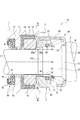
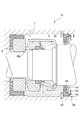
図1に示すように、冷凍機コンプレッサの軸封装置10は、メカニカルシール3とリップシール90(補助シール)とから構成されており、冷凍機コンプレッサは回転軸2を水平方向に配置した横置きに設置されている。メカニカルシール3とリップシール90とはそれぞれ、冷凍機コンプレッサのハウジング1と、ハウジング1の軸孔11を貫通して冷凍機コンプレッサの内部と外部に連通するように配置される回転軸2との間に装着されている。メカニカルシール3よりも機内M側には被密封流体であるガス状の冷媒として(二酸化炭素(CO2))及び冷凍機油としてPAG(ポリアルキレングリコール)が封入されている。実施例1では、メカニカルシール3とリップシール90との間の中間室Cにも冷凍機油Lを貯留する構成としている。なお、中間室Cの冷凍機油Lは、機内M側の冷凍機油と同じPAGであるが、必ずしもPAGに限られない。
As shown in FIG. 1, a
メカニカルシール3は、ハウジング1と回転軸2との間に装着されている。回転軸2は、大気A側において図示しないエンジンのクランク軸からの駆動力が電磁クラッチ等の機構を介して伝達され、これにより回転し、冷凍機コンプレッサ内部の機構を駆動する。
The
メカニカルシール3は、ハウジング1に非回転状態に装着される静止密封環であるメイティングリング30、回転軸2側に装着されてこの回転軸2と一体的に回転する回転側密封環であるシールリング40を有する。また、メカニカルシール3は、シールリング40を回転軸2に嵌着するための構成として、ケース60、スプリング70、スプリングホルダ71及びOリング80を有する。
The
メイティングリング30とシールリング40とは、回転軸2の軸方向に沿って互いに対向するように配置されており、それらの対向した端面である摺動面30a、40a同士が密接することにより、冷媒をシールする。すなわち、機内M側の冷媒は大気A側に漏洩、流出しないようにシールされる。
The
図1に示されるように、ハウジング1の右側の摺動面30a、40aの外周側の空間は、ガス状の冷媒が充満する機内M側空間であり、摺動面30a、40aの内周側からハウジング1の左側に至る空間が大気A側(機外)空間である。実施例1のメカニカルシール3は、外周側から内周側への被密封流体である冷媒の漏れを防止するインサイド形である。
As shown in FIG. 1, the space on the outer peripheral side of the sliding
メイティングリング30のシールリング40側の端面は摺動面30aとして形成されている。シールリング40の環状の摺動突起41のメイティングリング30側に摺動面40aが形成されている。また、摺動面30a及び摺動面40aは、鏡面仕上げにより中心線平均粗さRaが0.2mm以下好ましくは0.1mm以下とされている。
An end surface of the
シールリング40は、例えばカーボン摺動材により形成され、メイティングリング30は、カーボン摺動材よりもヤング率の大きい硬質摺動材(例えばSiC等のセラミックス)により形成される。
The
Oリング80は、シールリング40の背面側(メイティングリング30とは反対側の面)の端部の内周面に形成されたOリング装着凹部43に収容される。シールリング40の背面には、金属板であるスプリングホルダ71が当接配置され、その内径部はシールリング40のOリング装着凹部43の背後を塞ぐように延びている。スプリングホルダ71の背面側には三脚台状の金属板(例えばステンレス鋼板)からなるケース60が配置されている。
The O-
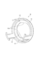
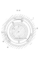
図2を参照し、ケース60は、中央に嵌合孔62を有する鍔状の底板61、底板61から軸方向に僅かに延びるリブ63、リブ63から軸方向に延びる3本のガイド片64(ガイド部材)から形成されている。ガイド片64は周方向に均等間隔で形成されており、シールリング40の外周面に同じく均等間隔に形成された切欠42(図1)と係合している。これにより、シールリング40は、回転軸2の軸方向には移動可能な状態となり、周方向(回転方向)には移動不能な状態とされる。
Referring to FIG. 2, the
メイティングリング30は、ガスケット50を介在させてハウジング1の軸孔11の機内M側開口部に拡径形成された環状凹部12に嵌入されている。ガスケット50は内部の金属環51がインサート成形によりゴム部材52により覆われている。
The
図1に示されるように、回転軸2は、機内M側から、大径部20、第1の段差部21、第2の段差部22、小径部23が形成されている。ケース60は底板61の外側面(右面)が、回転軸2の第1の段差部21の径方向面に当接されることにより、ケース60は回転軸2の軸方向に係止されている。また、ケース60は嵌合孔62の平坦部62aが回転軸2の第1の段差部21の一部に形成された切欠部26と係合するように構成されている(図1)。これによりケース60は、回転軸2に対して周方向に移動不能に、すなわち、回転軸2の回転に伴って回転軸2と一体的に回転するように、回転軸2に嵌合されている。
As shown in FIG. 1, the rotary shaft 2 is formed with a large-
第2の段差部22は、第1の段差部21よりも小径であり、シールリング40が取り付けられている。小径部23は第2の段差部22よりも小径であり傾斜部22aと連続して形成されており、メイティングリング30が挿通されるとともに、その外周面にリップシール90(補助シール)の先端部が接触している。リップシール90はハウジング1の軸孔11の大気A側開口部に拡径形成された環状凹部13に嵌入・固定されている。
The
リップシール90は、シール部材91と、金属環92と、バックアップリング94とから主に構成されている。シール部材91とバックアップリング94は、インサート成形によりゴム部材93により覆われた金属環92に収納・保持されている。シール部材91は、ポリテトラフルオロエチレン(PTFE)を主成分として形成されている。
The
このような構成により、シールリング40にはスプリング70による付勢力が回転軸2の軸方向に与えられ、摺動突起41先端の摺動面40aはメイティングリング30の摺動面30aに適切な使用圧力で押し付けられる。また、シールリング40は、回転軸2からの回転トルクをケース60を介して与えられることとなり、回転軸2と一体的に回転する。この結果、回転軸2の回転に伴って、メイティングリング30の摺動面30aとシールリング40の摺動面40aとは密接した状態で摺動することとなり、メイティングリング30の摺動面30aとシールリング40の摺動面40aとの摺動により冷媒をシールする。
With such a configuration, the urging force of the
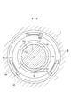
図1、図3に示すように、中間室Cは、大気A側(機外)空間に設けられた室であり、回転軸2の小径部23、回転軸2の傾斜部22a、シールリング40の内周面、メイティングリング30の内周面、ガスケット50の内周面、メカニカルシール3とリップシール90との間のハウジング1の内周面、リップシール90の側面により画成されている。
As shown in FIGS. 1 and 3, the intermediate chamber C is a chamber provided in the atmosphere A side (outside the machine) space, and includes a
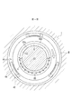
そして、この中間室Cには冷凍機油Lが環状の摺動面40aの略下半分の高さ位置(図1,図3において破線h0で示す位置)まで貯留されているため、摺動面30aと摺動面40aとの間に冷凍機油Lが供給されて、貧潤滑となることが防止される。摺動面30a及び摺動面40aは鏡面仕上げに加工され、摺動面30aと摺動面40aとの間の隙間(摺動面間)は極めて小さいため、図4において矢印で示すように、中間室Cの冷凍機油Lは当該隙間に毛細管現象により外径側に導かれる。このようにして、確実に当該隙間(摺動面間)に冷凍機油Lによる潤滑膜を介在させることができる。そして、冷凍機コンプレッサの停止後、当該隙間(摺動面間)には冷凍機油が毛細管現象により導かれるため、摺動面間に確実に潤滑膜を介在させることができる。特に、冷凍機コンプレッサの起動時において、摺動面間の冷凍機油が少なく貧潤滑を招きやすい状況にあっても、当該隙間(摺動面間)の下方の一部には冷凍機油が供給されており、シールリング40の回転(図4の白抜き矢印)に伴って冷凍機油は周方向に順次上方に導かれ摺動面全体に冷凍機油が供給されることとなる。このことからメカニカルシール3は流体潤滑を維持でき耐久性に優れる。
Since the refrigerating machine oil L is stored in the intermediate chamber C up to a height position (a position indicated by a broken line h0 in FIGS. 1 and 3) of the substantially lower half of the annular sliding
上述の毛細管現象を確実に発揮させるためには、摺動面30a及び摺動面40aを、それぞれ算術平均粗さRaが0.2μm以下、好ましくは0.1μm以下として、隙間(摺動面間)を小さくすることが好ましい。
In order to reliably exhibit the above-mentioned capillary phenomenon, each of the sliding surface 30a and the sliding
また、冷凍機油Lを隙間に確実に導くためには、冷凍機油Lを中間室Cにおいて最も下方に位置する摺動面40aの部位45の位置(図1、図3において破線h1で示す位置)よりも高い位置まで貯留されていることが必要である。好ましくは、冷凍機油Lを貯留しておく高さは、メイティングリング30の内周面のうち最も下方に位置(図1において破線h2で示す位置)する部位より高い位置、あるいは概ね回転軸2の小径部23の外周面のうち最も下方に位置(図1,図3において破線h3で示す位置)する部位より高い位置であればよい。すなわち、冷凍機油Lは摺動面40aの一部にかかる高さまで貯留されている必要がある、より詳しくは摺動面30aと摺動面40aとが摺接する部位の内周縁の一部にかかる高さまで貯留されている必要がある。図5には、冷凍機油Lを貯留する高さを、回転軸2の小径部23の外周面のうち最も下方に位置(図3において破線h3で示す位置)とした変形例を示している。
Further, in order to reliably guide the refrigerating machine oil L to the gap, the position of the
また、冷凍機油Lは、中間室Cにおいて上方に冷凍機油Lが存在しない空間C1を残して貯留することが好ましく、中間室Cにおいて上方に空間C1を残すことにより、冷凍機油Lが温度変化によって膨張しても、空間C1がバッファとして機能するため中間室Cの圧力は過度に上昇しない。そのため中間室Cの圧力は過度に上昇せず、メカニカルシール3の機内M側と中間室Cの差圧が大きく変動することがなく、メカニカルシール3に作用する圧力バランスが大きく崩れることがなく良好にシールできる。
The refrigerating machine oil L is preferably stored in the intermediate chamber C leaving a space C1 in which the refrigerating machine oil L does not exist, and the refrigerating machine oil L is changed by a temperature change by leaving the space C1 in the upper part in the intermediate chamber C. Even if it expands, since the space C1 functions as a buffer, the pressure in the intermediate chamber C does not increase excessively. Therefore, the pressure in the intermediate chamber C does not increase excessively, the differential pressure between the in-machine M side of the
また、シール部材91は、ポリテトラフルオロエチレン(PTFE)を主成分として形成されており、低摩擦性、耐熱性、冷媒透過性である。シール部材91が冷媒を透過する材料で形成されているため、メカニカルシール3の摺動面30a、40a間を通って中間室Cに漏洩した冷媒を大気A側に透過させることができる。これにより、中間室Cの圧力の変動が少なくなるため、メカニカルシール3の機内M側と中間室Cの差圧が大きく変動することがなく、メカニカルシール3に作用する圧力バランスが大きく崩れることがなく良好にシールできる。同様に中間室Cと大気A側との差圧の変動を小さすることができる。
The seal member 91 is formed mainly of polytetrafluoroethylene (PTFE), and has low friction, heat resistance, and refrigerant permeability. Since the seal member 91 is formed of a material that allows the refrigerant to pass therethrough, the refrigerant that has leaked into the intermediate chamber C through the sliding
シール部材91は、冷凍機油Lをシールしガス状の冷媒を透過する材料を主成分として形成されていればよく、ポリテトラフルオロエチレンの他、ニトリルゴム、水素化ニトリルゴム、フッ素ゴム、エチレン−プロピレン−ジエンゴム、アクリルゴム、シリコーンゴム等を用いることができる。 The seal member 91 only needs to be formed mainly of a material that seals the refrigerating machine oil L and permeates the gaseous refrigerant. In addition to polytetrafluoroethylene, nitrile rubber, hydrogenated nitrile rubber, fluororubber, ethylene- Propylene-diene rubber, acrylic rubber, silicone rubber and the like can be used.
冷凍機油Lを中間室Cに貯留しておく高さ、言い換えると冷凍機油Lを中間室Cに貯留しておく量は、上述した摺動面間に冷凍機油Lを供給する条件と上述した中間室Cの上方に空間C1を残す条件とを満たす範囲であればよい。そして、静止状態において、シール部材91が接触する部分の回転軸2すなわち小径部23の一部が冷凍機油Lに接する高さ位置(図1,図3において破線h3以上h4未満で示す位置)まで冷凍機油Lが貯留されていることが好ましい。これによれば、確実にこれら条件を満たすことができるとともに冷凍機油Lの注入量の管理が易しく軸封装置10の組み立てが簡単であるからである。
The height at which the refrigerating machine oil L is stored in the intermediate chamber C, in other words, the amount by which the refrigerating machine oil L is stored in the intermediate chamber C is determined by the conditions for supplying the refrigerating machine oil L between the sliding surfaces described above and the intermediate described above. Any range that satisfies the condition for leaving the space C1 above the chamber C may be used. And in a stationary state, to the height position (position shown by broken line h3 or more and less than h4 in FIGS. 1 and 3) where part of rotating shaft 2, that is, part of
また、補助シールの種類は問わないが、補助シールとしてリップシール90を採用しているためメカニカルシール等を採用する場合に比べ小型化できる。また、リップシール90は、シール部材91が1枚のいわゆる1枚シールとすると、冷媒の透過性を確保できるため好ましい。
The type of auxiliary seal is not limited, but since the
また、リップシール90は、メカニカルシール3よりも大気A側に配置されているため、メカニカルシール3が主シールとして機能するため圧力の高い冷媒の軸封が確実となる。また、中間室Cは大気A側まで延びているため中間室C内の冷凍機油Lは大気A側から冷やされ、メイティングリング30及びシールリング40の冷却に寄与する。
Further, since the
また、メカニカルシール3はインサイド形であり、中間室Cはメカニカルシール3の内周面と回転軸2の外周面により画成されているので、冷凍機油Lは回転側の部材と接触する箇所が少なく、回転軸2の回転トルクに及ぼす影響が少ない。
In addition, the
また、メカニカルシール3を用いているため圧力の高い冷媒たる二酸化炭素の軸封が確実となる。さらに、摺動面間の冷凍機油Lが液化された冷媒に溶解しても中間室Cの冷凍機油Lが摺動面間に供給されるため、潤滑膜を形成することができメカニカルシール3の耐久性に優れる。
Further, since the
以下、本発明の実施例2について説明する。実施例2はリップシール190を設ける位置が実施例1とは主に相違している。なお、実施例1と同様の構成についてはその説明を省略する。
Embodiment 2 of the present invention will be described below. The position where the
図6に示されるように、冷凍機コンプレッサの軸封装置10は、メカニカルシール3よりも機内M側にリップシール190(補助シール)が配置されている。リップシール190とメカニカルシール3との間の中間室Dは、機内M側空間に設けられた室であり、中間室Dには、上方に空間D1を残して、環状の摺動面40aの略下半分の高さ位置まで冷凍機油Lが貯留されている。
As shown in FIG. 6, the
リップシール190は、シール部材191と、バックアップリング194と、金属環192とから主に構成されている。シール部材191とバックアップリング194は、インサート成形によりゴム部材193により覆われた金属環192に収納・保持されている。シール部材191は、ポリテトラフルオロエチレン(PTFE)を主成分として形成されている。リップシール190の先端部は回転軸2の大径部20の外周面に接触している。また、リップシール190はハウジング1の軸孔11の機内M側開口部から嵌入され、軸方向位置をスナップリング195に規制されている。
The
以上のように構成したため、実施例1と同様に、中間室Dには冷凍機油Lが環状の摺動面40aの略下半分の高さ位置まで貯留されているため、摺動面30aと摺動面40aとの間に冷凍機油Lが供給されて、貧潤滑となることが防止される。
Since it is configured as described above, the refrigerating machine oil L is stored in the intermediate chamber D up to a height position of substantially the lower half of the annular sliding
以上、本発明の実施例を図面により説明してきたが、具体的な構成はこれら実施例に限られるものではなく、本発明の要旨を逸脱しない範囲における変更や追加があっても本発明に含まれる。 Although the embodiments of the present invention have been described with reference to the drawings, the specific configuration is not limited to these embodiments, and modifications and additions within the scope of the present invention are included in the present invention. It is.
例えば、上述した実施例では、メカニカルシール3として回転型のものについて説明したが、静止型のものであってもよい。
For example, in the above-described embodiment, the rotary type is described as the
また、中間室C、Dに貯留する冷凍機油を冷凍サイクル装置に封入される冷凍機油と同じものを例に説明したが、冷凍機油の種類は異なるものであってもよい。 Moreover, although the refrigerating machine oil stored in the intermediate chambers C and D has been described as the same as the refrigerating machine oil sealed in the refrigerating cycle device, the type of refrigerating machine oil may be different.
また、メイティングリング30は硬質摺動材により形成され、シールリング40はカーボン摺動材により形成される例について説明したが、これらの材質は問わない。例えば、メイティング30及びシールリング40をいずれも硬質摺動材(例えばSiC等のセラミックス)により形成してもよい。
Moreover, although the
1 ハウジング
2 回転軸
3 メカニカルシール
10 軸封装置
30 メイティングリング(固定密封環)
30a 摺動面
40 シールリング(回転密封環)
40a 摺動面
50 ガスケット
60 ケース
90 リップシール(補助シール)
91 シール部材
190 リップシール(補助シール)
191 シール部材
A 大気
M 機内
C,D 中間室
C1,D1 空間
L 冷凍機油
DESCRIPTION OF SYMBOLS 1 Housing 2
91
191 Seal member A Atmosphere M In-machine C, D Intermediate chamber C1, D1 Space L Refrigerator oil
Claims (8)
前記冷凍機コンプレッサの回転軸が挿通されるハウジングと、
前記ハウジングに保持された静止密封環及び前記回転軸に装着されその摺動面が前記静止密封環の摺動面と摺接する回転密封環を有するメカニカルシールと、
前記回転軸を軸封する補助シールと、
前記メカニカルシールと前記補助シールとの間に形成される中間室において、前記摺動面の少なくとも一部にかかる高さまで貯留された冷凍機油と
を備えた冷凍機コンプレッサの軸封装置。 A shaft seal device for a refrigerator compressor that compresses refrigerant,
A housing through which the rotating shaft of the refrigerator compressor is inserted;
A stationary seal ring held by the housing, and a mechanical seal having a rotation seal ring mounted on the rotary shaft and having a sliding surface slidably contacting the sliding surface of the stationary seal ring;
An auxiliary seal that seals the rotating shaft;
A shaft seal device for a refrigerator compressor, comprising: an intermediate chamber formed between the mechanical seal and the auxiliary seal, and refrigerator oil stored up to a height of at least a part of the sliding surface.
Priority Applications (2)
| Application Number | Priority Date | Filing Date | Title |
|---|---|---|---|
| JP2016213464A JP2018071702A (en) | 2016-10-31 | 2016-10-31 | Refrigerator compressor shaft seal device |
| EP17199087.2A EP3315833A1 (en) | 2016-10-31 | 2017-10-30 | Shaft seal device of refrigerator compressor |
Applications Claiming Priority (1)
| Application Number | Priority Date | Filing Date | Title |
|---|---|---|---|
| JP2016213464A JP2018071702A (en) | 2016-10-31 | 2016-10-31 | Refrigerator compressor shaft seal device |
Publications (1)
| Publication Number | Publication Date |
|---|---|
| JP2018071702A true JP2018071702A (en) | 2018-05-10 |
Family
ID=60201379
Family Applications (1)
| Application Number | Title | Priority Date | Filing Date |
|---|---|---|---|
| JP2016213464A Pending JP2018071702A (en) | 2016-10-31 | 2016-10-31 | Refrigerator compressor shaft seal device |
Country Status (2)
| Country | Link |
|---|---|
| EP (1) | EP3315833A1 (en) |
| JP (1) | JP2018071702A (en) |
Cited By (2)
| Publication number | Priority date | Publication date | Assignee | Title |
|---|---|---|---|---|
| JP2021028511A (en) * | 2019-08-09 | 2021-02-25 | イーグル工業株式会社 | Double mechanical seal |
| WO2022143029A1 (en) * | 2020-12-30 | 2022-07-07 | 清华大学 | Mechanical sealing device capable of monitoring amount of wear |
Families Citing this family (1)
| Publication number | Priority date | Publication date | Assignee | Title |
|---|---|---|---|---|
| CN113904478B (en) * | 2021-09-28 | 2022-10-25 | 珠海格力节能环保制冷技术研究中心有限公司 | Motor element, compressor and air conditioner |
Citations (9)
| Publication number | Priority date | Publication date | Assignee | Title |
|---|---|---|---|---|
| JPH06185628A (en) * | 1992-07-21 | 1994-07-08 | Cummins Engine Co Inc | Self seal type water pump seal |
| JP2000136881A (en) * | 1998-11-04 | 2000-05-16 | Eagle Ind Co Ltd | Shaft seal device for high-pressure gas compressor |
| JP2001026792A (en) * | 1999-07-13 | 2001-01-30 | Eagle Ind Co Ltd | Sliding material and mechanical seal using the sliding material |
| JP2007223890A (en) * | 2006-01-30 | 2007-09-06 | Kyocera Corp | Sintered silicon carbide, sliding member and mechanical seal ring using the same, and mechanical seal |
| JP2009092245A (en) * | 2007-10-11 | 2009-04-30 | Kaco Gmbh & Co Kg | Seal arrangement, especially for high pressure range, preferably for use in co2 compressor |
| JP2011058644A (en) * | 2010-12-24 | 2011-03-24 | Kobe Steel Ltd | Mechanical seal |
| WO2011036917A1 (en) * | 2009-09-24 | 2011-03-31 | イーグル工業株式会社 | Mechanical seal |
| WO2014168112A1 (en) * | 2013-04-09 | 2014-10-16 | イーグル工業株式会社 | Sliding seal member |
| JP2016166645A (en) * | 2015-03-09 | 2016-09-15 | 日本ピラー工業株式会社 | Multi-channel rotary joint |
Family Cites Families (6)
| Publication number | Priority date | Publication date | Assignee | Title |
|---|---|---|---|---|
| JPS571953U (en) * | 1980-06-04 | 1982-01-07 | ||
| GB2217396B (en) * | 1988-04-12 | 1992-11-18 | Flexibox Ltd | Tandem shaft seal |
| US5692756A (en) * | 1995-09-22 | 1997-12-02 | Rexnord Corporation | Refrigeration compressor and compressor seal |
| JP4307590B2 (en) * | 1998-05-29 | 2009-08-05 | イーグル工業株式会社 | Shaft seal device for refrigerator compressor |
| DE10056102A1 (en) * | 2000-11-13 | 2002-06-06 | Freudenberg Carl Kg | Mechanical seal |
| JP2007009886A (en) | 2005-07-04 | 2007-01-18 | Toyota Industries Corp | Compressor |
-
2016
- 2016-10-31 JP JP2016213464A patent/JP2018071702A/en active Pending
-
2017
- 2017-10-30 EP EP17199087.2A patent/EP3315833A1/en not_active Withdrawn
Patent Citations (9)
| Publication number | Priority date | Publication date | Assignee | Title |
|---|---|---|---|---|
| JPH06185628A (en) * | 1992-07-21 | 1994-07-08 | Cummins Engine Co Inc | Self seal type water pump seal |
| JP2000136881A (en) * | 1998-11-04 | 2000-05-16 | Eagle Ind Co Ltd | Shaft seal device for high-pressure gas compressor |
| JP2001026792A (en) * | 1999-07-13 | 2001-01-30 | Eagle Ind Co Ltd | Sliding material and mechanical seal using the sliding material |
| JP2007223890A (en) * | 2006-01-30 | 2007-09-06 | Kyocera Corp | Sintered silicon carbide, sliding member and mechanical seal ring using the same, and mechanical seal |
| JP2009092245A (en) * | 2007-10-11 | 2009-04-30 | Kaco Gmbh & Co Kg | Seal arrangement, especially for high pressure range, preferably for use in co2 compressor |
| WO2011036917A1 (en) * | 2009-09-24 | 2011-03-31 | イーグル工業株式会社 | Mechanical seal |
| JP2011058644A (en) * | 2010-12-24 | 2011-03-24 | Kobe Steel Ltd | Mechanical seal |
| WO2014168112A1 (en) * | 2013-04-09 | 2014-10-16 | イーグル工業株式会社 | Sliding seal member |
| JP2016166645A (en) * | 2015-03-09 | 2016-09-15 | 日本ピラー工業株式会社 | Multi-channel rotary joint |
Cited By (3)
| Publication number | Priority date | Publication date | Assignee | Title |
|---|---|---|---|---|
| JP2021028511A (en) * | 2019-08-09 | 2021-02-25 | イーグル工業株式会社 | Double mechanical seal |
| JP7234073B2 (en) | 2019-08-09 | 2023-03-07 | イーグル工業株式会社 | double mechanical seal |
| WO2022143029A1 (en) * | 2020-12-30 | 2022-07-07 | 清华大学 | Mechanical sealing device capable of monitoring amount of wear |
Also Published As
| Publication number | Publication date |
|---|---|
| EP3315833A1 (en) | 2018-05-02 |
Similar Documents
| Publication | Publication Date | Title |
|---|---|---|
| JP5580532B2 (en) | Mechanical seal device | |
| US10598286B2 (en) | Slide component | |
| US10473220B2 (en) | Slide component | |
| US5860656A (en) | Seal for rotating shaft | |
| JP6427778B2 (en) | mechanical seal | |
| JP2008255796A (en) | Shaft seal device of oil-free rotary compressor | |
| JP2018071702A (en) | Refrigerator compressor shaft seal device | |
| WO2000065260A1 (en) | Mechanical seal for compressor | |
| EP3276173A1 (en) | Refrigerant shaft seal and open refrigerant compressor equipped with refrigerant shaft seal | |
| JP4606545B2 (en) | Compressor shaft seal mechanism with mechanical seal | |
| WO2016103601A1 (en) | Shaft sealing device and compressor using same | |
| EP3742027A1 (en) | Seal structure and seal to be used in same | |
| JP2001004034A (en) | Mechanical seal for carbon dioxide compressor | |
| JP2000193099A (en) | Mechanical seal for gas compressor | |
| JP2000136881A (en) | Shaft seal device for high-pressure gas compressor | |
| JPH09133217A (en) | Lip type seal | |
| JP2006177500A (en) | Mechanical seal | |
| JP2009108688A (en) | Shaft sealing device for compressor | |
| JP4793151B2 (en) | Mechanical seal device and water pump | |
| JP2021500512A (en) | Gas-lubricated mechanical seal with improved antifouling properties | |
| JP2007292306A (en) | Shaft seal device for fluid machine | |
| JP2019148300A (en) | Sliding component | |
| JP2009257131A (en) | Lubricating agent supplying structure for compressor | |
| JP2004332829A (en) | Shaft seal structure | |
| JP2008286082A (en) | pump |
Legal Events
| Date | Code | Title | Description |
|---|---|---|---|
| A621 | Written request for application examination |
Free format text: JAPANESE INTERMEDIATE CODE: A621 Effective date: 20190422 |
|
| A131 | Notification of reasons for refusal |
Free format text: JAPANESE INTERMEDIATE CODE: A131 Effective date: 20200519 |
|
| A521 | Request for written amendment filed |
Free format text: JAPANESE INTERMEDIATE CODE: A523 Effective date: 20200625 |
|
| A131 | Notification of reasons for refusal |
Free format text: JAPANESE INTERMEDIATE CODE: A131 Effective date: 20200923 |
|
| A02 | Decision of refusal |
Free format text: JAPANESE INTERMEDIATE CODE: A02 Effective date: 20210323 |