JP2018067217A - Information terminal and escape guiding system - Google Patents
Information terminal and escape guiding system Download PDFInfo
- Publication number
- JP2018067217A JP2018067217A JP2016206470A JP2016206470A JP2018067217A JP 2018067217 A JP2018067217 A JP 2018067217A JP 2016206470 A JP2016206470 A JP 2016206470A JP 2016206470 A JP2016206470 A JP 2016206470A JP 2018067217 A JP2018067217 A JP 2018067217A
- Authority
- JP
- Japan
- Prior art keywords
- information
- display
- information terminal
- disaster
- evacuation
- Prior art date
- Legal status (The legal status is an assumption and is not a legal conclusion. Google has not performed a legal analysis and makes no representation as to the accuracy of the status listed.)
- Withdrawn
Links
Images


Abstract
Description
本発明の一形態は、情報端末、災害時に情報端末のユーザーを避難所まで誘導するためのシステム、およびそのシステムを用いたビジネスモデルに関する。 One embodiment of the present invention relates to an information terminal, a system for guiding a user of the information terminal to a shelter in a disaster, and a business model using the system.
災害時、有線または無線による災害情報提供装置を備え、津波の予想到達時刻までへの時間経過表示、並びに避難場所の方向表示を行うメディアポールを、街中に複数本システム的に立設して、津波の発生に対する住民の避難誘導指示を街や市町村ぐるみで行える避難誘導システムが知られている。 At the time of a disaster, equipped with a disaster information provision device by wired or wireless, set up multiple media poles in the city system that displays the time elapsed until the expected arrival time of the tsunami and the direction of the evacuation site, There is known an evacuation guidance system that allows residents to give evacuation guidance instructions to tsunamis in towns and municipalities.
一方、ユーザーの現在地と目的地を表示し、目的地までの経路の表示、および目的地までの所要時間を予測しながらユーザーを目的地まで誘導するシステムとして、ナビゲーションシステムあるいは、カーナビゲーションシステムが知られている。 On the other hand, a navigation system or car navigation system is known as a system that displays the user's current location and destination, displays the route to the destination, and guides the user to the destination while predicting the required time to the destination. It has been.
基地局と、複数の車両にそれぞれ設けられたナビゲーション装置からなる車両走行案内システムとして、ナビゲーション装置が、通信制御ユニットを介して自車両の走行状況を示す車両走行情報を基地局に送信し、基地局はその他の複数の車両に設けられたナビゲーション装置から渋滞情報を収集し、自車両の現在地と目的地の間に渋滞が発生している場合は、必要に応じてナビゲーション装置に迂回経路の算出を指示する車両走行案内システムが知られている(特許文献1)。 As a vehicle travel guidance system comprising a base station and a navigation device provided for each of a plurality of vehicles, the navigation device transmits vehicle travel information indicating the travel status of the host vehicle to the base station via the communication control unit, The station collects traffic congestion information from other navigation devices installed in multiple vehicles, and if there is traffic congestion between the current location and the destination of the vehicle, the navigation device calculates a detour route as necessary. There is known a vehicle travel guidance system for instructing (Patent Document 1).
しかしながら、メディアポールを広範囲に多く建てることは、建設費用の高騰を招いてしまうことが問題であった。また、メディアポールに設けられる表示装置として用いるLEDは、視認性を少しでも高めるため高輝度とすることが多く、電力の消費量が増大し問題となる。特に、災害によりメディアポールへの電力の供給が遮断された時は、メディアポールは各々に設けられたバッテリー、あるいは予備バッテリーにて駆動するため、電力の消費量の増大は大きな問題となる。つまり、メディアポールに設けられた他の機器の連続使用時間にも影響し、本来果たすべき避難誘導ができなくなってしまう。高容量のバッテリーを備え付け、連続使用時間を延ばすことも考えられるが、建設費用の高騰につながってしまう。また、情報量がナビゲーション装置等と比較して少ないことも、迅速な避難をする上では課題であった。 However, building a large number of media poles over a wide area has been a problem that caused construction costs to rise. Further, an LED used as a display device provided in the media pole is often set to high luminance in order to enhance the visibility as much as possible, which increases power consumption and causes a problem. In particular, when the supply of power to the media pole is interrupted due to a disaster, the media pole is driven by a battery or a spare battery provided to each media pole, so an increase in power consumption becomes a big problem. In other words, the continuous use time of other devices provided in the media pole is also affected, and the evacuation guidance that should be originally performed cannot be performed. Although it may be possible to install a high-capacity battery and extend the continuous use time, the construction cost will rise. In addition, the fact that the amount of information is smaller than that of a navigation device or the like is also a problem for quick evacuation.
また、災害発生時に最寄りの避難所への避難の場合、交通手段によっては避難所へたどり着くのが困難な場合がある。例えば自家用車で避難する場合、避難所の駐車可能台数によっては、車を受け入れられる台数に制限が生じる。また、複数の車両が一斉に避難所に向かうことで渋滞が生じ、逃げ遅れる人が出てくる恐れがある。また、家やビルなどの建築物や、電柱や街灯などの構造体の倒壊や、道路の破損などで、安全に車両が通行できない場合もある。 In case of evacuation to the nearest evacuation center when a disaster occurs, it may be difficult to reach the evacuation center depending on the means of transportation. For example, when evacuating with a private car, the number of cars that can be accepted is limited depending on the number of shelters that can be parked. In addition, a plurality of vehicles may go to the evacuation center at the same time, resulting in traffic jams, and there may be people who are late to escape. In addition, there are cases where a vehicle cannot pass safely due to a collapse of a building such as a house or a building, a structure such as a utility pole or a streetlight, or a road.
一方、徒歩での避難の場合、避難者は携帯型の情報端末を用いて避難所などの安全な場所への経路を確認し、避難することができる。携帯型の情報端末としては、スマートフォン、携帯電話、タブレット型コンピュータ、車から取り外し可能なナビゲーション装置などを用いることができる。但し、電力使用量が限られるようなバッテリー動作環境下などで使用する際には、頻繁な画面の更新(例えば、1フレーム(1/60秒)ごとの画面の更新)はナビゲーション装置の電力消費量が増大し、問題であった。また、ナビゲーション装置の表示部に用いられる透過型液晶装置や有機EL装置は、太陽光下では視認性が著しく低下することも問題であった。また、視認性を少しでも高めるため高輝度で表示しようとすると、やはりナビゲーション装置の電力消費量が増大し、問題であった。 On the other hand, in the case of evacuation on foot, an evacuee can confirm a route to a safe place such as a refuge using a portable information terminal and evacuate. As a portable information terminal, a smartphone, a mobile phone, a tablet computer, a navigation device that can be detached from a car, or the like can be used. However, when used in a battery operating environment where the amount of power used is limited, frequent screen updates (for example, screen updates every 1 frame (1/60 second)) require power consumption of the navigation device. The amount increased and was a problem. In addition, the transmission type liquid crystal device and the organic EL device used in the display unit of the navigation device have a problem that the visibility is significantly lowered under sunlight. In addition, if the display is to be performed with high brightness in order to improve the visibility as much as possible, the power consumption of the navigation device also increases, which is a problem.
本発明は、上記のような問題を解決しようとするものであり、電力消費量が低減された情報端末、および当該情報端末を用いた避難誘導システムを提供することを目的の一とする。 SUMMARY An advantage of some aspects of the invention is that it provides an information terminal with reduced power consumption and an evacuation guidance system using the information terminal.
なお、複数の課題の記載は、互いの課題の存在を妨げるものではない。なお、本発明の一形態は、これらの課題の全て解決する必要はない。また、列記した以外の課題が、明細書、図面、請求項などの記載から、自ずと明らかとなるものであり、これらの課題も、本発明の一形態の課題となり得る。 Note that the description of a plurality of tasks does not disturb each other's existence. Note that one embodiment of the present invention does not have to solve all of these problems. Problems other than those listed will be apparent from descriptions of the specification, drawings, claims, and the like, and these problems may also be a problem of one embodiment of the present invention.
本発明の一形態は、表示部を有し、表示部は第1の表示素子と第2の表示素子を有する画素を有する情報端末である。また、災害時に災害情報を受信し、避難誘導用の表示へ切り替えることを特徴の一つとする。また、本発明の一は、避難誘導システムであり、災害発生時あるいは災害の発生が予測された時に情報提供者が災害情報を発信し、システム契約者(ユーザー)の管理する情報端末がこの災害情報を有線または無線のネットワークを介して受信する避難誘導システムである。 One embodiment of the present invention is an information terminal including a display portion, and the display portion includes a pixel including a first display element and a second display element. In addition, one feature is that disaster information is received at the time of a disaster, and the display is switched to a display for evacuation guidance. Also, one aspect of the present invention is an evacuation guidance system, where an information provider transmits disaster information when a disaster occurs or when a disaster is predicted, and an information terminal managed by a system contractor (user) This is an evacuation guidance system that receives information via a wired or wireless network.
本発明の一形態は、表示部と、通信手段を有し、表示部は、第1の表示素子と第2の表示素子を有する画素を有し、第1の情報を第1の表示素子にて表示し、第2の情報を第2の表示素子にて表示し、第1の表示素子は、通信手段にて第1の情報の更新情報を受信した時に書き換えが行われ、第2の表示素子は、一定の周期で書き換えが行われるように構成されている情報端末である。 One embodiment of the present invention includes a display portion and communication means, and the display portion includes a pixel including a first display element and a second display element, and the first information is stored in the first display element. And the second information is displayed on the second display element, and the first display element is rewritten when the update information of the first information is received by the communication means. The element is an information terminal configured to be rewritten at a constant cycle.
また、上記形態において、第1の表示素子は液晶素子であり、第2の表示素子は発光素子であることが好ましい。 In the above embodiment, it is preferable that the first display element is a liquid crystal element and the second display element is a light-emitting element.
また、上記形態において、第1の情報は、地図情報および災害情報の少なくとも一方であり、第2の情報は、当該情報端末の位置情報であることが好ましい。 Moreover, in the said form, it is preferable that 1st information is at least one of map information and disaster information, and 2nd information is the positional information on the said information terminal.
また、本発明の一形態は、サーバと、表示部を有する情報端末と、有線および無線の一方または両方からなるネットワークを有し、サーバと情報端末は、ネットワークを介して接続されており、サーバには第1の地図情報が保存され、第1の地図情報には、複数の避難場所の情報が含まれており、第1の地図情報は、複数のブロックに分割されてサーバに保存されている避難誘導システムであって、災害発生時、あるいは災害予測時、サーバは情報端末の現在地を含む位置情報を取得し、位置情報を基に最適な避難場所を選択し、第1の地図情報から、情報端末の現在地と、避難場所を含むブロックを一つまたは複数選択することで第2の地図情報を生成し、情報端末に、第2の地図情報、災害情報、および情報端末の現在地から避難場所までの最適ルートを計算する指示を送信する避難誘導システムである。 One embodiment of the present invention includes a server, an information terminal having a display unit, and a network including one or both of wired and wireless, and the server and the information terminal are connected via the network. The first map information is stored in the first map information. The first map information includes information on a plurality of evacuation sites. The first map information is divided into a plurality of blocks and stored in the server. When a disaster occurs or when a disaster is predicted, the server obtains location information including the current location of the information terminal, selects an optimum evacuation site based on the location information, and uses the first map information. The second map information is generated by selecting one or a plurality of blocks including the current location of the information terminal and the evacuation location, and the second map information, the disaster information, and the current location of the information terminal are evacuated to the information terminal. Place A evacuation guidance system that sends an instruction to calculate the optimal route.
また、上記形態において、情報端末の現在地から避難所までの最適ルートの計算は、情報端末で行われることが好ましい。 Moreover, in the said form, it is preferable that the calculation of the optimal route from the present location of an information terminal to a refuge is performed by an information terminal.
また、上記形態において、第2の地図情報、災害情報、および第2の地図情報上に情報端末の現在地から避難場所までの最適ルートを、表示部に表示することが好ましい。 Moreover, in the said form, it is preferable to display on a display part the optimal route from the present location of an information terminal to an evacuation place on 2nd map information, disaster information, and 2nd map information.
また、上記形態において、最適ルートは、情報端末の現在地から避難場所までの距離と、災害情報を基に複数のルートから特定のルートの選択を行うように計算することで導出されることが好ましい。 Further, in the above embodiment, the optimum route is preferably derived by calculating so as to select a specific route from a plurality of routes based on the distance from the current location of the information terminal to the evacuation site and disaster information. .
また、上記形態において、情報端末の表示部は第1の表示素子と第2の表示素子を有する画素を有していてもよく、第2の地図情報、および災害情報は第1の表示素子を用いて表示し、情報端末の現在地、および最適ルートは第2の表示素子を用いて表示することが好ましい。 In the above embodiment, the display unit of the information terminal may include a pixel having a first display element and a second display element, and the second map information and the disaster information are stored in the first display element. It is preferable that the current location of the information terminal and the optimum route are displayed using the second display element.
本発明の一形態により、消費電力の小さい情報端末を提供することができる。本発明の一形態により、視認性の優れた情報端末を提供することができる。また、本発明の一形態により、新規な情報端末を提供することができる。 According to one embodiment of the present invention, an information terminal with low power consumption can be provided. According to one embodiment of the present invention, an information terminal with excellent visibility can be provided. According to one embodiment of the present invention, a novel information terminal can be provided.
また、上記情報端末と情報提供者のサーバをネットワークでつなぐことで、安全に避難できる避難誘導システムを提供することができる。 Moreover, the evacuation guidance system which can evacuate safely can be provided by connecting the said information terminal and the server of an information provider with a network.
なお、これらの効果の記載は、他の効果の存在を妨げるものではない。なお、本発明の一形態は、これらの効果の全てを有する必要はない。なお、これら以外の効果は、明細書、図面、請求項などの記載から、自ずと明らかとなるものであり、明細書、図面、請求項などの記載から、これら以外の効果を抽出することが可能である。 Note that the description of these effects does not disturb the existence of other effects. Note that one embodiment of the present invention need not have all of these effects. It should be noted that the effects other than these are naturally obvious from the description of the specification, drawings, claims, etc., and it is possible to extract the other effects from the descriptions of the specification, drawings, claims, etc. It is.
以下、実施の形態について図面を参照しながら説明する。但し、実施の形態は多くの異なる形態で実施することが可能であり、趣旨及びその範囲から逸脱することなくその形態及び詳細を様々に変更し得ることは当業者であれば容易に理解される。従って、本発明は、以下の実施の形態の記載内容に限定して解釈されるものではない。 Hereinafter, embodiments will be described with reference to the drawings. However, the embodiments can be implemented in many different forms, and it is easily understood by those skilled in the art that the forms and details can be variously changed without departing from the spirit and the scope thereof. . Therefore, the present invention should not be construed as being limited to the description of the following embodiments.
また、図面において、大きさ、層の厚さ、または領域は、明瞭化のために誇張されている場合がある。よって、必ずしもそのスケールに限定されない。なお図面は、理想的な例を模式的に示したものであり、図面に示す形状または値などに限定されない。 In the drawings, the size, the thickness of layers, or regions are exaggerated for clarity in some cases. Therefore, it is not necessarily limited to the scale. The drawings schematically show an ideal example, and are not limited to the shapes or values shown in the drawings.
また、本明細書は、以下の実施の形態を適宜組み合わせることが可能である。また、1つの実施の形態の中に、複数の構成例が示される場合は、互い構成例を適宜組み合わせることが可能である。 Further, in this specification, the following embodiments can be combined as appropriate. In addition, in the case where a plurality of structure examples are given in one embodiment, any of the structure examples can be combined as appropriate.
(実施の形態1)
本実施の形態では、本発明の一形態である情報端末について図1および図2を用いて説明する。
(Embodiment 1)
In this embodiment, an information terminal which is one embodiment of the present invention will be described with reference to FIGS.
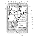
図1は情報端末10の形態および使用例を示している。情報端末10は、筐体11、表示部12、操作ボタン13、操作ボタン14、カメラ15、センサ34などを有する。また、図示していないが、情報端末10は通信手段も有しており、電話などの通話や、無線通信のためのアンテナや、有線で通信するためのコネクタなどが設けられている。センサ34は情報端末10周囲の明るさを検知するものであり、フォトダイオードなどの受光素子が用いられる。センサ34により検知された情報端末10の周囲の明るさに応じて、表示部12の表示方式を変えることができる。
FIG. 1 shows the form and usage example of the
表示部12にはさまざまな情報を表示できるように構成されている。図1では、表示部12に災害情報の発令中を知らせるアイコン21、電話やデータ通信を行うための電波の受信状況を知らせるアイコン22、無線ネットワークのための電波の受信状況を知らせるアイコン23、電子メールなどのメッセージの着信を知らせるアイコン24、情報端末10を動作させるためのバッテリーの残量(充電量)を知らせるアイコン25、時刻26が表示されている。
The
情報端末10は、災害が発生した時、あるいは災害の発生が予測された時などの非常時には避難誘導のための情報端末となるが、それ以外では、スマートフォン、携帯電話、タブレット型コンピュータ、ラップトップ型コンピュータ、ナビゲーション装置などを通常使用モードとして用いることができる。
The
一方、非常時には、避難誘導モードとして、情報端末10の現在地、すなわち情報端末10を所持しているユーザーの現在地、近くの避難所、避難所までの経路、方位を示すアイコン28などを示す地図27、災害の状況、災害の予測などの災害情報を示す欄30、災害情報の発信時刻などを示す見出し29、通常使用モードと避難誘導モードを切り替えるためのモード切り替えボタン32を表示することができる。
On the other hand, in an emergency, a
なお、災害情報には、災害の発生および災害の予測のみでなく、ユーザーがいる地域に災害が及ぶ予想時刻、現在地に関する情報、道路名、交差点名、渋滞情報、通行可・不可情報などの避難ルートに関する情報、現在地から避難所等の目的地までの、交通手段ごとの所要時間、避難所の収容可能人数および収容率などの避難所に関する情報が含まれていてもよい。特に、災害が地震である場合、地震発生後は、後に続く余震、津波、崖崩れ、火災などにも注意が必要である。本実施の形態では、このような災害やその予測に関する情報も災害情報に含まれる。なお、災害情報は文字情報でも良いし、写真やイラストを用いた情報でもよい。 In addition to disaster occurrence and disaster prediction, disaster information includes evacuation such as predicted time, disaster location information, road name, intersection name, traffic jam information, traffic allowance / impossibility information, etc. Information about the route, the time required for each means of transportation from the current location to the destination such as the evacuation center, information about the evacuation site such as the number of evacuation shelters that can be accommodated and the accommodation rate may be included. In particular, if the disaster is an earthquake, attention should be paid to aftershocks, tsunamis, landslides, and fires after the earthquake. In the present embodiment, information on such a disaster and its prediction is also included in the disaster information. The disaster information may be text information or information using a photograph or an illustration.
表示部12は複数の画素を有している。各画素には、第1の表示素子および第2の表示素子が設けられており、これらのいずれか一方、あるいは両方を用いて表示を行うことができる。また、カラー表示を行う表示装置では、画素は色毎にサブ画素を有する場合もある。例えば、赤を表示させるためのサブ画素(R)、緑を表示させるためのサブ画素(G)、青を表示させるためのサブ画素(B)が各画素に設けられることで、フルカラー表示が可能となる。また、サブ画素を、シアン(C)、マゼンタ(M)、イエロー(Y)等で構成し、フルカラー表示を行ってもよい。この場合は、各サブ画素が第1の表示素子および第2の表示素子を有しても良い。また、画素毎に第1の表示素子を有し、サブ画素毎に第2の表示素子を有しても良い。
The
第1の表示素子と第2の表示素子は異なる表示方式により表示を行う。例えば、第1の表示素子を外光を利用する表示素子とし、第2の表示素子を自発光型の表示素子とすることができる。外光を利用する表示素子としては、反射型の液晶表示素子、電気泳動方式の表示素子、マイクロカプセル方式の表示素子、エレクトロウェッティング方式の表示素子等を用いることができる。 The first display element and the second display element perform display by different display methods. For example, the first display element can be a display element that uses external light, and the second display element can be a self-luminous display element. As a display element using external light, a reflective liquid crystal display element, an electrophoretic display element, a microcapsule display element, an electrowetting display element, or the like can be used.
ここで、外光を利用する表示素子とは、表示に必要な光源として外光を用いる表示素子のことをいう。また、外光とは、屋外における太陽光や、屋内における蛍光灯や電球等の照明からの光、表示パネルの前面や端部に設けられたフロントライトからの光など、情報端末10が有する表示パネルへ入射する光のことをいう。外光の強度は、センサ34にて検知することができる。
Here, a display element that uses external light refers to a display element that uses external light as a light source necessary for display. In addition, the external light is a display that the
また、自発光型の表示素子としては、エレクトロルミネセンスを用いた発光素子を用いることができる。このような発光素子として、発光ダイオード(LED)、有機EL(OEL、またはOLEDともいう)、無機EL(IEL)、量子ドットLED(QドットLED)等を用いることができる。また、本実施の形態では、バックライトを用いて表示を行う透過型液晶素子を自発光型の表示素子に置き換え、外光を利用する表示素子と一体化させて表示を行うことも可能である。本実施の形態では、このように一つの画素に2種類の表示素子を用いる表示方法をハイブリッド表示方法、またこのような表示装置をハイブリッドディスプレイと呼ぶ。 As the self-luminous display element, a light-emitting element using electroluminescence can be used. As such a light emitting element, a light emitting diode (LED), an organic EL (also referred to as OEL or OLED), an inorganic EL (IEL), a quantum dot LED (Q dot LED), or the like can be used. In this embodiment mode, a transmissive liquid crystal element that performs display using a backlight can be replaced with a self-luminous display element, and display can be performed integrally with a display element that uses external light. . In this embodiment mode, a display method using two types of display elements for one pixel is called a hybrid display method, and such a display device is called a hybrid display.
ハイブリッド表示とは、1つのパネルにおいて、反射型素子での反射光と自発光型素子(例えば、OEL、LED等)からの発光とを併用して、色調または光強度を互いに補完して、文字または画像を表示する方法である。または、ハイブリッド表示とは、同一画素または同一副画素において複数の表示素子から、それぞれの光を用いて、文字及び/または画像を表示する方法である。ただし、ハイブリッド表示を行っているハイブリッドディスプレイを局所的にみると、複数の表示素子のいずれか一方を用いて表示される画素または副画素と、複数の表示素子の双方二以上を用いて表示される画素または副画素と、を有する場合がある。 Hybrid display is a combination of light reflected from a reflective element and light emitted from a self-luminous element (for example, OEL, LED, etc.) in one panel, complementing each other in color tone or light intensity. Or it is a method of displaying an image. Alternatively, the hybrid display is a method for displaying characters and / or images using light from a plurality of display elements in the same pixel or the same sub-pixel. However, when a hybrid display that performs hybrid display is viewed locally, it is displayed using two or more of both the pixel or sub-pixel displayed using one of the plurality of display elements and the plurality of display elements. A pixel or a sub-pixel.
なお、本明細書等において、上記構成のいずれか1つまたは複数の表現を満たすものを、ハイブリッド表示という。 Note that in this specification and the like, a display that satisfies any one or a plurality of expressions of the above configuration is referred to as a hybrid display.
また、ハイブリッドディスプレイは、同一画素または同一副画素に複数の表示素子を有する。なお、複数の表示素子としては、例えば、光を反射する反射型素子と、光を射出する自発光素子とが挙げられる。なお、反射型素子と、自発光素子とは、それぞれ独立に制御することができる。ハイブリッドディスプレイは、表示部において、反射型素子での反射光と自発光型素子からの発光のいずれか一方または双方を用いて、文字及び/または画像を表示する機能を有する。 The hybrid display has a plurality of display elements in the same pixel or the same sub-pixel. Examples of the plurality of display elements include a reflective element that reflects light and a self-luminous element that emits light. Note that the reflective element and the self-luminous element can be controlled independently. The hybrid display has a function of displaying characters and / or images in the display unit using either or both of light reflected from the reflective element and light emitted from the self-light-emitting element.
また、ハイブリッドディスプレイが有する表示パネルの表面は、平面、曲面、またはその両方を有する。 In addition, the surface of the display panel included in the hybrid display has a flat surface, a curved surface, or both.
また、ハイブリッドディスプレイとは、表示方式の異なる表示装置を一体化させた表示装置と呼ぶこともできる。例えば、反射型液晶表示装置と有機EL表示装置を一体化させた表示装置、あるいは反射型液晶表示装置と透過型液晶表示装置を一体化させた表示装置をハイブリッドディスプレイと呼ぶことができる。 The hybrid display can also be called a display device in which display devices having different display methods are integrated. For example, a display device in which a reflective liquid crystal display device and an organic EL display device are integrated, or a display device in which a reflective liquid crystal display device and a transmissive liquid crystal display device are integrated can be called a hybrid display.
図2にハイブリッドディスプレイの概念を示す。ハイブリッドディスプレイ1010は第1の基板1012、第2の基板1014の間に、外光を利用する表示素子として第1の表示素子1020、自発光型の表示素子として第2の表示素子1016、第1の表示素子1020、第2の表示素子1016それぞれを駆動する素子1018が設けられている。
FIG. 2 shows the concept of the hybrid display. The
図2(A)は、夜間の屋外や照明の無い屋内など、外光の得られない暗所でハイブリッドディスプレイ1010を使用する例を示している。例えば、センサ34で検知される明るさは、100lx未満である。このような場合、ハイブリッドディスプレイ1010は、外光を利用する表示素子による表示は視認性が悪い。一方、周囲が暗いほど、自発光型の表示素子の視認性は良い。自発光型の表示装置は、その発光強度が強くなるにつれて消費電力が増加する。暗所での表示ならば、発光強度が強くなくても高い視認性が得られ、電力の消費量を抑えることができ好ましい。そこで、ハイブリッドディスプレイ1010は、自発光型の第2の表示素子1016のみを用いて表示している。図2(A)中の矢印1022は第2の表示素子1016からの発光を示している。
FIG. 2A shows an example in which the
図2(C)は、太陽光の当たる昼間の屋外や、強い照明が設けられた屋内など、十分な外光が得られる明るい場所でハイブリッドディスプレイ1010を使用する例を示している。例えば、センサ34で検知される明るさは、1000lx以上である。このような場合、表示装置に入射する外光の反射光や散乱光により、自発光型の表示装置やバックライトを用いた透過型の液晶表示装置の視認性は悪くなる。一方、外光を利用する表示素子の視認性は良い。そこで、ハイブリッドディスプレイ1010は、外光を利用する第1の表示素子1020のみを用いて表示している。図2(C)中の矢印1028はハイブリッドディスプレイ1010への入射光、および第1の表示素子1020での反射光を示している。
FIG. 2C illustrates an example in which the
図2(B)は、明け方や夕方の薄暗い屋外や、屋内など、十分な外光が得られない場所でハイブリッドディスプレイ1010を使用する例を示している。例えば、センサ34で検知される明るさは、100lx以上1000lx未満である。このような場合、外光を利用する表示素子では十分な視認性が得られない。そこで、自発光型の表示素子も利用して表示を行う。外光を利用する表示素子と、自発光型の表示素子を組み合わせて表示していることから、このような表示方法はハイブリッド表示と呼ぶことができる。図2(B)では、第1の表示素子1020と第2の表示素子1016の両方を用いて表示しており、矢印1024はハイブリッドディスプレイ1010への入射光、および第1の表示素子1020での反射光を示し、矢印1026は第2の表示素子1016からの発光を示している。
FIG. 2B illustrates an example in which the
なお、得られる外光の強度に応じて、第2の表示素子1016の発光強度は適宜調整されるのが好ましい。すなわち、たとえ屋内でも得られる外光が比較的強く、第1の表示素子1020による表示がわかる程度であれば、第2の表示素子1016の発光強度は弱くても構わない。一方、外光が弱く、第1の表示素子1020による表示が認識しにくい場合は、第2の表示素子1016の発光強度を強くすればよい。ハイブリッド表示では、第1の表示素子1020による表示をアシストするように第2の表示素子1016による表示を用いることができる。
Note that the emission intensity of the
また、ハイブリッド表示が適しているのは、上記のように十分な外光が得られない環境だけではない。仮に、図2(C)で説明したような十分な外光が得られる明るい場所でもハイブリッド表示により得られる効果がある。本実施の形態のハイブリッドディスプレイは、表示する情報に応じて第1の表示素子1020と第2の表示素子1016を使い分けることができる。例えば表示データの書き換え頻度が少ない地図データや災害情報などのテキストデータは、第1の表示素子1020に表示し、情報端末10の移動に伴い、地図上を移動する現在地を示す表示、避難ルートの表示、あるいは動画など、表示データの書き換え頻度が多いデータを第2の表示素子1016に表示してもよい。第1の表示素子1020は画像を保持することができ、同じ画像を表示し続ける場合、1フレーム(例えば、1/60秒)ごとに画像データを書き換える必要はない。地図情報の変更や、災害情報の更新があったときのみ画像データの書き換えを行うこともできる。
In addition, the hybrid display is suitable not only in an environment where sufficient external light cannot be obtained as described above. Temporarily, there is an effect obtained by hybrid display even in a bright place where sufficient external light can be obtained as described in FIG. In the hybrid display of this embodiment, the
特に、各表示素子を駆動する素子1018に酸化物半導体を有するトランジスタ(OSトランジスタ)を用いた場合、OSトランジスタはオフ電流が非常に小さい。そのことを利用して、静止画像を表示する際のリフレッシュ頻度を少なくし、液晶ディスプレイや有機ELディスプレイの消費電力を低減することができる。具体的には、フレーム周波数に対応した画面の書き換えが不要となり、より長い周期毎に、あるいは特別な信号を受信したときに画面の書き換えを行えばよく、画面の書き換えに要する電力を大幅に削減できる。なお、本明細書において、このような表示装置の消費電力を減らす技術を、アイドリングストップ(IDS)と呼称する。特に第1の表示素子1020でアイドリングストップを行うことにより、情報端末10の消費電力を抑えることができる。
In particular, when a transistor including an oxide semiconductor (OS transistor) is used as the
本実施の形態において、情報端末10を非常時の避難誘導装置として用いる場合、上記のようなハイブリッドディスプレイ1010を用い、ハイブリッド表示やアイドリングストップを行うことで情報端末10の消費電力を小さくすることができ、避難所までの移動中にバッテリーが枯渇してしまう問題を防ぐことができる。
In the present embodiment, when the
以上、本実施の形態に記載の情報端末10を用いることで、消費電力の小さい情報端末を提供することができる。また、視認性の優れた情報端末を提供することができる。また、新規な情報端末を提供することができる。
As described above, by using the
本実施の形態は、少なくともその一部を本明細書中に記載する他の実施の形態と適宜組み合わせて実施することができる。 This embodiment can be implemented in appropriate combination with at least part of the other embodiments described in this specification.
(実施の形態2)
本実施の形態では、災害が発生した時、あるいは災害の発生が予測された時などの非常時に、情報端末10を避難誘導装置として用いる例を図3乃至図9を用いて説明する。また、避難誘導システム、および避難誘導システムを用いたサービスおよびビジネスモデルについても説明する。
(Embodiment 2)
In the present embodiment, an example in which the
図3は本実施の形態の避難誘導システムの例である。また、図9は本実施の形態の避難誘導システムを説明するフローチャートである。図9(A)は災害発生から主に災害に関する情報提供者50(以下、災害情報提供者50)に関するフローを示し、図9(B)は、主に情報端末10に関するフローを示す。災害の発生、あるいは災害発生の予測があると(S101)、災害情報提供者50が管理するサーバ55は、情報端末10の現在地を含む位置情報を、ネットワーク60を介して収集し、サーバ55に保存する。以降、特段の説明が無い限り、サーバ55とは災害情報提供者50が管理するサーバ55を指す。
FIG. 3 shows an example of the evacuation guidance system of this embodiment. FIG. 9 is a flowchart for explaining the evacuation guidance system of the present embodiment. FIG. 9A shows a flow mainly related to the information provider 50 (hereinafter referred to as disaster information provider 50) from the occurrence of the disaster, and FIG. 9B mainly shows a flow related to the
各情報端末10はGPSなどを利用して自らの位置情報を取得する。サーバ55はネットワーク60を介してこの位置情報を取得する。また、情報端末10は、自身の回転や向きの変化を検知するセンサを内蔵していてもよく、これにより情報端末10の移動距離や方角を算出することができる。このようなセンサとして、ジャイロセンサを用いることができる。サーバは、情報端末10の移動距離や方角も位置情報として取得することができる。
Each
ここで、災害情報提供者50とは、国あるいは気象庁といった国の機関、都道府県といった広域普通地方公共団体、あるいは市区町村といった普通地方公共団体などの包括的地方公共団体、州や省といった地域ごとの団体、気象情報や自然現象を調査、研究、情報発信などを行っている民間企業、携帯電話会社などの通信事業者や公共事業などの団体などを差す。
Here, the
また、情報端末10は、個人が所有するスマートフォン、携帯電話、タブレット型コンピュータ、ラップトップ型コンピュータ、ナビゲーション装置などでよい。以降、このような個人が所有する情報端末を単に情報端末と記す。情報端末10で後述するような災害情報を受け取るためには、事前に災害情報提供者50に災害情報提供のための申請、申込み、あるいは契約が必要となる。災害情報提供のシステムによっては、個人(以降、ユーザーあるいは契約者という)が所有している情報端末に専用のプログラムあるいはアプリケーションをインストールする必要がある。プログラムあるいはアプリケーションは、ネットワーク60を介して災害情報提供者50あるいはその代理人からダウンロードし、インストールすればよい。また、災害情報提供者50はプログラムあるいはアプリケーションのコピーをメモリーカードなどの記憶媒体に保存し、契約者に配布してもよい。契約者は各自の情報端末10に記憶媒体をセットし、プログラムあるいはアプリケーションをインストールすることができる。また、災害情報提供者50や携帯電話などの通信事業者が情報端末10に直接プログラムあるいはアプリケーションをインストールしてもよい。プログラムあるいはアプリケーションが有料の場合は、契約者はそのインストール前後に災害情報提供者50に料金を支払う。支払う料金の中に、契約料およびサービスの利用料が含まれていてもよい。
The
災害情報提供者50が所有するサーバ55には、所定の地域の地図情報が保存されている。所定の地域とは、災害情報提供者50が管轄する地方や地域のことを指す。災害情報提供者50が国の場合は、その国全体および周辺の国の地図を、県の場合はその県全体およびその周辺の都道府県の地図を、市の場合はその市全体およびその周辺の市区町村の地図を保存していればよい。一方、民間企業が災害情報提供者50の場合は、その企業のある地域に限らず、全国あるいは世界中の必要な地域の地図情報を保存していればよい。また、所定の地域とは、災害情報提供者50からの情報を電波にして出力するアンテナあるいは基地局からの電波が各情報端末10に届く範囲としても良い。この場合、地図情報や災害情報の一部は出力されるアンテナあるいは基地局ごとに異なる場合がある。当該アンテナや基地局は、災害情報提供者50が管理していても良い。あるいは、携帯電話会社などの通信事業者が管理しているアンテナや基地局を災害情報提供者50が利用してもよい。
The
アンテナあるいは基地局は、ネットワーク60を介してサーバ55と接続されている。各アンテナあるいは各基地局から出力される情報には、そこから出力される電波が届く範囲のものが含まれており、情報端末10は現在地周辺の詳細情報を受信することができる。
The antenna or base station is connected to the
地図情報には、少なくとも災害が発生する恐れのある場所に関する情報が含まれている。例えば、海、河川、火山などの山、浸水や冠水の恐れのある低地など、所謂ハザードマップの情報が含まれている。また、地図情報には、避難所の情報も含まれる。避難所の情報には、立地条件や収容可能人数の他、駐車可能台数、飲料や食品の備蓄情報などが含まれていてもよい。さらに、地図情報には、避難時に使用可能な道路の情報も含まれている。道路の情報としては、海、河川、あるいは山など災害が起こりうる場所の近くを通る道路かどうか、冠水が起こりうる道路かどうか、河川の氾濫により崩壊する恐れのある橋を通るかどうか、道幅は十分にあるか、渋滞が発生しやすいか、など安全に避難するための情報が含まれる。 The map information includes at least information regarding a place where a disaster may occur. For example, information on so-called hazard maps such as seas, rivers, mountains such as volcanoes, and lowland areas where there is a risk of flooding or flooding is included. The map information also includes information on shelters. The shelter information may include location information and the number of people that can be accommodated, as well as information on the number of cars that can be parked, storage information for beverages and foods, and the like. Further, the map information includes information on roads that can be used during evacuation. Information on roads includes roads that pass near places where disasters can occur, such as the sea, rivers, and mountains, whether roads can be flooded, whether they pass through bridges that may collapse due to river flooding, road width It contains information on how to evacuate safely, such as whether there is enough or is likely to be congested.
サーバ55は、情報端末10の位置情報を収集後、各情報端末10に対して最も適した避難所を検索する。災害の種類によって好ましい避難所は異なる。例えば、地震により津波が発生する可能性がある場合、台風などの低気圧により高潮、高波が発生しているは、海沿いの避難所を避け、内陸および海抜の高い避難所を検索する。また、大雨により河川の氾濫が予測される場合は、川沿いの避難所を避け、火山、土砂崩れ、あるいは崖崩れの恐れがある場合は、山に近い避難所を避けるように避難所を検索すればよい。
After collecting the position information of the
サーバ55は、避難所の検索後、災害の発生、あるいはその予測を含む災害情報とともに、情報端末10の現在地と検索した避難所を含む地図情報を当該情報端末10に送信する(S102)。この地図情報(便宜上第2の地図情報と呼ぶ)は、災害情報提供者50が保存している全ての地図情報(便宜上第1の地図情報と呼ぶ)ではない。サーバ55には、第1の地図情報は複数のブロックに分割して保存されている。サーバ55は、情報端末10と検索した避難所を含むブロックを第2の地図情報として、情報端末10に送信する。
The
なお、情報端末10と検索した避難所が同一のブロック内に存在する場合、情報端末10に送信される第2の地図情報は1ブロック分の情報を有することになる。また、情報端末10が存在するブロックの隣に検索した避難所が存在するブロックがある場合、情報端末10に送信される第2の地図情報は2ブロック分の情報を有することになる。さらに、情報端末10が存在するブロックと検索した避難所が存在するブロックが離れている場合、情報端末10に送信される第2の地図情報はそれらの間のブロックの情報を有することになる。つまり、第2の地図情報は、一つのブロックの情報に限らず、複数のブロックの情報を有していてもよい。
In addition, when the
図4に災害情報提供者50が保存している地図情報2100、すなわち第1の地図情報の例を示す。図4には、その地域の土地の地形、道路、海2121、山2122、避難所2123、避難所2125、避難所2127、避難所2129、避難所2131、の情報が含まれている。また、当該地図はブロック2101乃至ブロック2120の20ブロックに分割されている。なお、地図情報には、道路や交差点の名前、住所、ランドマークとなる建造物が含まれていてもよい。
FIG. 4 shows an example of the
各ブロックは、ある距離を単位にして分割されてもよいし、市区町村などの地区あるいは地域ごとに分割されていてもよいし、災害情報を発信するアンテナあるいは基地局からの電波が届く範囲で分割されていてもよい。 Each block may be divided in units of a certain distance, or may be divided into districts or regions such as municipalities, and the range from which radio waves from antennas or base stations that transmit disaster information reach It may be divided by.
図5は、非常時に災害情報提供者50が管理するサーバ55に保存される情報端末10の位置情報である。地図情報2100の中に、A乃至Dの4つの情報端末の位置情報が含まれている。情報端末Aの最も近い避難所は、避難所2123となる。また、情報端末Aおよび避難所2123はブロック2109に存在する。よって、情報端末Aには、第2の地図情報としてブロック2109の情報が送信される。
FIG. 5 shows the location information of the
情報端末Aが災害情報および第2の地図情報を受信すると(S103)、一旦情報端末Aのメモリに情報を保存し、表示部12でこれらの情報を表示や、避難ルートを検索するための準備をする。情報端末Aは現在地から避難所2123までの最適な避難ルートを検索する。検索条件としては、避難所までの距離や安全なルートであることが要求される。情報端末Aに関しては、図6(A)の点線で示すような最短距離で避難所2123に避難するのが最適と考えられる。
When the information terminal A receives the disaster information and the second map information (S103), the information is temporarily stored in the memory of the information terminal A, and the
このとき、サーバ55から送られてきた第2の地図情報が好ましくない場合は、情報端末Aはサーバ55に最適な地図情報を要求することができる。例えば避難ルートが第2の地図情報に含まれていないブロックを経由しなくてはいけない場合、情報端末Aはサーバ55に追加のブロックを含めた地図情報を要求することができる。また、最適な避難所の選択を情報端末Aが行ってもよいし、最適な避難ルートの検索をサーバ55が行ってもよい。この場合情報端末Aは災害や避難に関する周辺の情報を事前に取得し、保存していればよい。言うまでもないが、情報端末Aだけでなく、全ての情報端末10で同様の処理を行うことができる。
At this time, if the second map information sent from the
各情報端末10は少なくとも災害情報を受信すると、表示部12に災害情報を受信したことを表示して、情報端末10のユーザーに災害の発生あるいは予測を通知する。例えば、図7に示すように、アイコン21を表示させる、あるいは情報端末10の利用状況に限らず表示部12にポップアップ31を表示させる。また、アラーム音など音声による通知を行っても良い。
When at least disaster information is received, each
各ユーザーは情報端末10の表示を通常使用モードから避難誘導モードに切り替えることができる(S104、S105)。避難誘導モードに切り替えると、情報端末10の表示部12には、地図情報や災害情報が表示される(S106)また、通常使用モードのまま現在の作業を継続することもできる。現在の作業を継続した場合でも、ユーザーは任意のタイミングで通常モードから避難誘導モードに切り替えることができる(S107)。また、避難誘導モードから通常モードへの切り替えも可能である。この場合、情報端末10の表示部12にモード切り替え用のボタン32を表示させておく(S108)。
Each user can switch the display of the
次に情報端末Bの場合を考える。情報端末Bにおいても避難所2123が最寄りの避難所となる。情報端末Bはブロック2113に存在している。そこで、情報提供者は避難経路も考慮し、第2の地図情報として、ブロック2109とブロック2113だけでなく、ブロック2108およびブロック2114の情報も情報端末Bに送信される。
Next, consider the case of the information terminal B. Also in the information terminal B, the
情報端末Bが第2の地図情報を受信すると、情報端末Bは現在地から避難所2123までの最適な避難ルートを検索する。避難所2123まで最短距離で避難するには、情報端末Aが存在していた交差点まで移動し、情報端末Aと同様のルートで避難するのが好ましいと考えられる。一方、災害が地震であり、地震の発生後に津波が発生する可能性があるという予測が発生した場合、当該ルートは海沿いを移動しながら避難することになり、危険が伴う。このような危険を鑑みて、情報端末Bは、図6(B)の点線で示すように、ブロック2108に存在する交差点2133まで一旦移動し、そこから避難所2123を目指すルートを示す。この場合、最短距離よりも安全なルートが優先して選択される。このように、本実施の形態の避難誘導システムは、避難ルートの候補に危険個所が含まれる場合にその場所を迂回する、あるいは別のルートを選択することができる。
When the information terminal B receives the second map information, the information terminal B searches for an optimum evacuation route from the current location to the
次に情報端末Cの場合を考える。情報端末Cの最も近い避難所は避難所2127となる。情報提供者は、ブロック2101、ブロック2102、ブロック2106、ブロック2107の情報を第2の地図情報として情報端末Cに送信する。
Next, consider the case of the information terminal C. The shelter closest to the information terminal C is the
情報端末Cが第2の地図情報を受信すると、情報端末Cは現在地から避難所2127までの最適な避難ルートを検索する。この場合、図6(C)の点線で示すように、最短距離で避難するのが最適な避難ルートであると判断し、受信した第2の地図情報と避難ルートが情報端末Cの表示部に表示される。
When the information terminal C receives the second map information, the information terminal C searches for the optimum evacuation route from the current location to the
次に情報端末Dの場合を考える。情報端末Dの場合、避難所2127の他にも避難所2129や避難所2131も避難先の候補となる。そこで、情報提供者は避難所情報を参照する。避難所2129は避難所2127よりも小さく、避難所2129に辿り着いても、避難所2129の中に入れない恐れがある。そのような場合、情報提供者は、避難先の候補から避難所2129を外すことがある。
Next, consider the case of the information terminal D. In the case of the information terminal D, in addition to the
また、災害が火山であり、山2122の噴火の可能性が予測されている場合、あるいは災害が地震であり、山2122周辺で崖崩れの可能性が予測されている場合、避難所2131に避難することはかえって危険である。このような状況を鑑みて、情報提供者は、情報端末Dの避難先として、避難所2127を選択することができる。この場合、情報提供者は、少なくともブロック2101およびブロック2112の情報を含む情報を第2の地図情報として情報端末Dに送信する。その際、避難ルートも考慮して、第2の地図情報には、ブロック2102、ブロック2106、ブロック2107、およびブロック2111の情報も含まれていることが好ましい。
If the disaster is a volcano and the possibility of the eruption of the
一方、災害が津波や河川の氾濫などの水害であり、避難先としてより海抜(標高)の高い場所へ避難することが好ましい場合は、情報提供者は、情報端末Dの避難先として、避難所2131を選択することができる。この場合、情報提供者は、少なくともブロック2112およびブロック2116の情報を含む情報を第2の地図情報として情報端末Dに送信する。その際、避難ルートも考慮して、第2の地図情報には、ブロック2111およびブロック2117の情報も含まれていることが好ましい。
On the other hand, if the disaster is a flood such as a tsunami or river flooding and it is preferable to evacuate to a place above sea level (elevation) as an evacuation destination, the information provider uses the evacuation center as the evacuation destination of the
情報端末Dが第2の地図情報を受信すると、情報端末Dは現在地から避難所2127までの最適な避難ルートを検索する。この場合、避難所2127までの最短距離は交差点2135まで行き、そこを左折して、情報端末Cと同じルートで避難するのが最短ルートと考えられる。一方、交差点2135から先のルートが狭くて安全に通行できない場合や崖崩れなどで道が塞がれている場合は、情報端末Dは別ルートを検索することができる。例えば、図6(D)の点線で示すように、交差点2137を経由して避難所2127まで避難するルートとすればよい。
When the information terminal D receives the second map information, the information terminal D searches for the optimum evacuation route from the current location to the
ここで、先に説明した図1は、情報端末Bが第2の地図情報を受信し、最適な避難ルートを検索した後の、避難誘導モードにおける表示部12の例を示している。表示部12には地図27が表示され、地図27上には、現在地、避難所2123、図中点線で示された避難ルート、方位を示すアイコン28、距離を示すスケール33、などが表示される。また、見出し29には、災害情報の発信時刻あるいは受信時刻が示されている。また、欄30には、災害情報のテキストデータ、イラストデータ、写真データなどが示されている。
Here, FIG. 1 described above shows an example of the
図8(A)は、情報端末Aが第2の地図情報を受信し、最適な避難ルートを検索した後の、避難誘導モードにおける表示部12の例を示している。表示部12には地図27が表示され、地図27上には、現在地、避難所2123、図中点線で示された避難ルート、方位を示すアイコン28、距離を示すスケール33、などが表示される。また、見出し29には、災害情報の発信時刻あるいは受信時刻が示されている。また、欄30には、災害情報のテキストデータ、イラストデータ、写真データなどが示されている。
FIG. 8A shows an example of the
表示部12では、第2の地図情報の範囲に応じて、地図の縮尺を変えることができる。図8(A)では、第2の地図情報はブロック2109のみであり、図1と比較して地図が拡大表示されている。図1においても、情報端末Bが避難所2123に近づくにつれて地図を拡大して表示してもよいし、ユーザーが倍率を調整しても良い。地図上には地図の倍率や距離を示すスケール33が表示されても良く、スケール33を用いて地図の倍率を変更しても良い。
In the
図8(B)は、情報端末Dが第2の地図情報を受信した後の、避難誘導モードにおける表示部12の例を示している。図8(B)では、地図上に複数の避難所が表示されている例を示す。表示部12には地図27が表示され、地図27上には、現在地、避難所2127、避難所2129、方位を示すアイコン28、距離を示すスケール33、などが表示される。また、見出し29には、災害情報の発信時刻あるいは受信時刻が示されている。また、欄30には、災害情報のテキストデータ、イラストデータ、写真データなどが示されている。ユーザーは、表示部12に表示された地図情報、災害情報から、所望の避難所を選択できる。避難所が選択されたら、情報端末Dは避難所までの最適な避難ルートを検索し、地図27上に表示する。避難所の選択は、例えば欄30に表示された各避難所の情報からユーザーが判断して行えばよく、例えば、避難所までの距離、収容可能人数、収容率などを比較して判断すればよい。
FIG. 8B shows an example of the
表示部12では、第2の地図情報の範囲に応じて、地図の縮尺を変えることができる。図8(B)では、第2の地図情報はブロック2101、ブロック2102、ブロック2103、ブロック2106、ブロック2107、ブロック2108、ブロック2111、ブロック2112、ブロック2113を含んでおり、図1と比較して地図が縮小表示されている。地図の倍率は、ユーザーが避難所を選択後に自動的に変更することができる。さらに、情報端末Dが選択した避難所に近づくにつれて地図を拡大して表示してもよいし、ユーザーが倍率を調整しても良い。地図上には地図の倍率や距離を示すスケール33が表示されても良く、スケール33を用いて地図の倍率を変更しても良い。
In the
災害情報提供者50は、災害情報を発信後、災害情報の収集を行う(S109)。ここで、災害が終了していれば(S110)、災害終了情報を各情報端末10に送信して、災害情報の提供を終了する(S111)。情報端末10は災害終了情報を受信すると(S112、S113)、避難誘導モードを終了して、通常使用モードに変更する(S114、S115)。
The
災害に関して最新情報がある場合は(S116)、災害更新情報を各情報端末10に送信して(S117)、引き続き災害情報の収集を行う(S109)。情報端末10は災害更新情報を受信すると(S118)災害情報が更新され、情報端末10の表示部12には、最新の地図情報や災害情報が表示される(S106)
When there is the latest information regarding the disaster (S116), the disaster update information is transmitted to each information terminal 10 (S117), and the disaster information is continuously collected (S109). When the
本実施の形態において、情報端末10の表示部12には、ハイブリッドディスプレイを用いるのが好ましい。ここでは、第1の表示素子として、反射型の液晶素子を用い、第2の表示素子として、自発光型表示素子であるEL素子を用いる例を示す。避難誘導モードの表示においては、避難先に到着するまでの間、可能な限り電力消費を抑制するため、表示に用いることができる外光が得られる昼間は、地図や災害情報等を第1の表示素子のみで表示することが好ましい。また、地図や災害情報等の更新が必要ない場合はアイドリングストップ(IDS)ができ、さらに消費電力を抑制することができる。
In the present embodiment, it is preferable to use a hybrid display for the
一方、第1の表示素子を用いた表示が十分認識できるほど外光が得られない場合は、第2の表示素子を用いて、第1の表示素子による表示をアシストしてもよい。また、外光が得られない夜間においては、第2の表示素子を用いて表示を行えばよい。 On the other hand, when the external light cannot be obtained enough to recognize the display using the first display element, the display by the first display element may be assisted using the second display element. In addition, at night when outside light cannot be obtained, display may be performed using the second display element.
なお、情報端末10の表示部12上に表示された地図や災害情報等の更新は、あらかじめ情報に変更があると判断された場合のみ、更新情報として地図や災害情報が提供される仕組みとすることで、各情報端末10で、現在表示中の情報と新たに受信した情報との差分を判断する必要がなくなる。すなわち、更新情報の受信を、アイドリングストップを制御する信号として流用することもできる。
The update of the map and disaster information displayed on the
一方、各情報端末10の位置や避難ルートはユーザーの移動により変化するため、逐一情報端末10の表示部12に表示させる必要がある。その場合、各情報端末10の位置や避難ルートは第2の表示素子を用いて表示するのが好ましい。尚、第2の表示素子は自発光型であるため、間欠表示させることにより消費電力を抑制することができ好ましい。
On the other hand, since the position and evacuation route of each
なお、本実施の形態においては、第2の表示素子としてバックライト等の光源を利用した透過型液晶素子を用いることもできる。光源の消費電力が大きく、情報端末10の連続使用時間を短くしてしまう恐れがある場合は光源として、LEDを多数配置したバックライトを用い、ローカルディミングにより光源での消費電力を低減してもよい。
Note that in this embodiment mode, a transmissive liquid crystal element using a light source such as a backlight may be used as the second display element. If the power consumption of the light source is large and there is a risk of shortening the continuous use time of the
以上のような表示方法により、情報端末10は周囲の明るさによらず視認性の優れた表示を行うことができるため、ユーザーに危険をより確実に知らせることができる。一方、ユーザーは非常時において、常に、現在地、目指すべき避難所、現在地から避難所へのルート、災害情報などを確認することができる。また電力の消費量も少ないため、ユーザーはバッテリーの残量を気にすることなく、避難に集中できる。これにより、バッテリー残量が枯渇する前に、避難所にたどり着ける確率が高まる。
By the display method as described above, the
各情報端末10において、避難誘導モードは、少なくとも各情報端末10が所定の避難所に到着するまで実行されることが好ましい(S119)。具体的には、情報端末Aおよび情報端末Bは、避難所2123に到着するまで、情報端末Cおよび情報端末Dは、避難所2127に到着するまで実行される。サーバ55は、各情報端末10の位置情報から、所定の避難所に到着したかどうかを判断し、到着が確認できたら、災害情報の配信は終了し、避難誘導モードを終了させることができる。避難誘導モードは、ユーザーからの到着報告、すなわち避難誘導モード終了のリクエストを基に終了させても良いし、GPSなどから得られた情報端末10の位置情報からサーバ55が判断し終了させても良い。
In each
あるいは、避難誘導モードは、災害の終了まで、あるいは災害の恐れが無くなるまで実行されることが好ましい。災害情報提供者50あるいはサーバ55は、災害終了の情報を入手したら、各情報端末10にその旨を伝えるメッセージを配信する。また、それに合わせて災害情報の配信を終了し、避難誘導モードを終了させてもよい。
Alternatively, the evacuation guidance mode is preferably executed until the end of the disaster or until there is no danger of the disaster. When the
以上のような避難誘導システムにより、情報端末10のユーザーは災害発生時、あるいは災害が予測された際に安全に避難所まで避難することができる。特に本避難誘導システムを用いることで、単に最寄りの避難所に最短距離で避難するだけでなく、サーバ55に蓄積されたデータから最も安全な避難場所を割り出すことができ、また災害情報を基に避難ルートを検索することでユーザーは避難途中に災害や不具合に遭遇することなく避難することができる。
With the evacuation guidance system as described above, the user of the
また、情報端末10として、ハイブリッドディスプレイを用いることで、周囲の明るさによらず、常に視認性の優れた表示を行うことができるため、ユーザーに危険をより確実に知らせることができる。一方、ユーザーは非常時において、常に、現在地、目指すべき避難所、現在地から避難所へのルート、災害情報などを確認することができる。また、ハイブリッド表示は電力の消費量が少ないことも特徴の一つであるが、アイドリングストップと組み合わせることでさらに消費電力を低減できる。このため、ユーザーはバッテリーの残量を気にすることなく、避難に集中でき、バッテリー残量が枯渇する前に、避難所にたどり着ける確率が高まる。
In addition, by using a hybrid display as the
また、災害情報提供者50は、避難者の同意の元、契約者の避難後の位置情報(例えば、GPS情報)を取得することができる。これにより、避難後の物資の供給や、安否確認のサービスを迅速に提供することができる。
In addition, the
本実施の形態は、少なくともその一部を本明細書中に記載する他の実施の形態と適宜組み合わせて実施することができる。 This embodiment can be implemented in appropriate combination with at least part of the other embodiments described in this specification.
(実施の形態3)
本実施の形態では、情報端末10の構成例に関して、図10および図11を用いて説明する。
(Embodiment 3)
In the present embodiment, a configuration example of the
図10(A)に情報端末10の構成例を、図10(B)に外部との接続例を示す。なお、図10(A)では、第1の表示素子として液晶素子3104を用い、第2の表示素子としてEL素子3106を用いる例を示す。
FIG. 10A shows a configuration example of the
プロセッサー3101およびメモリ3112は、必要に応じて各構成要素との間で情報を授受し、プログラムを用いて情報処理を実行し、各構成要素を制御する。プロセッサー3101はデータの授受やその演算をし、メモリ3112は演算や構成要素を制御するために必要な各種情報を記憶するために用いる。尚、各種プログラムは、予めメモリ3112に保存されているものや、通信手段として機能する入出力ポート(有線・無線)3103を通して得たものをメモリ3112に保存し、必要に応じてプロセッサー3101に読み出して使用する。
The
バッテリー3102は、プロセッサー3101により適切に制御された上で、情報端末10全体に電力を供給する。また、プロセッサー3101がバッテリーの残量を管理することは、動作時間を算出する上で非常に重要である。
The
入出力ポート(有線・無線)3103は、通信用回線や通信用端子で、外部機器3120の入出力ポート(有線・無線)3121を介して外部機器3120と、あるいは外部ネットワーク3130の入出力ポート(有線・無線)3131を介して外部ネットワーク3130と情報の授受を行う。災害時には、公共機関等のサーバ(外部ネットワーク3130)から災害に関する情報(例えば、ユーザーがいる地域の震度、災害が及ぶ予想時刻、避難所の情報等)を得ることができる。また、公共機関等のサーバに安否確認の情報等を登録することもできる。公共機関等のサーバにアクセスする場合は、ユーザーがサーバに登録されている端末のIDや暗証番号を入力することでアクセスが可能になる。
An input / output port (wired / wireless) 3103 is a communication line or a communication terminal. The input / output port (wired / wireless) 3121 of the
液晶素子用コントローラー3105は、プロセッサー3101から受信した情報を元に、液晶素子3104を駆動する。例えば、アイドリングストップの命令を受信した場合には、液晶素子3104用のゲートドライバとソースドライバに信号を送り、液晶素子3104の各画素内の映像信号が変更されない様に制御する。
The liquid
液晶素子3104は、プロセッサー3101と液晶素子用コントローラー3105により制御され、表示を行う。
The
EL素子用コントローラー3107は、プロセッサー3101から受信した情報を元に、EL素子3106を駆動する。例えば、液晶素子3104のみ駆動する命令を受信した場合には、EL素子3106内のゲートドライバとソースドライバに信号を送り、EL素子3106の各画素を消灯させる様に制御する。
The
EL素子3106は、プロセッサー3101とEL素子用コントローラー3107により制御され、表示を行う。
The
冷却システム3108は、主にプロセッサー3101を適切な温度に冷却する。
The
スピーカ3109は、プロセッサー3101により制御され、音声、音楽、警告音などを出力する。
The
キーボ−ドやタッチパネルなどの入力装置3110は、ユーザーが入力した情報を、プロセッサー3101に入力する。
An
センサ3111は情報端末10周囲の明るさを検知するものであり、フォトダイオードなどの受光素子が用いられる。センサ3111は、プロセッサー3101、液晶素子3104、液晶素子用コントローラー3105、EL素子3106、およびEL素子用コントローラー3107の少なくとも一つと情報を授受することができる。センサ3111により検知された情報端末10の周囲の明るさに関する情報を信号として、プロセッサー3101、液晶素子3104、液晶素子用コントローラー3105、EL素子3106、およびEL素子用コントローラー3107の少なくとも一つに送信し、表示部12の表示方式を制御することができる。
The
情報端末10は、上記以外にも、カメラ、マイク、ジャイロセンサ、圧力センサ、赤外線センサ、温度センサ等を有していてもよく、主にプロセッサー3101と情報を授受することができる。
In addition to the above, the
《表示パネルの断面図》<表示装置の構成例1>
図11は、第1の表示素子として反射型液晶素子と第2の表示素子として有機ELからなる発光素子を一体化したハイブリッドディスプレイの例を示す断面模式図である。有機ELを用いた発光素子(Emission)と反射型液晶素子(Reflection)を一体化した表示装置は、ER−Hybridディスプレイと呼ぶことができる。
<< Cross Section of Display Panel >><Configuration Example 1 of Display Device>
FIG. 11 is a schematic cross-sectional view showing an example of a hybrid display in which a reflective liquid crystal element as a first display element and a light emitting element made of an organic EL as a second display element are integrated. A display device in which a light emitting element (Emission) using organic EL and a reflective liquid crystal element (Reflection) are integrated can be called an ER-Hybrid display.
図11に示す表示パネル100は、基板351と基板361の間に、絶縁層220を有する。また基板351と絶縁層220の間に、発光素子170、フォトダイオード190、トランジスタ201、トランジスタ205、トランジスタ206、着色層134等を有する。また絶縁層220と基板361の間に、液晶素子180、着色層131等を有する。また基板361と絶縁層220は接着層141を介して接着され、基板351と絶縁層220は接着層142を介して接着されている。
A
トランジスタ206は、液晶素子180と電気的に接続し、トランジスタ205は、発光素子170と電気的に接続する。トランジスタ205とトランジスタ206は、いずれも絶縁層220の基板351側の面上に形成されているため、これらを同一の工程を用いて作製することができる。
The
基板361には、着色層131、遮光層132、絶縁層121、及び液晶素子180の共通電極として機能する導電層113、配向膜133b、絶縁層117等が設けられている。絶縁層117は、液晶素子180のセルギャップを保持するためのスペーサーとして機能する。
The
絶縁層220の基板351側には、絶縁層211、絶縁層212、絶縁層213、絶縁層214、絶縁層215等の絶縁層が設けられている。絶縁層211は、その一部が各トランジスタのゲート絶縁層として機能する。絶縁層212、絶縁層213、及び絶縁層214は、各トランジスタを覆って設けられている。また絶縁層214を覆って絶縁層215が設けられている。絶縁層214及び絶縁層215は、平坦化層としての機能を有する。なお、ここではトランジスタ等を覆う絶縁層として、絶縁層212、絶縁層213、絶縁層214の3層を有する場合について示しているが、これに限られず4層以上であってもよいし、単層、または2層であってもよい。また平坦化層として機能する絶縁層214は、不要であれば設けなくてもよい。
On the
また、トランジスタ201、トランジスタ205、及びトランジスタ206は、一部がゲートとして機能する導電層221、一部がソースまたはドレインとして機能する導電層222a、半導体層231を有する。ここでは、同一の導電膜を加工して得られる複数の層に、同じハッチングパターンを付している。
The
液晶素子180は反射型の液晶素子である。液晶素子180は、導電層311a、液晶112、導電層113が積層された積層構造を有する。また導電層311aの基板351側に接して、可視光を反射する導電層311bが設けられている。導電層311bは開口451を有する。また導電層311a及び導電層113は可視光を透過する。また液晶112と導電層311aの間に配向膜133aが設けられ、液晶112と導電層113の間に配向膜133bが設けられている。また、基板361の外側の面には、偏光板135を有する。
The
液晶素子180において、導電層311bは可視光を反射する機能を有し、導電層113は可視光を透過する機能を有する。基板361側から入射した光は、偏光板135により偏光され、導電層113、液晶112を透過し、導電層311bで反射する。そして液晶112及び導電層113を再度透過して、偏光板135に達する。このとき、導電層311bと導電層113の間に与える電圧によって液晶の配向を制御し、光の光学変調を制御することができる。すなわち、偏光板135を介して射出される光の強度を制御することができる。また光は着色層131によって特定の波長領域以外の光が吸収されることにより、取り出される光は、例えば赤色を呈する光となる。
In the
発光素子170は、ボトムエミッション型の発光素子である。発光素子170は、絶縁層220側から導電層191、EL層192、及び導電層193bの順に積層された積層構造を有する。絶縁層216が導電層191の端部を覆っている。また導電層193bを覆って導電層193aが設けられている。導電層193bは可視光を反射する材料を含み、導電層191及び導電層193aは可視光を透過する材料を含む。発光素子170が発する光は、着色層134、絶縁層220、開口451、導電層113等を介して、基板361側に射出される。
The light emitting element 170 is a bottom emission type light emitting element. The light-emitting element 170 has a stacked structure in which a
ここで、図11に示すように、開口451には可視光を透過する導電層311aが設けられていることが好ましい。これにより、開口451と重なる領域においてもそれ以外の領域と同様に液晶112が配向するため、これらの領域の境界部で液晶の配向不良が生じ、意図しない光が漏れてしまうことを抑制できる。
Here, as shown in FIG. 11, the
ここで、基板361の外側の面に配置する偏光板135として直線偏光板を用いてもよいが、円偏光板を用いることもできる。円偏光板としては、例えば直線偏光板と1/4波長位相差板を積層したものを用いることができる。これにより、外光反射を抑制することができる。また、偏光板の種類に応じて、液晶素子180に用いる液晶素子のセルギャップ、配向、駆動電圧等を調整することで、所望のコントラストが実現されるようにすればよい。
Here, a linear polarizing plate may be used as the
トランジスタ205のソースまたはドレインの一方は、導電層224aを介して発光素子170の導電層191と電気的に接続されている。
One of a source and a drain of the
トランジスタ206のソースまたはドレインの一方は、接続部207を介して導電層311bと電気的に接続されている。導電層311bと導電層311aは接して設けられ、これらは電気的に接続されている。ここで、接続部207は、絶縁層220に設けられた開口を介して、絶縁層220の両面に設けられる導電層同士を接続する部分である。
One of a source and a drain of the
フォトダイオード190は、p型の半導体層と、i型の半導体層と、n型の半導体層と、を積層して有している。導電層222b及び導電層224bのうち一方はp型の半導体層に接続され、他方はn型の半導体層に接続される。フォトダイオード190は、着色層131、遮光層132、及び可視光を反射する導電層311bのいずれとも重ならない部分を有する。当該部分からフォトダイオード190に外光が入射される。導電層224bは、フォトダイオード190を透過した光を反射する機能を有する。
The
フォトダイオード190には、単結晶基板にpn型やpin型の接合が形成されたダイオード素子を用いてもよい。または非晶質シリコン膜や微結晶シリコン膜などを用いたpin型ダイオード素子などを用いてもよい。なお、上記においては、フォトダイオードを有する構成を例示したが、他の光電変換素子であってもよい。例えば、ダイオード接続のトランジスタを用いてもよい。また、光電効果を利用した可変抵抗などをシリコン、ゲルマニウム、セレンなどを用いて形成してもよい。また、アバランシェ増倍を利用したセレンを用いたフォトダイオードを用いてもよい。当該フォトダイオードでは、入射する光量に対する電子の増幅が大きい高感度の受光素子とすることができる。
As the
フォトダイオード190は、情報端末の表示部へのタッチ操作を検出するタッチセンサとして用いてもよいし、情報端末の周囲の明るさや、情報端末の表示部へ入射する外光の強さを検知する照度センサとして用いてもよい。表示部に複数設けられたフォトダイオード19の内、全てのフォトダイオード19がタッチセンサと照度センサの両方の機能を兼ねてもよいし、一部のフォトダイオード19がタッチセンサとして機能し、残りのフォトダイオード19が照度センサとして機能してもよい。
The
基板351の基板361と重ならない領域には、接続部204が設けられている。接続部204は、接続層242を介してFPC372と電気的に接続されている。接続部204は接続部207と同様の構成を有している。接続部204の上面は、導電層311aと同一の導電膜を加工して得られた導電層が露出している。これにより、接続部204とFPC372とを接続層242を介して電気的に接続することができる。
A
接着層141が設けられる一部の領域には、接続部252が設けられている。接続部252において、導電層311aと同一の導電膜を加工して得られた導電層と、導電層113の一部が、接続体243により電気的に接続されている。したがって、基板361側に形成された導電層113に、基板351側に接続されたFPC372から入力される信号または電位を、接続部252を介して供給することができる。
A
接続体243としては、例えば導電性の粒子を用いることができる。導電性の粒子としては、有機樹脂またはシリカなどの粒子の表面を金属材料で被覆したものを用いることができる。金属材料としてニッケルや金を用いると接触抵抗を低減できるため好ましい。またニッケルをさらに金で被覆するなど、2種類以上の金属材料を層状に被覆させた粒子を用いることが好ましい。また接続体243として、弾性変形、または塑性変形する材料を用いることが好ましい。このとき導電性の粒子である接続体243は、図11に示すように上下方向に潰れた形状となる場合がある。こうすることで、接続体243と、これと電気的に接続する導電層との接触面積が増大し、接触抵抗を低減できるほか、接続不良などの不具合の発生を抑制することができる。
As the
接続体243は、接着層141に覆われるように配置することが好ましい。例えば接着層141となるペースト等を塗布した後に、接続体243を配置すればよい。
The
図11では、ゲートドライバ102の例としてトランジスタ201が設けられている例を示している。
FIG. 11 illustrates an example in which a
図11では、トランジスタ201及びトランジスタ205の例として、チャネルが形成される半導体層231を2つのゲートで挟持する構成が適用されている。一方のゲートは導電層221により、他方のゲートは絶縁層212を介して半導体層231と重なる導電層223により構成されている。このような構成とすることで、トランジスタの閾値電圧を制御することができる。このとき、2つのゲートを接続し、これらに同一の信号を供給することによりトランジスタを駆動してもよい。このようなトランジスタは他のトランジスタと比較して電界効果移動度を高めることが可能であり、オン電流を増大させることができる。その結果、高速駆動が可能な回路を作製することができる。さらには、回路部の占有面積を縮小することが可能となる。オン電流の大きなトランジスタを適用することで、表示パネルを大型化、または高精細化したときに配線数が増大したとしても、各配線における信号遅延を低減することが可能であり、表示ムラを抑制することができる。
In FIG. 11, as an example of the
トランジスタ201、205、206はシリコンを有するトランジスタや、OSトランジスタを用いることができる。シリコンを有するトランジスタを用いる場合は、半導体層231はシリコンを含む半導体を用いることが好ましい。半導体の構造は特に限定されず、アモルファスシリコン、微結晶シリコン、多結晶シリコンなどの非単結晶シリコンを用いることができる。あるいは、これら2以上を含む半導体を、半導体層231に用いてもよい。また、単結晶シリコンを用いても良い。OSトランジスタを用いる場合は、半導体層231は酸化物半導体を用いることが好ましい。このとき、半導体の構造は特に限定されず、アモルファス酸化物半導体、微結晶酸化物半導体、多結晶酸化物半導体などの非単結晶酸化物半導体を用いることができる。なお、非単結晶酸化物半導体には、後述するCAAC構造も含まれる。また、単結晶酸化物半導体を用いることもできる。半導体層231に用いることが可能な酸化物半導体は、In−Ga酸化物、In−Zn酸化物、In−M−Zn酸化物(Mは、Ti、Ga、Y、Zr、La、Ce、Nd、SnまたはHf)などが挙げられる。また、上記酸化物半導体は、Inを含む酸化物に限定されない。例えば、Zn酸化物、Zn−Sn酸化物、Ga−Sn酸化物であっても構わない。
As the
なお、ゲートドライバ102が有するトランジスタと、画素101が有するトランジスタは、同じ構造であってもよい。またゲートドライバ102が有する複数のトランジスタは、全て同じ構造であってもよいし、異なる構造のトランジスタを組み合わせて用いてもよい。また、画素101が有する複数のトランジスタは、全て同じ構造であってもよいし、異なる構造のトランジスタを組み合わせて用いてもよい。
Note that the transistor included in the
各トランジスタを覆う絶縁層212、絶縁層213のうち少なくとも一方は、水や水素などの不純物が拡散しにくい材料を用いることが好ましい。すなわち、絶縁層212または絶縁層213はバリア膜として機能させることができる。このような構成とすることで、トランジスタに対して外部から不純物が拡散することを効果的に抑制することが可能となり、信頼性の高い表示パネルを実現できる。
At least one of the insulating
基板361側において、着色層131、遮光層132を覆って絶縁層121が設けられている。絶縁層121は、平坦化層としての機能を有していてもよい。絶縁層121により、導電層113の表面を概略平坦にできるため、液晶112の配向状態を均一にできる。
On the
表示パネル100を作製する方法の一例について説明する。例えば剥離層を有する支持基板上に、導電層311a、導電層311b、絶縁層220を順に形成し、その後、トランジスタ205、トランジスタ206、発光素子170、フォトダイオード190等を形成した後、接着層142を用いて基板351と支持基板を貼り合せる。その後、剥離層と絶縁層220、及び剥離層と導電層311aのそれぞれの界面で剥離することにより、支持基板及び剥離層を除去する。またこれとは別に、着色層131、遮光層132、導電層113等をあらかじめ形成した基板361を準備する。そして基板351または基板361に液晶112を滴下し、接着層141により基板351と基板361を貼り合せることで、表示パネル100を作製することができる。
An example of a method for manufacturing the
剥離層としては、絶縁層220及び導電層311aとの界面で剥離が生じる材料を適宜選択することができる。特に、剥離層としてタングステンなどの高融点金属材料を含む層と当該金属材料の酸化物を含む層を積層して用い、剥離層上の絶縁層220として、窒化シリコンや酸化窒化シリコン、窒化酸化シリコン等を複数積層した層を用いることが好ましい。剥離層に高融点金属材料を用いると、これよりも後に形成する層の形成温度を高めることが可能で、不純物の濃度が低減され、信頼性の高い表示装置を実現できる。
As the separation layer, a material that causes separation at the interface between the insulating
導電層311aとしては、金属酸化物、金属窒化物、または低抵抗化された酸化物半導体等の酸化物または窒化物を用いることが好ましい。酸化物半導体を用いる場合には、水素、ボロン、リン、窒素、及びその他の不純物の濃度、並びに酸素欠損量の少なくとも一が、トランジスタに用いる半導体層に比べて高められた材料を、導電層311aに用いればよい。
As the
以上、本実施の形態に記載の表示パネル100を情報端末10を用いることで、消費電力の小さい情報端末を提供することができる。また、視認性の優れた情報端末を提供することができる。また、新規な情報端末を提供することができる。
As described above, by using the
本実施の形態は、少なくともその一部を本明細書中に記載する他の実施の形態と適宜組み合わせて実施することができる。 This embodiment can be implemented in appropriate combination with at least part of the other embodiments described in this specification.
(実施の形態4)
本実施の形態では、実施の形態1で示した表示パネル100と異なる表示パネルの例を図12乃至図15に示す。
(Embodiment 4)
In this embodiment, examples of a display panel different from the
<表示装置の構成例2>
図12は、有機EL素子と反射型液晶素子を一体化したER−Hybridディスプレイの異なる構成例を示す断面模式図である。
<Configuration Example 2 of Display Device>
FIG. 12 is a schematic cross-sectional view showing a different configuration example of an ER-Hybrid display in which an organic EL element and a reflective liquid crystal element are integrated.
表示装置450は、導電体467を介してトランジスタ305と電気的に接続された発光素子452、トランジスタ375と電気的に接続された液晶素子453を有している。
The
トランジスタ305およびトランジスタ375は、同一工程で形成され、第1のゲート電極601、絶縁層603、半導体605、ソース電極またはドレイン電極として機能する導電体607、絶縁層609、および第2のゲート電極611を有する。
The
発光素子452は、第1の電極461、EL層613、および第2の電極615を有する。
The light-emitting
また、表示装置450は、基体455、基体457、封止材459、発光素子452の第1の電極461と絶縁膜463の間に設けられた光透過媒体465、絶縁膜463と絶縁膜469の間に設けられた反射体471、容量線として機能する導電体473、液晶素子453の一方の電極475、液晶素子453の他方の電極489、絶縁膜477、配向膜479、配向膜481、シール材483、液晶485、スペーサー487、絶縁膜491、着色層493、絶縁膜495、拡散フィルム497、タッチパネル499、開口部505が設けられた偏光板503を有する。また、矢印507はEL層からの発光を示し、矢印509は外光および電極475での反射光を示す。
The
このような表示装置を作製するには、トランジスタ305、トランジスタ375、発光素子452等を含む層511、液晶素子453、着色層493等を含む層513、タッチパネル499をそれぞれ異なる基体上に作成し、これらの素子や層を基体から剥離し、基体455や基体457に張り合わせ(転置)すればよい。このように素子や層を第1の基体から剥離し、第2の基体に転置する工程を、剥離転置プロセスと呼ぶことがある。
In order to manufacture such a display device, a
剥離転置プロセスで用いることができる第1の基体には、一般的な半導体製造装置やディスプレイ製造装置で処理可能な基体を用いることができ、例えばガラス基板、半導体基板、金属基板等を用いることができる。第1の基体上に剥離層を設け、その上に所望の素子や層を形成する。その後、第1の基体と剥離層との界面、剥離層内、あるいは剥離層と素子や層との界面で剥離を行い、第2の基体に転置する。 As the first substrate that can be used in the separation transfer process, a substrate that can be processed by a general semiconductor manufacturing apparatus or display manufacturing apparatus can be used. For example, a glass substrate, a semiconductor substrate, a metal substrate, or the like can be used. it can. A release layer is provided on the first substrate, and a desired element or layer is formed thereon. After that, peeling is performed at the interface between the first substrate and the release layer, in the release layer, or at the interface between the release layer and the element or layer, and transferred to the second substrate.
剥離転置プロセスで用いることができる第2の基体としては、フィルムやプラスチック、あるいは、可とう性を有する程度に薄く形成されたガラス基板等の可とう性基板を用いることができる。例えば、0.1mm以上0.5mm以下、好ましくは0.2mm以上0.4mm以下の膜厚を有するガラス基板は可とう性を有する。上記のような可とう性を有する基板は、曲げることができるだけでなく、軽いことも特徴の一つである。基体が軽いと表示装置を軽くでき、表示装置を有する電子機器を軽くすることができる。軽量化された電子機器は、落下等の衝撃を受けても壊れにくい。さらに基体にフィルムやプラスチックを用いることで表示部の破損が起こりにくい効果もある。 As the second substrate that can be used in the separation transfer process, a flexible substrate such as a film, plastic, or a glass substrate formed thin enough to have flexibility can be used. For example, a glass substrate having a thickness of 0.1 mm to 0.5 mm, preferably 0.2 mm to 0.4 mm has flexibility. One of the features of the flexible substrate as described above is that it can be bent as well as light. If the substrate is light, the display device can be lightened, and the electronic device having the display device can be lightened. Lightweight electronic devices are not easily broken even when subjected to impacts such as dropping. Further, the use of a film or plastic for the substrate has an effect that the display portion is hardly damaged.
剥離層としては、金属やポリイミドを用いることができる。特に、酸化により体積変化が起こる、あるいは物理的強度が変化する金属材料を用いることが好ましい。このような金属材料として、タングステンやモリブデンがあげられる。金属からなる剥離層を用いる場合、剥離層上に素子や層を形成した後、熱処理を行うことで素子や層を剥離することができる。これは、熱処理により金属が酸化することで体積が増加する、あるいは物理的強度が弱くなることで剥離が起こると考えられる。また、ポリイミドからなる剥離層を用いる場合、剥離層上に素子や層を形成した後、第1の基体の裏面からレーザを照射することで素子や層を剥離することができる。これはレーザ照射により、ポリイミド膜中の水分が蒸発し、第1の基体から素子や層が剥離される、あるいは剥離されやすくなると考えられる。また、第1の基体上に金属酸化膜を設け、金属酸化膜上にポリイミドを形成して剥離層としてもよい。この場合、金属酸化膜とポリイミドの密着性が弱いため、レーザ照射を行わなくても金属酸化膜とポリイミドの界面で剥離が可能となる。金属酸化膜としては酸化チタン、インジウム錫酸化物(ITO)、シリコンを含有するITO等を用いることができる。 As the release layer, metal or polyimide can be used. In particular, it is preferable to use a metal material in which a volume change occurs due to oxidation or a physical strength changes. Examples of such a metal material include tungsten and molybdenum. In the case of using a release layer made of a metal, the element or layer can be peeled off by forming a device or layer on the release layer and then performing heat treatment. This is thought to be due to the increase in volume due to the oxidation of the metal by heat treatment or the decrease in physical strength. In the case of using a release layer made of polyimide, after the element or layer is formed on the release layer, the element or layer can be peeled off by irradiating a laser from the back surface of the first substrate. This is considered to be due to the fact that moisture in the polyimide film evaporates by laser irradiation, and the elements and layers are peeled off from the first substrate or are easily peeled off. Alternatively, a metal oxide film may be provided over the first substrate, and polyimide may be formed over the metal oxide film to form a release layer. In this case, since the adhesion between the metal oxide film and the polyimide is weak, peeling can be performed at the interface between the metal oxide film and the polyimide without performing laser irradiation. As the metal oxide film, titanium oxide, indium tin oxide (ITO), ITO containing silicon, or the like can be used.
また、剥離を行う際には素子や層に第2の基体を張り付けてから素子や層と第2の基体を第1の基体から剥離することが好ましい。 Further, when peeling, it is preferable that the element or layer and the second substrate are peeled from the first substrate after the second substrate is attached to the element or layer.
光透過媒体465は発光素子452から発せられた光を集光するレンズの機能を有する。光透過媒体465には、屈折率が1.5以上、好ましくは2.0以上の光を透過する物質を用いることが好ましい。例えば、インジウム錫酸化物や、インジウム、ガリウム、および亜鉛を含む酸化物などの金属酸化物、あるいはポリイミドやアクリル等の樹脂を用いることができる。発光素子452から発せられた光は、光透過媒体465および反射体471により集光され、絶縁膜463、スペーサー487等を透過して、基体457側に放射される。
The
液晶素子453は、反射型の液晶素子を用いる。液晶素子453の一方の電極475は反射電極であり、アルミニウムや銀等を含む材料を用いる。電極475は絶縁膜474および絶縁膜476に設けられた開口部を介して、トランジスタ375のソースまたはドレインの一方と電気的に接続する。本実施の形態では、電極475とトランジスタ375のソースまたはドレインの一方との接続をゲート電極と同じ材料からなる電極を介して接続する例を示しているが、これに限らない。良好な接続が行われるならば、電極を設けなくてもよい。また、液晶素子453の他方の電極489には光を透過する材料を用いる。電極489には、インジウム錫酸化物(ITO)やシリコンを含むITO等を用いることができる。
As the
絶縁膜469、絶縁膜470、絶縁膜477、および絶縁膜491には、窒化シリコンや窒化酸化シリコン等、窒素を含むシリコン膜を用いることが好ましい。窒素を含むシリコン膜を用いることで、表示装置450の外部からの水分、表示装置に用いられる絶縁膜等の構成要素に含まれる水分が発光素子452、液晶素子453、トランジスタ305、およびトランジスタ375に拡散せず、表示装置の動作が安定し、信頼性が向上する。
As the insulating
スペーサー487は、液晶485の厚さを制御するために設けられるが、本実施の形態では、発光素子452から発せられた光の経路上に設けるのが好ましい。これにより、発光素子452から発せられた光が液晶485により遮られることがなく、輝度の低下を防ぐことができる。
The
偏光板503には開口部505が設けられる。開口部はポリイミドやアクリル等の透光性の樹脂が設けられている。偏光板503を加工し、開口部505を形成してから透光性の樹脂を充填しても良いし、開口部505の形状を有する透光性の樹脂を形成してから、その周辺に偏光板503を設けても良い。開口部505は発光素子452から発せられた光の経路上に設けられる。
An
このように発光素子452と反射型液晶素子である液晶素子453を一体化することで、視認性の向上した表示装置を提供することができる。また、一方の表示素子に反射型液晶素子を用いているため表示装置はバックライトが不要で、消費電力を削減できる。
In this manner, by integrating the light-emitting
上記の説明は、本実施の形態の他の例や、以降の実施の形態においても適用できる。 The above description can be applied to other examples of the present embodiment and the following embodiments.
<表示装置の構成例3>
図13は、有機EL素子と反射型液晶素子を一体化したER−Hybridディスプレイの異なる構成例を示す断面模式図である。
<Configuration Example 3 of Display Device>
FIG. 13 is a schematic cross-sectional view showing a different configuration example of an ER-Hybrid display in which an organic EL element and a reflective liquid crystal element are integrated.
表示装置515は、EL素子部517と液晶素子部519を張り合わせることで構成されている。さらに液晶素子部519にタッチパネル499が張り合わされている。表示装置515も上述した剥離転置プロセスを用いることができる。
The display device 515 is configured by bonding an
トランジスタ343は、第1のゲート電極617、絶縁層619、チャネル領域621と低抵抗領域623を有する半導体625、絶縁膜627、および第2のゲート電極として機能する導電体629を有する。また、低抵抗領域623、絶縁膜627、および導電体629で容量を構成してもよい。
The
EL素子部517と液晶素子部519の間には接着層521が設けられているが、本実施の形態はこれに限らない。封止材311などが接着層521の機能を有するならば、接着層521は設けなくても良い。発光素子309から発せられた光は、光透過媒体465および反射体471により集光され、絶縁膜463、スペーサー487、偏光板503に設けられた開口部505等を通って、基体457側から取り出される。
Although the
このように発光素子452と反射型液晶素子である液晶素子453を組み合わせた表示装置は、周囲の明るさや外光の強さによらず、良好な表示品質を有する。発光素子452を用いた表示は、周囲が暗い環境においても鮮明な表示が可能となる。一方、周囲が明るく、表示に外光が利用できる場合は反射型液晶素子を用いることで鮮明な表示が可能となる。さらに、反射型液晶表示装置はバックライトが不要で、消費電力を削減できる。
In this manner, a display device in which the light-emitting
上記の説明は、本実施の形態の他の例や、以降の実施の形態においても適用できる。 The above description can be applied to other examples of the present embodiment and the following embodiments.
<表示装置の構成例4>
図14は、表示素子として透過型液晶素子と反射型液晶素子を組み合わせた表示装置525の例を示す断面模式図である。透過型液晶素子(Transmission)と反射型液晶素子(Reflection)を組み合わせた表示装置は、TR−Hybridディスプレイと呼ぶことができる。
<Configuration Example 4 of Display Device>
FIG. 14 is a schematic cross-sectional view illustrating an example of a
なお、透過型液晶素子を第1の液晶素子527として、これを駆動するトランジスタを第1のトランジスタ529とする。また、反射型液晶素子を第2の液晶素子531として、これを駆動するトランジスタを第2のトランジスタ533とする。トランジスタ529およびトランジスタ533は前述のトランジスタ305やトランジスタ375と同じ構成とすればよい。
Note that a transmissive liquid crystal element is a first
第1の液晶素子527、第1のトランジスタ529、第2のトランジスタ533等は第1の素子層535に設けられ、第2の液晶素子531、着色層537等は第2の素子層539に設けられる。第1の素子層535、第2の素子層539、タッチパネル499等を上述した剥離転置プロセスにより張り合わせることで、表示装置525が得られる。
The first
表示装置525は、光源541、拡散シート543、集光シート545、および偏光板547が基体549の外側に設けられている。基体549の第1の液晶素子527側には、第1の液晶素子527の一方の電極551、およびスペーサー553が設けられ、電極551およびスペーサー553を覆うように配向膜555が設けられている。第1の液晶素子527の他方の電極557は第1のトランジスタ529に電気的に接続され、電極557を覆うように配向膜559が設けられている。
In the
光源541はバックライトとして機能する。光源541から発せられた光561は、拡散シート543、集光シート545、および偏光板547を通って第1の液晶素子527に入射する。第1の液晶素子527は入射してきた光561に対してシャッターの役割をする。第1の液晶素子527を通りぬけた光561は、反射体471で集光され、絶縁膜463、スペーサー487、着色層537等を通って基体457側から取り出される。着色層537により、取り出された光は表示装置525のカラー表示に用いることができる。バックライトをローカルディミング方式とすることで、必要とするところのみ表示が可能となり、表示装置および情報端末の低消費電力を低減することができる。
The
第2の液晶素子531は反射型液晶素子であり、基体457側から第2の液晶素子531に入射する外光509は、電極475で反射され、再び基体457側から取り出される。このとき、光509は、着色層537を2度通り抜けることになる。よって、光561が通る着色層の距離と光509が通る着色層の距離を調整するため、第2の液晶素子531の表示に用いる着色層には、絶縁膜563が設けられている。
The second
<表示装置の構成例5>
図15は、透過型液晶素子と反射型液晶素子を組み合わせたTR−Hybridディスプレイの異なる構成例を示す断面模式図である。
<Configuration Example 5 of Display Device>
FIG. 15 is a schematic cross-sectional view showing a different configuration example of a TR-Hybrid display in which a transmissive liquid crystal element and a reflective liquid crystal element are combined.
表示装置570は、フィールドシーケンシャル方式(色順次表示方式、時間分割表示方式、継時加法混色表示方式とも呼ばれる)で表示を行う表示装置である。フィールドシーケンシャル方式は、赤、緑、青のバックライトの点灯を時間的に切り替えて、加法混色によりカラー表示を行う。そのため、各画素にカラーフィルタを設ける必要がなく、バックライトからの透過する光の利用効率を高めることができ、低消費電力化を実現できる。またフィールドシーケンシャル方式で表示を行う表示装置は1つの画素で赤、緑、青を表現することができるため、高精細化が容易であるといった利点がある。
The
光源571は、赤、緑、青の点灯を順次切り替えることができる。具体的には、赤を発光するLED,緑を発光するLED、および青を発光するLEDが設けられている。
The
また、図14で示した表示装置525に設けられていた着色層537は設けられていない。このようにフィールドシーケンシャル方式を用いた表示装置570は、着色層の形成に必要な工程を削減できるため好ましい。
Further, the
このように透過型液晶素子である第1の液晶素子527と反射型液晶素子である第2の液晶素子531を一体化することで、視認性の向上した表示装置を提供することができる。また、一方の表示素子に反射型液晶素子を用いているため表示装置はバックライトが不要で、消費電力を削減できる。
Thus, by integrating the first
上記の説明は、本実施の形態の他の例や、他の実施の形態においても適用できる。 The above description can also be applied to other examples of the present embodiment and other embodiments.
本実施の形態は、少なくともその一部を本明細書中に記載する他の実施の形態と適宜組み合わせて実施することができる。 This embodiment can be implemented in appropriate combination with at least part of the other embodiments described in this specification.
(実施の形態5)
本実施の形態では、本発明の一態様を用いて作製することができる表示モジュールについて説明する。
(Embodiment 5)
In this embodiment, a display module that can be manufactured using one embodiment of the present invention will be described.
図16は、光学式のタッチセンサを備える表示モジュール6000の断面概略図である。
FIG. 16 is a schematic cross-sectional view of a
表示モジュール6000は、プリント基板6010に設けられた発光部6015及び受光部6016を有する。また、上部カバー6001と下部カバー6002により囲まれた領域に一対の導光部(導光部6017a、導光部6017b)を有する。
The
上部カバー6001と下部カバー6002は、例えばプラスチック等を用いることができる。また、上部カバー6001と下部カバー6002とは、それぞれ薄く(例えば0.5mm以上5mm以下)することが可能である。そのため、表示モジュール6000を極めて軽量にすることが可能となる。また少ない材料で上部カバー6001と下部カバー6002を作製できるため、作製コストを低減できる。
For the
表示パネル6006は、フレーム6009を間に介してプリント基板6010やバッテリー6011と重ねて設けられている。表示パネル6006とフレーム6009は、導光部6017a、導光部6017bに固定されている。
The
発光部6015から発せられた光6018は、導光部6017aにより表示パネル6006の上部を経由し、導光部6017bを通って受光部6016に達する。例えば指や、スタイラスなどのタッチペンなどの被検知体により、光6018が遮られることにより、タッチ操作を検出することができる。
発光部6015は、例えば表示パネル6006の隣接する2辺に沿って複数設けられる。受光部6016は、発光部6015と表示パネル6006を挟んで対向する位置に複数設けられる。これにより、タッチ操作がなされた位置の情報を取得することができる。
For example, a plurality of light emitting
発光部6015は、例えばLED素子などの光源を用いることができる。特に、発光部6015として、ユーザーに視認されず、且つユーザーにとって無害である赤外線を発する光源を用いることが好ましい。
For the
受光部6016は、発光部6015が発する光を受光し、電気信号に変換する光電素子を用いることができる。好適には、赤外線を受光可能なフォトダイオードを用いることができる。
The
導光部6017a、導光部6017bとしては、少なくとも光6018を透過する部材を用いることができる。導光部6017a及び導光部6017bを用いることで、発光部6015と受光部6016とを表示パネル6006の下側に配置することができ、外光が受光部6016に到達してタッチセンサが誤動作することを抑制できる。特に、可視光を吸収し、赤外線を透過する樹脂を用いることが好ましい。これにより、タッチセンサの誤動作をより効果的に抑制できる。
As the
本実施の形態は、少なくともその一部を本明細書中に記載する他の実施の形態と適宜組み合わせて実施することができる。 This embodiment can be implemented in appropriate combination with at least part of the other embodiments described in this specification.
(実施の形態6)
本実施の形態では、上記実施の形態のOSトランジスタに用いることができるCAC(Cloud Aligned Composite)−OSについて説明する。
(Embodiment 6)
In this embodiment, a CAC (Cloud Aligned Composite) -OS that can be used for the OS transistor of the above embodiment will be described.
CAC−OSとは、例えば、酸化物半導体を構成する元素が、0.5nm以上10nm以下、好ましくは、1nm以上2nm以下、またはその近傍のサイズで偏在した材料の一構成である。なお、以下では、酸化物半導体において、一つあるいはそれ以上の金属元素が偏在し、該金属元素を有する領域が、0.5nm以上10nm以下、好ましくは、1nm以上2nm以下、またはその近傍のサイズで混合した状態をモザイク状、またはパッチ状ともいう。 The CAC-OS is one structure of a material in which an element included in an oxide semiconductor is unevenly distributed with a size of 0.5 nm to 10 nm, preferably 1 nm to 2 nm, or the vicinity thereof. Note that in the following, in an oxide semiconductor, one or more metal elements are unevenly distributed, and a region including the metal element has a size of 0.5 nm to 10 nm, preferably 1 nm to 2 nm, or the vicinity thereof. The state mixed with is also referred to as a mosaic or patch.
なお、酸化物半導体は、少なくともインジウムを含むことが好ましい。特にインジウムおよび亜鉛を含むことが好ましい。また、それらに加えて、アルミニウム、ガリウム、イットリウム、銅、バナジウム、ベリリウム、ホウ素、シリコン、チタン、鉄、ニッケル、ゲルマニウム、ジルコニウム、モリブデン、ランタン、セリウム、ネオジム、ハフニウム、タンタル、タングステン、またはマグネシウムなどから選ばれた一種、または複数種が含まれていてもよい。 Note that the oxide semiconductor preferably contains at least indium. In particular, it is preferable to contain indium and zinc. In addition, aluminum, gallium, yttrium, copper, vanadium, beryllium, boron, silicon, titanium, iron, nickel, germanium, zirconium, molybdenum, lanthanum, cerium, neodymium, hafnium, tantalum, tungsten, magnesium, etc. One kind selected from the above or a plurality of kinds may be included.
例えば、In−Ga−Zn酸化物におけるCAC−OS(CAC−OSの中でもIn−Ga−Zn酸化物を、特にCAC−IGZOと呼称してもよい。)とは、インジウム酸化物(以下、InOX1(X1は0よりも大きい実数)とする。)、またはインジウム亜鉛酸化物(以下、InX2ZnY2OZ2(X2、Y2、およびZ2は0よりも大きい実数)とする。)と、ガリウム酸化物(以下、GaOX3(X3は0よりも大きい実数)とする。)、またはガリウム亜鉛酸化物(以下、GaX4ZnY4OZ4(X4、Y4、およびZ4は0よりも大きい実数)とする。)などと、に材料が分離することでモザイク状となり、モザイク状のInOX1、またはInX2ZnY2OZ2が、膜中に均一に分布した構成(以下、クラウド状ともいう。)である。 For example, a CAC-OS in In-Ga-Zn oxide (In-Ga-Zn oxide among CAC-OSs may be referred to as CAC-IGZO in particular) is an indium oxide (hereinafter referred to as InO). X1 (X1 is greater real than 0) and.), or indium zinc oxide (hereinafter, in X2 Zn Y2 O Z2 ( X2, Y2, and Z2 is larger real than 0) and a.), gallium An oxide (hereinafter referred to as GaO X3 (X3 is a real number greater than 0)) or a gallium zinc oxide (hereinafter referred to as Ga X4 Zn Y4 O Z4 (where X4, Y4, and Z4 are greater than 0)) to.) and the like, the material becomes mosaic by separate into, mosaic InO X1 or in X2 Zn Y2 O Z2, is a configuration in which uniformly distributed in the film (hereinafter Also referred to as a cloud-like.) A.
つまり、CAC−OSは、GaOX3が主成分である領域と、InX2ZnY2OZ2、またはInOX1が主成分である領域とが、混合している構成を有する複合酸化物半導体である。なお、本明細書において、例えば、第1の領域の元素Mに対するInの原子数比が、第2の領域の元素Mに対するInの原子数比よりも大きいことを、第1の領域は、第2の領域と比較して、Inの濃度が高いとする。 That, CAC-OS includes a region GaO X3 is the main component, and In X2 Zn Y2 O Z2, or InO X1 is the main component region is a composite oxide semiconductor having a structure that is mixed. Note that in this specification, for example, the first region indicates that the atomic ratio of In to the element M in the first region is larger than the atomic ratio of In to the element M in the second region. It is assumed that the concentration of In is higher than that in the second region.
なお、IGZOは通称であり、In、Ga、Zn、およびOによる1つの化合物をいう場合がある。代表例として、InGaO3(ZnO)m1(m1は自然数)、またはIn(1+x0)Ga(1−x0)O3(ZnO)m0(−1≦x0≦1、m0は任意数)で表される結晶性の化合物が挙げられる。 Note that IGZO is a common name and may refer to one compound of In, Ga, Zn, and O. As a typical example, InGaO 3 (ZnO) m1 (m1 is a natural number) or In (1 + x0) Ga (1-x0) O 3 (ZnO) m0 (−1 ≦ x0 ≦ 1, m0 is an arbitrary number) A crystalline compound may be mentioned.
上記結晶性の化合物は、単結晶構造、多結晶構造、またはCAAC構造を有する。なお、CAAC構造とは、複数のIGZOのナノ結晶がc軸配向を有し、かつa−b面においては配向せずに連結した結晶構造である。 The crystalline compound has a single crystal structure, a polycrystalline structure, or a CAAC structure. The CAAC structure is a crystal structure in which a plurality of IGZO nanocrystals have c-axis orientation and are connected without being oriented in the ab plane.
一方、CAC−OSは、酸化物半導体の材料構成に関する。CAC−OSとは、In、Ga、Zn、およびOを含む材料構成において、一部にGaを主成分とするナノ粒子状に観察される領域と、一部にInを主成分とするナノ粒子状に観察される領域とが、それぞれモザイク状にランダムに分散している構成をいう。従って、CAC−OSにおいて、結晶構造は副次的な要素である。 On the other hand, CAC-OS relates to a material structure of an oxide semiconductor. CAC-OS refers to a region observed in the form of nanoparticles mainly composed of Ga in a material structure including In, Ga, Zn and O, and nanoparticles mainly composed of In. The region observed in a shape is a configuration in which the regions are randomly dispersed in a mosaic shape. Therefore, in the CAC-OS, the crystal structure is a secondary element.
なお、CAC−OSは、組成の異なる二種類以上の膜の積層構造は含まないものとする。例えば、Inを主成分とする膜と、Gaを主成分とする膜との2層からなる構造は、含まない。 Note that the CAC-OS does not include a stacked structure of two or more kinds of films having different compositions. For example, a structure composed of two layers of a film mainly containing In and a film mainly containing Ga is not included.
なお、GaOX3が主成分である領域と、InX2ZnY2OZ2、またはInOX1が主成分である領域とは、明確な境界が観察できない場合がある。 Incidentally, a region GaO X3 is the main component, and In X2 Zn Y2 O Z2 or InO X1 is the main component region, in some cases clear boundary can not be observed.
なお、ガリウムの代わりに、アルミニウム、イットリウム、銅、バナジウム、ベリリウム、ホウ素、シリコン、チタン、鉄、ニッケル、ゲルマニウム、ジルコニウム、モリブデン、ランタン、セリウム、ネオジム、ハフニウム、タンタル、タングステン、またはマグネシウムなどから選ばれた一種、または複数種が含まれている場合、CAC−OSは、一部に該金属元素を主成分とするナノ粒子状に観察される領域と、一部にInを主成分とするナノ粒子状に観察される領域とが、それぞれモザイク状にランダムに分散している構成をいう。 In place of gallium, aluminum, yttrium, copper, vanadium, beryllium, boron, silicon, titanium, iron, nickel, germanium, zirconium, molybdenum, lanthanum, cerium, neodymium, hafnium, tantalum, tungsten, or magnesium are selected. In the case where one or a plurality of types are included, the CAC-OS includes a region that is observed in a part of a nanoparticle mainly including the metal element and a nanoparticle mainly including In. The region observed in the form of particles refers to a configuration in which each region is randomly dispersed in a mosaic shape.
CAC−OSは、例えば基板を加熱しない条件で、スパッタリング法により形成することができる。また、CAC−OSをスパッタリング法で形成する場合、成膜ガスとして、不活性ガス(代表的にはアルゴン)、酸素ガス、及び窒素ガスの中から選ばれたいずれか一つまたは複数を用いればよい。また、成膜時の成膜ガスの総流量に対する酸素ガスの流量比は低いほど好ましく、例えば酸素ガスの流量比を0%以上30%未満、好ましくは0%以上10%以下とすることが好ましい。 The CAC-OS can be formed by a sputtering method, for example, without heating the substrate. In the case where a CAC-OS is formed by a sputtering method, any one or more selected from an inert gas (typically argon), an oxygen gas, and a nitrogen gas may be used as a deposition gas. Good. Further, the flow rate ratio of the oxygen gas to the total flow rate of the deposition gas during film formation is preferably as low as possible. .
CAC−OSは、X線回折(XRD:X−ray diffraction)測定法のひとつであるOut−of−plane法によるθ/2θスキャンを用いて測定したときに、明確なピークが観察されないという特徴を有する。すなわち、X線回折から、測定領域のa−b面方向、およびc軸方向の配向は見られないことが分かる。 The CAC-OS is characterized in that no clear peak is observed when it is measured using a θ / 2θ scan by the out-of-plane method, which is one of the X-ray diffraction (XRD) measurement methods. Have. That is, it can be seen from X-ray diffraction that no orientation in the ab plane direction and c-axis direction of the measurement region is observed.
またCAC−OSは、プローブ径が1nmの電子線(ナノビーム電子線ともいう。)を照射することで得られる電子線回折パターンにおいて、リング状に輝度の高い領域と、該リング領域に複数の輝点が観測される。従って、電子線回折パターンから、CAC−OSの結晶構造が、平面方向、および断面方向において、配向性を有さないnc(nano−crystal)構造を有することがわかる。 In addition, in the CAC-OS, an electron diffraction pattern obtained by irradiating an electron beam with a probe diameter of 1 nm (also referred to as a nanobeam electron beam) has a ring-like region having a high luminance and a plurality of bright regions in the ring region. A point is observed. Therefore, it can be seen from the electron beam diffraction pattern that the crystal structure of the CAC-OS has an nc (nano-crystal) structure having no orientation in the planar direction and the cross-sectional direction.
また例えば、In−Ga−Zn酸化物におけるCAC−OSでは、エネルギー分散型X線分光法(EDX:Energy Dispersive X−ray spectroscopy)を用いて取得したEDXマッピングにより、GaOX3が主成分である領域と、InX2ZnY2OZ2、またはInOX1が主成分である領域とが、偏在し、混合している構造を有することが確認できる。 Further, for example, in a CAC-OS in an In—Ga—Zn oxide, a region in which GaO X3 is a main component is obtained by EDX mapping obtained by using energy dispersive X-ray spectroscopy (EDX). It can be confirmed that a region in which In X2 Zn Y2 O Z2 or InO X1 is a main component is unevenly distributed and mixed.
CAC−OSは、金属元素が均一に分布したIGZO化合物とは異なる構造であり、IGZO化合物と異なる性質を有する。つまり、CAC−OSは、GaOX3などが主成分である領域と、InX2ZnY2OZ2、またはInOX1が主成分である領域と、に互いに相分離し、各元素を主成分とする領域がモザイク状である構造を有する。 The CAC-OS has a structure different from that of the IGZO compound in which the metal element is uniformly distributed, and has a property different from that of the IGZO compound. That is, in the CAC-OS, a region in which GaO X3 or the like is a main component and a region in which In X2 Zn Y2 O Z2 or InO X1 is a main component are phase-separated from each other, and a region in which each element is a main component. Has a mosaic structure.
ここで、InX2ZnY2OZ2、またはInOX1が主成分である領域は、GaOX3などが主成分である領域と比較して、導電性が高い領域である。つまり、InX2ZnY2OZ2、またはInOX1が主成分である領域を、キャリアが流れることにより、酸化物半導体としての導電性が発現する。従って、InX2ZnY2OZ2、またはInOX1が主成分である領域が、酸化物半導体中にクラウド状に分布することで、高い電界効果移動度(μ)が実現できる。 Here, the region containing In X2 Zn Y2 O Z2 or InO X1 as a main component is a region having higher conductivity than a region containing GaO X3 or the like as a main component. That, In X2 Zn Y2 O Z2 or InO X1, is an area which is the main component, by carriers flow, expressed the conductivity of the oxide semiconductor. Accordingly, a region where In X2 Zn Y2 O Z2 or InO X1 is a main component is distributed in a cloud shape in the oxide semiconductor, whereby high field-effect mobility (μ) can be realized.
一方、GaOX3などが主成分である領域は、InX2ZnY2OZ2、またはInOX1が主成分である領域と比較して、絶縁性が高い領域である。つまり、GaOX3などが主成分である領域が、酸化物半導体中に分布することで、リーク電流を抑制し、良好なスイッチング動作を実現できる。 On the other hand, areas such as GaO X3 is the main component, as compared to the In X2 Zn Y2 O Z2 or InO X1 is the main component area, it is highly regions insulating. That is, a region containing GaO X3 or the like as a main component is distributed in the oxide semiconductor, whereby leakage current can be suppressed and good switching operation can be realized.
従って、CAC−OSを半導体素子に用いた場合、GaOX3などに起因する絶縁性と、InX2ZnY2OZ2、またはInOX1に起因する導電性とが、相補的に作用することにより、高いオン電流(Ion)、および高い電界効果移動度(μ)を実現することができる。 Therefore, when CAC-OS is used for a semiconductor element, the insulating property caused by GaO X3 and the like and the conductivity caused by In X2 Zn Y2 O Z2 or InO X1 act in a complementary manner, resulting in high An on-current (I on ) and high field effect mobility (μ) can be realized.
また、CAC−OSを用いた半導体素子は、信頼性が高い。従って、CAC−OSは、ディスプレイをはじめとするさまざまな半導体装置に最適である。 In addition, a semiconductor element using a CAC-OS has high reliability. Therefore, the CAC-OS is optimal for various semiconductor devices including a display.
本明細書において、特に断りがない場合、オン電流とは、トランジスタがオン状態にあるときのドレイン電流をいう。オン状態(オンと略す場合もある)とは、特に断りがない場合、nチャネル型トランジスタでは、ゲートとソースの間の電圧(VG)がしきい値電圧(Vth)以上の状態、pチャネル型トランジスタでは、VGがVth以下の状態をいう。例えば、nチャネル型のトランジスタのオン電流とは、VGがVth以上のときのドレイン電流を言う。また、トランジスタのオン電流は、ドレインとソースの間の電圧(VD)に依存する場合がある。 In this specification, unless otherwise specified, on-state current refers to drain current when a transistor is in an on state. The ON state (sometimes abbreviated as ON) is a state where the voltage between the gate and the source (V G ) is equal to or higher than the threshold voltage (V th ) in an n-channel transistor, unless otherwise specified, p In a channel type transistor, V G is a state of V th or less. For example, the on-current of the n-channel transistor, V G refers to a drain current when the above V th. In addition, the on-state current of the transistor may depend on a voltage (V D ) between the drain and the source.
本明細書において、特に断りがない場合、オフ電流とは、トランジスタがオフ状態にあるときのドレイン電流をいう。オフ状態(オフと略す場合もある)とは、特に断りがない場合、nチャネル型トランジスタでは、VGがVthよりも低い状態、pチャネル型トランジスタでは、VGがVthよりも高い状態をいう。例えば、nチャネル型のトランジスタのオフ電流とは、VGがVthよりも低いときのドレイン電流を言う。トランジスタのオフ電流は、VGに依存する場合がある。従って、トランジスタのオフ電流が10−21A未満である、とは、トランジスタのオフ電流が10−21A未満となるVGの値が存在することを言う場合がある。 In this specification, unless otherwise specified, off-state current refers to drain current when a transistor is off. The OFF state (sometimes referred to as OFF), unless otherwise specified, the n-channel type transistor, V G is lower than V th state, the p-channel type transistor, V G is higher than V th state Say. For example, the off-current of the n-channel transistor, refers to the drain current when V G is lower than V th. Off-state current of the transistor may be dependent on the V G. Accordingly, the off current of the transistor is less than 10 -21 A, and may refer to the value of V G to off-current of the transistor is less than 10 -21 A are present.
また、トランジスタのオフ電流は、VDに依存する場合がある。本明細書において、オフ電流は、特に記載がない場合、VDの絶対値が0.1V、0.8V、1V、1.2V、1.8V、2.5V、3V、3.3V、10V、12V、16V、または20Vにおけるオフ電流を表す場合がある。または、当該トランジスタが含まれる半導体装置等において使用されるVDにおけるオフ電流を表す場合がある。 In addition, the off-state current of the transistor may depend on V D. In this specification, unless otherwise specified, the off-state current is such that the absolute value of V D is 0.1 V, 0.8 V, 1 V, 1.2 V, 1.8 V, 2.5 V, 3 V, 3.3 V, 10 V , 12V, 16V, or 20V may be represented. Alternatively, the off-state current in V D used in a semiconductor device or the like including the transistor may be represented.
本明細書等において、トランジスタの接続関係を説明する際、ソースとドレインとの一方を、「ソースまたはドレインの一方」(又は第1電極、又は第1端子)と表記し、ソースとドレインとの他方を「ソースまたはドレインの他方」(又は第2電極、又は第2端子)と表記している。これは、トランジスタのソースとドレインは、トランジスタの構造又は動作条件等によって変わるためである。なおトランジスタのソースとドレインの呼称については、ソース(ドレイン)端子や、ソース(ドレイン)電極等、状況に応じて適切に言い換えることができる。 In this specification and the like, when describing the connection relation of a transistor, one of a source and a drain is referred to as “one of a source and a drain” (or a first electrode or a first terminal), and the source and the drain The other is indicated as “the other of the source and the drain” (or the second electrode or the second terminal). This is because the source and drain of a transistor vary depending on the structure or operating conditions of the transistor. Note that the names of the source and the drain of the transistor can be appropriately rephrased depending on the situation, such as a source (drain) terminal or a source (drain) electrode.
例えば、本明細書等において、XとYとが接続されている、と明示的に記載されている場合は、XとYとが電気的に接続されている場合と、XとYとが機能的に接続されている場合と、XとYとが直接接続されている場合とが、本明細書等に開示されているものとする。したがって、所定の接続関係、例えば、図または文章に示された接続関係に限定されず、図または文章に示された接続関係以外のものも、図または文章に記載されているものとする。 For example, in this specification and the like, when X and Y are explicitly described as being connected, X and Y are electrically connected, and X and Y are functional. And the case where X and Y are directly connected are disclosed in this specification and the like. Therefore, it is not limited to a predetermined connection relationship, for example, the connection relationship shown in the figure or text, and anything other than the connection relation shown in the figure or text is also described in the figure or text.
ここで、X、Yは、対象物(例えば、装置、素子、回路、配線、電極、端子、導電膜、層、など)であるとする。 Here, X and Y are assumed to be objects (for example, devices, elements, circuits, wirings, electrodes, terminals, conductive films, layers, etc.).
XとYとが直接的に接続されている場合の一例としては、XとYとの電気的な接続を可能とする素子(例えば、スイッチ、トランジスタ、容量素子、インダクタ、抵抗素子、ダイオード、表示素子、発光素子、負荷など)が、XとYとの間に接続されていない場合であり、XとYとの電気的な接続を可能とする素子(例えば、スイッチ、トランジスタ、容量素子、インダクタ、抵抗素子、ダイオード、表示素子、発光素子、負荷など)を介さずに、XとYとが、接続されている場合である。 As an example of the case where X and Y are directly connected, an element that enables electrical connection between X and Y (for example, a switch, a transistor, a capacitor, an inductor, a resistor, a diode, a display, etc.) Element, light emitting element, load, etc.) are not connected between X and Y, and elements (for example, switches, transistors, capacitive elements, inductors) that enable electrical connection between X and Y X and Y are not connected via a resistor element, a diode, a display element, a light emitting element, a load, or the like.
XとYとが電気的に接続されている場合の一例としては、XとYとの電気的な接続を可能とする素子(例えば、スイッチ、トランジスタ、容量素子、インダクタ、抵抗素子、ダイオード、表示素子、発光素子、負荷など)が、XとYとの間に1個以上接続されることが可能である。なお、スイッチは、オン・オフが制御される機能を有している。つまり、スイッチは、導通状態(オン状態)、または、非導通状態(オフ状態)になり、電流を流すか流さないかを制御する機能を有している。または、スイッチは、電流を流す経路を選択して切り替える機能を有している。なお、XとYとが電気的に接続されている場合は、XとYとが直接的に接続されている場合を含むものとする。 As an example of the case where X and Y are electrically connected, an element (for example, a switch, a transistor, a capacitive element, an inductor, a resistance element, a diode, a display, etc.) that enables electrical connection between X and Y is shown. More than one element, light emitting element, load, etc.) can be connected between X and Y. The switch has a function of controlling on / off. That is, the switch is in a conductive state (on state) or a non-conductive state (off state), and has a function of controlling whether or not to pass a current. Alternatively, the switch has a function of selecting and switching a path through which a current flows. Note that the case where X and Y are electrically connected includes the case where X and Y are directly connected.
XとYとが機能的に接続されている場合の一例としては、XとYとの機能的な接続を可能とする回路(例えば、論理回路(インバータ、NAND回路、NOR回路など)、信号変換回路(DA変換回路、AD変換回路、ガンマ補正回路など)、電位レベル変換回路(電源回路(昇圧回路、降圧回路など)、信号の電位レベルを変えるレベルシフタ回路など)、電圧源、電流源、切り替え回路、増幅回路(信号振幅または電流量などを大きく出来る回路、オペアンプ、差動増幅回路、ソースフォロワ回路、バッファ回路など)、信号生成回路、記憶回路、制御回路など)が、XとYとの間に1個以上接続されることが可能である。なお、一例として、XとYとの間に別の回路を挟んでいても、Xから出力された信号がYへ伝達される場合は、XとYとは機能的に接続されているものとする。なお、XとYとが機能的に接続されている場合は、XとYとが直接的に接続されている場合と、XとYとが電気的に接続されている場合とを含むものとする。 As an example of the case where X and Y are functionally connected, a circuit (for example, a logic circuit (an inverter, a NAND circuit, a NOR circuit, etc.) that enables a functional connection between X and Y, signal conversion, etc. Circuit (DA conversion circuit, AD conversion circuit, gamma correction circuit, etc.), potential level conversion circuit (power supply circuit (boost circuit, step-down circuit, etc.), level shifter circuit that changes signal potential level, etc.), voltage source, current source, switching Circuit, amplifier circuit (circuit that can increase signal amplitude or current amount, operational amplifier, differential amplifier circuit, source follower circuit, buffer circuit, etc.), signal generation circuit, memory circuit, control circuit, etc.) One or more can be connected between them. As an example, even if another circuit is interposed between X and Y, if the signal output from X is transmitted to Y, X and Y are functionally connected. To do. Note that the case where X and Y are functionally connected includes the case where X and Y are directly connected and the case where X and Y are electrically connected.
なお、XとYとが電気的に接続されている、と明示的に記載されている場合は、XとYとが電気的に接続されている場合(つまり、XとYとの間に別の素子又は別の回路を挟んで接続されている場合)と、XとYとが機能的に接続されている場合(つまり、XとYとの間に別の回路を挟んで機能的に接続されている場合)と、XとYとが直接接続されている場合(つまり、XとYとの間に別の素子又は別の回路を挟まずに接続されている場合)とが、本明細書等に開示されているものとする。つまり、電気的に接続されている、と明示的に記載されている場合は、単に、接続されている、とのみ明示的に記載されている場合と同様な内容が、本明細書等に開示されているものとする。 In addition, when it is explicitly described that X and Y are electrically connected, a case where X and Y are electrically connected (that is, there is a separate connection between X and Y). And X and Y are functionally connected (that is, they are functionally connected with another circuit between X and Y). And the case where X and Y are directly connected (that is, the case where another element or another circuit is not connected between X and Y). It shall be disclosed in the document. In other words, when it is explicitly described that it is electrically connected, the same contents as when it is explicitly described only that it is connected are disclosed in this specification and the like. It is assumed that
なお、例えば、トランジスタのソース(又は第1の端子など)が、Z1を介して(又は介さず)、Xと電気的に接続され、トランジスタのドレイン(又は第2の端子など)が、Z2を介して(又は介さず)、Yと電気的に接続されている場合や、トランジスタのソース(又は第1の端子など)が、Z1の一部と直接的に接続され、Z1の別の一部がXと直接的に接続され、トランジスタのドレイン(又は第2の端子など)が、Z2の一部と直接的に接続され、Z2の別の一部がYと直接的に接続されている場合では、以下のように表現することが出来る。 Note that for example, the source (or the first terminal) of the transistor is electrically connected to X through (or not through) Z1, and the drain (or the second terminal or the like) of the transistor is connected to Z2. Through (or without), Y is electrically connected, or the source (or the first terminal, etc.) of the transistor is directly connected to a part of Z1, and another part of Z1 Is directly connected to X, and the drain (or second terminal, etc.) of the transistor is directly connected to a part of Z2, and another part of Z2 is directly connected to Y. Then, it can be expressed as follows.
例えば、「XとYとトランジスタのソース(又は第1の端子など)とドレイン(又は第2の端子など)とは、互いに電気的に接続されており、X、トランジスタのソース(又は第1の端子など)、トランジスタのドレイン(又は第2の端子など)、Yの順序で電気的に接続されている。」と表現することができる。または、「トランジスタのソース(又は第1の端子など)は、Xと電気的に接続され、トランジスタのドレイン(又は第2の端子など)はYと電気的に接続され、X、トランジスタのソース(又は第1の端子など)、トランジスタのドレイン(又は第2の端子など)、Yは、この順序で電気的に接続されている」と表現することができる。または、「Xは、トランジスタのソース(又は第1の端子など)とドレイン(又は第2の端子など)とを介して、Yと電気的に接続され、X、トランジスタのソース(又は第1の端子など)、トランジスタのドレイン(又は第2の端子など)、Yは、この接続順序で設けられている」と表現することができる。これらの例と同様な表現方法を用いて、回路構成における接続の順序について規定することにより、トランジスタのソース(又は第1の端子など)と、ドレイン(又は第2の端子など)とを、区別して、技術的範囲を決定することができる。 For example, “X and Y, and the source (or the first terminal or the like) and the drain (or the second terminal or the like) of the transistor are electrically connected to each other. The drain of the transistor (or the second terminal, etc.) and the Y are electrically connected in this order. ” Or “the source (or the first terminal or the like) of the transistor is electrically connected to X, the drain (or the second terminal or the like) of the transistor is electrically connected to Y, and X or the source ( Or the first terminal or the like, the drain of the transistor (or the second terminal, or the like) and Y are electrically connected in this order. Or “X is electrically connected to Y through the source (or the first terminal) and the drain (or the second terminal) of the transistor, and X is the source of the transistor (or the first terminal). Terminal, etc.), the drain of the transistor (or the second terminal, etc.), and Y are provided in this connection order. By using the same expression method as in these examples and defining the order of connection in the circuit configuration, the source (or the first terminal, etc.) and the drain (or the second terminal, etc.) of the transistor are separated. Apart from that, the technical scope can be determined.
または、別の表現方法として、例えば、「トランジスタのソース(又は第1の端子など)は、少なくとも第1の接続経路を介して、Xと電気的に接続され、前記第1の接続経路は、第2の接続経路を有しておらず、前記第2の接続経路は、トランジスタを介した、トランジスタのソース(又は第1の端子など)とトランジスタのドレイン(又は第2の端子など)との間の経路であり、前記第1の接続経路は、Z1を介した経路であり、トランジスタのドレイン(又は第2の端子など)は、少なくとも第3の接続経路を介して、Yと電気的に接続され、前記第3の接続経路は、前記第2の接続経路を有しておらず、前記第3の接続経路は、Z2を介した経路である。」と表現することができる。または、「トランジスタのソース(又は第1の端子など)は、少なくとも第1の接続経路によって、Z1を介して、Xと電気的に接続され、前記第1の接続経路は、第2の接続経路を有しておらず、前記第2の接続経路は、トランジスタを介した接続経路を有し、トランジスタのドレイン(又は第2の端子など)は、少なくとも第3の接続経路によって、Z2を介して、Yと電気的に接続され、前記第3の接続経路は、前記第2の接続経路を有していない。」と表現することができる。または、「トランジスタのソース(又は第1の端子など)は、少なくとも第1の電気的パスによって、Z1を介して、Xと電気的に接続され、前記第1の電気的パスは、第2の電気的パスを有しておらず、前記第2の電気的パスは、トランジスタのソース(又は第1の端子など)からトランジスタのドレイン(又は第2の端子など)への電気的パスであり、トランジスタのドレイン(又は第2の端子など)は、少なくとも第3の電気的パスによって、Z2を介して、Yと電気的に接続され、前記第3の電気的パスは、第4の電気的パスを有しておらず、前記第4の電気的パスは、トランジスタのドレイン(又は第2の端子など)からトランジスタのソース(又は第1の端子など)への電気的パスである。」と表現することができる。これらの例と同様な表現方法を用いて、回路構成における接続経路について規定することにより、トランジスタのソース(又は第1の端子など)と、ドレイン(又は第2の端子など)とを、区別して、技術的範囲を決定することができる。 Alternatively, as another expression method, for example, “a source (or a first terminal or the like of a transistor) is electrically connected to X through at least a first connection path, and the first connection path is The second connection path does not have a second connection path, and the second connection path includes a transistor source (or first terminal or the like) and a transistor drain (or second terminal or the like) through the transistor. The first connection path is a path through Z1, and the drain (or the second terminal, etc.) of the transistor is electrically connected to Y through at least the third connection path. The third connection path is connected and does not have the second connection path, and the third connection path is a path through Z2. " Or, “the source (or the first terminal or the like) of the transistor is electrically connected to X via Z1 by at least a first connection path, and the first connection path is a second connection path. The second connection path has a connection path through the transistor, and the drain (or the second terminal, etc.) of the transistor is at least connected to Z2 by the third connection path. , Y, and the third connection path does not have the second connection path. Or “the source of the transistor (or the first terminal or the like) is electrically connected to X through Z1 by at least a first electrical path, and the first electrical path is a second electrical path Does not have an electrical path, and the second electrical path is an electrical path from the source (or first terminal or the like) of the transistor to the drain (or second terminal or the like) of the transistor; The drain (or the second terminal or the like) of the transistor is electrically connected to Y through Z2 by at least a third electrical path, and the third electrical path is a fourth electrical path. The fourth electrical path is an electrical path from the drain (or second terminal or the like) of the transistor to the source (or first terminal or the like) of the transistor. can do. Using the same expression method as those examples, by defining the connection path in the circuit configuration, the source (or the first terminal or the like) of the transistor and the drain (or the second terminal or the like) are distinguished. The technical scope can be determined.
なお、これらの表現方法は、一例であり、これらの表現方法に限定されない。ここで、X、Y、Z1、Z2は、対象物(例えば、装置、素子、回路、配線、電極、端子、導電膜、層、など)であるとする。 In addition, these expression methods are examples, and are not limited to these expression methods. Here, it is assumed that X, Y, Z1, and Z2 are objects (for example, devices, elements, circuits, wirings, electrodes, terminals, conductive films, layers, and the like).
なお、回路図上は独立している構成要素同士が電気的に接続しているように図示されている場合であっても、1つの構成要素が、複数の構成要素の機能を併せ持っている場合もある。例えば配線の一部が電極としても機能する場合は、一の導電膜が、配線の機能、及び電極の機能の両方の構成要素の機能を併せ持っている。したがって、本明細書における電気的に接続とは、このような、一の導電膜が、複数の構成要素の機能を併せ持っている場合も、その範疇に含める。 In addition, even when the components shown in the circuit diagram are electrically connected to each other, even when one component has the functions of a plurality of components. There is also. For example, in the case where a part of the wiring also functions as an electrode, one conductive film has both the functions of the constituent elements of the wiring function and the electrode function. Therefore, the term “electrically connected” in this specification includes in its category such a case where one conductive film has functions of a plurality of components.
本実施の形態は、少なくともその一部を本明細書中に記載する他の実施の形態と適宜組み合わせて実施することができる。 This embodiment can be implemented in appropriate combination with at least part of the other embodiments described in this specification.
(実施の形態7)
本実施の形態では、本発明の一態様の情報端末に適用可能な電子機器について図17乃至図19を用いて説明する。
(Embodiment 7)
In this embodiment, electronic devices applicable to the information terminal of one embodiment of the present invention will be described with reference to FIGS.
図17(A)、(B)に、携帯情報端末の一例を示す。図17(A)、(B)に示す携帯情報端末800は、タブレット型コンピュータや電子書籍として用いることができる。携帯情報端末800は、筐体801、筐体802、表示部803、表示部804、及びヒンジ部805等を有する。
FIGS. 17A and 17B show an example of a portable information terminal. A
筐体801と筐体802は、ヒンジ部805で連結されている。携帯情報端末800は、図17(A)に示すように折り畳んだ状態から、図17(B)に示すように筐体801と筐体802を開くことができる。
The
例えば表示部803及び表示部804に、文書情報を表示することが可能であり、電子書籍端末としても用いることができる。また、表示部803及び表示部804に静止画像や動画像を表示することもできる。
For example, document information can be displayed on the
このように、携帯情報端末800は、持ち運ぶ際には折り畳んだ状態にできるため、汎用性に優れる。
Thus, since the
なお、筐体801及び筐体802には、電源ボタン、操作ボタン、外部接続ポート、スピーカ、マイク等を有していてもよい。
Note that the
図17(C)に携帯情報端末の一例を示す。図17(C)に示す携帯情報端末810は、筐体811、表示部812、操作ボタン813、外部接続ポート814、スピーカ815、マイク816、カメラ817等を有する。
FIG. 17C illustrates an example of a portable information terminal. A
表示部812に、本発明の一態様の表示装置を備える。
The
携帯情報端末810は、表示部812にタッチセンサを備える。電話を掛ける、或いは文字を入力するなどのあらゆる操作は、指やスタイラスなどで表示部812に触れることで行うことができる。
The
また、操作ボタン813の操作により、電源のON、OFF動作や、表示部812に表示される画像の種類を切り替えることができる。例えば、メール作成画面から、メインメニュー画面に切り替えることができる。
Further, the operation of the
また、携帯情報端末810の内部に、ジャイロセンサまたは加速度センサ等の検出装置を設けることで、携帯情報端末810の向き(縦か横か)を判断して、表示部812の画面表示の向きを自動的に切り替えるようにすることができる。また、画面表示の向きの切り替えは、表示部812を触れること、操作ボタン813の操作、またはマイク816を用いた音声入力等により行うこともできる。
Further, by providing a detection device such as a gyro sensor or an acceleration sensor inside the
携帯情報端末810は、例えば、電話機、手帳または情報閲覧装置等から選ばれた一つまたは複数の機能を有する。具体的には、スマートフォンとして用いることができる。携帯情報端末810は、例えば、移動電話、電子メール、文章閲覧及び作成、音楽再生、動画再生、インターネット通信、ゲームなどの種々のアプリケーションを実行することができる。
The
図18(A)はラップトップ型のコンピュータ850を示している。コンピュータ850は、表示部851、筐体852、タッチパッド853、接続ポート854等を有する。
FIG. 18A illustrates a
タッチパッド853は、ポインティングデバイスや、ペンタブレット等の入力手段として機能し、指やスタイラス等で操作することができる。
The
また、タッチパッド853には表示素子が組み込まれている。図18(A)に示すように、タッチパッド853の表面に入力キー855を表示することで、タッチパッド853をキーボードとして使用することができる。このとき、入力キー855に触れた際に、振動により触感を実現するため、振動モジュールがタッチパッド853に組み込まれていてもよい。例えば、上記実施の形態のハイブリッドディスプレイを表示部851やタッチパッド853に用いることにより、消費電力を低減し、視認性を向上することができる。
In addition, a display element is incorporated in the
図18(B)は、ナビゲーション装置860を示している。図18(B)に示すナビゲーション装置は、表示部861、操作ボタン862、及び外部入力端子863を具備する。通常使用時は車、オートバイ、自転車などの乗り物に取り付けられ、外部電源により駆動しているが、避難誘導用の情報端末として用いる場合は、乗り物から取り外し使用することができる。例えば、上記実施の形態のハイブリッドディスプレイを表示部861に用いることにより、消費電力を低減し、視認性を向上することができる。特に、ナビゲーション装置860を乗り物から取り外した場合、電源の供給は内部電源からのみとなるので、ハイブリッドディスプレイやアイドリングストップにより消費電力を低減するのは好ましい。
FIG. 18B illustrates the
図18(C)は、携帯電話機870を示している。図18(C)に示す携帯電話機870は、操作スイッチ類873、マイクロフォン874などが備えられた本体(A)871と、表示部875、アンテナ876、スピーカ877などが備えられた本体(B)872とが、蝶番878で開閉可能に連結されている。
FIG. 18C illustrates a
本実施例に係る携帯電話機は、その機能や用途に応じてさまざまな態様に変容し得る。例えば、蝶番878の部位に撮像素子を組み込んで、カメラ付きの携帯電話機としても良い。また、操作スイッチ類873、表示部875、を一つの筐体内に納め、一体化させた構成としても、上記した作用効果を奏することができる。また、本体(A)871と本体(B)872に表示部を複数個そなえてもよい。例えば、上記実施の形態のハイブリッドディスプレイを表示部875に用いることにより、消費電力を低減し、視認性を向上することができる。
The mobile phone according to the present embodiment can be transformed into various modes according to the function and application. For example, an image sensor may be incorporated in the
図19(A)、および図19(B)は、それぞれ折り畳みが可能な電子機器を示している。 FIG. 19A and FIG. 19B each illustrate an electronic device that can be folded.
図19(A)に示す電子機器900は、筐体901a、筐体901b、ヒンジ903、表示部902等を有する。表示部902は筐体901及び筐体901bに、組み込まれている。
An
筐体901aと筐体901bとは、ヒンジ903で回転可能に連結されている。電子機器900は、筐体901aと筐体901bとが閉じた状態と、図19(A)に示すように開いた状態と、に変形することができる。これにより、持ち運ぶ際には可搬性に優れ、使用するときには大きな表示領域により、視認性に優れる。
The
また、ヒンジ903は、筐体901aと筐体901bとを開いたときに、これらの角度が所定の角度よりも大きい角度にならないように、ロック機構を有することが好ましい。例えば、ロックがかかる(それ以上に開かない)角度は、90度以上180度未満であることが好ましく、代表的には、90度、120度、135度、または150度、175度などとすることができる。これにより、利便性、安全性、及び信頼性を高めることができる。
In addition, the
表示部902は、タッチパネルとして機能し、指やスタイラスなどにより操作することができる。
The
筐体901aまたは筐体901bのいずれか一には、無線通信モジュールが設けられ、インターネットやLAN(Local Area Network)、Wi−Fi(Wireless Fidelity:登録商標)などのコンピュータネットワークを介して、データを送受信することが可能である。
One of the
表示部902には、一つのフレキシブルディスプレイで構成されていることが好ましい。これにより、筐体901aと筐体901bの間で途切れることのない連続した表示を行うことができる。このとき、筐体901aと筐体901bとが開いた状態において、表示部902を構成するフレキシブルディスプレイは一部が湾曲した状態で保持されることが好ましい。なお、筐体901aと筐体901bのそれぞれに、ディスプレイが設けられる構成としてもよい。
The
図19(B)に示す電子機器920は、ヒンジ923により連結された筐体921aと筐体921bに亘って、フレキシブルな表示部922が設けられている。
In the
図19(B)では、筐体921aと筐体921bとを開いたときに、表示部922が大きく湾曲した形態で保持されている。例えば、曲率半径を1mm以上50mm以下、好ましくは5mm以上30mm以下の状態で、表示部922が保持された状態とすることができる。表示部922の一部は、筐体921aから筐体921bにかけて、連続的に画素が配置され、曲面状の表示を行うことができる。
In FIG. 19B, when the
ヒンジ923は、上述したロック機構を有しているため、表示部922に無理な力がかかることなく、表示部922が破損することを防ぐことができる。そのため、信頼性の高い電子機器を実現できる。
Since the
本実施の形態は、少なくともその一部を本明細書中に記載する他の実施の形態と適宜組み合わせて実施することができる。 This embodiment can be implemented in appropriate combination with at least part of the other embodiments described in this specification.
(実施の形態8)
本実施の形態では、本発明の一態様の避難誘導に関するフローチャートついて図20乃至図28を用いて説明する。
(Embodiment 8)
In this embodiment, flowcharts of evacuation guidance according to one embodiment of the present invention will be described with reference to FIGS.
図20および図21は、本発明の避難誘導システムを利用しているユーザーの情報端末における動作の一態様を示すフローチャートである。ユーザーの情報端末が通常表示(通常動作)中に、災害情報を受信する(S202)。 20 and 21 are flowcharts showing one mode of operation in the information terminal of the user who uses the evacuation guidance system of the present invention. Disaster information is received during normal display (normal operation) of the user's information terminal (S202).
情報端末内避難誘導システムのアプリケーション(以降、アプリケーション)は、災害時刻監視を開始する(S203)。なお、災害時刻監視に関するサブルーチン(フローチャート)は、図22を用いて後述する。 The application of the evacuation guidance system in the information terminal (hereinafter referred to as application) starts disaster time monitoring (S203). A subroutine (flowchart) relating to disaster time monitoring will be described later with reference to FIG.
アプリケーションは、情報端末の表示部に、災害情報を表示しつつ、避難誘導に関する表示(以降、専用表示)への切り替えの問い合わせを表示する(S204)。 The application displays an inquiry for switching to a display related to evacuation guidance (hereinafter, a dedicated display) while displaying the disaster information on the display unit of the information terminal (S204).
ユーザーが専用表示への切り替えを選択しない場合は、情報端末の表示画面は通常表示を継続する(S205、S207)。 If the user does not select switching to dedicated display, the display screen of the information terminal continues normal display (S205, S207).
ユーザーが専用表示に切り替える場合は、情報端末の表示画面は通常表示から専用表示に切り替わる(S205、S206)。 When the user switches to the dedicated display, the display screen of the information terminal is switched from the normal display to the dedicated display (S205, S206).
アプリケーションは、情報端末の表示画面を通常表示から専用表示、または専用表示から通常表示にいつでも切り替えられる様、切り替えボタンを表示し、表示切り替え監視を開始する(S208)。なお、表示切り替え監視に関するサブルーチン(フローチャート)は、図23を用いて後述する。 The application displays a switching button so that the display screen of the information terminal can be switched from normal display to dedicated display or from dedicated display to normal display at any time, and starts display switching monitoring (S208). A subroutine (flowchart) relating to display switching monitoring will be described later with reference to FIG.
情報端末には、表示部にハイブリッドディスプレイを用いたハイブリッドディスプレイシステムが搭載されている。ハイブリッドディスプレイシステムは、各ディスプレイを最適な輝度に調整するために、受光装置を用いて表示部に入射する外光の照度を測定する(S209)。 The information terminal is equipped with a hybrid display system using a hybrid display as a display unit. The hybrid display system measures the illuminance of external light incident on the display unit using the light receiving device in order to adjust each display to an optimum luminance (S209).
受光装置は、表示部に入射する外光の照度や、情報端末周囲の照度を測定できる様、表示部またはその背面等に必要に応じて配置する。 The light receiving device is arranged as necessary on the display unit or the back surface thereof so that the illuminance of external light incident on the display unit and the illuminance around the information terminal can be measured.
前記照度が規定値A以上の場合は、反射型液晶に比較的更新頻度の低い画像(地図や災害情報等)を表示し、比較的更新頻度の高い画像(時計やユーザーの位置を示す点滅表示等)はELに表示する(S210、S211)。前記照度が規定値B未満の場合は、反射型液晶をoffし、ELのみにて表示する(S213)。前記照度が規定値B以上規定値A未満の場合は、反射型液晶とELの両方を用いて表示する(S212)。ここで、規定値A>規定値B>0lxである。例えば、規定値Aとして、1000lx、規定値Bとして、100lxとすることができる。 When the illuminance is greater than or equal to the specified value A, an image with a relatively low update frequency (such as a map or disaster information) is displayed on the reflective liquid crystal, and an image with a relatively high update frequency (a blinking display indicating the position of the clock or the user) Etc.) are displayed on the EL (S210, S211). If the illuminance is less than the specified value B, the reflective liquid crystal is turned off and displayed only by EL (S213). When the illuminance is not less than the specified value B and less than the specified value A, the display is performed using both the reflective liquid crystal and the EL (S212). Here, the prescribed value A> the prescribed value B> 0lx. For example, the specified value A can be 1000 lx, and the specified value B can be 100 lx.
規定値Aおよび規定値Bは、情報端末の製造時あるいは出荷時に設定されていても良いし、ユーザーが購入後自由に設定あるいは変更しても良い。 The specified value A and the specified value B may be set at the time of manufacture or shipment of the information terminal, or may be set or changed freely after purchase by the user.
情報端末の表示部に地図や災害情報が表示されていない場合、アプリケーションは地図や災害情報を表示する(S214、S215)。 If no map or disaster information is displayed on the display unit of the information terminal, the application displays the map or disaster information (S214, S215).
アプリケーションは、地図に、ユーザー向けの避難場所への経路と、ユーザーの現在地を表示、または再表示する(S216)。 The application displays or redisplays the route to the evacuation site for the user and the current location of the user on the map (S216).
アプリケーションは、表示部に表示する地図や災害情報を受信する。地図や災害情報の受信およびその変更の有無は、外部信号により検出する。その一例としては、ハイブリッドディスプレイシステムに内蔵されたプロセッサーが、地図や災害情報を外部から受信することにより、表示部のソースドライバに入力される映像信号を更新する。この方法により、表示部に表示する地図や災害情報の変更の有無を比較するためのフレームバッファと呼ばれる記憶装置が不要になる。 The application receives a map and disaster information displayed on the display unit. The reception of maps and disaster information and the presence / absence of changes are detected by an external signal. As an example, a processor built in the hybrid display system updates a video signal input to the source driver of the display unit by receiving a map and disaster information from the outside. This method eliminates the need for a storage device called a frame buffer for comparing whether there is a change in the map displayed on the display unit or disaster information.
アプリケーションは、地図や災害情報の受信の有無を判断する(S217)。上記の外部信号が無かった場合は、ハイブリッドディスプレイシステムは、IDSによる表示を継続する(S218)。一方、外部信号が有った場合には、ハイブリッドディスプレイシステムは、IDSによる表示を解除し、地図や災害情報を更新する(S219)。その後、IDSによる表示を行う(S220)。 The application determines whether a map or disaster information has been received (S217). If there is no external signal, the hybrid display system continues the display by IDS (S218). On the other hand, when there is an external signal, the hybrid display system cancels the display by IDS and updates the map and disaster information (S219). Thereafter, display by IDS is performed (S220).
ユーザーが、避難所などの目的地に到着していない場合は、ハイブリッドディスプレイシステムは、S209から処理を再度実行する(S221)。一方、ユーザーが目的地に到着した場合、アプリケーションは、到着したので、避難誘導を終了する旨を表示する(S222)と共に、避難誘導を終了する意思を確認する(S223)。 If the user has not arrived at the destination such as an evacuation center, the hybrid display system executes the process again from S209 (S221). On the other hand, when the user arrives at the destination, since the application has arrived, the application displays that the evacuation guidance is to be terminated (S222) and confirms the intention to terminate the evacuation guidance (S223).
ユーザーが避難誘導を終了する意思のない場合、アプリケーションは避難誘導を終了するボタンを表示し、避難誘導を終了するボタンがユーザーにより選択されるまで、監視を続ける(S224、S225)。 If the user does not intend to end the evacuation guidance, the application displays a button for ending the evacuation guidance and continues monitoring until the user selects the button for ending the evacuation guidance (S224, S225).
一方、ユーザーが避難誘導を終了する意思を示した場合は、情報端末内避難誘導システムのアプリケーションは、通常表示に切り替え、避難誘導を終了する(S226、S227)。 On the other hand, when the user indicates an intention to end the evacuation guidance, the application of the information terminal evacuation guidance system switches to the normal display and ends the evacuation guidance (S226, S227).
図22は、本発明の災害時刻監視に関するサブルーチンの一態様を示すフローチャートである。 FIG. 22 is a flowchart showing an aspect of a subroutine regarding disaster time monitoring according to the present invention.
図20のS203に示す災害時刻監視が始まると、災害時刻監視に関するサブルーチン(S231)が始まる。 When the disaster time monitoring shown in S203 of FIG. 20 starts, a subroutine (S231) relating to the disaster time monitoring starts.
本発明の情報端末内避難誘導システムのアプリケーション(以降、アプリケーション)は、現在の時刻と、災害到達予想時刻を比較する(S232)。災害到達予想時刻まで一定時間(第1の閾値、例えば1分)以内でない場合、アプリケーションは災害到達予想時刻まで一定時間(第1の閾値)以内となるまで監視を継続する。 The application (hereinafter referred to as application) of the information terminal evacuation guidance system of the present invention compares the current time with the predicted disaster arrival time (S232). If it is not within a certain time (first threshold, for example, 1 minute) until the predicted disaster arrival time, the application continues to monitor until it reaches within a certain time (first threshold) until the predicted disaster arrival time.
災害到達予想時刻まで一定時間(第1の閾値)以内になると、アプリケーションは改めて現在の時刻と災害到達予想時刻を比較する(S233)。現在の時刻が災害到達予想時刻から一定時間(第2の閾値、例えば5分)を経過していない場合、アプリケーションは、災害到達時刻である旨を表示する(S234)。これは、災害到達予想時刻から一定時間(第2の閾値)が経過するまで継続する。 When it is within a certain time (first threshold) until the predicted disaster arrival time, the application again compares the current time with the predicted disaster arrival time (S233). When the current time has not passed a certain time (second threshold, for example, 5 minutes) from the predicted disaster arrival time, the application displays that it is the disaster arrival time (S234). This continues until a certain time (second threshold) elapses from the predicted disaster arrival time.
災害到達予想時刻から一定時間(第2の閾値)以上経過した場合、アプリケーションは、災害到達時刻である旨の表示を非表示とし、通常表示に切り替える旨を表示する(S235)。ユーザーが通常表示への切り替えを選択した場合、アプリケーションは通常表示に切り替え、通常表示に切り替えるボタンを非表示とした後、災害時刻監視を終了する(S236、S239、S240)。一方、ユーザーが通常表示への切り替えを選択しなかった場合は、アプリケーションは、通常表示に切り替えるボタンを表示し、ユーザーが通常表示に切り替えるボタンを選択するまで、前記通常表示に切り替えるボタンの選択を監視する(S237)。ユーザーが通常表示に切り替えるボタンを選択した場合、アプリケーションは、前記通常表示に切り替えるボタンを非表示とし、災害時刻監視を終了する(S238、S239、S240)。 When a certain time (second threshold) or more has elapsed from the predicted disaster arrival time, the application hides the display indicating the disaster arrival time, and displays that the display is switched to the normal display (S235). When the user selects switching to the normal display, the application switches to the normal display, hides the button for switching to the normal display, and then ends the disaster time monitoring (S236, S239, S240). On the other hand, if the user has not selected to switch to the normal display, the application displays a button to switch to the normal display, and selects the button to switch to the normal display until the user selects the button to switch to the normal display. Monitor (S237). When the user selects the button for switching to the normal display, the application hides the button for switching to the normal display, and ends the disaster time monitoring (S238, S239, S240).
災害時刻監視において、第1の閾値および第2の閾値は情報提供元が定めることができる。この際、災害の種類、あるいは現在地に応じて第1の閾値および第2の閾値の一方あるいは両方を異ならせてもよい。一方、閾値の設定に関して、国、包括的地方公共団体、あるいは地域ごとに基準が設けられている場合は、それに従う。 In the disaster time monitoring, the information provider can determine the first threshold value and the second threshold value. At this time, one or both of the first threshold value and the second threshold value may be varied depending on the type of disaster or the current location. On the other hand, if a standard is set for each country, comprehensive local government, or region regarding the setting of thresholds, it will be followed.
図23は、本発明の表示切り替え監視に関するサブルーチンの一態様を示すフローチャートである。 FIG. 23 is a flowchart showing an aspect of a subroutine regarding display switching monitoring of the present invention.
図20のS208に示す表示切り替え監視が始まると、表示切り替え監視に関するサブルーチン(S241)が始まる。 When the display switching monitoring shown in S208 of FIG. 20 is started, a subroutine (S241) regarding the display switching monitoring is started.
災害時刻監視が終了している場合は、情報端末内避難誘導システムのアプリケーション(以降、アプリケーション)は、表示切り替えボタンを非表示として、表示切り替え監視を終了する(S242、S243、S244)。 If the disaster time monitoring has been completed, the application of the evacuation guidance system in the information terminal (hereinafter referred to as application) hides the display switching button and ends the display switching monitoring (S242, S243, S244).
災害時刻監視が終了していない場合、アプリケーションは表示切り替えボタンが押されたかどうかを監視する(S245)。表示切り替えボタンが押されていない場合、アプリケーションは災害時刻監視の状況を再度確認する。 If the disaster time monitoring has not ended, the application monitors whether the display switching button has been pressed (S245). If the display switching button is not pressed, the application checks again the status of the disaster time monitoring.
災害時刻監視が終了していない場合で、且つ表示切り替えボタンが押された場合、アプリケーションは現在の表示が専用表示であるか否かを判定する(S246)。現在の表示が専用表示である場合、アプリケーションは、通常表示へ表示を切り替える(S247)。その後、アプリケーションは、災害時刻監視の状況を再度確認する。 When the disaster time monitoring is not completed and the display switching button is pressed, the application determines whether or not the current display is a dedicated display (S246). If the current display is a dedicated display, the application switches the display to the normal display (S247). Thereafter, the application confirms again the status of the disaster time monitoring.
災害時刻監視が終了していない場合で、且つ表示切り替えボタンが押された場合で、且つ現在の表示が専用表示でない場合(即ち、通常表示である場合)、アプリケーションは専用表示へ表示を切り替える(S248)。その後、アプリケーションは災害時刻監視の状況を再度確認する。 If the disaster time monitoring has not ended, and the display switching button has been pressed, and the current display is not a dedicated display (that is, a normal display), the application switches the display to the dedicated display ( S248). After that, the application checks the status of disaster time monitoring again.
図24は本発明のビジネスモデルの一態様を示すフローチャートである。 FIG. 24 is a flowchart showing one aspect of the business model of the present invention.
ユーザーは、情報端末購入時などに、災害情報提供者(以降、情報提供元)と災害情報受信契約を締結する(S252)。公共のサービスとして提供される場合には、この手続きは事前承認となる場合がある。 A user concludes a disaster information reception contract with a disaster information provider (hereinafter referred to as an information provider) at the time of purchasing an information terminal or the like (S252). This procedure may be pre-approved if provided as a public service.
避難誘導システムのアプリケーションは情報提供元から提供される(S253)。ユーザーあるいは情報提供元が、避難誘導システムのアプリケーションをユーザーの情報端末にインストールすることにより、避難誘導システムのアプリケーションは使用可能となる(S254)。情報端末内の記憶装置に保存して使用する避難誘導システムのアプリケーションの提供には、インターネット等の通信、メモリーカード等の記憶装置、あるいは店頭据え置き型の専用装置等を用いることができる。 The application of the evacuation guidance system is provided from the information provider (S253). When the user or the information provider installs the application of the evacuation guidance system in the user information terminal, the application of the evacuation guidance system can be used (S254). In order to provide an application of an evacuation guidance system that is stored and used in a storage device in an information terminal, communication such as the Internet, a storage device such as a memory card, a dedicated store-type device, or the like can be used.
図25および図26に、本発明の災害情報受信契約に関するフローチャートの一例を示す。この例では、国から認可を受けた法人を情報提供元とする。 FIG. 25 and FIG. 26 show an example of a flowchart regarding the disaster information reception contract of the present invention. In this example, the corporation that has been approved by the country is the information provider.
災害情報提供システムは、災害情報受信契約対象者の現状を確認(新規:新生児、解除:死亡、その他:継続)する(S302、S303、S304)。災害情報受信契約対象者が新生児の場合には、新規扱いとする。災害情報受信契約対象者が死亡している場合、災害情報提供システムは、契約解除手続きを進める(S304、S309)。その際、災害情報受信契約対象者が災害情報受信契約者である場合には死亡する前月までの料金を徴収する(S308)。 The disaster information providing system confirms the current status of the disaster information reception contract subject (new: newborn, cancellation: death, others: continued) (S302, S303, S304). If the disaster information receiving contract subject is a newborn baby, it will be treated as a new one. When the disaster information receiving contract subject has died, the disaster information providing system proceeds with the contract cancellation procedure (S304, S309). At that time, if the disaster information reception contract subject is a disaster information reception contractor, a fee up to the previous month of death is collected (S308).
災害情報提供システムは、災害情報受信契約対象者が行方不明など特殊な事情がある場合は、情報提供元にその旨通知し、災害情報受信契約対象者やその関係者と情報提供元との話し合いにより解決するよう、災害情報提供システムは情報提供元に連絡する(S307)。その後、災害情報提供システムは、災害情報受信契約を終了させる(S309)。解決後、災害情報受信契約対象者が再登録を希望した場合は、情報提供元は災害情報提供システムに災害情報受信契約対象者の情報を再度登録する必要がある。 The disaster information provision system notifies the information provider when there is a special situation such as the person who is subject to the disaster information reception contract is missing, and discusses with the information provider about the disaster information reception contract subject and related parties The disaster information providing system contacts the information providing source so as to solve the problem (S307). Thereafter, the disaster information providing system ends the disaster information reception contract (S309). After the solution, when the disaster information receiving contract target person wishes to re-register, the information provider needs to register the information of the disaster information receiving contract target person again in the disaster information providing system.
災害情報受信契約対象者の現状が新規でなく、契約解除も行わない場合、災害情報提供システムは継続手続きを進める。その際、災害情報提供システムは、災害情報受信契約対象者の年齢を確認する(S305)。災害情報受信契約対象者の年齢が情報提供元の定めた課金対象となる年齢以上の場合と、それ未満の場合で区別する。課金対象となる年齢以上とは、成人として認められる年齢、納税の義務が発生する年齢、選挙権が与えられる年齢、学生か否かなどで定めることができる。例えば、本実施の形態の災害情報提供システムは災害情報受信契約対象者の年齢が20歳以上の場合とそれ未満の場合で区別する。 If the current status of the disaster information receiving contract subject is not new and the contract is not canceled, the disaster information provision system proceeds with the continuation procedure. At that time, the disaster information providing system checks the age of the disaster information receiving contract target person (S305). A distinction is made between cases where the age of the disaster information receiving contract subject is over the age of the billing target determined by the information provider and under age. The age to be charged can be determined based on the age recognized as an adult, the age at which tax obligations arise, the age at which voting rights are granted, and whether or not a student is a student. For example, the disaster information providing system according to the present embodiment makes a distinction between the case where the age of the disaster information reception contract subject is 20 years old or older and the case where the age is less than 20 years old.
前記の情報を用いて、災害情報提供システムは、災害情報受信契約対象者リストを更新する(S310)。ここで、災害情報受信契約対象者は、あくまで対象者であり、契約の有無は問わない。災害情報提供システムは、災害情報受信契約の確認(災害情報受信契約対象者リストの更新)から1年が経過した後、災害情報受信契約対象者の現状確認(S302)を再度実行する(S322)。 Using the above information, the disaster information providing system updates the disaster information reception contract target person list (S310). Here, the disaster information receiving contract target person is only the target person, and it does not matter whether or not there is a contract. The disaster information provision system again executes the current status confirmation (S302) of the disaster information reception contract target person after one year has passed since the confirmation of the disaster information reception contract (update of the disaster information reception contract target person list) (S322). .
災害情報提供システムは、災害情報受信契約対象者リストに基づいて、災害情報受信契約対象者に災害情報受信契約を連絡する(S311)。 The disaster information providing system notifies the disaster information reception contract target person of the disaster information reception contract based on the disaster information reception contract target person list (S311).
災害情報受信契約対象者が契約しない場合、災害情報提供システムは、災害情報受信未契約者リストに登録する(S312、S313)。 When the disaster information receiving contract target person does not contract, the disaster information providing system registers in the disaster information receiving non-contracted party list (S312 and S313).
災害情報受信契約対象者が契約する場合、災害情報提供システムは、新生児または課金対象年齢未満(例えば20歳未満あるいは未成年)の場合には、無料で災害情報受信契約者リスト(災害時に連絡するための一覧)に登録する(S314、S315、S320)。課金対象年齢(例えば20歳以上あるいは成年)の場合には、災害情報提供システムは、災害情報受信契約に関する料金を請求する(S316)。料金が納入されると、災害情報提供システムは災害情報受信契約対象者を災害情報受信契約者リスト(災害時に連絡する一覧)に登録する(S317、S320)。料金が納入されなかった場合は、災害情報提供システムは、災害情報受信契約対象者に再度通告する(S318)。料金が納入されると、災害情報提供システムは災害情報受信契約対象者を災害情報受信契約者リスト(災害時に連絡する一覧)に登録する(S319、S320)。それでも料金が納入されない場合(未納の場合)には、災害情報提供システムは、未納のため契約を一旦打ち切る旨を災害情報受信契約対象者に連絡し、災害情報受信未契約者リストに登録する(S319、S321、S313)。 When a disaster information receiving contract target person makes a contract, the disaster information providing system provides a list of disaster information receiving contractors free of charge (contact at the time of a disaster) for a newborn or younger than a chargeable age (for example, less than 20 years or a minor). (S314, S315, S320). In the case of a chargeable age (for example, 20 years old or older or an adult), the disaster information providing system charges a fee related to the disaster information reception contract (S316). When the fee is paid, the disaster information provision system registers the disaster information reception contract target person in the disaster information reception contractor list (list to be contacted at the time of disaster) (S317, S320). If the fee has not been delivered, the disaster information providing system notifies the disaster information receiving contract subject again (S318). When the fee is paid, the disaster information provision system registers the disaster information reception contract target person in the disaster information reception contractor list (list to be contacted at the time of disaster) (S319, S320). If the fee is still not delivered (unpaid), the disaster information provision system notifies the disaster information receiving contract target person that the contract is to be terminated due to non-payment, and registers it in the disaster information receiving non-contracted party list ( S319, S321, S313).
図27に本発明の災害情報受信契約に関するフローチャートの一例を示す。この例では、国またはそれに準ずる機関を情報提供元とする。 FIG. 27 shows an example of a flowchart regarding the disaster information reception contract of the present invention. In this example, the information provider is the country or a similar organization.
災害情報提供システムは、災害情報受信契約対象者の現状を確認(新規:新生児、解除:死亡、その他:継続)する(S352、S353、S354)。災害情報受信契約対象者が新生児の場合には、新規扱いとする。災害情報受信契約対象者が死亡していた場合には、災害情報提供システムは、契約解除手続きを進める(S357)。その際、死亡する前月までの料金を、税金として徴収して、災害情報受信契約を終了させる(S359、S360)。 The disaster information providing system confirms the current status of the disaster information reception contract subject (new: newborn, cancellation: death, others: continued) (S352, S353, S354). If the disaster information receiving contract subject is a newborn baby, it will be treated as a new one. If the disaster information receiving contract subject has died, the disaster information providing system proceeds with the contract cancellation procedure (S357). At that time, the fee up to the previous month of death is collected as a tax and the disaster information reception contract is terminated (S359, S360).
災害情報受信契約対象者が行方不明など特殊な事情がある場合は、災害情報受信契約対象者やその関係者と情報提供元との話し合いにより解決するよう、災害情報提供システムは情報提供元に連絡し、災害情報受信契約を終了させる(S358、S360)。解決後、災害情報受信契約対象者が再登録を希望した場合は、情報提供元は災害情報提供システムに災害情報受信契約対象者の情報を再度登録する必要がある。 The disaster information provision system contacts the information provider so that it can be resolved through discussions between the information subject to the disaster information reception contract subject and related parties when there is a special situation such as the missing information subject to the disaster information reception contract. Then, the disaster information reception contract is terminated (S358, S360). After the solution, when the disaster information receiving contract target person wishes to re-register, the information provider needs to register the information of the disaster information receiving contract target person again in the disaster information providing system.
災害情報受信契約対象者の現状が新規でなく、契約解除も行わない場合、災害情報提供システムは、継続手続きを進める。災害情報提供システムは、災害情報受信契約対象者に対し、納税対象年齢(例えば20歳)以上の場合と、それ未満の場合で区別する(S355)。災害情報受信契約対象者が新生児または納税対象年齢未満の場合には、災害情報提供システムは無料で災害情報受信契約者リスト(災害時に連絡する一覧)に登録する(S361)。 If the current status of the disaster information receiving contract target person is not new and the contract is not canceled, the disaster information providing system proceeds with the continuation procedure. The disaster information providing system makes a distinction with respect to a disaster information reception contract target person when the tax payment age (for example, 20 years old) or higher and when it is lower (S355). When the disaster information receiving contract subject is a newborn or younger than the taxable age, the disaster information providing system registers for free in the disaster information receiving contractor list (list to be contacted at the time of disaster) (S361).
納税対象年齢以上の場合には、料金を税金として徴収した上で、災害情報受信契約者リストに登録する(S356、S361)。 If the tax payment age is over, the fee is collected as tax and registered in the disaster information reception contractor list (S356, S361).
災害情報受信契約の確認(災害情報受信契約者リストの登録)から1年が経過した後、災害情報受信契約対象者の現状確認(S352)を再度実行する(S362)。 After one year has passed since the confirmation of the disaster information reception contract (registration of the disaster information reception contractor list), the current state confirmation (S352) of the disaster information reception contract target person is executed again (S362).
図28に本発明の災害情報の収集と送信に関するフローチャートの一例を示す。 FIG. 28 shows an example of a flowchart relating to the collection and transmission of disaster information according to the present invention.
情報提供元は、災害の発生を予知または確認すると、災害情報の送信回数(N)の初期化を実施し、N=0とする(S372、S373)。 When the information provider predicts or confirms the occurrence of a disaster, the information provider initializes the number of times disaster information is transmitted (N) and sets N = 0 (S372, S373).
情報提供元は災害情報を収集する(S374)。 The information provider collects disaster information (S374).
災害情報の送信回数が0(N=0)の場合、初めて災害情報を送信することになる。従って、災害情報提供システムは、それまでに収集した災害の情報から、避難場所とユーザーの位置関係に基づいた災害の情報を選別し、ユーザーの情報端末に送信する(S375、S378)。 When the number of transmissions of disaster information is 0 (N = 0), disaster information is transmitted for the first time. Therefore, the disaster information providing system selects disaster information based on the positional relationship between the evacuation site and the user from the disaster information collected so far and transmits the information to the user information terminal (S375, S378).
一方、N=0ではない場合、情報提供元は、過去に災害情報を情報端末に送信していることになる。従って、それまでに収集した災害の情報から、前回送信した情報と比較して変化があった場合のみ、避難場所とユーザーの位置関係に基づいた災害の情報を選別し、ユーザーの端末に送信する(S376、S377)。 On the other hand, when N is not 0, the information provider has transmitted disaster information to the information terminal in the past. Therefore, only when there is a change from the previously collected disaster information compared to the previously transmitted information, the disaster information based on the location relationship between the evacuation site and the user is selected and transmitted to the user's terminal. (S376, S377).
その後、災害情報提供システムは、災害の状況(災害時刻監視の状況)を確認する(S379)。災害が終了していない場合は、Nに1を加え(N=N+1)、災害情報の収集(S374)を再度実行する(S380)。災害が終了している場合は、災害情報提供システムは、避難場所とユーザーの位置関係に基づいた災害が終息した旨の情報を送信し、災害情報の収集と送信を終了する(S381、S382)。 Thereafter, the disaster information providing system confirms the disaster status (disaster time monitoring status) (S379). If the disaster has not ended, 1 is added to N (N = N + 1), and disaster information collection (S374) is executed again (S380). When the disaster has ended, the disaster information providing system transmits information indicating that the disaster has ended based on the positional relationship between the evacuation site and the user, and ends the collection and transmission of the disaster information (S381, S382). .
本実施の形態は、少なくともその一部を本明細書中に記載する他の実施の形態と適宜組み合わせて実施することができる。 This embodiment can be implemented in appropriate combination with at least part of the other embodiments described in this specification.
10 情報端末
11 筐体
12 表示部
13 操作ボタン
14 操作ボタン
15 カメラ
21 アイコン
22 アイコン
23 アイコン
24 アイコン
25 アイコン
26 時刻
28 アイコン
30 欄
31 ポップアップ
32 ボタン
33 スケール
34 センサ
50 災害情報提供者
55 サーバ
60 ネットワーク
100 表示パネル
101 画素
102 ゲートドライバ
112 液晶
113 導電層
117 絶縁層
121 絶縁層
131 着色層
132 遮光層
133a 配向膜
133b 配向膜
134 着色層
135 偏光板
141 接着層
142 接着層
170 発光素子
180 液晶素子
190 フォトダイオード
191 導電層
192 EL層
193a 導電層
193b 導電層
201 トランジスタ
204 接続部
205 トランジスタ
206 トランジスタ
207 接続部
211 絶縁層
212 絶縁層
213 絶縁層
214 絶縁層
215 絶縁層
216 絶縁層
220 絶縁層
221 導電層
222a 導電層
222b 導電層
223 導電層
224a 導電層
224b 導電層
231 半導体層
242 接続層
243 接続体
252 接続部
305 トランジスタ
309 発光素子
311 封止材
311a 導電層
311b 導電層
343 トランジスタ
351 基板
361 基板
372 FPC
375 トランジスタ
450 表示装置
451 開口
452 発光素子
453 液晶素子
455 基体
457 基体
459 封止材
461 電極
463 絶縁膜
465 光透過媒体
467 導電体
469 絶縁膜
470 絶縁膜
471 反射体
473 導電体
474 絶縁膜
475 電極
476 絶縁膜
477 絶縁膜
479 配向膜
481 配向膜
483 シール材
485 液晶
487 スペーサー
489 電極
491 絶縁膜
493 着色層
495 絶縁膜
497 拡散フィルム
499 タッチパネル
503 偏光板
505 開口部
507 矢印
509 矢印
511 層
513 層
515 表示装置
517 EL素子部
519 液晶素子部
521 接着層
525 表示装置
527 液晶素子
529 トランジスタ
531 液晶素子
533 トランジスタ
535 素子層
537 着色層
539 素子層
541 光源
543 拡散シート
545 集光シート
547 偏光板
549 基体
551 電極
553 スペーサー
555 配向膜
557 電極
559 配向膜
561 光
563 絶縁膜
570 表示装置
571 光源
601 ゲート電極
603 絶縁層
605 半導体
607 導電体
609 絶縁層
611 ゲート電極
613 EL層
615 電極
617 ゲート電極
619 絶縁層
621 チャネル領域
623 低抵抗領域
625 半導体
627 絶縁膜
629 導電体
800 携帯情報端末
801 筐体
802 筐体
803 表示部
804 表示部
805 ヒンジ部
810 携帯情報端末
811 筐体
812 表示部
813 操作ボタン
814 外部接続ポート
815 スピーカ
816 マイク
817 カメラ
850 コンピュータ
851 表示部
852 筐体
853 タッチパッド
854 接続ポート
855 入力キー
860 ナビゲーション装置
861 表示部
862 操作ボタン
863 外部入力端子
870 携帯電話機
873 操作スイッチ類
874 マイクロフォン
875 表示部
876 アンテナ
877 スピーカ
878 蝶番
900 電子機器
901 筐体
901a 筐体
901b 筐体
902 表示部
903 ヒンジ
920 電子機器
921a 筐体
921b 筐体
922 表示部
923 ヒンジ
1010 ハイブリッドディスプレイ
1012 基板
1014 基板
1016 表示素子
1018 素子
1020 表示素子
1022 矢印
1024 矢印
1026 矢印
1028 矢印
2100 地図情報
2101 ブロック
2102 ブロック
2103 ブロック
2106 ブロック
2107 ブロック
2108 ブロック
2109 ブロック
2111 ブロック
2112 ブロック
2113 ブロック
2114 ブロック
2120 ブロック
2121 海
2122 山
2123 避難所
2125 避難所
2127 避難所
2129 避難所
2131 避難所
2133 交差点
2135 交差点
2137 交差点
3101 プロセッサー
3102 バッテリー
3104 液晶素子
3105 液晶素子用コントローラー
3106 EL素子
3107 EL素子用コントローラー
3108 冷却システム
3109 スピーカ
3110 入力装置
3111 センサ
3112 メモリ
3120 外部機器
3130 外部ネットワーク
6000 表示モジュール
6001 上部カバー
6002 下部カバー
6005 FPC
6006 表示パネル
6009 フレーム
6010 プリント基板
6011 バッテリー
6015 発光部
6016 受光部
6017a 導光部
6017b 導光部
6018 光
DESCRIPTION OF
375 Transistor 450 Display device 451 Opening 452 Light emitting element 453 Liquid crystal element 455 Base 457 Base 459 Sealing material 461 Electrode 463 Insulating film 465 Light transmission medium 467 Conductor 469 Insulating film 470 Insulating film 471 Reflector 473 Conductor 474 Insulating film 475 Electrode 476 Insulating film 477 Insulating film 479 Aligned film 481 Aligned film 483 Sealing material 485 Liquid crystal 487 Spacer 489 Electrode 491 Insulating film 493 Colored layer 495 Insulating film 497 Diffusion film 499 Touch panel 503 Polarizing plate 505 Opening 507 Arrow 509 Arrow 511 Layer 513 Layer 515 Display device 517 EL element portion 519 Liquid crystal element portion 521 Adhesive layer 525 Display device 527 Liquid crystal element 529 Transistor 531 Liquid crystal element 533 Transistor 535 Element layer 537 Colored layer 539 Element layer 541 Light 543 Diffusion sheet 545 Condensing sheet 547 Polarizing plate 549 Base 551 Electrode 553 Spacer 555 Alignment film 557 Electrode 559 Alignment film 561 Light 563 Insulating film 570 Display device 571 Light source 601 Gate electrode 603 Insulating layer 605 Semiconductor 607 Conductor 609 Insulating layer 611 Gate Electrode 613 EL layer 615 Electrode 617 Gate electrode 619 Insulating layer 621 Channel region 623 Low resistance region 625 Semiconductor 627 Insulating film 629 Conductor 800 Portable information terminal 801 Case 802 Case 803 Display portion 804 Display portion 805 Hinge portion 810 Portable information terminal 811 Case 812 Display unit 813 Operation button 814 External connection port 815 Speaker 816 Microphone 817 Camera 850 Computer 851 Display unit 852 Case 853 Touch pad 854 Connection port 855 Input key -860 Navigation device 861 Display unit 862 Operation button 863 External input terminal 870 Mobile phone 873 Operation switch 874 Microphone 875 Display unit 876 Antenna 877 Speaker 878 Hinge 900 Electronic device 901 Case 901a Case 901b Case 902 Display unit 903 Hinge 920 Electronic device 921a Case 921b Case 922 Display unit 923 Hinge 1010 Hybrid display 1012 Board 1014 Board 1016 Display element 1018 Element 1020 Display element 1022 Arrow 1024 Arrow 1026 Arrow 1028 Arrow 2100 Map information 2101 Block 2102 Block 2103 Block 2106 Block 2107 Block 2108 Block 2109 Block 2111 Block 2112 Block 2113 Block 2 114 Block 2120 Block 2121 Sea 2122 Mountain 2123 Evacuation area 2125 Evacuation area 2127 Evacuation area 2131 Evacuation area 2133 Intersection 2135 Intersection 2137 Intersection 3101 Processor 3102 Battery 3104 Liquid crystal element 3105 Liquid crystal element controller 3106 EL element 3107 EL element controller 3108 Cooling system 3109 Speaker 3110 Input device 3111 Sensor 3112 Memory 3120 External device 3130 External network 6000 Display module 6001 Upper cover 6002 Lower cover 6005 FPC
6006
Claims (9)
通信手段を有する情報端末であって、
前記表示部は、
第1の表示素子と第2の表示素子を有する画素を有し、
第1の情報を前記第1の表示素子にて表示し、
第2の情報を前記第2の表示素子にて表示し、
前記第1の表示素子は、前記通信手段にて前記第1の情報の更新情報を受信した時に書き換えが行われ、
前記第2の表示素子は、一定の周期で書き換えが行われるように構成されている情報端末。 A display unit;
An information terminal having communication means,
The display unit
A pixel having a first display element and a second display element;
Displaying first information on the first display element;
Displaying second information on the second display element;
The first display element is rewritten when update information of the first information is received by the communication means,
The information terminal configured such that the second display element is rewritten at a constant cycle.
前記第1の表示素子は液晶素子であり、
前記第2の表示素子は発光素子であることを特徴とする情報端末。 In claim 1,
The first display element is a liquid crystal element;
The information terminal, wherein the second display element is a light emitting element.
前記第1の情報は、地図情報および災害情報の少なくとも一方であり、
前記第2の情報は、前記情報端末の位置情報であることを特徴とする情報端末。 In claim 1 or claim 2,
The first information is at least one of map information and disaster information,
The information terminal, wherein the second information is position information of the information terminal.
表示部を有する情報端末と、
有線および無線の一方または両方からなるネットワークを有し、
前記サーバと前記情報端末は、前記ネットワークを介して接続されており、
前記サーバには第1の地図情報が保存されており、
前記第1の地図情報には、複数の避難場所の情報が含まれており、
前記第1の地図情報は、複数のブロックに分割されて前記サーバに保存されており、
災害発生時あるいは災害予測時、前記サーバは前記情報端末に、前記第1の地図情報から、前記情報端末の現在地を含むブロック、災害情報、および前記情報端末の現在地から前記避難場所までの最適ルートを計算する指示を送信することが特徴の避難誘導システム。 Server,
An information terminal having a display unit;
Have a network of one or both wired and wireless,
The server and the information terminal are connected via the network,
The server stores first map information,
The first map information includes information on a plurality of evacuation sites,
The first map information is divided into a plurality of blocks and stored in the server,
When a disaster occurs or when a disaster is predicted, the server sends the information terminal to the block including the current location of the information terminal from the first map information, the disaster information, and the optimum route from the current location of the information terminal to the evacuation site. The evacuation guidance system is characterized by sending instructions to calculate.
表示部を有する情報端末と、
有線および無線の一方または両方からなるネットワークを有し、
前記サーバと前記情報端末は、前記ネットワークを介して接続されており、
前記サーバには第1の地図情報が保存されており、
前記第1の地図情報には、複数の避難場所の情報が含まれており、
前記第1の地図情報は、複数のブロックに分割されて前記サーバに保存されており、
災害発生時あるいは災害予測時、前記サーバは、
前記情報端末の現在地を含む位置情報を取得し、
前記位置情報を基に最適な避難場所を選択し、
前記第1の地図情報から、前記情報端末の現在地と、前記避難場所を含むブロックを一つまたは複数選択することで第2の地図情報を生成し、
前記情報端末に、前記第2の地図情報、災害情報、および前記情報端末の現在地から前記避難場所までの最適ルートを計算する指示を送信することが特徴の避難誘導システム。 Server,
An information terminal having a display unit;
Have a network of one or both wired and wireless,
The server and the information terminal are connected via the network,
The server stores first map information,
The first map information includes information on a plurality of evacuation sites,
The first map information is divided into a plurality of blocks and stored in the server,
When a disaster occurs or when a disaster is predicted, the server
Obtain location information including the current location of the information terminal,
Select the most suitable evacuation site based on the location information,
The second map information is generated by selecting one or more blocks including the current location of the information terminal and the evacuation site from the first map information,
An evacuation guidance system characterized by transmitting to the information terminal the second map information, disaster information, and an instruction for calculating an optimum route from the current location of the information terminal to the evacuation site.
前記情報端末の現在地から前記避難所までの最適ルートの計算は、前記情報端末で行われることが特徴の避難誘導システム。 In claim 4 or claim 5,
The evacuation guidance system characterized in that calculation of the optimum route from the current location of the information terminal to the evacuation site is performed by the information terminal.
前記第2の地図情報、前記災害情報、および前記第2の地図情報上に前記情報端末の現在地から前記避難場所までの最適ルートを、前記表示部に表示することが特徴の避難誘導システム。 In claim 6,
An evacuation guidance system characterized in that an optimal route from the current location of the information terminal to the evacuation site is displayed on the display unit on the second map information, the disaster information, and the second map information.
前記最適ルートは、前記情報端末の現在地から前記避難場所までの距離と、災害情報を基に複数のルートから特定のルートの選択を行うように計算することで導出されることが特徴の避難誘導システム。 In claim 6 or claim 7,
The optimum route is derived by calculating a distance from the current location of the information terminal to the evacuation site and selecting a specific route from a plurality of routes based on disaster information. system.
前記表示部は第1の表示素子と第2の表示素子を有する画素を有し、
前記第2の地図情報、および前記災害情報は前記第1の表示素子を用いて表示し、
前記情報端末の現在地、および前記最適ルートは前記第2の表示素子を用いて表示することが特徴の避難誘導システム。 In claims 5 to 7,
The display unit includes a pixel having a first display element and a second display element,
The second map information and the disaster information are displayed using the first display element,
An evacuation guidance system characterized in that the current location of the information terminal and the optimum route are displayed using the second display element.
Priority Applications (1)
| Application Number | Priority Date | Filing Date | Title |
|---|---|---|---|
| JP2016206470A JP2018067217A (en) | 2016-10-21 | 2016-10-21 | Information terminal and escape guiding system |
Applications Claiming Priority (1)
| Application Number | Priority Date | Filing Date | Title |
|---|---|---|---|
| JP2016206470A JP2018067217A (en) | 2016-10-21 | 2016-10-21 | Information terminal and escape guiding system |
Publications (2)
| Publication Number | Publication Date |
|---|---|
| JP2018067217A true JP2018067217A (en) | 2018-04-26 |
| JP2018067217A5 JP2018067217A5 (en) | 2019-10-31 |
Family
ID=62086157
Family Applications (1)
| Application Number | Title | Priority Date | Filing Date |
|---|---|---|---|
| JP2016206470A Withdrawn JP2018067217A (en) | 2016-10-21 | 2016-10-21 | Information terminal and escape guiding system |
Country Status (1)
| Country | Link |
|---|---|
| JP (1) | JP2018067217A (en) |
Cited By (5)
| Publication number | Priority date | Publication date | Assignee | Title |
|---|---|---|---|---|
| JP2020024530A (en) * | 2018-08-07 | 2020-02-13 | 株式会社日立製作所 | Evacuation guiding system |
| JP2020061005A (en) * | 2018-10-11 | 2020-04-16 | 株式会社オリエンタルコンサルタンツ | Evacuation behavior support system |
| AU2019200767A1 (en) * | 2019-02-05 | 2020-08-20 | Yun Yang Fire Safety Equipment Co. Ltd. | Information providing system and method for providing disaster prevention information |
| CN114659525A (en) * | 2022-05-19 | 2022-06-24 | 武汉理工大学 | Three-dimensional ship scene oriented extensible real-time rapid emergency path planning method |
| WO2023026425A1 (en) * | 2021-08-26 | 2023-03-02 | 日本電気株式会社 | Route search device, route search system, route search method, and recording medium |
Citations (13)
| Publication number | Priority date | Publication date | Assignee | Title |
|---|---|---|---|---|
| JP2002304136A (en) * | 2001-01-17 | 2002-10-18 | Seiko Epson Corp | Electronic equipment provided with organic electroluminescence display |
| JP2002323867A (en) * | 2001-01-22 | 2002-11-08 | Seiko Epson Corp | Electro-optical device, method for actuating the same, electronic equipment, and method for actuating the same |
| JP2003076302A (en) * | 2001-09-06 | 2003-03-14 | Sharp Corp | Display device |
| JP2003098983A (en) * | 2001-09-21 | 2003-04-04 | Seiko Epson Corp | Electronic equipment and display body |
| JP2005512124A (en) * | 2001-12-05 | 2005-04-28 | コーニンクレッカ フィリップス エレクトロニクス エヌ ヴィ | Display device having laminated transmissive electroluminescent display element |
| JP2005276105A (en) * | 2004-03-26 | 2005-10-06 | Fujitsu Ltd | Intermediation system |
| JP2005295329A (en) * | 2004-04-01 | 2005-10-20 | Konica Minolta Opto Inc | Portable information terminal unit |
| WO2006049105A1 (en) * | 2004-11-04 | 2006-05-11 | Nikon Corporation | Display device and electronic device |
| JP2008020712A (en) * | 2006-07-13 | 2008-01-31 | Denso Corp | Display device and monitor device for periphery of car |
| WO2008084549A1 (en) * | 2007-01-12 | 2008-07-17 | Fujitsu Limited | Display device |
| JP2010049143A (en) * | 2008-08-25 | 2010-03-04 | Panasonic Corp | Display device |
| JP2013231985A (en) * | 2006-04-14 | 2013-11-14 | Semiconductor Energy Lab Co Ltd | Display device and electronic apparatus |
| JP2017116740A (en) * | 2015-12-24 | 2017-06-29 | カシオ計算機株式会社 | Display control device, display control method, and program |
-
2016
- 2016-10-21 JP JP2016206470A patent/JP2018067217A/en not_active Withdrawn
Patent Citations (13)
| Publication number | Priority date | Publication date | Assignee | Title |
|---|---|---|---|---|
| JP2002304136A (en) * | 2001-01-17 | 2002-10-18 | Seiko Epson Corp | Electronic equipment provided with organic electroluminescence display |
| JP2002323867A (en) * | 2001-01-22 | 2002-11-08 | Seiko Epson Corp | Electro-optical device, method for actuating the same, electronic equipment, and method for actuating the same |
| JP2003076302A (en) * | 2001-09-06 | 2003-03-14 | Sharp Corp | Display device |
| JP2003098983A (en) * | 2001-09-21 | 2003-04-04 | Seiko Epson Corp | Electronic equipment and display body |
| JP2005512124A (en) * | 2001-12-05 | 2005-04-28 | コーニンクレッカ フィリップス エレクトロニクス エヌ ヴィ | Display device having laminated transmissive electroluminescent display element |
| JP2005276105A (en) * | 2004-03-26 | 2005-10-06 | Fujitsu Ltd | Intermediation system |
| JP2005295329A (en) * | 2004-04-01 | 2005-10-20 | Konica Minolta Opto Inc | Portable information terminal unit |
| WO2006049105A1 (en) * | 2004-11-04 | 2006-05-11 | Nikon Corporation | Display device and electronic device |
| JP2013231985A (en) * | 2006-04-14 | 2013-11-14 | Semiconductor Energy Lab Co Ltd | Display device and electronic apparatus |
| JP2008020712A (en) * | 2006-07-13 | 2008-01-31 | Denso Corp | Display device and monitor device for periphery of car |
| WO2008084549A1 (en) * | 2007-01-12 | 2008-07-17 | Fujitsu Limited | Display device |
| JP2010049143A (en) * | 2008-08-25 | 2010-03-04 | Panasonic Corp | Display device |
| JP2017116740A (en) * | 2015-12-24 | 2017-06-29 | カシオ計算機株式会社 | Display control device, display control method, and program |
Cited By (5)
| Publication number | Priority date | Publication date | Assignee | Title |
|---|---|---|---|---|
| JP2020024530A (en) * | 2018-08-07 | 2020-02-13 | 株式会社日立製作所 | Evacuation guiding system |
| JP2020061005A (en) * | 2018-10-11 | 2020-04-16 | 株式会社オリエンタルコンサルタンツ | Evacuation behavior support system |
| AU2019200767A1 (en) * | 2019-02-05 | 2020-08-20 | Yun Yang Fire Safety Equipment Co. Ltd. | Information providing system and method for providing disaster prevention information |
| WO2023026425A1 (en) * | 2021-08-26 | 2023-03-02 | 日本電気株式会社 | Route search device, route search system, route search method, and recording medium |
| CN114659525A (en) * | 2022-05-19 | 2022-06-24 | 武汉理工大学 | Three-dimensional ship scene oriented extensible real-time rapid emergency path planning method |
Similar Documents
| Publication | Publication Date | Title |
|---|---|---|
| JP2018067217A (en) | Information terminal and escape guiding system | |
| JP2024037731A (en) | liquid crystal display device | |
| US9478666B2 (en) | Thin film transistor, method for manufacturing the same, and display device comprising the same | |
| US7375650B2 (en) | LED traffic light | |
| US20170082887A1 (en) | Display device and method for manufacturing the same | |
| US20240105732A1 (en) | Display device, display module, and electronic device | |
| CN103410347B (en) | A kind of bus shelter | |
| TWI723271B (en) | Display device, driving method of display device, program, and memory medium | |
| US20160294199A1 (en) | Public Service and Charging Kiosk | |
| CN111029382A (en) | Display panel, multi-area display panel and display device | |
| US10942392B2 (en) | Display device, input/output device, and semiconductor device | |
| CN206370703U (en) | A kind of multi-functional charging pile of photovoltaic generation applied to smart city | |
| TW201514582A (en) | Display device and manufacturing method thereof | |
| JP7102153B2 (en) | Information terminal and input support system | |
| JP6311909B2 (en) | Multifunctional signage device for evacuation guidance and display operation method thereof | |
| US20180067373A1 (en) | Display device, input/output device, and semiconductor device | |
| JP2018025787A (en) | Display device and method for manufacturing display device | |
| US11843955B2 (en) | Installation of repeaters for a millimeter wave communications network | |
| US20210160960A1 (en) | Wireless device powered by a city device and a method of providing wireless cellular and internet services | |
| KR20150133898A (en) | Display device with window | |
| JP2016057719A (en) | Sign for road surface | |
| JPWO2019215538A1 (en) | Display devices, display modules, and electronic devices | |
| CN113170548A (en) | Display panel and data processing device | |
| Rodrigues et al. | IoE accessible bus stop: An initial concept | |
| WO2022095417A1 (en) | Privacy information generation method and terminal device |
Legal Events
| Date | Code | Title | Description |
|---|---|---|---|
| A521 | Request for written amendment filed |
Free format text: JAPANESE INTERMEDIATE CODE: A523 Effective date: 20190913 |
|
| A621 | Written request for application examination |
Free format text: JAPANESE INTERMEDIATE CODE: A621 Effective date: 20190913 |
|
| A131 | Notification of reasons for refusal |
Free format text: JAPANESE INTERMEDIATE CODE: A131 Effective date: 20200804 |
|
| A761 | Written withdrawal of application |
Free format text: JAPANESE INTERMEDIATE CODE: A761 Effective date: 20200807 |