JP2018054021A - Liquid leakage detection unit - Google Patents
Liquid leakage detection unit Download PDFInfo
- Publication number
- JP2018054021A JP2018054021A JP2016191105A JP2016191105A JP2018054021A JP 2018054021 A JP2018054021 A JP 2018054021A JP 2016191105 A JP2016191105 A JP 2016191105A JP 2016191105 A JP2016191105 A JP 2016191105A JP 2018054021 A JP2018054021 A JP 2018054021A
- Authority
- JP
- Japan
- Prior art keywords
- liquid
- seal
- space
- pressure
- shaft
- Prior art date
- Legal status (The legal status is an assumption and is not a legal conclusion. Google has not performed a legal analysis and makes no representation as to the accuracy of the status listed.)
- Granted
Links
Images


Landscapes
- Sealing With Elastic Sealing Lips (AREA)
- Sealing Devices (AREA)
Abstract
Description
この発明は、一般的には、液体漏れ検知ユニットに関し、より特定的には、可動式のシャフトに組み付けられる液体漏れ検知ユニットに関する。 The present invention relates generally to a liquid leak detection unit, and more particularly to a liquid leak detection unit assembled to a movable shaft.
液体漏れを検知する従来の技術に関して、たとえば、特開2016−45068号公報(特許文献1)には、視覚的に一目で漏洩の有無を確認することを目的とした、液体漏れ検知ユニットが開示されている。 Regarding conventional techniques for detecting liquid leakage, for example, Japanese Patent Laying-Open No. 2006-45068 (Patent Document 1) discloses a liquid leakage detection unit for the purpose of visually confirming the presence or absence of leakage at a glance. Has been.
上記液体漏れ検知ユニットにおいては、ロッドシールと異形ダストシールとの間の圧力上昇をシャフトの突出量から判別する機構が採用されているが、圧力上昇を検知するための、その他のより具体的な構成については、何ら開示されていない。 In the liquid leak detection unit, a mechanism for discriminating the pressure increase between the rod seal and the irregular dust seal from the protruding amount of the shaft is employed, but other more specific configurations for detecting the pressure increase Is not disclosed at all.
この発明の目的は、上記の課題を解決することにあり、シール材のメンテナンス時期をより的確に把握して、液体漏れの発生を防ぐ液体漏れ検知ユニットを提供することである。 An object of the present invention is to solve the above-described problems, and to provide a liquid leakage detection unit that accurately grasps the maintenance time of the sealing material and prevents the occurrence of liquid leakage.
この発明に従った液体漏れ検知ユニットは、可動式のシャフトに組み付けられる液体漏れ検知ユニットであって、上記シャフトの外周上に設けられ、上記シャフトの外周上の液側空間に液体を封止するための第1シール材と、上記シャフトの外周上に設けられ、上記シャフトの軸方向において上記第1シール材に対して上記液側空間の反対側に配置され、上記第1シール材との間にシール間空間を規定する第2シール材と、上記シール間空間に位置する液体の液体情報を得る第1液体情報取得装置と、上記第1液体情報取得装置から得られる情報に基づき、上記シール間空間内に位置する液体の状態の変化を監視する制御部と、を備える。 A liquid leak detection unit according to the present invention is a liquid leak detection unit assembled to a movable shaft, provided on the outer periphery of the shaft, and seals liquid in a liquid side space on the outer periphery of the shaft. A first sealing material for the first sealing material, and disposed on an outer periphery of the shaft, disposed on the opposite side of the liquid space with respect to the first sealing material in an axial direction of the shaft, and between the first sealing material and the first sealing material Based on information obtained from the second sealing material that defines the space between the seals, a first liquid information acquisition device that obtains liquid information of the liquid located in the space between the seals, and the first liquid information acquisition device. And a controller that monitors a change in the state of the liquid located in the interspace.
他の形態においては、上記第1液体情報取得装置は、圧力スイッチであり、上記制御部は、予め定められた所定圧力と、上記圧力スイッチで得られた上記液側空間の液体の圧力を比較して、上記液側空間の液体の状態の変化を監視する。 In another embodiment, the first liquid information acquisition device is a pressure switch, and the control unit compares a predetermined pressure determined in advance with the liquid pressure in the liquid side space obtained by the pressure switch. Then, a change in the state of the liquid in the liquid side space is monitored.
他の形態においては、上記液側空間に位置する液体の液体情報を得る第2液体情報取得装置をさらに備え、上記制御部は、上記第1液体情報取得装置から得られる上記液側空間の液体情報と、上記第2液体情報取得装置から得られる上記シール間空間の液体情報とを比較して、上記液側空間の液体の状態の変化を監視する。 In another aspect, the apparatus further includes a second liquid information acquisition device that obtains liquid information of the liquid located in the liquid side space, and the control unit obtains the liquid in the liquid side space obtained from the first liquid information acquisition device. The change in the state of the liquid in the liquid side space is monitored by comparing the information with the liquid information in the space between the seals obtained from the second liquid information acquisition device.
他の形態においては、上記第1液体情報取得装置は、第1圧力センサであり、上記第2液体情報取得装置は、第2圧力センサであり、上記制御部は、上記第1液体情報取得装置から得られる上記液側空間の圧力と、上記第2液体情報取得装置から得られる上記シール間空間の圧力とを比較して、上記液側空間の液体の圧力の変化を監視する。 In another aspect, the first liquid information acquisition device is a first pressure sensor, the second liquid information acquisition device is a second pressure sensor, and the control unit is the first liquid information acquisition device. Is compared with the pressure in the space between the seals obtained from the second liquid information acquisition device, and the change in the pressure of the liquid in the liquid side space is monitored.
他の形態においては、上記第1液体情報取得装置は、第1流量センサであり、上記第2液体情報取得装置は、第2流量センサであり、上記制御部は、上記第1液体情報取得装置から得られる上記液側空間の圧力と、上記第2液体情報取得装置から得られる上記シール間空間の圧力とを比較して、上記液側空間の液体の圧力の変化を監視する。 In another aspect, the first liquid information acquisition device is a first flow rate sensor, the second liquid information acquisition device is a second flow rate sensor, and the control unit is the first liquid information acquisition device. Is compared with the pressure in the space between the seals obtained from the second liquid information acquisition device, and the change in the pressure of the liquid in the liquid side space is monitored.
この液体漏れ検知ユニットによれば、シール材のメンテナンス時期をより的確に把握して、液体漏れの発生を防ぐ液体漏れ検知ユニットを提供することを可能とする。 According to this liquid leakage detection unit, it is possible to provide a liquid leakage detection unit that accurately grasps the maintenance time of the sealing material and prevents the occurrence of liquid leakage.
本発明に基づいた各実施の形態における液体漏れ検知ユニットについて、以下、図を参照しながら説明する。なお、以下に説明する各実施の形態において、個数、量などに言及する場合、特に記載がある場合を除き、本発明の範囲は必ずしもその個数、量などに限定されない。また、同一の部品、相当部品に対しては、同一の参照番号を付し、重複する説明は繰り返さない場合がある。 The liquid leak detection unit in each embodiment based on the present invention will be described below with reference to the drawings. In each embodiment described below, when referring to the number, amount, and the like, the scope of the present invention is not necessarily limited to the number, amount, and the like unless otherwise specified. The same parts and corresponding parts are denoted by the same reference numerals, and redundant description may not be repeated.
(実施の形態1:液体漏れ検知ユニット100)
図1を参照して、液体漏れ検知ユニット100の構成について説明する。図1は、実施の形態1における圧力センサを用いた場合の液体漏れ検知ユニット100をシャフトに組み付けた状態を示す断面図である。
(Embodiment 1: Liquid leak detection unit 100)
The configuration of the liquid
図1を参照して、本実施の形態における液体漏れ検知ユニット100は、シャフト21に組み付けられる組み付けユニットである。シャフト21は、中心軸101に沿って軸状に延びる形状を有する。シャフト21は、可動式のシャフトである。本実施の形態では、シャフト21が油圧シリンダのシャフトである場合を想定している。シャフト21は、中心軸101の軸方向に往復運動する。
Referring to FIG. 1, liquid
シャフト21の外周上には、ハウジング31が設けられている。ハウジング31は、中心軸101の軸方向に円筒状に延びる形状を有する。
A
シャフト21の外周上には、液側空間60が規定されている。液側空間60には、オイルが配置されている。液側空間60は、シャフト21を動作させるためのオイルが供給される油圧室として設けられている。液側空間60は、中心軸101の軸方向におけるハウジング31の一方の側に設けられている。中心軸101の軸方向におけるハウジング31の他方の側には、外部空間70が規定されている。
A
本実施の形態における液体漏れ検知ユニット100は、一次シールとして第1ロッドシール23A、二次シールとしての第2ロッドシール23B、および、三次シールとしての異形ダストシール26を有する。
The liquid
第1ロッドシール23A、第2ロッドシール23B、および、異形ダストシール26は、閉環状のシール材である。第1ロッドシール23A、第2ロッドシール23B、および、異形ダストシール26は、ゴム等の弾性部材から形成されている。第1ロッドシール23A、第2ロッドシール23B、および、異形ダストシール26は、シャフト21の外周面21a上に設けられている。
The
第1ロッドシール23A、第2ロッドシール23B、および、異形ダストシール26は、中心軸101の軸方向に距離を隔てて設けられている。中心軸101の軸方向において、第1ロッドシール23Aは、液側空間60側に設けられ、異形ダストシール26は、外部空間70側に設けられている。第2ロッドシール23Bは、第1ロッドシール23Aと異形ダストシール26との間に配置されている。
The first rod seal 23 </ b> A, the second rod seal 23 </ b> B, and the
ハウジング31には、第1シール溝38A、第2シール溝38B、および、第3シール溝39が形成されている。第1シール溝38A、第2シール溝38B、および、第3シール溝39は、ハウジング31の内周面31bから凹み、中心軸101を中心に周回する溝形状を有する。第1シール溝38Aおよび第2シール溝38Bは、矩形形状の断面を有する。第3シール溝39は、中心軸101の軸方向において外部空間70側に解放された矩形形状の断面を有する。
The
第1ロッドシール23Aは、第1シール溝38Aに収容され、第2ロッドシール23Bは、第2シール溝38Bに収容され、異形ダストシール26は、第3シール溝39に収容されている。シャフト21の外周上において、第1ロッドシール23Aと第2ロッドシール23Bとの間には、シール間空間65が規定されている。
The
第1ロッドシール23Aは、液側空間60に配置されたオイルを封止するシール機能を有する。
The first rod seal 23 </ b> A has a sealing function for sealing the oil disposed in the
異形ダストシール26は、その構成部位として、リップ部27(第1リップ部)、リップ部28(第2リップ部)および基部29を有する。基部29は、第3シール溝39に設置されている。リップ部27およびリップ部28は、基部29からシャフト21に向けて延出し、シャフト21の外周面21aに接触する。中心軸101の軸方向において、リップ部27は、シール間空間65側に設けられ、リップ部28は、外部空間70側に設けられている。
The deformed
第2ロッドシール23Bは、第1ロッドシール23Aからのオイルの漏洩時、液側空間60からシール間空間65側に進入したオイルをシール間空間65内に封止する機能を有する。異形ダストシール26は、リップ部28により、外部空間70からシール間空間65側へのダストの侵入を防ぐ機能を有する。
The
本実施の形態では、オイルを封止する機能を有する第2ロッドシール23Bと、ダストの侵入を防ぐ機能を有する異形ダストシール26とを分けたシール材構成を採用しているが、第2ロッドシール23Bと異形ダストシール26とを一つのシール部材で兼用させる構成を採用することもできる。
In the present embodiment, a seal material configuration in which the
ハウジング31には、凹部32および貫通孔33が形成されている。凹部32および貫通孔33は、中心軸101の軸方向において、第1ロッドシール23Aおよび第2ロッドシール23Bの間に規定されている。凹部32は、ハウジング31の内周面31bから凹み、中心軸101を中心に周回する形状を有する。貫通孔33は、センシングポート33Pとして機能する。
The
ハウジング31には、第1ブロック120が連結されている。第1ブロック120には、ハウジング31の貫通孔33に連通する孔120Pが設けられている。この孔120Pの出口領域には、センシングポート33Pを通じてシール間空間65に位置する液体の液体情報を得る第1液体情報取得装置としての第1圧力センサ110が設けられている。第1圧力センサ110によって計測されたシール間空間65に位置する液体の圧力は、制御部180に送られる。
A
ハウジング31の液側空間60には、第2ブロック170が連結されている。第2ブロック170には、液側空間60に連通する印加ポート170Pが設けられている。印加ポート170Pには油圧印加装置160、および、液側空間60に位置する液体の液体情報を得る第2液体情報取得装置としての第2圧力センサ150が連結されている。第2圧力センサ150によって計測された液側空間60に位置する液体の圧力は、制御部180に送られる。
A
次に、図2から図4を参照して、制御部180におけるシール間空間65に位置する液体の状態である圧力の変化の監視について説明する。図2は、一次シールである第1ロッドシール23Aが健全な状態の場合の圧力情報を示す図、図3は、第1ロッドシール23Aが交換時期となる圧力情報を示す図、図4は、第1ロッドシール23Aが機能しなくなった圧力情報を示す図である。
Next, referring to FIG. 2 to FIG. 4, monitoring of a change in pressure that is a state of the liquid located in the
図中において「押し工程」および「引き工程」とは、シャフト21の往復移動を示し、シャフト21が軸方向に沿った一の方向への移動を「押し工程」と称した場合には、一の方向とは反対の方向の移動を「引き工程」と称する。以下に示す図においても同様である。
In the figure, “pushing step” and “pulling step” indicate reciprocating movement of the
図2を参照して、ラインL2は、第2圧力センサ150によって液側空間60に位置する液体の圧力の計測結果が示されている。シャフト21の「引き工程」において、液側空間60の圧力が上昇していることがわかる。
Referring to FIG. 2, the line L <b> 2 shows the measurement result of the pressure of the liquid located in the
一方、ラインL1は、第1圧力センサ110によってシール間空間65に位置する液体の圧力計測結果が示されている。シャフト21の「引き工程」においても、シール間空間65の圧力に変化はない。
On the other hand, the line L1 shows the pressure measurement result of the liquid located in the
この図2の監視結果から、一次シールである第1ロッドシール23Aは、液側空間60とシール間空間65とを完全に分離し、液側空間60からシール間空間65への液体漏れは発生しておらず、第1ロッドシール23Aが健全な状態であると判別することができる。
From the monitoring result of FIG. 2, the
図3に示す状態では、シャフト21の「引き工程」において、液側空間60の圧力の上昇にともなって、シール間空間65の圧力も上昇している。その結果、液側空間60からシール間空間65への液体漏れが発生している。しかし、シール間空間65の圧力の上昇値は、液側空間60の圧力の上昇値も低いことから、第1ロッドシール23Aの交換時期であると判別することができる。
In the state shown in FIG. 3, in the “pulling process” of the
図4に示す状態では、シャフト21の「引き工程」において、液側空間60の圧力の上昇にともなって、シール間空間65の圧力も上昇している。さらに、シール間空間65の圧力の上昇値と液側空間60の圧力の上昇値とが略同じである。その結果、第1ロッドシール23Aは、シール材としての機能を有していない状態であると判別することができる。第1ロッドシール23Aを直ぐに交換する必要がある時期であることが分かる。
In the state shown in FIG. 4, in the “pulling process” of the
このように本実施の形態における液体漏れ検知ユニット100によれば、第1ロッドシール23Aのメンテナンス時期をより的確に把握して、液体漏れの発生を防ぐ液体漏れ検知ユニット100を提供することを可能としている。
As described above, according to the liquid
(実施の形態2:液体漏れ検知ユニット100A)
図5を参照して、液体漏れ検知ユニット100Aの構成について説明する。図5は、実施の形態2における流量センサを用いた場合の液体漏れ検知ユニット100Aをシャフト21に組み付けた状態を示す断面図である。
(Embodiment 2: Liquid
The configuration of the liquid
本実施の形態における液体漏れ検知ユニット100Aの基本的構成は、上述の実施の形態1において示した液体漏れ検知ユニット100と同じであり、相違点は、シール間空間65に位置する液体の液体情報を得る第1液体情報取得装置として、実施の形態1では、第1圧力センサ110を用いているのに対して、本実施の形態では、第1流量センサ110Aを用いている点にある。同様に、液側空間60に位置する液体の液体情報を得る第2液体情報取得装置として、実施の形態1では、第2圧力センサ150を用いているのに対して、本実施の形態では、第2流量センサ150Aを用いている点にある。
The basic configuration of the liquid
次に、図6から図8を参照して、制御部180におけるシール間空間65に位置する液体の状態である流量の変化の監視について説明する。図6は、一次シールである第1ロッドシール23Aが健全な状態の場合の圧力情報を示す図、図7は、第1ロッドシール23Aが交換時期となる圧力情報を示す図、図8は、第1ロッドシール23Aが機能しなくなった圧力情報を示す図である。
Next, referring to FIG. 6 to FIG. 8, the monitoring of the change in flow rate that is the state of the liquid located in the
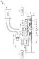
図6を参照して、ラインL2は、第2流量センサ150Aによって液側空間60に位置する液体の計測結果が示されている。シャフト21の「押し工程」および「引き工程」において、液側空間60の流量が正流および逆流に変化していることがわかる。
With reference to FIG. 6, the line L2 shows the measurement result of the liquid located in the
一方、ラインL1は、第1流量センサ110Aによってシール間空間65に位置する液体の計測結果が示されている。シャフト21の「引き工程」においても、シール間空間65の流量に変化はない。
On the other hand, the line L1 shows the measurement result of the liquid located in the
この図6の監視結果から、一次シールである第1ロッドシール23Aは、液側空間60とシール間空間65とを完全に分離し、液側空間60からシール間空間65への液体漏れは発生しておらず、第1ロッドシール23Aが健全な状態であると判別することができる。
From the monitoring result of FIG. 6, the
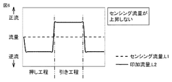
図7に示す状態では、シャフト21の「押し工程」および「引き工程」において、液側空間60の流量が正流および逆流に変化することに伴ない、シール間空間65の流量が正流および逆流に変化している。その結果、液側空間60からシール間空間65への液体漏れが発生していることが分かる。しかし、シール間空間65の流量の変化量は、液側空間60の流量の変化量も低いことから、第1ロッドシール23Aの交換時期であると判別することができる。
In the state shown in FIG. 7, in the “pushing process” and “pulling process” of the
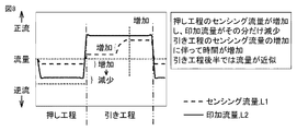
図8に示す状態では、シャフト21の「押し工程」および「引き工程」において、液側空間60の流量が正流および逆流に変化することに伴ない、シール間空間65の流量も正流および逆流に変化している。特に、「引き工程」の後半部分では、シール間空間65の流量の正流値と液側空間60の流量の正流値とが近似している。その結果、第1ロッドシール23Aは、シール材としての機能を有していない状態であると判別することができる。第1ロッドシール23Aを直ちに交換する必要がある時期であることが分かる。
In the state shown in FIG. 8, in the “pushing step” and “pulling step” of the
このように本実施の形態における液体漏れ検知ユニット100によれば、第1ロッドシール23Aのメンテナンス時期をより的確に把握して、液体漏れの発生を防ぐ液体漏れ検知ユニット100を提供することを可能としている。
As described above, according to the liquid
(実施の形態3:液体漏れ検知ユニット100B)
図9を参照して、液体漏れ検知ユニット100Bの構成について説明する。図9は、実施の形態3における圧力スイッチを用いた場合の液体漏れ検知ユニット100Bをシャフト21に組み付けた状態を示す断面図である。
(Embodiment 3: Liquid
With reference to FIG. 9, the structure of the liquid
本実施の形態における液体漏れ検知ユニット100Bの基本的構成は、上述の実施の形態1において示した液体漏れ検知ユニット100と同じであり、相違点は、シール間空間65に位置する液体の液体情報を得る第1液体情報取得装置として、実施の形態1では、第1圧力センサ110を用いているのに対して、本実施の形態では、圧力スイッチ110Bを用いている点にある。印加ポート170P側には、液体情報取得装置は設けていない。
The basic configuration of the liquid
次に、図10から図13を参照して、制御部180におけるシール間空間65に位置する液体の状態である圧力の変化の監視について説明する。図10および図11は、一次シールが健全な状態の場合の圧力情報を示す第1図および第2図、図12は、一次シールが交換時期となる圧力情報を示す図、図13は、一次シールが機能しなくなった圧力情報を示す図である。
Next, referring to FIG. 10 to FIG. 13, monitoring of a change in pressure that is a state of the liquid located in the
図10を参照して、L2は、予め定められた所定圧力を示す。ラインL1は、圧力スイッチ110Bによって、シール間空間65に位置する液体の計測結果が示されている。シャフト21の「押し工程」および「引き工程」においても、シール間空間65に位置する液体の圧力に変化はない。
Referring to FIG. 10, L2 represents a predetermined pressure that is determined in advance. The line L1 shows the measurement result of the liquid located in the
この図10の監視結果から、一次シールである第1ロッドシール23Aは、液側空間60とシール間空間65とを完全に分離し、液側空間60からシール間空間65への液体漏れは発生しておらず、第1ロッドシール23Aが健全な状態であると判別することができる。
From the monitoring result of FIG. 10, the
図11に示す状態では、シャフト21の「引き工程」において、ラインL1に、シール間空間65の圧力上昇が観測される。その結果、液側空間60からシール間空間65への液体漏れが発生していることが分かる。しかし、L2として定めた所定圧力よりよりも50%未満であることから、第1ロッドシール23Aとしては健全な状態であると判別することができる。
In the state shown in FIG. 11, in the “pulling process” of the
図12に示す状態では、シャフト21の「引き工程」において、ラインL1に、シール間空間65の圧力上昇が観測される。その結果、液側空間60からシール間空間65への液体漏れが発生していることが分かる。また、図11に示す圧力状態と比較すると、L2として定めた所定圧力の50%以上を超えていることから、第1ロッドシール23Aの交換時期であると判別することができる。
In the state shown in FIG. 12, in the “pulling process” of the
図13に示す状態では、シャフト21の「引き工程」において、ラインL1に、シール間空間65の圧力が、予め定められた所定圧力のラインL2にまで到達していることが観測できる。その結果、第1ロッドシール23Aは、シール材としての機能を有していない状態であると判別することができる。至急、第1ロッドシール23Aを交換する必要がある時期であることが分かる。
In the state shown in FIG. 13, in the “pulling process” of the
このように本実施の形態における液体漏れ検知ユニット100Bによれば、第1ロッドシール23Aのメンテナンス時期をより的確に把握して、液体漏れの発生を防ぐ液体漏れ検知ユニット100Bを提供することを可能としている。
As described above, according to the liquid
今回開示された各実施の形態はすべての点で例示であって制限的なものではないと考えられるべきである。本発明の範囲は上記した説明ではなくて特許請求の範囲によって示され、特許請求の範囲と均等の意味および範囲内でのすべての変更が含まれることが意図される。 Each embodiment disclosed this time must be considered as illustrative in all points and not restrictive. The scope of the present invention is defined by the terms of the claims, rather than the description above, and is intended to include any modifications within the scope and meaning equivalent to the terms of the claims.
この発明は、たとえば、油圧シリンダや流体ポンプなどに利用される。 The present invention is used for, for example, a hydraulic cylinder and a fluid pump.
21 シャフト、21a 外周面、23A 第1ロッドシール、23B 第2ロッドシール、26 異形ダストシール、27,28 リップ部、29 基部、31 ハウジング、31b 内周面、32 凹部、33 貫通孔、38A 第1シール溝、33P センシングポート、38B 第2シール溝、39 第3シール溝、60 液側空間、65 シール間空間、70 外部空間、100,100A,100B 液体漏れ検知ユニット、101 中心軸、110 第1圧力センサ、110A 第1流量センサ、110B 圧力スイッチ、120 第1ブロック、120P 孔、150 第2圧力センサ、150A 第2流量センサ、160 油圧印加装置、170 第2ブロック、170P 印加ポート、180 制御部。 21 Shaft, 21a Outer peripheral surface, 23A First rod seal, 23B Second rod seal, 26 Deformed dust seal, 27, 28 Lip portion, 29 Base portion, 31 Housing, 31b Inner peripheral surface, 32 Recessed portion, 33 Through hole, 38A First Seal groove, 33P sensing port, 38B 2nd seal groove, 39 3rd seal groove, 60 liquid side space, 65 space between seals, 70 external space, 100, 100A, 100B Liquid leak detection unit, 101 central axis, 110 1st Pressure sensor, 110A first flow sensor, 110B pressure switch, 120 first block, 120P hole, 150 second pressure sensor, 150A second flow sensor, 160 hydraulic pressure application device, 170 second block, 170P application port, 180 control unit .
Claims (5)
前記シャフトの外周上に設けられ、前記シャフトの外周上の液側空間に液体を封止するための第1シール材と、
前記シャフトの外周上に設けられ、前記シャフトの軸方向において前記第1シール材に対して前記液側空間の反対側に配置され、前記第1シール材との間にシール間空間を規定する第2シール材と、
前記シール間空間に位置する液体の液体情報を得る第1液体情報取得装置と、
前記第1液体情報取得装置から得られる情報に基づき、前記シール間空間内に位置する液体の状態の変化を監視する制御部と、
を備える、液体漏れ検知ユニット。 A liquid leak detection unit assembled on a movable shaft,
A first seal member provided on the outer periphery of the shaft, for sealing liquid in a liquid side space on the outer periphery of the shaft;
Provided on the outer periphery of the shaft, disposed on the opposite side of the liquid-side space with respect to the first sealing material in the axial direction of the shaft, and defining a space between the seals with the first sealing material. Two sealing materials;
A first liquid information acquisition device for obtaining liquid information of the liquid located in the space between the seals;
Based on information obtained from the first liquid information acquisition device, a controller that monitors a change in the state of the liquid located in the space between the seals;
A liquid leak detection unit comprising:
前記制御部は、予め定められた所定圧力と、前記圧力スイッチで得られた前記液側空間の液体の圧力を比較して、前記液側空間の液体の状態の変化を監視する、請求項1に記載の液体漏れ検知ユニット。 The first liquid information acquisition device is a pressure switch,
The control unit compares a predetermined pressure determined in advance with the pressure of the liquid in the liquid side space obtained by the pressure switch, and monitors a change in the state of the liquid in the liquid side space. The liquid leak detection unit described in 1.
前記制御部は、
前記第1液体情報取得装置から得られる前記液側空間の液体情報と、前記第2液体情報取得装置から得られる前記シール間空間の液体情報とを比較して、前記液側空間の液体の状態の変化を監視する、請求項1に記載の液体漏れ検知ユニット。 A second liquid information acquisition device for obtaining liquid information of the liquid located in the liquid side space;
The controller is
The liquid information in the liquid side space obtained by comparing the liquid information in the liquid side space obtained from the first liquid information obtaining device with the liquid information in the space between the seals obtained from the second liquid information obtaining device. The liquid leakage detection unit according to claim 1, wherein the liquid leakage detection unit is monitored.
前記第2液体情報取得装置は、第2圧力センサであり、
前記制御部は、
前記第1液体情報取得装置から得られる前記液側空間の圧力と、
前記第2液体情報取得装置から得られる前記シール間空間の圧力とを比較して、前記液側空間の液体の圧力の変化を監視する、請求項3に記載の液体漏れ検知ユニット。 The first liquid information acquisition device is a first pressure sensor,
The second liquid information acquisition device is a second pressure sensor,
The controller is
The pressure of the liquid side space obtained from the first liquid information acquisition device;
The liquid leak detection unit according to claim 3, wherein a change in the pressure of the liquid in the liquid side space is monitored by comparing the pressure in the space between the seals obtained from the second liquid information acquisition device.
前記第2液体情報取得装置は、第2流量センサであり、
前記制御部は、
前記第1液体情報取得装置から得られる前記液側空間の圧力と、
前記第2液体情報取得装置から得られる前記シール間空間の圧力とを比較して、前記液側空間の液体の圧力の変化を監視する、請求項3に記載の液体漏れ検知ユニット。 The first liquid information acquisition device is a first flow sensor,
The second liquid information acquisition device is a second flow rate sensor,
The controller is
The pressure of the liquid side space obtained from the first liquid information acquisition device;
The liquid leak detection unit according to claim 3, wherein a change in the pressure of the liquid in the liquid side space is monitored by comparing the pressure in the space between the seals obtained from the second liquid information acquisition device.
Priority Applications (1)
| Application Number | Priority Date | Filing Date | Title |
|---|---|---|---|
| JP2016191105A JP7039165B2 (en) | 2016-09-29 | 2016-09-29 | Liquid leak detection unit |
Applications Claiming Priority (1)
| Application Number | Priority Date | Filing Date | Title |
|---|---|---|---|
| JP2016191105A JP7039165B2 (en) | 2016-09-29 | 2016-09-29 | Liquid leak detection unit |
Publications (2)
| Publication Number | Publication Date |
|---|---|
| JP2018054021A true JP2018054021A (en) | 2018-04-05 |
| JP7039165B2 JP7039165B2 (en) | 2022-03-22 |
Family
ID=61836378
Family Applications (1)
| Application Number | Title | Priority Date | Filing Date |
|---|---|---|---|
| JP2016191105A Active JP7039165B2 (en) | 2016-09-29 | 2016-09-29 | Liquid leak detection unit |
Country Status (1)
| Country | Link |
|---|---|
| JP (1) | JP7039165B2 (en) |
Cited By (4)
| Publication number | Priority date | Publication date | Assignee | Title |
|---|---|---|---|---|
| WO2019146513A1 (en) * | 2018-01-29 | 2019-08-01 | Kyb株式会社 | Fluid leakage detector and reciprocating hydraulic device |
| CN110361136A (en) * | 2019-07-19 | 2019-10-22 | 中国航发沈阳发动机研究所 | A kind of between centers seal tester |
| JP2019200069A (en) * | 2018-05-14 | 2019-11-21 | Kyb株式会社 | Fluid leakage detection system |
| KR20240035786A (en) | 2021-07-19 | 2024-03-18 | 주식회사 발카 | Hydraulic equipment monitoring system |
Citations (4)
| Publication number | Priority date | Publication date | Assignee | Title |
|---|---|---|---|---|
| JPS59153765U (en) * | 1983-04-01 | 1984-10-15 | 株式会社神戸製鋼所 | Hydraulic cylinder seal monitoring device |
| JPS6155405A (en) * | 1984-08-28 | 1986-03-19 | Hitachi Constr Mach Co Ltd | Internal leakage detecting system for hydraulic cylinder |
| JP2016045068A (en) * | 2014-08-22 | 2016-04-04 | 日本バルカー工業株式会社 | Liquid leakage detection unit |
| JP2017207078A (en) * | 2016-05-16 | 2017-11-24 | Kyb株式会社 | Liquid leakage detection device |
-
2016
- 2016-09-29 JP JP2016191105A patent/JP7039165B2/en active Active
Patent Citations (4)
| Publication number | Priority date | Publication date | Assignee | Title |
|---|---|---|---|---|
| JPS59153765U (en) * | 1983-04-01 | 1984-10-15 | 株式会社神戸製鋼所 | Hydraulic cylinder seal monitoring device |
| JPS6155405A (en) * | 1984-08-28 | 1986-03-19 | Hitachi Constr Mach Co Ltd | Internal leakage detecting system for hydraulic cylinder |
| JP2016045068A (en) * | 2014-08-22 | 2016-04-04 | 日本バルカー工業株式会社 | Liquid leakage detection unit |
| JP2017207078A (en) * | 2016-05-16 | 2017-11-24 | Kyb株式会社 | Liquid leakage detection device |
Cited By (7)
| Publication number | Priority date | Publication date | Assignee | Title |
|---|---|---|---|---|
| WO2019146513A1 (en) * | 2018-01-29 | 2019-08-01 | Kyb株式会社 | Fluid leakage detector and reciprocating hydraulic device |
| JP2019200069A (en) * | 2018-05-14 | 2019-11-21 | Kyb株式会社 | Fluid leakage detection system |
| JP7032999B2 (en) | 2018-05-14 | 2022-03-09 | Kyb株式会社 | Fluid leak detection system |
| CN110361136A (en) * | 2019-07-19 | 2019-10-22 | 中国航发沈阳发动机研究所 | A kind of between centers seal tester |
| CN110361136B (en) * | 2019-07-19 | 2021-05-25 | 中国航发沈阳发动机研究所 | Inter-shaft sealing tester |
| KR20240035786A (en) | 2021-07-19 | 2024-03-18 | 주식회사 발카 | Hydraulic equipment monitoring system |
| DE112021007791T5 (en) | 2021-07-19 | 2024-04-18 | Valqua, Ltd. | Monitoring system for a fluid pressure device |
Also Published As
| Publication number | Publication date |
|---|---|
| JP7039165B2 (en) | 2022-03-22 |
Similar Documents
| Publication | Publication Date | Title |
|---|---|---|
| JP2018054021A (en) | Liquid leakage detection unit | |
| JP6296500B2 (en) | Liquid leak detection unit | |
| RU2674824C1 (en) | Methods and apparatus to diagnose valve using electric valve actuators | |
| JP6643393B2 (en) | Fluid leak detection system and fluid pressure system | |
| CN110118283B (en) | Method for determining the degree of wear of a valve and device for carrying out the method | |
| KR20160099696A (en) | Valve body and high temperature valve | |
| KR101694641B1 (en) | Sealing assembly and hydraulic actuator cylinder assembly of turbine valve having the same | |
| TW202102792A (en) | High-sealing-performance high-pressure needle valve | |
| JP4637163B2 (en) | Mechanical seal with discharge mechanism | |
| WO2019077699A1 (en) | Liquid leakage detection unit | |
| TWI751210B (en) | Liquid leak detection unit | |
| WO2019146459A1 (en) | Fluid leakage detector and reciprocating hydraulic device | |
| WO2008127471A1 (en) | Methods and apparatus for a fluid or slurry pump piston | |
| US9310235B2 (en) | Double isolation for double chamber differential pressure meter | |
| WO2018131560A1 (en) | Liquid leakage detection device | |
| JP2009243522A (en) | Safety valve and sealing structure | |
| JP6858098B2 (en) | Shaft sealing device | |
| US20160341628A1 (en) | Method for monitoring health of a seal | |
| JP6945932B2 (en) | Leakage detection device | |
| JP2019117165A (en) | Improvement of liquid leak detection mechanism | |
| JP2012137121A (en) | Sealing device | |
| WO2021087202A1 (en) | Sensing leak in a multi-seal sealing assembly with sensors | |
| JP2019199895A (en) | Seal deterioration diagnostic device and fluid pressure system | |
| TWM603925U (en) | High-sealing and high-pressure needle valve | |
| KR100799256B1 (en) | Dynamic high pressure sealing device |
Legal Events
| Date | Code | Title | Description |
|---|---|---|---|
| A621 | Written request for application examination |
Free format text: JAPANESE INTERMEDIATE CODE: A621 Effective date: 20190826 |
|
| A977 | Report on retrieval |
Free format text: JAPANESE INTERMEDIATE CODE: A971007 Effective date: 20200706 |
|
| A131 | Notification of reasons for refusal |
Free format text: JAPANESE INTERMEDIATE CODE: A131 Effective date: 20200714 |
|
| A521 | Request for written amendment filed |
Free format text: JAPANESE INTERMEDIATE CODE: A523 Effective date: 20200910 |
|
| A131 | Notification of reasons for refusal |
Free format text: JAPANESE INTERMEDIATE CODE: A131 Effective date: 20210209 |
|
| A521 | Request for written amendment filed |
Free format text: JAPANESE INTERMEDIATE CODE: A523 Effective date: 20210312 |
|
| A02 | Decision of refusal |
Free format text: JAPANESE INTERMEDIATE CODE: A02 Effective date: 20210831 |
|
| A521 | Request for written amendment filed |
Free format text: JAPANESE INTERMEDIATE CODE: A523 Effective date: 20211026 |
|
| C60 | Trial request (containing other claim documents, opposition documents) |
Free format text: JAPANESE INTERMEDIATE CODE: C60 Effective date: 20211026 |
|
| A911 | Transfer to examiner for re-examination before appeal (zenchi) |
Free format text: JAPANESE INTERMEDIATE CODE: A911 Effective date: 20211104 |
|
| C21 | Notice of transfer of a case for reconsideration by examiners before appeal proceedings |
Free format text: JAPANESE INTERMEDIATE CODE: C21 Effective date: 20211109 |
|
| A131 | Notification of reasons for refusal |
Free format text: JAPANESE INTERMEDIATE CODE: A131 Effective date: 20220104 |
|
| A521 | Request for written amendment filed |
Free format text: JAPANESE INTERMEDIATE CODE: A523 Effective date: 20220210 |
|
| TRDD | Decision of grant or rejection written | ||
| A01 | Written decision to grant a patent or to grant a registration (utility model) |
Free format text: JAPANESE INTERMEDIATE CODE: A01 Effective date: 20220308 |
|
| A61 | First payment of annual fees (during grant procedure) |
Free format text: JAPANESE INTERMEDIATE CODE: A61 Effective date: 20220309 |
|
| R150 | Certificate of patent or registration of utility model |
Ref document number: 7039165 Country of ref document: JP Free format text: JAPANESE INTERMEDIATE CODE: R150 |