JP6858098B2 - Shaft sealing device - Google Patents
Shaft sealing device Download PDFInfo
- Publication number
- JP6858098B2 JP6858098B2 JP2017160391A JP2017160391A JP6858098B2 JP 6858098 B2 JP6858098 B2 JP 6858098B2 JP 2017160391 A JP2017160391 A JP 2017160391A JP 2017160391 A JP2017160391 A JP 2017160391A JP 6858098 B2 JP6858098 B2 JP 6858098B2
- Authority
- JP
- Japan
- Prior art keywords
- gland
- inner peripheral
- gland packing
- peripheral surface
- packing
- Prior art date
- Legal status (The legal status is an assumption and is not a legal conclusion. Google has not performed a legal analysis and makes no representation as to the accuracy of the status listed.)
- Active
Links
Images


Classifications
-
- F—MECHANICAL ENGINEERING; LIGHTING; HEATING; WEAPONS; BLASTING
- F16—ENGINEERING ELEMENTS AND UNITS; GENERAL MEASURES FOR PRODUCING AND MAINTAINING EFFECTIVE FUNCTIONING OF MACHINES OR INSTALLATIONS; THERMAL INSULATION IN GENERAL
- F16J—PISTONS; CYLINDERS; SEALINGS
- F16J15/00—Sealings
- F16J15/16—Sealings between relatively-moving surfaces
- F16J15/18—Sealings between relatively-moving surfaces with stuffing-boxes for elastic or plastic packings
- F16J15/24—Sealings between relatively-moving surfaces with stuffing-boxes for elastic or plastic packings with radially or tangentially compressed packing
-
- F—MECHANICAL ENGINEERING; LIGHTING; HEATING; WEAPONS; BLASTING
- F16—ENGINEERING ELEMENTS AND UNITS; GENERAL MEASURES FOR PRODUCING AND MAINTAINING EFFECTIVE FUNCTIONING OF MACHINES OR INSTALLATIONS; THERMAL INSULATION IN GENERAL
- F16J—PISTONS; CYLINDERS; SEALINGS
- F16J15/00—Sealings
- F16J15/16—Sealings between relatively-moving surfaces
- F16J15/32—Sealings between relatively-moving surfaces with elastic sealings, e.g. O-rings
- F16J15/324—Arrangements for lubrication or cooling of the sealing itself
Description
本発明は、軸封装置に関する。 The present invention relates to a shaft sealing device.
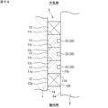
従来より、バルブやポンプなどの流体機器に装備される軸封装置として、複数のグランドパッキンを軸方向に並べて配置したものが知られている。従来のグランドパッキンは、図10に示すように、バルブなどのハウジング91内に、軸92が例えば軸方向に往復移動可能に配置されており、これらの間に形成された環状空間Aに、複数の(図例では3つの)グランドパッキン93が軸方向に並べて設置され、これらのグランドパッキン93の軸方向両側にアダプタパッキン94がそれぞれ配置されている。これらのグランドパッキン93は、ハウジング91の内周側段部95と、大気側に設けられている筒状の締め付け部材96との間に軸方向から挟まれた状態にある。
Conventionally, as a shaft sealing device installed in a fluid device such as a valve or a pump, a device in which a plurality of gland packings are arranged side by side in the axial direction has been known. As shown in FIG. 10, in the conventional gland packing, a
そして、締め付け部材96がボルト97によって被密封流体99側(機内側)へ締め付けられると、グランドパッキン93及びアダプタパッキン94は、軸方向に圧縮されることによって径方向に延びるように変形する。この変形によってグランドパッキン93及びアダプタパッキン94の各外周面93a,94a及び各内周面93b,94bが、ハウジング91の内周面及び軸92の外周面にそれぞれ密着する。これにより、ハウジング91内の被密封流体99が大気側へ漏れるのを防ぐことができる(例えば、特許文献1参照)。
Then, when the tightening
従来の上記軸封装置では、各グランドパッキン93の内周面93bにグリース等の潤滑剤が塗布されている。この潤滑剤によって、軸92が軸方向に往復移動したときの前記内周面93bの摺動抵抗を低減して耐摩耗性を向上させるとともに、グランドパッキン93だけではシールしきれない被密封流体99の漏れを抑制してシール特性を向上させている。
In the conventional shaft sealing device, a lubricant such as grease is applied to the inner
しかし、上記のように各グランドパッキン93の内周面93bに塗布された潤滑剤は、軸92が往復移動することによって、軸方向両端部にそれぞれ配置されたグランドパッキン93の内周面93bから軸方向外側へ流出し易いため、耐摩耗性及びシール特性を維持することができないという問題があった。
本発明は、このような事情に鑑みてなされたものであり、耐摩耗性及びシール特性を維持することができる軸封装置を提供することを目的とする。
However, the lubricant applied to the inner
The present invention has been made in view of such circumstances, and an object of the present invention is to provide a shaft sealing device capable of maintaining wear resistance and sealing characteristics.
(1)本発明の軸封装置は、軸方向に並べて配置される複数の環状のグランドパッキンと、前記複数のグランドパッキンの軸方向両側にそれぞれ配置される一対の環状のアダプタパッキンと、を備え、前記複数のグランドパッキン及び前記一対のアダプタパッキンを軸方向に圧縮することで、径方向に対向する内側被シール面と外側被シール面との間をシールする軸封装置であって、前記グランドパッキンの内周面には、前記内側被シール面との間に介在する潤滑剤が入り込む環状溝が形成されている。 (1) The shaft sealing device of the present invention includes a plurality of annular gland packings arranged side by side in the axial direction and a pair of annular adapter packings arranged on both sides of the plurality of gland packings in the axial direction. A shaft sealing device that seals between the inner surface to be sealed and the outer surface to be sealed facing each other in the radial direction by compressing the plurality of gland packings and the pair of adapter packings in the axial direction. An annular groove is formed on the inner peripheral surface of the packing to allow the lubricant interposed between the inner peripheral surface and the inner surface to be sealed to enter.
この軸封装置によれば、例えば内側被シール面が外側被シール面に対して軸方向に往復移動することで、グランドパッキンの内周面と内側被シール面との間に介在する潤滑剤は、前記内周面に沿って軸方向外側(アダプタパッキン側)に向かって移動しようとするが、その際、前記内周面に形成された環状溝に前記潤滑剤の一部が入り込む。これにより、各アダプタパッキンよりも軸方向外側へ潤滑剤が流出するのを抑制することができる。その結果、グランドパッキンの内周面と内側被シール面との間に潤滑剤を長期間にわたって留めることができるので、内側被シール面の前記往復移動によるグランドパッキンの内周面の摺動抵抗を潤滑剤により低減して耐摩耗性を維持することができる。また、グランドパッキンだけではシールしきれない被密封流体の漏れを潤滑剤により抑制してシール特性を維持することができる。 According to this shaft sealing device, for example, the inner surface to be sealed reciprocates in the axial direction with respect to the outer surface to be sealed, so that the lubricant interposed between the inner peripheral surface and the inner surface to be sealed of the gland packing can be removed. , Along the inner peripheral surface, it tries to move toward the outer side in the axial direction (adapter packing side), but at that time, a part of the lubricant enters the annular groove formed on the inner peripheral surface. As a result, it is possible to prevent the lubricant from flowing out axially outward from each adapter packing. As a result, the lubricant can be retained between the inner peripheral surface of the gland packing and the inner surface to be sealed for a long period of time, so that the sliding resistance of the inner peripheral surface of the gland packing due to the reciprocating movement of the inner surface to be sealed can be reduced. It can be reduced by the lubricant and the wear resistance can be maintained. Further, the leakage of the sealed fluid that cannot be completely sealed by the gland packing alone can be suppressed by the lubricant to maintain the sealing characteristics.
(2)前記環状溝の軸方向全長は、前記グランドパッキンの内周面の軸方向全長の50%以下に設定されているのが好ましい。
この場合、グランドパッキンの内周面に環状溝が形成されても、前記内周面(環状溝を除く)と内側被シール面との間を、シール特性を維持することができる程度に潤滑剤を介在させた状態で接触させることができる。したがって、シール特性を確実に維持することができる。
(2) The axial total length of the annular groove is preferably set to 50% or less of the axial total length of the inner peripheral surface of the gland packing.
In this case, even if an annular groove is formed on the inner peripheral surface of the gland packing, the lubricant can maintain the sealing characteristics between the inner peripheral surface (excluding the annular groove) and the inner sealed surface. Can be brought into contact with each other. Therefore, the sealing characteristics can be reliably maintained.
(3)前記環状溝は、前記グランドパッキンの軸方向一端面に開口するように形成されているのが好ましい。
この場合、グランドパッキンと、その軸方向一端面側に隣接する他のグランドパッキン又はアダプタパッキンとの間に環状溝が形成されるため、この環状溝に入り込んだ潤滑剤によって、被密封流体が、グランドパッキンの内周側から前記軸方向一端面を通過して外周側に漏れるのを抑制することができる。その結果、シール特性をさらに向上させた状態で維持することができる。
(3) The annular groove is preferably formed so as to open on one end surface in the axial direction of the gland packing.
In this case, since an annular groove is formed between the gland packing and another gland packing or adapter packing adjacent to the one end surface side in the axial direction, the lubricant that has entered the annular groove causes the fluid to be sealed to be released. It is possible to prevent leakage from the inner peripheral side of the gland packing to the outer peripheral side through the one end surface in the axial direction. As a result, the sealing characteristics can be maintained in a further improved state.
(4)前記環状溝は、軸方向に隣り合う前記グランドパッキンの各内周面において、これらのグランドパッキンの互いに対向する軸方向端面にそれぞれ開口するように形成されているのが好ましい。
この場合、軸方向に隣り合うグランドパッキンの各内周面に形成された環状溝同士が互いに軸方向に連通するため、これらの環状溝に入り込む潤滑剤の量を増加させることができる。これにより、各アダプタパッキンよりも軸方向外側へ潤滑剤が流出するのを効果的に抑制することができるので、耐摩耗性をさらに向上させた状態で維持することができる。
(4) It is preferable that the annular groove is formed so as to open on each inner peripheral surface of the gland packings adjacent to each other in the axial direction to the axial end faces of the gland packings facing each other.
In this case, since the annular grooves formed on the inner peripheral surfaces of the gland packings adjacent to each other in the axial direction communicate with each other in the axial direction, the amount of the lubricant entering the annular grooves can be increased. As a result, it is possible to effectively suppress the outflow of the lubricant to the outside in the axial direction of each adapter packing, so that the wear resistance can be maintained in a further improved state.
また、これらの環状溝は、隣り合うグランドパッキンの互いに対向する端面を跨いで互いに連通するため、これらの環状溝に入り込んだ潤滑剤によって、被密封流体が、隣り合うグランドパッキンの内周側から、前記軸方向端面同士の間を通過して外周側に漏れるのを効果的に抑制することができる。その結果、シール特性をさらに向上させた状態で維持することができる。 Further, since these annular grooves communicate with each other across the end faces of the adjacent gland packings facing each other, the lubricating fluid that has entered the annular grooves allows the fluid to be sealed to flow from the inner peripheral side of the adjacent gland packings. , It is possible to effectively suppress leakage to the outer peripheral side by passing between the axial end faces. As a result, the sealing characteristics can be maintained in a further improved state.
本発明によれば、耐摩耗性及びシール特性を維持することができる。 According to the present invention, wear resistance and sealing properties can be maintained.
次に、本発明の好ましい実施形態について添付図面を参照しながら説明する。
[第1実施形態]
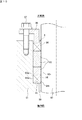
図1は、本発明の第1実施形態に係る軸封装置を備えた流体機器の一部を示す断面図である。この流体機器は、例えばバルブ又はポンプなどであり、ハウジング1と、このハウジング1の内部空間に設けられている軸2と、ハウジング1と軸2との間をシールする軸封装置3とを備えている。軸2は、ハウジング1に対して、軸2の軸線C回りに回転したり、軸方向に往復移動したりするようになっている。なお、本実施形態の流体機器は、軸2の軸線Cが鉛直方向となるように配置されているが、当該軸線Cが水平方向となるように配置されていてもよい。
Next, a preferred embodiment of the present invention will be described with reference to the accompanying drawings.
[First Embodiment]
FIG. 1 is a cross-sectional view showing a part of a fluid device provided with a shaft sealing device according to the first embodiment of the present invention. This fluid device is, for example, a valve or a pump, and includes a
軸封装置3は、ハウジング1と軸2との間に形成されている環状空間Aにおいて軸方向に並べて配置された複数(ここでは3つ)のグランドパッキン11と、これら複数のグランドパッキン11の軸方向両側にそれぞれ配置された一対のアダプタパッキン12と、環状空間Aの大気側(図1の上側)に設けられた締め付け部材13とを備えている。
The
グランドパッキン11は、環状の成形パッキンからなる。具体的には、グランドパッキン11は、膨張黒鉛シートを所定幅のテープ状に形成し、その膨張黒鉛のテープを径方向に渦巻き状に巻き重ねた状態で金型により圧縮成形したものである。アダプタパッキン12は、グランドパッキン11と同様に、環状の成形パッキンからなる。 The gland packing 11 is made of an annular molded packing. Specifically, the gland packing 11 is formed by forming an expanded graphite sheet into a tape having a predetermined width, and compression-molding the expanded graphite tape with a mold in a state of being spirally wound in the radial direction. Like the gland packing 11, the adapter packing 12 is made of an annular molded packing.
グランドパッキン11及びアダプタパッキン12は、パッキンボックス5内に設置されている。パッキンボックス5は、ハウジング1の大気側の内周面1a及び段差面1bと、軸2の外周面2aとによって構成されており、その内部に環状空間Aが形成されている。
The gland packing 11 and the adapter packing 12 are installed in the
締め付け部材13は、円筒状に形成されており、円板状のフランジ部13aを有している。フランジ部13aには、周方向に複数(図1では1個のみ図示)のボルト6が軸方向に貫通しており、これらの各ボルト6は、ハウジング1の大気側の側面に形成されたねじ孔7に螺合されている。
The tightening
ボルト6によって締め付け部材13を機内側(図1の下側)へ締め付けると、各グランドパッキン11及び各アダプタパッキン12は、軸方向に圧縮され(潰され)、径方向に延びるように変形する。この変形によって、各グランドパッキン11の外周面11a及び内周面11bは、径方向に対向するハウジング1の内周面1a及び軸2の外周面2aにそれぞれ密着する。同様に、前記変形によって、アダプタパッキン12の外周面12a及び内周面12bは、ハウジング1の内周面1a及び軸2の外周面2aにそれぞれ密着する。
When the tightening
これにより、軸2が回転したり軸方向に往復移動したりしても、ハウジング1の機内側に存在する被密封流体が外部(大気側)へ漏れるのを防ぐことができる。以下、ハウジング1の内周面1aを「外側被シール面1a」ともいう。また、軸2の外周面2aを「内側被シール面2a」ともいう。
As a result, even if the
図2Aは、本実施形態の複数のグランドパッキン11を示す断面図である。各グランドパッキン11の内周面11bには、グリース(潤滑剤)が塗布されている。これにより、各グランドパッキン11の内周面11bと内側被シール面2aとの間にはグリースが介在している。なお、潤滑剤としては、グリース以外に潤滑油を用いてもよい。
FIG. 2A is a cross-sectional view showing a plurality of gland packings 11 of the present embodiment. Grease (lubricant) is applied to the inner
前記グリースにより、軸2が回転したり軸方向に往復移動したりしたときに、前記内周面11bにおける内側被シール面2aに対する摺動抵抗を低減して耐摩耗性を向上させるとともに、グランドパッキン11だけではシールしきれない被密封流体の漏れを抑制してシール特性を向上させている。
When the
各グランドパッキン11の内周面11bには、前記内周面11bに塗布されているグリースが一時的に入り込む環状溝20が形成されている。環状溝20は、前記内周面11bにおいて周方向に連なるように凹設された溝である。これにより、軸2が主に軸方向に往復移動したときに、前記内周面11bに沿って軸方向両側に移動するグリースが環状溝20に入り込むことで、大気側に配置されたアダプタパッキン12よりも軸方向外側(大気側)へグリースが流出するのを抑制することができ、且つ機内側に配置されたアダプタパッキン12よりも軸方向外側(機内側)へグリースが流出するのを抑制することができる。
An
その結果、グランドパッキン11の内周面11bと内側被シール面2aとの間にグリースを長期間にわたって留めることができるので、軸2の往復移動による前記内周面11bの摺動抵抗をグリースにより低減して耐摩耗性を維持することができる。また、グランドパッキン11だけではシールしきれない被密封流体の漏れをグリースにより抑制してシール特性を維持することができる。
As a result, grease can be retained between the inner
本実施形態の環状溝20は、グランドパッキン11の内周面11bにおいて、大気側の端部に形成された環状の第1溝部21と、機内側の端部に形成された環状の第2溝部22とによって構成されている。第1及び第2溝部21,22は、例えば断面凹状に形成されており、これらの内部には予め余剰のグリースが充填されている。
但し、第1及び第2溝部21,22には、上記のように前記内周面11bに塗布されているグリースが一時的に入り込むため、余剰のグリースが充填された状態で、前記塗布されているグリースが入り込むスペースが確保されている。
The
However, since the grease applied to the inner
また、本実施形態では、複数のグランドパッキン11に形成された第1及び第2溝部21,22のうち、大気側のアダプタパッキン12に隣接するグランドパッキン11に形成された第1溝部21A、及び機内側のアダプタパッキン12に隣接するグランドパッキン11に形成された第2溝部22Aには、余剰のグリースを充填していない。
Further, in the present embodiment, of the first and
これにより、機内側から大気側のアダプタパッキン12に移動してきたグリースが前記第1溝部21Aに入り込むことで、そのグリースを回収することができる。同様に、大気側から機内側のアダプタパッキン12に移動してきたグリースが前記第2溝部22Aに入り込むことで、そのグリースを回収することができる。
As a result, the grease that has moved from the inside of the machine to the adapter packing 12 on the atmosphere side enters the
なお、第1溝部21A及び第2溝部22Aに替えて又はこれらに加えて、他の第1溝部21や他の第2溝部22に余剰のグリースを充填しないようにしてもよい。また、第1溝部21A及び第2溝部22Aに予め余剰のグリースを充填させてもよい。
In addition, instead of or in addition to the
第1溝部21は、当該第1溝部21が形成されたグランドパッキン11の大気側の端面11cに開口するように形成されている。また、第2溝部22は、当該第2溝部22が形成されたグランドパッキン11の機内側の端面11dに開口するように形成されている。
The
これにより、各グランドパッキン11の第1溝部21に入り込んだグリースによって、機内側の被密封流体が、各グランドパッキン11の内周側から、前記端面11cとこれに対向する上側(大気側)のグランドパッキン11の端面11d(又はアダプタパッキン12の端面)との間を通過して、各グランドパッキン11の外周側に漏れるのを抑制することができる。
As a result, the grease that has entered the
同様に、各グランドパッキン11の第2溝部22Aに入り込んだグリースによって、機内側の被密封流体が、各グランドパッキン11の内周側から、前記端面11dとこれに対向する下側(機内側)のグランドパッキン11の端面11c(又はアダプタパッキン12の端面)との間を通過して外周側に漏れるのを抑制することができる。
その結果、シール特性をさらに向上させた状態で維持することができる。
Similarly, due to the grease that has entered the
As a result, the sealing characteristics can be maintained in a further improved state.
隣り合うグランドパッキン11,11のうち、大気側に配置されたグランドパッキン11の第2溝部22、及び機内側に配置されたグランドパッキン11の第1溝部21は、これらのグランドパッキン11,11の互いに対向する端面11c,11dにそれぞれ開口するように形成されている。これにより、前記大気側に配置されたグランドパッキン11の第2溝部22、及び前記機内側に配置されたグランドパッキン11の第1溝部21は、これらのグランドパッキン11,11の互いに対向する端面11c,11dを跨いで、互いに軸方向に連通している。
Of the adjacent gland packings 11 and 11, the
したがって、これらの第2溝部22及び第1溝部21に入り込むグリースの量を増加させることができるので、グリースが隣り合うグランドパッキン11,11よりも軸方向外側(大気側及び機内側)へ移動するのを効果的に抑制することができる。その結果、耐摩耗性をさらに向上させた状態で維持することができる。
Therefore, since the amount of grease that enters the
特に、本実施形態では、軸方向中央部に配置されたグランドパッキン11の軸方向両端部において、互いに連通した第2溝部22及び第1溝部21が2つ形成される。このため、軸2が往復移動したときに、一方の溝部22,21と、他方の溝部22,21との間で、グリースが行き来することで、軸方向中央部に配置されたグランドパッキン11の内周面11bの周辺にグリースを長期間にわたって留めることができる。これにより、各アダプタパッキン12よりも軸方向外側へグリースが流出するのをさらに効果的に抑制することができる。
In particular, in the present embodiment, two
また、前記第2溝部22及び第1溝部21は、隣り合うグランドパッキン11,11の互いに対向する端面11c,11dを跨いで互いに連通するため、これらの溝部22,21に入り込んだグリースによって、被密封流体が、隣り合うグランドパッキン11,11の内周側から、前記対向する端面11c,11d同士の間を通過して、これらグランドパッキン11,11の外周側に漏れるのを効果的に抑制することができる。その結果、シール特性をさらに向上させた状態で維持することができる。
Further, since the
図2Bは、本実施形態のグランドパッキン11を示す拡大断面図である。各グランドパッキン11における環状溝20の軸方向全長L1は、当該グランドパッキン11の内周面11bの軸方向全長L2の50%以下に設定されている。本実施形態では、環状溝20の軸方向全長L1は、第1溝部21の軸方向全長L11と、第2溝部22の軸方向全長L12との合計長さであり、前記軸方向全長L2の50%に設定されている。
FIG. 2B is an enlarged cross-sectional view showing the gland packing 11 of the present embodiment. The axial total length L1 of the
これにより、グランドパッキン11の内周面11bに環状溝20が形成されても、前記内周面11b(環状溝20を除く)と内側被シール面2aとの間を、シール特性を維持することができる程度にグリースを介在させた状態で接触させることができる(シール長を確保することができる)。したがって、グリースによるシール特性を確実に維持することができる。
As a result, even if the
[第2実施形態]
図3Aは、本発明の第2実施形態に係る軸封装置3の複数のグランドパッキン11を示す断面図である。第2実施形態における各グランドパッキン11の内周面11bには、大気側の端部に環状の第1溝部21のみが形成されている。したがって、本実施形態では、各グランドパッキン11の環状溝20は、第1溝部21のみによって構成されている。
[Second Embodiment]
FIG. 3A is a cross-sectional view showing a plurality of gland packings 11 of the
図3Bは、第2実施形態のグランドパッキン11を示す拡大断面図である。本実施形態の各グランドパッキン11における環状溝20の軸方向全長L1は、当該グランドパッキン11の内周面11bの軸方向全長L2の50%以下に設定されている。本実施形態では、環状溝20の軸方向全長L1は、第1溝部21の軸方向全長L11であり、前記軸方向全長L2の25%に設定されている。
なお、第2実施形態のその他の構成は、第1実施形態と同様であるため、説明を省略する。
FIG. 3B is an enlarged cross-sectional view showing the gland packing 11 of the second embodiment. The axial total length L1 of the
Since the other configurations of the second embodiment are the same as those of the first embodiment, the description thereof will be omitted.
以上の構成により、第2実施形態における軸封装置3でも、グリースが第1溝部21に入り込むことで、グランドパッキン11の内周面11bと内側被シール面2aとの間にグリースを長期間にわたって留めることができる。これにより、軸2の往復移動による前記内周面11bの摺動抵抗をグリースにより低減して耐摩耗性を維持することができる。また、グランドパッキン11だけではシールしきれない被密封流体の漏れをグリースにより抑制してシール特性を維持することができる。
With the above configuration, even in the
また、各グランドパッキン11の第1溝部21に入り込んだグリースによって、機内側の被密封流体が、各グランドパッキン11の内周側から、その端面11cとこれに対向する上側(大気側)のグランドパッキン11の端面11d(又はアダプタパッキン12の端面)との間を通過して、各グランドパッキン11の外周側に漏れるのを抑制することができる。その結果、シール特性をさらに向上させた状態で維持することができる。
Further, due to the grease that has entered the
また、環状溝20の軸方向全長L1は、当該グランドパッキン11の内周面11bの軸方向全長L2の50%以下に設定されているため、前記内周面11bに環状溝20が形成されても、前記内周面11b(環状溝20を除く)と内側被シール面2aとの間を、シール特性を維持することができる程度にグリースを介在させた状態で接触させることができる(シール長を確保することができる)。したがって、シール特性を確実に維持することができる。
Further, since the axial total length L1 of the
[第3実施形態]
図4Aは、本発明の第3実施形態に係る軸封装置3の複数のグランドパッキン11を示す断面図である。第3実施形態における各グランドパッキン11の内周面11bには、機内側の端部に環状の第2溝部22のみが形成されている。したがって、本実施形態では、各グランドパッキン11の環状溝20は、第2溝部22のみによって構成されている。
[Third Embodiment]
FIG. 4A is a cross-sectional view showing a plurality of gland packings 11 of the
図4Bは、第3実施形態のグランドパッキン11を示す拡大断面図である。本実施形態の各グランドパッキン11における環状溝20の軸方向全長L1は、当該グランドパッキン11の内周面11bの軸方向全長L2の50%以下に設定されている。本実施形態では、環状溝20の軸方向全長L1は、第2溝部22の軸方向全長L12であり、前記軸方向全長L2の25%に設定されている。
なお、第3実施形態のその他の構成は、第1実施形態と同様であるため、説明を省略する。
FIG. 4B is an enlarged cross-sectional view showing the gland packing 11 of the third embodiment. The axial total length L1 of the
Since the other configurations of the third embodiment are the same as those of the first embodiment, the description thereof will be omitted.
以上の構成により、第3実施形態における軸封装置3でも、グリースが第2溝部22に入り込むことで、グランドパッキン11の内周面11bと内側被シール面2aとの間にグリースを長期間にわたって留めることができる。これにより、軸2の往復移動による前記内周面11bの摺動抵抗をグリースにより低減して耐摩耗性を維持することができる。また、グランドパッキン11だけではシールしきれない被密封流体の漏れをグリースにより抑制してシール特性を維持することができる。
With the above configuration, even in the
また、各グランドパッキン11の第2溝部22に入り込んだグリースによって、機内側の被密封流体が、各グランドパッキン11の内周側から、その端面11dとこれに対向する下側(機内側)のグランドパッキン11の端面11c(又はアダプタパッキン12の端面)との間を通過して、各グランドパッキン11の外周側に漏れるのを抑制することができる。その結果、シール特性をさらに向上させた状態で維持することができる。
Further, due to the grease that has entered the
また、環状溝20の軸方向全長L1は、当該グランドパッキン11の内周面11bの軸方向全長L2の50%以下に設定されているため、前記内周面11bに環状溝20が形成されても、前記内周面11b(環状溝20を除く)と内側被シール面2aとの間を、シール特性を維持することができる程度にグリースを介在させた状態で接触させることができる(シール長を確保することができる)。したがって、シール特性を確実に維持することができる。
Further, since the axial total length L1 of the
[第4実施形態]
図5Aは、本発明の第4実施形態に係る軸封装置3の複数のグランドパッキン11を示す断面図である。第4実施形態における各グランドパッキン11の内周面11bには、軸方向中央部に環状の第3溝部23のみが形成されている。したがって、本実施形態では、各グランドパッキン11の環状溝20は、第3溝部23によって構成されている。第3溝部23は、例えば断面凹状に形成されている。
[Fourth Embodiment]
FIG. 5A is a cross-sectional view showing a plurality of gland packings 11 of the
図5Bは、第4実施形態のグランドパッキン11を示す拡大断面図である。本実施形態の各グランドパッキン11における環状溝20の軸方向全長L1は、当該グランドパッキン11の内周面11bの軸方向全長L2の50%以下に設定されている。本実施形態では、環状溝20の軸方向全長L1は、第3溝部23の軸方向全長L13であり、前記軸方向全長L2の25%に設定されている。
なお、第4実施形態のその他の構成は、第1実施形態と同様であるため、説明を省略する。
FIG. 5B is an enlarged cross-sectional view showing the gland packing 11 of the fourth embodiment. The axial total length L1 of the
Since the other configurations of the fourth embodiment are the same as those of the first embodiment, the description thereof will be omitted.
以上の構成により、第4実施形態における軸封装置3でも、グリースが第3溝部23に入り込むことで、グランドパッキン11の内周面11bと内側被シール面2aとの間にグリースを長期間にわたって留めることができる。これにより、軸2の往復移動による前記内周面11bの摺動抵抗をグリースにより低減して耐摩耗性を維持することができる。また、グランドパッキン11だけではシールしきれない被密封流体の漏れをグリースにより抑制してシール特性を維持することができる。
With the above configuration, even in the
また、環状溝20の軸方向全長L1は、当該グランドパッキン11の内周面11bの軸方向全長L2の50%以下に設定されているため、前記内周面11bに環状溝20が形成されても、前記内周面11b(環状溝20を除く)と内側被シール面2aとの間を、シール特性を維持することができる程度にグリースを介在させた状態で接触させることができる(シール長を確保することができる)。したがって、シール特性を確実に維持することができる。
Further, since the axial total length L1 of the
[第5実施形態]
図6Aは、本発明の第5実施形態に係る軸封装置3の複数のグランドパッキン11を示す断面図である。第5実施形態における各グランドパッキン11の内周面11bには、大気側の端部に環状の第1溝部21が形成され、且つ軸方向中央部に環状の第3溝部23が形成されている。したがって、本実施形態では、各グランドパッキン11の環状溝20は、第1溝部21と第3溝部23とによって構成されている。
[Fifth Embodiment]
FIG. 6A is a cross-sectional view showing a plurality of gland packings 11 of the
図6Bは、第5実施形態のグランドパッキン11を示す拡大断面図である。本実施形態の各グランドパッキン11における環状溝20の軸方向全長L1は、当該グランドパッキン11の内周面11bの軸方向全長L2の50%以下に設定されている。本実施形態では、環状溝20の軸方向全長L1は、第1溝部21の軸方向全長L11と、第3溝部23の軸方向全長L13との合計長さであり、前記軸方向全長L2の50%に設定されている。
なお、第5実施形態のその他の構成は、第1実施形態及び第4実施形態と同様であるため、説明を省略する。
FIG. 6B is an enlarged cross-sectional view showing the gland packing 11 of the fifth embodiment. The axial total length L1 of the
Since the other configurations of the fifth embodiment are the same as those of the first embodiment and the fourth embodiment, the description thereof will be omitted.
以上の構成により、第5実施形態における軸封装置3でも、グリースが第1及び第3溝部21,23にそれぞれ入り込むことで、グランドパッキン11の内周面11bと内側被シール面2aとの間にグリースを長期間にわたって留めることができる。これにより、軸2の往復移動による前記内周面11bの摺動抵抗をグリースにより低減して耐摩耗性を維持することができる。また、グランドパッキン11だけではシールしきれない被密封流体の漏れをグリースにより抑制してシール特性を維持することができる。
With the above configuration, even in the
また、各グランドパッキン11の第1溝部21に入り込んだグリースによって、機内側の被密封流体が、各グランドパッキン11の内周側から、その端面11cとこれに対向する上側(大気側)のグランドパッキン11の端面11d(又はアダプタパッキン12の端面)との間を通過して、各グランドパッキン11の外周側に漏れるのを抑制することができる。その結果、シール特性をさらに向上させた状態で維持することができる。
Further, due to the grease that has entered the
また、環状溝20の軸方向全長L1は、当該グランドパッキン11の内周面11bの軸方向全長L2の50%以下に設定されているため、前記内周面11bに環状溝20が形成されても、前記内周面11b(環状溝20を除く)と内側被シール面2aとの間を、シール特性を維持することができる程度にグリースを介在させた状態で接触させることができる(シール長を確保することができる)。したがって、シール特性を確実に維持することができる。
Further, since the axial total length L1 of the
[第6実施形態]
図7Aは、本発明の第6実施形態に係る軸封装置3の複数のグランドパッキン11を示す断面図である。第6実施形態における各グランドパッキン11の内周面11bには、機内側の端部に環状の第2溝部22が形成され、且つ軸方向中央部に環状の第3溝部23が形成されている。したがって、本実施形態では、各グランドパッキン11の環状溝20は、第2溝部22と第3溝部23とによって構成されている。
[Sixth Embodiment]
FIG. 7A is a cross-sectional view showing a plurality of gland packings 11 of the
図7Bは、第6実施形態のグランドパッキン11を示す拡大断面図である。本実施形態の各グランドパッキン11における環状溝20の軸方向全長L1は、当該グランドパッキン11の内周面11bの軸方向全長L2の50%以下に設定されている。本実施形態では、環状溝20の軸方向全長L1は、第2溝部22の軸方向全長L12と、第3溝部23の軸方向全長L13との合計長さであり、前記軸方向全長L2の50%に設定されている。
なお、第6実施形態のその他の構成は、第1実施形態及び第4実施形態と同様であるため、説明を省略する。
FIG. 7B is an enlarged cross-sectional view showing the gland packing 11 of the sixth embodiment. The axial total length L1 of the
Since the other configurations of the sixth embodiment are the same as those of the first embodiment and the fourth embodiment, the description thereof will be omitted.
以上の構成により、第6実施形態における軸封装置3でも、グリースが第2及び第3溝部22,23にそれぞれ入り込むことで、グランドパッキン11の内周面11bと内側被シール面2aとの間にグリースを長期間にわたって留めることができる。これにより、軸2の往復移動による前記内周面11bの摺動抵抗をグリースにより低減して耐摩耗性を維持することができる。また、グランドパッキン11だけではシールしきれない被密封流体の漏れをグリースにより抑制してシール特性を維持することができる。
With the above configuration, even in the
また、各グランドパッキン11の第2溝部22に入り込んだグリースによって、機内側の被密封流体が、各グランドパッキン11の内周側から、その端面11dとこれに対向する下側(機内側)のグランドパッキン11の端面11c(又はアダプタパッキン12の端面)との間を通過して、各グランドパッキン11の外周側に漏れるのを抑制することができる。その結果、シール特性をさらに向上させた状態で維持することができる。
Further, due to the grease that has entered the
また、環状溝20の軸方向全長L1は、当該グランドパッキン11の内周面11bの軸方向全長L2の50%以下に設定されているため、前記内周面11bに環状溝20が形成されても、前記内周面11b(環状溝20を除く)と内側被シール面2aとの間を、シール特性を維持することができる程度にグリースを介在させた状態で接触させることができる(シール長を確保することができる)。したがって、シール特性を確実に維持することができる。
Further, since the axial total length L1 of the
[第7実施形態]
図8Aは、本発明の第7実施形態に係る軸封装置3の複数のグランドパッキン11を示す断面図である。第7実施形態における各グランドパッキン11の内周面11bには、大気側の端部に環状の第1溝部21が形成され、且つ機内側の端部に環状の第2溝部22が形成されている。さらに、前記内周面11bには、軸方向中央部に環状の第3溝部23が形成されている。したがって、本実施形態では、各グランドパッキン11の環状溝20は、第1溝部21、第2溝部22、及び第3溝部23によって構成されている。
[7th Embodiment]
FIG. 8A is a cross-sectional view showing a plurality of gland packings 11 of the
図8Bは、第7実施形態のグランドパッキン11を示す拡大断面図である。本実施形態の各グランドパッキン11における環状溝20の軸方向全長L1は、当該グランドパッキン11の内周面11bの軸方向全長L2の50%を超えるように設定されている。本実施形態では、環状溝20の軸方向全長L1は、第1溝部21の軸方向全長L11と、第2溝部22の軸方向全長L12と、第3溝部23の軸方向全長L13との合計長さであり、前記軸方向全長L2の75%に設定されている。
なお、第7実施形態のその他の構成は、第1実施形態及び第4実施形態と同様であるため、説明を省略する。
FIG. 8B is an enlarged cross-sectional view showing the gland packing 11 of the seventh embodiment. The axial total length L1 of the
Since the other configurations of the seventh embodiment are the same as those of the first embodiment and the fourth embodiment, the description thereof will be omitted.
以上の構成により、第7実施形態における軸封装置3でも、グリースが第1〜第3溝部21〜23にそれぞれ入り込むことで、グランドパッキン11の内周面11bと内側被シール面2aとの間にグリースを長期間にわたって留めることができる。これにより、軸2の往復移動による前記内周面11bの摺動抵抗をグリースにより低減して耐摩耗性を維持することができる。また、グランドパッキン11だけではシールしきれない被密封流体の漏れをグリースにより抑制してシール特性を維持することができる。
With the above configuration, even in the
また、各グランドパッキン11の第1溝部21に入り込んだグリースによって、機内側の被密封流体が、各グランドパッキン11の内周側から、その端面11cとこれに対向する上側(大気側)のグランドパッキン11の端面11d(又はアダプタパッキン12の端面)との間を通過して、各グランドパッキン11の外周側に漏れるのを抑制することができる。
Further, due to the grease that has entered the
同様に、各グランドパッキン11の第2溝部22に入り込んだグリースによって、機内側の被密封流体が、各グランドパッキン11の内周側から、その端面11dとこれに対向する下側(機内側)のグランドパッキン11の端面11c(又はアダプタパッキン12の端面)との間を通過して、各グランドパッキン11の外周側に漏れるのを抑制することができる。
その結果、シール特性をさらに向上させた状態で維持することができる。
Similarly, due to the grease that has entered the
As a result, the sealing characteristics can be maintained in a further improved state.
また、隣り合うグランドパッキン11,11のうち、大気側に配置されたグランドパッキン11の第2溝部22、及び機内側に配置されたグランドパッキン11の第1溝部21は、互いに軸方向に連通している。このため、これらの第2溝部22及び第1溝部21に入り込むグリースの量を増加させることができるので、グリースが隣り合うグランドパッキン11,11よりも軸方向外側(大気側及び機内側)へ移動するのを効果的に抑制することができる。その結果、耐摩耗性をさらに向上させた状態で維持することができる。
Further, among the adjacent gland packings 11 and 11, the
また、前記第2溝部22及び第1溝部21は、隣り合うグランドパッキン11,11の互いに対向する端面11c,11dを跨いで互いに連通するため、これらの溝部22,21に入り込んだグリースによって、被密封流体が、隣り合うグランドパッキン11,11の内周側から、前記対向する端面11c,11d同士の間を通過して、これらグランドパッキン11,11の外周側に漏れるのを効果的に抑制することができる。その結果、シール特性をさらに向上させた状態で維持することができる。
Further, since the
[評価試験]
次に、上記各実施形態の軸封装置により得られる効果を検証するために、本発明者らが行った検証試験について説明する。
この検証試験では、上記第1〜第7実施形態、及び図10に示す従来の軸封装置(グランドパッキンの内周面に環状溝が形成されていないもの)である比較例について、それぞれ締め付け部材による締付荷重を40MPaとし、軸を常温で1500回往復移動させてグランドパッキンの内周面を摺動させる摺動試験を行った後、シール特性及び耐摩耗性を検証した。
[Evaluation test]
Next, a verification test conducted by the present inventors in order to verify the effect obtained by the shaft sealing device of each of the above embodiments will be described.
In this verification test, the tightening member is used for each of the first to seventh embodiments and the comparative example of the conventional shaft sealing device (the one in which the inner peripheral surface of the gland packing is not formed with an annular groove) shown in FIG. After performing a sliding test in which the tightening load was set to 40 MPa and the shaft was reciprocated 1500 times at room temperature to slide the inner peripheral surface of the gland packing, the sealing characteristics and wear resistance were verified.
シール特性の検証では、漏洩試験(流体圧4.1MPa負荷時)を行い、被密封流体の漏洩濃度を測定した。この漏洩試験での許容漏洩濃度は100ppm以下である。
耐摩耗性の検証では、検証対象としたグランドパッキンの内周面の摩耗量を測定した。この測定での許容摩耗量は0.2mm以下である。
In the verification of the sealing characteristics, a leakage test (at a fluid pressure of 4.1 MPa) was performed to measure the leakage concentration of the sealed fluid. The permissible leakage concentration in this leakage test is 100 ppm or less.
In the verification of wear resistance, the amount of wear on the inner peripheral surface of the gland packing to be verified was measured. The allowable wear amount in this measurement is 0.2 mm or less.
図9は、上記検証試験の試験結果を示す表である。図9に示すように、第1〜第7実施形態は、比較例と比較すると、いずれもシール特性および耐摩耗性が向上している。したがって、グランドパッキンの内周面に環状溝を形成することで、シール特性及び耐摩耗性を向上させた状態で維持できるのが分かる。 FIG. 9 is a table showing the test results of the above verification test. As shown in FIG. 9, in each of the first to seventh embodiments, the sealing characteristics and the wear resistance are improved as compared with the comparative examples. Therefore, it can be seen that by forming an annular groove on the inner peripheral surface of the gland packing, the sealing characteristics and wear resistance can be maintained in an improved state.
第1〜第6実施形態(図2B〜図7B参照)のシール特性と、第7実施形態(図8B参照)のシール特性とを比較すると、第1〜第6実施形態は、いずれも許容漏洩濃度が100ppm以下となっており、第7実施形態よりもシール特性がさらに向上している。第1〜第6実施形態において第7実施形態と相違する点は、環状溝20の軸方向全長L1が、グランドパッキン11の内周面11bの軸方向全長L2の50%以下に設定されている点であることから、この相違点がシール特性の差として試験結果に表れていると考えられる。したがって、前記軸方向全長L1を前記軸方向全長L2の50%以下に設定することで、シール特性を確実に維持できるのが分かる。
Comparing the sealing characteristics of the first to sixth embodiments (see FIGS. 2B to 7B) with the sealing characteristics of the seventh embodiment (see FIG. 8B), all of the first to sixth embodiments are permissible leaks. The concentration is 100 ppm or less, and the sealing characteristics are further improved as compared with the seventh embodiment. The difference between the first to sixth embodiments and the seventh embodiment is that the axial total length L1 of the
一方、第1〜第6実施形態の耐摩耗性と第7実施形態の耐摩耗性とを比較すると、第7実施形態が、最も少ない摩耗量(0.1mm)となっており、第1〜第6実施形態よりも耐摩耗性がさらに向上している。第7実施形態において第1〜第6実施形態と相違する点は、環状溝20の軸方向全長L1が、グランドパッキン11の内周面11bの軸方向全長L2の50%を超えて設定されている点であることから、この相違点が耐摩耗性の差として試験結果に表れていると考えられる。したがって、前記軸方向全長L1を前記軸方向全長L2の50%を超えた値に設定することで、耐摩耗性を確実に維持できるのが分かる。
On the other hand, when the wear resistance of the first to sixth embodiments and the wear resistance of the seventh embodiment are compared, the seventh embodiment has the smallest amount of wear (0.1 mm), and the first to first ones. The wear resistance is further improved as compared with the sixth embodiment. The difference between the seventh embodiment and the first to sixth embodiments is that the axial total length L1 of the
第1〜第6実施形態のうち、第4実施形態(図5A参照)のシール特性と他の実施形態のシール特性とを比較すると、第4実施形態よりも他の実施形態のほうが、シール特性がさらに向上している。前記他の実施形態において第4実施形態と相違する点は、環状溝20がグランドパッキン11の端面11c(11d)に開口して形成されている点であることから、この相違点がシール特性の差として試験結果に表れていると考えられる。したがって、環状溝20がグランドパッキン11の端面11c(11d)に開口して形成されることで、シール特性をさらに向上させた状態で維持できるのが分かる。
Comparing the seal characteristics of the fourth embodiment (see FIG. 5A) with the seal characteristics of the other embodiments among the first to sixth embodiments, the seal characteristics of the other embodiments are higher than those of the fourth embodiment. Is further improved. The difference from the fourth embodiment in the other embodiment is that the
前記他の実施形態(第1〜第3,第5及び第6実施形態)を互いに比較すると、第1実施形態(図2A参照)のシール特性及び耐摩耗性が最も向上している。第1実施形態において、第2,第3,第5及び第6実施形態と相違する点は、軸方向に隣り合うグランドパッキン11,11の各内周面11b,11bに形成された環状溝20同士が、これらのグランドパッキン11,11の互いに対向する端面11c,11dを跨いで、互いに軸方向に連通している点であることから、この相違点がシール特性の差および耐摩耗性の差として試験結果に表れていると考えられる。
Comparing the other embodiments (1st to 3rd, 5th and 6th embodiments) with each other, the sealing characteristics and wear resistance of the first embodiment (see FIG. 2A) are most improved. The difference between the second, third, fifth and sixth embodiments in the first embodiment is that the
したがって、軸方向に隣り合うグランドパッキン11,11の各内周面11b,11bに形成された環状溝20同士を互いに軸方向に連通させることで、耐摩耗性をさらに向上させた状態で維持できるのが分かる。
また、これらの環状溝20が、隣り合うグランドパッキン11,11の互いに対向する端面11c,11dを跨いで互いに連通することで、シール特性をさらに向上させた状態で維持できるのが分かる。
Therefore, by communicating the
Further, it can be seen that these
[その他]
上記各実施形態において、複数のグランドパッキン11には、全て同じ位置に環状溝20が形成されているが、互いに異なる位置に環状溝20が形成されていてもよい。また、上記各実施形態では、グランドパッキン11の内周面11bに環状溝20を形成しているが、これに加えてグランドパッキン11の外周面11aにも環状溝(外周面11aにおいて周方向に連なるように凹設された溝)を形成してもよい。また、上記各実施形態では、環状溝20を全て断面形状が略矩形状の角溝としているが、全部又は一部の環状溝20について、断面形状が略半円形状の丸溝、断面形状が略三角形状のV溝、又は断面形状が略台形状のあり溝としてもよい。
[Other]
In each of the above embodiments, the plurality of
なお、本発明が適用されるグランドパッキン11は、膨張黒鉛のテープを径方向に渦巻き状に巻き重ねて成形したパッキンに限定されないが、本発明を当該パッキンに適用することは特に有用である。その理由は、当該パッキンの内周面には燐片状の膨張黒鉛が露出しているため、内周面が軸2と摺動すると、内周面から剥がれ落ちた粉状の膨張黒鉛が軸2に付着してシール性能の低下を招くおそれがあるところ、環状溝20によってグリースが保持されやすくなることで膨張黒鉛が剥がれ落ちるのを抑制することができ(耐摩耗性を維持することができ)、シール性能の低下を抑制することができるためである。
The gland packing 11 to which the present invention is applied is not limited to a packing formed by winding expanded graphite tape in a spiral shape in the radial direction, but it is particularly useful to apply the present invention to the packing. The reason is that since the flaky expanded graphite is exposed on the inner peripheral surface of the packing, when the inner peripheral surface slides with the
今回開示された実施形態はすべての点で例示であって制限的なものではないと考えられるべきである。本発明の範囲は、上記した意味ではなく、特許請求の範囲によって示され、特許請求の範囲と均等の意味、及び範囲内でのすべての変更が含まれることが意図される。 The embodiments disclosed this time should be considered to be exemplary in all respects and not restrictive. The scope of the present invention is indicated by the scope of claims, not the above-mentioned meaning, and is intended to include the meaning equivalent to the scope of claims and all modifications within the scope.
1a 内周面(外側被シール面)
2a 外周面(内側被シール面)
3 軸封装置
11 グランドパッキン
11b 内周面
11c,11d 端面
12 アダプタパッキン
20 環状溝
L1 環状溝の軸方向全長
L2 グランドパッキンの内周面の軸方向全長
1a Inner peripheral surface (outer surface to be sealed)
2a Outer peripheral surface (inner sealed surface)
3
Claims (3)
前記複数のグランドパッキン及び前記一対のアダプタパッキンが軸方向に圧縮された状態で、前記グランドパッキンの内周面には、前記内側被シール面との間に介在する潤滑剤が入り込む環状溝が形成されており、
前記環状溝の軸方向全長は、前記グランドパッキンの内周面の軸方向全長の25%以上かつ50%以下に設定されている、軸封装置。 A plurality of annular gland packings arranged side by side in the axial direction and a pair of annular adapter packings arranged on both sides of the plurality of gland packings in the axial direction are provided, and the plurality of gland packings and the pair of adapters are provided. by compressing the gasket axially, the shaft sealing the outer side the sealing surface, between the inner side the sealing surface which reciprocates in opposite vital axis direction radially inward with respect to the outer object seal surface It ’s a sealing device,
In a state where the plurality of gland packings and the pair of adapter packings are compressed in the axial direction, an annular groove is formed on the inner peripheral surface of the gland packings to allow a lubricant interposed between the gland packings and the inner surface to be sealed to enter. Has been
A shaft sealing device in which the axial total length of the annular groove is set to 25% or more and 50% or less of the axial total length of the inner peripheral surface of the gland packing.
Priority Applications (2)
| Application Number | Priority Date | Filing Date | Title |
|---|---|---|---|
| JP2017160391A JP6858098B2 (en) | 2017-08-23 | 2017-08-23 | Shaft sealing device |
| PCT/JP2018/016103 WO2019038988A1 (en) | 2017-08-23 | 2018-04-19 | Shaft sealing device |
Applications Claiming Priority (1)
| Application Number | Priority Date | Filing Date | Title |
|---|---|---|---|
| JP2017160391A JP6858098B2 (en) | 2017-08-23 | 2017-08-23 | Shaft sealing device |
Publications (2)
| Publication Number | Publication Date |
|---|---|
| JP2019039467A JP2019039467A (en) | 2019-03-14 |
| JP6858098B2 true JP6858098B2 (en) | 2021-04-14 |
Family
ID=65438691
Family Applications (1)
| Application Number | Title | Priority Date | Filing Date |
|---|---|---|---|
| JP2017160391A Active JP6858098B2 (en) | 2017-08-23 | 2017-08-23 | Shaft sealing device |
Country Status (2)
| Country | Link |
|---|---|
| JP (1) | JP6858098B2 (en) |
| WO (1) | WO2019038988A1 (en) |
Families Citing this family (1)
| Publication number | Priority date | Publication date | Assignee | Title |
|---|---|---|---|---|
| JP2020176681A (en) * | 2019-04-18 | 2020-10-29 | 中国電力株式会社 | Water leakage countermeasure device |
Family Cites Families (9)
| Publication number | Priority date | Publication date | Assignee | Title |
|---|---|---|---|---|
| JPS5021163A (en) * | 1973-06-26 | 1975-03-06 | ||
| JPS5625864U (en) * | 1979-08-03 | 1981-03-10 | ||
| JPS6035762Y2 (en) * | 1981-07-10 | 1985-10-24 | 住友金属工業株式会社 | hydraulic cylinder |
| JPH01144569U (en) * | 1988-03-29 | 1989-10-04 | ||
| JPH0218971U (en) * | 1988-07-25 | 1990-02-08 | ||
| US5419568A (en) * | 1992-11-06 | 1995-05-30 | Seal Company Of New England, Inc. | Method and apparatus for reducing packing ring spin for trapezoidally shaped mechanically braided packing |
| JPH08100860A (en) * | 1994-09-30 | 1996-04-16 | Nippon Valqua Ind Ltd | Gland packing |
| JPH1122828A (en) * | 1997-07-03 | 1999-01-26 | Nichias Corp | Gland packing and its manufacture |
| JP4958350B2 (en) * | 2001-09-26 | 2012-06-20 | 日本バルカー工業株式会社 | Sealing device using gland packing |
-
2017
- 2017-08-23 JP JP2017160391A patent/JP6858098B2/en active Active
-
2018
- 2018-04-19 WO PCT/JP2018/016103 patent/WO2019038988A1/en active Application Filing
Also Published As
| Publication number | Publication date |
|---|---|
| JP2019039467A (en) | 2019-03-14 |
| WO2019038988A1 (en) | 2019-02-28 |
Similar Documents
| Publication | Publication Date | Title |
|---|---|---|
| US4618154A (en) | Annular lip type sealing ring with pre-loaded lip portions | |
| US2538683A (en) | Fluid seal | |
| US2394364A (en) | Pressure seal | |
| EP3080490B1 (en) | Single seal ring stuffing box | |
| US20160245406A1 (en) | Seal and method of manufacturing and/or using same | |
| JP6267475B2 (en) | Sealing device | |
| CN104755817B (en) | Piston ring | |
| WO2014184972A1 (en) | Sealing device | |
| WO2019208182A1 (en) | Piston ring and compressor | |
| US8282106B1 (en) | Gland packing | |
| JP6858098B2 (en) | Shaft sealing device | |
| US8210542B1 (en) | Plunger seal ring | |
| KR101694641B1 (en) | Sealing assembly and hydraulic actuator cylinder assembly of turbine valve having the same | |
| US11221072B2 (en) | Arrangement structure for seal member | |
| KR20170003399U (en) | Sealing apparatus | |
| JP6076789B2 (en) | Seal structure | |
| JP6735673B2 (en) | Sealing assembly and actuator | |
| JP6868983B2 (en) | Sealing device | |
| US603736A (en) | William ii | |
| US10823248B2 (en) | Hydraulic damper | |
| US11300208B2 (en) | Seal assembly with anti-rotation and stability features | |
| JP7203971B2 (en) | sealing device | |
| US846668A (en) | Metallic piston-packing. | |
| US774710A (en) | Metallic packing. | |
| JP6895357B2 (en) | Sealing device |
Legal Events
| Date | Code | Title | Description |
|---|---|---|---|
| A621 | Written request for application examination |
Free format text: JAPANESE INTERMEDIATE CODE: A621 Effective date: 20200312 |
|
| A131 | Notification of reasons for refusal |
Free format text: JAPANESE INTERMEDIATE CODE: A131 Effective date: 20200721 |
|
| A521 | Written amendment |
Free format text: JAPANESE INTERMEDIATE CODE: A523 Effective date: 20200918 |
|
| A131 | Notification of reasons for refusal |
Free format text: JAPANESE INTERMEDIATE CODE: A131 Effective date: 20201124 |
|
| A521 | Written amendment |
Free format text: JAPANESE INTERMEDIATE CODE: A523 Effective date: 20210120 |
|
| TRDD | Decision of grant or rejection written | ||
| A01 | Written decision to grant a patent or to grant a registration (utility model) |
Free format text: JAPANESE INTERMEDIATE CODE: A01 Effective date: 20210302 |
|
| A61 | First payment of annual fees (during grant procedure) |
Free format text: JAPANESE INTERMEDIATE CODE: A61 Effective date: 20210323 |
|
| R150 | Certificate of patent or registration of utility model |
Ref document number: 6858098 Country of ref document: JP Free format text: JAPANESE INTERMEDIATE CODE: R150 |