JP2018036366A - Image tremor correction device, imaging device and control method - Google Patents
Image tremor correction device, imaging device and control method Download PDFInfo
- Publication number
- JP2018036366A JP2018036366A JP2016167908A JP2016167908A JP2018036366A JP 2018036366 A JP2018036366 A JP 2018036366A JP 2016167908 A JP2016167908 A JP 2016167908A JP 2016167908 A JP2016167908 A JP 2016167908A JP 2018036366 A JP2018036366 A JP 2018036366A
- Authority
- JP
- Japan
- Prior art keywords
- motion vector
- subject
- focus
- detected
- detection
- Prior art date
- Legal status (The legal status is an assumption and is not a legal conclusion. Google has not performed a legal analysis and makes no representation as to the accuracy of the status listed.)
- Granted
Links
- 238000003384 imaging method Methods 0.000 title claims abstract description 35
- 238000000034 method Methods 0.000 title claims description 52
- 206010044565 Tremor Diseases 0.000 title abstract 5
- 239000013598 vector Substances 0.000 claims abstract description 168
- 238000001514 detection method Methods 0.000 claims abstract description 134
- 238000004091 panning Methods 0.000 claims abstract description 37
- 230000003287 optical effect Effects 0.000 description 9
- 230000006641 stabilisation Effects 0.000 description 7
- 238000011105 stabilization Methods 0.000 description 7
- 238000010586 diagram Methods 0.000 description 5
- 230000000903 blocking effect Effects 0.000 description 1
- 230000011514 reflex Effects 0.000 description 1
Images


Classifications
-
- G06T5/73—
-
- H—ELECTRICITY
- H04—ELECTRIC COMMUNICATION TECHNIQUE
- H04N—PICTORIAL COMMUNICATION, e.g. TELEVISION
- H04N23/00—Cameras or camera modules comprising electronic image sensors; Control thereof
- H04N23/60—Control of cameras or camera modules
- H04N23/68—Control of cameras or camera modules for stable pick-up of the scene, e.g. compensating for camera body vibrations
- H04N23/681—Motion detection
- H04N23/6811—Motion detection based on the image signal
-
- H—ELECTRICITY
- H04—ELECTRIC COMMUNICATION TECHNIQUE
- H04N—PICTORIAL COMMUNICATION, e.g. TELEVISION
- H04N23/00—Cameras or camera modules comprising electronic image sensors; Control thereof
- H04N23/60—Control of cameras or camera modules
- H04N23/61—Control of cameras or camera modules based on recognised objects
- H04N23/611—Control of cameras or camera modules based on recognised objects where the recognised objects include parts of the human body
-
- H—ELECTRICITY
- H04—ELECTRIC COMMUNICATION TECHNIQUE
- H04N—PICTORIAL COMMUNICATION, e.g. TELEVISION
- H04N23/00—Cameras or camera modules comprising electronic image sensors; Control thereof
- H04N23/60—Control of cameras or camera modules
- H04N23/62—Control of parameters via user interfaces
-
- H—ELECTRICITY
- H04—ELECTRIC COMMUNICATION TECHNIQUE
- H04N—PICTORIAL COMMUNICATION, e.g. TELEVISION
- H04N23/00—Cameras or camera modules comprising electronic image sensors; Control thereof
- H04N23/60—Control of cameras or camera modules
- H04N23/63—Control of cameras or camera modules by using electronic viewfinders
-
- H—ELECTRICITY
- H04—ELECTRIC COMMUNICATION TECHNIQUE
- H04N—PICTORIAL COMMUNICATION, e.g. TELEVISION
- H04N23/00—Cameras or camera modules comprising electronic image sensors; Control thereof
- H04N23/60—Control of cameras or camera modules
- H04N23/667—Camera operation mode switching, e.g. between still and video, sport and normal or high- and low-resolution modes
-
- H—ELECTRICITY
- H04—ELECTRIC COMMUNICATION TECHNIQUE
- H04N—PICTORIAL COMMUNICATION, e.g. TELEVISION
- H04N23/00—Cameras or camera modules comprising electronic image sensors; Control thereof
- H04N23/60—Control of cameras or camera modules
- H04N23/67—Focus control based on electronic image sensor signals
-
- H—ELECTRICITY
- H04—ELECTRIC COMMUNICATION TECHNIQUE
- H04N—PICTORIAL COMMUNICATION, e.g. TELEVISION
- H04N23/00—Cameras or camera modules comprising electronic image sensors; Control thereof
- H04N23/60—Control of cameras or camera modules
- H04N23/68—Control of cameras or camera modules for stable pick-up of the scene, e.g. compensating for camera body vibrations
- H04N23/681—Motion detection
- H04N23/6812—Motion detection based on additional sensors, e.g. acceleration sensors
-
- H—ELECTRICITY
- H04—ELECTRIC COMMUNICATION TECHNIQUE
- H04N—PICTORIAL COMMUNICATION, e.g. TELEVISION
- H04N23/00—Cameras or camera modules comprising electronic image sensors; Control thereof
- H04N23/60—Control of cameras or camera modules
- H04N23/68—Control of cameras or camera modules for stable pick-up of the scene, e.g. compensating for camera body vibrations
- H04N23/681—Motion detection
- H04N23/6815—Motion detection by distinguishing pan or tilt from motion
-
- H—ELECTRICITY
- H04—ELECTRIC COMMUNICATION TECHNIQUE
- H04N—PICTORIAL COMMUNICATION, e.g. TELEVISION
- H04N23/00—Cameras or camera modules comprising electronic image sensors; Control thereof
- H04N23/60—Control of cameras or camera modules
- H04N23/68—Control of cameras or camera modules for stable pick-up of the scene, e.g. compensating for camera body vibrations
- H04N23/682—Vibration or motion blur correction
- H04N23/683—Vibration or motion blur correction performed by a processor, e.g. controlling the readout of an image memory
-
- H—ELECTRICITY
- H04—ELECTRIC COMMUNICATION TECHNIQUE
- H04N—PICTORIAL COMMUNICATION, e.g. TELEVISION
- H04N23/00—Cameras or camera modules comprising electronic image sensors; Control thereof
- H04N23/60—Control of cameras or camera modules
- H04N23/68—Control of cameras or camera modules for stable pick-up of the scene, e.g. compensating for camera body vibrations
- H04N23/682—Vibration or motion blur correction
- H04N23/685—Vibration or motion blur correction performed by mechanical compensation
-
- H—ELECTRICITY
- H04—ELECTRIC COMMUNICATION TECHNIQUE
- H04N—PICTORIAL COMMUNICATION, e.g. TELEVISION
- H04N23/00—Cameras or camera modules comprising electronic image sensors; Control thereof
- H04N23/60—Control of cameras or camera modules
- H04N23/69—Control of means for changing angle of the field of view, e.g. optical zoom objectives or electronic zooming
Abstract
Description
本発明は、像ブレ補正装置、撮像装置および制御方法に関する。 The present invention relates to an image blur correction apparatus, an imaging apparatus, and a control method.
カメラの撮影方法の一つに流し撮りがある。流し撮りは、例えば、水平方向に移動している被写体の動きにカメラを追従させながら撮影する手法である。流し撮りの際には、一般的に、被写体の躍動感を出すために、シャッター速度を遅くする。 One of the camera shooting methods is panning. For example, panning is a technique in which a camera follows a movement of a subject moving in the horizontal direction. During panning, the shutter speed is generally slowed down to give the subject a lively feeling.
ユーザが、長秒のシャッター速度(例えば、1/30秒)でカメラを振りながら被写体(例えば、時速60km/hで移動する電車)を上手く追従して撮影するためには、長年の経験が必要である。特に初心者にとって、長秒のシャッター速度で露光期間中に被写体の速度とカメラを振る速度を合せることは困難である。特許文献1は、光学式補正機能を用いて、像ブレ補正を行うとともに、被写体を静止するように光軸シフトレンズを動かすことで、流し撮りをアシストする撮像装置を開示している。 It is necessary for the user to have many years of experience in order to follow and photograph the subject (for example, a train moving at 60 km / h) well while shaking the camera at a long shutter speed (for example, 1/30 second). It is. Especially for beginners, it is difficult to match the speed of the subject and the speed of shaking the camera during the exposure period with a long shutter speed. Patent Document 1 discloses an imaging apparatus that assists panning by performing image blur correction using an optical correction function and moving an optical axis shift lens so that a subject is stationary.
流し撮りをアシストするための像ブレ補正装置を有する撮像装置は、例えば、撮像画像から検出される主被写体の動きベクトルに基づいてシフトレンズを駆動させる。これにより、主被写体とカメラのパンニング速度の差(被写体振れ量)と、手振れ量とが補正されて、流し撮り対象である主被写体に係る像ブレを抑えることができる。 An imaging apparatus having an image blur correction apparatus for assisting panning shots drives a shift lens based on a motion vector of a main subject detected from a captured image, for example. As a result, the difference between the main subject and the panning speed of the camera (subject shake amount) and the amount of camera shake are corrected, and image blurring related to the main subject that is the subject of panning can be suppressed.
動きベクトルの検出方法として、相関演算に基づく相関法やブロックマッチング法等が知られている。例えば、ブロックマッチング法では、入力された画像信号を複数の適当な大きさのブロック(ベクトル検出ブロック)に分割する。そして、このブロック単位で前のフレームの一定範囲の画素との差を計算し、この差の絶対値の和が最小となる前のフレームのブロックを探索する。画面間の相対的なずれが、そのブロックの動きベクトルを示す。 As a motion vector detection method, a correlation method based on a correlation calculation, a block matching method, or the like is known. For example, in the block matching method, an input image signal is divided into a plurality of appropriately sized blocks (vector detection blocks). Then, a difference from a certain range of pixels in the previous frame is calculated in units of blocks, and a block in the previous frame that minimizes the sum of absolute values of the differences is searched. The relative shift between the screens indicates the motion vector of the block.
動画撮影時など、画面全体を防振したい場合は、ベクトル検出ブロックを画面全体に配置することが好ましい。一方、流し撮り撮影など、画面全体の一部を防振したい場合は、防振したい個所に密集させてベクトル検出ブロックを配置することが好ましい。更に、流し撮り撮影では、ベクトル検出ブロックのサイズを小さくして、動きベクトルの検出精度を高めた方が良い。しかし、密集させた配置で画面全体にブロックを配置すると、動きベクトル検出の処理時間が長くなり、像面上での移動量が大きくなるので、シフトレンズを駆動させる量が大きくなってしまう。また、ベクトル検出ブロックを密集させ、画面中央付近に配置すると、被写体が画面端でベクトル検出ブロックの範囲内に存在していないときには、動きベクトルを検出できず、流し撮り対象の被写体に係る像ブレの補正を精度良く実行することができない。本発明は、画面内のどの位置でも被写体の動きベクトルを検出でき、流し撮りを容易に行うことを可能にする像ブレ補正装置の提供を目的とする。 When it is desired to dampen the entire screen, such as during moving image shooting, it is preferable to arrange the vector detection block over the entire screen. On the other hand, when a part of the entire screen is to be shaken, such as in a panning shot, it is preferable to place vector detection blocks densely at a place to be shaken. Furthermore, in panning shooting, it is better to reduce the size of the vector detection block and increase the accuracy of motion vector detection. However, if blocks are arranged on the entire screen in a dense arrangement, the processing time for motion vector detection becomes long and the amount of movement on the image plane increases, so that the amount of driving the shift lens increases. If the vector detection blocks are densely arranged and arranged near the center of the screen, the motion vector cannot be detected when the subject is not within the range of the vector detection block at the edge of the screen, and the image blur related to the subject to be shot is taken. Cannot be accurately performed. An object of the present invention is to provide an image blur correction device that can detect a motion vector of a subject at any position in a screen and can easily perform a panning.
本発明の一実施形態の像ブレ補正装置は、撮像画像から検出される動きベクトルから被写体の動きベクトルである第1の動きベクトルを取得する取得手段と、撮像装置に加わる振れを示す振れ検出信号と、前記第1の動きベクトルとに基づいて、撮像画像に生じる像ブレを補正するために用いる補正手段を駆動する駆動手段と、焦点検出手段によって検出される合焦位置に応じて、前記動きベクトルの検出領域の位置を設定する制御手段とを備える。 An image blur correction apparatus according to an embodiment of the present invention includes an acquisition unit that acquires a first motion vector that is a motion vector of a subject from a motion vector detected from a captured image, and a shake detection signal that indicates a shake applied to the imaging device. Based on the first motion vector, the driving means for driving the correction means used for correcting the image blur occurring in the captured image, and the movement according to the in-focus position detected by the focus detection means. Control means for setting the position of the vector detection region.
本発明の像ブレ補正装置によれば、画面内のどの位置でも被写体の動きベクトルを検出でき、流し撮りを容易に行うことが可能になる。 According to the image blur correction device of the present invention, it is possible to detect a motion vector of a subject at any position in the screen, and to easily perform a panning.
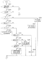
図1は、本実施形態の像ブレ補正装置を備える撮像装置の構成を示す図である。
以下の説明では、画像のヨー方向またはピッチ方向のいずれか一方の像ブレ補正制御に関して説明を行う。他方向の像ブレ補正制御は、説明を省略する。
FIG. 1 is a diagram illustrating a configuration of an imaging apparatus including the image blur correction apparatus according to the present embodiment.
In the following description, image blur correction control in either the yaw direction or the pitch direction of the image will be described. Description of the image blur correction control in the other direction is omitted.
図1に示す撮像装置は、デジタルカメラである。図1に示す例では、撮像装置は、像ブレ補正装置100、角速度検出部102、動きベクトル検出部115、モード情報入力部119、焦点検出部120、補正系駆動部111、補正部112、補正系位置検出部113を備える。
The imaging apparatus shown in FIG. 1 is a digital camera. In the example illustrated in FIG. 1, the imaging device includes an image
角速度検出部102は、撮像装置に加わる振れを角速度信号(振れ検出信号)として検出する。角速度検出部102の出力は、角速度データとしてマイコン(以下、μCOM)101内部のハイパスフィルタ(以下、HPF)103に供給される。
The angular
μCOM101は、像ブレ補正装置100を実現する。μCOM101は、HPF103乃至減算器118を備える。HPF103は、任意の周波数帯域でその特性を変更し得る機能を有している。HPF103は、角速度データに含まれる低周波数成分を遮断してから高周波数帯域の信号を出力する。なお、HPF103が、角速度センサ102の出力から角速度センサ102の出力に対して高周波数帯域の信号を遮断するローパスフィルタ(LPF)を通過させた信号を減算する構成にしても良い。
The μCOM 101 implements the image
利得・位相特性演算部104は、入力データであるハイパスフィルタの出力を所定のゲインで増幅する増幅器と、位相補償フィルタとを有する。焦点距離演算部105は、焦点検出部120から撮像光学系の焦点検出結果を受け取って焦点距離を算出し、補正部112を駆動するのに最適な値となるように利得・位相特性演算部104の出力を補正する。スイッチ106は、補正部112の目標信号を選択する。具体的には、スイッチ106は、モード情報入力部119が出力するモード情報に応じて、被写体振れ補正の目標信号と手振れ補正の目標信号とを切り換えて出力する。被写体振れ補正は、流し撮り時における流し撮り対象の被写体に係る像ブレ補正である。手振れ補正は、流し撮り時以外の撮影時における像ブレ補正である。モード情報の判定値が、撮像装置の動作モードとして流し撮りモードを示す場合、スイッチ106は、減算器118の出力信号を積分器107に供給し、補正部112の駆動による被写体振れ補正が行われるようにする。後述するように、減算器118は、被写体のベクトルから算出される被写体角速度から角速度検出部102の出力を減算する。したがって、流し撮りモードの際には、μCOM101は、撮像装置に加わる振れを示す振れ検出信号と、被写体のベクトルとに基づいて、撮像画像に生じる像ブレを補正するために用いる補正手段を駆動する駆動手段として機能する。モード情報の判定値が、流し撮りモードを示さない場合は、スイッチ106は、焦点距離演算部105の出力を積分器107に供給し、手振れ補正が行われるようにする。
The gain / phase
モード情報の判定値が流し撮りモードか否かについては、μCOM101が、ダイヤルのモード設定に用意されている流し撮りモードを撮影者が選択したか否かによって判定しても良い。また、μCOM101が、ヨー方向とピッチ方向の角速度検出部102の出力との比較結果に基づいて判定してもよい。具体的には、片軸の角速度検出部102の出力がもう片軸の角速度検出部102よりも大きい場合(例えば10dps以上の場合)に、パンニングまたはチルティング状態と判定し、流し撮りモードと判定しても良い。
Whether the determination value of the mode information is the panning mode may be determined by whether the photographer has selected the panning mode prepared for the dial mode setting. Further, the
積分器107は、任意の周波数帯域でその特性を変更し得る機能を有している。積分器107は、スイッチ106の出力を積分し、補正部112の駆動量を算出する。減算器108は、積分器107の出力から、A/D変換器114の出力を減算して、制御器109に出力する。補正系位置検出部113は、補正部112の位置を検出してA/D変換器114に出力する。A/D変換器114は、補正系位置検出部113から出力された補正部112の位置をA/D変換して出力する。
The
制御器109は、入力データを所定のゲインで増幅する増幅器と、位相補償フィルタとを有する。減算器108から供給された偏差データは、制御器109において増幅器及び位相補償フィルタによる信号処理が行われた後、パルス幅変調部110に出力される。パルス幅変調部110は、制御器109を通過して供給されたデータを、パルス波のデューティー比を変化させる波形(即ちPWM波形)に変調して、補正系駆動部111に供給する。
The
補正系駆動部111は、補正部112を駆動させるボイスコイル型モータである。補正部112は、補正系駆動部111によって駆動されることにより、光軸と垂直な方向に移動する。補正部112は、例えばシフトレンズであり、光軸と垂直な方向に移動されることにより光軸を偏光することで、光学的に像ブレを補正する。その結果、装置の振れ等により生じる撮像面上の被写体の移動が補正された像が、撮像素子に結像される。
The correction
補正系位置検出部113は、補正部112の光軸と垂直な方向への移動量を検出し、その検出結果をA/D変換器114を介して減算器108に供給する。補正系位置検出部113は、磁石と、磁石に対抗する位置に供えられたホールセンサとを有する。
The correction system
次に、被写体振れ補正を行うための被写体振れ補正量の算出について説明する。動きベクトル検出部115は、不図示の信号処理部で生成された現在の映像信号に含まれる輝度信号と、1フレーム前の映像信号に含まれる輝度信号とに基づいて、画像の動きベクトルを検出する。この時、μCOM101は、合焦位置検出手段である焦点検出部120によって検出される合焦位置の、基準位置からの移動量または移動割合に応じて、動きベクトル検出部115による動きベクトルの検出領域であるベクトル検出領域を設定する。合焦位置の基準位置からの移動量または移動割合に応じたベクトル検出領域の設定方法については後述する。動きベクトル検出部115によって検出された動きベクトルデータは、被写体ベクトル検出部116に供給される。
Next, calculation of the subject shake correction amount for performing subject shake correction will be described. The motion
被写体ベクトル検出部116は、動きベクトル検出部116によって検出された画面内の動きベクトルから被写体ベクトルを検出して、被写体動きベクトル(第1の動きベクトル)と背景動きベクトル(第2の動きベクトル)を分離する。具体的には、被写体ベクトル検出部116は、角速度検出部102の出力から直流成分を除去した角速度を撮像面上の移動量(像面移動量)へ換算する。被写体ベクトル検出部116は、画面内の動きベクトルと像面移動量とに基づいて、被写体動きベクトルを検出する。
The subject
被写体角速度演算部117は、被写体ベクトル検出部116の出力である被写体ベクトルを、焦点検出部120の焦点距離やフレームレートに基づいて被写体角速度へ換算する。減算器118は、被写体角速度演算部117で算出した被写体角速度から角速度検出部102を減算、つまりは被写体とカメラの差分角速度を算出して、スイッチ106に供給する。
The subject angular
図2は、ベクトル検出ブロックの配置例を示す図である。
ベクトル検出ブロックは、動きベクトル検出部116が動きベクトルの検出対象とするブロックである。図2(A)は、流し撮り時におけるベクトル検出ブロックの配置例を示す。図2(B)は、流し撮影時でない動画撮影の際のベクトル検出ブロックの配置例を示す。動画撮影時など画面全体を対象にして防振したい場合は、ベクトル検出領域202bが画面全体になるようにベクトル検出ブロック203bが配置される。流し撮りなど画面全体ではなく画面内の一部分を対象にして防振したい場合は、ベクトル検出領域202aは、防振したい箇所に密集して配置する。しかし、ベクトル検出領域201aが画面中央付近に配置されていると、被写体201が画面端にいる場合、つまりベクトル検出領域202aの領域内に存在しない場合は、被写体201のベクトル検出をすることができない。
FIG. 2 is a diagram illustrating an arrangement example of vector detection blocks.
The vector detection block is a block that is detected by the motion
図3は、ベクトル検出ブロックを用いて得られた動きベクトルのヒストグラムの例を示す図である。
図3(A)の横軸は、検出されたベクトルの移動量を示す。縦軸は、度数を示す。図2に示すように、画面内に被写体が1つしか存在しない場合は、ヒストグラムは第1ベクトル群301と第2ベクトル群302のように、大きく2つのベクトル群に分かれる。ヒストグラムから被写体ベクトルを判定する方法の一例として、移動量が0pix付近の第1ベクトル群301が被写体で、移動量が0pixから一定以上離れた第2ベクトル群302を背景と判定することができる。しかし、移動量が0pix付近にあるベクトルは、撮影者が被写体をうまく追従できている場合に検出されるベクトルである。流し撮りに不慣れな撮影者は、被写体とカメラの角速度差が大きくなるので、第1ベクトル群301が0pixから離れていく。これにより、第1ベクトル群301と第2ベクトル群302について、被写体ベクトル群と背景ベクトル群との判別が困難となる。
FIG. 3 is a diagram illustrating an example of a motion vector histogram obtained using a vector detection block.
The horizontal axis in FIG. 3A indicates the amount of movement of the detected vector. The vertical axis indicates the frequency. As shown in FIG. 2, when there is only one subject on the screen, the histogram is roughly divided into two vector groups, such as a
図3(B)に示すように、μCOM101は、角速度検出部102の出力である角速度を換算した像面移動量303を中心に、背景範囲の閾値304内に存在するベクトルは背景ベクトル候補と判定する。また、背景範囲の閾値304外に存在するベクトルは被写体ベクトル候補と判定する。像面移動量303を中心に閾値304を用いるのは以下の理由からである。像面移動量303は、撮像装置の動きに伴う像面の移動量であって静止被写体のベクトルに対応している。一方、動きベクトル検出部114が出力するベクトルは、1フレームで60個(例えば縦6ライン横10ライン)であるのに対し、角速度検出部102が出力する角速度は、1フレームで1個のデータ数である。動きベクトル検出部114が出力するベクトルは、静止被写体であっても若干のばらつきがあるため、像面移動量303と動き量が等しいベクトルのみを背景ベクトルと判定すると背景ベクトルの判定精度がよくない。例えば、図3(B)で背景ベクトル群としている動き量のうち中心のベクトルのみが背景ベクトルとして判定すると、その他の背景ベクトル群を被写体ベクトルと誤判定する可能性がでてくる。そのため、背景ベクトルの判定精度を向上させるため、像面移動量303を中心に閾値304を用いる。この閾値304は、角速度検出部102の出力に応じて可変させる。
As shown in FIG. 3B, the
図4は、本実施形態におけるベクトル検出領域の移動を説明する図である。
μCOM101は、図4に示すように、カメラのフォーカス枠402に連動させて、ベクトル検出領域403を移動させる。フォーカス枠は、焦点検出領域を示す。ベクトル検出領域の移動をフォーカス枠402を基準にしている理由は、撮影者は、主被写体にフォーカス枠402を合わせる可能性が高いからである。μCOM101は、フォーカス枠402が合焦した位置を取得し、その位置の基準位置401からの移動量または移動割合を算出し、その算出結果に基づいて、ベクトル検出領域403を設定する。
FIG. 4 is a diagram for explaining the movement of the vector detection region in the present embodiment.
As shown in FIG. 4, the
図5および図6は、本実施形態の防振制御処理を説明するフローチャートである。
ステップS501において、μCOM101が、手振れ補正機能の機能設定が有効になっているか否かを判定する。手振れ補正機能の機能設定が有効になっている場合は、処理が、ステップS502へ進む。手振れ補正機能の機能設定が無効になっている場合は、μCOM101は、補正部112を光学中心位置に維持し続け、防振制御を行わない。
5 and 6 are flowcharts for explaining the image stabilization control processing of the present embodiment.
In step S501, the
ステップS502において、μCOM101は、撮像装置の動作モードが流し撮りモードであるか否かを判定する。撮像装置の動作モードが流し撮りモードである場合は、処理がステップS503に進む。撮像装置の動作モードが流し撮りモードでない場合は、処理がステップS527に進む。流し撮りモードの判定方法の例について説明する。μCOM101は、例えば、ダイヤルのモード設定が、流し撮りモードに選択されている場合に、動作モードが流し撮りモードであると判定する。あるいは、μCOM101が、角速度検出部102の出力である角速度が所定値以上であれば、パンニング(若しくはチルティング)されているとして、動作モードが流し撮りモードであると判定してもよい。
In step S502, the
ステップS503において、μCOM101が、焦点検出方式がオートフォーカス方式(AF)であるかマニュアルフォーカス方式(MF)であるかを判定する。焦点検出方式がAFである場合は、処理がステップS504に進む。焦点検出方式がMFである場合は、処理がステップS526に進む。
In step S503, the
ステップS504において、μCOM101が、オートフォーカス方式が顔優先AFであるか否かを判定する。顔優先AFは、撮影画像中の被写体の顔を優先して焦点検出処理の対象とするAFである。オートフォーカス方式が顔優先AFである場合は、処理が、ステップS505に進む。オートフォーカス方式が顔優先AFでない場合は、処理が、ステップS525へ進む。
In step S504, the
ステップS505において、μCOM101が、タッチAFがされているか否かを判定する。タッチAFは、ユーザ操作で選択される被写体に対して焦点検出処理を実行するオートフォーカス方式である。この例では、タッチAFは、ユーザによってタッチされた領域を焦点検出処理の対象とする。タッチAFがされている場合は、処理がステップS506へ進む。タッチAFがされていない場合は、処理がステップS519に進む。ステップS506において、μCOM101が、タッチAFされた位置での合焦位置、つまり、ユーザによって選択される被写体に対応する焦点検出領域内で検出される合焦位置を取得する。そして、処理が図6のステップS507に進む。
In step S505, the
図7は、画面内に複数の被写体が存在する場合における、ベクトル検出領域の移動を説明する図である。
図7(A)に示すように、画角内に複数の被写体が存在する。フォーカス枠604は、被写体602に対応する。フォーカス枠603は、被写体601に対応する。605は、ベクトル検出領域を示す。μCOM101は、撮影者がタッチAFで指定した被写体601に表示されるフォーカス枠603の合焦位置を取得する。
FIG. 7 is a diagram for explaining the movement of the vector detection area when there are a plurality of subjects on the screen.
As shown in FIG. 7A, there are a plurality of subjects within the angle of view. A
図6のステップS507において、μCOM101が、合焦位置の基準位置(例えば画角中心位置)からの移動量または移動割合を算出する。この合焦位置は、図5のステップS506,ステップS522,ステップS523,ステップS525のいずれかで取得される合焦位置である。また、後述する図5のステップS526でアシスト枠内の領域の中心位置が取得された場合には、μCOM101は、この中心位置の基準位置からの移動量または移動割合を算出する。
In step S507 in FIG. 6, the
次に、図6のステップS508において、μCOM101が、ステップS507で算出した移動量または移動割合の値に基づいて、ベクトル検出領域を移動する。続いて、ステップS509において、動きベクトル検出部116が、ステップS508で移動したベクトル検出領域での動きベクトルを検出する。
Next, in step S508 of FIG. 6, the
次に、ステップS510において、μCOM101が、角速度検出部102の出力である露光重心間の角速度、の平均値を取得する。動きベクトル検出部115が撮像の露光重心間でフレーム間の差分ベクトルを検出しており、ステップS513で動きベクトル検出部115の出力と角速度検出部102の出力から算出する像面移動量のヒストグラムを作成する際に同期をとるためである。
Next, in step S <b> 510, the
次に、ステップS511において、μCOM101が、ステップS504で得られた露光重心間の角速度の平均値からオフセット成分を除去する。オフセット成分を除去するのは、後述する被写体動きベクトル算出処理において、オフセット重畳した分、角速度から換算した像面移動量がオフセットして被写体ベクトルが誤検出されることを防ぐためである。続いて、ステップS512において、μCOM101が、フレームレートと焦点距離情報とに基づいて、露光重心間の角速度の平均値を撮像面上での像面移動量に変換する。角速度情報を像面移動量に変換する理由は、後述する被写体動きベクトルの判定処理で、角速度から求めた像面移動量を使用するからである。
Next, in step S511, the
ステップS513において、μCOM101が、ステップS509で検出した動きベクトルからヒストグラムを作成する。例えば、動きベクトル検出部115の検出ブロック数の設定が、縦6ライン、横10ラインである場合、総数60個のベクトルデータ分のヒストグラムが作成される。また、μCOM101は、ステップS512で算出した撮像面上の像面移動量からヒストグラムを作成する。具体的には、1フレームで取得する角速度は1データであるので、μCOM101は、角速度から換算した撮像面上の像面移動量を中心に±αを背景範囲の閾値として、像面移動量のヒストグラムを作成する。なお、本実施形態では、1フレームで取得する角速度は1データであるため、像面移動量を中心に±αを背景ベクトルと判定する範囲として設定すればよく、像面移動量からヒストグラムを作成しなくてもよい。
In step S513, the
ステップS514において、μCOM101が、被写体動きベクトルが検出可能であるか否かを判定する。具体的には、μCOM101は、ステップS513で作成されたヒストグラムで、背景範囲の閾値304内のベクトルを背景ベクトル群、背景範囲の閾値304外のベクトルを被写体ベクトル群の候補として判定する。そして、各々のベクトル群でピークベクトルの度数が閾値以上(例えば5)であれば、動きベクトルが正しく検出出来ていると判断し、最終的に被写体動きベクトル、背景動きベクトルとして検出する。被写体動きベクトルが検出可能である場合は、処理がステップS515へ進む。被写体動きベクトルが検出不可能である場合は、処理がステップS527へ進む。
In step S514, the
ステップS515において、μCOM101が、ステップS514で検出された被写体ベクトル群のベクトル平均値を算出する。続いて、μCOM101が、ステップS515で算出された被写体動きベクトルを、焦点距離とフレームレートに基づいて角速度に換算して被写体角速度とする。ステップS517において、μCOM101が、ステップS514で算出された被写体角速度と、角速度検出部102の出力との差分値を積分して、被写体振れ補正に用いる補正信号を算出する。
In step S515, the
ステップS518において、μCOM101が、補正部112を駆動する。具体的には、ステップS502で流し撮りモードと判定された場合には、μCOM101は、ステップS517で算出された被写体振れ補正の補正信号に基づいて、補正部112を駆動させる。また、ステップS502で流し撮りモードでないと判定された場合は、μCOM101は、後述するステップS531で算出された手振れ補正の補正信号に基づいて、補正部112を駆動させる。
In step S518, the
また、図5のステップS519において、μCOM101が、顔検出されているかを判定する。顔検出されている場合は、処理がステップS520に進む。顔検出されていない場合は、処理がステップS524に進む。
Further, in step S519 in FIG. 5, it is determined whether the
次に、ステップS520において、μCOM101が、顔検出数が2以上であるかを判定する。顔検出以上が2以上である場合は、処理がステップS521に進む。顔検出数が1である場合は、処理がステップS523に進む。ステップS520で顔検出数を判定している理由は、タッチAFをしていないので、図7(B)に示すように画面内に複数の被写体が存在する場合において、どの被写体が流し撮りの対象であるかを判断する必要があるからである。
Next, in step S520, the
次に、ステップS521において、μCOM101が、主被写体を検出できているかを判定する。ステップS505で撮影者によるタッチAFでの主被写体指定動作がないと判定されているので、ステップS521ではカメラで自動判定する。例えば、μCOM101は、顔のサイズや顔検出位置が画角中央よりかを特定することで、主被写体を検出できているかを判定する。主被写体を検出できている場合は、処理がステップS522に進む。主被写体を検出できていない場合は、処理がステップS524へ進む。
Next, in step S521, the
ステップS522においては、図7(B)に示すように、画面内の複数の被写体601,602のうち、被写体601が主被写体として検出されている。したがって、μCOM101は、主被写体601の顔に対応するフォーカス枠603内の合焦位置を取得する。そして、処理がステップS507に進む。
In step S522, as shown in FIG. 7B, the subject 601 is detected as the main subject among the plurality of
ステップS523においては、画面内に被写体は1人かつ顔検出ができているので、μCOM101は、被写体の顔に対応する焦点検出領域内(フォーカス枠内)で検出される合焦位置を取得する。そして、処理がステップS507に進む。
In step S523, since one subject is detected on the screen and the face is detected, the
ステップS524においては、図7(C)に示すように、画面内に複数の被写体601,602が存在するが、カメラが主被写体を判定できていないか、若しくはステップS519で顔検出がないと判定されている。これは、画面内の人以外の被写体(例えば電車)が撮影されているか、画面内に被写体が存在しないからである。したがって、μCOM101は、移動量または移動割合を0として、ベクトル検出領域605の位置を、例えば画面中心に維持する。
In step S524, as shown in FIG. 7C, there are a plurality of
ステップS525においては、顔優先AF以外のオートフォーカス方式が設定されている。したがって、例えば、指定されたフォーカス枠1点でピント合わせをする方式が設定されている場合には、μCOM101は、指定されたフォーカス枠の合焦位置を取得する。そして、処理がステップS507に進む。
In step S525, an autofocus method other than face priority AF is set. Therefore, for example, when a method of focusing with one designated focus frame is set, the
ステップS526においては、マニュアルフォーカス方式が指定されている。ここで、マニュアルフォーカス時は、μCOM101は、オートフォーカス時の表示枠とは異なる枠(アシスト枠)を表示する。アシスト枠は、撮影をアシストするための枠、具体的には、撮影者が被写体の止めたい位置に合わせやすくするための枠である。したがって、μCOM101は、アシスト枠内の領域の中心位置を取得する。そして、処理がステップS507に進む。
In step S526, the manual focus method is designated. Here, during manual focus, the
また、ステップS527において、μCOM101が、角速度検出部102の出力である角速度を取得する。ステップS528においては、角速度検出部102の出力には直流成分が重畳しているので、μCOM101は、ハイパスフィルタを通して直流成分を除去する。続いて、ステップS529において、μCOM101は、直流成分が除去された角速度検出部102の出力が所望の周波数特性になるように、所定のゲインで増幅する増幅器、及び位相補償フィルタで演算する。
In step S527, the
ステップS530において、μCOM101が、撮像光学系の焦点距離を算出し、補正部112を駆動するのに最適な値となるように利得・位相特性演算部104の出力を補正する。そして、ステップS531において、μCOM101が、ステップS530で補正された出力を積分して、手振れ補正の補正信号を算出する。そして、処理がステップS518に進む。
In step S530, the
以上説明したように、μCOM101が、フォーカス枠と連動してベクトル検出領域を移動させることで、画面内のどの位置でもベクトル検出が可能となる。本発明は、デジタル一眼レフやデジタルコンパクトカメラの像振れ補正装置に限らず、監視カメラ、Webカメラ、携帯電話などの撮影装置にも適用可能である。また、上記の実施形態では、被写体や背景の画面内の動き情報として動きベクトルを用いる例を説明したが、移動量と移動方向とを分離した動き情報を用いてもよい。
As described above,
(その他の実施形態)
本発明は、上述の実施形態の1以上の機能を実現するプログラムを、ネットワーク又は記憶媒体を介してシステム又は装置に供給し、そのシステム又は装置のコンピュータにおける1つ以上のプロセッサーがプログラムを読出し実行する処理でも実現可能である。また、1以上の機能を実現する回路(例えば、ASIC)によっても実現可能である。
(Other embodiments)
The present invention supplies a program that realizes one or more functions of the above-described embodiments to a system or apparatus via a network or a storage medium, and one or more processors in a computer of the system or apparatus read and execute the program This process can be realized. It can also be realized by a circuit (for example, ASIC) that realizes one or more functions.
101 μCOM
102 角速度検出部
111 補正系駆動部
112 補正部
115 動きベクトル検出部
101 μCOM
102 Angular
Claims (12)
撮像装置に加わる振れを示す振れ検出信号と、前記第1の動きベクトルとに基づいて、撮像画像に生じる像ブレを補正するために用いる補正手段を駆動する駆動手段と、
焦点検出手段によって検出される合焦位置に応じて、前記動きベクトルの検出領域の位置を設定する制御手段とを備える
ことを特徴とする像ブレ補正装置。 Obtaining means for obtaining a first motion vector that is a motion vector of a subject from a motion vector detected from a captured image;
A drive unit that drives a correction unit that is used to correct an image blur that occurs in a captured image based on a shake detection signal that indicates a shake applied to the imaging apparatus and the first motion vector;
An image blur correction apparatus comprising: control means for setting a position of the motion vector detection area in accordance with a focus position detected by the focus detection means.
ことを特徴とする請求項1に記載の像ブレ補正装置。 The said control means sets the position of the detection area of the said motion vector according to the said focus position, when the operation mode of the said imaging device is a panning mode. Image blur correction device.
ことを特徴とする請求項2に記載の像ブレ補正装置。 The image blur correction apparatus according to claim 2, wherein the control unit sets the position of the detection area of the motion vector to a position corresponding to the movement of the in-focus position from a reference position.
ことを特徴とする請求項3に記載の像ブレ補正装置。 When the focus detection method of the imaging apparatus is an autofocus method, the control means determines the position of the motion vector detection region as the angle of view center position of the focus position detected in the selected focus detection region. The image blur correction device according to claim 3, wherein the image blur correction device is set to a position corresponding to movement from the camera.
前記撮像装置の焦点検出方式がオートフォーカス方式でない場合に、被写体の撮影をアシストするための枠を表示し、
前記動きベクトルの検出領域の位置を、前記表示された枠内の領域の中心位置の、前記画角中心位置からの移動に応じた位置に設定する
ことを特徴とする請求項3または請求項4に記載の像ブレ補正装置。 The control means includes
When the focus detection method of the imaging device is not an autofocus method, a frame for assisting shooting of the subject is displayed.
The position of the motion vector detection area is set to a position corresponding to the movement of the center position of the area within the displayed frame from the center position of the angle of view. The image blur correction device according to 1.
ことを特徴とする請求項4または請求項5に記載の像ブレ補正装置。 When the focus detection method of the imaging device is a face-priority autofocus method, the control means determines the position of the motion vector detection region corresponding to the face of the subject detected from the captured image. The image blur correction apparatus according to claim 4, wherein the position is set to a position corresponding to the movement of the in-focus position detected from the center of the angle of view.
ことを特徴とする請求項6に記載の像ブレ補正装置。 The control means is configured to detect the position of the motion vector detection region in the focus detection region corresponding to the main subject when the faces of a plurality of subjects are detected from the captured image. The image blur correction apparatus according to claim 6, wherein the image blur correction apparatus is set to a position corresponding to movement from the corner center position.
ことを特徴とする請求項7に記載の像ブレ補正装置。 The image according to claim 7, wherein the control unit sets the position of the detection area of the motion vector to the center of the angle of view when the face of the subject is not detected from the captured image. Blur correction device.
ことを特徴とする請求項6乃至8のいずれか1項に記載の像ブレ補正装置。 When the focus detection method of the imaging apparatus is a face-priority autofocus method and a method of executing focus detection processing on a subject selected by a user operation, the control means The position of the vector detection area is set to a position corresponding to the movement of the in-focus position detected from the focus angle detection area corresponding to the selected subject from the center of the angle of view. The image blur correction device according to any one of 6 to 8.
ことを特徴とする請求項1乃至9のいずれか1項に記載の像ブレ補正装置。 10. The image blur according to claim 1, wherein the control unit maintains a position of the detection region of the motion vector when an operation mode of the imaging apparatus is not a panning mode. Correction device.
撮像画像に生じる像ブレを補正する補正手段と、
撮像画像から動きベクトルを検出するベクトル検出手段と、
前記動きベクトルから被写体のベクトルを算出する算出手段と、
合焦位置を検出する合焦位置検出手段と、
前記振れ検出信号と、前記被写体のベクトルとに基づいて、前記補正手段を駆動する駆動手段と、
前記検出された合焦位置に応じて、前記ベクトル検出手段による動きベクトルの検出領域を移動する制御手段とを備える
ことを特徴とする撮像装置。 Output means for outputting a shake detection signal relating to shake applied to the device;
Correction means for correcting image blur occurring in the captured image;
Vector detection means for detecting a motion vector from the captured image;
Calculating means for calculating a subject vector from the motion vector;
A focus position detecting means for detecting a focus position;
Driving means for driving the correction means based on the shake detection signal and the vector of the subject;
An imaging apparatus comprising: control means for moving a motion vector detection area by the vector detection means in accordance with the detected in-focus position.
撮像装置に加わる振れを示す振れ検出信号と、前記第1の動きベクトルとに基づいて、撮像画像に生じる像ブレを補正するために用いる補正手段を駆動する工程と、
焦点検出手段によって検出される合焦位置に応じて、前記動きベクトルの検出領域の位置を設定する工程とを有する
ことを特徴とする像ブレ補正装置の制御方法。 Obtaining a first motion vector that is a motion vector of a subject from motion vectors detected from a captured image;
Driving a correction unit used to correct image blur that occurs in a captured image based on a shake detection signal indicating shake applied to the imaging apparatus and the first motion vector;
And a step of setting a position of the motion vector detection area in accordance with the focus position detected by the focus detection means.
Priority Applications (3)
| Application Number | Priority Date | Filing Date | Title |
|---|---|---|---|
| JP2016167908A JP6661493B2 (en) | 2016-08-30 | 2016-08-30 | Image blur control device, imaging device, and control method |
| US15/659,819 US10321058B2 (en) | 2016-08-30 | 2017-07-26 | Image pickup apparatus and motion vector detection method |
| CN201710762942.7A CN107800957B (en) | 2016-08-30 | 2017-08-30 | Image pickup apparatus and motion vector detection method |
Applications Claiming Priority (1)
| Application Number | Priority Date | Filing Date | Title |
|---|---|---|---|
| JP2016167908A JP6661493B2 (en) | 2016-08-30 | 2016-08-30 | Image blur control device, imaging device, and control method |
Publications (3)
| Publication Number | Publication Date |
|---|---|
| JP2018036366A true JP2018036366A (en) | 2018-03-08 |
| JP2018036366A5 JP2018036366A5 (en) | 2019-07-11 |
| JP6661493B2 JP6661493B2 (en) | 2020-03-11 |
Family
ID=61244067
Family Applications (1)
| Application Number | Title | Priority Date | Filing Date |
|---|---|---|---|
| JP2016167908A Active JP6661493B2 (en) | 2016-08-30 | 2016-08-30 | Image blur control device, imaging device, and control method |
Country Status (3)
| Country | Link |
|---|---|
| US (1) | US10321058B2 (en) |
| JP (1) | JP6661493B2 (en) |
| CN (1) | CN107800957B (en) |
Cited By (1)
| Publication number | Priority date | Publication date | Assignee | Title |
|---|---|---|---|---|
| JP2020056962A (en) * | 2018-10-04 | 2020-04-09 | キヤノン株式会社 | Image capturing device and control method therefor |
Families Citing this family (11)
| Publication number | Priority date | Publication date | Assignee | Title |
|---|---|---|---|---|
| US10769442B1 (en) * | 2017-09-11 | 2020-09-08 | Amazon Technologies, Inc. | Scene change detection in image data |
| JP7023663B2 (en) | 2017-10-12 | 2022-02-22 | キヤノン株式会社 | Image pickup device and its control method |
| JP7013199B2 (en) | 2017-10-23 | 2022-01-31 | キヤノン株式会社 | Image pickup device and its control method |
| US11070729B2 (en) * | 2018-07-27 | 2021-07-20 | Canon Kabushiki Kaisha | Image processing apparatus capable of detecting moving objects, control method thereof, and image capture apparatus |
| US11722771B2 (en) * | 2018-12-28 | 2023-08-08 | Canon Kabushiki Kaisha | Information processing apparatus, imaging apparatus, and information processing method each of which issues a notification of blur of an object, and control method for the imaging apparatus |
| JP7443005B2 (en) * | 2019-09-18 | 2024-03-05 | キヤノン株式会社 | Image processing device, imaging device and control method |
| JP7414484B2 (en) | 2019-11-19 | 2024-01-16 | キヤノン株式会社 | Optical equipment, imaging device and control method |
| US11575834B2 (en) * | 2019-12-17 | 2023-02-07 | Canon Kabushiki Kaisha | Image stabilization apparatus, method of controlling same, and storage medium |
| JP2021164087A (en) * | 2020-04-01 | 2021-10-11 | キヤノン株式会社 | Imaging device and control method therefor |
| US11381730B2 (en) * | 2020-06-25 | 2022-07-05 | Qualcomm Incorporated | Feature-based image autofocus |
| JP2022093912A (en) * | 2020-12-14 | 2022-06-24 | キヤノン株式会社 | Imaging device, imaging method, and program |
Citations (10)
| Publication number | Priority date | Publication date | Assignee | Title |
|---|---|---|---|---|
| JP2006317848A (en) * | 2005-05-16 | 2006-11-24 | Canon Inc | Still picture imaging apparatus |
| JP2007288726A (en) * | 2006-04-20 | 2007-11-01 | Matsushita Electric Ind Co Ltd | Imaging apparatus |
| JP2009296030A (en) * | 2008-06-02 | 2009-12-17 | Canon Inc | Imaging device |
| JP2010021598A (en) * | 2008-07-08 | 2010-01-28 | Victor Co Of Japan Ltd | Image capturing apparatus and method |
| JP2010114752A (en) * | 2008-11-07 | 2010-05-20 | Canon Inc | Device and method of imaging and program |
| JP2011233963A (en) * | 2010-04-23 | 2011-11-17 | Ricoh Co Ltd | Imaging apparatus and tracking object detection method |
| JP2014168227A (en) * | 2013-01-31 | 2014-09-11 | Canon Inc | Image processing apparatus, imaging apparatus, and image processing method |
| JP2015012482A (en) * | 2013-06-28 | 2015-01-19 | キヤノン株式会社 | Image processing apparatus and image processing method |
| JP2015012480A (en) * | 2013-06-28 | 2015-01-19 | キヤノン株式会社 | Image processing apparatus and image processing method |
| JP2015161730A (en) * | 2014-02-26 | 2015-09-07 | キヤノン株式会社 | Image blur correction device, control method thereof, optical device, and imaging apparatus |
Family Cites Families (7)
| Publication number | Priority date | Publication date | Assignee | Title |
|---|---|---|---|---|
| US5629735A (en) * | 1989-08-20 | 1997-05-13 | Canon Kabushiki Kaisha | Image sensing device having a selectable detecting area |
| JP4874668B2 (en) * | 2006-02-22 | 2012-02-15 | Hoya株式会社 | Autofocus unit and camera |
| JP5213613B2 (en) * | 2008-09-26 | 2013-06-19 | キヤノン株式会社 | Image processing apparatus, image processing method, imaging apparatus, and program |
| US8704908B1 (en) * | 2008-11-03 | 2014-04-22 | Marvell International Ltd. | Method and apparatus for multiple zone statistics collection for digital image/video capture systems |
| WO2012099175A1 (en) * | 2011-01-18 | 2012-07-26 | 富士フイルム株式会社 | Auto focus system |
| JP5917133B2 (en) * | 2011-12-22 | 2016-05-11 | キヤノン株式会社 | Anti-vibration control device, anti-vibration control method, optical device, imaging device |
| JP6335058B2 (en) * | 2013-09-24 | 2018-05-30 | キヤノン株式会社 | Imaging apparatus and imaging method |
-
2016
- 2016-08-30 JP JP2016167908A patent/JP6661493B2/en active Active
-
2017
- 2017-07-26 US US15/659,819 patent/US10321058B2/en active Active
- 2017-08-30 CN CN201710762942.7A patent/CN107800957B/en active Active
Patent Citations (10)
| Publication number | Priority date | Publication date | Assignee | Title |
|---|---|---|---|---|
| JP2006317848A (en) * | 2005-05-16 | 2006-11-24 | Canon Inc | Still picture imaging apparatus |
| JP2007288726A (en) * | 2006-04-20 | 2007-11-01 | Matsushita Electric Ind Co Ltd | Imaging apparatus |
| JP2009296030A (en) * | 2008-06-02 | 2009-12-17 | Canon Inc | Imaging device |
| JP2010021598A (en) * | 2008-07-08 | 2010-01-28 | Victor Co Of Japan Ltd | Image capturing apparatus and method |
| JP2010114752A (en) * | 2008-11-07 | 2010-05-20 | Canon Inc | Device and method of imaging and program |
| JP2011233963A (en) * | 2010-04-23 | 2011-11-17 | Ricoh Co Ltd | Imaging apparatus and tracking object detection method |
| JP2014168227A (en) * | 2013-01-31 | 2014-09-11 | Canon Inc | Image processing apparatus, imaging apparatus, and image processing method |
| JP2015012482A (en) * | 2013-06-28 | 2015-01-19 | キヤノン株式会社 | Image processing apparatus and image processing method |
| JP2015012480A (en) * | 2013-06-28 | 2015-01-19 | キヤノン株式会社 | Image processing apparatus and image processing method |
| JP2015161730A (en) * | 2014-02-26 | 2015-09-07 | キヤノン株式会社 | Image blur correction device, control method thereof, optical device, and imaging apparatus |
Cited By (2)
| Publication number | Priority date | Publication date | Assignee | Title |
|---|---|---|---|---|
| JP2020056962A (en) * | 2018-10-04 | 2020-04-09 | キヤノン株式会社 | Image capturing device and control method therefor |
| JP7214424B2 (en) | 2018-10-04 | 2023-01-30 | キヤノン株式会社 | Imaging device and its control method |
Also Published As
| Publication number | Publication date |
|---|---|
| CN107800957A (en) | 2018-03-13 |
| CN107800957B (en) | 2020-08-14 |
| JP6661493B2 (en) | 2020-03-11 |
| US10321058B2 (en) | 2019-06-11 |
| US20180063436A1 (en) | 2018-03-01 |
Similar Documents
| Publication | Publication Date | Title |
|---|---|---|
| JP6661493B2 (en) | Image blur control device, imaging device, and control method | |
| JP6674264B2 (en) | Image blur detection apparatus and method, and imaging apparatus | |
| US10306131B2 (en) | Focus detection apparatus and control method therefor | |
| US9531938B2 (en) | Image-capturing apparatus | |
| US10250808B2 (en) | Imaging apparatus and control method therefor | |
| US9865064B2 (en) | Image processing apparatus, image processing method, and storage medium | |
| JP6995561B2 (en) | Image stabilization device and its control method, image pickup device | |
| CN109698912B (en) | Image pickup apparatus and control method thereof | |
| JP6932531B2 (en) | Image blur correction device, image pickup device, control method of image pickup device | |
| JP2018060126A (en) | Image blur correction device, control method of the same and imaging apparatus | |
| JP2013205723A (en) | Image blur correction device, imaging device, and control method of image blur correction device | |
| US10873701B2 (en) | Image pickup apparatus and control method thereof | |
| JP2017097218A (en) | Image shake correction device, image shake correction method, imaging device, and program | |
| JP2017161649A (en) | Image shake correction device and method of controlling image shake correction device, program, and storage medium | |
| JP7346076B2 (en) | Control device, lens device, imaging device, control method, and program | |
| US10389942B2 (en) | Image blur correction apparatus, control method thereof, and imaging apparatus | |
| JP2018082232A (en) | Imaging device and control method | |
| JP2020148999A (en) | Control device, imaging device, lens device, control method, and program | |
| JP2019091063A (en) | Shake correction device, electronic apparatus and camera | |
| JP7023663B2 (en) | Image pickup device and its control method | |
| JP7414484B2 (en) | Optical equipment, imaging device and control method | |
| JP2022124464A (en) | Image capturing apparatus, control method of the same, program, and storage medium | |
| WO2020012960A1 (en) | Imaging device | |
| JP2023062881A (en) | Imaging apparatus and control method for the same | |
| JP2020056962A (en) | Image capturing device and control method therefor |
Legal Events
| Date | Code | Title | Description |
|---|---|---|---|
| A521 | Request for written amendment filed |
Free format text: JAPANESE INTERMEDIATE CODE: A523 Effective date: 20190606 |
|
| A621 | Written request for application examination |
Free format text: JAPANESE INTERMEDIATE CODE: A621 Effective date: 20190606 |
|
| A871 | Explanation of circumstances concerning accelerated examination |
Free format text: JAPANESE INTERMEDIATE CODE: A871 Effective date: 20190606 |
|
| A975 | Report on accelerated examination |
Free format text: JAPANESE INTERMEDIATE CODE: A971005 Effective date: 20190830 |
|
| A131 | Notification of reasons for refusal |
Free format text: JAPANESE INTERMEDIATE CODE: A131 Effective date: 20190903 |
|
| A521 | Request for written amendment filed |
Free format text: JAPANESE INTERMEDIATE CODE: A523 Effective date: 20191030 |
|
| TRDD | Decision of grant or rejection written | ||
| A01 | Written decision to grant a patent or to grant a registration (utility model) |
Free format text: JAPANESE INTERMEDIATE CODE: A01 Effective date: 20200114 |
|
| A61 | First payment of annual fees (during grant procedure) |
Free format text: JAPANESE INTERMEDIATE CODE: A61 Effective date: 20200212 |
|
| R151 | Written notification of patent or utility model registration |
Ref document number: 6661493 Country of ref document: JP Free format text: JAPANESE INTERMEDIATE CODE: R151 |